Standard Single Use CIP System and Integration Leading Technologies. Individual Solutions.

Gea_std Single Use Cip Sys_cipd
Dec 19, 2015
CIP Systems
Welcome message from author
This document is posted to help you gain knowledge. Please leave a comment to let me know what you think about it! Share it to your friends and learn new things together.
Transcript

Standard Single Use
CIP Systemand
Integration
Leading Technologies. Individual Solutions.

There are three importantelements to consider in thedesign and implementation ofany CIP System; the CIP Skid,the equipment & systems to becleaned and the CIP supply &return lines.
The CIP Skid controls thecleaning (“T.A.C.T.”) parametersof Temperature, Action(velocity/pressure), Chemicalconcentration and Time ofexposure. It can be configuredwith many different options as required by the owner toachieve the desired cleaningresults.
Knowledge and Experience Required
More of a challenge is thedesign considerations of theequipment & systems to becleaned. In recent years theindustry has given moreattention to this and importantguidelines have been publishedby ASME-BPE, ISPE, etc. Andwhile these guideline havemade large strides addressing
the mechanical aspects, it is not mandatory (or sometimespossible!) for equipmentsuppliers to follow them. Thus it requires knowledge and experience in identifyingpotential CIP issues relating to equipment geometry anddeveloping a tactical CIPapproach to the process system.
There are several integrationtechniques for connecting theCIP skid with the targetedprocesses to be cleaned with theCIP supply & return circuits.Perhaps the most known is the use of flow-plates so that“make-break” circuits can beestablished, thus giving theowner a safe operation with a degree of flexibility albeit a manual operation. In moreadvanced operations, the use of matrix piping technology is used which employs mix-proof valves that allow the CIPsupply & return to be totally“hardpiped” and automated,thus maximize the efficiency of the CIP operation.
GEA Liquid Processing takescomplete responsibility for all aspects of the CIP System.
Our Process Engineers will audit your process forcleanability. Our CIP Systemskids are completely designed,engineered, fabricated,automated and tested in ourworkshop. We can furtherintegrate the CIP System Skid into your operating plantutilizing the latest integrationtechniques.
We assign a qualified ProcessEngineer to your project tofacilitate discussions regardingsite-specific requirements,integration concerns and final FAT/SAT protocols. Thisvertically integrated projectapproach has the benefit of: • Seamless communications
between disciplines• Eliminates budget variances
that would result from havingmultiple contracts
• Enhances the “speed tomarket” of the overall project
CIP SKID“T.A.C.T”
ControllableParameters
PROCESS EQUIPMENT AND SYSTEMS• Equipment geometry• Hygienic design of system• Tactical selection of CIP devices
Non-controllable elements, as they are set in thedesign and construction phase
Elements of a CIP System:
CIP Supply
CIP Return
CIP System In today’s pharmaceutical and biologic manufacturing,cleaning the process equipment and systems is crucial to the overall success of the enterprise. For larger productionand bulk facilities, cleaning is accomplished by acentralized CIP system and is considered a critical utility.
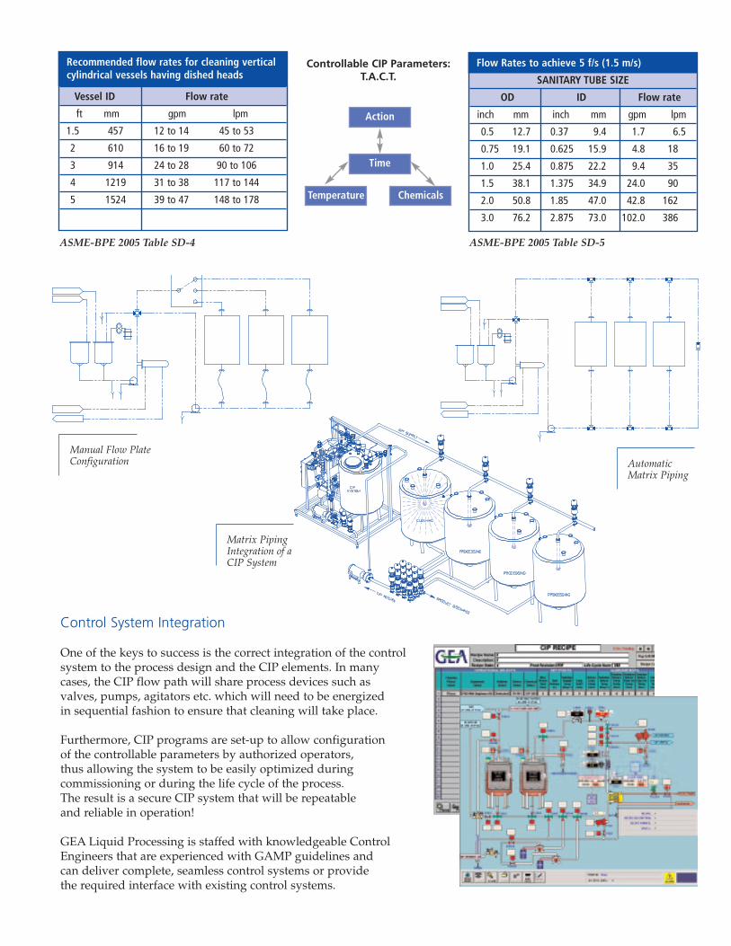
Recommended flow rates for cleaning verticalcylindrical vessels having dished heads
Vessel ID Flow rate
ft mm gpm lpm
1.5 457 12 to 14 45 to 53
2 610 16 to 19 60 to 72
3 914 24 to 28 90 to 106
4 1219 31 to 38 117 to 144
5 1524 39 to 47 148 to 178
Flow Rates to achieve 5 f/s (1.5 m/s)
SANITARY TUBE SIZE
OD ID Flow rate
inch mm inch mm gpm lpm
0.5 12.7 0.37 9.4 1.7 6.5
0.75 19.1 0.625 15.9 4.8 18
1.0 25.4 0.875 22.2 9.4 35
1.5 38.1 1.375 34.9 24.0 90
2.0 50.8 1.85 47.0 42.8 162
3.0 76.2 2.875 73.0 102.0 386
ASME-BPE 2005 Table SD-4 ASME-BPE 2005 Table SD-5
Control System Integration
One of the keys to success is the correct integration of the controlsystem to the process design and the CIP elements. In manycases, the CIP flow path will share process devices such asvalves, pumps, agitators etc. which will need to be energized in sequential fashion to ensure that cleaning will take place.
Furthermore, CIP programs are set-up to allow configuration of the controllable parameters by authorized operators, thus allowing the system to be easily optimized duringcommissioning or during the life cycle of the process. The result is a secure CIP system that will be repeatable and reliable in operation!
GEA Liquid Processing is staffed with knowledgeable ControlEngineers that are experienced with GAMP guidelines and can deliver complete, seamless control systems or provide the required interface with existing control systems.
Matrix PipingIntegration of aCIP System
Manual Flow PlateConfiguration Automatic
Matrix Piping
Action
Chemicals
Time
Temperature
Controllable CIP Parameters:T.A.C.T.

CIP tank
Secondary dedicated water tank
CIP return pump with low pointdrain valve
Chemical addition system(s)
Tank insulation
Air blow
CIP supply pressure transmitter
CIP supply temperature transmitter
CIP supply flow transmitter
Steam supply condensate drip leg
Heat exchanger drain
CIP return temperaturetransmitter
CIP return flow switch
CIP return conductivitytransmitter
Portable
Explosion Proof (Class I / Div 1,2)
Options
GEA’s single use CIP System Skid can be configured with the following options to meet your specific needs.
For detailed technical support, call us at 410-997-8700. Our engineers will assist you with the final CIP systemskid configuration required to deliver specified CIP solutions and discuss plant integration options.
2
1
3
4
5
6
7
8
9
10
11
12
13
14
15
16
4
13 1214
8
7
9
3 CIP RETURN PUMP
CIP RETURN
CIP SUPPLY
STEAM
CONDENSATE
10
11
HEATEXCHANGER
PLANT AIR
CIPSUPPLYPUMP
CHEM2
CHEM1
6
PRO
CESS
AIR
5 5DEDICATED
WATERTANK
2
CIPTANK
1
PROCESS WATER
USP WATER
CT FS TE TT
TT TE
PT
FE FT
PI
LT LT
4

Technical Data Typical Utility Requirements
Steam . . . . . . . . . . . .1000 lb/hr at 35 psi.Process water . . . . . .30-60 gpmElectrical . . . . . . . . . .120 VAC, 20 Amp for control cabinet. . . . . . . . . . . . . . . . . . .460V, 3 phase 60 Hz for the MCCAir . . . . . . . . . . . . . .90 psi (30CFH for airblow)*Specific flow data and utility requirements will be altered to suit individual process requirements.
Dimensional Information
Standard Documentation Package
• Pipe and Instrument Diagram (P&ID)• Dimensional drawings• Complete set of electrical drawings• Functional Design Specification (FDS)• Software Design Specification (SDS)• I/O list• Set of software applications• Maintenance manuals and spare parts
list for all components• Welding & inspection documentation• Material certificates and surface finish
reports for all process components
One-tank systemA = Height: 8’B = Width: 6’C = Length: 9’Dry weight: 4200 lbs
Two-tank systemA = Height: 8’B = Width: 6’C = Length: 13’
Dry weight: 6800 lbs
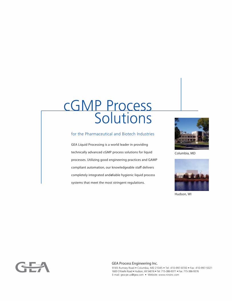
cGMP Process Solutions
for the Pharmaceutical and Biotech Industries
GEA Liquid Processing is a world leader in providing
technically advanced cGMP process solutions for liquid
processes. Utilizing good engineering practices and GAMP
compliant automation, our knowledgeable sta� delivers
completely integrated and reliable hygienic liquid process
systems that meet the most stringent regulations.
Columbia, MD
Hudson, WI
GEA Process Engineering Inc.9165 Rumsey Road • Columbia, MD 21045 • Tel: 410-997-8700 • Fax: 410-997-50211600 O'Keefe Road • Hudson, WI 54016 • Tel: 715-386-9371 • Fax: 715-386-9376E-mail: [email protected] • Website: www.niroinc.com
Related Documents