184 GEARHEADS: STEALTH PLANETARY AND NEMA SPUR

Welcome message from author
This document is posted to help you gain knowledge. Please leave a comment to let me know what you think about it! Share it to your friends and learn new things together.
Transcript

184
GEARHEADS:STEALTH PLANETARY AND NEMA SPUR

185
Stealth® Planetary Gearheads
188 PS Advanced In-Line
196 PX In-Line
200 PV Power & Versitility
208 RS Advanced Right Angle
216 RX Right Angle
220 MultiDrive Right Angle
NEMA Gearheads
228
NE In-Line NEMA
NR Right Angle NEMA
Specials232
Gearheads
Still serviced & MRO Consult factory
PG Series - still serviced & MRO Consult factory

186
Gearheads: Application Solutions
APPLICATION CHALLENGE
The customer manufactures machines for gluing, fill, sealing and diverting of food containers for the food-processing industry. The motor and gearhead needed to be mounted above the food plane. Certain modifications had to be made to the gearhead to make it safe in this environment, as well as making the gearhead able to withstand frequent washdowns. Design Considerations
Gearhead Lubrication – must be USDA food grade approved in case of incidental contact to food.
Gearhead Sealing – to prevent any leaking as well as prevent any ingress of the fluid during washdown.
Gearhead Finish – special FDA-approved finish must be used, making it very durable and resistant to chipping, oxidizing or rusting.
Gearhead Output Shaft – stainless steel to prevent any rust from developing and contaminating the processing food.
Stealth Gearmotors for Factory Automation
APPLICATION CHALLENGE
The manufacturer of high-performance plastic extrusion equipment. They needed a drop-in replacement gearhead for an existing worm gearbox used with their motor without having to alter the design of their machine. The gearhead/motor combination is being used to drive the machine's rollers. It controls the speed at which the plastic is extruded into high-quality plastic sheets. The smoothness of the rollers is critical to the quality of the plastic sheets being produced.
High Transmission Error and Velocity RippleThe customer used worm gearheads to control the rollers. Worm gears exhibit a sliding action of involute gears instead of a rolling action, contributing to the lack of smoothness of the machine rollers. Due to the high transmission error and velocity ripple from the worm drive, the rollers operated at differing speeds. This produced small lines and imperfections on the plastic sheets, rendering it unusable.
High Wear and Low EfficiencyThe high level of rubbing (sliding action) between the worm and wheel teeth in the worm gearhead caused a high gear-tooth-wear rate and a lower efficiency (70%) than other major gear types.
Stealth Gearheads on High-Speed Milling Machines
APPLICATION CHALLENGE
The manufacturer of high-speed milling machines used in the aerospace industry. These milling machines are becoming more commonplace in the aerospace and automotive industries because it allows large structural components to be machined from one piece, where before they were assembled from many smaller subcomponents. In high-speed milling, spindle heads are operating at speeds ranging from 18,000 to 40,000 RPM, so that the cutting is above the resonant frequency of the machine. Because of this, many characteristics become more critical than in standard machines. The extremely large size of the spindle head also posed problems for the customer in trying to keep it accurately positioned during the milling stage.
Low StiffnessThe spindle head was moved rotationally by 2 bull gears, driving a large ring gear. Because of the system characteristics, it was difficult to keep the spindle head absolutely stiff during the milling process. The problems associated with low stiffness are:
1. Poor surface finish 2. Accuracy errors 3. Excessive tool chatter 4. Reduced tool life
Stealth Gearheads on a Bottling Application

187187
Parker Bayside SOLUTION
(1) Stealth PS Gearhead and (1) Stealth RT MultiDrive (throughbore) Gearhead The above Stealth gearhead products were used in combination to provide the required 120:1 ratio. The result was high-quality plastics sheets that exceeded the customer's specifications.
The Stealth's all-helical planetary design (HeliCrown Gear Tooth) features extremely high gear tooth accuracy, minimizing transmission error and velocity ripple. The Helicrown design features extremely high efficiency (98%) while minimizing tooth wear by providing a pure rolling action. Parker Bayside's Plasma Nitriding heat-treating process further heightens the gear tooth's wear resistance.
The Stealth MultiDrive gearhead features a space-saving thru-bore (hollow shaft) option, eliminating compliance that occurs when coupling a gearhead shaft to the rollers being driven.
This solution can be used for a variety of applications, including:1. Packaging 2. Food 3. Semiconductor 4. Automotive 5. Medical
Parker Bayside SOLUTION
PS115-010-F01 Stealth PS planetary gearhread with standard food grade option. The F01 designation provides the gearhead with standard modifications: special lubrication, viton seals, special finish and a stainless steel output shaft.
Since this food grade modification is a standard option, delivery is only one week over the standard (typically one week) gearhead lead time.
Note: Similar standard modifications exist for vacuum, clean room, high temperature and radiation.
Parker Bayside SOLUTION
(2) Stealth PS142 Helical Planetary Gearheads The above Stealth gearheads were used in tandem to create a stiff platform for the spindle machine head. One gearhead, acting as the master, and the other as the slave, were attached to the bull gears to simultaneously turn the ring gear that positioned the machine head. While the master gearhead moved the ring, the slave was taking up the backlash. In this way, the precision gears allowed for the spindle to be moved accurately, while the two gearhead combination maintained maximum system stiffness.
Parker Bayside's Stealth PS gearhead features an all-helical planetary gear design. Helical gears have a much higher tooth-contact ratio and greater face width than straight-spur gears, providing higher loads, smoother tooth engagement and quieter operation. The Stealth's HeliCrown Gear Tooth design provides extremely high gear tooth accuracy, while minimizing tooth wear. Parker Bayside's Plasma Nitriding heat-treating process further heightens the gear tooth's wear resistance.
This solution can be used in the aerospace and automotive industries.

Ratios * 3:1 25:1 4:1 30:1 5:1 40:1 7:1 50:1 10:1 70:1 15:1 100:1 20:1 * For PS300
see Note (4)
Stealth Advanced PS is Parker Bayside’s highest-performance servo gearhead. Available in 8 frame sizes and 12 gear ratios, you are guaranteed to find a Stealth PS to fit your high-performance servo applications.
Stealth® PS Advanced Series: The Ultimate in Gearhead Performance
Stealth PS Advanced Series
7 Frame Sizes
PS60 PS180 PS90 PS220 PS115 PS300 PS142

189
Stealth® PS Advanced Series
(1) Maximum of 1,000 stops(2) Measured at 2% of rated torque(3) Measured at 1 meter(4) PS300 is available in Ratios of: 4, 5, 7, 10, 20, 50, 70 & 100:1 Specification are subject to change without notice
Frame Size Units Ratio PS60 PS90 PS115 PS142 PS180 PS220 PS300
Nominal Output Nm 3-10 25 74 170 294 735 1,413 3,616
Torque, Tnom r in lb 220 650 1,500 2,600 6,500 12,500 32,000
Nm 15-50 34 107 226 396 1,017 1,808 4,520
in lb 300 950 2,000 3,500 9,000 16,000 40,000
Nm 70-100 28 90 203 339 893 1,582 4,181
in lb 250 800 1,800 3,000 7,900 14,000 37,000
Maximum Acceleration Nm 3-10, 70-100 34 105 232 367 972 1,763 4,825
Output Torque, in lb 300 930 2,050 3,250 8,600 15,600 42,700
Tacc r Nm 15-50 42 130 283 452 1,198 2,011 5,492
in lb 370 1,150 2,500 4,000 10,600 17,800 48,600
Emergency(1) Stop Nm 3-10, 70-100 78 243 537 853 2,237 4,068 11,119
Output Torque, in lb 690 2,150 4,750 7,550 19,800 36,000 98,400
Tem r Nm 15-50 96 299 655 1,040 2,757 4,520 12,656
in lb 850 2,650 5,800 9,200 24,400 40,000 112,000
Nominal Input Speed, RPM 3-5 3,200 2,800 2,400 2,000 1,600 1,200 1,000
Nnom r RPM 7-10 3,700 3,300 2,900 2,500 2,000 1,500 1,250
RPM 15-50 4,200 3,800 3,400 3,000 2,400 1,800 1,500
RPM 70-100 4,700 4,300 3,900 3,500 2,800 2,100 1,750
Max. Input Speed, Nmaxr RPM 3-100 6,000 5,300 4,500 3,800 3,000 2,300 1,900
Standard Backlash (2) arc min 3-10 6 6 4 4 4 4 4
arc min 15-100 8 8 6 6 6 6 6
Low Backlash (2) arc min 3-10 4 4 3 3 3 3 3
arc min 15-100 6 6 5 5 5 5 5
Efficiency at % 3-10 97 97 97 97 97 97 97
Nominal Torque % 15-100 94 94 94 94 94 94 94
Noise Level(3) at:
3,000 RPM dB 3-100 62 62 62 64 — — —
2,000 RPM dB 3-100 — — — — 66 68 70
Torsional Stiffness Nm / arc min 3-100 3 12 23 44 110 210 360
in lb / arc min 26 106 204 389 973 1,858 3,185
Maximum Weight kg 3-10 1.3 3 7 14 26 49 103
lb 2.8 7 15 30 57 108 228
kg 15-100 1.7 5 10 20 35 71 149
lb 3.7 10 22 43 77 157 330
Maximum Allowable oC 3-100
100
Case Temperature For applications requiring lower case temperature, consult factory
Performance Specifications

Helical Planetary Design - Helical gears have more tooth contact and greater face width than spur gears. This results in higher loads, smoother tooth engagement, quieter operation and lower backlash.
HeliCrown® - Parker Bayside developed the HeliCrown gear tooth to further optimize Stealth’s® performance. Since most vibration occurs at the entry and exit points of a gear tooth, HeliCrown eliminates metal only in these areas, without sacrificing gear strength, producing a quieter and stronger gear.
Plasma Nitriding - Parker Bayside’s in-house Plasma Nitriding process results in an ideal gear tooth. The surface is very hard (65 Rc) and the core is strong, but flexible (36 Rc). The result is a wear-resistant gear tooth that can withstand heavy shock, ensuring high accuracy for the life of the gearhead.
ServoMount® - Parker Bayside’s patented ServoMount design features a balanced input gear supported by a floating bearing. This unique design compensates for motor shaft runout and misalignment, ensuring TRUE alignment of the input sun gear with the planetary section and allowing input speeds up to 6,000 RPM. ServoMount ensures error-free installation to any motor, in a matter of minutes.
Stealth’s® superior design and construction deliver “The Helical Advantage”:
Strong…30% More Torque
Fast…6,000 RPM Input Speeds
Accurate…Less Than 3 Arc minutes Backlash
Quiet…Less Than 68dB Noise
Plus... Over 97% Efficiency Magnetic Oil Fill Drain PlugThe magnetic plug attracts normal wear particles keeping them away from the gear mesh.
9
Output Wave Seal TechnologyCreates a hydrodynamic film between seal and shaft and reducing heat and wear.
10
Front Output Seal CoverCompletely captures and protects output seal and allows in-field seal replacement.
11
Stealth® Advanced in the PS / RS Models incorporates the latest enhancement in gearhead technology:
Latest technology in seals…reduce heat and wear
Oil lubrication…reduces, friction and operating temperature
Front output seal cover…captures and protects output seal
Get the Helical Advantage!
For Applications Requiring Lower dB, Consult Factory
Stealth PS Advanced Series

Sealed UnitVition seals and O-Rings provide IP65 protection to prevent leaks and protect against harsh environments.
5
2l
6
4
3
5
HeliCrown®
Parker Bayside’s proprietary gear tooth geometry ensures quieter operation and higher loads than conventional gears.
4
Precision BearingsLarge, deep groove bearings provide high-speed capacity and radial loads.
3
7
Helical PlanetaryProvides smooth, quiet operation, high torque and high accuracy.
ServoMount®
Patented motor-mounting design ensures error-free installation and the balanced pinion allows higher input speeds.
2l
Rigid Sun GearPerfectly aligned between two large bearings for maximum stiffness and strength.
6
Integral Ring GearCutting the ring gear directly into the housing allows for larger bearing and planet gears, delivering maximum power and stiffness in a minimum package.
7
Oil LubricationOil provides better lubrication, reduces friction and operating temperatures.
8
11
10
9
8
191

Frame Size
Specifications: Units Ratio PS60 PS90 PS115 PS142 PS180 PS220 PS300
Small Motor mm 3-100 6-12.7 6-16 9-19 12.7-24 15.9-35 24-48 28-65Shaft Diameter
in 0.236-0.500 0.236-0.630 0.354-0.748 0.500-0.944 0.626-1.378 0.945-1.89 1.10-2.56Range
gm cm sec2 3 0.176 0.784 2.34 7.81 28.6 — —
oz in sec2 0.002 0.011 0.033 0.109 0.397 — —
gm cm sec2 4,5 0.101 0.486 1.87 4.92 17.6 62.6 284
oz in sec2 0.001 0.007 0.026 0.068 0.244 0.869 3.95
gm cm sec2 7,10 0.063 0.298 0.960 2.68 9.24 34.3 136
oz in sec2 0.001 0.004 0.013 0.037 0.128 0.476 1.88
gm cm sec2 15 0.092 0.420 1.60 4.17 15.8 51.0 —
oz in sec2 0.001 0.006 0.022 0.058 0.219 0.708 —
gm cm sec2 16,20,25 0.098 0.444 1.73 4.50 16.7 53.3 219
oz in sec2 0.001 0.006 0.024 0.063 0.232 0.741 3.05
gm cm sec2 30-100 0.054 0.247 0.760 2.18 7.450 27.1 93.9
oz in sec2 0.001 0.003 0.011 0.030 0.104 0.377 1.30
Large Motor mm 3-100 16-19 19-24 24-35 35-42 48-55 —Shaft Diameter
in 0.500-0.630 0.630-0.748 0.748-0.944 0.944-1.38 1.38-1.65 1.89-2.17 —Range
gm cm sec2 3 0.253 1.07 3.25 10.6 37.8 111 —
oz in sec2 0.004 0.015 0.045 0.148 0.526 1.54 —
gm cm sec2 4,5 0.185 0.745 2.70 7.51 25.6 72.4 —
oz in sec2 0.003 0.010 0.038 0.104 0.356 1.01 —
gm cm sec2 7,10 0.143 0.566 1.70 5.01 15.8 44.1 —
oz in sec2 0.002 0.008 0.024 0.070 0.219 0.613 —
gm cm sec2 15 0.176 0.685 2.43 6.76 23.8 60.8 —
oz in sec2 0.002 0.010 0.034 0.094 0.331 0.845 —
gm cm sec2 16,20,25 0.182 0.715 2.56 7.09 24.7 62.9 —
oz in sec2 0.003 0.010 0.036 0.099 0.344 0.874 —
gm cm sec2 30-100 0.134 0.507 1.50 4.50 14.0 37.0 —
oz in sec2 0.002 0.007 0.021 0.063 0.195 0.513 —
Moment of Inertia
Note: All Moment of Inertia values are as reflected at the input shaft of the gearhead.
Specification are subject to change without notice
Stealth PS Advanced Series
193
0
(Lbs) (N)
100 200 300 400 500 600 700
0
150
200
100
50
800 900 1000
0
600
800
1000
400
200
Axial load
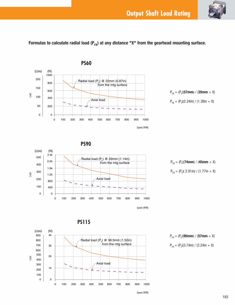
Radial load (Pr) @ 22mm (0.87in) from the mtg surface
PS60
Load
Speed (RPM)
Formulas to calculate radial load (Prx) at any distance "X" from the gearhead mounting surface.
Prx = (Pr)(57mm) / (35mm + X)
Prx = (Pr)(2.24in) / (1.38in + X)
Prx = (Pr)(74mm) / (45mm + X)
Prx = (Pr)( 2.91in) / (1.77in + X)
Prx = (Pr)(95mm) / (57mm + X)
Prx = (Pr)(3.74in) / (2.24in + X)
0
(Lbs) (N)
100 200 300 400 500 600 700
0
300
400
500
200
100
800 900 1000
0
1.2k
1.6k
2.0k
2.4k
800
400
Axial load
Radial load (Pr) @ 29mm (1.14in) from the mtg surface
PS90
Load
Speed (RPM)
0
(Lbs) (N)
100 200 300 400 500 600 700
0
300
400
500
200
100
800 900 1000
0
1k
2k
3k
4k
Axial load
700
800
900
600
Radial load (Pr) @ 38.5mm (1.52in) from the mtg surface
PS115
Load
Speed (RPM)
Output Shaft Load Rating

0
(Lbs) (N)
100 200 300 400 500 600
0
1.0k
0.5k
0
6.0k
2.0k
1.5k
2.0k
4.0k
9.0k
Axial load
8.0k
7.0k
5.0k
3.0k
1.0k
Radial load (Pr) @ 62.5mm (2.46in) from the mtg surface
0
(Lbs) (N)
100 200 300 400 500 600
0
20k
10k
0
6.0k
40k
30k
2.0k
4.0k
9.0k
Axial load
8.0k
7.0k
5.0k
3.0k
1.0k
Radial load (Pr) @ 84mm (3.31in) from the mtg surface
50
(Lbs) (N)
100 150 200 250 300 350 400
0
10k
5k
0
60k
15k
20k
40k
80k
Axial load
Radial load (Pr) @ 112.5mm (4.43in) from the mtg surface
0
(Lbs) (N)
100 200 300 400 500 600 700
0
400
200
0
6k
800
6002k
5k
7k
Axial load
Radial load (Pr) @ 56mm (2.20in) from the mtg surface
800
4k
3k
1k
1.2k
1.0k
1.6k
1.4k
PS180
PS220
PS300
PS142 Formulas to calculate radial load (Prx) at any distance "X" from the gearhead mounting surface.
Prx = (Pr)(127mm) / (71mm + X) Prx = (Pr)(5in) / (2.79in + X)
Prx = (Pr)(138mm) / (76mm + X) Prx = (Pr)(5.43in) / (2.99in + X)
Prx = (Pr)(190mm) / (106mm + X) Prx = (Pr)(7.48in) / (4.17in + X)
Prx = (Pr)(268mm) / (156mm + X) Prx = (Pr)(10.55in) / (6.14in + X)
Load
Speed (RPM)
Load
Speed (RPM)
Load
Speed (RPM)
Load
Speed (RPM)
Output Shaft Load RatingStealth PS
Advanced Series

195
A B C D E F G H I J Square Bolt Bolt Pilot Output Shaft Output Shaft Pilot Flange Housing Housing Frame Flange Hole Circle Diameter Diameter Length Thickness Thickness Diameter Recess Size (mm) (in) (mm) (in) (mm) (in) (mm) (in) (mm) (in) (mm) (in) (mm) (in) (mm) (in) (mm) (in) (mm) (in)
PS60 60 2.362 5.5 0.217 70 2.756 50 1.969 16 0.630 37 1.457 8 0.315 8 0.315 80 3.150 5 0.197
PS90 90 3.543 6.5 0.256 100 3.937 80 3.150 22 0.866 48 1.890 11 0.433 10 0.394 116 4.567 6.5 0.256
PS115 115 4.528 8.5 0.335 130 5.118 110 4.331 32 1.260 65 2.559 13 0.512 14 0.551 152 5.984 7.5 0.295
PS142 142 5.591 11 0.433 165 6.496 130 5.118 40 1.575 97 3.819 15 0.591 15 0.591 185 7.283 10 0.394
PS180 182 7.165 13 0.512 215 8.465 160 6.299 55 2.165 105 4.134 20 0.787 16 0.630 240 9.449 16 0.630
PS220 220 8.661 17 0.669 250 9.843 180 7.087 75 2.953 138 5.433 30 1.181 22 0.866 290 11.417 16 0.630
PS300 305 12.008 21 0.827 350 13.780 250 9.843 100 3.937 190 7.480 35 1.378 26 1.024 400 15.748 18 0.709
OUTPUT VIEW SIDE VIEW8
*AD=Adapter Length. Adapter will vary, depending on motor. Consult Internet (www.baysidemotion.com or www.parkermotion.com) for details or call Parker Bayside.
How to Order1. Pick frame size and ratio. 2. Pick backlash and orientation.3. Specify motor, make and model for mounting kit.
FRAME SIZE60 180
90 220
115 300*** 142
RATIO003 010 030
004 015 040
005 020 050
007 025 070
100
PS Gearheads are supported by a worldwide network of offices and local distributors. Call 1-800-305-4555 for application engineering assistance or for the name of your local distributor. Information can also be obtained at www.baysidemotion.com or www.parkermotion.com
BACKLASHL = Low
S = Standard
ORIENTATION
H = Horizontal orientation
U = Output shaft pointing up
D = Output shaft pointing down
(For other orientations consult the factory)
SPECIAL(Factory
Issued)
-- P S 1 4 2 0 0 3 X X X L H
*** PS300 is available in Ratios of: 4, 5, 7, 10, 20, 50, 70 & 100:1
Dimensions
Specifications are subject to change without notice.
K1 K2 L1 L2 M N O P Q R Recess Length Recess Length Length Length Dist. From Keyway Key Keyway Shoulder Shoulder Frame (For Ratio < 10:1) (For Ratio > 10:1) (For Ratio < 10:1) (For Ratio > 10:1) Shaft End Length Height Width Height Diameter Size (mm) (in) (mm) (in) (mm) (in) (mm) (in) (mm) (in) (mm) (in) (mm) (in) (mm) (in) (mm) (in) (mm) (in)
PS60 37 1.457 67 2.638 36.7 1.445 66.7 2.626 2 0.079 25 0.984 18 0.709 5 0.197 0.5 0.020 22 0.866
PS90 48 1.890 88 3.465 49.5 1.949 89 3.504 3 0.118 32 1.260 24.5 0.965 6 0.236 0.5 0.020 35 1.378
PS115 62 2.441 110 4.331 61.7 2.429 109.5 4.311 5 0.197 40 1.575 35 1.378 10 0.394 1 0.039 45 1.772
PS142 82 3.228 143 5.630 76.5 3.012 138 5.433 5 0.197 63 2.480 43 1.693 12 0.472 3 0.118 55 2.165
PS180 88 3.465 158 6.220 83.5 3.287 153.5 6.043 6 0.236 70 2.756 59 2.323 16 0.630 3 0.118 70 2.756
PS220 116 4.567 218 8.583 108 4.252 210.5 8.287 6 0.236 90 3.543 79.5 3.130 20 0.787 3 0.118 95 3.740
PS300 160 6.299 332 13.071 158 6.220 292 11.496 7 0.276 140 5.512 106 4.173 28 1.102 3 0.118 140 5.512

3:14:15:17:1
10:115:120:125:1
30:150:170:1
100:1
Stealth PX incorporates Parker Bayside’s helical planetary technology in a lower-cost package. Available in NEMA and metric frame sizes, Stealth PX delivers high torque and quiet, smooth operation for less-demanding servo applications.
Stealth® PX Series: Best Technology . . Best Value
Stealth PX Series
4 Frame Sizes
Ratios
PX60PX90PX115 PX142
PX23PX34PX42PX56

197
Frame Size Units Ratio PX60/PX23 PX90/PX34 PX115/PX42 PX142/56
Nominal Output Torque, Nm 3-5 18 45 124 226
Tnom r in lb 160 400 1,100 1,994
Nm 7-15 22 57 147 231
in lb 190 500 1,300 2,038
Nm 20-50 28 74 181 278
in lb 250 650 1,600 2,453
Nm 70-100 23 57 158 261
in lb 200 500 1,400 2,038
Max. Acceleration Nm 3-15, 70-100 26 71 175 282
Output Torque, in lb 230 630 1,550 2,488
Tacc r Nm 20-50 32 86 215 347
in lb 280 760 1,900 3,062
Emergency(1) Stop Nm 3-15, 70-100 60 164 407 656
Output Torque, in lb 530 1,450 3,600 5,789
Tem r Nm 20-50 74 198 497 800
in lb 650 1,750 4,400 7,055
Nominal Input Speed, RPM 3-5 3,200 2,800 2,400 2,000
Nnom r RPM 7-15 3,700 3,300 2,900 2,500
RPM 20-50 4,200 3,800 3,400 3,000
RPM 70-100 4,700 4,300 3,900 3,500
Maximum Input Speed, Nmaxr RPM 3-100 6,000 5,300 4,500 3,800
Standard Backlash (2) arc min 3-10 10 9 8 8
arc min 15-100 12 11 10 10
Low Backlash (2) arc min 3-10 8 7 6 6
arc min 15-100 10 9 8 8
Efficiency at % 3-10 96 96 96 96
Nominal Torque % 15-100 93 93 93 93
Noise Level(3) at: 3,000 RPM dB 3-100 64 64 64 66
Torsional Stiffness Nm / arc min 3-100 3 10 20 39
in lb / arc min 22 88 177 345
Maximum Weight kg 3-10 1 3 7 14
lb 3 7 15 30
kg 15-100 2 5 10 20
lb 4 10 21 43
Max. Allowable Case Temperature oC 3-100 100
(1) Maximum of 1,000 stops(2) Measured at 2% of rated torque.
(3) Measured at 1 meterSpecification are subject to change without notice
(4) All Moment of Inertia values are as reflected at the input shaft of the gearhead.
Frame SizeSpecifications: Units Ratio PX60/PX23 PX90/PX34 PX115/PX42 PX142/56
Moment of Inertia(4) gm cm sec2 3 0.212 0.918 2.53 8.826
oz in sec2 0.003 0.013 0.035 0.124
gm cm sec2 4,5 0.134 0.590 1.92 4.514
oz in sec2 0.002 0.008 0.027 0.063
gm cm sec2 7,10 0.092 0.372 1.12 3.326
oz in sec2 0.001 0.005 0.016 0.047
gm cm sec2 15 0.122 0.524 1.64 4.849
oz in sec2 0.002 0.007 0.023 0.068
gm cm sec2 20,25 0.128 0.548 1.78 5.179
oz in sec2 0.002 0.008 0.025 0.073
gm cm sec2 30-100 0.083 0.322 0.924 2.840
oz in sec2 0.001 0.004 0.013 0.040
Performance Specifications

Output Shaft Load Rating
PX60 / PX23
PX90 / PX34
PX115 / PX42
0
(Lbs) (N)
100 200 300 400 500 600 700
0
300
200
100
800 900 1000
0
1.2k
2.0k
800
400
Axial load
400
500
1.6k
2.4k
Radial load (Pr) @ 21.5mm (0.85in) from the mtg surface
0
(Lbs) (N)
100 200 300 400 500 600 700
0
150
100
50
800 900 1000
0
600
800
400
200
Axial load
Radial load (Pr) @ 13.5mm (0.53in) from the mtg surface
0
(Lbs) (N)
100 200 300 400 500 600 700
0
600
400
200
800 900 1000
0
1.0k
3.0k
Axial load
800
2.0k
4.0k
Radial load (Pr) @ 26.5mm (1.04in) from the mtg surface
Prx = (Pr)(54mm) / (41mm + X) Prx = (Pr)(2.13in) / (1.61in + X)
Prx = (Pr)(73mm) / (52mm + X) Prx = (Pr)(2.87in) / (2.05in + X)
Prx = (Pr)(89mm) / (63mm + X) Prx = (Pr)(3.5in) / (2.48in + X)
Formulas to calculate radial load (Prx) at any distance "X" from the gearhead mounting surface.
Load
Speed (RPM)
Load
Speed (RPM)
Load
Speed (RPM)
0
(Lbs) (N)
100 200 300 400 500 600 700
0
400
200
0
6k
800
6002k
5k
Axial load
Radial load (Pr) @ 42mm (1.65in) from the mtg surface
800
4k
3k
1k
1.2k
1.0k
1.4k
PX142 / PX56
Speed (RPM)
Load
Prx = (Pr)(121mm) / (65mm + X) Prx = (Pr)(4.76in) / (2.56in + X)
Stealth PX Series

199
g6
h8 j6
P
OSHAFT
DETAILS
SHAFT DETAILS FORNEMA SIZES
OUTPUT VIEW SHAFT DETAILS FOR NEMA SIZES
SIDE VIEW
MOTOR INPUT
NEMA SIZES
*AD=Adapter Length. Adapter will vary, depending on motor. Consult Internet (www.baysidemotion.com or www.parkermotion.com) for details or call Parker Bayside.
K1 K2 L1 L2 M N O P Q R
Recess Length Recess Length Length Length Dist. From Keyway Key Keyway Shoulder Shoulder Frame (For Ratio < 10:1) (For Ratio > 10:1) (For Ratio < 10:1) (For Ratio > 10:1) Shaft End Length Height Width Height Diameter Size (mm) (in) (mm) (in) (mm) (in) (mm) (in) (mm) (in) (mm) (in) (mm) (in) (mm) (in) (mm) (in) (mm) (in)
PX60 30 1.181 60 2.362 43 1.693 73 2.874 3 0.118 16 0.630 18 0.709 5 0.197 1 0.039 22 0.866
PX90 39.5 1.555 79 3.110 56.5 2.224 96 3.780 5 0.197 28 1.102 22.5 0.886 6 0.236 1 0.039 35 1.378
PX115 47.8 1.882 95.6 3.764 67.8 2.669 115.6 4.551 7 0.276 32 1.260 27 1.063 8 0.315 1.5 0.059 35 1.378
PX142 61.5 2.421 123.0 4.843 86.5 3.406 148.0 5.827 8 0.315 63 2.480 43.0 1.693 12 0.472 1.5 0.059 46 1.811
METRIC SIZES A B C D E F G H I J
Square Bolt Bolt Pilot Output Shaft Output Shaft Pilot Flange Housing Housing Frame Flange Hole Circle Diameter Diameter Length Thickness Thickness Diameter Recess Size (mm) (in) (mm) (in) (mm) (in) (mm) (in) (mm) (in) (mm) (in) (mm) (in) (mm) (in) (mm) (in) (mm) (in)
PX60 60 2.362 5.5 0.217 70 2.756 50 1.969 16 0.630 25 0.984 2.5 0.098 13 0.512 80 3.150 5.5 0.217
PX90 90 3.543 6.5 0.256 100 3.937 80 3.150 20 0.787 40 1.575 3 0.118 17 0.669 116 4.567 6.5 0.256
PX115 115 4.528 8.5 0.335 130 5.118 110 4.331 24 0.945 50 1.969 3.5 0.138 20 0.787 152 5.984 7.5 0.295
PX142 142 5.591 11.0 0.433 165 6.496 130 5.118 40 1.575 80 3.150 3.5 0.138 25 0.984 194 7.637 10.0 0.394
flatflat flat flat
B C D E F N O P
Bolt Bolt Pilot Output Shaft Output Shaft Keyway Keyway Keyway Frame Hole Circle Diameter Diameter Length Length Depth Width Size (in) (mm) (in) (mm) (in) (mm) (in) (mm) (in) (mm) (in) (mm) (in) (mm) (in) (mm)
PX23 0.195 4.953 2.625 66.675 1.5 38.100 0.375 9.525 1 25.400 0.75
19.050
0.015
0.381
— —
PX34 0.217 5.512 3.875 98.425 2.875 73.025 0.5 12.700 1.25 31.750 1.063 27.000 0.072 1.829 0.125 3.175
PX42 0.281 7.137 4.95 125.730 2.187 55.550 0.625 15.875 1.5 38.100 1.142 29.007 0.094 2.388 0.188 4.775
PX56 0.398 10.109 7.000 177.8 4.500 114.300 1.000 25.400 2.000 50.800 1.625 41.275 0.142 3.607 0.250 6.350
How to Order1. Pick frame size and ratio. 2. Pick options.3. Specify motor make and model for mounting kit.
Order Numbering
Example:
FRAME SIZE(Metric Sizes) (NEMA Sizes) 60 23 90 34 115 42 142 56
RATIO003 010 030004 015 050005 020 070007 025 100
OPTIONALLOW BACKLASH
PX Gearheads are supported by a worldwide network of offices and local distributors. Call 1-800-305-4555 for application engineering assistance or for the name of your local distributor. Information can also be obtained at www.baysidemotion.com or www.parkermotion.com
-- P X 1 1 5 0 1 0 X X X L B
SPECIAL(Factory
Issued)
Dimensions
NOTE: NEMA sizes have 20% lower torque/stiffness ratings due to smaller output shaft diameter.
Specifications are subject to change without notice.

Power & Versatility in a Value Alternative
100:1 Ratios * 3:1 4:1 5:1 7:1 10:1
12:115:116:120:125:1
30:135:140:150:170:1
PV Series Gearhead
PV Series
High radial load with competitive output faces in a value alternative.
3 Frame Sizes PV40 PV17 PV60 PV23 PV90 PV34
Right Angle coming soon - Spring 2007. Consult factory.

201
1) tacc+tdec=.2(tacc+tcont+tdec) Tcont=.25Tacc2) Maximum of 1000 stops.3) Measured at 2% of rated torque.
4) Measure at 1m. r = rated values
PV Series, Specifi cations
Parameter Units Ratio PV40 PV60 PV90
<
<
The PV Series planetary gearhead combines power and versatility in an economical package. It comes in a wide range of options including dimensional output face crossovers to the Parker Bayside PX, Alpha LP, Neugart PLE, Stober PE and standard NEMA gearheads.
The PV Series is available in metric or NEMA frame sizes ranging from 40mm, 60mm and 90mm. NEMA sizes are NEMA 17, NEMA 23 and NEMA 34. Ratios are available from 3:1 to 100:1. Whether you’re an OEM or an end user searching for competitive alternatives, the PV offers a superior solution. Manufactured in the USA, Parker Bayside’s PV Series gearheads are manufactured in the USA.”
3 12 (106.2) 35 (309.75) 4 5.9 (52.215) 18.9 (167.265) 56 (495.6) 5 6.2 (54.87) 19.6 (173.46) 58 (513.3) 7 5.5 (48.675) 16.7 (147.795) 52 (460.2) 10 3.5 (30.975) 10.6 (93.81) 33 (292.05) 12 18.2 (161.07) 54 (477.9) 15 19.4 (171.69) 58 (513.3) 16 6.5 (57.525) Nominal Output Torque, Tnom r Nm (in-lb) 20 6.5 (57.525) 21.5 (190.255) 67 (592.95) 25 6.7 (59.295) 20.0 (177) 63 (557.55) 30 22.5 (199.125) 71 (628.35) 35 6.7 (59.295) 40 6.5 (57.525) 21.5 (190.275) 67 (592.95) 50 6.7 (59.295) 20 (177) 63 (557.55) 70 5.5 (48.675) 16.7 (147.795) 52 (460.2) 100 3.5 (30.975) 10.6 (93.81) 33 (292.05)
3 24 (212.4) 70 (619.5) 4,5,12,15 11.8 (104.43) 36.4 (322.14) 108 (955.8) Max. Acceleration Nm (in-lb) 7,70 11(97.35) 33.4 (295.59) 104 (920.4) Output Torque,Tacc r 1 10,100 7 (61.95) 21.2 (187.62) 66 (584.1) 16,20,25,28, 30,35,40,50 13 (115.05) 40 (354) 126 (1115.1)
3,4,5,12,15,16,Emergency Stop Nm (in-lb) 20,25,30,35,40,Output Torque,Tem r 2 50
16 (141.6
55 (486.75)
170 (1504.5)
7,70 13.7 (121.245) 44 (389.4) 137 (1212.45) 10,100 9.2 (81.42) 39 (345.15) 122 (1079.7)
Nominal Input Speed, Nnom r RPM All Ratios 4500 4000 3500
Maximum Input Speed, Nmax r RPM All Ratios 8000 6000 6000
Lifetime h All Ratios 20,000 _ 10:1 < 15 < 12 < 10 Standard Backlash3 arc-min > 1-:1 < 18 < 16 < 14
_ 10:1 96 96 96 Effi ciency at Nominal Torque % > 10:1 94 94 94
Noise Level at 3000 RPM4 dB(A) All Ratios 60 65 65 Maximum AllowableCase Temperature Degree C All Ratios -20 to 100
Lubrication All Ratios Lifetime lubrication
Mounting Position All Ratios Any
Direction of Rotation All Ratios Same as input
Degree of Protection All Ratios IP 64 Maximum Weight kg (lbs) < 10:1 0.6 (1.2) 1.1 (2.5) 3.2 (7.0) > 10:1 0.9 (2.0) 1.6 (3.5) 4.3 (9.5)

Output shaft load rating
Load vs. Speed
PV40TN
0
100
200
300
400
500
600
0 500 1000 1500 2000 2500 3000
Speed, n (rpm)
Lo
ad
, P
(N
)
Radial
Axial
Load vs. Speed
PV40FB
0
100
200
300
400
500
600
0 500 1000 1500 2000 2500 3000
Speed, n (rpm)
Lo
ad
, P
(N
)
Radial
Axial
Load vs. Speed
PV17FE
0
100
200
300
400
500
600
0 500 1000 1500 2000 2500 3000
Speed, n (rpm)
Lo
ad
, P
(N
)
Radial
Axial
Load vs. Speed
PV40TA
0
100
200
300
400
500
600
0 500 1000 1500 2000 2500 3000
Speed, n (rpm)
Lo
ad
, P
(N
)
Radial
Axial
Load vs. Speed
PV60TN, PV23FE
0
100
200
300
400
500
600
700
800
900
1000
0 500 1000 1500 2000 2500 3000
Speed, n (rpm)
Lo
ad
, P
(N
)
Radial
Axial
Load vs. Speed
PV60TA,FB,FN
0
250
500
750
1000
1250
1500
1750
2000
2250
2500
2750
3000
0 500 1000 1500 2000 2500 3000
Speed, n (rpm)
Lo
ad
, P
(N
)
Radial
Axial
Load vs. Speed
PV90TN, PV34FE
0
250
500
750
1000
1250
1500
0 500 1000 1500 2000 2500 3000
Speed, n (rpm)
Lo
ad
, P
(N
)
Radial
Axial
Load vs. Speed
PV90TA,FB
0
500
1000
1500
2000
2500
3000
3500
4000
4500
5000
0 500 1000 1500 2000 2500 3000
Speed, n (rpm)
Lo
ad
, P
(N
)
Radial
Axial
1) Maximum axial load, Fa.2) Maximum radial load applied to the center of the shaft, Fr.3) Radial load curves can be used to combine (radial + axial) load if Fa/Fr < .22.4) If Fa/Fr > .22 consult factory.
PV Series
203
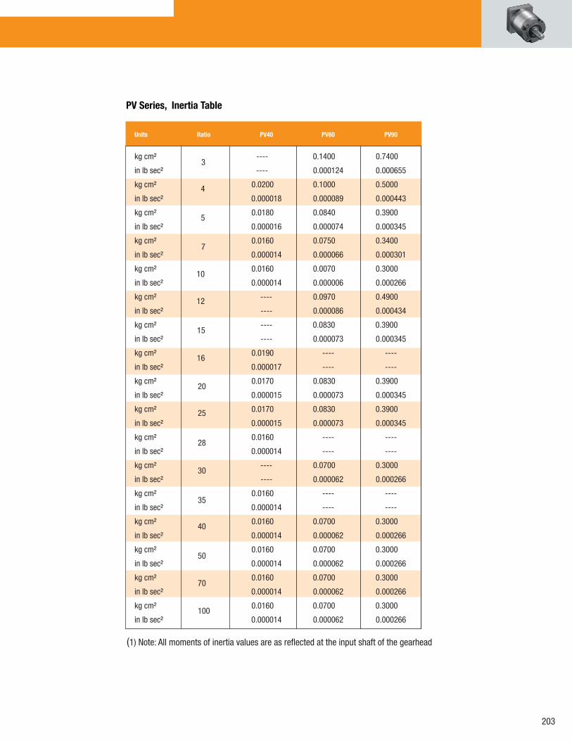
PV Series, Inertia Table
3
4
5
7
10
12
15
16
20
25
28
30
35
40
50
70
100
(1) Note: All moments of inertia values are as refl ected at the input shaft of the gearhead.
Units Ratio PV40 PV60 PV90 PV115
kg cm² ---- 0.1400 0.7400 1.9700
in lb sec² ---- 0.000124 0.000655 0.001743
kg cm² 0.0200 0.1000 0.5000 1.3400
in lb sec² 0.000018 0.000089 0.000443 0.001186
kg cm² 0.0180 0.0840 0.3900 1.1300
in lb sec² 0.000016 0.000074 0.000345 0.001000
kg cm² 0.0160 0.0750 0.3400 0.9300
in lb sec² 0.000014 0.000066 0.000301 0.000823
kg cm² 0.0160 0.0070 0.3000 0.8500
in lb sec² 0.000014 0.000006 0.000266 0.000752
kg cm² ---- 0.0970 0.4900 1.2300
in lb sec² ---- 0.000086 0.000434 0.001089
kg cm² ---- 0.0830 0.3900 1.0400
in lb sec² ---- 0.000073 0.000345 0.000920
kg cm² 0.0190 ---- ---- ----
in lb sec² 0.000017 ---- ---- ----
kg cm² 0.0170 0.0830 0.3900 1.0400
in lb sec² 0.000015 0.000073 0.000345 0.000920
kg cm² 0.0170 0.0830 0.3900 1.0400
in lb sec² 0.000015 0.000073 0.000345 0.000920
kg cm² 0.0160 ---- ---- ----
in lb sec² 0.000014 ---- ---- ----
kg cm² ---- 0.0700 0.3000 0.8400
in lb sec² ---- 0.000062 0.000266 0.000743
kg cm² 0.0160 ---- ---- ----
in lb sec² 0.000014 ---- ---- ----
kg cm² 0.0160 0.0700 0.3000 0.8400
in lb sec² 0.000014 0.000062 0.000266 0.000743
kg cm² 0.0160 0.0700 0.3000 0.8400
in lb sec² 0.000014 0.000062 0.000266 0.000743
kg cm² 0.0160 0.0700 0.3000 0.8400
in lb sec² 0.000014 0.000062 0.000266 0.000743
kg cm² 0.0160 0.0700 0.3000 0.8400
in lb sec² 0.000014 0.000062 0.000266 0.000743

PV Tapped Face Dimensions Units: mm (in)
Ø C
Ø B4 PL
A
D h6
P h9
E h6
NM
Q
H
G
F
L AD*
O
S
J°
Ø R
K
Dimensions
PV Series
*AD = Adapter length. See how to order page for mounting kit adapter lengths.
A B C D E F G H I J Body Diameter Tap x Depth Bolt Circle Pilot Diameter Output Shaft Output Shaft Pilot Flange Housing Lead Angle Diameter Length Thickness Thickness Diameter (mm) (in) (mm) (in) (mm) (in) (mm) (in) (mm) (in) (mm) (in) (mm) (in) (mm) (in) (mm) (in) (deg)
PV40-TN 43 1.693 M4x7 34 1.339 26 1.024 10 0.394 26 1.024 1.5 0.059 10 0.394 --- 45
PV40-TA 50 1.969 M4X10 44 1.732 35 1.378 12 0.472 25 0.984 3 0.118 10 0.394 --- 90
PV60-TN 62 2.441 M5x10 52 2.047 40 1.575 14 0.551 35 1.378 2.5 0.098 12 0.472 --- 45
PV60-TA 70 2.756 M5x10 62 2.362 52 2.047 16 0.630 36 1.417 5 0.197 16 0.630 --- 90
PV90-TN 90 3.543 M6x11 70 2.756 60 2.362 20 0.787 40 1.575 3 0.118 15 0.591 --- 45
PV90-TA 90 3.543 M6x12 80 3.150 68 2.677 22 0.866 46 1.811 5 0.197 18.5 0.728 --- 90
K L1 L2 M N O P Q R S Rear Thickness Length Length Dist. From Keyway Key Keyway Shoulder Shoulder Tap x Depth (Ratio <10:1) (Ratio >10:1) Shaft End Length Height Width Height Height
(mm) (in) (mm) (in) (mm) (in) (mm) (in) (mm) (in) (mm) (in) (mm) (in) (mm) (in) (mm) (in)
PV40-TN 11 0.433 48.5 1.909 63 2.480 3.1 0.122 16 0.630 10.2 0.402 3 0.118 0.6 0.024 11.633 0.458 M3X6
PV40-TA 11 0.433 48.5 1.909 63 2.480 1.3 0.051 16 0.630 13.5 0.531 4 0.157 3.5 0.138 17.831 0.702 M4x8
PV60-TN 16 0.630 63 2.480 83 3.268 2.71 0.107 25 0.984 16 0.630 5 0.197 2.5 0.098 19.939 0.785 M5x12
PV60-TA 16 0.630 67 2.638 87 3.425 2.21 0.087 25 0.984 18 0.709 5 0.197 3 0.118 28 1.102 M5x12
PV90-TN 17 .670 82 3.228 105.5 4.154 4.197 0.165 28 1.102 22.5 0.886 6 0.236 1 0.039 25 0.984 M6x12
PV90-TA 17 .670 85.5 3.366 109 4.291 3.197 0.126 28 1.102 24.5 0.965 6 0.236 5 0.197 38 1.496 M8x13

205
PV Flange Face Dimensions Units: mm (in)
Ø CP h9
Ø B4 PL
O
Ø R
D h6
A
Ø I
E h6
M N
Q
AD*LG
F
H
S
K
J°
*AD = Adapter length. See how to order page for mounting kit adapter lengths.
A B C D E F G H I J Square Flange Bolt Hole Bolt Circle Pilot Diameter Output Shaft Output Shaft Pilot Flange Housing Lead Angle Diameter Length Thickness Thickness Diameter (mm) (in) (mm) (in) (mm) (in) (mm) (in) (mm) (in) (mm) (in) (mm) (in) (mm) (in) (mm) (in) (deg)
PV40-FB 43 1.693 3.4 0.134 50 1.969 35 1.378 13 0.512 26 1.024 3 0.118 10 0.394 56 2.205 45
PV17-FE 43 1.693 3.5 0.138 43.8 1.724 22 0.866 6.35 0.250 25 0.984 1.5 0.059 6 0.236 55 2.165 45
PV60-FB 62 2.441 5.5 0.217 70 2.756 50 1.969 16 0.630 25 0.984 2.5 0.098 10.3 0.406 80 3.150 45
PV23-FE 62 2.441 4.95 0.195 66.675 2.625 38.1 1.500 9.525 0.375 25.4 1.000 2.5 0.098 9.5 0.374 80 3.150 45
PV60-FN 62 2.441 5.5 0.217 70 2.756 50 1.969 14 0.551 25 0.984 2.5 0.098 10.3 0.406 80 3.150 45
PV90-FB 90 3.543 6.5 0.256 100 3.937 80 3.150 20 0.787 40 1.575 3 0.118 14 0.551 116 4.567 45
PV34-FE 90 3.543 5.52 0.217 98.43 3.875 73.025 2.875 12.7 0.500 31.75 1.250 3 0.118 15 0.591 116 4.567 45
K L1 L2 M N O P Q R S Rear Thickness Length Length Dist. From Keyway Key Keyway Shoulder Shoulder Tap x Depth (Ratio < 10:1) (Ratio >10:1) Shaft End Length Height Width Height Diameter (mm) (in) (mm) (in) (mm) (in) (mm) (in) (mm) (in) (mm) (in) (mm) (in) (mm) (in) (mm) (in)
PV40-FB 11 0.433 48.5 1.909 63 2.480 2.1 0.083 16 0.630 15 0.591 5 0.197 2 0.079 17.831 0.702 M4x8
PV17-FE 11 0.433 48.5 1.909 63 2.480 --- --- --- --- --- --- --- --- 2.3 0.091 11.633 0.458 ---
PV60-FB 16 0.630 71.5 2.815 91.5 3.602 3.2 0.126 16 0.630 18 0.709 5 0.197 1 0.039 28 1.102 M5x12
PV23-FE 16 0.630 60.5 2.382 80.5 3.169 --- --- 19 0.748 9.444 0.372 Flat --- 1 0.039 19.939 0.785 M5x12
PV60-FN 16 0.630 71.5 2.815 91.5 3.602 3.2 0.126 16 0.630 16 0.630 5 0.197 1 0.039 28 1.102 M5x12
PV90-FB 17 .670 90.5 3.563 114 4.488 3.197 0.126 28 1.102 22.5 0.886 6 0.236 1 0.039 38 1.496 M6x12
PV34-FE 17 .670 82 3.228 105.5 4.154 --- --- 27 1.063 14.247 0.561 3.175 0.125 1 0.039 25 0.984 M6x12

PV Series
PV Completes The Parker Bayside Gear Family
The Parker Bayside gearhead family offers choices to customers in almost every possible feature and specifi cation. The depth of the Parker Bayside gearhead family is unmatched with frame sizes from 40mm (1.57”) up to 300mm (11.8”), ratios from 3:1 to 100:1, environmental options, backlash availability from 3 arc minutes to 18 arc minutes and a multitude of output face and mounting options that can fi t any application.
Helical planetary technology is superb for low-backlash, high-stiffness and high-accuracy requirements, making the Parker Bayside Stealth line of helical planetary gearheads ideal for these high-and medium-level performance applications. The introduction of the PV Series gearhead completes the Parker Bayside gear family by offering a standard-grade gearhead with the highest radial load capacity available today in a cost-effective solution. Whether you need high-, medium- or standard-grade performance, Parker Bayside can match the need.
All Parker Bayside gearheads are proudly manufactured in the USA in our state-of-the-art facility which, displays the best use of Lean manufacturing practices. For more information go to parkermotion.com or baysidemotion.com

207
Notes:(1) NEMA sizes only available with front face option ‘F’(2) Output face dimensionsOption ‘A’ only available with front face option ‘T’Option ‘B’ and ‘E’ only available with front face option ‘F’(3) For PV90FN use PV90FB(4) Only available for NEMA 17, 23 and 34
Order NumberingExample: PV
A E
FC
60
B
ND
- 003
Mounting Kit
MV
A C
60
B
XXX
E RATIO
40/17 frame options = 004, 005, 007, 010, 016, 020, 035, 040, 050, 070, 100
60/23 and 90/40 frame options = 003, 004, 005, 007, 009, 010, 012, 015, 016, 020, 025, 028, 030, 040, 050, 070, 100
D OUTPUT FACE DIMENSIONS
A Alpha / Stober 2
N Neugart3
B Parker Bayside (Same as PX)2
E NEMA (English)2,4
A PRODUCT
PV Power Versatility
B FRAME SIZE1
40 40mm 17 NEMA 17 60 60mm 23 NEMA 23 90 90mm 34 NEMA 34
C FRONT FACE
F Flange (Square) Face T Round (Tapped) Face
A PRODUCT
MV PV mounting kit
B FRAME SIZE1
40 40mm/NEMA 17 60 60mm/NEMA 23 90 90mm/NEMA 34
C Factory assigned XXX Consult factory for part number
How to order
FRAME SIZE MOTOR SHAFT LENGTHS GEARHEAD ADAPTER LENGTHS MM (IN) MM (IN)PV40/PV17 12 thru 20 (0.472 thru 0.787) 13.7 (0.539) 20.1 thru 25.4 (0.791 thru 1.000) 19 (0.748)PV60/PV23 16 thru 25.4 (0.630 thru 1.000) 16.5 (0.65) 25.4 thru 31.8 (1.004 thru 1.252) 22.5 (0.886) PV90/PV34 20 thru 31.8 (0.787 thru 1.252) 20 (0.787) 31.9 thru 40 (1.256 thru 1.575) 28.5 (1.122)
FRAME SIZE MOTOR SHAFT LENGTHS GEARHEAD ADAPTER LENGTHS MM (IN) MM (IN)
Note:Adapter lengths may vary based on make and model of motor.

7 Frame SizesRS60RS90RS115RS142
RS180RS220RS300
5:1 30:1 10:1 40:1 15:1 50:1 20:1 100:1 25:1 * For RS300 see Note (5)
Stealth® RS Advanced Series: Compact, Right-Angle Servo Gearhead
Stealth® RS delivers “The Helical Advantage” in a compact, right-angle package. With 7 frame sizes and 9 gear ratios to choose from, you’re guaranteed to find a Stealth® RS to fit your high performance servo applications.
Stealth RS Adanced Series
Ratios*

209
Frame SizeSpecifications: Units Ratio RS60 RS90 RS115 RS142 RS180 RS220 RS300
Moment of Inertia(4) g cm sec^2 5 0.197 0.745 2.68 8.94 26.5 82.2 378
oz-in-sec^2 0.003 0.010 0.037 0.124 0.368 1.14 5.26
g cm sec^2 10 0.095 0.489 1.67 5.87 16.7 50.4 238
oz-in-sec^2 0.001 0.007 0.023 0.082 0.232 0.700 3.31
g cm sec^2 15,30 0.092 0.453 1.58 5.60 15.2 47.4 158
oz-in-sec^2 0.001 0.006 0.022 0.078 0.211 0.658 2.19
g cm sec^2 20,25,40 0.083 0.358 1.13 4.17 10.7 34.3 116
oz-in-sec^2 0.001 0.005 0.016 0.058 0.149 0.476 1.61
g cm sec^2 50,100 0.072 0.238 0.685 2.26 6.70 21.2 95.4
oz-in-sec^2 0.001 0.003 0.010 0.031 0.093 0.294 1.32
(5) RS300 is available in Ratios of: 4, 6, 10, 15, 20, 24, 30 & 50:1
Frame Size Units Ratio RS60 RS90 RS115 RS142 RS180 RS220 RS300
Nominal Output Torque, Nm 5 11 28 75 141 316 678 2,203
Tnom r in lb 95 250 660 1,250 2,800 6,000 19,500
Nm 10 21 55 147 271 621 1,299 2,712
in lb 190 490 1,300 2,400 5,500 11,500 24,000
Nm 15-25 33 85 215 395 938 1,808 4,181
in lb 290 750 1,900 3,500 8,300 16,000 37,000
Nm 30-100 28 85 192 316 836 1,469 4,181
in lb 250 750 1,700 2,800 7,400 13,000 37,000
Max. Acceleration Nm 5 13 33 88 166 373 802 2,644
Output Torque, in lb 115 295 780 1,470 3,300 7,100 23,400
Tacc r Nm 10 26 66 169 333 734 1,582 3,277
in lb 230 580 1,500 2,950 6,500 14,000 29,000
Nm 15-100 37 101 260 452 1,096 2,000 5,311
in lb 330 890 2,300 4,000 9,700 17,700 47,000
Emergency(1) Stop Nm 5 31 77 203 384 870 1,853 6,102
Output Torque, in lb 270 680 1,800 3,400 7,700 16,400 54,000
Tem r Nm 10 60 153 395 768 1,695 3,684 7,684
in lb 530 1,350 3,500 6,800 15,000 32,600 68,000
Nm 15-100 87 232 599 1,040 2,520 4,588 12,316
in-lb 770 2,050 5,300 9,200 22,300 40,600 109,000
Nominal Input Speed, RPM 5,10 3,200 2,800 2,400 2,000 1,600 1,200 1,000
Nnom r RPM 15-40 3,700 3,300 2,900 2,500 2,000 1,500 1,250
RPM 50-100 4,200 3,800 3,400 3,000 2,400 1,800 1,500
Maximum Input Speed, Nmax r RPM 5-100 6,000 5,300 4,500 3,800 3,000 2,300 1,900
Standard Backlash (2) arc min 5,10 14 12 12 10 10 10 10
arc min 15-100 12 10 10 8 8 8 8
Low Backlash (2) arc min 5,10 10 8 8 6 6 6 6
arc min 15-100 8 6 6 4 4 4 4
Efficiency at Nominal Torque % 94 94 94 94 94 94 94
Noise Level(3) at: 3,000 RPM dB 5-100 70 70 70 — — — — 2,000 RPM dB — — — 72 72 — — 1,500 RPM dB — — — — — 72 72
Torsional Stiffness Nm / arc min 5-100 3 10 19 35 90 170 290
in lb / arc min 22 84 164 310 800 1,500 2,560
Maximum Weight kg 5-100 2 6 11 24 43 80 120
lb 4 13 25 52 94 177 265
Max. Allowable Case Temp. oC 5-100 100
Performance Specifications
(1) Maximum of 1,000 stops(2) Measured at 2% of rated torque(3) Measured at 1 meter
(4) All Moment of Inertia values are as reflected at the input shaft of the gearhead.
Specification are subject to change without notice

L
L
Stealth’s superior design and construction deliver “The Helical Advantage”:
Strong…30% More Torque
Quiet…Less Than 70dB Noise
Fast…6,000 RPM Input Speeds
Accurate…Less Than 4 Arc minutes Backlash
Plus... Over 94% Efficiency
IN-LINE MOUNTING
For space constrained- applications Parker Bayside’s Right-Angle gearheads can offer a two times space savings when compared to in-line products.
RIGHT-ANGLE MOUNTING
Stealth® Advanced in the PS / RS Models incorporates the latest enhancements in gearhead technology:
Latest technology in seals…reduce heat and wear
Oil lubrication…reduces, friction and operating temperature
Front output seal cover…captures and protects output seal
Space Tight? Turn Right
Stealth RS Adanced Series

211
l2
3
5
46
Compact DesignTorque and package size are the same regardless of ratio.
5
Sealed UnitViton seals and O-Rings provide IP65 protection to prevent leaks and protect against harsh environments.
6
Stealth Planetary OutputStealth RS is built into the gearhead to deliver “The Helical Advantage” at the load-carrying output section.
l
Magnetic Oil Fill Drain PlugThe magnetic plug attracts normal wear particles keeping them away from the gear mesh.
8Output Wave Seal TechnologyCreates a hydrodynamic film between seal and shaft and reducing heat and wear.
9
Front Output Seal CoverCompletely captures and protects output seal and allows in-field seal replacement.
10
Oil LubricationOil provides better lubrication, reduces friction and operating temperatures.
7
Spiral Bevel GearsDeliver high efficiency and high torque in a compact, right angle package.
2
7
8
9
10
ServoMount®
Patented motor mounting design ensures error-free installation and the balanced pinion allows higher input speeds.
4
High Speed InputHelical Stealth gearing provides high input speeds with quiet operation. Input cavity surrounds the gears for constant lubrication in any orientation.
3

RS60
RS90
RS115
Prx = (Pr)(57mm) / (35mm + X)Prx = (Pr)(2.24in) / (1.38in + X)
Prx = (Pr)(74mm) / (45mm + X) Prx = (Pr)( 2.91in) / (1.77in + X)
Prx = (Pr)(95mm) / (57mm + X) Prx = (Pr)(3.74in) / (2.24in + X)
Formulas to calculate radial load (Prx) at any distance "X" from the gearhead mounting surface.
0
(Lbs) (N)
100 200 300 400 500 600 700
0
150
200
100
50
800 900 1000
0
600
800
1000
400
200
Axial load
Radial load (Pr) @ 22mm (0.87in) from the mtg surface
0
(Lbs) (N)
100 200 300 400 500 600 700
0
300
400
500
200
100
800 900 1000
0
1.2k
1.6k
2.0k
2.4k
800
400
Axial load
Radial load (Pr) @ 29mm (1.14in) from the mtg surface
0
(Lbs) (N)
100 200 300 400 500 600 700
0
300
400
500
200
100
800 900 1000
0
1k
2k
3k
4k
Axial load
700
800
900
600
Radial load (Pr) @ 38.5mm (1.52in) from the mtg surface
Load
Speed (RPM)
Load
Speed (RPM)
Load
Speed (RPM)
Output Shaft Load RatingStealth RS Adanced Series
213
RS142
RS180
RS220
RS300
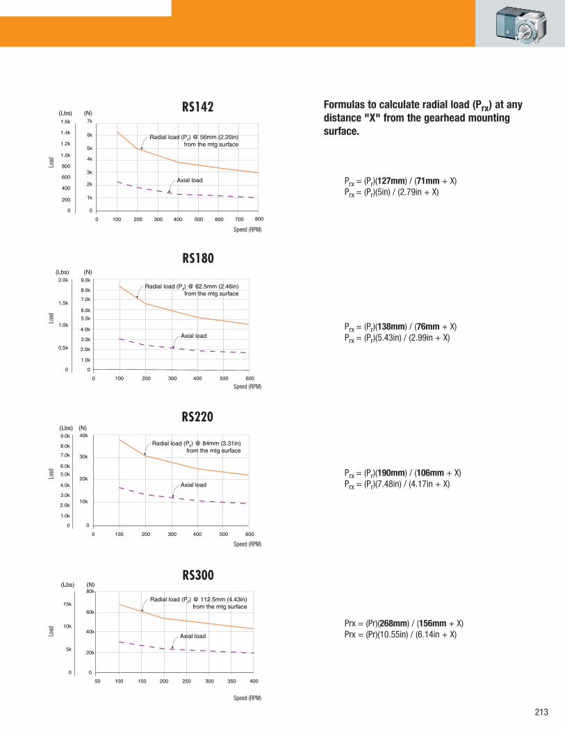
Formulas to calculate radial load (Prx) at any distance "X" from the gearhead mounting surface.
Prx = (Pr)(127mm) / (71mm + X) Prx = (Pr)(5in) / (2.79in + X)
Prx = (Pr)(138mm) / (76mm + X) Prx = (Pr)(5.43in) / (2.99in + X)
Prx = (Pr)(190mm) / (106mm + X) Prx = (Pr)(7.48in) / (4.17in + X)
Prx = (Pr)(268mm) / (156mm + X) Prx = (Pr)(10.55in) / (6.14in + X)
0
(Lbs) (N)
100 200 300 400 500 600
0
1.0k
0.5k
0
6.0k
2.0k
1.5k
2.0k
4.0k
9.0k
Axial load
8.0k
7.0k
5.0k
3.0k
1.0k
Radial load (Pr) @ 62.5mm (2.46in) from the mtg surface
0
(Lbs) (N)
100 200 300 400 500 600
0
20k
10k
0
6.0k
40k
30k
2.0k
4.0k
9.0k
Axial load
8.0k
7.0k
5.0k
3.0k
1.0k
Radial load (Pr) @ 84mm (3.31in) from the mtg surface
50
(Lbs) (N)
100 150 200 250 300 350 400
0
10k
5k
0
60k
15k
20k
40k
80k
Axial load
Radial load (Pr) @ 112.5mm (4.43in) from the mtg surface
0
(Lbs) (N)
100 200 300 400 500 600 700
0
400
200
0
6k
800
6002k
5k
7k
Axial load
Radial load (Pr) @ 56mm (2.20in) from the mtg surface
800
4k
3k
1k
1.2k
1.0k
1.6k
1.4k
Load
Speed (RPM)
Load
Speed (RPM)
Load
Speed (RPM)
Load
Speed (RPM)

MOTOR INPUT
OUTPUT VIEW
*AD=Adapter Length. Adapter will vary, depending on motor. Consult Internet (www.baysidemotion.com or www.parkermotion.com) for details or call Parker Bayside.
A B C D E F G H I J
Square Bolt Bolt Pilot Output Shaft Output Shaft Pilot Flange Recess Housing Frame Flange Hole Circle Diameter Diameter Length Thickness Thickness Length Recess Size (mm) (in) (mm) (in) (mm) (in) (mm) (in) (mm) (in) (mm) (in) (mm) (in) (mm) (in) (mm) (in) (mm) (in)
RS60 60 2.362 5.5 0.217 70 2.756 50 1.969 16 0.630 37 1.457 8 0.315 8 0.315 36 1.417 5 0.197
RS90 90 3.543 6.5 0.256 100 3.937 80 3.150 22 0.866 48 1.890 11 0.433 10 0.394 51.5 2.028 6.5 0.256
RS115 115 4.528 8.5 0.335 130 5.118 110 4.331 32 1.260 65 2.559 13 0.512 14 0.472 63 2.480 7.5 0.295
RS142 142 5.591 11 0.433 165 6.496 130 5.118 40 1.575 97 3.819 15 0.591 15 0.591 81.5 3.209 10 0.394
RS180 182 7.165 13 0.512 215 8.465 160 6.299 55 2.165 105 4.134 20 0.787 16 0.630 97.5 3.839 16 0.630
RS220 220 8.661 17 0.669 250 9.843 180 7.087 75 2.953 138 5.433 30 1.181 22 0.866 101 3.976 16 0.630
RS300 305 12.008 21 0.827 350 13.780 250 9.843 100 3.937 190 7.480 35 1.378 26 1.024 172 6.772 18 0.709
K L M N O P Q R S T U
Dist. to Output Housing Housing Dist. to Input Taper Dist. From Keyway Key Keyway Shoulder Shoulder Frame Centerline Length Width Centerline Dist. Shaft End Length Height Width Height Diameter Size (mm) (in) (mm) (in) (mm) (in) (mm) (in) (mm) (in) (mm) (in) (mm) (in) (mm) (in) (mm) (in) (mm) (in) (mm) (in)
RS60 66 2.598 96 3.780 73 2.874 43 1.693 14 0.551 2 0.079 25 0.984 18 0.709 5 0.197 0.5 0.020 22 0.866
RS90 103 4.055 148 5.827 103 4.055 58 2.283 25 0.984 3 0.118 32 1.260 24.5 0.965 6 0.236 0.5 0.020 35 1.378
RS115 122.5 4.823 180 7.087 129 5.079 71.5 2.815 32 1.260 5 0.197 40 1.575 35 1.378 10 0.394 1 0.039 45 1.772
RS142 159 6.260 230 9.055 162 6.378 91 3.583 40 1.575 5 0.197 63 2.480 43 1.693 12 0.472 3 0.118 55 2.165
RS180 172 6.772 263 10.354 197 7.756 106 4.173 55 2.165 6 0.236 70 2.756 59 2.323 16 0.630 3 0.118 70 2.756
RS220 230 9.055 340 13.386 245 9.646 135 5.315 60 2.362 6 0.236 90 3.543 79.5 3.130 20 0.787 3 0.118 95 3.740
RS300 327.5 12.894 480 18.898 350 13.780 197.5 7.776 80 3.150 7 0.276 140 5.512 106 4.173 28 1.102 3 0.118 140 5.512
SIDE VIEW
Dimensions
Stealth RS Adanced Series

215
Specifications are subject to change without notice.
Horizontal Output shaft Output shaft orientation (H) pointing up (U) pointing down (D)
RS input facing up (E) RS input facing down (F)
How to Order1. Pick frame size and ratio. 2. Pick backlash and orientation.3. Specify motor make and model for mounting kit.
FRAME SIZE60
90
115
142
180
220
300
RATIO005 030
010 040
015 050
020 100
025
BACKLASHL = Low backlash
S = Standard backlash
RS Gearheads are supported by a worldwide network of offices and local distributors. Call 1-800-305-4555 for application engineering assistance or for the name of your local distributor. Information can also be obtained at www.baysidemotion.com or www.parkermotion.com.
ORIENTATION
H = Horizontal orientation
U = Output shaft pointing up
D = Output shaft pointing down
E = RS input facing up
F = RS input facing down
(For other orientations consult the factory)
Order Numbering
Example: -- R S 1 8 0 0 1 0 X X X L H
SPECIAL(Factory
Issued)
How to Order

Stealth® RX incorporates Parker Bayside’s helical planetary technology in a lower cost package. Available in NEMA and Metric frame sizes, Stealth® RX delivers high torque and quiet, smooth operation for less demanding servo applications.
RX60RX90RX115
RX23RX34RX42
Ratios5:1
10:115:1
20:125:130:1
40:150:1
100:1
Stealth RXAdanced Series
Stealth® RX Series: Best Technology
6 Frame Sizes
Stealth RX incorporates Parker Bayside’s helical planetary technology in a lower-cost package. Stealth RX delivers high torque and quiet, smooth operation for less-demanding servo applications.

217
Frame Size Units Ratio RX60 RX90 RX115
Nominal Output Torque, Nm 5 7 17 45
Tnom r in lb 58 149 484
Nm 10 13 33 88
in lb 112 292 484
Nm 15-25 20 51 129
in lb 175 451 1,238
Nm 30-100 17 51 115
in lb 149 451 1,323
Max. Acceleration Nm 5 8 20 53
Output Torque, in lb 69 175 587
Tacc r Nm 10 16 40 101
in lb 138 350 1,140
Nm 15-100 22 61 156
in lb 196 536 1,748
Emergency(1) Stop Nm 5 19 46 122
Output Torque, in lb 165 409 1,362
Tem r Nm 10 46 92 237
in lb 409 812 2,653
Nm 15-100 67 139 359
in lb 594 1,232 4,022
Nominal Input Speed, RPM 5, 10 3,200 2,800 2,400
Nnom r RPM 15-40 3,700 3,300 2,900
RPM 50-100 4,200 3,800 3,400
Maximum Input Speed, Nmaxr RPM 5-100 6,000 5,300 4,500
Standard Backlash (2) arc min 5, 10 20 18 18
arc min 15-100 20 18 16
Low Backlash (2) arc min 5, 10 18 16 16
arc min 15-100 16 14 12
Efficiency at % 5-100 94 94 94
Nominal Torque
Noise Level(3) at: 3,000 RPM dB 5-100 70 70 70
Torsional Stiffness Nm / arc min 5-100 2.5 9.5 18.5
in lb / arc min 22 84 164
Maximum Weight kg 5-100 2.01 5.74 11.35
lb 4.42 12.65 25
Max. Allowable Case Temperature oC 5-100 100
(1) Maximum of 1,000 stops(2) Measured at 2% of rated torque
Frame SizeSpecifications: Units Ratio RX60 RX90 RX115
Moment of Inertia(4) gm cm sec2 5 0.1970 0.7450 2.6820
oz in sec2 0.0030 0.0100 0.0373
gm cm sec2 10 0.0950 0.4890 1.6688
oz in sec2 0.0013 0.0068 0.0232
gm cm sec2 15, 30 0.0920 0.4530 1.5794
oz in sec2 0.0013 0.0063 0.0219
gm cm sec2 20-40 0.0830 0.3576 1.1324
oz in sec2 0.0012 0.0050 0.0157
gm cm sec2 50-100 0.0720 0.2384 0.6854
oz in sec2 0.0010 0.0033 0.0095
Performance Specifications
(3) Measured at 1 meter
(4) All Moment of Inertia values are as reflected at the input shaft of the gearhead.
Specification are subject to change without notice

RX90 / RX34
RX115 / RX42
0
(Lbs) (N)
100 200 300 400 500 600 700
0
300
200
100
800 900 1000
0
1.2k
2.0k
800
400
Axial load
400
500
1.6k
2.4k
Radial load (Pr) @ 21.5mm (0.85in) from the mtg surface
0
(Lbs) (N)
100 200 300 400 500 600 700
0
600
400
200
800 900 1000
0
1.0k
3.0k
Axial load
800
2.0k
4.0k
Radial load (Pr) @ 26.5mm (1.04in) from the mtg surface
Prx = (Pr)(73mm) / (52mm + X)Prx = (Pr)(2.87in) / (2.05in + X)
Prx = (Pr)(89mm) / (63mm + X)Prx = (Pr)(3.5in) / (2.48in + X)
Load
Speed (RPM)
Load
Speed (RPM)
Output Shaft Load RatingStealth RXAdanced Series
RX60 / RX23
0
(Lbs) (N)
100 200 300 400 500 600 700
0
150
100
50
800 900 1000
0
600
800
400
200
Axial load
Radial load (Pr) @ 13.5mm (0.53in) from the mtg surface
Prx = (Pr)(54mm) / (41mm + X)Prx = (Pr)(2.13in) / (1.61in + X)
Load
Speed (RPM)
Formulas to calculate radial load (Prx) at any distance "X" from the gearhead mounting surface.

219
NEMA SIZES
Specifications are subject to change without notice.
METRIC SIZES
How to Order1. Pick frame size and ratio. 2 .Pick options.3. Specify motor, make and model for mounting kit.
Order Numbering
Example:
FRAME SIZE(Metric Sizes) (NEMA Sizes)
60 23
90 34
115 42
RATIO005 020 040
010 025 050
015 030 100
OPTIONALLOW BACKLASH
RX gearheads are supported by a worldwide network of offices and local distributors. Call 1-800-305-4555 for application engineering assistance or for the name of your local distributor. Information can also be obtained at www.baysidemotion.com or www.parkermotion.com
-- R X 1 1 5 0 1 0 X X X L B
SPECIAL(Factory
Issued)
OUTPUT VIEW
*AD=Adapter Length. Adapter will vary, depending on motor. Consult Internet (www.baysidemotion.com or www.parkermotion.com) for details or call Parker Bayside.
A B C D E F G H I J
Square Bolt Bolt Pilot Output Shaft Output Shaft Pilot Flange Recess Housing Frame Flange Hole Circle Diameter Diameter Length Thickness Thickness Length Recess Size (mm) (in) (mm) (in) (mm) (in) (mm) (in) (mm) (in) (mm) (in) (mm) (in) (mm) (in) (mm) (in) (mm) (in)
RX60 60 2.362 5.5 0.217 70 2.756 50 1.969 16 0.630 25 0.984 2.5 0.098 13 0.512 36 1.417 5 0.197
RX90 90 3.543 6.5 0.256 100 3.937 80 3.150 20 0.787 40 1.575 3 0.118 17 0.669 51.5 2.028 6.5 0.256
RX115 115 4.528 8.5 0.335 130 5.118 110 4.331 24 0.945 50 1.969 3.5 0.138 20 0.787 63 2.480 7.5 0.295
K L M N O P Q R S T U
Dist. to Output Housing Housing Dist. to Input Taper Dist. From Keyway Key Keyway Shoulder Shoulder Frame Centerline Length Width Centerline Dist. Shaft End Length Height Width Height Diameter Size (mm) (in) (mm) (in) (mm) (in) (mm) (in) (mm) (in) (mm) (in) (mm) (in) (mm) (in) (mm) (in) (mm) (in) (mm) (in)
RX60 66 2.598 96 3.780 79.3 3.122 43 1.693 14 0.551 3 0.197 16 0.630 18 0.709 5 0.197 0.5 0.020 22 0.866
RX90 103 4.055 148 5.827 110 4.330 58 2.283 25 0.984 5 0.238 28 1.102 24.5 0.965 6 0.236 0.5 0.020 35 1.378
RX115 122.5 4.823 180 7.087 186 7.323 77.6 3.055 32 1.260 7 0.315 32 1.260 27 1.063 8 0.315 1 0.039 45 1.772
SIDE VIEW
Dimensions
NOTE: NEMA sizes have 20% lower torque/stiffness ratings due to smaller output shaft diameter.
flatflat flat flat
B C D E F Q R S
Bolt Bolt Pilot Output Shaft Output Shaft Keyway Keyway Keyway Frame Hole Circle Diameter Diameter Length Length Depth Width Size (in) (mm) (in) (mm) (in) (mm) (in) (mm) (in) (mm) (in) (mm) (in) (mm) (in) (mm) RX23 0.195 4.953 2.625 66.675 1.5 38.100 0.375 9.525 1 25.400
0.75
19.050
0.015
0.381 — —
RX34 0.217 5.512 3.875 98.425 2.875 73.025 0.5 12.700 1.25 31.750 1.063 27.000 0.072 1.829 0.125 3.175
RX42 0.281 7.137 4.95 125.730 2.187 55.550 0.625 15.875 1.5 38.100 1.142 29.007 0.094 2.388 0.188 4.775
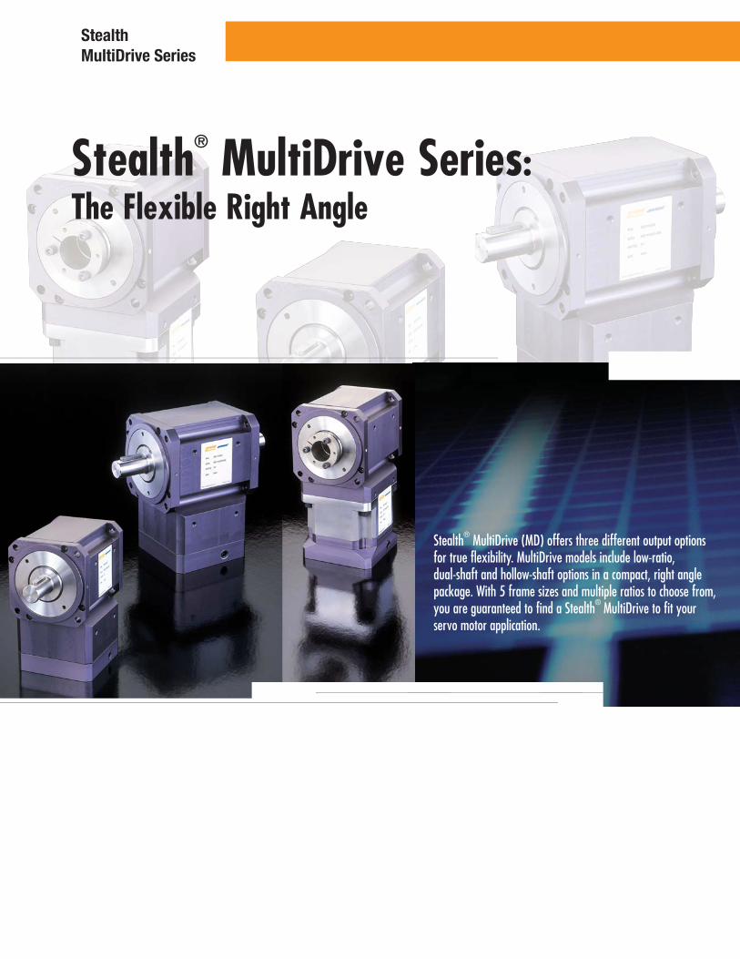
Stealth® MultiDrive Series:The Flexible Right Angle
Stealth® MultiDrive (MD) offers three different output options for true flexibility. MultiDrive models include low-ratio, dual-shaft and hollow-shaft options in a compact, right angle package. With 5 frame sizes and multiple ratios to choose from, you are guaranteed to find a Stealth® MultiDrive to fit your servo motor application.
Stealth MultiDrive Series

221
RT Model Hollow Shaft
5 Frame SizesRT90RT115RT142RT180RT220
Ratios3:19:1
15:121:130:1
MultiDrive™ features Stealth® helical gearing for high torque, high accuracy and quiet operation in a compact, right-angle package.
Low BacklashStandard as low as 8 arc minutes and 4 arc minutes optional
Space Savingcompact, right-angle design saves space in many applications
Smooth, Quiet Operation and Long Lifehardened, precision spiral bevel gears ensure quiet operation
Quick, Error-Free Mountingto any servo or stepper motor using Parker Bayside’s patented ServoMount® design
Sealed Unit…seals and o-rings provide IP65 protection to prevent leaks and to protect against harsh environments
RD ModelDual Shaft
5 Frame SizesRB90RB115RB142RB180RB220
1:12:13:1
Ratios
1:12:13:19:1
15:121:130:1
Ratios
RD Dual Shaft Model
5 Frame SizesRD90RD115RD142RD180RD220
RB Model Low Ratio
Stealth®
MultiDrive Series: Overview

Frame Size (RT, RD, RB) Units Ratio R_90 R_115 R_142 R_180 R_220
Nominal Output Torque, Nm 1 23 45 113 192 508
Tnom r in lb 200 400 1,000 1,700 4,500
Nm 2-30 34 90 136 260 565
in lb 300 800 1,200 2,300 5,000
Max. Acceleration Nm 1 28 56 141 240 636
Output Torque, in lb 250 500 1,250 2,125 5,625
Tacc r Nm 2-30 42 113 169 324 636
in lb 375 1,000 1,500 2,875 5,625
Emergency(1) Stop Nm 1 45 90 226 384 1,017
Output Torque, in lb 400 800 2,000 3,400 9,000
Tem r Nm 2-30 68 181 271 520 1,130
in lb 600 1,600 2,400 4,600 10,000
Nominal Input Speed, RPM 1,2,3 3,000 2,600 2,200 1,800 1,400
Nnom r RPM 9,15,21,30 3,800 3,400 3,000 2,400 1,800
Max. Input Speed, Nmaxr RPM 1,2,3 4,000 3,500 2,900 2,500 1,600
RPM 9,15,21,30 5,300 4,500 3,800 3,000 2,300
Standard Backlash arc min 1,2,3 10 9 9 8 8
arc min 9,15,21,30 12 11 11 10 10
Low Backlash arc min 1,2,3 6 5 5 4 4
arc min 9,15,21,30 8 7 7 6 6
Efficiency at % 1,2,3 95 95 95 95 95
Nominal Torque % 9,15,21,30 92 92 92 92 92
Noise Level(2) at:
2,500 RPM dB All 70 70 70 — —
1,500 RPM dB — — — 72 72
Torsional Stiffness Nm / arc min All
3 6 16 43 90
in lb / arc min 28 56 140 380 800
Maximum Weight kg All
7 13 25 54 114
lb 16 28 56 120 250
Maximum Allowable oC All 100 Case Temperature
Frame Size (RT, RD, RB)
Specifications: Units Ratio R_90 R_115 R_142 R_180 R_220
Moment of Inertia(3) gm cm sec2 1 3.28 11.0 38.7 101 444
oz in sec2 0.046 0.153 0.538 1.41 6.17
gm cm sec2 2 4.17 11.3 32.8 95.4 274
oz in sec2 0.058 0.157 0.455 1.32 3.81
gm cm sec2 3 2.68 7.75 22.3 65.6 191
oz in sec2 0.037 0.108 0.311 0.911 2.65
gm cm sec2 9 1.07 3.28 10.4 35.8 119
oz in sec2 0.015 0.046 0.145 0.497 1.66
gm cm sec2 15 - 30 0.566 2.09 5.36 17.9 62.6
oz in sec2 0.008 0.029 0.075 0.248 0.869
(1) Maximum of 1,000 stops(2) Measured at 1 meter(3) All Moment of Inertia values are as reflected at the input shaft of the gearhead.
Specification are subject to change without notice
Performance Specifications
Stealth MultiDrive Series

223
Prx = (Pr)(201mm) / (160mm + X) Prx = (Pr)(7.91in) / (6.30in + X)
0
(Lbs) (N)
500 1000 1500 2000 2500
0
200
0
400
1.0k
2.0k
600
800
3.0k
4.0k
Axial load
5.0k
1.0k
Radial load (Pr) @ 26.5mm (1.04in) from the mtg surface
0
(Lbs) (N)
500 1000 1500 2000 2500 3000
0
300
200
100
0
400
1.2k
400
800
1.6k
Axial load
600
500
700
2.0k
2.8k
2.4k
3.2k
Radial load (Pr) @ 21.5mm (0.85in) from the mtg surface
R_115
R_90
R_142
0
(Lbs) (N)
500 1000 1500 2000 2500
0
500
0
1.0k
2.0k
4.0k
1.5k6.0k
8.0k
Axial load
10k
2.0k
Radial load (Pr) @ 41.5mm (1.63in) from the mtg surface
Prx = (Pr)(121mm) / (100mm + X) Prx = (Pr)(4.76in) / (3.94in + X)
Prx = (Pr)(151mm) / (125mm + X) Prx = (Pr)(5.94in) / (4.92in + X)
Formulas to calculate radial load (Prx) at any distance "X" from the gearhead mounting surface.
Load
Speed (RPM)
Load
Speed (RPM)
Load
Speed (RPM)
Output Shaft Load Rating

R_180
R_220
0
(Lbs) (N)
500 1000 1500 2000
0
1.0k
0
2.0k
5k
3.0k
10k
15k
Axial load
20k
4.0k
Radial load (Pr) @ 52.5mm (2.07in) from the mtg surface
0
(Lbs) (N)
500 1000 1500 2000
0
2.0k
0
4.0k
10k
6.0k
20k
30k
Axial load
40k
8.0k
50k
10.0k
12.0k
Radial load (Pr) @ 85mm (3.35in) from the mtg surface
Prx = (Pr)(260mm) / (208mm + X) Prx = (Pr)(10.24in) / (8.19in + X)
Prx = (Pr)(352mm) / (267mm + X) Prx = (P)(13.86in) / (10.5in + X)
Formulas to calculate radial load (Prx) at any distance "X" from the gearhead mounting surface.
Load
Speed (RPM)
Load
Speed (RPM)
Output Shaft Load RatingStealth MultiDrive Series
225
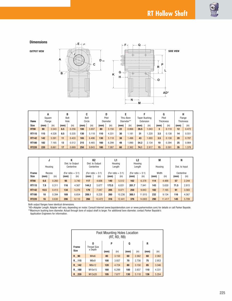
RT Hollow Shaft
SIDE VIEWOUTPUT VIEW
Both output flanges have identical dimensions. *AD=Adapter Length. Adapter will vary, depending on motor. Consult Internet (www.baysidemotion.com or www.parkermotion.com) for details or call Parker Bayside. **Maximum bushing bore diameter. Actual through bore of output shaft is larger. For additional bore diameter, contact Parker Bayside’s Application Engineers for information.
O P Q RFrame Thread SizeSize
x Depth (mm) (in) (mm) (in) (mm) (in)
R__90 M4x6 80 3.150 60 2.362 60 2.362
R__115 M6x9 100 3.937 70 2.756 75 2.953
R__142 M8x12 120 4.724 80 3.150 85 3.346
R__180 M10x15 160 6.299 100 3.937 110 4.331
R__220 M12x20 195 7.677 130 5.118 136 5.354
Foot Mounting Holes Location(RT, RD, RB)
A B C D E F G H Square Bolt Bolt Pilot Thru Bore Taper Bushing Pilot FlangeFrame Flange Hole Circle Diameter Diameter** Extension Thickness Thickness
Size (mm) (in) (mm) (in) (mm) (in) (mm) (in) (mm) (in) (mm) (in) (mm) (in) (mm) (in) RT90 90 3.543 6.5 0.256 100 3.937 80 3.150 22 0.866 26.5 1.043 3 0.118 12 0.472
RT115 115 4.528 8.5 0.335 130 5.118 110 4.331 30 1.181 31 1.220 3.5 0.138 14 0.551
RT142 142 5.591 11 0.433 165 6.496 130 5.118 38 1.496 43 1.693 3.5 0.138 20 0.787
RT180 182 7.165 13 0.512 215 8.465 160 6.299 48 1.890 54.2 2.134 10 0.394 25 0.984
RT220 220 8.661 17 0.669 250 9.843 180 7.087 60 2.362 74.1 2.917 15 0.591 35 1.378
Dimensions
J K K2 L1 L2 M N Dist. to Output Dist. to Output Housing Housing
Housing Centerline Centerline Length Length Housing Dist. to Input Frame Recess (For ratio = 3:1) (For ratio > 3:1) (For ratio = 3:1) (For ratio > 3:1) Width CenterlineSize (mm) (in) (mm) (in) (mm) (in) (mm) (in) (mm) (in) (mm) (in) (mm) (in)
RT90 6.6 0.260 95 3.740 117 4.606 140 5.512 162 6.378 114 4.488 57 2.244
RT115 7.9 0.311 116 4.567 144.2 5.677 173.5 6.831 201.7 7.941 143 5.630 71.5 2.815
RT142 10.5 0.413 134 5.276 179 7.047 205 8.071 250 9.843 182 7.165 91 3.583
RT180 10 0.394 169 6.654 209.1 8.228 260 10.236 300.1 11.815 232 9.134 116 4.567
RT220 16 0.630 206 8.110 266 10.472 316 12.441 376 14.803 290 11.417 145 5.709

RD Dual Shaft
SIDE VIEWOUTPUT VIEW
Both output flanges have identical dimensions. Contact Parker Bayside’s Application Engineers for information.*AD=Adapter Length. Adapter will vary, depending on motor. Consult Internet (www.baysidemotion.com or www.parkermotion.com) for details or call Parker Bayside.
Encoder Mounting Option Dimensions For All Frame Sizes (mm) (in)
Shaft Diameter 9.525 0.375Shaft Length 19.050 0.750Bolt Circle 74.981 2.952Tapped Holes M4x6 (Min. Depth)
Encoder (Not Supplied) DRC C25, BEI E25, RENCO C2520
An additional flange is required on the gearhead for encoder mounting. It will increase the thickness of one output flange by 10mm.
O P Q RFrame Thread SizeSize
x Depth (mm) (in) (mm) (in) (mm) (in)
R__90 M4x6 80 3.150 60 2.362 60 2.362
R__115 M6x9 100 3.937 70 2.756 75 2.953
R__142 M8x12 120 4.724 80 3.150 85 3.346
R__180 M10x15 160 6.299 100 3.937 110 4.331
R__220 M12x20 195 7.677 130 5.118 136 5.354
Foot Mounting Holes Location(RT, RD, RB)
Dimensions
A B C D E F G H I J Square Bolt Bolt Pilot Output Shaft Output Shaft Pilot Flange Dist. From Housing Frame Flange Hole Circle Diameter Diameter Length Thickness Thickness Shaft End RecessSize (mm) (in) (mm) (in) (mm) (in) (mm) (in) (mm) (in) (mm) (in) (mm) (in) (mm) (in) (mm) (in) (mm) (in)
RD90 90 3.543 6.5 0.256 100 3.937 80 3.150 20 0.787 40 1.575 3 0.118 12 0.472 5 0.197 6.6 0.260
RD115 115 4.528 8.5 0.335 130 5.118 110 4.331 24 0.945 50 1.969 3.5 0.138 14 0.551 7 0.276 7.9 0.311
RD142 142 5.591 11 0.433 165 6.496 130 5.118 40 1.575 80 3.150 3.5 0.138 20 0.787 8 0.315 10.5 0.413
RD180 182 7.165 13 0.512 215 8.465 160 6.299 50 1.969 95 3.740 10 0.394 25 0.984 6 0.236 10 0.394
RD220 220 8.661 17 0.669 250 9.843 180 7.087 75 2.953 155 6.102 15 0.591 35 1.378 8 0.315 16 0.630
K1 K2 L1 L2 M N S T U V X Dist. to Output Dist. to Output Housing Housing Centerline Centerline Length Length Housing Dist. to Input Keyway Keyway Keyway Shoulder ShoulderFrame (For ratio <= 3:1) (For ratio > 3:1) (For ratio <= 3:1) (For ratio > 3:1) Width Centerline Length Thickness Height Height DiameterSize (mm) (in) (mm) (in) (mm) (in) (mm) (in) (mm) (in) (mm) (in) (mm) (in) (mm) (in) (mm) (in) (mm) (in) (mm) (in)
RD90 95 3.740 117 4.606 140 5.512 162 6.378 114 4.488 57 2.244 28 1.102 6 0.236 22.5 0.886 2.5 0.098 45 1.575
RD115 116 4.567 144.2 5.677 173.5 6.831 201.7 7.941 143 5.630 71.5 2.815 32 1.260 8 0.315 27 1.063 2.5 0.098 50 1.969
RD142 134 5.276 179 7.047 205 8.071 250 9.843 182 7.165 91 3.583 63 2.480 12 0.472 43 1.693 2.5 0.098 50 1.969
RD180 169 6.654 209.1 8.232 260 10.236 300.1 11.815 232 9.134 116 4.567 70 2.756 14 0.551 53.5 2.106 2.5 0.098 55 2.165
RD220 206 8.110 266 10.472 316 12.441 376 14.803 290 11.417 145 5.709 100 3.937 20 0.787 79.5 3.130 2.5 0.098 100 3.937
Stealth MultiDrive Series

227
RB Low Ratio
�
�
SIDE VIEWOUTPUT VIEW
Both output flanges have identical dimensions. *AD=Adapter Length. Adapter will vary, depending on motor. Consult Internet (www.baysidemotion.com or www.parkermotion.com) for details or call Parker Bayside. *Additional hollow shaft bore diameters are available. Contact Parker Bayside’s Application Engineers for information.
A B C D E F G H I J Square Bolt Bolt Pilot Output Shaft Output Shaft Pilot Flange Dist. From Housing Frame Flange Hole Circle Diameter Diameter Length Thickness Thickness Shaft End RecessSize (mm) (in) (mm) (in) (mm) (in) (mm) (in) (mm) (in) (mm) (in) (mm) (in) (mm) (in) (mm) (in) (mm) (in)
RB90 90 3.543 6.5 0.256 100 3.937 80 3.150 20 0.787 40 1.575 3 0.118 12 0.472 5 0.197 6.6 0.260
RB115 115 4.528 8.5 0.335 130 5.118 110 4.331 24 0.945 50 1.969 3.5 0.138 14 0.551 7 0.276 7.9 0.311
RB142 142 5.591 11 0.433 165 6.496 130 5.118 40 1.575 80 3.150 3.5 0.138 20 0.787 8 0.315 10.5 0.413
RB180 182 7.165 13 0.512 215 8.465 160 6.299 50 1.969 95 3.740 10 0.394 25 0.984 6 0.236 10.0 0.394
RB220 220 8.661 17 0.669 250 9.843 180 7.087 75 2.953 155 6.102 15 0.591 35 1.378 8 0.315 16.0 0.630
How to Order1. Pick frame size and ratio. 2. Pick options.3. Specify motor, make and model for mounting kit.
FRAME SIZE090
115
142
180
220
OPTIONALLOW BACKLASH
MultiDrive Gearheads are supported by a worldwide network of offices and local distributors. Call 1-800-305-4555 for application engineering assistance or for the name of your local distributor. Information can also be obtained at www.baysidemotion.com or www.parkermotion.com
MODELRB= Low Ratio
RD= Dual-Shaft
RT= Hollow Shaft
OPTIONALENCODERMOUNTRD Only
RATIOSRB RD RT
001 001 -
002 002 -
003 003 003
- 009 009
- 015 015
- 021 021
- 030 030
Order Numbering
Example: -
SPECIAL(Factory
Issued)
R D 1 4 2 E 0 1 0 X X X L B
Dimensions
K L M N S T U V X Dist. to Output Housing Housing Dist. to Input Keyway Keyway Keyway Shoulder ShoulderFrame Centerline Length Width Centerline Length Thickness Height Height DiameterSize (mm) (in) (mm) (in) (mm) (in) (mm) (in) (mm) (in) (mm) (in) (mm) (in) (mm) (in) (mm) (in)
RB90 95 3.740 140.6 5.512 114 4.488 57 2.244 28 1.102 6 0.236 22.5 0.886 2.5 0.098 45 1.575
RB115 116 4.567 173.5 6.831 143 5.630 71.5 2.815 32 1.260 8 0.315 27 1.063 2.5 0.098 50 1.969
RB142 134 5.276 205 8.071 182 7.165 91 3.583 63 2.480 12 0.472 43 1.693 2.5 0.098 50 1.969
RB180 169 6.654 260 10.236 232 9.134 116 4.567 70 2.756 14 0.551 53.5 2.106 2.5 0.098 55 2.165
RB220 206 8.110 316 12.441 290 11.417 145 5.709 100 3.937 20 0.787 79.5 3.130 2.5 0.098 100 3.937
Specifications are subject to change without notice.
Related Documents