NOTICE The enclosed materials are considered proprietary property of GE Water & Process Technologies. No assignments, either implied or expressed, of intellectual property rights, data, know-how, trade secrets or licenses of use thereof are given. All information is provided exclusively for the addressee for the purposes of evaluation and is not to be reproduced or divulged to other parties, nor used for manufacture or other means, or to authorize any of the above, without the express written consent of GE Water & Process Technologies. The acceptance of this document will be construed as an acceptance of the foregoing conditions. * Trademark of General Electric Company; may be registered in one or more countries. GE Water & Process Technologies 3239 Dundas Street West Oakville, ON, Canada L6M 4B2 Phone: 905-465-3030 Fax: 905-465-3050 Email: [email protected] OPERATION & MAINTENANCE MANUAL SYSTEM: ZeeWeed MBR-Ultrafiltration System CLIENT: SCLA Industrial Wastewater Treatment Facility LOCATION: City of Victorville, CA PROJECT: 200326 REV.: 0 DATE: June, 2010

GE Water and Process Tech OMManual
Jan 22, 2016
GE operations and maintenance of the ge plant
Welcome message from author
This document is posted to help you gain knowledge. Please leave a comment to let me know what you think about it! Share it to your friends and learn new things together.
Transcript
NOTICE
GE Water & Process Technologies
3239 Dundas Street WestOakville, ON, CanadaL6M 4B2Phone: 905-465-3030Fax: 905-465-3050Email: [email protected]
OPERATION & MAINTENANCE MANUAL
SYSTEM: ZeeWeed MBR-Ultrafiltration System
CLIENT: SCLA Industrial Wastewater Treatment Facility
LOCATION: City of Victorville, CA
PROJECT: 200326
REV.: 0
DATE: June, 2010
The enclosed materials are considered proprietary property of GE Water & Process Technologies. No assignments, either implied or expressed, of intellectual property rights, data, know-how, trade secrets or licenses of use thereof are given. All information is provided exclusively for the addressee for the purposes of evaluation and is not to be reproduced or divulged to other parties, nor used for manufacture or other means, or to authorize any of the above, without the express written consent of GE Water & Process Technologies. The acceptance of this document will be construed as an acceptance of the foregoing conditions. * Trademark of General Electric Company; may be registered in one or more countries.

This page has beenintentionally left blank

200326 SCLA Industrial Wastewater Treatment FacilityZeeWeed MBR-Ultrafiltration System
GE Water & Process TechnologiesOperation & Maintenance Manual
TABLE OF CONTENTS
PrefaceUsing This Manual . . . . . . . . . . . . . . . . . . . . . . . . . . . . . . . . . . . . . . . . . . . . . . . . . . . . . . . . . . . . . . . xvTypographical Conventions . . . . . . . . . . . . . . . . . . . . . . . . . . . . . . . . . . . . . . . . . . . . . . . . . . . . . . xvList of Effective Pages . . . . . . . . . . . . . . . . . . . . . . . . . . . . . . . . . . . . . . . . . . . . . . . . . . . . . . . . . . . xvi
Section 1 - General Safety1.1 Introduction . . . . . . . . . . . . . . . . . . . . . . . . . . . . . . . . . . . . . . . . . . . . . . . . . . . . . . . . . . . . . . . . .1-11.2 Personal Safety . . . . . . . . . . . . . . . . . . . . . . . . . . . . . . . . . . . . . . . . . . . . . . . . . . . . . . . . . . . . . .1-1
1.2.1 Personal Protective Equipment . . . . . . . . . . . . . . . . . . . . . . . . . . . . . . . . . . . . . . . . . .1-11.2.1.1 Head and Facial Protection . . . . . . . . . . . . . . . . . . . . . . . . . . . . . . . . . . . . . . . . .1-11.2.1.2 Limb Protection . . . . . . . . . . . . . . . . . . . . . . . . . . . . . . . . . . . . . . . . . . . . . . . . . . . .1-21.2.1.3 Fall Protection . . . . . . . . . . . . . . . . . . . . . . . . . . . . . . . . . . . . . . . . . . . . . . . . . . . . .1-2
1.2.2 Cleanliness . . . . . . . . . . . . . . . . . . . . . . . . . . . . . . . . . . . . . . . . . . . . . . . . . . . . . . . . . . . . .1-21.3 Safety on Site. . . . . . . . . . . . . . . . . . . . . . . . . . . . . . . . . . . . . . . . . . . . . . . . . . . . . . . . . . . . . . . .1-2
1.3.1 General Precautions. . . . . . . . . . . . . . . . . . . . . . . . . . . . . . . . . . . . . . . . . . . . . . . . . . . . .1-31.3.2 Safety Checklist . . . . . . . . . . . . . . . . . . . . . . . . . . . . . . . . . . . . . . . . . . . . . . . . . . . . . . . . .1-41.3.3 Electrical and Thermal Hazards . . . . . . . . . . . . . . . . . . . . . . . . . . . . . . . . . . . . . . . . . .1-51.3.4 Mechanical and Chemical Hazards . . . . . . . . . . . . . . . . . . . . . . . . . . . . . . . . . . . . . .1-51.3.5 Pinch and Falling Hazards . . . . . . . . . . . . . . . . . . . . . . . . . . . . . . . . . . . . . . . . . . . . . . .1-61.3.6 Noise and Vision Hazards. . . . . . . . . . . . . . . . . . . . . . . . . . . . . . . . . . . . . . . . . . . . . . . .1-61.3.7 Pressure and Rupture Hazards. . . . . . . . . . . . . . . . . . . . . . . . . . . . . . . . . . . . . . . . . . .1-71.3.8 Bacterial Hazards . . . . . . . . . . . . . . . . . . . . . . . . . . . . . . . . . . . . . . . . . . . . . . . . . . . . . . .1-7
1.4 High-Risk Procedures . . . . . . . . . . . . . . . . . . . . . . . . . . . . . . . . . . . . . . . . . . . . . . . . . . . . . . . .1-71.4.1 Locking Out Equipment. . . . . . . . . . . . . . . . . . . . . . . . . . . . . . . . . . . . . . . . . . . . . . . . . .1-81.4.2 Entering Confined Spaces . . . . . . . . . . . . . . . . . . . . . . . . . . . . . . . . . . . . . . . . . . . . . . .1-8
Section 2 - System Overview2.1 Introduction . . . . . . . . . . . . . . . . . . . . . . . . . . . . . . . . . . . . . . . . . . . . . . . . . . . . . . . . . . . . . . . . .2-12.2 System Design Parameters . . . . . . . . . . . . . . . . . . . . . . . . . . . . . . . . . . . . . . . . . . . . . . . . . .2-12.3 Primary Subsystems . . . . . . . . . . . . . . . . . . . . . . . . . . . . . . . . . . . . . . . . . . . . . . . . . . . . . . . . .2-1
2.3.1 Pretreatment . . . . . . . . . . . . . . . . . . . . . . . . . . . . . . . . . . . . . . . . . . . . . . . . . . . . . . . . . . .2-22.3.2 ZeeWeed Ultrafiltration Membranes . . . . . . . . . . . . . . . . . . . . . . . . . . . . . . . . . . . . .2-2
2.3.2.1 ZeeWeed Trains and Membranes. . . . . . . . . . . . . . . . . . . . . . . . . . . . . . . . . . . .2-22.3.2.2 Aeration System . . . . . . . . . . . . . . . . . . . . . . . . . . . . . . . . . . . . . . . . . . . . . . . . . . .2-32.3.2.3 Air Extraction . . . . . . . . . . . . . . . . . . . . . . . . . . . . . . . . . . . . . . . . . . . . . . . . . . . . . .2-32.3.2.4 Recirculation/Drain Pump . . . . . . . . . . . . . . . . . . . . . . . . . . . . . . . . . . . . . . . . . .2-42.3.2.5 Chemical Feed System. . . . . . . . . . . . . . . . . . . . . . . . . . . . . . . . . . . . . . . . . . . . . .2-42.3.2.6 Air Compressors and Associated Equipment . . . . . . . . . . . . . . . . . . . . . . . . .2-42.3.2.7 Turbidimeters and Associated Eq . . . . . . . . . . . . . . . . . . . . . . . . . . . .uipment2-4
Section 3 - Pre-Installation & Initial Startup3.1 Introduction . . . . . . . . . . . . . . . . . . . . . . . . . . . . . . . . . . . . . . . . . . . . . . . . . . . . . . . . . . . . . . . . .3-1
Rev. 0June, 2010
i

GE Water & Process TechnologiesOperation & Maintenance Manual
200326 SCLA Industrial Wastewater TreatmentFacility
ZeeWeed MBR-Ultrafiltration System
3.2 Preparing the Site . . . . . . . . . . . . . . . . . . . . . . . . . . . . . . . . . . . . . . . . . . . . . . . . . . . . . . . . . . .3-13.2.1 Foundations . . . . . . . . . . . . . . . . . . . . . . . . . . . . . . . . . . . . . . . . . . . . . . . . . . . . . . . . . . . .3-13.2.2 Drains . . . . . . . . . . . . . . . . . . . . . . . . . . . . . . . . . . . . . . . . . . . . . . . . . . . . . . . . . . . . . . . . . .3-1
3.3 Receiving Equipment . . . . . . . . . . . . . . . . . . . . . . . . . . . . . . . . . . . . . . . . . . . . . . . . . . . . . . . .3-23.3.1 Piping . . . . . . . . . . . . . . . . . . . . . . . . . . . . . . . . . . . . . . . . . . . . . . . . . . . . . . . . . . . . . . . . . .3-23.3.2 Vessel Internals . . . . . . . . . . . . . . . . . . . . . . . . . . . . . . . . . . . . . . . . . . . . . . . . . . . . . . . . .3-23.3.3 Instrumentation & Valves . . . . . . . . . . . . . . . . . . . . . . . . . . . . . . . . . . . . . . . . . . . . . . . .3-33.3.4 Pumps & Blowers . . . . . . . . . . . . . . . . . . . . . . . . . . . . . . . . . . . . . . . . . . . . . . . . . . . . . . .3-33.3.5 Control Panels . . . . . . . . . . . . . . . . . . . . . . . . . . . . . . . . . . . . . . . . . . . . . . . . . . . . . . . . . .3-3
3.4 Pre-installation . . . . . . . . . . . . . . . . . . . . . . . . . . . . . . . . . . . . . . . . . . . . . . . . . . . . . . . . . . . . . .3-43.4.1 Fastening & Connecting Equipment . . . . . . . . . . . . . . . . . . . . . . . . . . . . . . . . . . . . . .3-43.4.2 Installing Mechanical Equipment. . . . . . . . . . . . . . . . . . . . . . . . . . . . . . . . . . . . . . . . .3-53.4.3 Installing Electrical Equipment . . . . . . . . . . . . . . . . . . . . . . . . . . . . . . . . . . . . . . . . . . .3-63.4.4 Completing Pre-Installation. . . . . . . . . . . . . . . . . . . . . . . . . . . . . . . . . . . . . . . . . . . . . .3-6
3.5 Initial Startup . . . . . . . . . . . . . . . . . . . . . . . . . . . . . . . . . . . . . . . . . . . . . . . . . . . . . . . . . . . . . . .3-73.5.1 Preparing for Initial Startup . . . . . . . . . . . . . . . . . . . . . . . . . . . . . . . . . . . . . . . . . . . . . .3-73.5.2 Powering Up the System . . . . . . . . . . . . . . . . . . . . . . . . . . . . . . . . . . . . . . . . . . . . . . . .3-83.5.3 Dry Test . . . . . . . . . . . . . . . . . . . . . . . . . . . . . . . . . . . . . . . . . . . . . . . . . . . . . . . . . . . . . . . .3-9
3.5.3.1 Electrician . . . . . . . . . . . . . . . . . . . . . . . . . . . . . . . . . . . . . . . . . . . . . . . . . . . . . . . . .3-93.5.3.2 Millwright . . . . . . . . . . . . . . . . . . . . . . . . . . . . . . . . . . . . . . . . . . . . . . . . . . . . . . . . . .3-93.5.3.3 Pipefitter. . . . . . . . . . . . . . . . . . . . . . . . . . . . . . . . . . . . . . . . . . . . . . . . . . . . . . . . . 3-103.5.3.4 Miscellaneous . . . . . . . . . . . . . . . . . . . . . . . . . . . . . . . . . . . . . . . . . . . . . . . . . . . . 3-10
3.5.4 Introducing Media Into the System . . . . . . . . . . . . . . . . . . . . . . . . . . . . . . . . . . . . . 3-103.5.5 Wet Test . . . . . . . . . . . . . . . . . . . . . . . . . . . . . . . . . . . . . . . . . . . . . . . . . . . . . . . . . . . . . . 3-11
3.5.5.1 Preparing for a Wet Test . . . . . . . . . . . . . . . . . . . . . . . . . . . . . . . . . . . . . . . . . . 3-113.5.5.2 Conducting a Wet Test. . . . . . . . . . . . . . . . . . . . . . . . . . . . . . . . . . . . . . . . . . . . 3-12
Section 4 - Operating the System4.1 Introduction . . . . . . . . . . . . . . . . . . . . . . . . . . . . . . . . . . . . . . . . . . . . . . . . . . . . . . . . . . . . . . . . .4-14.2 Common Equipment . . . . . . . . . . . . . . . . . . . . . . . . . . . . . . . . . . . . . . . . . . . . . . . . . . . . . . . . .4-14.3 ZeeWeed UF Subsystem . . . . . . . . . . . . . . . . . . . . . . . . . . . . . . . . . . . . . . . . . . . . . . . . . . . . .4-1
4.3.1 Starting Up the ZeeWeed UF Subsystem . . . . . . . . . . . . . . . . . . . . . . . . . . . . . . . . .4-14.4 Resuming Operation Following an Alarm Shutdown. . . . . . . . . . . . . . . . . . . . . . . . . .4-44.5 Controlling Specific Equipment Manually . . . . . . . . . . . . . . . . . . . . . . . . . . . . . . . . . . . .4-7
4.5.1 Accessing Device Controls . . . . . . . . . . . . . . . . . . . . . . . . . . . . . . . . . . . . . . . . . . . . . . .4-74.5.2 Valves . . . . . . . . . . . . . . . . . . . . . . . . . . . . . . . . . . . . . . . . . . . . . . . . . . . . . . . . . . . . . . . . . .4-84.5.3 Process Pumps. . . . . . . . . . . . . . . . . . . . . . . . . . . . . . . . . . . . . . . . . . . . . . . . . . . . . . . . . .4-94.5.4 Chemical Pumps . . . . . . . . . . . . . . . . . . . . . . . . . . . . . . . . . . . . . . . . . . . . . . . . . . . . . . . .4-94.5.5 Air Compressors . . . . . . . . . . . . . . . . . . . . . . . . . . . . . . . . . . . . . . . . . . . . . . . . . . . . . . 4-104.5.6 Power Control Hardware . . . . . . . . . . . . . . . . . . . . . . . . . . . . . . . . . . . . . . . . . . . . . . 4-10
4.5.6.1 Control Panel Disconnect Switch . . . . . . . . . . . . . . . . . . . . . . . . . . . . . . . . . . 4-104.5.6.2 System Stop Button . . . . . . . . . . . . . . . . . . . . . . . . . . . . . . . . . . . . . . . . . . . . . . 4-11
4.6 System Setpoints . . . . . . . . . . . . . . . . . . . . . . . . . . . . . . . . . . . . . . . . . . . . . . . . . . . . . . . . . . 4-11
Section 5 - Control Documentation
ii Rev. 0June, 2010
200326 SCLA Industrial Wastewater Treatment FacilityZeeWeed MBR-Ultrafiltration System
GE Water & Process TechnologiesOperation & Maintenance Manual
Section 6 - Warranty
Section 7 - Recommended Spare Parts List
Section 8 - Material Safety Data Sheets
Section 9 - Service & Support9.1 Introduction . . . . . . . . . . . . . . . . . . . . . . . . . . . . . . . . . . . . . . . . . . . . . . . . . . . . . . . . . . . . . . . . .9-19.2 Contacting GE W&PT Service . . . . . . . . . . . . . . . . . . . . . . . . . . . . . . . . . . . . . . . . . . . . . . . .9-19.3 MyZENON . . . . . . . . . . . . . . . . . . . . . . . . . . . . . . . . . . . . . . . . . . . . . . . . . . . . . . . . . . . . . . . . . . .9-19.4 Available Services . . . . . . . . . . . . . . . . . . . . . . . . . . . . . . . . . . . . . . . . . . . . . . . . . . . . . . . . . . .9-2
9.4.1 ZenoTrac . . . . . . . . . . . . . . . . . . . . . . . . . . . . . . . . . . . . . . . . . . . . . . . . . . . . . . . . . . . . . . .9-29.4.2 Site Visits . . . . . . . . . . . . . . . . . . . . . . . . . . . . . . . . . . . . . . . . . . . . . . . . . . . . . . . . . . . . . . .9-39.4.3 Training . . . . . . . . . . . . . . . . . . . . . . . . . . . . . . . . . . . . . . . . . . . . . . . . . . . . . . . . . . . . . . . .9-3
Section 10 - Glossary10.1 Introduction. . . . . . . . . . . . . . . . . . . . . . . . . . . . . . . . . . . . . . . . . . . . . . . . . . . . . . . . . . . . . . 10-110.2 Acronyms & Abbreviations . . . . . . . . . . . . . . . . . . . . . . . . . . . . . . . . . . . . . . . . . . . . . . . 10-110.3 Definitions . . . . . . . . . . . . . . . . . . . . . . . . . . . . . . . . . . . . . . . . . . . . . . . . . . . . . . . . . . . . . . . 10-3
Appendix A - ZeeWeed 500DA.1 - Cautions
A.1.1 Cautions Specific to This Subsystem . . . . . . . . . . . . . . . . . . . . . . . . . . . . . . . . . . . . . . . . .A-1A.2 - Subsystem Overview
A.2.1 Overview. . . . . . . . . . . . . . . . . . . . . . . . . . . . . . . . . . . . . . . . . . . . . . . . . . . . . . . . . . . . . . . . . . .A-5A.2.2 Membrane Fiber. . . . . . . . . . . . . . . . . . . . . . . . . . . . . . . . . . . . . . . . . . . . . . . . . . . . . . . . . . . .A-6A.2.3 Modules. . . . . . . . . . . . . . . . . . . . . . . . . . . . . . . . . . . . . . . . . . . . . . . . . . . . . . . . . . . . . . . . . . . .A-6A.2.4 Cassettes . . . . . . . . . . . . . . . . . . . . . . . . . . . . . . . . . . . . . . . . . . . . . . . . . . . . . . . . . . . . . . . . . .A-8A.2.5 Theory Of Operations . . . . . . . . . . . . . . . . . . . . . . . . . . . . . . . . . . . . . . . . . . . . . . . . . . . . . A-10
A.2.5.1 Filtration . . . . . . . . . . . . . . . . . . . . . . . . . . . . . . . . . . . . . . . . . . . . . . . . . . . . . . . . . . . . A-10A.2.5.2 Ultrafiltration: An Introduction . . . . . . . . . . . . . . . . . . . . . . . . . . . . . . . . . . . . . . . A-11A.2.5.3 ZeeWeed Ultrafiltration . . . . . . . . . . . . . . . . . . . . . . . . . . . . . . . . . . . . . . . . . . . . . . A-11
A.3 - Installation & TestingA.3.1 Introduction . . . . . . . . . . . . . . . . . . . . . . . . . . . . . . . . . . . . . . . . . . . . . . . . . . . . . . . . . . . . . . A-15A.3.2 Installation Requirements . . . . . . . . . . . . . . . . . . . . . . . . . . . . . . . . . . . . . . . . . . . . . . . . . A-15A.3.3 Personal Safety. . . . . . . . . . . . . . . . . . . . . . . . . . . . . . . . . . . . . . . . . . . . . . . . . . . . . . . . . . . A-16A.3.4 Handling of Factory Shipped ZeeWeed Cassettes . . . . . . . . . . . . . . . . . . . . . . . . . . A-16
A.3.4.1 Unloading Shipped Cassettes . . . . . . . . . . . . . . . . . . . . . . . . . . . . . . . . . . . . . . . . A-17A.3.4.2 Confirming Equipment and Materials . . . . . . . . . . . . . . . . . . . . . . . . . . . . . . . . . A-17A.3.4.3 Confirming Handling Indicators . . . . . . . . . . . . . . . . . . . . . . . . . . . . . . . . . . . . . . A-18
A.3.5 Storing Membranes. . . . . . . . . . . . . . . . . . . . . . . . . . . . . . . . . . . . . . . . . . . . . . . . . . . . . . . A-19A.3.5.1 Storing Crated Cassettes . . . . . . . . . . . . . . . . . . . . . . . . . . . . . . . . . . . . . . . . . . . . A-20A.3.5.2 Storing Bagged Modules . . . . . . . . . . . . . . . . . . . . . . . . . . . . . . . . . . . . . . . . . . . . . A-21A.3.5.3 Storing Wetted Membranes. . . . . . . . . . . . . . . . . . . . . . . . . . . . . . . . . . . . . . . . . . A-21A.3.5.4 Storing Wetted Cassettes . . . . . . . . . . . . . . . . . . . . . . . . . . . . . . . . . . . . . . . . . . . . A-22
Rev. 0June, 2010
iii
GE Water & Process TechnologiesOperation & Maintenance Manual
200326 SCLA Industrial Wastewater TreatmentFacility
ZeeWeed MBR-Ultrafiltration System
A.3.6 Uncrating and Installing Cassettes . . . . . . . . . . . . . . . . . . . . . . . . . . . . . . . . . . . . . . . . A-23A.3.6.1 Preparing the Site . . . . . . . . . . . . . . . . . . . . . . . . . . . . . . . . . . . . . . . . . . . . . . . . . . . A-23A.3.6.2 Installing Leveling Pins. . . . . . . . . . . . . . . . . . . . . . . . . . . . . . . . . . . . . . . . . . . . . . . A-25A.3.6.3 Maneuvering the Cassette . . . . . . . . . . . . . . . . . . . . . . . . . . . . . . . . . . . . . . . . . . . A-25A.3.6.4 Uncrating Cassettes . . . . . . . . . . . . . . . . . . . . . . . . . . . . . . . . . . . . . . . . . . . . . . . . . A-26
A.3.6.4.1 Removing the Cassette Bag . . . . . . . . . . . . . . . . . . . . . . . . . . . . . . . . . . . . A-29A.3.6.5 Moving Uncrated Cassettes . . . . . . . . . . . . . . . . . . . . . . . . . . . . . . . . . . . . . . . . . . A-30A.3.6.6 Inspecting the ZeeWeed 500D Cassette - Inspection 1 . . . . . . . . . . . . . . . . A-31A.3.6.7 Installing Union to Cassette’s Main Aeration Pipes. . . . . . . . . . . . . . . . . . . . . A-33A.3.6.8 Uprighting a Cassette . . . . . . . . . . . . . . . . . . . . . . . . . . . . . . . . . . . . . . . . . . . . . . . A-33
A.3.6.8.1 Removing the Cassette from the Wooden Skid. . . . . . . . . . . . . . . . . . . A-35A.3.6.8.2 Uprighting Cassette . . . . . . . . . . . . . . . . . . . . . . . . . . . . . . . . . . . . . . . . . . . . A-38
A.3.6.9 Installing Cassette Arms . . . . . . . . . . . . . . . . . . . . . . . . . . . . . . . . . . . . . . . . . . . . . A-39A.3.6.10 Removing the Plastic Wrapping . . . . . . . . . . . . . . . . . . . . . . . . . . . . . . . . . . . . . A-41A.3.6.11 Removing the Protective Foam . . . . . . . . . . . . . . . . . . . . . . . . . . . . . . . . . . . . . A-41A.3.6.12 Inspecting the ZeeWeed 500D Cassette - Inspection 2 . . . . . . . . . . . . . . . A-42A.3.6.13 Assembling Aeration Piping. . . . . . . . . . . . . . . . . . . . . . . . . . . . . . . . . . . . . . . . . A-44
A.3.7 Preventing Debris Contamination . . . . . . . . . . . . . . . . . . . . . . . . . . . . . . . . . . . . . . . . . A-44A.3.8 Installing Cassettes in the Membrane Tank . . . . . . . . . . . . . . . . . . . . . . . . . . . . . . . . A-45
A.3.8.1 Installing Permeate and Air Connections . . . . . . . . . . . . . . . . . . . . . . . . . . . . . A-47A.3.8.2 Connecting Permeate Piping . . . . . . . . . . . . . . . . . . . . . . . . . . . . . . . . . . . . . . . . . A-47A.3.8.3 Connecting Air Piping. . . . . . . . . . . . . . . . . . . . . . . . . . . . . . . . . . . . . . . . . . . . . . . . A-49
A.3.9 After Cassette Installation. . . . . . . . . . . . . . . . . . . . . . . . . . . . . . . . . . . . . . . . . . . . . . . . . A-50A.3.9.1 Flushing . . . . . . . . . . . . . . . . . . . . . . . . . . . . . . . . . . . . . . . . . . . . . . . . . . . . . . . . . . . . A-51
A.3.9.1.1 Purging Glycerin From Membranes . . . . . . . . . . . . . . . . . . . . . . . . . . . . . A-51A.3.9.2 Checking Aeration. . . . . . . . . . . . . . . . . . . . . . . . . . . . . . . . . . . . . . . . . . . . . . . . . . . A-52A.3.9.3 Testing Performance . . . . . . . . . . . . . . . . . . . . . . . . . . . . . . . . . . . . . . . . . . . . . . . . A-53A.3.9.4 Bubble Test . . . . . . . . . . . . . . . . . . . . . . . . . . . . . . . . . . . . . . . . . . . . . . . . . . . . . . . . . A-53
A.3.9.4.1 Bubble Types . . . . . . . . . . . . . . . . . . . . . . . . . . . . . . . . . . . . . . . . . . . . . . . . . . A-54A.3.10 Membrane Inspection/Replacement . . . . . . . . . . . . . . . . . . . . . . . . . . . . . . . . . . . . . A-56
A.3.10.1 Heavy Cassette Lifting. . . . . . . . . . . . . . . . . . . . . . . . . . . . . . . . . . . . . . . . . . . . . . A-57A.3.11 Returning Damaged Membranes. . . . . . . . . . . . . . . . . . . . . . . . . . . . . . . . . . . . . . . . . A-59A.3.12 System Shutdown and Membrane Preservation . . . . . . . . . . . . . . . . . . . . . . . . . . A-59
A.3.12.1 Short Term Shutdown . . . . . . . . . . . . . . . . . . . . . . . . . . . . . . . . . . . . . . . . . . . . . . A-59A.3.12.2 Long Term Membrane Shutdown . . . . . . . . . . . . . . . . . . . . . . . . . . . . . . . . . . . A-60
A.4 - Membrane CareA.4.1 Introduction . . . . . . . . . . . . . . . . . . . . . . . . . . . . . . . . . . . . . . . . . . . . . . . . . . . . . . . . . . . . . . A-67A.4.2 Membrane Fouling . . . . . . . . . . . . . . . . . . . . . . . . . . . . . . . . . . . . . . . . . . . . . . . . . . . . . . . A-67
A.4.2.1 Problems Associated with Membrane Fouling. . . . . . . . . . . . . . . . . . . . . . . . . A-67A.4.2.2 Fouling and Foulants . . . . . . . . . . . . . . . . . . . . . . . . . . . . . . . . . . . . . . . . . . . . . . . . A-68A.4.2.3 Fouling Treatment. . . . . . . . . . . . . . . . . . . . . . . . . . . . . . . . . . . . . . . . . . . . . . . . . . . A-69A.4.2.4 Fouling Prevention . . . . . . . . . . . . . . . . . . . . . . . . . . . . . . . . . . . . . . . . . . . . . . . . . . A-70
A.4.2.4.1 Prescreening. . . . . . . . . . . . . . . . . . . . . . . . . . . . . . . . . . . . . . . . . . . . . . . . . . . A-70A.4.3 Fiber Shrinkage and Slack. . . . . . . . . . . . . . . . . . . . . . . . . . . . . . . . . . . . . . . . . . . . . . . . . A-71
A.4.3.1 Slack Adjustment. . . . . . . . . . . . . . . . . . . . . . . . . . . . . . . . . . . . . . . . . . . . . . . . . . . . A-74A.4.3.1.1 Manpower Requirement . . . . . . . . . . . . . . . . . . . . . . . . . . . . . . . . . . . . . . . . A-74
iv Rev. 0June, 2010

200326 SCLA Industrial Wastewater Treatment FacilityZeeWeed MBR-Ultrafiltration System
GE Water & Process TechnologiesOperation & Maintenance Manual
A.4.3.1.2 Tools/Parts Required . . . . . . . . . . . . . . . . . . . . . . . . . . . . . . . . . . . . . . . . . . . A-75A.4.3.1.3 Definitions and Notes . . . . . . . . . . . . . . . . . . . . . . . . . . . . . . . . . . . . . . . . . . A-76A.4.3.1.4 Slack Adjustment Procedure - Preliminary Steps . . . . . . . . . . . . . . . . . A-78A.4.3.1.5 Adjustment for the Front/Back Beams. . . . . . . . . . . . . . . . . . . . . . . . . . . A-80A.4.3.1.6 Adjustment for the Center Beam . . . . . . . . . . . . . . . . . . . . . . . . . . . . . . . . A-84
A.4.4 Module Removal from a Cassette . . . . . . . . . . . . . . . . . . . . . . . . . . . . . . . . . . . . . . . . . A-91A.4.4.1 Manpower and Time Requirement . . . . . . . . . . . . . . . . . . . . . . . . . . . . . . . . . . . A-92
A.4.4.1.1 Tool Preparation - Removal . . . . . . . . . . . . . . . . . . . . . . . . . . . . . . . . . . . . . A-92A.4.4.2 Tool Preparation – Installation . . . . . . . . . . . . . . . . . . . . . . . . . . . . . . . . . . . . . . . A-94
A.4.4.2.1 Tools Required . . . . . . . . . . . . . . . . . . . . . . . . . . . . . . . . . . . . . . . . . . . . . . . . . A-95A.4.4.2.2 Module Removal . . . . . . . . . . . . . . . . . . . . . . . . . . . . . . . . . . . . . . . . . . . . . . . A-96
A.4.5 Installation of Modules into the Cassette Frame . . . . . . . . . . . . . . . . . . . . . . . . . . . A-100A.4.5.1 Manpower Requirement . . . . . . . . . . . . . . . . . . . . . . . . . . . . . . . . . . . . . . . . . . . . A-100A.4.5.2 Tools Required . . . . . . . . . . . . . . . . . . . . . . . . . . . . . . . . . . . . . . . . . . . . . . . . . . . . . A-100A.4.5.3 Checking for Slack Adjustment . . . . . . . . . . . . . . . . . . . . . . . . . . . . . . . . . . . . . . A-101A.4.5.4 Unpacking the Module. . . . . . . . . . . . . . . . . . . . . . . . . . . . . . . . . . . . . . . . . . . . . . A-101A.4.5.5 Installing the Module . . . . . . . . . . . . . . . . . . . . . . . . . . . . . . . . . . . . . . . . . . . . . . . A-101
A.4.5.5.1 Preliminary Inspection and Set Up . . . . . . . . . . . . . . . . . . . . . . . . . . . . . A-101A.4.5.5.2 Installing the Top Header . . . . . . . . . . . . . . . . . . . . . . . . . . . . . . . . . . . . . . A-102A.4.5.5.3 Installing the Bottom Header . . . . . . . . . . . . . . . . . . . . . . . . . . . . . . . . . . A-106A.4.5.5.4 Completing the Module Installation . . . . . . . . . . . . . . . . . . . . . . . . . . . . A-108A.4.5.5.5 Tightening the Expanders. . . . . . . . . . . . . . . . . . . . . . . . . . . . . . . . . . . . . . A-109
A.4.5.6 Final Checks . . . . . . . . . . . . . . . . . . . . . . . . . . . . . . . . . . . . . . . . . . . . . . . . . . . . . . . A-109A.4.5.7 Returning Damaged Membranes. . . . . . . . . . . . . . . . . . . . . . . . . . . . . . . . . . . . A-110
A.4.6 Fiber Repair . . . . . . . . . . . . . . . . . . . . . . . . . . . . . . . . . . . . . . . . . . . . . . . . . . . . . . . . . . . . . A-110A.4.6.1 Cut Fibers . . . . . . . . . . . . . . . . . . . . . . . . . . . . . . . . . . . . . . . . . . . . . . . . . . . . . . . . . . A-110A.4.6.2 Leaking Fibers. . . . . . . . . . . . . . . . . . . . . . . . . . . . . . . . . . . . . . . . . . . . . . . . . . . . . . A-113
A.5 - Preventive MaintenanceA.5.1 Introduction . . . . . . . . . . . . . . . . . . . . . . . . . . . . . . . . . . . . . . . . . . . . . . . . . . . . . . . . . . . . . A-117A.5.2 Vendor Data and Maintenance Procedures . . . . . . . . . . . . . . . . . . . . . . . . . . . . . . . A-118A.5.3 Preventive Maintenance Equipment Schedule. . . . . . . . . . . . . . . . . . . . . . . . . . . . . A-119A.5.4 ZeeWeed 500D Inspection Procedure . . . . . . . . . . . . . . . . . . . . . . . . . . . . . . . . . . . . A-121
A.5.4.1 Tools and Equipment Needed . . . . . . . . . . . . . . . . . . . . . . . . . . . . . . . . . . . . . . . A-121A.5.4.2 Information Gathering and Recording . . . . . . . . . . . . . . . . . . . . . . . . . . . . . . . A-121A.5.4.3 Inspection Frequency. . . . . . . . . . . . . . . . . . . . . . . . . . . . . . . . . . . . . . . . . . . . . . . A-122A.5.4.4 Aeration Patterns and Hitch Pins . . . . . . . . . . . . . . . . . . . . . . . . . . . . . . . . . . . . A-123A.5.4.5 Hoses, Camlocks, and Straub Connections. . . . . . . . . . . . . . . . . . . . . . . . . . . A-124A.5.4.6 Removing the Cassette . . . . . . . . . . . . . . . . . . . . . . . . . . . . . . . . . . . . . . . . . . . . . A-124A.5.4.7 Leveling Pins . . . . . . . . . . . . . . . . . . . . . . . . . . . . . . . . . . . . . . . . . . . . . . . . . . . . . . . A-125A.5.4.8 Solids Accumulation Patterns . . . . . . . . . . . . . . . . . . . . . . . . . . . . . . . . . . . . . . . A-126A.5.4.9 Shells . . . . . . . . . . . . . . . . . . . . . . . . . . . . . . . . . . . . . . . . . . . . . . . . . . . . . . . . . . . . . . A-127A.5.4.10 Cassette Frame and Hardware . . . . . . . . . . . . . . . . . . . . . . . . . . . . . . . . . . . . A-127A.5.4.11 Permeate Collection and Saddle Inspection . . . . . . . . . . . . . . . . . . . . . . . . A-128A.5.4.12 Aeration Tube Inspection . . . . . . . . . . . . . . . . . . . . . . . . . . . . . . . . . . . . . . . . . . A-129
A.5.4.12.1 Reporting. . . . . . . . . . . . . . . . . . . . . . . . . . . . . . . . . . . . . . . . . . . . . . . . . . . . A-130A.5.5 Module Interconnecting Strip Inspection . . . . . . . . . . . . . . . . . . . . . . . . . . . . . . . . . . A-130
Rev. 0June, 2010
v

GE Water & Process TechnologiesOperation & Maintenance Manual
200326 SCLA Industrial Wastewater TreatmentFacility
ZeeWeed MBR-Ultrafiltration System
A.5.6 Preventing Stainless Steel Corrosion . . . . . . . . . . . . . . . . . . . . . . . . . . . . . . . . . . . . . . A-133A.5.6.1 Causes of Corrosion . . . . . . . . . . . . . . . . . . . . . . . . . . . . . . . . . . . . . . . . . . . . . . . . A-134A.5.6.2 Preventing Corrosion . . . . . . . . . . . . . . . . . . . . . . . . . . . . . . . . . . . . . . . . . . . . . . . A-134A.5.6.3 Detecting, Cleaning, & Repairing Corrosion . . . . . . . . . . . . . . . . . . . . . . . . . . A-135
A.5.6.3.1 Detecting Embedded Iron . . . . . . . . . . . . . . . . . . . . . . . . . . . . . . . . . . . . . A-135A.5.6.3.2 Cleaning & Repairing Surface Corrosion . . . . . . . . . . . . . . . . . . . . . . . . A-135
A.6 - Cleaning & VentilationA.6.1 Cleaning Chemicals. . . . . . . . . . . . . . . . . . . . . . . . . . . . . . . . . . . . . . . . . . . . . . . . . . . . . . A-139A.6.2 Frequency of Cleanings . . . . . . . . . . . . . . . . . . . . . . . . . . . . . . . . . . . . . . . . . . . . . . . . . . A-140A.6.3 Types of Cleanings. . . . . . . . . . . . . . . . . . . . . . . . . . . . . . . . . . . . . . . . . . . . . . . . . . . . . . . A-140
A.6.3.1 Cleaning Logsheet. . . . . . . . . . . . . . . . . . . . . . . . . . . . . . . . . . . . . . . . . . . . . . . . . . A-141A.6.3.2 Relax . . . . . . . . . . . . . . . . . . . . . . . . . . . . . . . . . . . . . . . . . . . . . . . . . . . . . . . . . . . . . . A-141A.6.3.3 Backpulse. . . . . . . . . . . . . . . . . . . . . . . . . . . . . . . . . . . . . . . . . . . . . . . . . . . . . . . . . . A-142
A.6.3.3.1 Entering Backpulse Setpoints . . . . . . . . . . . . . . . . . . . . . . . . . . . . . . . . . . A-142A.6.3.3.2 Initiating Backpulses . . . . . . . . . . . . . . . . . . . . . . . . . . . . . . . . . . . . . . . . . . A-143
A.6.3.4 Maintenance Clean. . . . . . . . . . . . . . . . . . . . . . . . . . . . . . . . . . . . . . . . . . . . . . . . . A-144A.6.3.4.1 Scheduling a Maintenance Clean . . . . . . . . . . . . . . . . . . . . . . . . . . . . . . A-145A.6.3.4.2 Performing a Maintenance Clean . . . . . . . . . . . . . . . . . . . . . . . . . . . . . . A-146A.6.3.4.3 Alternative Maintenance Clean . . . . . . . . . . . . . . . . . . . . . . . . . . . . . . . . A-146
A.6.3.5 Recovery Clean . . . . . . . . . . . . . . . . . . . . . . . . . . . . . . . . . . . . . . . . . . . . . . . . . . . . A-147A.6.3.5.1 Preparing for a Recovery Clean . . . . . . . . . . . . . . . . . . . . . . . . . . . . . . . . A-148A.6.3.5.2 Performing a Recovery Clean . . . . . . . . . . . . . . . . . . . . . . . . . . . . . . . . . . A-148
A.6.4 Ventilation . . . . . . . . . . . . . . . . . . . . . . . . . . . . . . . . . . . . . . . . . . . . . . . . . . . . . . . . . . . . . . A-149A.7 - Troubleshooting
A.7.1 Overview. . . . . . . . . . . . . . . . . . . . . . . . . . . . . . . . . . . . . . . . . . . . . . . . . . . . . . . . . . . . . . . . A-153A.7.2 Equipment Troubleshooting Guide. . . . . . . . . . . . . . . . . . . . . . . . . . . . . . . . . . . . . . . . A-154A.7.3 Permeate Quality . . . . . . . . . . . . . . . . . . . . . . . . . . . . . . . . . . . . . . . . . . . . . . . . . . . . . . . . A-156
A.7.3.1 Membrane Damage . . . . . . . . . . . . . . . . . . . . . . . . . . . . . . . . . . . . . . . . . . . . . . . . A-156A.7.3.2 Cassette Seal Leakage. . . . . . . . . . . . . . . . . . . . . . . . . . . . . . . . . . . . . . . . . . . . . . A-157
A.7.4 Process Pump Has Lost Prime . . . . . . . . . . . . . . . . . . . . . . . . . . . . . . . . . . . . . . . . . . . . A-157A.7.5 Air Release Valves (Crispin Valve with ejector) . . . . . . . . . . . . . . . . . . . . . . . . . . . . . A-159A.7.6 Aeration Problem . . . . . . . . . . . . . . . . . . . . . . . . . . . . . . . . . . . . . . . . . . . . . . . . . . . . . . . . A-160A.7.7 System Component Failure . . . . . . . . . . . . . . . . . . . . . . . . . . . . . . . . . . . . . . . . . . . . . . A-160
A.8 - Performance MonitoringA.8.1 Introduction . . . . . . . . . . . . . . . . . . . . . . . . . . . . . . . . . . . . . . . . . . . . . . . . . . . . . . . . . . . . . A-165A.8.2 Logsheets . . . . . . . . . . . . . . . . . . . . . . . . . . . . . . . . . . . . . . . . . . . . . . . . . . . . . . . . . . . . . . . A-165A.8.3 ZenoTrac. . . . . . . . . . . . . . . . . . . . . . . . . . . . . . . . . . . . . . . . . . . . . . . . . . . . . . . . . . . . . . . . A-165
A.9 - CalculationsA.9.1 Introduction . . . . . . . . . . . . . . . . . . . . . . . . . . . . . . . . . . . . . . . . . . . . . . . . . . . . . . . . . . . . . A-169
A.9.1.1 Unit Conversions . . . . . . . . . . . . . . . . . . . . . . . . . . . . . . . . . . . . . . . . . . . . . . . . . . . A-169A.9.2 General Dosing Calculation . . . . . . . . . . . . . . . . . . . . . . . . . . . . . . . . . . . . . . . . . . . . . . A-171A.9.3 Calculating Membrane Permeability . . . . . . . . . . . . . . . . . . . . . . . . . . . . . . . . . . . . . . A-172
vi Rev. 0June, 2010

200326 SCLA Industrial Wastewater Treatment FacilityZeeWeed MBR-Ultrafiltration System
GE Water & Process TechnologiesOperation & Maintenance Manual
Rev. 0June, 2010
ix
LIST OF TABLESTable 1.1.1 - Safety Checklist . . . . . . . . . . . . . . . . . . . . . . . . . . . . . . . . . . . . . . . . . . . . . . . . . . . . . . . . .1-4Table 2.1.1 - Membrane System Design. . . . . . . . . . . . . . . . . . . . . . . . . . . . . . . . . . . . . . . . . . . . . . .2-1Table 3.1.1 - Initial Startup Checklist . . . . . . . . . . . . . . . . . . . . . . . . . . . . . . . . . . . . . . . . . . . . . . . . . .3-8Table 10.1.1 - Acronyms & Abbreviations . . . . . . . . . . . . . . . . . . . . . . . . . . . . . . . . . . . . . . . . . . . 10-1Table 10.1.2 - Log Removal . . . . . . . . . . . . . . . . . . . . . . . . . . . . . . . . . . . . . . . . . . . . . . . . . . . . . . . 10-18Table A.2.1 - Module Specifications. . . . . . . . . . . . . . . . . . . . . . . . . . . . . . . . . . . . . . . . . . . . . . . . . . .A-7Table A.2.2 - Cassette Specifications . . . . . . . . . . . . . . . . . . . . . . . . . . . . . . . . . . . . . . . . . . . . . . . . .A-9Table A.3.1 - Handling Indicators . . . . . . . . . . . . . . . . . . . . . . . . . . . . . . . . . . . . . . . . . . . . . . . . . . . A-18Table A.4.1 - Recommended Inspection Intervals . . . . . . . . . . . . . . . . . . . . . . . . . . . . . . . . . . . A-72Table A.4.2 - Pin Location and Function. . . . . . . . . . . . . . . . . . . . . . . . . . . . . . . . . . . . . . . . . . . . . A-92Table A.5.1 - Preventive Maintenance Schedule . . . . . . . . . . . . . . . . . . . . . . . . . . . . . . . . . . . . A-119Table A.5.2 - Ingredients to the Ferroxyl Test . . . . . . . . . . . . . . . . . . . . . . . . . . . . . . . . . . . . . . . A-135Table A.5.3 - Effective Cleaning Methods. . . . . . . . . . . . . . . . . . . . . . . . . . . . . . . . . . . . . . . . . . . A-136Table A.6.1 - Chemicals Required for ZeeWeed Cleaning . . . . . . . . . . . . . . . . . . . . . . . . . . . A-139Table A.7.1 - Troubleshooting Guide . . . . . . . . . . . . . . . . . . . . . . . . . . . . . . . . . . . . . . . . . . . . . . . A-155Table A.9.1 - Solution Concentrations and Densities . . . . . . . . . . . . . . . . . . . . . . . . . . . . . . . . A-170Table A.9.2 - Mass Percent Nitrogen or Phosphorus in Chemical . . . . . . . . . . . . . . . . . . . . A-172Table A.9.3 - Water Viscosity . . . . . . . . . . . . . . . . . . . . . . . . . . . . . . . . . . . . . . . . . . . . . . . . . . . . . . A-173

This page has beenintentionally left blank

200326 SCLA Industrial Wastewater Treatment FacilityZeeWeed MBR-Ultrafiltration System
GE Water & Process TechnologiesOperation & Maintenance Manual
LIST OF FIGURES
Figure 4.1 - ZeeWeed UF System Overview Screen . . . . . . . . . . . . . . . . . . . . . . . . . . . . . . . . . . .4-3 Figure 4.2 - ZeeWeed UF Train Overview Screen. . . . . . . . . . . . . . . . . . . . . . . . . . . . . . . . . . . . . .4-3 Figure 4.3 - ZeeWeed UF Mode Control Screen . . . . . . . . . . . . . . . . . . . . . . . . . . . . . . . . . . . . . . .4-4 Figure 4.4 - Alarm Banner . . . . . . . . . . . . . . . . . . . . . . . . . . . . . . . . . . . . . . . . . . . . . . . . . . . . . . . . . . .4-5 Figure 4.5 - Alarm Summary Screen . . . . . . . . . . . . . . . . . . . . . . . . . . . . . . . . . . . . . . . . . . . . . . . . .4-6 Figure 4.6 - Alarm History Screen . . . . . . . . . . . . . . . . . . . . . . . . . . . . . . . . . . . . . . . . . . . . . . . . . . . .4-6 Figure 4.7 - Valve Device Control Screen . . . . . . . . . . . . . . . . . . . . . . . . . . . . . . . . . . . . . . . . . . . . .4-8 Figure 4.8 - Process Pump Device Control Screen. . . . . . . . . . . . . . . . . . . . . . . . . . . . . . . . . . . . .4-9 Figure 4.9 - Chemical Skid Screen. . . . . . . . . . . . . . . . . . . . . . . . . . . . . . . . . . . . . . . . . . . . . . . . . . 4-10 Figure A.2.1 - ZeeWeed 500D Cassettes in a Treatment System . . . . . . . . . . . . . . . . . . . . . . .A-5 Figure A.2.2 - ZeeWeed 500D Module . . . . . . . . . . . . . . . . . . . . . . . . . . . . . . . . . . . . . . . . . . . . . . . .A-6 Figure A.2.3 - ZeeWeed 500D Cassette. . . . . . . . . . . . . . . . . . . . . . . . . . . . . . . . . . . . . . . . . . . . . . .A-8 Figure A.2.4 - Filtration Spectrum . . . . . . . . . . . . . . . . . . . . . . . . . . . . . . . . . . . . . . . . . . . . . . . . . . A-10 Figure A.3.1 - Harness and Lanyard. . . . . . . . . . . . . . . . . . . . . . . . . . . . . . . . . . . . . . . . . . . . . . . . A-16 Figure A.3.2 - Shipping Indicators . . . . . . . . . . . . . . . . . . . . . . . . . . . . . . . . . . . . . . . . . . . . . . . . . . A-19 Figure A.3.3 - Top of Crate Removed . . . . . . . . . . . . . . . . . . . . . . . . . . . . . . . . . . . . . . . . . . . . . . . A-28 Figure A.3.4 - Cassette Sealed in Plastic . . . . . . . . . . . . . . . . . . . . . . . . . . . . . . . . . . . . . . . . . . . . A-28 Figure A.3.5 - Bag Sealing the Cassette . . . . . . . . . . . . . . . . . . . . . . . . . . . . . . . . . . . . . . . . . . . . A-29 Figure A.3.6 - Removing the Cassette Bag. . . . . . . . . . . . . . . . . . . . . . . . . . . . . . . . . . . . . . . . . . A-30 Figure A.3.7 - Cassette Inspections . . . . . . . . . . . . . . . . . . . . . . . . . . . . . . . . . . . . . . . . . . . . . . . . A-32 Figure A.3.8 - Aerators . . . . . . . . . . . . . . . . . . . . . . . . . . . . . . . . . . . . . . . . . . . . . . . . . . . . . . . . . . . . A-32 Figure A.3.9 - Union Installation. . . . . . . . . . . . . . . . . . . . . . . . . . . . . . . . . . . . . . . . . . . . . . . . . . . . A-33 Figure A.3.10 - Hoist Ring Location. . . . . . . . . . . . . . . . . . . . . . . . . . . . . . . . . . . . . . . . . . . . . . . . . A-35 Figure A.3.11 - Hoist Ring Assembly. . . . . . . . . . . . . . . . . . . . . . . . . . . . . . . . . . . . . . . . . . . . . . . . A-36 Figure A.3.12 - Lifting a Cassette Without a Four-Point Lift Frame and Spreader Bar. . A-37 Figure A.3.13 - Uprighting a Cassette . . . . . . . . . . . . . . . . . . . . . . . . . . . . . . . . . . . . . . . . . . . . . . A-39 Figure A.3.14 - Cassette Arms . . . . . . . . . . . . . . . . . . . . . . . . . . . . . . . . . . . . . . . . . . . . . . . . . . . . . A-40 Figure A.3.15 - Installed Cassette Arms with Lifting Bracket . . . . . . . . . . . . . . . . . . . . . . . . . A-40 Figure A.3.16 - Cutting the Wrapper . . . . . . . . . . . . . . . . . . . . . . . . . . . . . . . . . . . . . . . . . . . . . . . A-41 Figure A.3.17 - Removing the Protective Foam . . . . . . . . . . . . . . . . . . . . . . . . . . . . . . . . . . . . . A-42 Figure A.3.18 - Tighten Expander Blocks . . . . . . . . . . . . . . . . . . . . . . . . . . . . . . . . . . . . . . . . . . . A-43 Figure A.3.19 - Aeration Piping. . . . . . . . . . . . . . . . . . . . . . . . . . . . . . . . . . . . . . . . . . . . . . . . . . . . . A-44 Figure A.3.20 - Lifting Bracket . . . . . . . . . . . . . . . . . . . . . . . . . . . . . . . . . . . . . . . . . . . . . . . . . . . . . A-46 Figure A.3.21 - Permeate and Air Connections. . . . . . . . . . . . . . . . . . . . . . . . . . . . . . . . . . . . . . A-47 Figure A.3.22 - Cassette Header . . . . . . . . . . . . . . . . . . . . . . . . . . . . . . . . . . . . . . . . . . . . . . . . . . . A-48 Figure A.3.23 - Air Connections . . . . . . . . . . . . . . . . . . . . . . . . . . . . . . . . . . . . . . . . . . . . . . . . . . . . A-50 Figure A.3.24 - Bubble Sizes . . . . . . . . . . . . . . . . . . . . . . . . . . . . . . . . . . . . . . . . . . . . . . . . . . . . . . . A-55 Figure A.4.1 - Solids Accumulation Between Fibers . . . . . . . . . . . . . . . . . . . . . . . . . . . . . . . . . A-69 Figure A.4.2 - Correct Slack for ZeeWeed 500D . . . . . . . . . . . . . . . . . . . . . . . . . . . . . . . . . . . . . A-73 Figure A.4.3 - Incorrect Slack for ZeeWeed 500D . . . . . . . . . . . . . . . . . . . . . . . . . . . . . . . . . . . A-73 Figure A.4.4 - Water Pressure Test . . . . . . . . . . . . . . . . . . . . . . . . . . . . . . . . . . . . . . . . . . . . . . . . . A-75 Figure A.4.5 - Center Beam . . . . . . . . . . . . . . . . . . . . . . . . . . . . . . . . . . . . . . . . . . . . . . . . . . . . . . . . A-77 Figure A.4.6 - Loosen Support Expanders . . . . . . . . . . . . . . . . . . . . . . . . . . . . . . . . . . . . . . . . . . A-78 Figure A.4.7 - Locked and Unlocked Module . . . . . . . . . . . . . . . . . . . . . . . . . . . . . . . . . . . . . . . . A-78Rev. 0June, 2010
xi
GE Water & Process TechnologiesOperation & Maintenance Manual
200326 SCLA Industrial Wastewater TreatmentFacility
ZeeWeed MBR-Ultrafiltration System
Figure A.4.8 - Remove the Aeration Tubes . . . . . . . . . . . . . . . . . . . . . . . . . . . . . . . . . . . . . . . . . . A-79 Figure A.4.9 - Module Slid Out of Cassette . . . . . . . . . . . . . . . . . . . . . . . . . . . . . . . . . . . . . . . . . . A-80 Figure A.4.10 - Modules Removed From These Positions . . . . . . . . . . . . . . . . . . . . . . . . . . . . A-81 Figure A.4.11 - Removing the Bolts. . . . . . . . . . . . . . . . . . . . . . . . . . . . . . . . . . . . . . . . . . . . . . . . . A-81 Figure A.4.12 - Front Adjustable Bottom Beam . . . . . . . . . . . . . . . . . . . . . . . . . . . . . . . . . . . . . A-82 Figure A.4.13 - Adjusting the Front Adjustable Bottom Beam . . . . . . . . . . . . . . . . . . . . . . . . A-83 Figure A.4.14 - Align the Holes . . . . . . . . . . . . . . . . . . . . . . . . . . . . . . . . . . . . . . . . . . . . . . . . . . . . . A-83 Figure A.4.15 - Slide the Modules to the Stop Position . . . . . . . . . . . . . . . . . . . . . . . . . . . . . . . A-84 Figure A.4.16 - Tighten the Bolts . . . . . . . . . . . . . . . . . . . . . . . . . . . . . . . . . . . . . . . . . . . . . . . . . . . A-85 Figure A.4.17 - Remove the Slack Adjustment Clip . . . . . . . . . . . . . . . . . . . . . . . . . . . . . . . . . . A-85 Figure A.4.18 - Insert Jacking Bolts . . . . . . . . . . . . . . . . . . . . . . . . . . . . . . . . . . . . . . . . . . . . . . . . A-86 Figure A.4.19 - Drill Out Saddle . . . . . . . . . . . . . . . . . . . . . . . . . . . . . . . . . . . . . . . . . . . . . . . . . . . . A-87 Figure A.4.20 - Flush Away Debris. . . . . . . . . . . . . . . . . . . . . . . . . . . . . . . . . . . . . . . . . . . . . . . . . . A-87 Figure A.4.21 - Remove Center Beam Bolts . . . . . . . . . . . . . . . . . . . . . . . . . . . . . . . . . . . . . . . . . A-88 Figure A.4.22 - Adjust the Center Beam . . . . . . . . . . . . . . . . . . . . . . . . . . . . . . . . . . . . . . . . . . . . A-88 Figure A.4.23 - Align the Middle Bolt Hole. . . . . . . . . . . . . . . . . . . . . . . . . . . . . . . . . . . . . . . . . . . A-89 Figure A.4.24 - Torque the Bolts. . . . . . . . . . . . . . . . . . . . . . . . . . . . . . . . . . . . . . . . . . . . . . . . . . . . A-90 Figure A.4.25 - Tighten Support Expanders . . . . . . . . . . . . . . . . . . . . . . . . . . . . . . . . . . . . . . . . . A-91 Figure A.4.26 - Module Removal Tool. . . . . . . . . . . . . . . . . . . . . . . . . . . . . . . . . . . . . . . . . . . . . . . A-92 Figure A.4.27 - Pin Removal From The Top . . . . . . . . . . . . . . . . . . . . . . . . . . . . . . . . . . . . . . . . . A-93 Figure A.4.28 - Pin Removal From The Bottom . . . . . . . . . . . . . . . . . . . . . . . . . . . . . . . . . . . . . . A-93 Figure A.4.29 - Faceplate . . . . . . . . . . . . . . . . . . . . . . . . . . . . . . . . . . . . . . . . . . . . . . . . . . . . . . . . . . A-94 Figure A.4.30 - Standard and Repaired Header (Repair Adapter) . . . . . . . . . . . . . . . . . . . . . A-94 Figure A.4.31 - Installation Assistance From The Top. . . . . . . . . . . . . . . . . . . . . . . . . . . . . . . . A-95 Figure A.4.32 - Installation Assistance From The Bottom . . . . . . . . . . . . . . . . . . . . . . . . . . . . A-95 Figure A.4.33 - Prohibited Removal Tools . . . . . . . . . . . . . . . . . . . . . . . . . . . . . . . . . . . . . . . . . . . A-96 Figure A.4.34 - Attach the Removal Tool. . . . . . . . . . . . . . . . . . . . . . . . . . . . . . . . . . . . . . . . . . . . A-97 Figure A.4.35 - Module Removal . . . . . . . . . . . . . . . . . . . . . . . . . . . . . . . . . . . . . . . . . . . . . . . . . . . A-97 Figure A.4.36 - Turn Rotating Ring . . . . . . . . . . . . . . . . . . . . . . . . . . . . . . . . . . . . . . . . . . . . . . . . . A-98 Figure A.4.37 - Module Removal Handle. . . . . . . . . . . . . . . . . . . . . . . . . . . . . . . . . . . . . . . . . . . . A-99 Figure A.4.38 - ZeeWeed 500D Cassette . . . . . . . . . . . . . . . . . . . . . . . . . . . . . . . . . . . . . . . . . . A-100 Figure A.4.39 - Correct Position of the O-rings on the Permeate Spigot . . . . . . . . . . . . . A-102 Figure A.4.40 - Module Header . . . . . . . . . . . . . . . . . . . . . . . . . . . . . . . . . . . . . . . . . . . . . . . . . . . A-103 Figure A.4.41 - Cassette . . . . . . . . . . . . . . . . . . . . . . . . . . . . . . . . . . . . . . . . . . . . . . . . . . . . . . . . . . A-103 Figure A.4.42 - Handling the Module . . . . . . . . . . . . . . . . . . . . . . . . . . . . . . . . . . . . . . . . . . . . . . A-104 Figure A.4.43 - Aligning the Rail on the Module with the Cassette Frame . . . . . . . . . . . . A-105 Figure A.4.44 - Turning the Bottom Header Sideways During Installation . . . . . . . . . . . A-106 Figure A.4.45 - Inserting the Bottom Header. . . . . . . . . . . . . . . . . . . . . . . . . . . . . . . . . . . . . . . A-107 Figure A.4.46 - Locating Nipples . . . . . . . . . . . . . . . . . . . . . . . . . . . . . . . . . . . . . . . . . . . . . . . . . . A-107 Figure A.4.47 - Lock Position. . . . . . . . . . . . . . . . . . . . . . . . . . . . . . . . . . . . . . . . . . . . . . . . . . . . . . A-108 Figure A.4.48 - Tightening Expanders . . . . . . . . . . . . . . . . . . . . . . . . . . . . . . . . . . . . . . . . . . . . . A-109 Figure A.4.49 - Membrane Cut Position. . . . . . . . . . . . . . . . . . . . . . . . . . . . . . . . . . . . . . . . . . . . A-111 Figure A.4.50 - Axial Silicone Injection . . . . . . . . . . . . . . . . . . . . . . . . . . . . . . . . . . . . . . . . . . . . . A-112 Figure A.4.51 - Subjacent Silicone Injection . . . . . . . . . . . . . . . . . . . . . . . . . . . . . . . . . . . . . . . . A-114 Figure A.5.1 - Correct Aeration Pattern . . . . . . . . . . . . . . . . . . . . . . . . . . . . . . . . . . . . . . . . . . . . A-123 Figure A.5.2 - Water Pressure Test . . . . . . . . . . . . . . . . . . . . . . . . . . . . . . . . . . . . . . . . . . . . . . . . A-125
xii Rev. 0June, 2010

200326 SCLA Industrial Wastewater Treatment FacilityZeeWeed MBR-Ultrafiltration System
GE Water & Process TechnologiesOperation & Maintenance Manual
Figure A.5.3 - Typical Levelling Pin Diagram . . . . . . . . . . . . . . . . . . . . . . . . . . . . . . . . . . . . . . . A-125 Figure A.5.4 - Solids Accumulation (OK). . . . . . . . . . . . . . . . . . . . . . . . . . . . . . . . . . . . . . . . . . . . A-126 Figure A.5.5 - High Solids Accumulation . . . . . . . . . . . . . . . . . . . . . . . . . . . . . . . . . . . . . . . . . . . A-127 Figure A.5.6 - Shells . . . . . . . . . . . . . . . . . . . . . . . . . . . . . . . . . . . . . . . . . . . . . . . . . . . . . . . . . . . . . . A-127 Figure A.5.7 - Bottom Permeate Collection Port. . . . . . . . . . . . . . . . . . . . . . . . . . . . . . . . . . . . A-128 Figure A.5.8 - Top Permeate Saddle . . . . . . . . . . . . . . . . . . . . . . . . . . . . . . . . . . . . . . . . . . . . . . . A-128 Figure A.5.9 - Location of Collection Port and Saddle. . . . . . . . . . . . . . . . . . . . . . . . . . . . . . . A-129 Figure A.5.10 - Aerator Caps. . . . . . . . . . . . . . . . . . . . . . . . . . . . . . . . . . . . . . . . . . . . . . . . . . . . . . A-129 Figure A.5.11 - MIS Location . . . . . . . . . . . . . . . . . . . . . . . . . . . . . . . . . . . . . . . . . . . . . . . . . . . . . . A-130 Figure A.5.12 - Locking Key Locked Position (Vertical) . . . . . . . . . . . . . . . . . . . . . . . . . . . . . . A-131 Figure A.5.13 - Locking Key Unlocked Position (Horizontal) . . . . . . . . . . . . . . . . . . . . . . . . . A-131 Figure A.5.14 - Locking Pin Locked Position (Vertical) . . . . . . . . . . . . . . . . . . . . . . . . . . . . . . . A-132 Figure A.5.15 - Locking Pin Unlocked Position (Diagonal) . . . . . . . . . . . . . . . . . . . . . . . . . . . A-132 Figure A.5.16 - Module Header, Showing Wear Location . . . . . . . . . . . . . . . . . . . . . . . . . . . A-133 Figure A.1 - Train Overview . . . . . . . . . . . . . . . . . . . . . . . . . . . . . . . . . . . . . . . . . . . . . . . . . . . . . . . A-142 Figure A.2 - Train Setpoints . . . . . . . . . . . . . . . . . . . . . . . . . . . . . . . . . . . . . . . . . . . . . . . . . . . . . . . A-143 Figure A.3 - Mode of Operation . . . . . . . . . . . . . . . . . . . . . . . . . . . . . . . . . . . . . . . . . . . . . . . . . . . A-144 Figure A.4 - Maintenance Clean Schedule . . . . . . . . . . . . . . . . . . . . . . . . . . . . . . . . . . . . . . . . . A-145 Figure A.6.1 - Maintenance Clean Setpoints Screen . . . . . . . . . . . . . . . . . . . . . . . . . . . . . . . . A-146 Figure A.9.1 - Dosing Calculation Diagram . . . . . . . . . . . . . . . . . . . . . . . . . . . . . . . . . . . . . . . . A-171
Rev. 0June, 2010
xiii

This page has beenintentionally left blank

200326 SCLA Industrial Wastewater Treatment FacilityZeeWeed MBR-Ultrafiltration System
GE Water & Process TechnologiesOperation & Maintenance Manual
PREFACEThis manual provides installation, operation, maintenance, and ownership information for the SCLA Industrial Wastewater Treatment Facility ZeeWeed MBR-Ultrafiltration System, and should be read and internalized in its entirety by all system operators.
Failure to adhere to the instructions provided in this manual may result in severe injury or damage to property, and will render the warranty null and void.
USING THIS MANUAL
Sections 1 - 10 of this manual provide a high-level description of overall system design and functionality, while information specific to individual subsystems can be found in the accompanying appendices. Refer to Volume I - Vendor Data Manual for information regarding individual pieces of equipment, such as pumps and valves.
TYPOGRAPHICAL CONVENTIONS
Typographical conventions used within this manual are defined as follows:
Bold - indicates a control with which the reader is required to interact.
Bold italics - indicates important information.
Rev. 0June, 2010
xv

GE Water & Process TechnologiesOperation & Maintenance Manual
200326 SCLA Industrial Wastewater TreatmentFacility
ZeeWeed MBR-Ultrafiltration System
Warns against an unsafe situation or practice that, if not avoided, could result in property damage.
Warns against an unsafe situation or practice that, if not avoided, could result in minor or moderate injury.
Warns against an unsafe situation or practice that, if not avoided, could result in severe injury or death.
Warns against an unsafe situation or practice that, if not avoided, will result in severe injury or death.
LIST OF EFFECTIVE PAGES
When updating this document, insert new pages and dispose of outdated versions before recording all changes using the tables below.
Record the date of each change in the following table:
Change Date Change Date Change Date0 (original) 4 8
1 5 9
2 6 10
3 7 11
xvi Rev. 0June, 2010

SECTION 1GENERAL SAFETY

This page has beenintentionally left blank

200326 SCLA Industrial Wastewater Treatment FacilityZeeWeed MBR-Ultrafiltration System
GE Water & Process TechnologiesOperation & Maintenance Manual
1.1 INTRODUCTION
This section provides general personal and environmental safety information for all system operators. Material Safety Data Sheets (MSDSs) for chemicals provided by GE W&PT can be found in Section 8 - Material Safety Data Sheets (MSDSs for chemicals provided by other manufacturers may be inserted here as well), while safety information for specific equipment can be found in Volume I - Vendor Data Manual.
Failure by facility management or system operators to adhere to the information provided in this section may put personnel at significant risk of injury.
1.2 PERSONAL SAFETY
The following sections provide general guidelines regarding personal safety and cleanliness. Refer to local codes and regulations for more detailed information.
1.2.1 PERSONAL PROTECTIVE EQUIPMENT
The following equipment list constitutes the minimum scope of protective gear that should be available to all system operators. Local codes and regulations may require the use of additional equipment beyond that mentioned below.
1.2.1.1 HEAD AND FACIAL PROTECTION
• At all times while in the plant operating area, wear a hard hat and safety glasses with side shields.
• When handling chemicals or working near pressurized lines, (air and liquid), wear a full face shield.
Rev. 0June, 2010
General Safety1-1
GE Water & Process TechnologiesOperation & Maintenance Manual
200326 SCLA Industrial Wastewater TreatmentFacility
ZeeWeed MBR-Ultrafiltration System
• When exposed to noise levels that exceed 85 dB, wear adequate hearing protection.
1.2.1.2 LIMB PROTECTION
• When working near pinch or thermal hazards, wear protective gloves. When handling chemicals, wear chemical-resistant gloves.
• At all times while in the plant operating area, wear safety boots with steel toe and shank inserts.
1.2.1.3 FALL PROTECTION
• When working in a position where the possibility of falling a significant distance (approximately 10 ft) is present, wear an approved safety harness in accordance with local safety requirements. The harness safety line should not allow the person to fall more than 5 ft before arresting the fall.
1.2.2 CLEANLINESS
A water treatment plant poses a number of potential health hazards that make consistent personal and site cleanliness practices essential. Immunization protects against infection, but common sense and care are required at all times when in the plant operating area.
Do not expose cuts or open sores to feedwater, and ensure that hands are washed with an antibacterial soap on a regular basis, especially prior to eating, drinking, or smoking.
1.3 SAFETY ON SITE
The following sections provide information regarding general site safety and proper conduct during various procedures, and are not intended to replace or override local codes and regulations.
General Safety1-2
Rev. 0June, 2010
200326 SCLA Industrial Wastewater Treatment FacilityZeeWeed MBR-Ultrafiltration System
GE Water & Process TechnologiesOperation & Maintenance Manual
1.3.1 GENERAL PRECAUTIONS
The following list provides general recommendations intended to ensure the safety of personnel working in and around the plant operating area:
• Ensure that all personnel have been made familiar with the proper operating procedures described in this manual and the accompanying Volume I - Vendor Data Manual. In particular, procedures related to the handling of acidic or caustic chemicals and the maintenance of pressurized lines or equipment with rotating components should be emphasized.
• Ensure that safety shower and eye wash stations are operational and in close proximity to areas where chemicals will be used. Consider installing an alarm (visible and audible throughout the plant operating area) that will activate if an emergency shower or eye wash station is used.
• Install flange guards on all chemical lines.
• Install spray curtains or Plexiglas shields around all chemical skids and ensure that dilution stations are available nearby in case of a chemical spray or leak.
• Ensure that chemical-resistant protective clothing is worn by all personnel working near acidic or caustic substances or equipment that may contain such substances.
• When preparing to perform maintenance on pipes or tubing, ensure that all connected lines are either isolated or emptied.
• Ensure that all personnel working with hazardous chemicals are properly trained and familiar with both government and plant-specific safety requirements.
• Ensure that areas where chemicals will be handled are well lit and that access is not restricted.
• Personnel engaged in a procedure that involves obvious risk of injury (example: entering a confined space) should work under the supervision of a colleague prepared to provide assistance if required.
Rev. 0June, 2010
General Safety1-3

GE Water & Process TechnologiesOperation & Maintenance Manual
200326 SCLA Industrial Wastewater TreatmentFacility
ZeeWeed MBR-Ultrafiltration System
• Personnel engaged in a procedure for which they do not feel properly trained must cease action immediately and seek advice from a supervisor.
1.3.2 SAFETY CHECKLIST
Prior to initial system startup, review the following list and ensure that all items are confirmed by both the plant supervisor and an appointed GE W&PT representative.
Table 1.1.1 - Safety Checklist
Task Plant GE W&PTTest all safety showers and eye wash stations [ ] [ ]
Ensure that all chemical flange guards are fitted properly [ ] [ ]
Post contact information for emergency services in a highly visible location
[ ] [ ]
Ensure that all operators are familiar with applicable safe workplace practices and regulations
[ ] [ ]
Confirm all pump shutoff and emergency kill-switch locations [ ] [ ]
Confirm that all equipment is properly tagged [ ] [ ]
Ensure adequate space and lighting around all equipment [ ] [ ]
Supply all required acid/caustic protective gear, including full-face shields, rubber suits, and gloves; and store near chemical skids
[ ] [ ]
Ensure all equipment is clean and undamaged [ ] [ ]
Provide adequate ventilation to all plant locations [ ] [ ]
Ensure that a system for maintaining up-to-date operating records is in place
[ ] [ ]
Ensure that guidelines are in place to prevent operating temperatures from exceeding maximum limits
[ ] [ ]
General Safety1-4
Rev. 0June, 2010

200326 SCLA Industrial Wastewater Treatment FacilityZeeWeed MBR-Ultrafiltration System
GE Water & Process TechnologiesOperation & Maintenance Manual
1.3.3 ELECTRICAL AND THERMAL HAZARDS
Only qualified personnel should perform installation and maintenance procedures for electrical equipment.
SERVICING ENERGIZED EQUIPMENT: Even with the power switch in the OFF position, certain components inside a control panel or other electrical device will remain energized. Servicing must not begin unless the power supply to the device is first disconnected.
HEATED SURFACES: Areas on certain pieces of equipment, such as pumps, can become heated to the point where contact with skin will inflict severe burns. Ensure that all safety guards and other protective measures are in place and familiarize personnel working with or around such equipment with the relevant documentation in Volume I - Vendor Data Manual.
1.3.4 MECHANICAL AND CHEMICAL HAZARDS
MSDSS: For ease of reference, add MSDSs for chemicals purchased from suppliers other than GE W&PT to Section 8 - Material Safety Data Sheets.
PUMPS: When working with or around pumps, take the following precautions:
• Before performing maintenance, isolate and drain all piping connected to a pump.
• Before performing maintenance, turn off power to a pump and complete all lockout procedures required by government and plant-specific regulations, as well as any included in Volume I - Vendor Data Manual. Refer to 1.4.1 Locking Out Equipment for more information.
• After completing maintenance, replace any guards or other safety components removed during the procedure.
Rev. 0June, 2010
General Safety1-5

GE Water & Process TechnologiesOperation & Maintenance Manual
200326 SCLA Industrial Wastewater TreatmentFacility
ZeeWeed MBR-Ultrafiltration System
• Personnel working on pumps used to transfer chemicals must be familiar with the safe-handling procedures associated with the chemical(s) involved.
• When working with diaphragm pumps used to transfer chemicals, be aware that some media may remain within the pump’s diaphragm chamber even after the pump has been drained.
1.3.5 PINCH AND FALLING HAZARDS
Exposed rotating parts can catch clothing, fingers, or tools and cause severe personal injury or death.
ROTATING EQUIPMENT: Before operating equipment with rotating components or other possible pinch hazards, ensure that all shields, guards, and emergency kill-switches are in place.
FALLING HAZARDS: Falling hazards include any situation where the possibility of either personnel or equipment falling from a significant height (approximately 10 ft) is present. Ensure that personnel exposed to this risk are secured using a harness as described in 1.2.1 Personal Protective Equipment, and that all equipment involved is stored and handled in a way that prevents it from falling.
1.3.6 NOISE AND VISION HAZARDS
HEARING PROTECTION: Extended exposure to noise levels greater than 85 dB can be harmful to human hearing. When the possibility of exposure to such noise levels is present, use adequate hearing protection at all times.
Exposure to UV lamps can cause severe burns to skin and eyes.
General Safety1-6
Rev. 0June, 2010
200326 SCLA Industrial Wastewater Treatment FacilityZeeWeed MBR-Ultrafiltration System
GE Water & Process TechnologiesOperation & Maintenance Manual
ULTRAVIOLET (UV) LAMPS: Do not look directly at blue UV lamps or operate UV lamps outside of the UV disinfection chamber.
1.3.7 PRESSURE AND RUPTURE HAZARDS
Some pumps and compressors are capable of pressurizing lines to 30 - 1,000 psi, and the danger of an explosion due to overpressurization may arise if proper operating procedures are not observed. In particular, pressure relief valves should be checked regularly, and tubing used to convey pressurized air, such as actuated valve air lines (typically operated at 80 psi), should be regularly inspected for cracks.
1.3.8 BACTERIAL HAZARDS
Personnel should take every measure to avoid contact with or ingestion of feedwater. If brought into contact with feedwater, eyes should be immediately rinsed at an eye wash station and exposed skin should be cleaned thoroughly with soap and warm water, particularly before eating, drinking or smoking. If feedwater is ingested, notify a supervisor immediately.
GE W&PT recommends that all employees working in a water treatment plant should be vaccinated for tetanus and Hepatitis A and B.
Any concerns about possible infection should be brought to the attention of a medical physician immediately.
1.4 HIGH-RISK PROCEDURES
The procedures described in this section pose a significant risk to personnel involved. The possibility of severe injury or death will be significant if the instructions provided below, as well as all relevant plant and local regulatory practices, are not followed.
Rev. 0June, 2010
General Safety1-7
GE Water & Process TechnologiesOperation & Maintenance Manual
200326 SCLA Industrial Wastewater TreatmentFacility
ZeeWeed MBR-Ultrafiltration System
1.4.1 LOCKING OUT EQUIPMENT
When preparing to lock out a device for service, replacement, or repair, ensure the following:
• All relevant local guidelines and procedures must be observed.
• Only system operators qualified to work with the device should perform a lockout procedure.
• Lockout tags should be applied before performing the lockout procedure and should be removed only after work has been completed and by the person who applied them.
1.4.2 ENTERING CONFINED SPACES
Any area characterized by 1 or more of the following features should be considered a confined space:
• The accumulation of hazardous gases, vapors, dust, fumes, biological contaminants, or the creation of an oxygen-deficient atmosphere may occur.
• A space not intended for frequent or extended human occupancy.
• Access is gained through a restricted entry as a result of design, orientation, or location.
GE W&PT strongly recommends that any personnel required to enter a confined space first complete an official confined space entry training program.
Prior to entering a confined space, ensure that the following equipment is available and functional:
• Gas detector.
• Tripod.
• Body harness and safety line.
General Safety1-8
Rev. 0June, 2010

200326 SCLA Industrial Wastewater Treatment FacilityZeeWeed MBR-Ultrafiltration System
GE Water & Process TechnologiesOperation & Maintenance Manual
• Charged cellular phone and list of emergency numbers.
• Portable ventilator and generator.
• Suitable breathing apparatus.
• Protective clothing (if exposure to harmful substances is possible).
• Ladder (where required).
• Flashlight and alarm horn (where required).
• Manhole opener (where required).
• Traffic control equipment (where required).
The above list of required equipment may vary according to local regulations. Any item that does not pass inspection or which cannot be calibrated properly must be replaced or repaired before work may begin.
Rev. 0June, 2010
General Safety1-9

This page has beenintentionally left blank

SECTION 2SYSTEM OVERVIEW

This page has beenintentionally left blank

200326 SCLA Industrial Wastewater Treatment FacilityZeeWeed MBR-Ultrafiltration System
GE Water & Process TechnologiesOperation & Maintenance Manual
2.1 INTRODUCTION
This section provides a high-level description of the SCLA Industrial Wastewater Treatment Facility ZeeWeed MBR-Ultrafiltration System, including performance specifications, structure, and production process. Detailed information about the design and operation of specific subsystems can be found in the accompanying appendices, while technical illustrations are provided in Volume III - Drawings Binder.
2.2 SYSTEM DESIGN PARAMETERS
The SCLA Industrial Wastewater Treatment Facility ZeeWeed MBR-Ultrafiltration System is designed with an average treated water (permeate) flowrate of 2.23 MGD.
2.3 PRIMARY SUBSYSTEMS
The following sections provide brief descriptions of the primary subsystems that compose the SCLA Industrial Wastewater Treatment Facility ZeeWeed MBR-Ultrafiltration System, and describe the order of subsystems that feed water moves through as it is processed.
Table 2.1.1 - Membrane System Design
Parameter ValueMembrane Model ZeeWeed 500D
Module Surface Area 340 ft2
Number of Trains 4
Number of Cassettes per Train 6
Number of Modules per Cassette 48 per Cassette for 5 Trains28 per Cassette for 1 Train
Minimum Temperature 18
Maximum Temperature 35
Rev. 0June, 2010
System Overview2-1

GE Water & Process TechnologiesOperation & Maintenance Manual
200326 SCLA Industrial Wastewater TreatmentFacility
ZeeWeed MBR-Ultrafiltration System
Information regarding specific equipment used in the subsystems described below has been created and supplied by the third-party vendors who manufactured the equipment, and is provided in Volume I - Vendor Data Manual.
GE W&PT has not independently verified information provided by vendors and offers no representations or warranties of any kind, express or implied, as to its quality, suitability, accuracy, timeliness, or completeness. GE W&PT does not accept liability for the consequences of any action or inaction taken on the basis of information provided by third-party vendors.
2.3.1 PRETREATMENT
Water in the pretreatment stage has yet to be introduced into the SCLA Industrial Wastewater Treatment Facility ZeeWeed MBR-Ultrafiltration System supplied by GE W&PT. Equipment and procedures used to control water in the pretreatment stage have been provided by others and cannot be accurately documented within this manual.
Mixed liquor from the bioreactor flows into the membrane tanks.
2.3.2 ZEEWEED ULTRAFILTRATION MEMBRANES
ZeeWeed membranes are grouped into 4 process trains with associated equipment dedicated to each train.
2.3.2.1 ZEEWEED TRAINS AND MEMBRANES
A ZeeWeed train is composed of series of cassettes, each containing several ZeeWeed modules and connected together by a common permeate collection header. Each of the 4 trains has 6 cassettes of 48 modules per cassette for 5 cassette and 28 module per cassette for 1 cassette. The surface area of each membrane module is 340 ft2.
System Overview2-2
Rev. 0June, 2010

200326 SCLA Industrial Wastewater Treatment FacilityZeeWeed MBR-Ultrafiltration System
GE Water & Process TechnologiesOperation & Maintenance Manual
The membranes, which consist of bundles of hollow fibers, are suspended in the feed water. The membranes operate under a slight negative pressure created within the hollow membrane fibers by the process pump (20-P-301-1/2/3/4). This negative pressure draws permeate through the membranes, leaving contaminants behind in the membrane tanks. The process pump (20-P-301-1/2/3/4) moves permeate to a common permeate header and then to a storage tank.
2.3.2.2 AERATION SYSTEM
Membrane blowers introduce air into the membrane tanks near the bottom of the membranes to create turbulence within the feed water. This aeration scours the outside of the membrane fibers and also oxidizes iron and organic compounds.
Aeration enhances the functionality of the membrane system and must be performed whenever the system is operating. If the system is shut down, blowers must be manually activated for a minimum of one 30-minute span every 24 hours.
Refer to the Control Documentation for more information on membrane blower operation.
2.3.2.3 AIR EXTRACTION
A vacuum ejector (20-E-801-1/2/3/4) is used to intermittently remove air from the permeate header. This process, known as “priming,” prevents large pockets of air from being drawn into the process pump (20-P-301-1/2/3/4).
The vacuum ejector uses compressed air flowing through an orifice to create a vacuum (the Venturi effect). Water (liquid or vapor) entering the ejector is discharged to drain along with the ejected air. The line to the ejector forms a tee in the permeate header, creating turbulence that helps break up any larger bubbles formed in the permeate header.
Rev. 0June, 2010
System Overview2-3
GE Water & Process TechnologiesOperation & Maintenance Manual
200326 SCLA Industrial Wastewater TreatmentFacility
ZeeWeed MBR-Ultrafiltration System
2.3.2.4 RECIRCULATION/DRAIN PUMP
The recirculation/drain pump (16-P-801-1/2/3/4) draws the thickened waste activated sludge from the membrane tanks and delivers it to the sludge holding tank. This pump also pumps return activated sludge from the membrane tank to mix tank and also drains the membrane tank after the maintenance and recovery cleans.
2.3.2.5 CHEMICAL FEED SYSTEM
The chemical feed system consists of a citric acid tank (by others), two citric acid pumps (23-P-310/320), a sodium hypochlorite tank (by others) and two sodium hypochlorite pumps (23-P-110/120).
This system pumps citric acid and sodium hypochlorite to recirc/neutralization pump’s (P-9700A/B) during maintenance clean and recovery clean. Refer to the control documentation for more information.
2.3.2.6 AIR COMPRESSORS AND ASSOCIATED EQUIPMENT
The compressed air receiver tanks (90-TK-001-1/2), receive compressed air from the air compressors (90-AC-001-1/2). This compressed air acts as the instrument air for this water treatment plant. The refrigerated air drier (90-DR-001-1/2) removes any moisture from the compressed air.
2.3.2.7 TURBIDIMETERS AND ASSOCIATED EQUIPMENT
The integrity of each train is monitored by on-line turbidimeters (20-AE/AIT-320-1/2/3/4). Refer to the control documentation for more information.
System Overview2-4
Rev. 0June, 2010

SECTION 3PRE-INSTALLATION & INITIAL STARTUP

This page has beenintentionally left blank

200326 SCLA Industrial Wastewater Treatment FacilityZeeWeed MBR-Ultrafiltration System
GE Water & Process TechnologiesOperation & Maintenance Manual
3.1 INTRODUCTION
TIP: Refer to Volume I - Vendor Data Manual. for installation information regarding GE W&PT system components not manufactured by GE W&PT.
This section provides general information about system pre-installation and initial startup procedures. Refer to the accompanying appendices for information about specific subsystems, and to Volume I - Vendor Data Manual for specific equipment.
The pre-installation process includes all procedures in this section up to and including those described in 3.4.4 Completing Pre-Installation, and must be completed before a GE W&PT Field Service Representative (FSR) will be sent to the site.
3.2 PREPARING THE SITE
The following sections describe site requirements that must be fulfilled prior to the arrival of system components.
3.2.1 FOUNDATIONS
The foundation for a piece of equipment must be designed to support the full operating weight of the unit as defined in the applicable drawing(s) provided in Volume III - Drawings Binder.
3.2.2 DRAINS
Drains must be designed to accommodate a minimum flowrate equal to the maximum flowrate (service or regeneration) of one process line. This is normally the maximum flow encountered, but higher rates may occur during initial startup or other abnormal processes.
Rev. 0June, 2010
Pre-installation & Initial Startup3-1

GE Water & Process TechnologiesOperation & Maintenance Manual
200326 SCLA Industrial Wastewater TreatmentFacility
ZeeWeed MBR-Ultrafiltration System
3.3 RECEIVING EQUIPMENT
All components should be examined immediately upon arrival. Compare all received components with items listed in the shipping manifest and report any damage or discrepancy to GE W&PT immediately upon discovery.
Information in the sections below must be followed in order to avoid causing damage when receiving, handling, or storing particular types of equipment. Refer to Volume I - Vendor Data Manual for detailed information about a particular piece of equipment.
3.3.1 PIPING
Do not bump, weld, or heat piping or fittings, as doing so may seriously compromise the integrity of the lining.
Protect piping from exposure to sudden extreme temperature changes.
Do not handle roughly, and exercise extreme caution when handling PVC piping.
Do not stack carbon steel piping with stainless steel piping.
3.3.2 VESSEL INTERNALS
Vessel internals are installed and inspected prior to shipment. However, damage or loosening can occur during shipping and installation. All vessel internals must be carefully inspected after shipment and again immediately following vessel installation.
Pre-installation & Initial Startup3-2
Rev. 0June, 2010

200326 SCLA Industrial Wastewater Treatment FacilityZeeWeed MBR-Ultrafiltration System
GE Water & Process TechnologiesOperation & Maintenance Manual
3.3.3 INSTRUMENTATION & VALVES
Protect all valves and instrumentation from exposure to the elements or contamination by dirt and moisture, and store indoors in a temperature-controlled location.
3.3.4 PUMPS & BLOWERS
Inspect immediately upon receiving for missing or damaged components.
Store indoors if possible. If equipment must be stored outdoors, protect from exposure to the elements and extreme temperatures.
Rotate motor shafts monthly by hand. Refer to Volume I - Vendor Data Manual for lubrication and maintenance schedules.
3.3.5 CONTROL PANELS
To prevent exposure to dirt and moisture, keep cabinet doors closed.
To protect PLC memory, connect panels to a power supply as soon as possible.
If necessary, build temporary shelter(s) to protect panels from the elements during field wiring.
Store panels indoors in a temperature-controlled location and away from large transistors, transformers, fuse boxes, strong magnets, and any other sources of electromagnetic radiation.
Rev. 0June, 2010
Pre-installation & Initial Startup3-3

GE Water & Process TechnologiesOperation & Maintenance Manual
200326 SCLA Industrial Wastewater TreatmentFacility
ZeeWeed MBR-Ultrafiltration System
3.4 PRE-INSTALLATION
The following sections provide information regarding the installation and alignment of common system components, such as piping, tanks, and pumps. This equipment must be installed and tested prior to the installation of subsystem-specific equipment, such as UF membranes.
The procedures outlined in these sections are intended to provide a general indication of the order in which common equipment is installed. Refer to Volume I - Vendor Data Manual for detailed installation information regarding specific components.
3.4.1 FASTENING & CONNECTING EQUIPMENT
Review the following information before attempting to bolt, fasten, or connect components during the procedures outlined in the upcoming sections.
Metal washers should be used to prevent all bolt-heads and nuts from coming into direct contact with a fiberglass surface.
Before tightening bolts or other fasteners, ensure that both connecting surfaces are properly aligned.
Nut and bolt threads should be lubricated before tightening.
When using bolts to secure fiberglass tanks, take-up torque should be applied uniformly, alternating 180º and rotating as near to 90º as possible. A bolt torque pressure of 30 lbf.ft. is normally sufficient to create a seal.
All joints are to be marked with a torque tag which indicates the date installed, name of installer, and torque value applied.
Whenever possible, all fasteners should be tightened by hand (that is, without the use of power tools).
Pre-installation & Initial Startup3-4
Rev. 0June, 2010

200326 SCLA Industrial Wastewater Treatment FacilityZeeWeed MBR-Ultrafiltration System
GE Water & Process TechnologiesOperation & Maintenance Manual
3.4.2 INSTALLING MECHANICAL EQUIPMENT
This section outlines the general procedure for installing mechanical system components, such as pumps, valves, or blowers. Refer to Volume I - Vendor Data Manual for installation information regarding specific equipment.
After receiving and inspecting all mechanical components, install by performing the following steps:
1. Position all major components, such as pumps and blowers, as shown in drawings provided in Volume III - Drawings Binder.
2. Install any valves and piping that were removed from components prior to shipping.
3. Install all interconnecting piping.
4. Install pipe supports in accordance with ANSI B31.3 or other recognized standards.
5. Secure all components using the appropriate bolts or other fasteners.
6. Connect a filter regulator and a pressurized supply of clean, dry, oil-free air to each solenoid box.
7. After grouting has been completed, align all pumps.
8. Perform initial startup procedures for all pumps as per manufacturer instructions (refer to Volume I - Vendor Data Manual).
9. Install flange guards on all chemical lines.
It is highly recommended that, to avoid injury caused by leaks or ruptures, spray curtains or similar barriers be installed around acid and caustic regeneration components.
Rev. 0June, 2010
Pre-installation & Initial Startup3-5

GE Water & Process TechnologiesOperation & Maintenance Manual
200326 SCLA Industrial Wastewater TreatmentFacility
ZeeWeed MBR-Ultrafiltration System
3.4.3 INSTALLING ELECTRICAL EQUIPMENT
This section outlines the general procedure for installing electrical system components, such as control panels and wiring. Refer to Volume I - Vendor Data Manual for installation information regarding specific equipment.
After receiving and inspecting all electrical components, install by performing the following steps:
1. Install the PLC panel.
2. Install all field-mounted instrumentation.
3. Install all field-run wiring and tubing in accordance with applicable drawing(s) provided in Volume III - Drawings Binder.
4. Perform a continuity test for all field wiring.
5. Calibrate all instruments.
6. Ensure that all analog and digital signals to and from the PLC are transmitting properly.
3.4.4 COMPLETING PRE-INSTALLATION
After all common mechanical and electrical components have been installed, ensure the following:
• All terminal points have been connected to the appropriate supply source, drain, or storage facility.
• All manual valves are closed.
• All manual overrides on solenoid valves have been released.
• All pumps are set to OFF.
• All step times are preset to 3 minutes.
Pre-installation & Initial Startup3-6
Rev. 0June, 2010

200326 SCLA Industrial Wastewater Treatment FacilityZeeWeed MBR-Ultrafiltration System
GE Water & Process TechnologiesOperation & Maintenance Manual
3.5 INITIAL STARTUP
After completing all pre-installation procedures described in the sections above, notify GE W&PT that the system is prepped for the initial startup process and provide all necessary reports. An FSR will then be sent out to the site to assist with the procedures outlined in the following sections.
3.5.1 PREPARING FOR INITIAL STARTUP
After completing the pre-installation process, initiate a service and shutdown flush cycle to ensure that the program cycles properly. Override alarms as required in order to enable the program to advance through the sequence. This can be performed by an FSR if assistance is required.
Before beginning the initial startup procedure, ensure the following:
• A supply of feed water is available and at the correct pressure level.
• Drains, drain system, and neutralization systems are in place and functional.
• Air supply is connected and operational.
• All rotating equipment has been lubricated, all motor rotations checked, and all couplings aligned.
• All instruments have been calibrated.
• Safety equipment, such as spray curtains and eye wash stations, is installed and operational.
Rev. 0June, 2010
Pre-installation & Initial Startup3-7

GE Water & Process TechnologiesOperation & Maintenance Manual
200326 SCLA Industrial Wastewater TreatmentFacility
ZeeWeed MBR-Ultrafiltration System
The following checklist should be used to ensure that all initial startup requirements have been met:
3.5.2 POWERING UP THE SYSTEM
TIP: The Distributed Control System (DCS) retains settings and statuses from the last system power-up for all system components.
This section describes how to properly power up the system after all pre-installation procedures described above have been completed.
Before beginning the power-up procedure, set valves and pumps according to the Operations Sequence Chart (OSC) provided in Section 5 - Control Documentation.
To power up your system, perform the following steps:
1. Ensure that the main incoming power connection is connected to the cabinet.
2. Power up the supply cable at the main breaker.
Table 3.1.1 - Initial Startup Checklist
Activity Completed/NAAre all facility systems installed and ready for uninterrupted service? [ ]
Is there a PLC interface terminal and communications cable that can be dedicated to the GE W&PT control panel during startup?
[ ]
Have pipe-flushing and hydrotest procedures been completed? [ ]
Has all field wiring been installed and tested? [ ]
Are formal safety procedures in place and has adequate safety equipment been provided for all personnel?
[ ]
Additional Notes
Pre-installation & Initial Startup3-8
Rev. 0June, 2010

200326 SCLA Industrial Wastewater Treatment FacilityZeeWeed MBR-Ultrafiltration System
GE Water & Process TechnologiesOperation & Maintenance Manual
3. On the control panel, set the main power breaker to ON. Several indicator lights on the control cabinet illuminate and the HMI displays the startup screen.
4. Press the Control Power Switch. The DCS activates.
5. Ensure that all motor disconnect switches are in the ON position.
The system is now powered up. To obtain access to the control program, input the user name and password.
3.5.3 DRY TEST
The following checks must be performed before feed water is introduced into the system:
3.5.3.1 ELECTRICIAN
• All input and output signals to the DCS must be checked by an electrician with an FSR present for confirmation.
• All motors must be dry "bump" tested to ensure correct motor rotation.
• All remote valves must be trigger-tested using the DCS.
• Completed Mechanical and Electrical Installation Checklists must be returned to GE W&PT.
• Completion of all actions listed above must be reported to and signed off on by a GE W&PT representative.
3.5.3.2 MILLWRIGHT
• All pumps that require alignment must be checked and an Alignment Report issued to GE W&PT.
Rev. 0June, 2010
Pre-installation & Initial Startup3-9

GE Water & Process TechnologiesOperation & Maintenance Manual
200326 SCLA Industrial Wastewater TreatmentFacility
ZeeWeed MBR-Ultrafiltration System
3.5.3.3 PIPEFITTER
• All piping must be verified according to applicable drawing(s) provided in Volume III - Drawings Binder, and all hand valves must be verified with the OSC provided in Section 5 - Control Documentation.
3.5.3.4 MISCELLANEOUS
The following points must also be verified:
• Pumps and blowers are aligned, oiled, and ready for operation (provide reports to GE W&PT).
• Air supply for instrumentation is available.
• Adequate feed water is available.
• Water drainage system is functioning.
• Chemicals required for all system operation modes are available in sufficient quantities.
• Valves are stroked and timed at 3 - 5 seconds travel time for small valves, and up to 15 seconds for larger pneumatic valves. The FSR will provide the contractor with a detailed listing of all system valves.
• Instrumentation is configured and calibrated (provide reports to GE W&PT).
3.5.4 INTRODUCING MEDIA INTO THE SYSTEM
After completing all procedures outlined in the sections above, introduce media into the system by performing the following steps:
Pre-installation & Initial Startup3-10
Rev. 0June, 2010
200326 SCLA Industrial Wastewater Treatment FacilityZeeWeed MBR-Ultrafiltration System
GE Water & Process TechnologiesOperation & Maintenance Manual
TIP: Prior to loading media into vessels, the internals should be inspected by a GE W&PT representative to ensure that all components are secure and undamaged.
1. Hydrotest the entire system with the exception of the concentrated chemical systems, which should be pneumatically tested to 0.69 bar(g) (10 psig) with all connections being soap-tested for leaks.
2. Flush all piping with the exception of concentrated chemical piping.
3. Drain and isolate all vessels, and then inspect vessel internals for cleanliness.
4. Load media into each individual subsystem in accordance with media-loading instructions provided in the accompanying appendices.
3.5.5 WET TEST
An FSR will assist with conducting a wet test during the initial startup process.
3.5.5.1 PREPARING FOR A WET TEST
In preparation for the wet test and prior to the FSR’s arrival, perform the following steps:
1. Close all hand valves that connect the ZeeWeed main permeate header to the individual ZeeWeed membrane permeate headers.
2. Close all hand valves that connect the ZeeWeed air lines to the individual ZeeWeed membrane air lines.
3. Ensure that the membrane tank is empty and that all debris is vacuumed out.
4. Flush all piping by opening all necessary hand valves, automatic valves, and pumps as shown in Volume III - Drawings Binder. This flushing includes, but is not limited to, feed, blower, permeate, and chemical piping systems. All debris in piping and tanks must be removed prior to initiating the wet test.
5. Repair any leaks detected.
Rev. 0June, 2010
Pre-installation & Initial Startup3-11

GE Water & Process TechnologiesOperation & Maintenance Manual
200326 SCLA Industrial Wastewater TreatmentFacility
ZeeWeed MBR-Ultrafiltration System
TIP: Some piping may not be conducive to pressure testing due to lack of isolation components.
6. After flushing has been completed, all piping must be pressure tested to detect leaks. During installation, it is the contractor’s responsibility to determine the required testing specifications and carry out the pressure testing procedure. The piping must be flooded and all air removed. Any system components that are not rated for test pressure must be removed or isolated.
7. Repair any leaks detected during pressure testing and repeat testing until successful.
8. Fill the membrane tanks to approximately 15 cm (6 in.) below the top of the overflow with fresh water by opening all hand valves and the feed flow control valve, as shown in Volume III - Drawings Binder. Check that the feed system does not leak while filling the membrane tanks.
9. Completely fill all other tanks and check for deflection, distortion, or leakage.
10. Complete the Mechanical Installation Checklist and return it to GE W&PT.
3.5.5.2 CONDUCTING A WET TEST
A Wet test cannot be performed until the procedures outlined in both 3.5.3 Dry Test and 3.5.5.1 Preparing for a Wet Test have been completed.
A source of potable water at greater than 276 kPa (40 psi) must be available for wet testing procedures.
After completing the steps listed above and with the assistance of an FSR, perform the wet test procedure by completing the following steps:
1. With the FSR’s assistance, align the valves for a backpulse. Refer to the OSC provided in Section 5 - Control Documentation.
Pre-installation & Initial Startup3-12
Rev. 0June, 2010

200326 SCLA Industrial Wastewater Treatment FacilityZeeWeed MBR-Ultrafiltration System
GE Water & Process TechnologiesOperation & Maintenance Manual
2. Alternately open each membrane cassette isolation valve until all piping is flushed. Drain the membrane tanks and remove any remaining debris.
3. Open the air line isolation valve for a single cassette (the air line isolation valves for all other cassettes should remain closed), and then align the blower valve as shown in Volume III - Drawings Binder.
4. Set the blower to ON to blow any dirt out of the lines. Repeat steps 4 and 5 for each air line isolation valve, and then remove any debris that has been blown out of the air lines.
It may be unsafe to test acid and polymer systems with water. To determine whether water can be used to test these systems, refer to Volume I - Vendor Data Manual for manufacturer’s instructions.
5. Check the chemical systems, and their respective interlocks by performing the following steps:
a. Connect the chemical feed system to a local municipal pressure line at 138 kPa (20 psi) for initial integrity testing.
b. Repair any leaks detected.
c. Partially fill the chemical feed tanks with potable water, and then test the chemical feed systems with the pumps operating at full capacity.
d. Repair any leaks detected.
e. Set the chemical pumps for proper dosing.
f. Drain and refill chemical tanks with the actual chemical(s) prior to final startup.
g. Verify dosing rates again while purging water from chemical lines.
Rev. 0June, 2010
Pre-installation & Initial Startup3-13

GE Water & Process TechnologiesOperation & Maintenance Manual
200326 SCLA Industrial Wastewater TreatmentFacility
ZeeWeed MBR-Ultrafiltration System
After the steps listed above have been performed, the wet test is complete.
Pre-installation & Initial Startup3-14
Rev. 0June, 2010

SECTION 4OPERATING THE SYSTEM

This page has beenintentionally left blank

200326 SCLA Industrial Wastewater Treatment FacilityZeeWeed MBR-Ultrafiltration System
GE Water & Process TechnologiesOperation & Maintenance Manual
4.1 INTRODUCTION
This section provides general information regarding Standard Operating Procedures (SOPs) used to start up and operate various subsystems and equipment. Refer to the accompanying appendices for detailed information regarding SOPs for specific subsystems, and to Volume I - Vendor Data Manual for information regarding specific equipment.
4.2 COMMON EQUIPMENT
Before starting up any subsystem-specific equipment, ensure that the following common equipment is activated and functioning properly:
AIR COMPRESSORS: At the Motor Control Center (MCC), ensure that all air compressor circuit-breakers are ON and that all air compressor selector switches are set to Auto.
4.3 ZEEWEED UF SUBSYSTEM
The following sections provide general SOPs required both prior to and while operating the ZeeWeed UF subsystem.
4.3.1 STARTING UP THE ZEEWEED UF SUBSYSTEM
Use the following SOP to start up the ZeeWeed UF subsystem under normal operating conditions. If restarting the ZeeWeed UF subsystem after an alarm shutdown, refer to 4.4 Resuming Operation Following an Alarm Shutdown.
Rev. 0June, 2010
Operating the System4-1

GE Water & Process TechnologiesOperation & Maintenance Manual
200326 SCLA Industrial Wastewater TreatmentFacility
ZeeWeed MBR-Ultrafiltration System
1. At the ZeeWeed UF MCC, ensure that the circuit-breaker is set to ON and that the selector switches for all equipment related to the subsystem are set to Auto. Refer to Volume I - Vendor Data Manual for information regarding startup procedures for specific equipment.
TIP: Automatic valves may not function properly if air pressure falls below this level.
2. Ensure that pressure within the air compressor tank is at 100 kPa (14.5 psi) or greater.
3. Set all manually operated valves in the proper position for normal operation. Refer to Volume III - Drawings Binder for information regarding valve positioning, and to Volume I - Vendor Data Manual for information regarding valve operation.
4. At the PLC control panel(s), ensure that power is ON.
5. At the HMI, ensure that power is ON and that the screen displays the ZeeWeed UF subsystem control graphics. If power is ON but the screen remains dark, touch the screen to activate.
6. In the HMI main screen, enter the user name and password, and then touch (HMI) the OK button. The System Overview screen appears.
Operating the System4-2
Rev. 0June, 2010
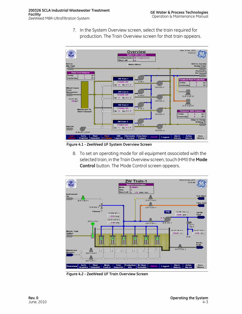
200326 SCLA Industrial Wastewater Treatment FacilityZeeWeed MBR-Ultrafiltration System
GE Water & Process TechnologiesOperation & Maintenance Manual
7. In the System Overview screen, select the train required for production. The Train Overview screen for that train appears.
8. To set an operating mode for all equipment associated with the selected train, in the Train Overview screen, touch (HMI) the Mode Control button. The Mode Control screen appears.
Figure 4.1 - ZeeWeed UF System Overview Screen
Figure 4.2 - ZeeWeed UF Train Overview Screen
Rev. 0June, 2010
Operating the System4-3

GE Water & Process TechnologiesOperation & Maintenance Manual
200326 SCLA Industrial Wastewater TreatmentFacility
ZeeWeed MBR-Ultrafiltration System
TIP: The All Off button is only available if the train is in Off mode.
TIP: The train will first enter standby mode after being activated.
9. To activate the train, in the Mode Control screen, touch (HMI) the On button. The train begins operating in automatic mode.
10. Click Exit when finished. The Mode Control screen closes.
If more trains are to be activated, repeat steps 8 - 12 for each additional train.
4.4 RESUMING OPERATION FOLLOWING AN ALARM SHUTDOWN
Use the following SOP to acknowledge an alarm, address the cause(s), and resume system operation:
Figure 4.3 - ZeeWeed UF Mode Control Screen
Operating the System4-4
Rev. 0June, 2010

200326 SCLA Industrial Wastewater Treatment FacilityZeeWeed MBR-Ultrafiltration System
GE Water & Process TechnologiesOperation & Maintenance Manual
TIP: An alarm banner (Figure 4.4 - Alarm Banner) will appear on screen displaying information that includes time of activation and of acknowledgement.
1. To deactivate the alarm horn, touch (HMI) the Horn Silence button found in both the Process and Alarm screens.
Figure 4.4 - Alarm Banner
Rev. 0June, 2010
Operating the System4-5

GE Water & Process TechnologiesOperation & Maintenance Manual
200326 SCLA Industrial Wastewater TreatmentFacility
ZeeWeed MBR-Ultrafiltration System
2. Based on the information provided in the Alarm Summary and Alarm History screens, determine what condition(s) caused the emergency shutdown.
3. To acknowledge the alarm, in the Alarm Banner screen, touch (HMI) the Acknowledge All button.
Figure 4.5 - Alarm Summary Screen
Figure 4.6 - Alarm History Screen
Operating the System4-6
Rev. 0June, 2010
200326 SCLA Industrial Wastewater Treatment FacilityZeeWeed MBR-Ultrafiltration System
GE Water & Process TechnologiesOperation & Maintenance Manual
TIP: If an alarm condition remains when the system operator attempts to resume operation, the alarm will sound again and this procedure will need to be repeated.
4. Resolve the alarm condition(s) before proceeding. Refer to the accompanying appendices for information regarding issues related to specific subsystems, and to Volume I - Vendor Data Manual for information regarding particular equipment.
5. After all alarm conditions have been resolved, to reset the alarm, in the [Screen Name] screen, touch (HMI) the Alarm Reset button.
6. To resume operation, perform the relevant step(s) from among those listed below, depending upon the subsystem in question:
For the ZeeWeed UF subsystem, perform steps 8 - 12 under 4.3.1 Starting Up the ZeeWeed UF Subsystem.If an alarm sounds but does not trigger a shutdown of any subsystem or associated equipment and deactivates automatically, consult the Alarm History screen for an explanation. In most cases where this occurs, the condition that triggered the alarm was resolved automatically. However, system operators should confirm this in order to rule out the possibility of a faulty alarm.
4.5 CONTROLLING SPECIFIC EQUIPMENT MANUALLY
The following sections provide general instructions for controlling specific equipment, such as valves, pumps, and blowers, from the HMI.
Refer to Volume I - Vendor Data Manual for detailed information regarding the operating procedures for specific equipment.
4.5.1 ACCESSING DEVICE CONTROLS
To open the Device Control screen for a specific device, in the Process screen, touch (HMI) the symbol for that device. The Device Control screen opens.
Rev. 0June, 2010
Operating the System4-7

GE Water & Process TechnologiesOperation & Maintenance Manual
200326 SCLA Industrial Wastewater TreatmentFacility
ZeeWeed MBR-Ultrafiltration System
4.5.2 VALVES
Valves can be set in the following modes:
• Auto - the valve is controlled by the PLC.
• Open - the valve is opened manually.
• Close - the valve is closed manually.
Valves in Open or Close mode must be monitored and controlled manually (that is, the PLC will only control valves in Auto mode).
Figure 4.7 - Valve Device Control Screen
Operating the System4-8
Rev. 0June, 2010

200326 SCLA Industrial Wastewater Treatment FacilityZeeWeed MBR-Ultrafiltration System
GE Water & Process TechnologiesOperation & Maintenance Manual
4.5.3 PROCESS PUMPS
A subsystem that has been set in Manual mode must not be left unattended.
4.5.4 CHEMICAL PUMPS
Chemical pumps can be set in the following modes:
• Auto - the pump is controlled by the PLC.
• Start - the pump is activated manually.
• Stop - the pump is deactivated manually.
Pumps that are in Start or Stop mode must be monitored and controlled manually (that is, the PLC will only control pumps in Auto mode).
Figure 4.8 - Process Pump Device Control Screen
Rev. 0June, 2010
Operating the System4-9

GE Water & Process TechnologiesOperation & Maintenance Manual
200326 SCLA Industrial Wastewater TreatmentFacility
ZeeWeed MBR-Ultrafiltration System
4.5.5 AIR COMPRESSORS
Before activating an air compressor, set the duty cycle timer to the required setting. The factory default value is provided in the CLC.
4.5.6 POWER CONTROL HARDWARE
The control panel disconnect switch, PLC stop button, and pilot light are located on the outside of the control panel(s).
4.5.6.1 CONTROL PANEL DISCONNECT SWITCH
The disconnect switch can be used to cut power to the control panel, which will in turn de-energize the PLC and any equipment controlled by the PLC.
Figure 4.9 - Chemical Skid Screen
Operating the System4-10
Rev. 0June, 2010
200326 SCLA Industrial Wastewater Treatment FacilityZeeWeed MBR-Ultrafiltration System
GE Water & Process TechnologiesOperation & Maintenance Manual
4.5.6.2 SYSTEM STOP BUTTON
Pressing the System Stop Button immediately places all PLC-controlled equipment into OFF mode. To resume operation, after the button has been pulled back out, the operator must follow the startup procedures outlined in the applicable sections above and in the accompanying appendices.
TIP: All manually operated equipment will retain pre-shutdown status and equipment in Auto mode remain in Auto mode.
Pressing the System Stop Button immediately places all PLC-controlled equipment into OFF mode. After this button is pulled back out, operation will resume automatically in accordance with the startup sequence outlined in the CLC provided in Section 5 - Control Documentation. A power-up status bar will display on the HMI as operation resumes.
4.6 SYSTEM SETPOINTS
The design values for system setpoints are listed in the CLC provided in Section 5 - Control Documentation. These values can be changed from the setpoints screen of a particular system component.
Record all setpoint changes. In the event of a complete loss of power, the system will restart with setpoints taken from the electronically erasable programmable read only memory (E2PROM) and any recent changes will be lost.
To change a setpoint, perform the following steps:
1. In the System Overview screen, click the Plant Setpoints button. The Plant Setpoints screen is displayed.
2. In the Plant Setpoints screen, click the gray box corresponding to the applicable setpoint.
3. Type the new setpoint value into the box, and then touch (HMI) the Enter button. The setpoint is changed.
Rev. 0June, 2010
Operating the System4-11

GE Water & Process TechnologiesOperation & Maintenance Manual
200326 SCLA Industrial Wastewater TreatmentFacility
ZeeWeed MBR-Ultrafiltration System
4. To close the Plant Setpoints screen, touch (HMI) the Exit button. The Plant Setpoints screen closes.
Operating the System4-12
Rev. 0June, 2010

SECTION 5CONTROL DOCUMENTATION

This page has beenintentionally left blank

NOTICE
The enclosed materials are considered proprietary property of GE Water & Process Technologies. No assignments, either implied or expressed, of intellectual property rights, data, know how, trade secrets or licensees of use thereof are given. All information is provided exclusively to the addressee for the purpose of evaluation and is not to be reproduced or divulged to other parties, nor used for manufacture or other means, or authorize any of the above, without the express written consent of GE Water & Process Technologies. The acceptance of this document will be construed as an acceptance of the foregoing conditions.
GE Water & Process Technologies
SCLA Victorville, CA CONTROL NARRATIVE
Issued: November 16, 2009
AO# 200326
3239 Dundas Street West, Oakville, ON
CANADA Phone: (905) 465-3030
Fax: (905) 465-3050
CN_200236_Victorville_Rdraft@_12Nov09_DC.doc

AO# 200326
SCLA Victorville Control Narrative
CN_200326_Victorville_R02_28May10_AV.doc
Printed:
June 16, 2010
Page 2 of 22
Table of Contents
1 PLANT OVERVIEW .....................................................................................................................................4
2 GENERAL INFORMATION .........................................................................................................................4
3 ZEEWEED® PERMEATE EQUIPMENT OPERATION & CONTROL ..........................................................4 3.1 ZEEWEED® TRAINS..........................................................................................................................................................4
3.1.1 Membrane Tank Isolation Gate........................................................................................................................5 3.1.2 Influent Flow, Membrane Tanks Level & Permeate Flow Control ....................................................5
3.2 THICKENER TRAIN............................................................................................................................................................6 3.2.1 Membrane Tank Isolation Gate........................................................................................................................6 3.2.2 Recirculation/Drain Pump...................................................................................................................................6 3.2.3 Process Pump ...........................................................................................................................................................6 3.2.4 Thickener Aeration .................................................................................................................................................7 3.2.5 Thickener Operation ..............................................................................................................................................7 3.2.6 Drain..............................................................................................................................................................................8
4 FLOW CONTROL........................................................................................................................................8 4.1 PRODUCTION TRANSMEMBRANE PRESSURE (TMP)..............................................................................................8 4.2 TRANSMEMBRANE PRESSURE (TMP) CALCULATION ............................................................................................9 4.3 START & STOP TRAIN TRIGGERS...............................................................................................................................10 4.4 PUTTING A ZEEWEED® TRAIN TO STANDBY ......................................................................................................10 4.5 PUTTING A THICKENER TRAIN TO STANDBY/PRODUCTION.........................................................................10 4.6 WINTER MODE ENABLED ...........................................................................................................................................11 4.7 TRAIN ROTATION...........................................................................................................................................................11
5 BACKPULSE EQUIPMENT CONTROL.................................................................................................... 11 5.1 BACKPULSE SEQUENCING .........................................................................................................................................12 5.2 RELAX ...............................................................................................................................................................................12
6 MEMBRANE AERATION CONTROL....................................................................................................... 12 6.1 SEQUENTIAL AERATION ..............................................................................................................................................13 6.2 STANDBY AERATION...................................................................................................................................................13 6.3 BLOWER LOW AIRFLOW.............................................................................................................................................13

AO# 200326
SCLA Victorville Control Narrative
CN_200326_Victorville_R02_28May10_AV.doc
Printed:
June 16, 2010
Page 3 of 22
7 RECIRCULATION FLOW CONTROL ...................................................................................................... 13 7.1 RECIRCULATION/DRAIN PUMPS...............................................................................................................................13 7.2 STANDBY RECIRCULATION.........................................................................................................................................13
8 INTEGRITY MONITORING & CONTROL................................................................................................ 14
9 CLEAN IN PLACE (CIP) CONTROLS ....................................................................................................... 14 9.1 SODIUM HYPOCHLORITE CLEANING EQUIPMENT ..............................................................................................14 9.2 CITRIC ACID CLEANING EQUIPMENT.......................................................................................................................14 9.3 MAINTENANCE CLEAN .............................................................................................................................................15
9.3.1 Maintenance Clean Sequence.......................................................................................................................15 9.4 RECOVERY CLEAN.........................................................................................................................................................15
10 NEUTRALIZATION CONTROLS.............................................................................................................. 16
11 PRIMING SYSTEM CONTROL................................................................................................................. 16
12 AIR COMPRESSOR CONTROL ............................................................................................................... 17
13 ZEEWEED® MODES OF OPERATION .................................................................................................... 17 13.1 ZEEWEED® TRAIN & THICKENER ON & OFF BUTTONS.....................................................................................18
14 ZEEWEED® TRIGGERS & ALARMS ........................................................................................................ 18 14.1 ALARMS............................................................................................................................................................................18
15 ZEEWEED® PLANT OPERATING INTERFACE....................................................................................... 20 15.1 PASSWORD ACCESS & PRIVILEGES .........................................................................................................................20 15.2 SCREEN COLOR-CODING ...........................................................................................................................................20
16 POWER INTERRUPTION / POWER UP ................................................................................................. 20
17 LOSS OF COMMUNICATION ALARMS.................................................................................................. 21 17.1 LOSS OF COMMUNICATION ALARM WITH PLANT SCADA...............................................................................21
18 SIGNALS FOR COMMUNICATION......................................................................................................... 21 18.1 PLANT PLC TO THE GE W&PT PLC SIGNALS .......................................................................................................21 18.2 GE W&PT PLC TO THE PLANT PLC SIGNALS .......................................................................................................22

AO# 200326
SCLA Victorville Control Narrative
CN_200326_Victorville_R02_28May10_AV.doc
Printed:
June 16, 2010
Page 4 of 22
1 Plant Overview
This document covers a general description of the controls by GE W&PT for the following unit processes:
• ZeeWeed® Trains, (One of ZeeWeed® Trains can function as a thickener) • Backpulse Equipment, • Aeration Equipment, • Clean-In-Place (CIP) Equipment, • Compressed Air.
2 General Information
The reader should refer to the Piping and Instrumentation Diagrams (P&ID’s), Operations Sequence Chart (OSC) and the Control Logic Summary Chart (CLSC) for a complete understanding of the plant control scheme as described below.
The PLC follows specific steps to automatically control valves, pumps, etc. during the operating states for the treatment plant. These steps are listed and described in the OSC.
Details of the control logic, setpoints, etc. that are required to operate the plant are given in the CLSC.
In the documentation the Programmable Logic Controller is referred to as the PLC. The PLC provides automated control of the ZeeWeed® equipment. All the programming for the control of the ZeeWeed® plant is stored in the PLC.
Setpoints, alarms, and calculated parameters, etc., are assigned tags in the PLC code. When tags are used in the Control Narrative, they are identified by an alpha-numeric label, for example, 20-P-301, for a Process pump.
Modes are a series of steps the train follows to perform various operations, such as a cleaning. A specific mode discussed in this document is shown in capital letters, such as MAINTENANCE CLEAN. Buttons displayed on the HMI screen that the operator can press to initiate a mode or other operation are shown with the first letter capitalized. For example, one button that is used to put a train to OFF mode is the Off button.
3 ZeeWeed® Permeate Equipment Operation & Control
3.1 ZeeWeed® Trains
A ZeeWeed® train is functionally described as a group of ZeeWeed® modules and cassettes connected by a common permeate collection header. During PRODUCTION the process pump draws water through the membranes and delivers it to the common permeate header and then the UV channel.

AO# 200326
SCLA Victorville Control Narrative
CN_200326_Victorville_R02_28May10_AV.doc
Printed:
June 16, 2010
Page 5 of 22
3.1.1 Membrane Tank Isolation Gate
Membrane tank isolation gate is used to isolate the membrane tank from the influent flow during RECOVERY CLEANS. Consult the OSC for further details on the gate’s position.
3.1.2 Influent Flow, Membrane Tanks Level & Permeate Flow Control
The influent flow signal is used in the calculation of the plant flow demand, which controls the speed of the process pump. As the influent flow increases the plant flow demand increases, causing the process pump(s) to speed up. To prevent standby and overflow conditions, the average level in the membrane tanks is used to trim the plant flow demand. Level control is accomplished with Proportional control. The PLC performs these calculations. The plant flow demand is the net permeate flowrate required from the trains and does not include additional permeate the trains produce for non-production operations, such as BACKPULSE.
The trim flowrate, which is a calculated flow, is added to or subtracted from the influent flowrate according to the average level in the membrane tanks and the difference from the level setpoint. As the level increases above the setpoint in the membrane tanks, the trim increases causing the overall plant flow demand to increase. When the plant flow demand increases, the process pumps for the trains in operation are ramped up to increase the plant permeate production which brings the level down in the membrane tanks. Conversely, if the membrane tanks are below the setpoint, the calculated trim flowrate is a negative flow and the overall plant flow demand decreases. The process pumps are ramped down, decreasing permeate production, and the membrane tanks level increases as a result of the decreased permeate production.
The flow setpoints for trains with a manual flow setpoint are added together and subtracted from the plant flow demand which includes the level trim. This revised plant flow demand is then divided equally to the trains in operation without a manually entered flow setpoint. This value becomes the net production flow setpoint for a train. A correction factor is calculated to account for the time when the train is not producing water (i.e. Relax or Backpulse) and to produce additional water required for backpulsing the train, when trains are being backpulsed. The net production flow setpoint multiplied by the correction factor is then used to calculate the instantaneous flow setpoint for the train. This value controls the process pump speed through the flow PID loop.
A flow setpoint may also be entered for each train manually. The supervisor can do this by setting the production flowrate for some or all of the trains on the HMI. The PLC will maintain the entered production flowrate or PLC calculated production flowrate up to a maximum TransMembrane Pressure (TMP) or a minimum membrane tank level.
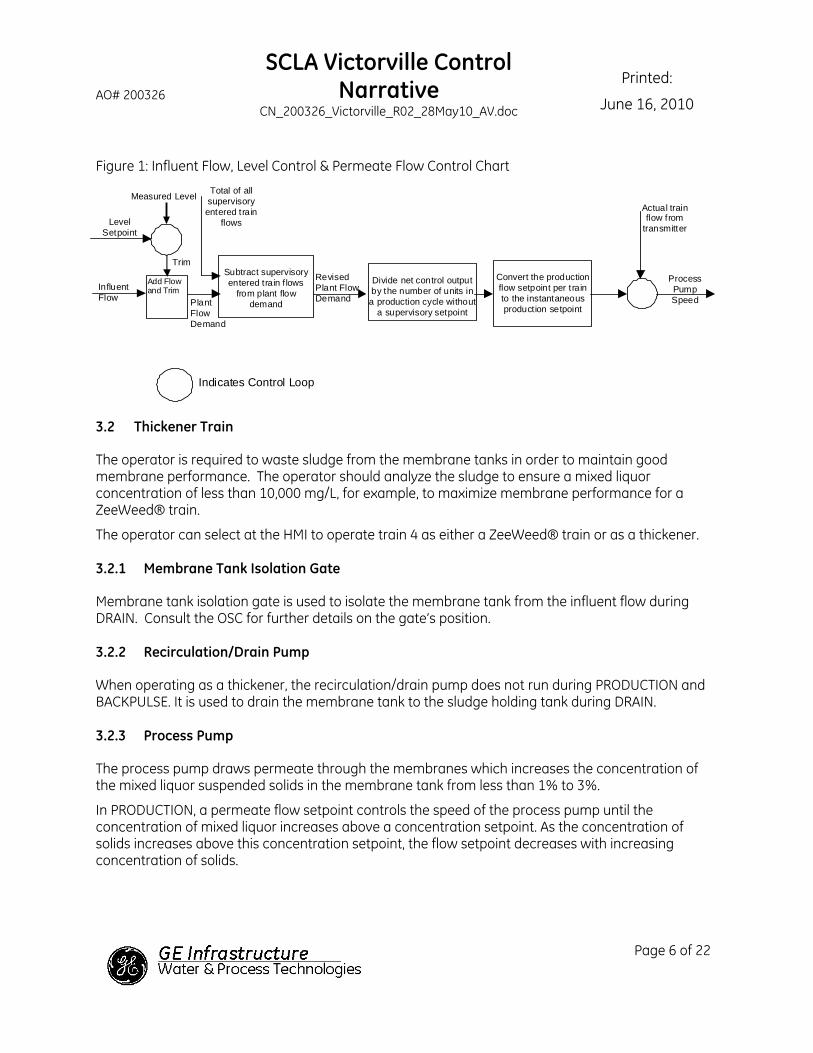
AO# 200326
SCLA Victorville Control Narrative
CN_200326_Victorville_R02_28May10_AV.doc
Printed:
June 16, 2010
Page 6 of 22
Figure 1: Influent Flow, Level Control & Permeate Flow Control Chart
Subtract supervisory entered train f lows
from plant flow demand
Divide net control output by the number of units in a production cycle without
a supervisory setpoint
Convert the production flow setpoint per train to the instantaneous production setpoint Plant
Flow Demand
Total of all supervisory entered train
flows
Indicates Control Loop
Actual train flow from
transmitter
Process Pump Speed
Revised Plant Flow Demand
Level Setpoint
Measured Level
Influent Flow
Add Flow and Trim
Trim
3.2 Thickener Train
The operator is required to waste sludge from the membrane tanks in order to maintain good membrane performance. The operator should analyze the sludge to ensure a mixed liquor concentration of less than 10,000 mg/L, for example, to maximize membrane performance for a ZeeWeed® train.
The operator can select at the HMI to operate train 4 as either a ZeeWeed® train or as a thickener.
3.2.1 Membrane Tank Isolation Gate
Membrane tank isolation gate is used to isolate the membrane tank from the influent flow during DRAIN. Consult the OSC for further details on the gate’s position.
3.2.2 Recirculation/Drain Pump
When operating as a thickener, the recirculation/drain pump does not run during PRODUCTION and BACKPULSE. It is used to drain the membrane tank to the sludge holding tank during DRAIN.
3.2.3 Process Pump
The process pump draws permeate through the membranes which increases the concentration of the mixed liquor suspended solids in the membrane tank from less than 1% to 3%.
In PRODUCTION, a permeate flow setpoint controls the speed of the process pump until the concentration of mixed liquor increases above a concentration setpoint. As the concentration of solids increases above this concentration setpoint, the flow setpoint decreases with increasing concentration of solids.

AO# 200326
SCLA Victorville Control Narrative
CN_200326_Victorville_R02_28May10_AV.doc
Printed:
June 16, 2010
Page 7 of 22
3.2.4 Thickener Aeration
The membranes are aerated in 10/10 aeration in STANDBY, PRIME, PRODUCTION, and BACKPULSE. The membrane tank is not aerated while the membrane tank is being drained.
3.2.5 Thickener Operation
To operate the train 4 as a thickener, the operator selects the Thickener button at the HMI. The following setpoints are entered at the HMI.
• The concentration of the mixed liquor solids in the membrane tank distribution channel;
• Setpoint for the Mixed Liquor Suspended Solids Concentration to drain the thickener
A typical waste activated sludge thickening cycle is as follows:
1) In Off, the operator selects the enable thickener button. The thickener goes to PRODUCTION. The process pump draws permeate through the membranes while leaving the thickened activated sludge in the membrane tank [20-TK-201-4]. The permeate volume is totalized by the PLC.
Using the permeate volume, volume of the membrane tank, and the mixed liquor solids concentration is measured in the membrane tank distribution channel, the PLC calculates the mixed liquor suspended solids concentration in the membrane tank.
2) Whenever the mixed liquor solids concentration in the membrane tank is greater than the Mixed Liquor Suspended Solids Concentration to drain the thickener, the thickener goes to STANDBY and the HMI displays a banner “Drain the thickener”. In STANDBY, aeration continues.
The operator selects the Drain button.
3) The recirculation/drain pump [20-P-801-4] draws the thickened waste activated sludge from the membrane tank and delivers it to sludge holding tank through valve [16-FV-821]. The recirculation/drain pump operates until the membrane tank level reaches an operator adjustable low level setpoint (as close to empty as possible).
4) The membrane tank gate [20-FV-110-4] opens and refills the membrane tank to the operating level. (The membrane gate opens for set duration and stops opening for a duration. This prevents damage to the membranes.)
5) The membrane tank is aerated for fifteen to thirty minutes.
6) The thickener status switches back to train status.
3.2.5.1 The Mixed Liquor Suspended Solids Concentration to Drain the Thickener
The Mixed Liquor Suspended Solids Concentration to drain the thickener is an operator adjustable setpoint on the HMI with a maximum value of 3%. The operator enters at the HMI the concentration of mix liquor suspended solids feeding the thickener. The PLC totalizes the permeate flow from the thickener. The percent mixed liquor solids concentration in a thickener is calculated as follows:

AO# 200326
SCLA Victorville Control Narrative
CN_200326_Victorville_R02_28May10_AV.doc
Printed:
June 16, 2010
Page 8 of 22
Percent MLSS in the thickener = Total net permeate volume divided by the membrane thickener tank volume multiplied by percent solids in the thickener feed.
= (Totalized permeate volume minus the totalized backpulse volume in the backpulse) divided by the level in the thickener multiplied by the thickener tank area multiplied by percent Mixed Liquor Suspended Solids in the feed.
3.2.6 Drain
The operator selects the Drain button at the HMI to start Drain mode.
The steps for DRAIN are:
1. The valves [20-FV-501-4 and 16-FV-821] open;
2. The recirculation/drain pump [20-P-801-4] draws the thickened waste activated sludge from the membrane tank and delivers it to sludge holding tank through valve [16-FV-821]. The membranes are backpulsed every fifteen minutes.
3. The valves [20-FV-501-4 and 16-FV-821] close;
4. Refill the membrane tank to the cleaning level from the membrane tank distribution channel. The membrane tank gate’s position is controlled based on timers to prevent damage to the membrane and sending the other trains to STANDBY on low level.
5. The membrane tank is aerated for fifteen to thirty minutes.
6. Proceeds to OFF.
Consult the OSC and CLSC for setpoints and additional operation information.
4 Flow Control
The production cycle for a train is PRODUCTION followed by either BACKPULSE or RELAX. The production cycle for a thickener is PRODUCTION followed by BACKPULSE. The thickener and train used the same timer to control the production cycle. The default value for this timer is twelve minutes.
4.1 Production TransMembrane Pressure (TMP)
The PLC continuously calculates the TMP value while in PRODUCTION. If the TMP is too low, (i.e., too negative) the TMP low trigger is active and the flow control PID loop output is captured. This value becomes the maximum value for the flow control PID loop output.
When the TMP low trigger becomes active, the PLC gradually reduces the maximum for the flow PID loop output until the TMP low trigger is not active, (i.e., TMP is less negative). At the moment when the TMP low trigger becomes inactive, the maximum value is then gradually increased until the TMP low trigger is active again, or continues to increase until the maximum value for the flow control PID loop
AO# 200326
SCLA Victorville Control Narrative
CN_200326_Victorville_R02_28May10_AV.doc
Printed:
June 16, 2010
Page 9 of 22
output equals 100%. This control strategy allows the PLC to vary the pump speed to maximize flow while avoiding excessive TMP across the membranes.
4.2 TransMembrane Pressure (TMP) Calculation
TMP is calculated by using the equation below. During PRODUCTION the value is negative, for backpulses and CIP, it is positive. The transmembrane pressure calculation is the same for the ZeeWeed® trains and the thickener.
TMP = Header Pressure + C x (A + B - Membrane Tank Level)
Where:
A is the height of the pressure transmitter above the top of the membranes.
B is the height to the top of membranes in the membrane tank.
C is a conversion factor (water depth to pressure); consult the CLSC for the value.
In PRODUCTION, an increased TMP value means a larger pressure differential because the pressure inside the membranes is lower than outside the membranes. This corresponds to a lower number as expressed in engineering units. Therefore a high production TMP is actually expressed as a Pressure Differential Alarm Low.

AO# 200326
SCLA Victorville Control Narrative
CN_200326_Victorville_R02_28May10_AV.doc
Printed:
June 16, 2010
Page 10 of 22
Figure 2 TMP Chart
4.3 Start & Stop Train Triggers
The number of trains in operation at any given time will vary depending on the plant flow demand. As this demand increases, the number of trains in PRODUCTION increases. Start and stop train triggers determine when another train is to start or when a train in PRODUCTION is switched to STANDBY respectively. These triggers are defined in the CLSC.
4.4 Putting a ZeeWeed® Train to STANDBY
Several triggers may cause a train to go to STANDBY rather than shutting it down. These triggers include a low membrane tank level, low plant flow demand, or a loss of compressed air. If a low membrane tank level occurs, the train will immediately proceed to STANDBY. If the STANDBY triggers no longer exist and a Start trigger is active, the train proceeds into PRODUCTION.
4.5 Putting a Thickener Train to STANDBY/PRODUCTION
Several triggers may cause the thickener to go to STANDBY rather than shutting it down. These triggers include a low membrane tank level, a loss of compressed air; the Calculated MLSS

AO# 200326
SCLA Victorville Control Narrative
CN_200326_Victorville_R02_28May10_AV.doc
Printed:
June 16, 2010
Page 11 of 22
Concentration in the Thickener is greater than The Mixed Liquor Suspended Solids Concentration to drain the thickener.
If the Calculated MLSS Concentration in the Thickener is less than the Mixed Liquor Suspended Solids Concentration to drain the thickener; and the membrane tank level is above the low level trigger then the thickener proceeds to PRODUCTION.
4.6 Winter Mode Enabled
Winter mode operation is for plants that can freeze. Winter mode only works as long as there is demand for at least one train to be in the Production cycle. It is not applicable to the thickener operation.
The PLC is programmed to force a train, which is in Standby more than 30 minutes to go to Production (this train stays in the Production cycle for at least 200 seconds) another trains in the Production cycle will be pushed (by logic) into Standby because of high production time.
After 200 seconds, the PLC check again all the Standby trains and select the train which has more than 30 minutes standby time and the highest standby time to repeat the same process again, one train at the time. The timers are operator adjustable at the HMI. The number of trains in the Production cycle is still controlled by the start/stop triggers. There are selector switches on the HMI to select either Enable Winter or Disable Winter Mode.
During this switching time the request for the number of running blowers is held constant.
4.7 Train Rotation
When there are long periods of low plant flow demand, the same trains in a plant run most of the time. The operator can select the Train Rotation button at the HMI. When the plant is operating with Train Rotation, a timer starts. The timer specifies the running time for the next train to go to STANDBY. This train goes to STANDBY after the timer times out and the train has completed either a Backpulse or a Relax. The timer is reset to zero. This rotation only occurs when there is at least one train in STANDBY and at least one train is in the Production cycle. The number of trains in the Production cycle is controlled by the start/stop triggers. The blower operation does not change during this rotation. Winter Mode and Train Rotation cannot be selected at the same time. When train 4 is functioning as a thickener, it is not included in Train Rotation.
5 Backpulse Equipment Control
The membranes are backpulsed using process pump. Treated water is periodically reversed back through the membranes to maintain stable transmembrane pressures.
The PLC controls the pump speed to backpulse the trains at a set flow rate per train up to a maximum TMP. A transmitter on the membrane header is used to calculate the BACKPULSE TMP. This provides membrane protection against over-pressurization. If the TMP is too high, the TMP high trigger is active and the flow control PID loop output is captured. This value becomes the maximum value for the output of the flow control PID loop.

AO# 200326
SCLA Victorville Control Narrative
CN_200326_Victorville_R02_28May10_AV.doc
Printed:
June 16, 2010
Page 12 of 22
When the TMP high trigger becomes active, the PLC gradually reduces the maximum for the flow PID loop output until the TMP high trigger is not active, (i.e., TMP is less positive). At the moment when the TMP high trigger becomes inactive, the maximum value is then gradually increased until the TMP high trigger is active again, or continues to increase until the maximum value for the flow control PID loop output equals 100%. This control strategy allows the PLC to vary the pump speed to maximize flow while avoiding excessive TMP across the membranes.
The backpulse duration, production cycle duration, TMP setpoint and flow setpoint for all ZeeWeed® trains can be set through the HMI. All ZeeWeed® trains in the plant share the same backpulse duration and production cycle duration.
5.1 Backpulse Sequencing
The PLC staggers the backpulses of the trains and thickener throughout each cycle to distribute the backpulses evenly when all trains/thickener are in the Production cycle. Each train/thickener is given a fixed scheduled time in the master Production cycle timer to begin either a BACKPULSE or RELAX. Train 1 is assigned the first time slot, train 2 is assigned the second time slot, and so on for all trains/thickener in the system. Regardless of the number of trains/thickener in the Production cycle, each train/thickener is always backpulsed at the same time slot of the master Production cycle timer. For example, when there are four trains (three trains and one thickener) in the system and the Production cycle time is 12 minutes, the first time slot is at time 0 min. and the second time slot, to backpulse Train 2, is at 3 minutes of the master Production cycle timer.
The master Production cycle timer starts when there are no trains/thickener in Production and one train/thickener is requested to start PRODUCTION. The timer restarts every time it times out.
The operator can initiate a BACKPULSE from the HMI for any ZeeWeed® train by pressing the Backpulse button. This button is disabled if any other train is in BACKPULSE.
5.2 Relax
RELAX control is an alternative to backpulsing. If a backpulse failure occurs and no pump is available, the PLC will place the trains into RELAX mode.
In RELAX mode, the PLC will stop permeating and the membranes sits for an operator entered duration before continuing PRODUCTION. During this time solids that have concentrated around the membrane will be distributed away from the membrane surface by the aeration.
6 Membrane Aeration Control
There are four membrane blowers, 20-P-201. The PLC determines the number of blowers required to run and the flow setpoint for these blowers. Blower duty is alternated according to an operator entered run time. The blowers supply low pressure air into a common air header. This common air header then divides into multiple air headers to the membrane tanks.
For further details on blower operation, refer to the OSC and CLSC for the occurrence and number of blowers to be running at any given time. The blowers operate at a constant speed. The PLC starts and stops membrane blowers as necessary based on the aeration demand.
AO# 200326
SCLA Victorville Control Narrative
CN_200326_Victorville_R02_28May10_AV.doc
Printed:
June 16, 2010
Page 13 of 22
6.1 Sequential Aeration
Each train/thickener operates under sequential aeration, which is accomplished by aerating a given membrane module for 10 seconds, then not aerating it for 10 seconds. The cyclic aeration valves will cycle air within a train/thickener, reducing both the air required to run the system and the operating costs.
6.2 STANDBY Aeration
In STANDBY, the train are aerated intermittently based on timers. The PLC aerates trains sequentially to limit the number of starts and stops on the membrane aeration blowers. The trains are aerated starting with the first train followed by the second train, then the third train, without stopping the blower. Trains are aerated in the order of their train number. If, for example, train 2, and 3 are in Standby, train 2 is aerated first, and then train 3. Sequential aeration involves an overlap of aeration to allow the membrane aeration blower to continue to operate as one train completes its aeration and another train begins its aeration.
In STANDBY, the thickener is aerated continuously in 10/10 aeration.
6.3 Blower Low Airflow
A low air flow switch is located on the discharge of each blower, for blower protection. If the switch is active, an alarm occurs and the PLC changes the lead to the next available blower. If there is no other blower available, a different alarm occurs and the PLC shuts down trains until there is sufficient aeration capacity. If all blowers are faulted, then all the trains are shut down.
7 Recirculation Flow Control
The recirculation/drain pumps circulate RAS at an operator adjustable ratio based on the required plant flow demand. As the plant flow demand increases the recirculation flow demand increases, causing the recirculation/drain pump(s) to speed up. The PLC performs these calculations.
7.1 Recirculation/Drain Pumps
Each membrane tank has a dedicated recirculation/drain pump. Recirculation/drain pumps will operate during all modes of operation for a ZeeWeed® train excluding MAINTENANCE CLEAN and NEUTRALIZATION. In RECOVERY CLEAN, the recirculation/drain pump drains the membrane tank. When a train is functioning as a thickener, the recirculation/drain pump does not operate in PRODUCTION, RELAX, and BACKPULSE. In DRAIN, the recirculation/drain pump drains the membrane tank.
7.2 Standby Recirculation
In the event all of the trains are in STANDBY, a RAS pump will remain running on one train.
When a train in STANDBY is aerated, the recirculation/drain pump will operate for the Standby aeration duration.

AO# 200326
SCLA Victorville Control Narrative
CN_200326_Victorville_R02_28May10_AV.doc
Printed:
June 16, 2010
Page 14 of 22
8 Integrity Monitoring & Control
Integrity of each train/thickener is monitored with on-line turbidimeters.
There are three turbidity alarms used to assist the operator in running the system. One alarm is used to detect a problem that is not a spike and will immediately shutdown the train/thickener in PRODUCTION. For example, a train/thickener will be shutdown when the turbidity is above the setpoint, 0.5 NTU, for 60 seconds.
A second alarm is used to detect a spike in turbidity and will set all trains that are in BACKPULSE mode to RELAX mode. For example, the alarm is active when the turbidity is above the setpoint, 5 NTU, for 10 seconds. The alarm will also skip all scheduled MAINTENANCE CLEANS until the turbidity alarm condition no longer exists. From this time on, MAINTENANCE CLEANS will again be completed as scheduled.
The third alarm also detects turbidity spikes but at a lower setpoint and is used to notify the operator of a potential problem which needs to be addressed. For example, the alarm is active when the turbidity is above the setpoint, 0.2 NTU for 60 seconds.
The turbidity alarm setpoints and the time delays, before the alarms become active, are adjustable at the HMI. For further details consult the CLSC.
9 Clean In Place (CIP) Controls
The membranes require cleaning to maintain peak performance. There are two types of cleaning methods; Maintenance Cleans and Recovery Cleans. The cleaning chemical is either citric acid or sodium hypochlorite for Maintenance Cleans and Recovery Cleans.
RECOVERY CLEANS are operator initiated from OFF and should have the operator present during the majority of this clean.
When train 4 is operating as a thickener then Maintenance Clean and Recovery Clean are not available.
9.1 Sodium Hypochlorite Cleaning Equipment
Sodium hypochlorite is used to remove organic contaminants from the membranes. The sodium hypochlorite pumps 23-P-110/23-P-120 are an air diaphragm pumps. The GE W&PT PLC requests a sodium hypochlorite valve, 23-FV-101 for MAINTENANCE CLEANS or 23-FV-102 for RECOVERY CLEANS, to open to run the pump in specific steps during the cleaning procedure. Consult the OSC for these steps.
9.2 Citric Acid Cleaning Equipment
Citric acid is periodically used to remove inorganic contaminants from the membranes such as calcium carbonate, manganese and iron compounds. The citric acid pumps 23-P-310/23-P-320 are an air diaphragm pumps. The GE W&PT PLC requests a citric acid valve, 23-FV-301 for MAINTENANCE CLEANS or 23-FV-302 for RECOVERY CLEANS, to open to run the pump in specific steps during the cleaning procedure. Consult the OSC for these steps.

AO# 200326
SCLA Victorville Control Narrative
CN_200326_Victorville_R02_28May10_AV.doc
Printed:
June 16, 2010
Page 15 of 22
9.3 MAINTENANCE CLEAN
Maintenance Cleans are scheduled through the HMI and are automatically initiated by the PLC based on a 24 hour clock. The operator is able to schedule one Maintenance Clean per train per day. He/She enters the starting time and selects the cleaning chemical for the clean.
When it is time to carry out a Maintenance Clean, the PLC compares the current plant flow demand with the available capacity of the plant if one train is not in service. If the plant flow demand exceeds this capacity, then the scheduled MAINTENANCE CLEAN is skipped but the request remains active and will be started when demand is lower. When a Maintenance Clean is skipped or aborted, an alarm occurs to inform the operator.
If the plant flow demand does not exceed this capacity, when it is time to carry out a Maintenance Clean, the train will complete its current production cycle before starting the cleaning procedure. If a train is in STANDBY it will go directly to MAINTENANCE CLEAN.
9.3.1 Maintenance Clean Sequence
The steps for Maintenance Clean are:
1) Aerates the membrane tank;
2) Initial chemically enhanced pulse for all cassettes;
3) Relaxation period for all cassettes;
4) Chemically enhanced pulse for all cassettes;
5) Relaxation period for all cassettes;
6) Steps 4 and 5 are repeated for a number of iterations;
7) Non-chemically enhanced pulse for all cassettes;
8) Aerates the membrane tank;
9) Proceeds to STANDBY.
9.4 Recovery Clean
Recovery Cleans can only be carried out for a train if it is in RECOVERY CLEAN. The cleaning chemical is either citric acid or sodium hypochlorite. The operator turns the train OFF and then selects either the R. Clean with Citric Acid button or R. Clean with Sodium Hypochlorite button for the cleaning to begin. During a Recovery Clean there are several prompts which the operator must address. Consult the OSC and CLSC for further details. As a result it is suggested to have the operator present during the Recovery Clean so that these prompts can be responded to in a timely manner.
The steps for Recovery Clean are:
1. Aerates the membrane tank;
2. Drains the membrane tank with the recirculation/drain pump;
3. Manual drain and flush step. The PLC will proceed to the next step after a defined duration.
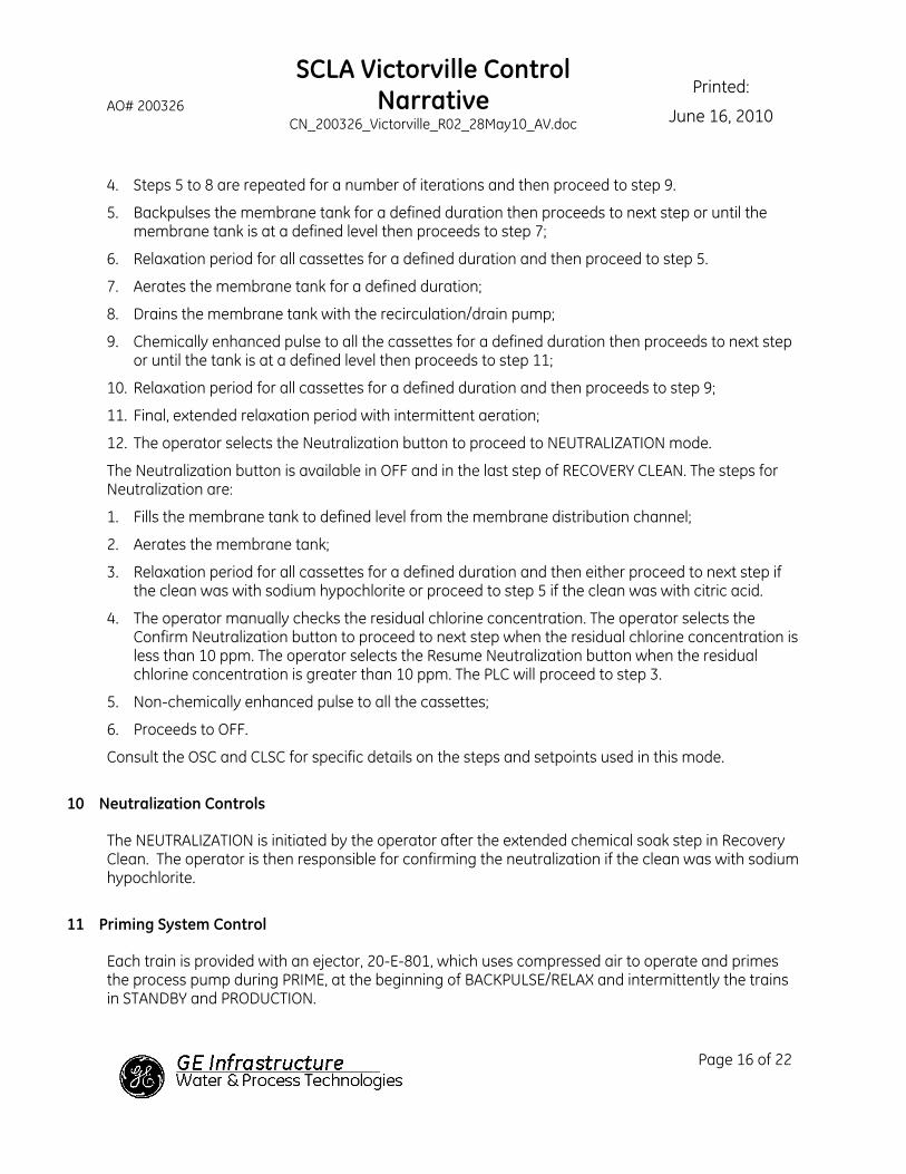
AO# 200326
SCLA Victorville Control Narrative
CN_200326_Victorville_R02_28May10_AV.doc
Printed:
June 16, 2010
Page 16 of 22
4. Steps 5 to 8 are repeated for a number of iterations and then proceed to step 9.
5. Backpulses the membrane tank for a defined duration then proceeds to next step or until the membrane tank is at a defined level then proceeds to step 7;
6. Relaxation period for all cassettes for a defined duration and then proceed to step 5.
7. Aerates the membrane tank for a defined duration;
8. Drains the membrane tank with the recirculation/drain pump;
9. Chemically enhanced pulse to all the cassettes for a defined duration then proceeds to next step or until the tank is at a defined level then proceeds to step 11;
10. Relaxation period for all cassettes for a defined duration and then proceeds to step 9;
11. Final, extended relaxation period with intermittent aeration;
12. The operator selects the Neutralization button to proceed to NEUTRALIZATION mode.
The Neutralization button is available in OFF and in the last step of RECOVERY CLEAN. The steps for Neutralization are:
1. Fills the membrane tank to defined level from the membrane distribution channel;
2. Aerates the membrane tank;
3. Relaxation period for all cassettes for a defined duration and then either proceed to next step if the clean was with sodium hypochlorite or proceed to step 5 if the clean was with citric acid.
4. The operator manually checks the residual chlorine concentration. The operator selects the Confirm Neutralization button to proceed to next step when the residual chlorine concentration is less than 10 ppm. The operator selects the Resume Neutralization button when the residual chlorine concentration is greater than 10 ppm. The PLC will proceed to step 3.
5. Non-chemically enhanced pulse to all the cassettes;
6. Proceeds to OFF.
Consult the OSC and CLSC for specific details on the steps and setpoints used in this mode.
10 Neutralization Controls
The NEUTRALIZATION is initiated by the operator after the extended chemical soak step in Recovery Clean. The operator is then responsible for confirming the neutralization if the clean was with sodium hypochlorite.
11 Priming System Control
Each train is provided with an ejector, 20-E-801, which uses compressed air to operate and primes the process pump during PRIME, at the beginning of BACKPULSE/RELAX and intermittently the trains in STANDBY and PRODUCTION.

AO# 200326
SCLA Victorville Control Narrative
CN_200326_Victorville_R02_28May10_AV.doc
Printed:
June 16, 2010
Page 17 of 22
When the operator selects the On button, the train goes to PRIME. The train’s ejector compressed air valve opens which also opens the permeate header isolation valve. During this time, air in the permeate header is pulled up and out through the ejector, which also pulls water into the membranes and process pump suction. Any water that is drawn into the ejector drains out by gravity. After the priming duration, the train proceeds to STANDBY.
The PLC staggers the priming of the trains throughout the Master Ejector cycle to distribute the priming when trains are in Production and Standby. Each train is given a fixed scheduled time in the Master Ejector Cycle Timer to begin priming. Train 1 is assigned the first time slot, train 2 is assigned the second time slot, and so on for all trains in the system. Regardless of the number of trains, each train is always primed at the same time slot of the Master Ejector Cycle Timer. The Master Ejector Cycle Timer starts once any train is in STANDBY and continues while there is at least one train in STANDBY, PRODUCTION, BACKPULSE, & RELAX.
When train 4 is functioning as a thickener, its ejector runs according to the Master Ejector cycle in Standby for Thickener and Production for Thickener.
The operator can manually initiate the priming sequence in STANDBY by pressing the Prime button at the HMI.
12 Air Compressor Control
Local control panels, supplied by the Vendor, control the compressors. Refer to Vendor supplied information for more details.
There is a low pressure switch on the common discharge piping which is used to alarm and callout. When this alarm is active, all trains/thickener in PRODUCTION, RELAX, and BACKPULSE switch to STANDBY.
13 ZeeWeed® Modes of Operation
Each ZeeWeed® train has separate mode buttons. There are several modes for each train, these modes are: OFF, SHUTDOWN, POWER OFF, STANDBY for train, PRIME, BACKPULSE for train, RELAX, PRODUCTION for train, MAINTENANCE CLEAN, RECOVERY CLEAN and NEUTRALIZATION. Using the ZeeWeed® train mode buttons on the HMI, the operator can put each ZeeWeed® train into a different mode. There are some interlocks present to prevent the user from proceeding to one mode from another. These interlocks are for membrane protection. Not all modes are selectable. Consult the CLSC and OSC for further details on the modes.
A train/thickener is in POWER OFF because a loss of power alarm is active or the system stop button is selected. A train/thickener is in SHUTDOWN because a shutdown alarm is active. A train/thickener is in STANDBY because a stop trigger or a standby trigger is active.
The thickener’s modes are OFF, SHUTDOWN, POWER OFF, STANDBY for thickener, PRIME, BACKPULSE for thickener, and PRODUCTION for thickener.

AO# 200326
SCLA Victorville Control Narrative
CN_200326_Victorville_R02_28May10_AV.doc
Printed:
June 16, 2010
Page 18 of 22
13.1 ZeeWeed® Train & Thickener On & Off Buttons
For the train to operate automatically the operator needs to have all devices set to auto and On button for the train selected. The On button is only active for a train if it is in either OFF or SHUTDOWN. Pressing the On button places the train into PRIME and then into STANDBY mode. When a start trigger is active, the train proceeds to PRODUCTION and then either BACKPULSE or RELAX modes. The train will continue in the production cycle, alternating between PRODUCTION and either BACKPULSE or RELAX modes, until the plant flow demand to treat wastewater decreases placing the train to STANDBY. A scheduled MAINTENANCE CLEAN will automatically interrupt the production cycle. An alarm may also place a train to STANDBY or SHUTDOWN.
The operator may interrupt the production cycle by pressing either the Maintenance Clean or Backpulse button. The train will proceed to the selected mode once the resources are available. There are interlocks preventing more than one train from entering the same mode at the same time. Consult the CLSC and the OSC for details on the interlocks.
The operator may turn a train/thickener OFF at any time. Pressing the Off button places the train/thickener into OFF mode. It is the responsibility of the operator to ensure that if the Off button is pressed when a train is in the MAINTENANCE CLEAN or RECOVERY CLEAN modes the membrane tank’s contents are suitable for a train to proceed to another mode. Neutralization may be required, or the membrane tank may need to be drained.
For the thickener to operate automatically the operator needs to have all devices set to auto and On button for the thickener selected. The On button is only active for a thickener if it is in either OFF or SHUTDOWN. Pressing the On button places the thickener into PRIME and then into STANDBY for thickener mode. When a start trigger is active, the thickener proceeds to PRODUCTION and then BACKPULSE mode. The thickener will continue in the production cycle, alternating between PRODUCTION and BACKPULSE modes, until the Calculated MLSS Concentration in the Thickener is greater than the Mixed Liquor Suspended Solids Concentration to drain the thickener placing the thickener to STANDBY. An alarm may also place a thickener to STANDBY or SHUTDOWN.
14 ZEEWEED® Triggers & Alarms
A trigger is a normal event that can clear an alarm or be one of several points in a sequence of events.
14.1 Alarms
Alarms are used to identify a problem with the system. Depending on the nature of the problem the alarm may either shutdown the train(s), place a train to STANDBY, and initiate a callout to notify the operator that there is a problem. It is understood that the operator will acknowledge the alarm and address the situation. If the problem is not corrected, production quality and quantity will drop off quickly.
An alarm that is activated by an instrument, pressure transmitter, flow transmitters, or level instrumentation, typically requires a pump or certain device to be on to generate the required flow or pressure. Otherwise, the alarm will be ignored if the device to be protected is off.

AO# 200326
SCLA Victorville Control Narrative
CN_200326_Victorville_R02_28May10_AV.doc
Printed:
June 16, 2010
Page 19 of 22
All alarms are indicated with a message on the screen. The operator cannot reset the alarm without the correct password. All alarms and the time they occurred are recorded on the alarm history screen.
Some alarms can shutdown a ZeeWeed® train or all the trains and the thickener. These alarms close appropriate valves and stop the pumps. The shutdown alarm puts the train to SHUTDOWN mode. Restarting after a shutdown will require the alarm to be reset. The shutdown alarm puts the thickener to SHUTDOWN mode. Restarting after a shutdown will require the alarm to be reset.
Devices which are being controlled remotely cannot have their status changed by the PLC.
Consult the CLSC for details on specific alarms, the corresponding actions and reset procedures.
Typical alarms that shutdown a train and alarms that put a train/thickener to STANDBY are listed in the following tables.
Table 1: Train Shutdown Alarms
Alarm Description Possible Causes for Alarm
High Flow Alarm - permeate Suction hose disconnecting from fittings.
Low Flow Alarm - permeate Loss of prime of process pump
Pressure High-High Alarm – permeate
(measured by pressure Transmitter) Suction hose disconnecting from fittings.
Transmembrane Pressure Low, Low Fouled UF membranes
Process pump Fault VFD Fault
Compressed Air – Low pressure and train is in Recovery Clean
Insufficient Compressed Air Supply to operate pneumatically actuated valves
Table 2: Train Standby Alarms
Alarm Description Possible Causes for Alarm
Low Level Alarm – membrane tank Permeate flowrate is higher than the Feed flowrate
Power Failure Tripped breaker inside panel
Low Flow Demand Standby Trigger Decreased Feed
– train is not required for Production
Compressed Air – Low pressure and train is in Production, Backpulse, or Relax, or Maintenance
Clean.
Insufficient Compressed Air Supply to operate pneumatically actuated valves

AO# 200326
SCLA Victorville Control Narrative
CN_200326_Victorville_R02_28May10_AV.doc
Printed:
June 16, 2010
Page 20 of 22
15 ZeeWeed® PLANT OPERATING Interface
To accommodate the above operational requirements and all other control, display, and monitoring requirements, this plant employs a Human Machine Interface (HMI) for access to plant controls. The HMI communicates with the Programmable Logic Controller (PLC (referred to as “PLC” in the documentation)), which in turn controls the plant.
15.1 Password Access & Privileges
The entire plant is controlled from the PLC through a HMI. The ability to silence the horn and acknowledge alarms does not require a password, but alarms can not be reset.
To gain access to make changes on the HMI, the operator is required to enter the correct password. A screensaver blanks the screen after a set amount of time of inactivity. The screen is reactivated by a single touch. Reactivation cannot select a device or operating mode.
In order to access the control screens, the individual must enter a correct password then press Enter. There are three levels of password protection; Operator, Supervisor, & GE W&PT. The operator password is factory set; consult the CLSC for the operator password. The supervisor password can be modified from the HMI. There is no limit to the number of times another password can be attempted. The password must be re-entered after a set amount of time of inactivity. For details of password privileges consult the CLSC.
15.2 Screen Color-Coding
The color-coded status indicates whether the device is either running automatically, shutdown, in STANDBY, off, manually overridden, etc.
The HMI uses the color-coding shown below.
Table 3: HMI Color Code Devices Chart
Color Valve Pump
Green Open On
Red Fault Fault
Grey Close Off
16 Power Interruption / Power Up
When a loss of power occurs, the affected trains/thickener will immediately proceed to POWER OFF mode. After power returns, the plant powers up common equipment and then the trains/thickener will start-up automatically in the order of the membrane tank number. The CLSC lists the order in which the common equipment and trains will power up; it also specifies the mode that a train/thickener will proceed to from POWER OFF mode.

AO# 200326
SCLA Victorville Control Narrative
CN_200326_Victorville_R02_28May10_AV.doc
Printed:
June 16, 2010
Page 21 of 22
17 Loss of Communication Alarms
During operation of the GE W&PT system, there are “heartbeat signals generated by each PLC. Each “heartbeat” signal is a counter that increases by one unit each second. When the communication with a PLC is lost, the PLC that is monitoring the “heartbeat” counter detects that the value of the counter has not changed for a preset time, for example after 5 seconds, and alarms. When the counter reaches 10,000 it restarts counting from zero.
Discussions of the alarms and the changes that occur to the control systems are given in the following sections.
17.1 Loss of Communication Alarm with Plant SCADA
When there is a loss of communication with the plant SCADA, the trains proceed to SHUTDOWN.
18 Signals for Communication
For the GE W&PT membrane system to maintain optimal performance, information must be communicated between the plant SCADA and the GE W&PT PLC.
Operating parameters of the GE W&PT system such as flowrates, pressures, train modes, etc. are available for communication, if necessary, when the plant SCADA is required to only monitor these parameters. A list showing this information, however, is not provided in this document due to the large number of parameters available.
The MBR system operates in a continuous automatic mode controlled by GE W&PT PLC, which shall interface with the plant SCADA system.
18.1 Plant PLC to the GE W&PT PLC Signals
The list given below shows the signals that are communicated from the plant SCADA over the network to the GE W&PT PLC to operate the membrane system.
1. Feed Flowrate
2. Permissive to run the trains and thickener (the UV is ready)
3. Running signal for blower 20-B-201-1
4. Running signal for blower 20-B-201-2
5. Running signal for blower 20-B-201-3
6. Running signal for blower 20-B-201-4
7. Running signal for process pump 20-P-301-1
8. Running signal for process pump 20-P-301-2
9. Running signal for process pump 20-P-301-3
10. Running signal for process pump 20-P-301-4
11. Running signal for recirculation drain pump 16-P-801-1
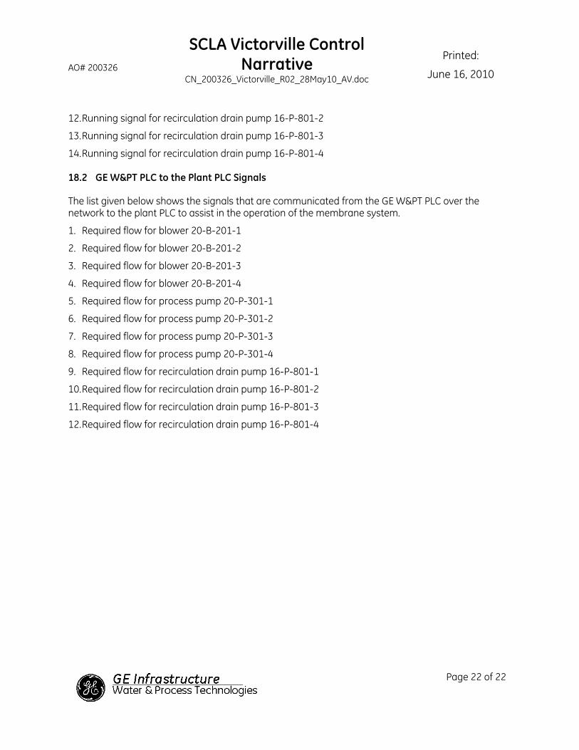
AO# 200326
SCLA Victorville Control Narrative
CN_200326_Victorville_R02_28May10_AV.doc
Printed:
June 16, 2010
Page 22 of 22
12. Running signal for recirculation drain pump 16-P-801-2
13. Running signal for recirculation drain pump 16-P-801-3
14. Running signal for recirculation drain pump 16-P-801-4
18.2 GE W&PT PLC to the Plant PLC Signals
The list given below shows the signals that are communicated from the GE W&PT PLC over the network to the plant PLC to assist in the operation of the membrane system.
1. Required flow for blower 20-B-201-1
2. Required flow for blower 20-B-201-2
3. Required flow for blower 20-B-201-3
4. Required flow for blower 20-B-201-4
5. Required flow for process pump 20-P-301-1
6. Required flow for process pump 20-P-301-2
7. Required flow for process pump 20-P-301-3
8. Required flow for process pump 20-P-301-4
9. Required flow for recirculation drain pump 16-P-801-1
10. Required flow for recirculation drain pump 16-P-801-2
11. Required flow for recirculation drain pump 16-P-801-3
12. Required flow for recirculation drain pump 16-P-801-4

GE Water & Process TechnologiesSCLA Victorville, CA
Operations Sequence Chart for Train Sequenced Equipment
Operating Mode
Step Description Step #
MEM
. AIR
- Se
quen
tial
FEED
- M
embr
ane
Tank
Isol
atio
n
PERM
EATE
- He
ader
to P
ump
PERM
EATE
- In
stru
men
t Iso
latio
n
CLEA
N - S
odiu
m H
ypoc
hlor
ite Is
olat
ion
CLEA
N - C
itric
Acid
Isol
atio
n
Recir
cula
tion/
Drai
nRA
S to
Mix
Tank
Isol
atio
nN6
DRAI
N - S
ludg
e Ho
ldin
g Iso
latio
nN6
M. C
LEAN
- Ci
tric A
cidM
. CLE
AN -
Sodi
um H
ypoc
hlor
ite
R. C
LEAN
- Ci
tric
Acid
R. C
LEAN
- So
dium
Hyp
ochl
orite
VACU
UM -
Ejec
tor c
ompr
esse
d ai
r
Activ
ated
Slu
dge
- Rec
ircul
atio
n/Dr
ain
Mem
bran
e Ae
ratio
n De
man
d
Proc
ess
Step
Dela
y
Step
LegendThis column is for the GE W&PT Tags
T - Indicates that the valve is throttling in Auto. O - Indicates that the valve/motor is open/on in Auto.
X - Indicates that the valve/motor is closed/OFF in Auto.C - Indicates that valve cycles though an open/close sequence.
-x - Indicates that there are multiple trains associated with this tag number.LS - Indicates that the valve/pump will retain the last state it had (open/closed, on/OFF) to avoid damaging equipment.
Valves Pumps & BlowersTag Numbers
20-F
V-21
0-x
20-F
V-21
1-x
20-F
V-11
0-x
20-F
V-30
1
20-F
V-32
0-x
23-F
V-13
1-x
23-F
V-33
1-x
20-F
V-50
1-x
16-F
V-82
0
16-F
V-82
1
23-F
V-30
1
23-F
V-10
1
23-F
V-30
2
23-F
V-10
2
20-F
V-80
2-x
For 2
0-E-
801-
x
16-P
-801
-x
20-B
-201
-x
20-P
-301
-x The Operations Sequence Chart (OSC), Control Logic Summary Chart (CLSC) and the Control Narrative (CN) should all be read to assist in the understanding of plant operations.
Comments & Sequencing Logic
OFF 1
Step 1 LS LS LS LS LS LS LS LS LS X X X X X X X X 6 1 Stops all rotating equipment, and leaves valves as they were.Waits for step delay, then proceeds to the next step.
Step 2 X X X X X X X X X X X X X X X X X 2
Train/thickener remains OFF until the operator changes it to another operational mode.If the ON button is pressed proceeds to PRIME - step 1.
For a train, if the BACKPULSE button is pressed proceeds to BACKPULSE - step 1 for a train.For the thickener, if the BACKPULSE button is pressed proceeds to BACKPULSE - step 1 for thickener.
When the train 4 is operating as a thickener the Drain button is available. If the Drain button is pressed proceeds to DRAIN - step 1.If the NEUTRALIZATION button is pressed proceeds to NEUTRALIZATION - step 1. (This button is not available for the thickener.)
If the MAINTENANCE CLEAN button is pressed proceeds to MAINTENANCE CLEAN - step 1. (This button is not available for the thickener.)If the RECOVERY CLEAN button is pressed proceeds to RECOVERY CLEAN - step 1. (This button is not available for the thickener.)
If PRIME pushbutton is pressed proceeds to PRIME - step 1.Only proceeds to the step indicated if the resources are available and the interlocks preventing the action are not present.
SHUTDOWN 2
Shutdown Step 1 LS LS LS LS LS LS LS LS LS X X X X X X X X 6 1 Stops all rotating equipment, and leaves valves as they were.Waits for step delay, then proceeds to the next step.
Tank Fill Step 2 X O X X X X X X X X X X X X X X X 2When 20-LS-201Q-x is active, then open the gate for 20-KQS-110C seconds gate stop opening the gate for 20-KQS-110D seconds. Repeat opening the gate with the frequency and duration timers.
When 20-LS-201Q-x is not active, then request to open the gate continously and ignore the timers.When 20-LS-201E-x is active, proceeds to the next step.
Shutdown Step 3 X X X X X X X X X X X X X X X X X 3Train/thickener remains in this mode until the operator changes the train/thickener to ON or OFF mode.
If the ON button is pressed proceeds to PRIME - step 1.If the OFF button is pressed proceeds to OFF - step 1.
POWER OFF 3 3
All Devices OFF Step 1 1 Train remains in this step until it is enabled by the start-up sequence steps.Consult the CLSC for specific details.
STANDBY for Train 5 5
Step 1 LS O LS LS LS LS LS LS LS X X X X X X X X 6 1 Stops all rotating equipment, and leaves valves as they were.Waits for step delay, then proceeds to the next step.
Tank Fill Step 2 X O X X X X X X X X X X X X X X X 2 When 20-LS-201E-x is active, proceeds to the next step.
STANDBY Step 3 CN1 O X X X X O O X X X X X ON4 ON3,5 ON1 X 3
Aerates for 20-KQS-201C seconds every 20-KQS-201D seconds.Runs the ejector intermittently according to Master Ejector Cycle Timer.
The train remains in this step indefinitely until one of the following occurs:If a start train trigger is active, defined in the CLSC, the train proceeds to the PRODUCTION - step 1 for a train.
If the BACKPULSE button is pressed proceeds to BACKPULSE - step 1 for a train.If the RELAX button is pressed proceeds to RELAX - step 1.
If the MAINTENANCE CLEAN button is pressed proceeds to MAINTENANCE CLEAN - step 1.If the PRIME TRAIN button is pressed proceeds to PRIME - step 1.
Only proceeds to the step indicated if the resources are available and the interlocks preventing the action are not present.
STANDBY for Thickener 5 5
Step 1 C O LS LS LS LS LS LS LS X X X X X X LS X 6 1 Stops all rotating equipment, and leaves valves as they were.Waits for step delay, then proceeds to the next step.
Tank Fill Step 2 C O X X X X X X X X X X X X X O X 2 When 20-LS-201E-4 is active, proceeds to the next step.
STANDBY Step 3 C O X X X X X X X X X X X ON4 X O X 3
Runs the ejector intermittently according to Master Ejector Cycle Timer.The thickener remains in this step indefinitely until one of the following occurs:
If the Drain the Thickener Trigger is not active, defined in the CLSC, the thickener proceeds to PRODUCTION - step 1 for thickener.If the PRIME button is pressed proceeds to PRIME - step 1.
If the BACKPULSE button is pressed proceeds to BACKPULSE - step 1 for the thickener.If the Drain button is pressed proceeds to DRAIN - step 1.
Only proceeds to the step indicated if the resources are available and the interlocks preventing the action are not present.PRIME 8 8 Only one train/thickener can be in PRIME mode at a time but more than one train/thickener can be in a priming step (when an ejector is running).
Priming Train Step 1 X O X X X X X X X X X X X O X X X 20-KQS-801 1
Holds this step for step durationIF PRIME was initiated from STANDBY then for a train proceeds to STANDBY - step 1 for a train.
IF PRIME was initiated from STANDBY then for a thickener proceeds to STANDBY - step 1 for thickener.If the On button was pressed in Off or Shutdown, then for a train proceeds to STANDBY - step 1 for a train.
If the On button was pressed in Off or Shutdown, then for a thickener proceeds to STANDBY - step 1 for a thickener.PRODUCTION for Train 14 14
Step 1 C O O O X X O O X X X X X X LS LS X 6 1 Waits for step delay, then proceeds to the next step.
Permeate Step 2 C O O O X X O O X X X X X ON4 O O O 2Permeates until the end of the current Production cycle, then:
If there is a demand for the train to run and there are no mode requests noted below, proceeds to either BACKPULSE for a train - step 1 or RELAX - step 1.If a MAINTENANCE CLEAN request is active proceeds to MAINTENANCE CLEAN - step 1.
PRODUCTION for Thickener 19 19 Only train 4 can function as a thickener.Valve Alignment Step 1 C O O O X X X X X X X X X X X O X 6 1 Waits for step delay, then proceeds to the next step.
Permeate Step 2 C O O O X X X X X X X X X ON4 X O O 2Permeates until the end of the current Production cycle, then:
If the Drain the Thickener Trigger is not active, the thickener proceeds to BACKPULSE - step 1 for thickener.If the Drain the Thickener Trigger is active, the thickener proceeds to STANDBY - step 1 for thickener.
Valves Pumps & Blowers
Issued: Nov 16, 2009Process Controls: D. Courtney
Page 1 of 4
The enclosed materials are considered proprietary property of GE Water & Process Technologies. OSC_200326_Victorville_R02_11May10_MdK2.xls
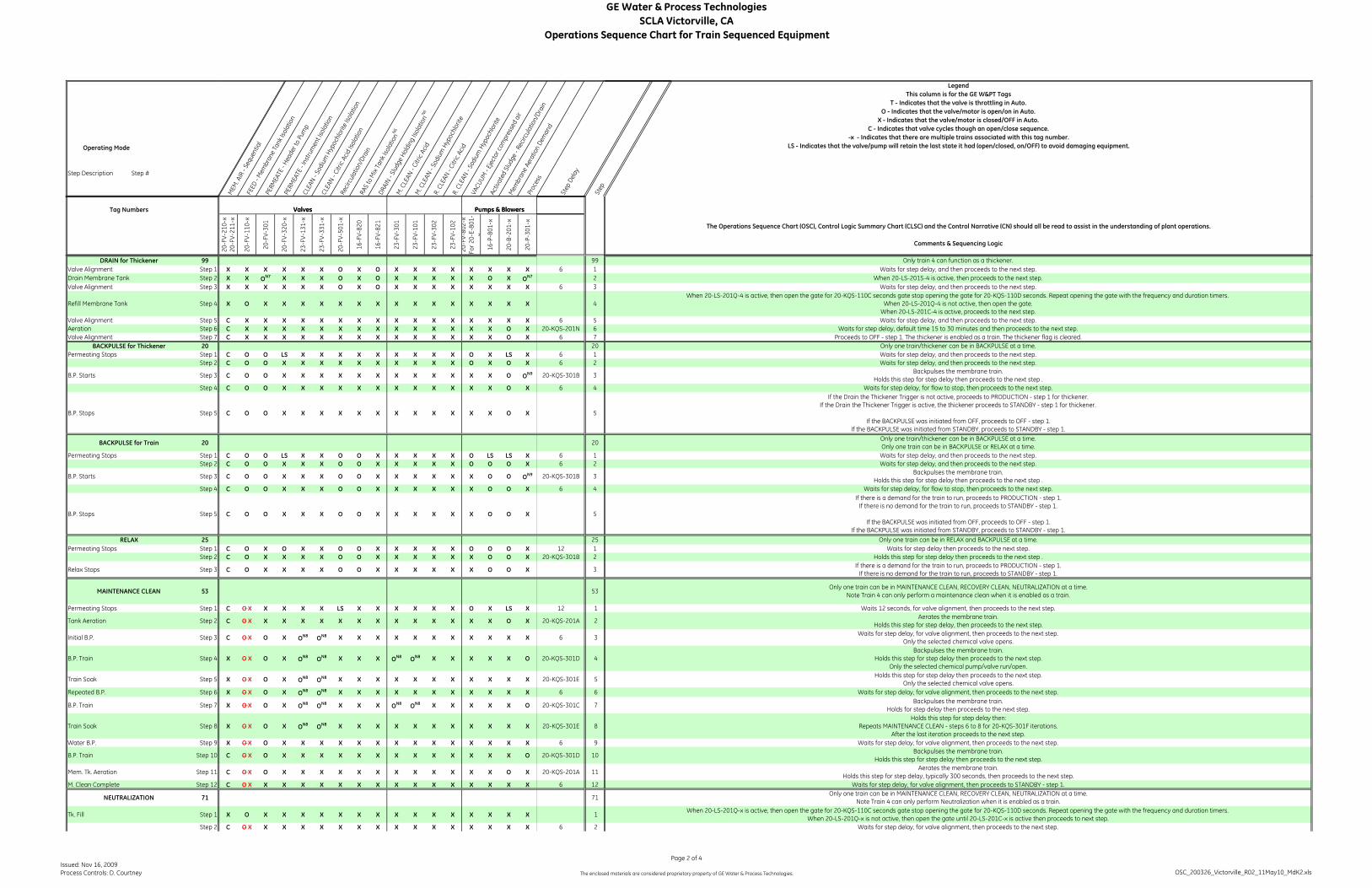
GE Water & Process TechnologiesSCLA Victorville, CA
Operations Sequence Chart for Train Sequenced Equipment
Operating Mode
Step Description Step #
MEM
. AIR
- Se
quen
tial
FEED
- M
embr
ane
Tank
Isol
atio
n
PERM
EATE
- He
ader
to P
ump
PERM
EATE
- In
stru
men
t Iso
latio
n
CLEA
N - S
odiu
m H
ypoc
hlor
ite Is
olat
ion
CLEA
N - C
itric
Acid
Isol
atio
n
Recir
cula
tion/
Drai
nRA
S to
Mix
Tank
Isol
atio
nN6
DRAI
N - S
ludg
e Ho
ldin
g Iso
latio
nN6
M. C
LEAN
- Ci
tric A
cidM
. CLE
AN -
Sodi
um H
ypoc
hlor
ite
R. C
LEAN
- Ci
tric
Acid
R. C
LEAN
- So
dium
Hyp
ochl
orite
VACU
UM -
Ejec
tor c
ompr
esse
d ai
r
Activ
ated
Slu
dge
- Rec
ircul
atio
n/Dr
ain
Mem
bran
e Ae
ratio
n De
man
d
Proc
ess
Step
Dela
y
Step
LegendThis column is for the GE W&PT Tags
T - Indicates that the valve is throttling in Auto. O - Indicates that the valve/motor is open/on in Auto.
X - Indicates that the valve/motor is closed/OFF in Auto.C - Indicates that valve cycles though an open/close sequence.
-x - Indicates that there are multiple trains associated with this tag number.LS - Indicates that the valve/pump will retain the last state it had (open/closed, on/OFF) to avoid damaging equipment.
Valves Pumps & BlowersTag Numbers
20-F
V-21
0-x
20-F
V-21
1-x
20-F
V-11
0-x
20-F
V-30
1
20-F
V-32
0-x
23-F
V-13
1-x
23-F
V-33
1-x
20-F
V-50
1-x
16-F
V-82
0
16-F
V-82
1
23-F
V-30
1
23-F
V-10
1
23-F
V-30
2
23-F
V-10
2
20-F
V-80
2-x
For 2
0-E-
801-
x
16-P
-801
-x
20-B
-201
-x
20-P
-301
-x The Operations Sequence Chart (OSC), Control Logic Summary Chart (CLSC) and the Control Narrative (CN) should all be read to assist in the understanding of plant operations.
Comments & Sequencing Logic
Valves Pumps & Blowers
DRAIN for Thickener 99 99 Only train 4 can function as a thickener.Valve Alignment Step 1 X X X X X X O X O X X X X X X X X 6 1 Waits for step delay, and then proceeds to the next step.Drain Membrane Tank Step 2 X X ON7 X X X O X O X X X X X O X ON7 2 When 20-LS-201S-4 is active, then proceeds to the next step.Valve Alignment Step 3 X X X X X X O X O X X X X X X X X 6 3 Waits for step delay, and then proceeds to the next step.
Refill Membrane Tank Step 4 X O X X X X X X X X X X X X X X X 4When 20-LS-201Q-4 is active, then open the gate for 20-KQS-110C seconds gate stop opening the gate for 20-KQS-110D seconds. Repeat opening the gate with the frequency and duration timers.
When 20-LS-201Q-4 is not active, then open the gate. When 20-LS-201C-4 is active, proceeds to the next step.
Valve Alignment Step 5 C X X X X X X X X X X X X X X X X 6 5 Waits for step delay, and then proceeds to the next step.Aeration Step 6 C X X X X X X X X X X X X X X O X 20-KQS-201N 6 Waits for step delay, default time 15 to 30 minutes and then proceeds to the next step.Valve Alignment Step 7 C X X X X X X X X X X X X X X O X 6 7 Proceeds to OFF - step 1. The thickener is enabled as a train. The thickener flag is cleared.
BACKPULSE for Thickener 20 20 Only one train/thickener can be in BACKPULSE at a time.Permeating Stops Step 1 C O O LS X X X X X X X X X O X LS X 6 1 Waits for step delay, and then proceeds to the next step.
Step 2 C O O X X X X X X X X X X O X O X 6 2 Waits for step delay, and then proceeds to the next step.
B.P. Starts Step 3 C O O X X X X X X X X X X X X O ON9 20-KQS-301B 3 Backpulses the membrane train.Holds this step for step delay then proceeds to the next step .
Step 4 C O O X X X X X X X X X X X X O X 6 4 Waits for step delay, for flow to stop, then proceeds to the next step.
B.P. Stops Step 5 C O O X X X X X X X X X X X X O X 5
If the Drain the Thickener Trigger is not active, proceeds to PRODUCTION - step 1 for thickener.If the Drain the Thickener Trigger is active, the thickener proceeds to STANDBY - step 1 for thickener.
If the BACKPULSE was initiated from OFF, proceeds to OFF - step 1.If the BACKPULSE was initiated from STANDBY, proceeds to STANDBY - step 1.
BACKPULSE for Train 20 20 Only one train/thickener can be in BACKPULSE at a time.Only one train can be in BACKPULSE or RELAX at a time.
Permeating Stops Step 1 C O O LS X X O O X X X X X O LS LS X 6 1 Waits for step delay, and then proceeds to the next step.Step 2 C O O X X X O O X X X X X O O O X 6 2 Waits for step delay, and then proceeds to the next step.
B.P. Starts Step 3 C O O X X X O O X X X X X X O O ON9 20-KQS-301B 3 Backpulses the membrane train.Holds this step for step delay then proceeds to the next step .
Step 4 C O O X X X O O X X X X X X O O X 6 4 Waits for step delay, for flow to stop, then proceeds to the next step.
B.P. Stops Step 5 C O O X X X O O X X X X X X O O X 5
If there is a demand for the train to run, proceeds to PRODUCTION - step 1.If there is no demand for the train to run, proceeds to STANDBY - step 1.
If the BACKPULSE was initiated from OFF, proceeds to OFF - step 1.If the BACKPULSE was initiated from STANDBY, proceeds to STANDBY - step 1.
RELAX 25 25 Only one train can be in RELAX and BACKPULSE at a time.Permeating Stops Step 1 C O X O X X O O X X X X X O O O X 12 1 Waits for step delay then proceeds to the next step.
Step 2 C O X X X X O O X X X X X X O O X 20-KQS-301B 2 Holds this step for step delay then proceeds to the next step .
Relax Stops Step 3 C O X X X X O O X X X X X X O O X 3 If there is a demand for the train to run, proceeds to PRODUCTION - step 1.If there is no demand for the train to run, proceeds to STANDBY - step 1.
MAINTENANCE CLEAN 53 53 Only one train can be in MAINTENANCE CLEAN, RECOVERY CLEAN, NEUTRALIZATION at a time.Note Train 4 can only perform a maintenance clean when it is enabled as a train.
Permeating Stops Step 1 C O X X X X X LS X X X X X X O X LS X 12 1 Waits 12 seconds, for valve alignment, then proceeds to the next step.
Tank Aeration Step 2 C O X X X X X X X X X X X X X X O X 20-KQS-201A 2 Aerates the membrane train.Holds this step for step delay, then proceeds to the next step.
Initial B.P. Step 3 C O X O X ON8 ON8 X X X X X X X X X X X 6 3 Waits for step delay, for valve alignment, then proceeds to the next step.Only the selected chemical valve opens.
B.P. Train Step 4 X O X O X ON8 ON8 X X X ON8 ON8 X X X X X O 20-KQS-301D 4Backpulses the membrane train.
Holds this step for step delay then proceeds to the next step.Only the selected chemical pump/valve run/open.
Train Soak Step 5 X O X O X ON8 ON8 X X X X X X X X X X X 20-KQS-301E 5 Holds this step for step delay then proceeds to the next step.Only the selected chemical valve opens.
Repeated B.P. Step 6 X O X O X ON8 ON8 X X X X X X X X X X X 6 6 Waits for step delay, for valve alignment, then proceeds to the next step.
B.P. Train Step 7 X O X O X ON8 ON8 X X X ON8 ON8 X X X X X O 20-KQS-301C 7 Backpulses the membrane train.Holds for step delay then proceeds to the next step.
Train Soak Step 8 X O X O X ON8 ON8 X X X X X X X X X X X 20-KQS-301E 8Holds this step for step delay then:
Repeats MAINTENANCE CLEAN - steps 6 to 8 for 20-KQS-301F iterations.After the last iteration proceeds to the next step.
Water B.P. Step 9 X O X O X X X X X X X X X X X X X X 6 9 Waits for step delay, for valve alignment, then proceeds to the next step.
B.P. Train Step 10 C O X O X X X X X X X X X X X X X O 20-KQS-301D 10 Backpulses the membrane train.Holds this step for step delay then proceeds to the next step.
Mem. Tk. Aeration Step 11 C O X O X X X X X X X X X X X X O X 20-KQS-201A 11 Aerates the membrane train.Holds this step for step delay, typically 300 seconds, then proceeds to the next step.
M. Clean Complete Step 12 C O X X X X X X X X X X X X X X X X 6 12 Waits for step delay, for valve alignment, then proceeds to STANDBY - step 1.
NEUTRALIZATION 71 71 Only one train can be in MAINTENANCE CLEAN, RECOVERY CLEAN, NEUTRALIZATION at a time.Note Train 4 can only perform Neutralization when it is enabled as a train.
Tk. Fill Step 1 X O X X X X X X X X X X X X X X X 1 When 20-LS-201Q-x is active, then open the gate for 20-KQS-110C seconds gate stop opening the gate for 20-KQS-110D seconds. Repeat opening the gate with the frequency and duration timers.When 20-LS-201Q-x is not active, then open the gate until 20-LS-201C-x is active then proceeds to next step.
Step 2 C O X X X X X X X X X X X X X X X X 6 2 Waits for step delay, for valve alignment, then proceeds to the next step.
Issued: Nov 16, 2009Process Controls: D. Courtney
Page 2 of 4
The enclosed materials are considered proprietary property of GE Water & Process Technologies. OSC_200326_Victorville_R02_11May10_MdK2.xls

GE Water & Process TechnologiesSCLA Victorville, CA
Operations Sequence Chart for Train Sequenced Equipment
Operating Mode
Step Description Step #
MEM
. AIR
- Se
quen
tial
FEED
- M
embr
ane
Tank
Isol
atio
n
PERM
EATE
- He
ader
to P
ump
PERM
EATE
- In
stru
men
t Iso
latio
n
CLEA
N - S
odiu
m H
ypoc
hlor
ite Is
olat
ion
CLEA
N - C
itric
Acid
Isol
atio
n
Recir
cula
tion/
Drai
nRA
S to
Mix
Tank
Isol
atio
nN6
DRAI
N - S
ludg
e Ho
ldin
g Iso
latio
nN6
M. C
LEAN
- Ci
tric A
cidM
. CLE
AN -
Sodi
um H
ypoc
hlor
ite
R. C
LEAN
- Ci
tric
Acid
R. C
LEAN
- So
dium
Hyp
ochl
orite
VACU
UM -
Ejec
tor c
ompr
esse
d ai
r
Activ
ated
Slu
dge
- Rec
ircul
atio
n/Dr
ain
Mem
bran
e Ae
ratio
n De
man
d
Proc
ess
Step
Dela
y
Step
LegendThis column is for the GE W&PT Tags
T - Indicates that the valve is throttling in Auto. O - Indicates that the valve/motor is open/on in Auto.
X - Indicates that the valve/motor is closed/OFF in Auto.C - Indicates that valve cycles though an open/close sequence.
-x - Indicates that there are multiple trains associated with this tag number.LS - Indicates that the valve/pump will retain the last state it had (open/closed, on/OFF) to avoid damaging equipment.
Valves Pumps & BlowersTag Numbers
20-F
V-21
0-x
20-F
V-21
1-x
20-F
V-11
0-x
20-F
V-30
1
20-F
V-32
0-x
23-F
V-13
1-x
23-F
V-33
1-x
20-F
V-50
1-x
16-F
V-82
0
16-F
V-82
1
23-F
V-30
1
23-F
V-10
1
23-F
V-30
2
23-F
V-10
2
20-F
V-80
2-x
For 2
0-E-
801-
x
16-P
-801
-x
20-B
-201
-x
20-P
-301
-x The Operations Sequence Chart (OSC), Control Logic Summary Chart (CLSC) and the Control Narrative (CN) should all be read to assist in the understanding of plant operations.
Comments & Sequencing Logic
Valves Pumps & Blowers
Tk. Aeration Step 3 C O X X X X X X X X X X X X X X O X 20-KQS-201J 3 Aerates the membrane train.Holds this step for step delay, typically 60 seconds, then proceeds to the next step.
Step 4 C O X X X X X X X X X X X X X X X X 6 4 Waits for step delay, for valve alignment, then proceeds to the next step.Tk. Soak Step 5 X O X X X X X X X X X X X X X X X X 20-KQS-301U 5 Train soaks without aeration for step delay, typically 900 seconds, then either proceeds to the next step if clean was with sodium hypochlorite or proceed to step 7 if clean was with citric acid.
Operator prompt Step 6 X O X X X X X X X X X X X X X X X X 6
Prompts operator."Check the chlorine concentration in the membrane tank.
Solution is neutralized if chlorine concentration is below 10 mg/L."
Operator presses CONFIRM NEUTRALIZATION to proceed to next step, or presses RESUME NEUTRALIZATION to return to NEUTRALIZATION step 5.Step 7 X O X O X X X X X X X X X X X X X X 6 7 Waits for step delay, for valve alignment, then proceeds to the next step.
Flush Permeate Header Step 8 X O X O X X X X X X X X X X X X X O 20-KQS-301M 8 Backpulses the membrane train.Holds this step for step delay then proceeds to the next step.
NEUTRALIZATION complete Step 9 X O X O X X X X X X X X X X X X X X 6 9 Waits for step delay, for valve alignment, then proceeds to OFF - step 1.
RECOVERY CLEAN 82 82 Only one train can be in MAINTENANCE CLEAN, RECOVERY CLEAN, NEUTRALIZATION at a time.Note Train 4 can only perform a recovery clean when it is enabled as a train.
Step 1 C X X X X X X X X X X X X X X X X 6 1 Waits for step delay, for valve alignment, then proceeds to the next step.
Tk. Aeration Step 2 C X X X X X X X X X X X X X X O X 20-KQS-201B 2 Aerates the membrane train.Holds this step for step delay, then proceeds to the next step.
Step 3 C X X X X X O O X X X X X X X X X 6 3 Waits for step delay, for valve alignment, then proceeds to the next step.
Tk. Drain Step 4 X X X X X X O O X X X X X X O X X 4 Drains the membrane tank.When 20-LS-201S-x is active then go to the next step.
Step 5 X X X X X X O O X X X X X X X X X 6 5 Waits for step delay, for valve alignment, then proceeds to the next step. Manual Flush Step 6 X X X X X X X X X X X X X X X X X 20-KQS-301T 6 Holds this step for step delay (0 seconds adjustable from 0-1800 seconds) then proceeds to the next step.
Tk Flush (Auto) Step 7 X X X X X X X X X X X X X X X X X 6 7
RECOVERY CLEAN - steps 8 to 15 are executed for 20-KQS-301V iterations (1 Iteration, adjustable from 0 - 3).After the last iteration proceeds to Step 16.IF 20-KQS-301V is 0, proceeds to Step 16.
Waits for step delay, for valve alignment, then proceeds to the next step.Step 8 X X O X X X X X X X X X X X X X X 6 8 Waits for step delay, for valve alignment, then proceeds to the next step.
Repeat B.P with Permeate Step 9 X X O X X X X X X X X X X X X X O 20-KQS-301M 9Backpulses the membrane train.
Holds this step for step delay or until 20-LAL-303 is active then proceeds to the next step. When in this step and the membrane tank level is at or above 20-LS-601B 20-LS-201E-x (Cleaning level trigger) setpoint then proceeds to RECOVERY CLEAN step 11.
Train Soak (Pause Tank Fill) Step 10 X X O X X X X X X X X X X X X X X 20-KQS-301N 10 Holds this step for step delay and/or 20-LSL-302 is not active then: Repeats RECOVERY CLEAN - steps 8 to 10.
Step 11 C X X X X X X X X X X X X X X X X 6 11 Waits for step delay, for valve alignment, then proceeds to the next step.
Tk. Aeration Step 12 C X X X X X X X X X X X X X X O X 20-KQS-201B 12 Aerates the membrane train.Holds this step for step delay, then proceeds to the next step.
Step 13 C X X X X X O O X X X X X X X X X 6 13 Waits for step delay, for valve alignment, then proceeds to the next step.
Tk. Drain Step 14 X X X X X X O O X X X X X X O X X 14 Drains the membrane tank.When 20-LS-201S-x is active then go to the next step.
Step 15 X X X X X X O O X X X X X X X X X 6 15 Waits for step delay, for valve alignment, then proceeds to the next step or step 8.Step 16 X X O X ON8 ON8 X X X X X X X X X X X 6 16 Waits for step delay, for valve alignment, then proceeds to the next step.
Repeat B.P. with Chemical Step 17 X X O X ON8 ON8 X X X X X ON8 ON8 X X X O 20-KQS-301M 17Backpulses the membrane train.
Holds this step for step delay or until 20-LAL-303 is active then proceeds to the next step.When in this step and the membrane tank level is at or above (90% x 20-LS-201E-x setpoint) then proceeds to RECOVERY CLEAN step 19.
Train Soak Step 18 X X O X ON8 ON8 X X X X X X X X X X X 20-KQS-301N 18 Holds this step for step delay and/or 20-LSL-302 is not active then: Repeats RECOVERY CLEAN - steps 16 to 18.
Tk Fill with Permeate Step 19 X X O X X X X X X X X X X X X X O 20-KQS-301M 19Backpulses the membrane train.
Holds this step for step delay or until 20-LAL-303 is active then proceeds to the next step.When in this step and the membrane tank level is at or above (20-LS-201E-x setpoint) then proceeds to step 21.
Step 20 X X O X X X X X X X X X X X X X X 20-KQS-301N 20 Holds this step for step delay and/or 20-LSL-302 is not active then: Repeats RECOVERY CLEAN - steps 19 to 20.
Step 21 X X O X X X X X X X X X X X X X X 6 21 Waits for step delay, for valve alignment, then proceeds to the next step.
Mem. Tk. Chemical Soak Step 22 CN2 X X X X X X X X X X X X X X ON2 X 20-KQS-301P 22 Aerates the membrane tank, if enabled, for 20-KQS-301Q seconds every 20-KQS-301R seconds in this step.Holds this step for step delay then proceeds to the next step.
RECOVERY CLEAN COMPLETE Step 23 X X X X X X X X X X X X X X X X X 23 Prompts operator to press button and "Proceed to NEUTRALIZATION". When button is pressed, proceeds to NEUTRALIZATION step 1.DEVICE SPECIFIC NOTES:
N1
N2 (Intermittent aeration in Recovery Clean) Aeration valves open every 20-KQS-301R seconds. The blower starts 6 seconds (if necessary) after the valve is requested open and the train is aerated for 20-KQS-301Q. Aeration valves close 6 seconds after blower stops (if necessary).
N3
N4 (intermittent priming in Standby step 3 and Production step 2) Master Ejector Cycle Timer operates train ejectors to maintain prime on all trains that are in STANDBY step 3 and PRODUCTION step 2.N5 When none of the trains are in the production cycle, then for the train with the highest Starting priority the recirculation/drain valve open and after 6 seconds the recirculation/drain pump runs. There should not be a time without at least one recirculation/drain pump running unless all the trains are in OFF. N6 These valves are located only on the recirculation line for train 4. They only open and close according to train 4 OSC.N7 Every 20-KQS-301H second and when 20-LSL-302 is not active then the valve opens and after six seconds the process pump backpulses the membranes for 20-KQS-301B. The process pump stops and then after six seconds the valve closes.N8 Depending on the chemical requested for the clean. The sodium hypochlorite and citric acid cannot be selected for the same clean.N9 If 20-LAL-303 is active, the process pump does not run.
1 For operator protection, sodium hypochlorite pumps are interlocked at the PLC with the citric acid pumps to prevent them from running at the same time Mixing sodium hypochlorite and citric acid generates chlorine gas. Chlorine gas is toxic at levels greater than 1 ppm. Refer to CLSC for further information.2 Devices will follow the start-up sequence in the CLSC when powering up from the E2PROM.
GENERAL NOTES:
(Intermittent aeration in Standby) Aeration valves open every 20-KQS-201D seconds. The blower starts 6 seconds (if necessary) after the first train to be aerated valve is requested open and the train is aerated for 20-KQS-201C seconds. If more than one train is being aerated the next train's valve opens and after six second the previous train's valve closes. When the last train is aerated, the aeration valves close 6 seconds after the blower stops (if necessary).
(Intermittent Recirculation in Standby) When duration timer for standby aeration is active and the value of the iterations counter 16-KQS-801 equals the value of its setpoint the recirculation/drain pumps for the trains in Standby run. When the standby duration timer 20-KQS-201C times out for the LAST train in the standby aeration cycle and the value of the counter equals the setpoint value then the recirculation/drain pumps stop.
Issued: Nov 16, 2009Process Controls: D. Courtney
Page 3 of 4
The enclosed materials are considered proprietary property of GE Water & Process Technologies. OSC_200326_Victorville_R02_11May10_MdK2.xls

GE Water & Process TechnologiesSCLA Victorville, CA
Operations Sequence Chart for Train Sequenced Equipment
Operating Mode
Step Description Step #
MEM
. AIR
- Se
quen
tial
FEED
- M
embr
ane
Tank
Isol
atio
n
PERM
EATE
- He
ader
to P
ump
PERM
EATE
- In
stru
men
t Iso
latio
n
CLEA
N - S
odiu
m H
ypoc
hlor
ite Is
olat
ion
CLEA
N - C
itric
Acid
Isol
atio
n
Recir
cula
tion/
Drai
nRA
S to
Mix
Tank
Isol
atio
nN6
DRAI
N - S
ludg
e Ho
ldin
g Iso
latio
nN6
M. C
LEAN
- Ci
tric A
cidM
. CLE
AN -
Sodi
um H
ypoc
hlor
ite
R. C
LEAN
- Ci
tric
Acid
R. C
LEAN
- So
dium
Hyp
ochl
orite
VACU
UM -
Ejec
tor c
ompr
esse
d ai
r
Activ
ated
Slu
dge
- Rec
ircul
atio
n/Dr
ain
Mem
bran
e Ae
ratio
n De
man
d
Proc
ess
Step
Dela
y
Step
LegendThis column is for the GE W&PT Tags
T - Indicates that the valve is throttling in Auto. O - Indicates that the valve/motor is open/on in Auto.
X - Indicates that the valve/motor is closed/OFF in Auto.C - Indicates that valve cycles though an open/close sequence.
-x - Indicates that there are multiple trains associated with this tag number.LS - Indicates that the valve/pump will retain the last state it had (open/closed, on/OFF) to avoid damaging equipment.
Valves Pumps & BlowersTag Numbers
20-F
V-21
0-x
20-F
V-21
1-x
20-F
V-11
0-x
20-F
V-30
1
20-F
V-32
0-x
23-F
V-13
1-x
23-F
V-33
1-x
20-F
V-50
1-x
16-F
V-82
0
16-F
V-82
1
23-F
V-30
1
23-F
V-10
1
23-F
V-30
2
23-F
V-10
2
20-F
V-80
2-x
For 2
0-E-
801-
x
16-P
-801
-x
20-B
-201
-x
20-P
-301
-x The Operations Sequence Chart (OSC), Control Logic Summary Chart (CLSC) and the Control Narrative (CN) should all be read to assist in the understanding of plant operations.
Comments & Sequencing Logic
Valves Pumps & Blowers
3 B.P. is short for BACKPULSE in the step descriptions.
Issued: Nov 16, 2009Process Controls: D. Courtney
Page 4 of 4
The enclosed materials are considered proprietary property of GE Water & Process Technologies. OSC_200326_Victorville_R02_11May10_MdK2.xls

GE Water & Process TechnologiesSCLA Victorville, CA
Controls Logic Summary Chart
SORTING GE W&PT Type Description Component Equipment RangeMin
RangeMax Setpoint Units Set Action or Derivation Reset
Not
ifica
tion
Cal
lout
Shut
dow
n
Zeno
Trac
®
1
1
A. Info ZeeWeed® Trains Plant All There are 4 similar, ZeeWeed® trains. Tags with a suffix of "-x" represent 4 tags, one for each train. The "-x" represents a -1, through to -4 for each of the trains. Only the fourth train can function as a thickener.
1A. Info Controls Documents Plant All The OSC, CLSC and Control Narrative with the P&ID's should be reviewed
in their entirety to assist in the understanding of plant operations.
1 A. Info Returning a Train to Run Plant All Any action, i.e. an alarm, which causes a train to shutdown will require the operator to put the train back to ON from SHUTDOWN.
1 A. Info Returning a Device to Auto Plant All Any device which is placed into manual, i.e. due to an alarm, will need to be placed back into Auto by the operator.
1 A. Info Setpoints Plant All All setpoints to be verified in the field. Changes may be required for field conditions & requirements.
1
A. Info Device Display Colors, Line Display Colors & Status (HMI & SCADA)
Plant All The following color scheme is used for device status:
Green - indicates a pump/blower is on and a valve is open.Red - indicates a pump/blower is faulted and a valve is failed.Grey - indicates a pump/blower is off or valve is closed.
A device placed in MCC control will have MCC displayed over or beside the device.
A device placed in MANUAL control will have MAN displayed over or beside the device.
1
A. Info Displays/Alarms, Setpoints & Selections (HMI & SCADA)
Plant All All active alarms are displayed on the screen. Alarms are tracked on the alarm summary screen.
All setpoints and selections, for example "Auto/Start/Stop", are displayed on the screen.
1
A. Info Display Instrumentation Values (HMI & SCADA)
Plant All The following items are to be displayed:
1) All analog instrumentation signals wired directly to the GE W&PT PLC. (e.g., Flow, Pressure, Turbidity)2) All analog instrumentation signals communicated to the GE W&PT PLC by another PLC. (e.g., Flow, Pressure, Turbidity)3) Transmembrane Pressure (TMP)
1
A. Info Trending Analog Values Plant All On plants which incorporate a SCADA system the items below are to be trended.
1) All analog instrumentation signals wired directly to the GE W&PT PLC. (e.g., Flow, Pressure, Turbidity)2) All analog instrumentation signals communicated to the GE W&PT PLC by another PLC. (e.g., Flow, Pressure, Turbidity)3) Transmembrane Pressure (TMP)
Update time is 5 sec. for all items. Minimum storage time is 2 months.
1
A. Info Trending PID Loops Plant All All PID loop parameters are trended.
HMI screen graphically displays Setpoint (SP), Process Variable (PV), and Control Variable (CV).
1A. Info PLC Address(es) Ethernet Control I/P Address:
Sub Net Mask: Gateway (LAN Modem assigned address):
1 A. Info HMI Address(es) Ethernet Control I/P Address: Sub Net Mask:
1
A. Info Date & Time Synchronization (HMI & SCADA)
Plant All Every day when the time is 2:22 am, ORWhen the operator presses the "Synchronize PLC Clock Now" button.
The PLC date and time are synchronized to the HMI/SCADA Date & Time .
Date & Time shown on the HMI/SCADA screens are the PLC date and time.
1PLC_TIME.SYNC_ALM Alarm Clock Synchronization Failed Settings All IN ALL MODES:
When there is a clock synchronization request for 10 seconds.
IN ALL MODES:When synchronization occurs.
Y
1
A. Info Heartbeat Settings Control A "heartbeat" is required between the GE W&PT PLC and the client's PLC to ensure there is communication.
Each PLC will maintains a independent "heartbeat", which increments every second.
The PLC's will look at the other PLC's "heartbeat" to see if it is changing.
Plant Information and Control Panel Devices
Issued: Nov. 16, 2009Process Controls: D. Courtney
Page 1 of 23
The enclosed materials are considered proprietary property of GE Water & Process Technologies. 200326_Victorville_CLSC_R02_25May10_MdK.xls
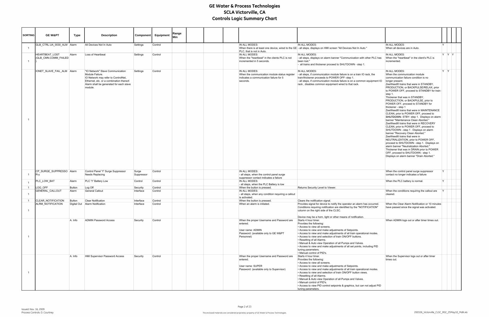
GE Water & Process TechnologiesSCLA Victorville, CA
Controls Logic Summary Chart
SORTING GE W&PT Type Description Component Equipment RangeMin
1GLB_CTRL.UA_0030_ALM Alarm All Devices Not In Auto Settings Control IN ALL MODES:
When there is at least one device, wired to the GE PLC, that is not in Auto.
IN ALL MODES:- all steps, displays on HMI screen "All Devices Not In Auto."
IN ALL MODES:When all devices are in Auto.
Y
1
HEARTBEAT_LOST (GLB_CMN.COMM_FAILED)
Alarm Loss of Heartbeat Settings Control IN ALL MODES:When the "heartbeat" in the clients PLC is not incremented in 5 seconds.
IN ALL MODES:- all steps, displays on alarm banner "Communication with other PLC has been lost."- all trains and thickener proceed to SHUTDOWN - step 1.
IN ALL MODES:When the "heartbeat" in the client's PLC is incremented.
Y Y Y
1
IONET_SLAVE_FAIL_ALM Alarm "IO Network" Slave Communication Module Failure.IO Network may refer to ControlNet, Ethernet, etc. or a combination thereof. Alarm shall be generated for each slave module.
Settings Control IN ALL MODES:When the communication module status registerindicates a communication failure for 5seconds.
IN ALL MODES:- all steps, if communication module failure is on a train IO rack, the train/thickener proceeds to POWER OFF- step 1.- all steps, if communication module failure is on a common equipment IO rack , disables common equipment wired to that rack.
IN ALL MODES:When the communication modulecommunication failure condition is nolonger present.ZeeWeed® trains that were in STANDBY, PRODUCTION, or BACKPULSE/RELAX, prior to POWER OFF, proceed to STANDBY for train -step 1.Thickener that was in STANDBY, PRODUCTION, or BACKPULSE, prior to POWER OFF, proceed to STANDBY for thickener - step 1ZeeWeed® trains that were in MAINTENANCE CLEAN, prior to POWER OFF, proceed to SHUTDOWN STBY- step 1. Displays on alarm banner "Maintenance Clean Aborted."ZeeWeed® trains that were in RECOVERY CLEAN, prior to POWER OFF, proceed to SHUTDOWN - step 1 . Displays on alarm banner "Recovery Clean Aborted."ZeeWeed® trains that were in NEUTRALIZATION, prior to POWER OFF, proceed to SHUTDOWN - step 1. Displays on alarm banner "Neutralization Aborted." Thickener that was in DRAIN prior to POWER OFF, proceed to SHUTDOWN - step 1. Displays on alarm banner "Drain Aborted."
Y Y
1CP_SURGE_SUPPRESSOR-y
Alarm Control Panel 'Y' Surge Suppressor Needs Replacing
Surge Suppressor
Control IN ALL MODES:- all steps, when the control panel surge suppressor contact indicates a failure
When the control panel surge suppressor contact no longer indicates a failure
Y
1 PLC_LOW_BAT Alarm PLC 'Y' Battery Low Control Control IN ALL MODES:- all steps, when the PLC Battery is low
When the PLC battery is normal. Y
1 LOG_OFF Button Log Off Security Control When the button is pressed. Returns Security Level to Viewer.
1GENERAL_CALLOUT Alarm General Callout Interface Control IN ALL MODES:
- all steps, when any condition requiring a callout is activated.
When the conditions requiring the callout are cleared.
Y
1 CLEAR_NOTIFICATION Button Clear Notification Interface Control When the button is pressed. Clears the notification signal.
1
ALRM_NOTIFICATION Digital Out Alarm Notification Interface Control When an alarm is initiated. Provides signal for device to notify the operator an alarm has occurred.Conditions requiring notification are identified by the "NOTIFICATION" column on the right side of the CLSC.
Device may be a horn, light or other means of notification.
When the Clear Alarm Notification or 10 minutes have passed since the signal was activated.
1
A. Info ADMIN Password Access Security Control When the proper Username and Password are entered.
User name: ADMINPassword: (available only to GE W&PT Personnel)
Starts 4 hour timer.Provides the following:• Access to view all screens.• Access to view and make adjustments of Setpoints.• Access to view and make adjustments of all train operational modes.• Access to view and selection of train ON/OFF buttons.• Resetting of all Alarms.• Manual & Auto view Operation of all Pumps and Valves.• Access to view and make adjustments of all set points, including PID tuning parameters.• Manual control of PID's.
When ADMIN logs out or after timer times out.
1
A. Info HMI Supervisor Password Access Security Control When the proper Username and Password are entered.
User name: SUPERPassword: (available only to Supervisor)
Starts 4 hour timer.Provides the following:• Access to view all screens.• Access to view and make adjustments of Setpoints.• Access to view and make adjustments of all train operational modes.• Access to view and selection of train ON/OFF button views.• Resetting of all Alarms.• Manual & Auto view Operation of all Pumps and Valves.• Manual control of PID's.• Access to view PID control setpoints & graphics, but can not adjust PID tuning parameters.
When the Supervisor logs out or after timer times out.
Issued: Nov. 16, 2009Process Controls: D. Courtney
Page 2 of 23
The enclosed materials are considered proprietary property of GE Water & Process Technologies. 200326_Victorville_CLSC_R02_25May10_MdK.xls

GE Water & Process TechnologiesSCLA Victorville, CA
Controls Logic Summary Chart
SORTING GE W&PT Type Description Component Equipment RangeMin
RangeMax Setpoint Units Set Action or Derivation Reset
Not
ifica
tion
Cal
lout
Shut
dow
n
Zeno
Trac
®
1
A. Info HMI Operator Password Access Security Control When the proper Username and Password are entered.
User name: OPER Password: GE W&PT six digit AO number
Starts 4 hour timer.Provides the following:• Access to view all screens.• Access only to view Setpoints.• Access to view and make adjustments of all train operational modes, excluding manual.• Access to view and selection of train ON/OFF button views.• Resetting of all Alarms.• Auto view Operation of all Pumps and Valves, not Manual.• Access only to view PID control setpoints & graphics.
When the Operator logs out or after timer times out.
1A. Info HMI Default Password Access Security Control Access to major screens.
Silence horn and acknowledge alarms.No access to alarm reset.
1A. Info HMI Screen Blanking Security Control Automatically turns off screen after 30 minutes of continuous idle time.
Configured in Control Panel - Displays Properties.
When the screen is touched in any location.
00-HA-005 Alarm System Stop button Mode Control ALWAYS:- when System Stop Button is pressed.
The trains and thickener are placed to POWER OFF When the System Stop button is no longer pressed ZeeWeed® trains that were in STANDBY, PRODUCTION, or BACKPULSE/RELAX, prior to POWER OFF, proceed to STANDBY for train -step 1.Thickener that was in STANDBY, PRODUCTION, or BACKPULSE, prior to POWER OFF, proceed to STANDBY for thickener - step 1ZeeWeed® trains that were in MAINTENANCE CLEAN, prior to POWER OFF, proceed to SHUTDOWN stby - step 1. Displays on alarm banner "Maintenance Clean Aborted."ZeeWeed® trains that were in RECOVERY CLEAN, prior to POWER OFF, proceed to SHUTDOWN - step 1 . Displays on alarm banner "Recovery Clean Aborted."ZeeWeed® trains that were in NEUTRALIZATION, prior to POWER OFF, proceed to SHUTDOWN - step 1. Displays on alarm banner "Neutralization Aborted." Thickener that was in DRAIN prior to POWER OFF, proceed to SHUTDOWN - step 1. Displays on alarm banner "Drain Aborted."
Y
1
A. Info Winter Mode Mode Control Winter mode operation for plants that can freeze are programmed to force a train which is in standby more than 30 minutes (typically) to go to service (this train will stay in service for at least 200 sec (typically)) other service trains will be pushed (by logic) into Standby because of high production time. There are selector switches on the HMI to enable/disable Winter Mode.During this switching time the request for the number of running blowers is the same as before. When train 4 is operating as a thickener, it is not part of the winter mode rotation.
1
Button Winter Mode Enabled Mode Control When the Button is Pressed Enable Winter Mode: Trains will Proceed to Production according to the Starting Priority, Start Triggers and 20-KQS-201K-xDisable Train Rotation
1
Button Winter Mode Disabled Mode Control When the Button is Pressed Disable Winter mode: Trains Proceed to Production according to Starting Priority and Start Trigger only Enable train rotation.
1
20-US-201-x Trigger Winter Mode - Force Train to PRODUCTION from STANDBY Trigger
Sequence ZeeWeed® IN STANDBY for train:- all steps, when Winter Mode is EnabledAND20-KQS-201K-x is active,ANDthe Train has the highest Starting PriorityAND20-KQS-201L has timed out for any train in PRODUCTION.
IN STANDBY for train:- the train proceeds to PRODUCTION as per the OSC.
IN PRODUCTION for train:- after timer for 20-KQS-201L-x is started.
Issued: Nov. 16, 2009Process Controls: D. Courtney
Page 3 of 23
The enclosed materials are considered proprietary property of GE Water & Process Technologies. 200326_Victorville_CLSC_R02_25May10_MdK.xls
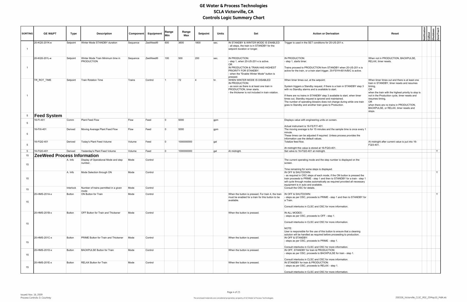
GE Water & Process TechnologiesSCLA Victorville, CA
Controls Logic Summary Chart
SORTING GE W&PT Type Description Component Equipment RangeMin
RangeMax Setpoint Units Set Action or Derivation Reset
Not
ifica
tion
Cal
lout
Shut
dow
n
Zeno
Trac
®
1
20-KQS-201K-x Setpoint Winter Mode STANDBY duration Sequence ZeeWeed® 600 3600 1800 sec. IN STANDBY & WINTER MODE IS ENABLED:- all steps, the train is in STANDBY for the setpoint duration or longer.
Trigger is used in the SET conditions for 20-US-201-x.
1
20-KQS-201L-x Setpoint Winter Mode Train Minimum time in PRODUCTION
Sequence ZeeWeed® 100 500 200 sec. IN PRODUCTION:- step 1, when 20-US-201-x is active.ORIN PRODUCTION & TRAIN HAS HIGHEST PRIORITY FOR STANDBY:- when the "Enable Winter Mode" button is pressed.
IN PRODUCTION:- step 1, starts timer.
Trains proceed to PRODUCTION from STANDBY when 20-US-201-x is active for the train, or a train start trigger, 20-FSYH-601A/B/C is active.
When not in PRODUCTION, BACKPULSE, RELAX, timer resets.
1
TR_ROT_TIME Setpoint Train Rotation Time Trains Control 1 72 4 hr. WHEN WINTER MODE IS DISABLEDIN PRODUCTION:- as soon as there is at least one train in PRODUCTION, timer starts.- the thickener is not included in train rotation.
When timer times out, at the setpoint;
System triggers a Standby request, if there is a train in STANDBY step 3 with no Standby alarms and is available to start.
If there are no trains in STANDBY step 3 available to start, when timer times out, Standby request is ignored and maintained.The number of operating blowers does not change during while one train goes to Standby and another train goes to Production.
When timer times out and there is at least one train in STANDBY, timer resets and resumes timing,ORwhen the train with the highest priority to stop is not in the Production cycle, timer resets and resumes timing,ORwhen there are no trains in PRODUCTION, BACKPULSE, or RELAX, timer resets and stops.
5 Feed System5
16-FI-401 Comm Plant Feed Flow Flow Feed 0 5000 gpm Displays value with engineering units on screen.
Actual instrument is 16-FE/FIT-401.
5
16-FXI-401 Derived Moving Average Plant Feed Flow Flow Feed 0 5000 gpm The moving average is for 15 minutes and the sample time is once every 1 minute.These times can be adjusted if required. Unless process provides the information use the default values.
516-FQI2-401 Derived Today's Plant Feed Volume Volume Feed 0 1000000000 gal Totalize feed flow.
At midnight this value is stored at 16-FQI3-401.
At midnight after current value is put into 16-FQI3-401.
5 16-FQI3-401 Derived Yesterday's Plant Feed Volume Volume Feed 0 1000000000 gal At midnight. Set valve to 16-FQI2-401 at midnight. Y
15 ZeeWeed Process Information
15
A. Info Display of Operational Mode and step number.
Mode Control The current operating mode and the step number is displayed on the screen.
Time remaining for some steps is displayed.
15
A. Info Mode Selection through ON Mode Control IN OFF & SHUTDOWN:- as required in OSC steps of each mode, if the ON button is pressed the train proceeds to PRIME - step 1 and then to STANDBY for a train - step 1 will cycle through modes automatically as required provided all necessary equipment is in auto and available.
Y
15 Interlock Number of trains permitted in a given mode
Mode Control Consult the OSC for details.
15
20-HMS-201A-x Button ON Button for Train Mode Control When the button is pressed. For train 4, the train must be enabled for a train for this button to be available.
IN OFF & SHUTDOWN:- steps as per OSC, proceeds to PRIME - step 1 and then to STANDBY for a Train.
Consult interlocks in CLSC and OSC for more information.
Y
15
20-HMS-201B-x Button OFF Button for Train and Thickener Mode Control When the button is pressed. IN ALL MODES :- steps as per OSC, proceeds to OFF - step 1.
Consult interlocks in CLSC and OSC for more information.
NOTE:User is responsible for the use of this button to ensure that a cleaning solution will be handled as required before proceeding to production.
15
20-HMS-201C-x Button PRIME Button for Train and Thickener Mode Control When the button is pressed. IN OFF & STANDBY:- steps as per OSC, proceeds to PRIME - step 1.
Consult interlocks in CLSC and OSC for more information.
15
20-HMS-201D-x Button BACKPULSE Button for Train Mode Control When the button is pressed. IN OFF, STANDBY for train & PRODUCTION:- steps as per OSC, proceeds to BACKPULSE for train - step 1.
Consult interlocks in CLSC and OSC for more information.
15
20-HMS-201E-x Button RELAX Button for Train Mode Control When the button is pressed. IN STANDBY for train & PRODUCTION:- steps as per OSC, proceeds to RELAX - step 1.
Consult interlocks in CLSC and OSC for more information.
Issued: Nov. 16, 2009Process Controls: D. Courtney
Page 4 of 23
The enclosed materials are considered proprietary property of GE Water & Process Technologies. 200326_Victorville_CLSC_R02_25May10_MdK.xls

GE Water & Process TechnologiesSCLA Victorville, CA
Controls Logic Summary Chart
SORTING GE W&PT Type Description Component Equipment RangeMin
RangeMax Setpoint Units Set Action or Derivation Reset
Not
ifica
tion
Cal
lout
Shut
dow
n
Zeno
Trac
®
15
20-HMS-201F-x Button M. CLEAN Hypochlorite Button for Train Mode Control When the button is pressed.Train 4 must be enabled as a train.
IN OFF, STANDBY & PRODUCTION:- steps as per OSC, proceeds to MAINTENANCE CLEAN - step 1.
Consult interlocks in CLSC and OSC for more information.
15
20-HMS-201G-x Button M. CLEAN Citric Acid Button for Train Mode Control When the button is pressed.Train 4 must be enabled as a train.
IN OFF, STANDBY & PRODUCTION:- steps as per OSC, proceeds to MAINTENANCE CLEAN - step 1.
Consult interlocks in CLSC and OSC for more information.
15
20-HMS-201I-x Button R. CLEAN WITH CITRIC ACID Button for Train
Mode Control When the button is pressed.Train 4 must be enabled as a train.
IN OFF:- steps as per OSC, proceeds to RECOVERY CLEAN - step 1.
Consult interlocks in CLSC and OSC for more information.Initiates a recovery clean with citric acid.
15
20-HMS-201J-x Button R. CLEAN WITH SODIUM HYPOCHLORITE Button for Train
Mode Control When the button is pressed.Train 4 must be enabled as a train.
IN OFF:- steps as per OSC, proceeds to RECOVERY CLEAN - step 1.
Consult interlocks in CLSC and OSC for more information.Initiates a recovery clean with sodium hypochlorite.
15
20-HMS-201K-x Button NEUTRALIZATION Button for Train Mode Control When the button is pressed. IN OFF & RECOVERY CLEAN:- steps as per OSC, proceeds to NEUTRALIZATION - step 1.
Consult interlocks in CLSC and OSC for more information.
15
A. Info Standby Priority Demand ZeeWeed® A train that has been in PRODUCTION the longest time has the highest priority to proceed to STANDBY from PRODUCTION.A train in demand override, has the lowest priority to proceed to STANDBY.
15 A. Info Starting Priority Demand ZeeWeed® A train that has been in STANDBY the longest time has the highest priority to proceed to PRODUCTION from STANDBY.
15 NUM_TR_PROD Derived Number of Trains Cycling through Production
Trains ZeeWeed® This is the number of trains in PRODUCTION for train, BACKPULSE for train, RELAX, PRIME.
15NUM_TR_PROD_SUP Derived Number of Trains Cycling through
Production with supervisory Flow SetpointTrains ZeeWeed® This is the number of trains in PRODUCTION for train, BACKPULSE for
train, RELAX or PRIME, with a supervisory flow setpoint.
1520-KQS-801 Setpoint Priming Duration Sequence ZeeWeed® 30 300 60 sec. IN PRIME:
- step 1.IN PRIME:- starts timer, action when the timer times out proceeds as per the OSC.
When the timer times out.
15
20-KQY-301 Setpoint Production Cycle Timer - total time to complete one Production sequence plus one Backpulse sequence.
Sequence ZeeWeed® 8 15 12 min. When a train/thickener enters the production cycle for the first time and no other train/thickener is in the production cycle.
Value entered at the HMI, in minutes.
Time remaining in the production cycle for each train/thickener, 20-KI-301-x, is displayed, in seconds.
The timer keeps running through all of the valve alignment steps and through backpulse.
If all trains/thickener are in OFF or POWER OFF the time is retained. When trains enter the production cycle the timer resumes.
When the full production duration has expired.
15 Thickener Process InformationA. Info Thickener Mode Control Only train 4 can function as a thickener. The following buttons are only
available for train 4 when enabled as a thickener.
15
A. Info Display of Operational Mode and step number.
Mode Control The current operating mode and the step number is displayed on the screen.
Time remaining for some steps is displayed.
15
A. Info Mode Selection through ON Mode Control IN OFF & SHUTDOWN:- as required in OSC steps of each mode, if the ON button is pressed the thickener proceeds to PRIME - step 1 and then to STANDBY for thickener - step 1 will cycle through modes automatically as required provided all necessary equipment is in auto and available.
Y
15
20-HMS-201A-x Button ON Button for Thickner Mode Control When the button is pressed. Train 4 must be enabled as a thickener for this button to be available.
IN OFF & SHUTDOWN:- steps as per OSC, proceeds to PRIME - step 1 and then to STANDBY for thickener.
Consult interlocks in CLSC and OSC for more information.
Y
15
20-HMS-201D-x Button BACKPULSE Button Mode Control When the button is pressed. IN OFF, STANDBY for thickener & PRODUCTION for thickener:- steps as per OSC, proceeds to BACKPULSE - step 1 for a thickener.
Consult interlocks in CLSC and OSC for more information.
15
16-HMS-801B-4 Button DRAIN Button Mode Control When the button is pressed. IN OFF, STANDBY for thickener:- steps as per OSC, proceeds to DRAIN - step 1.
Consult interlocks in CLSC and OSC for more information.
20 Membrane Aeration System
Issued: Nov. 16, 2009Process Controls: D. Courtney
Page 5 of 23
The enclosed materials are considered proprietary property of GE Water & Process Technologies. 200326_Victorville_CLSC_R02_25May10_MdK.xls
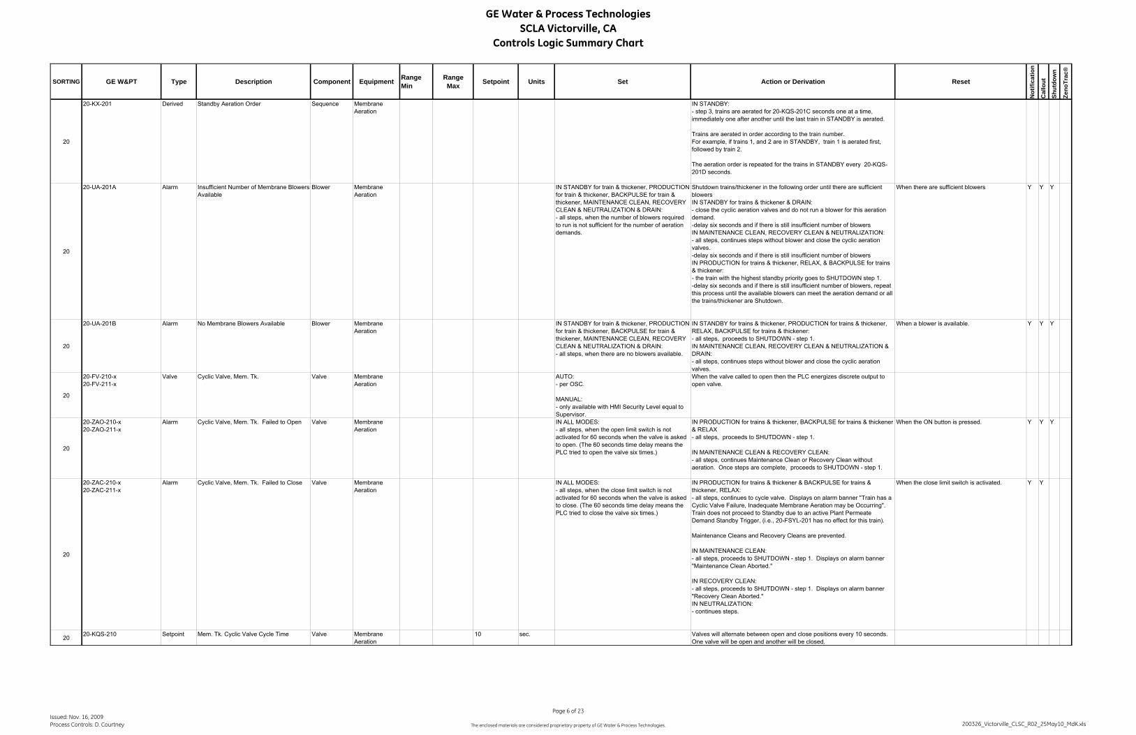
GE Water & Process TechnologiesSCLA Victorville, CA
Controls Logic Summary Chart
SORTING GE W&PT Type Description Component Equipment RangeMin
RangeMax Setpoint Units Set Action or Derivation Reset
Not
ifica
tion
Cal
lout
Shut
dow
n
Zeno
Trac
®
20
20-KX-201 Derived Standby Aeration Order Sequence Membrane Aeration
IN STANDBY:- step 3, trains are aerated for 20-KQS-201C seconds one at a time, immediately one after another until the last train in STANDBY is aerated.
Trains are aerated in order according to the train number. For example, if trains 1, and 2 are in STANDBY, train 1 is aerated first, followed by train 2.
The aeration order is repeated for the trains in STANDBY every 20-KQS-201D seconds.
20
20-UA-201A Alarm Insufficient Number of Membrane Blowers Available
Blower Membrane Aeration
IN STANDBY for train & thickener, PRODUCTION for train & thickener, BACKPULSE for train & thickener, MAINTENANCE CLEAN, RECOVERY CLEAN & NEUTRALIZATION & DRAIN:- all steps, when the number of blowers required to run is not sufficient for the number of aeration demands.
Shutdown trains/thickener in the following order until there are sufficient blowersIN STANDBY for trains & thickener & DRAIN:- close the cyclic aeration valves and do not run a blower for this aeration demand.-delay six seconds and if there is still insufficient number of blowersIN MAINTENANCE CLEAN, RECOVERY CLEAN & NEUTRALIZATION:- all steps, continues steps without blower and close the cyclic aeration valves.-delay six seconds and if there is still insufficient number of blowersIN PRODUCTION for trains & thickener, RELAX, & BACKPULSE for trains & thickener:- the train with the highest standby priority goes to SHUTDOWN step 1.-delay six seconds and if there is still insufficient number of blowers, repeat this process until the available blowers can meet the aeration demand or all the trains/thickener are Shutdown.
When there are sufficient blowers Y Y Y
20
20-UA-201B Alarm No Membrane Blowers Available Blower Membrane Aeration
IN STANDBY for train & thickener, PRODUCTION for train & thickener, BACKPULSE for train & thickener, MAINTENANCE CLEAN, RECOVERY CLEAN & NEUTRALIZATION & DRAIN:- all steps, when there are no blowers available.
IN STANDBY for trains & thickener, PRODUCTION for trains & thickener, RELAX, BACKPULSE for trains & thickener:- all steps, proceeds to SHUTDOWN - step 1.IN MAINTENANCE CLEAN, RECOVERY CLEAN & NEUTRALIZATION & DRAIN:- all steps, continues steps without blower and close the cyclic aeration valves.
When a blower is available. Y Y Y
20
20-FV-210-x20-FV-211-x
Valve Cyclic Valve, Mem. Tk. Valve Membrane Aeration
AUTO:- per OSC.
MANUAL:- only available with HMI Security Level equal to Supervisor.
When the valve called to open then the PLC energizes discrete output to open valve.
20
20-ZAO-210-x20-ZAO-211-x
Alarm Cyclic Valve, Mem. Tk. Failed to Open Valve Membrane Aeration
IN ALL MODES:- all steps, when the open limit switch is not activated for 60 seconds when the valve is asked to open. (The 60 seconds time delay means the PLC tried to open the valve six times.)
IN PRODUCTION for trains & thickener, BACKPULSE for trains & thickener & RELAX- all steps, proceeds to SHUTDOWN - step 1.
IN MAINTENANCE CLEAN & RECOVERY CLEAN:- all steps, continues Maintenance Clean or Recovery Clean without aeration. Once steps are complete, proceeds to SHUTDOWN - step 1.
When the ON button is pressed. Y Y Y
20
20-ZAC-210-x20-ZAC-211-x
Alarm Cyclic Valve, Mem. Tk. Failed to Close Valve Membrane Aeration
IN ALL MODES:- all steps, when the close limit switch is not activated for 60 seconds when the valve is asked to close. (The 60 seconds time delay means the PLC tried to close the valve six times.)
IN PRODUCTION for trains & thickener & BACKPULSE for trains & thickener, RELAX:- all steps, continues to cycle valve. Displays on alarm banner "Train has a Cyclic Valve Failure, Inadequate Membrane Aeration may be Occurring". Train does not proceed to Standby due to an active Plant Permeate Demand Standby Trigger, (i.e., 20-FSYL-201 has no effect for this train).
Maintenance Cleans and Recovery Cleans are prevented.
IN MAINTENANCE CLEAN:- all steps, proceeds to SHUTDOWN - step 1. Displays on alarm banner "Maintenance Clean Aborted."
IN RECOVERY CLEAN:- all steps, proceeds to SHUTDOWN - step 1. Displays on alarm banner "Recovery Clean Aborted."IN NEUTRALIZATION:- continues steps.
When the close limit switch is activated. Y Y
20 20-KQS-210 Setpoint Mem. Tk. Cyclic Valve Cycle Time Valve Membrane Aeration
10 sec. Valves will alternate between open and close positions every 10 seconds. One valve will be open and another will be closed.
Issued: Nov. 16, 2009Process Controls: D. Courtney
Page 6 of 23
The enclosed materials are considered proprietary property of GE Water & Process Technologies. 200326_Victorville_CLSC_R02_25May10_MdK.xls

GE Water & Process TechnologiesSCLA Victorville, CA
Controls Logic Summary Chart
SORTING GE W&PT Type Description Component Equipment RangeMin
RangeMax Setpoint Units Set Action or Derivation Reset
Not
ifica
tion
Cal
lout
Shut
dow
n
Zeno
Trac
®
20
A. Info Membrane Blowers Alternating Lead Blower Membrane Aeration
IN ALL MODES:- all steps, when the accumulated run time is equal to or greater than 20-KQS-201F, the lead blower is not running,OR- all steps, when the lead blower is not available, (Blower is available if in Auto at HMI and is in Remote at the MCC).
IN ALL MODES:- all steps, changes the lead of the blowers.Lead is not switched if other blower is not available.
When lead is switched.
20
20-KQS-201F Setpoint Membrane Blowers Lead Alternating Time
Blower Membrane Aeration
12 72 24 hr. IN ALL MODES:- all steps, when the blower is running.
One setpoint with multiple equipment run times.
This is the actual accumulated run time of the equipment.
This is not displayed.
When lead is switched.
2020-KQS-201C Setpoint Train in Standby Aeration Duration Sequence Membrane
Aeration120 600 300 sec. IN STANDBY for train:
- step 3.IN STANDBY: - step 3, aerates the membrane tank for 20-KQS-201C seconds every 20-KQS-201D seconds. Starts step with no mixing.
When train is not in Standby - step 3.
2020-KQS-201D Setpoint Train in Standby Aeration Frequency Sequence Membrane
Aeration1800 sec. IN STANDBY for train:
- step 3.This setpoint is not adjustable.
IN STANDBY: - step 3, aerates the membrane tank for 20-KQS-201C seconds every 20-KQS-201D seconds. Starts step with no mixing.
When the timer times out.
20
A. Info Number of Blowers per Membrane Aeration Demand
Blower Membrane Aeration
One aeration demand requires one blower to operate; two aeration demands require two blowers to operate; three or four aeration demands require three blowers to operate. The number of aeration demands refers to trains and thickener.
20-PAL-201-x Alarm Inlet Low Pressure for Membrane Blower Blower Membrane Aeration
IN ALL MODES:- all steps, when the blower is running and the switch is active for 5 seconds
IN PRODUCTION for trains & thickener, BACKPULSE for trains & thickener, RELAX, MAINTENANCE CLEAN, RECOVERY CLEAN, NEUTRALIZATION & DRAIN:- all steps, places blower into manual-stop.
When the switch is not active
20-PAH-201-x Alarm Outlet High Pressure for Membrane Blower
Blower Membrane Aeration
IN ALL MODES:- all steps, when the blower is running and the switch is active for 5 seconds
IN PRODUCTION for trains & thickener, BACKPULSE for trains & thickener, RELAX, MAINTENANCE CLEAN, RECOVERY CLEAN, NEUTRALIZATION & DRAIN:- all steps, places blower into manual-stop.
When the switch is not active
20-TAH-201-x Alarm Outlet High Temperature for Membrane Blower
Blower Membrane Aeration
IN ALL MODES:- all steps, when the blower is running and the switch is active for 5 seconds
IN PRODUCTION for trains & thickener, BACKPULSE for trains & thickener, RELAX, MAINTENANCE CLEAN, RECOVERY CLEAN, NEUTRALIZATION & DRAIN:- all steps, places blower into manual-stop.
When the switch is not active
20
20-FC-201 Derived Mem. Tk. Membrane Aeration Air Flow Requirement Per Train
Flow Membrane Aeration
1487 1572 1500 SCFM Use 1500 when the temperature is approx. 18CUse 1487 when the temperature is approx. 35C
Membrane Aeration Requirement Per Train = the value of the setpoint
20-FC-201 equals the value of the setpoint. This is a plant setpoint.
20
20-MK-201-x Comm Membrane Aeration Required Air Flow Per Blower
Flow Membrane Aeration
When there are zero aeration demand 20-MK-201-x =zero and no blowers operateWhen there is one aeration demand 20-MK-201-x =20-FC-201. One blower operatesWhen there are two aeration demands 20-MK-201-x =20-FC-201. Two blowers operateWhen there are three aeration demands 20-MK-201-x =20-FC-201. Three blowers operate.When there are four aeration demands 20-MK-201-x =(20-FC-201 multiplied by 4 and divided by 3). Three blowers operate. (The four refers to the number of aeration demands. The three refers to the number of operating blowers.)Communicate this value to the client's PLC.
A. Info Membrane Blowers Blower Membrane Aeration
The controls for the membrane blowers are through the Ethernet
20
20-YA-201-x Alarm/comm..
Membrane Aeration Blower Fail Blower Membrane Aeration
IN ALL MODES:- all steps, when the blower is requested to run. When the MCC running confirmation is missing for 5 seconds.
IN PRODUCTION for trains & thickener, BACKPULSE for trains & thickener, RELAX, MAINTENANCE CLEAN, RECOVERY CLEAN, NEUTRALIZATION & DRAIN:- all steps, places blower into fault.
When the Blower Auto button is pressed. Y Y
20 20-KQI-201-x Derived Membrane Aeration Blower Accumulated Run Time
Blower Membrane Aeration
0 30000 hours IN ALL MODES:When the blower is operating.
IN ALL MODES:Displays accumulated run time for the blower on the screen.
When the Reset Run Time button is pressed, run time resets to 0 hours.
20
20-B-201-x Comm Membrane Aeration Blower Run Command
Blower Membrane Aeration
MANUAL:- only available with SUPER password
AUTO:- according to the OSCDISABLED (in AUTO or MANUAL):- when any of the following are true: blower Fail 20-YA-201-x System Stop Activated 00-HA-005
When the blower is called to run, energizes the PLC discrete output to operate motor.If VFD called to start, the flow command is set at the setpoint. Otherwise set to zero
20
20-FAL-201-x Alarm Membrane Aeration Blower Air Flow Low Flow Membrane Aeration
IN ALL MODES:- all steps, when a blower -1/2/3/4 has been requested to run and its switch, 20-FAL-201-1, 20-FAL-201-2, 20-FAL-201-3, 20-FAL-201-3, is active for 10 seconds.
IN ALL MODES:- all steps, places blower into fault.
When the Blower Auto button is pressed. Y Y
25 Membrane TankA. Info Design Basis Design is N+1, N is = 3.
Issued: Nov. 16, 2009Process Controls: D. Courtney
Page 7 of 23
The enclosed materials are considered proprietary property of GE Water & Process Technologies. 200326_Victorville_CLSC_R02_25May10_MdK.xls

GE Water & Process TechnologiesSCLA Victorville, CA
Controls Logic Summary Chart
SORTING GE W&PT Type Description Component Equipment RangeMin
RangeMax Setpoint Units Set Action or Derivation Reset
Not
ifica
tion
Cal
lout
Shut
dow
n
Zeno
Trac
®
2520-LI-201A-x Analog In Mem. Tk Level Level ZeeWeed® 0 160 in. Displays value with engineering units on screen.
Actual instrument is 20-LE/LIT-201A-x.
Y
25 20-LXI-201 Derived Average Mem. Tk Level Level ZeeWeed® 0 160 in. The average is calculated for all trains/thickener in Standby, Prime, Production, Backpulse, Relax.
25
20-LAT-201A-x Alarm Mem. Tk Level Transmitter Out of Range Level ZeeWeed® 0 160 in. IN ALL MODES:When the transmitter is out of range by 1% of the calibrated range for 2 seconds.(i.e. calibrated range = range max. - range min.)
IN PRODUCTION for trains & thickener, BACKPULSE for trains & thickener, RELAX, MAINTENANCE CLEAN, RECOVERY CLEAN except steps 22 and 23, NEUTRALIZATION:- all steps, proceeds to SHUTDOWN - step 1.
IN MAINTENANCE CLEAN:- Displays on alarm banner "Maintenance Clean Aborted."
IN RECOVERY CLEAN steps 1 to 21:- Displays on alarm banner "Recovery Clean Aborted."IN RECOVERY CLEAN step 22 and 23:- continue with sequence.IN NEUTRALIZATION:- Displays on alarm banner "Neutralization Aborted."IN DRAIN:- holds step- all steps, places all operating pumps into man off and after a delay of six seconds close the valves.- 20-KQS-301W startsDisplays, "Thickener will be Shutdown due to active alarm" .
IN PRODUCTION for trains & thickener, BACKPULSE for trains & thickener, RELAX, MAINTENANCE CLEAN, RECOVERY CLEAN except steps 22 and 23, NEUTRALIZATION:When the ON or OFF button is pressed.IN DRAIN:When the pumps are put back into auto and Fault Timer clears then align valves as per OSC step after a six second delay resume step, as shown in the OSC.
Y Y Y
2520-LAHH-201-x Alarm Mem. Tk Level High High Level ZeeWeed® IN ALL MODES:
When the level Alarm high has been active for more than 90 seconds.
When the level Alarm high is no longer active. Y Y
25
20-LAH-201A-x Alarm Mem. Tk Level High Level ZeeWeed® 0 160 140 in. IN ALL MODES:When the level is at or above this level for 8 seconds.
IN ALL MODES:- all steps, sets the plant flow demand equal to the peak flow for the plant.The peak flow equals 3098 gpmIN MAINTENANCE CLEAN:- all steps, alarm only.
IN RECOVERY CLEAN, NEUTRALIZATION, DRAIN:- all steps, alarm only.
When 20-LS-201A-x is active. Y
2520-LS-201A-x Trigger Mem. Tk Level to Enable Membrane Tank
FeedLevel ZeeWeed® 0 160 108 in. IN ALL MODES:
When the level is at or below this level for 8 seconds.
Resets 20-LAH-201A-x
25
20-LS-201C-x Trigger Mem. Tk Level 3 for Fill and Aerate Level ZeeWeed® 0 160 127 in. IN NEUTRALIZATION & DRAIN:- step 4, when the level is at or above the setpoint for 8 seconds. This level should be close to the operating level of the trains to prevent stealing the air from the other trains.
IN NEUTRALIZATION & DRAIN:- proceeds to the next step.
Target setpoint is a level about 24 inches above the 20-LS-201E-x setpoint but prevents the high level alarm from becoming active.
25
20-LS-201E-x Trigger Mem. Tk Level Above Membranes Level ZeeWeed® 0 160 103.2 in. IN ALL MODES:When the level is at or above this level for 8 seconds.
Resets 20-LAL-201A-x.
The train will come out of standby and resume production if there is a demand to produce water.The thickener will come out of standby and resume production if the Drain the Thickener Trigger is not active.
25
20-LAL-201A-x Alarm Mem. Tk Level Low Level ZeeWeed® 0 160 102 in. IN ALL MODES except RECOVERY CLEAN & DRAIN:When the level is at or below this level for 8 seconds.
IN PRODUCTION:- all steps, proceeds to STANDBY - step 1.
This level is just above the membrane fibers in the cassette.
When 20-LS-201E-x is active. Y Y
25
20-LALL-201A-x Alarm Mem. Tk Level Low Low Level ZeeWeed® 20-LAL-201A in. IN ALL MODES:When the level is at or below the setpoint for more than 3600 seconds.
IN ALL MODES:- all steps, displays on alarm banner "Membrane Tank 'X' Possible Membrane Exposure."
When the level is above the setpoint. Y Y
20-LS-201Q-x Trigger Fill Membrane Tk with Inlet Gate Timers Level ZeeWeed® 0 160 100 in. IN SHUTDOWN & NEUTRALIZATION & DRAIN:When the level is at or below this setpoint for 2 seconds in the steps as indicated in the OSC.
IN SHUTDOWN & NEUTRALIZATION & DRAIN:- use the frequency and duration timers to open the membrane tank isolation gate.Consult the OSC, shutdown & neutralization & drain steps, for details.
When the level is at or above this setpoint.
2520-LS-201S-x Trigger Mem. Tk Empty Tank Level ZeeWeed® 0 160 10 in. IN RECOVERY CLEAN & DRAIN:
When the level is at or below this setpoint for 2 seconds in the steps as indicated in the OSC.
IN RECOVERY CLEAN & DRAIN:- steps as indicated in the OSC, proceeds to next step.
When the level is at or above this setpoint for 5 seconds
25
20-LCH-201A Setpoint Mem. Tk Level Setpoint High Level ZeeWeed® 0 160 150 in. This is a plant setpoint. This is the maximum membrane level setpoint where flow demand is at the peak flow value. Used to calculate trim flow/plant flow demand 20-FCY-201B.Operator entered value.
25
20-LC-201A Setpoint Mem. Tk Level Setpoint Level ZeeWeed® 0 160 118 in. This is a plant setpoint. Operator entered level setpoint.This level is used to calculate the trim plant flow demand. It is in the middle of the maximum and minimum levels for the trim volume
Issued: Nov. 16, 2009Process Controls: D. Courtney
Page 8 of 23
The enclosed materials are considered proprietary property of GE Water & Process Technologies. 200326_Victorville_CLSC_R02_25May10_MdK.xls
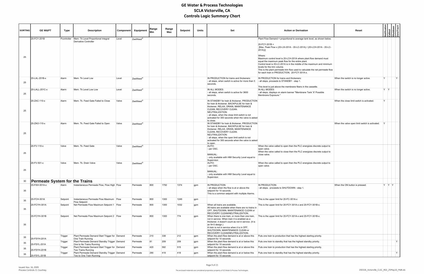
GE Water & Process TechnologiesSCLA Victorville, CA
Controls Logic Summary Chart
SORTING GE W&PT Type Description Component Equipment RangeMin
RangeMax Setpoint Units Set Action or Derivation Reset
Not
ifica
tion
Cal
lout
Shut
dow
n
Zeno
Trac
®
25
20-FCY-201B Pcontroller Mem. Tk Level Proportional Integral Derivative Controller
Level ZeeWeed® Plant Flow Demand = proportional to average tank level, as shown below.
20-FCY-201B = [Max. Peak Flow x (20-LXI-201A - 20-LC-201A) / (20-LCH-201A - 20-LC-201A))]
Where:Maximum control level is 20-LCH-201A where plant flow demand must equal the maximum peak flow for the entire plant.Control level is 20-LC-201A is in the middle of the maximum and minimum levels for the trim volume.This is the plant permeate trim flow used to calculate the net permeate flow for each train in PRODUCTION, 20-FCY-301A-x.
25
20-LAL-201B-x Alarm Mem. Tk Level Low Level ZeeWeed® IN PRODUCTION for trains and thickeners:- all steps, when switch is active for more than 5 seconds.
IN PRODUCTION for trains and thickeners:- all steps, proceeds to STANDBY - step 1.
This level is just above the membrane fibers in the cassette.
When the switch is no longer active. Y Y
25
20-LALL-201C-x Alarm Mem. Tk Level Low Low Level ZeeWeed® IN ALL MODES:- all steps, when switch is active for 3600 seconds.
IN ALL MODES:- all steps, displays on alarm banner "Membrane Tank 'X' Possible Membrane Exposure."
When the switch is no longer active. Y Y
25
20-ZAC-110-x Alarm Mem. Tk. Feed Gate Failed to Close Valve ZeeWeed® IN STANDBY for train & thickener, PRODUCTION for train & thickener, BACKPULSE for train & thickener, RELAX, DRAIN, MAINTENANCE CLEAN, RECOVERY CLEAN. NEUTRALIZATION:- all steps, when the close limit switch is not activated for 300 seconds when the valve is asked to close.
When the close limit switch is activated. Y
25
20-ZAO-110-x Alarm Mem. Tk. Feed Gate Failed to Open Valve ZeeWeed® IN STANDBY for train & thickener, PRODUCTION for train & thickener, BACKPULSE for train & thickener, RELAX, DRAIN, MAINTENANCE CLEAN, RECOVERY CLEAN. NEUTRALIZATION:- all steps, when the open limit switch is not activated for 300 seconds when the valve is asked to open.
When the valve open limit switch is activated. Y
25
20-FV-110-x Valve Mem. Tk. Feed Gate Valve ZeeWeed® AUTO:- per OSC.
MANUAL:- only available with HMI Security Level equal to Supervisor.
When the valve called to open then the PLC energizes discrete output to open valve.When the valve called to close then the PLC energizes discrete output to close valve.
25
20-FV-501-x Valve Mem. Tk. Drain Valve Valve ZeeWeed® AUTO:- per OSC.
MANUAL:- only available with HMI Security Level equal to Supervisor.
When the valve called to open then the PLC energizes discrete output to open valve.
30 Permeate System for the Trains
35
20-FAH-301A-x Alarm Instantaneous Permeate Flow, Flow High Flow Permeate 800 1750 1374 gpm IN PRODUCTION:- all steps when the flow is at or above the setpoint for 10 seconds.This is a common setpoint with multiple Alarms.
IN PRODUCTION:- all steps, proceeds to SHUTDOWN - step 1.
When the ON button is pressed. Y Y Y
35 20-FCH-301A Setpoint Instantaneous Permeate Flow Maximum Flow Setpoint
Flow Permeate 800 1300 1249 gpm This is the upper limit for 20-FC-301A-x
35
20-FCYH-301A Setpoint Net Permeate Flow Maximum Setpoint 1 Flow Permeate 800 1300 1032 gpm When all trains are available.All trains are available when there are no trains in OFF, SHUTDOWN, MAINTENANCE CLEAN or RECOVERY CLEAN/NEUTRALIZATION.
This is the upper limit for 20-FCY-301A-x and 20-FCY-301B-x.
35
20-FCYH-301B Setpoint Net Permeate Flow Maximum Setpoint 2 Flow Permeate 800 1300 774 gpm When there is one train, or more than one train, not in service. When train 4 is enabled as a thickener, it doesn't count as not in service. (It is an N=3 design.)A train is not in service when it is in OFF, SHUTDOWN, MAINTENANCE CLEAN or RECOVERY CLEAN/NEUTRALIZATION.
This is the upper limit for 20-FCY-301A-x and 20-FCY-301B-x.
35 20-FSYH-201ATrigger Plant Permeate Demand Start Trigger for
One Train RunningDemand Permeate 210 338 212 gpm When the plant flow demand is at or above this
setpoint for 10 secondsPuts one train to production that has the highest starting priority.
35 20-FSYL-201ATrigger Plant Permeate Demand Standby Trigger -
One to No Trains RunningDemand Permeate 81 209 209 gpm When the plant flow demand is at or below this
setpoint for 10 secondsPuts one train to standby that has the highest standby priority. Y
35 20-FSYH-201BTrigger Plant Permeate Demand Start Trigger for
Two Trains RunningDemand Permeate 420 592 515 gpm When the plant flow demand is at or above this
setpoint for 10 secondsPuts one train to production that has the highest starting priority.
35 20-FSYL-201BTrigger Plant Permeate Demand Standby Trigger -
Two to One Train RunningDemand Permeate 290 419 418 gpm When the plant flow demand is at or below this
setpoint for 10 secondsPuts one train to standby that has the highest standby priority. Y
Issued: Nov. 16, 2009Process Controls: D. Courtney
Page 9 of 23
The enclosed materials are considered proprietary property of GE Water & Process Technologies. 200326_Victorville_CLSC_R02_25May10_MdK.xls

GE Water & Process TechnologiesSCLA Victorville, CA
Controls Logic Summary Chart
SORTING GE W&PT Type Description Component Equipment RangeMin
RangeMax Setpoint Units Set Action or Derivation Reset
Not
ifica
tion
Cal
lout
Shut
dow
n
Zeno
Trac
®
35 20-FSYH-201CTrigger Plant Permeate Demand Start Trigger for
Three Trains RunningDemand Permeate 801 1057 1030 gpm When the plant flow demand is at or above this
setpoint for 10 secondsPuts one train to production that has the highest starting priority.
35 20-FSYL-201CTrigger Plant Permeate Demand Standby Trigger -
Three to Two Trains RunningDemand Permeate 499 755 627 gpm When the plant flow demand is at or below this
setpoint for 10 secondsPuts one train to standby that has the highest standby priority. Y
35 20-FSYH-201DTrigger Plant Permeate Demand Start Trigger for
Four Trains RunningDemand Permeate 1060 1600 1548 gpm When the plant flow demand is at or above this
setpoint for 10 secondsPuts one train to production that has the highest starting priority.
35 20-FSYL-201DTrigger Plant Permeate Demand Standby Trigger -
Four to Three Trains RunningDemand Permeate 630 964 836 gpm When the plant flow demand is at or below this
setpoint for 10 secondsPuts one train to standby that has the highest standby priority. Y
35 20-FCL-301A Setpoint Instantaneous Permeate Flow Minimum Flow Setpoint
Flow Permeate 100 150 140 gpm This is the lower limit for 20-FC-301A-x
35
20-FAL-301A-x Alarm Instantaneous Permeate Flow, Flow Low Flow Permeate 100 140 126 gpm IN PRODUCTION:- all steps, when the pump is running and the flow is at or below the setpoint for 10 seconds.This is a common setpoint with multiple Alarms.
IN PRODUCTION:- all steps, proceeds to SHUTDOWN - step 1.
When the ON button is pressed. Y Y Y
35
20-FAT-301-x Alarm Permeate Flow Transmitter Out of Range Flow Permeate 0 2000 gpm IN ALL MODES: When the transmitter is out of range by 1% of the calibrated range for 2 seconds.(i.e. calibrated range = range max. - range min.)
IN PRODUCTION for train & thickener, BACKPULSE for train & thickener, MAINTENANCE CLEAN, RECOVERY CLEAN & NEUTRALIZATION:- all steps, proceeds to SHUTDOWN - step 1.IN DRAIN:- place the process pump in fault, continue steps without the backpulses.
When the ON button is pressed. Y Y Y
3520-FI-301A-x Analog In Instantaneous Permeate Flow for Train
and ThickenerFlow Permeate 0 2000 gpm Displays value with engineering units on screen.
Actual instrument is 20-FE/FIT-301-x.
35
20-FQIY-301A-x Derived Last Production Cycle's Net Permeate Volume for Train
Volume Permeate -10000 1000000000 gal Totalize the net permeate flow during the last production cycle.Net permeate flow = Totalized Permeate volume during Production - steps 1 through to the end of the cycle minus Total Backpulse volume from Backpulsing pump
Y
35
20-FQIY-301B-x Derived Today's Permeate Volume for Train Volume Permeate -10000 1000000000 gal Total Train Production Volume for Today = Totalized Permeate volume during Production - steps 1 through to the end of the cycle minus Total Backpulse volume from Backpulsing pump.
At midnight this value is stored at 20-FQIY-301C-x.
20-FQIY-301B-x = Totalized 20-FI-301A-x (In Production) - Totalized 20-FI-301B-x (During Backpulse)
At midnight after current value is put into 20-FQIY-301C-x.
35 20-FQIY-301C-x Derived Yesterday's Permeate Volume for Train Volume Permeate -10000 1000000000 gal At midnight. Set value to 20-FQIY-301B-x. Y
35
20-FIR-301A-x Derived Backpulse Analysis Flow Prior to Last Backpulse for Train and Thickener
Flow Permeate IN PRODUCTION for the train and thickener:When the Pre-Backpulse trigger, BP_TRIG_PRE, is active.
Captures and Displays value and engineering units in Backpulse Analysis Chart:- prior to last backpulse- during last backpulse- after last backpulse- after previous backpulse
Y
35
20-FIR-301C-x Derived Backpulse Analysis Flow After Last Backpulse for Train and Thickener
Flow Permeate IN PRODUCTION for the train and thickener:When the Post-backpulse trigger, BP_TRIG_POST, is active.
Captures and Displays value and engineering units in Backpulse Analysis Chart:- prior to last backpulse- during last backpulse- after last backpulse- after previous backpulse
Y
35
20-FIR-301D-x Derived Backpulse Analysis Flow After Previous Backpulse for Train and Thickener
Flow Permeate IN PRODUCTION for the train and thickener:When the Post-backpulse trigger, BP_TRIG_POST, is active.
Move value of 20-FIR-301C-x into 20-FIR-301D-x.
Displays value and engineering units in Backpulse Analysis Chart:- prior to last backpulse- during last backpulse- after last backpulse- after previous backpulse
Y
35
20-FFY-301A-x Setpoint Net Instantaneous Production Flow Correction Factor for Train and Thickener
Flow Permeate 1.00 1.3 The system recalculates then freezes this value in Production step 2 when 20-FIC-301A-x is set to Auto.
In Auto20-FFY-301A-x = (20-KQY-301 + 20-FQI-301B-x/20-FCY-301A-x)/(20-KI-301-x)In Sup20-FFY-301A-x = (20-KQY-301 + 20-FQI-301B-x/20-FCY-301B-x)/(20-KI-301-x)Where:KI-3500-x is the time remaining to next Backpulse, and,In Auto SP: 20-FC-301A-x = (20-FCY-301A-x) × 20-FFY-301A-xIn Sup SP: 20-FC-301A-x = (20-FCY-301B-x) × 20-FFY-301A-x
Issued: Nov. 16, 2009Process Controls: D. Courtney
Page 10 of 23
The enclosed materials are considered proprietary property of GE Water & Process Technologies. 200326_Victorville_CLSC_R02_25May10_MdK.xls

GE Water & Process TechnologiesSCLA Victorville, CA
Controls Logic Summary Chart
SORTING GE W&PT Type Description Component Equipment RangeMin
RangeMax Setpoint Units Set Action or Derivation Reset
Not
ifica
tion
Cal
lout
Shut
dow
n
Zeno
Trac
®
35
20-FCY-301A-x Derived Target Net Permeate Flow Calculated for Train
Flow Permeate 20-FAL-301A-x
20-FCYH-301A
When auto setpoint is selected. This is the value used in the calculation of 20-FC-301A-x.
Target Net Permeate Flow = (Plant Flow Demand - ∑ Supervisory Entered Flows - Thickener flow when in thickener mode) ÷ (Number of Trains In Production/Backpulse - Number of Trains In Production/Backpulse with a Supervisory Setpoint)
20-FCY-301A-x = (20-FCY-201A - (∑ 20-FCY-301B-x for trains with supervisory SP)-(20-FCY-301C-4 when train 4 is in thickening mode with an auto setpoint)-(20-FCY-301D-4 when train 4 is in thickening mode with a manual setpoint)) ÷ (NUM_TR_PROD - NUM_TR_PROD_SUP).
35
20-FCY-301B-x Setpoint Target Net Permeate Flow Operator Entered for Train
Flow Permeate 20-FAL-301A-x
20-FCYH-301A
### gpm When supervisory setpoint is selected. This is the value used in the calculation of 20-FC-301A-x.
Initially:20-FCY-301B-x = 20-FCY-301A-x when alternating between auto and supervisory setpoint. This is a bumpless transfer.
35
20-FIC-301A-x PID/Comm Permeate Instantaneous Flow Proportional Integral Derivative Controller for Train and Thickener
Flow Permeate IN PRODUCTION for trains & thickener:- steps as per the OSC
PV is the permeate flow, 20-FI-301A-xSP = 20-FC-301A-x for TrainSP = SP = 20-FC-301F-4 for Thickener CV is the speed of the process pump.The minimum CV is 25% and the maximum CV is defined by 20-PDSLL-301-x action.
Deadband=0, Loop Update=0.5 secondsE=SP-PV
35
20-FC-301A-x Derived Permeate Flow Instantaneous Flow Setpoint for Train
Flow Permeate 20-FAL-301A-x
20-FCH-301A-x
gpm PV is the permeate flow, 20-FI-301A-xSP = 20-FC-301A-x for TrainSP = SP = 20-FC-301F-4 for Thickener CV is the speed of the process pump.
35 20-HMS-201N-x Button Permeate Flow Auto Setpoint Button for train
Flow Permeate When the button is pressed. Allows the operator to use the calculated setpoint for the trains net permeate flow.
35
20-HMS-201P-x Button Permeate Flow Supervisory Setpoint Button for train
Flow Permeate When the button is pressed. Allows the operator to use a supervisory setpoint for the trains net permeate flow.
When pressed the system will use the operator entered setpoint for the trains net permeate flow until changed by the user.
20-FV-320-x Valve Instrument Isolation Valve Quality Permeate AUTO:- per OSC.
MANUAL:- only available with HMI Security Level equal to Supervisor.
When the valve called to open then the PLC energizes discrete output to open valve.
35
20-AAT-320-x Alarm Permeate Turbidity Transmitter Out of Range
Quality Permeate 0.0 10.0 NTU IN ALL MODES: When the transmitter is out of range by 1% of the calibrated range for 2 seconds.(i.e. calibrated range = range max. - range min.)
When the transmitter is in range. Y Y
3520-AI-320-x Analog In Permeate Turbidity Quality Permeate 0.0 10.0 NTU Displays value with engineering units on screen.
Actual instrument is 20-AE/AIT-320-x.
Y
35
20-AAH-320A-x Alarm Permeate Turbidity High 1 Quality Permeate 0.0 10.0 5.0 NTU IN PRODUCTION for trains & thickener:- all steps, when the turbidity reading is at or above this setpoint for 20-KQS-320A seconds.
This is a plant setpoint for all trains
IN ALL MODES:- all steps, for all trains, changes to Relax mode and prevents scheduled Maintenance Cleans.
When the turbidity reading is below this setpoint. The trains that had Backpulse selected by the operator before the alarm switch back to backpulse mode.
Y Y
35
20-AAH-320B-x Alarm Permeate Turbidity High 2 Quality Permeate 0.0 10.0 0.2 NTU IN PRODUCTION for trains & thickener::- all steps, when the turbidity reading is at or above this setpoint for 20-KQS-320B seconds.
This is a plant setpoint for all trains
When the turbidity reading is below this setpoint. Y
35
20-AAH-320C-x Alarm Permeate Turbidity High 3 Quality Permeate 0.0 10.0 0.5 NTU IN PRODUCTION for trains & thickener::- all steps, when the turbidity reading is at or above this setpoint for 20-KQS-320C seconds.
This is a plant setpoint for all trains
IN PRODUCTION for trains & thickener::- all steps, proceeds to SHUTDOWN - step 1.
When the ON button is pressed. Y Y Y
35
20-KQS-320A Setpoint Permeate Turbidity High 1 Timer Quality Permeate 0.0 60.0 10.0 sec. IN PRODUCTION for trains & thickener::- all steps, when turbidity reading is at or above 20-AAH-320A-x setpoint, timer operates.
Timer is used to trigger high Alarm.When timer times out, 20-AAH-320A-x is active.
When turbidity reading is below 20-AAH-320A-x setpoint.
35
20-KQS-320B Setpoint Permeate Turbidity High 2 Timer Quality Permeate 0.0 300.0 60.0 sec. IN PRODUCTION for trains & thickener::- all steps, when turbidity reading is at or above 20-AAH-320B-x setpoint, timer operates.
Timer is used to trigger high Alarm.When timer times out, 20-AAH-320B-x is active.
When turbidity reading is below 20-AAH-320B-x setpoint.
Issued: Nov. 16, 2009Process Controls: D. Courtney
Page 11 of 23
The enclosed materials are considered proprietary property of GE Water & Process Technologies. 200326_Victorville_CLSC_R02_25May10_MdK.xls

GE Water & Process TechnologiesSCLA Victorville, CA
Controls Logic Summary Chart
SORTING GE W&PT Type Description Component Equipment RangeMin
RangeMax Setpoint Units Set Action or Derivation Reset
Not
ifica
tion
Cal
lout
Shut
dow
n
Zeno
Trac
®
35
20-KQS-320C Setpoint Permeate Turbidity High 3 Timer Quality Permeate 0.0 300.0 120.0 sec. IN PRODUCTION for trains & thickener::- all steps, when turbidity reading is at or above 20-AAH-320C-x setpoint, timer operates.
Timer is used to trigger high alarm.When timer times out, 20-AAH-320C-x is active.
When turbidity reading is below 20-AAH-320C-x setpoint.
3520-HMS-201Q-x Button Demand Override Enabled Button for train Sequence Permeate When the button is pressed. IN ALL MODES:
- all steps, train will not be effected by the low flow demand trigger.
35 20-HMS-201R-x Button Demand Override Disabled Button for train
Sequence Permeate When the button is pressed. IN ALL MODES:- all steps, train will be effected by the low flow demand trigger.
35
20-YA-301-x Alarm/comm..
Process Pump Fail Pump Permeate IN ALL MODES:- all steps requiring the pump to run, when the MCC running confirmation is missing for 5 seconds.
IN PRODUCTION for train and thickener & BACKPULSE for train and thickener, & NEUTRALIZATION:- all steps, places pump into man off. The train/thickener proceeds to SHUTDOWN - step 1.
IN MAINTENANCE CLEAN:-as required in OSC steps, places pump into man off. Proceeds to last step of MAINTENANCE CLEAN. Train will be shutdown at end of Maintenance Clean.Displays on alarm banner "Maintenance Clean Aborted."
IN RECOVERY CLEAN:- holds step- all steps, places pump into man off and after a delay of six seconds closes valve 20-FV-301-x.- auto-stops chemical pumps (if necessary).- 20-KQS-301W startsDisplays, "Train will be Shutdown due to active alarm" .IN DRAIN:- continues step- all steps, place process pump into fault and after a delay of six seconds close the valve 20-FV-301-4.
IN PRODUCTION for train and thickener & BACKPULSE for train and thickener, & NEUTRALIZATION, MAINTENANCE CLEAN and DRAIN:When the pump auto button is pressed.IN RECOVERY CLEAN:When the pumps are put back into auto and Fault Timer clears then align valves as per OSC step after a six second delay resume step, as shown in the OSC.
Y Y Y
35
20-KQS-301W Alarm Fault Timer Pump Permeate 120 min IN RECOVERY CLEAN:- all steps, when one of the following alarms are active 20-YA-301-x, 20-FAH-301B-x, 20-FAL-301B-x, 20-PDAH-301-x, 20-PAHH-601-x, 20-PAH-301B-x, 20-YA-801-x, 90-PAL-002 for 120 continuous minutes.IN DRAIN:- all steps, when one of the following alarms are active 16-YA-801-4, 20-LAT-201A-4, 90-PAL-002 for 120 continuous minutes.
IN RECOVERY CLEAN & DRAIN:- proceeds to SHUTDOWN - step 1.
IN RECOVERY CLEAN & DRAIN:When all hold step alarms clear.
Y Y Y
3520-SMS-301A-x Setpoint Process Pump Permeating Start Speed Pump Permeate 25 100 60 % IN PRODUCTION:
- all steps where the pump is requested to start.IN PRODUCTION:- all steps, this is the pumps starting speed, held for 3 seconds, before starting PID control.
3520-SMS-301B-x Setpoint Process Pump Backpulsing Start Speed Pump Permeate 25 100 50 % IN BACKPULSE & DRAIN:
- all steps where the pump is requested to start.IN BACKPULSE & DRAIN:- all steps, this is the pumps starting speed, held for 3 seconds, before starting PID control.
35
20-SMS-301C-x Setpoint Process Pump CIP & Neutralization Start Speed
Pump Permeate 25 100 50 % IN MAINTENANCE CLEAN, RECOVERY CLEAN & NEUTRALIZATION:- all steps where the pump is requested to start.
IN MAINTENANCE CLEAN, RECOVERY CLEAN & NEUTRALIZATION:- all steps, this is the pumps starting speed, held for 3 seconds, before starting PID control.
3520-KQI-301-x Derived Process Pump
Accumulated Run TimePump Permeate 0 30000 hours IN ALL MODES:
When the pump is operating.IN ALL MODES:Displays accumulated run time for the pump on the screen.
When the Reset Run Time button is pressed, run time resets to 0 hours.
35
20-P-301-x Comm Process Pump Pump Permeate MANUAL:- only available with SUPER password
AUTO:- according to the OSCDISABLED (in AUTO or MANUAL):- when any of the following are true: pump Fail 20-YA-301-x System Stop Activated 00-HA-005
When the pump is called to run, energizes the PLC discrete output to operate motor.If VFD called to start, the speed command is set at the setpoint. Otherwise set to zero
35
20-MK-301-x Setpoint Process Pump Speed Pump Permeate IN PRODUCTION for train and thickener:- all steps, this setpoint is overwritten by the CV value from PID loop flow controller 20-FIC-301A-x to control the pump.
IN BACKPULSE for train and thickener & DRAIN:- all steps, this setpoint is overwritten by the CV value from PID loop flow controller 20-FIC-301B-x to control the pump.
IN MAINTENANCE CLEAN & RECOVERY CLEAN & NEUTRALIZATION:- all steps, this setpoint is overwritten by the CV value from PID loop flow controller 20-FIC-301B-x to control the pump.
Issued: Nov. 16, 2009Process Controls: D. Courtney
Page 12 of 23
The enclosed materials are considered proprietary property of GE Water & Process Technologies. 200326_Victorville_CLSC_R02_25May10_MdK.xls
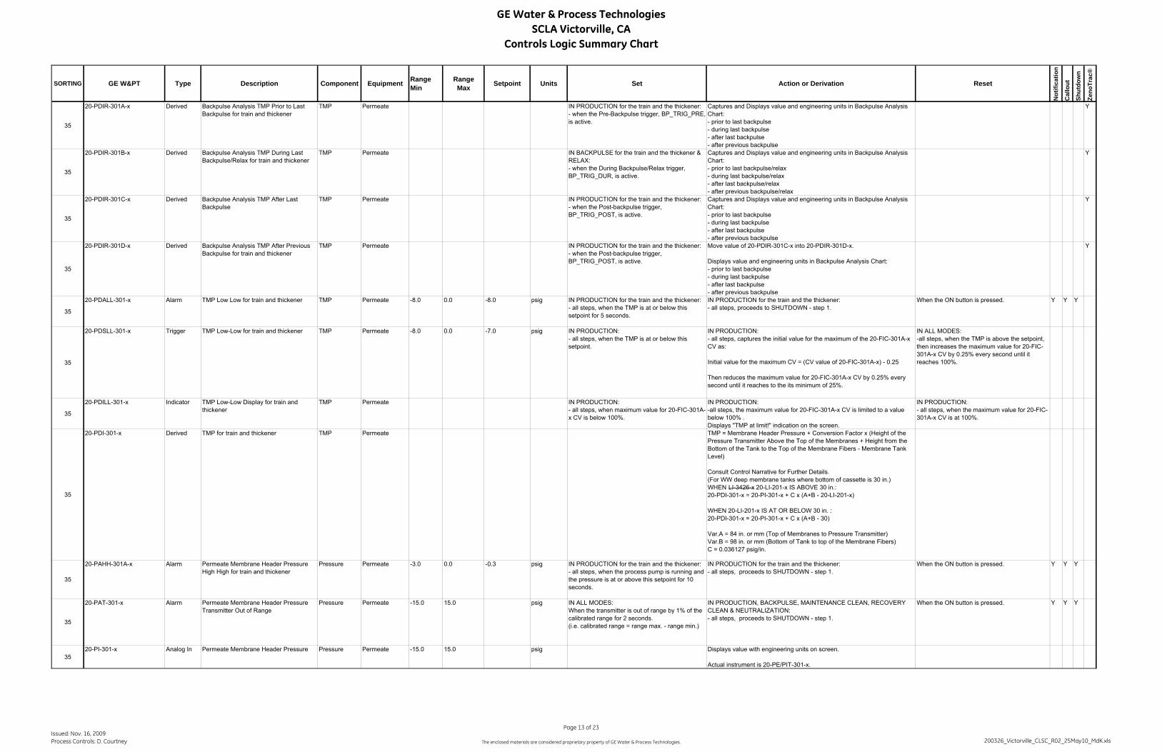
GE Water & Process TechnologiesSCLA Victorville, CA
Controls Logic Summary Chart
SORTING GE W&PT Type Description Component Equipment RangeMin
RangeMax Setpoint Units Set Action or Derivation Reset
Not
ifica
tion
Cal
lout
Shut
dow
n
Zeno
Trac
®
35
20-PDIR-301A-x Derived Backpulse Analysis TMP Prior to Last Backpulse for train and thickener
TMP Permeate IN PRODUCTION for the train and the thickener:- when the Pre-Backpulse trigger, BP_TRIG_PRE, is active.
Captures and Displays value and engineering units in Backpulse Analysis Chart:- prior to last backpulse- during last backpulse- after last backpulse- after previous backpulse
Y
35
20-PDIR-301B-x Derived Backpulse Analysis TMP During Last Backpulse/Relax for train and thickener
TMP Permeate IN BACKPULSE for the train and the thickener & RELAX:- when the During Backpulse/Relax trigger, BP_TRIG_DUR, is active.
Captures and Displays value and engineering units in Backpulse Analysis Chart:- prior to last backpulse/relax- during last backpulse/relax- after last backpulse/relax- after previous backpulse/relax
Y
35
20-PDIR-301C-x Derived Backpulse Analysis TMP After Last Backpulse
TMP Permeate IN PRODUCTION for the train and the thickener:- when the Post-backpulse trigger, BP_TRIG_POST, is active.
Captures and Displays value and engineering units in Backpulse Analysis Chart:- prior to last backpulse- during last backpulse- after last backpulse- after previous backpulse
Y
35
20-PDIR-301D-x Derived Backpulse Analysis TMP After Previous Backpulse for train and thickener
TMP Permeate IN PRODUCTION for the train and the thickener:- when the Post-backpulse trigger, BP_TRIG_POST, is active.
Move value of 20-PDIR-301C-x into 20-PDIR-301D-x.
Displays value and engineering units in Backpulse Analysis Chart:- prior to last backpulse- during last backpulse- after last backpulse- after previous backpulse
Y
35
20-PDALL-301-x Alarm TMP Low Low for train and thickener TMP Permeate -8.0 0.0 -8.0 psig IN PRODUCTION for the train and the thickener:- all steps, when the TMP is at or below this setpoint for 5 seconds.
IN PRODUCTION for the train and the thickener:- all steps, proceeds to SHUTDOWN - step 1.
When the ON button is pressed. Y Y Y
35
20-PDSLL-301-x Trigger TMP Low-Low for train and thickener TMP Permeate -8.0 0.0 -7.0 psig IN PRODUCTION:- all steps, when the TMP is at or below this setpoint.
IN PRODUCTION:- all steps, captures the initial value for the maximum of the 20-FIC-301A-x CV as:
Initial value for the maximum CV = (CV value of 20-FIC-301A-x) - 0.25
Then reduces the maximum value for 20-FIC-301A-x CV by 0.25% every second until it reaches to the its minimum of 25%.
IN ALL MODES:-all steps, when the TMP is above the setpoint, then increases the maximum value for 20-FIC-301A-x CV by 0.25% every second until it reaches 100%.
35
20-PDILL-301-x Indicator TMP Low-Low Display for train and thickener
TMP Permeate IN PRODUCTION:- all steps, when maximum value for 20-FIC-301A-x CV is below 100%.
IN PRODUCTION:-all steps, the maximum value for 20-FIC-301A-x CV is limited to a value below 100% .Displays "TMP at limit!" indication on the screen.
IN PRODUCTION:- all steps, when the maximum value for 20-FIC-301A-x CV is at 100%.
35
20-PDI-301-x Derived TMP for train and thickener TMP Permeate TMP = Membrane Header Pressure + Conversion Factor x (Height of the Pressure Transmitter Above the Top of the Membranes + Height from the Bottom of the Tank to the Top of the Membrane Fibers - Membrane Tank Level)
Consult Control Narrative for Further Details.(For WW deep membrane tanks where bottom of cassette is 30 in.)WHEN LI-3426-x 20-LI-201-x IS ABOVE 30 in.:20-PDI-301-x = 20-PI-301-x + C x (A+B - 20-LI-201-x)
WHEN 20-LI-201-x IS AT OR BELOW 30 in. :20-PDI-301-x = 20-PI-301-x + C x (A+B - 30)
Var.A = 84 in. or mm (Top of Membranes to Pressure Transmitter)Var.B = 98 in. or mm (Bottom of Tank to top of the Membrane Fibers)C = 0.036127 psig/in.
35
20-PAHH-301A-x Alarm Permeate Membrane Header Pressure High High for train and thickener
Pressure Permeate -3.0 0.0 -0.3 psig IN PRODUCTION for the train and the thickener:- all steps, when the process pump is running and the pressure is at or above this setpoint for 10 seconds.
IN PRODUCTION for the train and the thickener:- all steps, proceeds to SHUTDOWN - step 1.
When the ON button is pressed. Y Y Y
35
20-PAT-301-x Alarm Permeate Membrane Header Pressure Transmitter Out of Range
Pressure Permeate -15.0 15.0 psig IN ALL MODES: When the transmitter is out of range by 1% of the calibrated range for 2 seconds.(i.e. calibrated range = range max. - range min.)
IN PRODUCTION, BACKPULSE, MAINTENANCE CLEAN, RECOVERY CLEAN & NEUTRALIZATION:- all steps, proceeds to SHUTDOWN - step 1.
When the ON button is pressed. Y Y Y
3520-PI-301-x Analog In Permeate Membrane Header Pressure Pressure Permeate -15.0 15.0 psig Displays value with engineering units on screen.
Actual instrument is 20-PE/PIT-301-x.
Issued: Nov. 16, 2009Process Controls: D. Courtney
Page 13 of 23
The enclosed materials are considered proprietary property of GE Water & Process Technologies. 200326_Victorville_CLSC_R02_25May10_MdK.xls
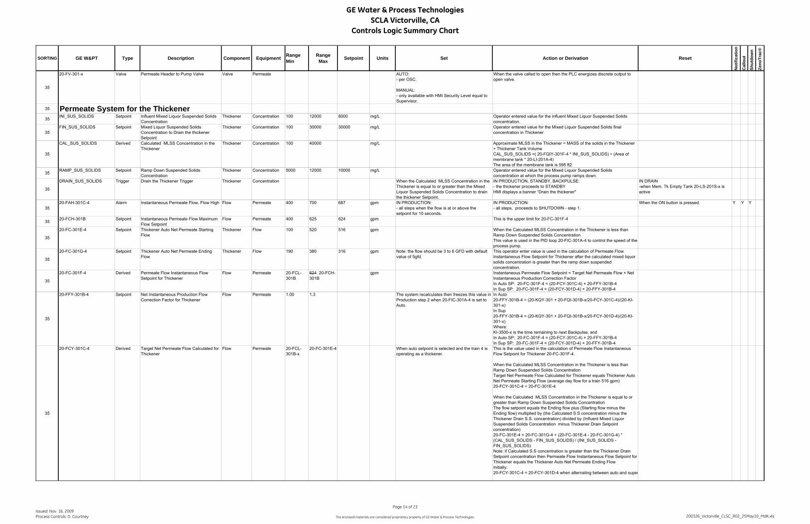
GE Water & Process TechnologiesSCLA Victorville, CA
Controls Logic Summary Chart
SORTING GE W&PT Type Description Component Equipment RangeMin
RangeMax Setpoint Units Set Action or Derivation Reset
Not
ifica
tion
Cal
lout
Shut
dow
n
Zeno
Trac
®
35
20-FV-301-x Valve Permeate Header to Pump Valve Valve Permeate AUTO:- per OSC.
MANUAL:- only available with HMI Security Level equal to Supervisor.
When the valve called to open then the PLC energizes discrete output to open valve.
35 Permeate System for the Thickener35 INI_SUS_SOLIDS Setpoint Influent Mixed Liquor Suspended Solids
Concentration Thickener Concentration 100 12000 8000 mg/L Operator entered value for the influent Mixed Liquor Suspended Solids
concentration.
35FIN_SUS_SOLIDS Setpoint Mixed Liquor Suspended Solids
Concentration to Drain the thickener Setpoint
Thickener Concentration 100 30000 30000 mg/L Operator entered value for the Mixed Liquor Suspended Solids final concentration in Thickener
35
CAL_SUS_SOLIDS Derived Calculated MLSS Concentration in the Thickener
Thickener Concentration 100 40000 mg/L Approximate MLSS in the Thickener = MASS of the solids in the Thickener ÷ Thickener Tank VolumeCAL_SUS_SOLIDS =( 20-FQIY-301F-4 * INI_SUS_SOLIDS) ÷ (Area of membrane tank * 20-LI-201A-4)The area of the membrane tank is 595 ft2
35 RAMP_SUS_SOLIDS Setpoint Ramp Down Suspended Solids Concentration
Thickener Concentration 5000 12000 10000 mg/L Operator entered value for the Mixed Liquor Suspended Solids concentration at which the process pump ramps down.
35
DRAIN_SUS_SOLIDS Trigger Drain the Thickener Trigger Thickener Concentration When the Calculated MLSS Concentration in the Thickener is equal to or greater than the Mixed Liquor Suspended Solids Concentration to drain the thickener Setpoint.
IN PRODUCTION, STANDBY, BACKPULSE:- the thickener proceeds to STANDBYHMI displays a banner “Drain the thickener"
IN DRAIN-when Mem. Tk Empty Tank 20-LS-201S-x is active
3520-FAH-301C-4 Alarm Instantaneous Permeate Flow, Flow High Flow Permeate 400 700 687 gpm IN PRODUCTION:
- all steps when the flow is at or above the setpoint for 10 seconds.
IN PRODUCTION:- all steps, proceeds to SHUTDOWN - step 1.
When the ON button is pressed. Y Y Y
35 20-FCH-301B Setpoint Instantaneous Permeate Flow Maximum Flow Setpoint
Flow Permeate 400 625 624 gpm This is the upper limit for 20-FC-301F-4
35
20-FC-301E-4 Setpoint Thickener Auto Net Permeate Starting Flow
Thickener Flow 100 520 516 gpm When the Calculated MLSS Concentration in the Thickener is less than Ramp Down Suspended Solids ConcentrationThis value is used in the PID loop 20-FIC-301A-4 to control the speed of the process pump.
35
20-FC-301G-4 Setpoint Thickener Auto Net Permeate Ending Flow
Thickener Flow 190 380 316 gpm Note: the flow should be 3 to 6 GFD with default value of 5gfd.
This operator enter value is used in the calculation of Permeate Flow Instantaneous Flow Setpoint for Thickener after the calculated mixed liquor solids concentration is greater than the ramp down suspended concentration.
35
20-FC-301F-4 Derived Permeate Flow Instantaneous Flow Setpoint for Thickener
Flow Permeate 20-FCL-301B
624 20-FCH-301B
gpm Instantaneous Permeate Flow Setpoint = Target Net Permeate Flow × Net Instantaneous Production Correction FactorIn Auto SP: 20-FC-301F-4 = (20-FCY-301C-4) × 20-FFY-301B-4In Sup SP: 20-FC-301F-4 = (20-FCY-301D-4) × 20-FFY-301B-4
35
20-FFY-301B-4 Setpoint Net Instantaneous Production Flow Correction Factor for Thickener
Flow Permeate 1.00 1.3 The system recalculates then freezes this value in Production step 2 when 20-FIC-301A-4 is set to Auto.
In Auto20-FFY-301B-4 = (20-KQY-301 + 20-FQI-301B-x/20-FCY-301C-4)/(20-KI-301-x)In Sup20-FFY-301B-4 = (20-KQY-301 + 20-FQI-301B-x/20-FCY-301D-4)/(20-KI-301-x)Where:KI-3500-x is the time remaining to next Backpulse, andIn Auto SP: 20-FC-301F-4 = (20-FCY-301C-4) × 20-FFY-301B-4In Sup SP: 20-FC-301F-4 = (20-FCY-301D-4) × 20-FFY-301B-4
35
20-FCY-301C-4 Derived Target Net Permeate Flow Calculated for Thickener
Flow Permeate 20-FCL-301B-x
20-FC-301E-4 When auto setpoint is selected and the train 4 is operating as a thickener.
This is the value used in the calculation of Permeate Flow Instantaneous Flow Setpoint for Thickener 20-FC-301F-4.
When the Calculated MLSS Concentration in the Thickener is less than Ramp Down Suspended Solids ConcentrationTarget Net Permeate Flow Calculated for Thickener equals Thickener Auto Net Permeate Starting Flow (average day flow for a train 516 gpm)20-FCY-301C-4 = 20-FC-301E-4
When the Calculated MLSS Concentration in the Thickener is equal to or greater than Ramp Down Suspended Solids Concentration The flow setpoint equals the Ending flow plus (Starting flow minus the Ending flow) multiplied by (the Calculated S.S concentration minus the Thickener Drain S.S. concentration) divided by (Influent Mixed Liquor Suspended Solids Concentration minus Thickener Drain Setpoint concentration)20-FC-301E-4 = 20-FC-301G-4 + (20-FC-301E-4 - 20-FC-301G-4) * (CAL_SUS_SOLIDS - FIN_SUS_SOLIDS) / (INI_SUS_SOLIDS - FIN_SUS_SOLIDS)Note: if Calculated S.S concentration is greater than the Thickener Drain Setpoint concentration then Permeate Flow Instantaneous Flow Setpoint for Thickener equals the Thickener Auto Net Permeate Ending FlowInitially:20-FCY-301C-4 = 20-FCY-301D-4 when alternating between auto and super
Issued: Nov. 16, 2009Process Controls: D. Courtney
Page 14 of 23
The enclosed materials are considered proprietary property of GE Water & Process Technologies. 200326_Victorville_CLSC_R02_25May10_MdK.xls

GE Water & Process TechnologiesSCLA Victorville, CA
Controls Logic Summary Chart
SORTING GE W&PT Type Description Component Equipment RangeMin
RangeMax Setpoint Units Set Action or Derivation Reset
Not
ifica
tion
Cal
lout
Shut
dow
n
Zeno
Trac
®
35
20-FCY-301D-4 Setpoint Target Net Permeate Flow Operator Entered for Train
Flow Permeate 20-FCL-301B-x
20-FC-301E-5 ### gpm When supervisory setpoint is selected. This is the value used in the calculation of 20-FC-301F-4.
Initially:20-FCY-301C-4 = 20-FCY-301D-4 when alternating between auto and supervisory setpoint. This is a bumpless transfer.
35 20-FCL-301B Setpoint Instantaneous Permeate Flow Minimum Flow Setpoint for Thickener
Flow Permeate 100 140 130 gpm This is the lower limit for 20-FC-301F-4
35
20-FAL-301C-x -4 Alarm Instantaneous Permeate Flow, Flow Low for Thickener
Flow Permeate 100 140 117 gpm IN PRODUCTION for thickener:- all steps, when the pump is running and the flow is at or below the setpoint for 10 seconds.This is a common setpoint.
IN PRODUCTION for thickener:- all steps, proceeds to SHUTDOWN - step 1.
When the ON button is pressed. Y Y Y
35 20-HMS-201Y-4 Button Permeate Flow Auto Setpoint Button for thickener
Flow Permeate When the button is pressed and train 4 is operating as a thickener.
Allows the operator to use the calculated setpoint for the thickener net permeate flow.
35
20-HMS-201Z-4 Button Permeate Flow Supervisory Setpoint Button for thickener
Flow Permeate When the button is pressed and train 4 is operating as a thickener.
Allows the operator to use a supervisory setpoint for the thickener net permeate flow.
When pressed the system will use the operator entered setpoint for the trains net permeate flow until changed by the user.
35 THICK_FLAG Trigger Thickener Flag Sequence WAS When the Thickener Enabled Button is pressed. Set Thickener flag In the last step of DRAIN, the thickener flag is reset. When the OFF button is pressed.
3520-HMS-201G Button Thickener Enabled Button Sequence WAS IN OFF
When the button is pressed. The operator is required to confirm the selection.
IN ALL MODES:- enables train 4 as a thickener and it operates according to the thickener OSC when the On button is selected.
3520-HMS-201H Button Train Enabled Button Sequence WAS IN OFF
When the button is pressed. This button is not available if the thickener flag is set.
IN ALL MODES:- enables train 4 as a train and it operates according to the train OSC immediately.
35
20-FQIY-301D-4 Derived Today's Thickener Net Permeate Volume Volume WAS 0 1,000,000 gal When train 4 is enabled as a thickener Total Train Production Volume for Today = Totalized Permeate volume during Production - steps 1 through to the end of the cycle minus Total Backpulse volume from Backpulsing pump.
At midnight this value is stored at 20-FQIY-301E-x.
20-FQIY-301D-4 = Totalized 20-FI-301A-4 (In Production) - Totalized 20-FI-301B-4 (During Backpulse)
At midnight, totalizer is reset to zero.
35 20-FQIY-301E-4 Derived Yesterday's Thickener Net Permeate Volume
Volume WAS 0 1,000,000 gal Set to 20-FQIY-301D-4 at midnight.
20-FQIY-301F-4 Derived Thickener Net Permeate Volume Since Last Tank Drain
Volume WAS When train 4 is enabled as a thickener Total Train Production Volume for Today = Totalized Permeate volume during Production - steps 1 through to the end of the cycle minus Total Backpulse volume from Backpulsing pump.
20-FQIY-301F-4 = Totalized 20-FI-301A-4 (In Production) - Totalized 20-FI-301B-4 (During Backpulse)
This totalizer is reset when 20-LS-201S-4 is active.
50 Recirculation/RAS System50
16-FAH-801-x Alarm Recirculation Flow High Flow Recirculation 0 100 110 90 % IN ALL MODES:- all steps when the flow is at or above the setpoint for 5 seconds.
Setpoint is a percentage of 16-FC-801A-x. When the flow is below the setpoint. Y
5016-FAL-801-x Alarm Recirculation Flow Low Flow Recirculation 0 100 10 % IN ALL MODES:
- all steps, when the pump is running and the flow is at or below the setpoint for 10 seconds.
Setpoint is a percentage of 16-FC-801A-x. When the flow is above the setpoint. Y
5016-FI-801-x Analog In Recirculation Flow Flow Recirculation 0 2500 gpm Displays value with engineering units on screen.
Actual instrument is 16-FE/FIT-801-x.
50
16-FAT-801-x Alarm Recirculation Flow Transmitter Out of Range
Flow Recirculation 0 2500 gpm IN ALL MODES: When the transmitter is out of range by 1% of the calibrated range for 2 seconds.(i.e. calibrated range = range max. - range min.)
IN STANDBY for train, PRODUCTION for train, BACKPULSE for train, RELAX, RECOVERY CLEAN, DRAIN:- all steps, proceeds to SHUTDOWN - step 1.
When the transmitter is in range. Y Y Y
50
16-FIC-801-x PID/Comm Recirculation/Drain Pump Flow Proportional Integral Derivative Controller
Flow Recirculation PV is the recirculation flow rate, 16-FI-801-xSP = 16-FC-801A-x CV is the speed of the Recirculation/Drain Pump the minimum CV is 25%
Deadband = 0, Loop Update = 0.5 secondsE=SP-PV
Issued: Nov. 16, 2009Process Controls: D. Courtney
Page 15 of 23
The enclosed materials are considered proprietary property of GE Water & Process Technologies. 200326_Victorville_CLSC_R02_25May10_MdK.xls

GE Water & Process TechnologiesSCLA Victorville, CA
Controls Logic Summary Chart
SORTING GE W&PT Type Description Component Equipment RangeMin
RangeMax Setpoint Units Set Action or Derivation Reset
Not
ifica
tion
Cal
lout
Shut
dow
n
Zeno
Trac
®
50
16-FC-801A Derived Recirculation/Drain Pump Flow Setpoint Flow Recirculation gpm When there is at least one train is in Production, Relax or Backpulse (Production Cycle):Recirculation Setpoint = Flow Factor multiplied by the plant flow demand flow divided by (# of trains in the production cycle)16-FC-801A-x = (16-FFY-801 * 20-FCY-201A)/(NUM_TR_PROD) Flow setpoint is updated every 5 minutes.When there is at least one train in Production, Relax or Backpulse (Production Cycle) and the duration timer for standby aeration is active and the value of the iterations counter 16-KQS-801A equals the value of its setpoint.Recirculation Setpoint = Flow Factor multiplied by the plant flow demand flow divided by (# of trains in the production cycle) multiplied by (# of trains in the production cycle plus 1) divided by the # of trains in the production cycle16-FC-801A-x = [16-FFY-801 * 20-FCY-201A /(NUM_TR_PROD)] * [(NUM_TR_PROD + 1)/NUM_TR_PROD] Flow setpoint is updated every 5 minutes.When none of the trains are in Production, Relax or Backpulse and at least one train is in Standby Step 3, operate the recirculation/drain pump at 1250 gpm flow setpoint. This operation is not based on the standby aeration timersIN RECOVERY CLEAN & DRAIN, operate the recirculation/drain pump at 12
50 16-FFY-801 Setpoint Recirculation/Drain Pumps Recirculation Factor
Flow Recirculation 2.0 4.0 3.0 N/A Common setpoint for all trains in PRODUCTION, BACKPULSE & RELAX.
Flow Factor, 16-FFY-801, is used to calculate the Recirculation/Drain Pump's flow setpoint, 20-FC-801A.
50
16-YA-801-x Alarm/comm..
Recirculation/Drain Pump Fail Pump Recirculation IN ALL MODES:- all steps requiring the pump to run, when the MCC running confirmation is missing for 5 seconds.
IN STANDBY for train, PRODUCTION for train, BACKPULSE for train, RELAX:- all steps, proceeds to SHUTDOWN - step 1.
IN RECOVERY CLEAN:- holds step- all steps, places pump into man off and after a delay of six seconds closes 20-FV-501-x.- 20-KQS-301W startsDisplays, "Train will be Shutdown due to active alarm" .
IN DRAIN:- holds step- all steps, places pump (recirculation & process pump) into man off and after a delay of six seconds close the valves.- 20-KQS-301W startsDisplays, "Train will be Shutdown due to active alarm" .
When the pump ON START OR AUTO button is pressed.IN RECOVERY CLEAN & DRAIN:When the pump (recirculation & process pump) is put back into auto and Fault Timer clears then align valves as per OSC step after a six second delay resume step, as shown in the OSC.
Y Y Y
5016-KQI-801-x Derived Recirculation/Drain Pump
Accumulated Run TimePump Recirculation 0 30000 hours IN ALL MODES:
When the pump is operating.IN ALL MODES:Displays accumulated run time for the pump on the screen.
When the Reset Run Time button is pressed, run time resets to 0 hours.
50
16-P-801-x Comm Recirculation/Drain Pump Pump Recirculation MANUAL:- only available with SUPER password
AUTO:- according to the OSCDISABLED (in AUTO or MANUAL):- when any of the following are true: pump Fail 16-YA-801-x System Stop Activated 00-HA-005
When the pump is called to run, energizes the PLC discrete output to operate motor.If VFD called to start, the speed command is set at the setpoint. Otherwise set to zero
5016-SMS-801-x Setpoint Recirculation/Drain Pump Start Speed Pump Recirculation 25 100 60 % IN ALL MODES:
- all steps where the pump is requested to start.IN ALL MODES:- all steps, this is the pumps starting speed, held for 3 seconds, before starting PID control 16-FIC-801-x.
5016-MK-801-x Setpoint Recirculation/Drain Pump Speed Pump Recirculation ALL MODES:
- all steps, this setpoint is overwritten by the lower CV value from PID loop flow controller 16-FIC-801-x to control the pump.
50
16-KQS-801A Setpoint Standby recirculation/drain pump Operation Iterations
Pump Recirculation 0 10 1 # of times When the standby frequency timer 20-KQS-201D times out.
Increase the iterations counter by one.When the value of the iterations counter equals the value of the setpoint, run the recirculation drain pumps for all the trains in Standby.Note: when the iterations counter equals zero run the recirculation drain pumps each time the trains in standby are aerated.
When the standby duration timer 20-KQS-201C times out for the LAST train in the standby aeration cycle and the value of the counter equals the setpoint value.
35
16-FV-820 Valve RAS to Mix Tank Isolation Valve Valve Permeate AUTO:- per OSC.
MANUAL:- only available with HMI Security Level equal to Supervisor.
When the valve called to open then the PLC energizes discrete output to open valve.
Issued: Nov. 16, 2009Process Controls: D. Courtney
Page 16 of 23
The enclosed materials are considered proprietary property of GE Water & Process Technologies. 200326_Victorville_CLSC_R02_25May10_MdK.xls

GE Water & Process TechnologiesSCLA Victorville, CA
Controls Logic Summary Chart
SORTING GE W&PT Type Description Component Equipment RangeMin
RangeMax Setpoint Units Set Action or Derivation Reset
Not
ifica
tion
Cal
lout
Shut
dow
n
Zeno
Trac
®
35
16-FV-821 Valve Sludge Holding Isolation Valve Valve Permeate AUTO:- per OSC.
MANUAL:- only available with HMI Security Level equal to Supervisor.
When the valve called to open then the PLC energizes discrete output to open valve.
55 BACKPULSE
55
20-KQS-301G Derived Staggered Backpulse Order Sequence Backpulse Staggered Backpulsing:The time slots to do backpulse are evenly distributed throughout one production cycle. The distribution is based on the maximum number of trains installed in the plant. The production cycle is 12 minutes and there are 4 trains. A backpulse is scheduled to occur every 3 minutes. Each train is assigned a time slot to do backpulse according its train number, e.g., train 1 is backpulsed in the first time slot, and train 2 is backpulsed in the second time slot, etc. Any train that is not in a production cycle will be skipped. When train 4 is functioning as a thickener, the time slot for the backpulse/relax remains the same.
55
20-KQS-301B Setpoint Backpulse/RELAX Duration Sequence Backpulse 5 200 30 sec. IN BACKPULSE train and thickener:- step 3.
IN RELAX:- step 2.
IN RELAX & BACKPULSE train and thickener:- starts timer. Proceeds as per OSC when timer times out.
When timer times out.
55 BP_TRIG_PRE Trigger Pre-Backpulse Snapshot Trigger Info Backpulse IN PRODUCTION:- end of in permeate step.
Y
55
BP_TRIG_DUR Trigger Backpulse/Relax Snapshot Trigger Info Backpulse IN BACKPULSE:- 10 seconds into step 3.IN RELAX:- 10 seconds into step 2.
Y
55 BP_TRIG_POST Trigger Post-Backpulse Snapshot Trigger Info Backpulse IN PRODUCTION:- 30 seconds into production steps.
Y
55 20-FC-301B Setpoint Backpulse Flow Setpoint Flow Backpulse 140 1590 1265 gpm Operator entered flow setpoint for backpulsing the entire train.This is a plant setpoint.
55
20-FIC-301B-x PID/Comm Process Pump - Backpulse, Maintenance Clean Recovery Clean and NeutralizationFlow Proportional Integral Derivative Controller
Flow Backpulse IN BACKPULSE:- steps as per the OSCIN MAINTENANCE CLEAN:- steps as per the OSCIN RECOVERY CLEAN:- steps as per the OSCIN NEUTRALIZATION:- steps as per the OSCIN DRAIN:- steps as per the OSC
IN BACKPULSE & DRAIN:PV is the Backpulse flow rate measured at 20-FIT-301-x.SP = 20-FC-301B for the train and thickener.CV is the speed of the process pump.The minimum CV is 25% and the maximum CV is defined by 20-PDYH-301-x action.
IN RECOVERY CLEAN and NEUTRALIZATION:PV is the CIP flow rate measured at 20-FIT-301-x.SP = 20-FC-301C.CV is the speed of the process pump.The minimum CV is 25% and the maximum CV is defined by 20-PDYH-301-x action.
IN MAINTENANCE CLEAN:PV is the CIP flow rate measured at 20-FIT-301-x.SP = 20-FC-301DCV is the speed of the process pump.The minimum CV is 25% and the maximum CV is defined by 20-PDYH-301-x action.
Deadband = 0, LoopUpdate = 0.5 secondsE=SP-PV
5520-FI-301B-x Derived Backpulse Pump Flow Flow Backpulse 0 2000 gpm Displays value with engineering units on screen.
Actual instrument is 20-FE/FIT-301.
55
20-FAH-301B-x Alarm Backpulsing Pump, Flow High Flow Backpulse 140 1750 1392 gpm IN BACKPULSE, MAINTENANCE CLEAN, RECOVERY CLEAN, NEUTRALIZATION & DRAIN:- all steps when the backpulse flow is at or above the setpoint for 5 seconds.
This is a common setpoint with multiple Alarms.
IN BACKPULSE, MAINTENANCE CLEAN & NEUTRALIZATION:- all steps, proceeds to SHUTDOWN - step 1.
IN RECOVERY CLEAN:- holds step- all steps, places pump into man off and after a delay of six seconds closes 20-FV-301-x.- auto-stops chemical pumps (if necessary).- 20-KQS-301W startsDisplays, "Train will be Shutdown due to active alarm" .IN DRAIN:- continues step- all steps, place process pump into man off and after a delay of six seconds close the valve 20-FV-301-4.
When the ON or OFF button is pressed.IN RECOVERY CLEAN:When the pumps are put back into auto and Fault Timer clears then align valves as per OSC step after a six second delay resume step, as shown in the OSC.
Y Y Y
Issued: Nov. 16, 2009Process Controls: D. Courtney
Page 17 of 23
The enclosed materials are considered proprietary property of GE Water & Process Technologies. 200326_Victorville_CLSC_R02_25May10_MdK.xls

GE Water & Process TechnologiesSCLA Victorville, CA
Controls Logic Summary Chart
SORTING GE W&PT Type Description Component Equipment RangeMin
RangeMax Setpoint Units Set Action or Derivation Reset
Not
ifica
tion
Cal
lout
Shut
dow
n
Zeno
Trac
®
55
20-FAL-301B-x Alarm Backpulse Pump, Flow Low Flow Backpulse 140 1100 1000 gpm IN BACKPULSE, MAINTENANCE CLEAN, RECOVERY CLEAN, NEUTRALIZATION & DRAIN:- all steps where the pump is running and the backpulse flow is at or below the setpoint for 10 seconds.
This is a common setpoint with multiple Alarms.
IN BACKPULSE, MAINTENANCE CLEAN & NEUTRALIZATION:- all steps, proceeds to SHUTDOWN - step 1.
IN RECOVERY CLEAN:- holds step- all steps, places pump into man off and after a delay of six seconds closes 20-FV-301-x.- auto-stops chemical pumps (if necessary).- 20-KQS-301W startsDisplays, "Train will be Shutdown due to active alarm" .IN DRAIN:- continues step- all steps, place process pump into man off and after a delay of six seconds close the valve 20-FV-301-4.
When the ON or OFF button is pressed.IN RECOVERY CLEAN:When the pumps are put back into auto and Fault Timer clears then align valves as per OSC step after a six second delay resume step, as shown in the OSC.
Y Y Y
55 20-FQI-301B-x Derived Backpulse Volume Volume Backpulse 0 10000 gal IN BACKPULSE:- beginning of step 2
IN BACKPULSE:- all steps, totalizes backpulse flow.
IN BACKPULSE:- step 1
55
20-FIR-301B-x Derived Backpulse Analysis Flow During Last Backpulse/Relax
Flow Backpulse IN BACKPULSE for train and thickener & RELAX:- when the During Backpulse/Relax trigger, BP_TRIG_DUR, is active.
Captures and Displays value and engineering units in Backpulse Analysis Chart:- prior to last backpulse/relax- during last backpulse/relax- after last backpulse/relax- after previous backpulse/relax
Y
55 20-HMS-201S-x Button Enable Backpulse Button Sequence Backpulse When the button is pressed. Train will use backpulse mode and not relax mode.
55
20-HMS-201T-x Button Enable Relax Button Sequence Backpulse When the button is pressed or with specific alarms, as specified in the CLSC.Relax is not available for train 4 when it is enabled as a thickener
Train will use relax mode and not backpulse mode.
55
20-PDAH-301-x Alarm Backpulsing Pump, TMP High TMP Backpulse 0.0 8.0 8.0 psig IN BACKPULSE, MAINTENANCE CLEAN, RECOVERY CLEAN, NEUTRALIZATION, DRAIN:- all steps, when the TMP is at or above this setpoint for 5 seconds during backpulse.
This is a common setpoint with multiple Alarms.
IN BACKPULSE, MAINTENANCE CLEAN & NEUTRALIZATION:- all steps, proceeds to SHUTDOWN - step 1.
IN RECOVERY CLEAN:- holds step- all steps, places pump into man off and after a delay of six seconds closes 20-FV-301-x.- auto-stops chemical pumps (if necessary).- 20-KQS-301W startsDisplays, "Train will be Shutdown due to active alarm" .IN DRAIN:- continues step- all steps, place process pump into man off and after a delay of six seconds close the valve 20-FV-301-4.
When the ON or OFF button is pressed.IN RECOVERY CLEAN:When the pumps are put back into auto and Fault Timer clears then align valves as per OSC step after a six second delay resume step, as shown in the OSC.
Y Y Y
55
20-PDYH-301-x Trigger TMP High TMP Backpulse 5.0 20-PDAH-301B
7.0 psig IN BACKPULSE for train, BACKPULSE for thickener, MAINTENANCE CLEAN, RECOVERY CLEAN, NEUTRALIZATION, DRAIN:- all steps, when the TMP is at or above this setpoint.
IN BACKPULSE for train, BACKPULSE for thickener, MAINTENANCE CLEAN, RECOVERY CLEAN, NEUTRALIZATION, DRAIN:- all steps, captures the initial value for the maximum of the 20-FIC-301B-x CV as:
Initial value for the maximum CV = (CV value of 20-FIC-301B-x) - 0.25
Then reduces the maximum value for 20-FIC-301B-x CV by 0.25% every second until it reaches to the its minimum of 25%.
IN ALL MODES:-all steps, when the TMP is below the setpoint, then increases the maximum value for 20-FIC-301B-x CV by 0.25% every second until it reaches 100%.
55
20-PDIH-301-x Indicator TMP High Display TMP Backpulse IN BACKPULSE for train, BACKPULSE for thickener, MAINTENANCE CLEAN, RECOVERY CLEAN, NEUTRALIZATION, DRAIN:- all steps, when maximum value for 20-FIC-301B-x CV is below 100%.
IN BACKPULSE for train, BACKPULSE for thickener, MAINTENANCE CLEAN, RECOVERY CLEAN, NEUTRALIZATION, DRAIN:-all steps, the maximum value for 20-FIC-301B-x CV is limited to a value below 100% .Displays "TMP at limit!" indication on the screen.
IN PRODUCTION:- all steps, when the maximum value for 20-FIC-301A-x CV is at 100%.
55
20-PAH-301B-x Alarm Backpulsing, Pressure High Pressure Backpulse 0.0 11.4 9.0 psig IN BACKPULSE, MAINTENANCE CLEAN, RECOVERY CLEAN, NEUTRALIZATION, DRAIN:- all steps, when the backpulse header pressure is at or above this setpoint for 6 seconds.
This is a common setpoint with multiple Alarms.
IN BACKPULSE, MAINTENANCE CLEAN & NEUTRALIZATION:- all steps, proceeds to SHUTDOWN - step 1.
IN RECOVERY CLEAN:- holds step- all steps, places pump into man off and after a delay of six seconds closes 20-FV-301-x.- auto-stops chemical pumps (if necessary).- 20-KQS-301W startsDisplays, "Train will be Shutdown due to active alarm" .IN DRAIN:- continues step- all steps, place process pump into man off and after a delay of six seconds close the valve 20-FV-301-4.
When the ON or OFF button is pressed.IN RECOVERY CLEAN:When the pumps are put back into auto and Fault Timer clears then align valves as per OSC step after a six second delay resume step, as shown in the OSC.
Y Y Y
5520-PAH-601-x Alarm Backpulsing Pump, Switch 20-PSH-601
Pressure HighPressure Backpulse IN BACKPULSE:
- all steps, when the switch is active for 5 seconds.
IN PRODUCTION:- step 1.
Y
5520-PAH-602-x Alarm Backpulsing Pump, Switch 20-PSH-602
Pressure HighPressure Backpulse IN BACKPULSE:
- all steps, when the switch is active for 5 seconds.
IN PRODUCTION:- step 1.
Y
Issued: Nov. 16, 2009Process Controls: D. Courtney
Page 18 of 23
The enclosed materials are considered proprietary property of GE Water & Process Technologies. 200326_Victorville_CLSC_R02_25May10_MdK.xls
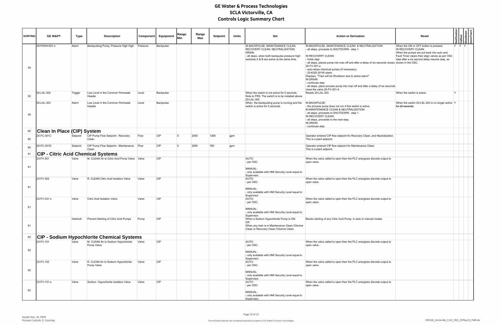
GE Water & Process TechnologiesSCLA Victorville, CA
Controls Logic Summary Chart
SORTING GE W&PT Type Description Component Equipment RangeMin
RangeMax Setpoint Units Set Action or Derivation Reset
Not
ifica
tion
Cal
lout
Shut
dow
n
Zeno
Trac
®
55
20-PAHH-601-x Alarm Backpulsing Pump, Pressure High High Pressure Backpulse IN BACKPULSE, MAINTENANCE CLEAN, RECOVERY CLEAN, NEUTRALIZATION, DRAIN:- all steps, when both backpulse pressure high switches A & B are active at the same time.
IN BACKPULSE, MAINTENANCE CLEAN & NEUTRALIZATION:- all steps, proceeds to SHUTDOWN - step 1.
IN RECOVERY CLEAN:- holds step- all steps, places pump into man off and after a delay of six seconds closes 20-FV-301-x.- auto-stops chemical pumps (if necessary).- 20-KQS-301W startsDisplays, "Train will be Shutdown due to active alarm" .IN DRAIN:- continues step- all steps, place process pump into man off and after a delay of six seconds close the valve 20-FV-301-4.
When the ON or OFF button is pressed.IN RECOVERY CLEAN:When the pumps are put back into auto and Fault Timer clears then align valves as per OSC step after a six second delay resume step, as shown in the OSC.
Y Y Y
5520-LSL-302 Trigger Low Level in the Common Permeate
HeaderLevel Backpulse When the switch is not active for 5 seconds.
Note to FRS: The switch is to be installed above 20-LAL-303
Resets 20-LAL-303 When the switch is active. Y
55
20-LAL-303 Alarm Low Level in the Common Permeate Header
Level Backpulse When the backpulsing pump is running and the switch is active for 5 seconds.
IN BACKPULSE:- the process pump does not run if this switch is active.IN MAINTENANCE CLEAN & NEUTRALIZATION:- all steps, proceeds to SHUTDOWN - step 1.IN RECOVERY CLEAN:- all steps, proceeds to the next step.IN DRAIN:- continues step
When the switch 20-LSL-302 is no longer active for 20 seconds.
Y
60 Clean In Place (CIP) System60
20-FC-301C Setpoint CIP Pump Flow Setpoint - Recovery Clean
Flow CIP 0 2000 1265 gpm Operator entered CIP flow setpoint for Recovery Clean, and Neutralization.This is a plant setpoint.
60 20-FC-301D Setpoint CIP Pump Flow Setpoint - Maintenance Clean
Flow CIP 0 2000 760 gpm Operator entered CIP flow setpoint for Maintenance Clean.This is a plant setpoint.
61 CIP - Citric Acid Chemical Systems
61
23-FV-301 Valve M. CLEAN Air to Citric Acid Pump Valve Valve CIP AUTO:- per OSC.
MANUAL:- only available with HMI Security Level equal to Supervisor.
When the valve called to open then the PLC energizes discrete output to open valve.
61
23-FV-302 Valve R. CLEAN Citric Acid Isolation Valve Valve CIP AUTO:- per OSC.
MANUAL:- only available with HMI Security Level equal to Supervisor.
When the valve called to open then the PLC energizes discrete output to open valve.
61
23-FV-331-x Valve Citric Acid Isolation Valve Valve CIP AUTO:- per OSC.
MANUAL:- only available with HMI Security Level equal to Supervisor.
When the valve called to open then the PLC energizes discrete output to open valve.
61
Interlock Prevent Starting of Citric Acid Pumps Pump CIP When a Sodium Hypochlorite Pump is ON.OR When any train is in Maintenance Clean Chlorine Clean or Recovery Clean Chlorine Clean.
Blocks starting of any Citric Acid Pump, in auto or manual modes.
62 CIP - Sodium Hypochlorite Chemical Systems
62
23-FV-101 Valve M. CLEAN Air to Sodium Hypochlorite Pump Valve
Valve CIP AUTO:- per OSC.
MANUAL:- only available with HMI Security Level equal to Supervisor.
When the valve called to open then the PLC energizes discrete output to open valve.
62
23-FV-102 Valve R. CLEAN Air to Sodium Hypochlorite Pump Valve
Valve CIP AUTO:- per OSC.
MANUAL:- only available with HMI Security Level equal to Supervisor.
When the valve called to open then the PLC energizes discrete output to open valve.
62
23-FV-131-x Valve Sodium Hypochlorite Isolation Valve Valve CIP AUTO:- per OSC.
MANUAL:- only available with HMI Security Level equal to Supervisor.
When the valve called to open then the PLC energizes discrete output to open valve.
Issued: Nov. 16, 2009Process Controls: D. Courtney
Page 19 of 23
The enclosed materials are considered proprietary property of GE Water & Process Technologies. 200326_Victorville_CLSC_R02_25May10_MdK.xls

GE Water & Process TechnologiesSCLA Victorville, CA
Controls Logic Summary Chart
SORTING GE W&PT Type Description Component Equipment RangeMin
RangeMax Setpoint Units Set Action or Derivation Reset
Not
ifica
tion
Cal
lout
Shut
dow
n
Zeno
Trac
®
62
Interlock Prevent Starting of NaOCl Pumps Pump CIP When a Citric Acid Pump is ON.ORWhen any train is in Maintenance Clean Acid Clean or Recovery Clean Acid Clean.
Blocks starting of any Sodium Hypochlorite Pump, in auto or manual modes.
63 CIP - Maintenance Clean
63
20-KQS-201A Setpoint Maintenance Clean Aeration Step Timer Pump Maintenance Clean
600 3600 900 sec. IN MAINTENANCE CLEAN:- In aeration steps, as detailed in OSC.
IN MAINTENANCE CLEAN:- steps as noted in the OSC, this is the steps duration.
Consult the OSC, Maintenance Clean steps, for details.
63
20-KQS-201G Trigger Maintenance Clean Schedule Schedule Maintenance Clean
IN PRODUCTION & STANDBY:- all steps, when the system time is greater than or equal to the operator entered time to start/enable the Maintenance Cleans, 20-KQS-201H, the train has not done a maintenance clean since midnight, and a Maintenance Clean has been selected to occur that day. Note: the maintenance clean is skipped when the train is enabled as a thickener.
IN PRODUCTION:- in permeate step, proceeds to MAINTENANCE CLEAN - step 1.IN STANDBY:-proceeds to MAINTENANCE CLEAN - step 1.Only one Maintenance Clean can be scheduled per day.
IN MAINTENANCE CLEAN:- step 1.
63
20-HMS-201U-x Button Maintenance Clean to Occur on Given Day Enable Button
Schedule Maintenance Clean
Operator can select to have a Maintenance Clean on specific days of the week. ENABLE indicates a Maintenance Clean for that train.
Only one Maintenance Clean can be scheduled per day, Sunday to Saturday. Each day can have a different start/enabled and stop/disabled time.
6320-KQS-201H Setpoint Maintenance Clean Start/Enable Time Schedule Maintenance
Clean0 2400 Determined by
Operatorhr. Operator entered value to start/enable Maintenance Clean on the given day.
63
20-FSH-201 Trigger Maintenance Cleans Delay or Aborted when Plant Flow Demand is high.
Schedule Maintenance Clean
System calculates the plant capacity as if there was one currently available train not in service. WHEN:Current plant permeate demand is at or above [Max. net flow for Train 1 x Total number of trains available less one train].IF:20-FCY-201A ≥ [(20-FCYH-301B) x (NUM_TR_PROD + # of tr. in Standby step 3 + # of tr. in Maintenance Clean - 1]
The result of the calculation determines if one train can proceed to do a Maintenance Clean and the remaining trains can meet the current permeate demand.
63
20-FAH-201-x Alarm Maintenance Clean Delay/Abort Alarm Schedule Maintenance Clean
When 20-FSH-201 is active and either the Maintenance Clean is pending for train "X" or train "X" is in a Maintenance Clean.
Prevents Maintenance Cleans from starting and aborts Maintenance Cleans that are in progress.
WHEN IN PRODUCTION, BACKPULSE, OR RELAX:The Maintenance Clean request is blocked and remains active. Alarms and displays on the alarm banner "Maintenance Clean delayed".When alarm 20-FAH-201-x clears at lower plant demands, 20-FSH-201 is not active, trains that have a Maintenance Clean request active will proceed to Maintenance Clean step 1 when no other train is in a Maintenance Clean, as described in the OSC.
WHEN IN MAINTENANCE CLEAN:- steps 1 to 8, proceeds to MAINTENANCE CLEAN step 9.- steps 12, proceeds to MAINTENANCE CLEAN step 13.Displays on the alarm banner "Maintenance Clean aborted"
When 20-FSH-201 is not active. Y Y
63 23-HMS-101A-x Button Maintenance Clean Sodium Hypochlorite Button
Sequence Maintenance Clean
When the button is pressed. Allows the operator to select Sodium Hypochlorite Maintenance Clean for each scheduled Maintenance Clean.
63 23-HMS-301A-x Button Maintenance Clean Citric Acid Button Sequence Maintenance Clean
When the button is pressed. Allows the operator to select Citric Acid Maintenance Clean for each scheduled Maintenance Clean.
63
20-KQS-301C Setpoint Maintenance Clean Repeated Pulse Duration
Sequence Maintenance Clean
5 200 30for steel tanks use 20
sec. IN MAINTENANCE CLEAN:- steps as noted in the OSC.
IN MAINTENANCE CLEAN:- steps as noted in the OSC, this is the steps duration.
Consult the OSC, Maintenance Clean steps, for details.
63
20-KQS-301D Setpoint Maintenance Clean First & Last Pulse, Pulse Duration
Sequence Maintenance Clean
5 200 120for steel tanks use 60
sec. IN MAINTENANCE CLEAN:- steps as noted in the OSC.
IN MAINTENANCE CLEAN:- steps as noted in the OSC, this is the steps duration.
Consult the OSC, Maintenance Clean steps, for details.
63
20-KQS-301E Setpoint Maintenance Clean Soak Duration Sequence Maintenance Clean
5 600 270 sec. IN MAINTENANCE CLEAN:- steps as noted in the OSC.
IN MAINTENANCE CLEAN:- steps as noted in the OSC, this is the steps duration.
Consult the OSC, Maintenance Clean steps, for details.
Issued: Nov. 16, 2009Process Controls: D. Courtney
Page 20 of 23
The enclosed materials are considered proprietary property of GE Water & Process Technologies. 200326_Victorville_CLSC_R02_25May10_MdK.xls
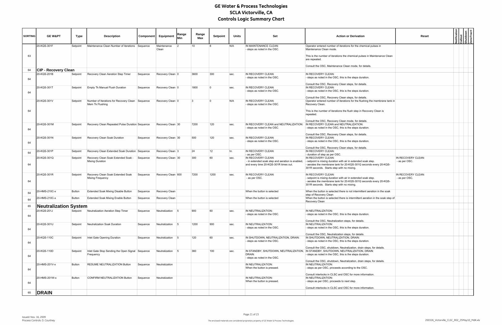
GE Water & Process TechnologiesSCLA Victorville, CA
Controls Logic Summary Chart
SORTING GE W&PT Type Description Component Equipment RangeMin
RangeMax Setpoint Units Set Action or Derivation Reset
Not
ifica
tion
Cal
lout
Shut
dow
n
Zeno
Trac
®
63
20-KQS-301F Setpoint Maintenance Clean Number of iterations Sequence Maintenance Clean
2 10 8 N/A IN MAINTENANCE CLEAN:- steps as noted in the OSC.
Operator entered number of iterations for the chemical pulses in Maintenance Clean mode.
This is the number of iterations the chemical pulses in Maintenance Clean are repeated.
Consult the OSC, Maintenance Clean mode, for details.64 CIP - Recovery Clean
64
20-KQS-201B Setpoint Recovery Clean Aeration Step Timer Sequence Recovery Clean 0 3600 300 sec. IN RECOVERY CLEAN:- steps as noted in the OSC.
IN RECOVERY CLEAN:- steps as noted in the OSC, this is the steps duration.
Consult the OSC, Recovery Clean steps, for details.
64
20-KQS-301T Setpoint Empty Tk Manual Flush Duration Sequence Recovery Clean 0 1800 0 sec. IN RECOVERY CLEAN:- steps as noted in the OSC.
IN RECOVERY CLEAN:- steps as noted in the OSC, this is the steps duration.
Consult the OSC, Recovery Clean steps, for details.
64
20-KQS-301V Setpoint Number of Iterations for Recovery Clean Mem Tk Flushing
Sequence Recovery Clean 0 3 0 N/A IN RECOVERY CLEAN:- steps as noted in the OSC.
Operator entered number of iterations for the flushing the membrane tank in Recovery Clean.
This is the number of iterations the flush step in Recovery Clean is repeated.
Consult the OSC, Recovery Clean mode, for details.
64
20-KQS-301M Setpoint Recovery Clean Repeated Pulse Duration Sequence Recovery Clean 30 7200 120 sec. IN RECOVERY CLEAN and NEUTRALIZATION:- steps as noted in the OSC.
IN RECOVERY CLEAN and NEUTRALIZATION:- steps as noted in the OSC, this is the steps duration.
Consult the OSC, Recovery Clean steps, for details.
64
20-KQS-301N Setpoint Recovery Clean Soak Duration Sequence Recovery Clean 30 500 120 sec. IN RECOVERY CLEAN:- steps as noted in the OSC.
IN RECOVERY CLEAN:- steps as noted in the OSC, this is the steps duration.
Consult the OSC, Recovery Clean steps, for details.
64 20-KQS-301P Setpoint Recovery Clean Extended Soak Duration Sequence Recovery Clean 3 24 12 hr. IN RECOVERY CLEAN:- as per OSC.
IN RECOVERY CLEAN:- duration of step as per OSC.
64
20-KQS-301Q Setpoint Recovery Clean Soak Extended Soak - Mixing Duration
Sequence Recovery Clean 30 300 60 sec. IN RECOVERY CLEAN: - in extended soak step and aeration is enabled, and every time 20-KQS-301R times out.
IN RECOVERY CLEAN:- setpoint is mixing duration with air in extended soak step.- aerates the membrane tank for 20-KQS-301Q seconds every 20-KQS-301R seconds. Starts step with no mixing.
IN RECOVERY CLEAN: - as per OSC.
64
20-KQS-301R Setpoint Recovery Clean Soak Extended Soak Mixing Frequency
Sequence Recovery Clean 600 7200 1200 sec. IN RECOVERY CLEAN: - as per OSC.
IN RECOVERY CLEAN:- setpoint is mixing duration with air in extended soak step.- aerates the membrane tank for 20-KQS-301Q seconds every 20-KQS-301R seconds. Starts step with no mixing.
IN RECOVERY CLEAN: - as per OSC.
64 20-HMS-210C-x Button Extended Soak Mixing Disable Button Sequence Recovery Clean When the button is selected When the button is selected there is not intermittent aeration in the soak step of Recovery Clean
64 20-HMS-210C-x Button Extended Soak Mixing Enable Button Sequence Recovery Clean When the button is selected When the button is selected there is intermittent aeration in the soak step of Recovery Clean
65 Neutralization System
64
20-KQS-201J Setpoint Neutralization Aeration Step Timer Sequence Neutralization 5 900 60 sec. IN NEUTRALIZATION:- steps as noted in the OSC.
IN NEUTRALIZATION:- steps as noted in the OSC, this is the steps duration.
Consult the OSC, Neutralization steps, for details.
64
20-KQS-301U Setpoint Neutralization Soak Duration Sequence Neutralization 5 1200 900 sec. IN NEUTRALIZATION:- steps as noted in the OSC.
IN NEUTRALIZATION:- steps as noted in the OSC, this is the steps duration.
Consult the OSC, Neutralization steps, for details.
64
20-KQS-110C Setpoint Inlet Gate Opening Duration Sequence Neutralization 5 120 60 sec. IN SHUTDOWN, NEUTRALIZATION, DRAIN:- steps as noted in the OSC.
IN SHUTDOWN, NEUTRALIZATION, DRAIN:- steps as noted in the OSC, this is the steps duration.
Consult the OSC, shutdown, Neutralization, drain steps, for details.
64
20-KQS-110D Setpoint Inlet Gate Stop Sending the Open Signal Frequency
Sequence Neutralization 5 360 100 sec. IN STANDBY, SHUTDOWN, NEUTRALIZATION, DRAIN:- steps as noted in the OSC.
IN STANDBY, SHUTDOWN, NEUTRALIZATION, DRAIN:- steps as noted in the OSC, this is the steps duration.
Consult the OSC, shutdown, Neutralization, drain steps, for details.
64
20-HMS-201V-x Button RESUME NEUTRALIZATION Button Sequence Neutralization IN NEUTRALIZATION:When the button is pressed.
IN NEUTRALIZATION:- steps as per OSC, proceeds according to the OSC.
Consult interlocks in CLSC and OSC for more information.
64
20-HMS-201W-x Button CONFIRM NEUTRALIZATION Button Sequence Neutralization IN NEUTRALIZATION:When the button is pressed.
IN NEUTRALIZATION:- steps as per OSC, proceeds to next step.
Consult interlocks in CLSC and OSC for more information.
65 DRAIN
Issued: Nov. 16, 2009Process Controls: D. Courtney
Page 21 of 23
The enclosed materials are considered proprietary property of GE Water & Process Technologies. 200326_Victorville_CLSC_R02_25May10_MdK.xls

GE Water & Process TechnologiesSCLA Victorville, CA
Controls Logic Summary Chart
SORTING GE W&PT Type Description Component Equipment RangeMin
RangeMax Setpoint Units Set Action or Derivation Reset
Not
ifica
tion
Cal
lout
Shut
dow
n
Zeno
Trac
®
64
20-KQS-201N Setpoint Drain Aeration Step Timer Sequence Neutralization 900 1800 900 sec. IN DRAIN:- steps as noted in the OSC.
IN DRAIN:- steps as noted in the OSC, this is the steps duration.
Consult the OSC, Neutralization steps, for details.
64
20-KQS-301H Setpoint Frequency of Backpulse During Drain Sequence Neutralization 600 1800 900 sec. IN DRAIN:- steps as noted in the OSC.
IN DRAIN:- steps as noted in the OSC, this is the steps duration.
Consult the OSC, Neutralization steps, for details.
70 Vacuum System
70
20-FV-802-x Button Vacuum Ejector Compressed Air Valve Valve Vacuum AUTO:- per OSC.
MANUAL:- only available with HMI Security Level equal to Supervisor.
When the valve called to open then the PLC energizes discrete output to open valve.
70
20-PAH-301A-x Alarm Re-Priming Pressure High Pressure Vacuum 4.0 9.0 9.0 psig IN ALL MODES:- when the compressed air ejector valve is requested open and the pressure, 20-PI-301-x, is at or above this setpoint with no time delay.
IN ALL MODES:- closes the ejector valves then proceeds to SHUTDOWN - step 1.
Displays on alarm banner "Priming Aborted"
When the ON button is pressed. Y Y Y
70
20-KS-802A Setpoint Train Ejector Operating Frequency - Master Ejector Cycle Timer
Sequence Vacuum 4 120 8 min. Operator entered value used as a Master Ejector Cycle Timer.Setpoint sets the frequency for ejector operation for each train.Ejector for train X operates every 20-KS-802A seconds.
Master Ejector Cycle Timer starts once any train is in STANDBY step 3 and continues while there is at least one train in STANDBY step 3 or in PRODUCTION step 2. When there are no trains in these steps, the cycle timer stops.
Train # ejector opens at time = # x 20-KS-802B, of the Master Ejector Cycle Timer as follows:Train 1 ejector opens at start time = 1 x 20-KS-802BTrain 2 ejector opens at start time = 2 x 20-KS-802BTrain 3 ejector opens at start time = 3 x 20-KS-802Betc.
70
20-KS-802B Derived Ejector Operating Interval - time between operating any two ejectors
Sequence Vacuum sec. Derived setpoint is the ejector operation interval between any two trains.This time is used to determine when to trigger an ejector to operate in the Master Ejector Cycle Timer, as described in 20-KS-802A.
20-KS-802B seconds = 60 sec. x 20-KS-802A / (# of trains installed)
70
20-KS-802C-x Setpoint Train Ejector Open Duration Sequence Vacuum 5 30 15 sec. IN STANDBY step 3, & PRODUCTION step 2:- When ejector is required to operate according to the start time calculated in 20-KS-802AThis is a plant setpoint.
Operator entered value.Ejector opens for this duration.
75 Treated Water System
75
20-FCY-201A Derived Plant Permeate Flow Demand Flow Plant Permeate 0 3098 gpm Plant Flow Demand = Moving Average Feed Flow + Trim Factor from average Membrane Tk. Level
20-FCY-201A = 16-FXI-401 + 20-FCY-201B
Where: 20-FCY-201B = (Trim Factor from Membrane Tk Level )Where the water accumulates in the plant, is the location the level trim is calculated. The peak flow equals 3098 gpmThe overall plant flow demand used to calculate the net permeate flow 20-FCY-301A-x.
7520-FIY-301 Derived Plant Permeate Flow Flow Plant Permeate 0 3700 gpm IN PRODUCTION and BACKPULSE:
- all steps, totalizes permeate flows (Sum of 20-FI-301-x) minus backpulse flow (Sum of 20-FI-601-x).
75 20-FQI-301C Derived Today's Plant Production Volume Volume Plant Permeate -10000 1000000000 gal IN PRODUCTION:- all steps, totalizes permeate volumes from each train.
At midnight after current value is put into 20-FQI-301D.
75 20-FQI-301D Derived Yesterday's Plant Production Volume Volume Plant Permeate -10000 1000000000 gal At midnight. Set value to 20-FQI-301C. Y
75
20-TAT-301 Alarm Plant Permeate Temperature Transmitter Out of Range
Temperature Plant Permeate 0 30 deg. C IN ALL MODES:When the transmitter is out of range by 1% of the calibrated range for 2 seconds.(i.e. calibrated range = range max. - range min.)
When the transmitter is in range. Y Y
7520-TI-301 Analog in Plant Permeate Temperature Temperature Plant Permeate 0 30 deg. C Displays value with engineering units on screen.
Actual instrument is 20-TE/TIT-301
Y
80 Utility Air System80 90-YA-001-x Alarm Air Compressor Fail Compressor Utility Air IN ALL MODES:
- all steps, when the failed signal is present.IN ALL MODES:- all steps, alarm only. Continues steps.
When the failed signal is no longer present. Y
80 90-KQI-002 Derived Air Compressor Accumulated Run Time
Compressor Utility Air 0 30000 hours IN ALL MODES:When the compressor is operating.
IN ALL MODES:Displays accumulated run time for the compressor on the screen.
When the Reset Run Time button is pressed, run time resets to 0 hours.
Issued: Nov. 16, 2009Process Controls: D. Courtney
Page 22 of 23
The enclosed materials are considered proprietary property of GE Water & Process Technologies. 200326_Victorville_CLSC_R02_25May10_MdK.xls
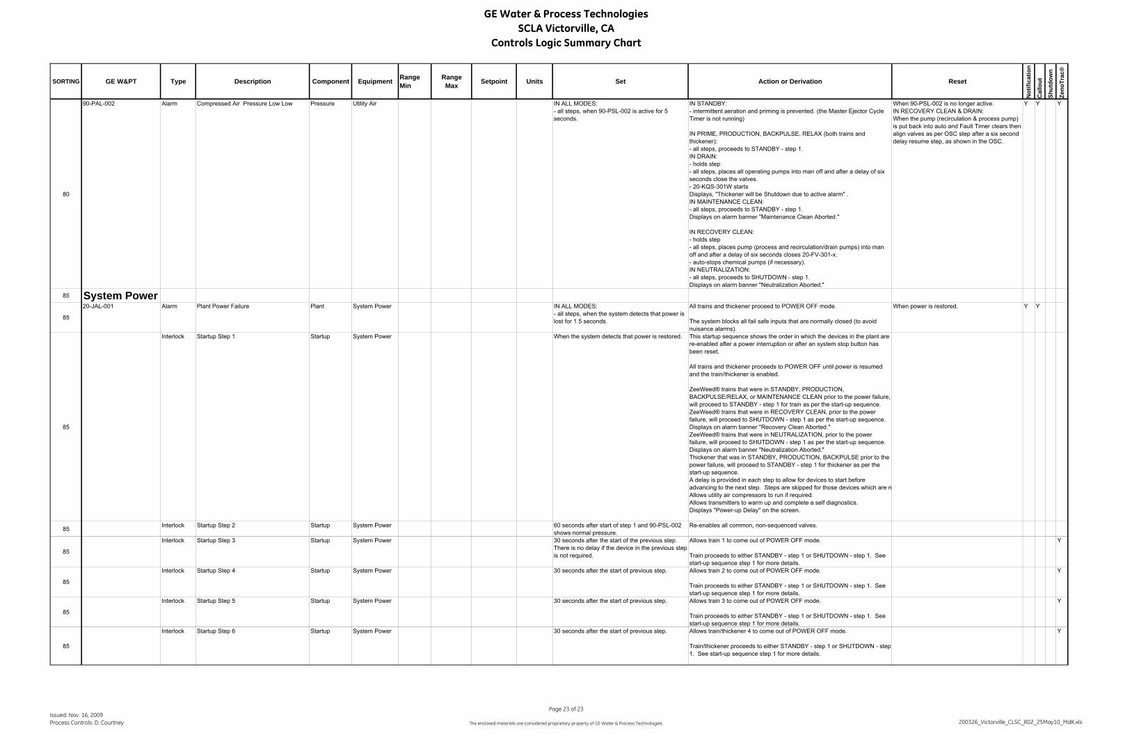
GE Water & Process TechnologiesSCLA Victorville, CA
Controls Logic Summary Chart
SORTING GE W&PT Type Description Component Equipment RangeMin
RangeMax Setpoint Units Set Action or Derivation Reset
Not
ifica
tion
Cal
lout
Shut
dow
n
Zeno
Trac
®
80
90-PAL-002 Alarm Compressed Air Pressure Low Low Pressure Utility Air IN ALL MODES:- all steps, when 90-PSL-002 is active for 5 seconds.
IN STANDBY:- intermittent aeration and priming is prevented. (the Master Ejector Cycle Timer is not running)
IN PRIME, PRODUCTION, BACKPULSE, RELAX (both trains and thickener):- all steps, proceeds to STANDBY - step 1.IN DRAIN:- holds step- all steps, places all operating pumps into man off and after a delay of six seconds close the valves.- 20-KQS-301W startsDisplays, "Thickener will be Shutdown due to active alarm" .IN MAINTENANCE CLEAN:- all steps, proceeds to STANDBY - step 1.Displays on alarm banner "Maintenance Clean Aborted."
IN RECOVERY CLEAN:- holds step- all steps, places pump (process and recirculation/drain pumps) into man off and after a delay of six seconds closes 20-FV-301-x.- auto-stops chemical pumps (if necessary).IN NEUTRALIZATION:- all steps, proceeds to SHUTDOWN - step 1.Displays on alarm banner "Neutralization Aborted."
When 90-PSL-002 is no longer active.IN RECOVERY CLEAN & DRAIN:When the pump (recirculation & process pump) is put back into auto and Fault Timer clears then align valves as per OSC step after a six second delay resume step, as shown in the OSC.
Y Y Y
85 System Power
85
20-JAL-001 Alarm Plant Power Failure Plant System Power IN ALL MODES:- all steps, when the system detects that power is lost for 1.5 seconds.
All trains and thickener proceed to POWER OFF mode.
The system blocks all fail safe inputs that are normally closed (to avoid nuisance alarms).
When power is restored. Y Y
85
Interlock Startup Step 1 Startup System Power When the system detects that power is restored. This startup sequence shows the order in which the devices in the plant are re-enabled after a power interruption or after an system stop button has been reset.
All trains and thickener proceeds to POWER OFF until power is resumed and the train/thickener is enabled.
ZeeWeed® trains that were in STANDBY, PRODUCTION, BACKPULSE/RELAX, or MAINTENANCE CLEAN prior to the power failure, will proceed to STANDBY - step 1 for train as per the start-up sequence.ZeeWeed® trains that were in RECOVERY CLEAN, prior to the power failure, will proceed to SHUTDOWN - step 1 as per the start-up sequence. Displays on alarm banner "Recovery Clean Aborted."ZeeWeed® trains that were in NEUTRALIZATION, prior to the power failure, will proceed to SHUTDOWN - step 1 as per the start-up sequence. Displays on alarm banner "Neutralization Aborted."Thickener that was in STANDBY, PRODUCTION, BACKPULSE prior to the power failure, will proceed to STANDBY - step 1 for thickener as per the start-up sequence.A delay is provided in each step to allow for devices to start before advancing to the next step. Steps are skipped for those devices which are nAllows utility air compressors to run if required.Allows transmitters to warm up and complete a self diagnostics.Displays "Power-up Delay" on the screen.
85 Interlock Startup Step 2 Startup System Power 60 seconds after start of step 1 and 90-PSL-002 shows normal pressure.
Re-enables all common, non-sequenced valves.
85
Interlock Startup Step 3 Startup System Power 30 seconds after the start of the previous step. There is no delay if the device in the previous step is not required.
Allows train 1 to come out of POWER OFF mode.
Train proceeds to either STANDBY - step 1 or SHUTDOWN - step 1. See start-up sequence step 1 for more details.
Y
85
Interlock Startup Step 4 Startup System Power 30 seconds after the start of previous step. Allows train 2 to come out of POWER OFF mode.
Train proceeds to either STANDBY - step 1 or SHUTDOWN - step 1. See start-up sequence step 1 for more details.
Y
85
Interlock Startup Step 5 Startup System Power 30 seconds after the start of previous step. Allows train 3 to come out of POWER OFF mode.
Train proceeds to either STANDBY - step 1 or SHUTDOWN - step 1. See start-up sequence step 1 for more details.
Y
85
Interlock Startup Step 6 Startup System Power 30 seconds after the start of previous step. Allows train/thickener 4 to come out of POWER OFF mode.
Train/thickener proceeds to either STANDBY - step 1 or SHUTDOWN - step 1. See start-up sequence step 1 for more details.
Y
Issued: Nov. 16, 2009Process Controls: D. Courtney
Page 23 of 23
The enclosed materials are considered proprietary property of GE Water & Process Technologies. 200326_Victorville_CLSC_R02_25May10_MdK.xls

This page has beenintentionally left blank

SECTION 6WARRANTY

This page has beenintentionally left blank

Warranty Information Sheet
m- fill out Green Highlighted sections before transfer to Service. Tech Support - fill out Yellow Highlighted sections before transfer A 0 Binder to PM. Include this sheet with every A 0
MECHANICAL EQUIPMENT IXI Zenon Standard Proposal Terms Client Specification Terms
Term Details: WARRANTY TERM: 12 months from Substantial Completion or 18 months from ship
PROCESS GUARANTEE - N/A Biology by Others Zenon Standard Proposal Terms Client Specification Terms
Term Details:- GUARANTEE TERM:
DETAILS OF WARRANTY:
MEMBRANE Zenon Standard Proposal Terms Client Specification Terms
Term Details:-
WARRANTY TERM: Cliff Warranty Term - Length of Cliff term Prorated Warranty Term - Length of Pro-rated term
GUARANTEED MEMBRANE REPLACEMENT COST: $NONE given IXI USD [7 CDN Other Unique calculation required for replacement price?
List details MSRP
MSRP Price List Effective Date
MEMBRANE REPLACEMENT 'OST (No $None given tXI USD CDN Other MEMBRANE COST FOR FUTURE EXPANSION NIA us, ,DN Other
Oakville
PRICE ESCALATION CALCULATION REQUIRED: (XI Yes No IXI US Bureau of Labour State Specific
Canada Unique terms: Maximum Fibre Repairs : (module/cassette/train)
over (montldy earllife) SERVICE
LEVEL OF ZENOTRAC SERVICE: None SERVICE CONTRACT: # OF VISITS 0 # OF YEARS 0
I ENF-042 Rev 06 16-Jan-06 This warranty applies to the Originalpurc/mser only, and is non transferable. 1 of 1 This is a summary and requires supporting documentation for each item. I

This page has beenintentionally left blank

SECTION 7RECOMMENDED SPARE PARTS LIST

This page has beenintentionally left blank
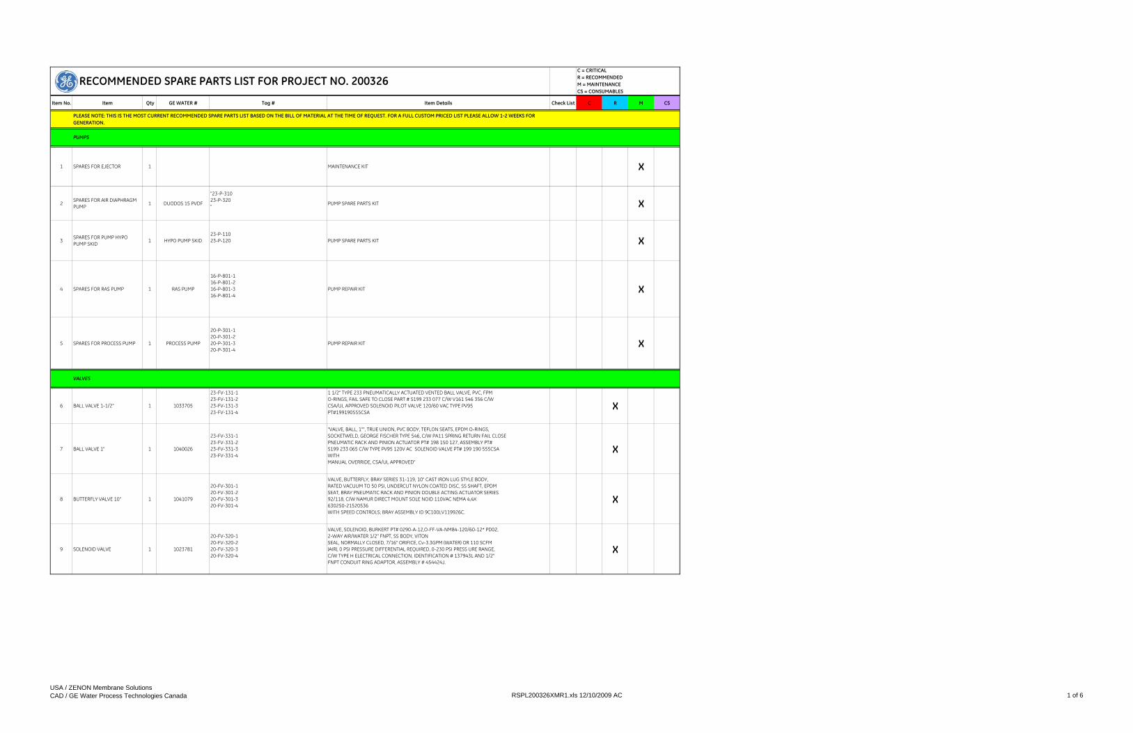
Item No. Item Qty GE WATER # Tag # Item Details Check List C R M CS
1 SPARES FOR EJECTOR 1 MAINTENANCE KIT X
2SPARES FOR AIR DIAPHRAGM PUMP 1 DUODOS 15 PVDF
"23-P-31023-P-320" PUMP SPARE PARTS KIT X
3SPARES FOR PUMP HYPO PUMP SKID 1 HYPO PUMP SKID
23-P-11023-P-120 PUMP SPARE PARTS KIT X
4 SPARES FOR RAS PUMP 1 RAS PUMP
16-P-801-116-P-801-216-P-801-316-P-801-4
PUMP REPAIR KIT X
5 SPARES FOR PROCESS PUMP 1 PROCESS PUMP
20-P-301-120-P-301-220-P-301-320-P-301-4
PUMP REPAIR KIT X
6 BALL VALVE 1-1/2" 1 1033705
23-FV-131-123-FV-131-223-FV-131-323-FV-131-4
1 1/2" TYPE 233 PNEUMATICALLY ACTUATED VENTED BALL VALVE, PVC, FPM O-RINGS, FAIL SAFE TO CLOSE PART # S199 233 077 C/W V161 546 356 C/W CSA/UL APPROVED SOLENOID PILOT VALVE 120/60 VAC TYPE PV95 PT#199190555CSA
X
7 BALL VALVE 1" 1 1040026
23-FV-331-123-FV-331-223-FV-331-323-FV-331-4
"VALVE, BALL, 1"", TRUE UNION, PVC BODY, TEFLON SEATS, EPDM O-RINGS, SOCKETWELD, GEORGE FISCHER TYPE 546, C/W PA11 SPRING RETURN FAIL CLOSE PNEUMATIC RACK AND PINION ACTUATOR PT# 198 150 127, ASSEMBLY PT# S199 233 065 C/W TYPE PV95 120V AC SOLENOID VALVE PT# 199 190 555CSA WITH MANUAL OVERRIDE, CSA/UL APPROVED"
X
8 BUTTERFLY VALVE 10" 1 1041079
20-FV-301-120-FV-301-220-FV-301-320-FV-301-4
VALVE, BUTTERFLY, BRAY SERIES 31-119, 10" CAST IRON LUG STYLE BODY, RATED VACUUM TO 50 PSI, UNDERCUT NYLON COATED DISC, SS SHAFT, EPDM SEAT, BRAY PNEUMATIC RACK AND PINION DOUBLE ACTING ACTUATOR SERIES 92/118, C/W NAMUR DIRECT MOUNT SOLE NOID 110VAC NEMA 4,4X 630250-21520536 WITH SPEED CONTROLS; BRAY ASSEMBLY ID 9C100LV119926C.
X
9 SOLENOID VALVE 1 1023781
20-FV-320-120-FV-320-220-FV-320-320-FV-320-4
VALVE, SOLENOID, BURKERT PT# 0290-A-12,O-FF-VA-NM84-120/60-12* PD02, 2-WAY AIR/WATER 1/2" FNPT, SS BODY, VITONSEAL, NORMALLY CLOSED, 7/16" ORIFICE, Cv-3.3GPM (WATER) OR 110 SCFM(AIR), 0 PSI PRESSURE DIFFERENTIAL REQUIRED, 0-230 PSI PRESS URE RANGE,C/W TYPE H ELECTRICAL CONNECTION, IDENTIFICATION # 137943L AND 1/2"FNPT CONDUIT RING ADAPTOR, ASSEMBLY # 454424J.
X
PLEASE NOTE: THIS IS THE MOST CURRENT RECOMMENDED SPARE PARTS LIST BASED ON THE BILL OF MATERIAL AT THE TIME OF REQUEST. FOR A FULL CUSTOM PRICED LIST PLEASE ALLOW 1-2 WEEKS FOR GENERATION.
PUMPS
VALVES
C = CRITICAL R = RECOMMENDEDM = MAINTENANCECS = CONSUMABLES
RECOMMENDED SPARE PARTS LIST FOR PROJECT NO. 200326
USA / ZENON Membrane SolutionsCAD / GE Water Process Technologies Canada RSPL200326XMR1.xls 12/10/2009 AC 1 of 6

Item No. Item Qty GE WATER # Tag # Item Details Check List C R M CS
C = CRITICAL R = RECOMMENDEDM = MAINTENANCECS = CONSUMABLES
RECOMMENDED SPARE PARTS LIST FOR PROJECT NO. 200326
10 ANGLE SEAT VALVE 0.5" 1 1033457
0.5" BURKERT ANGLE SEAT AND SOLENOID VALVE ASSEMBLYUSED FOR VACCON EJECTORSYST-2000-463250-6518-CD06041Type 2000 Piston Valve material # 92707036.2/2-Ways Normaly ClosedOrifice: 13mm (1/2")Seal: FKM (viton)Body: Stainless SteelPort: NPT 1/2"Actautor: PAActuator Size: 50mmFLOW ABOVE SEATVACUUM VERSIONType 6518 Pilot ValvePower Supply: 120 Volts / 60 Hertz / 2 Watts
X
11 KNIFE GATE VALVE 14" 1 KN GATE DA 14IN16-FV-82016-FV-821
14 INCH ORBINOX #20-3636R-14-PA FULL KNIFE GATEVALVE,316SS BODY AND GATE, PTFE IMPREGNATEDSYNTHETIC FIBER PACKING, EPDM SEATC/W PNEUMATIC DOUBLE ACTING CYLINDER, BASED ON 80 PSI AIR SUPPLY AND 60 PSIDIFFERENTIAL PRESSURE.DOUBLE ACTING PNEUMATIC ACTUATOR
X
12 KNIFE GATE VALVE 18" 1 KN GATE DA 18IN
20-FV-501-120-FV-501-220-FV-501-320-FV-501-4
18 INCH ORBINOX #20-3636R-18-PA FULL KNIFE GATEVALVE,316SS BODY AND GATE, PTFE IMPREGNATEDSYNTHETIC FIBER PACKING, EPDM SEAT,C/W 10” BORE PNEUMATIC DOUBLE ACTINGCYLINDER, BASED ON 80 PSI AIR SUPPLY AND 30 PSIDIFFERENTIAL PRESSURE.
X
13 CYCLIC VALVE 10" 1 1033379
20-FV-210-120-FV-210-220-FV-210-320-FV-210-420-FV-211-120-FV-211-220-FV-211-320-FV-211-4
BUTTERFLY VALVE, LUG, HIGH PERFORMANCE, 10", TYCO, K-LOK PT#F362-105-K-LOK, ANSI 150#, 316SS LUG STYLE BODY, 316SS DISC, 17-4pH,SS STEM, RTFE SEAT,FIBERGLASS RTFE IMPREGNATED BUSHINGS, C/W MORIN SERIES B-036 DA, DOUBLE ACTING PNEUMATIC A CTUATOR SCOTCH YOKE STYLE, DUCTILE IRON ACTUATOR BODY AND END CAPS, SS CYLINDER C/W WESTLOCK QUANTUM POSITION MONITOR PT# 765-N-BY-1A-2M06-00-A-36-0-L, 1/2" CONDUIT ENTRY, C/W WITH BUILT-IN 120VAC SOLENOID ENERGIZED TO CLOSE, MANUAL OVE RRIDE, POWER LOSS OPENS, TWO SPDT MAGNUM PROXIMITY SWITCHES 3A @ 120VAC, NEMA 4, 4,4X, C/W ASCO SERIES 112, 1/4" NPT FILTER/REGULATOR WITH PRESSURE GAUGE, PT# 34203089, 25 MICRON FILTER WITH BOWL PROTECTOR, SEMI-AUTO DRAIN, PRESSURE CONT ROL RANGE 7-145 PSI, COMES ASSEMBLED WITH TWO DELTROL 1/4" INLINE SPEED CONTROLS & TWO PARKER ES25MB MUFFLERS FOR NOISE REDUCTION.
X
14 PRESSURE GAUGE 1 1023426
16-PI-801-116-PI-801-216-PI-801-316-PI-801-416-PI-802-116-PI-802-216-PI-802-316-PI-802-4
PRESSURE GAUGE, ASHCROFT PT# 100-1008SL-04L 15PSI, SS CASE 100MM DIAL(4"), 0-15 PSI (DUAL SCALE PSI & kPa) 1/2" LOWER CONNECTION, GLYCERINEFILLED, 3-2-3% ASME GR B ACCURACY, POLYCARBONATE WINDOW. X
15DIAPHRAGM SEAL FOR ABOVE PRESSURE GAUGES 1 1033613
FOR16-PI-801-1/2/3/416-PI-802-1/2/3/4
DIAPHRAGM SEAL, TYPE 100, ASHCROFT PT # 15-102SSL-04T-CK-150, ALL CLAMPED, 1 ½” FLANGE CONNECTION 150#, DIAPHRAGM AND HOUSING OF 316SS, ½” FNPT GAUGE CONNECTION, GUAGE MOUNTED WITH SILICONE FLUID FOR PRESSURE APPLICATION. X
16 PRESSURE GAUGE 1 1023462
20-PI-301-120-PI-301-220-PI-301-320-PI-301-420-PI-302-120-PI-302-220-PI-302-320-PI-302-4
PRESSURE GAUGE, ASHCROFT PT# 100-1008SL-04L 30PSI, SS CASE, 100MM DIAL(4"), 30" MERCURY-30 PSI (DUAL SCALE IN MECURY & PSI/kPa) 1/2" LOWERCONNECTION, GLYCERINE FILLED, 3-2-3% ASME GR B ACCURACY, POLYCARBONATEWINDOW.
X
INSTRUMENTS
USA / ZENON Membrane SolutionsCAD / GE Water Process Technologies Canada RSPL200326XMR1.xls 12/10/2009 AC 2 of 6
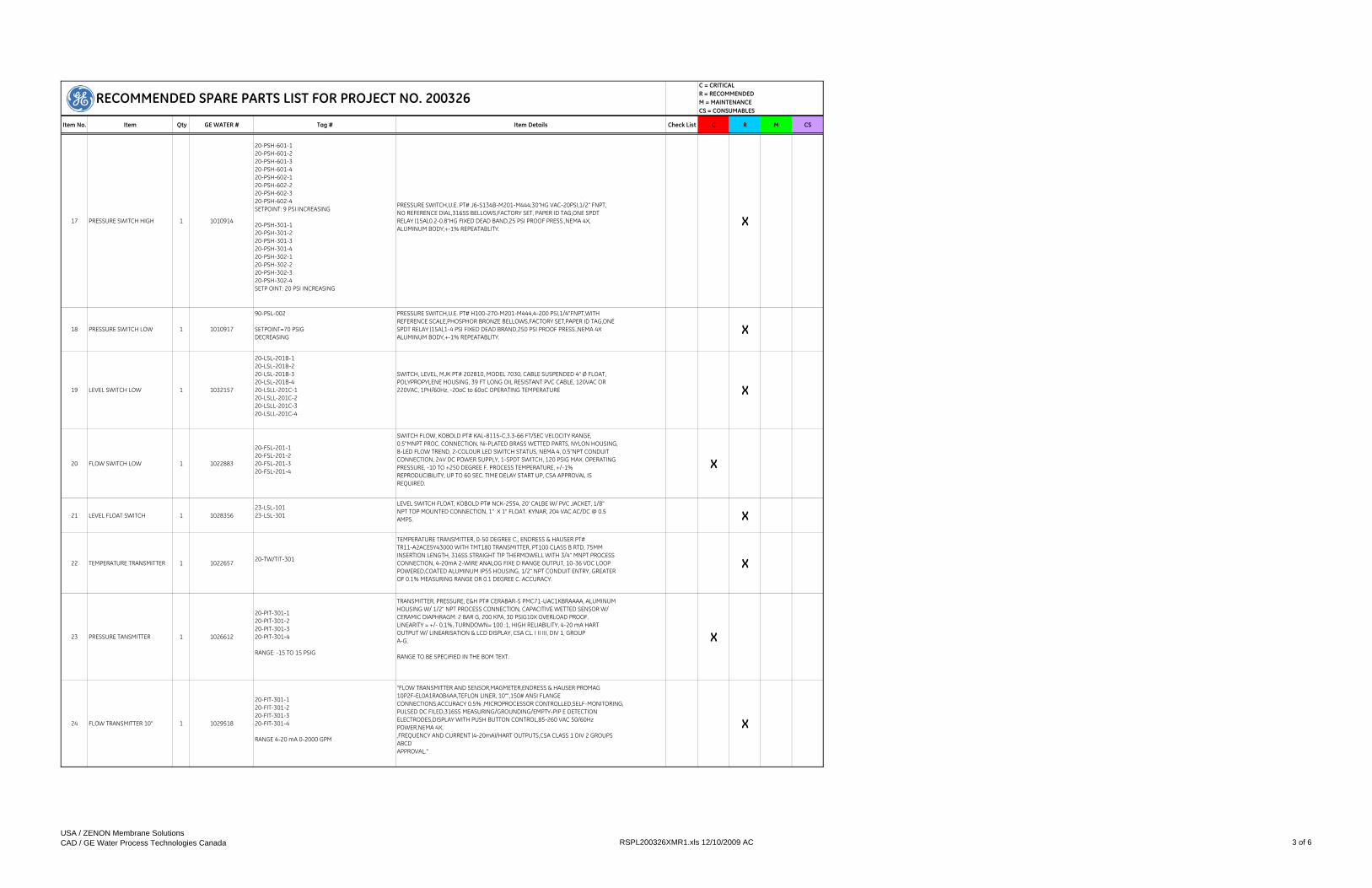
Item No. Item Qty GE WATER # Tag # Item Details Check List C R M CS
C = CRITICAL R = RECOMMENDEDM = MAINTENANCECS = CONSUMABLES
RECOMMENDED SPARE PARTS LIST FOR PROJECT NO. 200326
17 PRESSURE SWITCH HIGH 1 1010914
20-PSH-601-120-PSH-601-220-PSH-601-320-PSH-601-420-PSH-602-120-PSH-602-220-PSH-602-320-PSH-602-4SETPOINT: 9 PSI INCREASING
20-PSH-301-120-PSH-301-220-PSH-301-320-PSH-301-420-PSH-302-120-PSH-302-220-PSH-302-320-PSH-302-4SETP OINT: 20 PSI INCREASING
PRESSURE SWITCH,U.E. PT# J6-S134B-M201-M444,30"HG VAC-20PSI,1/2" FNPT,NO REFERENCE DIAL,316SS BELLOWS,FACTORY SET, PAPER ID TAG,ONE SPDTRELAY (15A),0.2-0.8"HG FIXED DEAD BAND,25 PSI PROOF PRESS.,NEMA 4X,ALUMINUM BODY,+-1% REPEATABLITY.
X
18 PRESSURE SWITCH LOW 1 1010917
90-PSL-002
SETPOINT=70 PSIG DECREASING
PRESSURE SWITCH,U.E. PT# H100-270-M201-M444,4-200 PSI,1/4"FNPT,WITHREFERENCE SCALE,PHOSPHOR BRONZE BELLOWS,FACTORY SET,PAPER ID TAG,ONESPDT RELAY (15A),1-4 PSI FIXED DEAD BRAND,250 PSI PROOF PRESS.,NEMA 4XALUMINUM BODY,+-1% REPEATABLITY.
X
19 LEVEL SWITCH LOW 1 1032157
20-LSL-201B-120-LSL-201B-220-LSL-201B-320-LSL-201B-420-LSLL-201C-120-LSLL-201C-220-LSLL-201C-320-LSLL-201C-4
SWITCH, LEVEL, MJK PT# 202810, MODEL 7030, CABLE SUSPENDED 4" Ø FLOAT, POLYPROPYLENE HOUSING, 39 FT LONG OIL RESISTANT PVC CABLE, 120VAC OR 220VAC, 1PH/60Hz, -20oC to 60oC OPERATING TEMPERATURE X
20 FLOW SWITCH LOW 1 1022883
20-FSL-201-120-FSL-201-220-FSL-201-320-FSL-201-4
SWITCH FLOW, KOBOLD PT# KAL-8115-C,3.3-66 FT/SEC VELOCITY RANGE,0.5"MNPT PROC. CONNECTION, Ni-PLATED BRASS WETTED PARTS, NYLON HOUSING,8-LED FLOW TREND, 2-COLOUR LED SWITCH STATUS, NEMA 4, 0.5"NPT CONDUITCONNECTION, 24V DC POWER SUPPLY, 1-SPDT SWITCH, 120 PSIG MAX. OPERATINGPRESSURE, -10 TO +250 DEGREE F. PROCESS TEMPERATURE, +/-1%REPRODUCIBILITY, UP TO 60 SEC. TIME DELAY START UP, CSA APPROVAL ISREQUIRED.
X
21 LEVEL FLOAT SWITCH 1 102835623-LSL-10123-LSL-301
LEVEL SWITCH FLOAT, KOBOLD PT# NCK-2554, 20' CALBE W/ PVC JACKET, 1/8" NPT TOP MOUNTED CONNECTION, 1" X 1" FLOAT. KYNAR, 204 VAC AC/DC @ 0.5 AMPS. X
22 TEMPERATURE TRANSMITTER 1 102265720-TW/TIT-301
TEMPERATURE TRANSMITTER, 0-50 DEGREE C., ENDRESS & HAUSER PT# TR11-A2ACESY43000 WITH TMT180 TRANSMITTER, PT100 CLASS B RTD, 75MM INSERTION LENGTH, 316SS STRAIGHT TIP THERMOWELL WITH 3/4" MNPT PROCESS CONNECTION, 4-20mA 2-WIRE ANALOG FIXE D RANGE OUTPUT, 10-36 VDC LOOP POWERED,COATED ALUMINUM IP55 HOUSING, 1/2" NPT CONDUIT ENTRY, GREATER OF 0.1% MEASURING RANGE OR 0.1 DEGREE C. ACCURACY.
X
23 PRESSURE TANSMITTER 1 1026612
20-PIT-301-120-PIT-301-220-PIT-301-320-PIT-301-4
RANGE: -15 TO 15 PSIG
TRANSMITTER, PRESSURE, E&H PT# CERABAR-S PMC71-UAC1KBRAAAA, ALUMINUM HOUSING W/ 1/2" NPT PROCESS CONNECTION, CAPACITIVE WETTED SENSOR W/ CERAMIC DIAPHRAGM: 2 BAR G, 200 KPA, 30 PSIG10X OVERLOAD PROOF. LINEARITY = +/- 0.1%, TURNDOWN= 100 :1, HIGH RELIABILITY, 4-20 mA HART OUTPUT W/ LINEARISATION & LCD DISPLAY, CSA CL. I II III, DIV 1, GROUP A-G.
RANGE TO BE SPECIFIED IN THE BOM TEXT.
X
24 FLOW TRANSMITTER 10" 1 1029518
20-FIT-301-120-FIT-301-220-FIT-301-320-FIT-301-4
RANGE 4-20 mA 0-2000 GPM
"FLOW TRANSMITTER AND SENSOR,MAGMETER,ENDRESS & HAUSER PROMAG 10P2F-EL0A1RA0B4AA,TEFLON LINER, 10"",150# ANSI FLANGE CONNECTIONS,ACCURACY 0.5% ,MICROPROCESSOR CONTROLLED,SELF-MONITORING,PULSED DC FILED,316SS MEASURING/GROUNDING/EMPTY-PIP E DETECTIONELECTRODES,DISPLAY WITH PUSH BUTTON CONTROL,85-260 VAC 50/60Hz POWER,NEMA 4X,,FREQUENCY AND CURRENT (4-20mA)/HART OUTPUTS,CSA CLASS 1 DIV 2 GROUPS ABCDAPPROVAL."
X
USA / ZENON Membrane SolutionsCAD / GE Water Process Technologies Canada RSPL200326XMR1.xls 12/10/2009 AC 3 of 6

Item No. Item Qty GE WATER # Tag # Item Details Check List C R M CS
C = CRITICAL R = RECOMMENDEDM = MAINTENANCECS = CONSUMABLES
RECOMMENDED SPARE PARTS LIST FOR PROJECT NO. 200326
25 FLOW TRANSMITTER 14" 1 1029520
16-FIT-801-116-FIT-801-216-FIT-801-316-FIT-801-4
RANGE 4-20mA FROM 0-2500 GPM
"FLOW TRANSMITTER AND SENSOR,MAGMETER,ENDRESS & HAUSER PROMAG 10P3F-EL0A1RA0B4AA,TEFLON LINER, 14"",150# ANSI FLANGE CONNECTIONS,ACCURACY 0.5% ,MICROPROCESSOR CONTROLLED,SELF-MONITORING,PULSED DC FILED,316SS MEASURING/GROUNDING/EMPTY-PIP E DETECTIONELECTRODES,DISPLAY WITH PUSH BUTTON CONTROL,85-260 VAC 50/60Hz POWER,NEMA 4X,,FREQUENCY AND CURRENT (4-20mA)/HART OUTPUTS,CSA CLASS 1 DIV 2 GROUPS ABCDAPPROVAL."
X
26 LEVEL SWITCH LOW 1 103057820-LSL-30220-LSL-303
E&H VIBRATION LEVEL SWITCH, COMPACT, PT# FTL20-3314, CSA GENERAL PURPOSE, 3/4" NPT, 316SS, HOUSING 316SS, 1/2" NPT ELECTRICAL CONN, 2 WIRE OUTPUTS, 19…253VAC, CABLE ENTRY IP65. X
27 LEVEL TRANSMITTER 1 1030631
20-LIT-201A-120-LIT-201A-220-LIT-201A-320-LIT-201A-4
ROD LENGTH = 160 INCHRANGE 4-20mA from 0 to 160 INCHSG = 1
TRANSMITTER, LEVEL, E&H PT# DELTAPILOT-S DB51A-TG32FC11GE3A, 316L 3"150# ANSI FLANGE PROCESS CONNECTION, TRANSMITTER FOR HYDROSTATIC LEVEL MEASUREMENT, TUBE (ROD) VERSION FOR MOUNTING IN TANKS, FLUSH MOUNTED CONTITE-SENSOR W/ METALLIC D IAPHRAGM ALLOY C4, HERMETICALLY WELDED. CSA, CL. 1, DIV 2, GROUP A-D. MEASURING RANGE: 0-15 PSIG. CELL W/ LINEARITY < 0.2%, SILICON FILL & VITON SEAL. LOOP POWERED 4-20 mA W/ DISPLAY, HART PROT. 316l SS NEMA 4X HOUSING W/ 1/2"" CON DUIT CONNECTION.
X
28 SPARE LAMP FOR ON-LINE TURBIDIMETER
1 1022882
20-AE/AIT-320-120-AE/AIT-320-220-AE/AIT-320-320-AE/AIT-320-4
SPARE LAMP FOR ON-LINE TURBIDIMETER. X
29 SPARE PHOTOCELL FOR ON-LINE TURBIDIMETER
1 1027420
20-AE/AIT-320-120-AE/AIT-320-220-AE/AIT-320-320-AE/AIT-320-4
SPARE PHOTOCELL FOR ON-LINE TURBIDIMETER. X
30 CALIBRATION SOLUTION 1L 4 1028119 For Turbidimater STABLCAL STABILIZED FORMAZIN CALIBRATION SOLUTION, HACH,PT #26601-53, INCLUDES 1L OF 20 NTU STABLCAL STANDARD (CALIBRATION CYLINDER REQUIRED). FOR SINGLE CALIBRATION ONLY.
X X
31 COUPLING 3" 14 1027929
STRAUB COUPLING, NON-RESTRAINT, FLEX 1L, F1L 3" IPS, E, 316L SS CASING, LP & INSERT, 3.7" LONG, 3" NOM INNER DIAMETER (88.9 MM), 5.4" OUTER DIAMETER, 1 PC, PRESSURE RATING: 232 PSI, 316L SS FULL VACUUM RATED STRIP INSERT EPDM SEALING SLE EVE, 2 X BOLTS, M8, 5.5 FT.LB, MAX PIPE GAP 1".
X
32 COUPLING 6" 7 1027931
STRAUB COUPLING, NON-RESTRAINT, FLEX 1L, F1L 6" IPS, E, 316L SS CASING, LP & INSERT, 4.21" LONG, 6" NOM INNER DIAMETER (168.3 MM), 7.5" OUTER DIAMETER, 1 PC PRESSURE RATING: 232 PSI, 316L SS FULL VACUUM RATED STRIP INSERT EPDM SEALING SLEEVE, 2 X BOLTS, M10, 7.5 FT.LB.
X
33SPARES FOR - COALESCING PREFILTER FOR COMPRESSED AIR
190-F-020
FILTER ELEMENT X X
34 40 MICRON FILTER 2F-9200-1F-9200-2
FILTER ONLY FOR - FILTER, COMPRESSED AIR, GENERAL PURPOSE, 40 MICRON ELEMENT, 1/4" NPTF CONNECTIONS, C/W SIGHT GAUGE AND TWIST DRAIN, METAL BOWL X X
35 SPARES FOR - PRV COMP AIR 1 PRV COMP AIR
90-PY-001
SETPOINT = 80 PSIG
40 MICRON ELEMENT, 0-250 PSI RANGE, C/W GAUGE. RATED FOR
X X
36 AIR DRYER 1 AIR DRYER90-DR-001-190-DR-001-2
Great Lakes Model GRF-100A-116 Refrigerated DryerComplete with: Stainless Steel Coolers, Low Ambient Head Master Control, NEMA4 Electrics, Crankcase heater, High/Low Refrigerant Pressure Cut Out with Manual Reset.
X
MISCELLANEOUS
USA / ZENON Membrane SolutionsCAD / GE Water Process Technologies Canada RSPL200326XMR1.xls 12/10/2009 AC 4 of 6

Item No. Item Qty GE WATER # Tag # Item Details Check List C R M CS
C = CRITICAL R = RECOMMENDEDM = MAINTENANCECS = CONSUMABLES
RECOMMENDED SPARE PARTS LIST FOR PROJECT NO. 200326
37 SPARES FOR AIR COMPRESSOR 2 AIR COMPRESSOR
90-F-001-190-AC-001-190-TK001-190-PSV-001-190-FV-001-190-HV-001-190-PI-001-1
90-F-001-290-AC-001-290-TK001-290-PSV-001-290-FV-001-290-HV-001-290-PI-001-2
SPARE PARTS KIT X X
38SPARES FOR MEMBRANE BLOWER 4 MEMBRANE BLOWER
20-B-201-120-B-201-220-B-201-320-B-201-4
AIR FILTER & BELT SET X X
39 ZW500D V2.1.3CASSETTE SPARE PARTS KIT
1 1029418 KIT INCLUDES: INTERCONNECTION STRIP, O-RINGS, BOLTS, NUTS, WASHERS, MODULE RELEASE TOOL, LOCKING KEYS. X
40 ZW 500D Module Permeate Adapter
1 1028578 SINGLE MODULE ADAPTER FOR FLUSHING/BUBBLE TESTING X
41 ZW500D REMOVAL TOOL 1 1032836 ZW500D MDL REMOVAL TOOL(REV5-NOV2007) X
42 ZW500D Blank Header 1 1029083 ZW500D, DUMMY ELEMENT, TOP AND BOTTOM FILLED WITH URETHANE X
43 Bubble/Pressure Decay Test Kit
1 1023613
PORTABLE INSTRUMENTS FOR TESTING THE INTEGRITY OF ZEEWEED MEMBRANES. THE UNIT INCLUDES A HIGH ACCURACY DIGITAL PRESSURE DISPLAY, A PRECISION AIR REGULATOR WITH PRESET UPPER LIMIT PRIMARY. PROTECTION AT 8 PSI, A SECONDARY AIR RELIEF PROTECTION VALVE, COALESCING AIR FILTER, STAINLESS STEEL CASING WITH HANDLE, 20 FEET OF 1/4 TUBING, 2X3" AND 2X4" CAMLOCK END CAPS EACH WITH A 1/4" FEMALE QUICK CONNECT.
X
44 Fiber Repair Kit 1 1022887 ( 4 ) 20cc SYRINGE, ( 10 ) NEEDLES (PURPLE), ( 5 ) 22G NEEDLES, SILICONE ( SHELF LIFE OF 6 MONTHS ), SCISSORS 4 1/2", ( 2 ) GLOVES. X X
45 Silicone Dispensing Gun 1 1025796 FOR USE WITH FIBER REPAIR KIT. X
46Pneumatic Silicone Injection Tool (LITTLE JOE)
1 1028260 *Option to above Item*Compressed Air Injection Gun (requires 10cc barrels) X
47 Membrane Maintenance Station - Tank
1 1027906 PLASTIC WORK TANK WITH METAL STAND X
48 Membrane Maintenance Station - Pump Kit
1 1027907 SKID MOUNTED - PUMP FOR FLUSHING/PRESERVING MODULES X
49 Membrane Maintenance Station - Hose Kit
1 1027908 3 HOSE SECTIONS FOR CONNECTION PUMP KIT TO MODULES X
50 Membrane Maintenance Station - Work Tray
1 1027985 SLIDING TRAY FOR TOP OF TANK X
ZEE-WEED Membrane Spares
REQUIRED FOR REGULAR CASSETTE & MEMBRANE MAINTENANCE.
USA / ZENON Membrane SolutionsCAD / GE Water Process Technologies Canada RSPL200326XMR1.xls 12/10/2009 AC 5 of 6
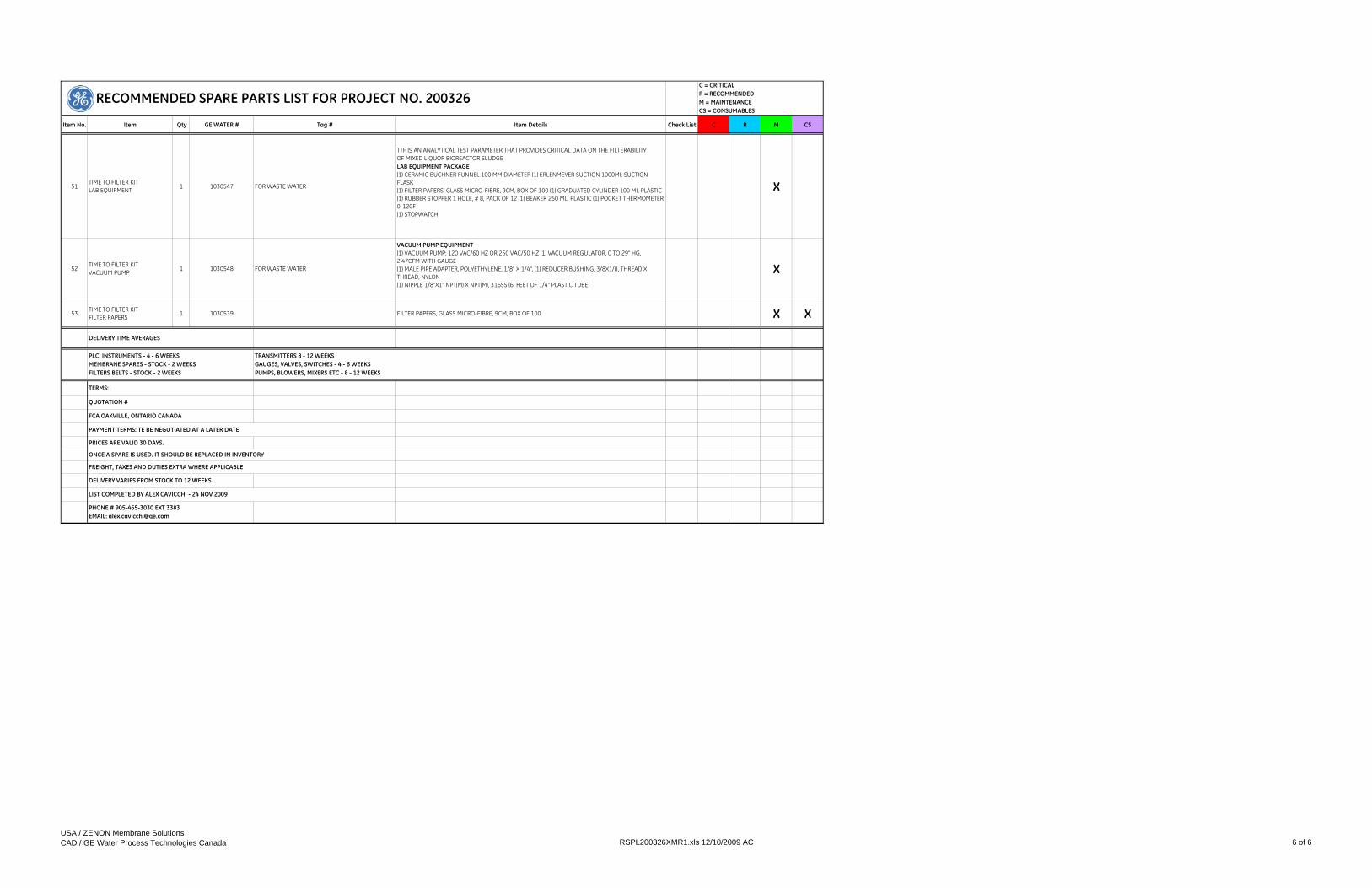
Item No. Item Qty GE WATER # Tag # Item Details Check List C R M CS
C = CRITICAL R = RECOMMENDEDM = MAINTENANCECS = CONSUMABLES
RECOMMENDED SPARE PARTS LIST FOR PROJECT NO. 200326
51TIME TO FILTER KIT LAB EQUIPMENT 1 1030547 FOR WASTE WATER
TTF IS AN ANALYTICAL TEST PARAMETER THAT PROVIDES CRITICAL DATA ON THE FILTERABILITY OF MIXED LIQUOR BIOREACTOR SLUDGELAB EQUIPMENT PACKAGE(1) CERAMIC BUCHNER FUNNEL 100 MM DIAMETER (1) ERLENMEYER SUCTION 1000ML SUCTION FLASK(1) FILTER PAPERS, GLASS MICRO-FIBRE, 9CM, BOX OF 100 (1) GRADUATED CYLINDER 100 ML PLASTIC(1) RUBBER STOPPER 1 HOLE, # 8, PACK OF 12 (1) BEAKER 250 ML, PLASTIC (1) POCKET THERMOMETER 0-120F(1) STOPWATCH
X
52TIME TO FILTER KIT VACUUM PUMP 1 1030548 FOR WASTE WATER
VACUUM PUMP EQUIPMENT (1) VACUUM PUMP; 120 VAC/60 HZ OR 250 VAC/50 HZ (1) VACUUM REGULATOR, 0 TO 29" HG, 2.47CFM WITH GAUGE(1) MALE PIPE ADAPTER, POLYETHYLENE, 1/8" X 1/4", (1) REDUCER BUSHING, 3/8X1/8, THREAD X THREAD, NYLON(1) NIPPLE 1/8"X1" NPT(M) X NPT(M), 316SS (6) FEET OF 1/4" PLASTIC TUBE
X
53 TIME TO FILTER KIT FILTER PAPERS
1 1030539 FILTER PAPERS, GLASS MICRO-FIBRE, 9CM, BOX OF 100 X X
PHONE # 905-465-3030 EXT 3383EMAIL: [email protected]
TERMS:
QUOTATION #
PLC, INSTRUMENTS - 4 - 6 WEEKS MEMBRANE SPARES - STOCK - 2 WEEKS FILTERS BELTS - STOCK - 2 WEEKS
FREIGHT, TAXES AND DUTIES EXTRA WHERE APPLICABLE
LIST COMPLETED BY ALEX CAVICCHI - 24 NOV 2009
DELIVERY VARIES FROM STOCK TO 12 WEEKS
FCA OAKVILLE, ONTARIO CANADA
PRICES ARE VALID 30 DAYS.
TRANSMITTERS 8 - 12 WEEKSGAUGES, VALVES, SWITCHES - 4 - 6 WEEKSPUMPS, BLOWERS, MIXERS ETC - 8 - 12 WEEKS
PAYMENT TERMS: TE BE NEGOTIATED AT A LATER DATE
ONCE A SPARE IS USED. IT SHOULD BE REPLACED IN INVENTORY
DELIVERY TIME AVERAGES
USA / ZENON Membrane SolutionsCAD / GE Water Process Technologies Canada RSPL200326XMR1.xls 12/10/2009 AC 6 of 6

SECTION 8MATERIAL SAFETY DATA SHEETS

This page has beenintentionally left blank

MSDS Number: G4774 * * * * * Effective Date: 05/25/05 * * * * * Supercedes: 08/10/04
GLYCEROL
1. Product Identification Synonyms: 1,2,3-propanetriol; glycerin; glycol alcohol; glycerol, anhydrous CAS No.: 56-81-5 Molecular Weight: 92.10 Chemical Formula: C3H5(OH)3 Product Codes: J.T. Baker: 2135, 2136, 2140, 2142, 2143, 2988, 4043, M778 Mallinckrodt: 0564, 5092, 5093, 5100
2. Composition/Information on Ingredients Ingredient CAS No Percent Hazardous --------------------------------------- ------------ ------------ --------- Glycerin 56-81-5 90 - 100% Yes
3. Hazards Identification Emergency Overview --------------------------
Page 1 of 7GLYCEROL
8/26/2005http://www.jtbaker.com/msds/englishhtml/G4774.htm
CAUTION! MAY CAUSE IRRITATION TO SKIN, EYES, AND RESPIRATORY TRACT. MAY AFFECT KIDNEYS. SAF-T-DATA(tm) Ratings (Provided here for your convenience) ----------------------------------------------------------------------------------------------------------- Health Rating: 2 - Moderate (Life) Flammability Rating: 1 - Slight Reactivity Rating: 0 - None Contact Rating: 1 - Slight Lab Protective Equip: GOGGLES; LAB COAT; VENT HOOD; PROPER GLOVES Storage Color Code: Green (General Storage) ----------------------------------------------------------------------------------------------------------- Potential Health Effects ---------------------------------- Inhalation: Due to the low vapor pressure, inhalation of the vapors at room temperatures is unlikely. Inhalation of mist may cause irritation of respiratory tract. Ingestion: Low toxicity. May cause nausea, headache, diarrhea. Skin Contact: May cause irritation. Eye Contact: May cause irritation. Chronic Exposure: May cause kidney injury. Aggravation of Pre-existing Conditions: Persons with pre-existing skin disorders or eye problems or impaired liver or kidney function may be more susceptible to the effects of the substance.
4. First Aid Measures Inhalation: Remove to fresh air. Get medical attention for any breathing difficulty. Ingestion: Induce vomiting immediately as directed by medical personnel. Never give anything by mouth to an unconscious person. Get medical attention. Skin Contact: Immediately flush skin with plenty of water for at least 15 minutes. Remove contaminated clothing and shoes. Wash clothing before reuse. Thoroughly clean shoes before reuse. Get medical attention if irritation develops. Eye Contact: Immediately flush eyes with plenty of water for at least 15 minutes, lifting upper and lower eyelids occasionally. Get medical attention if irritation persists.
Page 2 of 7GLYCEROL
8/26/2005http://www.jtbaker.com/msds/englishhtml/G4774.htm
5. Fire Fighting Measures Fire: Flash point: 199C (390F) CC Autoignition temperature: 370C (698F) Slight fire hazard when exposed to heat or flame. Slight fire hazard when exposed to heat or flame. Explosion: Above flash point, vapor-air mixtures may cause flash fire. Fire Extinguishing Media: Use any means suitable for extinguishing surrounding fire. Water spray may be used to extinguish surrounding fire and cool exposed containers. Water spray will also reduce fume and irritant gases. Special Information: In the event of a fire, wear full protective clothing and NIOSH-approved self-contained breathing apparatus with full facepiece operated in the pressure demand or other positive pressure mode.
6. Accidental Release Measures Ventilate area of leak or spill. Wear appropriate personal protective equipment as specified in Section 8. Contain and recover liquid when possible. Collect liquid in an appropriate container or absorb with an inert material (e. g., vermiculite, dry sand, earth), and place in a chemical waste container. Do not use combustible materials, such as saw dust. Do not flush to sewer!
7. Handling and Storage Keep in a tightly closed container, stored in a cool, dry, ventilated area. Protect against physical damage. Isolate from incompatible substances. Containers of this material may be hazardous when empty since they retain product residues (vapors, liquid); observe all warnings and precautions listed for the product.
8. Exposure Controls/Personal Protection Airborne Exposure Limits: For Glycerin Mist: - OSHA Permissible Exposure Limit (PEL): Total Dust: 15 mg/m3 (TWA); Respirable Fraction: 5 mg/m3(TWA). - ACGIH Threshold Limit Value (TLV): 10 mg/m3
Page 3 of 7GLYCEROL
8/26/2005http://www.jtbaker.com/msds/englishhtml/G4774.htm
Ventilation System: A system of local and/or general exhaust is recommended to keep employee exposures below the Airborne Exposure Limits. Local exhaust ventilation is generally preferred because it can control the emissions of the contaminant at its source, preventing dispersion of it into the general work area. Please refer to the ACGIH document, Industrial Ventilation, A Manual of Recommended Practices, most recent edition, for details. Personal Respirators (NIOSH Approved): If the exposure limit is exceeded and engineering controls are not feasible, a half facepiece particulate respirator (NIOSH type P95 or R95 filters) may be worn for up to ten times the exposure limit or the maximum use concentration specified by the appropriate regulatory agency or respirator supplier, whichever is lowest.. A full-face piece particulate respirator (NIOSH type P100 or R100 filters) may be worn up to 50 times the exposure limit, or the maximum use concentration specified by the appropriate regulatory agency, or respirator supplier, whichever is lowest. Please note that N filters are not recommended for this material. For emergencies or instances where the exposure levels are not known, use a full-facepiece positive-pressure, air-supplied respirator. WARNING: Air-purifying respirators do not protect workers in oxygen-deficient atmospheres. Skin Protection: Wear protective gloves and clean body-covering clothing. Eye Protection: Use chemical safety goggles. Maintain eye wash fountain and quick-drench facilities in work area.
9. Physical and Chemical Properties Appearance: Clear oily liquid. Odor: Odorless. Solubility: Miscible in water. Specific Gravity: 1.26 @ 20C/4C pH: (neutral to litmus) % Volatiles by volume @ 21C (70F): 0 Boiling Point: 290C (554F) Melting Point: 18C (64F) Vapor Density (Air=1): 3.17 Vapor Pressure (mm Hg): 0.0025 @ 50C (122F) Evaporation Rate (BuAc=1): No information found.
Page 4 of 7GLYCEROL
8/26/2005http://www.jtbaker.com/msds/englishhtml/G4774.htm

10. Stability and Reactivity Stability: Stable under ordinary conditions of use and storage. Hazardous Decomposition Products: Toxic gases and vapors may be released if involved in a fire. Glycerin decomposes upon heating above 290C, forming corrosive gas (acrolein). Hazardous Polymerization: Will not occur. Incompatibilities: Strong oxidizers. Can react violently with acetic anhydride, calcium oxychloride, chromium oxides and alkali metal hydrides. Conditions to Avoid: Heat, flames, ignition sources and incompatibles.
11. Toxicological Information Oral rat LD50: 12,600 mg/kg. Investigated as a mutagen, reproductive effector.
--------\Cancer Lists\------------------------------------------------------ ---NTP Carcinogen--- Ingredient Known Anticipated IARC Category ------------------------------------ ----- ----------- ------------- Glycerin (56-81-5) No No None
12. Ecological Information Environmental Fate: When released into the soil, this material is expected to readily biodegrade. When released into the soil, this material is not expected to evaporate significantly. When released into water, this material is expected to readily biodegrade. This material is not expected to significantly bioaccumulate. When released into the air, this material may be moderately degraded by reaction with photochemically produced hydroxyl radicals. When released into the air, this material may be removed from the atmosphere to a moderate extent by wet deposition. Environmental Toxicity: This material is not expected to be toxic to aquatic life.
13. Disposal Considerations
Page 5 of 7GLYCEROL
8/26/2005http://www.jtbaker.com/msds/englishhtml/G4774.htm
Whatever cannot be saved for recovery or recycling should be managed in an appropriate and approved waste disposal facility. Processing, use or contamination of this product may change the waste management options. State and local disposal regulations may differ from federal disposal regulations. Dispose of container and unused contents in accordance with federal, state and local requirements.
14. Transport Information Not regulated.
15. Regulatory Information --------\Chemical Inventory Status - Part 1\--------------------------------- Ingredient TSCA EC Japan Australia ----------------------------------------------- ---- --- ----- --------- Glycerin (56-81-5) Yes Yes Yes Yes --------\Chemical Inventory Status - Part 2\--------------------------------- --Canada-- Ingredient Korea DSL NDSL Phil. ----------------------------------------------- ----- --- ---- ----- Glycerin (56-81-5) Yes Yes No Yes --------\Federal, State & International Regulations - Part 1\---------------- -SARA 302- ------SARA 313------ Ingredient RQ TPQ List Chemical Catg. ----------------------------------------- --- ----- ---- -------------- Glycerin (56-81-5) No No No No --------\Federal, State & International Regulations - Part 2\---------------- -RCRA- -TSCA- Ingredient CERCLA 261.33 8(d) ----------------------------------------- ------ ------ ------ Glycerin (56-81-5) No No No Chemical Weapons Convention: No TSCA 12(b): No CDTA: No SARA 311/312: Acute: Yes Chronic: Yes Fire: No Pressure: No Reactivity: No (Pure / Liquid)
Australian Hazchem Code: None allocated. Poison Schedule: None allocated. WHMIS: This MSDS has been prepared according to the hazard criteria of the Controlled Products Regulations (CPR) and the MSDS contains all of the information required by the CPR.
Page 6 of 7GLYCEROL
8/26/2005http://www.jtbaker.com/msds/englishhtml/G4774.htm

16. Other Information NFPA Ratings: Health: 1 Flammability: 1 Reactivity: 0 Label Hazard Warning: CAUTION! MAY CAUSE IRRITATION TO SKIN, EYES, AND RESPIRATORY TRACT. MAY AFFECT KIDNEYS. Label Precautions: Avoid breathing mist. Avoid contact with eyes, skin and clothing. Keep container closed. Use with adequate ventilation. Wash thoroughly after handling. Label First Aid: If inhaled, remove to fresh air. Get medical attention for any breathing difficulty. In case of contact, immediately flush eyes or skin with plenty of water for at least 15 minutes. Get medical attention if irritation develops or persists. Product Use: Laboratory Reagent. Revision Information: MSDS Section(s) changed since last revision of document include: 3. Disclaimer: ******************************************************************************* Mallinckrodt Baker, Inc. provides the information contained herein in good faith but makes no representation as to its comprehensiveness or accuracy. This document is intended only as a guide to the appropriate precautionary handling of the material by a properly trained person using this product. Individuals receiving the information must exercise their independent judgment in determining its appropriateness for a particular purpose. MALLINCKRODT BAKER, INC. MAKES NO REPRESENTATIONS OR WARRANTIES, EITHER EXPRESS OR IMPLIED, INCLUDING WITHOUT LIMITATION ANY WARRANTIES OF MERCHANTABILITY, FITNESS FOR A PARTICULAR PURPOSE WITH RESPECT TO THE INFORMATION SET FORTH HEREIN OR THE PRODUCT TO WHICH THE INFORMATION REFERS. ACCORDINGLY, MALLINCKRODT BAKER, INC. WILL NOT BE RESPONSIBLE FOR DAMAGES RESULTING FROM USE OF OR RELIANCE UPON THIS INFORMATION. ******************************************************************************* Prepared by: Environmental Health & Safety Phone Number: (314) 654-1600 (U.S.A.)
Page 7 of 7GLYCEROL
8/26/2005http://www.jtbaker.com/msds/englishhtml/G4774.htm

This page has beenintentionally left blank

SECTION 9SERVICE & SUPPORT

This page has beenintentionally left blank

200326 SCLA Industrial Wastewater Treatment FacilityZeeWeed MBR-Ultrafiltration System
GE Water & Process TechnologiesOperation & Maintenance Manual
9.1 INTRODUCTION
This section provides information regarding the various support services offered by GE W&PT. All service bulletins associated with the SCLA Industrial Wastewater Treatment Facility ZeeWeed MBR-Ultrafiltration System are to be inserted at the end of this section.
9.2 CONTACTING GE W&PT SERVICE
Upon subscribing to GE W&PT’s 24/7 technical support service and activating your customer account, a 4-digit security code will be issued. Provide this code when contacting the Service Department, which can be reached at:
PHONE: 1-866-439-8272
EMAIL: [email protected]
Contact your facility representative for additional information about the 24/7 technical support service and other services provided by GE W&PT.
9.3 MYZENONTIP: In the event of a lost MyZENON password, contact the Service department immediately.
MyZENON (www.MyZENON.com) provides an information exchange location between GE W&PT and your facility. It is strongly recommended that the contact information for all facility supervisors be posted and regularly updated in order to allow for better support.
Rev. 0June, 2010
Service & Support9-1

GE Water & Process TechnologiesOperation & Maintenance Manual
200326 SCLA Industrial Wastewater TreatmentFacility
ZeeWeed MBR-Ultrafiltration System
9.4 AVAILABLE SERVICES
GE W&PT delivers a comprehensive range of services beyond system design and installation. Contact the Service Department to enquire about the following services:
• ZenoTrac* automated process data monitoring and analysis.
• Site visits and equipment audits.
• Training programs.
• 24/7 technical support.
• Emergency call-out support.
• OEM components and consumable products inventory.
• O&M agreements.
• Plant commissioning, optimization, and upgrades.
• System controls support.
• Equipment calibration and preventive maintenance planning.
9.4.1 ZENOTRAC
ZenoTrac is a powerful plant support tool available to those system owners who choose to subscribe. It provides fully automated process data monitoring and trend analysis, and stores information in a centralized database. This information is then presented as a series of charts and provided to system operators through email, a secure web site, or as printed reports.
With ZenoTrac, system operators can view trends, solve process problems quickly, improve plant productivity, reduce the impact of operator turnover, and manage continuous software enhancements.
Service & Support9-2
Rev. 0June, 2010
200326 SCLA Industrial Wastewater Treatment FacilityZeeWeed MBR-Ultrafiltration System
GE Water & Process TechnologiesOperation & Maintenance Manual
9.4.2 SITE VISITS
GE W&PT service professionals are on-hand for both emergency service calls (call-outs) and planned service visits. Areas of plant operation that they can assist with include instrument calibration, preventive maintenance planning, process monitoring, and DCS code modifications. Contact the Service Department and ask them to develop a service plan tailored to your system.
Emergency call-outs are invoiced based on the Field Services Labor Rate Sheet, which can be found on MyZENON or obtained by contacting the Service Department.
9.4.3 TRAINING
Training for all system operators is provided at the time of plant commissioning. Customized training packages are available. Contact the Service department for more information.
Rev. 0June, 2010
Service & Support9-3

This page has beenintentionally left blank

SECTION 10GLOSSARY

This page has beenintentionally left blank

200326 SCLA Industrial Wastewater Treatment FacilityZeeWeed MBR-Ultrafiltration System
GE Water & Process TechnologiesOperation & Maintenance Manual
10.1 INTRODUCTION
The following sections define acronyms, abbreviations, and terms used within this manual and the water treatment industry in general.
This glossary is intended to address all aspects of the products and services offered by GE Water & Process Technologies (GE W&PT), and may include some information that does not apply to your system.
10.2 ACRONYMS & ABBREVIATIONS
Table 10.1.1 - Acronyms & Abbreviations
Acronym Definition Acronym DefinitionBBD Brine Blowdown MLVSS Mixed Liquor Volatile
Suspended Solids
BMU Brine Make-up MMF Multi-Media Filtration
BOD Biological Oxygen Demand MMI Man Machine Interface (see HMI)
c/w complete with MOV Motor Operated Valve
CaCO3 Calcium Carbonate NaOCl Sodium Hypochlorite
CBD Concentrate Blowdown NaOH Sodium Hydroxide
CEB Chemically Enhanced Backwash
NH3 Ammonia
CIP Clean In Place NO2 Nitrite
CLC Control Logic Chart NO3 Nitrate
COD Chemical Oxygen Demand NTU Nephelometric Turbidity Unit
CPU Central Process Unit O2 Molecular Oxygen
CMU Concentrate Make-Up OI Operator Interface
OIT Operator Interface Terminal
CR Concentrate Recycle OSC Operations Sequence Chart
DCS Distributed Control System OSP Off-Spec Product
DF Dilute Feed OUR oxygen uptake rate
DO Dissolved Oxygen PAC Powdered Activated Carbon
ECIP Electrode Clean In Place P&ID Piping & Instrumentation Diagram
ED Electrodialysis PDT Pressure Decay Test
Rev. 0June, 2010
Glossary10-1
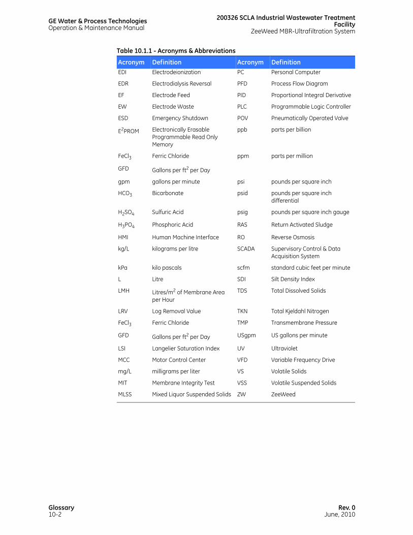
GE Water & Process TechnologiesOperation & Maintenance Manual
200326 SCLA Industrial Wastewater TreatmentFacility
ZeeWeed MBR-Ultrafiltration System
EDI Electrodeionization PC Personal Computer
EDR Electrodialysis Reversal PFD Process Flow Diagram
EF Electrode Feed PID Proportional Integral Derivative
EW Electrode Waste PLC Programmable Logic Controller
ESD Emergency Shutdown POV Pneumatically Operated Valve
E2PROM Electronically Erasable Programmable Read Only Memory
ppb parts per billion
FeCl3 Ferric Chloride ppm parts per million
GFD Gallons per ft2 per Day
gpm gallons per minute psi pounds per square inch
HCO3 Bicarbonate psid pounds per square inch differential
H2SO4 Sulfuric Acid psig pounds per square inch gauge
H3PO4 Phosphoric Acid RAS Return Activated Sludge
HMI Human Machine Interface RO Reverse Osmosis
kg/L kilograms per litre SCADA Supervisory Control & Data Acquisition System
kPa kilo pascals scfm standard cubic feet per minute
L Litre SDI Silt Density Index
LMH Litres/m2 of Membrane Area per Hour
TDS Total Dissolved Solids
LRV Log Removal Value TKN Total Kjeldahl Nitrogen
FeCl3 Ferric Chloride TMP Transmembrane Pressure
GFD Gallons per ft2 per Day USgpm US gallons per minute
LSI Langelier Saturation Index UV Ultraviolet
MCC Motor Control Center VFD Variable Frequency Drive
mg/L milligrams per liter VS Volatile Solids
MIT Membrane Integrity Test VSS Volatile Suspended Solids
MLSS Mixed Liquor Suspended Solids ZW ZeeWeed
Table 10.1.1 - Acronyms & Abbreviations
Acronym Definition Acronym Definition
Glossary10-2
Rev. 0June, 2010
200326 SCLA Industrial Wastewater Treatment FacilityZeeWeed MBR-Ultrafiltration System
GE Water & Process TechnologiesOperation & Maintenance Manual
10.3 DEFINITIONS
AC MOTOR Consists of two basic parts: A rotating cylinder called a Rotor and a stationary part called a Stator. The Stator surrounds the Rotor. It has coil windings, which produce an alternating magnetic field. This magnetic field causes current to flow through the Rotor conductors, resulting in a rotational force. The Rotor spins at a speed proportional to the frequency of the applied alternating current. The motor rotates at a set rotation depending on the frequency of the winding configuration.
ACID A solution having an excess of hydrogen (H+) ions (with a pH of less than 7.0).
ACTIVATED SLUDGE The floc produced in raw or settled wastewater due to the growth of bacteria and other organisms in the presence of dissolved oxygen (DO).
ACTUATED VALVE Any valve with an actuator that is controlled by an external command.
ADSORPTION Non-permanent attachment of a particular molecule to a solid substrate.
ADVISORY ALARM A process alarm, which alerts the operator, that action is needed to prevent an impending shutdown, or to restore the equipment to a normal state.
AEROBIC BACTERIA Any bacteria requiring free oxygen for the metabolic breakdown of material.
AEROBIC ZONE An environment where there is dissolved air or free oxygen.
AIR COMPRESSOR Air compressors provide oil-free, pressurized air for the operation of the actuated valves and for Membrane Integrity Tests (MITs).
AIR DIAPHRAGM METERING PUMPS
Air diaphragm metering pumps provide chemical dosing at measured rates. This dosing is set manually and it is regulated either by the amount of compressed air driving the pump or by setting the backpressure of the pumps.
Rev. 0June, 2010
Glossary10-3

GE Water & Process TechnologiesOperation & Maintenance Manual
200326 SCLA Industrial Wastewater TreatmentFacility
ZeeWeed MBR-Ultrafiltration System
AIR DRYER Air dryers protect pneumatic devices, like valves and air diaphragm pumps, from damage due to condensation in the compressed air. The controls on the air dryer allow for adjustment of dew point and temperature setpoints.
AIR FLOW SWITCH Air flow switches, located in the membrane aeration piping or the supplemental aeration piping, are used to indicate when a specific flow rate has been reached for a blower. This flow rate identifies low aeration to the membranes or bioreactor, triggering an alarm or alert.
AIR RELEASE VALVES Air release valves allow the air to separate from the permeate to prevent air locks in the permeate piping.
ALARM A visible or audible indication that an operator is expected to take action to rectify or prevent an abnormal situation. An alarm may be an operator interface screen message, a pilot light, a buzzer, or another form of communication to the operator.
ALARM BEACON A visible device for alerting an operator when a new alarm occurs, such as a flashing or rotating light.
ALERT A warning to the operator that a process or piece of equipment is operating outside normally accepted limits and requires attention to prevent the occurrence of an alarm.
ALTERNATION A control scheme for 2 or more pumps or process units in parallel, where the unit that has been running for the longest time is stopped first, and the unit that has been in readiness to start for the longest time is started first.
ALKALINE A solution having an excess of hydroxyl (OH) ions (with pH greater than 7.0).
ALKALINITY A measure of the capacity of water or wastewater to neutralize an acid. Alkalinity in wastewater results from the presence of carbonate, bicarbonate, and hydroxide. Alkalinity in water helps to resist changes in pH caused by the addition of acids. A measure of the amount of HCO3 present in water, generally expressed as an amount of CaCO3 equivalent.
ANAEROBIC BACTERIA
Any bacteria that can survive in partial or complete absence of oxygen by using molecular oxygen found in nitrates and sulfates.
Glossary10-4
Rev. 0June, 2010

200326 SCLA Industrial Wastewater Treatment FacilityZeeWeed MBR-Ultrafiltration System
GE Water & Process TechnologiesOperation & Maintenance Manual
ANAEROBIC ZONE An environment where there is an absence of any electron receptor (nitrate, sulfate or oxygen).
ANALOG An electrical signal that is proportional to the size of the variable being monitored or controlled. Analog signals in our systems are exclusively 4-20 mA, but an analog signal can be 0-20 mA or 0-10 VDC.
ANION An ion that is negatively charged resulting from the dissociation of salts, minerals, or acids in water.
ANTISCALANT In membrane systems, a compound added to feed water to increase concentrations at which scalants will precipitate, thereby increasing efficiency.
ANOXIC ZONE An environment where there is an absence or deficiency of free oxygen.
AUTOMATIC FLOW VALVE
Automatic flow valves are used when regular changes are required in the state of the valve (fully open or fully closed only). They are controlled by the PLC.
AVERAGE OPERATING PRESSURE FOR RO
Average of the module inlet and outlet pressures. Expressed in psi or kPa.
BACK DIFFUSION A phenomenon in which ions will transfer to the demineralized stream from the concentrate stream against the DC current. This transfer is due to high concentrations of ions in the concentrate. (EDR)
BACKPULSE A mode of operation in which the flow of permeate is reversed through the ZeeWeed membrane and directed from the inside of the fibers to the outside. During backpulse, there is a net flow of solids away from the membrane surface due to the combined effects of the membrane aeration and the backpulse of permeate.
BACKWASH (FOR EDI, EDR)
The process of cleaning a filter or membrane by reversing flow of clean water through it.
BACKWASH (FOR ZEEWEED 1000)
An event that takes place regularly throughout the day, consisting of backpulse, tank drain, and aeration.
BACKWASH CHANNEL (FOR ZEEWEED 1000)
The channel running along the length of the membrane tank. The channel collects water from the troughs in the membrane tank and discharges it to the drain.
Rev. 0June, 2010
Glossary10-5

GE Water & Process TechnologiesOperation & Maintenance Manual
200326 SCLA Industrial Wastewater TreatmentFacility
ZeeWeed MBR-Ultrafiltration System
BACKWASH TMP TRIGGER
The change in TMP over a permeation cycle that overrides the permeation time in order to trigger a backwash.
BACKWASH TROUGH The trough on the side of the membrane tank that collects the water during a backwash and discharges it to the backwash channel.
BIOCHEMICAL OXYGEN DEMAND (BOD)
The measurement of the amount of oxygen required by microorganisms to oxidize (eat) the organic matter (food) in the water. This test is used to estimate the amount of organic matter in a sample. The units of BOD5 are mg/L. The ‘5’ refers to the duration of the test (5 days). Due to the long period of time required to perform the test, Chemical Oxygen Demand (COD) is becoming a more common test to measure the amount of ‘food’.
BIOCIDE A chemical for preventing biological growth.
BIOLOGICAL OXYGEN DEMAND (BOD)
See Biochemical Oxygen Demand.
BIOMASS The mixture of biodegradable material, bacteria, and biosolids present in a biological wastewater treatment system.
BIOSOLIDS The by-product from the biodegradation of organics by bacteria.
BLOWER Blowers provide aeration to recirculate influent in the ZeeWeed membrane tank and for scouring the membranes to prevent membrane fouling. In a bioreactor, blowers are used to introduce air in order to create an aerobic environment for BOD removal.
BRINE The stream (usually Concentrate) into which ions or solids are concentrated.
BRINE BLOWDOWN (BBM)
The portion of the concentrate stream displaced by concentrate make-up and sent to waste.
BRINE MAKEUP (BMU)
The portion of the feed stream added to the brine recycle stream to maintain ionic concentrations in the brine stream. (EDI)
CASSETTE FOR A ZEEWEED 500
A group of interlocked ZeeWeed modules, fastened together to act as a single unit. A cassette is the smallest functional part of a ZeeWeed system that can be removed or isolated for removal or bubble testing.
Glossary10-6
Rev. 0June, 2010

200326 SCLA Industrial Wastewater Treatment FacilityZeeWeed MBR-Ultrafiltration System
GE Water & Process TechnologiesOperation & Maintenance Manual
CATHODE Electrode with negative electrode potential that attracts cations. (EDI, EDR)
CATION A negatively charged ion, resulting from dissociation of molecules in solution. (EDI, EDR)
CELL PAIR Basic element of an EDI or EDR stack consisting of a cation membrane, a demineralized water flow spacer, an anion membrane, and a concentrate water flow spacer. (EDI, EDR)
CATION MEMBRANE Flexible sheet of cloth-reinforced membrane permeable to cations and impermeable to anions. (EDI, EDR)
CHEMICAL OXYGEN DEMAND (COD)
A test used to estimate the amount of organic matter within a sample. A strong chemical oxidizing agent is used to measure the amount of organic matter that can be oxidized. The COD of wastewater is generally higher than the BOD because more compounds can be chemically oxidized than can be biologically oxidized. The units of COD are mg/L. Generally the BOD/COD ratio varies from 0.4 to 0.8.
CHEMICAL FEED REQUIREMENTS
The required concentration (example: design dosage) of anti-scalant and/or acid and/or sodium bisulfite specific to each RO or other membrane system.
CHEMICALLY ENHANCED BACKWASH (CEB)
Backwash and soaking of ultrafiltration (UF) membranes with a chemical solution in order to remove scale and fouling from the membrane surfaces.
CHLORINE CONTACT CHAMBER
The part of a water treatment plant where effluent is disinfected by chlorine.
CIP MODE The system operating mode in which the unit is undergoing the CIP procedure.
CLEAN-IN-PLACE (CIP)
A system or procedure for cleaning a membrane system without removing or disassembling the system. CIP involves the circulation of chemicals through the membrane system to remove scale and biological fouling from the piping and membranes.
COAGULANT An agent that causes dissolved or fine impurities to group together (coagulate). Coagulants are typically inorganic compounds, such as ferric chloride or alum.
Rev. 0June, 2010
Glossary10-7
GE Water & Process TechnologiesOperation & Maintenance Manual
200326 SCLA Industrial Wastewater TreatmentFacility
ZeeWeed MBR-Ultrafiltration System
COAGULATION The addition of inorganic coagulants into raw water prior to filtration. This promotes clumping (aggregation) of dissolved or fine impurities.
CO-CURRENT FLOW Flow across and through a membrane where the feed/reject and permeate flow in the same direction and parallel to the membrane surface.
COLOR Color can occur as the result of decaying or organic debris in the water.
COMPOSITE MEMBRANE
A membrane with two or more distinct layers.
CONCENTRATE The portion of the feed solution that does not pass through the membrane, in which solids or ions are at an increased concentration. Also known as Reject or Retentate.
CONCENTRATE RECYCLE (CR)
A method in which overall recovery is increased by reusing a fraction of the concentrate stream. Also refers to the portion of the concentrate stream that exits the membrane stack, and is repressurized by the concentrate recycle pump and returned to the stack concentrating stream.
CONCENTRATE STREAM
The process stream flowing through the concentrate compartments of a membrane stack.
CONCENTRATE BLOWDOWN (CBD)
Portion of the concentrate stream displaced by concentrate makeup and sent to waste.
CONCENTRATE MAKEUP (CMU)
Portion of the feed stream added to the concentrate recycle stream to control ionic concentrations in the concentrate stream.
CONCENTRATION FACTOR
The amount of a given compound in the reject as a multiple of the amount in the feed stream.
CONDUCTIVITY SENSOR
A device for measuring conductivity in aqueous solutions, primarily to obtain information on total ionic concentrations (example: dissolved compounds).
Glossary10-8
Rev. 0June, 2010
200326 SCLA Industrial Wastewater Treatment FacilityZeeWeed MBR-Ultrafiltration System
GE Water & Process TechnologiesOperation & Maintenance Manual
CONTACTOR The electrical switch component of the motor starter. The contactor protects the PLC by isolating it from the high currents and voltages necessary to run most motors. A contactor operates as follows: an output of 120 V or less from the PLC energizes a magnetic coil and/or coils in the contactor. The magnetic field causes the contact(s) to pull in, completing the motor’s circuit.
CONTROL LOGIC CHART (CLC)
A control system development document in spreadsheet form that lists the control logic elements of a system, such as process variables, motors, valves, PID controls, alarms, and operator selections. For each control element, the chart defines attributes such as tag number, description, unit of measure, range, setpoint, and control actions.
CONTROL NARRATIVE (CN)
A control system development document, in narrative text form, that describes high level functions of the programmable controllers and operator interfaces. This document also defines any control system details that are not included in the associated Control Logic Chart (CLC) and Operations Sequence Chart (OSC).
CONTROL STRATEGY The document, or set of documents, that defines the function of the programmable controllers and operator interfaces that will be used to control a process system. Generally, a GE W&PT control strategy includes a Control Narrative (CN), a Control Logic Chart (CLC), and an Operations Sequence Chart (OSC).
CONTROL VALVE A valve with a positioning actuator (not an open/closed actuator) for manipulating a process flow, or a self-actuated valve. Typically tagged “FCV”, “LCV”, “PCV”, or “TCV” on a P&ID.
CORROSION The attack upon metals by chemical agents, converting them to non-metallic products. Stainless steel has a passive film created by the presence of chromium (and often other alloying elements) that resists this process.
CRITICAL ALARM An alarm condition that requires the operator’s immediate attention to allow the system to run at the necessary level of production, or to investigate a potentially unsafe condition.
CRITICAL FAILURE A condition that triggers a process alarm that causes the unit to shut down immediately, because continued operation could present an immediate hazard or cause damage to the equipment.
Rev. 0June, 2010
Glossary10-9

GE Water & Process TechnologiesOperation & Maintenance Manual
200326 SCLA Industrial Wastewater TreatmentFacility
ZeeWeed MBR-Ultrafiltration System
CROSS-FLOW FILTRATION
Flow across and through a membrane where the feed/reject stream flows parallel to the membrane while the permeate stream flows perpendicular. The flow pattern reduces fouling on the media surface. Cross flow filtration necessitates a certain amount of the feed being lost to maintain flow.
CROSS LEAK Hydraulic transfer of water between manifolds in the stack (from the demineralizing stream to the concentrate stream).
CRYPTO OOCYST The hard shell in which the parasite cryptosporidium resides. This hard shell protects the cryptosporidium from chlorine disinfection treatment.
CRYPTOSPORIDIUM A parasite that contaminates water and can cause severe illness in humans. Since chlorine does not kill cryptosporidium, the most effective treatment for water supplies is through filtration.
CURRENT The movement of electrons through a conductor (such as wire). Electrical current is analogous to the flow of water through a pipe. Current is measured in Amperes (A) or milliAmperes (mA). The current direction can be either direct (DC) or alternating (AC). The current draw of a motor is stamped on the factory nameplate of the motor. This is the tested maximum ampere draw of the motor under full load conditions (FLA).
CURRENT DAY TOTAL A totalized value that is reset to zero at midnight.
CYCLIC AERATION VALVES
Cyclic aeration valves control the air flow to the ZeeWeed membrane cassettes, typically in 10 second intervals. The PLC controls the operation of cyclic aeration valves.
DECHLORINATION The process of removing residual chlorine from water. Also, GE W&PT typically uses specially formulated, thin film composite RO membranes, which have a limited tolerance for the free chlorine found in most municipal water supplies. Hence, dechlorination is typically required upstream of the RO membranes. Activated carbon filters or sodium bisulfite are used to remove the free chlorine. With ZeeWeed membrane systems, dechlorination with the use of sodium bisulfite, is required after a chlorine Recovery Clean procedure.
DECONCENTRATION An operation to periodically drain water from a membrane tank to reduce the average solids concentration when permeation is stopped.
Glossary10-10
Rev. 0June, 2010

200326 SCLA Industrial Wastewater Treatment FacilityZeeWeed MBR-Ultrafiltration System
GE Water & Process TechnologiesOperation & Maintenance Manual
DEIONIZATION The removal of ions by ion exchange processes.
DEMAND A dynamic setpoint that is typically used for controlling a system with multiple process trains or units in parallel (example: an integer setpoint for the number of trains or pumps that should be running or a flow setpoint for the desired system production rate).
DEMINERALIZATION The process of reducing the quantity of minerals or salts in an aqueous solution.
DEMINERALIZING STREAM
Process stream flowing through and out of the demineralizing compartments of the membrane stack.
DENITRIFICATION The biological process by which nitrate is converted to nitrogen gas. This process occurs in the absence of free oxygen (example: anoxic zone of a bioreactor).
DISSOLVED OXYGEN (DO)
The amount of free oxygen dissolved in water or wastewater. Dissolved oxygen levels are measured to ensure that sufficient oxygen is available for the biological population to degrade the wastewater during aerobic digestion. DO is normally expressed in mg/L, ppm, or percent of saturation. Oxygen dissolves into the mixed liquor by diffusion across the water surface and aeration.
DIGITAL VS. ANALOG SIGNALS
A digital (discrete) electrical signal is either on or off. This signal is used for simple on/off control of devices or alarm/alert setpoints.
DILUTE FEED The stream that serves as the feed water source for demineralization.
DILUTE IN The dilute (feed) stream entering the EDI stack(s).
DILUTE OUT The dilute (product) stream leaving the EDI stack(s).
DISTRIBUTED CONTROL SYSTEM (DCS)
A centralized electronic monitoring and control system for unit operations.
DRY CONTACT An electrically isolated relay contact that is not directly connected to a power source. Typically used for sending a contact closure to a remote control circuit where the circuit power comes from a remotely located controller.
Rev. 0June, 2010
Glossary10-11

GE Water & Process TechnologiesOperation & Maintenance Manual
200326 SCLA Industrial Wastewater TreatmentFacility
ZeeWeed MBR-Ultrafiltration System
E-CELL The trade name for GE W&PT’s Electrodeionization (EDI) process, which uses electrical impulse or stimulus to remove ions from water.
EDR STACK An Electrodialysis Regeneration (EDR) stack is comprised of sets of cell pairs stacked one on top of the other. Each cell pair consists of an anion transfer and a cation transfer membrane, separated by a spacer, with another spacer on one side of the cell pair. The stack has an anode electrode on one side, and a cation electrode on the other. Applied direct current induces ion migration in feed water. When current is applied to the stacks, alternating channels of demineralized product water and concentrate are created.
EDUCTOR A jet pump for withdrawing a fluid or powdery substance from a space.
EFFLUENT The flow of a liquid out of a system or process.
EJECTOR A device for removing air from the system.
ELECTRICAL POWER The rate of consumption of electrical energy. Power is calculated by multiplying the current by the voltage. Power is usually expressed in watts (W), kilowatts (kW), or horsepower (Hp).
ELECTRICAL STAGE Cell pairs bounded by two electrodes.
ELECTRODE A thin metal plate (usually platinum plated titanium) used to apply electrical potential to an electrical stage of an ED/EDI/EDR membrane stack.
ELECTRODE CLEAN IN PLACE (ECIP)
An automatic procedure for cleaning the electrode compartments in an EDR system without removing or disassembling the system. ECIP is a preventive procedure, not a repair procedure, to help prevent the build up of scale and foulants. If the electrode compartments are blocked to the point where no flow can get through, this procedure will not work, and the stacks will require disassembly.
ELECTRODE COMPARTMENT
Independent flow path formed by the electrode, electrode spacer, and heavy cation membrane. It prevents gases and pH changes resulting from electrode reactions from entering the main process flow.
ELECTRODE FEED (EF)
Feed water that is diverted to the electrode compartments.
Glossary10-12
Rev. 0June, 2010

200326 SCLA Industrial Wastewater Treatment FacilityZeeWeed MBR-Ultrafiltration System
GE Water & Process TechnologiesOperation & Maintenance Manual
ELECTRODE SPACER An extra thick spacer used with a heavy cation membrane to form the electrode compartment.
ELECTRODE WASTE (EW)
Wastewater from the electrode stream.
ELECTRODEIONIZATI
ON
Removal of ions using electrical impulse or stimulus.
ELECTRODIALYSIS A process in which ions are transferred through membranes from a less concentrated to a more concentrated solution under the impulse or stimulus of an electric current.
ELECTRODIALYSIS REVERSAL
A continuous self-cleaning electrodialysis process involving periodic reversal of the DC polarity, switching concentrating and diluting flow streams.
ELECTROMAGNETIC FLOW METERS (MAG METERS)
Electromagnetic flow meters (mag meters) measure liquid flow rate. The PLC uses this information to regulate pump speed and to totalize flow.
ELEMENT The smallest membrane entity replaceable in a ZeeWeed cassette. (See also Module).
EMERGENCY STOP The manual stopping of operation as quickly and reliably as possible, using a circuit that meets the requirements of NFPA 79, Chapters 9 and 10.
ENGINEERED UNITS A numerical data value that is correct for its unit of measure, so it does not need to be scaled for use or display.
EVENT An occurrence that is not an alarm condition.
FAULT An abnormal condition that affects the ability of a device to perform its normal function. “Fault” should generally be used instead of “failure”, “failed”, or “faulted”, and should not be used where “alarm” would be applicable.
FEED A water stream entering a unit treatment process.
FEED CHANNEL FOR ZEEWEED 1000
The channel running along the length of the membrane tank that distributes the feed to the cassettes.
Rev. 0June, 2010
Glossary10-13

GE Water & Process TechnologiesOperation & Maintenance Manual
200326 SCLA Industrial Wastewater TreatmentFacility
ZeeWeed MBR-Ultrafiltration System
FEED FLUSH FOR ZEEWEED 1000
The flow of feed from the bottom to the top of the tank during a backwash, to assist in the discharge of water to the backwash channel.
FILTRATE Liquid exiting a filtration process with reduced content of solids or contaminants. (See also Permeate).
FILTRATION CYCLE A repeated sequence of permeate production and backpulse.
FLOC A mass of clumped solids or precipitates formed in sewage by biological or chemical activity.
FLOCCULANTS Materials that can precipitate into aggregates or flocs from finely suspended particles. The suspended materials can then be separated from the water.
FLOCCULATION The process of creating aggregates or flocs from finely suspended particles that can later be separated from the water. Flocculation is often aided by a coagulant addition.
FLUX A measure of the rate at which permeate passes through the filtration membrane per unit surface area of membrane. Usually measured in GFD (gallons per ft2 per day) or LMH (liters per m2 per hour). Flux = permeate flow rate / membrane surface area.
FOOD-TO-MICROORGANISM RATIO (F:M)
The mass (kg) of organic matter fed to the bioreactor each day per unit mass of microorganism. Expressed as (kg BOD (or COD) / kg VSS - d).
FOULANTS The unwanted materials that deposit on the surface of a membrane.
FOULING The buildup of unwanted materials on the surface or within the pores of the filtration membrane. Fouling reduces the active surface area of the membrane and results in a reduction in permeability.
FREEBOARD (FOR SOFTENERS)
The space above the resin that accommodates the resin expansion during the backwash procedure.
GAS BLANKETING The accumulation of electrode reaction gases on the surface of the electrode.
GIARDIA LAMBLIA A parasite that contaminates water and can cause illness (giardiasis) in humans. The most effective treatment for water supplies is through filtration.
Glossary10-14
Rev. 0June, 2010

200326 SCLA Industrial Wastewater Treatment FacilityZeeWeed MBR-Ultrafiltration System
GE Water & Process TechnologiesOperation & Maintenance Manual
GLYCERIN (GLYCEROL)
Glycerin is the impure commercial form of glycerol. Glycerin is used to preserve and prevent ZeeWeed membranes from drying out or freezing.
GLYCEROL See Glycerin.
HAND VALVES FOR FLOW CONTROL
Hand valves are used to control flow in situations where regular changes in flow are not required. The valve is in the fully open or fully closed position.
HAND VALVES FOR ISOLATION
Hand valves for isolation are used in situations where regular changes in the valve’s state are not required. The valve is in the fully open or fully closed position. Types of hand valves used for isolation include ball valves, butterfly valves, and gate valves.
HARDNESS A measure of the amount of calcium and magnesium present in water. A property of water that can produce scale as a result of the presence of calcium and magnesium salts in solution.
HEADLOSS The drop in pressure of water flow through a resin bed.
HEAVY CATION MEMBRANE
A cation membrane formed more thickly to withstand higher differential pressures. The heavy cation membrane is used as an electrode compartment border.
HIGH A condition in which a process variable is greater than its normal value or range of values. This condition is typically used for control and/or for an advisory alarm.
HIGH-HIGH A condition in which a process variable is greater than a High setpoint. This condition typically causes an equipment shutdown.
HUMAN MACHINE INTERFACE (HMI)
A typical panel-mounted operator interface, which allows the operator access and control of the various equipment functions of a system. An HMI may be an operator interface with proprietary software or a Windows-based industrial computer running SCADA software.
HYDRAULIC RETENTION TIME (HRT)
The time required to displace the working volume of a bioreactor, by the feed flow into the bioreactor, in a continuous flow system.HRT (d) = anoxic and aerobic bioreactor volume (L) / feed flow rate (L/d)
HYDROMETER Measures the specific gravity of fluids.
Rev. 0June, 2010
Glossary10-15

GE Water & Process TechnologiesOperation & Maintenance Manual
200326 SCLA Industrial Wastewater TreatmentFacility
ZeeWeed MBR-Ultrafiltration System
HYDROXYL The anion of water. The chemical formula is OH-.
IMMEDIATE SHUTDOWN ALARM
A shutdown alarm condition that causes the process unit to stop immediately (because continued operation could damage the equipment) instead of using the normal shutdown sequence that might include flushing or cleaning.
INFLUENT A liquid flow into a tank or system.
INPUTS/OUTPUTS Inputs/outputs refer to the direction of the electronic signal in reference to the PLC. Inputs are signals that come into the PLC via an external device. Outputs are signals that are sent from the PLC to an external device. Inputs/outputs can be either digital or analog signals.
INTERLOCK A control scheme for preventing a mechanism or action from being set in motion when another mechanism or action is in operation, because the two operating simultaneously might produce undesirable results.
ION An electrically charged particle with a positive or negative charge, formed by the dissociation of a salt, mineral, or acid in water.
ION EXCHANGE The process by which salts (cations and anions) are removed from water by using electricity to replace undesirable ions with a certain charge with desirable ions of the same charge.
ION EXCHANGE REGENERATION
The process of restoring the ion exchange resin to its fully charged state.
LANGELIER SATURATION INDEX (LSI)
A measure of the tendency of water to dissolve or deposit calcium carbonate (scaling). LSI is calculated based on the total alkalinity, hardness, total dissolved solids (TDS), pH, and temperature of the water, and scaling. An LSI of 3.0 is indicative of a potential for severe scaling. The LSI is a calculated, dimensionless number that is used to determine the tendency of a water supply to foul RO membranes with calcium carbonate scale. It is dependent upon the following:
• the calcium content of the water supply.
• the bicarbonate alkalinity of the water supply.
• the pH of the water.
• the temperature of the water.
Glossary10-16
Rev. 0June, 2010

200326 SCLA Industrial Wastewater Treatment FacilityZeeWeed MBR-Ultrafiltration System
GE Water & Process TechnologiesOperation & Maintenance Manual
If the LSI is negative, there is no potential for calcium carbonate scale as CaCO3 dissolves in water. If the LSI is zero, there is no potential for scaling or CaCO3 dissolving. If the LSI is positive, there is a potential for CaCO3 scale, the magnitude of the potential being dependent upon the magnitude of the LSI number. An LSI of 3.0 would be considered to be a water with severe scaling tendencies.
As the concentrate stream moving through a reverse osmosis unit becomes more and more concentrated in dissolved minerals, the LSI of the water changes from the inlet of the system to the final concentrate outlet. As all RO membrane processes are staged (except for single element systems) with the concentrate out of one membrane feeding into the next, the worst LSI (example: most positive) is seen in the water coming out of the last membrane from the last housing. If it is predicted that this LSI will in fact be positive, it is common practice to either:
• polish the raw water, reducing the calcium and magnesium contents.
• feed antiscalant chemical, which 'negates' the effects of the calcium.
• feed an acid to lower the pH and move the LSI in a negative direction.
LEVEL SWITCH Level switches are placed in tanks to indicate very high or very low tank levels.
LEVEL TRANSMITTERS Level transmitters measure the liquid level in membrane tanks. The PLC uses these levels to calculate the permeate rate or the feed flow rate to maintain appropriate tank levels.
LOG REMOVAL VALUE (LRV)
Log removal is the degree of removal or inactivation of pathogenic organisms through physical-chemical treatment of water. For the ZeeWeed system, the calculation is for removal. The log scale is used. Each increase in whole number is a 10 fold improvement in removal. The calculation is expressed in whole numbers, which are dimensionless.
Rev. 0June, 2010
Glossary10-17

GE Water & Process TechnologiesOperation & Maintenance Manual
200326 SCLA Industrial Wastewater TreatmentFacility
ZeeWeed MBR-Ultrafiltration System
For example, if the feed concentration is 100:
Given:
• Feed Concentration: 800,000 particle counts 1,238 colonies
• Permeate Concentration: 50 particle counts 2 colonies
Calculation:
Log removal = -Log10 (50 counts / 800,000 counts) = 4.2
Or
Log removal = -Log10 (25,238 colonies / 2 colonies) = 4.1
LOW A condition in which a process variable is less than its normal value or range of values. This condition is typically used for control and/or for an advisory alarm.
LOW-LOW A condition in which a process variable is lower than the Low setpoint. This condition typically causes an equipment shutdown.
LUMEN The internal cavity within the hollow fiber of a ZeeWeed membrane through which air and permeate flow.
MAINTENANCE CLEAN
A cleaning procedure consisting of aeration, backpulsing, and soaking the ZeeWeed membranes. The operator selects either citric acid or sodium hypochlorite as the cleaning solution.
MANIFOLD A flow path that feeds several other flow paths.
MAN MACHINE INTERFACE (MMI)
See Human Machine Interface (HMI).
Table 10.1.2 - Log Removal
Permeate Concentration Removal Log Removal10 90% 1
1 99% 2
0.1 99.9% 3
0.01 99.99% 4
0.001 99.999% 5
Glossary10-18
Rev. 0June, 2010

200326 SCLA Industrial Wastewater Treatment FacilityZeeWeed MBR-Ultrafiltration System
GE Water & Process TechnologiesOperation & Maintenance Manual
MC-1 (CITRIC ACID) A proprietary cleaning chemical available from GE W&PT and designed to remove inorganic foulants from membranes.
MEMBRANE Thin barriers or films of material with many small pores of a predetermined size. These pores allow solvent and other smaller molecules, ions, or particles to pass through while preventing the passage of other materials. Membranes are designed to allow the separation of permeate streams from feed streams.
MEMBRANE AERATION
The process of using blowers to provide turbulence at the membrane surface to reduce accumulation of foulants on the membranes.
MEMBRANE BIOREACTOR
A biological wastewater treatment system that uses a membrane to separate water from biomass.
MEMBRANE BLOWER Membrane blowers provide aeration to recirculate influent and provide turbulence to membrane surfaces to reduce membrane fouling.
MEMBRANE INTEGRITY TEST (MIT)
A test procedure that introduces air under pressure into the lumen side of the ZeeWeed membrane. This test detects the condition of the membranes and any broken fibers, while the membranes remain in the tank. Membrane Integrity Test (MIT) and Pressure Decay Test (PDT) are two terms that are often used interchangeably when referring to protocols for integrity monitoring. However, there are subtle but important differences between the two terms. MIT refers to any method, both direct and indirect, used to monitor the integrity of the ZeeWeed membranes. Two currently used methods of indirect monitoring are particle counting and turbidity tracking.
The PDT is GE W&PT’s standard method for direct membrane integrity monitoring. The PDT consists of pressurizing the inside of the membrane fibers with clean air between 3.0 and 10.0 psig, depending on which ZeeWeed membrane product and version is being used. This pressure is allowed to stabilize in order to ensure that all of the water inside the membrane fibers has been displaced by air. The flow of air to the membranes is then turned off and the decay in pressure is measured in regular intervals over a specified duration. The rate of pressure decay is a function of the rate of air loss through the membranes due to diffusion, dry pores, and leaks. Other than leaks, air can only pass through a wetted pore by diffusion since the air pressure required to displace the water out of a pore is much higher than the air pressure used for the PDT.
Rev. 0June, 2010
Glossary10-19

GE Water & Process TechnologiesOperation & Maintenance Manual
200326 SCLA Industrial Wastewater TreatmentFacility
ZeeWeed MBR-Ultrafiltration System
A PDT at 3 and 5 psig can detect broken fibers, tears, and delamination. These are the types of membrane leaks expected to develop as the membranes age. However, to be compliant with future regulations, GE W&PT has increased the test pressure to 9.0 psig for ZW500D membranes and 10.0 psig for ZW1000 membranes. This measures the air loss from defects larger than 3 microns, which will be a requirement of the USEPA Long-term 2 Enhanced Surface Water Treatment Rule (LT2ESWTR).
MEMBRANE PERMEABILITY
The ratio of the flux and the transmembrane pressure at that flux. Usually expressed in L/m2/h/kPa or GFD/psi.
MEMBRANE SURFACE AREA
A measurement of the effective surface area of each element.
METERING PUMP A chemical metering pump is an electronically-controlled, solenoid or motor-driven diaphragm pump used for metering fluids, such as acid, base, and hypochlorite. The stroke length and rate of the pump can be manually set from the control panel on the pump face. Electronic metering pumps dose chemicals into the ZeeWeed system at measured rates. Changing the stroke frequency and stroke length can control the dosing rate, allowing it to be fixed or paced to achieve the correct dosing rate.
MHO A measure of conductance. It represents the ratio of the current flowing through a conductor, measured in amperes, to the potential difference between the end to the conductor, measured in volts. A mho is a unit of conductance equal to the reciprocal of the ohm, expressed as amperes/volt.
MICROMHO (μMHO) One millionth of a mho.
MICROSIEMENS (μS) A measure of conductance equivalent to a micromho.
MIXED BED An ion exchange tank consisting of both cation and anion resin. Provides the most complete deionization of water, up to 18.3 megohm/cm resistivity. Mixed bed resins or mixed bed ion exchange resins are mainly used in water purification for polishing process water to achieve demineralized water quality (example: after a reverse osmosis system).
Glossary10-20
Rev. 0June, 2010

200326 SCLA Industrial Wastewater Treatment FacilityZeeWeed MBR-Ultrafiltration System
GE Water & Process TechnologiesOperation & Maintenance Manual
MIXED LIQUOR The liquid mixture present in the aeration tank of an activated sludge system. The liquid is a mixture of activated sludge and water containing organic matter undergoing activated sludge treatment. The mixed liquor is a living ‘soup’ of microorganisms that requires food, oxygen, nutrients, proper pH, and correct solids retention time.
MIXED LIQUOR SUSPENDED SOLIDS (MLSS)
A measure of the quantity of suspended solids in the aeration tank of an activated sludge treatment system. Mixed Liquor Suspended Solids (MLSS) is usually measured in milligrams per liter (mg/L).
MIXED LIQUOR VOLATILE SUSPENDED SOLIDS (MLVSS)
The portion of the Mixed Liquor Suspended Solids (MLSS) that vaporizes when heated to 550ºC ± 50ºC (1022ºF ± 122ºF). This volatile portion is mainly organic material and thus indicates the biomass present in the aeration tank. The portion of solids that does not vaporize is mostly inorganic substances.
MODULE (MEMBRANE) FOR ZEEWEED 500A/B
A filtration device consisting of membrane fibers, top and bottom headers, and connecting air and permeate pipes. A module is the smallest distinct portion into which a cassette can be divided.
MODULE (TUBULAR MEMBRANE)
A filtration device consisting of membrane tubes, entrance and return headers, and connecting feed and concentrate pipes. A module is the smallest distinct portion that a system can be divided into. The module houses and contains the tubular membrane. The modules consist of two endcaps, one capped and the other with two hosebarb connections for the feed inlet and reject outlet. The permeate collects inside the module and exits via an elbow near the closed end.
MODULE FLOW RATE The fluid flow rate through the module, which is normally equal to the sum of the permeate and concentrate flow rates. Measured in US gpm or liters/minute.
MODULE FLOW RATE FOR RO
The fluid flow rate through the RO module, which is normally equal to the sum of the permeate and the concentrate flow rates. Measured in US gpm or liters/minute.
MOLECULAR WEIGHT CUT-OFF
The size of the molecule that determines whether or not the molecule is small enough to pass through the membrane’s pore.
MOTOR CONTROL CENTER (MCC)
The control panel that holds the motor starters and breakers for the system equipment.
Rev. 0June, 2010
Glossary10-21

GE Water & Process TechnologiesOperation & Maintenance Manual
200326 SCLA Industrial Wastewater TreatmentFacility
ZeeWeed MBR-Ultrafiltration System
MOTOR FUNDAMENTALS
A number of important motor components consist of a motor starter, contactor, overload, A.C. motors, variable frequency drive, and pump rotation verification.
MOTOR ROTATION CHECK
A pump may be severely damaged if started in reverse rotation. Three-phase motors can run either clockwise or counter-clockwise depending on how they are wired. It is essential to verify motor rotation before operating a pump. Rotation should be checked each time the motor’s three-phase power is disconnected. A coupled pump should always be uncoupled before checking the rotation.
MOTOR STARTER A starter allows the PLC to operate a motor while remaining electrically isolated from the motor circuit. A motor starter consists of a contactor and an overload.
NAVIGATION The process of getting from one graphic or pop-up screen on an operator interface to another.
NEPHELOMETRIC TURBIDITY UNIT (NTU)
A measurement of the turbidity (opacity) of water.
NITRATE Nitrate is the most highly oxidized form of nitrogen found in wastewater. Total Kjedahl Nitrate (TKN) is converted to nitrate during nitrification. Nitrate is converted to nitrogen gas during denitrification. Nitrate is chemically written as NO3
-.
NITRIFICATION The biological process by which ammonia is converted to nitrite and then to nitrate.
NITRITE Nitrite is the middle step of nitrification where ammonia is converted to nitrite and then to nitrate. Nitrite is relatively unstable and easily oxidized to the nitrate form. Nitrite is chemically written as NO2
-.
NO VS. NC SWITCHES
A circuit is either open (off) or closed (on). A circuit is closed if current flows through it; a circuit is open if there is no current.
NON-CRITICAL ALARM
An alarm condition that needs to be addressed but that does not require immediate operator attention.
NON-CRITICAL FAILURE
A process alarm condition which starts an orderly shutdown of the unit.
Glossary10-22
Rev. 0June, 2010

200326 SCLA Industrial Wastewater Treatment FacilityZeeWeed MBR-Ultrafiltration System
GE Water & Process TechnologiesOperation & Maintenance Manual
NORMALLY OPEN SWITCH (NO)
The circuit is open when no forces are acting on the switch.
NORMALLY CLOSED SWITCH (NC)
The circuit is closed when no forces are acting on the switch.
OFF-SPEC PRODUCT (OSP)
Portion of product stream sent to the feed tank or waste tank for not meeting product quality standards.
OPERATOR INTERFACE (OI)
Also called Human Machine Interface (HMI) or Man Machine Interface (MMI). A display screen through which system conditions can be monitored and controlled.
OPERATOR INTERFACE TERMINAL (OIT)
Also called Human Machine Interface (HMI) or Man Machine Interface (MMI).
ORGANIC LOADING RATE
The mass of organic matter feed to the anoxic and aerobic reactors each day per unit volume. Expressed as kg of COD/m3 of nitrification reactor/d or kg of BOD5/m3 of nitrification reactor/d. The organic loading rate can be reported using the units of mg/L/min.
OPERATIONS SEQUENCE CHART (OSC)
A control system development document in spreadsheet form that shows the required sequences for process operations. For each process sequence step, the chart defines attributes such as pump states, valve actuations, step times, interlocks, and control actions.
OVERLOAD Provides thermal overload protection to the motor. This occurs when the motor is drawing a higher current than its full load amperage (FLA) for an extended period. Common thermal overloads use bimetallic strip switches or heater coils. Common features on an overload are as follows:
• A reset button/dial that allows the motor circuit to reset manually after it has been tripped, or the overload to reset itself automatically after a few minutes.
• A trip current dial (for bimetallic strip overloads) sets the current (usually at or slightly above the FLA) at which the circuit will trip.
• A test button trips the circuit manually.
Rev. 0June, 2010
Glossary10-23

GE Water & Process TechnologiesOperation & Maintenance Manual
200326 SCLA Industrial Wastewater TreatmentFacility
ZeeWeed MBR-Ultrafiltration System
• A trip indicator window displays a colored indicator when the circuit is tripped.
OXYGEN UPTAKE RATE (OUR)
The rate of oxygen at which microorganisms consume food in the bioreactor. The rate at which the microorganisms use oxygen (OUR) can be a direct indicator of their biological activity. OUR is measured in mg of O2 consumed/L of biomass/minute.
PANELVIEW HMI (HUMAN MACHINE INTERFACE)
Provides an interface between the operator and the PLC. The PanelView screen enables the operator to monitor the system’s operation. The touch-screen controls and/or push buttons allow the operator to control the system.
PARTICLE COUNTS The number of particles per 100 ml of filtrate water. Water can be microscopically examined using a particle counter, which classifies suspended particles by number and size.
PARTICLE COUNTER Particle counters are placed in piping to measure the particle count, verify membrane integrity, and ensure the quality of the permeate.
PARTICULATES Very small suspended solids in water. They vary in size, shape, density, and electrical charge, and can be gathered together by coagulation and flocculation.
PASSIVATION A chemical treatment used to expedite the natural passive quality of stainless steels. When exposed to air, stainless steels passivate naturally due to the presence of chromium. The rate of natural passivation varies. To ensure that a passive layer forms rapidly after pickling, a solution of nitric acid and water is applied to the metal surface. Passivation does not remove embedded surface contamination. Thorough water rinsing must follow all passivating treatments.
PASSIVE A characteristic condition of stainless steels, which impedes normal corrosion tendencies, and renders the steel passive to its environment.
Glossary10-24
Rev. 0June, 2010

200326 SCLA Industrial Wastewater Treatment FacilityZeeWeed MBR-Ultrafiltration System
GE Water & Process TechnologiesOperation & Maintenance Manual
PERCENT REJECTION FOR RO
Percent (%) rejection is defined as the percentage of Total Dissolved Solids (TDS) that are rejected by the membranes into the concentrate stream. It is calculated using the following formula:
For example, if the feed water has a TDS level of 359 mg/L (or ppm) and the permeate water has a TDS level of 9 mg/L, the percent rejection of the system would be calculated as follows:
The Total Dissolved Solids level is typically measured with a conductivity probe and instrument. The rejection typically increases with decreasing recovery levels and higher transmembrane pressures.
PERMAFLOW The trade name for GE W&PT’s tubular membranes.
PERMEATE The portion of the feed solution that passes through the membrane.
PERMEATE FLOW RATE (FLUX)
The permeate flow rate per unit of membrane area. This is used for a specific system with a fixed number of membranes. The term can be used interchangeably with permeate flow rate. The most common usage is in GFD (gallons of permeate per square foot of membrane area per day) or in LMH (liters of permeate per square meter per day).
PERMEATE FLOW RATE (FLUX) FOR RO
Permeate flux is defined as the permeate flow rate per square foot of membrane area. It is used interchangeably with permeate flow rate. The rate at which permeate is produced is dependent upon the following:
• the membrane operating pressure.
• the feed water analysis.
• the system recovery ratio.
Percent Rejection = 100 -Permeate TDS x 100
Feed TDS
Percent Rejection = 100 -9 x 100
359
= 97.5%
Rev. 0June, 2010
Glossary10-25

GE Water & Process TechnologiesOperation & Maintenance Manual
200326 SCLA Industrial Wastewater TreatmentFacility
ZeeWeed MBR-Ultrafiltration System
• the feed water temperature.
PERMEATE HEADER The piping running along the length of the membrane tank that collects permeate from each of the permeate manifolds.
PERMEATE MANIFOLD
The piping running across the top of the cassette (parallel to the main axis of the cassette) that collects the permeate from the individual stacks. The permeate is discharged to the permeate header.
PICKLING When stainless steels have been heated to elevated temperatures (such as during welding), an oxide scale will form on the surface unless the material is surrounded by a protective atmosphere. Any such oxides must be removed to restore the stainless steel to its optimum corrosion resistance.
The part is immersed in a pickling solution to remove oxides and loosely embedded iron. Pickling paste can be used to clean larger affected areas in accordance with the manufacturer’s directions.
PH The measure of the acidity or alkalinity of a solution, based on the concentration of hydrogen ions. pH values are expressed as numbers on a scale of 0 to 14. With values less than 7 being acidic, and greater than 7 being basic.
PH ANALYZER pH analyzers measure the pH levels in the recirculation line during Recovery Cleans. The PLC uses the analyzer to monitor the pH of the cleaning chemicals and to control the dosing of neutralizing chemicals.
POLARIZATION The point at which the amount of current per unit area of membrane is high enough to dissociate water molecules, resulting in the formation of OH- and H+ ions.
POPUP SCREEN A screen design that is displayed by selecting buttons on a graphical screen of the operator interface. The popup screen overlays a portion of the graphical screen. Popup screens are typically used for controlling a motor or entering setpoints.
POWER SUPPLY A device that converts an AC input to a DC output.
PORE SIZE The size of the holes in the membranes.
PPM Parts per million. 1 ppm = 1 mg/L (assuming specific gravity = 1.0).
Glossary10-26
Rev. 0June, 2010

200326 SCLA Industrial Wastewater Treatment FacilityZeeWeed MBR-Ultrafiltration System
GE Water & Process TechnologiesOperation & Maintenance Manual
PRESSURE DROP A loss of pressure due to friction or flow restriction.
PRESSURE DECAY TEST
See Membrane Integrity Test.
PRESSURE GAUGE A device used for measuring the pressure of a gas or liquid.
PRESSURE TRANSMITTER
Pressure transmitters, located on the permeate header, are used to control pump speed during production, backpulse, and membrane integrity tests of the conventional membrane systems. The transmitters inform the PLC of high or low pressures, triggering an alarm.
PRESSURE VESSEL A cylindrical vessel (usually made of FRP) that contains membrane elements.
PROCEDURE The strategy for carrying out a process. It may refer to a process that does not result in the production of a product, for example a Clean-In-Place (CIP) procedure.
PRODUCT WATER A treated water stream exiting a unit treatment process.
PROGRAMMABLE LOGIC CONTROLLER (PLC)
A microprocessor-based controller that uses programmable memory to store instructions in order to control a process. The main components of a PLC are the power supply, processor, memory, input interface, and output interface.
PROPORTIONAL CONTROL
A control scheme in which the controller output is varied to maintain a process variable to a certain ratio of another variable. As an example, proportional control is used to vary a chemical dosing pump speed in proportion to the water flow at the chemical dosing location. This control method ensures that the chemical concentration in the water will not change when the water flow changes.
PROPORTIONAL INTEGRAL DERIVATIVE (PID) CONTROL LOOP
Feedback control with proportional, integral, and derivative control action. This control method allows the PLC to manipulate a physical device (control variable) to achieve a setpoint by constantly observing the response (process variable). A PID controller attempts to correct the error between a measured process variable and a desired setpoint by calculating and then outputting a corrective action that can adjust the process accordingly and rapidly in order to keep the error minimal.
The PID loop contains the following three parameters:
Rev. 0June, 2010
Glossary10-27

GE Water & Process TechnologiesOperation & Maintenance Manual
200326 SCLA Industrial Wastewater TreatmentFacility
ZeeWeed MBR-Ultrafiltration System
Gain (Kc) - Proportional control.
Reset (Ti) - Integral control.
Rate (Td) - Derivative control.
The proportional control term Kc changes the control variable by an amount proportional to the setpoint deviation. The magnitude of Kc determines the sensitivity of the PID control loop to process changes. The larger the Kc value, the larger the proportional change in the control variable.
The integral control term Ti is the time during which the actuating variable is changed for an existing deviation. The magnitude of Ti determines the amount of memory that the PID control loop exhibits. A large Ti value has a low effect on the setpoint deviation and vice versa. Controllers that use 1/Ti have opposite effects on the deviation.
The derivative control term Td changes the control variable by an amount proportional to the rate of change (slope) of the setpoint deviation. The larger the Td value, the more effect the rate of change of the deviation has on the control variable and vice versa. Systems that use 1/Td have the opposite effect.
RATE The tuning parameter for the derivative control action of a PID controller.
RECOVERY The amount of water recovered as permeate divided by the amount of feed water supplied to the system. High recovery ratios mean that a large percentage of the water is collected as permeate, whereas a low recovery results in most of the feed water going to the reject stream. As the recovery ratio increases, the suspended solids concentration of the reject stream increases. Higher solids in the reject stream represent higher solids concentrations in the membrane tank. This may result in higher transmembrane pressure (TMP) readings.
While membrane systems can be forced to run at a higher recovery than designed, premature membrane fouling may result. DO NOT run the system at a higher recovery than designed.
Glossary10-28
Rev. 0June, 2010

200326 SCLA Industrial Wastewater Treatment FacilityZeeWeed MBR-Ultrafiltration System
GE Water & Process TechnologiesOperation & Maintenance Manual
The formula for determining percent recovery is as follows:
RECOVERY CLEAN A chemical cleaning procedure used to restore ZeeWeed membrane permeability.
RECTIFIER An electrical device that changes AC power to DC power.
REDOX/ORP ANALYZER
The redox analyzer measures the ability of a solution to act as an oxidizing agent or reducing agent. Redox potential/ORP (oxidation-reduction potential) is measured in the range specified in the vendor data. Positive readings indicate an oxidizing agent, while negative readings indicate a reducing agent.
REGENERANT CHEMICALS
Chemicals used in the regeneration of resin beds in an ion exchange unit.
REGENERATION A process for restoring the resin in an ion exchange unit to its fully charged state.
REINFORCED FIBER GE W&PT-patented hollow fiber used in the ZeeWeed 500 series modules, consisting of a polymeric membrane on a strong support.
RESET The process of using a manual reset button to clear an alarm condition after it has been resolved. The tuning parameter for the integral control action of a PID controller.
RESIN BEDS Layers of resin in an ion exchange unit. See also Mixed Bed.
RESIDUAL CHLORINE ANALYZER
Residual chlorine analyzers are placed in the recirculation piping to electronically measure the level of chlorine present during Recovery Cleans. The PLC uses this online chlorine measurement to control the neutralizing chemical dosing pumps.
RESISTIVITY FOR RO The property of a substance (in this case, water) to resist the flow of electricity. Resistivity is the measurement of that resistance. Resistivity is the inverse of conductivity. Measured by a resistivity monitor.
RETENTATE See Reject.
Percent Recovery =Permeate Flow Rate x 100
Feed Flow Rate
Rev. 0June, 2010
Glossary10-29

GE Water & Process TechnologiesOperation & Maintenance Manual
200326 SCLA Industrial Wastewater TreatmentFacility
ZeeWeed MBR-Ultrafiltration System
REJECT Also known as Concentrate or Retentate. The portion of the feed solution that does not pass through the membrane.
REVERSE OSMOSIS (RO)
A water purification process that utilizes high-pressure pumps to drive process water through semi-permeable reverse osmosis (RO) membranes in order to remove dissolved ions and unwanted matter.
RO FEED The feed solution is the stream that enters the reverse osmosis (RO) membrane unit. Following reverse osmosis, the feed stream is divided into concentrate and permeate streams.
RUN TIME METER A run time counter for a motor or process unit, usually with units of hours.
SCALE Precipitate of calcium carbonate or calcium sulfate.
SCALING The formation of a precipitate on a surface in contact with water as the result of scale deposit. The process of converting a raw numerical value to a value in engineering units.
SEQUENTIAL CONTROL
A control function intended to set the states of the pumps, valves, and other control devices of a process unit for a series of operation steps.
SETPOINT An adjustable value for a process variable, which is used for controlling a process. A controller will vary the process to keep the process variable at the setpoint, or a process alarm and/or control action will occur when the process variable reaches the setpoint.
SHUTDOWN ALARM An alarm that alerts the operator that action is needed to recover from a situation where either a piece of equipment is unable to operate, or the control system has determined that operation is unsafe or undesirable.
SHROUD The plastic covering that protects the ZeeWeed 1000 element.
SILICA ANALYZER A device for measuring silica concentrations in liquid.
SILT DENSITY INDEX (SDI)
The silt density index represents the quantity of silt (colloidal material) present in a water source. It is a measure of the potential of suspended solids to foul RO membranes.
SLUDGE WASTING RATE
The excess volume of biological sludge wasted daily from the bioreactor. Usually measured in L/d or g/d.
Glossary10-30
Rev. 0June, 2010

200326 SCLA Industrial Wastewater Treatment FacilityZeeWeed MBR-Ultrafiltration System
GE Water & Process TechnologiesOperation & Maintenance Manual
SODIUM HYPOCHLORITE (NAOCL)
A membrane cleaning and conditioning agent that removes organic foulants and sanitizes the system permeate/treated water piping. This substance is a strong oxidant and disinfectant.
SOLENOID VALVE Solenoid valves provide on/off control for low flow volume locations, including air diaphragm chemical pumps and pneumatic valves. The PLC controls the solenoid valves.
SOLIDS RETENTION TIME (SRT)
The time required to remove the working volume of the bioreactor’s mixed liquor by the average flow rate of waste sludge from the system.
SOLUTE Material (such as salts) dissolved by a solvent (such as water).
SOLVENT Any material that acts to dissolve another. The solvent constitutes the dissolving medium, or liquid portion, of a solution. Water is frequently referred to as the universal solvent.
SPACERS Polyethylene sheets with die cut water flow paths and manifolds to allow water in the membrane stack to be channeled into demineralizing and concentrating streams.
STACK A group of two or three elements arranged in a vertical stack with a common permeate collection pipe.
STACK DIFFERENTIAL PRESSURE
The hydraulic pressure between the demineralizing and concentrating streams in the membrane stack.
STACK SHORTING Damage to stack membranes due to excessive voltage travelling through the membranes and generating heat.
STAGING In reverse osmosis (RO), a process configuration where rejected water is fed through additional sets of membrane in order to increase recovery (without changing final product water quality).
STRAINER A slotted or screen sieve for screening flowing liquid.
SRT (d) =Anoxic and Aerobic Reactor Volume (L)
Sludge Wasting Rate (L/d)
Rev. 0June, 2010
Glossary10-31

GE Water & Process TechnologiesOperation & Maintenance Manual
200326 SCLA Industrial Wastewater TreatmentFacility
ZeeWeed MBR-Ultrafiltration System
SUPERVISORY CONTROL AND DATA ACQUISITION (SCADA)
A computer system that collects and records process data and alarms, and provides a graphical user interface for a process system. It is typically a Windows-based desktop computer that runs a SCADA software package. The SCADA, which is the center of the control system, acts as a link between the PLC and the operator. It allows the control of valves, pumps, and blowers. All electronic parameters are displayed and setpoint values are stored.
SWITCH A device that produces a binary signal in response to an operator action or the comparison of a process variable to a setpoint. For example a High level switch converts a tank level into a binary signal for high level. The device may be a mechanical float switch, a relay in an electronic instrument, or a software comparator.
SYSTEM RECOVERY The system recovery ratio is the ratio of water recovered as permeate versus the amount of feed water supplied to the system. A high recovery ratio means that a large percentage of the water is collected as permeate; a low recovery ratio results in most of the feed water going to the reject stream. As the recovery ratio increases, the concentration of the reject stream increases and the permeate quality decreases. As the recovery ratio is lowered, the proportion of feed water that is rejected increases.
Operating the RO subsystem at a higher rate of recovery than recommended will result in premature membrane fouling.
The formula for determining percent recovery is as follows:
SUPPORT MEDIA A high-density material with a graded particle size for supporting resin (example: gravel, anthrafil, and quartz).
TANK DRAIN FOR ZEEWEED 1000
An event that takes place once per day, consisting of draining the tank while backpulsing and air scouring.
Percent Recovery =Permeate Flow Rate x 100
Feed Flow Rate
Glossary10-32
Rev. 0June, 2010
200326 SCLA Industrial Wastewater Treatment FacilityZeeWeed MBR-Ultrafiltration System
GE Water & Process TechnologiesOperation & Maintenance Manual
TANK HEATER During a Recovery Clean, a CIP tank heater increases the temperature of the cleaning solution.
TEMPERATURE EFFECTS
The feed water temperature has a pronounced effect on the permeability through the membranes. As the operating temperature increases, the permeability also increases.
TEMPERATURE TRANSMITTER
Temperature transmitters monitor temperatures.
TOTAL DISSOLVED SOLIDS (TDS)
The concentration of all solids dissolved in a solution (normally expressed in ppm).
TOTAL KJELDAHL NITROGEN (TKN)
The total concentration of nitrogen in a sample present as ammonia or bound in organic compounds. Total Kjeldahl Nitrogen (TKN) is usually measured in mg/L.
TOTAL ORGANIC CARBON (TOC)
A measure of the amount of organic materials suspended or dissolved in water. Total Organic Carbon (TOC) is a quicker sampling method than measuring Chemical Oxygen Demand (COD) or Biological Oxygen Demand (BOD) for determining the quality of the effluent.
TOTAL SOLIDS (TS) A measure of the amount of material that is dissolved or suspended in a water sample, by weight. Total Solids is determined by allowing a known volume to evaporate and then weighing the remaining residue.
TOTAL SUSPENDED SOLIDS (TSS)
A measure of the solids (normally expressed in ppm) found in water, which can be removed by filtration.
TRAIN FOR ZEEWEED MEMBRANES
A group of cassettes immersed in a tank and connected to a common header through which the permeate is drawn. Suction is created with either a permeate/process pump or a siphon.
TRAIN FOR SOFTENERS
A single filtration or ion exchange system capable of producing the desired treated water.
Total Solids = Total Dissolved Solids + Total Suspended Solids
Rev. 0June, 2010
Glossary10-33

GE Water & Process TechnologiesOperation & Maintenance Manual
200326 SCLA Industrial Wastewater TreatmentFacility
ZeeWeed MBR-Ultrafiltration System
TRANSMEMBRANE PRESSURE (TMP)
The difference in pressure across the membranes, between the outer and inner surface of membrane. TMP is the driving force that causes filtration through the membranes to occur. This pressure difference is created by applying a partial vacuum inside the membrane fibers with the suction of the permeate/process pump. TMP can be varied by changing the speed of this pump.
TRIGGER A trigger allows a change in operation. It is a normal event that can clear an alarm or be one of several points in a sequence of events.
TUBULAR MEMBRANE A pressure driven cross flow filtration membrane used for separating and concentrating suspended solids and high molecular weight particles from a variety of waste and process streams. The filtration surface is a strong polymeric membrane cast on the inside surface of a porous support tube. The membrane is constructed of materials that can withstand harsh chemical environments.
TURBIDITY A measure (via light penetration) of the cloudiness of an otherwise clear liquid. Measured in Nephelometric Turbidity Units (NTU). Sediment or foreign particles stirred up or suspended in water.
TURBIDITY METER (TURBIDIMETER)
Turbidity meters are placed in the permeate piping or the feed piping to measure turbidity. When registering high turbidity, the PLC will trigger an alarm and shut down the ZeeWeed system.
ULTRAFILTRATION Water treatment methods used to remove suspended solids, bacteria, and viruses from water. This method operates using low pressures and typically using hollow-fiber or rolled membrane elements.
ULTRAVIOLET (UV) A light wave, at a specific wavelength, used to disinfect water. UV will kill any viable bacteria, viruses, and parasites.
UNREINFORCED FIBER
Conventional hollow fiber, which is based on a simple polymeric structure, used in the ZeeWeed 1000 module.
VACUUM DEGASIFIER A tower to which a vacuum is applied and through which water droplets descend to remove dissolved gas.
VACUUM PUMP Vacuum pumps remove air from the system and ensure that the permeate/process pump remains primed.
VALVE TEST The process in which the operation of motor-operated valves may be manually tested.
Glossary10-34
Rev. 0June, 2010

200326 SCLA Industrial Wastewater Treatment FacilityZeeWeed MBR-Ultrafiltration System
GE Water & Process TechnologiesOperation & Maintenance Manual
VARIABLE FREQUENCY DRIVE (VFD)
An electrical device attached to a pump motor used to automatically adjust motor speed in response to process conditions. A VFD controls the speed of a pump by changing the frequency of the alternating current to power the motor. For example, a pump motor operating at 1800 rpm at 60 Hz would run at 900 rpm if the frequency is reduced to 30 Hz.
VOID VOLUME The space between media particles in a settled bed.
VOLATILE SOLIDS (VS)
The total content of suspended and dissolved solids in water, which are volatile at 550ºC (1022ºF).
VOLATILE SUSPENDED SOLIDS (VSS)
The suspended solids that can be filtered from a sample of water and are volatile at 550ºC (1022ºF).
VOLTAGE The difference in electrical potential across two points. This is analogous to gauge pressure in water applications. Voltage is measured in volts (V).
WATER HAMMER Instantaneous surges of water pressure caused by a sudden interruption in water flow.
WATER SOFTENER Cation resin in sodium form that removes cations such as calcium and magnesium from the water, and releases sodium ions.
WATER SOFTENING The exchange of sodium by ion exchange.
WATER FLOW SPACER
A die-cut sheet of plastic which forms direct flow paths for demineralized and concentrate streams. (EDI)
WATER TRANSFER Water that is electrically (but not hydraulically) transferred through the membranes along with ions.
ZENOGEM The trade name for GE W&PT’s process of using a ZeeWeed membrane system to clarify effluent from a bioreactor.
ZENOTRAC The trade name for GE W&PT’s powerful plant process support tool which provides fully automated process data monitoring and trend analysis.
ZEEWEED The trade name for GE W&PT’s immersible hollow fiber filtration module.
Rev. 0June, 2010
Glossary10-35

This page has beenintentionally left blank

GE Water & Process Technologies
APPENDIX A
ZEEWEED 500DIMMERSED HOLLOW-FIBER ULTRAFILTRATION TECHNOLOGY
NOTICE
The enclosed materials are considered proprietary property of GE Water & Process Technologies. No assignments, either implied or expressed, of intellectual property rights, data, know-how, trade secrets or licenses of use thereof are given. All information is provided exclusively for the addressee for the purposes of evaluation and is not to be reproduced or divulged to other parties, nor used for manufacture or other means, or to authorize any of the above, without the express written consent of GE Water & Process Technologies. The acceptance of this document will be construed as an acceptance of the foregoing conditions. * Trademark of General Electric Company; may be registered in one or more countries.

This page has beenintentionally left blank

A.1CAUTIONS

This page has beenintentionally left blank

200326 SCLA Industrial Wastewater Treatment FacilityZeeWeed MBR-Ultrafiltration System
GE Water & Process TechnologiesOperation & Maintenance Manual
A.1.1 CAUTIONS SPECIFIC TO THIS SUBSYSTEM
The following precautions must be read and adhered to by all system operators.
1. This appendix must be read and understood in its entirety before operating the subsystem.
2. Membranes must be kept moist at all times. Store in a temperature between 5 - 35ºC (41 - 95ºF). Do not allow membranes to freeze or dry out.
3. If the system has been preserved (example: for shipment or shutdown), any shipping preservatives should be flushed from the system before startup. See Section 3.7.1: Flushing for more information.
4. Membranes must be immersed in a biocidal solution prior to storage, shipping or system shutdowns longer than 72 hours. Flushing the system at least once per day while off-line is also sufficient for short term shutdowns. See the section on cleaning for procedures.
5. The customer is fully responsible for the effects of unapproved chemicals when used with ZeeWeed filtration systems. Their use will render the membrane warranty null and void. Contact GE Water & Process Technologies if there is a concern about chemical use.
6. To avoid damaging the membranes, all prescreening measures must be in operation at all times. Do not bypass prescreening processes under any circumstances.
7. During construction, maintenance, or any other work performed directly above the membrane tank, ensure that foreign debris (example: pipe turnings) does not fall into the tank.
Rev. 0June, 2010
ZeeWeed 500D - CautionsA-1

GE Water & Process TechnologiesOperation & Maintenance Manual
200326 SCLA Industrial Wastewater TreatmentFacility
ZeeWeed MBR-Ultrafiltration System
8. During membrane integrity tests (MIT) or bubble tests, the compressed air must be clean, dry, and free of oil. Do not exceed the maximum recommended pressure.
9. Do not allow membrane fibers to come in contact with sharp objects, become entangled with equipment or tools, be pulled tightly, or to freeze or dry out.
10. Do not clean the membranes with a high-pressure water stream (example: pressure washer or fire hose), and do not use water that exceeds maximum temperatures for membranes
11. Membranes that are to be returned to GE W&PT must be cleaned, sanitized, and preserved before shipment. Contact GE W&PT for instructions before returning membranes.
ZeeWeed 500D - CautionsA-2
Rev. 0June, 2010

A.2SUBSYSTEM OVERVIEW

This page has beenintentionally left blank

200326 SCLA Industrial Wastewater Treatment FacilityZeeWeed MBR-Ultrafiltration System
GE Water & Process TechnologiesOperation & Maintenance Manual
A.2.1 OVERVIEW
The ZeeWeed 500D is a supported hollow-fiber ultrafiltration membrane technology introduced in 1997.
The ZeeWeed 500D product line consists of both modules and cassettes. A module is the basic building block and smallest replaceable unit of a ZeeWeed 500D membrane treatment system as shown in Figure A.2.1 - ZeeWeed 500D Cassettes in a Treatment System. Modules are joined together to form a cassette, which is the smallest operable unit of a treatment system.
Cassettes are integrated into a treatment system by suspension in a membrane tank and connection to permeate collection and air distribution piping. They are designed to be lifted by overhead devices and special tools exist to facilitate cassette access.
Figure A.2.1 - ZeeWeed 500D Cassettes in a Treatment System
Rev. 0June, 2010
ZeeWeed 500D - Subsystem OverviewA-5

GE Water & Process TechnologiesOperation & Maintenance Manual
200326 SCLA Industrial Wastewater TreatmentFacility
ZeeWeed MBR-Ultrafiltration System
A.2.2 MEMBRANE FIBER
The ZeeWeed 500D membrane is an outside-in supported polyvinylidene fluoride (PVDF) hollow-fiber. The term ‘supported’ refers to the fact that the membrane polymer coats a braided material that reinforces the fiber. The ultrafiltration membrane fiber has a nominal pore size of 0.04 µm and is capable of removing suspended solids, protozoa, bacteria, and most viruses. As a result, high quality water can be produced with minimum chemical addition and treatment.
A.2.3 MODULES
Membrane fibers are arranged vertically between two headers. Water is drawn through the fibers into the permeate header and then exits the module via the permeate spigot or saddle. The module has a key, which is used to lock the module in place when it is installed in the cassette.
Figure A.2.2 - ZeeWeed 500D Module
ZeeWeed 500D - Subsystem OverviewA-6
Rev. 0June, 2010

200326 SCLA Industrial Wastewater Treatment FacilityZeeWeed MBR-Ultrafiltration System
GE Water & Process TechnologiesOperation & Maintenance Manual
The following table provides general specifications for the ZeeWeed 500D module.
Table A.2.1 - Module Specifications
Module DimensionsHeight 2,198 mm (86.4”)
Width 844 mm (33.2”)
Depth 49 mm (1.9”)
Module WeightMax. Shipping Weight (crated) 26 kg (58 lb) (wastewater)
28 kg (62 lb) (drinking water)
Lifting Weight (varies with solids accumulation)
26-75 kg (58-163 lb) (wastewater)30-74 kg (66-163 lb) (drinking water)
Membrane PropertiesNominal Surface Area 31.6 m2 (340 ft2) (wastewater)
31.6 m2 (340 ft2); 40.9 m2 (440 ft2) (drinking water)
Material PVDF
Nominal Pore Size 0.04 microns
Surface Properties Non-Ionic & Hydrophilic
Fiber Diameter 1.9 mm OD/0.8 mm ID
Flow Path Outside-In
Operating SpecificationsTMP Range -55 to 55 kPa (-8 to 8 psi) (wastwater),
-90 to 90 kPa (-13 to 13 psi) (drinking water)
Max. Operating Temperature 40ºC (104ºF)
Operating pH Range 5.0-9.5
Cleaning SpecificationsMax. Cleaning Temperature 40ºC (104ºF)
Cleaning pH Range 2.0-10.5
Max. Cl2 Concentration 1000 ppm
Rev. 0June, 2010
ZeeWeed 500D - Subsystem OverviewA-7

GE Water & Process TechnologiesOperation & Maintenance Manual
200326 SCLA Industrial Wastewater TreatmentFacility
ZeeWeed MBR-Ultrafiltration System
A.2.4 CASSETTES
The cassette is comprised of a welded stainless steel frame. The ZeeWeed 500D module can be slid into and out of the cassette. Four modules are connected in parallel into top and bottom common saddles, which are linked by a 2’’ PVC permeate downcomer pipe. The top saddle connects into the stainless steel 8’’ permeate manifold. The cassette is then linked to an external permeate header on the train using hard pipe or hose connections.
The cassette uses 3’’ aeration CPVC downcomer pipes to feed tube diffusers assembled into a grid at the bottom of the cassette. For membrane bioreactor applications, the 1.5’’ PVC diffuser tubes are clear; for other applications, the tubes are white.
Figure A.2.3 - ZeeWeed 500D Cassette
ZeeWeed 500D - Subsystem OverviewA-8
Rev. 0June, 2010

200326 SCLA Industrial Wastewater Treatment FacilityZeeWeed MBR-Ultrafiltration System
GE Water & Process TechnologiesOperation & Maintenance Manual
The following table provides general specifications for the ZeeWeed 500D cassette.
Table A.2.2 - Cassette Specifications
Cassette Size 48M 64MMax. No. of ZeeWeed Modules
48 64
DimensionsLength 2,112 mm (83.1”)
743 mm (29.3”)2,085 mm (82.1”)Width
Height
Tie-PointsPermeate Connection 6” 316 L SS vert. pipe 8” 316 L SS horz. pipe
Air Connection two 3” PVC vert. spigot
WeightsMax. Shipping Weight (crated)
1,730 kg (3,815 lb) 2,040 kg (4,500 lb)
Lifting Weight (varies with solids accumulation)
1,335-4,260 kg (2,945-9,385 lb) 1,425-4,535 kg (3,140-10,000 lb)
Rev. 0June, 2010
ZeeWeed 500D - Subsystem OverviewA-9

GE Water & Process TechnologiesOperation & Maintenance Manual
200326 SCLA Industrial Wastewater TreatmentFacility
ZeeWeed MBR-Ultrafiltration System
A.2.5 THEORY OF OPERATIONS
A.2.5.1 FILTRATION
Filtration is defined as the separation of one or more components from a fluid stream. In conventional usage, it usually refers to the separation of solid or insoluble particles from liquid or gaseous streams. The most commonly employed membrane processes and the filtration ranges in which they operate are presented in Figure A.2.4 - Filtration Spectrum.
Membrane separation processes can be categorized in various ways; three of which are pore size, molecular weight cutoff (MWCO), and operation pressure. As the pore size gets smaller (and the molecular weight cutoff decreases), the pressure applied to the membrane for separation generally increases. The water treatment objectives of each system decide the basis on which a process is selected and operated.
Figure A.2.4 - Filtration Spectrum
ZeeWeed 500D - Subsystem OverviewA-10
Rev. 0June, 2010

200326 SCLA Industrial Wastewater Treatment FacilityZeeWeed MBR-Ultrafiltration System
GE Water & Process TechnologiesOperation & Maintenance Manual
A.2.5.2 ULTRAFILTRATION: AN INTRODUCTION
Ultrafiltration (UF) is a process that filters particles on the basis of size. In membrane separations, UF is typically used to separate or remove relatively large particles, such as microbes, bacteria, and macromolecules with molecular weights greater than about 300,000 molecular weight. UF uses “loose” membranes, which refers to membranes that have relatively large pores.
A.2.5.3 ZEEWEED ULTRAFILTRATION
ZeeWeed 500D is an immersed ultrafiltration membrane system for low suspended solids water feeds. The membrane and process have been developed with the goal of reducing costs while maintaining the high level of treated water quality.
The filtrate (permeate) is pushed through the membrane from the bulk fluid by atmospheric pressure due to a partial vacuum applied within the membrane fibers. The physical barrier of the ZeeWeed membrane prevents the passage of bacterial organisms and solids into the water supply.
Rev. 0June, 2010
ZeeWeed 500D - Subsystem OverviewA-11

This page has beenintentionally left blank

A.3INSTALLATION & TESTING

This page has beenintentionally left blank

200326 SCLA Industrial Wastewater Treatment FacilityZeeWeed MBR-Ultrafiltration System
GE Water & Process TechnologiesOperation & Maintenance Manual
A.3.1 INTRODUCTION
This section provides information regarding subsystem installation, initial testing, and maintenance procedures. This information must be read and internalized in its entirety by system operators prior to installing or operating the subsystem.
A.3.2 INSTALLATION REQUIREMENTS
The following must be available before the subsystem can be installed:
APPLICABLE DRAWINGS: The Process and Instrumentation Diagram (P&ID), General Arrangement (GA), Plot Plan, and Electrical drawings for the system are provided in this manual. These drawings will be needed during installation.
WATER: Water introduced into the system during installation must be free of particulates, and any debris that falls into the tanks must be removed immediately.
ELECTRICITY: GE W&PT is not responsible for supplying power to the subsystem. During installation, a qualified electrician must verify the following:
• That all electrical connections meet local government and industry standards.
• That all electrical cables have been properly fitted.
• That all 3-phase motors have been wired for proper rotation.
QUALIFIED PERSONNEL: A qualified electrician, pipefitter, and millwright are required on site when commissioning the system.
Rev. 0June, 2010
ZeeWeed 500D - Installation & TestingA-15

GE Water & Process TechnologiesOperation & Maintenance Manual
200326 SCLA Industrial Wastewater TreatmentFacility
ZeeWeed MBR-Ultrafiltration System
A.3.3 PERSONAL SAFETY
It is crucial that fall arrest equipment be worn when working overtop the membrane tank. A fall arrest harness must be worn and appropriate tie-off lanyards must be used while installing and/or working on a cassette.
A.3.4 HANDLING OF FACTORY SHIPPED ZEEWEED CASSETTES
• ZeeWeed 500D cassettes are always shipped with modules installed.
• The cassette itself is sealed in a plastic bag to retain moisture to prevent damage to the membranes due to drying.
• The cassette is shipped on its side in a plywood crate.
Figure A.3.1 - Harness and Lanyard
ZeeWeed 500D - Installation & TestingA-16
Rev. 0June, 2010
200326 SCLA Industrial Wastewater Treatment FacilityZeeWeed MBR-Ultrafiltration System
GE Water & Process TechnologiesOperation & Maintenance Manual
A.3.4.1 UNLOADING SHIPPED CASSETTES
The Installer is responsible for the prompt and proper unloading of all membrane equipment and materials received into his custody. During unloading, ensure the following:
• Dock level, off-loading facilities are recommended.
• The wooden shipping crates have been designed to be lifted from the bottom using a forklift.
• Damage incurred or observed during equipment off-loading needs to be immediately reported to your GE representative.
It is recommended that an experienced/qualified forklift truck driver unloads the membranes from the carrier. ZeeWeed 500D cassettes are shipped on their sides and will require uprighting. Follow all procedures carefully to prevent injury. Shipping crates are not to be stacked!
A.3.4.2 CONFIRMING EQUIPMENT AND MATERIALS
A cross-check should be performed on the shipment using the packing slip to confirm the delivery of membrane equipment.
Do not open membrane crates. Verification is limited to external examination of crates.
• The equipment delivery will be checked for content and any damage that may have occurred during shipping or the unloading process.
• Any non-conformance shall be immediately reported to your GE representative (in writing). Digital pictures of damage should be provided.
Rev. 0June, 2010
ZeeWeed 500D - Installation & TestingA-17

GE Water & Process TechnologiesOperation & Maintenance Manual
200326 SCLA Industrial Wastewater TreatmentFacility
ZeeWeed MBR-Ultrafiltration System
• Refer to A.3.4.3 Confirming Handling Indicators to confirm the condition of the handling indicators.
• When the equipment shipment has been checked, the Equipment Acceptance Certificate and Checklist must be completed and signed by the Site Organization's representatives.
• The Installer shall expeditiously replace all materials and equipment that are lost or damaged while in the custody of the Installer.
• Replacement materials and equipment will be of a type and quality equal to the original materials and equipment, and will be acceptable to GE W&PT and to the Owner.
A.3.4.3 CONFIRMING HANDLING INDICATORS
GE W&PT includes a series of shipping indicators to protect the integrity of the membrane cassettes while they are being shipped. Indicators may include freeze and/or heat (see Figure A.3.2 - Shipping Indicators).
• The Installer's representative should document the indicator condition on the indicator check label located on the membrane crate.
At the time of discovery, the Installer must inform the GE representative of any triggered indicators.
Table A.3.1 - Handling Indicators
Freeze Indicator Heat IndicatorIndicator Location External External
When to check At time of receipt At time of receipt
ZeeWeed 500D - Installation & TestingA-18
Rev. 0June, 2010

200326 SCLA Industrial Wastewater Treatment FacilityZeeWeed MBR-Ultrafiltration System
GE Water & Process TechnologiesOperation & Maintenance Manual
TIP: A triggered indicator indicates ideal shipping conditions were not maintained. The GE representative will evaluate membranes prior to installation.
During membrane installation, the GE representative on site will also inspect and record the status of all indicators.
Duplicate indicators used by the GE representative are located inside the crate.
A.3.5 STORING MEMBRANES
The Installer must provide all facilities and services required for the storage, maintenance, protection, and security of the equipment and materials delivered by GE W&PT.
The following conditions should be followed:
• Equipment and materials must be stored in assigned lay-down areas.
• Stored equipment and materials must be adequately supported and protected to prevent damage. Equipment must be moved into the permanent building or onto its permanent foundation as soon as construction will permit.
Figure A.3.2 - Shipping Indicators
Rev. 0June, 2010
ZeeWeed 500D - Installation & TestingA-19

GE Water & Process TechnologiesOperation & Maintenance Manual
200326 SCLA Industrial Wastewater TreatmentFacility
ZeeWeed MBR-Ultrafiltration System
• Stored materials and equipment must not be allowed to contact the ground. In warehouses that do not have dry concrete or suspended floors, materials and equipment must be stored on platforms or shoring.
• Indoor storage furnished by the Installer must consist of suitable construction trailers or portable enclosures and must be weather-tight, well ventilated, and secure against theft and vandalism.
• Access doors must be adequate to accommodate the movement and handling of materials and equipment to be stored and must be equipped with secure locks.
• Membrane cassettes will be stored upright on a level surface.
• The membrane cassette crates must remain closed until the Installer begins membrane installation, to prevent permanent membrane damage due to drying out.
• The membrane crates should never be exposed to excessive vibration or large bumps.
Membranes should be stored in a dark dry area with a storage temperature between 5 - 35ºC (41 - 95ºF) and a setpoint of 20ºC (68ºF).
A.3.5.1 STORING CRATED CASSETTES
The following conditions should be ensured when storing crated cassettes:
• Sheltered area protected from freezing, direct sunlight, or extreme heat.
• Vacuum sealed bag should remain sealed until membrane installation is being performed.
ZeeWeed 500D - Installation & TestingA-20
Rev. 0June, 2010

200326 SCLA Industrial Wastewater Treatment FacilityZeeWeed MBR-Ultrafiltration System
GE Water & Process TechnologiesOperation & Maintenance Manual
The cassettes have been manufactured and preserved to comply with the contractually specified membrane/cassette delivery and installation schedule. Should the installation of the membranes/cassettes be delayed more than one month, contact your GE representative for instructions.
A.3.5.2 STORING BAGGED MODULES
New modules preserved with glycerin solution, bagged and factory sealed, may be stored for up to 12 months from manufacturing. For the exact expiry date, contact GE W&PT technical support. The following conditions should be ensured when storing bagged modules:
• Stored in a sheltered area protected from freezing, direct sunlight, extreme heat, and winds that could accelerate drying.
• The module should be kept bagged and sealed at all times.
Disassembly of cassettes to replace modules requires attention and care. Contact GE W&PT technical services for reassembly procedures, which include step-by-step instructions, bolt torques, and identification of non-reusable hardware.
A.3.5.3 STORING WETTED MEMBRANES
ZeeWeed membranes should not be allowed to dry out as membrane properties will be adversely affected. Drying may result in irreversible damage to the membranes.
If the preservative is flushed out or if the module has been in contact with water, the membrane must not be allowed to dry out under any circumstances. The membranes may be left in air for a maximum of 45 minutes out of direct sunlight and wind. After 45 minutes, membranes should be immersed in water. Spraying the membranes after this period is not sufficient to prevent drying-out and will not allow a longer period of contact with air.
Rev. 0June, 2010
ZeeWeed 500D - Installation & TestingA-21
GE Water & Process TechnologiesOperation & Maintenance Manual
200326 SCLA Industrial Wastewater TreatmentFacility
ZeeWeed MBR-Ultrafiltration System
If membranes are frequently lightly misted (not sprayed with fire hoses or pressure washers) from the time they have been taken out of the water, they may be left in air for a maximum of 6 hours between 5ºC - 35ºC (41ºF - 95ºF). Since the membranes are maintained wet, there is no need for specific rewetting procedures. However, if necessary for other reasons (for example, drinking water compliance and residual of preservatives) the standard procedures for rinsing and disinfection may be used before starting the operation.
If it is impractical to immerse or repeatedly spray the membrane, the membrane should be cleaned, preserved in glycerin solution, and re-bagged according to membrane preservation procedures (see A.3.12 System Shutdown and Membrane Preservation).
Discuss longer storage durations with GE W&PT technical services.
A.3.5.4 STORING WETTED CASSETTES
For storage periods of up to approximately 15 days, simple immersion of the cassettes in water containing sodium hypochlorite (NaOCl) with a residual concentration of 3 mg/L is suitable. Perform weekly testing of the water and add chlorine if the residual chlorine concentration drops to less than 0.2 mg/L. A Recovery Clean of the membrane prior to storage is strongly recommended. Periodic aeration may also be necessary to prevent anoxic or anaerobic conditions from developing in the tank. Perform weekly testing of the water to ensure that the residual chlorine concentration is within acceptable limits. A log must be maintained recording daily sodium hypochlorite concentration and water temperature.
Longer storage durations are to be discussed with GE W&PT technical services.
Four (4) - 3/8 - 16 NC
ZeeWeed 500D - Installation & TestingA-22
Rev. 0June, 2010

200326 SCLA Industrial Wastewater Treatment FacilityZeeWeed MBR-Ultrafiltration System
GE Water & Process TechnologiesOperation & Maintenance Manual
A.3.6 UNCRATING AND INSTALLING CASSETTES
The purpose of this document is to outline the steps required to properly install modules into a 500D 48E WW cassette installed with MARS.
Follow proper safety procedures to prevent injury when carrying out this procedure.
These instructions are specific to this model of cassette.
Proper crane training is required along with a certified and inspected crane.
Prior to installation of the membranes, all piping and tanks must be installed, tested, and readied to accept membrane cassettes.
A.3.6.1 PREPARING THE SITE
The Membrane Pre-Installation Checklist must be completed before cassettes can be uncrated and installed. The GE representative will provide the Membrane Pre-Installation Checklist, the Membrane Map, and Repair Log.
All loose shipped parts required for cassette installation must be located. All guide brackets, permeate piping and air piping are to be installed as per installation documentation supplied by GE W&PT.
Membrane tanks must be thoroughly cleaned and free of debris. There must be enough water in the membrane tank to ensure that the fibers are completely submerged within water.
Locate and reserve an area for proper cassette assembly and unloading.
Rev. 0June, 2010
ZeeWeed 500D - Installation & TestingA-23
GE Water & Process TechnologiesOperation & Maintenance Manual
200326 SCLA Industrial Wastewater TreatmentFacility
ZeeWeed MBR-Ultrafiltration System
The following parts should be available:
• Forklift with extended forks rated for cassette weight – to move crate
• Crane/hoist, slings, and lifting bracket – to upright cassette and install cassette in tank. Lifting hoist requirements:
• 64 element cassette: 3000-4500 kg (6614-9921 lbs)
• 48 element cassette: 2800-3800 kg (6172-8377 lbs)
• 2 sheets of 1 in. thick foam (90 in. x 90 in.)
• Four (4) 3/4 in. lifting safety hoist rings rated for 2268 kg (5000 lbs), material: 4140 aircraft quality carbon steel (recommended manufacturer ACTEK, part #46018) c/w 8 3/4 in. diameter SS flat washers and 4 3/4 in. diameter SS hex nuts (included with shipment)
• Four (4) slings
• Four (4) point spreader bar
• Two (2) point spreader bar
• Module Removal Tool
• NEFAB tool/flat head screwdriver – to uncrate the cassette
• Camera – for documenting the condition of the cassette and indic in.” socket – to attach cassette arms
• 1 1/8 in. socket - to attach cassette arms
• PVC glue and primer – to install necessary PVC elbows to cassette
• Anti-Seize - use NSF grade only for drinking water applications (for example, White Knight)
Always use trained operators and inspected equipment.
ZeeWeed 500D - Installation & TestingA-24
Rev. 0June, 2010

200326 SCLA Industrial Wastewater Treatment FacilityZeeWeed MBR-Ultrafiltration System
GE Water & Process TechnologiesOperation & Maintenance Manual
• Four (4) - 3 in. x 3/4 in. 316 SS bolts
• Eight (8) - 3/4 in. 316 SS nuts
• Four (4) - 3/4 in. 316 SS flat washers
• Four (4) - 3/4 in. 316 SS nord-lock washers
A.3.6.2 INSTALLING LEVELING PINS
The purpose of these pins is to allow for proper leveling of each membrane cassette during the final stages of the plant construction.
The cassette must be individually leveled to a tolerance of +/-1/8 in. per cassette within a train. All cassettes across adjoining process must be +/- 1/4 in. level tolerance of one another. The cassette support design in the membrane tank includes adjustable pins to fine tune the cassette levels. Use a laser level prior to cassette installation to ensure the required tolerances are achieved. Cassettes that are not properly leveled may exhibit more rapid fouling as air distribution may be affected.
Ensure that the following parts are available:
• Item #1 - Hitch Pin or Double Split Shaft Collar - please refer to project specifics
• Item #3 - Qty 8 - 1in. UNC 316L SS Hex Nut
• Item #5 - Qty 8 - 1 in. NL SS Nord-Lock locking washer 1 in. Nom
• Torque = 104 ft-lbs
A.3.6.3 MANEUVERING THE CASSETTE
It is important that before any work begins, the necessary planning and precautions are done in order to ensure that the membrane installation procedure is safely carried out. It is the responsibility of those installing the membranes to properly prepare.
Rev. 0June, 2010
ZeeWeed 500D - Installation & TestingA-25

GE Water & Process TechnologiesOperation & Maintenance Manual
200326 SCLA Industrial Wastewater TreatmentFacility
ZeeWeed MBR-Ultrafiltration System
Before the crates or cassettes can be moved, ensure that the lifting mechanism (fork lift and crane) are in good operating conditions and are rated for the load.
While maneuvering the crate or cassette, ensure that no one is in its path or out of sight of the crane/forklift operator.
Do not stand under the cassette or crate.
The forklift and crane operators must be qualified and certified forklift and crane operators and must have the proper documentation on the person while operating the equipment.
A.3.6.4 UNCRATING CASSETTES
ZeeWeed 500D cassettes are always shipped with modules installed. The cassette is shipped on its side in a plywood crate. The cassette itself is sealed in plastic to retain moisture and prevent membrane damage.
500D crates are not designed to be stacked on top of one another.
Damage, such as punctures, water damage, and tripped indicators incurred during equipment off-loading needs to be reported to the site superintendent and GE W&PT immediately.
Uncrate the membranes with a GE W&PT representative present to monitor the process and verify the receiving tanks and piping have been satisfactorily prepared. Failure to do so may affect the membrane warranty.
The cassette will need to be transported to a designated uncrating area using a forklift. Uncrating the cassettes is to be completed on a dry level surface, out of direct sunlight.
ZeeWeed 500D - Installation & TestingA-26
Rev. 0June, 2010

200326 SCLA Industrial Wastewater Treatment FacilityZeeWeed MBR-Ultrafiltration System
GE Water & Process TechnologiesOperation & Maintenance Manual
The cassette should not be allowed to freeze. Refer to Membrane Care.
Membranes are not to be uncrated if any of the following activities are taking place in the immediate vicinity:
• painting
• wiring and terminations
• roofing
• grinding
• tinwork
• welding
• pipe flushing
• sandblasting
• drilling
• all power tools that discharge debris (including carpentry)
• or any other activity that could pose harm to the membranes
The cassettes should be uncrated by removing the top first followed by the sides. Please note that at least two people are required to uncrate the cassette. The following pictures illustrate the order of cassette uncrating.
Use two workers to remove the box sides.
Rev. 0June, 2010
ZeeWeed 500D - Installation & TestingA-27
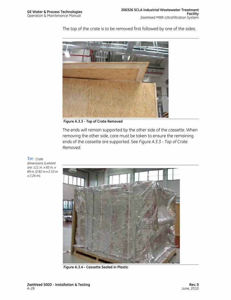
GE Water & Process TechnologiesOperation & Maintenance Manual
200326 SCLA Industrial Wastewater TreatmentFacility
ZeeWeed MBR-Ultrafiltration System
The top of the crate is to be removed first followed by one of the sides.
The ends will remain supported by the other side of the cassette. When removing the other side, care must be taken to ensure the remaining ends of the cassette are supported. See Figure A.3.3 - Top of Crate Removed.
TIP: Crate dimensions (LxWxH) are: 111 in. x 83 in. x 89 in. (2.82 m x 2.10 m x 2.26 m).
Figure A.3.3 - Top of Crate Removed
Figure A.3.4 - Cassette Sealed in Plastic
ZeeWeed 500D - Installation & TestingA-28
Rev. 0June, 2010

200326 SCLA Industrial Wastewater Treatment FacilityZeeWeed MBR-Ultrafiltration System
GE Water & Process TechnologiesOperation & Maintenance Manual
A.3.6.4.1 REMOVING THE CASSETTE BAG
The cassette comes packaged in a vacuum sealed bag. After the cassette is uncrated, and immediately prior to installing the cassette into the membrane tank with water, carefully remove the bag. See Figure A.3.4 - Cassette Sealed in Plastic.
Cut open the bag sealing at the top, then carefully roll it down to the base of the crate. See Figure A.3.5 - Bag Sealing the Cassette.
Do NOT cut along the center of the cassette. Fibers can be damaged.
Once rolled down to the base of the cassette, cut the bag at the base and discard.
There is a plastic wrap underneath the bag. The plastic wrap must stay intact for the uprighting of the cassette.
Figure A.3.5 - Bag Sealing the Cassette
Rev. 0June, 2010
ZeeWeed 500D - Installation & TestingA-29

GE Water & Process TechnologiesOperation & Maintenance Manual
200326 SCLA Industrial Wastewater TreatmentFacility
ZeeWeed MBR-Ultrafiltration System
Depending upon the version of the cassette, it may come equipped with yellow shipping braces. If these braces are present, they need to be removed prior to uprighting the cassette.
If the membranes have been in storage, check for any signs of mold on the fibers. If mold is present, immediately rebag and contact GE W&PT.
A.3.6.5 MOVING UNCRATED CASSETTES
When the cassette has been removed from the shipping crate, care must be taken to ensure that contact with the membrane fibers is avoided.
Lift the cassette by the factory-supplied lifting points on the top of the cassette using the lifting module. If a lifting module is not available, a spreader bar is required.
Do not attach ropes to the four hanger brackets and lift the hanger brackets. The hanger brackets will not withstand the horizontal (inward) loads produced by the ropes.
Figure A.3.6 - Removing the Cassette Bag
ZeeWeed 500D - Installation & TestingA-30
Rev. 0June, 2010

200326 SCLA Industrial Wastewater Treatment FacilityZeeWeed MBR-Ultrafiltration System
GE Water & Process TechnologiesOperation & Maintenance Manual
Cassettes are designed to be lifted vertically and lowered slowly. Do not swing or drop cassettes. Never tilt or drag an uncrated cassette. Treat the product with care.
If necessary, the uncrated and uprighted cassette can be moved on the wooden skid on which it was shipped, using a forklift. Extreme caution must be taken to avoid wind, environmental, and safety risks that may be present while moving the cassette in this manner.
If there is contact with the fibers, the integrity of the membranes may be compromised. Advise GE W&PT staff on site immediately so the fibers can be inspected and repairs can be initiated before cassette is installed. If fiber damage is not reported to GE W&PT staff, extra time and effort will be required later to remove the cassette and make the repairs.
A.3.6.6 INSPECTING THE ZEEWEED 500D CASSETTE - INSPECTION 1
With the cassette uncrated but still on its side, perform the following inspections of the aeration piping and connections:
• Ensure that aerators are properly in place. See Figure A.3.7 - Cassette Inspections and Figure A.3.8 - Aerators.
• Ensure that the large holes on the aerators are facing down relative to the cassette.
• Ensure that all saddles are securely clipped to the cassette frame.
• Ensure that the correct number of non permeating (“dummy”) headers are installed and in the correct location.
• Ensure that the correct type of aerators are used under the non-permeating (“dummy”) headers (some aerators are “left” aerators and some are “right” aerators depending on which side the small side holes are on).
Rev. 0June, 2010
ZeeWeed 500D - Installation & TestingA-31

GE Water & Process TechnologiesOperation & Maintenance Manual
200326 SCLA Industrial Wastewater TreatmentFacility
ZeeWeed MBR-Ultrafiltration System
• Ensure that the two main aeration pipes are installed and secure.
Figure A.3.7 - Cassette Inspections
Figure A.3.8 - Aerators
ZeeWeed 500D - Installation & TestingA-32
Rev. 0June, 2010

200326 SCLA Industrial Wastewater Treatment FacilityZeeWeed MBR-Ultrafiltration System
GE Water & Process TechnologiesOperation & Maintenance Manual
A.3.6.7 INSTALLING UNION TO CASSETTE’S MAIN AERATION PIPES
All cassettes require that either a PVC union or hose barb fitting be glued to the PVC pipes on the cassette. In order to minimize the amount of time and work required on the cassette after it is installed and to reduce the risk of damage to the membranes, these parts should be installed prior to the cassette being installed in the tank. The ideal time is when the cassette is still on its side.
A.3.6.8 UPRIGHTING A CASSETTE
The cassettes are shipped on their sides and need to be lifted, then rotated to the upright position.
Read this procedure completely before proceeding with the uprighting operation.
Figure A.3.9 - Union Installation
Rev. 0June, 2010
ZeeWeed 500D - Installation & TestingA-33

GE Water & Process TechnologiesOperation & Maintenance Manual
200326 SCLA Industrial Wastewater TreatmentFacility
ZeeWeed MBR-Ultrafiltration System
To promote safety, uprighting a cassette must be done in a dedicated staging area. The staging area shall be cordoned-off to people who are not directly involved in this activity.
Bring shipping crates into the staging area one at a time. Clear the area of any material and provide the safe space required for both removing the cassette from the wooden skid and uprighting it. The area for the uprighting operation shall be at least 7.5 meters X 3 meters (25 ft X 10 ft).
Clearly mark the area and isolate it, so that access of unauthorized personnel is prevented. The use of a perimeter fence, rope/chain barriers, pylons, or other signalling and blocking means is highly recommended.
Be alert! Cassettes have sharp edges.
Follow these two steps:
1. A.3.6.8.1 Removing the Cassette from the Wooden Skid.
2. A.3.6.8.2 Uprighting Cassette.
Remove all uncrating material from the staging area before commencing the uprighting activity.
The use of an overhead hoist is recommended; however, if an appropriate overhead hoist is not available, then a mobile telescopic boom crane or equivalent lifting device should be used. The hoist/crane must be rated for at least a 5 ton (10,000 lb) lifting capacity at both the jib extension and the angle required for the lift.
The operation of the hoist/crane shall be performed by a qualified operator, according to the local and international safety codes and regulations for lifting operations. If a crane is being used, it shall be located at an appropriate distance to prevent collision with the cassette during the lifting and uprighting.
ZeeWeed 500D - Installation & TestingA-34
Rev. 0June, 2010
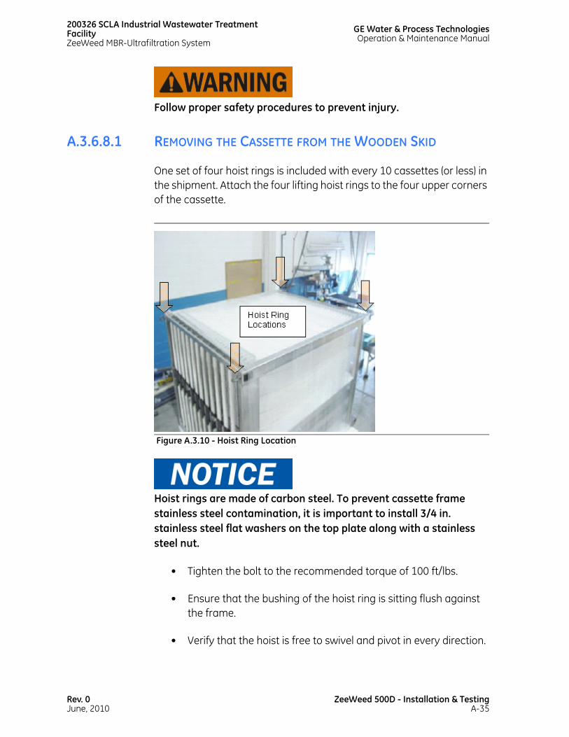
200326 SCLA Industrial Wastewater Treatment FacilityZeeWeed MBR-Ultrafiltration System
GE Water & Process TechnologiesOperation & Maintenance Manual
Follow proper safety procedures to prevent injury.
A.3.6.8.1 REMOVING THE CASSETTE FROM THE WOODEN SKID
One set of four hoist rings is included with every 10 cassettes (or less) in the shipment. Attach the four lifting hoist rings to the four upper corners of the cassette.
Hoist rings are made of carbon steel. To prevent cassette frame stainless steel contamination, it is important to install 3/4 in. stainless steel flat washers on the top plate along with a stainless steel nut.
• Tighten the bolt to the recommended torque of 100 ft/lbs.
• Ensure that the bushing of the hoist ring is sitting flush against the frame.
• Verify that the hoist is free to swivel and pivot in every direction.
Figure A.3.10 - Hoist Ring Location
Rev. 0June, 2010
ZeeWeed 500D - Installation & TestingA-35
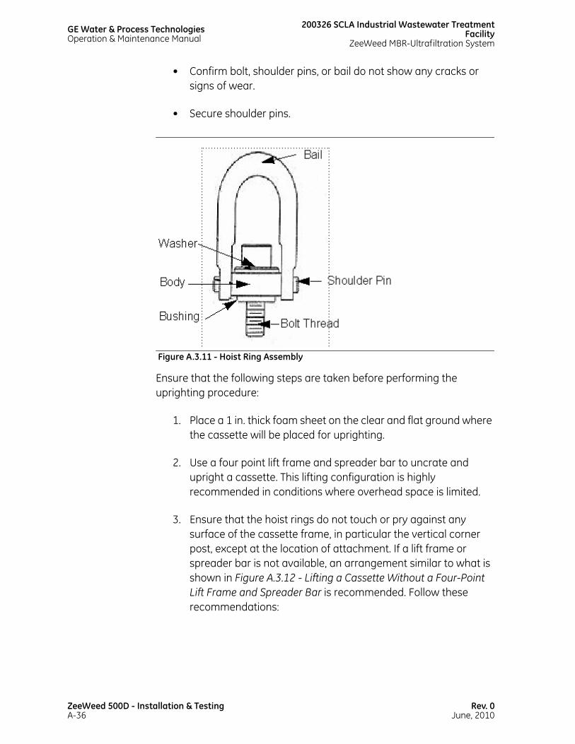
GE Water & Process TechnologiesOperation & Maintenance Manual
200326 SCLA Industrial Wastewater TreatmentFacility
ZeeWeed MBR-Ultrafiltration System
• Confirm bolt, shoulder pins, or bail do not show any cracks or signs of wear.
• Secure shoulder pins.
Ensure that the following steps are taken before performing the uprighting procedure:
1. Place a 1 in. thick foam sheet on the clear and flat ground where the cassette will be placed for uprighting.
2. Use a four point lift frame and spreader bar to uncrate and upright a cassette. This lifting configuration is highly recommended in conditions where overhead space is limited.
3. Ensure that the hoist rings do not touch or pry against any surface of the cassette frame, in particular the vertical corner post, except at the location of attachment. If a lift frame or spreader bar is not available, an arrangement similar to what is shown in Figure A.3.12 - Lifting a Cassette Without a Four-Point Lift Frame and Spreader Bar is recommended. Follow these recommendations:
Figure A.3.11 - Hoist Ring Assembly
ZeeWeed 500D - Installation & TestingA-36
Rev. 0June, 2010

200326 SCLA Industrial Wastewater Treatment FacilityZeeWeed MBR-Ultrafiltration System
GE Water & Process TechnologiesOperation & Maintenance Manual
• Use two slings on each lifting bracket. The sling closest to the cassette should be a short nylon strap about 4 feet long. This arrangement will prevent damage from the crane hooks. The longer cables should be at least 20 feet long.
• Use flexible synthetic material (such as reinforced man-made fibers) instead of metal chains to avoid damage to the cassette body material.
• Minimum angles between the horizontal plane and the cables should be:
i. 60° where the spreader bar (lifting frame) is used
ii. 75° for one point lift
Ensure that the surrounding area is clear of people.
4. Slowly lift the hoist until the cassette is at the minimum height (not more than 2 in. or 5 cm) required to move the cassette off the wooden skid.
Figure A.3.12 - Lifting a Cassette Without a Four-Point Lift Frame and Spreader Bar
Rev. 0June, 2010
ZeeWeed 500D - Installation & TestingA-37

GE Water & Process TechnologiesOperation & Maintenance Manual
200326 SCLA Industrial Wastewater TreatmentFacility
ZeeWeed MBR-Ultrafiltration System
5. Slowly and gently transfer the cassette to above the 1 in. foam sheet, and gently lower the cassette to the ground.
6. Remove the skid and the remains of the vacuum-sealed bag.
7. Clean the area of any spills, using rags or other absorbent material. Clean and dry the floor to prevent slip hazards.
8. Disengage the hoist and slings. Remove the two hoist rings attached to the bottom side of cassette (the side that will be placed on the ground).
A.3.6.8.2 UPRIGHTING CASSETTE
If a crane is being used, it must be located at an appropriate distance to prevent collision with the cassette during the uprighting, in case a “kicking out” occurs.
Follow these steps:
1. Locate the crane on the side of the cassette where the cassette moves horizontally during the uprighting.
2. Place another 1 in. foam sheet to the side of the cassette where it will be placed on the ground.
3. Attach a two-point spreader bar to the lifting hoist. Attach the spreader bar to the two hoist rings on the upper side of the cassette using two slings.
Ensure that the surrounding area is clear of people.
4. Slowly lifting the cassette off the ground. The cassette will tilt as it is lifted. The lifting device must be free to move laterally to remain over the cassette’s center of gravity.
ZeeWeed 500D - Installation & TestingA-38
Rev. 0June, 2010

200326 SCLA Industrial Wastewater Treatment FacilityZeeWeed MBR-Ultrafiltration System
GE Water & Process TechnologiesOperation & Maintenance Manual
5. At all times, keep the hoist in vertical alignment with the lifting points on the cassette. Failure to do so could result in the cassette “kicking out”. Do not attempt to stop the cassette if it kicks out.
6. If a crane is being used, a signaling person, standing at a safe distance, should signal the crane operator. Appropriate signaling/communication means are required.
7. Lift the cassette until it pivots onto its side, then lower it until it rests fully on the foam in its vertical position.
8. After lowering the cassette to the vertical position, remove the slings and lifting hoist rings.
A.3.6.9 INSTALLING CASSETTE ARMS
The cassette arms, which allow the cassette to be moved using the lifting frame, are installed after the uprighting procedure. Refer to the applicable fabrication drawings that are provided for details on this assembly.
A torque of 104 ft-lb for 3/4 in. Nord-Locks is needed.
Figure A.3.13 - Uprighting a Cassette
Rev. 0June, 2010
ZeeWeed 500D - Installation & TestingA-39
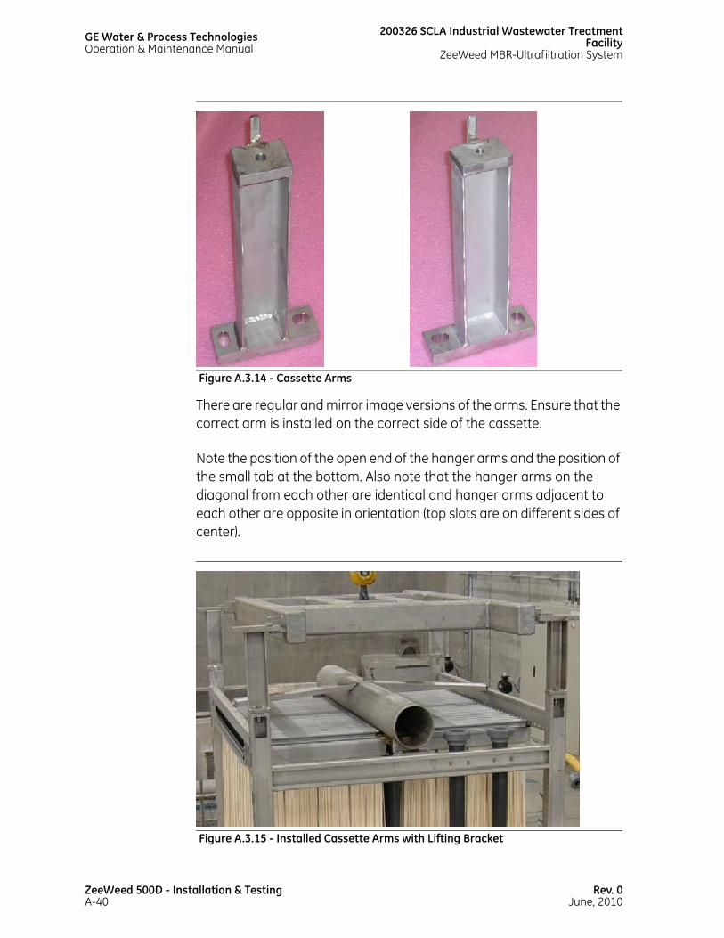
GE Water & Process TechnologiesOperation & Maintenance Manual
200326 SCLA Industrial Wastewater TreatmentFacility
ZeeWeed MBR-Ultrafiltration System
There are regular and mirror image versions of the arms. Ensure that the correct arm is installed on the correct side of the cassette.
Note the position of the open end of the hanger arms and the position of the small tab at the bottom. Also note that the hanger arms on the diagonal from each other are identical and hanger arms adjacent to each other are opposite in orientation (top slots are on different sides of center).
Figure A.3.14 - Cassette Arms
Figure A.3.15 - Installed Cassette Arms with Lifting Bracket
ZeeWeed 500D - Installation & TestingA-40
Rev. 0June, 2010

200326 SCLA Industrial Wastewater Treatment FacilityZeeWeed MBR-Ultrafiltration System
GE Water & Process TechnologiesOperation & Maintenance Manual
A.3.6.10 REMOVING THE PLASTIC WRAPPING
Cassettes are shipped with plastic wrap around the fibers. It must be removed carefully so that the membrane fibers are not cut. To remove the plastic, cut the wrapping close to the corner beam. To avoid contamination of the stainless steel frame (leading to corrosion), do not come in contact with the cassette frame while cutting. Discard the wrapping following its removal.
Be sure to cut along the corner beam to prevent fibers from being damaged. Do not cut plastic wrapper along the membrane area.
A.3.6.11 REMOVING THE PROTECTIVE FOAM
Cassettes are shipped with protective foam placed against the 2 in. vertical permeate down pipes, on the back side of the cassette. This foam is used to prevent fibers from rubbing on the pipes during shipping.
Figure A.3.16 - Cutting the Wrapper
Rev. 0June, 2010
ZeeWeed 500D - Installation & TestingA-41
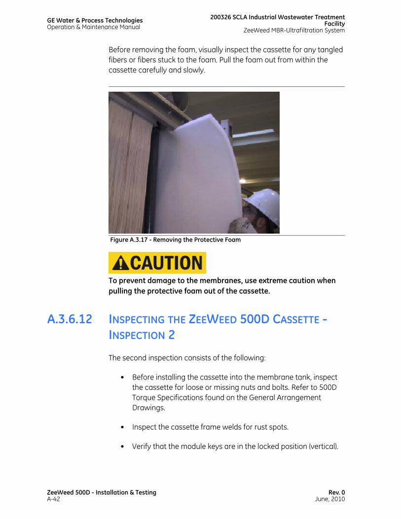
GE Water & Process TechnologiesOperation & Maintenance Manual
200326 SCLA Industrial Wastewater TreatmentFacility
ZeeWeed MBR-Ultrafiltration System
Before removing the foam, visually inspect the cassette for any tangled fibers or fibers stuck to the foam. Pull the foam out from within the cassette carefully and slowly.
To prevent damage to the membranes, use extreme caution when pulling the protective foam out of the cassette.
A.3.6.12 INSPECTING THE ZEEWEED 500D CASSETTE - INSPECTION 2
The second inspection consists of the following:
• Before installing the cassette into the membrane tank, inspect the cassette for loose or missing nuts and bolts. Refer to 500D Torque Specifications found on the General Arrangement Drawings.
• Inspect the cassette frame welds for rust spots.
• Verify that the module keys are in the locked position (vertical).
Figure A.3.17 - Removing the Protective Foam
ZeeWeed 500D - Installation & TestingA-42
Rev. 0June, 2010

200326 SCLA Industrial Wastewater Treatment FacilityZeeWeed MBR-Ultrafiltration System
GE Water & Process TechnologiesOperation & Maintenance Manual
• Record the serial numbers of each membrane module on the membrane map. When placed into the membrane tank, record the location in the tank where the membrane is placed.
• Ensure that the top and bottom expander blocks are tight and fully engaged and flush with the bottom surface of the key side outer assembly.
Figure A.3.18 - Tighten Expander Blocks
Rev. 0June, 2010
ZeeWeed 500D - Installation & TestingA-43

GE Water & Process TechnologiesOperation & Maintenance Manual
200326 SCLA Industrial Wastewater TreatmentFacility
ZeeWeed MBR-Ultrafiltration System
A.3.6.13 ASSEMBLING AERATION PIPING
Some parts of the cassette aeration spool may be assembled together before the cassette is installed. These sub-assemblies are then assembled together after the cassette is installed in the tank. For the specific parts that can be assembled together, look in the spool drawings for the specific project. Preassembling reduces the cassette installation time and reduces the amount of work that will have to be done on the cassettes after they are installed.
A.3.7 PREVENTING DEBRIS CONTAMINATION
It is critical to ensure that no debris capable of damaging the membranes enters the membrane tank at any time. Damaged incurred by debris is not covered by the membrane warranty. Possible contamination pathways include:
• Feed water laden with debris.
• Debris being blown or falling into the tank during construction, maintenance, or repairs over the membranes.
• Residue from piping or process equipment.
Figure A.3.19 - Aeration Piping
ZeeWeed 500D - Installation & TestingA-44
Rev. 0June, 2010

200326 SCLA Industrial Wastewater Treatment FacilityZeeWeed MBR-Ultrafiltration System
GE Water & Process TechnologiesOperation & Maintenance Manual
A clean membrane tank needs to be protected from contamination by debris, especially debris larger than 1.6 mm (1/16 in.). If debris is allowed to enter the tank, irreversible damage to the membranes can occur.
Examples of common materials that cause damage include (but are not limited to):
• Cable ties
• Plastic turnings from drilling
• Pieces of wire
• Broken measuring tapes
• Weld slag and metal debris from grinding
• Twigs
• Leaves
• Shells
• Fish
• Sand
To prevent construction debris from entering the tank after membrane installation, cover cleaned tanks with a continuous plastic barrier protected by plywood sheets. General good housekeeping practices are recommended.
A.3.8 INSTALLING CASSETTES IN THE MEMBRANE TANK
After the cassette has been fully inspected, the cassette can be installed in the membrane tank.
Rev. 0June, 2010
ZeeWeed 500D - Installation & TestingA-45

GE Water & Process TechnologiesOperation & Maintenance Manual
200326 SCLA Industrial Wastewater TreatmentFacility
ZeeWeed MBR-Ultrafiltration System
There must be enough potable water in the membrane tank such that no fibers will be exposed to air once the cassette is installed.
The lifting arm is moved using the crane to the overtop of the cassette. The pins at its four corners slide into the hanger arm slotted hole facing the inside of the cassette. Once the pins are through the slotted holes, a hitch pin must be passed through the lifting bracket pins to secure the lifting bracket to the cassette.
Using the hoist and lifting bracket, carefully lift the cassette and install it onto the leveling pins inside the membrane tank. The outside slotted holes on the hanger arms slide onto the leveling pins in the tank.
During lifting, the cassette is to be guided by the cassette stainless steel supports only. Never touch the membranes.
Figure A.3.20 - Lifting Bracket
ZeeWeed 500D - Installation & TestingA-46
Rev. 0June, 2010
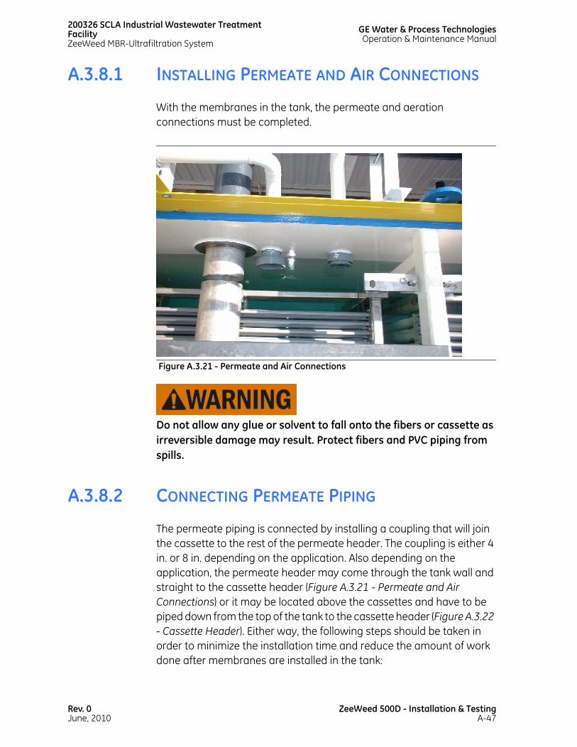
200326 SCLA Industrial Wastewater Treatment FacilityZeeWeed MBR-Ultrafiltration System
GE Water & Process TechnologiesOperation & Maintenance Manual
A.3.8.1 INSTALLING PERMEATE AND AIR CONNECTIONS
With the membranes in the tank, the permeate and aeration connections must be completed.
Do not allow any glue or solvent to fall onto the fibers or cassette as irreversible damage may result. Protect fibers and PVC piping from spills.
A.3.8.2 CONNECTING PERMEATE PIPING
The permeate piping is connected by installing a coupling that will join the cassette to the rest of the permeate header. The coupling is either 4 in. or 8 in. depending on the application. Also depending on the application, the permeate header may come through the tank wall and straight to the cassette header (Figure A.3.21 - Permeate and Air Connections) or it may be located above the cassettes and have to be piped down from the top of the tank to the cassette header (Figure A.3.22 - Cassette Header). Either way, the following steps should be taken in order to minimize the installation time and reduce the amount of work done after membranes are installed in the tank:
Figure A.3.21 - Permeate and Air Connections
Rev. 0June, 2010
ZeeWeed 500D - Installation & TestingA-47
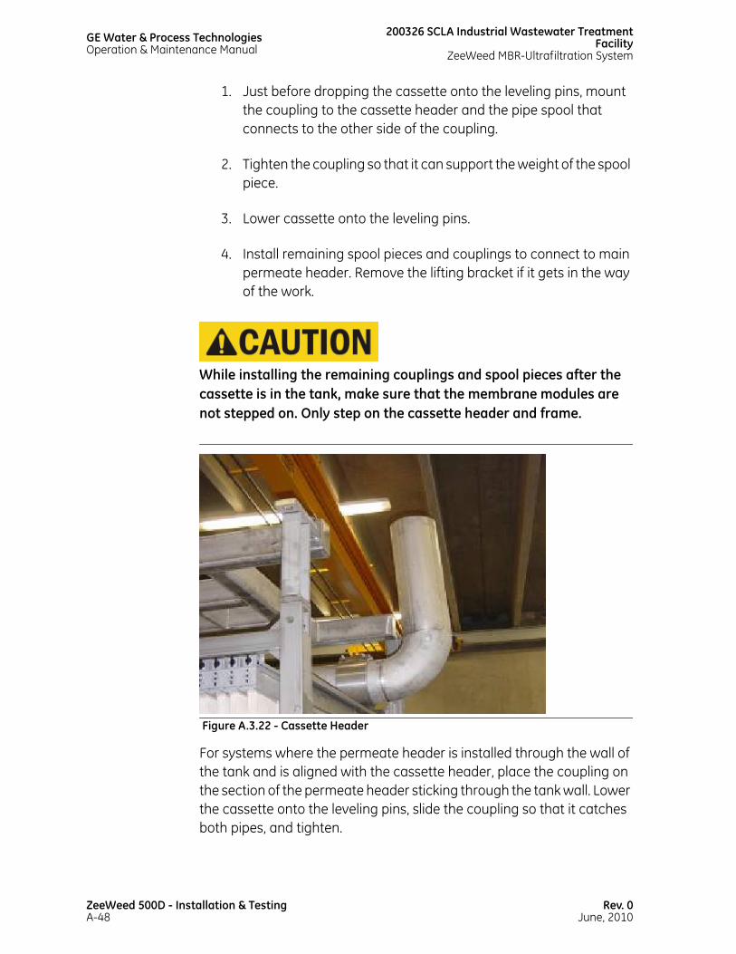
GE Water & Process TechnologiesOperation & Maintenance Manual
200326 SCLA Industrial Wastewater TreatmentFacility
ZeeWeed MBR-Ultrafiltration System
1. Just before dropping the cassette onto the leveling pins, mount the coupling to the cassette header and the pipe spool that connects to the other side of the coupling.
2. Tighten the coupling so that it can support the weight of the spool piece.
3. Lower cassette onto the leveling pins.
4. Install remaining spool pieces and couplings to connect to main permeate header. Remove the lifting bracket if it gets in the way of the work.
While installing the remaining couplings and spool pieces after the cassette is in the tank, make sure that the membrane modules are not stepped on. Only step on the cassette header and frame.
For systems where the permeate header is installed through the wall of the tank and is aligned with the cassette header, place the coupling on the section of the permeate header sticking through the tank wall. Lower the cassette onto the leveling pins, slide the coupling so that it catches both pipes, and tighten.
Figure A.3.22 - Cassette Header
ZeeWeed 500D - Installation & TestingA-48
Rev. 0June, 2010

200326 SCLA Industrial Wastewater Treatment FacilityZeeWeed MBR-Ultrafiltration System
GE Water & Process TechnologiesOperation & Maintenance Manual
A.3.8.3 CONNECTING AIR PIPING
Each cassette is provided with two 3 in. air connections. Each of these air connections provides air to half of the aerators at the bottom of the cassette. Depending on the design of the system, these two air connections can either:
• connect together with a 4 in. tee at the cassette and then a
• 4 in. connection is made to the header, or;
• run independently as two 3 in. spools; each spool connecting to separate aeration headers.
The single 4 in. tee version is for installations with cyclic aeration (whole cassette on-off air cycling). The twin 3 in. connection version is for installations with sequential aeration (air is cycled first to half the aerators on a cassette - and then the other half). If there is any uncertainty as to which design is to be used, refer to the P&IDs.
Follow these steps:
1. Lower the cassette onto the leveling pins and remove the lifting bracket, if necessary, to make room to work.
2. Install the permeate piping completely. See Figure A.3.19 - Aeration Piping.
3. Install the aeration hose connection to the main aeration header.
4. Connect the other end of the hose to the already installed (see A.3.6.7 Installing Union to Cassette’s Main Aeration Pipes) fitting on the cassette main aeration pipes.
Rev. 0June, 2010
ZeeWeed 500D - Installation & TestingA-49

GE Water & Process TechnologiesOperation & Maintenance Manual
200326 SCLA Industrial Wastewater TreatmentFacility
ZeeWeed MBR-Ultrafiltration System
Always connect the air hose to the main aeration header first and then connect the other end to the cassette PVC aeration pipes. This avoids stressing the PVC parts on the cassette.
A.3.9 AFTER CASSETTE INSTALLATION
The following procedures must be completed after all cassettes have been installed in the membrane tanks.
Figure A.3.23 - Air Connections
ZeeWeed 500D - Installation & TestingA-50
Rev. 0June, 2010

200326 SCLA Industrial Wastewater Treatment FacilityZeeWeed MBR-Ultrafiltration System
GE Water & Process TechnologiesOperation & Maintenance Manual
A.3.9.1 FLUSHING
All ZeeWeed membrane modules and cassettes are shipped in a glycerin solution with a pH of 3.5 to 4.5 to prevent the membranes from drying. This glycerin solution has a high biochemical oxygen demand (BOD) and is not suitable for discharge to surface water or as drinking water.
The contractor is responsible for supplying available disposal capacity for spent water, including disposal of wastewater following flushing of glycerin after membrane installation (pH range of 2 to 11).
The downstream tank for permeate must not be contaminated with glycerin.
A.3.9.1.1 PURGING GLYCERIN FROM MEMBRANES
Complete the following steps:
1. Install the membranes in the membrane tank filled with feed water.
2. Run the system so that the membranes are permeating at 40 LMH (23.6 GFD). Recycle the permeate from the permeate pump discharge to the membrane tank for 60 minutes.
3. Drain the membrane tank contents to a drain and pump to headworks of the plant.
4. Refill the membrane tank with feed water.
5. As in step 2, run the system so that the membranes are permeating at 40 LMH (23.6 GFD). Recycle the permeate from the permeate pump discharge to the membrane tank for 30 minutes.
6. Drain the tank contents to a drain or a tanker.
Rev. 0June, 2010
ZeeWeed 500D - Installation & TestingA-51
GE Water & Process TechnologiesOperation & Maintenance Manual
200326 SCLA Industrial Wastewater TreatmentFacility
ZeeWeed MBR-Ultrafiltration System
7. Repeat steps 4, 5, and 6 twice. Measure the organic contents of the final tank drain to verify that TOC is less than 3 mg/L above the background level, or that the COD is less than 10 mg/L above the background level.
If there are multiple trains, the glycerin flushing water can be reused. GE W&PT will provide calculations to determine the volume of water required.
A.3.9.2 CHECKING AERATION
The cassettes must be installed before starting an aeration check.
To verify proper aeration to the membranes, complete the following steps:
1. Start the blower and ensure that air is being supplied to the membrane cassettes.
2. If the installation procedure is carried out correctly, the aeration diffuser system should be totally horizontal, providing even distribution of air over the membranes. After install the cassettes, visually verify that the air distribution is even.
Air must be evenly distributed within the cassette.
3. Observe the bubble pattern on the surface of the tank. The surface should bubble evenly above the membrane cassette. If any uneven aeration is observed, the system must be stopped and the cause isolated. If the airflow is uneven, it can be corrected by adjusting the level of the cassette using the levelling bolts. This is critical and will be supervised by a GE W&PT FSR.
4. Check the air pipe connections for leakage. If any leaks are found, fix the piping immediately to ensure that the membrane cassettes are receiving sufficient aeration.
ZeeWeed 500D - Installation & TestingA-52
Rev. 0June, 2010
200326 SCLA Industrial Wastewater Treatment FacilityZeeWeed MBR-Ultrafiltration System
GE Water & Process TechnologiesOperation & Maintenance Manual
5. With the aeration on, observe the airflow pattern in the various membrane tanks. Determine if the difference in membrane tank level while backpulsing has an effect on the airflow pattern.
6. Observe the aeration pattern within the individual cassettes during the 10-second cycle to determine whether all of the modules are receiving equal airflow.
7. Turn aeration on in one membrane tank and off in another tank. Ensure there is no aeration in the membrane tank that is off.
A.3.9.3 TESTING PERFORMANCE
The customer is responsible for ensuring a supply of raw water and a receiving body for the treated water for commissioning and performance testing of the equipment.
The customer is responsible for the provision of necessary analytical tests for treated water quality, as per project specifications.
A.3.9.4 BUBBLE TEST
A bubble test is used to locate leaks in the membranes and should be completed for each cassette in the subsystem. To complete a bubble test, perform the following steps:
TIP: If possible, remove the cassette from the membrane tank and test in a separate tank.
1. Reduce the water level in the membrane tank to a point below the permeate connection, so that no water can get into the cassette after the connection is removed. The membranes must be completely submerged.
Before making any connections, ensure that the membrane safety hand valve and the pressure regulating valve are closed.
2. Connect the PDT kit adapters to the permeate connection(s) on the cassette.
Rev. 0June, 2010
ZeeWeed 500D - Installation & TestingA-53
GE Water & Process TechnologiesOperation & Maintenance Manual
200326 SCLA Industrial Wastewater TreatmentFacility
ZeeWeed MBR-Ultrafiltration System
3. Connect the 1/4 in. tubing from the adapter to the permeate air connection, and then connect the 1/4 in. tubing from the compressed air source.
4. Slowly open the pressure regulating valve to empty liquid from the permeate side of the membrane into the membrane tank.
5. Set the applied air pressure to just over half of the required pressure.
6. Wait 5 minutes to ensure the air has purged the water, and then increase the air pressure to just under the required pressure.
7. Examine the membranes for escaping bubbles (indicating a leak).
8. If a leak is found, analyze the bubble stream as described in A.3.9.4.1 Bubble Types. Based on the type of bubble stream found, the module can be repaired using the procedures outlined later in this manual.
In cases where few leaks are present in a given module, and none of the leaks are serious, the repairs should be made on site. If a module requires difficult or numerous repairs, contact GE W&PT for further information.
A.3.9.4.1 BUBBLE TYPES
The size and type of bubbles released by a leak during a bubble test indicate the type of leak. Bubbles are classified according to four types, as shown in Figure A.3.24 - Bubble Sizes.
TYPE 1: A Type 1 bubble stream appears as a steady flow of large bubbles, typically 10 mm (3/8 in.) in diameter or greater. Type 1 streams are usually released by a broken membrane fiber. However, if the stream appears to come from one of the permeate headers, it may also be caused by an improperly installed O-ring.
ZeeWeed 500D - Installation & TestingA-54
Rev. 0June, 2010
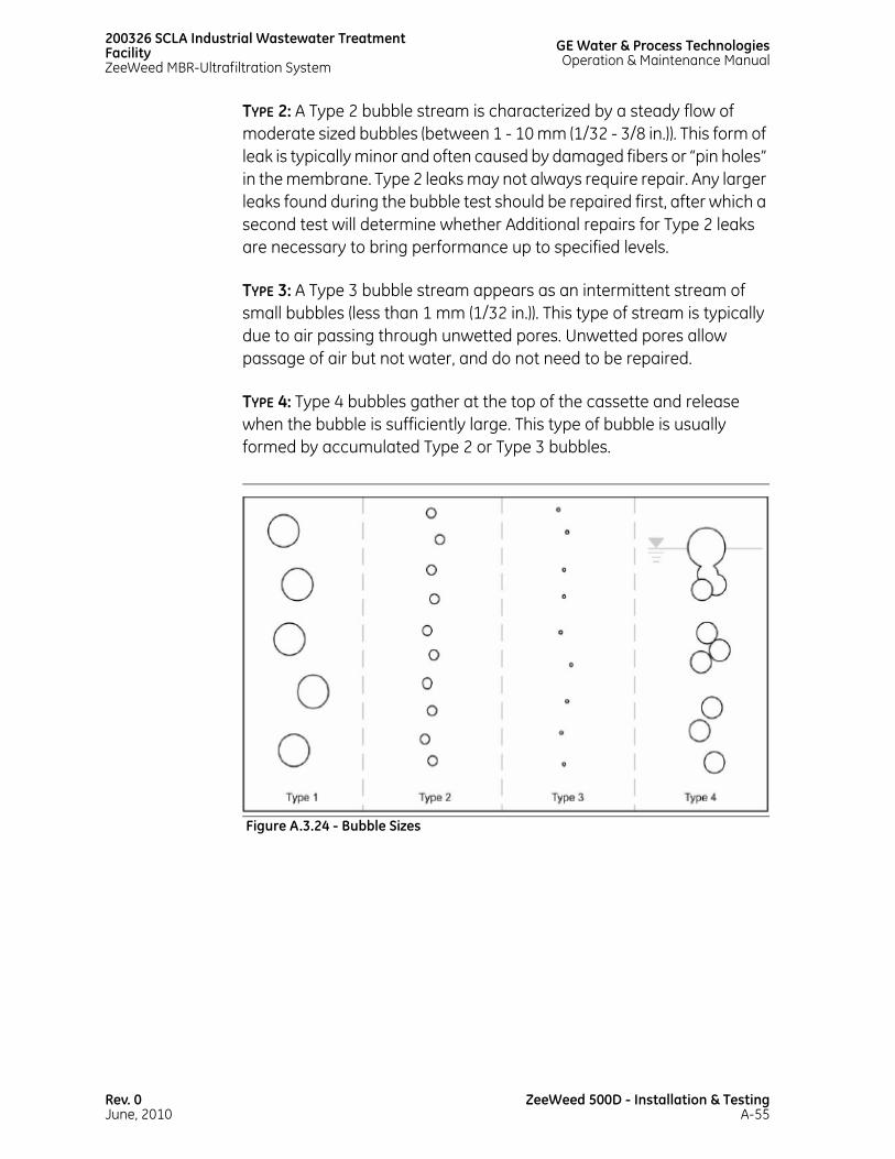
200326 SCLA Industrial Wastewater Treatment FacilityZeeWeed MBR-Ultrafiltration System
GE Water & Process TechnologiesOperation & Maintenance Manual
TYPE 2: A Type 2 bubble stream is characterized by a steady flow of moderate sized bubbles (between 1 - 10 mm (1/32 - 3/8 in.)). This form of leak is typically minor and often caused by damaged fibers or “pin holes” in the membrane. Type 2 leaks may not always require repair. Any larger leaks found during the bubble test should be repaired first, after which a second test will determine whether Additional repairs for Type 2 leaks are necessary to bring performance up to specified levels.
TYPE 3: A Type 3 bubble stream appears as an intermittent stream of small bubbles (less than 1 mm (1/32 in.)). This type of stream is typically due to air passing through unwetted pores. Unwetted pores allow passage of air but not water, and do not need to be repaired.
TYPE 4: Type 4 bubbles gather at the top of the cassette and release when the bubble is sufficiently large. This type of bubble is usually formed by accumulated Type 2 or Type 3 bubbles.
Figure A.3.24 - Bubble Sizes
Rev. 0June, 2010
ZeeWeed 500D - Installation & TestingA-55
GE Water & Process TechnologiesOperation & Maintenance Manual
200326 SCLA Industrial Wastewater TreatmentFacility
ZeeWeed MBR-Ultrafiltration System
A.3.10 MEMBRANE INSPECTION/REPLACEMENT
This procedure is required if the membranes are being replaced, inspected as part of routine maintenance, or being removed from the tank. GE W&PT recommends that direct supervision of GE personnel be arranged whenever the membranes are removed from the tanks. If there is a build up of solids on the membranes, read A.3.10.1 Heavy Cassette Lifting before lifting the cassette from the membrane tank.
Once membrane inspection or replacement has begun, it must be completed promptly. It is vital that the membranes DO NOT DRY OUT OR FREEZE before completing this procedure.
To remove a cassette from the membrane tank:
1. Lower the liquid level in the membrane tank to just below the connections. Carry out a general shutdown of the whole system. Isolate the cassettes using the manual valves at the permeate and air headers.
Individual membrane modules cannot be isolated from the rest of a membrane cassette.
2. Disconnect the YN couplings from the cassette: 1 coupling for permeate and 2 couplings for air per cassette.
3. Attach the lifting bracket to the cassette.
4. Attach a chain or lifting strap to the steel lifting harness on the cassette.
5. Use a manual hoist and monorail (boom truck or crane) to carefully lift the cassette until the strap is tight. Continue to lift the membrane cassette out of the frame with the crane, taking care not to trap the flexible piping or damage the membranes, especially if any sharp edges are exposed in the area.
ZeeWeed 500D - Installation & TestingA-56
Rev. 0June, 2010
200326 SCLA Industrial Wastewater Treatment FacilityZeeWeed MBR-Ultrafiltration System
GE Water & Process TechnologiesOperation & Maintenance Manual
6. Remove the cassette to a safe, preferably level, location and transplant the necessary items to the new membranes (if applicable; no transplantation is necessary when inspecting the membranes). If new membranes are being installed, the customer will ensure that the delivery is correct and will assist in checking the integrity of the supplied membranes.
7. When inspecting the membranes, check for any apparent damage to the modules or fibers, and for items that are clearly different from module to module. Look for any loose hardware or fasteners. Ensure that none of the membrane fibers are broken. Check the top and bottom permeate headers and piping for any apparent damage or cracking.
8. When replacing a membrane cassette or installing new membranes, disassemble the cassette in reverse order of assembly. Contact GE W&PT before disassembling a cassette.
Contact the Service Department at (905) 465-3030 for additional technical assistance if any problems are observed. GE W&PT maintains an inventory of membranes at all times. Generally, if membrane modules are being replaced, they can be shipped on short notice.
A.3.10.1 HEAVY CASSETTE LIFTING
ZeeWeed cassettes that have been operated for extended periods of time may accumulate debris, which will add weight to the cassette. The extent of debris buildup over time will depend on the nature of the waste stream, the effectiveness of the wastewater prescreening step, and other factors.
If heavily weighted cassettes are completely removed from the tank for inspection and cleaning, this could result in the cassette frame and cassette lifting mechanism being subjected to excessive loadings. In some cases, the resulting load may encroach on the design safety factor of the cassette frame and lifting mechanism, as well as the cassette support beam and grating in the location where the cassette is set down.
Rev. 0June, 2010
ZeeWeed 500D - Installation & TestingA-57

GE Water & Process TechnologiesOperation & Maintenance Manual
200326 SCLA Industrial Wastewater TreatmentFacility
ZeeWeed MBR-Ultrafiltration System
Improper handling of overweight cassettes may result in injury or property loss.
If by direct measurement with a weigh scale or by other means, it is suspected the cassettes are overweight, or if for safety reasons, it is assumed the cassettes are overloaded every time the cassettes are removed, the following procedure will assist in removing the debris from the cassettes before they are removed from the tank:
1. Isolate the cassettes from permeation and aerate them for 12 to 24 hours. The cassettes can be isolated via the local hand valves or by disabling the train from the HMI. Aerating without permeation has proven effective in removing built up debris from the cassette and will reduce or eliminate the overweight condition.
2. Turn off the aeration and lift the cassette partially out of the tank. Flush the exposed section with clean water (process effluent is sufficient). Lift the cassette approximately 50 cm – 75 cm (20 in. -30 in.) at a time and repeat the process. By lifting the cassette in steps, the submerged sections will be partially supported by the wastewater and will reduce the lifting loads. For a deep tank application, where this process is not practical, wash off the debris prior to lifting the cassette above the grating.
3. Do not complete any lift with staff directly under or in the immediate vicinity of the cassette. The normal safe operating practice of using guide ropes should always be used for controlling the lift. Any direct staff contact with the cassette should be minimized.
For optimal performance and long life of the equipment, all areas must be kept clean. Remove any chemical spills immediately and wipe down the maintenance equipment frequently.
ZeeWeed 500D - Installation & TestingA-58
Rev. 0June, 2010

200326 SCLA Industrial Wastewater Treatment FacilityZeeWeed MBR-Ultrafiltration System
GE Water & Process TechnologiesOperation & Maintenance Manual
A.3.11 RETURNING DAMAGED MEMBRANES
If the membrane is being returned to GE Water & Process Technologies, it is imperative that it be properly cleaned, preserved, and that a “Returned Goods Authorization” (RGA) number be obtained prior to shipping it. Contact GE Water & Process Technologies technical services for information on the RGA procedure.
A.3.12 SYSTEM SHUTDOWN AND MEMBRANE PRESERVATION
When membranes have been installed in a tank, they need to be kept wet at all times. When the protective glycerin solution is removed during soaking in water, the membranes become especially susceptible to drying. For storage periods of up to approximately 15 days, simple immersion of the cassettes in water containing sodium hypochlorite (NaOCl) with a maximum residual concentration of 3 mg/L. Residual chlorine levels should be monitored every week and repeat testing is required if the chlorine level drops to less than 0.2 mg/L. Recovery cleaning of the membrane prior to storage is strongly recommended.
An isolated cassette must be cleaned before it is returned to service. If a cassette is isolated for less than a week, perform a Maintenance Clean with sodium hypochlorite. If a cassette is isolated for longer than a week, perform a Recovery Clean with sodium hypochlorite. For information on Maintenance and Recovery Cleans, refer to A.5 - Preventive Maintenance.
A.3.12.1 SHORT TERM SHUTDOWN
The system is always expected to operate in On, with all components in Auto. Do not leave the system unattended, if any component without an online spare is not in Auto.
Rev. 0June, 2010
ZeeWeed 500D - Installation & TestingA-59

GE Water & Process TechnologiesOperation & Maintenance Manual
200326 SCLA Industrial Wastewater TreatmentFacility
ZeeWeed MBR-Ultrafiltration System
System shutdown procedures include the following steps:
1. Chemical clean the system component(s) to be shutdown.
2. Switch the train(s) to OFF.
3. Shutdown the plant.
Before the system is returned to service, it must be cleaned. The period of time that the system has been shutdown will dictate the type of cleaning required; short shutdown periods (less than a week) require a less vigorous cleaning then shutdown periods lasting longer than a week.
Alternatively, for long-term storage, the components can be removed from the system and preserved in glycerine.
A.3.12.2 LONG TERM MEMBRANE SHUTDOWN
Following are the steps by the operator:
1. Perform a Recovery Clean. For Recovery Clean instructions, refer to A.5 - Preventive Maintenance.
2. Ensure that the membranes are free of solids.
3. Prepare a solution of 50 wt% glycerin.
The preservative solution is extremely slippery on surfaces and extreme care should be exercised when handling the solution. To minimize the risk of staff injury from slipping, clean up spills immediately.
ZeeWeed 500D - Installation & TestingA-60
Rev. 0June, 2010

200326 SCLA Industrial Wastewater Treatment FacilityZeeWeed MBR-Ultrafiltration System
GE Water & Process TechnologiesOperation & Maintenance Manual
The following is an example calculation for preparing 1000 liters of the preservative solution. The specific gravity of 100% glycerine is 1.26. For 1000 liters of preservative solution: Add 396 liters of 100% glycerine. Fill the tank to the 1000 liter mark. (Approximately 600 liters).
4. Use one of the following procedures to impregnate the modules:
Option I for ZeeWeed 500D:
a. ZeeWeed 500D modules in a horizontal tank:
i. Soak the module in the above solution and apply 0.34 bar vacuum (0.66 bar absolute) for 30 minutes.
ii. Take the module out of the solution and place it on the floor for 30 minutes to allow excess solution to drain off.
iii. Bag and seal the module immediately as described in step 5.
b. Single module vertical in stand:
i. Plug the bottom permeate port and pour 3 liters (0.8 gallons) of mixture prepared in Step 3 into the top port.
ii. Bag and seal the module immediately, as described in step 5.
Option II for ZeeWeed 500D:
a. ZeeWeed 500D cassettes:
i. With the cassette immersed in water, ensure that the lumen is full of water by operating under vacuum (permeation).
ii. Close permeate isolation valves and then remove cassette from water. Do not allow air to enter the permeate side of the module.
Rev. 0June, 2010
ZeeWeed 500D - Installation & TestingA-61

GE Water & Process TechnologiesOperation & Maintenance Manual
200326 SCLA Industrial Wastewater TreatmentFacility
ZeeWeed MBR-Ultrafiltration System
iii. Connect a reservoir of preservative solution (as prepared in Step 3) to the permeate piping and keep the reservoir at least 60 cm (24”) above the top of the cassette.
iv. Open the permeate isolation valves; the level in the reservoir should fall as the holdup water volume reverse permeates and preservative enters the module.
v. Continue reverse permeation until a volume of preservative equivalent to 3 liters (0.8 gal) is reverse permeated through each module in the cassette (a 64 module cassette requires 192 liters (51 gal) of preservative solution).
5. Bag the module using a 0.15 mm (6 mil) thick plastic bag. These bags are available from GE W&PT. Seal the membranes in the plastic bag, using either a hand held sealer or tape, so that they will remain preserved and will not dry out. For the tape seal, remove as much air as possible from the bag. Seal most of the membrane bag with tape, then remove the excess air with a shop vacuum.
6. Store in a cool, dry area, out of the direct sunlight and protected from accidental contact that could damage the module or bag. It is recommended that the membranes be double bagged or enclosed in suitable cardboard cartons.
The membranes are now properly preserved, and the system can be shut down.
To shut down the ZeeWeed system:
1. Set the system to Off.
2. Set all equipment to Off.
3. Close all automatic valves.
The ZeeWeed train is now shut down.
ZeeWeed 500D - Installation & TestingA-62
Rev. 0June, 2010

200326 SCLA Industrial Wastewater Treatment FacilityZeeWeed MBR-Ultrafiltration System
GE Water & Process TechnologiesOperation & Maintenance Manual
4. To allow drainage, open the appropriate lines on the permeate pumps and associated piping runs. The permeate header and all dedicated pipelines to the out-of-service train should be drained, flushed, and dried.
5. Close the isolation valves on the permeate header.
6. Leave the cassette isolation valves on the air headers open, and the header outlets capped with camlock caps.
7. Remove and store the membrane tank level transmitter from the membrane tank.
8. Follow the normal maintenance schedule for all equipment, specifically all pumps and blowers.
Contact the Service Department at (905) 465-3030 for any additional technical assistance with the handling and storage of the membranes.
Rev. 0June, 2010
ZeeWeed 500D - Installation & TestingA-63

This page has beenintentionally left blank

A.4MEMBRANE CARE

This page has beenintentionally left blank
200326 SCLA Industrial Wastewater Treatment FacilityZeeWeed MBR-Ultrafiltration System
GE Water & Process TechnologiesOperation & Maintenance Manual
A.4.1 INTRODUCTION
This section describes various aspects of membrane care that may arise during operations including:
• Causes and prevention of ZeeWeed fouling
• Fiber shrinkage and slack
• Module removal from a cassette
• Module insertion into a cassette
• Fiber repair
If any of the problems discussed in this section persist or other difficulties arise, the operator should contact GE Water & Process Technologies. Complete operating logsheets are necessary to determine the source of the problem.
A.4.2 MEMBRANE FOULING
The following section provides information regarding membrane fouling, types of foulants, and the processes used to remove them.
A.4.2.1 PROBLEMS ASSOCIATED WITH MEMBRANE FOULING
Membrane fouling causes increased operational TMP, increased energy costs, and reduced membrane life. Foulants create an increased resistance to permeation, requiring more vacuum (or operational TMP) to treat similar quantities of water. When TMP increases, the process pump requires more energy to draw the increased vacuum to meet the flow setpoint.
Rev. 0June, 2010
ZeeWeed 500D - Membrane CareA-67

GE Water & Process TechnologiesOperation & Maintenance Manual
200326 SCLA Industrial Wastewater TreatmentFacility
ZeeWeed MBR-Ultrafiltration System
Membrane fouling reduces the life of a membrane.
A.4.2.2 FOULING AND FOULANTS
Fouling is defined as the accumulation of unwanted deposits on a membrane surface. These deposits reduce the effective membrane surface area, thus reducing the flow of purified water.
Foulants are materials that accumulate on the surface of a membrane and decrease membrane performance. Foulants are divided into the following four groups:
• Biological
• Precipitative
• Adsorptive
• Solids Formation
BIOLOGICAL FOULING: Aerobic and anaerobic living materials, such as bacteria, fungus, and algae, are classified as biological foulants. These organisms colonize on the surface of the membrane, which can block the flow through the membrane surface.
PRECIPITATIVE FOULING: Precipitative fouling usually occurs in the form of scale. Scale forms when the compounds in the feed water are concentrated beyond their solubility. Common precipitative foulants include calcium carbonate and magnesium sulfate.
Inorganic foulants form a hard scale on the membrane surface, hindering membrane performance. Scale can be caused by high pH levels and extremely hard feed water. This type of fouling is not common in ZeeWeed systems because filtration does not remove dissolved ions from the water.
ADSORPTIVE FOULING: Compounds that stick to the surface of the membrane, such as oil, polymers, cationic surfactants, and hydrocarbons, are classified as adsorptive foulants.
ZeeWeed 500D - Membrane CareA-68
Rev. 0June, 2010
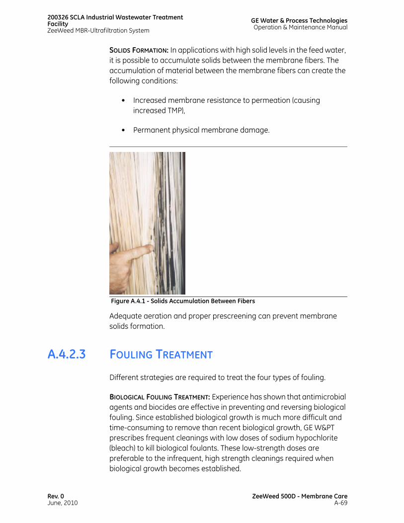
200326 SCLA Industrial Wastewater Treatment FacilityZeeWeed MBR-Ultrafiltration System
GE Water & Process TechnologiesOperation & Maintenance Manual
SOLIDS FORMATION: In applications with high solid levels in the feed water, it is possible to accumulate solids between the membrane fibers. The accumulation of material between the membrane fibers can create the following conditions:
• Increased membrane resistance to permeation (causing increased TMP),
• Permanent physical membrane damage.
Adequate aeration and proper prescreening can prevent membrane solids formation.
A.4.2.3 FOULING TREATMENT
Different strategies are required to treat the four types of fouling.
BIOLOGICAL FOULING TREATMENT: Experience has shown that antimicrobial agents and biocides are effective in preventing and reversing biological fouling. Since established biological growth is much more difficult and time-consuming to remove than recent biological growth, GE W&PT prescribes frequent cleanings with low doses of sodium hypochlorite (bleach) to kill biological foulants. These low-strength doses are preferable to the infrequent, high strength cleanings required when biological growth becomes established.
Figure A.4.1 - Solids Accumulation Between Fibers
Rev. 0June, 2010
ZeeWeed 500D - Membrane CareA-69

GE Water & Process TechnologiesOperation & Maintenance Manual
200326 SCLA Industrial Wastewater TreatmentFacility
ZeeWeed MBR-Ultrafiltration System
PRECIPITATIVE FOULING TREATMENT: Membranes fouled with precipitative scale are cleaned using an acidic cleaner, such as citric acid. It is preferable to avoid precipitative fouling by reducing the concentration of potential fouling compounds. Feed water can be pretreated by lime softening and pH adjustment to remove scale-forming compounds in the influent stream. Concentrations of hydroxide and carbonate ions can be reduced by adding acid.
ADSORPTIVE FOULING TREATMENT: Since adsorptive fouling is extremely difficult to reverse, it is critical to avoid exposure to oils, polymers, and hydrocarbons. If considering polymers or surfactants, check with GE W&PT.
MEMBRANE SOLIDS FORMATION: Proper aeration is effective in preventing membrane solids formation. It is imperative to inspect the aeration pattern on a routine basis.
A.4.2.4 FOULING PREVENTION
The three most common methods of preventing fouling in a ZeeWeed subsystem are to perform a backpulse, a maintenance clean, and a recovery clean. Depending on the type of fouling, maintenance cleans and recovery cleans are performed with either a sodium hypochlorite or citric acid solution, used to remove organic and inorganic foulants, respectively. Refer to A.5 - Preventive Maintenance for more information regarding cleaning frequency and procedures.
A.4.2.4.1 PRESCREENING
Improper prescreening leads to difficulties in membrane cleaning and potential damage to the membranes.
Proper prescreening helps eliminate the build-up of trash, hair, lint, and other fibrous materials, and decreases the risk of solids accumulation.
When screening is required for the ZeeWeed system, a 2 mm or 1/16” punch hole traveling band screen is appropriate.
ZeeWeed 500D - Membrane CareA-70
Rev. 0June, 2010

200326 SCLA Industrial Wastewater Treatment FacilityZeeWeed MBR-Ultrafiltration System
GE Water & Process TechnologiesOperation & Maintenance Manual
A.4.3 FIBER SHRINKAGE AND SLACK
ZeeWeed 500D modules consist of hollow fibers supported between two headers maintained at a product specific fixed distance from each other. The fiber length on a module relative to the overall distance between the two headers is marginally larger, which results in fibers that can move to a limited degree.
ZeeWeed 500D modules are manufactured with inherent fiber slack designed to optimize membrane air scouring during operation as well as accommodate typical changes. A module with taut fibers may not perform well because the random motion of the fibers during aeration is critical to the filtration efficiency of ZeeWeed membranes. If the fibers shrink during operation, the predetermined slack will disappear and the fibers will become taut affecting membrane performance.
Fiber slack changes for a specific plant and application, and is a function of operating temperature, chlorine concentration, and time. Significant changes in fiber slack are generally observed when a module is operated extensively at temperatures of >25ºC (77ºF) or in the presence of certain solvents sometimes found in industrial wastewater applications.
Shrinkage is a physical change that can be expected to be observed in any product composed of synthetic polymers. The slack of the fibers within respective ZeeWeed 500D products is a measurable property and adjustments can be made as required.
The exact rate of fiber shrinkage is difficult to predict due to variability in site specific parameters; however, the shrinkage rate increases with temperature. For example, a plant operating at 35ºC (95ºF) will typically exhibit more fiber shrinkage than a plant operating at 30ºC (86ºF) over the same period of time. Plants operating at temperatures below 25ºC (77ºF) are not expected to exhibit significant fiber shrinkage and the need for slack adjustment is unlikely.
For the reasons listed above, it is important for plant operations staff to monitor their ZeeWeed product slack, even those sites operating below 25ºC (77ºF), to ensure optimum performance from their membranes. If an insufficient fiber slack problem is observed, it is strongly recommended that it be remedied in a timely manner.
Rev. 0June, 2010
ZeeWeed 500D - Membrane CareA-71
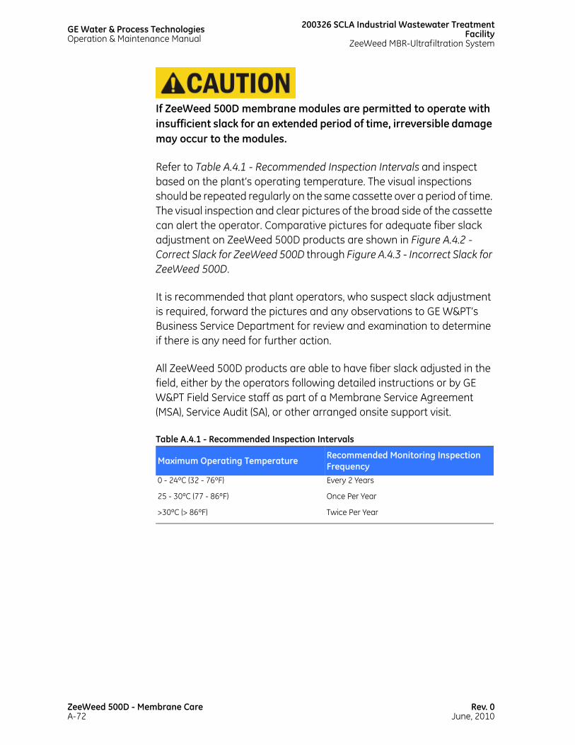
GE Water & Process TechnologiesOperation & Maintenance Manual
200326 SCLA Industrial Wastewater TreatmentFacility
ZeeWeed MBR-Ultrafiltration System
If ZeeWeed 500D membrane modules are permitted to operate with insufficient slack for an extended period of time, irreversible damage may occur to the modules.
Refer to Table A.4.1 - Recommended Inspection Intervals and inspect based on the plant’s operating temperature. The visual inspections should be repeated regularly on the same cassette over a period of time. The visual inspection and clear pictures of the broad side of the cassette can alert the operator. Comparative pictures for adequate fiber slack adjustment on ZeeWeed 500D products are shown in Figure A.4.2 - Correct Slack for ZeeWeed 500D through Figure A.4.3 - Incorrect Slack for ZeeWeed 500D.
It is recommended that plant operators, who suspect slack adjustment is required, forward the pictures and any observations to GE W&PT’s Business Service Department for review and examination to determine if there is any need for further action.
All ZeeWeed 500D products are able to have fiber slack adjusted in the field, either by the operators following detailed instructions or by GE W&PT Field Service staff as part of a Membrane Service Agreement (MSA), Service Audit (SA), or other arranged onsite support visit.
Table A.4.1 - Recommended Inspection Intervals
Maximum Operating Temperature Recommended Monitoring Inspection Frequency
0 - 24ºC (32 - 76ºF) Every 2 Years
25 - 30ºC (77 - 86ºF) Once Per Year
>30ºC (> 86ºF) Twice Per Year
ZeeWeed 500D - Membrane CareA-72
Rev. 0June, 2010

200326 SCLA Industrial Wastewater Treatment FacilityZeeWeed MBR-Ultrafiltration System
GE Water & Process TechnologiesOperation & Maintenance Manual
It is strongly emphasized that a plant’s failure to identify and promptly address concerns with insufficient fiber slack may impact the overall usable life of the installed membrane modules and cassettes. In some extreme cases, inaction may contribute to premature module failures. This is not a warrantable product failure.
Figure A.4.2 - Correct Slack for ZeeWeed 500D
Figure A.4.3 - Incorrect Slack for ZeeWeed 500D
Rev. 0June, 2010
ZeeWeed 500D - Membrane CareA-73

GE Water & Process TechnologiesOperation & Maintenance Manual
200326 SCLA Industrial Wastewater TreatmentFacility
ZeeWeed MBR-Ultrafiltration System
A.4.3.1 SLACK ADJUSTMENT
Every effort has been made by GE Water and Process Technologies to provide current information while preparing this procedure. GE maintains that depictions of methods and/or techniques and use of specific tools and/or apparatus shown within the situations portrayed are accurate at the time of printing. GE accepts no liability for any reliance placed on the information contained herein.
A.4.3.1.1 MANPOWER REQUIREMENT
The slack adjustment procedure requires the use of 2 people at all times to prevent damage to the modules and cassette.
Prior to removing the cassette from the tank, don protective clothing, face mask, gloves and boots. Using a high flow, low pressure water supply, hose down the cassette thoroughly during its removal to remove solids.
This procedure will require the cassette to be out of the process tank for an extended period of time. The membranes must be sprayed with water every 30 minutes in order for them to stay moist. Local weather condition may demand more frequent spraying.
Be careful when removing a cassette caked with solids as the cassette will be heavier.
When removing cassettes, ensure that they are level and inspect the aerator plates/tubes. Before beginning work, verify the rated capacity of lifting brackets, cranes, and the cassette lifting frame. As the cassette is removed from the water, use a weight scale to ensure that components under load are within their design capacity.
To reduce the amount of solids on the cassette before lifting, aerate the cassette without permeation. Use a garden hose to dislodge the solids from the cassettes as they are being removed from the tank. Remember to spray the garden hose as gently as possible to avoid permanent damage to the fibers.
ZeeWeed 500D - Membrane CareA-74
Rev. 0June, 2010

200326 SCLA Industrial Wastewater Treatment FacilityZeeWeed MBR-Ultrafiltration System
GE Water & Process TechnologiesOperation & Maintenance Manual
To ensure that the water pressure in the hose is not excessive, test that the stream does not extend more than 3 ft when the hose is held at a height of 3 ft (as demonstrated in Figure A.4.4 - Water Pressure Test). If the stream contacts the ground within 3 ft of the hose, the pressure is suitable for spraying the membranes.
A thorough clean and soak of the cassettes may be required prior to lifting them from the membrane tank.
A.4.3.1.2 TOOLS/PARTS REQUIRED
• Large Flat Head Screw Driver (SS or Plated)
• Small Flat Head Screw Driver (SS or Plated)
• Torque Wrench: 25-250 Inch lbs. or 3.6-29 Nm
• 3/8 in. or 1/2 in. Ratchet (same size as torque wrench)
• 17mm socket
• 17mm open wrench
• Rubber Mallet
• Pry Bar (Stainless Steel or Plated)
• Coarse File
• Qty 28 Nordlocks M10 (Replacement)
Figure A.4.4 - Water Pressure Test
Rev. 0June, 2010
ZeeWeed 500D - Membrane CareA-75

GE Water & Process TechnologiesOperation & Maintenance Manual
200326 SCLA Industrial Wastewater TreatmentFacility
ZeeWeed MBR-Ultrafiltration System
• White Knight Food Grade Anti-Seize
• Module Removal Tool
• Full Face Mask
• Protective clothing including boots and gloves
• 5mm Allen Key Socket
• 13/32 in. drill bit
• Drill
• Qty 6 - M10 x 250 mm Jack Bolts
A.4.3.1.3 DEFINITIONS AND NOTES
During a slack adjustment procedure, remember the following information:
• The front of the cassette is defined as follows: when facing the front of the cassette, the 3 in. Aeration pipes are located on the left side of the cassette
• Apply food grade anti-seize to all bolts (for example: White Knight Anti-Seize)
• Replace all Nordlocks with new
• Ensure the use of stainless steel or plated tools only
• Review the latest ZeeWeed 500D Module Inspection Checklist for items to be inspected while cassette/modules are out of the water.
The ZeeWeed 500D Cassette has four adjustable positions:
1. Position #1: Standard from the Manufacturing Assembly Plant
2. Position #2 Adjustment raises the modules 8mm from position #1
ZeeWeed 500D - Membrane CareA-76
Rev. 0June, 2010
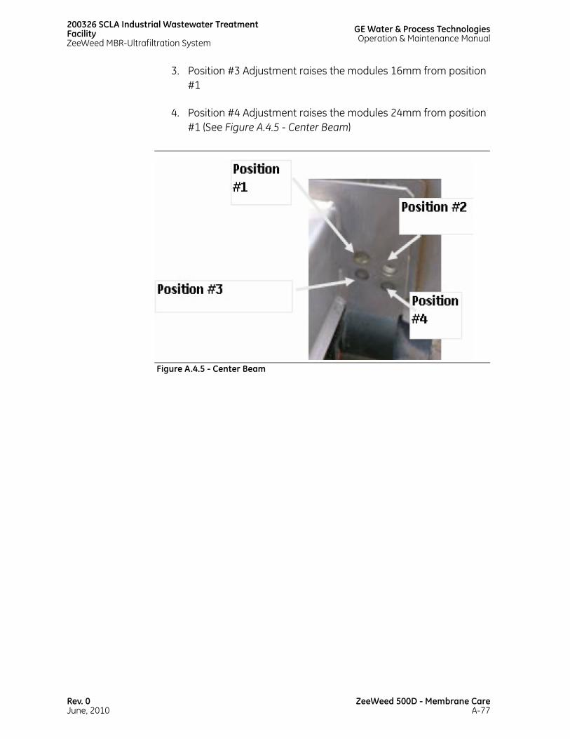
200326 SCLA Industrial Wastewater Treatment FacilityZeeWeed MBR-Ultrafiltration System
GE Water & Process TechnologiesOperation & Maintenance Manual
3. Position #3 Adjustment raises the modules 16mm from position #1
4. Position #4 Adjustment raises the modules 24mm from position #1 (See Figure A.4.5 - Center Beam)
Figure A.4.5 - Center Beam
Rev. 0June, 2010
ZeeWeed 500D - Membrane CareA-77
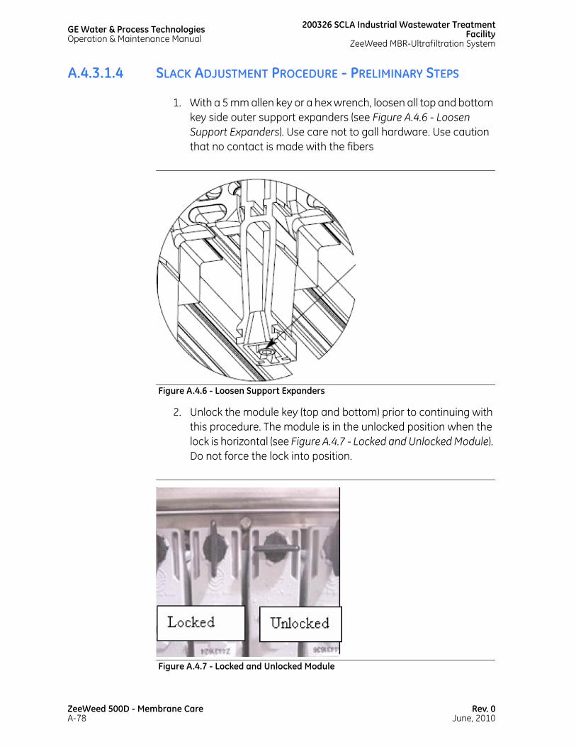
GE Water & Process TechnologiesOperation & Maintenance Manual
200326 SCLA Industrial Wastewater TreatmentFacility
ZeeWeed MBR-Ultrafiltration System
A.4.3.1.4 SLACK ADJUSTMENT PROCEDURE - PRELIMINARY STEPS
1. With a 5 mm allen key or a hex wrench, loosen all top and bottom key side outer support expanders (see Figure A.4.6 - Loosen Support Expanders). Use care not to gall hardware. Use caution that no contact is made with the fibers
2. Unlock the module key (top and bottom) prior to continuing with this procedure. The module is in the unlocked position when the lock is horizontal (see Figure A.4.7 - Locked and Unlocked Module). Do not force the lock into position.
Figure A.4.6 - Loosen Support Expanders
Figure A.4.7 - Locked and Unlocked Module
ZeeWeed 500D - Membrane CareA-78
Rev. 0June, 2010

200326 SCLA Industrial Wastewater Treatment FacilityZeeWeed MBR-Ultrafiltration System
GE Water & Process TechnologiesOperation & Maintenance Manual
3. Remove the aeration tubes by carefully sliding them out of the bottom front of the cassette (see Figure A.4.8 - Remove the Aeration Tubes).
Be aware that tubes must be placed back into their original position in the cassette.
Figure A.4.8 - Remove the Aeration Tubes
Rev. 0June, 2010
ZeeWeed 500D - Membrane CareA-79

GE Water & Process TechnologiesOperation & Maintenance Manual
200326 SCLA Industrial Wastewater TreatmentFacility
ZeeWeed MBR-Ultrafiltration System
A.4.3.1.5 ADJUSTMENT FOR THE FRONT/BACK BEAMS
1. On the front side only (top and bottom), slide all of the modules out of the cassette, approximately 2-3 in. from the permeate manifolds (see Figure A.4.9 - Module Slid Out of Cassette).
Figure A.4.9 - Module Slid Out of Cassette
ZeeWeed 500D - Membrane CareA-80
Rev. 0June, 2010

200326 SCLA Industrial Wastewater Treatment FacilityZeeWeed MBR-Ultrafiltration System
GE Water & Process TechnologiesOperation & Maintenance Manual
2. To gain access to the front bottom beam bolts, remove modules from the following positions within the cassette - # 2, # 9, # 16, # 23, (left to right) (see Figure A.4.10 - Modules Removed From These Positions).
3. Remove the bolts from positions # 9, # 16, and # 23. Loosen but do not remove the bolt in position # 2. This bolt will keep the Front Bottom Adjustable Beam aligned with the holes (see Figure A.4.11 - Removing the Bolts).
Figure A.4.10 - Modules Removed From These Positions
Figure A.4.11 - Removing the Bolts
Rev. 0June, 2010
ZeeWeed 500D - Membrane CareA-81

GE Water & Process TechnologiesOperation & Maintenance Manual
200326 SCLA Industrial Wastewater TreatmentFacility
ZeeWeed MBR-Ultrafiltration System
4. Pry the end of the Front Adjustable Bottom Beam where the bolts have been removed (see Figure A.4.12 - Front Adjustable Bottom Beam).
Use stainless steel or plated tools only.
5. To achieve acceptable slack, adjust the Front Adjustable Bottom Beam to the desired height (see Figure A.4.13 - Adjusting the Front Adjustable Bottom Beam).
6. Install one bolt in position # 23 (loose). Ensure bolts are installed properly; bolt threads towards the outside of the cassette.
Figure A.4.12 - Front Adjustable Bottom Beam
ZeeWeed 500D - Membrane CareA-82
Rev. 0June, 2010

200326 SCLA Industrial Wastewater Treatment FacilityZeeWeed MBR-Ultrafiltration System
GE Water & Process TechnologiesOperation & Maintenance Manual
7. Remove bolt from position #2 and repeat steps 4 to 6.
8. Install bolts in positions # 9 and # 16. If required, use a screwdriver to align the holes (see Figure A.4.14 - Align the Holes).
Figure A.4.13 - Adjusting the Front Adjustable Bottom Beam
Figure A.4.14 - Align the Holes
Rev. 0June, 2010
ZeeWeed 500D - Membrane CareA-83

GE Water & Process TechnologiesOperation & Maintenance Manual
200326 SCLA Industrial Wastewater TreatmentFacility
ZeeWeed MBR-Ultrafiltration System
A.4.3.1.6 ADJUSTMENT FOR THE CENTER BEAM
1. Slide all the modules to the STOP position of the top Header (see Figure A.4.15 - Slide the Modules to the Stop Position).
2. Tighten all 4 bolts as per drawing specification (247 inch pounds). Re-install the modules that had been removed (see Figure A.4.16 - Tighten the Bolts).
Do not slide any of the modules back into the permeate saddles.
3. Repeat the procedure for the back beam of the cassette.
Figure A.4.15 - Slide the Modules to the Stop Position
ZeeWeed 500D - Membrane CareA-84
Rev. 0June, 2010

200326 SCLA Industrial Wastewater Treatment FacilityZeeWeed MBR-Ultrafiltration System
GE Water & Process TechnologiesOperation & Maintenance Manual
Number the modules left to right.
4. Referencing Figure A.4.5 - Center Beam, remove one of the Slack Adjustment Clips from the bottom per position change (see Figure A.4.17 - Remove the Slack Adjustment Clip).
Figure A.4.16 - Tighten the Bolts
Figure A.4.17 - Remove the Slack Adjustment Clip
Rev. 0June, 2010
ZeeWeed 500D - Membrane CareA-85

GE Water & Process TechnologiesOperation & Maintenance Manual
200326 SCLA Industrial Wastewater TreatmentFacility
ZeeWeed MBR-Ultrafiltration System
5. Install Qty 6 - M10 x 250 mm bolts into the existing threaded jacking bolt holes found on either end and center of the centre beam (see Figure A.4.18 - Insert Jacking Bolts).
a. If required, file the adjacent saddle to allow insertion of the bolt at either end of the beam.
Figure A.4.18 - Insert Jacking Bolts
ZeeWeed 500D - Membrane CareA-86
Rev. 0June, 2010

200326 SCLA Industrial Wastewater Treatment FacilityZeeWeed MBR-Ultrafiltration System
GE Water & Process TechnologiesOperation & Maintenance Manual
b. If required, drill out in between the saddles to allow enough space for the centre jack bolt to be inserted (see Figure A.4.19 - Drill Out Saddle).
6. Before proceeding, use a low pressure hose to flush away any debris left from the filing or drilling of the saddles (see Figure A.4.20 - Flush Away Debris).
Figure A.4.19 - Drill Out Saddle
Figure A.4.20 - Flush Away Debris
Rev. 0June, 2010
ZeeWeed 500D - Membrane CareA-87

GE Water & Process TechnologiesOperation & Maintenance Manual
200326 SCLA Industrial Wastewater TreatmentFacility
ZeeWeed MBR-Ultrafiltration System
7. Remove the bolts located at the middle of the centre beam. Note there is one bolt on either side of the beam (see Figure A.4.21 - Remove Center Beam Bolts).
.
8. Adjust the center beam by removing the bolts from each side of the centre beam at both ends of the beam - four bolts in total. Retain all hardware for replacement (see Figure A.4.22 - Adjust the Center Beam).
.
Figure A.4.21 - Remove Center Beam Bolts
Figure A.4.22 - Adjust the Center Beam
ZeeWeed 500D - Membrane CareA-88
Rev. 0June, 2010

200326 SCLA Industrial Wastewater Treatment FacilityZeeWeed MBR-Ultrafiltration System
GE Water & Process TechnologiesOperation & Maintenance Manual
9. Use the jacking bolts to lift the centre beam to the desired height, referencing Figure A.4.5 - Center Beam.
10. Once all four bolts have been installed at the ends, align the appropriate middle bolt hole on each side of the middle of the centre beam (see Figure A.4.23 - Align the Middle Bolt Hole).
11. Install and tighten the six center beam bolts as per torque specification 247 inch lbs (see Figure A.4.24 - Torque the Bolts).
12. Reinstall modules and lock into position. Reinstall aeration tubes in their original positions.
Figure A.4.23 - Align the Middle Bolt Hole
Rev. 0June, 2010
ZeeWeed 500D - Membrane CareA-89

GE Water & Process TechnologiesOperation & Maintenance Manual
200326 SCLA Industrial Wastewater TreatmentFacility
ZeeWeed MBR-Ultrafiltration System
The installation of a 500D module must be completed with two people. The bottom module header must not swing freely when the top header is slid into place. If the bottom header is not controlled during installation, it can swing into the centre of the cassette and impact the bottom permeate collectors. Damage from this impact will result in the need for module replacement.
Figure A.4.24 - Torque the Bolts
ZeeWeed 500D - Membrane CareA-90
Rev. 0June, 2010

200326 SCLA Industrial Wastewater Treatment FacilityZeeWeed MBR-Ultrafiltration System
GE Water & Process TechnologiesOperation & Maintenance Manual
13. Tighten all top and bottom key side outer support expanders using a 5 mm Allen Key or a hex wrench. The expander is fully engaged when flush with the bottom surface of the key side outer assembly. Max tightening torque not to exceed 5.0 Nm (3.6 FT-LBS, 44 IN-LBS) (see Figure A.4.25 - Tighten Support Expanders).
.
14. Indicate on the membrane map the date of the slack adjustment and the amount of slack adjusted. List the bolt positions used.
A.4.4 MODULE REMOVAL FROM A CASSETTE
Follow proper safety procedures to prevent injury when carrying out this procedure.
Completely read and understand this procedure before attempting to remove modules.
Figure A.4.25 - Tighten Support Expanders
Rev. 0June, 2010
ZeeWeed 500D - Membrane CareA-91

GE Water & Process TechnologiesOperation & Maintenance Manual
200326 SCLA Industrial Wastewater TreatmentFacility
ZeeWeed MBR-Ultrafiltration System
A.4.4.1 MANPOWER AND TIME REQUIREMENT
The removal of a single module should take a few minutes once the cassette is removed from the tank. Always use two people when extracting a cassette or module.
A.4.4.1.1 TOOL PREPARATION - REMOVAL
The removal tool is orientated differently when removing from the top and bottom of the module. To adjust the pin location, remove the cotter pin, change the face position and reinsert the cotter pin.
Figure A.4.26 - Module Removal Tool
Table A.4.2 - Pin Location and Function
Pin Location Function1 Installation assistance - top header
2 Future use
3 Future use
4 Removal, installation assistance - bottom header
ZeeWeed 500D - Membrane CareA-92
Rev. 0June, 2010

200326 SCLA Industrial Wastewater Treatment FacilityZeeWeed MBR-Ultrafiltration System
GE Water & Process TechnologiesOperation & Maintenance Manual
The module removal tool is supplied with a standard faceplate. Use a repair adaptor faceplate (optional) when removing/installing modules that have been repaired using the repair adapter (see Figure A.4.29 - Faceplate).
Figure A.4.27 - Pin Removal From The Top
Figure A.4.28 - Pin Removal From The Bottom
Rev. 0June, 2010
ZeeWeed 500D - Membrane CareA-93

GE Water & Process TechnologiesOperation & Maintenance Manual
200326 SCLA Industrial Wastewater TreatmentFacility
ZeeWeed MBR-Ultrafiltration System
A.4.4.2 TOOL PREPARATION – INSTALLATION
This tool should not be used on Drinking Water (DW) or Tertiary Treatment (TT) designated cassettes.
Figure A.4.29 - Faceplate
Figure A.4.30 - Standard and Repaired Header (Repair Adapter)
ZeeWeed 500D - Membrane CareA-94
Rev. 0June, 2010

200326 SCLA Industrial Wastewater Treatment FacilityZeeWeed MBR-Ultrafiltration System
GE Water & Process TechnologiesOperation & Maintenance Manual
In all instances, attempt to install the module by hand. Only use the tool for assistance, if required.
A.4.4.2.1 TOOLS REQUIRED
• 500D module removal tool
Figure A.4.31 - Installation Assistance From The Top
Figure A.4.32 - Installation Assistance From The Bottom
Rev. 0June, 2010
ZeeWeed 500D - Membrane CareA-95

GE Water & Process TechnologiesOperation & Maintenance Manual
200326 SCLA Industrial Wastewater TreatmentFacility
ZeeWeed MBR-Ultrafiltration System
• Gloves
Do not use any other tools to remove or install the 500D module.
Part # 1032836 replaces all previous versions of the 500D Removal Tool.
A.4.4.2.2 MODULE REMOVAL
1. Check that all retaining components of the cassette have been removed or slacked so the module is no longer restrained in the cassette.
2. Clamp the teeth of the Insert/Removal tool to the cavities on the membrane fiber side of the module header face.
Figure A.4.33 - Prohibited Removal Tools
ZeeWeed 500D - Membrane CareA-96
Rev. 0June, 2010

200326 SCLA Industrial Wastewater Treatment FacilityZeeWeed MBR-Ultrafiltration System
GE Water & Process TechnologiesOperation & Maintenance Manual
3. If the cavities are filled with material clean them out so the Insert/Removal tool will mate properly.
4. Mate the Insert/Removal tool to the face of the module (see Figure A.4.35 - Module Removal).
Be sure to keep tool flush against module face while locking into position.
Turn the circular rotating ring counter clockwise to lock the insert/removal tool to the module by engaging the locking tabs. A light spray lubricant can be used on the locating ring if operation becomes difficult (see Figure A.1.54 - Turn Rotating Ring).
Figure A.4.34 - Attach the Removal Tool
Figure A.4.35 - Module Removal
Rev. 0June, 2010
ZeeWeed 500D - Membrane CareA-97
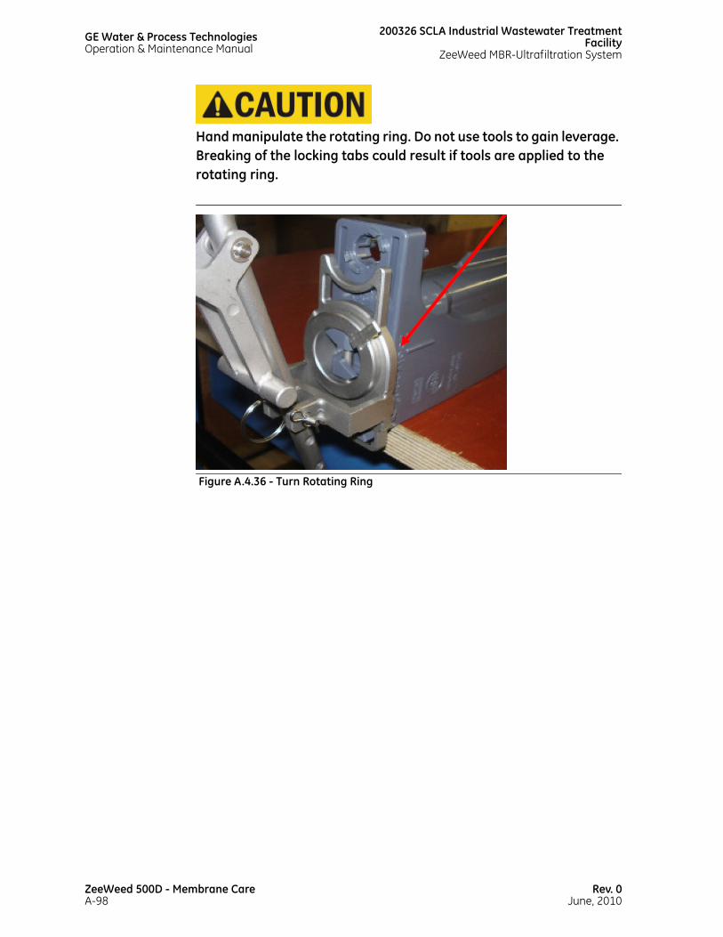
GE Water & Process TechnologiesOperation & Maintenance Manual
200326 SCLA Industrial Wastewater TreatmentFacility
ZeeWeed MBR-Ultrafiltration System
Hand manipulate the rotating ring. Do not use tools to gain leverage. Breaking of the locking tabs could result if tools are applied to the rotating ring.
Figure A.4.36 - Turn Rotating Ring
ZeeWeed 500D - Membrane CareA-98
Rev. 0June, 2010
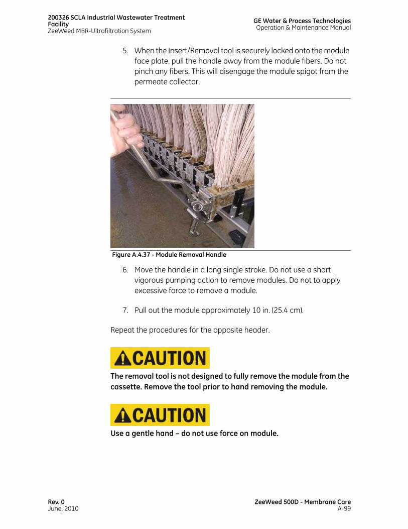
200326 SCLA Industrial Wastewater Treatment FacilityZeeWeed MBR-Ultrafiltration System
GE Water & Process TechnologiesOperation & Maintenance Manual
5. When the Insert/Removal tool is securely locked onto the module face plate, pull the handle away from the module fibers. Do not pinch any fibers. This will disengage the module spigot from the permeate collector.
6. Move the handle in a long single stroke. Do not use a short vigorous pumping action to remove modules. Do not to apply excessive force to remove a module.
7. Pull out the module approximately 10 in. (25.4 cm).
Repeat the procedures for the opposite header.
The removal tool is not designed to fully remove the module from the cassette. Remove the tool prior to hand removing the module.
Use a gentle hand – do not use force on module.
Figure A.4.37 - Module Removal Handle
Rev. 0June, 2010
ZeeWeed 500D - Membrane CareA-99
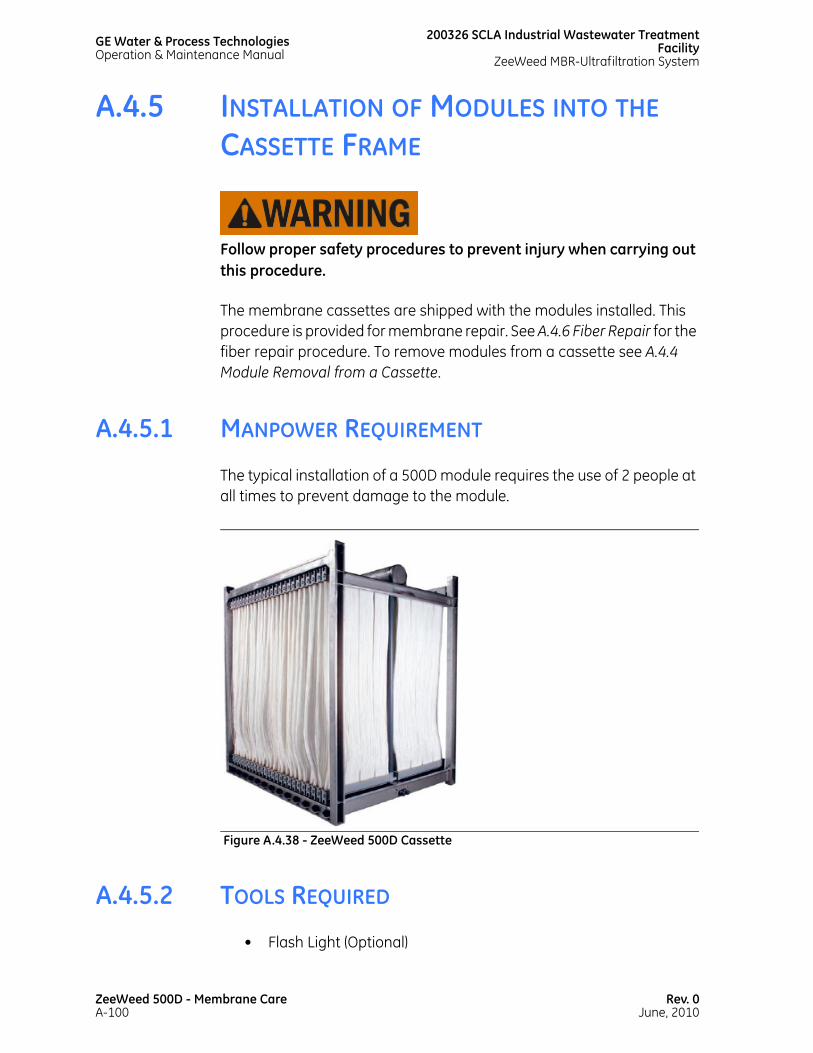
GE Water & Process TechnologiesOperation & Maintenance Manual
200326 SCLA Industrial Wastewater TreatmentFacility
ZeeWeed MBR-Ultrafiltration System
A.4.5 INSTALLATION OF MODULES INTO THE CASSETTE FRAME
Follow proper safety procedures to prevent injury when carrying out this procedure.
The membrane cassettes are shipped with the modules installed. This procedure is provided for membrane repair. See A.4.6 Fiber Repair for the fiber repair procedure. To remove modules from a cassette see A.4.4 Module Removal from a Cassette.
A.4.5.1 MANPOWER REQUIREMENT
The typical installation of a 500D module requires the use of 2 people at all times to prevent damage to the module.
A.4.5.2 TOOLS REQUIRED
• Flash Light (Optional)
Figure A.4.38 - ZeeWeed 500D Cassette
ZeeWeed 500D - Membrane CareA-100
Rev. 0June, 2010
200326 SCLA Industrial Wastewater Treatment FacilityZeeWeed MBR-Ultrafiltration System
GE Water & Process TechnologiesOperation & Maintenance Manual
• 500D Module MARS Removal Tool
• O-Ring lubricant (i.e. Lubri-gel)
• Step Ladder
A.4.5.3 CHECKING FOR SLACK ADJUSTMENT
Prior to installing the new module, visually inspect the cassette and refer to A.4.3 Fiber Shrinkage and Slack to determine if the cassette should be adjusted for slack.
A.4.5.4 UNPACKING THE MODULE
Each module is packaged in a sealed bag in a box. Using 2 people, remove the module from the box, and lay it out flat on a clean table or work surface larger than the fully extended module. Through the clear bag, inspect the module to ensure that no damage was incurred during shipping. Check that all O-rings are present. If an O-ring is missing, do not open bag until a spare O-ring is located. Carefully cut completely across the one end of the bag. Do not cut towards yourself or the fibers. With one person holding the header, the second person should pull on the bottom of the bag sliding the bag off of the module.
Be mindful of the module and membrane at all times when working around the cassettes. Do not allow clothing, body parts, tools, materials, jewelry etc. to scrape or touch the membrane. Do not allow the module headers to bump up against the cassette frame or other modules. Ensure the module is not allowed to dry out.
A.4.5.5 INSTALLING THE MODULE
A.4.5.5.1 PRELIMINARY INSPECTION AND SET UP
Once the module is unpacked, the permeate spigots will be exposed.
Rev. 0June, 2010
ZeeWeed 500D - Membrane CareA-101

GE Water & Process TechnologiesOperation & Maintenance Manual
200326 SCLA Industrial Wastewater TreatmentFacility
ZeeWeed MBR-Ultrafiltration System
1. Inspect the spigot for any cracks or damage.
2. Confirm the black EPDM #118 ‘s are present, intact and in proper placement on the permeate spigot. O-rings must not be twisted, cracked, or worn. Apply a water-soluble lubricant (such as Lubri-gel or KY Jelly) to the O-rings (see Figure A.4.39 - Correct Position of the O-rings on the Permeate Spigot).
3. When reinstalling a used module that was removed for inspection, hose down the module to remove any obvious solids and debris. Pay particular attention to the rail support guide on the top of the header.
A.4.5.5.2 INSTALLING THE TOP HEADER
Quality testing has shown that the majority of module failures can be attributed to incorrect module installation. It is very important that the following instructions are followed to prevent damage. Under no circumstances should excessive force be used on the module to aid in insertion or removal from the cassette.
Figure A.4.39 - Correct Position of the O-rings on the Permeate Spigot
ZeeWeed 500D - Membrane CareA-102
Rev. 0June, 2010

200326 SCLA Industrial Wastewater Treatment FacilityZeeWeed MBR-Ultrafiltration System
GE Water & Process TechnologiesOperation & Maintenance Manual
Each module has one square-end header and one round-end header. Modules are installed alternating square and round ends up.
For a wastewater application with ZeeWeed 500D-48 cassettes, the module at the extreme right hand side (when viewed with the 3” aeration pipes on the left) will have the square-end header at the top and round end at the bottom. The second module will have the round-end at the top and square end at the bottom. Subsequent modules will alternate square and round ends. Install the modules according to the pattern above.
Figure A.4.40 - Module Header
Figure A.4.41 - Cassette
Rev. 0June, 2010
ZeeWeed 500D - Membrane CareA-103

GE Water & Process TechnologiesOperation & Maintenance Manual
200326 SCLA Industrial Wastewater TreatmentFacility
ZeeWeed MBR-Ultrafiltration System
Support the headers at all times. Do not allow the module headers to bump up against the cassette frame or other modules.
Check that the desired end (round or square) is at the top. Use 2 people to lift the module. Be careful not to let the fibers or the bottom header contact the ground. While one person climbs the ladder to install the top header, the second person must support the bottom header at all times.
The installation of a 500D module must be completed with two people. The bottom module header must not swing freely when the top header is slid into place. If the bottom header is not controlled during installation, it can swing into the centre of the cassette and impact the bottom permeate collectors. Damage from this impact will result in module replacement.
Figure A.4.42 - Handling the Module
ZeeWeed 500D - Membrane CareA-104
Rev. 0June, 2010

200326 SCLA Industrial Wastewater Treatment FacilityZeeWeed MBR-Ultrafiltration System
GE Water & Process TechnologiesOperation & Maintenance Manual
1. To insert the module into the cassette, align the rail on the top of the module with the cassette.
2. If space allows, wipe any visible debris from the rail and apply lubri-gel to both the rail and rail support guides on the top of the header to allow a smooth insertion.
Under no circumstances should excessive force be used to insert the module. Avoid the use of a hammer or any blunt force object.
3. With one person supporting the top and another person supporting the bottom header of the module, slide the top header in until it is about 10 in. (250 mm) from being completely installed.
Figure A.4.43 - Aligning the Rail on the Module with the Cassette Frame
Rev. 0June, 2010
ZeeWeed 500D - Membrane CareA-105

GE Water & Process TechnologiesOperation & Maintenance Manual
200326 SCLA Industrial Wastewater TreatmentFacility
ZeeWeed MBR-Ultrafiltration System
A.4.5.5.3 INSTALLING THE BOTTOM HEADER
If necessary, use a flash light to illuminate the bottom permeate port. If space allows, turn the bottom header sideways to reduce some of the slack.
1. Line up the bottom header spigot with the permeate connection on the cassette. Use care that the spigot does not impact the permeate collector.
2. Once alignment is confirmed, use gentle but firm pressure to push the bottom header towards the centre of the cassette.
Figure A.4.44 - Turning the Bottom Header Sideways During Installation
ZeeWeed 500D - Membrane CareA-106
Rev. 0June, 2010

200326 SCLA Industrial Wastewater Treatment FacilityZeeWeed MBR-Ultrafiltration System
GE Water & Process TechnologiesOperation & Maintenance Manual
3. Confirm the O-ring seal on the module is correctly made with the bottom permeate collector.
4. With the spigot properly seated, slightly and gently lift the header - do not put stress on the spigot connection – and slip the locating nipples on the front of the header into the holes on the cassette frame.
Figure A.4.45 - Inserting the Bottom Header
Figure A.4.46 - Locating Nipples
Rev. 0June, 2010
ZeeWeed 500D - Membrane CareA-107

GE Water & Process TechnologiesOperation & Maintenance Manual
200326 SCLA Industrial Wastewater TreatmentFacility
ZeeWeed MBR-Ultrafiltration System
A.4.5.5.4 COMPLETING THE MODULE INSTALLATION
1. After the bottom header is successfully connected, connect the top header.
2. If space allows, wipe any visible debris from the rail and apply lubri-gel to both the rail and rail support guides on the top of the header to allow a smooth insertion.
Under no circumstances should excessive force be used to insert the module. Avoid hammering or using a blunt force object. Avoid using force in the area above the GE Water logo.
3. Once the module is in place, it must be locked in position at the top and bottom. The module is in the locked position when the locking key is vertical. A “click” will be felt when the locking key is in proper position. Do not force the locking key into position.
If a module does not easily slide into the cassette, visually check for the following:
• Permeate adaptor inserts seated properly. If not, reseat the inserts.
Figure A.4.47 - Lock Position
ZeeWeed 500D - Membrane CareA-108
Rev. 0June, 2010

200326 SCLA Industrial Wastewater Treatment FacilityZeeWeed MBR-Ultrafiltration System
GE Water & Process TechnologiesOperation & Maintenance Manual
• Extra plastic on the module header or urethane potting material over flowing header. To remove extra plastic, use a coarse file, and then a fine file. Carefully file off any extra material which may be interfering with the insertion of the module into the saddle.
A.4.5.5.5 TIGHTENING THE EXPANDERS
1. Tighten all top and bottom key side outer support expanders using a 5 mm Allen Key or a hex wrench.
Use caution that no contact is made with the fibres.
Expander is fully engaged when flush with the bottom surface of the key side outer assembly. Max tightening torque not to exceed 5.0 Nm (3.6 FT-LBS, 44 IN-LBS).
A.4.5.6 FINAL CHECKS
Perform a final check on the cassette and confirm:
• All spigots are seated properly
• All modules keys are in the locked positions
• All hardware is secure and torqued to the proper specifications (see General Arrangement Drawings).
Figure A.4.48 - Tightening Expanders
Rev. 0June, 2010
ZeeWeed 500D - Membrane CareA-109
GE Water & Process TechnologiesOperation & Maintenance Manual
200326 SCLA Industrial Wastewater TreatmentFacility
ZeeWeed MBR-Ultrafiltration System
Once the module(s) have been installed and final check has been completed, it may be necessary to carry out a glycerin flush and sanitization procedure.
A.4.5.7 RETURNING DAMAGED MEMBRANES
Before returning membranes to GE W&PT, it is imperative that they be properly cleaned, preserved, and that a “Returned Goods Authorization” (RGA) number be obtained prior to shipping it. Contact GE W&PT Technical Support for information on the RGA procedure.
A.4.6 FIBER REPAIR
A delaminated fiber needs to be cut and sealed. This section describes the procedure for the necessary repair.
Do not separate strands that are glued together at the header as this will cause damage to the membranes.
A.4.6.1 CUT FIBERS
For leaks detected at either end of the membrane fiber, or for fibers that have been cut badly, apply the steps outlined below:
ZeeWeed 500D - Membrane CareA-110
Rev. 0June, 2010

200326 SCLA Industrial Wastewater Treatment FacilityZeeWeed MBR-Ultrafiltration System
GE Water & Process TechnologiesOperation & Maintenance Manual
1. Remove the membrane module from the membrane tank and cut off the damaged portion 20 mm (3/4 in.) from the potting material on the ZeeWeed header. See Figure A.4.49 - Membrane Cut Position for the correct cut position.
2. Using a hypodermic syringe filled with silicone sealant (available from GE W&PT as a “membrane repair kit”, Baan # 1022887), insert the tip of the needle 10 mm (7/16 in.) into the centre of the membrane lumen. See Figure A.4.50 - Axial Silicone Injection for insertion positions.
3. Apply light pressure to inject the silicone. Fill the lumen back to the header, as indicated by the darkened zone in Figure A.4.50 - Axial Silicone Injection (this typically takes about 15-45 seconds). Slowly withdraw the needle while still injecting silicone to assure the lumen is completely filled. While still applying pressure to the syringe, use the tip of the needle to spread silicone over the cut end of the lumen.
Figure A.4.49 - Membrane Cut Position
Rev. 0June, 2010
ZeeWeed 500D - Membrane CareA-111

GE Water & Process TechnologiesOperation & Maintenance Manual
200326 SCLA Industrial Wastewater TreatmentFacility
ZeeWeed MBR-Ultrafiltration System
4. Once the repair is complete, place the cassette back into the membrane tank. Allow a ten minute curing time before performing further membrane testing.
Figure A.4.50 - Axial Silicone Injection
ZeeWeed 500D - Membrane CareA-112
Rev. 0June, 2010

200326 SCLA Industrial Wastewater Treatment FacilityZeeWeed MBR-Ultrafiltration System
GE Water & Process TechnologiesOperation & Maintenance Manual
A.4.6.2 LEAKING FIBERS
If the leak is in the middle of the lumen, follow the steps outlined below:
1. Remove the membrane module from the membrane tank.
2. Using a hypodermic syringe filled with silicone sealant (available from GE W&PT as a “membrane repair kit”, Baan # 1022887), push the tip of the needle through the lumen. Ensure that the needle does not go through the lumen completely, but only into the hollow centre. See Figure A.4.51 - Subjacent Silicone Injection for insertion instruction. The correct positioning of the needle is 5 to 10 mm (3/16 in. to 7/16 in.) away from the leak zone, at an angle of 5 to 10 degrees.
A metal shield should be used to protect the hand holding the fiber.
3. Apply light pressure to fill the lumen so that it is filled 5 to 10 mm (3/16 in. to 7/16 in.) past the leak zone on either end. Continue applying pressure while withdrawing the needle from the lumen, ensuring the puncture is sealed.
4. Once the repair is complete, place the cassette back into the membrane tank. Allow a ten minute curing time before performing further membrane testing.
Rev. 0June, 2010
ZeeWeed 500D - Membrane CareA-113
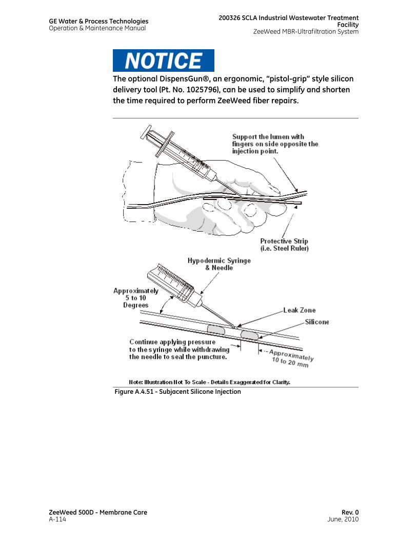
GE Water & Process TechnologiesOperation & Maintenance Manual
200326 SCLA Industrial Wastewater TreatmentFacility
ZeeWeed MBR-Ultrafiltration System
The optional DispensGun®, an ergonomic, “pistol-grip” style silicon delivery tool (Pt. No. 1025796), can be used to simplify and shorten the time required to perform ZeeWeed fiber repairs.
Figure A.4.51 - Subjacent Silicone Injection
ZeeWeed 500D - Membrane CareA-114
Rev. 0June, 2010

A.5PREVENTIVE MAINTENANCE

This page has beenintentionally left blank
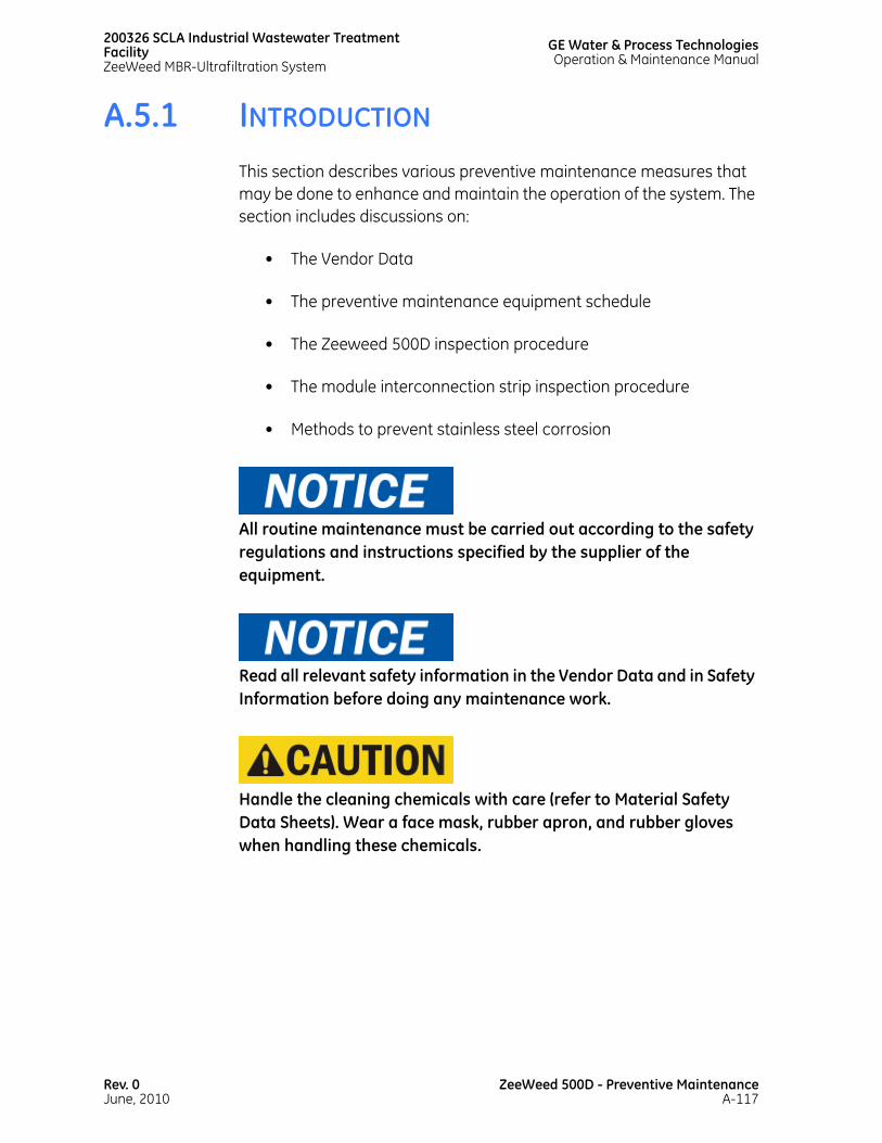
200326 SCLA Industrial Wastewater Treatment FacilityZeeWeed MBR-Ultrafiltration System
GE Water & Process TechnologiesOperation & Maintenance Manual
A.5.1 INTRODUCTION
This section describes various preventive maintenance measures that may be done to enhance and maintain the operation of the system. The section includes discussions on:
• The Vendor Data
• The preventive maintenance equipment schedule
• The Zeeweed 500D inspection procedure
• The module interconnection strip inspection procedure
• Methods to prevent stainless steel corrosion
All routine maintenance must be carried out according to the safety regulations and instructions specified by the supplier of the equipment.
Read all relevant safety information in the Vendor Data and in Safety Information before doing any maintenance work.
Handle the cleaning chemicals with care (refer to Material Safety Data Sheets). Wear a face mask, rubber apron, and rubber gloves when handling these chemicals.
Rev. 0June, 2010
ZeeWeed 500D - Preventive MaintenanceA-117
GE Water & Process TechnologiesOperation & Maintenance Manual
200326 SCLA Industrial Wastewater TreatmentFacility
ZeeWeed MBR-Ultrafiltration System
A.5.2 VENDOR DATA AND MAINTENANCE PROCEDURES
Technical specifications of the mechanical and electrical items in the system, as well as detailed maintenance guidelines and procedures, have been provided in the Vendor Data.
All routine maintenance must be carried out according to the technical specifications of each system component, as described in the Vendor Data. A summary of major preventive maintenance items in the system can be found in Table A.5.1 - Preventive Maintenance Schedule.
The Vendor Data is prepared and provided to the client at the time of delivery of the ZeeWeed Filtration System and is a compilation of installation, operation, maintenance, and safety information supplied to GE Water & Process Technologies (GE W&PT) by manufacturers of various component parts incorporated into your system.
GE W&PT has not independently verified the information contained in the Vendor Data and no representations or warranties of any kind, express or implied, are made by GE W&PT as to the quality, suitability, accuracy, timeliness, or completeness of any material, information, or data contained therein. GE W&PT does not accept liability for the consequences of any action taken on the basis of information contained in the Vendor Data.
If updated or additional information beyond what has been provided in the Vendor Data is required, contact GE W&PT Technical Support Department for assistance.
Selection of the correct lubricant is subject to seasonal conditions, ambient temperatures, air movement, and air quality. The selection of lubricants should be made carefully with due reference to the Vendor Data and with consideration for the operating conditions of the equipment.
If any of the problems discussed in this section persist or other difficulties arise, the operator should contact GE W&PT. Complete operating logsheets are necessary to determine the source of the problem.
ZeeWeed 500D - Preventive MaintenanceA-118
Rev. 0June, 2010
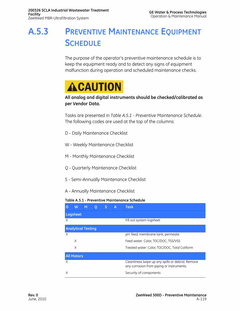
200326 SCLA Industrial Wastewater Treatment FacilityZeeWeed MBR-Ultrafiltration System
GE Water & Process TechnologiesOperation & Maintenance Manual
A.5.3 PREVENTIVE MAINTENANCE EQUIPMENT SCHEDULE
The purpose of the operator’s preventive maintenance schedule is to keep the equipment ready and to detect any signs of equipment malfunction during operation and scheduled maintenance checks.
All analog and digital instruments should be checked/calibrated as per Vendor Data.
Tasks are presented in Table A.5.1 - Preventive Maintenance Schedule. The following codes are used at the top of the columns:
D - Daily Maintenance Checklist
W - Weekly Maintenance Checklist
M - Monthly Maintenance Checklist
Q - Quarterly Maintenance Checklist
S - Semi-Annually Maintenance Checklist
A - Annually Maintenance Checklist
Table A.5.1 - Preventive Maintenance Schedule
D W M Q S A Task
LogsheetX Fill out system logsheet
Analytical TestingX pH: feed, membrane tank, permeate
X Feed water: Color, TOC/DOC, TSS/VSS
X Treated water: Color, TOC/DOC, Total Coliform
All MotorsX Cleanliness (wipe up any spills or debris). Remove
any corrosion from piping or instruments.
X Security of components
Rev. 0June, 2010
ZeeWeed 500D - Preventive MaintenanceA-119

GE Water & Process TechnologiesOperation & Maintenance Manual
200326 SCLA Industrial Wastewater TreatmentFacility
ZeeWeed MBR-Ultrafiltration System
X Check for leaks anywhere in the system
Replace the PLC battery every two to four years
Every 5 years, replace the UPS
X Inspect the piping for corrosion and repair as required. See A.5.6 Preventing Stainless Steel Corrosion.
X Inspect the inside of the membrane tank for damage. Repair as required.
X Inspect membrane tanks
TW: For wastewater systems, drain the tank.
X Have the ground checked every year if possible. Note: Copper-clad ground rods last longer than galvanized rods. Also check the clamp or weld connections for corrosion.
All MotorsX Where possible, remove fan cover and clean off dust
from fan and airway. Use low-pressure compressed air and/or dry cloth.
ZeeWeed ModulesX Check the module interconnecting strip. See A.5.6
Preventing Stainless Steel Corrosion.
X Check the cyclic/sequential aeration is functioning correctly by observing the membrane tank
X Clean with sodium hypochlorite and/or citric acida
X Check cassettes for level
X Inspect one cassette per train per year for any signs of wear. Take pictures of membranes in the cassette and send the pictures to GE W&PT. See A.4.3 Fiber Shrinkage and Slack, and A.5.5 Module Interconnecting Strip Inspection.
a. Monthly initially until optimum interval established for system.
Table A.5.1 - Preventive Maintenance Schedule
ZeeWeed 500D - Preventive MaintenanceA-120
Rev. 0June, 2010

200326 SCLA Industrial Wastewater Treatment FacilityZeeWeed MBR-Ultrafiltration System
GE Water & Process TechnologiesOperation & Maintenance Manual
A.5.4 ZEEWEED 500D INSPECTION PROCEDURE This procedure will serve as a guide for the field inspection of the ZeeWeed 500D membrane module/cassette.
Contact GE W&PT Technical Support if there are any concerns or questions about the following topics.
A.5.4.1 TOOLS AND EQUIPMENT NEEDED
Only common maintenance type tools (wrenches et al) are required to remove ZeeWeed 500D cassettes for inspection. The particular tools required are site specific.
Below is a list of tools and equipment you should have available during the inspection:
• ZeeWeed 500D Membrane Interconnecting Strip (MIS) Removal Tool
• Associated tools to remove the ZeeWeed 500D cassette safely from the membrane tank
• ZeeWeed 500D Header Removal Tool. Older versions will not provide suitable removal effectiveness and should not be used.
A.5.4.2 INFORMATION GATHERING AND RECORDING
It is recommended that the following information be recorded for every cassette inspected on the "ZW500D Inspection Template":
• Site Name
• Inspector
• Inspection Date
• Train Number
Rev. 0June, 2010
ZeeWeed 500D - Preventive MaintenanceA-121
GE Water & Process TechnologiesOperation & Maintenance Manual
200326 SCLA Industrial Wastewater TreatmentFacility
ZeeWeed MBR-Ultrafiltration System
• Cassette Position
• Cassette Serial Number
Photos should be taken at each step and filed with the completed Inspection Forms.
A.5.4.3 INSPECTION FREQUENCY
A typical new ZeeWeed 500 series plant should initially execute the inspection procedure quarterly (every three months) on at least one cassette from each train - this is typically called the 'indicator cassette' and should be the same cassette for each subsequent inspection.
For plants with operating temperatures greater than 30°C (86°F) or with a potential that suspended solids can accumulate within the membrane tanks (enhanced coagulation/MBR applications) it is recommended to initially execute the inspection procedure monthly. Since the processes at each plant are unique, and considering the variations in feed water quality, temperature changes and resultant accumulation of solids, the effects on ZeeWeed modules will vary.
An initial quarterly or monthly inspection frequency should be adjusted by experienced operating staff either up or down dynamically based on observed and recorded trends and site specific operating conditions. It is important for operating staff to monitor potential issues, adjust inspection frequency in response to trends, and correct detected issues promptly to ensure optimum performance of the membranes and to prevent irreversible damage. At a minimum, it is recommended that each cassette within a plant be inspected annually.
For assistance in determining the optimum frequency of membrane module inspection, call Technical Support.
ZeeWeed 500D - Preventive MaintenanceA-122
Rev. 0June, 2010

200326 SCLA Industrial Wastewater Treatment FacilityZeeWeed MBR-Ultrafiltration System
GE Water & Process TechnologiesOperation & Maintenance Manual
A.5.4.4 AERATION PATTERNS AND HITCH PINS
Before the cassette is removed from the water, a visual inspection of the aeration patterns should be performed with the liquid level a few inches above the permeate pipe. A rectangular air pattern of equal intensity (Figure A.5.1 - Correct Aeration Pattern) should be seen. Note any inconsistencies in the Additional Notes section on the inspection template. Inconsistencies could consist of poor air distribution on one side of the cassette or less air to the cassette due to poor valve operation or loose cassette leveling pins.
Ensure that the cyclic valves are operating correctly. Note the cyclic time (if applicable) in the notes section on the inspection template (i.e.-10 seconds on and 10 seconds off or other cycle time).
Also check hitch pins are all in place and in good condition. Hitch pins should fit snugly on the pin and not show signs of wear. There should be 4 hitch pins per cassette.
Figure A.5.1 - Correct Aeration Pattern
Rev. 0June, 2010
ZeeWeed 500D - Preventive MaintenanceA-123

GE Water & Process TechnologiesOperation & Maintenance Manual
200326 SCLA Industrial Wastewater TreatmentFacility
ZeeWeed MBR-Ultrafiltration System
A.5.4.5 HOSES, CAMLOCKS, AND STRAUB CONNECTIONS
Check that the hoses, camlocks, and straub connections are in good condition. Note any cracks and discolouration on hoses and check all hose clamps are tight. Check all Straub connections for tightness per factory torque specifications, and ensure connections are properly aligned to the pipe.
A.5.4.6 REMOVING THE CASSETTE
A cassette that has been in service will weigh more than it did when it was first installed. To avoid severe personal injury caused by a collapse, confirm that the load limits of all lifting equipment and of the surface that the cassette will be set on are sufficient.
Refer to A.3.10 Membrane Inspection/Replacement for instructions on removing cassettes from membrane tanks.
When removing a cassette with accumulated solids, verify the rated capacity of lifting brackets, cranes, and the cassette lifting frame before attempting a lift. As the cassette is removed from the tank, use a weight scale to ensure that components under load are within their design capacity. Ensure that the cassette remains level throughout the lift and inspect the aerator plates and tubes for solids accumulation.
Never spray membranes with a high-pressure water stream.
To reduce the amount of solids on the cassette before lifting, aerate the cassette without permeation and use a garden hose with a low-pressure stream to dislodge solids from the cassette.
ZeeWeed 500D - Preventive MaintenanceA-124
Rev. 0June, 2010

200326 SCLA Industrial Wastewater Treatment FacilityZeeWeed MBR-Ultrafiltration System
GE Water & Process TechnologiesOperation & Maintenance Manual
To ensure that the water pressure in the hose is not excessive, with the hose held 3 ft above the ground, confirm that the stream does not extend more than 3 ft from the hose before reaching the ground (refer to Figure A.5.2 - Water Pressure Test). A stream that extends any further with the hose held at this height is too strong to be used on the membranes.
A.5.4.7 LEVELING PINS
Once the cassette is removed from the water, a visual inspection of the leveling pins should be performed (Figure A.5.3 - Typical Levelling Pin Diagram). Check for loose or damaged pins. Check that all fasteners (nuts, bolts, etc.) are not loose, missing, or damaged. Leveling pins that are loose may result in cassettes that are not level, which will contribute to uneven aeration and solids accumulation.
Figure A.5.2 - Water Pressure Test
Figure A.5.3 - Typical Levelling Pin Diagram
Rev. 0June, 2010
ZeeWeed 500D - Preventive MaintenanceA-125

GE Water & Process TechnologiesOperation & Maintenance Manual
200326 SCLA Industrial Wastewater TreatmentFacility
ZeeWeed MBR-Ultrafiltration System
A.5.4.8 SOLIDS ACCUMULATION PATTERNS
Once the cassette has been removed from the membrane tank or the water level has been lowered to where membrane tank entry is feasible (abiding by all health and safety regulations), the following steps must be performed:
• Full length pictures should be taken from all four sides of the cassette
• Note any solids accumulation patterns on the inspection template. See Figure A.5.4 - Solids Accumulation (OK). Figure A.5.5 - High Solids Accumulation shows a high level of solids accumulation, which would cause concern.
Debris, such as sticks and leaves, are a concern. This type of material should not be in contact with the membranes.
Scaling on the membrane is also a concern. Scaling may cause undesirable effects on the membrane.
If excessive solids, debris or any scaling is noticed, check all screens prior to the membrane tank and then contact GE W&PT Technical Support.
Figure A.5.4 - Solids Accumulation (OK)
ZeeWeed 500D - Preventive MaintenanceA-126
Rev. 0June, 2010
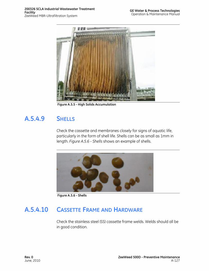
200326 SCLA Industrial Wastewater Treatment FacilityZeeWeed MBR-Ultrafiltration System
GE Water & Process TechnologiesOperation & Maintenance Manual
A.5.4.9 SHELLS
Check the cassette and membranes closely for signs of aquatic life, particularly in the form of shell life. Shells can be as small as 1mm in length. Figure A.5.6 - Shells shows an example of shells.
A.5.4.10 CASSETTE FRAME AND HARDWARE
Check the stainless steel (SS) cassette frame welds. Welds should all be in good condition.
Figure A.5.5 - High Solids Accumulation
Figure A.5.6 - Shells
Rev. 0June, 2010
ZeeWeed 500D - Preventive MaintenanceA-127

GE Water & Process TechnologiesOperation & Maintenance Manual
200326 SCLA Industrial Wastewater TreatmentFacility
ZeeWeed MBR-Ultrafiltration System
Check all fasteners, for example, nuts and bolts are not loose or missing. Refer to General Assembly drawings for specifics on locations. Contact GE W&PT Regional Accounts Manager for drawing details. Contact GE W&PT Technical Support if there are any questions.
A.5.4.11 PERMEATE COLLECTION AND SADDLE INSPECTION
An inspection of both the bottom end position permeate collection ports (Figure A.5.7 - Bottom Permeate Collection Port) and the top permeate end saddles should be conducted (Figure A.5.8 - Top Permeate Saddle). Note any issues on the inspection template. Figure A.5.9 - Location of Collection Port and Saddle shows the locations of the permeate collector and saddle.
Figure A.5.7 - Bottom Permeate Collection Port
Figure A.5.8 - Top Permeate Saddle
ZeeWeed 500D - Preventive MaintenanceA-128
Rev. 0June, 2010
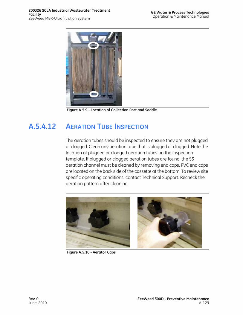
200326 SCLA Industrial Wastewater Treatment FacilityZeeWeed MBR-Ultrafiltration System
GE Water & Process TechnologiesOperation & Maintenance Manual
A.5.4.12 AERATION TUBE INSPECTION
The aeration tubes should be inspected to ensure they are not plugged or clogged. Clean any aeration tube that is plugged or clogged. Note the location of plugged or clogged aeration tubes on the inspection template. If plugged or clogged aeration tubes are found, the SS aeration channel must be cleaned by removing end caps. PVC end caps are located on the back side of the cassette at the bottom. To review site specific operating conditions, contact Technical Support. Recheck the aeration pattern after cleaning.
Figure A.5.9 - Location of Collection Port and Saddle
Figure A.5.10 - Aerator Caps
Rev. 0June, 2010
ZeeWeed 500D - Preventive MaintenanceA-129

GE Water & Process TechnologiesOperation & Maintenance Manual
200326 SCLA Industrial Wastewater TreatmentFacility
ZeeWeed MBR-Ultrafiltration System
A.5.4.12.1 REPORTING
Submit all your findings (inspection template and photos) along with any updated membrane maps to your GE W&PT’s Technical Support contact.
A.5.5 MODULE INTERCONNECTING STRIP INSPECTION
The Module Interconnecting Strip (MIS) holds groups of membrane modules together in the cassette. It requires monthly inspection to ensure proper operation and identifies worn parts that require replacement.
1. Visually inspect all of the Module Interconnecting Strips (MIS) and verify they are attached (see Figure A.5.11 - MIS Location).
Figure A.5.11 - MIS Location
ZeeWeed 500D - Preventive MaintenanceA-130
Rev. 0June, 2010

200326 SCLA Industrial Wastewater Treatment FacilityZeeWeed MBR-Ultrafiltration System
GE Water & Process TechnologiesOperation & Maintenance Manual
2. Verify that all locking keys are tightly locked in the vertical position (see Figure A.5.12 - Locking Key Locked Position (Vertical) and Figure A.5.13 - Locking Key Unlocked Position (Horizontal).
Figure A.5.12 - Locking Key Locked Position (Vertical)
Figure A.5.13 - Locking Key Unlocked Position (Horizontal)
Rev. 0June, 2010
ZeeWeed 500D - Preventive MaintenanceA-131

GE Water & Process TechnologiesOperation & Maintenance Manual
200326 SCLA Industrial Wastewater TreatmentFacility
ZeeWeed MBR-Ultrafiltration System
3. Inspect the MIS locking pins. The locking pins should be in the upright position.
Figure A.5.14 - Locking Pin Locked Position (Vertical)
Figure A.5.15 - Locking Pin Unlocked Position (Diagonal)
ZeeWeed 500D - Preventive MaintenanceA-132
Rev. 0June, 2010

200326 SCLA Industrial Wastewater Treatment FacilityZeeWeed MBR-Ultrafiltration System
GE Water & Process TechnologiesOperation & Maintenance Manual
4. Check for wear on the MIS. Each locking pin should lock into position tightly and securely. If the locking pins move freely, the MIS is worn. Figure A.5.16 - Module Header, Showing Wear Location shows typical wear location on a module header.
5. Check for independent movement between the module and the locking key mechanism.
6. Look for wear on the locking key mechanism.
A.5.6 PREVENTING STAINLESS STEEL CORROSION
A water treatment system may comprise stainless steel components. System operators must follow the preventive maintenance steps provided below in order to prevent corrosion from forming on stainless steel piping and components.
Figure A.5.16 - Module Header, Showing Wear Location
Rev. 0June, 2010
ZeeWeed 500D - Preventive MaintenanceA-133

GE Water & Process TechnologiesOperation & Maintenance Manual
200326 SCLA Industrial Wastewater TreatmentFacility
ZeeWeed MBR-Ultrafiltration System
A.5.6.1 CAUSES OF CORROSION
Stainless steel corrosion is primarily caused by surface contamination and/or chlorine attack. Surface contamination can cause serious corrosion if it is not removed quickly.
SURFACE CONTAMINATION. When the piping is installed with carbon steel tools or not protected from nearby welding or grinding work, carbon steel particles may embed in stainless steel surfaces. Exposure to rusty water or iron-laden dust and dirt can also cause surface corrosion.
CHLORINE ATTACK. Chlorine-induced corrosion can occur when chlorinated water splashes on piping or when chlorine vapors condense on the piping due to inadequate ventilation or high humidity.
A.5.6.2 PREVENTING CORROSION
Minimize corrosion as follows:
CLEAN REGULARLY. Piping and equipment should be kept clean and dry. Keep potential contaminants (for example, solvents, tools, and equipment), away from stainless steel components.
MINIMIZE CHLORINE CONTACT. Control splashing or condensation of chlorinated water streams. Remove contamination as soon as it is observed. Minimize work near stainless steel components. Avoid welding or grinding work. If local work is necessary, ensure that the stainless steel components are fully protected.
FABRICATION, HANDLING, AND INSTALLATION OF COMPONENTS. Use the correct tools and fabrication techniques for any new work. Properly weld and passivate new or repaired piping. Avoid the use of dissimilar metal fasteners and joining components. Ensure that any new components are thoroughly cleaned, inside and outside, before installation.
If excessive condensation is evident on piping surfaces, adjust the ventilation system or add dehumidification.
ZeeWeed 500D - Preventive MaintenanceA-134
Rev. 0June, 2010

200326 SCLA Industrial Wastewater Treatment FacilityZeeWeed MBR-Ultrafiltration System
GE Water & Process TechnologiesOperation & Maintenance Manual
A.5.6.3 DETECTING, CLEANING, & REPAIRING CORROSION
The following sections include recommendations on detecting, cleaning, and repairing corroded or contaminated components.
A.5.6.3.1 DETECTING EMBEDDED IRON
The simplest test for free, embedded iron is to wash down the stainless steel part with clean water, allow it to dry (or drain), and wait 24 hours. If there are rust streaks on the surface of the stainless steel, iron is present.
The ferroxyl test is a more sensitive indication of embedded iron. The system operator applies the solution with a spray bottle and checks for a blue stain within 15 seconds of the application. If a blue stain appears, there is iron contamination.
When handling this test solution, wear rubber gloves, protective clothing, and face shields. Avoid inhalation of the atomized spray!
Prepare the solution (specified in Table A.5.2 - Ingredients to the Ferroxyl Test) as follows:
1. Add the nitric acid to the distilled water.
2. Add the potassium ferricyanide to the nitric acid/distilled water combination.
A.5.6.3.2 CLEANING & REPAIRING SURFACE CORROSION
Do not allow cleaning compounds to fall in the membrane tanks.
Table A.5.2 - Ingredients to the Ferroxyl Test
Ingredient Volume/WeightDistilled Water 1000 mL
Nitric Acid, 60-67% 20 mL
Potassium Ferricyanide 30 g
Rev. 0June, 2010
ZeeWeed 500D - Preventive MaintenanceA-135

GE Water & Process TechnologiesOperation & Maintenance Manual
200326 SCLA Industrial Wastewater TreatmentFacility
ZeeWeed MBR-Ultrafiltration System
If corrosion occurs on a stainless steel part, clean and treat the oxidized areas in order to restore the surface to its original corrosion resistance. Remove the oxidized material with the appropriate wire brush. After the oxidized areas have been brushed clean, apply a pickling paste to the affected area to chemically clean the surface and remove any embedded contaminants.
As an added precaution, there are various protective coatings that can be used to help prevent stainless steel contamination and corrosion. Clear lacquers are preferred over the colored lacquers and paints, so that the operator can check the condition of the stainless steel surface below the coating.
Table A.5.3 - Effective Cleaning Methods
Job Cleaning Agents CommentsRoutine cleaning Warm water, soap, ammonia,
and detergentApply with a sponge or soft cloth.
Smears and fingerprints 3M Stainless Steel Cleaner and Polish, Arcal 20, Lac-O-Nu, Lumin Wash, Stainless Shine
Provides a barrier film to minimize fingerprints.
Stubborn stains and discoloration
3M Stainless Steel Cleaner and Polish, Twinkle, Liquid Nu Steel, Household Cleaners
Using a dry or damp cloth, rub lightly in the direction of the polish lines of the stainless steel.
Grease and oil Any good commercial detergent or caustic cleaner
Apply with a sponge or soft cloth in the direction of the polish lines of the stainless steel.
ZeeWeed 500D - Preventive MaintenanceA-136
Rev. 0June, 2010

ZW500D Inspection Template
Site Name: MLSS & pH: Inspection Performed by:
Water Level: Above/Below Permeate Pipe
Date Inspected: Aeration Type:
Train Number: Aeration Sequence (ie. 10/10 or 10/30):
Cassette Position: Module Inspection
Cassette S/N Inspection Point
L-M
odul
e 1
L-M
odul
e 2
L-M
odul
e 3
L-M
odul
e 4
L-M
odul
e 5
L-M
odul
e 6
L-M
odul
e 7
L-M
odul
e 8
L-M
odul
e 9
L-M
odul
e 10
L-M
odul
e 11
L-M
odul
e 12
L-M
odul
e 13
L-M
odul
e 14
L-M
odul
e 15
L-M
odul
e 16
L-M
odul
e 17
L-M
odul
e 18
L-M
odul
e 19
L-M
odul
e 20
L-M
odul
e 21
L-M
odul
e 22
L-M
odul
e 23
L-M
odul
e 24
R-M
odul
e 1
R-M
odul
e 2
R-M
odul
e 3
R-M
odul
e 4
R-M
odul
e 5
R-M
odul
e 6
R-M
odul
e 7
R-M
odul
e 8
R-M
odul
e 9
R-M
odul
e 10
R-M
odul
e 11
R-M
odul
e 12
R-M
odul
e 13
R-M
odul
e 14
R-M
odul
e 15
R-M
odul
e 16
R-M
odul
e 17
R-M
odul
e 18
R-M
odul
e 19
R-M
odul
e 20
R-M
odul
e 21
R-M
odul
e 22
R-M
odul
e 23
R-M
odul
e 24
Top Solids Accumulation - OK, Concern (C), Issue (I) Bot
Top Fibre Slack - Loose (L) / Tight (T) Bot
Top Clips and Inserts all Present (Y/N) Bot
Top Locking Key In Locked Position (Y/N) Bot
Top V-wedge Snug (Y/N) Bot
Header In Good Condition (Y/N)
Top
Plugged (P) or Clogged
(C ) Aerator Tubes/Channels Bot
Inspection Point Cassette Inspection Equal Intensity Aeration
Pattern (Y/N) Hitch Pins In Good Condition
(Y/N) Hoses/Hose Clamps In Good
Condition (Y/N) Camlocks/Straub In Good
Condition (Y/N) Cassette Lifting Load Limits (
OK / Issue (I) ) Leveling Pins In Good
Condition (Y/N) Fasteners or Nuts Loose (L) /
Missing (M) Bottom Permeate Collector in
Good Condition (Y/N)
INSE
RT C
ASSE
TTE
NU
MBE
R H
ERE
Top Permeate Saddle In Good Condition (Y/N)
*Note – Comments can be written on next page
QRF-020 REV 04 Page 1 of 2 Aug 24, 2007

ZW500D Inspection Template
QRF-020 REV 04 Page 2 of 2 Aug 24, 2007
Site Name: Inspection Performed by: Date Inspected:
Train Number:
Cassette Position: Module Inspection
Cassette S/N Inspection Point
L-M
odul
e 25
L-M
odul
e 26
L-M
odul
e 27
L-M
odul
e 28
L-M
odul
e 29
L-M
odul
e 30
L-M
odul
e 31
L-M
odul
e 32
R-M
odul
e 25
R-M
odul
e 26
R-M
odul
e 27
R-M
odul
e 28
R-M
odul
e 29
R-M
odul
e 30
R-M
odul
e 31
R-M
odul
e 32
Top Solids Accumulation - OK, Concern (C), Issue (I) Bot
Top Fibre Slack - Loose (L) / Tight (T) Bot
Top Clips and Inserts all Present (Y/N) Bot
Top Locking Key In Locked Position (Y/N) Bot
Top V-wedge Snug (Y/N) Bot
Header In Good Condition (Y/N)
Top
Plugged (P) or Clogged
(C ) Aerator Tubes/Channels Bot
INSE
RT C
ASSE
TTE
NU
MBE
R H
ERE
ADDITIONAL NOTES


This page has beenintentionally left blank

A.6CLEANING & VENTILATION

This page has beenintentionally left blank

200326 SCLA Industrial Wastewater Treatment FacilityZeeWeed MBR-Ultrafiltration System
GE Water & Process TechnologiesOperation & Maintenance Manual
A.6.1 CLEANING CHEMICALS
Depending on the type of cleaning required and the fouling on the membranes, use either a sodium hypochlorite (NaOCl) solution or a citric acid (MC-1) solution. Sodium hypochlorite is used to remove organic/biological fouling on the membranes. Citric acid is used to remove fouling due to mineral scales, iron, or other metals.
For more severe fouling, GE Water & Process Technologies (GE W&PT) offers specially designed and formulated cleaning chemicals for ZeeWeed membranes. These approved cleaning chemicals should be used along with the Maintenance Clean and Recovery Clean procedures provided in this section. Safety and handling instructions for these cleaning chemicals are located in Material Safety Data Sheets.
GE W&PT will advise on chemicals that are suitable.
Table A.6.1 - Chemicals Required for ZeeWeed Cleaning
Chemical Purpose Design Concentration
Frequency of Cleaning Design pH
Sodium Hypochlorite Maintenance CleanSodium hypochlorite 12% and specific gravity 1.168
Organic Cleaner
200 mg/La
a. Backpulse concentration
2 per week Maximum 10.5
Citric Acid Maintenance CleanCitric acid 50%
Scale Removal
2000 mg/Lb 1 per week 2.5-3.5
Sodium Hypochlorite Recovery CleanSodium hypochlorite 12% and specific gravity 1.168
Organic Cleaner
1000 mg/Lb
b. Membrane tank concentrationc. If required
2 per year Maximum 10.5 at T<30°C. Maximum pH 10 at 30°C <T< 40°C.
Citric Acid Recovery CleanCitric acid 50%
Scale Removal
2000 mg/Lb 2 per year 2.5-3.5
Rev. 0June, 2010
ZeeWeed 500D - Cleaning & VentilationA-139

GE Water & Process TechnologiesOperation & Maintenance Manual
200326 SCLA Industrial Wastewater TreatmentFacility
ZeeWeed MBR-Ultrafiltration System
Other cleaning chemicals may contain materials incompatible with the membranes and should NOT be used. Use of non-approved cleaning chemicals voids any membrane warranties.
Wear a face mask, rubber apron, and rubber gloves when handling chemicals. For more information, see Material Safety Data Sheets.
A.6.2 FREQUENCY OF CLEANINGS
The frequency of cleanings depends on specific operating conditions (operating time, feed flow rates, and permeate flow rates) and on the particular chemistry of the fluid being processed. During normal operation, membranes can become fouled by mineral salts (calcium carbonate, calcium sulfate, magnesium sulfate), iron (Fe), insoluble organics (such as oil), and biological matter (bacteria or products from bacterial action). Deposits that build up on the membrane surface during operation can cause a loss in permeability. It should be noted that permeability drops if the feed temperature decreases. This decrease is normal and does not necessarily indicate fouling.
For frequency of cleanings, refer to Table A.6.1 - Chemicals Required for ZeeWeed Cleaning.
A.6.3 TYPES OF CLEANINGS
Never apply Backpulse pressures greater than 8 psig (22.7 psia) across the membranes. Membrane life may decrease as a result.
ZeeWeed 500D - Cleaning & VentilationA-140
Rev. 0June, 2010

200326 SCLA Industrial Wastewater Treatment FacilityZeeWeed MBR-Ultrafiltration System
GE Water & Process TechnologiesOperation & Maintenance Manual
To maximize membrane life and operation, the system automatically undergoes a Backpulse according to a system operator-set frequency and duration. See During Relax, the membranes sit for a system operator-specified duration without permeation before resuming production. During this time, the membrane aeration disperses the solids that have concentrated around the membranes..
Relax is an alternative to Backpulse. If a Backpulse failure occurs and no pump is available, the PLC places the trains into Relax mode. See A.6.3.2 Relax.
An automatic Maintenance Clean is also performed according to a system operator-set frequency. See A.6.3.4 Maintenance Clean. GE W&PT must be consulted for assistance with setting up a Maintenance Clean schedule.
A Recovery Clean procedure is required to prevent fouling of the membranes and when it is no longer possible to operate the unit at the required flux without exceeding the maximum Transmembrane Pressure (TMP). See A.6.3.5 Recovery Clean.
A.6.3.1 CLEANING LOGSHEET
All cleaning data should be recorded on the cleaning logsheet located in performance monitoring. This logsheet should be faxed to GE W&PT’s Process Group (or e-mailed to [email protected]) for verification of cleaning effectiveness.
A.6.3.2 RELAX
During Relax, the membranes sit for a system operator-specified duration without permeation before resuming production. During this time, the membrane aeration disperses the solids that have concentrated around the membranes.
Rev. 0June, 2010
ZeeWeed 500D - Cleaning & VentilationA-141

GE Water & Process TechnologiesOperation & Maintenance Manual
200326 SCLA Industrial Wastewater TreatmentFacility
ZeeWeed MBR-Ultrafiltration System
A.6.3.3 BACKPULSE
Backpulse cleanings occur automatically during the normal production cycle of the system, at a system operator-set frequency and duration. The Backpulse frequency and duration should be periodically optimized by the system operator for changes in operating conditions and the influent feed to the system.
A.6.3.3.1 ENTERING BACKPULSE SETPOINTS
If required, the default setpoints for Backpulse can be adjusted at the HMI as follows:
1. Select Enable to switch a train from Relax to Backpulse. (It is not possible to enable Relax).
Figure A.1 - Train Overview
ZeeWeed 500D - Cleaning & VentilationA-142
Rev. 0June, 2010

200326 SCLA Industrial Wastewater Treatment FacilityZeeWeed MBR-Ultrafiltration System
GE Water & Process TechnologiesOperation & Maintenance Manual
2. Input the Backpulse frequency and duration.
3. Record all changes to the setpoints.
A.6.3.3.2 INITIATING BACKPULSES
The system operator can also initiate an additional Backwash by selecting the Initiate Backpulse button on Figure A.3 - Mode of Operation. The Backpulse occurs for the duration already set by the system operator. The Backpulse timer will be reset so that future Backpulse will occur at the set frequency. This button is only active in On mode, and is disabled if any other train is in Backpulse.
Figure A.2 - Train Setpoints
Rev. 0June, 2010
ZeeWeed 500D - Cleaning & VentilationA-143
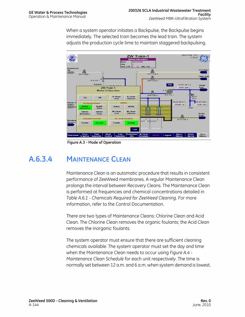
GE Water & Process TechnologiesOperation & Maintenance Manual
200326 SCLA Industrial Wastewater TreatmentFacility
ZeeWeed MBR-Ultrafiltration System
When a system operator initiates a Backpulse, the Backpulse begins immediately. The selected train becomes the lead train. The system adjusts the production cycle time to maintain staggered backpulsing.
A.6.3.4 MAINTENANCE CLEAN
Maintenance Clean is an automatic procedure that results in consistent performance of ZeeWeed membranes. A regular Maintenance Clean prolongs the interval between Recovery Cleans. The Maintenance Clean is performed at frequencies and chemical concentrations detailed in Table A.6.1 - Chemicals Required for ZeeWeed Cleaning. For more information, refer to the Control Documentation.
There are two types of Maintenance Cleans: Chlorine Clean and Acid Clean. The Chlorine Clean removes the organic foulants; the Acid Clean removes the inorganic foulants.
The system operator must ensure that there are sufficient cleaning chemicals available. The system operator must set the day and time when the Maintenance Clean needs to occur using Figure A.4 - Maintenance Clean Schedule for each unit respectively. The time is normally set between 12 a.m. and 6 a.m. when system demand is lowest.
Figure A.3 - Mode of Operation
ZeeWeed 500D - Cleaning & VentilationA-144
Rev. 0June, 2010

200326 SCLA Industrial Wastewater Treatment FacilityZeeWeed MBR-Ultrafiltration System
GE Water & Process TechnologiesOperation & Maintenance Manual
For more information about alternative Maintenance Clean procedures, contact the Service Department at (905) 465-3030 or by email at [email protected].
A.6.3.4.1 SCHEDULING A MAINTENANCE CLEAN
To schedule a Maintenance Clean for a train, complete the following steps:
1. On the Maintenance Clean schedule screen (see Figure A.4 - Maintenance Clean Schedule), enter the day and time for the Maintenance Clean. For days when a Maintenance Clean is not required, enter a time of 24:00.
Figure A.4 - Maintenance Clean Schedule
Rev. 0June, 2010
ZeeWeed 500D - Cleaning & VentilationA-145
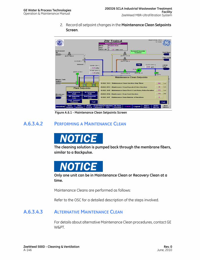
GE Water & Process TechnologiesOperation & Maintenance Manual
200326 SCLA Industrial Wastewater TreatmentFacility
ZeeWeed MBR-Ultrafiltration System
2. Record all setpoint changes in the Maintenance Clean Setpoints Screen.
A.6.3.4.2 PERFORMING A MAINTENANCE CLEAN
The cleaning solution is pumped back through the membrane fibers, similar to a Backpulse.
Only one unit can be in Maintenance Clean or Recovery Clean at a time.
Maintenance Cleans are performed as follows:
Refer to the OSC for a detailed description of the steps involved.
A.6.3.4.3 ALTERNATIVE MAINTENANCE CLEAN
For details about alternative Maintenance Clean procedures, contact GE W&PT.
Figure A.6.1 - Maintenance Clean Setpoints Screen
ZeeWeed 500D - Cleaning & VentilationA-146
Rev. 0June, 2010

200326 SCLA Industrial Wastewater Treatment FacilityZeeWeed MBR-Ultrafiltration System
GE Water & Process TechnologiesOperation & Maintenance Manual
Since a foulant can contain a variety of substances, rotating between sodium hypochlorite and citric acid (one cleaning event with sodium hypochlorite and the next one with citric acid) is recommended. Other chemical cleaners may also be used if recommended and approved by GE W&PT. It is recommended that the correct chemicals be selected for each site during the initial operating period.
A.6.3.5 RECOVERY CLEAN
A Recovery Clean should be performed if the automatic backpulsing of the system does not maintain membrane performance above the specified level. A Recovery Clean procedure is required to prevent fouling of the membranes and when it is no longer possible to operate the unit at the required flux without exceeding the maximum Transmembrane Pressure.
A Recovery Clean is operator-initiated and should have the operator present during the majority of the clean.
There are two types of Recovery Cleans: Chlorine Clean and Acid Clean. The Chlorine Clean removes the organic foulants; the Acid Clean removes the inorganic foulants. Normally, an Acid Clean follows a Chlorine Clean. At a reduced average operating capacity, the average interval between Recovery Cleans may be extended.
A 50% by weight solution of citric acid has a density of 1.24. Therefore, a 50% citric acid solution 0.62 kg of citric acid per liter of water.
kg of citricL of 50% solution------------------------------------------- 0.5 kg citric acid
1 kg 50% citric soln------------------------------------------------ 1.24 kg 50% citric soln
1 L 50% citric soln-------------------------------------------------------×=
kg of citricL of 50% solution------------------------------------------- 0.62 kg citric acid
1 kg 50% citric solution---------------------------------------------------------=
Rev. 0June, 2010
ZeeWeed 500D - Cleaning & VentilationA-147

GE Water & Process TechnologiesOperation & Maintenance Manual
200326 SCLA Industrial Wastewater TreatmentFacility
ZeeWeed MBR-Ultrafiltration System
The sodium hypochlorite (NaOCl) cleaning solution should be limited to a maximum pH of 11 at a temperature less than 30ºC, and a maximum pH of 10 at a temperature between 30ºC and 35ºC.
Citric acid solubility is 500 g/L at 10ºC. GE W&PT does not recommend increasing the concentration beyond 500 g/L. A 50% by weight solution of citric acid has a density of 1.24. Therefore, a 50% citric acid solution is made up using 0.62 kg of citric acid per liter of water. An example calculation for adding citric acid to the dosing tank is as follows: Required weight of citric acid = volume of water x 620 grams. When topping up the dosing tank by 4 L: Weight of citric acid = 4x620 = 2,480 grams. Therefore, add another 2,480 g of citric acid.
A.6.3.5.1 PREPARING FOR A RECOVERY CLEAN
To prepare for a Recovery Clean, complete the following steps:
Do not clean the membranes with a cleaning solution above 38ºC.
1. Ensure that the chemical tanks have sufficient solution.
2. Record the current water temperature, flux, and permeability while the train is operating in Production.
A.6.3.5.2 PERFORMING A RECOVERY CLEAN
Sodium hypochlorite cleaning solution generates gas that is both a health and safety concern and corrosive. Adequate ventilation must be provided.
ZeeWeed 500D - Cleaning & VentilationA-148
Rev. 0June, 2010

200326 SCLA Industrial Wastewater Treatment FacilityZeeWeed MBR-Ultrafiltration System
GE Water & Process TechnologiesOperation & Maintenance Manual
Do not pour chemicals directly on the membranes.
For the PLC-controlled Recovery Clean procedure, see the OSC.
To perform a Recovery Clean, complete the following steps:
Refer to the OSC for a detailed description of the steps involved in performing a recovery clean.
Toxic chlorine gas is produced if citric acid and sodium hypochlorite mix with each other. Always ensure that one chemical is completely rinsed from the tank and piping prior to cleaning with the other chemical. Clean water should be backpulsed through all contaminated piping until residual chlorine levels are less than 10 ppm. If chlorine gas is detected, the system operator should evacuate the area immediately and advise the plant safety officer and/or immediate supervisor accordingly. To minimize the chances of producing toxic chlorine vapors, the chemical feed pumps are interlocked during automatic operation so that sodium hypochlorite (NaOCl) and citric acid (MC-1) cannot be sent to the same location simultaneously. It is the system operator’s responsibility to ensure that sodium hypochlorite (NaOCl) and citric acid (MC-1) are not sent to the same location simultaneously if these devices are manually operated.
A.6.4 VENTILATION
Ventilation of the membrane tanks must be provided if the membrane plant is located in a building. This should include forced-air vents in the checker plate above the membrane tank, as well as standard ventilation for the building (for example, 4-6 exchanges/hour). Venting should be designed to provide only a small negative pressure above the membrane tank. Ventilation should be left on at all times.
Rev. 0June, 2010
ZeeWeed 500D - Cleaning & VentilationA-149

This page has beenintentionally left blank

A.7TROUBLESHOOTING

This page has beenintentionally left blank

200326 SCLA Industrial Wastewater Treatment FacilityZeeWeed MBR-Ultrafiltration System
GE Water & Process TechnologiesOperation & Maintenance Manual
A.7.1 OVERVIEW
GE Water & Process Technologies’ Technical Support Desk has drawn upon many years of experience in a wide variety of plants to compose this troubleshooting section. It conveniently brings together the most common issues and frequently asked questions.
GE W&PT has prepared specific training courses to develop troubleshooting skills. To discuss training options, call the Service department.
For pressurized systems, relieve the pressure before starting troubleshooting. Disconnect the air from the valves. Closing the valve will not relieve the pressure.
All routine troubleshooting must be carried out according to the safety regulations and instructions specified by the supplier of the equipment.
Read all relevant safety information in the Vendor Data and in Safety Information before doing any maintenance work.
Handle the cleaning chemicals with care (refer to the Material Safety Data Sheets). Wear a face mask, rubber apron, and rubber gloves when handling these chemicals.
Rev. 0June, 2010
ZeeWeed 500D - TroubleshootingA-153

GE Water & Process TechnologiesOperation & Maintenance Manual
200326 SCLA Industrial Wastewater TreatmentFacility
ZeeWeed MBR-Ultrafiltration System
A.7.2 EQUIPMENT TROUBLESHOOTING GUIDE
The following troubleshooting guide is provided for quick reference only. For detailed troubleshooting of system components, consult the Vendor Data.
If any of the problems discussed in this section persist or other difficulties arise, the operator should contact GE W&PT. Completed operating log sheets are necessary to determine the source of the problem.
Be sure to consult all necessary safety information prior to troubleshooting. Ensure that only qualified personnel are troubleshooting system components.
Mechanical or electrical maintenance should only be performed by qualified personnel. In the event of any differences between this manual and the supplied Vendor Data, the supplied Vendor Data should always take precedence. It is up to the operator to follow the correct safety procedures when doing any type of troubleshooting.
ZeeWeed 500D - TroubleshootingA-154
Rev. 0June, 2010
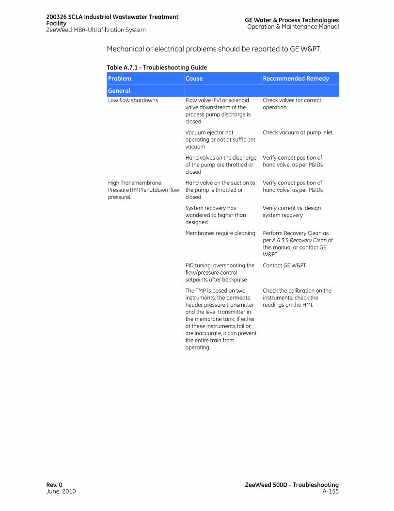
200326 SCLA Industrial Wastewater Treatment FacilityZeeWeed MBR-Ultrafiltration System
GE Water & Process TechnologiesOperation & Maintenance Manual
Mechanical or electrical problems should be reported to GE W&PT.
Table A.7.1 - Troubleshooting Guide
Problem Cause Recommended Remedy
GeneralLow flow shutdowns Flow valve (FV) or solenoid
valve downstream of the process pump discharge is closed
Check valves for correct operation
Vacuum ejector not operating or not at sufficient vacuum
Check vacuum at pump inlet
Hand valves on the discharge of the pump are throttled or closed
Verify correct position of hand valve, as per P&IDs
High Transmembrane Pressure (TMP) shutdown (low pressure).
Hand valve on the suction to the pump is throttled or closed
Verify correct position of hand valve, as per P&IDs
System recovery has wandered to higher than designed
Verify current vs. design system recovery
Membranes require cleaning Perform Recovery Clean as per A.6.3.5 Recovery Clean of this manual or contact GE W&PT
PID tuning: overshooting the flow/pressure control setpoints after backpulse
Contact GE W&PT
The TMP is based on two instruments: the permeate header pressure transmitter and the level transmitter in the membrane tank. If either of these instruments fail or are inaccurate, it can prevent the entire train from operating.
Check the calibration on the instruments; check the readings on the HMI.
Rev. 0June, 2010
ZeeWeed 500D - TroubleshootingA-155

GE Water & Process TechnologiesOperation & Maintenance Manual
200326 SCLA Industrial Wastewater TreatmentFacility
ZeeWeed MBR-Ultrafiltration System
A.7.3 PERMEATE QUALITY
Permeate quality may be affected by any number of factors, such as membrane damage, or a leak in the cassette seal.
A.7.3.1 MEMBRANE DAMAGE
To determine if damage has occurred to one or more of the membrane modules, examine the permeate from each membrane cassette. If the permeate is acceptable, the modules and cassette may continue service. If a damaged cassette is identified, find the damaged module either by visual fiber inspection or by a bubble test. Inspect and repair or replace any damaged modules to bring the overall system performance up to appropriate levels.
High-pressure shutdown (backpulse)
Hand valve on the suction to the pump is throttled or closed
Verify the correct position of hand valves, as per P&IDs
System recovery wandered to higher than designed
Verify current vs. design system recovery
The timers are too quick as they relate to pressure shutdowns
Contact GE W&PT
Level problems (analog) Failed 24 V DC power supply Verify power supply outlet
Problems with moisture in probe
Check probe seals
Level problems (digital) Switch compromised by chemicals
Verify operation of switch
Blown fuse to device Check the continuity of the fuses
Programing problem: switch programmed to behave improperly
Verify switch input to PLC versus program
ZeeWeed MembranesLeaking/cut fiber Damaged fiber See A.4.6 Fiber Repair for
fiber repair methods
Table A.7.1 - Troubleshooting Guide
Problem Cause Recommended Remedy
ZeeWeed 500D - TroubleshootingA-156
Rev. 0June, 2010

200326 SCLA Industrial Wastewater Treatment FacilityZeeWeed MBR-Ultrafiltration System
GE Water & Process TechnologiesOperation & Maintenance Manual
To locate a leaking element, use a bubble test. Streams of bubbles identify the location of possible leaks in the ZeeWeed system. After the cassette has been removed from the membrane tank and placed in another tank, slowly raise the module out of the water to locate the leak. In most cases, the cassette does not require disassembly to locate and repair leaking fibers.
Alternately, the membranes may be inspected after removing them from the system. This option should only be accomplished under the direct supervision of GE W&PT personnel. See A.3.10 Membrane Inspection/Replacement.
A.7.3.2 CASSETTE SEAL LEAKAGE
A leak in a cassette seal may result from improper attachment or loosening of the connections to the cassette. Check these connections periodically to see that they are properly installed.
A.7.4 PROCESS PUMP HAS LOST PRIME
A centrifugal permeate pump will not tolerate excessive air. Water in contact with air at atmospheric pressure naturally contains dissolved gases. After the water crosses the membrane boundary, the lower pressure encountered on the lumen side reduces the solubility of these gases in the water. The gases come out of solution and start to collect into bubbles.
If the air is not removed for any reason, the process pump will lose prime. An alarm will be generated and the train will be shut down.
PROBLEM: Process pump will not achieve prime due to air inside permeate header.
POSSIBLE CAUSES:
• Air leaks along pipe work.
• Missing or pinched camlock O-rings attached to permeate pipes.
Rev. 0June, 2010
ZeeWeed 500D - TroubleshootingA-157
GE Water & Process TechnologiesOperation & Maintenance Manual
200326 SCLA Industrial Wastewater TreatmentFacility
ZeeWeed MBR-Ultrafiltration System
• Cracks along PVC piping.
• Permeate header sample valves not entirely closed.
• Failed check valves.
• Air release valve rubber seat stuck at the discharge orifice.
• Air separator and/or associated spool fittings might have cracks, allowing in air.
RECOMMENDED REMEDIES: To determine exactly where a leak is occurring along the permeate header, use a spray bottle containing a soapy solution that can be sprayed at fittings and along piping and pipes to check for leaks. Because the system runs under a vacuum during production, wait until a backpulse occurs (positive pressure) to check for leaks on the permeate header.
• Physically check all permeate pipes for evidence of cracks, and replace as required.
• Replace any damaged or pinched O-rings inside permeate camlock fittings. Install any missing camlock O-rings.
• Ensure that sample valves are closed when the system is in operation.
• Ensure that the backpulse tank volume is well above the discharge point on the tank.
• Determine if the air release valve rubber seat is stuck at the top orifice. If so, it will prevent air from being vented from the permeate header. See A.7.5 Air Release Valves (Crispin Valve with ejector) for troubleshooting approaches. Ensure that the air release valve moves freely (vertically) inside the housing.
• Repair any leaks at or around the air separator.
• If the TMP is high, there is a greater probability of air being pulled across the membranes, which could hinder priming of the process pumps. Initiate a membrane cleaning to unclog membrane pores.
ZeeWeed 500D - TroubleshootingA-158
Rev. 0June, 2010

200326 SCLA Industrial Wastewater Treatment FacilityZeeWeed MBR-Ultrafiltration System
GE Water & Process TechnologiesOperation & Maintenance Manual
• Replace broken or missing check valve components.
• Request a program change to ensure that flow valves remain open in Standby.
A.7.5 AIR RELEASE VALVES (CRISPIN VALVE WITH EJECTOR)PROBLEM: Air cannot be removed from the permeate header, either due to the air release valve rubber seat remaining stuck to the top orifice discharge port on the air release valve housing or blockage inside the orifice port.
POSSIBLE CAUSES:
• Rust deposits formed on the internal surface area of the air release valve may prevent the float ball from rising/falling freely inside the air release valve housing.
• Rubber seat is set too far away from the top side of the brass support arm.
• Flakes of rust from non-epoxy-coated air release valve housings may have broken free and lodged into the orifice vent, creating a blockage and preventing air from being removed from the air separator.
RECOMMENDED REMEDIES:
1. Shutdown the train. Remove the air release valve housing cover. Inspect the interior surface area of the air release valve. If a low volume leak persists with the rubber valve against the orifice, then the rubber valve should be adjusted or replaced. If rust is present, arrange to have the air release valve sandblasted to remove the rust and recoat with epoxy.
2. Ensure that the float ball moves freely up/down inside the air release valve housing. If not, remove any obstructions.
Rev. 0June, 2010
ZeeWeed 500D - TroubleshootingA-159

GE Water & Process TechnologiesOperation & Maintenance Manual
200326 SCLA Industrial Wastewater TreatmentFacility
ZeeWeed MBR-Ultrafiltration System
3. Reassemble the air release valve.
4. Switch to train to On from Off mode to start the ejector. If necessary readjust the position of the rubber seat for the air release valve.
A.7.6 AERATION PROBLEM
Check all air connections and piping for damage. If damage is present, the system will have to be repaired immediately.
Ensure the air filter is changed at regular intervals. Refer to the Vendor Data for the recommended maintenance schedule. Proper aeration is essential to the operation of the ZeeWeed system. See A.3.9.2 Checking Aeration for instructions on checking for proper aeration.
A.7.7 SYSTEM COMPONENT FAILURE
If a system component has failed, perform the following steps:
1. Ensure that the device is locked out.
2. Record any information found on the device; for example, part number, model number, make, and tag number.
3. Check the spare parts list for availability.
4. Check the Vendor Data for troubleshooting, spare components list, and method to repair the device.
5. Contact GE W&PT at (905) 465-3030 and speak to our Service Department to order spare parts.
ZeeWeed 500D - TroubleshootingA-160
Rev. 0June, 2010

200326 SCLA Industrial Wastewater Treatment FacilityZeeWeed MBR-Ultrafiltration System
GE Water & Process TechnologiesOperation & Maintenance Manual
In Manual mode, all interlocks are disabled. This allows for manual entry of setpoints. Equipment can be damaged in Manual mode.
Rev. 0June, 2010
ZeeWeed 500D - TroubleshootingA-161

This page has beenintentionally left blank

A.8PERFORMANCE MONITORING

This page has beenintentionally left blank

200326 SCLA Industrial Wastewater Treatment FacilityZeeWeed MBR-Ultrafiltration System
GE Water & Process TechnologiesOperation & Maintenance Manual
A.8.1 INTRODUCTION
This section provides information regarding the procedures, tools, and schedules associated with gathering and tracking subsystem performance data. This information is essential when assessing long-standing performance issues, establishing trends, and determining the durability of various components.
A.8.2 LOGSHEETS
Logsheets, which are provided as electronic copies, are used for manually recording operational data and analytical results.
PERFORMANCE LOGSHEETS: Performance logsheets include those used for recording process data. Electronic copies of these documents will be provided by GE W&PT. Completed performance logsheets should be emailed to GE W&PT on a weekly basis in order to facilitate GE W&PT's ability to provide guidance,
SETPOINT LOGSHEET: The setpoint logsheet is used to record all changes made to setpoints associated with the subsystem or its various components (example: pumps). Because a complete loss of power to the system will cause the PLC to reboot using the original setpoints stored in the E2PROM, it is essential that this logsheet be updated whenever setpoints are changed so that the most recent values can be reentered.
A.8.3 ZENOTRAC
ZenoTrac is a powerful system support tool available as an option for all GE W&PT clients. Contact GE W&PT for more information about ZenoTrac.
Rev. 0June, 2010
ZeeWeed 500D - Performance MonitoringA-165

This page has beenintentionally left blank

A.9CALCULATIONS

This page has beenintentionally left blank
200326 SCLA Industrial Wastewater Treatment FacilityZeeWeed MBR-Ultrafiltration System
GE Water & Process TechnologiesOperation & Maintenance Manual
A.9.1 INTRODUCTION
This section provides calculations used to determine chemical quantities required for cleaning, maintenance, and various other subsystem procedures. These calculations are intended as general examples only; additional information specific to your subsystem may be provided by GE W&PT personnel during initial startup and commissioning.
A.9.1.1 UNIT CONVERSIONS
TIP: Multiply a value in US gpm by 3.785 to get the equivalent in lpm, and a value in lb/ft3 by 0.016 to get the equivalent in kg/L.
Convert all values to metric equivalents before performing the calculations provided in this section.
To find the corresponding value in kg/L for a known solution density, look up the density in Table A.9.1 - Solution Concentrations and Densities.
Concentrations are given as weight percentages. To create a solution using a dry chemical, use [x]/(1-[x]) kg of chemical for every liter of water, where [x] is the solution concentration written as a decimal.
EXAMPLE: To make a 35% calcium chloride solution, 0.35/(1-0.35) = 0.538 kg of calcium chloride for every liter of water used to make the solution.
Rev. 0June, 2010
ZeeWeed 500D - CalculationsA-169

GE Water & Process TechnologiesOperation & Maintenance Manual
200326 SCLA Industrial Wastewater TreatmentFacility
ZeeWeed MBR-Ultrafiltration System
NOTES:• Before mixing solution, consult the applicable MSDS for
chemical purity.
Table A.9.1 - Solution Concentrations and Densities
Chemical Solution Concentration (Weight%) Solution Density (kg/L)
Aluminum sulfate 48.50 1.335
Ammonium chloride 10.00 1.080
Calcium chloride (35% soln.) 35.00 1.250
Calcium chloride (15% soln.) 15.00 1.150
Calcium hydroxide 5.00 1.050
Ferric chloride 35.00 1.360
MC-1 50.00 1.240
Phosphoric acid (75% soln.) 75.00 1.582
Phosphoric acid (85% soln.) 85.00 1.694
Polyaluminum chloride 33.00 1.205
Potash 25.00 1.150
Potassium permanganate 3.00 1.030
Powdered activated carbon slurry
5.00 1.025
Sodium aluminate (10% soln.) 10.00 1.090
Sodium aluminate (32% soln.) 32.00 1.300
Sodium bicarbonate 3.50 1.035
Sodium bisulfite 40.00 1.370
Sodium carbonate 10.00 1.110
Sodium hydroxide (25% soln.) 25.00 1.260
Sodium hydroxide (50% soln.) 50.00 1.520
Sodium hypochlorite (12% soln.) 12.00 1.168
Sodium hypochlorite (6% soln.) 6.00 1.076
Sulfuric acid (77.67% soln.) 77.67 1.704
Sulfuric acid (93.19% soln.) 93.19 1.834
Sulfuric acid (98% soln.) 98.00 1.836
Urea 23.00 1.000
ZenoTreat 150 (antiscalant) 100.00 1.150
ZenoTreat 450 (antiscalant) 100.00 1.080
ZeeWeed 500D - CalculationsA-170
Rev. 0June, 2010

200326 SCLA Industrial Wastewater Treatment FacilityZeeWeed MBR-Ultrafiltration System
GE Water & Process TechnologiesOperation & Maintenance Manual
A.9.2 GENERAL DOSING CALCULATION
To determine the amount of chemical(s) required when dosing the subsystem, use the following calculation:
Calculate the flow rate of 35% ferric chloride solution to dose to 60 ppm in a 100 lpm stream.
The mass flow rate of ferric chloride in the feedwater stream equals the mass flow rate of ferric chloride dosed.
In the equations below, Qf and Qc are in lpm, Cf is in mg/L, ρc is in kg/L, and Cc is weight percent written as a decimal (example: 35% as 0.35).
Example:
Figure A.9.1 - Dosing Calculation Diagram
Feedwater flow rate Qf = 100 lpm
Chemical concentration in feedwater stream Cf = 60 ppm (60 mg/L)
Stock solution concentration Cc = 35% by weight
Stock solution density ρc = 1.36 kg/L
Qc =Qf x Cf
ρc x Cc x 106
100 x 60= 0.0126 lpm
1.36 x 0.35 x 106
100 L feed x 60mg FeCl3 = Qc
L FeCl3 soln. x 1.36 kg soln. x
35 kg FeCl3 x 106 mgminute L feed minute L soln. 100 kg soln. kg
Rev. 0June, 2010
ZeeWeed 500D - CalculationsA-171
GE Water & Process TechnologiesOperation & Maintenance Manual
200326 SCLA Industrial Wastewater TreatmentFacility
ZeeWeed MBR-Ultrafiltration System
If the required nutrient concentration (nitrogen or phosphorus) in the feedwater stream (Cf) is given in mg/L (or ppm), then an extra calculation step must be included.
Calculate the chemical flowrate according to the general example above, and then divide this flowrate by the mass percent nitrogen or phosphorus in the chemical being used (refer to Table A.9.2 - Mass Percent Nitrogen or Phosphorus in Chemical.
A.9.3 CALCULATING MEMBRANE PERMEABILITY
To gauge the effectiveness of a cleaning session, calculate the overall permeability of the membranes before versus after the session has been performed.
Refer to the example below when calculating membrane permeability.
EXAMPLE: A subsystem has a typical operating temperature of 20ºC (68ºF) (T1) and an actual (observed) operating temperature of 15ºC (59ºF) (T2). The permeate flowrate was recorded at 3,285.4 lpm (868 gpm) at a membrane pressure of 0.414 bar (6 psi), while total membrane surface area equals 4,548.53 m2 (48,960 ft2).
1. Calculate the membrane area:
Table A.9.2 - Mass Percent Nitrogen or Phosphorus in Chemical
Chemical Mass Percent Nitrogen or Phosphorus in Pure Chemical
Ammonium chloride 26.1%
Urea 46.6%
Phosphoric acid 31.6%
Membrane area per train = Number of modules
per cassette x Number of cassettes per train x Surface area per
module
48 modules per cassette x 3 cassettes per train x 340 ft2 per module = 48,960 ft2 per train
ZeeWeed 500D - CalculationsA-172
Rev. 0June, 2010

200326 SCLA Industrial Wastewater Treatment FacilityZeeWeed MBR-Ultrafiltration System
GE Water & Process TechnologiesOperation & Maintenance Manual
2. Convert flow rate to flux at the observed temperature:
3. Correct the flux value from the observed temperature (15ºC (59ºF)) (T2) to the reference temperature (20ºC (68ºF)) (T1). Viscosity values required for this calculation can be found in Table A.9.3 - Water Viscosity.
Flux at 59ºF = Flow x Number of minutes per dayMembrane surface area per train
868 gpm x 1,440 minutes per day = 25.5 gfd
48,960 in.2 per train
Table A.9.3 - Water Viscosity
Temperature Viscosity Temperature Viscosity Temperature Viscosity
°C °F cP °C °F cP °C °F cP1 34 1.7311 23 73 0.9356 45 113 0.5988
2 36 1.6736 24 75 0.9142 46 115 0.5884
3 37 1.6192 25 77 0.8935 47 117 0.5782
4 39 1.5677 26 79 0.8736 48 118 0.5683
5 41 1.5188 27 81 0.8544 49 120 0.5587
6 43 1.4723 28 82 0.8359 50 122 0.5494
7 45 1.4281 29 84 0.8180 51 124 0.5403
8 46 1.3860 30 86 0.8007 52 126 0.5315
9 48 1.3459 31 88 0.7840 53 127 0.5229
10 50 1.3077 32 90 0.7679 54 129 0.5145
11 52 1.2712 33 91 0.7523 55 131 0.5064
12 54 1.2362 34 93 0.7372 56 133 0.4984
13 55 1.2029 35 95 0.7225 57 135 0.4907
14 57 1.1709 36 97 0.7084 58 136 0.4832
15 59 1.1403 37 99 0.6946 59 138 0.4758
16 61 1.1109 38 100 0.6813 60 140 0.4687
17 63 1.0828 39 102 0.6685 61 142 0.4617
18 64 1.0558 40 104 0.6560 62 144 0.4549
19 66 1.0298 41 106 0.6438 63 145 0.4482
20 68 1.0049 42 108 0.6321 64 147 0.4418
21 70 0.9809 43 109 0.6207 65 149 0.4355
22 72 0.9578 44 111 0.6096
Rev. 0June, 2010
ZeeWeed 500D - CalculationsA-173

GE Water & Process TechnologiesOperation & Maintenance Manual
200326 SCLA Industrial Wastewater TreatmentFacility
ZeeWeed MBR-Ultrafiltration System
4. Using the recorded membrane pressure, convert the temperature-corrected flux to membrane permeability.
In order to accurately assess the effectiveness of a cleaning procedure, measure and record the membrane permeability immediately before and after each cleaning session is performed.
Flux at T1 = Flux at T2 xviscosity at T1viscosity at T2
25.5 gfd x 1.0049 = 22.47 gfd1.1403
Membrane permeability = Corrected flux
Membrane pressure
22.47 gfd = 3.7 gfd per 1 psi6 psi
ZeeWeed 500D - CalculationsA-174
Rev. 0June, 2010
Related Documents


![[Infographic] GE Water – Process Technologies](https://static.cupdf.com/doc/110x72/548718afb47959190d8b531c/infographic-ge-water-process-technologies.jpg)