Technical Publication GE Medical Systems Part Number FC091194 Revision 02 GE Medical Systems Vivid 7 / Vivid 7 PRO Service Manual Copyright© 2002 General Electric Co. All rights reserved

GE Vivid 7 - Service Manual
Oct 24, 2014
Welcome message from author
This document is posted to help you gain knowledge. Please leave a comment to let me know what you think about it! Share it to your friends and learn new things together.
Transcript

Technical Publication
GE Medical Systems
Part Number FC091194Revision 02
GE Medical SystemsVivid 7 / Vivid 7 PRO Service Manual
Copyright© 2002 General Electric Co. All rights reserved


GE MEDICAL SYSTEMSDIRECTION FC091194, REVISION 02 VIVID 7 / VIVID 7 PRO SERVICE MANUAL
- iii
IMPORTANT PRECAUTIONS
LANGUAGE
• THIS SERVICE MANUAL IS AVAILABLE IN ENGLISH ONLY.• IF A CUSTOMER’S SERVICE PROVIDER REQUIRES A
LANGUAGE OTHER THAN ENGLISH, IT IS THE CUSTOMER’S RESPONSIBILITY TO PROVIDE TRANSLATION SERVICES.
• DO NOT ATTEMPT TO SERVICE THE EQUIPMENT UNLESS THIS SERVICE MANUAL HAS BEEN CONSULTED AND IS UNDERSTOOD.
• FAILURE TO HEED THIS WARNING MAY RESULT IN INJURY TO THE SERVICE PROVIDER, OPERATOR OR PATIENT FROM ELECTRIC SHOCK, MECHANICAL OR OTHER HAZARDS.
• CE MANUEL DE MAINTENANCE N’EST DISPONIBLE QU’EN ANGLAIS.
• SI LE TECHNICIEN DU CLIENT A BESOIN DE CE MANUEL DANS UNE AUTRE LANGUE QUE L’ANGLAIS, C’EST AU CLIENT QU’IL INCOMBE DE LE FAIRE TRADUIRE.
• NE PAS TENTER D’INTERVENTION SUR LES ÉQUIPEMENTS TANT QUE LE MANUEL SERVICE N’A PAS ÉTÉ CONSULTÉ ET COMPRIS.
• LE NON-RESPECT DE CET AVERTISSEMENT PEUT ENTRAÎNER CHEZ LE TECHNICIEN, L’OPÉRATEUR OU LE PATIENT DES BLESSURES DUES À DES DANGERS ÉLECTRIQUES, MÉCANIQUES OU AUTRES.
• DIESES KUNDENDIENST-HANDBUCH EXISTIERT NUR IN ENGLISCHER SPRACHE.
• FALLS EIN FREMDER KUNDENDIENST EINE ANDERE SPRACHE BENÖTIGT, IST ES AUFGABE DES KUNDEN FÜR EINE ENTSPRECHENDE ÜBERSETZUNG ZU SORGEN.
• VERSUCHEN SIE NICHT, DAS GERÄT ZU REPARIEREN, BEVOR DIESES KUNDENDIENST-HANDBUCH NICHT ZU RATE GEZOGEN UND VERSTANDEN WURDE.
• WIRD DIESE WARNUNG NICHT BEACHTET, SO KANN ES ZU VERLETZUNGEN DES KUNDENDIENSTTECHNIKERS, DES BEDIENERS ODER DES PATIENTEN DURCH ELEKTRISCHE SCHLÄGE, MECHANISCHE ODER SONSTIGE GEFAHREN KOMMEN.
WARNING
AVERTISSEMENT
WARNUNG
GE MEDICAL SYSTEMSDIRECTION FC091194, REVISION 02 VIVID 7 / VIVID 7 PRO SERVICE MANUAL
iv -
• ESTE MANUAL DE SERVICIO SÓLO EXISTE EN INGLÉS.• SI ALGÚN PROVEEDOR DE SERVICIOS AJENO A GEMS
SOLICITA UN IDIOMA QUE NO SEA EL INGLÉS, ES RESPONSABILIDAD DEL CLIENTE OFRECER UN SERVICIO DE TRADUCCIÓN.
• NO SE DEBERÁ DAR SERVICIO TÉCNICO AL EQUIPO, SIN HABER CONSULTADO Y COMPRENDIDO ESTE MANUAL DE SERVICIO.
• LA NO OBSERVANCIA DEL PRESENTE AVISO PUEDE DAR LUGAR A QUE EL PROVEEDOR DE SERVICIOS, EL OPERADOR O EL PACIENTE SUFRAN LESIONES PROVOCADAS POR CAUSAS ELÉCTRICAS, MECÁNICAS O DE OTRA NATURALEZA.
• ESTE MANUAL DE ASSISTÊNCIA TÉCNICA SÓ SE ENCONTRA DISPONÍVEL EM INGLÊS.
• SE QUALQUER OUTRO SERVIÇO DE ASSISTÊNCIA TÉCNICA, QUE NÃO A GEMS, SOLICITAR ESTES MANUAIS NOUTRO IDIOMA, É DA RESPONSABILIDADE DO CLIENTE FORNECER OS SERVIÇOS DE TRADUÇÃO.
• NÃO TENTE REPARAR O EQUIPAMENTO SEM TER CONSULTADO E COMPREENDIDO ESTE MANUAL DE ASSISTÊNCIA TÉCNICA.
• O NÃO CUMPRIMENTO DESTE AVISO PODE POR EM PERIGO A SEGURANÇA DO TÉCNICO, OPERADOR OU PACIENTE DEVIDO A‘ CHOQUES ELÉTRICOS, MECÂNICOS OU OUTROS.
• IL PRESENTE MANUALE DI MANUTENZIONE È DISPONIBILE SOLTANTO IN INGLESE.
• SE UN ADDETTO ALLA MANUTENZIONE ESTERNO ALLA GEMS RICHIEDE IL MANUALE IN UNA LINGUA DIVERSA, IL CLIENTE È TENUTO A PROVVEDERE DIRETTAMENTE ALLA TRADUZIONE.
• SI PROCEDA ALLA MANUTENZIONE DELL’APPARECCHIATURA SOLO DOPO AVER CONSULTATO IL PRESENTE MANUALE ED AVERNE COMPRESO IL CONTENUTO.
• NON TENERE CONTO DELLA PRESENTE AVVERTENZA POTREBBE FAR COMPIERE OPERAZIONI DA CUI DERIVINO LESIONI ALL’ADDETTO ALLA MANUTENZIONE, ALL’UTILIZZATORE ED AL PAZIENTE PER FOLGORAZIONE ELETTRICA, PER URTI MECCANICI OD ALTRI RISCHI.
AVISO
ATENÇÃO
AVVERTENZA

GE MEDICAL SYSTEMSDIRECTION FC091194, REVISION 02 VIVID 7 / VIVID 7 PRO SERVICE MANUAL
- v
DAMAGE IN TRANSPORTATION (For USA Only)
All packages should be closely examined at time of delivery. If damage is apparent write “Damage In Shipment” on ALL copies of the freight or express bill BEFORE delivery is accepted or “signed for” by a GE representative or hospital receiving agent. Whether noted or concealed, damage MUST be reported to the carrier immediately upon discovery, or in any event, within 14 days after receipt, and the contents and containers held for inspection by the carrier. A transportation company will not pay a claim for damage if an inspection is not requested within this 14 day period.
For USA Only:
Call Traffic and Transportation, Milwaukee, WI (262) 785-5052 or 8*323 5052 immediately after damage is found. At this time be ready to supply name of carrier, delivery date, consignee name, freight or express bill number, item damaged and extent of damage.
For USA Only:
Complete instructions regarding claim procedure are found in Section S of the Policy And Procedures Bulletins.
14 July 1993

GE MEDICAL SYSTEMSDIRECTION FC091194, REVISION 02 VIVID 7 / VIVID 7 PRO SERVICE MANUAL
vi -
CERTIFIED ELECTRICAL CONTRACTOR STATEMENT (For USA Only)
All electrical Installations that are preliminary to positioning of the equipment at the site prepared for the equipment shall be performed by licensed electrical contractors. Other connections between pieces of electrical equipment, calibrations and testing shall be performed by qualified GE Medical personnel. In performing all electrical work on these products, GE will use its own specially trained field engineers. All of GE’s electrical work on these products will comply with the requirements of the applicable electrical codes.
The purchaser of GE equipment shall only utilize qualified personnel (i.e., GE’s field engineers, personnel of third-party service companies with equivalent training, or licensed electricians) to perform electrical servicing on the equipment.
OMISSIONS & ERRORSIf there are any omissions, errors or suggestions for improving this documentation, please contact the GE Medical Systems Global Documentation Group with specific information listing the system type, manual title, part number, revision number, page number and suggestion details. E-mail the information to : [email protected]
GE Medical Systems employees should use the Customer Quality Assurance (CQA) System to report all documentation omissions, errors or suggestions.

GE MEDICAL SYSTEMSDIRECTION FC091194, REVISION 02 VIVID 7 / VIVID 7 PRO SERVICE MANUAL
- vii
Revision History
REVISION DATE REASON FOR CHANGE
01 11. JUN. 2002 Covers both Vivid 7 and Vivid 7 PROReplaces Vivid 7 Service Manual, Part Number FB091202
02 30. AUG. 2002 Updated per BT02-M4 release. Included description for BEP-2.
GE MEDICAL SYSTEMSDIRECTION FC091194, REVISION 02 VIVID 7 / VIVID 7 PRO SERVICE MANUAL
viii -
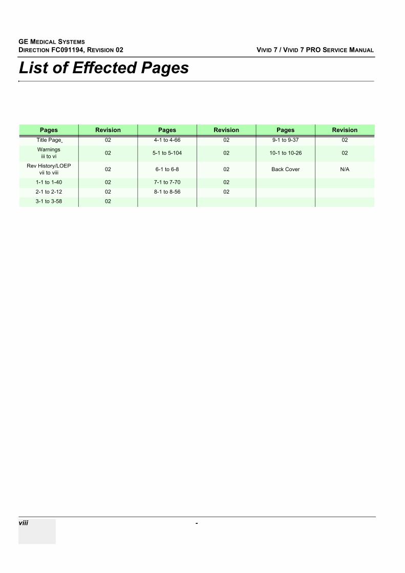
List of Effected Pages
Pages Revision Pages Revision Pages RevisionTitle Page 02 4-1 to 4-66 02 9-1 to 9-37 02
Warnings iii to vi 02 5-1 to 5-104 02 10-1 to 10-26 02
Rev History/LOEP vii to viii 02 6-1 to 6-8 02 Back Cover N/A
1-1 to 1-40 02 7-1 to 7-70 02
2-1 to 2-12 02 8-1 to 8-56 02
3-1 to 3-58 02

GE MEDICAL SYSTEMS DIRECTION FC091194, REVISION 02 VIVID 7 / VIVID 7 PRO SERVICE MANUAL
Table of Contents ix
Table of ContentsCHAPTER 1Introduction
Overview . . . . . . . . . . . . . . . . . . . . . . . . . . . . . . . . . . . . . . . . . . . . . . . . . . . . . . . . . 1 - 1Purpose of Chapter 1 . . . . . . . . . . . . . . . . . . . . . . . . . . . . . . . . . . . . . . . . . . 1 - 1Purpose of Service Manual . . . . . . . . . . . . . . . . . . . . . . . . . . . . . . . . . . . . . 1 - 1Typical Users of the Service Manual . . . . . . . . . . . . . . . . . . . . . . . . . . . . . . 1 - 2Vivid 7 / Vivid 7 PRO Models Covered by this Manual . . . . . . . . . . . . . . . . 1 - 2Purpose of Operator Manual(s) . . . . . . . . . . . . . . . . . . . . . . . . . . . . . . . . . . 1 - 7
Important Conventions. . . . . . . . . . . . . . . . . . . . . . . . . . . . . . . . . . . . . . . . . . . . . . . 1 - 8Conventions Used in Book . . . . . . . . . . . . . . . . . . . . . . . . . . . . . . . . . . . . . . 1 - 8Standard Hazard Icons . . . . . . . . . . . . . . . . . . . . . . . . . . . . . . . . . . . . . . . . 1 - 9Product Icons . . . . . . . . . . . . . . . . . . . . . . . . . . . . . . . . . . . . . . . . . . . . . . . . 1 - 10
Safety Considerations . . . . . . . . . . . . . . . . . . . . . . . . . . . . . . . . . . . . . . . . . . . . . . . 1 - 12Introduction . . . . . . . . . . . . . . . . . . . . . . . . . . . . . . . . . . . . . . . . . . . . . . . . . 1 - 12Human Safety . . . . . . . . . . . . . . . . . . . . . . . . . . . . . . . . . . . . . . . . . . . . . . . 1 - 12Mechanical Safety . . . . . . . . . . . . . . . . . . . . . . . . . . . . . . . . . . . . . . . . . . . . 1 - 12Electrical Safety . . . . . . . . . . . . . . . . . . . . . . . . . . . . . . . . . . . . . . . . . . . . . . 1 - 13Labels Locations . . . . . . . . . . . . . . . . . . . . . . . . . . . . . . . . . . . . . . . . . . . . . 1 - 14Dangerous Procedure Warnings . . . . . . . . . . . . . . . . . . . . . . . . . . . . . . . . . 1 - 36Lockout/Tagout Requirements (For USA Only) . . . . . . . . . . . . . . . . . . . . . . 1 - 36
EMC, EMI, and ESD . . . . . . . . . . . . . . . . . . . . . . . . . . . . . . . . . . . . . . . . . . . . . . . . 1 - 37Electromagnetic Compatibility (EMC) and Interference (EMI) . . . . . . . . . . . 1 - 37CE Compliance . . . . . . . . . . . . . . . . . . . . . . . . . . . . . . . . . . . . . . . . . . . . . . 1 - 37Electrostatic Discharge (ESD) Prevention . . . . . . . . . . . . . . . . . . . . . . . . . . 1 - 37
Customer Assistance . . . . . . . . . . . . . . . . . . . . . . . . . . . . . . . . . . . . . . . . . . . . . . . . 1 - 38Contact Information . . . . . . . . . . . . . . . . . . . . . . . . . . . . . . . . . . . . . . . . . . . 1 - 38System Manufacture . . . . . . . . . . . . . . . . . . . . . . . . . . . . . . . . . . . . . . . . . . 1 - 39
GE MEDICAL SYSTEMS DIRECTION FC091194, REVISION 02 VIVID 7 / VIVID 7 PRO SERVICE MANUAL
x Table of Contents
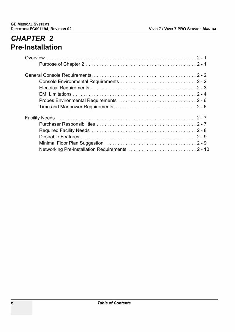
CHAPTER 2Pre-Installation
Overview . . . . . . . . . . . . . . . . . . . . . . . . . . . . . . . . . . . . . . . . . . . . . . . . . . . . . . . . . 2 - 1Purpose of Chapter 2 . . . . . . . . . . . . . . . . . . . . . . . . . . . . . . . . . . . . . . . . . . 2 - 1
General Console Requirements. . . . . . . . . . . . . . . . . . . . . . . . . . . . . . . . . . . . . . . . 2 - 2Console Environmental Requirements . . . . . . . . . . . . . . . . . . . . . . . . . . . . . 2 - 2Electrical Requirements . . . . . . . . . . . . . . . . . . . . . . . . . . . . . . . . . . . . . . . . 2 - 3EMI Limitations . . . . . . . . . . . . . . . . . . . . . . . . . . . . . . . . . . . . . . . . . . . . . . . 2 - 4Probes Environmental Requirements . . . . . . . . . . . . . . . . . . . . . . . . . . . . . 2 - 6Time and Manpower Requirements . . . . . . . . . . . . . . . . . . . . . . . . . . . . . . . 2 - 6
Facility Needs . . . . . . . . . . . . . . . . . . . . . . . . . . . . . . . . . . . . . . . . . . . . . . . . . . . . . 2 - 7Purchaser Responsibilities . . . . . . . . . . . . . . . . . . . . . . . . . . . . . . . . . . . . . . 2 - 7Required Facility Needs . . . . . . . . . . . . . . . . . . . . . . . . . . . . . . . . . . . . . . . . 2 - 8Desirable Features . . . . . . . . . . . . . . . . . . . . . . . . . . . . . . . . . . . . . . . . . . . . 2 - 9Minimal Floor Plan Suggestion . . . . . . . . . . . . . . . . . . . . . . . . . . . . . . . . . . 2 - 9Networking Pre-installation Requirements . . . . . . . . . . . . . . . . . . . . . . . . . . 2 - 10
GE MEDICAL SYSTEMS DIRECTION FC091194, REVISION 02 VIVID 7 / VIVID 7 PRO SERVICE MANUAL
Table of Contents xi
CHAPTER 3Installation
Overview. . . . . . . . . . . . . . . . . . . . . . . . . . . . . . . . . . . . . . . . . . . . . . . . . . . . . . . . . 3 - 1Purpose of Chapter 3 . . . . . . . . . . . . . . . . . . . . . . . . . . . . . . . . . . . . . . . . . 3 - 1
Installation Reminders . . . . . . . . . . . . . . . . . . . . . . . . . . . . . . . . . . . . . . . . . . . . . . 3 - 1Average Installation Time . . . . . . . . . . . . . . . . . . . . . . . . . . . . . . . . . . . . . . 3 - 1Installation Warnings . . . . . . . . . . . . . . . . . . . . . . . . . . . . . . . . . . . . . . . . . 3 - 2
Receiving and Unpacking the Equipment. . . . . . . . . . . . . . . . . . . . . . . . . . . . . . . . 3 - 3Introduction . . . . . . . . . . . . . . . . . . . . . . . . . . . . . . . . . . . . . . . . . . . . . . . . . 3 - 3
Receiving Vivid 7 / Vivid 7 PRO . . . . . . . . . . . . . . . . . . . . . . . . . . . . . . . . . . . . . . . 3 - 4Introduction . . . . . . . . . . . . . . . . . . . . . . . . . . . . . . . . . . . . . . . . . . . . . . . . . 3 - 4
Unpacking Vivid 7 / Vivid 7 PRO . . . . . . . . . . . . . . . . . . . . . . . . . . . . . . . . . . . . . . 3 - 5Transportation Box Dimensions . . . . . . . . . . . . . . . . . . . . . . . . . . . . . . . . . 3 - 7
Preparing for Installation. . . . . . . . . . . . . . . . . . . . . . . . . . . . . . . . . . . . . . . . . . . . . 3 - 8Physical Inspection . . . . . . . . . . . . . . . . . . . . . . . . . . . . . . . . . . . . . . . . . . . 3 - 8EMI Protection . . . . . . . . . . . . . . . . . . . . . . . . . . . . . . . . . . . . . . . . . . . . . . 3 - 8
Completing the Installation . . . . . . . . . . . . . . . . . . . . . . . . . . . . . . . . . . . . . . . . . . . 3 - 8System Specifications . . . . . . . . . . . . . . . . . . . . . . . . . . . . . . . . . . . . . . . . . 3 - 8Electrical Specifications . . . . . . . . . . . . . . . . . . . . . . . . . . . . . . . . . . . . . . . 3 - 9Connect Footswitch . . . . . . . . . . . . . . . . . . . . . . . . . . . . . . . . . . . . . . . . . . 3 - 10Connect Telephone Line to Modem Connector . . . . . . . . . . . . . . . . . . . . . 3 - 10Connect ECG . . . . . . . . . . . . . . . . . . . . . . . . . . . . . . . . . . . . . . . . . . . . . . . 3 - 11Connect Phono . . . . . . . . . . . . . . . . . . . . . . . . . . . . . . . . . . . . . . . . . . . . . . 3 - 11Connect Pulse Pressure Transducer . . . . . . . . . . . . . . . . . . . . . . . . . . . . . 3 - 12Connect Ethernet . . . . . . . . . . . . . . . . . . . . . . . . . . . . . . . . . . . . . . . . . . . . 3 - 12Probe Connection . . . . . . . . . . . . . . . . . . . . . . . . . . . . . . . . . . . . . . . . . . . . 3 - 13Power ON/Boot Up . . . . . . . . . . . . . . . . . . . . . . . . . . . . . . . . . . . . . . . . . . . 3 - 14Power Shut Down . . . . . . . . . . . . . . . . . . . . . . . . . . . . . . . . . . . . . . . . . . . . 3 - 17Switching OFF the Unit . . . . . . . . . . . . . . . . . . . . . . . . . . . . . . . . . . . . . . . . 3 - 17
Configuration . . . . . . . . . . . . . . . . . . . . . . . . . . . . . . . . . . . . . . . . . . . . . . . . . . . . . 3 - 21Vivid 7 / Vivid 7 PRO Configuration . . . . . . . . . . . . . . . . . . . . . . . . . . . . . . 3 - 22Service Screen . . . . . . . . . . . . . . . . . . . . . . . . . . . . . . . . . . . . . . . . . . . . . . 3 - 28Optional Peripherals/Peripheral Connection . . . . . . . . . . . . . . . . . . . . . . . . 3 - 32Available Probes . . . . . . . . . . . . . . . . . . . . . . . . . . . . . . . . . . . . . . . . . . . . . 3 - 32Video Specification . . . . . . . . . . . . . . . . . . . . . . . . . . . . . . . . . . . . . . . . . . . 3 - 32

GE MEDICAL SYSTEMS DIRECTION FC091194, REVISION 02 VIVID 7 / VIVID 7 PRO SERVICE MANUAL
xii Table of Contents
Software Options Configuration . . . . . . . . . . . . . . . . . . . . . . . . . . . . . . . . . . 3 - 33
Connectivity . . . . . . . . . . . . . . . . . . . . . . . . . . . . . . . . . . . . . . . . . . . . . . . . . . . . . . . 3 - 35Introduction . . . . . . . . . . . . . . . . . . . . . . . . . . . . . . . . . . . . . . . . . . . . . . . . . 3 - 35Physical Connection . . . . . . . . . . . . . . . . . . . . . . . . . . . . . . . . . . . . . . . . . . . 3 - 35Connectivity Setup . . . . . . . . . . . . . . . . . . . . . . . . . . . . . . . . . . . . . . . . . . . . 3 - 37
Installation Paperwork . . . . . . . . . . . . . . . . . . . . . . . . . . . . . . . . . . . . . . . . . . . . . . . 3 - 56User Manual(s) . . . . . . . . . . . . . . . . . . . . . . . . . . . . . . . . . . . . . . . . . . . . . . . 3 - 56Complete the Post Delivery Check List . . . . . . . . . . . . . . . . . . . . . . . . . . . . 3 - 56Post Delivery Check List . . . . . . . . . . . . . . . . . . . . . . . . . . . . . . . . . . . . . . . 3 - 57

GE MEDICAL SYSTEMS DIRECTION FC091194, REVISION 02 VIVID 7 / VIVID 7 PRO SERVICE MANUAL
Table of Contents xiii
CHAPTER 4Functional Checks
Overview. . . . . . . . . . . . . . . . . . . . . . . . . . . . . . . . . . . . . . . . . . . . . . . . . . . . . . . . . 4 - 1
Purpose of Chapter 4 . . . . . . . . . . . . . . . . . . . . . . . . . . . . . . . . . . . . . . . . . 4 - 1Special Equipment Required . . . . . . . . . . . . . . . . . . . . . . . . . . . . . . . . . . . 4 - 1
General Procedures . . . . . . . . . . . . . . . . . . . . . . . . . . . . . . . . . . . . . . . . . . . . . . . . 4 - 2Power ON/ Boot Up . . . . . . . . . . . . . . . . . . . . . . . . . . . . . . . . . . . . . . . . . . 4 - 2Power Shut Down . . . . . . . . . . . . . . . . . . . . . . . . . . . . . . . . . . . . . . . . . . . . 4 - 5Using Removable Media . . . . . . . . . . . . . . . . . . . . . . . . . . . . . . . . . . . . . . . 4 - 9Labeling Removable Media . . . . . . . . . . . . . . . . . . . . . . . . . . . . . . . . . . . . 4 - 10Formatting Removable Media . . . . . . . . . . . . . . . . . . . . . . . . . . . . . . . . . . . 4 - 11Verifying Removable Media . . . . . . . . . . . . . . . . . . . . . . . . . . . . . . . . . . . . 4 - 11Archiving and Loading Presets . . . . . . . . . . . . . . . . . . . . . . . . . . . . . . . . . . 4 - 12
Functional Checks . . . . . . . . . . . . . . . . . . . . . . . . . . . . . . . . . . . . . . . . . . . . . . . . . 4 - 14Preparation . . . . . . . . . . . . . . . . . . . . . . . . . . . . . . . . . . . . . . . . . . . . . . . . . 4 - 14Basic Controls . . . . . . . . . . . . . . . . . . . . . . . . . . . . . . . . . . . . . . . . . . . . . . . 4 - 14Performance Tests . . . . . . . . . . . . . . . . . . . . . . . . . . . . . . . . . . . . . . . . . . . 4 - 162D Mode (B mode) Checks . . . . . . . . . . . . . . . . . . . . . . . . . . . . . . . . . . . . 4 - 17M Mode Checks . . . . . . . . . . . . . . . . . . . . . . . . . . . . . . . . . . . . . . . . . . . . . 4 - 24Color Mode Checks . . . . . . . . . . . . . . . . . . . . . . . . . . . . . . . . . . . . . . . . . . 4 - 28Doppler Mode Checks . . . . . . . . . . . . . . . . . . . . . . . . . . . . . . . . . . . . . . . . 4 - 34Tissue Velocity Imaging (TVI) Checks . . . . . . . . . . . . . . . . . . . . . . . . . . . . 4 - 40Contrast Checks . . . . . . . . . . . . . . . . . . . . . . . . . . . . . . . . . . . . . . . . . . . . . 4 - 46Stress Echo . . . . . . . . . . . . . . . . . . . . . . . . . . . . . . . . . . . . . . . . . . . . . . . . 4 - 46Measurements and Multi Image Checks . . . . . . . . . . . . . . . . . . . . . . . . . . 4 - 47Multi Image Checks . . . . . . . . . . . . . . . . . . . . . . . . . . . . . . . . . . . . . . . . . . 4 - 49Probe/Connectors Check . . . . . . . . . . . . . . . . . . . . . . . . . . . . . . . . . . . . . . 4 - 50ECG Check . . . . . . . . . . . . . . . . . . . . . . . . . . . . . . . . . . . . . . . . . . . . . . . . . 4 - 51Cineloop Check . . . . . . . . . . . . . . . . . . . . . . . . . . . . . . . . . . . . . . . . . . . . . 4 - 52Backend Processor Checks . . . . . . . . . . . . . . . . . . . . . . . . . . . . . . . . . . . . 4 - 56Peripheral Checks . . . . . . . . . . . . . . . . . . . . . . . . . . . . . . . . . . . . . . . . . . . 4 - 57Mechanical Functions Checks . . . . . . . . . . . . . . . . . . . . . . . . . . . . . . . . . . 4 - 61
Application Turnover Check List. . . . . . . . . . . . . . . . . . . . . . . . . . . . . . . . . . . . . . . 4 - 63Software Configuration Checks . . . . . . . . . . . . . . . . . . . . . . . . . . . . . . . . . 4 - 63
Power Supply . . . . . . . . . . . . . . . . . . . . . . . . . . . . . . . . . . . . . . . . . . . . . . . . . . . . . 4 - 64Power Supply Test Procedure . . . . . . . . . . . . . . . . . . . . . . . . . . . . . . . . . . 4 - 64Power Supply Adjustment . . . . . . . . . . . . . . . . . . . . . . . . . . . . . . . . . . . . . . 4 - 64

GE MEDICAL SYSTEMS DIRECTION FC091194, REVISION 02 VIVID 7 / VIVID 7 PRO SERVICE MANUAL
xiv Table of Contents
Site Log . . . . . . . . . . . . . . . . . . . . . . . . . . . . . . . . . . . . . . . . . . . . . . . . . . . . . . . . . . 4 - 65
GE MEDICAL SYSTEMS DIRECTION FC091194, REVISION 02 VIVID 7 / VIVID 7 PRO SERVICE MANUAL
Table of Contents xv
CHAPTER 5Components and Functions (Theory)
Overview. . . . . . . . . . . . . . . . . . . . . . . . . . . . . . . . . . . . . . . . . . . . . . . . . . . . . . . . . 5 - 1Purpose of Chapter 5 . . . . . . . . . . . . . . . . . . . . . . . . . . . . . . . . . . . . . . . . . 5 - 1
General Information . . . . . . . . . . . . . . . . . . . . . . . . . . . . . . . . . . . . . . . . . . . . . . . . 5 - 2Block Diagram . . . . . . . . . . . . . . . . . . . . . . . . . . . . . . . . . . . . . . . . . . . . . . 5 - 3
Front End Processor. . . . . . . . . . . . . . . . . . . . . . . . . . . . . . . . . . . . . . . . . . . . . . . . 5 - 4General Information . . . . . . . . . . . . . . . . . . . . . . . . . . . . . . . . . . . . . . . . . . 5 - 4Front End Bus . . . . . . . . . . . . . . . . . . . . . . . . . . . . . . . . . . . . . . . . . . . . . . . 5 - 4Phased and Linear Array Front End . . . . . . . . . . . . . . . . . . . . . . . . . . . . . . 5 - 4Transmitter Power Supply . . . . . . . . . . . . . . . . . . . . . . . . . . . . . . . . . . . . . 5 - 5Mid Processors . . . . . . . . . . . . . . . . . . . . . . . . . . . . . . . . . . . . . . . . . . . . . . 5 - 5Major Sub-Systems in Vivid 7 / Vivid 7 PRO . . . . . . . . . . . . . . . . . . . . . . . 5 - 11Front End Subsystem . . . . . . . . . . . . . . . . . . . . . . . . . . . . . . . . . . . . . . . . . 5 - 12Mid Processors . . . . . . . . . . . . . . . . . . . . . . . . . . . . . . . . . . . . . . . . . . . . . . 5 - 13
Back End Processor . . . . . . . . . . . . . . . . . . . . . . . . . . . . . . . . . . . . . . . . . . . . . . . . 5 - 14Introduction . . . . . . . . . . . . . . . . . . . . . . . . . . . . . . . . . . . . . . . . . . . . . . . . . 5 - 14Signal Flow and Processing . . . . . . . . . . . . . . . . . . . . . . . . . . . . . . . . . . . . 5 - 14Location of the Back End Processor . . . . . . . . . . . . . . . . . . . . . . . . . . . . . . 5 - 14BEP-1 Block Diagram . . . . . . . . . . . . . . . . . . . . . . . . . . . . . . . . . . . . . . . . . 5 - 15BEP-1 Description . . . . . . . . . . . . . . . . . . . . . . . . . . . . . . . . . . . . . . . . . . . 5 - 16BEP-2 Block Diagram . . . . . . . . . . . . . . . . . . . . . . . . . . . . . . . . . . . . . . . . . 5 - 17BEP-2 Description . . . . . . . . . . . . . . . . . . . . . . . . . . . . . . . . . . . . . . . . . . . 5 - 18PCVIC Card . . . . . . . . . . . . . . . . . . . . . . . . . . . . . . . . . . . . . . . . . . . . . . . . 5 - 19UPS Battery Operation . . . . . . . . . . . . . . . . . . . . . . . . . . . . . . . . . . . . . . . . 5 - 19Internal Storage Devices: . . . . . . . . . . . . . . . . . . . . . . . . . . . . . . . . . . . . . . 5 - 20Inputs . . . . . . . . . . . . . . . . . . . . . . . . . . . . . . . . . . . . . . . . . . . . . . . . . . . . . 5 - 20Outputs . . . . . . . . . . . . . . . . . . . . . . . . . . . . . . . . . . . . . . . . . . . . . . . . . . . . 5 - 22
Patient I/O (Physio) . . . . . . . . . . . . . . . . . . . . . . . . . . . . . . . . . . . . . . . . . . . . . . . . 5 - 23
Internal I/O . . . . . . . . . . . . . . . . . . . . . . . . . . . . . . . . . . . . . . . . . . . . . . . . . . . . . . . 5 - 24Location in the Unit . . . . . . . . . . . . . . . . . . . . . . . . . . . . . . . . . . . . . . . . . . . 5 - 26LEDs . . . . . . . . . . . . . . . . . . . . . . . . . . . . . . . . . . . . . . . . . . . . . . . . . . . . . . 5 - 26Fuses . . . . . . . . . . . . . . . . . . . . . . . . . . . . . . . . . . . . . . . . . . . . . . . . . . . . . 5 - 26Jumpers and Dip-switches . . . . . . . . . . . . . . . . . . . . . . . . . . . . . . . . . . . . . 5 - 26Inputs . . . . . . . . . . . . . . . . . . . . . . . . . . . . . . . . . . . . . . . . . . . . . . . . . . . . . 5 - 27Outputs . . . . . . . . . . . . . . . . . . . . . . . . . . . . . . . . . . . . . . . . . . . . . . . . . . . . 5 - 29
GE MEDICAL SYSTEMS DIRECTION FC091194, REVISION 02 VIVID 7 / VIVID 7 PRO SERVICE MANUAL
xvi Table of Contents
Top Console. . . . . . . . . . . . . . . . . . . . . . . . . . . . . . . . . . . . . . . . . . . . . . . . . . . . . . . 5 - 31
Peripherals. . . . . . . . . . . . . . . . . . . . . . . . . . . . . . . . . . . . . . . . . . . . . . . . . . . . . . . . 5 - 32On-board Peripherals . . . . . . . . . . . . . . . . . . . . . . . . . . . . . . . . . . . . . . . . . . 5 - 32External Peripherals . . . . . . . . . . . . . . . . . . . . . . . . . . . . . . . . . . . . . . . . . . . 5 - 32
Modem . . . . . . . . . . . . . . . . . . . . . . . . . . . . . . . . . . . . . . . . . . . . . . . . . . . . . . . . . . . 5 - 33
Power Distribution . . . . . . . . . . . . . . . . . . . . . . . . . . . . . . . . . . . . . . . . . . . . . . . . . . 5 - 34Overall AC Power Distribution . . . . . . . . . . . . . . . . . . . . . . . . . . . . . . . . . . . 5 - 34Overview . . . . . . . . . . . . . . . . . . . . . . . . . . . . . . . . . . . . . . . . . . . . . . . . . . . 5 - 35AC Power Distribution Box (PWB) . . . . . . . . . . . . . . . . . . . . . . . . . . . . . . . . 5 - 35DC Power . . . . . . . . . . . . . . . . . . . . . . . . . . . . . . . . . . . . . . . . . . . . . . . . . . . 5 - 37TX Power Supply . . . . . . . . . . . . . . . . . . . . . . . . . . . . . . . . . . . . . . . . . . . . . 5 - 41
Circuit Boards . . . . . . . . . . . . . . . . . . . . . . . . . . . . . . . . . . . . . . . . . . . . . . . . . . . . . 5 - 44Overview . . . . . . . . . . . . . . . . . . . . . . . . . . . . . . . . . . . . . . . . . . . . . . . . . . . 5 - 44Relay Board, RLY . . . . . . . . . . . . . . . . . . . . . . . . . . . . . . . . . . . . . . . . . . . . 5 - 45Transmitter Board, TX128 . . . . . . . . . . . . . . . . . . . . . . . . . . . . . . . . . . . . . . 5 - 47Receiver Board, RX-128 . . . . . . . . . . . . . . . . . . . . . . . . . . . . . . . . . . . . . . . 5 - 50Beamformer Board(s), BF-64 . . . . . . . . . . . . . . . . . . . . . . . . . . . . . . . . . . . . 5 - 53Front End Controller Board, FEC-2 . . . . . . . . . . . . . . . . . . . . . . . . . . . . . . . 5 - 56Transducer Bus Boards, XD BUS Boards . . . . . . . . . . . . . . . . . . . . . . . . . . 5 - 61RF & Tissue Processor Board, RFT . . . . . . . . . . . . . . . . . . . . . . . . . . . . . . . 5 - 62Spectrum Doppler Processor Board, SDP . . . . . . . . . . . . . . . . . . . . . . . . . . 5 - 66Image Port 2 Board, IMP2 . . . . . . . . . . . . . . . . . . . . . . . . . . . . . . . . . . . . . . 5 - 70Backend Processor . . . . . . . . . . . . . . . . . . . . . . . . . . . . . . . . . . . . . . . . . . . 5 - 74Patient I/O . . . . . . . . . . . . . . . . . . . . . . . . . . . . . . . . . . . . . . . . . . . . . . . . . . 5 - 78Internal I/O . . . . . . . . . . . . . . . . . . . . . . . . . . . . . . . . . . . . . . . . . . . . . . . . . . 5 - 79External I/O . . . . . . . . . . . . . . . . . . . . . . . . . . . . . . . . . . . . . . . . . . . . . . . . . 5 - 87Interconnect Cabling . . . . . . . . . . . . . . . . . . . . . . . . . . . . . . . . . . . . . . . . . . 5 - 90Motherboard (Back Plane) . . . . . . . . . . . . . . . . . . . . . . . . . . . . . . . . . . . . . . 5 - 92Modem . . . . . . . . . . . . . . . . . . . . . . . . . . . . . . . . . . . . . . . . . . . . . . . . . . . . . 5 - 93
Video Specifications. . . . . . . . . . . . . . . . . . . . . . . . . . . . . . . . . . . . . . . . . . . . . . . . . 5 - 95PAL . . . . . . . . . . . . . . . . . . . . . . . . . . . . . . . . . . . . . . . . . . . . . . . . . . . . . . . 5 - 95NTSC . . . . . . . . . . . . . . . . . . . . . . . . . . . . . . . . . . . . . . . . . . . . . . . . . . . . . . 5 - 95
System Logs . . . . . . . . . . . . . . . . . . . . . . . . . . . . . . . . . . . . . . . . . . . . . . . . . . . . . . 5 - 95
Board Rack Cooling System . . . . . . . . . . . . . . . . . . . . . . . . . . . . . . . . . . . . . . . . . . 5 - 96General Description . . . . . . . . . . . . . . . . . . . . . . . . . . . . . . . . . . . . . . . . . . . 5 - 96Location in the Unit . . . . . . . . . . . . . . . . . . . . . . . . . . . . . . . . . . . . . . . . . . . 5 - 96
GE MEDICAL SYSTEMS DIRECTION FC091194, REVISION 02 VIVID 7 / VIVID 7 PRO SERVICE MANUAL
Table of Contents xvii
Top Console Movement . . . . . . . . . . . . . . . . . . . . . . . . . . . . . . . . . . . . . . . . . . . . . 5 - 97General Description Vivid 7 . . . . . . . . . . . . . . . . . . . . . . . . . . . . . . . . . . . . 5 - 97Transportation of Vivid 7 / Vivid 7 PRO . . . . . . . . . . . . . . . . . . . . . . . . . . . 5 - 97Location in the Unit . . . . . . . . . . . . . . . . . . . . . . . . . . . . . . . . . . . . . . . . . . . 5 - 98General Description Vivid 7 PRO . . . . . . . . . . . . . . . . . . . . . . . . . . . . . . . . 5 - 100Location in the Unit Vivid 7 PRO . . . . . . . . . . . . . . . . . . . . . . . . . . . . . . . . 5 - 100
Common Service Platform . . . . . . . . . . . . . . . . . . . . . . . . . . . . . . . . . . . . . . . . . . . 5 - 101Introduction . . . . . . . . . . . . . . . . . . . . . . . . . . . . . . . . . . . . . . . . . . . . . . . . . 5 - 101iLinq Interactive Platform Features . . . . . . . . . . . . . . . . . . . . . . . . . . . . . . . 5 - 101Global Service User Interface (GSUI) . . . . . . . . . . . . . . . . . . . . . . . . . . . . . 5 - 102

GE MEDICAL SYSTEMS DIRECTION FC091194, REVISION 02 VIVID 7 / VIVID 7 PRO SERVICE MANUAL
xviii Table of Contents
CHAPTER 6Service Adjustments
Overview . . . . . . . . . . . . . . . . . . . . . . . . . . . . . . . . . . . . . . . . . . . . . . . . . . . . . . . . . 6 - 1Purpose of Chapter 6 . . . . . . . . . . . . . . . . . . . . . . . . . . . . . . . . . . . . . . . . . . 6 - 1
Power Supply Adjustments . . . . . . . . . . . . . . . . . . . . . . . . . . . . . . . . . . . . . . . . . . . 6 - 1
Monitor Adjustments . . . . . . . . . . . . . . . . . . . . . . . . . . . . . . . . . . . . . . . . . . . . . . . . 6 - 2Cautions and Warnings . . . . . . . . . . . . . . . . . . . . . . . . . . . . . . . . . . . . . . . . 6 - 2Access to Adjustments . . . . . . . . . . . . . . . . . . . . . . . . . . . . . . . . . . . . . . . . . 6 - 2Adjustment Procedure(s) . . . . . . . . . . . . . . . . . . . . . . . . . . . . . . . . . . . . . . . 6 - 2
Front End Alignment Procedure. . . . . . . . . . . . . . . . . . . . . . . . . . . . . . . . . . . . . . . . 6 - 3Introduction . . . . . . . . . . . . . . . . . . . . . . . . . . . . . . . . . . . . . . . . . . . . . . . . . 6 - 3When to do a Front End Alignment Procedure . . . . . . . . . . . . . . . . . . . . . . 6 - 3Procedure . . . . . . . . . . . . . . . . . . . . . . . . . . . . . . . . . . . . . . . . . . . . . . . . . . . 6 - 3
Direction Lock and Brake Adjustment . . . . . . . . . . . . . . . . . . . . . . . . . . . . . . . . . . . 6 - 4Front Caster Brakes Adjustment Procedure . . . . . . . . . . . . . . . . . . . . . . . . 6 - 4Direction Lock Adjustment Procedure . . . . . . . . . . . . . . . . . . . . . . . . . . . . . 6 - 5Rear Brakes Adjustment . . . . . . . . . . . . . . . . . . . . . . . . . . . . . . . . . . . . . . . 6 - 7
GE MEDICAL SYSTEMS DIRECTION FC091194, REVISION 02 VIVID 7 / VIVID 7 PRO SERVICE MANUAL
Table of Contents xix
CHAPTER 7Diagnostics/Troubleshooting
Overview. . . . . . . . . . . . . . . . . . . . . . . . . . . . . . . . . . . . . . . . . . . . . . . . . . . . . . . . . 7 - 1Purpose of Chapter 7 . . . . . . . . . . . . . . . . . . . . . . . . . . . . . . . . . . . . . . . . . 7 - 1Service Software Tools . . . . . . . . . . . . . . . . . . . . . . . . . . . . . . . . . . . . . . . . 7 - 1Special Service Tool . . . . . . . . . . . . . . . . . . . . . . . . . . . . . . . . . . . . . . . . . . 7 - 1Frequently Asked Questions . . . . . . . . . . . . . . . . . . . . . . . . . . . . . . . . . . . . 7 - 2
Diagnostics . . . . . . . . . . . . . . . . . . . . . . . . . . . . . . . . . . . . . . . . . . . . . . . . . . . . . . . 7 - 3Diagnostic Procedure Summary . . . . . . . . . . . . . . . . . . . . . . . . . . . . . . . . . 7 - 3Common Service Diagnostic Interface (Ultrasound Interface) . . . . . . . . . . 7 - 4Service Home Page . . . . . . . . . . . . . . . . . . . . . . . . . . . . . . . . . . . . . . . . . . 7 - 5Description of Screens . . . . . . . . . . . . . . . . . . . . . . . . . . . . . . . . . . . . . . . . 7 - 6Error Logs . . . . . . . . . . . . . . . . . . . . . . . . . . . . . . . . . . . . . . . . . . . . . . . . . . 7 - 7Utilities . . . . . . . . . . . . . . . . . . . . . . . . . . . . . . . . . . . . . . . . . . . . . . . . . . . . 7 - 17Diagnostics . . . . . . . . . . . . . . . . . . . . . . . . . . . . . . . . . . . . . . . . . . . . . . . . . 7 - 23Image Quality . . . . . . . . . . . . . . . . . . . . . . . . . . . . . . . . . . . . . . . . . . . . . . . 7 - 28Calibration . . . . . . . . . . . . . . . . . . . . . . . . . . . . . . . . . . . . . . . . . . . . . . . . . . 7 - 29Configuration . . . . . . . . . . . . . . . . . . . . . . . . . . . . . . . . . . . . . . . . . . . . . . . 7 - 31Utilities . . . . . . . . . . . . . . . . . . . . . . . . . . . . . . . . . . . . . . . . . . . . . . . . . . . . 7 - 32Replacement . . . . . . . . . . . . . . . . . . . . . . . . . . . . . . . . . . . . . . . . . . . . . . . . 7 - 42PM . . . . . . . . . . . . . . . . . . . . . . . . . . . . . . . . . . . . . . . . . . . . . . . . . . . . . . . 7 - 43Home . . . . . . . . . . . . . . . . . . . . . . . . . . . . . . . . . . . . . . . . . . . . . . . . . . . . . 7 - 43Exit From Diagnostics . . . . . . . . . . . . . . . . . . . . . . . . . . . . . . . . . . . . . . . . . 7 - 43
Common Diagnostics . . . . . . . . . . . . . . . . . . . . . . . . . . . . . . . . . . . . . . . . . . . . . . . 7 - 44Common Diagnostics - Utilities . . . . . . . . . . . . . . . . . . . . . . . . . . . . . . . . . . 7 - 45PC (Backend Processor) Diagnostics, Non-Interactive Tests . . . . . . . . . . 7 - 47PC (Backend Processor) Diagnostics, Interactive Tests . . . . . . . . . . . . . . 7 - 53
Acquisition Diagnostics. . . . . . . . . . . . . . . . . . . . . . . . . . . . . . . . . . . . . . . . . . . . . . 7 - 59
System Test Diagnostics Summary . . . . . . . . . . . . . . . . . . . . . . . . . . . . . . 7 - 59Start System Test . . . . . . . . . . . . . . . . . . . . . . . . . . . . . . . . . . . . . . . . . . . . 7 - 59Beamformer Calibration . . . . . . . . . . . . . . . . . . . . . . . . . . . . . . . . . . . . . . . 7 - 60System Test . . . . . . . . . . . . . . . . . . . . . . . . . . . . . . . . . . . . . . . . . . . . . . . . 7 - 61Beamformer Calibration (Front End Alignment) . . . . . . . . . . . . . . . . . . . . . 7 - 65
Troubleshooting . . . . . . . . . . . . . . . . . . . . . . . . . . . . . . . . . . . . . . . . . . . . . . . . . . . 7 - 67Console Troubleshooting Trees . . . . . . . . . . . . . . . . . . . . . . . . . . . . . . . . . 7 - 67
GE MEDICAL SYSTEMS DIRECTION FC091194, REVISION 02 VIVID 7 / VIVID 7 PRO SERVICE MANUAL
xx Table of Contents
CHAPTER 8Replacement Procedures
Overview . . . . . . . . . . . . . . . . . . . . . . . . . . . . . . . . . . . . . . . . . . . . . . . . . . . . . . . . . 8 - 1Purpose of Chapter 8 . . . . . . . . . . . . . . . . . . . . . . . . . . . . . . . . . . . . . . . . . . 8 - 1Warnings . . . . . . . . . . . . . . . . . . . . . . . . . . . . . . . . . . . . . . . . . . . . . . . . . . . 8 - 1
Plastic Parts Replacement Procedures . . . . . . . . . . . . . . . . . . . . . . . . . . . . . . . . . . 8 - 2
Overview of Covers and Bumpers . . . . . . . . . . . . . . . . . . . . . . . . . . . . . . . . 8 - 2Side Covers Replacement Procedure . . . . . . . . . . . . . . . . . . . . . . . . . . . . . 8 - 3Front Cover Replacement Procedure . . . . . . . . . . . . . . . . . . . . . . . . . . . . . 8 - 5Filter Cover Replacement Procedure . . . . . . . . . . . . . . . . . . . . . . . . . . . . . . 8 - 6Filter Replacement Procedure . . . . . . . . . . . . . . . . . . . . . . . . . . . . . . . . . . . 8 - 7Lower Rear Cover Replacements Procedure . . . . . . . . . . . . . . . . . . . . . . . 8 - 8
SW Loading Procedure . . . . . . . . . . . . . . . . . . . . . . . . . . . . . . . . . . . . . . . . . . . . . . 8 - 9Introduction . . . . . . . . . . . . . . . . . . . . . . . . . . . . . . . . . . . . . . . . . . . . . . . . . 8 - 9Customer Provided Prerequisite . . . . . . . . . . . . . . . . . . . . . . . . . . . . . . . . . 8 - 9Tools Provided With Unit or After a Software Upgrade . . . . . . . . . . . . . . . . 8 - 10Preparation . . . . . . . . . . . . . . . . . . . . . . . . . . . . . . . . . . . . . . . . . . . . . . . . . . 8 - 11Prepare MO Disks for Image Storage . . . . . . . . . . . . . . . . . . . . . . . . . . . . . 8 - 12Move Images . . . . . . . . . . . . . . . . . . . . . . . . . . . . . . . . . . . . . . . . . . . . . . . . 8 - 13Prepare MO Disk for Patient Archive . . . . . . . . . . . . . . . . . . . . . . . . . . . . . . 8 - 15Backup of Patient Database and User Presets . . . . . . . . . . . . . . . . . . . . . . 8 - 16Recording of SW Option Keys, TCP/IP and Service Settings . . . . . . . . . . . 8 - 18Software Installation . . . . . . . . . . . . . . . . . . . . . . . . . . . . . . . . . . . . . . . . . . . 8 - 24
FRU Replacement Procedures . . . . . . . . . . . . . . . . . . . . . . . . . . . . . . . . . . . . . . . . 8 - 31AC Transformer Replacement Procedure . . . . . . . . . . . . . . . . . . . . . . . . . . 8 - 31AC Power Replacement Procedure . . . . . . . . . . . . . . . . . . . . . . . . . . . . . . . 8 - 34DC Power Replacement Procedure . . . . . . . . . . . . . . . . . . . . . . . . . . . . . . . 8 - 36TX Power Replacement Procedure . . . . . . . . . . . . . . . . . . . . . . . . . . . . . . . 8 - 38Rear Casters Replacement Procedure . . . . . . . . . . . . . . . . . . . . . . . . . . . . 8 - 40Front Casters Replacement Procedure . . . . . . . . . . . . . . . . . . . . . . . . . . . . 8 - 45Front Bumper Replacement Procedure . . . . . . . . . . . . . . . . . . . . . . . . . . . . 8 - 50Brake Pedal Replacement Procedure . . . . . . . . . . . . . . . . . . . . . . . . . . . . . 8 - 51Direction Lock Pedal Replacement Procedure . . . . . . . . . . . . . . . . . . . . . . 8 - 52Brake Pedal and Direction Lock Assembly Replacement Procedures . . . . . 8 - 53Power Supply Battery Pack Replacement Procedure . . . . . . . . . . . . . . . . . 8 - 54

GE MEDICAL SYSTEMS DIRECTION FC091194, REVISION 02 VIVID 7 / VIVID 7 PRO SERVICE MANUAL
Table of Contents xxi
CHAPTER 9Renewal Parts
Overview. . . . . . . . . . . . . . . . . . . . . . . . . . . . . . . . . . . . . . . . . . . . . . . . . . . . . . . . . 9 - 1Purpose of Chapter 9 . . . . . . . . . . . . . . . . . . . . . . . . . . . . . . . . . . . . . . . . . 9 - 1
List of Abbreviations . . . . . . . . . . . . . . . . . . . . . . . . . . . . . . . . . . . . . . . . . . . . . . . . 9 - 2
Parts List Groups . . . . . . . . . . . . . . . . . . . . . . . . . . . . . . . . . . . . . . . . . . . . . . . . . . 9 - 3
Plastic Parts, Console, Top and Front . . . . . . . . . . . . . . . . . . . . . . . . . . . . . . . . . . 9 - 4
Plastic Parts, Airduct Cover and Cover Boxes . . . . . . . . . . . . . . . . . . . . . . . . . . . . 9 - 5
Plastic Parts, Covers and Bumpers, Left, Right and Rear . . . . . . . . . . . . . . . . . . . 9 - 6
Control Panel Parts . . . . . . . . . . . . . . . . . . . . . . . . . . . . . . . . . . . . . . . . . . . . . . . . 9 - 7
Monitor . . . . . . . . . . . . . . . . . . . . . . . . . . . . . . . . . . . . . . . . . . . . . . . . . . . . . . . . . . 9 - 8
Input /Output Modules . . . . . . . . . . . . . . . . . . . . . . . . . . . . . . . . . . . . . . . . . . . . . . 9 - 9
PCB Boards . . . . . . . . . . . . . . . . . . . . . . . . . . . . . . . . . . . . . . . . . . . . . . . . . . . . . . 9 - 10
Mechanical Parts, Rack, Casters and Frogleg . . . . . . . . . . . . . . . . . . . . . . . . . . . . 9 - 12
Brake Assembly and Console Lock . . . . . . . . . . . . . . . . . . . . . . . . . . . . . . . . . . . . 9 - 13
Cables . . . . . . . . . . . . . . . . . . . . . . . . . . . . . . . . . . . . . . . . . . . . . . . . . . . . . . . . . . 9 - 14
Electrical Part . . . . . . . . . . . . . . . . . . . . . . . . . . . . . . . . . . . . . . . . . . . . . . . . . . . . . 9 - 23
Backend Processor . . . . . . . . . . . . . . . . . . . . . . . . . . . . . . . . . . . . . . . . . . . . . . . . 9 - 24
Peripherals . . . . . . . . . . . . . . . . . . . . . . . . . . . . . . . . . . . . . . . . . . . . . . . . . . . . . . . 9 - 25Printers On Board . . . . . . . . . . . . . . . . . . . . . . . . . . . . . . . . . . . . . . . . . . . . 9 - 25Network Printers . . . . . . . . . . . . . . . . . . . . . . . . . . . . . . . . . . . . . . . . . . . . . 9 - 25Video Cassette Recorder (VCR) . . . . . . . . . . . . . . . . . . . . . . . . . . . . . . . . . 9 - 25Footswitch . . . . . . . . . . . . . . . . . . . . . . . . . . . . . . . . . . . . . . . . . . . . . . . . . . 9 - 26Modem . . . . . . . . . . . . . . . . . . . . . . . . . . . . . . . . . . . . . . . . . . . . . . . . . . . . 9 - 27
Probes . . . . . . . . . . . . . . . . . . . . . . . . . . . . . . . . . . . . . . . . . . . . . . . . . . . . . . . . . . 9 - 28
Software . . . . . . . . . . . . . . . . . . . . . . . . . . . . . . . . . . . . . . . . . . . . . . . . . . . . . . . . . 9 - 29
Options . . . . . . . . . . . . . . . . . . . . . . . . . . . . . . . . . . . . . . . . . . . . . . . . . . . . . . . . . . 9 - 30

GE MEDICAL SYSTEMS DIRECTION FC091194, REVISION 02 VIVID 7 / VIVID 7 PRO SERVICE MANUAL
xxii Table of Contents
Kits . . . . . . . . . . . . . . . . . . . . . . . . . . . . . . . . . . . . . . . . . . . . . . . . . . . . . . . . . . . . . . 9 - 31Parts Lists for Bumper Kit, Frogleg (Vivid 7 ONLY) . . . . . . . . . . . . . . . . . . . 9 - 32Parts Lists for Column Cover Kit . . . . . . . . . . . . . . . . . . . . . . . . . . . . . . . . . 9 - 33
Accessory Box, Vivid 7 / Vivid 7 PRO . . . . . . . . . . . . . . . . . . . . . . . . . . . . . . . . . . . 9 - 34
Accessory Box, SERVICE V7, US . . . . . . . . . . . . . . . . . . . . . . . . . . . . . . . . . . . . . . 9 - 36
Packing Parts for Reshipment . . . . . . . . . . . . . . . . . . . . . . . . . . . . . . . . . . . . . . . . . 9 - 37
GE MEDICAL SYSTEMS DIRECTION FC091194, REVISION 02 VIVID 7 / VIVID 7 PRO SERVICE MANUAL
Table of Contents xxiii
CHAPTER 10Periodic Maintenance
Overview. . . . . . . . . . . . . . . . . . . . . . . . . . . . . . . . . . . . . . . . . . . . . . . . . . . . . . . . . 10 - 1
Purpose of Chapter 10 . . . . . . . . . . . . . . . . . . . . . . . . . . . . . . . . . . . . . . . . 10 - 1
Why do Periodic Maintenance . . . . . . . . . . . . . . . . . . . . . . . . . . . . . . . . . . . . . . . . 10 - 2Keeping Records . . . . . . . . . . . . . . . . . . . . . . . . . . . . . . . . . . . . . . . . . . . . 10 - 2Quality Assurance . . . . . . . . . . . . . . . . . . . . . . . . . . . . . . . . . . . . . . . . . . . . 10 - 2
Periodic Maintenance Schedule . . . . . . . . . . . . . . . . . . . . . . . . . . . . . . . . . . . . . . . 10 - 2How often should PMs be performed? . . . . . . . . . . . . . . . . . . . . . . . . . . . . 10 - 2
Tools Required . . . . . . . . . . . . . . . . . . . . . . . . . . . . . . . . . . . . . . . . . . . . . . . . . . . . 10 - 4
Special Tools, Supplies and Equipment . . . . . . . . . . . . . . . . . . . . . . . . . . . 10 - 4
System Periodic Maintenance . . . . . . . . . . . . . . . . . . . . . . . . . . . . . . . . . . . . . . . . 10 - 5Preliminary Checks . . . . . . . . . . . . . . . . . . . . . . . . . . . . . . . . . . . . . . . . . . . 10 - 5Functional Checks (See Also Chapter 4) . . . . . . . . . . . . . . . . . . . . . . . . . . 10 - 6Input Power . . . . . . . . . . . . . . . . . . . . . . . . . . . . . . . . . . . . . . . . . . . . . . . . . 10 - 7Cleaning . . . . . . . . . . . . . . . . . . . . . . . . . . . . . . . . . . . . . . . . . . . . . . . . . . . 10 - 7Physical Inspection . . . . . . . . . . . . . . . . . . . . . . . . . . . . . . . . . . . . . . . . . . . 10 - 8Optional Diagnostic Checks . . . . . . . . . . . . . . . . . . . . . . . . . . . . . . . . . . . . 10 - 9Probe Maintenance . . . . . . . . . . . . . . . . . . . . . . . . . . . . . . . . . . . . . . . . . . . 10 - 9
Using a Phantom . . . . . . . . . . . . . . . . . . . . . . . . . . . . . . . . . . . . . . . . . . . . . . . . . . 10 - 10
Electrical Safety Tests . . . . . . . . . . . . . . . . . . . . . . . . . . . . . . . . . . . . . . . . . . . . . . 10 - 10Safety Test Overview . . . . . . . . . . . . . . . . . . . . . . . . . . . . . . . . . . . . . . . . . 10 - 10GEMS Leakage Current Limits . . . . . . . . . . . . . . . . . . . . . . . . . . . . . . . . . . 10 - 11Outlet Test - Wiring Arrangement - USA & Canada . . . . . . . . . . . . . . . . . . 10 - 12Grounding Continuity . . . . . . . . . . . . . . . . . . . . . . . . . . . . . . . . . . . . . . . . . 10 - 12Chassis Leakage Current Test . . . . . . . . . . . . . . . . . . . . . . . . . . . . . . . . . . 10 - 14Isolated Patient Lead (Source) Leakage–Lead to Ground . . . . . . . . . . . . . 10 - 16Isolated Patient Lead (Source) Leakage–Lead to Lead . . . . . . . . . . . . . . . 10 - 17Isolated Patient Lead (Sink) Leakage-Isolation Test . . . . . . . . . . . . . . . . . 10 - 18Probe Leakage Current Test . . . . . . . . . . . . . . . . . . . . . . . . . . . . . . . . . . . 10 - 20
When There's Too Much Leakage Current... . . . . . . . . . . . . . . . . . . . . . . . . . . . . . 10 - 23
IndeX . . . . . . . . . . . . . . . . . . . . . . . . . . . . . . . . . . . . . . . . . . . . . . . . . . . . . . . . . Index - 1

GE MEDICAL SYSTEMS DIRECTION FC091194, REVISION 02 VIVID 7 / VIVID 7 PRO SERVICE MANUAL
xxiv Table of Contents
This page was intentionally left blank.
GE MEDICAL SYSTEMSDIRECTION FC091194, REVISION 02 VIVID 7 / VIVID 7 PRO SERVICE MANUAL
Chapter 1 - Introduction 1 - 1
Chapter 1 Introduction
Section 1-1Overview
1-1-1 Purpose of Chapter 1This chapter describes important issues related to safely servicing this ultrasound machine. The service provider must read and understand all the information presented here before installing or servicing a unit.
1-1-2 Purpose of Service ManualThis Service Manual provides installation and service information for the Vivid 7 / Vivid 7 PRO Ultrasound Scanning unit and contains the following chapters:
1.) Chapter 1 - Introduction: Contains a content summary and warnings.2.) Chapter 2 - Pre-Installation: Contains any pre-installation requirements for the Vivid 7 / Vivid
7 PRO.3.) Chapter 3 - Installation: Contains installation procedure with installation checklist.4.) Chapter 4 - Functional Checks: Contains functional checks that must be performed as part
of the installation, or as required during servicing and periodic maintenance.5.) Chapter 5 - Components and Functions (Theory): Contains block diagrams and functional
explanations of the electronics.6.) Chapter 6 - Service Adjustments: Contains instructions on how to make any available
adjustments to the Vivid 7 / Vivid 7 PRO.7.) Chapter 7 - Diagnostics/Troubleshooting: Provides procedures for running and diagnostic
or related routines for the Vivid 7 / Vivid 7 PRO.8.) Chapter 8 - Replacement Procedures: Provides disassembly procedures and reassembly
procedures for all changeable FRU.9.) Chapter 9 - Renewal Parts: Contains a complete list of replacement parts for Vivid 7 / Vivid 7
PRO.10.)Chapter 10 - Periodic Maintenance: Provides periodic maintenance procedures for Vivid 7 /
Vivid 7 PRO.
Table 1-1 Contents in Chapter 1
Section Description Page Number
1-1 Overview 1-1
1-2 Important Conventions 1-8
1-3 Safety Considerations 1-12
1-4 EMC, EMI, and ESD 1-37
1-5 Customer Assistance 1-38

GE MEDICAL SYSTEMSDIRECTION FC091194, REVISION 02 VIVID 7 / VIVID 7 PRO SERVICE MANUAL
1 - 2 -
1-1-3 Typical Users of the Service Manual• Service Personnel (installation, maintenance, etc.).• Hospital’s Service Personnel • Architectural Planners/Installation Planners (some parts of Chapter 2, Pre-Installation)
1-1-4 Vivid 7 / Vivid 7 PRO Models Covered by this Manual
1-1-4-1 Overview • Vivid 7 / Vivid 7 PRO is a phased and linear array ultrasound imaging scanner. It also has provisions
for analog input sources like ECG and phono, and a Doppler probe may be connected and used too. • The unit can be used for:
- 2D Black and White imaging - 2D Color Flow - M-Mode Black and White imaging - Color M-Mode - Doppler- a number of combinations of the above
• Vivid 7 / Vivid 7 PRO is a digital beam forming unit and can handle up to 192 element linear probes by use of multiplexing.
• Signal flow from the Probe Connector Panel to the Front End, then to the Mid Processors and Backend Processor and finally to the monitor and peripherals.
• System configuration is stored on a hard disk and all necessary software is loaded from the hard disk on power up.
Table 1-2 Vivid 7 / Vivid 7 PRO Models Covered in this Manual
GE VINGMED PART NUMBER DESCRIPTION VOLTAGE
FB000030 VIVID 7 (BT ’01) 230 VAC
FC000060 VIVID 7 (BT ’01) 100 - 120 VAC
FC000180 VIVID 7 PRO (BT ’02) 220 - 240 VAC
FC000190 VIVID 7 PRO (BT ’02) 100 - 120 VAC
FC000200 VIVID 7 (BT ’02) 220 - 240 VAC
FC000210 VIVID 7 (BT ’02) 100 - 120 VAC
GE MEDICAL SYSTEMSDIRECTION FC091194, REVISION 02 VIVID 7 / VIVID 7 PRO SERVICE MANUAL
Chapter 1 - Introduction 1 - 3
1-1-4-1 Overview (cont’d)
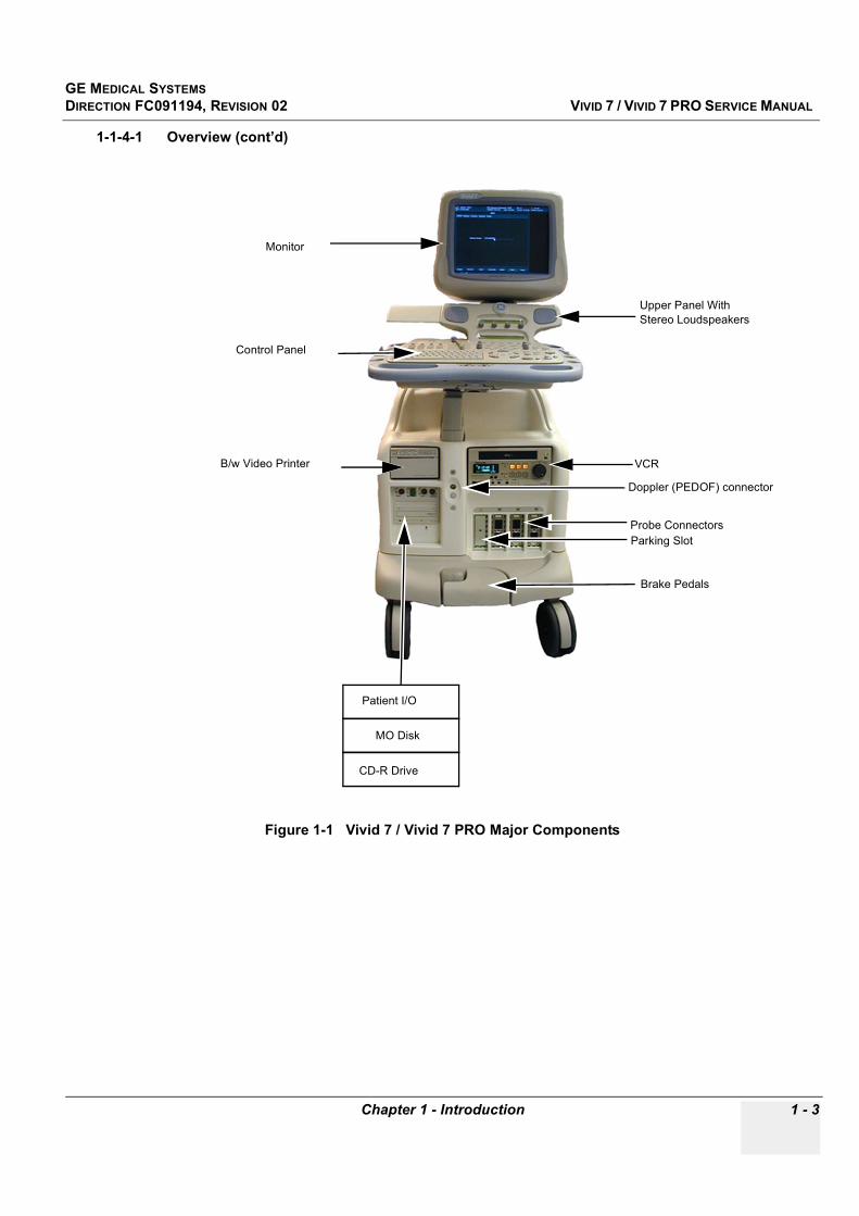
Figure 1-1 Vivid 7 / Vivid 7 PRO Major Components
Monitor
Control Panel
B/w Video Printer
CD-R Drive
MO Disk
Brake Pedals
Parking SlotProbe Connectors
VCR
Upper Panel With Stereo Loudspeakers
Doppler (PEDOF) connector
Patient I/O
GE MEDICAL SYSTEMSDIRECTION FC091194, REVISION 02 VIVID 7 / VIVID 7 PRO SERVICE MANUAL
1 - 4 -
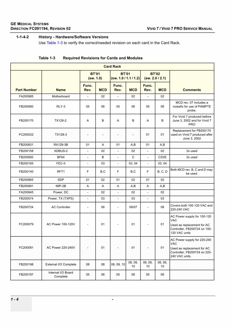
1-1-4-2 History - Hardware/Software Versions Use Table 1-3 to verify the correct/needed revision on each card in the Card Rack.
Table 1-3 Required Revisions for Cards and Modules
Card Rack
Part Number Name
BT’01 (sw. 1.0)
BT’01 (sw. 1.0 / 1.1 / 1.2)
BT’02(sw. 2.0 / 2.1)
CommentsFunc. Rev. MCD
Func. Rev. MCD
Func. Rev. MCD
FA200985 Motherboard - 02 - 02 - 02
FB200060 RLY-3 05 06 05 06 05 06MCD rev. 07 includes a
noisefix for use of PAMPTE probe.
FB200170 TX128-2. A B A B A BFor Vivid 7 produced before June 3, 2002 and for Vivid 7
PRO
FC200022 TX128-3 - - - - 01 01Replacement for FB200170
used on Vivid 7 produced after June 3, 2002
FB200831 RX128-3B 01 A 01 A,B 01 A,B
FB200158 XDBUS-2 - 02 - 02 - 02 2x used
FB200900 BF64 - B - C - C/D/E 2x used
FB200165 FEC-II - 03 - 03, 04 - 03, 04
FB200140 RFT1 F B,C F B,C F B, C, D Both MCD rev. B, C and D may be used.
FB200865 SDP 01 02 01 02 01 02
FB200991 IMP-2B A A A A,B A A,B
FA200945 Power, DC - 02 - 02 - 02
FB200574 Power, TX (TXPS) - 03 - 03 - 03
FB200724 AC Controller - 06 - 06/07 - 08 Covers both 100-120 VAC and 220-240 VAC
FC200079 AC Power 100-120V - 01 - 01 - 01
AC Power supply for 100-120 VAC Used as replacement for AC Controller, FB200724 on 100-120 VAC units
FC200081 AC Power 220-240V - 01 - 01 - 01
AC Power supply for 220-240 VAC Used as replacement for AC Controller, FB200724 on 220-240 VAC units.
FB200198 External I/O Complete 08 08 08, 09, 10 08, 09, 10
08, 09, 10
08, 09, 10
FB200197 Internal I/O Board Complete 05 06 05 06 05 06
GE MEDICAL SYSTEMSDIRECTION FC091194, REVISION 02 VIVID 7 / VIVID 7 PRO SERVICE MANUAL
Chapter 1 - Introduction 1 - 5
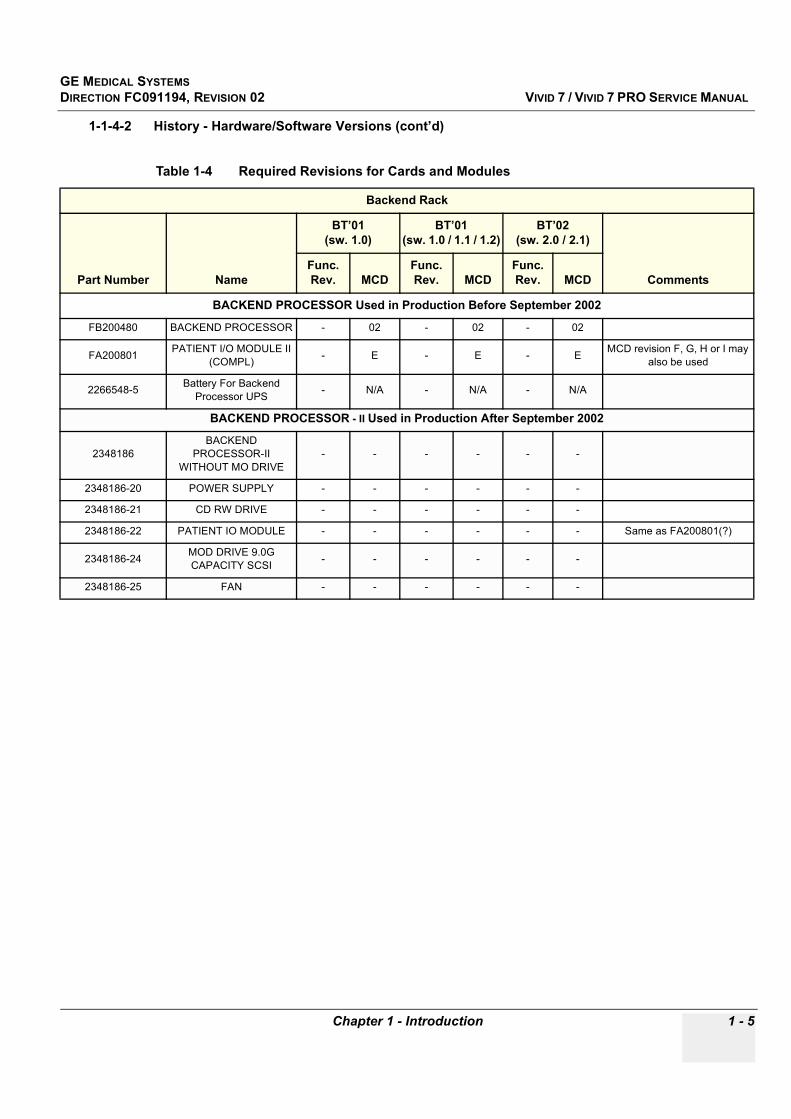
1-1-4-2 History - Hardware/Software Versions (cont’d)
Table 1-4 Required Revisions for Cards and Modules
Backend Rack
Part Number Name
BT’01 (sw. 1.0)
BT’01 (sw. 1.0 / 1.1 / 1.2)
BT’02(sw. 2.0 / 2.1)
CommentsFunc. Rev. MCD
Func. Rev. MCD
Func. Rev. MCD
BACKEND PROCESSOR Used in Production Before September 2002
FB200480 BACKEND PROCESSOR - 02 - 02 - 02
FA200801 PATIENT I/O MODULE II (COMPL) - E - E - E MCD revision F, G, H or I may
also be used
2266548-5 Battery For Backend Processor UPS - N/A - N/A - N/A
BACKEND PROCESSOR - II Used in Production After September 2002
2348186BACKEND
PROCESSOR-II WITHOUT MO DRIVE
- - - - - -
2348186-20 POWER SUPPLY - - - - - -
2348186-21 CD RW DRIVE - - - - - -
2348186-22 PATIENT IO MODULE - - - - - - Same as FA200801(?)
2348186-24 MOD DRIVE 9.0G CAPACITY SCSI - - - - - -
2348186-25 FAN - - - - - -
GE MEDICAL SYSTEMSDIRECTION FC091194, REVISION 02 VIVID 7 / VIVID 7 PRO SERVICE MANUAL
1 - 6 -
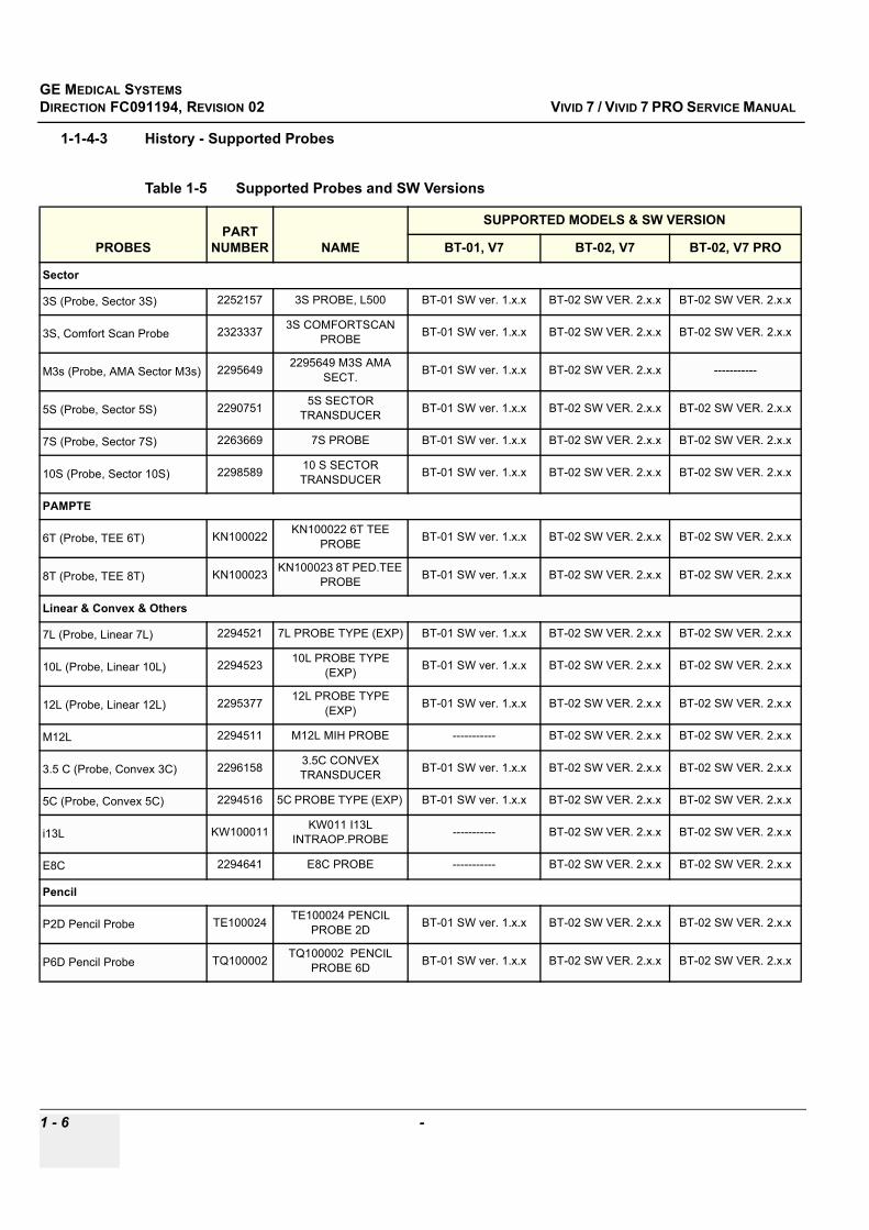
1-1-4-3 History - Supported Probes
Table 1-5 Supported Probes and SW Versions
PROBESPART
NUMBER NAME
SUPPORTED MODELS & SW VERSION
BT-01, V7 BT-02, V7 BT-02, V7 PRO
Sector
3S (Probe, Sector 3S) 2252157 3S PROBE, L500 BT-01 SW ver. 1.x.x BT-02 SW VER. 2.x.x BT-02 SW VER. 2.x.x
3S, Comfort Scan Probe 2323337 3S COMFORTSCAN PROBE BT-01 SW ver. 1.x.x BT-02 SW VER. 2.x.x BT-02 SW VER. 2.x.x
M3s (Probe, AMA Sector M3s) 2295649 2295649 M3S AMA SECT. BT-01 SW ver. 1.x.x BT-02 SW VER. 2.x.x -----------
5S (Probe, Sector 5S) 2290751 5S SECTOR TRANSDUCER BT-01 SW ver. 1.x.x BT-02 SW VER. 2.x.x BT-02 SW VER. 2.x.x
7S (Probe, Sector 7S) 2263669 7S PROBE BT-01 SW ver. 1.x.x BT-02 SW VER. 2.x.x BT-02 SW VER. 2.x.x
10S (Probe, Sector 10S) 2298589 10 S SECTOR TRANSDUCER BT-01 SW ver. 1.x.x BT-02 SW VER. 2.x.x BT-02 SW VER. 2.x.x
PAMPTE
6T (Probe, TEE 6T) KN100022 KN100022 6T TEE PROBE BT-01 SW ver. 1.x.x BT-02 SW VER. 2.x.x BT-02 SW VER. 2.x.x
8T (Probe, TEE 8T) KN100023 KN100023 8T PED.TEE PROBE BT-01 SW ver. 1.x.x BT-02 SW VER. 2.x.x BT-02 SW VER. 2.x.x
Linear & Convex & Others
7L (Probe, Linear 7L) 2294521 7L PROBE TYPE (EXP) BT-01 SW ver. 1.x.x BT-02 SW VER. 2.x.x BT-02 SW VER. 2.x.x
10L (Probe, Linear 10L) 2294523 10L PROBE TYPE (EXP) BT-01 SW ver. 1.x.x BT-02 SW VER. 2.x.x BT-02 SW VER. 2.x.x
12L (Probe, Linear 12L) 2295377 12L PROBE TYPE (EXP) BT-01 SW ver. 1.x.x BT-02 SW VER. 2.x.x BT-02 SW VER. 2.x.x
M12L 2294511 M12L MIH PROBE ----------- BT-02 SW VER. 2.x.x BT-02 SW VER. 2.x.x
3.5 C (Probe, Convex 3C) 2296158 3.5C CONVEX TRANSDUCER BT-01 SW ver. 1.x.x BT-02 SW VER. 2.x.x BT-02 SW VER. 2.x.x
5C (Probe, Convex 5C) 2294516 5C PROBE TYPE (EXP) BT-01 SW ver. 1.x.x BT-02 SW VER. 2.x.x BT-02 SW VER. 2.x.x
i13L KW100011 KW011 I13L INTRAOP.PROBE ----------- BT-02 SW VER. 2.x.x BT-02 SW VER. 2.x.x
E8C 2294641 E8C PROBE ----------- BT-02 SW VER. 2.x.x BT-02 SW VER. 2.x.x
Pencil
P2D Pencil Probe TE100024 TE100024 PENCIL PROBE 2D BT-01 SW ver. 1.x.x BT-02 SW VER. 2.x.x BT-02 SW VER. 2.x.x
P6D Pencil Probe TQ100002 TQ100002 PENCIL PROBE 6D BT-01 SW ver. 1.x.x BT-02 SW VER. 2.x.x BT-02 SW VER. 2.x.x

GE MEDICAL SYSTEMSDIRECTION FC091194, REVISION 02 VIVID 7 / VIVID 7 PRO SERVICE MANUAL
Chapter 1 - Introduction 1 - 7
1-1-4-4 How to Turn the Scanner ON and OFFPlease refer to Chapter 4, section 4-2-1 - Power ON/ Boot Up, for a detailed description of how to turn the scanner ON and to Chapter 4, section 4-2-2 - Power Shut Down for a detailed description of how to turn the scanner OFF.
1-1-4-5 How to Check for Hardware/Software Version, Installed Options• Please refer to "History - Hardware/Software Versions" on page 1-4 to check the hardware versions
on the boards• Please refer to "Software Configuration Checks" on page 4-63 to check the software versions on
local software on the boards.• Please refer to "Functional Checks" on page 4-14 to check for installed options.
1-1-5 Purpose of Operator Manual(s)The Operator Manual(s) should be fully read and understood before operating the Vivid 7 / Vivid 7 PRO and also kept near the unit for quick reference.

GE MEDICAL SYSTEMSDIRECTION FC091194, REVISION 02 VIVID 7 / VIVID 7 PRO SERVICE MANUAL
1 - 8 Section 1-2 - Important Conventions
Section 1-2Important Conventions
1-2-1 Conventions Used in Book
1-2-1-1 Model Designations. This manual covers the Vivid 7 / Vivid 7 PRO scanners listed in Table 1-2.
1-2-1-2 Icons. Pictures, or icons, are used wherever they will reinforce the printed message. The icons, labels and conventions used on the product and in the service information are described in this chapter.
1-2-1-3 Safety Precaution Messages. Various levels of safety precaution messages may be found on the equipment and in the service information. The different levels of concern are identified by a flag word that precedes the precautionary message. Known or potential hazards are labeled in one of three ways:
Example: Disk drive will crash.
NOTE: Notes are used to provide important information about an item or a procedure.
Be sure to read the notes; the information contained in a note can often save you time or effort.
DANGER Danger is used to indicate the presence of a hazard that will cause severe personal injury or death if the instructions are ignored.
WARNINGWARNING Warning is used to indicate the presence of a hazard that can cause severe personal injury and property damage if instructions are ignored.
CAUTION Caution is used to indicate the presence of a hazard that will or can cause minor personal injury and property damage if instructions are ignored. Equipment Damage Possible.
NOTICE Notice is used when a hazard is present that can cause property damage but has absolutely no personal injury risk.

GE MEDICAL SYSTEMSDIRECTION FC091194, REVISION 02 VIVID 7 / VIVID 7 PRO SERVICE MANUAL
Chapter 1 - Introduction 1 - 9
1-2-2 Standard Hazard Icons
Important information will always be preceded by the exclamation point contained within a triangle, as seen throughout this chapter. In addition to text, several different graphical icons (symbols) may be used to make you aware of specific types of hazards that could possibly cause harm.
Some others make you aware of specific procedures that should be followed.
Table 1-6 Standard Hazard Icons
ELECTRICAL MECHANICAL RADIATION
LASER HEAT PINCH
Table 1-7 Standard Icons that indicates that a special procedure is to be used
AVOID STATIC ELECTRICITY TAG AND LOCK OUT WEAR EYE PROTECTION
LASERLIGHT
Signed Date
TAG &
LOCKOUT

GE MEDICAL SYSTEMSDIRECTION FC091194, REVISION 02 VIVID 7 / VIVID 7 PRO SERVICE MANUAL
1 - 10 Section 1-2 - Important Conventions
1-2-3 Product IconsThe following table describes the purpose and location of safety labels and other important information provided on the equipment.
Table 1-8 Product Icons
LABEL/SYMBOL PURPOSE/MEANING LOCATION
Identification and Rating Plate
Manufacturer's name and addressDate of manufactureModel and serial numbersElectrical ratings
Rear of console near power inlet
Type/Class Label Used to indicate the degree of safety or protection.
IP Code (IPX8/IP68)
Indicates the degree of protection provided by the enclosure per IEC 529. IPX8 indicates drip proof and may be used in an Operating Theater. The footswitch delivered with Vivid 7 / Vivid 7 PRO is IP68 rated.
Footswitch
Equipment Type BF (man in the box symbol) IEC 878-02-03 indicates B Type equipment having a floating applied part.
Probe connectors including Doppler probe connector
Equipment Type CF (heart in the box symbol) IEC 878-02-05 indicates equipment having a floating applied part having a degree of protection suitable for direct cardiac contact.
ECG connector and surgical probes
Device Listing/Certification LabelsLaboratory logo or labels denoting conformance with industry safety standards such as UL or IEC.
Rear of console
CAUTION - This unit weighs...Special care must be used to avoid..."
This precaution is intended to prevent injury that may result if one person attempt to move the unit considerable distances or on an incline due to the weight of the unit.
On the console where easily seen during transport
"DANGER - Risk of explosion used in..." The system is not designed for use with flammable anesthetic gases.
Rear of console
“CAUTION” The equilateral triangle is usually used in combination with other symbols to advise or warn the user.
Various

GE MEDICAL SYSTEMSDIRECTION FC091194, REVISION 02 VIVID 7 / VIVID 7 PRO SERVICE MANUAL
Chapter 1 - Introduction 1 - 11
“ATTENTION - Consult accompanying documents” is intended to alert the user to refer to the operator manual or other instructions when complete information cannot be provided on the label.
Various
“CAUTION - Dangerous voltage” (the lightning flash with arrowhead in equilateral triangle) is used to indicate electric shock hazards.
Various
“Mains OFF” Indicates the power off position of the mains power switch.
Rear of system adjacent to mains switch
“OFF/Standby” Indicates the power off/standby position of the power switch.CAUTIONThis Power Switch DOES NOT ISOLATE Mains Supply
Adjacent to On/Off (Standby) Switch
“Mains ON” Indicates the Power ON position of the mains power switch.“ON” Indicates the power on position of the power switch.CAUTIONThe Power Switch on the Front Panel DOES NOT ISOLATE Mains Supply
“Protective Earth” Indicates the protective earth (grounding) terminal.
Used several places inside the scanner.
“Equipotentiality” Indicates the terminal to be used for connecting equipotential conductors when interconnecting (grounding) with other equipment.
Rear of console
Table 1-8 Product Icons (continued)
LABEL/SYMBOL PURPOSE/MEANING LOCATION
GE MEDICAL SYSTEMSDIRECTION FC091194, REVISION 02 VIVID 7 / VIVID 7 PRO SERVICE MANUAL
1 - 12 Section 1-3 - Safety Considerations
Section 1-3Safety Considerations
1-3-1 IntroductionThe following safety precautions must be observed during all phases of operation, service and repair of this equipment. Failure to comply with these precautions or with specific warnings elsewhere in this manual, violates safety standards of design, manufacture and intended use of the equipment.
1-3-2 Human SafetyOperating personnel must not remove the system covers.
Servicing should be performed by authorized personnel only.
Only personnel who have participated in a Vivid 7 / Vivid 7 PRO Training Seminar are authorized to service the equipment.
1-3-3 Mechanical Safety
WARNINGWARNING WHEN THE UNIT IS RAISED FOR A REPAIR OR MOVED ALONG ANY INCLINE, USE EXTREME CAUTION SINCE IT MAY BECOME UNSTABLE AND TIP OVER.
WARNINGWARNING ULTRASOUND PROBES ARE HIGHLY SENSITIVE MEDICAL INSTRUMENTS THAT CAN EASILY BE DAMAGED BY IMPROPER HANDLING. USE CARE WHEN HANDLING AND PROTECT FROM DAMAGE WHEN NOT IN USE. DO NOT USE A DAMAGED OR DEFECTIVE PROBE. FAILURE TO FOLLOW THESE PRECAUTIONS CAN RESULT IN SERIOUS INJURY AND EQUIPMENT DAMAGE.
WARNINGWARNING NEVER USE A PROBE THAT HAS FALLEN TO THE FLOOR. EVEN IF IT LOOKS OK, IT MAY BE DAMAGED.
CAUTION Ensure that nobody touch the console arm/frogleg when moving the keyboard console.
CAUTION Do not move the unit if the keyboard console is in unlocked position.
CAUTION Always lock the Control Console in its parking (locked) position before moving the scanner around.
WARNINGWARNING WHEN THE TOP CONSOLE IS IN ITS LOCKED POSITION, THE GAS SPRING IS COMPRESSED AND STORES MECHANICAL ENERGY. DURING NORMAL OPERATION THE TOP CONSOLE, THE WEIGHT OF THE MONITOR AND THE MECHANICAL FORCE OF THE GAS SPRING ARE IN BALANCE. TAKE CARE IF/WHEN YOU ACTIVATE THIS GAS SPRING. PERSONAL INJURY CAN OCCUR AFTER THE PANEL IS REMOVED AND THE SPRING PRESSURE IS RELEASED. TAKE CARE WHEN YOU REPAIR THE ELEVATION ASSEMBLY.

GE MEDICAL SYSTEMSDIRECTION FC091194, REVISION 02 VIVID 7 / VIVID 7 PRO SERVICE MANUAL
Chapter 1 - Introduction 1 - 13
1-3-3 Mechanical Safety (cont’d)
NOTE: Special care should be taken when transporting the unit in a vehicle:
• Lock keyboard in place.• Eject Magneto Optical disk from the MO Drive (if installed).• Eject CD from CD drive.• Secure the unit in an upright position.• Lock the casters (wheels) (brake)• DO NOT use the Control Panel as an anchor point.• Place the probes in their carrying case.
1-3-4 Electrical Safety
1-3-4-1 Safe PracticesFollow these guidelines to minimize shock hazards whenever you are using the scanner;
• The equipment chassis must be connected to an electrical ground. • The unit is equipped with a three-conductor AC power cable. This must be plugged into an approved
electrical outlet with safety ground.• The power outlet used for this equipment should not be shared with other types of equipment.• Both the system power cable and the power connector must meet international electrical standards.
1-3-4-2 ProbesFollow these guidelines before connecting a probe to the scanner;
• Inspect the probe prior to each use for damage or degradation to the;- housing - cable strain relief- lens- seal
• Do not use a damaged or defective probe.
CAUTION VIVID 7 / VIVID 7 PRO weighs 190 kg (419 lbs) or more, depending on installed peripherals, when ready for use. Care must be used when moving it or replacing its parts. Failure to follow the precautions listed below could result in injury, uncontrolled motion and costly damage.
CAUTION-
Do not transport Vivid 7 / Vivid 7 PRO in a vehicle without locking the casters (wheels). ALWAYS:- Be sure the pathway is clear.- Use slow, careful motions.- Use two people when moving on inclines or lifting more than 23 kg (50 lbs).
CAUTION Keep the heat venting holes on the monitor unobstructed to avoid overheating of the monitor.

GE MEDICAL SYSTEMSDIRECTION FC091194, REVISION 02 VIVID 7 / VIVID 7 PRO SERVICE MANUAL
1 - 14 Section 1-3 - Safety Considerations
• Never immerse the probe connector or adapter into any liquid.
1-3-5 Labels Locations
1-3-5-1 Labels on Front of Monitor and Control Panel
Table 1-9 Labels on Front of Monitor and Control Panel
DESCRIPTION ILLUSTRATION
Label, Vivid 7 (Monitor) - BT’01
Label, Vivid 7 (Monitor) - BT’02
Label, Vivid 7 PRO (Monitor) - BT’02
Label, GE Logo

GE MEDICAL SYSTEMSDIRECTION FC091194, REVISION 02 VIVID 7 / VIVID 7 PRO SERVICE MANUAL
Chapter 1 - Introduction 1 - 15
Label, On/Off Switch(Two versions of the label have been used, the one to the right is the latest
version.)
Table 1-9 Labels on Front of Monitor and Control Panel (continued)
DESCRIPTION ILLUSTRATION
ON/OFF: FC314104 03
press onceOR
Label position
GE MEDICAL SYSTEMSDIRECTION FC091194, REVISION 02 VIVID 7 / VIVID 7 PRO SERVICE MANUAL
1 - 16 Section 1-3 - Safety Considerations
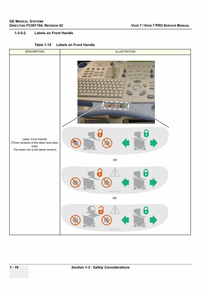
1-3-5-2 Labels on Front Handle
Table 1-10 Labels on Front Handle
DESCRIPTION ILLUSTRATION
Label, Front Handle(Three versions of the label have been
used. The lower one is the latest version)
OR
OR
OR
GE MEDICAL SYSTEMSDIRECTION FC091194, REVISION 02 VIVID 7 / VIVID 7 PRO SERVICE MANUAL
Chapter 1 - Introduction 1 - 17
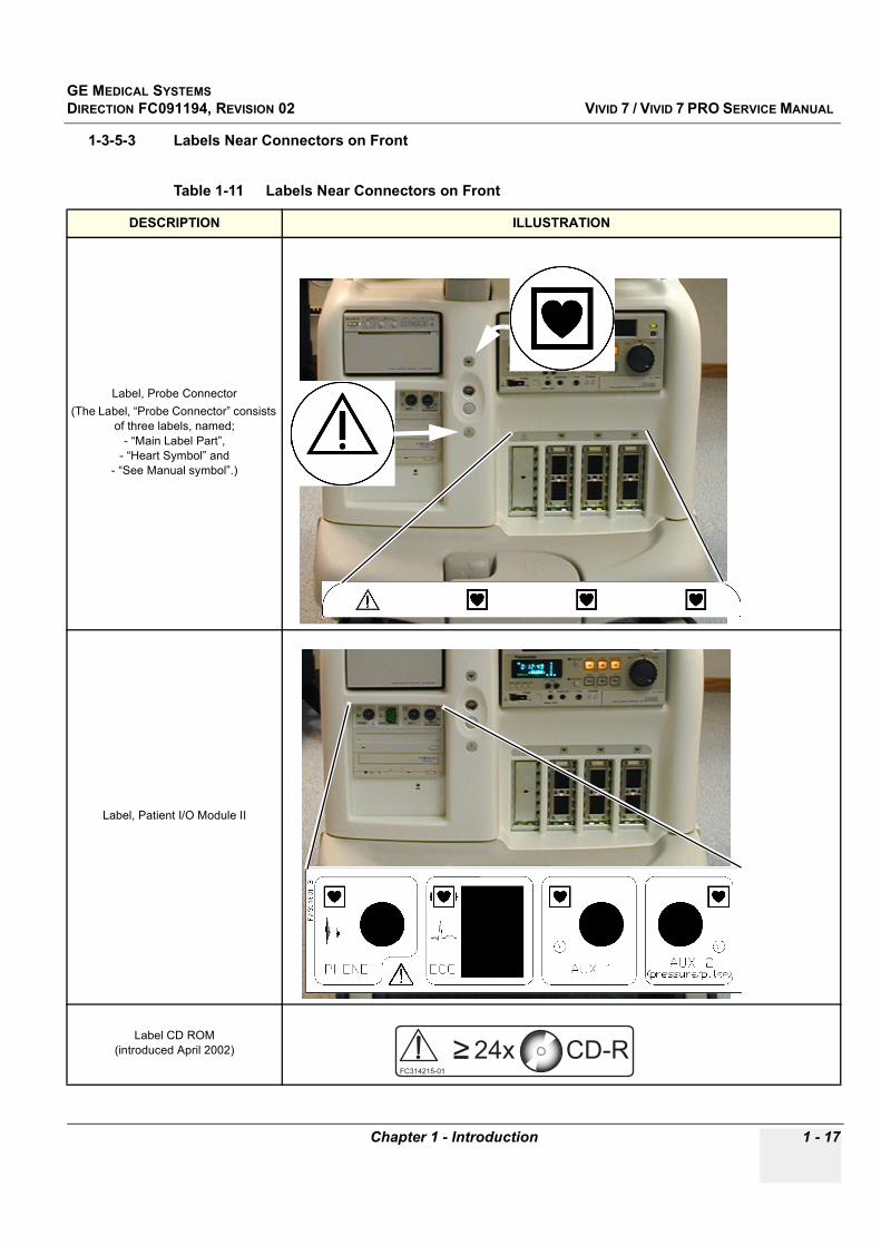
1-3-5-3 Labels Near Connectors on Front
Table 1-11 Labels Near Connectors on Front
DESCRIPTION ILLUSTRATION
Label, Probe Connector (The Label, “Probe Connector” consists
of three labels, named;- “Main Label Part”,
- “Heart Symbol” and - “See Manual symbol”.)
Label, Patient I/O Module II
Label CD ROM(introduced April 2002)
GE MEDICAL SYSTEMSDIRECTION FC091194, REVISION 02 VIVID 7 / VIVID 7 PRO SERVICE MANUAL
1 - 18 Section 1-3 - Safety Considerations
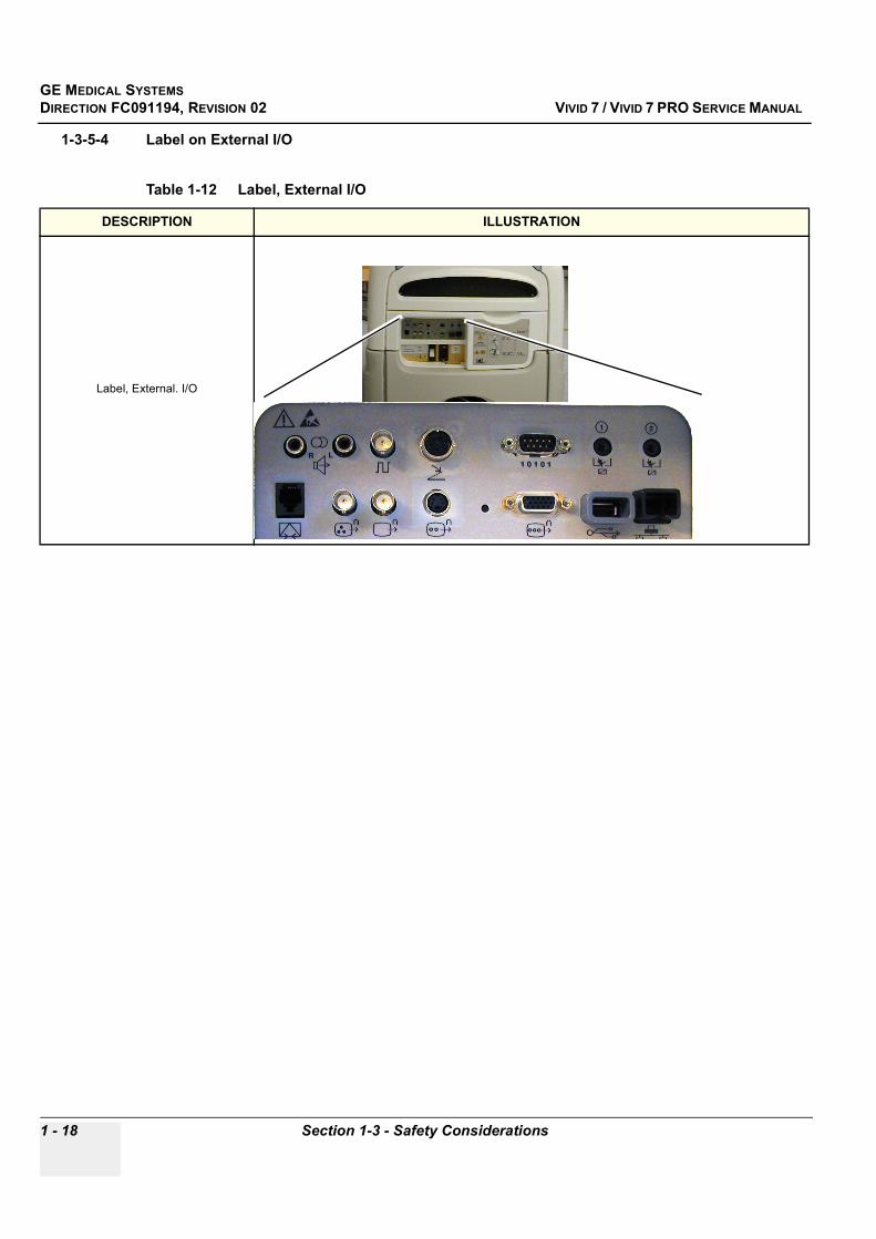
1-3-5-4 Label on External I/O
Table 1-12 Label, External I/O
DESCRIPTION ILLUSTRATION
Label, External. I/O

GE MEDICAL SYSTEMSDIRECTION FC091194, REVISION 02 VIVID 7 / VIVID 7 PRO SERVICE MANUAL
Chapter 1 - Introduction 1 - 19
1-3-5-5 Labels at AC Mains Inlet and Circuit Breaker
Table 1-13 Labels at AC Mains Inlet and Circuit Breaker (used before May 2002)
DESCRIPTION ILLUSTRATION
Label, Warning
Label, System: P/N, Pwr.rating
Label, System: S/N
Label, GND-symbol
Ground (GND) Label. (Used on 230 VAC Systems and some 100-120 VAC Systems.) l
oror

GE MEDICAL SYSTEMSDIRECTION FC091194, REVISION 02 VIVID 7 / VIVID 7 PRO SERVICE MANUAL
1 - 20 Section 1-3 - Safety Considerations
Label, GND-symbol., Hospital Grade
l
Table 1-14 Labels at AC Mains Inlet and Circuit Breaker (used after May 2002)
DESCRIPTION ILLUSTRATION
Label, AC Controller
Table 1-13 Labels at AC Mains Inlet and Circuit Breaker (used before May 2002) (continued)
DESCRIPTION ILLUSTRATION
Hospital Grade Ground (GND) Label. (Used on some 100-120 VAC Systems)
GE MEDICAL SYSTEMSDIRECTION FC091194, REVISION 02 VIVID 7 / VIVID 7 PRO SERVICE MANUAL
Chapter 1 - Introduction 1 - 21
1-3-5-6 Label on Rear Cover
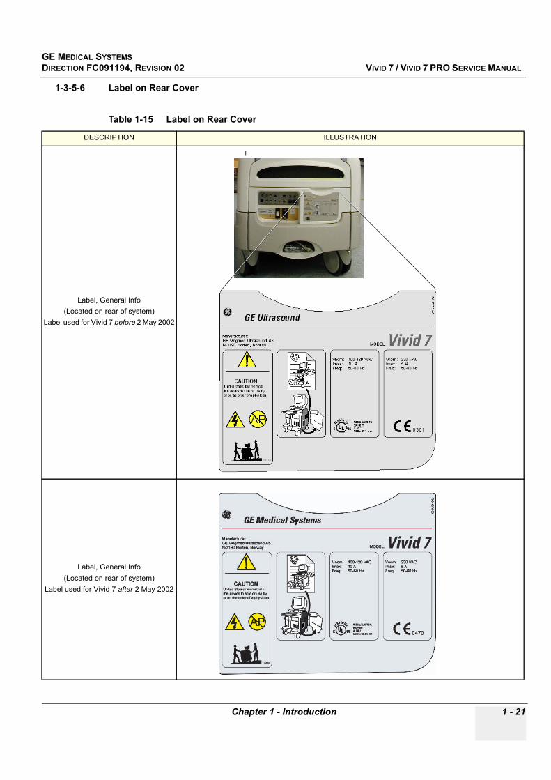
Table 1-15 Label on Rear Cover
DESCRIPTION ILLUSTRATION
Label, General Info(Located on rear of system)
Label used for Vivid 7 before 2 May 2002
l
Label, General Info(Located on rear of system)
Label used for Vivid 7 after 2 May 2002

GE MEDICAL SYSTEMSDIRECTION FC091194, REVISION 02 VIVID 7 / VIVID 7 PRO SERVICE MANUAL
1 - 22 Section 1-3 - Safety Considerations
Label, General Info(Located on rear of system)
Label used for Vivid 7 to China
Label, General Info(Located on rear of system)Label used for Vivid 7 PRO
Table 1-15 Label on Rear Cover (continued)
DESCRIPTION ILLUSTRATION
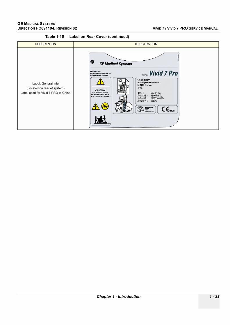
GE MEDICAL SYSTEMSDIRECTION FC091194, REVISION 02 VIVID 7 / VIVID 7 PRO SERVICE MANUAL
Chapter 1 - Introduction 1 - 23
Label, General Info(Located on rear of system)
Label used for Vivid 7 PRO to China
Table 1-15 Label on Rear Cover (continued)
DESCRIPTION ILLUSTRATION
GE MEDICAL SYSTEMSDIRECTION FC091194, REVISION 02 VIVID 7 / VIVID 7 PRO SERVICE MANUAL
1 - 24 Section 1-3 - Safety Considerations
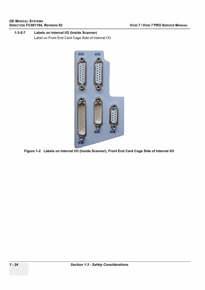
1-3-5-7 Labels on Internal I/O (Inside Scanner) Label on Front End Card Cage Side of Internal I/O
Figure 1-2 Labels on Internal I/O (Inside Scanner), Front End Card Cage Side of Internal I/O
GE MEDICAL SYSTEMSDIRECTION FC091194, REVISION 02 VIVID 7 / VIVID 7 PRO SERVICE MANUAL
Chapter 1 - Introduction 1 - 25
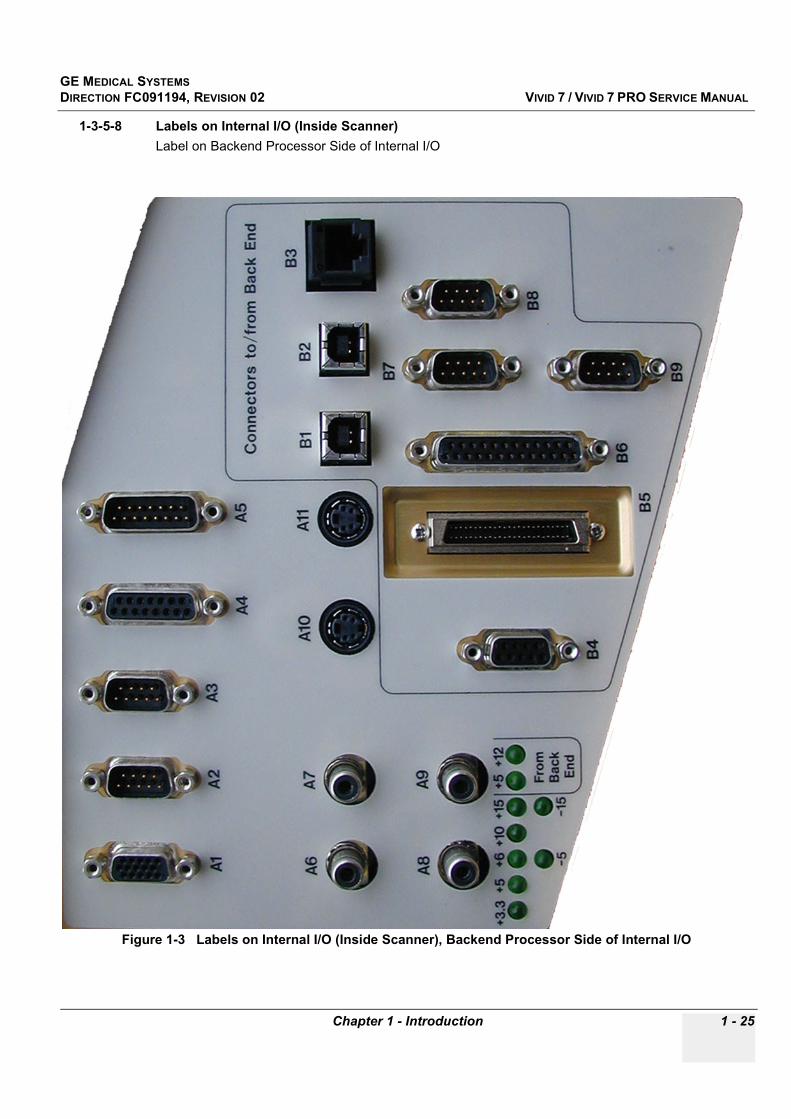
1-3-5-8 Labels on Internal I/O (Inside Scanner) Label on Backend Processor Side of Internal I/O
Figure 1-3 Labels on Internal I/O (Inside Scanner), Backend Processor Side of Internal I/O
GE MEDICAL SYSTEMSDIRECTION FC091194, REVISION 02 VIVID 7 / VIVID 7 PRO SERVICE MANUAL
1 - 26 Section 1-3 - Safety Considerations
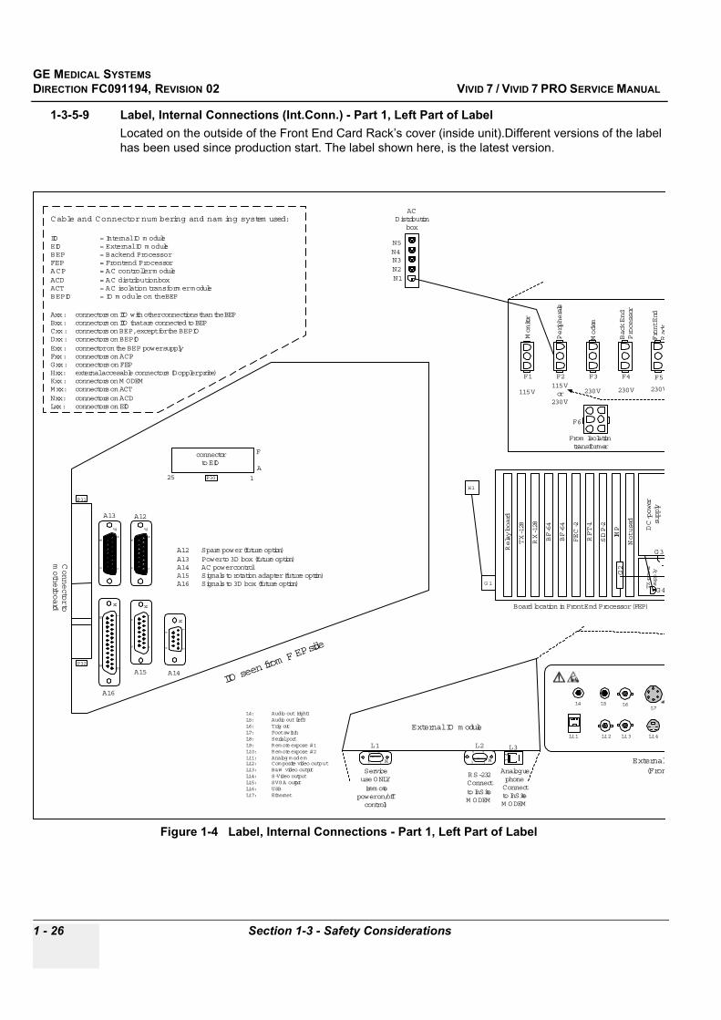
1-3-5-9 Label, Internal Connections (Int.Conn.) - Part 1, Left Part of Label Located on the outside of the Front End Card Rack’s cover (inside unit).Different versions of the label has been used since production start. The label shown here, is the latest version.
Figure 1-4 Label, Internal Connections - Part 1, Left Part of Label
Cable and Connector num bering and nam ing system used:
IIO = Internal IO m oduleEIO = External IO m oduleBEP = Backend ProcessorFEP = Frontend ProcessorACP = AC controller m oduleACD = AC distribution boxACT = AC isolation transform er moduleBEPIO = IO m odule on the BEP
Axx : connectors on IIO with other connections than the BEPBxx : connectors on IIO that are connected to BEPCxx : connectors on BEP, except for the BEPIODxx : connectors on BEPIOExx : connector on the BEP power supplyFxx : connectors on ACPGxx : connectors on FEPHxx : external accesable connectors (Doppler probe)Kxx : connectors on M ODEMMxx : connectors on ACTNxx : connectors on ACDLxx : connectors on EIO
External IO m odule
69
15M 1
4
69
15 M
AnaloguephoneConnectto InSiteM ODEM
RS-232Connectto InSiteM ODEM
Serviceuse ONLY(rem ote
power on/offcontrol)
L1 L2 L3
BF-64
BF-64
FEC-2
RFT-1
SDP-2
IMP
Not used
DC-power
supply
TX-power
supp
ly
Board location in Front End Processor (FEP)
Monitor
Peripherals
Modem
Back End
Processor
Front End
Rack
115V115Vor
230V
230V 230V 230V
From Isolationtransformer
H1
G 1
F1 F2 F3 F4 F5
F6
81
159
F
A13
81
159
F
A12
113
1425
M
A16
18
915
M
A15
69
15
M
A14
A12 Spare power (future option)A13 Power to 3D box (future option)A14 AC power controlA15 Signals to rotation adapter (future option)A16 Signals to 3D box (future option)
connectorto EIO
125A
F
P30
Connecto
r tomotherboard
P31
P32
IIO seen
from F E
P side
G4
G3
G2
ACDistribution
box
N1N2N3N4N5
RX-128
Relay board
L4 L5 L6L7
L11 L12 L13 L14
External (Fron
L4: Audio out (right)L5: Audio out (left)L6: Trig outL7: Foot switchL8: Serial portL9: Rem ote expose #1L10: Rem ote expose #2L11: Analog m odemL12: Com posite video outputL13: B&W video outputL14: S-Video outputL15: SVGA outputL16: USBL17: Ethernet
TX-128

GE MEDICAL SYSTEMSDIRECTION FC091194, REVISION 02 VIVID 7 / VIVID 7 PRO SERVICE MANUAL
Chapter 1 - Introduction 1 - 27
1-3-5-10 Label, Internal Connections (Int.Conn.) - Part 2, Right Part of Label Located on the outside of the Front End Card Rack’s cover (inside unit). Different versions of the label has been used since production start. The label shown here, is the latest version.
Figure 1-5 Label, Internal Connections - Part 1, Right Part of Label
K1 K2K3
gueneectiteEM
BF-64
BF-64
FEC-2
RFT-1
SDP-2
IMP
Not used
DC-power
supply
TX-power
supp
ly
oard location in Front End Processor (FEP)
Monitor
Peripherals
Modem
Back End
Processor
Front End
Rack
115V115Vor
230V
230V 230V 230V
From Isolationtransformer
230V
115V
W ARNING !Live Voltage inside,
do not open.
AC power control m odule
To Isolationtransformer
115V or 230V inletvoltage selection
Voltage Selectionon Peripherals
115V =
100-12
0V
230V =
220-240
V
(½ or 2 t
im es in
let
voltage
)
F1 F2 F3 F4 F5
F6
F7
F8
F9
Isolationtransformerm odule
M1
69
15
M
230V115V
Fan
control
Part no. : FB314746Rev. : 05
60,0
Cable toC15
M odemM T5634ZBAM odem
powersupplyK4
G4
G3
G2
RX-128
M
F
L4 L5 L6L7 L8
L9 L10
L11 L12 L13 L14 L15L16 L17
External IO m odule(Frontview)
RESET
TX-128
Cutout in the label
GE MEDICAL SYSTEMSDIRECTION FC091194, REVISION 02 VIVID 7 / VIVID 7 PRO SERVICE MANUAL
1 - 28 Section 1-3 - Safety Considerations
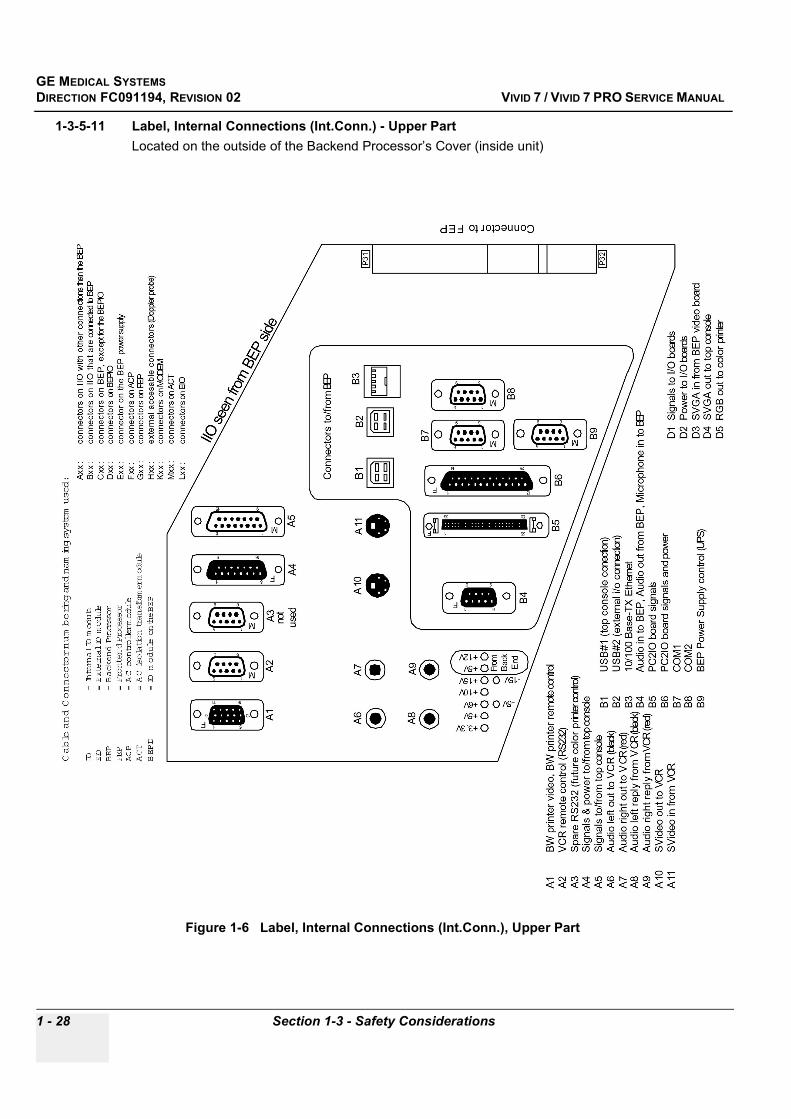
1-3-5-11 Label, Internal Connections (Int.Conn.) - Upper PartLocated on the outside of the Backend Processor’s Cover (inside unit)
Figure 1-6 Label, Internal Connections (Int.Conn.), Upper Part
GE MEDICAL SYSTEMSDIRECTION FC091194, REVISION 02 VIVID 7 / VIVID 7 PRO SERVICE MANUAL
Chapter 1 - Introduction 1 - 29
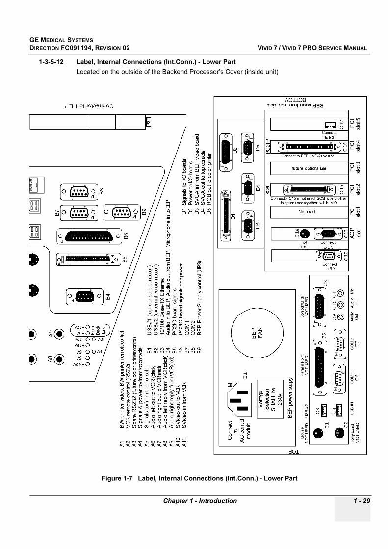
1-3-5-12 Label, Internal Connections (Int.Conn.) - Lower PartLocated on the outside of the Backend Processor’s Cover (inside unit)
Figure 1-7 Label, Internal Connections (Int.Conn.) - Lower Part

GE MEDICAL SYSTEMSDIRECTION FC091194, REVISION 02 VIVID 7 / VIVID 7 PRO SERVICE MANUAL
1 - 30 Section 1-3 - Safety Considerations
1-3-5-13 Label, Internal Connections (Int.Conn.) - Upper PartLocated on the outside of the Backend Processor’s Cover (inside unit)
Figure 1-8 Label, Internal Connections (Int.Conn.), Upper Part
B1
US
B#1 (
top c
onsole
conection)
B2
US
B#2 (
exte
rnal i/o c
onnection)
B3
10/1
00 B
ase-T
X E
thern
et
B4
Audio
in to B
EP
, A
udio
out fr
om
BE
P, M
icro
phone in t
o B
EP
B5
PC
2IO
board
sig
nals
B6
PC
2IO
board
sig
nals
and p
ow
er
B7
CO
M (
exte
rnal i/o c
onnection -
setu
p a
s C
OM
1)
B8
CO
M (
modem
- s
etu
p a
s C
OM
2)
B9
BE
P P
ow
er
Supply
contr
ol (U
PS
)
A1
BW
printe
r vid
eo, p
rinte
r re
mote
contr
ol
A2
VC
R r
em
ote
contr
ol (R
S232)
A3
Spare
RS
23
2
A4
Sig
nals
& p
ow
er
to/fro
m top c
onso
le
A5
Sig
nals
to/fro
m top c
onsole
A6
Audio
left o
ut to
VC
R
A7
Audio
rig
ht out to
VC
R
A8
Audio
left r
eply
fro
m V
CR
A9
Audio
rig
ht re
ply
fro
m V
CR
A1
0S
Vid
eo o
ut to
VC
R
A1
1S
Vid
eo in fro
m V
CR
81
159
F
69
15M
69
15M
1 13
14 25
F
51
96
F69
15M A
3
69
15M
Connecto
rs to/fro
m B
ack E
nd
Connector to motherboard
P3
1
P3
2
-5V
-15V
+3.3V
+5V
+6V
+10V
+15V
+5V
+12V
Fro
m
Ba
ck
End
inte
rnal I
Om
odule
seen
from
Back
End
Pro
cess
or(B
EP
)si
de
A2
51
1511
6 10
F A1
A4
18
915
M A5
A6
A7
A1
0A
11
A8
A9
B1
B2
B3
B4
50
1 25
26
F B5
B6
B7
B8
69
15M B
9
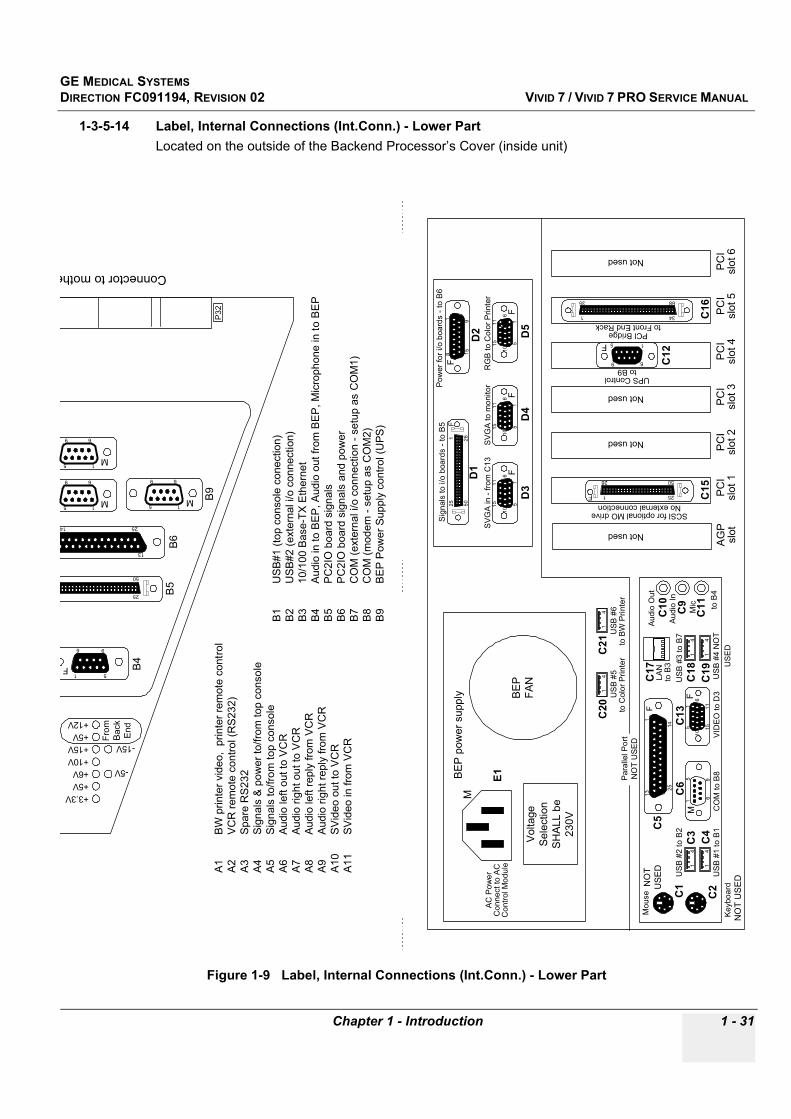
GE MEDICAL SYSTEMSDIRECTION FC091194, REVISION 02 VIVID 7 / VIVID 7 PRO SERVICE MANUAL
Chapter 1 - Introduction 1 - 31
1-3-5-14 Label, Internal Connections (Int.Conn.) - Lower PartLocated on the outside of the Backend Processor’s Cover (inside unit)
Figure 1-9 Label, Internal Connections (Int.Conn.) - Lower Part
51
15
11
61
0
F
B1
US
B#1 (
top c
onsole
conection)
B2
US
B#2 (
exte
rnal i/o c
onnection)
B3
10/1
00 B
ase-T
X E
thern
et
B4
Audio
in to B
EP
, A
udio
out fr
om
BE
P, M
icro
phone in t
o B
EP
B5
PC
2IO
board
sig
nals
B6
PC
2IO
board
sig
nals
and p
ow
er
B7
CO
M (
exte
rnal i/o c
onnection -
setu
p a
s C
OM
1)
B8
CO
M (
modem
- s
etu
p a
s C
OM
2)
B9
BE
P P
ow
er
Supply
contr
ol (U
PS
)
A1
BW
printe
r vid
eo, p
rinte
r re
mote
contr
ol
A2
VC
R r
em
ote
contr
ol (R
S232)
A3
Spare
RS
23
2
A4
Sig
nals
& p
ow
er
to/fro
m top c
onso
le
A5
Sig
nals
to/fro
m top c
onsole
A6
Audio
left o
ut to
VC
R
A7
Audio
rig
ht out to
VC
R
A8
Audio
left r
eply
fro
m V
CR
A9
Audio
rig
ht re
ply
fro
m V
CR
A1
0S
Vid
eo o
ut to
VC
R
A1
1S
Vid
eo in fro
m V
CR
50
12
5
26
69
15
M
AG
Pslo
tP
CI
slo
t 1
PC
Islo
t 2
PC
Islo
t 3
PC
Islo
t 4
PC
Islo
t 5
50
12
5
26
F
D1
81
15
9
F
D2
51
15
11
61
0
F
D3
51
15
11
61
0
F
D4
51
15
11
61
0
F
D5
Mo
use
US
B #
2 to
B2
CO
M t
o B
8
11
3
14
25
F
Pa
ralle
l P
ort
NO
T U
SE
D
Au
dio
Ou
t
Au
dio
In
Mic
14
14
51
15
11
61
0F
to B
3
68
1 34
35
PCI Bridgeto Front End Rack
50
1 25
26
F
SCSI for optional MO driveNo external connection
Not used
UPS Controlto B9
BE
P
FA
N
BE
P p
ow
er
supp
lyM
E1
C1
C2
C3
C4
C5
C12
C15
C16
Vo
lta
ge
Sele
ction
SH
ALL b
e
230
V
PC
Islo
t 6
C10
C11
C9
US
B #
3 to
B7
US
B #
4 N
OT
US
ED
C18
C19
C17
Not used
Not used
14
14
C20
14
C21
14
US
B #
6U
SB
#5
LA
N
VID
EO
to
D3
C13
C6
to C
olo
r P
rin
ter
to B
W P
rin
ter
NO
T
US
ED
US
B #
1 to
B1
to B
4
Not used
Ke
ybo
ard
NO
T U
SE
D
Sig
na
ls t
o i/o
boa
rds -
to
B5
Po
we
r fo
r i/o
bo
ard
s -
to
B6
SV
GA
in
- f
rom
C1
3S
VG
A t
o m
on
ito
rR
GB
to
Co
lor
Prin
ter
69
15M
69
15M
13
14 25
51
96
F
Connector to mothe
P3
2
-5V
-15V
+3.3V
+5V
+6V
+10V
+15V
+5V
+12V
Fro
m
Ba
ck
End
B4
50
25 B5
B6
69
15M B
9
AC
Po
we
rC
onnect to
AC
Co
ntr
ol M
od
ule
9 6
5 1F

GE MEDICAL SYSTEMSDIRECTION FC091194, REVISION 02 VIVID 7 / VIVID 7 PRO SERVICE MANUAL
1 - 32 Section 1-3 - Safety Considerations
1-3-5-15 Label, Disassembly Nester, Part 1 (Left Part of Label)Located on the outside of the Front End Card Rack’s Cover (inside unit)
Figure 1-10 Label, Disassembly Instruction, Part 1 (Left Part of Label)
DISASSEMBLY INSTRUCTIONSRemove all screws on rear side of monitor cover, and remove cover.
Remove all screws on rear side of monitor front cover, and remove front cover.
Remove all screws on the cover located under the shelf underneath the monitor, and remove cover.
Detach monitor by removing four unbrako screws located underneath the monitor neck.
Remove shelf by loosening all screws underneath it and remove speakers from shelf.
Remove all screws underneath operators panel. Disconnect and remove alphanumeric keyboard andoperators panel.
Remove probe holders and front handle.
Remove all unbrako screws, which fasten the top console cable to the console and loosen the cable.
Remove top console and horizontal movement mechanism by unscrewing the big unbrako screw ontop of the rear base of the horizontal movement mechanism.
Remove all quarterturn screws on both sidepanels of the system. Side panels can now be removed.
Remove screws underneath the pedals to remove the pedal plastics.
Remove the footrest bumper by unscrewing four screws.
Remove all screws on the rear-, top- and front covers to loosen the covers.
Remove rear handle by unscrewing all screws.
Remove fan cover by removing all fastening screws.
Remove fan bracket w/fan by removing all fastening screws.
Remove all peripheral units.
Disconnect, then remove all cables.
Detach computer by unscrewing all fastening screws.
Remove external i/o box by unscrewing all fastening screws.
Remove internal i/o box by unscrewing all fastening screws.
Remove ac-power box by unscrewing all fastening screws.
Remove ac-transformer box by unscrewing all fastening screws.
Remove sheet metal cover on electronic rack on lower right side.
Remove all PCB’s from the electronic rack.
Remove the two power supplys from the electronic rack by unscrewing all fastening screws.
Unscrew two screws on the connector (front) panel of the electronic rack, and remove the panel.
Remove the electronic cabinet by unscrewing all fastening screws in front of it and behind of it.
Remove the pedal mechanism by unscrewing all fastening screws.
Remove the wheels by unscrewing all fastening screws.

GE MEDICAL SYSTEMSDIRECTION FC091194, REVISION 02 VIVID 7 / VIVID 7 PRO SERVICE MANUAL
Chapter 1 - Introduction 1 - 33
1-3-5-16 Label, Disassembly Nester, Part 2 (Right Part of Label)Located on the outside of the Front End Card Rack’s Cover (inside unit)
Figure 1-11 Label, Disassembly Instruction, Part 2 (Right Part of Label)
PARTS DESCRIPTION DISPOSITION
Painted sheet metal, aluzinc steel Recyclable metal after cleaning
Sheet metal, aluzinc Recyclable metal
Printed circuit boards Recycling
Cables Recyclable metal. All cables are UL listed.
Nuts, steel + nylock Recyclable metal after cleaning
Nuts, steel Recyclable metal
Screws, steel + painted Recyclable metal after cleaning
Screws, steel Recyclable metal
Casters w/rubber Recyclable metal and plastics
Beryllium copper Recyclable metal
Lithium battery To be handled by battery recycler
Covers, made from ABS plastic To be handled by plastics recycler
Bumpers, made from EPP (expanding polypropylen)
To be handled by plastics recycler
Shelf made from Polyuretan, liquidpainted
To be handled by plastics recycler
Foot pedal, plastics made from EPP (expanding polypropylen)
To be handled by plastics recycler
Peripheral units Follow disassembly/recycling instructionsfrom original manufacturer
Computer Follow disassembly/recycling instructionsfrom original manufacturer
Ferrite cores Reusable
Electric fans Reusable

GE MEDICAL SYSTEMSDIRECTION FC091194, REVISION 02 VIVID 7 / VIVID 7 PRO SERVICE MANUAL
1 - 34 Section 1-3 - Safety Considerations
1-3-5-17 Labels on Footswitch
Table 1-16 Labels on Footswitch
DESCRIPTION ILLUSTRATION
Label, Footswitch
Footswitch, underneath
or

GE MEDICAL SYSTEMSDIRECTION FC091194, REVISION 02 VIVID 7 / VIVID 7 PRO SERVICE MANUAL
Chapter 1 - Introduction 1 - 35
LABEL, GE VINGMEDor
LABEL, GE MEDICAL SYSTEMS
Table 1-16 Labels on Footswitch (continued)
DESCRIPTION ILLUSTRATION
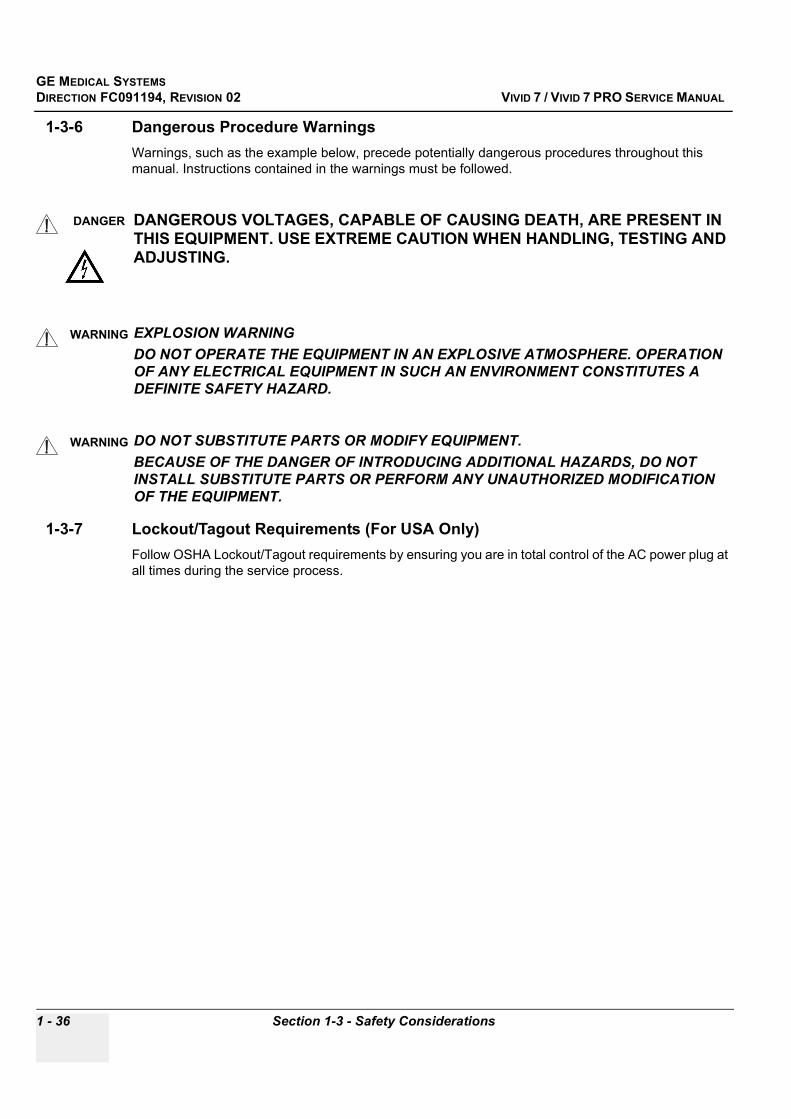
GE MEDICAL SYSTEMSDIRECTION FC091194, REVISION 02 VIVID 7 / VIVID 7 PRO SERVICE MANUAL
1 - 36 Section 1-3 - Safety Considerations
1-3-6 Dangerous Procedure WarningsWarnings, such as the example below, precede potentially dangerous procedures throughout this manual. Instructions contained in the warnings must be followed.
1-3-7 Lockout/Tagout Requirements (For USA Only)Follow OSHA Lockout/Tagout requirements by ensuring you are in total control of the AC power plug at all times during the service process.
DANGER DANGEROUS VOLTAGES, CAPABLE OF CAUSING DEATH, ARE PRESENT IN THIS EQUIPMENT. USE EXTREME CAUTION WHEN HANDLING, TESTING AND ADJUSTING.
WARNINGWARNING EXPLOSION WARNINGDO NOT OPERATE THE EQUIPMENT IN AN EXPLOSIVE ATMOSPHERE. OPERATION OF ANY ELECTRICAL EQUIPMENT IN SUCH AN ENVIRONMENT CONSTITUTES A DEFINITE SAFETY HAZARD.
WARNINGWARNING DO NOT SUBSTITUTE PARTS OR MODIFY EQUIPMENT.BECAUSE OF THE DANGER OF INTRODUCING ADDITIONAL HAZARDS, DO NOT INSTALL SUBSTITUTE PARTS OR PERFORM ANY UNAUTHORIZED MODIFICATION OF THE EQUIPMENT.

GE MEDICAL SYSTEMSDIRECTION FC091194, REVISION 02 VIVID 7 / VIVID 7 PRO SERVICE MANUAL
Chapter 1 - Introduction 1 - 37
Section 1-4EMC, EMI, and ESD
1-4-1 Electromagnetic Compatibility (EMC) and Interference (EMI)Electromagnetic compatibility describes a level of performance of a device within its electromagnetic environment. This environment consists of the device itself and its surroundings including other equipment, power sources and persons with which the device must interface. Inadequate compatibility results when a susceptible device fails to perform as intended due interference from its environment or when the device produces unacceptable levels of emission to its environment. This interference is often referred to as radio–frequency or electromagnetic interference (RFI/EMI) and can be radiated through space or conducted over interconnecting power of signal cables. In addition to electromagnetic energy, EMC also includes possible effects from electrical fields, magnetic fields, electrostatic discharge and disturbances in the electrical power supply.
1-4-2 CE ComplianceVivid 7 / Vivid 7 PRO conforms to all applicable conducted and radiated emission limits and to immunity from electrostatic discharge, radiated and conducted RF fields, magnetic fields and power line transient requirements.
Applicable standards are: 47CFR Part 18, IEC 601–1–2, and 806–13.
NOTE: For CE Compliance, it is critical that all covers, screws, shielding, gaskets, mesh, clamps, are in good condition, installed tightly without skew or stress. Proper installation following all comments noted in this service manual is required in order to achieve full EMC performance.
1-4-3 Electrostatic Discharge (ESD) Prevention
WARNINGWARNING2.)
DO NOT TOUCH ANY BOARDS WITH INTEGRATED CIRCUITS PRIOR TO TAKING THE NECESSARY ESD PRECAUTIONS: 1. ALWAYS CONNECT YOURSELF, VIA AN ARM-WRIST STRAP, TO THE ADVISED ESD CONNECTION POINT LOCATED ON THE REAR OF THE SCANNER (TO THE RIGHT OF THE POWER CONNECTOR). 2. FOLLOW GENERAL GUIDELINES FOR HANDLING OF ELECTROSTATIC SENSITIVE EQUIPMENT.

GE MEDICAL SYSTEMSDIRECTION FC091194, REVISION 02 VIVID 7 / VIVID 7 PRO SERVICE MANUAL
1 - 38 Section 1-5 - Customer Assistance
Section 1-5Customer Assistance
1-5-1 Contact InformationIf this equipment does not work as indicated in this service manual or in the User Manual, or if you require additional assistance, please contact the local distributor or appropriate support resource, as listed below.
Prepare the following information before you call:
- System ID serial number, --see label on rear side of unit.- Software version.
Table 1-17 Phone Numbers for Customer Assistance
Location Phone Number
USA/ CanadaGE Medical SystemsUltrasound Service Engineering4855 W. Electric AvenueMilwaukee, WI 53219
Customer Answer Center
Tel: 1-800-321-7937
1-800-682-53271-262-524-5698Fax: +1-414-647-4125
Latin AmericaGE Medical SystemsUltrasound Service Engineering4855 W. Electric AvenueMilwaukee, WI 53219
Customer Answer Center
Tel: 1-262-524-5300
1-262-524-5698Fax: +1-414-647-4125
EuropeGE Ultraschall Deutschland GmbH& Co. KGBeethovenstraBe 239Postfach 11 05 60, D-42655 SolingenGermany
Tel: +49 212 2802 208 - CARDIAC+49 212 2802 207 - GENERAL IMAGING
Fax: +49 212 2802 431
Asia (Singapore)GE Ultrasound AsiaService Department - Ultrasound298 Tiong Bahru Road #15-01/06Central PlazaSingapore 169730
Tel: +65-6277-3512
Fax: +65 6272-3997
GE MEDICAL SYSTEMSDIRECTION FC091194, REVISION 02 VIVID 7 / VIVID 7 PRO SERVICE MANUAL
Chapter 1 - Introduction 1 - 39
1-5-2 System Manufacture
Table 1-18 System Manufacture
MANUFACTURER PHONE NUMBER FAX NUMBER
GE Vingmed Ultrasound A/SStrandpromenaden 45P.O. Box 141N-3191 HORTENNORWAY
+47 3302 1100 +47 3302 1350

GE MEDICAL SYSTEMSDIRECTION FC091194, REVISION 02 VIVID 7 / VIVID 7 PRO SERVICE MANUAL
1 - 40 Section 1-5 - Customer Assistance
This page was intentionally left blank.
GE MEDICAL SYSTEMSDIRECTION FC091194, REVISION 02 VIVID 7 / VIVID 7 PRO SERVICE MANUAL
Chapter 2 - Pre-Installation 2 - 1
Chapter 2Pre-Installation
Section 2-1Overview
2-1-1 Purpose of Chapter 2This chapter provides the information required to plan and prepare for the installation of a Vivid 7 / Vivid 7 PRO. Included are descriptions of the facility and electrical needs to be met by the purchaser of the unit.
Table 2-1 Contents in Chapter 2
Section Description Page Number
2-1 Overview 2-1
2-2 General Console Requirements 2-2
2-3 Facility Needs 2-7

GE MEDICAL SYSTEMSDIRECTION FC091194, REVISION 02 VIVID 7 / VIVID 7 PRO SERVICE MANUAL
2 - 2 Section 2-2 - General Console Requirements
Section 2-2General Console Requirements
2-2-1 Console Environmental Requirements
2-2-1-1 CoolingThe cooling requirement for the Vivid 7 / Vivid 7 PRO is 3500 BTU/hr. This figure does not include cooling needed for lights, people, or other equipment in the room. Each person in the room places an additional 300 BTU/hr. demand on the cooling system.
2-2-1-2 LightingBright light is needed for system installation, updates and repairs. However, operator and patient comfort may be optimized if the room light is subdued and indirect. Therefore a combination lighting system (dim/bright) is recommended. Keep in mind that lighting controls and dimmers can be a source of EMI which could degrade image quality. These controls should be selected to minimize possible interference.
CAUTION If the unit is very cold or hot, do not turn on its power until it has had a chance to acclimate to its operating environment.
Table 2-2 Time for Settlement
°C 60 55 50 45 40 35 30 25 20 15 10 5 0 -5 -10 -15 -20 -25 -30 -35 -40
°F 140 131 122 113 104 96 86 77 68 59 50 41 32 23 14 5 -4 -13 -22 -31 -40
hrs 8 6 4 2 0 0 0 0 0 0 0 2 4 6 8 10 12 14 16 18 20
Table 2-3 Environmental Specifications for Vivid 7 / Vivid 7 PRO Scanners
Operating temperature Storage temperature Humidity Heat dissipation
10 to 35 oC (50 to 95 oF) -20 to 50 oC (- 4 to 122 oF) < 90% rH non-condensing 3500 BTU pr hour

GE MEDICAL SYSTEMSDIRECTION FC091194, REVISION 02 VIVID 7 / VIVID 7 PRO SERVICE MANUAL
Chapter 2 - Pre-Installation 2 - 3
2-2-2 Electrical Requirements
NOTE: GE Medical Systems requires a dedicated power and ground for the proper operation of its Ultrasound equipment. This dedicated power shall originate at the last distribution panel before the system.
Sites with a mains power system with defined Neutral and Live: The dedicated line shall consist of one phase, a neutral (not shared with any other circuit), and a full size ground wire from the distribution panel to the Ultrasound outlet.
Sites with a mains power system without a defined Neutral: The dedicated line shall consist of one phase (two lines), not shared with any other circuit, and a full size ground wire from the distribution panel to the Ultrasound outlet.
Please note that image artifacts can occur, if at any time within the facility, the ground from the main facility's incoming power source to the Ultrasound unit is only a conduit.
2-2-2-1 Electrical Requirements for Vivid 7 and Vivid 7 PROElectrical Specifications for Vivid 7 and Vivid 7 PRO. Monitor and on board peripherals are included.
2-2-2-2 Inrush Current• 230 VAC: 12 A• 120 VAC: 7 A
2-2-2-3 Site Circuit BreakerIt is recommended that the branch circuit breaker for the unit be readily accessible.
2-2-2-4 Site Power OutletsA dedicated AC power outlet must be within reach of the unit without extension cords. Other outlets adequate for the external peripherals, medical and test equipment needed to support this unit must also be present within 1 m (3.2 ft.) of the unit. Electrical installation must meet all current local, state, and national electrical codes.
2-2-2-5 Unit Power PlugIf the unit arrives without a power plug, or with the wrong plug, you must contact your GE dealer or the installation engineer must supply what is locally required.
Table 2-4 Electrical Specifications for Vivid 7 / Vivid 7 PRO
GE VINGMED PART NUMBER DESCRIPTION VOLTAGE TOLERANCES CURRENT FREQUENCY
FB000030 VIVID 7 (BT ’01) 230 VAC ±10% 5 A 50-60 Hz
FC000060 VIVID 7 (BT ’01) 115 VAC ±10% 10 A 50-60 Hz
FC000180 VIVID 7 PRO (BT ’02) 230 VAC ±10% 5 A 50-60 Hz
FC000190 VIVID 7 PRO (BT ’02) 115 VAC ±10% 10 A 50-60 Hz
FC000200 VIVID 7 (BT ’02) 230 VAC ±10% 5 A 50-60 Hz
FC000210 VIVID 7 (BT ’02) 115 VAC ±10% 10 A 50-60 Hz
CAUTION POWER OUTAGE MAY OCCUR. The Vivid 7 / Vivid 7 PRO requires a dedicated single branch circuit. To avoid circuit overload and possible loss of critical care equipment, make sure you DO NOT have any other equipment operating on the same circuit.
GE MEDICAL SYSTEMSDIRECTION FC091194, REVISION 02 VIVID 7 / VIVID 7 PRO SERVICE MANUAL
2 - 4 Section 2-2 - General Console Requirements
2-2-2-6 Power Stability RequirementsVoltage drop-out
Max 10 ms.
Power Transients
(All applications)
Less than 25% of nominal peak voltage for less than 1 millisecond for any type of transient, including line frequency, synchronous, asynchronous, or aperiodic transients.
2-2-3 EMI LimitationsUltrasound machines are susceptible to Electromagnetic Interference (EMI) from radio frequencies, magnetic fields, and transients in the air or wiring. They also generate EMI. The Vivid 7 / Vivid 7 PRO complies with limits as stated on the EMC label. However there is no guarantee that interference will not occur in a particular installation.
Possible EMI sources should be identified before the unit is installed.
Electrical and electronic equipment may produce EMI unintentionally as the result of a defect. These sources include:
• medical lasers, • scanners, • cauterizing guns, • computers, • monitors, • fans, • gel warmers, • microwave ovens,• light dimmers • portable phones. The presence of a broadcast station or broadcast van may also cause interference.
See Table 2-5 on page 2-5 for EMI Prevention tips.

GE MEDICAL SYSTEMSDIRECTION FC091194, REVISION 02 VIVID 7 / VIVID 7 PRO SERVICE MANUAL
Chapter 2 - Pre-Installation 2 - 5
2-2-3 EMI Limitations (cont’d).
Table 2-5 EMI Prevention/abatement
EMI Rule Details
Be aware of RF sourcesKeep the unit at least 5 meters or 15 feet away from other EMI sources. Special shielding may be required to eliminate interference problems caused by high frequency, high powered radio or video broadcast signals.
Ground the unit Poor grounding is the most likely reason a unit will have noisy images. Check grounding of the power cord and power outlet.
Replace all screws, RF gaskets, covers, cores
After you finish repairing or updating the system, replace all covers and tighten all screws. Any cable with an external connection requires a magnet wrap at each end. Install the Card Rack cover over the Card Rack. Loose or missing covers or RF gaskets allow radio frequencies to interfere with the ultrasound signals.
Replace broken RF gaskets
If more than 20% or a pair of the fingers on an RF gasket are broken, replace the gasket. Do not turn on the unit until any loose metallic part is removed.
Do not place labels where RF gaskets touch metal
Never place a label where RF gaskets meet the unit. Otherwise, the gap created will permit RF leakage. Or, if a label has been found in such a position, move the label.
Use GE specified harnesses and peripherals
The interconnect cables are grounded and require ferrite beads and other shielding. Also, cable length, material, and routing are all important; do not change from what is specified.
Take care with cellular phones Cellular phones may transmit a 5 V/m signal; that could cause image artifacts.
Properly dress peripheral cables
Do not allow cables to lie across the top of the Card Rack or hang out of the peripheral bays. Loop the excess length for peripheral cables inside the peripheral bays. Attach the monitor cables to the frame.

GE MEDICAL SYSTEMSDIRECTION FC091194, REVISION 02 VIVID 7 / VIVID 7 PRO SERVICE MANUAL
2 - 6 Section 2-2 - General Console Requirements
2-2-4 Probes Environmental Requirements
2-2-5 Time and Manpower RequirementsSite preparation takes time. Begin Pre-installation checks as soon as possible, if possible, six weeks before delivery, to allow enough time to make any changes.
Table 2-6 Operation and Storage Temperatures for Probes.
Electronic PAMPTE
Operation: 10 to 40 oC (50 to 104 oF) 5 to 42.7 oC (41 to 108,9 oF)
Storage: -20 to 50 oC (-4 to 122 oF) -20 to 50 oC (-4 to 122 oF)
Temperatures in degrees Celsius (oC) conversion to degrees F (oF) = (oC * 9/5) + 32
CAUTION Systems and electronic probes are designed for storage temperatures of -20 to + 50 degrees C (-4 to +122 degrees F). when exposed to large temperature variations, the product should be kept at room temperature the needed time to stabilize its temperature before use. Refer to Table 3-3 on page 3-2 to determine the needed settlement time.
CAUTION Have two people available to deliver and unpack the Vivid 7 / Vivid 7 PRO.Attempts to move the unit considerable distances or on an incline by one person could result in injury or damage or both.
GE MEDICAL SYSTEMSDIRECTION FC091194, REVISION 02 VIVID 7 / VIVID 7 PRO SERVICE MANUAL
Chapter 2 - Pre-Installation 2 - 7
Section 2-3Facility Needs
2-3-1 Purchaser ResponsibilitiesThe work and materials needed to prepare the site is the responsibility of the purchaser. Delay, confusion, and waste of manpower can be avoided by completing pre installation work before delivery. Purchaser responsibility includes:
• Procuring the materials required.• Completing the preparations before delivery of the ultrasound system.• Paying the costs for any alterations and modifications not specifically provided in the sales contract.
NOTE: All electrical installations that are preliminary to the positioning of the equipment at the site prepared for the equipment must be performed by licensed electrical contractors. Other connections between pieces of electrical equipment, calibrations, and testing must also be performed by qualified personnel. The products involved (and the accompanying electrical installations) are highly sophisticated and special engineering competence is required. All electrical work on these products must comply with the requirements of applicable electrical codes. The purchaser of GE equipment must only utilize qualified personnel to perform electrical servicing on the equipment.
The desire to use a non–listed or customer provided product or to place an approved product further from the system than the interface kit allows, presents challenges to the installation team. To avoid delays during installation, such variances should be made known to the individuals or group performing the installation at the earliest possible date (preferably prior to the purchase).
The ultrasound suite must be clean prior to delivery of the machine. Carpet is not recommended because it collects dust and creates static. Potential sources of EMI (electromagnetic interference) should also be investigated before delivery. Dirt, static, and EMI can negatively impact system reliability.

GE MEDICAL SYSTEMSDIRECTION FC091194, REVISION 02 VIVID 7 / VIVID 7 PRO SERVICE MANUAL
2 - 8 Section 2-3 - Facility Needs
2-3-2 Required Facility Needs
NOTE: GE Medical Systems requires a dedicated power and ground for the proper operation of its Ultrasound equipment. This dedicated power shall originate at the last distribution panel before the system.
Sites with a mains power system with defined Neutral and Live: The dedicated line shall consist of one phase, a neutral (not shared with any other circuit), and a full size ground wire from the distribution panel to the Ultrasound outlet.
Sites with a mains power system without a defined Neutral: The dedicated line shall consist of one phase (two lines), not shared with any other circuit, and a full size ground wire from the distribution panel to the Ultrasound outlet.
Please note that image artifacts can occur, if at any time within the facility, the ground from the main facility's incoming power source to the Ultrasound unit is only a conduit.
• Dedicated single branch power outlet of adequate amperage (see Table 2-4 on page 2-3) meeting all local and national codes which is located less than 2.5 m (8 ft.) from the unit’s proposed location
• Door opening is at least 76 cm (30 in) wide• Proposed location for unit is at least 0.3 m (1 ft.) from the wall for cooling• Power outlet and place for any external peripheral are within 2 m (6.5 ft) of each other with
peripheral within 1 m of the unit to connect cables.
NOTE: The Vivid 7 / Vivid 7 PRO has four outlets inside the unit. One is for the monitor and three for on board peripherals.
• Power outlets for other medical equipment and gel warmer• Power outlets for test equipment within 1 m (3.2 ft) of unit• Clean and protected space to store transducers (in their cases or on a rack)• Material to safely clean probes (done with a plastic container, never metal)
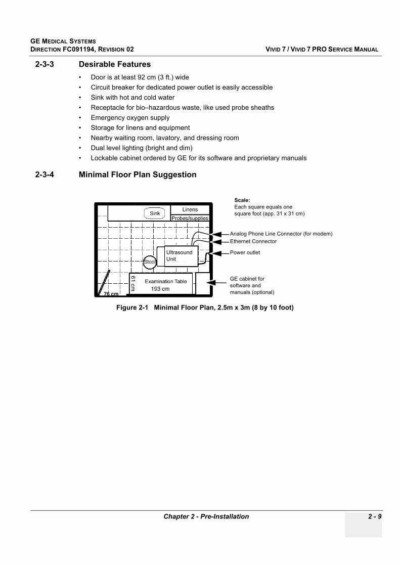
GE MEDICAL SYSTEMSDIRECTION FC091194, REVISION 02 VIVID 7 / VIVID 7 PRO SERVICE MANUAL
Chapter 2 - Pre-Installation 2 - 9
2-3-3 Desirable Features• Door is at least 92 cm (3 ft.) wide• Circuit breaker for dedicated power outlet is easily accessible• Sink with hot and cold water• Receptacle for bio–hazardous waste, like used probe sheaths• Emergency oxygen supply• Storage for linens and equipment• Nearby waiting room, lavatory, and dressing room• Dual level lighting (bright and dim)• Lockable cabinet ordered by GE for its software and proprietary manuals
2-3-4 Minimal Floor Plan Suggestion
Figure 2-1 Minimal Floor Plan, 2.5m x 3m (8 by 10 foot)
Power outlet
GE cabinet for software and manuals (optional)
Scale: Each square equals one square foot (app. 31 x 31 cm)
Ethernet ConnectorAnalog Phone Line Connector (for modem)
Ultrasound Unit

GE MEDICAL SYSTEMSDIRECTION FC091194, REVISION 02 VIVID 7 / VIVID 7 PRO SERVICE MANUAL
2 - 10 Section 2-3 - Facility Needs
2-3-5 Networking Pre-installation Requirements
2-3-5-1 Stand Alone Scanner (without Network Connection)None.
2-3-5-2 Scanner Connected to Hospital’s NetworkSupported networks:
DICOM Network (option)
2-3-5-3 Purpose of the DICOM Network FunctionDICOM services provide the operator with clinically useful features for moving images and patient information over a hospital network. Examples of DICOM services include the transfer of images to workstations for viewing or transferring images to remote printers. As an added benefit, transferring images in this manner frees up the on-board monitor and peripherals, enabling viewing to be done while scanning continues. With DICOM, images can be archived, stored, and retrieved faster, easier, and at a lower cost.
2-3-5-4 DICOM Option Pre-installation RequirementsTo configure the Vivid 7 / Vivid 7 PRO to work with other network connections, the site’s network administrator must provide information to complete the form in Figure 2-2 - Worksheet for DICOM Network Information. Ensure that there are no spaces in any field of the form.
Entries must include:
• A host name, local port number, AE Title, IP address and Net Mask for the Vivid 7 / Vivid 7 PRO. • The IP addresses for the default gateway and other routers at the site for ROUTING
INFORMATION.• The host name, IP address, port and AE Title for each device the site wants connected to the Vivid
7 / Vivid 7 PRO for DICOM APPLICATION INFORMATION. A field for the make (manufacturer) and the revision of the device, is also included. This information may be useful for error solving.
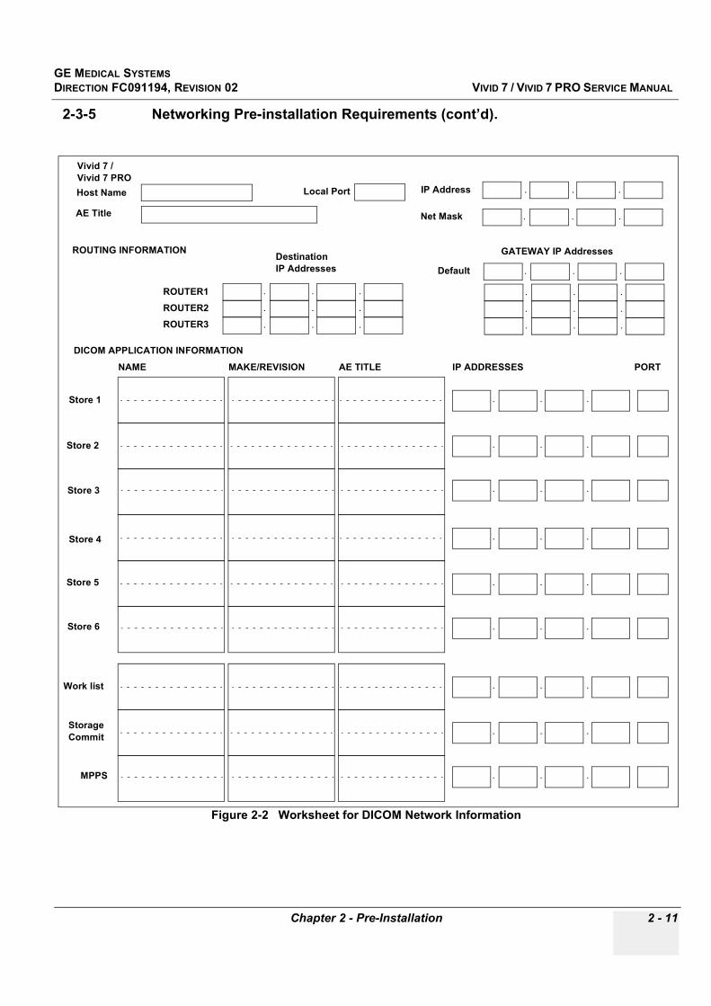
GE MEDICAL SYSTEMSDIRECTION FC091194, REVISION 02 VIVID 7 / VIVID 7 PRO SERVICE MANUAL
Chapter 2 - Pre-Installation 2 - 11
2-3-5 Networking Pre-installation Requirements (cont’d).
Figure 2-2 Worksheet for DICOM Network Information
Vivid 7 / Vivid 7 PROHost Name
AE Title
Local Port IP Address
Net Mask
.. .
.. .
ROUTING INFORMATION
ROUTER2ROUTER3
ROUTER1
.. .
.. .
.. .
.. .
.. .
.. .
.. .
Destination IP Addresses
GATEWAY IP Addresses
Default
DICOM APPLICATION INFORMATIONNAME
Store 2
Store 3
Store 1
MAKE/REVISION IP ADDRESSES PORTAE TITLE
Store 5
Store 6
Store 4
Storage Commit
MPPS
Work list .. .
.. .
.. .
.. .
.. .
.. .
.. .
.. .
.. .

GE MEDICAL SYSTEMSDIRECTION FC091194, REVISION 02 VIVID 7 / VIVID 7 PRO SERVICE MANUAL
2 - 12 Section 2-3 - Facility Needs
This page was intentionally left blank.
GE MEDICAL SYSTEMSDIRECTION FC091194, REVISION 02 VIVID 7 / VIVID 7 PRO SERVICE MANUAL
Chapter 3 - Installation 3 - 1
Chapter 3Installation
Section 3-1Overview
3-1-1 Purpose of Chapter 3This chapter contains information needed to install Vivid 7 / Vivid 7 PRO. Included is a procedure that describes how to receive and unpack the equipment and how to file a damage or loss claim.
How to prepare the facility and unit of the actual installation, and how to check and test the unit, probes, and external peripherals for electrical safety are included in this procedure. Also included in this section are guidelines for transporting the unit to a new site.
Section 3-2Installation Reminders
3-2-1 Average Installation Time
Table 3-1 Contents in Chapter 3
Section Description Page Number
3-1 Overview 3-1
3-3 Receiving and Unpacking the Equipment 3-3
3-6 Preparing for Installation 3-8
3-7 Completing the Installation 3-8
3-8 Configuration 3-21
3-9 Connectivity 3-35
3-10 Installation Paperwork 3-56
Table 3-2 Average Installation Time
Description
Average Installation
Time Comments
Unpacking the scanner 0.5 hour
Install Scanner wo/options 4 hours Dependent on the configuration
DICOM Network Configuration 2 hour Dependent on the configuration
Install InSite / iLink 0.5 hour

GE MEDICAL SYSTEMSDIRECTION FC091194, REVISION 02 VIVID 7 / VIVID 7 PRO SERVICE MANUAL
3 - 2 -
3-2-2 Installation Warnings
DANGER When using any test instrument that is capable of opening the ac ground line (i.e., meter’s ground switch is open), don’t touch the unit!
CAUTION If the unit is very cold or hot, do not turn on its power until it has had a chance to acclimate to its operating environment.
Table 3-3 Time for Settlement
°C 60 55 50 45 40 35 30 25 20 15 10 5 0 -5 -10 -15 -20 -25 -30 -35 -40
°F 140 131 122 113 104 96 86 77 68 59 50 41 32 23 14 5 -4 -13 -22 -31 -40
hrs 8 6 4 2 0 0 0 0 0 0 0 2 4 6 8 10 12 14 16 18 20
CAUTION To prevent electrical shock, connect the unit to a properly grounded power outlet. Do not use a three to two prong adapter. This defeats safety grounding.
CAUTION Do not wear the ESD wrist strap when you work on live circuits and more than 30 V peak is present.
CAUTION Do not operate this unit unless all board covers and frame panels are securely in place. System performance and cooling require this.
CAUTION OPERATOR MANUAL(S) The User Manual(s) should be fully read and understood before operating the Vivid 7 / Vivid 7 PRO and kept near the unit for quick reference.
CAUTION Acoustic Output Hazard Although the ultrasound energy transmitted from the Vivid 7 / Vivid 7 PRO probe is within AIUM/NEMA standards, avoid unnecessary exposure. Ultrasound energy can produce heat and mechanical damage.

GE MEDICAL SYSTEMSDIRECTION FC091194, REVISION 02 VIVID 7 / VIVID 7 PRO SERVICE MANUAL
Chapter 3 - Installation 3 - 3
Section 3-3Receiving and Unpacking the Equipment
3-3-1 IntroductionVivid 7 / Vivid 7 PRO is a fine tuned electronic equipment, and should be treated properly during transportation.
If the box is damaged or if the tilt & drop indicators show failure, please inform the sales representative immediately. Do also fill in that the tilt & drop indicators show failure in the “Package” column on the Post delivery checklist.
See “Damage In Transportation“ on page v in the beginning of this manual.
We strongly advice you to store the Vivid 7 / Vivid 7 PRO packing material in undamaged condition in case of future transportation.
The weight of the special designed wooden transportation box, with a Vivid 7 / Vivid 7 PRO and other normal equipment included, is approximate 300 kg (615 lbs).
CAUTION Please read this procedure before unpacking the Vivid 7 / Vivid 7 PRO.
CAUTION Have two people available to unpack the Vivid 7 / Vivid 7 PRO.Attempts to move the unit considerable distances or on an incline by one person could result in injury or damage or both.
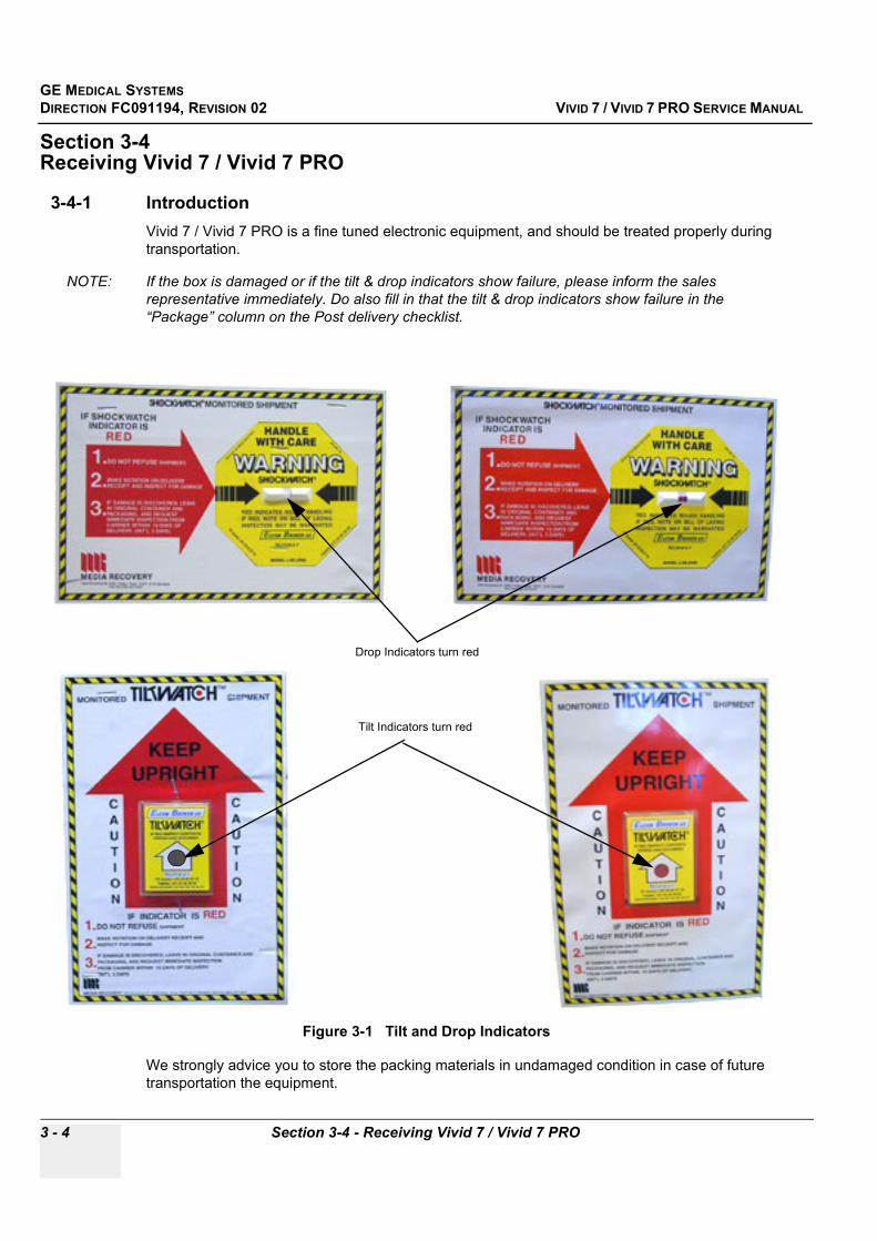
GE MEDICAL SYSTEMSDIRECTION FC091194, REVISION 02 VIVID 7 / VIVID 7 PRO SERVICE MANUAL
3 - 4 Section 3-4 - Receiving Vivid 7 / Vivid 7 PRO
Section 3-4Receiving Vivid 7 / Vivid 7 PRO
3-4-1 IntroductionVivid 7 / Vivid 7 PRO is a fine tuned electronic equipment, and should be treated properly during transportation.
NOTE: If the box is damaged or if the tilt & drop indicators show failure, please inform the sales representative immediately. Do also fill in that the tilt & drop indicators show failure in the “Package” column on the Post delivery checklist.
We strongly advice you to store the packing materials in undamaged condition in case of future transportation the equipment.
Figure 3-1 Tilt and Drop Indicators
Drop Indicators turn red
Tilt Indicators turn red

GE MEDICAL SYSTEMSDIRECTION FC091194, REVISION 02 VIVID 7 / VIVID 7 PRO SERVICE MANUAL
Chapter 3 - Installation 3 - 5
Section 3-5Unpacking Vivid 7 / Vivid 7 PRO
Table 3-4 Unpacking Vivid 7 / Vivid 7 PRO
Step Task
1. Open the four hinges on each door and remove the doors.One of the doors are used as ramp out off and into the transportation box. On the first version of the Transportation Box, only the front door is meant to be used as a ramp. It has bevel cut in one end.
2. Place the front door as a ramp against the rear edge of the pallet.
3. Carefully remove the accessory box, and any other items, including the wooden shelf above the scanners keyboard and all the filling material, from the Transportation Box.
Front door bevel cut. This end of the door should be used as the lower end of the ramp.
On the first version transportation box, which is no longer manufactured by GE, a 10 cm board (not furnished) is placed as a support under the upper end of the ramp.
On the second version transportation box, the ramp is placed directly on the labank ends.
“Labank”
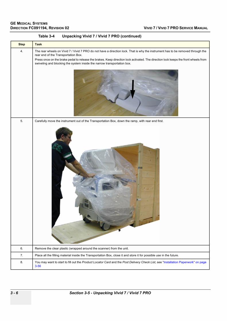
GE MEDICAL SYSTEMSDIRECTION FC091194, REVISION 02 VIVID 7 / VIVID 7 PRO SERVICE MANUAL
3 - 6 Section 3-5 - Unpacking Vivid 7 / Vivid 7 PRO
4. The rear wheels on Vivid 7 / Vivid 7 PRO do not have a direction lock. That is why the instrument has to be removed through the rear end of the Transportation Box. Press once on the brake pedal to release the brakes. Keep direction lock activated. The direction lock keeps the front wheels from swiveling and blocking the system inside the narrow transportation box.
5. Carefully move the instrument out of the Transportation Box, down the ramp, with rear end first.
6. Remove the clear plastic (wrapped around the scanner) from the unit.
7. Place all the filling material inside the Transportation Box, close it and store it for possible use in the future.
8. You may want to start to fill out the Product Locator Card and the Post Delivery Check List, see "Installation Paperwork" on page 3-56
Table 3-4 Unpacking Vivid 7 / Vivid 7 PRO (continued)
Step Task
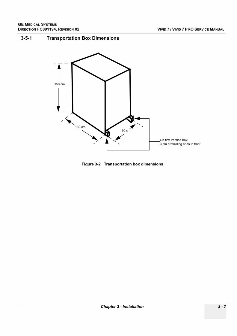
GE MEDICAL SYSTEMSDIRECTION FC091194, REVISION 02 VIVID 7 / VIVID 7 PRO SERVICE MANUAL
Chapter 3 - Installation 3 - 7
3-5-1 Transportation Box Dimensions
Figure 3-2 Transportation box dimensions
159 cm
130 cm80 cm
On first version box: 3 cm protruding ends in front
GE MEDICAL SYSTEMSDIRECTION FC091194, REVISION 02 VIVID 7 / VIVID 7 PRO SERVICE MANUAL
3 - 8 Section 3-6 - Preparing for Installation
Section 3-6Preparing for Installation
3-6-1 Physical Inspection• Verify that the system arrived intact (visual inspection).
If damaged, refer to “Damage In Transportation“on page v in this manual.• Verify that all items are present (see the Packing List)
3-6-2 EMI ProtectionThis unit has been designed to minimize the effects of Electro-Magnetic Interference (EMI). Many of the covers, shields, and screws are provided primarily to protect the system from image artifacts caused by this interference. For this reason, it is imperative that all covers and hardware are installed and secured before the unit is put into operation.
See Chapter 2, "EMI Limitations" on page 2-4 for more information about EMI protection.
Section 3-7Completing the Installation
3-7-1 System Specifications
3-7-1-1 System Requirements Verification• Verify that the site meets the requirements listed in Chapter 2 (see: "Facility Needs" on page 2-7)• Verify that the specifications below don’t conflict with any on site conditions
3-7-1-2 Physical Dimensions The physical dimensions of the Vivid 7 / Vivid 7 PRO unit are summarized in Table 3-5.
3-7-1-3 Weight with Monitor and Peripherals
3-7-1-4 Acoustic Noise OutputLess than 70dB(A) according to the standard DIN 45635 - 19 - 01 - KL2.
Table 3-5 Physical Dimensions of Vivid 7 / Vivid 7 PRO with monitor and peripherals
Height Width Depth Unit
137.5 - 157.5 64 90 cm
54.1 - 62 25.2 35,4 Inches
Table 3-6 Weight of Vivid 7 / Vivid 7 PRO with monitor and peripherals
Model Weight [kg] Weight [lbs]
Vivid 7 / Vivid 7 PRO 200 410
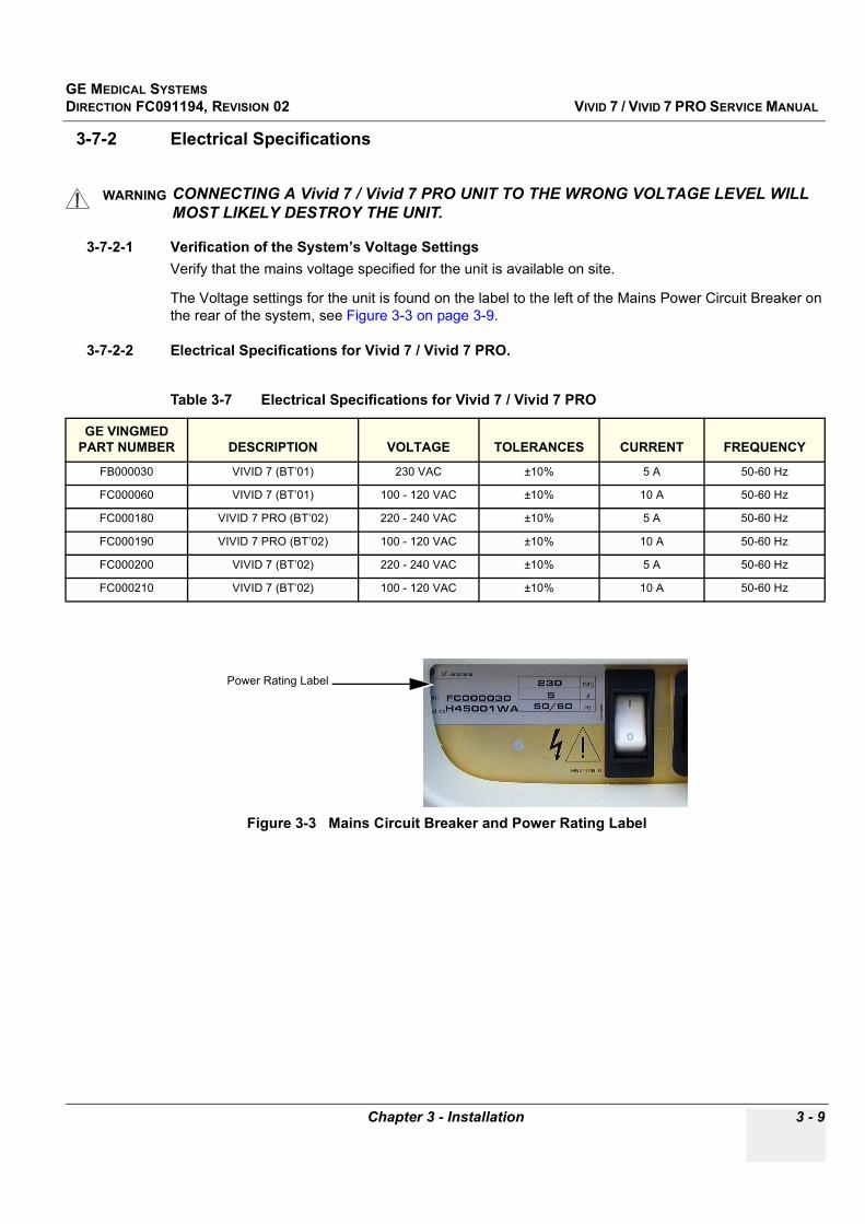
GE MEDICAL SYSTEMSDIRECTION FC091194, REVISION 02 VIVID 7 / VIVID 7 PRO SERVICE MANUAL
Chapter 3 - Installation 3 - 9
3-7-2 Electrical Specifications
3-7-2-1 Verification of the System’s Voltage SettingsVerify that the mains voltage specified for the unit is available on site.
The Voltage settings for the unit is found on the label to the left of the Mains Power Circuit Breaker on the rear of the system, see Figure 3-3 on page 3-9.
3-7-2-2 Electrical Specifications for Vivid 7 / Vivid 7 PRO.
WARNINGWARNING CONNECTING A Vivid 7 / Vivid 7 PRO UNIT TO THE WRONG VOLTAGE LEVEL WILL MOST LIKELY DESTROY THE UNIT.
Table 3-7 Electrical Specifications for Vivid 7 / Vivid 7 PRO
GE VINGMED PART NUMBER DESCRIPTION VOLTAGE TOLERANCES CURRENT FREQUENCY
FB000030 VIVID 7 (BT’01) 230 VAC ±10% 5 A 50-60 Hz
FC000060 VIVID 7 (BT’01) 100 - 120 VAC ±10% 10 A 50-60 Hz
FC000180 VIVID 7 PRO (BT’02) 220 - 240 VAC ±10% 5 A 50-60 Hz
FC000190 VIVID 7 PRO (BT’02) 100 - 120 VAC ±10% 10 A 50-60 Hz
FC000200 VIVID 7 (BT’02) 220 - 240 VAC ±10% 5 A 50-60 Hz
FC000210 VIVID 7 (BT’02) 100 - 120 VAC ±10% 10 A 50-60 Hz
Figure 3-3 Mains Circuit Breaker and Power Rating Label
Power Rating Label

GE MEDICAL SYSTEMSDIRECTION FC091194, REVISION 02 VIVID 7 / VIVID 7 PRO SERVICE MANUAL
3 - 10 Section 3-6 - Preparing for Installation
3-7-3 Connect FootswitchConnect Footswitch to External I/O at the rear side of Vivid 7 / Vivid 7 PRO. When not in use, store it in the tray below.
3-7-4 Connect Telephone Line to Modem Connector(For iLink/InSite Use)
Connect an analog telephone line to the Modem Connector on External I/O at the rear side of Vivid 7 / Vivid 7 PRO.
Figure 3-4 Footswitch connection
Figure 3-5 Connect an analog telephone line to Modem Connector
Footswitch connection
Modem Connector
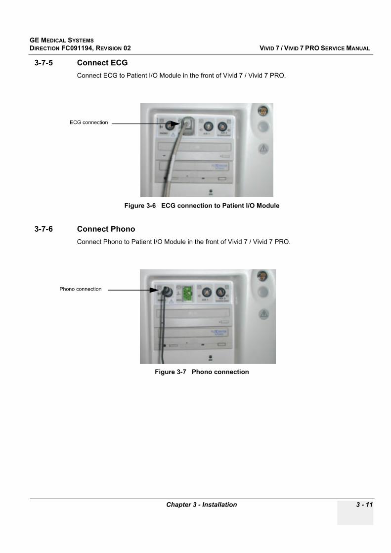
GE MEDICAL SYSTEMSDIRECTION FC091194, REVISION 02 VIVID 7 / VIVID 7 PRO SERVICE MANUAL
Chapter 3 - Installation 3 - 11
3-7-5 Connect ECGConnect ECG to Patient I/O Module in the front of Vivid 7 / Vivid 7 PRO.
3-7-6 Connect PhonoConnect Phono to Patient I/O Module in the front of Vivid 7 / Vivid 7 PRO.
Figure 3-6 ECG connection to Patient I/O Module
Figure 3-7 Phono connection
ECG connection
Phono connection
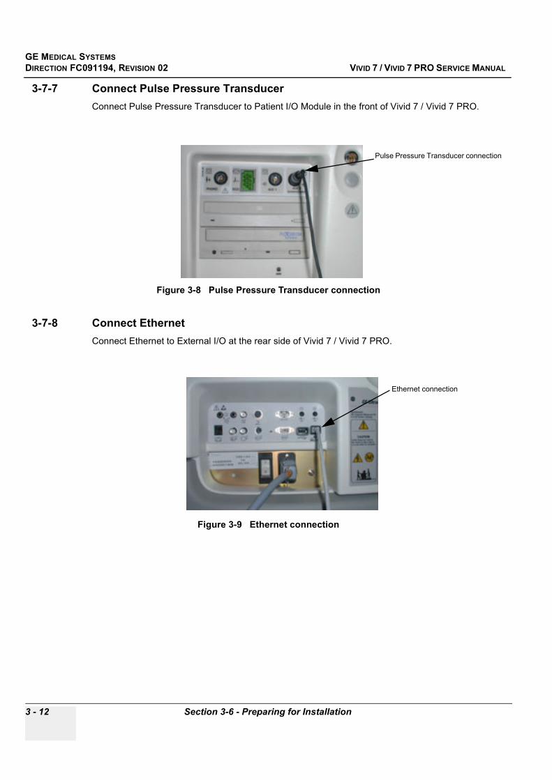
GE MEDICAL SYSTEMSDIRECTION FC091194, REVISION 02 VIVID 7 / VIVID 7 PRO SERVICE MANUAL
3 - 12 Section 3-6 - Preparing for Installation
3-7-7 Connect Pulse Pressure TransducerConnect Pulse Pressure Transducer to Patient I/O Module in the front of Vivid 7 / Vivid 7 PRO.
3-7-8 Connect EthernetConnect Ethernet to External I/O at the rear side of Vivid 7 / Vivid 7 PRO.
Figure 3-8 Pulse Pressure Transducer connection
Figure 3-9 Ethernet connection
Pulse Pressure Transducer connection
Ethernet connection
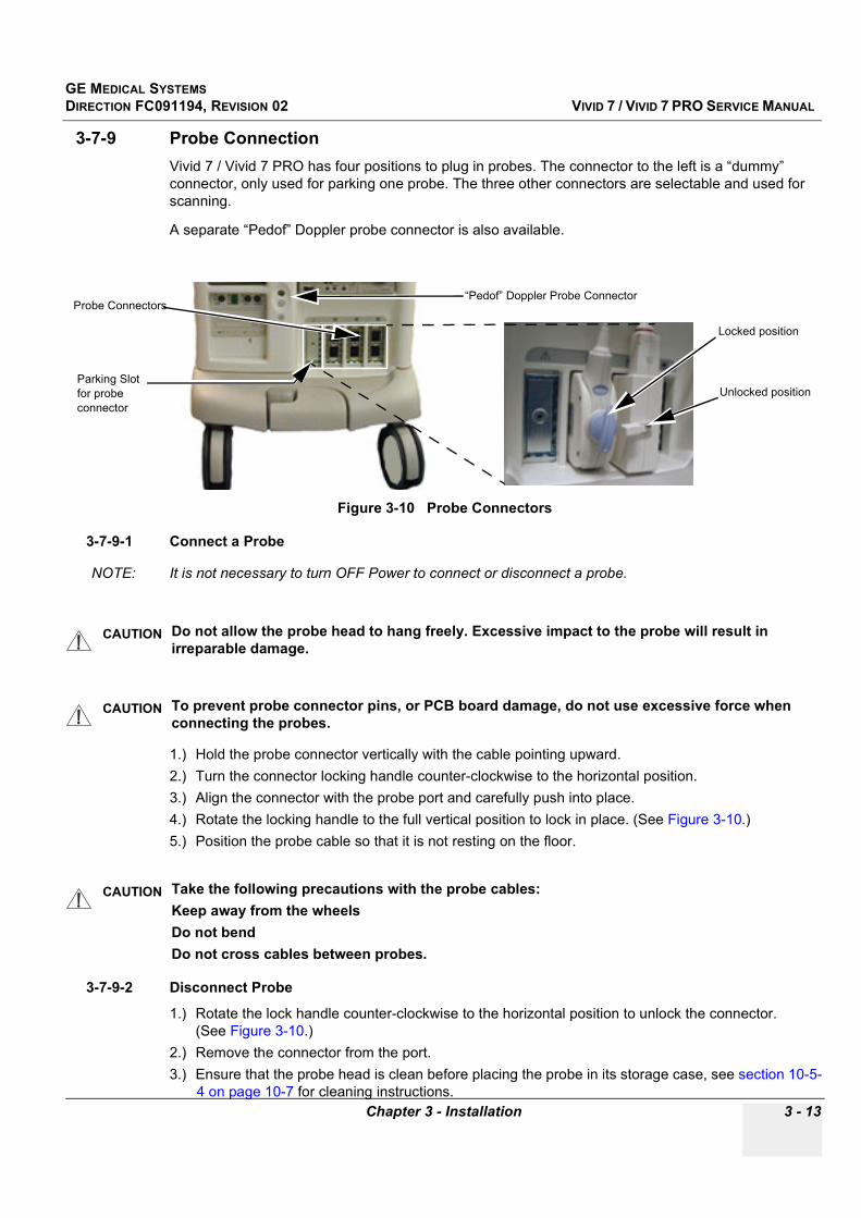
GE MEDICAL SYSTEMSDIRECTION FC091194, REVISION 02 VIVID 7 / VIVID 7 PRO SERVICE MANUAL
Chapter 3 - Installation 3 - 13
3-7-9 Probe ConnectionVivid 7 / Vivid 7 PRO has four positions to plug in probes. The connector to the left is a “dummy” connector, only used for parking one probe. The three other connectors are selectable and used for scanning.
A separate “Pedof” Doppler probe connector is also available.
3-7-9-1 Connect a Probe
NOTE: It is not necessary to turn OFF Power to connect or disconnect a probe.
1.) Hold the probe connector vertically with the cable pointing upward.2.) Turn the connector locking handle counter-clockwise to the horizontal position.3.) Align the connector with the probe port and carefully push into place.4.) Rotate the locking handle to the full vertical position to lock in place. (See Figure 3-10.)5.) Position the probe cable so that it is not resting on the floor.
3-7-9-2 Disconnect Probe
1.) Rotate the lock handle counter-clockwise to the horizontal position to unlock the connector. (See Figure 3-10.)
2.) Remove the connector from the port.3.) Ensure that the probe head is clean before placing the probe in its storage case, see section 10-5-
4 on page 10-7 for cleaning instructions.
Figure 3-10 Probe Connectors
CAUTION Do not allow the probe head to hang freely. Excessive impact to the probe will result in irreparable damage.
CAUTION To prevent probe connector pins, or PCB board damage, do not use excessive force when connecting the probes.
CAUTION Take the following precautions with the probe cables:Keep away from the wheelsDo not bendDo not cross cables between probes.
“Pedof” Doppler Probe ConnectorProbe Connectors
Parking Slot for probe connector
Locked position
Unlocked position
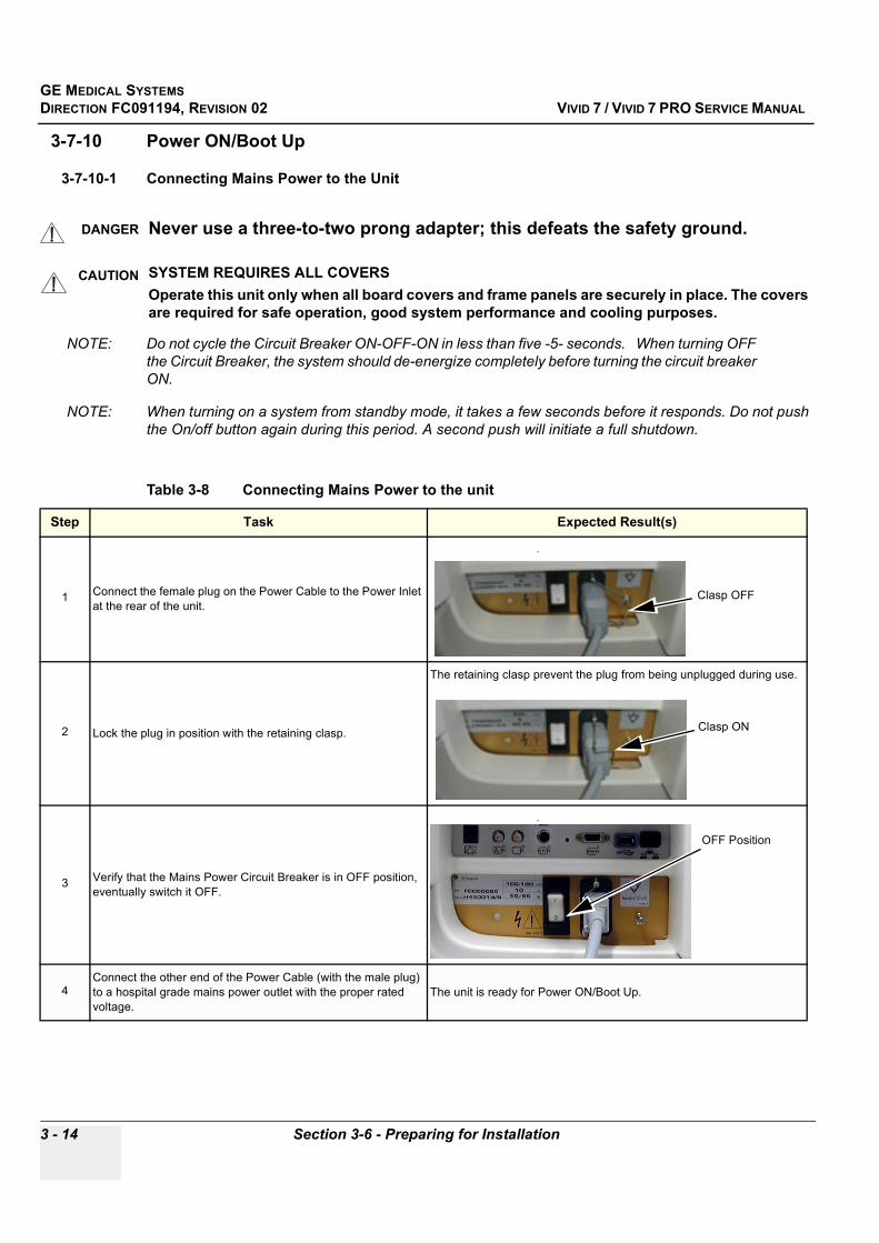
GE MEDICAL SYSTEMSDIRECTION FC091194, REVISION 02 VIVID 7 / VIVID 7 PRO SERVICE MANUAL
3 - 14 Section 3-6 - Preparing for Installation
3-7-10 Power ON/Boot Up
3-7-10-1 Connecting Mains Power to the Unit
NOTE: Do not cycle the Circuit Breaker ON-OFF-ON in less than five -5- seconds. When turning OFF the Circuit Breaker, the system should de-energize completely before turning the circuit breaker ON.
NOTE: When turning on a system from standby mode, it takes a few seconds before it responds. Do not push the On/off button again during this period. A second push will initiate a full shutdown.
DANGER Never use a three-to-two prong adapter; this defeats the safety ground.
CAUTION SYSTEM REQUIRES ALL COVERSOperate this unit only when all board covers and frame panels are securely in place. The covers are required for safe operation, good system performance and cooling purposes.
Table 3-8 Connecting Mains Power to the unit
Step Task Expected Result(s)
1 Connect the female plug on the Power Cable to the Power Inlet at the rear of the unit.
.
2 Lock the plug in position with the retaining clasp.
The retaining clasp prevent the plug from being unplugged during use.
3 Verify that the Mains Power Circuit Breaker is in OFF position, eventually switch it OFF.
.
4Connect the other end of the Power Cable (with the male plug) to a hospital grade mains power outlet with the proper rated voltage.
The unit is ready for Power ON/Boot Up.
Clasp OFF
Clasp ON
OFF Position

GE MEDICAL SYSTEMSDIRECTION FC091194, REVISION 02 VIVID 7 / VIVID 7 PRO SERVICE MANUAL
Chapter 3 - Installation 3 - 15
3-7-10-2 Turn Unit ON
Table 3-9 Turn Unit ON
Step Task Expected Result(s)
1
Switch ON the Mains Power Circuit Breaker at the rear of the unit.
You will hear a “click” from the relays in the AC Power/AC Controller. The unit is ready for Boot Up.
2
Press the ON/OFF key on the Control Panel (Keyboard) once..
1) The unit’s ventilation fan starts on full speed, but slows down after a few seconds (listen to the fan noise).2) Power is distributed to the peripherals, Control Panel (Console), Monitor, Card Rack and Backend Processor.3) Backend Processor and rest of Scanner starts with the following sequence:4) Backend Processor is turned ON and starts to load the software.5) The Start Screen (Vivid) is displayed on the monitor6) A start-up bar is displayed on the monitor, indicating the progress of the software loading.
NOTE: If the unit has been in the OFF condition for an extended period of time, (3 to 5 days or more), the unit may not boot, or may beep when turned on. See “System Doesn’t Boot” on page 7-67. for more details, including how to recover.
Mains Power Circuit Breaker in ON position
ON/OFF key
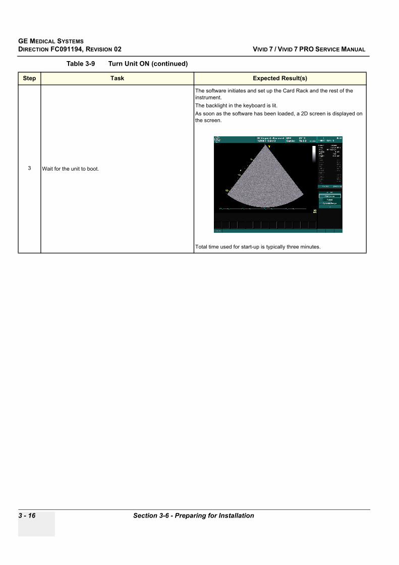
GE MEDICAL SYSTEMSDIRECTION FC091194, REVISION 02 VIVID 7 / VIVID 7 PRO SERVICE MANUAL
3 - 16 Section 3-6 - Preparing for Installation
3 Wait for the unit to boot.
The software initiates and set up the Card Rack and the rest of the instrument.The backlight in the keyboard is lit.As soon as the software has been loaded, a 2D screen is displayed on the screen.
Total time used for start-up is typically three minutes.
Table 3-9 Turn Unit ON (continued)
Step Task Expected Result(s)
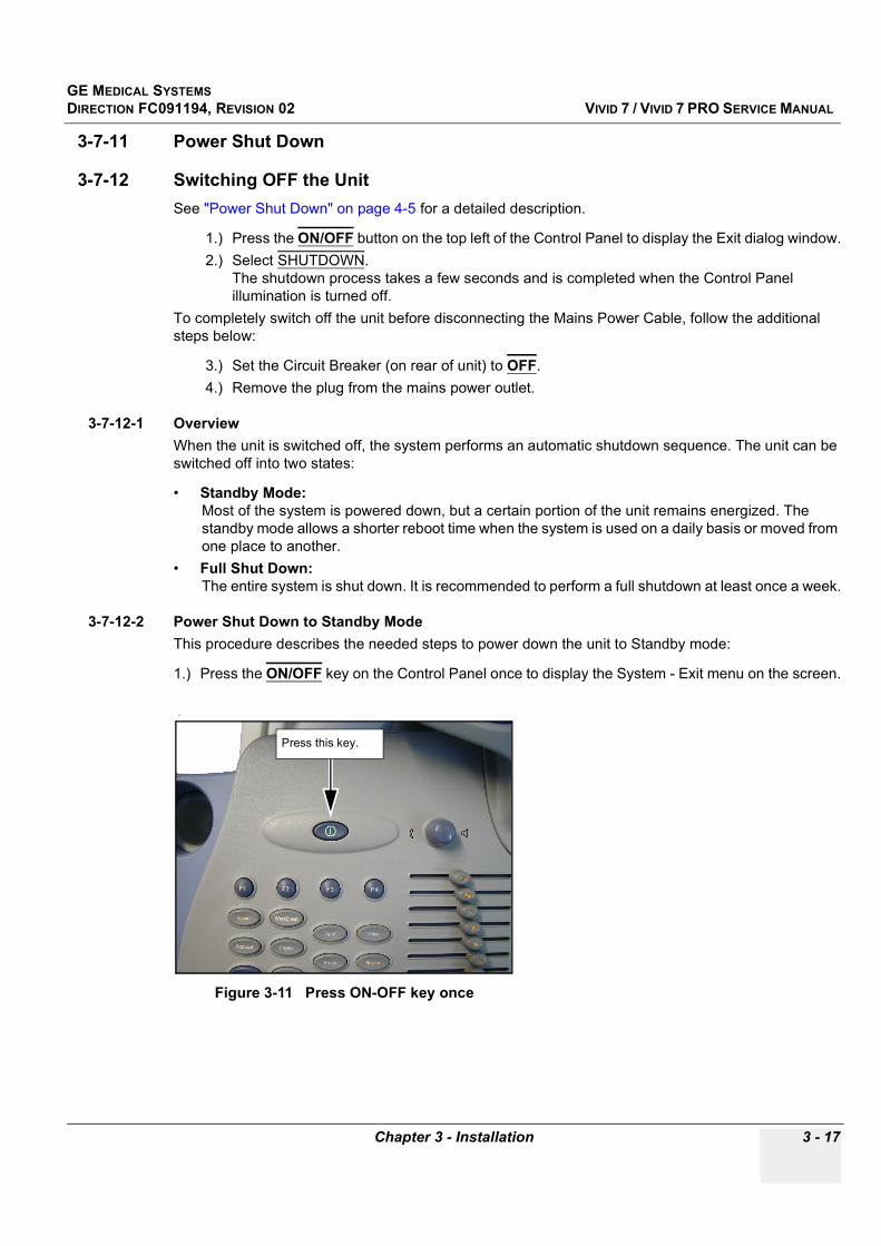
GE MEDICAL SYSTEMSDIRECTION FC091194, REVISION 02 VIVID 7 / VIVID 7 PRO SERVICE MANUAL
Chapter 3 - Installation 3 - 17
3-7-11 Power Shut Down
3-7-12 Switching OFF the UnitSee "Power Shut Down" on page 4-5 for a detailed description.
1.) Press the ON/OFF button on the top left of the Control Panel to display the Exit dialog window.2.) Select SHUTDOWN.
The shutdown process takes a few seconds and is completed when the Control Panel illumination is turned off.
To completely switch off the unit before disconnecting the Mains Power Cable, follow the additional steps below:
3.) Set the Circuit Breaker (on rear of unit) to OFF.4.) Remove the plug from the mains power outlet.
3-7-12-1 OverviewWhen the unit is switched off, the system performs an automatic shutdown sequence. The unit can be switched off into two states:
• Standby Mode: Most of the system is powered down, but a certain portion of the unit remains energized. The standby mode allows a shorter reboot time when the system is used on a daily basis or moved from one place to another.
• Full Shut Down: The entire system is shut down. It is recommended to perform a full shutdown at least once a week.
3-7-12-2 Power Shut Down to Standby ModeThis procedure describes the needed steps to power down the unit to Standby mode:
1.) Press the ON/OFF key on the Control Panel once to display the System - Exit menu on the screen.
.
Figure 3-11 Press ON-OFF key once
Press this key.
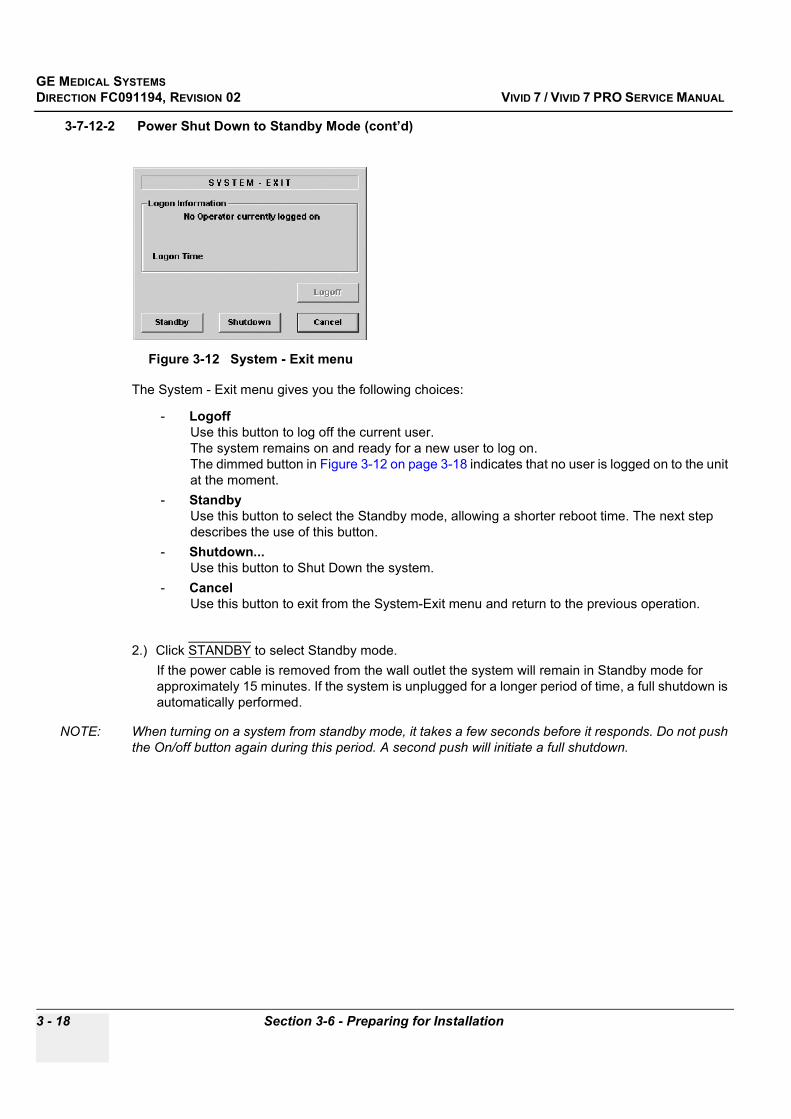
GE MEDICAL SYSTEMSDIRECTION FC091194, REVISION 02 VIVID 7 / VIVID 7 PRO SERVICE MANUAL
3 - 18 Section 3-6 - Preparing for Installation
3-7-12-2 Power Shut Down to Standby Mode (cont’d)
The System - Exit menu gives you the following choices:
- Logoff Use this button to log off the current user. The system remains on and ready for a new user to log on.The dimmed button in Figure 3-12 on page 3-18 indicates that no user is logged on to the unit at the moment.
- StandbyUse this button to select the Standby mode, allowing a shorter reboot time. The next step describes the use of this button.
- Shutdown... Use this button to Shut Down the system.
- Cancel Use this button to exit from the System-Exit menu and return to the previous operation.
2.) Click STANDBY to select Standby mode.If the power cable is removed from the wall outlet the system will remain in Standby mode for approximately 15 minutes. If the system is unplugged for a longer period of time, a full shutdown is automatically performed.
NOTE: When turning on a system from standby mode, it takes a few seconds before it responds. Do not push the On/off button again during this period. A second push will initiate a full shutdown.
Figure 3-12 System - Exit menu
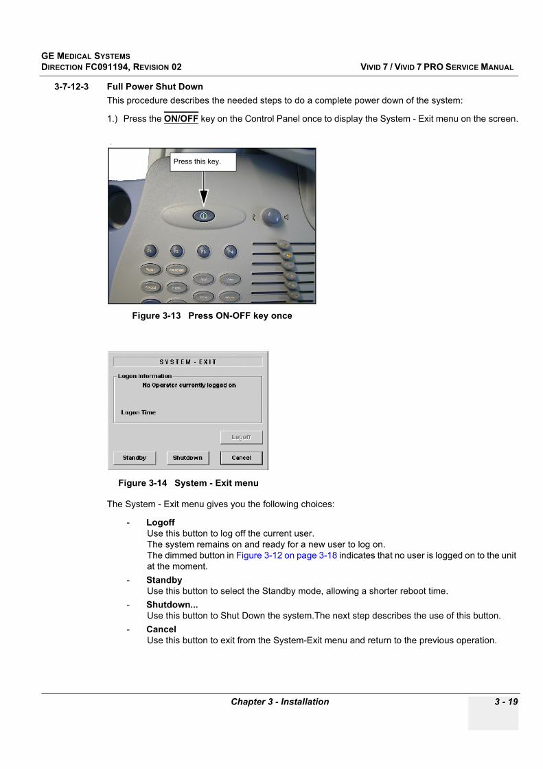
GE MEDICAL SYSTEMSDIRECTION FC091194, REVISION 02 VIVID 7 / VIVID 7 PRO SERVICE MANUAL
Chapter 3 - Installation 3 - 19
3-7-12-3 Full Power Shut DownThis procedure describes the needed steps to do a complete power down of the system:
1.) Press the ON/OFF key on the Control Panel once to display the System - Exit menu on the screen.
The System - Exit menu gives you the following choices:
- Logoff Use this button to log off the current user. The system remains on and ready for a new user to log on.The dimmed button in Figure 3-12 on page 3-18 indicates that no user is logged on to the unit at the moment.
- StandbyUse this button to select the Standby mode, allowing a shorter reboot time.
- Shutdown... Use this button to Shut Down the system.The next step describes the use of this button.
- Cancel Use this button to exit from the System-Exit menu and return to the previous operation.
.
Figure 3-13 Press ON-OFF key once
Figure 3-14 System - Exit menu
Press this key.

GE MEDICAL SYSTEMSDIRECTION FC091194, REVISION 02 VIVID 7 / VIVID 7 PRO SERVICE MANUAL
3 - 20 Section 3-6 - Preparing for Installation
3-7-12-3 Full Power Shut Down (cont’d)2.) Click SHUTDOWN to do a complete power down of the unit.
Backend Processor will first turn OFF the Scanner activity and print the message “Please wait - Shutdown in progress” in the LCD display. Then it starts to shut down itself. The time to turn down the Scanner including the Backend Processor, may vary from 10 seconds up to approximately 1 minute. The last thing that shut down, is the light in the LCD displays, indicating that you can continue to the next step.
3.) Switch OFF the CIRCUIT BREAKER (located on the rear of the unit)
This will cut power distribution within the unit.
If the Backend Processor is still running, the internal Un-interupted Power Supply (UPS) will switch over to battery power and supply the Backend Processor with power until it has shut down properly. A periodic high-pitch sound alarm indicates that the Backend Processor is running on battery power.
.
Figure 3-15 Circuit Breaker located on rear of the unitCircuit Breaker

GE MEDICAL SYSTEMSDIRECTION FC091194, REVISION 02 VIVID 7 / VIVID 7 PRO SERVICE MANUAL
Chapter 3 - Installation 3 - 21
Section 3-8Configuration
OVERVIEW
Table 3-10 Contents in Section 3-5
Sub-section Description Page Number
3-8-1 Vivid 7 / Vivid 7 PRO Configuration 3-21
3-8-1-1 Log on to the system 3-22
3-8-1-2 Enter Location 3-24
3-8-1-3 Date and Time Adjustments 3-25
3-8-1-4 Language Selection 3-26
3-8-1-5 Units of Measure 3-27
3-8-2-3 Select Video Format, PAL or NTSC 3-29
3-8-3 Optional Peripherals/Peripheral Connection 3-32
3-8-3-1 Approved On-board Peripherals 3-32
3-8-3-2 Off-board Peripherals 3-32
3-8-6 Software Options Configuration 3-33
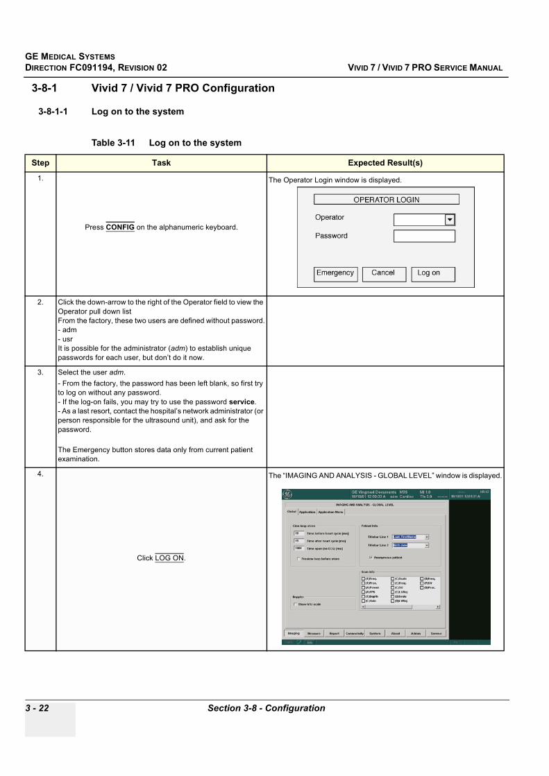
GE MEDICAL SYSTEMSDIRECTION FC091194, REVISION 02 VIVID 7 / VIVID 7 PRO SERVICE MANUAL
3 - 22 Section 3-8 - Configuration
3-8-1 Vivid 7 / Vivid 7 PRO Configuration
3-8-1-1 Log on to the system
Table 3-11 Log on to the system
Step Task Expected Result(s)
1.
Press CONFIG on the alphanumeric keyboard.
The Operator Login window is displayed.
2. Click the down-arrow to the right of the Operator field to view the Operator pull down listFrom the factory, these two users are defined without password.- adm- usrIt is possible for the administrator (adm) to establish unique passwords for each user, but don’t do it now.
3. Select the user adm.- From the factory, the password has been left blank, so first try to log on without any password. - If the log-on fails, you may try to use the password service. - As a last resort, contact the hospital’s network administrator (or person responsible for the ultrasound unit), and ask for the password.
The Emergency button stores data only from current patient examination.
4.
Click LOG ON.
The “IMAGING AND ANALYSIS - GLOBAL LEVEL” window is displayed.
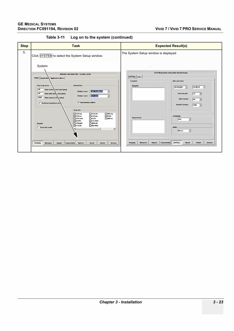
GE MEDICAL SYSTEMSDIRECTION FC091194, REVISION 02 VIVID 7 / VIVID 7 PRO SERVICE MANUAL
Chapter 3 - Installation 3 - 23
5.Click SYSTEM to select the System Setup window.
The System Setup window is displayed
.
Table 3-11 Log on to the system (continued)
Step Task Expected Result(s)
System
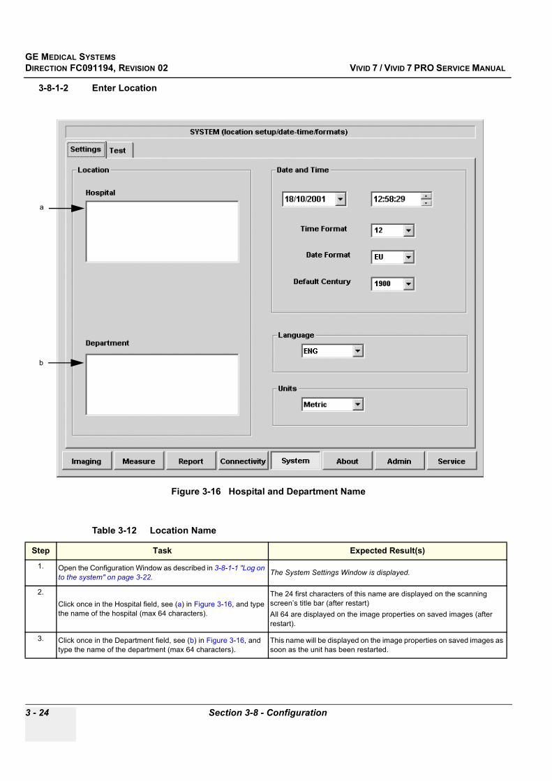
GE MEDICAL SYSTEMSDIRECTION FC091194, REVISION 02 VIVID 7 / VIVID 7 PRO SERVICE MANUAL
3 - 24 Section 3-8 - Configuration
3-8-1-2 Enter Location
Figure 3-16 Hospital and Department Name
Table 3-12 Location Name
Step Task Expected Result(s)
1. Open the Configuration Window as described in 3-8-1-1 "Log on to the system" on page 3-22. The System Settings Window is displayed.
2.Click once in the Hospital field, see (a) in Figure 3-16, and type the name of the hospital (max 64 characters).
The 24 first characters of this name are displayed on the scanning screen’s title bar (after restart)All 64 are displayed on the image properties on saved images (after restart).
3. Click once in the Department field, see (b) in Figure 3-16, and type the name of the department (max 64 characters).
This name will be displayed on the image properties on saved images as soon as the unit has been restarted.
a
b
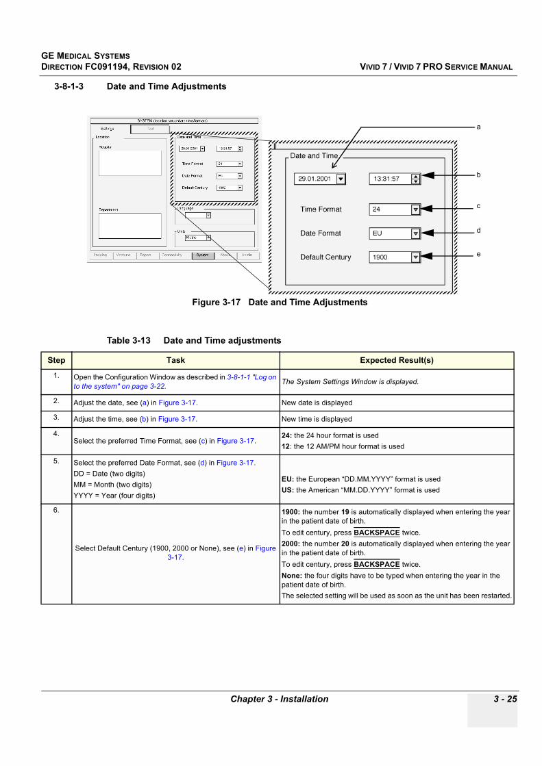
GE MEDICAL SYSTEMSDIRECTION FC091194, REVISION 02 VIVID 7 / VIVID 7 PRO SERVICE MANUAL
Chapter 3 - Installation 3 - 25
3-8-1-3 Date and Time Adjustments
Figure 3-17 Date and Time Adjustments
Table 3-13 Date and Time adjustments
Step Task Expected Result(s)
1. Open the Configuration Window as described in 3-8-1-1 "Log on to the system" on page 3-22. The System Settings Window is displayed.
2. Adjust the date, see (a) in Figure 3-17. New date is displayed
3. Adjust the time, see (b) in Figure 3-17. New time is displayed
4.Select the preferred Time Format, see (c) in Figure 3-17.
24: the 24 hour format is used12: the 12 AM/PM hour format is used
5. Select the preferred Date Format, see (d) in Figure 3-17.DD = Date (two digits)MM = Month (two digits)YYYY = Year (four digits)
EU: the European “DD.MM.YYYY” format is usedUS: the American “MM.DD.YYYY” format is used
6.
Select Default Century (1900, 2000 or None), see (e) in Figure 3-17.
1900: the number 19 is automatically displayed when entering the year in the patient date of birth.To edit century, press BACKSPACE twice.2000: the number 20 is automatically displayed when entering the year in the patient date of birth. To edit century, press BACKSPACE twice.None: the four digits have to be typed when entering the year in the patient date of birth.The selected setting will be used as soon as the unit has been restarted.
c
b
a
d
e
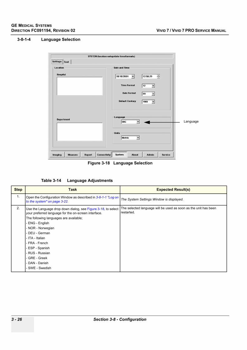
GE MEDICAL SYSTEMSDIRECTION FC091194, REVISION 02 VIVID 7 / VIVID 7 PRO SERVICE MANUAL
3 - 26 Section 3-8 - Configuration
3-8-1-4 Language Selection
Figure 3-18 Language Selection
Table 3-14 Language Adjustments
Step Task Expected Result(s)
1. Open the Configuration Window as described in 3-8-1-1 "Log on to the system" on page 3-22. The System Settings Window is displayed.
2. Use the Language drop down dialog, see Figure 3-18, to select your preferred language for the on-screen interface. The following languages are available;- ENG - English- NOR - Norwegian- DEU - German- ITA - Italian- FRA - French- ESP - Spanish- RUS - Russian- GRE - Greek- DAN - Danish- SWE - Swedish
The selected language will be used as soon as the unit has been restarted.
Language
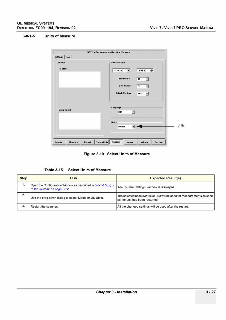
GE MEDICAL SYSTEMSDIRECTION FC091194, REVISION 02 VIVID 7 / VIVID 7 PRO SERVICE MANUAL
Chapter 3 - Installation 3 - 27
3-8-1-5 Units of Measure
Figure 3-19 Select Units of Measure
Table 3-15 Select Units of Measure
Step Task Expected Result(s)
1. Open the Configuration Window as described in 3-8-1-1 "Log on to the system" on page 3-22. The System Settings Window is displayed.
2.Use the drop down dialog to select Metric or US Units. The selected units (Metric or US) will be used for measurements as soon
as the unit has been restarted.
3. Restart the scanner. All the changed settings will be used after the restart.
Units
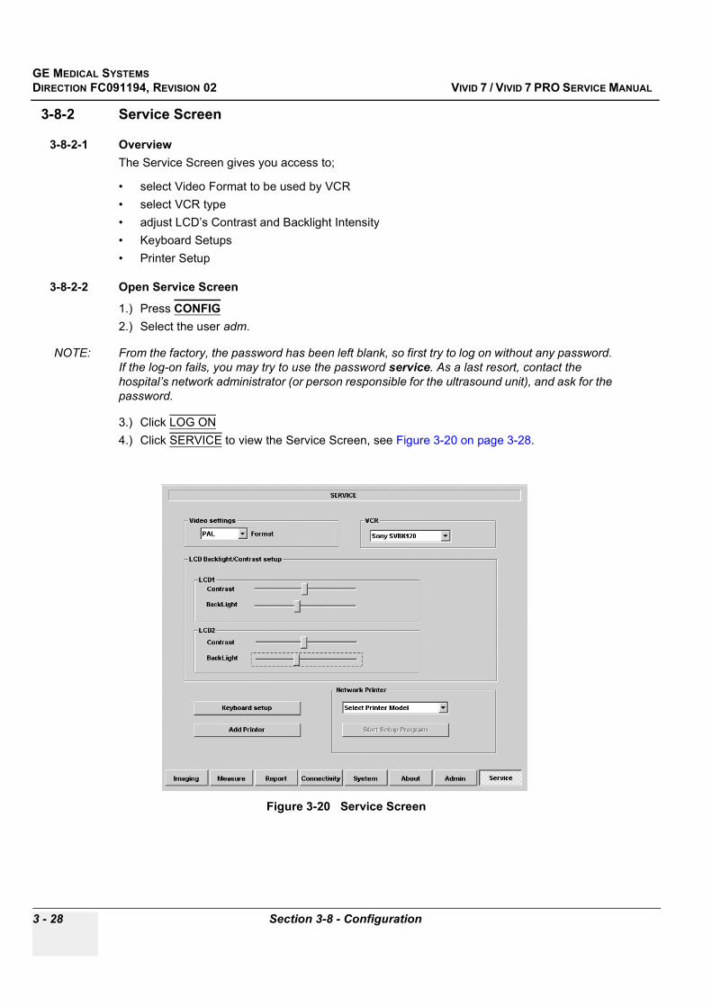
GE MEDICAL SYSTEMSDIRECTION FC091194, REVISION 02 VIVID 7 / VIVID 7 PRO SERVICE MANUAL
3 - 28 Section 3-8 - Configuration
3-8-2 Service Screen
3-8-2-1 OverviewThe Service Screen gives you access to;
• select Video Format to be used by VCR • select VCR type • adjust LCD’s Contrast and Backlight Intensity • Keyboard Setups • Printer Setup
3-8-2-2 Open Service Screen
1.) Press CONFIG2.) Select the user adm.
NOTE: From the factory, the password has been left blank, so first try to log on without any password. If the log-on fails, you may try to use the password service. As a last resort, contact the hospital’s network administrator (or person responsible for the ultrasound unit), and ask for the password.
3.) Click LOG ON4.) Click SERVICE to view the Service Screen, see Figure 3-20 on page 3-28.
Figure 3-20 Service Screen
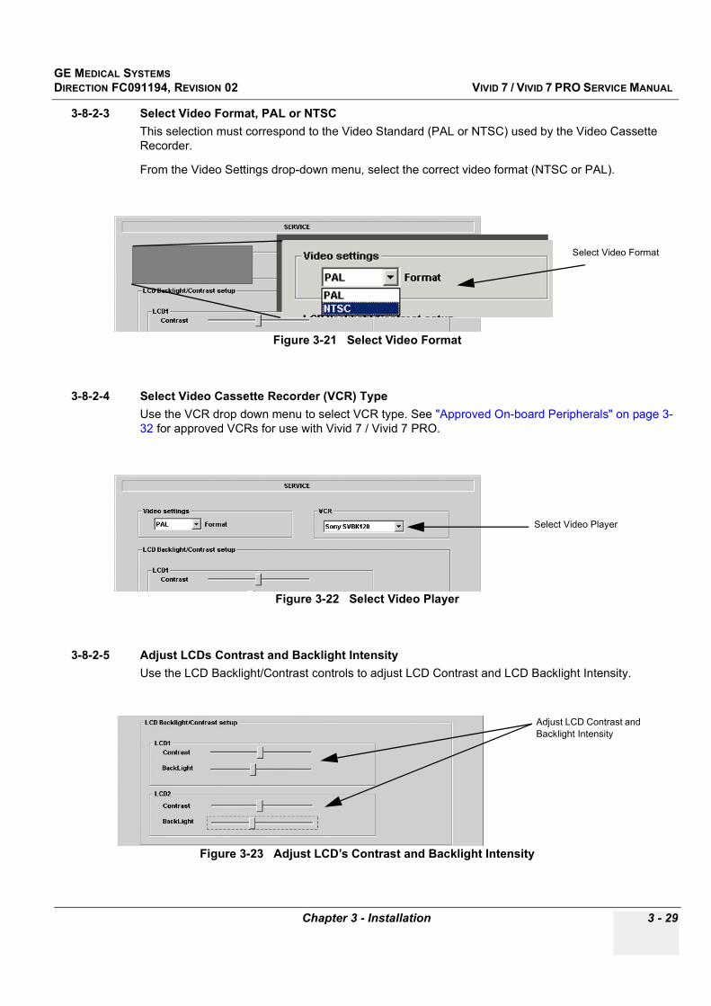
GE MEDICAL SYSTEMSDIRECTION FC091194, REVISION 02 VIVID 7 / VIVID 7 PRO SERVICE MANUAL
Chapter 3 - Installation 3 - 29
3-8-2-3 Select Video Format, PAL or NTSCThis selection must correspond to the Video Standard (PAL or NTSC) used by the Video Cassette Recorder.
From the Video Settings drop-down menu, select the correct video format (NTSC or PAL).
3-8-2-4 Select Video Cassette Recorder (VCR) TypeUse the VCR drop down menu to select VCR type. See "Approved On-board Peripherals" on page 3-32 for approved VCRs for use with Vivid 7 / Vivid 7 PRO.
3-8-2-5 Adjust LCDs Contrast and Backlight IntensityUse the LCD Backlight/Contrast controls to adjust LCD Contrast and LCD Backlight Intensity.
Figure 3-21 Select Video Format
Figure 3-22 Select Video Player
Figure 3-23 Adjust LCD’s Contrast and Backlight Intensity
Select Video Format
Select Video Player
Adjust LCD Contrast and Backlight Intensity

GE MEDICAL SYSTEMSDIRECTION FC091194, REVISION 02 VIVID 7 / VIVID 7 PRO SERVICE MANUAL
3 - 30 Section 3-8 - Configuration
3-8-2-6 Keyboard Setup Click KEYBOARD SETUP to get access to Keyboard Properties
The Keyboard Properties window has controls for:
• Character Repeat delay• Character Repeat Rate• Cursor Blink Rate
Figure 3-24 Select Keyboard Setup
Figure 3-25 Select Keyboard Properties
Select Keyboard setup

GE MEDICAL SYSTEMSDIRECTION FC091194, REVISION 02 VIVID 7 / VIVID 7 PRO SERVICE MANUAL
Chapter 3 - Installation 3 - 31
3-8-2-7 Add Printer
Click ADD PRINTER to start the Add Printer (Installation) Wizard.
Follow the instructions in the Wizard to install a new printer.
Figure 3-26 Select Add Printer
Figure 3-27 Add Printer Wizard
Click Add Printer
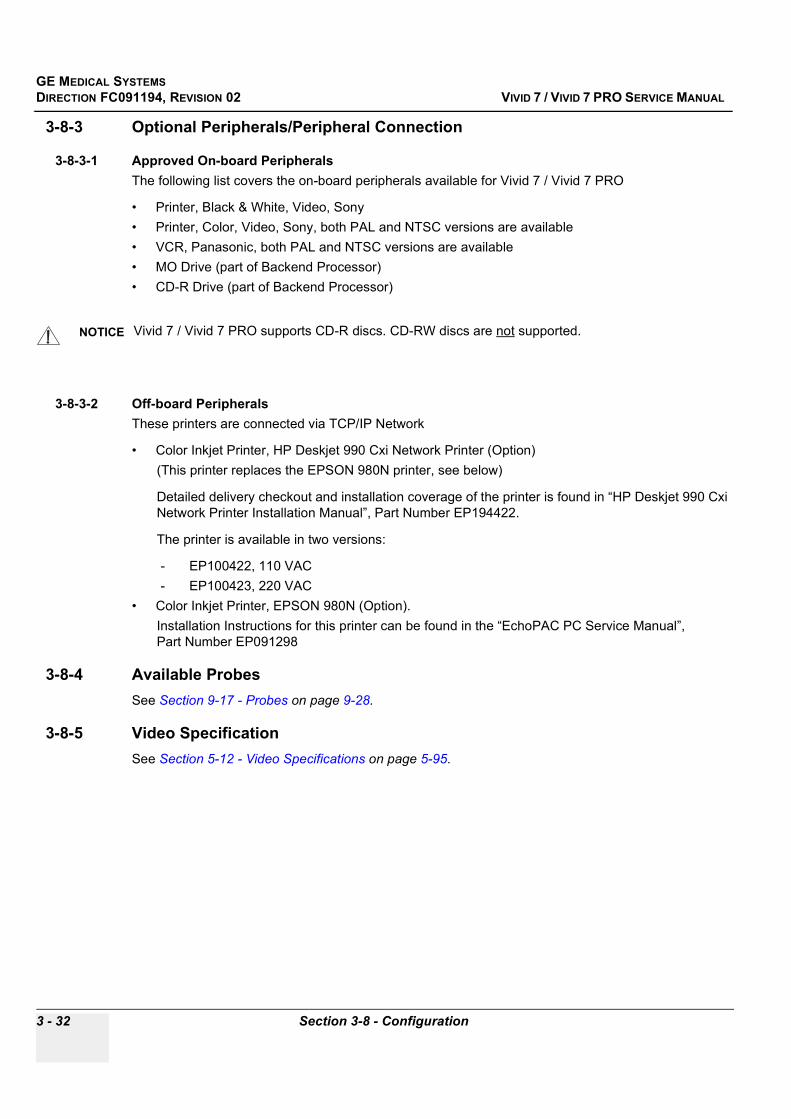
GE MEDICAL SYSTEMSDIRECTION FC091194, REVISION 02 VIVID 7 / VIVID 7 PRO SERVICE MANUAL
3 - 32 Section 3-8 - Configuration
3-8-3 Optional Peripherals/Peripheral Connection
3-8-3-1 Approved On-board PeripheralsThe following list covers the on-board peripherals available for Vivid 7 / Vivid 7 PRO
• Printer, Black & White, Video, Sony• Printer, Color, Video, Sony, both PAL and NTSC versions are available• VCR, Panasonic, both PAL and NTSC versions are available• MO Drive (part of Backend Processor)• CD-R Drive (part of Backend Processor)
3-8-3-2 Off-board PeripheralsThese printers are connected via TCP/IP Network
• Color Inkjet Printer, HP Deskjet 990 Cxi Network Printer (Option)(This printer replaces the EPSON 980N printer, see below)
Detailed delivery checkout and installation coverage of the printer is found in “HP Deskjet 990 Cxi Network Printer Installation Manual”, Part Number EP194422.
The printer is available in two versions:
- EP100422, 110 VAC- EP100423, 220 VAC
• Color Inkjet Printer, EPSON 980N (Option). Installation Instructions for this printer can be found in the “EchoPAC PC Service Manual”, Part Number EP091298
3-8-4 Available ProbesSee Section 9-17 - Probes on page 9-28.
3-8-5 Video SpecificationSee Section 5-12 - Video Specifications on page 5-95.
NOTICE Vivid 7 / Vivid 7 PRO supports CD-R discs. CD-RW discs are not supported.

GE MEDICAL SYSTEMSDIRECTION FC091194, REVISION 02 VIVID 7 / VIVID 7 PRO SERVICE MANUAL
Chapter 3 - Installation 3 - 33
3-8-6 Software Options Configuration
3-8-6-1 Software Option Installation
3-8-6-1-1 PrerequisitePassword (Software Option Key)
A Password enables the software option or combination of software options. This password is specific for each Vivid 7 / Vivid 7 PRO.
3-8-6-2 On site Configuration
1.) Press Config (See “Log on to the system” on page 3-22. for detailed description)2.) Select the user adm3.) Click LOG ON4.) Click SERVICE5.) Click ADMIN
Figure 3-28 Admin Screen
System Admin Tab
New
Admin
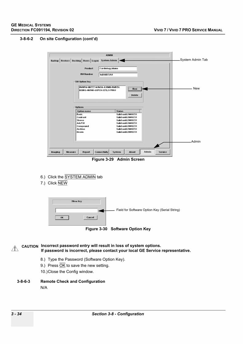
GE MEDICAL SYSTEMSDIRECTION FC091194, REVISION 02 VIVID 7 / VIVID 7 PRO SERVICE MANUAL
3 - 34 Section 3-8 - Configuration
3-8-6-2 On site Configuration (cont’d)
6.) Click the SYSTEM ADMIN tab7.) Click NEW
8.) Type the Password (Software Option Key).9.) Press OK to save the new setting.10.)Close the Config window.
3-8-6-3 Remote Check and ConfigurationN/A
Figure 3-29 Admin Screen
Figure 3-30 Software Option Key
CAUTION Incorrect password entry will result in loss of system options. If password is incorrect, please contact your local GE Service representative.
System Admin Tab
New
Admin
Field for Software Option Key (Serial String)

GE MEDICAL SYSTEMSDIRECTION FC091194, REVISION 02 VIVID 7 / VIVID 7 PRO SERVICE MANUAL
Chapter 3 - Installation 3 - 35
Section 3-9Connectivity
3-9-1 IntroductionThe next pages describes how to connect the Vivid 7 / Vivid 7 PRO to a remote archive/work station or a DICOM service, using a TCP/IP connection.
Major subjects discussed in this section;
• "Physical Connection" on page 3-35 • "Connectivity Setup" on page 3-37
3-9-2 Physical Connection
3-9-2-1 Ethernet Switch ConnectionsAn Ethernet Switch, Part Number: 066E0741, is used to connect Vivid 7 / Vivid 7 PRO to an EchoPAC PC and a network printer.
:
Figure 3-31 Ethernet Switch Identifications
Table 3-16 MDI Button Position Descriptions
Position Label Function
XTo PC To connect an end station or a Server to the Port
=To HUB To connect a HUB or another Switch to the Port
MDI ButtonControls the fifth connector, making it
crossed or non-crossed.
Informative LEDS Ethernet Cable connectors

GE MEDICAL SYSTEMSDIRECTION FC091194, REVISION 02 VIVID 7 / VIVID 7 PRO SERVICE MANUAL
3 - 36 Section 3-9 - Connectivity
3-9-2-2 Local Network Connection to EchoPAC PC Workstation
3-9-2-3 Hospital Network Connection to EchoPAC PC Workstation
See the EchoPAC PC Service Manual, Part Number EP091298 for details about EchoPAC PC, and its set-up.
Figure 3-32 Local Network Connection
Figure 3-33 Hospital Network Connections
EchoPAC PCNetworkPrinter
Vivid7
Do not use the fifth connector and the switch can be in any position,
Use only Standard non-crossed Ethernet cabling.
Vivid3
Using standard non-crossed cables and MDI switch set to position =HUB, connect like this.
Wall connection
EchoPAC PC Network Printer
Vivid3 or Vivid7
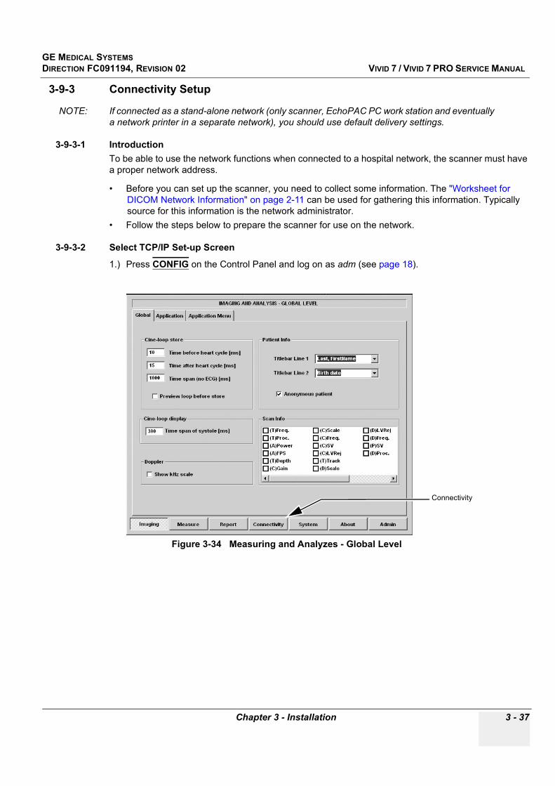
GE MEDICAL SYSTEMSDIRECTION FC091194, REVISION 02 VIVID 7 / VIVID 7 PRO SERVICE MANUAL
Chapter 3 - Installation 3 - 37
3-9-3 Connectivity Setup
NOTE: If connected as a stand-alone network (only scanner, EchoPAC PC work station and eventually a network printer in a separate network), you should use default delivery settings.
3-9-3-1 IntroductionTo be able to use the network functions when connected to a hospital network, the scanner must have a proper network address.
• Before you can set up the scanner, you need to collect some information. The "Worksheet for DICOM Network Information" on page 2-11 can be used for gathering this information. Typically source for this information is the network administrator.
• Follow the steps below to prepare the scanner for use on the network.
3-9-3-2 Select TCP/IP Set-up Screen
1.) Press CONFIG on the Control Panel and log on as adm (see page 18).
Figure 3-34 Measuring and Analyzes - Global Level
Connectivity
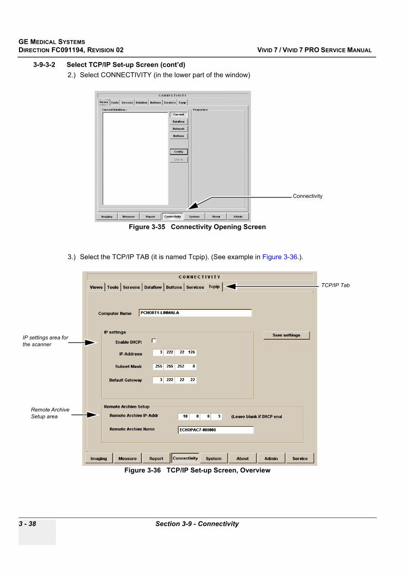
GE MEDICAL SYSTEMSDIRECTION FC091194, REVISION 02 VIVID 7 / VIVID 7 PRO SERVICE MANUAL
3 - 38 Section 3-9 - Connectivity
3-9-3-2 Select TCP/IP Set-up Screen (cont’d)2.) Select CONNECTIVITY (in the lower part of the window)
3.) Select the TCP/IP TAB (it is named Tcpip). (See example in Figure 3-36.).
Figure 3-35 Connectivity Opening Screen
Figure 3-36 TCP/IP Set-up Screen, Overview
Connectivity
TCP/IP Tab
IP settings area for the scanner
Remote Archive Setup area
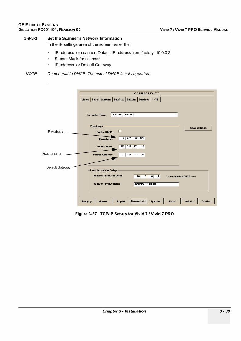
GE MEDICAL SYSTEMSDIRECTION FC091194, REVISION 02 VIVID 7 / VIVID 7 PRO SERVICE MANUAL
Chapter 3 - Installation 3 - 39
3-9-3-3 Set the Scanner’s Network InformationIn the IP settings area of the screen, enter the;
• IP address for scanner. Default IP address from factory: 10.0.0.3• Subnet Mask for scanner• IP address for Default Gateway
NOTE: Do not enable DHCP. The use of DHCP is not supported.
.
Figure 3-37 TCP/IP Set-up for Vivid 7 / Vivid 7 PRO
IP Address
Subnet Mask
Default Gateway

GE MEDICAL SYSTEMSDIRECTION FC091194, REVISION 02 VIVID 7 / VIVID 7 PRO SERVICE MANUAL
3 - 40 Section 3-9 - Connectivity
3-9-3-4 Set the Remote Archive’s Network InformationIn the Remote Archive Setup area of the screen (see example in Figure 3-36.), enter the;
1.) Remote Archive IP address2.) Remote Archive Name.
3-9-3-5 Save the New Settings
1.) Press SAVE SETTINGS to save the new settings. The new settings are saved to a common settings file. After a restart, the settings are also included in other screens.
2.) Restart Vivid 7 / Vivid 7 PRO to make the changes take place.
Figure 3-38 TCP/IP Set-up for Remote Archive (EchoPAC PC)
Remote Archive IP address
Remote Archive Name
Remote Archive Setup area
Save settings
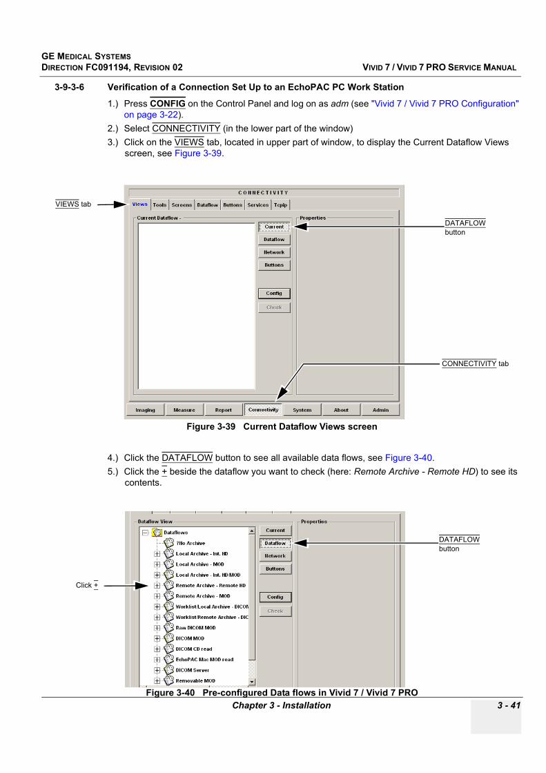
GE MEDICAL SYSTEMSDIRECTION FC091194, REVISION 02 VIVID 7 / VIVID 7 PRO SERVICE MANUAL
Chapter 3 - Installation 3 - 41
3-9-3-6 Verification of a Connection Set Up to an EchoPAC PC Work Station
1.) Press CONFIG on the Control Panel and log on as adm (see "Vivid 7 / Vivid 7 PRO Configuration" on page 3-22).
2.) Select CONNECTIVITY (in the lower part of the window)3.) Click on the VIEWS tab, located in upper part of window, to display the Current Dataflow Views
screen, see Figure 3-39.
4.) Click the DATAFLOW button to see all available data flows, see Figure 3-40.5.) Click the + beside the dataflow you want to check (here: Remote Archive - Remote HD) to see its
contents.
Figure 3-39 Current Dataflow Views screen
Figure 3-40 Pre-configured Data flows in Vivid 7 / Vivid 7 PRO
VIEWS tab
CONNECTIVITY tab
DATAFLOW button
DATAFLOW button
Click +

GE MEDICAL SYSTEMSDIRECTION FC091194, REVISION 02 VIVID 7 / VIVID 7 PRO SERVICE MANUAL
3 - 42 Section 3-9 - Connectivity
3-9-3-6 Verification of a Connection Set Up to an EchoPAC PC Work Station (cont’d).
The Remote Archive - Remote HD includes an EchoPAC PC with one Service also called Remote Archive - Remote HD. The name of this service indicates that the archive is located on a hard disk on a remote server (EchoPAC PC is used as an server).
6.) Click once on the EchoPAC PC’s name to highlight it, see Figure 3-41.7.) Click CHECK, see Figure 3-42, to verify if there is a connection between the ultrasound unit and the
EchoPAC PC work station.
Figure 3-41 Remote HD dataflow contents
Figure 3-42 Verify dataflow connection
Click once to highlight server’s name
Click CHECK

GE MEDICAL SYSTEMSDIRECTION FC091194, REVISION 02 VIVID 7 / VIVID 7 PRO SERVICE MANUAL
Chapter 3 - Installation 3 - 43
3-9-3-6 Verification of a Connection Set Up to an EchoPAC PC Work Station (cont’d)
• In the example in Figure 3-43, the red “X” next to the computer sign ( ), means that the check failed. The cause may be;- the setup of the network information, either on Vivid 7 / Vivid 7 PRO or on the EchoPAC PC, or- the network connection is broken somewhere between the Vivid 7 / Vivid 7 PRO and the
EchoPAC PC.• A green light next to the computer sign means that a network connection is in place.
Figure 3-43 Verification of connection failed
Red “X”

GE MEDICAL SYSTEMSDIRECTION FC091194, REVISION 02 VIVID 7 / VIVID 7 PRO SERVICE MANUAL
3 - 44 Section 3-9 - Connectivity
3-9-3-6 Verification of a Connection Set Up to an EchoPAC PC Work Station (cont’d)8.) Click the DATAFLOW tab to view the Dataflow Services window.
9.) Select Remote Archive - Remote HD on the drop-down menu to see the contents of that dataflow.
Figure 3-44 Dataflow Services Window
Figure 3-45 Obtaining Dataflow Contents Overview
Dataflow selection area
Dataflow Services area
DATAFLOW tab
Locale Archive -Internal HD service
DATAFLOW tab
Dataflow Name drop-down menu
Remote Archive -Remote HD

GE MEDICAL SYSTEMSDIRECTION FC091194, REVISION 02 VIVID 7 / VIVID 7 PRO SERVICE MANUAL
Chapter 3 - Installation 3 - 45
3-9-3-6 Verification of a Connection Set Up to an EchoPAC PC Work Station (cont’d)
Figure 3-46 Remote Archive - Remote HD Dataflow Contents Overview
Remote Archive -Remote HD

GE MEDICAL SYSTEMSDIRECTION FC091194, REVISION 02 VIVID 7 / VIVID 7 PRO SERVICE MANUAL
3 - 46 Section 3-9 - Connectivity
3-9-3-6 Verification of a Connection Set Up to an EchoPAC PC Work Station (cont’d)10.)Select the SERVICES tab (located near the top of the window).
11.)Select the EchoPAC PC work station you want to connect to, from the “Name” drop-down menu. In this example, it is called “EchoPAC7-000000”.
Figure 3-47 Dataflow Services
Figure 3-48 Dataflow Services, Choices and Setup
Name drop-down menu
SERVICES tab
Local Archive - Local Storage
Select Server
Name drop-down menu
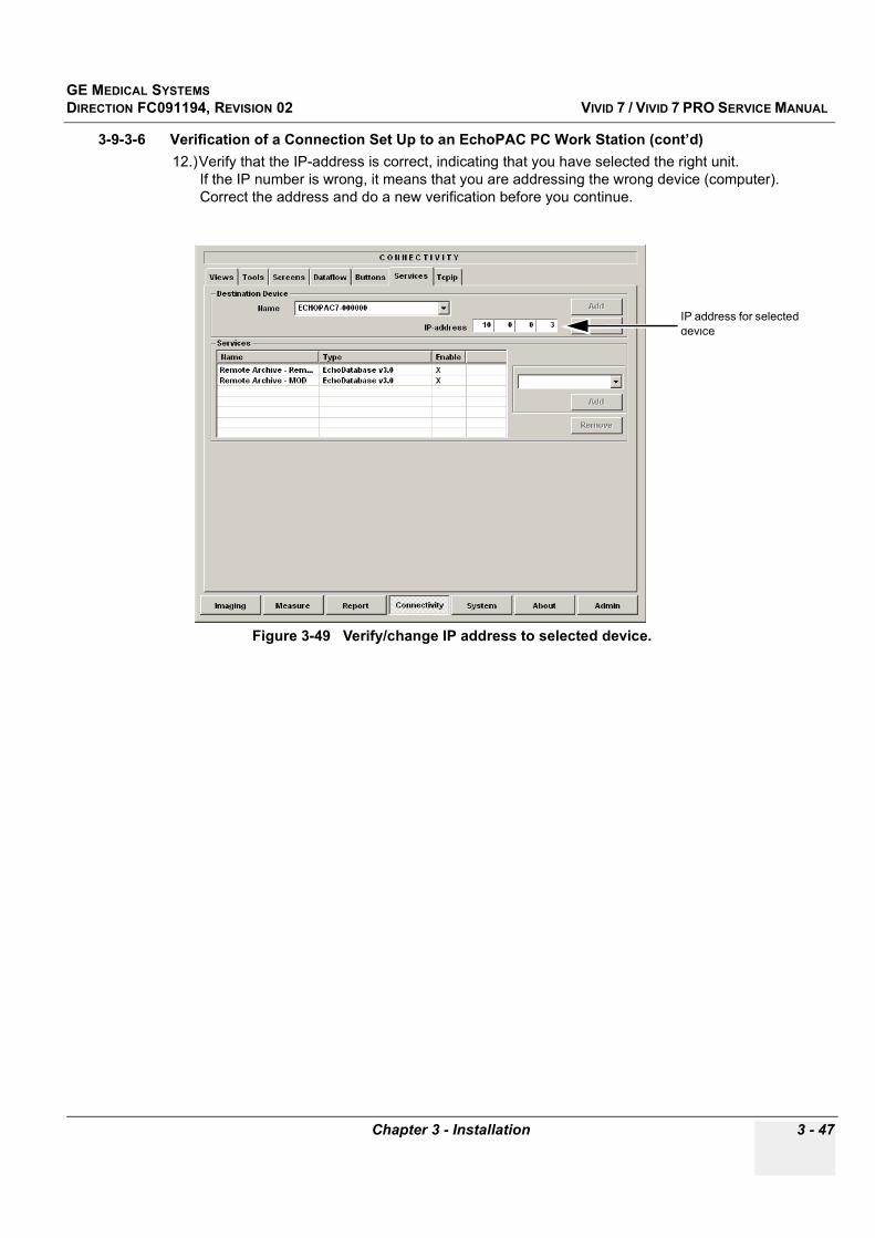
GE MEDICAL SYSTEMSDIRECTION FC091194, REVISION 02 VIVID 7 / VIVID 7 PRO SERVICE MANUAL
Chapter 3 - Installation 3 - 47
3-9-3-6 Verification of a Connection Set Up to an EchoPAC PC Work Station (cont’d)12.)Verify that the IP-address is correct, indicating that you have selected the right unit.
If the IP number is wrong, it means that you are addressing the wrong device (computer). Correct the address and do a new verification before you continue.
Figure 3-49 Verify/change IP address to selected device.
IP address for selected device
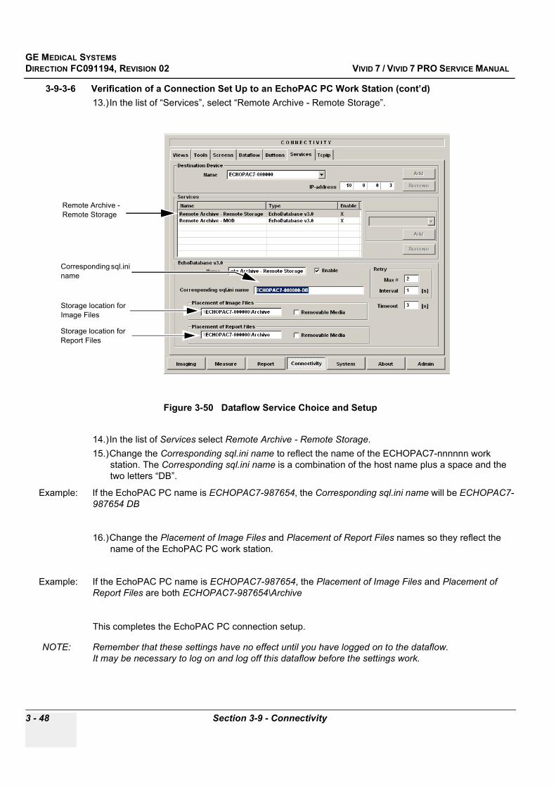
GE MEDICAL SYSTEMSDIRECTION FC091194, REVISION 02 VIVID 7 / VIVID 7 PRO SERVICE MANUAL
3 - 48 Section 3-9 - Connectivity
3-9-3-6 Verification of a Connection Set Up to an EchoPAC PC Work Station (cont’d)13.)In the list of “Services”, select “Remote Archive - Remote Storage”.
14.)In the list of Services select Remote Archive - Remote Storage. 15.)Change the Corresponding sql.ini name to reflect the name of the ECHOPAC7-nnnnnn work
station. The Corresponding sql.ini name is a combination of the host name plus a space and the two letters “DB”.
Example: If the EchoPAC PC name is ECHOPAC7-987654, the Corresponding sql.ini name will be ECHOPAC7-987654 DB
16.)Change the Placement of Image Files and Placement of Report Files names so they reflect the name of the EchoPAC PC work station.
Example: If the EchoPAC PC name is ECHOPAC7-987654, the Placement of Image Files and Placement of Report Files are both ECHOPAC7-987654\Archive
This completes the EchoPAC PC connection setup.
NOTE: Remember that these settings have no effect until you have logged on to the dataflow. It may be necessary to log on and log off this dataflow before the settings work.
Figure 3-50 Dataflow Service Choice and Setup
Remote Archive - Remote Storage
Corresponding sql.ini name
Storage location for Image Files
Storage location for Report Files
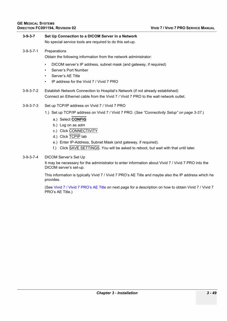
GE MEDICAL SYSTEMSDIRECTION FC091194, REVISION 02 VIVID 7 / VIVID 7 PRO SERVICE MANUAL
Chapter 3 - Installation 3 - 49
3-9-3-7 Set Up Connection to a DICOM Server in a NetworkNo special service tools are required to do this set-up.
3-9-3-7-1 PreparationsObtain the following information from the network administrator:
• DICOM server’s IP address, subnet mask (and gateway, if required)• Server’s Port Number• Server’s AE Title• IP address for the Vivid 7 / Vivid 7 PRO
3-9-3-7-2 Establish Network Connection to Hospital’s Network (if not already established)Connect an Ethernet cable from the Vivid 7 / Vivid 7 PRO to the wall network outlet.
3-9-3-7-3 Set up TCP/IP address on Vivid 7 / Vivid 7 PRO
1.) Set up TCP/IP address on Vivid 7 / Vivid 7 PRO. (See “Connectivity Setup” on page 3-37.)
a.) Select CONFIGb.) Log on as admc.) Click CONNECTIVITYd.) Click TCPIP tabe.) Enter IP-Address, Subnet Mask (and gateway, if required). f.) Click SAVE SETTINGS. You will be asked to reboot, but wait with that until later.
3-9-3-7-4 DICOM Server’s Set Up It may be necessary for the administrator to enter information about Vivid 7 / Vivid 7 PRO into the DICOM server’s set-up.
This information is typically Vivid 7 / Vivid 7 PRO’s AE Title and maybe also the IP address which he provides.
(See Vivid 7 / Vivid 7 PRO’s AE Title on next page for a description on how to obtain Vivid 7 / Vivid 7 PRO’s AE Title.)
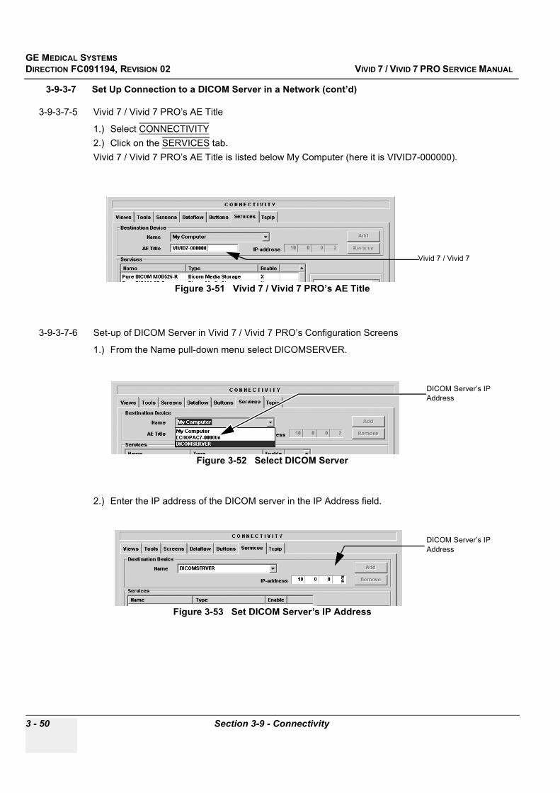
GE MEDICAL SYSTEMSDIRECTION FC091194, REVISION 02 VIVID 7 / VIVID 7 PRO SERVICE MANUAL
3 - 50 Section 3-9 - Connectivity
3-9-3-7 Set Up Connection to a DICOM Server in a Network (cont’d)
3-9-3-7-5 Vivid 7 / Vivid 7 PRO’s AE Title
1.) Select CONNECTIVITY 2.) Click on the SERVICES tab. Vivid 7 / Vivid 7 PRO’s AE Title is listed below My Computer (here it is VIVID7-000000).
3-9-3-7-6 Set-up of DICOM Server in Vivid 7 / Vivid 7 PRO’s Configuration Screens
1.) From the Name pull-down menu select DICOMSERVER.
2.) Enter the IP address of the DICOM server in the IP Address field.
Figure 3-51 Vivid 7 / Vivid 7 PRO’s AE Title
Figure 3-52 Select DICOM Server
Figure 3-53 Set DICOM Server’s IP Address
Vivid 7 / Vivid 7
DICOM Server’s IP Address
DICOM Server’s IP Address

GE MEDICAL SYSTEMSDIRECTION FC091194, REVISION 02 VIVID 7 / VIVID 7 PRO SERVICE MANUAL
Chapter 3 - Installation 3 - 51
3-9-3-7 Set Up Connection to a DICOM Server in a Network (cont’d)3-9-3-7-6 Set-up of DICOM Server in Vivid 7 / Vivid 7 PRO’s Configuration Screens (cont’d)
3.) Click once on the Pure DICOM Storage line under Services and the bottom part of the screen will be populated with set-up information for the DICOM server.
Figure 3-54 Click Once on Pure DICOM Storage
Click Once on Pure DICOM Storage.
Before clicking
After
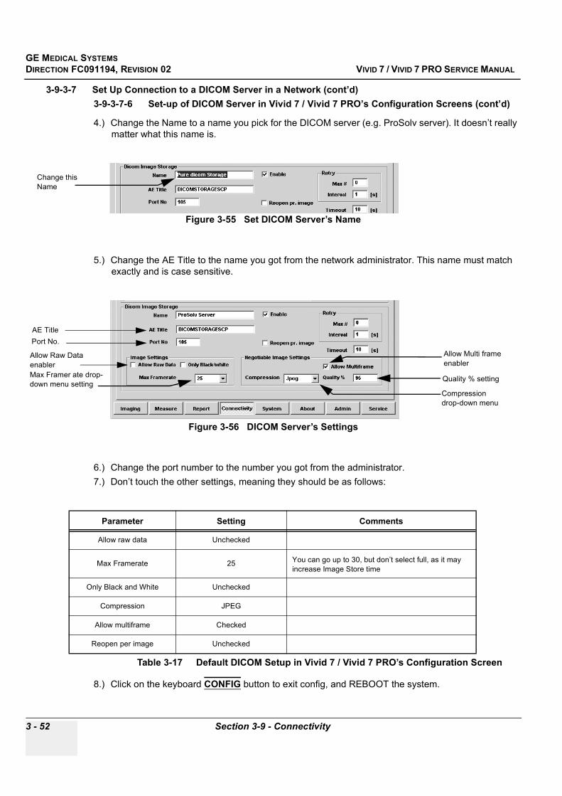
GE MEDICAL SYSTEMSDIRECTION FC091194, REVISION 02 VIVID 7 / VIVID 7 PRO SERVICE MANUAL
3 - 52 Section 3-9 - Connectivity
3-9-3-7 Set Up Connection to a DICOM Server in a Network (cont’d)3-9-3-7-6 Set-up of DICOM Server in Vivid 7 / Vivid 7 PRO’s Configuration Screens (cont’d)
4.) Change the Name to a name you pick for the DICOM server (e.g. ProSolv server). It doesn’t really matter what this name is.
5.) Change the AE Title to the name you got from the network administrator. This name must match exactly and is case sensitive.
6.) Change the port number to the number you got from the administrator.7.) Don’t touch the other settings, meaning they should be as follows:
8.) Click on the keyboard CONFIG button to exit config, and REBOOT the system.
Figure 3-55 Set DICOM Server’s Name
Figure 3-56 DICOM Server’s Settings
Parameter Setting Comments
Allow raw data Unchecked
Max Framerate 25 You can go up to 30, but don’t select full, as it may increase Image Store time
Only Black and White Unchecked
Compression JPEG
Allow multiframe Checked
Reopen per image Unchecked
Table 3-17 Default DICOM Setup in Vivid 7 / Vivid 7 PRO’s Configuration Screen
Change this Name
AE Title
Allow Raw Data enabler
Allow Multi frame enabler
Max Framer ate drop-down menu setting
Compression drop-down menu
Port No.
Quality % setting

GE MEDICAL SYSTEMSDIRECTION FC091194, REVISION 02 VIVID 7 / VIVID 7 PRO SERVICE MANUAL
Chapter 3 - Installation 3 - 53
3-9-3-7-7 Check the Connection to the DICOM Server (Ping)
1.) After the system is rebooted, press Config, log on as adm (no password) and enter the Connectivity screen.
2.) Click the VIEWS tab and the DATAFLOW button and you will see all available data flows.
3.) Click on the + by the “DICOM Server” dataflow to see the contents of that dataflow. This dataflow has one DICOM Server with Storage Service. Two new lines will appear, DICOMSERVER and the name of the server (e.g. ProSolv server).
..
4.) Click once on DICOMSERVER to highlight the line, then click on the Check button. You should get a green check mark. This is a hardware “ping” indicating that you have contact with the DICOM server’s hardware. If you get a red cross, double check cabling and TCPIP addresses).
5.) Click once on the next line (e.g. ProSolv server) to highlight, then click on CHECK. You should get a green check mark.This is a DICOM “ping” indicating that you have contact with the DICOM server software. If you get a red cross, double check AE Title and port number).
Figure 3-57 All Data flows - Select “DICOM Server”
Figure 3-58 Views and Dataflow Selections
VIEWS tab
DATAFLOW button
+
DICOM server
Storage service

GE MEDICAL SYSTEMSDIRECTION FC091194, REVISION 02 VIVID 7 / VIVID 7 PRO SERVICE MANUAL
3 - 54 Section 3-9 - Connectivity
3-9-3-7-8 Setting the DICOM Server as Default Dataflow
1.) Finnish the verification in "Check the Connection to the DICOM Server (Ping)" on page 3-53.You need to have green check marks on both Hardware Ping and DICOM Ping before you continue.
1.) Click the DATAFLOW tab.2.) Select “DICOM Server” dataflow on the “Dataflow Name” drop-down menu..
3.) Check the Default box..
4.) Exit Config and restart the scanner (by hitting CTRL-ALT-R at the same time).
Figure 3-59 Selecting DICOM Dataflow Services
Figure 3-60 Set DICOM as Default Dataflow
DATAFLOW tab
Dataflow Name drop-down menu
Select “DICOM Server”
Click once in this check box to make DICOM the Default dataflow

GE MEDICAL SYSTEMSDIRECTION FC091194, REVISION 02 VIVID 7 / VIVID 7 PRO SERVICE MANUAL
Chapter 3 - Installation 3 - 55
3-9-3-7-9 Performing a Study
1.) After restart, hit New Exam (you’ll see that DICOM Server is the default dataflow), enter a last name and patient ID and start scanning and image acquisition. Images are stored in the local image buffer on the system.
2.) After having finished the study, click on New Exam and select All when asked if you want to save. The images will now be transferred to the server via a spooler.
3.) To view the status of the spooler job, press the F4 key on the keyboard. You can select the Refresh button to get an update of the status of the spool job.
4.) Once the jobs are transferred, they will be deleted from the spooler.
3-9-3-7-10 Going Offline
1.) If you go offline with the scanner, you can still use the DICOM Server dataflow, and images will be saved into the spooler.
2.) Then, when connecting to the server, go into the spooler and highlight all the studies. Then select SEND TO… and select the server name (e.g. ProSolv server) from the Send to Service and click on SEND. All selected studies will then be sent to the server.
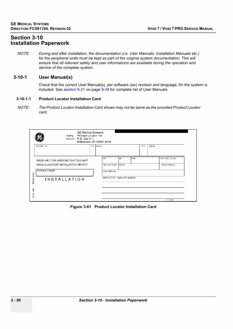
GE MEDICAL SYSTEMSDIRECTION FC091194, REVISION 02 VIVID 7 / VIVID 7 PRO SERVICE MANUAL
3 - 56 Section 3-10 - Installation Paperwork
Section 3-10Installation Paperwork
NOTE: During and after installation, the documentation (i.e. User Manuals, Installation Manuals etc.) for the peripheral units must be kept as part of the original system documentation. This will ensure that all relevant safety and user informations are available during the operation and service of the complete system.
3-10-1 User Manual(s)Check that the correct User Manual(s), per software (sw) revision and language, for the system is included. See section 9-21 on page 9-34 for complete list of User Manuals.
3-10-1-1 Product Locator Installation Card
NOTE: The Product Locator Installation Card shown may not be same as the provided Product Locator card.
Figure 3-61 Product Locator Installation Card

GE MEDICAL SYSTEMSDIRECTION FC091194, REVISION 02 VIVID 7 / VIVID 7 PRO SERVICE MANUAL
Chapter 3 - Installation 3 - 57
3-10-2 Complete the Post Delivery Check List Please fill in the enclosed form “Post Delivery Check List” (at the back of this reminder) and fax it to our System Test Department, Fax # +47 3302 1354, as soon as you have powered up and checked the system.This is most important for us to ensure top quality on our delivery. If any deviation according to specifications occurs, the responsible system tester will contact you immediately.

GE MEDICAL SYSTEMSDIRECTION FC091194, REVISION 02 VIVID 7 / VIVID 7 PRO SERVICE MANUAL
3 - 58 Section 3-10 - Installation Paperwork
3-10-3 Post Delivery Check ListFill in your observations and return the check list to:
GE Vingmed UltrasoundFax No.: +47 3302 1354Attention: System Test Department
System tester: ____________________________________________ (please use BLOCK LETTERS)
Post Delivery Check List for Vivid______________ Serial NO:_____________________
SUBJECT OK NOT OK COMMENTS
Packing
Loose screws /Hard Ware
Overall appearance
System documents (Followers, cont.lists)
Functional test
2D image
M-Mode
Doppler spectral
Color doppler
Configuration
Peripherals
EchoPAC PC
Probes
Corrective actionsReplaced boards/probesdocumented by S/N
Missing parts
Contact and signature
Do you want the responsible system tester to contact you YES: ___________________ NO:______________________
Sign:Date: ___________________ Fax page. ________ of _________
GE MEDICAL SYSTEMSDIRECTION FC091194, REVISION 02 VIVID 7 / VIVID 7 PRO SERVICE MANUAL
Chapter 4 - Functional Checks 4 - 1
Chapter 4 Functional Checks
Section 4-1 Overview
4-1-1 Purpose of Chapter 4This chapter provides procedures for quickly checking major functions of the Vivid 7 / Vivid 7 PRO scanner, diagnostics by using the built-in service software, and power supply adjustments.
4-1-2 Special Equipment Required• An empty (blank) MO Disk;
- P/N: 066E0490 (1.3 GB) - P/N: 066E0519 (5.4 GB)- P/N: 066E0514 (8.6 GB)
• ECG Pads• ECG Harness, CABLE ECG MARQ. AHA/AMERICA, P/N:164L0025
- CABLE ECG MARQ. AHA/AMERICA, P/N:164L0025- LEADWIRES ECG MARQ. AHA/AMERICA, P/N: 164L0027
or
- CABLE ECG MARQ. IEC / EU + AS, P/N:164L0026- LEADWIRES ECG MARQ. IEC/EU+AS, P/N:164L0028
• At least one probe (ideally you should check all the probes used on the system by the site.)See Probes on page 9-28, for an overview of available probes
Table 4-1 Contents in chapter 4
Section Description Page Number
4-1 Overview 4-1
4-2 General Procedures 4-2
4-3 Functional Checks 4-14
4-4 Application Turnover Check List 4-63
4-5 Power Supply 4-64
4-6 Site Log 4-65
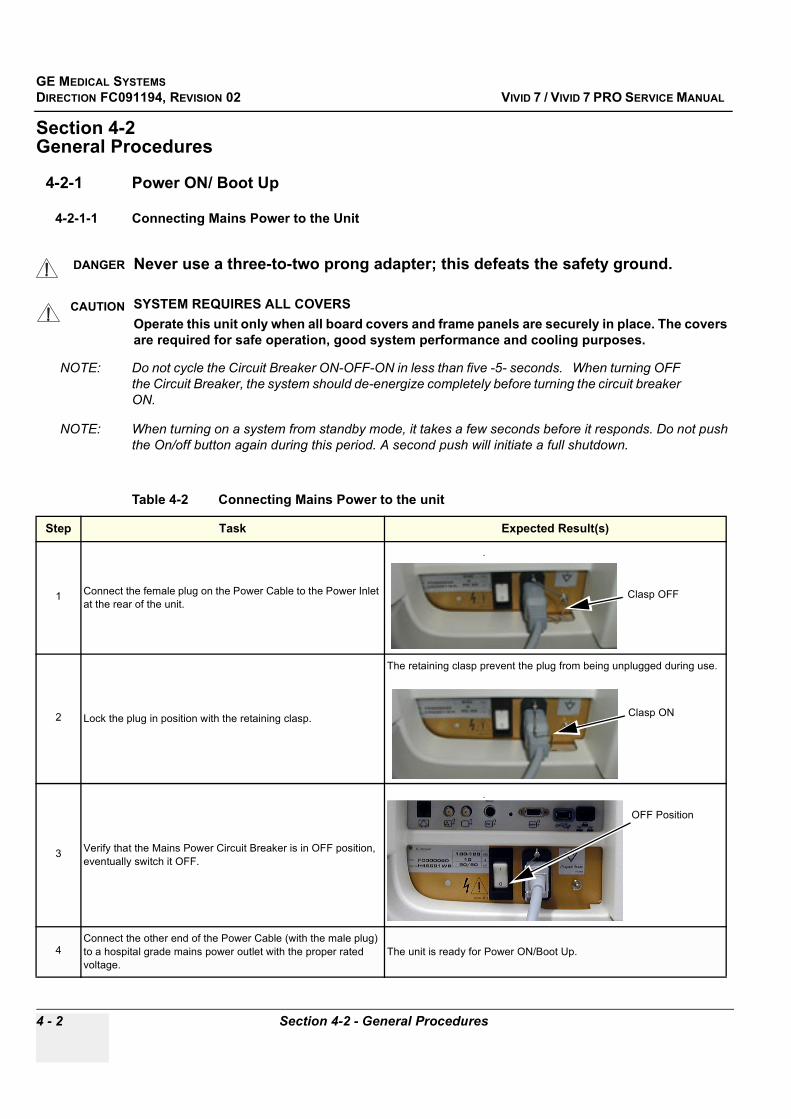
GE MEDICAL SYSTEMSDIRECTION FC091194, REVISION 02 VIVID 7 / VIVID 7 PRO SERVICE MANUAL
4 - 2 Section 4-2 - General Procedures
Section 4-2General Procedures
4-2-1 Power ON/ Boot Up
4-2-1-1 Connecting Mains Power to the Unit
NOTE: Do not cycle the Circuit Breaker ON-OFF-ON in less than five -5- seconds. When turning OFF the Circuit Breaker, the system should de-energize completely before turning the circuit breaker ON.
NOTE: When turning on a system from standby mode, it takes a few seconds before it responds. Do not push the On/off button again during this period. A second push will initiate a full shutdown.
DANGER Never use a three-to-two prong adapter; this defeats the safety ground.
CAUTION SYSTEM REQUIRES ALL COVERSOperate this unit only when all board covers and frame panels are securely in place. The covers are required for safe operation, good system performance and cooling purposes.
Table 4-2 Connecting Mains Power to the unit
Step Task Expected Result(s)
1 Connect the female plug on the Power Cable to the Power Inlet at the rear of the unit.
.
2 Lock the plug in position with the retaining clasp.
The retaining clasp prevent the plug from being unplugged during use.
3 Verify that the Mains Power Circuit Breaker is in OFF position, eventually switch it OFF.
.
4Connect the other end of the Power Cable (with the male plug) to a hospital grade mains power outlet with the proper rated voltage.
The unit is ready for Power ON/Boot Up.
Clasp OFF
Clasp ON
OFF Position

GE MEDICAL SYSTEMSDIRECTION FC091194, REVISION 02 VIVID 7 / VIVID 7 PRO SERVICE MANUAL
Chapter 4 - Functional Checks 4 - 3
4-2-1-2 Turn Unit ON
Table 4-3 Turn Unit ON
Step Task Expected Result(s)
1
Switch ON the Mains Power Circuit Breaker at the rear of the unit.
You will hear a “click” from the relays in the AC Power/AC Controller. The unit is ready for Boot Up.
2
Press the ON/OFF key on the Control Panel (Keyboard) once..
1) The unit’s ventilation fan starts on full speed, but slows down after a few seconds (listen to the fan noise).2) Power is distributed to the peripherals, Control Panel (Console), Monitor, Card Rack and Backend Processor.3) Backend Processor and rest of Scanner starts with the following sequence:4) Backend Processor is turned ON and starts to load the software.5) The Start Screen (Vivid) is displayed on the monitor6) A start-up bar is displayed on the monitor, indicating the progress of the software loading.
NOTE: If the unit has been in the OFF condition for an extended period of time, (3 to 5 days or more), the unit may not boot, or may beep when turned on. See “System Doesn’t Boot” on page 7-67. for more details, including how to recover.
Mains Power Circuit Breaker in ON position
ON/OFF key

GE MEDICAL SYSTEMSDIRECTION FC091194, REVISION 02 VIVID 7 / VIVID 7 PRO SERVICE MANUAL
4 - 4 Section 4-2 - General Procedures
3 Wait for the unit to boot.
The software initiates and set up the Card Rack and the rest of the instrument.The backlight in the keyboard is lit.As soon as the software has been loaded, a 2D screen is displayed on the screen.
Total time used for start-up is typically three minutes.
Table 4-3 Turn Unit ON (continued)
Step Task Expected Result(s)
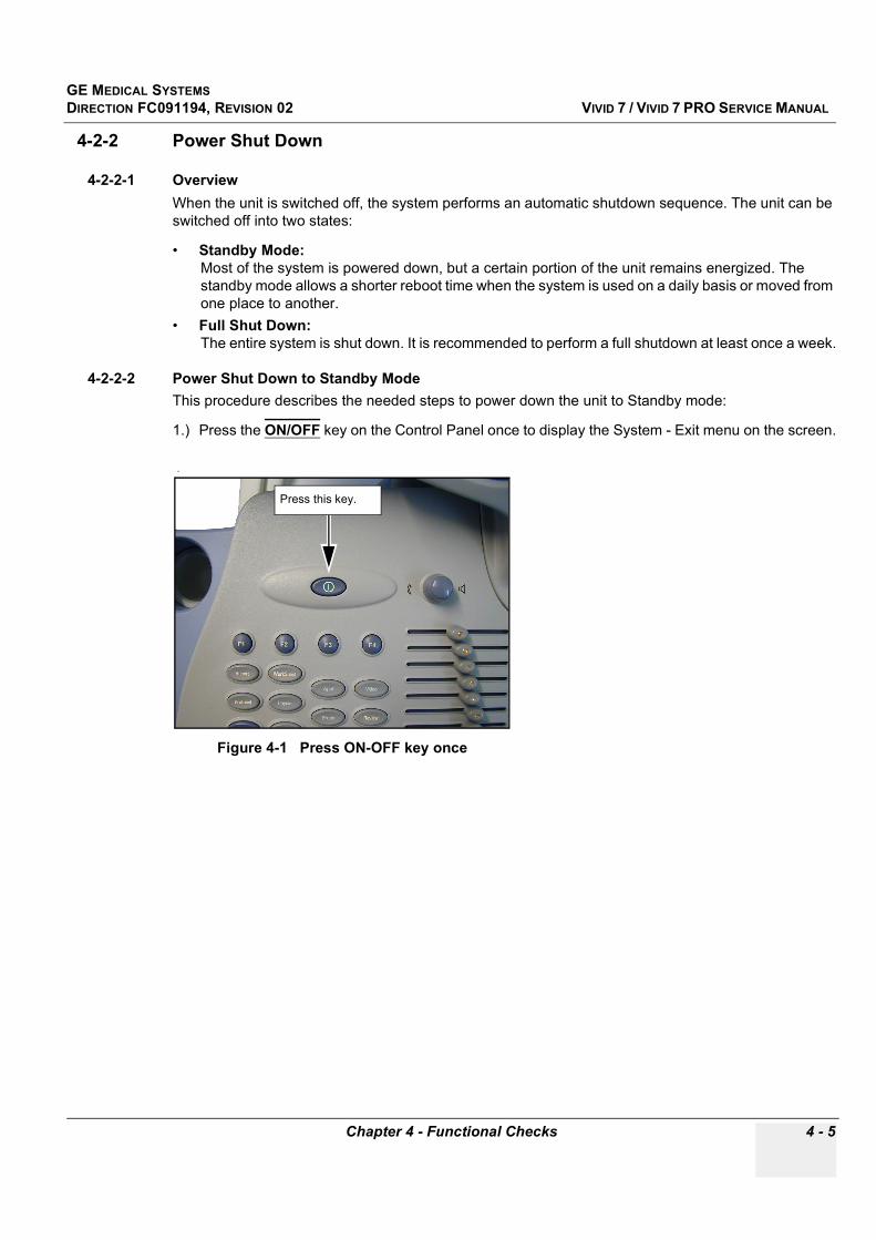
GE MEDICAL SYSTEMSDIRECTION FC091194, REVISION 02 VIVID 7 / VIVID 7 PRO SERVICE MANUAL
Chapter 4 - Functional Checks 4 - 5
4-2-2 Power Shut Down
4-2-2-1 OverviewWhen the unit is switched off, the system performs an automatic shutdown sequence. The unit can be switched off into two states:
• Standby Mode: Most of the system is powered down, but a certain portion of the unit remains energized. The standby mode allows a shorter reboot time when the system is used on a daily basis or moved from one place to another.
• Full Shut Down: The entire system is shut down. It is recommended to perform a full shutdown at least once a week.
4-2-2-2 Power Shut Down to Standby ModeThis procedure describes the needed steps to power down the unit to Standby mode:
1.) Press the ON/OFF key on the Control Panel once to display the System - Exit menu on the screen.
.
Figure 4-1 Press ON-OFF key once
Press this key.

GE MEDICAL SYSTEMSDIRECTION FC091194, REVISION 02 VIVID 7 / VIVID 7 PRO SERVICE MANUAL
4 - 6 Section 4-2 - General Procedures
4-2-2-2 Power Shut Down to Standby Mode (cont’d)
The System - Exit menu gives you the following choices:
- Logoff Use this button to log off the current user. The system remains on and ready for a new user to log on.The dimmed button in Figure 4-2 on page 4-6 indicates that no user is logged on to the unit at the moment.
- StandbyUse this button to select the Standby mode, allowing a shorter reboot time. The next step describes the use of this button.
- Shutdown... Use this button to Shut Down the system.
- Cancel Use this button to exit from the System-Exit menu and return to the previous operation.
2.) Click STANDBY to select Standby mode.If the power cable is removed from the wall outlet the system will remain in Standby mode for approximately 15 minutes. If the system is unplugged for a longer period of time, a full shutdown is automatically performed.
NOTE: When turning on a system from standby mode, it takes a few seconds before it responds. Do not push the On/off button again during this period. A second push will initiate a full shutdown.
Figure 4-2 System - Exit menu

GE MEDICAL SYSTEMSDIRECTION FC091194, REVISION 02 VIVID 7 / VIVID 7 PRO SERVICE MANUAL
Chapter 4 - Functional Checks 4 - 7
4-2-2-3 Full Power Shut DownThis procedure describes the needed steps to do a complete power down of the system:
1.) Press the ON/OFF key on the Control Panel once to display the System - Exit menu on the screen.
The System - Exit menu gives you the following choices:
- Logoff Use this button to log off the current user. The system remains on and ready for a new user to log on.The dimmed button in Figure 4-2 on page 4-6 indicates that no user is logged on to the unit at the moment.
- StandbyUse this button to select the Standby mode, allowing a shorter reboot time.
- Shutdown... Use this button to Shut Down the system.The next step describes the use of this button.
- Cancel Use this button to exit from the System-Exit menu and return to the previous operation.
.
Figure 4-3 Press ON-OFF key once
Figure 4-4 System - Exit menu
Press this key.

GE MEDICAL SYSTEMSDIRECTION FC091194, REVISION 02 VIVID 7 / VIVID 7 PRO SERVICE MANUAL
4 - 8 Section 4-2 - General Procedures
4-2-2-3 Full Power Shut Down (cont’d)2.) Click SHUTDOWN to do a complete power down of the unit.
Backend Processor will first turn OFF the Scanner activity and print the message “Please wait - Shutdown in progress” in the LCD display. Then it starts to shut down itself. The time to turn down the Scanner including the Backend Processor, may vary from 10 seconds up to approximately 1 minute. The last thing that shut down, is the light in the LCD displays, indicating that you can continue to the next step.
3.) Switch OFF the CIRCUIT BREAKER (located on the rear of the unit)
This will cut power distribution within the unit.
If the Backend Processor is still running, the internal Un-interupted Power Supply (UPS) will switch over to battery power and supply the Backend Processor with power until it has shut down properly. A periodic high-pitch sound alarm indicates that the Backend Processor is running on battery power.
.
Figure 4-5 Circuit Breaker located on rear of the unitCircuit Breaker
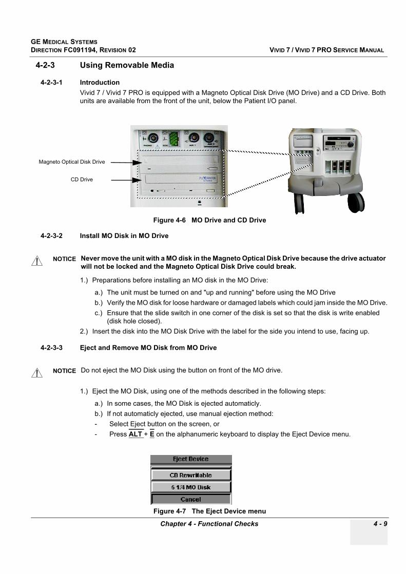
GE MEDICAL SYSTEMSDIRECTION FC091194, REVISION 02 VIVID 7 / VIVID 7 PRO SERVICE MANUAL
Chapter 4 - Functional Checks 4 - 9
4-2-3 Using Removable Media
4-2-3-1 IntroductionVivid 7 / Vivid 7 PRO is equipped with a Magneto Optical Disk Drive (MO Drive) and a CD Drive. Both units are available from the front of the unit, below the Patient I/O panel.
4-2-3-2 Install MO Disk in MO Drive
1.) Preparations before installing an MO disk in the MO Drive:
a.) The unit must be turned on and "up and running" before using the MO Driveb.) Verify the MO disk for loose hardware or damaged labels which could jam inside the MO Drive.c.) Ensure that the slide switch in one corner of the disk is set so that the disk is write enabled
(disk hole closed).2.) Insert the disk into the MO Disk Drive with the label for the side you intend to use, facing up.
4-2-3-3 Eject and Remove MO Disk from MO Drive
1.) Eject the MO Disk, using one of the methods described in the following steps:
a.) In some cases, the MO Disk is ejected automaticly.b.) If not automaticly ejected, use manual ejection method: - Select Eject button on the screen, or- Press ALT + E on the alphanumeric keyboard to display the Eject Device menu.
Figure 4-6 MO Drive and CD Drive
NOTICE Never move the unit with a MO disk in the Magneto Optical Disk Drive because the drive actuator will not be locked and the Magneto Optical Disk Drive could break.
NOTICE Do not eject the MO Disk using the button on front of the MO drive.
Figure 4-7 The Eject Device menu
Magneto Optical Disk Drive
CD Drive
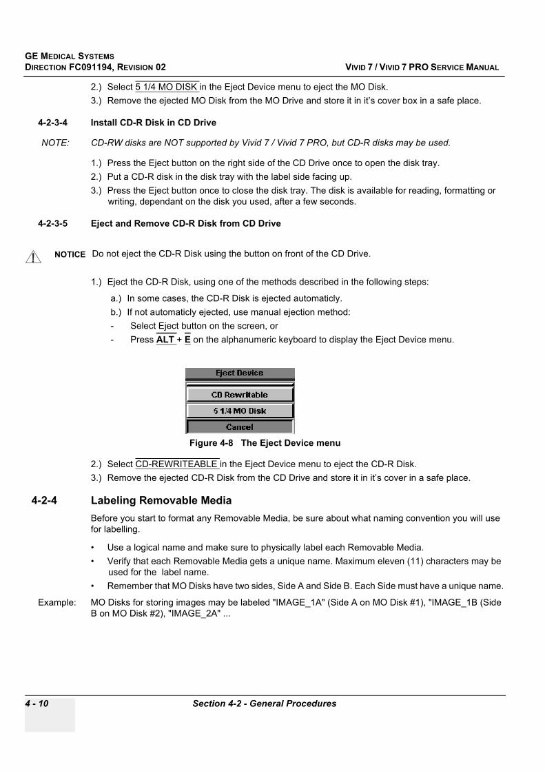
GE MEDICAL SYSTEMSDIRECTION FC091194, REVISION 02 VIVID 7 / VIVID 7 PRO SERVICE MANUAL
4 - 10 Section 4-2 - General Procedures
2.) Select 5 1/4 MO DISK in the Eject Device menu to eject the MO Disk.3.) Remove the ejected MO Disk from the MO Drive and store it in it’s cover box in a safe place.
4-2-3-4 Install CD-R Disk in CD Drive
NOTE: CD-RW disks are NOT supported by Vivid 7 / Vivid 7 PRO, but CD-R disks may be used.
1.) Press the Eject button on the right side of the CD Drive once to open the disk tray. 2.) Put a CD-R disk in the disk tray with the label side facing up.3.) Press the Eject button once to close the disk tray. The disk is available for reading, formatting or
writing, dependant on the disk you used, after a few seconds.
4-2-3-5 Eject and Remove CD-R Disk from CD Drive
1.) Eject the CD-R Disk, using one of the methods described in the following steps:
a.) In some cases, the CD-R Disk is ejected automaticly.b.) If not automaticly ejected, use manual ejection method: - Select Eject button on the screen, or- Press ALT + E on the alphanumeric keyboard to display the Eject Device menu.
2.) Select CD-REWRITEABLE in the Eject Device menu to eject the CD-R Disk.3.) Remove the ejected CD-R Disk from the CD Drive and store it in it’s cover in a safe place.
4-2-4 Labeling Removable MediaBefore you start to format any Removable Media, be sure about what naming convention you will use for labelling.
• Use a logical name and make sure to physically label each Removable Media. • Verify that each Removable Media gets a unique name. Maximum eleven (11) characters may be
used for the label name. • Remember that MO Disks have two sides, Side A and Side B. Each Side must have a unique name.
Example: MO Disks for storing images may be labeled "IMAGE_1A" (Side A on MO Disk #1), "IMAGE_1B (Side B on MO Disk #2), "IMAGE_2A" ...
NOTICE Do not eject the CD-R Disk using the button on front of the CD Drive.
Figure 4-8 The Eject Device menu

GE MEDICAL SYSTEMSDIRECTION FC091194, REVISION 02 VIVID 7 / VIVID 7 PRO SERVICE MANUAL
Chapter 4 - Functional Checks 4 - 11
4-2-5 Formatting Removable MediaThis procedure describes how to format an MO Disk or a CD-R disk.
Before you continue, be sure about what naming convention you will use for labelling the Removable Media.
1.) Select Config > Connectivity > Media2.) Select the removable media from the Media pop-up menu.3.) Enter a name for the removable media in the Label field.4.) Press FORMAT.5.) Wait for the display of the Information window indicating that the formatting process is completed.
NOTE: Do not eject the CD using the button on the CD drive
6.) Press ALT+E to display the Eject Device menu.7.) Select the relevant media. The selected media is ejected.
4-2-6 Verifying Removable Media1.) Insert the removable media to verify.2.) Select the pre-configured removable media from the Config > Connectivity > Media pop-up menu.3.) Press VERIFY. The unit starts to verify the DICOM directory on the selected media.
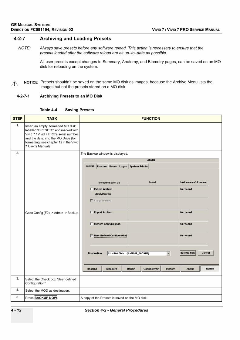
GE MEDICAL SYSTEMSDIRECTION FC091194, REVISION 02 VIVID 7 / VIVID 7 PRO SERVICE MANUAL
4 - 12 Section 4-2 - General Procedures
4-2-7 Archiving and Loading Presets
NOTE: Always save presets before any software reload. This action is necessary to ensure that the presets loaded after the software reload are as up–to–date as possible.
All user presets except changes to Summary, Anatomy, and Biometry pages, can be saved on an MO disk for reloading on the system.
4-2-7-1 Archiving Presets to an MO Disk
NOTICE Presets shouldn’t be saved on the same MO disk as images, because the Archive Menu lists the images but not the presets stored on a MO disk.
Table 4-4 Saving Presets
STEP TASK FUNCTION
1. Insert an empty, formatted MO disk labelled “PRESETS” and marked with Vivid 7 / Vivid 7 PRO’s serial number and the date, into the MO Drive (for formatting, see chapter 12 in the Vivid 7 User’s Manual).
2.
Go to Config (F2) -> Admin -> Backup
The Backup window is displayed.
3. Select the Check box “User defined Configuration”.
4. Select the MOD as destination.
5. Press BACKUP NOW. A copy of the Presets is saved on the MO disk.

GE MEDICAL SYSTEMSDIRECTION FC091194, REVISION 02 VIVID 7 / VIVID 7 PRO SERVICE MANUAL
Chapter 4 - Functional Checks 4 - 13
4-2-7-2 Loading Presets from an MO Disk
6. Press ALT + E on the alphanumeric keyboard. The MO disk is ejected.
Table 4-5 Loading Presets
STEP TASK FUNCTION
1. Insert the MO disk with the archived presets into the MOD.
2.
Go to Config (F2) -> Admin -> Restore
The Restore window is displayed.
3. Select the Check box “User defined Configuration”.
4. Select the MOD as source.
5. Press RESTORE NOW The Presets are restored to the System.
6. Press ALT + E on the alphanumeric keyboard. The MO disk is ejected.
Table 4-4 Saving Presets (continued)
STEP TASK FUNCTION
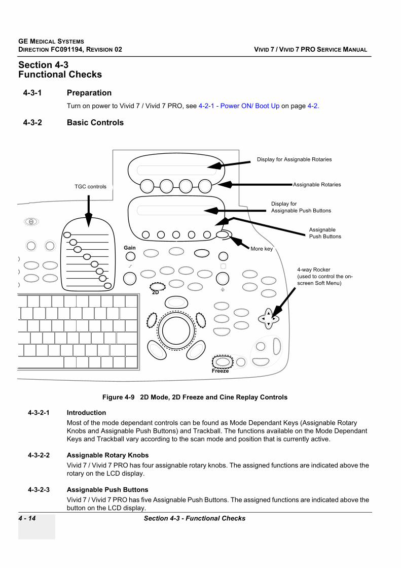
GE MEDICAL SYSTEMSDIRECTION FC091194, REVISION 02 VIVID 7 / VIVID 7 PRO SERVICE MANUAL
4 - 14 Section 4-3 - Functional Checks
Section 4-3Functional Checks
4-3-1 PreparationTurn on power to Vivid 7 / Vivid 7 PRO, see 4-2-1 - Power ON/ Boot Up on page 4-2.
4-3-2 Basic Controls
4-3-2-1 Introduction Most of the mode dependant controls can be found as Mode Dependant Keys (Assignable Rotary Knobs and Assignable Push Buttons) and Trackball. The functions available on the Mode Dependant Keys and Trackball vary according to the scan mode and position that is currently active.
4-3-2-2 Assignable Rotary KnobsVivid 7 / Vivid 7 PRO has four assignable rotary knobs. The assigned functions are indicated above the rotary on the LCD display.
4-3-2-3 Assignable Push ButtonsVivid 7 / Vivid 7 PRO has five Assignable Push Buttons. The assigned functions are indicated above the button on the LCD display.
Figure 4-9 2D Mode, 2D Freeze and Cine Replay Controls
Assignable RotariesTGC controls
Display for Assignable Rotaries
Assignable Push Buttons
4-way Rocker (used to control the on-screen Soft Menu)
More key
Display for Assignable Push Buttons
Gain
2D
Freeze

GE MEDICAL SYSTEMSDIRECTION FC091194, REVISION 02 VIVID 7 / VIVID 7 PRO SERVICE MANUAL
Chapter 4 - Functional Checks 4 - 15
4-3-2-4 MoreThe MORE button gives access to additional controls on the Assignable Push Buttons.
4-3-2-5 Soft Menu Control (4-way Rocker)The 4-way Rocker works together with the Soft menu on the screen.
• The vertical arrows (up/down) are used to do selections from the Soft Menu.• The horizontal arrows (left/right) are used to do adjustments on the selected function.
4-3-2-6 Trackball areaDifferent functions can be assigned to the trackball depending of the current active mode. The Trackball area consist of:
• The Trackball: used as a cursor control in acquisition mode, scrolling control in freeze and as a selection tool (like a mouse cursor) in post-processing mode.
• Three SELECT keys (identical): Perform the selected control or highlighted menu item.• The TRACKBALL key: Toggles between the available trackball function assignments displayed in
the Status bar.• The update menu key: enables quick access to image related functions from a pop-up menu.
4-3-2-7 Other ControlsOther controls are located on separate keys (knobs and buttons) or groups of keys on the Control Panel.

GE MEDICAL SYSTEMSDIRECTION FC091194, REVISION 02 VIVID 7 / VIVID 7 PRO SERVICE MANUAL
4 - 16 Section 4-3 - Functional Checks
4-3-3 Performance Tests
4-3-3-1 Recommended Test PhantomsGE Medical Systems recommends the RMI 430GS phantom. It is the most current phantom recommended to our field service personnel and provides the necessary targets and extended life necessary for consistent system testing.
Figure 4-10 Performance tests
2
4 3 2 1
4
6
8
10
12
14
16
RMI 403GS
Lateral DistanceMeasurement
FunctionalResolution
ContrastResolution
&Gray Scale
Photography
LateralResolution
AxialResolution
Axial DistanceMeasurement
Penetration

GE MEDICAL SYSTEMSDIRECTION FC091194, REVISION 02 VIVID 7 / VIVID 7 PRO SERVICE MANUAL
Chapter 4 - Functional Checks 4 - 17
4-3-4 2D Mode (B mode) Checks
4-3-4-1 IntroductionThe 2D Mode is the system’s default mode.
4-3-4-2 PreparationsUse a phantom when doing these tests.
1.) Connect one of the probes, to the scanner’s left-most active probe connector. - See "Probe Connection" on page 3-13 for info about connecting the probes.- See Chapter 9 - , section 9-17 for available probes.
2.) Turn ON the scanner.- See 4-2-1 - Power ON/ Boot Up on page 4-2 for info about booting the scanner.
The 2D Mode window is displayed (default mode).
3.) If needed, adjust the Display’s Brightness and Contrast setting (See “Monitor Adjustments” on page 6-2.).
Figure 4-11 2D Mode Screen Example
Status Window
Control Menu
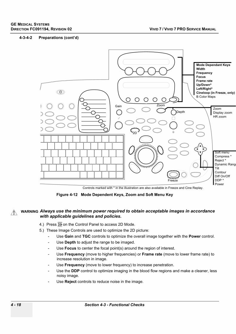
GE MEDICAL SYSTEMSDIRECTION FC091194, REVISION 02 VIVID 7 / VIVID 7 PRO SERVICE MANUAL
4 - 18 Section 4-3 - Functional Checks
4-3-4-2 Preparations (cont’d)
4.) Press 2D on the Control Panel to access 2D Mode.5.) These Image Controls are used to optimize the 2D picture:
- Use Gain and TGC controls to optimize the overall image together with the Power control.- Use Depth to adjust the range to be imaged.- Use Focus to center the focal point(s) around the region of interest.- Use Frequency (move to higher frequencies) or Frame rate (move to lower frame rate) to
increase resolution in image.- Use Frequency (move to lower frequency) to increase penetration.- Use the DDP control to optimize imaging in the blood flow regions and make a cleaner, less
noisy image.- Use Reject controls to reduce noise in the image.
Figure 4-12 Mode Dependent Keys, Zoom and Soft Menu Key
WARNINGWARNING Always use the minimum power required to obtain acceptable images in accordance with applicable guidelines and policies.
Depth
Gain
Mode Dependant KeysWidthFrequencyFocusFrame rateUp/Down* Left/Right* Cineloop (in Freeze, only)B Color Maps
Soft menuCompress *Reject *Dynamic RangeTiltContourDiff On/OffDDP *Power
2D
Freeze
Controls marked with * in the illustration are also available in Freeze and Cine Replay.
ZoomZoomDisplay zoomHR zoom

GE MEDICAL SYSTEMSDIRECTION FC091194, REVISION 02 VIVID 7 / VIVID 7 PRO SERVICE MANUAL
Chapter 4 - Functional Checks 4 - 19
4-3-4-3 Check Width, Focus, Framerate, FrequencyThese 2D Mode Functions are located on Assignable Rotaries.
The results of these adjustments must be verified on the 2D sector on the screen.
Table 4-6 2D Mode: Check Width, Focus, Framerate and Frequency
Step Task Expected Result
1. Turn the rotary labeled WIDTH left and right.Controls the size or angular width of the 2D image sector. A smaller angle generally produces a scan with higher frame rate.
2. Turn the rotary labeled FOCUS left and right to move the focal point up and down.
Changes the location of the focal point(s).A triangular focus marker indicates the depth of the focal point.
3. Turn the rotary labeled FRAMERATE left and right to adjust the Frame Rate
Adjusts frame rate. Rotate the knob clockwise to increase frame rate. The relative setting of the frame rate is displayed in the status window. When adjusting frame rate, there is a trade off between spatial and temporal resolution.
4. Turn the rotary labeled FREQUENCY left and right to verify that the probe’s operating frequency can be adjusted
Enables the adjustment of the probe’s operating frequency. Rotate the knob clockwise to increase the frequency.The selected frequency is displayed in the status window. For some probes/applications, the lowest frequency settings will be Octave Imaging settings.
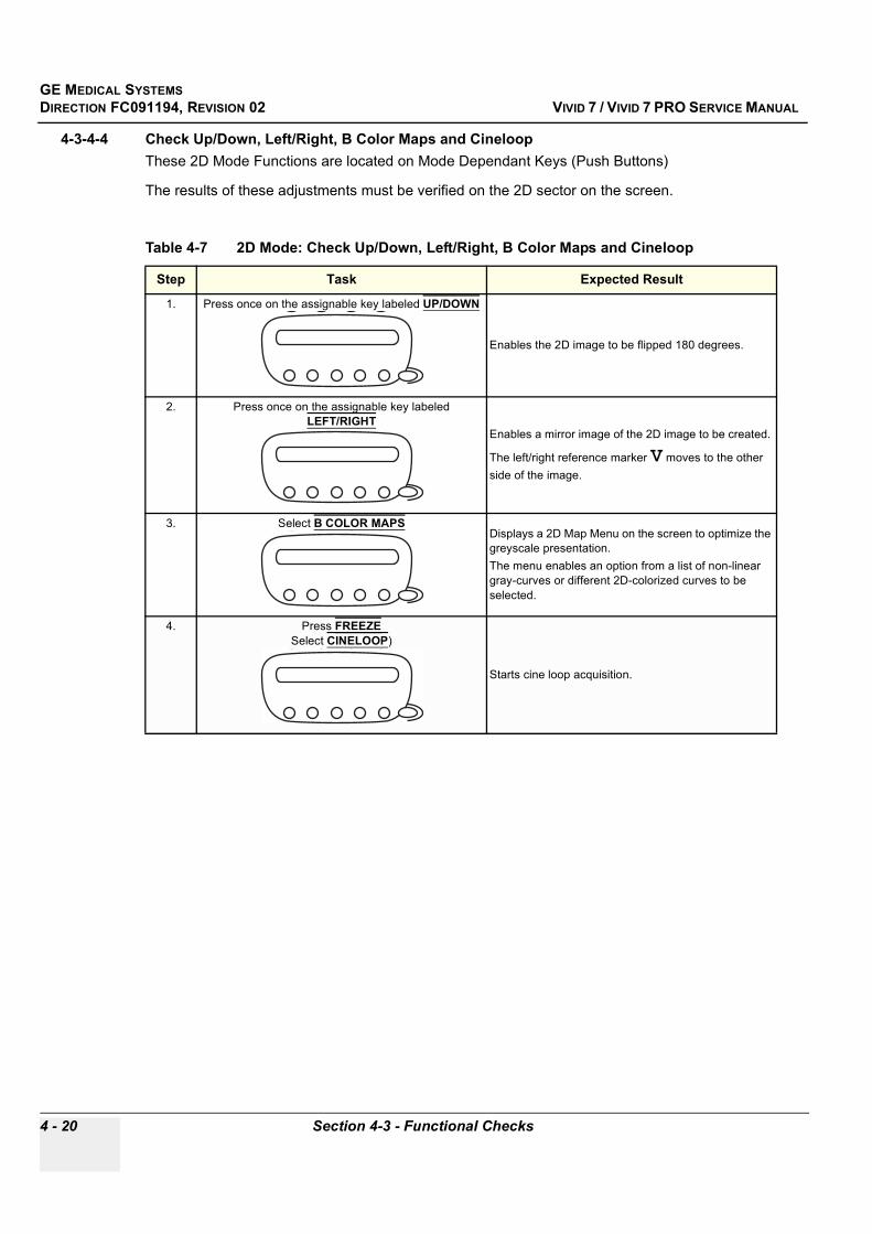
GE MEDICAL SYSTEMSDIRECTION FC091194, REVISION 02 VIVID 7 / VIVID 7 PRO SERVICE MANUAL
4 - 20 Section 4-3 - Functional Checks
4-3-4-4 Check Up/Down, Left/Right, B Color Maps and Cineloop These 2D Mode Functions are located on Mode Dependant Keys (Push Buttons)
The results of these adjustments must be verified on the 2D sector on the screen.
Table 4-7 2D Mode: Check Up/Down, Left/Right, B Color Maps and Cineloop
Step Task Expected Result
1. Press once on the assignable key labeled UP/DOWN
Enables the 2D image to be flipped 180 degrees.
2. Press once on the assignable key labeled LEFT/RIGHT
Enables a mirror image of the 2D image to be created.
The left/right reference marker V moves to the other side of the image.
3. Select B COLOR MAPS Displays a 2D Map Menu on the screen to optimize the greyscale presentation. The menu enables an option from a list of non-linear gray-curves or different 2D-colorized curves to be selected.
4. Press FREEZE Select CINELOOP)
Starts cine loop acquisition.
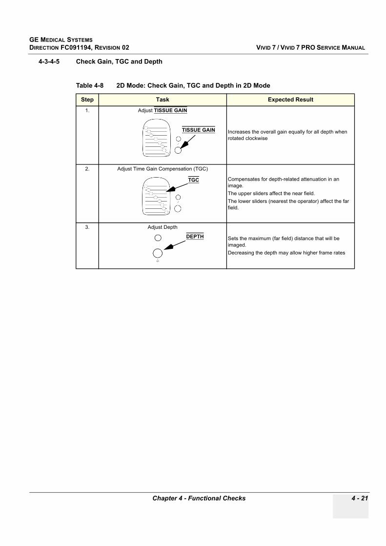
GE MEDICAL SYSTEMSDIRECTION FC091194, REVISION 02 VIVID 7 / VIVID 7 PRO SERVICE MANUAL
Chapter 4 - Functional Checks 4 - 21
4-3-4-5 Check Gain, TGC and Depth
Table 4-8 2D Mode: Check Gain, TGC and Depth in 2D Mode
Step Task Expected Result
1. Adjust TISSUE GAIN
Increases the overall gain equally for all depth when rotated clockwise
2. Adjust Time Gain Compensation (TGC)
Compensates for depth-related attenuation in an image. The upper sliders affect the near field.The lower sliders (nearest the operator) affect the far field.
3. Adjust Depth
Sets the maximum (far field) distance that will be imaged. Decreasing the depth may allow higher frame rates
TISSUE GAIN
TGC
DEPTH

GE MEDICAL SYSTEMSDIRECTION FC091194, REVISION 02 VIVID 7 / VIVID 7 PRO SERVICE MANUAL
4 - 22 Section 4-3 - Functional Checks
4-3-4-6 2D Soft Menu Controls
4-3-4-7 Check Compress, Contour, Reject and Tilt
Table 4-9 4-way rocker used for Soft Menu control
KEY DESCRIPTION
A 4-way rocker (4-way multi direction switch) used to;- access mode-specific menus on the screen.- select a menu option.- adjust option-related values.When using the Rocker;- the vertical arrows are used to select the menu options.- the horizontal arrows are used to adjust the values.
Table 4-10 2D Mode: Check Compress, Contour, Reject and Tilt
Step Task Expected Result(s)
1.Use the vertical arrows to select Compress. Use the horizontal arrows to adjust Compress.
Compress controls the amount of contrast in the 2D image. An index number is displayed in the status window to indicate the relative level of compression.
2. Use the vertical arrows to select Contour.Use the horizontal arrows to adjust Contour.
Contour controls image processing related to the extent of edge enhancement applied to an image.
3.Use the vertical arrows to select Reject.Use the horizontal arrows to adjust Reject.
When Reject is increased, low-level echoes and noise are rejected and appear darker in the 2D image. An index number is displayed in the status window to indicate the relative level of rejection.
4.
Use the vertical arrows to select Tilt.Use the horizontal arrows to adjust Tilt.
Tilts the axis of the 2D image to the left or right. By using this control in combination with Angle control, the image can be “aligned” to the direction of interest, and frame rates be optimized. By default the axis of symmetry of a 2D image is vertical.

GE MEDICAL SYSTEMSDIRECTION FC091194, REVISION 02 VIVID 7 / VIVID 7 PRO SERVICE MANUAL
Chapter 4 - Functional Checks 4 - 23
4-3-4-8 Check DDP, Diff, Power and Dynamic Range
Table 4-11 2D Mode: Check DDP, Diff, Power and Dynamic Range
Step Task Expected Result(s)
1.Use the vertical arrows to select DDP (Data Dependent Processing).Use the horizontal arrows to adjust DDP.
Performs temporal processing which reduces random noise without affecting the motion of significant tissue structures. An index number is displayed in the status window (under Proc) to indicate the relative DDP level.
2.Use the vertical arrows to select Diff.Use the horizontal arrows to turn Diff On/Off.
Affects the level of reverberations in the image.When turned ON, the frame rate (or the number of focal zones) will decrease, while the reverberations will be attenuated.
3.
Use the vertical arrows to select Power.Use the horizontal arrows to adjust Power.
Controls the amount of acoustic power applied in all modes.When power is set to maximum, it is equal to or less than the maximum acoustic power permitted by the FDA.The Thermal Index (TI) and the Mechanical Index (MI) are displayed on the screen.
4.Use the vertical arrows to select Dynamic Range. Use the horizontal arrows to adjust Dynamic Range.
Enables control of the dynamic range or contrast of the image.When Dynamic Range is set high, the image is softer and more low-level data is visible.

GE MEDICAL SYSTEMSDIRECTION FC091194, REVISION 02 VIVID 7 / VIVID 7 PRO SERVICE MANUAL
4 - 24 Section 4-3 - Functional Checks
4-3-5 M Mode Checks
4-3-5-1 Introduction
4-3-5-2 PreparationsUse a phantom when doing these tests.
1.) Connect one of the probes, to the scanner’s left-most probe connector.- See "Probe Connection" on page 3-13 for info about connecting the probes.- See Chapter 9 - , section 9-17 for available probes.
2.) Turn ON the scanner.- See see 4-2-1 - Power ON/ Boot Up on page 4-2 for info about booting the scanner.
The 2D Mode window is displayed (default mode).
3.) Press M-MODE to bring up an M-Mode picture on the screen.
Figure 4-13 M-Mode Screen Example
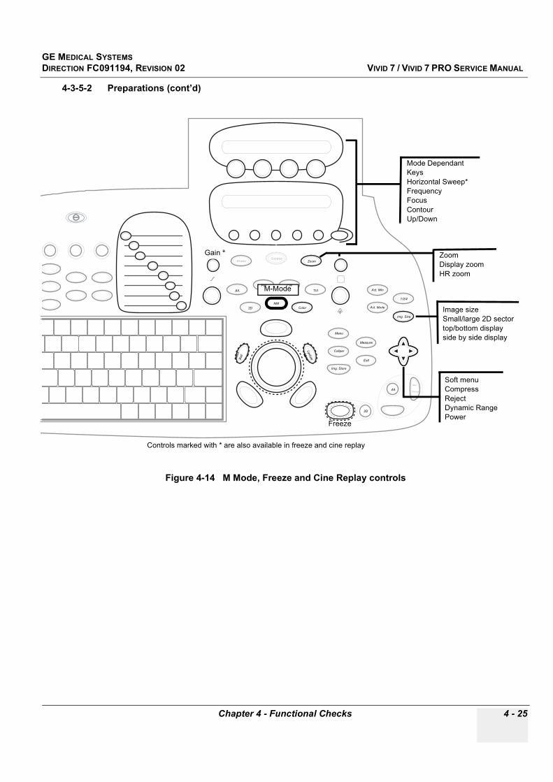
GE MEDICAL SYSTEMSDIRECTION FC091194, REVISION 02 VIVID 7 / VIVID 7 PRO SERVICE MANUAL
Chapter 4 - Functional Checks 4 - 25
4-3-5-2 Preparations (cont’d)
Figure 4-14 M Mode, Freeze and Cine Replay controls
Exit
Gain *
Mode Dependant KeysHorizontal Sweep*FrequencyFocusContourUp/Down
Soft menuCompressRejectDynamic RangePower
Freeze
Controls marked with * are also available in freeze and cine replay
SteerCursor
Zoom
Alt.PW CW
TVI
2DMM
Color
Trac
kBa
llU
pdate
Menu
Act. Win
Act. Mode
Img. Size
1/2/4
Menu
Measure
Exit
Caliper
Img. Store
2D
Alt.Rec.
Pause
ZoomDisplay zoomHR zoom
Image sizeSmall/large 2D sector top/bottom displayside by side display
M-Mode
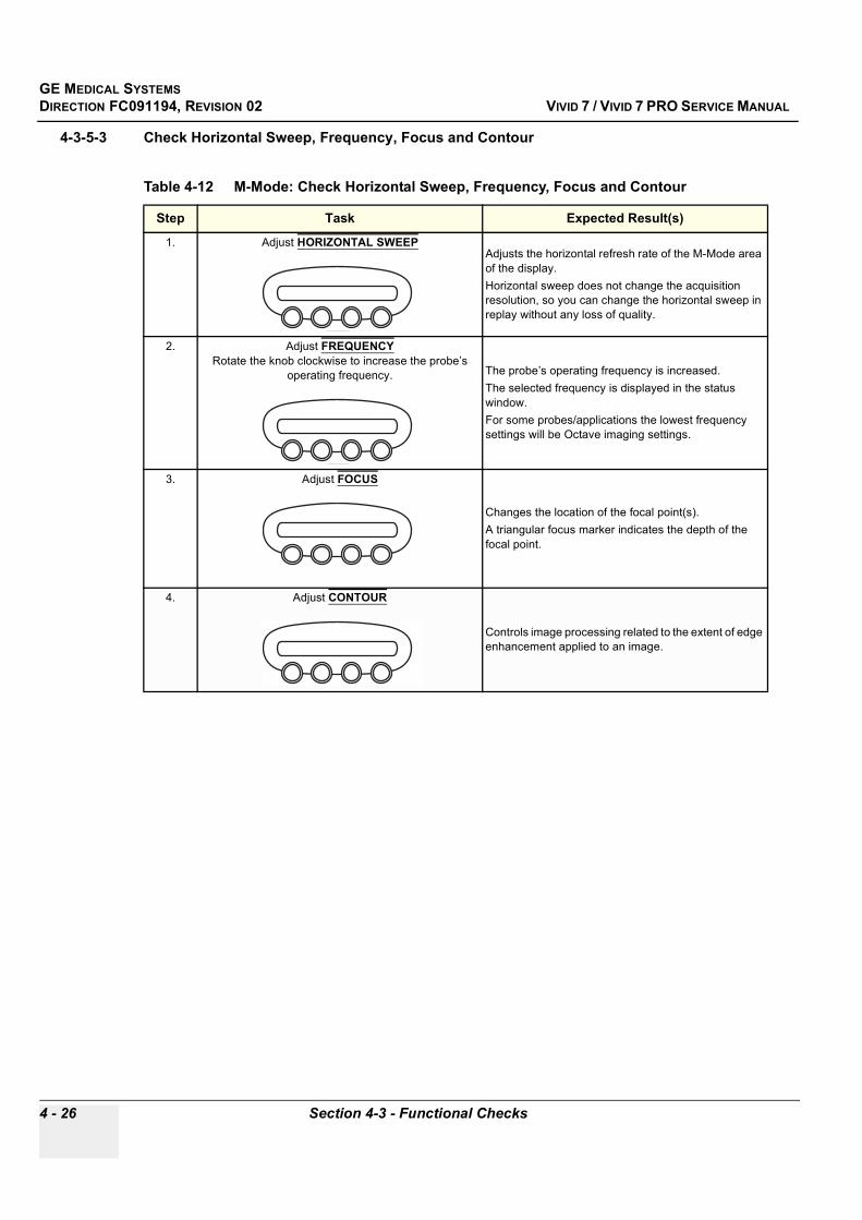
GE MEDICAL SYSTEMSDIRECTION FC091194, REVISION 02 VIVID 7 / VIVID 7 PRO SERVICE MANUAL
4 - 26 Section 4-3 - Functional Checks
4-3-5-3 Check Horizontal Sweep, Frequency, Focus and Contour
Table 4-12 M-Mode: Check Horizontal Sweep, Frequency, Focus and Contour
Step Task Expected Result(s)
1. Adjust HORIZONTAL SWEEP Adjusts the horizontal refresh rate of the M-Mode area of the display.Horizontal sweep does not change the acquisition resolution, so you can change the horizontal sweep in replay without any loss of quality.
2. Adjust FREQUENCYRotate the knob clockwise to increase the probe’s
operating frequency. The probe’s operating frequency is increased.The selected frequency is displayed in the status window.For some probes/applications the lowest frequency settings will be Octave imaging settings.
3. Adjust FOCUS
Changes the location of the focal point(s). A triangular focus marker indicates the depth of the focal point.
4. Adjust CONTOUR
Controls image processing related to the extent of edge enhancement applied to an image.

GE MEDICAL SYSTEMSDIRECTION FC091194, REVISION 02 VIVID 7 / VIVID 7 PRO SERVICE MANUAL
Chapter 4 - Functional Checks 4 - 27
4-3-5-4 Check Compress, Reject, Power and Dynamic Range. .
Table 4-13 M-Mode Soft menu Controls check
Step Task Expected Result(s)
1. Adjust Compress
Controls the amount of contrast in the image.An index number is displayed in the status window to indicate the relative level of compression.
2. Adjust Reject
Adjust reject level.When Reject is increased, low-level echoes are rejected and appear darker in the image. An index number in the status window indicates the relative level of rejection.
3. Adjust Power
Controls acoustic power in all modes. When power is set to maximum, it is equal to or less than the maximum acoustic power permitted by the FDA.Both Thermal Index (TI) and Mechanical Index (MI) are displayed on the screen.
4. Adjust Dynamic Range
Enables control of the dynamic range or contrast of the image. When dynamic range is set to High, the image is softer and more low-level data is visible.
GE MEDICAL SYSTEMSDIRECTION FC091194, REVISION 02 VIVID 7 / VIVID 7 PRO SERVICE MANUAL
4 - 28 Section 4-3 - Functional Checks
4-3-6 Color Mode Checks
4-3-6-1 IntroductionColor Flow screens is 2D or M Mode screens with colors representing blood or tissue movement.
Color Flow may be selected both from 2D mode or from M mode or a combination of these.
4-3-6-2 PreparationsUse a phantom when doing these tests.
1.) Connect one of the probes, to the scanner’s left-most probe connector.- See "Probe Connection" on page 3-13 for info about connecting the probes.- See Chapter 9 - , section 9-17 for available probes.
2.) Turn ON the scanner.- See 4-2-1 - Power ON/ Boot Up on page 4-2 for info about booting the scanner
The 2D Mode window is displayed (default mode).
4-3-6-3 Color 2D Mode:Press COLOR.
4-3-6-4 Color M Mode:
1.) Press MM (M Mode) to bring up an M Mode display on the screen.2.) Press COLOR.
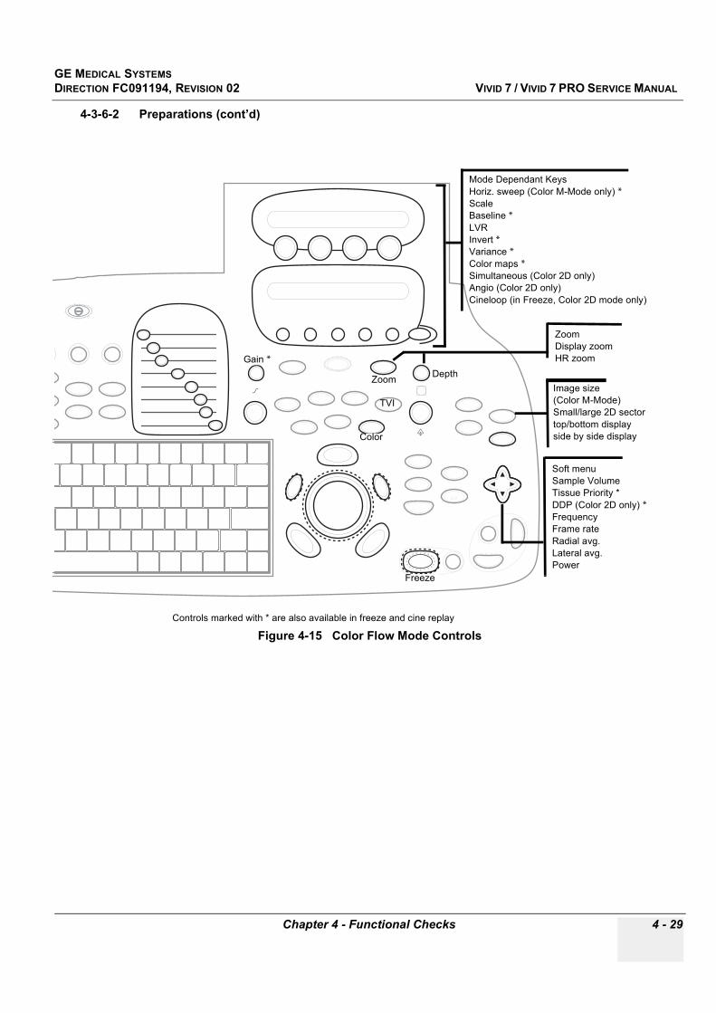
GE MEDICAL SYSTEMSDIRECTION FC091194, REVISION 02 VIVID 7 / VIVID 7 PRO SERVICE MANUAL
Chapter 4 - Functional Checks 4 - 29
4-3-6-2 Preparations (cont’d)
Figure 4-15 Color Flow Mode Controls
Exit
DepthGain *
Mode Dependant KeysHoriz. sweep (Color M-Mode only) *ScaleBaseline *LVRInvert *Variance *Color maps *Simultaneous (Color 2D only)Angio (Color 2D only)Cineloop (in Freeze, Color 2D mode only)
Soft menuSample VolumeTissue Priority *DDP (Color 2D only) *FrequencyFrame rateRadial avg.Lateral avg.Power
Freeze
Controls marked with * are also available in freeze and cine replay
Color
Zoom
TVI
ZoomDisplay zoomHR zoom
Image size(Color M-Mode)Small/large 2D sector top/bottom displayside by side display
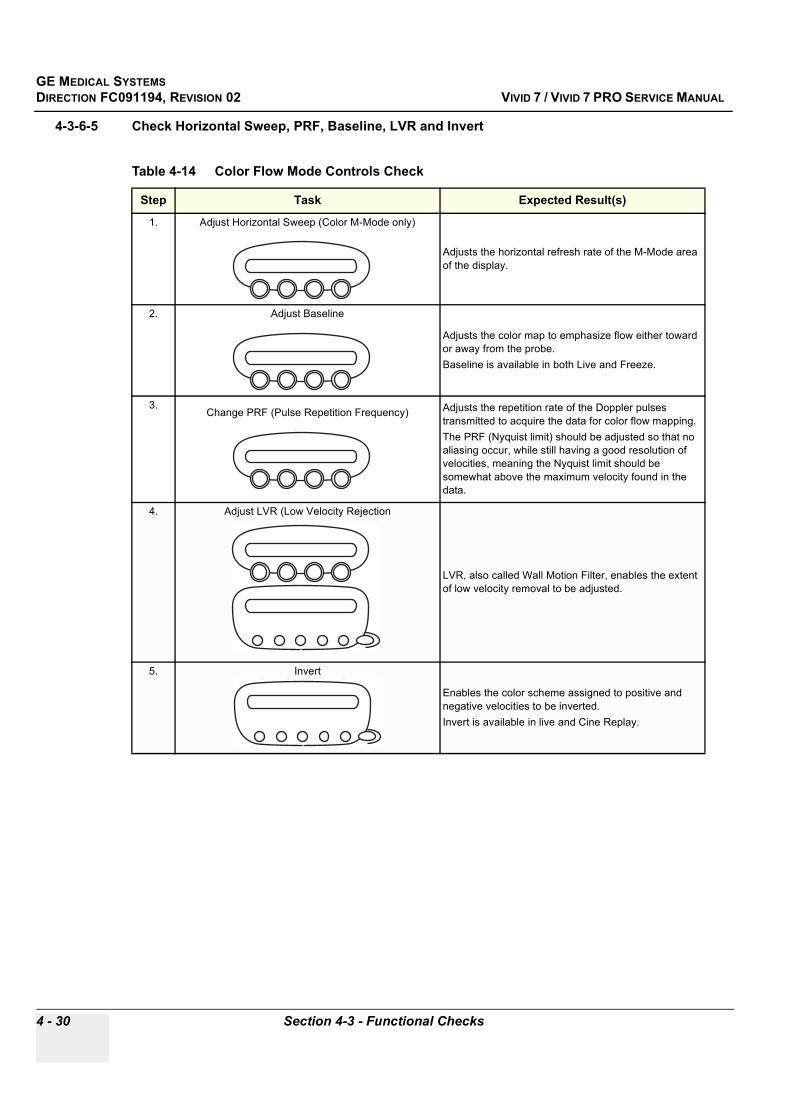
GE MEDICAL SYSTEMSDIRECTION FC091194, REVISION 02 VIVID 7 / VIVID 7 PRO SERVICE MANUAL
4 - 30 Section 4-3 - Functional Checks
4-3-6-5 Check Horizontal Sweep, PRF, Baseline, LVR and Invert
Table 4-14 Color Flow Mode Controls Check
Step Task Expected Result(s)
1. Adjust Horizontal Sweep (Color M-Mode only)
Adjusts the horizontal refresh rate of the M-Mode area of the display.
2. Adjust Baseline
Adjusts the color map to emphasize flow either toward or away from the probe. Baseline is available in both Live and Freeze.
3.Change PRF (Pulse Repetition Frequency) Adjusts the repetition rate of the Doppler pulses
transmitted to acquire the data for color flow mapping. The PRF (Nyquist limit) should be adjusted so that no aliasing occur, while still having a good resolution of velocities, meaning the Nyquist limit should be somewhat above the maximum velocity found in the data.
4. Adjust LVR (Low Velocity Rejection
LVR, also called Wall Motion Filter, enables the extent of low velocity removal to be adjusted.
5. Invert
Enables the color scheme assigned to positive and negative velocities to be inverted. Invert is available in live and Cine Replay.

GE MEDICAL SYSTEMSDIRECTION FC091194, REVISION 02 VIVID 7 / VIVID 7 PRO SERVICE MANUAL
Chapter 4 - Functional Checks 4 - 31
4-3-6-6 Check Variance, Color Maps and Cineloop
4-3-6-7 Check Sample Volume and Tissue Priority
Table 4-15 Color Flow Mode: Check Variance, Color Maps and Cineloop
Step Task Expected Result(s)
6. Adjust Variance
Controls the amount of variance data added to a color display. Variance enables computer-aided detection of non-luminary flow (e.g. jets or regurgitation). Variance is available in live and cine replay.
7. Select Color Maps
Displays a menu of color map options. Use the trackball to point to a color map and press SELECT to activate the desired color map. Each color map is assigning different color hues to different velocities.
8. Make Cineloop (in Freeze, Color 2D mode only)
Starts cine loop acquisition.
Table 4-16 Color Flow Mode: Check Variance, Color Maps and Cineloop
Step Task Expected Result(s)
9. Adjust Variance
Controls the amount of variance data added to a color display. Variance enables computer-aided detection of non-luminary flow (e.g. jets or regurgitation). Variance is available in live and cine replay.

GE MEDICAL SYSTEMSDIRECTION FC091194, REVISION 02 VIVID 7 / VIVID 7 PRO SERVICE MANUAL
4 - 32 Section 4-3 - Functional Checks
4-3-6-8 Check Frequency, Radial Averaging, Lateral Averaging, Power
10. Select Color Maps
Displays a menu of color map options. Use the trackball to point to a color map and press SELECT to activate the desired color map. Each color map is assigning different color hues to different velocities.
11. Make Cineloop (in Freeze, Color 2D mode only)
Starts cine loop acquisition.
Table 4-17 Color-Mode Soft Menu Controls Check
Step Task Expected Result(s)
1. Adjust Frequency
Enables the adjustment of the transmission frequency to control the sensitivity or the level of penetration. The selected frequency is displayed in the status window.Adjusting Frequency may affect Sample Volume and LVR settings.
2. Adjust Radial Averaging
Smooths the image by averaging collected data along the same radial line. An increase of the radial averaging will reduce noise, but this will also reduce the radial resolution.
3. Adjust Lateral Averaging (Color 2D only)
Smooths the image by averaging collected data along the same horizontal line. An increase of the lateral averaging will reduce noise, but this will also reduce the lateral resolution.
Table 4-16 Color Flow Mode: Check Variance, Color Maps and Cineloop
Step Task Expected Result(s)
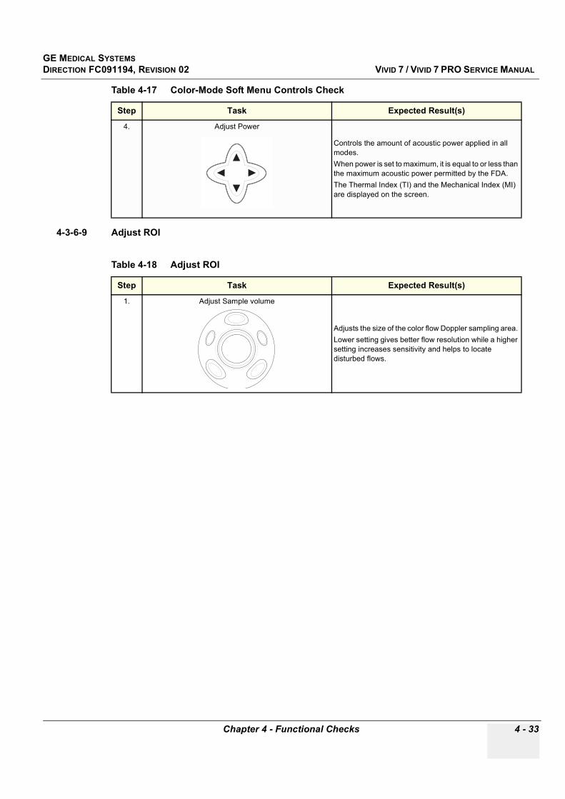
GE MEDICAL SYSTEMSDIRECTION FC091194, REVISION 02 VIVID 7 / VIVID 7 PRO SERVICE MANUAL
Chapter 4 - Functional Checks 4 - 33
4-3-6-9 Adjust ROI
4. Adjust Power
Controls the amount of acoustic power applied in all modes. When power is set to maximum, it is equal to or less than the maximum acoustic power permitted by the FDA. The Thermal Index (TI) and the Mechanical Index (MI) are displayed on the screen.
Table 4-18 Adjust ROI
Step Task Expected Result(s)
1. Adjust Sample volume
Adjusts the size of the color flow Doppler sampling area. Lower setting gives better flow resolution while a higher setting increases sensitivity and helps to locate disturbed flows.
Table 4-17 Color-Mode Soft Menu Controls Check
Step Task Expected Result(s)

GE MEDICAL SYSTEMSDIRECTION FC091194, REVISION 02 VIVID 7 / VIVID 7 PRO SERVICE MANUAL
4 - 34 Section 4-3 - Functional Checks
4-3-7 Doppler Mode Checks
4-3-7-1 IntroductionDoppler is used to measure velocity (most often in blood).
Doppler mode can be done with a special pencil probe or with an ordinary probe. By using an ordinary probe, you can first bring up a 2D picture for navigation purpose and then add Doppler.
4-3-7-2 PreparationsUse a phantom when doing these tests.
1.) Connect one of the probes, to the scanner’s left-most probe connector. - See Probe Connection, page 3-13 for info about connecting the probes- See Probes, page 9-28 for available probes
2.) Turn ON the scanner- See 4-2-1 - Power ON/ Boot Up on page 4-2 for info about booting the scanner.
The 2D Mode window is displayed (default mode).
3.) If needed, adjust the Display’s Brightness and Contrast setting. 4.) Press PW or CW to start Pulsed Wave Doppler (PW) or Continuous Wave Doppler (CW).5.) Use the trackball to select the Area of Interest (Sample Volume) in PW or direction of interest in CW.
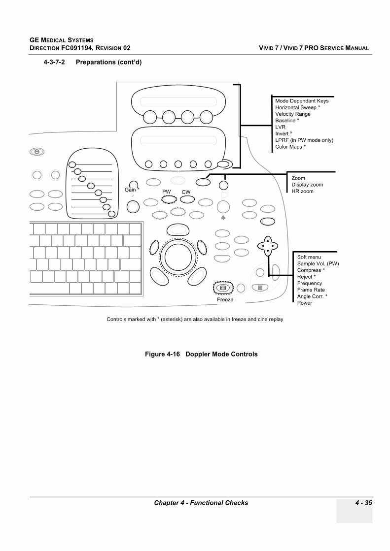
GE MEDICAL SYSTEMSDIRECTION FC091194, REVISION 02 VIVID 7 / VIVID 7 PRO SERVICE MANUAL
Chapter 4 - Functional Checks 4 - 35
4-3-7-2 Preparations (cont’d)
Figure 4-16 Doppler Mode Controls
Gain *
Mode Dependant KeysHorizontal Sweep *Velocity RangeBaseline *LVRInvert *LPRF (in PW mode only)Color Maps *
Soft menuSample Vol. (PW)Compress *Reject *FrequencyFrame RateAngle Corr. *Power
CW
Freeze
PW
ZoomDisplay zoomHR zoom
Controls marked with * (asterisk) are also available in freeze and cine replay
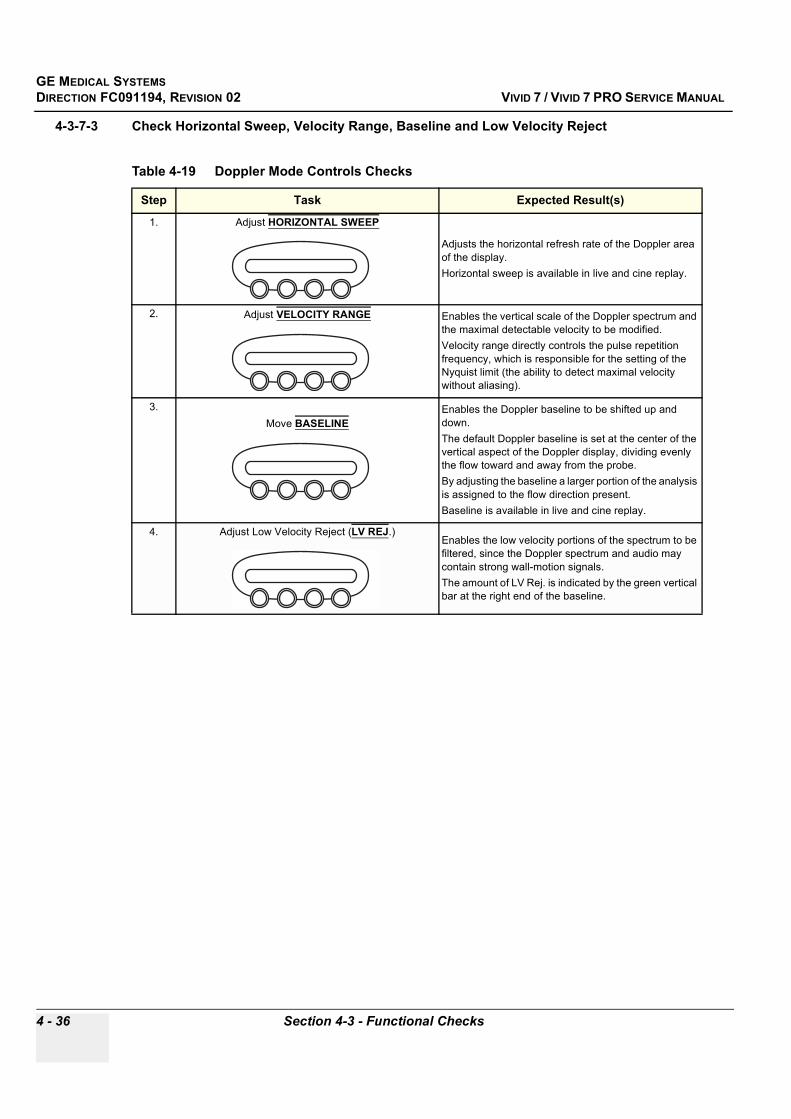
GE MEDICAL SYSTEMSDIRECTION FC091194, REVISION 02 VIVID 7 / VIVID 7 PRO SERVICE MANUAL
4 - 36 Section 4-3 - Functional Checks
4-3-7-3 Check Horizontal Sweep, Velocity Range, Baseline and Low Velocity Reject
Table 4-19 Doppler Mode Controls Checks
Step Task Expected Result(s)
1. Adjust HORIZONTAL SWEEP
Adjusts the horizontal refresh rate of the Doppler area of the display. Horizontal sweep is available in live and cine replay.
2. Adjust VELOCITY RANGE Enables the vertical scale of the Doppler spectrum and the maximal detectable velocity to be modified. Velocity range directly controls the pulse repetition frequency, which is responsible for the setting of the Nyquist limit (the ability to detect maximal velocity without aliasing).
3.Move BASELINE
Enables the Doppler baseline to be shifted up and down. The default Doppler baseline is set at the center of the vertical aspect of the Doppler display, dividing evenly the flow toward and away from the probe. By adjusting the baseline a larger portion of the analysis is assigned to the flow direction present. Baseline is available in live and cine replay.
4. Adjust Low Velocity Reject (LV REJ.)Enables the low velocity portions of the spectrum to be filtered, since the Doppler spectrum and audio may contain strong wall-motion signals. The amount of LV Rej. is indicated by the green vertical bar at the right end of the baseline.
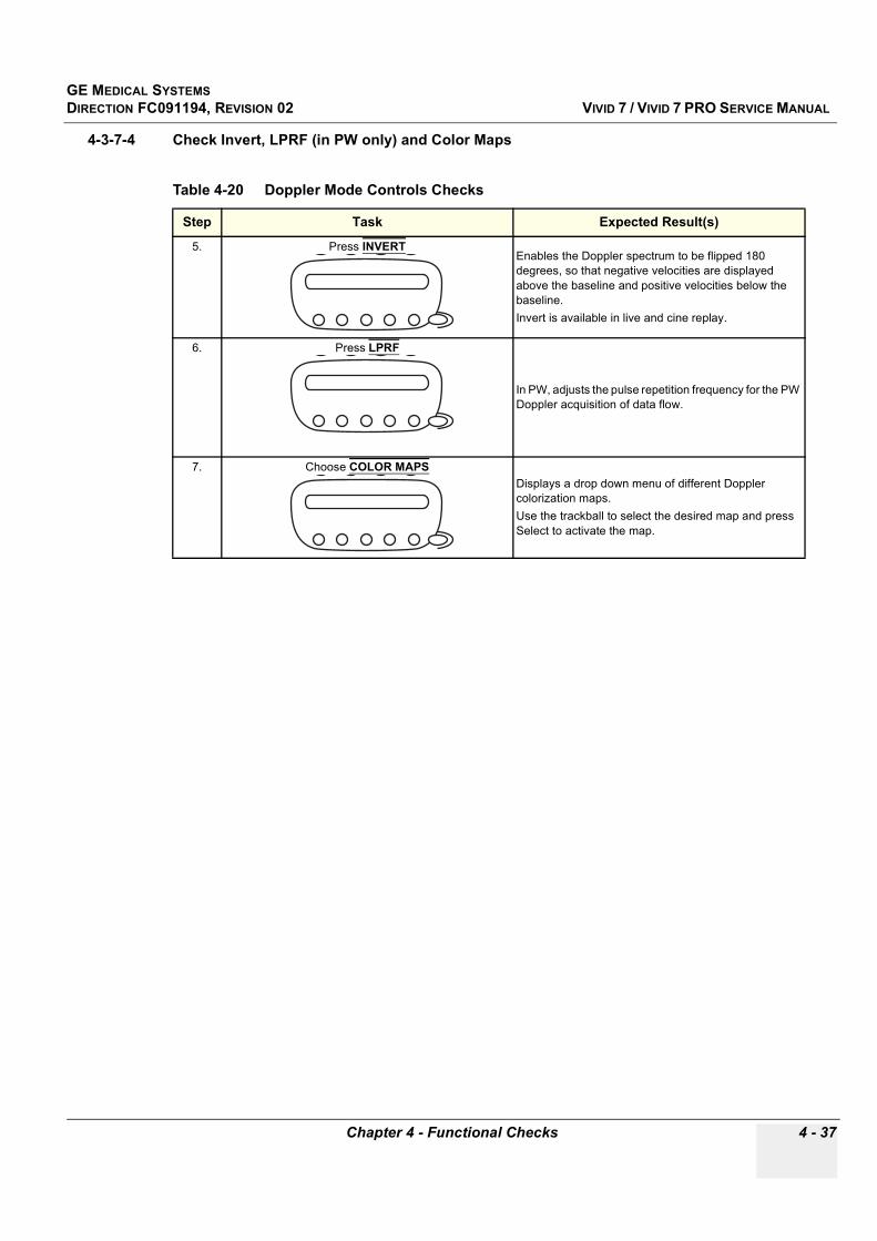
GE MEDICAL SYSTEMSDIRECTION FC091194, REVISION 02 VIVID 7 / VIVID 7 PRO SERVICE MANUAL
Chapter 4 - Functional Checks 4 - 37
4-3-7-4 Check Invert, LPRF (in PW only) and Color Maps
Table 4-20 Doppler Mode Controls Checks
Step Task Expected Result(s)
5. Press INVERT Enables the Doppler spectrum to be flipped 180 degrees, so that negative velocities are displayed above the baseline and positive velocities below the baseline. Invert is available in live and cine replay.
6. Press LPRF
In PW, adjusts the pulse repetition frequency for the PW Doppler acquisition of data flow.
7. Choose COLOR MAPSDisplays a drop down menu of different Doppler colorization maps.Use the trackball to select the desired map and press Select to activate the map.
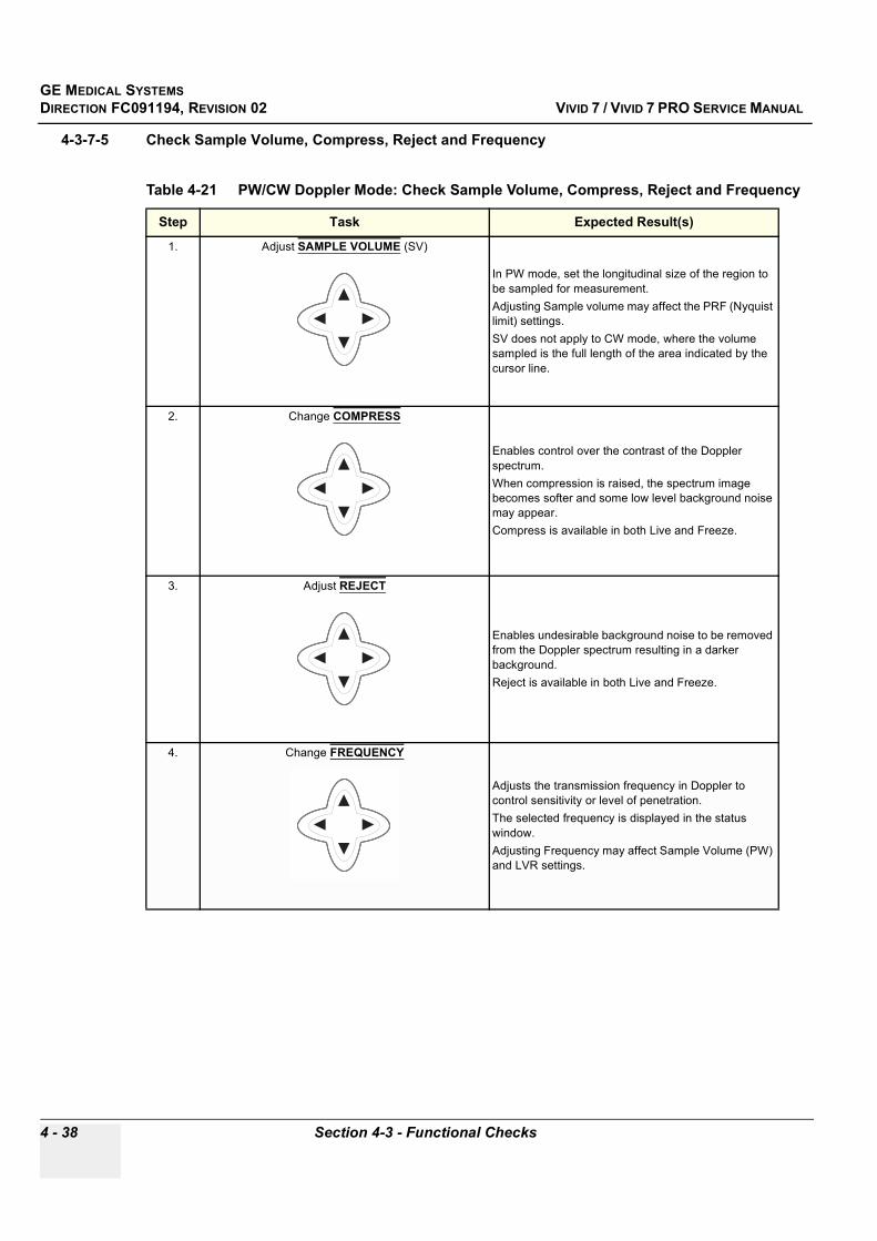
GE MEDICAL SYSTEMSDIRECTION FC091194, REVISION 02 VIVID 7 / VIVID 7 PRO SERVICE MANUAL
4 - 38 Section 4-3 - Functional Checks
4-3-7-5 Check Sample Volume, Compress, Reject and Frequency
Table 4-21 PW/CW Doppler Mode: Check Sample Volume, Compress, Reject and Frequency
Step Task Expected Result(s)
1. Adjust SAMPLE VOLUME (SV)
In PW mode, set the longitudinal size of the region to be sampled for measurement. Adjusting Sample volume may affect the PRF (Nyquist limit) settings. SV does not apply to CW mode, where the volume sampled is the full length of the area indicated by the cursor line.
2. Change COMPRESS
Enables control over the contrast of the Doppler spectrum. When compression is raised, the spectrum image becomes softer and some low level background noise may appear. Compress is available in both Live and Freeze.
3. Adjust REJECT
Enables undesirable background noise to be removed from the Doppler spectrum resulting in a darker background. Reject is available in both Live and Freeze.
4. Change FREQUENCY
Adjusts the transmission frequency in Doppler to control sensitivity or level of penetration.The selected frequency is displayed in the status window.Adjusting Frequency may affect Sample Volume (PW) and LVR settings.
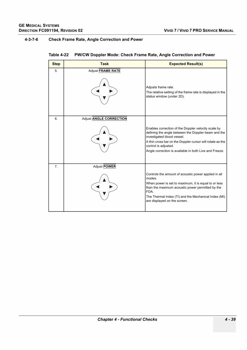
GE MEDICAL SYSTEMSDIRECTION FC091194, REVISION 02 VIVID 7 / VIVID 7 PRO SERVICE MANUAL
Chapter 4 - Functional Checks 4 - 39
4-3-7-6 Check Frame Rate, Angle Correction and Power
Table 4-22 PW/CW Doppler Mode: Check Frame Rate, Angle Correction and Power
Step Task Expected Result(s)
5. Adjust FRAME RATE
Adjusts frame rate.The relative setting of the frame rate is displayed in the status window (under 2D).
6. Adjust ANGLE CORRECTION
Enables correction of the Doppler velocity scale by defining the angle between the Doppler beam and the investigated blood vessel. A thin cross bar on the Doppler cursor will rotate as the control is adjusted.Angle correction is available in both Live and Freeze.
7. Adjust POWER
Controls the amount of acoustic power applied in all modes. When power is set to maximum, it is equal to or less than the maximum acoustic power permitted by the FDA.The Thermal Index (TI) and the Mechanical Index (MI) are displayed on the screen.

GE MEDICAL SYSTEMSDIRECTION FC091194, REVISION 02 VIVID 7 / VIVID 7 PRO SERVICE MANUAL
4 - 40 Section 4-3 - Functional Checks
4-3-8 Tissue Velocity Imaging (TVI) Checks
4-3-8-1 IntroductionTVI calculates and color codes the velocities in tissue. The tissue velocity information is acquired by sampling of tissue Doppler velocity values at discrete points.
4-3-8-2 PreparationsUse a phantom when doing these tests.
1.) Connect one of the probes, to the scanner’s left-most probe connector. - See Probe Connection, page 3-13 for info about connecting the probes- See Probes, page 9-28 for available probes
2.) Turn ON the scanner- See see 4-2-1 - Power ON/ Boot Up on page 4-2 for info about booting the scanner.
The 2D Mode window is displayed (default mode).
3.) If needed, adjust the Display’s Brightness and Contrast setting. 4.) Press TVI.
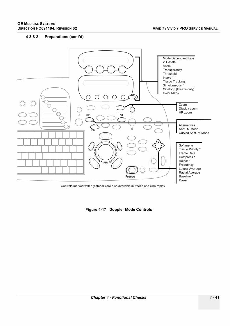
GE MEDICAL SYSTEMSDIRECTION FC091194, REVISION 02 VIVID 7 / VIVID 7 PRO SERVICE MANUAL
Chapter 4 - Functional Checks 4 - 41
4-3-8-2 Preparations (cont’d)
Figure 4-17 Doppler Mode Controls
Mode Dependant Keys2D WidthScaleTransparencyThresholdInvert *Tissue TrackingSimultaneous *Cineloop (Freeze only)Color Maps
Soft menuTissue Priority *Frame RateCompress *Reject *FrequencyLateral AverageRadial AverageBaseline *Power
TVI
Freeze
2D
Alt.
AlternativesAnat. M-ModeCurved Anat. M-Mode
ZoomDisplay zoomHR zoom
Controls marked with * (asterisk) are also available in freeze and cine replay
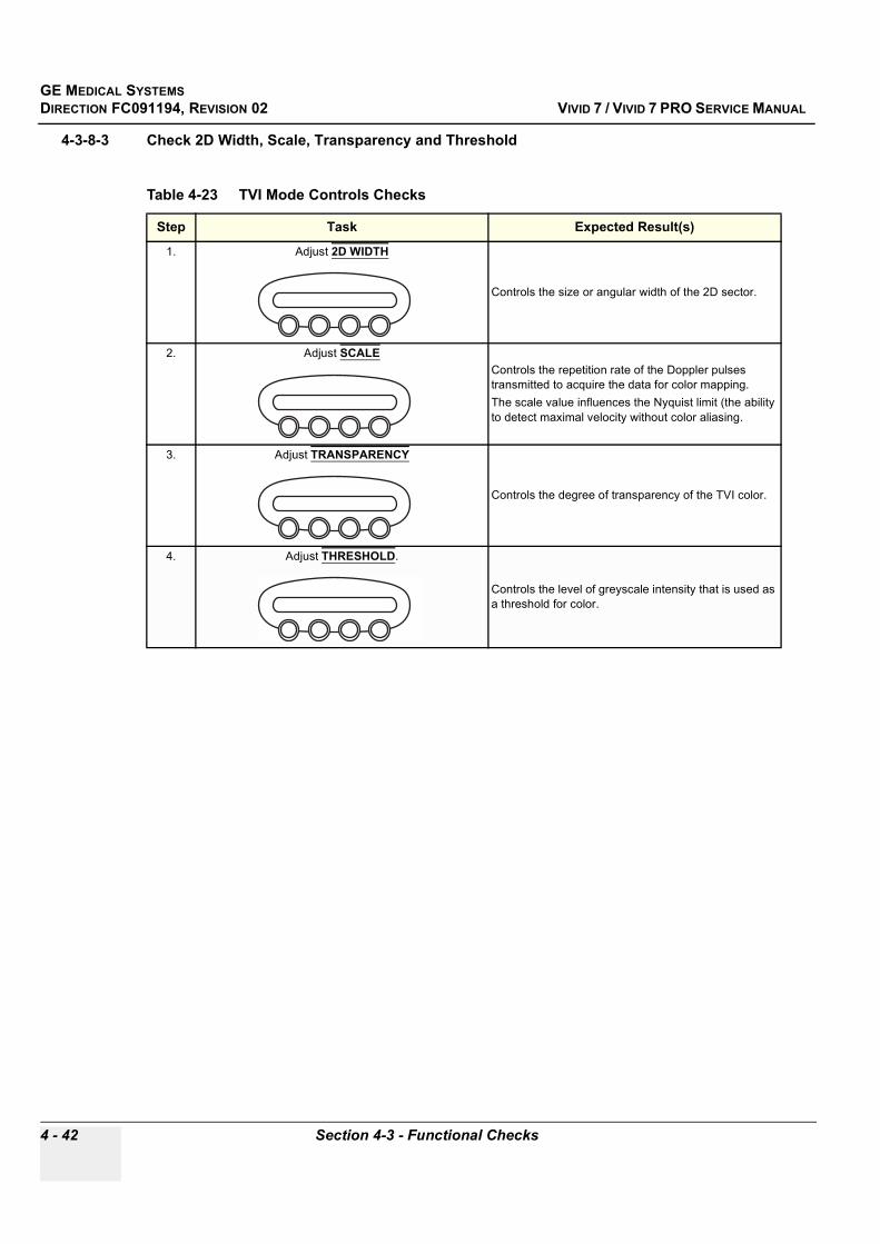
GE MEDICAL SYSTEMSDIRECTION FC091194, REVISION 02 VIVID 7 / VIVID 7 PRO SERVICE MANUAL
4 - 42 Section 4-3 - Functional Checks
4-3-8-3 Check 2D Width, Scale, Transparency and Threshold
Table 4-23 TVI Mode Controls Checks
Step Task Expected Result(s)
1. Adjust 2D WIDTH
Controls the size or angular width of the 2D sector.
2. Adjust SCALEControls the repetition rate of the Doppler pulses transmitted to acquire the data for color mapping. The scale value influences the Nyquist limit (the ability to detect maximal velocity without color aliasing.
3. Adjust TRANSPARENCY
Controls the degree of transparency of the TVI color.
4. Adjust THRESHOLD.
Controls the level of greyscale intensity that is used as a threshold for color.
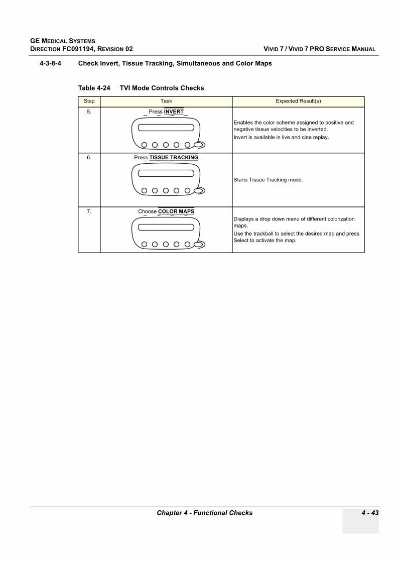
GE MEDICAL SYSTEMSDIRECTION FC091194, REVISION 02 VIVID 7 / VIVID 7 PRO SERVICE MANUAL
Chapter 4 - Functional Checks 4 - 43
4-3-8-4 Check Invert, Tissue Tracking, Simultaneous and Color Maps
Table 4-24 TVI Mode Controls Checks
Step Task Expected Result(s)
5. Press INVERT
Enables the color scheme assigned to positive and negative tissue velocities to be inverted. Invert is available in live and cine replay.
6. Press TISSUE TRACKING
Starts Tissue Tracking mode.
7. Choose COLOR MAPSDisplays a drop down menu of different colorization maps.Use the trackball to select the desired map and press Select to activate the map.

GE MEDICAL SYSTEMSDIRECTION FC091194, REVISION 02 VIVID 7 / VIVID 7 PRO SERVICE MANUAL
4 - 44 Section 4-3 - Functional Checks
4-3-8-5 Check Tissue Priority, Frame Rate, Compress, Reject, Frequency, Lateral & Radial Average, Baseline and Power
Table 4-25 TVI Mode: Soft Menu Controls Check
Step Task Expected Result(s)
8. Adjust TISSUE PRIORITY
Emphasizes either the color of the TVI or the greyscale tissue detail of the 2D image.Tissue priority is available in both Live and Freeze.
9. Adjust FRAME RATE
Controls the line density. When adjusting frame rate, there is a trade off between spatial and temporal resolution.
10. Adjust COMPRESS
Controls the amount of color compression. The color bar is adjusted accordingly.
11. Adjust REJECT
Adjust the cut-off level for the low velocity of TVI to be discarded when generating the color image.
12. Adjust FREQUENCY
Enables the adjustment of the transmission frequency to control the sensitivity or the level of penetration.

GE MEDICAL SYSTEMSDIRECTION FC091194, REVISION 02 VIVID 7 / VIVID 7 PRO SERVICE MANUAL
Chapter 4 - Functional Checks 4 - 45
13. Adjust LATERAL AVERAGE
Smooths the image by averaging collected data along the same horizontal line. An increase of the lateral averaging will reduce noise, but this will also reduce the lateral resolution.
14. Adjust RADIAL AVERAGE
Smooths the image by averaging collected data along the same radial line. An increase of the radial averaging will reduce noise, but this will also reduce the radial resolution.
15. Adjust BASELINE
Adjusts the color map to emphasize tissue motion either toward or away from the probe.Baseline is available in both Live and Freeze.
16. Adjust POWER
Controls the amount of acoustic power applied in all modes. When power is set to maximum, it is equal to or less than the maximum acoustic power level permitted by regulatory standards.The Thermal Index (TI) and the Mechanical Index (MI) are displayed on the screen.
Table 4-25 TVI Mode: Soft Menu Controls Check
Step Task Expected Result(s)

GE MEDICAL SYSTEMSDIRECTION FC091194, REVISION 02 VIVID 7 / VIVID 7 PRO SERVICE MANUAL
4 - 46 Section 4-3 - Functional Checks
4-3-9 Contrast ChecksRefer to Chapter 5 in Vivid 7 / Vivid 7 PRO User Manual.
4-3-10 Stress EchoRefer to Chapter 4 in Vivid 7 / Vivid 7 PRO User Manual.
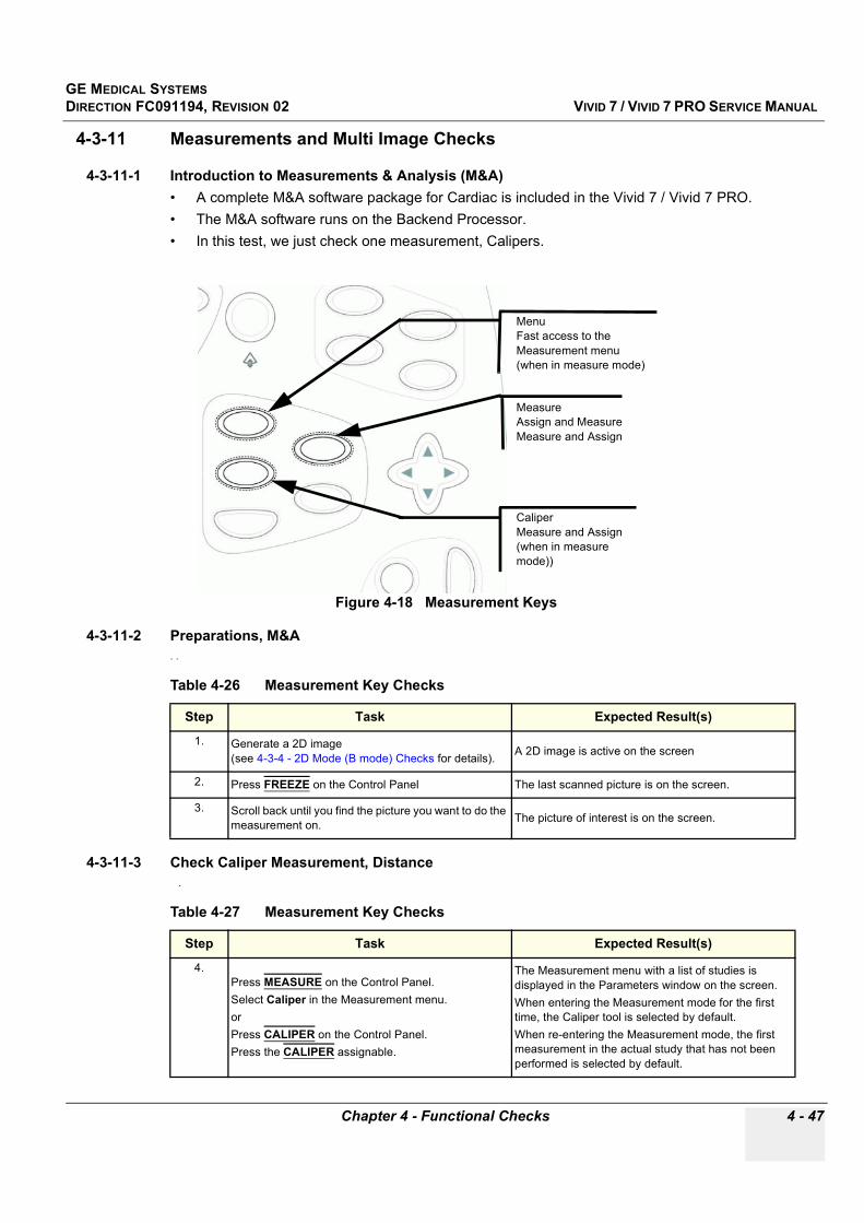
GE MEDICAL SYSTEMSDIRECTION FC091194, REVISION 02 VIVID 7 / VIVID 7 PRO SERVICE MANUAL
Chapter 4 - Functional Checks 4 - 47
4-3-11 Measurements and Multi Image Checks
4-3-11-1 Introduction to Measurements & Analysis (M&A)• A complete M&A software package for Cardiac is included in the Vivid 7 / Vivid 7 PRO. • The M&A software runs on the Backend Processor.• In this test, we just check one measurement, Calipers.
4-3-11-2 Preparations, M&A. .
4-3-11-3 Check Caliper Measurement, Distance .
Figure 4-18 Measurement Keys
Table 4-26 Measurement Key Checks
Step Task Expected Result(s)
1. Generate a 2D image (see 4-3-4 - 2D Mode (B mode) Checks for details). A 2D image is active on the screen
2. Press FREEZE on the Control Panel The last scanned picture is on the screen.
3. Scroll back until you find the picture you want to do the measurement on. The picture of interest is on the screen.
Table 4-27 Measurement Key Checks
Step Task Expected Result(s)
4.Press MEASURE on the Control Panel.Select Caliper in the Measurement menu.orPress CALIPER on the Control Panel.Press the CALIPER assignable.
The Measurement menu with a list of studies is displayed in the Parameters window on the screen. When entering the Measurement mode for the first time, the Caliper tool is selected by default. When re-entering the Measurement mode, the first measurement in the actual study that has not been performed is selected by default.
MeasureAssign and MeasureMeasure and Assign
CaliperMeasure and Assign(when in measure mode))
MenuFast access to the Measurement menu(when in measure mode)
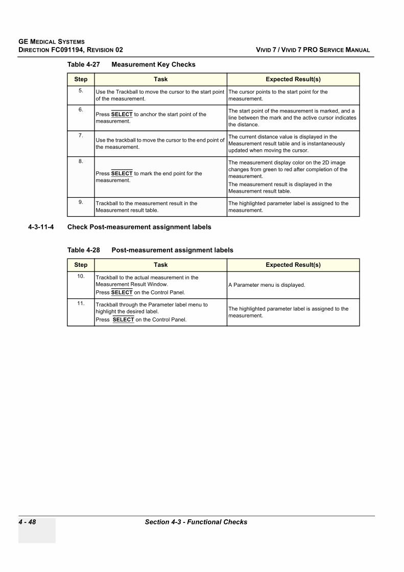
GE MEDICAL SYSTEMSDIRECTION FC091194, REVISION 02 VIVID 7 / VIVID 7 PRO SERVICE MANUAL
4 - 48 Section 4-3 - Functional Checks
4-3-11-4 Check Post-measurement assignment labels
5. Use the Trackball to move the cursor to the start point of the measurement.
The cursor points to the start point for the measurement.
6.Press SELECT to anchor the start point of the measurement.
The start point of the measurement is marked, and a line between the mark and the active cursor indicates the distance.
7.Use the trackball to move the cursor to the end point of the measurement.
The current distance value is displayed in the Measurement result table and is instantaneously updated when moving the cursor.
8.
Press SELECT to mark the end point for the measurement.
The measurement display color on the 2D image changes from green to red after completion of the measurement.The measurement result is displayed in the Measurement result table.
9. Trackball to the measurement result in the Measurement result table.
The highlighted parameter label is assigned to the measurement.
Table 4-28 Post-measurement assignment labels
Step Task Expected Result(s)
10. Trackball to the actual measurement in the Measurement Result Window.Press SELECT on the Control Panel.
A Parameter menu is displayed.
11. Trackball through the Parameter label menu to highlight the desired label.Press SELECT on the Control Panel.
The highlighted parameter label is assigned to the measurement.
Table 4-27 Measurement Key Checks
Step Task Expected Result(s)

GE MEDICAL SYSTEMSDIRECTION FC091194, REVISION 02 VIVID 7 / VIVID 7 PRO SERVICE MANUAL
Chapter 4 - Functional Checks 4 - 49
4-3-12 Multi Image Checks
4-3-12-1 Introduction to Multi ImageThis unit has a special function for displaying two or four examination pictures at the same time
4-3-12-2 PreparationsUse a phantom when doing these tests.
1.) Connect one of the probes, to the scanner’s left-most probe connector. - See Probe Connection, page 3-13 for info about connecting the probes- See Probes, page 9-28 for available probes
2.) Turn ON the scanner- See 4-2-1 - Power ON/ Boot Up on page 4-2 for info about booting the scanner.
The 2D Mode window is displayed (default mode).
If needed, adjust the Display’s Brightness and Contrast setting.
3.) Store four cineloops.
4-3-12-3 1,2,4 Key Check
Table 4-29 Use of Multi Image Key
Key Description
Enables multiple image display windows in which two or four images can be viewed simultaneously. When reducing the number of images, the active window will always be kept.
Table 4-30 Multi Image Checks
Step Task Expected Result(s)
1. Press the 1,2,4 Key once to display two images on the screen. 2 Images are displayed on the screen.
2. Press the 1,2,4 Key once more to display four images on the screen. 4 Images are displayed on the screen.
3. Press the 1,2,4 Key again to reduce the number of images on the screen. 1 image is displayed on the screen.
1/2/4

GE MEDICAL SYSTEMSDIRECTION FC091194, REVISION 02 VIVID 7 / VIVID 7 PRO SERVICE MANUAL
4 - 50 Section 4-3 - Functional Checks
4-3-13 Probe/Connectors Check
NOTE: Probes can be connected at any time, whether the unit is ON or OFF
CAUTION Take the following precautions with the probe cables: - Keep away from the wheels- Do not bend- Do not cross cables between probes
Table 4-31 Probe and Connectors Checks
Step Task Expected Result(s)
1. Press PROBE on the Control Panel. A list of the connected probes will pop up on the screen.
2. If not already selected. use the trackball to select the desired probe.
An application menu for the desired probe is listed on the screen.
3. Trackball to the desired applicationPress SELECT to launch the application.To change application without changing the current probe, press APPL. on the Control Panel.
The selected application starts.
4. Verify no missing channels All channels is functioning.
5. Verify there's no EMI/RFI or artifacts specific to the probe. No EMI/RFI or artifacts.
6. Test the probe in each active connector slot. See “Probe Connection” on page 3-13. It will display pictorial data each time
7. Do a leakage test on the probe, See “Electrical Safety Tests” on page 10-10. It passes the test.
8. Repeat this procedure for all available probes.

GE MEDICAL SYSTEMSDIRECTION FC091194, REVISION 02 VIVID 7 / VIVID 7 PRO SERVICE MANUAL
Chapter 4 - Functional Checks 4 - 51
4-3-14 ECG Check
4-3-14-1 IntroductionThe ECG capability on this unit, is intended as use as a trigger for measurements, but can also be viewed on the screen.
4-3-14-2 Parts needed• ECG Harness, P/N:16L0026 + P/N:16L0028• ECG Pads, (3 pc) or
• ECG simulator
4-3-14-3 PreparationsNone
4-3-14-4 ECG Check
Table 4-32 ECG Check
Step Task Expected Result(s)
1. Connect the ECG harness to the connector on the front of the system
The unit displays a straight curve along the bottom edge of the image sector on the screen.
2. Connect the three leads to a ECG simulator, or Fasten the three ECG Pads to your body and connect the three leads to respective ECG Pad
When connecting, the signal on the screen will be noisyWhen the connection is completed, a typical clean ECG signal is displayed.
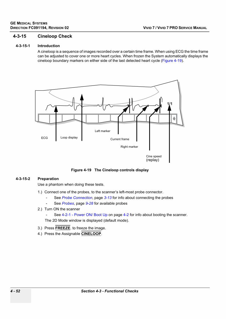
GE MEDICAL SYSTEMSDIRECTION FC091194, REVISION 02 VIVID 7 / VIVID 7 PRO SERVICE MANUAL
4 - 52 Section 4-3 - Functional Checks
4-3-15 Cineloop Check
4-3-15-1 IntroductionA cineloop is a sequence of images recorded over a certain time frame. When using ECG the time frame can be adjusted to cover one or more heart cycles. When frozen the System automatically displays the cineloop boundary markers on either side of the last detected heart cycle (Figure 4-19).
4-3-15-2 PreparationUse a phantom when doing these tests.
1.) Connect one of the probes, to the scanner’s left-most probe connector. - See Probe Connection, page 3-13 for info about connecting the probes- See Probes, page 9-28 for available probes
2.) Turn ON the scanner- See 4-2-1 - Power ON/ Boot Up on page 4-2 for info about booting the scanner.
The 2D Mode window is displayed (default mode).
3.) Press FREEZE. to freeze the image.4.) Press the Assignable CINELOOP.
Figure 4-19 The Cineloop controls display
Left marker
Right marker
Current frame
Cine speed(replay)
Loop displayECG

GE MEDICAL SYSTEMSDIRECTION FC091194, REVISION 02 VIVID 7 / VIVID 7 PRO SERVICE MANUAL
Chapter 4 - Functional Checks 4 - 53
4-3-7-2 Preparations (cont’d)
Figure 4-20 Cineloop controls
OffOff/
OnOn
Mode Dependant KeysLeft markerRight markerCycle selectNumber of cyclesFirst CycleLast CycleSyncCineloop
TrackballScroll (in freeze)Cine speed (in replay)
Freeze
Image Store
Start/stop cineloop

GE MEDICAL SYSTEMSDIRECTION FC091194, REVISION 02 VIVID 7 / VIVID 7 PRO SERVICE MANUAL
4 - 54 Section 4-3 - Functional Checks
4-3-15-3 Check Left Marker, Right Marker, Cycle Select and Number of Cycles
Table 4-33 Cineloop Controls Checks
Step Task Expected Result(s)
1. Adjust LEFT MARKER and RIGHT MARKER
Moves the Left and Right Markers to expand or trim the cineloop boundaries.
2. Adjust CYCLE SELECT
Moves the cineloop boundaries from heart cycle to heart cycle.
3. Adjust NUMBER OF CYCLE
Increase or decrease the number of heart cycles to be included in the cineloop.
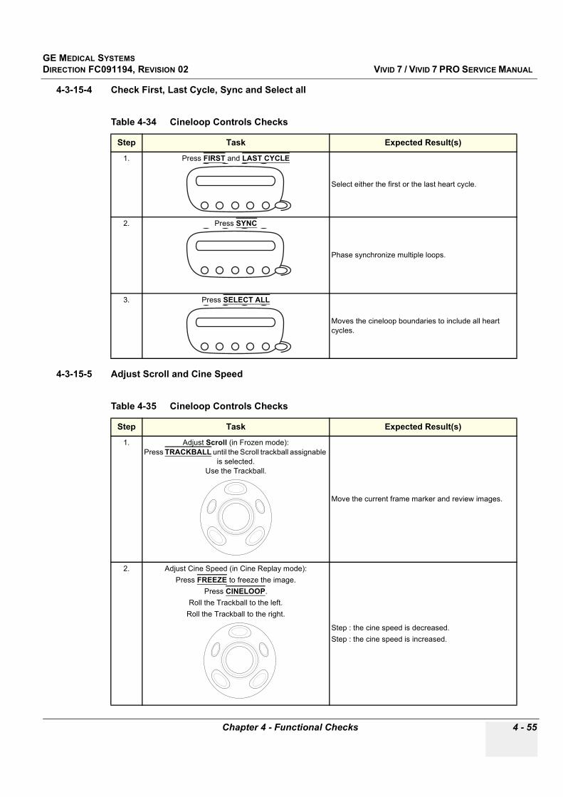
GE MEDICAL SYSTEMSDIRECTION FC091194, REVISION 02 VIVID 7 / VIVID 7 PRO SERVICE MANUAL
Chapter 4 - Functional Checks 4 - 55
4-3-15-4 Check First, Last Cycle, Sync and Select all
4-3-15-5 Adjust Scroll and Cine Speed
Table 4-34 Cineloop Controls Checks
Step Task Expected Result(s)
1. Press FIRST and LAST CYCLE
Select either the first or the last heart cycle.
2. Press SYNC
Phase synchronize multiple loops.
3. Press SELECT ALL
Moves the cineloop boundaries to include all heart cycles.
Table 4-35 Cineloop Controls Checks
Step Task Expected Result(s)
1. Adjust Scroll (in Frozen mode):Press TRACKBALL until the Scroll trackball assignable
is selected.Use the Trackball.
Move the current frame marker and review images.
2. Adjust Cine Speed (in Cine Replay mode):Press FREEZE to freeze the image.
Press CINELOOP.Roll the Trackball to the left.
Roll the Trackball to the right.
Step : the cine speed is decreased.Step : the cine speed is increased.

GE MEDICAL SYSTEMSDIRECTION FC091194, REVISION 02 VIVID 7 / VIVID 7 PRO SERVICE MANUAL
4 - 56 Section 4-3 - Functional Checks
4-3-16 Backend Processor Checks• If all the previous tests have been passed successfully, the Backend Processor is most likely OK.• If the system seems to be operating erratically, please refer to Chapter 7 - Diagnostics/
Troubleshooting.
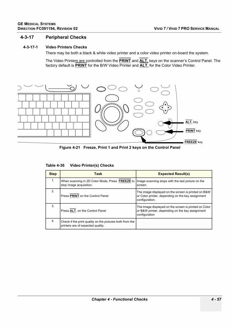
GE MEDICAL SYSTEMSDIRECTION FC091194, REVISION 02 VIVID 7 / VIVID 7 PRO SERVICE MANUAL
Chapter 4 - Functional Checks 4 - 57
4-3-17 Peripheral Checks
4-3-17-1 Video Printers ChecksThere may be both a black & white video printer and a color video printer on-board the system.
The Video Printers are controlled from the PRINT and ALT. keys on the scanner’s Control Panel. The factory default is PRINT for the B/W Video Printer and ALT. for the Color Video Printer.
Figure 4-21 Freeze, Print 1 and Print 2 keys on the Control Panel
Table 4-36 Video Printer(s) Checks
Step Task Expected Result(s)
1. When scanning in 2D Color Mode, Press FREEZE to stop image acquisition.
Image scanning stops with the last picture on the screen.
2.Press PRINT on the Control Panel
The image displayed on the screen is printed on B&W or Color printer, depending on the key assignment configuration.
3.Press ALT. on the Control Panel
The image displayed on the screen is printed on Color or B&W printer, depending on the key assignment configuration
4. Check if the print quality on the pictures both from the printers are of expected quality.
PRINT key
ALT. key
FREEZE key
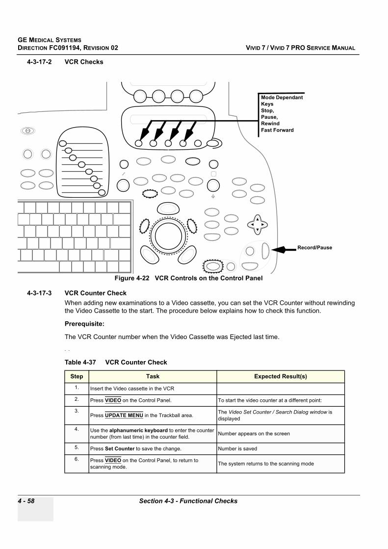
GE MEDICAL SYSTEMSDIRECTION FC091194, REVISION 02 VIVID 7 / VIVID 7 PRO SERVICE MANUAL
4 - 58 Section 4-3 - Functional Checks
4-3-17-2 VCR Checks
4-3-17-3 VCR Counter Check When adding new examinations to a Video cassette, you can set the VCR Counter without rewinding the Video Cassette to the start. The procedure below explains how to check this function.
Prerequisite:
The VCR Counter number when the Video Cassette was Ejected last time.
. .
Figure 4-22 VCR Controls on the Control Panel
Table 4-37 VCR Counter Check
Step Task Expected Result(s)
1. Insert the Video cassette in the VCR
2. Press VIDEO on the Control Panel. To start the video counter at a different point:
3.Press UPDATE MENU in the Trackball area. The Video Set Counter / Search Dialog window is
displayed
4. Use the alphanumeric keyboard to enter the counter number (from last time) in the counter field. Number appears on the screen
5. Press Set Counter to save the change. Number is saved
6. Press VIDEO on the Control Panel, to return to scanning mode. The system returns to the scanning mode
Mode Dependant KeysStop,Pause,Rewind Fast Forward
Record/Pause
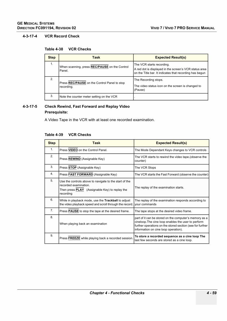
GE MEDICAL SYSTEMSDIRECTION FC091194, REVISION 02 VIVID 7 / VIVID 7 PRO SERVICE MANUAL
Chapter 4 - Functional Checks 4 - 59
4-3-17-4 VCR Record Check
4-3-17-5 Check Rewind, Fast Forward and Replay VideoPrerequisite:
A Video Tape in the VCR with at least one recorded examination.
Table 4-38 VCR Checks
Step Task Expected Result(s)
1.When scanning, press REC/PAUSE on the Control Panel.
The VCR starts recording.A red dot is displayed in the screen’s VCR status area on the Title bar. It indicates that recording has begun
2.Press REC/PAUSE on the Control Panel to stop recording.
The Recording stops.
The video status icon on the screen is changed to (Pause)
3. Note the counter meter setting on the VCR .
Table 4-39 VCR Checks
Step Task Expected Result(s)
1. Press VIDEO on the Control Panel. The Mode Dependant Keys changes to VCR controls
2.Press REWIND (Assignable Key) The VCR starts to rewind the video tape.(observe the
counter)
3. Press STOP (Assignable Key) The VCR Stops
4. Press FAST FORWARD (Assignable Key) The VCR starts the Fast Forward (observe the counter)
5. Use the controls above to navigate to the start of the recorded examination. Then press PLAY (Assignable Key) to replay the recording
The replay of the examination starts.
6. While in playback mode, use the Trackball to adjust the video playback speed and scroll through the record.
The replay of the examination responds according to your commands
7. Press PAUSE to stop the tape at the desired frame. The tape stops at the desired video frame.
8.
When playing back an examination
part of it can be stored on the computer’s memory as a cineloop.The cine loop enables the user to perform further operations on the stored section (see for further information on cine loop operation).
9.Press FREEZE while playing back a recorded session. To store a recorded sequence as a cine loop The
last few seconds are stored as a cine loop.
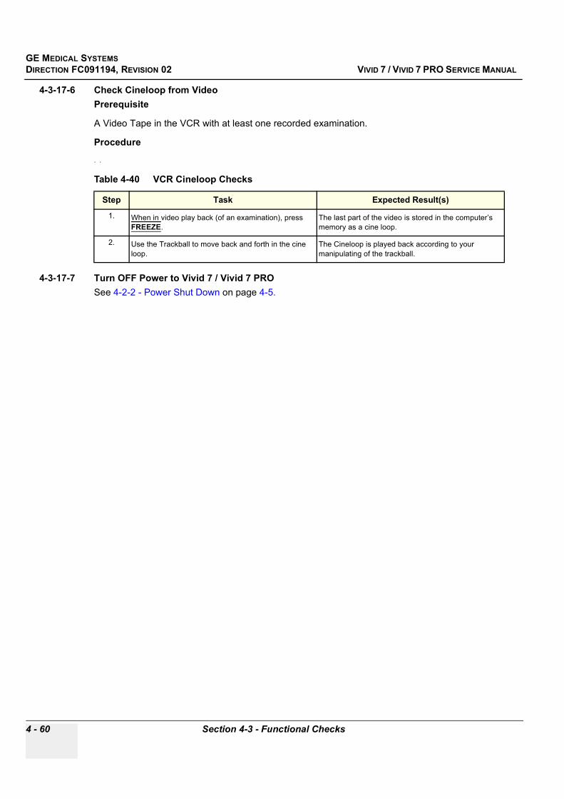
GE MEDICAL SYSTEMSDIRECTION FC091194, REVISION 02 VIVID 7 / VIVID 7 PRO SERVICE MANUAL
4 - 60 Section 4-3 - Functional Checks
4-3-17-6 Check Cineloop from VideoPrerequisite
A Video Tape in the VCR with at least one recorded examination.
Procedure
. .
4-3-17-7 Turn OFF Power to Vivid 7 / Vivid 7 PROSee 4-2-2 - Power Shut Down on page 4-5.
Table 4-40 VCR Cineloop Checks
Step Task Expected Result(s)
1. When in video play back (of an examination), press FREEZE.
The last part of the video is stored in the computer’s memory as a cine loop.
2. Use the Trackball to move back and forth in the cine loop.
The Cineloop is played back according to your manipulating of the trackball.
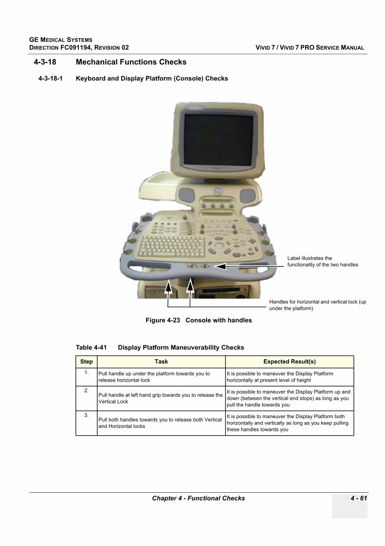
GE MEDICAL SYSTEMSDIRECTION FC091194, REVISION 02 VIVID 7 / VIVID 7 PRO SERVICE MANUAL
Chapter 4 - Functional Checks 4 - 61
4-3-18 Mechanical Functions Checks
4-3-18-1 Keyboard and Display Platform (Console) Checks
Figure 4-23 Console with handles
Table 4-41 Display Platform Maneuverability Checks
Step Task Expected Result(s)
1. Pull handle up under the platform towards you to release horizontal lock
It is possible to maneuver the Display Platform horizontally at present level of height
2.Pull handle at left hand grip towards you to release the Vertical Lock
It is possible to maneuver the Display Platform up and down (between the vertical end stops) as long as you pull the handle towards you
3.Pull both handles towards you to release both Vertical and Horizontal locks
It is possible to maneuver the Display Platform both horizontally and vertically as long as you keep pulling these handles towards you
Handles for horizontal and vertical lock (up under the platform)
Label illustrates the functionality of the two handles
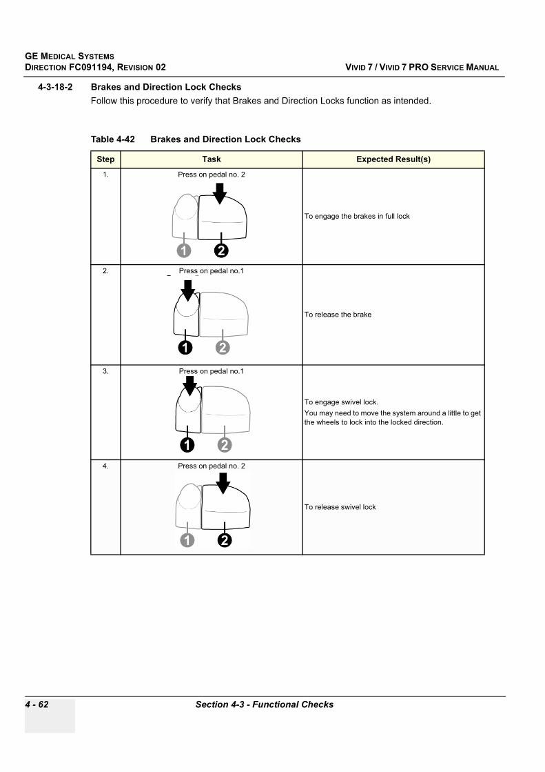
GE MEDICAL SYSTEMSDIRECTION FC091194, REVISION 02 VIVID 7 / VIVID 7 PRO SERVICE MANUAL
4 - 62 Section 4-3 - Functional Checks
4-3-18-2 Brakes and Direction Lock ChecksFollow this procedure to verify that Brakes and Direction Locks function as intended.
Table 4-42 Brakes and Direction Lock Checks
Step Task Expected Result(s)
1. Press on pedal no. 2
To engage the brakes in full lock
2. Press on pedal no.1
To release the brake
3. Press on pedal no.1
To engage swivel lock.You may need to move the system around a little to get the wheels to lock into the locked direction.
4. Press on pedal no. 2
To release swivel lock

GE MEDICAL SYSTEMSDIRECTION FC091194, REVISION 02 VIVID 7 / VIVID 7 PRO SERVICE MANUAL
Chapter 4 - Functional Checks 4 - 63
Section 4-4Application Turnover Check List
Complete these checks before returning the scanner to customer for use:
4-4-1 Software Configuration Checks
Table 4-43 Software Configuration Checks
STEP TASK CHECK ( )
1. Check Date and Time setting
2. Check that Location (Hospital Name & Department) is correct
3. Check Language settings
4. Check assignment of Printer Keys
5. Check that all of the customer’s options are set up correct

GE MEDICAL SYSTEMSDIRECTION FC091194, REVISION 02 VIVID 7 / VIVID 7 PRO SERVICE MANUAL
4 - 64 Section 4-5 - Power Supply
Section 4-5Power Supply
4-5-1 Power Supply Test Procedure
4-5-1-1 IntroductionThere is no need to do any special tests on the Power Supplies if there don’t seems to be a problem that may be related to the Power Supplies.
Refer to section 7-5-1 on page 7-67 if you appear to have a problem that may be related to the Power Supplies.
4-5-2 Power Supply AdjustmentThere are no adjustments on the power supplyes. The DC Power is self-regulated. If a voltage is outside the specified range, it means that something is wrong, either with the power supply itself or with a unit connected to that specific power outlet.

GE MEDICAL SYSTEMSDIRECTION FC091194, REVISION 02 VIVID 7 / VIVID 7 PRO SERVICE MANUAL
Chapter 4 - Functional Checks 4 - 65
Section 4-6Site Log
Table 4-44 Site Log
DATE SERVICE PERSON PROBLEM COMMENTS

GE MEDICAL SYSTEMSDIRECTION FC091194, REVISION 02 VIVID 7 / VIVID 7 PRO SERVICE MANUAL
4 - 66 Section 4-6 - Site Log
Table 4-44 Site Log (continued)
DATE SERVICE PERSON PROBLEM COMMENTS
GE MEDICAL SYSTEMSDIRECTION FC091194, REVISION 02 VIVID 7 / VIVID 7 PRO SERVICE MANUAL
Chapter 5 - Components and Functions (Theory) 5 - 1
Chapter 5Components and Functions (Theory)
Section 5-1Overview
5-1-1 Purpose of Chapter 5This chapter explains Vivid 7 / Vivid 7 PRO’s system concepts, component arrangement, and subsystem functions. It also describes the Power Distribution System (PDS).
Table 5-1 Contents in Chapter 5
Section Description Page Number
5-1 Overview 5-1
5-2 General Information 5-2
5-3 Front End Processor 5-4
5-4 Back End Processor 5-14
5-5 Patient I/O (Physio) 5-23
5-6 Internal I/O 5-24
5-7 Top Console 5-31
5-8 Peripherals 5-32
5-9 Modem 5-33
5-10 Power Distribution 5-34
5-11 Circuit Boards 5-44
5-12 Video Specifications 5-95
5-13 System Logs 5-95
5-14 Board Rack Cooling System 5-96
5-15 Top Console Movement 5-97
5-16 Common Service Platform 5-101

GE MEDICAL SYSTEMSDIRECTION FC091194, REVISION 02 VIVID 7 / VIVID 7 PRO SERVICE MANUAL
5 - 2 Section 5-2 - General Information
Section 5-2General Information
Vivid 7 / Vivid 7 PRO is a phased and linear array ultrasound imaging scanner. The system is versatile and can be used for a number of various applications; all a matter of software.
The system can be used for:
- 2D Grey Scale and 2D Color Flow Imaging- M-Mode Grey Scale Imaging- Color M-Mode - Doppler- a number of combinations of the above
A Physio module is incorporated in the Backend Processor (BEP) to provide ECG signals to synchronize cardiac ultrasound image acquisition. Additionally other analog inputs (e.g. ECG, phono) from devices such as treadmills are processed.
Vivid 7 / Vivid 7 PRO is a digital beamforming system which can handle up to 192 element linear probes by use of multiplexing.
Signal flow travels from the Probe Connector Panel to the Front End Electronics, to the Back-End Processor, and finally displayed on the monitor and peripherals.
System configuration is stored on a hard disk and all necessary software is loaded from the hard disk on power up.
• The user initiates system operation via the Operator Panel which contains a keyboard, control panel, TGC and LCD display.
• Vivid 7 / Vivid 7 PRO internal electronics are divided into two card cages;- Front End Processor (FEP) Sometimes called “Card Cage” in this manual.- Backend Processor (BEP)
• Interconnecting signals from the FEP, BEP, Operator Panel, Monitor and Power distribution subsystems are routed via cables and circuit boards IIO (Internal I/O) and EIO (External I/O). The main functional blocks in Vivid 7 / Vivid 7 PRO are:- Front End Processor (FEP)- Back End Processor (BEP)- Top Console- Power Distribution- Internal I/O- External I/O- Peripherals- Modem

GE MEDICAL SYSTEMSDIRECTION FC091194, REVISION 02 VIVID 7 / VIVID 7 PRO SERVICE MANUAL
Chapter 5 - Components and Functions (Theory) 5 - 3
5-2-1 Block Diagram
Figure 5-1 Vivid 7 / Vivid 7 PRO Simple Block Diagram
FRONT END PROCESSOR
PROBES
XDBUS
DOPPLER
ATX POWER SUPPLY
UPS
AC POWER
OP I/O PANEL 17" Monitor
USER INTERFACE
SONY COLOR PRINTERUP-2900MD
PC2IOPCVIC
PC MOTHERBOARD
POWER ON/OFF (RESET*)
EthernetPC2IPSOUND
CARD
AGP
VIDEO
EXTERNAL I/ O
MODEMAC CONTROLLER
XFMR BOX
TO MONITOR
TO PC
TO PERIPHERIALS
TO MODEM
TO CARD RACK
230Vac230Vac
115Vac
115 or 230Vac
2 30 V
a c
1 15V
a c
BACK END PROCESSOR
ECG Patient Interface
5.25" MOD
CD-ROMHard Drive
SONY VCRSVO-9500MD
SONY B/W PRINTERUP-890MD
TO OUTLET
INTERNAL I/O
PCI CABLE
230Vac
Vid
e o O
utpu
ts
Ne t
wor
k C
onne
ctio
n
US
B C
onne
c tio
n
FRONT END BACKPLANE
RLY
TX
FE
C
RF
T
SD
P
IMP
RX
BF
64
BF
64

GE MEDICAL SYSTEMSDIRECTION FC091194, REVISION 02 VIVID 7 / VIVID 7 PRO SERVICE MANUAL
5 - 4 Section 5-3 - Front End Processor
Section 5-3Front End Processor
5-3-1 General InformationThe Front End Processor includes all of the boards in the Front End Card Rack:
• RLY (Relay Board)• TX (Transmitter Board) • RX128 (Receiver Board)• BF64 (Beamformer Boards) (2x)• FEC (Front End Controller Board) • RFT (Radio Frequency & Tissue Board)• SDP (Spectrum Doppler Processor)• IMP2 (Image Port 2)
The Front End can be divided into two subsystems:
1.) The Front End subsystem includes the:- RLY (Relay Board)- TX (Transmitter Board) - RX128 (Receiver Board)- BF64 (Beamformer Boards) (2x)- FEC (Front End Controller Board)
2.) The Mid Processors subsystem include:- RFT (Radio Frequency & Tissue Board)- SDP (Spectrum Doppler Processor)- IMP2 (Image Port 2).
5-3-2 Front End Bus Most of the FE boards are controlled by the Front End Controller board via a Front End Bus (FE_BUS). The FE_BUS is a synchronous and bidirectional bus built up by 16-bit data, 6-bit device address select, 10-bit page address and 8 strobe signals controlling the data transactions. The Front End Controller board can also read the revision status of the Front End boards through a serial line to a E2PROM located on each board.
5-3-3 Phased and Linear Array Front End• The phased and linear array probes consist of several identical transducer elements (e.g. 64, 128,
192). Three probes can be connected to the system. The connectors are physically located on the RLY board, where one of them is selected and connected to the transmitter (TX) and receiver (RX) through a number of relays.
• Depending on probe type and system setup, a certain scan pattern is selected on the FEC board. This board loads scan parameters for both the transmitter and the beamformer (steering- and focusing delays) into local RAM on these boards. Thus, when the FEC board goes through a scan sequence, it loads the proper contents of the RAM into the Transmitter Puls Generator (TPG), then issues a transmit trigger pulse (TXTRIG_L) for the transmitter and a receive synchronization pulse (SYNC_L) for the beamformer. By firing the transmit pulses from the different elements at certain repeated time intervals and with different delays, the ultrasound beam can be steered in desired directions (re. principles of operation) obtaining the selected scan patterns (e.g. 2D, 2D Flow etc.).

GE MEDICAL SYSTEMSDIRECTION FC091194, REVISION 02 VIVID 7 / VIVID 7 PRO SERVICE MANUAL
Chapter 5 - Components and Functions (Theory) 5 - 5
5-3-3 Phased and Linear Array Front End (cont’d) • The ultrasound transmit bursts are generated on the TX board, initiated by the transmit trigger pulse
(TXTRIG_L). The transmit trigger starts the Transmit Pulse Generators (TPG) on the TX board, each generating 16 transmit pulses with different delays. The transmit pulses are then routed to separate transmit “amplifiers” fed with voltage HV1 and HV2 witch are controlled by the Acoustic Power control software.
• The transmit pulses are routed over an Xducer Bus Board (XDBUS) located on the front side of the Front End boards, to the Relay board, where they are fed to the selected (one out of three) phased/linear array probe.
• The reflected signal from body structures and blood cells are routed from the probe, via the Relay board over the Xducer Bus to the RX (receiver) board, where preamplification (20dB) and Analog Time Gain Compensation (ATGC) (-10 - +30 dB) is performed. Gain is determined by an analog signal (ATGC) generated by the FEC board. On the very input of the RX board are transmit/receive (T/R) switches to prevent the transmitters from destroying the receivers. Prior to preamplification the signals from the different channels were also fed through relays. This is for having the possibility to route echoes from annular array probes into the receiver, in addition to injecting a test signal, TSIG.
• The output channels from the RX board are fed to two Beamformer-64 boards. Each Beamformer board performs A/D conversion of 64 channels.
• The Front End Controller board controls all Front End boards. The board loads all parameters to the TX and Beamformer RAMs, it reads the probe identification, selects probe connector on Relay board and controls the high voltage multiplexer in linear probes. In addition the board generates the transmit trigger pulse for TX, a receive synchronization pulse (SYNC_L) used by Beamformers and RF & Tissue Processor, a differential ATGC voltage used by RX and control signals for the High Voltage Power Supply (HV POWER). The Front End Controller board also generates the global 40 MHz system clocks and reset pulse (SRES).
• The output from the Beamadders at BF#2 is fed to the RF and Tissue Processor Board (RFT).
5-3-4 Transmitter Power SupplyThe transmitters on the TX board are fed with high voltage from the TX supply. This module consists of three linear power supplies; one providing a symmetrical output voltage ranging from 0 to +/- 80 V (HV1), the other providing a voltage ranging from 0 to +/- 40 V (HV2) and the third outputting +/- 80 V for the multiplexers in the linear probes. HV1 and HV2 are programmable through a serial interface from the FEC board.
5-3-5 Mid ProcessorsThe Vivid 7 / Vivid 7 PRO Front End and visualization system are interconnected through digital signal processing modules, called the Mid Processors. These processors performs the adequate signal conditioning for the different data types; Tissue, Doppler and Flow. The current Mid Processors are the RF & Tissue Processor board (RFT), the Spectrum Doppler Processor board (SDP).
5-3-5-1 Pipelink bus• The Mid Processors are interconnected through a data bus system called the Pipelink. This is a
unidirectional bus transporting data from the pipelink dispatcher (RF & Tissue Processor) through the accessed processor to the destination, the Image Port. The Image Port will then map the data into the Image Memory.
• Data leaving the RF & Tissue Processor have a tag indicating what type of data that is transported; e.g. tissue, Doppler, 2D Flow. Each of the remaining mid processors decode this tag and when it matches their own address, the data is processed. Data that doesn’t have a matching tag, is passed on to the next processor.
• In 2D, data is typically transferred in vector blocks from the RFT board. In spectrum Doppler and Color Flow, data from one range gate is transferred.

GE MEDICAL SYSTEMSDIRECTION FC091194, REVISION 02 VIVID 7 / VIVID 7 PRO SERVICE MANUAL
5 - 6 Section 5-3 - Front End Processor
5-3-5-2 RF and Tissue Processor (RFT)The RF & Tissue Processor board receives its data from the Beamformer board in the Front End. Both type of data and what data samples (RF_MODE) to use are communicated to the RFT board from the Front End Controller board (over the Front End Bus).
RF Processing
Different types of RF processing can be performed depending on later usage of the data; e.g.:
• RF Demodulation• Digital Time Gain Compensation • Filtering• Decimation.Data Buffer
After RF filtering, the data is written into different sliding ring buffers, dedicated the different types of data. While data is written into the buffers sample by sample in vectors, multiple samples from the same range (depth) can be read out.
Both input addressing (start and length) and output addressing (through output events) is controlled by the Front End Controller board.
Tissue Processing
A number of different tissue processes are performed on this board:
1.) First the signal amplitude is obtained by detection. 2.) Then the data is compressed to attenuate the strong signals and amplify the low level echoes. 3.) After compression, Zone Stitching is performed. This is used to combine the (transmit) focal zones
from different vectors into one vector by weighting the zone transitions, and does only apply to phased/linear array probes where multiple vectors can be collected in the same direction. For M-Mode, peak detection and edge enhancement is implemented.
4.) Finally an offset can be added to the signal and clipping is performed. 5.) The tissue data is then tagged, and sent on to the Image Port board.Color Flow Processing
No Color Flow processing is performed here, except for the RF demodulation previously mentioned. The data used for Color Flow is tagged with the appropriate headers and tails and routed through an output multiplexer to the Backend Processor (BEP).
Doppler Processing
In addition to RF demodulation, a variable digital high pass filter is implemented on the RFT board.The purpose of this filter is to remove strong low frequency signals returning from wall motion, valves and leaflets. The filtering is performed by the local DSP. Data is then tagged and sent to the Spectrum Doppler Processor board.
GE MEDICAL SYSTEMSDIRECTION FC091194, REVISION 02 VIVID 7 / VIVID 7 PRO SERVICE MANUAL
Chapter 5 - Components and Functions (Theory) 5 - 7
5-3-5-2 RF and Tissue Processor (RFT) (cont’d)Control
The RFT board has a local Digital Signal Processor (DSP) with an external EPROM.
The DSP performs multiple control tasks:
1.) It handles communication with the BEP over the VME bus.2.) It updates filter coefficients and other parameters in the data path.3.) When output events from the Front End Controller is received, it sets up the Pipelink output control
for data tagging and transfer.4.) During transfer of time motion data, it sets up a time-slot data transfer (which replaced the output
event based transfer).
5-3-5-3 Spectrum Doppler ProcessorThe Spectrum Doppler Processor board (SDP) receives its data from the RFT board. In Pulsed Wave (PW) Doppler several sets of data from the same range (depth) originating from different transmit pulses are transferred from RFT data buffer. In Continuous Wave (CW) Doppler the data samples are transferred consecutively.
Spectrum Analysis
The data sets are written into a sliding ring buffer with different ranges along the vertical axis and different transmit pulses along the horizontal (time) axis, thus achieving a two-dimensional matrix. By reading the data out of the buffer in a certain way (re. Principles of Operation) and performing Discrete Fourier Transform on the data, velocities up to seven times the pulse repetition frequency (in PW) can be displayed. Parts of the spectral analysis is done by a digital signal processor (DSP1).
During Duplex modes (e.g. 2D and Doppler) the gaps in the spectrum (when doing 2D) is filled by stretching the “real” spectrum out to fill the missing time.
Audio
The Doppler audio channels (I and Q, or DOPLA and DOPLB) are generated based upon the digital data stored in the ring buffer. The data is transferred from the buffer into DSP2 (Digital Signal Processor no. 2) which controls the D/A conversion as well as the Missing Signal Estimation of audio in Duplex modes.
Trace Interface
A serial link from the Internal I/O board, feeds several A/D converted traces (like ECG, phono, pressure) into the Spectrum Doppler Processor board.
These traces as well as spectral data, are tagged and transported over the pipelink to the Image Port under control of DSP1.
Control
The DSP1 controls the data flow and updating of all parameters, including control of read/write address generation. It communicates with the BEP over the VME bus and provides the pipelink output with spectrum and trace data.

GE MEDICAL SYSTEMSDIRECTION FC091194, REVISION 02 VIVID 7 / VIVID 7 PRO SERVICE MANUAL
5 - 8 Section 5-3 - Front End Processor
5-3-5-4 Image Port The purpose of the Image Port is to capture signal processed data from the Mid Processors or video data from the VCR, and route this data to the appropriate locations.
Data from Mid Processors
1.) Data from the RFT Card and the SDP Card are transferred over the PipeLink in data packages called Frames, Packets and Tuplets, all depending on size of the package.
2.) At the Image Port the Packet is collapsed. A Frame contains enough data to construct one frame (e.g. one 2D frame), while one Tuplet contains enough data to construct one vector (e.g. one Color vector). The size of the vectors will depend on data type.
3.) The Image Port demultiplexes the different types of data, groups the same types and maps them into the proper ring buffers in the Image Memory located on the Image Port 2 card.
Data from VCR
1.) Video and S-VHS (both in PAL and NTSC format) from the VCR (or another video source) is first digitized and then fed through a video multi-standard decoder providing decoded luminance (black and white) and chroma (color) data.
2.) Data is then transferred to a ring buffer in the image memory where it later can be fetched by Scan Converter for display on the system monitor.
Memory
Typically size of the Image Memory is 256 MBytes.
The Image Port board is the data source and the BEP is the data destinations.
Up to eight of the data sets below can be stored live simultaneously in the Image Memory in eight different ring buffers.
• 2D Tissue data• Doppler data• M-Mode Tissue data• 2D Flow data• M-Mode Color data• Trace data• Video Luminance data• Video Chroma data• RF data
GE MEDICAL SYSTEMSDIRECTION FC091194, REVISION 02 VIVID 7 / VIVID 7 PRO SERVICE MANUAL
Chapter 5 - Components and Functions (Theory) 5 - 9
5-3-5-5 Internal I/O and Peripheral ControlThe Internal I/O board performs buffering and distribution of video and control data from various sources to multiple destinations.
• SVGA (R, G, B and Sync.) are fed from the BEP, directly up to the system monitor. Another set of RGB can be fed to a color printer.
• Composite video, black and white video and S-Video are buffered and distributed to VCR and printers.
• The analog Doppler signals are fed from the Spectrum Doppler board to the VCR audio inputs and through a switch where audio from VCR playback also is input, to the BEP and then to the speakers.
• Serial RS-232 interface signals from the BEP are fed to the destinations; VCR, Color Printer and Modem.
• Serial USB interface signals from the BEP are fed to the Front Panel and to EIO.• Remote control signals for printers are generated on the I/O board.• The Footswitch is connected to the I/O board.• An AC Power Interface controls power on/off and fan speed.
5-3-5-6 External I/OSeveral signal are fed from the Internal I/O board to an External I/O board located on the rear of the system. This board contains data buffers and a galvanic isolation section.
Different types of signals are fed to connectors accessible on the External I/O.
• R, G, B and Sync are provided for external RGB monitors or printers.• Composite video, black and white video and S-VHS video are buffered and fed to output connectors
for external monitors and printers.• Two serial RS-232 ports are provided for external communication with e.g. the System CPU.• An Ethernet signal from the BEP is fed to an Ethernet connector. It is used for connectivity, including
DICOM Network.

GE MEDICAL SYSTEMSDIRECTION FC091194, REVISION 02 VIVID 7 / VIVID 7 PRO SERVICE MANUAL
5 - 10 Section 5-3 - Front End Processor
5-3-5-6-1 System Block Diagram
Figure 5-2 Block Diagram, Vivid 7 / Vivid 7 PRO
MID Processors
Probe
VCR
Patient I/O
Patient Isolated Sensors
External I/O
Modem
Backend Processor
TX
RXFront End
S-V
ideo
/Aud
io
S-Vi
deo/
Aud
io
Storage
Control
Card Rack
Internal I/O
Network including External units & DICOM Network
Front Panel
Monitor
Top Console
Digitized received ultrasound signals
RG
B &
Sync
S-Vi
deo
(Lum
a) 1
TCP/IP
RS232
Phone Line (InSite)
PC2IP
PC2IO
PCVIC
Digital Trace Data
VME BUS Video Signals
Color Printer
B/W Printer
Dig
ital D
ata
1) S-Video (Luma) is the Luma (Black/White) part of the S-Video signal
SVGA

GE MEDICAL SYSTEMSDIRECTION FC091194, REVISION 02 VIVID 7 / VIVID 7 PRO SERVICE MANUAL
Chapter 5 - Components and Functions (Theory) 5 - 11
5-3-6 Major Sub-Systems in Vivid 7 / Vivid 7 PROThe following Sub-systems make up the Vivid 7 / Vivid 7 PRO:
• Front End Subsystem• Mid Processors• Back End Processor• Patient I/O (Physio) (with ECG and Physio)• Internal I/O• External I/O• Top Console (with monitor)• Peripherals• Modem
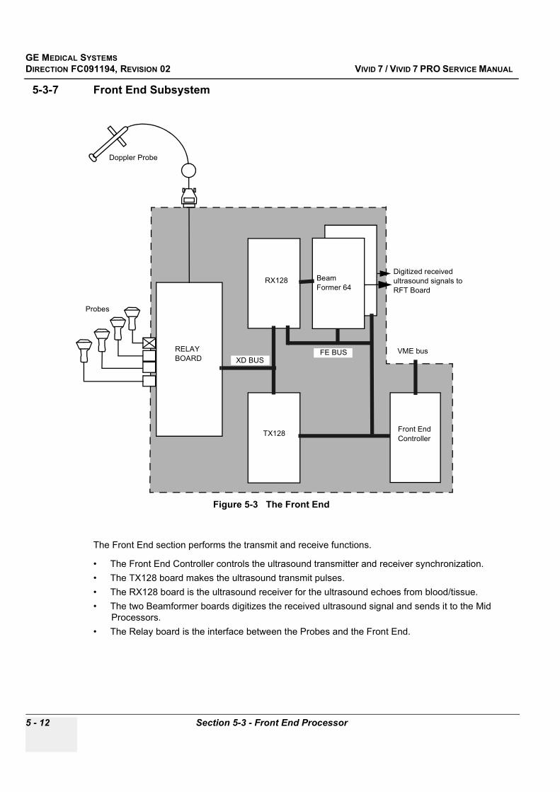
GE MEDICAL SYSTEMSDIRECTION FC091194, REVISION 02 VIVID 7 / VIVID 7 PRO SERVICE MANUAL
5 - 12 Section 5-3 - Front End Processor
5-3-7 Front End Subsystem
The Front End section performs the transmit and receive functions.
• The Front End Controller controls the ultrasound transmitter and receiver synchronization. • The TX128 board makes the ultrasound transmit pulses.• The RX128 board is the ultrasound receiver for the ultrasound echoes from blood/tissue. • The two Beamformer boards digitizes the received ultrasound signal and sends it to the Mid
Processors.• The Relay board is the interface between the Probes and the Front End.
Figure 5-3 The Front End
RELAY BOARD
RX128
TX128 Front End Controller
Probes
Doppler Probe
Digitized received ultrasound signals to RFT Board
VME busXD BUS
Beam Former 64
FE BUS
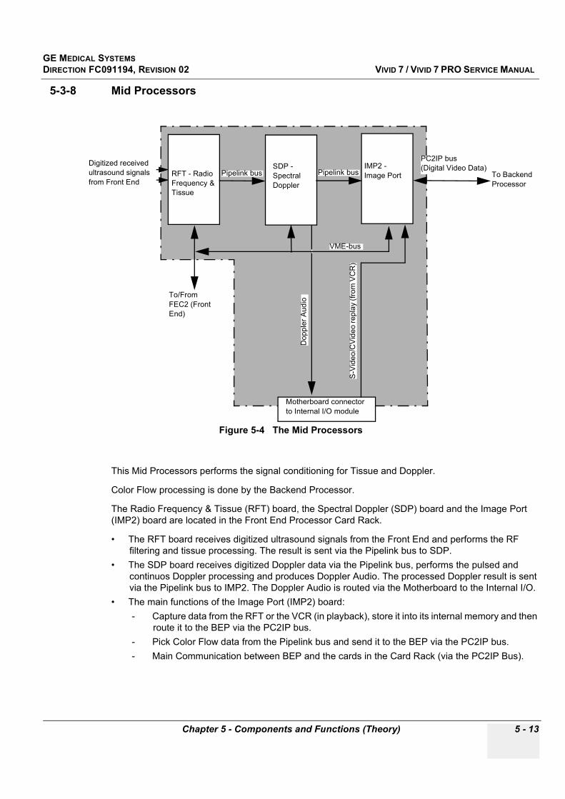
GE MEDICAL SYSTEMSDIRECTION FC091194, REVISION 02 VIVID 7 / VIVID 7 PRO SERVICE MANUAL
Chapter 5 - Components and Functions (Theory) 5 - 13
5-3-8 Mid Processors
This Mid Processors performs the signal conditioning for Tissue and Doppler.
Color Flow processing is done by the Backend Processor.
The Radio Frequency & Tissue (RFT) board, the Spectral Doppler (SDP) board and the Image Port (IMP2) board are located in the Front End Processor Card Rack.
• The RFT board receives digitized ultrasound signals from the Front End and performs the RF filtering and tissue processing. The result is sent via the Pipelink bus to SDP.
• The SDP board receives digitized Doppler data via the Pipelink bus, performs the pulsed and continuos Doppler processing and produces Doppler Audio. The processed Doppler result is sent via the Pipelink bus to IMP2. The Doppler Audio is routed via the Motherboard to the Internal I/O.
• The main functions of the Image Port (IMP2) board: - Capture data from the RFT or the VCR (in playback), store it into its internal memory and then
route it to the BEP via the PC2IP bus. - Pick Color Flow data from the Pipelink bus and send it to the BEP via the PC2IP bus.- Main Communication between BEP and the cards in the Card Rack (via the PC2IP Bus).
Figure 5-4 The Mid Processors
RFT - Radio Frequency & Tissue
SDP - Spectral Doppler
IMP2 - Image Port
Motherboard connector to Internal I/O module
VME-bus
Dop
pler
Aud
io
S-V
ideo
/CV
ideo
repl
ay (f
rom
VC
R)
To/From FEC2 (Front End)
Digitized received ultrasound signals from Front End
To Backend Processor
PC2IP bus (Digital Video Data)
Pipelink bus Pipelink bus

GE MEDICAL SYSTEMSDIRECTION FC091194, REVISION 02 VIVID 7 / VIVID 7 PRO SERVICE MANUAL
5 - 14 Section 5-4 - Back End Processor
Section 5-4Back End Processor
5-4-1 IntroductionThe Back End Processor is a computer designed specially for the use in Ultrasound Scanners made by GE. The first version, called BEP-1 in this manual, has been used since the introduction of the Vivid 7 / Vivid 7 PRO ultrasound scanners. A new version, called BEP-2 in this manual, will be introduced second half of 2002 as a replacement for BEP-1, both for new ultrasound scanners from factory and for service replacement in the field.
When the descriptions in this section applies only to one of the models, it will be marked in the text (BEP-1 or BEP-2)
5-4-2 Signal Flow and ProcessingThe Back End Processor receives the data from the Front-End Electronics, stores it in memory, performs scan conversion to pixel domain, and drives the system RGB monitor.
Back End Processor software is also providing processing of Color Flow, Doppler, and M-Mode Data.
See Figure 5-6 "CPU/Backend Processor Block Diagram (BEP-1)" on page 5-15 for an overview of the Back End Processor.
5-4-3 Location of the Back End ProcessorThe BEP is located on the left side, inside the scanner. The cover on the left side has been removed in Figure 5-5 "Backend Processor Mounted in Scanner (BEP-1 shown)" on page 5-14.
Figure 5-5 Backend Processor Mounted in Scanner (BEP-1 shown)
Backend Processor
Front of Scanner
BEP seen from Left Side of Scanner
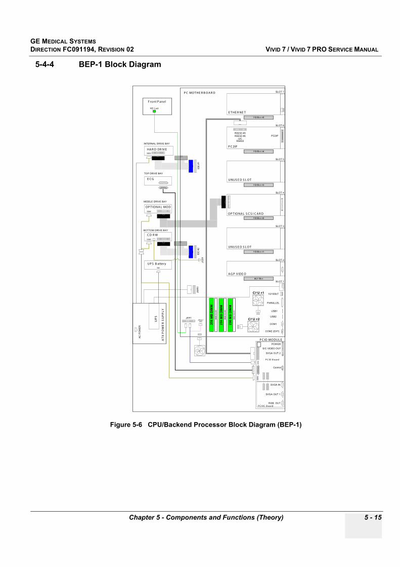
GE MEDICAL SYSTEMSDIRECTION FC091194, REVISION 02 VIVID 7 / VIVID 7 PRO SERVICE MANUAL
Chapter 5 - Components and Functions (Theory) 5 - 15
5-4-4 BEP-1 Block Diagram
Figure 5-6 CPU/Backend Processor Block Diagram (BEP-1)
O P T IO NA L S C S I C A R D
SLOT 5
UNU S E D S L O T
SLOT 3
A G P V IDE O
SLOT 2
SLOT 7
10/100bT
PARALLEL
COM1
COM2 (EXT)
USB1
USB2
P C MO T HE R B O A R D
P C IO MO DUL EAT
X P
OW
ER
SU
PP
LY
UP
S
HA R D DR IV E
E C G
O P T IO NA L MO D
C D R W
IDE
#2
JW
R1
SLOT 4
PC2IPRS232 #3
RS232 #4
I2C
P C 2IP
SLOT 6
AC
PO
WE
RRS422
RGB OUT
JFP1
SVGA OUT 1
SVGA OUT 2
S/C VIDEO OUT
SVGA IN
POWER
UNUS E D S L O T
F ront P anel
E T HE R NE T
P C IO B oard
P C V IC B oard
HD L ed
IDE
#1
UP S B attery
SLOT 1
Control
MIDDLE DRIVE BAY
BOTTOM DRIVE BAY
INTERNAL DRIVE BAY
TOP DRIVE BAY
CP U #1
CP U #2
25
6 M
B D
IMM
25
6 M
B D
IMM
DIM
M S
lot
#1
DIM
M S
lot
#2
DIM
M S
lot
#3
DIM
M S
lot
#4
JWOL1
AG P Slot
P CI Slot #1
P CI Slot #2
P CI Slot #3
P CI Slot #4
P CI Slot #5
JC
D1
25
6 M
B D
IMM

GE MEDICAL SYSTEMSDIRECTION FC091194, REVISION 02 VIVID 7 / VIVID 7 PRO SERVICE MANUAL
5 - 16 Section 5-4 - Back End Processor
5-4-5 BEP-1 Description
NOTE: Specifications mentioned about the Back End Processor (BEP-1) is minimum requirements. The actual hardware could exceed these specifications as technology advances.
The EMC enclosure houses an ATX Power Supply with UPS battery backup, an ATX style motherboard with minimum of 512 MB of ram and two 733 MHz processors
5 PCI slots on the mother board contains the following:
1.) Blank2.) Optional SCSI Card for MO Drive3.) Blank4.) PC2IP Card - GE designed. PCI Bus interface to the Front End Processor5.) Network Interface Card - 3Com Ethernet Card
• Analog output complies with the SVGA specification.• Resolution (on monitor) is 800x600.• Support for 32 bit True Color• Minimum of 8 Mbytes of high speed Video RAM, expandable to at least 16 Mbytes.• 128-bit internal memory interface.• Hardware supported asynchronous bit block transfer (80 Mpixels/sec).• Power and Internal PCI control signals• Two (2) USB Ports
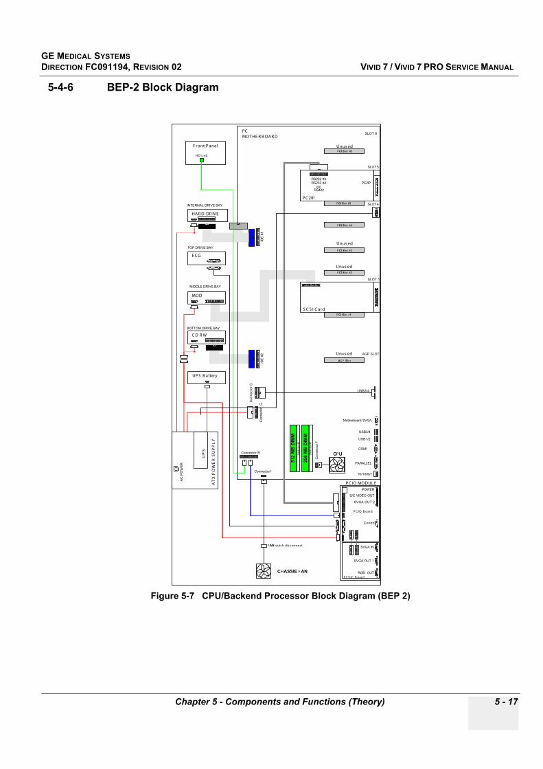
GE MEDICAL SYSTEMSDIRECTION FC091194, REVISION 02 VIVID 7 / VIVID 7 PRO SERVICE MANUAL
Chapter 5 - Components and Functions (Theory) 5 - 17
5-4-6 BEP-2 Block Diagram
Figure 5-7 CPU/Backend Processor Block Diagram (BEP 2)
AGP SLOT
SLOT 6
10/100bT
PARALLEL
COM1
USB1/2
PCMOT HE R B OAR D
P C IO MODUL EAT
X P
OW
ER
SU
PP
LY
UP
S
HAR D DR IVE
E C G
MOD
C D R W
IDE
#2
Connecto
r G
SLOT 5
AC
PO
WE
R
RGB OUT
Connector B
SVGA OUT 1
SVGA OUT 2
S/C VIDEO OUT
SVGA IN
POWER
F ront P anel
P C IO B oard
P C VIC B oard
H D L ed
IDE
#1
UP S B attery
Control
MIDDLE DRIVE BAY
BOTTOM DRIVE BAY
INTERNAL DRIVE BAY
TOP DRIVE BAY
CHASSIE FAN
CPU
512 M
B D
IMM
256 M
B D
IMM
DIM
M S
lot #1
DIM
M S
lot #2
AGP Slot
PC2IPRS232 #3RS232 #4
I2C
P C 2IP
RS422
USB3/4
USB3/4
Motherboard SVGA
Unus ed
PCI Slot #2
SLOT 1
PCI Slot #1
SLOT 4PCI Slot #5
FAN quick dis connect
Connector I
Co
nn
ecto
r C
Co
nn
ecto
r F
S C S I C ard
Unus ed
PCI Slot #3
Unus ed
PCI Slot #4
PCI Slot #6
Unus ed

GE MEDICAL SYSTEMSDIRECTION FC091194, REVISION 02 VIVID 7 / VIVID 7 PRO SERVICE MANUAL
5 - 18 Section 5-4 - Back End Processor
5-4-7 BEP-2 Description
NOTE: Specifications mentioned about the Back End Processor (BEP-2) is minimum requirements. The actual hardware could exceed these specifications as technology advances.
The EMC Enclosure House
• A Power Supply with UPS battery backup, • An Intel Motherboard with 768 Mbytes of ram and a single 2.0 GHz P4 processor w/ 400 MHz FSB.• Six (6) USB Ports • One (1) Serial Port (COM1 used for modem connection)• USB to Serial adapter cable (USB #3 to II/O B7) for External I/O serial output• AGP Video output from the motherboard (AGP Card Slot empty)• LAN output from the motherboard (PCI Card Slot 6 empty)
Use of 5 PCI slots on Mother Board
1.) Blank2.) Optional SCSI Card for MO Drive3.) Blank4.) PC2IP Card - GE designed. PCI Bus interface to the Front End Processor5.) Blank• Analog output complies with the SVGA specification.• Resolution (on monitor) is 800x600.• Support for 32 bit True Color• Minimum of 8 Mbytes of high speed Video RAM, expandable to at least 16 Mbytes.• 128-bit internal memory interface.• Hardware supported asynchronous bit block transfer (80 Mpixels/sec).
- Power and Internal PCI control signals
GE MEDICAL SYSTEMSDIRECTION FC091194, REVISION 02 VIVID 7 / VIVID 7 PRO SERVICE MANUAL
Chapter 5 - Components and Functions (Theory) 5 - 19
5-4-8 PCVIC Card• SVGA output to the monitor• RGB output to color printer
5-4-9 UPS Battery OperationThe UPS batteries provide power to the Back End Processor to enable a controlled shut down of the processor.
The UPS batteries will drain slightly when the system is in the off condition.
The off condition is defined as:
• Circuit Breaker in the OFF position• System unplugged from the wall outletIf the system is left in the OFF condition for an extended period of time (3 to 5 days or more), the system may not boot up or may beep when turned ON. Should this occur, the system needs to recharge the UPS batteries. This could take 15 minutes to as long as 24 hours, depending on the battery age, system input voltage and system temperature.
To eliminate draining the UPS batteries, the system should remain plugged into the wall outlet with the circuit breaker in the ON position.
GE MEDICAL SYSTEMSDIRECTION FC091194, REVISION 02 VIVID 7 / VIVID 7 PRO SERVICE MANUAL
5 - 20 Section 5-4 - Back End Processor
5-4-10 Internal Storage Devices:• Minimum 20 Gigabyte EIDE Hard Disk Drive (HDD) inside the Back End Processor cabinet.• 5.25 inch Magneto-Optical Drive (MOD) (option) available from front of scanner.• CD-RW Drive available from front of scanner.
5-4-11 Inputs
5-4-11-1 AC Power
5-4-11-2 DC Voltages
Table 5-2 AC Power
Input Description Connection from:
230 VAC AC Power AC Distribution Box > Backend Processor
Table 5-3 DC Input Voltages
Input Description Connected to:
+5Vstb Standby voltage DC Power Supply via Backplane
GND Electrical Ground DC Power Supply via Backplane and II/O
GE MEDICAL SYSTEMSDIRECTION FC091194, REVISION 02 VIVID 7 / VIVID 7 PRO SERVICE MANUAL
Chapter 5 - Components and Functions (Theory) 5 - 21
5-4-11 Inputs (cont’d)
5-4-11-3 Input Signals
5-4-11-4 Bi-directional Signals
Table 5-4 Input Signals
Signal Name Description Signal Path
PWR_OK* Power verification signal from Card Rack Card Rack > IIO > PC2IO
ON/OFF Switch Signal from the ON/OFF switch on the Control Panel and from the Reset button on the rear of the External I/O.
Top Console > IIO > PC2IOON/OFF Reset (EIO) > IIO > PC2IO
I2C Register Interrupt Interrupt signal from I2C Bus EIO > IIO > PC2IO
Microphone in to BEP Microphone signal from Monitor (Top Console) Top Console > IIO > BEP
Audio in to BEP Audio from VCR or Doppler AudioReplay Audio from VCR > IIO > BEP
Doppler Audio Out from Card Rack > IIO > BEP
Table 5-5 Bi-directional Signals
Signal Name Description Signal Path
UPS Control RS232 Control Signals to and from the UPS BEP > IIO
RS232 XDCTRL Not Used PC2IO > IIO > Not Used
I2C Bus Data bus used for Remote Control of External Units and for reading module versions. PC2IO > IIO > EIO
Spare RS232 Not Used PC2IO > IIO > Not Used
VCR Remote Ctrl (RS232) Control signal to Internal VCR PC2IO > IIO > VCR
USB #1 USB bus to Top Console PC2IO > IIO > Top Console
COM 1 Not Used PC2IO > IIO > EIO
COM 2 Modem PC2IO > IIO > EIO (Rear of Module) > Modem
Ethernet Standard TCP/IP Ethernet BEP > IIO > EIO > External Network
USB #2 USB Bus for External Units BEP > IIO > EIO > External USB Unit
GE MEDICAL SYSTEMSDIRECTION FC091194, REVISION 02 VIVID 7 / VIVID 7 PRO SERVICE MANUAL
5 - 22 Section 5-4 - Back End Processor
5-4-12 Outputs
Table 5-6 Output Signals
Signal Name Description Signal Path
+5VDC DC Voltage PC2IO > IIO
+12VDC DC Voltage PC2IO > IIO
PS_ON* Active Low PC2IO > IIO > Card Rack
Standby PC2IO > IIO > Top Console
SVideo SVideo Out PCVIC > PC2IO > IIO > EIO
CVideo Composite Color Video PCVIC > PC2IO > IIO > EIO
VGA VGA High Resolution Video to External Video Screen PCVIC > PC2IO > IIO > EIO
VGA VGA High Resolution Video to Internal Video Screen (Top Console) BEP > Top Console
BW Video RGB BW Video from RGB. This signal is not used on Vivid 7 / Vivid 7 PRO
PCVIC > PC2IO > IIO > EIOThis signal is not used on Vivid 7 / Vivid
7 PRO
Audio Out Audio Out from BEPBEP > IIO > Internal VCR
BEP > IIO > EIO > External VCR
TRIG Video Trig Signal PC2IO > IIO > EIO

GE MEDICAL SYSTEMSDIRECTION FC091194, REVISION 02 VIVID 7 / VIVID 7 PRO SERVICE MANUAL
Chapter 5 - Components and Functions (Theory) 5 - 23
Section 5-5Patient I/O (Physio)
The Patient I/O is mounted inside the Backend Processor’s cabinet with its connector panel available on the front of the scanner.
The Patient IO contains the electronics for ECG, phono and two analog inputs. One of the inputs has programmable gain. The module extracts respiration from ECG. The electronics also contains a pacemaker detector. The four inputs are separately isolated because of safety requirements.
Available inputs
• Phono (from a phono heart microphone)• ECG / Respiration• AUX1• AUX2 (Pulse/Pressure)These signals are optically isolated from the rest of the system.
Figure 5-8 Pat I/O - Block Diagram
Digital Trace Data
PHONO
AUX 1
ISOLATION
AUX 2
ECG / RESPIRATION
(Pulse/Pressure)
PHONO
ECG
AUX1
AUX2
A/D
(Pulse/Pressure)
to PC2IO

GE MEDICAL SYSTEMSDIRECTION FC091194, REVISION 02 VIVID 7 / VIVID 7 PRO SERVICE MANUAL
5 - 24 Section 5-6 - Internal I/O
Section 5-6Internal I/O
The Internal I/O is the interface between the Card Cage, BEP Module, and the rest of the system, including the Top Console and the Peripherals.
Figure 5-9 Internal I/O Module Overview
50M
50M
Cable #17
Cable #4
Cable #17
Cable #16
Cable #16
Left
Right
Right
Left
AUDIO OUT
AUDIO IN
RS-232C
VIDEO OUT
VIDEO IN
SONY VCR SVO-9500MD
Cable #3
Cable #2
A8
A9
A6A7
A2
A11
A10
USB, +12PC, MIC IN, AUDIO OUT
PC/VIC
PC2IO
D1
D2
Remote
ECG
MOD
CD/RW
FLOCK OF BIRDS(option)
SCSI
PC2IP
SOUND CARD
PCI VIDEO
AGP VIDEO
Mic InLine OutLine In
10/100 T
USB #1USB #2
COM1
COM2 (EXT)
Power from PC
I/O-PC2IOSignals Cable
PC MODULE
Op Panel I/F
AC Power
Video Mic
OP PANEL
Cable #10
Cable #29
Cable #19
Cable #18
Cable #18
A1
A3
A4
A5
B5
B6
B7
B8
B2
B1
B3
B4
A15
A14
Cable #9
Cable #9
TO CARD RACK
TOEXTERNAL I/O
BOARD
PS SUPPLYON FAN
SPEED CONTROL
USERINTERFACE
RS-232C
Video Output
B/W Video In
SONY B/W PRINTERUP890MD
SONYCOLOR PRINTER
UP-2900MD
INTERNAL I/O BOARD
PCMOTHERBOARD
Cable #7
Cable #11
MONITOR

GE MEDICAL SYSTEMSDIRECTION FC091194, REVISION 02 VIVID 7 / VIVID 7 PRO SERVICE MANUAL
Chapter 5 - Components and Functions (Theory) 5 - 25
Section 5-6 Internal I/O (cont’d)
The Internal I/O board performs buffering and distribution of video and control data from various sources to multiple destinations.
• SVGA (R, G, B and Sync.) are fed from the BEP, directly up to the system monitor. Another set of RGB can be fed to a color printer.
• Composite video, black and white video and S-Video are buffered and distributed to VCR and printers.
• The analog Doppler signals are fed from the Spectrum Doppler board to the VCR audio inputs and through a switch where audio from VCR playback also is input, to the BEP and then to the speakers.
• Serial RS-232 interface signals from the BEP are fed to the destinations; VCR, Color Printer and Modem.
• Serial USB interface signals from the BEP are fed to the Front Panel and to EIO.• Remote control signals for printers are generated on the I/O board.• The Footswitch is connected to the I/O board.• An AC Power Interface controls power on/off and fan speed.
Figure 5-10 Internal I/O Back End Processor Connections

GE MEDICAL SYSTEMSDIRECTION FC091194, REVISION 02 VIVID 7 / VIVID 7 PRO SERVICE MANUAL
5 - 26 Section 5-6 - Internal I/O
5-6-1 Location in the UnitThe Internal I/O Module is plugged into the Card Rack (at the end nearest to the rear of the system).
5-6-2 LEDsNine green LEDs indicate that the respective DC Voltages are OK.
5-6-3 FusesAll output voltages are fused
5-6-4 Jumpers and Dip-switchesTBD
Figure 5-11 Internal I/O: Location in the System (Seen from Left Side)
Figure 5-12 Internal I/O: Green LEDs for Power Status.
Back of System
Internal I/O is located behind the cables at the rear of the Back End Processor.
GE MEDICAL SYSTEMSDIRECTION FC091194, REVISION 02 VIVID 7 / VIVID 7 PRO SERVICE MANUAL
Chapter 5 - Components and Functions (Theory) 5 - 27
5-6-5 InputsDC Voltages
Video Input Signals
Audio Input Signals
Table 5-7 DC Input Voltages
Input Description Connection from
+3.3 VDC Input DC Voltage DC Power Supply > Backplane > J32
+5 VDC Input DC Voltage DC Power Supply > Backplane > J32
+10 VDC Input DC Voltage DC Power Supply > Backplane > J32
+15 VDC Input DC Voltage DC Power Supply > Backplane > J32
-15 VDC Input DC Voltage DC Power Supply > Backplane > J32
+6 VDC (analog) Input DC Voltage DC Power Supply > Backplane > J32
–5 VDC (analog) Input DC Voltage DC Power Supply > Backplane > J32
+5 VDC Input DC Voltage Backend Processor > J17
+12 VDC Input DC Voltage Backend Processor > J17)
Table 5-8 Video Input Signals
Input Description Connection from
SVGA Video Signal to External I/O PC2IO (Connector J16)
SVHS Video Signal to VCR & External I/O PC2IO(Connector J16)
SVHS Video Signal to MBD (IMP) VCR (Connector J11)
Luma Video Signal to B&W Printer and External I/O PC2IO (Connector J16)
Comp. Video Video Signal to External I/O PC2IO (Connector J16)
Comp. Video Video Signal to MBD (IMP) Color printer
Table 5-9 Audio Input Signals
Input Description Connection from
Two channel audio
Audio signals, summed and distributed
MBD (IMP)
Two channel audio VCR
Two channel audio BEP
GE MEDICAL SYSTEMSDIRECTION FC091194, REVISION 02 VIVID 7 / VIVID 7 PRO SERVICE MANUAL
5 - 28 Section 5-6 - Internal I/O
5-11-13-3 Inputs (cont’d)Serial Ports
Control Signals
Table 5-10 Serial Ports
Input Description Connection from
USB Standard USB Serial Bus BEPM - Top console
USB Standard USB Serial Bus BEPM - IEIO
Ethernet Standard Ethernet BEPM - IEIO
RS232 Standard RS232 Serial Bus BEPM COM1 - IEIO
RS232 Standard RS232 Serial Bus BEPM COM2 - IEIO
RS232 Standard RS232 Serial Bus PC2IO - Spare (J16)
RS232 Standard RS232 Serial Bus PC2IO - VCR (J16)
RS232 PC2IO - Color printer (Connector J16)
RS232 PC2IO – UPS (Connector J16)
Table 5-11 Control Signals
Input Description Connection from
Control signals Spare MBD/FEC (Connector J??)
Control signals Spare MBD/FEC (Connector J?)
Trace trigger To EIO PC2IO (Connector J16)
Fan control signals To AC Power MBD (Connector J?)
Power control signals To MBD and AC Power PC2IO (Connector J16)
Power on/off To Relay Top Console ON/OFF Switch and EIO Test (Connector J?)
Standby To Top Console PC2IO (Connector J16)
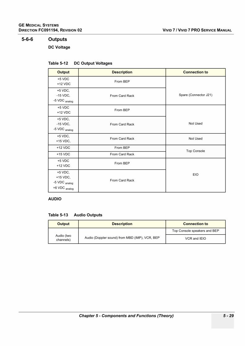
GE MEDICAL SYSTEMSDIRECTION FC091194, REVISION 02 VIVID 7 / VIVID 7 PRO SERVICE MANUAL
Chapter 5 - Components and Functions (Theory) 5 - 29
5-6-6 OutputsDC Voltage
AUDIO
Table 5-12 DC Output Voltages
Output Description Connection to
+5 VDC +12 VDC
From BEP
Spare (Connector J21)+5 VDC, -15 VDC,
-5 VDC analog
From Card Rack
+5 VDC +12 VDC
From BEP
Not Used +5 VDC, -15 VDC,
-5 VDC analog
From Card Rack
+5 VDC, +15 VDC,
From Card Rack Not Used
+12 VDC From BEPTop Console
+15 VDC From Card Rack
+5 VDC+12 VDC
From BEP
EIO+5 VDC,
+15 VDC, -5 VDC analog
+6 VDC analog
From Card Rack
Table 5-13 Audio Outputs
Output Description Connection to
Audio (two channels) Audio (Doppler sound) from MBD (IMP), VCR, BEP
Top Console speakers and BEP
VCR and IEIO

GE MEDICAL SYSTEMSDIRECTION FC091194, REVISION 02 VIVID 7 / VIVID 7 PRO SERVICE MANUAL
5 - 30 Section 5-6 - Internal I/O
5-11-13-4 Outputs (cont’d)Interface Connectors – Component Side
Table 5-14 Connectors, Component Side
Input Description Connection from
A1/J1 B&W printer, 15pins HD-sub, female.
A2/P4 VCR remote ctrl – RS232: 9pins D-sub, male.
A3/P5 Color printer - RS232: 9pins D-sub, male.
A4/J2 Top Console - Power & signals: 15pins D-sub, female.
A5/P4 Top Console - Signals: 15pins D-sub, male.
A6/J6 Audio out to VCR, left: Phono jack.
A7/J7 Audio out to VCR, right: Phono jack.
A8/J8 Audio in from VCR, left: Phono jack.
A9/J9 Audio in from VCR, right
A10/J10 SVHS out to VCR
A11/J11 SVHS in from VCR
B1/J12 USB to Top console
B2/J13 USB to external I/O
B3/J14 Ethernet
B4/J15 Audio I/O
B5/J16 PC2IO signals
B6/J17 PC2IO power
B7/P18 COM1
B8/P19 COM2
B9/P25 UPS remote control
J32 MBD – signals and power
Table 5-15 Connectors, Solder side
Input Description Connection from
A12/J21 Spare power, 15pins D-sub, female
A13/J20 Spare – power, 15pins D-sub, female
A14/J24 AC power ctrl, 9pins D-sub, female
A15/P23 Rotation adapter – signals, 15pins D-sub, male
A16/P22 Spare – signals, 25pins D-sub, female
P30 EIO – signals and power, 110pins male

GE MEDICAL SYSTEMSDIRECTION FC091194, REVISION 02 VIVID 7 / VIVID 7 PRO SERVICE MANUAL
Chapter 5 - Components and Functions (Theory) 5 - 31
Section 5-7Top Console
The Top Console includes;
• a SVGA video monitor • a Control Panel with;
- an ON/OFF (standby) switch - an alphanumeric (QWERTY) keyboard - controls for manipulating the picture quality and for use in Measure & Analyze (M&A)
• speakers for stereo sound output (used during Doppler scanning/replay)
Figure 5-13 Top Console Block Diagram
Monitor
Control Panel
Top Console
ON/Standby
Stereo Audio from Internal I/O
Speaker
SVGA from Backend Processor (via Internal I/O)
Speaker
ON/OFF to Internal I/O
USB from/to Backend Processor (via Internal I/O)
115 VAC from AC Distribution Box (AC Power)
12VDC from Backend Processor, +15VDC from Card Rack (both via Internal I/O)
GND
GE MEDICAL SYSTEMSDIRECTION FC091194, REVISION 02 VIVID 7 / VIVID 7 PRO SERVICE MANUAL
5 - 32 Section 5-8 - Peripherals
Section 5-8Peripherals
5-8-1 On-board Peripherals(See “Approved On-board Peripherals” on page 3-32.)
• VCR (connected to Internal I/O)• Black & White Video Printer (connected to Internal I/O)• Color Video Printer (connected to BEP - D5)• Modem (connected to External I/O)
5-8-2 External Peripherals(See “Off-board Peripherals” on page 3-32.)
• Color Inkjet Printer• Footswitch, Phone Line and Ethernet are connected to External I/O
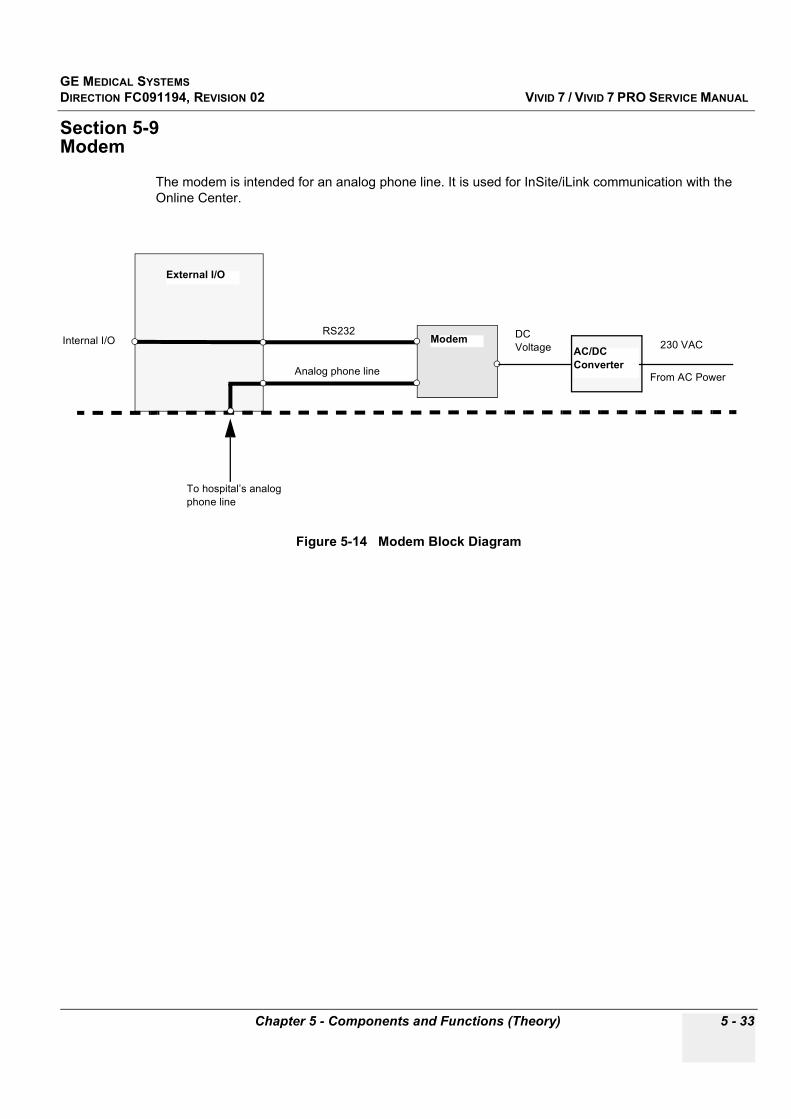
GE MEDICAL SYSTEMSDIRECTION FC091194, REVISION 02 VIVID 7 / VIVID 7 PRO SERVICE MANUAL
Chapter 5 - Components and Functions (Theory) 5 - 33
Section 5-9Modem
The modem is intended for an analog phone line. It is used for InSite/iLink communication with the Online Center.
Figure 5-14 Modem Block Diagram
External I/O
ModemInternal I/O
To hospital’s analog phone line
RS232
Analog phone line
DC Voltage AC/DC
Converter
230 VAC
From AC Power

GE MEDICAL SYSTEMSDIRECTION FC091194, REVISION 02 VIVID 7 / VIVID 7 PRO SERVICE MANUAL
5 - 34 Section 5-10 - Power Distribution
Section 5-10Power Distribution
5-10-1 Overall AC Power Distribution
Figure 5-15 Overall Power Distribution
Filter
Mains Switch
Inrush Limit
115 or 230 VAC
Transformer
20 VAC
230 VAC
115 VAC
Fan regulator Fan
DC Power
TX Power
DC Voltages to Cards
Card Rack
DC Power distribution inside Backend Processor
Backend Processor
AC/DC Converter Modem
VCR (Video Recorder)
Black & White Printer
Color Video Printer
TX Voltage
230 VAC
230 VAC
230 VAC
115 VAC
230 VAC
Monitor
BatteryAC/DC UPS
Manually Selected: 115 VAC or 230 VAC
IIO
AC Power
Select Voltage
AC Ctrl Assy
Transformer Box

GE MEDICAL SYSTEMSDIRECTION FC091194, REVISION 02 VIVID 7 / VIVID 7 PRO SERVICE MANUAL
Chapter 5 - Components and Functions (Theory) 5 - 35
5-10-2 OverviewThe AC Power’s main tasks are to supply the various internal subsystems with AC power and to galvanically isolate the scanner from the on site Mains Power System. To reduce inrush current, an inrush current limiter as well as an EMI filter. Voltage to peripherals can be configured to either 115 VAC or 230 VAC. The AC Power also controls and supplies the 20VAC needed by the systems cooling fan.
5-10-3 AC Power Distribution Box (PWB)
The mains cord has plugs in both ends. A female plug connects to the scanner and a male plug to the mains outlet on site.
The mains voltage is routed via an EMI filter to the Mains Switch, located on the rear of the system.
The Mains Switch is of the auto fuse type, if for some reason the current grows to high, the switch will automatically break the power.
From the Mains Switch, the AC power is routed via an Inrush Current Limiter (titled: Inrush Limiter in Figure 5-16) to a internal outlet connector for the Mains Transformer.
Figure 5-16 AC Power Distribution
AC INLET BOXTO OUTLET
M
INRUSHLIMIT
Mainsswitch
230V
ac
115V
ac
230Vac
20Vac
230 115
Fanregulator
L
TRANSFORMER BOX
TO PERIPHERIALS (115 or 230 Vac)
TO MONITOR (115 Vac)
TO MODEM (230 Vac)
TO PC (230 Vac)
TO CARD RACK (230 Vac)
Cable #27
Cable #13
Cable #7TO A14 ON INTERNAL I/O
POWER SUPPLY ON,FAN SPEED CONTROL
CABLES INTERNAL IN AC CONTROL MODULE #27
AC DISTRIBUTION PWB

GE MEDICAL SYSTEMSDIRECTION FC091194, REVISION 02 VIVID 7 / VIVID 7 PRO SERVICE MANUAL
5 - 36 Section 5-10 - Power Distribution
5-10-3 AC Power Distribution Box (PWB) (cont’d)The Transformer is the galvanic barrier between the rest of the scanner and the on site AC Mains.
Input voltage to the transformer can be either 230VAC or 115 VAC (two different part numbers/FRUs). The configuration of the plug on the cable to the AC Transformer is different for the two AC Voltages.
From the AC Transformer, there are three outlets;
• 20 VAC• 115 VAC• 230 VACThe 20 VAC is routed via the fan regulator to the system fan.
The 115 VAC is routed via a fuse to an AC Voltage selector, used for selecting the right output voltage for the Peripherals outlet and the Monitor. (The alternative voltage to this outlet is 230 VAC.)
The 230 VAC output from the Transformer is routed via a fuse and distributed to the AC Voltage selector for the Peripherals outlet and to the following AC outlets:
• Modem• Back End Processor• Card Rack
Figure 5-17 Connectors on Back of AC Controller
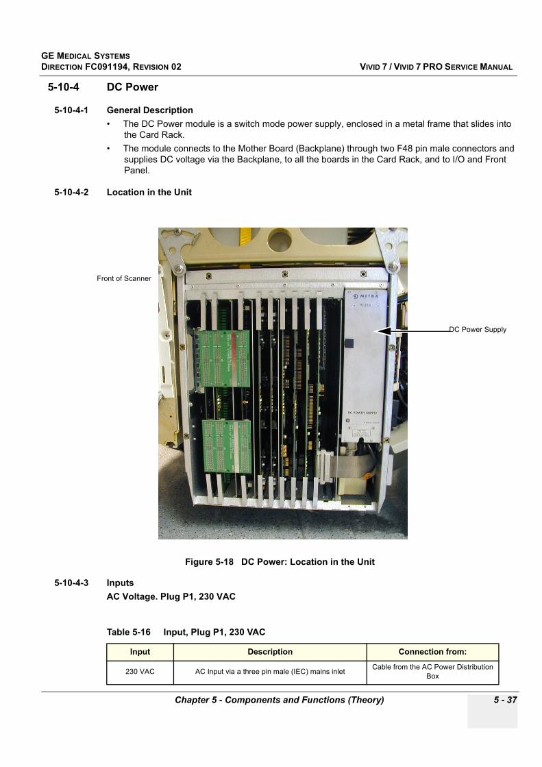
GE MEDICAL SYSTEMSDIRECTION FC091194, REVISION 02 VIVID 7 / VIVID 7 PRO SERVICE MANUAL
Chapter 5 - Components and Functions (Theory) 5 - 37
5-10-4 DC Power
5-10-4-1 General Description• The DC Power module is a switch mode power supply, enclosed in a metal frame that slides into
the Card Rack. • The module connects to the Mother Board (Backplane) through two F48 pin male connectors and
supplies DC voltage via the Backplane, to all the boards in the Card Rack, and to I/O and Front Panel.
5-10-4-2 Location in the Unit
5-10-4-3 InputsAC Voltage. Plug P1, 230 VAC
Figure 5-18 DC Power: Location in the Unit
Table 5-16 Input, Plug P1, 230 VAC
Input Description Connection from:
230 VAC AC Input via a three pin male (IEC) mains inlet Cable from the AC Power Distribution Box
Front of Scanner
DC Power Supply
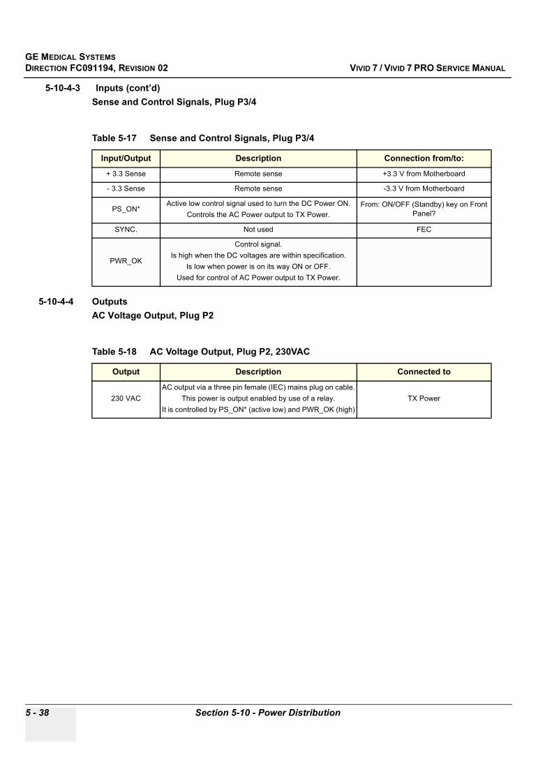
GE MEDICAL SYSTEMSDIRECTION FC091194, REVISION 02 VIVID 7 / VIVID 7 PRO SERVICE MANUAL
5 - 38 Section 5-10 - Power Distribution
5-10-4-3 Inputs (cont’d)Sense and Control Signals, Plug P3/4
5-10-4-4 OutputsAC Voltage Output, Plug P2
Table 5-17 Sense and Control Signals, Plug P3/4
Input/Output Description Connection from/to:
+ 3.3 Sense Remote sense +3.3 V from Motherboard
- 3.3 Sense Remote sense -3.3 V from Motherboard
PS_ON*Active low control signal used to turn the DC Power ON.
Controls the AC Power output to TX Power. From: ON/OFF (Standby) key on Front
Panel?
SYNC. Not used FEC
PWR_OK
Control signal. Is high when the DC voltages are within specification.
Is low when power is on its way ON or OFF.Used for control of AC Power output to TX Power.
Table 5-18 AC Voltage Output, Plug P2, 230VAC
Output Description Connected to
230 VACAC output via a three pin female (IEC) mains plug on cable.
This power is output enabled by use of a relay.It is controlled by PS_ON* (active low) and PWR_OK (high)
TX Power

GE MEDICAL SYSTEMSDIRECTION FC091194, REVISION 02 VIVID 7 / VIVID 7 PRO SERVICE MANUAL
Chapter 5 - Components and Functions (Theory) 5 - 39
5-10-4-4 Outputs (cont’d)DC Output Voltages, Plug P3/P4
Table 5-19 DC Output Voltages, Plug P3 & P4
Output Description Connected to:
+ 3.3 V DC output voltages, distributed via Mother Board (Back Plane) BF64 (two boards)
+ 5 VdDC output voltage, distributed via Mother Board (Back
Plane). The “d” indicates that this voltage is used for digital circuits.
BF64 (two boards)FECRFTSDPIMP2
Front PanelI/O
+ 6 VaDC output voltage, distributed via Mother Board (Back
Plane). The “a” indicates that this voltage is used for analog circuits
RelayTXRX
- 5 VaDC output voltage, distributed via Mother Board (Back
Plane). The “a” indicates that this voltage is used for analog circuits.
RelayRX
BF64 (two boards)FECRFTSDPIMP2
+5Vstb Standby voltage TBD
+10 V DC output voltage, distributed via Mother Board (Back Plane) TX
+15 V DC output voltage, distributed via Mother Board (Back Plane)
RelayRX
Front PanelI/O
- 15 V DC output voltage, distributed via Mother Board (Back Plane)
RXFront Panel
I/O
GND Distributed via Mother Board (Back Plane) All boards

GE MEDICAL SYSTEMSDIRECTION FC091194, REVISION 02 VIVID 7 / VIVID 7 PRO SERVICE MANUAL
5 - 40 Section 5-10 - Power Distribution
5-10-4-5 Fuses• None. • A current limiter will switch off the power if + 3.3 V, +5 V or +15 V outputs are overloaded• Over Voltage Protection is provided for these voltages:
- + 3.3 V- + 5 Vd- +/- 5 Va- +/- 15 Va
• Voltage will be turned off if the temperature grows too high.
5-10-4-6 Jumpers and Dip-switchesNone.
5-10-4-7 LEDsNone.
(Observe the LEDs on Internal I/O to check DC Voltage Status, see "Internal I/O" on page 5-79.)

GE MEDICAL SYSTEMSDIRECTION FC091194, REVISION 02 VIVID 7 / VIVID 7 PRO SERVICE MANUAL
Chapter 5 - Components and Functions (Theory) 5 - 41
5-10-5 TX Power Supply
5-10-5-1 General DescriptionThe TX Power is a switch mode power supply module. It is used to generate two symmetrical pairs of digitally programmable voltages for the transmitters in the Vivid 7 / Vivid 7 PRO scanner, and a fixed +/- 100VDC Probe MUX Voltage used by the multiplexers in Linear Array Probes with more than 128 transducer elements.
• It is enclosed in a metal frame that slides into the Card Rack. • The module connects to the Mother Board (Backplane) through a 32 pin connector • A pin between the two upper mounting holes, fits into the a corresponding hole in the Card Rack.
This key is used to prevent it from being plugged into other scanners.
Figure 5-19 TX Power Supply: Front Panel with Key (Pin)
Pin on rear side of TX Power’s Front Panel
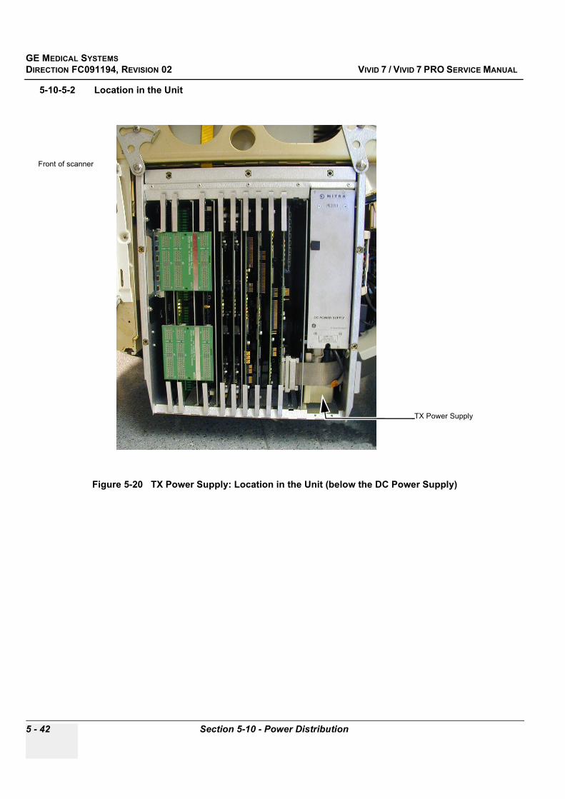
GE MEDICAL SYSTEMSDIRECTION FC091194, REVISION 02 VIVID 7 / VIVID 7 PRO SERVICE MANUAL
5 - 42 Section 5-10 - Power Distribution
5-10-5-2 Location in the Unit
Figure 5-20 TX Power Supply: Location in the Unit (below the DC Power Supply)
TX Power Supply
Front of scanner

GE MEDICAL SYSTEMSDIRECTION FC091194, REVISION 02 VIVID 7 / VIVID 7 PRO SERVICE MANUAL
Chapter 5 - Components and Functions (Theory) 5 - 43
5-10-5-3 InputsAC Voltage. Plug P1, 230 VAC
5-10-5-4 OutputsOutput Voltages, Plug P2
5-10-5-5 Fuses• Output Power Protection Circuit with these functions:
- Protect probe and TX board if a failure make the voltage exceed limits- Protect the power supply if there is a failure in probe or transmitter circuit
• A watch-dog disables the voltage (set it to zero Volt) if the; - serial communication with the FEC-2 module stops - nominal Power limit is exceeded- maximum Power limit is exceeded
5-10-5-6 Jumpers and Dip-switchesNone.
5-10-5-7 LEDsNone.
Table 5-20 Input, Plug P1, 230 VAC
Input Description Connection from:
230 VAC AC Input via a three pin male (IEC) mains inlet Cable from the DC Power Module
Table 5-21 Output Voltages, Plug P2
Output Description Connected to:
TSV1
TX Voltage 1 Voltage can be programmed to vary from +/- 2.5 V to +/-
80VUsed to drive the transmitters in 2D Mode and M mode
TX board
TSV2
TX voltage 2Voltage can be programmed to vary from +/- 2,5 V to +/-
40VUsed to drive the transmitters in Doppler (CW/PW) mode
and in Color Flow Mapping (CFM) mode
TX board
PMXVOUT
Probe Multiplexing VoltageA fixed +/-100 V Voltage
Used for the multiplexers in linear array probes with more than 128 transducer elements
RLY board

GE MEDICAL SYSTEMSDIRECTION FC091194, REVISION 02 VIVID 7 / VIVID 7 PRO SERVICE MANUAL
5 - 44 Section 5-11 - Circuit Boards
Section 5-11Circuit Boards
5-11-1 OverviewThis section describes the Circuit Boards in Vivid 7 / Vivid 7 PRO.
Table 5-22 Contents in Section 5-11
Sub-section Description Page Number
5-11-2 Relay Board, RLY 5-45
5-11-3 Transmitter Board, TX128 5-47
5-11-4 Receiver Board, RX-128 5-50
5-11-5 Beamformer Board(s), BF-64 5-53
5-11-6 Front End Controller Board, FEC-2 5-56
5-11-7 Transducer Bus Boards, XD BUS Boards 5-61
5-11-8 RF & Tissue Processor Board, RFT 5-62
5-11-9 Spectrum Doppler Processor Board, SDP 5-66
5-11-10 Image Port 2 Board, IMP2 5-70
5-11-11 Backend Processor 5-74
5-11-12 Patient I/O 5-78
5-11-13 Internal I/O 5-79
5-11-14 External I/O 5-87
5-11-15 Interconnect Cabling 5-90
5-11-16 Motherboard (Back Plane) 5-92
5-11-17 Modem 5-93
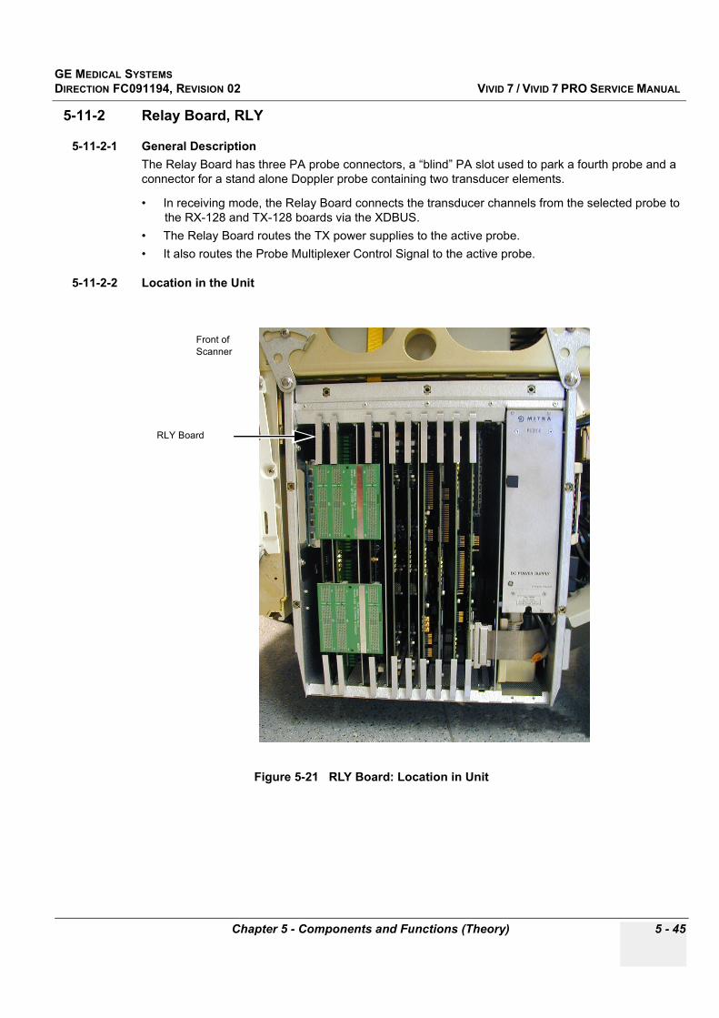
GE MEDICAL SYSTEMSDIRECTION FC091194, REVISION 02 VIVID 7 / VIVID 7 PRO SERVICE MANUAL
Chapter 5 - Components and Functions (Theory) 5 - 45
5-11-2 Relay Board, RLY
5-11-2-1 General DescriptionThe Relay Board has three PA probe connectors, a “blind” PA slot used to park a fourth probe and a connector for a stand alone Doppler probe containing two transducer elements.
• In receiving mode, the Relay Board connects the transducer channels from the selected probe to the RX-128 and TX-128 boards via the XDBUS.
• The Relay Board routes the TX power supplies to the active probe.• It also routes the Probe Multiplexer Control Signal to the active probe.
5-11-2-2 Location in the Unit
Figure 5-21 RLY Board: Location in Unit
RLY Board
Front of Scanner

GE MEDICAL SYSTEMSDIRECTION FC091194, REVISION 02 VIVID 7 / VIVID 7 PRO SERVICE MANUAL
5 - 46 Section 5-11 - Circuit Boards
5-11-2-3 InputsDC Voltages
Input Signals
Control Signals
5-11-2-4 OutputsOutput Signals
5-11-2-5 Fuses, Jumpers and Dip-switchesNone
5-11-2-6 LEDsNone.
Table 5-23 DC Output Voltages, Plug P3 & P4
Input Description Connected from:
+ 5 VaDC output voltage, distributed via Mother Board (Back
Plane). The “a” indicates that this voltage is used for analog circuits
DC Power Supply > Backplane
- 5 VaDC output voltage, distributed via Mother Board (Back
Plane). The “a” indicates that this voltage is used for analog circuits.
DC Power Supply > Backplane
GND Distributed via Mother Board (Back Plane) DC Power Supply > Back Plane
Table 5-24 Input Signals
Input Description Connection from:
EL1-128 Received signals (echoes) and Transmitted pulses (1 of 3 probe connectors) The active probe
Table 5-25 Input Signals
Input Description Connection from:
Front End Data Bus Digital data bus used for control of the boards in the Front End RLY > Backplane > FEC
Probe MUX Control Probe Configuration RLY > Backplane > FEC
Table 5-26 Output Signals
Output Description Connection to:
XD1 - 128 128 signals to TX-128 and RX-128 XD Bus Boards
CW or PW TX CW or PW Doppler transmitter pulses Stand Alone Doppler probe
CW or PW RX CW or PW Doppler RX signals (echoes) Stand Alone Doppler probe
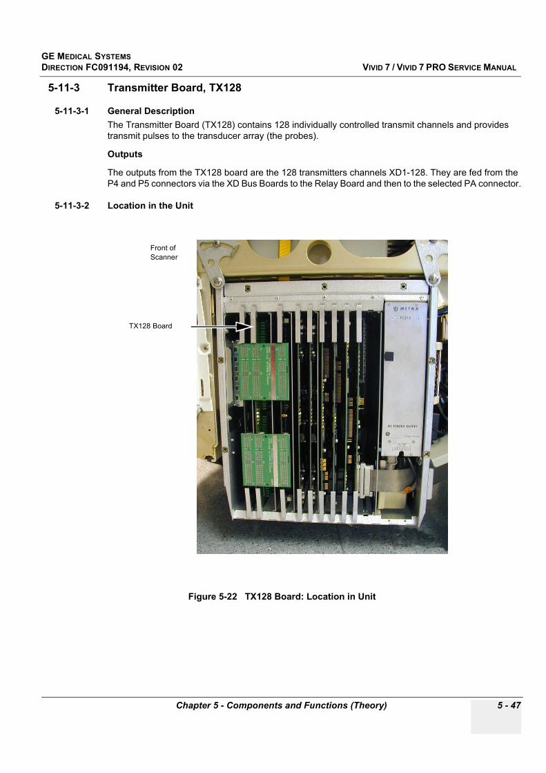
GE MEDICAL SYSTEMSDIRECTION FC091194, REVISION 02 VIVID 7 / VIVID 7 PRO SERVICE MANUAL
Chapter 5 - Components and Functions (Theory) 5 - 47
5-11-3 Transmitter Board, TX128
5-11-3-1 General DescriptionThe Transmitter Board (TX128) contains 128 individually controlled transmit channels and provides transmit pulses to the transducer array (the probes).
Outputs
The outputs from the TX128 board are the 128 transmitters channels XD1-128. They are fed from the P4 and P5 connectors via the XD Bus Boards to the Relay Board and then to the selected PA connector.
5-11-3-2 Location in the Unit
Figure 5-22 TX128 Board: Location in Unit
TX128 Board
Front of Scanner

GE MEDICAL SYSTEMSDIRECTION FC091194, REVISION 02 VIVID 7 / VIVID 7 PRO SERVICE MANUAL
5 - 48 Section 5-11 - Circuit Boards
5-11-3-3 InputsDC Voltages
Control Signals
5-11-3-4 Outputs
5-11-3-5 Fuses, Jumpers and Dip-switchesNone
Table 5-27 Input, DC Voltages
Input Description Connection from:
+5 VaDC voltage, distributed via Mother Board (Back Plane).
The “a” indicates that this voltage is used for analog circuits.DC Power
+10 VDC voltage, distributed via Mother Board (Back Plane).
The + 10V is only used by this board.DC Power
GND Ground is distributed via Mother Board (Back Plane). DC Power
TSV1
TX Voltage 1 Voltage can be programmed to vary from +/- 2.5 V to +/-
80VUsed to drive the transmitters in 2D Mode and M Mode
TX Power Supply > Backplane
TSV2
TX voltage 2Voltage can be programmed to vary from +/- 2,5 V to +/-
40VUsed to drive the transmitters in Doppler (CW/PW) mode
and in Color Flow Mapping (CFM) mode
TX Power Supply > Backplane
Table 5-28 Input, Control Signals
Input Description Connection from:
FE_D0-15 Front End Data bus, Digital TTL Front End Controller > Back Plane
FE_PA0-9 Front End Page Address bus, Digital TTL Front End Controller > Back Plane
FE_SA0-5 Front End Device Select Address bus, Digital TTL Front End Controller > Back Plane
TX_TRIG_L Transmit trigger, Digital TTL Front End Controller > Back Plane
Table 5-29 Output TX pulses, Plug P4 & P5
Output Description Connected to:
XD1 - 128 128 transmitter channels via the connectors P4 and P5 to the XD Bus Board TX128 > XD Bus Board > Relay Board
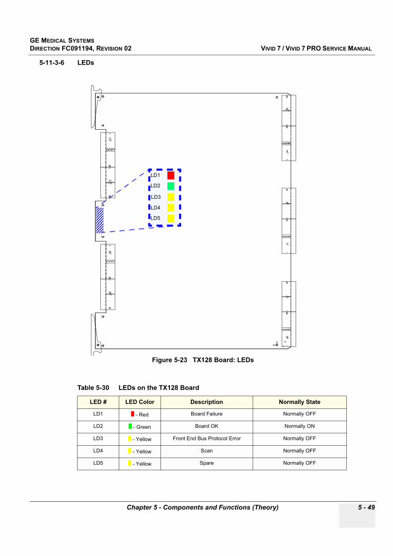
GE MEDICAL SYSTEMSDIRECTION FC091194, REVISION 02 VIVID 7 / VIVID 7 PRO SERVICE MANUAL
Chapter 5 - Components and Functions (Theory) 5 - 49
5-11-3-6 LEDs
Figure 5-23 TX128 Board: LEDs
Table 5-30 LEDs on the TX128 Board
LED # LED Color Description Normally State
LD1 - Red Board Failure Normally OFF
LD2 - Green Board OK Normally ON
LD3 - Yellow Front End Bus Protocol Error Normally OFF
LD4 - Yellow Scan Normally OFF
LD5 - Yellow Spare Normally OFF
LD5
LD4
LD3
LD2
LD1
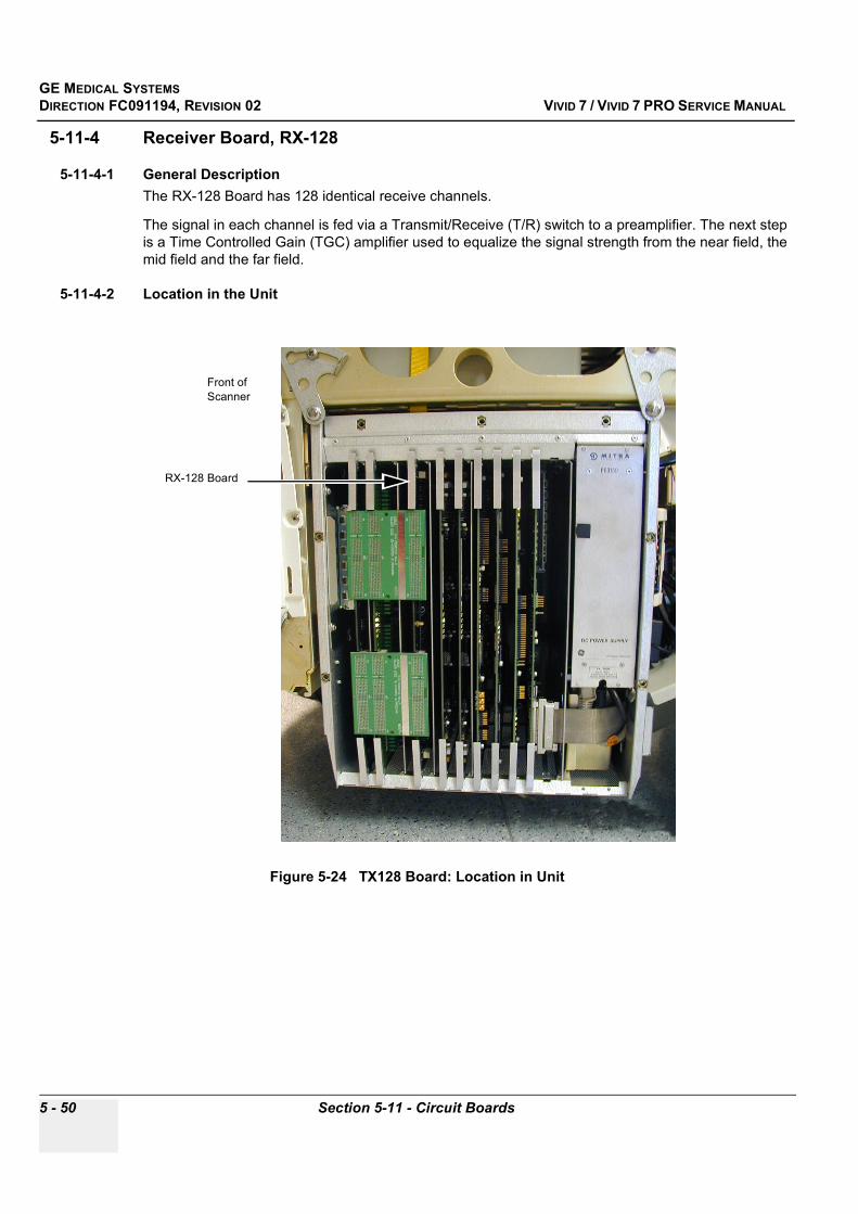
GE MEDICAL SYSTEMSDIRECTION FC091194, REVISION 02 VIVID 7 / VIVID 7 PRO SERVICE MANUAL
5 - 50 Section 5-11 - Circuit Boards
5-11-4 Receiver Board, RX-128
5-11-4-1 General DescriptionThe RX-128 Board has 128 identical receive channels.
The signal in each channel is fed via a Transmit/Receive (T/R) switch to a preamplifier. The next step is a Time Controlled Gain (TGC) amplifier used to equalize the signal strength from the near field, the mid field and the far field.
5-11-4-2 Location in the Unit
Figure 5-24 TX128 Board: Location in Unit
RX-128 Board
Front of Scanner
GE MEDICAL SYSTEMSDIRECTION FC091194, REVISION 02 VIVID 7 / VIVID 7 PRO SERVICE MANUAL
Chapter 5 - Components and Functions (Theory) 5 - 51
5-11-4-3 InputsDC Voltages
Input Signals
5-11-4-4 OutputsOutput Signals
5-11-4-5 FusesNone
5-11-4-6 Jumpers and Dip-switchesNone
Table 5-31 DC Input Voltages, Plug P3 & P4
Input Description Connected to:
+ 5 VaDC output voltage, distributed via Mother Board (Back
Plane). The “a” indicates that this voltage is used for analog circuits
DC Power Supply via Backplane
- 5 VaDC output voltage, distributed via Mother Board (Back
Plane). The “a” indicates that this voltage is used for analog circuits.
DC Power Supply via Backplane
+15 V DC output voltage, distributed via Mother Board (Back Plane) DC Power Supply via Backplane
- 15 V DC output voltages, distributed via Mother Board (Back Plane) DC Power Supply via Backplane
GND Distributed via Mother Board (Back Plane) DC Power Supply via Backplane
Table 5-32 Input Signals
Input Description Connection from:
XD1 - XD128 Signals containing the received back-scattered echoes from the active probe. Relay Board via the XD Bus Boards
Test SIG Analog test signal FEC Board
ATGCVP/ATGCVN TGC Control Voltages FEC Board
Table 5-33 Output Signals
Output Description Connection to:
RX1 - RX128 128 RX signals (echoes) Beamformer Boards via Backplane

GE MEDICAL SYSTEMSDIRECTION FC091194, REVISION 02 VIVID 7 / VIVID 7 PRO SERVICE MANUAL
5 - 52 Section 5-11 - Circuit Boards
5-11-4-7 LEDs
Figure 5-25 RX-128: LEDs (on the Solder Side of the Board)
Table 5-34 RX-128: LEDs (on the Solder Side of the Board)
LED # LED Color Description Normally State
LD1 - Red Board Failure Normally OFF
LD2 - Green Board OK Normally ON
LD3 - Yellow Spare Normally OFF
LD4 - Yellow Spare Normally OFF
LD4
LD3
LD2
LD1
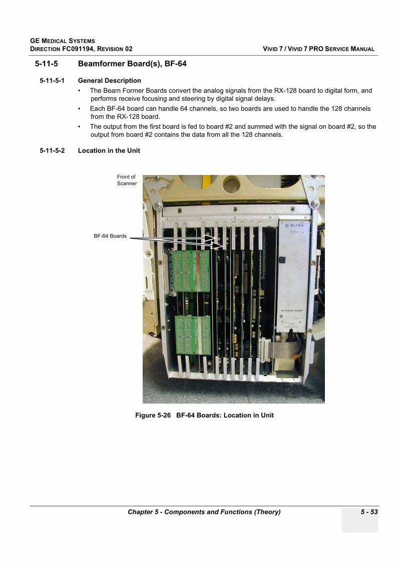
GE MEDICAL SYSTEMSDIRECTION FC091194, REVISION 02 VIVID 7 / VIVID 7 PRO SERVICE MANUAL
Chapter 5 - Components and Functions (Theory) 5 - 53
5-11-5 Beamformer Board(s), BF-64
5-11-5-1 General Description• The Beam Former Boards convert the analog signals from the RX-128 board to digital form, and
performs receive focusing and steering by digital signal delays.• Each BF-64 board can handle 64 channels, so two boards are used to handle the 128 channels
from the RX-128 board.• The output from the first board is fed to board #2 and summed with the signal on board #2, so the
output from board #2 contains the data from all the 128 channels.
5-11-5-2 Location in the Unit
Figure 5-26 BF-64 Boards: Location in Unit
BF-64 Boards
Front of Scanner

GE MEDICAL SYSTEMSDIRECTION FC091194, REVISION 02 VIVID 7 / VIVID 7 PRO SERVICE MANUAL
5 - 54 Section 5-11 - Circuit Boards
5-11-5-3 InputsDC Voltages
Input Signals
5-11-5-4 OutputsOutput Signals
5-11-5-5 FusesNone.
5-11-5-6 Dip-switchesNone.
Table 5-35 DC Output Voltages, Plug P3 & P4
Input Description Connected to:
+ 3.3 V DC voltage, distributed via Mother Board (Backplane) DC Power Supply via Backplane
+ 5 VdDC output voltage, distributed via Mother Board (Back
Plane). The “d” indicates that this voltage is used for digital circuits.
DC Power Supply via Backplane
- 5 VaDC output voltage, distributed via Mother Board (Back
Plane). The “a” indicates that this voltage is used for analog circuits.
DC Power Supply via Backplane
GND Distributed via Mother Board (Back Plane) DC Power Supply via Backplane
Table 5-36 Input Signals
Input Description Connection from:
RX1 - RX128 Receiver signals RX-128 board
FE Bus Front End Bus FEC Board
MLA0 and MLA1This input is used on BF64 #2:
The output signal from previous board.BF64 Board #1
Table 5-37 Output Signals
Output Description Connection to:
MLA0 and MLA1 This is the digital output from the board.From BF64 #1: To BF64 #2.
From BF64 #2: To RFT

GE MEDICAL SYSTEMSDIRECTION FC091194, REVISION 02 VIVID 7 / VIVID 7 PRO SERVICE MANUAL
Chapter 5 - Components and Functions (Theory) 5 - 55
5-11-5-7 LEDs and Jumpers
Figure 5-27 BF64: LEDs and Jumpers
Table 5-38 LEDs on the BF-64 Boards
LED Color Description Normally State
- Red Board Failure Normally OFF
- Green Board OK Normally ON
- Yellow Not Used Normally OFF
- Yellow Not Used Normally OFF
- Red Supply Voltage Error Normally OFF
LD5
LD4
LD3
LD1
LD2
1
910
SW1
2

GE MEDICAL SYSTEMSDIRECTION FC091194, REVISION 02 VIVID 7 / VIVID 7 PRO SERVICE MANUAL
5 - 56 Section 5-11 - Circuit Boards
5-11-6 Front End Controller Board, FEC-2
5-11-6-1 General DescriptionThe Front End Controller Board controls the other boards in the Front End. Most of the control is done through the Frond End Bus.
Main tasks done by the board:
• System Master Clock generator• Transmitter Control• ATGC Control• Receive Focusing Control• Analog Test Signal Generator• High Voltage Control and supervision• Probe Sensing• Control of Relay Board• Temperature Sensing for TEE probes• Step Motor Control for TEE probes• Temperature Sensing for circulated air
5-11-6-2 Location in the Unit
Figure 5-28 FEC-2 Board: Location in Unit
FEC-2 Board
Front of Scanner
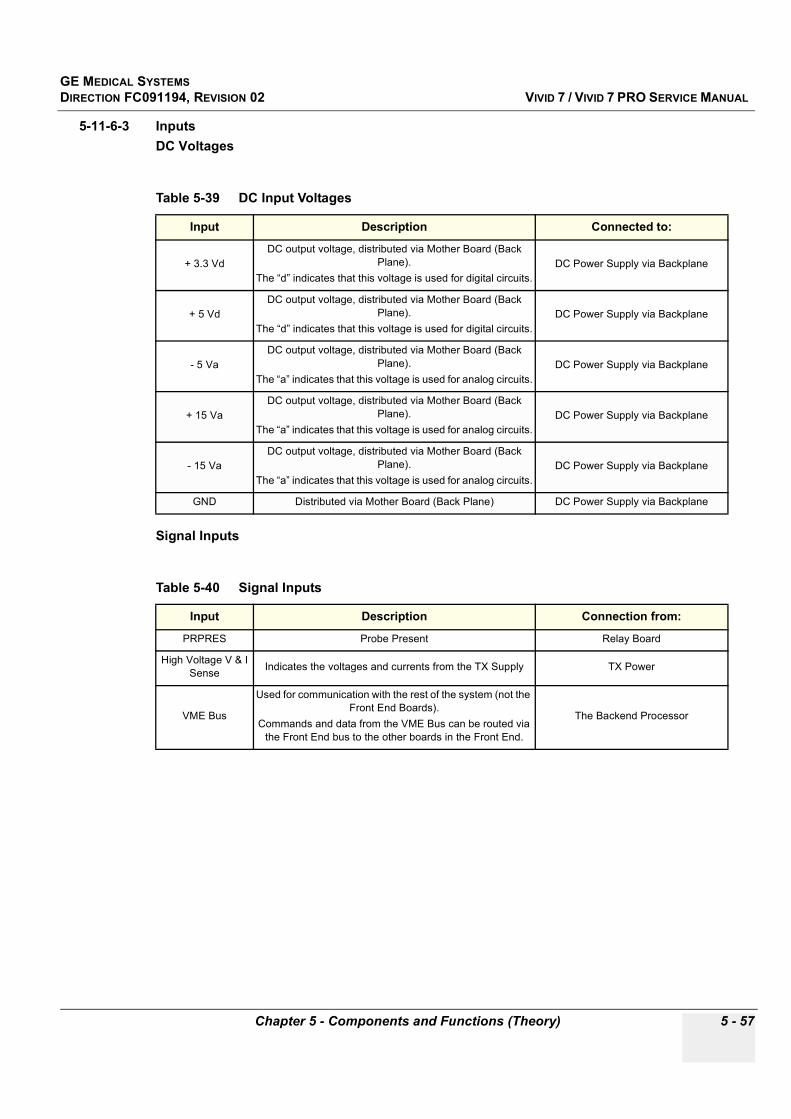
GE MEDICAL SYSTEMSDIRECTION FC091194, REVISION 02 VIVID 7 / VIVID 7 PRO SERVICE MANUAL
Chapter 5 - Components and Functions (Theory) 5 - 57
5-11-6-3 InputsDC Voltages
Signal Inputs
Table 5-39 DC Input Voltages
Input Description Connected to:
+ 3.3 VdDC output voltage, distributed via Mother Board (Back
Plane). The “d” indicates that this voltage is used for digital circuits.
DC Power Supply via Backplane
+ 5 VdDC output voltage, distributed via Mother Board (Back
Plane). The “d” indicates that this voltage is used for digital circuits.
DC Power Supply via Backplane
- 5 VaDC output voltage, distributed via Mother Board (Back
Plane). The “a” indicates that this voltage is used for analog circuits.
DC Power Supply via Backplane
+ 15 VaDC output voltage, distributed via Mother Board (Back
Plane). The “a” indicates that this voltage is used for analog circuits.
DC Power Supply via Backplane
- 15 VaDC output voltage, distributed via Mother Board (Back
Plane). The “a” indicates that this voltage is used for analog circuits.
DC Power Supply via Backplane
GND Distributed via Mother Board (Back Plane) DC Power Supply via Backplane
Table 5-40 Signal Inputs
Input Description Connection from:
PRPRES Probe Present Relay Board
High Voltage V & I Sense Indicates the voltages and currents from the TX Supply TX Power
VME Bus
Used for communication with the rest of the system (not the Front End Boards).
Commands and data from the VME Bus can be routed via the Front End bus to the other boards in the Front End.
The Backend Processor
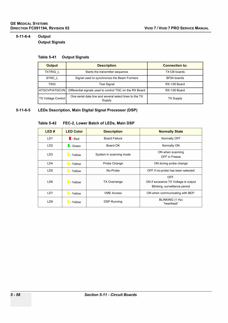
GE MEDICAL SYSTEMSDIRECTION FC091194, REVISION 02 VIVID 7 / VIVID 7 PRO SERVICE MANUAL
5 - 58 Section 5-11 - Circuit Boards
5-11-6-4 OutputOutput Signals
5-11-6-5 LEDs Description, Main Digital Signal Processor (DSP)
Table 5-41 Output Signals
Output Description Connection to:
TXTRIG_L Starts the transmitter sequence TX128 boards
SYNC_L Signal used to synchronize the Beam Formers BF64 boards
TSIG Test Signal RX-128 Board
ATGCVP/ATGCVN Differential signals used to control TGC on the RX Board RX-128 Board
TX Voltage Control One serial data line and several select lines to the TX Supply TX Supply
Table 5-42 FEC-2, Lower Batch of LEDs, Main DSP
LED # LED Color Description Normally State
LD1 - Red Board Failure Normally OFF
LD2 - Green Board OK Normally ON
LD3 - Yellow System in scanning modeON when scanning
OFF in Freeze
LD4 - Yellow Probe Change ON during probe change
LD5 - Yellow No-Probe OFF if no-probe has been selected
LD6 - Yellow TX OverrangeOFF.
ON if excessive TX Voltage is outputBlinking, surveillance period
LD7 - Yellow VME Access ON when communicating with BEP.
LD8 - Yellow DSP Running BLINKING (1 Hz)“heartbeat”
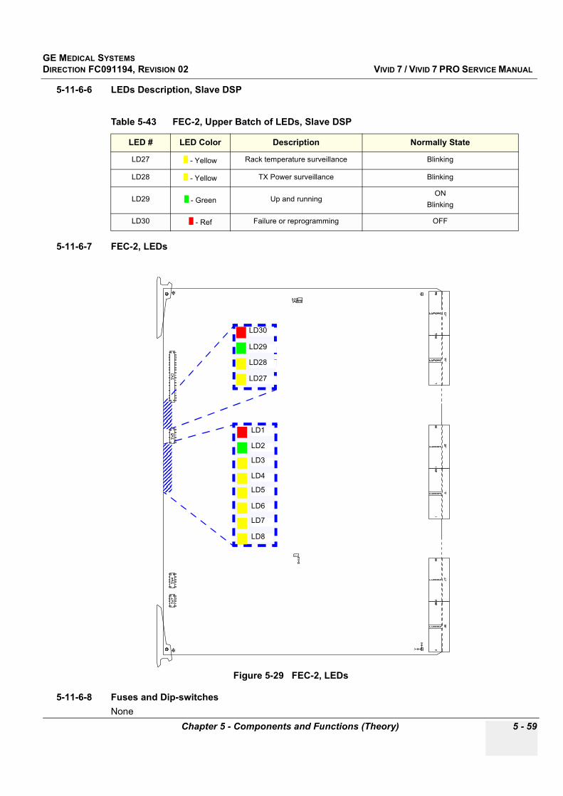
GE MEDICAL SYSTEMSDIRECTION FC091194, REVISION 02 VIVID 7 / VIVID 7 PRO SERVICE MANUAL
Chapter 5 - Components and Functions (Theory) 5 - 59
5-11-6-6 LEDs Description, Slave DSP
5-11-6-7 FEC-2, LEDs
5-11-6-8 Fuses and Dip-switchesNone
Table 5-43 FEC-2, Upper Batch of LEDs, Slave DSP
LED # LED Color Description Normally State
LD27 - Yellow Rack temperature surveillance Blinking
LD28 - Yellow TX Power surveillance Blinking
LD29 - Green Up and runningON
Blinking
LD30 - Ref Failure or reprogramming OFF
Figure 5-29 FEC-2, LEDs
LD30
LD29
LD28
LD27
LD1
LD2
LD3
LD4
LD5
LD6
LD7
LD8

GE MEDICAL SYSTEMSDIRECTION FC091194, REVISION 02 VIVID 7 / VIVID 7 PRO SERVICE MANUAL
5 - 60 Section 5-11 - Circuit Boards
5-11-6-9 Jumpers
Figure 5-30 FEC-2, Jumpers and Connectors
SW7
SW4
SW1SW2
SW10
12
910
12
1112
SW3
12
3940
SW5
12
1112
Connector used in factory test
Connector used in factory test
Connector used in factory test
Connector used in factory test
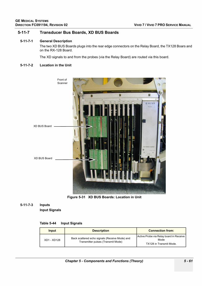
GE MEDICAL SYSTEMSDIRECTION FC091194, REVISION 02 VIVID 7 / VIVID 7 PRO SERVICE MANUAL
Chapter 5 - Components and Functions (Theory) 5 - 61
5-11-7 Transducer Bus Boards, XD BUS Boards
5-11-7-1 General DescriptionThe two XD BUS Boards plugs into the rear edge connectors on the Relay Board, the TX128 Boars and on the RX-128 Board.
The XD signals to and from the probes (via the Relay Board) are routed via this board.
5-11-7-2 Location in the Unit
5-11-7-3 Inputs Input Signals
Figure 5-31 XD BUS Boards: Location in Unit
Table 5-44 Input Signals
Input Description Connection from:
XD1 - XD128 Back scattered echo signals (Receive Mode) and Transmitter pulses (Transmit Mode)
Active Probe via Relay board in Receive Mode
TX128 in Transmit Mode.
XD BUS Board
Front of Scanner
XD BUS Board
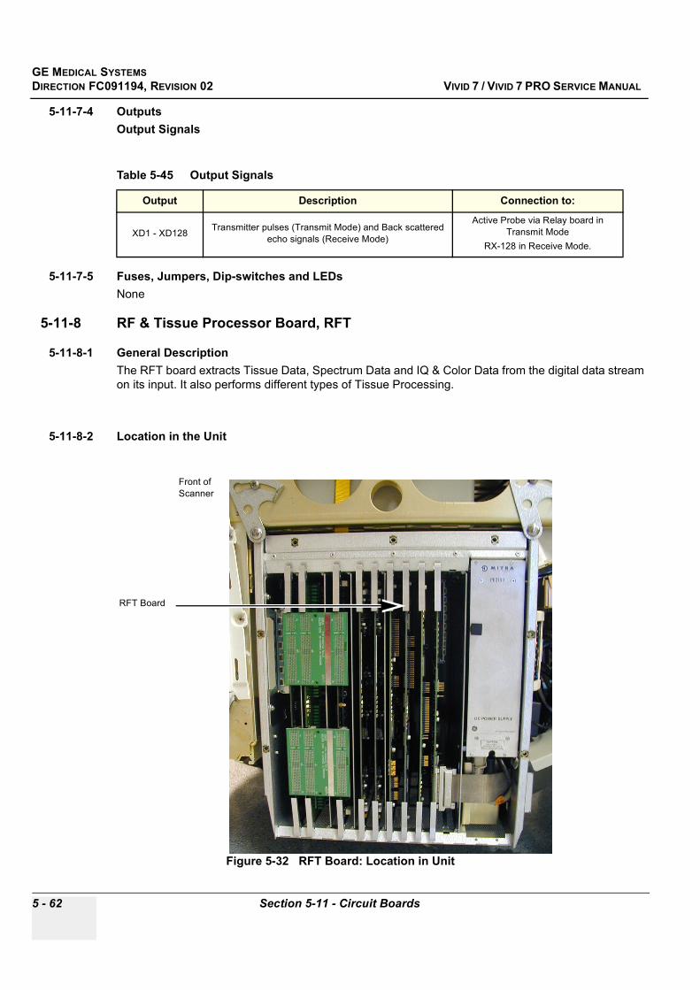
GE MEDICAL SYSTEMSDIRECTION FC091194, REVISION 02 VIVID 7 / VIVID 7 PRO SERVICE MANUAL
5 - 62 Section 5-11 - Circuit Boards
5-11-7-4 OutputsOutput Signals
5-11-7-5 Fuses, Jumpers, Dip-switches and LEDsNone
5-11-8 RF & Tissue Processor Board, RFT
5-11-8-1 General DescriptionThe RFT board extracts Tissue Data, Spectrum Data and IQ & Color Data from the digital data stream on its input. It also performs different types of Tissue Processing.
5-11-8-2 Location in the Unit
Table 5-45 Output Signals
Output Description Connection to:
XD1 - XD128 Transmitter pulses (Transmit Mode) and Back scattered echo signals (Receive Mode)
Active Probe via Relay board in Transmit Mode
RX-128 in Receive Mode.
Figure 5-32 RFT Board: Location in Unit
RFT Board
Front of Scanner
GE MEDICAL SYSTEMSDIRECTION FC091194, REVISION 02 VIVID 7 / VIVID 7 PRO SERVICE MANUAL
Chapter 5 - Components and Functions (Theory) 5 - 63
5-11-8-3 InputsDC Voltages
Input Signals
5-11-8-4 OutputsOutput Signals
5-11-8-5 Fuses and Dip-switchesNone
Table 5-46 DC Input Voltages
Input Description Connection from:
+ 5 VdDC output voltage, distributed via Mother Board (Back
Plane). The “d” indicates that this voltage is used for digital circuits.
DC Power Supply via Backplane
- 5 VaDC output voltage, distributed via Mother Board (Back
Plane). The “a” indicates that this voltage is used for analog circuits.
DC Power Supply via Backplane
GND Distributed via Mother Board (Back Plane) DC Power Supply via Backplane
Table 5-47 Input Signals
Input Description Connection from:
MLA 0 & MLA 1 Input data stream
VME Bus Data communication BEP
Front End Bus Information about the type of data and the data sample. FEC
Table 5-48 Output Signals
Output Description Connection to:
Clock distribution Clock distribution
Pipelink Digital Data Transfer BEP, SDP and IMP
P4 Production Test Plug
P5 Production Test Plug
VME Bus Data communication BEP (via P1)
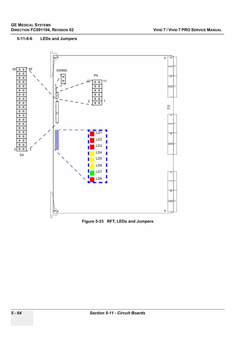
GE MEDICAL SYSTEMSDIRECTION FC091194, REVISION 02 VIVID 7 / VIVID 7 PRO SERVICE MANUAL
5 - 64 Section 5-11 - Circuit Boards
5-11-8-6 LEDs and Jumpers
Figure 5-33 RFT, LEDs and Jumpers
LD1
LD2
LD3
LD4
LD5
LD6
LD7
LD8
P512
3940
P4
12
1112
SW800
GE MEDICAL SYSTEMSDIRECTION FC091194, REVISION 02 VIVID 7 / VIVID 7 PRO SERVICE MANUAL
Chapter 5 - Components and Functions (Theory) 5 - 65
5-11-8-7 LEDs
Table 5-49 LEDs on the RFT Board
LED # LED Color Description Normally State
LD1 - Red Board Failure OFF
LD2 - Green Board OK ON
LD3 - Yellow DSP Runs BLINKING
LD4 - Yellow Data Out on Pipelink ON During Data Transfers to Pipelink
LD5 - Yellow Spare OFF
LD6 - Red Clock Problems OFF
LD7 - Red Clock Problems OFF
LD8 - Red Clock Problems OFF

GE MEDICAL SYSTEMSDIRECTION FC091194, REVISION 02 VIVID 7 / VIVID 7 PRO SERVICE MANUAL
5 - 66 Section 5-11 - Circuit Boards
5-11-9 Spectrum Doppler Processor Board, SDP
5-11-9-1 General Description• This board performs Spectrum Analysis on the Doppler signals and makes the velocity traces, • The Doppler audio channels are generated on this board.• During Duplex modes (e.g. 2D and Doppler), The Missing Signal Estimator will fill the gaps in the
Doppler spectrum by stretching the “real” spectrum out to fill the missing time. • A serial link from the Internal I/O board, feeds the A/D converted traces (like ECG, Phono and
Pressure) into the SDP. These signals are sent together with the Doppler data via the Pipelink bus to the Image Port Board.
5-11-9-2 Location in the Unit
Figure 5-34 SPD Board: Location in Unit
SDP Board
Front of Scanner
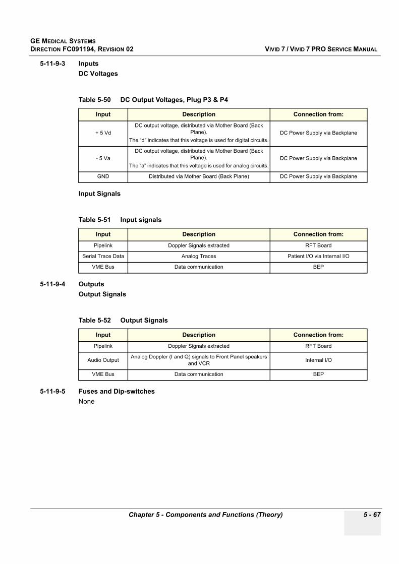
GE MEDICAL SYSTEMSDIRECTION FC091194, REVISION 02 VIVID 7 / VIVID 7 PRO SERVICE MANUAL
Chapter 5 - Components and Functions (Theory) 5 - 67
5-11-9-3 InputsDC Voltages
Input Signals
5-11-9-4 OutputsOutput Signals
5-11-9-5 Fuses and Dip-switchesNone
Table 5-50 DC Output Voltages, Plug P3 & P4
Input Description Connection from:
+ 5 VdDC output voltage, distributed via Mother Board (Back
Plane). The “d” indicates that this voltage is used for digital circuits.
DC Power Supply via Backplane
- 5 VaDC output voltage, distributed via Mother Board (Back
Plane). The “a” indicates that this voltage is used for analog circuits.
DC Power Supply via Backplane
GND Distributed via Mother Board (Back Plane) DC Power Supply via Backplane
Table 5-51 Input signals
Input Description Connection from:
Pipelink Doppler Signals extracted RFT Board
Serial Trace Data Analog Traces Patient I/O via Internal I/O
VME Bus Data communication BEP
Table 5-52 Output Signals
Input Description Connection from:
Pipelink Doppler Signals extracted RFT Board
Audio Output Analog Doppler (I and Q) signals to Front Panel speakers and VCR Internal I/O
VME Bus Data communication BEP
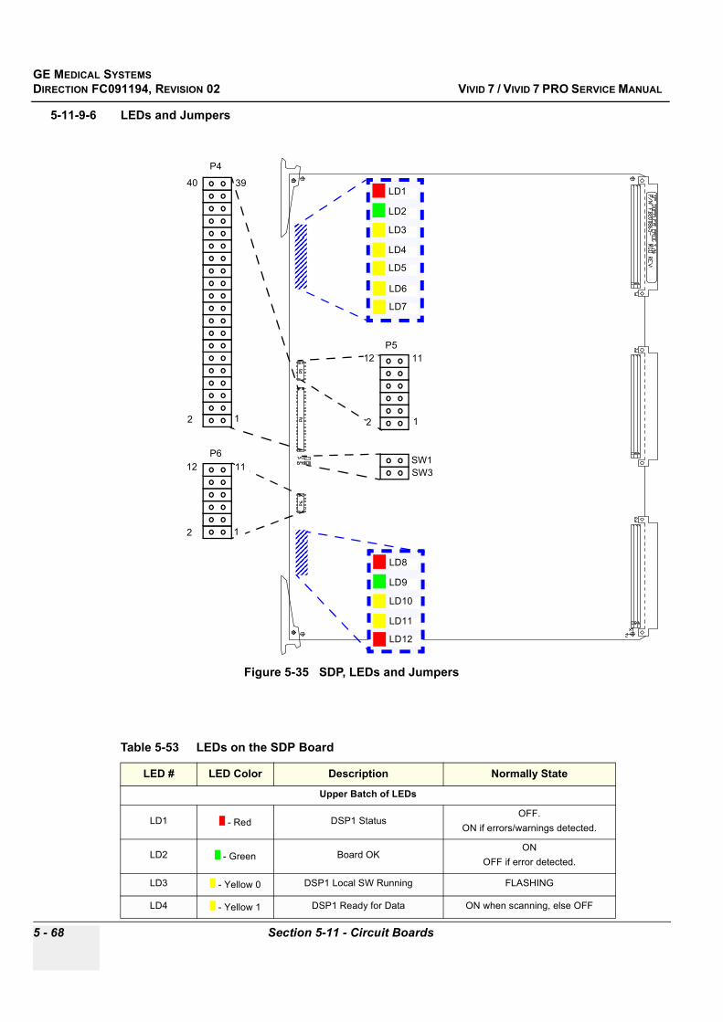
GE MEDICAL SYSTEMSDIRECTION FC091194, REVISION 02 VIVID 7 / VIVID 7 PRO SERVICE MANUAL
5 - 68 Section 5-11 - Circuit Boards
5-11-9-6 LEDs and Jumpers
Figure 5-35 SDP, LEDs and Jumpers
Table 5-53 LEDs on the SDP Board
LED # LED Color Description Normally State
Upper Batch of LEDs
LD1 - Red DSP1 StatusOFF.
ON if errors/warnings detected.
LD2 - Green Board OKON
OFF if error detected.
LD3 - Yellow 0 DSP1 Local SW Running FLASHING
LD4 - Yellow 1 DSP1 Ready for Data ON when scanning, else OFF
LD8
LD9
LD10
LD11
LD12
SW3
LD1
LD2
LD3
LD4
LD5
LD6
LD7
P4
12
3940
P6
12
1112SW1
P5
12
1112
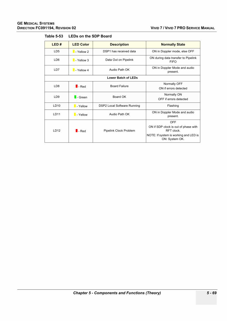
GE MEDICAL SYSTEMSDIRECTION FC091194, REVISION 02 VIVID 7 / VIVID 7 PRO SERVICE MANUAL
Chapter 5 - Components and Functions (Theory) 5 - 69
LD5 - Yellow 2 DSP1 has received data ON in Doppler mode, else OFF
LD6 - Yellow 3 Data Out on Pipelink ON during data transfer to Pipelink FIFO
LD7 - Yellow 4 Audio Path OK ON in Doppler Mode and audio present.
Lower Batch of LEDs
LD8 - Red Board FailureNormally OFF
ON if errors detected
LD9 - Green Board OKNormally ON
OFF if errors detected
LD10 - Yellow DSP2 Local Software Running Flashing
LD11 - Yellow Audio Path OK ON in Doppler Mode and audio present.
LD12 - Red Pipelink Clock Problem
OFFON if SDP clock is out of phase with
RFT clock.NOTE: If system is working and LED is
ON: System OK.
Table 5-53 LEDs on the SDP Board
LED # LED Color Description Normally State
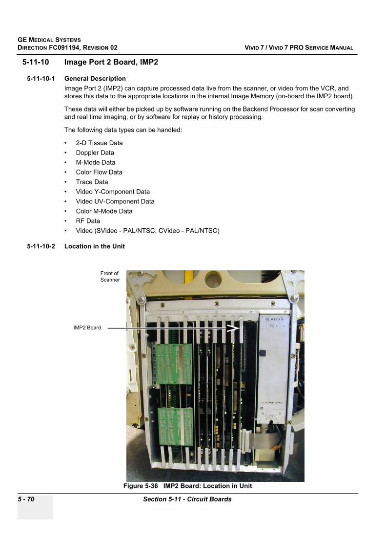
GE MEDICAL SYSTEMSDIRECTION FC091194, REVISION 02 VIVID 7 / VIVID 7 PRO SERVICE MANUAL
5 - 70 Section 5-11 - Circuit Boards
5-11-10 Image Port 2 Board, IMP2
5-11-10-1 General DescriptionImage Port 2 (IMP2) can capture processed data live from the scanner, or video from the VCR, and stores this data to the appropriate locations in the internal Image Memory (on-board the IMP2 board).
These data will either be picked up by software running on the Backend Processor for scan converting and real time imaging, or by software for replay or history processing.
The following data types can be handled:
• 2-D Tissue Data• Doppler Data• M-Mode Data• Color Flow Data• Trace Data• Video Y-Component Data• Video UV-Component Data• Color M-Mode Data• RF Data • Video (SVideo - PAL/NTSC, CVideo - PAL/NTSC)
5-11-10-2 Location in the Unit
Figure 5-36 IMP2 Board: Location in Unit
IMP2 Board
Front of Scanner
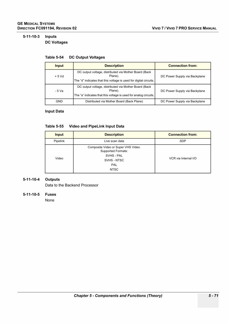
GE MEDICAL SYSTEMSDIRECTION FC091194, REVISION 02 VIVID 7 / VIVID 7 PRO SERVICE MANUAL
Chapter 5 - Components and Functions (Theory) 5 - 71
5-11-10-3 InputsDC Voltages
Input Data
5-11-10-4 OutputsData to the Backend Processor
5-11-10-5 FusesNone
Table 5-54 DC Output Voltages
Input Description Connection from:
+ 5 VdDC output voltage, distributed via Mother Board (Back
Plane). The “d” indicates that this voltage is used for digital circuits.
DC Power Supply via Backplane
- 5 VaDC output voltage, distributed via Mother Board (Back
Plane). The “a” indicates that this voltage is used for analog circuits.
DC Power Supply via Backplane
GND Distributed via Mother Board (Back Plane) DC Power Supply via Backplane
Table 5-55 Video and PipeLink Input Data
Input Description Connection from:
Pipelink Live scan data SDP
Video
Composite Video or Super VHS Video. Supported Formats:
SVHS - PALSVHS - NTSC
PALNTSC
VCR via Internal I/O

GE MEDICAL SYSTEMSDIRECTION FC091194, REVISION 02 VIVID 7 / VIVID 7 PRO SERVICE MANUAL
5 - 72 Section 5-11 - Circuit Boards
5-11-10-6 Jumpers and Dip-switches
Figure 5-37 IMP2, Jumpers and Switch
SW4
SW2
12
910
SW12
SW9
SW10
SW8
SW3
SW5
SW13
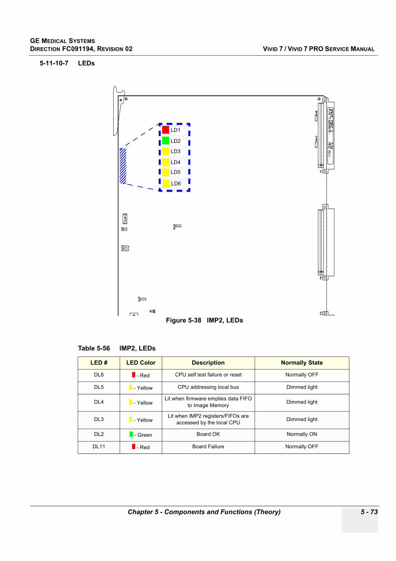
GE MEDICAL SYSTEMSDIRECTION FC091194, REVISION 02 VIVID 7 / VIVID 7 PRO SERVICE MANUAL
Chapter 5 - Components and Functions (Theory) 5 - 73
5-11-10-7 LEDs
Figure 5-38 IMP2, LEDs
Table 5-56 IMP2, LEDs
LED # LED Color Description Normally State
DL6 - Red CPU self test failure or reset Normally OFF
DL5 - Yellow CPU addressing local bus Dimmed light
DL4 - YellowLit when firmware empties data FIFO
to Image Memory Dimmed light
DL3 - YellowLit when IMP2 registers/FIFOs are
accessed by the local CPU Dimmed light
DL2 - Green Board OK Normally ON
DL11 - Red Board Failure Normally OFF
LD1
LD2
LD3
LD4
LD5
LD6
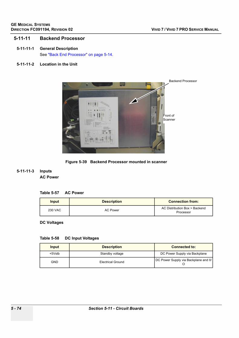
GE MEDICAL SYSTEMSDIRECTION FC091194, REVISION 02 VIVID 7 / VIVID 7 PRO SERVICE MANUAL
5 - 74 Section 5-11 - Circuit Boards
5-11-11 Backend Processor
5-11-11-1 General DescriptionSee "Back End Processor" on page 5-14.
5-11-11-2 Location in the Unit
5-11-11-3 InputsAC Power
DC Voltages
Figure 5-39 Backend Processor mounted in scanner
Table 5-57 AC Power
Input Description Connection from:
230 VAC AC Power AC Distribution Box > Backend Processor
Table 5-58 DC Input Voltages
Input Description Connected to:
+5Vstb Standby voltage DC Power Supply via Backplane
GND Electrical Ground DC Power Supply via Backplane and II/O
Backend Processor
Front of Scanner
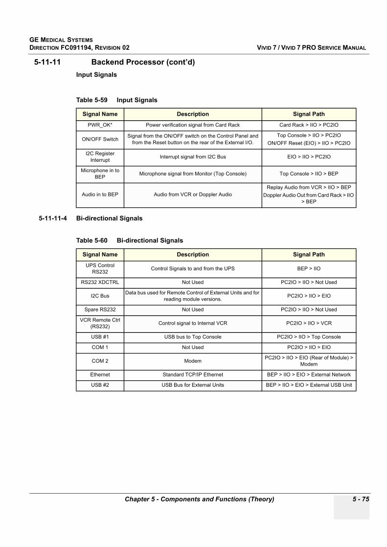
GE MEDICAL SYSTEMSDIRECTION FC091194, REVISION 02 VIVID 7 / VIVID 7 PRO SERVICE MANUAL
Chapter 5 - Components and Functions (Theory) 5 - 75
5-11-11 Backend Processor (cont’d)Input Signals
5-11-11-4 Bi-directional Signals
Table 5-59 Input Signals
Signal Name Description Signal Path
PWR_OK* Power verification signal from Card Rack Card Rack > IIO > PC2IO
ON/OFF Switch Signal from the ON/OFF switch on the Control Panel and from the Reset button on the rear of the External I/O.
Top Console > IIO > PC2IOON/OFF Reset (EIO) > IIO > PC2IO
I2C Register Interrupt Interrupt signal from I2C Bus EIO > IIO > PC2IO
Microphone in to BEP Microphone signal from Monitor (Top Console) Top Console > IIO > BEP
Audio in to BEP Audio from VCR or Doppler AudioReplay Audio from VCR > IIO > BEP
Doppler Audio Out from Card Rack > IIO > BEP
Table 5-60 Bi-directional Signals
Signal Name Description Signal Path
UPS Control RS232 Control Signals to and from the UPS BEP > IIO
RS232 XDCTRL Not Used PC2IO > IIO > Not Used
I2C Bus Data bus used for Remote Control of External Units and for reading module versions. PC2IO > IIO > EIO
Spare RS232 Not Used PC2IO > IIO > Not Used
VCR Remote Ctrl (RS232) Control signal to Internal VCR PC2IO > IIO > VCR
USB #1 USB bus to Top Console PC2IO > IIO > Top Console
COM 1 Not Used PC2IO > IIO > EIO
COM 2 Modem PC2IO > IIO > EIO (Rear of Module) > Modem
Ethernet Standard TCP/IP Ethernet BEP > IIO > EIO > External Network
USB #2 USB Bus for External Units BEP > IIO > EIO > External USB Unit
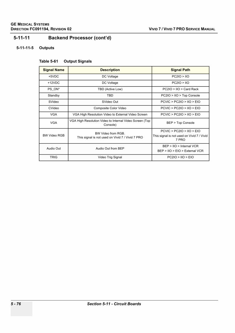
GE MEDICAL SYSTEMSDIRECTION FC091194, REVISION 02 VIVID 7 / VIVID 7 PRO SERVICE MANUAL
5 - 76 Section 5-11 - Circuit Boards
5-11-11 Backend Processor (cont’d)
5-11-11-5 Outputs
Table 5-61 Output Signals
Signal Name Description Signal Path
+5VDC DC Voltage PC2IO > IIO
+12VDC DC Voltage PC2IO > IIO
PS_ON* TBD (Active Low) PC2IO > IIO > Card Rack
Standby TBD PC2IO > IIO > Top Console
SVideo SVideo Out PCVIC > PC2IO > IIO > EIO
CVideo Composite Color Video PCVIC > PC2IO > IIO > EIO
VGA VGA High Resolution Video to External Video Screen PCVIC > PC2IO > IIO > EIO
VGA VGA High Resolution Video to Internal Video Screen (Top Console) BEP > Top Console
BW Video RGB BW Video from RGB. This signal is not used on Vivid 7 / Vivid 7 PRO
PCVIC > PC2IO > IIO > EIOThis signal is not used on Vivid 7 / Vivid
7 PRO
Audio Out Audio Out from BEPBEP > IIO > Internal VCR
BEP > IIO > EIO > External VCR
TRIG Video Trig Signal PC2IO > IIO > EIO

GE MEDICAL SYSTEMSDIRECTION FC091194, REVISION 02 VIVID 7 / VIVID 7 PRO SERVICE MANUAL
Chapter 5 - Components and Functions (Theory) 5 - 77
5-11-11 Backend Processor (cont’d)
5-11-11-6 UPS BatteryThe UPS batteries provide power to the Back End Processor to enable a controlled shut down of the processor.
The UPS batteries will drain slightly when the system is in the off condition. The off condition is defined as:
• Circuit Breaker in the OFF position• System unplugged from the wall outletIf the system is left in the OFF condition for an extended period of time (3 to 5 days or more), the system may not boot up or may beep when turned ON. Should this occur, the system needs to recharge the UPS batteries. This could take 15 minutes to as long as 24 hours, depending on the battery age, system input voltage and system temperature. To eliminate draining the UPS batteries, the system should remain plugged into the wall outlet with the circuit breaker in the ON position.
Figure 5-40 Battery Block Diagram
Figure 5-41 Battery pack
In Line20A Fuse
Battery 1
Battery 2
Compression tape used tominimize battery pack movement
while installed in chassis
Heat-shrink holds batteries togetherand insulates terminals.
Spacerseperatesbatteries
+ -
- +
Label to beattached tothis surface
In line 20A fuse
GE MEDICAL SYSTEMSDIRECTION FC091194, REVISION 02 VIVID 7 / VIVID 7 PRO SERVICE MANUAL
5 - 78 Section 5-11 - Circuit Boards
5-11-12 Patient I/O
5-11-12-1 General DescriptionThe Patient I/O contains the electronics for ECG, Phono and two analog inputs. One of the analog inputs has programable gain. The module extracts respiration from ECG. The patient leads can be rotated by software (i.e. it is possible to change between Lead I, II and III by pushing a button) The electronics also contains a pacemaker detector. The four inputs are separately isolated because of safety requirements.
5-11-12-2 Location in the UnitInside the Backend Processor with the connector panel available from the front of the system.
5-11-12-3 Inputs• ECG• Phono• Two Analog Inputs
5-11-12-4 OutputsSerial Trace Data via Internal I/O to the SPD Board
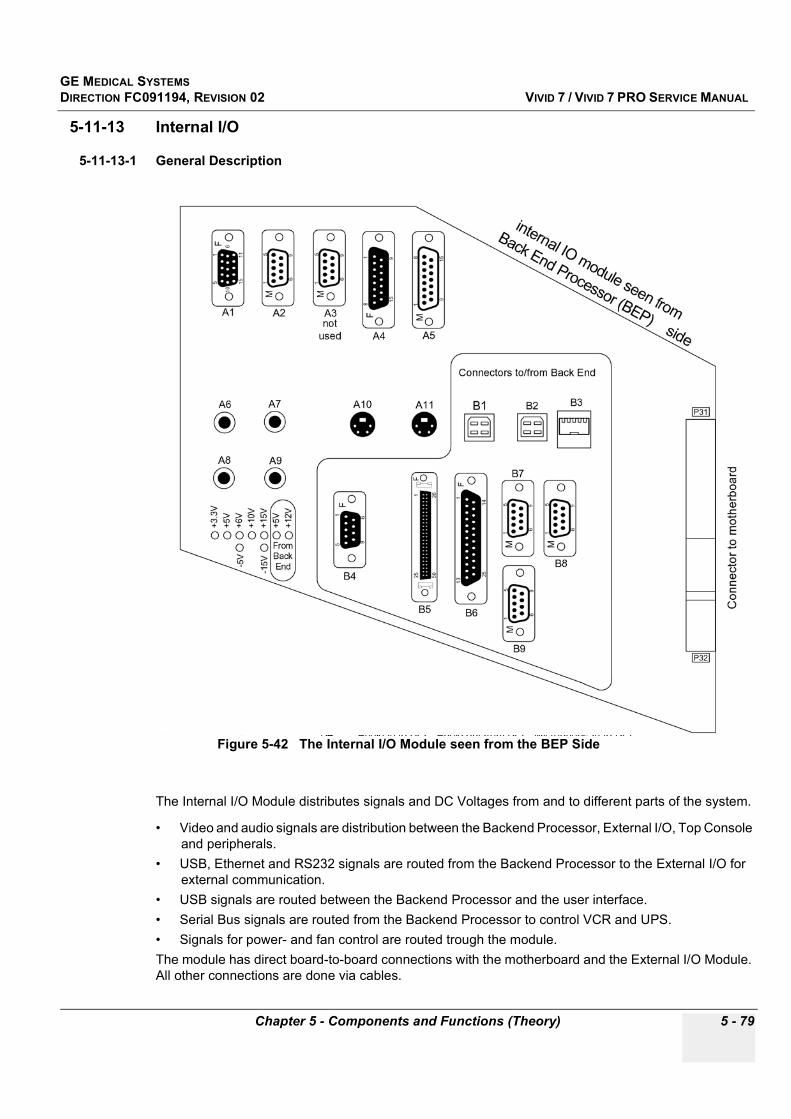
GE MEDICAL SYSTEMSDIRECTION FC091194, REVISION 02 VIVID 7 / VIVID 7 PRO SERVICE MANUAL
Chapter 5 - Components and Functions (Theory) 5 - 79
5-11-13 Internal I/O
5-11-13-1 General Description
The Internal I/O Module distributes signals and DC Voltages from and to different parts of the system.
• Video and audio signals are distribution between the Backend Processor, External I/O, Top Console and peripherals.
• USB, Ethernet and RS232 signals are routed from the Backend Processor to the External I/O for external communication.
• USB signals are routed between the Backend Processor and the user interface.• Serial Bus signals are routed from the Backend Processor to control VCR and UPS.• Signals for power- and fan control are routed trough the module.The module has direct board-to-board connections with the motherboard and the External I/O Module. All other connections are done via cables.
Figure 5-42 The Internal I/O Module seen from the BEP Side

GE MEDICAL SYSTEMSDIRECTION FC091194, REVISION 02 VIVID 7 / VIVID 7 PRO SERVICE MANUAL
5 - 80 Section 5-11 - Circuit Boards
5-11-13-2 Location in the UnitThe Internal I/O Module is plugged into the Card Rack (at the end nearest to the rear of the system).
Figure 5-43 Internal I/O: Location in the System (Seen from Right and Rear Side)
Internal I/O
Rear side of System
Right side of System
External I/O

GE MEDICAL SYSTEMSDIRECTION FC091194, REVISION 02 VIVID 7 / VIVID 7 PRO SERVICE MANUAL
Chapter 5 - Components and Functions (Theory) 5 - 81
5-11-13-3 InputsDC Voltages
Video Input Signals
Table 5-62 DC Input Voltages
Input Description Connection from
+3.3 VDC Input DC Voltage DC Power Supply > Backplane > J32
+5 VDC Input DC Voltage DC Power Supply > Backplane > J32
+10 VDC Input DC Voltage DC Power Supply > Backplane > J32
+15 VDC Input DC Voltage DC Power Supply > Backplane > J32
-15 VDC Input DC Voltage DC Power Supply > Backplane > J32
+6 VDC (analog) Input DC Voltage DC Power Supply > Backplane > J32
–5 VDC (analog) Input DC Voltage DC Power Supply > Backplane > J32
+5 VDC Input DC Voltage Backend Processor > J17
+12 VDC Input DC Voltage Backend Processor > J17)
Table 5-63 Video Input Signals
Input Description Connection from
SVGA Video Signal to External I/O PC2IO (Connector J16)
SVHS Video Signal to VCR & External I/O PC2IO(Connector J16)
SVHS Video Signal to MBD (IMP) VCR (Connector J11)
Luma Video Signal to B&W Printer and External I/O PC2IO (Connector J16)
Comp. Video Video Signal to External I/O PC2IO (Connector J16)
Comp. Video Video Signal to MBD (IMP) Color printer
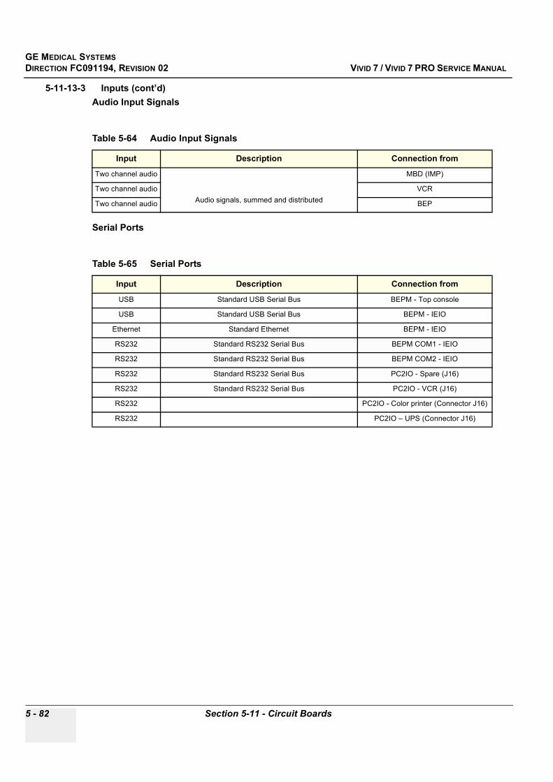
GE MEDICAL SYSTEMSDIRECTION FC091194, REVISION 02 VIVID 7 / VIVID 7 PRO SERVICE MANUAL
5 - 82 Section 5-11 - Circuit Boards
5-11-13-3 Inputs (cont’d)Audio Input Signals
Serial Ports
Table 5-64 Audio Input Signals
Input Description Connection from
Two channel audio
Audio signals, summed and distributed
MBD (IMP)
Two channel audio VCR
Two channel audio BEP
Table 5-65 Serial Ports
Input Description Connection from
USB Standard USB Serial Bus BEPM - Top console
USB Standard USB Serial Bus BEPM - IEIO
Ethernet Standard Ethernet BEPM - IEIO
RS232 Standard RS232 Serial Bus BEPM COM1 - IEIO
RS232 Standard RS232 Serial Bus BEPM COM2 - IEIO
RS232 Standard RS232 Serial Bus PC2IO - Spare (J16)
RS232 Standard RS232 Serial Bus PC2IO - VCR (J16)
RS232 PC2IO - Color printer (Connector J16)
RS232 PC2IO – UPS (Connector J16)
GE MEDICAL SYSTEMSDIRECTION FC091194, REVISION 02 VIVID 7 / VIVID 7 PRO SERVICE MANUAL
Chapter 5 - Components and Functions (Theory) 5 - 83
5-11-13-3 Inputs (cont’d)Control Signals
Table 5-66 Control Signals
Input Description Connection from
Control signals Spare MBD/FEC (Connector J??)
Control signals Spare MBD/FEC (Connector J??)
Trace trigger To EIO PC2IO (Connector J16)
Fan control signals To AC Power MBD (Connector J??)
Power control signals To MBD and AC Power PC2IO (Connector J16)
Power on/off To Relay Top Console ON/OFF Switch and EIO Test (Connector J??)
Standby To Top Console PC2IO (Connector J16)

GE MEDICAL SYSTEMSDIRECTION FC091194, REVISION 02 VIVID 7 / VIVID 7 PRO SERVICE MANUAL
5 - 84 Section 5-11 - Circuit Boards
5-11-13-4 OutputsDC Voltage
AUDIO
Table 5-67 DC Output Voltages
Output Description Connection to
+5 VDC +12 VDC
From BEP
Spare (Connector J21)+5 VDC, -15 VDC,
-5 VDC analog
From Card Rack
+5 VDC +12 VDC
From BEP
Not Used +5 VDC, -15 VDC,
-5 VDC analog
From Card Rack
+5 VDC, +15 VDC,
From Card Rack Not Used
+12 VDC From BEPTop Console
+15 VDC From Card Rack
+5 VDC+12 VDC
From BEP
EIO+5 VDC,
+15 VDC, -5 VDC analog
+6 VDC analog
From Card Rack
Table 5-68 Audio Outputs
Output Description Connection to
Audio (two channels) Audio (Doppler sound) from MBD (IMP), VCR, BEP
Top Console speakers and BEP
VCR and IEIO
GE MEDICAL SYSTEMSDIRECTION FC091194, REVISION 02 VIVID 7 / VIVID 7 PRO SERVICE MANUAL
Chapter 5 - Components and Functions (Theory) 5 - 85
5-11-13-4 Outputs (cont’d)Interface Connectors – Component Side
Table 5-69 Connectors, Component Side
Input Description Connection from
A1/J1 B&W printer, 15pins HD-sub, female.
A2/P4 VCR remote ctrl – RS232: 9pins D-sub, male.
A3/P5 Color printer - RS232: 9pins D-sub, male.
A4/J2 Top Console - Power & signals: 15pins D-sub, female.
A5/P4 Top Console - Signals: 15pins D-sub, male.
A6/J6 Audio out to VCR, left: Phono jack.
A7/J7 Audio out to VCR, right: Phono jack.
A8/J8 Audio in from VCR, left: Phono jack.
A9/J9 Audio in from VCR, right
A10/J10 SVHS out to VCR
A11/J11 SVHS in from VCR
B1/J12 USB to Top console
B2/J13 USB to external I/O
B3/J14 Ethernet
B4/J15 Audio I/O
B5/J16 PC2IO signals
B6/J17 PC2IO power
B7/P18 COM1
B8/P19 COM2
B9/P25 UPS remote control
J32 MBD – signals and power
GE MEDICAL SYSTEMSDIRECTION FC091194, REVISION 02 VIVID 7 / VIVID 7 PRO SERVICE MANUAL
5 - 86 Section 5-11 - Circuit Boards
5-11-13-4 Outputs (cont’d)
5-11-13-5 FusesAll output voltages are fused
5-11-13-6 Jumpers and Dip-switchesTBD
5-11-13-7 LEDs
Table 5-70 Connectors, Solder side
Input Description Connection from
A12/J21 Spare power, 15pins D-sub, female
A13/J20 Spare – power, 15pins D-sub, female
A14/J24 AC power ctrl, 9pins D-sub, female
A15/P23 Rotation adapter – signals, 15pins D-sub, male
A16/P22 Spare – signals, 25pins D-sub, female
P30 EIO – signals and power, 110pins male
Figure 5-44 Internal I/O: Green LEDs for Power Status.

GE MEDICAL SYSTEMSDIRECTION FC091194, REVISION 02 VIVID 7 / VIVID 7 PRO SERVICE MANUAL
Chapter 5 - Components and Functions (Theory) 5 - 87
5-11-14 External I/O
5-11-14-1 General DescriptionThe External I/O is the interface between the scanner and all external devices.
5-11-14-2 Location in the UnitOn the rear of the scanner, above the power inlet and power breaker.
5-11-14-3 Input Signals
Figure 5-45 External I/O Connector Panel
Table 5-71 Input Signals
Input Description Connection from/via/to
Footswitch Connector
Footswitch is a mechanical switch that connect a signal to ground.
Internal level is TTL (0-3.3V)
Footswitch > External I/O > Internal I/O > PC2IO (BEP)
DC Voltages from BEP
+5 VDCUsed for Optical Couplers on RS232 signals PC2IO (BEP) > Internal I/O > External I/
O +12 VDC
DC Voltages from Card Rack
+5 VDC
Used for Optical Couplers on FootswitchCard Rack > Internal I/O > External I/O
+15 VDC
-5 VDC analog
+6 VDC analog

GE MEDICAL SYSTEMSDIRECTION FC091194, REVISION 02 VIVID 7 / VIVID 7 PRO SERVICE MANUAL
5 - 88 Section 5-11 - Circuit Boards
5-11-14-4 Bi-directional Signals
5-11-14-5 Output Signals
Table 5-72 Bi-directional Signals
Signal Name Description Signal Path
Ethernet Standard 10/100 Base TX Ethernet Ethernet - External I/O - Internal I/O - BEP (Ethernet Connector)
COM1 Serial RS-232 port (Not used in Vivid 7 / Vivid 7 PRO) External Device - External I/O - Internal I/O - BEP (COM1)
USB Standard USB (Universal Serial Bus), (0-5V) USB Device - External I/O - Internal I/O - BEP (USB #2))
Modem Internal Modem Telephone Line ConnectionAnalog Phone Line - External I/O
(Connector Panel) - External I/O (Rear Side)- Modem
COM2 Serial RS-232 port (on rear side of External I/O)
Modem - External I/O (Rear Side) - Internal I/O - BEP (COM1)
Burn-in Power On/Off Control
Burn-in Power On/Off Control (on rear side of External I/O) - Used for factory testing. External I/O (Rear Side) - Internal I/O
Table 5-73 Output Signals
Signal Name Description Signal Path
Stereo Audio Stereo audio to external VCR. (Same signal as delivered to internal VCR).
Audio Source (Internal VCR/Microphone/BEP) > Internal
I/O > External I/O > External VCR.
Composite Video External composite video, 1.0Vp-p, 75 ohms, unbalanced, sync negative.
PC2IO (BEP) > Internal I/O > External I/O > External Composite Video Device
Super Video (SVHS)
Super VideoLuminance: 1.0Vp-p, 75 ohms, unbalanced.
Color: 1.0Vp-p, 75 ohms, unbalanced.
PC2IO (BEP) > Internal I/O > External I/O > External VCR
Black and White video
External black and white video1.0Vp-p, 75 ohms, unbalanced, sync negative.
PC2IO (BEP) > Internal I/O > External I/O > External B/W Video Device
Trig Trigger Signal, 0-3.3V
SVGASVGA (RGBS) high resolution video output
(Same signal as sent to the systems monitor)PCVIC > PC2IO (BEP) > Internal I/O >
External I/O > External Monitor
Remote Expose #1 A SW controllable relay, to control external peripherals PC2IO (BEP) > Internal I/O > External I/O > External Peripheral
Remote Expose #2 A SW controllable relay, to control external peripherals PC2IO (BEP) > Internal I/O > External I/O > External Peripheral

GE MEDICAL SYSTEMSDIRECTION FC091194, REVISION 02 VIVID 7 / VIVID 7 PRO SERVICE MANUAL
Chapter 5 - Components and Functions (Theory) 5 - 89
5-11-14-6 Fuses (internal in unit)• F400-403• F800-804• F200-201• F300
5-11-14-7 Jumpers and Dip-switchesNone
5-11-14-8 LEDsNone
GE MEDICAL SYSTEMSDIRECTION FC091194, REVISION 02 VIVID 7 / VIVID 7 PRO SERVICE MANUAL
5 - 90 Section 5-11 - Circuit Boards
5-11-15 Interconnect Cabling
Figure 5-46 Vivid 7 / Vivid 7 PRO Interconnect Cabling, (Left Part of Drawing)
exte
rnal
IOP
WB
EXTERNAL I/OModule
10/100bT
PA
RA
LLEL
CO
M1
CO
M2 (M
odem)
US
B1
US
B2
B/W PRINTERSONY
UP-890MD
AC IN
REMOTE
BW VIDEO IN
BW VIDEO OUT
COLOR PRINTERSONY
UP-2900MD
INPUT
RS-232CAC IN
SVIDEO
VIDEO
R
G
B
SYNC
VCRSONY
SVO-9500MD
LEFT
RIGHT
LEFT
RIGHT
VIDEO IN
RS-232C
AC IN
VIDEO OUT
MONITOR OUT
MIC
REMOTE
FOOTSWITCH
INDICATOR
AUDIO OUT
AUDIO IN
ATX POWER SUPPLYUPS
IDE #1DC POWER
PROBES
AC POWER
INTERNAL I/O
USER INTERFACE
REMOTE 1
REMOTE 2
R
G
B
SYNC
SVIDEO
VIDEOOUTPUT
TO AC BOX
MODEM
TO AC INLET BOX
TO AC INLET BOX
50M
50M
TRIGGER
USB
SVGA OUT
MODEM
FOOTSWITCH
BURN INPOWERON/OFF
CONTROL
RE
LAY
RX
-128
TX
-12 8
BF
- 64
FE
C2
RT
F2
SD
P
IMA
GE
PO
RT
DCPOWER
BACKPLANE
AC
IN
TO AC INLET BOX
CARDRACK
COLUMN
DOPPLER
TXPWR
AC
OU
T
BF
-64
RS
4 22 ,
I2C
US
B; +
1 2P
C; M
IC I N
; AU
DIO
OU
T
PS
ON
; FA
N S
PE
ED
CO
NT
RO
L
S- V
ideo
; C-V
ideo
; I2C
; RS
2 32
( X4)
68M
TO AC INLET BOXMODEMAC TO DCCONVERTER
A8 A9 A6 A7 A2 A11 A10 A1 A3
M F M M F
A4 A5 B5
F
B6
M
B7
M
B8 B2 B1 B3
F
B4
F
F
A14
M
A15M
A16F
A13F
A12 2mm maleconnector
2mm
male
connector
MM
RS232 (COM1:)
Audio (R)
Audio (L)
C-Video OUT
10/100Base-TX
S-Video OUT
BW Video OUT
EXPOSE #1
EXPOSE #2
exte
rnal
IOu p
per
PW
B
PC2IO
RG
B O
UT
SV
GA
OU
Tto top console
SV
GA
OU
T 2
S/C
VID
EO
OU
T
SV
GA
IN
PO
WE
RF
RO
M B
EP
I2CR
S232(X
4)
PCVIC
F
D5F
D4F
D3 D1F
D2
Serial interfaceto/from UPS
JFP1
POWER on/off (RESET*)
GND
5Vstb
BEP mo
Cable#1
Cable#2
Cable#3
Cable#16
Cable#16
Cable#17
Cable#17
Cable#9
Cable#18
Cable#5
Cable#6
Cable#10
Cable#11
Cable#7
Cable#4
Mushashi Flat panel video cable is not used
Parkingconector
JWOL1
Cable#21
Cable#23
Cable#24
Cable#25
MONITOR
VID
EO
MIC
OP PANELOP
PA
NE
L I/F
AC
PO
WE
R
Cable#26
AGP VIDEO
MIC
INLIN
E O
UT
LINE
IN
Cable#19
Cable#29
Cable#13
Cable#13
Cable#13
Cable#13
Cable#13
See Figure 5-47
See Figure 5-47

GE MEDICAL SYSTEMSDIRECTION FC091194, REVISION 02 VIVID 7 / VIVID 7 PRO SERVICE MANUAL
Chapter 5 - Components and Functions (Theory) 5 - 91
5-11-15 Interconnect Cabling (cont’d)
Figure 5-47 Vivid 7 / Vivid 7 PRO Interconnect Cabling (Right Part of Drawing)
exte
rnal
IOP
WB
EXTERNAL I/OModule
PC
I SLO
T 4
10/100bT
PA
RA
LLEL
CO
M1
CO
M2 (M
odem)
US
B1
US
B2
PC MOTHERBOARD
ATX POWER SUPPLYUPS
HARD DRIVE
ECG, P
atie
nt
interface m
odule
MOD
CD-R
IDE #1 IDE #2DC POWER
AC POWER
INTERNAL I/O
AC BOX
MODEM
TO AC INLET BOX
50M
50M
TRIGGER
USB
SVGA OUT
MODEM
FOOTSWITCH
BURN INPOWERON/OFF
CONTROL
based on David D. Voightharness map mar15.vsd
00mar15
RS
4 22 ,
I2C
US
B; +
1 2P
C; M
IC I N
; AU
DIO
OU
T
PS
ON
; FA
N S
PE
ED
CO
NT
RO
L
S- V
ideo
; C-V
ideo
; I2C
; RS
2 32
( X4)
PCI BUS EXTENSION CABLE
68M
TO AC INLET BOXMODEMAC TO DCCONVERTER
A6 A7 A2 A11 A10 A1 A3
M F M M F
A4 A5 B5
F
B6
M
B7
M
B8 B2 B1 B3
F
B4
F
F
A14
M
A15M
A16F
A12 2mm maleconnector
MM
XD
IF
TD
1
TD
2
TD
3
TD
4
EQ
SM
OR
GA
SB
OA
RD
BM
P
CF
P
BACKPLANE
MUSASHI CARDRACK
SP
AR
E
DCPOWER
AC
IN
AC
OU
T
RS232 (COM1:)
Audio (R)
Audio (L)
C-Video OUT
10/100Base-TX
S-Video OUT
BW Video OUT
EXPOSE #1
EXPOSE #2
exte
rnal
IOu p
per
PW
B
PC2IO
RG
B O
UT
SV
GA
OU
Tto top console
SV
GA
OU
T 2
S/C
VID
EO
OU
T
SV
GA
IN
PO
WE
RF
RO
M B
EP
I2CR
S232(X
4)
PCVIC
F
D5F
D4F
D3 D1F
D2
Serial interfaceto/from UPS
JFP1
POWER on/off (RESET*)
GND
5Vstb
BEP module
PC
I SLO
T 5
PC
2IPR
S232 (X
4)I2C
PC2IP
PC
i SLO
T 3
RS
422P
SO
NP
OK
SCSI
Cable#9
Cable#18
Cable#20
Cable#6
Cable#10
Cable#11
Cable#7
Cable # P/N:1 FB2007892 FB2007903 FB2007914 FB2007925 FB2007936 FB2007947 FB2007958 FB2007969 FB20079710 FB20079811 FB20079912 FB20080013 FB20080214 FB20080315 FB20080416 070M001717 070M001818 070D280219 070D290220 070M001621 FB20085122 FB20082923 FB20080124 FB20085225 FB20083626 FB20083727 ---28 FB20080529 FB200748
JWOL1
Cable#21
Cable#22
Cable#23
OR
Cable#26
AC DISTRIBUTION PWB AC INLET BOXTO OUTLET
M
INRUSHLIMIT
Mainsswitch
XFMR BOX
2 30V
ac
115V
ac
TO MONITOR
TO PC
TO PERIPHERIALS
TO MODEM
TO CARD RACK
115Vac
230Vac
230Vac
230Vac
115 OR 230 Vac
230Vac
20Vac
230 115
Fanregulator
Cable#27
Cables internalin ACCTRL
module
#27
SOUN
D CARD
SP
EA
KE
R O
UT
MUSAS
HI ONLY
PCI VIDEO
PC
I SLO
T 1
MUSAS
HI ONLY
AGP VIDEO A
GP
SLO
T
Cable#8
DIG
ITAL O
UT
MIC
INLIN
E O
UT
LINE
IN
PC
I SLO
T 2
MIC
INLIN
E O
UT
LINE
IN
Cable#19
Cable#29
Cable#13
Cable#13
L
See Figure 5-46
See Figure 5-46

GE MEDICAL SYSTEMSDIRECTION FC091194, REVISION 02 VIVID 7 / VIVID 7 PRO SERVICE MANUAL
5 - 92 Section 5-11 - Circuit Boards
5-11-16 Motherboard (Back Plane)
5-11-16-1 General DescriptionThe Motherboard is the Card Rack’s Back Plane. It distributes DC Voltages from the DC Power to all the boards in the Card Rack and interconnects (distributes signals and data buses between) the different boards.
5-11-16-2 Location in the UnitRear of Card Rack.
5-11-16-3 InputsSee the different board’s description
5-11-16-4 OutputsSee the different board’s description
5-11-16-5 FusesNone
5-11-16-6 Jumpers and Dip-switchesNone
5-11-16-7 LEDsNone
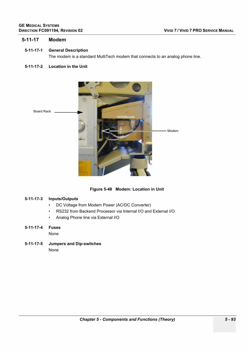
GE MEDICAL SYSTEMSDIRECTION FC091194, REVISION 02 VIVID 7 / VIVID 7 PRO SERVICE MANUAL
Chapter 5 - Components and Functions (Theory) 5 - 93
5-11-17 Modem
5-11-17-1 General DescriptionThe modem is a standard MultiTech modem that connects to an analog phone line.
5-11-17-2 Location in the Unit
5-11-17-3 Inputs/Outputs• DC Voltage from Modem Power (AC/DC Converter)• RS232 from Backend Processor via Internal I/O and External I/O• Analog Phone line via External I/O
5-11-17-4 FusesNone
5-11-17-5 Jumpers and Dip-switchesNone
Figure 5-48 Modem: Location in Unit
Modem
Board Rack
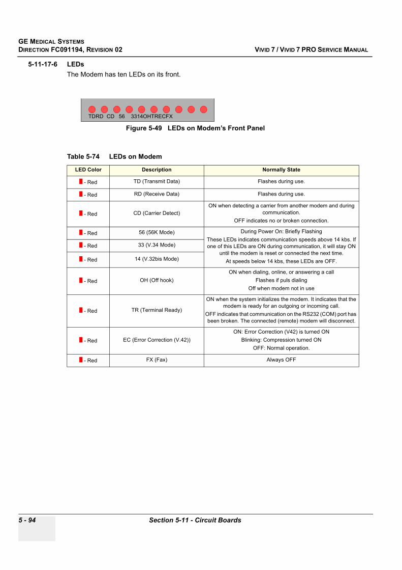
GE MEDICAL SYSTEMSDIRECTION FC091194, REVISION 02 VIVID 7 / VIVID 7 PRO SERVICE MANUAL
5 - 94 Section 5-11 - Circuit Boards
5-11-17-6 LEDsThe Modem has ten LEDs on its front.
Figure 5-49 LEDs on Modem’s Front Panel
Table 5-74 LEDs on Modem
LED Color Description Normally State
- Red TD (Transmit Data) Flashes during use.
- Red RD (Receive Data) Flashes during use.
- Red CD (Carrier Detect)ON when detecting a carrier from another modem and during
communication.OFF indicates no or broken connection.
- Red 56 (56K Mode) During Power On: Briefly FlashingThese LEDs indicates communication speeds above 14 kbs. If one of this LEDs are ON during communication, it will stay ON
until the modem is reset or connected the next time.At speeds below 14 kbs, these LEDs are OFF.
- Red 33 (V.34 Mode)
- Red 14 (V.32bis Mode)
- Red OH (Off hook)ON when dialing, online, or answering a call
Flashes if puls dialingOff when modem not in use
- Red TR (Terminal Ready)
ON when the system initializes the modem. It indicates that the modem is ready for an outgoing or incoming call.
OFF indicates that communication on the RS232 (COM) port has been broken. The connected (remote) modem will disconnect.
- Red EC (Error Correction (V.42))ON: Error Correction (V42) is turned ON
Blinking: Compression turned ONOFF: Normal operation.
- Red FX (Fax) Always OFF
TDRD CD 56 3314OHTRECFX
GE MEDICAL SYSTEMSDIRECTION FC091194, REVISION 02 VIVID 7 / VIVID 7 PRO SERVICE MANUAL
Chapter 5 - Components and Functions (Theory) 5 - 95
Section 5-12Video Specifications
5-12-1 PAL
5-12-2 NTSC
Section 5-13System Logs
The available logs can be viewed via the Common Service Interface, see "Error Logs" on page 7-7.
Table 5-75 PAL Video Specification
Horizontal TimingHorizontal Total (HT) us 944 pixels
Horizontal Start (HS) us 152 pixels
Horizontal Active (HA) us 768 pixels
Pixel Clock Freq 14.7 MHz (PAL)
Vertical Timing (Interlaced)
Vertical Start (VS) 53 Lines / fieldActive Lines (VA) Lines / frame (=PAL standard)
Total Lines (VT) 625 Lines / frame (=PAL standard)
Frame Rate 25Hz (=PAL standard)
Table 5-76 NTSC Video Specification
Horizontal TimingHorizontal Total (HT) us 780 pixels
Horizontal Start (HS) us 118 pixels
Horizontal Active (HA) us 640 pixels
Pixel Clock Freq 12.272725 MHz (NTSC)
Vertical Timing (Interlaced)Vertical Start (VS) 17 Lines / field
Active Lines (VA) (525 - 17) Lines / frame (=NTSC standard)
Total Lines (VT) 525 Lines / frame (=NTSC standard)
Frame Rate 30Hz (=NTSC standard)
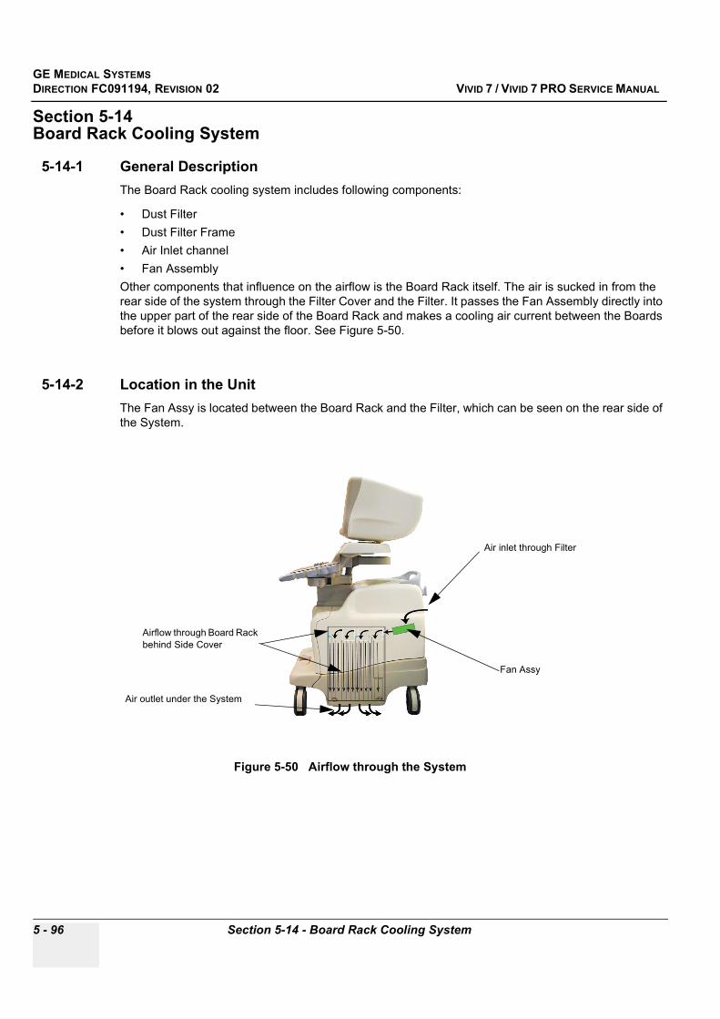
GE MEDICAL SYSTEMSDIRECTION FC091194, REVISION 02 VIVID 7 / VIVID 7 PRO SERVICE MANUAL
5 - 96 Section 5-14 - Board Rack Cooling System
Section 5-14Board Rack Cooling System
5-14-1 General DescriptionThe Board Rack cooling system includes following components:
• Dust Filter• Dust Filter Frame• Air Inlet channel• Fan AssemblyOther components that influence on the airflow is the Board Rack itself. The air is sucked in from the rear side of the system through the Filter Cover and the Filter. It passes the Fan Assembly directly into the upper part of the rear side of the Board Rack and makes a cooling air current between the Boards before it blows out against the floor. See Figure 5-50.
5-14-2 Location in the UnitThe Fan Assy is located between the Board Rack and the Filter, which can be seen on the rear side of the System.
Figure 5-50 Airflow through the System
Fan Assy
Air inlet through Filter
Airflow through Board Rack behind Side Cover
Air outlet under the System
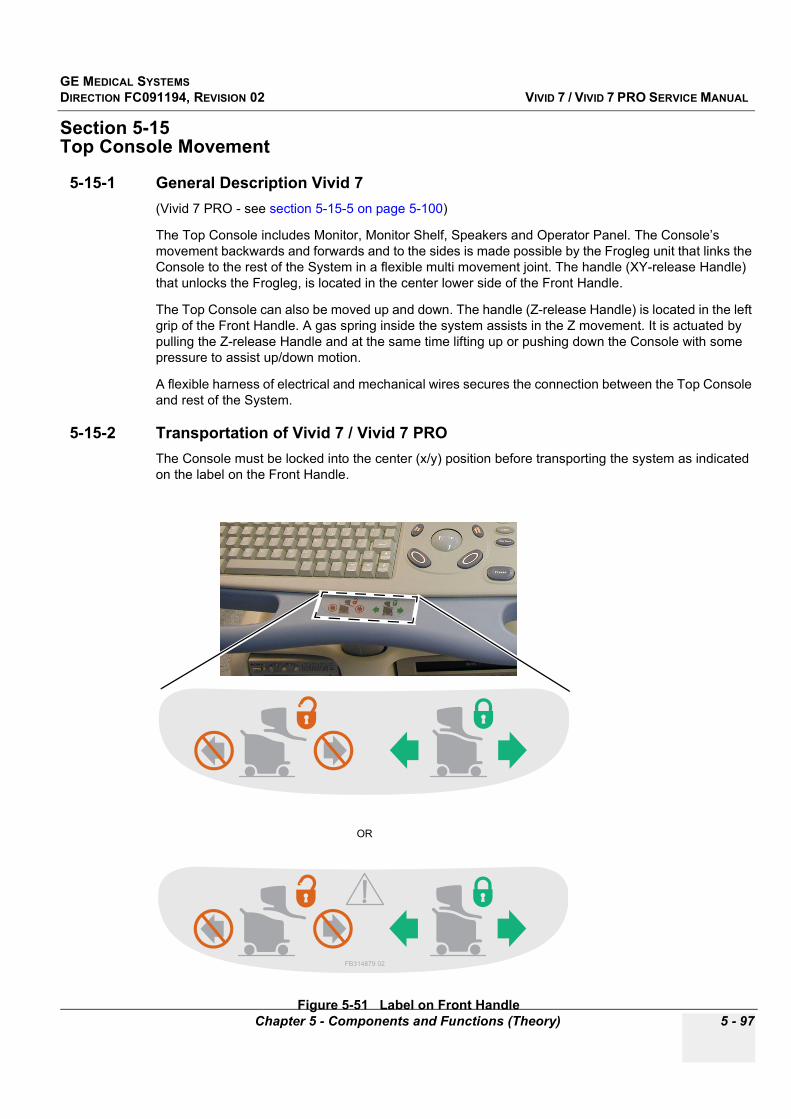
GE MEDICAL SYSTEMSDIRECTION FC091194, REVISION 02 VIVID 7 / VIVID 7 PRO SERVICE MANUAL
Chapter 5 - Components and Functions (Theory) 5 - 97
Section 5-15Top Console Movement
5-15-1 General Description Vivid 7 (Vivid 7 PRO - see section 5-15-5 on page 5-100)
The Top Console includes Monitor, Monitor Shelf, Speakers and Operator Panel. The Console’s movement backwards and forwards and to the sides is made possible by the Frogleg unit that links the Console to the rest of the System in a flexible multi movement joint. The handle (XY-release Handle) that unlocks the Frogleg, is located in the center lower side of the Front Handle.
The Top Console can also be moved up and down. The handle (Z-release Handle) is located in the left grip of the Front Handle. A gas spring inside the system assists in the Z movement. It is actuated by pulling the Z-release Handle and at the same time lifting up or pushing down the Console with some pressure to assist up/down motion.
A flexible harness of electrical and mechanical wires secures the connection between the Top Console and rest of the System.
5-15-2 Transportation of Vivid 7 / Vivid 7 PROThe Console must be locked into the center (x/y) position before transporting the system as indicated on the label on the Front Handle.
Figure 5-51 Label on Front Handle
OR
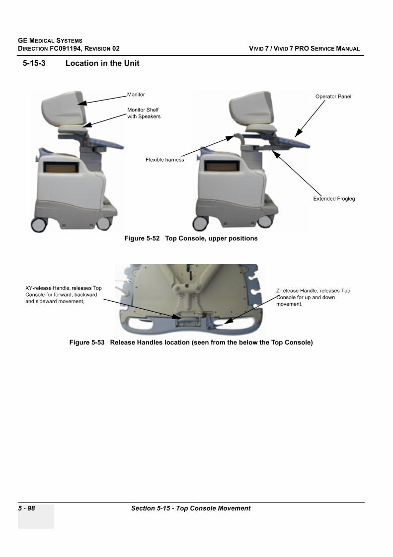
GE MEDICAL SYSTEMSDIRECTION FC091194, REVISION 02 VIVID 7 / VIVID 7 PRO SERVICE MANUAL
5 - 98 Section 5-15 - Top Console Movement
5-15-3 Location in the Unit
Figure 5-52 Top Console, upper positions
Figure 5-53 Release Handles location (seen from the below the Top Console)
Operator Panel
Extended Frogleg
Flexible harness
Monitor
Monitor Shelf with Speakers
Z-release Handle, releases Top Console for up and down movement.
XY-release Handle, releases Top Console for forward, backward and sideward movement,
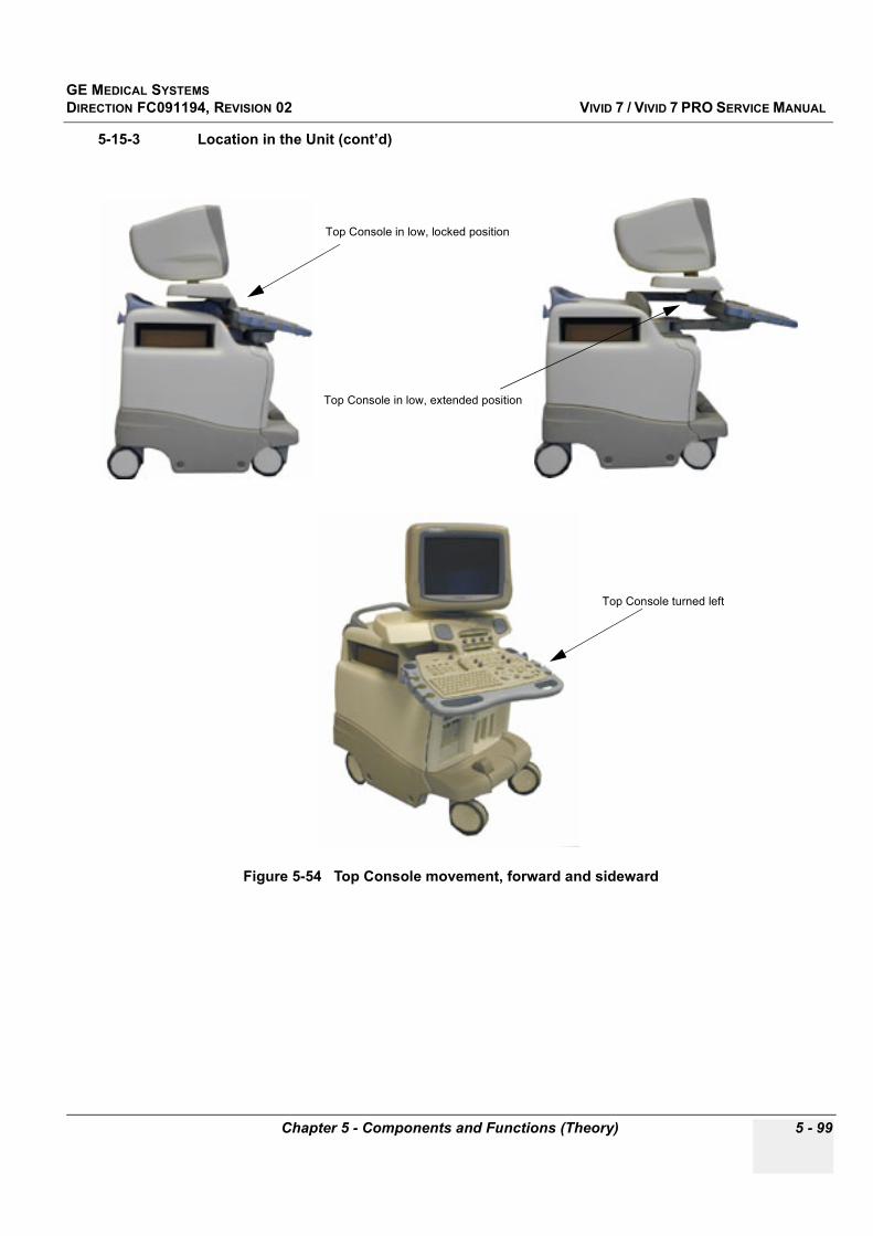
GE MEDICAL SYSTEMSDIRECTION FC091194, REVISION 02 VIVID 7 / VIVID 7 PRO SERVICE MANUAL
Chapter 5 - Components and Functions (Theory) 5 - 99
5-15-3 Location in the Unit (cont’d)
Figure 5-54 Top Console movement, forward and sideward
Top Console in low, locked position
Top Console in low, extended position
Top Console turned left
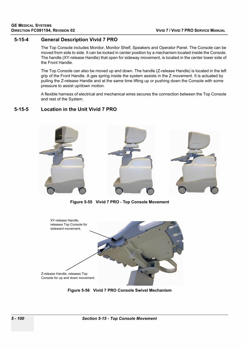
GE MEDICAL SYSTEMSDIRECTION FC091194, REVISION 02 VIVID 7 / VIVID 7 PRO SERVICE MANUAL
5 - 100 Section 5-15 - Top Console Movement
5-15-4 General Description Vivid 7 PROThe Top Console includes Monitor, Monitor Shelf, Speakers and Operator Panel. The Console can be moved from side to side. It can be locked in center position by a mechanism located inside the Console. The handle (XY-release Handle) that open for sideway movement, is located in the center lower side of the Front Handle.
The Top Console can also be moved up and down. The handle (Z-release Handle) is located in the left grip of the Front Handle. A gas spring inside the system assists in the Z movement. It is actuated by pulling the Z-release Handle and at the same time lifting up or pushing down the Console with some pressure to assist up/down motion.
A flexible harness of electrical and mechanical wires secures the connection between the Top Console and rest of the System.
5-15-5 Location in the Unit Vivid 7 PRO
Figure 5-55 Vivid 7 PRO - Top Console Movement
Figure 5-56 Vivid 7 PRO Console Swivel Mechanism
XY-release Handle, releases Top Console for sideward movement,
Z-release Handle, releases Top Console for up and down movement.

GE MEDICAL SYSTEMSDIRECTION FC091194, REVISION 02 VIVID 7 / VIVID 7 PRO SERVICE MANUAL
Chapter 5 - Components and Functions (Theory) 5 - 101
Section 5-16Common Service Platform
5-16-1 IntroductionThe Service Platform contains a set of software modules that are common to many of GE’s ultrasound and cardiology systems. This web-enabled technology provides linkage to e-Services, e-Commerce, and the iCenter, making GE’s scanners more e-enabled than ever.
5-16-2 iLinq Interactive Platform FeaturesMany of the services of the Common Service Platform come from its integration with iLinq. The following sections contain a brief introduction of iLinq’s features.
5-16-2-1 Web Server/BrowserThe Service platform and other Service software use the iLinq web server and browser.
5-16-2-2 ConnectivityThis feature provides basic connectivity between the scanner and the OnLine Center (OLC).
5-16-2-3 ConfigurationThis feature provides the interfaces to configure various iLinq parameters.
5-16-2-4 Contact GEAllows a one-switch touch for the user to contact the OnLine Center and describe problems with their scanner in an easy and convenient way.
5-16-2-5 Interactive ApplicationThe main application is displayed in the form of HTML pages whenever the browser starts. This is the entry point for any user to start any iLinq application.

GE MEDICAL SYSTEMSDIRECTION FC091194, REVISION 02 VIVID 7 / VIVID 7 PRO SERVICE MANUAL
5 - 102 Section 5-16 - Common Service Platform
5-16-3 Global Service User Interface (GSUI)GSUI is the pattern for the user interface. This interface standard will be followed by all modalities to achieve a common look-and-feel for service software across all GEMS products.
5-16-3-1 InternationalizationThe user interfaces provided by the service platform are designed for GE personnel and as such are in English only. At this time there is no multi-lingual capability built into the Common Service Interface.
5-16-3-2 Service Login
Press the switch with the wrench icon ( ) in the status bar at the bottom of the video screen.
This switch links the user or the Field Engineer (FE) to the service login screen.
Figure 5-57 Service Login Screen

GE MEDICAL SYSTEMSDIRECTION FC091194, REVISION 02 VIVID 7 / VIVID 7 PRO SERVICE MANUAL
Chapter 5 - Components and Functions (Theory) 5 - 103
5-16-3-3 Access / SecurityThe service interface has different access and security user levels. Users are only granted access to the tools they are authorized to use.
A modem on the scanner is specifically intended for iLinq use (by the user) and for InSite use.
Every access request, whether successful or not, will be logged into a service access log that is viewable to authorized users.
See Chapter 7 for more info about InSite and the Global Service User Interface.
Table 5-77 Access Authorization
User Level Access Authorization
Operator These service tools are normally used in-house and are protected with a password.
Administrator Use the OnLine Center access method provided by iLinq.
External Service Access is protected with a password.
GE Service Requires knowledge of a password.*

GE MEDICAL SYSTEMSDIRECTION FC091194, REVISION 02 VIVID 7 / VIVID 7 PRO SERVICE MANUAL
5 - 104 Section 5-16 - Common Service Platform
This page was intentionally left blank.

GE MEDICAL SYSTEMSDIRECTION FC091194, REVISION 02 VIVID 7 / VIVID 7 PRO SERVICE MANUAL
Chapter 6 - Service Adjustments 6 - 1
Chapter 6Service Adjustments
Section 6-1Overview
6-1-1 Purpose of Chapter 6This section describes how to adjust the scanner.
Section 6-2Power Supply Adjustments
It is not possible to adjust the power supplies on this unit.
Table 6-1 Contents in Chapter 6
Section Description Page Number
6-1 Overview 6-1
6-2 Power Supply Adjustments 6-1
6-3 Monitor Adjustments 6-2
6-4 Front End Alignment Procedure 6-3
6-5 Direction Lock and Brake Adjustment 6-4

GE MEDICAL SYSTEMSDIRECTION FC091194, REVISION 02 VIVID 7 / VIVID 7 PRO SERVICE MANUAL
6 - 2 Section 6-3 - Monitor Adjustments
Section 6-3Monitor Adjustments
6-3-1 Cautions and WarningsN/A
6-3-2 Access to AdjustmentsThe adjustments of the monitor is done via controls (buttons) on front of the monitor.
6-3-3 Adjustment Procedure(s)The display monitor’s contrast and brightness controls may need periodic adjustment due to changes in ambient light. They are adjusted from the three buttons on the front part of the display monitor.
Figure 6-1 Adjust Contrast and Brightness
Left Button
Right Button
Center Button
CONTRAST
BRIGHTNESS

GE MEDICAL SYSTEMSDIRECTION FC091194, REVISION 02 VIVID 7 / VIVID 7 PRO SERVICE MANUAL
Chapter 6 - Service Adjustments 6 - 3
6-3-3-1 Adjust Contrast
1.) Press Left button on the display monitor once (see Figure 6-1).2.) Press Right button to increase contrast.3.) Press Center button to decrease contrast.The amount of contrast is shown on a slider on the screen (see Figure 6-1).
6-3-3-2 Adjust Brightness
1.) Press the Left button on the display monitor twice (see Figure 6-1).2.) Press the Right button to increase brightness.3.) Press the Center button to decrease brightness.The amount of brightness is shown on a slider on the screen (see Figure 6-1).
Section 6-4Front End Alignment Procedure
6-4-1 IntroductionFront End Alignment Procedure (Beam Former Calibration Procedures) are performed to calibrate each ADC channel of the two Bean Former (BF) inputs. The system calibrates the ADC to zero output when there is no signal on the input. These bias voltages are stored in Backend Processor.
6-4-2 When to do a Front End Alignment ProcedureDo the Front End Alignment procedure;
• when installing a new Vivid 7 / Vivid 7 PRO• after software has been updated or replaced• when BF boards have been interchanged • when a BF board has been replaced • when the Backend Processor has been replaced
6-4-3 ProcedureSee 7-4-5 - Beamformer Calibration (Front End Alignment) starting on page 7-65.
GE MEDICAL SYSTEMSDIRECTION FC091194, REVISION 02 VIVID 7 / VIVID 7 PRO SERVICE MANUAL
6 - 4 Section 6-5 - Direction Lock and Brake Adjustment
Section 6-5Direction Lock and Brake Adjustment
6-5-1 Front Caster Brakes Adjustment Procedure
6-5-1-1 Manpower2 persons
6-5-1-2 Tools• Hexagon key 3/32” inch• Phillips screw driver size 2
6-5-1-3 Preparations
1.) Set Rear Brakes to prevent system from rolling.2.) Remove Front Bumper as described in "Front Bumper Removal Procedure" on page 8-50.
6-5-1-4 Front Caster Brakes Adjustment
1.) Use a hexagon key, and screw the adjustment screw until the opening between brake dogs and tires are approximate 2 mm.
2.) Install Front Bumper as described in "Front Bumper Installation Procedure" on page 8-50.3.) Test Front Brakes.
Figure 6-2 Front Brakes adjustment
2 mm opening
Brakedog "bites"
Adjustment screws

GE MEDICAL SYSTEMSDIRECTION FC091194, REVISION 02 VIVID 7 / VIVID 7 PRO SERVICE MANUAL
Chapter 6 - Service Adjustments 6 - 5
6-5-2 Direction Lock Adjustment Procedure
6-5-2-1 Manpower1 person, 30 minutes
6-5-2-2 ToolsOpen end wrench, 13 mm
6-5-2-3 Preparations
1.) Block Rear Casters.2.) Push down Direction Lock Pedal.3.) Turn Casters until they locks in forward pointing position.
6-5-2-4 Direction Lock Adjustment
1.) Loosen the retaining nuts on the brake rods on both Front Casters to allow room for adjustment.2.) Remove the lock pins that secures the balljoints (See Figure 6-3).3.) Pull balljoints apart.
4.) Each part of the separated balljoint shall match each other when the brake lever on the Casters are in direction lock position, which is in left position on both Casters.
Figure 6-3 Front Caster Brake Arm and Ball Joint Parts
Lock pin
Adjustment nut
Retaining nut
Brake lever
GE MEDICAL SYSTEMSDIRECTION FC091194, REVISION 02 VIVID 7 / VIVID 7 PRO SERVICE MANUAL
6 - 6 Section 6-5 - Direction Lock and Brake Adjustment
6-5-2-4 Direction Lock Adjustment (cont’d)5.) Turn adjustment nuts until the balljoints matches.
6.) Press the balljoint together.7.) Install the lock pins, see Figure 6-3.8.) Fasten the retaining nuts.9.) Test Direction Lock.
Figure 6-4 Balljoint with Lock Pin
Adjustment nut
Retaining nutLock Pin
GE MEDICAL SYSTEMSDIRECTION FC091194, REVISION 02 VIVID 7 / VIVID 7 PRO SERVICE MANUAL
Chapter 6 - Service Adjustments 6 - 7
6-5-3 Rear Brakes Adjustment
6-5-3-1 Manpower2 persons, 1 hour
6-5-3-2 Tools• Hexagon key 3/32 inch• Phillips screw driver size 2
6-5-3-3 Preparations
1.) Remove Filter Cover as described in "Filter Cover Removal Procedure" on page 8-6.2.) Remove Lower Rear Cover as described in "Lower Rear Cover Removal Procedure" on page 8-8.3.) Remove the Caster as described in "Rear Casters Removal Procedure" on page 8-41
6-5-3-4 Rear Brakes Adjustment
1.) Use a 3/32 inch hexagon key to adjust the brake until the space between brakedogs and tires are approximate 2 mm.
1.) Replace the Caster and tightly fasten it with four screws.2.) Install Lower Rear Cover as described in "Lower Rear Cover Installation Procedure" on page 8-8.3.) Install Filter Cover as described in "Filter Cover Installation Procedure" on page 8-6.
4.) Remove the Wooden Wedge.5.) Roll the system off the Bevel Edged Board.
Figure 6-5 Rear Brakes adjustment
WARNINGWARNING Use extreme caution in the next two steps. The scanner will be unstable.

GE MEDICAL SYSTEMSDIRECTION FC091194, REVISION 02 VIVID 7 / VIVID 7 PRO SERVICE MANUAL
6 - 8 Section 6-5 - Direction Lock and Brake Adjustment
This page was intentionally left blank.
GE MEDICAL SYSTEMSDIRECTION FC091194, REVISION 02 VIVID 7 / VIVID 7 PRO SERVICE MANUAL
Chapter 7 - Diagnostics/Troubleshooting 7 - 1
Chapter 7Diagnostics/Troubleshooting
Section 7-1Overview
7-1-1 Purpose of Chapter 7This section describes how to setup and run the tools and software that help maintain image quality and system operation. Very basic host, system and board level diagnostics are run whenever power is applied. Some Service Tools may be run at the application level.
7-1-2 Service Software ToolsTwo major Service Software tools are available;
• Global Service User Interface with Common DiagnosticsThis software tool makes it possible for you to do tests on various functions on the Backend Processor. It also includes an acquisition test that tests most of the PCBs in the Front End Rack. If this test fails, detailed Acquisition Diagnostics tests are available via Vivid 7 / Vivid 7 PRO’s software menus.
• Acquisition DiagnosticsThis software tool includes detailed Acquisition Diagnostics tests available via Vivid 7 / Vivid 7 PRO’s software menus. It is running on the Backend Processor too. It includes both a Test All function that is the same test as available from the GSUI, but also tests on PCB level.
7-1-3 Special Service Tool• Test Attenuator, PN: AA200215
Table 7-1 Contents in Chapter 7
Section Description Page Number
7-1 Overview 7-1
7-2 Diagnostics 7-3
7-3 Common Diagnostics 7-44
7-4 Acquisition Diagnostics 7-59
7-5 Troubleshooting 7-67
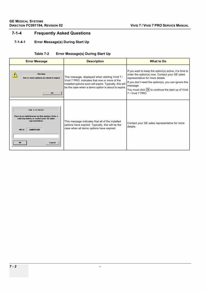
GE MEDICAL SYSTEMSDIRECTION FC091194, REVISION 02 VIVID 7 / VIVID 7 PRO SERVICE MANUAL
7 - 2 -
7-1-4 Frequently Asked Questions
7-1-4-1 Error Message(s) During Start Up
Table 7-2 Error Message(s) During Start Up
Error Message Description What to Do
This message, displayed when starting Vivid 7 / Vivid 7 PRO, indicates that one or more of the installed options soon will expire. Typically, this will be the case when a demo option is about to expire.
If you want to keep the option(s) active, it is time to order the option(s) now. Contact your GE sales representative for more details. If you don’t need the option(s), you can ignore this message.You must click OK to continue the start up of Vivid 7 / Vivid 7 PRO.
This message indicates that all of the installed options have expired. Typically, this will be the case when all demo options have expired.
Contact your GE sales representative for more details.
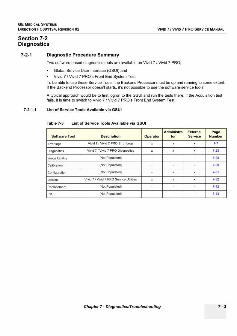
GE MEDICAL SYSTEMSDIRECTION FC091194, REVISION 02 VIVID 7 / VIVID 7 PRO SERVICE MANUAL
Chapter 7 - Diagnostics/Troubleshooting 7 - 3
Section 7-2Diagnostics
7-2-1 Diagnostic Procedure SummaryTwo software based diagnostics tools are available on Vivid 7 / Vivid 7 PRO;
• Global Service User Interface (GSUI) and• Vivid 7 / Vivid 7 PRO’s Front End System TestTo be able to use these Service Tools, the Backend Processor must be up and running to some extent. If the Backend Processor doesn’t starts, it’s not possible to use the software service tools!
A typical approach would be to first log on to the GSUI and run the tests there. If the Acquisition test fails, it is time to switch to Vivid 7 / Vivid 7 PRO’s Front End System Test.
7-2-1-1 List of Service Tools Available via GSUI
Table 7-3 List of Service Tools Available via GSUI
Software Tool Description OperatorAdministra
torExternal Service
Page Number
Error logs Vivid 7 / Vivid 7 PRO Error Logs x x x 7-7
Diagnostics Vivid 7 / Vivid 7 PRO Diagnostics x x x 7-23
Image Quality [Not Populated] - - - 7-28
Calibration [Not Populated] - - - 7-29
Configuration [Not Populated] - - - 7-31
Utilities Vivid 7 / Vivid 7 PRO Service Utilities x x x 7-32
Replacement [Not Populated] - - - 7-42
PM [Not Populated] - - - 7-43

GE MEDICAL SYSTEMSDIRECTION FC091194, REVISION 02 VIVID 7 / VIVID 7 PRO SERVICE MANUAL
7 - 4 Section 7-2 - Diagnostics
7-2-2 Common Service Diagnostic Interface (Ultrasound Interface)
7-2-2-1 Connect PC to the Ultrasound UnitIt is not necessary to connect a PC to Vivid 7 / Vivid 7 PRO to use the GSUI.
7-2-2-2 Log-in to GSUI
Double-click the button with the wrench icon ( ) in the status bar at the bottom of the video screen. This button links the user or the Field Engineer (FE) to the Service Login Screen.
Log on as External Service with password: gogems (all lowercase letters).
Figure 7-1 Service Login Screen
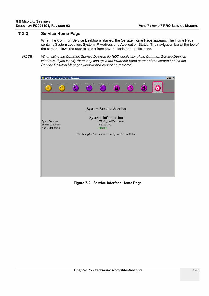
GE MEDICAL SYSTEMSDIRECTION FC091194, REVISION 02 VIVID 7 / VIVID 7 PRO SERVICE MANUAL
Chapter 7 - Diagnostics/Troubleshooting 7 - 5
7-2-3 Service Home PageWhen the Common Service Desktop is started, the Service Home Page appears. The Home Page contains System Location, System IP Address and Application Status. The navigation bar at the top of the screen allows the user to select from several tools and applications.
NOTE: When using the Common Service Desktop do NOT iconify any of the Common Service Desktop windows. If you iconify them they end up in the lower left-hand corner of the screen behind the Service Desktop Manager window and cannot be restored.
Figure 7-2 Service Interface Home Page

GE MEDICAL SYSTEMSDIRECTION FC091194, REVISION 02 VIVID 7 / VIVID 7 PRO SERVICE MANUAL
7 - 6 Section 7-2 - Diagnostics
7-2-3-1 Menu Bar DescriptionOn top of the Service Interface Home Page, there is a Menu Bar where you can choose between these screens, see Figure 7-3;
• Error Logs• Diagnostics• Image Quality• Calibration• Configuration• Utilities• Replacement• PM• Home
Click an icon to open the respective screen.
7-2-4 Description of ScreensEach screen may include one or more "sub-screens". The next sections describes the different screens available.
Figure 7-3 Service Interface Home Page
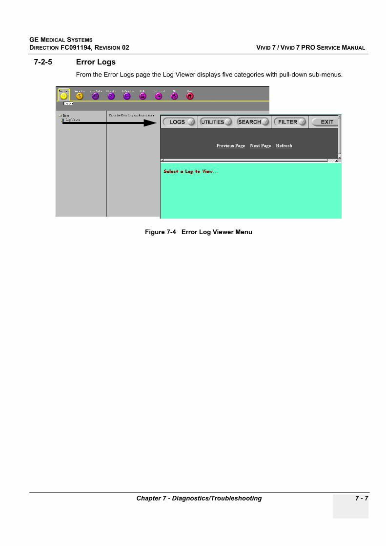
GE MEDICAL SYSTEMSDIRECTION FC091194, REVISION 02 VIVID 7 / VIVID 7 PRO SERVICE MANUAL
Chapter 7 - Diagnostics/Troubleshooting 7 - 7
7-2-5 Error LogsFrom the Error Logs page the Log Viewer displays five categories with pull-down sub-menus.
Figure 7-4 Error Log Viewer Menu
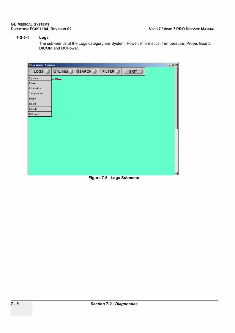
GE MEDICAL SYSTEMSDIRECTION FC091194, REVISION 02 VIVID 7 / VIVID 7 PRO SERVICE MANUAL
7 - 8 Section 7-2 - Diagnostics
7-2-5-1 LogsThe sub-menus of the Logs category are System, Power, Informatics, Temperature, Probe, Board, DICOM and DCPower.
Figure 7-5 Logs Submenu
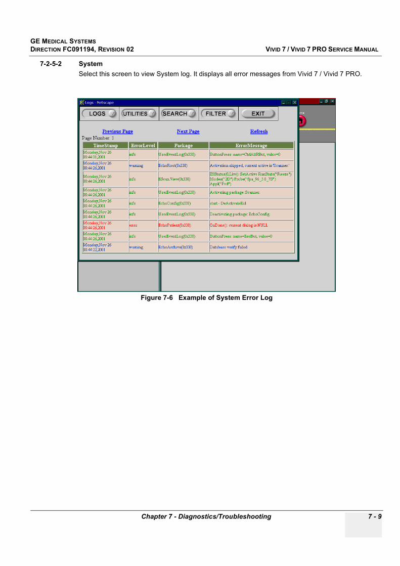
GE MEDICAL SYSTEMSDIRECTION FC091194, REVISION 02 VIVID 7 / VIVID 7 PRO SERVICE MANUAL
Chapter 7 - Diagnostics/Troubleshooting 7 - 9
7-2-5-2 SystemSelect this screen to view System log. It displays all error messages from Vivid 7 / Vivid 7 PRO.
Figure 7-6 Example of System Error Log

GE MEDICAL SYSTEMSDIRECTION FC091194, REVISION 02 VIVID 7 / VIVID 7 PRO SERVICE MANUAL
7 - 10 Section 7-2 - Diagnostics
7-2-5-3 PowerSelect this screen to view Power log.
Figure 7-7 Example of Power Log

GE MEDICAL SYSTEMSDIRECTION FC091194, REVISION 02 VIVID 7 / VIVID 7 PRO SERVICE MANUAL
Chapter 7 - Diagnostics/Troubleshooting 7 - 11
7-2-5-4 InformaticsSelect this screen to view Informatics log.
Figure 7-8 Example of Informatics Log
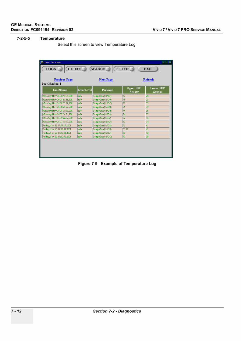
GE MEDICAL SYSTEMSDIRECTION FC091194, REVISION 02 VIVID 7 / VIVID 7 PRO SERVICE MANUAL
7 - 12 Section 7-2 - Diagnostics
7-2-5-5 TemperatureSelect this screen to view Temperature Log
Figure 7-9 Example of Temperature Log

GE MEDICAL SYSTEMSDIRECTION FC091194, REVISION 02 VIVID 7 / VIVID 7 PRO SERVICE MANUAL
Chapter 7 - Diagnostics/Troubleshooting 7 - 13
7-2-5-6 ProbeSelect this screen to view Probe Log.
Figure 7-10 Example of Probe Log

GE MEDICAL SYSTEMSDIRECTION FC091194, REVISION 02 VIVID 7 / VIVID 7 PRO SERVICE MANUAL
7 - 14 Section 7-2 - Diagnostics
7-2-5-7 BoardSelect this screen to view Board log.
Figure 7-11 Example of Board Log
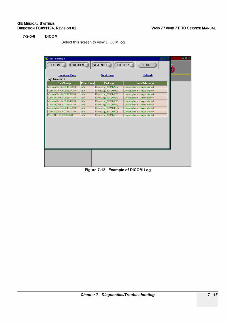
GE MEDICAL SYSTEMSDIRECTION FC091194, REVISION 02 VIVID 7 / VIVID 7 PRO SERVICE MANUAL
Chapter 7 - Diagnostics/Troubleshooting 7 - 15
7-2-5-8 DICOMSelect this screen to view DICOM log.
Figure 7-12 Example of DICOM Log
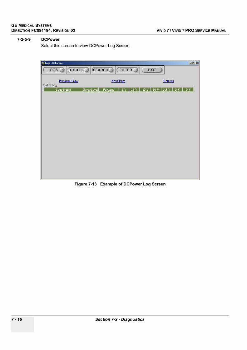
GE MEDICAL SYSTEMSDIRECTION FC091194, REVISION 02 VIVID 7 / VIVID 7 PRO SERVICE MANUAL
7 - 16 Section 7-2 - Diagnostics
7-2-5-9 DCPowerSelect this screen to view DCPower Log Screen.
Figure 7-13 Example of DCPower Log Screen
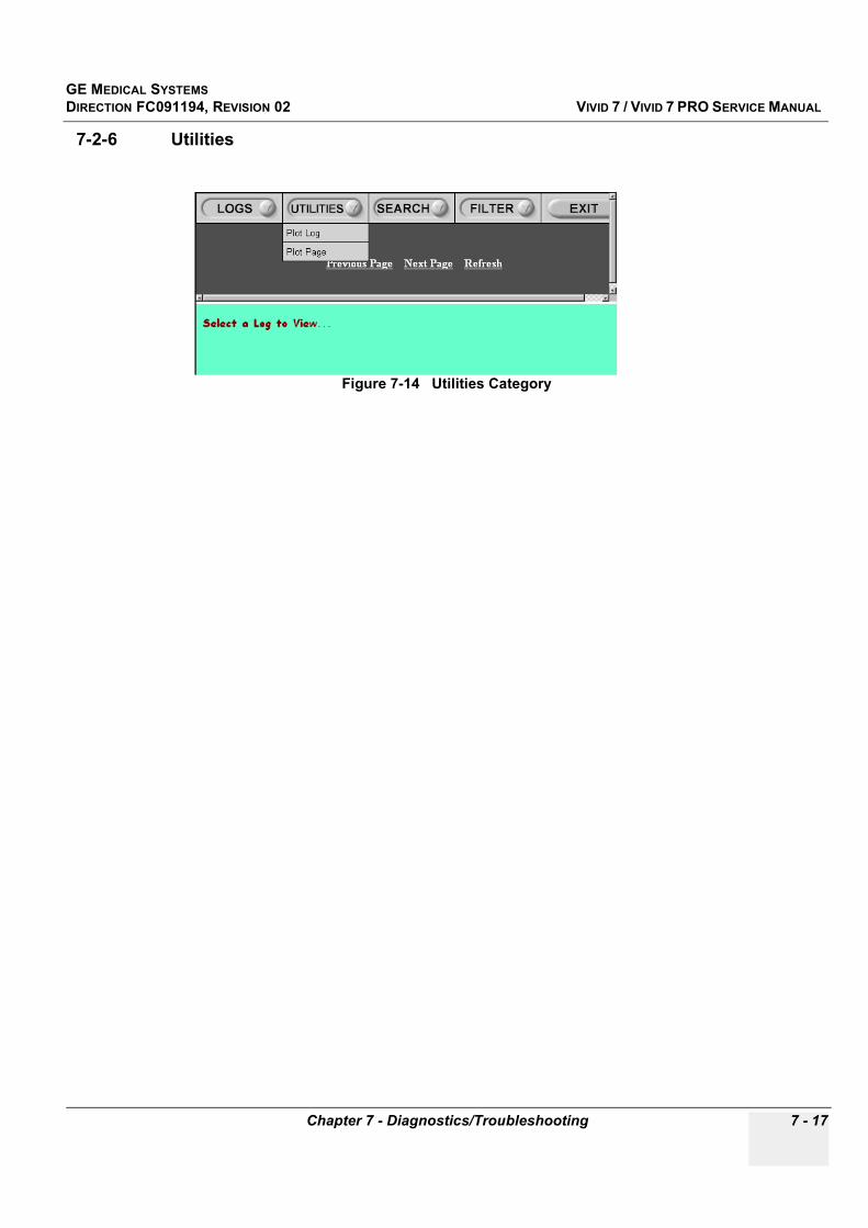
GE MEDICAL SYSTEMSDIRECTION FC091194, REVISION 02 VIVID 7 / VIVID 7 PRO SERVICE MANUAL
Chapter 7 - Diagnostics/Troubleshooting 7 - 17
7-2-6 Utilities
Figure 7-14 Utilities Category
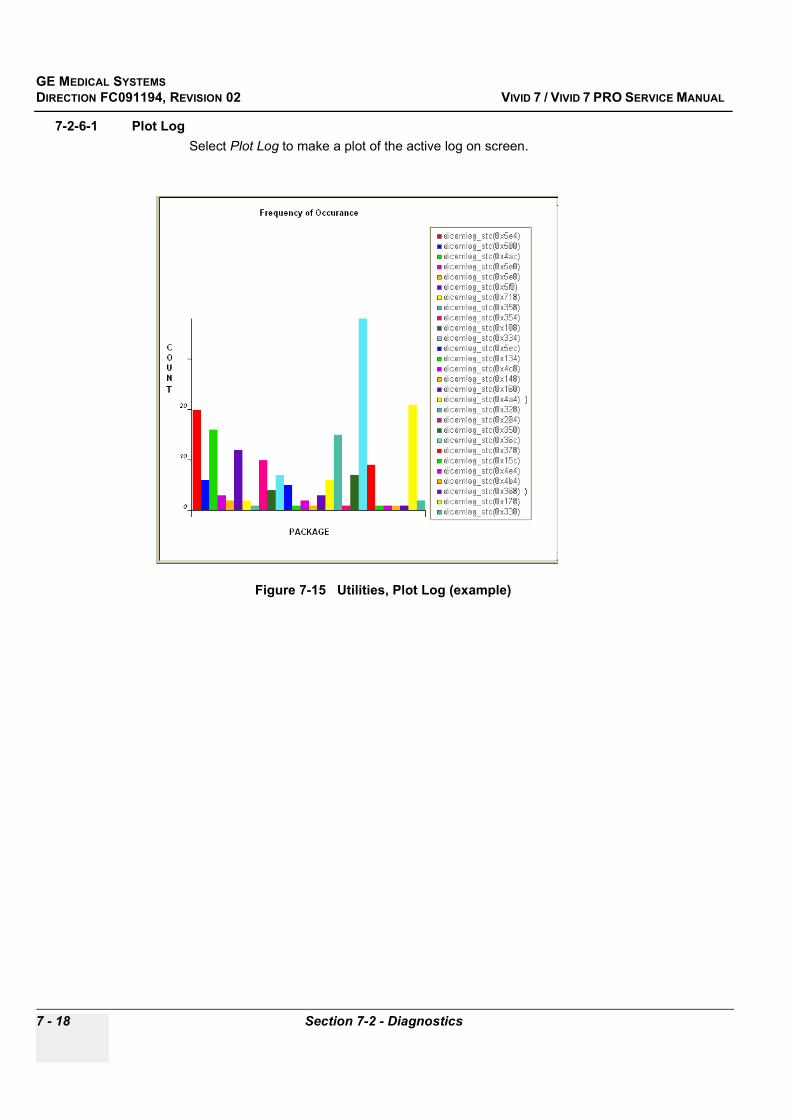
GE MEDICAL SYSTEMSDIRECTION FC091194, REVISION 02 VIVID 7 / VIVID 7 PRO SERVICE MANUAL
7 - 18 Section 7-2 - Diagnostics
7-2-6-1 Plot LogSelect Plot Log to make a plot of the active log on screen.
Figure 7-15 Utilities, Plot Log (example)

GE MEDICAL SYSTEMSDIRECTION FC091194, REVISION 02 VIVID 7 / VIVID 7 PRO SERVICE MANUAL
Chapter 7 - Diagnostics/Troubleshooting 7 - 19
7-2-6-2 Plot PageSelect Plot Page to make a plot of the active (log-) page on screen.
Figure 7-16 Utilities, Plot Page (example)
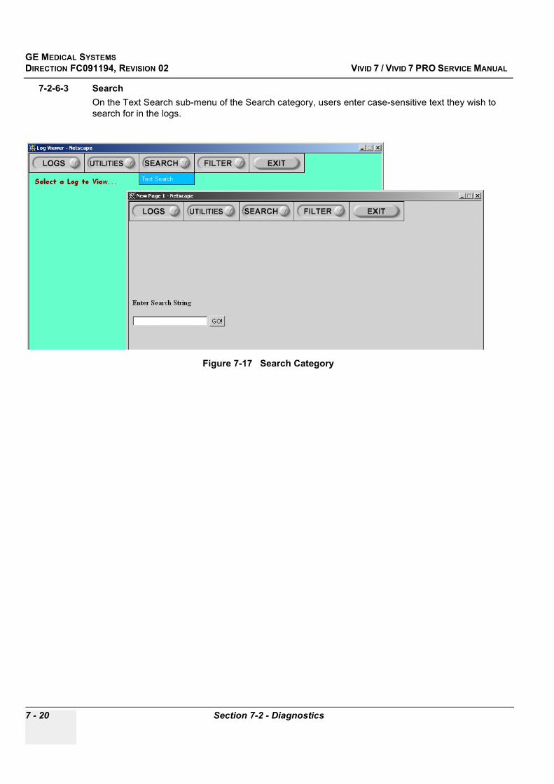
GE MEDICAL SYSTEMSDIRECTION FC091194, REVISION 02 VIVID 7 / VIVID 7 PRO SERVICE MANUAL
7 - 20 Section 7-2 - Diagnostics
7-2-6-3 SearchOn the Text Search sub-menu of the Search category, users enter case-sensitive text they wish to search for in the logs.
Figure 7-17 Search Category

GE MEDICAL SYSTEMSDIRECTION FC091194, REVISION 02 VIVID 7 / VIVID 7 PRO SERVICE MANUAL
Chapter 7 - Diagnostics/Troubleshooting 7 - 21
7-2-6-4 FilterThis function is available for GE Service only.

GE MEDICAL SYSTEMSDIRECTION FC091194, REVISION 02 VIVID 7 / VIVID 7 PRO SERVICE MANUAL
7 - 22 Section 7-2 - Diagnostics
7-2-6-5 ExitThe sub-menu, Exit Log Viewer, returns the user to the Common Service Desktop Home Page.
Figure 7-18 Exit Log Viewer Category
GE MEDICAL SYSTEMSDIRECTION FC091194, REVISION 02 VIVID 7 / VIVID 7 PRO SERVICE MANUAL
Chapter 7 - Diagnostics/Troubleshooting 7 - 23
7-2-7 DiagnosticsWhen the Diagnostics Screen has been selected, two main tools are available;
- Acquisition Diagnostics- Common Diagnostics, See “Common Diagnostics” on page 7-44.
Figure 7-19 Diagnostics Screen Home Page
GE MEDICAL SYSTEMSDIRECTION FC091194, REVISION 02 VIVID 7 / VIVID 7 PRO SERVICE MANUAL
7 - 24 Section 7-2 - Diagnostics
7-2-7-1 Acquisition Diagnostics-Test AllOne test is available, Test All.
Test All runs a sequential test of the following;
1.) PC2IP2.) IMP (Image Port Board)3.) VME (VME data bus on the Back Plane)4.) SDP (Spectrum Doppler Processor)5.) RFT (Radio Frequency & Tissue Board)6.) FEC (Front End Controller Board) (Some parts of TX board is also tested)7.) BF (Beam Former Boards)8.) RX (Receiver Board)9.) TXP (TX Power)
NOTE: Relay Board (RLB) and Chain are not tested in this test. Some parts of the Transmitter (TX) Board is tested during the FEC Board test, but other parts of the TX Board are not tested at all.
7-2-7-2 Instructions FrameDisplays a test-specific page or the default instructions page.
7-2-7-3 Status FrameInitially displays the last known status for the particular diagnostic. Once the diagnostic starts, the frame displays the “current” status of all test results.
Figure 7-20 User Interface Diagnostic Screen, Test All

GE MEDICAL SYSTEMSDIRECTION FC091194, REVISION 02 VIVID 7 / VIVID 7 PRO SERVICE MANUAL
Chapter 7 - Diagnostics/Troubleshooting 7 - 25
7-2-7-4 Control FrameContains the user interface elements used for:
• Diagnostic control• Operator feedback
a.) Execute ButtonThis button has two modes - each with appropriate text:
* Execute - to start the diagnostic, and* Abort - to stop a diagnostic
b.) Loop CountThis is an editable text field that will only accept numeric values with 4 digits or less. When the button described in Execute Button step a (above) is configured as an “execute” button and pressed, the loop count field will be queried to determine the number of times to execute the diagnostic.
c.) Progress IndicatorDisplays a graphical progress indicator for the user.
d.) Short Text MessageDisplays either a starting message or aborting message, as well as the diagnostic completion status.
e.) Control Frame Background ColorInitially gray, the Control Frame background color changes upon completion of a diagnostic to indicate completion status.
* Fail = Red* Pass = Green
GE MEDICAL SYSTEMSDIRECTION FC091194, REVISION 02 VIVID 7 / VIVID 7 PRO SERVICE MANUAL
7 - 26 Section 7-2 - Diagnostics
7-2-7-4 Control Frame (cont’d)Examine the log in the status frame to find the test(s) that failed. (In the example in Figure 7-21, all the tests failed.)
Figure 7-21 User Interface Diagnostic Screen, Test All Failed
GE MEDICAL SYSTEMSDIRECTION FC091194, REVISION 02 VIVID 7 / VIVID 7 PRO SERVICE MANUAL
Chapter 7 - Diagnostics/Troubleshooting 7 - 27
7-2-7-4 Control Frame (cont’d)In Figure 7-22, the test passed. The green background color in the Control Frame indicates that the test passed.
7-2-7-5 Common Diagnostics See “Common Diagnostics” on page 7-44.
Figure 7-22 User Interface Diagnostic Screen, Test All Passed
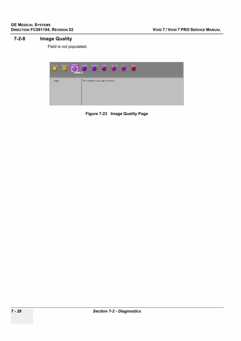
GE MEDICAL SYSTEMSDIRECTION FC091194, REVISION 02 VIVID 7 / VIVID 7 PRO SERVICE MANUAL
7 - 28 Section 7-2 - Diagnostics
7-2-8 Image QualityField is not populated.
Figure 7-23 Image Quality Page

GE MEDICAL SYSTEMSDIRECTION FC091194, REVISION 02 VIVID 7 / VIVID 7 PRO SERVICE MANUAL
Chapter 7 - Diagnostics/Troubleshooting 7 - 29
7-2-9 CalibrationThis screen gives you access to:
• DC Offset calibration• Reset DC-Offset cal
7-2-9-1 DC Offset calibrationDC Offset calibration also called “Beamformer Calibration” or "Frontend Alignment" is performed to calibrate each ADC channel of the two Beam Former (BF) board inputs. The system calibrates the Beamformer ADCs to zero output when there is no signal on the input.
These bias voltages are stored on hard disk in Backend Processor.
7-2-9-2 SetupDisconnect all probes before starting the calibration.
7-2-9-3 When to Use this ProcedureThis procedure should be performed;
- when installing a new Vivid 7 / Vivid 7 PRO- after software has been updated or replaced- when BF boards have been interchanged - when a BF board has been replaced - when the Backend Processor has been replaced
Figure 7-24 Calibration

GE MEDICAL SYSTEMSDIRECTION FC091194, REVISION 02 VIVID 7 / VIVID 7 PRO SERVICE MANUAL
7 - 30 Section 7-2 - Diagnostics
7-2-9-4 DC Offset Calibration Procedure
1.) Disconnect all connected probes.2.) Select DC Offset calibration and then click the EXECUTE button to start the DC Offset calibration
of the Beam Formers.3.) Wait for the calibration to take place. When finished, restart Vivid 7 / Vivid 7 PRO.
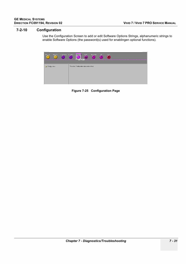
GE MEDICAL SYSTEMSDIRECTION FC091194, REVISION 02 VIVID 7 / VIVID 7 PRO SERVICE MANUAL
Chapter 7 - Diagnostics/Troubleshooting 7 - 31
7-2-10 ConfigurationUse the Configuration Screen to add or edit Software Options Strings, alphanumeric strings to enable Software Options (the password(s) used for enablingen optional functions).
Figure 7-25 Configuration Page
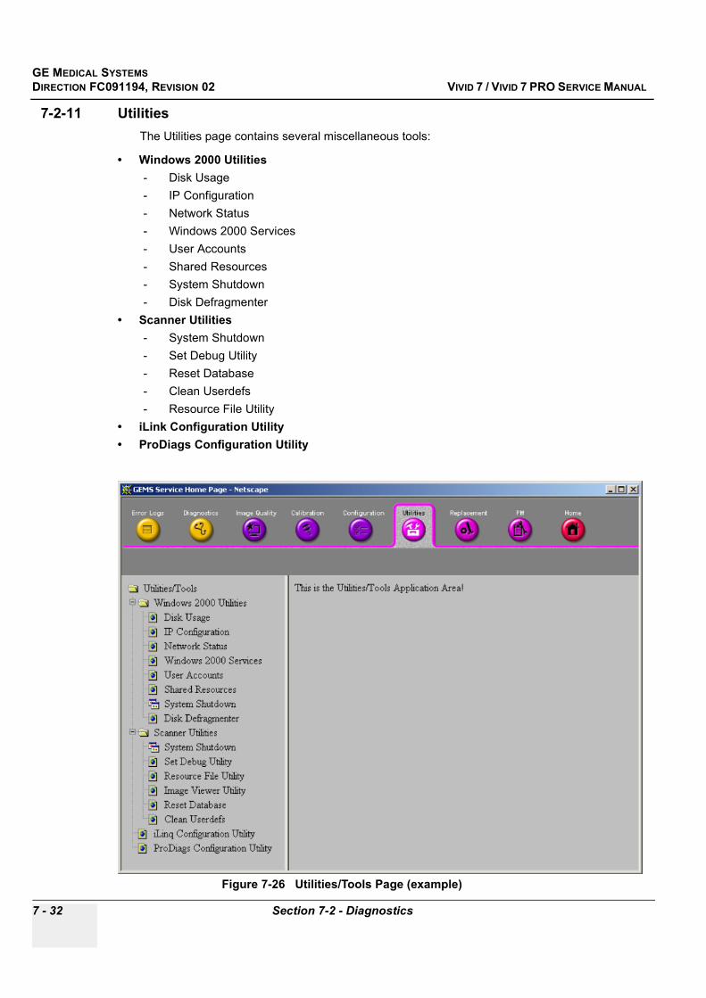
GE MEDICAL SYSTEMSDIRECTION FC091194, REVISION 02 VIVID 7 / VIVID 7 PRO SERVICE MANUAL
7 - 32 Section 7-2 - Diagnostics
7-2-11 UtilitiesThe Utilities page contains several miscellaneous tools:
• Windows 2000 Utilities- Disk Usage- IP Configuration- Network Status- Windows 2000 Services- User Accounts- Shared Resources- System Shutdown- Disk Defragmenter
• Scanner Utilities- System Shutdown- Set Debug Utility- Reset Database- Clean Userdefs- Resource File Utility
• iLink Configuration Utility• ProDiags Configuration Utility
Figure 7-26 Utilities/Tools Page (example)

GE MEDICAL SYSTEMSDIRECTION FC091194, REVISION 02 VIVID 7 / VIVID 7 PRO SERVICE MANUAL
Chapter 7 - Diagnostics/Troubleshooting 7 - 33
7-2-11-1 Windows 2000 Utilities
1.) Disk UsageThe Disk Usage page displays an overview of Vivid 7 / Vivid 7 PRO’s disk usage.
Figure 7-27 Disk Usage
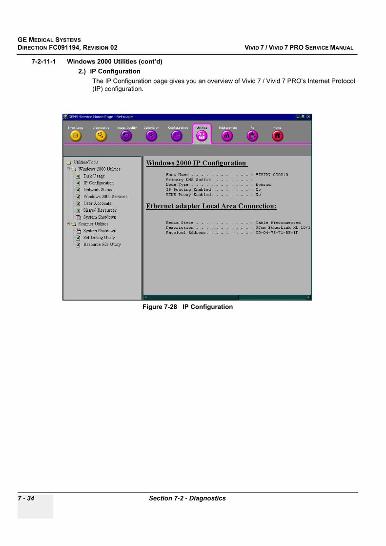
GE MEDICAL SYSTEMSDIRECTION FC091194, REVISION 02 VIVID 7 / VIVID 7 PRO SERVICE MANUAL
7 - 34 Section 7-2 - Diagnostics
7-2-11-1 Windows 2000 Utilities (cont’d)2.) IP Configuration
The IP Configuration page gives you an overview of Vivid 7 / Vivid 7 PRO’s Internet Protocol (IP) configuration.
Figure 7-28 IP Configuration
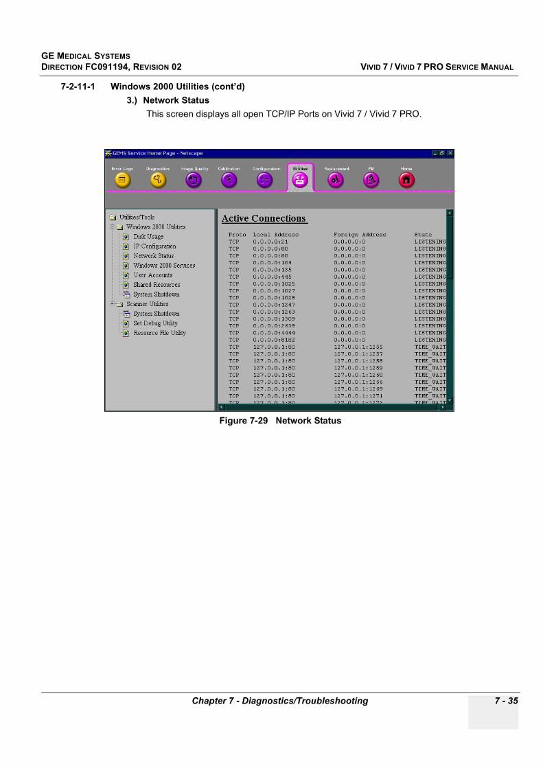
GE MEDICAL SYSTEMSDIRECTION FC091194, REVISION 02 VIVID 7 / VIVID 7 PRO SERVICE MANUAL
Chapter 7 - Diagnostics/Troubleshooting 7 - 35
7-2-11-1 Windows 2000 Utilities (cont’d)3.) Network Status
This screen displays all open TCP/IP Ports on Vivid 7 / Vivid 7 PRO.
Figure 7-29 Network Status
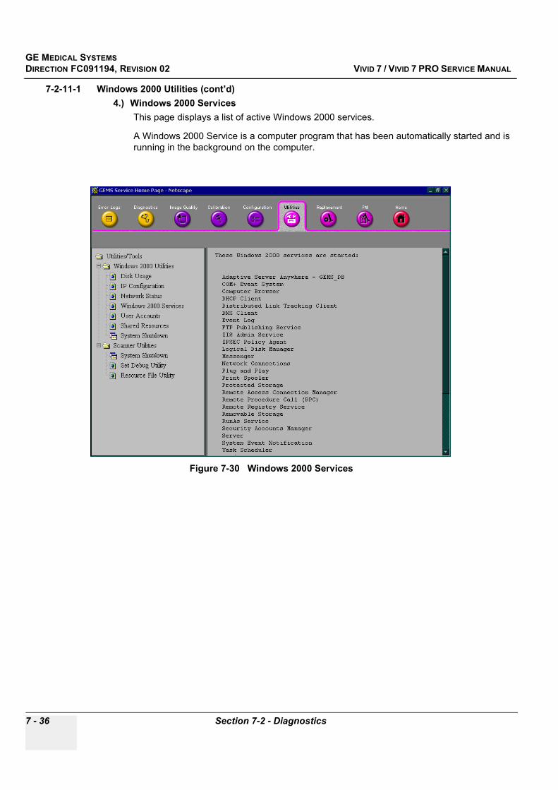
GE MEDICAL SYSTEMSDIRECTION FC091194, REVISION 02 VIVID 7 / VIVID 7 PRO SERVICE MANUAL
7 - 36 Section 7-2 - Diagnostics
7-2-11-1 Windows 2000 Utilities (cont’d)4.) Windows 2000 Services
This page displays a list of active Windows 2000 services.
A Windows 2000 Service is a computer program that has been automatically started and is running in the background on the computer.
Figure 7-30 Windows 2000 Services

GE MEDICAL SYSTEMSDIRECTION FC091194, REVISION 02 VIVID 7 / VIVID 7 PRO SERVICE MANUAL
Chapter 7 - Diagnostics/Troubleshooting 7 - 37
7-2-11-1 Windows 2000 Utilities (cont’d)5.) User Accounts
This page lists the Users that has been given access to this Vivid 7 / Vivid 7 PRO.
Figure 7-31 User Accounts
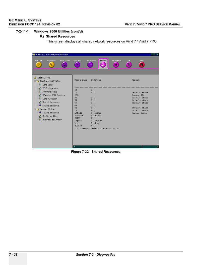
GE MEDICAL SYSTEMSDIRECTION FC091194, REVISION 02 VIVID 7 / VIVID 7 PRO SERVICE MANUAL
7 - 38 Section 7-2 - Diagnostics
7-2-11-1 Windows 2000 Utilities (cont’d)6.) Shared Resources
This screen displays all shared network resources on Vivid 7 / Vivid 7 PRO.
Figure 7-32 Shared Resources
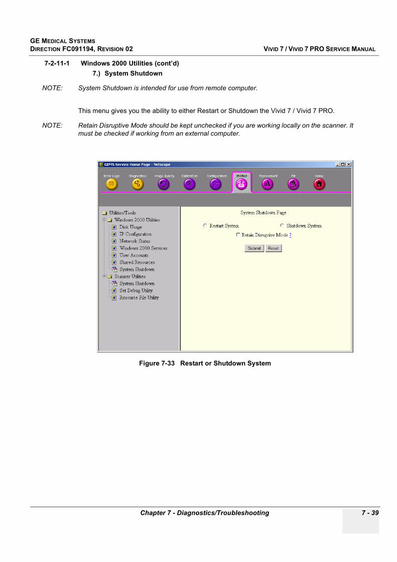
GE MEDICAL SYSTEMSDIRECTION FC091194, REVISION 02 VIVID 7 / VIVID 7 PRO SERVICE MANUAL
Chapter 7 - Diagnostics/Troubleshooting 7 - 39
7-2-11-1 Windows 2000 Utilities (cont’d)7.) System Shutdown
NOTE: System Shutdown is intended for use from remote computer.
This menu gives you the ability to either Restart or Shutdown the Vivid 7 / Vivid 7 PRO.
NOTE: Retain Disruptive Mode should be kept unchecked if you are working locally on the scanner. It must be checked if working from an external computer.
Figure 7-33 Restart or Shutdown System
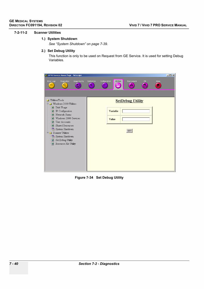
GE MEDICAL SYSTEMSDIRECTION FC091194, REVISION 02 VIVID 7 / VIVID 7 PRO SERVICE MANUAL
7 - 40 Section 7-2 - Diagnostics
7-2-11-2 Scanner Utilities
1.) System ShutdownSee “System Shutdown” on page 7-39.
2.) Set Debug UtilityThis function is only to be used on Request from GE Service. It is used for setting Debug Variables.
Figure 7-34 Set Debug Utility

GE MEDICAL SYSTEMSDIRECTION FC091194, REVISION 02 VIVID 7 / VIVID 7 PRO SERVICE MANUAL
Chapter 7 - Diagnostics/Troubleshooting 7 - 41
7-2-11-2 Scanner Utilities (cont’d)3.) Resource File Utility
From this page you can review the listed User Defined Resource File and save it to MO.
- ViewClick View to examine the User Defined Resource file on-screen.
- SaveClick Save and navigate to the MO drive to save the User Defined Resource file.
Figure 7-35 Resource File Utility
GE MEDICAL SYSTEMSDIRECTION FC091194, REVISION 02 VIVID 7 / VIVID 7 PRO SERVICE MANUAL
7 - 42 Section 7-2 - Diagnostics
7-2-12 ReplacementField is not populated.
Figure 7-36 Part Replacement Page

GE MEDICAL SYSTEMSDIRECTION FC091194, REVISION 02 VIVID 7 / VIVID 7 PRO SERVICE MANUAL
Chapter 7 - Diagnostics/Troubleshooting 7 - 43
7-2-13 PMField is not populated.
7-2-14 HomeClick HOME to return to the Service Home Page.
7-2-15 Exit From DiagnosticsClick the “X” in the upper right corner of the screen to exit Diagnostics.
Figure 7-37 Planned Maintenance Page
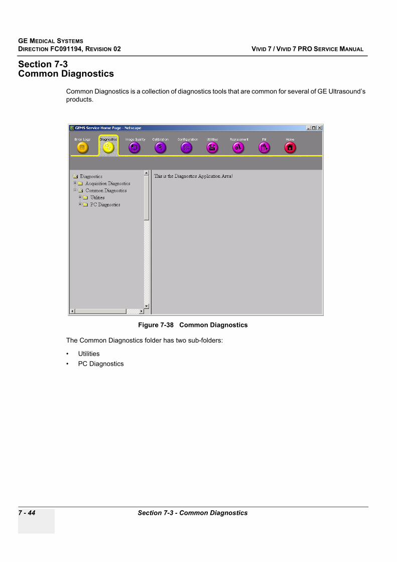
GE MEDICAL SYSTEMSDIRECTION FC091194, REVISION 02 VIVID 7 / VIVID 7 PRO SERVICE MANUAL
7 - 44 Section 7-3 - Common Diagnostics
Section 7-3Common Diagnostics
Common Diagnostics is a collection of diagnostics tools that are common for several of GE Ultrasound’s products.
The Common Diagnostics folder has two sub-folders:
• Utilities• PC Diagnostics
Figure 7-38 Common Diagnostics
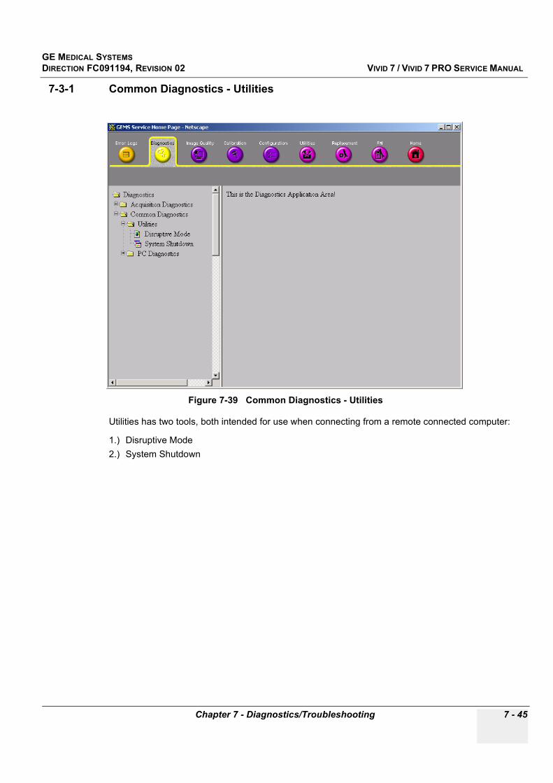
GE MEDICAL SYSTEMSDIRECTION FC091194, REVISION 02 VIVID 7 / VIVID 7 PRO SERVICE MANUAL
Chapter 7 - Diagnostics/Troubleshooting 7 - 45
7-3-1 Common Diagnostics - Utilities
Utilities has two tools, both intended for use when connecting from a remote connected computer:
1.) Disruptive Mode2.) System Shutdown
Figure 7-39 Common Diagnostics - Utilities

GE MEDICAL SYSTEMSDIRECTION FC091194, REVISION 02 VIVID 7 / VIVID 7 PRO SERVICE MANUAL
7 - 46 Section 7-3 - Common Diagnostics
7-3-1-1 Disruptive ModeDisruptive Mode Utility is used to enable/disable Disruptive Mode.
Disruptive Mode must be used if a remote computer is used to control Vivid 7 / Vivid 7 PRO. Example: InSite.
7-3-1-2 System ShutdownIntended for use from remote computer. See “System Shutdown” on page 7-39.
Figure 7-40 Common Diagnostics - Utilities - Disruptive Mode Utility

GE MEDICAL SYSTEMSDIRECTION FC091194, REVISION 02 VIVID 7 / VIVID 7 PRO SERVICE MANUAL
Chapter 7 - Diagnostics/Troubleshooting 7 - 47
7-3-2 PC (Backend Processor) Diagnostics, Non-Interactive TestsThe following sub-sections outline the non-interactive BEP Diagnostic tests.
7-3-2-1 CPU Tests
• CPU Test (All) - This diagnostic performs a battery of tests on your CPU to ensure it is working properly. The following tests are a complete list of the tests performed on the PC's CPU.
• CPU: Registers - The CPU registers are tested using the default test patterns defined above. On 32 bit CPUs, the extended registers are also checked. If errors are detected, the failed registers are listed.
• CPU: Arithmetic - Tests the proper function of arithmetic commands ADC, ADD, DEC, DIV, IDIV, IMUL, INC, MUL, SBB and SUB with 16 and 32-bit operands. If errors are detected, the failed commands and operands are listed.
• CPU: String Operations - Tests the proper operation of string commands LODS, MOVS, SCAS and STOS with 8, 16 and 32-bit operands. If errors are detected, the failed commands and operands are listed.
• CPU: Logical Operations - Tests the proper operation of logical operations AND, NOT, OR and XOR with 16 and 32-bit operands. If errors are detected, the failed operands are listed.
• CPU: Math Registers - Tests coprocessor register stack, pointers and commands FLDLZ, FLDPI, FLDLN2, FLDLG2, FLDL2T, FLDL2E and FLD1. If errors are detected, the failed steps and commands are listed.
• CPU: Math Commands - Tests coprocessor commands FBLD/FBSTP, FLD/FST, FXCH, FCOM, FICOM, FTST, FXAM and FUCOM. If errors are detected, the failed instructions are listed.
Figure 7-41 CPU Tests
GE MEDICAL SYSTEMSDIRECTION FC091194, REVISION 02 VIVID 7 / VIVID 7 PRO SERVICE MANUAL
7 - 48 Section 7-3 - Common Diagnostics
7-3-2-1 CPU Tests (cont’d)• CPU: Transcendental - Tests coprocessor transcendental commands F2XM1, FPATAN, FPTAN,
FYL2X, FYL2XP1, FCOS, FSIN and FSINCOS. If errors are detected, the failed commands are listed.
• CPU: MMX Arithmetic - Tests MMX commands PADD, PSUB, PMUL and PMADD. If errors are detected, the failed commands are listed.
• CPU: MMX Logical - Tests MMX commands PAND, PANDN, POR and PXOR. If errors are detected, the failed commands are listed.
• CPU: MMX Shift - Tests MMX commands PSLL and PSRL. If errors are detected, the failed commands are listed.
• CPU: MMX Data Transfer - Tests MMX commands MOVD and MOVQ. If errors are detected, the failed commands are listed.
• CPU: MMX Misc. - Tests MMX commands PCMPEQ, PCMPGT, PACKSS, PACKUS, PUNPCK and PUNPCK. If errors are detected, the failed commands are listed.
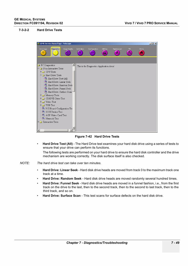
GE MEDICAL SYSTEMSDIRECTION FC091194, REVISION 02 VIVID 7 / VIVID 7 PRO SERVICE MANUAL
Chapter 7 - Diagnostics/Troubleshooting 7 - 49
7-3-2-2 Hard Drive Tests
• Hard Drive Test (All) - The Hard Drive test examines your hard disk drive using a series of tests to ensure that your drive can perform its functions.The following tests are performed on your hard drive to ensure the hard disk controller and the drive mechanism are working correctly. The disk surface itself is also checked.
NOTE: The hard drive test can take over ten minutes.
• Hard Drive: Linear Seek - Hard disk drive heads are moved from track 0 to the maximum track one track at a time.
• Hard Drive: Random Seek - Hard disk drive heads are moved randomly several hundred times.• Hard Drive: Funnel Seek - Hard disk drive heads are moved in a funnel fashion, i.e., from the first
track on the drive to the last, then to the second track, then to the second to last track, then to the third track, and so on.
• Hard Drive: Surface Scan - This test scans for surface defects on the hard disk drive.
Figure 7-42 Hard Drive Tests
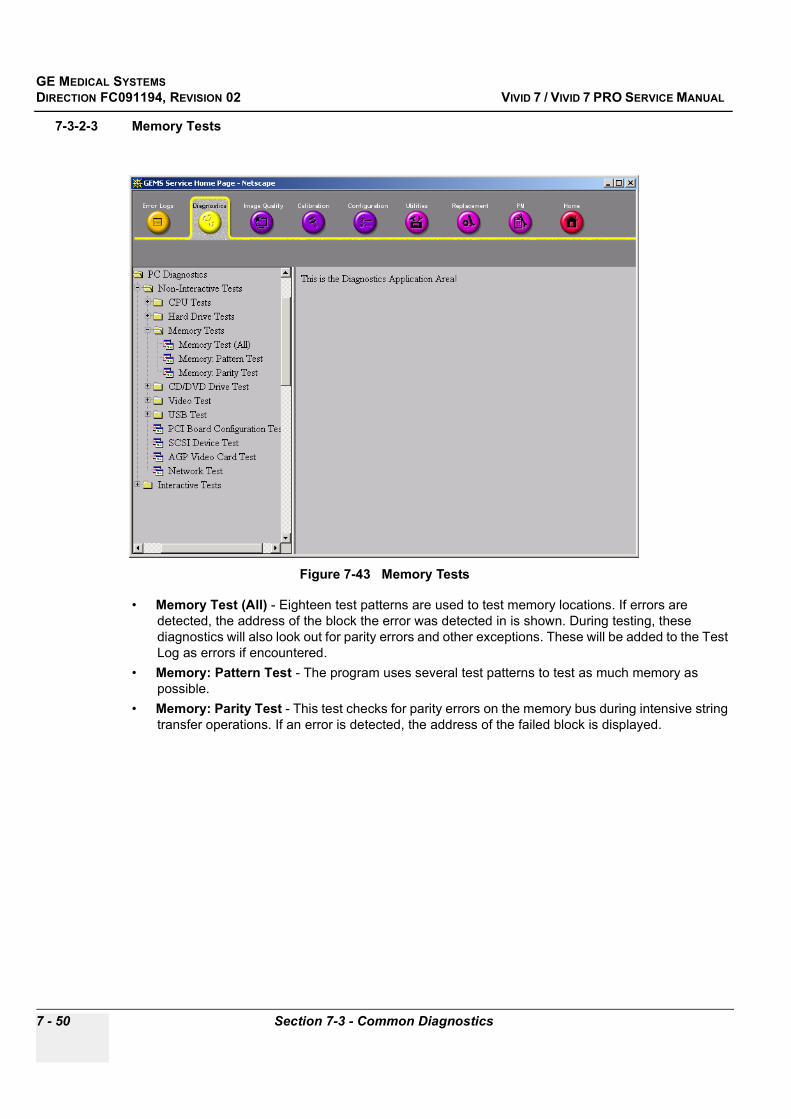
GE MEDICAL SYSTEMSDIRECTION FC091194, REVISION 02 VIVID 7 / VIVID 7 PRO SERVICE MANUAL
7 - 50 Section 7-3 - Common Diagnostics
7-3-2-3 Memory Tests
• Memory Test (All) - Eighteen test patterns are used to test memory locations. If errors are detected, the address of the block the error was detected in is shown. During testing, these diagnostics will also look out for parity errors and other exceptions. These will be added to the Test Log as errors if encountered.
• Memory: Pattern Test - The program uses several test patterns to test as much memory as possible.
• Memory: Parity Test - This test checks for parity errors on the memory bus during intensive string transfer operations. If an error is detected, the address of the failed block is displayed.
Figure 7-43 Memory Tests
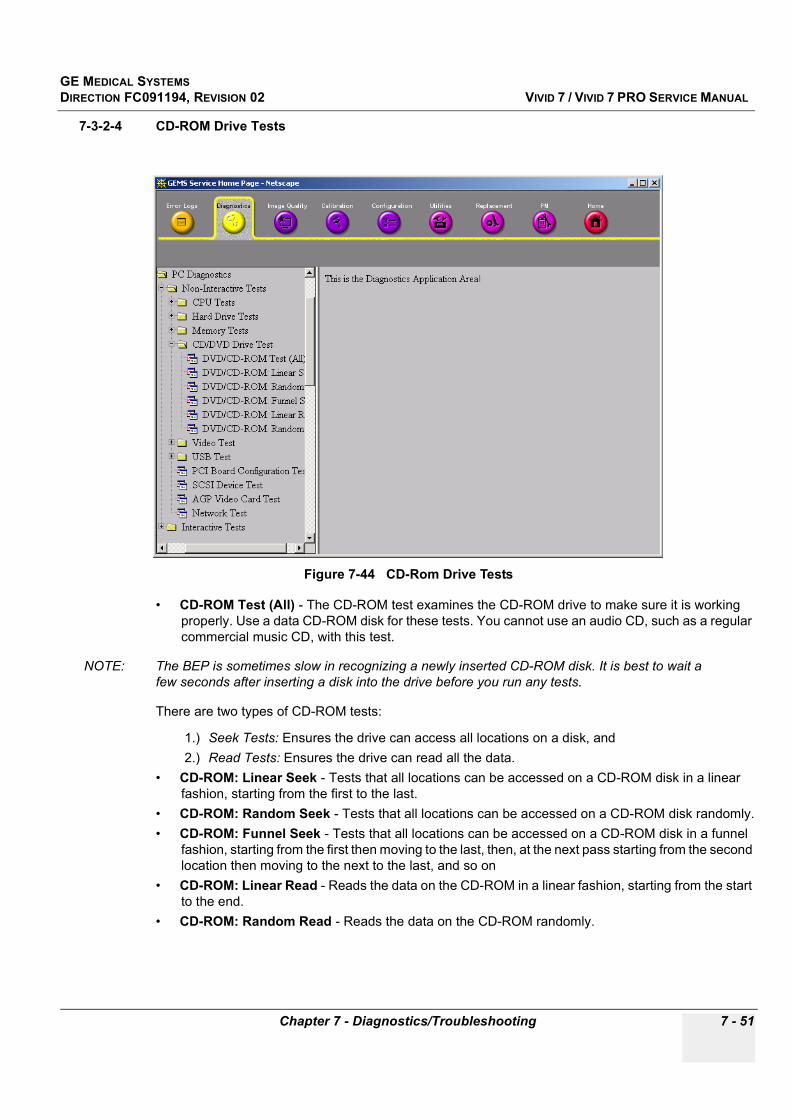
GE MEDICAL SYSTEMSDIRECTION FC091194, REVISION 02 VIVID 7 / VIVID 7 PRO SERVICE MANUAL
Chapter 7 - Diagnostics/Troubleshooting 7 - 51
7-3-2-4 CD-ROM Drive Tests
• CD-ROM Test (All) - The CD-ROM test examines the CD-ROM drive to make sure it is working properly. Use a data CD-ROM disk for these tests. You cannot use an audio CD, such as a regular commercial music CD, with this test.
NOTE: The BEP is sometimes slow in recognizing a newly inserted CD-ROM disk. It is best to wait a few seconds after inserting a disk into the drive before you run any tests.
There are two types of CD-ROM tests:
1.) Seek Tests: Ensures the drive can access all locations on a disk, and 2.) Read Tests: Ensures the drive can read all the data.
• CD-ROM: Linear Seek - Tests that all locations can be accessed on a CD-ROM disk in a linear fashion, starting from the first to the last.
• CD-ROM: Random Seek - Tests that all locations can be accessed on a CD-ROM disk randomly.• CD-ROM: Funnel Seek - Tests that all locations can be accessed on a CD-ROM disk in a funnel
fashion, starting from the first then moving to the last, then, at the next pass starting from the second location then moving to the next to the last, and so on
• CD-ROM: Linear Read - Reads the data on the CD-ROM in a linear fashion, starting from the start to the end.
• CD-ROM: Random Read - Reads the data on the CD-ROM randomly.
Figure 7-44 CD-Rom Drive Tests

GE MEDICAL SYSTEMSDIRECTION FC091194, REVISION 02 VIVID 7 / VIVID 7 PRO SERVICE MANUAL
7 - 52 Section 7-3 - Common Diagnostics
7-3-2-5 Video Test
• Video Test (All) - This diagnostic tests your system's video capabilities. This involves testing the video memory with 18 patterns, testing your graphics acceleration, and text output. You will see these tests being performed on your monitor.You can cancel this test at any time by hitting the Escape (Esc) key.
The following tests are performed on your monitor:
• Video: Memory - Video memory is tested by filling the video buffer with 18 test patterns, one pattern at a time. The tests will fill the entire screen with a single color.
• Video: Data Transfer - This tests the graphics acceleration part of your video controller. These tests will appear on your screen as black and white concentric squares and rectangles of various sizes and colors. If errors are detected, the locations of the problems are displayed.
• Video: Text Output - This test prints a text string in random sizes and colors to tests your video device driver and video controller.
7-3-2-6 PCI Board Configuration TestA bus is a set of circuits, wires or connectors which connect the various components of your system. A PCI (Peripheral Component Interconnect) bus is a fast standard bus which is common in Pentium systems. Various tests are run on the PCI bus in order to ensure it is working up to speed.
The motherboard is scanned to verify the configuration space and to make sure the diagnostics can communicate with the board.
Figure 7-45 Video Tests
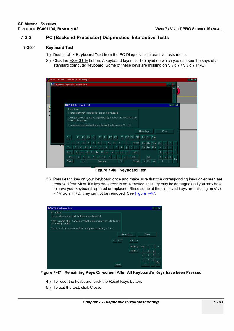
GE MEDICAL SYSTEMSDIRECTION FC091194, REVISION 02 VIVID 7 / VIVID 7 PRO SERVICE MANUAL
Chapter 7 - Diagnostics/Troubleshooting 7 - 53
7-3-3 PC (Backend Processor) Diagnostics, Interactive Tests
7-3-3-1 Keyboard Test
1.) Double-click Keyboard Test from the PC Diagnostics interactive tests menu.2.) Click the EXECUTE button. A keyboard layout is displayed on which you can see the keys of a
standard computer keyboard. Some of these keys are missing on Vivid 7 / Vivid 7 PRO.
3.) Press each key on your keyboard once and make sure that the corresponding keys on-screen are removed from view. If a key on-screen is not removed, that key may be damaged and you may have to have your keyboard repaired or replaced. Since some of the displayed keys are missing on Vivid 7 / Vivid 7 PRO, they cannot be removed. See Figure 7-47.
4.) To reset the keyboard, click the Reset Keys button. 5.) To exit the test, click Close.
Figure 7-46 Keyboard Test
Figure 7-47 Remaining Keys On-screen After All Keyboard’s Keys have been Pressed

GE MEDICAL SYSTEMSDIRECTION FC091194, REVISION 02 VIVID 7 / VIVID 7 PRO SERVICE MANUAL
7 - 54 Section 7-3 - Common Diagnostics
7-3-3-2 Audio Test
1.) Double-click Audio Test from the PC Diagnostic interactive tests menu.
2.) To test the WAV sound reproduction click Left Channel, Right Channel, or Both Channels to test your speakers. You should hear a guitar chord.
3.) To test MIDI sound reproduction click the button under MIDI. You should hear a few seconds of recorded music.
4.) Click on the Beep button. You should hear a low “beep” from your Backend Processor. (It may be difficult to hear due to noise from the fan.
If no sound is produced in these tests, choose the More Info button in the Audio Test dialog box for information about possible causes and solutions.
Figure 7-48 Sound Tests
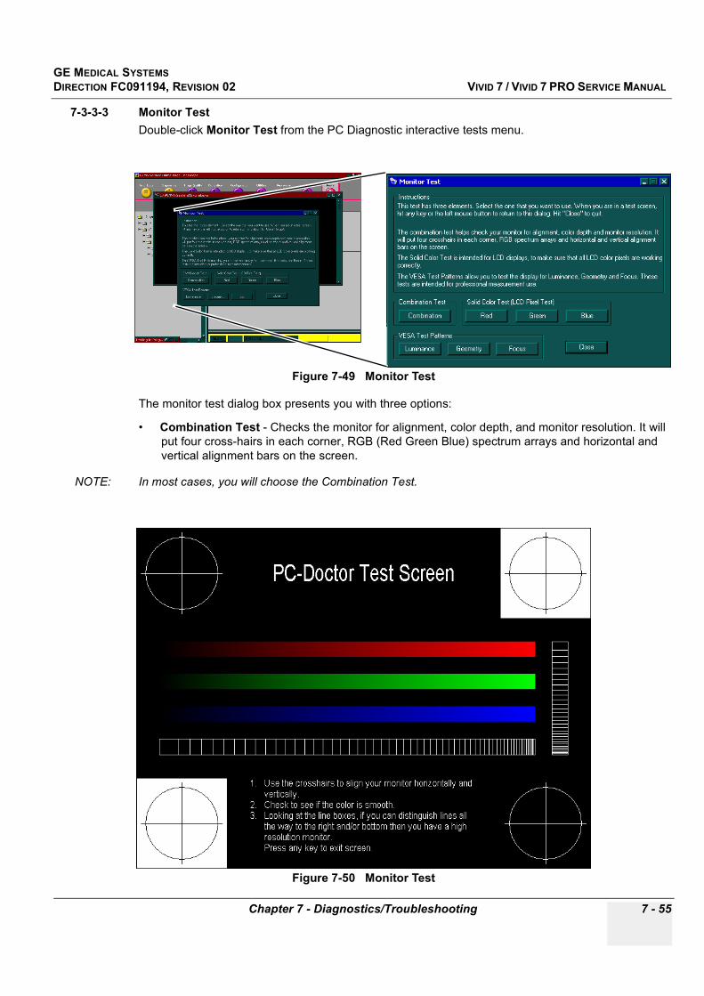
GE MEDICAL SYSTEMSDIRECTION FC091194, REVISION 02 VIVID 7 / VIVID 7 PRO SERVICE MANUAL
Chapter 7 - Diagnostics/Troubleshooting 7 - 55
7-3-3-3 Monitor TestDouble-click Monitor Test from the PC Diagnostic interactive tests menu.
The monitor test dialog box presents you with three options:
• Combination Test - Checks the monitor for alignment, color depth, and monitor resolution. It will put four cross-hairs in each corner, RGB (Red Green Blue) spectrum arrays and horizontal and vertical alignment bars on the screen.
NOTE: In most cases, you will choose the Combination Test.
Figure 7-49 Monitor Test
Figure 7-50 Monitor Test
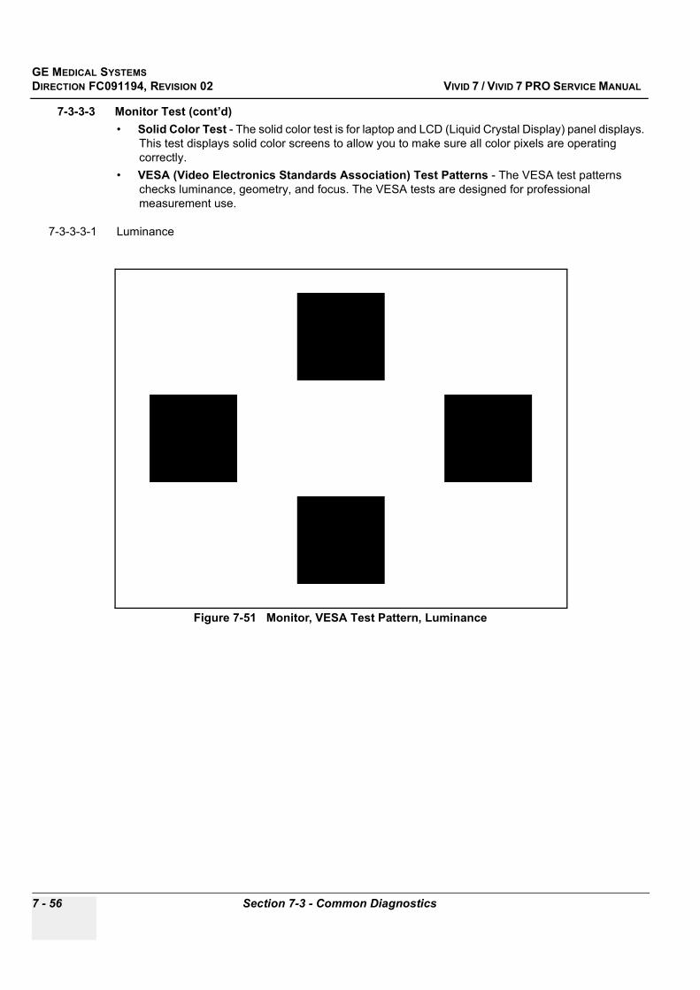
GE MEDICAL SYSTEMSDIRECTION FC091194, REVISION 02 VIVID 7 / VIVID 7 PRO SERVICE MANUAL
7 - 56 Section 7-3 - Common Diagnostics
7-3-3-3 Monitor Test (cont’d)• Solid Color Test - The solid color test is for laptop and LCD (Liquid Crystal Display) panel displays.
This test displays solid color screens to allow you to make sure all color pixels are operating correctly.
• VESA (Video Electronics Standards Association) Test Patterns - The VESA test patterns checks luminance, geometry, and focus. The VESA tests are designed for professional measurement use.
7-3-3-3-1 Luminance
Figure 7-51 Monitor, VESA Test Pattern, Luminance

GE MEDICAL SYSTEMSDIRECTION FC091194, REVISION 02 VIVID 7 / VIVID 7 PRO SERVICE MANUAL
Chapter 7 - Diagnostics/Troubleshooting 7 - 57
7-3-3-3 Monitor Test (cont’d)
7-3-3-3-2 Geometry
Figure 7-52 Monitor, VESA Test Pattern, Geometry
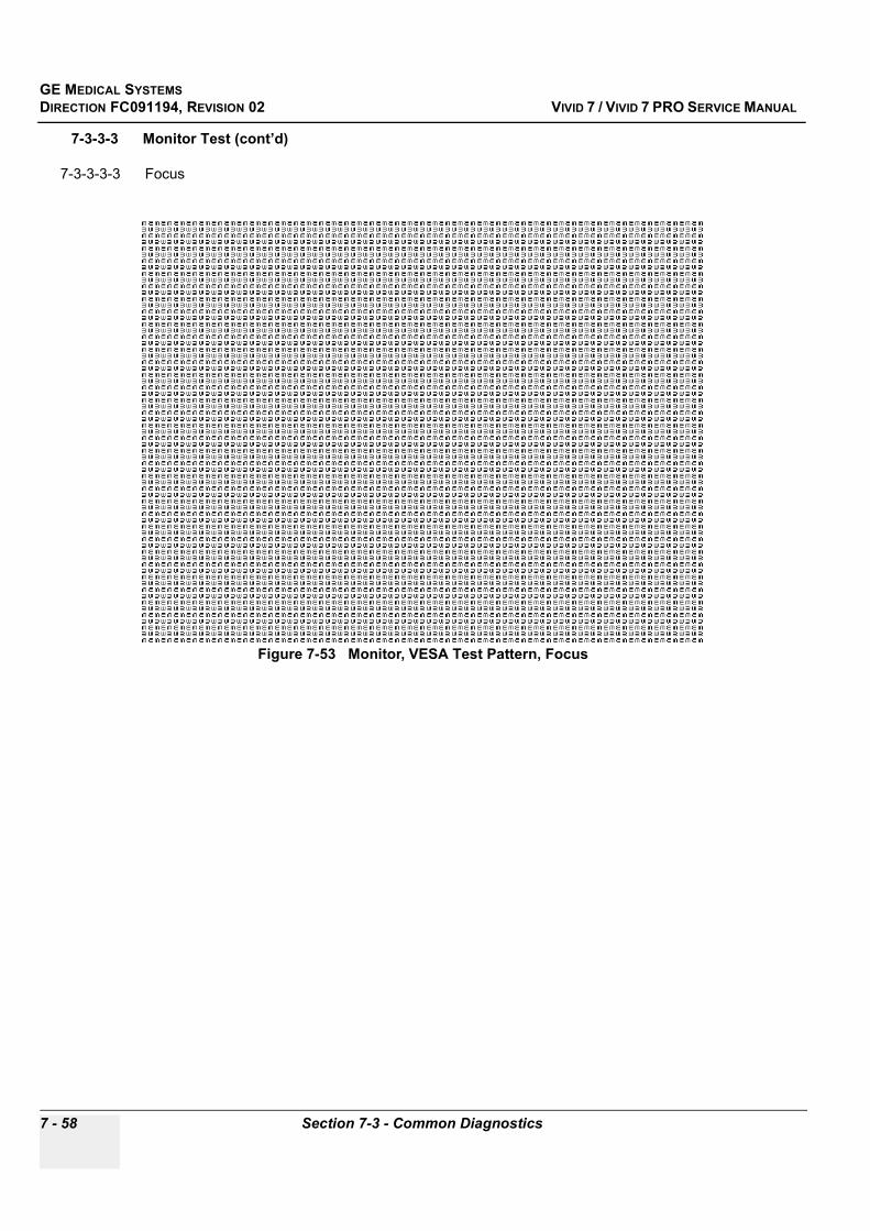
GE MEDICAL SYSTEMSDIRECTION FC091194, REVISION 02 VIVID 7 / VIVID 7 PRO SERVICE MANUAL
7 - 58 Section 7-3 - Common Diagnostics
7-3-3-3 Monitor Test (cont’d)
7-3-3-3-3 Focus
Figure 7-53 Monitor, VESA Test Pattern, Focus
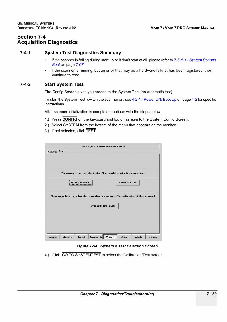
GE MEDICAL SYSTEMSDIRECTION FC091194, REVISION 02 VIVID 7 / VIVID 7 PRO SERVICE MANUAL
Chapter 7 - Diagnostics/Troubleshooting 7 - 59
Section 7-4 Acquisition Diagnostics
7-4-1 System Test Diagnostics Summary• If the scanner is failing during start up or it don’t start at all, please refer to 7-5-1-1 - System Doesn’t
Boot on page 7-67.• If the scanner is running, but an error that may be a hardware failure, has been registered, then
continue to read.
7-4-2 Start System TestThe Config Screen gives you access to the System Test (an automatic test).
To start the System Test, switch the scanner on, see 4-2-1 - Power ON/ Boot Up on page 4-2 for specific instructions.
After scanner initialization is complete, continue with the steps below;
1.) Press CONFIG on the keyboard and log on as adm to the System Config Screen. 2.) Select SYSTEM from the bottom of the menu that appears on the monitor.3.) If not selected, click TEST..
4.) Click GO TO SYSTEMTEST to select the Calibration/Test screen.
Figure 7-54 System > Test Selection Screen

GE MEDICAL SYSTEMSDIRECTION FC091194, REVISION 02 VIVID 7 / VIVID 7 PRO SERVICE MANUAL
7 - 60 Section 7-4 - Acquisition Diagnostics
7-4-3 Beamformer CalibrationWhen following the steps in 7-4-2 - Start System Test on page 7-59, the default screen will be the Calibration Screen.
From the Calibration Screen you can;
• Do DC Offset Calibration (DC Offs. Cal) of the A/D converters in the Front End.• Reset the calibration (Cal. Reset) to the factory default setting.• Show a graph regarding the calibration (Show graph).• Deselect/Select channels are used in manufacturing to isolate noisy channels (Channel Control).
With a linear probe connected to the system, it is possible to disconnect groups of channels either on the TX Board or on the RX Board to isolate the noise source.
• The buttons in the lower part of the screen are used for board testing (see 7-4-4 - System Test on page 7-61).
To start a test, click the respective button.
The “LEDs” in Figure 7-55 will change color when a test has been done;
• Green indicates that the test passed.• Red indicates that the test failed.
Figure 7-55 Calibration Dialog
Channel Control(used for factory tests)
DC Offs. Cal
Cal. Reset
Show graph
“LEDs”Gray - Test not doneGreen - Test PassedRed - Test failed

GE MEDICAL SYSTEMSDIRECTION FC091194, REVISION 02 VIVID 7 / VIVID 7 PRO SERVICE MANUAL
Chapter 7 - Diagnostics/Troubleshooting 7 - 61
7-4-4 System Test
7-4-4-1 Select the Test ScreenFrom the Calibration Screen, select TEST or click one of the buttons (not CAL) in the lower part of the screen. See Figure 7-56 - Select Test Window.
The System Test Screen gives you access to the tests needed for troubleshooting the Front End Card Rack.
Figure 7-56 Select Test Window
Figure 7-57 System Test Screen
Press TEST or press one of these buttons
“Block Diagram” with single tests
Progress field
Module Specific Tests Data field
Mode select: Test or Calibration
Module Name etc.
Status field
System: Test All, Break
Test loops
Status Light
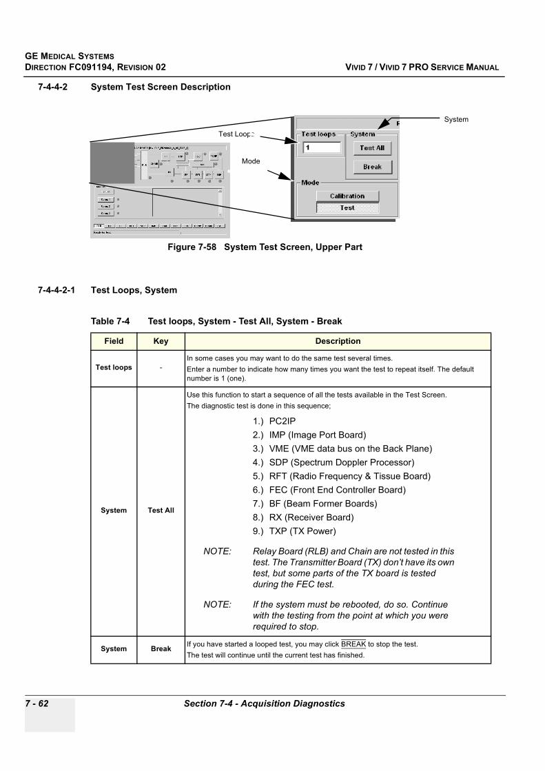
GE MEDICAL SYSTEMSDIRECTION FC091194, REVISION 02 VIVID 7 / VIVID 7 PRO SERVICE MANUAL
7 - 62 Section 7-4 - Acquisition Diagnostics
7-4-4-2 System Test Screen Description
7-4-4-2-1 Test Loops, System
Figure 7-58 System Test Screen, Upper Part
Table 7-4 Test loops, System - Test All, System - Break
Field Key Description
Test loops -In some cases you may want to do the same test several times. Enter a number to indicate how many times you want the test to repeat itself. The default number is 1 (one).
System Test All
Use this function to start a sequence of all the tests available in the Test Screen. The diagnostic test is done in this sequence;
1.) PC2IP2.) IMP (Image Port Board)3.) VME (VME data bus on the Back Plane)4.) SDP (Spectrum Doppler Processor)5.) RFT (Radio Frequency & Tissue Board)6.) FEC (Front End Controller Board) 7.) BF (Beam Former Boards)8.) RX (Receiver Board)9.) TXP (TX Power)
NOTE: Relay Board (RLB) and Chain are not tested in this test. The Transmitter Board (TX) don’t have its own test, but some parts of the TX board is tested during the FEC test.
NOTE: If the system must be rebooted, do so. Continue with the testing from the point at which you were required to stop.
System Break If you have started a looped test, you may click BREAK to stop the test. The test will continue until the current test has finished.
System
Test Loops
Mode

GE MEDICAL SYSTEMSDIRECTION FC091194, REVISION 02 VIVID 7 / VIVID 7 PRO SERVICE MANUAL
Chapter 7 - Diagnostics/Troubleshooting 7 - 63
7-4-4-2 System Test Screen Description (cont’d)
7-4-4-2-2 Mode (Calibration/Test Screen Selection)
7-4-4-2-3 “Block Schematics” with Single TestsClick one of the buttons in the “block schematics” in the upper part of the screen (or one of the duplicate buttons in the lower row of the screen) to select a particular test.
Some of the tests are described after the figure.
7-4-4-2-4 Receiver Board (RX) Test
Table 7-5 Mode (Calibration/Test Screen selection)
Field Key Description
Mode
The buttons in this field are used to select the Calibration Screen or the Test Screen.
Calibration Click this button to select the Calibration Screen.
Test Click this button to select the Test Screen.
Figure 7-59 Diagnostics Test Screen, Upper Part
Table 7-6 Receiver Board (RX) Test
Test (Key) Sub-tests Description
RX
Receiver Board (RX)
Test AllActivates the following tests, in sequence, see description for each sub test;
• RECV0• RECV1
RECV.0 Max Gain test for RX using FEC signal generator.
RECV.1 Reduced Gain test for RX using FEC signal generator.
Block Schematics
GE MEDICAL SYSTEMSDIRECTION FC091194, REVISION 02 VIVID 7 / VIVID 7 PRO SERVICE MANUAL
7 - 64 Section 7-4 - Acquisition Diagnostics
7-4-4-2 System Test Screen Description (cont’d)
7-4-4-2-5 Relay Board Test
NOTE: A Test Attenuator, Part Number AA200215 is needed for this test.
7-4-4-2-6 Chain (Signal Chain, RLB/RX/BF Test)
NOTE: A Test Attenuator, Part Number AA200215 is needed for this test.
Table 7-7 Relay Board (RLB) Test
Test (Key) Sub-tests Description
RLB
Relay Board (RLB)
Test All
Activates the following tests, in sequence (see the descriptions for the tests below);1. Conn. 12. Conn. 23. Conn. 3
Conn. 1 Max Gain test for RX using the signal generator on the Front End Controller (FEC) and a Test Attenuator, Part Number AA200215, in left (active) probe connector.
Conn. 2 Max Gain test for RX using the signal generator on the Front End Controller (FEC) and a Test Attenuator, Part Number AA200215, in mid (active) probe connector.
Conn. 3 Max Gain test for RX using the signal generator on the Front End Controller (FEC) and a Test Attenuator, Part Number AA200215, in right probe connector.
Table 7-8 Signal Chain (TX/RLB/RX/BF) Test
Test (Key) Sub-tests Description
Chain
Signal Chain Test (Chain)The Signal Chain/ Data Flow test checks for errors in the TX, RLY, RX and BF chain of data flow.
Test All Not Used.
TX/RLB/RX/BF
Tests data flow in Front End Transmit Receive signal chain.If an error occurs with this test, testing should be continued in the following order;1. BF digital and analog test2. RX test 3. RLY test.

GE MEDICAL SYSTEMSDIRECTION FC091194, REVISION 02 VIVID 7 / VIVID 7 PRO SERVICE MANUAL
Chapter 7 - Diagnostics/Troubleshooting 7 - 65
7-4-5 Beamformer Calibration (Front End Alignment)Beamformer Calibrations are performed to calibrate each ADC channel of the two Beam Former (BF) board inputs. The system calibrates the Beamformer ADCs to zero output when there is no signal on the input.
These bias voltages are stored on hard disk in Backend Processor.
7-4-5-1 When to Use this ProcedureThis procedure should be performed;
• when installing a new Vivid 7 / Vivid 7 PRO• after software has been updated or replaced• when BF boards have been interchanged • when a BF board has been replaced • when the Backend Processor has been replaced
7-4-5-2 Front End Alignment Procedure
1.) Disconnect all connected probes.2.) Turn on the scanner.3.) Press CONFIG and log in as adm4.) Click SYSTEM
5.) Click DC OFFS. CAL to start the DC Offset calibration of the Beam Formers (Front End Alignment).
Figure 7-60 Calibration Dialog
Channel Control
DC Offs. Cal
Cal. Reset
Show graph

GE MEDICAL SYSTEMSDIRECTION FC091194, REVISION 02 VIVID 7 / VIVID 7 PRO SERVICE MANUAL
7 - 66 Section 7-4 - Acquisition Diagnostics
7-4-5-2 Front End Alignment Procedure (cont’d)Front End Alignment Description
- Each A/D converter will get 0V input (by setting ATGC to minimum). - One by one channel will be digitized and the result put in the IQ buffer on the RFT board. - The BEP will then read the IQ buffer and computes a value per channel. These computed
values are compared to an upper/lower limit. - If all read values are ok, the message PASSED will appear. If values exceeding the limits are
read, the system will prompt you with FAILED and a message will tell you which BF board is bad.
- The resulting offsets for each channel are stored in a file on the Backend Processor’s hard disk.
- The values can be plotted in a diagram (click SHOW GRAPH).
6.) Always reboot the scanner after Front End Alignment is finished and verify proper operation.
NOTE: Do Not select “Cal Reset” after performing calibration. This will destroy the file located on the Backend Processor and the image quality will not be optimized.
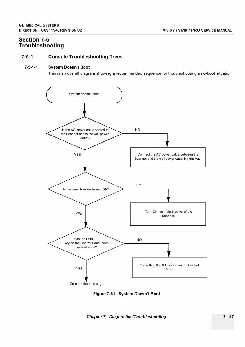
GE MEDICAL SYSTEMSDIRECTION FC091194, REVISION 02 VIVID 7 / VIVID 7 PRO SERVICE MANUAL
Chapter 7 - Diagnostics/Troubleshooting 7 - 67
Section 7-5Troubleshooting
7-5-1 Console Troubleshooting Trees
7-5-1-1 System Doesn’t BootThis is an overall diagram showing a recommended sequence for troubleshooting a no-boot situation.
Figure 7-61 System Doesn’t Boot
System doesn’t boot!
Connect the AC power cable between the Scanner and the wall power outlet in right way.
YES
YES
NO
Turn ON the main breaker of the Scanner.
Go on to the next page.
NO
Is the AC power cable seated to the Scanner and to the wall power
outlet?
Is the main breaker turned ON?
Press the ON/OFF button on the Control Panel.
NOHas the ON/OFF key on the Control Panel been
pressed once?
YES
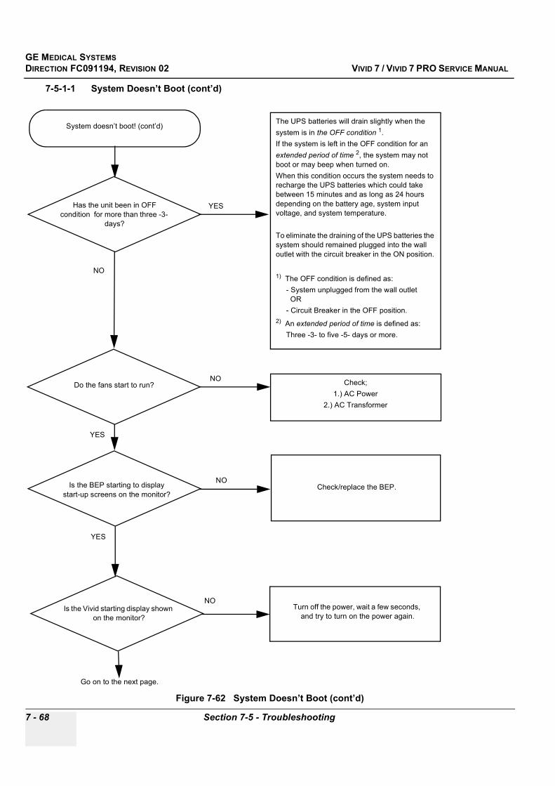
GE MEDICAL SYSTEMSDIRECTION FC091194, REVISION 02 VIVID 7 / VIVID 7 PRO SERVICE MANUAL
7 - 68 Section 7-5 - Troubleshooting
7-5-1-1 System Doesn’t Boot (cont’d)
Figure 7-62 System Doesn’t Boot (cont’d)
System doesn’t boot! (cont’d)
NO
Check;1.) AC Power
2.) AC Transformer
Go on to the next page.
YESHas the unit been in OFF condition for more than three -3-
days?
Check/replace the BEP.
YES
NOIs the BEP starting to display start-up screens on the monitor?
Is the Vivid starting display shown on the monitor?
Turn off the power, wait a few seconds, and try to turn on the power again.
NO
The UPS batteries will drain slightly when the system is in the OFF condition 1. If the system is left in the OFF condition for an extended period of time 2, the system may not boot or may beep when turned on. When this condition occurs the system needs to recharge the UPS batteries which could take between 15 minutes and as long as 24 hours depending on the battery age, system input voltage, and system temperature.
To eliminate the draining of the UPS batteries the system should remained plugged into the wall outlet with the circuit breaker in the ON position.
1) The OFF condition is defined as: - System unplugged from the wall outlet OR - Circuit Breaker in the OFF position.2) An extended period of time is defined as: Three -3- to five -5- days or more.
YES
NODo the fans start to run?
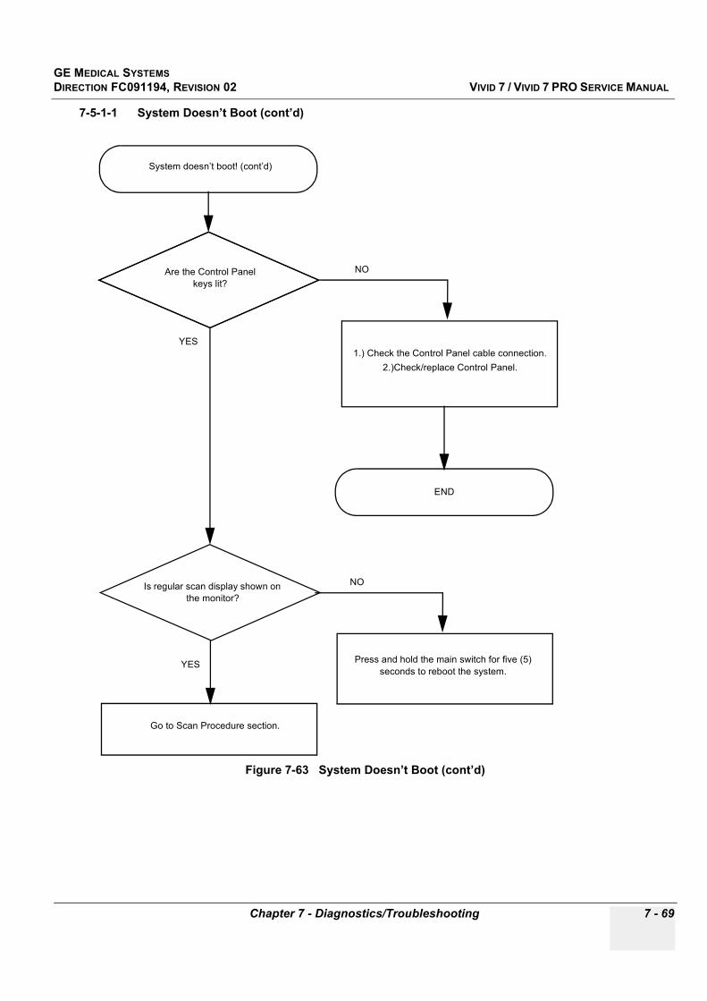
GE MEDICAL SYSTEMSDIRECTION FC091194, REVISION 02 VIVID 7 / VIVID 7 PRO SERVICE MANUAL
Chapter 7 - Diagnostics/Troubleshooting 7 - 69
7-5-1-1 System Doesn’t Boot (cont’d)
Figure 7-63 System Doesn’t Boot (cont’d)
System doesn’t boot! (cont’d)
1.) Check the Control Panel cable connection.2.)Check/replace Control Panel.
YES
YES
NOAre the Control Panelkeys lit?
Is regular scan display shown on the monitor?
Press and hold the main switch for five (5) seconds to reboot the system.
NO
Go to Scan Procedure section.
END

GE MEDICAL SYSTEMSDIRECTION FC091194, REVISION 02 VIVID 7 / VIVID 7 PRO SERVICE MANUAL
7 - 70 Section 7-5 - Troubleshooting
This page was intentionally left blank.
GE MEDICAL SYSTEMSDIRECTION FC091194, REVISION 02 VIVID 7 / VIVID 7 PRO SERVICE MANUAL
Chapter 8 - Replacement Procedures 8 - 1
Chapter 8 Replacement Procedures
Section 8-1Overview
8-1-1 Purpose of Chapter 8This chapter holds replacement procedures for the following modules/subsystems.
8-1-2 Warnings
Table 8-1 Contents in Chapter 8
Section DescriptionPage
Number
8-1 Overview 8-1
8-2 Plastic Parts Replacement Procedures 8-2
8-3 SW Loading Procedure 8-9
8-4 FRU Replacement Procedures 8-31
WARNINGWARNING AT LEAST TWO PERSONS ARE NEEDED WHEN REPLACING HEAVY PARTS LIKE THE MONITOR, THE FROGLEG AND THE AC TRANSFORMER.
WARNINGWARNING AT LEAST TWO PERSONS ARE NEEDED WHEN REPLACING CASTERS (WHEELS) OR ADJUSTING BRAKES.

GE MEDICAL SYSTEMSDIRECTION FC091194, REVISION 02 VIVID 7 / VIVID 7 PRO SERVICE MANUAL
8 - 2 Section 8-2 - Plastic Parts Replacement Procedures
Section 8-2 Plastic Parts Replacement Procedures
8-2-1 Overview of Covers and Bumpers
8-2-1-1 PreparationsShut down the system as described in "Power Shut Down" on page 4-5.
8-2-1-2 Order of removal is:
1.) Side Covers.2.) Filter Cover. 3.) Top Cover (fastened by screws).4.) Lower Rear Cover (Screws).5.) Front Cover (fastened by screws at each side).
Figure 8-1 Plastic parts
Front Panel Filter Cover
Top Cover
Lower Rear Cover
Left Side Cover Right Side Cover
Front Bumper
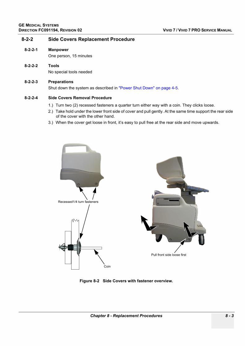
GE MEDICAL SYSTEMSDIRECTION FC091194, REVISION 02 VIVID 7 / VIVID 7 PRO SERVICE MANUAL
Chapter 8 - Replacement Procedures 8 - 3
8-2-2 Side Covers Replacement Procedure
8-2-2-1 ManpowerOne person, 15 minutes
8-2-2-2 ToolsNo special tools needed
8-2-2-3 PreparationsShut down the system as described in "Power Shut Down" on page 4-5.
8-2-2-4 Side Covers Removal Procedure
1.) Turn two (2) recessed fasteners a quarter turn either way with a coin. They clicks loose.2.) Take hold under the lower front side of cover and pull gently. At the same time support the rear side
of the cover with the other hand.3.) When the cover get loose in front, it’s easy to pull free at the rear side and move upwards.
Figure 8-2 Side Covers with fastener overview.
Coin
Recessed1/4 turn fasteners
Pull front side loose first

GE MEDICAL SYSTEMSDIRECTION FC091194, REVISION 02 VIVID 7 / VIVID 7 PRO SERVICE MANUAL
8 - 4 Section 8-2 - Plastic Parts Replacement Procedures
8-2-2-4 Side Covers Removal Procedure (cont’d)4.) Lift Side Cover gently upwards until the three hooks are free from Top Cover Retainer (See Figure
8-3).5.) To Remove Left side cover, repeat this procedure.
8-2-2-5 Side Covers Installation Procedure
1.) Guide hooks at the top of Side Cover into their slots in Top Cover (See Figure 8-3).2.) Install Side Cover. Push rear side first in position locked in Lower Rear Cover.3.) Push the front side in position locked in Front Cover.4.) Turn the 1/4 turn screws until the slot is vertical.
Figure 8-3 Side Cover installment
Top Cover slots
Side Cover hooks
1
2 34
GE MEDICAL SYSTEMSDIRECTION FC091194, REVISION 02 VIVID 7 / VIVID 7 PRO SERVICE MANUAL
Chapter 8 - Replacement Procedures 8 - 5
8-2-3 Front Cover Replacement Procedure
8-2-3-1 ManpowerOne person, 30 minutes
8-2-3-2 ToolsPhillips screwdriver
8-2-3-3 Preparations
1.) Shut down the system as described in "Power Shut Down" on page 4-5.2.) Disconnect all Probes and I/O cabling. See User manual. 3.) Remove Side Covers as described in "Side Covers Removal Procedure" on page 8-3.
8-2-3-4 Front Cover Removal Procedure
1.) Unscrew five (5) Phillips screws that fasten it to the chassis.2.) Pull it outwards to free it from the Top Cover and Front Bumper (See Figure 8-4).
8-2-3-5 Front Cover Installation Procedure
1.) Thread the same, or a new, cover so it fits in between chassis and bumper (See Figure 8-4).2.) Thread it so it links together with Top Cover. You may have to loosen two (2) Phillips screws on the
top cover that are closest to the Front cover.3.) Fasten Front Cover with five (5x) Phillips screws.4.) Fasten two (2x) Phillips screws on Top Cover if these were loosened.5.) Install Side Covers as described in "Side Covers Installation Procedure" on page 8-4.6.) New Front Cover: Install correct labels, see "Labels Locations" on page 1-14.
Figure 8-4 Front Cover Replacement
ScrewsScrews

GE MEDICAL SYSTEMSDIRECTION FC091194, REVISION 02 VIVID 7 / VIVID 7 PRO SERVICE MANUAL
8 - 6 Section 8-2 - Plastic Parts Replacement Procedures
8-2-4 Filter Cover Replacement Procedure
8-2-4-1 ManpowerOne person, 5 minutes
8-2-4-2 ToolsNo special tools needed
8-2-4-3 Filter Cover Removal ProcedureTake hold at the lower side of Filter Cover and pull it loose from the chassis. Hook it off at the upper side and remove it.
8-2-4-4 Filter Cover Installation ProcedureAlign the cover at the upper side and push it into place along its lower side.
Figure 8-5 Filter Cover
Installation starts at the upper side
Filter Cover
Removal starts from the lower side
GE MEDICAL SYSTEMSDIRECTION FC091194, REVISION 02 VIVID 7 / VIVID 7 PRO SERVICE MANUAL
Chapter 8 - Replacement Procedures 8 - 7
8-2-5 Filter Replacement Procedure
8-2-5-1 ManpowerOne person, 30 minutes
8-2-5-2 ToolsNo special tools are needed
8-2-5-3 Filter Replacement Procedure
1.) Remove Filter Cover as described in "Filter Cover Removal Procedure" on page 8-6.2.) Pull out plastic plugs and remove the filter.
Two different Plastic plugs have been used, the one to the left on early Vivid 7 scanners and the type to the right on newer units (both Vivid 7 and Vivid 7 PRO).
3.) Install a new or a cleaned filter (GE Vingmed Part No: FB307903). Use plastic plugs shown to the right (GE Vingmed Part No: 080X6520)
4.) Install Filter Cover as described in "Filter Cover Installation Procedure" on page 8-6.
Figure 8-6 Filter Cover and Filter
Figure 8-7 Plug replacement
FilterPlastic plugsFilter Cover
Replace this plug… with this plug
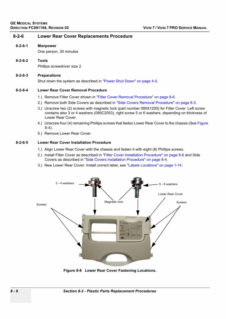
GE MEDICAL SYSTEMSDIRECTION FC091194, REVISION 02 VIVID 7 / VIVID 7 PRO SERVICE MANUAL
8 - 8 Section 8-2 - Plastic Parts Replacement Procedures
8-2-6 Lower Rear Cover Replacements Procedure
8-2-6-1 ManpowerOne person, 30 minutes
8-2-6-2 ToolsPhillips screwdriver size 2
8-2-6-3 PreparationsShut down the system as described in "Power Shut Down" on page 4-5.
8-2-6-4 Lower Rear Cover Removal Procedure
1.) Remove Filter Cover shown in "Filter Cover Removal Procedure" on page 8-6.2.) Remove both Side Covers as described in "Side Covers Removal Procedure" on page 8-3.3.) Unscrew two (2) screws with magnetic lock (part number 080X1200) for Filter Cover. Left screw
contains also 3 or 4 washers (080C2053), right screw 5 or 6 washers, depending on thickness of Lower Rear Cover.
4.) Unscrew four (4) remaining Phillips screws that fasten Lower Rear Cover to the chassis (See Figure 8-4).
5.) Remove Lower Rear Cover.
8-2-6-5 Lower Rear Cover Installation Procedure
1.) Align Lower Rear Cover with the chassis and fasten it with eight (8) Phillips screws.2.) Install Filter Cover as described in "Filter Cover Installation Procedure" on page 8-6 and Side
Covers as described in "Side Covers Installation Procedure" on page 8-4.3.) New Lower Rear Cover: Install correct label, see "Labels Locations" on page 1-14.
Figure 8-8 Lower Rear Cover Fastening Locations.
Screws
Lower Rear Cover
ScrewsMagnetic lock
5 - 6 washers3 - 4 washers
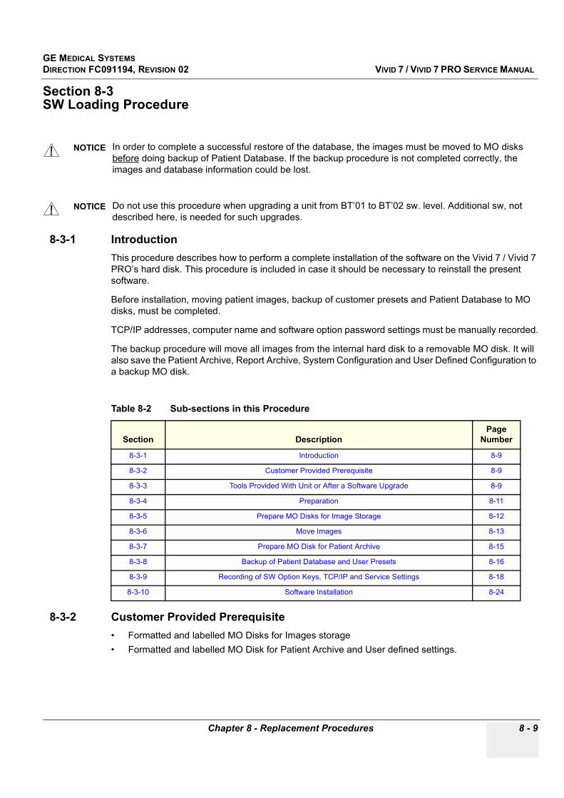
GE MEDICAL SYSTEMSDIRECTION FC091194, REVISION 02 VIVID 7 / VIVID 7 PRO SERVICE MANUAL
Chapter 8 - Replacement Procedures 8 - 9
Section 8-3SW Loading Procedure
8-3-1 IntroductionThis procedure describes how to perform a complete installation of the software on the Vivid 7 / Vivid 7 PRO’s hard disk. This procedure is included in case it should be necessary to reinstall the present software.
Before installation, moving patient images, backup of customer presets and Patient Database to MO disks, must be completed.
TCP/IP addresses, computer name and software option password settings must be manually recorded.
The backup procedure will move all images from the internal hard disk to a removable MO disk. It will also save the Patient Archive, Report Archive, System Configuration and User Defined Configuration to a backup MO disk.
8-3-2 Customer Provided Prerequisite• Formatted and labelled MO Disks for Images storage• Formatted and labelled MO Disk for Patient Archive and User defined settings.
NOTICE In order to complete a successful restore of the database, the images must be moved to MO disks before doing backup of Patient Database. If the backup procedure is not completed correctly, the images and database information could be lost.
NOTICE Do not use this procedure when upgrading a unit from BT’01 to BT’02 sw. level. Additional sw, not described here, is needed for such upgrades.
Table 8-2 Sub-sections in this Procedure
Section DescriptionPage
Number
8-3-1 Introduction 8-9
8-3-2 Customer Provided Prerequisite 8-9
8-3-3 Tools Provided With Unit or After a Software Upgrade 8-9
8-3-4 Preparation 8-11
8-3-5 Prepare MO Disks for Image Storage 8-12
8-3-6 Move Images 8-13
8-3-7 Prepare MO Disk for Patient Archive 8-15
8-3-8 Backup of Patient Database and User Presets 8-16
8-3-9 Recording of SW Option Keys, TCP/IP and Service Settings 8-18
8-3-10 Software Installation 8-24

GE MEDICAL SYSTEMSDIRECTION FC091194, REVISION 02 VIVID 7 / VIVID 7 PRO SERVICE MANUAL
8 - 10 Section 8-3 - SW Loading Procedure
8-3-3 Tools Provided With Unit or After a Software Upgrade
Table 8-3 CDs with BT’02-M4 Software, SW v.2.2.0
ITEM TITLE PART NUMBER DESCRIPTION
1 V7 SYSTEM SW CD, BEP-1 FC200165-04 Used for complete software installation
2 V7 SYSTEM SW CD, BEP-2 FC200265-03 Used for complete software installation
4 VIVID 7 & ECHOPAC PC APPL. SW FC200220-xx
Common CD for Vivid 7 / Vivid 7 PRO and EchoPAC PC
FC200220-01 is used for sw. 2.0.0 (BT02-M3)FC200220-02 is used for sw. 2.0.1 (L/R fix)
FC200220-03 is used for sw. 2.1.0 (BT02-M4-1)FC200220-04 is used for sw. 2.2.0 (BT02-M4-2)
Table 8-4 CDs with BT’01 Software, SW. v.1.x.x
ITEM TITLE PART NUMBER DESCRIPTION
1 Vivid 7, System SW installation CD, Disk 1 of 2
FC200165-01 or
FC200027-02
Used for complete software installation.- FC200165-01 is used for software v.1.0.1, v.1.1.0, v.1.1.1 and v.1.1.2
- FC200027-02 is used for software v.1.0.0
2 V7 SYSTEM SW UPGRADE CD FC200168-02 Used for update of C Drive when updating from BT01-M3 to BT01-M4
3Vivid 7/EchoPAC PC,
Application SW Installation CD, Disk 2 of 2
FC200090-xx
- FC200090-01 is used for software v.1.0.0- FC200090-02 is used for software v.1.0.1- FC200090-03 is used for software v.1.1.0- FC200090-04 is used for software v.1.1.1- FC200090-05 is used for software v.1.1.2- FC200090-06 is used for software v.1.1.3
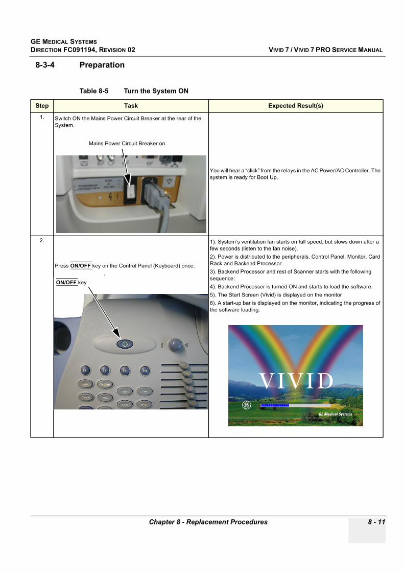
GE MEDICAL SYSTEMSDIRECTION FC091194, REVISION 02 VIVID 7 / VIVID 7 PRO SERVICE MANUAL
Chapter 8 - Replacement Procedures 8 - 11
8-3-4 Preparation
Table 8-5 Turn the System ON
Step Task Expected Result(s)
1. Switch ON the Mains Power Circuit Breaker at the rear of the System.
You will hear a “click” from the relays in the AC Power/AC Controller. The system is ready for Boot Up.
2.
Press ON/OFF key on the Control Panel (Keyboard) once..
1). System’s ventilation fan starts on full speed, but slows down after a few seconds (listen to the fan noise).2). Power is distributed to the peripherals, Control Panel, Monitor, Card Rack and Backend Processor.3). Backend Processor and rest of Scanner starts with the following sequence:4). Backend Processor is turned ON and starts to load the software.5). The Start Screen (Vivid) is displayed on the monitor6). A start-up bar is displayed on the monitor, indicating the progress of the software loading.
Mains Power Circuit Breaker on
ON/OFF key
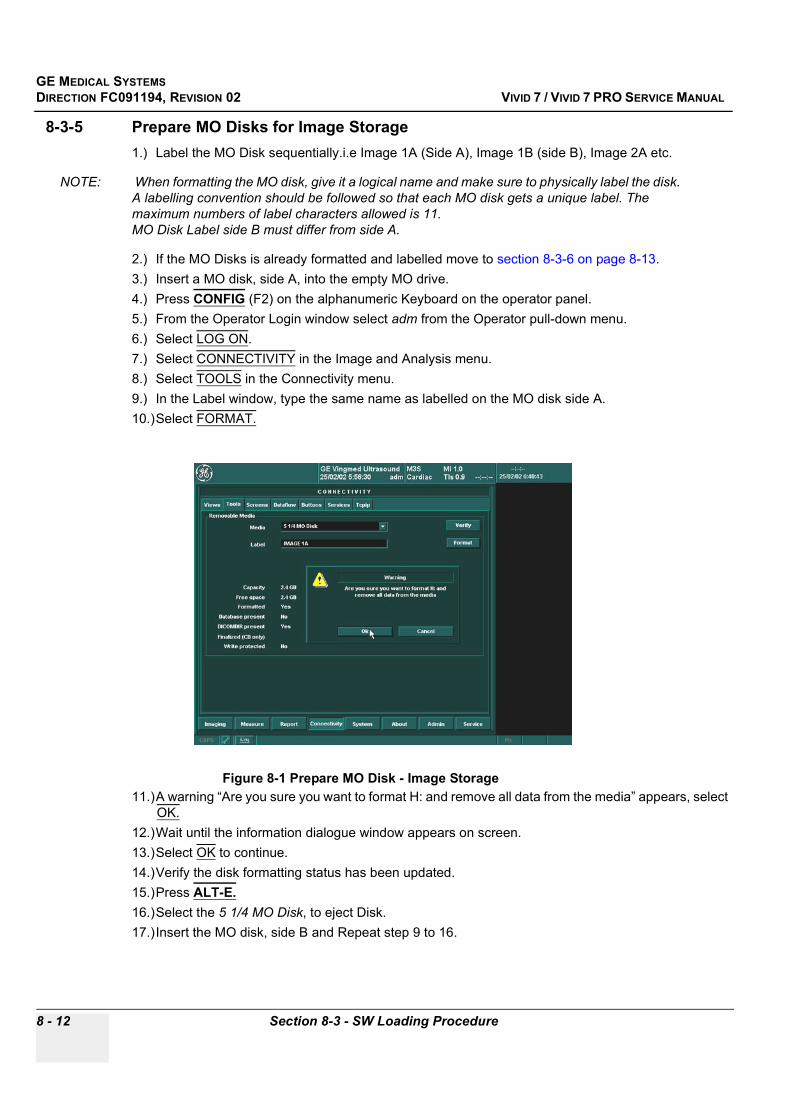
GE MEDICAL SYSTEMSDIRECTION FC091194, REVISION 02 VIVID 7 / VIVID 7 PRO SERVICE MANUAL
8 - 12 Section 8-3 - SW Loading Procedure
8-3-5 Prepare MO Disks for Image Storage1.) Label the MO Disk sequentially.i.e Image 1A (Side A), Image 1B (side B), Image 2A etc.
NOTE: When formatting the MO disk, give it a logical name and make sure to physically label the disk. A labelling convention should be followed so that each MO disk gets a unique label. The maximum numbers of label characters allowed is 11. MO Disk Label side B must differ from side A.
2.) If the MO Disks is already formatted and labelled move to section 8-3-6 on page 8-13.3.) Insert a MO disk, side A, into the empty MO drive.4.) Press CONFIG (F2) on the alphanumeric Keyboard on the operator panel.5.) From the Operator Login window select adm from the Operator pull-down menu.6.) Select LOG ON.7.) Select CONNECTIVITY in the Image and Analysis menu.8.) Select TOOLS in the Connectivity menu.9.) In the Label window, type the same name as labelled on the MO disk side A.10.)Select FORMAT.
11.)A warning “Are you sure you want to format H: and remove all data from the media” appears, select OK.
12.)Wait until the information dialogue window appears on screen.13.)Select OK to continue.14.)Verify the disk formatting status has been updated.15.)Press ALT-E.16.)Select the 5 1/4 MO Disk, to eject Disk.17.)Insert the MO disk, side B and Repeat step 9 to 16.
Figure 8-1 Prepare MO Disk - Image Storage

GE MEDICAL SYSTEMSDIRECTION FC091194, REVISION 02 VIVID 7 / VIVID 7 PRO SERVICE MANUAL
Chapter 8 - Replacement Procedures 8 - 13
8-3-6 Move ImagesThe Move Images function enables the movement of archived images from one volume/media to another and the deletion of the moved images from the original volume. The pointers to the database are restored in the new volume/media.
This function copies image data only, no database information is copied.
8-3-6-1 Moving Images from Local Archive to a Removable Media
1.) Insert a formatted MO Disk in the MO Drive.2.) Press ARCHIVE on the Operator Panel.
3.) Select MORE and press SELECT.
Figure 8-9 Search/Create Patient Window
Figure 8-10 Search/Create Patient Window
More
Move Images
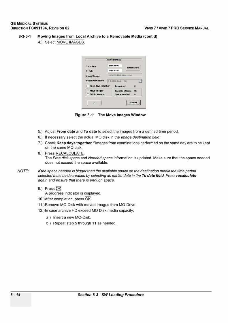
GE MEDICAL SYSTEMSDIRECTION FC091194, REVISION 02 VIVID 7 / VIVID 7 PRO SERVICE MANUAL
8 - 14 Section 8-3 - SW Loading Procedure
8-3-6-1 Moving Images from Local Archive to a Removable Media (cont’d)4.) Select MOVE IMAGES.
5.) Adjust From date and To date to select the images from a defined time period.6.) If necessary select the actual MO disk in the Image destination field.7.) Check Keep days together if images from examinations performed on the same day are to be kept
on the same MO disk.8.) Press RECALCULATE.
The Free disk space and Needed space information is updated. Make sure that the space needed does not exceed the space available.
NOTE: If the space needed is bigger than the available space on the destination media the time period selected must be decreased by selecting an earlier date in the To date field. Press recalculate again and ensure that there is enough space.
9.) Press OK.A progress indicator is displayed.
10.)After completion, press OK.11.)Remove MO-Disk with moved Images from MO-Drive.12.)In case archive HD exceed MO Disk media capacity;
a.) Insert a new MO-Disk.b.) Repeat step 5 through 11 as needed.
Figure 8-11 The Move Images Window
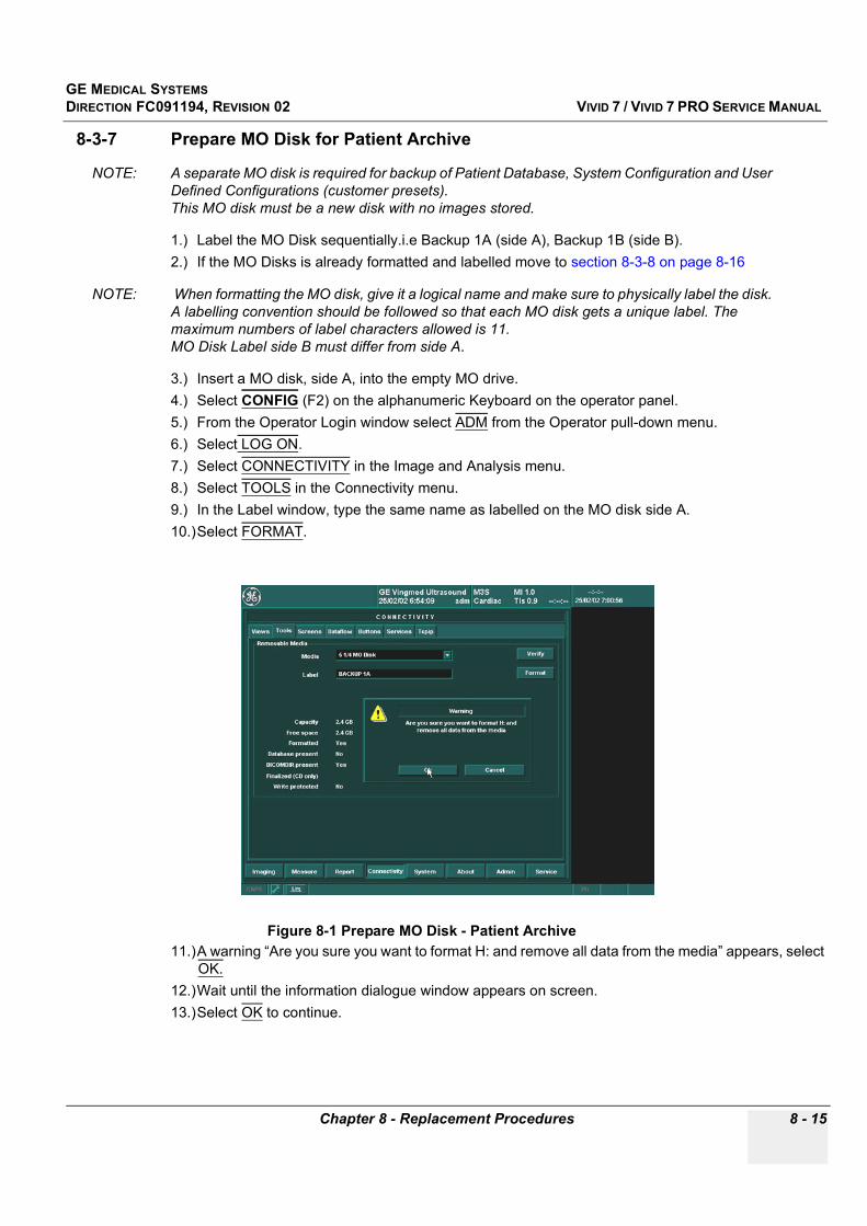
GE MEDICAL SYSTEMSDIRECTION FC091194, REVISION 02 VIVID 7 / VIVID 7 PRO SERVICE MANUAL
Chapter 8 - Replacement Procedures 8 - 15
8-3-7 Prepare MO Disk for Patient Archive
NOTE: A separate MO disk is required for backup of Patient Database, System Configuration and User Defined Configurations (customer presets).This MO disk must be a new disk with no images stored.
1.) Label the MO Disk sequentially.i.e Backup 1A (side A), Backup 1B (side B).2.) If the MO Disks is already formatted and labelled move to section 8-3-8 on page 8-16
NOTE: When formatting the MO disk, give it a logical name and make sure to physically label the disk. A labelling convention should be followed so that each MO disk gets a unique label. The maximum numbers of label characters allowed is 11. MO Disk Label side B must differ from side A.
3.) Insert a MO disk, side A, into the empty MO drive.4.) Select CONFIG (F2) on the alphanumeric Keyboard on the operator panel.5.) From the Operator Login window select ADM from the Operator pull-down menu.6.) Select LOG ON.7.) Select CONNECTIVITY in the Image and Analysis menu.8.) Select TOOLS in the Connectivity menu.9.) In the Label window, type the same name as labelled on the MO disk side A.10.)Select FORMAT.
11.)A warning “Are you sure you want to format H: and remove all data from the media” appears, select OK.
12.)Wait until the information dialogue window appears on screen.13.)Select OK to continue.
Figure 8-1 Prepare MO Disk - Patient Archive
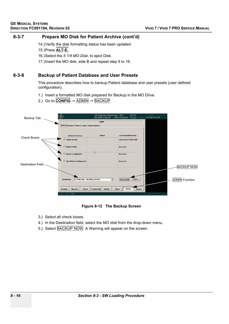
GE MEDICAL SYSTEMSDIRECTION FC091194, REVISION 02 VIVID 7 / VIVID 7 PRO SERVICE MANUAL
8 - 16 Section 8-3 - SW Loading Procedure
8-3-7 Prepare MO Disk for Patient Archive (cont’d)14.)Verify the disk formatting status has been updated.15.)Press ALT-E.16.)Select the 5 1/4 MO Disk, to eject Disk.17.)Insert the MO disk, side B and repeat step 9 to 16.
8-3-8 Backup of Patient Database and User PresetsThis procedure describes how to backup Patient database and user presets (user defined configuration).
1.) Insert a formatted MO disk prepared for Backup in the MO Drive.2.) Go to CONFIG -> ADMIN -> BACKUP.
3.) Select all check boxes.4.) In the Destination field, select the MO disk from the drop-down menu. 5.) Select BACKUP NOW. A Warning will appear on the screen.
Figure 8-12 The Backup Screen
ADMIN Function
Backup Tab
Check Boxes
Destination Field BACKUP NOW

GE MEDICAL SYSTEMSDIRECTION FC091194, REVISION 02 VIVID 7 / VIVID 7 PRO SERVICE MANUAL
Chapter 8 - Replacement Procedures 8 - 17
8-3-8 Backup of Patient Database and User Presets (cont’d).
NOTE: No process indicator will appear on screen. Verify that the “Finished, OK” Status appears in the Result column, and that the date appearing in the Last Successful Backup column is the current date and time. The backup is completed.
6.) Remove the Backup MO Disk when the backup is completed.
Figure 8-13 Backup Warning

GE MEDICAL SYSTEMSDIRECTION FC091194, REVISION 02 VIVID 7 / VIVID 7 PRO SERVICE MANUAL
8 - 18 Section 8-3 - SW Loading Procedure
8-3-9 Recording of SW Option Keys, TCP/IP and Service Settings
NOTE: Service Key is not required and should NOT be installed prior to Upgrade.
8-3-9-1 Record SW Option Keys
1.) Select CONFIG (F2) on the alphanumeric Keyboard on the operator panel.2.) From the Operator Login window select adm from the Operator pull-down menu.3.) Select LOG ON.4.) From ADMIN tab, select the SYSTEM ADMIN.
5.) Record SW Options Keys from SW Options Key window.
Figure 8-1 System Admin
WARNINGWARNING Make sure that the SW Option Keys (passwords) have been recorded correctly. If the key is incorrect, you will not be able to log on after the SW installation has been completed. The password is case sensitive. Hyphens must also be recorded. There may be more than one password.
Table 8-6 SW Options Keys
SW OPTIONS KEYS

GE MEDICAL SYSTEMSDIRECTION FC091194, REVISION 02 VIVID 7 / VIVID 7 PRO SERVICE MANUAL
Chapter 8 - Replacement Procedures 8 - 19
8-3-9-2 Record TCP/IP Settings
1.) Select CONNECTIVITY.2.) Select the TCPIP tab.3.) Record all settings in Table 8-7 on page 8-19.
Figure 8-14 TCP/IP Example Settings
Table 8-7 TCPIP Settings Table
FUNCTION SETTING
Computer Name
IP-Address
Subnet Mask
Default Gateway
Remote Archive IP-Address
Remote Archive Name

GE MEDICAL SYSTEMSDIRECTION FC091194, REVISION 02 VIVID 7 / VIVID 7 PRO SERVICE MANUAL
8 - 20 Section 8-3 - SW Loading Procedure
8-3-9-3 Record Standard Printer IP and Port Settings
1.) Select CONNECTIVITY.2.) Select SERVICES.3.) Scroll down until Standard Print appears.4.) Select Standard Print.5.) Select OPEN.
6.) Select Printer.7.) Select Properties.
Figure 8-15 Choosing Standard Print
Figure 8-16 Properties
CONNECTIVITY
Standard Print
OPEN
SERVICES
Scroll down menu
Printer
Properties
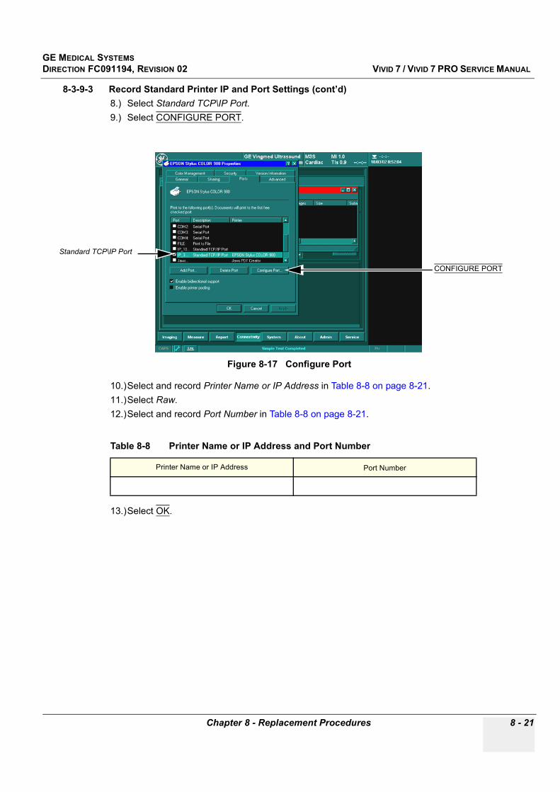
GE MEDICAL SYSTEMSDIRECTION FC091194, REVISION 02 VIVID 7 / VIVID 7 PRO SERVICE MANUAL
Chapter 8 - Replacement Procedures 8 - 21
8-3-9-3 Record Standard Printer IP and Port Settings (cont’d)8.) Select Standard TCP\IP Port.9.) Select CONFIGURE PORT.
10.)Select and record Printer Name or IP Address in Table 8-8 on page 8-21.11.)Select Raw.12.)Select and record Port Number in Table 8-8 on page 8-21.
13.)Select OK.
Figure 8-17 Configure Port
Table 8-8 Printer Name or IP Address and Port Number
Printer Name or IP Address Port Number
Standard TCP\IP Port
CONFIGURE PORT
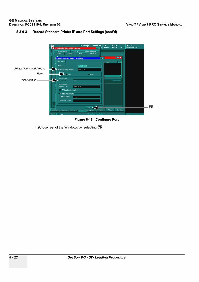
GE MEDICAL SYSTEMSDIRECTION FC091194, REVISION 02 VIVID 7 / VIVID 7 PRO SERVICE MANUAL
8 - 22 Section 8-3 - SW Loading Procedure
8-3-9-3 Record Standard Printer IP and Port Settings (cont’d)
14.)Close rest of the Windows by selecting OK.
Figure 8-18 Configure Port
Raw
Port Number
OK
Printer Name or IP Adress
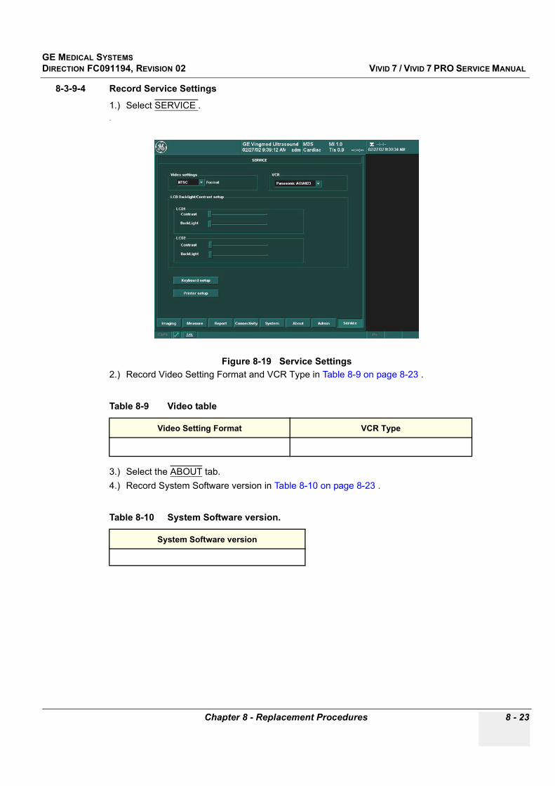
GE MEDICAL SYSTEMSDIRECTION FC091194, REVISION 02 VIVID 7 / VIVID 7 PRO SERVICE MANUAL
Chapter 8 - Replacement Procedures 8 - 23
8-3-9-4 Record Service Settings
1.) Select SERVICE ..
2.) Record Video Setting Format and VCR Type in Table 8-9 on page 8-23 .
3.) Select the ABOUT tab.4.) Record System Software version in Table 8-10 on page 8-23 .
Figure 8-19 Service Settings
Table 8-9 Video table
Video Setting Format VCR Type
Table 8-10 System Software version.
System Software version

GE MEDICAL SYSTEMSDIRECTION FC091194, REVISION 02 VIVID 7 / VIVID 7 PRO SERVICE MANUAL
8 - 24 Section 8-3 - SW Loading Procedure
8-3-10 Software Installation
NOTE: This software installation procedure covers both installation of BT’01 software (SW.v.1.x.x) on Vivid 7 units and installation of BT’02 Software (SW.v.2.x.x) on Vivid 7 / Vivid 7 PRO units.
You can also refer to Table 8-10 on page 8-23 where you recorded the unit’s software version.
8-3-10-1 Vivid 7 / Vivid 7 PRO System SW Installation
1.) Insert the applicable Vivid 7 SW CD, according to Table 8-12 on page 8-24, into the CD drive.
2.) Power down the System as described in section 4-2-2 on page 4-5.3.) Wait until the LCD’s on the Operator Panel are switched off and the Power Standby Switch has
turned yellow.4.) Power ON the System as described in Table 8-5 on page 8-11.5.) Wait for the SW Installation to be completed. (Typically installation time: 5 minutes). Status bar on
the screen indicates process.6.) You will now be prompted to remove the first CD and restart the System when the SW Installation
is completed. Remove the CD, but don’t restart the System this time.
Table 8-11 Vivid 7 / Vivid 7 PRO Models versus minimum software requirement
GE VINGMED PART NUMBER DESCRIPTION SOFTWARE VERSION
FB000030 VIVID 7 (BT’01) V.1.x.x (or higher)
FC000060 VIVID 7 (BT’01) V.1.x.x (or higher)
FC000180 VIVID 7 PRO (BT’02) V.2.x.x
FC000190 VIVID 7 PRO (BT’02) V.2.x.x
FC000200 VIVID 7 (BT’02) V.2.x.x
FC000210 VIVID 7 (BT’02) V.2.x.x
NOTICE When this procedure starts, existing software will be erased. If backup has not been performed as described earlier in this manual; Patient Database, System Configuration and User Configurations (customer presets) will be lost.
Table 8-12 System Software List
SOFTWARE DESCRIPTION PART NUMBER
SW. v.2.2.0 Vivid 7 System SW CD (BT’02-M4-2, BEP-2) FC200265-03
SW. v.2.1.0 Vivid 7 System SW CD (BT’02-M4-2, BEP-1) FC200165-04
SW. v.1.1.3 Vivid 7 System SW Installation CD (BT’01-M4) FC200165-01

GE MEDICAL SYSTEMSDIRECTION FC091194, REVISION 02 VIVID 7 / VIVID 7 PRO SERVICE MANUAL
Chapter 8 - Replacement Procedures 8 - 25
8-3-10-2 Application SW Installation
1.) Insert the applicable CD labelled Vivid7 & EchoPAC PC Application SW, according to Table 8-13 on page 8-25, into the CD drive.
2.) Hold down the power switch on the operator panel for a few seconds to power down the scanner (forced shut down).
3.) Wait until the LCD’s on the Operator Panel is switched OFF and the Power Switch on the Operator Panel has turned yellow.
4.) Power ON the System as described in Table 8-5 on page 8-11.5.) A dialogue box, called Start Application, will appear, select INSTALL SW.6.) A dialogue box, called Startloader, will appear, select OK to continue.7.) A dialogue box will appear, also named Startloader stating “New System SW installation will start
now”, select OK to continue.8.) A Command prompt window will appear, hit any key on the alphanumeric keyboard to continue9.) A message in the Command prompt window may prompt you that copying application software
takes 2 minutes.THIS WILL TAKE APPR. 5 MINUTES.
10.)Several dialogue boxes will appear on the screen during the SW load.
11.)Remove the CD from the CD drive when prompted.12.)The Scanner will now power down and reboot. Verify that the command prompt window is selected.
Table 8-13 Application Software List
SOFTWARE DESCRIPTION PART NUMBER
SW. v.2.2.0Vivid7 & EchoPAC PC
Application SW (BT’02-M4-2)
FC200220-04
SW. v.1.1.3Vivid7/EchoPAC PC Application
SW (BT’01-M4)
FC200090-06
NOTICE Do not interrupt the SW loading at any time.

GE MEDICAL SYSTEMSDIRECTION FC091194, REVISION 02 VIVID 7 / VIVID 7 PRO SERVICE MANUAL
8 - 26 Section 8-3 - SW Loading Procedure
8-3-10-3 Verify SW Key Option Settings
1.) From the alphanumeric keyboard on the Operator Panel, select CONFIG (F2 key), from the operator log in window, select adm from the pull down menu, then select LOG ON. (No password Needed).
2.) From the bottom of the configuration page select the CONNECTIVITY tab.3.) From the lower part of the window, select the SERVICE tab..
4.) From Video Settings pull down menu, verify Format as recorded in Table 8-9 on page 8-23 .5.) From the VCR pull down menu, verify VCR type as recorded in Table 8-9 on page 8-23 .6.) From the top of the connectivity tab, select the TCPIP tab.
Figure 8-20 Video Settings
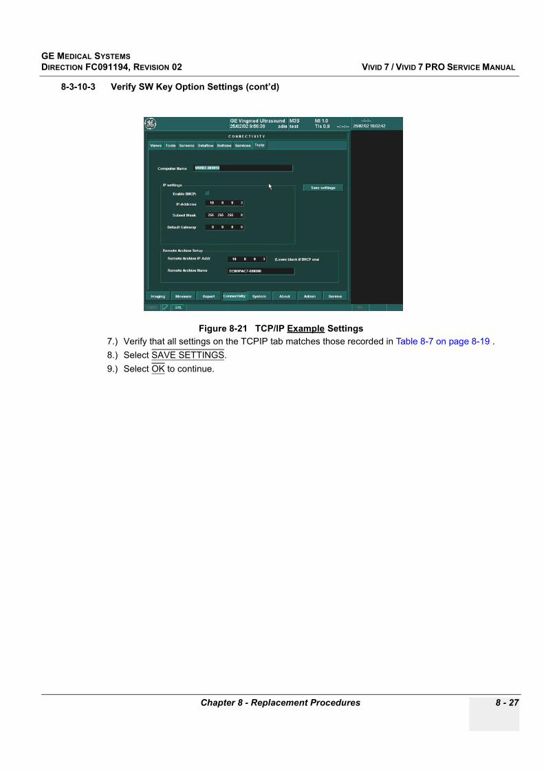
GE MEDICAL SYSTEMSDIRECTION FC091194, REVISION 02 VIVID 7 / VIVID 7 PRO SERVICE MANUAL
Chapter 8 - Replacement Procedures 8 - 27
8-3-10-3 Verify SW Key Option Settings (cont’d)
7.) Verify that all settings on the TCPIP tab matches those recorded in Table 8-7 on page 8-19 .8.) Select SAVE SETTINGS.9.) Select OK to continue.
Figure 8-21 TCP/IP Example Settings

GE MEDICAL SYSTEMSDIRECTION FC091194, REVISION 02 VIVID 7 / VIVID 7 PRO SERVICE MANUAL
8 - 28 Section 8-3 - SW Loading Procedure
8-3-10-4 Restore Standard Printer IP and Port Settings
1.) Select CONNECTIVITY.2.) Select SERVICE.3.) Select Standard Print.4.) Select OPEN.
Figure 8-22 Choosing Standard Print
CONNECTIVITY
Standard Print
OPEN
SERVICE
Scroll down to "Standard print"

GE MEDICAL SYSTEMSDIRECTION FC091194, REVISION 02 VIVID 7 / VIVID 7 PRO SERVICE MANUAL
Chapter 8 - Replacement Procedures 8 - 29
8-3-10-4 Restore Standard Printer IP and Port Settings (cont’d)5.) Select Printer.6.) Select Properties.
7.) Select Standard TCP\IP Port.8.) Select CONFIGURE PORT.
Figure 8-23 Properties
Figure 8-24 Configure Port
Printer
Properties
Standard TCP\IP Port.
CONFIGURE PORT
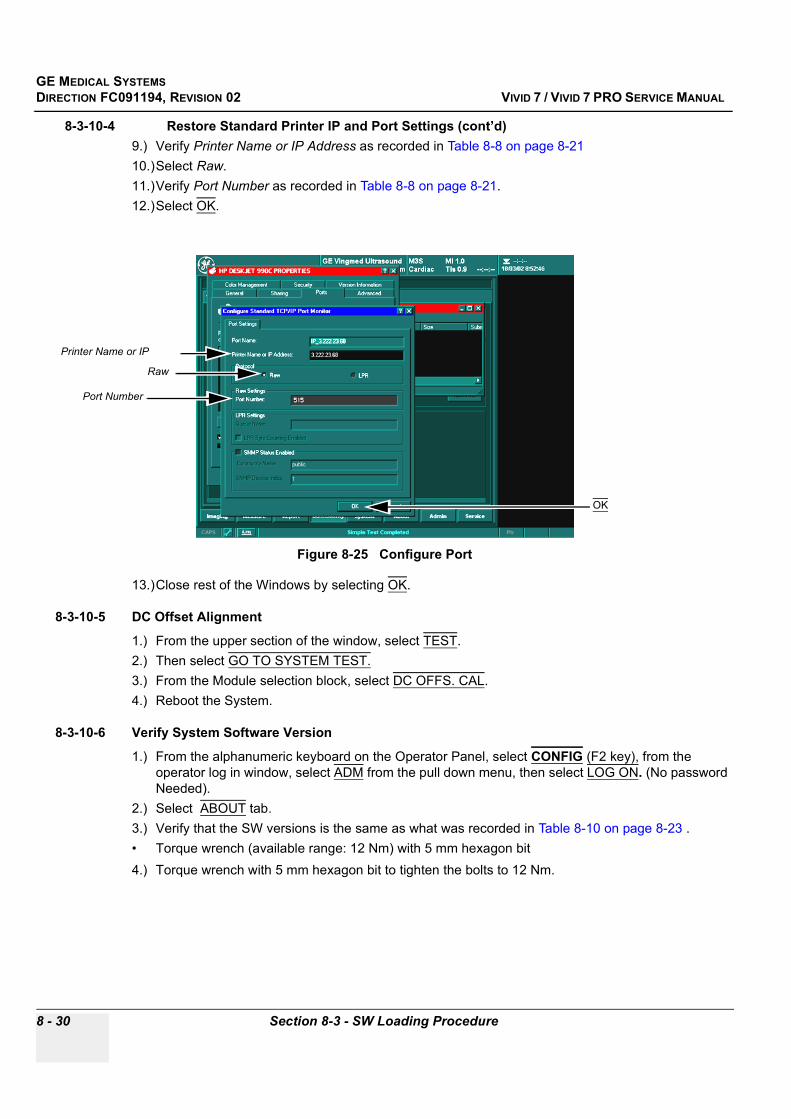
GE MEDICAL SYSTEMSDIRECTION FC091194, REVISION 02 VIVID 7 / VIVID 7 PRO SERVICE MANUAL
8 - 30 Section 8-3 - SW Loading Procedure
8-3-10-4 Restore Standard Printer IP and Port Settings (cont’d)9.) Verify Printer Name or IP Address as recorded in Table 8-8 on page 8-2110.)Select Raw.11.)Verify Port Number as recorded in Table 8-8 on page 8-21.12.)Select OK.
13.)Close rest of the Windows by selecting OK.
8-3-10-5 DC Offset Alignment
1.) From the upper section of the window, select TEST.2.) Then select GO TO SYSTEM TEST.3.) From the Module selection block, select DC OFFS. CAL.4.) Reboot the System.
8-3-10-6 Verify System Software Version
1.) From the alphanumeric keyboard on the Operator Panel, select CONFIG (F2 key), from the operator log in window, select ADM from the pull down menu, then select LOG ON. (No password Needed).
2.) Select ABOUT tab.3.) Verify that the SW versions is the same as what was recorded in Table 8-10 on page 8-23 .• Torque wrench (available range: 12 Nm) with 5 mm hexagon bit4.) Torque wrench with 5 mm hexagon bit to tighten the bolts to 12 Nm.
Figure 8-25 Configure Port
Raw
Port Number
OK
Printer Name or IP
GE MEDICAL SYSTEMSDIRECTION FC091194, REVISION 02 VIVID 7 / VIVID 7 PRO SERVICE MANUAL
Chapter 8 - Replacement Procedures 8 - 31
Section 8-4FRU Replacement Procedures
8-4-1 AC Transformer Replacement Procedure
8-4-1-1 ManpowerTwo persons, 1 hour 30 minutes
8-4-1-2 Tools• Phillips screwdriver size 2• Small wire nipper or blade screwdriver• Metal shears or hack saw
8-4-1-3 Preparations
1.) Shut down the system as described in "Power Shut Down" on page 4-5.
2.) Remove Left Side Cover as described in "Side Covers Removal Procedure" on page 8-3. 3.) Remove Filter Cover as described in "Filter Cover Removal Procedure" on page 8-6.4.) Remove Lower Rear Cover as described in "Lower Rear Cover Removal Procedure" on page 8-8.5.) Remove five (5) plastic expansion plugs that holds Ratcover. Use a small wire nipper or blade
screwdriver. 6.) Turn and bend Ratcover until it can be removed.7.) Disconnect two cables from AC transformer.
DANGER Dangerous voltages are present in this equipment. Completely power off and shut down the scanner before servicing.

GE MEDICAL SYSTEMSDIRECTION FC091194, REVISION 02 VIVID 7 / VIVID 7 PRO SERVICE MANUAL
8 - 32 Section 8-4 - FRU Replacement Procedures
8-4-1-4 AC Transformer Removal Procedure
1.) Loosen screw A, B and C (See Figure 8-26) a few turns. Unscrew screw D and E while you hold AC Transformer to prevent it from tilting forwards.
2.) Push AC Transformer to the left, tilt it forwards to free screw keyholes from screw heads (A, B and C) and lift the transformer off hooks along its the lower inner edge.
8-4-1-5 AC Transformer Installation Procedure
1.) Hang the inner lower edge of AC Transformer in its hooks.2.) Adjust its position so that screw keyholes matches screw heads (A,B and C).3.) Tilt AC Transformer upwards and push it to the right, screw heads into the keyholes.4.) Hold it steady while you fasten screw D and E.5.) Fasten screw A, B and C.6.) Connect two cables.
Figure 8-26 AC Transformer
Cable connectors.
Screw C
Ratcover
Screws D, E
Old expansion plug
Screw A
AC Transformer
Screw B

GE MEDICAL SYSTEMSDIRECTION FC091194, REVISION 02 VIVID 7 / VIVID 7 PRO SERVICE MANUAL
Chapter 8 - Replacement Procedures 8 - 33
8-4-1-5 AC Transformer Installation Procedure (cont’d).
7.) Compare Ratcover with illustration in Figure 8-27 above. If it is not already done, use a hack saw or metal shears and modify Ratcover according to this illustration.
8.) Install Ratcover.9.) Secure Ratcover with five (5) new plastic expansion plugs, P/N 080X3141.10.)Install Lower Rear Cover as described in "Lower Rear Cover Installation Procedure" on page 8-8.11.)Install Filter Cover as described in "Filter Cover Installation Procedure" on page 8-6.12.)Install Left Side Cover as described in "Side Covers Installation Procedure" on page 8-4.13.)Do functional check-out as described in Chapter 4.
Figure 8-27 Ratcover modification
Expansion plugs
36 mm
30 mm
40 mm
15 mm
12 mm
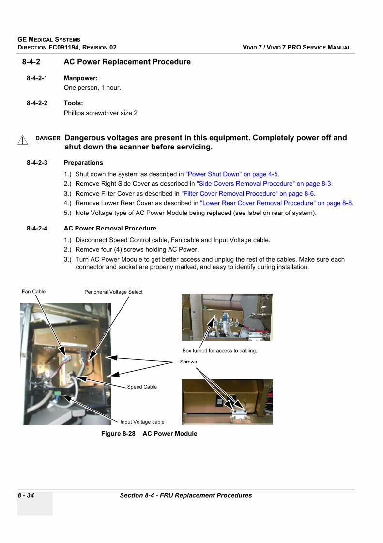
GE MEDICAL SYSTEMSDIRECTION FC091194, REVISION 02 VIVID 7 / VIVID 7 PRO SERVICE MANUAL
8 - 34 Section 8-4 - FRU Replacement Procedures
8-4-2 AC Power Replacement Procedure
8-4-2-1 Manpower:One person, 1 hour.
8-4-2-2 Tools:Phillips screwdriver size 2
8-4-2-3 Preparations
1.) Shut down the system as described in "Power Shut Down" on page 4-5.2.) Remove Right Side Cover as described in "Side Covers Removal Procedure" on page 8-3.3.) Remove Filter Cover as described in "Filter Cover Removal Procedure" on page 8-6.4.) Remove Lower Rear Cover as described in "Lower Rear Cover Removal Procedure" on page 8-8.5.) Note Voltage type of AC Power Module being replaced (see label on rear of system).
8-4-2-4 AC Power Removal Procedure
1.) Disconnect Speed Control cable, Fan cable and Input Voltage cable.2.) Remove four (4) screws holding AC Power.3.) Turn AC Power Module to get better access and unplug the rest of the cables. Make sure each
connector and socket are properly marked, and easy to identify during installation.
DANGER Dangerous voltages are present in this equipment. Completely power off and shut down the scanner before servicing.
Figure 8-28 AC Power Module
Fan Cable
Speed Cable
Screws
Peripheral Voltage Select
Box turned for access to cabling.
Input Voltage cable
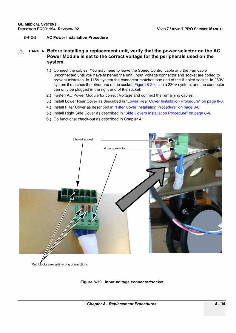
GE MEDICAL SYSTEMSDIRECTION FC091194, REVISION 02 VIVID 7 / VIVID 7 PRO SERVICE MANUAL
Chapter 8 - Replacement Procedures 8 - 35
8-4-2-5 AC Power Installation Procedure
1.) Connect the cables. You may need to leave the Speed Control cable and the Fan cable unconnected until you have fastened the unit. Input Voltage connector and socket are coded to prevent mistakes. In 115V system the connector matches one end of the 8-holed socket. In 230V system it matches the other end of the socket. Figure 8-29 is on a 230V system, and the connector can only be plugged in the right end of the socket.
2.) Fasten AC Power Module for correct Voltage and connect the remaining cables.3.) Install Lower Rear Cover as described in "Lower Rear Cover Installation Procedure" on page 8-8.4.) Install Filter Cover as described in "Filter Cover Installation Procedure" on page 8-6.5.) Install Right Side Cover as described in "Side Covers Installation Procedure" on page 8-4.6.) Do functional check-out as described in Chapter 4..
DANGER Before installing a replacement unit, verify that the power selector on the AC Power Module is set to the correct voltage for the peripherals used on the system.
Figure 8-29 Input Voltage connector/socket
4 pin connector
8 holed socket
Red blocks prevents wrong connections

GE MEDICAL SYSTEMSDIRECTION FC091194, REVISION 02 VIVID 7 / VIVID 7 PRO SERVICE MANUAL
8 - 36 Section 8-4 - FRU Replacement Procedures
8-4-3 DC Power Replacement Procedure
8-4-3-1 ManpowerOne person, 30 minutes
8-4-3-2 Tools4 mm blade screwdriver.
8-4-3-3 Preparations
1.) Shut down the system as described in "Power Shut Down" on page 4-5.2.) Remove Right Side Cover as described in "Side Covers Removal Procedure" on page 8-3.3.) Remove Card Rack Cover.
a.) Turn seven (7) quarter-turn screws to loosen Card Rack door.b.) Holding the door, lift it out of its retainers along the lower edge of Card Rack.
8-4-3-4 DC Power Removal Procedure
1.) Unscrew three (3) screws as shown in Figure 8-30.2.) Unplug PCI cable from the socket on IMP2 board.3.) Pull the DC Power a little to get access to power cables.4.) Remove retaining clasp and unplug Power Cable and HV Cable.5.) Remove DC Power.
DANGER Dangerous voltages are present in this equipment. Completely power off and shut down the scanner before servicing.
Figure 8-30 DC Power and Cabling.
Screws HV power cable
DC power cable
PCI cable
IMP2 Board
DC Power
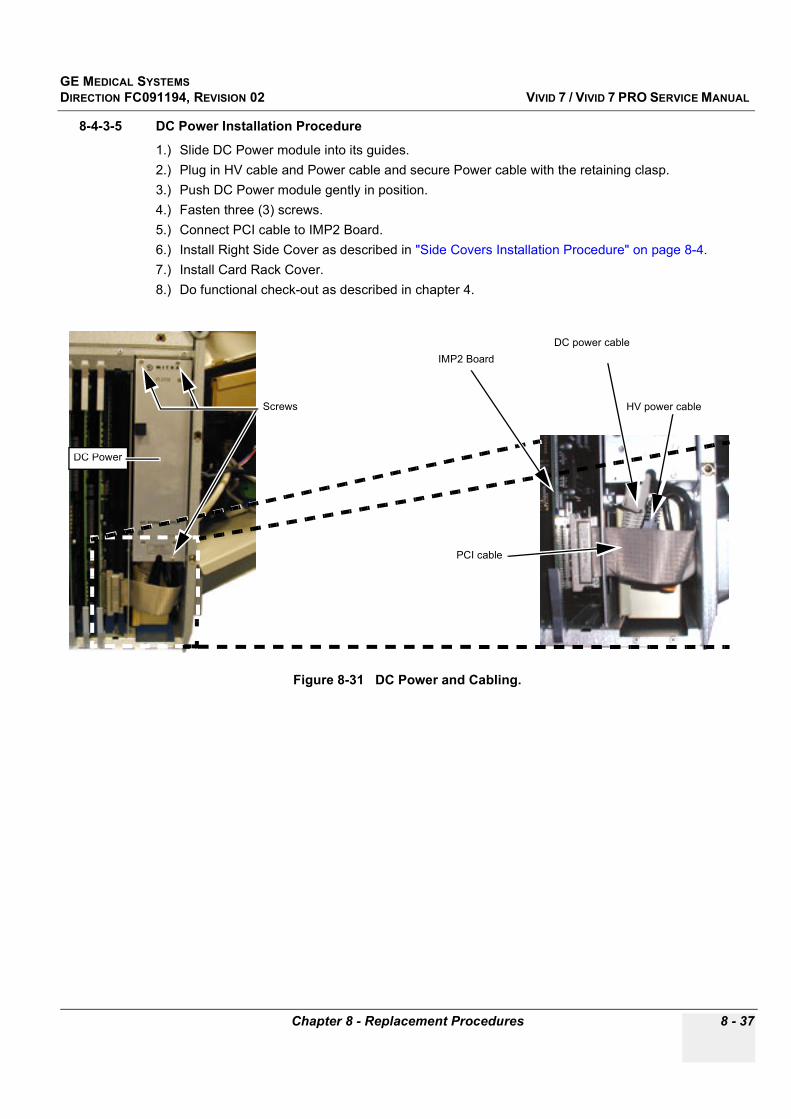
GE MEDICAL SYSTEMSDIRECTION FC091194, REVISION 02 VIVID 7 / VIVID 7 PRO SERVICE MANUAL
Chapter 8 - Replacement Procedures 8 - 37
8-4-3-5 DC Power Installation Procedure
1.) Slide DC Power module into its guides.2.) Plug in HV cable and Power cable and secure Power cable with the retaining clasp.3.) Push DC Power module gently in position.4.) Fasten three (3) screws.5.) Connect PCI cable to IMP2 Board.6.) Install Right Side Cover as described in "Side Covers Installation Procedure" on page 8-4.7.) Install Card Rack Cover.8.) Do functional check-out as described in chapter 4.
Figure 8-31 DC Power and Cabling.
Screws HV power cable
DC power cable
PCI cable
IMP2 Board
DC Power
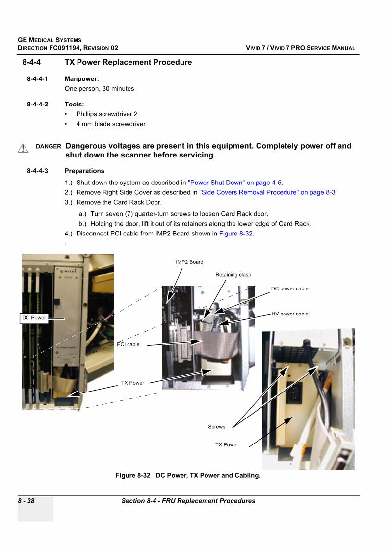
GE MEDICAL SYSTEMSDIRECTION FC091194, REVISION 02 VIVID 7 / VIVID 7 PRO SERVICE MANUAL
8 - 38 Section 8-4 - FRU Replacement Procedures
8-4-4 TX Power Replacement Procedure
8-4-4-1 Manpower:One person, 30 minutes
8-4-4-2 Tools:• Phillips screwdriver 2• 4 mm blade screwdriver
8-4-4-3 Preparations
1.) Shut down the system as described in "Power Shut Down" on page 4-5.2.) Remove Right Side Cover as described in "Side Covers Removal Procedure" on page 8-3.3.) Remove the Card Rack Door.
a.) Turn seven (7) quarter-turn screws to loosen Card Rack door.b.) Holding the door, lift it out of its retainers along the lower edge of Card Rack.
4.) Disconnect PCI cable from IMP2 Board shown in Figure 8-32..
DANGER Dangerous voltages are present in this equipment. Completely power off and shut down the scanner before servicing.
Figure 8-32 DC Power, TX Power and Cabling.
HV power cable
DC power cable
PCI cable
IMP2 Board
TX Power
Retaining clasp
TX Power
Screws
DC Power

GE MEDICAL SYSTEMSDIRECTION FC091194, REVISION 02 VIVID 7 / VIVID 7 PRO SERVICE MANUAL
Chapter 8 - Replacement Procedures 8 - 39
8-4-4-4 TX Power Removal Procedure
1.) Remove retaining clasp from DC Power connector.2.) Unplug DC Power and TX Power.3.) Unscrew two (2) screws in front of TX Power.4.) Push cables aside and pull out TX Power from its socket.
8-4-4-5 TX Power Installation Procedure
1.) Push cables aside and install TX Power.2.) Fasten two (2) screws.3.) Connect DC Power and secure the connector with retaining clasp.4.) Connect TX Power. 5.) Connect PCI cable to IMP2 Board.6.) Install Right Side Cover as described in "Side Covers Removal Procedure" on page 8-3.7.) Install Card Rack Cover.

GE MEDICAL SYSTEMSDIRECTION FC091194, REVISION 02 VIVID 7 / VIVID 7 PRO SERVICE MANUAL
8 - 40 Section 8-4 - FRU Replacement Procedures
8-4-5 Rear Casters Replacement Procedure
8-4-5-1 Manpower2 persons, 30 minutes (one Caster)
8-4-5-2 Tools• Phillips screwdriver size 2• 5 mm hexagon key• Bevel Edged Board and Wooden Wedge (both included in package with replacement Casters)
8-4-5-3 Preparations
1.) Shut down the system as described in "Power Shut Down" on page 4-5.2.) Remove the Side Covers as described in "Side Covers Removal Procedure" on page 8-3.3.) Remove Filter Cover As described in "Filter Cover Removal Procedure" on page 8-6.4.) Remove Lower Rear Cover as described in "Lower Rear Cover Removal Procedure" on page 8-8.
Figure 8-33 Bevel Edged Board and Wooden Wedge.
Wooden Wedge
Bevel Edged Board

GE MEDICAL SYSTEMSDIRECTION FC091194, REVISION 02 VIVID 7 / VIVID 7 PRO SERVICE MANUAL
Chapter 8 - Replacement Procedures 8 - 41
8-4-5-4 Rear Casters Removal Procedure
1.) Turn Front Casters as shown in Figure 8-34.2.) Activate Direction Lock.3.) Put the bevel-edged board on the floor.
4.) Pull the system backwards up the board incline. This will lift the Rear Wheel on the opposite side of the System from the floor.
WARNINGWARNING Prior to elevating scanner, verify that the floating keyboard is locked in its lowest position.
WARNINGWARNING Use extreme caution as long as VIVID 7 is un-stable, not resting on all four Casters.
Figure 8-34 Pull system backwards up the board incline
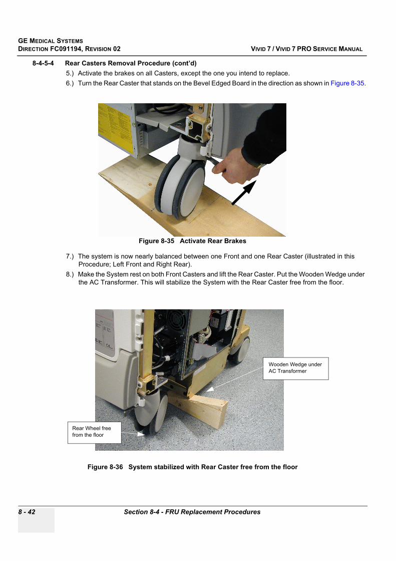
GE MEDICAL SYSTEMSDIRECTION FC091194, REVISION 02 VIVID 7 / VIVID 7 PRO SERVICE MANUAL
8 - 42 Section 8-4 - FRU Replacement Procedures
8-4-5-4 Rear Casters Removal Procedure (cont’d)5.) Activate the brakes on all Casters, except the one you intend to replace.6.) Turn the Rear Caster that stands on the Bevel Edged Board in the direction as shown in Figure 8-35.
7.) The system is now nearly balanced between one Front and one Rear Caster (illustrated in this Procedure; Left Front and Right Rear).
8.) Make the System rest on both Front Casters and lift the Rear Caster. Put the Wooden Wedge under the AC Transformer. This will stabilize the System with the Rear Caster free from the floor.
Figure 8-35 Activate Rear Brakes
Figure 8-36 System stabilized with Rear Caster free from the floor
Rear Wheel free from the floor
Wooden Wedge under AC Transformer
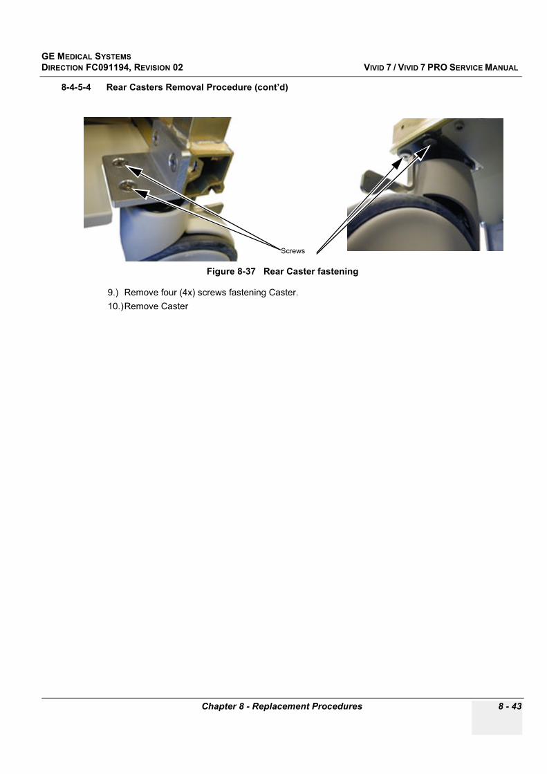
GE MEDICAL SYSTEMSDIRECTION FC091194, REVISION 02 VIVID 7 / VIVID 7 PRO SERVICE MANUAL
Chapter 8 - Replacement Procedures 8 - 43
8-4-5-4 Rear Casters Removal Procedure (cont’d)
9.) Remove four (4x) screws fastening Caster.10.)Remove Caster
Figure 8-37 Rear Caster fastening
Screws

GE MEDICAL SYSTEMSDIRECTION FC091194, REVISION 02 VIVID 7 / VIVID 7 PRO SERVICE MANUAL
8 - 44 Section 8-4 - FRU Replacement Procedures
8-4-5-5 Rear Casters Installation Procedure
1.) Replace the Caster and tightly fasten it with four (4x) screws.
2.) Remove the Wooden Wedge.3.) Roll the system off the Bevel Edged Board.4.) To replace the other Rear Caster, repeat all the steps from "Rear Casters Removal Procedure" on
page 8-41, but now using the Bevel Edged board and the Wooden Wedge on the other side of the system.
5.) Install Lower Rear Cover as described in "Lower Rear Cover Installation Procedure" on page 8-8.6.) Install Filter Cover as described in "Filter Cover Installation Procedure" on page 8-6.7.) Install Side Covers as described in "Side Covers Installation Procedure" on page 8-4.
WARNINGWARNING Use extreme caution in the next two steps. The scanner is unstable.
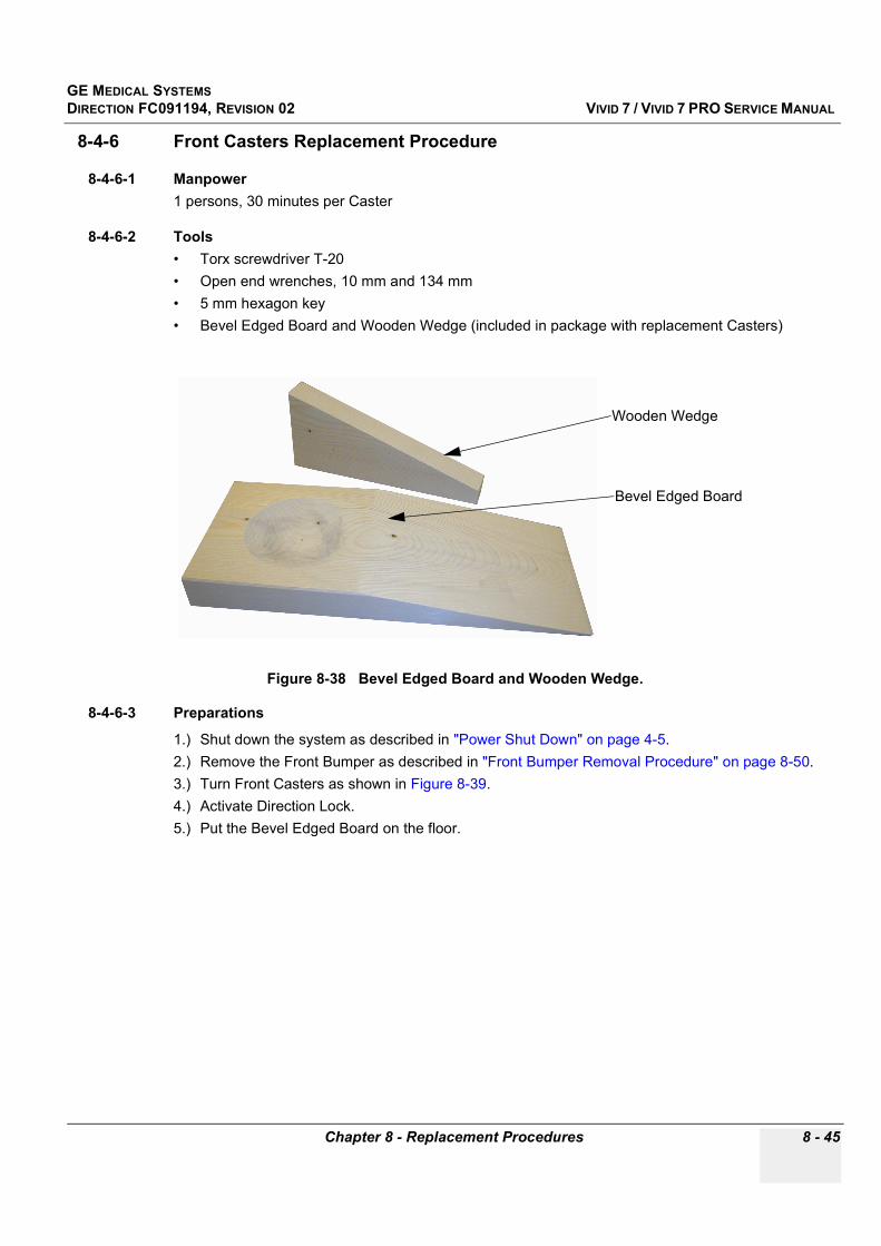
GE MEDICAL SYSTEMSDIRECTION FC091194, REVISION 02 VIVID 7 / VIVID 7 PRO SERVICE MANUAL
Chapter 8 - Replacement Procedures 8 - 45
8-4-6 Front Casters Replacement Procedure
8-4-6-1 Manpower1 persons, 30 minutes per Caster
8-4-6-2 Tools• Torx screwdriver T-20• Open end wrenches, 10 mm and 134 mm• 5 mm hexagon key• Bevel Edged Board and Wooden Wedge (included in package with replacement Casters)
8-4-6-3 Preparations
1.) Shut down the system as described in "Power Shut Down" on page 4-5.2.) Remove the Front Bumper as described in "Front Bumper Removal Procedure" on page 8-50.3.) Turn Front Casters as shown in Figure 8-39.4.) Activate Direction Lock.5.) Put the Bevel Edged Board on the floor.
Figure 8-38 Bevel Edged Board and Wooden Wedge.
Wooden Wedge
Bevel Edged Board
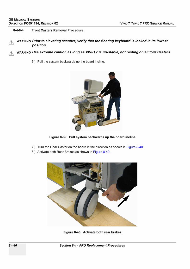
GE MEDICAL SYSTEMSDIRECTION FC091194, REVISION 02 VIVID 7 / VIVID 7 PRO SERVICE MANUAL
8 - 46 Section 8-4 - FRU Replacement Procedures
8-4-6-4 Front Casters Removal Procedure
6.) Pull the system backwards up the board incline.
7.) Turn the Rear Caster on the board in the direction as shown in Figure 8-40.8.) Activate both Rear Brakes as shown in Figure 8-40.
WARNINGWARNING Prior to elevating scanner, verify that the floating keyboard is locked in its lowest position.
WARNINGWARNING Use extreme caution as long as VIVID 7 is un-stable, not resting on all four Casters.
Figure 8-39 Pull system backwards up the board incline
Figure 8-40 Activate both rear brakes

GE MEDICAL SYSTEMSDIRECTION FC091194, REVISION 02 VIVID 7 / VIVID 7 PRO SERVICE MANUAL
Chapter 8 - Replacement Procedures 8 - 47
8-4-6-4 Front Casters Removal Procedure (cont’d)9.) Put the Wooden Wedge under the Card Rack. This will stabilize the System with the right Front
Wheel free from the floor..
Figure 8-41 System stabilized with front wheel free from the floor
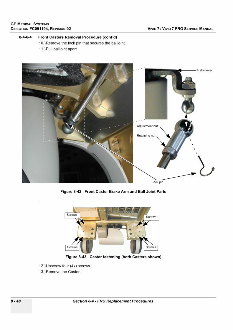
GE MEDICAL SYSTEMSDIRECTION FC091194, REVISION 02 VIVID 7 / VIVID 7 PRO SERVICE MANUAL
8 - 48 Section 8-4 - FRU Replacement Procedures
8-4-6-4 Front Casters Removal Procedure (cont’d)10.)Remove the lock pin that secures the balljoint.11.)Pull balljoint apart.
.
12.)Unscrew four (4x) screws.13.)Remove the Caster.
Figure 8-42 Front Caster Brake Arm and Ball Joint Parts
Figure 8-43 Caster fastening (both Casters shown)
Lock pin
Adjustment nut
Retaining nut
Brake lever
Screws
Screws
Screws
Screws

GE MEDICAL SYSTEMSDIRECTION FC091194, REVISION 02 VIVID 7 / VIVID 7 PRO SERVICE MANUAL
Chapter 8 - Replacement Procedures 8 - 49
8-4-6-5 Front Casters Installation Procedure
1.) Move the ball piece of the joint from old Caster to new Caster (See Figure 8-42).2.) Align new Caster on the frame and fasten it tightly with four (4x) hexagon screws.3.) Press the balljoint together and install the lock pin (See Figure 8-42).4.) To replace the other Front Caster, repeat all the steps from "Front Casters Removal Procedure" on
page 8-46, but now using the Bevel Edged board and the Wooden Wedge on the other side of the system.
5.) Install Bumper and Covers as described in "Front Bumper Installation Procedure" on page 8-50.6.) Roll the system off the Bevel Edged Board.
GE MEDICAL SYSTEMSDIRECTION FC091194, REVISION 02 VIVID 7 / VIVID 7 PRO SERVICE MANUAL
8 - 50 Section 8-4 - FRU Replacement Procedures
8-4-7 Front Bumper Replacement Procedure
8-4-7-1 ManpowerOne person, 30 minutes
8-4-7-2 Tools• Phillips size 2• Torx screwdriver T-20
8-4-7-3 Preparations
1.) Shut down the system as described in "Power Shut Down" on page 4-5.2.) Remove Front Cover as described in "Front Cover Removal Procedure" on page 8-5.
8-4-7-4 Front Bumper Removal Procedure1.) Unscrew 4 Torx screws under the bumper.
2.) Lift the bumper off.
8-4-7-5 Front Bumper Installation Procedure1.) Put the new bumper in position.
2.) Fasten the 4 screws.
NOTE: Gentle. Don't use power.
3.) Install Front Cover as described in "Front Cover Installation Procedure" on page 8-5.
Figure 8-44 System front and Front Bumper
Screw holes
Front Bumper

GE MEDICAL SYSTEMSDIRECTION FC091194, REVISION 02 VIVID 7 / VIVID 7 PRO SERVICE MANUAL
Chapter 8 - Replacement Procedures 8 - 51
8-4-8 Brake Pedal Replacement Procedure
8-4-8-1 ManpowerOne person, 15 minutes
8-4-8-2 ToolsTorx screwdriver T-20
8-4-8-3 Brake Pedal Replacement Procedure
1.) Unscrew 4 screws under the pedal.2.) Replace the pedal with a new one.3.) Fasten 4 screws.
Figure 8-45 Brake Pedal
Brake Pedal
GE MEDICAL SYSTEMSDIRECTION FC091194, REVISION 02 VIVID 7 / VIVID 7 PRO SERVICE MANUAL
8 - 52 Section 8-4 - FRU Replacement Procedures
8-4-9 Direction Lock Pedal Replacement Procedure
8-4-9-1 ManpowerOne person, 15 minutes
8-4-9-2 ToolsTorx screwdriver T-20
8-4-9-3 Direction Lock Replacement Procedure
1.) Unscrew 4 screws, 3 under and 1 at the left side of the pedal.2.) Replace the pedal with a new one.3.) Fasten 4 screws.
Figure 8-46 Direction Lock Pedal
Direction Lock Pedal

GE MEDICAL SYSTEMSDIRECTION FC091194, REVISION 02 VIVID 7 / VIVID 7 PRO SERVICE MANUAL
Chapter 8 - Replacement Procedures 8 - 53
8-4-10 Brake Pedal and Direction Lock Assembly Replacement Procedures
8-4-10-1 ManpowerOne person, 1 hour
8-4-10-2 Tools• Phillips screwdriver size 2• Hexagon key 5 mm• Torx screwdriver T-20• Wrench 11 and 13 mm
8-4-10-3 Preparations
1.) Remove Front Bumper as described in "Front Bumper Removal Procedure" on page 8-50.2.) Remove footrests on both pedals by unscrewing 4 Torx screws on each.
8-4-10-4 Brake pedal and Direction Lock Removal Procedure
1.) Unscrew 2 nuts on the two ball joints on the brake rods, located over the middle of brake assembly. Wrench 11 and 13.
2.) Unscrew the 4 hexagon screws. Two of them located under the Brake Assembly.
NOTE: The nuts may slide out of position.
3.) Remove the Brake Pedal and Direction Lock Assembly.
8-4-10-5 Brake pedal and Direction Lock Installation procedure
1.) Put the Brake Pedal and Direction Lock Assembly in position and fasten the 4 hexagon screws loosely in the sliding nuts.
2.) Fasten the ball joint nuts before tightening the 4 hexagon screws.3.) Install Front Bumper as described in "Front Bumper Installation Procedure" on page 8-50.4.) Fasten footrests to Brake Pedal and Direction Lock Assembly. Fasten the screws gently.
Figure 8-47 Brake AssemblyHexagon screws
Ball joint nuts
GE MEDICAL SYSTEMSDIRECTION FC091194, REVISION 02 VIVID 7 / VIVID 7 PRO SERVICE MANUAL
8 - 54 Section 8-4 - FRU Replacement Procedures
8-4-11 Power Supply Battery Pack Replacement Procedure
8-4-11-1 ToolsPhillips screwdriver 2
8-4-11-2 ManpowerOne person, 1 hour
8-4-11-3 Preparations
1.) Shut down the system as described in "Power Shut Down" on page 4-5.2.) Remove Left Side Cover as described in "Side Covers Removal Procedure" on page 8-3.
8-4-11-4 Power Supply Battery Pack Removal Procedure
1.) Remove Backend Processor Cover.2.) Remove the four screws from Power Supply Battery Pack cover plate.3.) Disconnect Battery Pack connection wire.4.) Remove Power Supply Battery Pack from Backend Processor.
Figure 8-48 Power Supply Battery Pack
1
3 4Battery Pack
Phillips screws

GE MEDICAL SYSTEMSDIRECTION FC091194, REVISION 02 VIVID 7 / VIVID 7 PRO SERVICE MANUAL
Chapter 8 - Replacement Procedures 8 - 55
8-4-11-5 Power Supply Battery Pack Installation Procedure
1.) Slide the new Power Supply Battery Pack into its position in Backend Processor.2.) Connect Battery Pack to power supply connector.
3.) Attach Power Supply Battery Pack cover plate and secure it with the four screws.4.) Install Backend Processor Cover.5.) Install Side Cover "Side Covers Installation Procedure" on page 8-46.) Boot-up the system.7.) Do a functional check-out by turning off power by the mains circuit breaker at the AC Power module
at the rear of the System.- The Battery Pack provides BEP with power to a proper shut down, which takes some seconds.
The UPS batteries will drain slightly when the system is in the Off Condition.
The Off Condition is defined as:
• Circuit Breaker in the OFF position• System unplugged from the wall outletIf the system is left in the OFF condition for an extended period of time (3 to 5 days or more), the system may not boot up or may beep when turned ON. Should this occur, the system needs to recharge the UPS batteries. This could take 15 minutes to as long as 24 hours, depending on the battery age, system input voltage and system temperature.
To eliminate draining the UPS batteries, the system should remain plugged into the wall outlet with the circuit breaker in the ON position.
Figure 8-49 Battery Pack Block Diagram
CAUTION The battery pack contains a 24V charge that will cause a spark when it is re-connected to the power supply. Be careful that this spark does not damage any equipment or cause any personal injury.
In Line20A Fuse
Battery 1
Battery 2
Compression tape used tominimize battery pack movement
while installed in chassis
Heat-shrink holds batteries togetherand insulates terminals.
Spacerseperatesbatteries
+ -
- +
Label to beattached tothis surface

GE MEDICAL SYSTEMSDIRECTION FC091194, REVISION 02 VIVID 7 / VIVID 7 PRO SERVICE MANUAL
8 - 56 Section 8-4 - FRU Replacement Procedures
This page was intentionally left blank.

GE MEDICAL SYSTEMSDIRECTION FC091194, REVISION 02 VIVID 7 / VIVID 7 PRO SERVICE MANUAL
Chapter 9 - Renewal Parts 9 - 1
Chapter 9 Renewal Parts
Section 9-1Overview
9-1-1 Purpose of Chapter 9This chapter gives you an overview of Spare Parts for Vivid 7 / Vivid 7 PRO.
Table 9-1 Contents in Chapter 9
SECTION DESCRIPTIONPAGE
NUMBER
9-1 Overview 9-1
9-2 List of Abbreviations 9-2
9-3 Parts List Groups 9-3
9-4 Plastic Parts, Console, Top and Front 9-4
9-5 Plastic Parts, Airduct Cover and Cover Boxes 9-5
9-6 Plastic Parts, Covers and Bumpers, Left, Right and Rear 9-6
9-7 Control Panel Parts 9-7
9-8 Monitor 9-8
9-9 Input /Output Modules 9-9
9-10 PCB Boards 9-10
9-11 Mechanical Parts, Rack, Casters and Frogleg 9-12
9-12 Brake Assembly and Console Lock 9-13
9-14 Electrical Part 9-23
9-13 Cables 9-14
9-15 Backend Processor 9-24
9-17 Probes 9-28
9-16 Peripherals 9-25
9-18 Software 9-29
9-19 Options 9-30
9-20 Kits 9-31
9-21 Accessory Box, Vivid 7 / Vivid 7 PRO 9-34
9-23 Packing Parts for Reshipment 9-37
GE MEDICAL SYSTEMSDIRECTION FC091194, REVISION 02 VIVID 7 / VIVID 7 PRO SERVICE MANUAL
9 - 2 -
9-1-1-1 Equipment Models Covered in this Chapter
Section 9-2List of Abbreviations
Table 9-2 Vivid 7 / Vivid 7 PRO Models Covered in this Manual
GE VINGMED PART NUMBER DESCRIPTION VOLTAGE
FB000030 VIVID 7 (BT’01) 230 VAC
FC000060 VIVID 7 (BT’01) 100 - 120 VAC
FC000180 VIVID 7 PRO (BT’02) 220 - 240 VAC
FC000190 VIVID 7 PRO (BT’02) 100 - 120 VAC
FC000200 VIVID 7 (BT’02) 220 - 240 VAC
FC000210 VIVID 7 (BT’02) 100 - 120 VAC
Table 9-3 List of Abbreviations
ABBREVIATIONS DESCRIPTION
Assy Assembly
BEP Back End Processor
Ctrl Control
FEP Front End Processor
F.O.B. Flock of Birds or 3-D Option (Not available on this scanner)
FRU 1 Replacement part available in parts hub
FRU 2 Replacement part available from the manufacturer (lead time involved)
FRU N Non stock part
LCD Liquid Crystal Display
Int Internal
I/O Input/Output
PC Personal Computer (Back End Processor)
PS Power Supply
PWA Printed Wire Assembly
QTY Quantity used per scanner
XFRMR Transformer
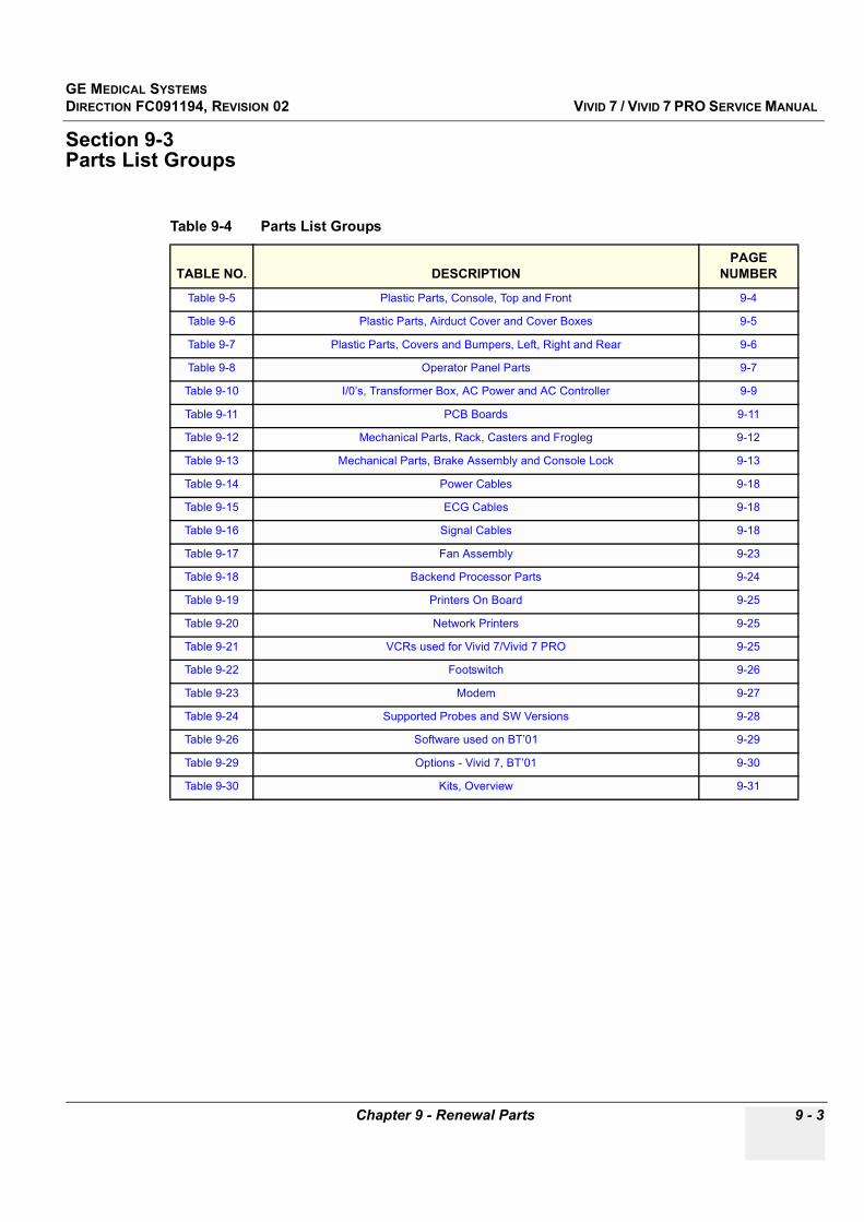
GE MEDICAL SYSTEMSDIRECTION FC091194, REVISION 02 VIVID 7 / VIVID 7 PRO SERVICE MANUAL
Chapter 9 - Renewal Parts 9 - 3
Section 9-3Parts List Groups
Table 9-4 Parts List Groups
TABLE NO. DESCRIPTIONPAGE
NUMBER
Table 9-5 Plastic Parts, Console, Top and Front 9-4
Table 9-6 Plastic Parts, Airduct Cover and Cover Boxes 9-5
Table 9-7 Plastic Parts, Covers and Bumpers, Left, Right and Rear 9-6
Table 9-8 Operator Panel Parts 9-7
Table 9-10 I/0’s, Transformer Box, AC Power and AC Controller 9-9
Table 9-11 PCB Boards 9-11
Table 9-12 Mechanical Parts, Rack, Casters and Frogleg 9-12
Table 9-13 Mechanical Parts, Brake Assembly and Console Lock 9-13
Table 9-14 Power Cables 9-18
Table 9-15 ECG Cables 9-18
Table 9-16 Signal Cables 9-18
Table 9-17 Fan Assembly 9-23
Table 9-18 Backend Processor Parts 9-24
Table 9-19 Printers On Board 9-25
Table 9-20 Network Printers 9-25
Table 9-21 VCRs used for Vivid 7/Vivid 7 PRO 9-25
Table 9-22 Footswitch 9-26
Table 9-23 Modem 9-27
Table 9-24 Supported Probes and SW Versions 9-28
Table 9-26 Software used on BT’01 9-29
Table 9-29 Options - Vivid 7, BT’01 9-30
Table 9-30 Kits, Overview 9-31

GE MEDICAL SYSTEMSDIRECTION FC091194, REVISION 02 VIVID 7 / VIVID 7 PRO SERVICE MANUAL
9 - 4 Section 9-4 - Plastic Parts, Console, Top and Front
Section 9-4Plastic Parts, Console, Top and Front
Figure 9-1 Plastic Parts, Front View of Vivid 7 / Vivid 7 PRO
Table 9-5 Plastic Parts, Console, Top and Front
ITEM PART NAMEPART
NUMBER DESCRIPTION QTY FRU
1 PROBEHOLDER, LEFT FB307293 Probe Holder, Left 1 1
2 PROBEHOLDER, RIGHT FB307294 Probe Holder, Right 1 1
3 HANDLE, MAIN FC200131Common Front Handle with Label.
1 1
4 SHELF FB307307 1 1
5 COVER, UNDERSHELF FB307308 1 2
6 COVER, UNDER FB307405 Below Control Panel 1 2
7 CUP, GEL FB307313 2 2
8 PEDAL, LOCK FB307407Pedal lock pad.
1 1
9 PEDAL, DIRECTIONLOCK FB307409Pedal direction lock pad.
1 1
10 COVER, TOP FB307383 1 1
11 BUMPER FOOTREST FB307387 1 1
1
2
3
4
5
6
7
8
9
10
11
12
13

GE MEDICAL SYSTEMSDIRECTION FC091194, REVISION 02 VIVID 7 / VIVID 7 PRO SERVICE MANUAL
Chapter 9 - Renewal Parts 9 - 5
Section 9-5Plastic Parts, Airduct Cover and Cover Boxes
12 COLUMN COVERS KIT FC200183 (Same as FC200088) 1 1
13 COVER, FRONT FC200076 1 2
Figure 9-2 Plastic parts, Airduct Cover and Cover boxes
Table 9-6 Plastic Parts, Airduct Cover and Cover Boxes
ITEM PART NAMEPART
NUMBER DESCRIPTION QTY FRU
1 COVER BOX, VCR FB307988 1 1
2 COVER BOX B/W-PRINTER FB307989 1 1
3 COVER BOX COLOR PRINTER FB307990 1 1
Table 9-5 Plastic Parts, Console, Top and Front (continued)
ITEM PART NAMEPART
NUMBER DESCRIPTION QTY FRU
23
1
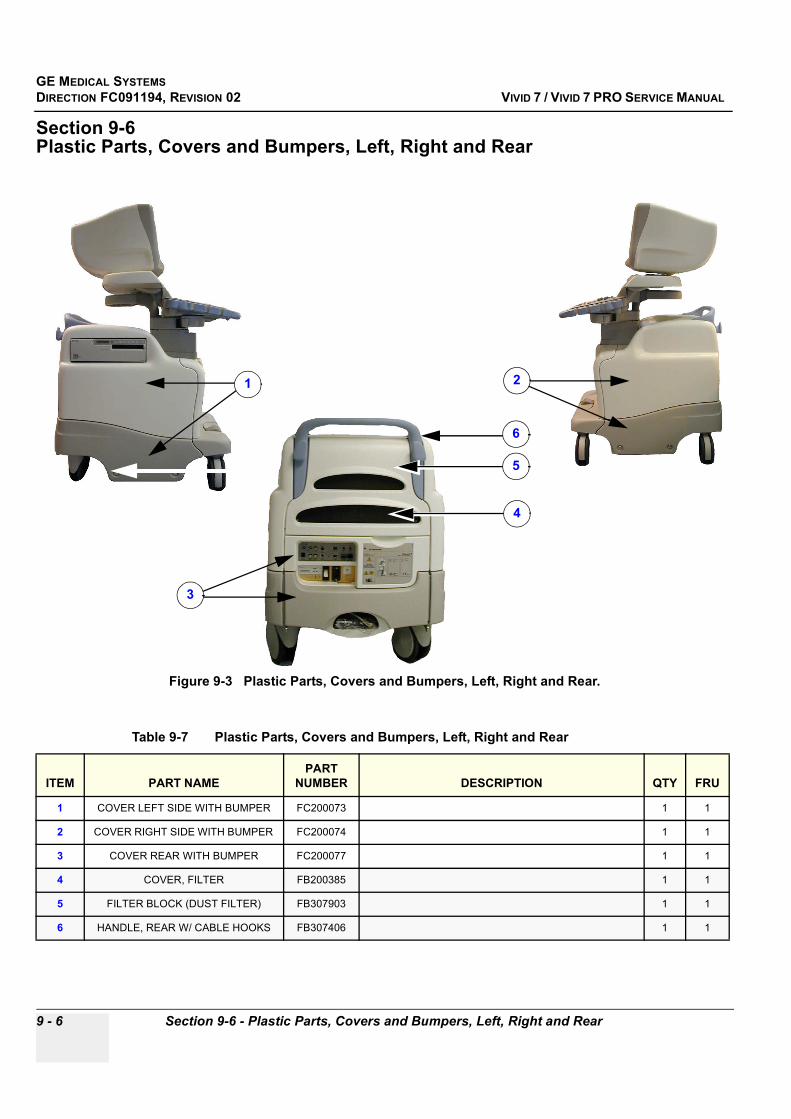
GE MEDICAL SYSTEMSDIRECTION FC091194, REVISION 02 VIVID 7 / VIVID 7 PRO SERVICE MANUAL
9 - 6 Section 9-6 - Plastic Parts, Covers and Bumpers, Left, Right and Rear
Section 9-6Plastic Parts, Covers and Bumpers, Left, Right and Rear
Figure 9-3 Plastic Parts, Covers and Bumpers, Left, Right and Rear.
Table 9-7 Plastic Parts, Covers and Bumpers, Left, Right and Rear
ITEM PART NAMEPART
NUMBER DESCRIPTION QTY FRU
1 COVER LEFT SIDE WITH BUMPER FC200073 1 1
2 COVER RIGHT SIDE WITH BUMPER FC200074 1 1
3 COVER REAR WITH BUMPER FC200077 1 1
4 COVER, FILTER FB200385 1 1
5 FILTER BLOCK (DUST FILTER) FB307903 1 1
6 HANDLE, REAR W/ CABLE HOOKS FB307406 1 1
1 2
3
4
5
6
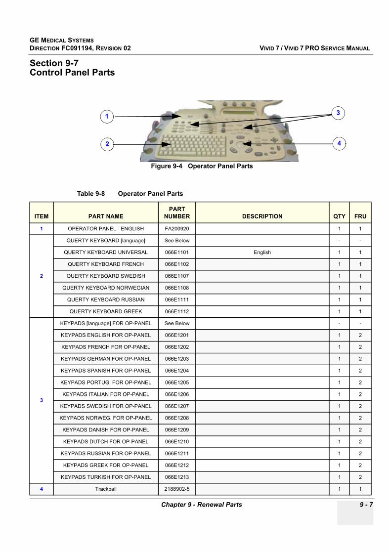
GE MEDICAL SYSTEMSDIRECTION FC091194, REVISION 02 VIVID 7 / VIVID 7 PRO SERVICE MANUAL
Chapter 9 - Renewal Parts 9 - 7
Section 9-7Control Panel Parts
Figure 9-4 Operator Panel Parts
Table 9-8 Operator Panel Parts
ITEM PART NAMEPART
NUMBER DESCRIPTION QTY FRU
1 OPERATOR PANEL - ENGLISH FA200920 1 1
2
QUERTY KEYBOARD [language] See Below - -
QUERTY KEYBOARD UNIVERSAL 066E1101 English 1 1
QUERTY KEYBOARD FRENCH 066E1102 1 1
QUERTY KEYBOARD SWEDISH 066E1107 1 1
QUERTY KEYBOARD NORWEGIAN 066E1108 1 1
QUERTY KEYBOARD RUSSIAN 066E1111 1 1
QUERTY KEYBOARD GREEK 066E1112 1 1
3
KEYPADS [language] FOR OP-PANEL See Below - -
KEYPADS ENGLISH FOR OP-PANEL 066E1201 1 2
KEYPADS FRENCH FOR OP-PANEL 066E1202 1 2
KEYPADS GERMAN FOR OP-PANEL 066E1203 1 2
KEYPADS SPANISH FOR OP-PANEL 066E1204 1 2
KEYPADS PORTUG. FOR OP-PANEL 066E1205 1 2
KEYPADS ITALIAN FOR OP-PANEL 066E1206 1 2
KEYPADS SWEDISH FOR OP-PANEL 066E1207 1 2
KEYPADS NORWEG. FOR OP-PANEL 066E1208 1 2
KEYPADS DANISH FOR OP-PANEL 066E1209 1 2
KEYPADS DUTCH FOR OP-PANEL 066E1210 1 2
KEYPADS RUSSIAN FOR OP-PANEL 066E1211 1 2
KEYPADS GREEK FOR OP-PANEL 066E1212 1 2
KEYPADS TURKISH FOR OP-PANEL 066E1213 1 2
4 Trackball 2188902-5 1 1
1
2
3
4

GE MEDICAL SYSTEMSDIRECTION FC091194, REVISION 02 VIVID 7 / VIVID 7 PRO SERVICE MANUAL
9 - 8 Section 9-7 - Control Panel Parts
Section 9-8Monitor
Figure 9-5 Monitor Assembly
Table 9-9 Monitor Parts
ITEM PART NAME PART NUMBER DESCRIPTION QTY FRU
1 OPEN FRAME MONITOR 17" 2283334 1 1
2 MONITOR CABLE KIT 2304171 1 1
3 MONITOR REAR COVER ASSEMBLY 2303930 (Without speakers) 1 2
4 MONITOR SCREW CAPS 2303932 ( 2 2
5 MONITOR FRONT BEZEL ASSEMBLY 2303929
This assembly contains different logo labels.- Please choose the appropriate one and attach it to the Monitor Front Bezel. - Discard the other labels.
(
1 2
6 MONITOR SWITCH ASSEMBLY 2297050 1 2
1
2
3
4
5
6
Logo Label
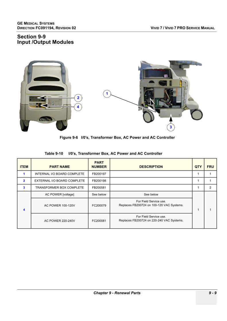
GE MEDICAL SYSTEMSDIRECTION FC091194, REVISION 02 VIVID 7 / VIVID 7 PRO SERVICE MANUAL
Chapter 9 - Renewal Parts 9 - 9
Section 9-9Input /Output Modules
Figure 9-6 I/0’s, Transformer Box, AC Power and AC Controller
Table 9-10 I/0’s, Transformer Box, AC Power and AC Controller
ITEM PART NAMEPART
NUMBER DESCRIPTION QTY FRU
1 INTERNAL I/O BOARD COMPLETE FB200197 1 1
2 EXTERNAL I/O BOARD COMPLETE FB200198 1 1
3 TRANSFORMER BOX COMPLETE FB200581 1 2
4
AC POWER [voltage] See below See below
1 1AC POWER 100-120V FC200079
For Field Service use. Replaces FB200724 on 100-120 VAC Systems.
AC POWER 220-240V FC200081For Field Service use.
Replaces FB200724 on 220-240 VAC Systems.
12
3
4
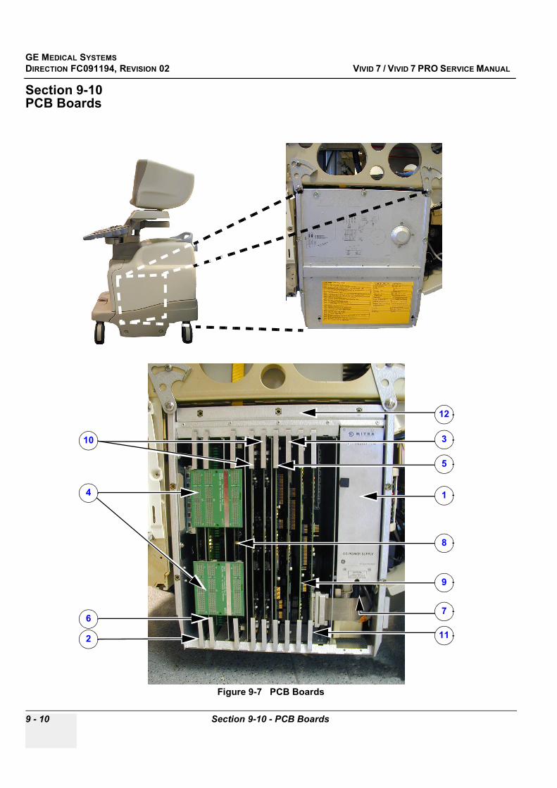
GE MEDICAL SYSTEMSDIRECTION FC091194, REVISION 02 VIVID 7 / VIVID 7 PRO SERVICE MANUAL
9 - 10 Section 9-10 - PCB Boards
Section 9-10PCB Boards
Figure 9-7 PCB Boards
1
2
3
4
5
67
8
9
10
11
12
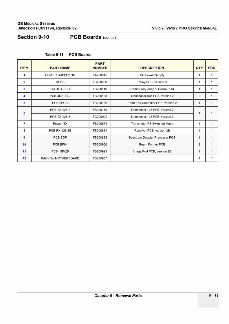
GE MEDICAL SYSTEMSDIRECTION FC091194, REVISION 02 VIVID 7 / VIVID 7 PRO SERVICE MANUAL
Chapter 9 - Renewal Parts 9 - 11
Section 9-10 PCB Boards (cont’d)
Table 9-11 PCB Boards
ITEM PART NAMEPART
NUMBER DESCRIPTION QTY FRU
1 POWER SUPPLY DC FA200945 DC Power Supply 1 1
2 RLY-3 FB200060 Relay PCB, version 3 1 1
3 PCB RF TISSUE FB200140 Radio Frequency & Tissue PCB 1 1
4 PCB XDBUS-2 FB200158 Transducer Bus PCB, version 2 2 1
5 PCB FEC-II FB200165 Front End Controller PCB, version 2 1 1
6PCB TX-128-2 FB200170 Transmitter 128 PCB, version 2
1 1PCB TX-128-3 FC200022 Transmitter 128 PCB, version 3
7 Power, TX FB200574 Transmitter PS Switched Mode 1 1
8 PCB RX-128-3B FB200831 Receiver PCB, version 3B 1 1
9 PCB SDP FB200865 Spectrum Doppler Processor PCB 1 1
10 PCB BF64 FB200900 Beam Former PCB 2 1
11 PCB IMP-2B FB200991 Image Port PCB, version 2B 1 1
12 RACK W/ MOTHERBOARD FB200957 1 1
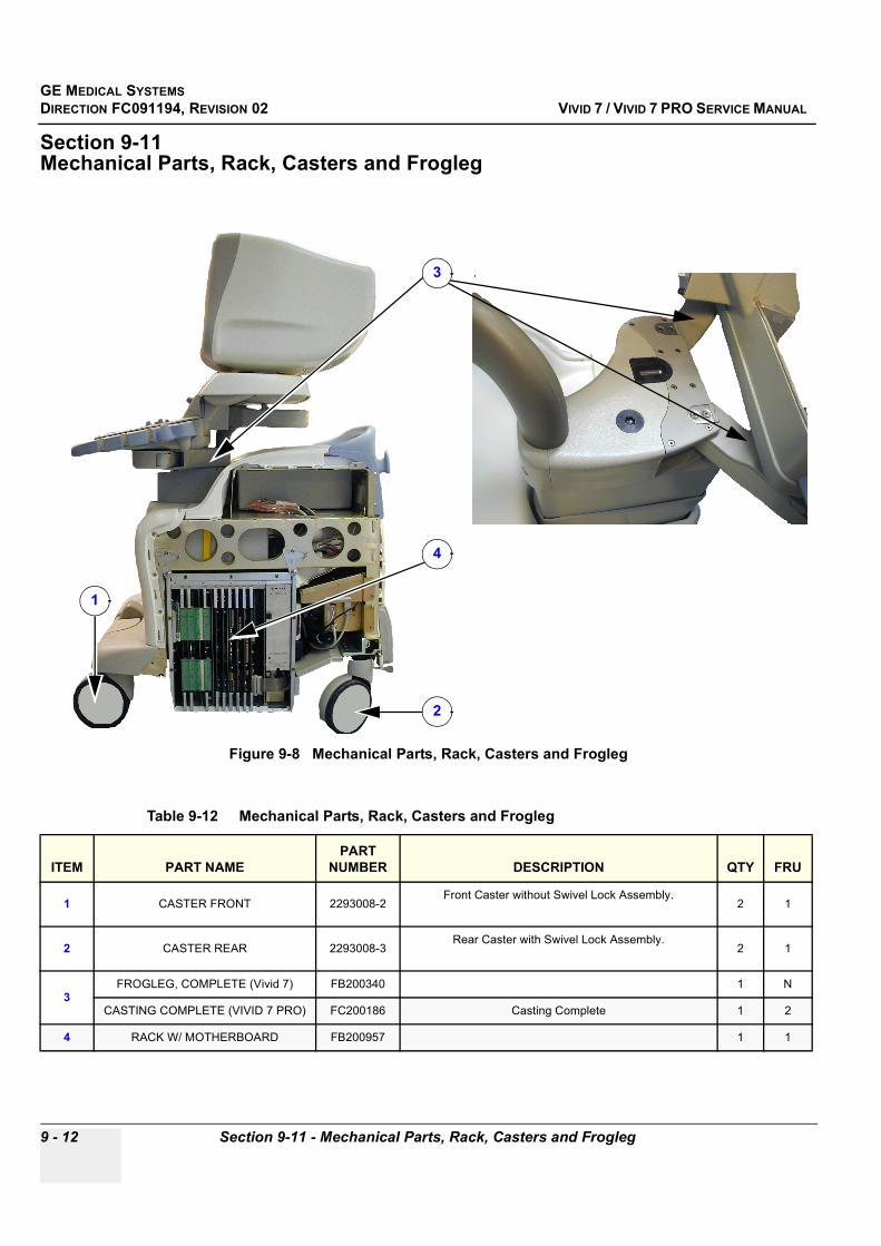
GE MEDICAL SYSTEMSDIRECTION FC091194, REVISION 02 VIVID 7 / VIVID 7 PRO SERVICE MANUAL
9 - 12 Section 9-11 - Mechanical Parts, Rack, Casters and Frogleg
Section 9-11Mechanical Parts, Rack, Casters and Frogleg
Figure 9-8 Mechanical Parts, Rack, Casters and Frogleg
Table 9-12 Mechanical Parts, Rack, Casters and Frogleg
ITEM PART NAMEPART
NUMBER DESCRIPTION QTY FRU
1 CASTER FRONT 2293008-2Front Caster without Swivel Lock Assembly.
2 1
2 CASTER REAR 2293008-3Rear Caster with Swivel Lock Assembly.
2 1
3FROGLEG, COMPLETE (Vivid 7) FB200340 1 N
CASTING COMPLETE (VIVID 7 PRO) FC200186 Casting Complete 1 2
4 RACK W/ MOTHERBOARD FB200957 1 1
1
2
4
3

GE MEDICAL SYSTEMSDIRECTION FC091194, REVISION 02 VIVID 7 / VIVID 7 PRO SERVICE MANUAL
Chapter 9 - Renewal Parts 9 - 13
Section 9-12Brake Assembly and Console Lock
Figure 9-9 Mechanical Parts, Brake Assembly and Console Lock
Table 9-13 Mechanical Parts, Brake Assembly and Console Lock
ITEM PART NAMEPART
NUMBER DESCRIPTION QTY FRU
1 COMMON TOP CONSOLE LOCK ASSY FB200350 1 2
2 RELEASE LOCK FB200920 1 2
3 PEDAL ASSEMBLY FB200595Brake Pedal Assembly
1 1
4 HANDLE, Z-RELEASE FB307296 1 2
5 HANDLE, XY-RELEASE FB307297 1 2
6 WIRECABLE FB307375 Wire used when operating vertical movement of Top Console 1 2
1
2
3
4
56

GE MEDICAL SYSTEMSDIRECTION FC091194, REVISION 02 VIVID 7 / VIVID 7 PRO SERVICE MANUAL
9 - 14 Section 9-13 - Cables
Section 9-13Cables
Figure 9-10 Vivid 7 / Vivid 7 PRO Interconnect Cabling, (Left Part of Drawing)
exte
rnal
IOP
WB
EXTERNAL I/OModule
10/100bT
PA
RA
LLEL
CO
M1
CO
M2 (M
odem)
US
B1
US
B2
B/W PRINTERSONY
UP-890MD
AC IN
REMOTE
BW VIDEO IN
BW VIDEO OUT
COLOR PRINTERSONY
UP-2900MD
INPUT
RS-232CAC IN
SVIDEO
VIDEO
R
G
B
SYNC
VCRSONY
SVO-9500MD
LEFT
RIGHT
LEFT
RIGHT
VIDEO IN
RS-232C
AC IN
VIDEO OUT
MONITOR OUT
MIC
REMOTE
FOOTSWITCH
INDICATOR
AUDIO OUT
AUDIO IN
ATX POWER SUPPLYUPS
IDE #1DC POWER
PROBES
AC POWER
INTERNAL I/O
USER INTERFACE
REMOTE 1
REMOTE 2
R
G
B
SYNC
SVIDEO
VIDEOOUTPUT
TO AC BOX
MODEM
TO AC INLET BOX
TO AC INLET BOX
50M
50M
TRIGGER
USB
SVGA OUT
MODEM
FOOTSWITCH
BURN INPOWERON/OFF
CONTROL
RE
LAY
RX
-128
TX
-12 8
BF
- 64
FE
C2
RT
F2
SD
P
IMA
GE
PO
RT
DCPOWER
BACKPLANE
AC
IN
TO AC INLET BOX
CARDRACK
COLUMN
DOPPLER
TXPWR
AC
OU
T
BF
-64
RS
4 22 ,
I2C
US
B; +
1 2P
C; M
IC I N
; AU
DIO
OU
T
PS
ON
; FA
N S
PE
ED
CO
NT
RO
L
S- V
ideo
; C-V
ideo
; I2C
; RS
2 32
( X4)
68M
TO AC INLET BOXMODEMAC TO DCCONVERTER
A8 A9 A6 A7 A2 A11 A10 A1 A3
M F M M F
A4 A5 B5
F
B6
M
B7
M
B8 B2 B1 B3
F
B4
F
F
A14
M
A15M
A16F
A13F
A12 2mm maleconnector
2mm
male
connector
MM
RS232 (COM1:)
Audio (R)
Audio (L)
C-Video OUT
10/100Base-TX
S-Video OUT
BW Video OUT
EXPOSE #1
EXPOSE #2
exte
rnal
IOu p
per
PW
B
PC2IO
RG
B O
UT
SV
GA
OU
Tto top console
SV
GA
OU
T 2
S/C
VID
EO
OU
T
SV
GA
IN
PO
WE
RF
RO
M B
EP
I2CR
S232(X
4)
PCVIC
F
D5F
D4F
D3 D1F
D2
Serial interfaceto/from UPS
JFP1
POWER on/off (RESET*)
GND
5Vstb
BEP mo
Cable#1
Cable#2
Cable#3
Cable#16
Cable#16
Cable#17
Cable#17
Cable#9
Cable#18
Cable#5
Cable#6
Cable#10
Cable#11
Cable#7
Cable#4
Mushashi Flat panel video cable is not used
Parkingconector
JWOL1
Cable#21
Cable#23
Cable#24
Cable#25
MONITOR
VID
EO
MIC
OP PANELOP
PA
NE
L I/F
AC
PO
WE
R
Cable#26
AGP VIDEO
MIC
INLIN
E O
UT
LINE
IN
Cable#19
Cable#29
Cable#13
Cable#13
Cable#13
Cable#13
Cable#13
See Figure 9-11
See Figure 9-11
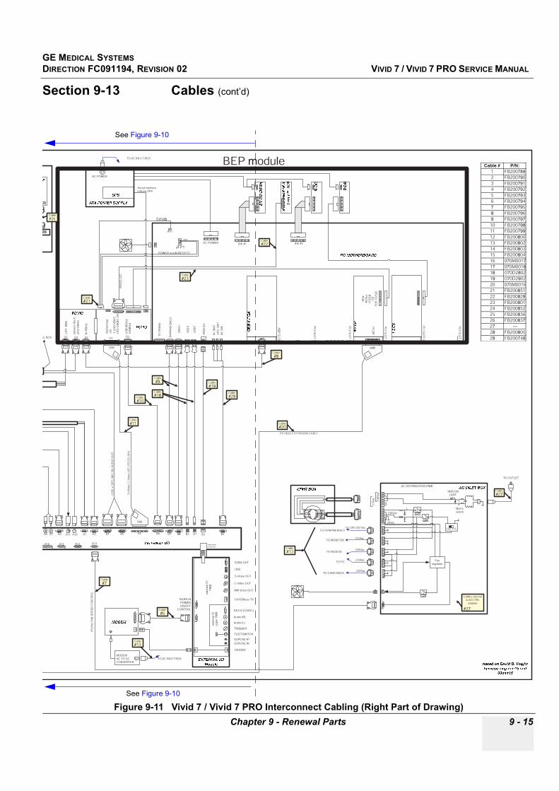
GE MEDICAL SYSTEMSDIRECTION FC091194, REVISION 02 VIVID 7 / VIVID 7 PRO SERVICE MANUAL
Chapter 9 - Renewal Parts 9 - 15
Section 9-13 Cables (cont’d)
Figure 9-11 Vivid 7 / Vivid 7 PRO Interconnect Cabling (Right Part of Drawing)
exte
rnal
IOP
WB
EXTERNAL I/OModule
PC
I SLO
T 4
10/100bT
PA
RA
LLEL
CO
M1
CO
M2 (M
odem)
US
B1
US
B2
PC MOTHERBOARD
ATX POWER SUPPLYUPS
HARD DRIVE
ECG, P
atie
nt
interface m
odule
MOD
CD-R
IDE #1 IDE #2DC POWER
AC POWER
INTERNAL I/O
AC BOX
MODEM
TO AC INLET BOX
50M
50M
TRIGGER
USB
SVGA OUT
MODEM
FOOTSWITCH
BURN INPOWERON/OFF
CONTROL
based on David D. Voightharness map mar15.vsd
00mar15
RS
4 22 ,
I2C
US
B; +
1 2P
C; M
IC I N
; AU
DIO
OU
T
PS
ON
; FA
N S
PE
ED
CO
NT
RO
L
S- V
ideo
; C-V
ideo
; I2C
; RS
2 32
( X4)
PCI BUS EXTENSION CABLE
68M
TO AC INLET BOXMODEMAC TO DCCONVERTER
A6 A7 A2 A11 A10 A1 A3
M F M M F
A4 A5 B5
F
B6
M
B7
M
B8 B2 B1 B3
F
B4
F
F
A14
M
A15M
A16F
A12 2mm maleconnector
MM
XD
IF
TD
1
TD
2
TD
3
TD
4
EQ
SM
OR
GA
SB
OA
RD
BM
P
CF
P
BACKPLANE
MUSASHI CARDRACK
SP
AR
E
DCPOWER
AC
IN
AC
OU
T
RS232 (COM1:)
Audio (R)
Audio (L)
C-Video OUT
10/100Base-TX
S-Video OUT
BW Video OUT
EXPOSE #1
EXPOSE #2
exte
rnal
IOu p
per
PW
B
PC2IO
RG
B O
UT
SV
GA
OU
Tto top console
SV
GA
OU
T 2
S/C
VID
EO
OU
T
SV
GA
IN
PO
WE
RF
RO
M B
EP
I2CR
S232(X
4)
PCVIC
F
D5F
D4F
D3 D1F
D2
Serial interfaceto/from UPS
JFP1
POWER on/off (RESET*)
GND
5Vstb
BEP module
PC
I SLO
T 5
PC
2IPR
S232 (X
4)I2C
PC2IP
PC
i SLO
T 3
RS
422P
SO
NP
OK
SCSI
Cable#9
Cable#18
Cable#20
Cable#6
Cable#10
Cable#11
Cable#7
Cable # P/N:1 FB2007892 FB2007903 FB2007914 FB2007925 FB2007936 FB2007947 FB2007958 FB2007969 FB20079710 FB20079811 FB20079912 FB20080013 FB20080214 FB20080315 FB20080416 070M001717 070M001818 070D280219 070D290220 070M001621 FB20085122 FB20082923 FB20080124 FB20085225 FB20083626 FB20083727 ---28 FB20080529 FB200748
JWOL1
Cable#21
Cable#22
Cable#23
OR
Cable#26
AC DISTRIBUTION PWB AC INLET BOXTO OUTLET
M
INRUSHLIMIT
Mainsswitch
XFMR BOX
2 30V
ac
115V
ac
TO MONITOR
TO PC
TO PERIPHERIALS
TO MODEM
TO CARD RACK
115Vac
230Vac
230Vac
230Vac
115 OR 230 Vac
230Vac
20Vac
230 115
Fanregulator
Cable#27
Cables internalin ACCTRL
module
#27
SOUN
D CARD
SP
EA
KE
R O
UT
MUSAS
HI ONLY
PCI VIDEO
PC
I SLO
T 1
MUSAS
HI ONLY
AGP VIDEO A
GP
SLO
T
Cable#8
DIG
ITAL O
UT
MIC
INLIN
E O
UT
LINE
IN
PC
I SLO
T 2
MIC
INLIN
E O
UT
LINE
IN
Cable#19
Cable#29
Cable#13
Cable#13
L
See Figure 9-10
See Figure 9-10
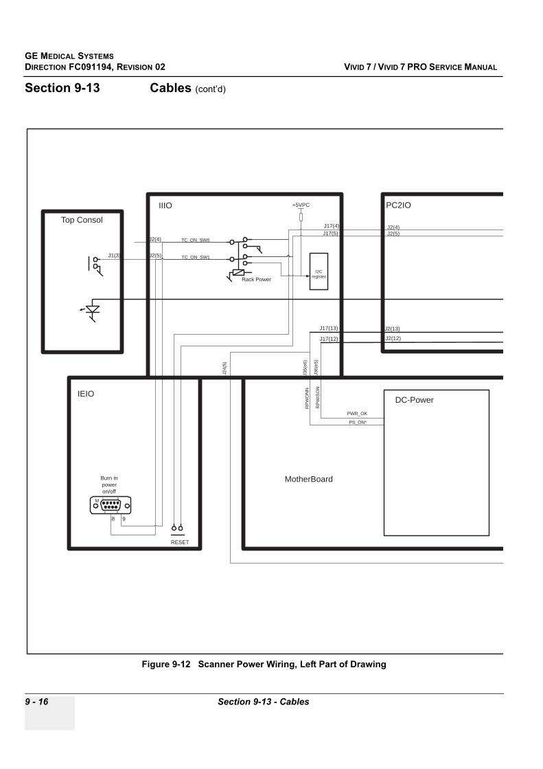
GE MEDICAL SYSTEMSDIRECTION FC091194, REVISION 02 VIVID 7 / VIVID 7 PRO SERVICE MANUAL
9 - 16 Section 9-13 - Cables
Section 9-13 Cables (cont’d)
Figure 9-12 Scanner Power Wiring, Left Part of Drawing
Top Consol
Rack Power
IIIO
J1(3)
J2(4)
IEIO
RESET
6 9
1 5M
Burn inpoweron/off
98
J2(5)
TC_ON_SW0
TC_ON_SW1
J2(4)J2(5)
PC2IO
J17(4)J17(5)
MotherBoard
DC-Power
PWR_OK
PS_ON*
J36(
e5)
J36(
e6)
J17(13)
J17(12)
J2(13)
J2(12)
RP
WIS
ON
RP
WO
NN
I2Cregister
+5VPC
J24(
5)
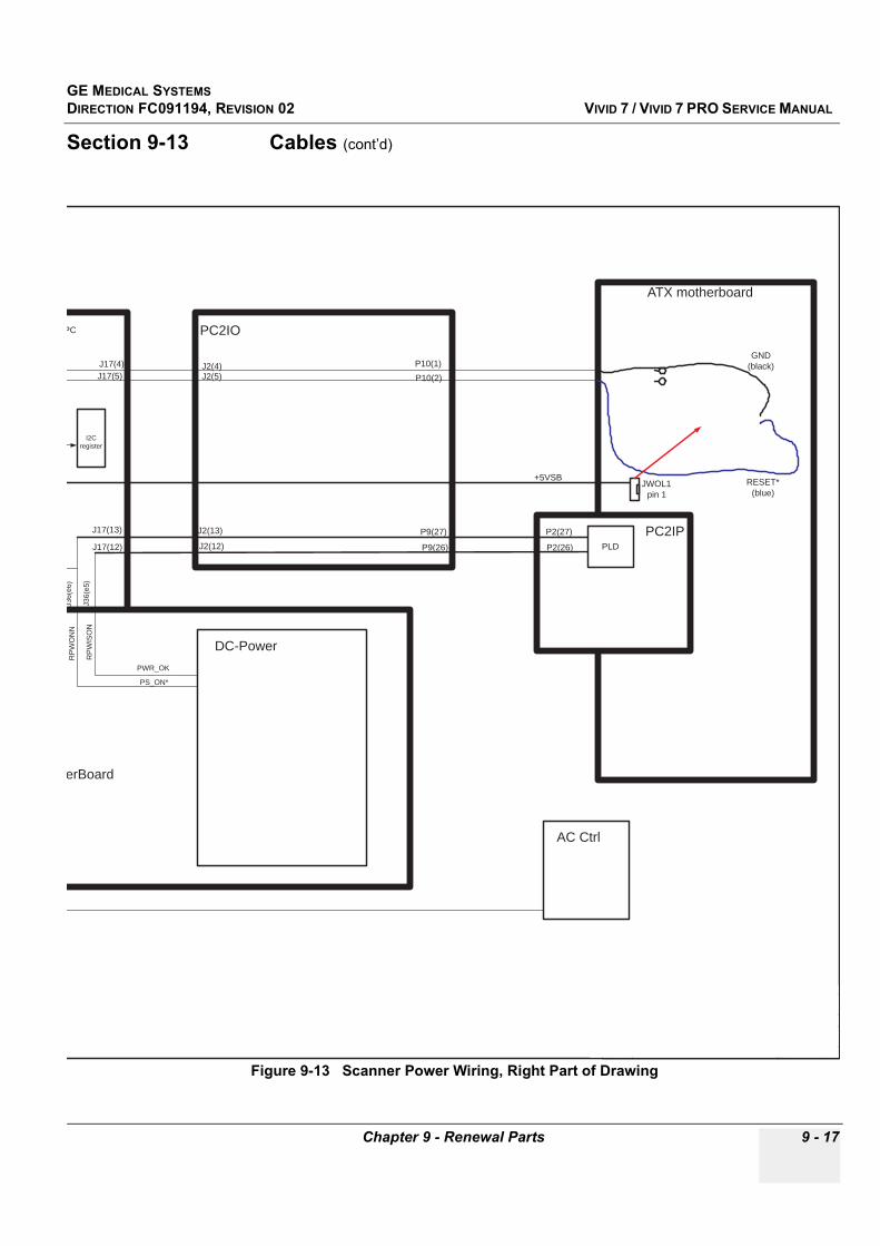
GE MEDICAL SYSTEMSDIRECTION FC091194, REVISION 02 VIVID 7 / VIVID 7 PRO SERVICE MANUAL
Chapter 9 - Renewal Parts 9 - 17
Section 9-13 Cables (cont’d)
Figure 9-13 Scanner Power Wiring, Right Part of Drawing
ATX motherboard
P10(1)
P10(2)J2(4)J2(5)
PC2IO
J17(4)J17(5)
PC2IP
therBoard
DC-Power
PWR_OK
PS_ON*
J36(
e5)
J36(
e6)
J17(13)
J17(12)
J2(13)
J2(12)
P9(27)
P9(26)
P2(27)
P2(26) PLD
RP
WIS
ON
RP
WO
NN
I2Cregister
VPC
GND(black)
RESET*(blue)
+5VSB
AC Ctrl
JWOL1pin 1
g GE Vingmed Ultrasound
MODULE
IDUNN top level
PROJECT
IDUNNDESIGNER
DV/MLHCHECKED
SÿAPPROVED
DS
DATE
10nov2000SIGN
DATE
10nov2000DATE
10nov2000
SIGN
SIGN
DRAWING NUMBER
FA004808
REV
02
TYPE OF DOC.
Wiring DiagramCLASIFICATION
SCALE
N/AFILE
C:\w\work\Idunn\harness-map\Idunn-wire-diagram.vsdSHEET
2 OF 3
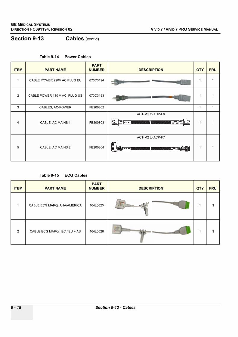
GE MEDICAL SYSTEMSDIRECTION FC091194, REVISION 02 VIVID 7 / VIVID 7 PRO SERVICE MANUAL
9 - 18 Section 9-13 - Cables
Section 9-13 Cables (cont’d)
Table 9-14 Power Cables
ITEM PART NAMEPART
NUMBER DESCRIPTION QTY FRU
1 CABLE POWER 220V AC PLUG EU 070C3194 1 1
2 CABLE POWER 110 V AC, PLUG US 070C3193 1 1
3 CABLES, AC-POWER FB200802 1 1
4 CABLE, AC MAINS 1 FB200803
ACT-M1 to ACP-F6
1 1
5 CABLE, AC MAINS 2 FB200804
ACT-M2 to ACP-F7
1 1
Table 9-15 ECG Cables
ITEM PART NAMEPART
NUMBER DESCRIPTION QTY FRU
1 CABLE ECG MARQ. AHA/AMERICA 164L0025 1 N
2 CABLE ECG MARQ. IEC / EU + AS 164L0026 1 N
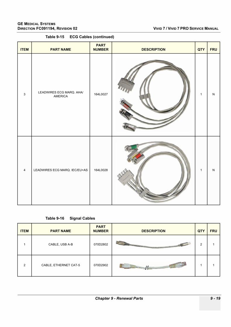
GE MEDICAL SYSTEMSDIRECTION FC091194, REVISION 02 VIVID 7 / VIVID 7 PRO SERVICE MANUAL
Chapter 9 - Renewal Parts 9 - 19
3 LEADWIRES ECG MARQ. AHA/AMERICA 164L0027 1 N
4 LEADWIRES ECG MARQ. IEC/EU+AS 164L0028 1 N
Table 9-16 Signal Cables
ITEM PART NAMEPART
NUMBER DESCRIPTION QTY FRU
1 CABLE, USB A-B 070D2802 2 1
2 CABLE, ETHERNET CAT-5 070D2902 1 1
Table 9-15 ECG Cables (continued)
ITEM PART NAMEPART
NUMBER DESCRIPTION QTY FRU
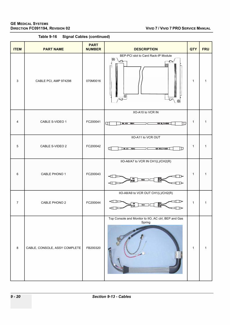
GE MEDICAL SYSTEMSDIRECTION FC091194, REVISION 02 VIVID 7 / VIVID 7 PRO SERVICE MANUAL
9 - 20 Section 9-13 - Cables
3 CABLE PCI, AMP 974298 070M0016
BEP-PCI slot to Card Rack-IP Module
1 1
4 CABLE S-VIDEO 1 FC200041
IIO-A10 to VCR IN
1 1
5 CABLE S-VIDEO 2 FC200042
IIO-A11 to VCR OUT
1 1
6 CABLE PHONO 1 FC200043
IIO-A6/A7 to VCR IN CH1(L)/CH2(R)
1 1
7 CABLE PHONO 2 FC200044
IIO-A8/A9 to VCR OUT CH1(L)/CH2(R)
1 1
8 CABLE, CONSOLE, ASSY COMPLETE FB200320
Top Console and Monitor to IIO, AC ctrl, BEP and Gas Spring
1 1
Table 9-16 Signal Cables (continued)
ITEM PART NAMEPART
NUMBER DESCRIPTION QTY FRU
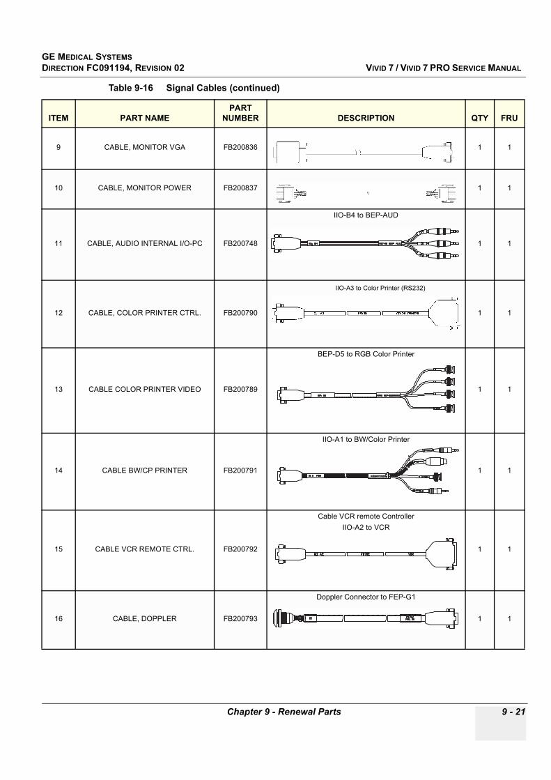
GE MEDICAL SYSTEMSDIRECTION FC091194, REVISION 02 VIVID 7 / VIVID 7 PRO SERVICE MANUAL
Chapter 9 - Renewal Parts 9 - 21
9 CABLE, MONITOR VGA FB200836 1 1
10 CABLE, MONITOR POWER FB200837 1 1
11 CABLE, AUDIO INTERNAL I/O-PC FB200748
IIO-B4 to BEP-AUD
1 1
12 CABLE, COLOR PRINTER CTRL. FB200790
IIO-A3 to Color Printer (RS232)
1 1
13 CABLE COLOR PRINTER VIDEO FB200789
BEP-D5 to RGB Color Printer
1 1
14 CABLE BW/CP PRINTER FB200791
IIO-A1 to BW/Color Printer
1 1
15 CABLE VCR REMOTE CTRL. FB200792
Cable VCR remote ControllerIIO-A2 to VCR
1 1
16 CABLE, DOPPLER FB200793
Doppler Connector to FEP-G1
1 1
Table 9-16 Signal Cables (continued)
ITEM PART NAMEPART
NUMBER DESCRIPTION QTY FRU

GE MEDICAL SYSTEMSDIRECTION FC091194, REVISION 02 VIVID 7 / VIVID 7 PRO SERVICE MANUAL
9 - 22 Section 9-13 - Cables
17 CABLE, STD. MODEM FB200794
Modem to EIO-L2
1 1
18 Modem Line Cable FC200032
EIO-L3 to Modem
1 ?
19 CABLE, FAN SPEED CTRL. FB200795
Cable, Fan Speed Controller.IIO-A15 to ACP-F8
1 1
20 CABLE, MON. STD. FB200796
BEP-C13 to BEP-D3
1 1
21 CABLE, RS232 COM 1/2 FB200797
IIO-C6 to BEP-C6 or IIO-B8 to BEP-C7
1 1
22 CABLE POWER/CTRL INT I/O PC2 I/O FB200798
Cable, Power/Controller. Internal I/O-PC2IOIIO-B6 to BEP-D2
1 1
23 CABLE, SIGNALS INT I/O-PC2IO FB200799
Cable, Signals Internal I/O-PC2IOBEP-D1 to IIO-B5
1 1
Table 9-16 Signal Cables (continued)
ITEM PART NAMEPART
NUMBER DESCRIPTION QTY FRU
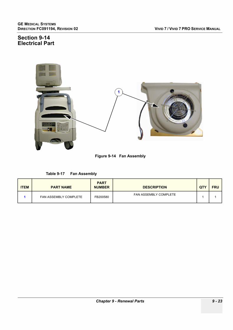
GE MEDICAL SYSTEMSDIRECTION FC091194, REVISION 02 VIVID 7 / VIVID 7 PRO SERVICE MANUAL
Chapter 9 - Renewal Parts 9 - 23
Section 9-14Electrical Part
Figure 9-14 Fan Assembly
Table 9-17 Fan Assembly
ITEM PART NAMEPART
NUMBER DESCRIPTION QTY FRU
1 FAN ASSEMBLY COMPLETE FB200580FAN ASSEMBLY COMPLETE
1 1
1
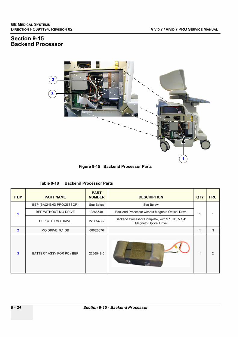
GE MEDICAL SYSTEMSDIRECTION FC091194, REVISION 02 VIVID 7 / VIVID 7 PRO SERVICE MANUAL
9 - 24 Section 9-15 - Backend Processor
Section 9-15Backend Processor
Figure 9-15 Backend Processor Parts
Table 9-18 Backend Processor Parts
ITEM PART NAMEPART
NUMBER DESCRIPTION QTY FRU
1
BEP (BACKEND PROCESSOR) See Below See Below
1 1BEP WITHOUT MO DRIVE 2266548 Backend Processor without Magneto Optical Drive
BEP WITH MO DRIVE 2266548-2 Backend Processor Complete, with 9.1 GB, 5 1/4” Magneto Optical Drive
2 MO DRIVE, 9,1 GB 066E0676 1 N
3 BATTERY ASSY FOR PC / BEP 2266548-5 1 2
1
3
2

GE MEDICAL SYSTEMSDIRECTION FC091194, REVISION 02 VIVID 7 / VIVID 7 PRO SERVICE MANUAL
Chapter 9 - Renewal Parts 9 - 25
Section 9-16Peripherals
9-16-1 Printers On Board
9-16-2 Network Printers
9-16-3 Video Cassette Recorder (VCR)
Table 9-19 Printers On Board
ITEM PART NAMEPART
NUMBER DESCRIPTION QTY FRU
1 SONY UP-895MDW 2288502 SONY B/W PRINTER 1 1
2 SONY UP21MD 066E2955 COLOR PRINTER UP21MD ASSEMBLY 1 1
3 SONY UP2950MD 066E2950 PRINTER UP-2950MD (INCL.MAN) 100-220V, NTSC/PAL 1 1
Table 9-20 Network Printers
ITEM PART NAMEPART
NUMBER DESCRIPTION QTY FRU
1 Epson 980N 066E0383 USB & Network printer 110V
1
N
2 Epson 980N 066E0384 USB & Network printer 220V N
3 HP DESKJET 990 CXI, 110V PC EP100422 Network Printer 1
4 HP DESKJET 990 CXI, 230V PC EP100423 Network Printer 1
Table 9-21 VCRs used for Vivid 7/Vivid 7 PRO
ITEM PART NAMEPART
NUMBER DESCRIPTION QTY FRU
1 SONY SVO9500MDP2 066E9510 SUPER-VHS, PAL Needs software v.2.0 (BT’02)
1
1
2 SONY SVO9500MD 066E9511 SUPER-VHS, NTSC Needs software v.2.0 (BT’02)
1
3 PANASONICS AG-MD835E 066E0836 SUPER-VHS, PAL 1
4 PANASONICS AG-MD835P 066E0835 SUPER-VHS, NTSC 1

GE MEDICAL SYSTEMSDIRECTION FC091194, REVISION 02 VIVID 7 / VIVID 7 PRO SERVICE MANUAL
9 - 26 Section 9-16 - Peripherals
9-16-4 Footswitch
Table 9-22 Footswitch
ITEM Part NamePart
Number Description QTY FRU
1 Footswitch FB200952 FOOTSWITCH 3-PEDALS IP68
1 2
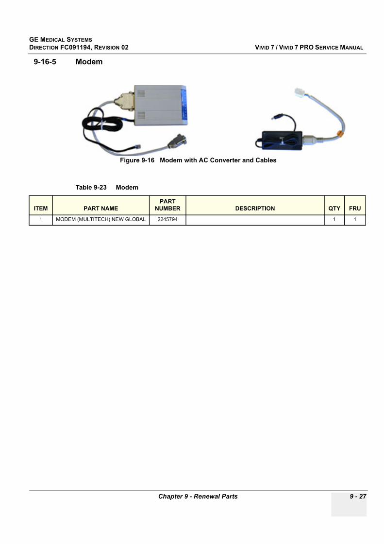
GE MEDICAL SYSTEMSDIRECTION FC091194, REVISION 02 VIVID 7 / VIVID 7 PRO SERVICE MANUAL
Chapter 9 - Renewal Parts 9 - 27
9-16-5 Modem
Figure 9-16 Modem with AC Converter and Cables
Table 9-23 Modem
ITEM PART NAMEPART
NUMBER DESCRIPTION QTY FRU
1 MODEM (MULTITECH) NEW GLOBAL 2245794 1 1
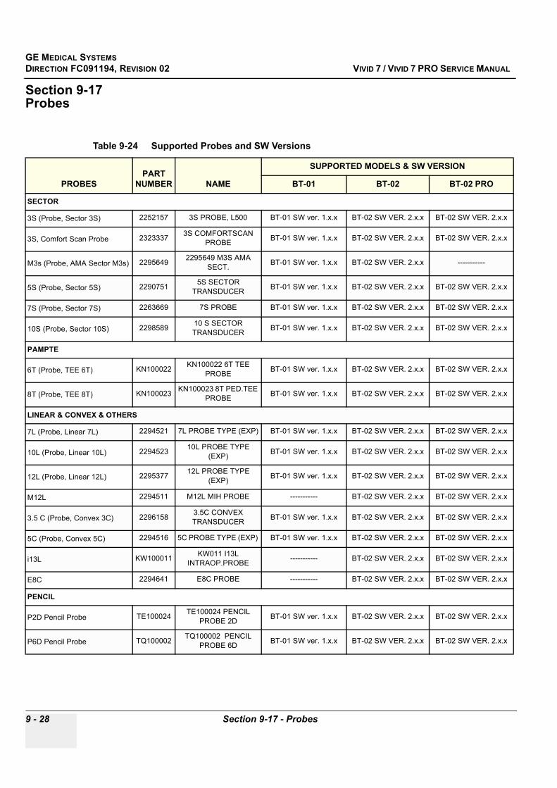
GE MEDICAL SYSTEMSDIRECTION FC091194, REVISION 02 VIVID 7 / VIVID 7 PRO SERVICE MANUAL
9 - 28 Section 9-17 - Probes
Section 9-17Probes
Table 9-24 Supported Probes and SW Versions
PROBESPART
NUMBER NAME
SUPPORTED MODELS & SW VERSION
BT-01 BT-02 BT-02 PRO
SECTOR
3S (Probe, Sector 3S) 2252157 3S PROBE, L500 BT-01 SW ver. 1.x.x BT-02 SW VER. 2.x.x BT-02 SW VER. 2.x.x
3S, Comfort Scan Probe 2323337 3S COMFORTSCAN PROBE BT-01 SW ver. 1.x.x BT-02 SW VER. 2.x.x BT-02 SW VER. 2.x.x
M3s (Probe, AMA Sector M3s) 2295649 2295649 M3S AMA SECT. BT-01 SW ver. 1.x.x BT-02 SW VER. 2.x.x -----------
5S (Probe, Sector 5S) 2290751 5S SECTOR TRANSDUCER BT-01 SW ver. 1.x.x BT-02 SW VER. 2.x.x BT-02 SW VER. 2.x.x
7S (Probe, Sector 7S) 2263669 7S PROBE BT-01 SW ver. 1.x.x BT-02 SW VER. 2.x.x BT-02 SW VER. 2.x.x
10S (Probe, Sector 10S) 2298589 10 S SECTOR TRANSDUCER BT-01 SW ver. 1.x.x BT-02 SW VER. 2.x.x BT-02 SW VER. 2.x.x
PAMPTE
6T (Probe, TEE 6T) KN100022 KN100022 6T TEE PROBE BT-01 SW ver. 1.x.x BT-02 SW VER. 2.x.x BT-02 SW VER. 2.x.x
8T (Probe, TEE 8T) KN100023 KN100023 8T PED.TEE PROBE BT-01 SW ver. 1.x.x BT-02 SW VER. 2.x.x BT-02 SW VER. 2.x.x
LINEAR & CONVEX & OTHERS
7L (Probe, Linear 7L) 2294521 7L PROBE TYPE (EXP) BT-01 SW ver. 1.x.x BT-02 SW VER. 2.x.x BT-02 SW VER. 2.x.x
10L (Probe, Linear 10L) 2294523 10L PROBE TYPE (EXP) BT-01 SW ver. 1.x.x BT-02 SW VER. 2.x.x BT-02 SW VER. 2.x.x
12L (Probe, Linear 12L) 2295377 12L PROBE TYPE (EXP) BT-01 SW ver. 1.x.x BT-02 SW VER. 2.x.x BT-02 SW VER. 2.x.x
M12L 2294511 M12L MIH PROBE ----------- BT-02 SW VER. 2.x.x BT-02 SW VER. 2.x.x
3.5 C (Probe, Convex 3C) 2296158 3.5C CONVEX TRANSDUCER BT-01 SW ver. 1.x.x BT-02 SW VER. 2.x.x BT-02 SW VER. 2.x.x
5C (Probe, Convex 5C) 2294516 5C PROBE TYPE (EXP) BT-01 SW ver. 1.x.x BT-02 SW VER. 2.x.x BT-02 SW VER. 2.x.x
i13L KW100011 KW011 I13L INTRAOP.PROBE ----------- BT-02 SW VER. 2.x.x BT-02 SW VER. 2.x.x
E8C 2294641 E8C PROBE ----------- BT-02 SW VER. 2.x.x BT-02 SW VER. 2.x.x
PENCIL
P2D Pencil Probe TE100024 TE100024 PENCIL PROBE 2D BT-01 SW ver. 1.x.x BT-02 SW VER. 2.x.x BT-02 SW VER. 2.x.x
P6D Pencil Probe TQ100002 TQ100002 PENCIL PROBE 6D BT-01 SW ver. 1.x.x BT-02 SW VER. 2.x.x BT-02 SW VER. 2.x.x
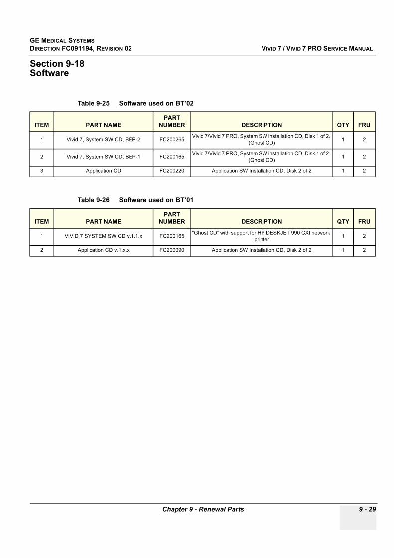
GE MEDICAL SYSTEMSDIRECTION FC091194, REVISION 02 VIVID 7 / VIVID 7 PRO SERVICE MANUAL
Chapter 9 - Renewal Parts 9 - 29
Section 9-18Software
Table 9-25 Software used on BT’02
ITEM PART NAMEPART
NUMBER DESCRIPTION QTY FRU
1 Vivid 7, System SW CD, BEP-2 FC200265 Vivid 7/Vivid 7 PRO, System SW installation CD, Disk 1 of 2. (Ghost CD) 1 2
2 Vivid 7, System SW CD, BEP-1 FC200165 Vivid 7/Vivid 7 PRO, System SW installation CD, Disk 1 of 2. (Ghost CD) 1 2
3 Application CD FC200220 Application SW Installation CD, Disk 2 of 2 1 2
Table 9-26 Software used on BT’01
ITEM PART NAMEPART
NUMBER DESCRIPTION QTY FRU
1 VIVID 7 SYSTEM SW CD v.1.1.x FC200165 “Ghost CD” with support for HP DESKJET 990 CXI network printer 1 2
2 Application CD v.1.x.x FC200090 Application SW Installation CD, Disk 2 of 2 1 2

GE MEDICAL SYSTEMSDIRECTION FC091194, REVISION 02 VIVID 7 / VIVID 7 PRO SERVICE MANUAL
9 - 30 Section 9-19 - Options
Section 9-19Options
Table 9-27 Options - Vivid 7 PRO, BT’02
ITEM PART NAMEPART
NUMBER DESCRIPTION QTY FRU
1 Contrast FC200162 - -
2 Stress FB200839 - -
3 Dicom FB200849 (DICOM via network) - -
4 QAnalysis FC200164
Table 9-28 Options - Vivid 7, BT’02
ITEM PART NAMEPART
NUMBER DESCRIPTION QTY FRU
1 Contrast FC200162 - -
2 Stress FB200839 - -
3 Dicom FB200849 (DICOM via network) - -
4 Strain FC200163 - -
5 Strain Japan FC200171
6 QAnalysis FC200164
Table 9-29 Options - Vivid 7, BT’01
ITEM PART NAMEPART
NUMBER DESCRIPTION QTY FRU
1 Contrast FB200842 - -
2 Stress FB200839 - -
3 Tissue Tracking FB200841 - -
4 Archive FB200838 - -
5 Dicom FB200849 (Dicom via network) - -

GE MEDICAL SYSTEMSDIRECTION FC091194, REVISION 02 VIVID 7 / VIVID 7 PRO SERVICE MANUAL
Chapter 9 - Renewal Parts 9 - 31
Section 9-20Kits
Table 9-30 Kits, Overview
Item PART NAMEPART
NUMBER DESCRIPTION QTY FRU
1 BUMPER KIT FROGLEG FC200086 BUMPER KIT, FROGLEG 1 1
2 COLUMN COVER KIT FC200183 COLUMN COVER KIT (Same as FC200088) 1 1
3 KNOB KIT 2188902-8 ROUND KNOBS ON OPERATOR PANEL 1 1

GE MEDICAL SYSTEMSDIRECTION FC091194, REVISION 02 VIVID 7 / VIVID 7 PRO SERVICE MANUAL
9 - 32 Section 9-20 - Kits
9-20-1 Parts Lists for Bumper Kit, Frogleg (Vivid 7 ONLY)
Figure 9-17 Bumper Kit, Frogleg, Base Seen From Above
Table 9-31 Bumper Kit, Frogleg
ITEM PART NAMEPART
NUMBER DESCRIPTION QTY FRU
1 BUMPER CRASH PAD - Bumper Crash Rear 1 N
2 BUMPER INNER BOSS - - 1 N
3 BUMPER RIGHT FROGLEG - - 1 N
4 BUMPER LEFT FROGLEG - - 1 N
5 BUMPER INNER BOSS CRASH - - 2 N
1
2
3
4
5

GE MEDICAL SYSTEMSDIRECTION FC091194, REVISION 02 VIVID 7 / VIVID 7 PRO SERVICE MANUAL
Chapter 9 - Renewal Parts 9 - 33
9-20-2 Parts Lists for Column Cover Kit
Table 9-32 Column Cover Kit
ITEM PART NAMEPART
NUMBER DESCRIPTION QTY FRU
1 Cover, Column, Lower - - 1 N
2 Cover, Column, Upper - - 1 N

GE MEDICAL SYSTEMSDIRECTION FC091194, REVISION 02 VIVID 7 / VIVID 7 PRO SERVICE MANUAL
9 - 34 Section 9-21 - Accessory Box, Vivid 7 / Vivid 7 PRO
Section 9-21Accessory Box, Vivid 7 / Vivid 7 PRO
Figure 9-18 Accessory Box, Vivid 7/Vivid 7 PRO
Table 9-33 Accessory Box, Vivid 7/Vivid 7 PRO
ITEM NAMEPART
NUMBER DESCRIPTION QTY FRU
1 ACCESSORY BOX, VIVID 7, US FC200038 1 N
2 ACCESSORY BOX, VIVID 7, EUR. FC200037 1 N
Table 9-34 Vivid 7 Accessory Box Contents (also used for Vivid 7 PRO)
ITEM NAMEPART
NUMBER DESCRIPTION QTY FRU
1 Vivid 7 Service Manual, English FC091194 This manual 1 N
2 Gel Ultrasound Bluescan 098B2001 Bottle 1 N
3 MO Disk 066E0519 Optional 1 N
4 Cable ECG Marquette IEC 164L0026 All countries except USA 1 N
5 Leadwires ECG Marquette IEC 164L0028 All countries except USA 1 N

GE MEDICAL SYSTEMSDIRECTION FC091194, REVISION 02 VIVID 7 / VIVID 7 PRO SERVICE MANUAL
Chapter 9 - Renewal Parts 9 - 35
6 Power Cable 070C3194 All countries except USA 1 N
7 Cable ECG Marquette AHA 164L0025 USA only 1 N
8 Leadwires ECG Marquette AHA 164L0027 USA only 1 N
9 Power Cable 070C3193 USA only 1 N
10 Vivid 7 PRO User Manual Update FC093202Multi-language
(Not needed for English V7USER MAN)
1 N
11
User Manual, Vivid 7, English FB092820 V7 USER MAN.
1
N
User Manual, Vivid 7, German FB092821 V7 USER MAN. N
User Manual, Vivid 7, French FB092822 V7 USER MAN. N
User Manual, Vivid 7, Italian FB092823 V7 USER MAN. N
User Manual, Vivid 7, Spanish FB092824 V7 USER MAN. N
User Manual, Vivid 7, Portuguese FB092825 V7 USER MAN. N
User Manual, Vivid 7, Swedish FB092866 V7 USER MAN. N
User Manual, Vivid 7, Norwegian FB092867 V7 USER MAN. N
User Manual, Vivid 7, Danish FB092868 V7 USER MAN. N
User Manual, Vivid 7, Dutch FB092869 V7 USER MAN. N
User Manual, Vivid 7, Greek FB092870 V7 USER MAN. N
User Manual, Vivid 7, Russian FB092871 V7 USER MAN. N
User Manual, Vivid 7, Turkish FB092872 V7 USER MAN. N
User Manual, Vivid 7, Japanese FB092873 V7 USER MAN. N
User Manual, Vivid 7, Chinese FB092874 V7 USER MAN. N
User Manual, Vivid 7, Polish FB092875 V7 USER MAN. N
User Manual, Vivid 7, Hungarian FB092877 V7 USER MAN. N
User Manual, Vivid 7, Finnish FB092958 V7 USER MAN N
12 Reference Manual Volume 2 FB092888 V7 REFERENCE MAN 1 N
13 Probe User Manual(s) As Required N
Table 9-34 Vivid 7 Accessory Box Contents (also used for Vivid 7 PRO) (continued)
ITEM NAMEPART
NUMBER DESCRIPTION QTY FRU

GE MEDICAL SYSTEMSDIRECTION FC091194, REVISION 02 VIVID 7 / VIVID 7 PRO SERVICE MANUAL
9 - 36 Section 9-22 - Accessory Box, SERVICE V7, US
Section 9-22Accessory Box, SERVICE V7, US
Table 9-35 Accessory Box, SERVICE V7, US, Part Number FC200111
ITEM NAMEPART
NUMBER DESCRIPTION QTY FRU
1 VIVID7 USER MANUAL, ENGLISH FB092820 Covers both Vivid 7 and Vivid 7 PRO 1 N
2
V7 SYSTEM- AND APPL. SW CDs - V7 SYSTEM SW CD
- V7 SYSTEM SW UPGRADE CD- VIVID 7 & ECHOPAC PC APPL. SW
FC200229---
Part of FC200229Part of FC200229Part of FC200229
1 N
3 VIVID7 USER REFER. MANUAL VOL2
FB092888 1 N
4 GEL ULTRASOUND BLUESCAN 098B2001 1 N
5 DISK FOR MO-DRIVE 5.2 GB 066E0519 1 N
6 CABLE ECG MARQUETTE AHA 164L0025 1 N
7 LEADWIRES ECG MARQUETTE AHA
164L0027 1 N
8 CABLE MAINS 3,5M 3*1.90MM2 070C3193 1 N

GE MEDICAL SYSTEMSDIRECTION FC091194, REVISION 02 VIVID 7 / VIVID 7 PRO SERVICE MANUAL
Chapter 9 - Renewal Parts 9 - 37
Section 9-23Packing Parts for Reshipment
Figure 9-19 Packing Material
Table 9-36 Packing Material for Vivid 7 / Vivid 7 PRO Reshipment
ITEM DESCRIPTION PART NUMBER COMMENTS
1 Rear Stop Bumper N/A
Re-shipping: Re-use the original wooden box and other packing materials used for shipment
2 Front Stop Bumper N/A
3 Front Panel Reinforcement N/A
4 Shelf Reinforcement N/A
5 Wedge N/A
6 Monitor Reinforcement N/A
7 Pink plate N/A
8 Wooden Shelf N/A
9 Wooden box N/A
Plastic Foil N/A To wrap around the unit
9
1
2
3
4
5
6
7
8

GE MEDICAL SYSTEMSDIRECTION FC091194, REVISION 02 VIVID 7 / VIVID 7 PRO SERVICE MANUAL
9 - 38 Section 9-23 - Packing Parts for Reshipment
This page was intentionally left blank.

GE MEDICAL SYSTEMSDIRECTION FC091194, REVISION 02 VIVID 7 / VIVID 7 PRO SERVICE MANUAL
Chapter 10 - Periodic Maintenance 10 - 1
Chapter 10Periodic Maintenance
Section 10-1 Overview
10-1-1 Purpose of Chapter 10This chapter describes Periodic Maintenance (PM) on the scanner and its peripherals. These PM procedures are intended to maintain the quality of the ultrasound systems performance. Read this chapter completely and familiarize yourself with the procedures before starting a PM.
Table 10-1 Contents in Chapter 10
Section Description Page Number
10-1 Overview 10-1
10-2 Why do Periodic Maintenance 10-2
10-3 Periodic Maintenance Schedule 10-2
10-4 Tools Required 10-4
10-5 System Periodic Maintenance 10-5
10-6 Using a Phantom 10-10
10-7 Electrical Safety Tests 10-10
10-8 When There's Too Much Leakage Current... 10-23
PM Inspection Certificate 10-29
CAUTION Practice good ESD prevention. Wear an anti–static strap when handling electronic parts and even when disconnecting/connecting cables.
DANGER THERE ARE SEVERAL PLACES ON THE BACKPLANE, THE AC DISTRIBUTION, AND DC DISTRIBUTION THAT ARE DANGEROUS. BE SURE TO DISCONNECT THE SYSTEM POWER PLUG AND OPEN THE MAIN CIRCUIT BREAKER BEFORE YOU REMOVE ANY PARTS. BE CAUTIOUS WHENEVER POWER IS STILL ON AND COVERS ARE REMOVED.
CAUTION Do not pull out or insert circuit boards while power is ON.
CAUTION Do not operate this unit unless all board covers and frame panels are securely in place. System performance and cooling require this.

GE MEDICAL SYSTEMSDIRECTION FC091194, REVISION 02 VIVID 7 / VIVID 7 PRO SERVICE MANUAL
10 - 2 -
Section 10-2Why do Periodic Maintenance
10-2-1 Keeping RecordsIt is good business practice that ultrasound facilities maintain records of periodic and corrective maintenance. The Ultrasound Periodic Maintenance Inspection Certificate provides the customer with documentation that the ultrasound scanner is maintained on a periodic basis.
A copy of the Ultrasound Periodic Maintenance Inspection Certificate should be kept in the same room or near the scanner.
10-2-2 Quality AssuranceIn order to gain accreditation from organizations such as the American College of Radiology (USA), it is the customer’s responsibility to have a quality assurance program in place for each scanner. The program must be directed by a medical physicists, the supervising radiologist/physician or appropriate designee.
Routine quality control testing must occur regularly. The same tests are performed during each period so that changes can be monitored over time and effective corrective action can be taken.
Testing results, corrective action and the effects of corrective action must be documented and maintained on the site.
Your GE service representative can help you with establishing, performing and maintaining records for a quality assurance program.
Section 10-3Periodic Maintenance Schedule
10-3-1 How often should PMs be performed?The Periodic Maintenance Schedule specifies how often your Vivid 7 / Vivid 7 PRO should be serviced and what items need attention. It is the customer’s responsibility to ensure the Vivid 7 / Vivid 7 PRO periodic maintenance is performed as scheduled in order to retain its high level of safety, dependability and performance.
Your GE Service Representative knows your Vivid 7 / Vivid 7 PRO best and can provide competent, efficient service. Please contact us for further information and to schedule GE Medical Systems Ultrasound to perform this service for you.
The services and intervals shown in the maintenance schedule assumes that you use your Vivid 7 / Vivid 7 PRO for an average patient load (10-12 per day) and not use it as a primary mobile unit which is transported between diagnostic facilities.
If conditions exist which exceed typical usage and patient load, then it is recommended to increase the periodic maintenance frequencies.

GE MEDICAL SYSTEMSDIRECTION FC091194, REVISION 02 VIVID 7 / VIVID 7 PRO SERVICE MANUAL
Chapter 10 - Periodic Maintenance 10 - 3
.
Table 10-2 Periodic Maintenance Schedule
Service at Indicated Time Daily Weekly Monthly Annually Notes
Clean Probes •* * or before each use
Clean Probe Holders •
Clean Air Filter • more frequently depending on your environment
Inspect AC Mains Cable • Mobile Unit Check Weekly
Inspect Cables and Connectors •Clean Console •Clean Monitor and Touch Panel •Inspect Wheels, Casters, brakes and Swivel Locks • Mobile Unit Check Daily
Check Control Panel Movement • Mobile Unit Check Daily
Console Leakage Current Checks •also after corrective maintenance or as required by your facilities QA program
Peripheral Leakage Current Checks •also after corrective maintenance or as required by your facilities QA program
Surface Probe Leakage Current Checks •also after corrective maintenance or as required by your facilities QA program
Endocavity Probe Leakage Current Checks
TwiceAnnually
Transesphongeal Probe Leakage Current Checks
As Prescribedin probe manual
Surgical Probe Leakage Current Checks
As Prescribedin probe manual
Measurement Accuracy Checks •also after corrective maintenance or as required by your facilities QA program
Probe/Phantom Checks •also after corrective maintenance or as required by your facilities QA program
Functional Checks •also after corrective maintenance or as required by your facilities QA program
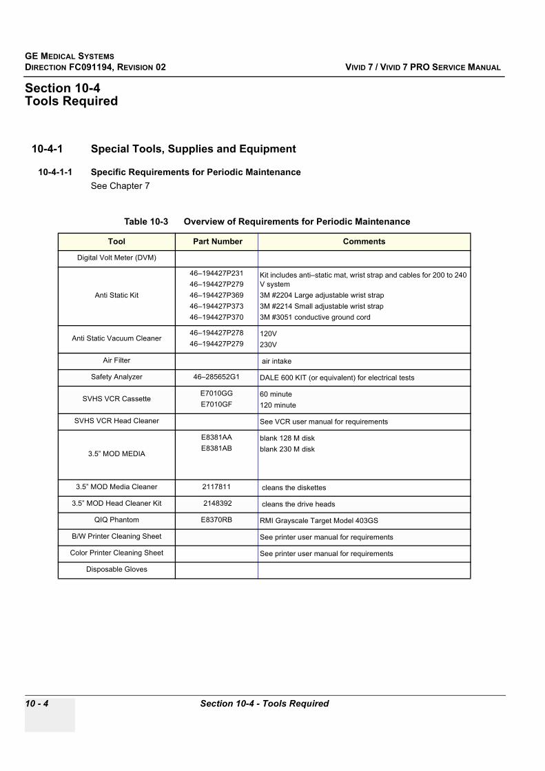
GE MEDICAL SYSTEMSDIRECTION FC091194, REVISION 02 VIVID 7 / VIVID 7 PRO SERVICE MANUAL
10 - 4 Section 10-4 - Tools Required
Section 10-4 Tools Required
10-4-1 Special Tools, Supplies and Equipment
10-4-1-1 Specific Requirements for Periodic MaintenanceSee Chapter 7
Table 10-3 Overview of Requirements for Periodic Maintenance
Tool Part Number Comments
Digital Volt Meter (DVM)
Anti Static Kit
46–194427P23146–194427P27946–194427P36946–194427P37346–194427P370
Kit includes anti–static mat, wrist strap and cables for 200 to 240 V system3M #2204 Large adjustable wrist strap3M #2214 Small adjustable wrist strap3M #3051 conductive ground cord
Anti Static Vacuum Cleaner46–194427P27846–194427P279
120V230V
Air Filter air intake
Safety Analyzer 46–285652G1 DALE 600 KIT (or equivalent) for electrical tests
SVHS VCR CassetteE7010GGE7010GF
60 minute120 minute
SVHS VCR Head Cleaner See VCR user manual for requirements
3.5” MOD MEDIA
E8381AAE8381AB
blank 128 M diskblank 230 M disk
3.5” MOD Media Cleaner 2117811 cleans the diskettes
3.5” MOD Head Cleaner Kit 2148392 cleans the drive heads
QIQ Phantom E8370RB RMI Grayscale Target Model 403GS
B/W Printer Cleaning Sheet See printer user manual for requirements
Color Printer Cleaning Sheet See printer user manual for requirements
Disposable Gloves

GE MEDICAL SYSTEMSDIRECTION FC091194, REVISION 02 VIVID 7 / VIVID 7 PRO SERVICE MANUAL
Chapter 10 - Periodic Maintenance 10 - 5
Section 10-5System Periodic Maintenance
10-5-1 Preliminary ChecksThe preliminary checks take about 15 minutes to perform. Refer to the system user documentation whenever necessary.
Table 10-4 System Preliminary Checks
Step Item Description
1 Ask & Listen Ask the customer if they have any problems or questions about the equipment.
2 Paperwork Fill in the top of the Periodic Maintenance (PM) Inspection Certificate. Note all probes and system options.
3 Power up Turn the system power on and verify that all fans and peripherals turn on. Watch the displays during power up to verify that no warning or error messages are displayed.
4 Probes Verify that the system properly recognizes all probes.
5 Displays Verify proper display on the monitor and touch panel.
6 Presets Backup all customer presets on a CD-R.

GE MEDICAL SYSTEMSDIRECTION FC091194, REVISION 02 VIVID 7 / VIVID 7 PRO SERVICE MANUAL
10 - 6 Section 10-5 - System Periodic Maintenance
10-5-2 Functional Checks (See Also Chapter 4)The functional checks take about 60 minutes to perform. Refer to the system user documentation whenever necessary.
10-5-2-1 System Checks
NOTE: * Some software may be considered standard depending upon system model configuration.
Table 10-5 System Functional Checks
Check Step Description
B-Mode Verify basic B-Mode (2D) operation. Check the basic system controls that affect this mode of operation.
CF-Mode Verify basic CF-Mode (Color Flow Mode) operation. Check the basic system controls that affect this mode of operation.
Doppler Modes Verify basic Doppler operation (PW and CW if available). Check the basic system controls that affect this mode of operation.
M-Mode Verify basic M-Mode operation. Check the basic system controls that affect this mode of operation.
*Applicable Software Options
Verify the basic operation of all optional modes such as Multi-Image, Contrast, Harmonics, Cine, Stress Echo,... etc. Check the basic system controls that affect each options operation.
Probe Elements Perform an Element Test, see section 7-4-3 on page 7-60, on each probe to verify that all probe elements (and system channels) are functional.
System Diagnostic Perform the Automatic Tests, see section Section 7-4 on page 7-59, to verify that all boards function according to specifications.
Control Panel TestPerform the Control Panel Test Procedure, see section 7-3-3-1 on page 7-53, to verify that all keyboard controls are OK. This is performed by the internal PC (backend processor) which does a normal keyboard run through.
Monitor Verify basic Monitor display functions. Refer to Chapter 3 of the User Manual.
Touch Panel Verify basic Touch Panel display functions. Refer to Chapter 3 of the User Manual.
Measurements Scan a gray scale phantom and use the measurement controls to verify distance and area calculation accuracy. Refer to the User Manual, Chapter 18, for measurement accuracy specifications.
GE MEDICAL SYSTEMSDIRECTION FC091194, REVISION 02 VIVID 7 / VIVID 7 PRO SERVICE MANUAL
Chapter 10 - Periodic Maintenance 10 - 7
10-5-2-2 Peripheral/Option ChecksIf any peripherals or options are not part of the system configuration, the check can be omitted. Refer to the User Manual for a list of approved peripherals/options.
10-5-3 Input Power
10-5-3-1 Mains Cable Inspection
10-5-4 Cleaning
10-5-4-1 General Cleaning
Table 10-6 GE Approved Peripheral/Hardware Option Functional Checks
Step Item Description
1 VCR Verify record/playback capabilities of the VCR. Clean heads and covers if necessary.
2 B/W Printer Verify hardcopy output of the B/W video page printer. Clean heads and covers if necessary.
3 Color Printer Verify hardcopy output of the Color video page printer. Clean heads and covers if necessary.
4 DICOM Verify that DICOM is functioning properly. Send an image to a DICOM device.
5 InSite/iLinq Verify that InSite is functioning properly. Ensure two-way remote communications.(Warranty & Contract Customers only)
7 Footswitch Verify that the footswitch is functioning as programed. Clean as necessary.
8 ECG Verify basic operation with customer
Table 10-7 Mains Cable Inspection
Step Item Description
1 Unplug Cord Disconnect the mains cable from the wall and system.
2 Inspect Inspect it and its connectors for damage of any kinds.
3 Verify Verify that the LINE, NEUTRAL and GROUND wires are properly attached to the terminals, and that no strands may cause a short circuit.
4 Verify Inlet connector retainer is functional.
Table 10-8 General Cleaning
Step Item Description
1 Console Use a fluid detergent in warm water on a soft, damp cloth to carefully wipe the entire system. Be careful not to get the cloth too wet so that moisture does not enter the console.
2 Probe Holder Clean probe holders. (they may need to be soaked to remove excess gel).
GE MEDICAL SYSTEMSDIRECTION FC091194, REVISION 02 VIVID 7 / VIVID 7 PRO SERVICE MANUAL
10 - 8 Section 10-5 - System Periodic Maintenance
10-5-4-2 Air Filter Cleaning
NOTE: For your convenience or of the air filter is too dirty, replacement filters are available. Refer to Chapter 9 for the air filter replacement part number.
10-5-5 Physical Inspection
Table 10-9 Air Filter Cleaning - frequency varies with your environment
Step Item Description
1 Remove Filter Cover Refer to Chapter 8 for air filter location and removal instructions
2 Clean Filter The filters can be cleaned in sprinkling water, or they can be dusted with a vacuum cleaner. If the filter is metal wash and/or vacuum. If the filter is fiber or plastic vacuum or replace
3 Install Filter Install the clean filter.
Table 10-10 Physical Checks
Step Item Description
1 Labeling Verify that all system labeling is present and in readable condition.
2 Scratches & Dents Inspect the console for dents, scratches or cracks.
3 Control Panel Inspect keyboard and control panel. Note any damaged or missing items.
4 Control Panel Movement
Verify ease of control panel (Operator I/O Panel) movement in all acceptable directions. Ensure that it latches in position as required.
5 Wheels & Brakes Check all wheels and casters for wear and verify operation of foot brake, to stop the unit from moving, and release mechanism. Check all wheel locks and wheel swivel locks for proper operation.
6 Cables & Connectors
Check all internal cable harnesses and connectors for wear and secure connector seating. Pay special attention to footswitch assembly and probe strain or bend reliefs.
7 Shielding & Covers
Check to ensure that all EMI shielding, internal covers, air flow panels and screws are in place. Missing covers and hardware could cause EMI/RFI problems while scanning.
8 External I/O Check all connectors for damage and verify that the labeling is good.
9 Op Panel Lights Check for proper operation of all operator panel and TCG lights.
10 Monitor Light Check for proper operation of any monitor lights and/or
11 External Microphone Check for proper operation of any external microphones by recording an audio test.

GE MEDICAL SYSTEMSDIRECTION FC091194, REVISION 02 VIVID 7 / VIVID 7 PRO SERVICE MANUAL
Chapter 10 - Periodic Maintenance 10 - 9
10-5-6 Optional Diagnostic ChecksTo complete the PM checks, access the diagnostic software as described in Chapters 5 or 7. View the error logs and run desired diagnostics.
10-5-6-1 View the Logs
1.) Review the system error log for any problems.2.) Check the temperature log to see if there are any trends that could cause problems in the future.
10-5-7 Probe Maintenance
10-5-7-1 Probe Related Checks
10-5-7-2 Basic Probe CareThe system user manuals and various probe handling cards provide a complete description of probe care, maintenance, cleaning and disinfection. Ensure that you are completely familiar with the proper care of GE probes.
Ultrasound probes can be easily damaged by improper handling. See the User Manual and probe care cards for more details. Failure to follow these precautions can result in serious injury and equipment damage. Failure to properly handle or maintain a probe may also void its warranty.
Any evidence of wear indicates the probe cannot be used.
Do a visual check of the probe pins and system sockets before plugging in a probe.
TEE and Interoperative probes often have special considerations and individual probe user manuals. For TEE and Interoperative probes also refer to their separate user manuals.
10-5-7-3 Basic Probe CleaningRefer to the User’s Manual for details on probe cleaning.
Table 10-11 Probe Related Checks
Step Item Description
1 Probe Holder Clean probe holders. (they may need to be soaked to remove excess gel).
2 Probes Thoroughly check the system probe connectors and remove dust from inside the connector sockets if necessary. Visually check for bent, damaged or missing pins
CAUTION To help protect yourself from blood borne diseases, wear approved disposable gloves. These are made of nitrile derived from vegetable starch to prevent allergic latex reactions.
CAUTION Failure to follow the prescribed cleaning or disinfection procedures will void the probe’s warranty. DO NOT soak or wipe the lens with any product not listed in the User Manual. Doing so could result in irreparable damage to the probe. Follow care instructions that came with the probe.
CAUTION Disinfect a defective probe before you return it. Be sure to tag the probe as being disinfected.

GE MEDICAL SYSTEMSDIRECTION FC091194, REVISION 02 VIVID 7 / VIVID 7 PRO SERVICE MANUAL
10 - 10 Section 10-6 - Using a Phantom
Section 10-6Using a Phantom
See the Basic User Manual “Customer Maintenance” for information on using a phantom and quality assurance tests.
Section 10-7Electrical Safety Tests
10-7-1 Safety Test OverviewThe electrical safety tests in this section are based on and conform to NFPA 99 (For USA) and IEC 60601-1 Medical Equipment Safety Standards. They are intended for the electrical safety evaluation of cord-connected, electrically operated, patient care equipment. If additional information is needed, refer to the NFPA 99 (For USA) and IEC 60601-1 documents.
Test the system, peripherals and probes for leakage current. Excessive leakage current can cause injury or death in sensitive patients. High leakage current can also indicate degradation of insulation and a potential for electrical failure. Do not use probes or equipment having excessive leakage current.
To minimize the risk that a probe may shock someone the customer should:
• Not use a probe that is cracked or damaged in any way• Check probe leakage current:
* once a year on surface probes* twice a year on endocavitary probes* whenever probe damage is suspected
WARNINGWARNING THE USER MUST ENSURE THAT THE SAFETY INSPECTIONS ARE PERFORMED AT LEAST EVERY 12 MONTHS ACCORDING TO THE REQUIREMENTS OF THE PATIENT SAFETY STANDARD IEC-EN 60601-1. ONLY TRAINED PERSONS ARE ALLOWED TO PERFORM THE SAFETY INSPECTIONS MENTIONED ABOVE.
CAUTION To avoid electrical shock, the unit under test must not be connected to other electrical equipment. Remove all interconnecting cables and wires. The unit under test must not be contacted by users or patients while performing these tests.
CAUTION Possible risk of infection. Do not handle soiled or contaminated probes and other components that have been in patient contact. Follow appropriate cleaning and disinfecting procedures before handling the equipment.

GE MEDICAL SYSTEMSDIRECTION FC091194, REVISION 02 VIVID 7 / VIVID 7 PRO SERVICE MANUAL
Chapter 10 - Periodic Maintenance 10 - 11
10-7-2 GEMS Leakage Current LimitsThe following limits are summarized for NFPA 99 (For USA) and IEC 60601-1 Medical Equipment Safety Standards. These limits are GEMS standards and in some cases are lower than the above standards listed.
NOTE: *Mains Applied refers to the sink leakage test where mains (supply) voltage is applied to the part to determine the amount of current that will pass (or sink) to ground if a patient contacted mains voltage.
The following tests are performed at the factory and should be performed at the site. These tests are: grounding continuity, chassis leakage current, probe leakage current, and ECG leakage current. All measurements are made with an electrical safety analyzer.
Table 10-12 Chassis Leakage Current Limits—Accessible Metal Surfaces
Country Normal Condition Open Ground Reverse Polarity Open Neutral
USA N/A 0.3 mA 0.3 mA N/A
Other 0.1 mA 0.5 mA 0.5 mA 0.5 mA
Table 10-13 Type BF Applied Part Leakage Current Limits - Non-Conductive (Floating) Surface and Cavity Probes
CountryNormal
Condition Open Ground Reverse Polarity Open Neutral *Mains Applied
USA 0.05 mA 0.05 mA 0.05 mA 0.05 mA N/A
Other 0.1 mA 0.5 mA 0.5 mA 0.5 mA 5.0 mA
Table 10-14 Type CF Applied Part Leakage Current Limits - Surgical Probes and ECG Connections
CountryNormal
Condition Open Ground Reverse Polarity Open Neutral *Mains Applied
USA 0.01 mA 0.05mA 0.05 mA N/A 0.025 mA
Other 0.01 mA 0.05 mA 0.05 mA 0.05 mA 0.05 mA
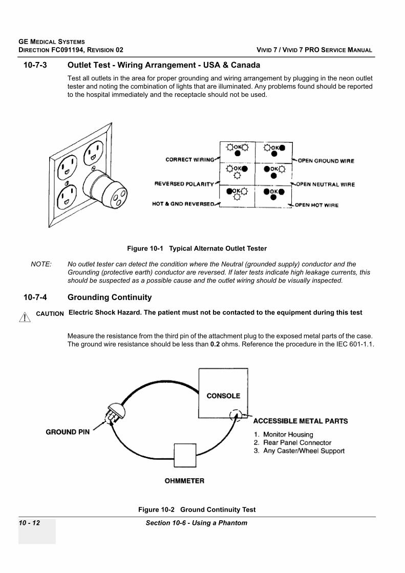
GE MEDICAL SYSTEMSDIRECTION FC091194, REVISION 02 VIVID 7 / VIVID 7 PRO SERVICE MANUAL
10 - 12 Section 10-6 - Using a Phantom
10-7-3 Outlet Test - Wiring Arrangement - USA & CanadaTest all outlets in the area for proper grounding and wiring arrangement by plugging in the neon outlet tester and noting the combination of lights that are illuminated. Any problems found should be reported to the hospital immediately and the receptacle should not be used.
NOTE: No outlet tester can detect the condition where the Neutral (grounded supply) conductor and the Grounding (protective earth) conductor are reversed. If later tests indicate high leakage currents, this should be suspected as a possible cause and the outlet wiring should be visually inspected.
10-7-4 Grounding Continuity
Measure the resistance from the third pin of the attachment plug to the exposed metal parts of the case. The ground wire resistance should be less than 0.2 ohms. Reference the procedure in the IEC 601-1.1.
Figure 10-1 Typical Alternate Outlet Tester
CAUTION Electric Shock Hazard. The patient must not be contacted to the equipment during this test
Figure 10-2 Ground Continuity Test

GE MEDICAL SYSTEMSDIRECTION FC091194, REVISION 02 VIVID 7 / VIVID 7 PRO SERVICE MANUAL
Chapter 10 - Periodic Maintenance 10 - 13
10-7-4-1 Meter ProcedureFollow these steps to test the ground wire resistance.
1.) Turn the Vivid 7 / Vivid 7 PRO unit OFF.2.) Plug the unit into the meter, and the meter into the tested AC wall outlet.3.) Plug the black chassis cable into the meter's “CHASSIS” connector and attach the black chassis
cable clamp to an exposed metal part of the Vivid 7 / Vivid 7 PRO unit.4.) Set the meter's “FUNCTION” switch to the RESISTANCE position.5.) Set the meter's “POLARITY” switch to the OFF (center) position.6.) Measure and record the ground wire resistance.
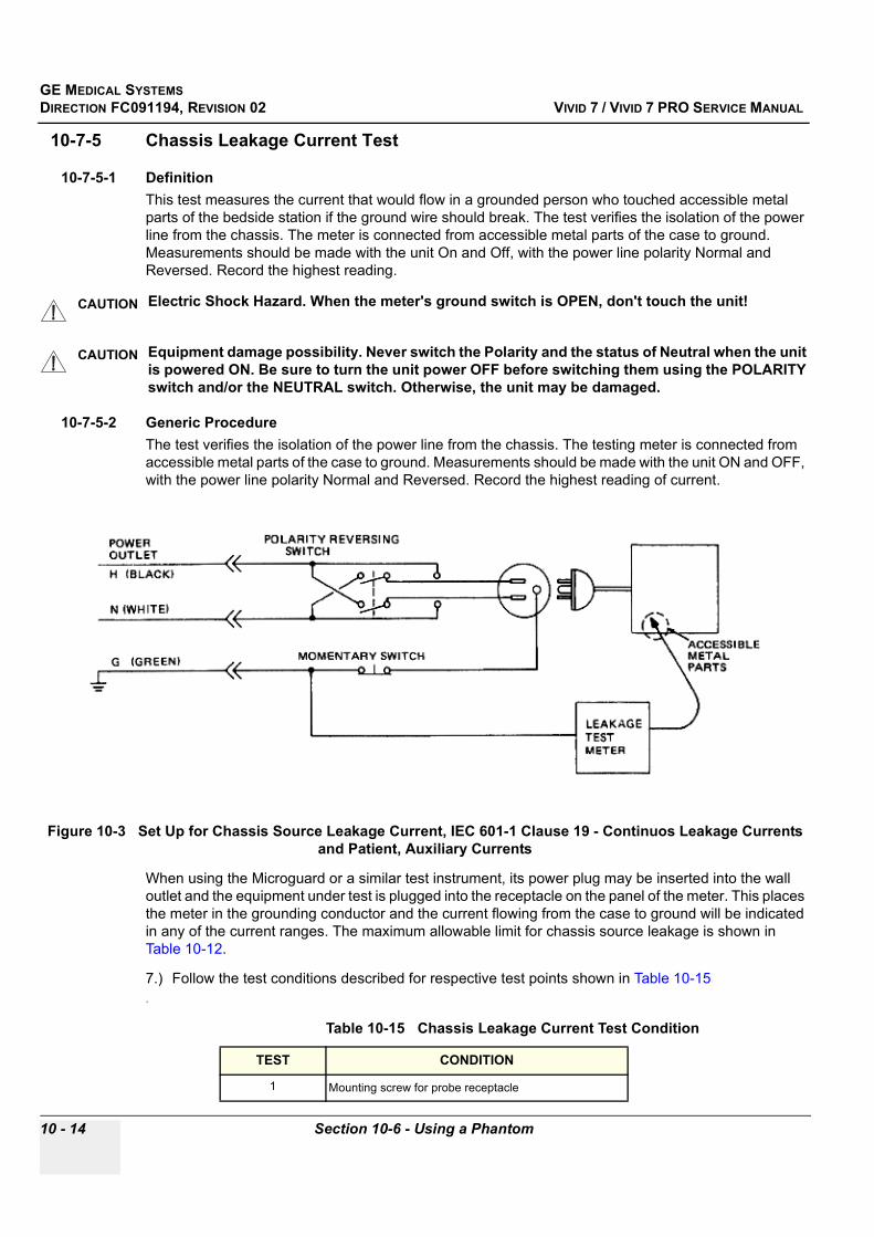
GE MEDICAL SYSTEMSDIRECTION FC091194, REVISION 02 VIVID 7 / VIVID 7 PRO SERVICE MANUAL
10 - 14 Section 10-6 - Using a Phantom
10-7-5 Chassis Leakage Current Test
10-7-5-1 DefinitionThis test measures the current that would flow in a grounded person who touched accessible metal parts of the bedside station if the ground wire should break. The test verifies the isolation of the power line from the chassis. The meter is connected from accessible metal parts of the case to ground. Measurements should be made with the unit On and Off, with the power line polarity Normal and Reversed. Record the highest reading.
10-7-5-2 Generic ProcedureThe test verifies the isolation of the power line from the chassis. The testing meter is connected from accessible metal parts of the case to ground. Measurements should be made with the unit ON and OFF, with the power line polarity Normal and Reversed. Record the highest reading of current.
When using the Microguard or a similar test instrument, its power plug may be inserted into the wall outlet and the equipment under test is plugged into the receptacle on the panel of the meter. This places the meter in the grounding conductor and the current flowing from the case to ground will be indicated in any of the current ranges. The maximum allowable limit for chassis source leakage is shown in Table 10-12.
7.) Follow the test conditions described for respective test points shown in Table 10-15.
CAUTION Electric Shock Hazard. When the meter's ground switch is OPEN, don't touch the unit!
CAUTION Equipment damage possibility. Never switch the Polarity and the status of Neutral when the unit is powered ON. Be sure to turn the unit power OFF before switching them using the POLARITY switch and/or the NEUTRAL switch. Otherwise, the unit may be damaged.
Figure 10-3 Set Up for Chassis Source Leakage Current, IEC 601-1 Clause 19 - Continuos Leakage Currents and Patient, Auxiliary Currents
Table 10-15 Chassis Leakage Current Test Condition
TEST CONDITION
1 Mounting screw for probe receptacle

GE MEDICAL SYSTEMSDIRECTION FC091194, REVISION 02 VIVID 7 / VIVID 7 PRO SERVICE MANUAL
Chapter 10 - Periodic Maintenance 10 - 15
8.) Keep a record of the results with other hard copies of PM data kept on site.
2 Wheel support
3 Mounting screw for CRT housing
4 Mounting screw for peripheral plugged into unit
5 Mounting screw for other peripheral powered by unit
Table 10-15 Chassis Leakage Current Test Condition
TEST CONDITION

GE MEDICAL SYSTEMSDIRECTION FC091194, REVISION 02 VIVID 7 / VIVID 7 PRO SERVICE MANUAL
10 - 16 Section 10-6 - Using a Phantom
10-7-5-3 Data Sheet for Chassis Source Leakage CurrentThe test passes when all readings measure less than the value shown in Table 10-12. Record all data on the PM Inspection Certificate.
10-7-6 Isolated Patient Lead (Source) Leakage–Lead to Ground
10-7-6-1 DefinitionThis test measures the current which would flow to ground from any of the isolated ECG leads. The meter simulates a patient who is connected to the monitoring equipment and is grounded by touching some other grounded surface. Measurements should be made with the ground open and closed, with power line polarity normal and reversed, and with the ultrasound console Off and On. For each combination the operating controls, such as the lead switch, should be operated to find the worst case condition.
Table 10-16 Typical Data Sheet for Chassis Source Leakage Current
Unit PowerTester Polarity
Switch
Tester Neutral or Ground
Switch
Test 1 Probe
ConnectorTest 2 Wheel
Test 3 CRT
Optional Test 4
Optional Test 5
Enter Name of tested peripheral here:
ON NORM OPEN
ON NORM CLOSED
ON REV OPEN
ON REV CLOSED
OFF NORM OPEN
OFF NORM CLOSED
OFF REV OPEN
OFF REV CLOSED
CAUTION Equipment damage possibility. Never switch the Polarity when the unit is powered ON. Be sure to turn the unit power OFF before switching the polarity using the POLARITY switch. Otherwise, the unit may be damaged.
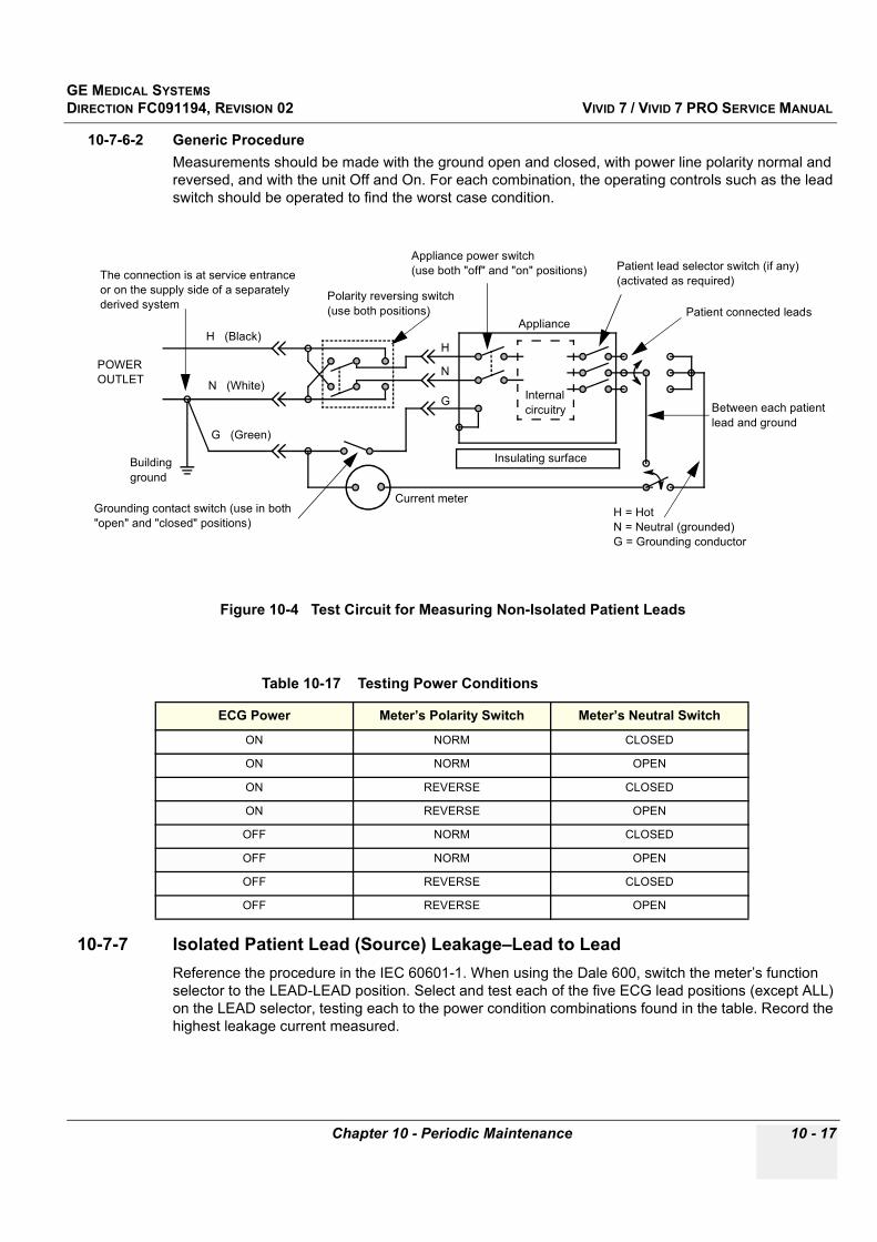
GE MEDICAL SYSTEMSDIRECTION FC091194, REVISION 02 VIVID 7 / VIVID 7 PRO SERVICE MANUAL
Chapter 10 - Periodic Maintenance 10 - 17
10-7-6-2 Generic ProcedureMeasurements should be made with the ground open and closed, with power line polarity normal and reversed, and with the unit Off and On. For each combination, the operating controls such as the lead switch should be operated to find the worst case condition.
10-7-7 Isolated Patient Lead (Source) Leakage–Lead to LeadReference the procedure in the IEC 60601-1. When using the Dale 600, switch the meter’s function selector to the LEAD-LEAD position. Select and test each of the five ECG lead positions (except ALL) on the LEAD selector, testing each to the power condition combinations found in the table. Record the highest leakage current measured.
Figure 10-4 Test Circuit for Measuring Non-Isolated Patient Leads
Table 10-17 Testing Power Conditions
ECG Power Meter’s Polarity Switch Meter’s Neutral Switch
ON NORM CLOSED
ON NORM OPEN
ON REVERSE CLOSED
ON REVERSE OPEN
OFF NORM CLOSED
OFF NORM OPEN
OFF REVERSE CLOSED
OFF REVERSE OPEN
POWEROUTLET
H (Black)
N (White)
G (Green)
Internalcircuitry
Insulating surface
Polarity reversing switch(use both positions)
Appliance power switch(use both "off" and "on" positions)
Patient connected leads
The connection is at service entranceor on the supply side of a separatelyderived system
Buildingground
Grounding contact switch (use in both"open" and "closed" positions)
Current meterH = HotN = Neutral (grounded)G = Grounding conductor
H
N
G
Patient lead selector switch (if any)(activated as required)
Appliance
Between each patient lead and ground

GE MEDICAL SYSTEMSDIRECTION FC091194, REVISION 02 VIVID 7 / VIVID 7 PRO SERVICE MANUAL
10 - 18 Section 10-6 - Using a Phantom
10-7-8 Isolated Patient Lead (Sink) Leakage-Isolation TestReference the procedure in the IEC 60601-1. When using the Dale 600, switch the meter’s function selector to the LEAD-ISO. Select the ALL position on the lead selector. Depress the rocker switch to ISO TEST to test lead isolation.
NOTE: It is not necessary to test each lead individually or power condition combinations as required in previous tests.
CAUTION Line voltage is applied to the ECG leads during this test. To avoid possible electric shock hazard, the system being tested must not be touched by patients, users or anyone while the ISO TEST switch is depressed.
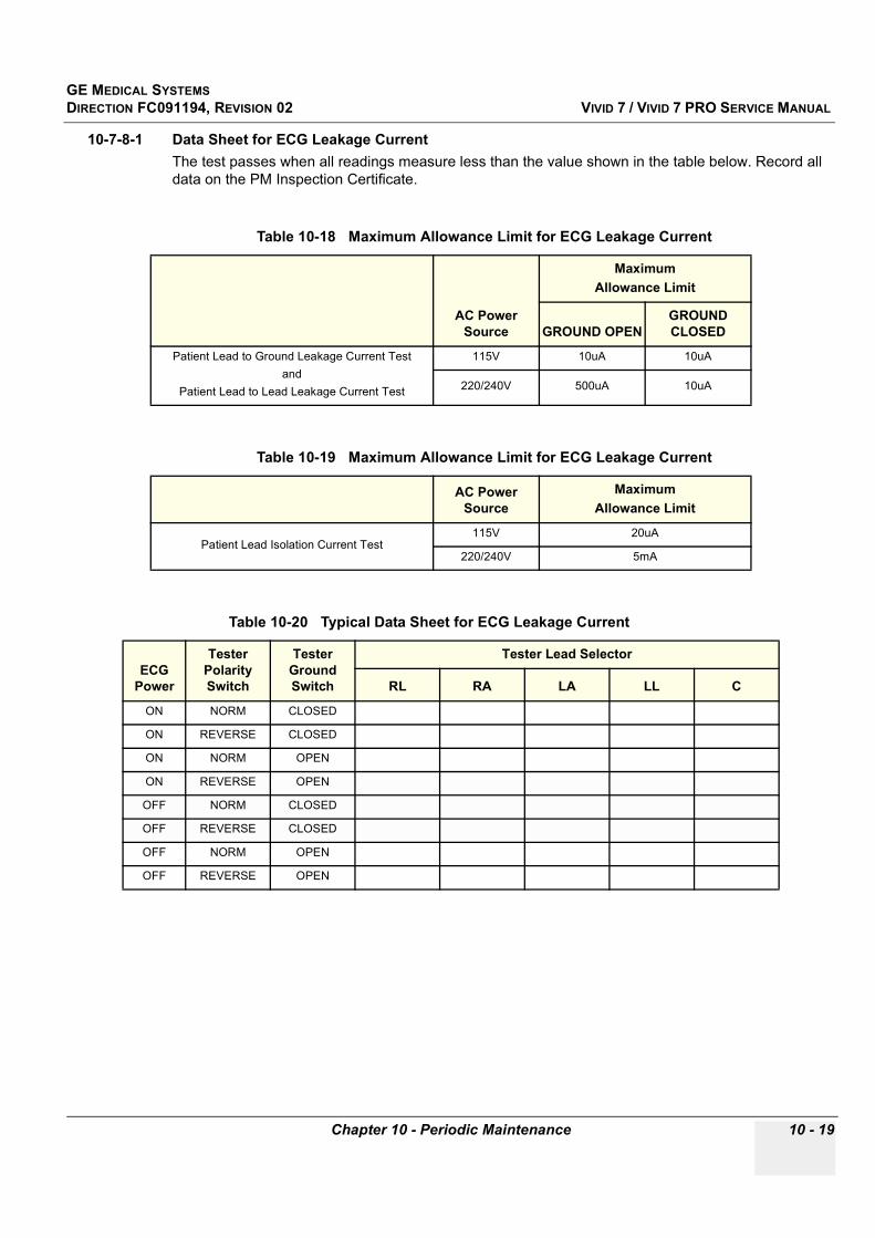
GE MEDICAL SYSTEMSDIRECTION FC091194, REVISION 02 VIVID 7 / VIVID 7 PRO SERVICE MANUAL
Chapter 10 - Periodic Maintenance 10 - 19
10-7-8-1 Data Sheet for ECG Leakage CurrentThe test passes when all readings measure less than the value shown in the table below. Record all data on the PM Inspection Certificate.
Table 10-18 Maximum Allowance Limit for ECG Leakage Current
AC Power Source
MaximumAllowance Limit
GROUND OPENGROUND CLOSED
Patient Lead to Ground Leakage Current Testand
Patient Lead to Lead Leakage Current Test
115V 10uA 10uA
220/240V 500uA 10uA
Table 10-19 Maximum Allowance Limit for ECG Leakage Current
AC Power Source
MaximumAllowance Limit
Patient Lead Isolation Current Test115V 20uA
220/240V 5mA
Table 10-20 Typical Data Sheet for ECG Leakage Current
ECG Power
Tester Polarity Switch
Tester Ground Switch
Tester Lead Selector
RL RA LA LL C
ON NORM CLOSED
ON REVERSE CLOSED
ON NORM OPEN
ON REVERSE OPEN
OFF NORM CLOSED
OFF REVERSE CLOSED
OFF NORM OPEN
OFF REVERSE OPEN

GE MEDICAL SYSTEMSDIRECTION FC091194, REVISION 02 VIVID 7 / VIVID 7 PRO SERVICE MANUAL
10 - 20 Section 10-6 - Using a Phantom
10-7-9 Probe Leakage Current Test
10-7-9-1 DefinitionThis test measures the current that would flow to ground from any of the probes through a patient who is being scanned and becomes grounded by touching some other grounded surface.
10-7-9-2 Generic ProcedureMeasurements should be made with the ground open and closed, with power line polarity normal and reversed, and with the unit Off and On. For each combination, the probe must be active to find the worst case condition.
NOTE: Each probe will have some amount of leakage current, dependent on its design. Small variations in probe leakage currents are normal from probe to probe. Other variations will result from differences in line voltage and test lead placement.
Figure 10-5 Set Up for Probe Leakage Current
POWEROUTLET
H (BLACK)POLARITY REVERSING SWITCH
MOMENTARYSWITCH
N (WHITE)
G (GREEN)
LEAKAGE TESTMETER
CONSOLE
PROBE
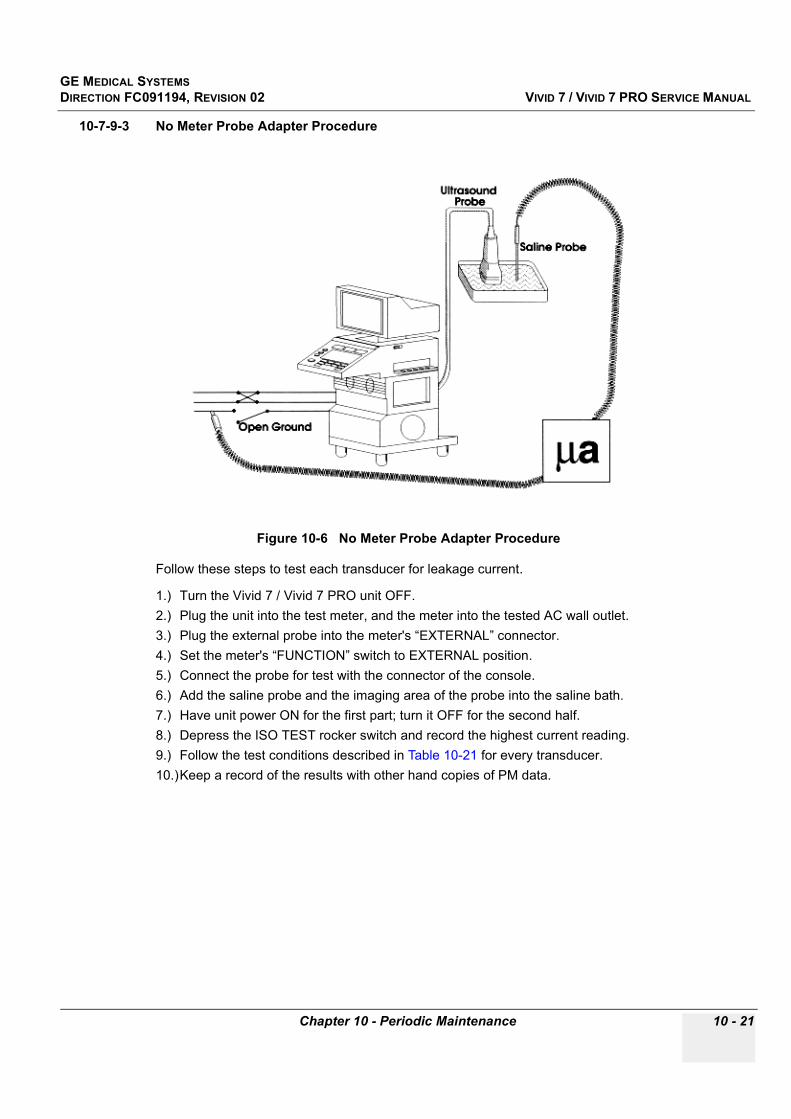
GE MEDICAL SYSTEMSDIRECTION FC091194, REVISION 02 VIVID 7 / VIVID 7 PRO SERVICE MANUAL
Chapter 10 - Periodic Maintenance 10 - 21
10-7-9-3 No Meter Probe Adapter Procedure
Follow these steps to test each transducer for leakage current.
1.) Turn the Vivid 7 / Vivid 7 PRO unit OFF.2.) Plug the unit into the test meter, and the meter into the tested AC wall outlet.3.) Plug the external probe into the meter's “EXTERNAL” connector.4.) Set the meter's “FUNCTION” switch to EXTERNAL position.5.) Connect the probe for test with the connector of the console.6.) Add the saline probe and the imaging area of the probe into the saline bath.7.) Have unit power ON for the first part; turn it OFF for the second half.8.) Depress the ISO TEST rocker switch and record the highest current reading.9.) Follow the test conditions described in Table 10-21 for every transducer.10.)Keep a record of the results with other hand copies of PM data.
Figure 10-6 No Meter Probe Adapter Procedure

GE MEDICAL SYSTEMSDIRECTION FC091194, REVISION 02 VIVID 7 / VIVID 7 PRO SERVICE MANUAL
10 - 22 Section 10-6 - Using a Phantom
10-7-9-4 Data Sheet for Transducer Source Leakage CurrentThe test passes when all readings measure less than the values shown in Table 10-13 and Table 10-14. Record all data on the PM Inspection Certificate.
.
CAUTION Equipment damage possibility. Never switch the Polarity and the status of Neutral when the unit is powered ON. Be sure to turn the unit power OFF before switching them using the POLARITY switch and/or the NEUTRAL switch. Otherwise, the unit may be damaged
Table 10-21 Typical Data Sheet For Transducer Source Leakage Current
Transducer Tested:
Unit PowerTester Power Polarity
SwitchTester GROUND or NUETRAL Switch Measurement
ON NORM OPEN
ON NORM CLOSED
ON REV OPEN
ON REV CLOSED
OFF NORM OPEN
OFF NORM CLOSED
OFF REV OPEN
OFF REV CLOSED

GE MEDICAL SYSTEMSDIRECTION FC091194, REVISION 02 VIVID 7 / VIVID 7 PRO SERVICE MANUAL
Chapter 10 - Periodic Maintenance 10 - 23
Section 10-8When There's Too Much Leakage Current...
CHASSIS FAILSCheck the ground on the power cord and plug for continuity. Ensure the ground is not broken, frayed, or intermittent. Replace any defective part.
Tighten all grounds. Ensure star washers are under all ground studs.
Inspect wiring for bad crimps, poor connections, or damage.
Test the wall outlet; verify it is grounded and is free of other wiring abnormalities. Notify the user or owner to correct any deviations. As a work around, check the other outlets to see if they could be used instead.
NOTE: No outlet tester can detect the condition where the white neutral wire and the green grounding wire are reversed. If later tests indicate high leakage currents, this should be suspected as a possible cause and the outlet wiring should be visually inspected.
PROBE FAILSTest the probe in another connector to isolate if the fault lies with the probe or the scanner.
NOTE: Each probe will have some amount of leakage, dependent on its design. Small variations in probe leakage currents are normal from probe to probe. Other variations will result from differences in line voltage and test lead placement. The maximum allowable leakage current for body surface contact probe differs from inter-cavity probe. Be sure to enter the correct probe type in the appropriate space on the check list.
If excessive leakage current is slot dependent, inspect the system connector for bent pins, poor connections, and ground continuity.
If the problem remains with the probe, replace the probe.
PERIPHERAL FAILSTighten all grounds. Ensure star washers are under all ground studs.
Inspect wiring for bad crimps, poor connections, or damage.
STILL FAILSIf all else fails, begin isolation by removing the probes, external peripherals, then the on board ones, one at a time while monitoring the leakage current measurement.
NEW UNITIf the leakage current measurement tests fail on a new unit and if situation can not be corrected, submit a Safety Failure Report to document the system problem. Remove unit from operation.
ECG FAILSInspect cables for damage or poor connections
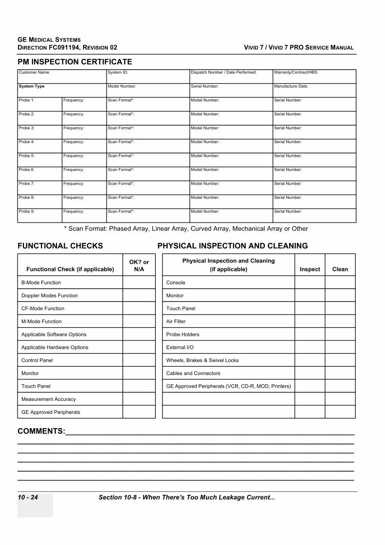
GE MEDICAL SYSTEMSDIRECTION FC091194, REVISION 02 VIVID 7 / VIVID 7 PRO SERVICE MANUAL
10 - 24 Section 10-8 - When There's Too Much Leakage Current...
PM INSPECTION CERTIFICATE
* Scan Format: Phased Array, Linear Array, Curved Array, Mechanical Array or Other
FUNCTIONAL CHECKS PHYSICAL INSPECTION AND CLEANING
COMMENTS:_________________________________________________________________________________________________________________________________________________________________________________________________________________________________________________________________________________________________________________________________________________________________________________________________________________________________________________________________________
Customer Name: System ID: Dispatch Number / Date Performed: Warranty/Contract/HBS
System Type Model Number: Serial Number: Manufacture Date:
Probe 1: Frequency: Scan Format*: Model Number: Serial Number:
Probe 2: Frequency: Scan Format*: Model Number: Serial Number:
Probe 3: Frequency: Scan Format*: Model Number: Serial Number:
Probe 4: Frequency: Scan Format*: Model Number: Serial Number:
Probe 5: Frequency: Scan Format*: Model Number: Serial Number:
Probe 6: Frequency: Scan Format*: Model Number: Serial Number:
Probe 7: Frequency: Scan Format*: Model Number: Serial Number:
Probe 8: Frequency: Scan Format*: Model Number: Serial Number:
Probe 9: Frequency: Scan Format*: Model Number: Serial Number:
Functional Check (if applicable)OK? or
N/APhysical Inspection and Cleaning
(if applicable) Inspect Clean
B-Mode Function Console
Doppler Modes Function Monitor
CF-Mode Function Touch Panel
M-Mode Function Air Filter
Applicable Software Options Probe Holders
Applicable Hardware Options External I/O
Control Panel Wheels, Brakes & Swivel Locks
Monitor Cables and Connectors
Touch Panel GE Approved Peripherals (VCR, CD-R, MOD, Printers)
Measurement Accuracy
GE Approved Peripherals

GE MEDICAL SYSTEMSDIRECTION FC091194, REVISION 02 VIVID 7 / VIVID 7 PRO SERVICE MANUAL
Chapter 10 - Periodic Maintenance 10 - 25
ELECTRICAL SAFETY
Final Check. All system covers are in place. System scans with all probes as expected.
Accepted by: ______________________________________________________________________
Electrical Test PerformedMax Value Allowed
Value Measured OK? Comments
Outlet (correct ground &wiring config.)
System Ground Continuity
Chassis Source Leakage Current - Probe
Chassis Source Leakage Current - Wheel
Chassis Source Leakage Current - CRT
Patient Lead Source Leakage(Lead to Ground)
Patient Lead Source Leakage(Lead to Lead)
Patient Lead Source Leakage(Isolation)
Peripheral 1 Leakage Current
Peripheral 1Ground Continuity
Peripheral 2 Leakage Current
Peripheral 2Ground Continuity
Peripheral 3 Leakage Current
Peripheral 3Ground Continuity
PROBES
Probe Number (from previous page)
Max Value Allowed
Max Value Measured OK? Comments
Probe 1:
Probe 2:
Probe 3:
Probe 4:
Probe 5:
Probe 6:
Probe 7:
Probe 8:
Probe 9:

GE MEDICAL SYSTEMSDIRECTION FC091194, REVISION 02 VIVID 7 / VIVID 7 PRO SERVICE MANUAL
10 - 26 Section 10-8 - When There's Too Much Leakage Current...
This page was intentionally left blank.

GE MEDICAL SYSTEMSDIRECTION FC091194, REVISION 02 VIVID 7 / VIVID 7 PRO SERVICE MANUAL
Index Index - 1
AAC Power
Replacement Procedure, 8-34AC Transformer
Replacement Procedure, 8-31Acoustic Noise Output, 3-8AE Title, 3-50Air Filter Cleaning, 10-8Application Turnover Check List, 4-63Archiving and Loading Presets, 4-12Archiving Presets to an MO Disk, 4-12Audio
Doppler, 5-7Available Probes, 3-32Average Installation Time, 3-1
BBack End Processor, 5-14, , 5-74
Theory, 5-14Back Plane (Motherboard), 5-92Battery (UPS) Operation, 5-19Beamformer Board(s), BF-64, 5-53Beamformer Calibration, 7-60Beamformer Calibration -- see DC Offset Calibration, 7-29Brake Pedal
Replacement Procedure, 8-51Brake Pedal and Direction Lock Assembly
Replacement Procedures, 8-53Brakes Check, 4-62Bumpers and Covers
- Overview, 8-2
CCertified Electrical Contractor Statement, -viChain
Signal Chain, TX/RLB/RX/BF Test, 7-64Chassis Leakage Current Test, 10-14Check the Connection to the DICOM Server, 3-53Circuit Boards, 5-44Cleaning, 10-7Color Flow
Processing, 5-6Color Inkjet Printer, 3-32Color Mode
Overview, 4-34Common Diagnostics, 7-44Common Service Interface, 5-101Completing the Installation, 3-8
Components and Functions, 5-1Configuration, 3-21Connecting Laptop Computer to the Ultrasound Unit, 7-4Connectivity, 3-35
Setup, 3-37Console
Environmental Requirements, 2-2Mechanical Checks, 4-61
Contact Information, 1-38Conventions
Conventions Used in Book, 1-8Cooling, 2-2Covers and Bumpers
- Overview, 8-2Customer Assistance, 1-38
DDamage in Transportation, -vDangerous Procedure Warnings, 1-36Data
Buffer, 5-6from Mid Processors, 5-8from VCR, 5-8
Data Sheet for- Chassis Source Leakage Current, 10-16- ECG Leakage Current, 10-19- Transducer Source Leakage Current, 10-22
Date and Time Adjustments, 3-25DC Offset calibration, 7-29DC Power, 5-37
Replacement Procedure, 8-36Default DICOM Setup in Configuration Screen, 3-52Department Name, 3-24Depth, 3-8Diagnostics/Troubleshooting, 7-1DICOM, 3-49
DICOM Option Pre-Installation Requirements, 2-10DICOM Server’s Set Up, 3-49
Digital Signal ProcessorDSP, 5-7
Direction LockCheck, 4-62Pedal Replacement Procedure, 8-52
Disconnect Probe, 3-13Display Platform Mechanical Checks, 4-61Doppler
Doppler Processing, 5-6DSP
Digital Signal Processor, 5-7
INDEX

GE MEDICAL SYSTEMSDIRECTION FC091194, REVISION 02 VIVID 7 / VIVID 7 PRO SERVICE MANUAL
Index - 2 Index
EElectrical
- Needs, 2-3- Safety, 1-13- Safety Tests, 10-10- Specifications, 3-9
Electrostatic Discharge Warning, 1-37EMC, 1-37EMI
- Description, 1-37- Limitations, 2-4- Protection, 3-8
Enter Location, 3-24Environmental Conditions
Probes, 2-6ESD, 1-37Establish Network Connection to Hospital’s Network, 3-49Ethernet
- Signal, 5-9- Switch Connections, 3-35
External I/O, 5-87External I/O to Rear Connector Panel, 5-9
External Peripherals, 5-32
FFacility Needs, 2-7Filter
Replacement Procedure, 8-7Filter Cover
Replacement Procedure, 8-6Forced Shut Down, 8-25Format a CD-R disk, 4-11Format an MO Disk, 4-11Formatting a Removable Media, 4-11Front Bumper
Replacement Procedure, 8-50Front Cover Replacement Procedure, 8-5Front End
- Alignment, 7-65- Alignment, when to do, 6-3- Calibration, 7-60- Controller Board, FEC-2, 5-56- Description, 5-4- FE Bus Description, 5-4- FE Modules Parts List, 9-11- Processor, 5-4- Subsystem, 5-12
Front Wheels Replacement Procedure, 8-45Frontend Alignment -- see DC Offset Calibration, 7-29FRU Replacement Procedures, 8-31Functional Checks, 4-1
2D Mode (B mode) Checks, 4-17Backend Processor Checks, 4-56Basic Controls, 4-14
Cineloop Check, 4-52Color Mode Checks, 4-28Contrast Checks, 4-46Doppler Mode Checks, 4-34ECG Check, 4-51M Mode Checks, 4-24Measurements and Multi Image Checks, 4-47Multi Image Checks, 4-49Performance Tests, 4-16Probe/Connectors Check, 4-50Stress Echo, 4-46Tissue Velocity Imaging (TVI) Checks, 4-40
GGEMS Leakage Current Limits, 10-11General Cleaning, 10-7General Procedures, 4-2Global Service User Interface (GSUI), 5-102Going Offline, 3-55Grounding Continuity, 10-12
HHardware/Software Versions, 1-4Hazard Icons, 1-9Heat Dissipation, 2-2Height, 3-8High Voltage
Power Supply, 5-5Hospital and Department Name, 3-24Hospital Network Connection
- to EchoPAC PC Workstation, 3-36How often should PMs be performed?, 10-2HP Deskjet 990 Cxi Network Printer, 3-32Human Safety, 1-12Humidity, 2-2
IiLinq, 5-101Image Port, 5-8
Image Port 2 Board, 5-8Image Port Board (IMPORT), 5-8IMP2 Board, 5-70
Input Power, 10-7Inrush Current, 2-3Installation, 3-1, , 3-56
Paperwork, 3-56Warnings, 3-2
Interconnect Cabling, 5-90Internal I/O, 5-24, , 5-79
– and Peripheral Control, 5-9connections, 5-25Outputs, 5-29
GE MEDICAL SYSTEMSDIRECTION FC091194, REVISION 02 VIVID 7 / VIVID 7 PRO SERVICE MANUAL
Index Index - 3
Internal Storage Devices, 5-20Introduction to this manual, 1-1
KKeeping Records, 10-2Keyboard Mechanical Checks, 4-61
LLabeling Removable Media, 4-10Labels Locations, 1-14Language
- Precautions, -iii- Selection, 3-26
Leakage Current Limits, 10-11Leakage Current.
Too Much!, 10-23Lighting, 2-2List of Abbrevations, 9-2List of Effected Pages (Revision), -viiiLoading and Archiving Presets, 4-12Loading Presets from an MO Disk, 4-13Local Network Connection
- to EchoPAC PC Workstation, 3-36Location
Enter Location, 3-24Lower Rear Cover Replacements Procedure, 8-8
MMains Cable Inspection, 10-7Major Sub-Systems in Vivid 7, 5-11Manpower Requirements, 2-6Mechanical
- Functions Checks, 4-61- Safety, 1-12
Mechanical Safety, 1-12Memory Board, 5-8Mid Processors, 5-13Minimal Floor Plan Suggestion, 2-9Modem, 5-33, , 5-93Monitor Adjustments, 6-2Motherboard (Back Plane), 5-92Move Images (SW.V.2.0.x), 8-13
NNetwork Printer, 3-32Networking Pre-installation Requirements, 2-10NTSC Video System Selection, 3-29
O
Off-board Peripherals, 3-32Omissions & Errors, -viOn site Configuration, 3-33On-board Peripherals, 3-32, , 5-32Operating Temperature, 2-2Optional Peripherals/Peripheral Connection, 3-32Options (Software) Configuration, 3-33Outlet Test - Wiring Arrangement - USA & Canada, 10-12
PPAL Video System Selection, 3-29Parts List
Front End Modules, 9-11Patient I/O, 5-23, , 5-78PC Diagnostics, 7-47PCVIC Card, 5-19Performing a Study, 3-55Periodic Maintenance, 10-1
Schedule, 10-2Peripheral/Option Checks, 10-7Peripherals, 5-32
Checks, 4-57Connection, 3-32Off-board Peripherals, 3-32On-board Peripherals, 3-32
Phased and Linear Array Front End Description, 5-4Physical
Connection, 3-35Dimensions, 3-8Inspection, 3-8, , 10-8
Physio (Patient I/O), 5-23Ping, 3-53
DICOM “ping”, 3-53Hardware “ping”, 3-53
Pipelink BusDescription, 5-5
Plastic Parts- Replacement Procedures, 8-2
Plastic Parts Replacement Procedures, 8-2PM INSPECTION CERTIFICATE, 10-24Power Shut Down, 4-5Power Stability Requirements, 2-4
Power Transients, 2-4Voltage Dop-out, 2-4
Power Supply- Adjustments, 6-1- Battery Pack Replacement Procedure, 8-54- Test Procedure, 4-64
Power Transients, 2-4Power-up Procedures
Voltage Settings, 3-9Pre-Installation, 2-1
RequirementsDICOM, 2-10

GE MEDICAL SYSTEMSDIRECTION FC091194, REVISION 02 VIVID 7 / VIVID 7 PRO SERVICE MANUAL
Index - 4 Index
Prepearing Unit for Installation, 3-8Probe
Connector Cleaning, 10-9Disconnect Probe, 3-13Leakage Current Test, 10-20Maintenance, 10-9
Probes, 3-32Disconnecting, 4-51Environmental Requirements, 2-6
Product Icons, 1-10Product Locator Installation Card, 3-56Purchaser Responsibilities, 2-7
QQuality Assurance, 10-2
RRear Cover, Lower Replacement Procedure, 8-8Rear Wheels Replacement Procedure, 8-40Receiver Board
- RX Test, 7-63- RX-128, 5-50
Receiving and Unpacking the Equipment, 3-3Record
- SW Option Key Settings (SW.V.2.0.x), 8-16- TCP/IP Settings (SW.2.0.x)(, 8-19
RejectOptimizing 2D, 4-18
Relay Board- Description, 5-45- Test, 7-64
Remote Archive’s Network InformationSetup, 3-40
Renewal Parts, 9-1Replacement Procedure, 8-1, , 8-31
AC Power, 8-34AC Transformer, 8-31Filter, 8-7Filter Cover, 8-6
Required Facility Needs, 2-8Revision
- History, -vii- List of Effected Pages, -viii
RF- & Tissue Processor- Description, 5-6- RFT Board Description, 5-62
RF Processing, 5-6RFT
see RF- & Tissue Processor, 5-6
SSafety
- Considerations, 1-12Safety Considerations, 1-12Safety.- Precaution Messages, 1-8Scanner’s Network Information, 3-39SDP
Spectrum Doppler Processor Board- Description, 5-7
Select Video Format, PAL or NTSC, 3-29Service Adjustments, 6-1Service Home Page, 7-5Service Login to Global Service User Interface, 5-102Service Screen, 3-28Set Up Connection to DICOM Server in Network, 3-49Set up TCP/IP address on Vivid 7, 3-49Setting DICOM Server as Default Dataflow, 3-54Set-up of DICOM Server in Vivid 7’s ConfigurationScreens, 3-50Side Covers Replacement Procedure, 8-3Site
- Circuit Breaker, 2-3- Log, 4-65- Power Outlets, 2-3- Requirements
Desirable Features, 2-9Software
- Loading, 8-9- Record Option Key Settings (SW.V.2.0.x), 8-16- Software Option Installation, 3-33- Software Options Configuration, 3-33- Software/Hardware Revisions, 1-4- System Software Version, 8-23
Software Options, 7-31Special Tools, Supplies and Equipment, 10-4Spectrum
- Analysis, 5-7- Spectrum Doppler Processor Board Description,
5-7, , 5-66Standard Hazard Icons, 1-9Start System Test, 7-59Storage temperature, 2-2Switching OFF the Unit, 3-17System
- Block Diagram, 5-10- Configuration, 3-22- Doesn’t Boot, 7-67- History, 1-4- Maintenance, 10-5- Manufacture, 1-39- Overview, 1-2- Periodic Maintenance, 10-5- Requirements Verification, 3-8- Software Version, 8-23- Specifications, 3-8- Tests, 7-61
Systems Covered by this Manual, 1-2

GE MEDICAL SYSTEMSDIRECTION FC091194, REVISION 02 VIVID 7 / VIVID 7 PRO SERVICE MANUAL
Index Index - 5
TTCP/IP
- Record Settings (SW.V.2.0.x), 8-19- Set-up Screen, 3-37
Theory, 5-1Time Adjustments, 3-25Time and Manpower Requirements, 2-6Time for Settlement, 2-2Tissue Processing, 5-6Top Console, 5-31Trace Interface, 5-7Transducer Bus Boards, XD BUS Boards, 5-61Transmitter Board, TX128, 5-47Transportation
Damage, -vTroubleshooting, 7-67TX Power
- Description, 5-41- Replacement Procedure, 8-38
UUnit Power Plug, 2-3Units of Measure, 3-27Unpacking the Equipment, 3-3UPS Battery Operation, 5-19Using
- a Phantom, 10-10- CD-R Drive, 4-9, , 4-10- Magneto Optical Disk Drive, 4-9
VVCR
- Checks, 4-58- Counter Check, 4-58
Version, 8-23Video
- Printers Checks, 4-57- Select PAL or NTSC format, 3-29- Specifications, 5-95
Vivid 7 Block Diagram, 5-3Voltage
- Drop-out, 2-4- Settings, 3-9
WWall motion filter see LVRWarnings and Cautions, 1-12Weight with Monitor and Peripherals, 3-8When There’s Too Much Leakage Current..., 10-23Why do Periodic Maintenance, 10-2Width of Vivid 7 and Vivid 7 PRO, 3-8Worksheet for DICOM Network Information, 2-11

GE MEDICAL SYSTEMSDIRECTION FC091194, REVISION 02 VIVID 7 / VIVID 7 PRO SERVICE MANUAL
Index - 6 Index


GE Medical Systems
GE Medical Systems: Telex 3797371P.O. Box 414; Milwaukee, Wisconsin 53201, U.S.A.(Asia, Pacific, Latin America, North America)
GE Ultraschall:Tel: +49 (0) 212 28 02 208Deutschland GmbH & Co KGBeethovenstrabe 239, Postfach 11 05 60D-42655 Solingen, Germany
Related Documents