GE Power Systems Advanced Technology Combined Cycles R.W. Smith P. Polukort C.E. Maslak C.M. Jones B.D. Gardiner GE Power Systems Schenectady, NY GER-3936A g

Ge Combined Cycle
Nov 19, 2014
GE Combined Cycle
Welcome message from author
This document is posted to help you gain knowledge. Please leave a comment to let me know what you think about it! Share it to your friends and learn new things together.
Transcript

GE Power Systems
Advanced TechnologyCombined Cycles
R.W. SmithP. PolukortC.E. MaslakC.M. JonesB.D. GardinerGE Power SystemsSchenectady, NY
GER-3936A
g


Contents
Introduction . . . . . . . . . . . . . . . . . . . . . . . . . . . . . . . . . . . . . . . . . . . . . . . . . . . . . . . . . . . . . . . . . . 1System Integration Overview . . . . . . . . . . . . . . . . . . . . . . . . . . . . . . . . . . . . . . . . . . . . . . . . . . . 1Performance . . . . . . . . . . . . . . . . . . . . . . . . . . . . . . . . . . . . . . . . . . . . . . . . . . . . . . . . . . . . . . . . . 2Steam Turbine . . . . . . . . . . . . . . . . . . . . . . . . . . . . . . . . . . . . . . . . . . . . . . . . . . . . . . . . . . . . . . . . 4Shaft Train Configuration . . . . . . . . . . . . . . . . . . . . . . . . . . . . . . . . . . . . . . . . . . . . . . . . . . . . . . . 4
Features . . . . . . . . . . . . . . . . . . . . . . . . . . . . . . . . . . . . . . . . . . . . . . . . . . . . . . . . . . . . . . . . . . 5Steam-Cooling System . . . . . . . . . . . . . . . . . . . . . . . . . . . . . . . . . . . . . . . . . . . . . . . . . . . . . . . . . 6Integrated Control System . . . . . . . . . . . . . . . . . . . . . . . . . . . . . . . . . . . . . . . . . . . . . . . . . . . . . . 8Plant Arrangement . . . . . . . . . . . . . . . . . . . . . . . . . . . . . . . . . . . . . . . . . . . . . . . . . . . . . . . . . . . 11Integrated Gasification Combined Cycle (IGCC) . . . . . . . . . . . . . . . . . . . . . . . . . . . . . . . . . . . 13Repowering . . . . . . . . . . . . . . . . . . . . . . . . . . . . . . . . . . . . . . . . . . . . . . . . . . . . . . . . . . . . . . . . . 13Conclusion . . . . . . . . . . . . . . . . . . . . . . . . . . . . . . . . . . . . . . . . . . . . . . . . . . . . . . . . . . . . . . . . . . 14List of Figures . . . . . . . . . . . . . . . . . . . . . . . . . . . . . . . . . . . . . . . . . . . . . . . . . . . . . . . . . . . . . . . 15List of Tables . . . . . . . . . . . . . . . . . . . . . . . . . . . . . . . . . . . . . . . . . . . . . . . . . . . . . . . . . . . . . . . . 15
Advanced Technology Combined Cycles
GE Power Systems ■ GER-3936A ■ (05/01) i

Advanced Technology Combined Cycles
GE Power Systems ■ GER-3936A ■ (05/01) ii

IntroductionThe General Electric H technology combinedcycles represent the most advanced power gen-eration systems available today. These com-bined-cycle power generation systems canachieve 60% net thermal efficiency burningnatural gas. Their environmental impact perkilowatt-hour is the lowest of all fossil-fired gen-eration equipment. These highly efficient com-bined cycles integrate the advanced technology,closed-circuit steam-cooled 60 Hz MS7001Hand 50 Hz MS9001H gas turbines with reliablesteam cycles using state-of-the-art steam tur-bines and unfired, multi-pressure, reheat heatrecovery steam generators (HRSGs).
System Integration OverviewThe STAG 107H and STAG 109H are offered ina single-shaft combined-cycle configuration.Figure 1 is a conceptual presentation of an out-door power plant with this equipment. Thisconfiguration complements the cycle integra-tion between the steam-cooled gas turbine andthe steam bottoming cycle.
A diagram of the cycle (Figure 2) shows anoverview of the three-pressure, reheat steamcycle and its integration with the gas turbinecooling system. Gas turbine cooling steam issupplied from the intermediate pressure (IP)superheater and the high pressure (HP) steamturbine exhaust to the closed circuit system thatcools the gas turbine stage 1 and 2 nozzles andbuckets. The cooling system operates in serieswith the reheater, with gas turbine coolingsteam returned to the steam cycle cold reheatline.
Air extracted from the compressor discharge iscooled using water from the IP economizer.The cooled air is readmitted to the gas turbineand compressor to cool compressor wheels andselected turbine gas path components. Theenergy extracted from the compressor dis-charge air is returned to the steam cycle by gen-erating IP steam. A fuel gas heating system uti-lizes low grade energy from the HRSG toimprove combined-cycle thermal efficiency.Water extracted from the discharge of theHRSG IP economizer is supplied to the fuel gas
Advanced Technology Combined Cycles
GE Power Systems ■ GER-3936A ■ (05/01) 1
Figure 1. Advanced technology combined-cycle unit
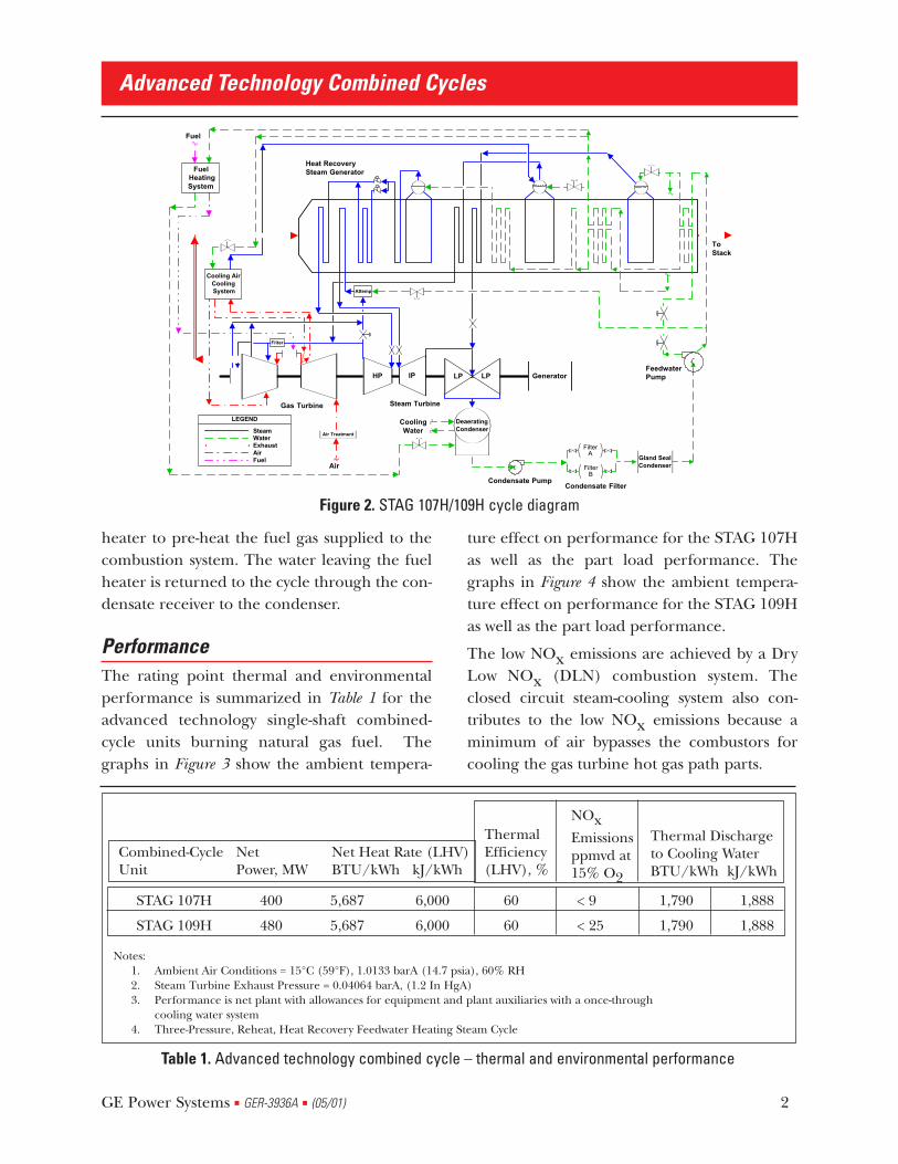
heater to pre-heat the fuel gas supplied to thecombustion system. The water leaving the fuelheater is returned to the cycle through the con-densate receiver to the condenser.
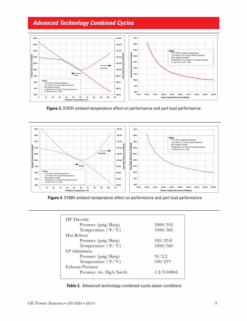
PerformanceThe rating point thermal and environmentalperformance is summarized in Table 1 for theadvanced technology single-shaft combined-cycle units burning natural gas fuel. Thegraphs in Figure 3 show the ambient tempera-
ture effect on performance for the STAG 107Has well as the part load performance. Thegraphs in Figure 4 show the ambient tempera-ture effect on performance for the STAG 109Has well as the part load performance.
The low NOx emissions are achieved by a DryLow NOx (DLN) combustion system. Theclosed circuit steam-cooling system also con-tributes to the low NOx emissions because aminimum of air bypasses the combustors forcooling the gas turbine hot gas path parts.
Advanced Technology Combined Cycles
GE Power Systems ■ GER-3936A ■ (05/01) 2
CoolingWater
Cooling AirCooling System
ToStack
Air
Gas Turbine
Air Treatment
Condensate Pump
Fuel
IPHP
Heat RecoverySteam GeneratorFuel
HeatingSystem
Gland SealCondenser
Generator
Attemp
Filter
LEGEND
FilterA
FilterB
FeedwaterPump
Condensate Filter
Fuel
SteamWaterExhaustAir
Steam Turbine
DeaeratingCondenser
LPLP
Figure 2. STAG 107H/109H cycle diagram
Table 1. Advanced technology combined cycle – thermal and environmental performance
STAG 107H 400 5,687 6,000 60 < 9 1,790 1,888
STAG 109H 480 5,687 6,000 60 < 25 1,790 1,888
Combined-CycleUnit
NetPower, MW
ThermalEfficiency(LHV), %
NOxEmissionsppmvd at15% O2
Thermal Dischargeto Cooling WaterBTU/kWh kJ/kWh
Net Heat Rate (LHV)BTU/kWh kJ/kWh
Notes:1. Ambient Air Conditions = 15°C (59°F), 1.0133 barA (14.7 psia), 60% RH2. Steam Turbine Exhaust Pressure = 0.04064 barA, (1.2 In HgA)3. Performance is net plant with allowances for equipment and plant auxiliaries with a once-through
cooling water system4. Three-Pressure, Reheat, Heat Recovery Feedwater Heating Steam Cycle
Advanced Technology Combined Cycles
GE Power Systems ■ GER-3936A ■ (05/01) 3
80%
90%
100%
110%
120%
130%
140%
150%
160%
170%
10.0% 20.0% 30.0% 40.0% 50.0% 60.0% 70.0% 80.0% 90.0% 100.0%
Power Output (Percent of Rated)
H
eat
Rat
e (P
erce
nt
of
Rat
ed)
Basis: 15°C (59°F) ambient temperature, 1.013 BarA (14.7 psia) ambient pressure, 60% relative humidity, 0.0508 BarA (1.5" HgA) ST exhaust pressure, 2 x 851mm (33.5") LSB
80%
85%
90%
95%
100%
105%
110%
115%
120%
125%
0 10 20 30 40 50 60 70 80 90 100 110
Ambient Temperature (°F)
O
utp
ut
(Per
cen
t o
f R
ated
)
98.0%
98.5%
99.0%
99.5%
100.0%
100.5%
101.0%
101.5%
102.0%
102.5%
H
eat
Rat
e (P
erce
nt
of
Rat
ed)
Basis: 15°C (59°F) ambient temperature, 1.013 BarA (14.7 psia) ambient pressure, 60% relative humidity, 0.0508 BarA (1.5" HgA) ST exhaust pressure, 2 x 851mm (33.5") LSB
Power
Heat Rate
Figure 3. S107H ambient temperature effect on performance and part load performance
80%
85%
90%
95%
100%
105%
110%
115%
120%
125%
0 10 20 30 40 50 60 70 80 90 100 110
Ambient Temperature (°F)
O
utp
ut
(Per
cen
t o
f R
ated
)
98.0%
98.5%
99.0%
99.5%
100.0%
100.5%
101.0%
101.5%
102.0%
102.5%
H
eat
Rat
e (P
erce
nt
of
Rat
ed)
Basis: 15°C (59°F) ambient temperature, 1.013 BarA (14.7 psia) ambient pressure, 60% relative humidity, 0.0508 BarA (1.5" HgA) ST exhaust pressure, 2 x 851mm (33.5") LSB
Power
Heat Rate
80%
90%
100%
110%
120%
130%
140%
150%
160%
170%
10.0% 20.0% 30.0% 40.0% 50.0% 60.0% 70.0% 80.0% 90.0% 100.0%
Power Output (Percent of Rated)
H
eat
Rat
e (P
erce
nt
of
Rat
ed)
Basis: 15°C (59°F) ambient temperature, 1.013 BarA (14.7 psia) ambient pressure, 60% relative humidity, 0.0508 BarA (1.5" HgA) ST exhaust pressure, 2 x 851mm (33.5") LSB
Figure 4. S109H ambient temperature effect on performance and part load performance
Table 2. Advanced technology combined-cycle steam conditions
HP ThrottlePressure (psig/Barg) 2400/165Temperature (°F/°C) 1050/565
Hot ReheatPressure (psig/Barg) 345/23.8Temperature (°F/°C) 1050/565
LP AdmissionPressure (psig/Barg) 31/2.2Temperature (°F/°C) 530/277
Exhaust PressurePressure (in. HgA/barA) 1.2/0.04064

The low thermal discharge to cooling waterresults from the high efficiency and the generalcharacteristic of combined-cycle systems inwhich approximately 30% of the unit poweroutput is produced by the steam cycle.
Bottoming cycle steam conditions are tabulatedin Table 2 for systems that produce the perform-ance shown in Table 1. The combined-cycle sys-tems are also available with 124 barA / (1800Psig) throttle pressure which may more opti-mally suit systems with lower cost fuel or a mid-range duty cycle.
Steam TurbineA wide range of steam turbines are available tosuit specific site, duty and economic require-ments for both 50 Hz and 60 Hz applicationswhile satisfying all of the combined-cycle inte-gration requirements. Since there are noextractions for feedwater heating and sincesteam is generated and admitted to the turbineat three pressures, the flow at the exhaust isapproximately 30% greater than the throttleflow. The last stage generates up to 15% of thesteam turbine output, so the efficiency of theturbine's last stage and the sizing of the exhaustannulus area are particularly important for allcombined-cycle applications. The range of site-
specific back pressure conditions expectedrequires low-pressure section designs with abroad range of exhaust annulus areas. This isachieved by selection of the last stage bucketlength and the use of both single-flow and dou-ble-flow exhausts. Table 3 summarizes the last-stage buckets that are applicable for theadvanced technology combined cycle units.
Applications with low condenser pressurerequire a steam turbine with a double-flowexhaust. This two-casing design is similar in con-figuration and construction to that applied byGE in single-shaft combined-cycle applicationswith F technology gas turbines. The high andintermediate pressure sections are combined inone casing connected by a single crossover tothe center of the double-flow low-pressure sec-tion.
Operation is with sliding pressure with the con-trol valves wide open. A control stage at theinlet is therefore not required.
Shaft Train ConfigurationThe single-shaft power train is configured withthe gas turbine on one end, the steam turbinein the middle and the generator on the otherend, as shown in Figure 5. This close coupling ofthe steam and gas turbines permits full mechan-
Advanced Technology Combined Cycles
GE Power Systems ■ GER-3936A ■ (05/01) 4
Table 3. Last-stage buckets for advanced technology combined-cycle applications
Frequency Length Pitch Diameter Exhaust annulus Area for Numberof Parallel Flows
1 1 2 2
Hz/RPM mm inches mm inches Sq M Sq Ft Sq M Sq Ft
60/3600 851 33.5 2300 95.5 12.28 132.2
1016 40.0 2540 100.0 8.11 87.3 16.22 174.6
50/3000 851 33.5 2530 99.5 13.51 145.4
1067 42.0 2804 110.4 9.4 101.2 18.80 202.4

ical integration as a single prime mover with asingle thrust bearing, thus minimizing the over-all machine length. Use of all solid rotor cou-plings provides maximum reliability and simpli-fies the control, overspeed protection, and aux-iliary systems.
The thrust bearing is located in the gas turbineinlet end bearing housing, which permits inde-pendent operation of the gas turbine for testingin the factory. This location is at the high pres-sure end of the steam turbine, which minimizesdifferential expansion and permits use of smallaxial clearances throughout the HP and IP sec-tions. The steam turbine contribution to theshaft thrust load is low and in the oppositedirection to that of the gas turbine, so that thethrust bearing is lightly loaded under all oper-ating conditions.
A single lubricating oil system with AC- and DC-powered pumps provides oil to all shaft bear-ings and to the generator hydrogen seals.Similarly, a single high-pressure hydraulic fluidsystem is used for all control and protectivedevices.
Features: 1. Steam turbine installed between the
gas turbine and the “field assembled”hydrogen-cooled generator.
2. Solid coupling between gas turbineand steam turbine. Direct coupledsteam turbine shafts and directcoupled steam turbine to generator.
3. Single thrust bearing in the gasturbine compressor to fix shaftposition in conjunction with tie rodinstallation between the steam turbinefront standard and the gas turbinecompressor inlet casing.
4. Steam turbine front standard keyed tofoundation.
5. Common lube oil system withhydrogen seal oil system. Commonfire-resistant hydraulic oil system.
6. Static start (LCI).
7. Turning gear mounted between steamturbine and generator
Advanced Technology Combined Cycles
GE Power Systems ■ GER-3936A ■ (05/01) 5
COL.
HP IP LP GEN.
TWO FLOW,DOWN EXHAUST
CT
BEARINGSOLID COUPLINGKEY FOR SHAFT POSITION
THRUST BEARING TIE RODS
CT
SINGLE FLOW,DOWN EXHAUST
COL.
GEN.LP IPHP
Figure 5. S107H and S109H single-shaft STAG equipment configuration
COL.
COL.
THRUST BEARING
SOLID COUPLING BEARING
TWO FLOW,DOWN EXHAUST
SINGLE-FLOW,DOWN EXHAUST
TIE RODS
KEY FOR SHAFT POSITION
8. Lift oil for gas turbine only.
9. Gas turbine, steam turbine, generator,and gas skid installed on a pedestalfoundation. All other modules (lubeoil, hydraulic, fuel oil/atomizing air,etc.) are installed at lower level. Shaftcenter line height (approximately10.2M [33.5 feet] above grade)determined by gas turbine inlet ductlocation and/or steam turbinecondenser.
10. Single-flow or two-flow down exhauststeam turbine with sliding shellsupport on the fixed/keyed frontstandard.
11. Integrated unit control system (GT,ST, Gen, HRSG & MechanicalAuxiliaries).
12. Integrated overspeed protection.
13. Down generator terminals.
14. Reheat, three-pressure steam cycle.
15. Integrated drawings - Shaft
Mechanical Outline, One-LineDiagram, Device Summary, PipingSchematics (Lube Oil, Hydraulic).
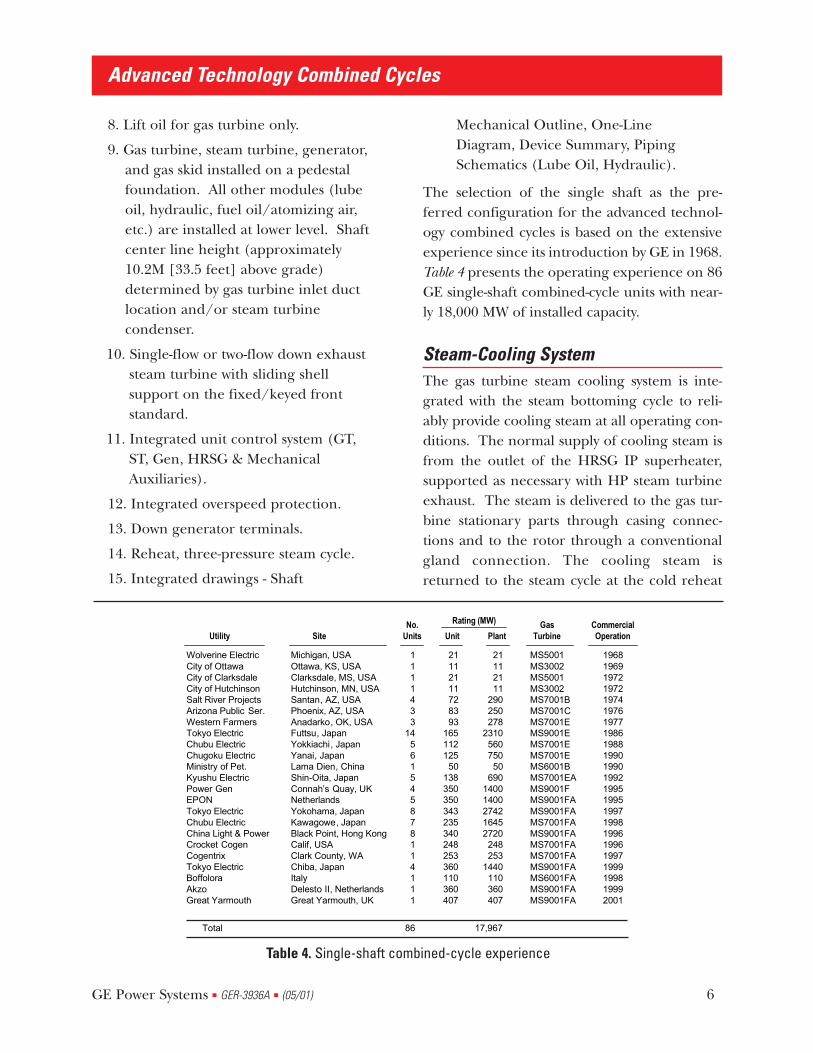
The selection of the single shaft as the pre-ferred configuration for the advanced technol-ogy combined cycles is based on the extensiveexperience since its introduction by GE in 1968.Table 4 presents the operating experience on 86GE single-shaft combined-cycle units with near-ly 18,000 MW of installed capacity.
Steam-Cooling SystemThe gas turbine steam cooling system is inte-grated with the steam bottoming cycle to reli-ably provide cooling steam at all operating con-ditions. The normal supply of cooling steam isfrom the outlet of the HRSG IP superheater,supported as necessary with HP steam turbineexhaust. The steam is delivered to the gas tur-bine stationary parts through casing connec-tions and to the rotor through a conventionalgland connection. The cooling steam isreturned to the steam cycle at the cold reheat
GE Power Systems ■ GER-3936A ■ (05/01) 6
Advanced Technology Combined Cycles
Wolverine ElectricCity of OttawaCity of ClarksdaleCity of HutchinsonSalt River ProjectsArizona Public Ser.Western FarmersTokyo ElectricChubu ElectricChugoku ElectricMinistry of Pet.Kyushu ElectricPower GenEPONTokyo ElectricChubu ElectricChina Light & PowerCrocket CogenCogentrixTokyo ElectricBoffoloraAkzoGreat Yarmouth
Utility
Michigan, USAOttawa, KS, USAClarksdale, MS, USAHutchinson, MN, USASantan, AZ, USAPhoenix, AZ, USAAnadarko, OK, USAFuttsu, JapanYokkiachi, JapanYanai, JapanLama Dien, ChinaShin-Oita, JapanConnah’s Quay, UKNetherlandsYokohama, JapanKawagowe, JapanBlack Point, Hong KongCalif, USAClark County, WAChiba, JapanItalyDelesto II, NetherlandsGreat Yarmouth, UK
Site
1111433
14561545878114111
No.Units
21112111728393
165112125
50138350350343235340248253360110360407
Unit
21112111
290250278
231056075050
69014001400274216452720248253
1440110360407
Plant
MS5001MS3002MS5001MS3002MS7001BMS7001CMS7001EMS9001EMS7001EMS7001EMS6001BMS7001EAMS9001FMS9001FAMS9001FAMS7001FAMS9001FAMS7001FAMS7001FAMS9001FAMS6001FAMS9001FAMS9001FA
GasTurbine
19681969197219721974197619771986198819901990199219951995199719981996199619971999199819992001
CommercialOperation
Rating (MW)
Total 86 17,967
Table 4. Single-shaft combined-cycle experience

line. The gas turbine cooling steam return andany HP steam turbine exhaust steam not usedfor gas turbine cooling are reheated in theHRSG and admitted to the IP steam turbine.
During unit acceleration to rated speed andoperation at low load, the gas turbine is cooledby air extracted from the compressor discharge.The air is filtered prior to supply to the coolingsystem. The cooling air from the gas turbinecooling circuit is discharged to the gas turbineexhaust. During air-cooled gas turbine opera-tion steam flow is established through the steamsupply system to warm the steam lines and sta-bilize the steam supply conditions prior toadmission of steam to the gas turbine coolingsystem. This steam is discharged via thereheater to the condenser through the IPbypass valve, which is modulated to maintainthe pressure of the cooling steam above the gasturbine compressor discharge pressure to pre-clude gas leakage into the steam cycle.Appropriate shutoff valves isolate the gas tur-bine cooling circuit from the steam cycle whileit is operating with air cooling. These coolingsteam shutoff valves are included in the trip cir-cuit such that the system is transferred to aircooling immediately upon an emergency shut-down to purge steam from the cooling system.
Initial cooling steam supply and line warmingsteam is supplied from the HRSG. Steam isextracted from the HP superheater after thefirst pass and mixed with steam from the HPsuperheater discharge to supply steam to thecooling steam system at the required tempera-ture. The cooling steam temperature controlwill match gas turbine cooling steam supply tothe gas turbine compressor discharge tempera-ture during transfer from gas turbine air cool-ing to gas turbine steam cooling, which occursprior to steam turbine loading. In addition toproviding start-up cooling steam supply to thegas turbine cooling steam circuit, the HP steam
extraction after the first superheater pass isused to cool the LP steam turbine from ~70%speed until steam turbine loading is underway.
Figure 2 includes a diagram of the three-pres-sure, reheat HRSG. While the system can beconfigured with either forced or natural circu-lation evaporators, Figure 2 shows a system withnatural circulation evaporators. The HRSG is atypical three-pressure, reheat HRSG that is com-monly applied in combined cycles. It includesthe following features to accommodate thesteam cooling system:
■ The reheater size is reduced since partof the reheating is performed by thegas turbine cooling steam system.
■ The reheater is located in the gas pathdownstream of the high temperaturesection of the HP superheater. Thereheater receives steam during alloperating modes except at very lowloads during startup, prior toavailability of IP steam.
■ HP steam is extracted after the firstpass of the HP superheater during lowload operation to establish gas turbinesteam cooled operation before thesteam turbine is loaded and providecooling steam to the LP steam turbineabove ~70% speed.
■ Control of the HP steam temperatureis accomplished by a steamattemperation system which bypasses asection of the HP superheater. Thissystem eliminates the potential fordissolved contaminants to enter thesteam as can occur with attemperationwith feedwater. Attemperation steamis extracted after it passes through onepass in the superheater to assure thatit will be dry after the small pressuredrop across the steam control valve.
Advanced Technology Combined Cycles
GE Power Systems ■ GER-3936A ■ (05/01) 7
Supply of high purity steam to the gas turbinecooling system is an essential requirement ofthe system for efficient long-term plant opera-tion with high availability. Features included inthe system to accomplish this requirement are:
■ Reliable condenser leakage detectionsystem with redundant condensateconductivity sensors and automatedprotection logic.
■ Full flow feedwater filtration.
■ All cooling steam is purified byevaporation in a steam drum withcontinuous monitoring of drum waterpurity.
■ HP steam temperature control bysteam attemperation.
■ Full flow steam filtration.
■ Application of non-corrosive materialsin piping, filters and equipmentdownstream of the cooling steam shut-off valves.
The steam filter is the final line of defenseagainst particulate contaminants in the cooling
steam supply to the gas turbine. This device willoperate at least 24,000 hours without mainte-nance when provided with steam meeting thesystem purity requirements. The upstream sys-tem design features and associated protectivestrategies provide a means of assuring thedesign life of the steam filter.
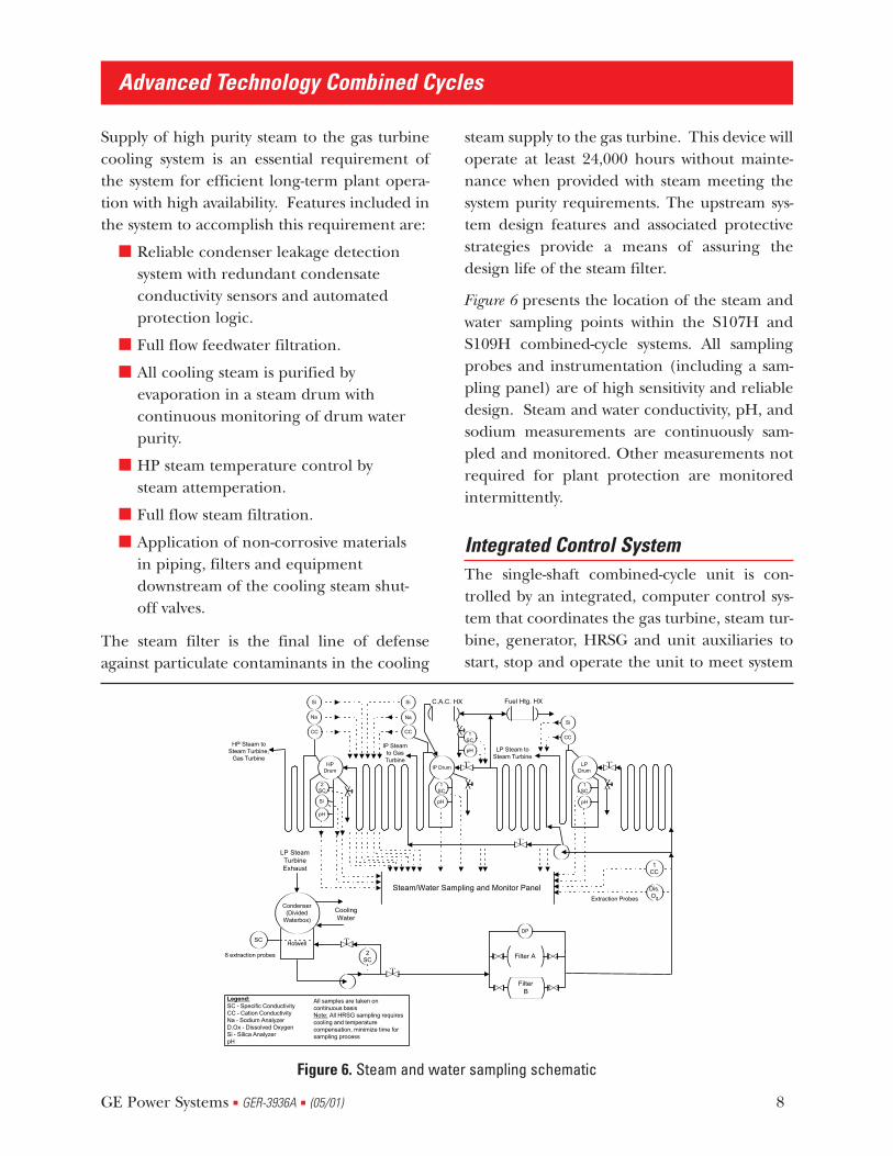
Figure 6 presents the location of the steam andwater sampling points within the S107H andS109H combined-cycle systems. All samplingprobes and instrumentation (including a sam-pling panel) are of high sensitivity and reliabledesign. Steam and water conductivity, pH, andsodium measurements are continuously sam-pled and monitored. Other measurements notrequired for plant protection are monitoredintermittently.
Integrated Control SystemThe single-shaft combined-cycle unit is con-trolled by an integrated, computer control sys-tem that coordinates the gas turbine, steam tur-bine, generator, HRSG and unit auxiliaries tostart, stop and operate the unit to meet system
Advanced Technology Combined Cycles
GE Power Systems ■ GER-3936A ■ (05/01) 8
HPDrum
IP DrumLP
Drum
LP SteamTurbineExhaust
CoolingWater
C.A.C. HX Fuel Htg. HX
CC
Si
Na
Dis.O2Extraction Probes
Legend:SC - Specific ConductivityCC - Cation ConductivityNa - Sodium AnalyzerD.Ox - Dissolved OxygenSi - Silica AnalyzerpH
1CC
Steam/Water Sampling and Monitor Panel
2SC
pH
Si
1SC
pH
1SC
pH
LP Steam toSteam Turbine
IP Steamto GasTurbine
HP Steam toSteam Turbine,
Gas Turbine
CC
Si
CC
Si
1SC
pH
All samples are taken oncontinuous basisNote: All HRSG sampling requirescooling and temperaturecompensation, minimize time forsampling process
DP
SC
8 extraction probes
Condenser(Divided
Waterbox)
Hotwell
Na
Filter A
FilterB
2SC
Figure 6. Steam and water sampling schematic

power requirements with input from a controlroom operator or from a remote dispatch area.The architecture for the single-shaft integratedcontrol system (ICS) for a single unit is shownon Figure 7. Figure 8 shows the architecture fora multiple-unit plant.
A redundant data highway connects all controlcomponents with the central control room con-soles. Historical archival and retrieval of plantdata assists performance optimization andequipment maintenance. Time synchronizationof all control components provides time coher-ent, time tagged data for process monitoring,historical archival, sequence of events logging,real time trending and comprehensive alarmmanagement. High speed communicationinterfaces link the plant control to external dis-patch and control systems.
The control and protection strategies are inte-grated between all components of the system.High levels of fault tolerance maximize unitstarting and running reliability for both base
load and daily start service. The high degree ofcontrol integration maximizes automation ofstartup, shutdown and normal operations,which reduces plant operating costs.
Easy to configure color graphic displays providea common look and feel to both the unit and
plant level control. Windowed displays enablethe operator to constantly monitor the desiredprocess and simultaneously view detailed pop-up windows to trend equipment operating dataor diagnose process problems. An engineeringworkstation enables the operator to configureand tune control loops, perform detailed con-trol and process diagnostics, maintain software,manage the system configuration and generateoperation reports.
The ICS is designed with dedicated I/O(inputs/outputs) to control the engineeredequipment packages. In addition, it has the flex-ibility and expandability needed to addressadditional I/O requirements to satisfy individ-ual owner requirements. This includes both
Advanced Technology Combined Cycles
GE Power Systems ■ GER-3936A ■ (05/01) 9
Control Room
Redundant Unit Data Highway
HRSG/MA
Generator
Steam Turbine
Gas Turbine BOPEquipment
GeneratorExcitation
&Protection
StaticStarter
SteamTurbine
&BypassControl
GasTurbine &CoolingSteamControl
HRSG &Steam CycleMechanicalAuxiliaries
Unit AuxiliaryControl
HMI/Server
HMI/Server
AlarmPrinter
ColorDisplayPrinter
LogPrinter
OperatorStation Historian
Remote Dispatch
Fault Tolerant Plant Data Highway
OperatorStation
EngineeringWorkstation
Figure 7. Single-shaft combined-cycle unit integrated control architecture
• All New Microprocessor Design
• Triple Modular Redundant
• Remotable I/O
• Capability for I/O Expansion
• Redundant Control and Plant DataHighways
• Peer-to-Peer Communications
• Time Synchronized Unit Controls
• Time Coherent System Data
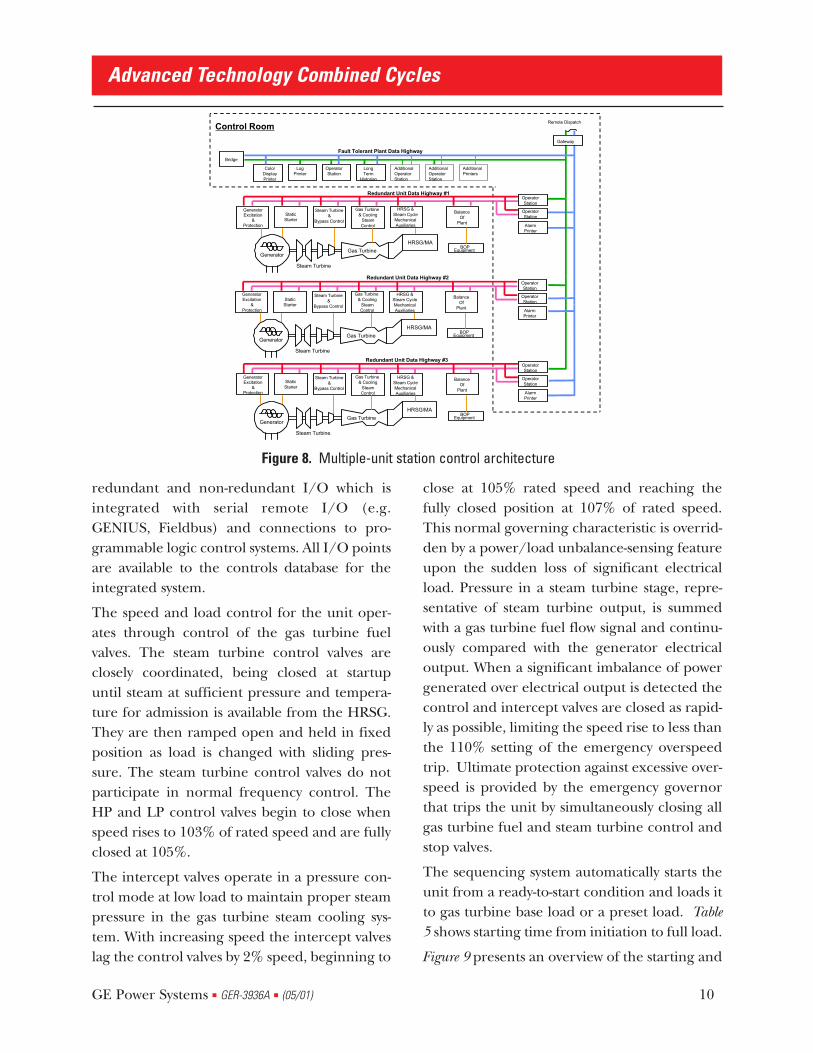
redundant and non-redundant I/O which isintegrated with serial remote I/O (e.g.GENIUS, Fieldbus) and connections to pro-grammable logic control systems. All I/O pointsare available to the controls database for theintegrated system.
The speed and load control for the unit oper-ates through control of the gas turbine fuelvalves. The steam turbine control valves areclosely coordinated, being closed at startupuntil steam at sufficient pressure and tempera-ture for admission is available from the HRSG.They are then ramped open and held in fixedposition as load is changed with sliding pres-sure. The steam turbine control valves do notparticipate in normal frequency control. TheHP and LP control valves begin to close whenspeed rises to 103% of rated speed and are fullyclosed at 105%.
The intercept valves operate in a pressure con-trol mode at low load to maintain proper steampressure in the gas turbine steam cooling sys-tem. With increasing speed the intercept valveslag the control valves by 2% speed, beginning to
close at 105% rated speed and reaching thefully closed position at 107% of rated speed.This normal governing characteristic is overrid-den by a power/load unbalance-sensing featureupon the sudden loss of significant electricalload. Pressure in a steam turbine stage, repre-sentative of steam turbine output, is summedwith a gas turbine fuel flow signal and continu-ously compared with the generator electricaloutput. When a significant imbalance of powergenerated over electrical output is detected thecontrol and intercept valves are closed as rapid-ly as possible, limiting the speed rise to less thanthe 110% setting of the emergency overspeedtrip. Ultimate protection against excessive over-speed is provided by the emergency governorthat trips the unit by simultaneously closing allgas turbine fuel and steam turbine control andstop valves.
The sequencing system automatically starts theunit from a ready-to-start condition and loads itto gas turbine base load or a preset load. Table5 shows starting time from initiation to full load.
Figure 9 presents an overview of the starting and
Advanced Technology Combined Cycles
GE Power Systems ■ GER-3936A ■ (05/01) 10
Remote Dispatch
Gateway
Control Room
BOPEquipment
GeneratorExcitation
&Protection
StaticStarter
Steam Turbine&
Bypass Control
Gas Turbine & Cooling
SteamControl
HRSG &Steam CycleMechanicalAuxiliaries
BalanceOf
Plant
OperatorStation
OperatorStation
AlarmPrinter
ColorDisplayPrinter
Bridge
LogPrinter
OperatorStation
LongTerm
Historian
Fault Tolerant Plant Data Highway
AdditionalOperatorStation
AdditionalOperatorStation
AdditionalPrinters
BOPEquipment
HRSG/MA
Generator
Steam Turbine
Gas Turbine
GeneratorExcitation
&Protection
StaticStarter
Steam Turbine&
Bypass Control
Gas Turbine & Cooling
SteamControl
HRSG &Steam CycleMechanicalAuxiliaries
BalanceOf
Plant
OperatorStation
OperatorStation
AlarmPrinter
Redundant Unit Data Highway #3
HRSG/MA
Generator
Steam Turbine
Gas Turbine
BOPEquipment
GeneratorExcitation
&Protection
StaticStarter
Steam Turbine&
Bypass Control
Gas Turbine & Cooling
SteamControl
HRSG &Steam CycleMechanicalAuxiliaries
BalanceOf
Plant
OperatorStation
OperatorStation
AlarmPrinter
HRSG/MA
Generator
Steam Turbine
Gas Turbine
Redundant Unit Data Highway #2
Redundant Unit Data Highway #1
Figure 8. Multiple-unit station control architecture

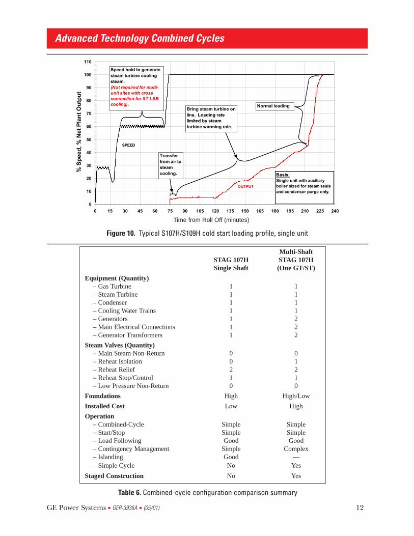
loading sequence for a hot start. Figure 10 is asimilar presentation of the cold start sequenceof a single unit. Note the speed hold shown fordeveloping steam for steam turbine cooling,which is not required in multi-unit installationswhere running units can be used to supportsteam turbine cooling needs of the startingunit.
Start Standby Time toDesignation Period (hrs) Full Load (min)
Hot 0-12 60Warm 12-48 120Cold >48 180
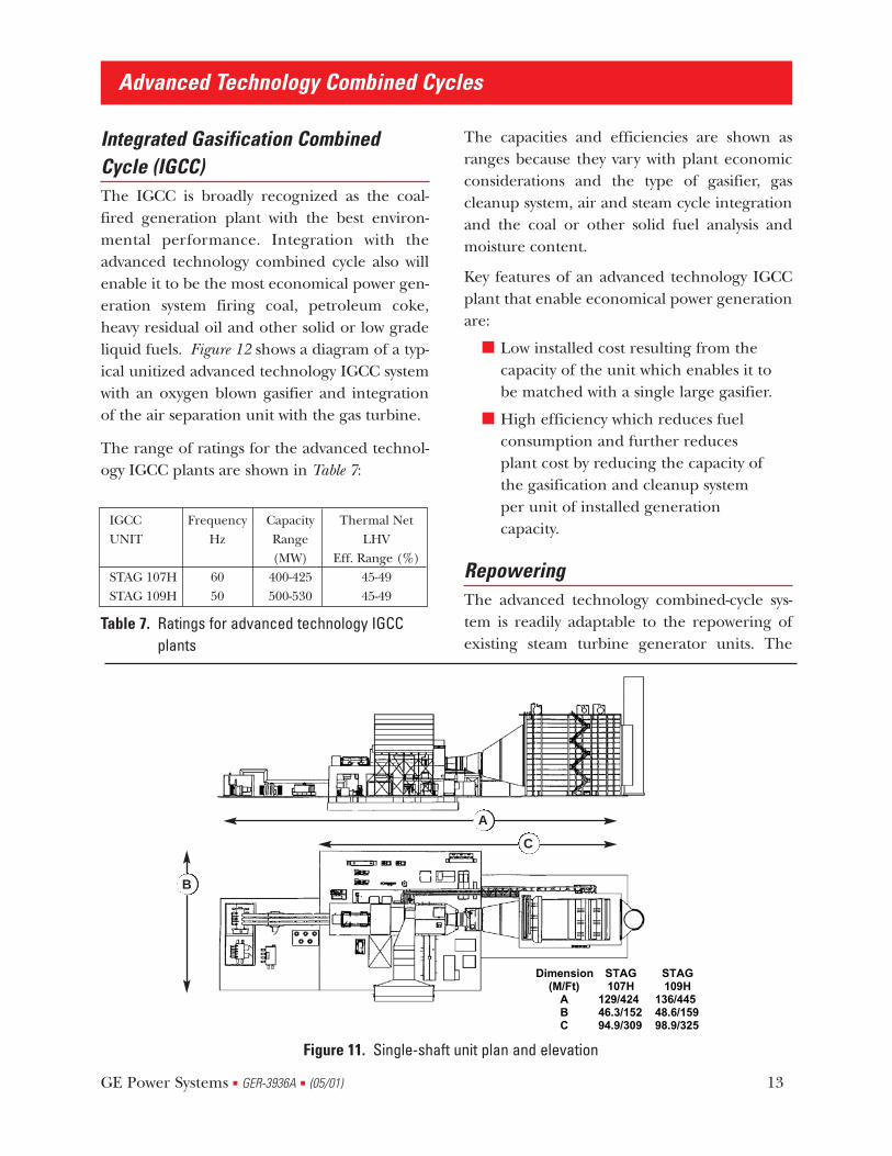
Plant ArrangementThe high power density of the advanced tech-nology combined-cycle systems enables a com-pact plant arrangement. Typical plan and eleva-tion arrangements are shown in Figure 11 withoverall dimensions for outdoor STAG 107H andSTAG 109H plants. In this arrangement, the
steam turbine has a single-casing and single-flow exhaust as would be applied at a site withsteam turbine condenser cooling that accom-modates the higher range of exhaust pressures.Plants using steam turbines with double-flowexhausts are approximately 10 feet (3m) longer.The plan area for the 60 Hz advanced technol-ogy combined cycle is approximately 10% larg-er than that for current technology combinedcycles, while the power is increased approxi-mately 60% so that the plot space per unit ofinstalled capacity is reduced approximately45%.
Plant related considerations that influence theselection of the single-shaft configuration forthe advanced technology combined cycle aretabulated in Table 6. The gas turbine cannotoperate independently of the steam cycle sothere is no operating flexibility advantage forthe multi-shaft system. The single-shaft system islower in installation cost because of the singlegenerator, main electrical connections, trans-former and switchgear as compared to two forthe multi-shaft system.
Advanced Technology Combined Cycles
GE Power Systems ■ GER-3936A ■ (05/01) 11
Table 5. Starting time from initiation to full load
0
10
20
30
40
50
60
70
80
90
100
110
0 5 10 15 20 25 30 35 40 45 50 55 60 65 70 75
Time from Synchronization (minutes)
..%
Sp
eed
, % N
et P
lan
t O
utp
ut.
.
Bring steam turbine on line.
Transfer from air to steam.
Normal loading
SPEED
OUTPUT
Figure 9. Typical S107H/S109H hot start loading profile
Time from Roll Off (minutes)
Advanced Technology Combined Cycles
GE Power Systems ■ GER-3936A ■ (05/01) 12
0
10
20
30
40
50
60
70
80
90
100
110
0 15 30 45 60 75 90 105 120 135 150 165 180 195 210 225 240
Time from Synchronization (minutes)
..%
Sp
eed
, % N
et P
lan
t O
utp
ut.
.
Normal loading
Transfer from air to steam cooling.
Bring steam turbine online. Loading rate limited by steam turbine warming rate.
Speed hold to generate steam turbine cooling steam.(Not required for multi-unit sites with cross connection for ST LSB cooling).
Basis:Single unit with auxiliary boiler sized for steam seals and condenser purge only.
SPEED
OUTPUT
Figure 10. Typical S107H/S109H cold start loading profile, single unit
Time from Roll Off (minutes)
Table 6. Combined-cycle configuration comparison summary
Multi-ShaftSTAG 107H STAG 107HSingle Shaft (One GT/ST)
Equipment (Quantity)– Gas Turbine 1 1– Steam Turbine 1 1– Condenser 1 1– Cooling Water Trains 1 1– Generators 1 2– Main Electrical Connections 1 2– Generator Transformers 1 2
Steam Valves (Quantity)– Main Steam Non-Return 0 0– Reheat Isolation 0 1– Reheat Relief 2 2– Reheat Stop/Control 1 1– Low Pressure Non-Return 0 0
Foundations High High/Low
Installed Cost Low High
Operation– Combined-Cycle Simple Simple– Start/Stop Simple Simple– Load Following Good Good– Contingency Management Simple Complex– Islanding Good —– Simple Cycle No Yes
Staged Construction No Yes
Integrated Gasification CombinedCycle (IGCC)The IGCC is broadly recognized as the coal-fired generation plant with the best environ-mental performance. Integration with theadvanced technology combined cycle also willenable it to be the most economical power gen-eration system firing coal, petroleum coke,heavy residual oil and other solid or low gradeliquid fuels. Figure 12 shows a diagram of a typ-ical unitized advanced technology IGCC systemwith an oxygen blown gasifier and integrationof the air separation unit with the gas turbine.
The range of ratings for the advanced technol-ogy IGCC plants are shown in Table 7:
IGCC Frequency Capacity Thermal Net UNIT Hz Range LHV
(MW) Eff. Range (%)STAG 107H 60 400-425 45-49STAG 109H 50 500-530 45-49
The capacities and efficiencies are shown asranges because they vary with plant economicconsiderations and the type of gasifier, gascleanup system, air and steam cycle integrationand the coal or other solid fuel analysis andmoisture content.
Key features of an advanced technology IGCCplant that enable economical power generationare:
■ Low installed cost resulting from thecapacity of the unit which enables it tobe matched with a single large gasifier.
■ High efficiency which reduces fuelconsumption and further reducesplant cost by reducing the capacity ofthe gasification and cleanup systemper unit of installed generationcapacity.
RepoweringThe advanced technology combined-cycle sys-tem is readily adaptable to the repowering ofexisting steam turbine generator units. The
Advanced Technology Combined Cycles
GE Power Systems ■ GER-3936A ■ (05/01) 13
Dimension STAG STAG(M/Ft) 107H 109H
A 129/424 136/445B 46.3/152 48.6/159C 94.9/309 98.9/325
Figure 11. Single-shaft unit plan and elevation
A
B
C
Table 7. Ratings for advanced technology IGCCplants

integration of the steam cycle with the gas tur-bine cooling system requires appropriate con-sideration, but several methods for matchingthe cooling requirements to the existing steamcycle are available and include the following:
■ The cooling steam temperature andpressure for the MS7001H andMS9001H gas turbines are in the samerange as those of the cold reheatsteam in many conventional steamunits with 2400 psig (165 bar) throttlepressure.
■ Apply cooling water and existingsupport facilities and replace theexisting steam turbine with a modern,high efficiency steam turbine that isspecifically matched to the combined-cycle requirements. This option isattractive when the use of existing
water permits can minimize sitepermitting work.
A wide range of steam turbine ratings can bematched to the MS7001H and MS9001H gasturbines by retaining existing feedwater heatersas may be necessary to meet exhaust flow limi-tations.
ConclusionThe GE advanced technology combined cyclespromise improved economics of electric powergeneration with outstanding environmentalperformance in natural gas and coal-fired appli-cations. These characteristics are enhanced bythe evolutionary development from a technolo-gy base with extensive experience, whichassures low maintenance and reliable, conven-ient operation.
Advanced Technology Combined Cycles
GE Power Systems ■ GER-3936A ■ (05/01) 14
GasTurbine
SteamTurbine
GeneratorElectricPower
Air SeparationUnit
Gasifier
GasCleanup
Heat RecoverySteam
Generator
Co
ld R
ehea
t
L.P
.
I.P.M
ain
Ho
t R
ehea
t
Coal
Air
Air
Air
Nit
rog
en
AirExh. GasNitrogenCoalCoal GasSteamWaterOxygen
GasCooler
Figure 12. Unitized advanced technology IGCC system

List of FiguresFigure 1. Advanced technology combined-cycle unit
Figure 2. STAG 107H/109H cycle diagram
Figure 3. S107H ambient temperature effect on performance and part load performance
Figure 4. S109H ambient temperature effect on performance and part load performance
Figure 5. S107H and 109H single-shaft STAG equipment configuration
Figure 6. Steam and water sampling schematic
Figure 7. Single-shaft combined-cycle unit integrated control architecture
Figure 8. Multiple-unit station control architecture
Figure 9. Typical S107H/S109H hot start loading profile
Figure 10. Typical S107H/S109H cold start loading profile, single unit
Figure 11. Single-shaft unit plan and elevation
Figure 12. Unitized advanced technology IGCC system
List of TablesTable 1. Advanced technology combined-cycle – thermal and environmental performance
Table 2. Advanced technology combined-cycle steam conditions
Table 3. Last-stage buckets for advanced technology combined-cycle applications
Table 4. Single-shaft combined-cycle experience
Table 5. Starting time from initiation to full load
Table 6. Combined-cycle configuration comparison summary
Table 7. Ratings for advanced technology IGCC plants
Advanced Technology Combined Cycles
GE Power Systems ■ GER-3936A ■ (05/01) 15

Advanced Technology Combined Cycles
GE Power Systems ■ GER-3936A ■ (05/01) 16
Related Documents