ENGR. BRODDETT B. ABATAYO, GE, REA Part - time Lecturer – GE division, CEIT, CSU, Ampayon , Butuan City Research Assistant – Phil - LiDAR 2 Project, CSU, Ampayon , Butuan City Proprietor – BPA ABATAYO Land Surveying Services 1 Lecture 2 Caraga State University College of Engineering and Information Technology Ampayon , Butuan City 8600 PROJECT CONTROL SURVEY GE 122 – Geodetic Surveying

Ge 122 lecture 2 (PROJECT CONTROL SURVEY) by: Broddett Bello Abatayo
Apr 11, 2017
Welcome message from author
This document is posted to help you gain knowledge. Please leave a comment to let me know what you think about it! Share it to your friends and learn new things together.
Transcript
ENGR. BRODDETT B. ABATAYO, GE, REA
Part-time Lecturer – GE division, CEIT, CSU, Ampayon, Butuan CityResearch Assistant – Phil-LiDAR 2 Project, CSU, Ampayon, Butuan City
Proprietor – BPA ABATAYO Land Surveying Services1
Lecture 2
Caraga State University
College of Engineering and Information Technology
Ampayon, Butuan City 8600
PROJECT CONTROL
SURVEY
GE 122 – Geodetic Surveying

Section 29. Project Control Surveys shall be conducted in order to establish set of reference points for a Cadastral Survey, Public Land Subdivision Survey, Townsite Reservation, and other similar survey projects which cover a whole or a portion of municipality or city, with accuracies belonging to:
o Primary Control or 3rd Order Geodetic Surveyo Secondary Control or 4th Order Geodetic Surveyo Tertiary Control
Project Control Surveys
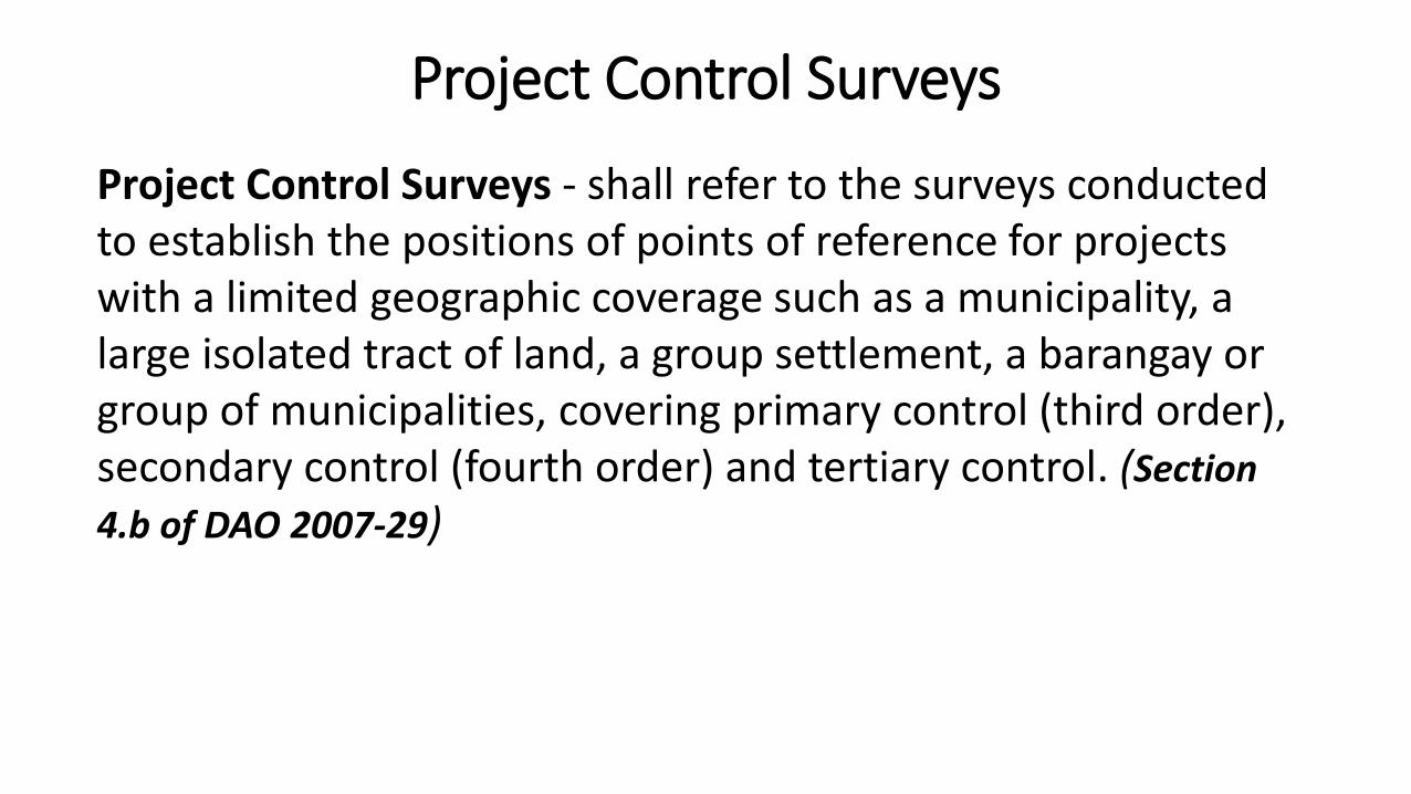
Project Control Surveys - shall refer to the surveys conducted to establish the positions of points of reference for projects with a limited geographic coverage such as a municipality, a large isolated tract of land, a group settlement, a barangay or group of municipalities, covering primary control (third order), secondary control (fourth order) and tertiary control. (Section
4.b of DAO 2007-29)
Project Control Surveys
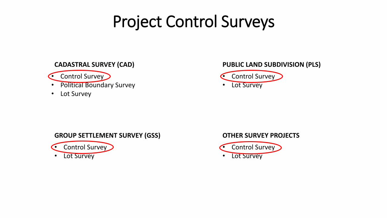
CADASTRAL SURVEY (CAD) PUBLIC LAND SUBDIVISION (PLS)
GROUP SETTLEMENT SURVEY (GSS) OTHER SURVEY PROJECTS
• Control Survey• Political Boundary Survey• Lot Survey
• Control Survey• Lot Survey
• Control Survey• Lot Survey
• Control Survey• Lot Survey
Project Control Surveys

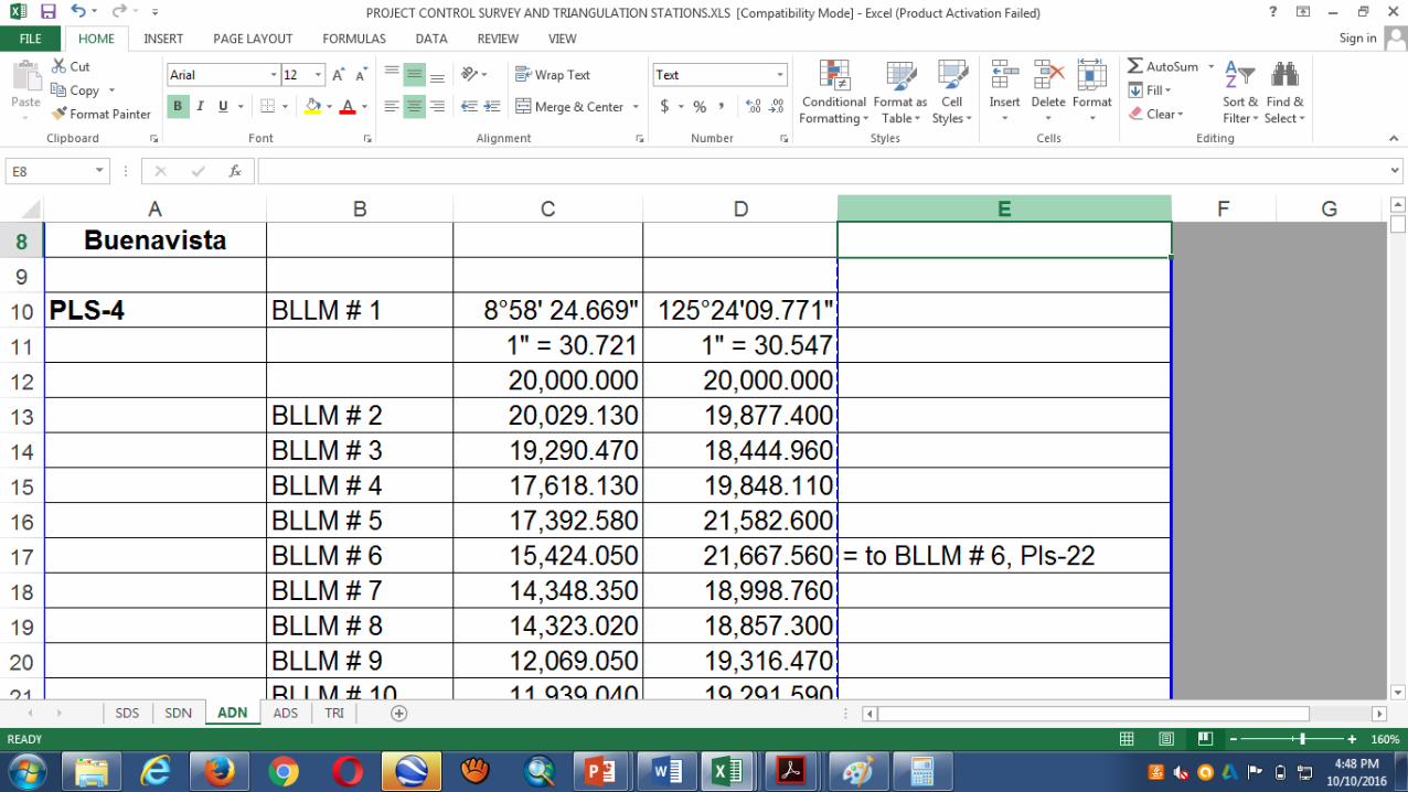
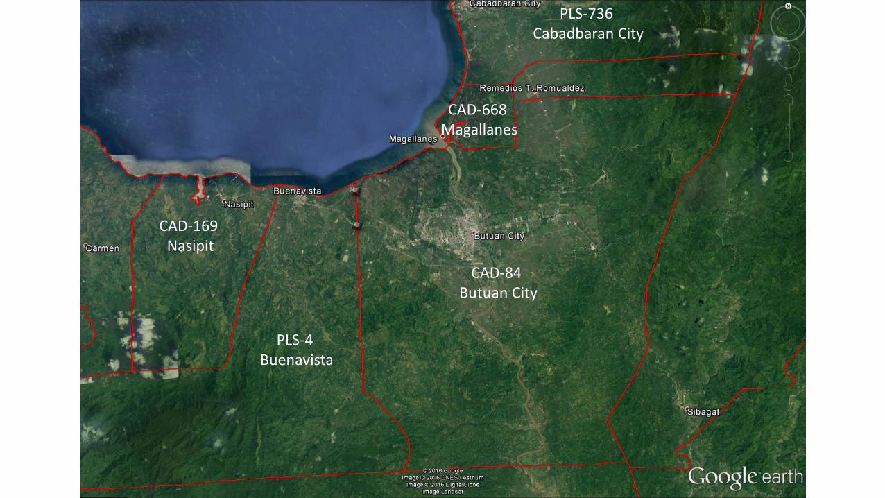
PLS-4 Buenavista
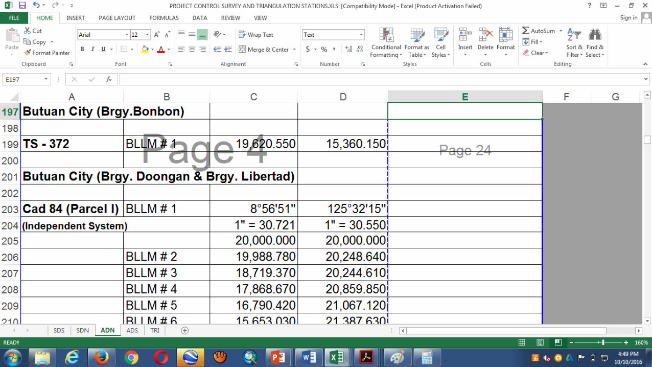
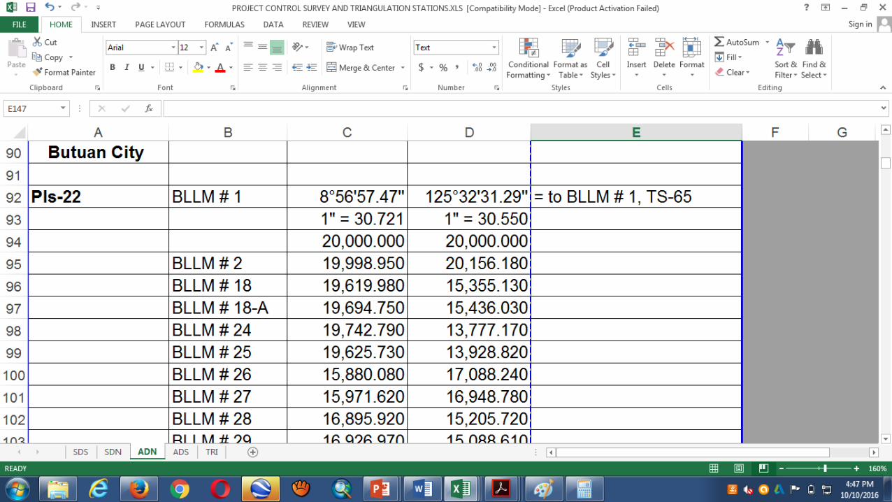
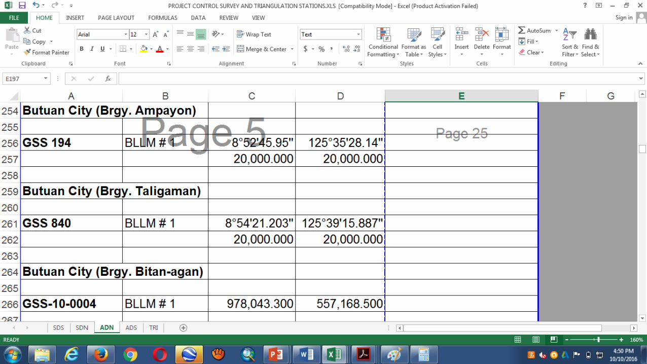
CAD-84 Butuan City
PLS-736 Cabadbaran City
CAD-668 Magallanes
CAD-169 Nasipit
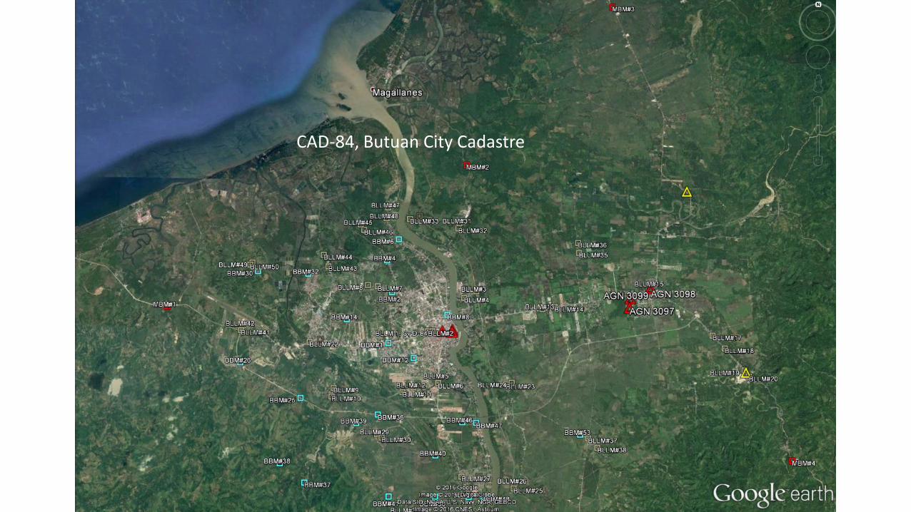
CAD-84, Butuan City Cadastre
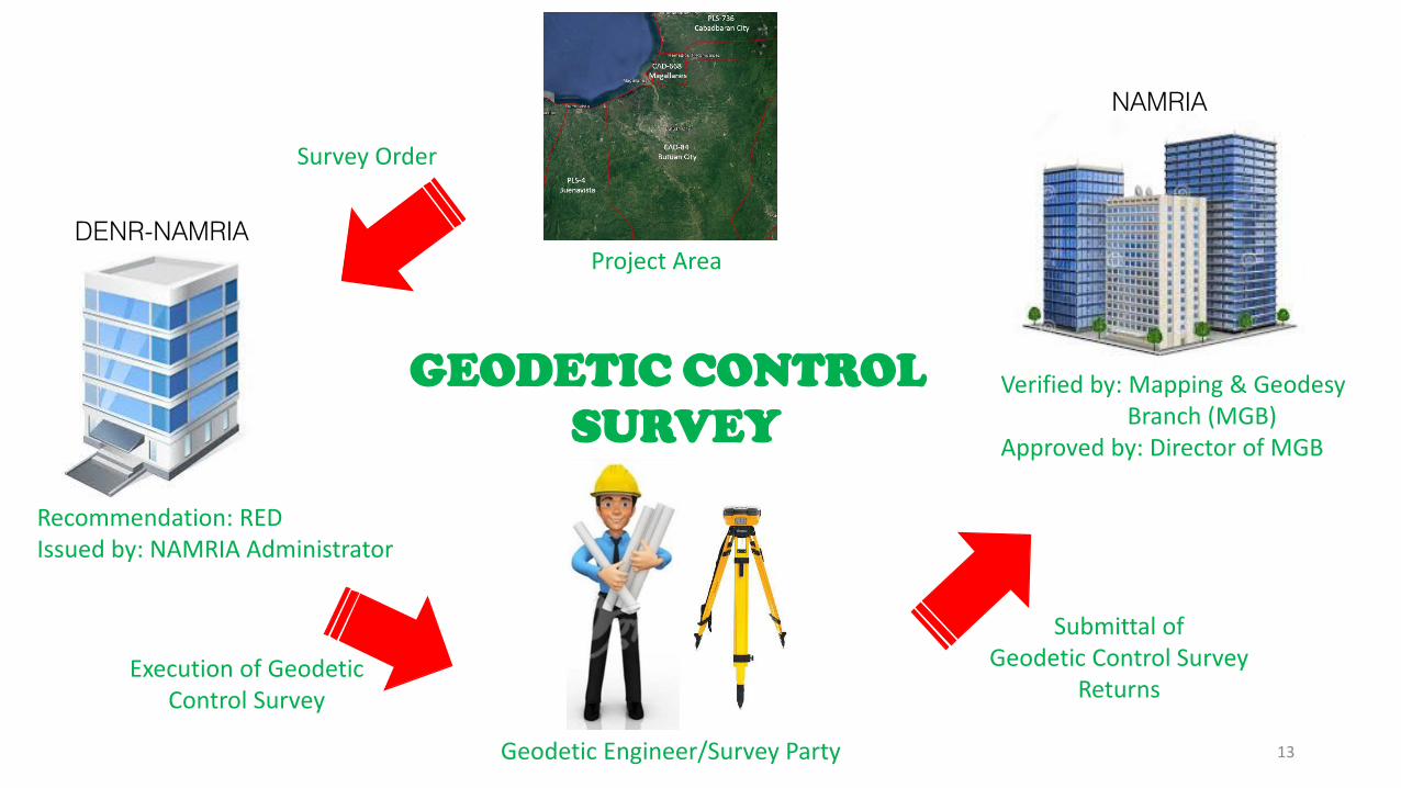
13Geodetic Engineer/Survey Party
NAMRIA
Project Area
Survey Order
Execution of Geodetic Control Survey
Submittal ofGeodetic Control Survey
Returns
GEODETIC CONTROL
SURVEY
Recommendation: REDIssued by: NAMRIA Administrator
Verified by: Mapping & Geodesy Branch (MGB)
Approved by: Director of MGB
DENR-NAMRIA
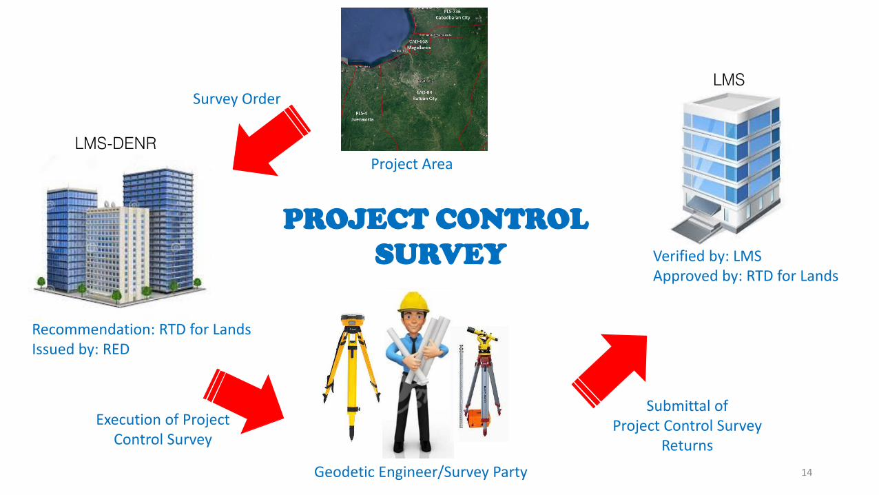
14Geodetic Engineer/Survey Party
LMS
Project Area
Survey Order
Execution of Project Control Survey
Submittal ofProject Control Survey
Returns
PROJECT CONTROL
SURVEY
Recommendation: RTD for LandsIssued by: RED
Verified by: LMSApproved by: RTD for Lands
LMS-DENR

PROJECT CONTROL
SURVEY PROCEDURE
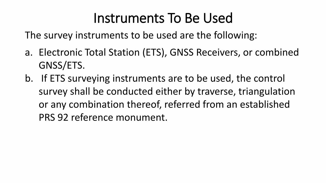
The survey instruments to be used are the following:
a. Electronic Total Station (ETS), GNSS Receivers, or combined GNSS/ETS.
b. If ETS surveying instruments are to be used, the control survey shall be conducted either by traverse, triangulation or any combination thereof, referred from an established PRS 92 reference monument.
Instruments To Be Used
Project Control Survey
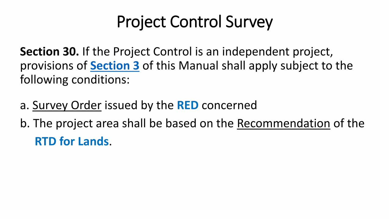
Section 30. If the Project Control is an independent project, provisions of Section 3 of this Manual shall apply subject to the following conditions:
a. Survey Order issued by the RED concerned
b. The project area shall be based on the Recommendation of the
RTD for Lands.
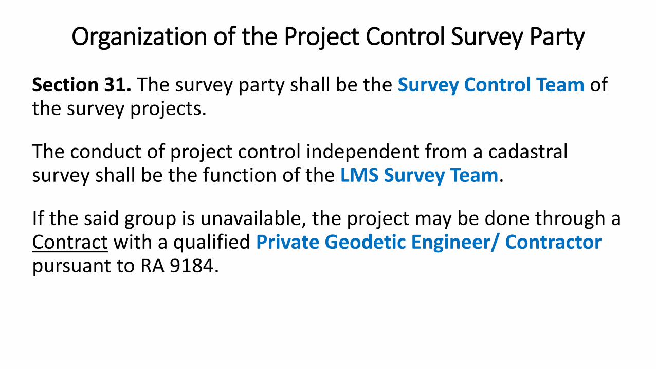
Section 31. The survey party shall be the Survey Control Team of the survey projects.
The conduct of project control independent from a cadastral survey shall be the function of the LMS Survey Team.
If the said group is unavailable, the project may be done through a Contract with a qualified Private Geodetic Engineer/ Contractorpursuant to RA 9184.
Organization of the Project Control Survey Party
Section 32. Once the Project Control Work Plan is approved, there shall be no changes to be made therein without prior approval of the RTD for Lands concerned.
Project Control Work Plan
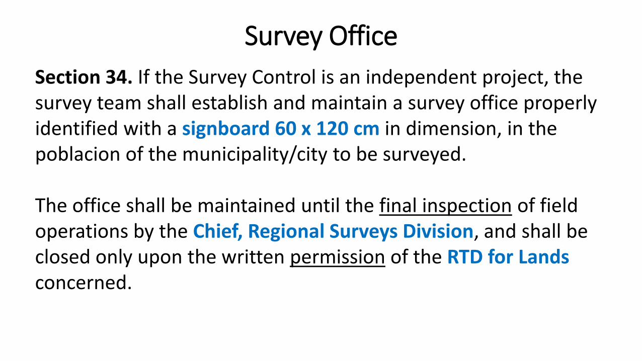
Section 34. If the Survey Control is an independent project, the survey team shall establish and maintain a survey office properly identified with a signboard 60 x 120 cm in dimension, in the poblacion of the municipality/city to be surveyed.
The office shall be maintained until the final inspection of field operations by the Chief, Regional Surveys Division, and shall be closed only upon the written permission of the RTD for Landsconcerned.
Survey Office
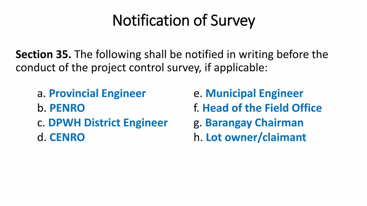
Section 35. The following shall be notified in writing before the conduct of the project control survey, if applicable:
Notification of Survey
e. Municipal Engineerf. Head of the Field Officeg. Barangay Chairmanh. Lot owner/claimant
a. Provincial Engineerb. PENROc. DPWH District Engineerd. CENRO
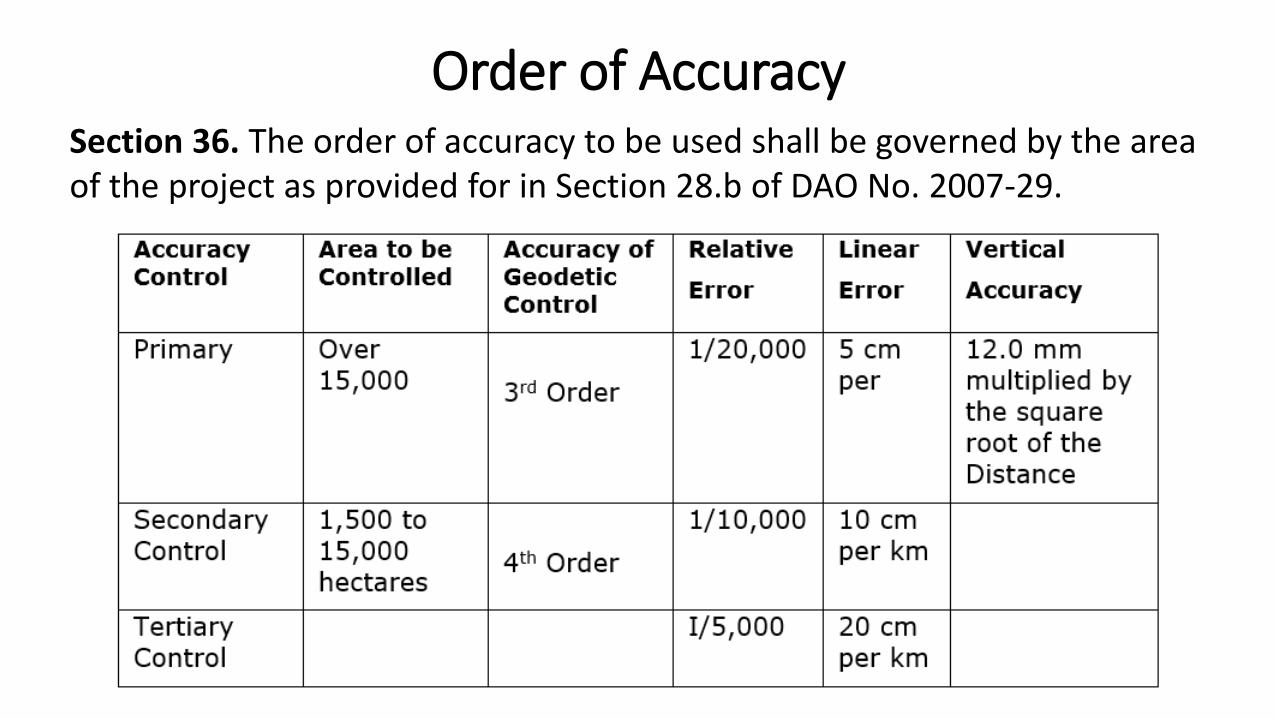
Section 36. The order of accuracy to be used shall be governed by the area of the project as provided for in Section 28.b of DAO No. 2007-29.
Order of Accuracy
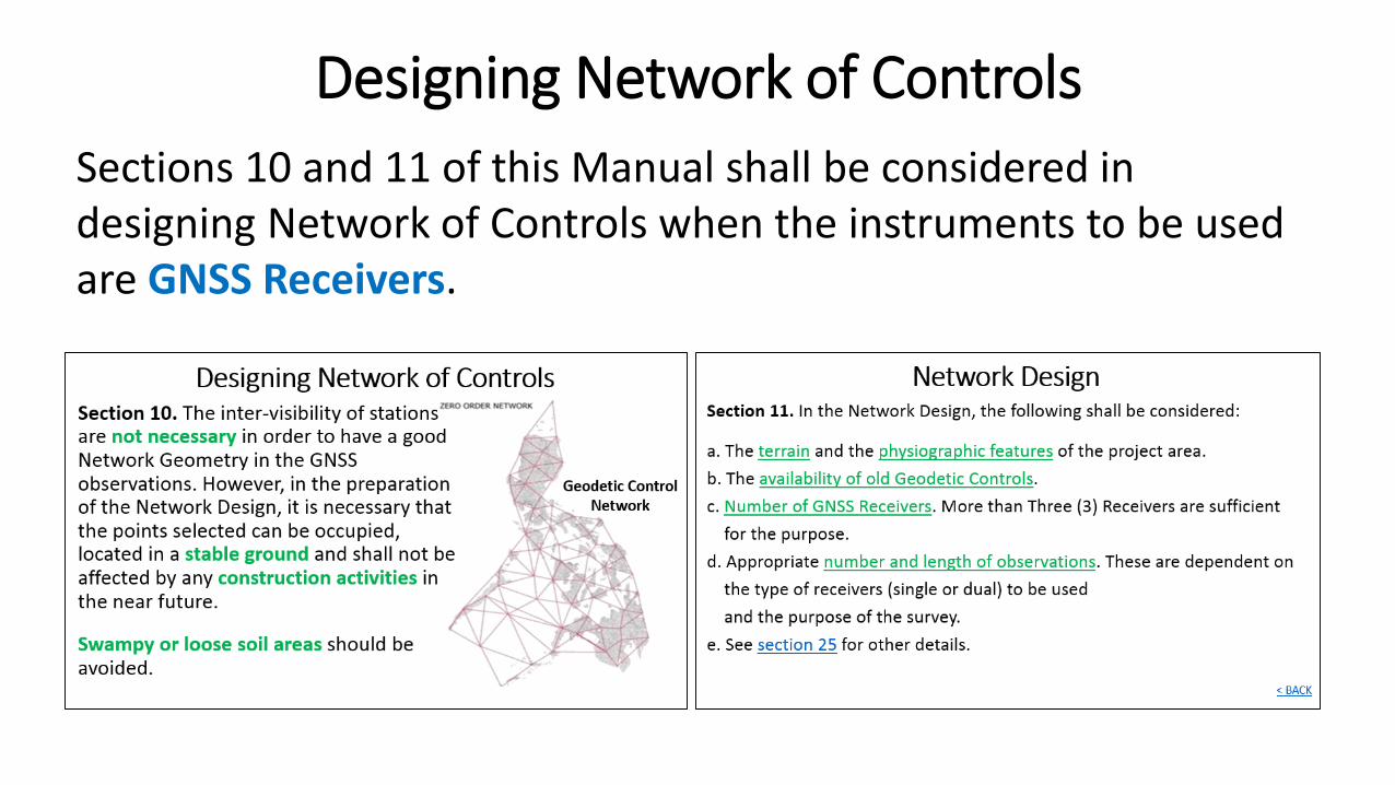
Sections 10 and 11 of this Manual shall be considered in designing Network of Controls when the instruments to be usedare GNSS Receivers.
Designing Network of Controls
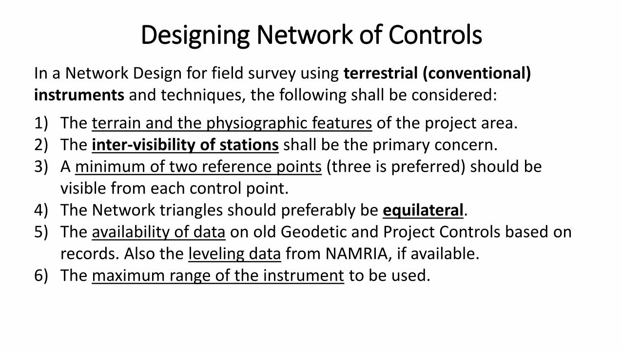
In a Network Design for field survey using terrestrial (conventional) instruments and techniques, the following shall be considered:
1) The terrain and the physiographic features of the project area. 2) The inter-visibility of stations shall be the primary concern.3) A minimum of two reference points (three is preferred) should be
visible from each control point.4) The Network triangles should preferably be equilateral.5) The availability of data on old Geodetic and Project Controls based on
records. Also the leveling data from NAMRIA, if available.6) The maximum range of the instrument to be used.
Designing Network of Controls
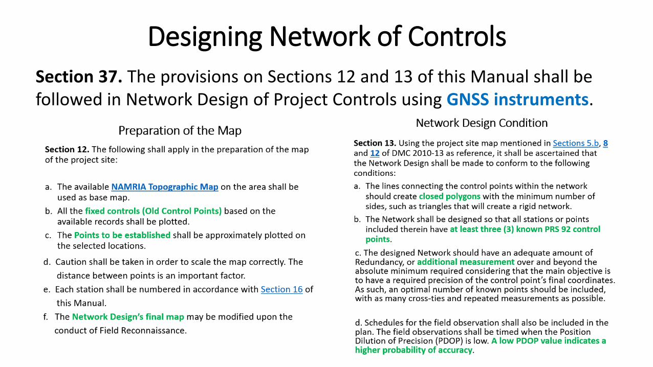
Section 37. The provisions on Sections 12 and 13 of this Manual shall be followed in Network Design of Project Controls using GNSS instruments.
Designing Network of Controls
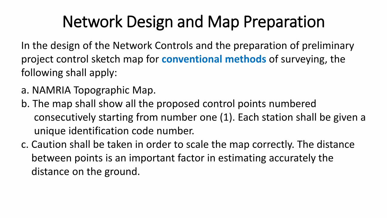
In the design of the Network Controls and the preparation of preliminary project control sketch map for conventional methods of surveying, the following shall apply:
a. NAMRIA Topographic Map.b. The map shall show all the proposed control points numbered
consecutively starting from number one (1). Each station shall be given a unique identification code number.
c. Caution shall be taken in order to scale the map correctly. The distancebetween points is an important factor in estimating accurately the distance on the ground.
Network Design and Map Preparation

d. All the main control points in a proposed Cadastral Project, Public LandSubdivision Projects, Townsite Reservation Subdivision, and other similarlarge survey projects shall be conducted with a Primary (3rd Order) Accuracy and shall be designated as Bureau of Lands Location Monuments (BLLMs).
The first primary control point known as P1 of the main control shall be designated as BLLM No. 1 of the project, the second primary control point(P2) or the last main control station shall be designated as the BLLM No. 2 of the project.
Network Design and Map Preparation
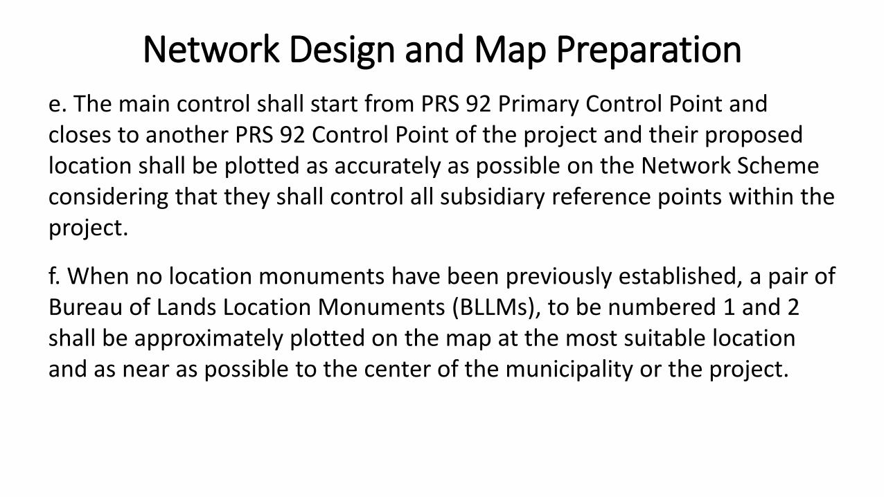
e. The main control shall start from PRS 92 Primary Control Point and closes to another PRS 92 Control Point of the project and their proposed location shall be plotted as accurately as possible on the Network Scheme considering that they shall control all subsidiary reference points within the project.
f. When no location monuments have been previously established, a pair ofBureau of Lands Location Monuments (BLLMs), to be numbered 1 and 2shall be approximately plotted on the map at the most suitable location and as near as possible to the center of the municipality or the project.
Network Design and Map Preparation
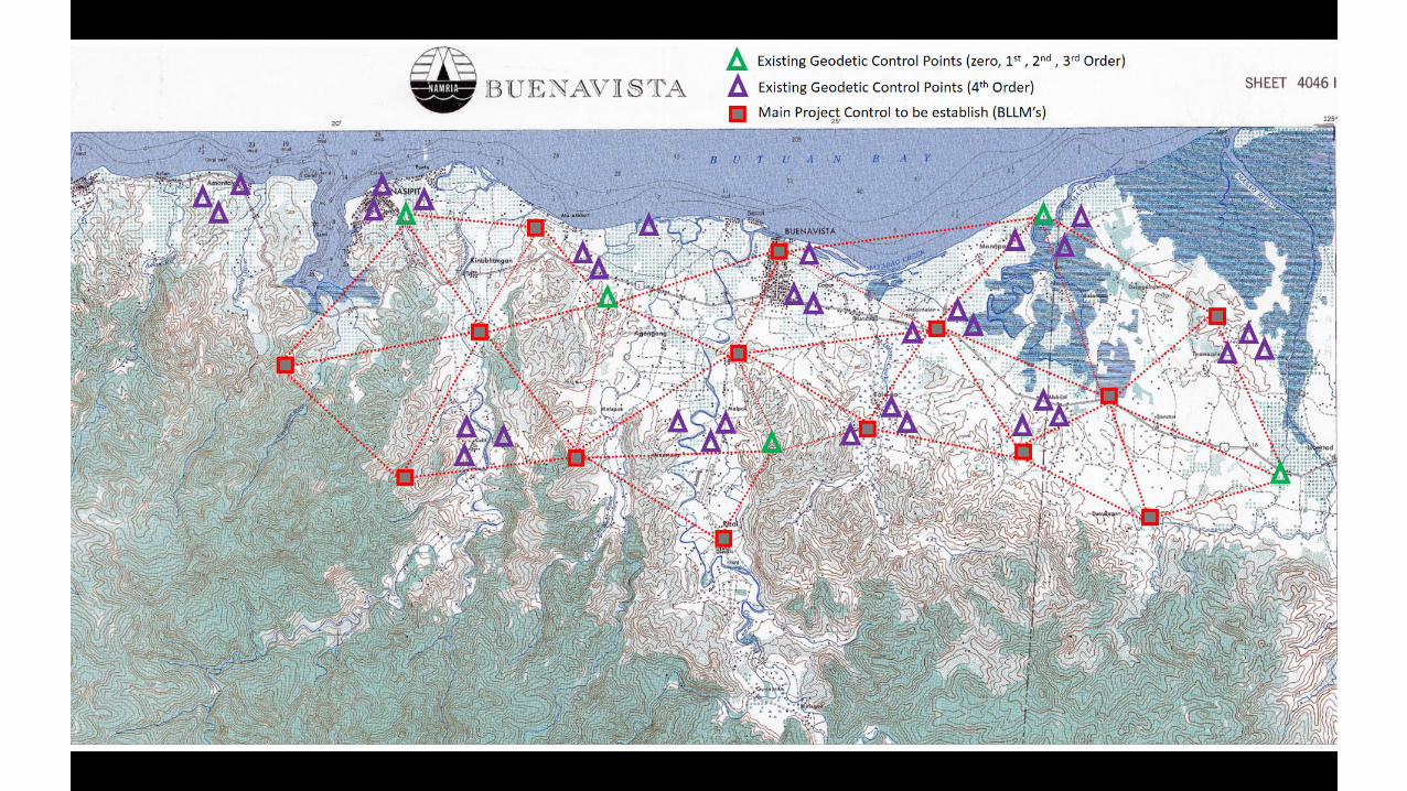
g. The points to be established shall be approximately plotted on the map. The approximate line routes or the connection lines from one control point to another shall be shown on the map.
h. All the fixed controls (old Control Points) based on the available records shall be accurately plotted. At least three (3) Second Order or Third OrderGeodetic Control stations shall be included in the Network.
i. Whenever the main control includes established geodetic control stations, the main control shall be designed such that it can be divided into loops wherein each loops shall start from one geodetic control station and shall close to another geodetic control station;
Network Design and Map Preparation
j. The main controls to be established, as much as possible, shall follow theproject boundary. If the place is rugged as shown in the topographic map, the controls shall be placed near the boundary where it is fairly level, although they are a little beyond the administrative jurisdiction of the concerned LGU.
k. In case mountain peaks or hills define the boundary of municipality or project, the primary controls shall be located at the base of the mountains or hills. If the terrain is rugged, it may be plotted along the existing road lines located as near as possible to the boundary;
Network Design and Map Preparation
l. Additional pairs of location monuments shall be established along the main control of the project at an interval of around 5 kilometers or at least a pair for every Barangay, whichever provides the shorter distance, and shall be designated and numbered as BLLM No. 3 and BLLM No. 4; BLLM No. 5 and BLLM No. 6; etc.. Pursuant to Section 28, DAO No. 2007-29, consideration should be taken by the Geodetic Engineer to ensure that no lots shall have a distance of more than one (1) kilometer from the nearest reference point, whenever possible, based on the project control network design.
Network Design and Map Preparation
Section 38. Provisions of Section 14 of this Manual shall apply in addition to the following conditions:
a. Intervisibility between pairs of stations.b. Line of sight is not in any way obstructed by transportation vehicle. c. Condition of the atmosphere.
Reconnaissance
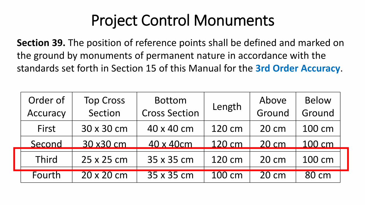
Section 39. The position of reference points shall be defined and marked on the ground by monuments of permanent nature in accordance with the standards set forth in Section 15 of this Manual for the 3rd Order Accuracy.
Project Control Monuments
Order ofAccuracy
Top CrossSection
BottomCross Section
LengthAbove
GroundBelow
Ground
First 30 x 30 cm 40 x 40 cm 120 cm 20 cm 100 cm
Second 30 x30 cm 40 x 40cm 120 cm 20 cm 100 cm
Third 25 x 25 cm 35 x 35 cm 120 cm 20 cm 100 cm
Fourth 20 x 20 cm 35 x 35 cm 100 cm 20 cm 80 cm
Markings of Reference Monuments
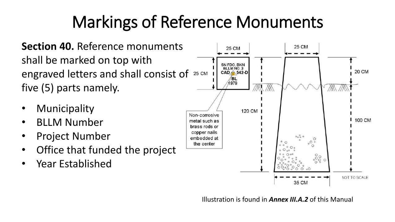
Illustration is found in Annex III.A.2 of this Manual
Section 40. Reference monuments shall be marked on top with engraved letters and shall consist of five (5) parts namely.
• Municipality• BLLM Number• Project Number• Office that funded the project• Year Established
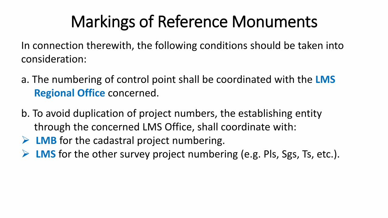
In connection therewith, the following conditions should be taken into consideration:
a. The numbering of control point shall be coordinated with the LMS Regional Office concerned.
b. To avoid duplication of project numbers, the establishing entitythrough the concerned LMS Office, shall coordinate with:
LMB for the cadastral project numbering. LMS for the other survey project numbering (e.g. Pls, Sgs, Ts, etc.).
Markings of Reference Monuments
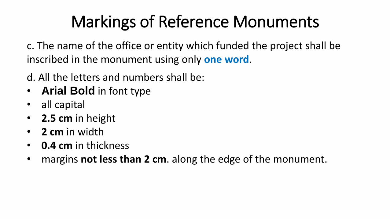
c. The name of the office or entity which funded the project shall be inscribed in the monument using only one word.
d. All the letters and numbers shall be: • Arial Bold in font type • all capital • 2.5 cm in height • 2 cm in width • 0.4 cm in thickness • margins not less than 2 cm. along the edge of the monument.
Markings of Reference Monuments
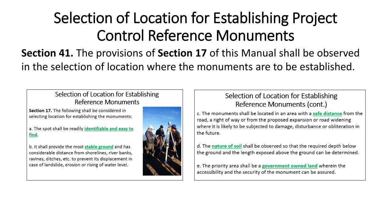
Section 41. The provisions of Section 17 of this Manual shall be observed in the selection of location where the monuments are to be established.
Selection of Location for Establishing Project Control Reference Monuments

Section 42. The data to be gathered and recorded for every established monument shall be in accordance with Section 18 of this Manual.
Markings of Reference Monuments
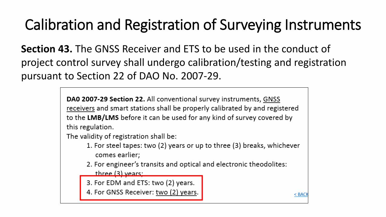
Section 43. The GNSS Receiver and ETS to be used in the conduct of project control survey shall undergo calibration/testing and registration pursuant to Section 22 of DAO No. 2007-29.
Calibration and Registration of Surveying Instruments
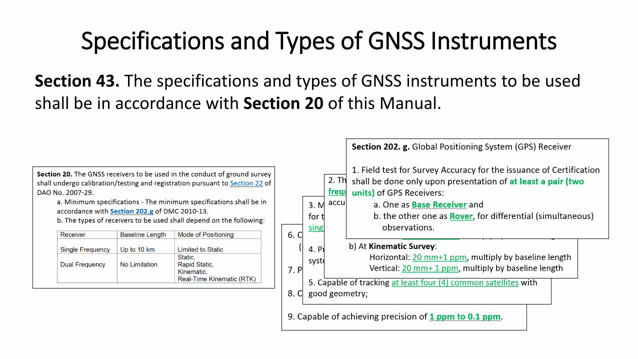
Section 43. The specifications and types of GNSS instruments to be used shall be in accordance with Section 20 of this Manual.
Specifications and Types of GNSS Instruments
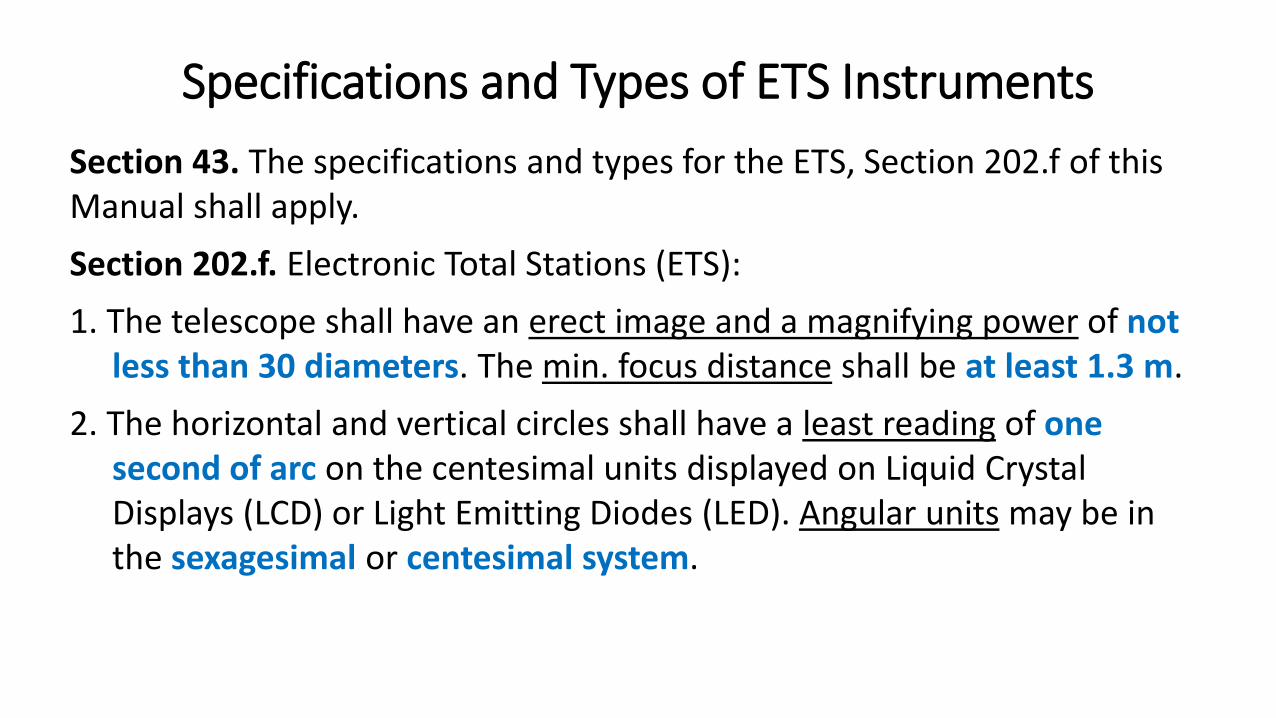
Section 43. The specifications and types for the ETS, Section 202.f of this Manual shall apply.
Section 202.f. Electronic Total Stations (ETS):
1. The telescope shall have an erect image and a magnifying power of notless than 30 diameters. The min. focus distance shall be at least 1.3 m.
2. The horizontal and vertical circles shall have a least reading of onesecond of arc on the centesimal units displayed on Liquid CrystalDisplays (LCD) or Light Emitting Diodes (LED). Angular units may be inthe sexagesimal or centesimal system.
Specifications and Types of ETS Instruments
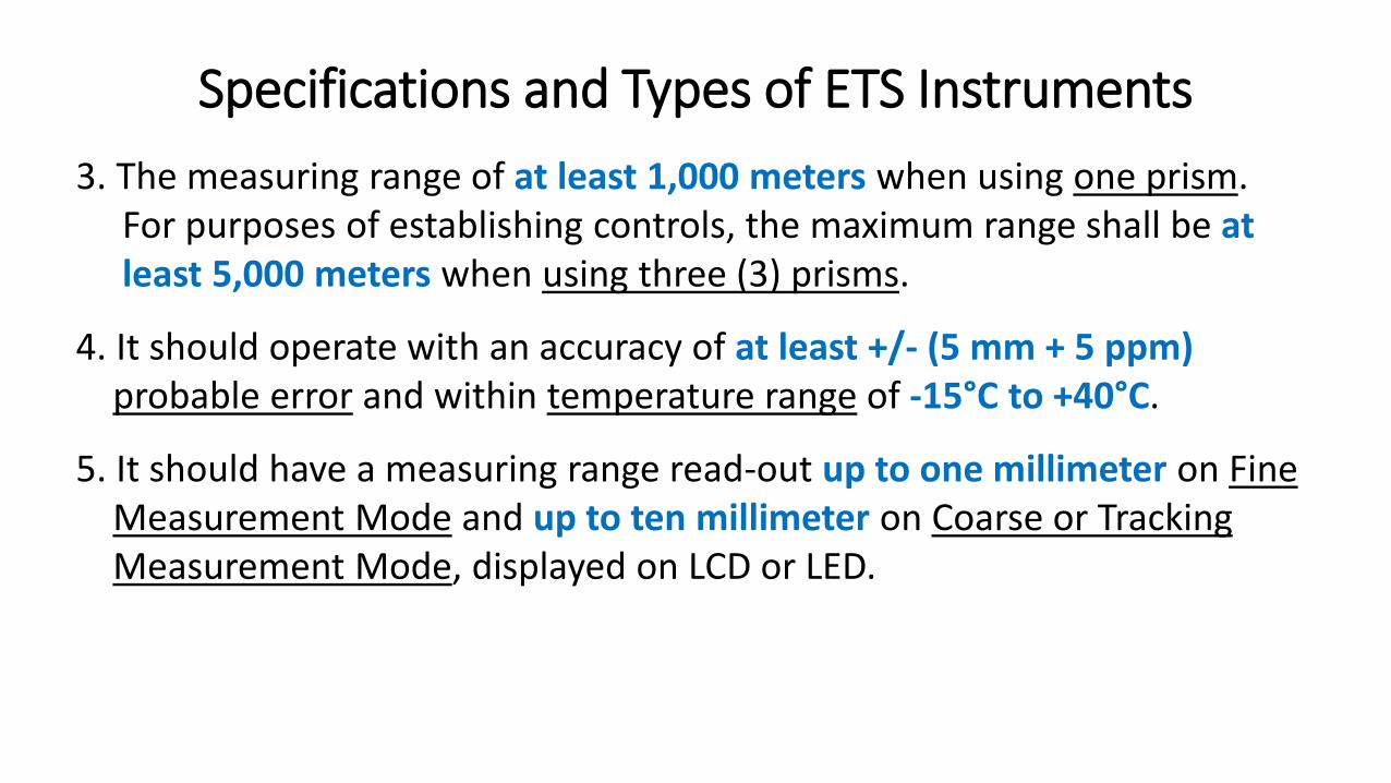
3. The measuring range of at least 1,000 meters when using one prism.For purposes of establishing controls, the maximum range shall be atleast 5,000 meters when using three (3) prisms.
4. It should operate with an accuracy of at least +/- (5 mm + 5 ppm)probable error and within temperature range of -15°C to +40°C.
5. It should have a measuring range read-out up to one millimeter on FineMeasurement Mode and up to ten millimeter on Coarse or TrackingMeasurement Mode, displayed on LCD or LED.
Specifications and Types of ETS Instruments
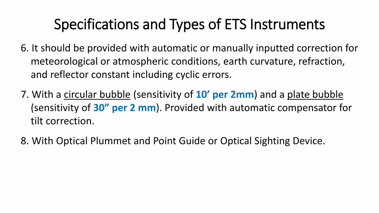
6. It should be provided with automatic or manually inputted correction formeteorological or atmospheric conditions, earth curvature, refraction,and reflector constant including cyclic errors.
7. With a circular bubble (sensitivity of 10’ per 2mm) and a plate bubble(sensitivity of 30” per 2 mm). Provided with automatic compensator fortilt correction.
8. With Optical Plummet and Point Guide or Optical Sighting Device.
Specifications and Types of ETS Instruments
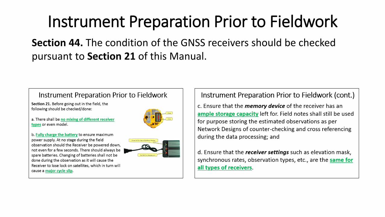
Instrument Preparation Prior to FieldworkSection 44. The condition of the GNSS receivers should be checked pursuant to Section 21 of this Manual.
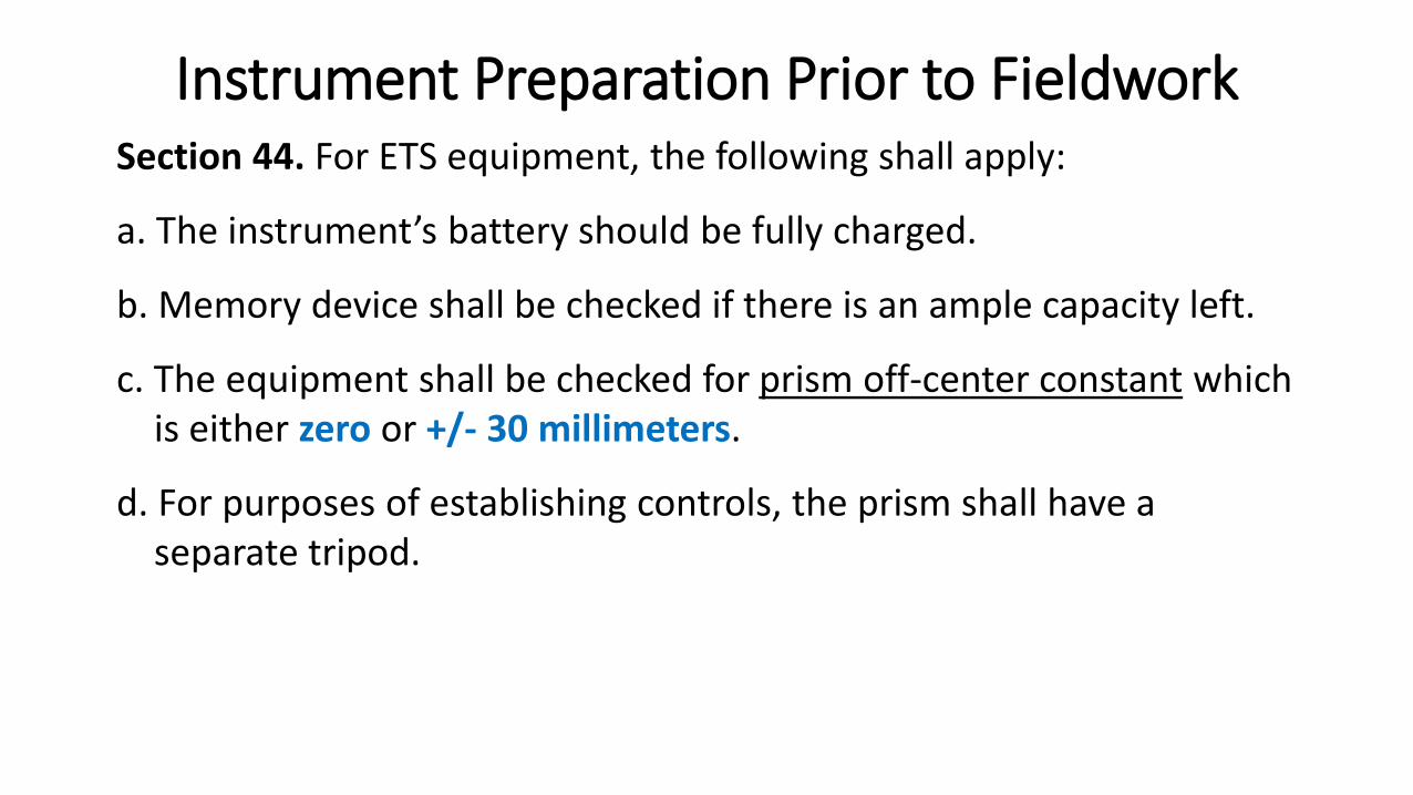
Instrument Preparation Prior to FieldworkSection 44. For ETS equipment, the following shall apply:
a. The instrument’s battery should be fully charged.
b. Memory device shall be checked if there is an ample capacity left.
c. The equipment shall be checked for prism off-center constant which is either zero or +/- 30 millimeters.
d. For purposes of establishing controls, the prism shall have a separate tripod.
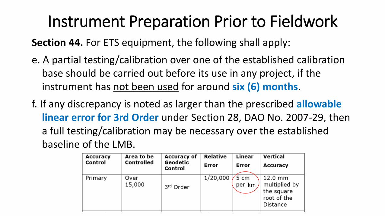
Instrument Preparation Prior to FieldworkSection 44. For ETS equipment, the following shall apply:
e. A partial testing/calibration over one of the established calibration base should be carried out before its use in any project, if the instrument has not been used for around six (6) months.
f. If any discrepancy is noted as larger than the prescribed allowable linear error for 3rd Order under Section 28, DAO No. 2007-29, then a full testing/calibration may be necessary over the established baseline of the LMB.
km

Conduct of Project Control SurveysSection 45. Ground survey for the establishment of Project Control using GNSS instrument shall be conducted following the provisions of Sections 23-27 of this Manual.
Section 23. Prescribed activities in the conduct of GNSS field observations.Section 24. Observation Time and Number of Session.Section 25. Connection to Existing Controls.Section 26. Independent ObservationsSection 27. Observation during and after Session
Conduct of Project Control SurveysSection 45. For the ETS, the procedure as stated in Annex XVII.A.1 of this Manual shall be followed. In addition, the following shall be taken into consideration:
a. For ETS with electronic data recorder, a printed and a digital file of raw data shall be included in the survey returns in an acceptable format.
Conduct of Project Control Surveysb. For those without electronic data recorder, all field observations
shall be recorded by the Geodetic Engineer in the field notes and the following shall apply:
1. In case of surveys executed by geodetic engineers in private practice,field notes and field notes cover on authorized LMB forms shall beproperly filled-out and sworn to before a notary public. In case ofgeodetic engineers employed in the government, the said documentsshould be sworn to before an official authorized to subscribe oath.
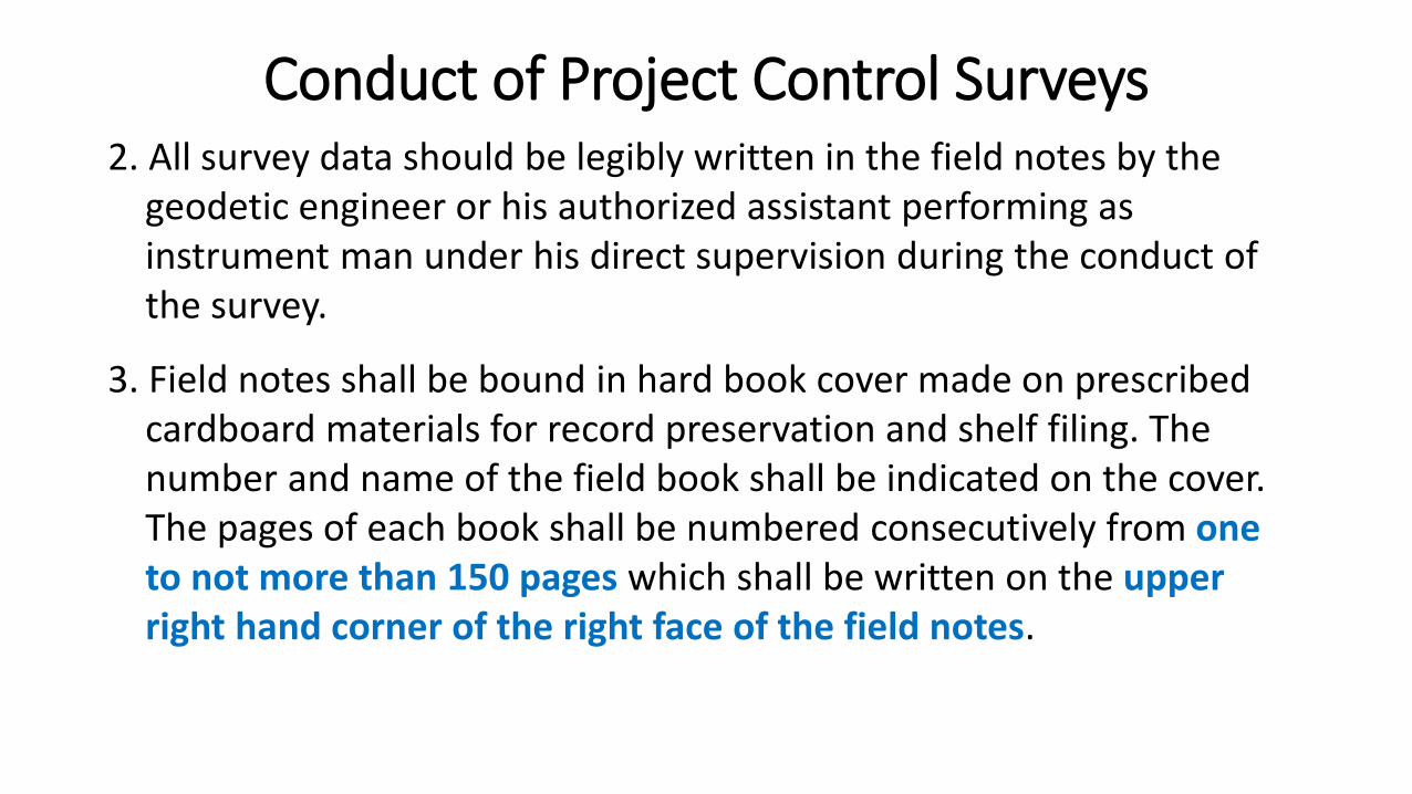
Conduct of Project Control Surveys2. All survey data should be legibly written in the field notes by the
geodetic engineer or his authorized assistant performing as instrument man under his direct supervision during the conduct of the survey.
3. Field notes shall be bound in hard book cover made on prescribedcardboard materials for record preservation and shelf filing. The number and name of the field book shall be indicated on the cover. The pages of each book shall be numbered consecutively from one to not more than 150 pages which shall be written on the upper right hand corner of the right face of the field notes.
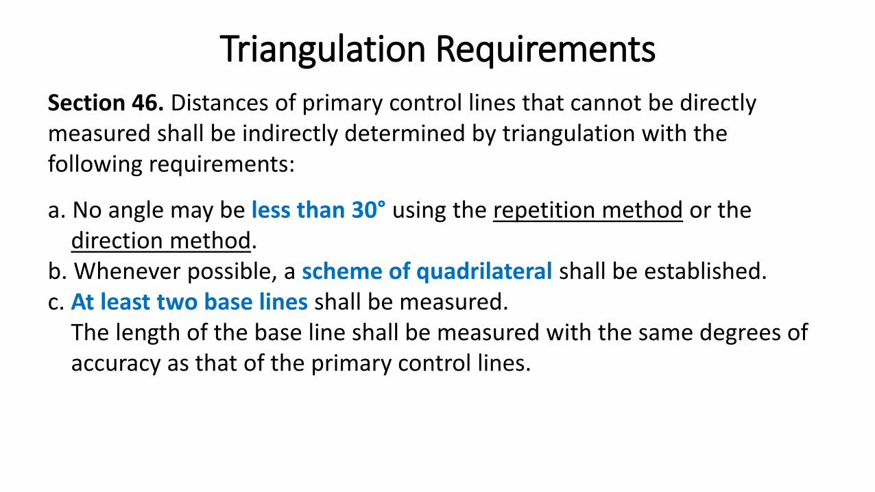
Section 46. Distances of primary control lines that cannot be directly measured shall be indirectly determined by triangulation with the following requirements:
a. No angle may be less than 30° using the repetition method or the direction method.
b. Whenever possible, a scheme of quadrilateral shall be established.c. At least two base lines shall be measured.
The length of the base line shall be measured with the same degrees of accuracy as that of the primary control lines.
Triangulation Requirements
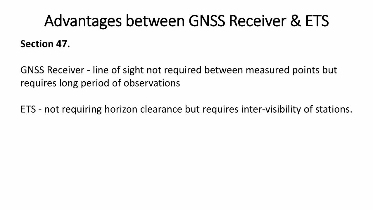
Section 47.
GNSS Receiver - line of sight not required between measured points but requires long period of observations
ETS - not requiring horizon clearance but requires inter-visibility of stations.
Advantages between GNSS Receiver & ETS
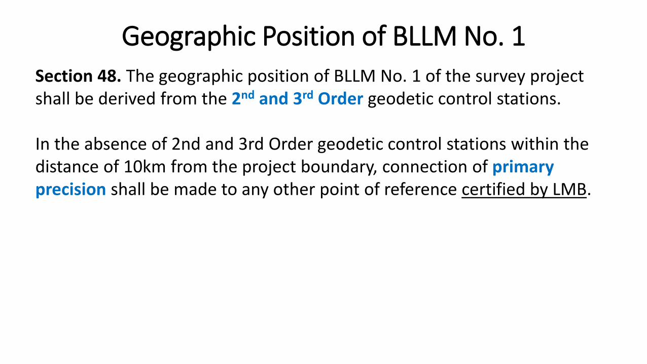
Section 48. The geographic position of BLLM No. 1 of the survey project shall be derived from the 2nd and 3rd Order geodetic control stations.
In the absence of 2nd and 3rd Order geodetic control stations within the distance of 10km from the project boundary, connection of primary precision shall be made to any other point of reference certified by LMB.
Geographic Position of BLLM No. 1
Section 49. The grid azimuth to be used in the Cadastral Project shallbe derived from the PRS92 grid coordinates.
Grid Azimuth
Section 50. The Main Control of the project shall be connected to the adjoining cadastral projects for conformity. However, the following shall govern this process:
a. The adjoining project/s must be in the PRS92 and was duly approved by the DENR-LMS Office concerned.
b. GNSS observations shall be conducted on the two extreme stationscommon to the two projects to determine the azimuth and distance of the line connecting the said points.
c. If there is a discrepancy between the adjoining projects and the on-goingproject, a report shall be made and shall be forwarded to the LMS, which in turn shall form a Technical Committee to investigate the matter and submit a corresponding recommendation to the RED.
Connection with Adjoining Projects
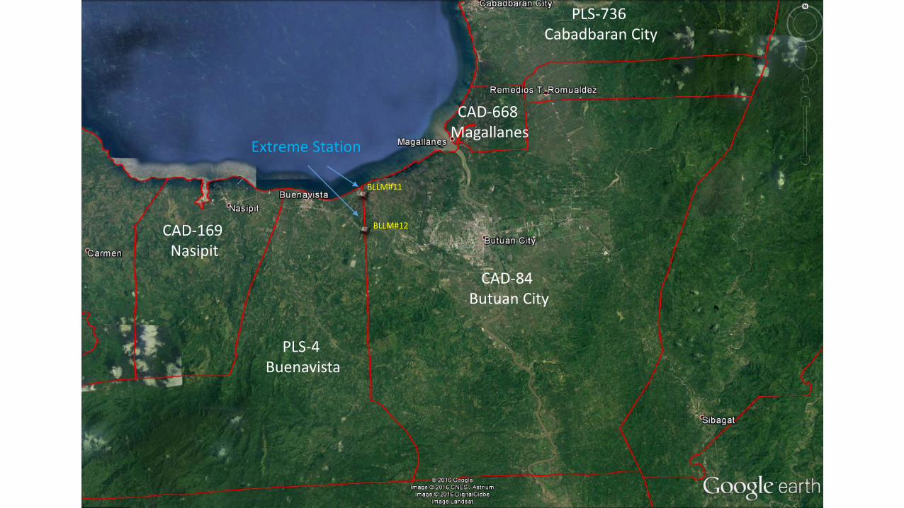
PLS-4 Buenavista
CAD-84 Butuan City
PLS-736 Cabadbaran City
CAD-668 Magallanes
CAD-169 Nasipit
BLLM#11
BLLM#12
Extreme Station
Section 52. The RED and/or the RTD for Lands and/or their duly authorizedrepresentative/s upon coordination with the CENRO concerned shall have the full and unrestricted rights to inspect and supervise the operations of the survey team and to issue instructions from time to time, as they may deem necessary for the proper execution of the project.

PROJECT CONTROL
SURVEY RETURNS
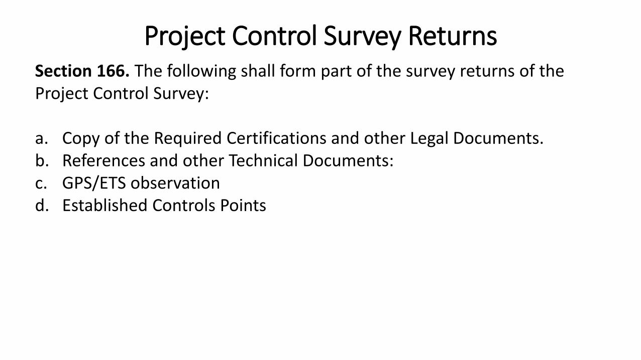
Section 166. The following shall form part of the survey returns of the Project Control Survey:
a. Copy of the Required Certifications and other Legal Documents.b. References and other Technical Documents:c. GPS/ETS observationd. Established Controls Points
Project Control Survey Returns
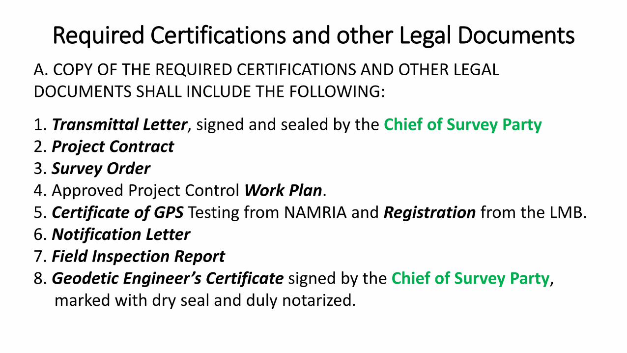
A. COPY OF THE REQUIRED CERTIFICATIONS AND OTHER LEGAL DOCUMENTS SHALL INCLUDE THE FOLLOWING:
1. Transmittal Letter, signed and sealed by the Chief of Survey Party2. Project Contract3. Survey Order4. Approved Project Control Work Plan.5. Certificate of GPS Testing from NAMRIA and Registration from the LMB.6. Notification Letter7. Field Inspection Report8. Geodetic Engineer’s Certificate signed by the Chief of Survey Party,
marked with dry seal and duly notarized.
Required Certifications and other Legal Documents
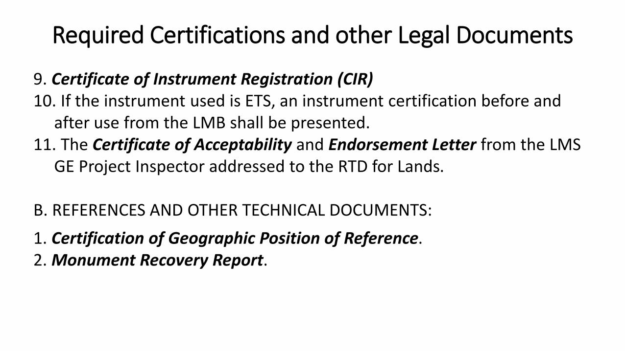
9. Certificate of Instrument Registration (CIR)10. If the instrument used is ETS, an instrument certification before and
after use from the LMB shall be presented.11. The Certificate of Acceptability and Endorsement Letter from the LMS
GE Project Inspector addressed to the RTD for Lands.
B. REFERENCES AND OTHER TECHNICAL DOCUMENTS:
1. Certification of Geographic Position of Reference.2. Monument Recovery Report.
Required Certifications and other Legal Documents
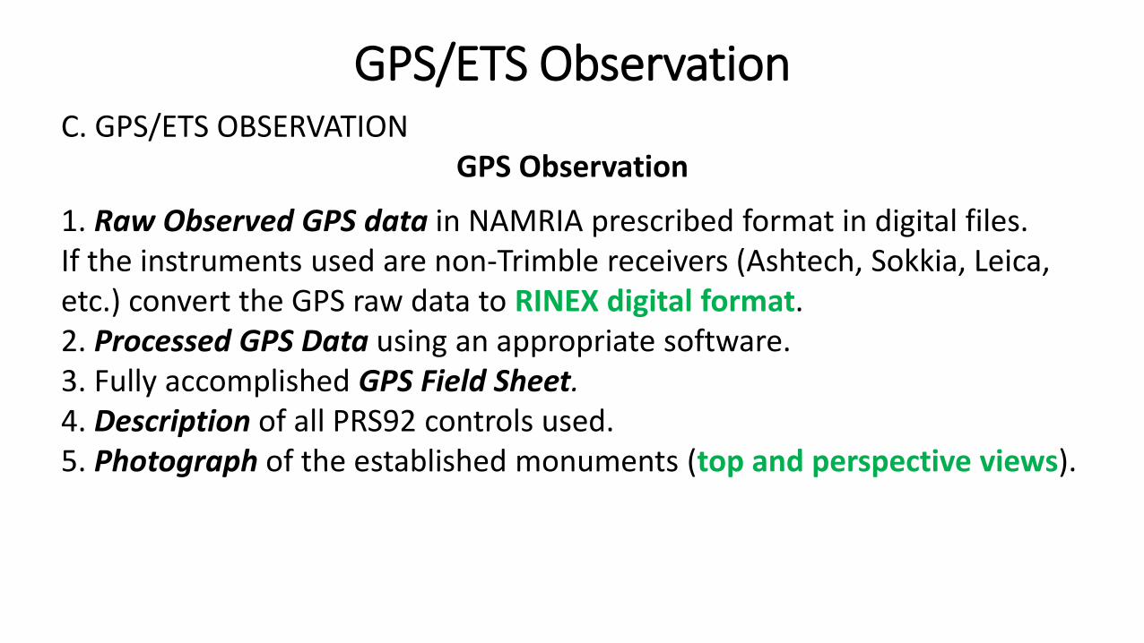
C. GPS/ETS OBSERVATIONGPS Observation
1. Raw Observed GPS data in NAMRIA prescribed format in digital files. If the instruments used are non-Trimble receivers (Ashtech, Sokkia, Leica, etc.) convert the GPS raw data to RINEX digital format.2. Processed GPS Data using an appropriate software.3. Fully accomplished GPS Field Sheet.4. Description of all PRS92 controls used.5. Photograph of the established monuments (top and perspective views).
GPS/ETS Observation
C. GPS/ETS OBSERVATIONETS Observation
If the instrument used is an ETS, in addition to the applicable provisions stated in Section 166.d of this Manual, the following shall also be prepared:
1. The following shall have each field notes:a) Primary Traversesb) Secondary Traversesc) Astronomical observations
GPS/ETS Observation

c. GPS/ETS observationETS Observation
2. The Original Computations of:a) Survey Control Traversesb) Astronomical Observationsc) Elevation and Sea Level Reductionsd) Scale Factor and Grid Distance and other misc. computatione) Azimuth Derivations
3. Test Traverse field notes and computations4. The Project Control Map shall be prepared in lieu of Geodetic Control
Map.
GPS/ETS Observation
D. ESTABLISHED CONTROL POINTS
1. Computer-print out of position derivation of PRS92 control points andother computations.
2. Monument Description Book in prescribed LMB Forms which includesthe following:
a) The geographic and grid coordinates of BLLM No. 1.b) There should be at least three (3) references for each station.
Each reference points should be described with correspondingdistance and bearings from station and BLLMs.
c) Each station and BLLM should be sketched in its location.
Established Control Points
3. PRS92 Project Network Control Map prepared in 54 x 54 cm draftingfilm with marginal lines of 50 x 50 cm in prescribed LMB forms duly signed by the Chief of Party and shall contain the following:
a) The boundary of the project.
b) The adjoining municipalities with their corresponding cadastral survey number, and survey projects undertaken within the area being surveyed, if any.
Established Control Points
c) The existing provincial and national roads, rivers, creeks, timber or forest lands (shaded), unclassified areas, and other natural features within the project.
d) The 3rd and 4th Order project control stations established shall be plotted in appropriate scale.
e) Existing triangulation stations and location monuments (old and those belonging to approved project within the boundary).
Established Control Points
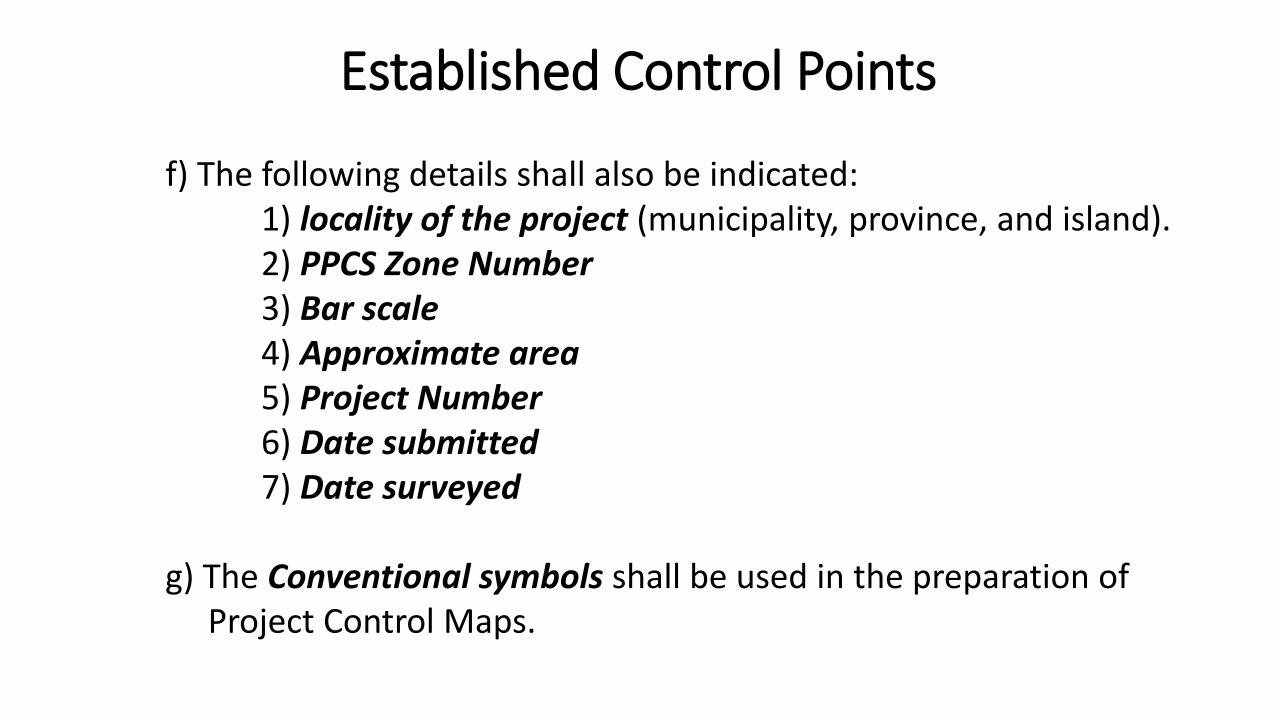
f) The following details shall also be indicated:1) locality of the project (municipality, province, and island).2) PPCS Zone Number3) Bar scale4) Approximate area5) Project Number6) Date submitted7) Date surveyed
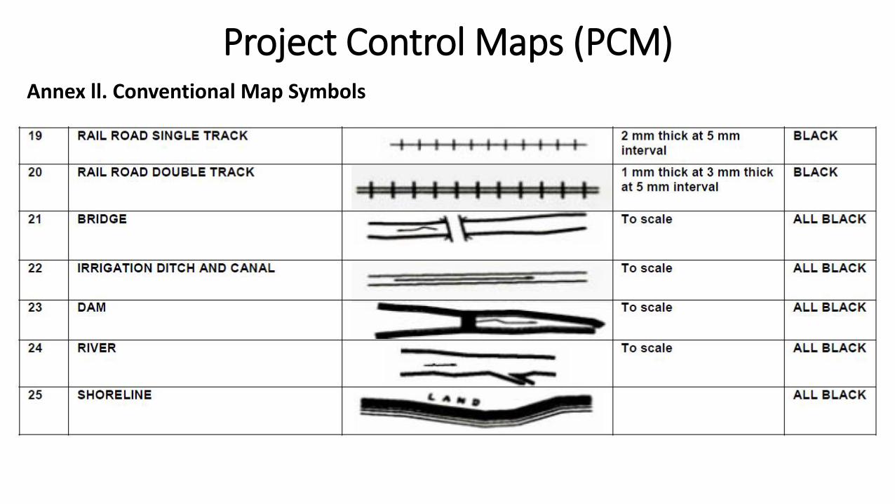
g) The Conventional symbols shall be used in the preparation ofProject Control Maps.
Established Control Points
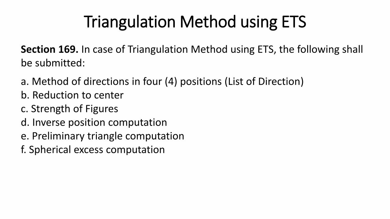
Section 169. In case of Triangulation Method using ETS, the following shall be submitted:
a. Method of directions in four (4) positions (List of Direction)b. Reduction to centerc. Strength of Figuresd. Inverse position computatione. Preliminary triangle computationf. Spherical excess computation
Triangulation Method using ETS
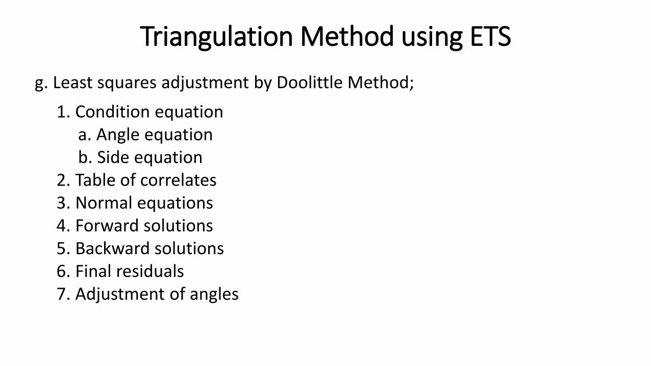
g. Least squares adjustment by Doolittle Method;
1. Condition equationa. Angle equationb. Side equation
2. Table of correlates3. Normal equations4. Forward solutions5. Backward solutions6. Final residuals7. Adjustment of angles
Triangulation Method using ETS
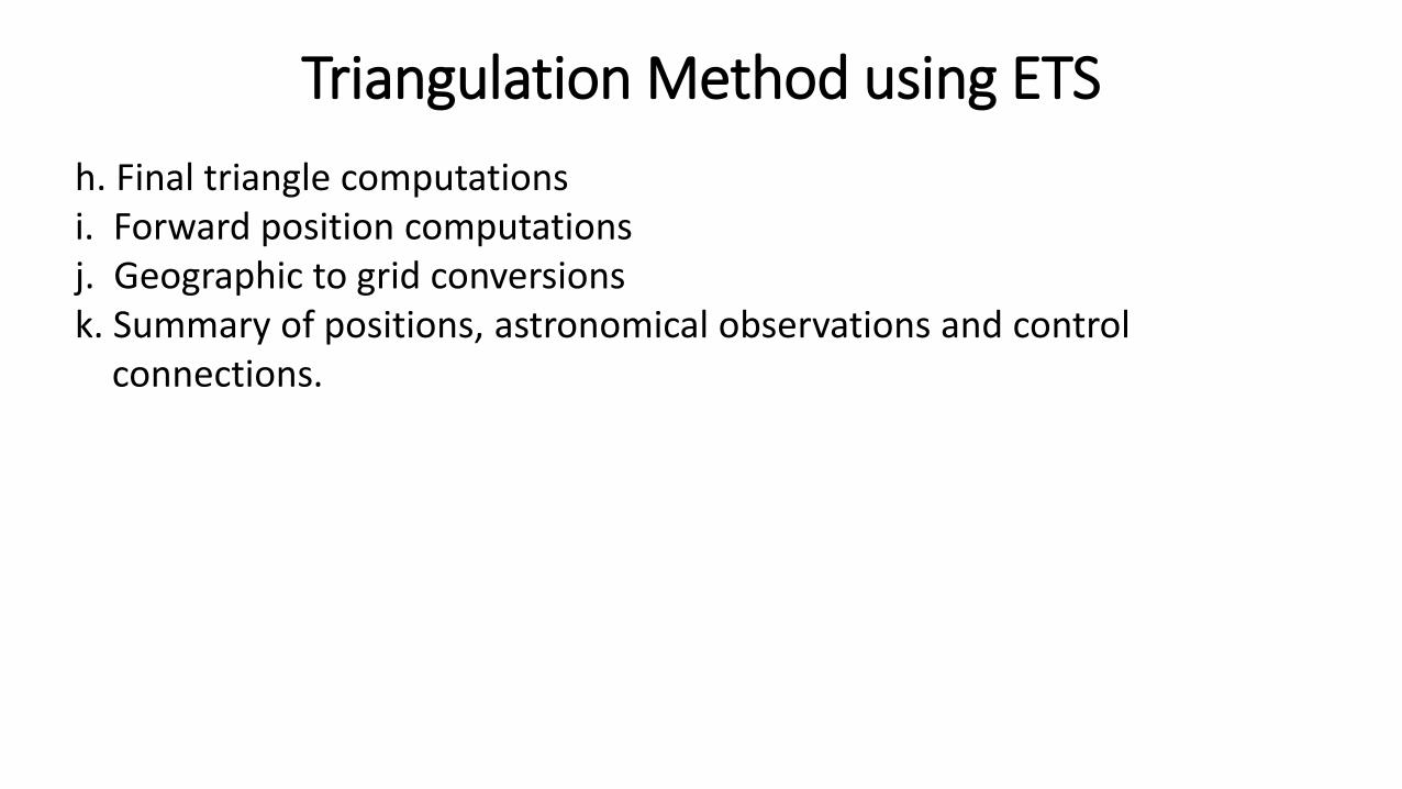
h. Final triangle computationsi. Forward position computationsj. Geographic to grid conversionsk. Summary of positions, astronomical observations and control
connections.
Triangulation Method using ETS
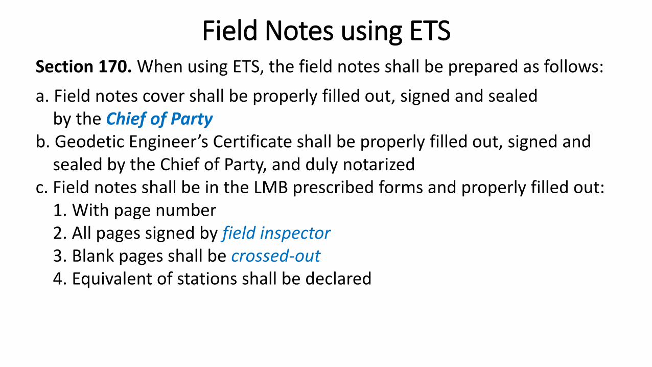
Section 170. When using ETS, the field notes shall be prepared as follows:
a. Field notes cover shall be properly filled out, signed and sealed by the Chief of Party
b. Geodetic Engineer’s Certificate shall be properly filled out, signed and sealed by the Chief of Party, and duly notarized
c. Field notes shall be in the LMB prescribed forms and properly filled out:1. With page number2. All pages signed by field inspector3. Blank pages shall be crossed-out4. Equivalent of stations shall be declared
Field Notes using ETS
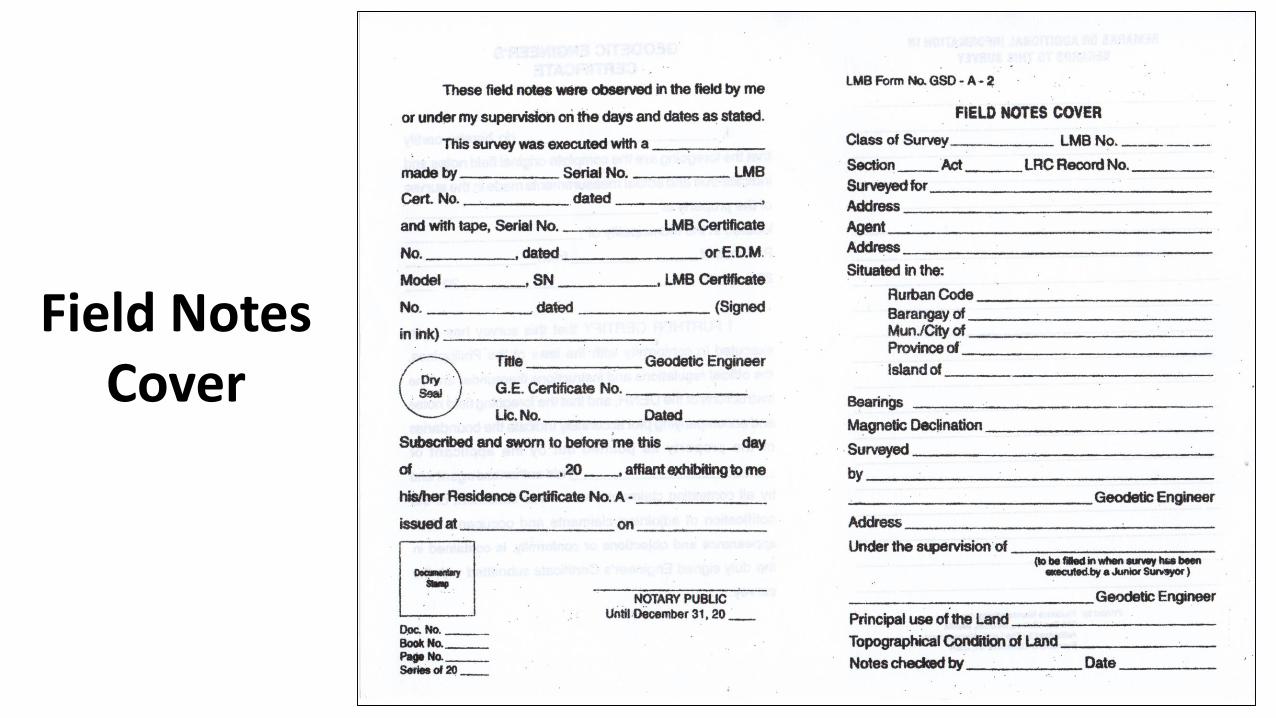
Field Notes Cover
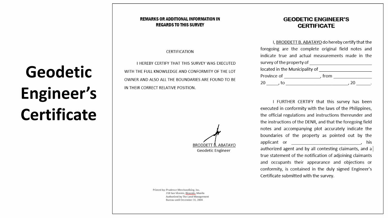
Geodetic Engineer’sCertificate
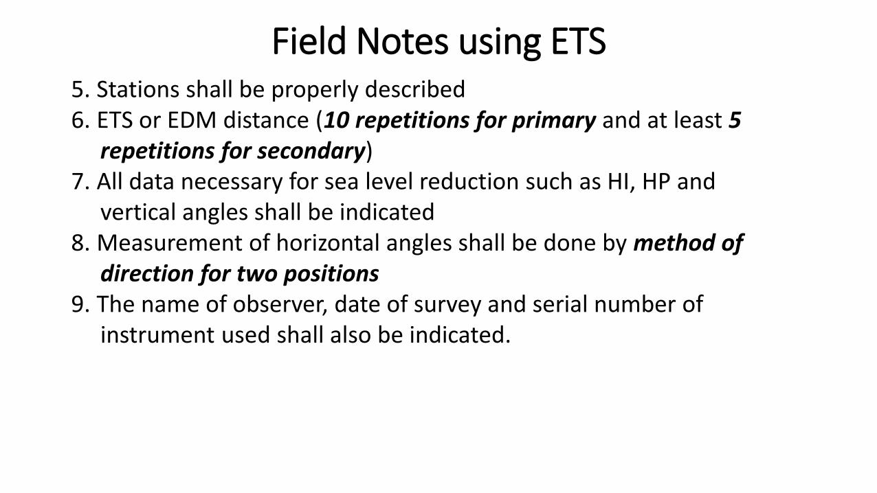
5. Stations shall be properly described6. ETS or EDM distance (10 repetitions for primary and at least 5
repetitions for secondary)7. All data necessary for sea level reduction such as HI, HP and
vertical angles shall be indicated8. Measurement of horizontal angles shall be done by method of
direction for two positions9. The name of observer, date of survey and serial number of
instrument used shall also be indicated.
Field Notes using ETS
Section 171. Preparation of Project Control Maps (PCM)
a. The PCM shall be divided into one minute by one minute quadrant in latitude and longitude and must have at least one control station in each quadrant; and
b. The Map shall show the main and subsidiary control stations and the BLLMs of the project established.
Project Control Maps (PCM)

Project Control Maps (PCM) Annex ll. Conventional Map Symbols
Project Control Maps (PCM) Annex ll. Conventional Map Symbols

Inspection, Verification,
and Approval of
PROJECT CONTROL
SURVEY RETURNS
Section 189. The LMS shall verify the correctness and technical accuracy of the survey returns of the Project Control Surveys. The following shall serve as guide in the inspection, verification and approval of Project Controls:
a. Preliminary Evaluationb. Technical Evaluation
Verification
PRELIMINARY EVALUATION or initial examination shall be conducted todetermine if the survey returns are complete as per List of Transmittal:
1. Certifications, Reports, endorsement letters, etc.Replacement of key personnel and equipment shall be with prior authority from the RED upon endorsement of the RTD for Lands.
2. References and Technical Documents.3. If the ETS is used, it shall be calibrated/field tested by the LMB/LMS
before and after its use in the project. If the instruments used are GPSReceivers, GPS Observation raw data on digital form and RINEX files (if non- Trimble receiver was used) shall be submitted.
Verification

PRELIMINARY EVALUATION or initial examination shall be conducted todetermine if the survey returns are complete as per List of Transmittal:
4. Field notes and computations.5. If the method of Triangulation was used in some part of the project, the
field notes and computations shall be submitted.
Verification
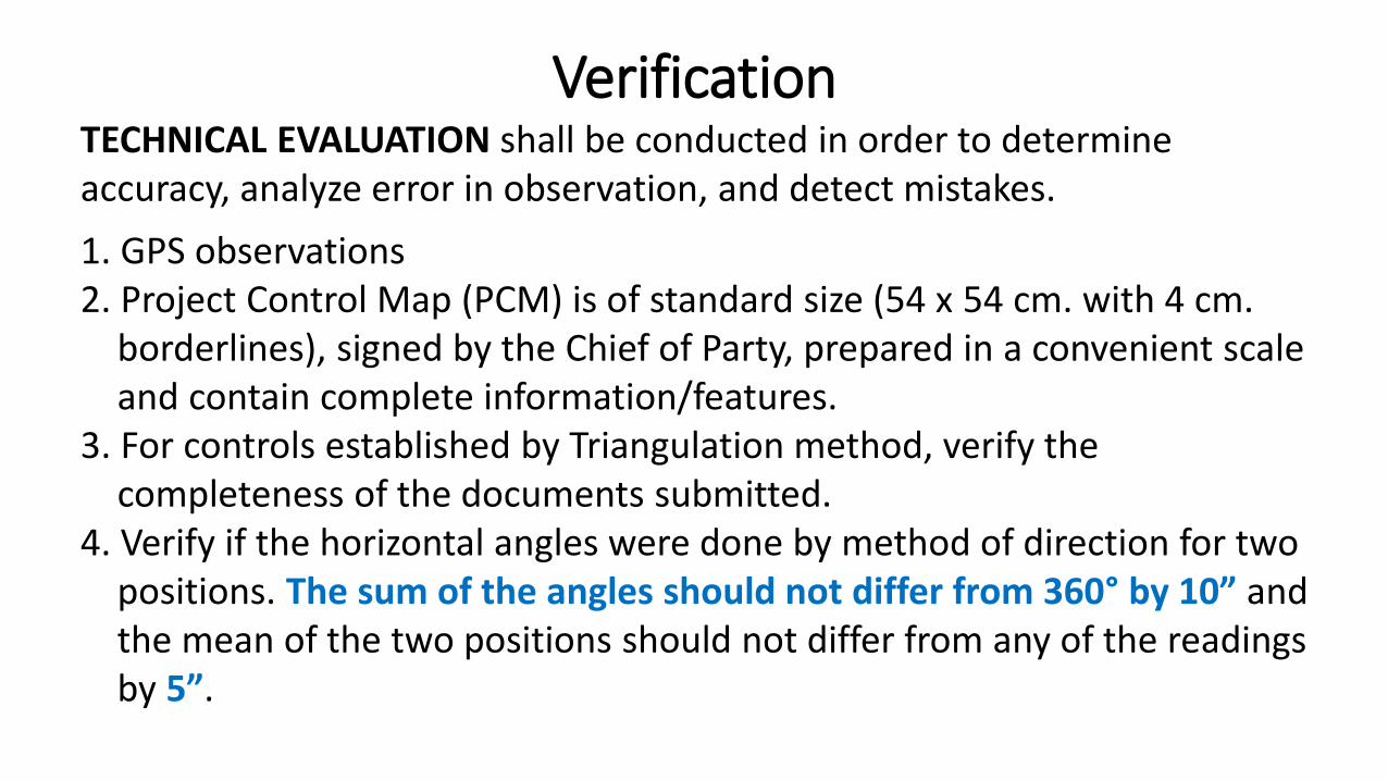
TECHNICAL EVALUATION shall be conducted in order to determine accuracy, analyze error in observation, and detect mistakes.
1. GPS observations2. Project Control Map (PCM) is of standard size (54 x 54 cm. with 4 cm.
borderlines), signed by the Chief of Party, prepared in a convenient scale and contain complete information/features.
3. For controls established by Triangulation method, verify thecompleteness of the documents submitted.
4. Verify if the horizontal angles were done by method of direction for twopositions. The sum of the angles should not differ from 360° by 10” andthe mean of the two positions should not differ from any of the readingsby 5”.
Verification
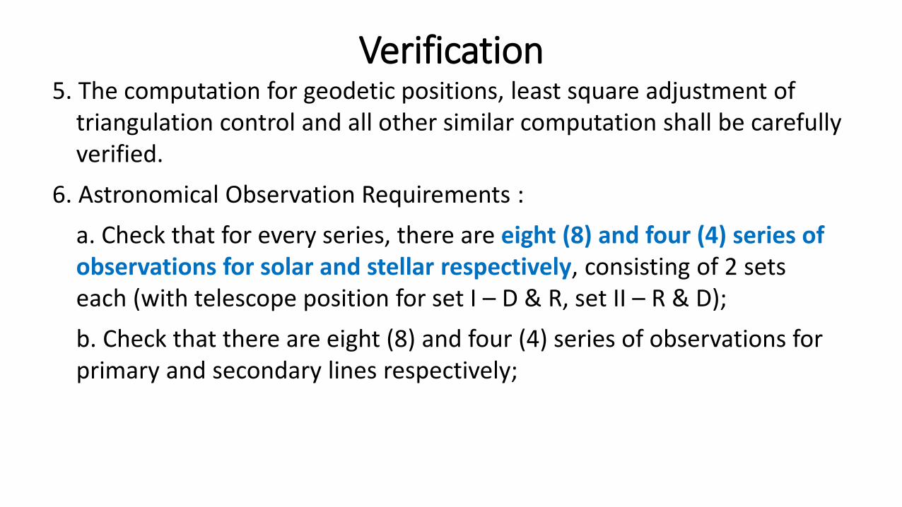
5. The computation for geodetic positions, least square adjustment oftriangulation control and all other similar computation shall be carefullyverified.
6. Astronomical Observation Requirements :
a. Check that for every series, there are eight (8) and four (4) series ofobservations for solar and stellar respectively, consisting of 2 setseach (with telescope position for set I – D & R, set II – R & D);
b. Check that there are eight (8) and four (4) series of observations forprimary and secondary lines respectively;
Verification
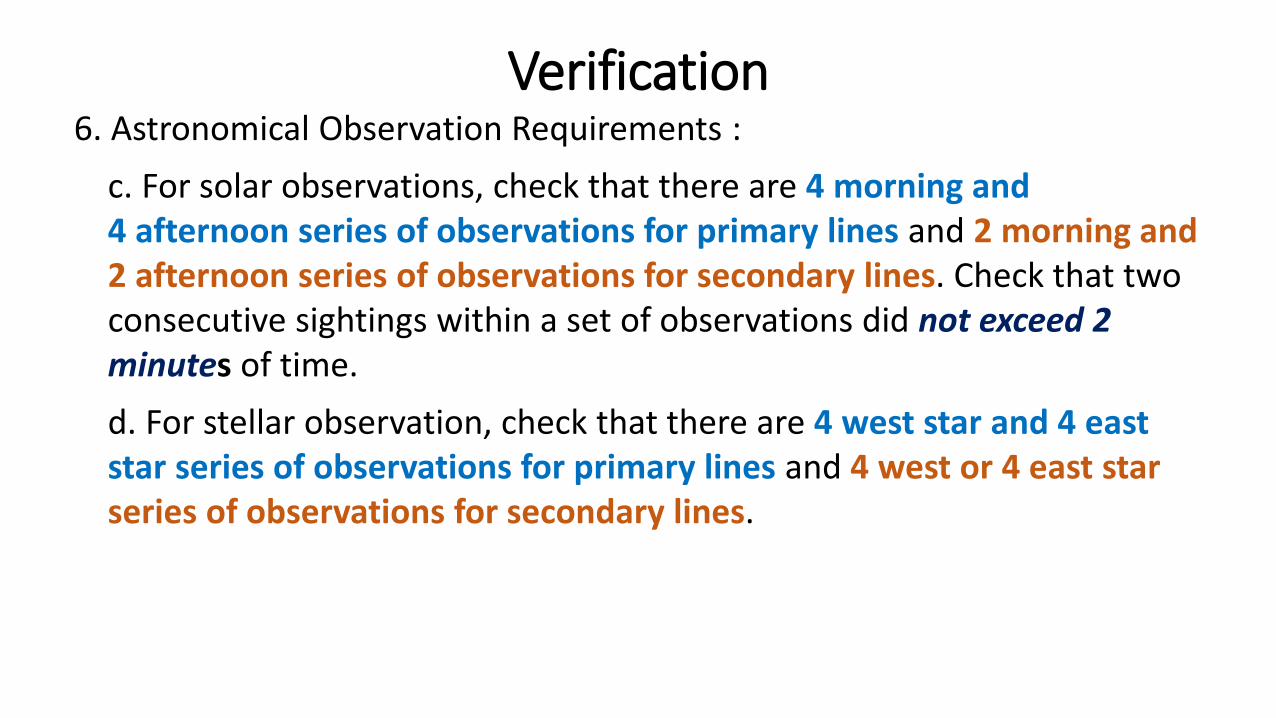
6. Astronomical Observation Requirements :
c. For solar observations, check that there are 4 morning and4 afternoon series of observations for primary lines and 2 morning and 2 afternoon series of observations for secondary lines. Check that two consecutive sightings within a set of observations did not exceed 2minutes of time.
d. For stellar observation, check that there are 4 west star and 4 east star series of observations for primary lines and 4 west or 4 east star series of observations for secondary lines.
Verification
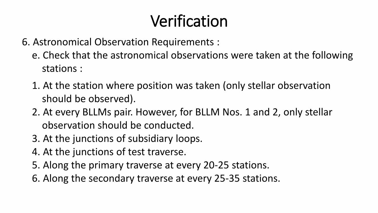
6. Astronomical Observation Requirements :e. Check that the astronomical observations were taken at the following
stations :
1. At the station where position was taken (only stellar observationshould be observed).
2. At every BLLMs pair. However, for BLLM Nos. 1 and 2, only stellar observation should be conducted.
3. At the junctions of subsidiary loops.4. At the junctions of test traverse.5. Along the primary traverse at every 20-25 stations.6. Along the secondary traverse at every 25-35 stations.
Verification
7. Control connection requirements – Check the connection made at thefollowing:
a. Stations of previously approved adjoining projectsb. Triangulation stations within the boundary of the projects.
Verification
8. Monument Description Book Requirements :
a. Check that the geographic and grid coordinates of BLLM No. 1 areIndicated.
b. Check that there are at least three (3) references for each station.Each reference points should be described with correspondingdistance and bearings from station and BLLMs.
c. Check that each station and BLLM is sketched in its location.
Verification of Monument Description Book
9. The Technical Verification Procedures shall be as follows:
a. Examine the Field Notes Book :
1. Angle Book - check the mean interior and exterior angles.2. Distance Book – check the mean horizontal distance.3. Astronomic Book – check the input in astronomic computation.
Verification of Field Notes Book
b. In verifying Astronomical Observation Computation :
1. Check the data entry in the computation sheet against the datarecorded in the field notes.
2. Check the mean and variation of horizontal angle, time, andaltitude.
3. Check the corrected value of altitude and North Polar Distance.
Verification of Astronomical Observation Computation
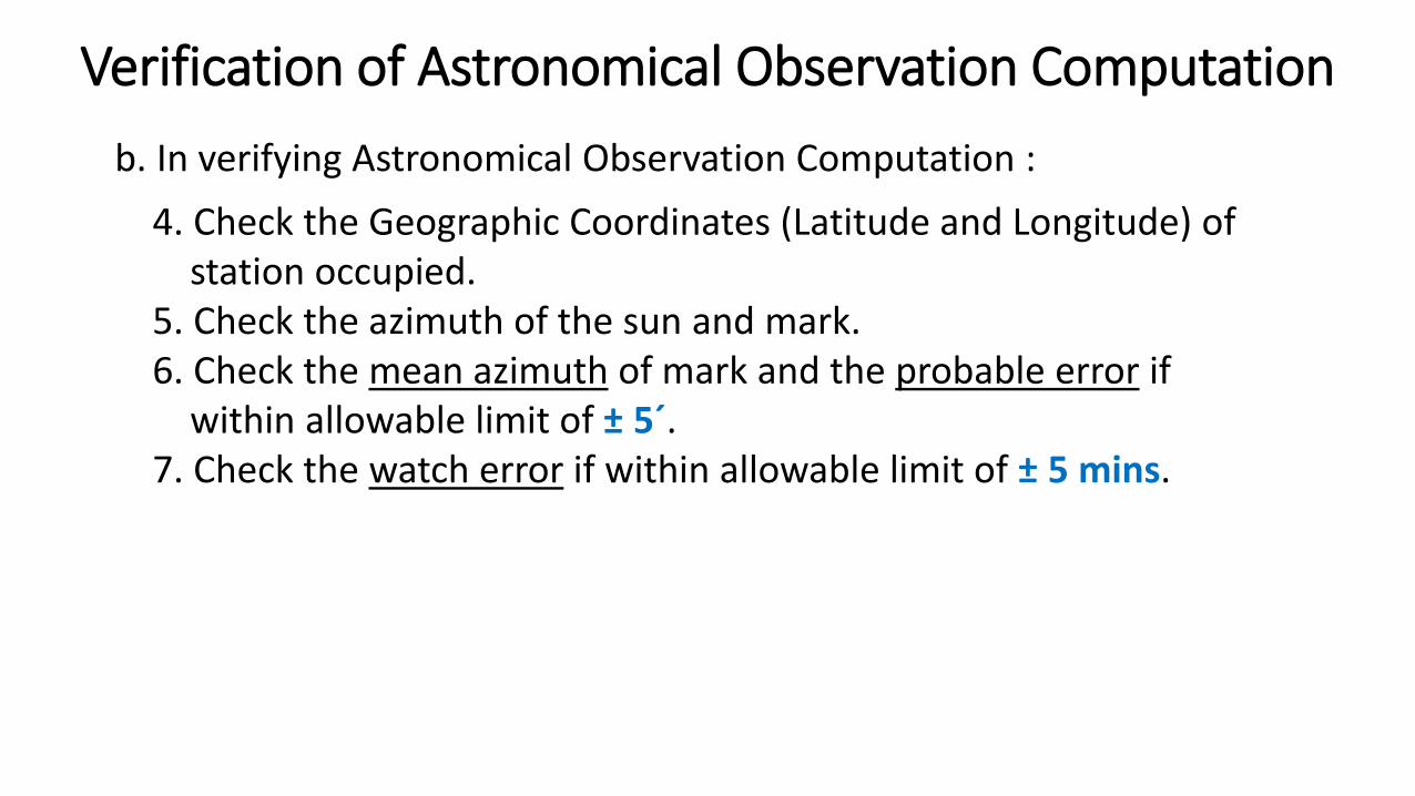
b. In verifying Astronomical Observation Computation :
4. Check the Geographic Coordinates (Latitude and Longitude) ofstation occupied.
5. Check the azimuth of the sun and mark.6. Check the mean azimuth of mark and the probable error if
within allowable limit of ± 5´.7. Check the watch error if within allowable limit of ± 5 mins.
Verification of Astronomical Observation Computation
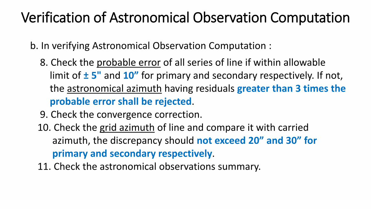
b. In verifying Astronomical Observation Computation :
8. Check the probable error of all series of line if within allowablelimit of ± 5" and 10” for primary and secondary respectively. If not, the astronomical azimuth having residuals greater than 3 times the probable error shall be rejected.
9. Check the convergence correction.10. Check the grid azimuth of line and compare it with carried
azimuth, the discrepancy should not exceed 20” and 30” forprimary and secondary respectively.
11. Check the astronomical observations summary.
Verification of Astronomical Observation Computation
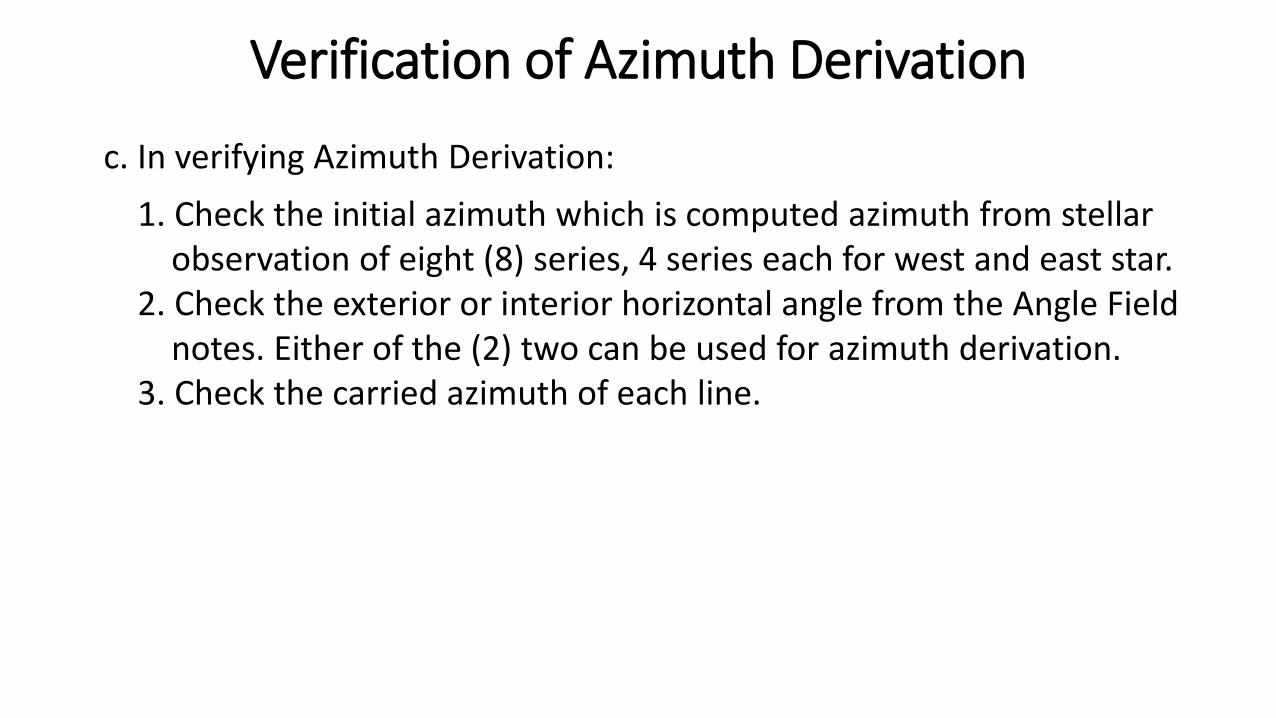
c. In verifying Azimuth Derivation:
1. Check the initial azimuth which is computed azimuth from stellar observation of eight (8) series, 4 series each for west and east star.
2. Check the exterior or interior horizontal angle from the Angle Field notes. Either of the (2) two can be used for azimuth derivation.
3. Check the carried azimuth of each line.
Verification of Azimuth Derivation
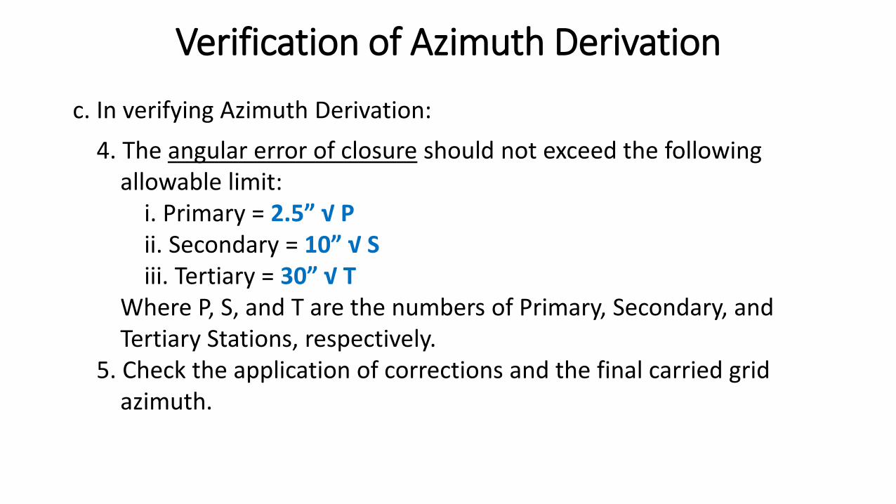
c. In verifying Azimuth Derivation:
4. The angular error of closure should not exceed the following allowable limit:
i. Primary = 2.5” √ Pii. Secondary = 10” √ Siii. Tertiary = 30” √ T
Where P, S, and T are the numbers of Primary, Secondary, andTertiary Stations, respectively.
5. Check the application of corrections and the final carried gridazimuth.
Verification of Azimuth Derivation
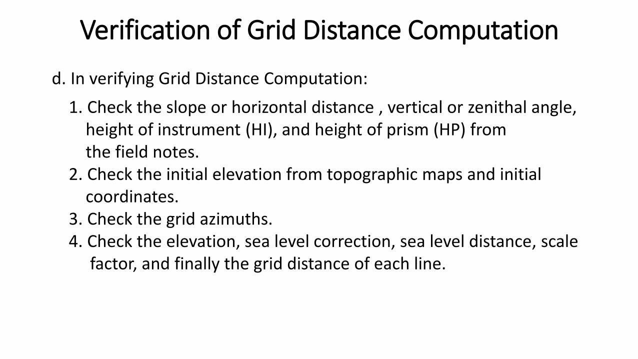
d. In verifying Grid Distance Computation:
1. Check the slope or horizontal distance , vertical or zenithal angle, height of instrument (HI), and height of prism (HP) fromthe field notes.
2. Check the initial elevation from topographic maps and initialcoordinates.
3. Check the grid azimuths.4. Check the elevation, sea level correction, sea level distance, scale
factor, and finally the grid distance of each line.
Verification of Grid Distance Computation

e. In verifying the Traverse Computation :
1) Check the initial and final coordinates;2) Check the grid azimuth and distance of each line;3) Adjust the traverse by transit rule;4) Check the relative precision if within allowable :
i. Primary = 1:20,000ii. Secondary = 1:10,000iii. Tertiary = 1:5,000
Verification of Traverse Computation
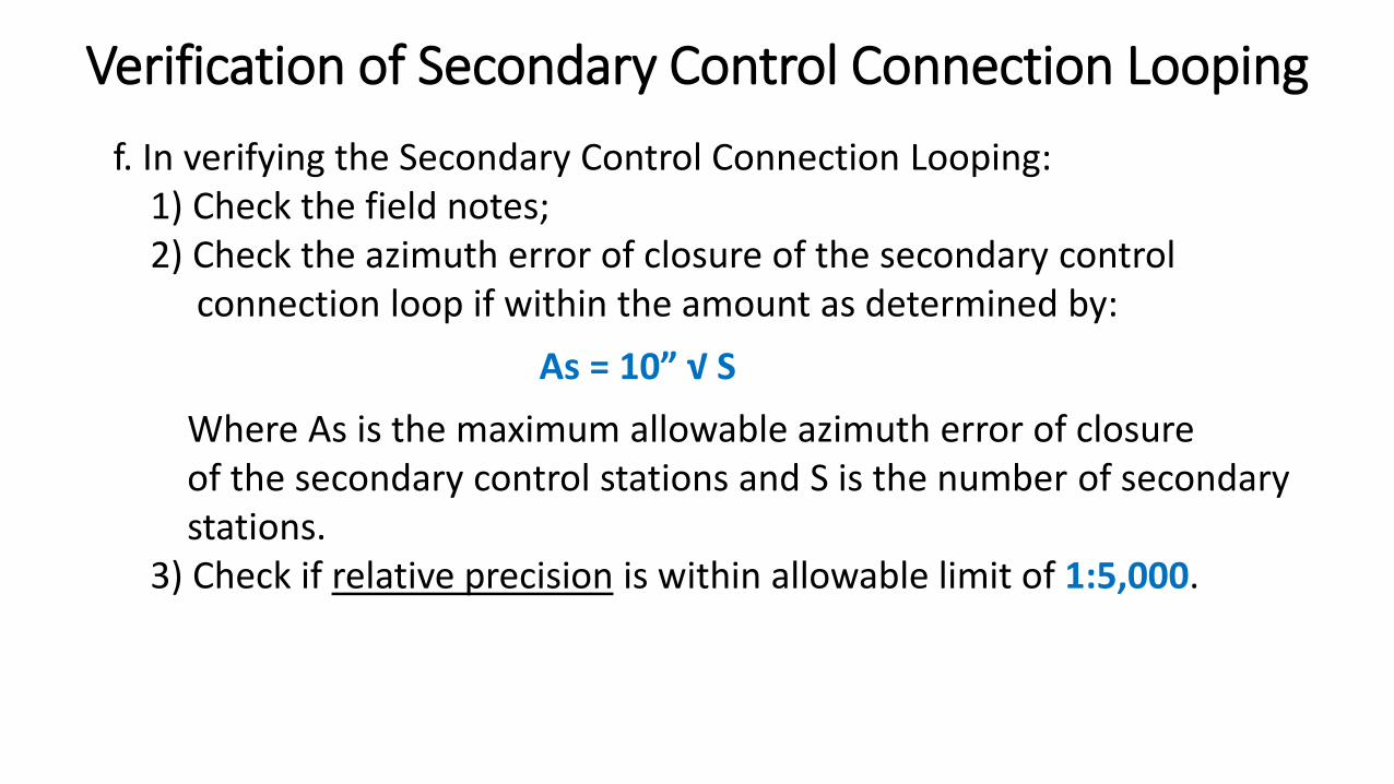
f. In verifying the Secondary Control Connection Looping:1) Check the field notes;2) Check the azimuth error of closure of the secondary control
connection loop if within the amount as determined by:
As = 10” √ S
Where As is the maximum allowable azimuth error of closureof the secondary control stations and S is the number of secondary stations.
3) Check if relative precision is within allowable limit of 1:5,000.
Verification of Secondary Control Connection Looping
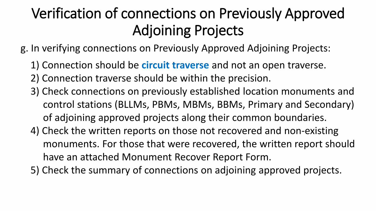
g. In verifying connections on Previously Approved Adjoining Projects:
1) Connection should be circuit traverse and not an open traverse.2) Connection traverse should be within the precision.3) Check connections on previously established location monuments and
control stations (BLLMs, PBMs, MBMs, BBMs, Primary and Secondary) of adjoining approved projects along their common boundaries.
4) Check the written reports on those not recovered and non-existingmonuments. For those that were recovered, the written report should have an attached Monument Recover Report Form.
5) Check the summary of connections on adjoining approved projects.
Verification of connections on Previously Approved Adjoining Projects
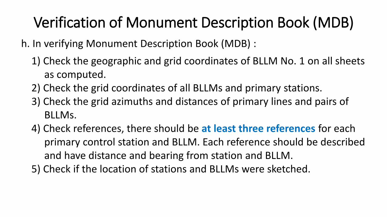
h. In verifying Monument Description Book (MDB) :
1) Check the geographic and grid coordinates of BLLM No. 1 on all sheets as computed.
2) Check the grid coordinates of all BLLMs and primary stations.3) Check the grid azimuths and distances of primary lines and pairs of
BLLMs.4) Check references, there should be at least three references for each
primary control station and BLLM. Each reference should be described and have distance and bearing from station and BLLM.
5) Check if the location of stations and BLLMs were sketched.
Verification of Monument Description Book (MDB)
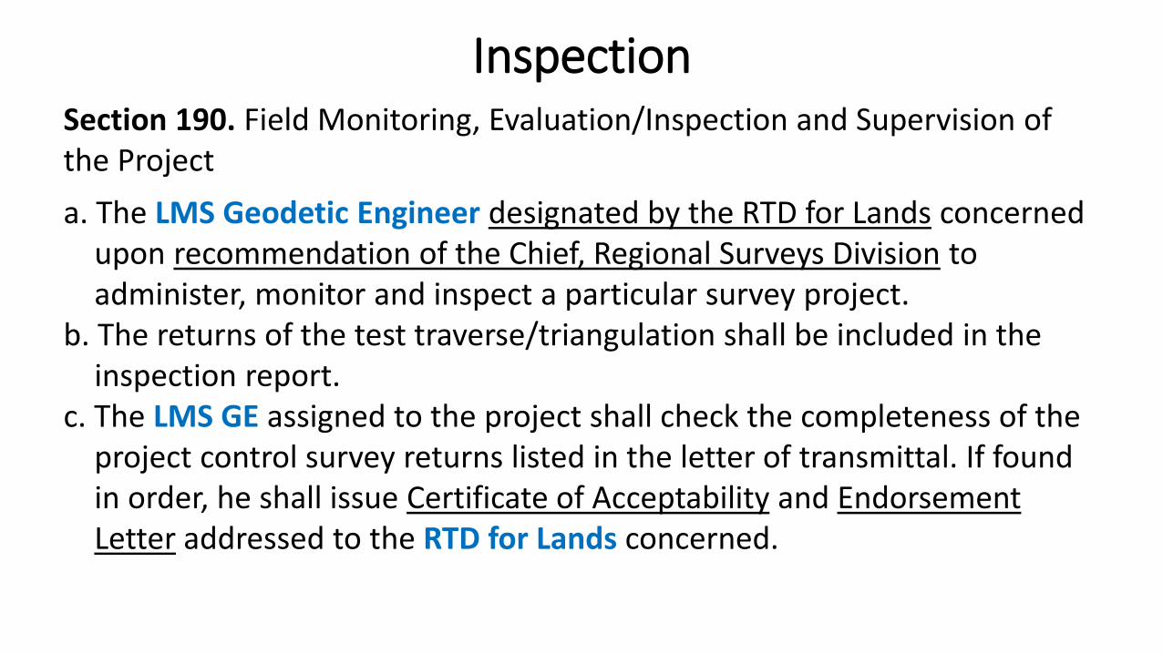
Section 190. Field Monitoring, Evaluation/Inspection and Supervision of the Project
a. The LMS Geodetic Engineer designated by the RTD for Lands concernedupon recommendation of the Chief, Regional Surveys Division to administer, monitor and inspect a particular survey project.
b. The returns of the test traverse/triangulation shall be included in theinspection report.
c. The LMS GE assigned to the project shall check the completeness of theproject control survey returns listed in the letter of transmittal. If found in order, he shall issue Certificate of Acceptability and Endorsement Letter addressed to the RTD for Lands concerned.
Inspection
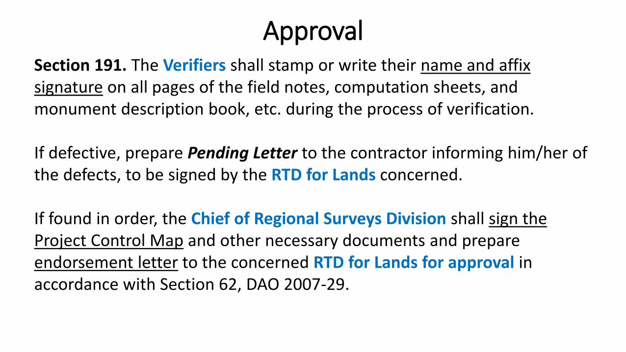
Section 191. The Verifiers shall stamp or write their name and affix signature on all pages of the field notes, computation sheets, and monument description book, etc. during the process of verification.
If defective, prepare Pending Letter to the contractor informing him/her of the defects, to be signed by the RTD for Lands concerned.
If found in order, the Chief of Regional Surveys Division shall sign the Project Control Map and other necessary documents and prepare endorsement letter to the concerned RTD for Lands for approval in accordance with Section 62, DAO 2007-29.
Approval
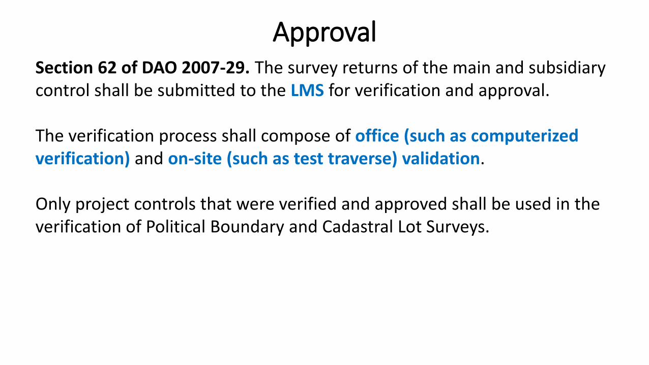
Section 62 of DAO 2007-29. The survey returns of the main and subsidiary control shall be submitted to the LMS for verification and approval.
The verification process shall compose of office (such as computerized verification) and on-site (such as test traverse) validation.
Only project controls that were verified and approved shall be used in the verification of Political Boundary and Cadastral Lot Surveys.
Approval

THANK YOU!
Related Documents