GE 100 – Trebuchet Field Activity Instruction Sheet Safety Instructions: 1) Make sure that at the time of trebuchet launch, no person is leaning over/or is in close proximity of the rotating arm. 2) Only use the provided soft clay projectiles. 3) Trebuchets must be inspected by a TA/ELA before launching, ensuring that: a. Knots, pin joints, bolts, and other connections are secure. b. The finger is adjusted so that the projectile is not launched backwards. Also, the finger bolt must be secure enough to prevent rotation of the finger. c. Trebuchets must be re-inspected after each modification. 4) There will be approximately one staff member for every 3-4 project groups. a. Staff members (ELAs/TAs) will be wearing yellow vests so that they are easy to identify. b. Staff members will be available to help answer questions in addition to inspecting trebuchets. c. Design decisions (fulcrum location, finger angle, wheels/no wheels, sling length) are up to the student group; staff members will allow students to make these decisions on their own, but supervise to ensure safety. 5) Do not launch if any person is in front of, behind, or leaning over the trebuchet. Ensure that no body part of any person is in the path of trebuchet + sling movement. 6) The sidewalks on the Bardeen Quad will be blocked at four locations, and caution tape will be used to block off the landing zone. Staff members will be standing watch at each sidewalk barricade to ensure pedestrians do not enter the landing zone. Students are not to enter the landing zone without permission. 7) Two staff members at the east end of the launch zone will each have a green flag. When they see that the landing zone is clear of people, they will raise their flag. Do not launch unless both green flags are raised.

Welcome message from author
This document is posted to help you gain knowledge. Please leave a comment to let me know what you think about it! Share it to your friends and learn new things together.
Transcript
GE 100 – Trebuchet Field Activity Instruction Sheet
Safety Instructions: 1) Make sure that at the time of trebuchet launch, no person is leaning over/or
is in close proximity of the rotating arm. 2) Only use the provided soft clay projectiles. 3) Trebuchets must be inspected by a TA/ELA before launching, ensuring that:
a. Knots, pin joints, bolts, and other connections are secure. b. The finger is adjusted so that the projectile is not launched backwards.
Also, the finger bolt must be secure enough to prevent rotation of the finger.
c. Trebuchets must be re-inspected after each modification. 4) There will be approximately one staff member for every 3-4 project groups.
a. Staff members (ELAs/TAs) will be wearing yellow vests so that they are easy to identify.
b. Staff members will be available to help answer questions in addition to inspecting trebuchets.
c. Design decisions (fulcrum location, finger angle, wheels/no wheels, sling length) are up to the student group; staff members will allow students to make these decisions on their own, but supervise to ensure safety.
5) Do not launch if any person is in front of, behind, or leaning over the trebuchet. Ensure that no body part of any person is in the path of trebuchet + sling movement.
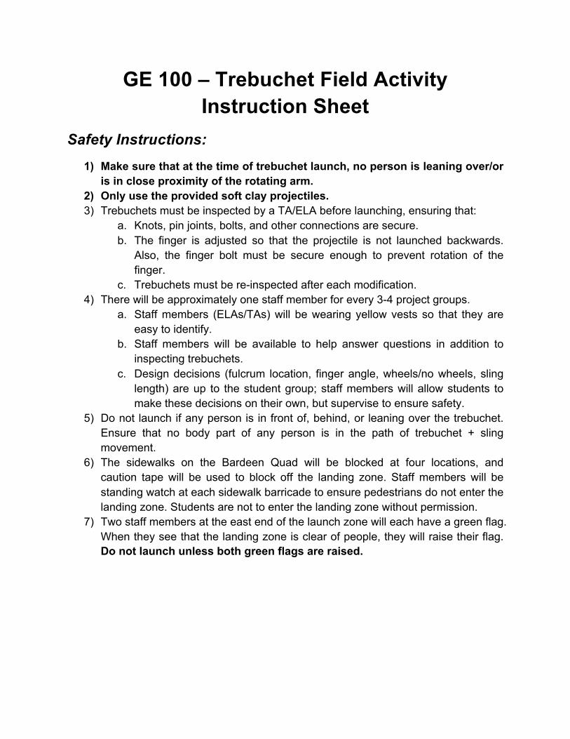
6) The sidewalks on the Bardeen Quad will be blocked at four locations, and caution tape will be used to block off the landing zone. Staff members will be standing watch at each sidewalk barricade to ensure pedestrians do not enter the landing zone. Students are not to enter the landing zone without permission.
7) Two staff members at the east end of the launch zone will each have a green flag. When they see that the landing zone is clear of people, they will raise their flag. Do not launch unless both green flags are raised.
Launch Area:
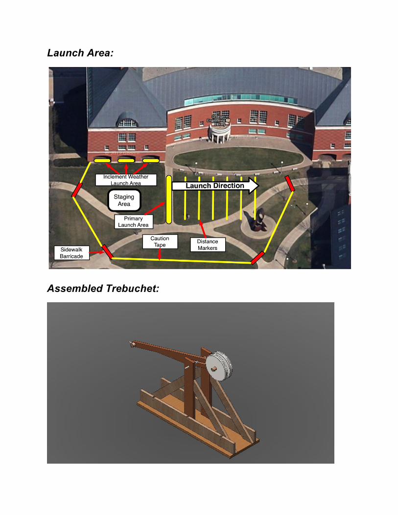
Assembled Trebuchet:
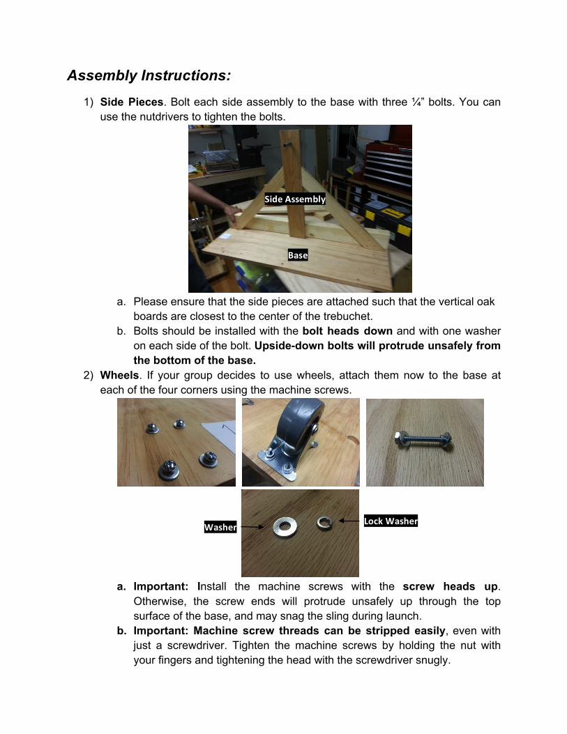
Assembly Instructions: 1) Side Pieces. Bolt each side assembly to the base with three ¼” bolts. You can
use the nutdrivers to tighten the bolts.
a. Please ensure that the side pieces are attached such that the vertical oak
boards are closest to the center of the trebuchet. b. Bolts should be installed with the bolt heads down and with one washer
on each side of the bolt. Upside-down bolts will protrude unsafely from the bottom of the base.
2) Wheels. If your group decides to use wheels, attach them now to the base at each of the four corners using the machine screws.
a. Important: Install the machine screws with the screw heads up.
Otherwise, the screw ends will protrude unsafely up through the top surface of the base, and may snag the sling during launch.
b. Important: Machine screw threads can be stripped easily, even with just a screwdriver. Tighten the machine screws by holding the nut with your fingers and tightening the head with the screwdriver snugly.
Side Assembly
Base
Washer Lock Washer
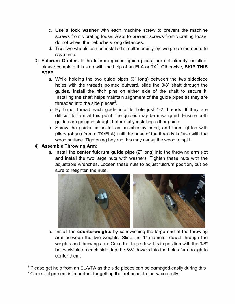
c. Use a lock washer with each machine screw to prevent the machine screws from vibrating loose. Also, to prevent screws from vibrating loose, do not wheel the trebuchets long distances.
d. Tip: two wheels can be installed simultaneously by two group members to save time.
3) Fulcrum Guides. If the fulcrum guides (guide pipes) are not already installed, please complete this step with the help of an ELA or TA1. Otherwise, SKIP THIS STEP.
a. While holding the two guide pipes (3” long) between the two sidepiece holes with the threads pointed outward, slide the 3/8” shaft through the guides. Install the hitch pins on either side of the shaft to secure it. Installing the shaft helps maintain alignment of the guide pipes as they are threaded into the side pieces2.
b. By hand, thread each guide into its hole just 1-2 threads. If they are difficult to turn at this point, the guides may be misaligned. Ensure both guides are going in straight before fully installing either guide.
c. Screw the guides in as far as possible by hand, and then tighten with pliers (obtain from a TA/ELA) until the base of the threads is flush with the wood surface. Tightening beyond this may cause the wood to split.
4) Assemble Throwing Arm: a. Install the center fulcrum guide pipe (2” long) into the throwing arm slot
and install the two large nuts with washers. Tighten these nuts with the adjustable wrenches. Loosen these nuts to adjust fulcrum position, but be sure to retighten the nuts.
b. Install the counterweights by sandwiching the large end of the throwing
arm between the two weights. Slide the 1” diameter dowel through the weights and throwing arm. Once the large dowel is in position with the 3/8” holes visible on each side, tap the 3/8” dowels into the holes far enough to center them.
1 Please get help from an ELA/TA as the side pieces can be damaged easily during this 2 Correct alignment is important for getting the trebuchet to throw correctly.
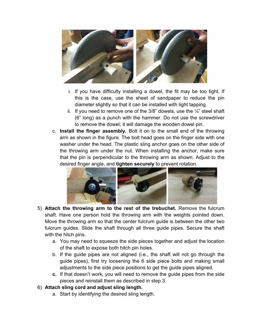
i. If you have difficulty installing a dowel, the fit may be too tight. If this is the case, use the sheet of sandpaper to reduce the pin diameter slightly so that it can be installed with light tapping.
ii. If you need to remove one of the 3/8” dowels, use the ¼” steel shaft (6” long) as a punch with the hammer. Do not use the screwdriver to remove the dowel; it will damage the wooden dowel pin.
c. Install the finger assembly. Bolt it on to the small end of the throwing arm as shown in the figure. The bolt head goes on the finger side with one washer under the head. The plastic sling anchor goes on the other side of the throwing arm under the nut. When installing the anchor, make sure that the pin is perpendicular to the throwing arm as shown. Adjust to the desired finger angle, and tighten securely to prevent rotation.
5) Attach the throwing arm to the rest of the trebuchet. Remove the fulcrum
shaft. Have one person hold the throwing arm with the weights pointed down. Move the throwing arm so that the center fulcrum guide is between the other two fulcrum guides. Slide the shaft through all three guide pipes. Secure the shaft with the hitch pins.
a. You may need to squeeze the side pieces together and adjust the location of the shaft to expose both hitch pin holes.
b. If the guide pipes are not aligned (i.e., the shaft will not go through the guide pipes), first try loosening the 6 side piece bolts and making small adjustments to the side piece positions to get the guide pipes aligned.
c. If that doesn’t work, you will need to remove the guide pipes from the side pieces and reinstall them as described in step 3.
6) Attach sling cord and adjust sling length. a. Start by identifying the desired sling length.
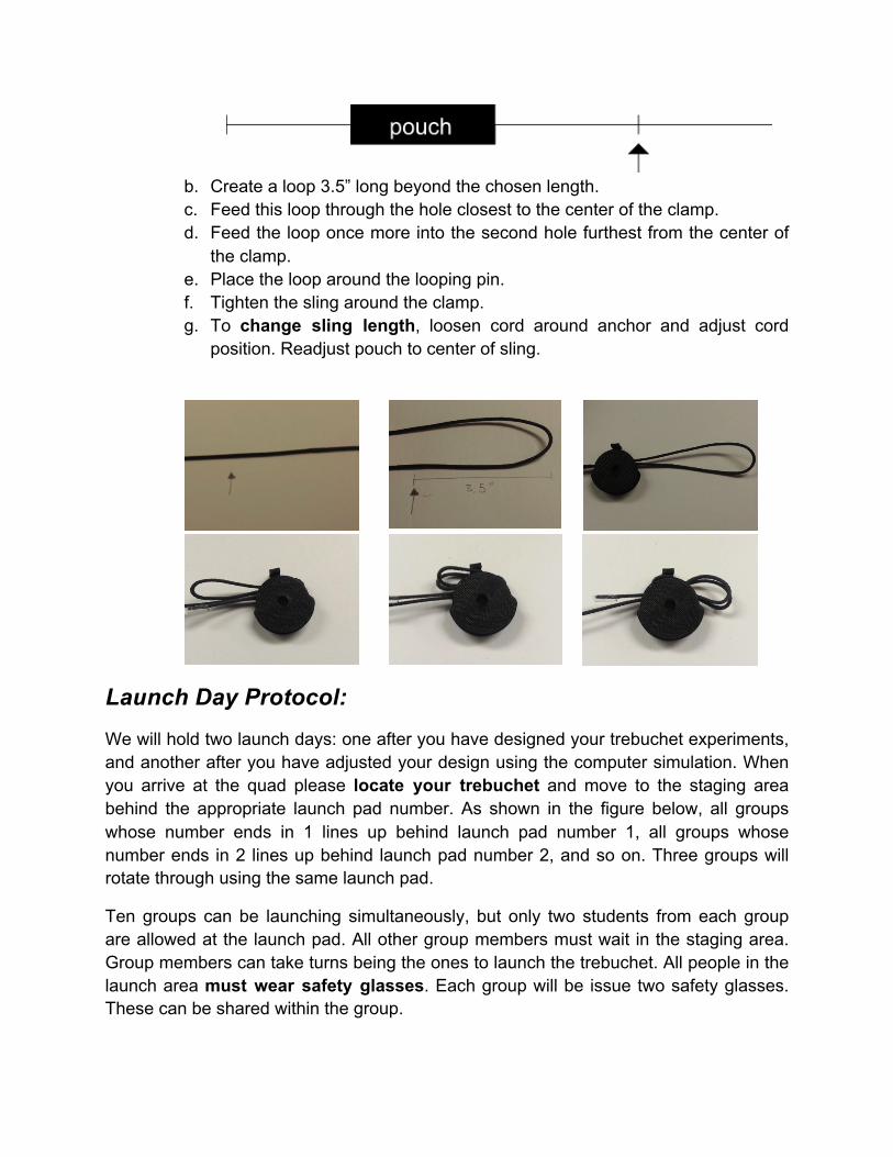
b. Create a loop 3.5” long beyond the chosen length. c. Feed this loop through the hole closest to the center of the clamp. d. Feed the loop once more into the second hole furthest from the center of
the clamp. e. Place the loop around the looping pin. f. Tighten the sling around the clamp. g. To change sling length, loosen cord around anchor and adjust cord
position. Readjust pouch to center of sling.
Launch Day Protocol: We will hold two launch days: one after you have designed your trebuchet experiments, and another after you have adjusted your design using the computer simulation. When you arrive at the quad please locate your trebuchet and move to the staging area behind the appropriate launch pad number. As shown in the figure below, all groups whose number ends in 1 lines up behind launch pad number 1, all groups whose number ends in 2 lines up behind launch pad number 2, and so on. Three groups will rotate through using the same launch pad.
Ten groups can be launching simultaneously, but only two students from each group are allowed at the launch pad. All other group members must wait in the staging area. Group members can take turns being the ones to launch the trebuchet. All people in the launch area must wear safety glasses. Each group will be issue two safety glasses. These can be shared within the group.
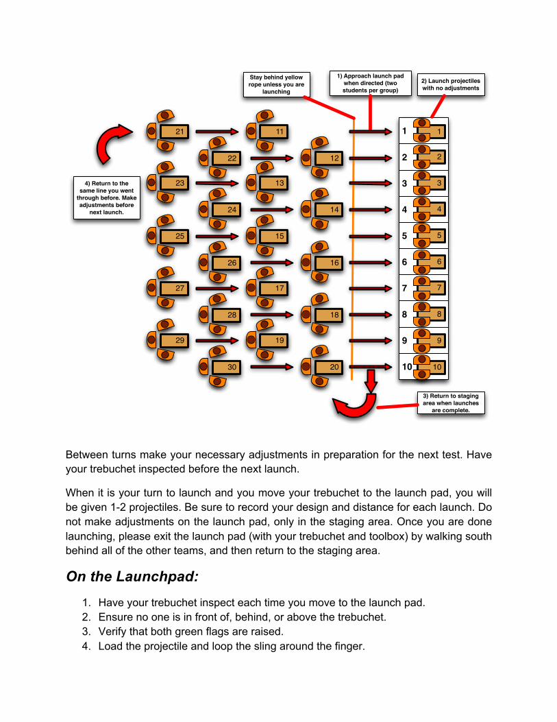
Between turns make your necessary adjustments in preparation for the next test. Have your trebuchet inspected before the next launch.
When it is your turn to launch and you move your trebuchet to the launch pad, you will be given 1-2 projectiles. Be sure to record your design and distance for each launch. Do not make adjustments on the launch pad, only in the staging area. Once you are done launching, please exit the launch pad (with your trebuchet and toolbox) by walking south behind all of the other teams, and then return to the staging area.
On the Launchpad: 1. Have your trebuchet inspect each time you move to the launch pad. 2. Ensure no one is in front of, behind, or above the trebuchet. 3. Verify that both green flags are raised. 4. Load the projectile and loop the sling around the finger.
1) Approach launch pad when directed (two students per group)
Stay behind yellow rope unless you are
launching
3) Return to staging area when launches
are complete.
1
2
3
4
5
6
7
8
9
10
1
2
3
4
5
6
7
8
9
10
1121
1222
1323
1424
1525
1626
1727
1828
1929
2030
2) Launch projectiles with no adjustments
4) Return to the same line you went
through before. Make adjustments before
next launch.
5. Rotate the throwing arm back as far as possible. 6. While holding the arm in position, place the projectile on the base toward the
front such that there is no slack in the sling. 7. Yell something so that people know you are launching. 8. Let go of the throwing arm, taking care to stay out of the path of the rotating arm
and sling. 9. Watch your nano-pumpkin sail! 10. Observe and record distance.
Trebuchet Competition: The group that achieves the longest range will be recognized in class after the second launch day, and at the Engineering Open House trebuchet demonstration. We are especially interested in the trebuchet design (the four variable values) that achieves this distance, so please record each design that you test.
Related Documents


