INSTRUCTION MANUAL FOR MICROCOMPUTER BASED TEMPERATURE INDICATING CONTROLLER GCM-200 Thank you for your purchase of our Microcomputer based Temperature Indicating Controller GCM-200. This manual contains instructions for the mounting, functions, operations and notes when operating the GCM-200. For model confirmation and unit specifications, please read this manual carefully before starting operation. To prevent accidents arising from the use of this controller, please ensure the operator using it receives this manual. PV SV OUT2 HB A1 OUT OFF MODE GCM AT OUT1 A2

Welcome message from author
This document is posted to help you gain knowledge. Please leave a comment to let me know what you think about it! Share it to your friends and learn new things together.
Transcript
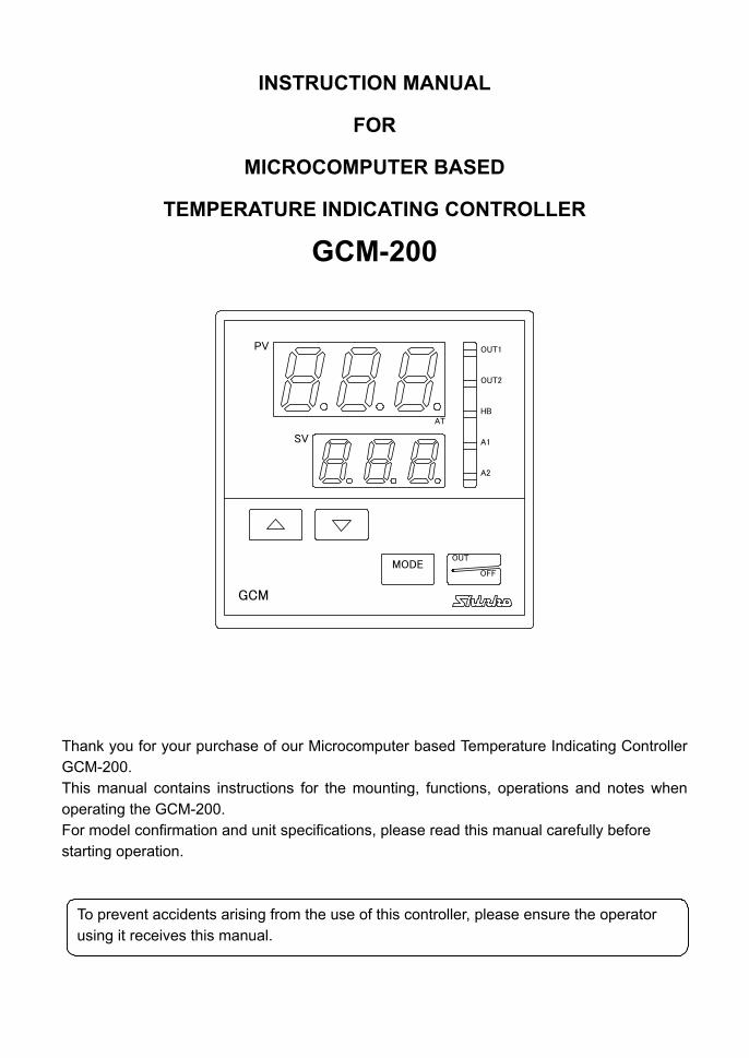
INSTRUCTION MANUAL
FOR
MICROCOMPUTER BASED
TEMPERATURE INDICATING CONTROLLER
GCM-200
Thank you for your purchase of our Microcomputer based Temperature Indicating Controller GCM-200. This manual contains instructions for the mounting, functions, operations and notes when operating the GCM-200. For model confirmation and unit specifications, please read this manual carefully before starting operation.
To prevent accidents arising from the use of this controller, please ensure the operator using it receives this manual.
PV
SV
OUT2
HB
A1
OUT
OFFMODE
GCM
AT
OUT1
A2
2
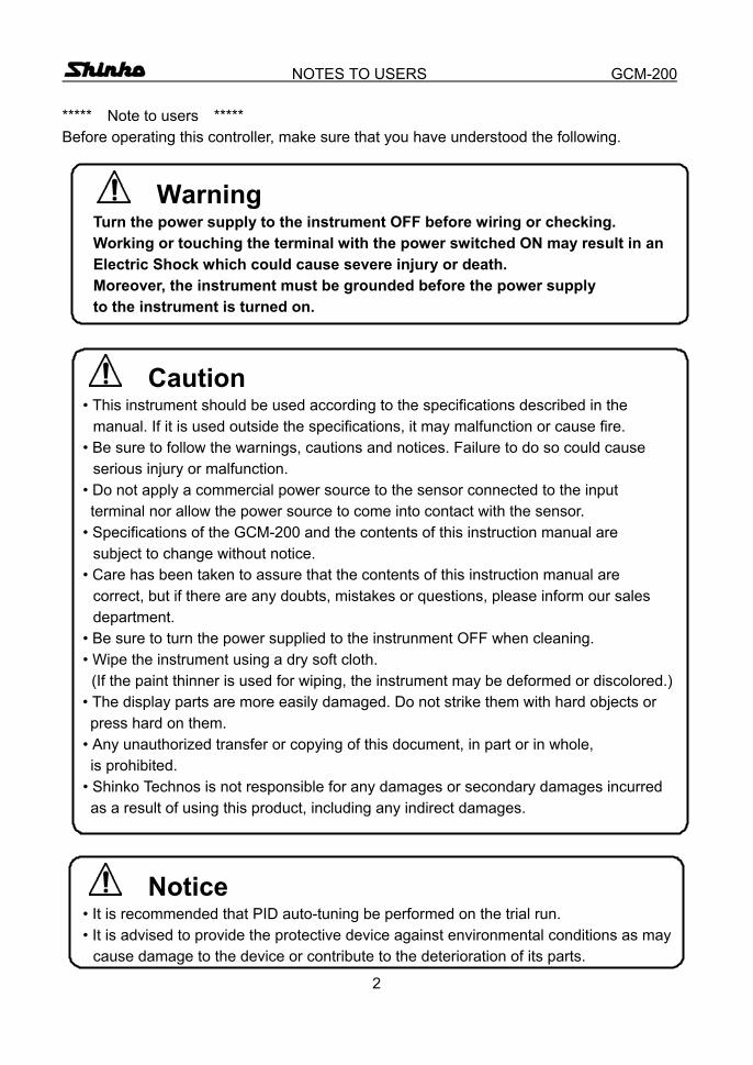
NOTES TO USERS GCM-200
***** Note to users ***** Before operating this controller, make sure that you have understood the following.
Warning Turn the power supply to the instrument OFF before wiring or checking. Working or touching the terminal with the power switched ON may result in an
Electric Shock which could cause severe injury or death. Moreover, the instrument must be grounded before the power supply to the instrument is turned on.
Caution • This instrument should be used according to the specifications described in the
manual. If it is used outside the specifications, it may malfunction or cause fire. • Be sure to follow the warnings, cautions and notices. Failure to do so could cause
serious injury or malfunction. • Do not apply a commercial power source to the sensor connected to the input terminal nor allow the power source to come into contact with the sensor. • Specifications of the GCM-200 and the contents of this instruction manual are
subject to change without notice. • Care has been taken to assure that the contents of this instruction manual are
correct, but if there are any doubts, mistakes or questions, please inform our sales department.
• Be sure to turn the power supplied to the instrunment OFF when cleaning. • Wipe the instrument using a dry soft cloth.
(If the paint thinner is used for wiping, the instrument may be deformed or discolored.) • The display parts are more easily damaged. Do not strike them with hard objects or press hard on them. • Any unauthorized transfer or copying of this document, in part or in whole, is prohibited. • Shinko Technos is not responsible for any damages or secondary damages incurred as a result of using this product, including any indirect damages.
Notice • It is recommended that PID auto-tuning be performed on the trial run. • It is advised to provide the protective device against environmental conditions as may
cause damage to the device or contribute to the deterioration of its parts.
3
CONTENTS GCM-200
--- CONTENTS --- 1. Model names
1.1 Model names --------------------------------------------------------------------------------- 5 1.2 How to indicate the model nameplate -------------------------------------------------- 5
2. Name and functions of the sections -------------------------------------------- 6 3. Operations
3.1 Operation flow chart ------------------------------------------------------------------------- 7 3.2 Operations
(1) PV/SV display mode ------------------------------------------------------------------ 8 (2) Main setting mode --------------------------------------------------------------------- 9
(3) Sub setting mode Auto-tuning Perform/Cancel or Auto-reset Perform --------------------------- 9 Main proportional band setting ----------------------------------------------------- 10 Cooling proportional band setting -------------------------------------------------- 10
Integral time setting -------------------------------------------------------------------- 11 Derivative time setting ----------------------------------------------------------------- 11
Main proportional cycle setting ------------------------------------------------------ 11 Cooling proportional cycle setting -------------------------------------------------- 11 Temperature alarm 1 (A1) setting -------------------------------------------------- 11 Temperature alarm 2 (A2) setting -------------------------------------------------- 12 Heater burnout alarm setting -------------------------------------------------------- 12
(4) Auxiliary function setting mode Setting value lock designation ------------------------------------------------------ 13 Main setting value high limit setting ------------------------------------------------ 13 Main setting value low limit setting ------------------------------------------------- 13 Sensor correction setting ------------------------------------------------------------- 13
Main output high limit setting -------------------------------------------------------- 14 Main output low limit setting --------------------------------------------------------- 14
Main output ON/OFF action hysteresis setting --------------------------------- 14 Cooling action mode selection ------------------------------------------------------ 14 Cooling output high limit setting ---------------------------------------------------- 14 Cooling output low limit setting ----------------------------------------------------- 15 Cooling output ON/OFF action hysteresis setting ------------------------------ 15
Overlap band/Dead band setting --------------------------------------------------- 15 Sensor selection ----------------------------------------------------------------------- 15 Temperature alarm 1 (A1) action selection ------------------------------------- 16 Temperature alarm 2 (A2) action selection ------------------------------------- 16
4
CONTENTS GCM-200 Temperature alarm 1 (A1) hysteresis setting ------------------------------------ 17 Temperature alarm 2 (A2) hysteresis setting ------------------------------------ 17 Heating/Cooling selection ------------------------------------------------------------ 17
(5) Control output OFF function ---------------------------------------------------------- 17 4. Running ---------------------------------------------------------------------------------------- 18 5. Action explanations
5.1 Standard action ------------------------------------------------------------------------------ 19 5.2 Heater burnout alarm action -------------------------------------------------------------- 19 5.3 Heating and Cooling actions (Option D )
Heating (reverse) and Cooling (direct) actions ----------------------------------- 20 When setting Dead band --------------------------------------------------------------- 21 When setting Overlap band with Relay contact output ------------------------- 22
5.4 ON/OFF action ------------------------------------------------------------------------------ 23 5.5 Temperature alarm 1 (A1) and 2 (A2) action ----------------------------------------- 24
6. Control actions 6.1 Explanations of PID ------------------------------------------------------------------------ 25 6.2 PID auto-tuning of this controller -------------------------------------------------------- 26 6.3 Auto-reset (offset correction) ------------------------------------------------------------- 27
7. Other functions ---------------------------------------------------------------------------- 27 8. Mounting to control panel
8.1 Site selection -------------------------------------------------------------------------------- 28 8.2 External dimension drawing ------------------------------------------------------------- 28 8.3 Panel cutout drawing ---------------------------------------------------------------------- 28 8.4 Current transformer (CT) dimension drawing --------------------------------------- 29 8.5 Mounting -------------------------------------------------------------------------------------- 29
9. Wiring connection 9.1 Terminal arrangement --------------------------------------------------------------------- 30 9.2 Wiring connection examples ------------------------------------------------------------ 31
10. Specifications 10.1 Standard specifications ------------------------------------------------------------------ 33 10.2 Optional specifications ------------------------------------------------------------------- 35
11.Troubleshooting ---------------------------------------------------------------------------- 37 12. Character table ----------------------------------------------------------------------------- 39

5
MODEL NAMES GCM-200 1. Model names 1.1 Model names Standard models
G C M – 2 3 – / GCM-200 type Control action 3 PID control
0 No alarm action Temperature alarm A Alarm action is applied * R Relay contact S Non-contact voltage Output A DC current
E Thermocouple K, J, E Input R RTD Pt100, JPt100 8 types of alarm action and no alarm action are selectable by key operation. Alphanumeric character to represent the functions or type is applied to the .
[Example] G C M – 2 3 A – R / E , W
Heater burnout alarm output Thermocouple input Relay contact output Temperature alarm action is applied 72(W) x 72(H) x 100(D)mm
Optional code Code Description
A2 Temperature alarm 2 output W Heater burnout alarm output (including sensor burnout alarm)
D
DR: Relay contact Heating/Cooling control output DS: Non-contact voltage Heating output: Main (OUT1) output DA: Current Cooling output: Sub (OUT2) output
MR Multi-range BK Color: Black IP Dust-proof•Drip-proof (IP54), only for front panel TC Terminal cover
Warning Do not take the inner assembly out nor touch the terminal with the power supply on. Touching the terminal with the power switched ON may result in an Electric Shock which could cause severe injury or death.
1.2 How to indicate the model nameplate Model nameplates are put on the case and the left side of the inner assembly. [Model nameplate] [Example]
2 3 A – R / E A 2 W ( 2 0 A ) 0 to 400 K N o.
(1): Model name (2): Option codes (3): Input (4): Instrument number (Indicated only on the inner assembly) In the case of Heater burnout alarm output, the specified current value is entered in ( ).
(1)
(2) (3)
Relay contact output, thermocouple input Temperature alarm 2 (A2) output Heater burnout alarm output (20A)
(4)
6
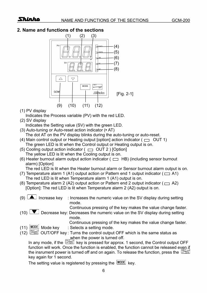
NAME AND FUNCTIONS OF THE SECTIONS GCM-200 2. Name and functions of the sections (1) (2) (3) (4) (5) (6) (7) (8) [Fig. 2-1] (9) (10) (11) (12)
(1) PV display Indicates the Process variable (PV) with the red LED.
(2) SV display Indicates the Setting value (SV) with the green LED.
(3) Auto-tuning or Auto-reset action indicator (• AT) The dot AT on the PV display blinks during the auto-tuning or auto-reset.
(4) Main control output or Heating output [option] action indicator ( OUT 1) The green LED is lit when the Control output or Heating output is on.
(5) Cooling output action indicator ( OUT 2 ) [Option] The yellow LED is lit when the Cooling output is on.
(6) Heater burnout alarm output action indicator ( HB) (including sensor burnout alarm) [Option] The red LED is lit when the Heater burnout alarm or Sensor burnout alarm output is on.
(7) Temperature alarm 1 (A1) output action or Pattern end 1 output indicator ( A1) The red LED is lit when Temperature alarm 1 (A1) output is on.
(8) Temperature alarm 2 (A2) output action or Pattern end 2 output indicator ( A2) [Option]: The red LED is lit when Temperature alarm 2 (A2) output is on.
(9) Increase key : Increases the numeric value on the SV display during setting mode.
Continuous pressing of the key makes the value change faster. (10) Decrease key: Decreases the numeric value on the SV display during setting mode.
Continuous pressing of the key makes the value change faster. (11) Mode key : Selects a setting mode. (12) OUT/OFF key : Turns the control output OFF which is the same status as when the power is turned off.
In any mode, if the key is pressed for approx. 1 second, the Control output OFF function will work. Once the function is enabled, the function cannot be released even if the insrument power is turned off and on again. To release the function, press the key again for 1 second. The setting value is registered by pressing the key.
PV
SV
OUT2
HB
A1
OUT
OFFMODE
GCM
AT
OUT1
A2
7
OPERATIONS GCM-200
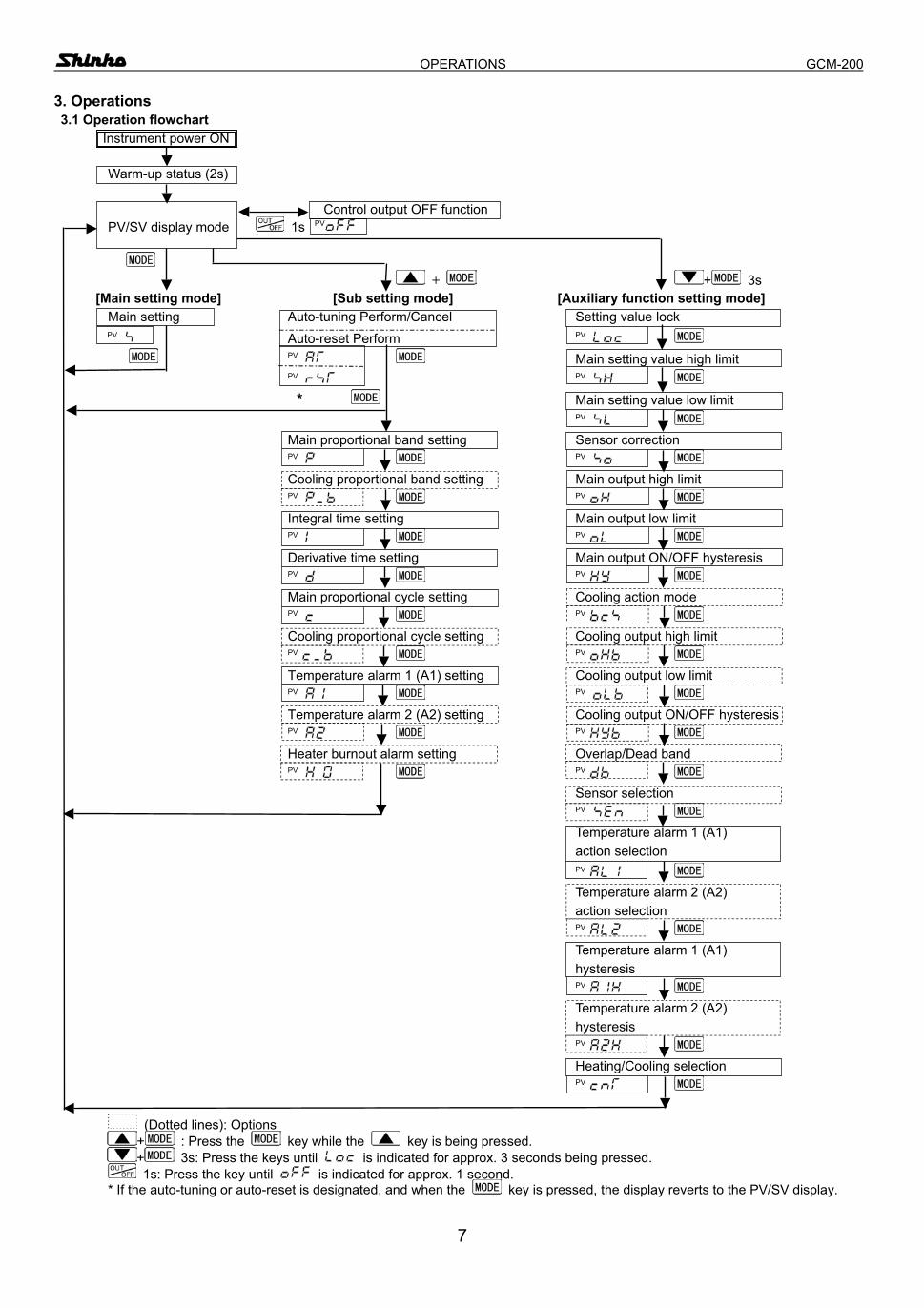
3. Operations 3.1 Operation flowchart Instrument power ON Warm-up status (2s) Control output OFF function PV/SV display mode 1s PV + + 3s
[Main setting mode] [Sub setting mode] [Auxiliary function setting mode] Main setting Auto-tuning Perform/Cancel Setting value lock
PV Auto-reset Perform PV PV Main setting value high limit PV PV * Main setting value low limit PV Main proportional band setting Sensor correction PV PV Cooling proportional band setting Main output high limit PV PV
Integral time setting Main output low limit PV PV Derivative time setting Main output ON/OFF hysteresis
PV PV Main proportional cycle setting Cooling action mode PV PV
Cooling proportional cycle setting Cooling output high limit PV PV Temperature alarm 1 (A1) setting Cooling output low limit PV PV
Temperature alarm 2 (A2) setting Cooling output ON/OFF hysteresis PV PV Heater burnout alarm setting Overlap/Dead band PV PV Sensor selection PV Temperature alarm 1 (A1) action selection PV Temperature alarm 2 (A2) action selection PV Temperature alarm 1 (A1) hysteresis PV Temperature alarm 2 (A2) hysteresis PV Heating/Cooling selection PV
(Dotted lines): Options + : Press the key while the key is being pressed. + 3s: Press the keys until is indicated for approx. 3 seconds being pressed. 1s: Press the key until is indicated for approx. 1 second.
* If the auto-tuning or auto-reset is designated, and when the key is pressed, the display reverts to the PV/SV display.
8
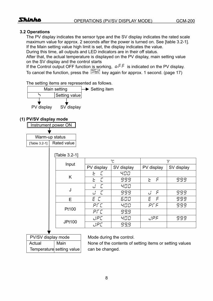
OPERATIONS (PV/SV DISPLAY MODE) GCM-200 3.2 Operations
The PV display indicates the sensor type and the SV display indicates the rated scale maximum value for approx. 2 seconds after the power is turned on. See [table 3.2-1]. If the Main setting value high limit is set, the display indicates the value. During this time, all outputs and LED indicators are in their off status. After that, the actual temperature is displayed on the PV display, main setting value on the SV display and the control starts If the Control output OFF function is working, is indicated on the PV display.
To cancel the function, press the key again for approx. 1 second. (page 17) The setting items are represented as follows.
Main setting Setting item Setting value
PV display SV display
(1) PV/SV display mode Instrument power ON
Warm-up status [Table 3.2-1] Rated value
[Table 3.2-1]
Input PV display SV display PV display SV display
K
J
E
Pt100
JPt100
PV/SV display mode Mode during the control. Actual Main None of the contents of setting items or setting values Temperature setting value can be changed.
9
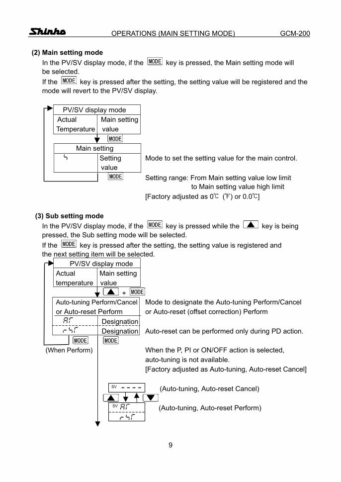
OPERATIONS (MAIN SETTING MODE) GCM-200 (2) Main setting mode
In the PV/SV display mode, if the key is pressed, the Main setting mode will be selected. If the key is pressed after the setting, the setting value will be registered and the mode will revert to the PV/SV display.
PV/SV display mode
Actual Main setting Temperature value
Main setting Setting Mode to set the setting value for the main control. value Setting range: From Main setting value low limit to Main setting value high limit [Factory adjusted as 0 ( ) or 0.0 ]
(3) Sub setting mode In the PV/SV display mode, if the key is pressed while the key is being pressed, the Sub setting mode will be selected. If the key is pressed after the setting, the setting value is registered and the next setting item will be selected. PV/SV display mode Actual Main setting temperature value
+ Auto-tuning Perform/Cancel Mode to designate the Auto-tuning Perform/Cancel or Auto-reset Perform or Auto-reset (offset correction) Perform Designation
Designation Auto-reset can be performed only during PD action.
(When Perform) When the P, PI or ON/OFF action is selected, auto-tuning is not available. [Factory adjusted as Auto-tuning, Auto-reset Cancel] SV (Auto-tuning, Auto-reset Cancel)
SV (Auto-tuning, Auto-reset Perform)
10
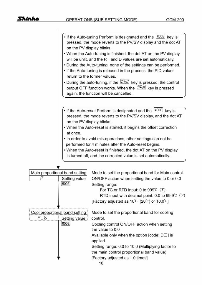
OPERATIONS (SUB SETTING MODE) GCM-200 • If the Auto-tuning Perform is designated and the key is pressed, the mode reverts to the PV/SV display and the dot AT on the PV display blinks. • When the Auto-tuning is finished, the dot AT on the PV display will be unlit, and the P, I and D values are set automatically. • During the Auto-tuning, none of the settings can be performed. • If the Auto-tuning is released in the process, the PID values return to the former values. • During the auto-tuning, if the key is pressed, the control output OFF function works. When the key is pressed again, the function will be cancelled. • If the Auto-reset Perform is designated and the key is pressed, the mode reverts to the PV/SV display, and the dot AT on the PV display blinks. • When the Auto-reset is started, it begins the offset correction at once. • In order to avoid mis-operations, other settings can not be performed for 4 minutes after the Auto-reset begins. • When the Auto-reset is finished, the dot AT on the PV display is turned off, and the corrected value is set automatically. Main proportional band setting Mode to set the proportional band for Main control.
Setting value ON/OFF action when setting the value to 0 or 0.0 Setting range:
For TC or RTD input: 0 to 999 ( ) RTD input with decimal point: 0.0 to 99.9 ( )
[Factory adjusted as 10 (20 ) or 10.0 ] Cool proportional band setting Mode to set the proportional band for cooling Setting value control. Cooling control ON/OFF action when setting the value to 0.0 Available only when the option [code: D ] is applied. Setting range: 0.0 to 10.0 (Multiplying factor to the main control proportional band value) [Factory adjusted as 1.0 times]
11
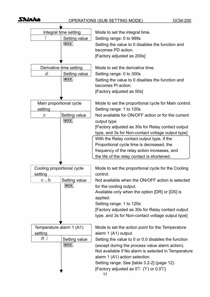
OPERATIONS (SUB SETTING MODE) GCM-200 Integral time setting Mode to set the integral time.
Setting value Setting range: 0 to 999s Setting the value to 0 disables the function and becomes PD action. [Factory adjusted as 200s] Derivative time setting Mode to set the derivative time.
Setting value Setting range: 0 to 300s Setting the value to 0 disables the function and becomes PI action. [Factory adjusted as 50s] Main proportional cycle Mode to set the proportional cycle for Main control. setting Setting range: 1 to 120s Setting value Not available for ON/OFF action or for the current output type [Factory adjusted as 30s for Relay contact output type, and 3s for Non-contact voltage output type] With the Relay contact output type, if the Proportional cycle time is decreased, the frequency of the relay action increases, and the life of the relay contact is shortened. Cooling proportional cycle Mode to set the proportional cycle for the Cooling setting control. Setting value Not available when the ON/OFF action is selected for the cooling output. Available only when the option [DR] or [DS] is applied. Setting range: 1 to 120s [Factory adjusted as 30s for Relay contact output type, and 3s for Non-contact voltage output type] Temperature alarm 1 (A1) Mode to set the action point for the Temperature setting alarm 1 (A1) output. Setting value Setting the value to 0 or 0.0 disables the function (except during the process value alarm action). Not available if No alarm is selected in Temperature alarm 1 (A1) action selection Setting range: See [table 3.2-2] (page 12). [Factory adjusted as 0 ( ) or 0.0 ]
12
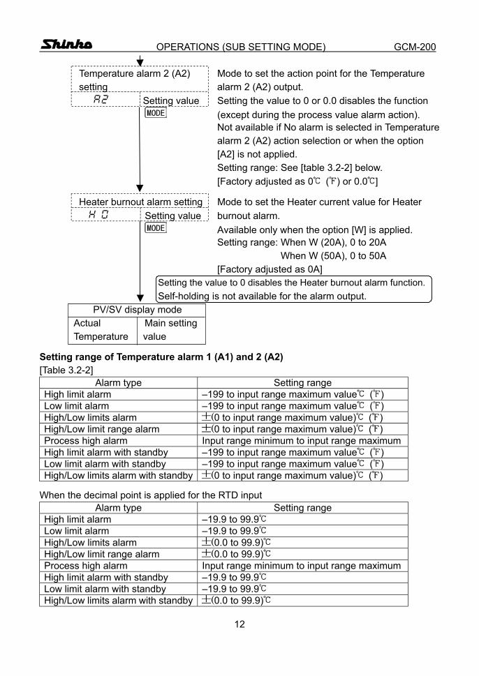
OPERATIONS (SUB SETTING MODE) GCM-200 Temperature alarm 2 (A2) Mode to set the action point for the Temperature setting alarm 2 (A2) output. Setting value Setting the value to 0 or 0.0 disables the function (except during the process value alarm action). Not available if No alarm is selected in Temperature alarm 2 (A2) action selection or when the option [A2] is not applied. Setting range: See [table 3.2-2] below. [Factory adjusted as 0 ( ) or 0.0 ]
Heater burnout alarm setting Mode to set the Heater current value for Heater Setting value burnout alarm. Available only when the option [W] is applied. Setting range: When W (20A), 0 to 20A When W (50A), 0 to 50A [Factory adjusted as 0A] Setting the value to 0 disables the Heater burnout alarm function. Self-holding is not available for the alarm output. PV/SV display mode Actual Main setting Temperature value
Setting range of Temperature alarm 1 (A1) and 2 (A2) [Table 3.2-2]
Alarm type Setting range High limit alarm –199 to input range maximum value ( ) Low limit alarm –199 to input range maximum value ( ) High/Low limits alarm (0 to input range maximum value) ( ) High/Low limit range alarm (0 to input range maximum value) ( ) Process high alarm Input range minimum to input range maximum High limit alarm with standby –199 to input range maximum value ( ) Low limit alarm with standby –199 to input range maximum value ( ) High/Low limits alarm with standby (0 to input range maximum value) ( )
When the decimal point is applied for the RTD input Alarm type Setting range
High limit alarm –19.9 to 99.9 Low limit alarm –19.9 to 99.9 High/Low limits alarm (0.0 to 99.9) High/Low limit range alarm (0.0 to 99.9) Process high alarm Input range minimum to input range maximum High limit alarm with standby –19.9 to 99.9 Low limit alarm with standby –19.9 to 99.9 High/Low limits alarm with standby (0.0 to 99.9)
13
OPERATIONS (AUXILIARY FUNCTION SETTING MODE) GCM-200 (4) Auxiliary function setting mode
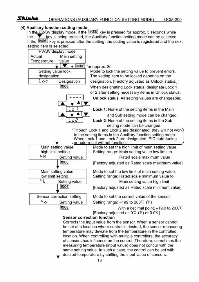
In the PV/SV display mode, if the key is pressed for approx. 3 seconds while the key is being pressed, the Auxiliary function setting mode can be selected. If the key is pressed after the setting, the setting value is registered and the next setting item is selected.
PV/SV display mode Actual Main setting Temperature value + for approx. 3s Setting value lock Mode to lock the setting value to prevent errors. designation The setting item to be locked depends on the Designation designation. [Factory adjusted as Unlock status.]
When designating Lock status, designate Lock 1 or 2 after setting necessary items in Unlock status. Unlock status. All setting values are changeable.
Lock 1: None of the setting items in the Main
and Sub setting mode can be changed. Lock 2: None of the setting items in the Sub setting mode can be changed. Though Lock 1 and Lock 2 are designated, they will not work to the setting items in the Auxiliary function setting mode. When Lock 1 and Lock 2 are designated, PID auto-tuning or auto-reset will not function. Main setting value Mode to set the high limit of main setting value. high limit setting Setting range: Main setting value low limit to
Setting value Rated scale maximum value [Factory adjusted as Rated scale maximum value]
Main setting value Mode to set the low limit of main setting value. low limit setting Setting range: Rated scale minimum value to
Setting value Main setting value high limit [Factory adjusted as Rated scale minimum value]
Sensor correction setting Mode to set the correct value of the sensor.
Setting value Setting range: –199 to 200 ( ) With a decimal point, –19.9 to 20.0
[Factory adjusted as 0 ( ) or 0.0 ] Sensor correction function Corrects the input value from the sensor. When a sensor cannot be set at a location where control is desired, the sensor measuring temperature may deviate from the temperature in the controlled location. When controlling with multiple controllers, the accuracy of sensors has influence on the control. Therefore, sometimes the measuring temperature (input value) does not concur with the same setting value. In such a case, the control can be set with desired temperature by shifting the input value of sensors.
14
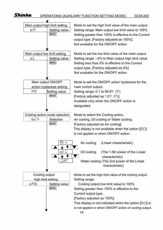
OPERATIONS (AUXILIARY FUNCTION SETTING MODE) GCM-200 Main output high limit setting Mode to set the high limit value of the main output. Setting value Setting range: Main output low limit value to 105% Setting greater than 100% is effective to the Current output type. [Factory adjusted as 100%] Not available for the ON/OFF action. Main output low limit setting Mode to set the low limit value of the main output. Setting value Setting range: –5% to Main output high limit value Setting less than 0% is effective to the Current output type. [Factory adjusted as 0%] Not available for the ON/OFF action. Main output ON/OFF Mode to set the ON/OFF action hysteresis for the action hysteresis setting main control output. Setting value Setting range: 0.1 to 99.9 ( ) [Factory adjusted as 1.0 ( )] Available only when the ON/OFF action is designated. Cooling action mode selection Mode to select the Cooling action, Selection Air cooling, Oil cooling or Water cooling. [Factory adjusted as Air cooling] This display is not available when the option [D ] is not applied or when ON/OFF action. Air cooling (Linear characteristic)
Oil cooling (The 1.5th power of the Linear characteristic) Water cooling (The 2nd power of the Linear characteristic)
Cooling output Mode to set the high limit value of the cooling output.
high limit setting Setting range: Setting value Cooling output low limit value to 105%
Setting greater than 100% is effective to the Current output type. [Factory adjusted as 100%] This display is not indicated when the option [D ] is is not applied or when ON/OFF action of cooling output.
15
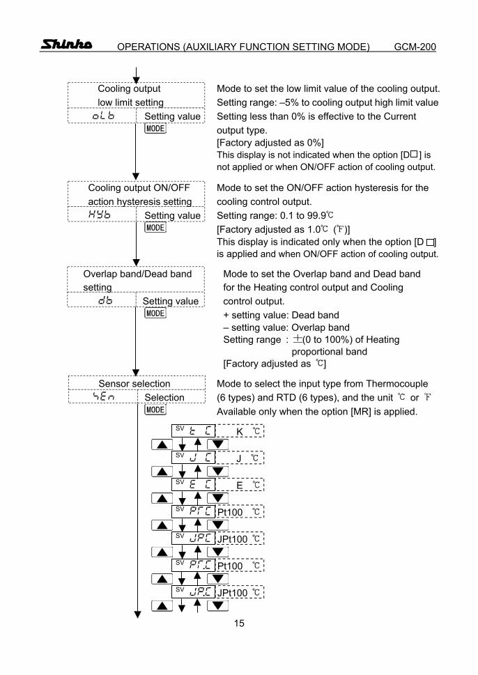
OPERATIONS (AUXILIARY FUNCTION SETTING MODE) GCM-200 Cooling output Mode to set the low limit value of the cooling output. low limit setting Setting range: –5% to cooling output high limit value
Setting value Setting less than 0% is effective to the Current output type. [Factory adjusted as 0%] This display is not indicated when the option [D ] is not applied or when ON/OFF action of cooling output. Cooling output ON/OFF Mode to set the ON/OFF action hysteresis for the action hysteresis setting cooling control output. Setting value Setting range: 0.1 to 99.9 [Factory adjusted as 1.0 ( )]
This display is indicated only when the option [D ] is applied and when ON/OFF action of cooling output.
Overlap band/Dead band Mode to set the Overlap band and Dead band setting for the Heating control output and Cooling
Setting value control output. + setting value: Dead band – setting value: Overlap band Setting range : (0 to 100%) of Heating proportional band [Factory adjusted as ] Sensor selection Mode to select the input type from Thermocouple Selection (6 types) and RTD (6 types), and the unit or Available only when the option [MR] is applied. SV K SV J SV E SV Pt100 SV JPt100 SV Pt100 SV JPt100
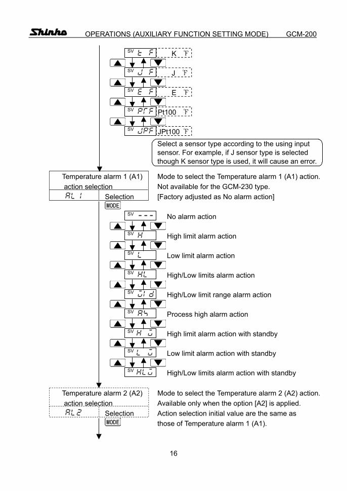
16
OPERATIONS (AUXILIARY FUNCTION SETTING MODE) GCM-200 SV K SV J SV E SV Pt100 SV JPt100 Select a sensor type according to the using input sensor. For example, if J sensor type is selected though K sensor type is used, it will cause an error. Temperature alarm 1 (A1) Mode to select the Temperature alarm 1 (A1) action. action selection Not available for the GCM-230 type. Selection [Factory adjusted as No alarm action] SV No alarm action SV High limit alarm action SV Low limit alarm action SV High/Low limits alarm action SV High/Low limit range alarm action SV Process high alarm action SV High limit alarm action with standby SV Low limit alarm action with standby SV High/Low limits alarm action with standby Temperature alarm 2 (A2) Mode to select the Temperature alarm 2 (A2) action. action selection Available only when the option [A2] is applied. Selection Action selection initial value are the same as those of Temperature alarm 1 (A1).
17
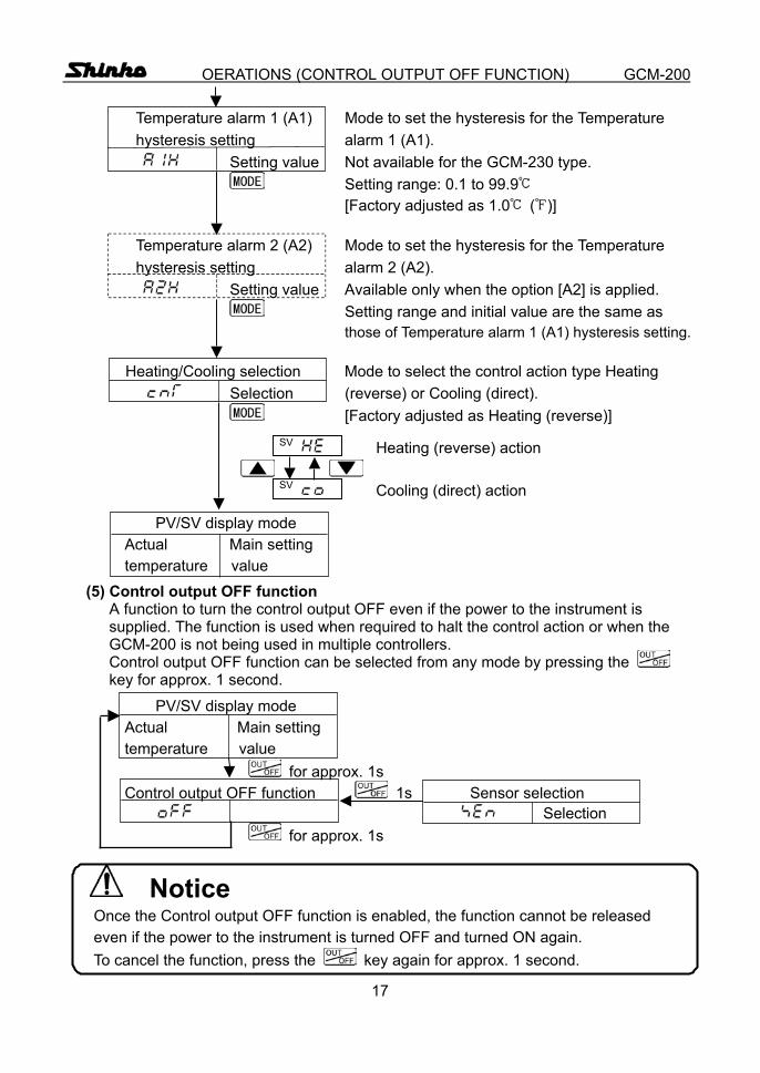
OERATIONS (CONTROL OUTPUT OFF FUNCTION) GCM-200 Temperature alarm 1 (A1) Mode to set the hysteresis for the Temperature hysteresis setting alarm 1 (A1). Setting value Not available for the GCM-230 type. Setting range: 0.1 to 99.9 [Factory adjusted as 1.0 ( )] Temperature alarm 2 (A2) Mode to set the hysteresis for the Temperature hysteresis setting alarm 2 (A2). Setting value Available only when the option [A2] is applied. Setting range and initial value are the same as those of Temperature alarm 1 (A1) hysteresis setting. Heating/Cooling selection Mode to select the control action type Heating Selection (reverse) or Cooling (direct). [Factory adjusted as Heating (reverse)] SV Heating (reverse) action SV Cooling (direct) action PV/SV display mode Actual Main setting temperature value (5) Control output OFF function A function to turn the control output OFF even if the power to the instrument is
supplied. The function is used when required to halt the control action or when the GCM-200 is not being used in multiple controllers. Control output OFF function can be selected from any mode by pressing the key for approx. 1 second.
PV/SV display mode Actual Main setting temperature value
for approx. 1s Control output OFF function 1s Sensor selection Selection for approx. 1s
Notice Once the Control output OFF function is enabled, the function cannot be released even if the power to the instrument is turned OFF and turned ON again. To cancel the function, press the key again for approx. 1 second.
18
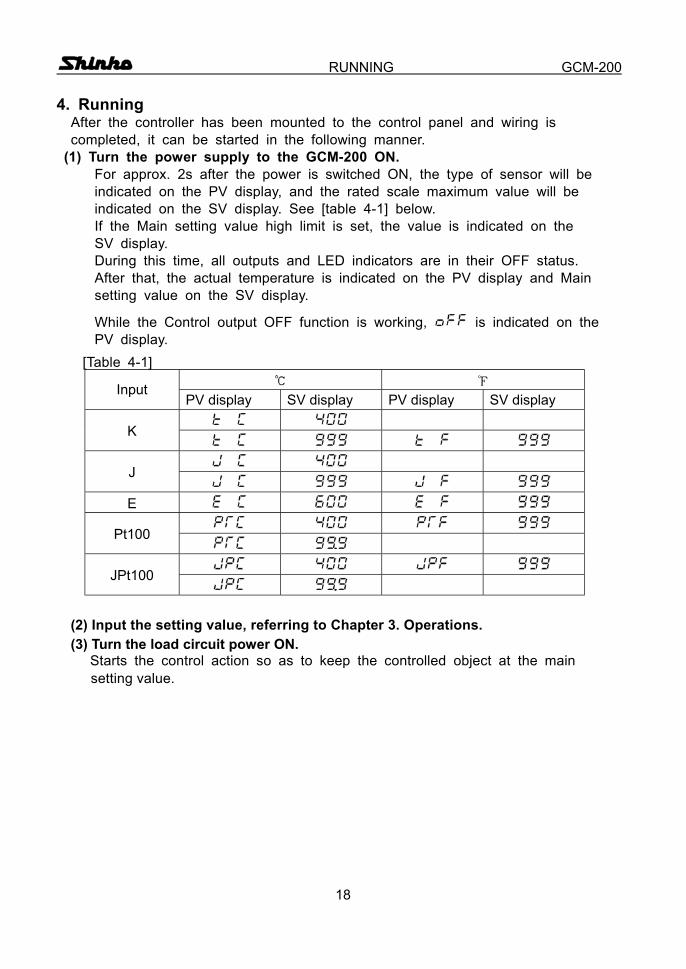
RUNNING GCM-200 4. Running
After the controller has been mounted to the control panel and wiring is completed, it can be started in the following manner.
(1) Turn the power supply to the GCM-200 ON. For approx. 2s after the power is switched ON, the type of sensor will be indicated on the PV display, and the rated scale maximum value will be indicated on the SV display. See [table 4-1] below. If the Main setting value high limit is set, the value is indicated on the SV display. During this time, all outputs and LED indicators are in their OFF status. After that, the actual temperature is indicated on the PV display and Main setting value on the SV display.
While the Control output OFF function is working, is indicated on the PV display.
[Table 4-1] Input
PV display SV display PV display SV display
K
J
E
Pt100
JPt100
(2) Input the setting value, referring to Chapter 3. Operations.
(3) Turn the load circuit power ON. Starts the control action so as to keep the controlled object at the main setting value.
19
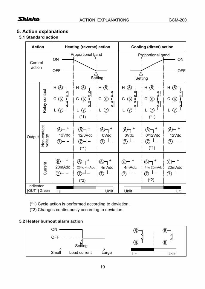
ACTION EXPLANATIONS GCM-200 5. Action explanations 5.1 Standard action
(*1) Cycle action is performed according to deviation. (*2) Changes continuously according to deviation.
5.2 Heater burnout alarm action
Action Heating (reverse) action
Control action
Cooling (direct) action
ON
OFF
Proportional band
Setting
ON
OFF
Proportional band
Setting
Output
Rel
ay c
onta
ctN
on-c
onta
ctvo
ltage
Cur
rent
H
C
L(*1)
H
C
L
H
C
L
H
C
L
H
C
L
H
C
L(*1)
12Vdc
+
12/0Vdc
+
0Vdc
+
0Vdc
+
0/12Vdc
+
12Vdc
+
(*1)(*1)
20mAdc
+
20 to 4mAdc
+
4mAdc
+
4mAdc
+4 to 20mAdc
+
20mAdc
+
(*2)(*2)
[OUT1] GreenIndicator
Lit Unlit LitUnlit
6
5
7
6
5
7
6
5
7
6
5
7
6
5
7
6
5
7
6
7
6
7
6
7
6
7
6
7
6
7
6
7
6
7
6
7
6
7
6
7
6
7
ON
OFF
Setting
Small LargeLoad current UnlitLit
8
9
8
9
20
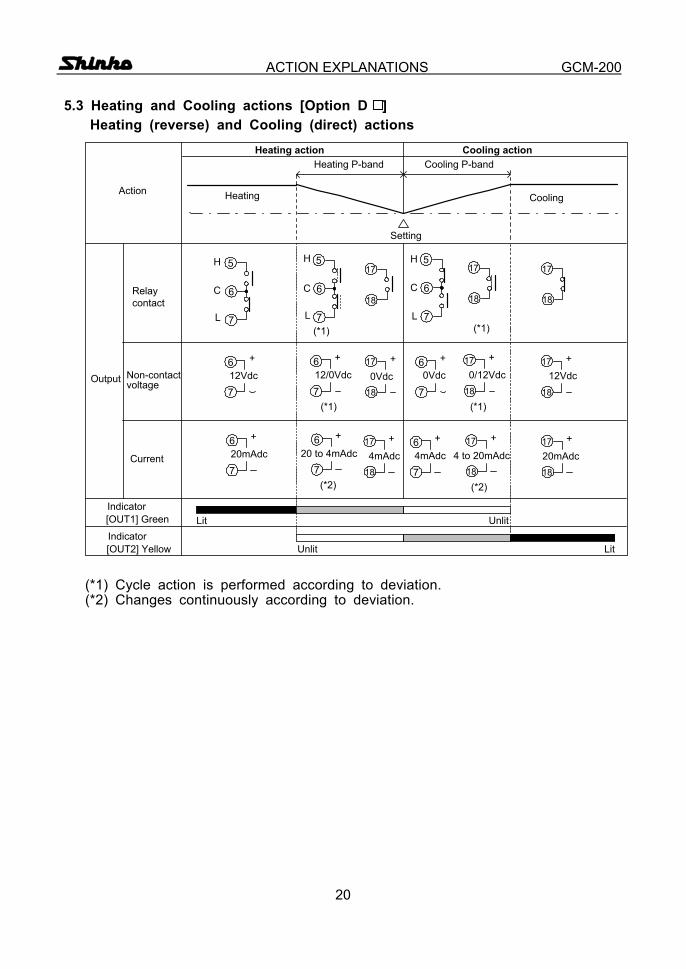
ACTION EXPLANATIONS GCM-200 5.3 Heating and Cooling actions [Option D ]
Heating (reverse) and Cooling (direct) actions
(*1) Cycle action is performed according to deviation. (*2) Changes continuously according to deviation.
Action
Relaycontact
Non-contactvoltage
Current
[OUT1] GreenIndicator
Lit Unlit
Heating
Heating P-band
Output
Heating action Cooling actionCooling P-band
[OUT2] YellowIndicator
LitUnlit
Setting
Cooling
6
5
7
H
C
L
17
18
6
70Vdc
+
0Vdc
+17
18
4mAdc
+17
18
6
74mAdc
+
6
5
7
H
C
L(*1)
6
5
7
H
C
L
6
712/0Vdc
+
(*1)
6
712Vdc
+
(*2)
6
720 to 4mAdc
+6
720mAdc
+
(*1)
17
18
17
18
0/12Vdc
+
(*1)
17
1812Vdc
+17
18
(*2)
4 to 20mAdc
+17
1820mAdc
+17
18
21
ACTION EXPLANATIONS GCM-200
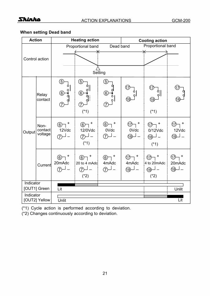
When setting Dead band
(*1) Cycle action is performed according to deviation. (*2) Changes continuously according to deviation.
Action Heating action
Control action
Cooling actionProportional band
Setting
Output
Relaycontact
Non-contactvoltage
Current
6
5
7(*1)
6
5
7
6
5
7(*1)
6
712Vdc
+ 6
712/0Vdc
+
0Vdc
+
0Vdc
+
0/12Vdc
+12Vdc
+
(*1)(*1)
6
720mAdc
+ 6
720 to 4 mAdc
+ 6
74mAdc
+
4mAdc
+
4 to 20mAdc
+
20mAdc
+
(*2)(*2)
[OUT1] GreenIndicator
Lit Unlit
Dead band Proportional band
[OUT2] Yellow Unlit LitIndicator
18
17
18
17
18
17
6
7
18
17
18
17
18
17
18
17
18
17
18
17
22
ACTION EXPLANATIONS GCM-200
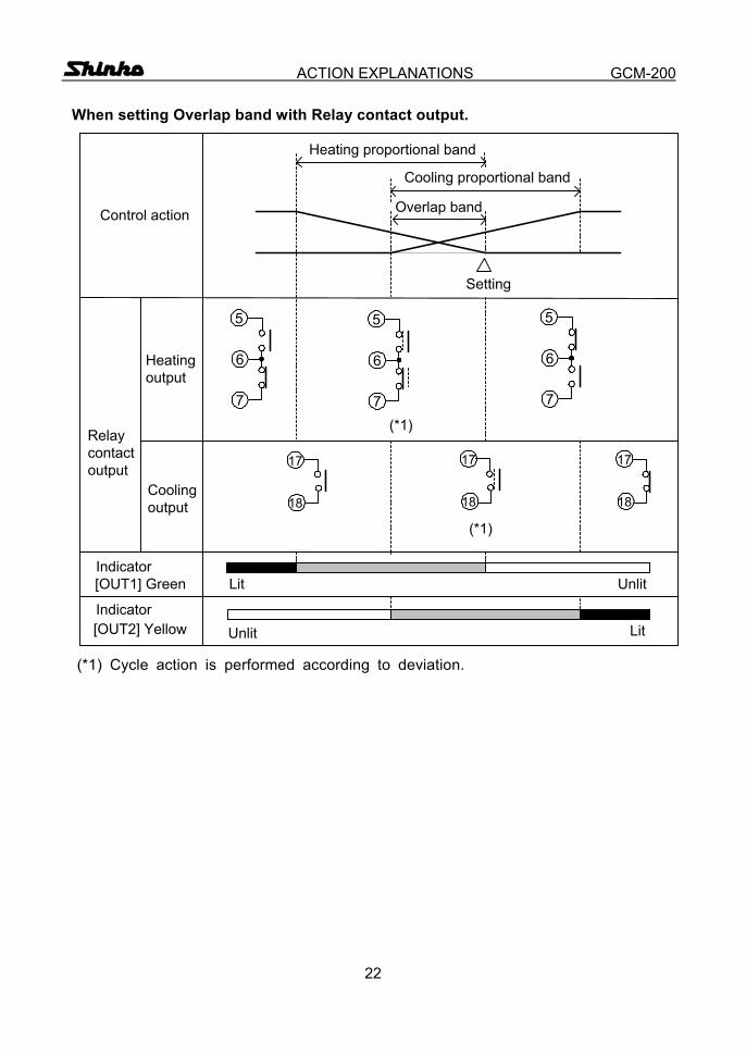
When setting Overlap band with Relay contact output.
(*1) Cycle action is performed according to deviation.
Control action
Setting
Relaycontactoutput
6
5
7(*1)
6
5
7
6
5
7
(*1)
[OUT1] GreenIndicator
Lit Unlit
Overlap band
Cooling proportional band
18
17
[OUT2] Yellow Unlit LitIndicator
Heatingoutput
Coolingoutput
Heating proportional band
18
17
18
17
23
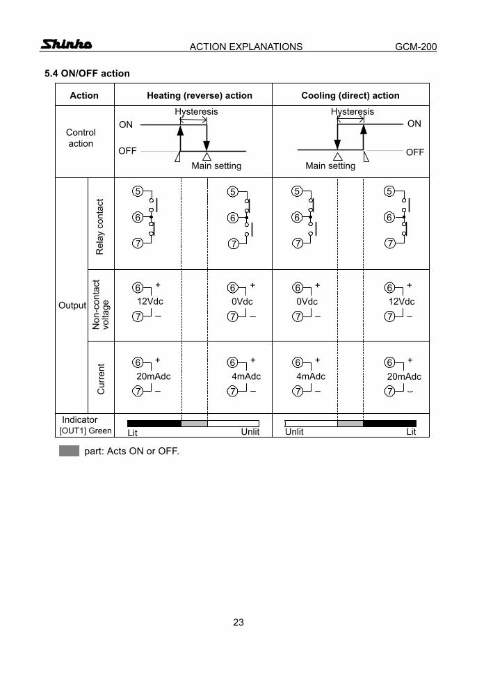
ACTION EXPLANATIONS GCM-200 5.4 ON/OFF action
part: Acts ON or OFF.
Action Heating (reverse) action
Control action
Cooling (direct) action
ON
OFF
Hysteresis
Main setting
Output
Rel
ay c
onta
ctN
on-c
onta
ctvo
ltage
Cur
rent
12Vdc
+
0Vdc
+
0Vdc
+
12Vdc
+
20mAdc
+
4mAdc
+
4mAdc
+
20mAdc
+
[OUT1] GreenIndicator
Lit Unlit LitUnlit
ON
OFFMain setting
Hysteresis
6
5
6
5
77
6
5
7
6
5
7
6
7
6
7
6
7
6
7
6
7
6
7
6
7
6
7
24
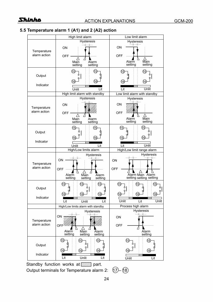
ACTION EXPLANATIONS GCM-200 5.5 Temperature alarm 1 (A1) and 2 (A2) action
Standby function works at part. Output terminals for Temperature alarm 2: 17 – 18
������
������
Temperaturealarm action
LitUnlit
Output
Indicator
High limit alarm Low limit alarmHysteresis
ON
OFF
Mainsetting
Alarmsetting
ON
OFF
Mainsetting
Alarmsetting
Hysteresis
Lit Unlit
Temperaturealarm action
LitUnlit
Output
Indicator
High limit alarm with standby Low limit alarm with standbyHysteresis
ON
OFF
Mainsetting
Alarmsetting
ON
OFF
Mainsetting
Alarmsetting
Hysteresis
Lit Unlit
Temperaturealarm action
Output
Indicator
High/Low limits alarm High/Low limit range alarm
Alarmsetting
Hysteresis
LitUnlit
ON
OFF
Mainsetting
Alarmsetting
Hysteresis
ON
OFF
Mainsetting
Alarmsetting
Alarmsetting
UnlitLit Unlit Lit
15
16
15
16
15
16
15
16
15
16
15
16
15
16
15
16
15
16
15
16
15
16
15
16
15
16
15
16
����
����Temperature
alarm action
Output
Indicator
High/Low limits alarm with standby
ON
OFF
Mainsetting
Alarmsetting
Hysteresis
Alarmsetting
Lit Unlit Lit LitUnlit
Process high alarmHysteresis
ON
OFF
Alarmsetting
15
16
15
16
15
16
15
16
15
16
25
CONTROL ACTIONS GCM-200 6. Control actions 6.1 Explanations of PID (1) Proportional band (P)
Proportional action is the action which the control output varies in proportion to the deviation between the setting value and the processing temperature.
If the proportional band is narrowed, even if the output changes by a slight variation of the processing temperature, better control results can be obtained
as the offset decreases. However, if when the proportional band is narrowed too much, even slight disturbances may cause variation in the processing temperature, and control
action changes to ON/OFF action and the so called hunting phenomenon occurs. Therefore, when the processing temperature comes to a balanced position
near the setting value and a constant temperature is maintained, the most suitable value is selected by gradually narrowing the proportional band while observing the control results. (2) Integral time (I)
Integral action is used to eliminate offset. When the integral time is shortened, the returning speed to the setting point is quickened. However, the cycle
of oscillation is also quickened and the control becomes unstable.
(3) Derivative time (D) Derivative action is used to restore the change in the processing temperature
according to the rate of change. It reduces the amplitude of overshoot and undershoot width.
If the derivative time is shortened, restoring value becomes small, and if the derivative time is made longer, an excessive returning phenomenon may
occur and the control system may be oscillated.
26
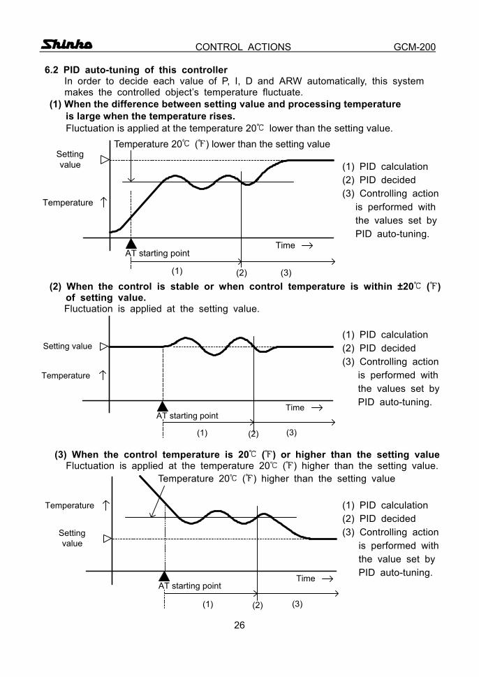
CONTROL ACTIONS GCM-200 6.2 PID auto-tuning of this controller In order to decide each value of P, I, D and ARW automatically, this system
makes the controlled object’s temperature fluctuate. (1) When the difference between setting value and processing temperature
is large when the temperature rises. Fluctuation is applied at the temperature 20 lower than the setting value.
(1) PID calculation (2) PID decided (3) Controlling action is performed with the values set by PID auto-tuning. (2) When the control is stable or when control temperature is within ±20 ( )
of setting value. Fluctuation is applied at the setting value.
(1) PID calculation (2) PID decided (3) Controlling action is performed with the values set by PID auto-tuning.
(3) When the control temperature is 20 ( ) or higher than the setting value Fluctuation is applied at the temperature 20 ( ) higher than the setting value. Temperature 20 ( ) higher than the setting value (1) PID calculation (2) PID decided (3) Controlling action is performed with the value set by PID auto-tuning.
Temperature 20 ( ) lower than the setting value
(1) (2) (3)
AT starting point
Settingvalue
Temperature
Time
AT starting point
(1) (2) (3)
Temperature
Setting value
Time
AT starting point
(1) (2) (3)
Temperature
Settingvalue
Time
27
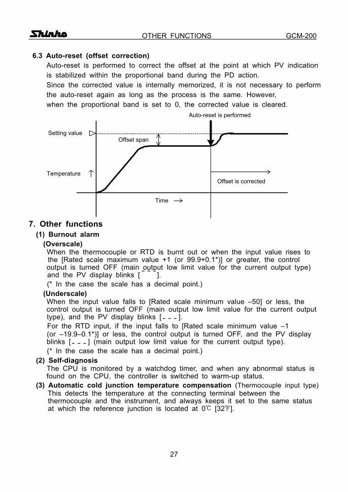
OTHER FUNCTIONS GCM-200 6.3 Auto-reset (offset correction)
Auto-reset is performed to correct the offset at the point at which PV indication is stabilized within the proportional band during the PD action. Since the corrected value is internally memorized, it is not necessary to perform the auto-reset again as long as the process is the same. However, when the proportional band is set to 0, the corrected value is cleared.
7. Other functions (1) Burnout alarm
(Overscale) When the thermocouple or RTD is burnt out or when the input value rises to
the [Rated scale maximum value +1 (or 99.9+0.1*)] or greater, the control output is turned OFF (main output low limit value for the current output type)
and the PV display blinks [ ]. (* In the case the scale has a decimal point.)
(Underscale) When the input value falls to [Rated scale minimum value –50] or less, the control output is turned OFF (main output low limit value for the current output type), and the PV display blinks [ ].
For the RTD input, if the input falls to [Rated scale minimum value –1 (or –19.9–0.1*)] or less, the control output is turned OFF, and the PV display blinks [ ] (main output low limit value for the current output type).
(* In the case the scale has a decimal point.) (2) Self-diagnosis The CPU is monitored by a watchdog timer, and when any abnormal status is
found on the CPU, the controller is switched to warm-up status. (3) Automatic cold junction temperature compensation (Thermocouple input type)
This detects the temperature at the connecting terminal between the thermocouple and the instrument, and always keeps it set to the same status at which the reference junction is located at 0 [32 ].
Temperature
Setting valueOffset span
Time
Offset is corrected
Auto-reset is performed
28
MOUNTING TO CONTROL PANEL GCM-200 8. Mounting to control panel 8.1 Site selection This instrument is intended to be used under the following environmental conditions (IEC61010-1): Overvoltage category , Pollution degree 2 Mount the controller in a place with:
(1) A minimum of dust, and an absence of corrosive gases (2) No flammable, explosive gasses
(3) No mechanical vibrations or shocks (4) No exposure to direct sunlight, an ambient temperature of 0 to 50 (32 to 122 ) that does not change suddenly (5) An ambient non-condensing humidity of 35 to 85%RH (6) The controller away from large capacity electromagnetic switches or cables through which large current is flowing
(7) No water, oil or chemicals or where the vapors of these substances can come into direct contact with the controller
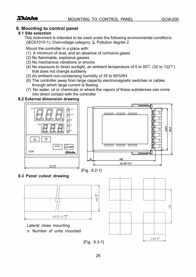
8.2 External dimension drawing [Fig. 8.2-1] 8.3 Panel cutout drawing
Lateral close mounting n: Number of units mounted
[Fig. 8.3-1]
PV
SV
OUT2
HB
A1
OUT
OFFMODE
GCM
AT
OUT1
A2
29
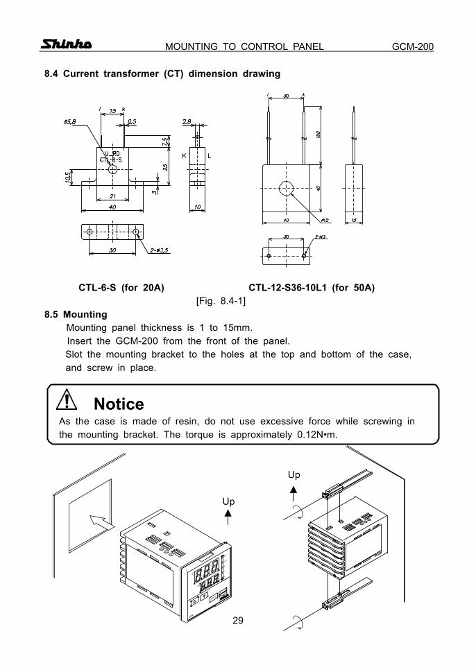
MOUNTING TO CONTROL PANEL GCM-200 8.4 Current transformer (CT) dimension drawing CTL-6-S (for 20A) CTL-12-S36-10L1 (for 50A) [Fig. 8.4-1] 8.5 Mounting
Mounting panel thickness is 1 to 15mm. Insert the GCM-200 from the front of the panel.
Slot the mounting bracket to the holes at the top and bottom of the case, and screw in place.
Notice As the case is made of resin, do not use excessive force while screwing in the mounting bracket. The torque is approximately 0.12N•m.
Up Up
A2
OUT1
AT
GCM
MODE
OFF
OUT
A1
HB
OUT2
SV
PV
30
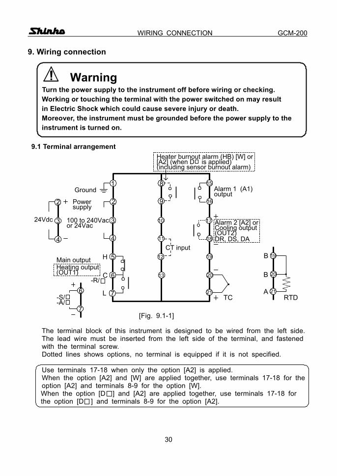
WIRING CONNECTION GCM-200 9. Wiring connection
Warning Turn the power supply to the instrument off before wiring or checking. Working or touching the terminal with the power switched on may result
in Electric Shock which could cause severe injury or death. Moreover, the instrument must be grounded before the power supply to the instrument is turned on. 9.1 Terminal arrangement
[Fig. 9.1-1]
The terminal block of this instrument is designed to be wired from the left side. The lead wire must be inserted from the left side of the terminal, and fastened with the terminal screw. Dotted lines shows options, no terminal is equipped if it is not specified.
Use terminals 17-18 when only the option [A2] is applied. When the option [A2] and [W] are applied together, use terminals 17-18 for the option [A2] and terminals 8-9 for the option [W]. When the option [D ] and [A2] are applied together, use terminals 17-18 for the option [D ] and terminals 8-9 for the option [A2].
RTD
100 to 240Vacor 24Vac
・
CT input
1
2
3
4
5 12
13
15
9
10
6
7
2
3
4
24Vdc
8Alarm 1 (A1)output
1811
17
19
20
21
16
TC
Alarm 2 [A2] orCooling output(OUT2)DR, DS, DA
19
20
21
B
B
A
H
C
L
・
6
7
Ground
Powersupply
-S/-A/
Main output
-R/
Heating output(OUT1)
Heater burnout alarm (HB) [W] or[A2] (when D is applied)(including sensor burnout alarm)
31
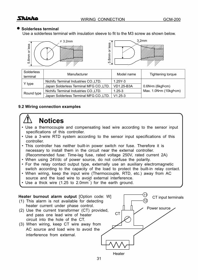
WIRING CONNECTION GCM-200 n Solderless terminal Use a solderless terminal with insulation sleeve to fit to the M3 screw as shown below.
Solderless terminal Manufacturer Model name Tightening torque
Nichifu Terminal Industries CO.,LTD. 1.25Y-3 Y type Japan Solderless Terminal MFG CO.,LTD. VD1.25-B3A Nichifu Terminal Industries CO.,LTD. 1.25-3 Round type Japan Solderless Terminal MFG CO.,LTD. V1.25-3
0.6N•m (6kgf•cm) Max. 1.0N•m (10kgf•cm)
9.2 Wiring connection examples
Notices • Use a thermocouple and compensating lead wire according to the sensor input
specifications of this controller. • Use a 3-wire RTD system according to the sensor input specifications of this
controller. • This controller has neither built-in power switch nor fuse. Therefore it is
necessary to install them in the circuit near the external controller. (Recommended fuse: Time-lag fuse, rated voltage 250V, rated current 2A)
• When using 24Vdc of power source, do not confuse the polarity. • For the relay contact output type, externally use an auxiliary electromagnetic
switch according to the capacity of the load to protect the built-in relay contact. • When wiring, keep the input wire (Thermocouple, RTD, etc.) away from AC
source and the load wire to avoid external interference. • Use a thick wire (1.25 to 2.0mm
2
) for the earth ground. Heater burnout alarm output [Option code: W]
(1) This alarm is not available for detecting heater current under phase control.
(2) Use the current transformer (CT) provided, and pass one lead wire of heater circuit into the hole of the CT.
(3) When wiring, keep CT wire away from AC source and load wire to avoid the interference from external.
������������
3.2mm
5.8m
m o
r les
s
������������
3.2mm
5.8m
m o
r les
s
CT input terminals
Power sourceCT
Heater
11
12
32
WIRING CONNECTION GCM-200
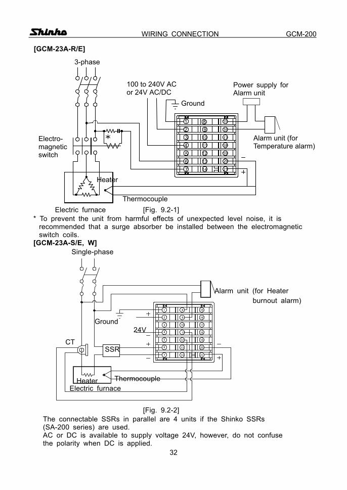
[GCM-23A-R/E]
Electric furnace [Fig. 9.2-1] * To prevent the unit from harmful effects of unexpected level noise, it is
recommended that a surge absorber be installed between the electromagnetic switch coils.
[GCM-23A-S/E, W] Single-phase Alarm unit (for Heater burnout alarm) 24V SSR Thermocouple Electric furnace
[Fig. 9.2-2] The connectable SSRs in parallel are 4 units if the Shinko SSRs (SA-200 series) are used. AC or DC is available to supply voltage 24V, however, do not confuse the polarity when DC is applied.
1 8 15
2
3
4
5
6
7
9
10
11
12
13
14
16
17
18
19
20
21
Ground
CT
Heater
1234567
89
10
11
12
13
14
15
16
17
18
19
20
21
3-phase
Ground
Electro- magnetic switch
Thermocouple
Heater
Power supply for Alarm unit
Alarm unit (for Temperature alarm)
100 to 240V AC or 24V AC/DC

33
SPECIFICATIONS GCM-200 10. Specifications 10.1 Standard specifications
Mounting method : Flush Setting : Input system using membrane sheet key Display
PV display : Red LED display 3 digits, size 8(W) x 14.3(H)mm SV display : Green LED display 3 digits, size 5.5(W) x 10(H)mm
Accuracy (Indication and setting): Within 0.3% of maximum scale range 1digit, or
within 2 (4 ), whichever is greater Input sampling period : 0.25 seconds
(When the option [W] is applied, 0.5 seconds) Input
Thermocouple : K, J or E External resistance, 100 or less
RTD : Pt100, JPt100, 3-wire system Allowable input lead wire resistance, 10 or less per wire
Control output Relay contact : 1a1b Control capacity, 250Vac 3A (resistive load) 250Vac 1A (inductive load cosø=0.4) Non-contact voltage : For SSR drive 12+2
0Vdc maximum 40mAdc (short circuit protected) Current : 4 to 20mAdc Load resistance, maximum 550
Temperature alarm 1 (A1) output Action : ON/OFF action
Hysteresis setting range: 0.1 to 99.9 ( ) Output : Relay contact 1a Control capacity, 250Vac 3A (resistive load) 250Vac 1A (inductive load cosø =0.4)
Controlling action PID action (with auto-tuning function) Proportional band (P) : 0 to 999 ( ) (ON/OFF action when set to 0) 0.0 to 99.9 (ON/OFF action when set to 0.0)
Integral time (I) : 0 to 999s (PD action when set to 0) Derivative time (D) : 0 to 300s (PI action when set to 0)
Proportional cycle : 1 to 120s
34
SPECIFICATIONS GCM-200 PD action (with auto-reset function) Proportional band (P): 0 to 999 ( ) (ON/OFF action when set to 0) 0.0 to 99.9 (ON/OFF action when set to 0.0) Derivative time (D): 0 to 300s (P action when set to 0) Proportional cycle : 1 to 120s
ON/OFF action : Hysteresis, 0.1 to 99.9 ( ) Supply voltage : 100 to 240Vac 50/60Hz, 24Vac/dc 50/60Hz Allowable voltage fluctuation 100 to 240Vac : 85 to 264Vac 24Vac/dc : 20 to 28Vac/dc
Ambient temperature : 0 to 50 (32 to 122 ) Ambient humidity : 35 to 85%RH (non-condensing) Power consumption : Approx. 8VA Insulation resistance : 10M or greater at 500Vdc
(When the type of main output or cooling output is current or non-contact voltage output, insulation test must not be carried out between output terminal and input terminal or between output terminal and CT input terminal.)
Dielectric strength Between input terminal and ground terminal, 1.5kVac for 1 minute Between input terminal and power terminal, 1.5kVac for 1 minute Between power terminal and ground terminal, 1.5kVac for 1 minute Between output terminal and ground terminal, 1.5kVac for 1 minute Between output terminal and power terminal, 1.5kVac for 1 minute
Weight : Approx. 250g External dimension : 72 x 72 x 100mm (W x H x D) Material : Base and Case, Flame resistant resin Color : Base and Case, Light gray Attached functions : Control output OFF function
Setting value lock function Setting value limiting function Sensor correction function Power failure countermeasure Self-diagnosis function Automatic cold junction temperature compensating function Sensor burnout function [overscale, underscale]
Accessories : Mounting bracket 1 set Instruction manual 1 copy Current transformer 1 piece (CTL-6-S) [When the option W (20A) is applied.] (CTL-12-S36-10L1) [When the option W (50A) is applied.] Terminal cover 1 piece [When the option TC is applied.]
35
SPECIFICATIONS GCM-200
10.2 Optional specifications Temperature alarm 2 (A2) output [Option code: A2]
The alarm action point is set by deviation to main setting (except Process value alarm). When the input exceeds the range, the output turns ON or OFF(in the case of High/Low limit range alarm). Setting accuracy : Within 0.3% of maximum scale range 1digit, or within 2 (4 ), whichever is greater Action : ON/OFF action, Hysteresis, 0.1 to 99.9 ( ) Output : Relay contact 1a
Control capacity, 250Vac 3A (resistive load) 250Vac 1A (inductive load cosø=0.4)
Heater burnout alarm output (Including sensor burnout alarm)[option code: W] Watches the heater current with CT (current transformer), and detects the burnout. (This option cannot be applied to the current output type.)
When the option [W] is applied, the input sampling period is 0.5 seconds. Rating : 20A [Option W (20A)] or
50A [Option W (50A)], Must be specified Setting accuracy : 5%
Action point : Setting value Action : ON/OFF action Output : Relay contact 1a (No self-holding) Control capacity, 250Vac 3A (resistive load)
250Vac 1A (inductive load, cosø=0.4) Heating/Cooling control output [option code: D ]
The specifications of heating side are the same as those of the Main output. Cooling side proportional band: Multiplying factor to the heating side proportional
band is 0.0 to 10.0. (ON/OFF action when setting the value to 0.0.)
Cooling side proportional cycle: 1 to 120s Overlap/Dead band setting range: (0 to 100%) of the Heating proportional band Output [DR] Relay contact 1a
Control capacity, 250Vac 3A (resistive load) 250Vac 1A (inductive load cosø=0.4) [DS] Non-contact voltage (for SSR drive) 12 +2
0 Vdc maximum 40mAdc (short circuit protected) [DA] Current 4 to 20mAdc Load resistance: Maximum 550
Cooling action mode selection function: Key selectable, Air cooling (Linear characteristic), Oil cooling (1.5th power of the linear characteristic) or Water cooling (2nd power of the linear characteristic).
36
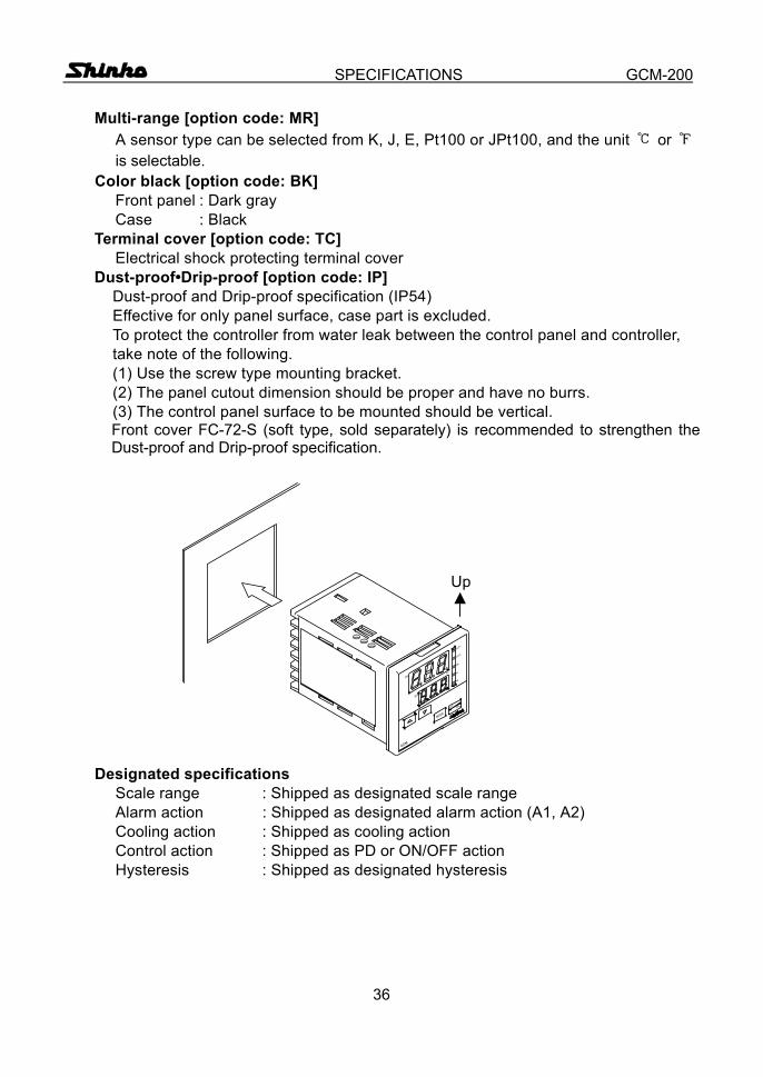
SPECIFICATIONS GCM-200 Multi-range [option code: MR] A sensor type can be selected from K, J, E, Pt100 or JPt100, and the unit or is selectable.
Color black [option code: BK] Front panel : Dark gray Case : Black
Terminal cover [option code: TC] Electrical shock protecting terminal cover
Dust-proof•Drip-proof [option code: IP] Dust-proof and Drip-proof specification (IP54) Effective for only panel surface, case part is excluded. To protect the controller from water leak between the control panel and controller, take note of the following. (1) Use the screw type mounting bracket. (2) The panel cutout dimension should be proper and have no burrs. (3) The control panel surface to be mounted should be vertical.
Front cover FC-72-S (soft type, sold separately) is recommended to strengthen the Dust-proof and Drip-proof specification.
Up
Designated specifications Scale range : Shipped as designated scale range Alarm action : Shipped as designated alarm action (A1, A2) Cooling action : Shipped as cooling action Control action : Shipped as PD or ON/OFF action Hysteresis : Shipped as designated hysteresis
A2
OUT1
AT
GCM
MODE
OFF
OUT
A1
HB
OUT2
SV
PV
37
TROUBLESHOOTING GCM-200
11. Troubleshooting If any malfunctions occur, refer to the following items after checking the
power and the wiring.
Warning Turn the power supply to the instrument off before wiring or checking. Working or touching the terminal with the power switched on may result in an Electric Shock which could cause severe injury or death. <Indication>
Phenomena Presumed cause and solution If the PV display is indicating [ ].
• Control output OFF function is working. Press the key for approx. 1s to release the function. (page 17)
If [ ] is blinking on the PV display.
• Thermocouple or RTD is burnt out. [In the case of Thermocouple]
If the input terminal of the instrument is shorted, and if nearby room temperature is indicated, the instrument should be normal and the sensor may be burnt out.
[In the case of RTD] If approx. 100 of resistance is connected to the input terminal between A-B of the instrument and between B-B is shorted, and if nearby 0 (32 ) is indicated, the instrument should be normal and the sensor may be burnt out.
• Lead wire of thermocouple or RTD is not securely mounted to the instrument terminal.
If [ ] is blinking on the PV display.
• Polarity of thermocouple or compensating lead wire is reversed.
• Codes (A, B, B) of RTD do not agree with the instrument terminal.
If indication of PV display is abnormal or unstable.
• Designation of the Sensor input is improper. Set the Sensor input properly (page 8).
• Temperature unit ( or ) is mistaken. • Sensor correcting value is unsuitable.
Set the value suitably. (page 13) • Specification of the Thermocouple or RTD is improper. • AC may be leaking into thermocouple or the RTD
circuit. • There may be an equipment producing an inductive
fault or noise near the controller.
38
TROUBLESHOOTING GCM-200 <Key operation>
Phenomena Presumed cause and solution If settings are impossible. If the value does not change by the
, keys.
• Setting value lock (mode 1 or 2) is designated. Release the lock designation. (page 13)
• During PID auto-tuning Cancel the tuning if necessary. (page 9)
• During auto-reset (It takes approx. 4 minutes until auto-reset is finished.)
If the setting indication does not change in the rated scale range even if the , keys are pressed, and settings are impossible.
• Main setting value high limit or low limit may be set at the point the value does not change.
Set it again in the Auxiliary function setting mode.
<Control> Phenomena Presumed cause and solution If process variable (temperature) does not rise.
• Thermocouple or RTD is burnt out. [In the case of Thermocouple]
If the input terminal of the instrument is connected, and if nearby room temperature is indicated, the instrument should be normal and sensor may be burnt out.
[In the case of RTD] If approx. 100 of resistance is connected to the input terminals between A-B of the instrument and between B-B is shorted, and if nearby 0 (32 ) is indicated, the instrument should be normal and sensor may be burnt out.
• Lead wire of thermocouple or RTD is not securely mounted to the instrument terminal.
If the main output remains in ON status.
• Main output low limit setting value is set to 100% or greater.
Set the value appropriately. (page 14) If the cooling output remains in ON status.
• Cooling output low limit setting value is set to 100% or greater.
Set the value appropriately. (page 15) If the main output remains in OFF status.
• Main output high limit setting value is set to 0% or less.
Set the value appropriately. (page 14) If the cooling output remains in OFF status.
• Cooling output high limit setting value is set to 0% or less
Set the value appropriately. (page 14) If any unexplained malfunctions occur other than the above mentioned, make inquiries at our agency or the shop where you purchased the unit.
39
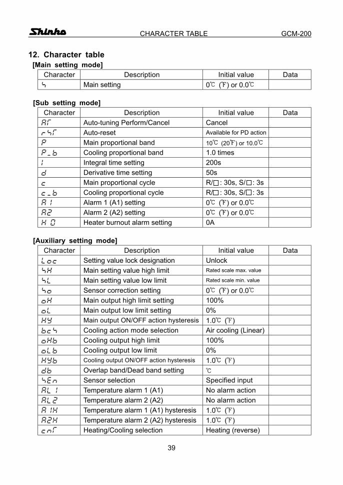
CHARACTER TABLE GCM-200
12. Character table [Main setting mode]
Character Description Initial value Data Main setting 0 ( ) or 0.0
[Sub setting mode]
Character Description Initial value Data Auto-tuning Perform/Cancel Cancel
Auto-reset Available for PD action Main proportional band 10 (20 ) or 10.0
Cooling proportional band 1.0 times Integral time setting 200s Derivative time setting 50s Main proportional cycle R/ : 30s, S/ : 3s
Cooling proportional cycle R/ : 30s, S/ : 3s Alarm 1 (A1) setting 0 ( ) or 0.0 Alarm 2 (A2) setting 0 ( ) or 0.0
Heater burnout alarm setting 0A [Auxiliary setting mode]
Character Description Initial value Data Setting value lock designation Unlock
Main setting value high limit Rated scale max. value Main setting value low limit Rated scale min. value Sensor correction setting 0 ( ) or 0.0 Main output high limit setting 100% Main output low limit setting 0% Main output ON/OFF action hysteresis 1.0 ( )
Cooling action mode selection Air cooling (Linear) Cooling output high limit 100% Cooling output low limit 0% Cooling output ON/OFF action hysteresis 1.0 ( )
Overlap band/Dead band setting Sensor selection Specified input Temperature alarm 1 (A1) No alarm action Temperature alarm 2 (A2) No alarm action Temperature alarm 1 (A1) hysteresis 1.0 ( ) Temperature alarm 2 (A2) hysteresis 1.0 ( ) Heating/Cooling selection Heating (reverse)
40
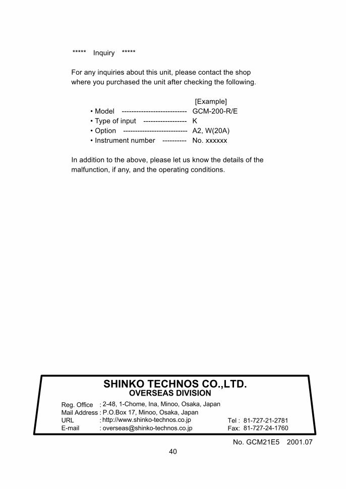
***** Inquiry *****
For any inquiries about this unit, please contact the shop where you purchased the unit after checking the following.
[Example]
• Model --------------------------- GCM-200-R/E • Type of input ------------------ K • Option --------------------------- A2, W(20A) • Instrument number ---------- No. xxxxxx
In addition to the above, please let us know the details of the malfunction, if any, and the operating conditions.
No. GCM21E5 2001.07
SHINKO TECHNOS CO.,LTD.OVERSEAS DIVISION
::::
Reg. OfficeMail AddressURLE-mail
2-48, 1-Chome, Ina, Minoo, Osaka, JapanP.O.Box 17, Minoo, Osaka, Japanhttp://[email protected]
Tel :Fax:
81-727-21-278181-727-24-1760
Related Documents