INSTRUCTION MANUAL SIMRAD GC80/85 DUAL Gyro Compass 20221537D English

GC80-85_Dual_OM_EN_20221537_D_w
Nov 29, 2015
Welcome message from author
This document is posted to help you gain knowledge. Please leave a comment to let me know what you think about it! Share it to your friends and learn new things together.
Transcript

INSTRUCTION MANUAL
SIMRAD GC80/85 DUAL Gyro Compass
20221537D English

Simrad GC80/85 Dual Gyro Compass
ii 20221537 / D
Document revisions Rev Date Written by Checked by Approved by
A 13.02.04 B 15.03.05 C 05.12.05 D 10.05.07
Document history Rev. A First issue.
Rev. B Updated according to new software release (Master compass: V.1.03, Control unit: V.1.04).
Rev. C New procedure for how to adjust true heading, updated dimensions for remote panel, other minor updates to text throughout the manual.
Rev.D Text and illustration updates.

INSTRUCTION MANUAL
20221537 / D iii
About this manual This manual is intended as a reference guide for installing, operating and maintaining Simrad GC80 and GC85 Dual Gyro compasses.
The manual assumes that the operator is a qualified ship officer, or is under supervision of a qualified person.
In this manual, references to buttons on the operator panels are written in boldface, but in a different text style (e.g. SET button, DISP button, GYRO button).
Important text that requires special attention from the reader is emphasized as follows:
Note! Used to draw the reader’s attention to a comment or some important information.
Caution! Used for warning the reader that a risk of damage to the equipment exists if care is not exercised.
WARNING Used when it is necessary to warn personnel that a risk of injury or death exists if care is not exercised.

Simrad GC80/85 Dual Gyro Compass
iv 20221537 / D
This manual is divided in the following sections:
1. System overview An overview of the GC80/GC85 Dual gyro system and it’s components.
2. User interface Overview of GC80 Dual Control unit and the user interface.
3. Operation Main operating procedures for using the GC80/GC85 Dual Gyro compass.
4. Maintenance Simple maintenance procedures that should be performed by the system operator, together with a complete procedure for how to replace the sensitive element and fuses.
5. Installation Mechanical installation, cable connection, and software configuration for the GC80/GC85 Dual gyro system.
6. Advanced settings A description of parameters that can be entered or changed in the Extension menu.
7. Technical specifications Specifications for the system and for all separate units in the GC80/GC85 Dual gyro system.
8. Drawings Outline drawings and wiring diagrams for the GC80/GC85 Dual gyro system.
9. Spare part list List of all standard and optional units that are used in the GC80 and GC85 Dual gyro systems.
10. Terminal layout List of all terminal pins and terminal labelling with details on GTERM and DTERM boards in the GC80 Control unit.
11. Dip switch settings Drawings and references of jumpers and dip switches for the different printed circuits boards in the Dual Control unit.
12. Alarm listing A listing of alarm codes, a short description, and the possible cause for the alarm message.
INSTRUCTION MANUAL
20221537 / D v
Contents
1 SYSTEM OVERVIEW...........................................................1 1.1 Introduction.......................................................................2 1.2 Precaution in use................................................................3 1.3 System components............................................................4 1.4 Bearing repeaters ...............................................................4
2 USER INTERFACE ..............................................................5 2.1 General.............................................................................6 2.2 Master compass control panels .............................................6
POWER button ..............................................................6 Display ........................................................................6 GYRO button ................................................................7 EXT button ...................................................................7 DISP button .................................................................7 SET button ...................................................................7 ACK/ENT button............................................................7 Arrow buttons...............................................................7 Alarm indicator .............................................................7
2.3 Change over panel..............................................................8
3 OPERATION.....................................................................11 3.1 General........................................................................... 12 3.2 System Start-up and Shut-down......................................... 12
Start-Up procedure for each gyro compass ..................... 12 Turning a gyro compass OFF......................................... 14 Starting and stopping the Dual function.......................... 15
3.3 Adjusting display illumination and contrast........................... 16 Display illumination on control panels............................. 16 Display contrast on change over panel ........................... 16 Automatically turning OFF the light in Change over panel.. 17
3.4 Displaying present settings for each compass ....................... 18 Displaying settings with no external sensor connected ...... 18 Displaying settings with external sensor connected .......... 19
3.5 Confirming present settings for each compass ...................... 20 True bearing............................................................... 21 Latitude ..................................................................... 21

Simrad GC80/85 Dual Gyro Compass
vi 20221537 / D
Speed........................................................................ 21 3.6 Pendulum function............................................................ 24 3.7 Selecting active compass ................................................... 25 3.8 Alarm messages............................................................... 26
Alarm messages on the compass control panels............... 26 Alarm messages on the change over panel...................... 27 Acknowledging an alarm .............................................. 27
4 MAINTENANCE ................................................................29 4.1 General........................................................................... 30 4.2 Precautions...................................................................... 30 4.3 Cleaning the operator panels and the cabinet surface ............ 30 4.4 Checking the connectors.................................................... 30 4.5 Checking mechanical installation......................................... 30 4.6 Preventive maintenance intervals........................................ 31 4.7 Replacing the Sensitive element ......................................... 31
Mechanical installation ................................................. 31 Verifying the element’s tilt angle ................................... 35 Parameter updates ...................................................... 36 Balancing the Horizontal ring ........................................ 37
4.8 Replacing the Fuses .......................................................... 38 Master Compass.......................................................... 38 Dual Control unit......................................................... 39
5 INSTALLATION................................................................41 5.1 Unpacking and handling .................................................... 42 5.2 Mechanical installation ...................................................... 42
Control unit ................................................................ 43 Master compass .......................................................... 45
5.3 Cabling ........................................................................... 46 Power supply .............................................................. 47
5.4 Grounding the units .......................................................... 48 5.5 Dip-switch and jumper settings .......................................... 48
Activating the control unit for GC80 or GC85 system ........ 48 Activating an external heading sensor ............................ 50 Activating the pendulum function .................................. 53
5.6 Installing the Sensitive elements ........................................ 54 Verifying the element’s tilt angle ................................... 56

INSTRUCTION MANUAL
20221537 / D vii
5.7 System start-up and software configuration ......................... 58 System Start-up for each gyro compass ......................... 58
5.8 Configuring the dual function ............................................. 64 Setting the heading difference alarm.............................. 65
6 ADVANCED SETTINGS .....................................................67 6.1 General........................................................................... 68 6.2 Using the Extension menu ................................................. 68 6.3 The Extension menu overview ............................................ 69
7 TECHNICAL SPECIFICATION ...........................................75 7.1 Accuracy ......................................................................... 76 7.2 General specification ......................................................... 76 7.3 Input specification ............................................................ 77 7.4 Output specification .......................................................... 78 7.5 Physical Dimensions.......................................................... 79
GC80/GC85 Master Compass ........................................ 79 GC80 Dual Control Unit ................................................ 79
7.6 Power ............................................................................. 80 GC80/GC85 Master Compass ........................................ 80 GC80 Dual Control Unit ................................................ 80
7.7 Environmental Specification ............................................... 80 GC80/GC85 Master Compass ........................................ 80 GC80 Dual Control unit ................................................ 80
8 DRAWINGS .....................................................................81 8.1 Drawings included ............................................................ 82
9 SPARE PART LIST............................................................89 9.1 GC80 Dual Gyro system .................................................... 90 9.2 GC85 Dual Gyro system .................................................... 90 9.3 Optional equipment, GC80/85 Dual system .......................... 91
10 TERMINAL LAYOUT .........................................................93 10.1 GTERM board ................................................................... 94
TB1........................................................................... 94 TB2........................................................................... 96
10.2 DTERM board ................................................................... 98 TB21 ......................................................................... 98
Simrad GC80/85 Dual Gyro Compass
viii 20221537 / D
11 DIP SWITCH SETTINGS.................................................101 11.1 General......................................................................... 102 11.2 GPOWER board 1 and 2 ................................................... 103
Jumper settings on GPOWER boards ............................ 103 11.3 GTERM board ................................................................. 104
Jumper settings on GTERM board ................................ 104 11.4 SCC board 1 and 2 ......................................................... 105
DIP switch settings on SCC boards............................... 105 Jumper settings on SCC board .................................... 107
11.5 SCOIF board .................................................................. 109 DIP switch settings on SCOIF board ............................. 109 Jumper settings on SCOIF board ................................. 110
11.6 PCC board ..................................................................... 118 DIP switch settings on PCC board ................................ 119 Jumper settings on PCC board..................................... 119
12 ALARM LISTING ............................................................121 12.1 The alarm system........................................................... 122 12.2 Fault finding .................................................................. 122
Alarms generated by each gyro compass ...................... 123 Alarms generated by the dual system .......................... 124

SYSTEM OVERVIEW
20221537 / D 1
1 SYSTEM OVERVIEW This section provides an overview of GC80 and GC85 Dual Gyro systems and their components.

Simrad GC80/GC85 Dual Gyro Compass
2 20221537 / D
1.1 Introduction GC80 and GC85 Dual Gyro systems have been designated for any size of vessels which requires more than one gyro system. The system includes one common control unit, from which each gyro system may be operated individually or as one dual system.
A GC80/85 gyro system enhances the navigation capabilities and reliability. It eliminates the inconvenience and limitations of magnetic compasses, and provides a variety of electrical outputs to supply accurate and consistent heading information to other navigational equipment.
- A GC80 Dual gyro system is designed for vessels with speed up to 30 knots. The system complies with IMO A.424 (11) and Wheel Mark Specifications.
- A GC85 Dual gyro system is suitable for high speed vessels with speed up to 70 knots. It complies with IMO A.821 (19) HSC.
GC80 standard and GC85 High Speed Dual gyro systems have different sensitive elements, but use identical GC80 Dual control unit. The systems are identified with divergent dip switch settings in Master compass and in the control unit.
Note! A GC80 or GC85 system is identified by the labelling on top of the Master compass’ case as shown on the figure below. The labelling on the control unit is identical for both gyro systems.
pfjo^a=d`UR
_lt

SYSTEM OVERVIEW
20221537 / D 3
1.2 Precaution in use The GC80/GC85 Dual Gyro system displays and outputs bearing information. Although the system continually checks for faults while the system is running, failures or malfunctions may occur.
Any errors in input information will generate an alarm. These errors may also cause large jumps in the output bearing from the gyro compass. If this happens, any external equipment depending on the bearing output from GC80/GC85 should be operated manually or switched to other bearing sensors.
To assure long time safe operation, the following precautions should be taken:
- Assure that the operator is familiar with the use of the gyro compass
- Perform daily check to maintain normal system operation. Refer MAINTENANCE, page 29 onwards
- If any unusual behavior is observed during daily inspection, the cause should be found and corrected. If necessary, the local Simrad dealer should be contacted
- If any alarm is generated, verify the reason for the alarm

Simrad GC80/GC85 Dual Gyro Compass
4 20221537 / D
1.3 System components A GC80/GC85 Dual Gyro system includes the following units:
- Master Compass 1 & 2 with Sensitive Elements
- Dual Control unit
Note! For details, refer TECHNICAL SPECIFICATION, page 75.
1.4 Bearing repeaters GC80 and GC85 outputs step and serial signals used for repeaters. Even when the gyro compasses are supplied by the emergency power supply, the connected repeaters will be driven by the repeater backup function included in GC80/GC85.
The following serial signal may be selected: Lo speed: IEC61162-1 ed.2, close in comparison with
NMEA0183 version 2.30 (4800 baud) High speed: IEC61162-2, based upon NMEA0183 version
2.30 (4800 and 38400 baud possible)
Note! A proprietary Tokimec serial signal may also be available, but this is normally not used.
These signals may be set separately for each circuit.
For connection of repeaters, refer to wiring diagrams, page Error! Bookmark not defined. onwards.
DUAL CONTROL
UNIT
MASTER COMPASS
1 & 2
110/220V AC
EXTERNAL HEADING SENSORGPS
SPEED
24V DC
4 x 24V STEP3 x ROT
ALARM CONTACT
10 x NMEA
2 x NMEA GYRO 2
2 x NMEA GYRO 1
24V DC BACKUP
I/O

USER INTERFACE
20221537 / D 5
2 USER INTERFACE This section gives an overview of the control panels in the GC80 Dual Control unit.

Simrad GC80/GC85 Dual Gyro Compass
6 20221537 / D
2.1 General The Dual Control unit includes 3 control panels: one for each gyro compass, and one change over panel used for displaying and controlling the dual gyro system.
From the Dual control unit each gyro compass may be operated individually, or the system may be operated as one dual system.
2.2 Master compass control panels The control panels for each of the two master compasses are identical. They are used for controlling each master compass individually, and include the buttons described in the following pages.
POWER button
mltbo
Used for switching the gyro system ON. The button will be lit to indicate that power is applied to this gyro compass. Refer System Start-up and Shut-down, page 12.
Display
The LCD displays data in two rows: the upper row shows data and the lower row shows active mode.
- The Data indicator consists of four 7-segments red LEDs. The indicator is used for displaying the vessel’s bearing, latitude and speed. Refer Displaying present settings for each compass, page 18. The Data indicator is also used for displaying alarm codes as described from page 26 onwards.
- The Mode indicator consists of three 7-segments green LEDs. The Mode indicator displays codes used for identifying input type for bearing, latitude and speed.
dvol
afpm pbq
afji^jmqbpq
^i^oj
^`hbkq
buq
afj
i^jm=qbpq
^`hbkq
Change Over Unit
afpm klKN klKO buq
pfjo^a=d`UM
^i^oj
mltbo
dvol
afpm pbq
afji^jmqbpq
^i^oj
^`hbkq
buq
mltbomltbo
pfjo^a=d`UM pfjo^a=d`UM
CONTROL PANEL
FOR MASTER COMPASS 2
CHANGE OVER PANEL
CONTROL PANEL FOR MASTER COMPASS 1

USER INTERFACE
20221537 / D 7
GYRO button
dvol
Used for selecting the gyro compass as the active heading reference source. The status lamp is lit to indicate that the gyro system is active.
Refer Selecting active compass, page 25.
EXT button
buq
Used for selecting the external heading source as the heading reference. The status lamp will be lit to indicate that the external heading reference source is active.
Refer Selecting active compass, page 25.
DISP button
afpm
Used for displaying data on the LCD. Displaying present settings for each compass, page 18.
SET button
pbq
Used for changing data and input sources. Refer System start-up and software configuration, page 58 onwards.
ACK/ENT button
^`hbkq
Used for confirming a change in data and input sources. Refer System start-up and software configuration, page 58 onwards.
The button is also used for acknowledging an alarm as described in Acknowledging an alarm, page 27.
Arrow buttons
afji^jmqbpq
Used for increasing or decreasing a parameter value. Refer System start-up and software configuration, page 58 onwards
Also used for lamp test and for setting the display illumination as described in page 15.
Alarm indicator
^i^oj Used for indicating an alarm situation. Refer Alarm messages, page 26.

Simrad GC80/GC85 Dual Gyro Compass
8 20221537 / D
2.3 Change over panel This panel is used for switching between available compasses, for displaying bearing for the gyro compasses, and alarm information. The panel is also used for setting the alarm difference limit.
The panel includes the buttons described in the following pages.
Power button
mltbo Used for switching the dual control panel ON.
The button is recessed into the front panel, and a pen or a blunt tool must be used for activating the button.
Display
The LCD displays data in 2 rows, where each row has 16 characters available. The figure below shows the display after the start-up procedure is completed.
1-GYRO:142.7° *A 2-GYRO:142.7°
When pressing the DISP button, the display will page through available data and eventually alarm lines as shown below:
DISPLAYED TEXT DESCPRIPTION
1-GYRO:142.7° SA* Heading for gyro number 1.
2-GYRO:142.7° SA* Heading for gyro number 2.
S = Less than 2 hours since the gyro was started
A = For internal use
* = Active gyro
E-SENS:141.9 Heading for external sensor. Only visible when an external sensor is connected.
HDM SET:05.0° Setting for heading difference alarm.
- PARAMETER SET - Used for entering the parameter setup submenu
< ALARMS > Visible if one or more alarms are generated. Refer Alarm messages on the change over panel, page 27.
DISP button
afpm
Used for paging through available data lines on the LCD.

USER INTERFACE
20221537 / D 9
GYRO no.1 and no.2 buttons
klKN klKO
Used for selecting master compass no.1 or no.2 as the active heading reference source.
Active compass source is selected by pressing one of these buttons and the ACK/ENT buttons simultaneously. The status lamp is lit to indicate which master compass that is active.
Refer Selecting active compass, page 25.
EXT button
buq
Used for selecting an external heading source as heading reference. The status lamp will be lit to indicate that the external heading reference source is active.
Refer Selecting active compass, page 25.
ACK/ENT Button
^`hbkq
Used for confirming a selection.
The button is also used for acknowledging an alarm as described in Acknowledging an alarm, page 27.
Arrow Buttons
afj
i^jm=qbpq
Used for increasing or decreasing a parameter value. Refer System start-up and software configuration, page 58 onwards
Also used for lamp test and for setting the display illumination as described in page 15.
Alarm Indicator
^i^oj Used for indicating an alarm situation. Refer Alarm messages, page 26.

Simrad GC80/GC85 Dual Gyro Compass
10 20221537 / D
THIS PAGE INTENTIONALLY LEFT BLANK

OPERATION
20221537 / D 11
3 OPERATION This section describes the main operating procedure used when operating the GC80/GC85 Dual Gyro system.

Simrad GC80/GC85 Dual Gyro Compass
12 20221537 / D
3.1 General In GC80/85 Dual systems, both gyro compasses may be operated individually as single gyro systems. Gyro 1 and gyro 2 is operated by NO.1 panel and NO.2 panel on the Dual control unit.
Note! The start-up procedure and configuration is identical for each gyro, and has to be performed for both gyro compasses before the dual function can be started. The start-up procedure may be performed simultaneously for both compasses.
Caution! Before the gyro compass is turned into normal operation, it has to be configured according to the description in System start-up and software configuration, page 58 onwards.
3.2 System Start-up and Shut-down A GC80/GC85 gyro compass is usually left with power on. If the compass has to be shut down and restarted, the procedures in the following sections should be followed.
Start-Up procedure for each gyro compass
mltbo
Turn ON each gyro compass by pressing the POWER button on the Control panel. The following start-up sequence will be run:
1 Control unit type (GC80 Std, or GC85 HSc), SW version for Control panel and for Master compass is displayed in rapid succession. Examples of display text are shown below:
OR
GC80 CONTROL PANEL
STD VERSION
GC80 CONTROL PANEL
HIGH SPEED VERSION
SW VERSION CONTROL PANEL
SW. VERSION MASTER COMPASS
OPERATION
20221537 / D 13
dvol
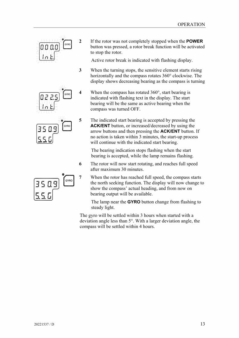
2 If the rotor was not completely stopped when the POWER button was pressed, a rotor break function will be activated to stop the rotor.
Active rotor break is indicated with flashing display.
3 When the turning stops, the sensitive element starts rising
horizontally and the compass rotates 360° clockwise. The display shows decreasing bearing as the compass is turning
dvol
4 When the compass has rotated 360°, start bearing is indicated with flashing text in the display. The start bearing will be the same as active bearing when the compass was turned OFF.
dvol
5 The indicated start bearing is accepted by pressing the ACK/ENT button, or increased/decreased by using the arrow buttons and then pressing the ACK/ENT button. If no action is taken within 3 minutes, the start-up process will continue with the indicated start bearing.
The bearing indication stops flashing when the start bearing is accepted, while the lamp remains flashing.
6 The rotor will now start rotating, and reaches full speed after maximum 30 minutes.
dvol
7 When the rotor has reached full speed, the compass starts the north seeking function. The display will now change to show the compass’ actual heading, and from now on bearing output will be available.
The lamp near the GYRO button change from flashing to steady light.
The gyro will be settled within 3 hours when started with a deviation angle less than 5°. With a larger deviation angle, the compass will be settled within 4 hours.

Simrad GC80/GC85 Dual Gyro Compass
14 20221537 / D
Turning a gyro compass OFF mltbo
1 Press the POWER button on the Control panel for the
master system that is to be turned OFF. The light in the POWER button will be switched off.
dvol
2 Repress the POWER button to activate the rotor break function. The light in the POWER button will be lit again.
Active rotor break is indicated by:
- flashing display
- a soft clicking sound heard from the gyrocompass
The rotor break function will be active for maximum 4 minutes.
Caution! It is very important that the rotor break is activated to stop the rotor rotation to prevent any possible damage by ship’s movement!
mltbo
3 Press the POWER button again to shut down the gyrocompass when both the data and the dot in the display change from flashing to steady light.
The light in the POWER button will now be turned OFF.

OPERATION
20221537 / D 15
Starting and stopping the Dual function
When each gyro compass is started and configured, the dual function may be started.
mltbo 1 Press the POWER button to turn ON the change over
panel.
The button is recessed into the front panel, and a pen or a blunt tool must be used for activating the button.
The display will show product name and software version for PCC and SCOIF boards:
HDM220 P:V1.02 C:V1.02
followed by:
HDM220 by Simrad
and then showing heading for gyro compass no.1 and no.2.
1-GYRO:123.4° A* 2-GYRO:123.4°
2 Verify that heading 1 and heading 2 is in according with the heading displayed on the gyro compass’ control panel.
The dual function is stopped by re-pressing the POWER button.
Simrad GC80/GC85 Dual Gyro Compass
16 20221537 / D
3.3 Adjusting display illumination and contrast
Display illumination on control panels
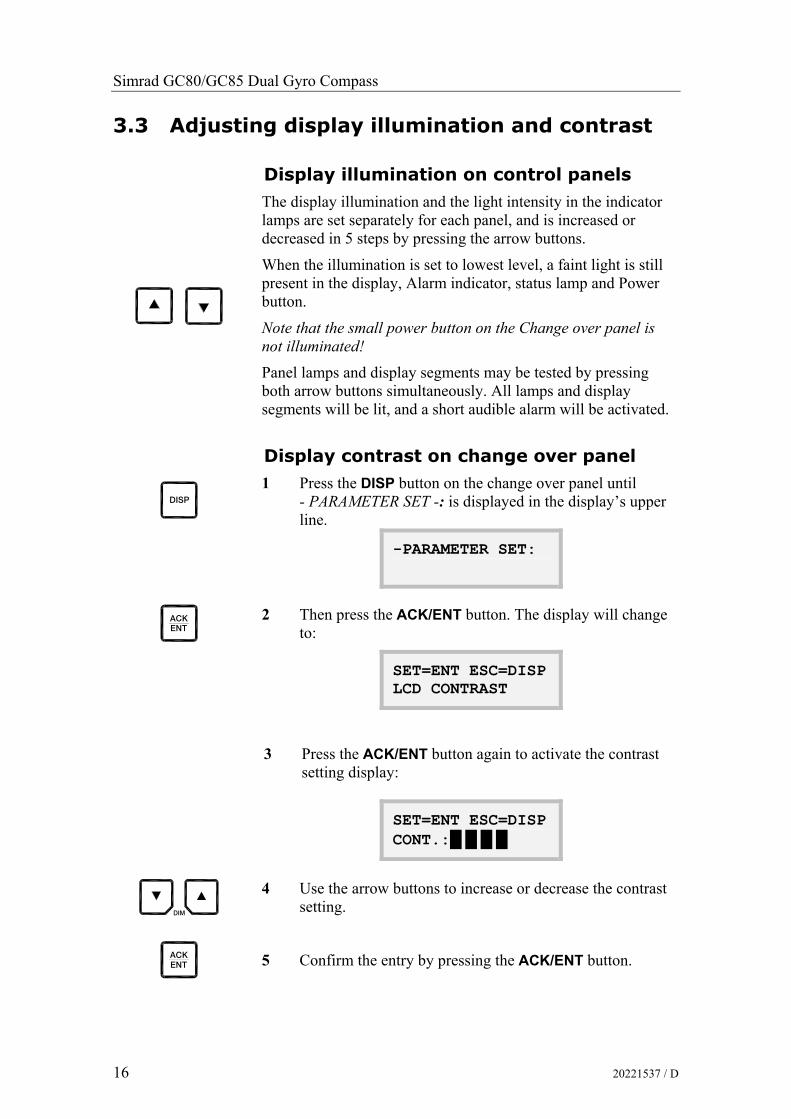
The display illumination and the light intensity in the indicator lamps are set separately for each panel, and is increased or decreased in 5 steps by pressing the arrow buttons.
When the illumination is set to lowest level, a faint light is still present in the display, Alarm indicator, status lamp and Power button.
Note that the small power button on the Change over panel is not illuminated!
Panel lamps and display segments may be tested by pressing both arrow buttons simultaneously. All lamps and display segments will be lit, and a short audible alarm will be activated.
Display contrast on change over panel
afpm
1 Press the DISP button on the change over panel until - PARAMETER SET -: is displayed in the display’s upper line.
-PARAMETER SET:
^`hbkq
2 Then press the ACK/ENT button. The display will change
to:
SET=ENT ESC=DISP LCD CONTRAST
3 Press the ACK/ENT button again to activate the contrast setting display:
SET=ENT ESC=DISP CONT.:█ █ █ █
afj 4 Use the arrow buttons to increase or decrease the contrast
setting.
^`hbkq
5 Confirm the entry by pressing the ACK/ENT button.

OPERATION
20221537 / D 17
Automatically turning OFF the light in Change over panel
The back light in the change over panel may be automatically turned OFF after a set time when it has been used.
afpm
1 Press the DISP button on the change over panel until - PARAMETER SET -: is displayed in the display’s upper line.
-PARAMETER SET:
^`hbkq
2 Press the ACK/ENT button. The display will change to:
SET=ENT ESC=DISP LCD CONTRAST
3 Press the Arrow Up button. The display changes to:
SET=ENT ESC=DISP LIGHT OFF TIME
4 Press the ACK/ENT button again to activate the light setting display:
SET=ENT ESC=DISP TIME: 01.0(min):
afj 5 Use the arrow buttons to increase or decrease the time
setting. Range: 0 – 10 minutes.
If the value is set to 0, the back light is not turned OFF.
^`hbkq
6 Confirm the entry by pressing the ACK/ENT button.

Simrad GC80/GC85 Dual Gyro Compass
18 20221537 / D
3.4 Displaying present settings for each compass
afpm
When pressing the DISP button on the GC80 Control unit, the system will loop through a display sequence showing present settings for the system.
The sequence will be depend on whether an external compass is connected or not. When an external compass is connected, the readout will depend on active compass.
The following sections; Displaying settings with no external sensor connected and Displaying settings with external sensor connected, show examples of how the present settings are presented by pressing the DISP button.
The display will be used as follows:
- The first row in the display will show the value
- The second row displays code used for identification
Displaying settings with no external sensor connected
Display state Display Description
Normal operation dvol
buq
- True output bearing
- Active compass
afpm
1st press on
DISP button
- Gyro compass bearing without correction
- Active speed input source indication (GPS, Manual, Log or Serial Log)
afpm
2nd press on DISP button
- Latitude
- Latitude indication: North (LA.n) or South (LA.s)
afpm
3rd press on DISP button
- Vessel speed
- Speed input indication (GPS, Manual, Log or Serial Log)

OPERATION
20221537 / D 19
Display state Display Description
afpm
4th press on
DISP button
- Rate of turn in °/min
- Rate of turn indication
afpm
5th press on
DISP button
- Error codes (up to 4)
- Error indication
afpm
6th press on
DISP button
Normal operation
dvol
buq
- True output bearing
- Active compass
Displaying settings with external sensor connected
Display state Display Description
Normal operation
dvol
buq
or
dvol
buq
- True output bearing
- Active compass
The compass indication equals the sensor selected as active compass (gyro or external)
afpm
1st press on
DISP button
or
- Bearing
- Passive compass

Simrad GC80/GC85 Dual Gyro Compass
20 20221537 / D
Display state Display Description
afpm
2nd press on DISP button
- Gyro compass bearing without correction
- Active speed input source indication (GPS, Manual, Log or Serial Log)
afpm
3rd press on DISP button
- Latitude
- Latitude indication: North (LA.n) or South (LA.s)
afpm
4th press on
DISP button
- Vessel speed
- Speed input indication (GPS, Manual, Log or Serial Log)
afpm
5th press on
DISP button
- Rate of turn in °/min
- Rate of turn indication
afpm
6th press on
DISP button
- Error codes (up to 4)
- Error indication
afpm
7th press on
DISP button
Normal operation
dvol
buq
or
dvol
buq
- True output bearing
- Active compass
3.5 Confirming present settings for each compass
After the GC80/GC85 is configured according to the System start-up and software configuration, described in page 58 onwards, it should not be necessary to adjust any settings when operating the gyro compass.
However, if an error is reported in any of the input sources, it may be necessary to switch to a different input source.

OPERATION
20221537 / D 21
True bearing
Make sure that the gyro compass is selected as active compass. Refer Selecting active compass, page 25.
dvol
Confirm that the gyro compass’s displayed true bearing is according to a known target or astronomical observation.
If there is any difference, adjust the bearing according to Adjusting True heading, page 63.
Latitude
Press the DISP button until the vessel’s latitude is displayed.
The displayed latitude value is calculated based on the vessel’s true bearing and the vessel’s actual speed. Refer setting the latitude input source and speed input source, page 61 onwards.
- If GPS is selected as latitude input source, the latitude obtained from the GPS is displayed on the LCD. Confirm that the displayed latitude is the same as indicated on the GPS indicator.
- If GYRO (manual setting of latitude) is selected as latitude input source and other than MANUAL selected as the vessel’s speed input source, the latitude will be automatically updated. In this case, the indicated latitude should be confirmed every 4th hour when the vessel is in harbor. If there is any significant difference between the displayed value and the vessel’s actual latitude, the value should be adjusted according to Setting the Latitude input , page 61.
Note! When GYRO is selected as latitude input source and MANUAL is selected as the speed input source, the indicated latitude value will not be updated and hence an error may build up.
Speed
The GC80/GC85 gyro compass calculates bearing based on the speed and latitude information that is input to the gyro as speed source. Any error in speed input will therefore cause incorrect true bearing from the gyro compass.
Press the DISP button until the vessel’s speed information is displayed.
Confirm in 4 hours intervals that the displayed speed is the same as the vessel’s actual speed.
Any discrepancy between displayed speed and actual speed is corrected as described in Setting the Speed input system, page 62.

Simrad GC80/GC85 Dual Gyro Compass
22 20221537 / D
Speed error correction
All gyro compasses will generate a heading error caused by the vessel speed and earth rotation. GC80/GC85 calculates this error based on latitude and speed input information, and corrects automatically the bearing signal output. If no speed information is available, the gyro compass will output a heading error either westwards or eastwards depending on the vessel’s course.
If speed information is unavailable, the figure on next page may be used for manually calculating the heading error.
In this figure, the following values are used as example:
- Latitude: 40°
- Vessel speed: 16 knots
- Vessel heading: 30°
The heading error is found by:
1 Drawing a line between the latitude and the vessel heading (shown with gray line on the figure)
2 Drawing a straight line (broken line in the figure) between the vessel speed and the point where the latitude/heading line intersects with the solid black line in the figure.
In the example above, the figure shows a speed error of appr. 1.1°, and the true bearing should then be 30°-1.1° = 28.9°.
Note! When the course is within 270° - 0° - 90°, true heading is found by subtracting the speed error from the compass heading. If the course is within 90° - 180° - 270°, true heading is found by adding the speed error to compass heading.

OPERATION
20221537 / D 23
VESSEL HEADING (degree) V
ES
SE
L S
PE
ED
(kn
ots
)
30
28
26
24
22
20
18
16
14
12
10
8
6
4
2
0
90 80 70 60 50 40 30 20 10 3.8
3.6
3.4
3.2
3.0
2.8
2.6
2.4
2.2
2.0
1.8
1.6
1.4
1.2
1.0
0.8
0.6
0.4
0.2
0
0
90 -
90
- 27
0 - 2
70
80 -
100
- 260
- 28
0
0 - 1
80 -
190
- 0
70 -
110
- 250
- 29
0
60 -
120
- 240
- 30
0
50 -
130
- 230
- 31
0
40 -
140
- 220
- 32
0
30 -
150
- 210
- 33
020
- 16
0 - 2
00 -
340
10 -
170
- 190
- 35
0
(+)
(+)
( )
( )
SP
EED
ER
RO
R (
deg
rees)
LATITUDE (degrees)

Simrad GC80/GC85 Dual Gyro Compass
24 20221537 / D
3.6 Pendulum function GC80/85 software includes a pendulum function that enables the heading to be changed by 180°.
The heading change is activated by closing a potential free contact connected between TB1, pin 71 and 72 on the GTERM board in GC80/85 control unit.
Note! To enable the function, S2-4 on the SCC boards has to be set to ON. Refer DIP switch settings on SCC boards, page 105 onwards.
When the switch is set to activate the function, the following functions are obtained:
- The compass heading and repeaters change by 180° from the heading
- An acoustic alarm sounds 5 times
- The dots in the indicator field in the display starts flashing. These will remain flashing for as long as the pendulum function is active.
Normal compass operation is resumed by opening the closed potential free contact. The function is indicated by the same acoustic alarm, and the flashing dots returns to fixed illuminated dots.
OPERATION
20221537 / D 25
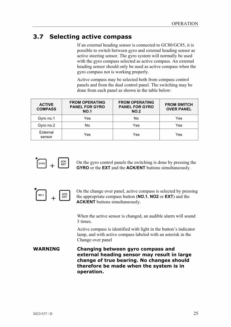
3.7 Selecting active compass If an external heading sensor is connected to GC80/GC85, it is possible to switch between gyro and external heading sensor as active steering sensor. The gyro system will normally be used with the gyro compass selected as active compass. An external heading sensor should only be used as active compass when the gyro compass not is working properly.
Active compass may be selected both from compass control panels and from the dual control panel. The switching may be done from each panel as shown in the table below:
ACTIVE COMPASS
FROM OPERATING PANEL FOR GYRO
NO.1
FROM OPERATING PANEL FOR GYRO
NO.2 FROM SWITCH OVER PANEL
Gyro no.1 Yes No Yes
Gyro no.2 No Yes Yes
External sensor Yes Yes Yes
dvol
+ ^`hbkq
On the gyro control panels the switching is done by pressing the GYRO or the EXT and the ACK/ENT buttons simultaneously.
klKN
+ ^`hbkq
On the change over panel, active compass is selected by pressing the appropriate compass button (NO.1, NO2 or EXT) and the ACK/ENT buttons simultaneously.
When the active sensor is changed, an audible alarm will sound 5 times.
Active compass is identified with light in the button’s indicator lamp, and with active compass labeled with an asterisk in the Change over panel
WARNING Changing between gyro compass and external heading sensor may result in large change of true bearing. No changes should therefore be made when the system is in operation.

Simrad GC80/GC85 Dual Gyro Compass
26 20221537 / D
3.8 Alarm messages Both the dual system at each separate gyro will continually check for faults while the system is running.
If a fault occurs, an alarm code will be displayed in the LCD, the Alarm lamp will be flashing, and an audible alarm will be activated.
Caution! When an alarm is generated, bearing information from the GC80/GC85 may not be present or may have large error. Any equipment using bearing information from the gyro compass should therefore immediately be operated according to the equipment’s emergency operating procedure.
Alarm messages on the compass control panels
Up to 4 alarm codes may be displayed in the LCD to indicate that several alarm situations are present. The last activated alarm will be displayed on the right side of the display. The figure shows that alarm with code 1, 3 and 2 were generated in that order.
^i^oj
If more than 4 alarms are active, this will be indicated with a dot behind the last number as shown on the figure below. Further alarm codes may then be displayed by pressing the “arrow up” button.
The example shows that alarm code 2, 3, U, d and 7 were activated.

OPERATION
20221537 / D 27
Alarm messages on the change over panel
The alarm codes for the dual system will be displayed one at a time in the change over panel’s display. The alarm codes will be displayed after the data lines when the Arrow Down button is pressed, and will only be available as long as the alarm situation is present.
G1 ALARM 01/05 GPS Com Alarm
In the example above, the system received a GPS communication alarm on gyro number 1. The indication shows that this is the first of 5 alarm codes.
Acknowledging an alarm
^`hbkq
An alarm is acknowledged by pressing the ACK/ENT button on the control panel, or on an external acknowledge button if this is installed.
- The audible alarm will be silenced
- If the alarm situation has disappeared, the alarm lamp will be switched off, and the alarm code will be removed from the LCD
- If the alarm situation continues, the alarm lamp will switch from flashing to steady light. The LCD will return to show true bearing with flashing numbers to indicate that the bearing may have large errors
An alarm code for an active error may be recalled by pressing the DISP button until the alarm display is shown. It is possible to recall any alarm code in the LCD for as long as the alarm situation is present.
The ALARM LISTING section, page 121, has a complete list of alarm codes.

Simrad GC80/GC85 Dual Gyro Compass
28 20221537 / D
Buzzer silence only
By installing an external acknowledging switch, it is possible to silence the buzzer while the alarm code remains in the display.
Install the switch to the control unit according to the Wiring diagram on page Error! Bookmark not defined. onwards.
Note! Could only be used if no pendulum switch is installed!

MAINTENANCE
20221537 / D 29
4 MAINTENANCE This section holds descriptions for maintenance procedures that should be performed by the system operator.
The section also includes a detailed description for how to replace the sensitive element and the fuses.

Simrad GC80/GC85 Dual Gyro Compass
30 20221537 / D
4.1 General All units in the GC80 system are designed for optimum safety and reliability. However, a limited amount of preventive maintenance should be performed to verify safe operation and durability.
If any strange motion, smell, sound or heat is generated from any unit, a Simrad dealer shall be contacted.
4.2 Precautions Touching internal parts may cause electric chock if power is connected to the system, even if the POWER button is turned OFF. Do not touch any terminal board or power supply unit when maintaining and checking the system. If necessary, disconnect the power cable from the Control unit.
Electrostatic charges may damage components on the circuit boards inside the units. Always wear a correctly connected earthing strap when opening the units.
4.3 Cleaning the operator panels and the cabinet surface
Use a vacuum cleaner with a soft brush to avoid damage to the buttons and the panel. If required, clean the buttons and panel with a non-abrasive cloth moistened with mild soap solution.
4.4 Checking the connectors The connectors should be checked by visual inspection only. Push the connector plugs into the connector. If the connector plugs are equipped with a lock, ensure that this is in correct position.
4.5 Checking mechanical installation Vibration and chock may cause mechanical parts to loosen. All fastening screws should therefore regularly be checked and eventually tightened.

MAINTENANCE
20221537 / D 31
4.6 Preventive maintenance intervals Local evaluations should be made to determine site-specific maintenance intervals.
ACTION INTERVAL RECOMMENDED
Confirm that the value of each repeater synchronizes with the displayed true bearing on the Operator panel.
Daily
Confirm that the displayed latitude and speed is according to the vessel’s actual latitude and speed.
Daily
Check connectors Every six month
Tighten fastening screws Every six month
Clean panels and cabinet Once a year or as required
Clean slip rings and brushes. Apply lightly “27102128 gyro slip ring lubrication oil”.
Every second year
4.7 Replacing the Sensitive element
Caution! The Sensitive element should only be replaced by authorized Simrad personnel.
Note! A special tool (Simrad part no. 44174449) is required when installing the Sensitive element. This tool is delivered together with the gyro, and the sensitive element should not be installed without using this tool.
Mechanical installation
Caution! Use extreme caution when handling the Sensitive element! Do not tilt the element. It is filled with oil and the top includes a ventilation opening.
1. Ensure that the power is disconnected from the Control unit.
2. Remove the four screws securing the compass case, and lift the case carefully upwards and away.
3. Loosen the screw on the plug-holder on the Sensitive element, and disconnect the plug.

Simrad GC80/GC85 Dual Gyro Compass
32 20221537 / D
4. Remove the four screws securing the Sensitive element. Tilt the Horizontal ring to the side where the plug is located, and carefully remove the element from the compass.
5. Place the defective Sensitive element in its original package, and put the rubber tube on top of the element.
6. Fasten the screw on the plug holder on the defective Sensitive element.
7. Lift the new element carefully from its package, and remove the rubber tube on top of the element.
Note! The package and the rubber tube should be kept for re-use if the Sensitive element has to be sent to factory for service!
8. Tilt the Horizontal ring to the side where the plug is located, and carefully put the sensitive element into the ring.
- The socket on the Sensitive element should be located right above the plug attached to the Horizontal ring.

MAINTENANCE
20221537 / D 33
9. Position the Sensitive element on the Horizontal ring by putting the assembly jigs into the holes as indicated on the figure below. Observe the rings on the jigs to ensure proper positioning. Insert and fasten the two screws in the other holes.
ASSEMBLY JIG WITH 1 CIRCLE
ASSEMBLY JIG WITH 2 CIRCLES

Simrad GC80/GC85 Dual Gyro Compass
34 20221537 / D
10. Replace the assembly jigs with the two remaining screws after placing the ground wire as shown on the figure.
11. Loosen the screw on the plug-holder on the Sensitive element, and lift the holder 2-3 mm upwards.
12. Connect the plug to the connectors on the Sensitive element’s pcb according to the labelling on the pcb and on the wires. Make sure that the pin guides on the plug are properly entered, and that the wires are not twisted.
13. Firmly tighten the screw on the holder.
Ground wire connection
Pin guides

MAINTENANCE
20221537 / D 35
Verifying the element’s tilt angle
1. Tilt the Sensitive element by hand towards the level tool on the Horizontal ring and keep it tilted for approximately 1 minute. Remove the pressure and observe that the tilt angle remains at:
- GC80: 15° to 19°
- GC85: 18° to 22°
The tilt angle is indicated on the figures below.
15°
19°
Max and min tilt angle for GC80 std system
18°
22°
Max and min tilt angle for GC85 High Speed system
Note! The tilt angle shown above is correct for cold condition. The angle may change when the element has reached normal operational temperature!

Simrad GC80/GC85 Dual Gyro Compass
36 20221537 / D
2. If the tilt angle is incorrect, weight disks must be adjusted by moving weights from one side to the other. After adjustments, wait for 2 minutes for the oil to set before the tilt angle verification is repeated.
Caution! The sensitive element must have equal number of weight disks on both weight points on the tilting side (north and south side)! 3. Carefully rotate the Horizontal ring at least one complete
rotation. Verify that all movable parts will rotate without making mechanical or electrical contact with any item or component.
Parameter updates
When a sensitive element is replaced, parameters for the new element have to be loaded into the GC80 Control unit before the gyro compass is started. This is done from the Extension menu as described below.
1. Enter the Extension menu by pressing and holding the SET button and the ACK/ENT buttons simultaneously for at appr. 3 seconds.
- Main category A-1 will be displayed.
2. Press the SET button to enter the sub-category loop. Sub-category 1.1.U and its parameter values will be displayed.
3. Use the arrow buttons to increase or decrease the parameter value until the value is according to the table supplied with the new sensitive element.
4. Confirm the entry by pressing the ACK/ENT button. The display will return to sub-category 1.1.U, and the data will be transferred to the gyro immediately.
5. Press the DISP button again to select sub-category 1.2.F, and use the arrow buttons to increase or decrease the parameter value until the value corresponds with the parameter for the new sensitive element. Confirm the entry by pressing the ACK/ENT button.
6. Repeat step 5 for sub-category 1.3.S, 1.4.u, 1.5.L and 1.6.t.

MAINTENANCE
20221537 / D 37
7. Press the SET button again to return to main category A1, and then press the DISP button to go to A2 main category.
8. Press the SET button, and enter values for 2.1.o and 2.3.h as described above.
9. Press the SET button again to return to main category A2, and then press the DISP button until main category A7 is displayed.
10. Press the SET button, and enter the value for 7.3.u as described above.
11. Exit the sub-category by pressing the SET button, and then exit the Extension main category by pressing and holding the SET and ACK/ENT buttons simultaneously for at appr. 3 seconds.
For more information about the Extension menu, see ADVANCED SETTINGS, page 67 onwards.
Balancing the Horizontal ring
After the Sensitive element has been replaced, the gyro compass should be started as described on page 12.
When the compass has been running continuously for at least 2 hours, the horizontal ring should be adjusted.
1. Locate the reference level tool on the horizontal ring, and check that the level bubble is within +/-10 minutes from the center. Each division equals 2 minutes.
2. If the level bubble not is within this limit, add or remove weights from the horizontal ring until it is level.
Note! It is important that the total number of weights on the horizontal ring are as few as possible.
3. Let the compass run for at least 20 minutes before the level is rechecked and eventually confirmed.
WARNING If the horizontal ring is tilted more than +/-10’, a bearing error may be generated!
+/-10 minutes
Simrad GC80/GC85 Dual Gyro Compass
38 20221537 / D
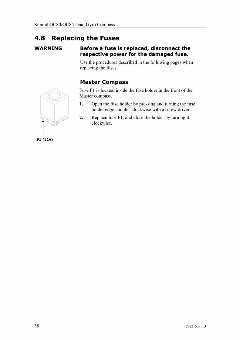
4.8 Replacing the Fuses
WARNING Before a fuse is replaced, disconnect the respective power for the damaged fuse.
Use the procedures described in the following pages when replacing the fuses.
Master Compass
Fuse F1 is located inside the fuse holder in the front of the Master compass.
1. Open the fuse holder by pressing and turning the fuse holder edge counter-clockwise with a screw driver.
2. Replace fuse F1, and close the holder by turning it clockwise.
F1 (12A)

MAINTENANCE
20221537 / D 39
Dual Control unit
For location of the fuses, refer to the drawing on next page.
Main fuses
FUSE NO CAPACITY TB-NO SIGNAL DESCRIPTION
F101 6.3A TB101 Gyro no.1 Main power supply
F102 20A TB101 Gyro no.1 Emergency power supply
F201 6.3A TB201 Gyro no.2 Main power supply
F202 20A TB201 Gyro no.2 Emergency power supply
GTERM board
FUSE NO CAPACITY TB-NO SIGNAL DESCRIPTION
F1 TB2-5 1R24+ Power supply for ch.1 serial repeater
F2 TB2-10 2R24+ Power supply for ch.2 serial repeater
F3 TB2-15 3R24+ Power supply for ch.3 serial repeater
F4 TB2-20 4R24+ Power supply for ch.4 serial repeater
F5 TB2-29 5R24+ Power supply for ch.5 serial repeater
F6 TB2-34 6R24+ Power supply for ch.6 serial repeater
F7 TB2-39 7R24+ Power supply for ch.7 serial repeater
F8 TB2-44 8R24+ Power supply for ch.8 serial repeater
F9 TB1-31 9R24+ Power supply for ch.9 serial repeater
F10 TB1-36 10R24+ Power supply for ch.10 serial repeater
F11 TB2-61 Power supply for ch.1 step motor repeater
F12 TB2-66 Power supply for ch.2 step motor repeater
F13
1A
TB2-71 Power supply for ch.3 step motor repeater
F14 TB2-24 Power supply for ch.4 step motor repeater
F15 J9, 1-6 Repeater power supply
F16 J4, 23-27 Power supply for SCC and SIFC boards
F17 J9, 15-16 Power supply for HDM part
DTERM board
FUSE NO CAPACITY TB-NO SIGNAL DESCRIPTION
F17 15A J7 Power supply for repeaters (gyro no.2)
F18 3.15A J7 Power supply for SSC or SCOIF board (E5V) for gyro no.2
F19 3.15A TB21 Power supply for HDM part, and for SCOIF board

Simrad GC80/GC85 Dual Gyro Compass
40 20221537 / D
F17F14F13
F4F8
F12F3
F7F6F5F1F2
F10F11
F9F16
F15
F17
F18F19
WARNING Make sure that the main power switches SW1 and SW2 is turned OFF before any fuse is replaced!
Note! The fuses in the Control unit are open glass type and may be damaged if handles with force.
1 Pull the damaged fuse up from the holder.
2 Re-install a new fuse by carefully pushing it into the holder. When correctly located, it should be fixed 1-2mm above and parallel with the mounting level.
SW1 AND SW2
MAIN POWER
SWITCHES FOR
MASTER COMPASS 1 AND 2
F201 (6.3A)
AND
F202 (20A)
FOR MASTER
COMPASS NO.2
F101 (6.3A)
AND
F102 (20A)
FOR MASTER
COMPASS NO.1
GTERM BOARD
DTERM BOARD

INSTALLATION
20221537 / D 41
5 INSTALLATION This section is a reference guide for correctly installing and configuring the GC80/85 Gyro Compasses.

Simrad GC80/GC85 Dual Gyro Compass
42 20221537 / D
5.1 Unpacking and handling A GC80/85 Gyro compass consist of the following units:
- 2 Master compasses
- 2 Sensitive elements
- Dual control unit
- Spare part kit
- Mounting jigs
- Documentation
The sensitive element is shipped from the factory packed separately in a carton box to protect it from excessive shock and vibration. The final assembly of the sensitive element into the Master compass have to be done when the Master compass is mounted onboard the vessel.. Refer page 52.
Note! It is strongly recommended to keep the packing material for the Sensitive elements. These original packing should be used if the element is sent to the factory for overhaul or repair.
Care should be taken when unpacking and handling the equipment. A visual inspection should be made to see that the equipment has not been damaged during shipment and that all components and parts are included.
5.2 Mechanical installation The units included in the GC80/GC85 system should be mounted with special regard to the units’ environmental protection, temperature range and cable length. Refer Technical specifications, page 75 onwards.
Note! A special tool (Simrad part no. 44174449) is required when installing the Sensitive element. This tool is delivered together with the gyro, and the sensitive element should not be installed without using this tool.

INSTALLATION
20221537 / D 43
Control unit
The Control unit is bulkhead mounted by using 4 bolts as shown in the illustration.
Flush mounting the control panels
The control panels for master compass no 1 and 2 may be removed from the Control unit and mounted in a remote location by using the optional flush mounting kit (part number 27101757).
The flush mounting kit includes:
- 1 flush mounting panel
- 4 corners
- 4 mounting screws
- 1 blind cover
In addition to this kit, optional control panel cables must be ordered. The cables are available in three different lengths:
- 5m (part no. 44170736) - 10m (part no. 44170744) - 15m (part no. 44170751)
Use the following procedure when remotely mounting the control panel:
1 Open the control unit, and remove the wiring strips holding the control panel’s cable.
2 Disconnect the cable’s grounding wires (labelled FG) from the control panel and from the SCC board in the Control unit.
3 Disconnect the plugs and remove the control panel’s cable.
GC80/85 REMOTE PANEL
CONTROL PANEL

Simrad GC80/GC85 Dual Gyro Compass
44 20221537 / D
4 Loosen the 4 nuts holding the control panel, and remove the panel. These nuts are to be re-used when fastening the control panel to the flush mounting panel.
5 Insert the control panel in the flush-mounting kit from the front side as shown on the figure. Fasten the panel with the 4 nuts.
6 Insert the plug on the optional control panel cable, and connect the grounding wire.
7 Mount the cover on the back side.
8 Fasten the cable to the cover by a wire strip.
9 Slide the control panel cable through the cable inlet, insert the plug in SCC board and connect the grounding wire. Secure the cable to the control unit by a wire strip.
10 Insert the blind cover in the Control unit by using the 4 bolts included in the kit.

INSTALLATION
20221537 / D 45
Master compass
Select a mounting location where the deck is horizontally, flat and with little vibration, and where the pitch/roll motion is as small as possible.
It is also important to select a mounting location with sufficient space for installation and service. Refer dimensional drawing, page 84.
1 Locate the compass on or parallel to the vessel’s horizontal centerline, with the bow indication on the top of the case pointing towards the vessel’s bow.
Use the datum line in the front and back to of the compass to line up the unit.
- It is possible to compensate for a small mounting offset by using the heading offset feature as described in Adjusting True heading, page 63.
2 Remove the four screws holding the compass case, and lift the case carefully upwards and away.
3 Remove the cable inlet cover.
4 Fasten the compass to the deck with four bolts. The bolts should be located in the center of the trails for later to be able to adjust the compass direction when the heading is tuned in. Refer Adjusting True heading, page 63.

Simrad GC80/GC85 Dual Gyro Compass
46 20221537 / D
5 Remove strips and foam rubber from the chock absorbers, together with all strips used for securing moving parts during transportation.
Note! The foam rubber should be kept for re-use if the Master compass has to be sent to factory for service!
5.3 Cabling
Note! No cables are included when the gyro system is delivered from factory.
The wiring diagram on page Error! Bookmark not defined. onwards includes cable specification for all cables that have to be used.
Connect power and signal cables according to the wiring diagram on page Error! Bookmark not defined. onwards.
To avoid that vibration should cause the cables to loose connection, the cables could be fastened to the fixing device by using wire straps as illustrated on the figure.
INSTALLATION
20221537 / D 47
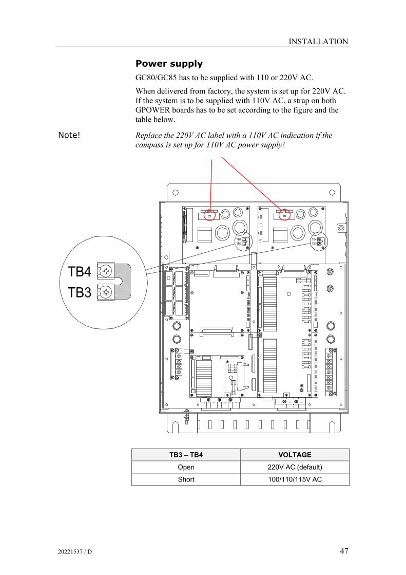
Power supply
GC80/GC85 has to be supplied with 110 or 220V AC.
When delivered from factory, the system is set up for 220V AC. If the system is to be supplied with 110V AC, a strap on both GPOWER boards has to be set according to the figure and the table below.
Note! Replace the 220V AC label with a 110V AC indication if the compass is set up for 110V AC power supply!
TB4TB3
TB4TB3
TB3TB4
TB3 – TB4 VOLTAGE
Open 220V AC (default)
Short 100/110/115V AC

Simrad GC80/GC85 Dual Gyro Compass
48 20221537 / D
5.4 Grounding the units All units in the GC80/GC85 system should have a proper ground connection from the unit’s ground terminal.
The wires should be as short as possible and have a cross section of at least AWG13 (2.5mm2).
MASTER COMPASS
DUAL CONTROL UNIT
5.5 Dip-switch and jumper settings GC80 and GC85 gyro systems include several dip switches and jumpers. Most of these are factory set and should not be alternated by the user.
5 switches in the Control unit must however be set when installing the GC80/85 system. 2 switches have to be set for configuring the Control panels to match type of gyro system (GC80 or GC85), while 3 switches have to be set if an external heading sensor is connected to the system.
Note! These dip switch settings are read when the system is started. Any changes when the system is running will therefore not take affect before the system is restarted.
For a complete list of dip switch settings, refer to DIP SWITCH SETTINGS, page 101.
Activating the control unit for GC80 or GC85 system
When the gyro system is shipped from factory, all dip switches in both master compass control panels are set as for a standard GC80 system.
The GC80/85 Dual system includes 2 SCC boards, one for each master compass. The boards are located as shown on the figure on page 49.
If the system is a high speed system (GC85), dip switch no.2 on S1 on both SCC boards has to be changed to identify the system as a GC85 system.

INSTALLATION
20221537 / D 49
J1 J4
J3
J2
6
1ON
8
1ON
SW4
8
1ON
SW3
SW2
SW1
ON
8
1
DS1DS2DS3DS4DS5DS6
12
12
12
56
123413
24
13
24
J5
J6
J7
J8
J9
J10
U1
U52
BT1
SCC board
GC80 system GC85 system
OFF
S1
1
8
S1
8
1ON
All outputs are selectable for 1, 5, 10 or 50Hz.
Refer dip switch and jumper settings on page 101 onwards.
Note! A GC85 system is recommended to be set for 50Hz output!
SCC BOARD NO.1 FOR MASTER
COMPASS NO.1
(LOCATED UNDERNEATH THE
GTERM BOARD)
SW1
SCC BOARD NO.2 FOR MASTER
COMPASS NO.2
SCIOF BOARD
Simrad GC80/GC85 Dual Gyro Compass
50 20221537 / D
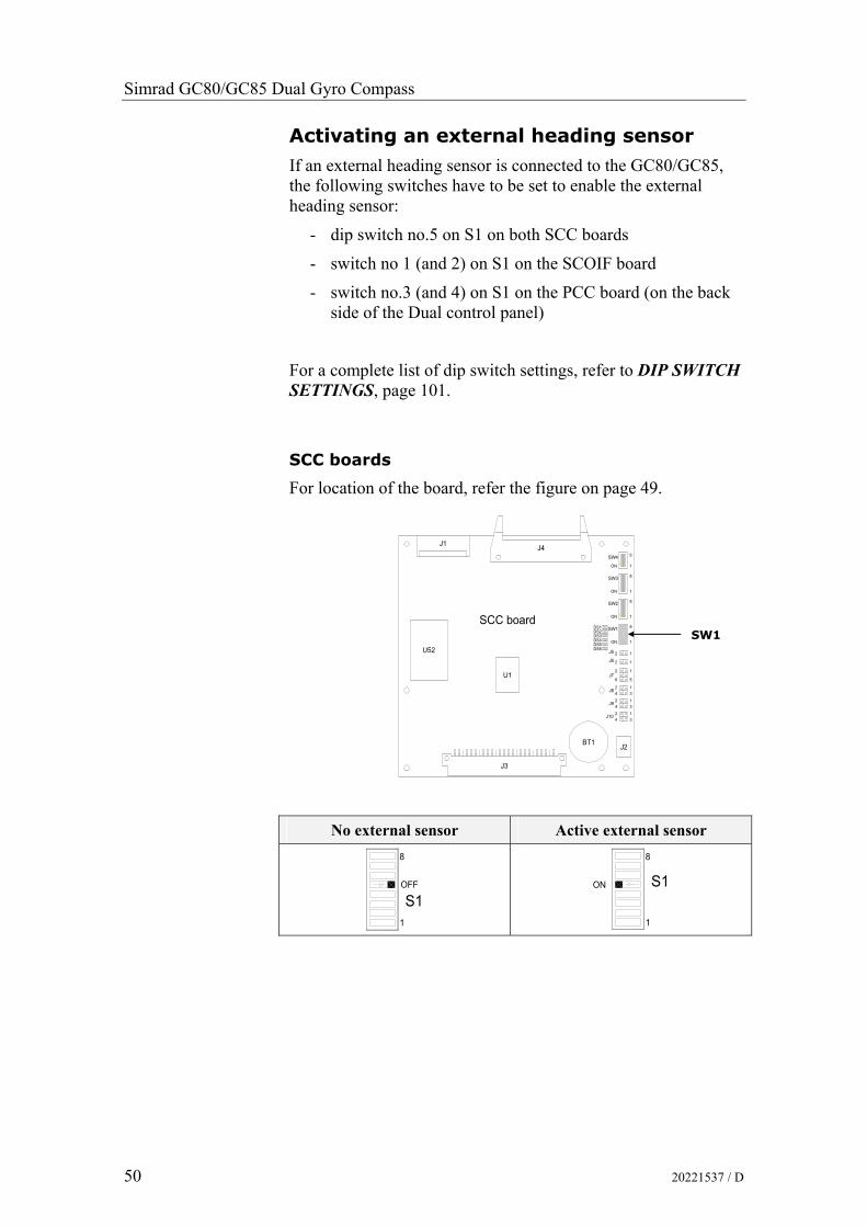
Activating an external heading sensor
If an external heading sensor is connected to the GC80/GC85, the following switches have to be set to enable the external heading sensor:
- dip switch no.5 on S1 on both SCC boards
- switch no 1 (and 2) on S1 on the SCOIF board
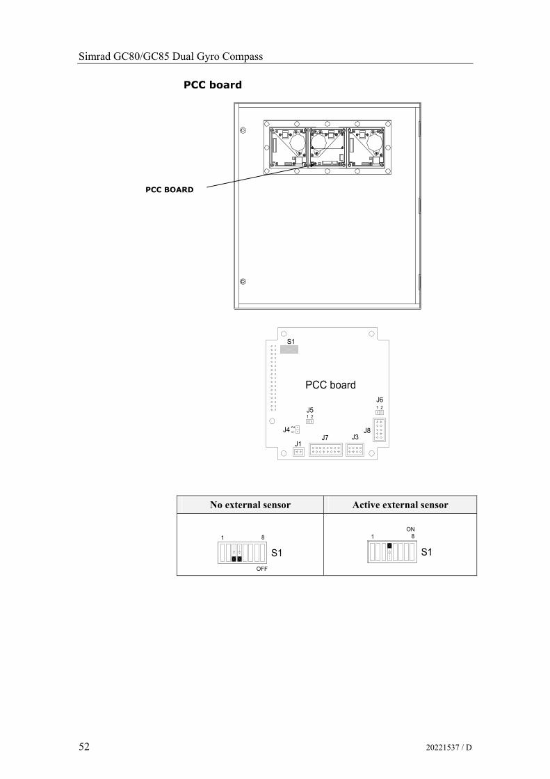
- switch no.3 (and 4) on S1 on the PCC board (on the back side of the Dual control panel)
For a complete list of dip switch settings, refer to DIP SWITCH SETTINGS, page 101.
SCC boards
For location of the board, refer the figure on page 49.
J1 J4
J3
J2
6
1ON
8
1ON
SW4
8
1ON
SW3
SW2
SW1
ON
8
1
DS1DS2DS3DS4DS5DS6
12
12
12
56
123413
24
13
24
J5
J6
J7
J8
J9
J10
U1
U52
BT1
SCC board
No external sensor Active external sensor
OFF
8
1
S1
ON S1
1
8
SW1

INSTALLATION
20221537 / D 51
SCOIF board
For location of the board, refer the figure on page 49.
No external sensor Active external sensor
S1OFF
1 8
ON1
S1
8
Simrad GC80/GC85 Dual Gyro Compass
52 20221537 / D
PCC board
1
S1
J8J3
J61 2
PCC board
J7J1
J4 12
J52
No external sensor Active external sensor
81
OFF
S1
S1
1ON
8
PCC BOARD

INSTALLATION
20221537 / D 53
Activating the pendulum function
If an external switch is connected to GC80/85 to operate the pendulum function, dip switch no.4 on S2 on the SSC boards has to be set to activate the pendulum function.
SCC board
U52
J3
U1
J1
2 1
BT1 J2
J104
J9
J8
2
24
4
3
1
13
3
DS2
DS6DS5DS4DS3
DS1 SW1
J6
J72
6
2
J5
ON
2
1
5
1
1
1
SW2
SW3
ON
ON
8
1
8
1
8
J4SW4
ON 1
6
Pendulum function disabled Pendulum switch enabled
OFF
S2
1
8
ON
S28
1
SW2
SCC BOARD 1
SCC BOARD 2

Simrad GC80/GC85 Dual Gyro Compass
54 20221537 / D
5.6 Installing the Sensitive elements
The Sensitive elements are shipped from the factory packed separately, and the elements have to be installed in the Master compasses according to the description below.
Note! A special tool (Simrad part no. 44174449) is required when installing the Sensitive element. This tool is delivered together with the gyro, and the sensitive element should not be installed without using this tool.
Caution! Use extreme caution when handling the Sensitive element! Do not tilt the element. It is filled with oil and the top includes a ventilation opening. 1 Make sure that the master compasses are installed and
cables connect according to the description on page 45 onwards.
2 Remove the four screws on the Horizontal ring.
3 Lift the sensitive element carefully from its package, and remove the rubber tube on top of the element.
Note! The package and the rubber tube should be kept for re-use if the Sensitive element has to be sent to factory for service!
4 Tilt the Horizontal ring to the side where the plug is located, and carefully put the sensitive element into the ring.
- The socket on the Sensitive element should be located right above the plug attached to the Horizontal ring.
5 Position the Sensitive element on the Horizontal ring by putting the assembly jigs into the holes as indicated on the figure below. Observe the labelling and the diameter on the jigs. Fasten two screws in the other two holes.

INSTALLATION
20221537 / D 55
6 Replace the assembly jigs with the two remaining screws. Locate the ground wire on one of the screws as shown on the figure.
7 Loosen the screw on the plug-holder on the Sensitive element, and lift the holder 2-3 mm upwards.
8 Connect the plug to the connectors on the Sensitive element’s pcb according to the labelling on the pcb and on the wires. Make sure that the pin guides on the plug are properly entered, and that the wires not are twisted.
9 Firmly tighten the screw on the holder.
ASSEMBLY JIG WITH 1 CIRCLE
ASSEMBLY JIG WITH 2 CIRCLES
Ground wire connection
Pin guides

Simrad GC80/GC85 Dual Gyro Compass
56 20221537 / D
Verifying the element’s tilt angle
1 Tilt the Sensitive element by hand towards the level tool on the Horizontal ring and keep it tilted for approximately 1 minute. Remove the pressure and observe that the tilt angle remains at:
- GC80: 15° to 19°
- GC85: 18° to 22°
The tilt angle is indicated on the figures below.
15°
19°
Max and min tilt angle for GC80 std system
18°
22°
Max and min tilt angle for GC85 High Speed system
Note! The tilt angle shown above is correct for cold condition. The angle may change when the element has reached normal operational temperature!

INSTALLATION
20221537 / D 57
2 If the tilt angle is incorrect, weight disks must be adjusted by moving weights from one side to the other. After adjustments, wait for 2 minutes for the oil to set before the tilt angle verification is repeated.
Caution! The sensitive element must have equal number of weight disks on both weight points on the tilting side (north and south side)! 3 Carefully rotate the Horizontal ring at least one complete
rotation. Verify that all movable parts will turn around without making any contact with mechanical or electrical components.
4 Lift the lid from the damper oil case, and fill the container with the supplied damper oil. The oil has high viscosity, and care should be taken when pouring the damper oil into the container to avoid spill. Reinstall the lid on the damper oil case.
Any oil spilled on the outside should be cleaned.

Simrad GC80/GC85 Dual Gyro Compass
58 20221537 / D
5.7 System start-up and software configuration When all GC80/85 units are installed and the cables connected according to the procedures described in previous chapters, the system is ready for the first time start-up procedure.
Note! The start-up procedure and configuration is identical for each gyro, and has to be performed for both gyro compasses before the dual function can be started. The start-up procedure may be performed simultaneously for both compasses.
System Start-up for each gyro compass
mltbo
1 Turn ON the gyro system by pressing the POWER button on the Control panel. The following start-up sequence will take place:
- Control unit type (GC80 Std, or GC85 HSc), SW version for Control unit and for Master compass is displayed in rapid succession. Examples of display text are shown below:
OR
GC80 CONTROL UNIT
STD VERSION
GC80 CONTROL UNIT
HIGH SPEED VERSION
SW VERSION CONTROL UNIT
SW. VERSION MASTER COMPASS
dvol
2 The sensitive element starts rising horizontally, and the compass turns 360° clockwise. The display shows decreasing bearing as the compass is turning
3 If the gyro has been turned ON and OFF again, but rotor still rotating when the POWER button was pressed for new start, a rotor break function will be activated to completely stop the rotor.
4 Active rotor break is indicated with flashing display.
dvol
5 When the rotor rotation is stopped, start bearing is indicated with flashing text in the display. The start bearing will be the same as active bearing when the compass was turned OFF.

INSTALLATION
20221537 / D 59
dvol
6 The indicated start bearing is accepted by pressing the ACK/ENT button, or increased/decreased by using the arrow buttons and then pressing the ACK/ENT button. If no action is taken within 3 minutes, the start-up process will continue with the indicated start bearing.
The bearing indication stops flashing when the start bearing is accepted, while the lamp remains flashing.
The rotor starts spinning, and reaches full speed after maximum 30 minutes.
dvol
7 When the rotor has reached full speed, the compass starts the north seeking function. The display will now change to show the compass’ actual heading, and from now on bearing output will be available.
The lamp next to the GYRO button changes from flashing to steady light.
The GC80/GC85 will be settled within 3 hours when started with a deviation angle less than 5°. With a larger deviation angle, the compass will be settled within 4 hours.
Configuring the sensitive element
Each Sensitive element is tuned to its Master compass before it is shipped from the factory. This tuning is reflected in a set of parameters specific for this gyro compass. These parameters are included in the sensitive element’s package, and they have to be entered into the Control panel as part of the gyro compass’ installation procedure.
Parameters used for time settings should also be entered. These parameters are essential when monitoring the occurrence of alarms.
The parameters are loaded into the Control panel from the Extension menu as described below.
1 Enter the Extension menu by pressing and holding the SET button and the ACK/ENT buttons simultaneously for appr. 3 seconds.
Main category A-1 will be displayed.
2 Press the SET button to enter the sub-category loop. Sub-category 1.1.U and its parameter values will be displayed.
3 Use the arrow buttons to increase or decrease the parameter value until the value is according to value in the table included with the sensitive element.
4 Confirm the entry by pressing the ACK/ENT button. The display will return to sub-category 1.1.U, and the data will be transferred to the gyro immediately.

Simrad GC80/GC85 Dual Gyro Compass
60 20221537 / D
5 Press the DISP button again to select sub-category 1.2.F, and use the arrow buttons to increase or decrease the parameter value until the value corresponds with the parameter for the new sensitive element. Confirm the entry by pressing the ACK/ENT button.
6 Repeat step 5 for sub-category 1.3.S, 1.4.u, 1.5.L and 1.6.t.
7 Press the SET button again to return to main category A1, and then press the DISP button to go to A2 main category.
8 Press the SET button, and enter values for 2.1.o and 2.3.h as described above.
9 While still in A2 main category, enter values for 2.5.y (Year), 2.6.N (Month and Day), 2.7.t (Hour and Minute) and 2.8.d (total days of operation. This value should be reset after installation).
Note! All time parameters should preferably be in CET (Central European Time) or eventually in local time.
10 Press the SET button again to return to main category A2, and then press the DISP button until main category A7 is displayed.
11 Exit the sub-category by pressing the SET button, and then exit the Extension main category by pressing and holding the SET and ACK/ENT buttons simultaneously for at appr. 3 seconds.
For more information about the Extension menu, see ADVANCED SETTINGS, page 67 onwards.

INSTALLATION
20221537 / D 61
Setting the Latitude input source
When the system is configured as described in Configuring the sensitive element page 59 onwards, the latitude input source can be changed as described below.
1 Press the DISP button until the display shows latitude value.
2 Press SET button once, and the upper line in the display starts flashing.
3 Use the arrow buttons for selecting Gyro or GPS as the latitude input source, and confirm the entry with the ACK/ENT button.
- If Gyro is selected, the display will change to flashing numbers
- If GPS is selected, the display will show the latitude value read from the GPS
4 When Gyro is selected and the numbers are flashing, press the arrow buttons for increasing/decreasing the latitude value, and confirm the entry with the ACK/ENT button.
- This entered latitude value will now be used, together with speed and bearing information, for calculating the vessel’s current latitude.
5 The display will return to show latitude value without flashing.

Simrad GC80/GC85 Dual Gyro Compass
62 20221537 / D
Setting the Speed input system
When the system is configured as described in Configuring the sensitive element page 59 onwards, the speed input source can be changed as described below.
1 Press the DISP button until the display shows speed value and speed input source.
2 Press SET button once, and the upper line in the display starts flashing.
3 Use the arrow buttons for toggling between available speed input source:
Manual
GPS
LOG (pulse)
LOG (serial)
4 Select active speed input source, and confirm the selection by pressing the ACK/ENT button.
5 If Manual input source is selected, the display will change to show flashing numerical values.
6 Use the arrow buttons for entering the speed value, and confirm the input by the ACK/ENT button.
7 The display will return to shown speed value and speed input source without flashing.

INSTALLATION
20221537 / D 63
Balancing the Horizontal ring
After the compass has been running continuously for at least 2 hours, the horizontal ring should be adjusted.
1 Locate the reference level tool on the horizontal ring, and check that the level bubble is within +/-10 minutes from the center. Each division equals 2 minutes.
2 If the level bubble not is within this limit, add or remove weights from the horizontal ring until it is levelled.
Note! It is important that the total number of weights on the horizontal ring are as few as possible.
Let the compass run for at least 20 minutes before the level is rechecked and eventually confirmed.
Caution! If the horizontal ring is tilted more than +/-10’, a bearing error will be generated.
Adjusting True heading
After the GC50 is settled, the gyrocompass has to be calibrated against an external reference, e.g.:
- a known target
- astronomical observation
- the heading of the pier or quay the vessel is moored to
- two fixed points on the chart that the vessel is sailing between
The observation period for the heading difference should be as long as possible.
If there is any difference between the gyro bearing and the confirmed external reference that not can be corrected by adjusting the mechanical location of the master compass, an offset value may be inserted in the GC80. This value is entered by using the Extension menu as follows:
1. Activate the Extension menu by pressing and holding the SET button and the ACK/ENT buttons simultaneously for at least 3 seconds.
- Main category A-1 will be displayed.
2. Press the DISP button once to display main category A-2.
3. Press the SET button to enter the sub-category 2.1.o.
+/-10 minutes

Simrad GC80/GC85 Dual Gyro Compass
64 20221537 / D
4. Use the arrow buttons to increase or decrease the offset parameter value.
Note! To correct for +1.5°, press the Arrow Up button until the display shows 1.5°. To correct for -1.5°, press the Arrow Down button until the display shows 358.5°!
5. Confirm the new value by pressing the ACK/ENT button, or reject the changes by pressing the SET button. The display will return to sub-category 2.1.o.
6. Exit the Extension menu by pressing and holding the SET and ACK/ENT buttons simultaneously for at least 3 seconds.
For further information about the Extension menu, refer Using the Extension menu, page 68 onwards.
5.8 Configuring the dual function When each gyro compass is started and configured according to the description in the previous pages, the dual function should be configured.
mltbo
1 Start the function by pressing the POWER button on the change over panel.
The button is recessed into the front panel, and a pen or a blunt tool must be used for activating the button.
The display will show product name and software version for PCC and SCOIF boards:
HDM220 P:V1.02 C:V1.02
followed by:
HDM220 by Simrad
and then by heading for gyro compass no.1 and no.2.

INSTALLATION
20221537 / D 65
The example to left below shows a display where the gyros not are settled (runtime less than 3 hours, indicated with an S). In the example to right, the gyros have run for more that 3 hours.
1-GYRO:123.4° SA*
2-GYRO:123.4° S
1-GYRO:123.4° A* 2-GYRO:123.4°
2 Verify that heading 1 and heading 2 is in according with the heading displayed on the gyro compass’ control panel.
Setting the heading difference alarm
The heading difference alarm is generated when the difference between gyro no.1 and gyro no.2 exceeds the heading difference value.
afpm
1 Press the DISP button twice on the change over panel until
HDM SET: is displayed in the display’s upper line.
HDM SET:10.0 - PARAMETER SET-
^`hbkq
2 Press the ACK/ENT button. The display will change to:
SET=ENT ESC=DISP HDM THRESHOLD
3 Press the ACK/ENT button again to activate the alarm setting display:
SET=ENT ESC=DISP HDM SET:010.0°
afj 4 Use the arrow buttons to increase or decrease the alarm
difference alarm value. Range: 5° - 15°.
^`hbkq
5 Confirm the entry by pressing the ACK/ENT button.
The dual system is now ready for operation. Refer Selecting active compass, page 25.

Simrad GC80/GC85 Dual Gyro Compass
66 20221537 / D
THIS PAGE INTENTIONALLY LEFT BLANK

ADVANCED SETTINGS
20221537 / D 67
6 ADVANCED SETTINGS This section gives an overview of the Extension menu, how to enter the menu and how to change parameter values.

Simrad GC80/GC85 Dual Gyro Compass
68 20221537 / D
6.1 General The Extension menu holds internal parameters and communication parameters required to achieve the best possible heading accuracy on the GC80/GC85 Gyro compass.
The Extension menu is grouped in 8 main categories, named A-1 through A-8. Each of these main categories has again several sub-categories where parameter values may be set.
All values in the Extension menu are stored in the nonvolatile memory of the compass.
6.2 Using the Extension menu
Caution! The Extension menu should not be entered by unauthorized personnel. Incorrect parameters may result in irregular operation of the GC80/GC85 gyro compass!
The extension menu can be entered when any display is shown in the LCD.
1 Activate the menu by pressing and holding the SET button and the ACK/ENT buttons simultaneously for at least 3 seconds.
- Main category A-1 will be displayed.
2 Page through the main categories to the selected category by pressing the DISP button. Pressing the DISP and ACK/ENT buttons simultaneously will display the main category loop in reversed order.
3 Press the SET button to enter the sub-category loop, and use the DISP button to select sub-category that holds the parameter to be changed.
4 Use the arrow buttons to increase or decrease the parameter value.
5 Confirm the new value by pressing the ACK/ENT button, or reject the changes by pressing the SET button. The display will return to selected sub-category.
6 Exit the Extension menu by pressing and holding the SET and ACK/ENT buttons simultaneously for at least 3 seconds.

ADVANCED SETTINGS
20221537 / D 69
afpmafpm
^`hbkq
pbqpbq
^`hbkq
afpmafpm
^`hbkq
pbq
^`hbkq
6.3 The Extension menu overview
Main Category
Sub Category Parameter/description Default
value Range
A-1 1.1.U Damping gain
Determines the damping (damping operation in north-seeking motion = half cycle attenuation) and actually represents a coefficient (ratio) to the standard value stored in the software.
1.00 0.00 – 2.00
1.2.F Bearing servo gain
Determines the gain of the bearing servo loop where phi Φ signal (deviation signal around rotor’s vertical axis) is calculated, drives the azimuth step motor and has the sensitive element follow to the gyro-sphere vertical axis (around azimuth axis) rotation. Presents a coefficient (ratio) to the standard value stored in software.
1.00 0.00 – 2.00
1.3.S Horizontal servo gain
Determines the gain of the horizontal servo loop where theta θ signal (rotor tilting angle signal) is calculated, drives the horizontal DST and has the sensitive element follow to the gyro sphere tilting angle (rotor tilting angle). Present a coefficient (ration) to the standard value stored in software.
1.00 0.00 – 2.00
1.4.u Leveling servo gain
Leveling motion (sensitive element erection motion) calculates X signal (equivalent inclination angle) which is output from the sensitive element and relative inclination angle signal from HRZC board, controls to have the sensitive element keep horizontal. The value determines this control loop gain. Presents a coefficient (ratio) to the standard value stored in the software.
1.00 0.00 – 2.00
A-1 cont. 1.5.L (φ) Phi offset (°)
Offset value (°) around the vertical axis of gyro sphere (rotor axis) and the sensitive element.
0.00 -3.00 – 3.00
CHANGE / CLEAR PARA-METER VALUE
NEXT MAIN CATEGORY
NEXT SUB CATEGORY
MAIN MENU

Simrad GC80/GC85 Dual Gyro Compass
70 20221537 / D
Main Category
Sub Category Parameter/description Default
value Range
1.6.t (θ) Theta offset (°)
Offset value (°) around the horizontal axis of gyro sphere (rotor axis) and the sensitive element.
0.00 -3.00 – 3.00
1.7.G X signal pickup gain (v/°)
Distance of the sensitive element share and the rotor axis direction. Inclination angle around horizontal axis is obtained equivalently by monitoring this signal. For example, when north side of the rotor axis rises, the sensitive element follows to rise its north side, then gyro sphere suspended by the suspension wire moves to south side. X signal represents this amount of movement (v/°).
This parameter is only used for GC85.
2.32 0.00 – 5.00
1.8.c Ks/H
Suspension wire twist torque. Fixed value.
1.477 1.000 – 2.000
1.9.r Maximum rate of turn (°/sec)
Maximum rate of turn in the turn rates which the bearing servo system followed up to this moment (°/sec).
NOTE: The maximum is measured after 3 hours from system start.
NOTE: Reset this data certainly after completion of installation!
0.00 -
1.A.F Maximum deviation of bearing servo (°)
Maximum deviation value in the bearing servo loop that occurred up to this moment (°).
NOTE: The maximum is measured after 3 hours from system start.
NOTE: Reset this data certainly after completion of installation!
0.00 -
1.b.S Maximum deviation of horizontal servo (°)
Maximum deviation value in the horizontal servo loop that occurred up to this moment (°).
NOTE: The maximum is measured after 3 hours from system start.
NOTE: Reset this data certainly after completion of installation!
0.00 -

ADVANCED SETTINGS
20221537 / D 71
Main Category
Sub Category Parameter/description Default
value Range
A-2 2.1.o Bearing offset A (°)
Offset value included in the “master bearing” and used for correction of fixed error (°). If the master compass not can be mounted parallel to the vessel’s fore-after line, this parameter is used to compensate for a small mounting error.
0.0 0.0 – 359.9
2.2.O Bearing offset B (°)1
Value for general bearing error correction to enter to master compass bearing. It is used to correct the bearing if the bearing for some reason deviates from correct heading.
This value is cleared when it passes the zero-cross pin or when power is switched OFF.
0.0 0.0 – 359.9
2.3.h Zero-cross bearing (°)
Absolute bearing set for MCU board when zero-cross pin was passed during start-up sequence (last azimuth operation) and normal running operation.
Zero-cross bearing can be set in this menu, but is normally set up be measuring position (angle) of the zero-cross pin in the master compass by the test mode A.
345.3 0.0 – 359.9
2.4.E Zero-cross error allowance (°)
Zero-cross alarm limit. The compass will generate a zero cross alarm when the difference between the zero-cross bearing and the relative bearing exceeds this zero cross value.
This value should be set every time the zero-cross pin is detected.
2.0 0.0 – 5.0
2.5.y Year
Used for setting current year.
- 2000 - 2099
2.6.N Month and Day
Used for setting current month and date.
- -
2.7.t Hour and Minute
Used for setting current hour and minute.
- -
2.8.d Total days of operation
This value should be reset after the installation is completed.
- -
1 This value is cleared at the time of zero crossing pin passage and a power supply OFF.

Simrad GC80/GC85 Dual Gyro Compass
72 20221537 / D
Main Category
Sub Category Parameter/description Default
value Range
A-2 cont. 2.9.G Display/setting of GPS connection
The following abbreviations are used: bE: GPS connected Non: No GPS connected
NOTE: When this value is set to “Non”, GPS can not be selected as the vessel’s input for speed and latitude.
- bE or Non
2.A.L Display/setting of LOG connection
The following abbreviations are used: bE: with Log (contact) Non: No Log (contact)
NOTE: When this value is set to “Non”, LOG can not be selected as the vessel’s speed input.
- bE or Non
2.b.S Display/setting of LOG (serial) connection
The following abbreviations are used: bE: with Log (serial) Non: No Log (serial)
NOTE: When this value is set to “Non”, SLOG can not be selected as the vessel’s speed input.
- bE or Non
2.c.t Display/setting of GPS performance index data check
The following abbreviations are used: bE: Check performance index Non: Not check performance index
- bE or Non
2.d.o Analogue signal output offset for ROT (°)
Offset value for analogue signal output of Rate Of Turn. Entered value is +/-5% of maximum output ROT.
0.00 0.0 – 162
2.e.F Filter time constant for rate of turn (sec) 2.00 0.5 – 10.0
2.F.G Analog output gain for rate of turn 1.00 0.90 – 1.00
3.1.E Alarm (error) - -
3.2.n Occurred number of zero-cross error - -
3.3.H Maximum zero-cross error - -
3.4.y Occurred year of zero-cross error - -
3.5.N Occurred month/day of zero-cross error - -
3.6.t Occurred hour/minute of zero-cross error - -
3.7.n Occurred number of encoder error - -
A-3
3.8.r Occurred number of reset with WATCH DOC TIMER - -
2 The maximum value is 5% of the maximum analog output for rate of turn.(32 deg./min: 1.6deg./min., 130deg./min: 6.5deg./min., 320deg./min: 16.0deg./min.)

ADVANCED SETTINGS
20221537 / D 73
Main Category
Sub Category Parameter/description Default
value Range
A-4 4.1.C GPS serial data character length 8 8 or 7
4.2.P GPS serial data parity bit Non Non, Even, Odd
4.3.S GPS serial data stop bits 1 1 or 2
A-5 5.1.C LOG serial data character length 8 8 or 7
5.2.P LOG serial data parity bit Non Non, Even, Odd
5.3.S LOG serial data stop bits 1 1 or 2
A-6 6.1.C External sensor (standard) serial data character length 8 8 or 7
6.2.P External sensor (standard) serial data parity bit Non Non, Even, Odd
6.3.S External sensor (standard) serial data stop bits 1 1 or 2
A-7 7.1.t Master compass type Std Std or Hsc
7.2.u SCC software version number - -
7.3.u MCC software version number - -
A-8 8.1.t For confirmation of extension menu - -
8.2.S Filter of speed error correction On On or Off

Simrad GC80/GC85 Dual Gyro Compass
74 20221537 / D
THIS PAGE INTENTIONALLY LEFT BLANK

TECHNICAL SPECIFICATION
20221537 / D 75
7 TECHNICAL SPECIFICATION This section lists all specifications for GC80/85 gyro compass.

Simrad GC80/GC85 Dual Gyro Compass
76 20221537 / D
7.1 Accuracy Settling time:.......................................................... within 3 hours
(if startup heading is within +/-5° of actual heading)
Settle point error: ................................................... less than ±0.1º
RMS value of the difference:................................... less than 0.1º
Repeatability of settle point error: ......................... less than ±0.1°
Roll and pitch error:............................................... less than ±0.4°
Static error: ............................................................ less than ±0.1°
Settle point error under general conditions:........... less than ±0.4°
Note! Accuracy at equator. For other latitudes, accuracy to be multiplied by *(1/COS f), where f = Latitude.
7.2 General specification Follow-up speed..............................................................> 75°/sec
Gimbal freedom ................................for both roll and pitch: ±45°
Range of speed correction: GC80 ................... 0-50 knots / latitude (0° - +70°) GC85 ................... 0-70 knots / latitude (0° - +70°)
Main power supply: .................. 100/110/115/200V AC, 50/60Hz
Power supply for alarm and back-up: .................... 24V DC, 70W
Voltage fluctuation: .......................................................AC ±10% DC -20% - +30%
Frequency variation: .............................................................. ±5%
Power consumption: Start:.....................................................within 140VA Ordinary: ................................................within 70VA Repeater: ................................................within 17VA
Repeater type: .................................................. 24V DC – 6 step/°
Number of step repeater connections: .........................................4
Number of NMEA connections: ................................................10
Repeater back-up circuits: .................................................... 4+10
Pendulum function....................................................refer page 24
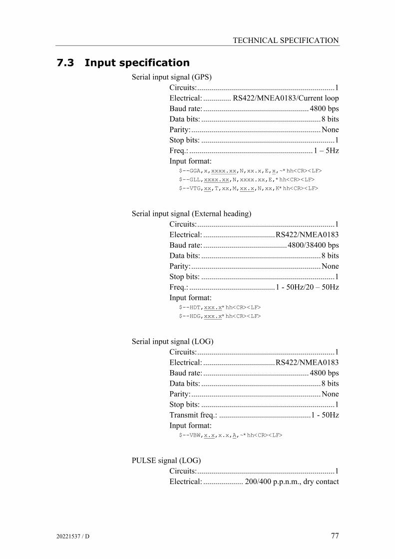
TECHNICAL SPECIFICATION
20221537 / D 77
7.3 Input specification Serial input signal (GPS)
Circuits:.....................................................................1 Electrical: .............. RS422/MNEA0183/Current loop Baud rate: ..................................................... 4800 bps Data bits: ............................................................8 bits Parity:.................................................................None Stop bits: ...................................................................1 Freq.: ..............................................................1 – 5Hz Input format:
$--GGA,x,xxxx.xx,N,xx.x,E,x,~*hh<CR><LF>
$--GLL,xxxx.xx,N,xxxx.xx,E,*hh<CR><LF>
$--VTG,xx,T,xx,M,xx.x,N,xx,K*hh<CR><LF>
Serial input signal (External heading) Circuits:.....................................................................1 Electrical: ....................................RS422/NMEA0183 Baud rate: ..........................................4800/38400 bps Data bits: ............................................................8 bits Parity:.................................................................None Stop bits: ...................................................................1 Freq.: ...........................................1 - 50Hz/20 – 50Hz Input format:
$--HDT,xxx.x*hh<CR><LF>
$--HDG,xxx.x*hh<CR><LF>
Serial input signal (LOG) Circuits:.....................................................................1 Electrical: ....................................RS422/NMEA0183 Baud rate: ..................................................... 4800 bps Data bits: ............................................................8 bits Parity:.................................................................None Stop bits: ...................................................................1 Transmit freq.: ..............................................1 - 50Hz Input format:
$--VBW,x.x,x.x,A,~*hh<CR><LF>
PULSE signal (LOG) Circuits:.....................................................................1 Electrical: .................... 200/400 p.p.n.m., dry contact

Simrad GC80/GC85 Dual Gyro Compass
78 20221537 / D
7.4 Output specification Serial output signal 1
Circuits:...................................................................10 Electrical: ..................................................RS422/485 Baud rate:
GC80: ...........................................4800/38400 bps GC85 ..................................................... 38400 bps
Data bits: ............................................................8 bits Parity:.................................................................None Stop bits: ...................................................................1 Transmit freq.:
GC80 ...............................................1, 5, 10, 50Hz GC85: ..............................................1, 5, 10, 50Hz
Output format: Data no.1 $ HEHDT,xxx.x,T*hh<CR><LF>
Data no.2 $ HEROT,-xxx.xx,A*hh<CR><LF>
Data no.3 $ PCICM,HEALM,xxxx,x,xx*hh<CR><LF>
Serial output signal 2 *1 Circuits:...................................................................10 Electrical: ..................................................RS422/485 Baud rate:
GC80: ...................................................... 4800 bps GC85 ..................................................... 38400 bps
Data bits: ............................................................8 bits Parity:.................................................................None Stop bits: ...................................................................1 Transmit freq.:
GC80 ...............................................1, 5, 10, 50Hz GC85: ..............................................1, 5, 10, 50Hz
Output format: Data no.1 $ HEHDT,xxx.x,T*hh<CR><LF>
Data no.2 $ PTICM,--xxxx,x,xx,*hh<CR><LF>
When Gyro is selected
When External heading sensor is selected

TECHNICAL SPECIFICATION
20221537 / D 79
STEP signal Circuits:.....................................................................4 Electrical: ...................................... 24V DC – 6 step/°
RATE OF TURN signal Circuits......................................................................1 Electrical: ........................ +/-10V (+/-120°) (default),
+/-10V (+/-30°), +/-10V (+/-300°), +/-5V (+/-120°), +/-5V (+/-300°),
+/-5V (+/-30°)
Note! Refer Rate of Turn scale dip switch settings, page 106, and to the separate manual delivered for Rate of Turn Instrument.
Alarm output Potential free .................................................. NO/NC
Running contact Potential free .................................................. NO/NC
Refer Jumper settings on SCC board, page 107.
7.5 Physical Dimensions
GC80/GC85 Master Compass
Height: .................................................................438 mm (17.2”)
Width: ..................................................................340 mm (13.4”)
Depth: ..................................................................340 mm (13.4”)
Weight: .................................................................... 23 kg (51lbs)
GC80 Dual Control Unit
Height: .................................................................561 mm (22.1”)
Width: ..................................................................467 mm (18.4”)
Depth: ....................................................................182 mm (7.2”)
Weight: ..................................................................... 23kg (51lbs)

Simrad GC80/GC85 Dual Gyro Compass
80 20221537 / D
7.6 Power
GC80/GC85 Master Compass
Voltage input: .................................... Supplied from Control unit
GC80 Dual Control Unit
Voltage input: ......................................................... 110/220V AC
Backup voltage: ............................................................... 24V DC
Power consumption per Master compass (incl. Master compass): Starting........................................... 1.5A at 100V AC Running:......................................... 1.2A at 100V AC
7.7 Environmental Specification
GC80/GC85 Master Compass
Enclosure material: ...................................................... Aluminum
Color: ................................................................................... Black
Temperature range: Operating: .............................-10 - 50°C (14 - 122°F) Storage: .............................. -25 – 70°C (-13 – 158°F)
Angular freedom of gimbal: ......................±45° for roll and pitch
GC80 Dual Control unit
Enclosure material: ...................................................... Aluminum
Environmental protection: ..................................................... IP22
Color: ................................................................................... Black
Temperature range: Operating: .............................-10 - 50°C (14 - 122°F) Storage: .............................. -25 – 70°C (-13 – 158°F)

DRAWINGS
20221537 / D 81
8 DRAWINGS This section contains outline drawings showing mechanical dimensions of the different GC80/GC85 units, together with wiring diagrams for the gyro system.

Simrad GC80/GC85 Dual Gyro Compass
82 20221537 / D
8.1 Drawings included The following mechanical drawings are enclosed:
Name Drw. no Rev.
GC80 Dual Control unit, dimensions N3-710189 A
GC80/85 Master Compass, dimensions N3-710179 A
GC80/85 Remote panel, dimensions D4-710208 B
To scale drawings are available upon request.
The following wiring diagrams are enclosed:
Name Drw. no Rev.
GC80/85 Gyro Compass, Dual system. Wiring diagram (page 1 and 2) N3-710188 C
Note! The original signed drawings are recorded at Simrad Egersund.

DRAWINGS
20221537 / D 83
páãê~Ç=bÖÉêëìåÇ
=^p
klot^v
J
bdboprka
d`UM
Ld`UR
aáã
Éåëáçåë
aì~
ä=`çåíêçä=ì
åáí
NP
kN
TNMN
UV^

Simrad GC80/GC85 Dual Gyro Compass
84 20221537 / D
_lt
páãê~Ç=bÖÉêëìåÇ=^p
klot^v
J
bdboprka
d`UMLd`UR
aáãÉåëáçåë
j~ëíÉê=`çãé~ëë
NP
kN
TNMNTV
^
^ob^
pbosf`b
^ob^
pbosf`b
^ob^
pbosf`b
^ob^
pbosf`b
_lt

DRAWINGS
20221537 / D 85

Simrad GC80/GC85 Dual Gyro Compass
86 20221537 / D
DU
AL
CO
NTR
OL
UN
ITG
C80
TB201
2B-
2B+
2AC
22A
C1
TB101
1B-
1B+
1AC
21A
C1
SH
IP'S
SU
PP
LY F
OR
GY
RO
(AC
)
EM
ER
GE
NC
Y S
OU
RC
E F
OR
GY
RO
BA
CK
UP
(DC
24V
Max
.10A
x2)
NO
.1
NO
.2
FGN
DM
SCM
R-
MR
+M
T-M
T+
1487654E
CC
EB
-E
B+EA
-E
A+A
LCAL2
AL1N-
N+
TB2
13121110932121
NO
.1
GC
80/8
5M
AS
TER
CO
MPA
SS
FGN
DM
SCM
R-
MR
+M
T-M
T+
16109876E
CC
EB-
EB
+E
A-E
A+
ALCAL2
AL1N-
N+
TB1
151413121154321
TB1
FGN
DM
SCM
R-
MR
+M
T-M
T+
16109876E
CC
EB-
EB
+E
A-E
A+
ALCAL2
AL1N-
N+
TB21151413121154321
NO
.2
GC
80/8
5M
AS
TER
CO
MPA
SS FG
ND
MSC
MR
-M
R+
MT-
MT+
1487654E
CC
EB
-E
B+EA
-E
A+A
LCAL2
AL1N-
N+
TB2
13121110932121
TB1
páãê~Ç=bÖÉêëìåÇ=^p
klot^v
J
bdboprka
d`UMLUR=dóêç=`çãé~ëë
táêáåÖ=aá~Öê~ã
aì~ä=p
óëíÉã
NP
kO
TNMNUU
`
200/
400
puls
e/n.
mile
CU
RR
EN
T LO
OP
IEC
6116
2-1/
-1.E
d2B
ELO
W
MN
EA
TB1H
DT
$--V
BW
$--G
LL$-
-GG
A$-
-VTG
SL-
ES
RX-
SL+
ES
RX
+
LSC
LRX
-LR
X+
GS
CG
RX
-G
RX+
47 4439 42 46 4341403837
EX
TER
NA
L H
EA
DIN
G S
EN
SO
R
SPE
ED
LO
G S
IGN
AL
INP
UT
GPS
SIG
NA
L IN
PUT
(ON
E or
BO
TH)
GTERM BOARD DTERM BOARD
GTE
RM
BO
AR
D
AW
G17
SH
IELD
ED3 13 148 9 11 12104 6 75
AWG
14
RE
CO
MM
EN
DE
D C
ABLE
TY
PES
1 2
CA
BLE
NO
.
AW
G17
SH
IELD
ED
AWG
14
CA
BLE
TY
PE
Shi
elde
d ca
bles
to b
e co
nnec
ted
to G
ND
12
3 45
6
78
910
11 12
1314
AW
G17
SH
IELD
ED
AW
G17
SH
IELD
ED
AWG
14
AWG
14
AWG
14
AWG
14
AW
G18
TW
ISTE
D/S
HIE
LDED
AW
G18
TW
ISTE
D/S
HIE
LDED
AWG
18
AW
G18
TW
ISTE
D/S
HIE
LDED
45E
SC

DRAWINGS
20221537 / D 87
ST X
2ST
X3
ST X
4ST
X5
ST X
1S
TEP
1S
TEP
2S
TEP
324
V R
ETU
RN
+ 24
V D
C
AW
G18
AW
G18
AW
G18
AW
G18
AW
G20
AW
G20
AW
G20
AW
G20
AW
G20
G2-
2SC
G2-
2TX
+G
2-2T
X+
G1-
2SC
G1-
2TX
-G
1-TT
X+
G2-
1SC
G2-
1TX
-G
2-1T
X+
G1-
1SC
G1-
TX1-
G1-
1TX
+30 31 32 33 34 35 57 58 59 60 61 62
TB21
GY
RO
1 TX
1 S
ER
IAL
NM
EA
GY
RO
2 TX
1 S
ER
IAL
NM
EA
GY
RO
1 TX
2 S
ER
IAL
NM
EAG
YR
O2
TX2
SE
RIA
L N
MEA
DTERM BOARDGTERM BOARDGTERM BOARD
GTERM BOARD GTERM BOARD
G1-
CC
+40
G1-
CC
-41
G2-
CC
+42
G2-
CC
-43
ECC
+44
ECC
N-
45E
XTE
RN
AL
SE
LEC
T SW
ITC
H
GY
RO
2 S
ELE
CT
SWIT
CH
GY
RO
1 S
ELE
CT
SWIT
CH
1516
1718
1920
2122
2627
28
3131
32
3435
3637
3839
40
2324
25
AWG
18 T
WIS
TED
/ SH
IELD
ED
AWG
18 T
WIS
TED
/ SH
IELD
ED
AWG
18 T
WIS
TED
/ SH
IELD
ED
AWG
18 T
WIS
TED
/ SH
IELD
ED39 414038
CA
BLE
TY
PES
42
AWG
18 T
WIS
TED
/ SH
IELD
ED
AW
G20
AW
G17
SH
IELD
ED
AWG
18 T
WIS
TED
/ SH
IELD
ED
REM
OTE
BU
ZZER
STO
P
2RN
CN
22R
NC
N1
3938G
YR
O 2
RU
NN
ING
CO
NTA
CT
29
43
AW
G20
4342
41
33
MAL
CN
2M
ALC
N1
53 54 55 56R
UN
NIN
G C
ON
T. F
OR
SEL
. GYR
O
ALA
RM
CO
NT.
FO
R S
EL. G
YRO
4445
44 45
AW
G20
AW
G20
CO
NTR
OL
UN
ITG
C80
DU
AL
TB2
23 24S
T44
45S
T42
46S
T43
47
ST1
157
ST1
258
ST1
359
ST1
460
ST4
5
ST4
1
ST1
561 62 63 64 65 66 67 68 69 70 71
ST2
1S
T22
ST2
3S
T24
ST2
5S
T31
ST3
2S
T33
ST3
4S
T35
1 2 3 4 5 11 12 13 14 15
TB2
1TX+
1TX-
1TSC
1R24
-1R
24+
6 7 8 9 10 16 17 18 19 20 255T
X+26 27 28 29
5TSC
5TX-
2TX+
2TX-
2TSC
2R24
-2R
24+
3TX+
3TX-
3TSC
3R24
-3R
24+
4TX+
4TX-
4TSC
4R24
-4R
24+
5R24
-5R
24+
8R24
+8R
24-
8TSC
8TX-
8TX+
44434241403938373635
7R24
+7R
24-
7TSC
343332
7TX-
7TX+
3130
6R24
+6R
24-
6TSC
6TX-
6TX+
363510
R24
+10
R24
-10
TSC
34333210
TX-
10TX
+3130
9R24
+9R
24-
9TSC
2928279T
X-9T
X+TB1
1RT+
2RT+
2RT-
3RT+
1RT-
3RT-
ALC
N1
ALC
N2
RN
CN
2E
ACK+
RN
CN
1
BZS
P+B
ZSP-
EAC
K-
50 70 71 7268 696757 58 65 6653 5449
TB1
páãê~Ç=bÖÉêëìåÇ=^p
klot^v
J
bdboprka
d`UMLUR=dóêç=`çãé~ëë
táêáåÖ=aá~Öê~ã
aì~ä=p
óëíÉã
OP
kO
TNMNUU
`
AN
ALO
G R
ATE
OF
TUR
N
ALA
RM
REL
AY
GY
RO
1 R
UN
NIN
G C
ON
TAC
T
RE
MO
TE A
LAR
M A
CK
NO
WLE
DG
E
PEN
DU
LUM
/
3735 3633 3431 3229 30
RE
CO
MM
EN
DE
D
CA
BLE
NO
.C
AB
LE T
YP
E
282724 2625232219 212018171615
Shi
elde
d ca
bles
to b
e co
nnec
ted
to G
ND
AW
G17
SH
IELD
ED
AW
G17
SH
IELD
ED
AW
G17
SH
IELD
ED
AW
G17
SH
IELD
ED
AWG
18 T
WIS
TED
/ SH
IELD
ED
AWG
18 T
WIS
TED
/ SH
IELD
ED
AWG
18 T
WIS
TED
/ SH
IELD
ED
AWG
18 T
WIS
TED
/ SH
IELD
ED
AW
G17
SH
IELD
ED
AW
G17
SH
IELD
ED
AW
G17
SH
IELD
ED
NM
EA
OU
T:H
EH
DT
& H
ERO
T
DC
24V
STE
P S
IGN
AL
STEP
MO
TOR
RE
PEA
TER
MO
TOR
CO
NN
EC
TIO
N M
ETH
OD
TER
MIN
AL
BO
AR
D

Simrad GC80/GC85 Dual Gyro Compass
88 20221537 / D
THIS PAGE INTENTIONALLY LEFT BLANK

SPARE PART LIST
20221537 / D 89
9 SPARE PART LIST This section includes part numbers for all standard and optional units that may be included in a GC80 and GC85 gyro system.

Simrad GC80/GC85 Dual Gyro Compass
90 20221537 / D
9.1 GC80 Dual Gyro system
PART NO DESCRIPTION
27101674
GC80 Master compass
44174027
GC80 Sensitive element
27101708
GC80 Dual Control unit
20221537 GC80/GC85 Dual gyro compass Instruction manual
44174449 Special tool required when installing the Sensitive element
9.2 GC85 Dual Gyro system
PART NO DESCRIPTION
27101682
GC85 Master compass
44170728
GC85 Sensitive element
27101708
GC80 Dual Control unit
20221537 GC80/GC85 Dual gyro compass Instruction manual
44174449 Special tool required when installing the Sensitive element

SPARE PART LIST
20221537 / D 91
9.3 Optional equipment, GC80/85 Dual system
PART NO DESCRIPTION
27101757
GC80 Flush mounting kit in Simrad design for remote installation of operating panel
44170736 GC80 Extension cable 5 meter for remote installation of operating panel normally mounted in Control unit
44170744 GC80 Extension cable 10 meter for remote installation of operating panel normally mounted in Control unit
44170751 GC80 Extension cable 15 meter for remote installation of operating panel normally mounted in Control unit
Simrad GC80/GC85 Dual Gyro Compass
92 20221537 / D
THIS PAGE INTENTIONALLY LEFT BLANK

TERMINAL LAYOUT
20221537 / D 93
10 TERMINAL LAYOUT This section includes tables which list all terminal pins and terminal labelling on GTERM and DTERM boards in the GC80 Dual Control unit. The tables include detailed description for each terminal.

Simrad GC80/GC85 Dual Gyro Compass
94 20221537 / D
10.1 GTERM board
TB1
PIN NO NAME DETAILS
1 N+ Master compass power supply (24V DC)
2 N- Master compass power supply (24V DC common)
3 AL1 Master compass inverter alarm (over current)
4 AL2 Master compass inverter alarm (over voltage)
5 ALC Master compass inverter alarm (common)
6 MT+
7 MT- Control unit – master compass serial signal
8 MR+
9 MR- Master compass – control unit serial signal
10 MSC Serial signal common
11 EA+ Master compass encoder signal (A phase +)
12 EA- Master compass encoder signal (A phase -)
13 EB+ Master compass encoder signal (B phase +)
14 EB- Master compass encoder signal (B phase -)
15 ECC Master compass encoder signal (common)
16 FGND Earth
17 24R+
18 24R-
19 24B+
20 24B-
Ext. power supply input (no connection)
21 PF
22 POC
23 POV
24 PC
Ext. power supply alarm input (no connection)
25 24M+
26 24M- Ext. power supply input (no connection)
27 9TX+
28 9TX- Serial signal output (IEC61162-1 ed.2/-2)
29 9TSC Serial signal common
30 9R24- Serial repeater power supply, -24V DC
31 9R24+ Serial repeater power supply, +24V DC
32 10TX+
33 10TX- Serial signal output (IEC61162-1 ed.2/-2)

TERMINAL LAYOUT
20221537 / D 95
PIN NO NAME DETAILS
34 10TSC Serial signal common
35 10R24- Serial repeater power supply, -24V DC
36 10R24+ Serial repeater power supply, +24V DC
37 GRX+
38 GRX- GPS serial signal input
39 GSC GPS serial signal common
40 LRX+
41 LRX- LOG serial signal input
42 LSC LOG serial signal common
43 ESRX+
44 ESRX- External sensor serial signal input
45 ESC External sensor serial signal common
46 SL+
47 SL- LOG contact signal input
48 SW+ External power supply switch (Not used)
49 1RT+ Rate of turn analog signal output
50 1RT- Rate of turn signal common
51 1SO+ Rate of turn scale over signal output
52 1SO- Rate of turn signal common
53 2RT+ Rate of turn analog signal output
54 2RT- Rate of turn signal common
55 2SO+ Rate of turn scale over signal output
56 2SO- Rate of turn signal common
57 3RT+ Rate of turn scale over signal output
58 3RT- Rate of turn signal common
59 3SO+ Rate of turn scale over signal output
60 3SO- Rate of turn signal common
61 GCC+
62 GCC-
63 ECC+
64 ECC-
Not used
65 ALCN1
66 ALCN2 Alarm contact signal output
67 RNCN1
68 RNCN2 Running contact signal output

Simrad GC80/GC85 Dual Gyro Compass
96 20221537 / D
PIN NO NAME DETAILS
69 EACK+
70 EACK- External acknowledge signal input
71 BZSP+
72 BZSP- Buzzer stop signal input/Pendulum
TB2 PIN NO NAME DETAILS
1 1TX+
2 1TX- Serial signal output (IEC61162-1 ed.2/-2)
3 1TSC Serial signal common
4 1R24- Serial repeater power supply, -24V DC
5 1R24+ Serial repeater power supply, +24V DC
6 2TX+
7 2TX- Serial signal output (IEC61162-1 ed.2/-2)
8 2TSC Serial signal common
9 2R24- Serial repeater power supply, -24V DC
10 2R24+ Serial repeater power supply, +24V DC
11 3TX+
12 3TX- Serial signal output (IEC61162-1 ed.2/-2)
13 3TSC Serial signal common
14 3R24- Serial repeater power supply, -24V DC
15 3R24+ Serial repeater power supply, +24V DC
16 4TX+
17 4TX- Serial signal output (IEC61162-1 ed.2/-2)
18 4TSC Serial signal common
19 4R24- Serial repeater power supply, -24V DC
20 4R24+ Serial repeater power supply, +24V DC
21 DFCN1
22 DFCN2 Not used
23 ST44 -24V DC for step signal output 4
24 ST45 +24V DC for step signal output 4
25 5TX+
26 5TX- Serial signal output (IEC61162-1 ed.2/-2)
27 5TSC Serial signal common

TERMINAL LAYOUT
20221537 / D 97
PIN NO NAME DETAILS 28 5R24- Serial repeater power supply, -24V DC
29 5R24+ Serial repeater power supply, +24V DC
30 6TX+
31 6TX- Serial signal output (IEC61162-1 ed.2/-2)
32 6TSC Serial signal common
33 6R24- Serial repeater power supply, -24V DC
34 6R24+ Serial repeater power supply, +24V DC
35 7TX+
36 7TX- Serial signal output (IEC61162-1 ed.2/-2)
37 7TSC Serial signal common
38 7R24- Serial repeater power supply, -24V DC
39 7R24+ Serial repeater power supply, +24V DC
40 8TX+
41 8TX- Serial signal output (IEC61162-1 ed.2/-2)
42 8TSC Serial signal common
43 8R24- Serial repeater power supply, -24V DC
44 8R24+ Serial repeater power supply, +24V DC
45 ST41
46 ST42
47 ST43
Step signal (open drain signal)
48 OCACN1
49 ST1/OPRX+
50 ST2/OPRX-
51 ST3/OPSC
52 OPMC+
53 OPMC-
54 GTX+
55 GXT-
56 GTSC
Not used
57 ST11
58 ST12
59 ST13
Step signal (open drain signal)
60 ST14 -24V DC for step signal output 1
61 ST15 +24V DC for step signal output 1

Simrad GC80/GC85 Dual Gyro Compass
98 20221537 / D
PIN NO NAME DETAILS
62 ST21
63 ST22
64 ST23
Step signal (open drain signal)
65 ST24 -24V DC for step signal output 2
66 ST25 +24V DC for step signal output 2
67 ST31
68 ST32
69 ST33
Step signal (open drain signal)
70 ST34 -24V DC for step signal output 3
71 ST35 +24V DC for step signal output 3
72 OCACN2 Not used
10.2 DTERM board
TB21
PIN NO NAME DETAILS
1 N+ No 2 Master compass power supply (24V DC)
2 N- No 2 Master compass power supply (24V DC common)
3 AL1 No 2 Master compass inverter alarm (over current)
4 AL2 No 2 Master compass inverter alarm (over voltage)
5 ALC No 2 Master compass inverter alarm (common)
6 MT+
7 MT- No 2 Control unit – master compass serial signal
8 MR+
9 MR- No 2 Master compass – control unit serial signal
10 MSC No 2 Serial signal common
11 EA+ No 2 Master compass encoder signal (A phase +)
12 EA- No 2 Master compass encoder signal (A phase -)
13 EB+ No 2 Master compass encoder signal (B phase +)
14 EB- No 2 Master compass encoder signal (B phase -)

TERMINAL LAYOUT
20221537 / D 99
PIN NO NAME DETAILS
15 ECC No 2 Master compass encoder signal (common)
16 FGND Earth
17 24M+
18 24M-
19 24R+
20 24R-
21 24B+
22 24B-
23 PF
24 POC
25 POV
26 PC
27 SW+
Ext. power supply input (no connection)
28 MDCN+
29 MDCN- Not used
30 G1-1TX+
31 G1-1TX- No 1 GYRO Serial signal output (IEC61162-1 ed.2/-2
32 G1-1SC Serial signal common
33 G2-1TX+
34 G2-1TX- No 2 GYRO Serial signal output (IEC61162-1 ed.2/-2
35 G2-1SC Serial signal common
36 2ALCN1
37 2ALCN2 No 2 GYRO alarm contact output
38 2RNCN1
39 2RNCN2 No 2 GYRO running contact output
40 G1CC+
41 G1CC- Sensor select contact input (no 1 GYRO select)
42 G2CC+
43 G2CC- Sensor select contact input (no 2 GYRO select)
44 ECC+
45 ECCN- Sensor select contact input (External sensor select)
46 PRRX+
47 PRRX-
48 PRSC
Not used
49 DFCN1
50 DFCN2 Heading monitor contact output (Not used)

Simrad GC80/GC85 Dual Gyro Compass
100 20221537 / D
PIN NO NAME DETAILS
51 OCACN1
52 OCANC2 Off course alarm contact output (Not used)
53 MALCN1
54 MALCN2 Alarm contact for selected gyro
55 MRNCN1
56 MRNCN2 Running contact for selected gyro
57 G1-2TX+
58 G1-2TX- No 1 GYRO Serial signal output (IEC61162-1 ed.2/-2
59 G1-2SC Serial signal common
60 G2-2TX+
61 G2-2TX- No 2 GYRO Serial signal output (IEC61162-1 ed.2/-2
62 G2-2SC Serial signal common
63 24MN+
64 24MN- Not used

DIP SWITCH SETTINGS
20221537 / D 101
11 DIP SWITCH SETTINGS This section includes drawings for the different printed circuits boards in the Control unit that include jumpers and dip switches.
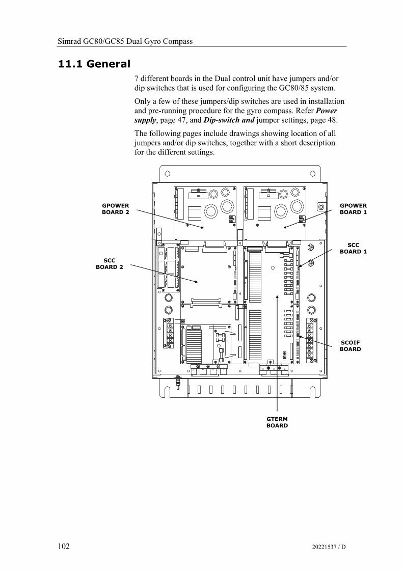
Simrad GC80/GC85 Dual Gyro Compass
102 20221537 / D
11.1 General 7 different boards in the Dual control unit have jumpers and/or dip switches that is used for configuring the GC80/85 system.
Only a few of these jumpers/dip switches are used in installation and pre-running procedure for the gyro compass. Refer Power supply, page 47, and Dip-switch and jumper settings, page 48.
The following pages include drawings showing location of all jumpers and/or dip switches, together with a short description for the different settings.
SCC BOARD 1
GTERM BOARD
SCOIF BOARD
GPOWER BOARD 1
GPOWER BOARD 2
SCC BOARD 2

DIP SWITCH SETTINGS
20221537 / D 103
11.2 GPOWER board 1 and 2
J9J10
J7
J8
TB4TB3
Jumper settings on GPOWER boards
JUMPER DEFAULT FUNCTION DESCRIPTION
J7 Open or
Short
Over-current limit set Over-current value of dc24v for Master compass is set up.
NOTE: Shall not be changed!
J8 Open Over-current limit change time
Used for inspection at a factory.
NOTE: Shall not be changed!
TB3 – TB4 Open Main power supply setting
Open = 220V AC
Short = 100/110/115V AC

Simrad GC80/GC85 Dual Gyro Compass
104 20221537 / D
11.3 GTERM board
TB4TB3
TB1
J9
J4J5
J6
J8
J7
J2
J1
TB2
J11 J12
J13
J50
Jumper settings on GTERM board
JUMPER DEFAULT FUNCTION DESCRIPTION
TB3 – TB4 - Gyro system Open = Two gyro systems
Short = One gyro system

DIP SWITCH SETTINGS
20221537 / D 105
11.4 SCC board 1 and 2
BT1
J10
J9 4
42
24
J8
313
31
J4
SW2
6
2J7
2
2J6
J5
SW1
ON
ON
ON
SW3
ON
SW4
5
1
1
1
8
1
1
1
8
1
8
6
U1
J3
U52
J1
2 1
J2
DIP switch settings on SCC boards
SWITCH DEFAULT FUNCTION DESCRIPTION
S1-1 - Control unit type OFF = Expanded, ON =Compact
S1-2 OFF Master compass type OFF = Standard, ON =High Speed
S1-3 ON Single or dual system OFF = Single, ON =Dual
S1-4 3 OFF
S1-4 4 ON Dual gyro system
NOTE:
Different settings for SSC board 1 and SSC board 2! Refer footnote below.
SW1-5 OFF
SW1-6 OFF No external sensor
SW1-5 OFF S1-5 OFF
SW1-6 ON Magnetic system connected (back-up)
SW1-5 ON
SW1-6 OFF External sensor connected
SW1-5 ON S1-6 OFF
External sensor connection
SW1-6 ON External system connected (back-up)
S1-7 OFF Serial signal format OFF = IEC61162-2 (NMEA0183, ref. page 4),
ON = Tokimec
S1-8 OFF Alarm output setup OFF = All alarms, ON = Only power failures
3 SSC board 1 (for Gyro 1): OFF 4 SSC board 2 (for Gyro 2): ON

Simrad GC80/GC85 Dual Gyro Compass
106 20221537 / D
SWITCH DEFAULT FUNCTION DESCRIPTION
SW2-1 OFF
SW2-2 OFF No output
SW2-1 OFF S2-1 OFF
SW2-2 ON Output for old monitor
SW2-1 ON
SW2-2 OFF Output for new monitor
SW2-1 ON S2-2 OFF
Data output for record
SW2-2 ON No output
S2-3 OFF Not used.
S2-4 OFF Pendulum ferry OFF = Not connected/Buzzer stop enable
ON = Pendulum function in use/Buzzer stop disable
SW2-5 OFF
SW2-6 OFF = 1sec (1Hz)
SW2-5 OFF S2-5 OFF
SW2-6 ON = 100msec (10Hz)
SW2-5 ON
SW2-6 OFF = 200msec (5Hz)
SW2-5 ON S2-6 ON
Serial signal transmit frequency IEC61162-1 ed.2
SW2-6 ON = Invalid
S2-7 OFF Alarm mask setting OFF = No alarm mask
ON = Control power abnormal
S2-8 OFF Not used.
S3-1 OFF Timer startup OFF = No, ON = Yes
S3-2 OFF Talker ID of “ROT” sentence OFF = “HE”, ON = “TI”
SW3-3 OFF
SW3-4 OFF Max 30.0 °/min.
SW3-3 OFF S3-3 ON
SW3-4 ON Max 300.0 °/min.
SW3-3 ON
SW3-4 OFF Max 120.0 °/min.
SW3-3 ON S3-4 OFF
Rate of turn scale
SW3-4 ON Invalid
S3-5 OFF Ban or permission of a “ROT” sentence output
Valid at the time of external sensor (standard) selection.
OFF = Disabled, ON = Enabled

DIP SWITCH SETTINGS
20221537 / D 107
SWITCH DEFAULT FUNCTION DESCRIPTION
S3-6 ON For Simrad use
OFF = Not used ON = Simrad GC type (80 or 85) shown in
display at start-up according to S1-2 setting.
S3-7 OFF
S3-8 OFF Not used
S4-1 OFF 38400 bps
S4-2 OFF 9600 bps
S4-3 ON
Forward bow rate
4800 bps
S4-4 OFF 38400 bps
S4-5 OFF 9600 bps
S4-6 ON
LOG serial receipt bow rate
4800 bps
Jumper settings on SCC board
JUMPER DEFAULT FUNCTION DESCRIPTION
J5 Open CPU reset Used for resetting the CPU
J6 Short Software installation
OPEN: Used when installing sw in the CSS board
NOTE: Be sure to also set "J25 and J26" on the SCOIF or MCOIF boards to OPEN.
NOTE: A damage will be given to a circuit if software is installed while this jumper has been short.
J7 3-4 short Output port: GTERM board, TB2 "1TX"
1-2 Short = Not used.
3-4 Short = IEC61162-2 or TOKIMEC version
5-6 Short = IEC61162-1 ed.2 (ref. page 4)
NOTE: Never use both jumpers at the same time!
J8 3-4 short
Serial signal output setting
Output port: GTERM board, TB2 "2TX"
1-2 Short = IEC61162-2.
3-4 Short = IEC61162-1 ed.2 (ref. page 4)
NOTE: Never use both jumpers at the same time!

Simrad GC80/GC85 Dual Gyro Compass
108 20221537 / D
JUMPER DEFAULT FUNCTION DESCRIPTION
J9 3-4 short Alarm contact setting
Output port: GTERM board, TB1 "ALCN"
1-2 Short = Alarm "CLOSES", Normal "OPEN"
3-4 Short = Alarm "OPEN", Normal "CLOSES"
NOTE: Never use both jumpers at the same time!
J10 3-4 short Running contact setting
Output port: GTERM board, TB1 "RNCN"
1-2 Short = Alarm "CLOSES", Normal "OPEN"
3-4 Short = Alarm "OPEN", Normal "CLOSES"
NOTE: Never use both jumpers at the same time!

DIP SWITCH SETTINGS
20221537 / D 109
11.5 SCOIF board
J44J45J42J43
42
31
J1542
31
42
31
J1742
31
42
31
J1642
31
42
31
2 1 J19J18 2 1
J21J20 42
31
42
31
S1
J25 2 1
2 1 J31J26 2 1
2 1 J32J30 2 1
J27J23 42
31
42
31
J33J29 42
31
42
31
J28J34 42
31
42
31
J36J35 42
31
42
31
42
31J37
42
31
42
31
42
31
13
24
1 2
6 5
J47J48J46J22
J24
42
31J38
42
31J39
42
31J40
42
31J41
DIP switch settings on SCOIF board
SWITCH DEFAULT FUNCTION DESCRIPTION
SW1-1 OFF
SW1-2 OFF No external sensor
SW1-1 OFF S1-1 OFF
SW1-2 ON Magnetic system connected (back-up)
SW1-1 ON
SW1-2 OFF External sensor connected
SW1-1 ON S1-2 OFF
External sensor connection
SW1-2 ON External system connected (back-up)
S1-3 OFF Automatic system change
OFF = NO
ON = YES
S1-4 OFF
S1-5 OFF
S1-6 OFF
S1-7 OFF
S1-8 OFF
Not used

Simrad GC80/GC85 Dual Gyro Compass
110 20221537 / D
Jumper settings on SCOIF board
JUMPER DEFAULT FUNCTION DESCRIPTION
J15 3-4 short
Output port: GTERM board, TB2: "3TX"
1-2 short = EC61162-2 or TOKIMEC version
3-4 short = IEC61162-1 ed.2 (ref. page 4)
NOTE: Never use both jumpers at the same time!
J16 3-4 short
Output port: GTERM board, TB2: "4TX"
1-2 short = EC-61162-2 or TOKIMEC version
3-4 short = IEC-61162-1 ed.2 (ref. page 4)
NOTE: Never use both jumpers at the same time!
J17 3-4 short
Serial signal output setting
Output port: GTERM board, TB2: "5TX"
1-2 short = EC61162-2 or TOKIMEC version
3-4 short = IEC61162-1 ed.2 (ref. page 4)
NOTE: Never use both jumpers at the same time!
J18 Short
J19 Short Type setup
Short: Standard
Open: With external sensor connected (type M or E)

DIP SWITCH SETTINGS
20221537 / D 111
JUMPER DEFAULT FUNCTION DESCRIPTION
J20 3-4 short
Output port: DTERM board, TB21B: "G1-1TX" and TB21D: "G1-2TX"
1-2 short = EC61162-2 or TOKIMEC version
3-4 short = IEC61162-1 ed.2 (ref. page 4)
NOTE: The true heading information on "NO.1 Gyro-compass" is output regardless of a system change.
J21 3-4 short
Serial signal output setting Output port: DTERM board,
TB21C: "G2-1TX" and TB21D: "G2-2TX"
1-2 short = EC61162-2 or TOKIMEC version
3-4 short = IEC61162-1 ed.2 (ref. page 4)
NOTE: True heading information on "NO.1 Gyro-compass" is output regardless of a system change.
J22 1-2 short Polarity of the "GPS" signal setting
Input port: GTERM board, TB1: "GRX"
1-2 short = Standard
3-4 short = Polarity is carried out reversely.
NOTE: Never use both jumpers at the same time!
NOTE: When a signal cannot be received by "1-2 short", it is set as "3-4 short."
J23 1-2 short Polarity of "LOG" signal setting
Input port: GTERM board, TB1: "LRX"
1-2 short = Standard
3-4 short = Polarity is carried out reversely.
NOTE: Never use both jumpers at the same time!
NOTE: When a signal cannot be received by "1-2 short", it is set as "3-4 short."

Simrad GC80/GC85 Dual Gyro Compass
112 20221537 / D
JUMPER DEFAULT FUNCTION DESCRIPTION
J24 1-2 short Setting receiving port of CPU on SCC board
1-2 short = An optional serial signal is received.
3-4 short = The serial signal output from SCOIF board received.
NOTE: Never use both jumpers at the same time!
J25 Short
Software install or internal communication
with "NO.1 Gyro compass"
Short: Internal communication with "NO.1 Gyro compass"
Open: Software is installed in SCC board
NOTE: A damage will be given to a circuit if software is installed while this jumper has been short.
J26 Short
Software install or internal communication
with "NO.2 Gyro compass"
Short: Internal communication with "NO.2 Gyro compass"
Open: Software is installed in SCC board
NOTE: A damage will be given to a circuit if software is installed while this jumper has been short.
J27 1-2 short LOG contact signal selection
Input port:GTERM board, TB1: "SL"
1-2 short = 200p.p.n.m.
3-4 short = 400p.p.n.m.
NOTE: Never use both jumpers at the same time!
J28 1-2 short "Rate of turn" Analog signal level selection
Output port: GTERM board, TB1 "1RT~3RT"
1-2 short = Output voltage 0v to ±5v DC or 0v to ±10v DC
3-4 short = Output voltage 0v to +5v DC or 0v to +10v DC
NOTE: Never use both jumpers at the same time!
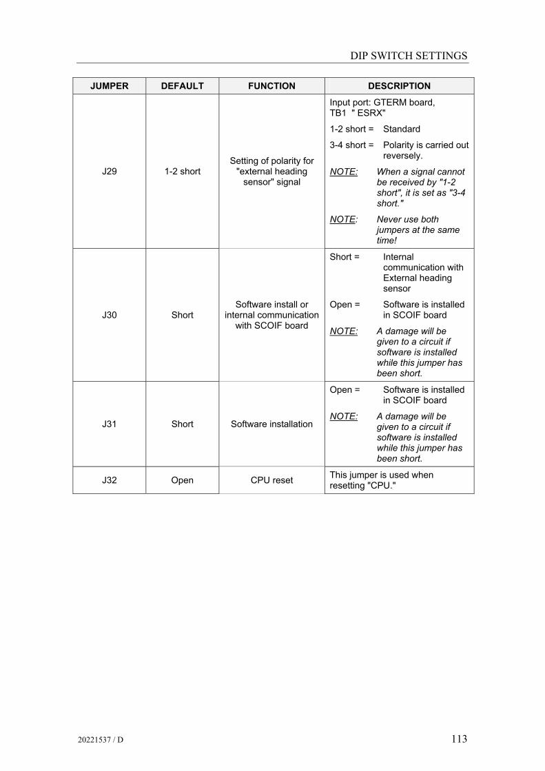
DIP SWITCH SETTINGS
20221537 / D 113
JUMPER DEFAULT FUNCTION DESCRIPTION
J29 1-2 short Setting of polarity for
"external heading sensor" signal
Input port: GTERM board, TB1 " ESRX"
1-2 short = Standard
3-4 short = Polarity is carried out reversely.
NOTE: When a signal cannot be received by "1-2 short", it is set as "3-4 short."
NOTE: Never use both jumpers at the same time!
J30 Short Software install or
internal communication with SCOIF board
Short = Internal communication with External heading sensor
Open = Software is installed in SCOIF board
NOTE: A damage will be given to a circuit if software is installed while this jumper has been short.
J31 Short Software installation
Open = Software is installed in SCOIF board
NOTE: A damage will be given to a circuit if software is installed while this jumper has been short.
J32 Open CPU reset This jumper is used when resetting "CPU."

Simrad GC80/GC85 Dual Gyro Compass
114 20221537 / D
JUMPER DEFAULT FUNCTION DESCRIPTION
J33 1-2 short
1-2 short = Standard (The serial signal of a standard external direction sensor is received, and the signal is sent to "NO.1 Gyro compass")
3-4 short = With an external heading sensor (with HDM or EHS unit) Type M or E.
J34 1-2 short
1-2 short = Standard (The serial signal of a standard external direction sensor is received, and the signal is sent to "NO.2 Gyro compass")
3-4 short = With an external heading sensor (with HDM or EHS unit) Type M or E.
J35 1-2 short
1-2 short = Standard (The serial signal of a standard external direction sensor is received, and the signal is receive from "external heading sensor")
3-4 short = With an external heading sensor (with HDM or EHS unit) Type M or E.
J36 1-2 short
Selection of Output serial signal
1-2 short = Standard (The serial signal of a standard external direction sensor is received, and the signal is receive from "external heading sensor")
3-4 short = With an external heading sensor (with HDM or EHS unit) Type M or E.

DIP SWITCH SETTINGS
20221537 / D 115
JUMPER DEFAULT FUNCTION DESCRIPTION
J37 3-4 short
Output port:GTERM board, TB2: "6TX"
1-2 short = EC61162-2 or TOKIMEC version
3-4 short = IEC61162-1 ed.2 (ref. page 4)
NOTE: Never use both jumpers at the same time!
J38 3-4 short
Output port:GTERM board, TB2: "7TX"
1-2 short = IEC61162-2 or TOKIMEC version
3-4 short = IEC61162-1 ed.2 (ref. page 4)
NOTE: Never use both jumpers at the same time!
J39 3-4 short
Output port:GTERM board, TB2: "8TX"
1-2 short = IEC61162-2 or TOKIMEC version
3-4 short = IEC61162-1 ed.2 (ref. page 4)
NOTE: Never use both jumpers at the same time!
J40 3-4 short
Output port:GTERM board, TB1: "9TX"
1-2 short = IEC61162-2 or TOKIMEC version
3-4 short = IEC61162-1 ed.2 (ref. page 4)
NOTE: Never use both jumpers at the same time!
J41 3-4 short
Output serial signal
Output port: GTERM board, TB1: "10TX"
1-2 short = IEC61162-2 or TOKIMEC version
3-4 short = IEC61162-1 ed.2 (ref. page 4)
NOTE: Never use both jumpers at the same time!

Simrad GC80/GC85 Dual Gyro Compass
116 20221537 / D
JUMPER DEFAULT FUNCTION DESCRIPTION
J42 3-4 short
Alarm contact output for Control panel (or Change Over
panel)
Output port: DTERM board. TB21D: " MALCN"
1-2 short = Alarm "CLOSES" Normal "OPEN"
3-4 short = Alarm "OPEN" Normal "CLOSES"
NOTE: Never use both jumpers at the same time!
J43 1-2 short
Running contact output for Control panel (or Change Over
panel)
Output port: DTERM board. TB21D: " MRNCN"
1-2 short = Alarm "CLOSES" Normal "OPEN"
3-4 short = Alarm "OPEN" Normal "CLOSES"
NOTE: Never use both jumpers at the same time!
J44 3-4 short
Difference alarm contact output for
Control panel (or Change Over
panel)
Output port: DTERM board. TB21D: "DFCN"
1-2 short = Alarm "CLOSES" Normal "OPEN"
3-4 short = Alarm "OPEN" Normal "CLOSES"
NOTE: Never use both jumpers at the same time!
J45 3-4 short Off course alarm contact output
Output port: DTERM board. TB21D: "OCACN"
1-2 short = Alarm "CLOSES" Normal "OPEN"
3-4 short = Alarm "OPEN" Normal "CLOSES"
NOTE: Never use both jumpers at the same time!
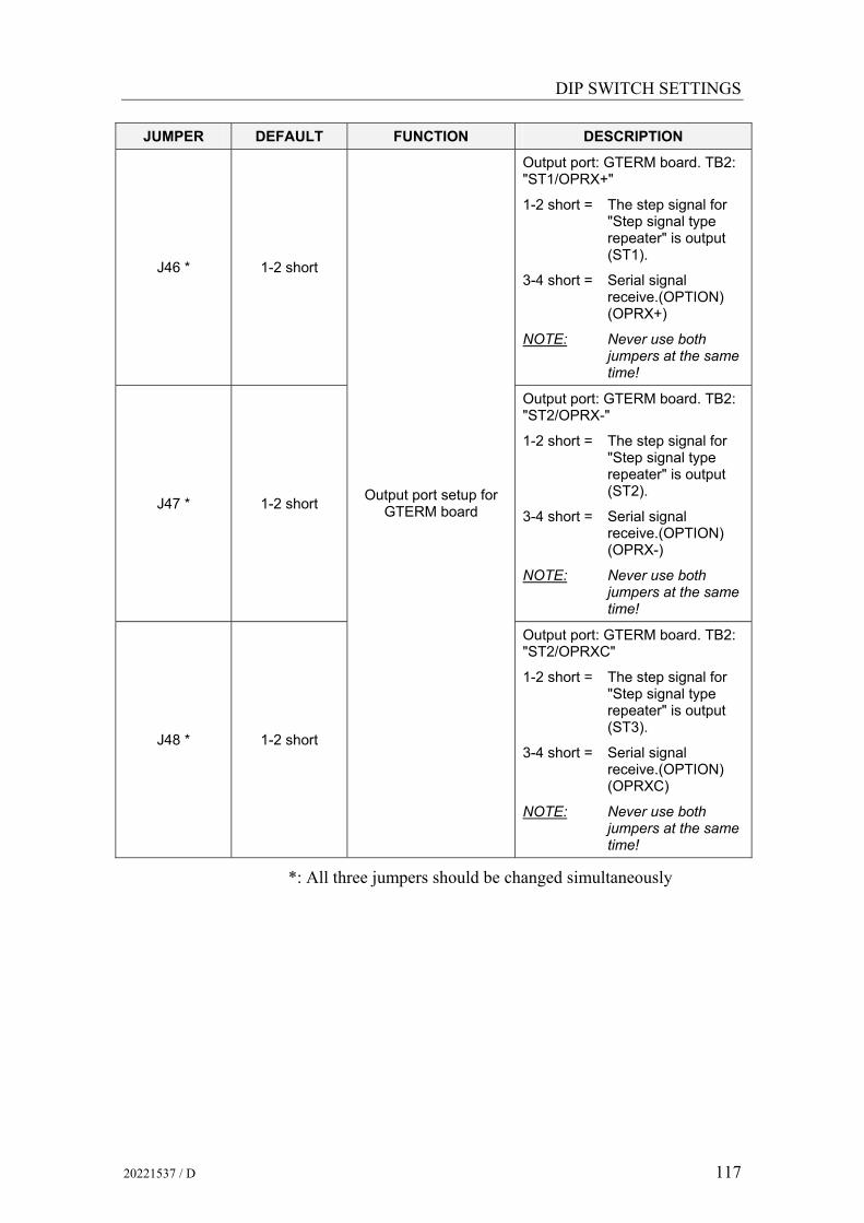
DIP SWITCH SETTINGS
20221537 / D 117
JUMPER DEFAULT FUNCTION DESCRIPTION
J46 * 1-2 short
Output port: GTERM board. TB2: "ST1/OPRX+"
1-2 short = The step signal for "Step signal type repeater" is output (ST1).
3-4 short = Serial signal receive.(OPTION) (OPRX+)
NOTE: Never use both jumpers at the same time!
J47 * 1-2 short
Output port: GTERM board. TB2: "ST2/OPRX-"
1-2 short = The step signal for "Step signal type repeater" is output (ST2).
3-4 short = Serial signal receive.(OPTION) (OPRX-)
NOTE: Never use both jumpers at the same time!
J48 * 1-2 short
Output port setup for GTERM board
Output port: GTERM board. TB2: "ST2/OPRXC"
1-2 short = The step signal for "Step signal type repeater" is output (ST3).
3-4 short = Serial signal receive.(OPTION) (OPRXC)
NOTE: Never use both jumpers at the same time!
*: All three jumpers should be changed simultaneously

Simrad GC80/GC85 Dual Gyro Compass
118 20221537 / D
11.6 PCC board
1
S1
J8J3
J61 2
PCC board
J7J1
J4 12
J52
PCC BOARD

DIP SWITCH SETTINGS
20221537 / D 119
DIP switch settings on PCC board
SWITCH DEFAULT FUNCTION DESCRIPTION
S1-1 OFF HDM function OFF = Yes, ON =No
S1-2 OFF OCA function OFF = NO, ON =Yes
SW1-3 OFF
SW1-4 OFF No external sensor connected
SW1-3 OFF S1-3 OFF
SW1-4 ON Magnetic system connected (back-up)
SW1-3 ON
SW1-4 OFF External sensor connected
SW1-3 ON S1-4 OFF
External sensor configuration
SW1-4 ON External sensor connected (back-up)
S1-5 ON Input of steering mode information
S1-6 ON SIMRAD / Tokimec ON = Simrad, OFF = Tokimec
S1-7 OFF
S1-8 OFF Not used
Jumper settings on PCC board
JUMPER DEFAULT FUNCTION DESCRIPTION
J4 Open CPU reset This jumper is used when resetting "CPU."
J5
Short Software installation
Open: Software is installed in SCCpwb
NOTE: A damage will be given to a circuit if software is installed while this jumper has been short.
J6 Open "Power supply" switch Short: Power "ON." (Power supply switch" pass.)

Simrad GC80/GC85 Dual Gyro Compass
120 20221537 / D
THIS PAGE INTENTIONALLY LEFT BLANK

ALARM LISTING
20221537 / D 121
12 ALARM LISTING This section provides a listing of alarm codes, a short description, and the possible cause for the alarm message.
Simrad GC80/GC85 Dual Gyro Compass
122 20221537 / D
12.1 The alarm system A GC80/GC85 compass will continually check for faults while the system is running.
If a fault occurs, an alarm code will be displayed in the LCD, the Alarm lamp will be flashing, and an audible alarm will be activated.
In a GC80/85 Dual system, alarms will be generated both from each single gyro compass, and from the dual system. Refer Alarm messages, page 26.
For a complete list of alarm codes, refer to the tables on the following pages.
12.2 Fault finding When an alarm is generated and not removed by pressing the ACK/ENT button, further actions should be taken to correct the alarm situation.
The following pages present a list of alarm messages that may be displayed on the gyro compass control panels and on the change over panel.
Before any fault finding procedure is started, the following actions should be performed to verify a system error:
- Shut down and restart the gyro compass
- Verify that all cables are properly connected according to the wiring diagrams, page 81 onwards
- Check the cables from the main power supply to the Control unit

ALARM LISTING
20221537 / D 123
Alarms generated by each gyro compass
Alarm code Alarm content Datailed
code Possible cause
E-1 Main power is abnormal 1 When the main power (AC power source) is lost.
2 Power supply unit in the control box becomes over current.
3 Power supply unit in the control box becomes over voltage.
E-2 Power is abnormal
4 24R is lost.
5 Inverter in the master compass becomes over current. E-3 Inverter is
abnormal 6 Inverter in the master compass becomes over voltage.
7 +12.5V is abnormal.
8 -12.5V is abnormal.
9 +10V is abnormal. E-4 *1 Control power is
abnormal
10 -10V is abnormal.
E-5 *1 Rotor current is abnormal 11 Gyro rotor current is abnormal.
E-6 Rotor tilting angle is abnormal 12 Rotor tilting angle is abnormal.
13 Horizontal servo loop is abnormal.
14 Bearing servo loop is abnormal. E-7 *1 Servo loop is abnormal
15 Rate limit is abnormal.
E-8 Zero cross is abnormal 36 Zero cross azimuth angle sensor is abnormal.
16
17
18
19
E-9 *1 Memory is abnormal
20
Memory is abnormal
21 Communication error (MCC→SCC). E-A Communication
error (1) 23 MCC is reset.
22 Communication error (SCC→MCC). E-b *1 Communication
error (2) 24 SCC is reset.
E-c GPS communication off 25 GPS system is stopped or serial signal from GPS is cut
(timeout is 15 sec.)
26 GPS latitude data abnormal (timeout is 17 sec.) E-d GPS data
abnormal 27 GPS speed data abnormal (timeout is 17 sec.)
E-E MAG/EHS communication off 32 MAG/EHS system is stopped or serial signal from GPS is
cut (timeout is 15 sec.)
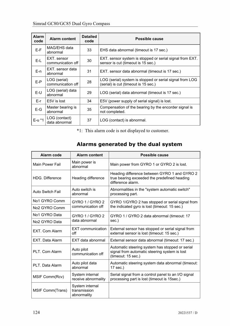
Simrad GC80/GC85 Dual Gyro Compass
124 20221537 / D
Alarm code Alarm content Datailed
code Possible cause
E-F MAG/EHS data abnormal 33 EHS data abnormal (timeout is 17 sec.)
E-L EXT. sensor communication off 30 EXT. sensor system is stopped or serial signal from EXT.
sensor is cut (timeout is 15 sec.)
E-n EXT. sensor data abnormal 31 EXT. sensor data abnormal (timeout is 17 sec.)
E-P LOG (serial) communication off 28 LOG (serial) system is stopped or serial signal from LOG
(serial) is cut (timeout is 15 sec.)
E-U LOG (serial) data abnormal 29 LOG (serial) data abnormal (timeout is 17 sec.)
E-r E5V is lost 34 E5V (power supply of serial signal) is lost.
E-G Master bearing is abnormal 35 Compensation of the bearing by the encorder signal is
not completed.
E-u *1 LOG (contact) data abnormal 37 LOG (contact) is abnormal.
*1: This alarm code is not displayed to customer.
Alarms generated by the dual system
Alarm code Alarm content Possible cause
Main Power Fail Main power is abnormal Main power from GYRO 1 or GYRO 2 is lost.
HDG. Difference Heading difference Heading difference between GYRO 1 and GYRO 2 true bearing exceeded the predefined heading difference alarm.
Auto Switch Fail Auto switch is abnormal
Abnormalities in the "system automatic switch" processing part.
No1 GYRO Comm
No2 GYRO Comm GYRO 1 / GYRO 2 communication off
GYRO 1/GYRO 2 has stopped or serial signal from the indicated gyro is lost (timeout: 15 sec.)
No1 GYRO Data
No2 GYRO Data GYRO 1 / GYRO 2 data abnormal
GYRO 1 / GYRO 2 data abnormal (timeout: 17 sec.)
EXT. Com Alarm EXT communication off
External sensor has stopped or serial signal from external sensor is lost (timeout: 15 sec.)
EXT. Data Alarm EXT data abnormal External sensor data abnormal (timeout: 17 sec.)
PLT. Com Alarm Auto pilot communication off
Automatic steering system has stopped or serial signal from automatic steering system is lost (timeout: 15 sec.)
PLT. Data Alarm Auto pilot data abnormal
Automatic steering system data abnormal (timeout: 17 sec.)
MSIF Comm(Rcv) System internal receive abnormality
Serial signal from a control panel to an I/O signal processing part is lost (timeout is 15sec.)
MSIF Comm(Trans) System internal transmission abnormality
Related Documents


