INSTALLATION AND OPERATION MANUAL CONTROLLER GC3 ELECTROGRIP

Welcome message from author
This document is posted to help you gain knowledge. Please leave a comment to let me know what you think about it! Share it to your friends and learn new things together.
Transcript

INSTALLATION AND OPERATION MANUAL
CONTROLLERGC3
ELECTROGRIP

WARRANTYLIABILITY. Although all care is taken to ensure stated, safe, and reliable performance, Electrogrip can not be held liable for any direct or consequential damages arising from the use or abuse of this equipment. Detailed descriptive, hazard and use data is provided with each unit. Proper operating and safety procedures must be followed and reasonable care must be taken by the user to avoid hazards.
GUARANTEE. Products manufactured by Electrogrip are warranted against defects in workmanship and components for 1 year after shipment from Electrogrip to the buyer. Liability under this warranty is expressly limited to replacement or repair (at Electrogrip's option) of defective parts. Electrogrip may at any time discharge its warranty as to any of its products by refunding the purchase price and taking back the products.All warranty replacement or repair of parts shall be limited to equipment malfunctions which, in the sole opinion of Electrogrip, are due or traceable to defects in original materials or workmanship. Malfunctions caused by abuse or neglect of the equipment are expressly not covered by this warranty. One particular such abuse is accessing, attempting to read, or reading the drive unit microcode. In-warranty repaired or replacement parts are warranted only for the remaining unexpired portion of the original warranty period applicable to the parts which have been repaired or replaced.After expiration of the applicable warranty period, the buyer shall be charged at Electrogrip's then current prices for parts and labour plus transportation.Except as stated herein, Electrogrip makes no warranty, expressed or implied (either in fact or by operation of law), statutory or otherwise: And, except as stated herein, Electrogrip shall have no liability for special or consequential damages of any kind or from any cause arising out of the sale, installation, or use of any of its products. Statements made by any person, including representatives of Electrogrip, which are inconsistent or in conflict with the terms of this warranty shall not be binding upon Electrogrip unless reduced to writing and approved by Electrogrip.
Service contracts are available for Electrogrip products. For additional assistance, contact Electrogrip or its authorised agent.
GC3 Controller
Page 2

CONTROLLER
GC3
This manual refers to Electrogrip Model GC3 Controllers
for use with:
Wafer lift stepper motor drive Rf Filter RFF-1;Electrostatic Driver versions DR3, DR4, DR5; andElectrogrip Electrostatic Chucks.
Revision _3_ 11 October 2005
Copyright 1995, 7; 2000 ,5 ELECTROGRIP6945 Lynn Way Pittsburgh PA 15208 USA
GC3 Controller
Page 3

CONTENTSOPERATIONAL SAFETY 5INPUT POWER, INTERLOCKS, HIGH VOLTAGE CAUTIONS 5GENERAL INFORMATION 6INTRODUCTION, DESCRIPTION, PANEL LAYOUTS 6SPECIFICATIONS 7INSTALLATION 8INTRODUCTION, UNPACKING, INSTALLATION TOOLS 8INSTALLATION, TEST 9OPERATION 10INTRODUCTION, CONTROLLER FUNCTIONS, FRONT AND REAR PANELS 10CONNECTIONS 1 2
CONTROL, INTERLOCK DB-15 CONNECTORS 12FLOW & PRESSURE CONTROL 13BACKPRESSURE SENSOR, PURGE VALVE 14STEPPER MOTOR WAFER LIFT, POSITION SENSOR 14SERIAL PORT 14VACUUM, GAS, ELECTRONIC CONNECTIONS 15
ADJUSTMENT AND PROGRAMMING 17INTRODUCTION 17USER INTERFACE FORMAT 17
CONNECTIONS 17MEMORY TYPES 17POWER-UP ACTIONS 17MENU FORMAT, NAVIGATION 17NUMERICAL FORMAT, NUMBER ENTRY 17MENU FORMATS 18
OPTION and PARAMETER DEFINITIONS 19OPTION DEFINITIONS 19PARAMETER DEFINITIONS 20
SAMPLE SESSION TEXT 21POWER-UP 21MENU CHANGE AND OPTION SETTING 22PARAMETER VALUE SETTING 23HEIGHT SENSOR CALIBRATION 24SERIAL PORT COMMAND RESPONSES 26
GC3 SERIAL PORT COMMANDS 27MOTOR MOVEMENT CONTROL 27
LIST OF ILLUSTRATIONSFig. 1 Front Panel (rack or horizontal DIN version) 6Fig. 2 Rear Panel (rack or horizontal DIN version) 7Fig. 3 Controls (vertical DIN GC1; GC3 is similar) 10Fig. 4 Control, Interlock connector pins 12Fig. 5 Flow & Backpressure Control plus Power Input connector pins 13Fig. 6 Pressure Sensor, Purge Valve connector pins. Mini-Din 8 rear panel socket view. 14Fig. 7 Motor Drive and Position Sensor pins. Mini-Din 6 rear panel socket view. 14Fig. 8 Serial Port connector pins 14Fig. 9 Vacuum and gas connections 15Fig. 10 System wiring 16Fig. 11 Pressure sensor wiring; on Electrogrip Interface Board 16
GC3 Controller
Page 4

OPERATIONAL SAFETY
INPUT POWER
This unit is powered from a +15V power source, normally derived from a mass flow controller connecton tap. Before connecting this unit, please ensure that its power is in the range 13.5-18V. The GC3 controller is NOT protected against reverse polarity power connections. Reversed power will cause extensive damage. An additional -15V source is not required by the GC3.
The GC3 is filtered against radio-frequency interference on its connection cables.
The motor drive and position sensing circuits are at rf bias potential and are connected using a recessed rear panel socket. Contact to the rf bias potential is not possible on a mated connector. Use caution when connecting the motor drive cable in the presence of rf bias. See caution, below.
INTERLOCKS
The GC3 controller interfaces directly with the DR4 or DR5 driver, passing the DR4/5 interlock line transparently through the GC3 at the same connector pin numbers. An interlock switch closure or signal from a control computer must be provided to enable the DR4/5 driver output. This interlock must be arranged to cut high voltage output when driver output terminals may be exposed. For example, any high-voltage access plate requires a microswitch in series with the interlock line which opens if the access plate is opened.
HIGH VOLTAGE CAUTIONSOnly for stepper motor wafer lift option with an rf-driven chuck;
The stepper motor drive electronics floats at the dc bias potential developed on the chuck. Operation must be in accordance with instructions given here and with normal safety practices for high voltage systems.
DANGER
HIGH DC BIAS VOLTAGES ARE PRESENT ON THE STEPPER MOTOR CONNECTOR WIRES WITH RF-POWERED CHUCKS.
GC3 Controller
Page 5

GENERAL INFORMATION
INTRODUCTIONThis section gives a description of the instrument and its specifications.
DESCRIPTION The GC3 Controller permits temperature-controlling electrostatic chuck systems to be installed in existing or new vacuum process chambers with a minimum of control wiring, yet permitting full operation and debugging flexibility. The GC3 interfaces directly with the Electrogrip DR4 or DR5 Electrostatic Driver for electrostatic chucks. Connection to rf-powered chucks for stepper motor wafer lift is through an Electrogrip RFF-1. Interconnection between sensors and an external control computer is facilitated using the Electrogrip GC Interface circuit board. The GC3 controls all aspects of chuck operation, from wafer lowering, grip and gas fill to sequenced process termination. Operation may be initiated manually or by computer.
The Electrogrip GC3 Controller accepts a start/stop signal to initiate an rf-driven backfilled electrostatic chuck process. The GC3 Controller interfaces with:
• all commercial backfill gas mass flow controllers;• all commercial backfill gas purge valves;• all commercial backfill gas pressure gauges, including the Electrogrip type BP1;• stepper motor wafer lifter and position sensor through the rf filter RFF-1;• Electrogrip DR4 or DR5 Electrostatic Driver; and a• central control computer. • In addition the CG2 front panel displays backfill gas flow and pressure, and their remote and manually set
setpoints, and has front panel switches for manual or automatic control.
The GC3 Controller is filtered on both inputs and outputs to minimise the corrupting effects of rf radiation and pickup. 13.56MHz signals of more than 7Vp-p injected directly into any input or output have no effect on GC3 performance.
PANEL LAYOUTS
ELECTROGRIPController
LOCAL
REMOTE SETPOINT SETPOINT
ACTUAL ACTUAL
DISPLAY DISPLAY
GAS FLOW (He sccm) CHUCK BACKPRESSURE (Torr)
CONTROL
STARTPROCESS
STOPPROCESS
FAULT
Fig. 1 Front Panel (rack or horizontal DIN version)
GC3 Controller
Page 6

ELECTROGRIP
FROM ELECTROSTATIC DRIVERGAS FLOW CONTROL
TO CONTROL COMPUTER
SERIAL PORTPRESSURESENSOR,
PURGE VALVE 1
LIFT MOTOR,PURGE VALVE 2
BACKPRESSURE
Model GC2
Made in the U.S.A.
Serial #
Rev
Date
Fig. 2 Rear Panel (rack or horizontal DIN version)
SPECIFICATIONS
CONTROLLER GC2 SPECIFICATIONS
BACKFILL GAS FLOWFULL SCALE SIGNAL INPUT 0 - 5 to 10VSENSOR FULL SCALE (display reads 0-20 sccm) 1 - 100 sccmSETPOINT INPUT, FLOW CONTROL OUTPUT 0 - 5V
BACKFILL GAS PRESSUREFULL SCALE SIGNAL INPUT 0 - 0.1 to 10VSENSOR FULL SCALE (display reads 0-20 Torr) 10 - 1000 TorrSETPOINT INPUT, SIGNAL OUTPUT 0 - 5V
CONTROL SIGNAL LOGIC LEVELSOUTPUTS open collector, optional internal pullup, max. 30VINPUTS CMOS 5V logic input, optional internal divider
ISOLATION to input power, mfc, pressure sensor, control linesSTEPPER MOTOR / MOTOR PURGE 4000V
INPUT POWER 14 - 18V, 2A
SERIAL PORT6 pin RJ - 11 connector, RS-232 with 5V power to handheld display
OUTPUT DRIVE RATINGSBACKPRESSURE PURGE VALVE 12V, 100ΩPARALLEL PORT LOGIC (TTL open collector) 30V, 10mASTEPPER MOTOR LINES (2 phase bipolar) 20V, 250mA
GC3 Controller
Page 7

INSTALLATION
INTRODUCTION
This section of the manual describes initial setup and operation of the GC3 controller. Additional information required for setup will be found in the following section for connector pin wiring.
UNPACKINGIn your package you should find:(i) Controller unit GC3(ii) Cable to Driver (ribbon cable with two DB15 connectors)(iii) Cables to GC Interface Board (one DB9 connector on GC3 end).(iv) DB15 connector for external computer control and interlock connection(v) Mini-Din 8 to DB25 cable for purge valve, and possibly to pressure sensor(vi) GC Interface Board in open-front metal box
For BP option;(vii) Pressure sensor
For BV option;(viii) Backside gas purge valve
For SM option;(ix) Mini-Din 6 double-ended cable for stepper motor and motor purge valve(x) RFF-1 filter box for stepper motor and motor purge valve(xi) Stepper motor and position sensor assembly if not installed in chuck
INSTALLATION TOOLS
You will require the following items for installation:(i) Attachment hardware for mounting GC3 into rack or other enclosure.(ii) Screwdrivers for rack mount, DB connectors, and GC Interface Board wiring.(iii) Interlock cable from o microswitch on chuck high voltage shield enclosure;
OR o computer interlock line (hi for safe, lo for open / unsafe).This cable connects to the interlock pin(s) on the DB15 control computer connector.
(iv) Plumbing and attachment hardware, cables for valves, pressure sensor, MFC's, and stepper motor filter RFF-1. This may include connection tap adaptors for the MFC's, included with the GC3 delivery.
Additional; Electrogrip Interface Enclosure with sensors, plumbing, interlocks, etc.(v) DS1 serial port handheld terminal or equivalent, plugged into the rear serial port.
GC3 Controller
Page 8
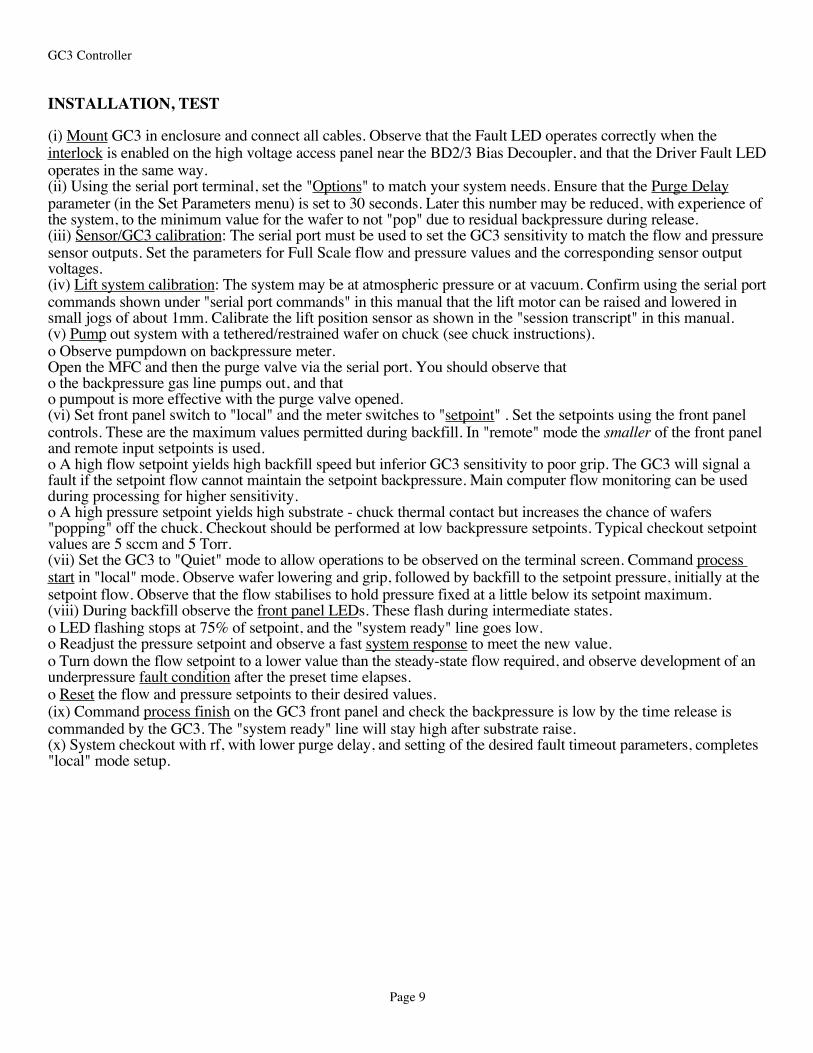
INSTALLATION, TEST
(i) Mount GC3 in enclosure and connect all cables. Observe that the Fault LED operates correctly when the interlock is enabled on the high voltage access panel near the BD2/3 Bias Decoupler, and that the Driver Fault LED operates in the same way.(ii) Using the serial port terminal, set the "Options" to match your system needs. Ensure that the Purge Delay parameter (in the Set Parameters menu) is set to 30 seconds. Later this number may be reduced, with experience of the system, to the minimum value for the wafer to not "pop" due to residual backpressure during release.(iii) Sensor/GC3 calibration: The serial port must be used to set the GC3 sensitivity to match the flow and pressure sensor outputs. Set the parameters for Full Scale flow and pressure values and the corresponding sensor output voltages.(iv) Lift system calibration: The system may be at atmospheric pressure or at vacuum. Confirm using the serial port commands shown under "serial port commands" in this manual that the lift motor can be raised and lowered in small jogs of about 1mm. Calibrate the lift position sensor as shown in the "session transcript" in this manual.(v) Pump out system with a tethered/restrained wafer on chuck (see chuck instructions). o Observe pumpdown on backpressure meter. Open the MFC and then the purge valve via the serial port. You should observe that o the backpressure gas line pumps out, and that o pumpout is more effective with the purge valve opened. (vi) Set front panel switch to "local" and the meter switches to "setpoint" . Set the setpoints using the front panel controls. These are the maximum values permitted during backfill. In "remote" mode the smaller of the front panel and remote input setpoints is used.o A high flow setpoint yields high backfill speed but inferior GC3 sensitivity to poor grip. The GC3 will signal a fault if the setpoint flow cannot maintain the setpoint backpressure. Main computer flow monitoring can be used during processing for higher sensitivity. o A high pressure setpoint yields high substrate - chuck thermal contact but increases the chance of wafers "popping" off the chuck. Checkout should be performed at low backpressure setpoints. Typical checkout setpoint values are 5 sccm and 5 Torr.(vii) Set the GC3 to "Quiet" mode to allow operations to be observed on the terminal screen. Command process start in "local" mode. Observe wafer lowering and grip, followed by backfill to the setpoint pressure, initially at the setpoint flow. Observe that the flow stabilises to hold pressure fixed at a little below its setpoint maximum.(viii) During backfill observe the front panel LEDs. These flash during intermediate states. o LED flashing stops at 75% of setpoint, and the "system ready" line goes low.o Readjust the pressure setpoint and observe a fast system response to meet the new value.o Turn down the flow setpoint to a lower value than the steady-state flow required, and observe development of an underpressure fault condition after the preset time elapses.o Reset the flow and pressure setpoints to their desired values.(ix) Command process finish on the GC3 front panel and check the backpressure is low by the time release is commanded by the GC3. The "system ready" line will stay high after substrate raise.(x) System checkout with rf, with lower purge delay, and setting of the desired fault timeout parameters, completes "local" mode setup.
GC3 Controller
Page 9

OPERATION
INTRODUCTIONThis section describes the GC3 controller functions, front panel controls, front panel indicators, and rear panel connectors. Wiring diagrams for the connectors are given.
CONTROLLER FUNCTIONSThe GC3 Controller lowers wafers onto a chuck. It then commands wafer grip by the DR4/DR5 (“DR”) Driver. It sequences gas backfill such that backfill is begun only after a wafer has been gripped correctly, and that backfill is accomplished within a set time. During wafer processing the GC3 monitors gas and grip conditions for change or abnormal conditions, and adjusts or signals accordingly. At process termination the GC3 vents the gas backfill and after a "purge delay" commands wafer release. Upon proper release the substrate is raised for robot pickup. Thus a complete process sequence can be implemented with a GC3 Controller and a process timer or single control line, simplifying implementation and installation of electrostatic chucks.
FRONT AND REAR PANELS
ELECTROGRIP
Model GC1Serial #
FROMELECTROSTATICDRIVER
GAS FLOW CONTROL
TO CONTROLCOMPUTER
BACKPRESSUREOUTPUT
SERIAL PORT
BACKPRESSURESENSOR, PURGE VALVE
WAFER LIFTMOTOR, PURGE VALVE
ELECTROGRIPGas Controller
CONTROL
GAS FLOW (He sccm)
CHUCK BACKPRESSURE (He Torr)
LOCAL
GRIP
REMOTE
RELEASE
FAULT
SETPOINT
SETPOINT
ACTUAL
ACTUAL
DISPLAY
DISPLAY
1
3 2
4
5
6
7
8 9
10
11
12
13
14
15
16
17
Fig. 3 Controls (vertical DIN GC1; GC3 is similar)
GC3 Controller
Page 10

1. CHUCK BACKPRESSURE display: Backpressure sensor output, internally scaled.
2. BACKPRESSURE SETPOINT control: Sets the maximum backfill backpressure.
3. DISPLAY SWITCH: Allows display of backpressure value, or current setpoint (the minimum value of control 2's value and the externally control input value if in Remote setting on Control Switch 10; or setpoint control 2's value if in Local setting).
4. GAS FLOW display: Displays flow sensor output, scaled internally.
5. FLOW SETPOINT control: Sets the max. allowable flow. In the absence of an external control signal, this is the flow level commanded during initial fill.
6. DISPLAY SWITCH: Allows display of flow value, or current setpoint (the minimum value of control 5's value and the externally control input value if in Remote setting on Control Switch 10; or setpoint control 5's value if in Local setting).
7. PROCESS STOP / START LEDs: STOP lit when process is terminated and substrate is ready for pickup. START lit when process rf power is capable of being used. Both flashing when in intermediate state & power-up.
8. PROCESS STOP / START SWITCH: STOP terminates a process in a staged fashion; purging gases, commanding release of the wafer and then raising it after release is signalled by the DR driver. START starts a process by lowering a wafer, commanding grip, then after confirmation of grip from the driver backfills with gas.
9. FAULT LED: On when DR signals a fault, or when a process takes too long to be correct operation (see "Parameter Settings"). Recovery from faults during an operating process is via commanding STOP, then letting the Fault indication clear before commanding START to complete the interrupted process.
10. LOCAL / REMOTE SWITCH: Controls whether external control signals for grip / release and control levels for backpressure and flow will be used, or the front panel grip / release switch and setpoints. Local front-panel setpoints are the maximum possible values under both local and remote operation, thus protecting against damaging external levels.
11. GAS FLOW CONTROL: Connects to mass flow controller, external flow setpoint, and power supply. Flow signal is shown on display 4 after scaling.
12. BACKPRESSURE OUTPUT: Connects to pressure sensor and external pressure setpoint. Alternate pressure input on connector 15, appropriate for high-level pressure signals only.
13. FROM DRIVER: Connect to DR4 Electrostatic Driver. GC3 controls driver operation, and uses status signals from DR4 to sequence operation.
14. TO CONTROL COMPUTER: Connect to control computer, which can toggle the "process start" line and observe system status ("ready", "fault"), and possibly provide interlock drive. Interlock closure of some type must be connected here. Note that the control computer also may drive the setpoints for flow and backpressure if desired, through connectors 11 and 12.
15. BACKPRESSURE, PURGE: Connects to and powers with ±15V optionally a backpressure sensor, and a purge valve (min. 100Ω coil resistance, 12-15V operation).
16. WAFER LIFT, PURGE: Isolated to 4000V from rest of system. Powers a small linear stepper motor and a position sensor. No longer powers a purge valve.
17. SERIAL PORT: RS-232 communication, control, and setup port. May be used for serial communication with host computer.
GC3 Controller
Page 11

GC3 Controller
Page 12

CONNECTIONS
CONTROL, INTERLOCK DB-15 CONNECTORSWiring to the Control, Interlock connectors 13, 14 is shown below. Refer also to the description of pin use in the DR4 Driver manual.
xtrain (user definable)
timeout error(lo if error)
DB-1
5
12345678
9101112131415
chassis gnd(control logic reference voltage; isolated)
remote grip/release(grip upon low; release upon hi
wafer sense output(pulls down when sensed)
interlock input(hi to remove fault)
interlock supply(high impedance chassis power)
chassis power(+5V output OR +6V to +30V logic supply input)
fault output (low if fault due to open interlock circuit)
wafer gripped output(low if wafer is being gripped)
xtraout(user definable)
extrain2(active hi)
FROM DR4 / DR5 DRIVER; MALE DB-15
DB-1
5
12345678
9101112131415
chassis gnd(control logic reference voltage; isolated)
remote process start(start and grip upon low; stop and release upon hi
wafer sense output(pulls down when sensed)
interlock input(hi to remove fault)
interlock supply(high impedance chassis power)
chassis power(+5V output OR +6V to +30V logic supply input)
fault output (low if fault due to open interlock or timeout)
system ready output(low if wafer is ready for rf power)
xtraout(user definable)
extrain2(active hi)
TO CONTROL COMPUTER; FEMALE DB-15
Above connector goes via 15-way ribbon cable to DR4 control input.
Above connector used for remote control of system, if required (operates when local/remote switch in remote position).
motor error(lo if error)
lift pins up (when pulled hi) ;lift pins down (when pulled lo)
extrainA(user definable)
xtrain (user definable)
Fig. 4 Control, Interlock connector pins
Minimal wiring for high voltage output: connect pins 5 and 6 via a high voltage interlock switch.Minimal addition for remote control: drive pin 2 both high and low to control process start.Additions for robotic feedback and fault monitoring: Fault, Sense, System Ready outputs used.Balance adjustment (required if chuck is asymmetric): drive pin 15 high to generate an ac signal on the gripping electrodes. Used to adjust the relative output levels of the A and B outputs to null the potential of a wafer on the chuck.
GC3 Controller
Page 13

FLOW & PRESSURE CONTROL; POWER INPUTGas flow external setpoints, mass flow controller drive, and mass flow reading input are connected in the Gas Flow Control connector 11 shown in Fig. 5. In addition power input to the GC3 Controller is derived from the +15V line. These lines are connected in parallel with the same pins on the Backpressure Output connector in Fig. 5.
The Backpressure Output connector 12 accepts an external backpressure setpoint and a pressure sensor signal.
A minimal connection to the external setpoint inputs is to leave them open circuit OR to drive them high (+5V). The GC3 controller will then operate from the internally set setpoints in both local and remote control settings.
DB-9
12345
6789
GAS FLOW CONTROL; MALE DB-9External Flow Setpoint Input0-5V signal to GC1, sets maximum flow to be allowed.Setpoint Ground ; take to ground of computer source.Setpoint Output to MFC0-5V signal; controls flow level in MFCPower GroundMain power ground for system
Connect to Flow Outputfrom MFC. This signal is shown on GC1 display
Flow Output Ground; take to signal ground of MFC+15V Power Input
Preferably use 18V supply here, 1.5A current capability-15V Optional Power Input
About 100mA here; internally generated if not supplied.ALTERNATIVE TO POWERING HERE;
see DB-25 connector, below.DB
-9
12345
6789
BACKPRESSURE OUTPUT; MALE DB-9External Pressure Setpoint Input0-5V input from control computer, if required
Setpoint Ground;Connect to ground of computer source, if used.
Pressure Outputfrom pressure sensor into the GC1
Pressure Output Ground; from pressure sensor+15V Power Input
-15V Optional Power Input;These inputs are same as Gas Flow Control inputs; no
need to connect power to more than one connector.
Fig. 5 Flow & Backpressure Control plus Power Input connector pins
GC3 Controller
Page 14

BACKPRESSURE SENSOR, PURGE VALVEThe Backpressure Sensor and Purge Valve connector 15 is shown below. The valve is connected between +15V and line 1. For more accurate pressure readings with ground voltage sensing, use the "Backpressure Output" DB-9 connector on previous page.
12
35
678
-15V
+15Vto valve and sensor
switchedline to valve
pressureoutput
4, 7, 8 = gnd nc
DB-2
5 co
nnec
tor
Term
inal
Stri
p
3 Pressure Output from backpressure gauge7 Ground2 -15V (unregulated)5 +15V (unregulated) to sensor if required
20 Purge Valve; connect a 12V mini solenoid between pins 20 and 5 for backside chuck purge. Solenoid drives pneumatic valve from chuck rear to foreline/load lock.
4
Above Mini-Din 8 and DB-25 connectors connected via cable (provided).
ALTERNATIVE POWER INPUT; can apply +15V to pin 5 to pin 2 of DB-25 connector.
Optional connection ofVALVE DRIVE; rear panel socket view
Fig. 6 Pressure Sensor, Purge Valve connector pins. Mini-Din 8 rear panel socket view.
STEPPER MOTOR WAFER LIFT, POSITION SENSORWiring to the Stepper Motor and Motor Purge Valve connector 17 is shown below. The position sensor is connected between pins 5 and 6.
12
34
56
MOTOR DRIVE; rear panel socket viewswitched + 5V
Pins 5, 6 carry signals to and from the height sensor.
B2 B1
A2 A1MOTOR PHASES
Connected to stepper motor through RFF-1 filter; isolated drive system for motor at rf potential
Fig. 7 Motor Drive and Position Sensor pins. Mini-Din 6 rear panel socket view
SERIAL PORTThe Serial Port 17 (Fig. 11) uses 9600 Baud, no parity, 8 bit, one stop and one start bit.
gnddata to GC1
data from GC1
power(+5V output)
mod
ular
6 p
in
123456
Fig. 8 Serial Port connector pins
GC3 Controller
Page 15

VACUUM, GAS, ELECTRONIC CONNECTIONSVACUUM SYSTEM PLUMBING
TURBO ROUGH
CHUCK
NO !! SHUTOFF VALVE ON MFC OUTPUT; MFC LEAKAGE CAN YIELD
EXCESSIVE SURGE PRESSURES
MFCBACK-
PRESSURE GAUGE
NEEDLE VALVE, MEDIUM FLOW TYPE (NOT FINE); ASSISTS IN
SYSTEM STABILITY AND SAFETY FOR LOW CHUCK
LEAKAGE RATES
HELIUM INPUT
PURGE VALVE
GB1 GAS BREAK
INTERFACERF SHIELD
ENCLOSURE
PLASMA CHAMBER
Needle valve; suggested Nupro ss-4mg-vcr medium flowPurge valve; suggested Nupro ss-4bk-vcr-1c bellows sealed air actuatedPurge actuator; 12V mini control solenoid eg Clippard 12V (McMaster Carr 4916k22, with 3 polybutylene tube fittings for 1/4" tubing 52065k116)
optional shutoff valve
Fig. 9 Vacuum and gas connections
GC3 Controller
Page 16

SYSTEM WIRNG DIAGRAM
DR4 driver
GC2controller
InterfaceBoard
InterfaceEnclosure
DB15 - DB15 ribbon
PowerSupply
+15V gnd -15V
A outB out DB15 - DB15 ribbonDB9-DB9 ribbon flow
DB9-DB9 ribbon P
MiniDin8 - MinDin8 motor
MiniDin6-DB25 valveMFC power, signalPurge valve drivePressure sensorInterlock
Computer Controller/ Terminal
serial cable serial cable
parallel cable
driver power cable, to power source
BiasV
BD-3 RFF-1
Fig. 10 System wiring
Pressure sensor wiring: using Electgrogrip pressure sensor.
78L05regulator
0.1µF 0.1µF
1kΩ, 1%
100Ω, 1%pressure output ground
pressure output
red
black (blue)
green
zero trim R; about 2.2kΩ
backpressure sensor
1/4" NPT male fitting
+15V
ground
in +5V out
common
Fig. 11 Pressure sensor wiring; on Electrogrip Interface Board
GC3 Controller
Page 17

ADJUSTMENT AND PROGRAMMINGINTRODUCTIONThis section describes how parameters may be monitored and modified using terminal commands to a GC3 driver serial port. Software version 2.0 is described here.
Typical adjustments and parameter settings are:o Height sensor calibration, maximum lift height, and motor step size;o Flow and pressure sensor full scale sensed values and output voltages;o Options for output line flashing, wafer lift sequencing, and control of backpressure;o Timeout values for permitting operations before a fault is signalled;o Time to wait between process steps, to allow system settling.
Additional functions performed include:o Monitoring of system status (height, action performed last);o Full control of the unit on the serial line, permitting; grip, release, purge, MFC full open,
wafer lift in large or small steps, height calibration of position sensor.o Storage of operating parameters in user-configurable memory;o Rapid changeover of operating modes through "Load" and "Dump" functions;o Autozeroing of output voltages at turn-on;o Quiet mode operation for minimal serial port activity.
USER INTERFACE FORMATCONNECTIONS9600 Baud; [no parity, 8 bit, 1 stop bit] or ["space" parity, 7 bits, 1 stop bit]. Use a "Modem" computer cable on DB-9 socket / DS1 Electrogrip terminal on RJ-11 phone jack.
MEMORY TYPES The GC3 contains two types of memory; (i) program storage which includes RAM space for storage of current parameter values;(ii) an electrically erasable EEPROM for long-term storage of adjustable parameters.The following user interface information relates to EEPROM and RAM access only.
POWER-UP ACTIONS When the GC3 is first powered up it will:(i) Do two inital "dumps" which will fill RAM with previously stored values;(ii) Raise the substrate (if this option is set);(iii) Display main menu. MENU FORMAT, NAVIGATIONGC3 software menus consist of four lines that contain numbers, words and questions, with some letters in words capitalised. These capitalised letters are keys for menu navigation.-Capitalised letters in keywords represent keys that can be pressed to call the function or menu corresponding to that keyword.- Upper or lower case characters are read identically.-Two dots ".." following a menu item indicate that it calls up another menu which will give further choices.-Because of space limitations not all possible valid entries are shown.
-e.g., X and ESC (escape) keys often cause return to the main menu.
NUMERICAL FORMAT, NUMBER ENTRY All values are in HEXADECIMAL format, not DECIMAL. Numbers use base 16, not base 10, and the additional numerals required are letters. Hence allowable numerals are 0, 1, 2, 3, 4, 5, 6, 7, 8, 9, A, B, C, D, E, and F. Single-byte (8-bit) numbers have the format 00 to FF (0 to 255 decimal), while double-byte numbers have the format 0000 to FFFF.-Numbers are output with leading $ signs to denote their hexadecimal base.-Numeric data for parameter adjustment can be entered using:
(i) Numbers (hexadecimal format); or(ii) +, - (plus and minus) keys for fast one-digit changes to any of the parameters.
GC3 Controller
Page 18

These changes affect RAM values only. Thus finish with a "Save" to EEPROM when correct parameter values are determined. This "Save" action will save the current parameter ONLY. Other parameters which have been changed but not individually saved will be lost upon power-down.-Numeric data for some parameters is in a format which allows two parameters per line to be stored, as a pair of two-digit numbers.
In these cases you can not enter values for just one parameter; both must be entered. Hence enter a four-digit number, altering just the pair of numbers corresponding to the parameter to be changed.-To abort a parameter alteration in progress, press ESC (Escape) or some other non-numeric key (ie, other than 0-9 or A-F) BEFORE entering a number. MENU FORMATSMAIN MENU This periodically refreshed menu is: Ht/0.1mm = $00 Substrate height, 100µm units Electrogrip (c) 1999 Electrogrip, copyright GC3 v 2.00 Ht cal..; Version, Ht. Cal. command Set.., Dump, Load: Main menu command line
Ht/0.1mm is the height returned by the height sensor, in units of 100µm; requires calibration using the Ht cal command. Zero is fully lowered substrate.Ht cal for height calibration is started by pressing H or h. For v.2.0 through 2.12 software, the TRVLmm/Step ms and Total Steps/4 parameters must be entered, at least approximately, before calibration commences. See sample session transcript for more details.S = Set.. Calls up another menu for calibrations and setup. See below.D = Dump (i) Lists all values in RAM, which can be captured and later down-loaded into a driver to give it the identical values of all set parameters and options.
(ii) Then dumps all values from EEPROM into RAM.L = Load (i) Accepts a down-loaded file and stores it into EEPROM.The data transmission rate should be slowed down some-what because programming occurs in realtime. A delay between characters of 1/10th second yields safe timing.
(ii) Stores into RAM the new Loaded values.
This menu can be turned off by setting "Quiet" mode; see "Serial Commands", following.
SET MENU The set menu is: Set-parameters.., detailed parameter setting or Options..; control option setting
or 'X' to eXit: exit to main menu
S = Set-parameters.., Sets numeric parameter values such as rates or time periods. All parameters may be set using this menu but the methods would be less straightforward than using the auto-setting procedures in the menus below.O = Options.. Enables/disables control options and external control pins.
SET-PARAMETERS MENUThis menu is of the form: this parameter is: header line PosnTbl 24,25 $0000 description of parameter Next,Back,Alter,Save choice of action... or 'X' to eXit: ...or exit to "main"
Second line Describes the parameter(s) to be set, with values being the last item on the line, following the $ (hexadecimal) sign.
See section "PARAMETER DEFINITIONS" for parameter descriptions. N = Next or <ENTER> Progress to the next parameter. The list wraps around at the end and returns to the first parameter. B = Back Go to previous parameter. The list wraps around from the list start, going to the last parameter. A = Alter Modify this parameter IN RAM ONLY. To save to EEPROM use the Save command after modification in RAM. S = Save Save this parameter, now in temporary RAM, to EEPROM.
GC3 Controller
Page 19

OPTION MENU The Option menu is of the form: Do you want to run with a stepper (Y) or pneumatic (N) ? 3-line question
Y/N/ENTER? (now YES) 3 possible responses
See the section "OPTION DEFINITIONS" for descriptions of the options.
Three lines ask a question which can be answered Yes or No.Fourth line prompts for a reply and shows the current state. Enter Y for Yes, N for No, ENTER will leave the answer the way it was previously set and go to the next question.ESC (escape) OR reaching the end of the option list returns to main menu.B = Back Back will return to the previous question.
All options get saved into EEPROM as you respond to the questions. This will occur EVEN IF YOU ESCAPE out of the list.
OPTION and PARAMETER DEFINITIONSOPTION DEFINITIONS Do you want to runwith a stepper (Y)or pneumatic (N) ?Choose Y to use a stepper motor for substrate lift, N for a pneumatic cylinder. If use a cylinder, the stepper motor outputs are normally connected to a solenoid valve which holds substrate raised with no power applied. Reversal of connection diodes reverses this valve's operation. See connection diagram in manual.
Do you want to makeoutput ready lineflash with LED's?Choose N if the "system ready" line only changes when a process is completed. Choose Y to make this line flash with the front panel LEDs while waiting for completion of a process.
Do you want to have a low outputlevel for gripping?Default value is Y, since the DR-4 and DR-5 drivers grip upon a LOW logic level at their standard "remote input" grip/release pin. If choose N, GC will output a high level to initiate substrate grip.
Do you want to useproportional bandbackfill control?Choose N to use the older method of control. This searches with large initial flow level steps, then after backfill pressure is reached uses small steps and needs no parameter adjustment. Y selects proportional band control during backfill, with linear reduction of flow from MFC max. setpoint value to zero over a pressure proportional band (Torr) centred on the setpoint value, delayed by a system response time constant (secs.). The band and time constant are parameters, set for best system stability.
Do you want to useautomatic cyclingsytem control?Choose N to operate normally from the "process start/stop" control line or front panel switch. Choose Y to automatically cycle the system with the backfilled process and between-process times shown in the parameter list.
Do you want to
GC3 Controller
Page 20

raise substrateat startup?Choose Y to operate normally and raise substrate at power-up. Choose N to start with MFC off, purge on, released substrate but no raise at power-up.
Other options will be added in later versions of the software and you may have custom options for your installation.
PARAMETER DEFINITIONS
Typical numerical values for the parameters are shown below, following the $ (hexadecimal) sign.PosnTbl 0, 1 $0C0D number pairs are sensor periods (128µs units)PosnTbl 2, 3 $0F11 distance betw. pairs is nominal 1mm of travel distancePosnTbl 4, 5 $1416PosnTbl 6, 7 $191BPosnTbl 8, 9 $1C1EPosnTbl 10,11 $1F00PosnTbl 12,13 $0000PosnTbl 14,15 $0000PosnTbl 16,17 $0000PosnTbl 18,19 $0000PosnTbl 20,21 $0000PosnTbl 22,23 $0000PosnTbl 24,25 $0000 Up to 25mm of travel distance (nominal) is availableVariable #13 $0000Variable #14 $0000Variable #15 $0000Options 'A' $0000 Set in Option setting menu; default values shown hereMFC FSD/SCCM$3214 FSD in 100mV & SCCM units; here is 5V, 20sccmPress FSD/Torr$640A FSD in 100mV & Torr units; here is 10V, 10 TorrGrip/Relse TKO$0A1E Time permitted before fault (secs) for: Gripping; Releasing;Bckfl/Purg TKO$1E14 Backfilling; PurgingAutoON/OFFtime$0505 Auto cycling on and off times in 10-second units, if option enabledMnuCycl/PrgDly$010A Menu cycle time and Purge delay time after backfill, secondsTotal Steps/4 $00C5 1/4 of full travel motor steps (weak+full); RHS two digitsTRVLmm/Step ms$0A0A Full travel of motor in mm, and ms time per motor stepWeakStepsUP/DN$1414 No. of weak steps done at ends of travel, going up & downCharDlyBEF/AFT$0102 software cycles before/after serial port characters; don't alter!MFC FullOffDly$0000 Delay time after MFC is turned off (secs); RHS two digitsPropBand/Integ$0000 Torr proportional band (LHS), Integration time constant (seconds, RHS).
For proportional band backfill option.
GC3 Controller
Page 21

SAMPLE SESSION TEXTELECTROGRIP V.2 SOFTWARE OPERATION; SESSION TRANSCRIPTComments on the session are shown in italics. User commands may be uppper or lower caseTypical operation is shown; later software versions have changed parameter names, etc.
POWER-UP.HEX startup at power on; hexadecimal*PosnTbl 0, 1 $0000 numbers are to be used*PosnTbl 2, 3 $0000*PosnTbl 4, 5 $0000*PosnTbl 6, 7 $0000 dump of parameter names; initial values*PosnTbl 8, 9 $0000 of parameters is zero. After this dump,*PosnTbl 10,11 $0000 parameter values from EEPROM*PosnTbl 12,13 $0000 are loaded into RAM.*PosnTbl 14,15 $0000*PosnTbl 16,17 $0000*PosnTbl 18,19 $0000*PosnTbl 20,21 $0000*PosnTbl 22,23 $0000*PosnTbl 24,25 $0000*Variable #13 $0000*Variable #14 $0000*Variable #15 $0000*Options 'A' $0000*MFC FSD/SCCM$0000*Press FSD/Torr$0000*Grip/Relse TKO$0000*Bckfl/Purg TKO$0000*AutoON/OFFtime$0000*MnuCycl/PrgDly$0000*Total Steps $0000*TRVLmm/SPEEDmS$0000*WeakStepsUP/DN$0000*CharDlyBEF/AFT$0000*MFC FullOffDly$0000*Variable #28 $0000.END
.HEX Second dump of list with parameters loaded*PosnTbl 0, 1 $0C0D*PosnTbl 2, 3 $0F11*PosnTbl 4, 5 $1416*PosnTbl 6, 7 $191B*PosnTbl 8, 9 $1C1E*PosnTbl 10,11 $1F00*PosnTbl 12,13 $0000*PosnTbl 14,15 $0000*PosnTbl 16,17 $0000*PosnTbl 18,19 $0000*PosnTbl 20,21 $0000*PosnTbl 22,23 $0000*PosnTbl 24,25 $0000*Variable #13 $0000*Variable #14 $0000*Variable #15 $0000*Options 'A' $0000*MFC FSD/SCCM$3214*Press FSD/Torr$6414*Grip/Relse TKO$0A1E
GC3 Controller
Page 22

*Bckfl/Purg TKO$1E14*AutoON/OFFtime$0505*MnuCycl/PrgDly$010A*Total Steps $00C5*TRVLmm/SPEEDmS$0A0A*WeakStepsUP/DN$1414*CharDlyBEF/AFT$0102*MFC FullOffDly$0000*Variable #28 $0000.END
MFC FULL OFF The MFC is turned off initially
Ht/0.1mm = $00 A main menu screen is shownElectrogrip (c) 1999GC3 v 2.00 Ht cal..;Set.., Dump, Load:OPEN PURGE VALVE The purge valve is opened to its normal state
RELEASE The susbtrate is released then raised
FULL RAISE
Ht/0.1mm = $00Electrogrip (c) 1999GC3 v 2.00 Ht cal..;Set.., Dump, Load:
Ht/0.1mm = $14Electrogrip (c) 1999GC3 v 2.00 Ht cal..;Set.., Dump, Load:
Ht/0.1mm = $32Electrogrip (c) 1999GC3 v 2.00 Ht cal..;Set.., Dump, Load:
Ht/0.1mm = $50Electrogrip (c) 1999GC3 v 2.00 Ht cal..;Set.., Dump, Load:PROCESS COMPLETED The susbtrate is up
MENU CHANGE AND OPTION SETTINGHt/0.1mm = $50Electrogrip (c) 1999GC3 v 2.00 Ht cal..;Set.., Dump, Load:S Press S to set options or parameters
Set-parameters.., or Options..;or 'X' to eXit:O "O" has been chosen, to set options
Do you want to runwith a stepper (Y)or pneumatic (N) ?Y/N/ENTER? (now YES) "ENTER" was pressed for no change
GC3 Controller
Page 23

Do you want to makeoutput ready lineflash with LED's?Y/N/ENTER? (now NO) Y Changing an option setting with a new inputOptions 'A' =$0002
Recognized YES
Do you want to have a low outputlevel for gripping?Y/N/ENTER? (now YES)
.............................
No more options. Leaving the option menu; back to set menu
PARAMETER VALUE SETTINGSet-parameters.., or Options..;or 'X' to eXit:S Now try setting some parameters
This parameter is: This position table can be scrolled forwardPosnTbl 0, 1 $0C0D using "N", or use "B" to enter the end of Next,Back,Alter,Save the paramter listing and scroll backwardor 'X' to eXit:N
..................................
This parameter is:PosnTbl 24,25 $0000Next,Back,Alter,Saveor 'X' to eXit:N
This parameter is:Variable #13 $0000Next,Back,Alter,Saveor 'X' to eXit:N
This parameter is:Variable #14 $0000Next,Back,Alter,Saveor 'X' to eXit:N
This parameter is:Variable #15 $0000Next,Back,Alter,Saveor 'X' to eXit:N
This parameter is:Options 'A' $0000 The numbers here reflect the options chosenNext,Back,Alter,Saveor 'X' to eXit:N
................................
This parameter is:MnuCycl/PrgDly$010A
GC3 Controller
Page 24

Next,Back,Alter,Saveor 'X' to eXit:A Alter a number by pressing "A"enter a HEX number: $030A Enter the new number
This parameter is:MnuCycl/PrgDly$030ANext,Back,Alter,Saveor 'X' to eXit:S Your change will not be saved without "S"MnuCycl/PrgDly=$030A
Done.
This parameter is:MnuCycl/PrgDly$030ANext,Back,Alter,Saveor 'X' to eXit:
.................................
This parameter is:PosnTbl 0, 1 $0C0DNext,Back,Alter,Saveor 'X' to eXit:X Enter "X" to exit this menu; return to main
HEIGHT SENSOR CALIBRATIONHt/0.1mm = $64Electrogrip (c) 1999GC3 v 2.00 Ht cal..;Set.., Dump, Load:H "H" to calibrate height sensor
Enter desired liftmovement (mm); must round upor 'X' to eXit:$0D Enter mm total movement allowed for the lift mechanism; 13mm is shown for 12.3mm lift
Setting the top position
step Up to top limit Step up until at top limit; GC unit will guess Down if past top; or some movement from current parametersReady for next step:U
step Up to top limit Step up until at top limit;Down if past top; orReady for next step:U
step Up to top limit thenDown if past top; orReady for next step: Step down until have moved down from D top limit (say by 0.5mm)
step Up to top limitDown if past top; orReady for next step:R Enter R after have moved a little from top
Move down to obtain steps per mm
Height Calibr.Enter:
GC3 Controller
Page 25

Normal/Weak stp downY if it's fully downX or ESC if fault:N If press "N" then it will lower under full power by one nominal 1mm step. Keep
doing that till almost fully down.
Height Calibr.Enter:Normal/Weak stp downY if it's fully downX or ESC if fault:N
.................................
Height Calibr.Enter:Normal/Weak stp downY if it's fully downX or ESC if fault:W Then finish the lowering; the GC calculates the no. of steps per mm for this motor
Height Calibr.Enter:Normal/Weak stp downY if it's fully downX or ESC if fault:Y Enter "Y"; start sensor calibration
mm:$00; Go UP;Enter:U-> 1 mm. step UPY if fully UPX or ESC if fault:U Press "U" to raise 1mm; system waits 5 secs.for best stability of reading
mm:$01; Go UP;Enter:U-> 1 mm. step UPY if fully UPX or ESC if fault:U
................................
mm:$0A; Go UP;Enter:U-> 1 mm. step UPY if fully UPX or ESC if fault:U In this case, this was at the max. height
so the system stopped on its ownwithout needing Y to be entered
0C 0D 0F 11 14 16 19 Printout of the final position sensor table1B 1C 1E 1F 00 00 0000 00 00 00 00 00 0000 00 00 00 00 Cont: Press "C" to continue; check initial table values are different from each other.
If values are equal or zero, sensor is bad
Height Calibrationis done. Save oreXit without savingthe table in EEPROM:S Press "S" to save a good set of valuesPosnTbl 0, 1 =$0C0D ..and the table is printed out againPosnTbl 2, 3 =$0F11PosnTbl 4, 5 =$1416PosnTbl 6, 7 =$191BPosnTbl 8, 9 =$1C1EPosnTbl 10,11 =$1F00PosnTbl 12,13 =$0000PosnTbl 14,15 =$0000PosnTbl 16,17 =$0000PosnTbl 18,19 =$0000
GC3 Controller
Page 26

PosnTbl 20,21 =$0000PosnTbl 22,23 =$0000PosnTbl 24,25 =$0000
Ht/0.1mm = $64 System returns to the main menuElectrogrip (c) 1999GC3 v 2.00 Ht cal..;Set.., Dump, Load:
SERIAL PORT COMMAND RESPONSES.......................... Below is text seen with serial port commands
OPEN PURGE VALVE
CLOSE PURGE VALVE
GRIP
RELEASE
BACKFILL
STEP LOWERING
STEP RAISING
FULL RAISE
FULL LOWER
MFC FULL ON
MFC FULL OFF
Ht/0.1mm = $1EPer(128us)=$54
Quiet mode and Exit quiet mode commandsyield no response from the serial port.
GC3 Controller
Page 27

GC3 SERIAL PORT COMMANDSThe GC3 allows individual control of system functions. Sending a recognised character to the GC3 on its serial line causes it to:
o stop any sequence of operations it has been performing;o leave any actions already performed in place such as LED flashing, or MFC open; ando perform the desired action.
Recognised characters are:
cntrl-E - FULL RAISE*cntrl-W - FULL LOWER*cntrl-U - STEP RAISING (1/16th of full raise distance)*cntrl-F - STEP LOWERING (1/16th of full lower distance)*cntrl-O - OPEN PURGE VALVE (main purge, not GC1 stepper purge)*cntrl-V - CLOSE PURGE VALVE*cntrl-G - GRIP*cntrl-R - RELEASE*cntrl-Y - MFC FULL ON cntrl-N - MFC FULL OFFcntrl-B - BACKFILL (controls backpressure)*cntrl-P - DEBUG PRINT (not for users)cntrl-T - PRINT HEIGHTcntrl-S - ENTER QUIET MODE; SUPPRESS MENUcntrl-X - EXIT QUIET MODE; SHOW MENU
(* these commands close the MFC in v. 2.00 software)
MOTOR MOVEMENT CONTROLThe GC3 lift motors are strong enough to be able to bind at their limit stops. V.2.00 software has a new method of lowering the motor to that stop, to prevent lockup of the moving piston.
In all normal full lowering motions (whether initiated during a process or from the serial port) the motor is lowered at full power by a fixed number of steps. Then it is bottommed on its limit stop with a further series of low-power steps.
This low power motion does not occur with step lowering or any form of raising, so it will still be possible to bind the motor if lowering manually in small steps, or by raising past an upper limit in any mode.
Set the parameters Total Steps/4 and WeakStepsUP/DN to control this action.
GC3 Controller
Page 28
Related Documents