GazePointer: A Real-Time Mouse Pointer Control Implementation Based on Eye Gaze Tracking Maryam Sohail M. Nafees Geelani M. Usman Ghani Sarah Chaudhry FALL 2012 Department of Electrical Engineering COMSATS INSTITUTE OF INFORMATION TECHNOLOGY LAHORE – PAKISTAN

Welcome message from author
This document is posted to help you gain knowledge. Please leave a comment to let me know what you think about it! Share it to your friends and learn new things together.
Transcript

GazePointer: A Real-Time Mouse Pointer
Control Implementation Based on
Eye Gaze Tracking
Maryam Sohail M. Nafees Geelani M. Usman Ghani Sarah Chaudhry
FALL 2012
Department of Electrical Engineering
COMSATS INSTITUTE OF INFORMATION TECHNOLOGY LAHORE – PAKISTAN

Submission Form for Final-Year
PROJECT REPORT
COMSATS Institute of Information Technology, Lahore Campus Department of Electrical Engineering
PROJECT ID 22 NUMBER OF
MEMBERS 4
TITLE GazePointer: A Real-Time Mouse Pointer Control Implementation based on Eye Gaze Tracking
SUPERVISOR NAME Mr Muhammad Adnan Siddique
MEMBER NAME REG. NO. EMAIL ADDRESS
Maryam Sohail SP09-BTE-035 [email protected]
M. Nafees Geelani SP09-BTE-048 [email protected]
M. Usman Ghani SP09-BTE-054 [email protected]
Sarah Chaudhry SP09-BTE-071 [email protected]
CHECKLIST:
Number of pages in this report 64
We have enclosed the soft-copy of this document along-with the codes
and scripts created by myself/ourselves YES / NO
Our supervisor has attested the attached document YES / NO
We confirm to state that this project is free from any type of
plagiarism and misuse of copyrighted material YES / NO
MEMBERS’ SIGNATURES
Supervisor’s Signature
This work, entitled “GazePointer: A Real-Time Mouse Pointer Control
Implementation based on Eye Gaze Tracking” has been approved for the
award of
Bachelors in Electrical Engineering
Date
External Examiner:
Head of Department:
Department of Electrical Engineering
COMSATS INSTITUTE OF INFORMATION TECHNOLOGY LAHORE – PAKISTAN

Declaration
“No portion of the work referred to in the dissertation has been submitted in support of an
application for another degree or qualification of this or any other university/institute or
other institution of learning”.
MEMBERS’ SIGNATURES

Acknowledgements
In the name of Allah, the Entirely Merciful, the Especially Merciful.
It is You we worship and You we ask for help. (Quran, 1:5)
First of all we would like to thank Allah (S.W.T.) for His continuous support, without His
support it would not have been possible to meet the goals of this project. May He keep
providing us with all the resources, and the guidance to keep helping the humanity.
We would like to thank our parents and family members who kept backing us up in all the times,
both financially and morally.
We would also like to thank Mr Naseer Ali Bajwa, who helped us in maturing the idea of this
project. He was the one who suggested us to apply idea of Eye Gaze Tracking on Mouse Pointer.
We would also like to thank our project Advisor Mr Adnan Siddique for his guidance and
encouraging us to work hard and smart. He was always willing to guide us. His critical
comments on our work have certainly made us think of new ideas and techniques for project
implementation.

Abstract
The field of Human-Computer Interaction (HCI) has witnessed a tremendous growth in the pastdecade. The advent of tablet PCs and cell phones allowing touch-based control has been hailedwarmly. The researchers in this field have also explored the potential of ‘eye-gaze’ as a possiblemeans of interaction. Some commercial solutions have already been launched, but they are asyet expensive and offer limited usability. This project strives to develop a low cost real timesystem for eye-gaze based human-computer interaction.
Contents
1 Introduction 7
1.1 Basic overview . . . . . . . . . . . . . . . . . . . . . . . . . . . . . . . . . . . . . 7
1.2 Background . . . . . . . . . . . . . . . . . . . . . . . . . . . . . . . . . . . . . . . 7
1.3 Goals and Objectives . . . . . . . . . . . . . . . . . . . . . . . . . . . . . . . . . . 8
1.4 Method . . . . . . . . . . . . . . . . . . . . . . . . . . . . . . . . . . . . . . . . . 8
1.5 Thesis Outline . . . . . . . . . . . . . . . . . . . . . . . . . . . . . . . . . . . . . 8
2 LITERATURE REVIEW 10
2.1 Eye gaze tracking using Head Mount . . . . . . . . . . . . . . . . . . . . . . . . . 10
2.2 Tobii PCEye . . . . . . . . . . . . . . . . . . . . . . . . . . . . . . . . . . . . . . 11
2.3 Eye Glasses . . . . . . . . . . . . . . . . . . . . . . . . . . . . . . . . . . . . . . . 11
2.4 SceneCamera Eye Tracking . . . . . . . . . . . . . . . . . . . . . . . . . . . . . . 12
2.5 Eye Gaze Tracking Applications . . . . . . . . . . . . . . . . . . . . . . . . . . . . 12
2.5.1 Neuroscience . . . . . . . . . . . . . . . . . . . . . . . . . . . . . . . . . . 12
2.5.2 Psychology . . . . . . . . . . . . . . . . . . . . . . . . . . . . . . . . . . . 12
2.5.3 Industrial Applications . . . . . . . . . . . . . . . . . . . . . . . . . . . . . 13
2.5.4 Marketing/Advertising . . . . . . . . . . . . . . . . . . . . . . . . . . . . . 13
2.5.5 Computer Science . . . . . . . . . . . . . . . . . . . . . . . . . . . . . . . 14
2.5.6 Conclusion . . . . . . . . . . . . . . . . . . . . . . . . . . . . . . . . . . . 14
3 Framework 15
3.1 Concept of Eye Gaze Tracking . . . . . . . . . . . . . . . . . . . . . . . . . . . . 15
3.1.1 System Limitations . . . . . . . . . . . . . . . . . . . . . . . . . . . . . . . 16
3.2 Facial Features . . . . . . . . . . . . . . . . . . . . . . . . . . . . . . . . . . . . . 16
3.3 Methodology . . . . . . . . . . . . . . . . . . . . . . . . . . . . . . . . . . . . . . 16
4 Algorithm Implementation using MATLAB R© 18
4.1 Introductory Task for Gaze Projection . . . . . . . . . . . . . . . . . . . . . . . . 18
4.2 Face Detection . . . . . . . . . . . . . . . . . . . . . . . . . . . . . . . . . . . . . 19
4.2.1 Introduction . . . . . . . . . . . . . . . . . . . . . . . . . . . . . . . . . . 19
4.2.2 Overview of Algorithm . . . . . . . . . . . . . . . . . . . . . . . . . . . . . 19
4.2.3 Lighting Compensation . . . . . . . . . . . . . . . . . . . . . . . . . . . . 20
4.2.4 Color Space Transformation . . . . . . . . . . . . . . . . . . . . . . . . . . 20
4.2.5 Skin Color Detection . . . . . . . . . . . . . . . . . . . . . . . . . . . . . . 21
4.3 Eyes Detection . . . . . . . . . . . . . . . . . . . . . . . . . . . . . . . . . . . . . 21
4.3.1 Drawbacks . . . . . . . . . . . . . . . . . . . . . . . . . . . . . . . . . . . 23
4.4 Pupil Detection . . . . . . . . . . . . . . . . . . . . . . . . . . . . . . . . . . . . . 24
4.4.1 Pupil detection algorithm . . . . . . . . . . . . . . . . . . . . . . . . . . . 24
4.4.2 Conclusion . . . . . . . . . . . . . . . . . . . . . . . . . . . . . . . . . . . 26
4.5 Gaze Estimation . . . . . . . . . . . . . . . . . . . . . . . . . . . . . . . . . . . . 26
4.5.1 Regression to Predict Synthetic Model Motion . . . . . . . . . . . . . . . 27
2

CONTENTS 3
4.5.2 Project Lisa’s Eye movements on Screen . . . . . . . . . . . . . . . . . . . 29
4.5.3 Screen Divisions, a Probabilistic Model . . . . . . . . . . . . . . . . . . . 30
4.5.4 Improvements in Probabilistic Model . . . . . . . . . . . . . . . . . . . . . 32
4.5.5 Filters to be used for Gaze estimation? . . . . . . . . . . . . . . . . . . . . 33
4.5.6 SIR Particle Filter . . . . . . . . . . . . . . . . . . . . . . . . . . . . . . . 34
4.5.7 SIR Particle Filter and Mouse Pointer . . . . . . . . . . . . . . . . . . . . 36
5 Algorithm Implementation Using OpenCV 39
5.1 OpenCV . . . . . . . . . . . . . . . . . . . . . . . . . . . . . . . . . . . . . . . . . 39
5.2 Face and Eyes Detection Using OpenCV . . . . . . . . . . . . . . . . . . . . . . . 39
5.2.1 Theory . . . . . . . . . . . . . . . . . . . . . . . . . . . . . . . . . . . . . 39
5.2.2 Finding Face and Eyes . . . . . . . . . . . . . . . . . . . . . . . . . . . . . 40
5.2.3 Implementation . . . . . . . . . . . . . . . . . . . . . . . . . . . . . . . . . 40
5.3 Pupil Detection using OpenCV . . . . . . . . . . . . . . . . . . . . . . . . . . . . 42
5.3.1 Image Enhancement . . . . . . . . . . . . . . . . . . . . . . . . . . . . . . 42
5.3.2 Hough Circle Transform . . . . . . . . . . . . . . . . . . . . . . . . . . . . 43
5.4 Eye Corner Extraction . . . . . . . . . . . . . . . . . . . . . . . . . . . . . . . . . 44
5.4.1 Introduction . . . . . . . . . . . . . . . . . . . . . . . . . . . . . . . . . . 44
5.4.2 Methodology . . . . . . . . . . . . . . . . . . . . . . . . . . . . . . . . . . 44
5.4.3 Conclusion . . . . . . . . . . . . . . . . . . . . . . . . . . . . . . . . . . . 47
5.5 Point of Gaze Calculation . . . . . . . . . . . . . . . . . . . . . . . . . . . . . . . 47
5.5.1 Point of Gaze . . . . . . . . . . . . . . . . . . . . . . . . . . . . . . . . . . 47
5.5.2 Finding the Reference point . . . . . . . . . . . . . . . . . . . . . . . . . . 47
5.5.3 Calculating the Scaling factor . . . . . . . . . . . . . . . . . . . . . . . . . 48
5.5.4 Computing the Point of Gaze . . . . . . . . . . . . . . . . . . . . . . . . . 48
5.5.5 Limiting and Smoothing the Cursor Motion . . . . . . . . . . . . . . . . . 49
5.6 Point of Gaze Calculation Algorithm [Live Stream] . . . . . . . . . . . . . . . . . 49
5.7 Algorithm for Test Bench . . . . . . . . . . . . . . . . . . . . . . . . . . . . . . . 51
6 Developing Graphical User Interface Using Qt framework 52
6.1 Introduction to Qt Classes . . . . . . . . . . . . . . . . . . . . . . . . . . . . . . . 52
6.1.1 Main Window . . . . . . . . . . . . . . . . . . . . . . . . . . . . . . . . . . 52
6.1.2 Qwidget . . . . . . . . . . . . . . . . . . . . . . . . . . . . . . . . . . . . . 52
6.1.3 Layouts . . . . . . . . . . . . . . . . . . . . . . . . . . . . . . . . . . . . . 53
6.1.4 Spacings . . . . . . . . . . . . . . . . . . . . . . . . . . . . . . . . . . . . . 53
6.1.5 CVImageWidget . . . . . . . . . . . . . . . . . . . . . . . . . . . . . . . . 53
6.1.6 QSlider . . . . . . . . . . . . . . . . . . . . . . . . . . . . . . . . . . . . . 53
6.1.7 QLabel . . . . . . . . . . . . . . . . . . . . . . . . . . . . . . . . . . . . . 54
6.1.8 QPushButton . . . . . . . . . . . . . . . . . . . . . . . . . . . . . . . . . . 54
6.2 Calibration . . . . . . . . . . . . . . . . . . . . . . . . . . . . . . . . . . . . . . . 54
6.3 Test Bench GUI . . . . . . . . . . . . . . . . . . . . . . . . . . . . . . . . . . . . 55
7 Result and Discussion 57
7.1 Face Detection . . . . . . . . . . . . . . . . . . . . . . . . . . . . . . . . . . . . . 57
7.2 Eyes Detection . . . . . . . . . . . . . . . . . . . . . . . . . . . . . . . . . . . . . 58
7.3 Pupil Detection . . . . . . . . . . . . . . . . . . . . . . . . . . . . . . . . . . . . . 58
7.4 Eye Corners Extraction . . . . . . . . . . . . . . . . . . . . . . . . . . . . . . . . 58
7.5 Point of Gaze Calculation [Live Stream] . . . . . . . . . . . . . . . . . . . . . . . 59
7.6 Test Bench . . . . . . . . . . . . . . . . . . . . . . . . . . . . . . . . . . . . . . . 59

CONTENTS 4
8 Conclusion & Future Work 618.1 Conclusion . . . . . . . . . . . . . . . . . . . . . . . . . . . . . . . . . . . . . . . 618.2 Future Work . . . . . . . . . . . . . . . . . . . . . . . . . . . . . . . . . . . . . . 61
Bibliography 63
List of Figures
1.1 Some available gaze tracking systems [1, 2, 3, 4, 5, 6] . . . . . . . . . . . . . . . . 8
2.1 Eye Gaze Tracking using Head Mount . . . . . . . . . . . . . . . . . . . . . . . . 102.2 Tobii PCEye . . . . . . . . . . . . . . . . . . . . . . . . . . . . . . . . . . . . . . 112.3 Eye Glasses . . . . . . . . . . . . . . . . . . . . . . . . . . . . . . . . . . . . . . . 112.4 SceneCamera Eye Tracking Device . . . . . . . . . . . . . . . . . . . . . . . . . . 12
3.1 An illustration of Setup for Eye Gaze Tracking [11] . . . . . . . . . . . . . . . . . 153.2 System Flow Diagram . . . . . . . . . . . . . . . . . . . . . . . . . . . . . . . . . 17
4.1 A frame from the video sequence captured by web-cam . . . . . . . . . . . . . . . 184.2 Some cropped frames from the video sequence showing eye ball movements . . . 194.3 Face Detection Algorithm Overview . . . . . . . . . . . . . . . . . . . . . . . . . 204.4 Original Image . . . . . . . . . . . . . . . . . . . . . . . . . . . . . . . . . . . . . 204.5 Detected Face . . . . . . . . . . . . . . . . . . . . . . . . . . . . . . . . . . . . . . 214.6 EyeMapC . . . . . . . . . . . . . . . . . . . . . . . . . . . . . . . . . . . . . . . . 224.7 EyeMapL . . . . . . . . . . . . . . . . . . . . . . . . . . . . . . . . . . . . . . . . 224.8 EyeMap . . . . . . . . . . . . . . . . . . . . . . . . . . . . . . . . . . . . . . . . . 224.9 Threshold Image . . . . . . . . . . . . . . . . . . . . . . . . . . . . . . . . . . . . 234.10 Eyes Detected . . . . . . . . . . . . . . . . . . . . . . . . . . . . . . . . . . . . . 234.11 Block diagram of Iris detection method . . . . . . . . . . . . . . . . . . . . . . . 254.12 Iris Monitoring Window . . . . . . . . . . . . . . . . . . . . . . . . . . . . . . . . 264.13 Lisa(Cartoon Character Selected) . . . . . . . . . . . . . . . . . . . . . . . . . . . 274.14 1st order Regression . . . . . . . . . . . . . . . . . . . . . . . . . . . . . . . . . . 284.15 2nd order Regression . . . . . . . . . . . . . . . . . . . . . . . . . . . . . . . . . . 284.16 3rd order Regression . . . . . . . . . . . . . . . . . . . . . . . . . . . . . . . . . . 284.17 Random Walk in Two-dimensions . . . . . . . . . . . . . . . . . . . . . . . . . . . 294.18 Frames from video sequence showing Random walk in Lisa’s eyes . . . . . . . . . 294.19 Frames from video sequence showing on-screen Gaze Projections . . . . . . . . . 304.20 Screen Region division . . . . . . . . . . . . . . . . . . . . . . . . . . . . . . . . . 314.21 Cursor Movements data of a computer user (5 minutes recording) . . . . . . . . . 314.22 Probability Mass Function for data shown in fig 4.21 . . . . . . . . . . . . . . . . 314.23 Screen divided into uniform sized regions . . . . . . . . . . . . . . . . . . . . . . 324.24 Cursor Movements data of a computer user (5 minutes recording) . . . . . . . . . 324.25 Probability Mass Function for data shown in fig 4.24 . . . . . . . . . . . . . . . 324.26 Frames from video sequence showing Random walk in Lisa’ eyes . . . . . . . . . 334.27 Frames from video sequence showing on-screen Gaze Projections (Light Gray:
Projections unbiased, Dark Gray: Projections biased towards cursor data) . . . . 334.28 Sample Weights at Sampling of SIR Particle Filter . . . . . . . . . . . . . . . . . 354.29 Importance Weights at Sampling of SIR Particle Filter . . . . . . . . . . . . . . . 354.30 Normalized Weights at Sampling of SIR Particle Filter . . . . . . . . . . . . . . . 364.31 Original & Predicted Cursor Positions . . . . . . . . . . . . . . . . . . . . . . . . 36
5

LIST OF FIGURES 6
4.32 Present Mouse cursor position . . . . . . . . . . . . . . . . . . . . . . . . . . . . . 374.33 Zoomed view of particles for present Mouse cursor position . . . . . . . . . . . . 374.34 Predicted Mouse cursor position . . . . . . . . . . . . . . . . . . . . . . . . . . . 384.35 Next Mouse cursor position . . . . . . . . . . . . . . . . . . . . . . . . . . . . . . 38
5.1 Face after cropping and marking eye patch with blue rectangle . . . . . . . . . . 425.2 Cropped eye patch . . . . . . . . . . . . . . . . . . . . . . . . . . . . . . . . . . . 425.3 HCT Results (Green Points indicating Pupil) . . . . . . . . . . . . . . . . . . . . 435.4 Eye Corners marked with rectangles (centres of these denote eye corner points) . 475.5 dimensions of rectangles used for corner detection . . . . . . . . . . . . . . . . . . 485.6 Algorithm Overview for Test Bench . . . . . . . . . . . . . . . . . . . . . . . . . . 51
6.1 GUI Image . . . . . . . . . . . . . . . . . . . . . . . . . . . . . . . . . . . . . . . 546.2 Test Bench GUI . . . . . . . . . . . . . . . . . . . . . . . . . . . . . . . . . . . . 55
7.1 Face and Eyes Detection Results in Different Frame . . . . . . . . . . . . . . . . 577.2 Cropped Eye Patch in different frames . . . . . . . . . . . . . . . . . . . . . . . . 587.3 Pupil detection in different frames . . . . . . . . . . . . . . . . . . . . . . . . . . 587.4 Eye Corners Extraction in different frames . . . . . . . . . . . . . . . . . . . . . . 597.5 Some Results of Test Bench Model . . . . . . . . . . . . . . . . . . . . . . . . . . 597.6 Some Results of Test Bench Model . . . . . . . . . . . . . . . . . . . . . . . . . . 60

Chapter 1
Introduction
1.1 Basic overview
GazePointer is a Human Computer Interaction application using computer vision algorithms forcontrolling the mouse pointer by calculating a person’s Point of Gaze. It explores potential of eyegaze as a pointing device and develop an algorithm based on computer vision techniques, so asto provide a low cost and fully software based solution. Project is developed using MATLAB R©,OpenCV and Qt. GazePointer can be extended to Microsoft Windows and Linux OS, andalgorithms developed in OpenCV can also be ported to Android and Mac OS.
Idea behind GazePointer was to develop an interface which can enhance user experience ofinteracting with computer, which detects eye gestures,which detects minute pupil movementsand result in pointer movements in accordance with them. GazePointer extracts human visualattention from video frames captured by Web-cam; it performs human eye gesture detection i.e.moving towards right, left, still etc. then uses these results to calculate Point of Gaze. This isachieved by applying computer vision algorithms on the video frames captured by webcam.
This thesis is intended to document the work done in this project and provides in-depth detailsof project. This thesis is written in LATEX.
1.2 Background
Eye tracking is the process of measuring eye position and movements. Whereas, eye gaze reflectsa person’s point of interest, tells where he/she is looking and eye gaze tracking seeks to keeptrack of person’s point of gaze. This project is concerned about gaze tracking rather than eyetracking.
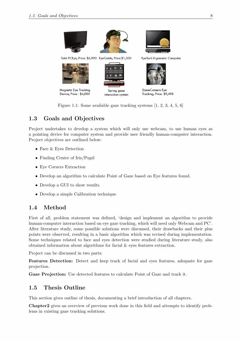
Researchers have been working on conducting studies about eye gaze tracking and developingsystems capable of eye gaze based interaction. Many companies also carried research on eye gazetracking, this led to successful production of proprietary solutions and made them available inmarket. But they offer only limited usability, involve complex hardware, don’t have capacity toprovide user friendly human-computer interaction and are very costly, out of reach for domesticusers. Some of them are shown in Figure (1.1).
Some of them use IR lighting, complex hardware which make it more difficult to interact withcomputer. Therefore, it would be exciting to conduct a research study which can lead to in-troduction of a non-intrusive, software system based on eye gaze tracking, offering user friendlyhuman-computer interaction.
7
1.3. Goals and Objectives 8
Figure 1.1: Some available gaze tracking systems [1, 2, 3, 4, 5, 6]
1.3 Goals and Objectives
Project undertakes to develop a system which will only use webcam, to use human eyes asa pointing device for computer system and provide user friendly human-computer interaction.Project objectives are outlined below:
• Face & Eyes Detection
• Finding Center of Iris/Pupil
• Eye Corners Extraction
• Develop an algorithm to calculate Point of Gaze based on Eye features found.
• Develop a GUI to show results.
• Develop a simple Calibration technique.
1.4 Method
First of all, problem statement was defined, ‘design and implement an algorithm to providehuman-computer interaction based on eye gaze tracking, which will need only Webcam and PC’.After literature study, some possible solutions were discussed, their drawbacks and their pluspoints were observed, resulting in a basic algorithm which was revised during implementation.Some techniques related to face and eyes detection were studied during literature study, alsoobtained information about algorithms for facial & eyes features extraction.
Project can be discussed in two parts:
Features Detection: Detect and keep track of facial and eyes features, adequate for gazeprojection.
Gaze Projection: Use detected features to calculate Point of Gaze and track it.
1.5 Thesis Outline
This section gives outline of thesis, documenting a brief introduction of all chapters.
Chapter2 gives an overview of previous work done in this field and attempts to identify prob-lems in existing gaze tracking solutions.

1.5. Thesis Outline 9
Chapter3 describes the basic framework for implementation of eye gaze tracking based humancomputer interaction application. The chapter introduces with different steps involved in algo-rithm implementation.
Chapter4 is a collection of different tasks performed for eye gaze tracking algorithm implemen-tation using MATLAB R© coding. It contains different sections, each one of them will explain theimplementation of a module.
Section4.2 presents a detailed overview of algorithm, used for face and eyes detection. Facedetection algorithm is a two-step approach, first the algorithm acquires face candidates andsecond step involves facial features detection to verify the face candidates. Where eyes weredetected from the eye maps derived from the luma and chroma components of the image.
Section4.3 describes Center of Iris/Pupil detection algorithm. Pupil detection algorithm isbased on Hough Circular Transform method. Images are firstly pre-processed to reduce falsedetections, passed through edge detection filter and then Circle detection algorithm is applied.
Section4.4 contains a detailed discussion about incomplete work done on Gaze estimation un-der this project.
Chapter5 is devoted to explain algorithm implementation using OpenCV library. This chapteris also divided into sections, each one of them attempts to give details of one stage of algorithm.
Section5.2 documents the face and eyes detection using OpenCV. OpenCV library providesface and eyes detection utility based on Viola & Jones object detection algorithm and uses Haarclassifier approach.
Section5.3 is committed to report pupil detection using OpenCV. Hough Circular Transformis being used for pupil detection.
Section5.4 describes eye corners extraction using OpenCV library. It gives a brief overview ofdifferent techniques which were tried for eye corners extraction but could not result in satisfac-tory results. A detailed discussion about Template Matching technique for eye corners extractionis also available in this section.
Section5.5 is dedicated to point of gaze calculation algorithm for pre-recorded frames. Thissection gives an insight of algorithm and seeks to illustrate the algorithm with help of figuresand equations.
Section5.6 explains the point of gaze calculation algorithm for live stream of frames comingfrom webcam. Different steps of algorithm are explained in this section.
Chapter6 contains a detailed overview of Graphical User Interface (GUI) designing using QtSDK. It also gives an in-depth overview of GUI design being used for this project.
Chapter7 is devoted to evaluation of different modules of this project. It attempts to quantifythe accuracy of algorithm.
Chapter8 gives final words of conclusion and suggests improvements and enhancements toalgorithm, which can help new researchers in this field.

Chapter 2
LITERATURE REVIEW
Many computing devices come already with built-in cameras, such as mobile phones, laptops,and displays. Processor power still increases steadily and standard processors are powerfulenough to process the video stream necessary to perform eye-gaze tracking, at least on desktopand laptop computers. Some people interact with the computer all day long, for their work andin their leisure time. As most interaction is done with keyboard and mouse, both using thehands, some people suffer from overstressing particular parts of their hands, typically causinga carpal tunnel syndrome. With a vision of ubiquitous computing, the amount of interactionwith computers will increase and we are in need of interaction techniques which do not causephysical problems. The eyes are a good candidate because they move anyway when interactingwith computers. Using the information lying in the eye movements could save some interaction,in particular head-based interaction [7] .
A literature study was conducted before start working on algorithm designing and implementa-tion, to learn about existing systems. This chapter is discussing some of such existing systemswhich are already developed, their pros and cons are being discussed briefly.
2.1 Eye gaze tracking using Head Mount
Figure 2.1: Eye Gaze Tracking using Head Mount
Eye gaze tracking is done through a complex hardware component. As it is shown in Figure (2.1),head mounted hardware is required for eye gaze tracking. It becomes difficult for user to usesuch gigantic equipment. Moreover, a basic problem is the maintenance of such a complicateddevice. They follow the technique that uses electrodes to predict the eyeball movements. Suchequipment can be even harmful for human beings.
10

2.2. Tobii PCEye 11
2.2 Tobii PCEye
Tobii PCEye is also controlling PC through eyes. Though, it is easy to use, portable and givesaccurate tracking, but its expensiveness (As it costs $6,900) makes it not easily available to allusers belonging to different economic backgrounds.
Due to high cost such equipment have limited access. The technique used in this thesis providesa low cost solution to eye gaze tracking, which can be easily available to all, because of its fullysoftware implementation and it is low cost.
Figure 2.2: Tobii PCEye
2.3 Eye Glasses
Another device used for eye gaze tracking is eye glasses or data glasses. To calculate the eyegaze, eyes are lightened with infrared light using light emitting diodes (LEDs). In combinationwith it a camera takes the position of the eyes and computer calculates the point of gaze. Thereflections of infrared light are determined in iris, through the image taken by the camera. Itis detected through differences in the brightness due to reflection in the eye. Finally, variousalgorithms are used to calculate the point if gaze.
Using such a device around the head can cause discomfort for the user. Moreover, use of LEDscan be harmful for human eye.
Figure 2.3: Eye Glasses

2.4. SceneCamera Eye Tracking 12
2.4 SceneCamera Eye Tracking
SceneCamera eye tracking device is an application which controls motion of mouse pointerthrough eyes movements. It records user’s eye position from the real-time video being extracted.At the back end software algorithm runs which saves the eye positioning and the real-time videoin computer hard drive. After this a calibration technique is applied which processes the mousepointer movement.
This apparatus costs $9,498. Moreover, it consists of a complicated hardware structure. Suchthings make this technology uncomfortable and out of reach for customers. The devices whichare not head-mounted are easy to use and little calibration is required for them.
Figure 2.4: SceneCamera Eye Tracking Device
2.5 Eye Gaze Tracking Applications
Eye gaze tracking research is entering its fourth era, distinguished by the emergence of interactiveapplications in various fields, covering Neuroscience, psychology, industry, marketing, computerscience etc. Some applications of Eye gaze tracking are discussed below.
2.5.1 Neuroscience
Eye Movements and Brain Imaging
Recently, eye movement recording and functional brain imaging have been used to track a sub-ject’s fixation point while simultaneously recording cortical activation during attentional tasks,in order to identify functional brain structures implicated in attentional behavior. Presently,possibly due to prohibitive cost, combined Eye gaze tracking and brain imaging equipment arenot in widespread use, although such devices are beginning to appear [8, 9, 10].
2.5.2 Psychology
Reading
Rayner (1998) synthesizes over 100 years of research. While the reader is referred to Rayner’sarticle. When reading English, eye fixations last about 200-250 ms and the mean saccade sizeis 7-9 letter spaces. Eye movements are influenced by textual and typographical variables,e.g., as text becomes conceptually more difficult, fixation duration increases and saccade lengthdecreases.
2.5. Eye Gaze Tracking Applications 13
Factors such as the quality of print, line length, and letter spacing influence eye movements. Eyemovements differ somewhat when reading silently from reading aloud: mean fixation durationsare longer when reading aloud or while listening to a voice reading the same text than in silentreading [8, 9, 10].
2.5.3 Industrial Applications
Aviation
An example of a recent combined use of relatively new Eye gaze tracking technology in a sophis-ticated flight simulator was reported by Anders (2001). Eye and head movements of professionalpilots were recorded under realistic flight conditions in an investigation of human-machine in-teraction behavior relevant to information selection and management as well as situation andmode awareness in a modern glass cock-pit. Analysis of eye movements illustrates the impor-tance of the Primary Flight Display (PFD) as the primary source of information during flight(the PFD is the familiar combined artificial horizon and altimeter display for combined altitudeand attitude awareness). As a proof of concept, this study shows the potential of eye movementsfor judgment of pilots performance and future training of novice pilots [8, 9, 10].
Driving
It is widely accepted that deficiencies in visual attention are responsible for a large proportionof road traffic accidents (Chapman & Underwood, 1998). Eye movement recording and analysisprovide important techniques for understanding the nature of the driving task and are importantfor developing driver training strategies and accident countermeasures [8, 9, 10].
Experienced drivers obtain visual information from two sections of their view of the road ahead,in order to maintain a correct position in lane whilst steering their vehicle around a curve.The more distant of these two sections is used to predict the road’s future curvature. Thissection is optimally 0.75-1.00 s ahead of the driver and is used by a feed-forward (anticipatory)mechanism which allows the driver to match the curvature of the road ahead. The other, nearer,section is about 0.5 s ahead of the driver and is used by a feedback (reactive) mechanism to‘fine tune’ the driver’s position in lane. Eye gaze tracking experiments have shown that thefeedback mechanism is present in most people regardless of their driving experience (althoughits accuracy is higher in those with experience), but that the feed-forward mechanism is learnedthrough experience of steering tasks (that can include riding a bicycle, computer driving games,etc.) [8, 9, 10].
2.5.4 Marketing/Advertising
Eye gaze tracking can aid in the assessment of ad effectiveness in such applications as copy testingin print, images, video, or graphics, and in disclosure research involving perception of fine printwithin print media and within television displays. Eye gaze tracking can provide insight intohow the consumer disperses visual attention over different forms of advertising [8, 9, 10].
Copy Testing
A particularly good example of analysis of eye movements over advertisements in the YellowPages TM is given by Lohse (1997). In this experiment, eye movement data is collected whileconsumers chose businesses from telephone directories. The study addresses (1) what particularfeatures cause people to notice an ad, (2) whether people view ads in any particular order, and(3) how viewing time varies as a function of particular ad features. Eye movement analysisrevealed that, consistent with previous findings, ad size, graphics, color, and copy all influenceattention to advertisements [8, 9, 10].
2.5. Eye Gaze Tracking Applications 14
2.5.5 Computer Science
Selective Systems
Interactive uses of eye gaze trackers typically employ gaze as a pointing modality, e.g. using gazein a similar manner to a mouse pointer. Prominent applications involve selection of interfaceitems (menus, buttons, etc.), as well as selection of objects or areas in Virtual Reality (VR).A prototypical application of gaze as an interactive modality is eye typing, particularly forhandicapped users [8, 9, 10].
2.5.6 Conclusion
As the present review demonstrates, eye gaze trackers have traditionally shown themselves to bevaluable in diagnostic studies of reading and other information processing tasks. The diagnosticuse of an eye tracker, as exemplified by the research reviewed here, can be considered the eyetrackers mainstay application at the present time and probably in its near future [8, 9, 10].
In this project some advancements in previous available systems are made, which will only usewebcam on computer system to interface with the human eyes and also make gaze trackinguser friendly. Solution to gaze tracking will be low cost, so that it can have access to everyone.Moreover, eye gaze tracking is based on software solutions, no hardware components are involvedas particular. This increases its chances of usage. It is easy to use, handle and interact. Nocomplex hardware is required to make user familiar with it than to proceed rather a user friendlyknown built-in camera of a laptop is required. The available proprietary solutions are veryexpensive and they involve complex hardware. In this thesis a low cost and a software basedsolution is provided.
Chapter 3
Framework
This chapter purports to explain the basic framework for implementation of algorithm. It intendsto identify different modules of framework and will give their brief overview. This chapter willserve to answer following questions:
• How will this problem be solved?
• What will be system limitations?
• Which features will be necessary and sufficient to calculate Point of Gaze?
3.1 Concept of Eye Gaze Tracking
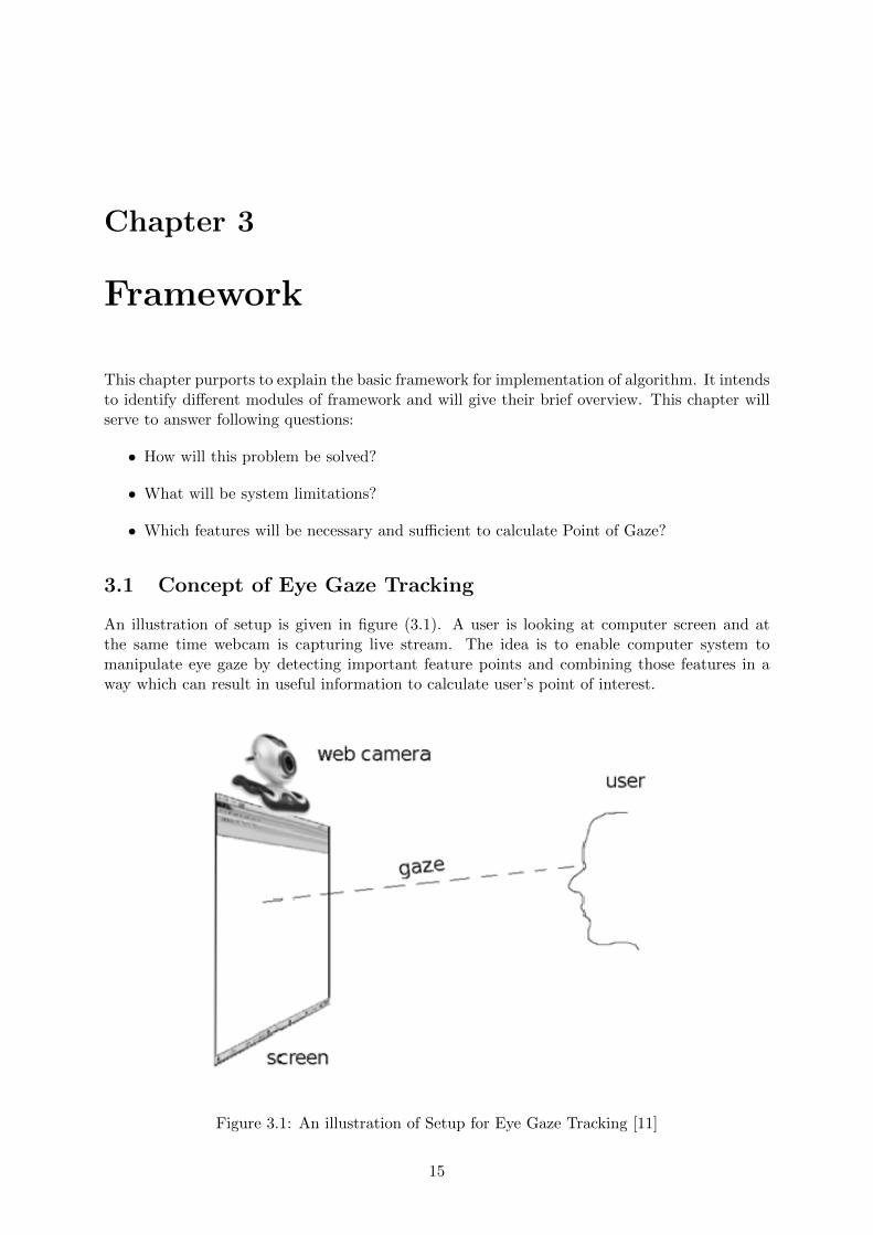
An illustration of setup is given in figure (3.1). A user is looking at computer screen and atthe same time webcam is capturing live stream. The idea is to enable computer system tomanipulate eye gaze by detecting important feature points and combining those features in away which can result in useful information to calculate user’s point of interest.
Figure 3.1: An illustration of Setup for Eye Gaze Tracking [11]
15
3.2. Facial Features 16
Basic concept of eye gaze tracking and framework implemented in this project is being explainedusing following points:
• Determine facial features which are necessary and sufficient for eye gaze tracking.
• Detecting and tracking these features points in live feed coming web-cam.
• Using these features in a way to extract user’s point of interest.
• Track user’s point of interest.
3.1.1 System Limitations
While implementing the system, some limitations have to be applied on the system to achievegood performance. The user head should be more or less at the same altitude as the web-cam.The user should be sitting in the center of screen, which is normally the case, user is most ofthe time sitting in center of screen. The distance between user’s eyes and web-cam should bein the range of 20 – 75 cm. Unfortunately due of Hough Circle Transform algorithm for Pupildetection, user can’t use the system with eye glasses. The lighting conditions should be good.Ideal situation will be with light pointing at user face and no light at backside of user, lightcoming from backside will result into shadows and will diminish image quality.
3.2 Facial Features
Literature study and experimentation during implementation helped in finalizing facial featureswhich will be necessary and sufficient to calculate Point of Gaze. A brief overview explaininghow these features will be helpful and how they will be found is given below.
Face: Face is an important feature in human, and it is useful in minimizing candidates for eyesduring eye patch extraction.
Eyes: Eyes are gist of this idea of eye gaze tracking. To find other feature points in eyes, eyepatch must be extracted.
Center of Iris/Pupil: Pupil tells about a person’s point of interest. It is being detected usingHough Circle Transform.
Eye Corners: Eye corners act as important feature points as they can be used to extract usefulinformation about eyes i.e. center of eye, eye width, eye height. Eye Corners are being extractedusing Template Matching technique.
3.3 Methodology
Algorithm overview is shown in Figure (3.2). It gives an outline of different stages involvedbetween frame capturing by web-cam and movement of pointer in accordance with user’s eyegaze.
Image Acquisition: A web-cam is required to acquire images. System will start with imageacquisition using an integrated web-cam or USB web-cam.
Image Preprocessing: Preprocessing the data is always helpful in extracting useful infor-mation. Images acquired by web-cam must be converted into appropriate formats required bydifferent algorithm at next stages.
Facial Features Detection: It is preliminary step for eyes detection. MATLAB R© implemen-tation for face detection is described in Chapter 4, and OpenCV implementation in Chapter 5.

3.3. Methodology 17
Eyes Features Detection: Necessary eye features were identified and different methods fortheir implementation were tried, finally HCT yielded satisfactory results for pupil detection andTemplate Matching technique proved helpful for eye corners detection. These techniques aredescribed in Chapter 4 and Chapter 5.
Point of Gaze Calculation: A mathematical calculations based algorithm was designed tocalculate PoG based on found feature points. Algorithm is described in Chapter 5.
Figure 3.2: System Flow Diagram

Chapter 4
Algorithm Implementation usingMATLAB R©
4.1 Introductory Task for Gaze Projection
Basic calculations always aid to take a better start, help to answer questions, which restrainus to begin. Before start working on algorithm implementation for face and eyes detection weperformed some prefatorial experimentation. Some prefatorial experimentation was performedto answer basic questions like:
• Can a web-cam capture eye movements?
• What resolution will be necessary and sufficient to catch adequate number of eyes pixelsacceptable to perform gaze calculations?
• Each movement should be tracked, what should be the frame rate? so as to allow trackingwith tolerable saccades.
• This is a research project, so it is mandatory to have knowledge about challenges, whichwill be trammeling the development and implementation of algorithm.
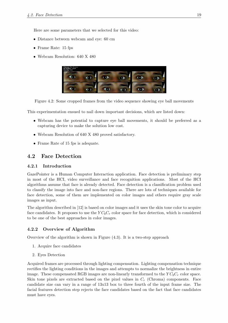
For this purpose, a video was recorded with still head and fixed distance, and eye ball movementswere captured, a frame is shown in figure (4.1). Then wrote a script in MATLAB R© to crop eyepatches using a fixed bounding box, some frames are show in figure (4.2), which established thefact that webcam has the potential to capture eye ball movements.
Figure 4.1: A frame from the video sequence captured by web-cam
18
4.2. Face Detection 19
Here are some parameters that we selected for this video:
• Distance between webcam and eye: 60 cm
• Frame Rate: 15 fps
• Webcam Resolution: 640 X 480
Figure 4.2: Some cropped frames from the video sequence showing eye ball movements
This experimentation ensued to nail down important decisions, which are listed down:
• Webcam has the potential to capture eye ball movements, it should be preferred as acapturing device to make the solution low cost.
• Webcam Resolution of 640 X 480 proved satisfactory.
• Frame Rate of 15 fps is adequate.
4.2 Face Detection
4.2.1 Introduction
GazePointer is a Human Computer Interaction application. Face detection is preliminary stepin most of the HCI, video surveillance and face recognition applications. Most of the HCIalgorithms assume that face is already detected. Face detection is a classification problem usedto classify the image into face and non-face regions. There are lots of techniques available forface detection, some of them are implemented on color images and others require gray scaleimages as input.
The algorithm described in [12] is based on color images and it uses the skin tone color to acquireface candidates. It proposes to use the Y CbCr color space for face detection, which is consideredto be one of the best approaches in color images.
4.2.2 Overview of Algorithm
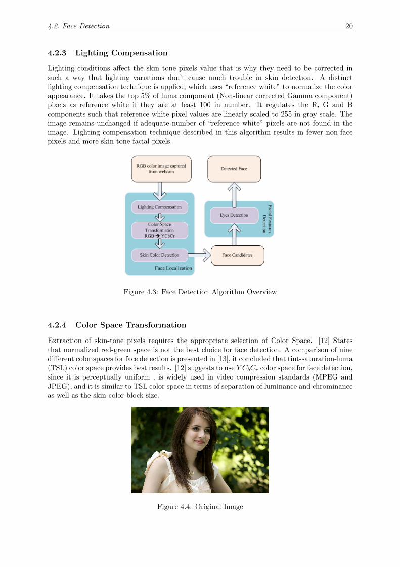
Overview of the algorithm is shown in Figure (4.3). It is a two-step approach
1. Acquire face candidates
2. Eyes Detection
Acquired frames are processed through lighting compensation. Lighting compensation techniquerectifies the lighting conditions in the images and attempts to normalize the brightness in entireimage. These compensated RGB images are non-linearly transformed to the Y CbCr color space.Skin tone pixels are extracted based on the pixel values in Cr (Chroma) components. Facecandidate size can vary in a range of 13x13 box to three fourth of the input frame size. Thefacial features detection step rejects the face candidates based on the fact that face candidatesmust have eyes.
4.2. Face Detection 20
4.2.3 Lighting Compensation
Lighting conditions affect the skin tone pixels value that is why they need to be corrected insuch a way that lighting variations don’t cause much trouble in skin detection. A distinctlighting compensation technique is applied, which uses “reference white” to normalize the colorappearance. It takes the top 5% of luma component (Non-linear corrected Gamma component)pixels as reference white if they are at least 100 in number. It regulates the R, G and Bcomponents such that reference white pixel values are linearly scaled to 255 in gray scale. Theimage remains unchanged if adequate number of “reference white” pixels are not found in theimage. Lighting compensation technique described in this algorithm results in fewer non-facepixels and more skin-tone facial pixels.
Figure 4.3: Face Detection Algorithm Overview
4.2.4 Color Space Transformation
Extraction of skin-tone pixels requires the appropriate selection of Color Space. [12] Statesthat normalized red-green space is not the best choice for face detection. A comparison of ninedifferent color spaces for face detection is presented in [13], it concluded that tint-saturation-luma(TSL) color space provides best results. [12] suggests to use Y CbCr color space for face detection,since it is perceptually uniform , is widely used in video compression standards (MPEG andJPEG), and it is similar to TSL color space in terms of separation of luminance and chrominanceas well as the skin color block size.
Figure 4.4: Original Image

4.3. Eyes Detection 21
Figure 4.5: Detected Face
4.2.5 Skin Color Detection
Skin tone color nonlinearly depends upon the luma component. Transformed space allows sub-stantial detection of skin-tone colors. More skin-tone pixels were detected with high and lowluma in transformed space as compared to the Y CbCr space. A bounding box was drawn aroundthe detected face from an image (Shown in figure 4.4). MATLAB R© function “rectangle” wasused to draw bounding box around face. This detected face was cropped using the function“imcrop” for eyes detection stage (Cropped Face is shown in Figure 4.5).
4.3 Eyes Detection
Eyes were detected from the eye maps derived from the luma and chroma components of theimage. We build two eye maps from the luma and chroma components and combined themtogether to acquire the eye map for detected eyes. The chroma eye map depends upon thevalues of Cb and Cr channels.
Following is the equation to derive the chroma eye map.
EyeMapC = 1/3[(Cb)2 + (C ′r)
2 + (Cb/Cr)]
Where Cb, Cr, C′r are all normalized values in the range [0,255]. Following lines of MATLAB R©
code describe the technique implemented, to normalize these values.
minC_r = min(min(C_r));
maxC_r = max(max(C_r));
C_r = 255 * (C_r - minC_r)/(maxC_r - minC_r);
Where the functions “min” and “max” returns the minimum and maximum values respectively.
Morphological operations like dilation and erosion were applied on the luma component ofthe image to acquire the luma eye map. Dilation is the process of expanding something. InMATLAB R©, the built-in function “imdilate” is used for dilation. It uses a structuring ele-ment ‘SE’ to expand an object in the image. Similarly, the built-in function used for erosion is“imerode”.
Following MATLAB R© statements were used to acquire the luma eye map.

4.3. Eyes Detection 22
SE=strel(‘disk’,4);
UP=imdilate(Y,SE);
DOWN=imerode(Y,SE);
EyeMapL = UP./(DOWN+1);
Figure 4.6: EyeMapC
Figure 4.7: EyeMapL
Histogram equalization was applied on the chroma eye map and then combined with the lumaeye map using following equation.
EyeMap = (EyeMapC)AND(EyeMapL)
Figure 4.8: EyeMap
4.3. Eyes Detection 23
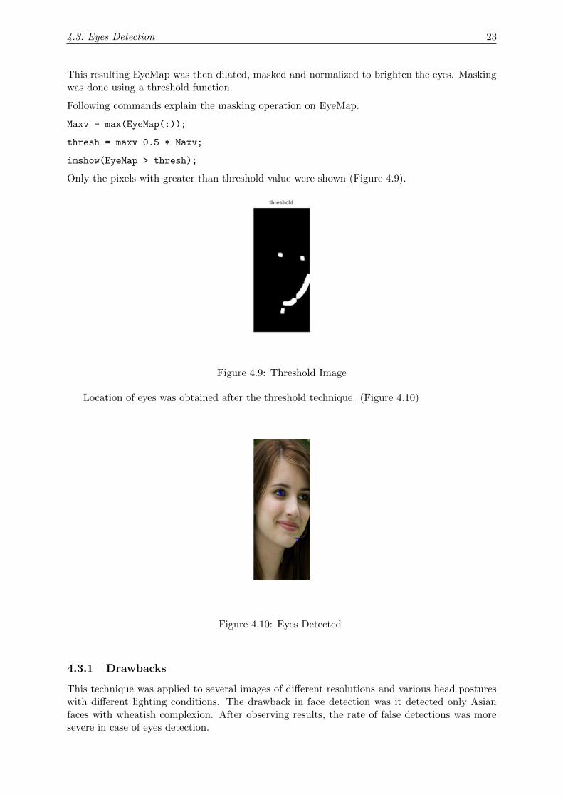
This resulting EyeMap was then dilated, masked and normalized to brighten the eyes. Maskingwas done using a threshold function.
Following commands explain the masking operation on EyeMap.
Maxv = max(EyeMap(:));
thresh = maxv-0.5 * Maxv;
imshow(EyeMap > thresh);
Only the pixels with greater than threshold value were shown (Figure 4.9).
Figure 4.9: Threshold Image
Location of eyes was obtained after the threshold technique. (Figure 4.10)
Figure 4.10: Eyes Detected
4.3.1 Drawbacks
This technique was applied to several images of different resolutions and various head postureswith different lighting conditions. The drawback in face detection was it detected only Asianfaces with wheatish complexion. After observing results, the rate of false detections was moresevere in case of eyes detection.

4.4. Pupil Detection 24
Therefore it was decided to skip these complex and time consuming processes like face and eyesdetection, rather use a simple approach for eye patch extraction. It was decided that user willhave to fit his/her eyes in a bounding box, in order for eye patch cropping.
4.4 Pupil Detection
Pupil is the central and focusing part of eye, located at center of iris. Light enters into eyethrough pupil, and finding the position of pupil is principal point of interest in this project. Eyegaze projection is based upon the relative displacement of pupil from center of eye. Pupil needsto be detected to project user’s eye gaze on the screen. The first step was to detect the iris fromthe frames captured with webcam, and then pupil can be found, as it is situated at center ofiris.
Iris is the flat, colored and circular part on the white region (Sclera) of an eye. Iris varies in coloras black, blue, green etc. As iris is a circular region, so it can be detected using a computer visiontechnique which can detect circular region. Digital Image Processing is a subject of ComputerVision which is used to extract information from an image. MATLAB R© has an Image Processingtoolbox, methods from this toolbox can prove helpful in detecting Iris and so Pupil position canbe found.
4.4.1 Pupil detection algorithm
Iris is a circular region and can be detected using the very commonly used Hough circular trans-form technique.The Hough transform is a feature extraction technique used in image analysis,computer vision, and digital image processing. The purpose of the technique is to find imperfectinstances of objects within a certain class of shapes.
The classical Hough transform was concerned with the identification of lines in the image, butlater the Hough transform has been extended to identifying positions of arbitrary shapes, mostcommonly circles or ellipses. The Hough transform as it is universally used today was inventedby Richard Duda and Peter Hart in 1972, who called it a ”generalized Hough transform” afterthe related 1962 patent of Paul Hough. The transform was popularized in the computer visioncommunity by Dana H. Ballard through a 1981 journal article titled ”Generalizing the Houghtransform to detect arbitrary shapes”.[14]
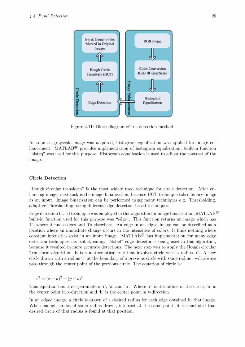
Hough Circular Transform takes a binary image as an input and detects circle in it. The qualityof the image needs to be good to extract every possible information from it. As webcam wasnot of high resolution i.e. 640x480 (VGA). Therefore, image enhancing techniques were appliedto improve the quality of the image. The flow of algorithm is shown in figure (4.11).Algorithm involves two phases.
1. Image enhancement.
2. Circle detection.
Image Enhancement
Image quality must be improved so that maximum information can be extracted and noise isminimized from it. The frames captured from a webcam are RGB images. An RGB image isa 3 channel image and each channel can have pixel values in a range of 0 to 255. As HoughCircular transform technique takes a binary image as an input, therefore, this 3-channel RGBimage was converted to single channel grayscale image using the built-in function in MATLAB R©
“rgb2gray”. A gray scale image is a single channel image and can have pixel values in a rangeof 0 to 255. A ’0’ pixel value represents black color and ‘255’ represents white in grayscale.
4.4. Pupil Detection 25
Figure 4.11: Block diagram of Iris detection method
As soon as grayscale image was acquired, histogram equalization was applied for image en-hancement. MATLAB R© provides implementation of histogram equalization, built-in function“histeq” was used for this purpose. Histogram equalization is used to adjust the contrast of theimage.
Circle Detection
“Hough circular transform” is the most widely used technique for circle detection. After en-hancing image, next task is the image binarization, because HCT technique takes binary imageas an input. Image binarization can be performed using many techniques e.g. Thresholding,adaptive Thresholding, using different edge detection based techniques.
Edge detection based technique was employed in this algorithm for image binarization, MATLAB R©
built-in function used for this purpose was “edge”. This function returns an image which has1’s where it finds edges and 0’s elsewhere. An edge in an edged image can be described as alocation where an immediate change occurs in the intensities of colors. It finds nothing whereconstant intensities exist in an input image. MATLAB R© has implementation for many edgedetection techniques i.e. sobel, canny. “Sobel” edge detector is being used in this algorithm,because it resulted in more accurate detections. The next step was to apply the Hough circularTransform algorithm. It is a mathematical rule that involves circle with a radius ‘r’. A newcircle drawn with a radius ‘r’ at the boundary of a previous circle with same radius , will alwayspass through the center point of the previous circle. The equation of circle is:
r2 = (x− a)2 + (y − b)2
This equation has three parameters ‘r’, ‘a’ and ‘b’. Where ‘r’ is the radius of the circle, ‘a’ isthe center point in x-direction and ‘b’ is the center point in y-direction.
In an edged image, a circle is drawn of a desired radius for each edge obtained in that image.When enough circles of same radius drawn, intersect at the same point, it is concluded thatdesired circle of that radius is found at that position.
4.5. Gaze Estimation 26
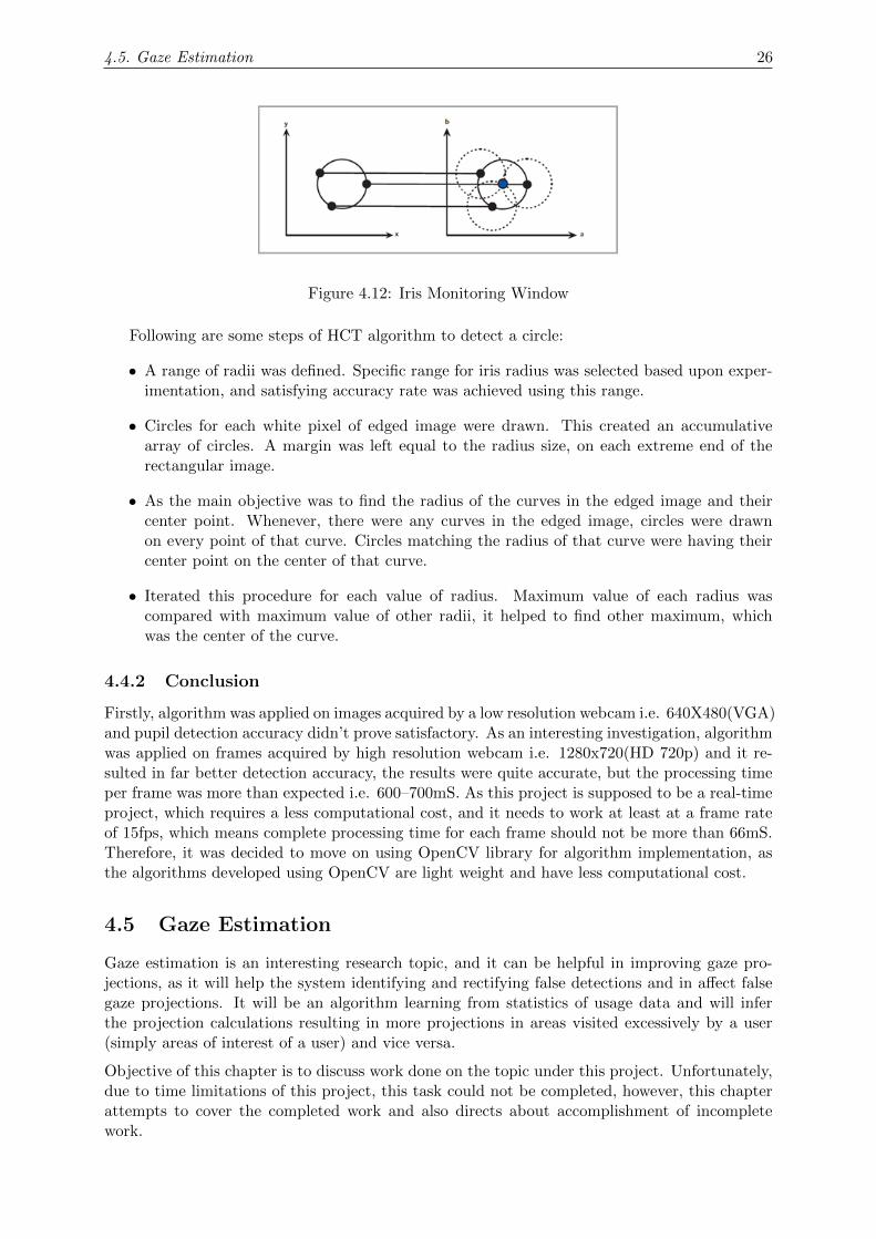
Figure 4.12: Iris Monitoring Window
Following are some steps of HCT algorithm to detect a circle:
• A range of radii was defined. Specific range for iris radius was selected based upon exper-imentation, and satisfying accuracy rate was achieved using this range.
• Circles for each white pixel of edged image were drawn. This created an accumulativearray of circles. A margin was left equal to the radius size, on each extreme end of therectangular image.
• As the main objective was to find the radius of the curves in the edged image and theircenter point. Whenever, there were any curves in the edged image, circles were drawnon every point of that curve. Circles matching the radius of that curve were having theircenter point on the center of that curve.
• Iterated this procedure for each value of radius. Maximum value of each radius wascompared with maximum value of other radii, it helped to find other maximum, whichwas the center of the curve.
4.4.2 Conclusion
Firstly, algorithm was applied on images acquired by a low resolution webcam i.e. 640X480(VGA)and pupil detection accuracy didn’t prove satisfactory. As an interesting investigation, algorithmwas applied on frames acquired by high resolution webcam i.e. 1280x720(HD 720p) and it re-sulted in far better detection accuracy, the results were quite accurate, but the processing timeper frame was more than expected i.e. 600–700mS. As this project is supposed to be a real-timeproject, which requires a less computational cost, and it needs to work at least at a frame rateof 15fps, which means complete processing time for each frame should not be more than 66mS.Therefore, it was decided to move on using OpenCV library for algorithm implementation, asthe algorithms developed using OpenCV are light weight and have less computational cost.
4.5 Gaze Estimation
Gaze estimation is an interesting research topic, and it can be helpful in improving gaze pro-jections, as it will help the system identifying and rectifying false detections and in affect falsegaze projections. It will be an algorithm learning from statistics of usage data and will inferthe projection calculations resulting in more projections in areas visited excessively by a user(simply areas of interest of a user) and vice versa.
Objective of this chapter is to discuss work done on the topic under this project. Unfortunately,due to time limitations of this project, this task could not be completed, however, this chapterattempts to cover the completed work and also directs about accomplishment of incompletework.

4.5. Gaze Estimation 27
Gaze estimation means to learn from usage statistics data and predict the next value of mousepointer based on probabilities of regions and previous movements of pointer using different al-gorithms. For the estimation, we started from very basic prediction mechanisms and then grad-ually developed algorithm using different basic and advanced techniques. These are discussedin gradual steps in different sub-sections of this topic.
4.5.1 Regression to Predict Synthetic Model Motion
“Regression” in statistics is name of careful, informed prediction and estimation. Discussion ofregression will concentrate on linear regression. Its basic idea is to find the straight line that“best” fits a set of observed points. Linear regression analysis is a powerful technique used forpredicting the unknown value of a variable from the known value of another variable [15].
If x and y are two related variables then the regression analysis can help us to predict valuesof y for values of x and vice versa. Regression analysis uses the power of polynomial fitting, bymaking guess of an nth order polynomial based on given data. So, as the pool of data grows, itmakes a good guess of polynomial resulting in improved predictions.
Regression analysis is one of the simplest techniques being used for prediction problems. Thissection is devoted to investigate the potential of regression analysis as a prediction tool. Asynthetic model was built for this purpose and the motion of that model was predicted usingregression. The task was divided into simple steps:
• A cartoon character was to be selected for synthetic modelling, Lisa was selected [16].(Shown in figure 4.13)
• A bounding box was fixed around the eyes of cartoon character and co-ordinates x and ywere found for center of eyes.
• Eye ball of cartoon character Lisa was moved using some equation (as a linear model) of1st, 2nd or 3rd order.
• 3rd value was predicted by using previous two actual values.
• When the actual 3rd value was obtained, error was removed in predicted and actual value.
Figure 4.13: Lisa(Cartoon Character Selected)
4.5. Gaze Estimation 28
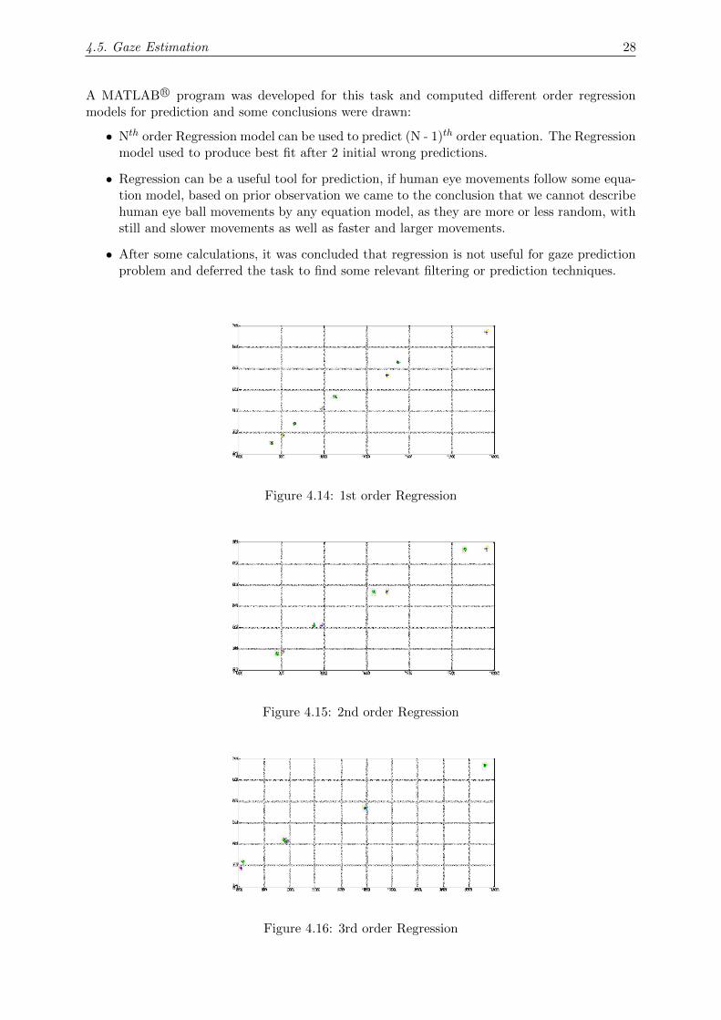
A MATLAB R© program was developed for this task and computed different order regressionmodels for prediction and some conclusions were drawn:
• Nth order Regression model can be used to predict (N - 1)th order equation. The Regressionmodel used to produce best fit after 2 initial wrong predictions.
• Regression can be a useful tool for prediction, if human eye movements follow some equa-tion model, based on prior observation we came to the conclusion that we cannot describehuman eye ball movements by any equation model, as they are more or less random, withstill and slower movements as well as faster and larger movements.
• After some calculations, it was concluded that regression is not useful for gaze predictionproblem and deferred the task to find some relevant filtering or prediction techniques.
Figure 4.14: 1st order Regression
Figure 4.15: 2nd order Regression
Figure 4.16: 3rd order Regression
4.5. Gaze Estimation 29
Results
Regression was applied on different order equations to predict next values. Outputs of this taskare shown in Figures 4.14, 4.15 and 4.16 (actual values: +, predicted values: o).
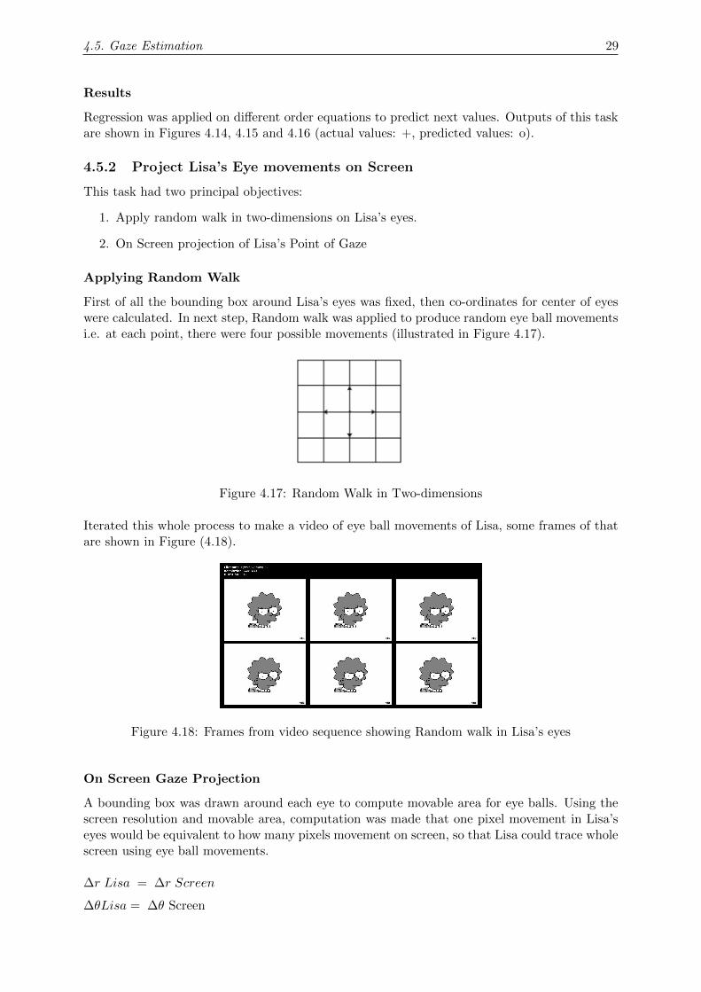
4.5.2 Project Lisa’s Eye movements on Screen
This task had two principal objectives:
1. Apply random walk in two-dimensions on Lisa’s eyes.
2. On Screen projection of Lisa’s Point of Gaze
Applying Random Walk
First of all the bounding box around Lisa’s eyes was fixed, then co-ordinates for center of eyeswere calculated. In next step, Random walk was applied to produce random eye ball movementsi.e. at each point, there were four possible movements (illustrated in Figure 4.17).
Figure 4.17: Random Walk in Two-dimensions
Iterated this whole process to make a video of eye ball movements of Lisa, some frames of thatare shown in Figure (4.18).
Figure 4.18: Frames from video sequence showing Random walk in Lisa’s eyes
On Screen Gaze Projection
A bounding box was drawn around each eye to compute movable area for eye balls. Using thescreen resolution and movable area, computation was made that one pixel movement in Lisa’seyes would be equivalent to how many pixels movement on screen, so that Lisa could trace wholescreen using eye ball movements.
∆r Lisa = ∆r Screen
∆θLisa = ∆θ Screen

4.5. Gaze Estimation 30
It was found that one pixel in Lisa’s eyes is approximately equal to a rectangle of 9 x 24.As the movement of one pixel results in a rectangle movement of 9 x 24.Whole procedure was applied iteratively on each frame of video recorded for eye ball movementsof Lisa, and recorded a video of the on-screen gaze projections, some frames of video sequenceare shown in Figure (4.19).
Figure 4.19: Frames from video sequence showing on-screen Gaze Projections
Here is some important data about the whole task:
• Screen Resolution: 640 x 480
• Eye Ball : 6 x 7
• Eye Patch Area: 72 x 27
• Movable area for Eye Ball : 66 x 20
• Rectangle on Screen (corresponding to each pixel of eye) : 9 x 24
4.5.3 Screen Divisions, a Probabilistic Model
Intelligent systems are highly popular nowadays. To make the system intelligent and userfriendly, a new concept was introduced of eye gaze system which not only depends upon on-screen gaze projections but also take advantage of user’s statistical data, so that final decisionabout Point of Gaze should be biased towards user’s areas of interest on screen.
For this purpose, user interfaces were analyzed for some popular applications and divided thecomputer screen into 50 regions of different sizes (Regions are shown in figure 4.20). Variablesized region division attempted to accommodate those popular user interfaces.
Applications which influenced the region’s partitions include:
• Microsoft office 2007 [17]
• Real Player [18]
• MATLAB R© [19]
• Gmail [20]
• Facebook [21]
• Eclipse IDE [22]

4.5. Gaze Estimation 31
Figure 4.20: Screen Region division
A MATLAB R© based program was developed to collect cursor movements data, the program itselfrecords cursor positions at a rate of 15 records per second and then computes region number foreach cursor position, and increments the region weight. Method is applied iteratively on eachcursor position recorded (Cursor movements data for a 5 minutes recording is shown in Figure4.21).
Figure 4.21: Cursor Movements data of a computer user (5 minutes recording)
Finally the program plots a probability mass function of cursor, showing probability of the cursorto be in nth region at a particular time (pmf is shown in Figure 4.22 for data of Figure 4.21).
Figure 4.22: Probability Mass Function for data shown in fig 4.21
4.5. Gaze Estimation 32
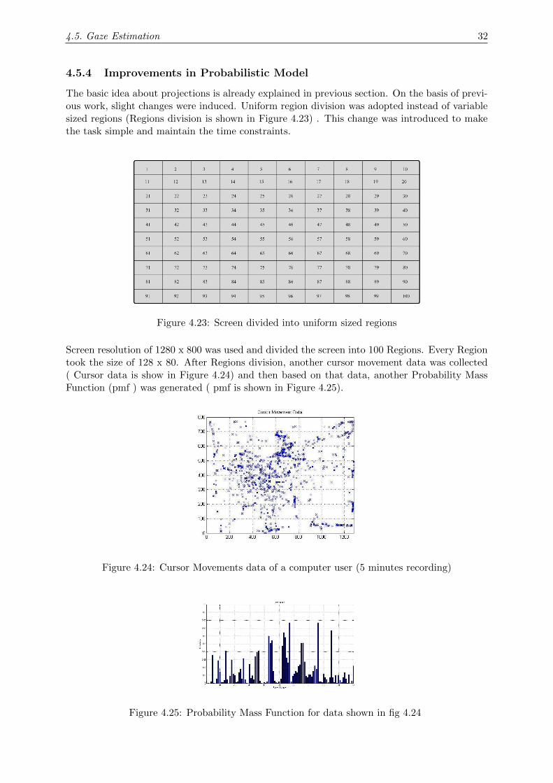
4.5.4 Improvements in Probabilistic Model
The basic idea about projections is already explained in previous section. On the basis of previ-ous work, slight changes were induced. Uniform region division was adopted instead of variablesized regions (Regions division is shown in Figure 4.23) . This change was introduced to makethe task simple and maintain the time constraints.
Figure 4.23: Screen divided into uniform sized regions
Screen resolution of 1280 x 800 was used and divided the screen into 100 Regions. Every Regiontook the size of 128 x 80. After Regions division, another cursor movement data was collected( Cursor data is show in Figure 4.24) and then based on that data, another Probability MassFunction (pmf ) was generated ( pmf is shown in Figure 4.25).
Figure 4.24: Cursor Movements data of a computer user (5 minutes recording)
Figure 4.25: Probability Mass Function for data shown in fig 4.24
4.5. Gaze Estimation 33
A simple algorithm was developed for this probabilistic model:
• On- screen gaze projection as in previous sections.
• Got the region number for present cursor position.
• Got the probability of present region (ppresent) from pmf matrix.
• Compared it with probability of the region in which gaze was projected in previous iteration(pprevious)
• If ppresent ≥ ppreviousProject this movement by making the movement equal to 9 x 24.
• elseProject the gaze after making the movement half of 9 x 24.
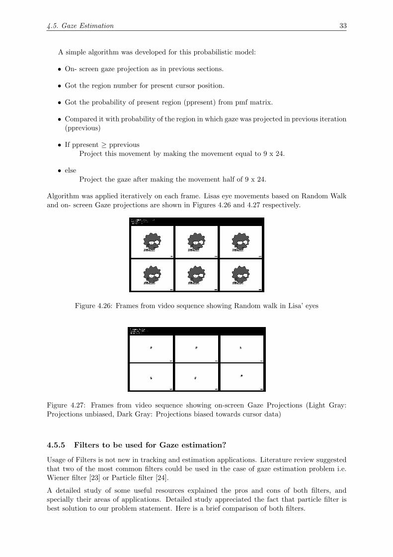
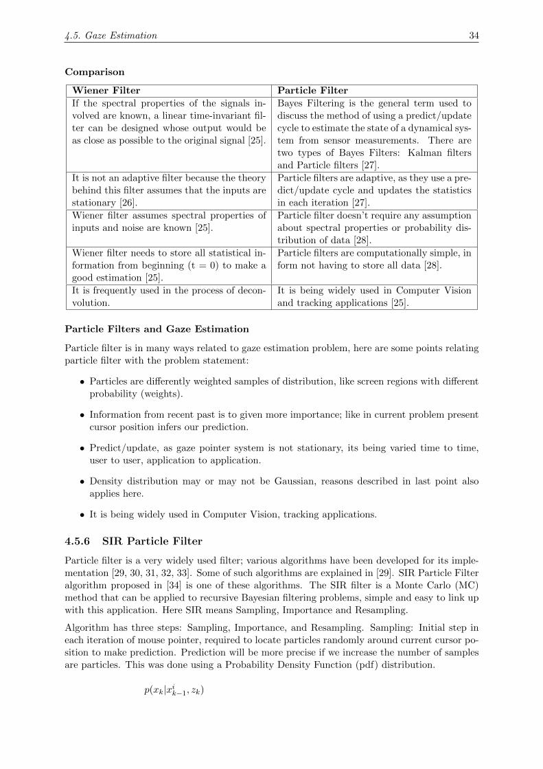
Algorithm was applied iteratively on each frame. Lisas eye movements based on Random Walkand on- screen Gaze projections are shown in Figures 4.26 and 4.27 respectively.
Figure 4.26: Frames from video sequence showing Random walk in Lisa’ eyes
Figure 4.27: Frames from video sequence showing on-screen Gaze Projections (Light Gray:Projections unbiased, Dark Gray: Projections biased towards cursor data)
4.5.5 Filters to be used for Gaze estimation?
Usage of Filters is not new in tracking and estimation applications. Literature review suggestedthat two of the most common filters could be used in the case of gaze estimation problem i.e.Wiener filter [23] or Particle filter [24].
A detailed study of some useful resources explained the pros and cons of both filters, andspecially their areas of applications. Detailed study appreciated the fact that particle filter isbest solution to our problem statement. Here is a brief comparison of both filters.
4.5. Gaze Estimation 34
Comparison
Wiener Filter Particle Filter
If the spectral properties of the signals in-volved are known, a linear time-invariant fil-ter can be designed whose output would beas close as possible to the original signal [25].
Bayes Filtering is the general term used todiscuss the method of using a predict/updatecycle to estimate the state of a dynamical sys-tem from sensor measurements. There aretwo types of Bayes Filters: Kalman filtersand Particle filters [27].
It is not an adaptive filter because the theorybehind this filter assumes that the inputs arestationary [26].
Particle filters are adaptive, as they use a pre-dict/update cycle and updates the statisticsin each iteration [27].
Wiener filter assumes spectral properties ofinputs and noise are known [25].
Particle filter doesn’t require any assumptionabout spectral properties or probability dis-tribution of data [28].
Wiener filter needs to store all statistical in-formation from beginning (t = 0) to make agood estimation [25].
Particle filters are computationally simple, inform not having to store all data [28].
It is frequently used in the process of decon-volution.
It is being widely used in Computer Visionand tracking applications [25].
Particle Filters and Gaze Estimation
Particle filter is in many ways related to gaze estimation problem, here are some points relatingparticle filter with the problem statement:
• Particles are differently weighted samples of distribution, like screen regions with differentprobability (weights).
• Information from recent past is to given more importance; like in current problem presentcursor position infers our prediction.
• Predict/update, as gaze pointer system is not stationary, its being varied time to time,user to user, application to application.
• Density distribution may or may not be Gaussian, reasons described in last point alsoapplies here.
• It is being widely used in Computer Vision, tracking applications.
4.5.6 SIR Particle Filter
Particle filter is a very widely used filter; various algorithms have been developed for its imple-mentation [29, 30, 31, 32, 33]. Some of such algorithms are explained in [29]. SIR Particle Filteralgorithm proposed in [34] is one of these algorithms. The SIR filter is a Monte Carlo (MC)method that can be applied to recursive Bayesian filtering problems, simple and easy to link upwith this application. Here SIR means Sampling, Importance and Resampling.
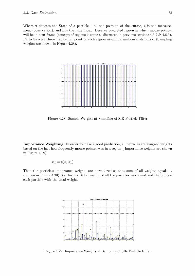
Algorithm has three steps: Sampling, Importance, and Resampling. Sampling: Initial step ineach iteration of mouse pointer, required to locate particles randomly around current cursor po-sition to make prediction. Prediction will be more precise if we increase the number of samplesare particles. This was done using a Probability Density Function (pdf) distribution.
p(xk|xik−1, zk)
4.5. Gaze Estimation 35
Where x denotes the State of a particle, i.e. the position of the cursor, z is the measure-ment (observation), and k is the time index. Here we predicted region in which mouse pointerwill be in next frame (concept of regions is same as discussed in previous sections 4.6.2 & 4.6.3).Particles were thrown at center point of each region assuming uniform distribution (Samplingweights are shown in Figure 4.28).
Figure 4.28: Sample Weights at Sampling of SIR Particle Filter
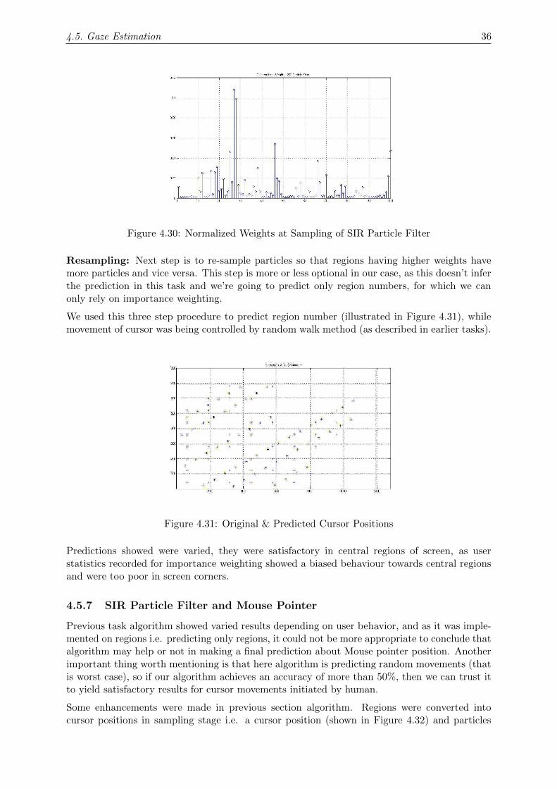
Importance Weighting: In order to make a good prediction, all particles are assigned weightsbased on the fact how frequently mouse pointer was in a region ( Importance weights are shownin Figure 4.29).
wik = p(zk|xik)
Then the particle’s importance weights are normalized so that sum of all weights equals 1.(Shown in Figure 4.30).For this first total weight of all the particles was found and then divideeach particle with the total weight.
Figure 4.29: Importance Weights at Sampling of SIR Particle Filter
4.5. Gaze Estimation 36
Figure 4.30: Normalized Weights at Sampling of SIR Particle Filter
Resampling: Next step is to re-sample particles so that regions having higher weights havemore particles and vice versa. This step is more or less optional in our case, as this doesn’t inferthe prediction in this task and we’re going to predict only region numbers, for which we canonly rely on importance weighting.
We used this three step procedure to predict region number (illustrated in Figure 4.31), whilemovement of cursor was being controlled by random walk method (as described in earlier tasks).
Figure 4.31: Original & Predicted Cursor Positions
Predictions showed were varied, they were satisfactory in central regions of screen, as userstatistics recorded for importance weighting showed a biased behaviour towards central regionsand were too poor in screen corners.
4.5.7 SIR Particle Filter and Mouse Pointer
Previous task algorithm showed varied results depending on user behavior, and as it was imple-mented on regions i.e. predicting only regions, it could not be more appropriate to conclude thatalgorithm may help or not in making a final prediction about Mouse pointer position. Anotherimportant thing worth mentioning is that here algorithm is predicting random movements (thatis worst case), so if our algorithm achieves an accuracy of more than 50%, then we can trust itto yield satisfactory results for cursor movements initiated by human.
Some enhancements were made in previous section algorithm. Regions were converted intocursor positions in sampling stage i.e. a cursor position (shown in Figure 4.32) and particles

4.5. Gaze Estimation 37
were dropped at probable cursor positions assuming uniform density (a zoomed view of droppedparticles is shown in Figure 4.33 for Cursor position of Figure 4.32).
Figure 4.32: Present Mouse cursor position
In importance weighting step, we merged our region importance weighting theory from earliertasks with a method described in [29]. Than we multiplied the particle importance weight withdecreasing exponential i.e. e−d.
wik = p(zk|xik)
wikxe−d
Here w is weight of a particle, x is the cursor position is the measurement (observation), kis the time index and d is the distance between particle position and present Mouse cursorposition.
Figure 4.33: Zoomed view of particles for present Mouse cursor position
At final stage prediction was made by finding the maximum of normalized weights and thealgorithm outputs this particle position as its prediction (Shown in Figure 4.34). Next Mousecursor position was once again computed by random walk method (next cursor position is shownin Figure 4.35)

4.5. Gaze Estimation 38
Figure 4.34: Predicted Mouse cursor position
Figure 4.35: Next Mouse cursor position
In this task we did not update our particle weights in each iteration, there is still more work tobe done on the particle filters and gaze estimation or prediction.

Chapter 5
Algorithm Implementation UsingOpenCV
5.1 OpenCV
OpenCV (Open Source Computer Vision Library) is an open source computer vision and ma-chine learning software library developed by Intel [35]. OpenCV is released under a BSD licenseand hence its free for both academic and commercial use [36]. OpenCV is often used in real-timevision applications because of its computational efficiency. OpenCV provides implementationsin its C, C++, JAVA and Python interfaces and it supports Microsoft Windows, Linux, Androidand MAC operating systems. OpenCV has four modules:
cv: These are main OpenCV Functions
cvaux: They are Auxiliary (experimental) OpenCV functions
cxcore :They support Linear Algebra
highgui: They support GUI Functions
Several areas of vision are covered with over 500 functions in OpenCV library, and its goalis to provide a simple-to-use computer vision infrastructure to build fairly sophisticated visionapplication quickly [37].
OpenCV 2.42 version is used for implementation of algorithms for GazePointer. Both C/C++are used. But during iris detection C programming language is used with OpenCV libraries,while in eye corners detection both C and C++ programming languages are used.
5.2 Face and Eyes Detection Using OpenCV
5.2.1 Theory
Face and eyes detection algorithms are being deployed in a wide variety of applications. Asthis project entirely depends on face and eyes detection results. So choosing an appropriatedetection algorithm was an important task. Face detection was just the first phase of objectdetection pipeline where object detection algorithms involved in this project need to locatefeatures, which in this case are eyes and then going more deep siting eyes features like eyecorners and center of iris detection. The algorithm should perform accurate detection andshould be less time consuming as per this project’s requirement. Detector being used here forface and eyes detection is based on Viola and Jones object detection algorithm and uses haarclassifier technique.
39
5.2. Face and Eyes Detection Using OpenCV 40
5.2.2 Finding Face and Eyes
Finding face and eyes means to locate composite objects, in OpenCV a statistical model knownas classifier is used, which is trained to locate the required object. The classifiers are trainedwith the help of ‘positive’ and ‘negative’ samples,one of them contain object of interest andother don’t contain.
A set of features are obtained when statistical model is educated with images and distinctivefeatures are selected that can help in classifying the object. As a result a detector is receivedwith the quality of finding desired object. The detector used by OpenCV is called Haar CascadeClassifier and uses simple rectangular features, called Haar features [37]. In classifier ‘cascade’means that it comprises of many simple classifiers which are applied on the region of interestuntil it is rejected or passed through all stages.
The feature is specified by its position and shape in the region of concern and also with itsscale. And the Haar feature is calculated or found by the difference between dark-region andlight-region pixel values.And a threshold value is fixed during its learning i.e. feature will besaid to be present if difference value comes out to be greater than the value fixed as threshold.
Integral Image is a technique used by Viola and Jones to check the absence or presence of HaarFeatures efficiently at different scales and each image location.In this case ‘integrating’ meansto sum pixel values i.e. addition of pixels above and left of a pixel is marked as its integralvalue. Similarly integration can be applied on whole image with some integral operations oneach pixel.
Face detection process is basically about sliding a window named ‘search window’ above theimage to check that if any of the image portion considered as ‘face object’ or not.A fixed scaleis assumed by the detector, but as face size can be different from assumed scale, so a range ofsizes is selected across which ‘search window’ slides through the image several times.
Similar procedure is followed for the eyes detection but this time “search window” goes throughthe image of detected and cropped face.
OpenCV have a number of classifiers like classifier for profile faces, frontal faces, eyes, nose,mouth,lower body, upper body, etc.
The data from the XML file is utilized by the classifier to determine that how each image lo-cation can be classified. XML files also includes three non-face XML files - one for full body(pedestrian) detection, one for upper body, and one for lower body [38].
Classifier need to be told that where it can find the desired data file. The classifiers used waslbpcascade frontalface.xml and for eyes it was:
haarcascade mcs eyepair big.xml.
So this algorithm will work only for the frontal face images, as in normal scenarios user inter-act with computer face towards it, detecting frontal images will not be an issue for the wholeproject’s scenario.
5.2.3 Implementation
Implementation of face and eyes detection algorithm was not a big issue remained after becauseof the functions already available in OpenCV library. Let’s have a look upon face detectionimplementation first.
5.2. Face and Eyes Detection Using OpenCV 41
Face Detection
As processing is to be performed on each frame from live stream from the web-cam, soVideoCapture is being used to acquire frames from the web-cam and for further processing.
For locating the XML for frontal face the following code was deployed.
String face_cascade_name = ‘‘data/lbpcascades/lbpcascade_frontalface.xml’’;
The variable CascadeClassifierface cascade has the data of the XML file. To load the XMLdata into variable face cascade, Load function was used, as
face_cascade.load( face_cascade_name );
Most importantly here a mechanism of downscaling was introduced, as a limited time to processa frame was available and if face detection was applied on high resolution image that was moretime demanding. Downscaling was applied to reduce pixels density five times from the originalimage pixels density.
Size dsize(frame.cols/5, frame.rows/5);
This classifier algorithm only intakes gray scale images, so the BGR image f frame was firstlytransferred to grayscale and resized. And then histogram is equalized.
cvtColor( f_frame, frame_gray, CV_BGR2GRAY );
equalizeHist( frame_gray, frame_gray );
Now faces were to be detected for this purpose the function detectMultiscale was used which inreturn gives the list of rectangles for detected objects. The function was used in the algorithm as:
face_cascade.detectMultiScale( frame_gray, faces, 1.2, 3, 0|CV_HAAR_SCALE_IMAGE,
Size(30, 30) );
Now further was quite simple, for extracting the face region algorithm loop through facesand draw a rectangle on face location. The next step was to detect and extract eyes region fromthe face region separated from acquired frame.
Eyes Detection
Eyes detection was performed on the same basis as the face detection. But this time extractedface named faceROI was being used as an input image for the eyes detection.For locating the XML file and then loading its data following functions was used:
String eyes_cascade_name = ‘‘data/haarcascades/haarcascade_mcs_eyepair_big.xml’’;
eyes_cascade.load( eyes_cascade_name );
Here also downscaling was applied on image of cropped face to reduce pixels density twiceof the original density and the reason was same to process the single frame within the limitedtime constraint.
Size esize(frame.cols/2, frame.rows/2);

5.3. Pupil Detection using OpenCV 42
The BGR image faceROI is converted to grayscale and then optionally resized. Then his-togram is equalized.
cvtColor(faceROI, e_gray, CV_BGR2GRAY );
equalizeHist( e_gray, faceROI);
Figure 5.1: Face after cropping and marking eye patch with blue rectangle
The function detectMultiscale is applied and In this case, the vector eyes will save the re-turned data.
eyes_cascade.detectMultiScale( faceROI, eyes, 1.2, 3, 0 , Size(0, 0) );
Then for extracting the eyes region algorithm loop through eyes and draw a rectangle on eyeslocation and eye patch is cropped(shown in figure 5.2).
Figure 5.2: Cropped eye patch
5.3 Pupil Detection using OpenCV
Technique of Hough Circular Transform is used for iris detection. Same steps were performed foriris detection in OpenCV as were performed in MATLAB R©. First, the input image is enhancedfor good quality and then “Hough Circular transform” is applied on it.
5.3.1 Image Enhancement
Eyes frames already extracted in previous step are here qualitatively enhanced for better results.
The image is in MAT form as OpenCV process images in MAT format. The image is first con-verted into grayscale image. Conversion of image into grayscale is done through‘cvtColor( img, gray, CV_BGR2GRAY )’. The first two parameters show the source and desti-nation location of the image simultaneously. The last parameter converts the image to grayscale.

5.3. Pupil Detection using OpenCV 43
After gray scale conversion, image smoothening is applied to reduce noise. For this purpose, thefunction ofGaussianBlur( src img, dest img, Size(7; 7) Gaussian deviation in x direction;
Gaussian deviation in y direction).
This function in takes the source image, the second parameter shows the location of the outputimage to be saved, next it shows Gaussian kernel parameter, taking its height and width. Thelast parameters illustrate Gaussian deviation in x and y direction.
5.3.2 Hough Circle Transform
The technique used for iris detection is ‘Hough Circular Transform’. Using this function, passesthe image through an edge detector .In this case, canny edge detection is used.
The function used is:
HoughCircles(gray, gray, CV_HOUGH_GRADIENT, i, 2, gray.cols/3, 30, 30,
min radius, max radius);
The first two parameters show the input and output location of the image.‘CV HOUGH GRADIENT ’ tells the method used for detection. In OpenCV this is themethod used by default. The third parameter shows the accumulator resolution which is auto-matically divided by 2, to make it half the size of the image. It basically tells about the targetedpoints of the circle detection. Where i shows the inverse resolution ratio. ‘gray.cols/3’, is theminimum distance required between two distinct circles. The next two parameters 30, 30 arethe canny edge threshold. The final two parameters are the minimum and maximum radius ofcircles to be found in an image.
Vector is formed of the points of the circle. ‘vector < V ec3f > circles’. It is a three dimensionalvector as it requires two x and y direction lengths and a center point of the circle. The value ofthese three points is stored in circles. After this, circle center and outline are drawn around it.Circle center is displayed by
‘circle (img, center, 3, scalar(R, G, B), thickness, line type, setoff);’.
The first two parameters show the source image and its center. Next parameter shows image col-ored components. Thickness and line type tells about the type of line and its thickness used forcircle drawing. Whereas, ‘setoff’ is the point how far a circle can be drawn away from the originalimage. Similarly, circle outline is also shown with the above function only the color contrast aredifferent ‘scalar(R,G,B)’ values are set to different from the circle center to be plotted clearly.In the end image is shown in a window by using the command ‘namedWindow(circles,1);’.Circles shows the name of the window and 1 illustrates that window can vary its size accordingto the image. The results for iris detection using HCT algorithm are shown in Figure (5.3).
Figure 5.3: HCT Results (Green Points indicating Pupil)
The processing time for this algorithm was 13 - 15 mS, which is much less as compared to theMATLAB R© implementation.
5.4. Eye Corner Extraction 44
5.4 Eye Corner Extraction
5.4.1 Introduction
Corners extraction have always been a point of interest in computer vision. It has been inter-esting as they are two dimensional features and could be easily detected. In this project eyecorners are being detected, as they are an important feature and are necessary to calculate pointof gaze. This is performed on the contours of the eye therefore it becomes difficult to find theposition of eye corners repeatedly, as they are to be found on the same image.
Eye corners are such an important eye feature that a lot of information about eyes can beextracted using eye corner locations. Once eye corner locations are known to system, it cancalculate eye width, can make a guess about eye height and most importantly this informationcan be used to locate center of eye.
5.4.2 Methodology
The following algorithms available in OpenCV were implemented:
1. Contour finding
2. Good Features to Track
3. Template Matching
Contour Finding
Contour finding is an algorithm to find contour in an image. To apply this algorithm theincoming image must be converted into binary image. Any technique can be applied to convertan image into binary i.e. Thresholding, adaptive Thresholding or using different edge detectionbased techniques. In this algorithm Canny Edge detector is being used.
Now the contour to be found can be located by scanning the image repeatedly. In contourfinding algorithm, firstly, the boundary pixels of the object are detected. The components ofthe image identified are then analyzed, and edges are detected from it by the minimum andmaximum value defined.
OpenCV Implementation
An image was processed. For the conversion of BGR image to gray scale, a methodcvtcolor(srcimage,dest image,CV_BGR2GRAY); from the OpenCV library was used. Thefirst parameter of cvtcolor, src image shows which image to convert, second parameter definesdestination to place the converted image and the last argument use the OpenCV library functionCV BGR2GRAY to convert the image from BGR color space to GRAY.
After the conversion of image to grayscale, the image is blurred with the help of OpenCVlibrary function blur(src image, dest image, size(3,3) );. The first parameter takes thesource image, ‘dest image’ tells the destination place o the output image and the last argumenttells the size of the object to be made blurr. Canny Edge detector is applied using functionCanny (src gray image, canny output, threshold, threshold*2, kernelsize);.
The ‘source image’ displays the image in gray scale. Second parameter is the output of cannydetection. threshold provides the lower threshold. ‘threshold*2’ gives the higher threshold forcanny detector.
5.4. Eye Corner Extraction 45
Good Features to Track
Arrival of floating-point processors in the market have made it possible to perform eigen valuedecomposition on these processors, and this has minimized the simplifications introduced dueto incapability of processors to perform such operations.
A second new concept helps the idea of feature-point clustering. Introduction of local maximacondition has an impact on feature detection, but even then mostly they are unevenly distributed.Solution to this problem is to apply a minimum distance condition between feature points. Thissolution has been implemented in OpenCV library function ‘cv :: goodFeaturesToTrack’. Asthe function’s name suggests features detected by this function can act as good features fortracking [39].
This function has many parameters for tuning it and extracting the required features. It needs aquality level threshold value to find features and then these extracted features can be minimizedby threshold for minimum tolerated distance between feature points and then further these fea-tures can be reduced by another parameter which tells the function maximum number of featurepoints to be extracted. These parameters can be tuned to acquire desired corner/feature points.
This approach exploits the tuning of parameters to acquire desired results and make this ap-proach very complex, as this implementation requires each features point to be stored and sortedby their Harris score. Of course, this approach will result in higher processing time but outputscan be improved by tuning the parameters, a tradeoff exists between performance and processingtime.
OpenCV Implementation for cv::goodFeaturestoTrack
cv::goodFeaturesToTrack(image,corners, maxNumberOfCorners, qualityLevel,
minAllowedDistance);
image: input image, in which features/corners are to be detected.
corners: vector in which detected features/corners are to be stored.
maxNumberOfCorners: Maximum Number of Corners to be returned.
qualityLevel : Quality level threshold for features/corners detection.
maxAllowedDistance: Minimum allowed Distance between detected feature points.
Unfortunately, this approach could not provide satisfactory results for eye corners detection. Itdetects correct eye corners points plus many points which are not actually eye corners. So itwas concluded that this approach can’t be used for eye corners detection.
Template Matching
Template matching is an algorithm to match a template to an image, where template is a portionof the image which is to be located. The template is slide along the input image and pixels valuesare compared, where the template is matched to a portion of an input image it counts up. Thisprocess is repeated for the entire image. The output is generated for the best match (showingwhere there is maximum match).
In edge detection noise effects a lot due to differentiation, template matching provides us a goodsolution for it. This technique was helpful due to its noise immunity.
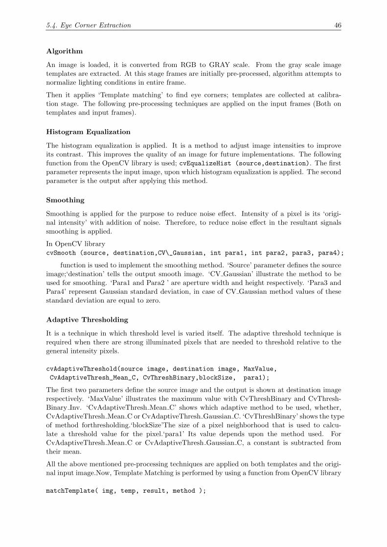
5.4. Eye Corner Extraction 46
Algorithm
An image is loaded, it is converted from RGB to GRAY scale. From the gray scale imagetemplates are extracted. At this stage frames are initially pre-processed, algorithm attempts tonormalize lighting conditions in entire frame.
Then it applies ‘Template matching’ to find eye corners; templates are collected at calibra-tion stage. The following pre-processing techniques are applied on the input frames (Both ontemplates and input frames).
Histogram Equalization
The histogram equalization is applied. It is a method to adjust image intensities to improveits contrast. This improves the quality of an image for future implementations. The followingfunction from the OpenCV library is used; cvEqualizeHist (source,destination). The firstparameter represents the input image, upon which histogram equalization is applied. The secondparameter is the output after applying this method.
Smoothing
Smoothing is applied for the purpose to reduce noise effect. Intensity of a pixel is its ‘origi-nal intensity’ with addition of noise. Therefore, to reduce noise effect in the resultant signalssmoothing is applied.
In OpenCV librarycvSmooth (source, destination,CV\_Gaussian, int para1, int para2, para3, para4);
function is used to implement the smoothing method. ‘Source’ parameter defines the sourceimage;‘destination’ tells the output smooth image. ‘CV Gaussian’ illustrate the method to beused for smoothing. ‘Para1 and Para2 ’ are aperture width and height respectively. ‘Para3 andPara4’ represent Gaussian standard deviation, in case of CV Gaussian method values of thesestandard deviation are equal to zero.
Adaptive Thresholding
It is a technique in which threshold level is varied itself. The adaptive threshold technique isrequired when there are strong illuminated pixels that are needed to threshold relative to thegeneral intensity pixels.
cvAdaptiveThreshold(source image, destination image, MaxValue,
CvAdaptiveThresh_Mean_C, CvThreshBinary,blockSize, para1);
The first two parameters define the source image and the output is shown at destination imagerespectively. ‘MaxValue’ illustrates the maximum value with CvThreshBinary and CvThresh-Binary Inv. ‘CvAdaptiveThresh Mean C’ shows which adaptive method to be used, whether,CvAdaptiveThresh Mean C or CvAdaptiveThresh Gaussian C. ‘CvThreshBinary’ shows the typeof method forthresholding.‘blockSize’The size of a pixel neighborhood that is used to calcu-late a threshold value for the pixel.‘para1’ Its value depends upon the method used. ForCvAdaptiveThresh Mean C or CvAdaptiveThresh Gaussian C, a constant is subtracted fromtheir mean.
All the above mentioned pre-processing techniques are applied on both templates and the origi-nal input image.Now, Template Matching is performed by using a function from OpenCV library
matchTemplate( img, temp, result, method );
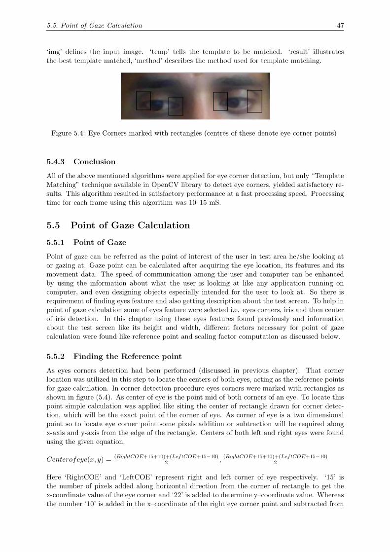
5.5. Point of Gaze Calculation 47
‘img’ defines the input image. ‘temp’ tells the template to be matched. ‘result’ illustratesthe best template matched, ‘method’ describes the method used for template matching.
Figure 5.4: Eye Corners marked with rectangles (centres of these denote eye corner points)
5.4.3 Conclusion
All of the above mentioned algorithms were applied for eye corner detection, but only “TemplateMatching” technique available in OpenCV library to detect eye corners, yielded satisfactory re-sults. This algorithm resulted in satisfactory performance at a fast processing speed. Processingtime for each frame using this algorithm was 10–15 mS.
5.5 Point of Gaze Calculation
5.5.1 Point of Gaze
Point of gaze can be referred as the point of interest of the user in test area he/she looking ator gazing at. Gaze point can be calculated after acquiring the eye location, its features and itsmovement data. The speed of communication among the user and computer can be enhancedby using the information about what the user is looking at like any application running oncomputer, and even designing objects especially intended for the user to look at. So there isrequirement of finding eyes feature and also getting description about the test screen. To help inpoint of gaze calculation some of eyes feature were selected i.e. eyes corners, iris and then centerof iris detection. In this chapter using these eyes features found previously and informationabout the test screen like its height and width, different factors necessary for point of gazecalculation were found like reference point and scaling factor computation as discussed below.
5.5.2 Finding the Reference point
As eyes corners detection had been performed (discussed in previous chapter). That cornerlocation was utilized in this step to locate the centers of both eyes, acting as the reference pointsfor gaze calculation. In corner detection procedure eyes corners were marked with rectangles asshown in figure (5.4). As center of eye is the point mid of both corners of an eye. To locate thispoint simple calculation was applied like siting the center of rectangle drawn for corner detec-tion, which will be the exact point of the corner of eye. As corner of eye is a two dimensionalpoint so to locate eye corner point some pixels addition or subtraction will be required alongx-axis and y-axis from the edge of the rectangle. Centers of both left and right eyes were foundusing the given equation.
Centerofeye(x, y) = (RightCOE+15+10)+(LeftCOE+15−10)2 , (RightCOE+15+10)+(LeftCOE+15−10)
2
Here ‘RightCOE’ and ‘LeftCOE’ represent right and left corner of eye respectively. ‘15’ isthe number of pixels added along horizontal direction from the corner of rectangle to get thex-coordinate value of the eye corner and ‘22’ is added to determine y–coordinate value. Whereasthe number ‘10’ is added in the x–coordinate of the right eye corner point and subtracted from

5.5. Point of Gaze Calculation 48
the left eye corner to estimate the moveable area available to pupil inside eye region becausepupil can’t move to the extreme ends of the eye along horizontal direction. And then for findingthe center of eye mid–point of both left and right corners is found as shown in above equation.This calculation of reference point is similar for both left and right eyes.
Figure 5.5: dimensions of rectangles used for corner detection
5.5.3 Calculating the Scaling factor
In this step the cursor movements and pupil movements were interrelated i.e. it was to befound that how many pixels a cursor will traverse for a single movement of the pupil. For thiscalculation width and height of eyes were associated with the width and height of the screen.Now to calculate width of the eye following equation was used.
EyeWidth = (LeftCOE − 10)− (RightCOE + 10)
As height of an eye varies from 28% to 32% of the width of eye. Here height is calculatedby considering it to be 28% of the width.
EyeHeight = EyeWidth× 28100
This calculation of width and height is same for both left and right eyes. As width and height ofboth eyes might vary because of some false detections in one or both eyes. To reduce the errordue to this detection width and height averages were found i.e. ‘AvgWidth’ and ‘AvgHeight’respectively. Scaling factor was calculated by dividing the width and height of test area withaverage width and average height of eyes respectively.
RxFactor = TestWidthAvgWidth
RyFactor = TestHeightAvgHeight
5.5.4 Computing the Point of Gaze
Point of gaze was calculated using all the results and steps performed earlier. Here the focuswas on pupil movement and displacement from the reference point or center of the each eyeseparately. The translation of center of iris from the center of eye was calculated separately forleft and right eyes.

5.6. Point of Gaze Calculation Algorithm [Live Stream] 49
RightR(x, y) = rightCOEye(x, y)RightCOI(x, y)
LeftR(x, y) = leftCOEye(x, y)LeftCOI(x, y)
In above equations ‘rightCOEye(x,y)’ and ‘leftCOEye (x,y)’ are the centers of left and righteyes respectively . Similarly ‘RightCOI(x,y)’ is the right eye’s center of iris point and ‘LeftCOI(x,y)’ is the left eye’s center of iris.
Now again the relative distance of center of iris and center of eye were averaged to reduce theerror if any in the iris detection or also it can be said as for a better estimation of gaze pointingincluding both eyes relative distances along both x–axis and y–axis direction.
RxAvg = (RightRx+LeftRx)2
RyAvg = (RightRx+LeftRx)2
Now projection on screen can be found by finding the relative distance from the center oftest area associated with the relative motion of center of iris with the center of eye. Followingequations were employed to calculate the screen coordinates.
Projection(x) = TestWidth2 +RxFactor ×RxAvg
Projection(y) = TestHeight2 +RyFactor ×RyAvg
Where ‘Projection(x)’ and ‘Projection(y)’ are coordinates of the test area for x-axis and y-axis respectively the projection point will be as ‘Projection (x, y)’. This whole procedure forpoint of gaze calculation is repeated for each frame from the camera.
5.5.5 Limiting and Smoothing the Cursor Motion
As we are trying to implement the cursor movements as the mouse pointer motion on the screento make these alike smoothing in the mouse pointer movements and introducing limitations tothe test screen coordinates.
As in this algorithm one pixel movement in eye results in several pixels traversing on screencoordinates so this results in jerky motion of the cursor. To make the movement smooth enoughso that it may look like the original motion of the mouse pointer, values were inserted amongthe previous and the next value of the cursor position pixel by pixel. This was done by applying“for loop” from previous value of projection to the next value or point calculated.
Now limiting the cursor movements within screen coordinates meant to bind the cursor insidethe screen. As if the eyes of the user are looking out of the screen of computer computationmay be as the cursor to be out of the region of screen, to limit this some restrictions are appliedusing if conditions so that if the calculations depict cursor as out of the screen this algorithmwill keep and show the cursor to be at the extreme ends of screen.
5.6 Point of Gaze Calculation Algorithm [Live Stream]
Algorithm for pre-recorded sequences worked well for pre-recorded videos, but when tested onlive stream of frames captured by web-cam, its performance was not satisfactory. It given riseto need for improvements or rather design a new algorithm for live stream.
For this purpose, experimentation was performed to analyze the difference between both sce-narios.
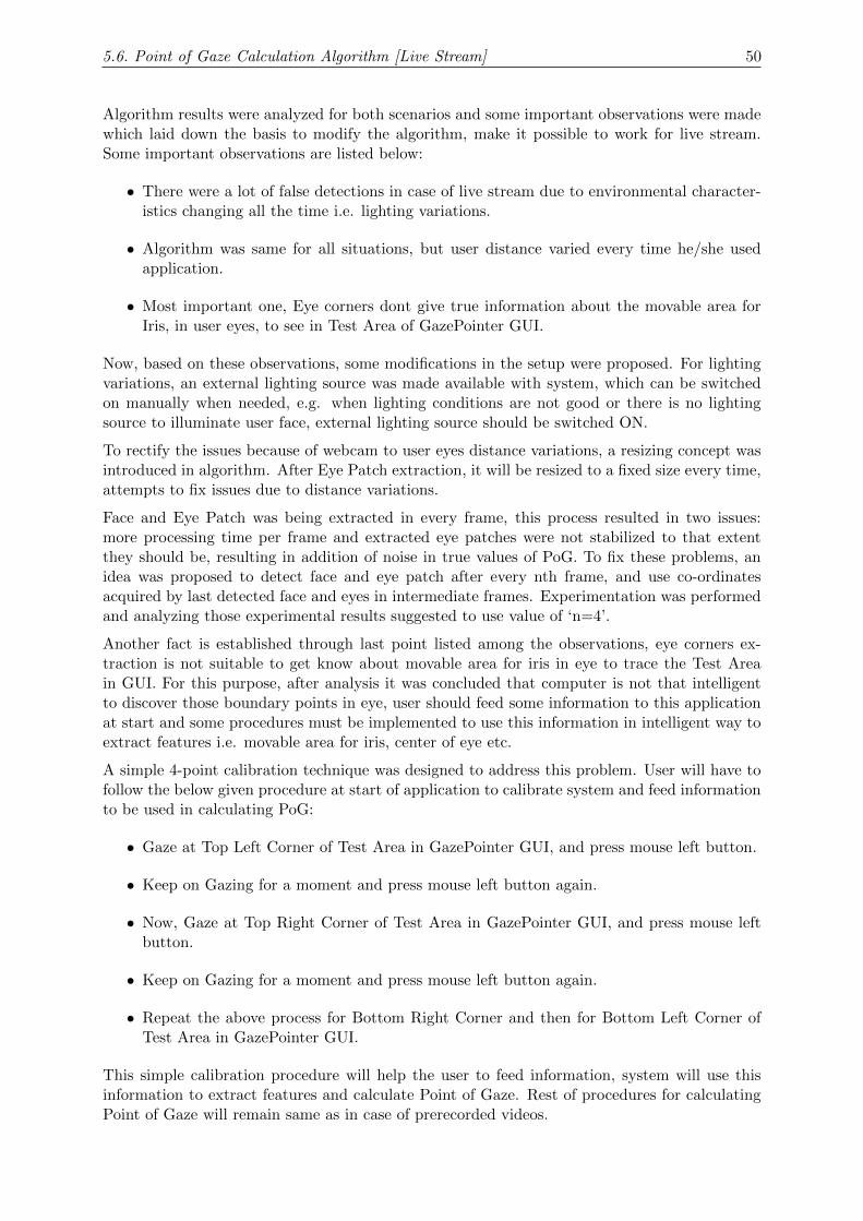
5.6. Point of Gaze Calculation Algorithm [Live Stream] 50
Algorithm results were analyzed for both scenarios and some important observations were madewhich laid down the basis to modify the algorithm, make it possible to work for live stream.Some important observations are listed below:
• There were a lot of false detections in case of live stream due to environmental character-istics changing all the time i.e. lighting variations.
• Algorithm was same for all situations, but user distance varied every time he/she usedapplication.
• Most important one, Eye corners dont give true information about the movable area forIris, in user eyes, to see in Test Area of GazePointer GUI.
Now, based on these observations, some modifications in the setup were proposed. For lightingvariations, an external lighting source was made available with system, which can be switchedon manually when needed, e.g. when lighting conditions are not good or there is no lightingsource to illuminate user face, external lighting source should be switched ON.
To rectify the issues because of webcam to user eyes distance variations, a resizing concept wasintroduced in algorithm. After Eye Patch extraction, it will be resized to a fixed size every time,attempts to fix issues due to distance variations.
Face and Eye Patch was being extracted in every frame, this process resulted in two issues:more processing time per frame and extracted eye patches were not stabilized to that extentthey should be, resulting in addition of noise in true values of PoG. To fix these problems, anidea was proposed to detect face and eye patch after every nth frame, and use co-ordinatesacquired by last detected face and eyes in intermediate frames. Experimentation was performedand analyzing those experimental results suggested to use value of ‘n=4’.
Another fact is established through last point listed among the observations, eye corners ex-traction is not suitable to get know about movable area for iris in eye to trace the Test Areain GUI. For this purpose, after analysis it was concluded that computer is not that intelligentto discover those boundary points in eye, user should feed some information to this applicationat start and some procedures must be implemented to use this information in intelligent way toextract features i.e. movable area for iris, center of eye etc.
A simple 4-point calibration technique was designed to address this problem. User will have tofollow the below given procedure at start of application to calibrate system and feed informationto be used in calculating PoG:
• Gaze at Top Left Corner of Test Area in GazePointer GUI, and press mouse left button.
• Keep on Gazing for a moment and press mouse left button again.
• Now, Gaze at Top Right Corner of Test Area in GazePointer GUI, and press mouse leftbutton.
• Keep on Gazing for a moment and press mouse left button again.
• Repeat the above process for Bottom Right Corner and then for Bottom Left Corner ofTest Area in GazePointer GUI.
This simple calibration procedure will help the user to feed information, system will use thisinformation to extract features and calculate Point of Gaze. Rest of procedures for calculatingPoint of Gaze will remain same as in case of prerecorded videos.
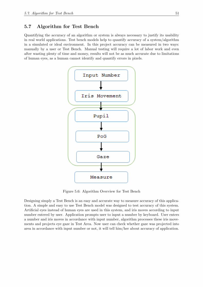
5.7. Algorithm for Test Bench 51
5.7 Algorithm for Test Bench
Quantifying the accuracy of an algorithm or system is always necessary to justify its usabilityin real world applications. Test bench models help to quantify accuracy of a system/algorithmin a simulated or ideal environment. In this project accuracy can be measured in two ways:manually by a user or Test Bench. Manual testing will require a lot of labor work and evenafter wasting plenty of time and money, results will not be as much accurate due to limitationsof human eyes, as a human cannot identify and quantify errors in pixels.
Figure 5.6: Algorithm Overview for Test Bench
Designing simply a Test Bench is an easy and accurate way to measure accuracy of this applica-tion. A simple and easy to use Test Bench model was designed to test accuracy of this system.Artificial eyes instead of human eyes are used in this system, and iris moves according to inputnumber entered by user. Application prompts user to input a number by keyboard. User entersa number and iris moves in accordance with input number, algorithm processes these iris move-ments and projects eye gaze in Test Area. Now user can check whether gaze was projected intoarea in accordance with input number or not, it will tell him/her about accuracy of application.
Chapter 6
Developing Graphical User InterfaceUsing Qt framework
As soon as results are ready to display, a ‘Graphical User Interface’ needs to be developed toshow results. OpenCV library doesn’t provide enough support to develop a customizable GUIwith a number of areas. A number of tools were searched to develop a GUI using C/C++,finally, Qt framework was selected. It provides excellent functions for GUI development andextensive documentation makes it easier to develop a GUI using Qt.
Qt is a cross-platform application framework that is widely used for developing applicationsoftware with a graphical user interface (GUI) , and also used for developing non-GUI programssuch as command-line tools and consoles for servers [40].
It consists of two elements: a cross-platform IDE, called Qt Creator, and a set of Qt classlibraries and development tools. Qt framework has many advantages including formation ofGUI using a cross-platform GUI library, which follows an object-oriented model.
6.1 Introduction to Qt Classes
Qt provides extensive support for GUI development, it offers a lot of different types of classeswhich can be used to create a user friendly and easily accessible GUI. These Qt classes offercustomization to developers, so they can design good looking GUIs. This section is devotedto explain different Qt classes which are being used in GUI development. Each class is beingexplained under a different heading and it will also explain the usage details of particular classin GUI.
6.1.1 Main Window
A main window is made by creating an instance of QMainWindow(). Different types of widgetscan be added to layouts as per requirements and then these layouts can be added to a mainlayout, which can be added to Main Window. In current GUI implementation an instance ofQMainWindow() is created as ‘GazePointer’.
6.1.2 Qwidget
Widgets are the main elements for creating UI. The main purpose for using widgets in thisproject is to display results and to handle user input during calibration stage. Qwidget class isused to create a widget.
Three widgets are created to show results of different stages of algorithm:
52
6.1. Introduction to Qt Classes 53
1. First Widget shows extracted eye patch after face and eyes detection
2. Second widget is used to display eye patch after processing and it shows detected eyefeatures.
3. A test area showing the mouse pointer movements.
6.1.3 Layouts
Layouts are used to arrange the widgets according to their size and orientation. The size of thewidget is provided through the use of ‘sizeHint()’ property. Layouts in GUI are represented inthree main formats: horizontal, vertical and grid layout.
‘QHBoxLayout’ is used to align the widgets in a horizontal layout. The number and box in theGUI are arranged horizontally in GUI using ‘QHBoxLayout’ .
‘QVBoxLayout’ aligns the widgets in a vertical layout. Two widgets are created in verticalorientation to show the original video frames and other to detected iris and eye corners.
‘QGridLayout’ has aligned all the widgets in the main window in horizontal and vertical align-ments as required.
6.1.4 Spacings
Spacings between all the widgets are adjusted by ‘setSpacing()’. Spacing are adjusted accordingto the requirements
6.1.5 CVImageWidget
OpenCV deals with images in Mat, IplImage or CvMat format, unfortunately Qt is unabledisplay frames in these formats. It only handles images in two formats QImage and QPixmap.OpenCV images must be converted to any of the format that Qt support, to display them inGUI. QWidget class can display OpenCV images, if somehow OpenCV image can be convertedto QImage format. QImage class has support for in-memory construction, that is, a QImagecan be assigned to an existing image stored in the memory [41].
OpenCV stores color images in BGR format but Qt handles color images in RGB format,therefore, OpenCV image is first converted to RGB image before converting to QImage. Animage widget class is created to display the image. Firstly a QImage is stored in memory andthen point the converted (RGB) OpenCV image to Qimage. The widget itself updates theimage in memory. Qt can display QImage using QPainter::DrawImage. Three image widgetsare created and assigned to vertical layouts. In the first widget the frames are being showedafter extracting eye patch, the next widget shows eye patch after processing, and another widgetto show test area for mouse pointer movement.
6.1.6 QSlider
A slider is created to control the speed of mouse pointer using the command QSlider. It isadjusted in a vertical layout using QVBoxLayout. It converts the rate of change in mouseposition according to the slider position and converts the position to an integer value to performthe required function. Position of the slider is fixed by giving it maximum and minimum valuesusing setFixedSize( max val, min val).
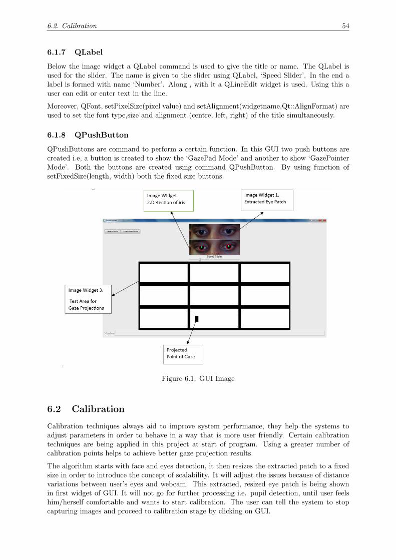
6.2. Calibration 54
6.1.7 QLabel
Below the image widget a QLabel command is used to give the title or name. The QLabel isused for the slider. The name is given to the slider using QLabel, ‘Speed Slider’. In the end alabel is formed with name ‘Number’. Along , with it a QLineEdit widget is used. Using this auser can edit or enter text in the line.
Moreover, QFont, setPixelSize(pixel value) and setAlignment(widgetname,Qt::AlignFormat) areused to set the font type,size and alignment (centre, left, right) of the title simultaneously.
6.1.8 QPushButton
QPushButtons are command to perform a certain function. In this GUI two push buttons arecreated i.e, a button is created to show the ‘GazePad Mode’ and another to show ‘GazePointerMode’. Both the buttons are created using command QPushButton. By using function ofsetFixedSize(length, width) both the fixed size buttons.
Figure 6.1: GUI Image
6.2 Calibration
Calibration techniques always aid to improve system performance, they help the systems toadjust parameters in order to behave in a way that is more user friendly. Certain calibrationtechniques are being applied in this project at start of program. Using a greater number ofcalibration points helps to achieve better gaze projection results.
The algorithm starts with face and eyes detection, it then resizes the extracted patch to a fixedsize in order to introduce the concept of scalability. It will adjust the issues because of distancevariations between user’s eyes and webcam. This extracted, resized eye patch is being shownin first widget of GUI. It will not go for further processing i.e. pupil detection, until user feelshim/herself comfortable and wants to start calibration. The user can tell the system to stopcapturing images and proceed to calibration stage by clicking on GUI.
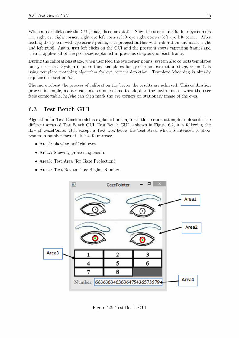
6.3. Test Bench GUI 55
When a user click once the GUI, image becomes static. Now, the user marks its four eye cornersi.e., right eye right corner, right eye left corner, left eye right corner, left eye left corner. Afterfeeding the system with eye corner points, user proceed further with calibration and marks rightand left pupil. Again, user left clicks on the GUI and the program starts capturing frames andthen it applies all of the processes explained in previous chapters, on each frame.
During the calibrations stage, when user feed the eye corner points, system also collects templatesfor eye corners. System requires these templates for eye corners extraction stage, where it isusing template matching algorithm for eye corners detection. Template Matching is alreadyexplained in section 5.3.
The more robust the process of calibration the better the results are achieved. This calibrationprocess is simple, as user can take as much time to adapt to the environment, when the userfeels comfortable, he/she can then mark the eye corners on stationary image of the eyes.
6.3 Test Bench GUI
Algorithm for Test Bench model is explained in chapter 5, this section attempts to describe thedifferent areas of Test Bench GUI. Test Bench GUI is shown in Figure 6.2, it is following theflow of GazePointer GUI except a Text Box below the Test Area, which is intended to showresults in number format. It has four areas:
• Area1: showing artificial eyes
• Area2: Showing processing results
• Area3: Test Area (for Gaze Projection)
• Area4: Text Box to show Region Number.
Figure 6.2: Test Bench GUI

6.3. Test Bench GUI 56
When User run this GUI application, a command prompt screen will appear, user will enter anumber in between 1-9. Iris in artificial eyes will move in accordance with input number andshown in Area1. Processing results will be shown in Area2. Gaze will be projected in Test Area,a number will be entered into the Text Box (below to Test Area in GUI) according to gazeprojection.

Chapter 7
Result and Discussion
This chapter is devoted to evaluate results of GazePointer implementation using OpenCV. It willfollow the flow of algorithm, starting with face detection then evaluating eye patch extraction,later it will discuss results of pupil detection and then eye corners extraction.
7.1 Face Detection
OpenCV library provides a high performance implementation of face detection in different en-vironments. As it is explained earlier, it is not a skin color based approach so detection ratedoes not deteriorate with different background colors or with different lighting environments.Face detection implementation provides satisfactory results in outdoor as well as indoor environ-ments. Accuracy does not drops with changing lighting conditions, backgrounds, and distancewhile using a computer. Face needs to be frontal, it will not detect profile faces, a limited levelmobility is available for face. It also detects face accurately even when user is wearing glasses.
According to limitations of this system explained in chapter 3, Face detection accuracy remained100% when tested on a limited dataset of 223 frames. Generally face detection results were quitesatisfactory in every environment, and this is as it should be, because it is a preliminary stageand accuracy of this stage must remain above 95% ideally.
As explained earlier in chapter 5, that face detection is a complex process and it requires a lot ofcomplex processes to be done in a series to detect a face accurately, so detection time will alwaysbe high especially for high resolution images. GazePointer is assumed to be a system workingwith real-time constraints, so to reduce the computation time captured frames are downsampled5 times (both sides, in width and height). Before resizing the frame, face detection took 500–600mS per frame and it reduced to only 13–15 mS per frame.
Figure 7.1: Face and Eyes Detection Results in Different Frame
57
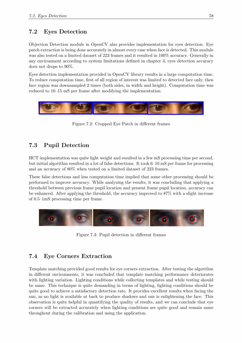
7.2. Eyes Detection 58
7.2 Eyes Detection
Objection Detection module in OpenCV also provides implementation for eyes detection. Eyepatch extraction is being done accurately in almost every case when face is detected. This modulewas also tested on a limited dataset of 223 frames and it resulted in 100% accuracy. Generally inany environment according to system limitations defined in chapter 3, eyes detection accuracydoes not drops to 90%.
Eyes detection implementation provided in OpenCV library results in a large computation time.To reduce computation time, first of all region of interest was limited to detected face only, thenface region was downsampled 2 times (both sides, in width and height). Computation time wasreduced to 10–15 mS per frame after modifying the implementation.
Figure 7.2: Cropped Eye Patch in different frames
7.3 Pupil Detection
HCT implementation was quite light weight and resulted in a few mS processing time per second,but initial algorithm resulted in a lot of false detections. It took 6–10 mS per frame for processingand an accuracy of 80% when tested on a limited dataset of 223 frames.
These false detections and less computation time implied that some other processing should beperformed to improve accuracy. While analyzing the results, it was concluding that applying athreshold between previous frame pupil location and present frame pupil location, accuracy canbe enhanced. After applying the threshold, the accuracy improved to 87% with a slight increaseof 0.5–1mS processing time per frame.
Figure 7.3: Pupil detection in different frames
7.4 Eye Corners Extraction
Template matching provided good results for eye corners extraction. After testing the algorithmin different environments, it was concluded that template matching performance deteriorateswith lighting variation. Lighting conditions while collecting templates and while testing shouldbe same. This technique is quite demanding in terms of lighting, lighting conditions should bequite good to achieve a satisfactory detection rate. It provides excellent results when facing thesun, as no light is available at back to produce shadows and sun is enlightening the face. Thisobservation is quite helpful in quantifying the quality of results, and we can conclude that eyecorners will be extracted accurately when lighting conditions are quite good and remain samethroughout during the calibration and using the application.
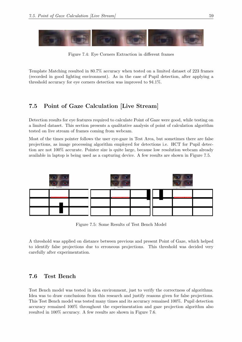
7.5. Point of Gaze Calculation [Live Stream] 59
Figure 7.4: Eye Corners Extraction in different frames
Template Matching resulted in 80.7% accuracy when tested on a limited dataset of 223 frames(recorded in good lighting environment). As in the case of Pupil detection, after applying athreshold accuracy for eye corners detection was improved to 94.1%.
7.5 Point of Gaze Calculation [Live Stream]
Detection results for eye features required to calculate Point of Gaze were good, while testing ona limited dataset. This section presents a qualitative analysis of point of calculation algorithmtested on live stream of frames coming from webcam.
Most of the times pointer follows the user eye-gaze in Test Area, but sometimes there are falseprojections, as image processing algorithm employed for detections i.e. HCT for Pupil detec-tion are not 100% accurate. Pointer size is quite large, because low resolution webcam alreadyavailable in laptop is being used as a capturing device. A few results are shown in Figure 7.5.
Figure 7.5: Some Results of Test Bench Model
A threshold was applied on distance between previous and present Point of Gaze, which helpedto identify false projections due to erroneous projections. This threshold was decided verycarefully after experimentation.
7.6 Test Bench
Test Bench model was tested in idea environment, just to verify the correctness of algorithms.Idea was to draw conclusions from this research and justify reasons given for false projections.This Test Bench model was tested many times and its accuracy remained 100%. Pupil detectionaccuracy remained 100% throughout the experimentation and gaze projection algorithm alsoresulted in 100% accuracy. A few results are shown in Figure 7.6.

7.6. Test Bench 60
Figure 7.6: Some Results of Test Bench Model
This accuracy of 100% shows the correctness of algorithms employed, also justifies the reasonsexplained for false projections and detections. Test Bench results established the fact that workdone under this project is substantial and algorithm for eye gaze projection is reliable.

Chapter 8
Conclusion & Future Work
This chapter details main conclusions of this project, discusses possible enhancements and givesproposals for future research in this field.
8.1 Conclusion
In this thesis, a Human Computer Interaction application is developed using concept of EyeGaze Tracking. The main objective of testing the potential of eye gaze as a possible meansof interaction and to develop an eye-gaze based interaction application using built-in cameraavailable in computing devices is accomplished.
Eye gaze tracking is a complex problem and there can be many solutions to address this prob-lem. In this project a computer vision algorithms based solution is implemented. A low cost,real-time solution for eye gaze tracking is developed with help of OpenCV library. There aremany applications of eye gaze tracking, for instance in HCI, appliances control, usability studiesand in advertising effectiveness.
Accuracy for facial features extraction algorithms depend on image quality and lighting condi-tions. Algorithm performance drops down in poor lighting environment i.e. light coming fromback side of user causing shadow, low light intensity on face. Algorithm accuracy deteriorate inlighting variant environments. Computer Vision algorithms are employed for features detectionand they dont perform well in lighting environments discussed earlier.
Point of gaze (PoG) calculation is a crucial stage in this project, multiple features are combinedin a systematic way to result in accurate calculation of PoG. Simple mathematical equationsrelate these feature points to PoG. PoG is accurately calculated provided detections are correct,only a few erroneous PoG projections were found and reason was false detections in featuresdetection stage. Pointer size is large due to low resolution and small Test Area.
Test Bench model is developed to test algorithm in ideal environment and to infer conclusionsabout false projections. This model verified the correctness of algorithm and accuracy proved tobe 100%. This also confirms the reason for erroneous projections to be, performance of computervision algorithms in lighting variant environment and poor lighting conditions.
8.2 Future Work
To improve the projection results, image quality must be enhanced. Better image quality wouldimprove accuracy of computer vision algorithms. Sophisticated pre-processing algorithms shouldbe introduced to compensate lighting variations and webcam resolution should also be increasedto decrease pointer size.
61
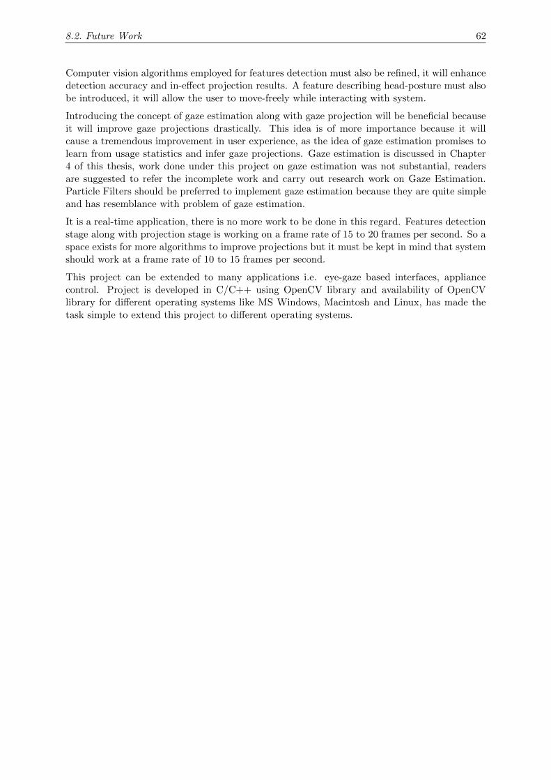
8.2. Future Work 62
Computer vision algorithms employed for features detection must also be refined, it will enhancedetection accuracy and in-effect projection results. A feature describing head-posture must alsobe introduced, it will allow the user to move-freely while interacting with system.
Introducing the concept of gaze estimation along with gaze projection will be beneficial becauseit will improve gaze projections drastically. This idea is of more importance because it willcause a tremendous improvement in user experience, as the idea of gaze estimation promises tolearn from usage statistics and infer gaze projections. Gaze estimation is discussed in Chapter4 of this thesis, work done under this project on gaze estimation was not substantial, readersare suggested to refer the incomplete work and carry out research work on Gaze Estimation.Particle Filters should be preferred to implement gaze estimation because they are quite simpleand has resemblance with problem of gaze estimation.
It is a real-time application, there is no more work to be done in this regard. Features detectionstage along with projection stage is working on a frame rate of 15 to 20 frames per second. So aspace exists for more algorithms to improve projections but it must be kept in mind that systemshould work at a frame rate of 10 to 15 frames per second.
This project can be extended to many applications i.e. eye-gaze based interfaces, appliancecontrol. Project is developed in C/C++ using OpenCV library and availability of OpenCVlibrary for different operating systems like MS Windows, Macintosh and Linux, has made thetask simple to extend this project to different operating systems.
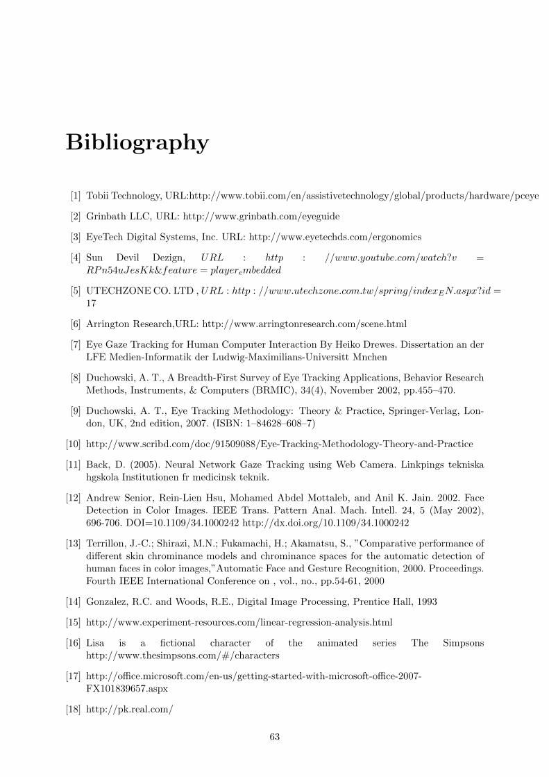
Bibliography
[1] Tobii Technology, URL:http://www.tobii.com/en/assistivetechnology/global/products/hardware/pceye
[2] Grinbath LLC, URL: http://www.grinbath.com/eyeguide
[3] EyeTech Digital Systems, Inc. URL: http://www.eyetechds.com/ergonomics
[4] Sun Devil Dezign, URL : http : //www.youtube.com/watch?v =RPn54uJesKk&feature = playerembedded
[5] UTECHZONE CO. LTD , URL : http : //www.utechzone.com.tw/spring/indexEN.aspx?id =17
[6] Arrington Research,URL: http://www.arringtonresearch.com/scene.html
[7] Eye Gaze Tracking for Human Computer Interaction By Heiko Drewes. Dissertation an derLFE Medien-Informatik der Ludwig-Maximilians-Universitt Mnchen
[8] Duchowski, A. T., A Breadth-First Survey of Eye Tracking Applications, Behavior ResearchMethods, Instruments, & Computers (BRMIC), 34(4), November 2002, pp.455–470.
[9] Duchowski, A. T., Eye Tracking Methodology: Theory & Practice, Springer-Verlag, Lon-don, UK, 2nd edition, 2007. (ISBN: 1–84628–608–7)
[10] http://www.scribd.com/doc/91509088/Eye-Tracking-Methodology-Theory-and-Practice
[11] Back, D. (2005). Neural Network Gaze Tracking using Web Camera. Linkpings tekniskahgskola Institutionen fr medicinsk teknik.
[12] Andrew Senior, Rein-Lien Hsu, Mohamed Abdel Mottaleb, and Anil K. Jain. 2002. FaceDetection in Color Images. IEEE Trans. Pattern Anal. Mach. Intell. 24, 5 (May 2002),696-706. DOI=10.1109/34.1000242 http://dx.doi.org/10.1109/34.1000242
[13] Terrillon, J.-C.; Shirazi, M.N.; Fukamachi, H.; Akamatsu, S., ”Comparative performance ofdifferent skin chrominance models and chrominance spaces for the automatic detection ofhuman faces in color images,”Automatic Face and Gesture Recognition, 2000. Proceedings.Fourth IEEE International Conference on , vol., no., pp.54-61, 2000
[14] Gonzalez, R.C. and Woods, R.E., Digital Image Processing, Prentice Hall, 1993
[15] http://www.experiment-resources.com/linear-regression-analysis.html
[16] Lisa is a fictional character of the animated series The Simpsonshttp://www.thesimpsons.com/#/characters
[17] http://office.microsoft.com/en-us/getting-started-with-microsoft-office-2007-FX101839657.aspx
[18] http://pk.real.com/
63
BIBLIOGRAPHY 64
[19] http://www.mathworks.com/products/matlab/
[20] https://mail.google.com/mail/u/0/#inbox
[21] http://www.facebook.com/
[22] http://www.eclipse.org/indigo/
[23] Wiener, Norbert (1949). Extrapolation, Interpolation, and Smoothing of Stationary TimeSeries. New York: Wiley. ISBN 0-262-73005-7.
[24] Doucet, A.; De Freitas, N.; Gordon, N.J. (2001). Sequential Monte Carlo Methods in Prac-tice. Springer.
[25] http : //person.hst.aau.dk/enk/ST 7/lecture7s lides.pdf
[26] Standard Mathematical Tables and Formulae(30ed.).CRC Press, Inc.1996.pp.660661.ISBN08493 24793
[27] http : //web.mit.edu/16.412j/www/html/Advanced%20lectures/Slides/HsaioplinvalmillerParticleFiltersPrint.pdf
[28] http://www.cs.ubc.ca/ nando/smc/index.html
[29] Arulampalam, M. S., Maskell, S., Gordon, N., & Clapp, T. (2002, February). A Tutorialon Particle Filters for Online Nonlinear/Non-Gaussian Bayesian Tracking. IEEE TRANS-ACTIONS ON SIGNAL PROCESSING, 50(2), 174-188.
[30] Salmond, D., & Gordon, N. (2005, September). An introduction to particle Filters.
[31] http://www.cs.ubc.ca/ nando/smc/index.html
[32] http://www.oursland.net/pro jects/particlefilter/
[33] http://www.computing.edu.au/ 12482661/applet.html
[34] N. Gordon, D. Salmond, and A. F. M. Smith, Novel approach to nonlinear and non-GaussianBayesian state estimation, Proc. Inst. Elect.Eng., F, vol. 140, pp. 107113, 1993
[35] http://opencv.org/about.html
[36] http://opencv.org
[37] http://www.xavigimenez.net/blog/2010/02/face-detection-how-to-find-faces-with-opencv/
[38] http : //www.cognotics.com/opencv/servo2007series/part2/index.html
[39] Laganire, R. (May 23, 2011). OpenCV 2 Computer Vision Application Programming Cook-book. Packt Publishing.
[40] Blanchette, J., & Summerfield, M. (2008). C++ GUI Programming with Qt 4. PrenticeHall.
[41] http://develnoter.blogspot.com/

Appendix A: Project Timeline
DATE January 14,2013
PROJECT ID 22 TOTAL NUMBER
OF WEEKS IN
PLAN 43
TITLE GazePointer: A Real-Time Mouse Pointer Control Implementation based on Eye Gaze Tracking
Related Documents