Service Guide Gateway M675 Notebook

Gateway M675 laptop
Nov 18, 2014
Complete service manual
Welcome message from author
This document is posted to help you gain knowledge. Please leave a comment to let me know what you think about it! Share it to your friends and learn new things together.
Transcript

Service GuideGateway M675 Notebook


ContentsReplacing Gateway M675 Components . . . . . . . . . . . . . . . . . . . . . . . . . . . . . . . . . . . . 1
Introduction . . . . . . . . . . . . . . . . . . . . . . . . . . . . . . . . . . . . . . . . . . . . . . . . . . . . . . . . . . . . . . . 2Identifying the notebook model . . . . . . . . . . . . . . . . . . . . . . . . . . . . . . . . . . . . . . . . . . . . . . . 2Identifying components . . . . . . . . . . . . . . . . . . . . . . . . . . . . . . . . . . . . . . . . . . . . . . . . . . . . . 3Preparing your work space . . . . . . . . . . . . . . . . . . . . . . . . . . . . . . . . . . . . . . . . . . . . . . . . . . 4Preventing static electricity discharge . . . . . . . . . . . . . . . . . . . . . . . . . . . . . . . . . . . . . . . . . . 5Preparing the notebook . . . . . . . . . . . . . . . . . . . . . . . . . . . . . . . . . . . . . . . . . . . . . . . . . . . . . 6Removing the battery . . . . . . . . . . . . . . . . . . . . . . . . . . . . . . . . . . . . . . . . . . . . . . . . . . . . . . . 7Replacing the hard drive kit . . . . . . . . . . . . . . . . . . . . . . . . . . . . . . . . . . . . . . . . . . . . . . . . . . 9Replacing the hard drive in the hard drive kit . . . . . . . . . . . . . . . . . . . . . . . . . . . . . . . . . . . 12Replacing the optical drive . . . . . . . . . . . . . . . . . . . . . . . . . . . . . . . . . . . . . . . . . . . . . . . . . 14Replacing the diskette drive, card reader, or second hard drive . . . . . . . . . . . . . . . . . . . . 15Replacing the keyboard cover . . . . . . . . . . . . . . . . . . . . . . . . . . . . . . . . . . . . . . . . . . . . . . . 16Replacing the keyboard . . . . . . . . . . . . . . . . . . . . . . . . . . . . . . . . . . . . . . . . . . . . . . . . . . . . 18Replacing the modem . . . . . . . . . . . . . . . . . . . . . . . . . . . . . . . . . . . . . . . . . . . . . . . . . . . . . 23Adding or replacing memory modules . . . . . . . . . . . . . . . . . . . . . . . . . . . . . . . . . . . . . . . . . 26Replacing the cooling assembly . . . . . . . . . . . . . . . . . . . . . . . . . . . . . . . . . . . . . . . . . . . . . 29Replacing the IEEE 802.11 Mini-PCI card . . . . . . . . . . . . . . . . . . . . . . . . . . . . . . . . . . . . . 32Replacing the hinge covers . . . . . . . . . . . . . . . . . . . . . . . . . . . . . . . . . . . . . . . . . . . . . . . . . 36Replacing the LCD panel assembly . . . . . . . . . . . . . . . . . . . . . . . . . . . . . . . . . . . . . . . . . . 40Replacing the palm rest assembly . . . . . . . . . . . . . . . . . . . . . . . . . . . . . . . . . . . . . . . . . . . 44Replacing the LED panel . . . . . . . . . . . . . . . . . . . . . . . . . . . . . . . . . . . . . . . . . . . . . . . . . . . 48Replacing the CMOS battery . . . . . . . . . . . . . . . . . . . . . . . . . . . . . . . . . . . . . . . . . . . . . . . . 51Replacing the speakers . . . . . . . . . . . . . . . . . . . . . . . . . . . . . . . . . . . . . . . . . . . . . . . . . . . . 54Replacing the system board . . . . . . . . . . . . . . . . . . . . . . . . . . . . . . . . . . . . . . . . . . . . . . . . 57
iwww.gateway.com

ii www.gateway.com

�������������� ��������������
© 2004 Gateway, Inc. All rights reserved. Gateway, Gateway Country, the Gateway stylized logo, and the black-and-white spot design are trademarks or registered trademarks of Gateway, Inc. in the United States and other countries. All other brands and product names are trademarks or registered trademarks of their respective companies.
1

Introduction
Use this service guide to help plan maintenance tasks for the Gateway M675 notebook. All tasks covered in this guide can be performed by an authorized field technician without jeopardizing the notebook’s warranty.
For information on the notebook’s general maintenance, technical support, safety notices, and regulatory notices, see the Gateway user guide.
If you have suggestions regarding the content of this guide, send an e-mail with the subject “Service Guide Comments” to [email protected].
Identifying the notebook modelThe label on the bottom of the notebook contains information that identifies the notebook model and its features.
Important This service guide is not intended to be provided to individual users or consumers. It cannot be provided to anyone other than an authorized service provider.
Caution It is important that you use the correct service guide for the notebook. Failure to follow the approved tasks for the notebook model may result in damage to the notebook.
Gatewaymodel
number
2 www.gateway.com

Identifying componentsWhere screw measurements are shown, the first number indicates screw head width, and the second number indicates screw length.
Use this chart to identify the main components of the notebook. For a complete list of replaceable parts, see the “Contents” on page i.
Modem(see page 23)
Cooling assembly(see page 29)
LCD panel assembly(see page 40)
Keyboard cover(see page 16)
Keyboard(see page 18)
Palm rest assembly(see page 44)
System board(see page 57)
3www.gateway.com
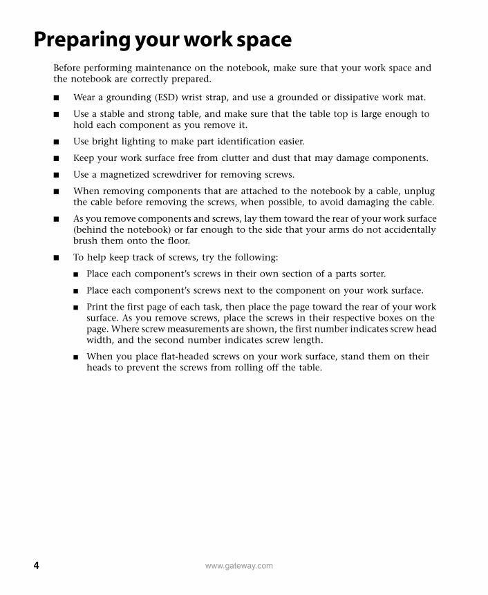
Preparing your work spaceBefore performing maintenance on the notebook, make sure that your work space and the notebook are correctly prepared.
■ Wear a grounding (ESD) wrist strap, and use a grounded or dissipative work mat.
■ Use a stable and strong table, and make sure that the table top is large enough to hold each component as you remove it.
■ Use bright lighting to make part identification easier.
■ Keep your work surface free from clutter and dust that may damage components.
■ Use a magnetized screwdriver for removing screws.
■ When removing components that are attached to the notebook by a cable, unplug the cable before removing the screws, when possible, to avoid damaging the cable.
■ As you remove components and screws, lay them toward the rear of your work surface (behind the notebook) or far enough to the side that your arms do not accidentally brush them onto the floor.
■ To help keep track of screws, try the following:
■ Place each component’s screws in their own section of a parts sorter.
■ Place each component’s screws next to the component on your work surface.
■ Print the first page of each task, then place the page toward the rear of your work surface. As you remove screws, place the screws in their respective boxes on the page. Where screw measurements are shown, the first number indicates screw head width, and the second number indicates screw length.
■ When you place flat-headed screws on your work surface, stand them on their heads to prevent the screws from rolling off the table.
4 www.gateway.com
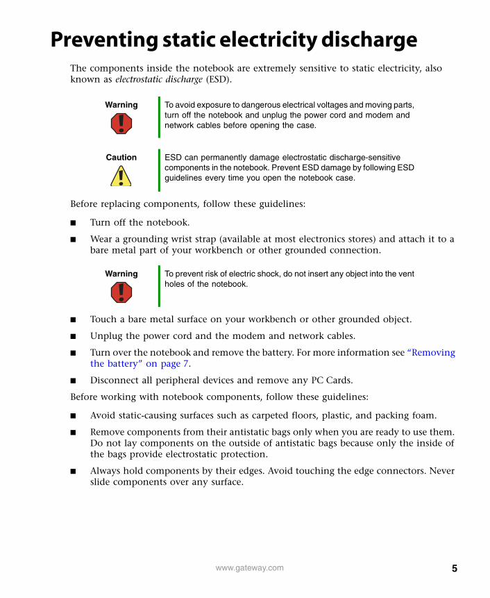
Preventing static electricity dischargeThe components inside the notebook are extremely sensitive to static electricity, also known as electrostatic discharge (ESD).
Before replacing components, follow these guidelines:
■ Turn off the notebook.
■ Wear a grounding wrist strap (available at most electronics stores) and attach it to a bare metal part of your workbench or other grounded connection.
■ Touch a bare metal surface on your workbench or other grounded object.
■ Unplug the power cord and the modem and network cables.
■ Turn over the notebook and remove the battery. For more information see “Removing the battery” on page 7.
■ Disconnect all peripheral devices and remove any PC Cards.
Before working with notebook components, follow these guidelines:
■ Avoid static-causing surfaces such as carpeted floors, plastic, and packing foam.
■ Remove components from their antistatic bags only when you are ready to use them. Do not lay components on the outside of antistatic bags because only the inside of the bags provide electrostatic protection.
■ Always hold components by their edges. Avoid touching the edge connectors. Never slide components over any surface.
Warning To avoid exposure to dangerous electrical voltages and moving parts, turn off the notebook and unplug the power cord and modem and network cables before opening the case.
Caution ESD can permanently damage electrostatic discharge-sensitive components in the notebook. Prevent ESD damage by following ESD guidelines every time you open the notebook case.
Warning To prevent risk of electric shock, do not insert any object into the vent holes of the notebook.
5www.gateway.com
Preparing the notebook
To prepare the notebook for maintenance:
■ Make sure that the CD or DVD drive is empty.
■ Disconnect all peripheral devices.
■ Remove any memory cards, PC Cards, and diskettes.
■ Turn off the notebook and unplug the power cord and modem and network cables (if attached).
■ Turn over the notebook and remove the battery. For more information see “Removing the battery” on page 7.
Warning To avoid exposure to dangerous electrical voltages and moving parts, turn off the notebook, remove the battery, and unplug the power cord and modem and network cables before opening the case. Reassemble the notebook before you restore power or reconnect the modem and network cables.
6 www.gateway.com

Removing the battery
To remove the battery:1 Disconnect the AC adapter and modem and network cables, then prepare the
notebook by following the instructions in “Preparing the notebook” on page 6.
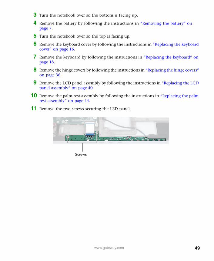
2 Turn the notebook over so the bottom is facing up.
3 Slide the battery release latch.
Battery
7www.gateway.com

4 Lift the battery out of the bay.
8 www.gateway.com

Replacing the hard drive kitTools you need to complete this task:
To replace the hard drive kit:1 Disconnect the AC adapter and modem and network cables, then prepare the
notebook by following the instructions in “Preparing the notebook” on page 6.
2 Turn the notebook over so the bottom is facing up.
3 Remove the battery by following the instructions in “Removing the battery” on page 7.
Phillips #0 screwdriver
Hard drive kit
9www.gateway.com

4 Loosen the captive hard drive bay cover screw, then remove the hard drive bay cover. This screw cannot be removed.
5 Slide the old hard drive kit away from the connector.
Screw
10 www.gateway.com
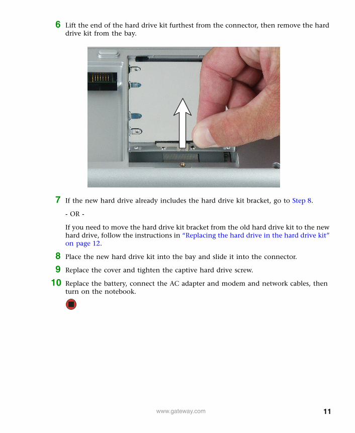
6 Lift the end of the hard drive kit furthest from the connector, then remove the hard drive kit from the bay.
7 If the new hard drive already includes the hard drive kit bracket, go to Step 8.
- OR -
If you need to move the hard drive kit bracket from the old hard drive kit to the new hard drive, follow the instructions in “Replacing the hard drive in the hard drive kit” on page 12.
8 Place the new hard drive kit into the bay and slide it into the connector.
9 Replace the cover and tighten the captive hard drive screw.
10 Replace the battery, connect the AC adapter and modem and network cables, then turn on the notebook.
11www.gateway.com
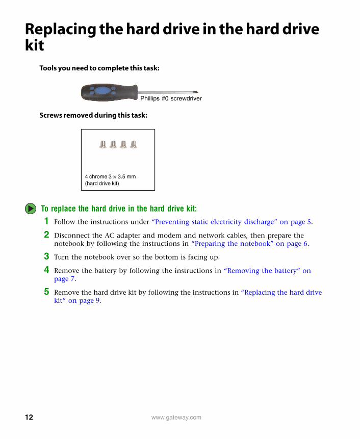
Replacing the hard drive in the hard drive kit
Tools you need to complete this task:
Screws removed during this task:
To replace the hard drive in the hard drive kit:
1 Follow the instructions under “Preventing static electricity discharge” on page 5.
2 Disconnect the AC adapter and modem and network cables, then prepare the notebook by following the instructions in “Preparing the notebook” on page 6.
3 Turn the notebook over so the bottom is facing up.
4 Remove the battery by following the instructions in “Removing the battery” on page 7.
5 Remove the hard drive kit by following the instructions in “Replacing the hard drive kit” on page 9.
Phillips #0 screwdriver
4 chrome 3 × 3.5 mm(hard drive kit)
12 www.gateway.com
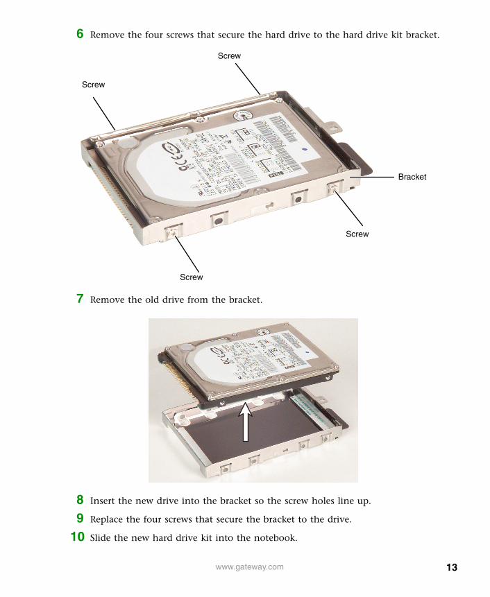
6 Remove the four screws that secure the hard drive to the hard drive kit bracket.
7 Remove the old drive from the bracket.
8 Insert the new drive into the bracket so the screw holes line up.
9 Replace the four screws that secure the bracket to the drive.
10 Slide the new hard drive kit into the notebook.
Screw
Screw
Screw
Screw
Bracket
13www.gateway.com

11 Replace the hard drive cover and tighten the captive hard drive screw.
12 Replace the battery, connect the AC adapter and modem and network cables, then turn on the notebook.
Replacing the optical drive
To replace the optical drive:1 Disconnect the AC adapter and modem and network cables, then prepare the
notebook by following the instructions in “Preparing the notebook” on page 6.
2 Turn the notebook over so the bottom is facing up.
3 Remove the battery by following the instructions in “Removing the battery” on page 7.
4 Slide the optical drive release latch, then remove the optical drive from the notebook.
5 Slide the new optical drive into the notebook.
6 Replace the battery, connect the AC adapter and modem and network cables, then turn on the notebook.
14 www.gateway.com

Replacing the diskette drive, card reader, or second hard drive
To replace the diskette drive, card reader, or second hard drive:
1 Disconnect the AC adapter and modem and network cables, then prepare the notebook by following the instructions in “Preparing the notebook” on page 6.
2 Turn the notebook over so the bottom is facing up.
3 Remove the battery by following the instructions in “Removing the battery” on page 7.
4 Slide the module release latch, then remove the module from the notebook.
5 Slide the new module into the notebook.
6 Replace the battery, connect the AC adapter and modem and network cables, then turn on the notebook.
Important This modular bay on the Gateway M675 can hold a diskette drive, a memory card reader, or a second hard drive. The replacement procedure is the same for any module.
To order a different module, contact Gateway.
15www.gateway.com
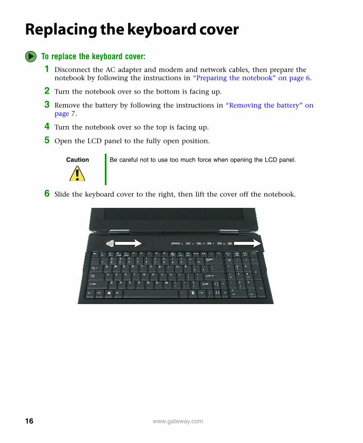
Replacing the keyboard cover
To replace the keyboard cover:
1 Disconnect the AC adapter and modem and network cables, then prepare the notebook by following the instructions in “Preparing the notebook” on page 6.
2 Turn the notebook over so the bottom is facing up.
3 Remove the battery by following the instructions in “Removing the battery” on page 7.
4 Turn the notebook over so the top is facing up.
5 Open the LCD panel to the fully open position.
6 Slide the keyboard cover to the right, then lift the cover off the notebook.
Caution Be careful not to use too much force when opening the LCD panel.
16 www.gateway.com

7 Lay the new keyboard cover on the notebook, then slide it into place.
8 Press down on the keyboard cover in several places to make sure it is in place. The cover is correctly mounted when you can run your finger along the cover and find no loose spots. The keyboard cover should be flat all the way across.
9 Close and latch the LCD panel.
10 Replace the battery, connect the AC adapter and modem and network cables, then turn on the notebook.
Caution If the keyboard cover is not correctly replaced, the notebook could be damaged when you try to close the LCD panel.
17www.gateway.com

Replacing the keyboardTools you need to complete this task:
Screws removed during this task:
To replace the keyboard:1 Follow the instructions under “Preventing static electricity discharge” on page 5.
2 Disconnect the AC adapter and modem and network cables, then prepare the notebook by following the instructions in “Preparing the notebook” on page 6.
3 Turn the notebook over so the bottom is facing up.
4 Remove the battery by following the instructions in “Removing the battery” on page 7.
5 Turn the notebook over so the top is facing up.
6 Open the LCD panel to the fully open position.
7 Remove the keyboard cover by following the instructions in “Replacing the keyboard cover” on page 16.
Caution Be careful not to use too much force when opening the LCD panel.
Phillips #0 screwdriver
Flat-blade driver
5 chrome 2.5 × 2.5 mm(keyboard)
18 www.gateway.com
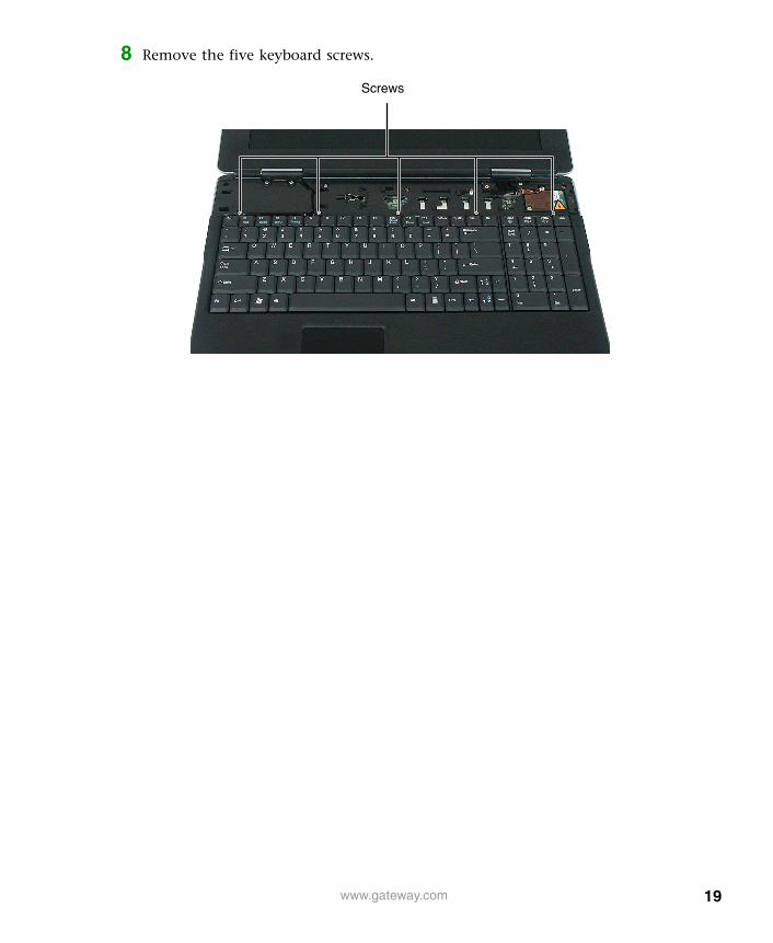
8 Remove the five keyboard screws.
Screws
19www.gateway.com
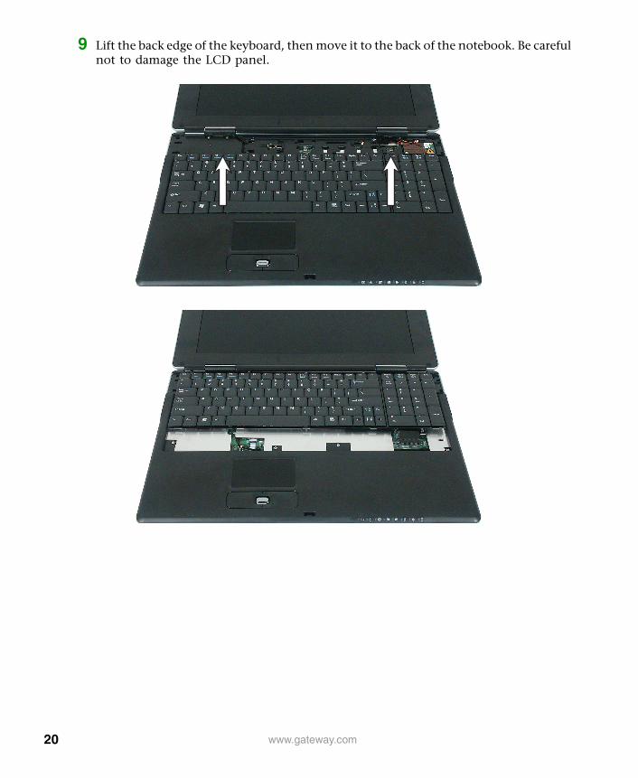
9 Lift the back edge of the keyboard, then move it to the back of the notebook. Be careful not to damage the LCD panel.
20 www.gateway.com

10 Carefully insert the small flat-blade screwdriver between the keyboard cable and the black plastic hinge where the cable connects to the system board. Gently lift the hinge off the cable. The cable is now free and you can remove the keyboard.
11 Place the new keyboard keys-up on the notebook with the spacebar towards you. Be careful not to damage the LCD panel.
12 Make sure that the black plastic hinge on the system board keyboard connector is in the raised position.
21www.gateway.com

13 Insert the end of the keyboard cable between the black plastic hinge and the white connector.
14 Press the black plastic hinge onto the keyboard cable.
15 Lift the keyboard and insert the tabs on the front of it under the palm rest.
16 Gently press the keyboard down until it is flat all the way across. The keyboard should easily fall into place.
17 Replace the five keyboard screws.
18 Replace the keyboard cover by following the instructions in “Replacing the keyboard cover” on page 16.
19 Replace the battery, connect the AC adapter and modem and network cables, then turn on the notebook.
Important The plug is correctly oriented if the cable is not twisted.
Tabs
22 www.gateway.com

Replacing the modemTools you need to complete this task:
Screws removed during this task:
To replace the modem:1 Follow the instructions under “Preventing static electricity discharge” on page 5.
2 Disconnect the AC adapter and modem and network cables, then prepare the notebook by following the instructions in “Preparing the notebook” on page 6.
3 Turn the notebook over so the bottom is facing up.
4 Remove the battery by following the instructions in “Removing the battery” on page 7.
5 Turn the notebook over so the top is facing up.
6 Open the LCD panel to the fully open position.
7 Remove the keyboard cover by following the instructions in “Replacing the keyboard cover” on page 16.
Caution Be careful not to use too much force when opening the LCD panel.
Phillips #0 screwdriver
2 chrome 2.5 × 2.5 mm(modem)
23www.gateway.com
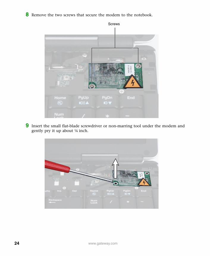
8 Remove the two screws that secure the modem to the notebook.
9 Insert the small flat-blade screwdriver or non-marring tool under the modem and gently pry it up about ¼ inch.
Screws
24 www.gateway.com

10 Turn the modem over, then unplug the modem cable from the modem.
11 Connect the modem cable into the new modem.
12 Align the modem’s screw holes with the holes on the notebook, then press the modem into place.
13 Replace the two screws that secure the modem to the notebook.
14 Reassemble the notebook.
25www.gateway.com

Adding or replacing memory modulesTools you need to complete this task:
The M675 notebook uses memory modules called SO-DIMMs (Small Outline Dual Inline Memory Modules). The modules are available in various capacities and any module can be placed in the memory bay.
To add or replace memory modules:
1 Follow the instructions under “Preventing static electricity discharge” on page 5.
2 Disconnect the AC adapter and modem and network cables, then prepare the notebook by following the instructions in “Preparing the notebook” on page 6.
3 Turn the notebook over so the bottom is facing up.
4 Remove the battery by following the instructions in “Removing the battery” on page 7.
Important Use only memory modules designed for the Gateway M675.
Phillips #0 screwdriver
Memory bay
26 www.gateway.com

5 Loosen the four captive memory bay cover screws, then remove the memory bay cover. These screws cannot be removed.
6 If you are removing a module, gently press outward on the clip at each end of the memory module until the module tilts upward.
27www.gateway.com

7 Pull the memory module out of the slot.
8 Hold the new or replacement module at a 30-degree angle and press it into the empty memory slot. This module is keyed so it can only be inserted in one direction. If the module does not fit, make sure that the notch in the module lines up with the tab in the memory bay.
9 Gently push the module down until it clicks in place.
10 Replace the memory bay cover and secure with the cover screws.
11 Insert the battery, connect the power adapter and modem and network cables, then turn on the notebook.
Important Use only memory modules designed for the Gateway M675.
28 www.gateway.com

Replacing the cooling assemblyTools you need to complete this task:
To replace the cooling assembly:
1 Follow the instructions under “Preventing static electricity discharge” on page 5.
2 Disconnect the AC adapter and modem and network cables, then prepare the notebook by following the instructions in “Preparing the notebook” on page 6.
3 Turn the notebook over so the bottom is facing up.
4 Remove the battery by following the instructions in “Removing the battery” on page 7.
5 Loosen the four captive memory bay cover screws, then remove the memory bay cover. These screws cannot be removed.
Phillips #0 screwdriver
29www.gateway.com

6 Unplug the cooling fans.
7 Loosen the five captive screws that secure the cooling assembly to the notebook. These screws cannot be removed.
Screws
Screws
30 www.gateway.com

8 Remove the cooling assembly.
9 If the new cooling assembly came with a blue plastic cover that covers the thermal grease on the bottom side of the new cooling assembly, remove the cover. Go to Step 11.
-OR-
If the new cooling assembly did not come with thermal grease already applied, go to Step 10.
10 Use the provided applicator to apply a thin layer of thermal grease to the bottom of the cooling assembly where it will make contact with the processor.
11 Remove any thermal grease residue that may remain on the processor. The residue can be removed using Isopropyl alcohol, acetone, or toluene and a lint free cloth.
12 Insert the new cooling assembly into the notebook.
13 Tighten the five cooling assembly screws in numerical order. Each screw hole has a numeral next to it.
14 Plug in the cooling fans.
15 Reassemble the notebook.
Caution Do not apply thermal grease to any other part of the cooling assembly or notebook.
Caution When tightening the cooling assembly’s chrome screws into the numbered holes, tighten them in numerical order.
31www.gateway.com

Replacing the IEEE 802.11 Mini-PCI card
Tools you need to complete this task:
Screws removed during this task:
To replace the IEEE 802.11 Mini-PCI card:
1 Follow the instructions under “Preventing static electricity discharge” on page 5.
2 Disconnect the AC adapter and modem and network cables, then prepare the notebook by following the instructions in “Preparing the notebook” on page 6.
3 Turn the notebook over so the bottom is facing up.
4 Remove the battery by following the instructions in “Removing the battery” on page 7.
5 Remove the hard drive by following the instructions in “Replacing the hard drive kit” on page 9. The IEEE 802.11 mini-PCI card is located inside the hard drive bay.
Caution By law, only approved wireless modules provided by Gateway, or a Gateway authorized representative, explicitly for the Gateway M675 may be installed in this notebook.
Phillips #0 screwdriver Torx T8 screwdriver
1 chrome 2.5 × 2.5 mm Torx(mini-PCI card)
32 www.gateway.com

6 Remove the Torx screw that secures the mini-PCI cover to the notebook, then lift the cover off.
7 Unplug the two antenna cables.
Caution Legal requirements dictate that a security screw (or other means) be used to attach the mini-PCI cover to the notebook in a manner that restricts end user access. End users are strictly prohibited from having access to the wireless card. Due to manufacturing process changes, Gateway M675 notebooks require a Torx head security screw to attach the mini-PCI cover.
Torx screw
33www.gateway.com
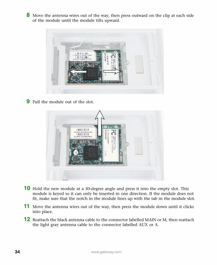
8 Move the antenna wires out of the way, then press outward on the clip at each side of the module until the module tilts upward.
9 Pull the module out of the slot.
10 Hold the new module at a 30-degree angle and press it into the empty slot. This module is keyed so it can only be inserted in one direction. If the module does not fit, make sure that the notch in the module lines up with the tab in the module slot.
11 Move the antenna wires out of the way, then press the module down until it clicks into place.
12 Reattach the black antenna cable to the connector labelled MAIN or M, then reattach the light gray antenna cable to the connector labelled AUX or A.
34 www.gateway.com

13 Replace the mini-PCI cover and secure with the Torx screw.
14 Reassemble the notebook.
Caution Legal requirements dictate the mini-PCI cover be in place during any and all operation of the notebook’s wireless feature.
35www.gateway.com
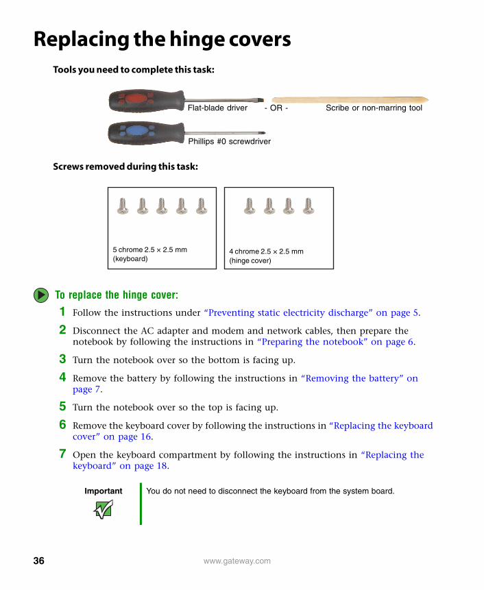
Replacing the hinge coversTools you need to complete this task:
Screws removed during this task:
To replace the hinge cover:
1 Follow the instructions under “Preventing static electricity discharge” on page 5.
2 Disconnect the AC adapter and modem and network cables, then prepare the notebook by following the instructions in “Preparing the notebook” on page 6.
3 Turn the notebook over so the bottom is facing up.
4 Remove the battery by following the instructions in “Removing the battery” on page 7.
5 Turn the notebook over so the top is facing up.
6 Remove the keyboard cover by following the instructions in “Replacing the keyboard cover” on page 16.
7 Open the keyboard compartment by following the instructions in “Replacing the keyboard” on page 18.
Important You do not need to disconnect the keyboard from the system board.
Flat-blade driver Scribe or non-marring tool- OR -
Phillips #0 screwdriver
4 chrome 2.5 × 2.5 mm(hinge cover)
5 chrome 2.5 × 2.5 mm(keyboard)
36 www.gateway.com

8 Open the LCD panel to the fully open position.
9 Remove the left and right hinge cover screws.
Caution Be careful not to use too much force when opening the LCD panel.
Screws
37www.gateway.com

10 Insert the small flat-blade screwdriver or non-marring tool under the bottom of the hinge cover, then carefully pry it up. Press down on the two plastic tabs which contain the screw holes while you pry.
Caution To avoid breaking the hinge cover or putting stress on the LCD panel, hold down on the two plastic screw tabs while you pry.
Left Hinge Cover
Right Hinge Cover
38 www.gateway.com

11 Snap the new cover into place over the hinge.
12 Replace the hinge cover screws.
13 Reassemble the notebook.
39www.gateway.com

Replacing the LCD panel assemblyTools you need to complete this task:
Screws removed during this task:
To replace the LCD panel assembly:
1 Follow the instructions under “Preventing static electricity discharge” on page 5.
2 Disconnect the AC adapter and modem and network cables, then prepare the notebook by following the instructions in “Preparing the notebook” on page 6.
3 Turn the notebook over so the bottom is facing up.
4 Remove the battery by following the instructions in “Removing the battery” on page 7.
5 Remove the hard drive by following the instructions in “Replacing the hard drive kit” on page 9.
Flat-blade driver Scribe or non-marring tool- OR -
Phillips #0 screwdriver Torx T8 screwdriver
4 chrome 2.5 × 2.5 mm(hinge cover)
5 chrome 2.5 × 2.5 mm(keyboard)
1 chrome 2.5 × 2.5 mm Torx(mini-PCI card)
6 chrome 2.5 × 2.5 mm(LCD panel assembly)
2 chrome 2.5 × 2.5 mm(LCD plug)
40 www.gateway.com

6 Remove the cover from the mini-PCI card and disconnect the antenna wires by following the instructions in “Replacing the IEEE 802.11 Mini-PCI card” on page 32.
7 Turn the notebook over so the top is facing up.
8 Open the LCD panel to the fully open position.
9 Remove the keyboard cover by following the instructions in “Replacing the keyboard cover” on page 16.
10 Open the keyboard compartment by following the instructions in “Replacing the keyboard” on page 18.
11 Remove the hinge covers by following the instructions in “Replacing the hinge covers” on page 36.
12 Remove the antenna cables from the mini-PCI card by carefully removing the cabling from the palm rest assembly.
Caution Be careful not to use too much force when opening the LCD panel.
Important You do not need to disconnect the keyboard from the system board.
41www.gateway.com

13 Remove the two screws that secure the LCD video connector to the notebook. Note the location of the LCD panel grounding wires attached to one of the right hinge screw holes.
14 Use the plastic tab to carefully unplug the LCD video cable from the notebook. Make sure that you grasp the tab, not the cable.
Caution The connector is fragile.
Screws
42 www.gateway.com

15 Remove the six screws that secure the LCD panel to the notebook.
16 Lift the LCD panel assembly away from the notebook. The LCD panel assembly is now completely detached from the notebook.
17 Place the new LCD panel assembly onto the notebook, then replace the six screws that secure the LCD panel to the notebook. Make sure to reattach the grounding cable to the appropriate screw.
18 Plug the LCD video cable into the notebook.
19 Secure the LCD video connector to the notebook with two screws.
20 Position the antenna cables, channeling them through the palm rest assembly to the mini-PCI card. Reattach the black antenna cable to the connector labelled MAIN or M, then reattach the light gray antenna cable to the connector labelled AUX or A.
21 Replace the hinge covers.
22 Reassemble the notebook.
Caution The IEEE 802.11 connectors may catch on the EMI shielding. Be careful not to break off the connectors on the antenna cable.
Caution The connector is fragile.
Screws
43www.gateway.com

Replacing the palm rest assemblyTools you need to complete this task:
Screws removed during this task:
To replace the palm rest assembly:1 Follow the instructions under “Preventing static electricity discharge” on page 5.
2 Disconnect the AC adapter and modem and network cables, then prepare the notebook by following the instructions in “Preparing the notebook” on page 6.
Flat-blade driver Scribe or non-marring tool- OR -
Phillips #0 screwdriver Torx T8 screwdriver
4 chrome 2.5 × 2.5 mm(hinge cover)
5 chrome 2.5 × 2.5 mm(keyboard)
1 chrome 2.5 × 2.5 mm Torx(mini-PCI card)
6 chrome 2.5 × 2.5 mm(LCD panel assembly)
2 chrome 2.5 × 2.5 mm(LCD plug)
8 chrome 2.5 × 4 mm (top, palm rest)2 chrome 2.5 × 2.5 mm (top, palm rest)
4 chrome 2.5 × 4 mm (bottom, palm rest)
44 www.gateway.com

3 Turn the notebook over so the bottom is facing up.
4 Remove the battery by following the instructions in “Removing the battery” on page 7.
5 Remove the cover from the mini-PCI card and disconnect the antenna wires by following the instructions in “Replacing the IEEE 802.11 Mini-PCI card” on page 32.
6 Remove the four screws on the bottom of the notebook.
7 Turn the notebook over so the top is facing up.
8 Open the LCD panel to the fully open position.
9 Remove the keyboard cover by following the instructions in “Replacing the keyboard cover” on page 16.
10 Remove the keyboard by following the instructions in “Replacing the keyboard” on page 18.
11 Remove the hinge covers by following the instructions in “Replacing the hinge covers” on page 36.
Caution Be careful not to use too much force when opening the LCD panel.
Screws
45www.gateway.com

12 Remove the LCD panel assembly by following the instructions in “Replacing the LCD panel assembly” on page 40.
13 Remove the ten screws on the top of the notebook.
Important The two shorter screws fit in the silver EMI shield on the top of the palm rest assembly.
Screws
Screws
46 www.gateway.com
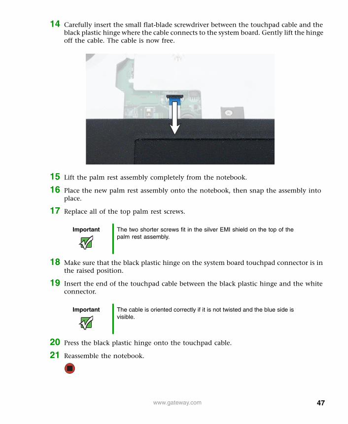
14 Carefully insert the small flat-blade screwdriver between the touchpad cable and the black plastic hinge where the cable connects to the system board. Gently lift the hinge off the cable. The cable is now free.
15 Lift the palm rest assembly completely from the notebook.
16 Place the new palm rest assembly onto the notebook, then snap the assembly into place.
17 Replace all of the top palm rest screws.
18 Make sure that the black plastic hinge on the system board touchpad connector is in the raised position.
19 Insert the end of the touchpad cable between the black plastic hinge and the white connector.
20 Press the black plastic hinge onto the touchpad cable.
21 Reassemble the notebook.
Important The two shorter screws fit in the silver EMI shield on the top of the palm rest assembly.
Important The cable is oriented correctly if it is not twisted and the blue side is visible.
47www.gateway.com
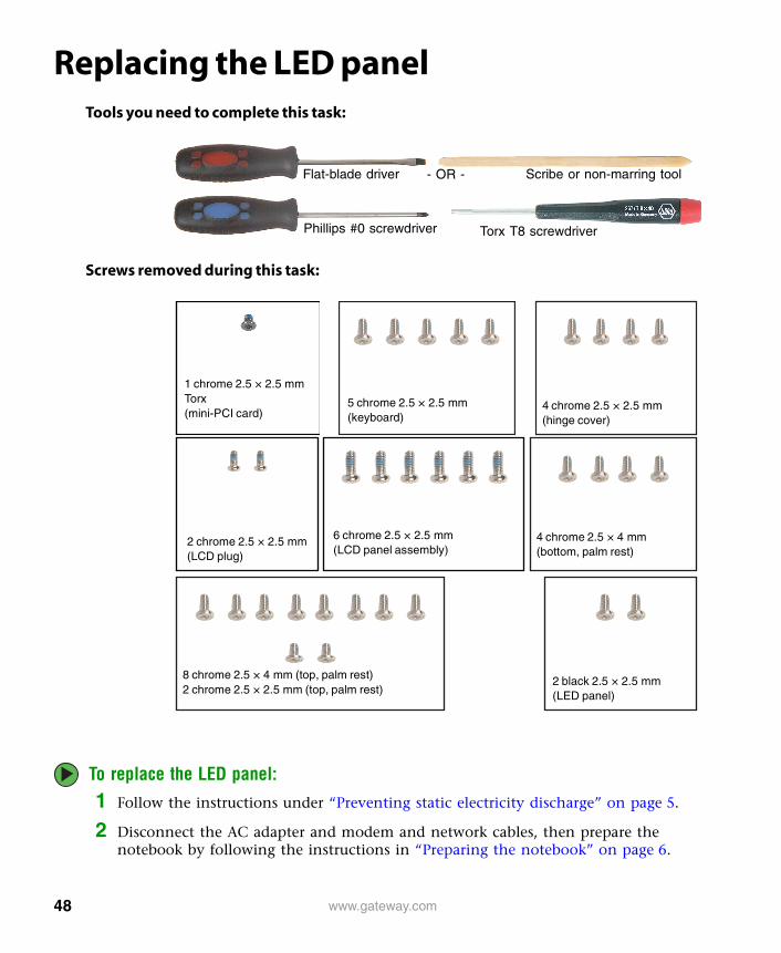
Replacing the LED panelTools you need to complete this task:
Screws removed during this task:
To replace the LED panel:
1 Follow the instructions under “Preventing static electricity discharge” on page 5.
2 Disconnect the AC adapter and modem and network cables, then prepare the notebook by following the instructions in “Preparing the notebook” on page 6.
Flat-blade driver Scribe or non-marring tool- OR -
Phillips #0 screwdriver Torx T8 screwdriver
4 chrome 2.5 × 2.5 mm(hinge cover)
5 chrome 2.5 × 2.5 mm(keyboard)
1 chrome 2.5 × 2.5 mm Torx(mini-PCI card)
2 black 2.5 × 2.5 mm(LED panel)
6 chrome 2.5 × 2.5 mm(LCD panel assembly)
2 chrome 2.5 × 2.5 mm(LCD plug)
4 chrome 2.5 × 4 mm (bottom, palm rest)
8 chrome 2.5 × 4 mm (top, palm rest)2 chrome 2.5 × 2.5 mm (top, palm rest)
48 www.gateway.com
3 Turn the notebook over so the bottom is facing up.
4 Remove the battery by following the instructions in “Removing the battery” on page 7.
5 Turn the notebook over so the top is facing up.
6 Remove the keyboard cover by following the instructions in “Replacing the keyboard cover” on page 16.
7 Remove the keyboard by following the instructions in “Replacing the keyboard” on page 18.
8 Remove the hinge covers by following the instructions in “Replacing the hinge covers” on page 36.
9 Remove the LCD panel assembly by following the instructions in “Replacing the LCD panel assembly” on page 40.
10 Remove the palm rest assembly by following the instructions in “Replacing the palm rest assembly” on page 44.
11 Remove the two screws securing the LED panel.
Screws
49www.gateway.com

12 Carefully insert the small flat-blade screwdriver between the LED panel cable and the black plastic hinge where the cable connects to the system board. Gently lift the hinge off the cable. The cable is now free.
13 Remove the LED panel.
14 Insert the new LED panel, then secure it with two screws.
15 Make sure that the black plastic hinge on the system board LED connector is in the raised position.
16 Insert the end of the LED cable between the black plastic hinge and the white connector.
17 Reassemble the notebook.
Important The cable is oriented correctly if it is not twisted and the blue side is visible.
50 www.gateway.com

Replacing the CMOS batteryTools you need to complete this task:
Screws removed during this task:
To replace the CMOS battery:
1 Follow the instructions under “Preventing static electricity discharge” on page 5.
2 Disconnect the AC adapter and modem and network cables, then prepare the notebook by following the instructions in “Preparing the notebook” on page 6.
3 Turn the notebook over so the bottom is facing up.
Flat-blade driver Scribe or non-marring tool- OR -
Phillips #0 screwdriver Torx T8 screwdriver
4 chrome 2.5 × 2.5 mm(hinge cover)
5 chrome 2.5 × 2.5 mm(keyboard)
1 chrome 2.5 × 2.5 mm Torx(mini-PCI card)
6 chrome 2.5 × 2.5 mm(LCD panel assembly)
2 chrome 2.5 × 2.5 mm(LCD plug)
4 chrome 2.5 × 4 mm (bottom, palm rest)
8 chrome 2.5 × 4 mm (top, palm rest)2 chrome 2.5 × 2.5 mm (top, palm rest)
51www.gateway.com

4 Remove the battery by following the instructions in “Removing the battery” on page 7.
5 Remove the cover from the mini-PCI card and disconnect the antenna wires by following the instructions in “Replacing the IEEE 802.11 Mini-PCI card” on page 32.
6 Turn the notebook over so the top is facing up.
7 Open the LCD panel to the fully open position.
8 Remove the keyboard cover by following the instructions in “Replacing the keyboard cover” on page 16.
9 Remove the keyboard by following the instructions in “Replacing the keyboard” on page 18.
10 Remove the hinge covers by following the instructions in “Replacing the hinge covers” on page 36.
11 Remove the LCD panel assembly by following the instructions in “Replacing the LCD panel assembly” on page 40.
12 Remove the palm rest assembly by following the instructions in “Replacing the palm rest assembly” on page 44.
13 Locate the old battery at the edge of the system board and in front of the processor.
Caution Be careful not to use too much force when opening the LCD panel.
52 www.gateway.com

14 Unplug the battery cable from the system board.
15 Plug the new battery cable into the connector on the system board.
16 Reassemble the notebook.
53www.gateway.com

Replacing the speakersTools you need to complete this task:
Screws removed during this task:
Flat-blade driver Scribe or non-marring tool- OR -
Phillips #0 screwdriver Torx T8 screwdriver
4 chrome 2.5 × 2.5 mm(hinge cover)
5 chrome 2.5 × 2.5 mm(keyboard)
1 chrome 2.5 × 2.5 mm Torx(mini-PCI card)
2 black 2.5 × 2.5 mm(LED panel)
6 chrome 2.5 × 2.5 mm(LCD panel assembly)
2 chrome 2.5 × 2.5 mm(LCD plug)
4 chrome 2.5 × 4 mm (bottom, palm rest)
8 chrome 2.5 × 4 mm (top, palm rest)2 chrome 2.5 × 2.5 mm (top, palm rest)
1 chrome 2.5 × 4 mm(right speaker)
54 www.gateway.com

To replace the speakers:1 Follow the instructions under “Preventing static electricity discharge” on page 5.
2 Disconnect the AC adapter and modem and network cables, then prepare the notebook by following the instructions in “Preparing the notebook” on page 6.
3 Turn the notebook over so the bottom is facing up.
4 Remove the battery by following the instructions in “Removing the battery” on page 7.
5 Remove the cover from the mini-PCI card and disconnect the antenna wires by following the instructions in “Replacing the IEEE 802.11 Mini-PCI card” on page 32.
6 Turn the notebook over so the top is facing up.
7 Open the LCD panel to the fully open position.
8 Remove the keyboard cover by following the instructions in “Replacing the keyboard cover” on page 16.
9 Remove the keyboard by following the instructions in “Replacing the keyboard” on page 18.
10 Remove the LED panel by following the instructions in “Replacing the LED panel” on page 48.
11 Remove the hinge covers by following the instructions in “Replacing the hinge covers” on page 36.
12 Remove the LCD panel assembly by following the instructions in “Replacing the LCD panel assembly” on page 40.
13 Remove the palm rest assembly by following the instructions in “Replacing the palm rest assembly” on page 44.
Caution Be careful not to use too much force when opening the LCD panel.
55www.gateway.com
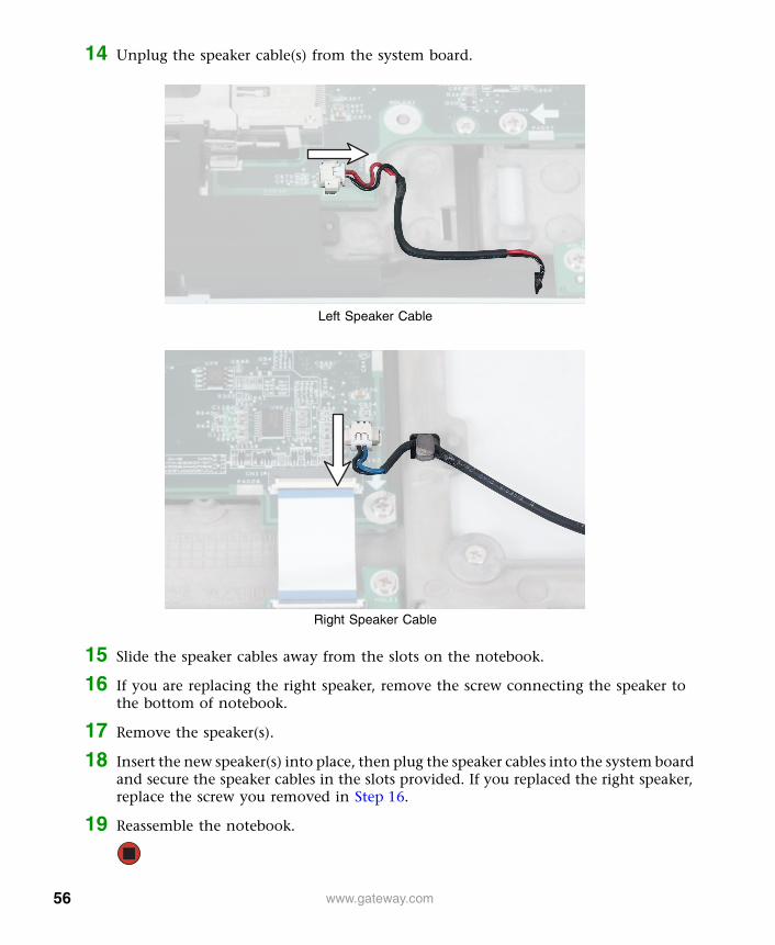
14 Unplug the speaker cable(s) from the system board.
15 Slide the speaker cables away from the slots on the notebook.
16 If you are replacing the right speaker, remove the screw connecting the speaker to the bottom of notebook.
17 Remove the speaker(s).
18 Insert the new speaker(s) into place, then plug the speaker cables into the system board and secure the speaker cables in the slots provided. If you replaced the right speaker, replace the screw you removed in Step 16.
19 Reassemble the notebook.
Left Speaker Cable
Right Speaker Cable
56 www.gateway.com
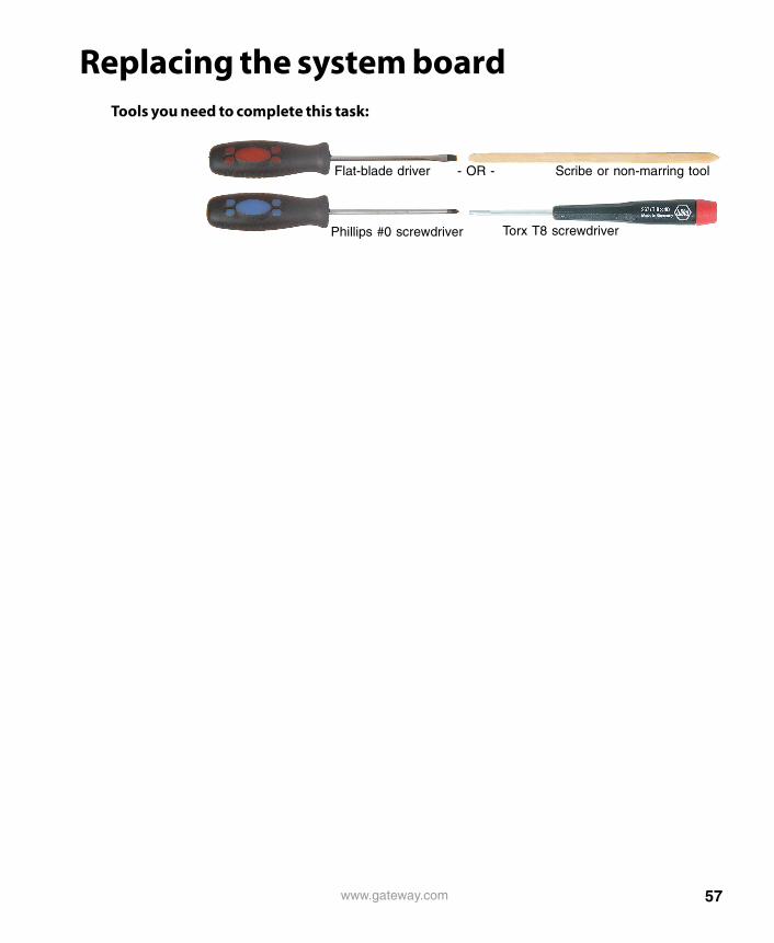
Replacing the system boardTools you need to complete this task:
Flat-blade driver Scribe or non-marring tool- OR -
Phillips #0 screwdriver Torx T8 screwdriver
57www.gateway.com
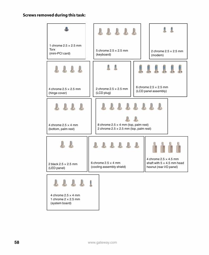
Screws removed during this task:
4 chrome 2.5 × 2.5 mm(hinge cover)
5 chrome 2.5 × 2.5 mm(keyboard)
1 chrome 2.5 × 2.5 mm Torx(mini-PCI card)
2 black 2.5 × 2.5 mm(LED panel)
6 chrome 2.5 × 2.5 mm(LCD panel assembly)
2 chrome 2.5 × 2.5 mm(LCD plug)
4 chrome 2.5 × 4 mm (bottom, palm rest)
8 chrome 2.5 × 4 mm (top, palm rest)2 chrome 2.5 × 2.5 mm (top, palm rest)
2 chrome 2.5 × 2.5 mm(modem)
6 chrome 2.5 × 4 mm(cooling assembly shield)
4 chrome 2.5 × 4.5 mm shaft with 5 × 4.5 mm head hexnut (rear I/O panel)
4 chrome 2.5 × 4 mm1 chrome 2 × 2.5 mm(system board)
58 www.gateway.com
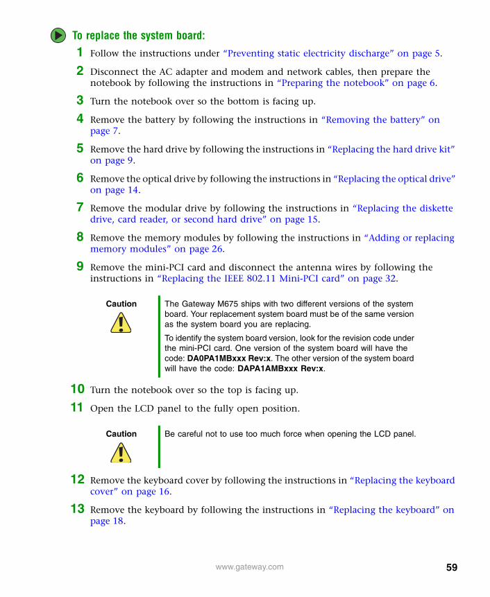
To replace the system board:1 Follow the instructions under “Preventing static electricity discharge” on page 5.
2 Disconnect the AC adapter and modem and network cables, then prepare the notebook by following the instructions in “Preparing the notebook” on page 6.
3 Turn the notebook over so the bottom is facing up.
4 Remove the battery by following the instructions in “Removing the battery” on page 7.
5 Remove the hard drive by following the instructions in “Replacing the hard drive kit” on page 9.
6 Remove the optical drive by following the instructions in “Replacing the optical drive” on page 14.
7 Remove the modular drive by following the instructions in “Replacing the diskette drive, card reader, or second hard drive” on page 15.
8 Remove the memory modules by following the instructions in “Adding or replacing memory modules” on page 26.
9 Remove the mini-PCI card and disconnect the antenna wires by following the instructions in “Replacing the IEEE 802.11 Mini-PCI card” on page 32.
10 Turn the notebook over so the top is facing up.
11 Open the LCD panel to the fully open position.
12 Remove the keyboard cover by following the instructions in “Replacing the keyboard cover” on page 16.
13 Remove the keyboard by following the instructions in “Replacing the keyboard” on page 18.
Caution The Gateway M675 ships with two different versions of the system board. Your replacement system board must be of the same version as the system board you are replacing.
To identify the system board version, look for the revision code under the mini-PCI card. One version of the system board will have the code: DA0PA1MBxxx Rev:x. The other version of the system board will have the code: DAPA1AMBxxx Rev:x.
Caution Be careful not to use too much force when opening the LCD panel.
59www.gateway.com

14 Remove the modem by following the instructions in “Replacing the modem” on page 23.
15 Remove the hinge covers by following the instructions in “Replacing the hinge covers” on page 36.
16 Remove the LCD panel assembly by following the instructions in “Replacing the LCD panel assembly” on page 40.
17 Remove the palm rest assembly by following the instructions in “Replacing the palm rest assembly” on page 44.
18 Remove the LED panel by following the instructions in “Replacing the LED panel” on page 48.
19 Remove the CMOS battery by following the instructions in “Replacing the CMOS battery” on page 51.
20 Unplug the speakers from the system board by following the instructions in “Replacing the speakers” on page 54.
21 Remove the six screws that secure the cooling assembly shield to the system board, then remove the cooling assembly shield.
Screws
Screws
60 www.gateway.com
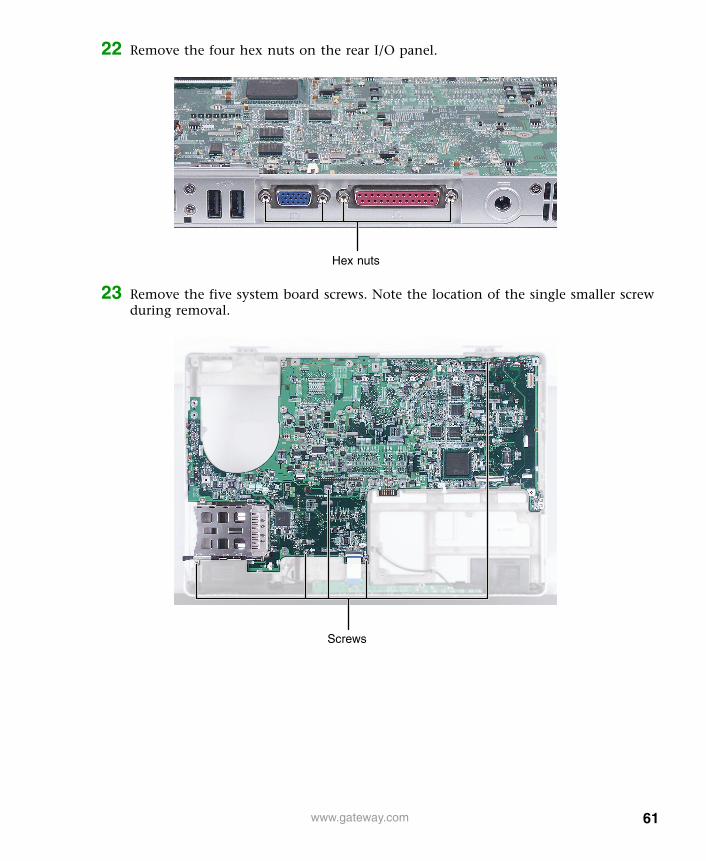
22 Remove the four hex nuts on the rear I/O panel.
23 Remove the five system board screws. Note the location of the single smaller screw during removal.
Hex nuts
Screws
61www.gateway.com

24 Remove the system board. Make sure that the rear I/O panel clears the bottom of the notebook and the side audio jacks clear the bottom of the notebook.
25 Place the new system board into the notebook.
26 Replace the five system board screws.
27 Replace the four rear I/O panel hex nuts.
28 Connect the speakers and the front LED panel.
29 Replace the cooling assembly shield and secure with six screws.
30 Reassemble the notebook.
Caution If the thermal grease on the cooling assembly is dried, clean the grease off the cooling assembly. The residue can be removed using isopropyl alcohol, acetone, or toluene and a lint free cloth. Use the provided applicator to apply a thin layer of thermal grease to the bottom of the cooling assembly where it will make contact with the processor. Do not apply thermal grease to any other part of the cooling assembly or notebook.
62 www.gateway.com


MAN SYS M675 SERVICE GDE R1 5/04
Related Documents