15 Vol. 45 No. 1 2012 Gasification of Lignite Coal and Biomass Using Twin IHI Gasifier (TIGAR ® ) SUDA Toshiyuki : Doctor of Engineering, Manager, Heat & Fluid Dynamics Department, Research Laboratory, Corporate Research & Development LIU Zhihong : Doctor of Engineering, Manager, Heat & Fluid Dynamics Department, Research Laboratory, Corporate Research & Development TAKAFUJI Makoto : Manager, Heat & Fluid Dynamics Department, Research Laboratory, Corporate Research & Development HAMADA Koki : Manager, Chemical Engineering Department, Products Development Center, Corporate Research & Development TANI Hidehisa : Manager, TIGAR Project Department, Project Center, Energy Operations The importance of coal gasification technology is increasing around the world due to the rising cost of oil and natural gas. Lignite coal is suitable for gasification because of its high reactivity, and since there are huge reserves of this coal available, simple and cheap gasifier is needed. IHI has developed the TIGAR ® (Twin IHI Gasifier) process for lignite coal, based on our commercialized circulating fluidized bed technology. TIGAR ® is a circulating fluidized bed gasifier with twin reactors (a riser combustor and a bubbling bed gasifier), and can produce high calorific syngas at low temperatures (800 - 900°C) and atmospheric pressures. In the development of TIGAR ® , predicting the Residence Time Distribution (RTD) of coal particles inside the gasifier was important because it affects the performance (cold gas efficiency) of the gasifier. This paper demonstrates the numerical model for the prediction of the RTD of coal particles inside the gasifier. 1. Introduction The recent wild fluctuations in oil and gas prices have highlighted the significance of coal technology because of coal’s relatively stable price compared to other fossil fuels. Conventionally, the predominant portion of coal as an energy source has been in the form of boiler fuel, the combustion of which produces heat used to make steam for power generation. New methods that will gain significance in the future, however, are pursuing even higher efficiency like that of the integrated coal gasification combined cycle, as well as synthesizing methanol, methane, and other fuels from coal syngas such as carbon monoxide and hydrogen in order to use them as a chemical feedstock. Coal gasification technology lies at the heart of these methods. Research and development efforts are underway around the world concerning various gasification technologies. Coal gasification is a technology for converting coal into a gas mixture including carbon monoxide and hydrogen by means of coal pyrolysis and char gasification. Gasification is an endothermic reaction. The necessary heat for gasification is supplied by partially oxidizing coal with air or oxygen. Oxygen, steam, and air are typically used as the gasifying agents. Various models of gasifiers have been developed and others are being developed, including those with fixed beds, entrained beds, and fluidized beds. Each one of them has its own distinct features. We are conducting research and development into a gasification technology suitable for lignite coal because it is highly reactive compared to other types of coal. The application of low rank coals like lignite coal has been limited due to their high water content, despite the fact that such coals represent almost half of the world’s coal reserves. Technology to utilize this coal with high efficiency is much needed. Lignite coal is a good material for gasification because of its high volatile matter content and high char reactivity (1) due to the catalytic activity of Alkali and Alkaline Earth Metals (AAEM). Based on the circulating fluidized bed technology, we have been developing a circulating twin fluidized bed gasifier, TIGAR ® (Twin IHI Gasifier), for the gasification of lignite coal. TIGAR ® combines a riser combustor and a bubbling fluidized bed gasifier and is capable of producing high-concentration and high-calorific syngas. This paper discusses the method for predicting the Residence Time Distribution (RTD) of coal particles inside the gasifier, which was instrumental in developing the TIGAR ® . 2. TIGAR ® features and performance prediction The concept of a twin fluidized bed gasifier actually has a long history. Twin fluidized bed gasifiers combining various fluidized beds are being researched and developed throughout the world, and are mainly intended for biomass

Welcome message from author
This document is posted to help you gain knowledge. Please leave a comment to let me know what you think about it! Share it to your friends and learn new things together.
Transcript
15Vo l . 4 5 N o . 1 2 012
Gasification of Lignite Coal and Biomass Using Twin IHI Gasifier
(TIGAR®)
SUDA Toshiyuki : Doctor of Engineering, Manager, Heat & Fluid Dynamics Department, Research Laboratory, Corporate Research & Development LIU Zhihong : Doctor of Engineering, Manager, Heat & Fluid Dynamics Department, Research Laboratory, Corporate Research & Development TAKAFUJI Makoto : Manager, Heat & Fluid Dynamics Department, Research Laboratory, Corporate Research & Development HAMADA Koki : Manager, Chemical Engineering Department, Products Development Center, Corporate Research & Development TANI Hidehisa : Manager, TIGAR Project Department, Project Center, Energy Operations
The importance of coal gasification technology is increasing around the world due to the rising cost of oil and natural gas. Lignite coal is suitable for gasification because of its high reactivity, and since there are huge reserves of this coal available, simple and cheap gasifier is needed. IHI has developed the TIGAR® (Twin IHI Gasifier) process for lignite coal, based on our commercialized circulating fluidized bed technology. TIGAR® is a circulating fluidized bed gasifier with twin reactors (a riser combustor and a bubbling bed gasifier), and can produce high calorific syngas at low temperatures (800 - 900°C) and atmospheric pressures. In the development of TIGAR®, predicting the Residence Time Distribution (RTD) of coal particles inside the gasifier was important because it affects the performance (cold gas efficiency) of the gasifier. This paper demonstrates the numerical model for the prediction of the RTD of coal particles inside the gasifier.
1. Introduction
The recent wild fluctuations in oil and gas prices have highlighted the significance of coal technology because of coal’s relatively stable price compared to other fossil fuels. Conventionally, the predominant portion of coal as an energy source has been in the form of boiler fuel, the combustion of which produces heat used to make steam for power generation. New methods that will gain significance in the future, however, are pursuing even higher efficiency like that of the integrated coal gasification combined cycle, as well as synthesizing methanol, methane, and other fuels from coal syngas such as carbon monoxide and hydrogen in order to use them as a chemical feedstock. Coal gasification technology lies at the heart of these methods. Research and development efforts are underway around the world concerning various gasification technologies.
Coal gasification is a technology for converting coal into a gas mixture including carbon monoxide and hydrogen by means of coal pyrolysis and char gasification. Gasification is an endothermic reaction. The necessary heat for gasification is supplied by partially oxidizing coal with air or oxygen. Oxygen, steam, and air are typically used as the gasifying agents. Various models of gasifiers have been developed and others are being developed, including those with fixed beds, entrained beds, and fluidized beds. Each one of them has its own distinct features.
We are conducting research and development into a gasification technology suitable for lignite coal because it is highly reactive compared to other types of coal. The application of low rank coals like lignite coal has been limited due to their high water content, despite the fact that such coals represent almost half of the world’s coal reserves. Technology to utilize this coal with high efficiency is much needed. Lignite coal is a good material for gasification because of its high volatile matter content and high char reactivity(1) due to the catalytic activity of Alkali and Alkaline Earth Metals (AAEM). Based on the circulating fluidized bed technology, we have been developing a circulating twin fluidized bed gasif ier, TIGAR® (Twin IHI Gasif ier), for the gasif ication of lignite coal. TIGAR® combines a riser combustor and a bubbling fluidized bed gasifier and is capable of producing high-concentration and high-calorific syngas. This paper discusses the method for predicting the Residence Time Distribution (RTD) of coal particles inside the gasifier, which was instrumental in developing the TIGAR®.
2. TIGAR® features and performance prediction
The concept of a twin fluidized bed gasifier actually has a long history. Twin fluidized bed gasifiers combining various fluidized beds are being researched and developed throughout the world, and are mainly intended for biomass
16 Vo l . 4 5 N o . 1 2 012
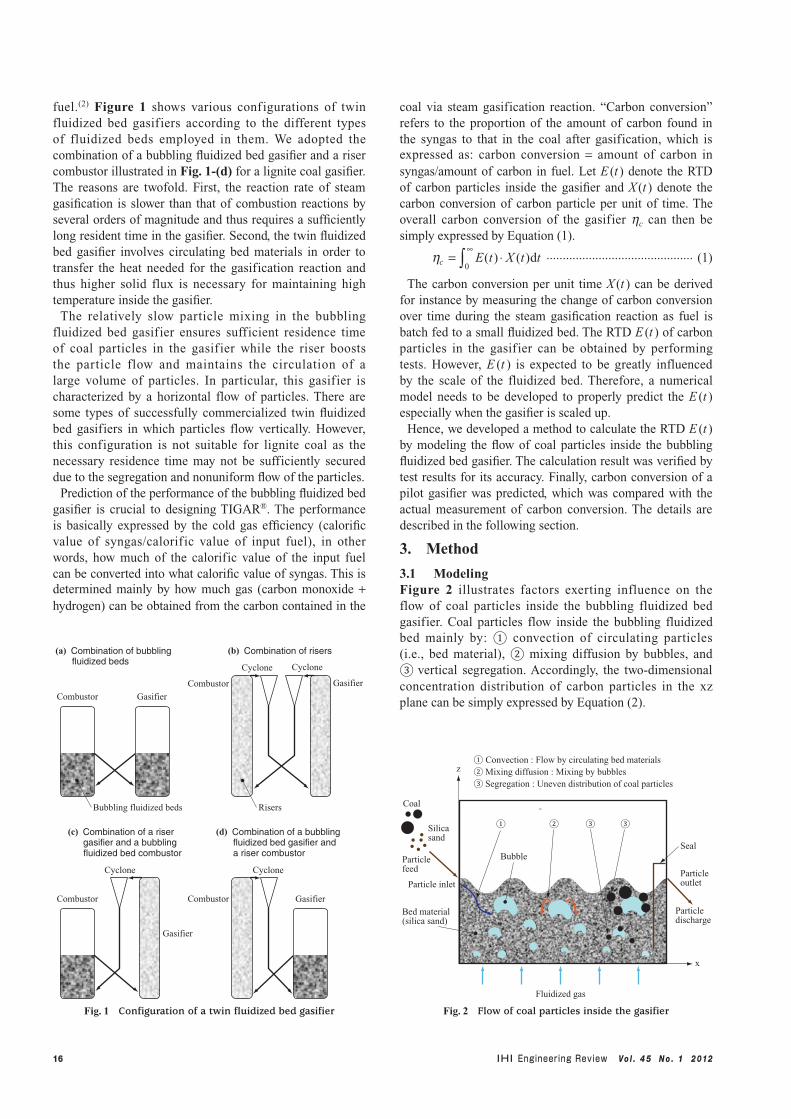
fuel.(2) Figure 1 shows various configurations of twin fluidized bed gasifiers according to the different types of fluidized beds employed in them. We adopted the combination of a bubbling fluidized bed gasifier and a riser combustor illustrated in Fig. 1-(d) for a lignite coal gasifier. The reasons are twofold. First, the reaction rate of steam gasification is slower than that of combustion reactions by several orders of magnitude and thus requires a sufficiently long resident time in the gasifier. Second, the twin fluidized bed gasifier involves circulating bed materials in order to transfer the heat needed for the gasification reaction and thus higher solid flux is necessary for maintaining high temperature inside the gasifier.
The relatively slow particle mixing in the bubbling fluidized bed gasifier ensures sufficient residence time of coal particles in the gasif ier while the riser boosts the particle flow and maintains the circulation of a large volume of particles. In particular, this gasifier is characterized by a horizontal flow of particles. There are some types of successfully commercialized twin fluidized bed gasifiers in which particles flow vertically. However, this configuration is not suitable for lignite coal as the necessary residence time may not be sufficiently secured due to the segregation and nonuniform flow of the particles.
Prediction of the performance of the bubbling fluidized bed gasifier is crucial to designing TIGAR®. The performance is basically expressed by the cold gas efficiency (calorific value of syngas/calorific value of input fuel), in other words, how much of the calorific value of the input fuel can be converted into what calorific value of syngas. This is determined mainly by how much gas (carbon monoxide + hydrogen) can be obtained from the carbon contained in the
coal via steam gasification reaction. “Carbon conversion” refers to the proportion of the amount of carbon found in the syngas to that in the coal after gasification, which is expressed as: carbon conversion = amount of carbon in syngas/amount of carbon in fuel. Let E (t ) denote the RTD of carbon particles inside the gasifier and X (t ) denote the carbon conversion of carbon particle per unit of time. The overall carbon conversion of the gasifier hc can then be simply expressed by Equation (1).
hc E t X t dt= ⋅∞
∫ ( ) ( )0
............................................. (1)
The carbon conversion per unit time X (t ) can be derived for instance by measuring the change of carbon conversion over time during the steam gasification reaction as fuel is batch fed to a small fluidized bed. The RTD E (t ) of carbon particles in the gasifier can be obtained by performing tests. However, E (t ) is expected to be greatly influenced by the scale of the fluidized bed. Therefore, a numerical model needs to be developed to properly predict the E (t ) especially when the gasifier is scaled up.
Hence, we developed a method to calculate the RTD E (t ) by modeling the flow of coal particles inside the bubbling fluidized bed gasifier. The calculation result was verified by test results for its accuracy. Finally, carbon conversion of a pilot gasifier was predicted, which was compared with the actual measurement of carbon conversion. The details are described in the following section.
3. Method
3.1 ModelingFigure 2 illustrates factors exerting influence on the flow of coal particles inside the bubbling fluidized bed gasifier. Coal particles flow inside the bubbling fluidized bed mainly by: ① convection of circulating particles (i.e., bed material), ② mixing diffusion by bubbles, and ③ vertical segregation. Accordingly, the two-dimensional concentration distribution of carbon particles in the xz plane can be simply expressed by Equation (2).
(a) Combination of bubbling fluidized beds
(b) Combination of risers
(c) Combination of a riser gasifier and a bubbling fluidized bed combustor
(d) Combination of a bubbling fluidized bed gasifier and
a riser combustor
Combustor Gasifier
Combustor Combustor Gasifier
Gasifier
Cyclone Cyclone
Combustor Gasifier
Cyclone Cyclone
Bubbling fluidized beds Risers
Fig. 1 Configuration of a twin fluidized bed gasifier
① ② ③ ③
Coal
Bubble
Silica sand
Particlefeed
Bed material (silica sand)
Particle inlet
Seal
Particle discharge
Particle outlet
Fluidized gas
① Convection : Flow by circulating bed materials② Mixing diffusion : Mixing by bubbles③ Segregation : Uneven distribution of coal particles
z
x
Fig. 2 Flow of coal particles inside the gasifier
17Vo l . 4 5 N o . 1 2 012
∂∂
+ ∂∂
+ ∂∂
= ∂∂
∂∂
+ ∂∂
∂∂
C
tu
C
xwS
C
z xD
C
x zD
C
zx z
.......................................... (2)
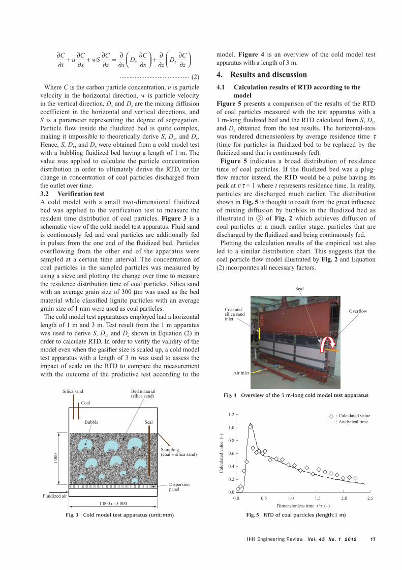
Where C is the carbon particle concentration, u is particle velocity in the horizontal direction, w is particle velocity in the vertical direction, Dx and Dz are the mixing diffusion coefficient in the horizontal and vertical directions, and S is a parameter representing the degree of segregation. Particle flow inside the fluidized bed is quite complex, making it impossible to theoretically derive S, Dx, and Dz. Hence, S, Dx, and Dz were obtained from a cold model test with a bubbling fluidized bed having a length of 1 m. The value was applied to calculate the particle concentration distribution in order to ultimately derive the RTD, or the change in concentration of coal particles discharged from the outlet over time.3.2 Verification testA cold model with a small two-dimensional fluidized bed was applied to the verification test to measure the resident time distribution of coal particles. Figure 3 is a schematic view of the cold model test apparatus. Fluid sand is continuously fed and coal particles are additionally fed in pulses from the one end of the fluidized bed. Particles overflowing from the other end of the apparatus were sampled at a certain time interval. The concentration of coal particles in the sampled particles was measured by using a sieve and plotting the change over time to measure the residence distribution time of coal particles. Silica sand with an average grain size of 300 mm was used as the bed material while classified lignite particles with an average grain size of 1 mm were used as coal particles.
The cold model test apparatuses employed had a horizontal length of 1 m and 3 m. Test result from the 1 m apparatus was used to derive S, Dx, and Dz shown in Equation (2) in order to calculate RTD. In order to verify the validity of the model even when the gasifier size is scaled up, a cold model test apparatus with a length of 3 m was used to assess the impact of scale on the RTD to compare the measurement with the outcome of the predictive test according to the
model. Figure 4 is an overview of the cold model test apparatus with a length of 3 m.
4. Results and discussion
4.1 Calculation results of RTD according to the model
Figure 5 presents a comparison of the results of the RTD of coal particles measured with the test apparatus with a 1 m-long fluidized bed and the RTD calculated from S, Dx, and Dz obtained from the test results. The horizontal-axis was rendered dimensionless by average residence time t (time for particles in fluidized bed to be replaced by the fluidized sand that is continuously fed).
Figure 5 indicates a broad distribution of residence time of coal particles. If the fluidized bed was a plug-flow reactor instead, the RTD would be a pulse having its peak at t/t = 1 where t represents residence time. In reality, particles are discharged much earlier. The distribution shown in Fig. 5 is thought to result from the great influence of mixing diffusion by bubbles in the fluidized bed as illustrated in ② of Fig. 2 which achieves diffusion of coal particles at a much earlier stage, particles that are discharged by the fluidized sand being continuously fed.
Plotting the calculation results of the empirical test also led to a similar distribution chart. This suggests that the coal particle flow model illustrated by Fig. 2 and Equation (2) incorporates all necessary factors.
1.2
1.0
0.8
0.6
0.4
0.2
0.00.0 0.5 1.0 1.5 2.0 2.5
Dimensionless time t /t (–)
Cal
cula
ted
valu
e (
–)
: Calculated value: Analytical time
Fig. 5 RTD of coal particles (length:1 m)
Fluidized air
1 000 or 3 000
1 00
0
Seal
Dispersion panel
Sampling (coal + silica sand)
Bubble
Coal
Silica sand Bed material (silica sand)
Fig. 3 Cold model test apparatus (unit:mm)
OverflowCoal and silica sand inlet
Air inlet
Seal
Fig. 4 Overview of the 3 m-long cold model test apparatus
18 Vo l . 4 5 N o . 1 2 012
4.2 Verification of 3 m-long cold model test apparatus
Figure 6 compares the predicted RTD with the actual distribution measured with the cold model test apparatus with a length of 3 m (Fig. 4). A fair match could be observed between the test results and prediction results without particularly altering S, Dx, and Dz, which are thought to be uninfluenced by the scale of the gasifier.
The f inding demonstrates that the developed model accurately represents the particle flow within the bubbling fluidized bed and that the model is applicable even when the gasifier is scaled-up in size. By comparing Fig. 5 with Fig. 6, the RTD corresponding to the 3 m-long apparatus indicates a longer residence time in comparison to that of the 1 m-long apparatus (i.e., the peak shifts to the right). The difference can be explained in relation to the influence of scale on the mixing diffusion and convection illustrated in Fig. 2. On the one hand, the mixing diffusion of particles is basically influenced by the flow of bubbles in the fluidized bed. Here, the scale does not have an impact on the bubble size unless the operation conditions, such as intensity of fluidization (superficial velocity/minimum fluidizing velocity), are altered. The scale therefore does not affect the mixing diffusion coefficient either.
On the other hand, in terms of convection, velocity in
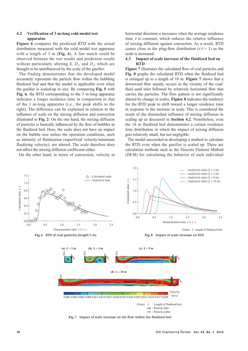
horizontal direction u increases when the average residence time t is constant, which reduces the relative influence of mixing diffusion against convection. As a result, RTD comes close to the plug-flow distribution (t/t = 1) as the scale is increased.4.3 Impact of scale increase of the fluidized bed on
RTDFigure 7 illustrates the calculated flow of coal particles and Fig. 8 graphs the calculated RTD when the fluidized bed is enlarged up to a length of 18 m. Figure 7 shows that a downward flow mainly occurs in the vicinity of the coal/fluid sand inlet followed by relatively horizontal flow that carries the particles. The flow pattern is not significantly altered by change in scales. Figure 8 indicates the tendency for the RTD peak to shift toward a longer residence time in response to the increase in scale. This is considered the result of the diminished influence of mixing diffusion in scaling up as discussed in Section 4.2. Nonetheless, even the 18 m fluidized bed demonstrates a certain residence time distribution in which the impact of mixing diffusion gets relatively small, but not negligible.
The model succeeded in developing a method to calculate the RTD even when the gasifier is scaled up. There are calculation methods such as the Discrete Element Method (DEM) for calculating the behavior of each individual
(a) L = 1 m (b) L = 3 m
(d) L = 18 m
(c) L = 9 m
Velocity(m/s)0.000 0.0400.0370.0340.0310.0290.0260.0230.0200.0170.0140.0110.0090.0060.003
(Note) L : Length of fluidized bed : Particle inlet : Particle outlet
Fig. 7 Impact of scale increase on the flow within the fluidized bed
1.2
1.0
0.8
0.6
0.4
0.2
0.00.0 0.5 1.0 1.5 2.0 2.5
Dimensionless time t /t (–)
Cal
cula
ted
valu
e (
–)
: Calculated value: Analytical time
Fig. 6 RTD of coal particles (length:3 m)
2.0
1.5
1.0
0.5
0.00.0 0.5 1.0 1.5 2.0 2.5
Dimensionless time t /t (–)
Cal
cula
ted
valu
e (
–)
: Analytical value (L = 1 m) : Analytical value (L = 3 m) : Analytical value (L = 9 m) : Analytical value (L = 18 m)
(Note) L : length of fluidized bed
Fig. 8 Impact of scale increase on RTD
19Vo l . 4 5 N o . 1 2 012
particle. However, the number of particles significantly increases corresponding to the degree the gasif ier is scaled up, which results in computation times that are quite unrealistic. In the pursuit of the optimal design, it is considered important to express the RTD of particles with simplified convection/diffusion models, such as the proposed model that treats particles as a continuum body — even if such models are certainly limited in scope of application.
5. Performance prediction of the pilot plant
The ultimate task is to predict the performance of a gasifier based on the derived RTD of coal particles. Therefore, a test was performed with a pilot plant to compare the predicted and tested performances.
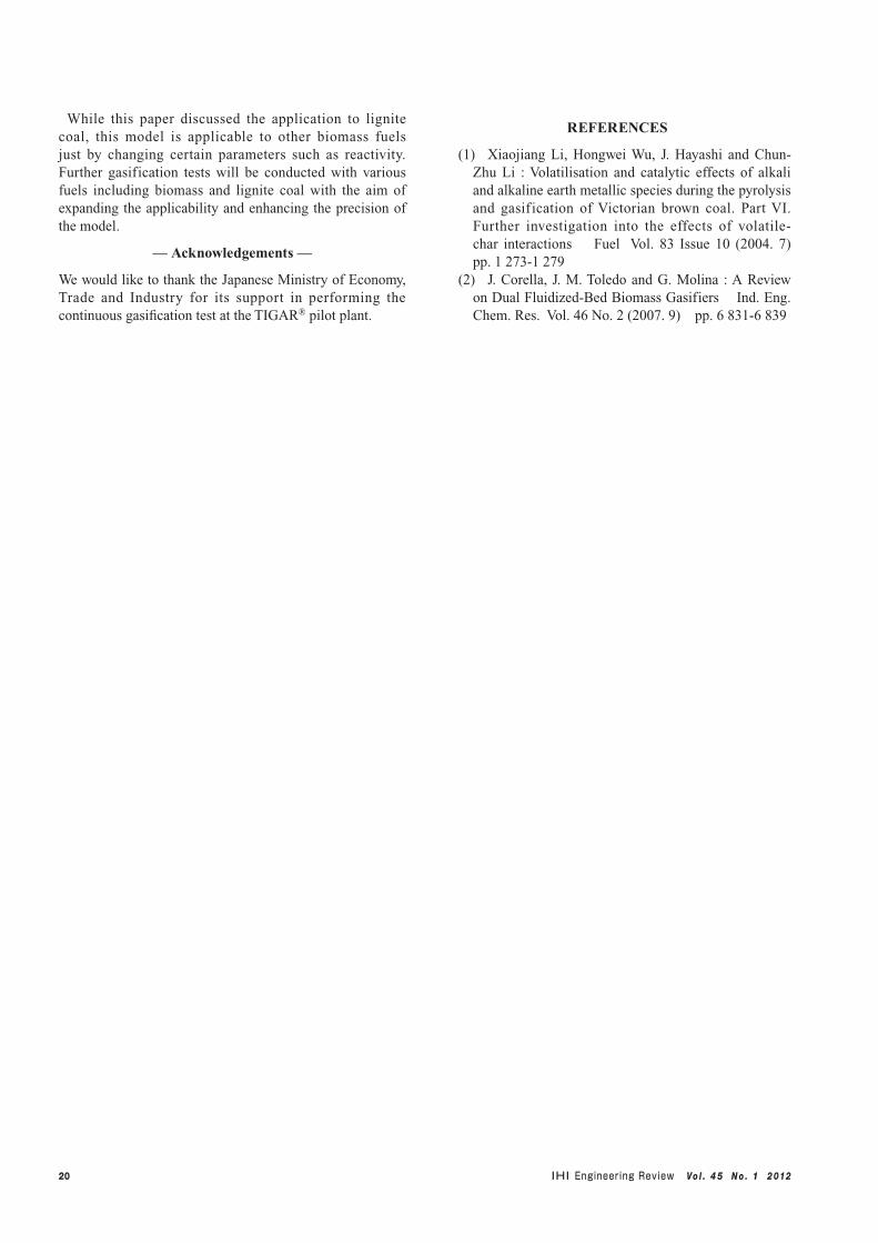
The overview of the TIGAR® pilot plant is shown in Fig. 9. The pilot plant is a gasifier with a coal feeding capacity of 6 t/d (250 kg/h) which can operate continuously with automated coal feeding. Beside the gasif ier, the plant is equipped with gas purif ication and water treatment facilities. The plant is capable of monitoring the performance of the entire gasification process.
This test analyzed the amount and composition of generated gas when the plant reached a steady-state in terms of gasif ier and combustor temperature through continuous feeding of coal. The carbon conversion was calculated by comparing the amount of carbon input with the carbon contained in the resultant syngas.
The actual operation conditions were applied as input data for the performance prediction in order to calculate the residence time of coal particles inside the gasifier according to the model described in Section 3.1. We derived the reactivity of coal from the change of carbon conversion over time with a small batch fluidized bed gasification test apparatus. Carbon conversion of the overall gasifier was calculated by integrating the product of RTD and change in carbon conversion over time according to Equation (1).
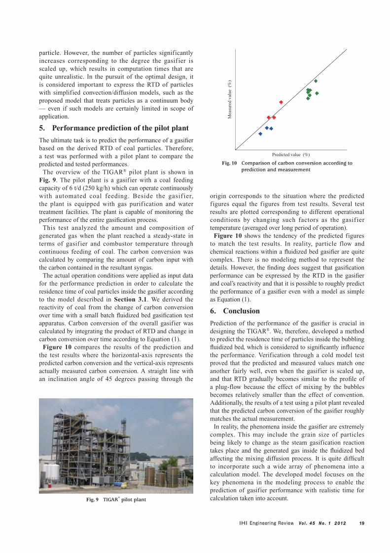
Figure 10 compares the results of the prediction and the test results where the horizontal-axis represents the predicted carbon conversion and the vertical-axis represents actually measured carbon conversion. A straight line with an inclination angle of 45 degrees passing through the
origin corresponds to the situation where the predicted figures equal the figures from test results. Several test results are plotted corresponding to different operational conditions by changing such factors as the gasif ier temperature (averaged over long period of operation).
Figure 10 shows the tendency of the predicted figures to match the test results. In reality, particle flow and chemical reactions within a fluidized bed gasifier are quite complex. There is no modeling method to represent the details. However, the finding does suggest that gasification performance can be expressed by the RTD in the gasifier and coal’s reactivity and that it is possible to roughly predict the performance of a gasifier even with a model as simple as Equation (1).
6. Conclusion
Prediction of the performance of the gasifier is crucial in designing the TIGAR®. We, therefore, developed a method to predict the residence time of particles inside the bubbling fluidized bed, which is considered to significantly influence the performance. Verification through a cold model test proved that the predicted and measured values match one another fairly well, even when the gasifier is scaled up, and that RTD gradually becomes similar to the profile of a plug-flow because the effect of mixing by the bubbles becomes relatively smaller than the effect of convention. Additionally, the results of a test using a pilot plant revealed that the predicted carbon conversion of the gasifier roughly matches the actual measurement.
In reality, the phenomena inside the gasifier are extremely complex. This may include the grain size of particles being likely to change as the steam gasification reaction takes place and the generated gas inside the fluidized bed affecting the mixing diffusion process. It is quite difficult to incorporate such a wide array of phenomena into a calculation model. The developed model focuses on the key phenomena in the modeling process to enable the prediction of gasifier performance with realistic time for calculation taken into account.Fig. 9 TIGAR® pilot plant
Predicted value (%)
Mea
sure
d va
lue
(%
)
Fig. 10 Comparison of carbon conversion according to prediction and measurement
20 Vo l . 4 5 N o . 1 2 012
While this paper discussed the application to lignite coal, this model is applicable to other biomass fuels just by changing certain parameters such as reactivity. Further gasification tests will be conducted with various fuels including biomass and lignite coal with the aim of expanding the applicability and enhancing the precision of the model.
— Acknowledgements —
We would like to thank the Japanese Ministry of Economy, Trade and Industry for its support in performing the continuous gasification test at the TIGAR® pilot plant.
REFERENCES
(1) Xiaojiang Li, Hongwei Wu, J. Hayashi and Chun-Zhu Li : Volatilisation and catalytic effects of alkali and alkaline earth metallic species during the pyrolysis and gasification of Victorian brown coal. Part VI. Further investigation into the effects of volatile-char interactions Fuel Vol. 83 Issue 10 (2004. 7) pp. 1 273-1 279
(2) J. Corella, J. M. Toledo and G. Molina : A Review on Dual Fluidized-Bed Biomass Gasifiers Ind. Eng. Chem. Res. Vol. 46 No. 2 (2007. 9) pp. 6 831-6 839
Related Documents