Gas/Air Ratio Control MB-VEF DMV-VEF

Welcome message from author
This document is posted to help you gain knowledge. Please leave a comment to let me know what you think about it! Share it to your friends and learn new things together.
Transcript
Gas/Air Ratio Control
MB-VEFDMV-VEF
Luftdruck-MembraneRegler-MembraneAnschlussflanschFeinfilterVentil V1Steuerventil V3Schliessfeder V1Anker V1Magnet V 1GasdruckwächterGW-ElektroanschlussMB-ElektroanschlussNullpunkt-KorrekturVerhältnis-EinstellungGasdruck-MembraneSteuerventil V4Ventil V2Schliessfeder V2Anker V2Magnet V2Magnetgehäuse
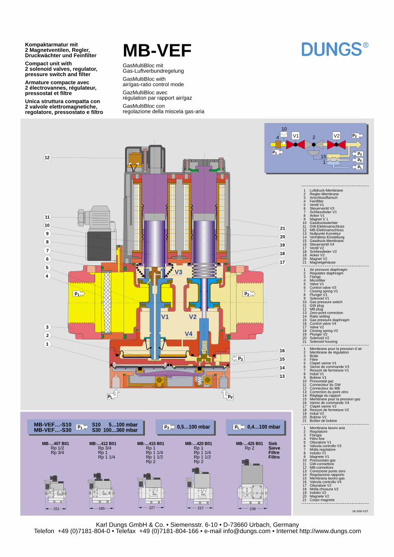
Air pressure diaphragmRegulator diaphragmFlangeMicrofilterValve V1Control valve V3Closing spring V1Plunger V1Solenoid V1Gas pressure switchGW plugMB plugZero-point correctionRatio settingGas pressure diaphragmControl valve V4Valve V2Closing spring V2Plunger V2Solenoid V2Solenoid housing
Membrane pour la pression d´airMembrane de régulationBrideFiltreClapet vanne V1Vanne de commande V3Ressort de fermeture V1Induit V1Bobine V1Pressostat gazConnecteur du GWConnecteur du MBCorrection du point zéroRéglage du rapportMembrane pour la pression gazVanne de commande V4Clapet vanne V2Ressort de fermeture V2Induit V2Bobine V2Boîtier de bobine
Membrana lavoro ariaRegolatoreFlangiaFiltro fineOtturatore V1Valvola controllo V3Molla regolatoreIndotto V1Magnete V1Pressostato gasGW-connettoreMB-connettoreCorrezione punto zeroRegolazione rapportoMembrana lavoro gasValvola controllo V4Otturatore V2Molla chiusura V2Indotto V2Magnete V2Corpo magnete
1 2 3 4 5 6 7 8 9101112131415161718192021
1 2 3 4 5 6 7 8 9101112131415161718192021
1 2 3 4 5 6 7 8 9101112131415161718192021
1 2 3 4 5 6 7 8 9101112131415161718192021
Karl Dungs GmbH & Co. • Siemensstr. 6-10 • D-73660 Urbach, GermanyTelefon +49 (0)7181-804-0 • Telefax +49 (0)7181-804-166 • e-mail [email protected] • Internet http://www.dungs.com
V4
V3
V2V1
V1 V2
16
15
14
13
6
5
4
3
2
1
7
10
11
8
921
20
12
19
18
17
p2
p2
p1
06.2000 KST
V1 2
10
4 V2
pF115
pL
p1
p2
p2
pFpL
227227185151 239
MB-VEFGasMultiBloc mitGas-Luftverbundregelung
GasMultiBloc withair/gas-ratio control mode
GazMultiBloc avecrégulation par rapport air/gaz
GasMultiBloc conregolazione della miscela gas-aria
Kompaktarmatur mit2 Magnetventilen, Regler,Druckwächter und Feinfilter
Compact unit with2 solenoid valves, regulator,pressure switch and filter
Armature compacte avec2 électrovannes, régulateur,pressostat et filtre
Unica struttura compatta con2 valvole elettromagnetiche,regolatore, pressostato e filtro
MB-…407 B01 Rp 1/2 Rp 3/4
MB-…412 B01 Rp 3/4 Rp 1 Rp 1 1/4
MB-…420 B01 Rp 1 Rp 1 1/4 Rp 1 1/2 Rp 2
MB-…415 B01 Rp 1 Rp 1 1/4 Rp 1 1/2 Rp 2
MB-…425 B01 Sieb Rp 2 Sieve
FiltreFiltro
MB-VEF…-S10MB-VEF…-S30
S10 5…100 mbarS30 100…360 mbar
0,5…100 mbar pL 0,4…100 mbarp1 p2
Luftdruck-MembraneRegler-MembraneAnschlussflanschFeinfilterVentil V1Steuerventil V3Schliessfeder V1Anker V1Magnet V 1GasdruckwächterGW-ElektroanschlussMB-ElektroanschlussNullpunkt-KorrekturVerhältnis-EinstellungGasdruck-MembraneSteuerventil V4Ventil V2Schliessfeder V2Anker V2Magnet V2Magnetgehäuse
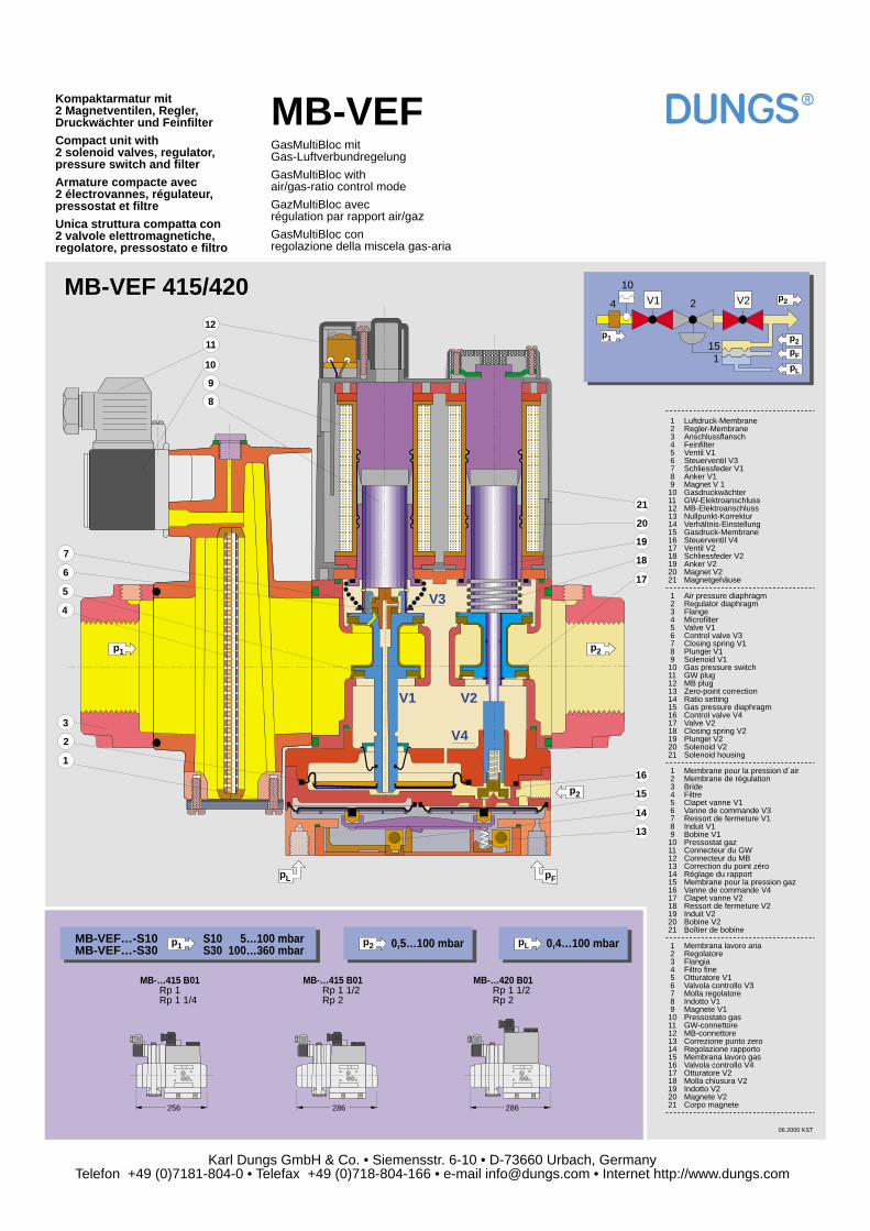
Air pressure diaphragmRegulator diaphragmFlangeMicrofilterValve V1Control valve V3Closing spring V1Plunger V1Solenoid V1Gas pressure switchGW plugMB plugZero-point correctionRatio settingGas pressure diaphragmControl valve V4Valve V2Closing spring V2Plunger V2Solenoid V2Solenoid housing
Membrane pour la pression d´airMembrane de régulationBrideFiltreClapet vanne V1Vanne de commande V3Ressort de fermeture V1Induit V1Bobine V1Pressostat gazConnecteur du GWConnecteur du MBCorrection du point zéroRéglage du rapportMembrane pour la pression gazVanne de commande V4Clapet vanne V2Ressort de fermeture V2Induit V2Bobine V2Boîtier de bobine
Membrana lavoro ariaRegolatoreFlangiaFiltro fineOtturatore V1Valvola controllo V3Molla regolatoreIndotto V1Magnete V1Pressostato gasGW-connettoreMB-connettoreCorrezione punto zeroRegolazione rapportoMembrana lavoro gasValvola controllo V4Otturatore V2Molla chiusura V2Indotto V2Magnete V2Corpo magnete
1 2 3 4 5 6 7 8 9101112131415161718192021
1 2 3 4 5 6 7 8 9101112131415161718192021
1 2 3 4 5 6 7 8 9101112131415161718192021
1 2 3 4 5 6 7 8 9101112131415161718192021
Karl Dungs GmbH & Co. • Siemensstr. 6-10 • D-73660 Urbach, GermanyTelefon +49 (0)7181-804-0 • Telefax +49 (0)718-804-166 • e-mail [email protected] • Internet http://www.dungs.com
V4
V3
V2V1
V1 V2
16
15
14
13
6
5
4
3
2
1
7
10
11
8
9
21
20
12
19
18
17
06.2000 KST
V1 2
10
4 V2
pF115
pL
p1
p2
p2
pFpL
MB-VEFGasMultiBloc mitGas-Luftverbundregelung
GasMultiBloc withair/gas-ratio control mode
GazMultiBloc avecrégulation par rapport air/gaz
GasMultiBloc conregolazione della miscela gas-aria
Kompaktarmatur mit2 Magnetventilen, Regler,Druckwächter und Feinfilter
Compact unit with2 solenoid valves, regulator,pressure switch and filter
Armature compacte avec2 électrovannes, régulateur,pressostat et filtre
Unica struttura compatta con2 valvole elettromagnetiche,regolatore, pressostato e filtro
MB-VEF…-S10MB-VEF…-S30
S10 5…100 mbarS30 100…360 mbar
0,5…100 mbar pL 0,4…100 mbarp1 p2
p1 p2
p2
MB-…420 B01 Rp 1 1/2 Rp 2
MB-…415 B01 Rp 1 Rp 1 1/4
MB-…415 B01 Rp 1 1/2 Rp 2
286286256
MB-VEF 415/420
Analysis Report on
Gas/Air Ratio Controls MB –VEF / DMV – VEF
Fitted to Forced Draught Burners
Dipl. Ing. (FH) Hans-Peter MengsHead of Burner Test Laboratory
Karl Dungs GmbH & Co.
Urbach, 22.02 2000
-2-
Contents
1. Introduction Page
2. Specification of pulse connections 32.1 Burner pressure Pburner 42.2 Combustion air pressure Pair 42.3 Combustion chamber pressure PCC 4
3. Coarse setting for setup 53.1 Combustion air pressure Pai 53.2 Gas pressure Pburner 63.3 Ratio V 63.4 Zero point correction N 6
4. Setup 74.1 Burner ignition 74.2 Maximum load adjustment 74.3 Minimum load adjustment 74.4 Adjustment of intermediate steps 84.5 Notes on setup 8
5. Impacts in operation 85.1 Modification of combustion chamber pressure PCC 85.2 Modification of inlet pressure Pe 95.3 Modification of combustion air pressure Pair 9
6. Examinations on operating response 106.1 Drift response 106.2 Hysteresis response 116.3 Reproducibility 12
7. Summary 12
-3-
1. Introduction
Due to the increasing demand of gas burners for modulating operation, the demand for suitable gas/air ratio control systems is more and more the focus of discussions.In this context, a high modulation range for burners is required.For many years, DUNGS has been supplying compact controlss (MB – VEF and DMV – VEF) whichare equipped with gas/air ratio control units.The DUNGS gas/air ratio control system requires no additional power for the control function.The forced air pressure Pair is the key parameter to control the gas/air ratio control system.The control controls a gas pressure which is proportional to the forced air pressure via an adjustableratio V so that the gas volume corresponds to the current combustion air volume.The controls can also be used for a two-stage floating operation.
These controls have a compact design comprising the following functional elements:
- 2 solenoid valves (Class A)- Pressure controller in double-seat technology, located on the axis of the first solenoid valve (inlet
side)- Servo pressure control unit controlling the pressure controller without any additional power- Ratio setting V = Pburner / Pair, 0.75 : 1 to 3 : 1- Zero point correction- Dirt trap or premount filter- Pressure limiter- Pulse flange (for threaded versions)
Additionally, DUNGS provides microprocessors equipped with controlled automatic burner controlscomprising integrated fuel/air ratio control systems of types MPA or BCS. They can also be combinedwith a pneumatic ratio control system.
The controls can be supplied in nominal widths of DN 15 to DN 100 (DN 15 to DN 65 with threadedflange and DN 65 to DN 100 in flanged versions).
For technical details (e.g. gas flow rates depending on inlet and outlet pressures, equipment andoptions, dimensions and functional descriptions), refer to datasheets and equipment specifications aswell as operating and mounting instructions. They are also available on our homepage:http://www.dungs.com.
Below we will specify the key items resulting from various tests on the VEF controls.In the DUNGS burner test laboratory, we have tested burners of different types and manufacturers(150, 330 and 770 kW) with VEF controls.From the results we gained, the following special instructions have been issued to ensure properfunctioning of the VEF controls.
- Definition of pulse connections- Setup and settings- Impacts in operation
2. Definition of pulse connections
Please refer to the operating and mounting instructions for line dimensioning and for routing pulselines between control and burner.
-4-
Please note the following when connecting VEF controls to marked pulse connections, e.g:Pbuner: Gas outlet pressure (variable)Pair: Combustion air pressure (leading parameter)Pcc : Combustion chamber pressure (interference variable)
2.1 Burner pressure Pburner
Define the measuring location (measuring point) at a distance of 5 x d in the gas line between controland gas burner.Please note that the bore hole diameter at the measuring point is at least 4 mm and that the pulsebore hole is drilled in such a way that it cannot be blocked by any condensate occurring.Instead of the 5 x d measuring point, you can use a pulse flange for controls with a threadedconnection flange.
2.2 Combustion air pressure Pair
The Pair pulse is the key parameter for the pneumatic gas/air ratio control system and defines thefunction of the ratio control.
The pulse is decisive for the following items listed below:- selection of ratio V- ignition response of the burner- modulation range of the burner- gas/air mixture response and combustion quality
Route the measuring point for the pulse tap within a range of the combustion air route in which the airflow is smooth and cannot be influenced by deviations or flow stops.
Experience shows that the most favourable solution is when the measuring tube with an innerdiameter of 4 mm is attached in parallel to the burner tube directly at the mixing point of thecombustion gas.
For gas-forced air burners with a gas outlet downstream of the splash plate, route the measuring up tojust upstream of splash plate. Consider the adjustability of the nozzle bar.
For gas-forced air burners with premixture, the measuring tube must be installed sufficiently far awayfrom the gas outlet slots.
On some burners, we obtained positive results by installing the measuring tube at right-angles to theair flow direction in the burner tube to measure the dynamic pressure.We provided the measuring tube with 2 mm through-holes along its complete length.
A check of the correct measuring point is possible by recording an air flow characteristic (refer to 3.1).
2.3 Combustion chamber pressure PCC
The best point for measuring the pulse of the combustion chamber pressure is the burner outlet insidethe burner.Route a measuring tube with an inner diameter of 4mm in parallel to the burner tube which ends justupstream of the burner tube.
For proper functioning of the gas/air ratio control system, it is not necessary to connect the PCC pulse,in case ratio V is equal to 1.
-5-
The PCC pulse, however, is a key correction factor which ensures a constant selected ratio in case thegas/air ratios are not equal to 1.
3. Coarse setting for setup
To make a first coarse setting of ratio V and zero point correction N for setting up the VEF, thecombustion air pressure Pair and the required gas pressure upstream of burner Pburner must be knownroughly or calculated.
3.1 Combustion air pressure Pair
Determine the combustion air pressure by determining an air flow characteristic.
Measure the combustion air pressure Pair at different air valve position angles and display it in a curveby using the pre-ventilation time of the burner at maximum air valve position.The air valve positions in steps of 5 angle degrees are obtained by manually adjusting the actuatormotor of the air valve.Measure the air flow characteristic at different nozzle bar positions.
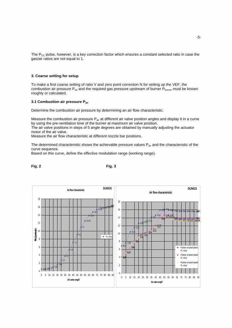
The determined characteristic shows the achievable pressure values Pair and the characteristic of thecurve sequence.Based on this curve, define the effective modulation range (working range).
Fig. 2 Fig. 3
Air flow characteristic
0,45 0,54 0,71,05
1,64
2,7
3,7
5,3
7,1
9,1
11
12,55
13,8
14,715,35
15,7515,9516,116,3
0
2
4
6
8
10
12
14
16
18
0 5 10 15 20 25 30 35 40 45 50 55 60 65 70 75 80 85 90
Air valve angle˚
PL
[m
ba
r]
PL mbar
DUNGS
6,97,65
10,4
11,5
12,612,9 13,2
14,114,6
15,9 16,1 15,9 15,8 15,6 15,6 15,6 15,6 15,515,6
4,05
5,25
6,45
8,1
9,5510,1
10,411,1
12,05
13,914,6 14,6
13,9 13,7 13,7 13,7 13,7 13,813,8
3,9
5,2
6,6
7,9
9,059,55
10,110,6
11,6
13,614,1514,15
13,6 13,5 13,3 13,2513,2513,2513,25
0
2
4
6
8
10
12
14
16
18
0 5 10 15 20 25 30 35 40 45 50 55 60 65 70 75 80 85 90
Air valve angle˚
Position of splash plate1PL mbar
Position of splash plate5PL mbar
Position of splash plate8PL mbar
DUNGSAir flow characteristic
-6-
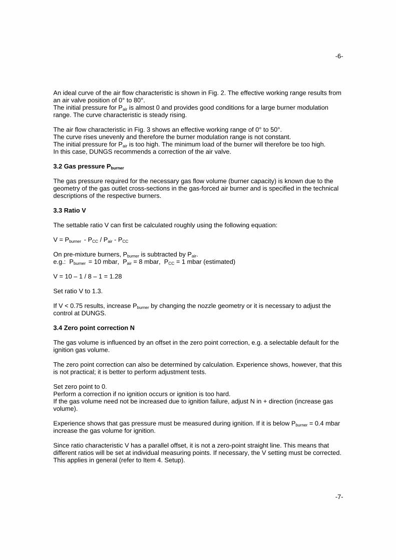
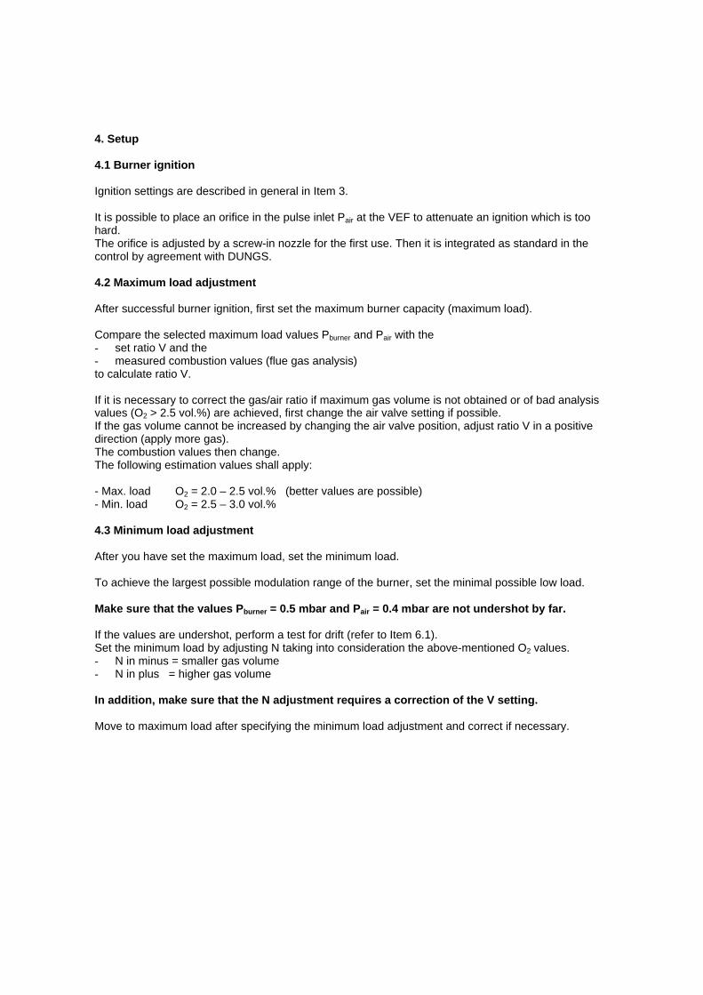
An ideal curve of the air flow characteristic is shown in Fig. 2. The effective working range results froman air valve position of 0° to 80°.The initial pressure for Pair is almost 0 and provides good conditions for a large burner modulationrange. The curve characteristic is steady rising.
The air flow characteristic in Fig. 3 shows an effective working range of 0° to 50°.The curve rises unevenly and therefore the burner modulation range is not constant.The initial pressure for Pair is too high. The minimum load of the burner will therefore be too high.In this case, DUNGS recommends a correction of the air valve.
3.2 Gas pressure Pburner
The gas pressure required for the necessary gas flow volume (burner capacity) is known due to thegeometry of the gas outlet cross-sections in the gas-forced air burner and is specified in the technicaldescriptions of the respective burners.
3.3 Ratio V
The settable ratio V can first be calculated roughly using the following equation:
V = Pburner - PCC / Pair - PCC
On pre-mixture burners, Pburner is subtracted by Pair.e.g.: Pburner = 10 mbar, Pair = 8 mbar, PCC = 1 mbar (estimated)
V = 10 – 1 / 8 – 1 = 1.28
Set ratio V to 1.3.
If V < 0.75 results, increase Pburner by changing the nozzle geometry or it is necessary to adjust thecontrol at DUNGS.
3.4 Zero point correction N
The gas volume is influenced by an offset in the zero point correction, e.g. a selectable default for theignition gas volume.
The zero point correction can also be determined by calculation. Experience shows, however, that thisis not practical; it is better to perform adjustment tests.
Set zero point to 0.Perform a correction if no ignition occurs or ignition is too hard.If the gas volume need not be increased due to ignition failure, adjust N in + direction (increase gasvolume).
Experience shows that gas pressure must be measured during ignition. If it is below Pburner = 0.4 mbarincrease the gas volume for ignition.
Since ratio characteristic V has a parallel offset, it is not a zero-point straight line. This means thatdifferent ratios will be set at individual measuring points. If necessary, the V setting must be corrected.This applies in general (refer to Item 4. Setup).
-7-
4. Setup
4.1 Burner ignition
Ignition settings are described in general in Item 3.
It is possible to place an orifice in the pulse inlet Pair at the VEF to attenuate an ignition which is toohard.The orifice is adjusted by a screw-in nozzle for the first use. Then it is integrated as standard in thecontrol by agreement with DUNGS.
4.2 Maximum load adjustment
After successful burner ignition, first set the maximum burner capacity (maximum load).
Compare the selected maximum load values Pburner and Pair with the- set ratio V and the- measured combustion values (flue gas analysis)to calculate ratio V.
If it is necessary to correct the gas/air ratio if maximum gas volume is not obtained or of bad analysisvalues (O2 > 2.5 vol.%) are achieved, first change the air valve setting if possible.If the gas volume cannot be increased by changing the air valve position, adjust ratio V in a positivedirection (apply more gas).The combustion values then change.The following estimation values shall apply:
- Max. load O2 = 2.0 – 2.5 vol.% (better values are possible)- Min. load O2 = 2.5 – 3.0 vol.%
4.3 Minimum load adjustment
After you have set the maximum load, set the minimum load.
To achieve the largest possible modulation range of the burner, set the minimal possible low load.
Make sure that the values Pburner = 0.5 mbar and Pair = 0.4 mbar are not undershot by far.
If the values are undershot, perform a test for drift (refer to Item 6.1).Set the minimum load by adjusting N taking into consideration the above-mentioned O2 values.- N in minus = smaller gas volume- N in plus = higher gas volume
In addition, make sure that the N adjustment requires a correction of the V setting.
Move to maximum load after specifying the minimum load adjustment and correct if necessary.
-8-
4.4 Adjustment of intermediate steps
Even in modulating mode, we recommend you check 2 to 3 load stages within the burner workingrange by performing combustion-specific measurements.
Perform any necessary corrections by adjusting minimum and maximum loads.
4.5 Notes on setup
- After setting V and N, always re-ignite the burner and check the combustion values.
- Without suitable measuring media for:. pressure measurements Pburner, Pair, PCC
. gas volume measurements, and
. flue gas analysisit is not possible to adjust the ratio control exactly.
To reduce time required to perform system setup, we recommend you use pre-adjusted controls.
The adjustment values can first be determined at the burner manufacturer on the burner test stand orduring an initial setup. Burner-specific estimation values are provided for further systems. In thiscontext, orifices for Pair and PCC can be determined for attenuating the pulses.
5.0 Impacts on operation
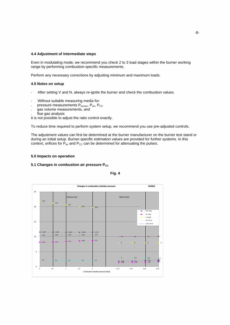
5.1 Changes in combustion air pressure PCC
Fig. 4
11,57 11,54 11,53 11,52 11,52
1,85 1,9 2,02 2,18
8,18 8,22 8,47 8,59 8,71
1,38 1,43 1,52 1,69
21,921,3
20,720,1
19,8
8 8 8 8
2,2 2,1 2,1 2,1 2,1
3 2,9 2,8 2,7
10,5 10,6 10,6 10,6 10,610 10 10 10,1
0
5
10
15
20
25
0 0,5 1 1,5 2 -0,15 0,15 0,25 0,35
Combustion chamber pressure [mbar]
PBr mbar
PL mbar
V m3n/h
O2 Vol.%
CO2 Vol.%
Maximum load Minimum load
DUNGSChanges in combustion chamber pressure
-9-
Changes in pressure ratios in the stack (e.g. due to weather conditions) lead to pressure changes inthe combustion chamber of the heat generator.A change in gas volume due to gas and combustion air pressure changes will result. The combustionvalues however remain almost constant.
As can be seen from Fig. 4, pressure value Pair increases at an increase of PCC.The gas volume diminishes.The combustion values O2 and CO2 remain constant.
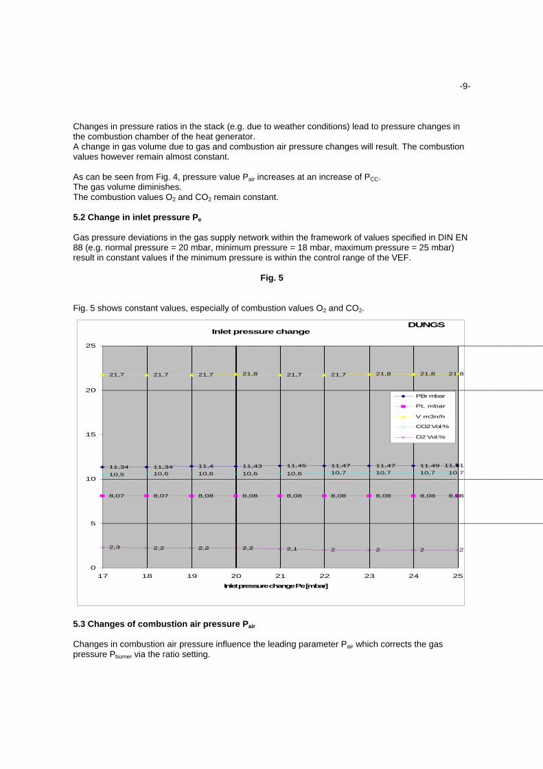
5.2 Change in inlet pressure Pe
Gas pressure deviations in the gas supply network within the framework of values specified in DIN EN88 (e.g. normal pressure = 20 mbar, minimum pressure = 18 mbar, maximum pressure = 25 mbar)result in constant values if the minimum pressure is within the control range of the VEF.
Fig. 5
Fig. 5 shows constant values, especially of combustion values O2 and CO2.
5.3 Changes of combustion air pressure Pair
Changes in combustion air pressure influence the leading parameter Pair which corrects the gaspressure Pburner via the ratio setting.
11,34 11,34 11,4 11,43 11,45 11,47 11,47 11,49 11,51
8,07 8,07 8,08 8,08 8,08 8,08 8,08 8,08 8,08
21,7 21,7 21,7 21,8 21,7 21,7 21,8 21,8 21,8
10,5 10,6 10,6 10,6 10,6 10,7 10,7 10,7 10,7
2,3 2,2 2,2 2,2 2,1 2 2 2 2
0
5
10
15
20
25
17 18 19 20 21 22 23 24 25
Inlet pressure change Pe [mbar]
PBr mbar
PL mbar
V m3n/h
CO2 Vol.%
O2 Vol.%
DUNGSInlet pressure change
-10-
6. Experiments to determine operating response
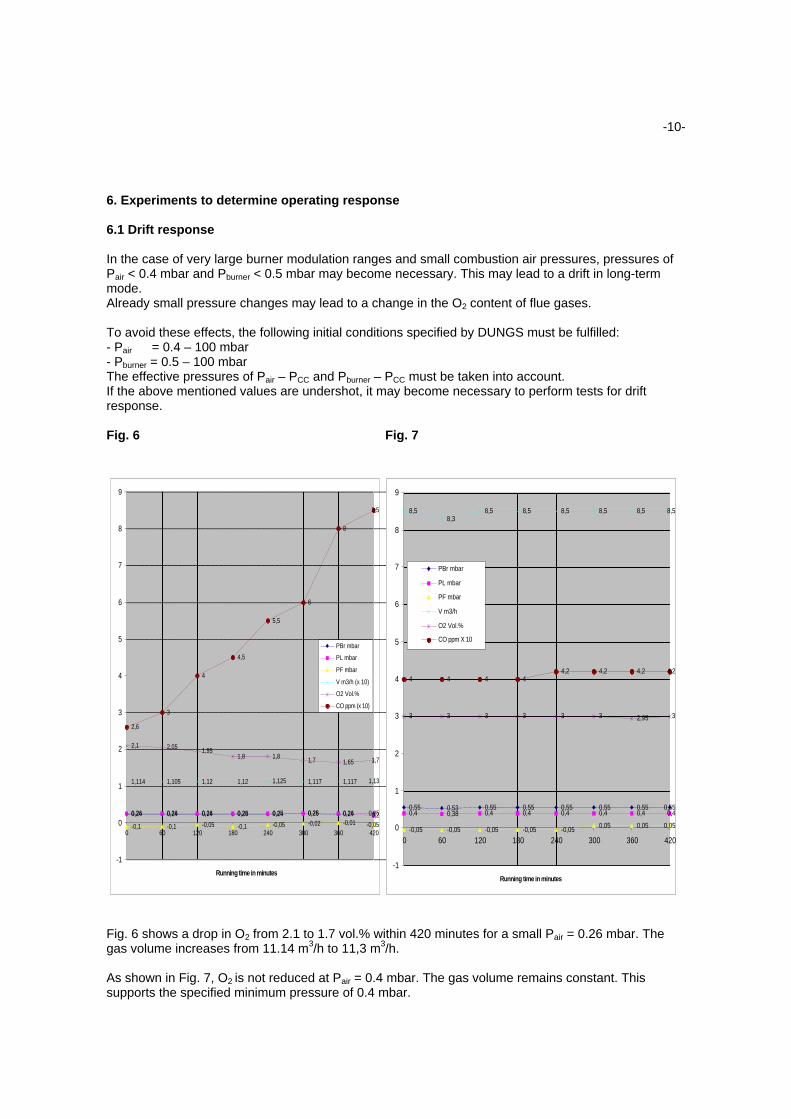
6.1 Drift response
In the case of very large burner modulation ranges and small combustion air pressures, pressures ofPair < 0.4 mbar and Pburner < 0.5 mbar may become necessary. This may lead to a drift in long-termmode.Already small pressure changes may lead to a change in the O2 content of flue gases.
To avoid these effects, the following initial conditions specified by DUNGS must be fulfilled:- Pair = 0.4 – 100 mbar- Pburner = 0.5 – 100 mbarThe effective pressures of Pair – PCC and Pburner – PCC must be taken into account.If the above mentioned values are undershot, it may become necessary to perform tests for driftresponse.
Fig. 6 Fig. 7
Fig. 6 shows a drop in O2 from 2.1 to 1.7 vol.% within 420 minutes for a small Pair = 0.26 mbar. Thegas volume increases from 11.14 m3/h to 11,3 m3/h.
As shown in Fig. 7, O2 is not reduced at Pair = 0.4 mbar. The gas volume remains constant. Thissupports the specified minimum pressure of 0.4 mbar.
0,24 0,24 0,24 0,23 0,24 0,25 0,24 0,250,26 0,26 0,26 0,26 0,25 0,26 0,26 0,2
-0,1 -0,1 -0,05 -0,1 -0,05 -0,02 -0,01 -0,05
1,114 1,105 1,12 1,12 1,125 1,117 1,117 1,13
2,1 2,051,95
1,8 1,81,7 1,65 1,7
2,6
3
4
4,5
5,5
6
8
8,5
-1
0
1
2
3
4
5
6
7
8
9
0 60 120 180 240 300 360 420
Running time in minutes
PBr mbar
PL mbar
PF mbar
V m3/h (x 10)
O2 Vol.%
CO ppm (x 10)
0,55 0,53 0,55 0,55 0,55 0,55 0,55 0,550,4 0,38 0,4 0,4 0,4 0,4 0,4 0,4
-0,05 -0,05 -0,05 -0,05 -0,050,05 0,05 0,05
8,58,3
8,5 8,5 8,5 8,5 8,5 8,5
3 3 3 3 3 3 2,95 3
4 4 4 44,2 4,2 4,2 4,2
-1
0
1
2
3
4
5
6
7
8
9
0 60 120 180 240 300 360 420
Running time in minutes
PBr mbar
PL mbar
PF mbar
V m3/h
O2 Vol.%
CO ppm X 10
-11-
The question still remains whether a long-term minimum load mode with minimum gas volume isrelevant in practice at all or if its only occurs in exceptional cases. Practice tests regarding suchmeasurements must still be made.
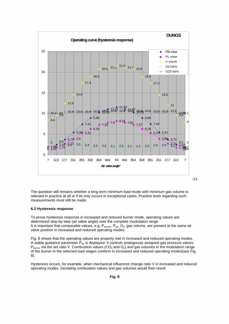
6.2 Hysteresis response
To prove hysteresis response in increased and reduced burner mode, operating values aredetermined step-by-step (air value angle) over the complete modulation range.It is important that comparable values, e.g. Pburner, Pair, O2, gas volume, are present at the same airvalve position in increased and reduced operating modes.
Fig. 8 shows that the operating values are properly met in increased and reduced operating modes.A stable guidance parameter Pair is displayed. It controls analogously assigned gas pressure valuesPburner via the set ratio V. Combustion values (CO2 and O2) and gas volumes in the modulation rangeof the burner in the selected load stages conform in increased and reduced operating modes(see Fig.8).
Hysteresis occurs, for example, when mechanical influences change ratio V in increased and reducedoperating modes. Deviating combustion values and gas volumes would then result.
Fig. 8
1,882,42
3,71
5,38
7,41
8,89
10,2811,01
11,5411,02
10,29
8,89
7,44
5,41
3,72
2,431,87
1,41 1,792,73
3,9
5,316,29
7,287,8
8,167,81
7,27
6,295,27
3,86
2,711,791,39
8,4
9,6
12,5
14,6
17,4
18,9
20,8 21,121,5
21,1 20,8
18,9
17,3
14,5
12
9,6
8
3 3,22,4 2,5 2,4 2,2 2,2 2,1 2,2 2,1 2,1 2,2 2,3 2,4 2,2
3,1 3
10,1 1010,4 10,4 10,4 10,5 10,6 10,6 10,6 10,6 10,6 10,6 10,5 10,5 10,6
10,110,1
0
5
10
15
20
25
7 12,3 17,7 23,1 28,5 33,8 39,4 44,6 50 44,6 39,4 33,8 28,5 23,1 17,7 12,3 7
Air valve angle°
PBr mbar
PL mbar
V m3n/h
O2 Vol.%
CO2 Vol.%
DUNGSOperating curve (hysteresis response)
-12-
6.3 Reproducibility
The reproducibility of the set values have been tested after several ignitions of the burner and in long-term tests.Deviations from the settings do normally not occur.
7. Summary
The experience we gained from in-company analyses and application cases have shown that thegas/air ratio control s MB - VEF and DMV-VEF fully comply with the specified requirements.
In especially critical applications, we were able to adjust the controls in co-operation with the burnermanufacturers to special requirements and thus achieve optimum results.
To set up the controls properly, you require special knowledge. If these specifications are fulfilled, youcan set up a burner in a very short period of time.
Related Documents