Chapter 10 - Gas - Compression Compressors Performance calculations for reciprocating compressors Estimating suction and discharge volume bottle sizes for pulsation control for reciprocating compressors Compression horsepower determination Generalized compressability factor Nomograph aids in diagnosing compressor cylinder ills Centrifugal Compressor Data Centrifugal compressor performance calculations Nomographs for estimating compressor performance Estimate hp required to compress natural gas Estimate compressor hp where discharge pressure is 1,000 psi Calculate brake horsepower required to compress gas How to find the size fuel gas line for a compressor station Estimating engine cooling water requirements Estimate fuel requirements for internal combustion engines Estimating fuel requirements for compressor installation Compressors The following data are for use in the approximation of horsepower needed for compression of gas. Definitions

Gas Compression (Chapter 10)
Nov 28, 2015
Gas Compression
Welcome message from author
This document is posted to help you gain knowledge. Please leave a comment to let me know what you think about it! Share it to your friends and learn new things together.
Transcript
Chapter 10 - Gas - Compression
Compressors Performance calculations for reciprocating compressors Estimating suction and discharge volume bottle sizes for pulsation control for
reciprocating compressors Compression horsepower determination Generalized compressability factor Nomograph aids in diagnosing compressor cylinder ills
Centrifugal Compressor Data Centrifugal compressor performance calculations Nomographs for estimating compressor performance Estimate hp required to compress natural gas Estimate compressor hp where discharge pressure is 1,000 psi Calculate brake horsepower required to compress gas How to find the size fuel gas line for a compressor station Estimating engine cooling water requirements Estimate fuel requirements for internal combustion engines Estimating fuel requirements for compressor installation
Compressors
The following data are for use in the approximation of horsepower needed for compression of gas.
Definitions
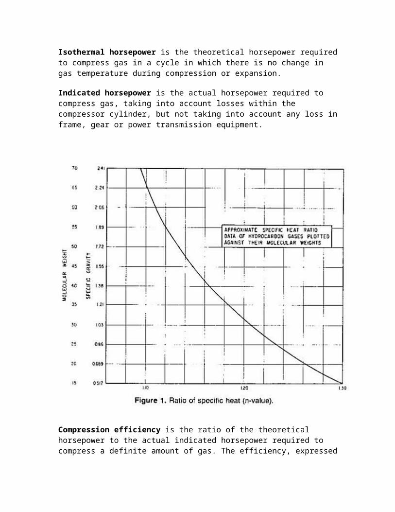
The "N value" of gas is the ratio of the specific heat at constant pressure (Cp) to the specific heat at constant volume (Cv).
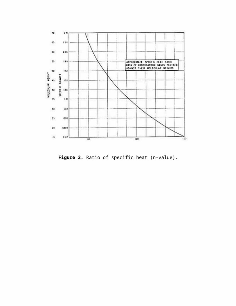
If the composition of gas is known, the value of N for a gas mixture may be determined from the molal heat capacities of the components. If only the specific gravity of gas is known an approximate N value may be obtained by using the chart in Figure 1.
Piston Displacement of a compressor cylinder is the volume swept by the piston with the proper deduction for the piston rod. The displacement is usually expressed in cubic ft per minute.
Clearance is the volume remaining in one end of a cylinder with the piston positioned at the end of the delivery stroke for this end. The clearance volume is expressed as a percentage of the volume swept by the piston in making its full delivery stroke for the end of the cylinder being considered.
Ratio of compression is the ratio of the absolute discharge pressure to the absolute inlet pressure.
Actual capacity is the quantity of gas compressed and delivered, expressed in cubic ft per minute, at the intake pressure and temperature.
Volumetric efficiency is the ratio of actual capacity, in cubic ft per minute, to the piston displacement, in cubic ft per minute, expressed in percent.
Adiabatic horsepower is the theoretical horsepower required to compress gas in a cycle in which there is no transfer of sensible heat to or from the gas during compression of expansion.
Isothermal horsepower is the theoretical horsepower required to compress gas in a cycle in which there is no change in gas temperature during compression or expansion.
Indicated horsepower is the actual horsepower required to compress gas, taking into account losses within the compressor cylinder, but not taking into account any loss in frame, gear or power transmission equipment.
Compression efficiency is the ratio of the theoretical horsepower to the actual indicated horsepower required to compress a definite amount of gas. The efficiency, expressed in percent, should be defined in regard to the base at which the theoretical power was calculated, whether adiabatic or isothermal.
Mechanical efficiency is the ratio of the indicated horsepower of the compressor cylinder to the brake horsepower delivered to the shaft in the case of a power driven machine. It is expressed in percent.
Overall efficiency is the product, expressed in percent, of the compression efficiency and the mechanical efficiency. It must be defined according to the base, adiabatic isothermal, which was used in establishing the compression efficiency.
Piston rod gas load is the varying, and usually reversing, load imposed on the piston rod and crosshead during the operation, by different gas pressures existing on the faces of the compressor piston.
The maximum piston rod gas load is determined for each compressor by the manufacturer, to limit the stresses in the frame members and the bearing loads in accordance with mechanical design. The maximum allowed piston rod gas load is affected by the ratio of compression and also by the cylinder design; i.e., whether it is single or double acting.
Performance Calculations for Reciprocating Compressors
Piston Displacement
Single acting compressor:
Pd = [St x N x 3.1416 x D2] / [4 x 1,728]
Double acting compressor without a tail rod:
Pd = [St x N x 3.1416 x (2D2 - d2)] / [4 x 1,728]
Double acting compressor with a tail rod:
Pd = [St x N x 3.1416 x 2 x (D2 - d2)] / [4 x 1,728]
Single acting compressor compressing on frame end only:
Pd = [St x N x 3.1416 x (D2 - d2)] / [4 x 1,728]
wherePd = Cylinder displacement, cu ft/minSt = Stroke length, in.N = Compressor speed, number of compression strokes/minD = Cylinder diameter, in.d = Piston rod diameter, in.
Volumetric Efficiency
Ev = 0.97 - [(1 / f)rp1/k - 1]C - L
whereEv = Volumetric efficiencyf = ratio of discharge compressibility to suction compressibility Z2 / Z1
rp = pressure ratio
k = isentropic exponentC = percent clearanceL = gas slippage factorLet L = 0.3 for lubricated compressorsLet L = 0.07 for non lubricated compressors
These values are approximations and the exact value may vary by as much as an additional 0.02 to 0.03.
Note: A value of 0.97 is used in the volumetric efficiency equation rather than 1.0 since even with 0 clearance, the cylinder will not fill perfectly.
Cylinder inlet capacity
Q1 = Ev x Pd
Piston Speed
PS = [2 x St x N] / 12
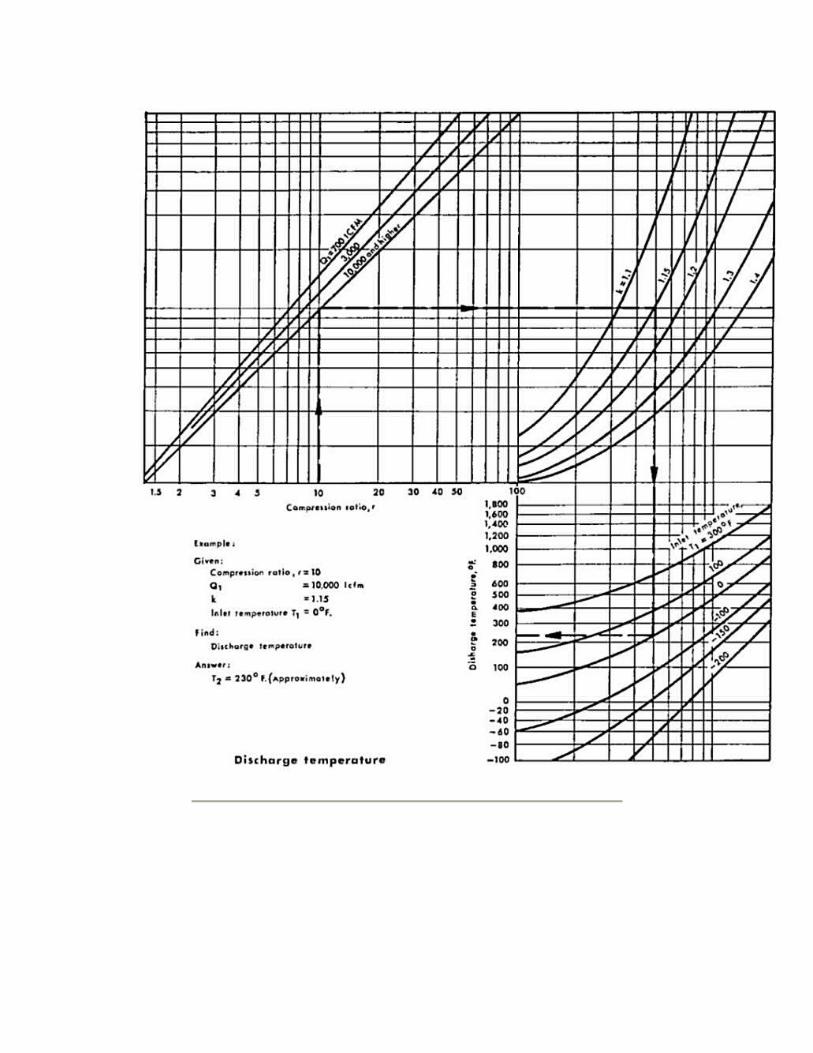
Discharge Temperature
T2 = T1(rp(k-1) / k)
whereT2 = Absolute discharge temperature °RT1 = Absolute suction temperature °R
Note: Even though this is an adiabatic relationship, cylinder cooling will generally offset the effect of efficiency.
Power
Wcyl = [144 P1Q1 / 33,000 ncyl] x [k/(k - 1)] x [rpk-1/k - 1]
wherencyl = efficiencyWcyl = Cylinder horsepower
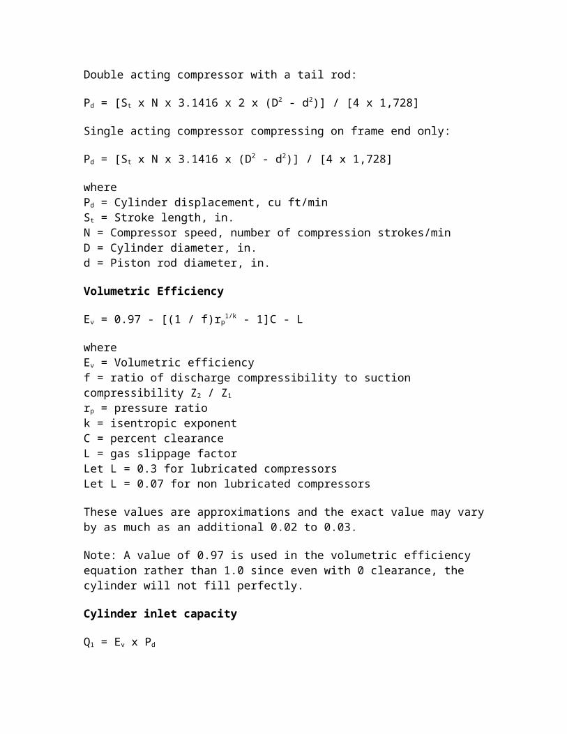
See Figure 1: for curve of efficiency vs. pressure ratio. This curve includes a 95% mechanical efficiency and a valve velocity of 3,000 ft per minutes. Tables 1 and 2 permit a correction to be made to the compressor horsepower for specific gravity and low inlet pressure. While it is recognized that the efficiency is not necessarily the element affected, the desire is to modify the power required per the criteria in these figures. The efficiency correction accomplishes this. These corrections become more significant at the lower pressure ratios.
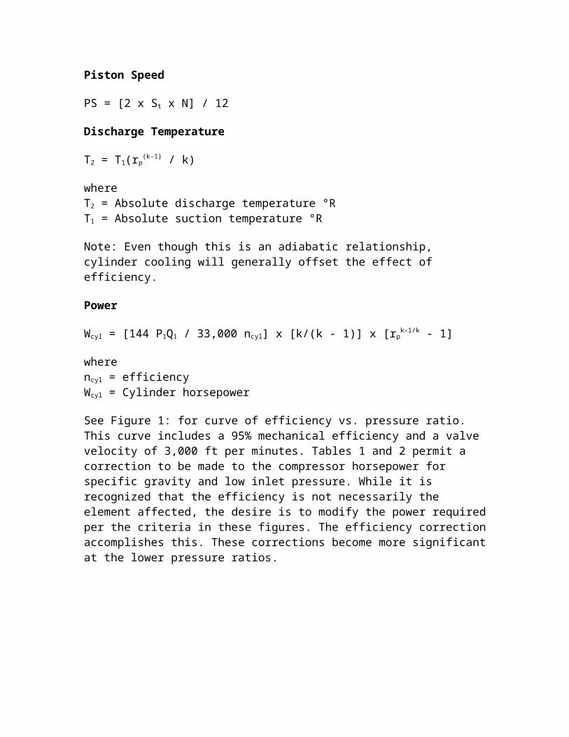
Figure 1. Reciprocating compressor efficiencies.
Figure 2. Volume bottle sizing.
Inlet Valve Velocity
V = 288 x Pd / A
whereV = Inlet valve velocityA = Product of actual lift and the valve opening periphery and is the total for inlet valves in a cylinder expressed in square in. (This is a compressor vendor furnished number).
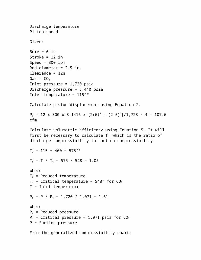
Example. Calculate the following:
Suction capacityHorsepowerDischarge temperaturePiston speed
Given:
Bore = 6 in.Stroke = 12 in.Speed = 300 rpmRod diameter = 2.5 in.Clearance = 12%Gas = CO2
Inlet pressure = 1,720 psiaDischarge pressure = 3,440 psiaInlet temperature = 115°F
Calculate piston displacement using Equation 2.
Pd = 12 x 300 x 3.1416 x [2(6)2 - (2.5)2]/1,728 x 4 = 107.6 cfm
Calculate volumetric efficiency using Equation 5. It will first be necessary to calculate f, which is the ratio of discharge compressibility to suction compressibility.
T1 = 115 + 460 = 575°R
Tr = T / Tc = 575 / 548 = 1.05
whereTr = Reduced temperatureTc = Critical temperature = 548° for CO2
T = Inlet temperature
Pr = P / Pc = 1,720 / 1,071 = 1.61
wherePr = Reduced pressurePc = Critical pressure = 1,071 psia for CO2
P = Suction pressure
From the generalized compressibility chart:
Z1 = 0.312
Determine discharge compressibility. Calculate discharge temperature by using Equation 9.
rp = 3,400 / 1,720 = 2
k = cp / cv = 1.3 for CO2
T2 = 575 x [2.0(1.3 - 1) / 1.3] = 674.7°R = 674.7 - 460 = 214°F
Tr = 674.7 / 548 = 1.23
Pr = 3,440 / 1,071 = 3.21
From the generalized compressibility chart:
Z2 = 0.575
f = 0.575 / 1.61 = 1.843
Ev = 0.97 - [(1 / 1.843) x (2.01 / 1.3) - 1] x 0.12 - 0.05 = 0.929 = 93%
Note: A value of 0.05 was used for L because of the high differential pressure.
Calculate suction capacity.
Q1 = Ev x Pd = 0.93 x 107.6 = 100.1 cfm
Calculate piston speed.
PS = [2 x St x N] / 12 = [2 x 12 x 300] / 12 = 600 ft/min
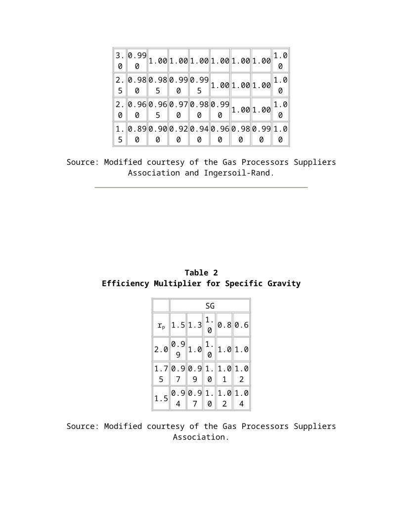
Table 1Efficiency Multiplier for Low Pressure
Pressure Psia
rp 10 14.7 20 40 60 80 100 150
3.0 0.990 1.00 1.00 1.00 1.00 1.00 1.00 1.00
2.5 0.980 0.985 0.990 0.995 1.00 1.00 1.00 1.00
2.0 0.960 0.965 0.970 0.980 0.990 1.00 1.00 1.00
1.5 0.890 0.900 0.920 0.940 0.960 0.980 0.990 1.00
Source: Modified courtesy of the Gas Processors Suppliers Association and Ingersoil-Rand.
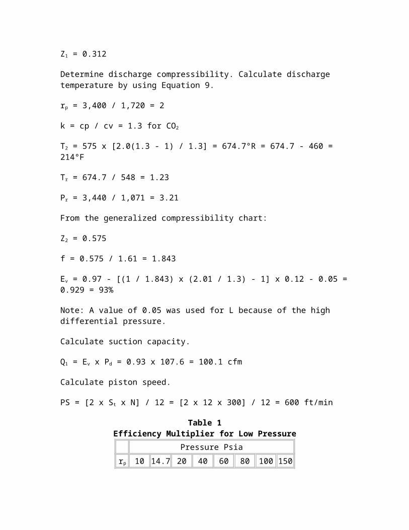
Table 2Efficiency Multiplier for Specific Gravity
SG
rp 1.5 1.3 1.0 0.8 0.6
2.0 0.99 1.0 1.0 1.0 1.0
1.75 0.97 0.99 1.0 1.01 1.02
1.5 0.94 0.97 1.0 1.02 1.04
Source: Modified courtesy of the Gas Processors Suppliers Association.
Estimating Suction and Discharge Volume Bottle Sizes for Pulsation Control for Reciprocating Compressors
Pressure surges are created as a result of the cessation of flow at the end of the compressor's discharge and suction stroke. As long as the compressor speed is constant, the pressure pulses will also be constant. A low pressure compressor will likely require little if any treatment for pulsation control; however, the same machine with increased gas density, pressure, or other operational changes may develop a problem with pressure pulses. Dealing with pulsation becomes more complex when multiple cylinders are connected to one header or when multiple stages are used.
API Standard 618 should be reviewed in detail when planning a compressor installation. The pulsation level at the outlet side of any pulsation control device, regardless of type, should be no more than 2% peak-to-peak of the line pressure of the value given by the following equation, whichever is less.
P% = 10 / Pline1/3
Where a detailed pulsation analysis is required, several approaches may be follows. An analog analysis may be performed on the Southern Gas Association dynamic compressor simulator, or the analysis may be made a part of the compressor purchase contract. Regardless of who makes the analysis, a detailed drawing of the piping in the compressor area will be needed.
The following equations are intended as an aid in estimating bottle sizes or for check sizes proposed by a vendor for simple installations - i.e., single cylinder connected to a header without the interaction of multiple cylinders. The bottle type is the simple unbaffled type.
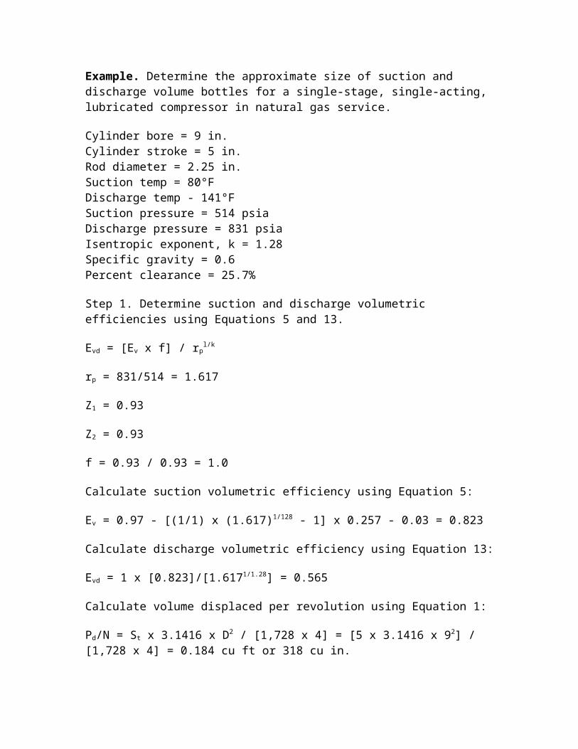
Example. Determine the approximate size of suction and discharge volume bottles for a single-stage, single-acting, lubricated compressor in natural gas service.
Cylinder bore = 9 in.Cylinder stroke = 5 in.Rod diameter = 2.25 in.Suction temp = 80°FDischarge temp - 141°FSuction pressure = 514 psiaDischarge pressure = 831 psiaIsentropic exponent, k = 1.28Specific gravity = 0.6Percent clearance = 25.7%
Step 1. Determine suction and discharge volumetric efficiencies using Equations 5 and 13.
Evd = [Ev x f] / rpl/k
rp = 831/514 = 1.617
Z1 = 0.93
Z2 = 0.93
f = 0.93 / 0.93 = 1.0
Calculate suction volumetric efficiency using Equation 5:
Ev = 0.97 - [(1/1) x (1.617)1/128 - 1] x 0.257 - 0.03 = 0.823
Calculate discharge volumetric efficiency using Equation 13:
Evd = 1 x [0.823]/[1.6171/1.28] = 0.565
Calculate volume displaced per revolution using Equation 1:
Pd/N = St x 3.1416 x D2 / [1,728 x 4] = [5 x 3.1416 x 92] / [1,728 x 4] = 0.184 cu ft or 318 cu in.
Refer to Figure 3, volume bottle sizing, using volumetric efficiencies previously calculated, and determine the multipliers.
Suction multiplier = 13.5Discharge multiplier = 10.4
Discharge volume = 318 x 13.5 = 3,308 cu in.
Suction volume = 318 x 10.4 = 4,294 cu in.
Calculate bottle dimensions. For elliptical heads, use Equation 14.
Bottle diameter db = 0.86 x volume1/3
Volume = suction or discharge volume
Suction bottle diameter = 0.86 x 4,2941/3 = 13.98 in.
Discharge bottle diameter = 0.86 x 3,3081/3 = 12.81 in.
Bottle length = Lb = 2 x db
Suction bottle length = 2 x 12.81 = 25.62 in.
Source
Compressors - Selection & Sizing, Gulf Publishing Company, Houston, Texas.
Compression Horsepower Determination
The method outlined below permits determination of approximate horsepower requirements for compression of gas.
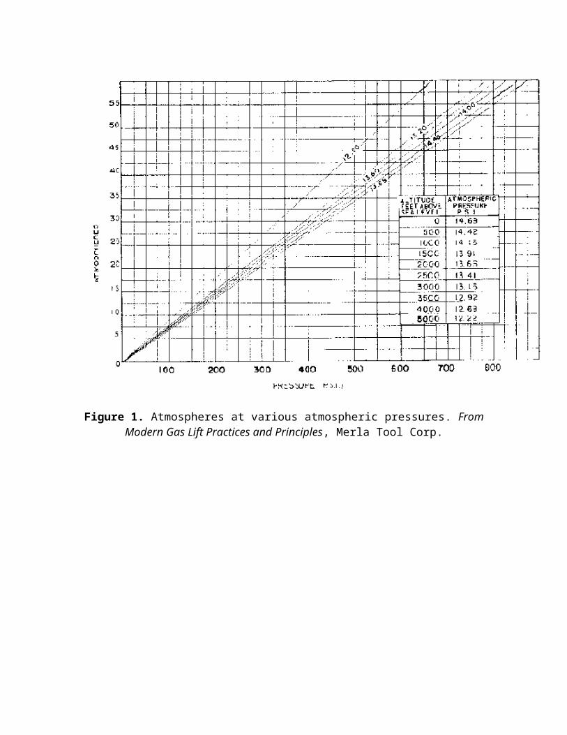
1. From Figure 1, determine the atmospheric pressure in psia for the altitude above sea level at which the compressor is to operate.
2. Determine intake pressure (Ps) and discharge pressure (Pd) by adding the atmospheric pressure to the corresponding gauge pressure for the conditions of compression.
3. Determine total compression ratio R = Pd / Ps. If ratio R is more than 5 to 1, two or more compressor stages will be required. Allow for a pressure loss of approximately 5 psi between stages. Use the same ratio for each stage. The ratio per stage, so that each stage has the same ratio, can be approximated by finding the nth root of the total ratio, when n = number of stages. The exact ratio can be found by trial and error, accounting for the 5 psi interstage pressure losses.
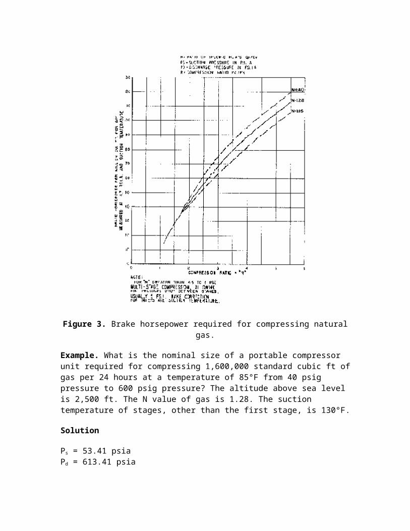
4. Determine the N value of gas. 5. Figure 3 gives horsepower requirements for compression of one million cu ft per
day for the compression ratios and N values commonly encountered in oil producing operations.
6. If the suction temperature is not 60°F, correct the curve horsepower figure in proportion to absolute temperature. This is done as follows:
HP x ((460° + Ts) / (460° + 60°F)) = hp (corrected for suction temperature)
where Ts is suction temperature in °F.
7. Add together horsepower loads determined for each stage to secure the total compression horsepower load. For altitudes greater than 1,500 ft above sea level apply a multiplier derived from the following table to determine the nominal sea level horsepower rating of the internal combustion engine driver.
Altitude - Multiplier 1,500 ft 1.00 2,000 ft 1.03 2,500 ft 1.05 3,000 ft 1.07 3,500 ft 1.10 4,000 ft 1.12 4,500 ft 1.14 5,000 ft 1.17 5,500 ft 1.20 6,000 ft 1.22
8. For a portable unit with fan cooler and pump driven from the compressor unit, increase the horsepower figure by 7-1/2%.
The resulting figure is sufficiently accurate for all purposes. The nearest commercially available size of compressor is then selected.
The method does not take into consideration the super compressibility of gas and is applicable for pressures up to 1,000 psi. In the region of high pressures, neglecting the deviation of behavior of gas from that of the perfect gas may lead to substantial errors in calculating the compression horsepower requirements. The enthalpy-entropy charts may be used conveniently in such cases. The procedures are given in references 1 and 2.
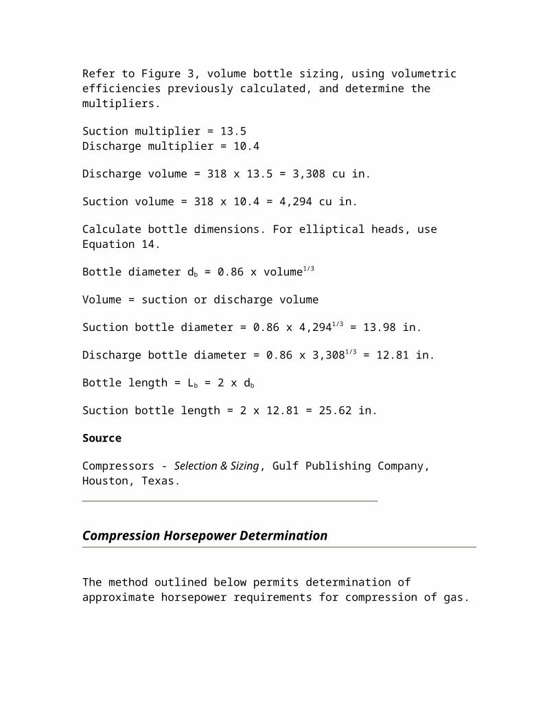
Figure 1. Atmospheres at various atmospheric pressures. From Modern Gas Lift Practices and Principles, Merla Tool Corp.
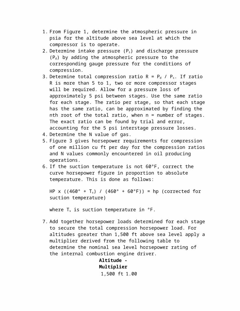
Figure 2. Ratio of specific heat (n-value).
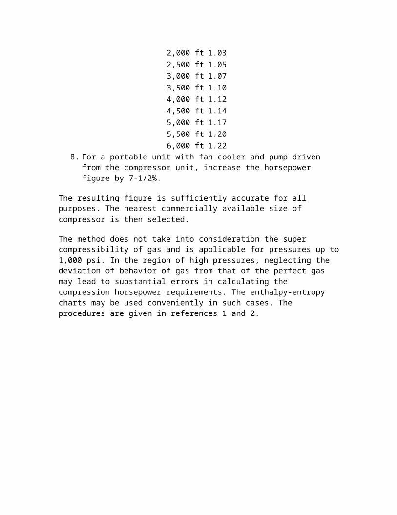
Figure 3. Brake horsepower required for compressing natural gas.
Example. What is the nominal size of a portable compressor unit required for compressing 1,600,000 standard cubic ft of gas per 24 hours at a temperature of 85°F from 40 psig pressure to 600 psig pressure? The altitude above sea level is 2,500 ft. The N value of gas is 1.28. The suction temperature of stages, other than the first stage, is 130°F.
Solution
Ps = 53.41 psiaPd = 613.41 psia
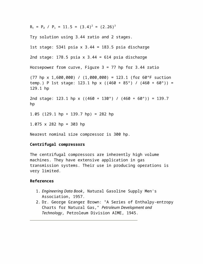
Rt = Pd / Ps = 11.5 = (3.4)2 = (2.26)3
Try solution using 3.44 ratio and 2 stages.
1st stage: 5341 psia x 3.44 = 183.5 psia discharge
2nd stage: 178.5 psia x 3.44 = 614 psia discharge
Horsepower from curve, Figure 3 = 77 hp for 3.44 ratio
(77 hp x 1,600,000) / (1,000,000) = 123.1 (for 60°F suction temp.) P 1st stage: 123.1 hp x ((460 + 85°) / (460 + 60°)) = 129.1 hp
2nd stage: 123.1 hp x ((460 + 130°) / (460 + 60°)) = 139.7 hp
1.05 (129.1 hp + 139.7 hp) = 282 hp
1.075 x 282 hp = 303 hp
Nearest nominal size compressor is 300 hp.
Centrifugal compressors
The centrifugal compressors are inherently high volume machines. They have extensive application in gas transmission systems. Their use in producing operations is very limited.
References
1. Engineering Data Book, Natural Gasoline Supply Men's Association, 1957. 2. Dr. George Granger Brown: "A Series of Enthalpy-entropy Charts for Natural
Gas," Petroleum Development and Technology, Petroleum Division AIME, 1945.
Generalized Compressibility Factor
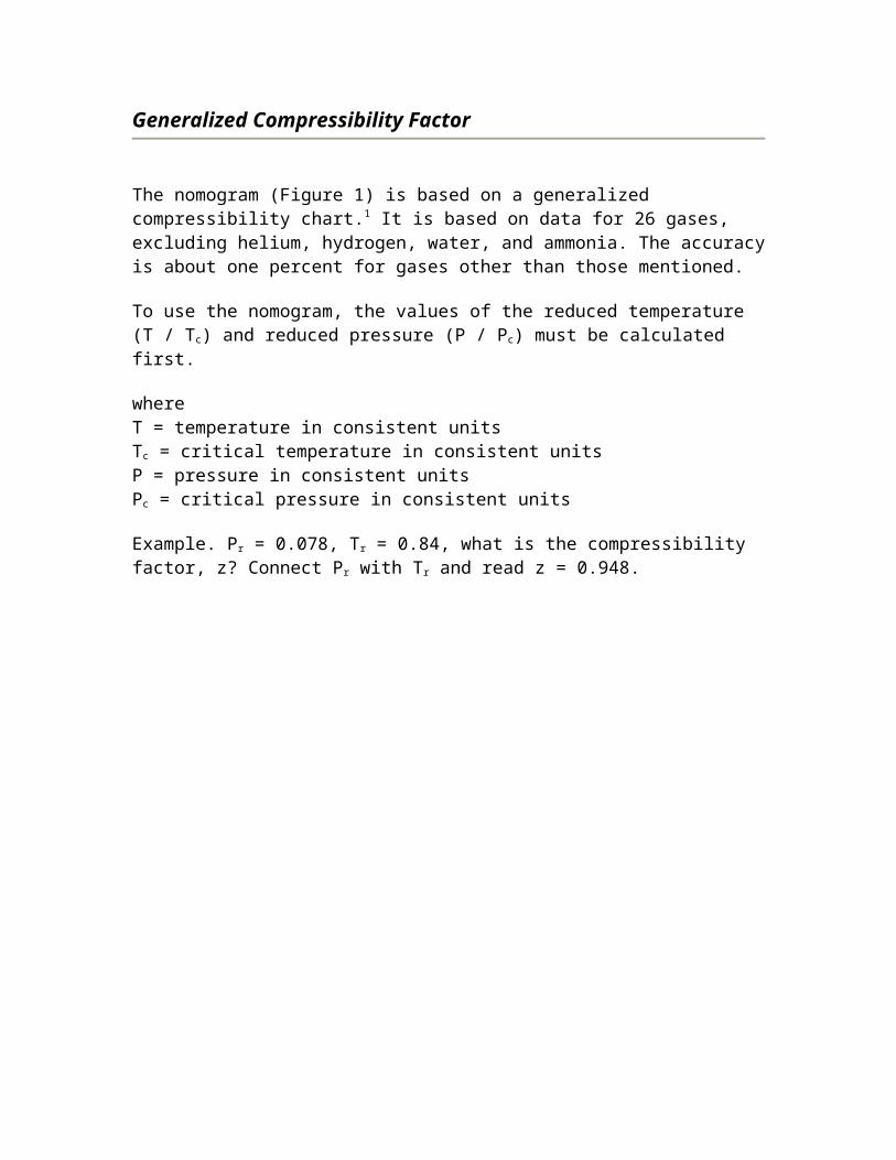
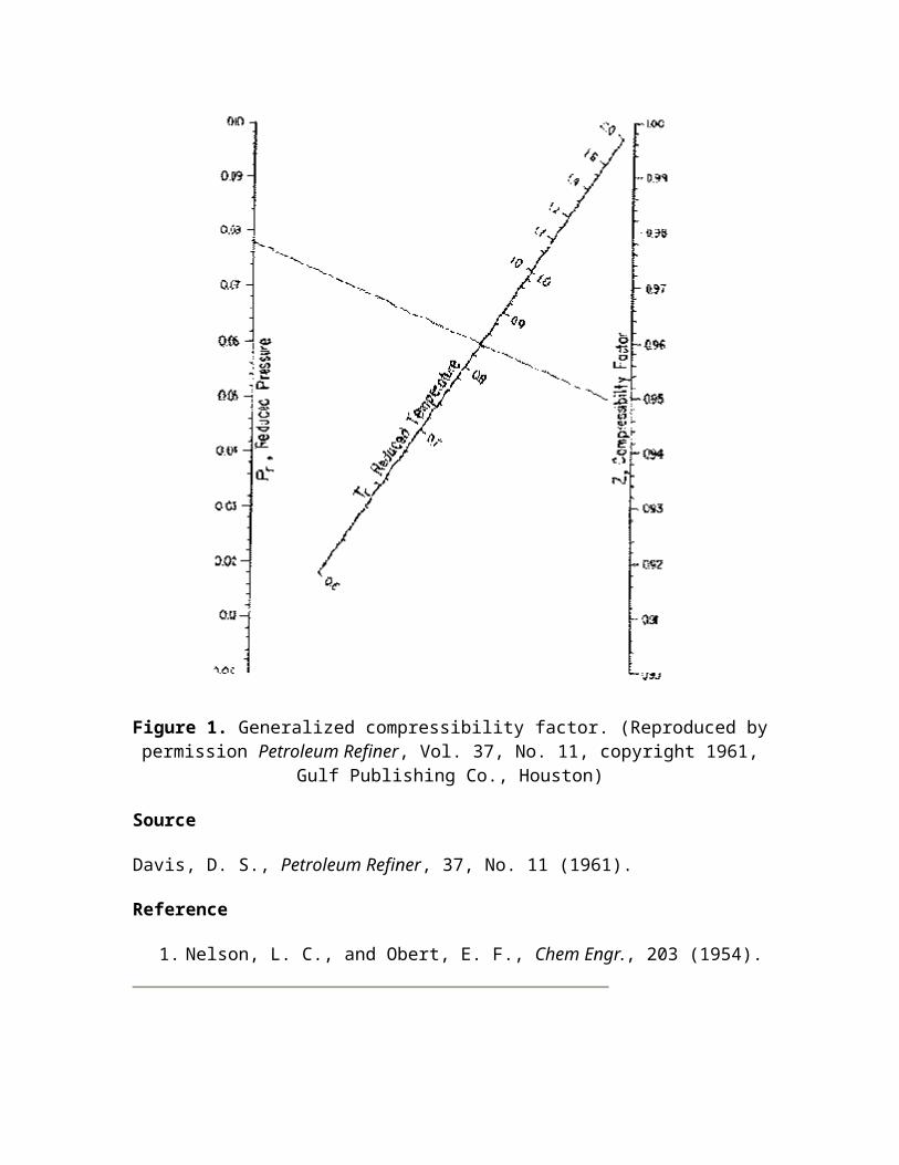
The nomogram (Figure 1) is based on a generalized compressibility chart.1 It is based on data for 26 gases, excluding helium, hydrogen, water, and ammonia. The accuracy is about one percent for gases other than those mentioned.
To use the nomogram, the values of the reduced temperature (T / Tc) and reduced pressure (P / Pc) must be calculated first.
whereT = temperature in consistent unitsTc = critical temperature in consistent unitsP = pressure in consistent unitsPc = critical pressure in consistent units
Example. Pr = 0.078, Tr = 0.84, what is the compressibility factor, z? Connect Pr with Tr and read z = 0.948.
Figure 1. Generalized compressibility factor. (Reproduced by permission Petroleum Refiner, Vol. 37, No. 11, copyright 1961, Gulf Publishing Co., Houston)
Source
Davis, D. S., Petroleum Refiner, 37, No. 11 (1961).
Reference
1. Nelson, L. C., and Obert, E. F., Chem Engr., 203 (1954).
Nomograph Aids in Diagnosing Compressor Cylinder Ills
B. W. Robertson, Tennessee Gas Pipeline Co., Houston
Compressor cylinders, like people, develop a fever when they are sick. Unlike humans, however, the normal temperature (suction) is not constant. The trick of using temperatures to determine malfunctions lies in determining the correct starting position.
To determine the starting position, it is necessary to know the true k value of the product being pumped. The k value may be obtained from measured pressures and temperatures according to the formula:
T2 / T1 = (P2 / P1) ((k - I) / k)
where the subfix 2 refers to discharge conditions and the 1 to suction, and all values of P and T are absolute.1
The preferred time to obtain this k would be with new equipment, or from data obtained when the equipment was new. The next best time would be with newly overhauled equipment. Lacking either of these data, any values of k must be considered to contain some malfunctions, and any unnecessarily high numbers should be discarded.
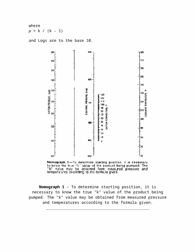
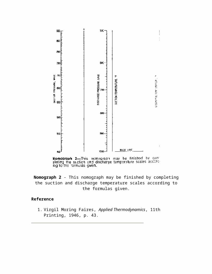
Nomograph 1 has been successfully used for a number of years, although it is slowly giving way to electronic equipment. Nomograph 2 may be finished by completing the suction and discharge temperature scales according to the following formulas:
Suction: ti = 8.557 p Log (ts + 460) - 23.135 p + 2.51 in. above base line
Discharge: t = 23.067 p Log (td + 460) - 62.65 p above base line
wherep = k / (k - 1)
and Logs are to the base 10.
Nomograph 1 - To determine starting position, it is necessary to know the true "k" value of the product being pumped. The "k" value may be obtained from measured pressure and
temperatures according to the formula given.
Nomograph 2 - This nomograph may be finished by completing the suction and discharge temperature scales according to the formulas given.
Reference
1. Virgil Moring Faires, Applied Thermodynamics, 11th Printing, 1946, p. 43.
Centrifugal Compressor Performance Calculations
Centrifugal compressors are versatile, compact, and generally used in the range of 1,000 to 100,000 inlet cubic ft per minute (ICFM) for process and pipe line compression applications.
Centrifugal compressor can use either a horizontal or a vertical split case. The type of case used will depend on the pressure rating with vertical split casings generally being used for the higher pressure applications. Flow arrangements include straight through, double flow, and side flow configurations.
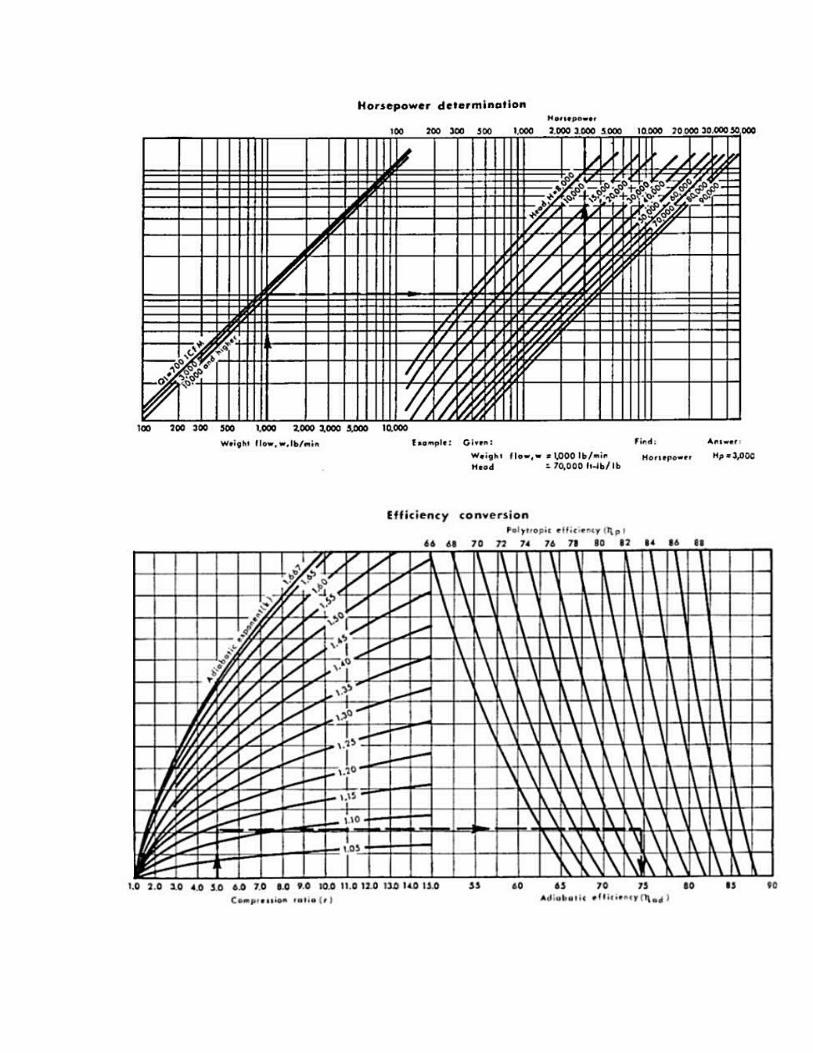
Centrifugal compressors may be evaluated using either the adiabatic or polytropic process method. An adiabatic process is one in which no heat transfer occurs. This doesn't imply a constant temperature, only that no heat is transferred into or out of the process system. Adiabatic is normally intended to mean adiabatic isentropic. A polytropic process is a variable-entropy process in which heat transfer can take place.
When the compressor is installed in the field, the power required from the driver will be the same whether the process is called adiabatic or polytropic during design. Therefore, the work input will be the same value for either process. It will be necessary to use corresponding values when making the calculations. When using adiabatic head, use polytropic efficiency. Polytropic calculations are easier to make even though the adiabatic approach appears to be simpler and quicker.
The polytropic approach offers two advantages over the adiabatic approach. The polytropic approach is independent of the thermodynamic state of the gas being compressed, whereas the adiabatic efficiency is a function of the pressure ratio and therefore is dependent upon the thermodynamic state of the gas.
If the design considers all processes to be polytropic, an impeller may be designed, its efficiency curve determined, and it can be applied without correction regardless of pressure, temperature, or molecular weight of the gas being compressed. Another advantage of the polytropic approach is that the sum of the polytropic heads for each stage of compression equals the total polytropic head required to get from state point 1 to state point 2. This is not true for adiabatic heads.
Sample Performance Calculations
Determine the compressor frame size, number of stages, rotational speed, power requirement, and discharge temperature required to compress 5,000 lbm/min of gas from 30 psia at 60°F to 100 psia. The gas mixture molar composition is as follows:
Ethane 5%Propane 80%n-Butane 15%
This is the same gas mixture that was considered in Sample Calculation 1, p. 214, where the gas properties were calculated. The properties of this mixture were determined to be as follows:
MW = 45.5Pc = 611 psiaTc = 676oRcp = 17.76k1 = 1.126Z1 = 0.955
Before proceeding with the compressor calculations, let's review the merits of using average values of Z and k in calculating the polytropic head.
The inlet compressibility must be used to determine the actual volume entering the compressor to approximate the size of the compressor and to communicate with the vendor via the data sheets. The maximum value of theta is of interest and will be at its maximum at the inlet to the compressor where the inlet compressibility occurs (although using the average compressibility will result in a conservative estimate of theta).
Compressibility will decrease as the gas is compressed. This would imply that using the inlet compressibility would be conservative since as the compressibility decreases, the head requirement also decreases. If the variation in compressibility is drastic, the polytropic head requirement calculated by using the inlet compressibility would be practically useless. Compressor manufacturers calculate the performance for each stage and use the inlet compressibility for each stage. An accurate approximation may be substituted for the stage-by-stage calculation by calculating the polytropic head for the overall section using the average compressibility. This technique results in over-estimating the first half of the impellers and underestimating the last half of the impellers, thereby calculating a polytropic head very near that calculated by the stage-by-stage technique.
Determine the inlet flow volume, Q1:
Q1 = m1[(Z1RT1) / (144P1)]
wherem = mass flowZ1 = inlet compressibility factorR = gas constant = 1,545/MWT1 = inlet temperature °RP1 = inlet pressure
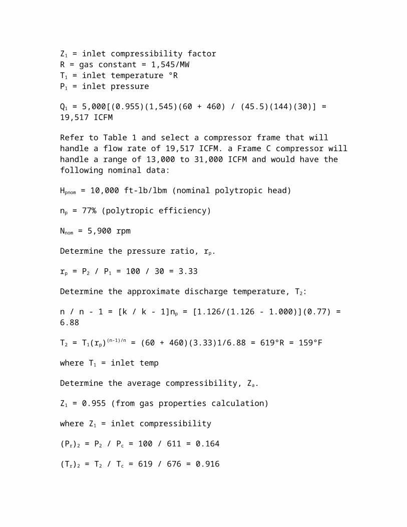
Q1 = 5,000[(0.955)(1,545)(60 + 460) / (45.5)(144)(30)] = 19,517 ICFM
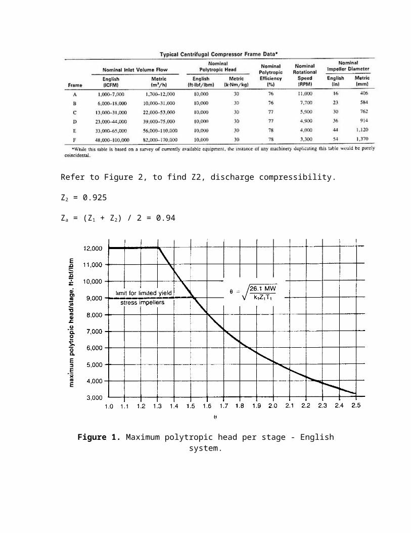
Refer to Table 1 and select a compressor frame that will handle a flow rate of 19,517 ICFM. a Frame C compressor will handle a range of 13,000 to 31,000 ICFM and would have the following nominal data:
Hpnom = 10,000 ft-lb/lbm (nominal polytropic head)
np = 77% (polytropic efficiency)
Nnom = 5,900 rpm
Determine the pressure ratio, rp.
rp = P2 / P1 = 100 / 30 = 3.33
Determine the approximate discharge temperature, T2:
n / n - 1 = [k / k - 1]np = [1.126/(1.126 - 1.000)](0.77) = 6.88
T2 = T1(rp)(n-1)/n = (60 + 460)(3.33)1/6.88 = 619°R = 159°F
where T1 = inlet temp
Determine the average compressibility, Za.
Z1 = 0.955 (from gas properties calculation)
where Z1 = inlet compressibility
(Pr)2 = P2 / Pc = 100 / 611 = 0.164
(Tr)2 = T2 / Tc = 619 / 676 = 0.916
Refer to Figure 2, to find Z2, discharge compressibility.
Z2 = 0.925
Za = (Z1 + Z2) / 2 = 0.94
Figure 1. Maximum polytropic head per stage - English system.
Determine average k-value. For simplicity, the inlet value of k will be used for this calculation. The polytropic head equation is insensitive to k-value (and therefore n-value) within the limits that k normally varies during compression. This is because any errors in the n / (n - 1) multiplier in the polytropic head equation tend to balance corresponding
errors in the (n - 1)/n exponent. Discharge temperature is very sensitive to k-value. Since the k-value normally decreases during compression, a discharge temperature calculated by using the inlet k-value will be conservative and the actual temperature may be several degrees higher - possibly as much as 25-50°F. Calculating the average k-value can be time-consuming, especially for mixtures containing several gases, since not only must the mol-weighted cp of the mixture be determined at the inlet temperature but also at the estimated discharge temperature.
The suggested approach is as follows:
1. If the k-value is felt to be highly variable, one pass should be made at estimating discharge temperature based on the inlet k-value; the average k-value should then be calculated using the estimated discharge temperature.
2. If the k-value is felt to be fairly constant, the inlet k-value can be used in the calculations.
3. If the k-value is felt to be highly variable, but sufficient time to calculate the average value is not available, the inlet k-value can be used (but be aware of the potential discrepancy in the calculated discharge temperature).
k1 = ka = 1.126
Determine average n / (n - 1) value from the average k-value. For the same reasons discussed above, use n/(n - 1) = 6.88.
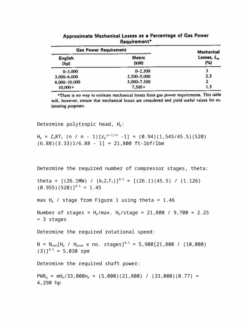
Determine polytropic head, Hp:
Hp = ZaRT1 (n / n - 1)[rp(n-1)/n -1] = (0.94)(1,545/45.5)(520)(6.88)(3.33)1/6.88 - 1] = 21,800
ft-lbf/lbm
Determine the required number of compressor stages, theta:
theta = [(26.1MW) / (k1Z1T1)]0.5 = [(26.1)(45.5) / (1.126)(0.955)(520)]0.5 = 1.45
max Hp / stage from Figure 1 using theta = 1.46
Number of stages = Hp/max. Hp/stage = 21,800 / 9,700 = 2.25 = 3 stages
Determine the required rotational speed:
N = Nnom[Hp / Hpnom x no. stages]0.5 = 5,900[21,800 / (10,000)(3)]0.5 = 5,030 rpm
Determine the required shaft power:
PWRg = mHp/33,000np = (5,000)(21,800) / (33,000)(0.77) = 4,290 hp
Mechanical losses (Lm) = 2.5% (from Table 2)Lm = (0.025)(4,290) = 107 hp
PWRs = PWRg + Lm = 4,290 + 107 = 4,397 hp
Determine the actual discharge temperature:
T2 = T1(rp)(n - 1)/n = 520(3.33)1/6.88 = 619°R = 159°F The discharge temperature calculated in the last step is the same as that calculated earlier only because of the decision to use the inlet k-value instead of the average k-value. Had the average k-value been used, the actual discharge temperature would have been lower.
Source
Estimating Centrifugal Compressor Performance, Gulf Publishing Company, Houston, Texas.
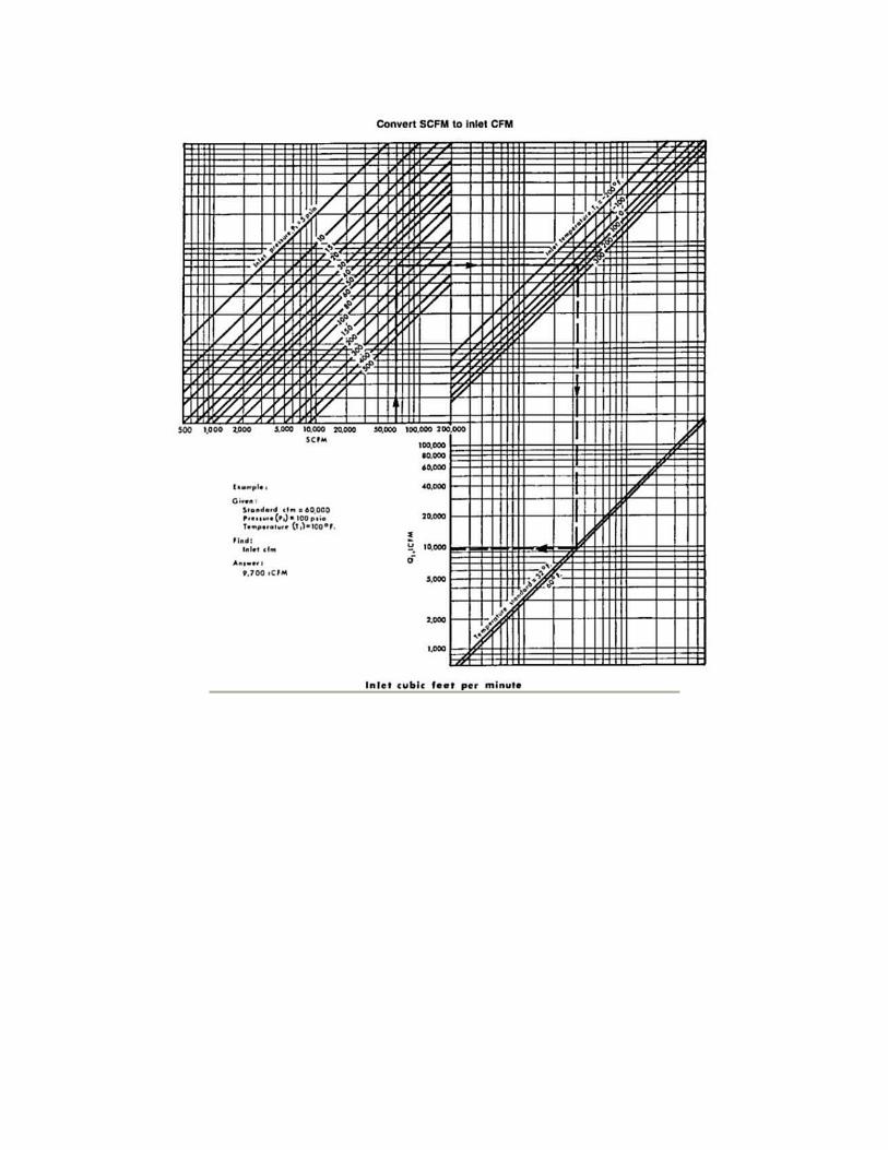
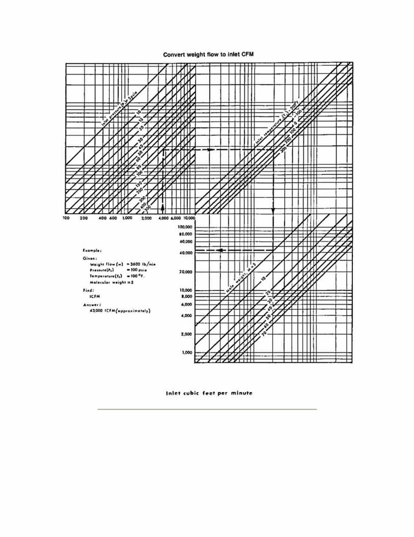
Nomographs for Estimating Compressor Performance*
* Reprinted by permission of Gas Processors Suppliers Association.
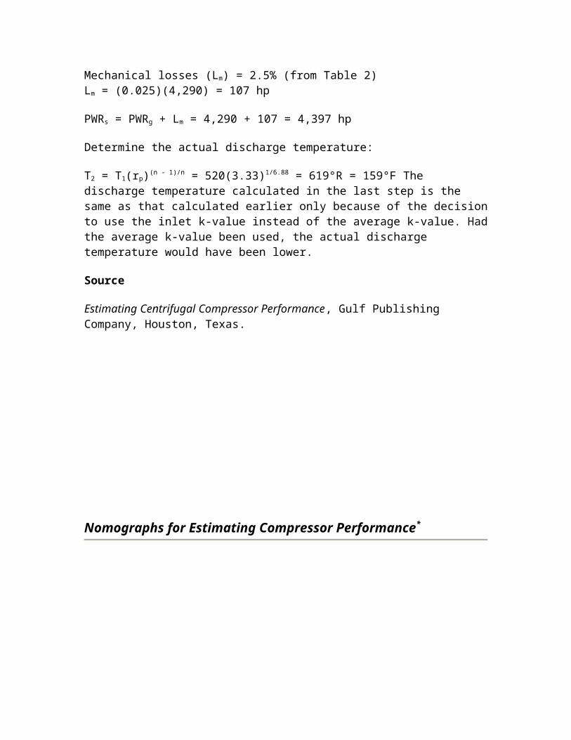
Estimate Hp Required to Compress Natural Gas
To estimate the horsepower to compress a million cubic ft of gas per day, use the following formula:
BHP/MMcfd = (R / R + RJ)x (5.16 + 124 Log R / 0.97 - 0.03 R)
whereR = compression ratio. Absolute discharge pressure divided by absolute suction pressureJ = supercompressibility factor - assumed 0.022 per 100 psia suction pressure
Example. How much horsepower should be installed to raise the pressure of 10 million cubic ft of gas per day from 185.3 psi to 985.3 psi?
This gives absolute pressures of 200 and 1,000.
then R = 1,000 / 200 = 5.0
Substituting in the formula:
BHP/MMcfd = (5.0 / 5.0 + 5 x 0.044) x (5.16 + 124 x .699 / .97 - .03 x 5) = 106.5 hp = BHP for 10 MMcfd = 1,065 hp
Where the suction pressure is about 400 psia, the brake horsepower per MMcfd can be read from the chart.
The above formula may be used to calculate horsepower requirements for various suction pressures and gas physical properties to plot a family of curves.
Estimate Compressor Hp Where Discharge Pressure is 1,000 psi
Rule. Use the following formula for reciprocating compressors where the compressor ratio is between 1.20 and 1.40.
Brake horsepower per MMcfd = 11 + (42.5)(R - 1.20)
R is compression ratio
Example. How much horsepower would have to be installed in a field compressor station where the discharge pressure would be 1,055 psia and suction would be 800 psia. The station must handle 10,000,000 cubic ft per day.
Solution. The compression ratio is
1,055 / 800 = 1.32
Substituting in the formula:
Brake horsepower per MMcfd = 11 + (42.5)(1.32 - 1.20) = 11 + 5.1 = 16.1 hp
The station would require 161 hp.
For a centrifugal compressor the formula would be:
Brake horsepower per MMcfd = 10 + 49 (R - 1.20)
Example. How much horsepower should be installed in centrifugal compressor station handling 100,000,000 cubic ft per day if the suction and discharge are the same as above?
Solution.
Brake horsepower per MMcfd = 10 + (49)(0.12) = 15.9
For 100 MMcfd the horsepower would be 1,590.
Calculate Brake Horsepower Required to Compress Gas
The approximate brake horsepower per million cubic ft of gas to be compressed may be obtained from this table. The total brake horsepower required is calculated by multiplying the total million cubic ft of gas compressed. In this estimation, gas volumes are expressed 14.7 psia and 60°F, specific gravity as 0.6 and K (the ratio of specific heats) is 1.27. The suction temperature is assumed as 80°F and interstage temperature as 130°F. The relative humidity of the air equals 100%.
Example. What is the brake horsepower required to compress 5.0 million cubic ft of gas from 200 psig suction pressure to 1,000 psig discharge pressure?
On the chart, read opposite a suction pressure of 200 and under a discharge pressure of 1,000 psig, that 100 brake horsepower is required per million cubic ft of gas compressed. Multiply 5.0 times 100 = 500 bhp.
How to Find the Size Fuel Gas Line for a Compressor Station
Suppose that an 8,000 hp compressor building is added to an existing compressor plant. What size fuel line should be run from the meter building 1,600 ft distant? Take-off pressure at the meter building will be 50 lb/in.2, and it is desirable to maintain 25 psi pressure on the large engine fuel header in the building. Assume that the gas is heated prior to expansion so that outlet temperature is 60°F.
The first step is to estimate the ultimate compressor-building horsepower. Assume in the foreseeable future the building will be expanded to 12,000 horsepower.
Next, estimate the fuel needs.
Q = 12,000 x 240 cubic ft per day = 2,880,000 cubic ft per day
To estimate the size line which must be run for fuel use this formula:
where Q = cubic ft of gas per 24 hoursd = pipe ID in in.1 = length of pipe in ftP1 = psi (abs) at starting pointP2 = psi (abs) at ending point
Using this formula, try several pipe diameters to determine the approximate size. For instance, if 6-in. ID pipe were used, the approximate flow could be found as follows:
Q = approximately 10,036,000 cubic ft per 24 hours
From this it is obvious that 6-in. pipe would be considerably oversized, especially if the fuel gas header in the compressor building is of large diameter.
Try substituting 4-in. diameter pipe in this formula to find an approximate size pipe.
Q = 2,973,700 cubic ft per 24 hours
Apparently 4-in. pipe will be correct size. To check it, use this more accurate formula which is based on the Weymouth:
Four-in. pipe is adequate
Q = 3,322,000 cubic ft per day
Note. This latter formula is based on the Weymouth formula, for gas with a specific gravity of 0.60 and a temperature of 60°F. For every 10° variation in temperature, the answer will be approximately 1% in error. For every 0.01 variation in specific gravity, the answer will be three fourth percent in error.
Estimate Engine Cooling Water Requirements
This equation can be used for calculating engine jacket water requirements as well as lube oil cooling water requirements:
GPM = (H x BHP) / 500Delta(t)
whereH = Heat dissipation in Btu's per BHP/hr. This will vary for different engines; where they are available, the manufacturer's values should be used. Otherwise, you will be safe in substituting the following values in the formula: For engines with water-cooled exhaust manifolds: Engine jacket water = 2,200 Btu's per BHP/hr. Lube oil cooling water = 600 Btu's per BHP/hr. For engines with dry type manifolds (so far as cooling water is concerned) use 1,500 Btu's/BHP/hr for the engine jackets and 650 Btu's/BHP/hr for lube oil cooling water requirements.
BHP = Brake Horsepower Hour
Delta(t) = Temperature differential across engine. Usually manufacturers recommend this not exceed 15oF; 10oF is preferable.
Example. Find the jacket water requirements for a 2,000 hp gas engine which has no water jacket around the exhaust manifold.
Solution.
GPM = (1,500 x 2,000) / (500 x 10)
GPM = 3,000,000 / 5,000 = 600 gallons per min
The lube oil cooling water requirements could be calculated in like manner.
Estimate Fuel Requirements for Internal Combustion Engines
When installing an internal combustion engine at a gathering station, a quick approximation of fuel consumptions could aid in selecting the type fuel used.
Using Natural Gas: Multiply the brake hp at drive by 11.5 to get cubic ft of gas per hour.
Using Butane: Multiply the brake hp at drive by 0.107 to get gallons of butane per hour.
Using Gasoline: Multiply the brake hp at drive by 0.112 to get gallons of gasoline per hour.
These approximations will give reasonably accurate figures under full load conditions.
Example. Internal combustion engine rated at 50 bhp - 3 types of fuel available.
Natural Gas: 50 x 11.5 = 575 cubic ft of gas per hour
Butane: 50 x 0.107 = 5.35 gallons of butane per hour
Gasoline: 50 x 0.112 = 5.60 gallons of gasoline per hour
Estimating Fuel Requirements for Compressor Installation
Rule. Multiply installation horsepower by 240 to obtain cubic ft of fuel gas required per day.
Example. Estimate the amount of fuel required to supply a 1,000-hp field compressor installation.
1,000 x 240 = 240 Mcfd
Related Documents