INTRODUCTION Now day electricity has become an essential part in everyone’s routine life Our whole day starts and with it is the backbone of the industrial and economical development of any country. Gandhinagar thermal power station situated at the right bank of river sabarmati is mainly constructed to meet with power need of North Gujarat and to improve the voltage condition of the Western Grid. Gandhinagar thermal power station unit 1 $ 2 are over 33 year old. The place where electricity is produced is called power station. The power station is classified according to fuel they use: 1. Diesel Power Station, 2. Thermal Power Station, 3. Hydro Power Station, 4. Nuclear Power Station, 5. Tidal Power Station, Mostly the power station used in India is a thermal power station. Hydro Power station needs the large amount of water at a desired potential head. While Nuclear Power station has a limitation that it requires a large amount of capital investment and power station of nuclear waste is still a problem. This is not at solved. So we have to depend upon the Thermal Power Plants, Which has the major part in total Electricity generator of India. In India we have many coal mines. Some of those places are Bihar Madhya Pradesh, etc. in India some coal is exporting from Foreign like Australia, South Africa, etc. the efficiency of the foreign coal is about 70 and

GANDHINAGAR THERMAL POWER PLANT
Nov 18, 2014
Welcome message from author
This document is posted to help you gain knowledge. Please leave a comment to let me know what you think about it! Share it to your friends and learn new things together.
Transcript
INTRODUCTION
Now day electricity has become an essential part in everyone’s routine life Our whole day starts and with it is the backbone of the industrial and economical development of any country. Gandhinagar thermal power station situated at the right bank of river sabarmati is mainly constructed to meet with power need of North Gujarat and to improve the voltage condition of the Western Grid.
Gandhinagar thermal power station unit 1 $ 2 are over 33 year old. The place where electricity is produced is called power station. The power station is classified according to fuel they use:
1. Diesel Power Station,2. Thermal Power Station,3. Hydro Power Station,4. Nuclear Power Station,5. Tidal Power Station,
Mostly the power station used in India is a thermal power station. Hydro Power station needs the large amount of water at a desired potential head. While Nuclear Power station has a limitation that it requires a large amount of capital investment and power station of nuclear waste is still a problem. This is not at solved.
So we have to depend upon the Thermal Power Plants, Which has the major part in total Electricity generator of India. In India we have many coal mines. Some of those places are Bihar Madhya Pradesh, etc. in India some coal is exporting from Foreign like Australia, South Africa, etc. the efficiency of the foreign coal is about 70 and that of India coal is about 35-40.Steam coal is best coal in every respect. So availability of fuel is more than other Hydro and Nuclear power plants.
Station has taken shape in two phases : Stage-1 comprising of two Units of 120 MW each for which the construction work had started in year 1974 and completed within a record period of 3.5 year and that too by saving of Rs.4/- crore budget provision of Rs.62.50/- crore. Since then this two unit of 120 MW each is working continuously without any major trouble.
Similarly Stage-2 consist of 3 Units of 210 MW each have also to installed capacity of this T.P.S. Unit of 210 MW were installed in 1990-91 and running at full load generation without any problem. It also enhances the capacity of T.P.S from 240 MW to 870 MW. The latest Units-5 which started it’s generation of electricity in 1998.
LAYOUT OF T.P.S


Unit Detail Installed Capacity Date of starting
1 120MW 13th March 1977
2 120MW 10th April 1977
3 210 MW 22th March 1990
4 210MW 20th July 1991
5 210MW 17th March 1998
Total 870 MW
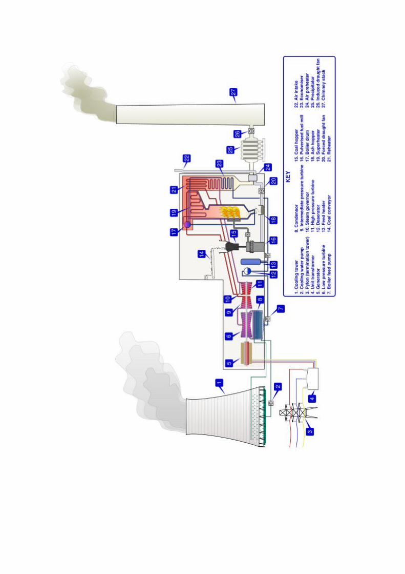
PROCESS OF T.P.S
The transportation of coal from the coal-mine to the power plant is done by Indian railway for oval handling the wagon carrying the coal is fitted upside down by tippler mechanism and coal falls in the underground hopper from the tippler hopper. The coal is supplied to crusher house with the help of conveyers, in the crusher house the coal is crushed and sized. The crushed coal coming out of the crusher us the supplied to coal bunker with the help of a conveyor belt. Crushed coal is feed to the pulverize through feeder. Hot air is passed through the feeder to dry the coal before being feed to the pulverize. Coal is carried from the bowl mill with the help of air force. This further causes coal through sort combustion chamber.
The hot gases produced due to the combustion of coal Passover the water super heater, Re-heater, Economizer, Air pre-heater, etc., then rejected to the atmosphere through the chimney. An ID fan is produced at the base of a chimney to suck the hot fuel. Chimney fuel gases also pass through ESP that is type of dust collector.
The heat in the fuel gases us utilized while passing through the system. It gives latent heat to the feed water passing through the water tube and so the water gets evaporated. While it is passing over super heater and re-heater the hot fire gas's superheat the wet steam which is produced due to evaporation of water in drum and thus increase the plant efficiency.
The feed water is pumped to water drum through the LP heater, HP heater and then economizer with the help of the feed pump. In the economizer water is preheated and it gets to sensible heal by using the gases. The water gets evaporated in the drum and steam is produced, which is wet steam. Wet steam is dried and superheated by super heater. Then it is supplied to the turbine. First the steam is supplied to the HP turbine, The high velocity steam rotates the rotor blade and thus turbine shaft.
The steam from the HP turbine is supplied to IP and then low pressure steam is supplied to the LP turbine. In between these parts the steam is reheated and also supplied LP & HP feed water heater. The excess steam from turbine is condensed in condenser by circulation of cooling water. Due to condensation of steam cooling water gets heated as it extracts the heat from steam. The cooling water is further cooled down in cooling water is further recycled in condenser with CW pump.
The DM water produced in condenser fins collected in the hot well at the bottom of the condenser. The water from hot well passed through the LP feed heater than the feed water is passing through detractor to remove gasses from the water,

which cause corrosion. Cooling tower may be natural or artificial further cools down the cooling water in the cooling tower the hot water is spayed from height and thus exposing the removed to the atmosphere and the water become cool and collected in the pond. This cooling tower is further recycled in condenser with CW pump.
Then through BFP water is passed to economizer through HPH and thus water recycled to the boiler drum, Then further the steam produced and which rotates the turbine. The turbine rotates the alternator connected to the same shaft and at the way corrosion from kinetic energy of steam to mechanical energy and then finally to the electric energy is done.

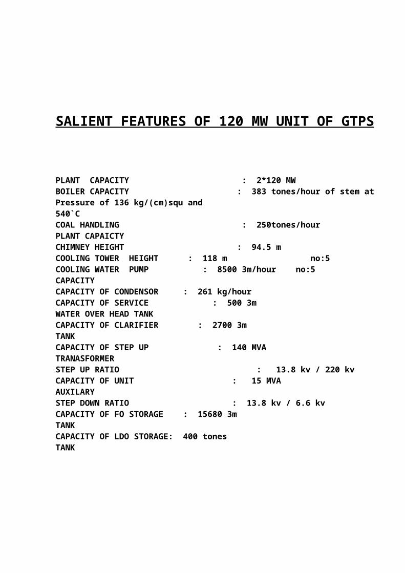
SALIENT FEATURES OF 120 MW UNIT OF GTPS
PLANT CAPACITY : 2*120 MWBOILER CAPACITY : 383 tones/hour of stem atPressure of 136 kg/(cm)squ and540`CCOAL HANDLING : 250tones/hourPLANT CAPAICTYCHIMNEY HEIGHT : 94.5 mCOOLING TOWER HEIGHT : 118 m no:5COOLING WATER PUMP : 8500 3m/hour no:5CAPACITYCAPACITY OF CONDENSOR : 261 kg/hourCAPACITY OF SERVICE : 500 3mWATER OVER HEAD TANKCAPACITY OF CLARIFIER : 2700 3mTANKCAPACITY OF STEP UP : 140 MVATRANASFORMERSTEP UP RATIO : 13.8 kv / 220 kvCAPACITY OF UNIT : 15 MVAAUXILARYSTEP DOWN RATIO : 13.8 kv / 6.6 kvCAPACITY OF FO STORAGE : 15680 3mTANKCAPACITY OF LDO STORAGE: 400 tonesTANK

SALIENT FEATURES OF 210 MW UNIT OF GTPS
PLANT CAPACITY : 3*210MWBOILER CAPACITY : 690 tones/hour of stem atPressure of 136 kg/(cm)squ and 540`CCOAL HANDLING : 1000 tones/hourPLANT CAPAICTYCHIMNEY HEIGHT : 120 m for 3 & 4 and 220 m for unit 5COOLING TOWER HEIGHT : 121 m for 3 & 4 and 131 m for unit 5COOLING TOWER CAPACITY : 33000 3m / hrCOOLING WATER PUMP : 16,500 3m/hour no:3CAPACITYCAPACITY OF CONDENSOR : 700 t/hourCAPACITY OF SERVICE : 150 3mWATER OVER HEAD TANKCAPACITY OF CLARIFIER : 2700 3mTANKCAPACITY OF STEP UP : 140 MVATRANASFORMERSTEP UP RATIO : 15.7 kv / 220 kvCAPACITY OF UNIT : 15 MVAAUXILARYSTEP DOWN RATIO : 13.8 kv / 6.6 kvCAPACITY OF FO STORAGE : 2*15680 3mTANKCAPACITY OF LDO STORAGE : 400 tonesTANKDCAPACITY OF : 160 T / hrASH HANDALING

OIL PLANT
Oil is the auxiliary or supporting fuel to five initial heats to the boiler before giving the supply of the coal to the boiler. There are two type of oil used in GTPS.
1. LDO (light diesel oil)2. RFO (residual fuel oil)
HOW LDO AND FO ARE SUPPLIED TO THE BOILER?
L.D.O (LIGHT DIESEL OIL)
It comes through tankers and store in the main LDO storage tank. Now, by using centrifugal pump, it is taken from the tank and supplied in the boiler.
R.F.O (RESIDUAL FUAL OIL)
It comes through railway wagons. As FO is very thick so we have to provide some amount of heat to convert the thick oil into liquid from of oil for tripping action and the taken into the FO storage tank and it is taken into boiler through the pump.
BURNIG OF LDO AND RFO:
From the bottom side of the burning zone of boiler, LDO & RFO are entered in to the boiler and fired to give heat to boilerFor firing of LDO. LDO + Air are entered and ignited through igniter. After ignition of LDO, RFO + Steam and ignited through igniter. Igniter fan is provided to give some air for heating purpose of LDO and RFO.

BOILER SECTION

►Boiler is the heart of the thermal power plant. The boiler ids mounted properly and properly with suitable accessories produces steam of the desired quality and quantity. The boiler in the especially in GSECL is
1. High pressure2. High temperature3. Tangentially fire type4. Water tube type5. Pulverized fuel type6. Balanced draft type7. Vertical and pendent type boiler
MAIN ACCESSORIES OF BOILER ARE AS UNDER:-
1. Boiler drum2. Super heater3. Reheater4. Economizer5. Primary air heater6. Secondary heater
BOILER DRUM:
► The boiler drum is made of heavy duty steel plate. The inlet water to boiler drum is coming from economizer which has increase up to the temperature 250`C. Fore down comers are attached to a single ring header, which is at bottom of the furnace. This ring header is extended upwards as.
►These tubes are attached with the wall of the furnace and finnaly they reach to the boiler drum. The water the boiler drum is through down comers towards the ring headers. Then their water goes into water where it is converted in to steam. So, both water and steam are present inside the water tube walls.
►Then this mixture of water steam goes to the boiler drum through riser tubes. Here steam is separated from water by steam repeater. According to the difference in densities of water by steam , the natural circulation occurs in this path . Here the steam separated from water is collected the drum and drawn towards the super heater.

SUPER HEATER
►The steam separated from water in boiler drum never dry. This causes the corrosion of blades. For reason the steam should the steam should be dry it is provided by super heating inside the super heater.
►These rises the temperature steam up to 540`C super heated steam are placed in the path of the flue gases. Here, super heater are found inside the boiler drum namely;
1. Low temperature super heater2. De-super heater3. Platen super heater4. Final or Pendent super heater
►First of all, the steam from the boiler drum enters into the low temperature super heater. Then steam passes to plane super heater through desuperheater and finnaly it reaches to final super heater where it temperature is taken up to 540`C and the pressure of 135 kg/cm2, It is given to the high pressure turbine.
REHEATER
►They are similar to super heater modern utility boiler for boosting plate efficiency. Reaheater obtain the used steam from the pressure turbine at a pressure lower than the boiler pressure and which is nearly 34.1 kg/cm2.
►The low pressure steam passing through reheater is heated to 540◦ and then it is introduced in the I.P turbine. The steam entering the I.P turbine has pressure of 32.1 kg/cm2.
ECONOMIZER
►The purpose of economizer is to preheat the boiler feed water before it is introduced in the boiler drum and there by recover some of the from the flue gases leaving the boiler.
►Each section of the economizer is composed of a number of parallel tube circuits. All the tube circuit originates from the inlet header and discharge in to the outlet header through the economizer immediate headers.
►The external surface of the tubes is kept dirt free since it is a bad conductor of heat. This is necessary to increase the efficiency of the economizer inlet header via the boiler feed discharge.The feed water is in such a way that counter direction (upward) than that of flue gases. thereby most efficiency heat transfer is accomplished from the outlet via the economizer outlet lines the feed water is let to drum .the outlet temperature of water coming from economizer is nearly 250°C.
PRIMARY AIR PREHEATER
►In order to have an efficient combustion in the boiler the coal should be somewhat before it is fired. To achieve this purpose the primary air, this is heated in primary air heater.
►The primary air heater is placed in the path of flue gases, and is heated in between economizer and secondary air heater in the boiler. This is order to reclaim the heat from the outgoing flue gases. This is partially recovered in economizer. Primary air fans provided the primary air here.
SECONDARY AIR HEATER►The secondary air heater, which is used combustion purpose should be not enough for and efficient combustion in the furnace if the boiler. The secondary air heater servers this purpose.
►It is also installed in the path of flue gases in order to reclaim the remaining heat from the flue gases. This is the last heat recovery unit. The hot flue gases leaving secondary air heater pass a temperature of 150°C.

CONSTRACTION AND WORKING OF BOILER
►Boiler is handling type, tangentially fired. It is constructed by using number of tubes in which steam is generated due to firing of coal. Boiler is hanging from the toper side through some rigid and flexible supports.
►At the bottom portion of boiler, seal drum is given in which water is feed which is used to prevent entering of air and other substances in boiler. At the outer periphery of boiler, water wall tubes are provided which is used for cooling purpose o boiler heat absorption.
►In boiler, 5 cm of water pressure is created as having the cause of flue gas cannot come outside so such type of vacuum is provided.
►Now, boiler is ignited in different tubers. Each boiler has 6 coal mills and 6 tubers. LDO and FO are supplied in between two tubers. And coal is feed into the boiler from four corners of the boiler through nozzles which is in pulverized from and it will constitute tangentially firing zone. It is burnt by giving initial heating by LDO &FO.
►Now water enters into the boiler tubes through BFP. Due to the flue gas water is heated and collected in the boiler drum. Here through turbo-separator, steam is separated from the water and taken to the HP turbine to rotate the rotor and the power generation.
►After burning of fuel, flue gases are produced and pass through the super heater and reheated, economizer, air preheater, ESP and finally to the suction of ID fan and exhausted in atmosphere through chimney.
TURBINE SECTION
TURBINE
INTRODUCTION:
►Turbine is the main device to generate electricity. Miens this device converts steam pressure into mechanical energy and by this energy, generator produce electricity.
WORKING:
►Tubes are mainly divided into 3 parts named as
1. High pressure turbine2. Inter mediate pressure turbine3. Low pressure turbine
►One other parts also connected with the turbine is main part called generator. These all parts of the turbine shares one common rotor.
►Some coming from boilers enters HP turbine first. It has the temperature of 540°C and pressure of 155 kg/cm2. It turned the HP turbine and it loses its pressure and the temperature and then steam is taken away from HP turbine and sent back to the boiler for reheating is called CRH (cool reheating). This steam enters IP turbine and rotates it. After taken away and directly enters the LP turbine. It rotates the turbine; due to heat it may increase the size or turbine rotor so far cooling purpose oil id provided.
TURBINE DATA:
TYPE:Horizontal, tandem, compounded, reheate impulse turbine, stop valve steam condition 126.55kg/cm2 and 538°C.
SPEED:3000rpm, No of extraction is 6
NO OF STAGE:HP cylinder 11IP cylinder 13LP cylinder 6, double flow
LUBICATION OF TURBINE:
►After knowing about the steam rotates the turbine with very high speed as 3000rpm, so in bearings some lubrication oil is used from main tank through three different pumps.
1. MOP ( Main Oil Pump )2. AOP ( auxiliary Pump )3. JOP ( Jet Oil Pump )
►MOP and AOP are used for the distribution of oil fro lubricating purpose of the speed 3000rpm and less then 3000rpm respectively.
►JOP is used to lift the rotor by providing the pressure of jet oil pump.
BARRING GEAR MECHANISM:
►Generally, our turbine with 3000rpm. But if any problem of steam consumption, and if we cannot supply the steam to the turbine we cannot immediately stop the turbine. As the having the possibility of bending of rotor, as per the reduction of speed from 3000 to 0rpm, our rotor rotates with barring gear which suddenly not decrease the rpm of rotor.
►As given above baring gear is also used to start the rotor of turbine
►In stage-1, barring gear is motor operated
►In stage-2, it is hydraulic
GENERATOR:
►Here, generator is connected with turbine. As the turbine with 3000rpm, generator rotor is also rotates as it connected with turbine. Rotor rotates in stator and cut the flux lines around the coil and thus the electricity generated. For cooling of generator, H 2
gas is used.

ASH HANDLING&
DUST COLLECTION

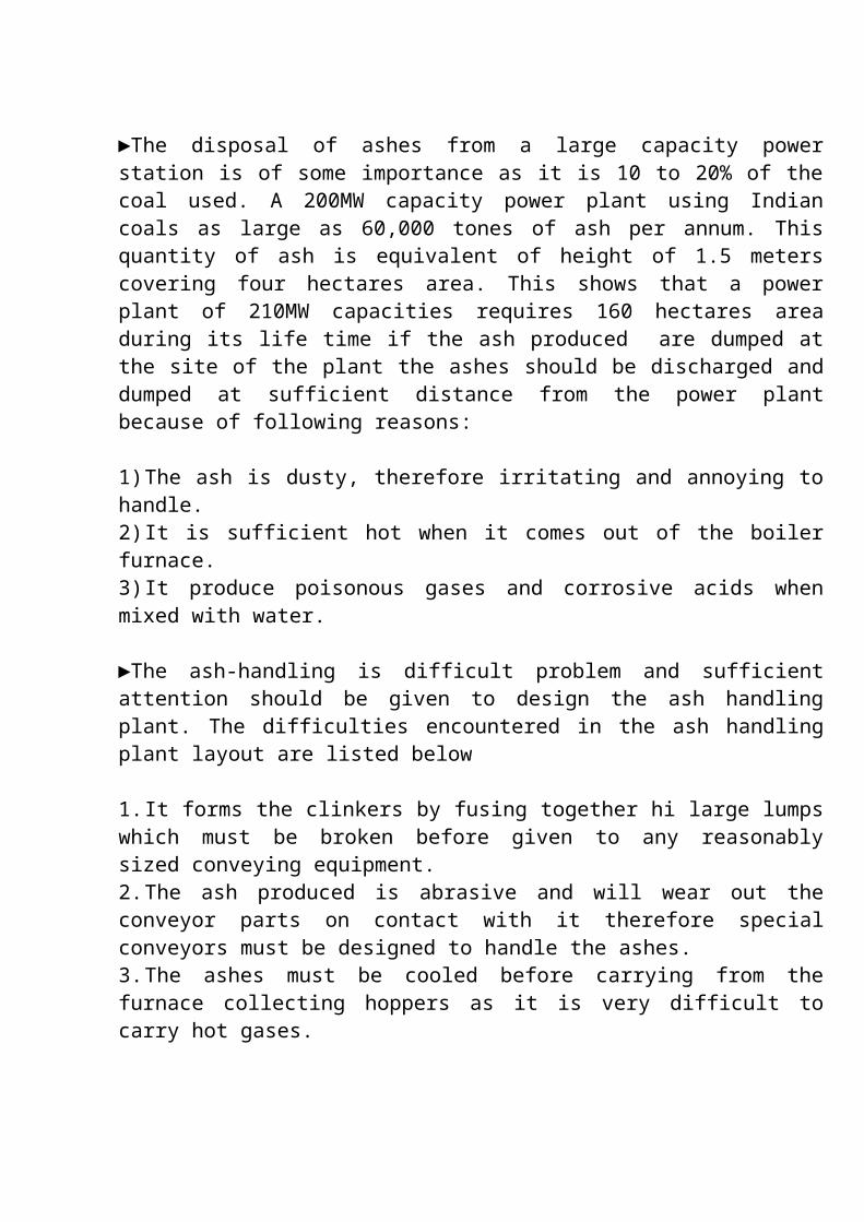
►The disposal of ashes from a large capacity power station is of some importance as it is 10 to 20% of the coal used. A 200MW capacity power plant using Indian coals as large as 60,000 tones of ash per annum. This quantity of ash is equivalent of height of 1.5 meters covering four hectares area. This shows that a power plant of 210MW capacities requires 160 hectares area during its life time if the ash produced are dumped at the site of the plant the ashes should be discharged and dumped at sufficient distance from the power plant because of following reasons:
1) The ash is dusty, therefore irritating and annoying to handle.2) It is sufficient hot when it comes out of the boiler furnace.3) It produce poisonous gases and corrosive acids when mixed with water.
►The ash-handling is difficult problem and sufficient attention should be given to design the ash handling plant. The difficulties encountered in the ash handling plant layout are listed below
1. It forms the clinkers by fusing together hi large lumps which must be broken before given to any reasonably sized conveying equipment.2. The ash produced is abrasive and will wear out the conveyor parts on contact with it therefore special conveyors must be designed to handle the ashes.3. The ashes must be cooled before carrying from the furnace collecting hoppers as it is very difficult to carry hot gases.
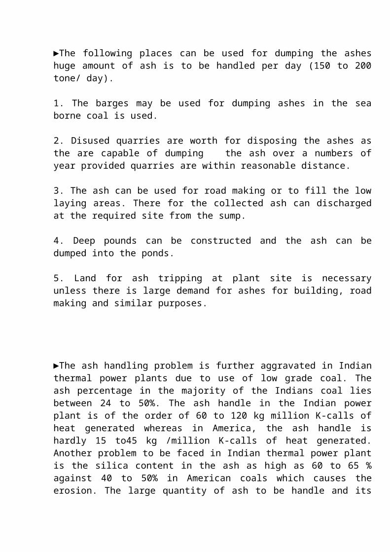
►The following places can be used for dumping the ashes huge amount of ash is to be handled per day (150 to 200 tone/ day).
1. The barges may be used for dumping ashes in the sea borne coal is used.
2. Disused quarries are worth for disposing the ashes as the are capable of dumping the ash over a numbers of year provided quarries are within reasonable distance.
3. The ash can be used for road making or to fill the low laying areas. There for the collected ash can discharged at the required site from the sump.
4. Deep pounds can be constructed and the ash can be dumped into the ponds.
5. Land for ash tripping at plant site is necessary unless there is large demand for ashes for building, road making and similar purposes.

►The ash handling problem is further aggravated in Indian thermal power plants due to use of low grade coal. The ash percentage in the majority of the Indians coal lies between 24 to 50%. The ash handle in the Indian power plant is of the order of 60 to 120 kg million K-calls of heat generated whereas in America, the ash handle is hardly 15 to45 kg /million K-calls of heat generated. Another problem to be faced in Indian thermal power plant is the silica content in the ash as high as 60 to 65 % against 40 to 50% in American coals which causes the erosion. The large quantity of ash to be handle and its erosive characteristics are posing a big problem today for the design of ash handling system and boiler in India.
►Any ash handling system comprises the following operations
1. To remove the ashes from the ash furnace ash hopper2. To convey the ashes from furnace ash-hopper to a storage or fill with the help of conveyors.3. To dispose the ashes from the storage
ASH HANDLING SYSTEM► The ever increasing capacities of units together with their ability to use low grade high ash content coals have been responsible for the development of modern ash handling systems.
► The general layout of the components used in modern ash handling and dust collection plan is shown in figure.
► The modern ash handling systems are mainly classified into four group:1) Mechanical handling system2) Hydraulic system3) Pneumatic (silo) system4) Steam jet system

DM WATER PLANT

DM WATER PLANT
►DM water is an essential thing for boiler. As we take the water directly from Natmada canal and bore well. Water contains so many impurities as having dissolved gases and salts as well as minerals and undisclosed and suspended solid materials.
►Due to these impurities it creates certain effects like scale formation in boiler tubes, corrosion priming and carryover. As per having calcium and magnesium bicarbonates, due to heat it will convert into carbonates in soft sludge. So we have to purify this water by water softening DM plant. All the detailed process is shown in figure and expressed below.
►First of all make up water or raw water which is taken from the NARMADA canal and bowels enters into the big sump of DM plants and gone to the PSF(Placific sand filter). In which different layers of sand stones are given here. Now here big and undisclosed particles removed from water.
►Then water enters into the portable sump through the centrifugal pump from PSF. Then it goes to the activation carbon filter. Here impurities of carbon particles are removed.
►Now to remove different dissolved ions or particles from water we have the process named as DEMINERALIZING CATEXER-ANEXER water treatment system. Her first of all water enters into the cat ions exchange in which different resins are used to remove the impurities of negative ions like chloride, florid ions.
►Then water enters into the degasser tower in which carbon dioxide is removed from water. This tower is situated at a somewhat higher elevation to the cat ion exchange.
►From degasser tower water enters into the ion exchange. Here different resins are used to remove positive or an ion like calcium and magnesium ions.
►If any impurity is there in water after the process of caterer, annexure each other and makes water which in the ash handling system of hydraulic type by giving high pressure water to the ash making slurry of ash. So we have to purify this water softening plant.
►Exchanger system water collects in the fixed bed. Here both of resins are presents to remove if having any impurity of cat ion. Now water is pure 100 of dissolved

particles and it is taken to the boiler drum through a feed pump. Now wastage of cat ion and an ion exchange is collected into the N-pit. In which cat ion and ions which are separated from their corresponding exchangers mixes with each other. Thus they neutralize.
PROCESS CYCLES
WATER & STEAM CYCLE
►For generating the power to about 870 MW we need lot of water and steam is arranged from river sabarmati from three French wells. Each well is having three pumps of 200 KW each. The water pumped , mainly divides in to three parts.
1. To overload tank to meet with colony requirements2. For the make up cooling water system3. Major parts are stores in a big sump
►At the sump primary alum chlorine treatment is given to the water and then the water is taken to D.M plant for purifying the water. The D.M water then comes to CST (condensate storage tanks) situated very near top the boiler And thereafter making up the water losses.
►Initially the boiler drum is filled up with water is initially heated up and drum. From upper half of the boiler drum the steam goes to 14 super heaters.
►This super heated steam, has a pressure of 155 kg/cm2 and temperature of 540°C . This steam is mainly divided in to three parts (HP/IP/LP). The main steam rolls the HP turbine taken back again to reheaters in the boiler for reheating.
►This steam so heated in reheaters is known as HRH (hot reheat) steam, comes to IP turbine and from here it goes to the LP turbine. From LP turbine the steam is dumped to condenser to convert in to water. Water so converted steam in the condenser is collected in the hot well.
►From the hot well the water is pumped to various heater and finally reaches in to desecrator. In the desecrator the dissolved air is separated out and the water collected at bottom of the desecrator comes to the suction side of feed pumps boiler feed pump


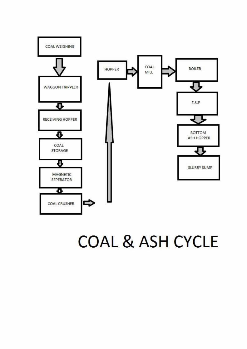
COAL AND ASH CYCLE
►As already mentioned earlier for forming steam we have to burn oil and coal in the boiler furnace with help of primary and secondary air. After coal burning smoke is formed. This is known as flue gases. These flue gases are coming out from the boiler contains co2 so2 and huge quantity of ash particles as the quality of the coal what we are getting is of very inferior quality and contains about 40% ashes.
►As already mentioned in coal cycle daily for generating power to about 660 MW we need coal to about 8500 MT. And as just mentioned the ash contained are about 40% we have to separate the ash of about 2600 MT from the gases coming out from the boiler . From the boiler. From the boiler 1st the flue gases are coming to economizer. Here the feed water is heated up by condition method. Thereafter the flue gases are coming to air preheaters A & B. Here the flue gases temperature is utilized for heating primary and secondary air.
►After this from outlet/discharge side the flue gases enters to ESP (Electrostatic Precipitator). Here the ash particles contained in the flue gases are separated out and pure smoke with the help of I.D fans is thrown to atmosphere through chimney.
►The ash particles separated out in ESP falls in the bottom hoppers of ESP with the help of rapping mechanism. From the hoppers the ash collected is brought to the ash plant with the help of vacuum & here in ash plant the ash is mixed with water and the slurry is formed. This slurry is than pumped to big dykes through pipeline. When one dyke is filled up the pipelines are shifted to other dykes. The dyke filled up earlier is left open for drying out the moisture.
►After some time the layer of about one to one and half feet is spread over the dykes and on this upper surface of ash dyke plantation is done.


AIR CYCLE

1. PRIMARY AIR:-
► This air is sucks from the atmosphere by primary air fans. These fans may be two in numbers or individually one for each coal mill. The air sucks by fans goes to 2/3 portion of the airpreheater . After being heated up at preheater air comes to coal mills. From here the mixture of coal and air goes to boiler furnace. In this way the primary air has two functions.
1. Being used as carrier of coal mill up to boiler.2. After reaching the boiler furnace it takes part in combustion
2. SECONDARY AIR:-
►For burning anything we needs air in the furnace we need air to burn oil and coal to heat up water and in turn steam to run the turbine. For air we normally have to FD fanes. This fans are suck air from the atmosphere.
►The air is so sucked that is passes through SCAPH (steam coal air preheater) for primary heating. Then air passed through air preheater. Here the air is heated with the help of flue gases. After the air being heated at air preheater it comes to wind bag and there after goes to boiler for burning the fuel.

OTHER DETAILS

CONDENSOR
►From LP turbine, steam enters into the condenser for cooing purpose. Here surface type of condenser is used. In this type of condenser is used, cooling water and exhaust steam do not come in water. Due to the cooling water vacuum in condenser to condensate the steam. Now condensate steam is collected in Hot well.
HOT WELL
►In hot well condensate water enters. Here the water is collected as boiler water as water has very low pressure and temperature is 40 to 45`C.
DEAERATOR
►It works on thermo mechanical principal as well as Daltons low of partial pressure. As per entering water into deaerator, having the pressure of 7 kg/cm2 it is constructed on toper side to give net positive suction head to the water before entering BFP.
►The water which is to be dearator is first passes through the condenser where it is preheated by the gas and air is liberated from the water and the part of steam carried with gases. Then it is pass through the spray distributor and it falls over an entire from of heating tray of uniform shower.
►The water from heating trace falls over the air separating trays and then it passed into storage space of the dearator. The released air and part of the steam I vented passing over the condenser. This condenser reduces the steam consumption and economizer the dearating process.
BOILER FEED PUMP (BFP)BFP is divided into two parts. First is booster pump and second is main BFP. Booster pump is used to increase the pressure of water which is coming out from the deaerator storage tank up to 18 bars. Then this water is used as suction of main BFD. It raises the pressure of water up to 190 bars. It supplies this water to the boiler drum after passing through HP heater and economizer.

CONDRNSATE EXTRECTION PUMP (CEP)
►CEP is used to increase the pressure of condensate water is coming from the hot well. It supplies this condensate water to the deaetator after passing through the LP heater.
LOW PRESSURE HEATER
►It is provide for primary heating of water. It uses the steam which is talen from the LP turbine for heating purpose.
HIGH PRESSURE HEATER
►It is used to give some additional heating to the water which is coming from the BFP. HP heater uses the steam which is coming from either IP turbine or CRH for heating purpose.


COOLING WATER
SYSTEM

COOLING TOWER
As mentioned above after rolling turbine (LP) steam is dumped to condenser for converting into water. The condenser is mainly divided in for parts e.g. left, right, top and bottom. In the condenser there are thousands of steel tubes and gets cooled down to water. Where as cold water coming from the bottom of the cooling tower duly pumped by CW pumps comes inside the steel tubes of the condenser and heated up. This hot water inside the condenser tube from bottom left and right side of the condenser comes to top R & L side of the condenser and than taking to the cooling tower for getting cooling. The hot water falls from the height of about 8 Mts duly separated into fine showers and gets cooled down. The cooling effect is due to very high height of the cooling tower which creates a natural draft (air circulation). At the top of the cooling tower air pressure remains low whereas at bottom of the cooling tower it is high air pressure. Thus air blow/flows from bottom to top side of the cooling tower and water falls from the top to bottom and gets cooled down by coming in contact of air circulation. The loss in cooling water is made up by French well water mentioned initially in water/steam cycle
Two basic types of cooling tower are commonly used;
1) Evaporative cooling tower2) Non evaporative cooling tower
One transfers the heat from warmer water to cooler air by an evaporation heat transfer process and is known as the evaporative or cooling tower.
Evaporation cooling tower are classified according to the means employed for production air circulation through them atmosphere, natural draft and mechanical draft. The other transfer the heat from wormer water to cooler air by sensible heat transfer process is known as nonvaporative or dry cooling tower.
Non evaporative cooling tower are classified as air cooled condenser and as air cooled heat exchanger, and are further classified by the means used for production air circulation through them. These two basic type are sometimes combined, with the two cooling processes generally used in parallel or separately and are known as wet dry cooling towers.

SHOOT BLOWER & LONG RETRACTABLE SHOOT BLOWER
These are the special accessories of boiler which is used to remove deposited ash from the outer surface of boiler tubes which is harmful for boiler tubes as it createa erosion of boiler tubes.
Same as, Ash can also be depleted on the outer surface of super heater,reheater and economizer tubes doing the same problem of erosion. So in LRSB and suit blower,from PRDS auxiliary steam is entered and sprinkles on tubes to remove the ash. This operation is like drip irrigation types. So as per steam is affected to the tubes and removes the ash. There are total 52 suit blowers provided
FANS USE IN BOILER CYCLE
1. FORCED DRAUGHT FAN
It is used to provide secondary air to boiler and initially of pulverized coal. From atmosphere, air is entered due to suction of FD fan and it enters into air preheated. Now one extraction is provided for air to the coal mill and another for the boiler for secondary air through dampers.
2. PRIMARY AIR FAN
It uses the air coming from air preheater and give the pressure to the pulverized coal in bowl mill to go boiler for heating purpose.
3. SCANER FAN It is use to cool the scanner(into the boiler)
4. INDUCED DRAUGHT FAN
This fan is provide in boiler for the removal of flue gas from boiler as it creates negative in the boiler. It is situated in between ESP and chimney.
SMOKE STACK (CHIMNEY)
A chimney is a system for venting hot flue gases or smoke from a boiler, stove, furnace or fireplace to the outside atmosphere.

They are typically almost vertical to ensure that hot gases flow smoothly, drawing air into the combustion through the chimney effect (also known as the stack effect). The space inside a chimney is called a flue.
Chimney is tall to increase their draw of air for combustion and to disperse pollutants in the flue gases over a grater area so as to reduce the pollutant concentrations in compliance with regulatory or other limits.

Related Documents


