1 GAMMON INDIA LIMITED

Welcome message from author
This document is posted to help you gain knowledge. Please leave a comment to let me know what you think about it! Share it to your friends and learn new things together.
Transcript

1
GAMMON INDIA LIMITED

Steel Reinforcement & Detailing

3
• The cost of Reinforcement in Reinforced concrete structures will contribute 15 % to 25% of cost of contract value of a project.
• Hence there is a need to control on all activities related to Reinforcement steel
• The activities to be controlled are planning, indenting, ordering, procurement, inventory management, storage, utilization, measurement, reconciliation etc.
CONTROLLING REINFORCEMENT ACTIVITIES

4
CONTROLLING REINFORCEMENT ACTIVITIES
• Nominate an experienced Sr. Engineer at site.
• Depute the assistants to assist him as per the quantum of work.

5
PLANNING:• Study the contract documents and technical
specifications
• Find the provisions regarding mode of measurement in item rate contract.
• Check the items payable including reinforcement.
• Check whether laps, spacers and chairs are payable or inclusive.
• Arrange the required relevant codes, standards and other related documents at site for reference and study.
• Study the tender drawings without fail.
CONTROLLING REINFORCEMENT ACTIVITIES
6
PLANNING:• Calculate quantity as per the preliminary drawings, Dia
wise and grade wise.
• Prepare the month wise procurement schedule as per the construction schedule.
• Prepare procurement schedule of binding along with reinforcement schedule.
• Plan for cover blocks and splices (if required) in advance to get required strength of cover blocks casted at site.
CONTROLLING REINFORCEMENT ACTIVITIES

7
PLANNING:• Obtain Dia wise and grade wise quantities from designer
for lump sum contract if drawings were not available at initial stages of project for planning procurement.
• Allow an inventory of 45 days while planning procurement or depending upon the availability.
• Indent only 90% of quantities of total requirement till you have all approved drawings to avoid variations due to design/drawing revisions.
• Cover block – with grade in excess of 5N/mm2
CONTROLLING REINFORCEMENT ACTIVITIES
8
INFRASTRUCTURE:• Locate the reinforcement yard at suitable location
keeping logistics in view.
• Provide centralized reinforcement yard.
• Provide separate yard for storage and for cutting/bending.
• Provide separate yard for scrap storage.
• Fence all yards.
CONTROLLING REINFORCEMENT ACTIVITIES

9
• Keep only one entry and exit with security in each yard.
• Plan the internal roads in the yard with proper drainage facility.
• Plan and Locate cutting and bending machine suitably.
• Maintain documents either in soft/hard from for entry and exit of vehicle with registration number of vehicles.
• Install electronic weigh bridge of required capacity inside the yard .
CONTROLLING REINFORCEMENT ACTIVITIES

10
PLACING ORDER:• Indent for quarterly requirement 30 days in
advance apart from total requirement in phase.
• Specify supply lengths Dia wise along with quantity.
• Specify the rolling margin and straight length bars and avoid U-bars procurement.
• Insist for traceable manufacturers test certificate with each lot.
CONTROLLING REINFORCEMENT ACTIVITIES

11
• Check the purchase order before releasing to the vendor with the indent raised at site to avoid miss match with indented quantity, type/size and other requirements.
• Before releasing of PO check the stock at site to avoid excess inventory of reinforcement at the site either in the from of cut/bend/protruding steel/usable scrap, etc.
• In metros check for availability of ready made cut and bent steel suppliers and amend the PO accordingly.
CONTROLLING REINFORCEMENT ACTIVITIES

12
RECEIPT AT SITE:• Declare receiving time as Day time only.• Inspect carefully for defects like excessive corrosion,
scaling, pitting etc. before accepting the consignment.
• Check type and grade of reinforcement steel.• Correlate the material, invoice and the MTC before
accepting/ even taking weighment.
• Accept only after weighing and check physically verifying weight on weigh bridge.
• Where weigh bridges are not installed, inform the transporter to stop the vehicles at nearest weigh bridge to site to avoid redirecting truck from site to weigh bridge.
CONTROLLING REINFORCEMENT ACTIVITIES

13
• Keep an escort from weigh bridge to site yard after weighing and for weighing of tare weight of vehicle .
• Take random samples to establish actual unit weight and rolling margin supplier wise and diameter wise for each lot.
• Put tags/identification boards with diameter, weight, batch etc.
• Unload the reinforcement carefully by mechanical means or manually to avoid deformation of bars.
CONTROLLING REINFORCEMENT ACTIVITIES

Check for TMT Bar
14
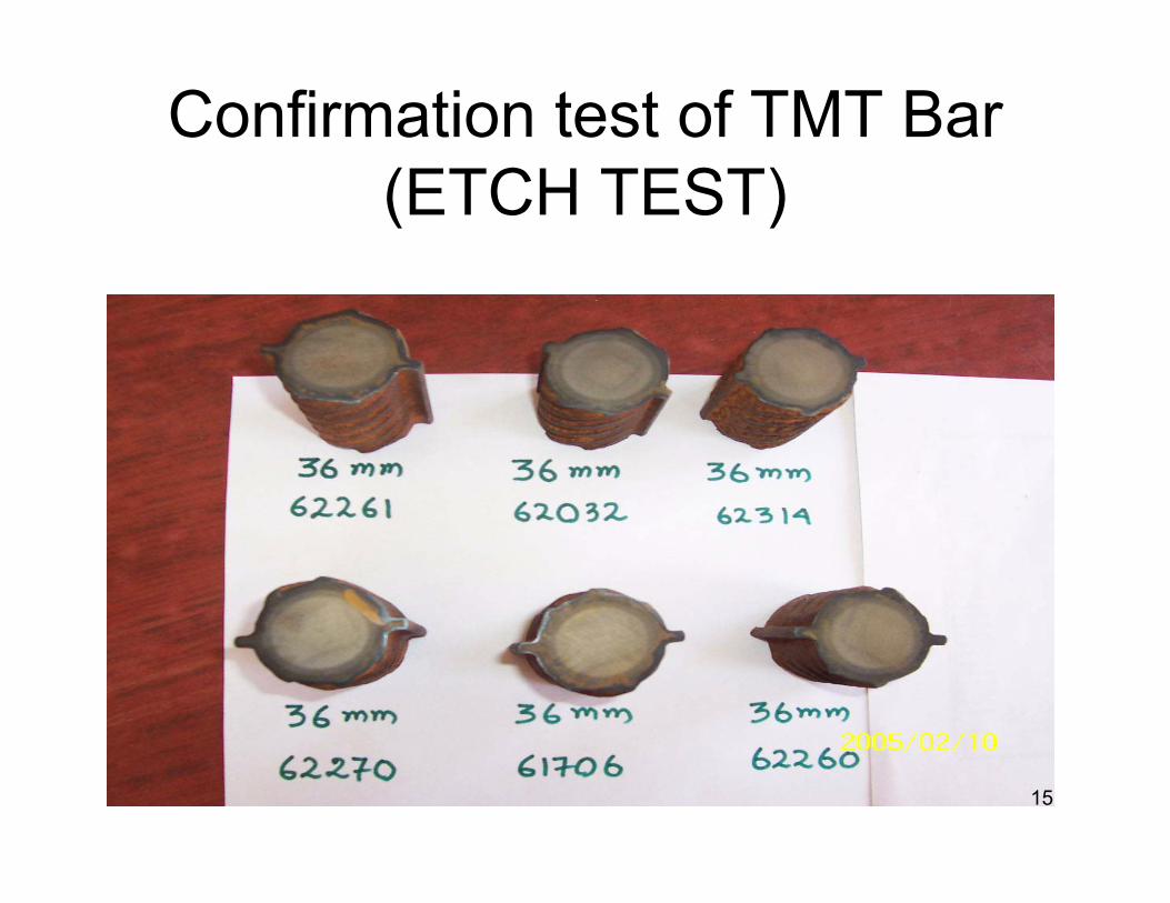
Confirmation test of TMT Bar (ETCH TEST)
15
16
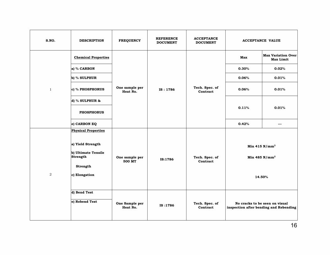
S.NO. DESCRIPTION FREQUENCY REFERENCE DOCUMENT
ACCEPTANCE DOCUMENT ACCEPTANCE VALUE
1
Chemical Properties
One sample per Heat No. IS : 1786 Tech. Spec. of
Contract
Max Max Variation Over Max Limit
a) % CARBON 0.30% 0.02%
b) % SULPHUR 0.06% 0.01%
c) % PHOSPHORUS 0.06% 0.01%
d) % SULPHUR &
0.11% 0.01%PHOSPHORUS
e) CARBON EQ 0.42% ---
2
Physical Properties
One sample per 500 MT IS:1786 Tech. Spec. of
Contract
a) Yield Strength Min 415 N/mm2
b) Ultimate Tensile Strength Min 485 N/mm2
Strength
c) Elongation 14.50%
d) Bend Test
One Sample per Heat No. IS :1786 Tech. Spec. of
ContractNo cracks to be seen on visual
inspection after bending and Rebendinge) Rebend Test
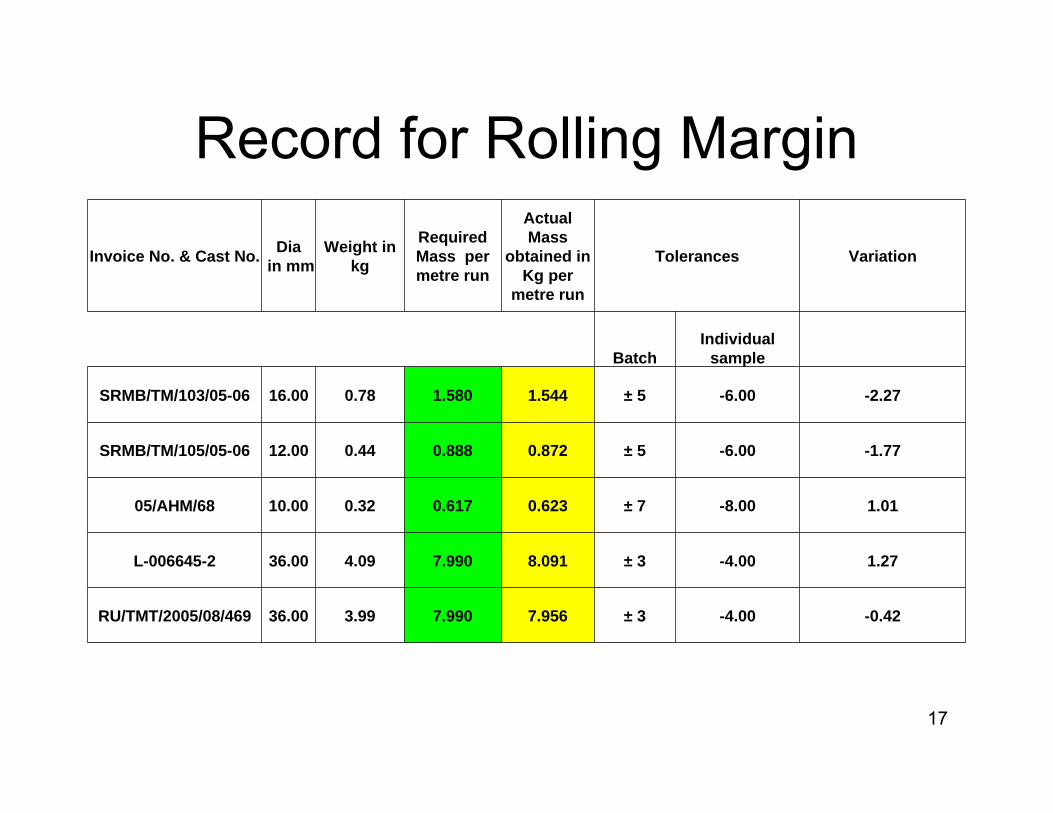
Record for Rolling Margin
17
Invoice No. & Cast No. Diain mm
Weight in kg
Required Mass per metre run
Actual Mass
obtained in Kg per
metre run
Tolerances Variation
BatchIndividual
sample
SRMB/TM/103/05-06 16.00 0.78 1.580 1.544 ± 5 -6.00 -2.27
SRMB/TM/105/05-06 12.00 0.44 0.888 0.872 ± 5 -6.00 -1.77
05/AHM/68 10.00 0.32 0.617 0.623 ± 7 -8.00 1.01
L-006645-2 36.00 4.09 7.990 8.091 ± 3 -4.00 1.27
RU/TMT/2005/08/469 36.00 3.99 7.990 7.956 ± 3 -4.00 -0.42
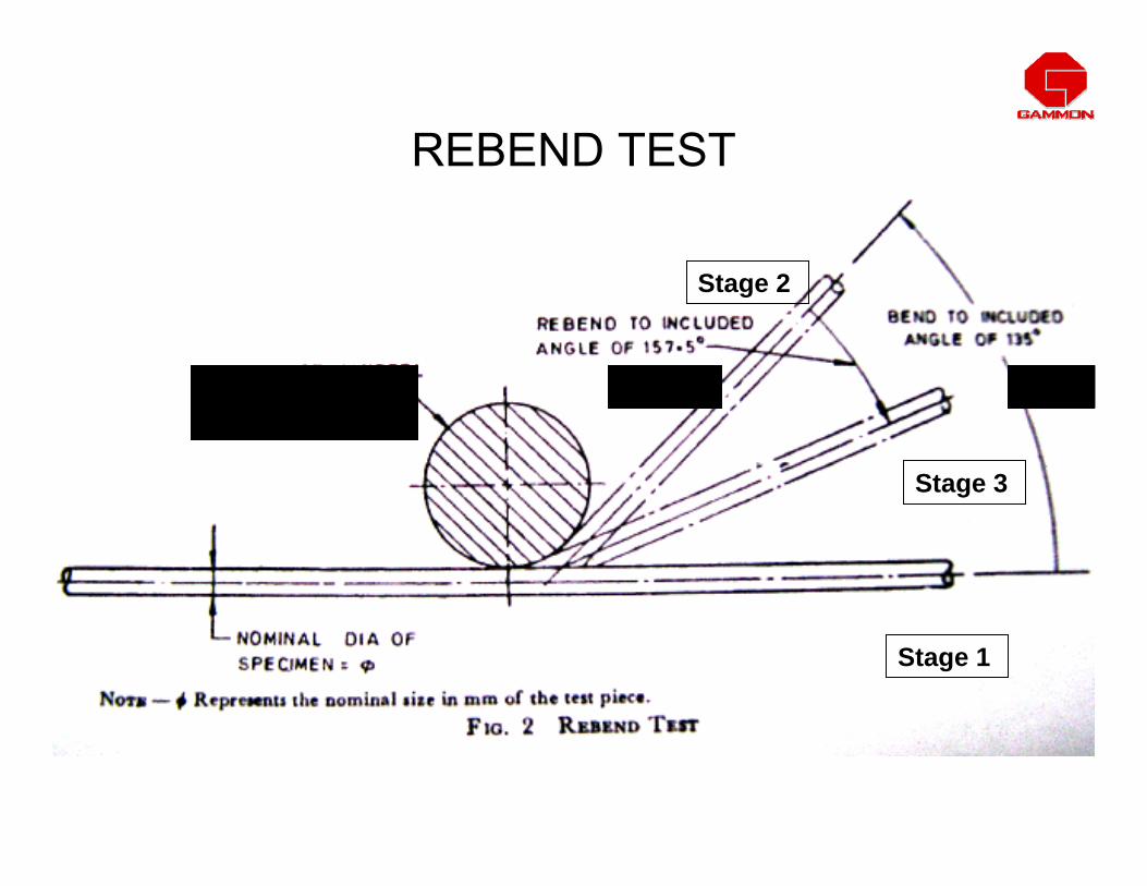
REBEND TEST
Dia of mandrel 5ø to 8ø
157.5º 135º
Stage 1
Stage 2
Stage 3

BEND TEST AS PER IS 1786 - 2008
•The test piece, when cold ,shall be doubled over the mandrel by continuous pressure until the sides are parallel.
•The specimen shall be considered to have passed the test if there is no rupture or cracks on bent portion.
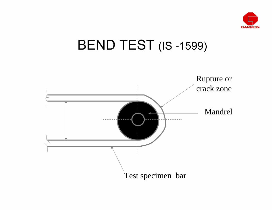
BEND TEST (IS -1599)
Mandrel
Test specimen bar
Rupture or crack zone

COMMON CHECKS• Mandrel / bar bending machine ( for 16 ø & above )
Mandrel of proper dia meter is to be used for maintaining the radius of bend. If mandrel made tight the bar may show cracks at the bend due to less radius of bend.
• Mark on rebars / Grade Check the grade of steel and trade mark/name of the manufacturer.
• Check coupler welded or threaded is as per drawing , For bars in tension max 20 % of steel area staggered 600mm c/c minimum.
• Check lap welding Min length 12d with gap or space ,welded with recommended electrode by ( checking carbon content of rebar matching electrode.)
COMMON CHECKS

23
STORAGE AND ISSUE:• Stock reinforcement on elevated pedestals of minimum
150 mm above ground level cover with PVC sheets
• Issue reinforcement on FISRT-IN-FIRST-OUT BASIS to minimize oxidation loss.
• Keep record of all steel issued from storage yard to cutting and bending yard.
• In case of theft lodge FIR and register claim with insurance company
CONTROLLING REINFORCEMENT ACTIVITIES

24REINFORCEMENT STEEL STOCK YARD
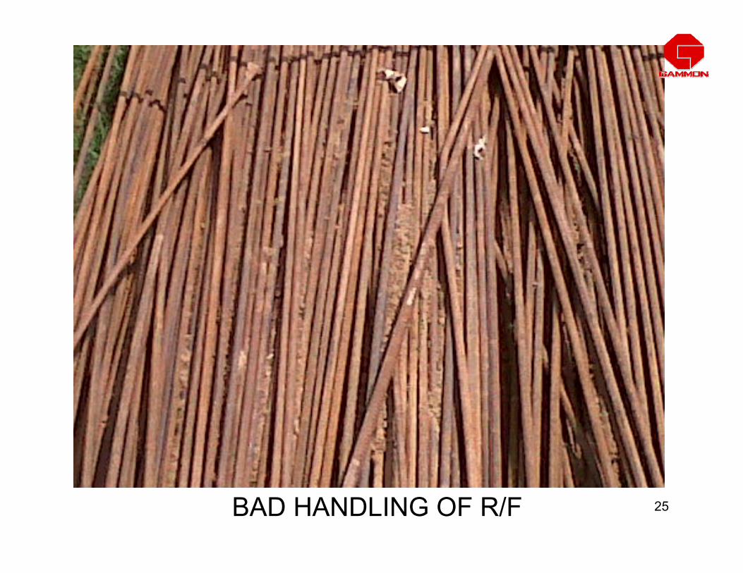
25BAD HANDLING OF R/F

26BAD HANDLING OF R/F
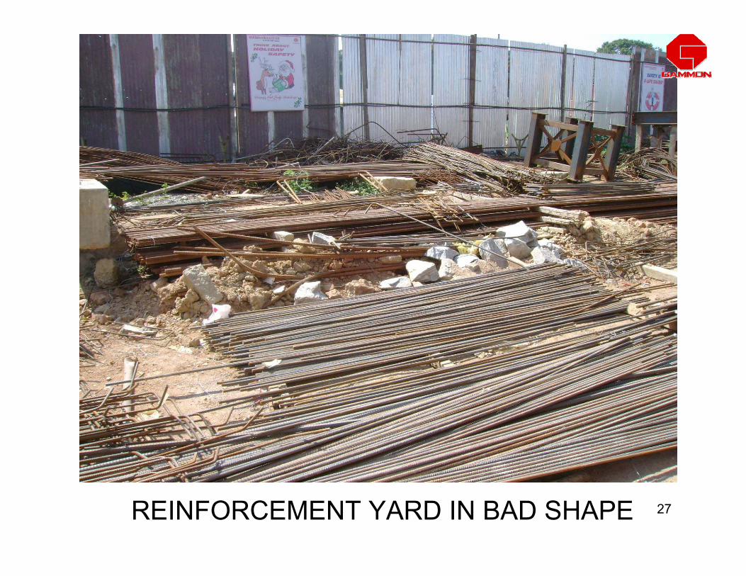
27REINFORCEMENT YARD IN BAD SHAPE
28
PREPERATION OF BBS AND REORD OF CONSUMPTION:• Prepare bar bending schedule from approved, latest revised
drawings and check for error/inconsistencies and take approval from consultant/client..
• Plan and check for fix ability and sequence of fixing.• Plan intelligent cutting from full length bars by preparing
cutting length.• Cutting length shall be worked out after considering bend
effect.• Check the bent shapes for dimensional accuracy against full
scale template and get approval from client.• Keep painted specimen bars for comparison with production.• Use cut pieces for ancillary works and record consumption.
CONTROLLING REINFORCEMENT ACTIVITIES

29
HANDLING OF REINFORCEMENT:• Avoid re bend, reshape and straighten bent bars • If bending and re bending are unavoidable, ensure bending
radius is not less than 4D AND 6D respectively for MS and Tor bars.
• After complete fabrication bundle them with identification tags.
• Use tractor trailer for internal shifting of reinforcement in the project area.
• Avoid manual shifting as for as possible.• Shift only the required qty of cut and bent bars to nearest
location where bars are to be fixed.
CONTROLLING REINFORCEMENT ACTIVITIES
30
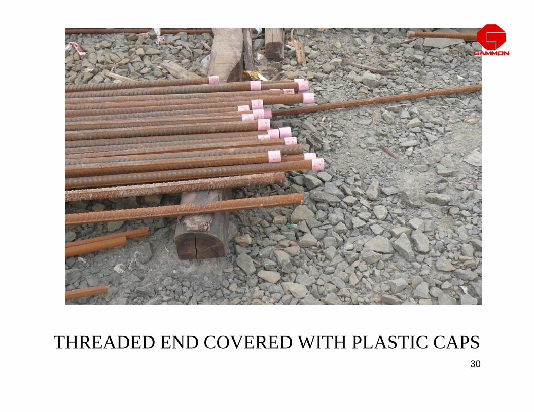
THREADED END COVERED WITH PLASTIC CAPS

31
FIXING OF REINFORCEMENT:• Draw the lay out as per the drawing on PCC, Shuttering, on
vertical bars etc.
• Stagger laps and avoid excessive laps.
• Use mechanical splices for higher diameter.
• Insist for open stirrups and links in case of complex structures.
• Provide minimum number of laps by using full length bars wherever possible.
• Use pre-fabricated cages wherever possible. Provide adequate bracing, spacers and sufficient lifting points to avoid deformation of cage.
CONTROLLING REINFORCEMENT ACTIVITIES

32
FIXING OF REINFORCEMENT:• Avoid substitution of bars, if unavoidable check for over
consumption.
• Do not use tack weld at cross points.
• Avoid excessive chairs. Arrive at optimum spacing of chairs by trials.
• Use cut pieces/welded scraps for chairs. Avoid using full length bars for making chairs.
• Use spider beam to lift heavy cages.
CONTROLLING REINFORCEMENT ACTIVITIES

33
FIXING OF REINFORCEMENT:• Check spacing's, number of bars, location of bars etc.
before start of concrete.• Fix the bars accurately with specified cover of size and
grade.• Plan best fixing sequence to achieve accuracy and to
accommodate form work, void formers, starter bars etc.• Ensure inspection of reinforcement fixing intermittently to
avoid redoing.• Avoid large time gap between the concrete pours to
prevent deterioration of projected reinforcement.• Record deviations /extra bars provided as per instruction
of consultant / client.
CONTROLLING REINFORCEMENT ACTIVITIES

34
Arrangement of concrete pipeline
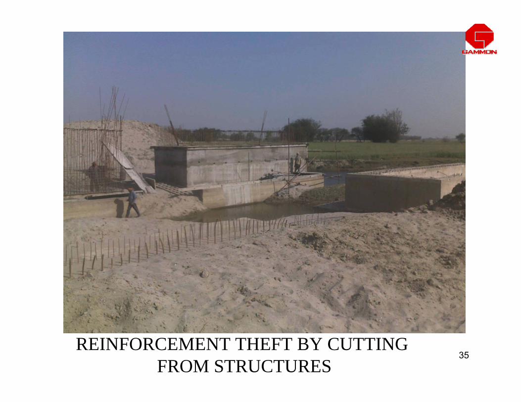
35REINFORCEMENT THEFT BY CUTTING
FROM STRUCTURES

36IMPROPER FIXING OF REINFORCEMENT

37PROPER ACCESS MUST BE MADE FOR
FIXING LOCATION

38
NO COVER AT THIS SIDE
39
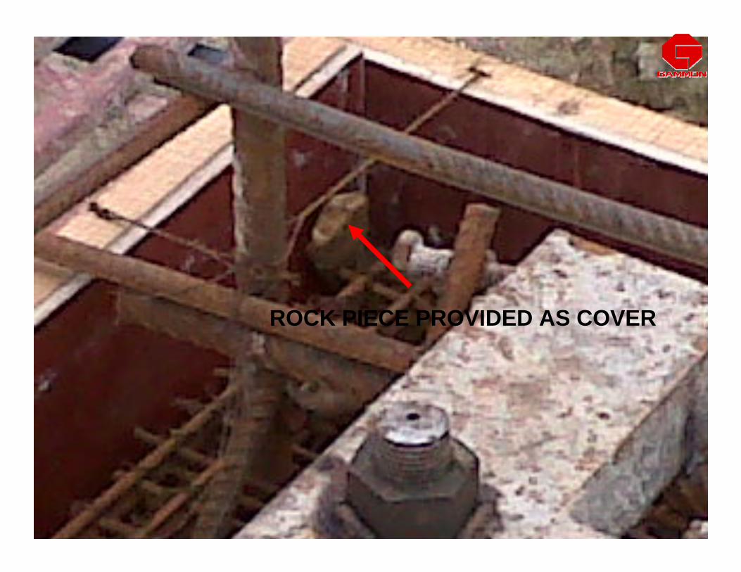
ROCK PIECE PROVIDED AS COVER

40
MORE COVER ATONE SIDE ANDLESS OTHER SIDE

41
MORE COVER ATONE SIDE ANDLESS OTHER SIDE

42
MORE LENGTH OF BINDING WIRE LEADS TO CORROSSIONAND COST
43
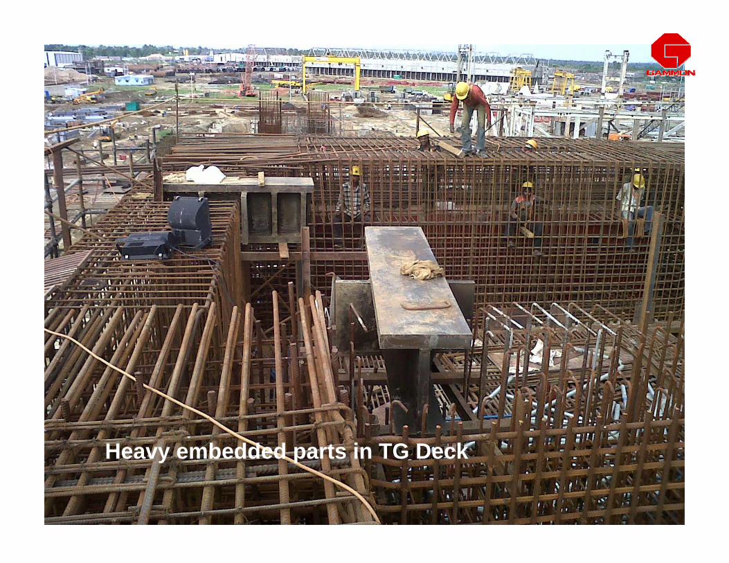
Heavy embedded parts in TG Deck

44
Congested reinforcement
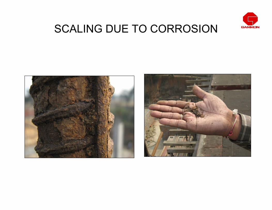
SCALING DUE TO CORROSION

VARIOUS SIZES OF MANDRELS ON BENDING MACHINE
Mandrels

COMMON CHECKS• Clear cover : Measured from nearest surface of main
reinforcement and concrete surface.
• Nominal cover : Cover considered for design purpose which includes stirrups and links.
• Check Nominal cover as per drawing tolerance 0 to +10 mm for nominal cover only.
• Check Size and spacing of links and stirrups as per drawing.

Nominal Cover
Clear cover
Main Reinforcement
Stirrups / Links
Tolerance 0 to +10 mm Tolerance 0 to +10 mm for Nominal coverfor Nominal cover
No tolerance for Clear cover

• Check that rebar diameter ,numbers, shape and spacing is as per drawing and changes if made are approved by RCC consultant.Slab tolerance in spacing of reinforcement± 10 mm for slabs upto 200mm thick± 15 mm for slabs more than 200mm thick
• Double binding not specified in IS .
COMMON CHECKS

CORRECT SPACING OF SLAB REINFORCEMENT
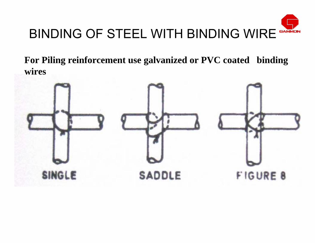
BINDING OF STEEL WITH BINDING WIRE
For Piling reinforcement use galvanized or PVC coated binding wires
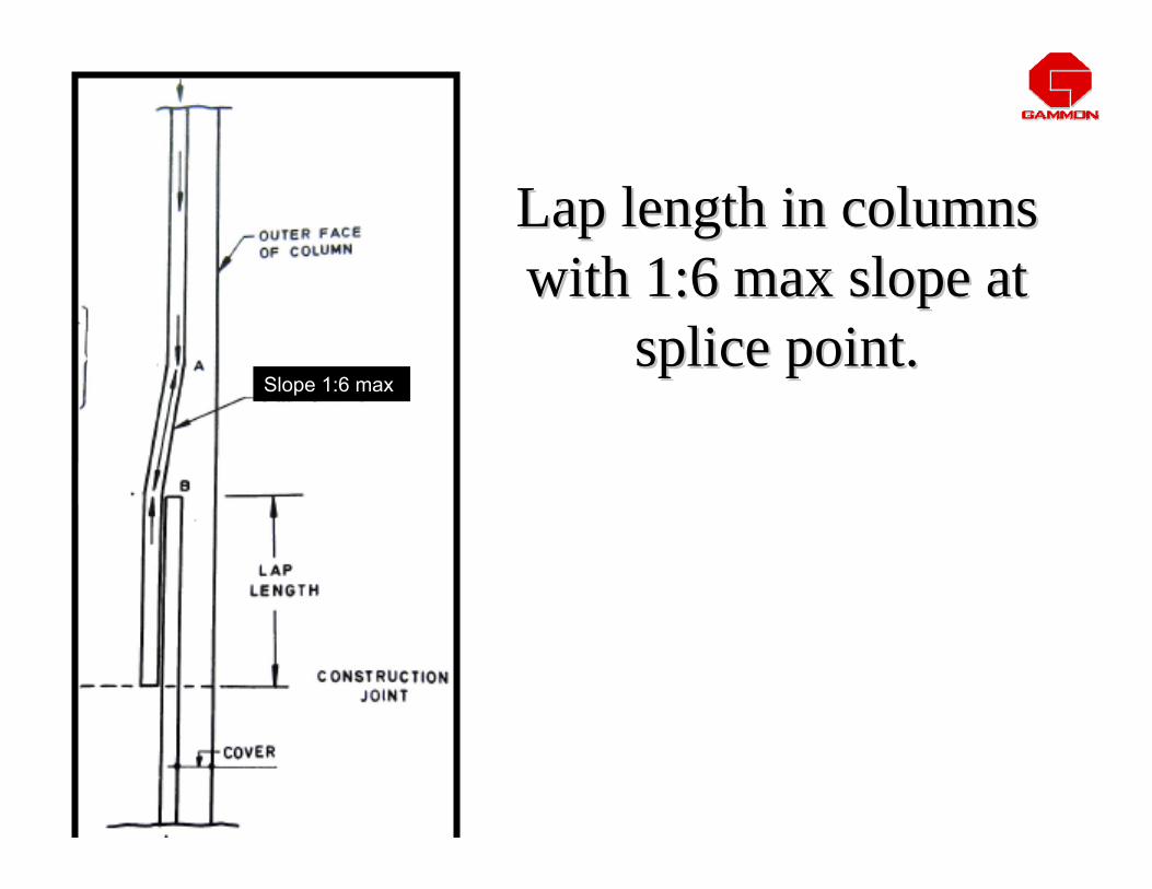
Lap length in columnsLap length in columnswith 1:6 max slope at with 1:6 max slope at
splice point.splice point.Slope 1:6 max

COLUMN REINFORCEMENT• Check that column bars laps staggered ( min 50 % )
and Clear distance between two laps c/c 1.3 Ld
C/c 1.3 Ld
Column main bars details for staggered laps
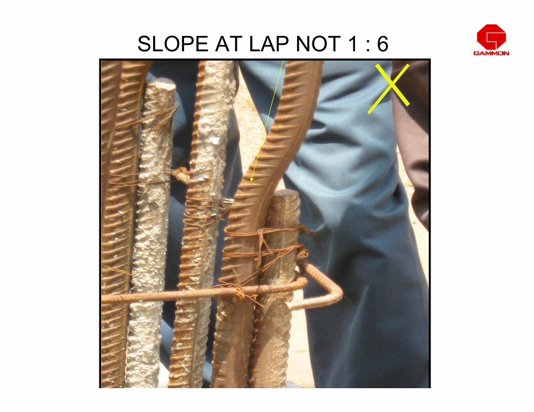
SLOPE AT LAP NOT 1 : 6

T E C H N I C A L .S P E C I F I C A T I O N ST E C H N I C A L .S P E C I F I C A T I O N S
COUPLER COUPLER DIMENSIODIMENSIONSNS
BAR SIZEBAR SIZE
1616 2020 2525 2828 3232 3636 4040 5050
LengthLength AA 5252 7070 8585 9595 105105 110110 125125 130130
DiameterDiameter GG 2525 3030 3636 4242 4545 5050 5454 6565
WeightWeight KgKg 0.130.13 0.260.26 0.400.40 0.640.64 0.80.8 1.001.00 1.271.27 1.651.65
No. of Rebar No. of Rebar ThreadThread 1010--1212 1010--1313 1313--1616 1515--1818 1717--2020 1818--2121 2121--2424 2222--2424
MECHANICAL SPLICING SPECIFICATIONS

56
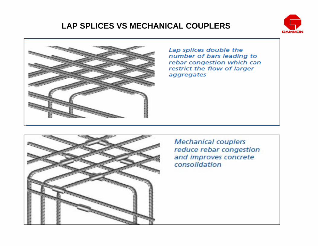
LAP SPLICES VS MECHANICAL COUPLERS

LAP SPLICES VS MECHANICAL SPLICES
59
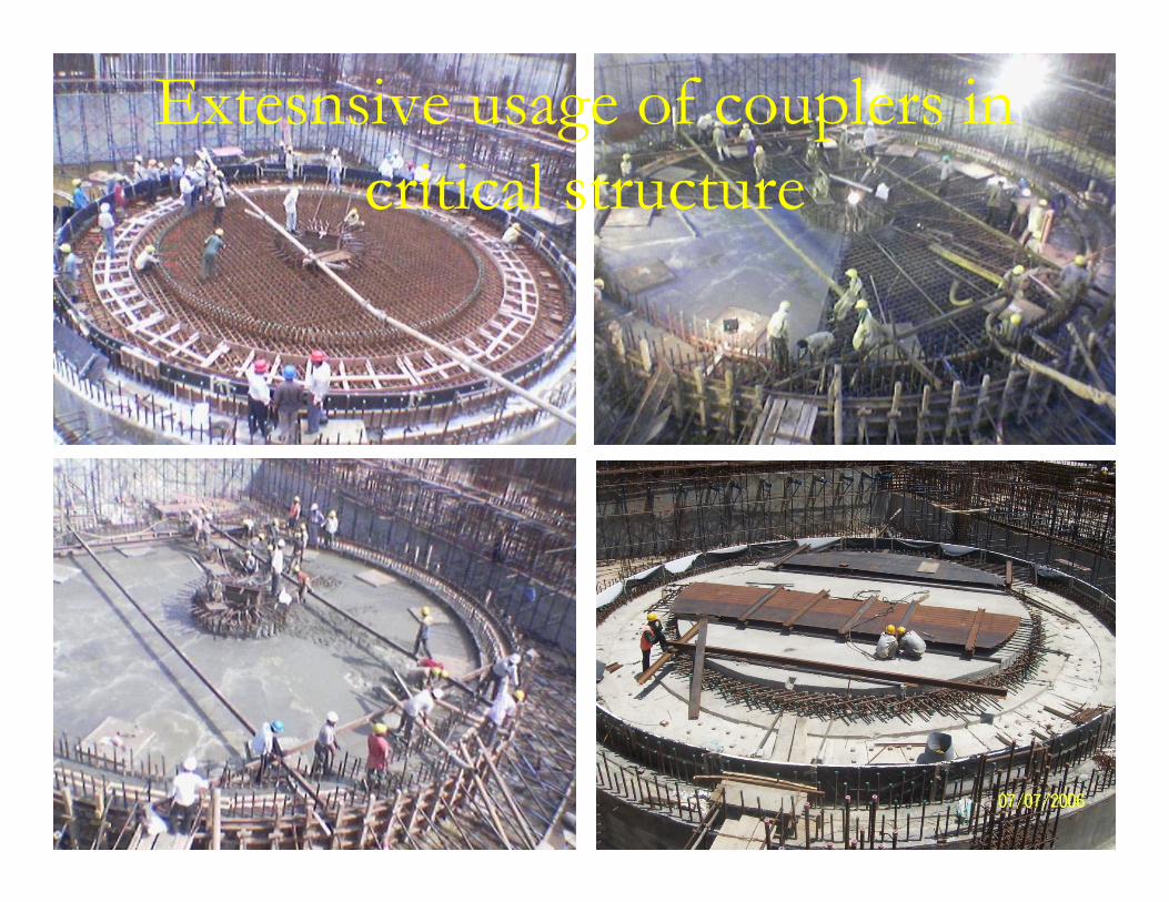
Extesnsive usage of couplers in critical structure

60
Extensive usage of couplers for critical structure
61
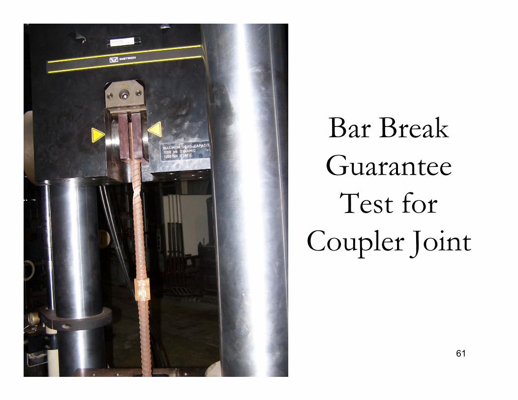
Bar Break Guarantee Test for
Coupler Joint

62
Acceptance Criteria:The following shall constitute the acceptance standard of spliced joint:•The tensile strength of the spliced joint shall be more than Rebars of Fe 415.•The spliced Bartech coupler joint should not fail in tension test at coupler location.•Check at site:•Thread dimension check with GO and NOGO gauges•Tensile strength check one sample per 1000 joints


Butt Welding of Reinforcement
64
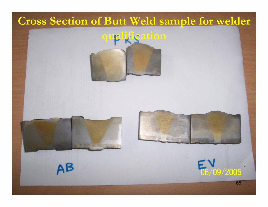
• Butt weld cut pieces of reinforcement steel beyond economical break even length by cutting ‘V’ groove and welding by qualified welder, especially for 20mm dia and above.
• Test welded joint to make sure that joint is stronger than parent bar, irrespective whether such testing is insisted by clients or not.
• Use butt weld bars not more than 20% in a given cross section.
65
Cross Section of Butt Weld sample for welder qualification
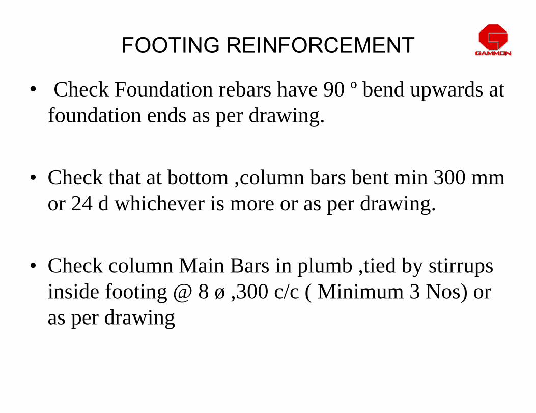
FOOTING REINFORCEMENT
• Check Foundation rebars have 90 º bend upwards at foundation ends as per drawing.
• Check that at bottom ,column bars bent min 300 mm or 24 d whichever is more or as per drawing.
• Check column Main Bars in plumb ,tied by stirrups inside footing @ 8 ø ,300 c/c ( Minimum 3 Nos) or as per drawing

Lap length
LdtLdc
300mm or 24 D which is greater
Depth of foundation >500 mm
Ldt
G L
75
50 mm cover
TYPICAL FOOTING DETAILS
75 mm
Use 8ø 300mm links Min 3 Nos Or as specified.
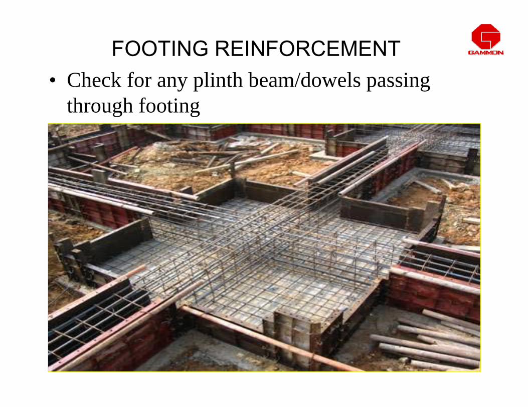
FOOTING REINFORCEMENT• Check for any plinth beam/dowels passing
through footing

• Check column Bars Joggle,( max shape 1:6 )
• Column offset ≤ 75mm ( 1 or 2 sides ), main bars offset bent. If cranking not within beam, provide 3 Nos ties c/c 8 dia ( 2 extra + 1 regular ) at crank point.
COLUMN REINFORCEMENT

Slop 1: 6 max
Fixing ties to be removed before erecting cage above
Splicing when lower bar cranked into a position inside the upper bars when relative displacement of column faces is less than 75mm
< 75 mm

Fixing ties to be removed before erecting cage above
Splice with lower bars cranked into position inside upper bars ( Intermediate Floors)
< 75 mm
Extra ties at the point of bend
Slop 1: 6 max
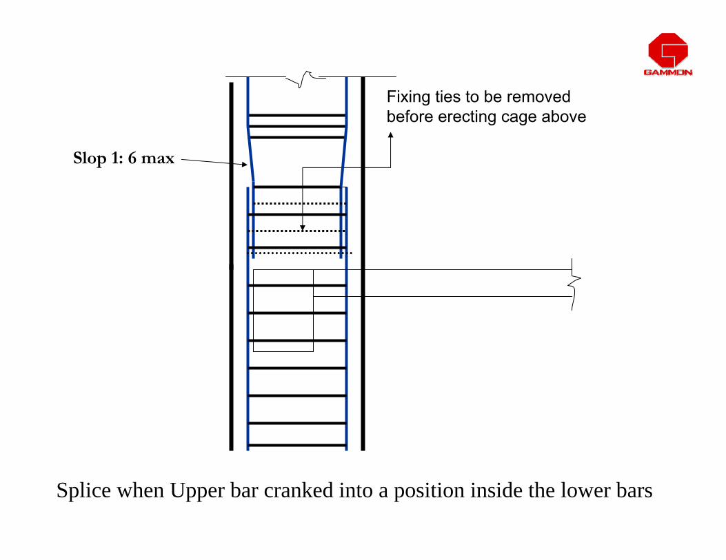
Slop 1: 6 max
Fixing ties to be removed before erecting cage above
Splice when Upper bar cranked into a position inside the lower bars
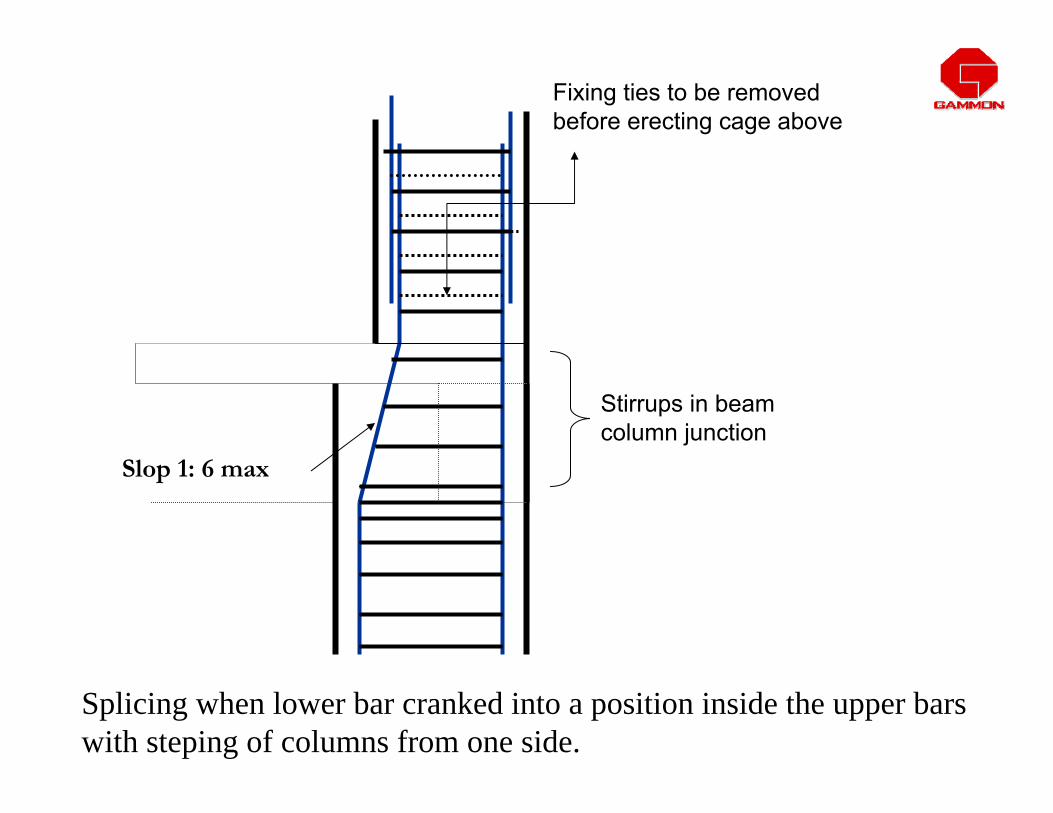
Slop 1: 6 max
Fixing ties to be removed before erecting cage above
Stirrups in beam column junction
Splicing when lower bar cranked into a position inside the upper bars with steping of columns from one side.

Fixing ties to be removed before erecting cage above
Splicing at the floor level when the relative displacement of column faces is more than 75 mm
> 75 mmColumn Starter

• Check that dowels ( 2 Ld ) for bars requiring change in diameter for next floor.
COLUMN REINFORCEMENT

• Check that column offset > 75mm ( 1 or 2 sides ) bars in columns ( not extending ) stopped at floor ( inverted L ) and dowels provided.
COLUMN REINFORCEMENT

At Roof At Roof Level Level Column Bar Column Bar inside Slabinside Slab

LEG LENGTH OF STIRRUP LESS THAN 8D

LOOSE COLUMN LINKS
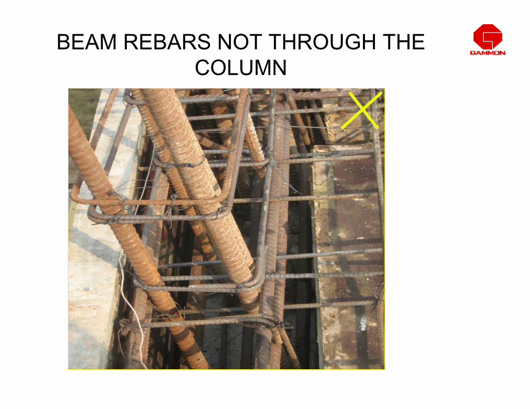
BEAM REBARS NOT THROUGH THE COLUMN

Local bend Local bend in in column bars column bars provided at column. provided at column. Sudden bend in Sudden bend in column bars.column bars.
COLUMN REINFORCEMENT
• Check column bars projecting min 50 (Ld) above slab or as per drawing with minimum 2/3 fixing ties/ temporary stirrups before casting of slab.Ties removed for erecting next stage.
COLUMN REINFORCEMENT
• Check spacing of stirrups, diameter,shape is as per drawing ( end anchorage 8d for 90 º and 6d for 135 º) for heavy columns fabricated in parts, extra 12 øopen ties at double spacing .
COLUMN REINFORCEMENT

Slide 83
v1 nbmnhmhmh mh mvikram, 1/9/2009
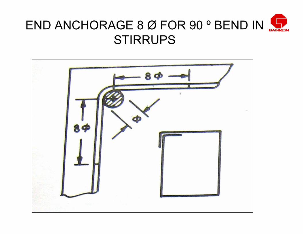
END ANCHORAGE 8 Ø FOR 90 º BEND IN STIRRUPS

END ANCHORAGE 6 Ø FOR 135 º BEND IN STIRRUPS
By bending ring into 135º net saving per ring is 16 d

• Check lap length of steel in beams / slab is 30 d or as per drawing.
SLAB / BEAM REINFORCEMENT
Lap Length
Reinforcement bars
40 øø
øLap Length 40 ø
Two rebars with different diameters. Provide lap with respect to smaller diameter

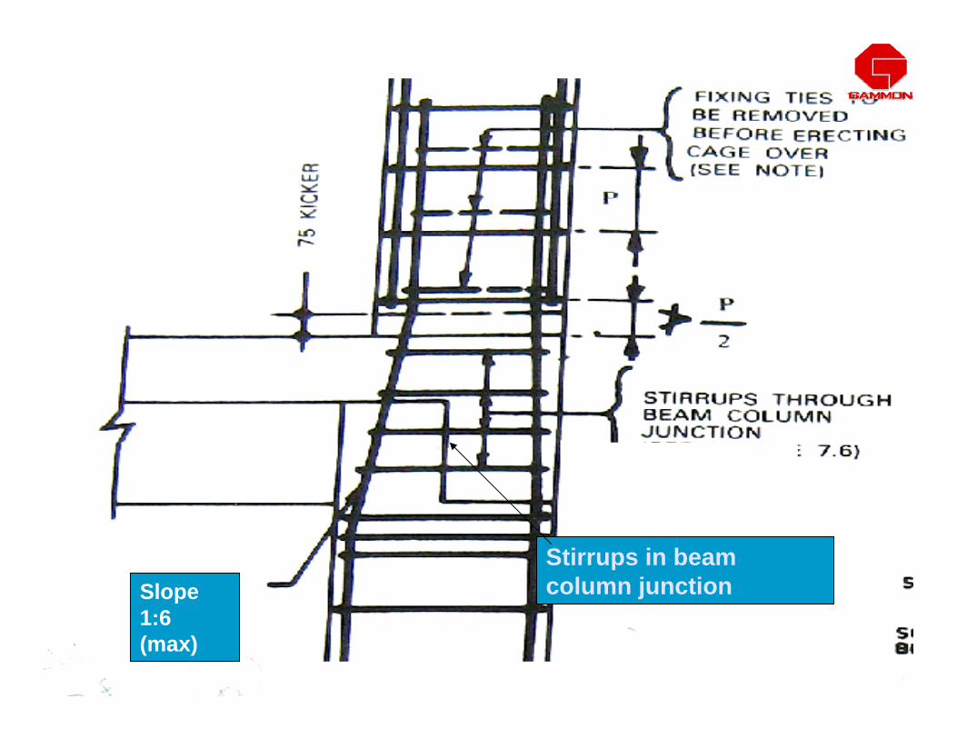
Stirrups in beam column junctionSlope
1:6Slope 1:6 (max)
• Check that beam bars are modified for electric down take conduits with adequate cover to the conduits.
• Between two electrical conduits 25mm gap shall be given.
SLAB / BEAM REINFORCEMENT

ELECTRIC CONDUITS INCORRECTLY PLACED
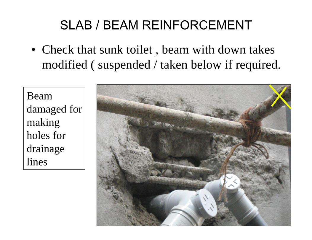
• Check that sunk toilet , beam with down takes modified ( suspended / taken below if required.
SLAB / BEAM REINFORCEMENT
Beam damaged for making holes for drainage lines
• Check position of lap in continuous beams bottom bars over intermediate support, top bars extreme middle third or as per drawing.
SLAB / BEAM REINFORCEMENT

Clear Span
End Support Intermediate Support
POSITION OF LAPS IN CONTINUOUS BEAM
Top reinforcement lap at extreme middle third
Bottom reinforcement lap at center of intermediate support
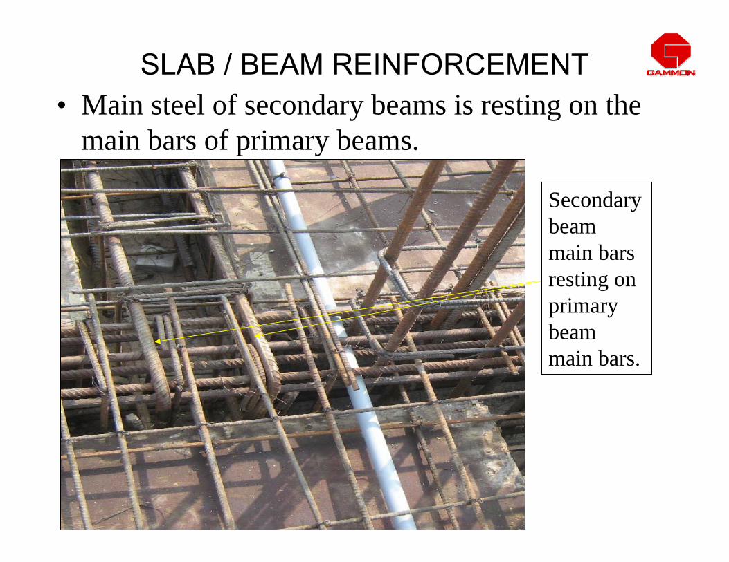
• Main steel of secondary beams is resting on the main bars of primary beams.
SLAB / BEAM REINFORCEMENT
Secondary beam main bars resting on primary beam main bars.
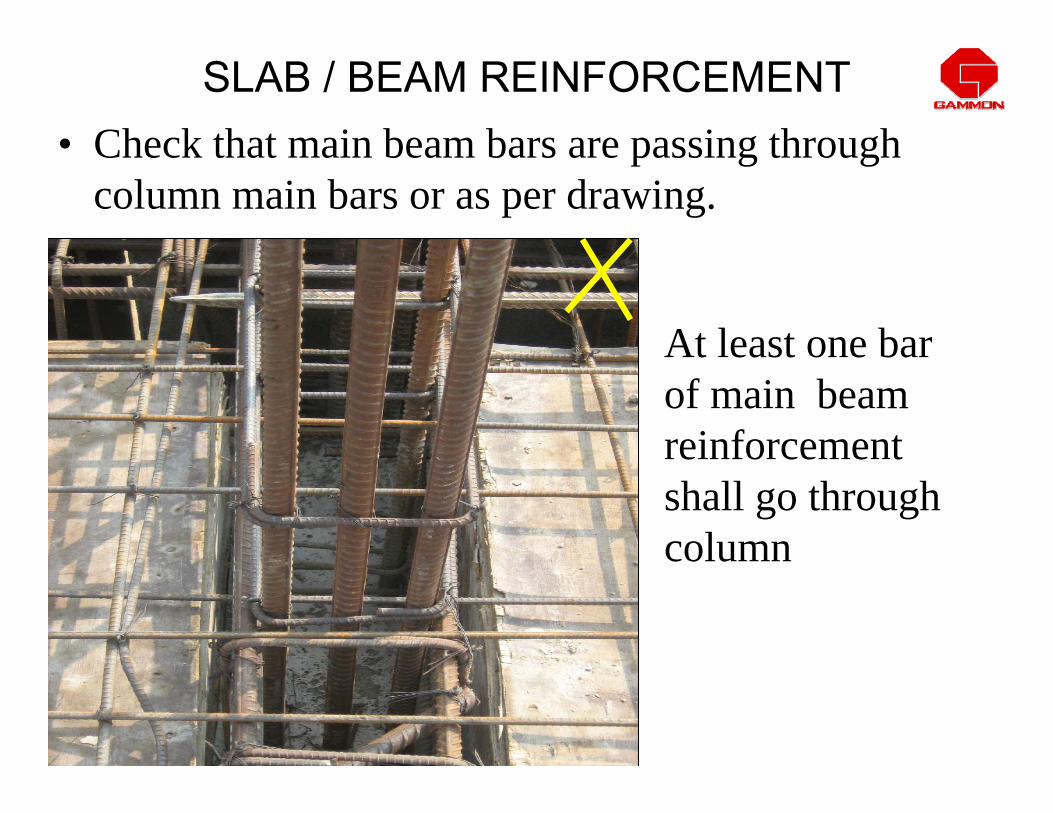
• Check that main beam bars are passing through column main bars or as per drawing.
SLAB / BEAM REINFORCEMENT
At least one bar of main beam reinforcement shall go through column

• Check that minimum horizontal spacing between the bars max of :
1 ) Max diameter of bar2 ) 5 mm more than the max size of aggregates.
SLAB / BEAM REINFORCEMENT
SLAB / BEAM REINFORCEMENT
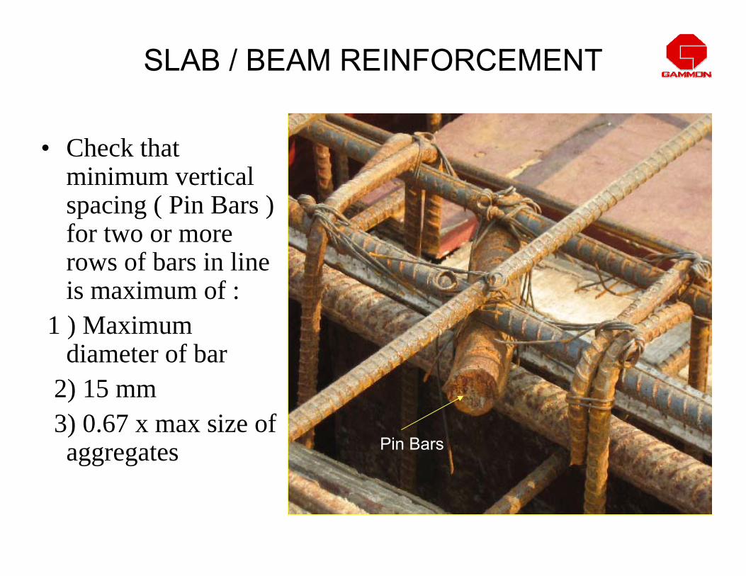
• Check that minimum vertical spacing ( Pin Bars ) for two or more rows of bars in line is maximum of :
1 ) Maximum diameter of bar
2) 15 mm3) 0.67 x max size of aggregates Pin Bars

SLAB / BEAM REINFORCEMENT
• Check spacing of stirrups, diameter,shape is as per drawing ( end anchorage 8d for 90 º bend and 6d for 135 º bend )

CHAIRS FOR SLABS
• Chairs shall be designed to take manual and mechanical loads during slab casting chair is meant to maintain spacing between two meshes of slab top and bottom.
• Chair shall not be touching to shuttering or sheathing.

WRONG PRACTICE FOR PLACING CHAIRS ON SHUTTERING
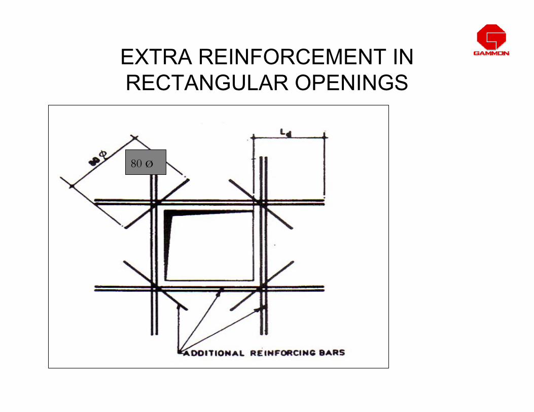
EXTRA REINFORCEMENT IN RECTANGULAR OPENINGS
80 ø

EXTRA REINFORCEMENT IN CIRCULAR OPENINGS

VERTICAL SECTIONS OF THE WALLS
Horizontal bars tied to vertical
Clips connecting the two layers of vertical reinforcement
Clips connecting the two layers of Horizontal reinforcement
Wall Thickness
<=170 mm
Wall >170 mm BUT<=220 mm & walls> 220 mm with vertical reinforcement greater than nominal
WALLS of thk > 220 mm with nominal reinforcement

COMMON STEEL DETAILING ERRORS


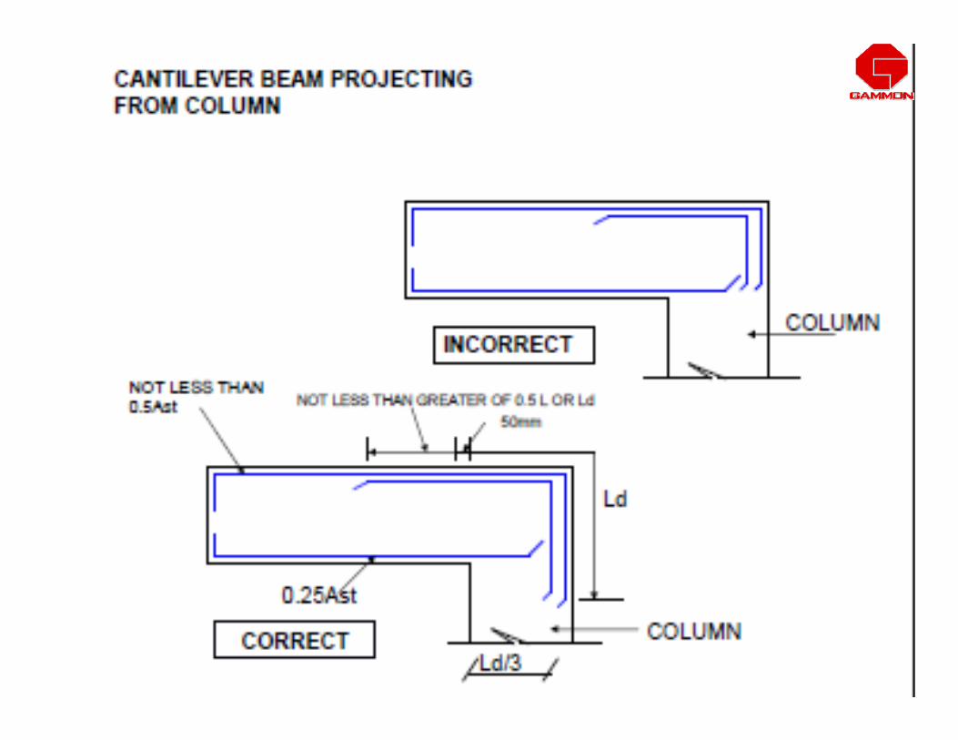


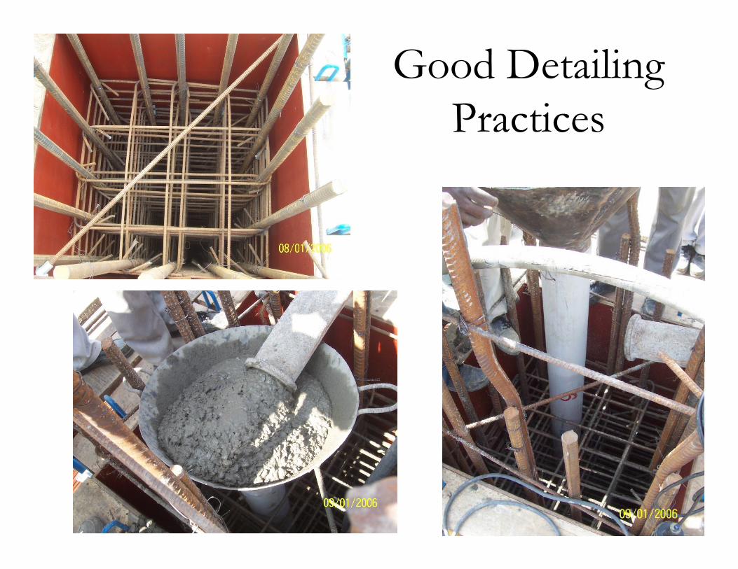
116
Good Detailing Practices
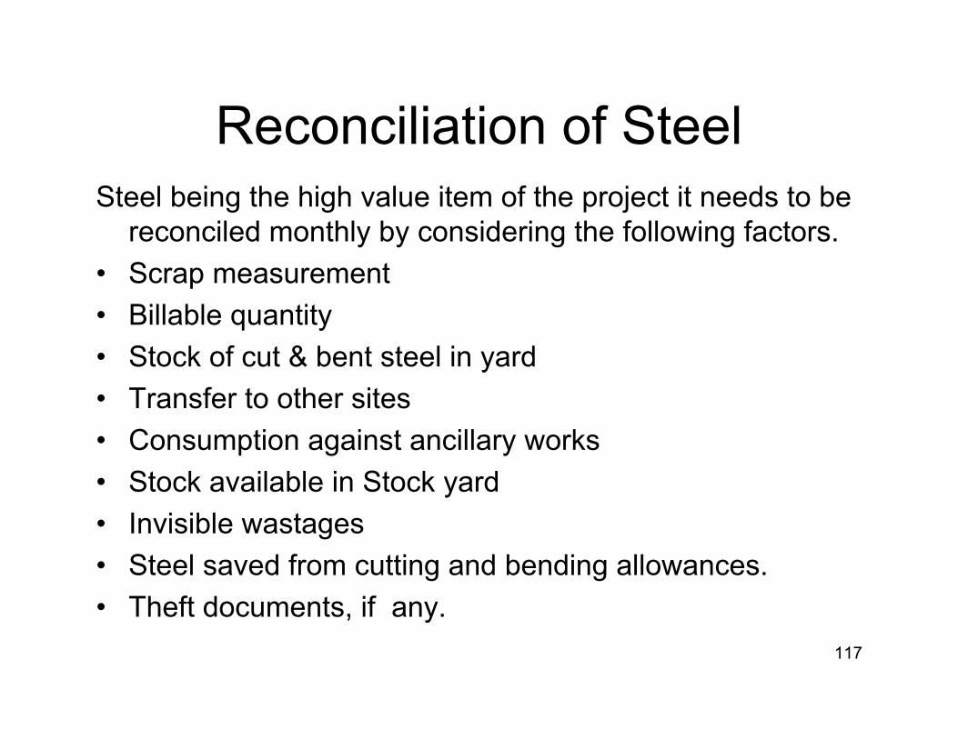
Reconciliation of SteelSteel being the high value item of the project it needs to be
reconciled monthly by considering the following factors.• Scrap measurement• Billable quantity• Stock of cut & bent steel in yard• Transfer to other sites• Consumption against ancillary works• Stock available in Stock yard• Invisible wastages• Steel saved from cutting and bending allowances.• Theft documents, if any.
117

Safety Measures by hazard identification
Safety measures for the following hazards to be taken care on priority
• Cut / Crush injury• Toppling of crane• Failure of wire rope• Hit by truck / trailer• Poor lighting• Improper earthing of machines• Fall of material / person• Over speed of vehicle• Hit by projected rods• Fall of person due to poor house keeping
118

119
Related Documents