G ® alaxyPro 20 mm AF-3700 Series Installation & Operation Manual ED-16281 Rev 4 23 March 2009 331 32nd Ave PO Box 5128 Brookings SD 57006 Website: www.daktronics.com Tel: 866-343-3122 Fax 605-697-4444

Welcome message from author
This document is posted to help you gain knowledge. Please leave a comment to let me know what you think about it! Share it to your friends and learn new things together.
Transcript

G ® alaxyPro 20 mmAF-3700 Series
Installation & Operation Manual
ED-16281 Rev 4 23 March 2009
331 32nd Ave PO Box 5128 Brookings SD 57006
Website: www.daktronics.com Tel: 866-343-3122 Fax 605-697-4444

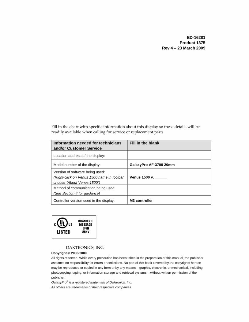
ED-16281 Product 1375 Rev 4 – 23 March 2009
Fill in the chart with specific information about this display so these details will be readily available when calling for service or replacement parts. Information needed for technicians and/or Customer Service
Fill in the blank
Location address of the display:
Model number of the display: GalaxyPro AF-3700 20mm
Version of software being used: (Right-click on Venus 1500 name in toolbar, choose “About Venus 1500”)
Venus 1500 v. ______
Method of communication being used: (See Section 4 for guidance)
Controller version used in the display: M3 controller
DAKTRONICS, INC. Copyright © 2006-2009 All rights reserved. While every precaution has been taken in the preparation of this manual, the publisher assumes no responsibility for errors or omissions. No part of this book covered by the copyrights hereon may be reproduced or copied in any form or by any means – graphic, electronic, or mechanical, including photocopying, taping, or information storage and retrieval systems – without written permission of the publisher. GalaxyPro® is a registered trademark of Daktronics, Inc. All others are trademarks of their respective companies.

Reproduction Reference ED-16281 – P1375
Display Manual; GalaxyPro® 20mm – Series AF-3700
1) This page is for reproduction reference only and will not be included in the manual. 2) This manual is to be copied on FRONT AND BACK PAGES -8 ½ x 11 paper.
Note: The first page, Cover Page, uses the front of the page (blank on back). Section heading pages always start on a new page; they never start on the back of another page.
3) Insert ED-7244 at the end of Section 2. 4) Insert the drawings into Appendix A. Use the drawing list to print and arrange the drawings. Print
C-size as B-size. 5) Insert ED-16704 within Appendix C. NOTE!!! New number for GalaxyPro.
6) Insert SL-02374 into Appendix D. 7) Use a blue window cover and a blue back. 8) Punch all pages, window cover, and back cover along the left edge, and bind with a spiral binder. 9) Please direct questions and suggestions to Engineering Secretarial.

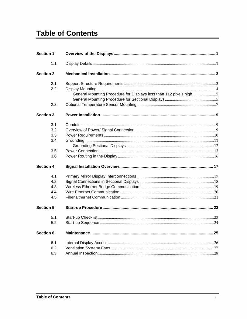
Table of Contents i
Table of Contents
Section 1: Overview of the Displays ........................................................................................... 1
1.1 Display Details ......................................................................................................................... 1
Section 2: Mechanical Installation .............................................................................................. 3
2.1 Support Structure Requirements .......................................................................................... 3 2.2 Display Mounting ..................................................................................................................... 4
General Mounting Procedure for Displays less than 112 pixels high ....................... 5 General Mounting Procedure for Sectional Displays .................................................. 5
2.3 Optional Temperature Sensor Mounting .............................................................................. 7
Section 3: Power Installation ....................................................................................................... 9
3.1 Conduit ...................................................................................................................................... 9 3.2 Overview of Power/ Signal Connection ................................................................................ 9 3.3 Power Requirements ............................................................................................................ 10 3.4 Grounding ............................................................................................................................... 11
Grounding Sectional Displays ...................................................................................... 12 3.5 Power Connection ................................................................................................................. 13 3.6 Power Routing in the Display .............................................................................................. 16
Section 4: Signal Installation Overview .................................................................................... 17
4.1 Primary Mirror Display Interconnections ............................................................................ 17 4.2 Signal Connections in Sectional Displays ......................................................................... 18 4.3 Wireless Ethernet Bridge Communication ......................................................................... 19 4.4 Wire Ethernet Communication ............................................................................................ 20 4.5 Fiber Ethernet Communication ........................................................................................... 21
Section 5: Start-up Procedure ................................................................................................... 23
5.1 Start-up Checklist .................................................................................................................. 23 5.2 Start-up Sequence ................................................................................................................ 24
Section 6: Maintenance .............................................................................................................. 25
6.1 Internal Display Access ........................................................................................................ 26 6.2 Ventilation System/ Fans ..................................................................................................... 27 6.3 Annual Inspection .................................................................................................................. 28
Table of Contents ii
Section 7: Diagnostics and Troubleshooting ........................................................................... 29
7.1 Controller Diagnostics ........................................................................................................... 29 7.2 Temperature Sensor Diagnostic ......................................................................................... 30 7.3 Troubleshooting Display Problems ..................................................................................... 31
Module and LED problems ........................................................................................... 31 Brightness problems ...................................................................................................... 32 Message problems ......................................................................................................... 32 Temperature problems .................................................................................................. 33 Testing displays .............................................................................................................. 33 Before calling for help .................................................................................................... 33
Section 8: Parts Replacement .................................................................................................... 35
8.1 About Replacement Parts .................................................................................................... 35 8.2 Instructions for Replacing Parts .......................................................................................... 37
Module Replacement ..................................................................................................... 37 Controller Replacement ................................................................................................. 38 Power Supply Replacement ......................................................................................... 40 Light Sensor Replacement ........................................................................................... 41 Temperature Sensor Replacement ............................................................................. 42
Section 9: Daktronics Exchange and Repair & Return Programs .......................................... 43
9.1 Exchange Program ............................................................................................................... 43 9.2 Repair & Return Program ..................................................................................................... 44 9.3 Daktronics Warranty and Limitation of Liability ................................................................. 44
Appendix A: Reference Drawings ................................................................................................. 45
Appendix B: Glossary ..................................................................................................................... 47
Definitions of Terms ....................................................................................................... 47 Common Power and Signal Connectors ..................................................................... 48
Appendix C: Temperature Sensor Installation ............................................................................. 51
Appendix D: Daktronics Warranty and Limitation of Liability (SL-02374) ................................. 53
List of Figures iii
List of Figures
Figure 1: Single Module ..................................................................................................................................... 1 Figure 2: Display Components .......................................................................................................................... 2 Figure 3: Basic Display Set-up ......................................................................................................................... 2 Figure 4: Fans on Back ...................................................................................................................................... 3 Figure 5: Back View of Typical Display ........................................................................................................... 4 Figure 6: Multiple Section Lifting Not Advised ................................................................................................ 4 Figure 7: Correct Lifting Procedures ................................................................................................................ 5 Figure 8: Bottom Section Preparation ............................................................................................................. 5 Figure 9: Top Section Preparation ................................................................................................................... 6 Figure 10: Correct Lifting Method ..................................................................................................................... 6 Figure 11: Clip Angle Attachment ..................................................................................................................... 6 Figure 12: Replacing Alignment Pins with Bolts ............................................................................................ 6 Figure 13: Attaching Top to Bottom Sections ................................................................................................. 7 Figure 14: Correct Grounding of Display ....................................................................................................... 11 Figure 15: Grounding Sectional Displays ...................................................................................................... 12 Figure 16: Bonding Jumper Attachment ........................................................................................................ 12 Figure 17: Single-phase 6-breaker Domestic Panel .................................................................................... 13 Figure 18: Single-phase 6-breaker International Panel .............................................................................. 13 Figure 19: Single-phase Wiring for 9, 12, and 18 breaker Domestic Panels ........................................... 13 Figure 20: Three-phase Wiring for 9, 12, and 18 Breaker Domestic Panels ........................................... 14 Figure 21: Three-phase Wiring for 9 and 12 breaker International Panels .............................................. 14 Figure 22: Three-phase 6-breaker Panel for Domestic and International ................................................ 14 Figure 23: 120/240 V Power Termination ..................................................................................................... 15 Figure 24: 240 V Power Termination ............................................................................................................. 15 Figure 25: Power Flow Summary ................................................................................................................... 16 Figure 26: Quick-connect Cable ..................................................................................................................... 17 Figure 27: Multiple Quick-connect Connections .......................................................................................... 17 Figure 28: Module Outputs .............................................................................................................................. 18 Figure 29: Bonding Jumper Connection ........................................................................................................ 18 Figure 30: Signal Connections in Sectional Display .................................................................................... 18 Figure 31: Wireless Ethernet Bridge Layout ................................................................................................. 19 Figure 32: Ethernet Communication Layout ................................................................................................. 20 Figure 33: Fiber Ethernet Communication Layout ....................................................................................... 21 Figure 34: Basic Display Set-up ..................................................................................................................... 23 Figure 35: Internal Components in Sectional ............................................................................................... 25 Figure 36: Internal Components- Single Cabinet ......................................................................................... 25 Figure 37: Module Access Locations ............................................................................................................. 26 Figure 38: Removing a Module ...................................................................................................................... 26 Figure 39: Air Exhaust in Smaller Displays ................................................................................................. 27 Figure 40: Air Exhaust in Larger Displays ..................................................................................................... 27 Figure 41: Air Exhaust in Sectionals .............................................................................................................. 27 Figure 42: Thermostat ...................................................................................................................................... 27 Figure 43: Controller Locations ...................................................................................................................... 29 Figure 44: Controller Diagnostics ................................................................................................................... 30 Figure 45: Temperature sensor board ........................................................................................................... 30 Figure 46: Modules Not Working .................................................................................................................... 31 Figure 47: Interior Location of Components ................................................................................................. 35
iiii List of Figures
Figure 48: Typical Label .................................................................................................................................. 35 Figure 49: Module, Front/Back ....................................................................................................................... 37 Figure 50: Removing a Module ....................................................................................................................... 37 Figure 51: GalaxyPro Controller ..................................................................................................................... 38 Figure 52: Rotary Address Switches .............................................................................................................. 39 Figure 53: Jacks and Fuses on RGB Power Supply ................................................................................... 40 Figure 54: Power Supply with Power Distribution Board ............................................................................ 40 Figure 55: Light Sensor Assembly ................................................................................................................. 41 Figure 56: Wire around Sensor ....................................................................................................................... 42 Figure 57: Temperature Sensor ..................................................................................................................... 42 Figure 58: Ribbon Cable Connector .............................................................................................................. 48 Figure 59: One Breaker Termination Block ................................................................................................... 48 Figure 60: Phoenix Connector ........................................................................................................................ 48 Figure 61: Mate-n-Lok Connector .................................................................................................................. 48 Figure 62: RJ11/RJ45 Connector ................................................................................................................... 48 Figure 63: RS232/Six-pin Quick-connect Jack ............................................................................................. 49 Figure 64: Fiber-Optic Cable ........................................................................................................................... 49
Section 1: Overview of the Displays
Daktronics GalaxyPro® 3700 series displays are built to display a wide variety of messages with great color depth. This manual provides installation, maintenance, and troubleshooting information to help ensure the optimal performance of the display. Diagnostic information and parts replacement are also included. Definitions of terms and connectors used in the manual can be found in Appendix B.
1.1 Display Details The GalaxyPro® model numbers are described as follows:
AF-3700-RRxCCC-20-RGB-X AF-3700 = Outdoor GalaxyPro display
RR = Number of pixel rows high (16, 32, 48… to 128)
CCC = Number of pixel columns long (Up to 384 columns standard)
20 = 20 mm pixel to pixel spacing
RGB = LED Color: R (Red), G (Green), B (blue) (68 billion colors - pixel calibrated)
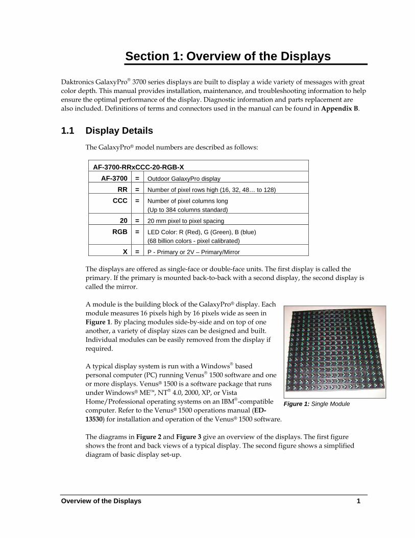
X = P - Primary or 2V – Primary/Mirror The displays are offered as single-face or double-face units. The first display is called the primary. If the primary is mounted back-to-back with a second display, the second display is called the mirror. A module is the building block of the GalaxyPro® display. Each module measures 16 pixels high by 16 pixels wide as seen in Figure 1. By placing modules side-by-side and on top of one another, a variety of display sizes can be designed and built. Individual modules can be easily removed from the display if required.
Figure 1: Single Module
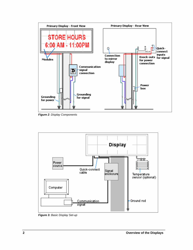
A typical display system is run with a Windows® based personal computer (PC) running Venus® 1500 software and one or more displays. Venus® 1500 is a software package that runs under Windows® ME™, NT® 4.0, 2000, XP, or Vista Home/Professional operating systems on an IBM®-compatible computer. Refer to the Venus® 1500 operations manual (ED-13530) for installation and operation of the Venus® 1500 software. The diagrams in Figure 2 and Figure 3 give an overview of the displays. The first figure shows the front and back views of a typical display. The second figure shows a simplified diagram of basic display set-up.
Overview of the Displays 1
2 Overview of the Displays
Figure 2: Display Components
Figure 3: Basic Display Set-up
Section 2: Mechanical Installation
Read the Mechanical, Power and Signal Installation sections before installing the display(s). Daktronics engineering staff must approve any changes that may affect the weather-tightness of the display. If any modifications are made, detailed drawings of the changes must be submitted to Daktronics for evaluation and approval, or the warranty may be void. Daktronics is not responsible for installations or the structural integrity of support structures done by others. The customer is responsible for ensuring that a qualified structural engineer approves the structure and any additional hardware.
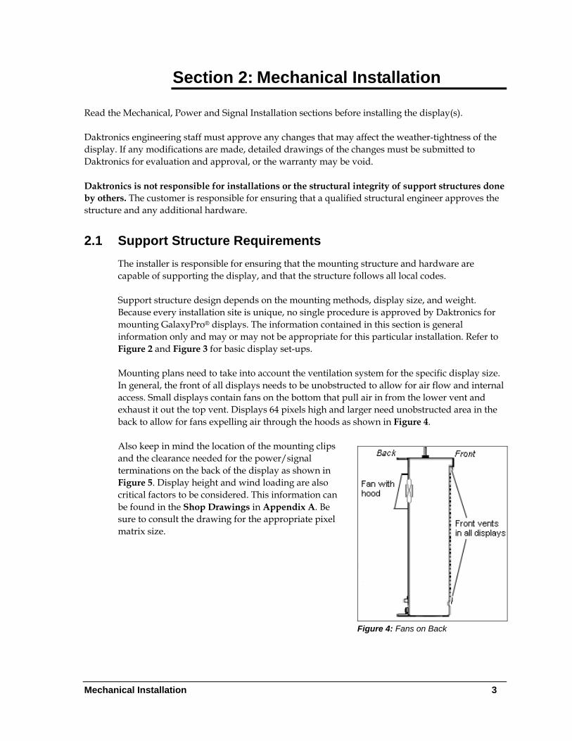
2.1 Support Structure Requirements The installer is responsible for ensuring that the mounting structure and hardware are capable of supporting the display, and that the structure follows all local codes. Support structure design depends on the mounting methods, display size, and weight. Because every installation site is unique, no single procedure is approved by Daktronics for mounting GalaxyPro® displays. The information contained in this section is general information only and may or may not be appropriate for this particular installation. Refer to Figure 2 and Figure 3 for basic display set-ups. Mounting plans need to take into account the ventilation system for the specific display size. In general, the front of all displays needs to be unobstructed to allow for air flow and internal access. Small displays contain fans on the bottom that pull air in from the lower vent and exhaust it out the top vent. Displays 64 pixels high and larger need unobstructed area in the back to allow for fans expelling air through the hoods as shown in Figure 4. Also keep in mind the location of the mounting clips and the clearance needed for the power/signal terminations on the back of the display as shown in Figure 5. Display height and wind loading are also critical factors to be considered. This information can be found in the Shop Drawings in Appendix A. Be sure to consult the drawing for the appropriate pixel matrix size.
Figure 4: Fans on Back
Mechanical Installation 3
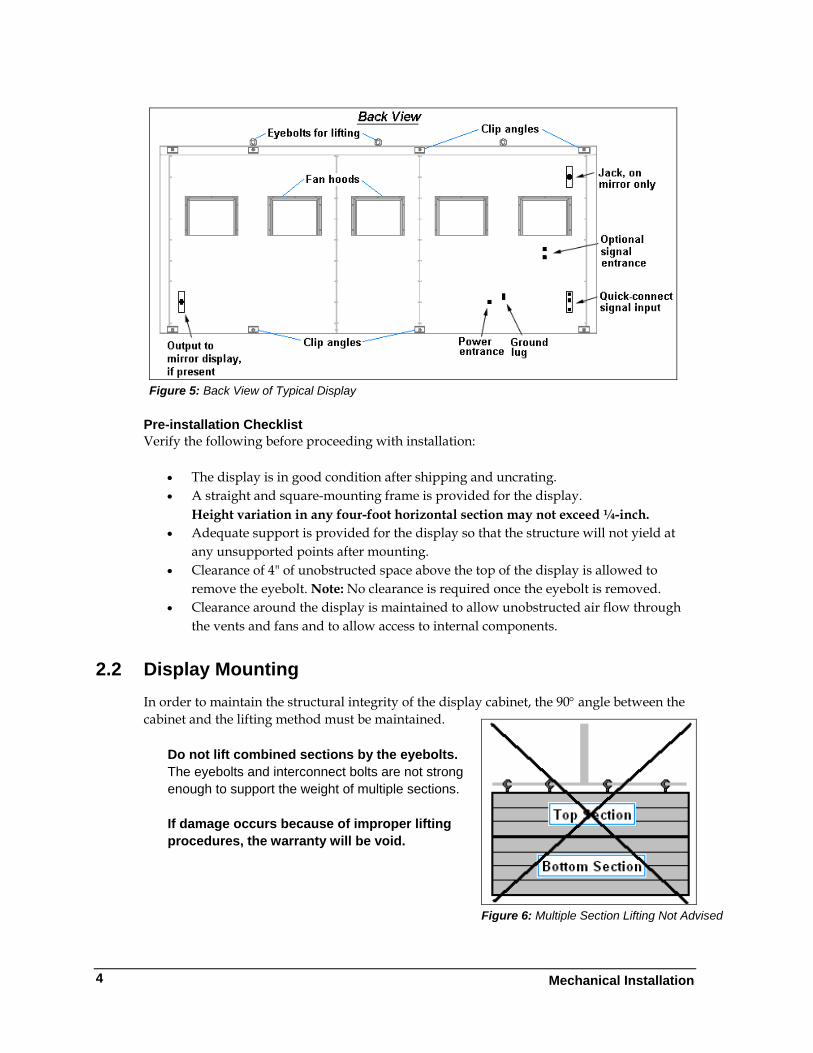
Figure 5: Back View of Typical Display
Pre-installation Checklist Verify the following before proceeding with installation:
• The display is in good condition after shipping and uncrating. • A straight and square-mounting frame is provided for the display.
Height variation in any four-foot horizontal section may not exceed ¼-inch. • Adequate support is provided for the display so that the structure will not yield at
any unsupported points after mounting. • Clearance of 4" of unobstructed space above the top of the display is allowed to
remove the eyebolt. Note: No clearance is required once the eyebolt is removed. • Clearance around the display is maintained to allow unobstructed air flow through
the vents and fans and to allow access to internal components.
2.2 Display Mounting In order to maintain the structural integrity of the display cabinet, the 90° angle between the cabinet and the lifting method must be maintained.
Figure 6: Multiple Section Lifting Not Advised
Do not lift combined sections by the eyebolts. The eyebolts and interconnect bolts are not strong enough to support the weight of multiple sections. If damage occurs because of improper lifting procedures, the warranty will be void.
4 Mechanical Installation
General Mounting Procedure for Displays less than 112 pixels high
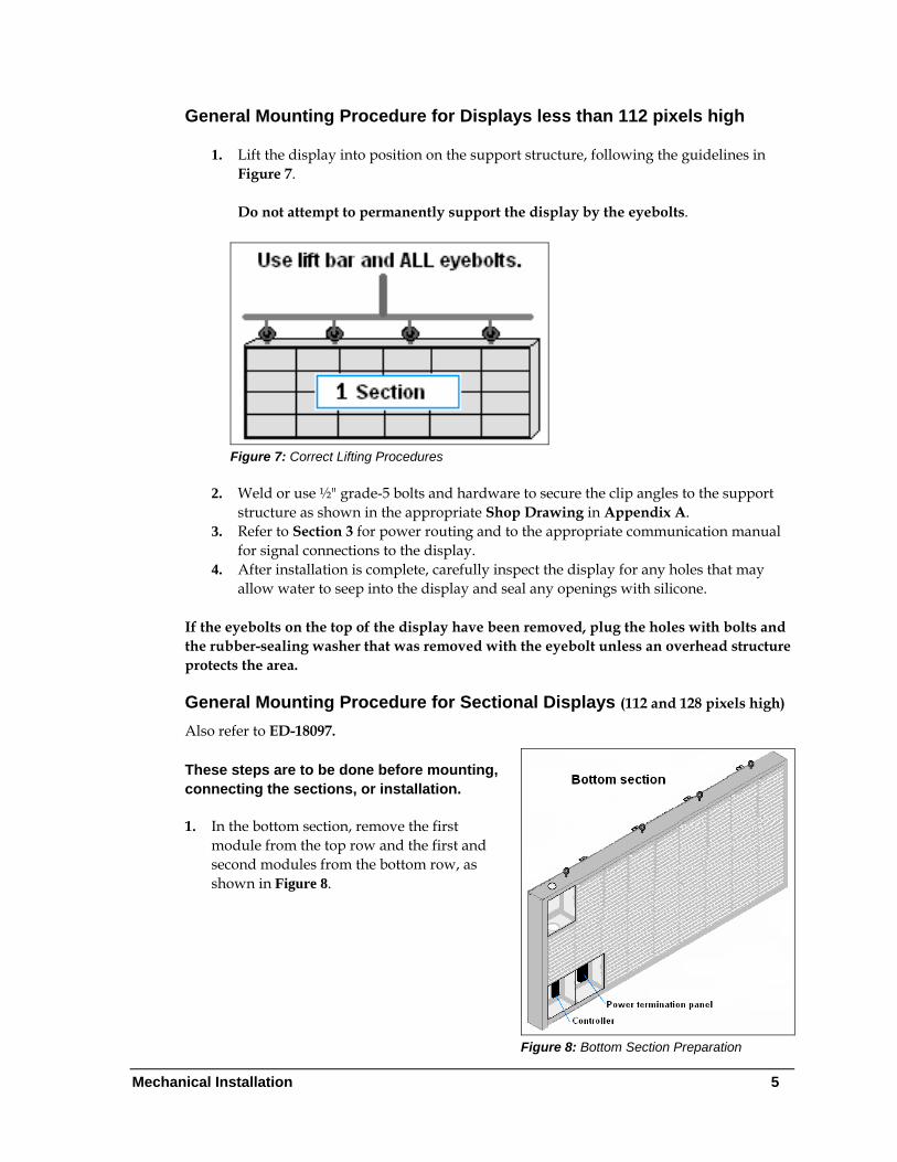
1. Lift the display into position on the support structure, following the guidelines in Figure 7.
Do not attempt to permanently support the display by the eyebolts.
Figure 7: Correct Lifting Procedures
2. Weld or use ½" grade-5 bolts and hardware to secure the clip angles to the support
structure as shown in the appropriate Shop Drawing in Appendix A. 3. Refer to Section 3 for power routing and to the appropriate communication manual
for signal connections to the display. 4. After installation is complete, carefully inspect the display for any holes that may
allow water to seep into the display and seal any openings with silicone.
If the eyebolts on the top of the display have been removed, plug the holes with bolts and the rubber-sealing washer that was removed with the eyebolt unless an overhead structure protects the area.
General Mounting Procedure for Sectional Displays (112 and 128 pixels high)
Also refer to ED-18097.
Figure 8: Bottom Section Preparation
These steps are to be done before mounting, connecting the sections, or installation. 1. In the bottom section, remove the first
module from the top row and the first and second modules from the bottom row, as shown in Figure 8.
Mechanical Installation 5
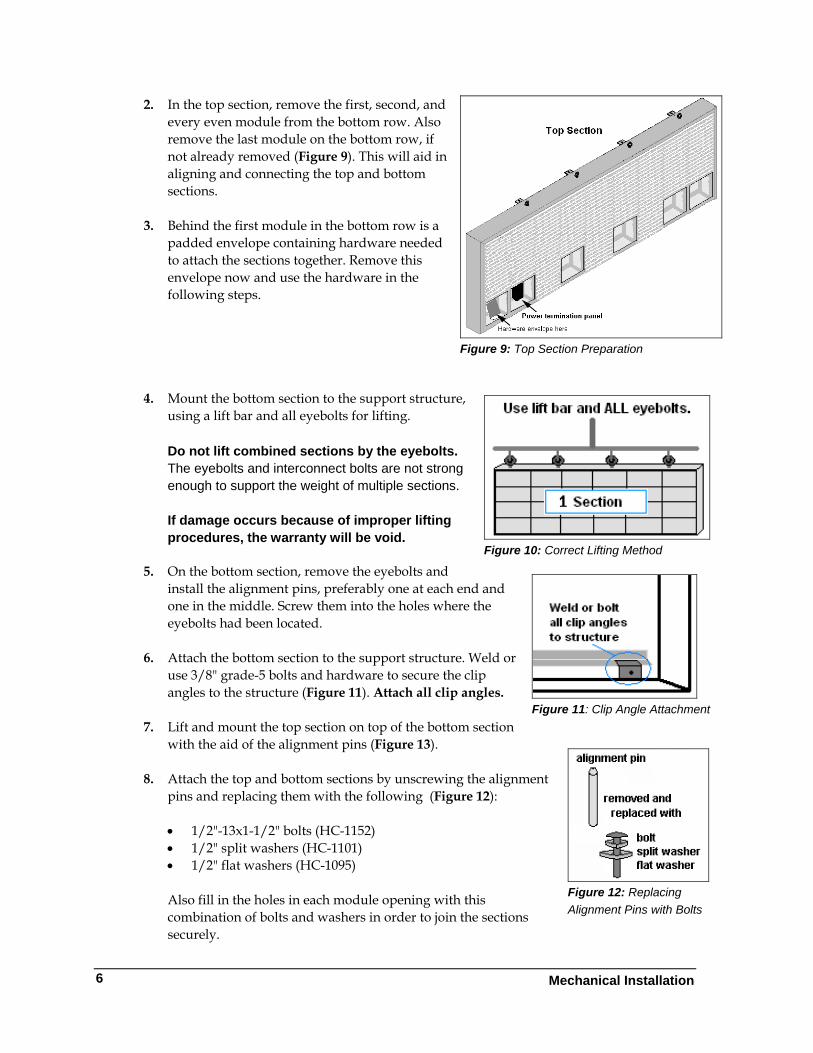
2. In the top section, remove the first, second, and every even module from the bottom row. Also remove the last module on the bottom row, if not already removed (Figure 9). This will aid in aligning and connecting the top and bottom sections.
Figure 9: Top Section Preparation
3. Behind the first module in the bottom row is a
padded envelope containing hardware needed to attach the sections together. Remove this envelope now and use the hardware in the following steps.
4. Mount the bottom section to the support structure,
using a lift bar and all eyebolts for lifting.
Figure 10: Correct Lifting Method
Do not lift combined sections by the eyebolts. The eyebolts and interconnect bolts are not strong enough to support the weight of multiple sections.
If damage occurs because of improper lifting procedures, the warranty will be void.
5. On the bottom section, remove the eyebolts and
install the alignment pins, preferably one at each end and one in the middle. Screw them into the holes where the eyebolts had been located.
Figure 11: Clip Angle Attachment
6. Attach the bottom section to the support structure. Weld or
use 3/8" grade-5 bolts and hardware to secure the clip angles to the structure (Figure 11). Attach all clip angles.
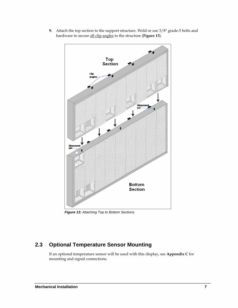
7. Lift and mount the top section on top of the bottom section
with the aid of the alignment pins (Figure 13).
Figure 12: Replacing Alignment Pins with Bolts
8. Attach the top and bottom sections by unscrewing the alignment
pins and replacing them with the following (Figure 12):
• 1/2"-13x1-1/2" bolts (HC-1152) • 1/2" split washers (HC-1101) • 1/2" flat washers (HC-1095)
Also fill in the holes in each module opening with this combination of bolts and washers in order to join the sections securely.
6 Mechanical Installation
Mechanical Installation 7
9. Attach the top section to the support structure. Weld or use 3/8" grade-5 bolts and hardware to secure all clip angles to the structure (Figure 13).
Figure 13: Attaching Top to Bottom Sections
2.3 Optional Temperature Sensor Mounting If an optional temperature sensor will be used with this display, see Appendix C for mounting and signal connections.

Power Installation 9
Section 3: Power Installation
Read the Mechanical, Power, and Signal Installation sections before installing the display(s). Only a qualified individual should terminate power and signal cable at this Daktronics display. All proposed changes must be approved by Daktronics engineering staff or the warranty will be rendered null and void.
3.1 Conduit Daktronics does not include the conduit. Separate conduit must be used to route:
• Power. • signal IN wires to the signal termination enclosure, when applicable. • signal OUT wires (if not using the provided interconnect cable).
Most displays are provided with unthreaded knockouts on the back for use with ½” conduit. The 16 pixel high displays have a J-box on the back for power termination.
3.2 Overview of Power/ Signal Connection
Following is a brief summary of the power and signal connections to the display.
1. Power to the display will be terminated internally in most cases. Section 3.5 shows the internal wiring diagrams.
2. Possible methods for signal termination are shown in the manual for the specific communication type.
3. Power is routed to the display through a fused disconnect switch capable of opening all ungrounded power conductors. Install this disconnect within the line-of-sight of any personnel performing maintenance on the display. (If the disconnect is located out of sight of the display, it must be capable of being locked in the open position.)
Note: Displays are equipped with overcurrent protection devices that carry a UL489 or UL1077 (IEC 60947, VDE 660) rating. These devices are only intended to protect the components within the display. Suitable devices must be used for the equipment and feeders supplying power to the display.
4. Power conductors from the disconnect to the display should be routed through conduit in agreement with local code.
5. Display power will terminate internally at the power termination panel. 6. Connect the grounding electrode conductor at the grounding lug on the back of the
display. With sectional displays, connect one grounding lug to earth ground and run the bonding jumper between display sections.
Power Installation
10
7. Signal cable is routed to the signal termination enclosure. When a ground cable is provided with the enclosure, ground the enclosure to an isolated earth ground connector.
8. Signal into the enclosures must be routed through conduit. The knockouts in the enclosures require the use of ½" conduit.
9. The signal quick-connect cable from the enclosure to the display can be routed through conduit or through the display pole if power is not also routed in the display pole.
Note: Daktronics strongly recommends that the quick-connect cable be secured to protect it from weather or vandalism.
3.3 Power Requirements Do not connect the displays to any voltage other than that listed on the Daktronics product label. Important Note: Conductors of circuits delivering power to a Daktronics display shall be sized in accordance with NEC and local electrical codes so that the power distribution system is capable of delivering full load power to the display while maintaining a voltage within 5% of the utility nominal voltage. Each display size may be constructed to use either single-phase or three-phase power, with the exception of the 16 high displays which use only single-phase power. Proper power installation is imperative for proper display operation. Power specifications for various size displays can be found in Appendix A. The following sub-sections provide general details of power installation. Main Disconnect The National Electrical Code requires the use of a lockable power disconnect near the display. Provide a lockable disconnect switch (knife switch) at the display location so that all power lines can be completely disconnected. Use a disconnect so that all hot lines and the neutral can be disconnected. The main disconnect should be mounted at or near the point of power connection. A main disconnect is to be provided for each supply circuit to the display. The disconnecting means must be located in a direct line of sight from the display or outline lighting that it controls. This requirement enables a worker to keep the disconnecting means within view while working on the display. Exception: Disconnect components that are capable of being locked in the open position may be located elsewhere.
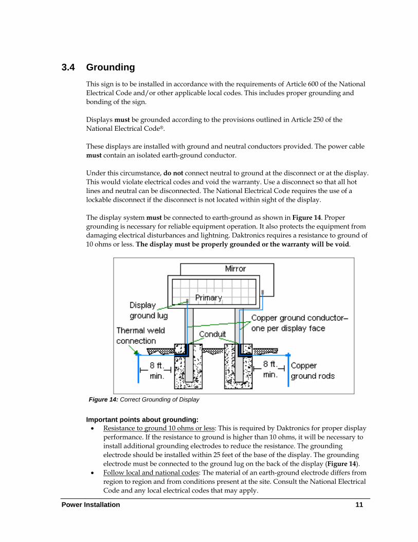
3.4 Grounding This sign is to be installed in accordance with the requirements of Article 600 of the National Electrical Code and/or other applicable local codes. This includes proper grounding and bonding of the sign. Displays must be grounded according to the provisions outlined in Article 250 of the National Electrical Code®. These displays are installed with ground and neutral conductors provided. The power cable must contain an isolated earth-ground conductor. Under this circumstance, do not connect neutral to ground at the disconnect or at the display. This would violate electrical codes and void the warranty. Use a disconnect so that all hot lines and neutral can be disconnected. The National Electrical Code requires the use of a lockable disconnect if the disconnect is not located within sight of the display. The display system must be connected to earth-ground as shown in Figure 14. Proper grounding is necessary for reliable equipment operation. It also protects the equipment from damaging electrical disturbances and lightning. Daktronics requires a resistance to ground of 10 ohms or less. The display must be properly grounded or the warranty will be void.
Figure 14: Correct Grounding of Display
Important points about grounding: • Resistance to ground 10 ohms or less: This is required by Daktronics for proper display
performance. If the resistance to ground is higher than 10 ohms, it will be necessary to install additional grounding electrodes to reduce the resistance. The grounding electrode should be installed within 25 feet of the base of the display. The grounding electrode must be connected to the ground lug on the back of the display (Figure 14).
• Follow local and national codes: The material of an earth-ground electrode differs from region to region and from conditions present at the site. Consult the National Electrical Code and any local electrical codes that may apply.
Power Installation 11
• Support structure cannot be used as an earth-ground electrode: The support is generally embedded in concrete, and if in earth, the steel is either primed or it corrodes, making it a poor ground.
• One grounding electrode for each display face: The grounding electrode is typically one grounding rod for each display face. Other grounding electrodes as described in Article 250 of the National Electric Code may be used. Note: Each section of a sectional display has a ground lug but only one lug per display face needs to be connected to the ground rod. A bonding jumper runs between sections.
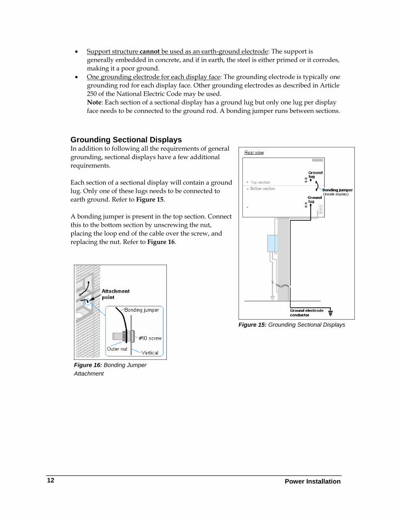
Grounding Sectional Displays In addition to following all the requirements of general grounding, sectional displays have a few additional requirements.
Figure 15: Grounding Sectional Displays
Each section of a sectional display will contain a ground lug. Only one of these lugs needs to be connected to earth ground. Refer to Figure 15. A bonding jumper is present in the top section. Connect this to the bottom section by unscrewing the nut, placing the loop end of the cable over the screw, and replacing the nut. Refer to Figure 16.
Figure 16: Bonding Jumper Attachment
Power Installation
12
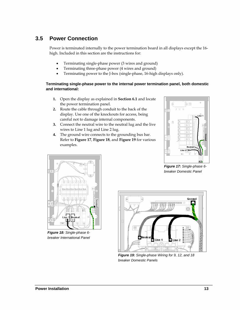
3.5 Power Connection Power is terminated internally to the power termination board in all displays except the 16-high. Included in this section are the instructions for:
• Terminating single-phase power (3 wires and ground) • Terminating three-phase power (4 wires and ground) • Terminating power to the J-box (single-phase, 16-high displays only).
Terminating single-phase power to the internal power termination panel, both domestic and international:
1. Open the display as explained in Section 6.1 and locate the power termination panel.
Figure 17: Single-phase 6-breaker Domestic Panel
2. Route the cable through conduit to the back of the display. Use one of the knockouts for access, being careful not to damage internal components.
3. Connect the neutral wire to the neutral lug and the live wires to Line 1 lug and Line 2 lug.
4. The ground wire connects to the grounding bus bar. Refer to Figure 17, Figure 18, and Figure 19 for various examples.
Figure 18: Single-phase 6-breaker International Panel
Figure 19: Single-phase Wiring for 9, 12, and 18 breaker Domestic Panels
Power Installation 13
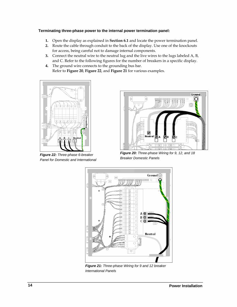
Terminating three-phase power to the internal power termination panel:
1. Open the display as explained in Section 6.1 and locate the power termination panel. 2. Route the cable through conduit to the back of the display. Use one of the knockouts
for access, being careful not to damage internal components. 3. Connect the neutral wire to the neutral lug and the live wires to the lugs labeled A, B,
and C. Refer to the following figures for the number of breakers in a specific display. 4. The ground wire connects to the grounding bus bar.
Refer to Figure 20, Figure 22, and Figure 21 for various examples.
Figure 22: Three-phase 6-breaker Panel for Domestic and International
Figure 20: Three-phase Wiring for 9, 12, and 18 Breaker Domestic Panels
Figure 21: Three-phase Wiring for 9 and 12 breaker International Panels
Power Installation
14
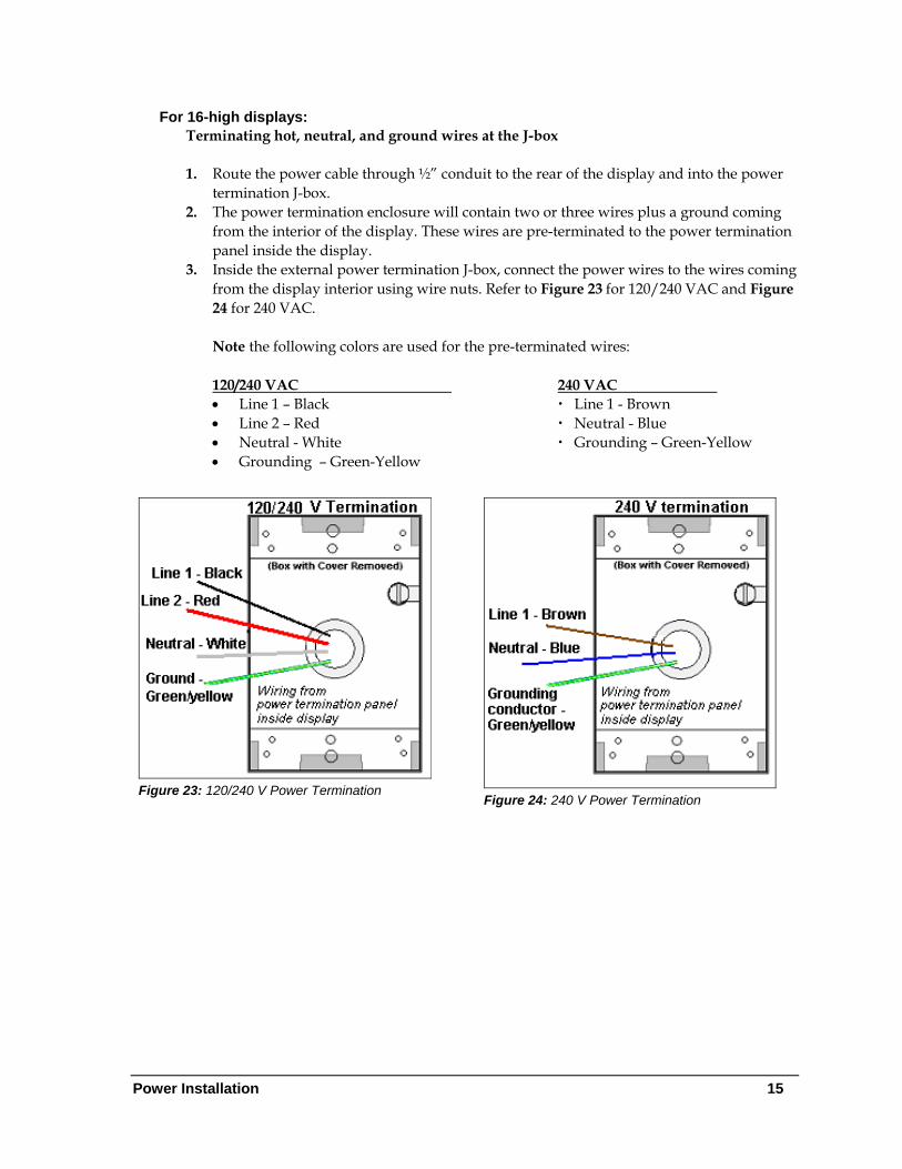
For 16-high displays: Terminating hot, neutral, and ground wires at the J-box
1. Route the power cable through ½” conduit to the rear of the display and into the power
termination J-box. 2. The power termination enclosure will contain two or three wires plus a ground coming
from the interior of the display. These wires are pre-terminated to the power termination panel inside the display.
3. Inside the external power termination J-box, connect the power wires to the wires coming from the display interior using wire nuts. Refer to Figure 23 for 120/240 VAC and Figure 24 for 240 VAC.
Note the following colors are used for the pre-terminated wires: 120/240 VAC 240 VAC • Line 1 – Black Line 1 - Brown • Line 2 – Red Neutral - Blue • Neutral - White Grounding – Green-Yellow • Grounding – Green-Yellow
Figure 23: 120/240 V Power Termination Figure 24: 240 V Power Termination
Power Installation 15
Power Installation
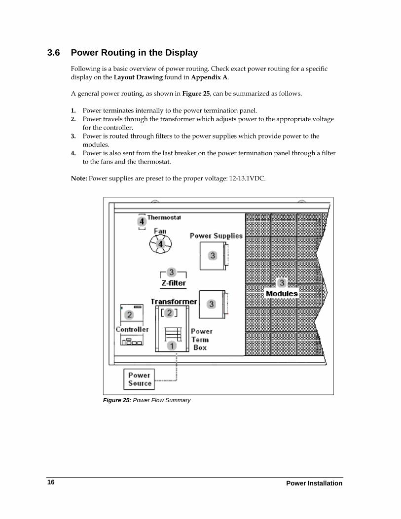
3.6 Power Routing in the Display Following is a basic overview of power routing. Check exact power routing for a specific display on the Layout Drawing found in Appendix A. A general power routing, as shown in Figure 25, can be summarized as follows. 1. Power terminates internally to the power termination panel. 2. Power travels through the transformer which adjusts power to the appropriate voltage
for the controller. 3. Power is routed through filters to the power supplies which provide power to the
modules. 4. Power is also sent from the last breaker on the power termination panel through a filter
to the fans and the thermostat. Note: Power supplies are preset to the proper voltage: 12-13.1VDC.
Figure 25: Power Flow Summary
16
Section 4: Signal Installation Overview
Daktronics GalaxyPro® displays are equipped to receive many types of communication signals. The following sections include a brief description of each available communication type. Also included is a list of troubleshooting tips to check that the display is connected and configured correctly. For specific details on installing the communication signal, consult the quick guide and manual included in the box with the communication equipment. Each type of communication is listed below with its manual number.
Communication Type Communication Manual ED# Wireless Ethernet Bridge ED-16483
Ethernet ED-14745 Fiber Ethernet ED-14746
Note: These are the standard communication types but each site is unique and may include additional equipment. If problems arise, contact the display’s service company or Daktronics Customer Service.
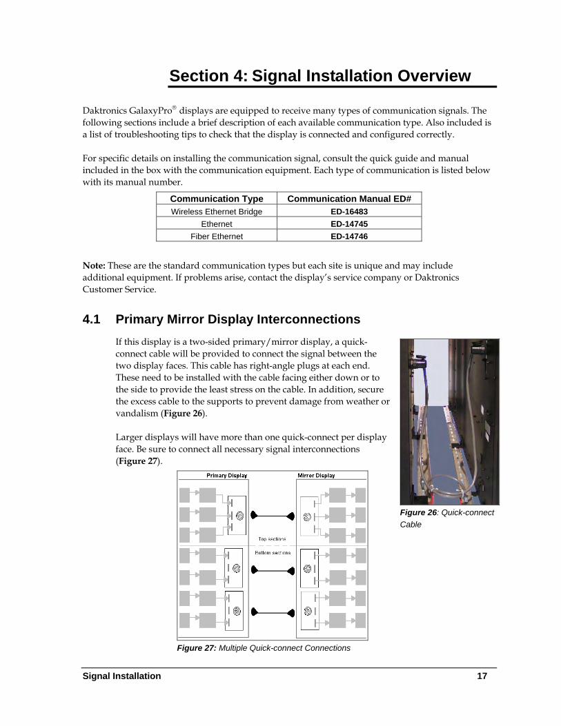
4.1 Primary Mirror Display Interconnections If this display is a two-sided primary/mirror display, a quick-connect cable will be provided to connect the signal between the two display faces. This cable has right-angle plugs at each end. These need to be installed with the cable facing either down or to the side to provide the least stress on the cable. In addition, secure the excess cable to the supports to prevent damage from weather or vandalism (Figure 26).
Figure 26: Quick-connect Cable
Larger displays will have more than one quick-connect per display face. Be sure to connect all necessary signal interconnections (Figure 27).
Figure 27: Multiple Quick-connect Connections
Signal Installation 17
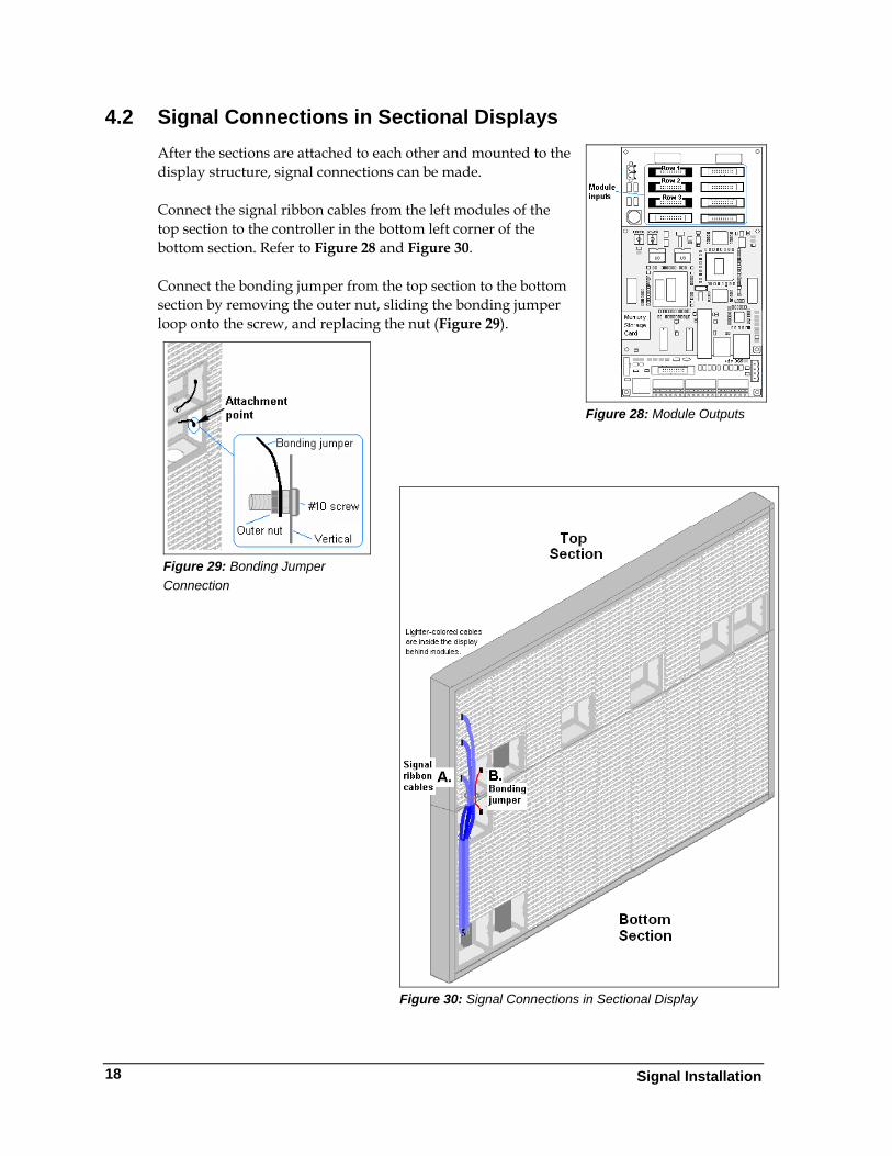
4.2 Signal Connections in Sectional Displays After the sections are attached to each other and mounted to the display structure, signal connections can be made.
Figure 28: Module Outputs
Connect the signal ribbon cables from the left modules of the top section to the controller in the bottom left corner of the bottom section. Refer to Figure 28 and Figure 30. Connect the bonding jumper from the top section to the bottom section by removing the outer nut, sliding the bonding jumper loop onto the screw, and replacing the nut (Figure 29).
Figure 29: Bonding Jumper Connection
Figure 30: Signal Connections in Sectional Display
Signal Installation
18
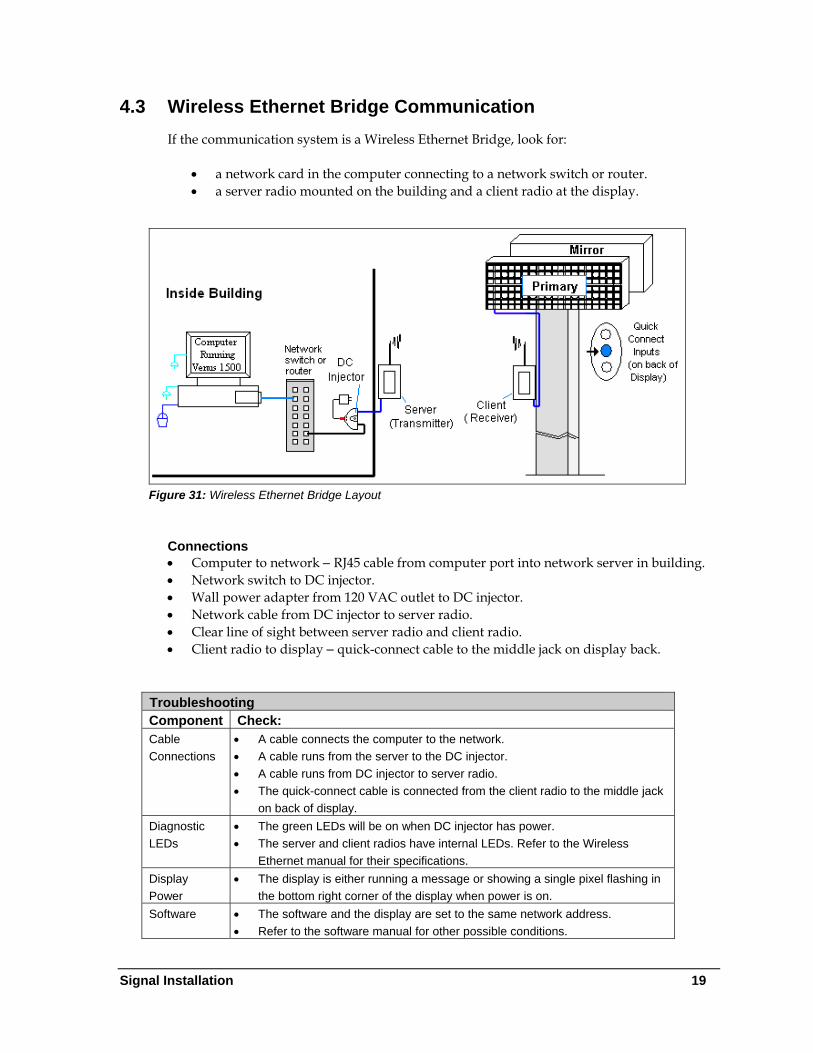
4.3 Wireless Ethernet Bridge Communication If the communication system is a Wireless Ethernet Bridge, look for:
• a network card in the computer connecting to a network switch or router. • a server radio mounted on the building and a client radio at the display.
Figure 31: Wireless Ethernet Bridge Layout
Connections • Computer to network − RJ45 cable from computer port into network server in building. • Network switch to DC injector. • Wall power adapter from 120 VAC outlet to DC injector. • Network cable from DC injector to server radio. • Clear line of sight between server radio and client radio. • Client radio to display − quick-connect cable to the middle jack on display back.
Troubleshooting Component Check: Cable Connections
• A cable connects the computer to the network. • A cable runs from the server to the DC injector. • A cable runs from DC injector to server radio. • The quick-connect cable is connected from the client radio to the middle jack
on back of display. Diagnostic LEDs
• The green LEDs will be on when DC injector has power. • The server and client radios have internal LEDs. Refer to the Wireless
Ethernet manual for their specifications. Display Power
• The display is either running a message or showing a single pixel flashing in the bottom right corner of the display when power is on.
Software • The software and the display are set to the same network address. • Refer to the software manual for other possible conditions.
Signal Installation 19
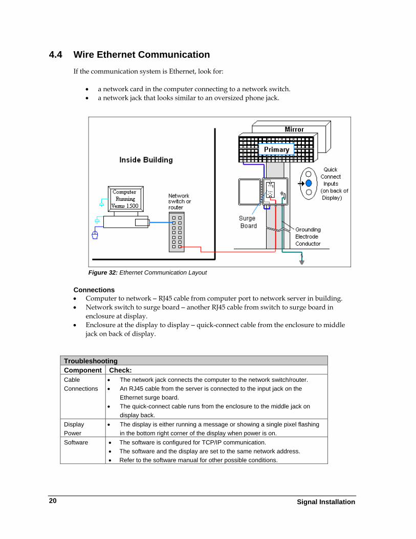
4.4 Wire Ethernet Communication If the communication system is Ethernet, look for:
• a network card in the computer connecting to a network switch. • a network jack that looks similar to an oversized phone jack.
Figure 32: Ethernet Communication Layout
Connections • Computer to network − RJ45 cable from computer port to network server in building. • Network switch to surge board − another RJ45 cable from switch to surge board in
enclosure at display. • Enclosure at the display to display − quick-connect cable from the enclosure to middle
jack on back of display.
Troubleshooting Component Check: Cable Connections
• The network jack connects the computer to the network switch/router. • An RJ45 cable from the server is connected to the input jack on the
Ethernet surge board. • The quick-connect cable runs from the enclosure to the middle jack on
display back. Display Power
• The display is either running a message or showing a single pixel flashing in the bottom right corner of the display when power is on.
Software • The software is configured for TCP/IP communication. • The software and the display are set to the same network address. • Refer to the software manual for other possible conditions.
Signal Installation
20
Signal Installation 21
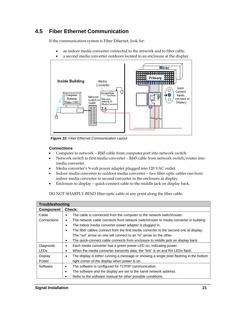
4.5 Fiber Ethernet Communication If the communication system is Fiber Ethernet, look for:
• an indoor media converter connected to the network and to fiber cable. • a second media converter outdoors located in an enclosure at the display.
Figure 33: Fiber Ethernet Communication Layout
Connections • Computer to network − RJ45 cable from computer port into network switch. • Network switch to first media converter − RJ45 cable from network switch/router into
media converter. • Media converter’s 9-volt power adapter plugged into 120 VAC outlet. • Indoor media converter to outdoor media converter − two fiber-optic cables run from
indoor media converter to second converter in the enclosure at display. • Enclosure to display − quick-connect cable to the middle jack on display back. DO NOT SHARPLY BEND fiber-optic cable at any point along the fiber cable.
Troubleshooting Component Check: Cable Connections
• The cable is connected from the computer to the network switch/router. • The network cable connects from network switch/router to media converter in building. • The indoor media converter power adapter is plugged in. • The fiber cables connect from the first media converter to the second one at display.
The “out” arrow on one will connect to an “in” arrow on the other. • The quick-connect cable connects from enclosure to middle jack on display back.
Diagnostic LEDs
• Each media converter has a green power LED on, indicating power. • When the media converter transmits data, the “link” is on and RX LEDs flash.
Display Power
• The display is either running a message or showing a single pixel flashing in the bottom right corner of the display when power is on.
Software • The software is configured for TCP/IP communication. • The software and the display are set to the same network address. • Refer to the software manual for other possible conditions.

Section 5: Start-up Procedure
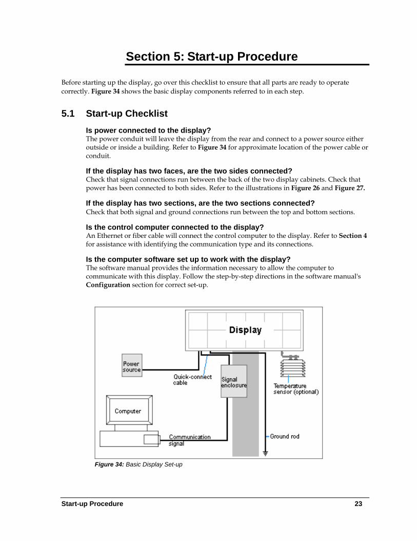
Before starting up the display, go over this checklist to ensure that all parts are ready to operate correctly. Figure 34 shows the basic display components referred to in each step.
5.1 Start-up Checklist Is power connected to the display? The power conduit will leave the display from the rear and connect to a power source either outside or inside a building. Refer to Figure 34 for approximate location of the power cable or conduit.
If the display has two faces, are the two sides connected? Check that signal connections run between the back of the two display cabinets. Check that power has been connected to both sides. Refer to the illustrations in Figure 26 and Figure 27.
If the display has two sections, are the two sections connected? Check that both signal and ground connections run between the top and bottom sections.
Is the control computer connected to the display? An Ethernet or fiber cable will connect the control computer to the display. Refer to Section 4 for assistance with identifying the communication type and its connections.
Is the computer software set up to work with the display? The software manual provides the information necessary to allow the computer to communicate with this display. Follow the step-by-step directions in the software manual's Configuration section for correct set-up.
Figure 34: Basic Display Set-up
Start-up Procedure 23
Start-up Procedure
24
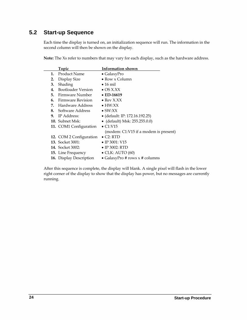
5.2 Start-up Sequence Each time the display is turned on, an initialization sequence will run. The information in the second column will then be shown on the display. Note: The Xs refer to numbers that may vary for each display, such as the hardware address. Topic Information shown
1. Product Name • GalaxyPro 2. Display Size • Row x Column 3. Shading • 16 mil 4. Bootloader Version • OS X.XX 5. Firmware Number • ED-16619 6. Firmware Revision • Rev X.XX 7. Hardware Address • HW:XX 8. Software Address • SW:XX 9. IP Address: • (default: IP: 172.16.192.25) 10. Subnet Msk: • (default) Msk: 255.255.0.0) 11. COM1 Configuration • C1:V15
(modem: C1:V15 if a modem is present) 12. COM 2 Configuration • C2: RTD 13. Socket 3001: • IP 3001: V15 14. Socket 3002: • IP 3002: RTD 15. Line Frequency • CLK: AUTO (60) 16. Display Description • GalaxyPro # rows x # columns
After this sequence is complete, the display will blank. A single pixel will flash in the lower right corner of the display to show that the display has power, but no messages are currently running.
Section 6: Maintenance
Important Notes: • Power must be turned OFF before any repair or maintenance work is done on the display. • Qualified service personnel are recommended for servicing internal electronic components. • The Daktronics’ engineering staff must approve ANY changes made to the display. Before
altering the display, detailed drawings for proposed modifications must be submitted to Daktronics’ engineering staff for evaluation and approval, or the warranty will be rendered null and void.
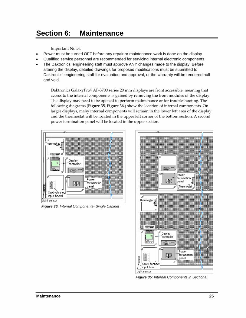
Daktronics GalaxyPro® AF-3700 series 20 mm displays are front accessible, meaning that access to the internal components is gained by removing the front modules of the display. The display may need to be opened to perform maintenance or for troubleshooting. The following diagrams (Figure 35, Figure 36,) show the location of internal components. On larger displays, many internal components will remain in the lower left area of the display and the thermostat will be located in the upper left corner of the bottom section. A second power termination panel will be located in the upper section.
Figure 36: Internal Components- Single Cabinet
Figure 35: Internal Components in Sectional
Maintenance 25
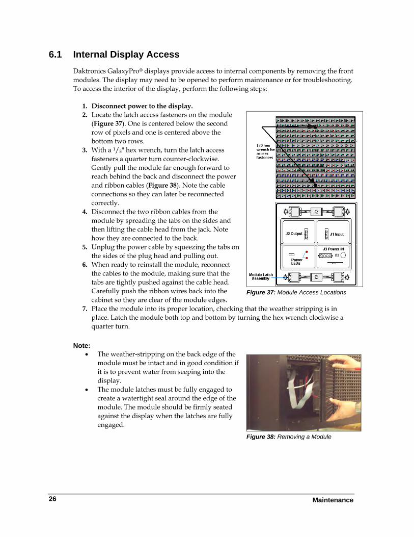
6.1 Internal Display Access Daktronics GalaxyPro® displays provide access to internal components by removing the front modules. The display may need to be opened to perform maintenance or for troubleshooting. To access the interior of the display, perform the following steps:
1. Disconnect power to the display. 2. Locate the latch access fasteners on the module
(Figure 37). One is centered below the second row of pixels and one is centered above the bottom two rows.
Figure 37: Module Access Locations
3. With a 1/8" hex wrench, turn the latch access fasteners a quarter turn counter-clockwise. Gently pull the module far enough forward to reach behind the back and disconnect the power and ribbon cables (Figure 38). Note the cable connections so they can later be reconnected correctly.
4. Disconnect the two ribbon cables from the module by spreading the tabs on the sides and then lifting the cable head from the jack. Note how they are connected to the back.
5. Unplug the power cable by squeezing the tabs on the sides of the plug head and pulling out.
6. When ready to reinstall the module, reconnect the cables to the module, making sure that the tabs are tightly pushed against the cable head. Carefully push the ribbon wires back into the cabinet so they are clear of the module edges.
7. Place the module into its proper location, checking that the weather stripping is in place. Latch the module both top and bottom by turning the hex wrench clockwise a quarter turn.
Note:
• The weather-stripping on the back edge of the module must be intact and in good condition if it is to prevent water from seeping into the display.
Figure 38: Removing a Module
• The module latches must be fully engaged to create a watertight seal around the edge of the module. The module should be firmly seated against the display when the latches are fully engaged.
Maintenance
26
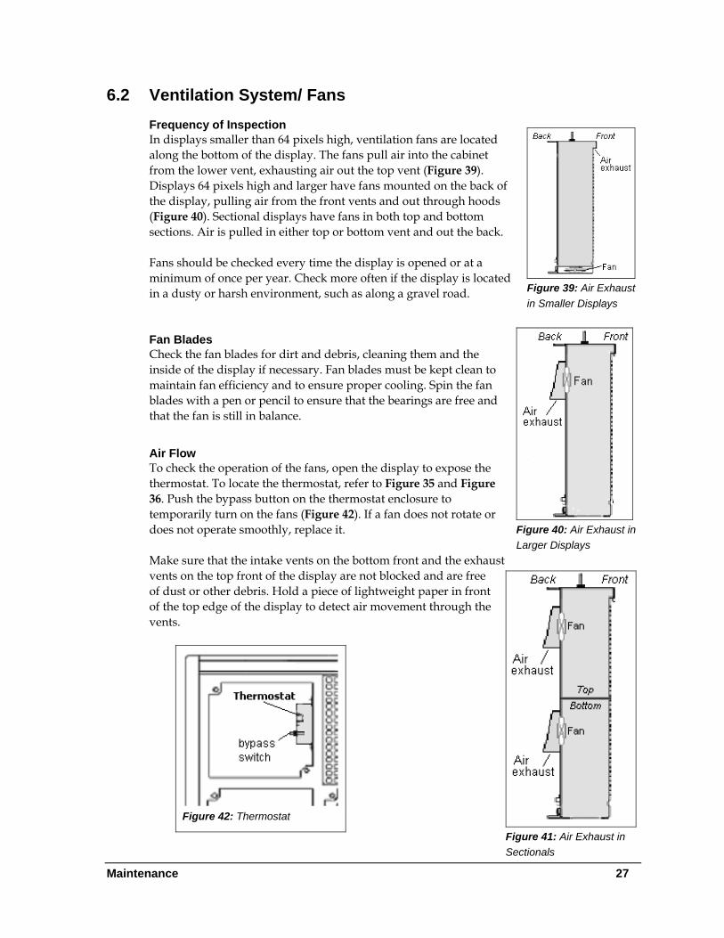
6.2 Ventilation System/ Fans Frequency of Inspection
Figure 39: Air Exhaust in Smaller Displays
In displays smaller than 64 pixels high, ventilation fans are located along the bottom of the display. The fans pull air into the cabinet from the lower vent, exhausting air out the top vent (Figure 39). Displays 64 pixels high and larger have fans mounted on the back of the display, pulling air from the front vents and out through hoods (Figure 40). Sectional displays have fans in both top and bottom sections. Air is pulled in either top or bottom vent and out the back. Fans should be checked every time the display is opened or at a minimum of once per year. Check more often if the display is located in a dusty or harsh environment, such as along a gravel road.
Figure 40: Air Exhaust in Larger Displays
Fan Blades Check the fan blades for dirt and debris, cleaning them and the inside of the display if necessary. Fan blades must be kept clean to maintain fan efficiency and to ensure proper cooling. Spin the fan blades with a pen or pencil to ensure that the bearings are free and that the fan is still in balance.
Air Flow To check the operation of the fans, open the display to expose the thermostat. To locate the thermostat, refer to Figure 35 and Figure 36. Push the bypass button on the thermostat enclosure to temporarily turn on the fans (Figure 42). If a fan does not rotate or does not operate smoothly, replace it. Make sure that the intake vents on the bottom front and the exhaust vents on the top front of the display are not blocked and are free of dust or other debris. Hold a piece of lightweight paper in front of the top edge of the display to detect air movement through the vents.
Figure 41: Air Exhaust in Sectionals
Figure 42: Thermostat
Maintenance 27
Maintenance
28
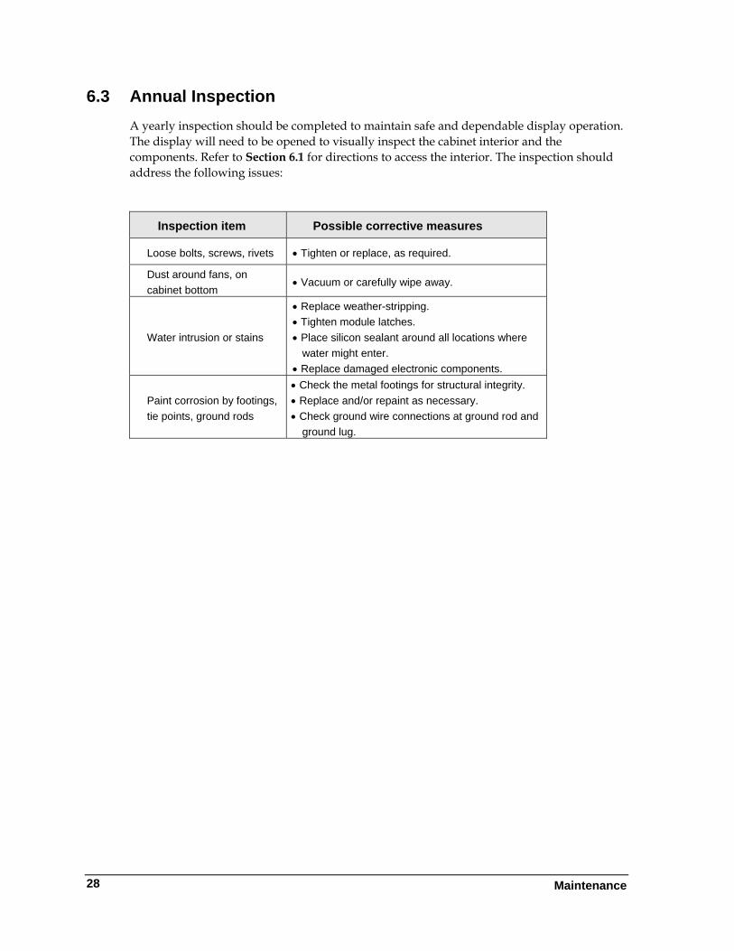
6.3 Annual Inspection A yearly inspection should be completed to maintain safe and dependable display operation. The display will need to be opened to visually inspect the cabinet interior and the components. Refer to Section 6.1 for directions to access the interior. The inspection should address the following issues:
Inspection item Possible corrective measures
Loose bolts, screws, rivets • Tighten or replace, as required.
Dust around fans, on cabinet bottom
• Vacuum or carefully wipe away.
Water intrusion or stains
• Replace weather-stripping. • Tighten module latches. • Place silicon sealant around all locations where
water might enter. • Replace damaged electronic components.
Paint corrosion by footings, tie points, ground rods
• Check the metal footings for structural integrity. • Replace and/or repaint as necessary. • Check ground wire connections at ground rod and
ground lug.
Section 7: Diagnostics and Troubleshooting
This section defines the diagnostic LEDs located on the controller and the temperature sensor. Troubleshooting tips are also provided for solving display problems. Safety Precautions
Disconnect power when servicing the display. Qualified service personnel are recommended for servicing internal electronic components.
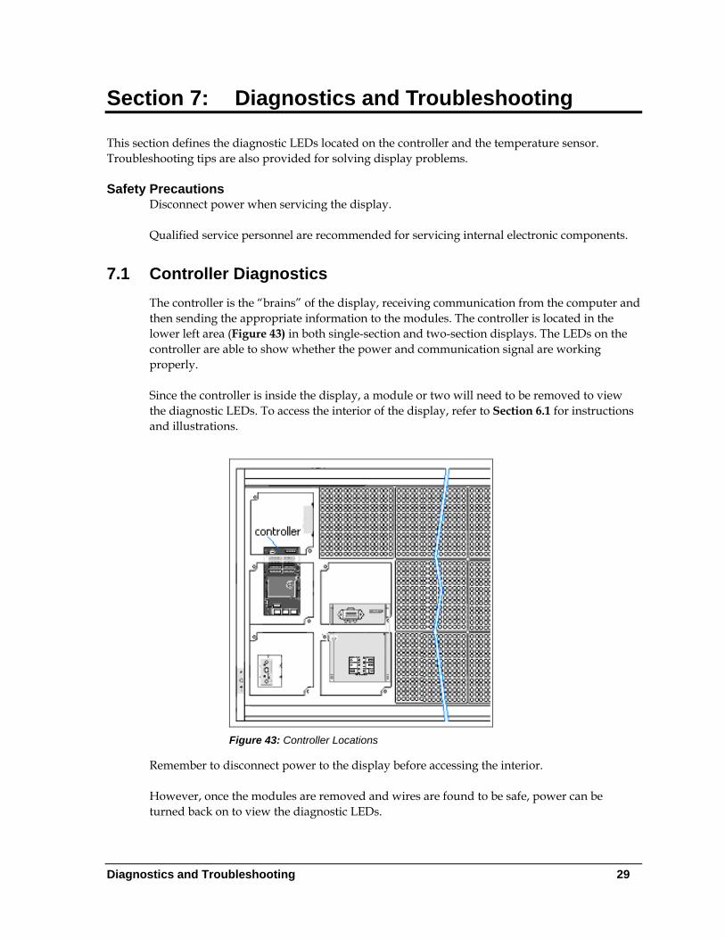
7.1 Controller Diagnostics The controller is the “brains” of the display, receiving communication from the computer and then sending the appropriate information to the modules. The controller is located in the lower left area (Figure 43) in both single-section and two-section displays. The LEDs on the controller are able to show whether the power and communication signal are working properly. Since the controller is inside the display, a module or two will need to be removed to view the diagnostic LEDs. To access the interior of the display, refer to Section 6.1 for instructions and illustrations.
Figure 43: Controller Locations
Remember to disconnect power to the display before accessing the interior. However, once the modules are removed and wires are found to be safe, power can be turned back on to view the diagnostic LEDs.
Diagnostics and Troubleshooting 29
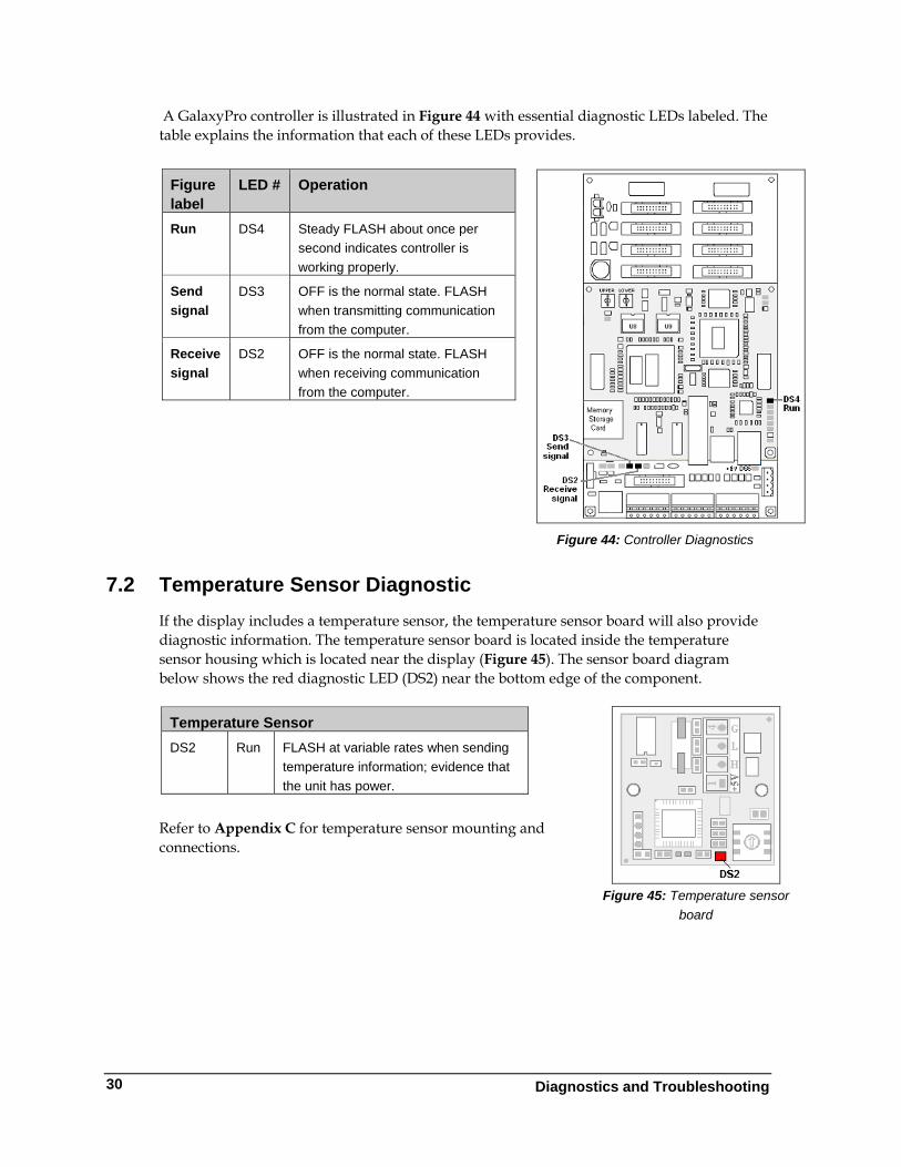
A GalaxyPro controller is illustrated in Figure 44 with essential diagnostic LEDs labeled. The table explains the information that each of these LEDs provides.
Diagnostics and Troubleshooting
30
7.2 Temperature Sensor Diagnostic If the display includes a temperature sensor, the temperature sensor board will also provide diagnostic information. The temperature sensor board is located inside the temperature sensor housing which is located near the display (Figure 45). The sensor board diagram below shows the red diagnostic LED (DS2) near the bottom edge of the component.
Refer to Appendix C for temperature sensor mounting and connections.
Figure label
LED # Operation
Run DS4 Steady FLASH about once per second indicates controller is working properly.
Send signal
DS3 OFF is the normal state. FLASH when transmitting communication from the computer.
Receive signal
DS2 OFF is the normal state. FLASH when receiving communication from the computer.
Figure 44: Controller Diagnostics
Figure 45: Temperature sensor
board
Temperature Sensor DS2 Run FLASH at variable rates when sending
temperature information; evidence that the unit has power.
7.3 Troubleshooting Display Problems This section contains some symptoms that may be encountered with the displays. This list does not include every possible symptom or solution but does represent common situations and simple steps to resolve them. The solutions are given in priority order so try the first solution first. Troubleshooting may require removal and replacement of modules. Refer to Section 6.1 for instructions on this procedure. When replacing modules, make sure that the power and signal cables are reconnected correctly and the latches are tightly closed.
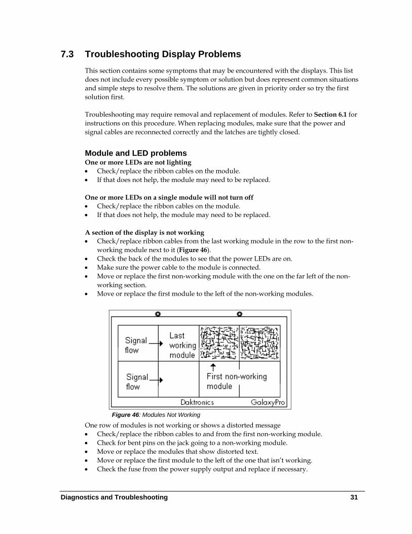
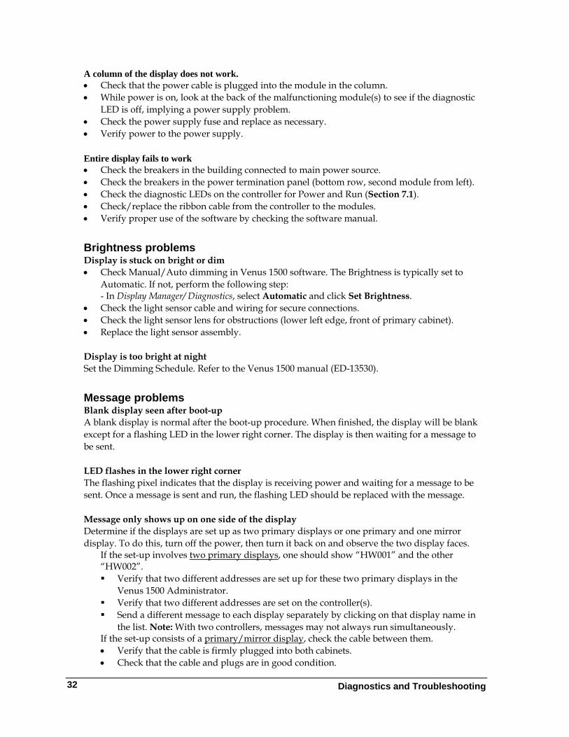
Module and LED problems One or more LEDs are not lighting • Check/replace the ribbon cables on the module. • If that does not help, the module may need to be replaced. One or more LEDs on a single module will not turn off • Check/replace the ribbon cables on the module. • If that does not help, the module may need to be replaced. A section of the display is not working • Check/replace ribbon cables from the last working module in the row to the first non-
working module next to it (Figure 46). • Check the back of the modules to see that the power LEDs are on. • Make sure the power cable to the module is connected. • Move or replace the first non-working module with the one on the far left of the non-
working section. • Move or replace the first module to the left of the non-working modules.
Figure 46: Modules Not Working
One row of modules is not working or shows a distorted message • Check/replace the ribbon cables to and from the first non-working module. • Check for bent pins on the jack going to a non-working module. • Move or replace the modules that show distorted text. • Move or replace the first module to the left of the one that isn’t working. • Check the fuse from the power supply output and replace if necessary.
Diagnostics and Troubleshooting 31
Diagnostics and Troubleshooting
32
A column of the display does not work. • Check that the power cable is plugged into the module in the column. • While power is on, look at the back of the malfunctioning module(s) to see if the diagnostic
LED is off, implying a power supply problem. • Check the power supply fuse and replace as necessary. • Verify power to the power supply.
Entire display fails to work • Check the breakers in the building connected to main power source. • Check the breakers in the power termination panel (bottom row, second module from left). • Check the diagnostic LEDs on the controller for Power and Run (Section 7.1). • Check/replace the ribbon cable from the controller to the modules. • Verify proper use of the software by checking the software manual.
Brightness problems Display is stuck on bright or dim
• Check Manual/Auto dimming in Venus 1500 software. The Brightness is typically set to Automatic. If not, perform the following step: - In Display Manager/ Diagnostics, select Automatic and click Set Brightness.
• Check the light sensor cable and wiring for secure connections. • Check the light sensor lens for obstructions (lower left edge, front of primary cabinet). • Replace the light sensor assembly.
Display is too bright at night Set the Dimming Schedule. Refer to the Venus 1500 manual (ED-13530).
Message problems Blank display seen after boot-up A blank display is normal after the boot-up procedure. When finished, the display will be blank except for a flashing LED in the lower right corner. The display is then waiting for a message to be sent.
LED flashes in the lower right corner The flashing pixel indicates that the display is receiving power and waiting for a message to be sent. Once a message is sent and run, the flashing LED should be replaced with the message.
Message only shows up on one side of the display Determine if the displays are set up as two primary displays or one primary and one mirror display. To do this, turn off the power, then turn it back on and observe the two display faces.
If the set-up involves two primary displays, one should show “HW001” and the other “HW002”. Verify that two different addresses are set up for these two primary displays in the
Venus 1500 Administrator. Verify that two different addresses are set on the controller(s). Send a different message to each display separately by clicking on that display name in
the list. Note: With two controllers, messages may not always run simultaneously. If the set-up consists of a primary/mirror display, check the cable between them. • Verify that the cable is firmly plugged into both cabinets. • Check that the cable and plugs are in good condition.
Diagnostics and Troubleshooting 33
Temperature problems (For displays with a temperature sensor installed.) Showing the current temperature on the display
1. Open the Venus 1500 Message Studio. 2. Choose File New if the temperature will be part of a new message or File Open if
this will be added to a current message. 3. Open the message field and click Data Fields at the top. 4. Choose Temperature. 5. Select the desired format. The field is now in the message. 6. Send and run the message and the temperature will now be shown. Note: The temperature sensor must be correctly installed before a current temperature can be shown.
Temperature shown is too high or too low
The temperature on the display can be adjusted either up or down to become more accurate. 1. Open the Venus 1500 Display Manager and click Diagnostic Control. 2. Click on the name of this display under the Display List. 3. To the right of the Set Temperature Offset button, use the slider bar to adjust the
temperature being shown. The change made will be shown next to the bar. The range is ±9°C. (1°C=1.8°F).
4. Once the adjustment is made, click Set Temperature Offset to send this change to the display.
Note: Repeat these steps for each primary display that shows the temperature.
Temperature always reads –196F/-127C degrees • Check the temperature sensor cable connections. • Look for bent pins on connectors. • Check that the temperature sensor is set to address 1. • Make sure the sensor has power by checking that the LED is blinking. • Replace the temperature sensor.
Testing displays Start and stop the test pattern
1. Open the Venus 1500 Display Manager and click Diagnostic Control. 2. Click on the name of the chosen display under the Display List, then choose Cycle All for
the complete sequence or use the arrow to choose the specific test to be shown. Click Start Test.
3. Once testing is finished, click on the name of the display, then click Stop Test. Note: This procedure must be done for each primary display being tested.
Before calling for help Steps to take before calling Daktronics Customer Service 1. Turn off the power breaker switch. Wait a few minutes and turn it back on. Have
someone watch the display(s) to make sure that the initialization sequence runs. 2. Once the sequence is complete, try to communicate with the display. 3. Check the Communication and Troubleshooting sections of this manual. 4. Call the service technician or Daktronics Customer Service at 866-343-3122. Note: It is helpful to be sitting at the control computer while talking with the service technician.
Diagnostics and Troubleshooting
34
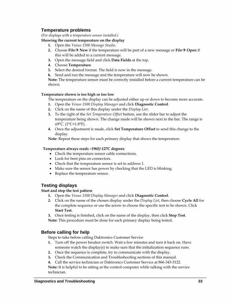
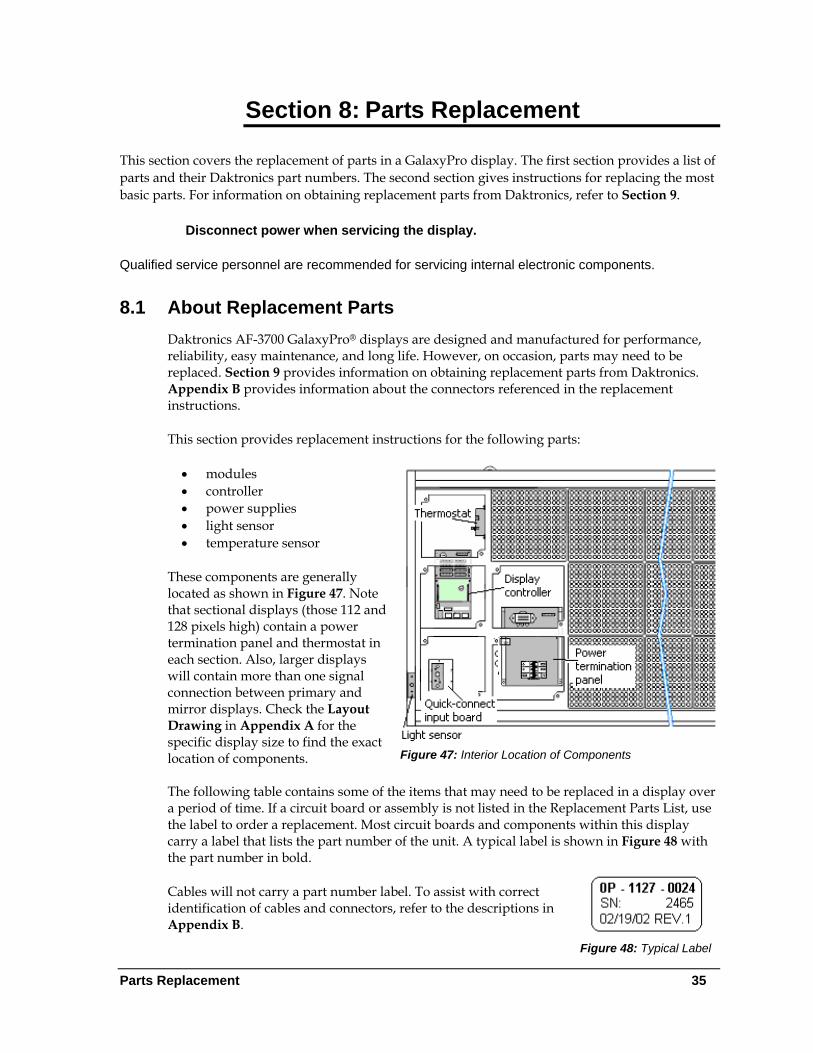
This chart is also provided inside the front cover of this manual for easy reference.
Information needed for technicians and/or Customer Service
Fill in the blank
Location address of the display:
Model number of the display: AF-3700
Version of software being used: (Right-click on Venus 1500 name in toolbar, choose “About Venus 1500”)
Venus 1500 v. _____
Method of communication being used: (See Section 4 for guidance)
Controller version used in the display: M3 controller
Section 8: Parts Replacement
This section covers the replacement of parts in a GalaxyPro display. The first section provides a list of parts and their Daktronics part numbers. The second section gives instructions for replacing the most basic parts. For information on obtaining replacement parts from Daktronics, refer to Section 9.
Disconnect power when servicing the display.
Qualified service personnel are recommended for servicing internal electronic components.
8.1 About Replacement Parts Daktronics AF-3700 GalaxyPro® displays are designed and manufactured for performance, reliability, easy maintenance, and long life. However, on occasion, parts may need to be replaced. Section 9 provides information on obtaining replacement parts from Daktronics. Appendix B provides information about the connectors referenced in the replacement instructions.
This section provides replacement instructions for the following parts:
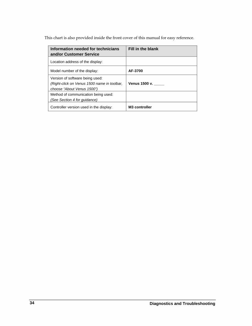
Figure 47: Interior Location of Components
• modules • controller • power supplies • light sensor • temperature sensor
These components are generally located as shown in Figure 47. Note that sectional displays (those 112 and 128 pixels high) contain a power termination panel and thermostat in each section. Also, larger displays will contain more than one signal connection between primary and mirror displays. Check the Layout Drawing in Appendix A for the specific display size to find the exact location of components. The following table contains some of the items that may need to be replaced in a display over a period of time. If a circuit board or assembly is not listed in the Replacement Parts List, use the label to order a replacement. Most circuit boards and components within this display carry a label that lists the part number of the unit. A typical label is shown in Figure 48 with the part number in bold.
Figure 48: Typical Label
Cables will not carry a part number label. To assist with correct identification of cables and connectors, refer to the descriptions in Appendix B.
Parts Replacement 35
Parts Replacement
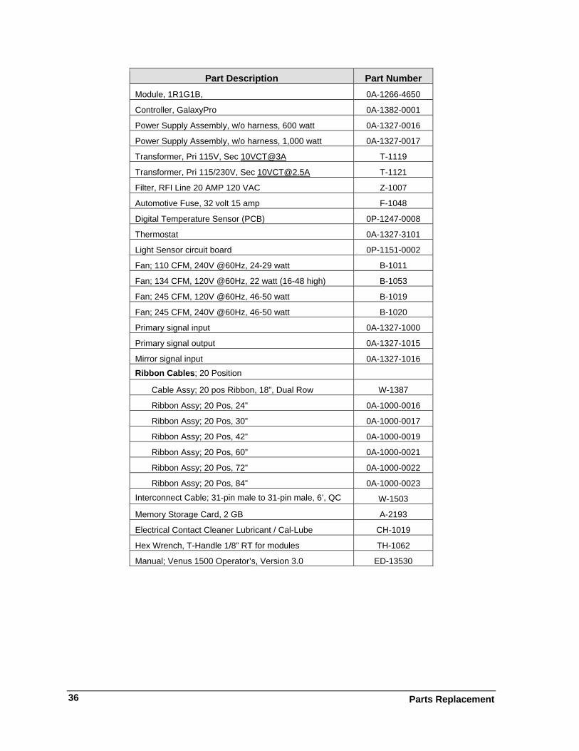
36
Part Description Part Number Module, 1R1G1B, 0A-1266-4650
Controller, GalaxyPro 0A-1382-0001
Power Supply Assembly, w/o harness, 600 watt 0A-1327-0016
Power Supply Assembly, w/o harness, 1,000 watt 0A-1327-0017
Transformer, Pri 115V, Sec 10VCT@3A T-1119
Transformer, Pri 115/230V, Sec [email protected] T-1121
Filter, RFI Line 20 AMP 120 VAC Z-1007
Automotive Fuse, 32 volt 15 amp F-1048
Digital Temperature Sensor (PCB) 0P-1247-0008
Thermostat 0A-1327-3101
Light Sensor circuit board 0P-1151-0002
Fan; 110 CFM, 240V @60Hz, 24-29 watt B-1011
Fan; 134 CFM, 120V @60Hz, 22 watt (16-48 high) B-1053
Fan; 245 CFM, 120V @60Hz, 46-50 watt B-1019
Fan; 245 CFM, 240V @60Hz, 46-50 watt B-1020
Primary signal input 0A-1327-1000
Primary signal output 0A-1327-1015
Mirror signal input 0A-1327-1016
Ribbon Cables; 20 Position
Cable Assy; 20 pos Ribbon, 18”, Dual Row W-1387
Ribbon Assy; 20 Pos, 24” 0A-1000-0016
Ribbon Assy; 20 Pos, 30” 0A-1000-0017
Ribbon Assy; 20 Pos, 42” 0A-1000-0019
Ribbon Assy; 20 Pos, 60” 0A-1000-0021
Ribbon Assy; 20 Pos, 72” 0A-1000-0022
Ribbon Assy; 20 Pos, 84” 0A-1000-0023
Interconnect Cable; 31-pin male to 31-pin male, 6’, QC W-1503
Memory Storage Card, 2 GB A-2193
Electrical Contact Cleaner Lubricant / Cal-Lube CH-1019
Hex Wrench, T-Handle 1/8” RT for modules TH-1062
Manual; Venus 1500 Operator’s, Version 3.0 ED-13530
8.2 Instructions for Replacing Parts
Module Replacement
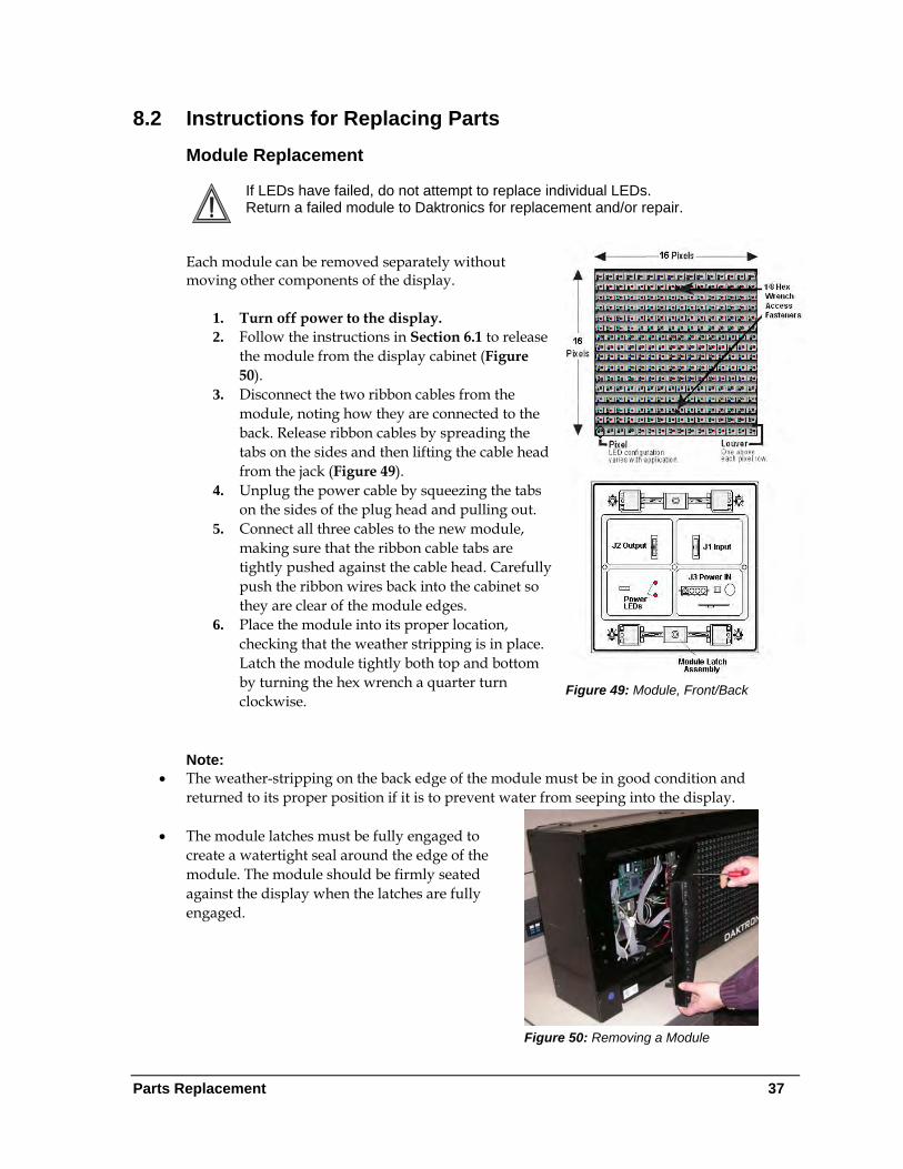
If LEDs have failed, do not attempt to replace individual LEDs. Return a failed module to Daktronics for replacement and/or repair.
Figure 49: Module, Front/Back
Each module can be removed separately without moving other components of the display.
1. Turn off power to the display. 2. Follow the instructions in Section 6.1 to release
the module from the display cabinet (Figure 50).
3. Disconnect the two ribbon cables from the module, noting how they are connected to the back. Release ribbon cables by spreading the tabs on the sides and then lifting the cable head from the jack (Figure 49).
4. Unplug the power cable by squeezing the tabs on the sides of the plug head and pulling out.
5. Connect all three cables to the new module, making sure that the ribbon cable tabs are tightly pushed against the cable head. Carefully push the ribbon wires back into the cabinet so they are clear of the module edges.
6. Place the module into its proper location, checking that the weather stripping is in place. Latch the module tightly both top and bottom by turning the hex wrench a quarter turn clockwise.
Note:
• The weather-stripping on the back edge of the module must be in good condition and returned to its proper position if it is to prevent water from seeping into the display.
Figure 50: Removing a Module
• The module latches must be fully engaged to create a watertight seal around the edge of the module. The module should be firmly seated against the display when the latches are fully engaged.
Parts Replacement 37
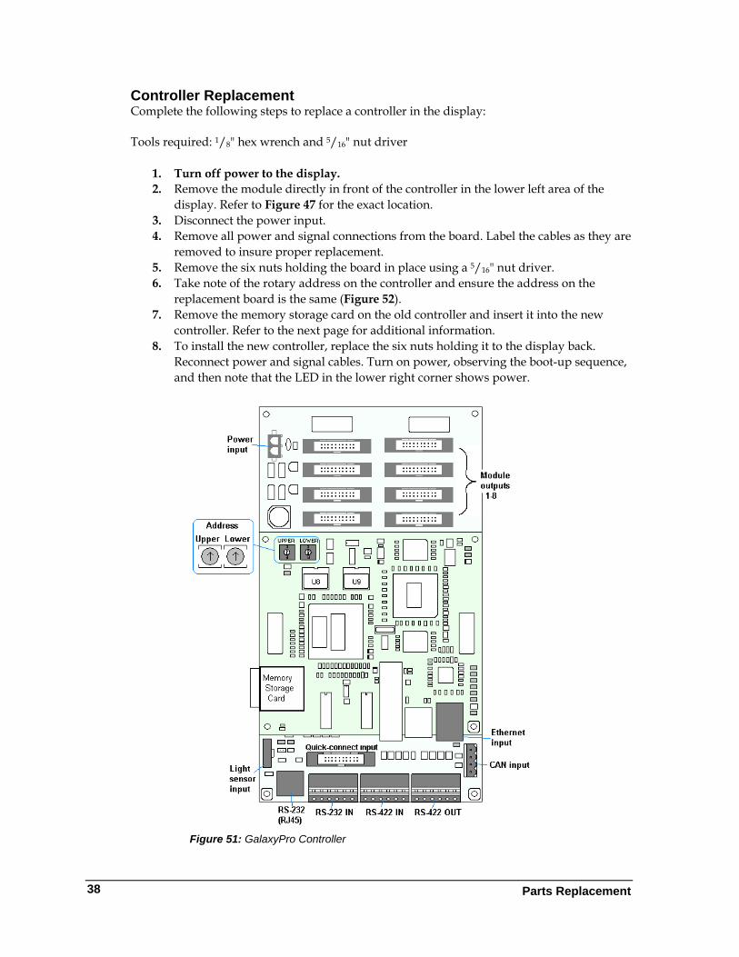
Controller Replacement Complete the following steps to replace a controller in the display: Tools required: 1/8" hex wrench and 5/16" nut driver
1. Turn off power to the display. 2. Remove the module directly in front of the controller in the lower left area of the
display. Refer to Figure 47 for the exact location. 3. Disconnect the power input. 4. Remove all power and signal connections from the board. Label the cables as they are
removed to insure proper replacement. 5. Remove the six nuts holding the board in place using a 5/16" nut driver. 6. Take note of the rotary address on the controller and ensure the address on the
replacement board is the same (Figure 52). 7. Remove the memory storage card on the old controller and insert it into the new
controller. Refer to the next page for additional information. 8. To install the new controller, replace the six nuts holding it to the display back.
Reconnect power and signal cables. Turn on power, observing the boot-up sequence, and then note that the LED in the lower right corner shows power.
Figure 51: GalaxyPro Controller
Parts Replacement
38
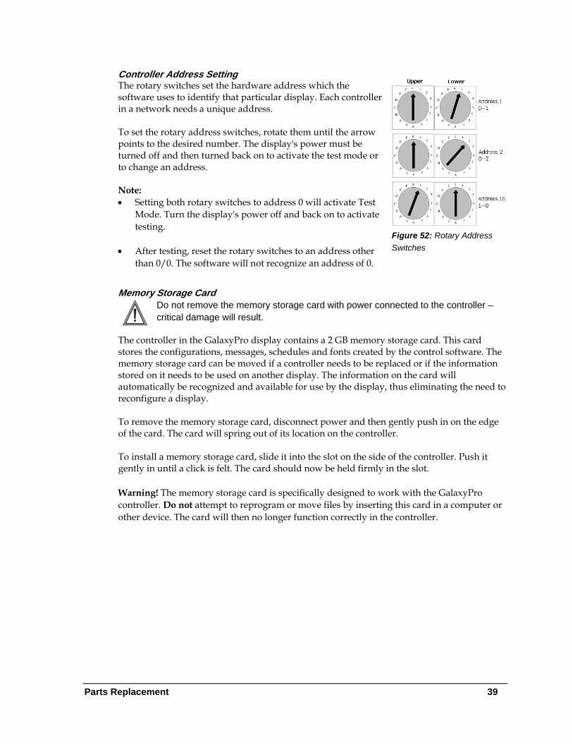
Controller Address Setting
Figure 52: Rotary Address Switches
The rotary switches set the hardware address which the software uses to identify that particular display. Each controller in a network needs a unique address. To set the rotary address switches, rotate them until the arrow points to the desired number. The display's power must be turned off and then turned back on to activate the test mode or to change an address. Note: • Setting both rotary switches to address 0 will activate Test
Mode. Turn the display's power off and back on to activate testing.
• After testing, reset the rotary switches to an address other than 0/0. The software will not recognize an address of 0.
Memory Storage Card Do not remove the memory storage card with power connected to the controller – critical damage will result.
The controller in the GalaxyPro display contains a 2 GB memory storage card. This card stores the configurations, messages, schedules and fonts created by the control software. The memory storage card can be moved if a controller needs to be replaced or if the information stored on it needs to be used on another display. The information on the card will automatically be recognized and available for use by the display, thus eliminating the need to reconfigure a display. To remove the memory storage card, disconnect power and then gently push in on the edge of the card. The card will spring out of its location on the controller. To install a memory storage card, slide it into the slot on the side of the controller. Push it gently in until a click is felt. The card should now be held firmly in the slot. Warning! The memory storage card is specifically designed to work with the GalaxyPro controller. Do not attempt to reprogram or move files by inserting this card in a computer or other device. The card will then no longer function correctly in the controller.
Parts Replacement 39
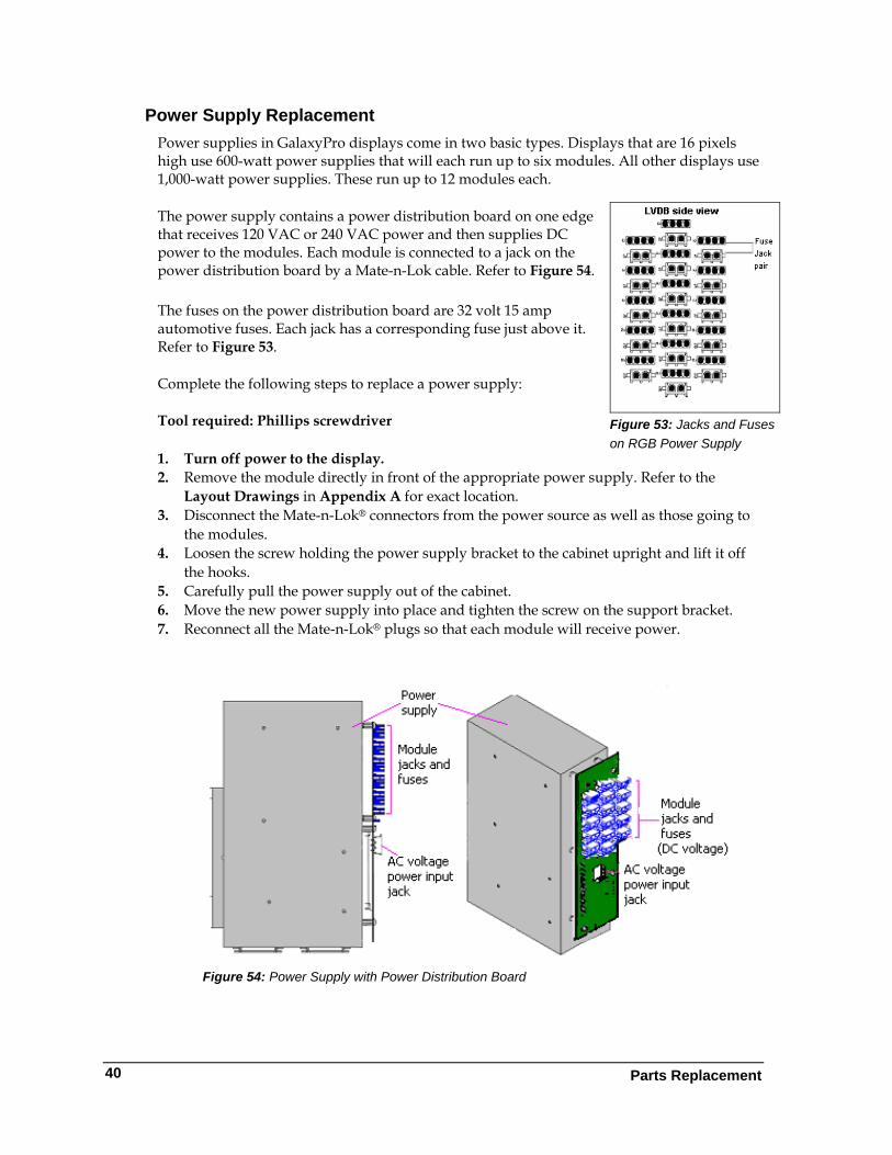
Power Supply Replacement Power supplies in GalaxyPro displays come in two basic types. Displays that are 16 pixels high use 600-watt power supplies that will each run up to six modules. All other displays use 1,000-watt power supplies. These run up to 12 modules each.
Figure 53: Jacks and Fuses on RGB Power Supply
The power supply contains a power distribution board on one edge that receives 120 VAC or 240 VAC power and then supplies DC power to the modules. Each module is connected to a jack on the power distribution board by a Mate-n-Lok cable. Refer to Figure 54.
The fuses on the power distribution board are 32 volt 15 amp automotive fuses. Each jack has a corresponding fuse just above it. Refer to Figure 53.
Complete the following steps to replace a power supply:
Tool required: Phillips screwdriver
1. Turn off power to the display. 2. Remove the module directly in front of the appropriate power supply. Refer to the
Layout Drawings in Appendix A for exact location. 3. Disconnect the Mate-n-Lok® connectors from the power source as well as those going to
the modules. 4. Loosen the screw holding the power supply bracket to the cabinet upright and lift it off
the hooks. 5. Carefully pull the power supply out of the cabinet. 6. Move the new power supply into place and tighten the screw on the support bracket. 7. Reconnect all the Mate-n-Lok® plugs so that each module will receive power.
Figure 54: Power Supply with Power Distribution Board
Parts Replacement
40
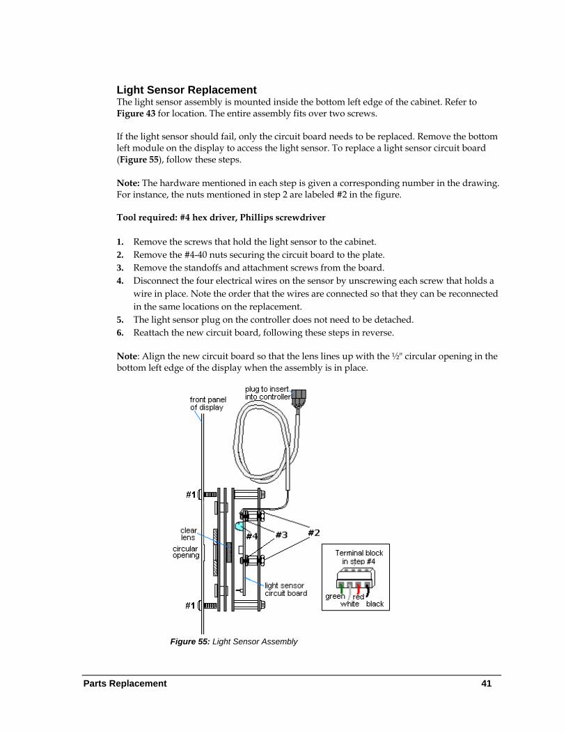
Light Sensor Replacement The light sensor assembly is mounted inside the bottom left edge of the cabinet. Refer to Figure 43 for location. The entire assembly fits over two screws. If the light sensor should fail, only the circuit board needs to be replaced. Remove the bottom left module on the display to access the light sensor. To replace a light sensor circuit board (Figure 55), follow these steps. Note: The hardware mentioned in each step is given a corresponding number in the drawing. For instance, the nuts mentioned in step 2 are labeled #2 in the figure. Tool required: #4 hex driver, Phillips screwdriver 1. Remove the screws that hold the light sensor to the cabinet. 2. Remove the #4-40 nuts securing the circuit board to the plate. 3. Remove the standoffs and attachment screws from the board. 4. Disconnect the four electrical wires on the sensor by unscrewing each screw that holds a
wire in place. Note the order that the wires are connected so that they can be reconnected in the same locations on the replacement.
5. The light sensor plug on the controller does not need to be detached. 6. Reattach the new circuit board, following these steps in reverse. Note: Align the new circuit board so that the lens lines up with the ½" circular opening in the bottom left edge of the display when the assembly is in place.
Figure 55: Light Sensor Assembly
Parts Replacement 41
Parts Replacement
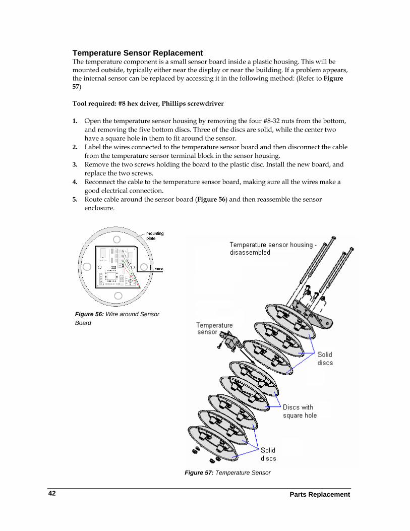
Temperature Sensor Replacement The temperature component is a small sensor board inside a plastic housing. This will be mounted outside, typically either near the display or near the building. If a problem appears, the internal sensor can be replaced by accessing it in the following method: (Refer to Figure 57)
Tool required: #8 hex driver, Phillips screwdriver
1. Open the temperature sensor housing by removing the four #8-32 nuts from the bottom,
and removing the five bottom discs. Three of the discs are solid, while the center two have a square hole in them to fit around the sensor.
2. Label the wires connected to the temperature sensor board and then disconnect the cable from the temperature sensor terminal block in the sensor housing.
3. Remove the two screws holding the board to the plastic disc. Install the new board, and replace the two screws.
4. Reconnect the cable to the temperature sensor board, making sure all the wires make a good electrical connection.
5. Route cable around the sensor board (Figure 56) and then reassemble the sensor enclosure.
Figure 56: Wire around Sensor Board
Figure 57: Temperature Sensor
42
Exchange and Repair Program 43
Section 9: Daktronics Exchange and Repair & Return Programs
To serve customers' repair and maintenance needs, Daktronics offers both an Exchange Program and a Repair & Return Program.
9.1 Exchange Program Daktronics' unique Exchange Program is a quick service for replacing key parts in need of repair. If a part requires repair or replacement, Daktronics sends the customer a replacement, and the customer sends the problem part to Daktronics. This decreases display downtime. Before Contacting Daktronics Print any important part numbers here:
Fill in these numbers before calling Customer Service:
Display Serial Number: ________________________________________ Display Model Number: ____GalaxyPro AF-3700 20mm____________ Contract Number: _____________________________________________ Date Installed: ________________________________________________ Location of Display: ___________________________________________ Daktronics Customer ID Number: _______________________________
To participate in the Exchange Program, follow these steps.
1. Call Daktronics Customer Service: 866-343-3122.
2. When the new exchange part is received, mail the old part to Daktronics. If the replacement part fixes the problem, send in the problem part which is being replaced. a. Package the old part in the same shipping materials in which the replacement
part arrived. b. Fill out and attach the enclosed UPS shipping document. c. Ship the part to Daktronics.
3. A charge will be made for the replacement part immediately, unless a qualifying
service agreement is in place. In most circumstances, the replacement part will be invoiced at the time it is shipped.
4. If the replacement part does not solve the problem, return the part within 30
working days or the full purchase price will be charged. If the equipment is still defective after the exchange is made, please contact Customer Service immediately. Daktronics expects immediate return of an exchange part if it
Exchange and Repair Program
44
does not solve the problem. The company also reserves the right to refuse parts that have been damaged due to acts of nature or causes other than normal wear and tear.
9.2 Repair & Return Program For items not subject to exchange, Daktronics offers a Repair & Return Program. To send a part for repair, follow these steps.
1. Call or fax Daktronics Customer Service: Phone: 866-343-3122 Fax: 605-697-4444
2. Receive a Return Materials Authorization (RMA) number before shipping. This expedites repair of the part.
3. Package and pad the item carefully to prevent damage during shipment. Electronic components, such as printed circuit boards, should be placed in an antistatic bag before boxing.
4. Enclose: • your name • address • phone number • the RMA number • a clear description of symptoms
Shipping Address Daktronics Customer Service PO Box 5128 331 32nd Ave Brookings SD 57006
9.3 Daktronics Warranty and Limitation of Liability Daktronics Warranty and Limitation of Liability is located in Appendix D. The Warranty is independent of the Extended Service agreement and is the authority in matters of service, repair, and display operation.
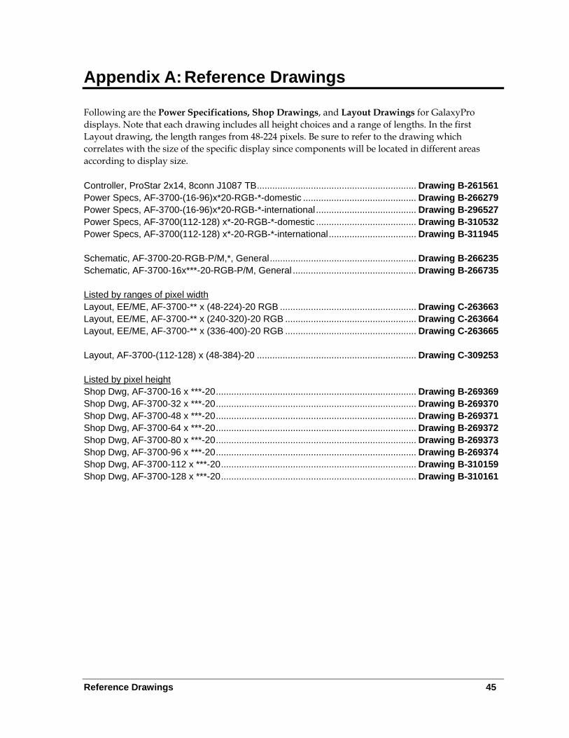
Reference Drawings 45
Appendix A: Reference Drawings
Following are the Power Specifications, Shop Drawings, and Layout Drawings for GalaxyPro displays. Note that each drawing includes all height choices and a range of lengths. In the first Layout drawing, the length ranges from 48-224 pixels. Be sure to refer to the drawing which correlates with the size of the specific display since components will be located in different areas according to display size. Controller, ProStar 2x14, 8conn J1087 TB .............................................................. Drawing B-261561 Power Specs, AF-3700-(16-96)x*20-RGB-*-domestic ............................................ Drawing B-266279 Power Specs, AF-3700-(16-96)x*20-RGB-*-international ....................................... Drawing B-296527 Power Specs, AF-3700(112-128) x*-20-RGB-*-domestic ....................................... Drawing B-310532 Power Specs, AF-3700(112-128) x*-20-RGB-*-international .................................. Drawing B-311945 Schematic, AF-3700-20-RGB-P/M,*, General ......................................................... Drawing B-266235 Schematic, AF-3700-16x***-20-RGB-P/M, General ................................................ Drawing B-266735 Listed by ranges of pixel width Layout, EE/ME, AF-3700-** x (48-224)-20 RGB ..................................................... Drawing C-263663 Layout, EE/ME, AF-3700-** x (240-320)-20 RGB ................................................... Drawing C-263664 Layout, EE/ME, AF-3700-** x (336-400)-20 RGB ................................................... Drawing C-263665 Layout, AF-3700-(112-128) x (48-384)-20 .............................................................. Drawing C-309253 Listed by pixel height Shop Dwg, AF-3700-16 x ***-20 .............................................................................. Drawing B-269369 Shop Dwg, AF-3700-32 x ***-20 .............................................................................. Drawing B-269370 Shop Dwg, AF-3700-48 x ***-20 .............................................................................. Drawing B-269371 Shop Dwg, AF-3700-64 x ***-20 .............................................................................. Drawing B-269372 Shop Dwg, AF-3700-80 x ***-20 .............................................................................. Drawing B-269373 Shop Dwg, AF-3700-96 x ***-20 .............................................................................. Drawing B-269374 Shop Dwg, AF-3700-112 x ***-20 ............................................................................ Drawing B-310159 Shop Dwg, AF-3700-128 x ***-20 ............................................................................ Drawing B-310161

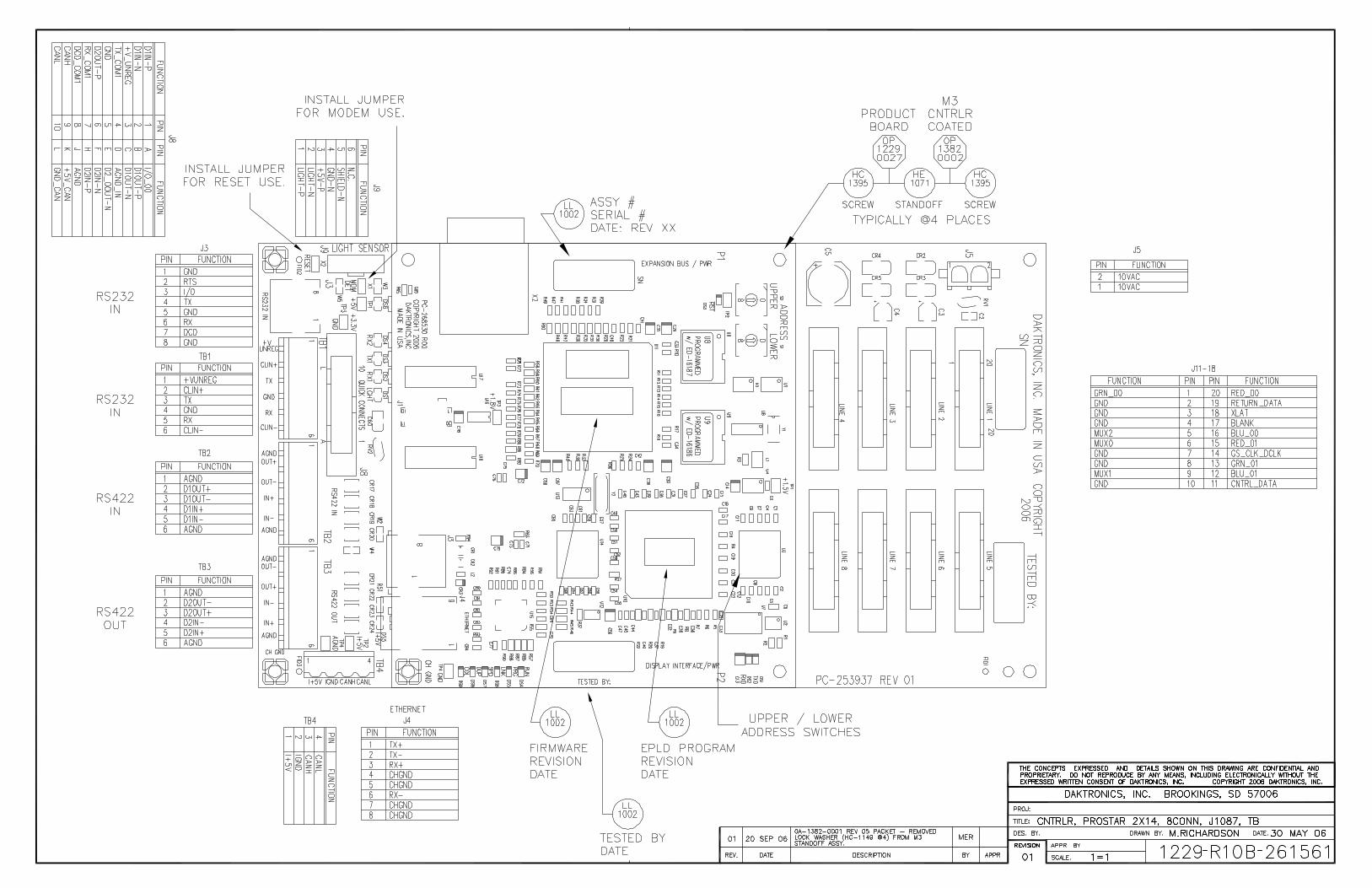
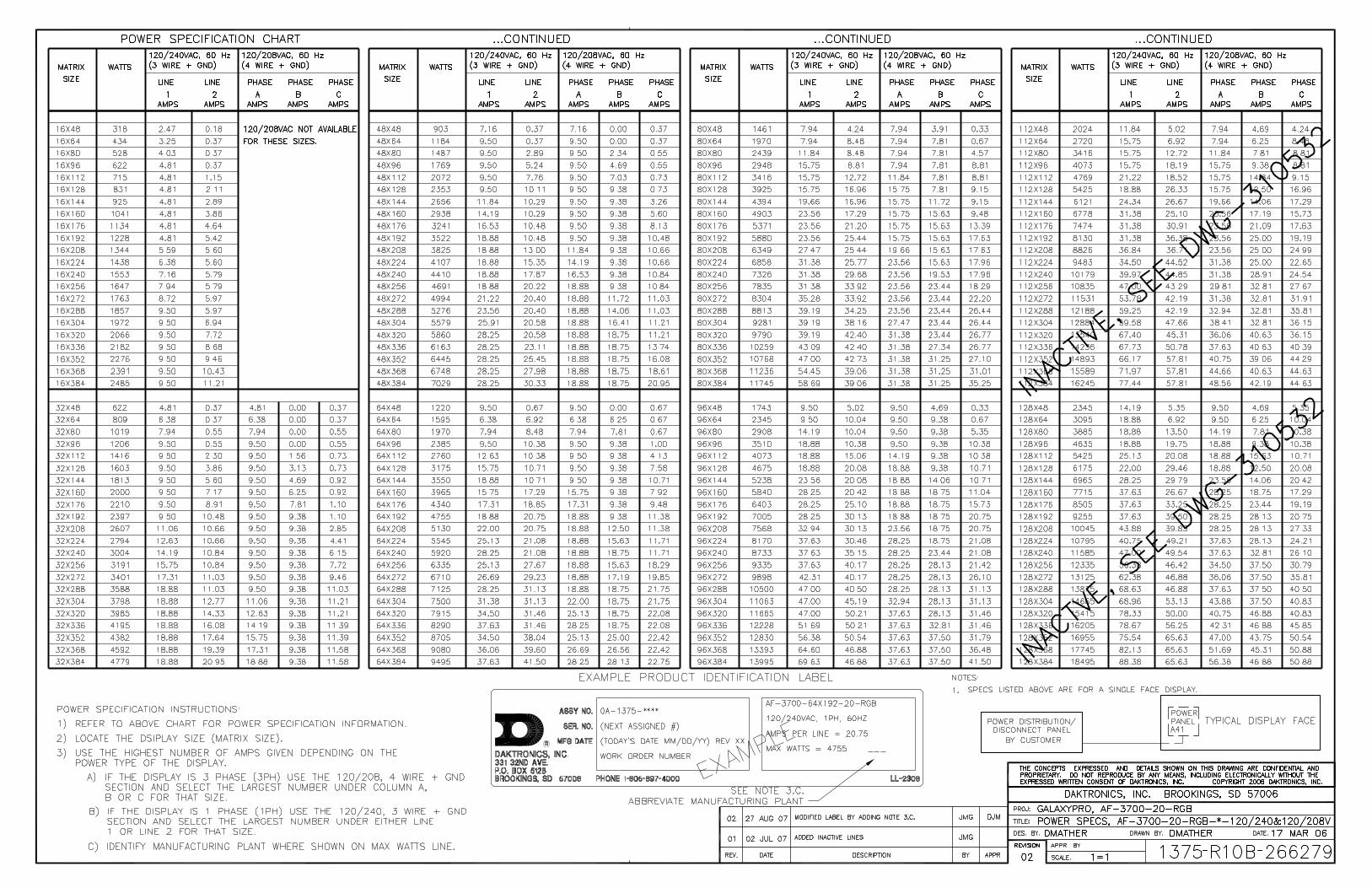
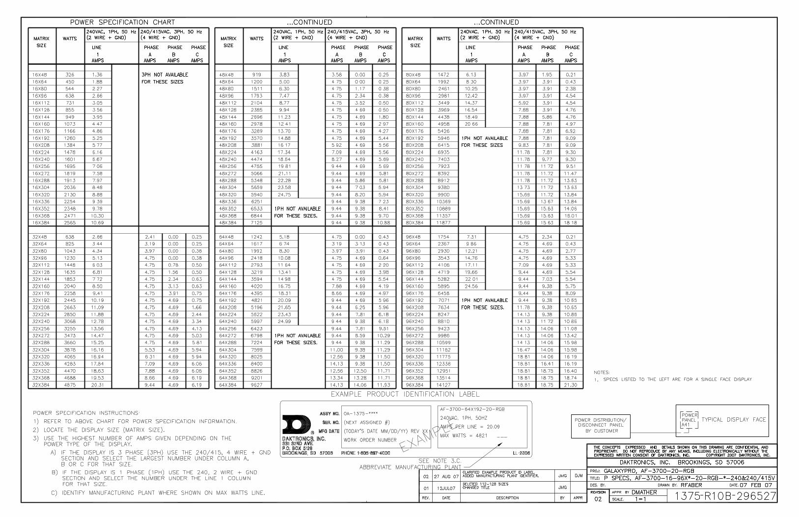
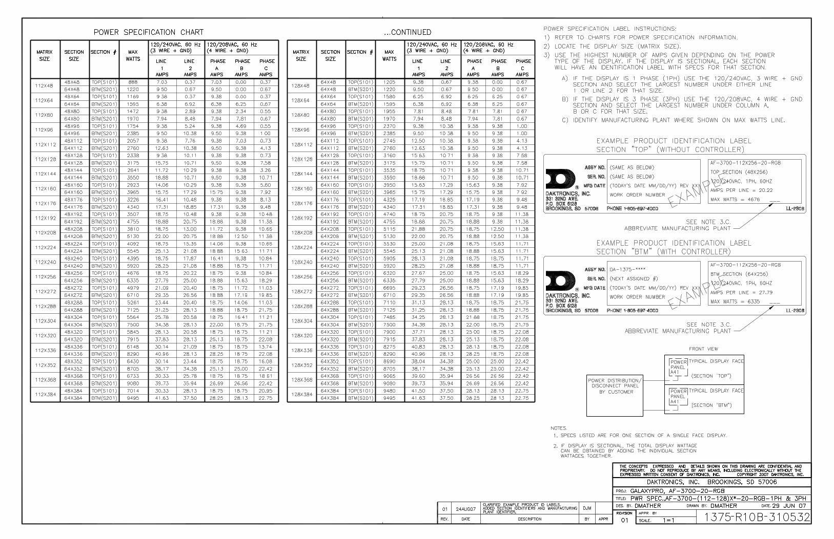
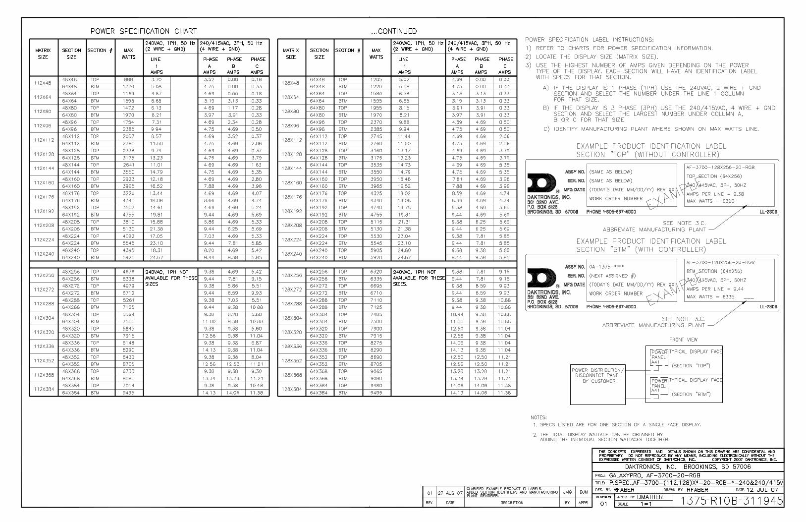
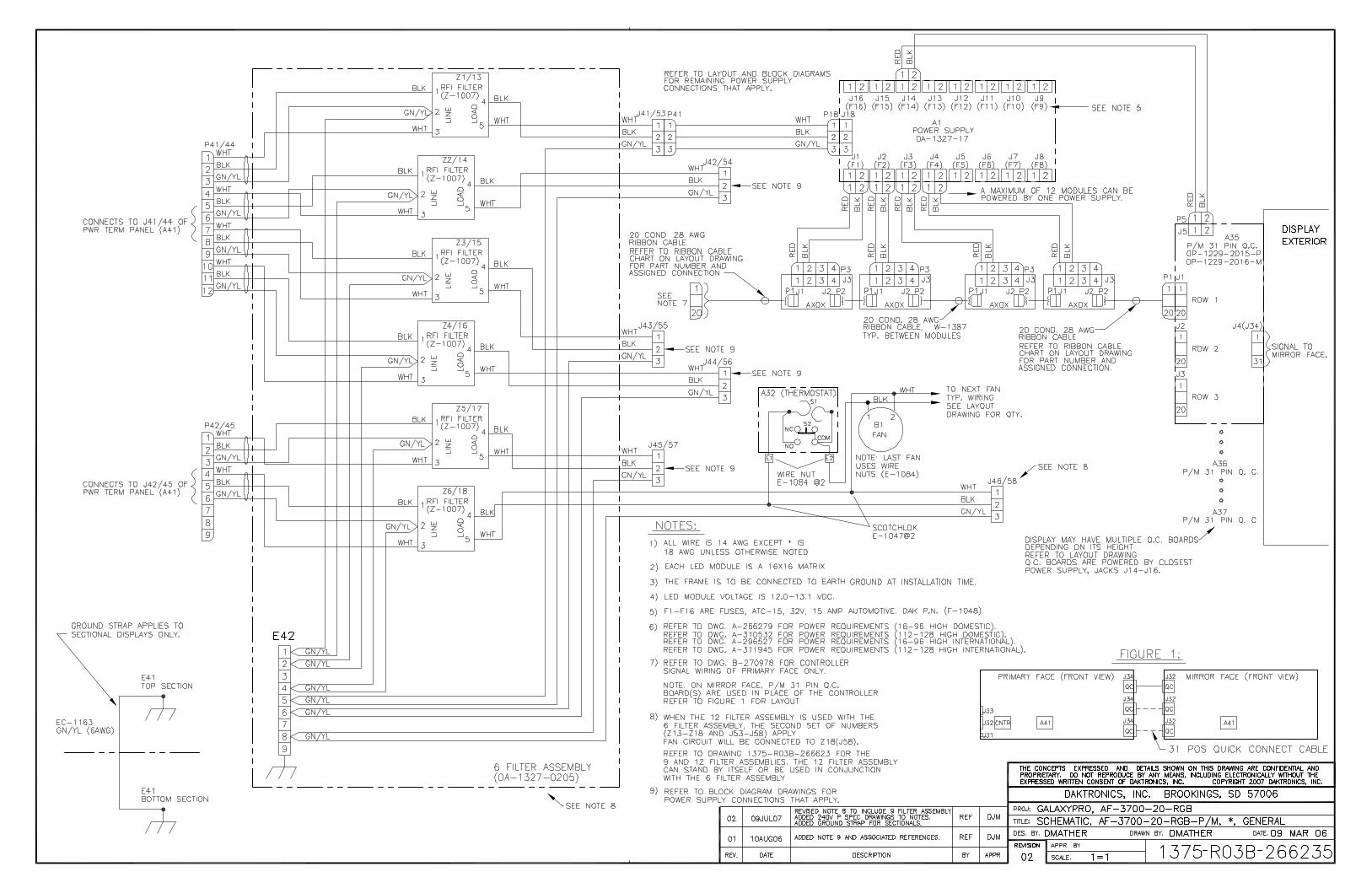
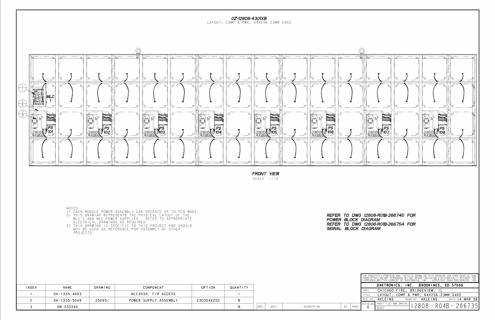
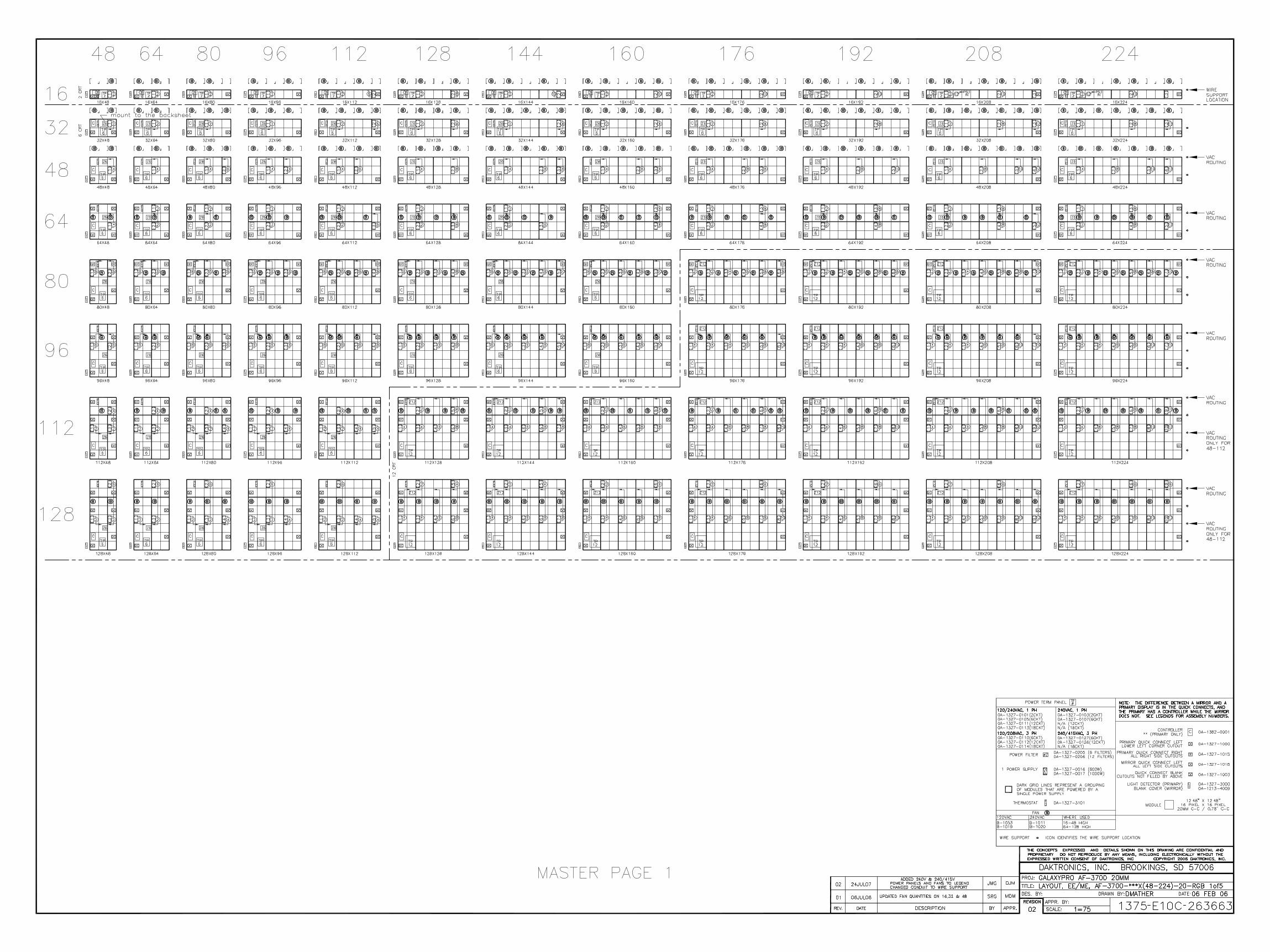
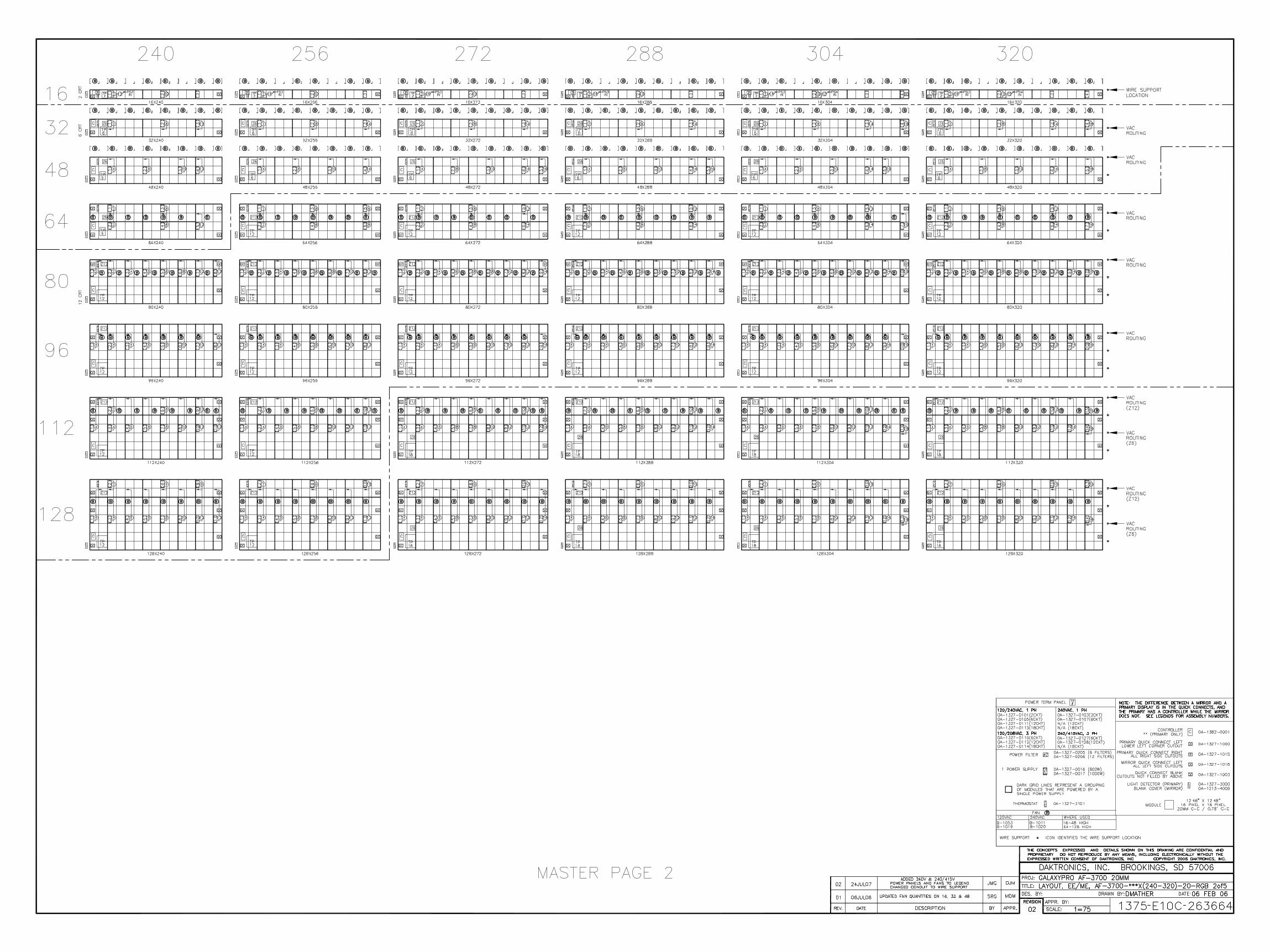
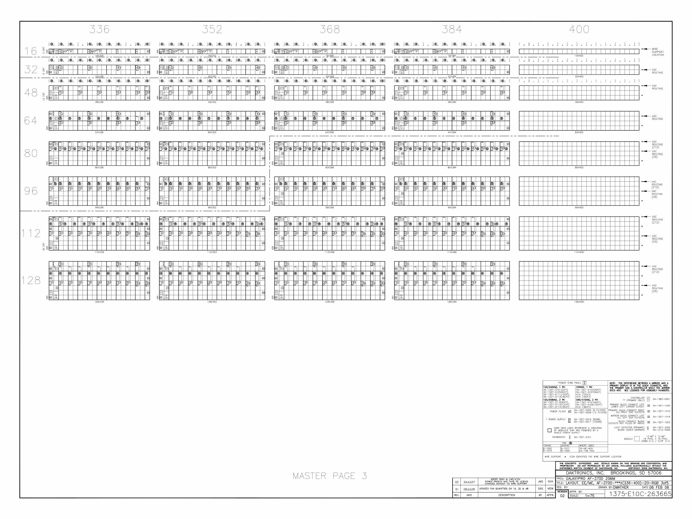
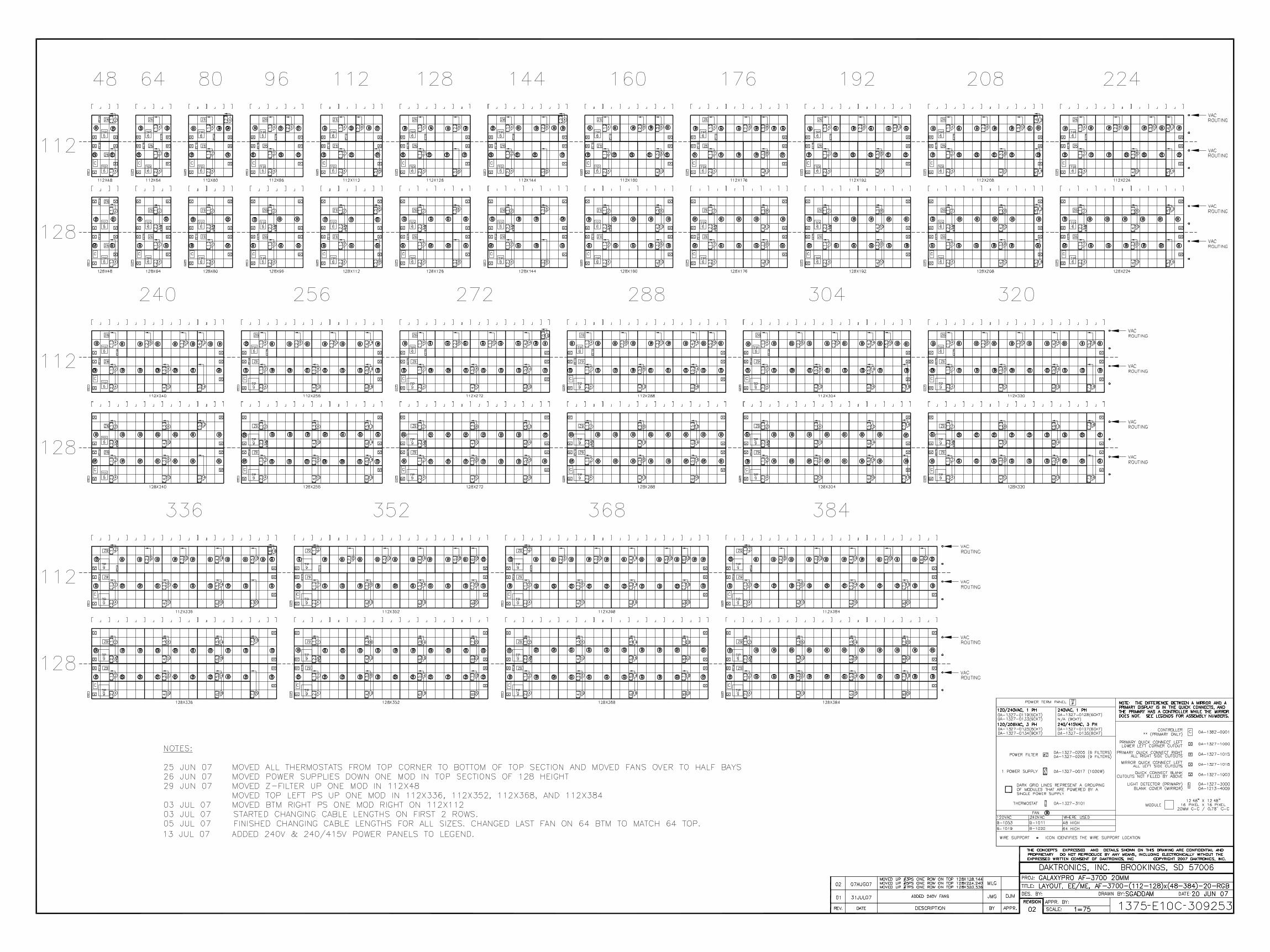
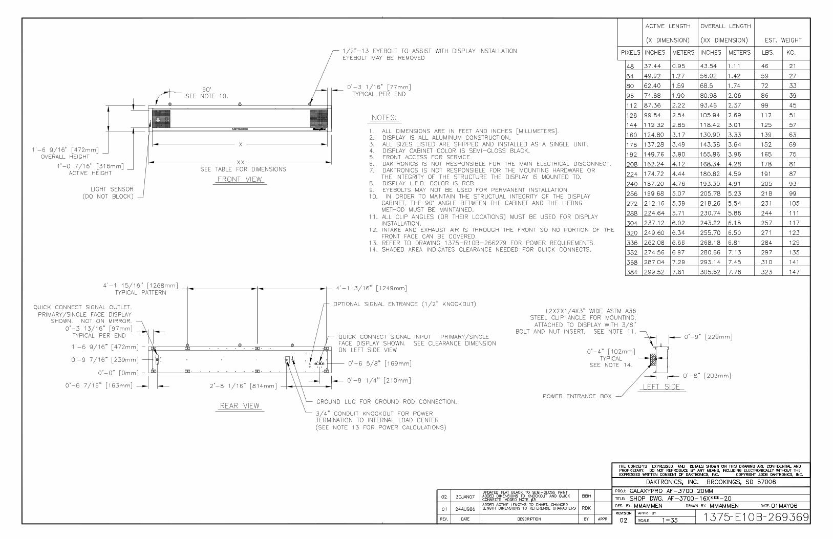
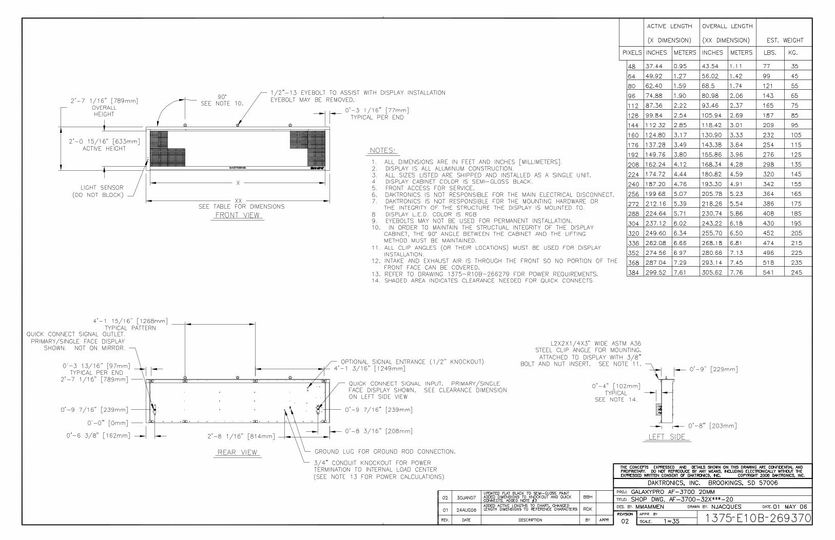
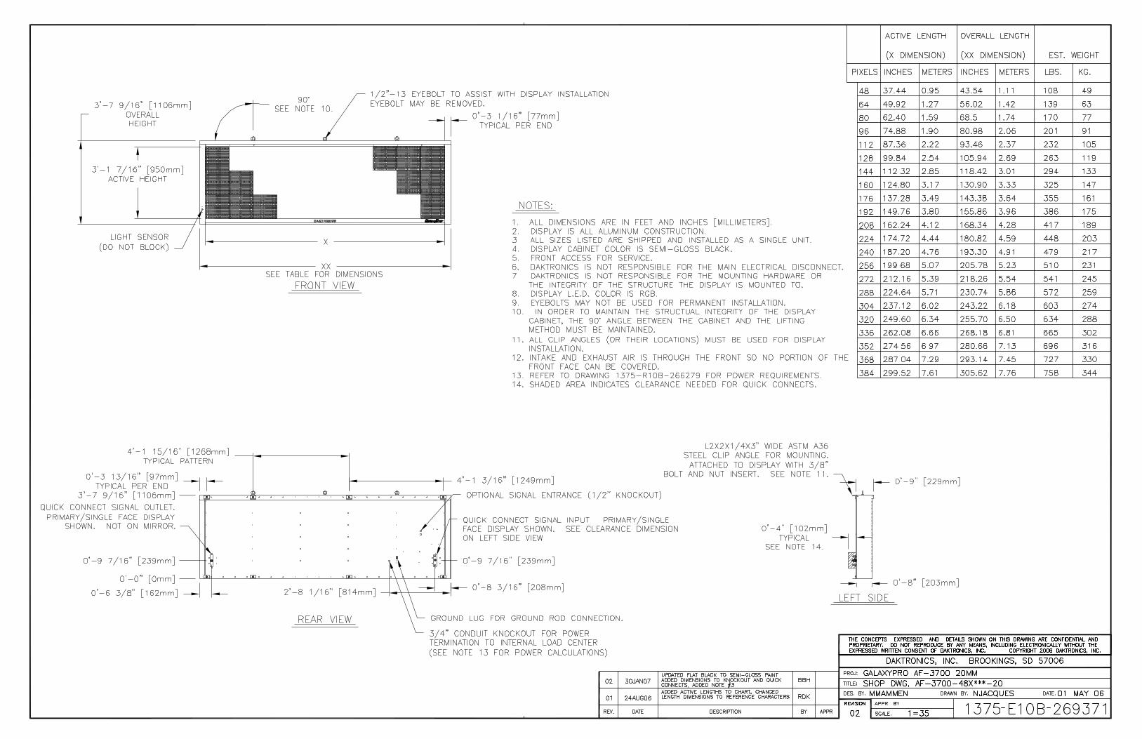
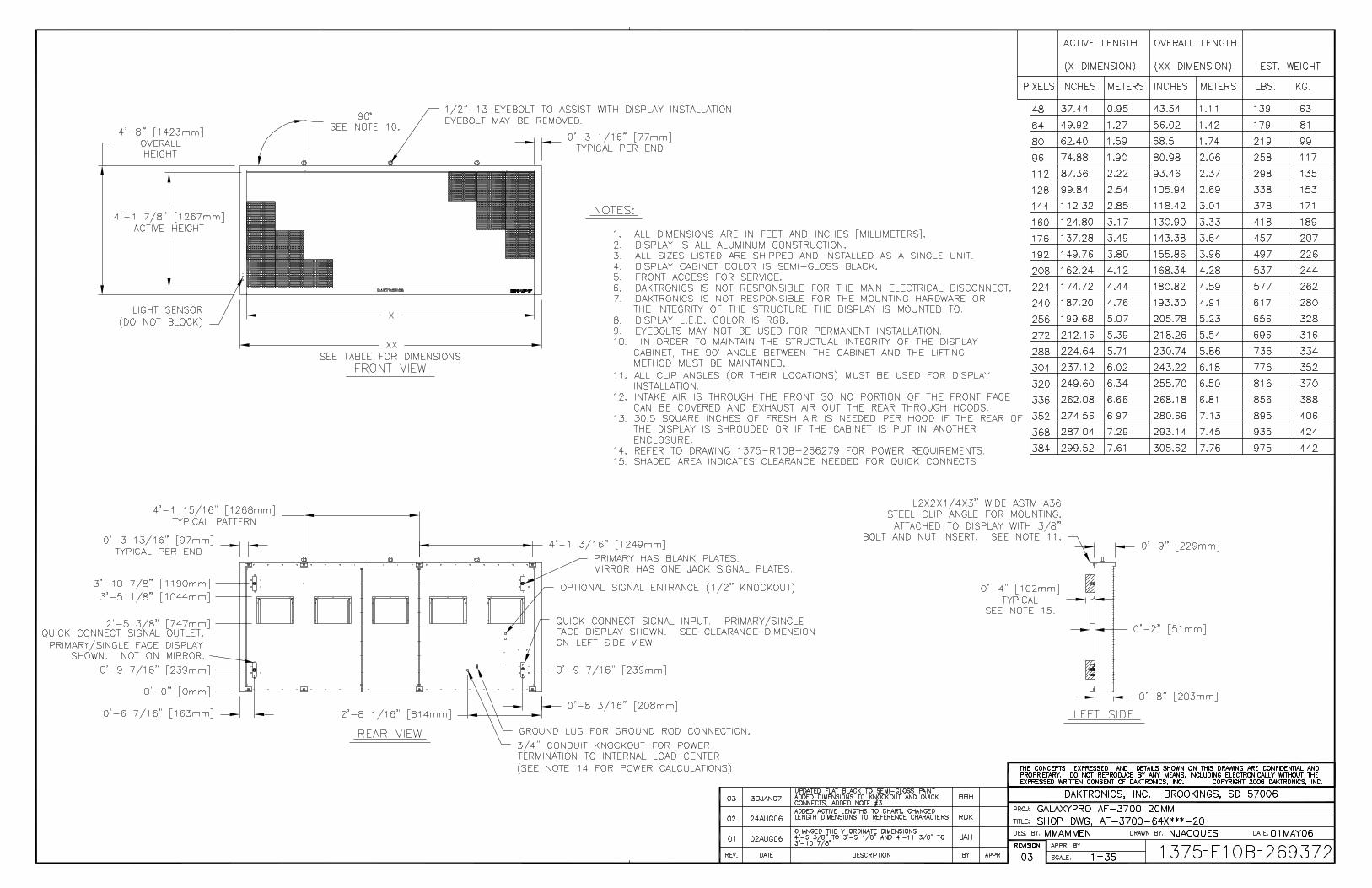
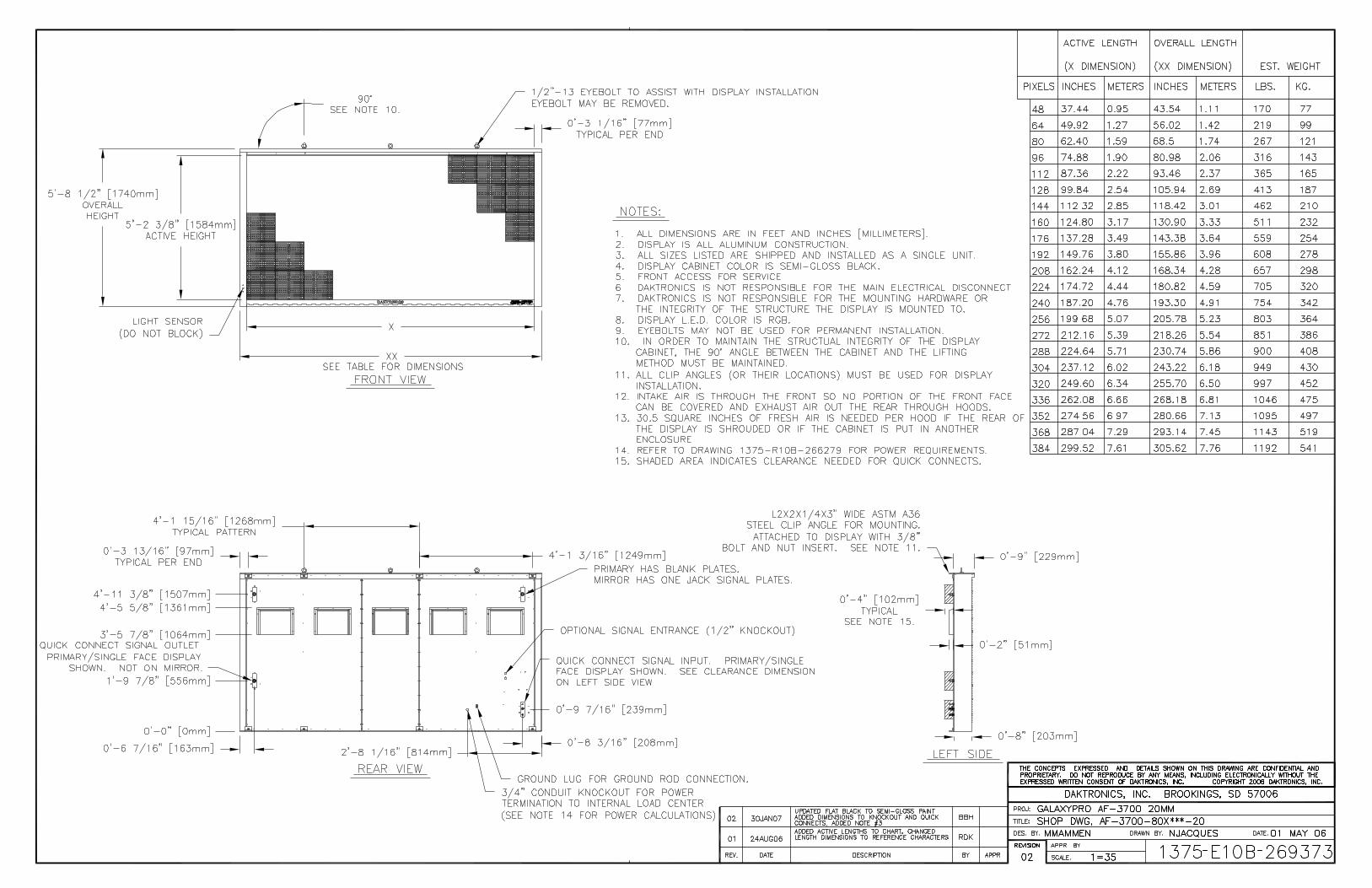
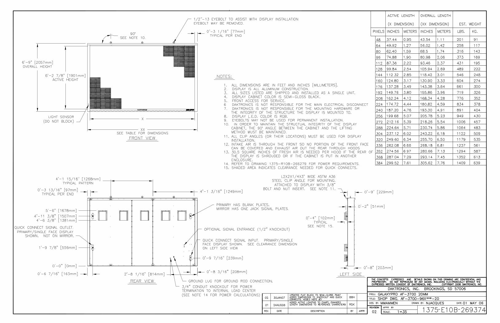
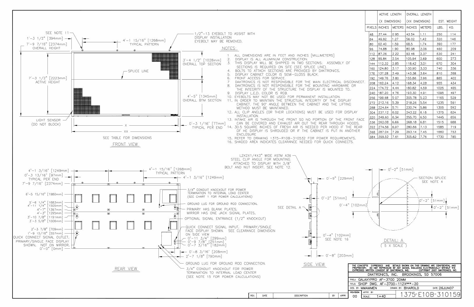
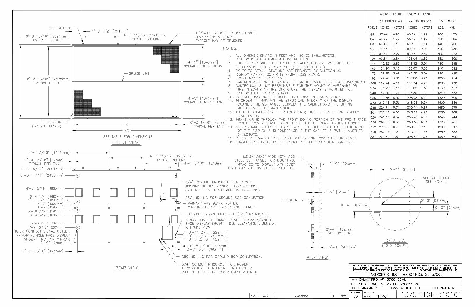
Glossary 47
Appendix B: Glossary
Definitions of Terms Controller: The “brains” of the display. The controller receives signal communication from the computer and sends the appropriate information to the modules. Messages and schedules may also be stored on the controller for use when desired. Display Address: An identification number assigned to each display of a network. The control software uses the address to locate and communicate with each display. Displays that are on the same network must have different addresses. Driver/LED Board: The LEDs are mounted directly onto the module. This board is also responsible for the on/off and intensity levels of the LEDs. GalaxyPro®: Daktronics trademarked name for LED RGB matrix displays. LED (light emitting diode): A low energy, high intensity lighting unit. Louver: Black plastic ledge positioned horizontally above each pixel row. The louvers block sunlight, thus increasing the level of contrast on the display face. Mirror: The second display in a two-sided configuration. The mirror display does not have a controller so it displays an exact copy of the information on the primary display. All signal information to the mirror is received through an inter-connect cable from the primary display. Module: 20 mm GalaxyPro® modules are 16 pixels high by 16 pixels wide. Each is individually removable from the front of the display. Network: Consists of multiple displays connected to each other. As many as 240 primary displays can exist on one network. Pixel: A single LED or cluster of LEDs. The number and color of the LEDs will depend on display application. Primary: A single-faced unit or the first display in a Primary-Mirror (2V) configuration. The communication signal, light sensor and temperature sensor will be connected to this display. The information from these components will be relayed from the primary display to the mirror display so that it shows exactly the same information. An inter-connect cable will transfer this information from the primary to the mirror display in this configuration. Venus 1500: Name given to the software on the control computer that is used to create messages and send them to the displays. The Venus 1500 manual is included on the installation disk.
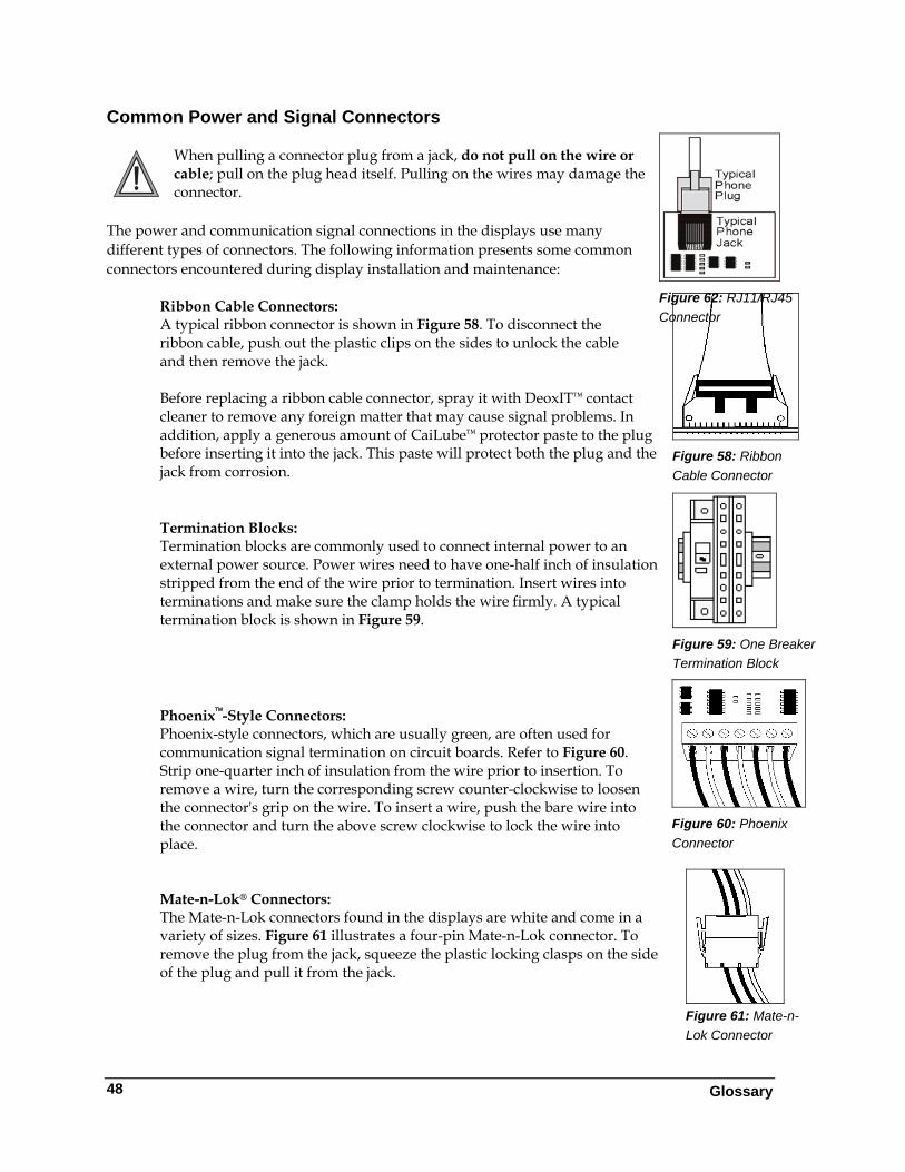
Common Power and Signal Connectors
Glossary
48
When pulling a connector plug from a jack, do not pull on the wire or cable; pull on the plug head itself. Pulling on the wires may damage the connector.
The power and communication signal connections in the displays use many different types of connectors. The following information presents some common connectors encountered during display installation and maintenance:
Ribbon Cable Connectors: A typical ribbon connector is shown in Figure 58. To disconnect the ribbon cable, push out the plastic clips on the sides to unlock the cable and then remove the jack. Before replacing a ribbon cable connector, spray it with DeoxIT™ contact cleaner to remove any foreign matter that may cause signal problems. In addition, apply a generous amount of CaiLube™ protector paste to the plug before inserting it into the jack. This paste will protect both the plug and the jack from corrosion.
Figure 58: Ribbon Cable Connector
Figure 62: RJ11/RJ45 Connector
Figure 59: One Breaker Termination Block
Termination Blocks: Termination blocks are commonly used to connect internal power to an external power source. Power wires need to have one-half inch of insulation stripped from the end of the wire prior to termination. Insert wires into terminations and make sure the clamp holds the wire firmly. A typical termination block is shown in Figure 59.
Figure 60: Phoenix Connector
Phoenix™-Style Connectors: Phoenix-style connectors, which are usually green, are often used for communication signal termination on circuit boards. Refer to Figure 60. Strip one-quarter inch of insulation from the wire prior to insertion. To remove a wire, turn the corresponding screw counter-clockwise to loosen the connector's grip on the wire. To insert a wire, push the bare wire into the connector and turn the above screw clockwise to lock the wire into place.
Figure 61: Mate-n-Lok Connector
Mate-n-Lok® Connectors: The Mate-n-Lok connectors found in the displays are white and come in a variety of sizes. Figure 61 illustrates a four-pin Mate-n-Lok connector. To remove the plug from the jack, squeeze the plastic locking clasps on the side of the plug and pull it from the jack.
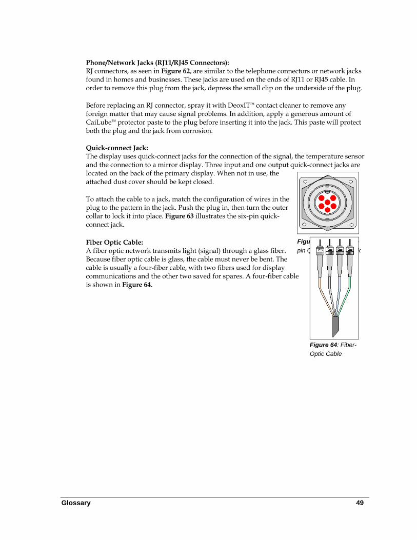
Glossary 49
Phone/Network Jacks (RJ11/RJ45 Connectors): RJ connectors, as seen in Figure 62, are similar to the telephone connectors or network jacks found in homes and businesses. These jacks are used on the ends of RJ11 or RJ45 cable. In order to remove this plug from the jack, depress the small clip on the underside of the plug. Before replacing an RJ connector, spray it with DeoxIT™ contact cleaner to remove any foreign matter that may cause signal problems. In addition, apply a generous amount of CaiLube™ protector paste to the plug before inserting it into the jack. This paste will protect both the plug and the jack from corrosion.
Quick-connect Jack: The display uses quick-connect jacks for the connection of the signal, the temperature sensor and the connection to a mirror display. Three input and one output quick-connect jacks are located on the back of the primary display. When not in use, the attached dust cover should be kept closed.
To attach the cable to a jack, match the configuration of wires in the plug to the pattern in the jack. Push the plug in, then turn the outer collar to lock it into place. Figure 63 illustrates the six-pin quick-connect jack. Fiber Optic Cable: A fiber optic network transmits light (signal) through a glass fiber. Because fiber optic cable is glass, the cable must never be bent. The cable is usually a four-fiber cable, with two fibers used for display communications and the other two saved for spares. A four-fiber cable is shown in Figure 64.
Figure 63: RS232/Six-pin Quick-connect Jack
Figure 64: Fiber-
Optic Cable
Temperature Sensor Installation 51
Appendix C: Temperature Sensor Installation
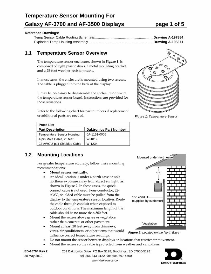
Temperature Sensor Mounting For Galaxy AF-3700 and AF-3500 Displays page 1 of 5
ED-16704 Rev 2 28 May 2010
201 Daktronics Drive PO Box 5128, Brookings, SD 57006-5128 tel: 866-343-3122 fax: 605-697-4700
www.daktronics.com
Reference Drawings: Temp Sensor Cable Routing Schematic ............................................................. Drawing A-197884 Exploded Temp Housing Assembly .................................................................... Drawing A-198371
1.1 Temperature Sensor Overview The temperature sensor enclosure, shown in Figure 1, is composed of eight plastic disks, a metal mounting bracket, and a 25-foot weather-resistant cable. In most cases, the enclosure is mounted using two screws. The cable is plugged into the back of the display. It may be necessary to disassemble the enclosure or rewire the temperature sensor board. Instructions are provided for those situations. Refer to the following chart for part numbers if replacement or additional parts are needed. Parts List Part Description Daktronics Part Number Temperature Sensor Housing 0A-1151-0005 4-pin Male Cable, 25 feet W-1819 22 AWG 2-pair Shielded Cable W-1234
1.2 Mounting Locations For greater temperature accuracy, follow these mounting recommendations:
• Mount sensor vertically. • An ideal location is under a north eave or on a
northern exposure away from direct sunlight, as shown in Figure 2. In these cases, the quick-connect cable is not used. Four-conductor, 22-AWG, shielded cable must be pulled from the display to the temperature sensor location. Route the cable through conduit when exposed to outdoor conditions. The maximum length of the cable should be no more than 500 feet.
• Mount the sensor above grass or vegetation rather than concrete or other pavement.
• Mount at least 20 feet away from chimneys, vents, air conditioners, or other items that would influence correct temperature readings.
• Do not mount the sensor between displays or locations that restrict air movement. • Mount the sensor so the cable is protected from weather and vandalism.
Figure 1: Temperature Sensor
Figure 2: Located on the North Eave
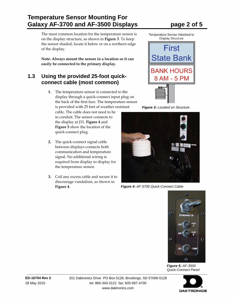
Temperature Sensor Mounting For Galaxy AF-3700 and AF-3500 Displays page 2 of 5
ED-16704 Rev 2 28 May 2010
201 Daktronics Drive PO Box 5128, Brookings, SD 57006-5128 tel: 866-343-3122 fax: 605-697-4700
www.daktronics.com
The most common location for the temperature sensor is on the display structure, as shown in Figure 3. To keep the sensor shaded, locate it below or on a northern edge of the display. Note: Always mount the sensor in a location so it can easily be connected to the primary display.
1.3 Using the provided 25-foot quick-connect cable (most common)
1. The temperature sensor is connected to the display through a quick-connect input plug on the back of the first face. The temperature sensor is provided with 25 feet of weather resistant cable. The cable does not need to be in conduit. The sensor connects to the display at J31. Figure 4 and Figure 5 show the location of the quick-connect plug.
2. The quick-connect signal cable between displays connects both communication and temperature signal. No additional wiring is required from display to display for the temperature sensor.
3. Coil any excess cable and secure it to discourage vandalism, as shown in Figure 4.
Figure 3: Located on Structure
Figure 4: AF-3700 Quick-Connect Cable
Figure 5: AF-3500 Quick-Connect Panel
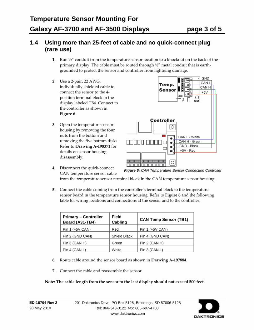
Temperature Sensor Mounting For Galaxy AF-3700 and AF-3500 Displays page 3 of 5
ED-16704 Rev 2 28 May 2010
201 Daktronics Drive PO Box 5128, Brookings, SD 57006-5128 tel: 866-343-3122 fax: 605-697-4700
www.daktronics.com
1.4 Using more than 25-feet of cable and no quick-connect plug (rare use)
1. Run ½” conduit from the temperature sensor location to a knockout on the back of the primary display. The cable must be routed through ½” metal conduit that is earth-grounded to protect the sensor and controller from lightning damage.
2. Use a 2-pair, 22 AWG, individually shielded cable to connect the sensor to the 4-position terminal block in the display labeled TB4. Connect to the controller as shown in Figure 6.
3. Open the temperature sensor housing by removing the four nuts from the bottom and removing the five bottom disks. Refer to Drawing A-198371 for details on sensor housing disassembly.
4. Disconnect the quick-connect CAN temperature sensor cable from the temperature sensor terminal block in the CAN temperature sensor housing.
5. Connect the cable coming from the controller’s terminal block to the temperature sensor board in the temperature sensor housing. Refer to Figure 6 and the following table for wiring locations and connections at the sensor and to the controller.
6. Route cable around the sensor board as shown in Drawing A-197884.
7. Connect the cable and reassemble the sensor. Note: The cable length from the sensor to the last display should not exceed 500 feet.
Figure 6: CAN Temperature Sensor Connection Controller
Primary – Controller Board (A31-TB4)
Field Cabling CAN Temp Sensor (TB1)
Pin 1 (+5V CAN) Red Pin 1 (+5V CAN)
Pin 2 (GND CAN) Shield Black Pin 4 (GND CAN)
Pin 3 (CAN H) Green Pin 2 (CAN H)
Pin 4 (CAN L) White Pin 3 (CAN L)
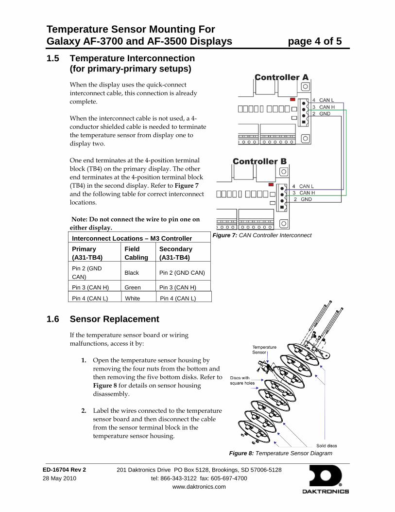
Temperature Sensor Mounting For Galaxy AF-3700 and AF-3500 Displays page 4 of 5
ED-16704 Rev 2 28 May 2010
201 Daktronics Drive PO Box 5128, Brookings, SD 57006-5128 tel: 866-343-3122 fax: 605-697-4700
www.daktronics.com
1.5 Temperature Interconnection (for primary-primary setups) When the display uses the quick-connect interconnect cable, this connection is already complete. When the interconnect cable is not used, a 4-conductor shielded cable is needed to terminate the temperature sensor from display one to display two. One end terminates at the 4-position terminal block (TB4) on the primary display. The other end terminates at the 4-position terminal block (TB4) in the second display. Refer to Figure 7 and the following table for correct interconnect locations. Note: Do not connect the wire to pin one on either display. Interconnect Locations – M3 Controller Primary (A31-TB4)
Field Cabling
Secondary (A31-TB4)
Pin 2 (GND CAN)
Black Pin 2 (GND CAN)
Pin 3 (CAN H) Green Pin 3 (CAN H)
Pin 4 (CAN L) White Pin 4 (CAN L)
1.6 Sensor Replacement If the temperature sensor board or wiring malfunctions, access it by:
1. Open the temperature sensor housing by removing the four nuts from the bottom and then removing the five bottom disks. Refer to Figure 8 for details on sensor housing disassembly.
2. Label the wires connected to the temperature sensor board and then disconnect the cable from the sensor terminal block in the temperature sensor housing.
Figure 7: CAN Controller Interconnect
Figure 8: Temperature Sensor Diagram

Temperature Sensor Mounting For Galaxy AF-3700 and AF-3500 Displays page 5 of 5
ED-16704 Rev 2 28 May 2010
201 Daktronics Drive PO Box 5128, Brookings, SD 57006-5128 tel: 866-343-3122 fax: 605-697-4700
www.daktronics.com
3. Remove the two screws holding the board to the plastic disk. Install the new board and replace the two screws.
4. Reconnect the cable to the temperature sensor board, making sure all the wires make a good electrical connection.
5. Route wires around the sensor board as shown in Figure 9 and reassemble the sensor enclosure.
Figure 9: Temperature Sensor Wiring
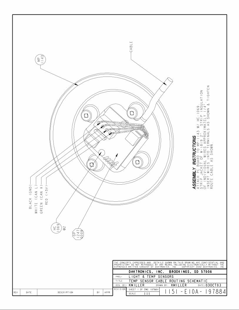
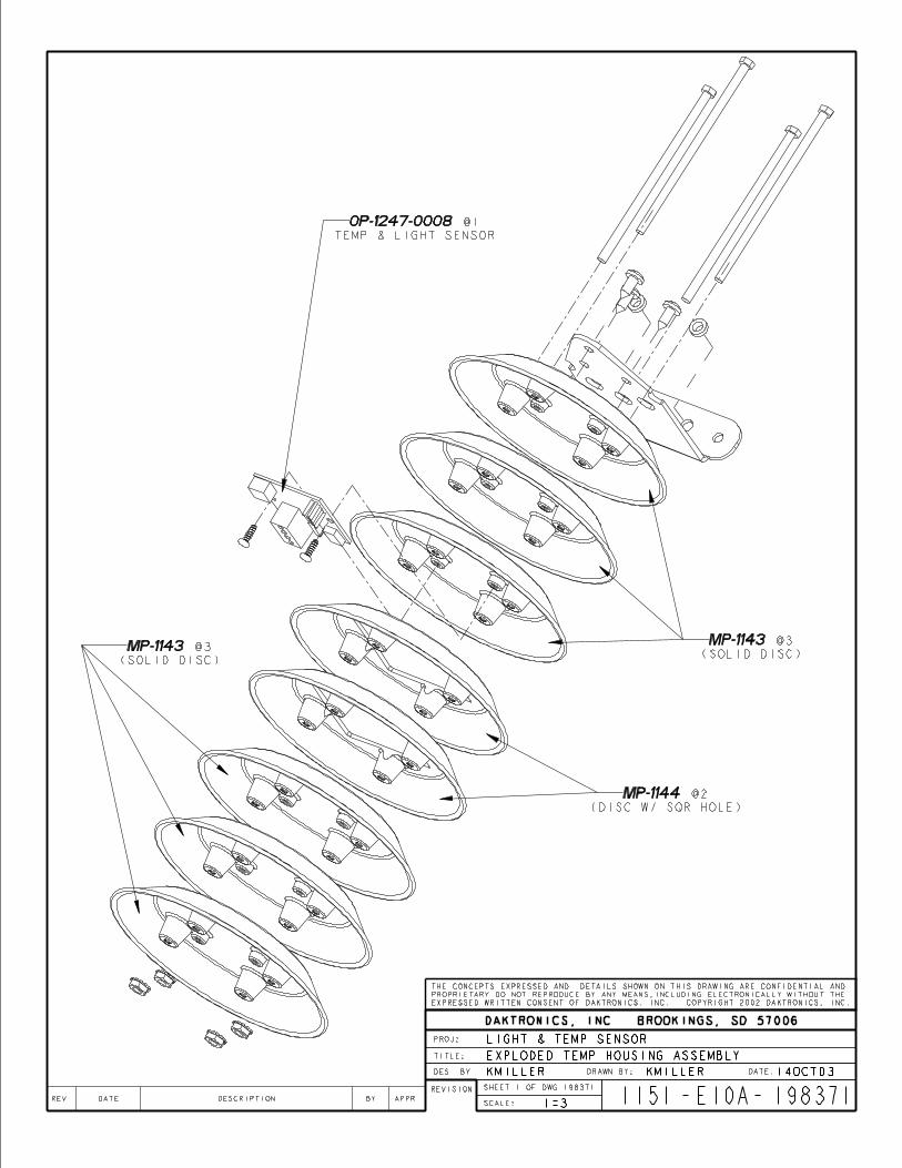
Daktronics Warranty and Limitation of Liability (SL-02374) 53
Appendix D: Daktronics Warranty and Limitation of Liability (SL-02374)
Related Documents