GA-EQ45M-S2 LGA775 socket motherboard for Intel ® Core TM processor family/ Intel ® Pentium ® processor family/Intel ® Celeron ® processor family User's Manual Rev. 2001 12ME-EQ45MS2-2001R Downloaded from www.Manualslib.com manuals search engine

gaeq45ms2 Gigabyte
Dec 21, 2015
Manual Gigabyte GA-EQ45-MS2 Rev 1.0
Welcome message from author
This document is posted to help you gain knowledge. Please leave a comment to let me know what you think about it! Share it to your friends and learn new things together.
Transcript

GA-EQ45M-S2LGA775 socket motherboard for Intel® CoreTM processor family/Intel® Pentium® processor family/Intel® Celeron® processor family
User's ManualRev. 200112ME-EQ45MS2-2001R
Downloaded from www.Manualslib.com manuals search engine

Feb. 9, 2009
Motherboard
GA-EQ45M-S2
Motherboard
Feb. 9, 2009
GA
-EQ45M
-S2
Downloaded from www.Manualslib.com manuals search engine
Copyright© 2009 GIGA-BYTE TECHNOLOGY CO., LTD. All rights reserved.The trademarks mentioned in this manual are legally registered to their respective owners.
DisclaimerInformation in this manual is protected by copyright laws and is the property of GIGABYTE.Changes to the specifications and features in this manual may be made by GIGABYTE without priornotice. No part of this manual may be reproduced, copied, translated, transmitted, or published in anyform or by any means without GIGABYTE's prior written permission.
Documentation ClassificationsIn order to assist in the use of this product, GIGABYTE provides the following types of documentations:
For detailed product information, carefully read the User's Manual. For instructions on how to use GIGABYTE's unique features, read or download the
information on/from the Support\Motherboard\Technology Guide page on our website.
For product-related information, check on our website at:http://www.gigabyte.com.tw
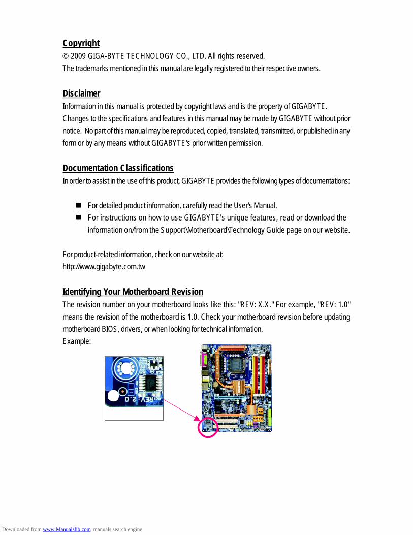
Identifying Your Motherboard RevisionThe revision number on your motherboard looks like this: "REV: X.X." For example, "REV: 1.0"means the revision of the motherboard is 1.0. Check your motherboard revision before updatingmotherboard BIOS, drivers, or when looking for technical information.Example:
Downloaded from www.Manualslib.com manuals search engine

- 4 -
Table of Contents
Box Contents ................................................................................................................. 6Optional Items ................................................................................................................. 6GA-EQ45M-S2 Motherboard Layout .............................................................................. 7Block Diagram ................................................................................................................ 8
Chapter 1 Hardware Installation .................................................................................... 91-1 Installation Precautions ..................................................................................... 91-2 Product Specifications .................................................................................... 101-3 Installing the CPU and CPU Cooler .............................................................. 13
1-3-1 Installing the CPU ................................................................................................ 131-3-2 Installing the CPU Cooler ................................................................................... 15
1-4 Installing the Memory ..................................................................................... 161-4-1 Dual Channel Memory Configuration ................................................................ 161-4-2 Installing a Memory ............................................................................................. 17
1-5 Installing an Expansion Card ......................................................................... 181-6 Back Panel Connectors ................................................................................. 191-7 Internal Connectors ........................................................................................ 21
Chapter 2 BIOS Setup ................................................................................................. 332-1 Startup Screen ................................................................................................ 342-2 The Main Menu .............................................................................................. 352-3 MB Intelligent Tweaker(M.I.T.) ....................................................................... 372-4 Standard CMOS Features ............................................................................. 402-5 Advanced BIOS Features .............................................................................. 422-6 Advanced Chipset Features ........................................................................... 452-7 Integrated Peripherals ..................................................................................... 472-8 Power Management Setup ............................................................................. 492-9 PnP/PCI Configurations ................................................................................. 512-10 PC Health Status ........................................................................................... 522-11 Load Fail-Safe Defaults ................................................................................... 542-12 Load Optimized Defaults ................................................................................. 542-13 Set Supervisor/User Password ..................................................................... 552-14 Save & Exit Setup ......................................................................................... 562-15 Exit Without Saving ....................................................................................... 562-16 Security Chip Configuration ............................................................................ 57
Downloaded from www.Manualslib.com manuals search engine

- 5 -
Chapter 3 Drivers Installation ...................................................................................... 593-1 Installing Chipset Drivers ............................................................................... 593-2 Application Software ....................................................................................... 603-3 Technical Manuals .......................................................................................... 603-4 Contact ........................................................................................................... 613-5 System........................................................................................................... 613-6 Download Center ............................................................................................ 62
Chapter 4 Unique Features ......................................................................................... 634-1 Xpress Recovery2 ......................................................................................... 634-2 BIOS Update Utilities ..................................................................................... 66
4-2-1 Updating the BIOS with the Q-Flash Utility ...................................................... 664-2-2 Updating the BIOS with the @BIOS Utility ....................................................... 69
4-3 Dynamic Energy Saver Advanced ................................................................ 704-4 Ultra TPM ...................................................................................................... 724-5 Q-Share ......................................................................................................... 734-6 Time Repair .................................................................................................... 74
Chapter 5 Appendix .................................................................................................... 755-1 Configuring SATA Hard Drive(s) .................................................................... 75
5-1-1 Configuring Intel ICH10DO SATA Controllers ................................................... 755-1-2 Making a SATA RAID/AHCI Driver Diskette ..................................................... 815-1-3 Installing the SATA RAID/AHCI Driver and Operating System ...................... 82
5-2 Configuring Audio Input and Output ................................................................. 875-2-1 Configuring 2/4/5.1/7.1-Channel Audio ............................................................ 875-2-2 Configuring S/PDIF In/Out .................................................................................. 895-2-3 Configuring Microphone Recording ................................................................... 915-2-4 Using the Sound Recorder ................................................................................. 93
5-3 Troubleshooting ............................................................................................... 945-3-1 Frequently Asked Questions ............................................................................. 945-3-2 Troubleshooting Procedure ................................................................................ 95
5-4 Regulatory Statements ................................................................................... 97
Downloaded from www.Manualslib.com manuals search engine
- 6 -
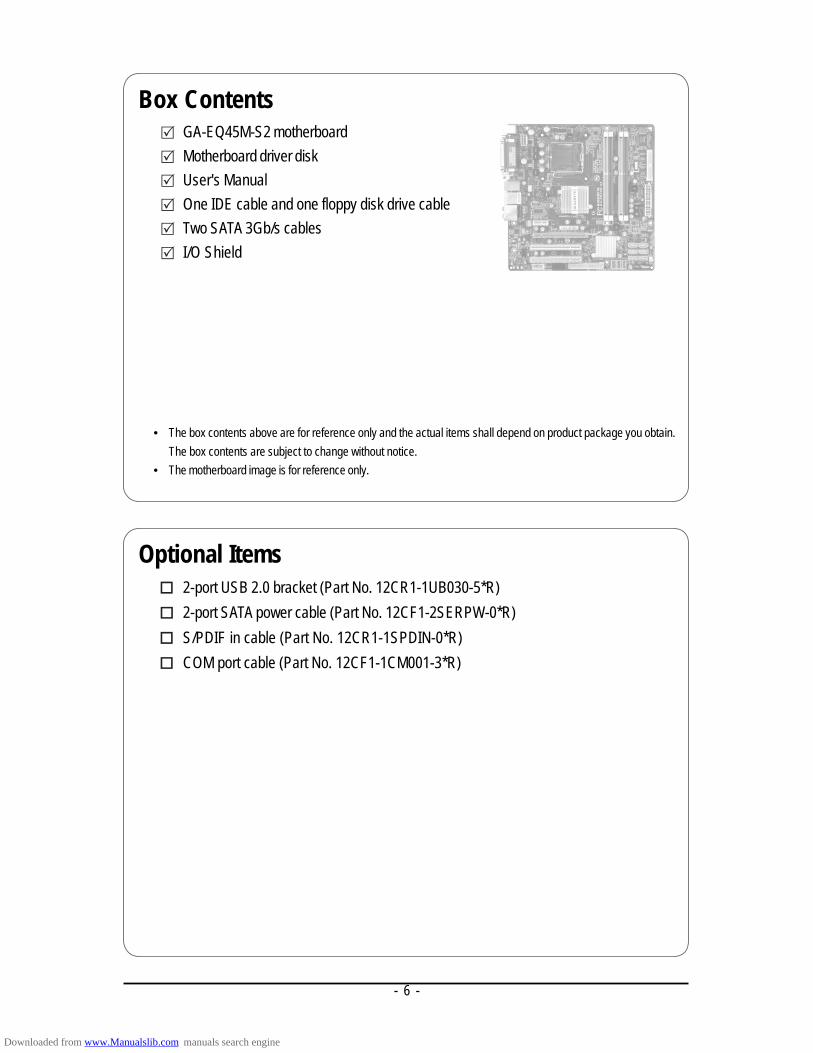
• The box contents above are for reference only and the actual items shall depend on product package you obtain.The box contents are subject to change without notice.
• The motherboard image is for reference only.
Box ContentsGA-EQ45M-S2 motherboardMotherboard driver diskUser's ManualOne IDE cable and one floppy disk drive cableTwo SATA 3Gb/s cablesI/O Shield
Optional Items2-port USB 2.0 bracket (Part No. 12CR1-1UB030-5*R)2-port SATA power cable (Part No. 12CF1-2SERPW-0*R)S/PDIF in cable (Part No. 12CR1-1SPDIN-0*R)COM port cable (Part No. 12CF1-1CM001-3*R)
Downloaded from www.Manualslib.com manuals search engine

- 7 -
GA-EQ45M-S2 Motherboard Layout
KB_MS
LGA775
ATX
GA-E
Q45M
-S2
USB
LAN
F_AUDIOAUDIO
IT87
20
ATX_12V_2X
R_USBCPU_FAN
Intel® Q45
MFG
SATA2_0
Intel® ICH10DO1_
BIOS
CD_IN
BAT
Intel 82567LM
PCI1
SYS_
FAN
DVI
SPDIF_I
FDD
F_USB2F_USB1
CODEC
SPDIF_O
CLR_CMOS
PCIEX16
F_PANEL
VGA
PCIEX1
COMA
JMicron 368
SATA2_1
SATA2_2 SATA2_3
SATA2_4 SATA2_5
CI
COMB
TPM IC
F_USB3
DDR2
_1
DDR2
_2
DDR2
_3
DDR2
_4
PHASE LED ACPI_LED(S0/1/3/4/5_LED)
LPT
PWR_LED
2_BI
OS
DEBUG PORT*
PCI2
* Whether this feature is supported depends on the product being received.
IDE
Downloaded from www.Manualslib.com manuals search engine

- 8 -
Block Diagram
BIOS
CPU CLK+/-(333/266/200 MHz)
LGA775Processor
Intel® Q45
LPC BUS
Line-
Out
MIC
CODEC
Line-
InSP
DIF
InSP
DIF
Out
Side
Spe
aker
Out
Cent
er/S
ubwo
ofer
Spe
aker
Out
Surro
und
Spea
ker O
ut
F loppy
HostInterface
PCI Express Bus
GMCH CLK(333/266/200 MHz)
PS/2 KB/Mouse
IT8720
Intel® ICH10DO
1 PCI Express x1
PCIe CLK(100 MHz)
x1
DDR2 800/667 MHz
Dual Channel Memory
12 USB Ports
6 SATA 3Gb/s
2 COM Ports
Intel82567LM
LAN
RJ45
GLCIx1
TPM
(Note) Simultaneous output for PCI Express x16 and DVI-D is not supported.
DVI-D (Note)
PCI Express Bus
1 PCI Express x16 (Note)
12 Lanes
Switchor
D-Sub
Level Shifter
4 Lanes
2 PCI
PCI Bus
ATA-133/100/66/33IDE Channel
JMicron 368
PCI CLK(33 MHz)
Downloaded from www.Manualslib.com manuals search engine

Hardware Installation- 9 -
1-1 Installation Precautions
The motherboard contains numerous delicate electronic circuits and components which can becomedamaged as a result of electrostatic discharge (ESD). Prior to installation, carefully read the user'smanual and follow these procedures:
• Prior to installation, do not remove or break motherboard S/N (Serial Number) sticker orwarranty sticker provided by your dealer. These stickers are required for warranty validation.
• Always remove the AC power by unplugging the power cord from the power outlet beforeinstalling or removing the motherboard or other hardware components.
• When connecting hardware components to the internal connectors on the motherboard,make sure they are connected tightly and securely.
• When handling the motherboard, avoid touching any metal leads or connectors.• It is best to wear an electrostatic discharge (ESD) wrist strap when handling electronic
components such as a motherboard, CPU or memory. If you do not have an ESD wrist strap,keep your hands dry and first touch a metal object to eliminate static electricity.
• Prior to installing the motherboard, please have it on top of an antistatic pad or within anelectrostatic shielding container.
• Before unplugging the power supply cable from the motherboard, make sure the power supplyhas been turned off.
• Before turning on the power, make sure the power supply voltage has been set according tothe local voltage standard.
• Before using the product, please verify that all cables and power connectors of your hardwarecomponents are connected.
• To prevent damage to the motherboard, do not allow screws to come in contact with themotherboard circuit or its components.
• Make sure there are no leftover screws or metal components placed on the motherboard orwithin the computer casing.
• Do not place the computer system on an uneven surface.• Do not place the computer system in a high-temperature environment.• Turning on the computer power during the installation process can lead to damage to system
components as well as physical harm to the user.• If you are uncertain about any installation steps or have a problem related to the use of the
product, please consult a certified computer technician.
Chapter 1 Hardware Installation
Downloaded from www.Manualslib.com manuals search engine
GA-EQ45M-S2 Motherboard - 10 -
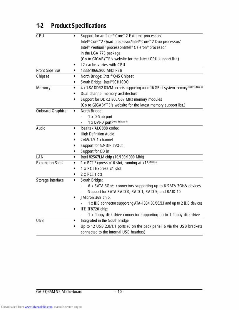
1-2 Product SpecificationsCPU Support for an Intel® CoreTM 2 Extreme processor/
Intel® CoreTM 2 Quad processor/Intel® CoreTM 2 Duo processor/Intel® Pentium® processor/Intel® Celeron® processorin the LGA 775 package(Go to GIGABYTE's website for the latest CPU support list.)
L2 cache varies with CPUFront Side Bus 1333/1066/800 MHz FSBChipset North Bridge: Intel® Q45 Chipset
South Bridge: Intel® ICH10DOMemory 4 x 1.8V DDR2 DIMM sockets supporting up to 16 GB of system memory (Note 1) (Note 2)
Dual channel memory architecture Support for DDR2 800/667 MHz memory modules
(Go to GIGABYTE's website for the latest memory support list.)Onboard Graphics North Bridge:
- 1 x D-Sub port- 1 x DVI-D port (Note 3)(Note 4)
Audio Realtek ALC888 codec High Definition Audio 2/4/5.1/7.1-channel Support for S/PDIF In/Out Support for CD In
LAN Intel 82567LM chip (10/100/1000 Mbit)Expansion Slots 1 x PCI Express x16 slot, running at x16 (Note 4)
1 x PCI Express x1 slot 2 x PCI slots
Storage Interface South Bridge:- 6 x SATA 3Gb/s connectors supporting up to 6 SATA 3Gb/s devices- Support for SATA RAID 0, RAID 1, RAID 5, and RAID 10
JMicron 368 chip:- 1 x IDE connector supporting ATA-133/100/66/33 and up to 2 IDE devices
iTE IT8720 chip:- 1 x floppy disk drive connector supporting up to 1 floppy disk drive
USB Integrated in the South Bridge Up to 12 USB 2.0/1.1 ports (6 on the back panel, 6 via the USB brackets
connected to the internal USB headers)
Downloaded from www.Manualslib.com manuals search engine
Hardware Installation- 11 -
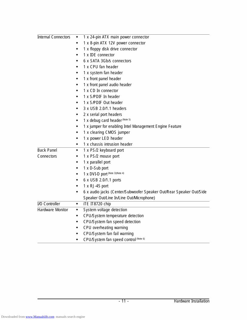
Internal Connectors 1 x 24-pin ATX main power connector 1 x 8-pin ATX 12V power connector 1 x floppy disk drive connector 1 x IDE connector 6 x SATA 3Gb/s connectors 1 x CPU fan header 1 x system fan header 1 x front panel header 1 x front panel audio header 1 x CD In connector 1 x S/PDIF In header 1 x S/PDIF Out header 3 x USB 2.0/1.1 headers 2 x serial port headers 1 x debug card header (Note 5)
1 x jumper for enabling Intel Management Engine Feature 1 x clearing CMOS jumper 1 x power LED header 1 x chassis intrusion header
Back Panel 1 x PS/2 keyboard portConnectors 1 x PS/2 mouse port
1 x parallel port 1 x D-Sub port 1 x DVI-D port (Note 3)(Note 4)
6 x USB 2.0/1.1 ports 1 x RJ-45 port 6 x audio jacks (Center/Subwoofer Speaker Out/Rear Speaker Out/Side
Speaker Out/Line In/Line Out/Microphone)I/O Controller iTE IT8720 chipHardware Monitor System voltage detection
CPU/System temperature detection CPU/System fan speed detection CPU overheating warning CPU/System fan fail warning CPU/System fan speed control (Note 6)
Downloaded from www.Manualslib.com manuals search engine

GA-EQ45M-S2 Motherboard - 12 -
BIOS 2 x 16 Mbit flash Use of licensed AWARD BIOS PnP 1.0a, DMI 2.0, SM BIOS 2.4, ACPI 1.0b
Unique Features Support for @BIOS Support for Q-Flash Support for Virtual Dual BIOS Support for Download Center Support for Xpress Install Support for Xpress Recovery2 Support for Dynamic Energy Saver Advanced Support for Ultra TPM Support for Time Repair Support for Q-Share
Bundled Software Norton Internet Security (OEM version)Operating System Support for Microsoft® Windows® Vista/XPForm Factor Micro ATX Form Factor; 24.4cm x 24.4cm
(Note 1) Due to Windows Vista/XP 32-bit operating system limitation, when more than 4 GB of physicalmemory is installed, the actual memory size displayed will be less than 4 GB.
(Note 2) Before enabling Intel Management Engine, make sure DDR2_1 socket in Channel 0 is populated.(Note 3) The DVI-D port does not support D-Sub connection by adapter.(Note 4) Simultaneous output for PCI Express x16 and DVI-D is not supported.(Note 5) Whether this feature is supported depends on the product being received.(Note 6) Whether the CPU/System fan speed control function is supported will depend on the CPU/
System cooler you install.
Downloaded from www.Manualslib.com manuals search engine

Hardware Installation- 13 -
NotchNotch
Alignment KeyAlignment Key
LGA 775 CPU
LGA775 CPU Socket
Pin One Corner of the CPU Socket
Triangle Pin One Marking on the CPU
1-3 Installing the CPU and CPU CoolerRead the following guidelines before you begin to install the CPU:• Make sure that the motherboard supports the CPU.
(Go to GIGABYTE's website for the latest CPU support list.)• Always turn off the computer and unplug the power cord from the power outlet before
installing the CPU to prevent hardware damage.• Locate the pin one of the CPU. The CPU cannot be inserted if oriented incorrectly. (Or you
may locate the notches on both sides of the CPU and alignment keys on the CPU socket.)• Apply an even and thin layer of thermal grease on the surface of the CPU.• Do not turn on the computer if the CPU cooler is not installed, otherwise overheating and
damage of the CPU may occur.• Set the CPU host frequency in accordance with the CPU specifications. It is not recom-
mended that the system bus frequency be set beyond hardware specifications since itdoes not meet the standard requirements for the peripherals. If you wish to set the fre-quency beyond the standard specifications, please do so according to your hardwarespecifications including the CPU, graphics card, memory, hard drive, etc.
1-3-1 Installing the CPUA. Locate the alignment keys on the motherboard CPU socket and the notches on the CPU.
Downloaded from www.Manualslib.com manuals search engine

GA-EQ45M-S2 Motherboard - 14 -
B. Follow the steps below to correctly install the CPU into the motherboard CPU socket.
Before installing the CPU, make sure to turn off the computer and unplug the powercord from the power outlet to prevent damage to the CPU.
Step 1:Completely raise the CPU socket lever.
CPU Socket Lever
Step 3:Remove the protective socket cover from theload plate. (To protect the CPU socket, alwaysreplace the protective socket cover when theCPU is not installed.)
Step 5:Once the CPU is properly inserted, replacethe load plate and push the CPU socket leverback into its locked position.
Step 2:Lift the metal load plate from the CPU socket.(DO NOT touch socket contacts.)
Step 4:Hold the CPU with your thumb and indexfingers. Align the CPU pin one marking (triangle)with the pin one corner of the CPU socket (oryou may align the CPU notches with the socketalignment keys) and gently insert the CPUinto position.
Downloaded from www.Manualslib.com manuals search engine
Hardware Installation- 15 -
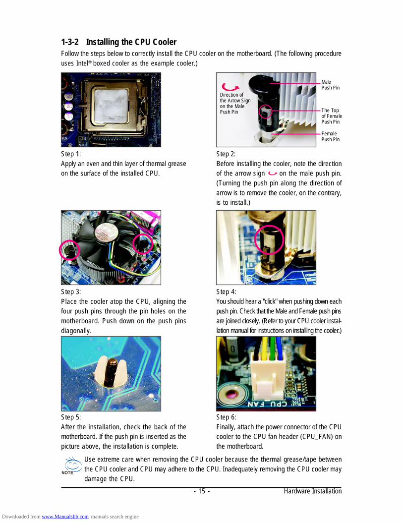
1-3-2 Installing the CPU CoolerFollow the steps below to correctly install the CPU cooler on the motherboard. (The following procedureuses Intel® boxed cooler as the example cooler.)
Step 1:Apply an even and thin layer of thermal greaseon the surface of the installed CPU.
Step 2:Before installing the cooler, note the directionof the arrow sign on the male push pin.(Turning the push pin along the direction ofarrow is to remove the cooler, on the contrary,is to install.)
MalePush Pin
FemalePush Pin
The Topof FemalePush Pin
Direction ofthe Arrow Signon the MalePush Pin
Step 3:Place the cooler atop the CPU, aligning thefour push pins through the pin holes on themotherboard. Push down on the push pinsdiagonally.
Step 4:You should hear a "click" when pushing down eachpush pin. Check that the Male and Female push pinsare joined closely. (Refer to your CPU cooler instal-lation manual for instructions on installing the cooler.)
Use extreme care when removing the CPU cooler because the thermal grease/tape betweenthe CPU cooler and CPU may adhere to the CPU. Inadequately removing the CPU cooler maydamage the CPU.
Step 5:After the installation, check the back of themotherboard. If the push pin is inserted as thepicture above, the installation is complete.
Step 6:Finally, attach the power connector of the CPUcooler to the CPU fan header (CPU_FAN) onthe motherboard.
Downloaded from www.Manualslib.com manuals search engine

GA-EQ45M-S2 Motherboard - 16 -
1-4 Installing the MemoryRead the following guidelines before you begin to install the memory:• Make sure that the motherboard supports the memory. It is recommended that memory of
the same capacity, brand, speed, and chips be used.(Go to GIGABYTE's website for the latest memory support list.)
• Always turn off the computer and unplug the power cord from the power outlet beforeinstalling the memory to prevent hardware damage.
• Memory modules have a foolproof design. A memory module can be installed in only onedirection. If you are unable to insert the memory, switch the direction.
When memory modules of different capacity and chips are installed, a message which saysmemory is operating in Flex Memory Mode will appear during the POST. Intel® Flex MemoryTechnology offers greater flexibility to upgrade by allowing different memory sizes to bepopulated and remain in Dual Channel mode/performance.
1-4-1 Dual Channel Memory ConfigurationThis motherboard provides four DDR2 memory sockets and supports Dual ChannelTechnology. After the memory is installed, the BIOS will automatically detect thespecifications and capacity of the memory. Enabling Dual Channel memory modewill double the original memory bandwidth.
The four DDR2 memory sockets are divided into two channels and each channel has two memorysockets as following:
Channel 0: DDR2_1, DDR2_2Channel 1: DDR2_3, DDR2_4
Two Modules
Four Modules
DDR2_1 DDR2_2 DDR2_3 DDR2_4DS/SS - - DS/SS - -- - DS/SS - - DS/SSDS/SS DS/SS DS/SS DS/SS
Dual Channel Memory Configurations Table
(SS=Single-Sided, DS=Double-Sided, "- -"=No Memory)
Due to chipset limitation, read the following guidelines before installing the memory in Dual Channel mode.1. Dual Channel mode cannot be enabled if only one DDR2 memory module is installed.2. When enabling Dual Channel mode with two or four memory modules, it is recommended that
memory of the same capacity, brand, speed, and chips be used and installed in the samecolored DDR2 sockets for optimum performance.
3. Before enabling Intel Management Engine, make sure DDR2_1 socket in Channel 0 is populated.
DDR2
_1DD
R2_2
DDR2
_3DD
R2_4
Downloaded from www.Manualslib.com manuals search engine

Hardware Installation- 17 -
1-4-2 Installing a Memory
Notch
DDR2 DIMM
Before installing a memory module , make sure to turn off the computer and unplugthe power cord from the power outlet to prevent damage to the memory module.DDR2 DIMMs are not compatible to DDR DIMMs. Be sure to install DDR2 DIMMs onthis motherboard.
Step 1:Note the orientation of the memory module. Spread the retainingclips at both ends of the memory socket. Place the memorymodule on the socket. As indicated in the picture on the left,place your fingers on the top edge of the memory, push downon the memory and insert it vertically into the memory socket.
Step 2:The clips at both ends of the socket will snap into place whenthe memory module is securely inserted.
A DDR2 memory module has a notch, so it can only fit in one direction. Follow the steps below tocorrectly install your memory modules in the memory sockets.
Downloaded from www.Manualslib.com manuals search engine

GA-EQ45M-S2 Motherboard - 18 -
1-5 Installing an Expansion CardRead the following guidelines before you begin to install an expansion card:• Make sure the motherboard supports the expansion card. Carefully read the manual that
came with your expansion card.• Always turn off the computer and unplug the power cord from the power outlet before
installing an expansion card to prevent hardware damage.
Follow the steps below to correctly install your expansion card in the expansion slot.1. Locate an expansion slot that supports your card. Remove the metal slot cover from the chassis back panel.2. Align the card with the slot, and press down on the card until it is fully seated in the slot.3. Make sure the metal contacts on the card are completely inserted into the slot.4. Secure the card's metal bracket to the chassis back panel with a screw.5. After installing all expansion cards, replace the chassis cover(s).6. Turn on your computer. If necessary, go to BIOS Setup to make any required BIOS changes for
your expansion card(s).7. Install the driver provided with the expansion card in your operating system.
Example: Installing and Removing a PCI Express Graphics Card:
PCI Slot
PCI Express x16 Slot
PCI Express x1 Slot
• Installing a Graphics Card:Gently push down on the top edge of the carduntil it is fully inserted into the PCI Express slot.Make sure the card is securely seated in theslot and does not rock.
• Removing the Card:Gently push back on the lever on the slot and then lift the card straight outfrom the slot.
Downloaded from www.Manualslib.com manuals search engine

Hardware Installation- 19 -
1-6 Back Panel Connectors
PS/2 Keyboard and PS/2 Mouse PortUse the upper port (green) to connect a PS/2 mouse and the lower port (purple) to connect a PS/2keyboard.Parallel PortUse the parallel port to connect devices such as a printer, scanner and etc. The parallel port is alsocalled a printer port.D-Sub PortThe D-Sub port supports a 15-pin D-Sub connector. Connect a monitor that supports D-Sub connectionto this port.DVI-D PortThe DVI-D port supports DVI-D specifictation. Connect a monitor that supports DVI-D connection tothis port.USB PortThe USB port supports the USB 2.0/1.1 specification. Use this port for USB devices such as anUSB keyboard/mouse, USB printer, USB flash drive and etc.RJ-45 LAN PortThe Gigabit Ethernet LAN port provides Internet connection at up to 1 Gbps data rate. The followingdescribes the states of the LAN port LEDs.
Connection/Activity LEDSpeed LED
LAN Port
Connection/Activity LED:Speed LED:State DescriptionOrange 1 Gbps data rateGreen 100 Mbps data rateOff 10 Mbps data rate
State DescriptionBlinking Data transmission or receiving is occurringOn No data transmission or receiving is occurringOff LAN link is not established
• When removing the cable connected to a back panel connector, first remove the cablefrom your device and then remove it from the motherboard.
• When removing the cable, pull it straight out from the connector. Do not rock it side to sideto prevent an electrical short inside the cable connector.
Downloaded from www.Manualslib.com manuals search engine
GA-EQ45M-S2 Motherboard - 20 -
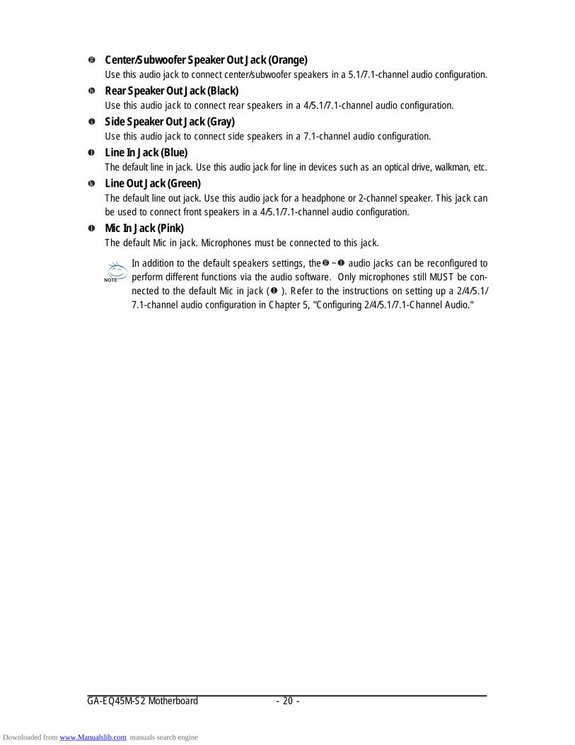
In addition to the default speakers settings, the ~ audio jacks can be reconfigured toperform different functions via the audio software. Only microphones still MUST be con-nected to the default Mic in jack ( ). Refer to the instructions on setting up a 2/4/5.1/7.1-channel audio configuration in Chapter 5, "Configuring 2/4/5.1/7.1-Channel Audio."
Center/Subwoofer Speaker Out Jack (Orange)Use this audio jack to connect center/subwoofer speakers in a 5.1/7.1-channel audio configuration.Rear Speaker Out Jack (Black)Use this audio jack to connect rear speakers in a 4/5.1/7.1-channel audio configuration.Side Speaker Out Jack (Gray)Use this audio jack to connect side speakers in a 7.1-channel audio configuration.Line In Jack (Blue)The default line in jack. Use this audio jack for line in devices such as an optical drive, walkman, etc.Line Out Jack (Green)The default line out jack. Use this audio jack for a headphone or 2-channel speaker. This jack canbe used to connect front speakers in a 4/5.1/7.1-channel audio configuration.Mic In Jack (Pink)The default Mic in jack. Microphones must be connected to this jack.
Downloaded from www.Manualslib.com manuals search engine

Hardware Installation- 21 -
1-7 Internal Connectors
Read the following guidelines before connecting external devices:• First make sure your devices are compliant with the connectors you wish to connect.• Before installing the devices, be sure to turn off the devices and your computer. Unplug the
power cord from the power outlet to prevent damage to the devices.• After installing the device and before turning on the computer, make sure the device cable
has been securely attached to the connector on the motherboard.
1) ATX_12V_2X2) ATX3) CPU_FAN4) SYS_FAN5) FDD6) IDE7) SATA2_0/1/2/3/4/58) PWR_LED9) BAT
10) F_PANEL11) F_AUDIO12) CD_IN
13) SPDIF_I14) SPDIF_O15) F_USB1/F_USB2/F_USB316) COMA17) COMB18) DEBUG PORT*19) C I20) CLR_CMOS21) MFG22) PHASE LED23) S0/S1/S3/S4/S5_LED
2
1
3
22
5
4
9
7
11
12
15613 2016 10
14 8
19
21
18
23
17
* Whether this feature is supported depends on the product being received.
Downloaded from www.Manualslib.com manuals search engine

GA-EQ45M-S2 Motherboard - 22 -
ATX:Pin No. Definition
13 3.3V14 -12V15 GND16 PS_ON(soft On/Off)17 GND18 GND19 GND20 -5V21 +5V22 +5V23 +5V (Only for 2x12-pin ATX)24 GND (Only for 2x12-pin ATX)
Pin No. Definition1 3.3V2 3.3V3 GND4 +5V5 GND6 +5V7 GND8 Power Good9 5V SB(stand by +5V)10 +12V11 +12V (Only for 2x12-pin ATX)12 3.3V (Only for 2x12-pin ATX)131
2412
ATX
ATX_12V_2X:Pin No. Definition
1 GND (Only for 2x4 pin 12V)2 GND (Only for 2x4 pin 12V)3 GND4 GND5 +12V (Only for 2x4 pin 12V)6 +12V (Only for 2x4 pin 12V)7 +12V8 +12V
1/2) ATX_12V_2X/ATX (2x4 12V Power Connector and 2x12 Main Power Connector)With the use of the power connector, the power supply can supply enough stable power to all thecomponents on the motherboard. Before connecting the power connector, first make sure thepower supply is turned off and all devices are properly installed. The power connector possessesa foolproof design. Connect the power supply cable to the power connector in the correct orientation.The 12V power connector mainly supplies power to the CPU. If the 12V power connector is notconnected, the computer will not start.
• Use of a power supply providing a 2x4 12V power connector is recommended by theCPU manufacturer when using an Intel Extreme Edition CPU (130W).
• To meet expansion requirements, it is recommended that a power supply that can withstandhigh power consumption be used (500W or greater). If a power supply is used that does notprovide the required power, the result can lead to an unstable or unbootable system.
• The power connectors are compatible with power supplies with 2x2 12V and 2x10 powerconnectors. When using a power supply providing a 2x4 12V and a 2x12 power connector,remove the protective covers from the 12V power connector and the main power connector onthe motherboard. Do not insert the power supply cables into pins under the protective coverswhen using a power supply providing a 2x2 12V and a 2x10 power connector.
8
5
4
1
ATX_12V_2X
Downloaded from www.Manualslib.com manuals search engine
Hardware Installation- 23 -
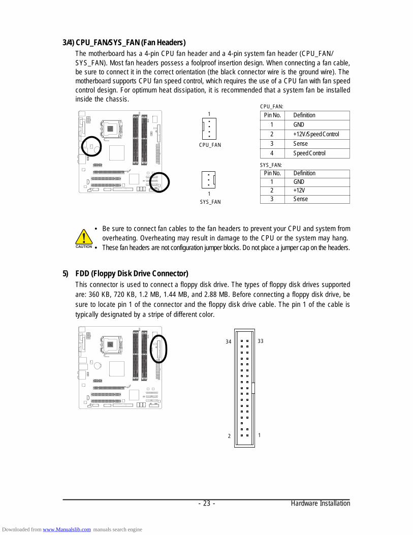
3/4) CPU_FAN/SYS_FAN (Fan Headers)The motherboard has a 4-pin CPU fan header and a 4-pin system fan header (CPU_FAN/SYS_FAN). Most fan headers possess a foolproof insertion design. When connecting a fan cable,be sure to connect it in the correct orientation (the black connector wire is the ground wire). Themotherboard supports CPU fan speed control, which requires the use of a CPU fan with fan speedcontrol design. For optimum heat dissipation, it is recommended that a system fan be installedinside the chassis.
Pin No. Definition1 GND2 +12V/Speed Control3 Sense4 Speed Control
CPU_FAN:
SYS_FAN:
• Be sure to connect fan cables to the fan headers to prevent your CPU and system fromoverheating. Overheating may result in damage to the CPU or the system may hang.
• These fan headers are not configuration jumper blocks. Do not place a jumper cap on the headers.
5) FDD (Floppy Disk Drive Connector)This connector is used to connect a floppy disk drive. The types of floppy disk drives supportedare: 360 KB, 720 KB, 1.2 MB, 1.44 MB, and 2.88 MB. Before connecting a floppy disk drive, besure to locate pin 1 of the connector and the floppy disk drive cable. The pin 1 of the cable istypically designated by a stripe of different color.
Pin No. Definition1 GND2 +12V3 SenseSYS_FAN
1
CPU_FAN
1
12
3334
Downloaded from www.Manualslib.com manuals search engine

GA-EQ45M-S2 Motherboard - 24 -
6) IDE (IDE Connector)The IDE connector supports up to two IDE devices such as hard drives and optical drives. Beforeattaching the IDE cable, locate the foolproof groove on the connector. If you wish to connect two IDEdevices, remember to set the jumpers and the cabling according to the role of the IDE devices (forexample, master or slave). (For information about configuring master/slave settings for the IDEdevices, read the instructions from the device manufacturers.)
7) SATA2_0/1/2/3/4/5 (SATA 3Gb/s Connectors, Controlled by ICH10DO, Orange)The SATA connectors conform to SATA 3Gb/s standard and are compatible with SATA 1.5Gb/sstandard. Each SATA connector supports a single SATA device. The ICH10DO controller supportsRAID 0, RAID 1, RAID 5 and RAID 10. Refer to Chapter 5, "Configuring SATA Hard Drive(s)," forinstructions on configuring a RAID array. Pin No. Definition
1 GND2 TXP3 TXN4 GND5 RXN6 RXP7 GND
Please connect the L-shaped endof the SATA 3Gb/s cable to yourSATA hard drive.
• A RAID 0 or RAID 1 configuration requires at least two hard drives. If more than two harddrives are to be used, the total number of hard drives must be an even number.
• A RAID 5 configuration requires at least three hard drives. (The total number of harddrives does not have to be an even number.)
• A RAID 10 configuration requires at least four hard drives and the total number of harddrives must be an even number.
240
139
1
SATA2_0 SATA2_1
7
1
SATA2_2 SATA2_3
7
1
SATA2_4 SATA2_5
7
Downloaded from www.Manualslib.com manuals search engine

Hardware Installation- 25 -
8) PWR_LED (System Power LED Header)This header can be used to connect a system power LED on the chassis to indicate system powerstatus. The LED is on when the system is operating. The LED keeps blinking when the system isin S1 sleep state. The LED is off when the system is in S3/S4 sleep state or powered off (S5).
Pin No. Definition1 MPD+2 MPD-3 MPD-
System Status LEDS0 OnS1 BlinkingS3/S4/S5 Off
9) BAT (Battery)The battery provides power to keep the values (such as BIOS configurations, date, and timeinformation) in the CMOS when the computer is turned off. Replace the battery when the batteryvoltage drops to a low level, or the CMOS values may not be accurate or may be lost.
• Always turn off your computer and unplug the power cord before replacing the battery.• Replace the battery with an equivalent one. Danger of explosion if the battery is replaced
with an incorrect model.• Contact the place of purchase or local dealer if you are not able to replace the battery by
yourself or uncertain about the battery model.• When installing the battery, note the orientation of the positive side (+) and the negative
side (-) of the battery (the positive side should face up).• Used batteries must be handled in accordance with local environmental regulations.
You may clear the CMOS values by removing the battery:1. Turn off your computer and unplug the power cord.2. Gently remove the battery from the battery holder and wait for one minute.
(Or use a metal object like a screwdriver to touch the positive andnegative terminals of the battery holder, making them short for 5 seconds.)
3. Replace the battery.4. Plug in the power cord and restart your computer.
1
Downloaded from www.Manualslib.com manuals search engine

GA-EQ45M-S2 Motherboard - 26 -
10) F_PANEL (Front Panel Header)Connect the power switch, reset switch, speaker and system status indicator on the chassis frontpanel to this header according to the pin assignments below. Note the positive and negative pinsbefore connecting the cables.
• PW (Power Switch, Red):Connects to the power switch on the chassis front panel. You may configure the way to turn offyour system using the power switch (refer to Chapter 2, "BIOS Setup," "Power ManagementSetup," for more information).
• SPEAK (Speaker, Orange):Connects to the speaker on the chassis front panel. The system reports system startup statusby issuing a beep code. One single short beep will be heard if no problem is detected at systemstartup. If a problem is detected, the BIOS may issue beeps in different patterns to indicate theproblem. Refer to Chapter 5, "Troubleshooting," for information about beep codes.
• HD (Hard Drive Activity LED, Blue)Connects to the hard drive activity LED on the chassis front panel. The LED is on when the harddrive is reading or writing data.
• RES (Reset Switch, Green):Connects to the reset switch on the chassis front panel. Press the reset switch to restart thecomputer if the computer freezes and fails to perform a normal restart.
• NC (Purple):No connection
System Status LEDS0 OnS1 BlinkingS3/S4/S5 Off
• MSG (Message/Power/Sleep LED, Yellow):Connects to the power status indicator on the chassis front panel. TheLED is on when the system is operating. The LED keeps blinking whenthe system is in S1 sleep state. The LED is off when the system is inS3/S4 sleep state or powered off (S5).
The front panel design may differ by chassis. A front panel module mainly consists ofpower switch, reset switch, power LED, hard drive activity LED, speaker and etc. Whenconnecting your chassis front panel module to this header, make sure the wire assign-ments and the pin assignments are matched correctly.
12
1920
HD-
HD+ RE
S+RE
S- NC
SPEA
K-
MSG-
MSG+
PW-
PW+
Message/Power/Sleep LED Speaker
SPEA
K+
PowerSwitch
Hard DriveActivity LED
ResetSwitch
Downloaded from www.Manualslib.com manuals search engine

Hardware Installation- 27 -
11) F_AUDIO (Front Panel Audio Header)The front panel audio header supports Intel High Definition audio (HD) and AC'97 audio. You mayconnect your chassis front panel audio module to this header. Make sure the wire assignments ofthe module connector match the pin assignments of the motherboard header. Incorrect connectionbetween the module connector and the motherboard header will make the device unable to workor even damage it.
12) CD_IN (CD In Connector, Black)You may connect the audio cable that came with your optical drive to the header.
Pin No. Definition1 CD-L2 GND3 GND4 CD-R
For AC'97 Front Panel Audio:Pin No. Definition
1 MIC2_L2 GND3 MIC2_R4 -ACZ_DET5 LINE2_R6 GND7 FAUDIO_JD8 No Pin9 LINE2_L10 GND
For HD Front Panel Audio:
• The front panel audio header supports HD audio by default. If your chassis provides anAC'97 front panel audio module, refer to the instructions on how to activate AC'97 functioninalityvia the audio software in Chapter 5, "Configuring 2/4/5.1/7.1-Channel Audio."
• Audio signals will be present on both of the front and back panel audio connectionssimultaneously. If you want to mute the back panel audio (only supported when using an HDfront panel audio module), refer to Chapter 5, "Configuring 2/4/5.1/7.1-Channel Audio."
• Some chassis provide a front panel audio module that has separated connectors on eachwire instead of a single plug. For information about connecting the front panel audiomodule that has different wire assignments, please contact the chassis manufacturer.
Pin No. Definition1 MIC2 GND3 MIC Power4 NC5 Line Out (R)6 NC7 NC8 No Pin9 Line Out (L)10 NC
10 9
2 1
1
Downloaded from www.Manualslib.com manuals search engine

GA-EQ45M-S2 Motherboard - 28 -
13) SPDIF_I (S/PDIF In Header, Red)This header supports digital S/PDIF in and can connect to an audio device that supports digitalaudio out via an optional S/PDIF in cable. For purchasing the optional S/PDIF in cable, pleasecontact the local dealer.
Pin No. Definition1 Power2 SPDIFI3 GND
Pin No. Definition1 SPDIFO2 GND
14) SPDIF_O (S/PDIF Out Header)This header supports digital S/PDIF out and connects a S/PDIF digital audio cable (provided byexpansion cards) for digital audio output from your motherboard to certain expansion cards likegraphics cards and sound cards. For example, some graphics cards may require you to use aS/PDIF digital audio cable for digital audio output from your motherboard to your graphics card ifyou wish to connect an HDMI display to the graphics card and have digital audio output from theHDMI display at the same time. For information about connecting the S/PDIF digital audio cable,carefully read the manual for your expansion card.
1
1
Downloaded from www.Manualslib.com manuals search engine

Hardware Installation- 29 -
16/17) COMA/COMB (Serial Port Header, White)The COMA/COMB header can provide one serial port via an optional COM port cable. Forpurchasing the optional COM port cable, please contact the local dealer.
Pin No. Definition1 NDCD-2 NSIN3 NSOUT4 NDTR-5 GND6 NDSR-7 NRTS-8 NCTS-9 NRI-10 No Pin
15) F_USB1/F_USB2/F_USB3 (USB Headers, Yellow)The headers conform to USB 2.0/1.1 specification. Each USB header can provide two USB portsvia an optional USB bracket. For purchasing the optional USB bracket, please contact the localdealer.
Pin No. Definition1 Power (5V)2 Power (5V)3 USB DX-4 USB DY-5 USB DX+6 USB DY+7 GND8 GND9 No Pin10 NC
• Do not plug the IEEE 1394 bracket (2x5-pin) cable into the USB header.• Prior to installing the USB bracket, be sure to turn off your computer and unplug the
power cord from the power outlet to prevent damage to the USB bracket.
9
1
10
2
10
9
2
1
COMA
10 9
2 1
COMB
Downloaded from www.Manualslib.com manuals search engine
GA-EQ45M-S2 Motherboard - 30 -
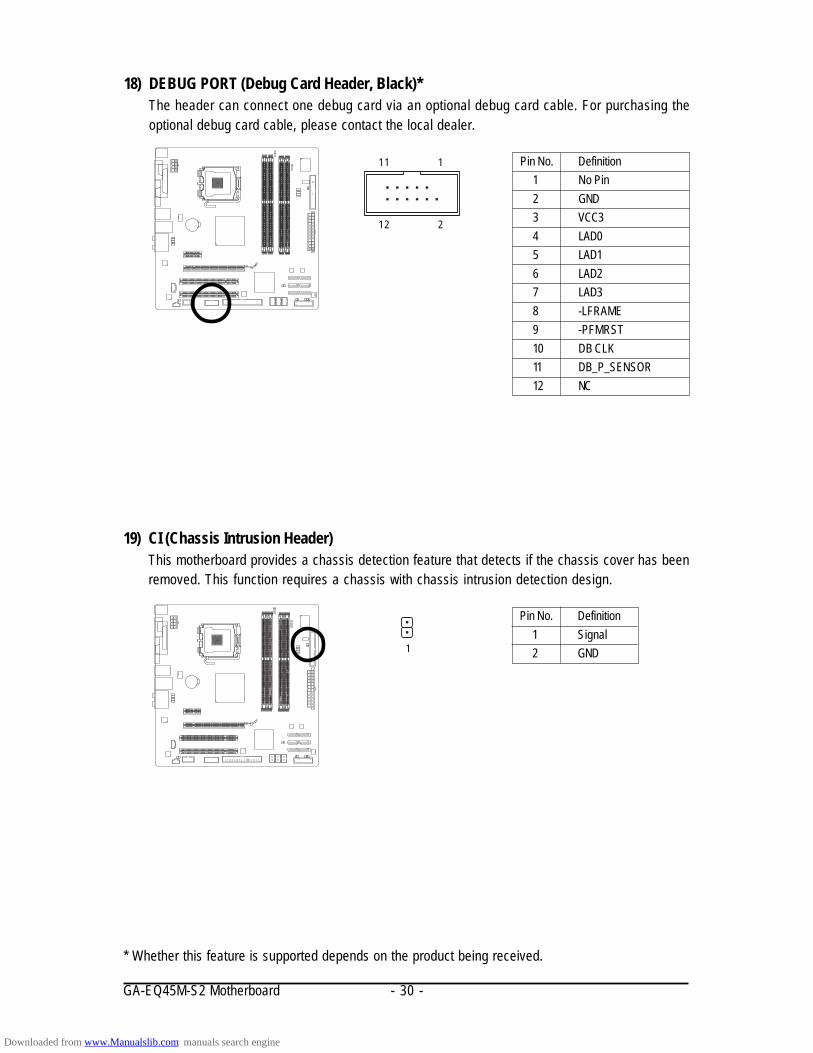
19) CI (Chassis Intrusion Header)This motherboard provides a chassis detection feature that detects if the chassis cover has beenremoved. This function requires a chassis with chassis intrusion detection design.
Pin No. Definition1 Signal2 GND
18) DEBUG PORT (Debug Card Header, Black)*The header can connect one debug card via an optional debug card cable. For purchasing theoptional debug card cable, please contact the local dealer.
Pin No. Definition1 No Pin2 GND3 VCC34 LAD05 LAD16 LAD27 LAD38 -LFRAME9 -PFMRST10 DB CLK11 DB_P_SENSOR12 NC
1
12
11
2
1
* Whether this feature is supported depends on the product being received.
Downloaded from www.Manualslib.com manuals search engine
Hardware Installation- 31 -
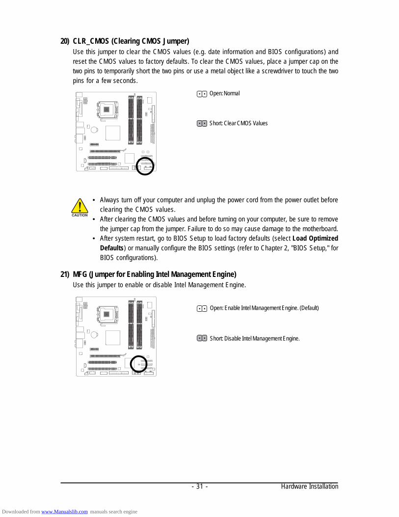
20) CLR_CMOS (Clearing CMOS Jumper)Use this jumper to clear the CMOS values (e.g. date information and BIOS configurations) andreset the CMOS values to factory defaults. To clear the CMOS values, place a jumper cap on thetwo pins to temporarily short the two pins or use a metal object like a screwdriver to touch the twopins for a few seconds.
• Always turn off your computer and unplug the power cord from the power outlet beforeclearing the CMOS values.
• After clearing the CMOS values and before turning on your computer, be sure to removethe jumper cap from the jumper. Failure to do so may cause damage to the motherboard.
• After system restart, go to BIOS Setup to load factory defaults (select Load OptimizedDefaults) or manually configure the BIOS settings (refer to Chapter 2, "BIOS Setup," forBIOS configurations).
21) MFG (Jumper for Enabling Intel Management Engine)Use this jumper to enable or disable Intel Management Engine.
Open: Enable Intel Management Engine. (Default)
Short: Disable Intel Management Engine.
Open: Normal
Short: Clear CMOS Values
Downloaded from www.Manualslib.com manuals search engine

GA-EQ45M-S2 Motherboard - 32 -
22) PHASE LEDThe number of lighted LEDs indicates the CPU loading. The higher the CPU loading, the more thenumber of lighted LEDs. To enable the Phase LED display function, please first enable DynamicEnergy Saver Advanced. Refer to Chapter 4, "Dynamic Energy Saver Advanced," for more details.
23) S0/S1/S3/S4/S5 LED (ACPI LEDs)The ACPI LEDs indicate the system power status (S0, S1, S3, S4, S5) to prevent potentialhardware damage due to improper plug/unplug actions.
System Status DefinitionS0 Normal working stateS1 POS (Power on Suspend), only the CPU stops workingS3 STR (Suspend to RAM), only the memory is workingS4 STD (Suspend to Disk), the system main power is turned
off but the system can still be waked upS5 System is turned off
Downloaded from www.Manualslib.com manuals search engine

- 33 - BIOS Setup
Chapter 2 BIOS SetupBIOS (Basic Input and Output System) records hardware parameters of the system in the CMOS on themotherboard. Its major functions include conducting the Power-On Self-Test (POST) during systemstartup, saving system parameters and loading operating system, etc. BIOS includes a BIOS Setupprogram that allows the user to modify basic system configuration settings or to activate certain systemfeatures. When the power is turned off, the battery on the motherboard supplies the necessary powerto the CMOS to keep the configuration values in the CMOS.
To access the BIOS Setup program, press the <Delete> key during the POST when the power is turnedon. To see more advanced BIOS Setup menu options, you can press <Ctrl> + <F1> in the main menuof the BIOS Setup program.
To upgrade the BIOS, use either the GIGABYTE Q-Flash or @BIOS utility.• Q-Flash allows the user to quickly and easily upgrade or back up BIOS without entering the
operating system.• @BIOS is a Windows-based utility that searches and downloads the latest version of BIOS from the
Internet and updates the BIOS.For instructions on using the Q-Flash and @BIOS utilities, refer to Chapter 4, "BIOS Update Utilities."
• Because BIOS flashing is potentially risky, if you do not encounter problems using thecurrent version of BIOS, it is recommended that you not flash the BIOS. To flash the BIOS,do it with caution. Inadequate BIOS flashing may result in system malfunction.
• BIOS will emit a beep code during the POST. Refer to Chapter 5, "Troubleshooting," for thebeep codes description.
• It is recommended that you not alter the default settings (unless you need to) to preventsystem instability or other unexpected results. Inadequately altering the settings may resultin system's failure to boot. If this occurs, try to clear the CMOS values and reset the boardto default values. (Refer to the "Load Optimized Defaults" section in this chapter or introduc-tions of the battery/clearing CMOS jumper in Chapter 1 for how to clear the CMOS values.)
Downloaded from www.Manualslib.com manuals search engine

GA-EQ45M-S2 Motherboard - 34 -
2-1 Startup ScreenThe following screens may appear when the computer boots.
Function Keys:<DEL> : BIOS Setup/Q-Flash
Press the <Delete> key to enter BIOS Setup or to access the Q-Flash utility in BIOS Setup.
<F9> : Xpress Recovery2If you have ever entered Xpress Recovery2 to back up hard drive data using the motherboarddriver disk, the <F9> key can be used for subsequent access to XpressRecovery2 during thePOST. For more information, refer to Chapter 4, "Xpress Recovery2."
<F12> : Boot MenuBoot Menu allows you to set the first boot device without entering BIOS Setup. In Boot Menu, usethe up arrow key < > or the down arrow key< > to select the first boot device, then press <Enter>to accept. To exit Boot Menu, press <Esc>. The system will directly boot from the deviceconfigured in Boot Menu.Note: The setting in Boot Menu is effective for one time only. After system restart, the device bootorder will still be based on BIOS Setup settings. You can access Boot Menu again to change the firstboot device setting as needed.
<End> : Q-FlashPress the <End> key to access the Q-Flash utility directly without having to enter BIOS Setup first.
Intel Management Engine BIOS Setup (Note):After the POST memory test begins and before the operating system boot begins, a message willappear as shown below. Press <Ctrl>+<P> to enter the Intel Management Engine Setup utility.
Intel(R) Management Engine BIOS Extension v5.0.5.0010Copyright(C) 2003-08 Intel Corporation. All Rights Reversed.
Intel(R) ME Firmware version 5.0.2.1121Press <CTRL - P> to enter Intel(R) ME Setup
(Note) Before enabling Intel Management Engine, make sure DDR2_1 socket in Channel 0 is populated.
Motherboard Model
BIOS Version
Function Keys
Award Modular BIOS v6.00PG, An Energy Star AllyCopyright (C) 1984-2009, Award Software, Inc.
EQ45M-S2 EE....
<DEL>: BIOS Setup/Q-Flash <F9>: XpressRecovery2 <F12>: Boot Menu <End>: Qflash02/02/2009-Q45- ICH10-7A69PG0PC-00
Downloaded from www.Manualslib.com manuals search engine
- 35 - BIOS Setup
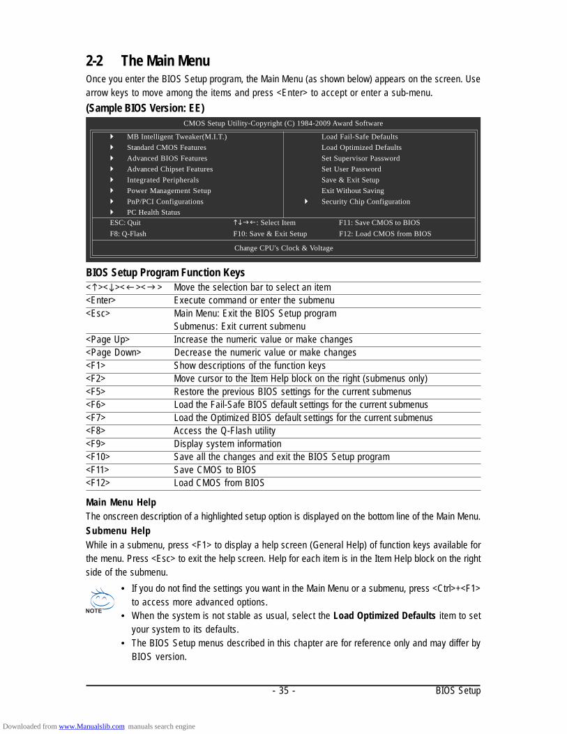
2-2 The Main MenuOnce you enter the BIOS Setup program, the Main Menu (as shown below) appears on the screen. Usearrow keys to move among the items and press <Enter> to accept or enter a sub-menu.(Sample BIOS Version: EE)
CMOS Setup Utility-Copyright (C) 1984-2009 Award Software
MB Intelligent Tweaker(M.I.T.) Standard CMOS Features Advanced BIOS Features Advanced Chipset Features Integrated Peripherals Power Management Setup PnP/PCI Configurations PC Health Status
Load Fail-Safe DefaultsLoad Optimized DefaultsSet Supervisor PasswordSet User PasswordSave & Exit SetupExit Without Saving
Security Chip Configuration
ESC: Quit : Select Item F11: Save CMOS to BIOSF8: Q-Flash F10: Save & Exit Setup F12: Load CMOS from BIOS
Change CPU's Clock & Voltage
• If you do not find the settings you want in the Main Menu or a submenu, press <Ctrl>+<F1>to access more advanced options.
• When the system is not stable as usual, select the Load Optimized Defaults item to setyour system to its defaults.
• The BIOS Setup menus described in this chapter are for reference only and may differ byBIOS version.
Main Menu HelpThe onscreen description of a highlighted setup option is displayed on the bottom line of the Main Menu.Submenu HelpWhile in a submenu, press <F1> to display a help screen (General Help) of function keys available forthe menu. Press <Esc> to exit the help screen. Help for each item is in the Item Help block on the rightside of the submenu.
BIOS Setup Program Function Keys< >< >< >< > Move the selection bar to select an item<Enter> Execute command or enter the submenu<Esc> Main Menu: Exit the BIOS Setup program
Submenus: Exit current submenu<Page Up> Increase the numeric value or make changes<Page Down> Decrease the numeric value or make changes<F1> Show descriptions of the function keys<F2> Move cursor to the Item Help block on the right (submenus only)<F5> Restore the previous BIOS settings for the current submenus<F6> Load the Fail-Safe BIOS default settings for the current submenus<F7> Load the Optimized BIOS default settings for the current submenus<F8> Access the Q-Flash utility<F9> Display system information<F10> Save all the changes and exit the BIOS Setup program<F11> Save CMOS to BIOS<F12> Load CMOS from BIOS
Downloaded from www.Manualslib.com manuals search engine

GA-EQ45M-S2 Motherboard - 36 -
The Functions of the <F11> and <F12> keys (For the Main Menu Only) F11 : Save CMOS to BIOSThis function allows you to save the current BIOS settings to a profile. You can create up to 8profiles (Profile 1-8) and name each profile. First enter the profile name (to erase the default profilename, use the SPACE key) and then press <Enter> to complete. F12 : Load CMOS from BIOSIf your system becomes unstable and you have loaded the BIOS default settings, you can use thisfunction to load the BIOS settings from a profile created before, without the hassles of reconfiguringthe BIOS settings. First select the profile you wish to load, then press <Enter> to complete.
MB Intelligent Tweaker(M.I.T.)Use this menu to configure the clock, frequency and voltages of your CPU, memory, etc.
Standard CMOS FeaturesUse this menu to configure the system time and date, hard drive types, floppy disk drive types,and the type of errors that stop the system boot, etc.
Advanced BIOS FeaturesUse this menu to configure the device boot order, advanced features available on the CPU, and theprimary display adapter.
Advanced Chipset FeaturesUse this menu to configure advanced features available on the chipset.
Integrated PeripheralsUse this menu to configure all peripheral devices, such as IDE, SATA, USB, integrated audio, andintegrated LAN, etc.
Power Management SetupUse this menu to configure all the power-saving functions.
PnP/PCI ConfigurationsUse this menu to configure the system's PCI & PnP resources.
PC Health StatusUse this menu to see information about autodetected system/CPU temperature, system voltageand fan speed, etc.
Load Fail-Safe DefaultsFail-Safe defaults are factory settings for the most stable, minimal-performance system operations.
Load Optimized DefaultsOptimized defaults are factory settings for optimal-performance system operations.
Set Supervisor PasswordChange, set, or disable password. It allows you to restrict access to the system and BIOS Setup.A supervisor password allows you to make changes in BIOS Setup.
Set User PasswordChange, set, or disable password. It allows you to restrict access to the system and BIOS Setup.An user password only allows you to view the BIOS settings but not to make changes.
Save & Exit SetupSave all the changes made in the BIOS Setup program to the CMOS and exit BIOS Setup.(Pressing <F10> can also carry out this task.)
Exit Without SavingAbandon all changes and the previous settings remain in effect. Pressing <Y> to the confirmationmessage will exit BIOS Setup. (Pressing <Esc> can also carry out this task.)
Security Chip ConfigurationUse this menu to configure the TPM module function.
Downloaded from www.Manualslib.com manuals search engine
- 37 - BIOS Setup
2-3 MB Intelligent Tweaker(M.I.T.)
(Note) This item appears only if you install a CPU that supports this feature.
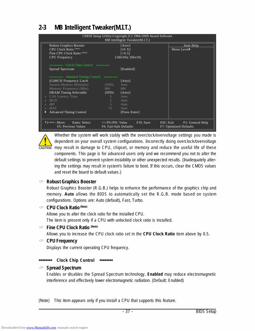
CMOS Setup Utility-Copyright (C) 1984-2009 Award SoftwareMB Intelligent Tweaker(M.I.T.)
Robust Graphics Booster [Auto]CPU Clock Ratio (Note) [10 X]Fine CPU Clock Ratio (Note) [+0.5]CPU Frequency 2.66GHz( 266x10)
******** Clock Chip Control ********Spread Spectrum [Enabled]
******** Standard Timing Control ********(G)MCH Frequency Latch [Auto]System Memory Multiplier (SPD) AutoMemory Frequency (Mhz) 800 800DRAM Timing Selectable (SPD) [Auto]
x CAS Latency Time 5 Autox tRCD 5 Autox tRP 5 Autox tRAS 15 Auto Advanced Timing Control [Press Enter]
: Move Enter: Select +/-/PU/PD: Value F10: Save ESC: Exit F1: General HelpF5: Previous Values F6: Fail-Safe Defaults F7: Optimized Defaults
Item HelpMenu Level
Whether the system will work stably with the overclock/overvoltage settings you made isdependent on your overall system configurations. Incorrectly doing overclock/overvoltagemay result in damage to CPU, chipset, or memory and reduce the useful life of thesecomponents. This page is for advanced users only and we recommend you not to alter thedefault settings to prevent system instability or other unexpected results. (Inadequately alter-ing the settings may result in system's failure to boot. If this occurs, clear the CMOS valuesand reset the board to default values.)
Robust Graphics BoosterRobust Graphics Booster (R.G.B.) helps to enhance the performance of the graphics chip andmemory. Auto allows the BIOS to automatically set the R.G.B. mode based on systemconfigurations. Options are: Auto (default), Fast, Turbo.CPU Clock Ratio (Note)
Allows you to alter the clock ratio for the installed CPU.The item is present only if a CPU with unlocked clock ratio is installed.Fine CPU Clock Ratio (Note)
Allows you to increase the CPU clock ratio set in the CPU Clock Ratio item above by 0.5.CPU FrequencyDisplays the current operating CPU frequency.
******** Clock Chip Control ********Spread SpectrumEnables or disables the Spread Spectrum technology. Enabled may reduce electromagneticinterference and effectively lower electromagnetic radiation. (Default: Enabled)
Downloaded from www.Manualslib.com manuals search engine

GA-EQ45M-S2 Motherboard - 38 -
******** Standard Timing Control ********(G)MCH Frequency LatchAllows you to fix the chipset frequency at system bootup. Options for adjusting memory multiplierbelow may differ according to the fixed frequency. Options are: Auto (default), 200MHz, 266MHz,333MHz.System Memory Multiplier (SPD)Sets memory multiplier according to memory SPD data. (Default: Auto)Memory Frequency (Mhz)Displays the memory frequency.DRAM Timing Selectable (SPD)Manual allows all DRAM timing control items below to be configurable.Options are: Auto (default), Manual.CAS Latency TimeOptions are: Auto (default), 3~7.tRCDOptions are: Auto (default), 1~15.tRPOptions are: Auto (default), 1~15.tRASOptions are: Auto (default), 1~63.Advanced Timing Control
CMOS Setup Utility-Copyright (C) 1984-2009 Award SoftwareAdvanced Timing Control
: Move Enter: Select +/-/PU/PD: Value F10: Save ESC: Exit F1: General Help F5: Previous Values F6: Fail-Safe Defaults F7: Optimized Defaults
x tRRD Autox tWTR Autox tWR Autox tRFC Autox tRTP Autox Command Rate (CMD) Auto
Item HelpMenu Level
tRRDOptions are: Auto (default), 1~15.tWTROptions are: Auto (default), 1~31.
Downloaded from www.Manualslib.com manuals search engine

- 39 - BIOS Setup
tWROptions are: Auto (default), 1~31.tRFCOptions are: Auto (default), 1~255.tRTPOptions are: Auto (default), 1~15.Command Rate(CMD)Options are: Auto (default), 1~3.
Downloaded from www.Manualslib.com manuals search engine

GA-EQ45M-S2 Motherboard - 40 -
2-4 Standard CMOS Features
DateSets the system date. The date format is week (read-only), month, date and year . Select thedesired field and use the up arrow or down arrow key to set the date.TimeSets the system time. For example, 1 p.m. is 13:0:0. Select the desired field and use the up arrowor down arrow key to set the time.IDE Channel 0, 1 Master/Slave
IDE HDD Auto-DetectionPress <Enter> to autodetect the parameters of the IDE/SATA device on this channel.
IDE Channel 0, 1 Master/SlaveConfigure your IDE/SATA devices by using one of the three methods below:
CMOS Setup Utility-Copyright (C) 1984-2008 Award SoftwareStandard CMOS Features
: Move Enter: Select +/-/PU/PD: Value F10: Save ESC: Exit F1: General HelpF5: Previous Values F6: Fail-Safe Defaults F7: Optimized Defaults
Item HelpMenu Level
Base Memory 640KExtended Memory 510MTotal Memory 512M
CMOS Setup Utility-Copyright (C) 1984-2009 Award SoftwareStandard CMOS Features
Date (mm:dd:yy) Fri, Jan 16 2009Time (hh:mm:ss) 17:31:24
IDE Channel 0 Master [None] IDE Channel 0 Slave [None] IDE Channel 1 Master [None] IDE Channel 1 Slave [None] IDE Channel 2 Master [None] IDE Channel 3 Master [None] IDE Channel 4 Master [None] IDE Channel 4 Slave [None] IDE Channel 6 Master [None] IDE Channel 6 Slave [None]
Drive A [1.44M, 3.5"]Floppy 3 Mode Support [Disabled]
Halt On [All, But Keyboard]
: Move Enter: Select +/-/PU/PD: Value F10: Save ESC: Exit F1: General HelpF5: Previous Values F6: Fail-Safe Defaults F7: Optimized Defaults
Item HelpMenu Level
Downloaded from www.Manualslib.com manuals search engine

- 41 - BIOS Setup
• Auto Lets BIOS automatically detect IDE/SATA devices during the POST. (Default)• None If no IDE/SATA devices are used, set this item to None so the system will
skip the detection of the device during the POST for faster system startup.• Manual Allows you to manually enter the specifications of the hard drive when the
hard drive access mode is set to CHS.Access Mode Sets the hard drive access mode. Options are: Auto (default), CHS, LBA, Large.
IDE Channel 2, 3 Master, 4, 6 Master/SlaveIDE Auto-Detection
Press <Enter> to autodetect the parameters of the IDE/SATA device on this channel.Extended IDE Drive
Configure your IDE/SATA devices by using one of the two methods below:• Auto Lets BIOS automatically detect IDE/SATA devices during the POST. (Default)• None If no IDE/SATA devices are used, set this item to None so the system will
skip the detection of the device during the POST for faster system startup.Access Mode Sets the hard drive access mode. Options are: Auto (default), Large.
The following fields display your hard drive specifications. If you wish to enter the parametersmanually, refer to the information on the hard drive.
Capacity Approximate capacity of the currently installed hard drive.Cylinder Number of cylinders.Head Number of heads.Precomp Write precompensation cylinder.Landing Zone Landing zone.Sector Number of sectors.
Drive AAllows you to selects the type of floppy disk drive installed in your system. If you do not install afloppy disk drive, set this item to None. Options are: None, 360K/5.25", 1.2M/5.25", 720K/3.5",1.44M/3.5", 2.88M/3.5".Floppy 3 Mode SupportAllows you to specify whether the installed floppy disk drive is 3-mode floppy disk drive, aJapanese standard floppy disk drive. Options are: Disabled (default), Drive A.Halt OnAllows you to determine whether the system will stop for an error during the POST.
No Errors The system boot will not stop for any error.All Errors Whenever the BIOS detects a non-fatal error the system boot will stop.All, But Keyboard The system boot will not stop for a keyboard error but stop for all other
errors. (Default)All, But Diskette The system boot will not stop for a floppy disk drive error but stop for all
other errors.All, But Disk/Key The system boot will not stop for a keyboard or a floppy disk drive error but
it will stop for all other errors.MemoryThese fields are read-only and are determined by the BIOS POST.
Base Memory Also called conventional memory. Typically, 640 KB will be reserved forthe MS-DOS operating system.
Extended Memory The amount of extended memory.Total Memory The total amount of memory installed on the system.
Downloaded from www.Manualslib.com manuals search engine

GA-EQ45M-S2 Motherboard - 42 -
2-5 Advanced BIOS Features
Hard Disk Boot PrioritySpecifies the sequence of loading the operating system from the installed hard drives. Use the upor down arrow key to select a hard drive, then press the plus key <+> (or <PageUp>) or the minuskey <-> (or <PageDown>) to move it up or down on the list. Press <Esc> to exit this menu whenfinished.First/Second/Third Boot DeviceSpecifies the boot order from the available devices. Use the up or down arrow key to select adevice and press <Enter> to accept. Options are: Floppy, LS120, Hard Disk, CDROM, ZIP,USB-FDD, USB-ZIP, USB-CDROM, USB-HDD, Legacy LAN, Disabled.Password CheckSpecifies whether a password is required every time the system boots, or only when you enterBIOS Setup. After configuring this item, set the password(s) under the Set Supervisor/UserPassword item in the BIOS Main Menu.
Setup A password is only required for entering the BIOS Setup program. (Default)System A password is required for booting the system and for entering the BIOS Setup
program.HDD S.M.A.R.T. CapabilityEnables or disables the S.M.A.R.T. (Self Monitoring and Reporting Technology) capability of yourhard drive. This feature allows your system to report read/write errors of the hard drive and toissue warnings when a third party hardware monitor utility is installed. (Default: Enabled)
(Note) This item is present only if you install a CPU that supports this feature. For more informationabout Intel CPUs' unique features, please visit Intel's website.
CMOS Setup Utility-Copyright (C) 1984-2009 Award SoftwareAdvanced BIOS Features
Hard Disk Boot Priority [Press Enter]First Boot Device [Floppy]Second Boot Device [Hard Disk]Third Boot Device [CDROM]Password Check [Setup]HDD S.M.A.R.T. Capability [Disabled]CPU Multi-Threading (Note) [Enabled]Limit CPUID Max. to 3 (Note) [Disabled]No-Execute Memory Protect (Note) [Enabled]CPU Enhanced Halt (C1E) (Note) [Enabled]CPU Thermal Monitor 2(TM2) (Note) [Enabled]CPU EIST Function (Note) [Enabled]Virtualization Technology (Note) [Enabled]Console Redirection Disabled
x Baud Rate 19200Agent after boot EnabledDelay For HDD (Secs) [0]ASF support [Enabled]
: Move Enter: Select +/-/PU/PD: Value F10: Save ESC: Exit F1: General HelpF5: Previous Values F6: Fail-Safe Defaults F7: Optimized Defaults
Item HelpMenu Level
Downloaded from www.Manualslib.com manuals search engine

- 43 - BIOS Setup
CPU Multi-Threading (Note)
Allows you to determine whether to enable all CPU cores and multi-threading function when usingan Intel® CPU that supports multi-core technology. This feature only works for operating systemsthat support multi-processor mode.
Enabled Enables all CPU cores and multi-threading capability. (Default)Disabled Enables only one CPU core.
Limit CPUID Max. to 3 (Note)
Allows you to determine whether to limit CPUID maximum value. Set this item to Disabled forWindows XP operating system; set this item to Enabled for legacy operating system such asWindows NT4.0. (Default: Disabled)No-Execute Memory Protect (Note)
Enables or disables Intel Execute Disable Bit function. This function may enhance protection for thecomputer, reducing exposure to viruses and malicious buffer overflow attacks when working withits supporting software and system. (Default: Enabled)CPU Enhanced Halt (C1E) (Note)
Enables or disables Intel CPU Enhanced Halt (C1E) function, a CPU power-saving function insystem halt state. When enabled, the CPU core frequency and voltage will be reduced duringsystem halt state to decrease power consumption. (Default: Enabled)CPU Thermal Monitor 2 (TM2) (Note)
Enables or disables Intel CPU Thermal Monitor (TM2) function, a CPU overheating protectionfunction. When enabled, the CPU core frequency and voltage will be reduced when the CPU isoverheated. (Default: Enabled)CPU EIST Function (Note)
Enables or disables Enhanced Intel SpeedStep Technology (EIST). Depending on CPU loading,Intel® EIST technology can dynamically and effectively lower the CPU voltage and core frequencyto decrease average power consumption and heat production. (Default: Enabled)Virtualization Technology (Note)
Enables or disables Intel Virtualization Technology. Virtualization enhanced by Intel VirtualizationTechnology will allow a platform to run multiple operating systems and applications in independentpartitions. With virtualization, one computer system can function as multiple virtual systems.(Default: Enabled)Console RedirectionThis feature allows your computer to send contents displayed in POST or MS-DOS to anothercomputer. (Default: Disabled)Baud RateDisplays the speed at which the contents are sent.Agent after bootThis feature allows your computer to send contents to another computer after the operating systemhas booted. (Default: Enabled)
(Note) This item is present only if you install a CPU that supports this feature. For more informationabout Intel CPUs' unique features, please visit Intel's website.
Downloaded from www.Manualslib.com manuals search engine

GA-EQ45M-S2 Motherboard - 44 -
Delay For HDD (Secs)Allows you to set a delay time for the BIOS to initialize the hard drive as the system boots up. Theadjustable range is from 0 to 15 seconds. (Default: 0)ASF supportThis feature allows another computer to control power-on/off or carry out remote control of yourcomputer. (Default: Enabled)
Downloaded from www.Manualslib.com manuals search engine
- 45 - BIOS Setup
2-6 Advanced Chipset FeaturesCMOS Setup Utility-Copyright (C) 1984-2009 Award Software
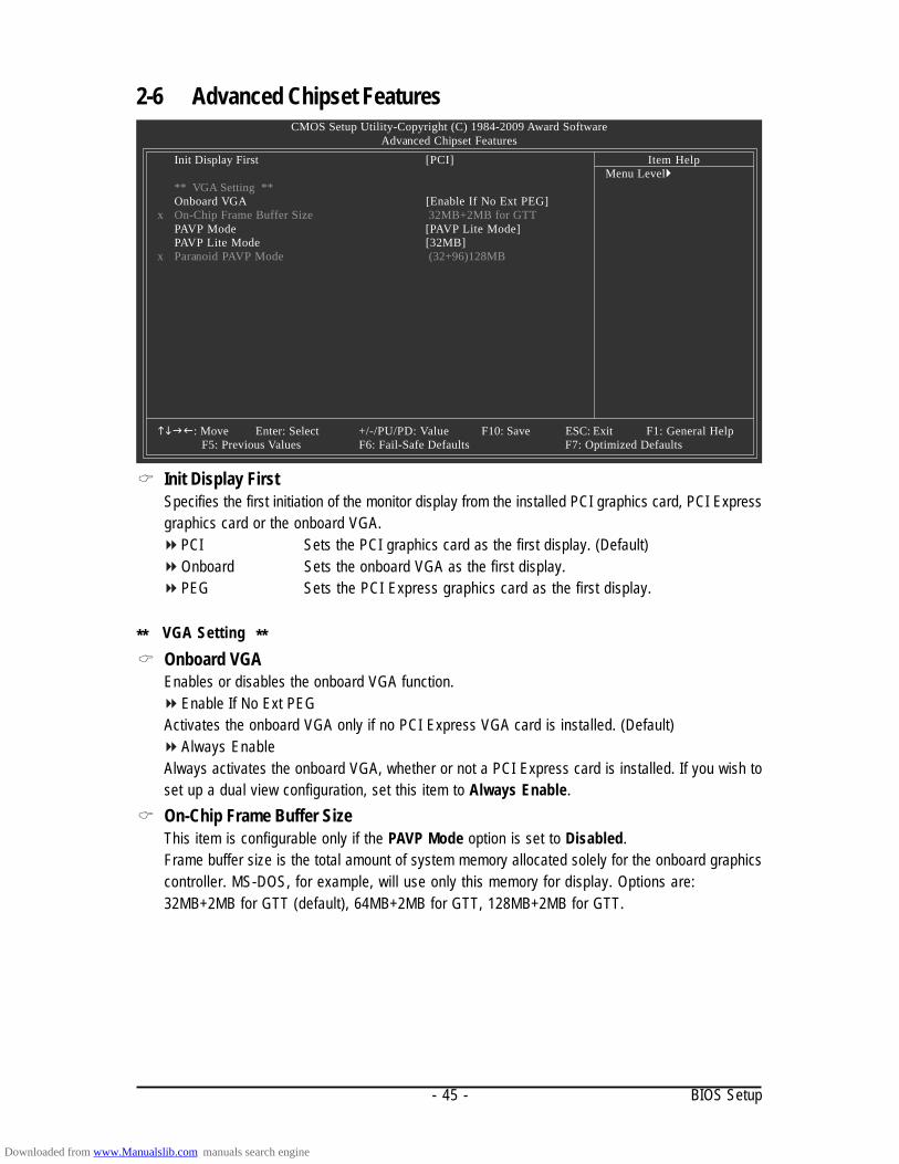
Advanced Chipset FeaturesInit Display First [PCI]
** VGA Setting **Onboard VGA [Enable If No Ext PEG]
x On-Chip Frame Buffer Size 32MB+2MB for GTTPAVP Mode [PAVP Lite Mode]PAVP Lite Mode [32MB]
x Paranoid PAVP Mode (32+96)128MB
: Move Enter: Select +/-/PU/PD: Value F10: Save ESC: Exit F1: General HelpF5: Previous Values F6: Fail-Safe Defaults F7: Optimized Defaults
Item HelpMenu Level
Init Display FirstSpecifies the first initiation of the monitor display from the installed PCI graphics card, PCI Expressgraphics card or the onboard VGA.
PCI Sets the PCI graphics card as the first display. (Default)Onboard Sets the onboard VGA as the first display.PEG Sets the PCI Express graphics card as the first display.
** VGA Setting **Onboard VGAEnables or disables the onboard VGA function.
Enable If No Ext PEGActivates the onboard VGA only if no PCI Express VGA card is installed. (Default)
Always EnableAlways activates the onboard VGA, whether or not a PCI Express card is installed. If you wish toset up a dual view configuration, set this item to Always Enable.On-Chip Frame Buffer SizeThis item is configurable only if the PAVP Mode option is set to Disabled.Frame buffer size is the total amount of system memory allocated solely for the onboard graphicscontroller. MS-DOS, for example, will use only this memory for display. Options are:32MB+2MB for GTT (default), 64MB+2MB for GTT, 128MB+2MB for GTT.
Downloaded from www.Manualslib.com manuals search engine

GA-EQ45M-S2 Motherboard - 46 -
PAVP ModeEnables or disables PAVP mode. Enable this function if you wish to playback HDCP contents.PAVP mode can support increased content protection and robustness requirements for premiumcontent playback (e.g. Blu-ray disc).
Disabled Disables this function.PAVP Lite Mode Specifies the buffer memory size for the encryption of compressed video.
(Default)Paranoid PAVP Reserves 96 MB of system memory during boot. This memory is not
seen by the operating system and not available to any user application.Aero (DWM) in Windows Vista will always be turned off in this mode.
PAVP Lite ModeThis item is configurable only if the PAVP Mode option is set to PAVP Lite Mode.Options are: 32MB (default), 48MB, 64MB, 128MB and 256MB.Paranoid PAVP ModeThis item is configurable only if the PAVP Mode option is set to Paranoid PAVP.Options are: (32+96)128MB (default), (48+96)144MB, (64+96)160MB, (128+96)224MB and(256+96)352MB.
Feature PAVP Lite PAVP ParanoidCompressed video buffer is encrypted Yes YesHardware 128-bit AES decryption Yes YesProtected memory No Yes(96 MB reserved during boot)
The table below shows the supported features of the PAVP Lite and Paranoid modes.
Downloaded from www.Manualslib.com manuals search engine

- 47 - BIOS Setup
2-7 Integrated Peripherals
SATA RAID/AHCI Mode (Intel ICH10DO Southbridge)Enables or disables RAID for the SATA controllers integrated in the Intel ICH10DO Southbridge orconfigures the SATA controllers to AHCI mode.
Disabled Disables RAID for the SATA controllers and configures the SATA controllers toPATA mode. (Default)
RAID Enables RAID for the SATA controllers.AHCI Configures the SATA controllers to AHCI mode. Advanced Host Controller
Interface (AHCI) is an interface specification that allows the storage driver toenable advanced Serial ATA features such as Native Command Queuing andhot plug.
SATA Port0-3 Native Mode (Intel ICH10DO Southbridge)Specifies the operating mode of the integrated SATA controllers.
Disabled Allows the SATA controllers to operate in Legacy IDE mode.In Legacy mode the SATA controllers use dedicated IRQs that cannot be sharedwith other device. Set this option to Disabled if you wish to install operatingsystems that do not support Native mode. (Default)
Enabled Allows the SATA controllers to operate in Native IDE mode.Enable Native IDE mode if you wish to install operating systems that supportNative mode.
USB ControllerEnables or disables the integrated USB controller. (Default: Enabled)Disabled will turn off all of the USB functionalities below.USB 2.0 ControllerEnables or disables the integrated USB 2.0 controller. (Default: Enabled)USB Keyboard SupportAllows USB keyboard to be used in MS-DOS. (Default: Disabled)
CMOS Setup Utility-Copyright (C) 1984-2009 Award SoftwareIntegrated Peripherals
SATA RAID/AHCI Mode [Disabled]SATA Port0-3 Native Mode [Disabled]USB Controller [Enabled]USB 2.0 Controller [Enabled]USB Keyboard Support [Disabled]USB Mouse Support [Disabled]Legacy USB storage detect [Enabled]Azalia Codec [Auto]Onboard LAN Function [Enabled]OnBoard LAN Boot ROM [Disabled]Onboard IDE Controller [Enabled]Onboard Serial Port 1 [3F8/IRQ4]Onboard Serial Port 2 [2F8/IRQ3]Onboard Parallel Port [378/IRQ7]Parallel Port Mode [SPP]
: Move Enter: Select +/-/PU/PD: Value F10: Save ESC: Exit F1: General Help F5: Previous Values F6: Fail-Safe Default F7: Optimized Defaults
Item HelpMenu Level
Downloaded from www.Manualslib.com manuals search engine

GA-EQ45M-S2 Motherboard - 48 -
USB Mouse SupportAllows USB mouse to be used in MS-DOS. (Default: Disabled)Legacy USB storage detectDetermines whether to detect USB storage devices, including USB flash drives and USB harddrives during the POST. (Default: Enabled)Azalia CodecEnables or disables the onboard audio function. (Default: Auto)If you wish to install a 3rd party add-in audio card instead of using the onboard audio, set this itemto Disabled.Onboard LAN FunctionEnables or disables the onboard LAN function. (Default: Enabled)If you wish to install a 3rd party add-in network card instead of using the onboard LAN, set this itemto Disabled.Onboard LAN Boot ROMAllows you to decide whether to activate the boot ROM integrated with the onboard LAN chip.(Default: Disabled)Onboard IDE Controller (JMicron 368 Chip)Enables or disables the IDE controller integrated in the JMicron 368 chip. (Default: Enabled)Onboard Serial Port 1Enables or disables the first serial port and specifies its base I/O address and correspondinginterrupt. Options are: Auto, 3F8/IRQ4 (default), 2F8/IRQ3, 3E8/IRQ4, 2E8/IRQ3, Disabled.Onboard Serial Port 2Enables or disables the first serial port and specifies its base I/O address and correspondinginterrupt. Options are: Auto, 3F8/IRQ4, 2F8/IRQ3 (default), 3E8/IRQ4, 2E8/IRQ3, Disabled.Onboard Parallel PortEnables or disables the onboard parallel port (LPT) and specifies its base I/O address andcorresponding interrupt. Options are: 378/IRQ7 (default), 278/IRQ5, 3BC/IRQ7, Disabled.Parallel Port ModeSelects an operating mode for the onboard parallel (LPT) port. Options are: SPP (Standard ParallelPort)(default), EPP (Enhanced Parallel Port), ECP (Extended Capabilities Port), ECP+EPP.
Downloaded from www.Manualslib.com manuals search engine

- 49 - BIOS Setup
2-8 Power Management SetupCMOS Setup Utility-Copyright (C) 1984-2009 Award Software
Power Management SetupACPI Suspend Type [S3(STR)]ACPI LED Control [Enabled]Soft-Off by PWR-BTTN [Instant-Off]PME Event Wake Up [Enabled]Power On by Ring [Enabled]Resume by Alarm [Disabled]
x Date (of Month) Alarm Everydayx Time (hh:mm:ss) Alarm 0 : 0 : 0
HPET Support (Note) [Enabled]HPET Mode (Note) [32-bit mode]Power On By Mouse [Disabled]Power On By Keyboard [Disabled]
x KB Power ON Password EnterAC Back Function [Soft-Off]
: Move Enter: Select +/-/PU/PD: Value F10: Save ESC: Exit F1: General HelpF5: Previous Values F6: Fail-Safe Defaults F7: Optimized Defaults
Item HelpMenu Level
ACPI Suspend TypeSpecifies the ACPI sleep state when the system enters suspend.
S1(POS) Enables the system to enter the ACPI S1 (Power on Suspend) sleep state.In S1 sleep state, the system appears suspended and stays in a low powermode. The system can be resumed at any time.
S3(STR) Enables the system to enter the ACPI S3 (Suspend to RAM) sleep state (default).In S3 sleep state, the system appears to be off and consumes less power thanin the S1 state. When signaled by a wake-up device or event, the systemresumes to its working state exactly where it was left off.
ACPI LED ControlEnables or disables the onboard ACPI LEDs. Enabled allows the onboard ACPI LEDs to light upaccording to the system status. (Default: Enabled)Soft-Off by PWR-BTTNConfigures the way to turn off the computer in MS-DOS mode using the power button.
Instant-Off Press the power button and then the system will be turned off instantly. (Default)Delay 4 Sec. Press and hold the power button for 4 seconds to turn off the system. If the power
button is pressed for less than 4 seconds, the system will enter suspend mode.PME Event Wake UpAllows the system to be awakened from an ACPI sleep state by a wake-up signal from a PCI orPCIe device. Note: To use this function, you need an ATX power supply providing at least 1A onthe +5VSB lead. (Default: Enabled)
(Note) Supported on Windows Vista operating system only.
Downloaded from www.Manualslib.com manuals search engine

GA-EQ45M-S2 Motherboard - 50 -
Power On by RingAllows the system to be awakened from an ACPI sleep state by a wake-up signal from a modemthat supports wake-up function. (Default: Enabled)Resume by AlarmDetermines whether to power on the system at a desired time. (Default: Disabled)If enabled, set the date and time as following:
Date (of Month) Alarm : Turn on the system at a specific time on each day or on a specific dayin a month.
Time (hh: mm: ss) Alarm : Set the time at which the system will be powered on automatically.Note: When using this function, avoid inadequate shutdown from the operating system or removalof the AC power, or the settings may not be effective.HPET Support (Note)
Enables or disables High Precision Event Timer (HPET) for Windows Vista operating system.(Default: Enabled)HPET Mode (Note)
Allows you to select the HPET mode for your Windows Vista operating system. Select 32-bitmode when you install 32-bit Windows Vista; select 64-bit mode when you install 64-bit WindowsVista. (Default: 32-bit mode)Power On By MouseAllows the system to be turned on by a PS/2 mouse wake-up event.Note: To use this function, you need an ATX power supply providing at least 1A on the +5VSB lead.
Disabled Disables this function. (Default)Double Click Double click on left button on the PS/2 mouse to turn on the system.
Power On By KeyboardAllows the system to be turned on by a PS/2 keyboard wake-up event.Note: you need an ATX power supply providing at least 1A on the +5VSB lead.
Disabled Disables this function. (Default)Password Set a password with 1~5 characters to turn on the system.Keyboard 98 Press POWER button on the Windows 98 keyboard to turn on the system.
KB Power ON PasswordSet the password when Power On by Keyboard is set to Password. Press <Enter> on this itemand set a password with up to 5 characters and then press <Enter> to accept. To turn on thesystem, enter the password and press <Enter>.Note: To cancel the password, press <Enter> on this item. When prompted for the password, press<Enter> again without entering the password to clear the password settings.AC Back FunctionDetermines the state of the system after the return of power from an AC power loss.
Soft-Off The system stays off upon the return of the AC power. (Default)Full-On The system is turned on upon the return of the AC power.Memory The system returns to its last known awake state upon the return of the AC
power.
(Note) Supported on Windows Vista operating system only.
Downloaded from www.Manualslib.com manuals search engine
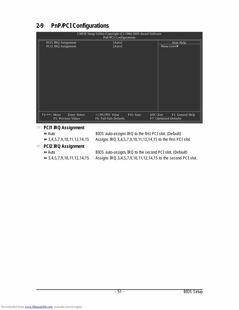
- 51 - BIOS Setup
2-9 PnP/PCI Configurations
PCI1 IRQ AssignmentAuto BIOS auto-assigns IRQ to the first PCI slot. (Default)3,4,5,7,9,10,11,12,14,15 Assigns IRQ 3,4,5,7,9,10,11,12,14,15 to the first PCI slot.
PCI2 IRQ AssignmentAuto BIOS auto-assigns IRQ to the second PCI slot. (Default)3,4,5,7,9,10,11,12,14,15 Assigns IRQ 3,4,5,7,9,10,11,12,14,15 to the second PCI slot.
CMOS Setup Utility-Copyright (C) 1984-2009 Award SoftwarePnP/PCI Configurations
PCI1 IRQ Assignment [Auto]PCI2 IRQ Assignment [Auto]
: Move Enter: Select +/-/PU/PD: Value F10: Save ESC: Exit F1: General HelpF5: Previous Values F6: Fail-Safe Defaults F7: Optimized Defaults
Item HelpMenu Level
Downloaded from www.Manualslib.com manuals search engine
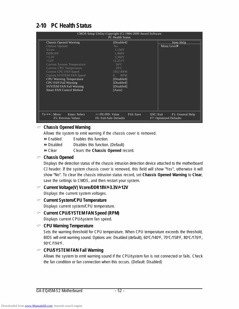
GA-EQ45M-S2 Motherboard - 52 -
2-10 PC Health Status
Chassis Opened WarningAllows the system to emit warning if the chassis cover is removed.
Enabled Enables this function.Disabled Disables this function. (Default)Clear Clears the Chassis Opened record.
Chassis OpenedDisplays the detection status of the chassis intrusion detection device attached to the motherboardCI header. If the system chassis cover is removed, this field will show "Yes", otherwise it willshow "No". To clear the chassis intrusion status record, set Chassis Opened Warning to Clear,save the settings to CMOS, and then restart your system.Current Voltage(V) Vcore/DDR18V/+3.3V/+12VDisplays the current system voltages.Current System/CPU TemperatureDisplays current system/CPU temperature.Current CPU/SYSTEM FAN Speed (RPM)Displays current CPU/system fan speed.CPU Warning TemperatureSets the warning threshold for CPU temperature. When CPU temperature exceeds the threshold,BIOS will emit warning sound. Options are: Disabled (default), 60oC/140oF, 70oC/158oF, 80oC/176oF,90oC/194oF.CPU/SYSTEM FAN Fail WarningAllows the system to emit warning sound if the CPU/system fan is not connected or fails. Checkthe fan condition or fan connection when this occurs. (Default: Disabled)
CMOS Setup Utility-Copyright (C) 1984-2009 Award SoftwarePC Health Status
Chassis Opened Warning [Disabled]Chassis Opened NoVcore 1.156VDDR18V 1.968V+3.3V 3.360V+12V 12.251VCurrent System Temperature 36oCCurrent CPU Temperature 29oCCurrent CPU FAN Speed 2922 RPMCurrent SYSTEM FAN Speed 0 RPMCPU Warning Temperature [Disabled]CPU FAN Fail Warning [Disabled]SYSTEM FAN Fail Warning [Disabled]Smart FAN Control Method [Auto]
: Move Enter: Select +/-/PU/PD: Value F10: Save ESC: Exit F1: General HelpF5: Previous Values F6: Fail-Safe Defaults F7: Optimized Defaults
Item HelpMenu Level
Downloaded from www.Manualslib.com manuals search engine

- 53 - BIOS Setup
Smart FAN Control Method (Note)
Specifies how to control CPU fan speed.Auto Lets BIOS control CPU fan speed. (Default)Intel(R) QST Allows CPU fan speed to be controlled by the Intel Quiet System Technology
(QST). This feature requires the installation of Intel Host Embedded ControlInterface (HECI) driver from the motherboard driver disk.
Legacy Allows CPU fan to run at different speed according to the CPU temperature.Disable Forces CPU fan to run at full speed.
(Note) Before setting this item to Intel(R) QST, make sure at least DDR2_1 or DDR2_2 socket inChannel 0 is populated. A small portion of system memory will be shared when Intel QST isenabled.
Downloaded from www.Manualslib.com manuals search engine

GA-EQ45M-S2 Motherboard - 54 -
2-11 Load Fail-Safe Defaults
Press <Enter> on this item and then press the <Y> key to load the safest BIOS default settings.In case system instability occurs, you may try to load Fail-Safe defaults, which are the safest and moststable BIOS settings for the motherboard.
2-12 Load Optimized Defaults
Press <Enter> on this item and then press the <Y> key to load the optimal BIOS default settings. TheBIOS defaults settings helps the system to operate in optimum state. Always load the Optimized defaultsafter updating the BIOS or after clearing the CMOS values.
CMOS Setup Utility-Copyright (C) 1984-2009 Award Software
MB Intelligent Tweaker(M.I.T.) Standard CMOS Features Advanced BIOS Features Advanced Chipset Features Integrated Peripherals Power Management Setup PnP/PCI Configurations PC Health StatusESC: Quit : Select Item F11: Save CMOS to BIOSF8: Q-Flash F10: Save & Exit Setup F12: Load CMOS from BIOS
Load Fail-Safe Defaults
Load Fail-Safe DefaultsLoad Optimized DefaultsSet Supervisor PasswordSet User PasswordSave & Exit SetupExit Without Saving
Security Chip Configuration
Load Fail-Safe Defaults (Y/N)? N
CMOS Setup Utility-Copyright (C) 1984-2009 Award Software
MB Intelligent Tweaker(M.I.T.) Standard CMOS Features Advanced BIOS Features Advanced Chipset Features Integrated Peripherals Power Management Setup PnP/PCI Configurations PC Health StatusESC: Quit : Select Item F11: Save CMOS to BIOSF8: Q-Flash F10: Save & Exit Setup F12: Load CMOS from BIOS
Load Optimized Defaults
Load Fail-Safe DefaultsLoad Optimized DefaultsSet Supervisor PasswordSet User PasswordSave & Exit SetupExit Without Saving
Security Chip Configuration
Load Optimized Defaults (Y/N)? N
Downloaded from www.Manualslib.com manuals search engine

- 55 - BIOS Setup
2-13 Set Supervisor/User Password
Press <Enter> on this item and type the password with up to 8 characters and then press <Enter>. Youwill be requested to confirm the password. Type the password again and press <Enter>.
The BIOS Setup program allows you to specify two separate passwords: Supervisor Password
When a system password is set and the Password Check item in Advanced BIOS Features isset to Setup, you must enter the supervisor password for entering BIOS Setup and making BIOSchanges.When the Password Check item is set to System, you must enter the supervisor password (oruser password) at system startup and when entering BIOS Setup.
User PasswordWhen the Password Check item is set to System, you must enter the supervisor password (oruser password) at system startup to continue system boot. In BIOS Setup, you must enter thesupervisor password if you wish to make changes to BIOS settings. The user password onlyallows you to view the BIOS settings but not to make changes.
To clear the password, press <Enter> on the password item and when requested for the password,press <Enter> again. The message "PASSWORD DISABLED" will appear, indicating the password hasbeen cancelled.
CMOS Setup Utility-Copyright (C) 1984-2009 Award Software
MB Intelligent Tweaker(M.I.T.) Standard CMOS Features Advanced BIOS Features Advanced Chipset Features Integrated Peripherals Power Management Setup PnP/PCI Configurations PC Health StatusESC: Quit : Select Item F11: Save CMOS to BIOSF8: Q-Flash F10: Save & Exit Setup F12: Load CMOS from BIOS
Change/Set/Disable Password
Load Fail-Safe DefaultsLoad Optimized DefaultsSet Supervisor PasswordSet User PasswordSave & Exit SetupExit Without Saving
Security Chip Configuration
Enter Password:
Downloaded from www.Manualslib.com manuals search engine

GA-EQ45M-S2 Motherboard - 56 -
2-14 Save & Exit Setup
2-15 Exit Without Saving
Press <Enter> on this item and press the <Y> key. This saves the changes to the CMOS and exits theBIOS Setup program. Press <N> or <Esc> to return to the BIOS Setup Main Menu.
Press <Enter> on this item and press the <Y> key. This exits the BIOS Setup without saving thechanges made in BIOS Setup to the CMOS. Press <N> or <Esc> to return to the BIOS Setup Main Menu.
CMOS Setup Utility-Copyright (C) 1984-2009 Award Software
MB Intelligent Tweaker(M.I.T.) Standard CMOS Features Advanced BIOS Features Advanced Chipset Features Integrated Peripherals Power Management Setup PnP/PCI Configurations PC Health StatusESC: Quit : Select Item F11: Save CMOS to BIOSF8: Q-Flash F10: Save & Exit Setup F12: Load CMOS from BIOS
Abandon all Data
Load Fail-Safe DefaultsLoad Optimized DefaultsSet Supervisor PasswordSet User PasswordSave & Exit SetupExit Without Saving
Security Chip Configuration
Quit Without Saving (Y/N)? N
CMOS Setup Utility-Copyright (C) 1984-2009 Award Software
MB Intelligent Tweaker(M.I.T.) Standard CMOS Features Advanced BIOS Features Advanced Chipset Features Integrated Peripherals Power Management Setup PnP/PCI Configurations PC Health StatusESC: Quit : Select Item F11: Save CMOS to BIOSF8: Q-Flash F10: Save & Exit Setup F12: Load CMOS from BIOS
Save Data to CMOS
Load Fail-Safe DefaultsLoad Optimized DefaultsSet Supervisor PasswordSet User PasswordSave & Exit SetupExit Without Saving
Security Chip ConfigurationSave to CMOS and EXIT (Y/N)? Y
CMOS Setup Utility-Copyright (C) 1984-2009 Award Software
Downloaded from www.Manualslib.com manuals search engine
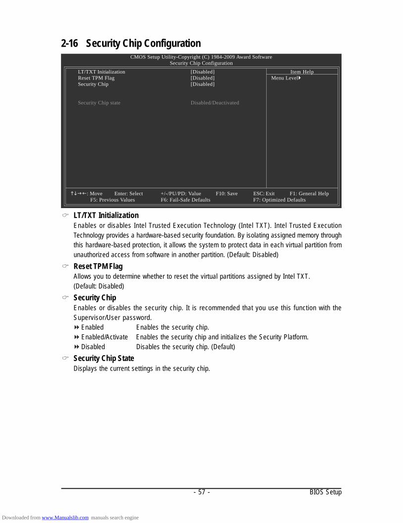
- 57 - BIOS Setup
2-16 Security Chip Configuration
LT/TXT InitializationEnables or disables Intel Trusted Execution Technology (Intel TXT). Intel Trusted ExecutionTechnology provides a hardware-based security foundation. By isolating assigned memory throughthis hardware-based protection, it allows the system to protect data in each virtual partition fromunauthorized access from software in another partition. (Default: Disabled)Reset TPM FlagAllows you to determine whether to reset the virtual partitions assigned by Intel TXT.(Default: Disabled)Security ChipEnables or disables the security chip. It is recommended that you use this function with theSupervisor/User password.
Enabled Enables the security chip.Enabled/Activate Enables the security chip and initializes the Security Platform.Disabled Disables the security chip. (Default)
Security Chip StateDisplays the current settings in the security chip.
CMOS Setup Utility-Copyright (C) 1984-2009 Award SoftwareSecurity Chip Configuration
LT/TXT Initialization [Disabled]Reset TPM Flag [Disabled]Security Chip [Disabled]
Security Chip state Disabled/Deactivated
: Move Enter: Select +/-/PU/PD: Value F10: Save ESC: Exit F1: General HelpF5: Previous Values F6: Fail-Safe Defaults F7: Optimized Defaults
Item HelpMenu Level
Downloaded from www.Manualslib.com manuals search engine

GA-EQ45M-S2 Motherboard - 58 -
Downloaded from www.Manualslib.com manuals search engine

Drivers Installation- 59 -
Chapter 3 Drivers Installation
3-1 Installing Chipset Drivers
• Before installing the drivers, first install the operating system.• After installing the operating system, insert the motherboard driver disk into your optical drive.
The driver Autorun screen is automatically displayed which looks like that shown in the screenshot below. (If the driver Autorun screen does not appear automatically, go to My Computer,double-click the optical drive and execute the Run.exe program.)
After inserting the driver disk, "Xpress Install" will automatically scan your system and then list all thedrivers that are recommended to install. You can click the Install All button and "Xpress Install" willinstall all the recommended drivers. Or click Install Single Items to manually select the drivers youwish to install.
• Please ignore the popup dialog box(es) (e.g. the Found New Hardware Wizard) displayedwhen "Xpress Install" is installing the drivers. Failure to do so may affect the driver installation.
• Some device drivers will restart your system automatically during the driver installation.After the system restart, "Xpress Install" will continue to install other drivers.
• After the drivers are installed, follow the onscreen instructions to restart your system. Youcan install other applications included in the motherboard driver disk.
• For USB 2.0 driver support under the Windows XP operating system, please install theWindows XP Service Pack 1 or later. After installing the SP1 (or later), if a question mark stillexists in Universal Serial Bus Controller in Device Manager, please remove thequestion mark (by right-clicking your mouse and select Uninstall) and restart the system.(The system will then autodetect and install the USB 2.0 driver.)
Downloaded from www.Manualslib.com manuals search engine

GA-EQ45M-S2 Motherboard - 60 -
3-2 Application SoftwareThis page displays all the utilities and applications that GIGABYTE develops and some free software.You can click the Install button on the right of an item to install it.
3-3 Technical ManualsThis page provides GIGABYTE's application guides, content descriptions for this driver disk, and themotherboard manuals.
Downloaded from www.Manualslib.com manuals search engine
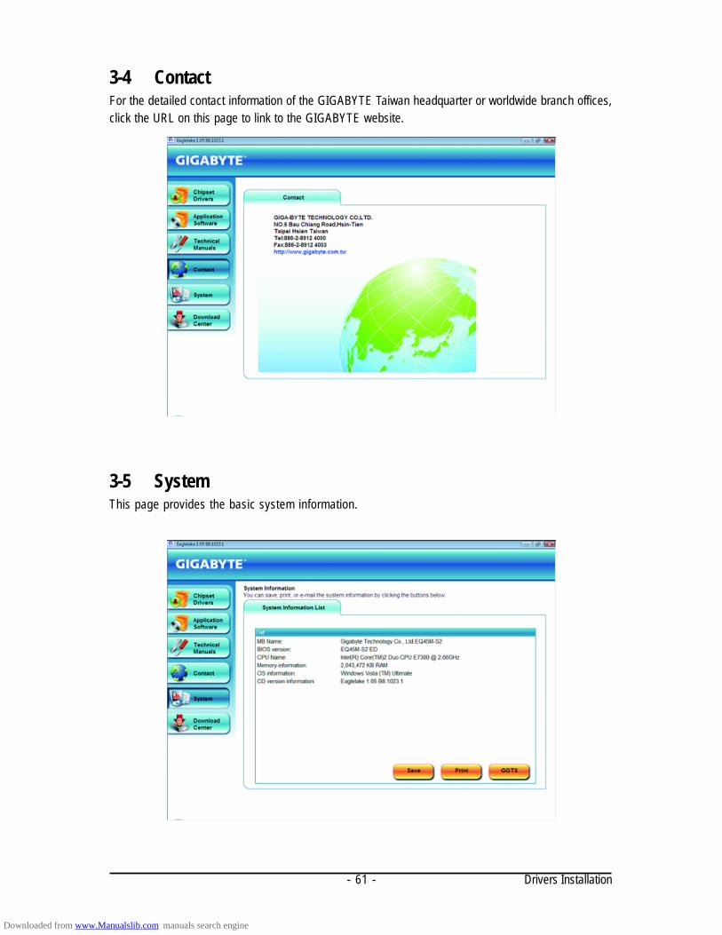
Drivers Installation- 61 -
3-4 ContactFor the detailed contact information of the GIGABYTE Taiwan headquarter or worldwide branch offices,click the URL on this page to link to the GIGABYTE website.
3-5 SystemThis page provides the basic system information.
Downloaded from www.Manualslib.com manuals search engine

GA-EQ45M-S2 Motherboard - 62 -
3-6 Download CenterTo update the BIOS, drivers, or applications, click the Download Center button to link to the GIGABYTEWeb site. The latest version of the BIOS, drivers, or applications will be displayed.
Downloaded from www.Manualslib.com manuals search engine

Unique Features- 63 -
Chapter 4 Unique Features4-1 Xpress Recovery2
"*" Xpress Recovery2 checks the first physical hard drive in the following sequence: The first PATA IDE connector,the second PATA IDE connector, the first SATA connector, the second SATA connector and so forth. Forexample, when hard drives are attached to the first IDE and the first SATA connectors, the hard drive on the firstIDE connector is the first physical drive. When hard drives are attached to the first and second SATA connectors,the hard drive on the first SATA connector is the first physical drive.
Xpress Recovery2 is a utility that allows you to quickly compress andback up your system data and perform restoration of it. SupportingNTFS, FAT32, and FAT16 file systems, Xpress Recovery2 can backup data on PATA and SATA hard drives and restore it.
Before You Begin:• Xpress Recovery2 will check the first physical hard drive* for the operating system. Xpress
Recovery2 can only back up/restore the first physical hard drive that has the operating systeminstalled.
• As Xpress Recovery2 will save the backup file at the end of the hard drive, make sure to leaveenough unallocated space in advanced (10 GB or more is recommended; actual size require-ments vary, depending on the amount of data).
• It is recommended to back up your system soon after the operating system and drivers areinstalled.
• The amount of data and hard drive access speed may affect the speed at which the data is backedup/restored.
• It takes longer to back up a hard drive than to restore it.System Requirements:
• At least 512 MB of system memory• VESA compatible graphics card• Windows XP with SP1 or later, Windows Vista
• Xpress Recovery and Xpress Recovery2 are different utilities. For example, a backup file created with XpressRecovery cannot be restored using Xpress Recovery2.
• USB hard drives are not supported.• Hard drives in RAID/AHCI mode are not supported.
Installation and ConfigurationTurn on your system to boot from the Windows Vista setup disk.A. Installing Windows Vista and Partitioning the Hard Drive
Step 1:Click Drive options.
Step 2:Click New.
Downloaded from www.Manualslib.com manuals search engine

GA-EQ45M-S2 Motherboard - 64 -
Step 3:When partitioning your hard drive, make sureto leave unallocated space (10 GB or more isrecommended; actual size requirements vary,depending on the amount of data) and begin theinstallation of the operating system.
Step 4:After the operating system is installed, right-click the Computer icon on your desktopand select Manage. Go to Disk Managementto check disk allocation.
Step 5:Xpress Recovery2 will save the backup file to theunallocated space (black stripe along the top). Pleasenote that if there is no enough unallocated space, XpressRecovery2 cannot save the backup file.
B. Accessing Xpress Recovery21. Boot from the motherboard driver disk to access Xpress Recovery2 for the first time. When you see
the following message: Press any key to startup Xpress Recovery2 , pressany key to enter Xpress Recovery2.
2. After you use the backup function in Xpress Recovery2 for the first time, Xpress Recovery2 will staypermanent in your hard drive. If you wish to enter Xpress Recovery2 later, simply press <F9> duringthe POST.
C. Using the Backup Function in Xpress Recovery2
Step 1:Select BACKUP to start backing up your harddrive data.
Step 2:When finished, go to Disk Management tocheck disk allocation.
Xpress Recovery2 will automatically create anew partition to store the backup image file.
Downloaded from www.Manualslib.com manuals search engine
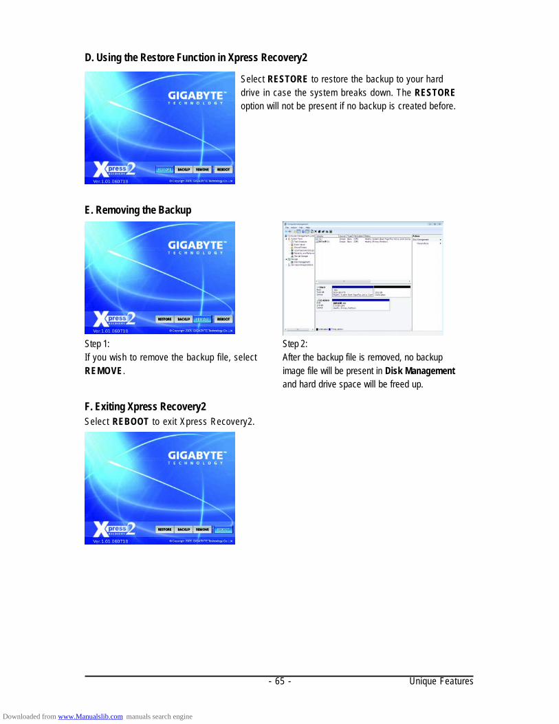
Unique Features- 65 -
E. Removing the Backup
D. Using the Restore Function in Xpress Recovery2
F. Exiting Xpress Recovery2Select REBOOT to exit Xpress Recovery2.
Select RESTORE to restore the backup to your harddrive in case the system breaks down. The RESTOREoption will not be present if no backup is created before.
Step 1:If you wish to remove the backup file, selectREMOVE.
Step 2:After the backup file is removed, no backupimage file will be present in Disk Managementand hard drive space will be freed up.
Downloaded from www.Manualslib.com manuals search engine

GA-EQ45M-S2 Motherboard - 66 -
4-2-1 Updating the BIOS with the Q-Flash Utility
A. Before You Begin:1. From GIGABYTE's website, download the latest compressed BIOS update file that matches your
motherboard model.2. Extract the file and save the new BIOS file (e.g. EQ45MS2.F1) to your floppy disk, USB flash
drive, or hard drive. Note: The USB flash drive or hard drive must use FAT32/16/12 file system.3. Restart the system. During the POST, press the <End> key to enter Q-Flash. Note: You can
access Q-Flash by either pressing the <End> key during the POST or pressing the <F8> key inBIOS Setup. However, if the BIOS update file is saved to a hard drive in RAID/AHCI mode or a harddrive attached to an independent IDE/SATA controller, use the <End> key during the POST toaccess Q-Flash.
Because BIOS flashing is potentially risky, please do it with caution. Inadequate BIOSflashing may result in system malfunction.
4-2 BIOS Update Utilities
GIGABYTE motherboards provide two unique BIOS update tools, Q-FlashTM and @BIOSTM. GIGABYTEQ-Flash and @BIOS are easy-to-use and allow you to update the BIOS without the need to enter MS-DOS mode.
What is Q-FlashTM?With Q-Flash you can update the system BIOS without having to enteroperating systems like MS-DOS or Window first. Embedded in the BIOS, the
Q-Flash tool frees you from the hassles of going through complicated BIOS flashing process.
What is @BIOSTM?@BIOS allows you to update the system BIOS while in the Windowsenvironment. @BIOS will download the latest BIOS file from the nearest
@BIOS server site and update the BIOS.
Award Modular BIOS v6.00PG, An Energy Star AllyCopyright (C) 1984-2009, Award Software, Inc.
EQ45M-S2 EE....
<DEL>: BIOS Setup/Q-Flash <F9>: XpressRecovery2 <F12>: Boot Menu <End>: Qflash02/02/2009-Q45- ICH10-7A69PG0PC-00
Downloaded from www.Manualslib.com manuals search engine

Unique Features- 67 -
B. Updating the BIOSWhen updating the BIOS, choose the location where the BIOS file is saved. The follow procedureassumes that you save the BIOS file to a floppy disk.
Step 1:1. Insert the floppy disk containing the BIOS file into the floppy disk drive. In the main menu of
Q-Flash, use the up or down arrow key to select Update BIOS from Drive and press <Enter>.
• The Save Main BIOS to Drive option allows you to save the current BIOS file.• Q-Flash only supports USB flash drive or hard drives using FAT32/16/12 file system.• If the BIOS update file is saved to a hard drive in RAID/AHCI mode or a hard drive
attached to an independent IDE/SATA controller, use the <End> key during the POST toaccess Q-Flash.
2. Select Floppy A and press <Enter>.
Q-Flash Utility v2.07 Flash Type/Size.................................MXIC 25L1605A 1M
Keep DMI Data Enable Update BIOS from Drive
Save BIOS to DriveEnter : Run :Move ESC:Reset F10:Power Off
0 file(s) foundFloppy A <Drive>HDD 0-0 <Drive>
Total size : 0 Free size : 0
3. Select the BIOS update file and press <Enter>.
Make sure the BIOS update file matches your motherboard model.
Step 2:The process of the system reading the BIOS file from the floppy disk is displayed on the screen. Whenthe message "Are you sure to update BIOS?" appears, press <Enter> to begin the BIOS update. Themonitor will display the update process.
• Do not turn off or restart the system when the system is reading/updating the BIOS.• Do not remove the floppy disk, USB flash drive, or hard drive when the system is
updating the BIOS.
Step 3:When the update process is complete, press any key to return to the main menu.
Q-Flash Utility v2.07 Flash Type/Size.................................MXIC 25L1605A 1M
Keep DMI Data Enable Update BIOS from Drive
Save BIOS to DriveEnter : Run :Move ESC:Reset F10:Power Off
!! Copy BIOS completed - Pass !!
Please press any key to continue
Downloaded from www.Manualslib.com manuals search engine
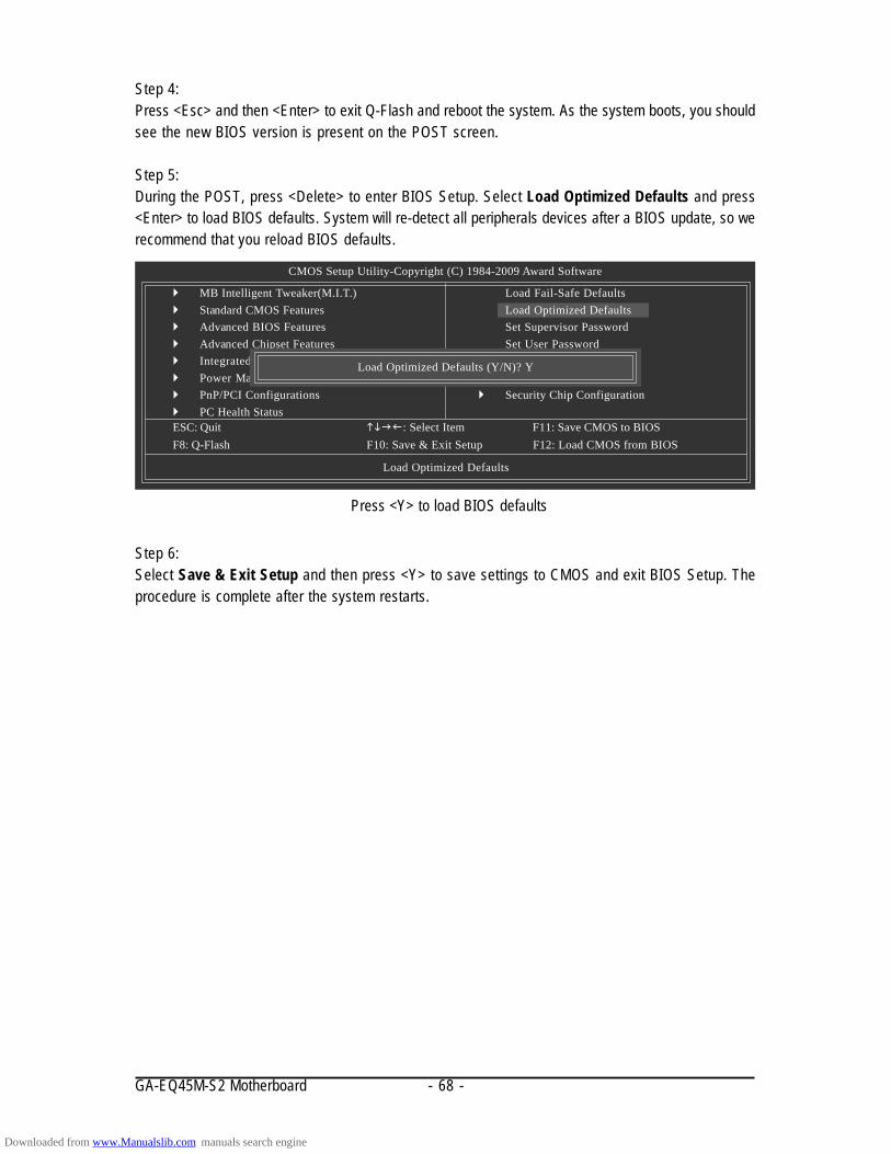
GA-EQ45M-S2 Motherboard - 68 -
Step 6:Select Save & Exit Setup and then press <Y> to save settings to CMOS and exit BIOS Setup. Theprocedure is complete after the system restarts.
Press <Y> to load BIOS defaults
Step 4:Press <Esc> and then <Enter> to exit Q-Flash and reboot the system. As the system boots, you shouldsee the new BIOS version is present on the POST screen.
Step 5:During the POST, press <Delete> to enter BIOS Setup. Select Load Optimized Defaults and press<Enter> to load BIOS defaults. System will re-detect all peripherals devices after a BIOS update, so werecommend that you reload BIOS defaults.
CMOS Setup Utility-Copyright (C) 1984-2009 Award Software
MB Intelligent Tweaker(M.I.T.) Standard CMOS Features Advanced BIOS Features Advanced Chipset Features Integrated Peripherals Power Management Setup PnP/PCI Configurations PC Health StatusESC: Quit : Select Item F11: Save CMOS to BIOSF8: Q-Flash F10: Save & Exit Setup F12: Load CMOS from BIOS
Load Optimized Defaults
Load Fail-Safe DefaultsLoad Optimized DefaultsSet Supervisor PasswordSet User PasswordSave & Exit SetupExit Without Saving
Security Chip Configuration
Load Optimized Defaults (Y/N)? Y
Downloaded from www.Manualslib.com manuals search engine

Unique Features- 69 -
4-2-2 Updating the BIOS with the @BIOS Utility
A. Before You Begin:1. In Windows, close all applications and TSR (Terminate and Stay Resident) programs. This helps
prevent unexpected failures when performing a BIOS update.2. During the BIOS update process, ensure the Internet connection is stable and do NOT interrupt the
Internet connection (for example, avoid a power loss or switching off the Internet). Failure to do somay result in a corrupted BIOS or a system that is unable to start.
3. Do not use the G.O.M. (GIGABYTE Online Management) function when using @BIOS.4. GIGABYTE product warranty does not cover any BIOS damage or system failure resulting from an
inadequate BIOS flashing.
B. Using @BIOS:
If the BIOS update file for your motherboard is not present on the @BIOS server site, pleasemanually download the BIOS update file from GIGABYTE's website and follow the instruc-tions in "Update the BIOS without Using the Internet Update Function" below.
2. Update the BIOS without Using the Internet Update Function:Click Update BIOS from File, then select the location where you save the BIOS update fileobtained from the Internet or through other source. Follow the on-screen instructions to complete.
1. Update the BIOS Using the Internet Update Function:Click Update BIOS from GIGABYTE Server, select the @BIOS server site closest to yourlocation and then download the BIOS file that matches your motherboard model. Follow the on-screen instructions to complete.
3. Save Current BIOS to File:Click Save Current BIOS to save the current BIOS file.
C. After Updating the BIOS:Restart your system after updating the BIOS.
Make sure that the BIOS file to be flashed matches your motherboard model. Updating theBIOS with an incorrect BIOS file could cause your system not to boot.
4. Load BIOS defaults after BIOS Update:Select the Load CMOS default after BIOS update check box and then the system will automaticallyload BIOS defaults after BIOS update and after the system restarts.
Downloaded from www.Manualslib.com manuals search engine

GA-EQ45M-S2 Motherboard - 70 -
4-3 Dynamic Energy Saver Advanced
GIGABYTE Dynamic Energy Saver Advanced (Note 1) is a revolutionary technology that delivers unpar-alleled power savings with a click of the button. Featuring an advanced proprietary hardware andsoftware design, GIGABYTE Dynamic Energy Saver Advanced is able to provide exceptional powersavings and enhanced power efficiency without sacrificing computing performance.
The Dynamic Energy Saver Advanced InterfaceA. Meter ModeIn Meter Mode, GIGABYTE Dynamic Energy Saver Advanced shows how much power they havesaved in a set period of time.
Meter Mode - Button Information TableButton Description
1 Dynamic Energy Saver On/Off Switch (Default: Off)2 Motherboard Phase LED On/Off Switch (Default: On)3 Dynamic CPU Frequency Function On/Off Switch (Default: Off) (Note 2)
4 CPU Throttling Display5 3-Level CPU Voltage Switch (Default:1) (Note 3)
6 CPU Voltage Display7 Dynamic Power Phase Status8 Current CPU Power Consumption9 Meter Time
10 Power Saving (Calculate power savings based on time)11 Meter/Timer Reset Switch12 Meter Mode Switch13 Total Mode Switch14 Close (Application will enter Stealth Mode)15 Minimize (Application will continue to run in taskbar)16 INFO/Help17 Live Utility Update (Check for the latest utility version)
• The above data is for reference only. Actual performance may vary depending on motherboard model.• CPU Power and Power Scores are for reference only. Actual results may vary based on testing method.
Downloaded from www.Manualslib.com manuals search engine

Unique Features- 71 -
Total Mode - Button Information Table
B. Total ModeIn Total Mode, users are able to see how much total power savings they have accumulated in a setperiod of time since activating Dynamic Energy Saver Advanced for the first time (Note 4).
(Note 1) Before using the DES function, make sure the CPU Enhanced Halt (C1E) and CPU EISTFunction items in the BIOS Setup program are set to Enabled.
(Note 2) Maximize system power saving with Dynamic Frequency Function; system performancemay be affected.
(Note 3) 1: Normal Power Saving (default); 2: Advanced Power Saving; 3: Extreme Power Saving.(Note 4) The total amount of power saved will be recorded until re-activated when only the Dynamic
Power Saver is under the enable status, and power savings meter is unable to reset to zero.(Note 5) Dynamic Energy Saver Meter will automatically reset when the total power saving reaches
99999999 Watts.
Button Description1 Dynamic Energy Saver On/Off Switch (Default: Off)2 Motherboard Phase LED On/Off Switch (Default: On)3 Dynamic CPU Frequency Function On/Off Switch (Default: Off)4 CPU Throttling Display5 3-Level CPU Voltage Switch (Default:1) (Note 3)
6 CPU Voltage Display7 Dynamic Power Phase Status8 Current CPU Power Consumption9 Time/Date Dynamic Energy Saver Enabled10 Total Power Savings (Total power saving with Dynamic Energy Saver enabled) (Note 5)
11 Dynamic Energy Saver Meter Mode Switch12 Dynamic Energy Saver Total Mode Switch13 Close (Application will enter Stealth Mode)14 Minimize (Application will continue to run in taskbar)15 INFO/Help16 Live Utility Update (Check for the latest utility version)
C. Stealth ModeIn Stealth Mode, the system continues to work with the user-defined power saving settings, even afterthe system is restarted. Re-enter the application only if you want to make any changes or completelyclose the application.
Downloaded from www.Manualslib.com manuals search engine
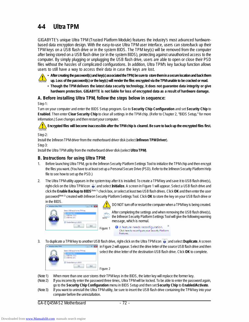
GA-EQ45M-S2 Motherboard - 72 -
4-4 Ultra TPM
GIGABYTE's unique Ultra TPM (Trusted Platform Module) features the industry's most advanced hardware-based data encryption design. With the easy-to-use Ultra TPM user interface, users can store/back up theirTPM keys on a USB flash drive or in the system BIOS. The TPM key(s) will be removed from the computerafter being stored on a USB flash drive (or in the system BIOS), protecting against unauthorized access to thecomputer. By simply plugging or unplugging the USB flash drive, users are able to open or close their PSDfiles without the hassles of complicated configurations. In addition, Ultra TPM's key backup function allowsusers to still have a way to access their data in case the keys are lost.
• After creating the password(s) and key(s) associated the TPM, be sure to store them in a secure location and back themup. Loss of the password(s) or the key(s) will render the files encrypted via the TPM unable to be cracked or read.
• Though the TPM delivers the latest data security technology, it does not guarantee data integrity or givehardware protection. GIGABYTE is not liable for loss of encrypted data as a result of hardware damage.
A. Before installing Ultra TPM, follow the steps below in sequence:Step 1:Turn on your computer and enter the BIOS Setup program. Go to Security Chip Configuration and set Security Chip toEnabled. Then enter Clear Security Chip to clear all settings in the TPM chip. (Refer to Chapter 2, "BIOS Setup," for moreinformation.) Save changes and then restart your computer.
Step 2:Install the Infineon TPM driver from the motherboard driver disk (select Infineon TPM Driver).Step 3:Install the Ultra TPM utility from the motherboard driver disk (select Ultra TPM).
Encrypted files will become inaccessible after the TPM chip is cleared. Be sure to back up the encrypted files first.
B. Instructions for using Ultra TPM:1. Before launching Ultra TPM, go to the Infineon Security Platform Settings Tool to initialize the TPM chip and then encrypt
the files you want. (You have to at least set up a Personal Secure Drive (PSD). Refer to the Infineon Security Platform Helpfile to see how to set up the PSD.)
2. The Ultra TPM utility appears in the system tray after it is installed. To create a TPM key and save it to USB flash drive(s),right-click on the Ultra TPM icon and select Initialize. A screen in Figure 1 will appear. Select a USB flash drive andclick the Enable Backup to BIOS(Note 1) check box, or select at least two USB flash drives. Click OK and then enter the userpassword(Note 2) created with Infineon Security Platform Settings Tool. Click OK to store the key on your USB flash drive orin the BIOS.
Figure 1
3. To duplicate a TPM key to another USB flash drive, right-click on the Ultra TPM icon and select Duplicate. A screenin Figure 2 will appear. Select the drive letter of the source USB flash drive and thenselect the drive letter of the destination USB flash drive. Click OK to complete.
Figure 2
DO NOT turn off or restart the computer when a TPM key is being created.
After completing the settings and when removing the USB flash drive(s),the Infineon Security Platform Settings Tool will give the following warningmessage, which is normal.
(Note 1) When more than one user stores their TPM keys in the BIOS, the latter key will replace the former key.(Note 2) If you incorrectly enter the password three times, Ultra TPM will be locked. To be able to enter the password again,
go to the Security Chip Configuration menu in BIOS Setup and then set Security Chip to Enabled/Activate.(Note 3) If you want to uninstall the Ultra TPM utility, be sure to insert the USB flash drive containing the TPM key into your
computer before the uninstallation.
Downloaded from www.Manualslib.com manuals search engine
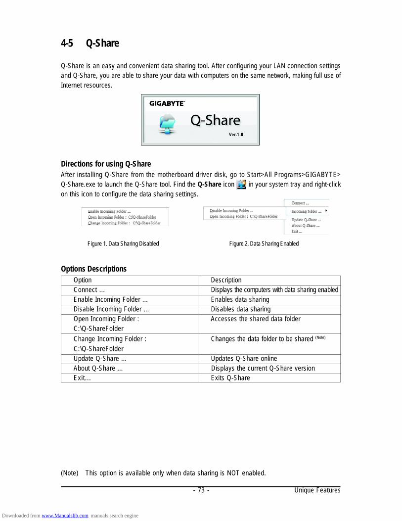
Unique Features- 73 -
4-5 Q-Share
Q-Share is an easy and convenient data sharing tool. After configuring your LAN connection settingsand Q-Share, you are able to share your data with computers on the same network, making full use ofInternet resources.
Directions for using Q-ShareAfter installing Q-Share from the motherboard driver disk, go to Start>All Programs>GIGABYTE>Q-Share.exe to launch the Q-Share tool. Find the Q-Share icon in your system tray and right-clickon this icon to configure the data sharing settings.
Figure 2. Data Sharing EnabledFigure 1. Data Sharing Disabled
Options Descriptions
(Note) This option is available only when data sharing is NOT enabled.
Option DescriptionConnect ... Displays the computers with data sharing enabledEnable Incoming Folder ... Enables data sharingDisable Incoming Folder ... Disables data sharingOpen Incoming Folder : Accesses the shared data folderC:\Q-ShareFolderChange Incoming Folder : Changes the data folder to be shared (Note)
C:\Q-ShareFolderUpdate Q-Share ... Updates Q-Share onlineAbout Q-Share ... Displays the current Q-Share versionExit... Exits Q-Share
Downloaded from www.Manualslib.com manuals search engine
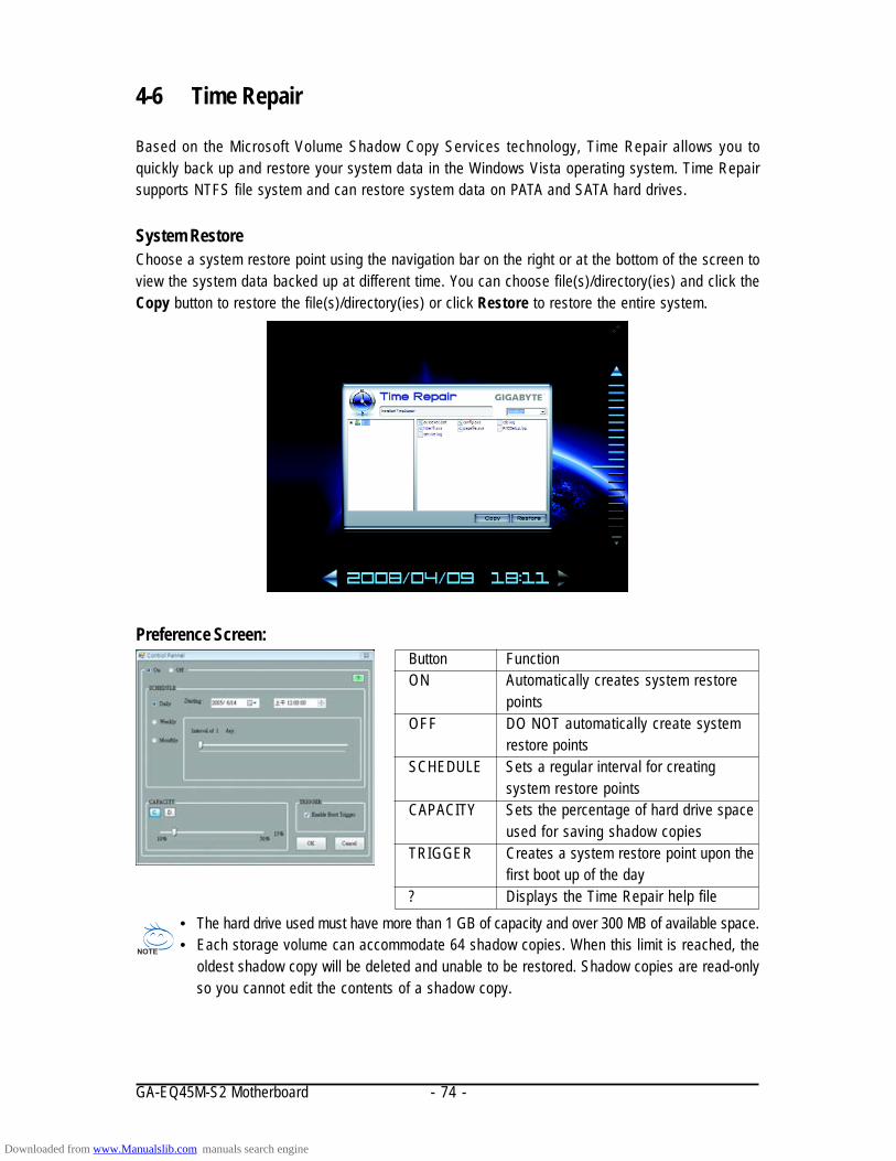
GA-EQ45M-S2 Motherboard - 74 -
4-6 Time Repair
Based on the Microsoft Volume Shadow Copy Services technology, Time Repair allows you toquickly back up and restore your system data in the Windows Vista operating system. Time Repairsupports NTFS file system and can restore system data on PATA and SATA hard drives.
System RestoreChoose a system restore point using the navigation bar on the right or at the bottom of the screen toview the system data backed up at different time. You can choose file(s)/directory(ies) and click theCopy button to restore the file(s)/directory(ies) or click Restore to restore the entire system.
Button FunctionON Automatically creates system restore
pointsOFF DO NOT automatically create system
restore pointsSCHEDULE Sets a regular interval for creating
system restore pointsCAPACITY Sets the percentage of hard drive space
used for saving shadow copiesTRIGGER Creates a system restore point upon the
first boot up of the day? Displays the Time Repair help file
Preference Screen:
• The hard drive used must have more than 1 GB of capacity and over 300 MB of available space.• Each storage volume can accommodate 64 shadow copies. When this limit is reached, the
oldest shadow copy will be deleted and unable to be restored. Shadow copies are read-onlyso you cannot edit the contents of a shadow copy.
Downloaded from www.Manualslib.com manuals search engine
Appendix- 75 -
(Note 1) Skip this step if you do not want to create RAID array on the SATA controller.(Note 2) Required when the SATA controller is set to AHCI or RAID mode.
Chapter 5 Appendix
5-1 Configuring SATA Hard Drive(s)
To configure SATA hard drive(s), follow the steps below:A. Install SATA hard drive(s) in your computer.B. Configure SATA controller mode in BIOS Setup.C . Configure a RAID array in RAID BIOS. (Note 1)
D. Make a floppy disk containing the SATA RAID/AHCI driver. (Note 2)
E. Install the SATA RAID/AHCI driver and operating system. (Note 2)
Before you beginPlease prepare:
• At least two SATA hard drives (to ensure optimal performance, it is recommended that you usetwo hard drives with identical model and capacity). If you do not want to create RAID, you mayprepare only one hard drive.
• An empty formatted floppy disk.• Windows Vista/XP setup disk.• Motherboard driver disk.
5-1-1 Configuring Intel ICH10DO SATA Controllers
A. Installing SATA hard drive(s) in your computerAttach one end of the SATA signal cable to the rear of the SATA hard drive and the other end to availableSATA port on the motherboard. Then connect the power connector from your power supply to the harddrive.
Downloaded from www.Manualslib.com manuals search engine

GA-EQ45M-S2 Motherboard - 76 -
B. Configuring SATA controller mode in BIOS SetupMake sure to configure the SATA controller mode correctly in system BIOS Setup .
Step 1:Turn on your computer and press <Delete> to enter BIOS Setup during the POST (Power-On Self-Test).To create RAID, set SATA RAID/AHCI Mode under the Integrated Peripherals menu to RAID(Figure 1)(Disabled by default). If you do not want to create RAID, set this item to Disabled or AHCI.
Figure 1
The BIOS Setup menus described in this section may differ from the exact settings for yourmotherboard. The actual BIOS Setup menu options you will see shall depend on the motherboardyou have and the BIOS version.
Step 2:Save changes and exit BIOS Setup.
CMOS Setup Utility-Copyright (C) 1984-2009 Award SoftwareIntegrated Peripherals
SATA RAID/AHCI Mode [RAID]SATA Port0-3 Native Mode [Disabled]USB Controller [Enabled]USB 2.0 Controller [Enabled]USB Keyboard Support [Disabled]USB Mouse Support [Disabled]Legacy USB storage detect [Enabled]Azalia Codec [Auto]Onboard LAN Function [Enabled]OnBoard LAN Boot ROM [Disabled]Onboard IDE Controller [Enabled]Onboard Serial Port 1 [3F8/IRQ4]Onboard Serial Port 2 [2F8/IRQ3]Onboard Parallel Port [378/IRQ7]Parallel Port Mode [SPP]
: Move Enter: Select +/-/PU/PD: Value F10: Save ESC: Exit F1: General HelpF5: Previous Values F6: Fail-Safe Defaults F7: Optimized Defaults
Item HelpMenu Level
Downloaded from www.Manualslib.com manuals search engine
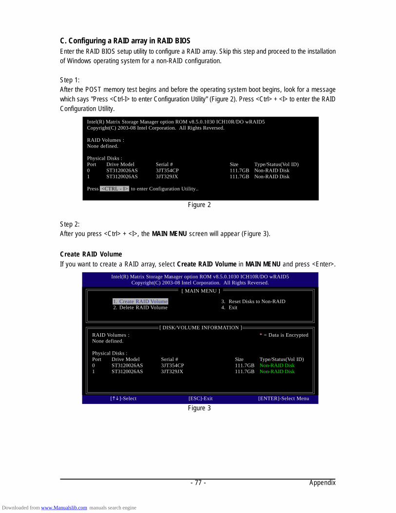
Appendix- 77 -
C. Configuring a RAID array in RAID BIOSEnter the RAID BIOS setup utility to configure a RAID array. Skip this step and proceed to the installationof Windows operating system for a non-RAID configuration.
Step 1:After the POST memory test begins and before the operating system boot begins, look for a messagewhich says "Press <Ctrl-I> to enter Configuration Utility" (Figure 2). Press <Ctrl> + <I> to enter the RAIDConfiguration Utility.
Step 2:After you press <Ctrl> + <I>, the MAIN MENU screen will appear (Figure 3).
Create RAID VolumeIf you want to create a RAID array, select Create RAID Volume in MAIN MENU and press <Enter>.
Figure 2
Figure 3
Intel(R) Matrix Storage Manager option ROM v8.5.0.1030 ICH10R/DO wRAID5Copyright(C) 2003-08 Intel Corporation. All Rights Reversed.
RAID Volumes :None defined.
Physical Disks :Port Drive Model Serial # Size Type/Status(Vol ID)0 ST3120026AS 3JT354CP 111.7GB Non-RAID Disk1 ST3120026AS 3JT329JX 111.7GB Non-RAID Disk
Press <CTRL - I> to enter Configuration Utility..
Intel(R) Matrix Storage Manager option ROM v8.5.0.1030 ICH10R/DO wRAID5Copyright(C) 2003-08 Intel Corporation. All Rights Reversed.
[ MAIN MENU ]
1. Create RAID Volume2. Delete RAID Volume
[ DISK/VOLUME INFORMATION ]RAID Volumes : * = Data is EncryptedNone defined.
Physical Disks :Port Drive Model Serial # Size Type/Status(Vol ID)0 ST3120026AS 3JT354CP 111.7GB Non-RAID Disk1 ST3120026AS 3JT329JX 111.7GB Non-RAID Disk
[]-Select [ESC]-Exit [ENTER]-Select Menu
3. Reset Disks to Non-RAID4. Exit
Downloaded from www.Manualslib.com manuals search engine

GA-EQ45M-S2 Motherboard - 78 -
Step 3:After entering the CREATE VOLUME MENU screen, enter a volume name with 1~16 letters (letterscannot be special characters) under the Name item and press <Enter>. Then, select a RAID level(Figure 4). There are four RAID levels supported: RAID 0, RAID 1, RAID 10 and RAID 5 (the selectionsavailable depend on the number of the hard drives being installed). Press <Enter> to proceed.
Step 4:Under Disks item, select the hard drives to be included in the RAID array. If only two hard drives areinstalled, they will be automatically assigned to the array. Set the stripe block size (Figure 5) ifnecessary. The stripe block size can be set from 4 KB to 128 KB. Once you have selected the stripeblock size, press <Enter>.
Figure 5
Figure 4
Intel(R) Matrix Storage Manager option ROM v8.5.0.1030 ICH10R/DO wRAID5Copyright(C) 2003-08 Intel Corporation. All Rights Reversed.
[ CREATE VOLUME MENU ]
[ HELP ]
The following are typical values:RAID0 - 128KBRAID10 - 64KBRAID5 - 64KB
[]-Change [TAB]-Next [ESC]-Previous Menu [ENTER]-Select
Name : Volume0RAID Level : RAID0(Stripe)
Disks : Select DisksStrip Size : 128KBCapacity : 223.6 GB
Create Volume
Intel(R) Matrix Storage Manager option ROM v8.5.0.1030 ICH10R/DO wRAID5Copyright(C) 2003-08 Intel Corporation. All Rights Reversed.
[ CREATE VOLUME MENU ]
[ HELP ]
Choose the RAID level:
RAID0: Stripes data (performance).RAID1: Mirrors data (redundancy).
RAID10: Mirrors data and stripes the mirror.RAID5: Stripes data and parity.
[]-Change [TAB]-Next [ESC]-Previous Menu [ENTER]-Select
Name : Volume0RAID Level : RAID0(Stripe)
Disks : Select DisksStrip Size : 128KBCapacity : 223.6 GB
Create Volume
Downloaded from www.Manualslib.com manuals search engine
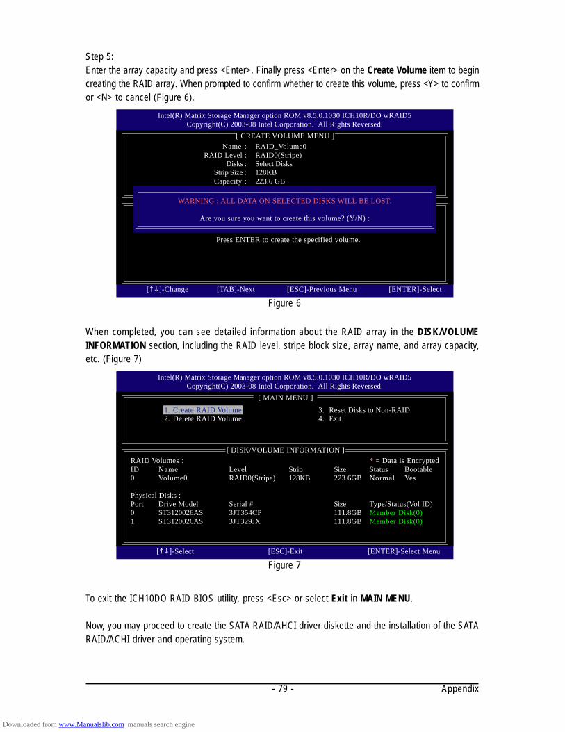
Appendix- 79 -
Step 5:Enter the array capacity and press <Enter>. Finally press <Enter> on the Create Volume item to begincreating the RAID array. When prompted to confirm whether to create this volume, press <Y> to confirmor <N> to cancel (Figure 6).
Figure 6
Intel(R) Matrix Storage Manager option ROM v8.5.0.1030 ICH10R/DO wRAID5Copyright(C) 2003-08 Intel Corporation. All Rights Reversed.
[ CREATE VOLUME MENU ]
[ HELP ]
Press ENTER to create the specified volume.
[]-Change [TAB]-Next [ESC]-Previous Menu [ENTER]-Select
Name : RAID_Volume0RAID Level : RAID0(Stripe)
Disks : Select DisksStrip Size : 128KBCapacity : 223.6 GB
Create VolumeWARNING : ALL DATA ON SELECTED DISKS WILL BE LOST.
Are you sure you want to create this volume? (Y/N) :
When completed, you can see detailed information about the RAID array in the DISK/VOLUMEINFORMATION section, including the RAID level, stripe block size, array name, and array capacity,etc. (Figure 7)
Figure 7
Intel(R) Matrix Storage Manager option ROM v8.5.0.1030 ICH10R/DO wRAID5Copyright(C) 2003-08 Intel Corporation. All Rights Reversed.
[ MAIN MENU ]
[ DISK/VOLUME INFORMATION ]RAID Volumes : * = Data is EncryptedID Name Level Strip Size Status Bootable0 Volume0 RAID0(Stripe) 128KB 223.6GB Normal Yes
Physical Disks :Port Drive Model Serial # Size Type/Status(Vol ID)0 ST3120026AS 3JT354CP 111.8GB Member Disk(0)1 ST3120026AS 3JT329JX 111.8GB Member Disk(0)
[]-Select [ESC]-Exit [ENTER]-Select Menu
1. Create RAID Volume2. Delete RAID Volume
3. Reset Disks to Non-RAID4. Exit
To exit the ICH10DO RAID BIOS utility, press <Esc> or select Exit in MAIN MENU.
Now, you may proceed to create the SATA RAID/AHCI driver diskette and the installation of the SATARAID/ACHI driver and operating system.
Downloaded from www.Manualslib.com manuals search engine
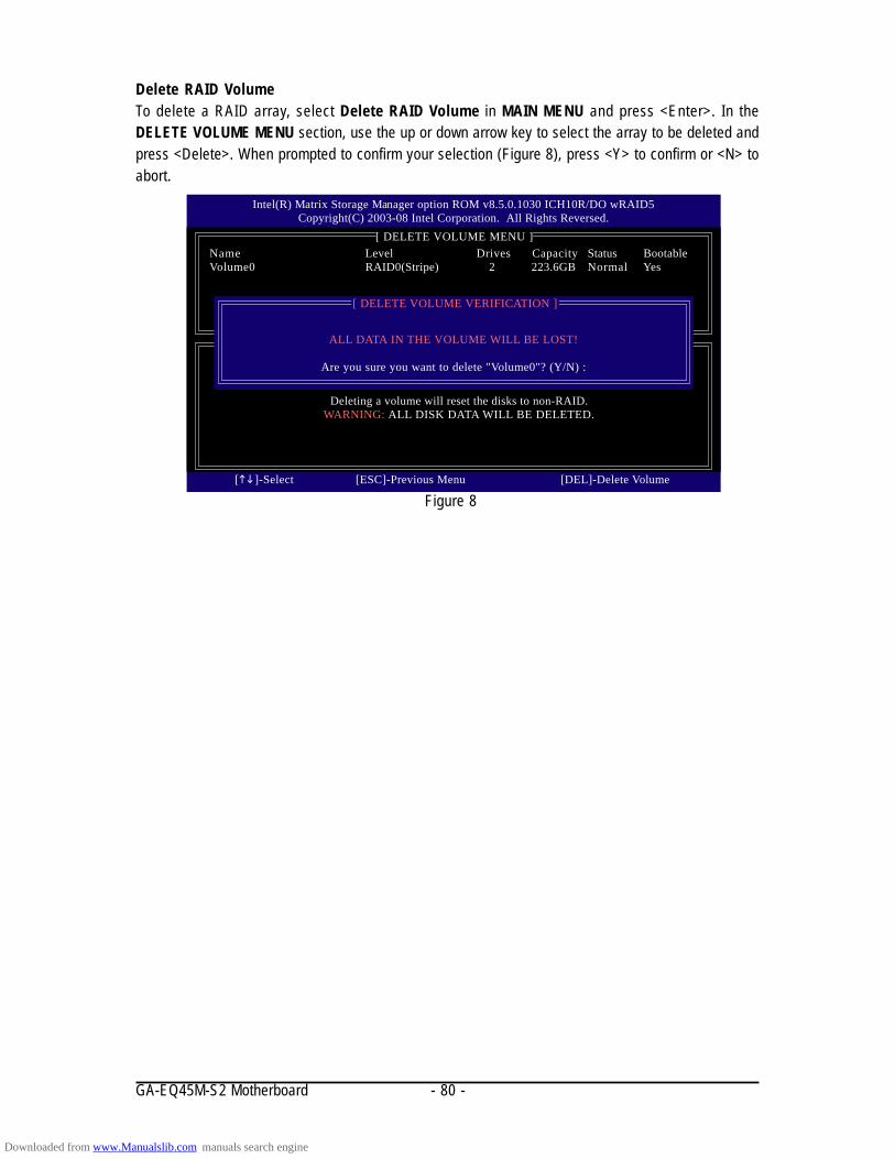
GA-EQ45M-S2 Motherboard - 80 -
Delete RAID VolumeTo delete a RAID array, select Delete RAID Volume in MAIN MENU and press <Enter>. In theDELETE VOLUME MENU section, use the up or down arrow key to select the array to be deleted andpress <Delete>. When prompted to confirm your selection (Figure 8), press <Y> to confirm or <N> toabort.
Figure 8
Intel(R) Matrix Storage Manager option ROM v8.5.0.1030 ICH10R/DO wRAID5Copyright(C) 2003-08 Intel Corporation. All Rights Reversed.
[ DELETE VOLUME MENU ]
[ HELP ]
Deleting a volume will reset the disks to non-RAID.WARNING: ALL DISK DATA WILL BE DELETED.
[]-Select [ESC]-Previous Menu [DEL]-Delete Volume
Name Level Drives Capacity Status BootableVolume0 RAID0(Stripe) 2 223.6GB Normal Yes
ALL DATA IN THE VOLUME WILL BE LOST!
Are you sure you want to delete "Volume0"? (Y/N) :
[ DELETE VOLUME VERIFICATION ]
Downloaded from www.Manualslib.com manuals search engine
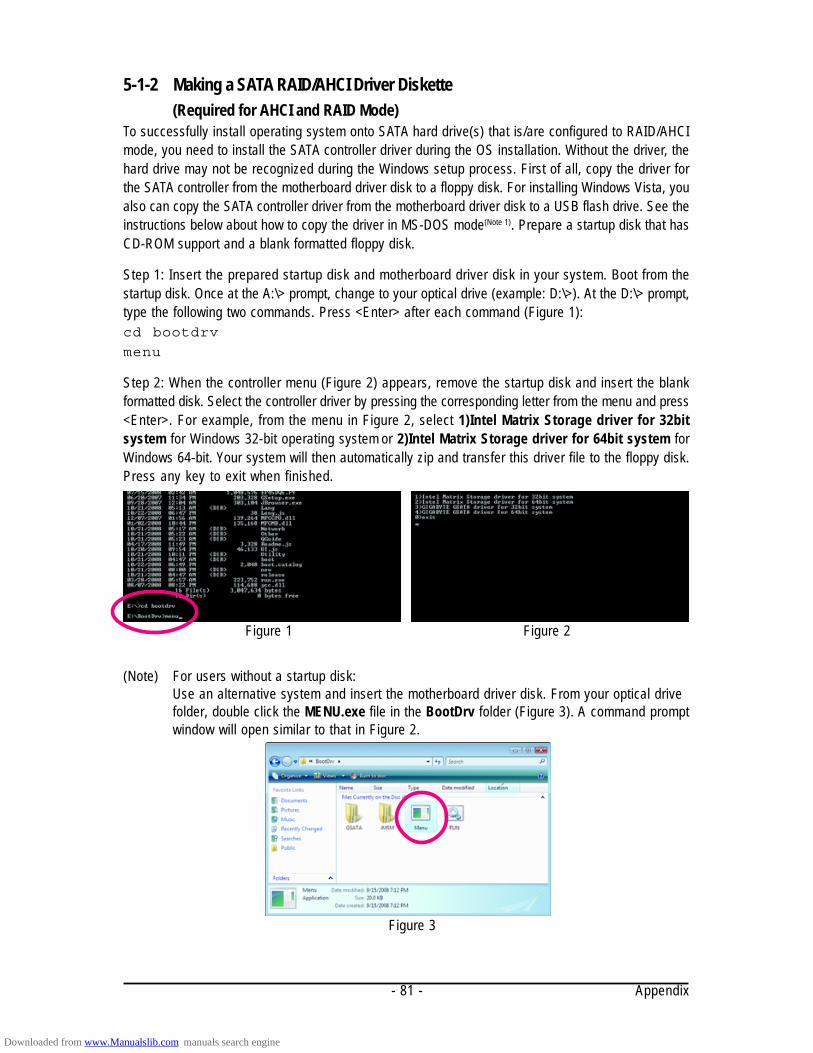
Appendix- 81 -
(Note) For users without a startup disk:Use an alternative system and insert the motherboard driver disk. From your optical drivefolder, double click the MENU.exe file in the BootDrv folder (Figure 3). A command promptwindow will open similar to that in Figure 2.
Figure 3
5-1-2 Making a SATA RAID/AHCI Driver Diskette(Required for AHCI and RAID Mode)
To successfully install operating system onto SATA hard drive(s) that is/are configured to RAID/AHCImode, you need to install the SATA controller driver during the OS installation. Without the driver, thehard drive may not be recognized during the Windows setup process. First of all, copy the driver forthe SATA controller from the motherboard driver disk to a floppy disk. For installing Windows Vista, youalso can copy the SATA controller driver from the motherboard driver disk to a USB flash drive. See theinstructions below about how to copy the driver in MS-DOS mode(Note 1). Prepare a startup disk that hasCD-ROM support and a blank formatted floppy disk.
Step 1: Insert the prepared startup disk and motherboard driver disk in your system. Boot from thestartup disk. Once at the A:\> prompt, change to your optical drive (example: D:\>). At the D:\> prompt,type the following two commands. Press <Enter> after each command (Figure 1):cd bootdrv
menu
Step 2: When the controller menu (Figure 2) appears, remove the startup disk and insert the blankformatted disk. Select the controller driver by pressing the corresponding letter from the menu and press<Enter>. For example, from the menu in Figure 2, select 1)Intel Matrix Storage driver for 32bitsystem for Windows 32-bit operating system or 2)Intel Matrix Storage driver for 64bit system forWindows 64-bit. Your system will then automatically zip and transfer this driver file to the floppy disk.Press any key to exit when finished.
Figure 1 Figure 2
Downloaded from www.Manualslib.com manuals search engine

GA-EQ45M-S2 Motherboard - 82 -
Figure 1Step 2:Then a controller menu similar to Figure 2 below will appear. Select Intel(R) ICH8R/ICH9R/ICH10R/DO SATA RAID Controller and press <Enter>. On the next screen, press <Enter> to continue thedriver installation. After the driver installation, you can proceed with the Windows XP installation.
Windows Setup
Press F6 if you need to install a third party SCSI or RAID driver.
5-1-3 Installing the SATA RAID/AHCI Driver and Operating SystemWith the SATA RAID/AHCI driver diskette and correct BIOS settings, you are ready to install WindowsVista/XP onto your hard drive(s). The followings are examples of Windows XP and Vista installation onthe Intel ICH10DO SATA controller.A. Installing Windows XPStep 1:Restart your system to boot from the Windows XP setup disk and press <F6> as soon as you see themessage "Press F6 if you need to install a 3rd party SCSI or RAID driver" (Figure 1). A screen will thenappear asking you to specify additional device. Insert the floppy disk containing the SATA RAID/AHCIdriver and press <S>.
Figure 2
Windows Setup
ENTER=Select F3=Exit
You have chosen to configure a SCSI Adapter for use with Windows,using a device support disk provided by an adapter manufacturer.
Select the SCSI Adapter you want from the following list, or press ESCto return to the previous screen.
Intel(R) ICH7R/DH SATA RAID ControllerIntel(R) ICH7MDH SATA RAID ControllerIntel(R) ICH8R/ICH9R/ICH10R/DO SATA RAID ControllerIntel(R) ICH8M-E/ICH9M-E SATA RAID Controller
Downloaded from www.Manualslib.com manuals search engine
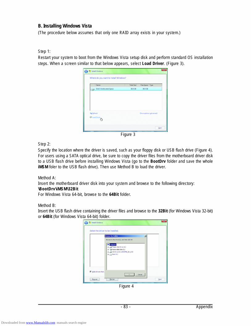
Appendix- 83 -
B. Installing Windows Vista(The procedure below assumes that only one RAID array exists in your system.)
Step 1:Restart your system to boot from the Windows Vista setup disk and perform standard OS installationsteps. When a screen similar to that below appears, select Load Driver. (Figure 3).
Step 2:Specify the location where the driver is saved, such as your floppy disk or USB flash drive (Figure 4).For users using a SATA optical drive, be sure to copy the driver files from the motherboard driver diskto a USB flash drive before installing Windows Vista (go to the BootDrv folder and save the wholeiMSM foler to the USB flash drive). Then use Method B to load the driver.
Method A:Insert the motherboard driver disk into your system and browse to the following directory:\BootDrv\iMSM\32BitFor Windows Vista 64-bit, browse to the 64Bit folder.
Method B:Insert the USB flash drive containing the driver files and browse to the 32Bit (for Windows Vista 32-bit)or 64Bit (for Windows Vista 64-bit) folder.
Figure 4
Figure 3
Downloaded from www.Manualslib.com manuals search engine
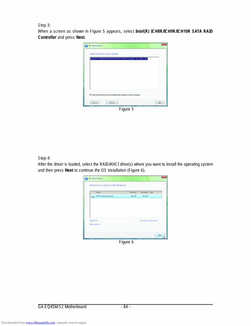
GA-EQ45M-S2 Motherboard - 84 -
Figure 5
Step 3:When a screen as shown in Figure 5 appears, select Intel(R) ICH8R/ICH9R/ICH10R SATA RAIDController and press Next.
Step 4:After the driver is loaded, select the RAID/AHCI drive(s) where you want to install the operating systemand then press Next to continue the OS installation (Figure 6).
Figure 6
Downloaded from www.Manualslib.com manuals search engine

Appendix- 85 -
Rebuilding an Array:Rebuilding is the process of restoring data to a hard drive from other drives in the array. Rebuildingapplies only to fault-tolerant arrays such as RAID 1, RAID 10, or RAID 5 arrays. The procedures belowassume a new drive is added to replace a failed drive to rebuild a RAID 1 array.
Intel ICH10DO SATA controller:Turn off your computer and replace the failed hard drive with a new one. Restart your computer.
Enabling Automatic RebuildStep 1:When the message "Press <Ctrl-I> to enter Configuration Utility" appears, press <Ctrl> + <I> to enter theRAID Configuration Utility. The following screen appears after you enter the RAID Configuration Utility.
Intel(R) Matrix Storage Manager option ROM v8.5.0.1030 ICH10R/DO wRAID5Copyright(C) 2003-08 Intel Corporation. All Rights Reversed.
[ MAIN MENU ]
1. Create RAID Volume2. Delete RAID Volume
[ DISK/VOLUME INFORMATION ]RAID Volumes :None defined.
Physical Disks :Port Drive Model Serial # Size Type/Status(Vol ID)0 WDC WD800JD-22LSWD-WMAM9W736201 74.4GB Member Disk (0)1 WDC WD800JD-22LSWD-WMAM9W736333 74.4GB Non-RAID Disk
[]-Select [ESC]-Exit [ENTER]-Select Menu
3. Reset Disks to Non-RAID4. Exit
[ DEGRADED VOLUME DETECTED ]"Degraded volume and disk available for rebuilding detected. Selectinga disk initiates a rebuild. Rebuild completes in the operating system.
Select the port of the destination disk for rebuilding (ESC to exit):
Port Drive Model Serial # Size1 WDC WD800JD-22LS WD-WMAM9W736333 74.4GB
[]-Previous/Next [ENTER]-Select [ESC]-Exit
Intel(R) Matrix Storage Manager option ROM v8.5.0.1030 ICH10R/DO wRAID5Copyright(C) 2003-08 Intel Corporation. All Rights Reversed.
[ MAIN MENU ]
[ DISK/VOLUME INFORMATION ]RAID Volumes :ID Name Level Strip Size Status Bootable0 gbb RAID1(Mirror) N/A 74.4GB Rebuild Yes
Physical Disks :Port Drive Model Serial # Size Type/Status(Vol ID)0 WDC WD800JD-22LSWD-WMAM9W736201 74.4GB Member Disk (0)1 WDC WD800JD-22LSWD-WMAM9W736333 74.4GB Member Disk (0)
[]-Select [ESC]-Exit [ENTER]-Select Menu
1. Create RAID Volume2. Delete RAID Volume
3. Reset Disks to Non-RAID4. Exit
Volumes with "Rebuild" status will be rebuilt within the operating system.
Step 2:Select the new hard drive to add into the array to be rebuilt and press <Enter>. The following screenappears, indicating that an automatic rebuild will be performed automatically after you enter theoperating system (look for the Intel Storage Console icon in the notification area, which will showthat a RAID volume is being rebuilt). If you do not enable automatic rebuild on this stage, you have tomanually rebuild the array in the operating system (see the next for more details).
Downloaded from www.Manualslib.com manuals search engine

GA-EQ45M-S2 Motherboard - 86 -
Step 1:On the View menu of the Intel Matrix StorageConsole, select Advanced Mode for a moredetailed view of the storage device information.
Step 2:The new hard drive appears under Non-RAIDHard Drive. Right-click on the new hard driveand select Rebuild to this Hard Drive.
Step 3:Click Next when the Rebuild RAID VolumeWizard appears. Follow the on-screen instruc-tions to proceed.
Step 4:To check the rebuild status during the rebuildprocess, right-click on the rebuild volume andselect Show Rebuild Progress.
Step 5:When the message "The rebuild was completedsuccessfully," appears, click OK to complete.
Step 6:After the RAID 1 volume rebuilding, click thevolume and its status in the information panewill display as Normal.
While in the operating system, make sure the chipset driver has been installed from the motherboarddriver disk. Then launch the Intel® Matrix Storage Console from Programs in the Start Menu.
Performing the Rebuild in the Operating System
Downloaded from www.Manualslib.com manuals search engine

Appendix- 87 -
5-2 Configuring Audio Input and Output
5-2-1 Configuring 2/4/5.1/7.1-Channel AudioThe motherboard provides six audio jacks on theback panel which support 2/4/5.1/7.1-channel audio.The picture to the right shows the default audio jackassignments.The integrated HD (High Definition) audio providesjack retasking capability that allows the user to changethe function for each jack through the audio driver.For example, in a 4-channel audio configuration, if aRear speaker is plugged into the default Center/Subwoofer speaker out jack, you can retask the Center/Subwoofer speaker out jack to be Rear speaker out.
High Definition Audio (HD Audio)HD Audio includes multiple high quality digital-to-analog converters (DACs) that support 44.1KHz/48KHz/ 96KHz/192KHz sampling rate. HD Audio features multistreaming capabilities that allow multipleaudio streams (in and out) to be simultaneously processed. For example, users can listen to MP3music, have an Internet chat, make a telephone call over the Internet, and etc. all at the same time.
Rear Speaker Out
Center/SubwooferSpeaker Out
Side Speaker Out
Line In
Front Speaker Out
Mic In
• To install a microphone, connect your microphone to the Mic in jack and manually configurethe jack for microphone functionality.
• Audio signals will be present on both of the front and back panel audio connections simultaneously.If you want to mute the back panel audio (only supported when using an HD front panel audiomodule), refer to instructions on the next page.
A. Configuring Speakers:(The following instructions use Windows Vista as the example operating system.)
Step 1:After installing the audio driver, the HD Audio Managericon will appear in the notification area. Double-click the icon to access the HD Audio Manager.
(Note) 2/4/5.1/7.1-Channel Audio Configurations:Refer to the following for multi-channel speaker configurations.• 2-channel audio: Headphone or Line out.• 4-channel audio: Front speaker out and Rear speaker out.• 5.1-channel audio: Front speaker out, Rear speaker out, and Center/Subwoofer speaker out.• 7.1-channel audio: Front speaker out, Rear speaker out, Center/Subwoofer speaker out, and Side speaker out.
Downloaded from www.Manualslib.com manuals search engine

GA-EQ45M-S2 Motherboard - 88 -
Step 3:On the Speakers screen, click the Speaker Configu-ration tab. In the Speaker Configuration list, selectStereo, Quadraphonic, 5.1 Speaker, or 7.1 Speakeraccording to the type of speaker configuration you wishto set up. Then the speaker setup is completed.
Step 2:Connect an audio device to an audio jack. The Thecurrent connected device is dialog box appears.Select the device according to the type of device youconnect. Then click OK.
B. Configuring Sound Effect:You may configure an audio environment on the Sound Effects tab.
If your chassis provides an AC'97 front panel audiomodule, to activate the AC'97 functionality, click thetool icon on the Speaker Configuration tab. On theConnector Settings dialog box, select the Disablefront panel jack detection check box. Click OK tocomplete.
D. Muting the Back Panel Audio (For HD Audio Only):
C. Activating an AC'97 Front Panel Audio Module:
Click Device advanced settings on the top right cor-ner on the Speaker Configuration tab to open theDevice advanced settings dialog box. Select the Mutethe rear output device, when a front headphoneplugged in check box. Click OK to complete.
Downloaded from www.Manualslib.com manuals search engine

Appendix- 89 -
5-2-2 Configuring S/PDIF In/Out
A. S/PDIF In:The S/PDIF in cable (optional) allows you to input digital audio signals to the computer for audioprocessing.
1. Installing the S/PDIF In Cable:
2. Configuring S/PDIF In:On the Digital Input screen, click the Default Format tab to select the default format. Click OK to complete.
Step 1:First, attach the connector at the end of the cableto the SPDIF_I header on your motherboard.
Step 2:Secure the metal bracket to the chassis backpanel with a screw.
(Note) The actual locations of the SPDIF In and SPDIF Out connectors may differ by model.
CoaxialS/PDIF In
OpticalS/PDIF In
S/PDIF In Cable
Downloaded from www.Manualslib.com manuals search engine
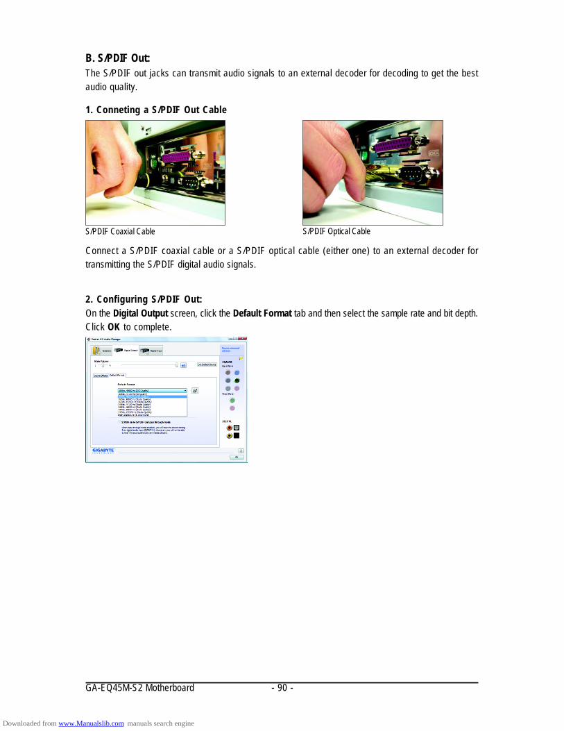
GA-EQ45M-S2 Motherboard - 90 -
B. S/PDIF Out:The S/PDIF out jacks can transmit audio signals to an external decoder for decoding to get the bestaudio quality.
1. Conneting a S/PDIF Out Cable
2. Configuring S/PDIF Out:On the Digital Output screen, click the Default Format tab and then select the sample rate and bit depth.Click OK to complete.
Connect a S/PDIF coaxial cable or a S/PDIF optical cable (either one) to an external decoder fortransmitting the S/PDIF digital audio signals.
S/PDIF Coaxial Cable S/PDIF Optical Cable
Downloaded from www.Manualslib.com manuals search engine

Appendix- 91 -
5-2-3 Configuring Microphone Recording
Step 1:After installing the audio driver, the HD Audio Managericon will appear in the notification area. Double-click the icon to access the HD Audio Manager.
Step 2:Connect your microphone to the Mic in jack (pink)on the back panel or the Mic in jack (pink) on the frontpanel. Then configure the jack for microphonefunctionality.Note: The microphone functions on the front paneland back panel cannot be used at the same time.
Step 3:Go to the Microphone screen. Do not mute therecording volume, or you'll not be able to record thesound. To hear the sound being recorded during therecording process, do not mute the playback volume.It is recommended that you set the volumes at amiddle level.
If you want to change the current sound inputdefault device to microphone, right-click onMicrophone and select Set Default Device.
Downloaded from www.Manualslib.com manuals search engine

GA-EQ45M-S2 Motherboard - 92 -
Step 5:After completing the settings above, click Start, pointto Programs, point to Accessories, and then clickSound Recorder to begin the sound recording.
Step 4:To raise the recording and playback volume for themicrophone, click the Microphone Boost iconon the right of the Recording Volume slider and setthe Microphone Boost level.
Step 2:On the Recording tab, right-click on an empty spaceand select Show Disabled Devices.
* Enabling Stereo MixIf the HD Audio Manager does not display the recording device you wish to use, refer to the stepsbelow. The following steps explain how to enable Stereo Mix (which may be needed when you wantto record sound from your computer).
Step 1:Locate the Volume icon in the notification areaand right-cl ick on this icon. Select RecordingDevices.
Downloaded from www.Manualslib.com manuals search engine

Appendix- 93 -
Step 4:Now you can access the HD Audio Manager toconfigure Stereo Mix and use Sound Recorder torecord the sound.
Step 3:When the Stereo Mix item appears, right-click onthis item and select Enable. Then set it as the defaultdevice.
A. Recording Sound:1. Make sure you have connected the sound input device (e.g. microphone) to the computer.2. To record the audio, click the Start Recording button .3. To stop recording audio, click the Stop Recording button .
Be sure to save the recorded audio file upon completion (by default, the recorded audio is saved as aWMA file).
B. Playing the Recorded Sound:You can play your recording in a digital media player program that supports playback of WMA files.
5-2-4 Using the Sound Recorder
Downloaded from www.Manualslib.com manuals search engine

GA-EQ45M-S2 Motherboard - 94 -
5-3 Troubleshooting
5-3-1 Frequently Asked QuestionsTo read more FAQs for your motherboard, please go to the Support\Motherboard\FAQ page onGIGABYTE's website.
Q: In the BIOS Setup program, why are some BIOS options missing?A: Some advanced options are hidden in the BIOS Setup program. Press <Delete> to enter BIOS Setup
during the POST. In the Main Menu, press <Ctrl>+<F1> to show the advanced options.
Q: Why is the light of my keyboard/optical mouse still on after the computer shuts down?A: Some motherboard provides a small amount of standby power after the computer shuts down and
that's why the light is still on.
Q: How do I clear the CMOS values?A: If your motherboard has a clearing CMOS jumper, refer to the instructions on the CLR_CMOS jumper
in Chapter 1 to short the jumper to clear the CMOS values. If your board doesn't have this jumper,refer to the instructions on the motherboard battery in Chapter 1. You can temporarily remove thebattery from the battery holder to stop supplying power to the CMOS, which will clear the CMOSvalues after about one minute. Refer to the steps below:Steps:1. Turn off your computer and unplug the power cord.2. Gently remove the battery from the battery holder and wait for one minute.
(Or use a metal object like a screwdriver to touch the positive and negative terminals of the batteryholder, making them short for 5 seconds.)
3. Replace the battery.4. Plug in the power cord and restart your computer.5. Press <Delete> to enter BIOS Setup. Select "Load Fail-Safe Defaults" (or "Load Optimized Defaults")
to load BIOS default settings.6. Saves changes and exit BIOS Setup (select "Save & Exit Setup") to restart your computer.
Q: Why do I still get a weak sound even though I have turned my speaker to the maximum volume?A: Make sure your speaker is equipped with an internal amplifier. If not, try a speaker with power/
amplifier.
Q: What do the beeps emitted during the POST mean?A: The following Award BIOS beep code descriptions may help you identify possible computer problems.
(For reference only.)1 short: System boots successfully2 short: CMOS setting error1 long, 1 short: Memory or motherboard error1 long, 2 short: Monitor or graphics card error1 long, 3 short: Keyboard error1 long, 9 short: BIOS ROM errorContinuous long beeps: Graphics card not inserted properlyContinuous short beeps: Power error
Downloaded from www.Manualslib.com manuals search engine

Appendix- 95 -
5-3-2 Troubleshooting Procedure
If you encounter any troubles during system startup, follow the troubleshooting procedure below tosolve the problem.
Turn off the power. Remove all peripherals, connecting cables, andpower cord etc.
The problem is verified and solved.
Yes
No
A
Check if the CPU cooler is attached to the CPU securely. Is thepower connector of the CPU cooler connected to the CPU_FANheader properly?
Check if the memory is installed properly on the memory slot.
Yes
Yes
START
Make sure the motherboard does not short-circuit with the chassisor other metal objects.
Insert the graphics card. Connect the ATX main power cable and the 12Vpower cable. Turn on the power to start the computer.
NoSecure the CPUcooler on the CPU.Connect the CPUcooler power cableto the motherboard.
No Correctly insert thememory into thememory socket.
Press <Delete> to enter BIOS Setup. Select "Load Fail-Safe Defaults"(or "Load Optimized Defaults"). Select "Save & Exit Setup" to savechanges and exit BIOS Setup.
(Continued...)
The problem is verified and solved.
The problem is verified and solved.
Isolate the shortcircuit.
Downloaded from www.Manualslib.com manuals search engine
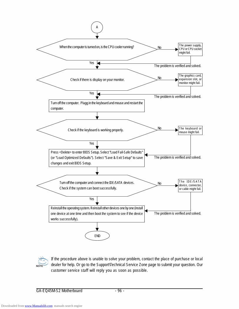
GA-EQ45M-S2 Motherboard - 96 -
If the procedure above is unable to solve your problem, contact the place of purchase or localdealer for help. Or go to the Support\Technical Service Zone page to submit your question. Ourcustomer service staff will reply you as soon as possible.
No
Yes
Check if there is display on your monitor.
Yes
When the computer is turned on, is the CPU cooler running?
No The graphics card,expansion slot, ormonitor might fail.
Turn off the computer. Plugg in the keyboard and mouse and restart thecomputer.
No
Yes
Check if the keyboard is working properly.
No
Yes
Reinstall the operating system. Reinstall other devices one by one (installone device at one time and then boot the system to see if the deviceworks successfully).
END
The power supply,CPU or CPU socketmight fail.
The keyboard ormouse might fail.
A
Turn off the computer and connect the IDE/SATA devices.Check if the system can boot successfully.
Press <Delete> to enter BIOS Setup. Select "Load Fail-Safe Defaults"(or "Load Optimized Defaults"). Select "Save & Exit Setup" to savechanges and exit BIOS Setup.
The problem is verified and solved.
The problem is verified and solved.
The problem is verified and solved.
The problem is verified and solved.
T h e I D E / S A T Adevice, connector,or cable might fail.
Downloaded from www.Manualslib.com manuals search engine

Appendix- 97 -
5-4 Regulatory Statements
Regulatory NoticesThis document must not be copied without our written permission, and the contents there of must not beimparted to a third party nor be used for any unauthorized purpose. Contravention will be prosecuted.We believe that the information contained herein was accurate in all respects at the time of printing.GIGABYTE cannot, however, assume any responsibility for errors or omissions in this text. Also notethat the information in this document is subject to change without notice and should not be construed asa commitment by GIGABYTE.
Our Commitment to Preserving the EnvironmentIn addition to high-efficiency performance, all GIGABYTE motherboards fulfill European Union regula-tions for RoHS (Restriction of Certain Hazardous Substances in Electrical and Electronic Equipment)and WEEE (Waste Electrical and Electronic Equipment) environmental directives, as well as mostmajor worldwide safety requirements. To prevent releases of harmful substances into the environmentand to maximize the use of our natural resources, GIGABYTE provides the following information onhow you can responsibly recycle or reuse most of the materials in your "end of life" product.
Restriction of Hazardous Substances (RoHS) Directive StatementGIGABYTE products have not intended to add and safe from hazardous substances (Cd, Pb, Hg, Cr+6,PBDE and PBB). The parts and components have been carefully selected to meet RoHS requirement.Moreover, we at GIGABYTE are continuing our efforts to develop products that do not use internationallybanned toxic chemicals.
Waste Electrical & Electronic Equipment (WEEE) Directive StatementGIGABYTE will fulfill the national laws as interpreted from the 2002/96/EC WEEE (Waste Electrical andElectronic Equipment) directive. The WEEE Directive specifies the treatment, collection, recycling anddisposal of electric and electronic devices and their components. Under the Directive, used equipmentmust be marked, collected separately, and disposed of properly.
WEEE Symbol StatementThe symbol shown below is on the product or on its packaging, which indicates that thisproduct must not be disposed of with other waste. Instead, the device should be taken tothe waste collection centers for activation of the treatment, collection, recycling anddisposal procedure. The separate collection and recycling of your waste equipment at thetime of disposal will help to conserve natural resources and ensure that it is recycled in a
manner that protects human health and the environment. For more information about where you candrop off your waste equipment for recycling, please contact your local government office, yourhousehold waste disposal service or where you purchased the product for details of environmentallysafe recycling. When your electrical or electronic equipment is no longer useful to you, "take it back" to your local
or regional waste collection administration for recycling. If you need further assistance in recycling, reusing in your "end of life" product, you may contact us
at the Customer Care number listed in your product's user's manual and we will be glad to help youwith your effort.
Downloaded from www.Manualslib.com manuals search engine

GA-EQ45M-S2 Motherboard - 98 -
Finally, we suggest that you practice other environmentally friendly actions by understanding andusing the energy-saving features of this product (where applicable), recycling the inner and outerpackaging (including shipping containers) this product was delivered in, and by disposing of orrecycling used batteries properly. With your help, we can reduce the amount of natural resourcesneeded to produce electrical and electronic equipment, minimize the use of landfills for the disposal of"end of life" products, and generally improve our quality of life by ensuring that potentially hazardoussubstances are not released into the environment and are disposed of properly.
China Restriction of Hazardous Substances TableThe following table is supplied in compliance with China's Restriction of Hazardous Substances (ChinaRoHS) requirements:
Downloaded from www.Manualslib.com manuals search engine


GA-EQ45M-S2 Motherboard - 100 -
Downloaded from www.Manualslib.com manuals search engine


GA-EQ45M-S2 Motherboard - 102 -
Downloaded from www.Manualslib.com manuals search engine

Appendix- 103 -
Contact Us
GIGA-BYTE TECHNOLOGY CO., LTD.Address: No.6, Bau Chiang Road, Hsin-Tien,Taipei 231, Taiwan TEL: +886-2-8912-4000 FAX: +886-2-8912-4003Tech. and Non-Tech. Support (Sales/Marketing) :http://ggts.gigabyte.com.twWEB address (English): http://www.gigabyte.com.twWEB address (Chinese): http://www.gigabyte.tw G.B.T. INC. - U.S.A.TEL: +1-626-854-9338FAX: +1-626-854-9339Tech. Support:http://rma.gigabyte-usa.comWeb address: http://www.gigabyte.us G.B.T. INC (USA) - MexicoTel: +1-626-854-9338 x 215 (Soporte de habla hispano)FAX: +1-626-854-9339Correo: [email protected]. Support:http://rma.gigabyte-usa.comWeb address: http://latam.giga-byte.com/ GIGA-BYTE SINGAPORE PTE. LTD. - SingaporeWEB address : http://www.gigabyte.sg ThailandWEB address : http://th.giga-byte.com VietnamWEB address : http://www.gigabyte.vn
NINGBO G.B.T. TECH. TRADING CO., LTD. - ChinaWEB address : http://www.gigabyte.cnShanghaiTEL: +86-21-63410999FAX: +86-21-63410100BeijingTEL: +86-10-62102838FAX: +86-10-62102848WuhanTEL: +86-27-87851312FAX: +86-27-87851330GuangZhouTEL: +86-20-87540700FAX: +86-20-87544306ChengduTEL: +86-28-85236930FAX: +86-28-85256822XianTEL: +86-29-85531943FAX: +86-29-85510930ShenyangTEL: +86-24-83992901FAX: +86-24-83992909 GIGABYTE TECHNOLOGY (INDIA) LIMITED - IndiaWEB address : http://www.gigabyte.in Saudi ArabiaWEB address : http://www.gigabyte.com.sa GIGABYTE TECHNOLOGY PTY. LTD. - AustraliaWEB address : http://www.gigabyte.com.au
Downloaded from www.Manualslib.com manuals search engine

GA-EQ45M-S2 Motherboard - 104 -
To submit a technical or non-technical (Sales/Marketing) question, please link to :http://ggts.gigabyte.com.twThen select your language to enter the system.
GIGABYTE Global Service System
G.B.T. TECHNOLOGY TRADING GMBH - GermanyWEB address : http://www.gigabyte.de G.B.T. TECH. CO., LTD. - U.K.WEB address : http://www.giga-byte.co.uk GIGA-BYTE TECHNOLOGY B.V. - The NetherlandsWEB address : http://www.giga-byte.nl GIGABYTE TECHNOLOGY FRANCE - FranceWEB address : http://www.gigabyte.fr SwedenWEB address : http://www.giga-byte.se ItalyWEB address : http://www.giga-byte.it SpainWEB address : http://www.giga-byte.es GreeceWEB address : http://www.giga-byte.gr Czech RepublicWEB address : http://www.gigabyte.cz
HungaryWEB address : http://www.giga-byte.hu TurkeyWEB address : http://www.gigabyte.com.tr RussiaWEB address : http://www.gigabyte.ru PolandWEB address : http://www.gigabyte.pl UkraineWEB address : http://www.gigabyte.ua RomaniaWEB address : http://www.gigabyte.com.ro SerbiaWEB address : http://www.gigabyte.co.yu KazakhstanWEB address : http://www.giga-byte.kz
You may go to the GIGABYTE website, select your languagein the language list on the top right corner of the website.
Downloaded from www.Manualslib.com manuals search engine
Related Documents