Alcatel-Lucent GSM 9120 BSC Commissioning Manual BSC & TC Document Commissioning Manual Release B10 3BK 17430 3001 RJZZA Ed.03

G2 BSC comm
Jan 04, 2016
telecommunication
Welcome message from author
This document is posted to help you gain knowledge. Please leave a comment to let me know what you think about it! Share it to your friends and learn new things together.
Transcript

Alcatel-Lucent GSM
9120 BSC Commissioning Manual
BSC & TC Document
Commissioning Manual
Release B10
3BK 17430 3001 RJZZA Ed.03

Status RELEASED
Short title Com
All rights reserved. Passing on and copying of this document, useand communication of its contents not permitted without writtenauthorization from Alcatel-Lucent.
BLANK PAGE BREAK
2 / 54 3BK 17430 3001 RJZZA Ed.03

Contents
Contents
Preface . . . . . . . . . . . . . . . . . . . . . . . . . . . . . . . . . . . . . . . . . . . . . . . . . . . . . . . . . . . . . . . . . . . . . . . . . . . . . . . . . . . . . . . . 5
1 Overview . . . . . . . . . . . . . . . . . . . . . . . . . . . . . . . . . . . . . . . . . . . . . . . . . . . . . . . . . . . . . . . . . . . . . . . . . . . . . . . . . . 71.1 Presentation . . . . . . . . . . . . . . . . . . . . . . . . . . . . . . . . . . . . . . . . . . . . . . . . . . . . . . . . . . . . . . . . . . . . . . 8
1.1.1 Hardware Description - Racks Configuration . . . . . . . . . . . . . . . . . . . . . . . . . . . . . . 81.1.2 Cases . . . . . . . . . . . . . . . . . . . . . . . . . . . . . . . . . . . . . . . . . . . . . . . . . . . . . . . . . . . . . . . . . 151.1.3 Options . . . . . . . . . . . . . . . . . . . . . . . . . . . . . . . . . . . . . . . . . . . . . . . . . . . . . . . . . . . . . . . . 151.1.4 Initial State . . . . . . . . . . . . . . . . . . . . . . . . . . . . . . . . . . . . . . . . . . . . . . . . . . . . . . . . . . . . . 151.1.5 Final State . . . . . . . . . . . . . . . . . . . . . . . . . . . . . . . . . . . . . . . . . . . . . . . . . . . . . . . . . . . . . 161.1.6 Restrictions . . . . . . . . . . . . . . . . . . . . . . . . . . . . . . . . . . . . . . . . . . . . . . . . . . . . . . . . . . . . 161.1.7 Grouped Task Sequence . . . . . . . . . . . . . . . . . . . . . . . . . . . . . . . . . . . . . . . . . . . . . . . . 17
1.2 Preparation . . . . . . . . . . . . . . . . . . . . . . . . . . . . . . . . . . . . . . . . . . . . . . . . . . . . . . . . . . . . . . . . . . . . . . . 181.2.1 Prerequisites . . . . . . . . . . . . . . . . . . . . . . . . . . . . . . . . . . . . . . . . . . . . . . . . . . . . . . . . . . . 181.2.2 Site-Specific Information . . . . . . . . . . . . . . . . . . . . . . . . . . . . . . . . . . . . . . . . . . . . . . . . 18
1.3 Scheduling . . . . . . . . . . . . . . . . . . . . . . . . . . . . . . . . . . . . . . . . . . . . . . . . . . . . . . . . . . . . . . . . . . . . . . . . 191.4 Resources . . . . . . . . . . . . . . . . . . . . . . . . . . . . . . . . . . . . . . . . . . . . . . . . . . . . . . . . . . . . . . . . . . . . . . . . 20
1.4.1 Tools . . . . . . . . . . . . . . . . . . . . . . . . . . . . . . . . . . . . . . . . . . . . . . . . . . . . . . . . . . . . . . . . . . 201.4.2 Supplies . . . . . . . . . . . . . . . . . . . . . . . . . . . . . . . . . . . . . . . . . . . . . . . . . . . . . . . . . . . . . . . 201.4.3 Applicable Documents . . . . . . . . . . . . . . . . . . . . . . . . . . . . . . . . . . . . . . . . . . . . . . . . . . 21
2 Commissioning Tests . . . . . . . . . . . . . . . . . . . . . . . . . . . . . . . . . . . . . . . . . . . . . . . . . . . . . . . . . . . . . . . . . . . . . 232.1 Before Going On Site . . . . . . . . . . . . . . . . . . . . . . . . . . . . . . . . . . . . . . . . . . . . . . . . . . . . . . . . . . . . . . 242.2 Before You Start . . . . . . . . . . . . . . . . . . . . . . . . . . . . . . . . . . . . . . . . . . . . . . . . . . . . . . . . . . . . . . . . . . . 25
2.2.1 Checks . . . . . . . . . . . . . . . . . . . . . . . . . . . . . . . . . . . . . . . . . . . . . . . . . . . . . . . . . . . . . . . . 252.2.2 Required Knowledge . . . . . . . . . . . . . . . . . . . . . . . . . . . . . . . . . . . . . . . . . . . . . . . . . . . 25
2.3 Check Hardware . . . . . . . . . . . . . . . . . . . . . . . . . . . . . . . . . . . . . . . . . . . . . . . . . . . . . . . . . . . . . . . . . . . 262.4 Check Power Supply and Power Up . . . . . . . . . . . . . . . . . . . . . . . . . . . . . . . . . . . . . . . . . . . . . . . . . 27
2.4.1 Check the Fuse Ratings . . . . . . . . . . . . . . . . . . . . . . . . . . . . . . . . . . . . . . . . . . . . . . . . . 272.4.2 Discharge Capacitors in Racks . . . . . . . . . . . . . . . . . . . . . . . . . . . . . . . . . . . . . . . . . . 272.4.3 Check Polarity of Power Supply Line, Branch A . . . . . . . . . . . . . . . . . . . . . . . . . . . . 272.4.4 Check Polarity of Power Supply Line, Branch B . . . . . . . . . . . . . . . . . . . . . . . . . . . . 282.4.5 Power Up BSC Racks . . . . . . . . . . . . . . . . . . . . . . . . . . . . . . . . . . . . . . . . . . . . . . . . . . . 28
2.5 Install BSC Terminal and X.25 Board . . . . . . . . . . . . . . . . . . . . . . . . . . . . . . . . . . . . . . . . . . . . . . . . 292.5.1 Install X.25 Communication Board and BSC Terminal Software . . . . . . . . . . . . . 292.5.2 Install the Craft Terminal . . . . . . . . . . . . . . . . . . . . . . . . . . . . . . . . . . . . . . . . . . . . . . . . 292.5.3 Install the BSS Software . . . . . . . . . . . . . . . . . . . . . . . . . . . . . . . . . . . . . . . . . . . . . . . . 29
2.6 Commissioning Tests . . . . . . . . . . . . . . . . . . . . . . . . . . . . . . . . . . . . . . . . . . . . . . . . . . . . . . . . . . . . . . 312.6.1 Relocate System-CPRCs . . . . . . . . . . . . . . . . . . . . . . . . . . . . . . . . . . . . . . . . . . . . . . . 312.6.2 Load and Activate BSC Software . . . . . . . . . . . . . . . . . . . . . . . . . . . . . . . . . . . . . . . . 312.6.3 Check Battery Backup of S-CPRC Boards . . . . . . . . . . . . . . . . . . . . . . . . . . . . . . . . 412.6.4 Correct BSC Date and Time . . . . . . . . . . . . . . . . . . . . . . . . . . . . . . . . . . . . . . . . . . . . . 422.6.5 Test External Alarms (O1) . . . . . . . . . . . . . . . . . . . . . . . . . . . . . . . . . . . . . . . . . . . . . . . 42
2.7 BSC Hardware Test (C1) . . . . . . . . . . . . . . . . . . . . . . . . . . . . . . . . . . . . . . . . . . . . . . . . . . . . . . . . . . . 432.7.1 Reboot BSC in Off-Line Test Mode . . . . . . . . . . . . . . . . . . . . . . . . . . . . . . . . . . . . . . . 432.7.2 Network Test . . . . . . . . . . . . . . . . . . . . . . . . . . . . . . . . . . . . . . . . . . . . . . . . . . . . . . . . . . . 442.7.3 Broadcast Test . . . . . . . . . . . . . . . . . . . . . . . . . . . . . . . . . . . . . . . . . . . . . . . . . . . . . . . . . 442.7.4 Clock Test . . . . . . . . . . . . . . . . . . . . . . . . . . . . . . . . . . . . . . . . . . . . . . . . . . . . . . . . . . . . . 452.7.5 Reboot BSC in OPERATIONAL Mode . . . . . . . . . . . . . . . . . . . . . . . . . . . . . . . . . . . . 45
2.8 Check BSC-TC Link (O2) . . . . . . . . . . . . . . . . . . . . . . . . . . . . . . . . . . . . . . . . . . . . . . . . . . . . . . . . . . . 462.8.1 Remove Ater Mux Loops . . . . . . . . . . . . . . . . . . . . . . . . . . . . . . . . . . . . . . . . . . . . . . . . 462.8.2 Check Alarms on the ASMB Boards . . . . . . . . . . . . . . . . . . . . . . . . . . . . . . . . . . . . . . 462.8.3 Check Status of A Trunk SBLs . . . . . . . . . . . . . . . . . . . . . . . . . . . . . . . . . . . . . . . . . . . 47
2.9 Set and Check BSC - 9153 OMC-R Link . . . . . . . . . . . . . . . . . . . . . . . . . . . . . . . . . . . . . . . . . . . . . 482.9.1 Connect Modem to CPRC Board . . . . . . . . . . . . . . . . . . . . . . . . . . . . . . . . . . . . . . . . . 482.9.2 Test the Communication Link . . . . . . . . . . . . . . . . . . . . . . . . . . . . . . . . . . . . . . . . . . . . 48
3BK 17430 3001 RJZZA Ed.03 3 / 54

Contents
2.10 Before You Leave . . . . . . . . . . . . . . . . . . . . . . . . . . . . . . . . . . . . . . . . . . . . . . . . . . . . . . . . . . . . . . . . . . 482.11 Supplemental Tasks . . . . . . . . . . . . . . . . . . . . . . . . . . . . . . . . . . . . . . . . . . . . . . . . . . . . . . . . . . . . . . . 49
2.11.1 Connect Inter-Rack Cables (Example) . . . . . . . . . . . . . . . . . . . . . . . . . . . . . . . . . . . . 492.11.2 Disable / Enable Alarm Reports . . . . . . . . . . . . . . . . . . . . . . . . . . . . . . . . . . . . . . . . . . 51
2.12 Workaround: Exit / Connect WinBSC Terminal . . . . . . . . . . . . . . . . . . . . . . . . . . . . . . . . . . . . . . . 52
Appendix A : Abbreviations . . . . . . . . . . . . . . . . . . . . . . . . . . . . . . . . . . . . . . . . . . . . . . . . . . . . . . . . . . . . . . . . . . . . 53
4 / 54 3BK 17430 3001 RJZZA Ed.03

Preface
Preface
Purpose This document describes the commissioning procedure for the 9120 BSC,release B10, of the Alcatel-Lucent BSS.
What’s New In Edition 03Update for new equipment naming.
In Edition 02Update of system title.
In Edition 01First official delivery of the document for B10 release.
Audience This document is intended for:
Site administrators
Project managers
Field service technician
Supervisors
Occasional users (e.g. subcontractors).
Assumed Knowledge You must have a basic understanding of the following:
Alcatel-Lucent Operations & Maintenance concepts for the Base StationSubsystem
Commissioning tools
Personal Computers using the Windows 2000/XP environment.
3BK 17430 3001 RJZZA Ed.03 5 / 54

Preface
6 / 54 3BK 17430 3001 RJZZA Ed.03

1 Overview
1 Overview
This Overview gives information needed by projet managers and foremen, forpresentation to the customer and for site planning.
3BK 17430 3001 RJZZA Ed.03 7 / 54

1 Overview
1.1 Presentation
1.1.1 Hardware Description - Racks Configuration
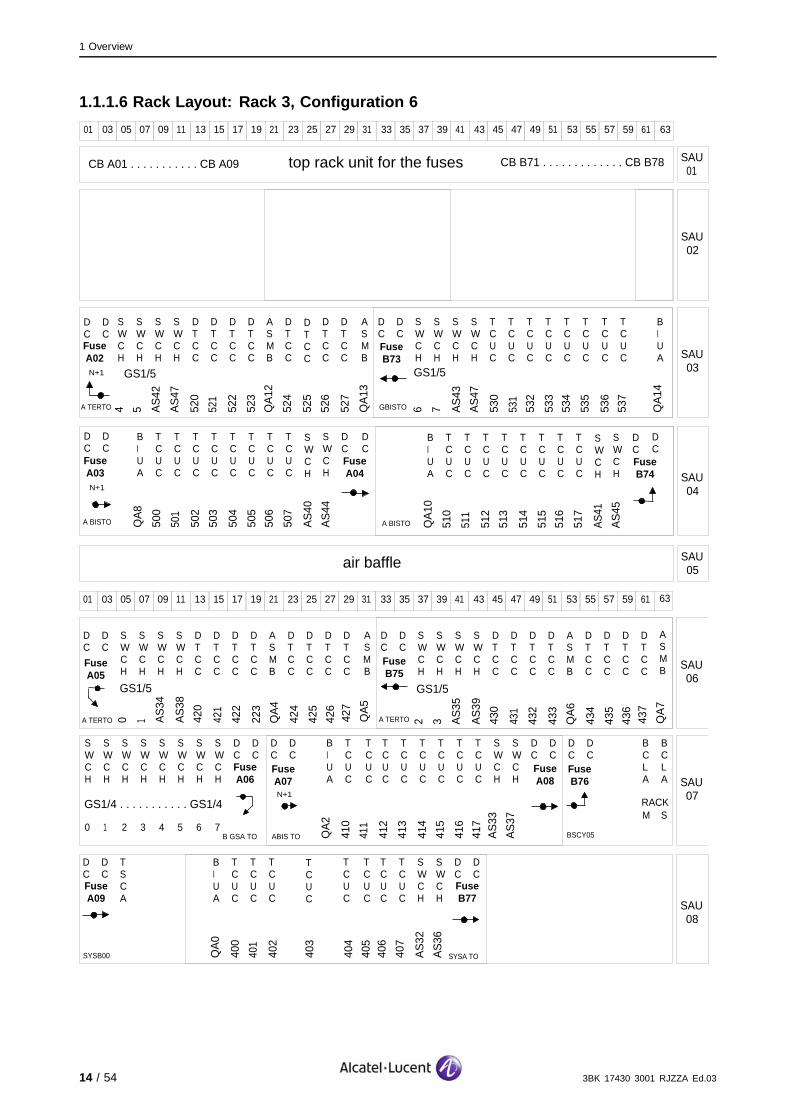
The layout of the equipment fitted in each rack for each BSC configuration isgiven in the sections below. Figures are provided to assist the visual checkprocedure.
The key used in the figures is as follows:
CE number at a CPRC unit. = Network address
AB = OSI- CPRC
AC= SYS- CPRC
AA= BC- CPRC
- number at a DTCC unit = Network address
- number at a TCUC unit = Network address
NE number at an QA unit = Qmux address
SWCH number at a AS unit AS = Access Switch Number
number at a GS unit GS1/n = Group Switch Stage 1/Plane +SwitchElement Number
GS2/n = Group Switch Stage 2/Plane +SwitchElement Number
number at a BCLA unit SYS = System Variant
M = Master
RACK = Rack Variant
S = Slave
8 / 54 3BK 17430 3001 RJZZA Ed.03

1 Overview
1.1.1.1 Rack Layout: Rack 1, Configuration 1
01
SWCH
0
DC
03
SWCH
1
DC
05
SWCH
2
07
SWCH
3
09
SWCH
4
11
SWCH
5
13
SWCH
6
15
SWCH
7
17
DC
19
DC
21
SWCH
0
23
SWCH
1
25
SWCH
2
27
SWCH
3
29
SWCH
4
31
SWCH
5
33
SWCH
6
35
SWCH
7
37
DC
39
DC
41
SWCH
0
43
SWCH
1
45
SWCH
2
47
SWCH
3
49
SWCH
4
51
SWCH
5
53
SWCH
6
55
SWCH
7
57
DC
59
DC
61 63
CB A01 . . . . . . . . . . . CB A09 CB B71 . . . . . . . . . . . . . CB B78top rack unit for the fuses SAU01
SAU02
SAU03
SAU04
SAU05
FuseA01
FuseB72
FuseB71
GS2/1 . . . . . . . . . . . GS2/1 GS2/2 . . . . . . . . . . . GS2/2 GS2/3 . . . . . . . . . . GS2/3
air baffle
FuseA02
A TERTO
N+1
01
DC
03
DC
05 07 09
SWCH
11
SWCH
13
DTCC
15
DTCC
17
DTCC
19
DTCC
21
ASMB
23
DTCC
25
DTCC
27
DTCC
29
DTCC
31
ASMB
33
DC
35
DC
37 39 41
SWCH
43
SWCH
45
DTCC
47
DTCC
49
DTCC
51
DTCC
53
ASMB
55
DTCC
57
DTCC
59
DTCC
61
DTCC
63
ASMB SAU
06
SAU07
SAU08
FuseA08
FuseB76
FuseB75
GS1/0 . . . . . . . . . . . GS1/0
FuseA05
A TERTO
SWCH
0
SWCH
1
SWCH
2
SWCH
3
SWCH
4
SWCH
5
SWCH
6
SWCH
7
DC
DC
DC
DC
BIUA
TCUC
TCUC
TCUC
TCUC
TCUC
TCUC
TCUC
TCUC
SWCH
SWCH
DC
DC
DC
DC
BCLA
M
BCLA
S
FuseA07
FuseA06
B GSA TO
A TERTO
ABIS TO BSCY05
RACKN+1
GS2/0 . . . . . . . . . . . GS2/0
DC
DC
TSCA
CPRC
CPRC
CPRC
CPRC
CPRC
SWCH
SWCH
DC
DC
SWCH
0
SWCH
1
SWCH
2
SWCH
3
SWCH
4
SWCH
7
DC
B GSA TOSYSB00
CPRC
SWCH
5
SWCH
6SYSA TO
DC
FuseB77
FuseB78
FuseA09
B GSATO B GSATO B GSATO
AS
2
AS
6
020
021
022
023
QA
4
024
025
026
027
QA
5
AS
3
AS
7
030
031
032
033
QA
6
034
035
036
037
QA
7
QA
2
010
011
012
013
014
015
016
017
AS1
AS
5
000
001
002
003
004
005
AS1
AS
5
BCLA
M
BCLA
SSYS
3BK 17430 3001 RJZZA Ed.03 9 / 54

1 Overview
1.1.1.2 Rack Layout: Rack 1, Configurations 2, 3, 4, 5, 6
01
SWCH
0
DC
03
SWCH
1
DC
05
SWCH
2
07
SWCH
3
09
SWCH
4
11
SWCH
5
13
SWCH
6
15
SWCH
7
17
DC
19
DC
21
SWCH
0
23
SWCH
1
25
SWCH
2
27
SWCH
3
29
SWCH
4
31
SWCH
5
33
SWCH
6
35
SWCH
7
37
DC
39
DC
41
SWCH
0
43
SWCH
1
45
SWCH
2
47
SWCH
3
49
SWCH
4
51
SWCH
5
53
SWCH
6
55
SWCH
7
57
DC
59
DC
61 63
CB A01 . . . . . . . . . . . CB A09 CB B71 . . . . . . . . . . . . . CB B78top rack unit for the fuses SAU01
SAU02
SAU03
SAU04
SAU05
FuseA01
FuseB72
FuseB71
GS2/1 . . . . . . . . . . . GS2/1 GS2/2 . . . . . . . . . . . GS2/2 GS2/3 . . . . . . . . . . . GS2/3
air baffle
FuseA02
A TERTO
N+1
01
DC
03
DC
05
SWCH
07
SWCH
09
SWCH
11
SWCH
13
DTCC
15
DTCC
17
DTCC
19
DTCC
21
ASMB
23
DTCC
25
DTCC
27
DTCC
29
DTCC
31
ASMB
33
DC
35
DC
37
SWCH
39
SWCH
41
SWCH
43
SWCH
45
DTCC
47
DTCC
49
DTCC
51
DTCC
53
ASMB
55
DTCC
57
DTCC
59
DTCC
61
DTCC
63
ASMB SAU
06
SAU07
SAU08
FuseA08
FuseB76
FuseB75
GS1/0 . . . . . . . . . . . GS1/0
GS1/1 GS1/1
FuseA05
A TERTO
SWCH
0
SWCH
1
SWCH
2
SWCH
3
SWCH
4
SWCH
5
SWCH
6
SWCH
7
DC
DC
DC
DC
BIUA
TCUC
TCUC
TCUC
TCUC
TCUC
TCUC
TCUC
TCUC
SWCH
SWCH
DC
DC
DC
DC
BCLA
M
BCLA
S
FuseA07
FuseA06
B GSA TO
A TERTO
ABIS TO BSCY05
RACKN+1
GS2/0 . . . . . . . . . . . GS2/0
DC
DC
TSCA
CPRC
CPRC
CPRC
CPRC
CPRC
SWCH
SWCH
DC
DC
SWCH
0
SWCH
1
SWCH
2
SWCH
3
SWCH
4
SWCH
7
DC
B GSA TOSYSB00
CPRC
SWCH
5
SWCH
6SYSA TO
DC
FuseB77
FuseB78
FuseA09
B GSATO B GSATO B GSATO
SWCH
SWCH
SWCH
SWCH
DTCC
DTCC
DTCC
DTCC
ASMB
DTCC
DTCC
DTCC
ASMB
DC
DC
SWCH
SWCH
SWCH
SWCH
TCUC
TCUC
TCUC
TCUC
TCUC
TCUC
BIUA
GBISTO
DC
DC
DC
GS1/1
4 5 AS
10
AS
14
120
121
122
123
QA
12
124
125
126
127
QA
13FuseB73
DTCC
TCUC
TCUC
QA
14
GS1/1
6 7 AS
11
AS
15
130
131
132
133
134
135
136
137
FuseA03
A BISTO
N+1
BIUA
TCUC
TCUC
TCUC
TCUC
TCUC
TCUC
TCUC
TCUC
SWCH
DC
DC
QA
8
100
101
102
103
104
105
106
107
AS
8
AS
12
SWCH
FuseA04
BIUA
TCUC
TCUC
TCUC
TCUC
TCUC
TCUC
TCUC
TCUC
SWCH
DC
QA
10
110
111
112
113
114
115
116
117
AS
9
AS
13
SWCH
FuseB74
A BISTO
0 1 AS
2
AS
6
020
021
022
023
QA
4
024
025
026
027
QA
5
2 3 AS
3
AS
7
030
031
032
033
QA
6
034
035
036
037
QA
7
QA
2
010
011
012
013
014
015
016
017
AS1
AS
5
000
001
002
003
004
005
AS
0
AS
4
BCLA
M
BCLA
SSYS
10 / 54 3BK 17430 3001 RJZZA Ed.03

1 Overview
1.1.1.3 Rack Layout: Rack 2, Configuration 3
01
SWCH
0
DC
03
SWCH
1
DC
05
SWCH
2
07
SWCH
3
09
SWCH
4
11
SWCH
5
13
SWCH
6
15
SWCH
7
17
DC
19
DC
21
SWCH
0
23
SWCH
1
25
SWCH
2
27
SWCH
3
29
SWCH
4
31
SWCH
5
33
SWCH
6
35
SWCH
7
37
DC
39
DC
41
SWCH
0
43
SWCH
1
45
SWCH
2
47
SWCH
3
49
SWCH
4
51
SWCH
5
53
SWCH
6
55
SWCH
7
57
DC
59
DC
61 63
CB A01 . . . . . . . . . . . CB A09 CB B71 . . . . . . . . . . . . . CB B78top rack unit for the fuses SAU01
SAU02
SAU03
SAU04
SAU05
FuseA01
FuseB72
FuseB71
GS2/5 . . . . . . . . . . . GS2/5 GS2/6 . . . . . . . . . . . GS2/6 GS2/7 . . . . . . . . . . . GS2/7
air baffle
FuseA02
A TERTO
N+1
01
DC
03
DC
05 07 09
SWCH
11
SWCH
13
DTCC
15
DTCC
17
DTCC
19
DTCC
21
ASMB
23
DTCC
25
DTCC
27
DTCC
29
DTCC
31
ASMB
33
DC
35
DC
37 39 41
SWCH
43
SWCH
45
DTCC
47
DTCC
49
DTCC
51
DTCC
53
ASMB
55
DTCC
57
DTCC
59
DTCC
61
DTCC
63
ASMB SAU
06
SAU07
SAU08
FuseA08
FuseB76
FuseB75
GS1/2 . . . . . . . . . . . GS1/2
GS1/3 GS1/3
FuseA05
A TERTO
SWCH
0
SWCH
1
SWCH
2
SWCH
3
SWCH
4
SWCH
5
SWCH
6
SWCH
7
DC
DC
DC
DC
BIUA
TCUC
TCUC
TCUC
TCUC
TCUC
TCUC
TCUC
TCUC
SWCH
SWCH
DC
DC
DC
DC
BCLA
M
BCLA
S
FuseA07
FuseA06
B GSA TO
A TERTO
ABIS TO BSCY05
RACKN+1
GS2/4 . . . . . . . . . . . GS2/4
DC
DC
TSCA
BIUA
TCUC
TCUC
TCUC
TCUC
TCUC
TCUC
TCUC
SWCH
SWCH
DC
DC
SWCH
0
SWCH
1
SWCH
2
SWCH
3
SWCH
4
SWCH
7
DC
B GSA TOSYSB00
TCUC
SWCH
5
SWCH
6SYSA TO
DC
FuseB77
FuseB78
FuseA09
BGSATO BGSATO BGSATO
AS
18
AS
22
220
221
222
223
QA
4
224
225
226
227
AS
19
AS
23
230
231
232
233
QA
6
234
235
236
237
QA
2
210
121
212
213
214
215
216
217
AS
17
AS
21
QA
0
200
201
202
203
204
205
206
207
AS
16
AS
20
QA
5
QA
7
3BK 17430 3001 RJZZA Ed.03 11 / 54

1 Overview
1.1.1.4 Rack Layout: Rack 2, Configurations 4, 5, 6
01
SWCH
0
DC
03
SWCH
1
DC
05
SWCH
2
07
SWCH
3
09
SWCH
4
11
SWCH
5
13
SWCH
6
15
SWCH
7
17
DC
19
DC
21
SWCH
0
23
SWCH
1
25
SWCH
2
27
SWCH
3
29
SWCH
4
31
SWCH
5
33
SWCH
6
35
SWCH
7
37
DC
39
DC
41
SWCH
0
43
SWCH
1
45
SWCH
2
47
SWCH
3
49
SWCH
4
51
SWCH
5
53
SWCH
6
55
SWCH
7
57
DC
59
DC
61 63
CB A01 . . . . . . . . . . . CB A09 CB B71 . . . . . . . . . . . . . CB B78top rack unit for the fuses SAU01
SAU02
SAU03
SAU04
SAU05
FuseA01
FuseB72
FuseB71
GS2/5 . . . . . . . . . . . GS2/5 GS2/6 . . . . . . . . . . . GS2/6 GS2/7 . . . . . . . . . . . GS2/7
air baffle
FuseA02
A TERTO
N+1
01
DC
03
DC
05
SWCH
07
SWCH
09
SWCH
11
SWCH
13
DTCC
15
DTCC
17
DTCC
19
DTCC
21
ASMB
23
DTCC
25
DTCC
27
DTCC
29
DTCC
31
ASMB
33
DC
35
DC
37
SWCH
39
SWCH
41
SWCH
43
SWCH
45
DTCC
47
DTCC
49
DTCC
51
DTCC
53
ASMB
55
DTCC
57
DTCC
59
DTCC
61
DTCC
63
ASMB SAU
06
SAU07
SAU08
FuseA08
FuseB76
FuseB75
GS1/2 . . . . . . . . . . . GS1/2
GS1/3 GS1/3
FuseA05
A TERTO
SWCH
0
SWCH
1
SWCH
2
SWCH
3
SWCH
4
SWCH
5
SWCH
6
SWCH
7
DC
DC
DC
DC
BIUA
TCUC
TCUC
TCUC
TCUC
TCUC
TCUC
TCUC
TCUC
SWCH
SWCH
DC
DC
DC
DC
BCLA
M
BCLA
S
FuseA07
FuseA06
B GSA TO
A TERTO
ABIS TO BSCY05
RACKN+1
GS2/4 . . . . . . . . . . . GS2/4
DC
DC
TSCA
BIUA
TCUC
TCUC
TCUC
TCUC
TCUC
TCUC
TCUC
SWCH
SWCH
DC
DC
SWCH
0
SWCH
1
SWCH
2
SWCH
3
SWCH
4
SWCH
7
DC
B GSA TOSYSB00
TCUC
SWCH
5
SWCH
6SYSA TO
DC
FuseB77
FuseB78
FuseA09
B GSATO B GSATO B GSATO
SWCH
SWCH
SWCH
SWCH
DTCC
DTCC
DTCC
DTCC
ASMB
DTCC
DTCC
DTCC
ASMB
DC
DC
SWCH
SWCH
SWCH
SWCH
TCUC
TCUC
TCUC
TCUC
TCUC
TCUC
BIUA
GBISTO
DC
DC
DC
GS1/3 . . . . . . . . . . . GS1/3
4 5 AS
26
AS
30
320
321
322
323
QA
12
324
325
326
327
QA
13FuseB73
DTCC
TCUC
TCUC
QA
14
GS1/3 . . . . . . . . . . . GS1/3
6 7 AS
27
AS
31
330
331
332
333
334
335
336
337
FuseA03
A BISTO
N+1
BIUA
TCUC
TCUC
TCUC
TCUC
TCUC
TCUC
TCUC
TCUC
SWCH
DC
DC
QA
8
300
301
302
303
304
305
306
307
AS
24
AS
28
SWCH
FuseA04
BIUA
TCUC
TCUC
TCUC
TCUC
TCUC
TCUC
TCUC
TCUC
SWCH
DC
QA
10
310
311
312
313
314
315
316
317
AS
25
AS
29
SWCH
FuseB74
A BISTO
0 1 AS
18
AS
22
220
221
222
223
QA
4
224
225
226
227
QA
5
2 3 AS
19
AS
23
230
231
232
233
QA
6
234
235
236
237
QA
7
QA
2
210
211
212
213
214
215
216
217
AS
17
AS
21
QA
0
200
201
202
203
204
205
206
207
AS
16
AS
20
12 / 54 3BK 17430 3001 RJZZA Ed.03

1 Overview
1.1.1.5 Rack Layout: Rack 3, Configuration 5
01 03 05 07 09 11 13 15 17 19 21 23 25 27 29 31 33 35 37 39 41 43 45 47 49 51 53 55 57 59 61 63
CB A01 . . . . . . . . . . . CB A09 CB B71 . . . . . . . . . . . . . CB B78top rack unit for the fuses SAU01
SAU02
SAU03
SAU04
SAU05air baffle
01
DC
03
DC
05 07 09
SWCH
11
SWCH
13
DTCC
15
DTCC
17
DTCC
19
DTCC
21
ASMB
23
DTCC
25
DTCC
27
DTCC
29
DTCC
31
ASMB
33
DC
35
DC
37 39 41
SWCH
43
SWCH
45
DTCC
47
DTCC
49
DTCC
51
DTCC
53
ASMB
55
DTCC
57
DTCC
59
DTCC
61
DTCC
63
ASMB SAU
06
SAU07
SAU08
FuseA08
FuseB76
FuseB75
GS1/4 . . . . . . . . . . . GS1/4
GS1/5 GS1/5
FuseA05
A TERTO
SWCH
0
SWCH
1
SWCH
2
SWCH
3
SWCH
4
SWCH
5
SWCH
6
SWCH
7
DC
DC
DC
DC
BIUA
TCUC
TCUC
TCUC
TCUC
TCUC
TCUC
TCUC
TCUC
SWCH
SWCH
DC
DC
DC
DC
BCLA
M
BCLA
S
FuseA07
FuseA06
B GSA TO
A TERTO
ABIS TO BSCY05
RACKN+1
DC
DC
TSCA
BIUA
TCUC
TCUC
TCUC
TCUC
TCUC
TCUC
TCUC
SWCH
SWCH
DC
DC
SYSB00
TCUC
SYSA TO
FuseB77
FuseA09
AS
34
AS
38
420
421
422
423
QA
4
424
425
426
427
QA
5
AS
35
AS
39
430
431
432
433
QA
6
434
435
536
437
QA
7
QA
2
410
411
412
413
414
415
416
417
AS
33
AS
37
QA
0
400
401
402
403
404
405
406
407
AS
32
AS
36
3BK 17430 3001 RJZZA Ed.03 13 / 54
1 Overview
1.1.1.6 Rack Layout: Rack 3, Configuration 6
01
DC
03
DC
05 07 09 11 13 15 17 19 21 23 25 27 29 31 33 35 37 39 41 43 45 47 49 51 53 55 57 59 61 63
CB A01 . . . . . . . . . . . CB A09 CB B71 . . . . . . . . . . . . . CB B78top rack unit for the fuses SAU01
SAU02
SAU03
SAU04
SAU05air baffle
FuseA02
A TERTO
N+1
01
DC
03
DC
05
SWCH
07
SWCH
09
SWCH
11
SWCH
13
DTCC
15
DTCC
17
DTCC
19
DTCC
21
ASMB
23
DTCC
25
DTCC
27
DTCC
29
DTCC
31
ASMB
33
DC
35
DC
37
SWCH
39
SWCH
41
SWCH
43
SWCH
45
DTCC
47
DTCC
49
DTCC
51
DTCC
53
ASMB
55
DTCC
57
DTCC
59
DTCC
61
DTCC
63
ASMB SAU
06
SAU07
SAU08
FuseA08
FuseB76
FuseB75
GS1/4 . . . . . . . . . . . GS1/4
GS1/5 GS1/5
FuseA05
A TERTO
SWCH
0
SWCH
1
SWCH
2
SWCH
3
SWCH
4
SWCH
5
SWCH
6
SWCH
7
DC
DC
DC
DC
BIUA
TCUC
TCUC
TCUC
TCUC
TCUC
TCUC
TCUC
TCUC
SWCH
SWCH
DC
DC
DC
DC
BCLA
M
BCLA
S
FuseA07
FuseA06
B GSA TO
A TERTO
ABIS TO BSCY05
RACKN+1
DC
DC
TSCA
BIUA
TCUC
TCUC
TCUC
TCUC
TCUC
TCUC
TCUC
SWCH
SWCH
DC
DC
SYSB00
TCUC
SYSA TO
FuseB77
FuseA09
SWCH
SWCH
SWCH
SWCH
DTCC
DTCC
DTCC
DTCC
ASMB
DTCC
DTCC
DTCC
ASMB
DC
DC
SWCH
SWCH
SWCH
SWCH
TCUC
TCUC
TCUC
TCUC
TCUC
TCUC
BIUA
GBISTO
DC
DC
DC
GS1/5
4 5 AS
42
AS
47
520
521
522
523
QA
12
524
525
526
527
QA
13
FuseB73
DTCC
TCUC
TCUC
QA
14
GS1/5
6 7 AS
43
AS
47
530
531
532
533
534
535
536
537
FuseA03
A BISTO
N+1
BIUA
TCUC
TCUC
TCUC
TCUC
TCUC
TCUC
TCUC
TCUC
SWCH
DC
DC
QA
8
500
501
502
503
504
505
506
507
AS
40
AS
44
SWCH
FuseA04
BIUA
TCUC
TCUC
TCUC
TCUC
TCUC
TCUC
TCUC
TCUC
SWCH
DC
QA
10
510
511
512
513
514
515
516
517
AS
41
AS
45
SWCH
FuseB74
A BISTO
0 1 AS
34
AS
38
420
421
422
223
QA
4
424
425
426
427
QA
5
2 3 AS
35
AS
39
430
431
432
433
QA
6
434
435
436
437
QA
7
QA
2
410
411
412
413
414
415
416
417
AS
33
AS
37
QA
0
400
401
402
403
404
405
406
407
AS
32
AS
36
14 / 54 3BK 17430 3001 RJZZA Ed.03

1 Overview
1.1.2 Cases
The following case applies:
C1: The BSC is in configuration is 3 or higher so the hardware is tested.
1.1.3 Options
The following options apply:
O1: External alarm cables are installed so they are tested.
O2: The TC is installed and connected at the DDF on the BSC site so the
BSC-TC link is checked.
1.1.4 Initial State
At the start of the commissioning:
The BSC racks are installed and wired on the customer’s site
The power supply is connected and powered up, but the racks are not
powered up (all circuit breakers at the top of each rack must be in theOFF position).
3BK 17430 3001 RJZZA Ed.03 15 / 54

1 Overview
1.1.5 Final State
When commissioning is finished:
The BSC is powered up and downloaded with the build requested by
the customer
The BSC is connected to the TC and 9153 OMC-R, ready for physical
connection of the BTSs.
1.1.6 Restrictions
None.
16 / 54 3BK 17430 3001 RJZZA Ed.03

1 Overview
1.1.7 Grouped Task Sequence
The following figure shows the task sequence for the 9120 BSC commissioningtasks.
Before Going on Site
Rellocate System CPRCs
Load and Activate BSC Software
Check Battery Backup of S−CPRC Boards
Correct BSC Date and Time
Check BSC − TC Link (O2)
Set and Check BSC − OMC−R Link
Before You Leave
Check Hardware
Check Power Supply and Power Up
Install BSC Terminal and X25 Board
Diskettes / CD−ROMInstall BSC Software from
Dikettes or CD−ROM
Alarm Cables Installed?
YesNoTest External Alarms (O1)
BSC Configuration 3 or
Higher?
BSC Hardware Test (C1)
Yes
No
Before You Start
3BK 17430 3001 RJZZA Ed.03 17 / 54

1 Overview
1.2 Preparation
1.2.1 Prerequisites
The following prerequisites must be fulfilled:
The site must comply with the safety rules as given in the BSS MethodsHandbook
At least two Ater Mux PCM links must be available.
1.2.2 Site-Specific Information
The following site-specific information is needed before starting thecommissioning:
SiteDDF map
Equipment
Rack configuration number (1 to 6)
X.25 routing:
Extraction at BSC site
Extraction on TRCU modules via X.25 packet switch
X.25 routed through MSC.
BSS topology
BSS software version
Other
TSC firmware version
Status of the A interface cables at the TC side (connected to MSC orlooped)
Which A interface cables are connected at the MSC (if applicable)
External alarm cables (available or not).
18 / 54 3BK 17430 3001 RJZZA Ed.03

1 Overview
1.3 Scheduling
Time based on technical constraintsThe number of resources shown in the following table does not take intoaccount individual customer or safety requirements.
Grouped Task Time / Task:Com. 1
Time / Task:Com. 2
Total Time / Task
Before Going on Site 20 min. 20 min. 40 min.
Before You Start 20 min. 20 min. 40 min.
Check Hardware(1) 10 - 60 min.(2) 10 - 60 min.(2) 20 min. - 2 hours
Check Power Supply and Power Up(1) 25 min. 25 min. 50 min.
Install BSC Terminal and BSS Software
Install BSC Terminal Software and X.25Communication Board
45 min. - 45 min.
Install Craft Terminal 10 min. - 10 min.
Install BSS Software 10 - 20 min.(3) - 10 - 20 min.
Perform Commissioning Tests
Relocate S-CPRCs 2 min. - 2 min.
Load and Activate BSC Software 1 h 30 min. - 1 h 30 min.
Check Battery Backup of S-CPRC Boards 30 min. - 30 min.
Correct BSC Date and Time 2 min. - 2 min.
Test External Alarms (O1) 10 min. 10 min. 20 min.
BSC Hardware Test (C1) 40 min. - 40 min.
Check BSC - TC link (O2) 20 min. - 20 min.
Set and Check BSC - 9153 OMC-R Link 30 min. - 30 min.
Before You Leave 20 min. - 20 min.
Total 6 h 24 min. /
7 h 24 min.
1 h 25 min. /
2 h 15 min.
7 h 50 min. /
9 h 40 min.
Com. : Commissioner
(1) : Tasks where two people are mandatory for execution
(2) : Depending on the BSC configuration (1-6)
(3) : 10 minutes from IOMEGA zip, 20 minutes from diskettes
3BK 17430 3001 RJZZA Ed.03 19 / 54

1 Overview
1.4 Resources
1.4.1 Tools
The following sections describe the necessary hardware tools, software toolsand forms.
1.4.1.1 Hardware ToolsUse the following table to check the availability of the necessary tools.
Refer to the Tools Catalogue to check the contents.
Item Reference Calibration
Basic kit OUT 001 No
Test cables and plugs (9120 BSC) OUT 013 No
Digital multimeter DES 001 No
Utility PC (BTS LMT) DES 002 No
Inventory kit Nr. 7 OUT 017 No
1.4.1.2 Software ToolsUse the following table to check the availability of the necessary software. Referto the corresponding document to check the software version.
Name Check Version in
Operating system Tools Catalogue
BSC Terminal/BSCWAVxxx BSS Software List
LMT_CT/CTxxx.exe BSS Software List
BSSBUILD BSS Software List
EICON board driver for Windows 2000/XP BSS Software List
1.4.1.3 FormsNone.
1.4.2 Supplies
None.
20 / 54 3BK 17430 3001 RJZZA Ed.03

1 Overview
1.4.3 Applicable Documents
The following documents are needed to complete the 9120 BSC commissioning:
Document Title Reference
Catalogue of Technical and Logistic Information(ITLs)
3DF 00462 0004 AAAGA
Applicable Operation Instruction List (IO) 3DF 00300 0004 UAZZA
BSS Methods Handbook 3BK 17430 0002 RJZZA
BSC Terminal User Guide 3BK 21220 AAAA PCZZA
Transmission Terminal User Guide 3BK 21257 AAAA PCZZA
Tools Catalogue for Field Activity 3BK 20458 0001 RJZZA
Specification for Site Preparation 9120 BSC(SPP-27)
8BL 00704 0018 DRBRA
BSS Site Premises Inspections, Post Handover 8BL 00704 0016 DRBRA
Site Premises Inspections form (CEL) 8BL 00704 0015 DRBRA
Completion Check List (CCL) 3BK 17430 3001 QZZZA
CI-08 Site Equipment Inventory 3BK 17257 0001 RJZZA
BSS Software List Depends on the software version requested by thecustomer.
3BK 17430 3001 RJZZA Ed.03 21 / 54

1 Overview
22 / 54 3BK 17430 3001 RJZZA Ed.03

2 Commissioning Tests
2 Commissioning Tests
This section presents all checks needed before starting the Commissioning,and all detailed tasks to be performed on site.
3BK 17430 3001 RJZZA Ed.03 23 / 54

2 Commissioning Tests
2.1 Before Going On SiteBefore going on-site, you must check that the following information andsupplies are available:
All Prerequisites (Section 1.2.1) are fulfilled
The customer has been informed of the
Date
Time
Site name
Site address
Purpose of the operation.
Personnel are available and ready for operation (Refer to Scheduling(Section 1.3))
Site-Specific Information (Section 1.2.2) is available and ready for operation
Hardware Tools (Section 1.4.1.1) are available and ready for operation
Software Tools (Section 1.4.1.2) are available in the correction versionand ready for operation
Applicable Documents (Section 1.4.3) are available and ready for operation.
24 / 54 3BK 17430 3001 RJZZA Ed.03

2 Commissioning Tests
2.2 Before You Start
2.2.1 Checks
Perform the following operations:
Check applicable notifications and operating instructions (refer to the
Applicable Notification List (ITL) and the Applicable Operation InstructionList (IO))
Check the availability of all necessary tools and supplies
Check that all Prerequisites (Section 1.2.1) are fulfilled
Check which Cases (Section 1.1.2) and Options (Section 1.1.3) apply
Complete the header field of the CCL, noting the type of BTS (see Hardware
Description - Racks Configuration (Section 1.1.1)). The CCL is completedas each instruction is carried out
Complete the Premises Inspection Form (BSS Site Premises Inspection,
Post Handover)
Complete the Premise Inspection form (CEL)
Check that the resistance of the anti-static wrist strap is greater then
1 Mohm.
2.2.2 Required Knowledge
You must be familiar with the following:
The safety rules and precautions given in the BSS Methods Handbook
How to document faults and anomalies as described in the BSS Methods
Handbook
Grouped Task Sequence (Section 1.1.7).
3BK 17430 3001 RJZZA Ed.03 25 / 54

2 Commissioning Tests
2.3 Check HardwareThese hardware checks are done to:
Check that the BSC configuration corresponds to the customer’s order
Verify that the hardware level of the boards inside the BSC is as requested
by the customer, by taking the rack inventory.
Two people are mandatory when checking the hardware.
To check the hardware:
1. Verify the presence and position of the boards according to the requestedconfiguration.
Refer to the Site-Specific Information and Hardware Description - RacksConfiguration sections.
2. Perform the rack inventory.
Refer to the CI 08 - Site Equipment Inventory.
Check for “NOT IN CAL” alarms.Check that there are no alarms of the type “NOT IN CAL” when runningInventar for the BTS. This ensures that the boards inside the BSC meet therequirements of a specific customer.
26 / 54 3BK 17430 3001 RJZZA Ed.03

2 Commissioning Tests
2.4 Check Power Supply and Power Up
Two people are mandatory when checking the power supply and powering up.
2.4.1 Check the Fuse Ratings
To check the fuse ratings:
1. On the customer power panel (cabinet), check for the existence of two DCpower supply distribution circuits. Each distribution circuit is provided with aDC circuit breaker (fuse holder).
2. On the site power panel, disconnect the two -48V power supply lines (line Aand B) at the rack fuse holders.
3. Check that the fuse ratings are in accordance with the SPP – 27 document.
2.4.2 Discharge Capacitors in Racks
To discharge the capacitors in the racks:
1. At the customer power panel, make sure the two -48 V power supply lines forthe BSC are disconnected.
2. Close (ON position) all the rack (and extension rack if applicable) circuitbreakers for 10 seconds.
3. Open (OFF position) all the rack circuit breakers.
2.4.3 Check Polarity of Power Supply Line, Branch A
To check the polarity of the power supply line, branch A:
1. On the BSC top rack filter units for each rack (basic and extension racks ifapplicable), remove the protection caps from the power supply terminals.
2. Connect the -48 V power supply (branch A) at the fuse holder.
Branch A is connected.
Branch A is associated with the fuse holder marked BAT A.
3. Using the multimeter, check the presence of -48V DC between BAT A andBATRET for all racks (basic and extensions).
4. Check that no voltage is present between BAT B and BATRET for all racks.
5. Switch all the rack circuit breakers to ON.
The DC/DC converters A01-A09 for all racks are powered up.
The DC/DC converters B71-B78 for all racks are not powered up.
Note : Converters B72 and B78 are removed starting from rack variant3BK 06796 AAAC.
6. Switch all the rack circuit breakers to OFF.
No board in the racks is powered up.
7. At the customer power panel, disconnect the -48 V power supply (branch A)at the fuse holder.
Branch A is disconnected.
3BK 17430 3001 RJZZA Ed.03 27 / 54

2 Commissioning Tests
2.4.4 Check Polarity of Power Supply Line, Branch B
To check the polarity of the power supply line, branch B:
1. Discharge the capacitors in the rack.
See Discharge Capacitors in Racks (Section 2.4.2).
2. On the BSC top rack filter units for each rack (basic and extension racks ifapplicable), remove the protection caps from the power supply terminals.
3. Connect the -48 V power supply (branch B) at the fuse holder.
Branch B is connected.
Branch B is associated with the fuse holder marked BAT B.
4. Using the multimeter, check the presence of -48V DC between BAT B andBATRET for all racks (basic and extensions).
5. Check that no voltage is present between BAT A and BATRET for all racks.
6. Switch all the rack circuit breakers to ON.
The DC/DC converters B71-B78 for all racks are powered up.
The DC/DC converters A01-A09 for all racks are not powered up.
Note : Converters B72 and B78 are removed starting from rack variant3BK 06796 AAAC.
7. Switch all the rack circuit breakers to OFF.
No board in the racks is powered up.
8. At the customer power panel, disconnect the -48 V power supply (branch B)at the fuse holder.
Branch B is disconnected.
2.4.5 Power Up BSC Racks
To power up the BSC racks:
1. Switch ON the two power supply lines on the customer power panel.
2. Switch ON the B71 to B78 rack circuit breakers.
Note: Converters B72 and B78 are removed starting from rack variant3BK 06796 AAAC.
3. Switch ON the A1 to A9 rack circuit breakers.
The boards take about one minute to run their self-tests.
4. Refer to the BSS Methods Handbook to check the LED states.
28 / 54 3BK 17430 3001 RJZZA Ed.03

2 Commissioning Tests
2.5 Install BSC Terminal and X.25 Board
2.5.1 Install X.25 Communication Board and BSC Terminal Software
You must first install the X.25 communications board and then the BSCTerminal Software.
2.5.1.1 Install EICON C91 BoardTo install the EICON C91 (for LMT) board in Windows environment, referto the BSC Terminal User Guide.
2.5.1.2 Install Windows BSC TerminalTo install the BSC Terminal software for Windows, refer to the BSC TerminalUser Guide.
2.5.2 Install the Craft Terminal
To install the LMT-CT Craft Terminal software on the PC, refer to theTransmission Terminal User Guide.
2.5.3 Install the BSS Software
The build is produced with POLO, and must be transferred to the BSC TerminalPC. The transfer can be performed directly through a network if available atthe BSC site. If not, the build can be delivered on diskettes, CD-ROM or anIOMEGA ZIP disk.
2.5.3.1 Build Delivered on Diskettes or CD-ROMTo install a build delivered either on diskettes or a CD-ROM:
1. On the LMT, create the following directories:
C:\BUILDBSS\B10\<Name of the customer build>
2. Copy all the build delivery compressed files (gzip) from the diskettes or theCD-ROM to the newly-created directory (all files in same directory).
3. Copy gzip.exe from C:\Program Files\Alcatel\WINBSC\B10 toC:\BUILDBSS\B10\<Name of customer build>
4. Open a command prompt window:
Start –> Programs –> Command Prompt
5. In the command prompt window, enter the following commands:cd \BUILDBSS\B10\Name of customer buildgzip -dvN *.gz
Note : *.gz means all the files in the current directory with the extension gz.
All the gzip files are uncompressed.
6. Using a text editor (e.g. Notepad) open the CONTENTS.LSTfile.
7. Check the BSC master file (i.e., bscmxXxx) version specified inCONTENTS.LSTagainst the requested customer version.
Refer to the BSS Software List.
3BK 17430 3001 RJZZA Ed.03 29 / 54

2 Commissioning Tests
2.5.3.2 Build Delivered on IOMEGA ZIP Disk
In this case, the LMT must have an IOMEGA ZIP drive installed.
To install a build delivered on an IOMEGA ZIP disk:
1. On the LMT, create the following directory(ies):
C:\BUILDBSS\B10\<Name of the customer build>
2. Copy all the build delivery files from the IOMEGA ZIP disk to thenewly-created directory.
3. Copy gzip.exe from C:\Program Files\Alcatel\WINBSC\B10 toC:\BUILDBSS\B10\<Name of customer build>
4. Open a command prompt window:
Start –> Programs –> Command Prompt
5. In the command prompt window, enter the following commands:cd \BUILDBSS\B10\Name of customer buildgzip -dvN *.gz
Note : *.gz means all the files in the current directory with the extension gz.
All the gzip files are uncompressed.
6. Using a text editor (e.g., Notepad), open the CONTENTS.LSTfile.
7. Check the BSC master file (i.e., bscmxXxx) version specified inCONTENTS.LSTagainst the requested customer version.
Refer to the BSS Software List.
30 / 54 3BK 17430 3001 RJZZA Ed.03

2 Commissioning Tests
2.6 Commissioning Tests
2.6.1 Relocate System-CPRCs
Use the anti-static wrist strap.Use the anti-static wrist strap when working in contact with the BSC boards.Otherwise permanent damage can be caused to the boards.
Move the S-CPRC PBAs from their transport positions to their operationalpositions as follows:
1. PBA in position 23 (transport) to position 21 (operational).
2. PBA in position 27 (transport) to position 25 (operational).
The S-CPRCs are in operational position. The boards run their self-testsfor about one minute. When the bottom LED is blinking, they are readyto be loaded.
Refer to the BSS Methods Handbook for a description of the LEDs.
2.6.2 Load and Activate BSC Software
2.6.2.1 Prepare X.25 Configuration LinkPrepare the X.25 configuration link as follows:
1. Connect the COM1 port of the BSC Terminal to the 9–pin connector ofS-CPRC 1 (SAU 08 position 21) using the CPRC serial cable.
Refer to the Tools Catalogue for the cable reference.
2. To start the BSC Terminal, follow the menu path:
Start -> Programs -> WinBSC -> B10 -> Windows BSC Terminal B10The following window appears:
3BK 17430 3001 RJZZA Ed.03 31 / 54

2 Commissioning Tests
3. In the BSC Communication Control window, select a serial connection and’Logging’ and click on [ Connect ].
4. In the Windows BSC Terminal window, follow the menu path:
Utilities -> Minibuild Loading
The Minibuild Loading window opens:
5. Enter the path of the minibuild directory in the ’Directory’ field (as shown inthe figure), using the [ Browse... ] button.
6. In the ’Available’ field, select the ‘bssmini.*’ files and click on [ Go! ].
Refer to the BSS Methods Handbook to monitor the progress of thedownload by observing the LEDs on the CPRC PBA.
The files are automatically downloaded.
When the download is complete, a successful report message appears.
Check the lower right corner in the Windows BSC Terminal windows to monitorcommunication between the PC and the BSC equipment. Check for ’the
message has been sent to BSC...’ and that a reply has been received).
7. Click on the shortcut exit button (top right corner in the Windows BSCterminal window).
8. Click on[ Yes ] to confirm the close connection message.
32 / 54 3BK 17430 3001 RJZZA Ed.03

2 Commissioning Tests
2.6.2.2 Check and Upgrade TSCA Firmware
This upgrade MUST be performed if the TSCA firmware does notcorrespond to release B6, B7 or B8!
This task is done to upgrade the TSCA firmware from B5 to B6 (even if thecommissioning of the BSC is done in B8).
2.6.2.3 Check TSCA Board Firmware VersionCheck the TSCA board firmware version:
1. Check the LED status of the TSCA, for all TSCA boards in the BSC
Turn−button Latch
Turn−button Latch
LED 1 (Red)
LED 2 (Red)
LED 3 (Red)
LED 4 (Red)
Push Button
9−pin Connector
PBA Identifying Label
Figure 1: TSCA Front Plate
3BK 17430 3001 RJZZA Ed.03 33 / 54

2 Commissioning Tests
The following table gives the possible LEDs status.
The status of the LEDs is correct taken in account if the BSC is new and nodownload was done to CPRA-SYS. If the BSC is IT, the TCU terminating theTSL should be disabled (For rack 1: TCU(1), for rack 2: TCU(41), for rack3: TCU(81)).
Status Action
Lower LED (LED1) is blinking slow(300ms ON / 300 ms OFF)
TSCA is in B5 mode and needs to bemigrated
Lower 2 LEDs (LED1 and LED2) aretoggling (like TCU/DTC)
TSCA is in B5 mode and needs to bemigrated
Middle LED (LED2) is blinking slow(4 blinks ON, 1 skipped)
TSCA is in B6 mode and does notneed to be migrated
If after the LEDs check the TSCA board must be migrated continue withthe following steps.
2. Connect the LMT Terminal to the first TSCA PBA using the LMT-CTTerminal/MMI cable.
3. Start the Craft Terminal B8 (lmctavxx) by double-clicking on the LMTTerminal SW icon.
4. When the password window appears, click on [ OK ].
The Main Menu appears:
5. In the Main Menu, select:
TSC -> Download Migration Software
If the connection is not established, close the Craft terminal and try toestablish the connection again.
If after the LEDs check the upgrade must be performed but following moreattempts the connection is still not possible it could be due to a failing RS232interface. Make sure that the serial interface is ok.
If afterwards (after BSC SW loading and init) it is still not ok, an alarm will beraised on the TSCA (Access failure).
34 / 54 3BK 17430 3001 RJZZA Ed.03
2 Commissioning Tests
6. Upgrade the TSCA firmware to firmware B6.2, if applicable. (seeSite-Specific Information). For details refer to Upgrade TSCA Firmwarefrom B5 to B6 (If Necessary) (Section 2.6.2.4).
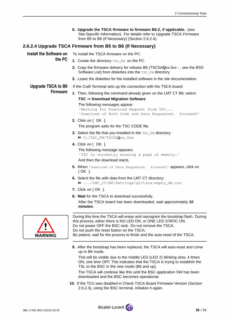
2.6.2.4 Upgrade TSCA Firmware from B5 to B6 (If Necessary)
Install the Software on
the PC
To install the TSCA firmware on the PC:
1. Create the directory TSC_FWon the PC.
2. Copy the firmware delivery for release B6 (TSCSAQxx.0xx - , see the BSSSoftware List) from diskettes into the TSC_FWdirectory.
3. Leave the diskettes for the installed software in the site documentation.
Upgrade TSCA to B6
Firmware
If the Craft Terminal sets up the connection with the TSCA board:
1. Then, following the command already given on the LMT CT B8, select:
TSC -> Download Migration SoftwareThe following messages appear:’Waiting for Download Request from TSC...’Download of Both Code and Data Requested. Proceed?’
2. Click on [ OK ].
The program asks for the TSC CODE file.
3. Select the file that you installed in the TSC_FWdirectory:C:/TSC_FW/TSCSAQxx.0xx
4. Click on [ OK ].
The following message appears:’TSC is currently erasing a page of memory.’
And then the download starts.
5. When ’Download of Data Requested. Proceed?’ appears, click on[ OK ].
6. Select the file with data from the LMT CT directory:.../LMT_CT/B8/Settings/g2/tsca/empty_db.tsc
7. Click on [ OK ].
8. Wait for the TSCA to download successfully.
After the TSCA board has been downloaded, wait approximately 10minutes .
During this time the TSCA will erase and reprogram the bootstrap flash. Duringthis process, either there is NO LED ON, or ONE LED STATIC ON.Do not power OFF the BSC rack. Do not remove the TSCA.Do not push the reset button on the TSCA.Be patient, wait for the process to finish and the auto-reset of the TSCA.
9. After the bootstrap has been replaced, the TSCA will auto-reset and comeup in B6 mode.
This will be visible due to the middle LED (LED 2) blinking slow, 4 timesON, one time OFF. This indicates that the TSCA is trying to establish theTSL to the BSC in the new mode (B6 and up).
The TSCA will continue like this until the BSC application SW has beendownloaded and the BSC becomes operational.
10. If the TCU was disabled in Check TSCA Board Firmware Version (Section2.6.2.3), using the BSC terminal, initialize it again.
3BK 17430 3001 RJZZA Ed.03 35 / 54

2 Commissioning Tests
When the TCU is initialized, the TSCA establishes the connection with the BSC.If the BSC is operational, in most cases the bootstrap and the TSC applicationsoftware will be upgraded by the BSC.
11. Apply the same procedure for each TSCA board.
2.6.2.5 Format Disk ATo format disk A:
1. Connect the X.25 number 0 port of the BSC Terminal to the 25-pin connectorof S-CPRC 1 (SAU 08 position 21) using the CPRC parallel cable.
Refer to the Tools Catalogue for the cable reference type.
2. Open a new session and select the ’X.25’ link and ’Logging’ in the BSCCommunication Control window.
3. Click on [ Connect ].
If an X.25 Link error message window appears, verify the link with the BSCequipment and repeat the last two steps.
4. From the Windows BSC Terminal window main menu, select:
Commands -> Disk operations -> Format SSD
The Format SSD window opens.
5. In the ’Directory’ field, enter the full path to the BSS directory using the[ Browse... ] button (e.g., C:\BUILDBSS\BSSS8 ).
6. Select [ Disk A. ]
A list of files that can be used to format the SSD appears.
7. Select the BSS-masterfile xxxMxWxx . xxx.
8. Click on [ Enter ].
9. Click on [ Go! ] to initiate SSD formatting.
When SSD formatting is complete, a report appears showing the resultof the formatting.
36 / 54 3BK 17430 3001 RJZZA Ed.03

2 Commissioning Tests
2.6.2.6 Load BSS Software onto Disk AWhen disk A is formatted, load the BSS software onto disk A:
1. From the Windows BSC Terminal window main menu, select:
Commands -> Disk operations -> File Transfer from PC to BSCThe BSS File Directory window opens:
2. In the ’Directory’ field, enter the full path to the BSS directory using the[ Browse... ] button (e.g., C:\BUILDBSS\BSSS9 ).
3. Select the BSS-masterfile xxxMxWxx . xxx.
4. Click on [ Enter ].
5. Enter Disk A in the ’Destination’ field.
In the Files To Transfer pane, the files to be transferred are displayed.
6. Click on [ Go! ] to initiate the file transfer (Start Download).
7. Check the reports.
3BK 17430 3001 RJZZA Ed.03 37 / 54
2 Commissioning Tests
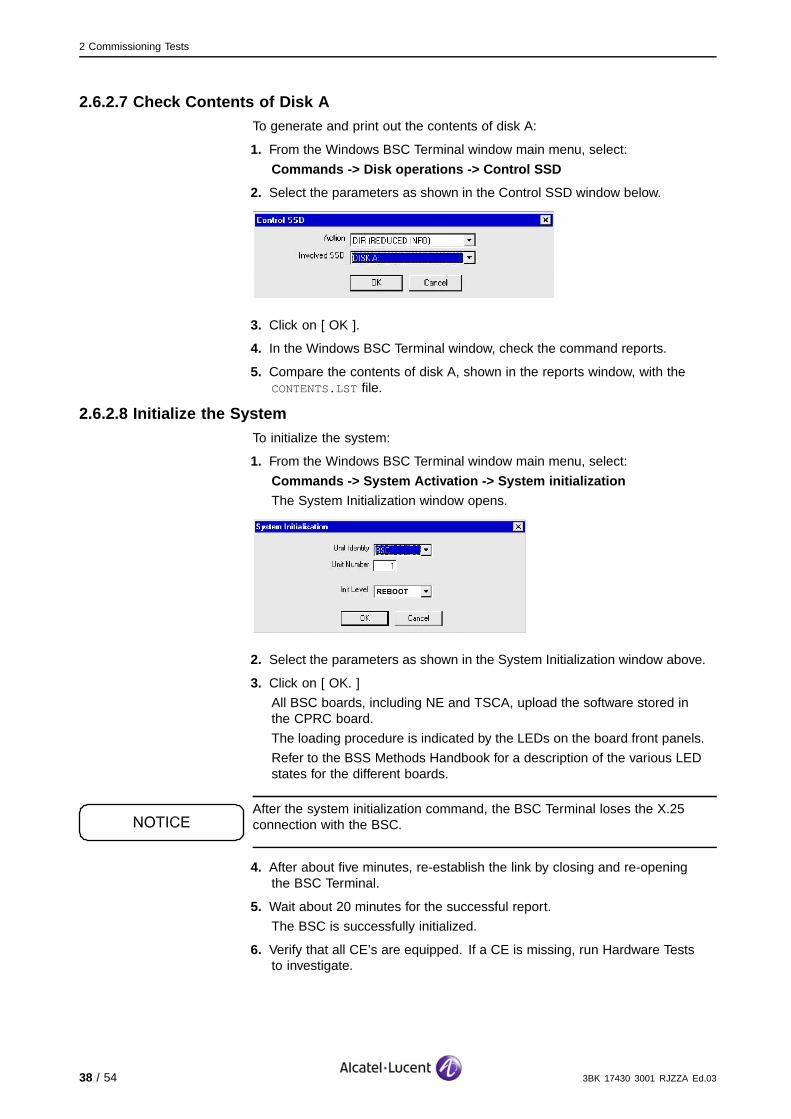
2.6.2.7 Check Contents of Disk ATo generate and print out the contents of disk A:
1. From the Windows BSC Terminal window main menu, select:
Commands -> Disk operations -> Control SSD
2. Select the parameters as shown in the Control SSD window below.
3. Click on [ OK ].
4. In the Windows BSC Terminal window, check the command reports.
5. Compare the contents of disk A, shown in the reports window, with theCONTENTS.LSTfile.
2.6.2.8 Initialize the SystemTo initialize the system:
1. From the Windows BSC Terminal window main menu, select:
Commands -> System Activation -> System initializationThe System Initialization window opens.
2. Select the parameters as shown in the System Initialization window above.
3. Click on [ OK. ]
All BSC boards, including NE and TSCA, upload the software stored inthe CPRC board.
The loading procedure is indicated by the LEDs on the board front panels.
Refer to the BSS Methods Handbook for a description of the various LEDstates for the different boards.
After the system initialization command, the BSC Terminal loses the X.25connection with the BSC.
4. After about five minutes, re-establish the link by closing and re-openingthe BSC Terminal.
5. Wait about 20 minutes for the successful report.
The BSC is successfully initialized.
6. Verify that all CE’s are equipped. If a CE is missing, run Hardware Teststo investigate.
38 / 54 3BK 17430 3001 RJZZA Ed.03

2 Commissioning Tests
2.6.2.9 Set SBLs of Declared BTSs OPRSet the SBLs of the declared BTSs OPR as follows:
1. From the Windows BSC Terminal window main menu, select:
Commands -> Equipment Handling -> SBL Disable
2. Select the parameters as shown in the SBL Disable window below:
3. In the "Unit number" field, enter the parameter number of the correspondingBTSs. (see Site-Specific Information (Section 1.2.2)).
4. Click on [ OK ] and wait for the successful report.
2.6.2.10 Check Board StatusTo generate and print out the states of the faulty SBLs:
1. From the Windows BSC Terminal window main menu, select:
Commands -> Equipment Handling -> SBL State List
2. Select the parameters as shown in the SBL State List window below.
3. Click on [ OK ].
4. In the Windows BSC Terminal window, check the reports to verify that all theCPR, DTC, TCU, TSC and SWITCH SBLs of the BSC are "In Traffic". Theyshould not appear in the State List command report.
The State List command displays the states of all SBLs that are not "In Traffic".In the Windows BSC Terminal window, use the mouse to double-click on thecompressed report message any time you want a Full Report View.
3BK 17430 3001 RJZZA Ed.03 39 / 54

2 Commissioning Tests
2.6.2.11 Format Disk BFormat disk B as follows:
1. Disable Alarm Reports (Disable / Enable Alarm Reports (Section 2.11.2)).
Sequence of operations is blockedIf the sequence of operations is blocked at any time, apply the Workaround:Exit / Connect WinBSC Terminal (Section 2.12) to restart the BSC Terminal.
2. From the Windows BSC Terminal window main menu, select:
Commands -> Disk Operations -> Format Duplex SSD
3. In the Format Duplex SSD window, enter the ’Source - Destination’parameter.
4. Click on [ OK ].
5. Check the reports to see if the action was successful.
6. Wait for the final report, FILE TRANSFER RESULT.
2.6.2.12 Copy BSS Software to Disk BWhen disk B is formatted, copy the BSS software files:
1. From the Windows BSC Terminal window main menu, select:
Commands -> Disk Operations -> File Transfer from BSC to BSC
2. Enter the Source and Destination disk parameters and select ’All Files’.
3. Click on [ OK ].
4. In the Windows BSC Terminal window, check the reports (check to see thatthe BOOTROOT file already exists on disk B).
2.6.2.13 Check Contents of Disk BRepeat the procedure in Section Check Contents of Disk A (Section 2.6.2.7)for Disk B.
40 / 54 3BK 17430 3001 RJZZA Ed.03

2 Commissioning Tests
2.6.2.14 Activate Disk BOnce the software is installed and the contents checked, activate disk B:
1. From the Windows BSC Terminal main menu, select:
Commands -> Equipment Handling -> SBL Initialize
2. Click on [ OK ].
3. Enable Alarm Reports
(See Disable / Enable Alarm Reports (Section 2.11.2)).
4. Check the message report.
2.6.3 Check Battery Backup of S-CPRC Boards
This task is done to check that the contents of the S-CPRC disks are not altered(safeguarded by the internal battery backup) by a loss of BSC power supply.
Check the internal battery backup as follows:
1. At the customer power panel, switch OFF the breakers for the two BSCbranches (A and B).
The BSC is powered down.
2. At the customer power panel, switch ON the breakers for the two BSCbranches (A and B).
The BSC is powered up and starts initialization.
3. Wait for BSC initialization to finish (follow the different LED states).
Refer to the BSS Methods Handbook for LED states.
4. Check the board status as described in Check Board Status (Section2.6.2.10).
The respective SBLs are “IT”.
5. Check the contents of the S-CPRC disks (A and B) against theCONTENTS.LSTfile. (Refer to sections Check Contents of Disk A (Section2.6.2.7) and Check Contents of Disk B (Section 2.6.2.13)).
The contents of the S-CPRC disks were not altered by the loss of powersupply.
3BK 17430 3001 RJZZA Ed.03 41 / 54
2 Commissioning Tests
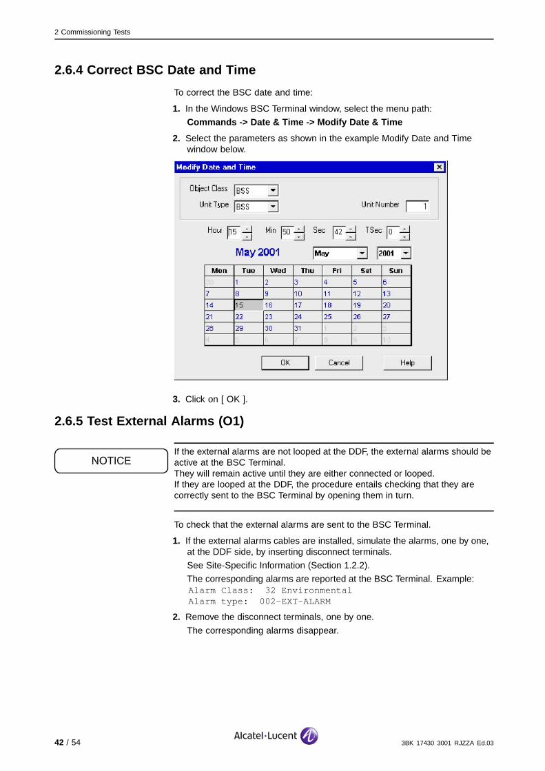
2.6.4 Correct BSC Date and Time
To correct the BSC date and time:
1. In the Windows BSC Terminal window, select the menu path:
Commands -> Date & Time -> Modify Date & Time
2. Select the parameters as shown in the example Modify Date and Timewindow below.
3. Click on [ OK ].
2.6.5 Test External Alarms (O1)
If the external alarms are not looped at the DDF, the external alarms should beactive at the BSC Terminal.They will remain active until they are either connected or looped.If they are looped at the DDF, the procedure entails checking that they arecorrectly sent to the BSC Terminal by opening them in turn.
To check that the external alarms are sent to the BSC Terminal.
1. If the external alarms cables are installed, simulate the alarms, one by one,at the DDF side, by inserting disconnect terminals.
See Site-Specific Information (Section 1.2.2).
The corresponding alarms are reported at the BSC Terminal. Example:Alarm Class: 32 EnvironmentalAlarm type: 002-EXT-ALARM
2. Remove the disconnect terminals, one by one.
The corresponding alarms disappear.
42 / 54 3BK 17430 3001 RJZZA Ed.03

2 Commissioning Tests
2.7 BSC Hardware Test (C1)
This test only applies to BSCs in configuration 3 or higher, to check theinter-rack cabling.For a BSC in configuration 1 or 2, the Hardware Test is not needed.
The following hardware tests are performed in “off-line” mode and in sequence:
Network test to detect failures in the switching network cabling
Broadcast test to detect failures in the broadcast bus cabling and faulty PBAs
Clock test to detect failures in the clock distribution bus cabling. It also
detects faulty PBAs.
Before the BSC can be tested, it must be in the idle state (all software in all theControl Elements (CE) is running in idle mode).
2.7.1 Reboot BSC in Off-Line Test Mode
Reboot the BSC in off-line test mode:
1. From the Windows BSC Terminal window main menu, select:
Commands -> Commissioning Tests -> BSC System Test InitThe BSC System Test Init window opens.
2. Select the parameters as shown in the BSC System Test Init window above.
3. Click on [ OK ].
A message indicating that the command has been sent to the BSC appearsin the lower left corner of the Windows BSC Terminal window.
4. Wait about 20 minutes for BSC to run in the test mode. (Wait about fiveminutes, exit and reconnect the BSC Terminal).
When the BSC is in test mode, both top LEDs are blinking fast.
To ensure the reliability of the offline test results, it is imperative that all CE’s ofthe BSC have been activated in offline test mode.
3BK 17430 3001 RJZZA Ed.03 43 / 54

2 Commissioning Tests
2.7.2 Network Test
To run the Network Test:
1. From the Windows BSC Terminal main menu select:
Commands -> Commissioning Tests -> Test Facilities for G2 ->Network TestThe Network Test window opens.
2. Select the parameters as shown in the Network Test window below.
3. Click on [ OK ].
4. Wait for the report message and try to fix the problem, if there is one by:
Noting down the given address
Finding the given address in the Inter Rack Cable List
Checking the corresponding cables for their addresses on both racks.
Use the mouse to double-click on the compressed report message any timeyou want a Full Report View.If one or more BSC test reports are not successful, the report provides theidentities of the network addresses of the links on which the most errorswere detected.Refer to the BSS Methods Handbook for cable and plug descriptions.See Connect Inter-Rack Cables (Example) (Section 2.11.1).
2.7.3 Broadcast Test
To run the Broadcast Test:
1. From the Windows BSC Terminal main menu, select:
Commands -> Commissioning Tests -> Test Facilities for G2 ->Broadcast TestThe Broadcast Test window opens.
2. Select the parameters as shown in the Broadcast Test window below.
3. Click on [ OK ].
4. Wait for the successful report message.
44 / 54 3BK 17430 3001 RJZZA Ed.03

2 Commissioning Tests
2.7.4 Clock Test
To run the Clock Test:
1. From the Windows BSC Terminal main menu, select:
Commands -> Commissioning Tests -> Test Facilities for G2 -> ClockTestThe Clock Test window opens.
2. Select the parameters as shown in the Clock Test window below.
3. Click on [ OK ].
4. Wait for the successful report message.
If a hardware test fails, try to identify the problem and fix it. Repeat all thehardware tests if necessary. If the failure persists, check the cabling betweenthe racks (see the BSS Methods Handbook).
2.7.5 Reboot BSC in OPERATIONAL Mode
To reboot the BSC:
1. From the Windows BSC Terminal window main menu, select:
Commands -> Commissioning Tests -> BSC System Test Init
The BSC System Test Init window opens.
2. Select the parameters as shown in the BSC System Test Init window below:
3. Click on [ OK ].
A message indicating that the command has been sent to the BSC appearsin the lower left corner of the Windows BSC Terminal window.
4. Wait about 15 minutes for the BSC to run in operational mode. (Exit andreconnect the BSC Terminal).
When the BSC is in operational mode, both bottom LEDs are blinking fast.
5. Check the board status. (See Check Board Status (Section 2.6.2.10)).
The CPR, DTC, TCU, TSC and SWITCH SBLs are “IT”.
3BK 17430 3001 RJZZA Ed.03 45 / 54

2 Commissioning Tests
2.8 Check BSC-TC Link (O2)
Apply the following procedures only if the TC is installed and connected atthe DDF on the BSC site.
2.8.1 Remove Ater Mux Loops
Remove the Ater Mux loops:
1. At the DDF on the BSC side, remove the loops for the Ater Mux PCMsconnected to the TC equipment. (See Site-Specific Information (Section1.2.2)).
2. Open the LMT Terminal application and connect the RS-232 cable to theLMT (COM).
2.8.2 Check Alarms on the ASMB Boards
For each ASMB board corresponding to the removed loop at the DDF:
1. Connect the serial cable to the board.
2. Follow the menu path:
Session -> ConnectThe message ’SM2M connection established’ appears.
3. Click on [ OK ].
4. Follow the menu path:
Services -> Alarm Collection
5. If the A interface cables are looped at the TC site, (refer to Site-SpecificInformation (Section 1.2.2)), check that the message No Alarms Detected
appears, meaning that the TC link has no alarms.
6. If the A interface cables are connected to the MSC, (refer to Site-SpecificInformation (Section 1.2.2)):
Check that for the A tributaries connected to MSC there are no alarms
Check there are no alarms for the “Highway and control module”.
46 / 54 3BK 17430 3001 RJZZA Ed.03
2 Commissioning Tests
2.8.3 Check Status of A Trunk SBLs
To check the status of the A trunk SBLs:
1. At the BSC Terminal, select:
Commands -> Equipment Handling -> SBL Read Status
2. Enter the following parameters:
Object class: > SBL
Unit Type: > BSC
Unit Number: > 1
SBL Type: > ATR
Nbr: > <A trunk number>
(corresponding to the number of the A trunk connected to the MSC or loopedat the TC).
SbNbr: > 255
3. Click on [ OK ].
4. Check that the ATR SBL is “In Traffic” in the report window.
5. Repeat steps 1 to 4 for all the A trunks connected to the MSC(corresponding to the Ater Mux PCMs connected to the TC).
3BK 17430 3001 RJZZA Ed.03 47 / 54

2 Commissioning Tests
2.9 Set and Check BSC - 9153 OMC-R Link
This procedure only applies if the BSC is linked to the 9153 OMC-R viathe X.25 network.
2.9.1 Connect Modem to CPRC Board
To connect the modem:
1. Connect the modem to the 25-way connector (reference 3BK 07784 GLAA)on the CPRC board C (subrack 8, slot 17).
On the modem, LEDs 103 and 104 must be ON.
On the CPRC C board, the top LED must be OFF.
2. At BSC Terminal, verify the alarms.
The Unsolicited Alarm Report should appear.
This message indicates that the X.25 link has been re-established.
2.9.2 Test the Communication Link
To test the communication link:
1. At the 9153 OMC-R site , ask the operator to check that the BSC - 9153OMC-R link is operational.
2. At the BSC site , check the X.25 SBL status.
The corresponding X.25 SBL is “IT”.
3. At the 9153 OMC-R site , perform a Software Audit of the BSS equipment.
Wait for the software audit report message.
4. At the 9153 OMC-R site , check for Communication Error Reports in the“BSS_xx Follow up” message window.
No communication errors must appear.
Do not switch OFF the main supply (48V) to the BSC when thecommissioning is done if the DC/DC converters with reference3BK07344AAAD02 have date code (serial number) after ZN0405XXXXXX.In case of mandatory customer requirement to switch OFF the (48V)supply of the BSC between the commissioning and the power OFF, theSystem-CPRC modules must be put in "transportation position" andthen the commissioning has to be partly re-done the day the power willbe re-established.
2.10 Before You LeaveBefore you leave, be sure to:
1. Close the doors of the racks.
2. Leave the site tidy.
3. Close the site and hand the keys to the key holder.
4. Make sure commissioning is finished and a copy of all reports from thecommissioning of the BSC equipment is left with the equipment on site.
48 / 54 3BK 17430 3001 RJZZA Ed.03

2 Commissioning Tests
5. Return the completed forms and the inventory files relating to the operationto base.
2.11 Supplemental Tasks
2.11.1 Connect Inter-Rack Cables (Example)
3
12
Rack B Rack A
A = Rack AB = Rack B
Figure 2: Connecting the Extension Loom
3BK 17430 3001 RJZZA Ed.03 49 / 54

2 Commissioning Tests
1. Run the interconnection loom at the rear of the racks (see the above figure).Use the addresses written on the end cable labels (as shown).
2. Connect the cables to the rear of the racks.
The addresses locate a locking latch (1), and the connector must be pluggedjust below it (2) (see Figure Locking Latch Address (3) below).
3. Tie the cables to the racks.
Example (shown below): 03::36BA03
Subrack 03
Slot 36
Board connector BA
Locking latch address 03
1
2
01
04
07
10
13
16
19
22
25
28
31
0103
07
10
13
16
19
22
25
28
31
AA
BA
Figure 3: Locking Latch Address
50 / 54 3BK 17430 3001 RJZZA Ed.03

2 Commissioning Tests
2.11.2 Disable / Enable Alarm Reports
Use this procedure to:
Disable Alarm Reports during file transfers between the PC and BSC
equipment. This measure is taken to avoid unsuccessful file transfers
Enable Alarm Reports when file transfers are finished.
2.11.2.1 Disable Alarm Reports1. From the Windows BSC Terminal main menu, select:
Commands -> Alarm Handling -> Enable PC Report
2. Select the parameters as shown in the window below.
3. Click on [ OK ].
4. In the Windows BSC Terminal window, check the report message.
2.11.2.2 Enable Alarm Reports1. From the Windows BSC Terminal main menu, select:
Commands -> Alarm Handling -> Enable PC Report
2. Select the parameters as shown in the window below.
3. Click on [ OK ].
4. In the Windows BSC Terminal window, check the report message.
3BK 17430 3001 RJZZA Ed.03 51 / 54

2 Commissioning Tests
2.12 Workaround: Exit / Connect WinBSC Terminal1. Click on the shortcut exit button (top corner in the Windows BSC Terminal
window).
The following message window appears.
2. To close the connection, choose [ Yes ].
3. To reconnect the BSC Terminal B10, from the Taskbar select:
Start -> Programs -> WinBSC -> B10 -> Windows BSC Terminal B10The following window appears.
4. In the BSC Communication Control window, select X.25 for ’Link Selection’and the ’Logging’ option.
5. Click on [ Connect ].
If an X25 Link error message window appears, verify the link with the BSCequipment and repeat the last three steps again.
52 / 54 3BK 17430 3001 RJZZA Ed.03

Appendix A : Abbreviations
Appendix A: Abbreviations
ASMC Ater submultiplexer C
Ater Interface link between TC and BSC
BSC Base Station Controller
BSS Base Station Subsystem
CCL Completion Check List
CPRC Control Processor Board
DDF Digital Distribution Frame
GSM Global System for Mobile communications
ITL-PRO Procedure technical and support information
IO Instruction Operation
NE Network Elements (i.e.: BIUA, ASMB ...)
PCM Pulse Code Modulation
SAU Subrack Unit
SR Subrack
TC Transcoder
3BK 17430 3001 RJZZA Ed.03 53 / 54

Appendix A : Abbreviations
BLANK PAGE BREAK
54 / 54 3BK 17430 3001 RJZZA Ed.03
Related Documents