www.siemens.com/sinamics-g120c SINAMICS G120C Multimedia Training Package

Welcome message from author
This document is posted to help you gain knowledge. Please leave a comment to let me know what you think about it! Share it to your friends and learn new things together.
Transcript

8/16/2019 G120C_Entrenamiento
http://slidepdf.com/reader/full/g120centrenamiento 1/76
www.siemens.com/sinamics-g120c
SINAMICS G120CMultimedia Training Package

8/16/2019 G120C_Entrenamiento
http://slidepdf.com/reader/full/g120centrenamiento 2/76
2
Required System Configuration CD-ROM
• Processor with min. 2 GHz (dual core recommended) • 1024 MB RAM • Graphics card (min. 256 MB memory recommended) • Screen resolution: 1280 x 1024 px • Operating Systems:
Microsoft® Windows™ XP (Service Pack 2 or later) Microsoft® Windows™ Vista Microsoft® Windows™ 7

8/16/2019 G120C_Entrenamiento
http://slidepdf.com/reader/full/g120centrenamiento 3/76
3
The booklet is an easy to understand introduction to the inverter family SINAMICS G120C.
04/20126FC5095-0AA86-0BA0
SINAMICS G120CTraining Booklet

8/16/2019 G120C_Entrenamiento
http://slidepdf.com/reader/full/g120centrenamiento 4/76
Materials and tools
The components listed below are presented in this booklet. To test your knowledge on the actual
product, you have the choice between the following order a lternatives:
* The training case is a complete demo station including a motor, the power module of the converter, switches, lights anda 230 V power supply connection.
Training case
Product
• SINAMICS G120C training case*
Order-no.
6AG1067-1AA25-0AA0
Single components
Product
• SINAMICS G120C FSA 0.55kWUSS/Modbus RTU
• Motor (0.55 kW)
• SINAMICS PC Connection Kit-2
• SINAMICS BOP-2
• Intelligent Operator Panel IOP
• Screening kit 2
Order-no.
6SL3210-1KE11-8UB0
1LA7096-4AA10
6SL3255-0AA00-2CA0
6SL3255-0AA00-4CA1
6SL3255-0AA00-4JA0
6SL3264-1EA00-0HA0
Optional components
Product
• IOP/BOP-2 door mounting kit
Order-no.
6SL3256-0AP00-0JA0
In addition you will need the following equipment:
• PC with USB interface • Switches – commercially available* • Potentiometer – commercially available* • Various M4 screws and nuts (length depends on installation location) with suitable screwdriver/
wrench – commercially available*

8/16/2019 G120C_Entrenamiento
http://slidepdf.com/reader/full/g120centrenamiento 5/76
5
Safety instructions
Validity
These instructions apply to the following converter:
Product
SINAMICS G120C
Prerequisites
You are proficient in working with the Microsoft® Windows™ operating system. You are conversant with the principles of electronics and electrical engineering.
Warning
Dangerous currents and voltages!The equipment contains dangerous voltages and controls potentially dangerous rotating mechanicalparts. Non-compliance with the warnings or failure to follow the instructions contained in the docu -mentation can result in loss of life, severe personal injury or serious damage to property.
Take particular notice of the general and regional installation and safety regulations regarding workon dangerous voltage installations (e.g. EN 50178) as well as the relevant regulations regarding thecorrect use of tools and personal protective equipment (PPE).
Qualified Personnel
The device/system may only be set up and used in conjunction with this documentation. Commission -ing and operation of a device/system may only be performed by qualified personnel. Within the con-text of the safety notes in this documentation, qualified persons are defined as persons who areauthorized to commission, ground and label devices, systems and circuits in accordance with estab -lished safety practices and standards.
Disclaimer of Liability
Depending upon the firmware and software version of the Control Unit, of the Operator Panel and ofthe STARTER, the masks, symbols and menus may differ. We have reviewed the contents of this publi -cation to ensure consistency with the hardware and software described. Since variance cannot beprecluded entirely, we cannot guarantee full consistency. However, the information in this publica -tion is reviewed regularly and any necessary corrections are included in subsequent editions.

8/16/2019 G120C_Entrenamiento
http://slidepdf.com/reader/full/g120centrenamiento 6/76
6
Welcome to the SINAMICS G120C Tutorial for First TimeUsers. This tutorial will help acquaint you simply, quick-ly and comfortably with the frequency converter. We’lltake you step by step through installation, settingparameters and initial start-up. We recommend that youdon’t skip any chapters.
1

8/16/2019 G120C_Entrenamiento
http://slidepdf.com/reader/full/g120centrenamiento 7/76
7
Converter family SINAMICS G120C 08–211.1 Components Interfaces 12
Operator Panels 14
1.2 Mounting and wiring Motor connection 16Control terminals 18
Operator Panel 20
Operator Panels BOP-2 and IOP 22‒412.1 Basic functions The BOP-2 display 24
Menu structure 25
2.2 Working with BOP-2 Parameter list 27
Operating pattern 27Function buttons 29
2.3 Quick commissioning Resetting the converter 30Setting the control mode 31
Selecting line frequency 31
Entering motor data 32
Motor data identification 33
Specifying application parameters 33
Saving and restoring data 35
2.4 Intelligent Operator Panel The device 37
Working with IOP 38
STARTER software and PC 42‒733.1 Mounting and preparation Creating a STARTER project 46
STARTER user interface 49Loading converter data 50
3.2 Parameterization Configuration wizard 54Safety Integrated 58
Start motor data identification 62
3.3 Application cases Setting setpoint specifications 65
Saving data 67
Restoring factory settings 70
Appendix Download overview 75

8/16/2019 G120C_Entrenamiento
http://slidepdf.com/reader/full/g120centrenamiento 8/76
8
This chapter will introduce the low-voltage SINAMICSG120C converter. You’ll learn about the main compo-nents, hear about its structure and get some practice-oriented insight about the assembly and wiring of thefrequency converter.
1
8/16/2019 G120C_Entrenamiento
http://slidepdf.com/reader/full/g120centrenamiento 9/76
9
Converter family
SINAMICS G120C

8/16/2019 G120C_Entrenamiento
http://slidepdf.com/reader/full/g120centrenamiento 10/76
10
1.1 ComponentsThe SINAMICS G120C frequency converter is a compact converterfor controlling the speed of three-phase motors.
1 2The Power Module supplies voltageto the motor (available in three framesizes from 0.55 kW to 18.5 kW)
The Basic Operator Panel (BOP-2) andthe Intelligent Operator Panel (IOP)are used to operate and monitor theconverter
Converter family SINAMICS G120C: Components

8/16/2019 G120C_Entrenamiento
http://slidepdf.com/reader/full/g120centrenamiento 11/76
11
+The optional PC Connection Kit-2can also be used to set parameters,operate and monitor the converter;the kit is required in order to establishcommunication between a PC and theControl Unit
8/16/2019 G120C_Entrenamiento
http://slidepdf.com/reader/full/g120centrenamiento 12/76
12 Converter family SINAMICS G120C: Components
1
1
2
2
33
4
4
5
5
6
6
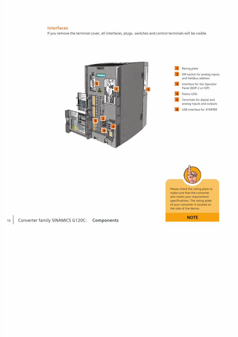
InterfacesIf you remove the terminal cover, all interfaces, plugs, switches and control terminals will be visible.
Rating plate
DIP switch for analog inputsand fieldbus address
Interface for the OperatorPanel (BOP-2 or IOP)
Status LEDs
Terminals for digital andanalog inputs and outputs
USB interface for STARTER
Please check the rating plate tomake sure that the converteralso meets your requirementspecifications. The rating plateof your converter is located onthe side of the device.
NOTE
1

8/16/2019 G120C_Entrenamiento
http://slidepdf.com/reader/full/g120centrenamiento 13/76
13
1
12
2
4
43
32
1
2
3
4
Connectors for the powersupply
PE connection terminals
Connector / Braking resistor
Connectors for the motor
8/16/2019 G120C_Entrenamiento
http://slidepdf.com/reader/full/g120centrenamiento 14/76
14 Converter family SINAMICS G120C: Components
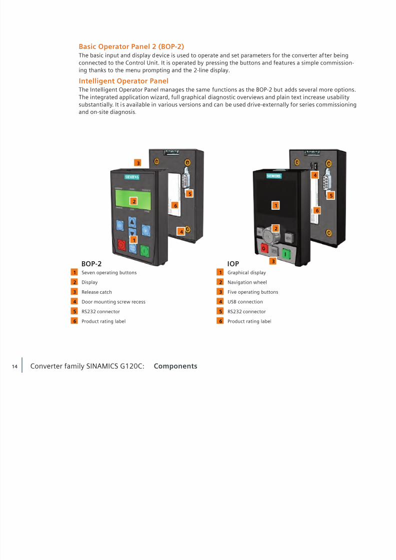
Basic Operator Panel 2 (BOP-2)The basic input and display device is used to operate and set parameters for the converter af ter beingconnected to the Control Unit. It is operated by pressing the buttons and features a simple commission-ing thanks to the menu prompting and the 2-line display.
Intelligent Operator PanelThe Intelligent Operator Panel manages the same functions as the BOP-2 but adds several more options.The integrated application wizard, full graphical diagnostic overviews and plain text increase usabilitysubstantially. It i s available in various versions and can be used drive-externally for series commissioningand on-site diagnosis.
1
3
4
1
2
3
26 6
5 5
4
1
1
6 6
5 5
4 4
3 3
2 2
BOP-2 IOP
Seven operating buttonsDisplay
Release catch
Door mounting screw recess
RS232 connector
Product rating label
Graphical displayNavigation wheel
Five operating buttons
USB connection
RS232 connector
Product rating label
8/16/2019 G120C_Entrenamiento
http://slidepdf.com/reader/full/g120centrenamiento 15/76
15
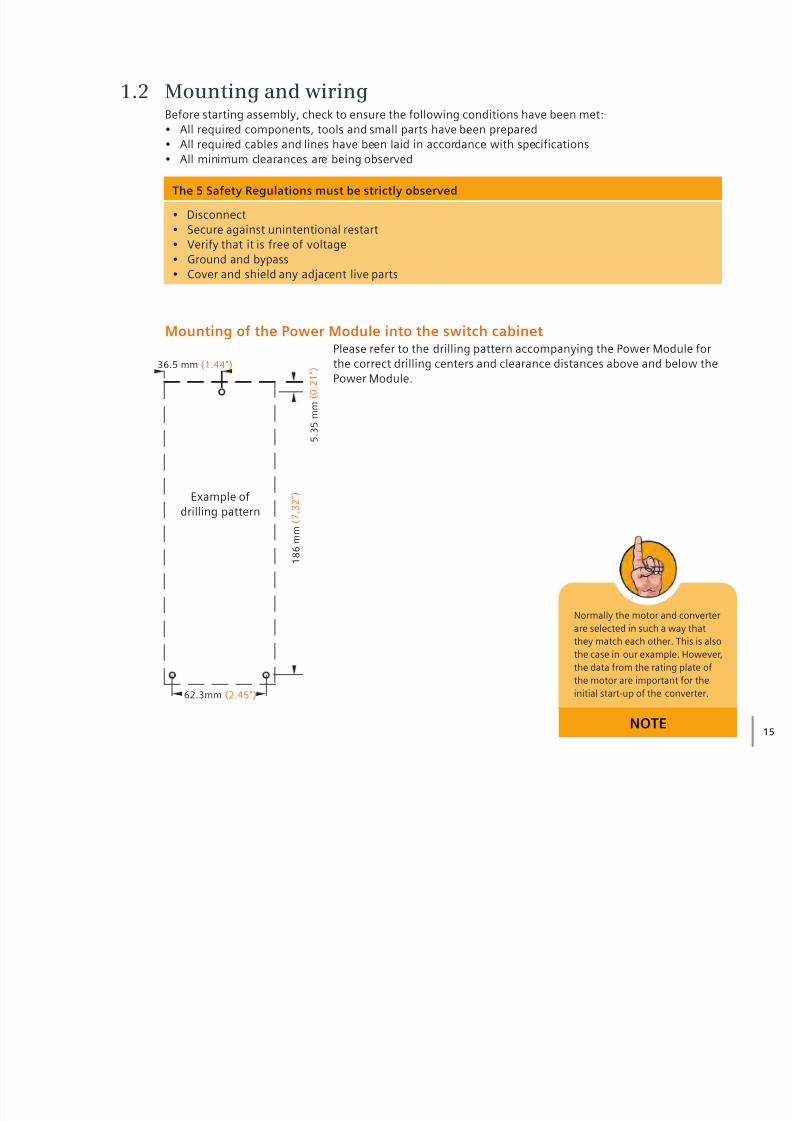
Mounting of the Power Module into the switch cabinetPlease refer to the drilling pattern accompanying the Power Module forthe correct drilling centers and clearance distances above and below thePower Module.
1.2 Mounting and wiringBefore starting assembly, check to ensure the following conditions have been met:• All required components, tools and small parts have been prepared • All required cables and lines have been laid in accordance with specifications • All minimum clearances are being observed
Normally the motor and converterare selected in such a way thatthey match each other. This is alsothe case in our example. However,the data from the rating plate ofthe motor are important for theinitial start-up of the converter.
NOTE
The 5 Safety Regulations must be strictly observed
• Disconnect • Secure against unintentional restart • Verify that it is free of voltage• Ground and bypass
• Cover and shield any adjacent live parts
Example ofdrilling pattern
36.5 mm (1.44")
62.3mm (2.45")
5 . 3
5 m m
( 0
. 2 1 " )
1 8 6
m m
( 7
. 3 2 " )

8/16/2019 G120C_Entrenamiento
http://slidepdf.com/reader/full/g120centrenamiento 16/76
16 Converter family SINAMICS G120C: Mounting and wiring
Motor connectionDepending on the operating environment, different cable length limits are required for the connectionbetween the converter and motor. Unshielded cables up to 100 m in length are possible in industrialelectrical networks.
The motor and converter are now connected.
The electrical wiring is now complete.
Wiring the converter
• Connect the phases and the earth conductor to the terminals U2, V2, W2 and PE
Connecting converter and motor
• Unscrew the cover to the motor’s terminal box (Siemens’ motors illustrate the possible wiring forthe Star connection and the Delta connection) • Remove the bridge rails from the connecting block and loosen the screws • Place the bridge rails on the terminal block and screw them into place (depending on the type of
connections required – Star or Delta, in this example a Star connection is shown) • Insert the cables from the converter through the opening of the terminal box to
the motor• Connect the PE connection first • Slide the phases in accordance to the phase assignment in the connections • Replace the terminal cover and ensure it is secured with the four screws
to the required torque
Wiring the power supply
• Connect the phases and the earth conductor to the pluggable terminal clamps L1, L2, L3 and PE
1
2
3

8/16/2019 G120C_Entrenamiento
http://slidepdf.com/reader/full/g120centrenamiento 17/76
17
Motor lines represent interferingtransmitters. As a result, youshould use shielded cable in order
to meet the corresponding elec-tromagnetic compatibility condi-tions. The cable lengths that areactually possible depend upon thefollowing:– Operating environment – Converter being used – Reactors and lters used – Shielded or unshielded cable
In order to meet Class A electro-
magnetic compatibility require-ments, you need a lter and ashielded cable (max. length: 25meters).
The depicted example shows aStar connection. The rating plateprovides information about thecorrect circuit data: e.g. 230/400 V∆/Y means that you are connec-ting the motor in Y with a 400 Vnetwork.
NOTE
3 1
2
2

8/16/2019 G120C_Entrenamiento
http://slidepdf.com/reader/full/g120centrenamiento 18/76
18 Converter family SINAMICS G120C: Mounting and wiring
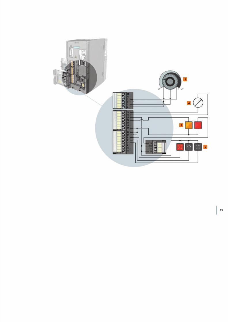
Wiring the control terminalsBefore wiring the control terminals, the terminal cover has to be opened.
General procedure for wiring with the cage clamp mechanism
• Slide the wire into the terminal opening • The inner clamp opens slightly and snaps the wire tightly into place
The wire is now firmly attached.
• To release the wire press a screw driver onto the lever • Remove the wire
• Withdraw the screwdriver from the terminal
The wiring is now complete.
Wiring the control terminals in the CU240E-2
The potentiometer:• Attach the positive pole of the supply voltage to 1 • Attach the negative pole to 2 • Wire the output of the potentiometer arm to 3 • Close the circuit by connecting 4 with negative pole 2
On/Off, Reverse, and Reset buttons: • Wire the button’s power supply to 9 • Attach the associated digital inputs to terminals 5, 6 and 7 • To close the circuit, connect 28 and 69 to 34
Indicator lamps:• Connect 9 with 20 and 21 to attach the power supply for the LEDs • Wire the Faults LED to digital output 19 and the Warning LED to digital output 22 • Connect the negative pole to terminal 28
Display for frequency output:• Connect the positive pole to 12 • Connect the negative pole to 13
1
2
3
4
8/16/2019 G120C_Entrenamiento
http://slidepdf.com/reader/full/g120centrenamiento 19/76
19
4
1
3
2

8/16/2019 G120C_Entrenamiento
http://slidepdf.com/reader/full/g120centrenamiento 20/76
20 Converter family SINAMICS G120C: Mounting and wiring
Mounting the Operator Panels (BOP-2 or IOP)• Remove the cover of the RS232 connection by lifting it up and sliding it to the side • Place the bottom edge of the IOP/BOP-2 into the lower recess of the converter housing
• Push the IOP/BOP-2 toward the converter until the release-catch clicks into placeMounting the IOP or BOP-2 in a cabinet doorThe operator panels can simply be mounted in a control cabinet door using the optionally available doormounting kit. Cabinet door mounting achieves IP55 / UL type 12 protection.
Door panel
Seal
Door mounting bracket
Screws
D-type retaining screws
1
2
3
4
5
Congratulations! Your converter is now ready for operation.After assembly is completed, the converter’s parameters must be set up, i.e., you must give theconverter the specific characteristics of the attached motor.
Mounting the IOPIdentical mounting with BOP-2
43
1
2
5

8/16/2019 G120C_Entrenamiento
http://slidepdf.com/reader/full/g120centrenamiento 21/76
21

8/16/2019 G120C_Entrenamiento
http://slidepdf.com/reader/full/g120centrenamiento 22/76
22
In this section, you will learn more about the usage ofOperator Panels to control the converter locally on-site.
You’ll learn how to use the Basic Operator Panel 2 (BOP-2)to set up parameters for the converter and the attached
motor and how to operate the converter with the BOP-2.Then, you will learn how to use the Intelligent OperatorPanel (IOP) to your advantage.
2
8/16/2019 G120C_Entrenamiento
http://slidepdf.com/reader/full/g120centrenamiento 23/76
23
Basic Operator Panel (BOP-2)
Intelligent Operator Panel (IOP)

8/16/2019 G120C_Entrenamiento
http://slidepdf.com/reader/full/g120centrenamiento 24/76
24
Menu bar indicates theselected menu function(see page 25)
Provides information aboutthe selected functionality ordisplays the actual value
Displays the values
Operator Panels BOP-2 and IOP: Basic functions
In this tutorial, we introduce anapplication that is based on “V/fcontrol with linear characteristiccurve”. This control method istypically applied for conveyorbelt applications. We recom-mend that you work through theexample we have presented herein order to familiarize yourselfwith setting up parameters for aconverter.
NOTE
2.1 Basic functionsThe Operator Panel is the input and display instrument for controlling the converter. It is used in stand-alone operation, i.e., locally, on the device, integrated in the cabinet door or as handheld version forseries setup (IOP).
The BOP-2 display
The BOP-2 is used to commission, diagnose (troubleshoot) and display the status of the converter. Up to2 status values can be simultaneously and continuously monitored. It features a simple navigation usinga transparent and well-structured menu and clearly assigned operator keys.
1 2
1
2
3
3
8/16/2019 G120C_Entrenamiento
http://slidepdf.com/reader/full/g120centrenamiento 25/76
25
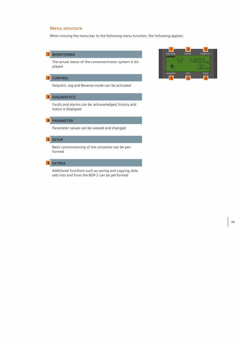
MONITORING
The actual status of the converter/motor system is dis-played
CONTROL
Setpoint, Jog and Reverse mode can be activated
DIAGNOSTICS
Faults and alarms can be acknowledged, history andstatus is displayed
PARAMETER
Parameter values can be viewed and changed
SETUP
Basic commissioning of the converter can be per-formed
EXTRAS
Additional functions such as saving and copying datasets into and from the BOP-2 can be per formed
1
1
4
2
5
3
62
3
4
5
6
Menu structure
When moving the menu bar to the following menu function, the following applies:
8/16/2019 G120C_Entrenamiento
http://slidepdf.com/reader/full/g120centrenamiento 26/76
26 Operator Panels BOP-2 and IOP: Working with BOP-2
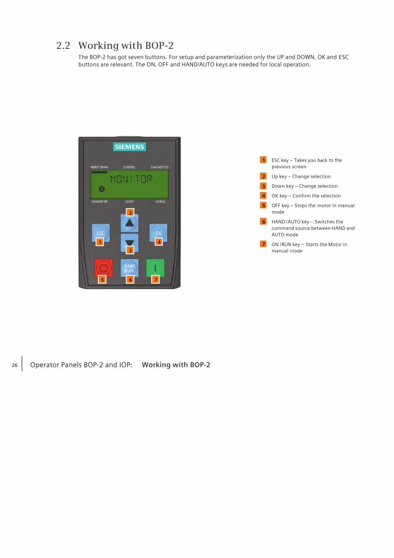
ESC key – Takes you back to theprevious screen
Up key – Change selection
Down key – Change selection
OK key – Confirm the selection
OFF key – Stops the motor in manualmode
HAND / AUTO key – Switches thecommand source between HAND andAUTO mode
ON / RUN key – Starts the Motor inmanual mode
2.2 Working with BOP-2The BOP-2 has got seven buttons. For setup and parameterization only the UP and DOWN, OK and ESCbuttons are relevant. The ON, OFF and HAND/AUTO keys are needed for local operation.
1
4 7
6
5
4
3
1
2
2
3
5 6 7

8/16/2019 G120C_Entrenamiento
http://slidepdf.com/reader/full/g120centrenamiento 27/76
27
• Press UP to access the next parameter • In this case, P3 appears (P means that you can change the value of this parameter) • Press OK to edit the parameter
• Use the UP and DOWN buttons to adjust the value • Confirm the value by pressing OK
Operating pattern
• Press ESC to enter the menu selection • Use the UP and DOWN buttons to move the menu bar to PARAMS and press OK • Press OK to select the Standard Level
Parameter listTo better understand the functionality of the buttons, you should be acquainted with the operatingpattern: The Basic Operator Panel gives you access to a parameter list. Stored behind the parameters are
parameter values that control the operation of the motor. However, not all the numbers are assigned.
The first parameter number that appears is displayed on the left side of the screen: r2 (r stands for readonly and means that you can only read this value but cannot change it). On the right side, the parametervalue of the selected number is shown.
E x a m p l e
If you want to change any param -eter using the parameter list, youare requested to choose a filterlevel (Standard or Expert). TheStandard Level limits the avail-able parameters, thus limitingthe risk of dangerous parameters.The Expert Level gives access toall parameters.
NOTE
E x a m p l e
ESC
ESC

8/16/2019 G120C_Entrenamiento
http://slidepdf.com/reader/full/g120centrenamiento 28/76
28 Operator Panels BOP-2 and IOP: Working with BOP-2
Example for index parameters• Pressing OK takes you to [00] • UP takes you to [01], DOWN back to [00] • Decide for an index number of your choice • Press OK again to edit the index• The value starts flashing • Adjust the value by pressing UP and DOWN • Confirm by pressing OK
Some parameters store more than one value. In this case, pressing OK does not take you directly to thevalue, but to an index that is displayed in brackets [00] above the actual value.
E x a m p l e
A complete list of all parameterscan be found in the “ParameterManual G120C” as a downloadat: http://support.automation.siemens.com/WW/view/ en/49383082
If you want to adjust any blink -ing/active value digit by digit(using the UP and DOWN buttonmight just take too long), youcan always press the OK buttonlonger than two seconds. Afterreleasing the button, you canchange any single digit by usingthe buttons OK (move to nextdigit), ESC (move to previousdigit), UP (increase value), andDOWN (decrease value).
NOTE
8/16/2019 G120C_Entrenamiento
http://slidepdf.com/reader/full/g120centrenamiento 29/76
29
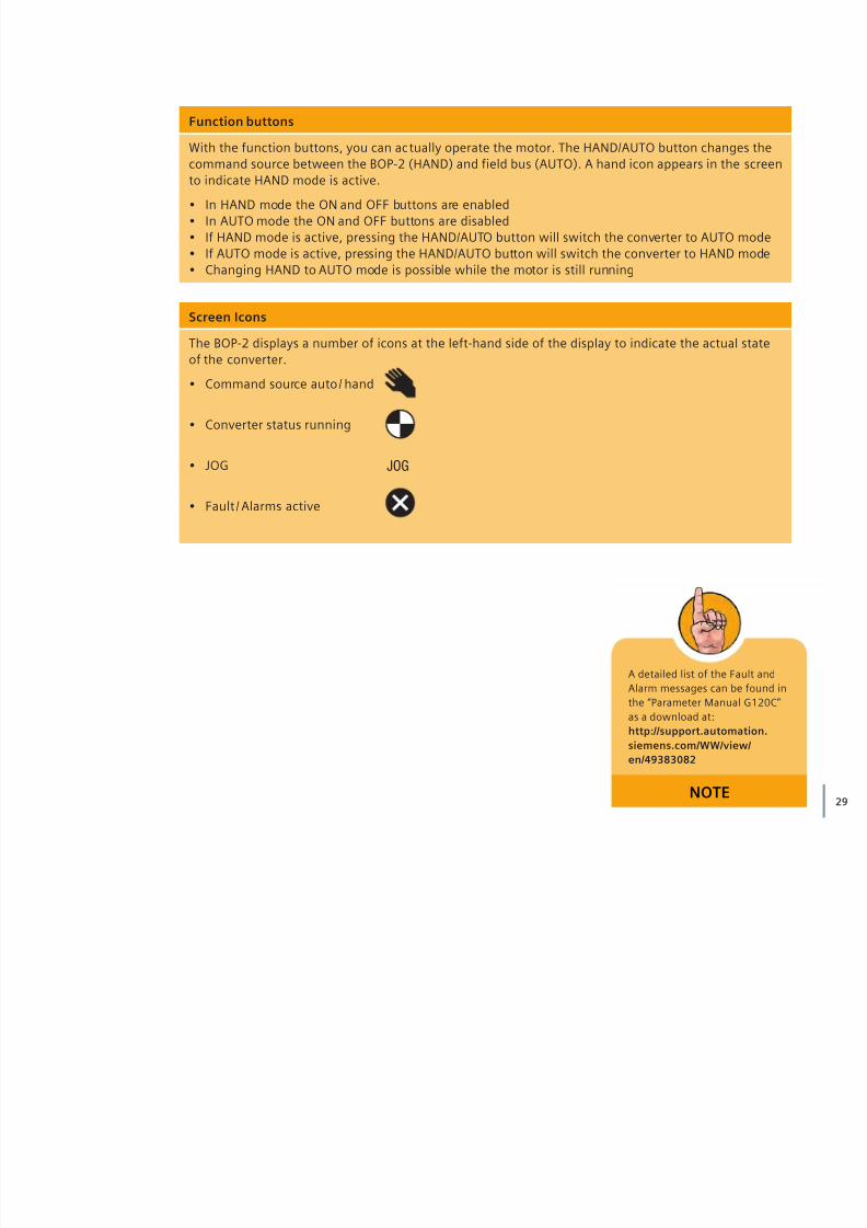
Function buttons
With the function buttons, you can ac tually operate the motor. The HAND/AUTO button changes thecommand source between the BOP-2 (HAND) and field bus (AUTO). A hand icon appears in the screento indicate HAND mode is active.
• In HAND mode the ON and OFF buttons are enabled • In AUTO mode the ON and OFF buttons are disabled • If HAND mode is active, pressing the HAND/AUTO button will switch the converter to AUTO mode• If AUTO mode is active, pressing the HAND/AUTO button will switch the converter to HAND mode• Changing HAND to AUTO mode is possible while the motor is still running
Screen Icons
The BOP-2 displays a number of icons at the left-hand side of the display to indicate the actual stateof the converter.
• Command source auto / hand
• Converter status running
• JOG
• Fault / Alarms active
JOG
A detailed list of the Fault andAlarm messages can be found inthe “Parameter Manual G120C”as a download at:http://support.automation.siemens.com/WW/view/ en/49383082
NOTE

8/16/2019 G120C_Entrenamiento
http://slidepdf.com/reader/full/g120centrenamiento 30/76
30
Starting quick commissioning
• Press ESC to enter the menu selection • Use UP and DOWN to move the menu bar to SETUP and press OK • The screen will automatically display the next parameter in the commissioning sequence
Resetting the converter
• Press OK while the BOP-2 shows RESET • Press UP or DOWN to change the value to YES • Press OK and wait until the BUSY sign disappears • Now all values are reset to the factory setting
Operator Panels BOP-2 and IOP: Quick commissioning
Any step of the commissioningwizard can be skipped by press -ing the DOWN button. Goingback one step can be done bypressing the UP button. By con-firming one step with OK, thescreen will automatically displaythe next parameter in the com -missioning sequence.
NOTE
2.3 Quick commissioningThe following descriptions show how to set up the drive using the quick commissioning wizardintegrated in the BOP-2.
Quick commissioning begins now. It will help you set all relevant parameters step by step. Parametersthat are not relevant will be skipped automatically. Thus, you adjust the factory settings of your con -verter to the requirements of your motor.
ESC

8/16/2019 G120C_Entrenamiento
http://slidepdf.com/reader/full/g120centrenamiento 31/76
31
Setting the control mode (P1300)
In our example it is assumed that your converter and the motor are new. As a result, a series ofpre paratory steps are required, e.g. selecting the control mode. This is indicated by the parameternumber 1300. ‘V/f control with linear characteristic curve’ is defined by the factory setting.
• Press OK to modify the parameter value CTRL MOD • The upper row shows the control mode associated to the actual parameter value below • Choose your desired control mode value by pressing UP or DOWN • See how the control mode name in the upper row changes accordingly • Press OK if the desired control mode is displayed
Selecting line frequency (P100)
The next parameter sequence sets the line frequency of the region in which the motor is being used.In our example, this is Europe.
• Press OK to modify the parameter value EUR USA
• Set 0 for Europe (50 Hz) (1 represents the US line frequency of 60 Hz) • Confirm the value by pressing OK • The screen will automatically display the next parameter in the commissioning sequence
The applicable line frequencycan be also found on your motorplate (see chapter “Enteringmotor data”).
NOTE
8/16/2019 G120C_Entrenamiento
http://slidepdf.com/reader/full/g120centrenamiento 32/76
32
2.0 HP
3.55-3.552.05-2.05
84.5%84.5%86.5%
NOM.EFF
K
AV380 - 420660 - 725
CL
IP55E0807/0496382_02 003
IMB3
UNIREX-N340°CTambTh.Cl. 155(F)25 kg
Design ATEFCMG1-12NEMASF 1.15 CONT60Hz:
Intervall: 4000hrs
IEC/EN 60034 100L3~Mot. 1LE10011AC434AA0
6206-2ZC3
6206-2ZC3Bearing
DE
NE 11g
15g
D-91056 Erlangen
-20°C
Y400
460690
V970970
1175
rpm0.730.730.69
PF
3.15
3.52.05
A kWHz50
6050
1.5
1.51.5
Operator Panels BOP-2 and IOP: Quick commissioning
If you want to adjust any flash -ing value digit by digit (using theUP and DOWN button might justtake too long) press the OK but -ton longer than two seconds.After releasing the button, youcan change each single digit byusing the buttons OK (move tonext digit), ESC (move to previ -ous digit), UP (increase value)and DOWN (decrease value).
NOTE
1 2 3 4 5
1
3
2
4
5
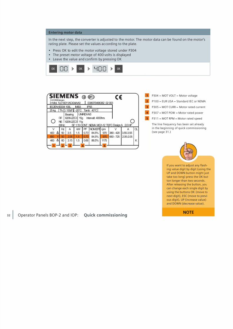
P304 = MOT VOLT = Motor voltage
P100 = EUR USA = Standard IEC or NEMA
P305 = MOT CURR = Motor rated current
P307 = MOT POW = Motor rated power
P311 = MOT RPM = Motor rated speed
The line frequency has been set alreadyin the beginning of quick commissioning(see page 31.)
Entering motor data
In the next step, the converter is adjusted to the motor. The motor data can be found on the motor’srating plate. Please set the values according to the plate.
• Press OK to edit the motor voltage stored under P304• The preset motor voltage of 400 volts is displayed • Leave the value and confirm by pressing OK

8/16/2019 G120C_Entrenamiento
http://slidepdf.com/reader/full/g120centrenamiento 33/76
33
Activating pre-defined settings (P15) e.g. for command and setpoint source
• Press OK to activate macro parameterization MAc PAr• Macro 12 (Std ASP) is displayed, it determines DI 0 for the command source and the
potentiometer for the setpoint source• Leave the value and confirm by pressing OK
The converter can now be turned on using digital input DI 0.The setpoint source is specified as the potentiometer.
Motor data identificationAfter entering the motor data, the wizards asks to activate the motor data identification. This is recom -mended for a live verification and optimization of the data that you have entered. The motor data iden -
tification initiates a “measurement” of the connected motor. In the process, the data previously calcu-lated in the converter are compared to the actual motor data and adapted to one another.
Specifying application parametersIn the next step, pre-defined settings for the converter’s interfaces can be activated. This is stored inparameter number 15 and indicated by MAc PAr for macro parameterization. For example, the converteroffers different pre-defined macros for setting the command and setpoint source.
Activating motor data identification (P1900)
• Press OK to confirm MOT ID • Change the displayed value to 1 by pressing UP
Motor data identification does only start after the basic commissioning sequence has been completedand the motor is switched on the first time!

8/16/2019 G120C_Entrenamiento
http://slidepdf.com/reader/full/g120centrenamiento 34/76
34 Operator Panels BOP-2 and IOP: Quick commissioning
Completing quick commissioning
• Press OK while the BOP-2 shows FINISH • Select YES and press OK again
The values are displayed in seconds. In both cases, the times indicated should not be too short, becausethis might result in an alarm.
The converter is now parameterized optimally to your application andmotor specifications. Now motor data identification should be per -formed to finalize the commissioning. This can be done by switchingon the motor. At the moment, command source is set to digital inputDI 0. Start the motor with turning on DI 0.
Minimum frequency, ramp up and ramp down time (P1080)
• Set the minimum frequency under parameter MIN RPM • Press OK (Parameter MIN RPM) • Change the value by pressing UP or DOWN • Press OK to confirm
• Set the ramping-up time under parameter RAMP UP for acceleration time to maximumfrequency (P1120)
• Set the ramping-down time under parameter RAMP DWN for time until standstill (P1121)
Changing the value digit by digitis possible by pressing the OK but -ton longer than 2 seconds. Afterreleasing the button, each singledigit can be changed by using the
buttons OK (move to next digit),ESC (move to previous digit), UP(increase value) and DOWN(decrease value).
Refer to the “Parameter ManualG120C” for a description of thecontrol modes and their corres-ponding parameter settings at:http://support.automation.siemens.com/WW/view/ en/49383082
NOTE

8/16/2019 G120C_Entrenamiento
http://slidepdf.com/reader/full/g120centrenamiento 35/76
35
The Basic Operator Panel 2 can also be used to make a variety of otheradjustments to your application. Please note that an overview of theparameter numbers can be found in the Operating Instructions.
Motor data identification
• Start the motor manually by using digital input DI 0• The measuring process is set in motion • When finished, the motor switches off • BOP-2 indicates that the measured values are now being converted into data
Saving parameter sets from converter to BOP-2
• Navigate with the menu bar to the function EXTRAS• Press OK • Push the DOWN button until TO BOP appears • Press OK
Copying parameter sets from BOP-2 to converter
• Navigate to the menu EXTRAS • Press OK • Push the DOWN button until FROM BOP appears• Press OK
Saving and restoring dataSaving data in different location is important. The EXTRAS function allows loading parameter data fromthe converter memory to the BOP-2 and vice versa.
The BOP-2 can be mounted orremoved at any time. The deviceis not necessary for ongoingoperation.
NOTE

8/16/2019 G120C_Entrenamiento
http://slidepdf.com/reader/full/g120centrenamiento 36/76
36 Operator Panels BOP-2 and IOP: Intelligent Operator Panel
2.4 Intelligent Operator PanelWith the Intelligent Operator Panel, you can set the inverter parameters, put the inverter into operation,monitor the ongoing operation of the motor, and get valuable information about faults and alarms. All
these functions can be accessed without expert knowledge. The main advantages are as follows:
Fast commissioning without expert knowledge
• Simple commissioning of standard applications using application-specific assistants, noknowledge of parameter structure necessary
• User customized parameter lists with reduced parameter sets• Simple local commissioning using the handheld version • Fast multiple commissioning with clone function
• Commissioning without documentation by using the integrated help function
Minimization of maintenance time
• Diagnosis with clear text display, without documentation usable on site• Simple update of languages, application assistants and firmware using the
integrated USB connection• Integrated clear text help function to read and resolve fault messages and reasons locally
High usability, intuitive handling
• Direct, manual control of the drive – simple switching from local to remote operation• Intuitive menu navigation using wheel-click interface• Graphical display for i.e. status values in vertical-bar charts (for example pressure or flow rate) • Status display with freely selectable units – display of real, physical values
Flexible usage
• Available for direct control unit mounting, for door mounting or as handheld version(depending on frequency converter type)
• Simple and fast mechanical and electrical door mounting• Handheld usable for a large variety of frequency converters• 5 integrated languages

8/16/2019 G120C_Entrenamiento
http://slidepdf.com/reader/full/g120centrenamiento 37/76
37
1 2 3
The deviceThe IOP is a menu-driven device. Its funct ionality is structured by three options:
1
2
3
The display
All necessary information is user-friendly displayed in plain text or icons. The displayed icons areshown at the top right-hand edge of the display. They indicate various states of the converter.
• Command source auto / hand • Inverter status ready / running
• Fault
• Alarm pending
• Battery condition Fully Charged / Discharged
[Wizards] Assists you to set up standardapplications
[Control] Allows you to change setpointvalue, turning direction activates the
jog function in real-t ime[Menu] Gives you access to all possiblefunctionalities

8/16/2019 G120C_Entrenamiento
http://slidepdf.com/reader/full/g120centrenamiento 38/76
38
Working with IOPThe IOP is operated mainly by using the push-wheel. The five additional buttons make it possible todisplay certain values or to switch between manual and auto mode. The buttons are called: ON key,
OFF key, ESC key, INFO key and HAND/AUTO key.
Turning changes the selection
Pressing confirms the selectionStarts the motor in manualmode
Stops the motor in manualmode
Takes you back to the previousscreen
Displays additionalinformation
Switches the command sourcebetween HAND and AUTOmode
The HAND/AUTO function worksidentically to the one imple-mented in the BOP-2. After start-ing the motor with the ON but -ton, you can change the setpointspeed by navigating to CON-TROL/SETPOINT and turning thewheel (right to increase speed,left to decrease speed).
NOTE
1
1
2
23 6
4 5
3
4
5
6
Operator Panels BOP-2 and IOP: Intelligent Operator Panel

8/16/2019 G120C_Entrenamiento
http://slidepdf.com/reader/full/g120centrenamiento 39/76
39
On the top of the screen, youcan see numbers that indicatethe present step of the wizardthat you are in. 2/15 for examplemeans that you are in step 2 of15.
NOTE
Example: Basic commissioning
• Use the wheel to highlight the word WIZARDS • Confirm by pressing OK • Navigate to BASIC COMMISSIONING by turning the wheel • Confirm by pressing OK
The wizardsThere are several wizards which allow you to set up various functions and commission the converter.They navigate you interactively through the parameterization of standard applications. The wizards are
accessed from the wizard menu, at the bottom-left of the status screen.
Now the wizard will guide you step by step through the basic commissioning process by presenting anumber of screens where you can choose the necessary options and values. At the conclusion of thebasic commissioning process, the data can be saved to the converters memory, and calculation of motorand control data is started.
• Always use the wheel to select an option and press OK to confirm • Press ESC to move back one step
• Press INFO to read context-sensitive help information
Wizards Basic CommissioningOK OK

8/16/2019 G120C_Entrenamiento
http://slidepdf.com/reader/full/g120centrenamiento 40/76

8/16/2019 G120C_Entrenamiento
http://slidepdf.com/reader/full/g120centrenamiento 41/76
41
If you want to find out aboutprevious faults and alarms,please navigate back one leveland select “History”. This will dis -play a list of all previous faultsand alarms including the timethey occurred.
NOTE
Getting information on active faults
• Use the wheel to highlight the word MENU • Confirm by pressing OK • Choose DIAGNOSTICS • Confirm by pressing OK • Select ACTIVE FAULTS/ALARMS
Now, all active fault messages that have not yet been acknowledged are displayed.To get further information, you can highlight each one and press INFO.
You now know how to use the Operator Panels to set the parameters on your converter and star t itup. A further possibility is setting up the parameters using your PC or a SIMATIC programming device.This method is clearer and more convenient, but requires somewhat more preparation time.
OK OK
OK
Menu Diagnostics
Active Faults/Alarms

8/16/2019 G120C_Entrenamiento
http://slidepdf.com/reader/full/g120centrenamiento 42/76
42
In the next step, you will learn how to connect your PC orPG to the converter and how to set parameters with theSTARTER software. With STARTER, you can also easilyactivate the Safety Integrated functions of the drive.
3

8/16/2019 G120C_Entrenamiento
http://slidepdf.com/reader/full/g120centrenamiento 43/76
43
STARTER software and PC

8/16/2019 G120C_Entrenamiento
http://slidepdf.com/reader/full/g120centrenamiento 44/76
44 STARTER software and PC: Mounting and preparation
3.1 Mounting and preparationThe optional PC Connection Kit 2 is required to set up the parameters using a PC. The kit consists of two components.
1 2Connecting cable STARTER software on DVD

8/16/2019 G120C_Entrenamiento
http://slidepdf.com/reader/full/g120centrenamiento 45/76
45
Hardware preparation
• Place the STARTER DVD into your DVD drive • Install the STARTER software by following the setup wizard • Connect the USB cable to the Control Unit • Connect the other end to the USB interface of your PC
You must install the USB driver if you are connecting the converter and PC together for the first t ime.Windows 7 automatically installs the driver; for older Windows versions, you must confirm the auto -matic installation.
The STARTER is also available asa download at: http://support.automation.siemens.com/WW/
view/en/26233208
NOTE

8/16/2019 G120C_Entrenamiento
http://slidepdf.com/reader/full/g120centrenamiento 46/76

8/16/2019 G120C_Entrenamiento
http://slidepdf.com/reader/full/g120centrenamiento 47/76
47
Check that “DEVICE” is set as Access point. If not, choose “Access point ...” and set “DEVICE” in the dialog box “Set AccessPoint for Accessible Nodes”. Check that “S7USB” is set as interface. If not, choose “PG/PC ...”.
Open the drop-down menu “Access Point of the Application”
Choose the command “DEVICE (STARTER – SCOUT) --> S7USB”
In “Interface Parameter Assignment Used” select “S7USB”
Close with OK
3
4
5
6
6
7
3
45
7

8/16/2019 G120C_Entrenamiento
http://slidepdf.com/reader/full/g120centrenamiento 48/76
48
The identified converter is displayed
Add the converter to your project with “Insert drive units”
Close the project wizard with “Complete”10
10
8
9
STARTER software and PC: Mounting and preparation
The converter is now integrated into the project tree and the parameters can be set up using theSTARTER software.
8
9
8/16/2019 G120C_Entrenamiento
http://slidepdf.com/reader/full/g120centrenamiento 49/76
49
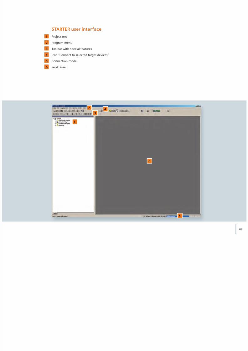
STARTER user interfaceProject tree
Program menu
Toolbar with special features
Icon “Connect to selected target devices”
Connection mode
Work area
1
1
4
2
2
5
5
6
3
34
6
8/16/2019 G120C_Entrenamiento
http://slidepdf.com/reader/full/g120centrenamiento 50/76
50 STARTER software and PC: Mounting and preparation
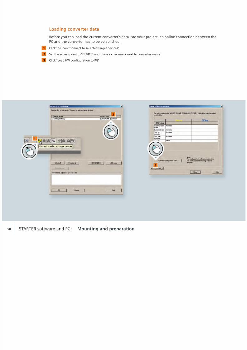
Loading converter data
Before you can load the current converter’s data into your project, an online connection between thePC and the converter has to be established.
Click the icon “Connect to sel ected target devices”
Set the access point to “DEVICE” and place a checkmark next to converter name
Click “Load HW configuration to PG”
1
2
3
1
2
3
8/16/2019 G120C_Entrenamiento
http://slidepdf.com/reader/full/g120centrenamiento 51/76
51
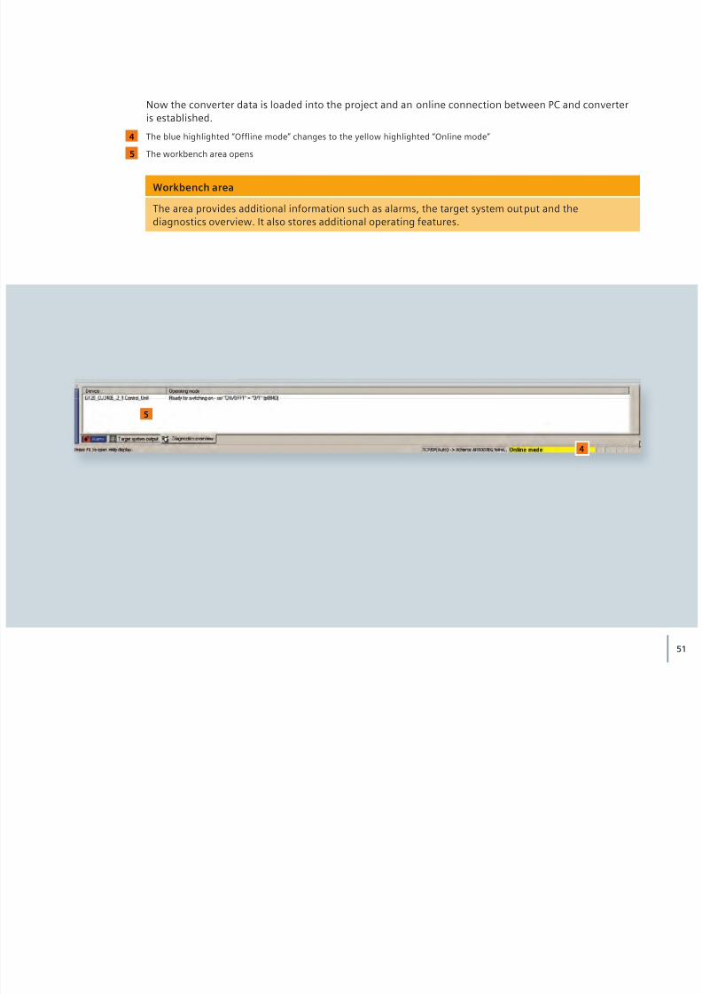
Now the converter data is loaded into the project and an online connection between PC and converteris established.
The blue highlighted “Offline mode” changes to the yellow highlighted “Online mode”
The workbench area opens
4
5
Workbench area
The area provides additional information such as alarms, the target system output and thediagnostics overview. It also stores additional operating features.
4
5

8/16/2019 G120C_Entrenamiento
http://slidepdf.com/reader/full/g120centrenamiento 52/76
52 STARTER software and PC: Parameterization
3.2 Parameterization You can now begin to parameterize your conver ter.
Double-click on the converter icon in the project tree
Click on “Load CPU / drive unit to PG”
1
2
1
2
2

8/16/2019 G120C_Entrenamiento
http://slidepdf.com/reader/full/g120centrenamiento 53/76
53
Double-click “Configuration”
Click “Wizard ...” in the work area and let the wizard guide you
3
3
4
We recommend parameterizing our
example using the online mode.
NOTE
4

8/16/2019 G120C_Entrenamiento
http://slidepdf.com/reader/full/g120centrenamiento 54/76
54
Configuration wizard
The configuration wizard guides you step by step through the following parameters:
• Control structure • Defaults of the setpoint source and the command source • Drive setting • Motor • Motor data • Drive functions • Important parameters • Calculation of the motor data • Summary
By clicking “Next” you get to the next configuration step.
STARTER software and PC: Parameterization
1 2

8/16/2019 G120C_Entrenamiento
http://slidepdf.com/reader/full/g120centrenamiento 55/76
55
Start by setting the control structure
Define the command and setpoint source
Select the motor type
Input motor data corresponding to the rating plate
1
2
4
3
For non-Siemens motors, pleaseuse the motor rating plate to
input the motor data.
NOTE
3 4
8/16/2019 G120C_Entrenamiento
http://slidepdf.com/reader/full/g120centrenamiento 56/76
56
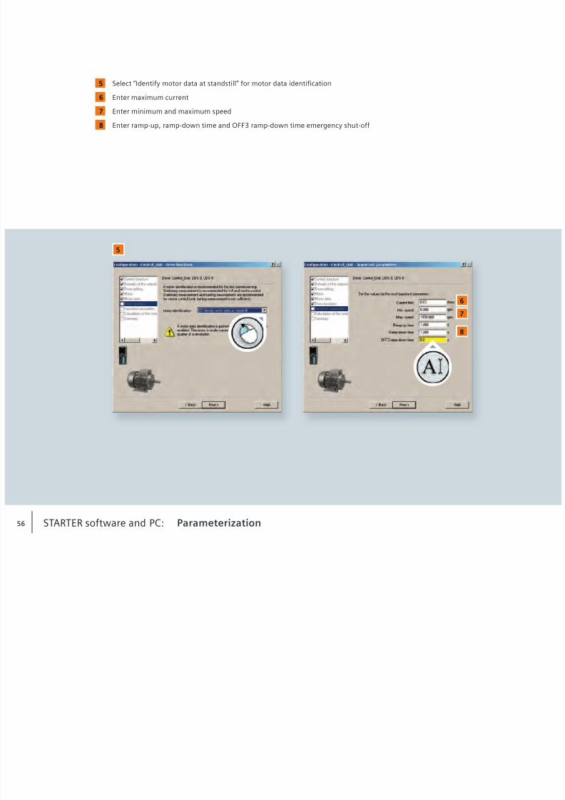
Select “Identify motor data at standstill” for motor data identification
Enter maximum current
Enter minimum and maximum speed
Enter ramp-up, ramp-down time and OFF3 ramp-down time emergency shut-off
5
6
7
8
STARTER software and PC: Parameterization
5
67
8

8/16/2019 G120C_Entrenamiento
http://slidepdf.com/reader/full/g120centrenamiento 57/76

8/16/2019 G120C_Entrenamiento
http://slidepdf.com/reader/full/g120centrenamiento 58/76
58
Safety Integrated
If your converter is used in a safety related environment, we strongly recommend performing SafetyIntegrated engineering using the STARTER. STARTER guides you clearly and easily through the process.Thus, the risk of wrong parameterization is reduced to a minimum.All control units CU240E-2 come with the Safety Integrated function STO (Safe Torque Off). STO can beused when the motor can decelerate to a standstill within a short period of time. Activating the STOfunction, immediately ensures that the motor cannot supply any further torque-generating energy.
Advantages for the user:
• No wearing parts thanks to electronic shutdown • Converter remains connected to the supply, it always supports full diagnostics capability • Password protected, no manipulation of the function possible
STARTER software and PC: Parameterization
Detailed information aboutSINAMICS Safety Integrated areavailable at: www.siemens.com/
safety-integrated
NOTE
STO
t
v

8/16/2019 G120C_Entrenamiento
http://slidepdf.com/reader/full/g120centrenamiento 59/76
59
Activating Safety IntegratedBrowse to “Safety Integrated” in the project tree
Select “Change settings”
Choose “STO via terminal” from the drop-down menu
1
1
23
2
3
Did you know that extendedSINAMICS Safety Integratedfunctions can be used withoutthe need of an encoder at themotor? This worldwide uniquefeature saves installation andengineering time, reduces sys-tem costs and saves space. Forfurther instructions consult theSafety functional manualSINAMICS G120 and SINAMICSG120C using the Siemens Prod-uct Information System (Prodis)at: http://support.automation.siemens.com/WW/view/
en/50736819
NOTE
3
8/16/2019 G120C_Entrenamiento
http://slidepdf.com/reader/full/g120centrenamiento 60/76
60
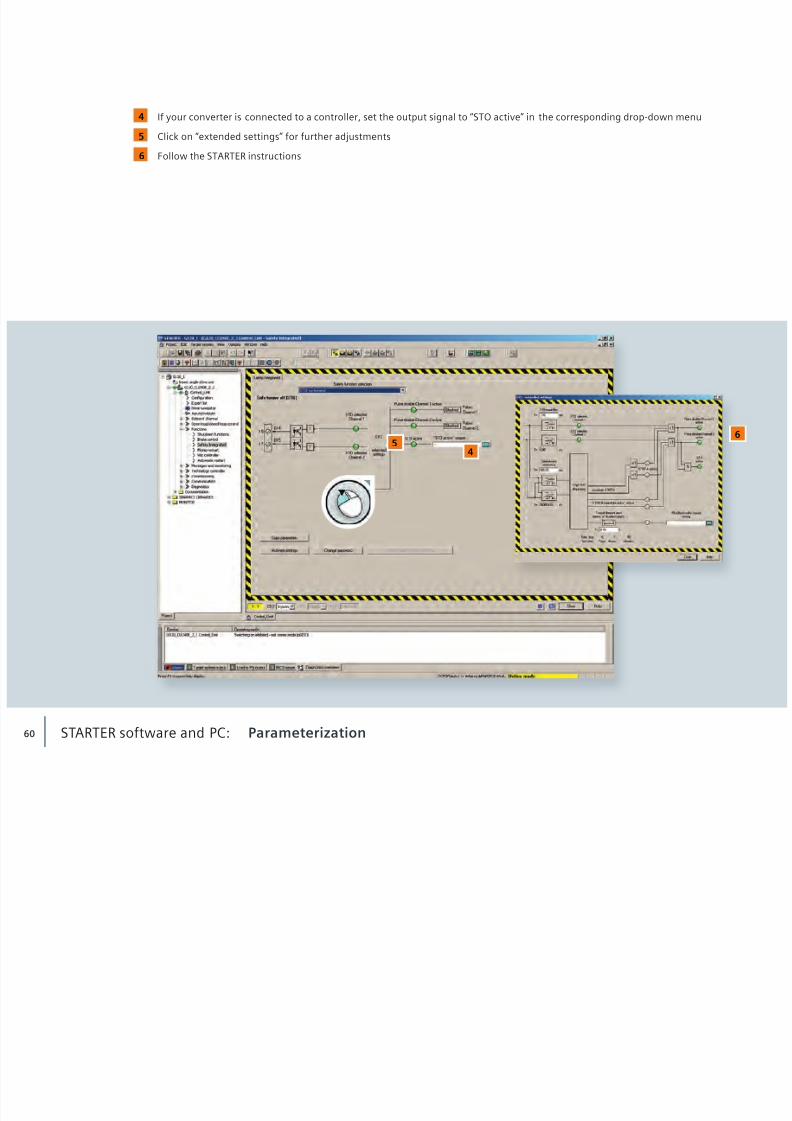
If your converter is connected to a controller, set the output signal to “STO active” in the corresponding drop-down menu
Click on “extended settings” for further adjustments
Follow the STARTER instructions
5
4
6
STARTER software and PC: Parameterization
56
4
8/16/2019 G120C_Entrenamiento
http://slidepdf.com/reader/full/g120centrenamiento 61/76
61
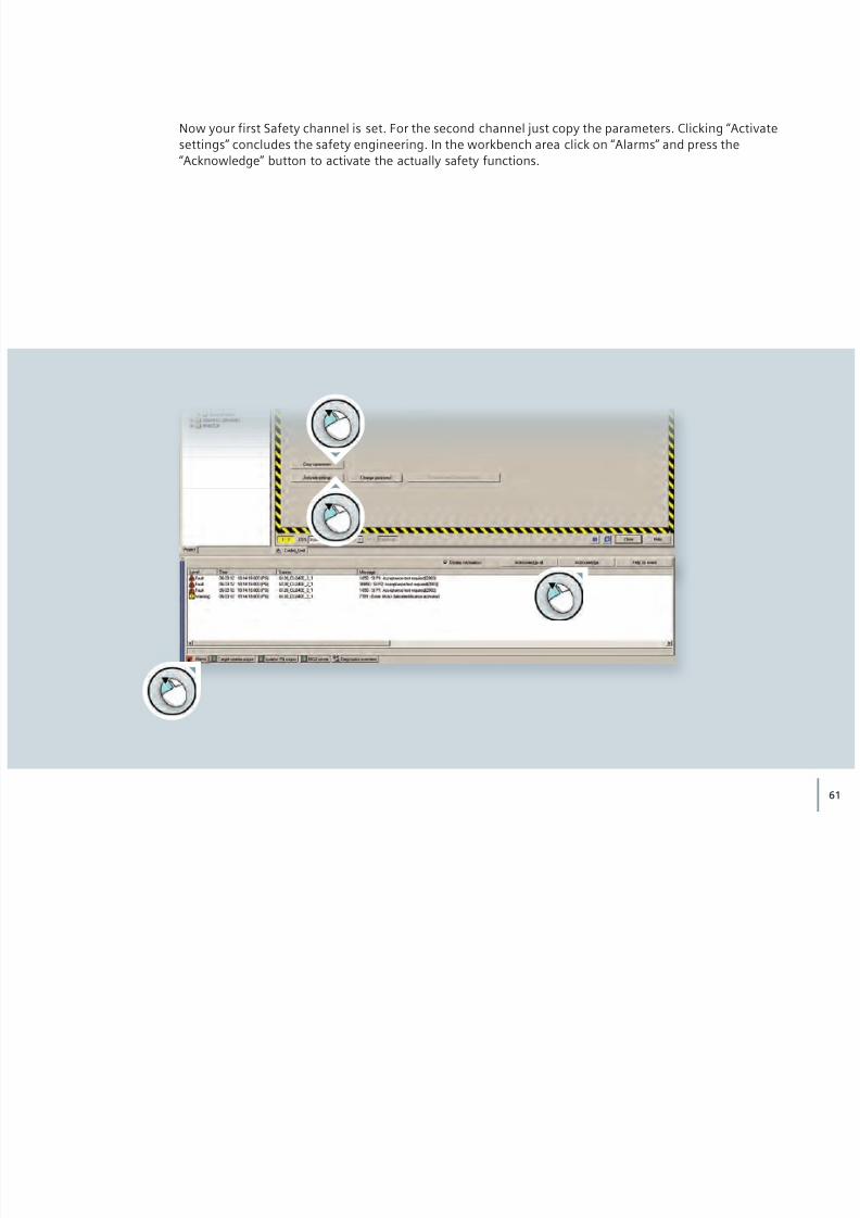
Now your first Safety channel is set. For the second channel just copy the parameters. Clicking “Activatesettings” concludes the safety engineering. In the workbench area click on “Alarms” and press the“Acknowledge” button to activate the actually safety functions.

8/16/2019 G120C_Entrenamiento
http://slidepdf.com/reader/full/g120centrenamiento 62/76
62
Start motor data identificationOpen the “Commissioning” entry in the project tree
Double-click “Control panel” in the project tree
Click on “Assume control priority!” in the workbench area
A setup window for command transfer opens, accept the displayed values and safety instructions
The pending motor data identifi-cation is indicated by the mes-sage “A7991” in the alarm tab.The message tells you that motordata identification will be per -formed after switching the
motor on.
NOTESTARTER software and PC: Parameterization
1
2
3
4
1
3
4
4
2

8/16/2019 G120C_Entrenamiento
http://slidepdf.com/reader/full/g120centrenamiento 63/76
63
Place a checkmark next to “Enables” in the workbench area
Now the STARTER software has control authority for the attached motor.
Click the green button to start the motor
5
6
56

8/16/2019 G120C_Entrenamiento
http://slidepdf.com/reader/full/g120centrenamiento 64/76
64
Motor data identification is processed. Parameter setup has been successfully completedwhen Alarm 7991 has disappeared.
STARTER software and PC: Parameterization
8/16/2019 G120C_Entrenamiento
http://slidepdf.com/reader/full/g120centrenamiento 65/76
65
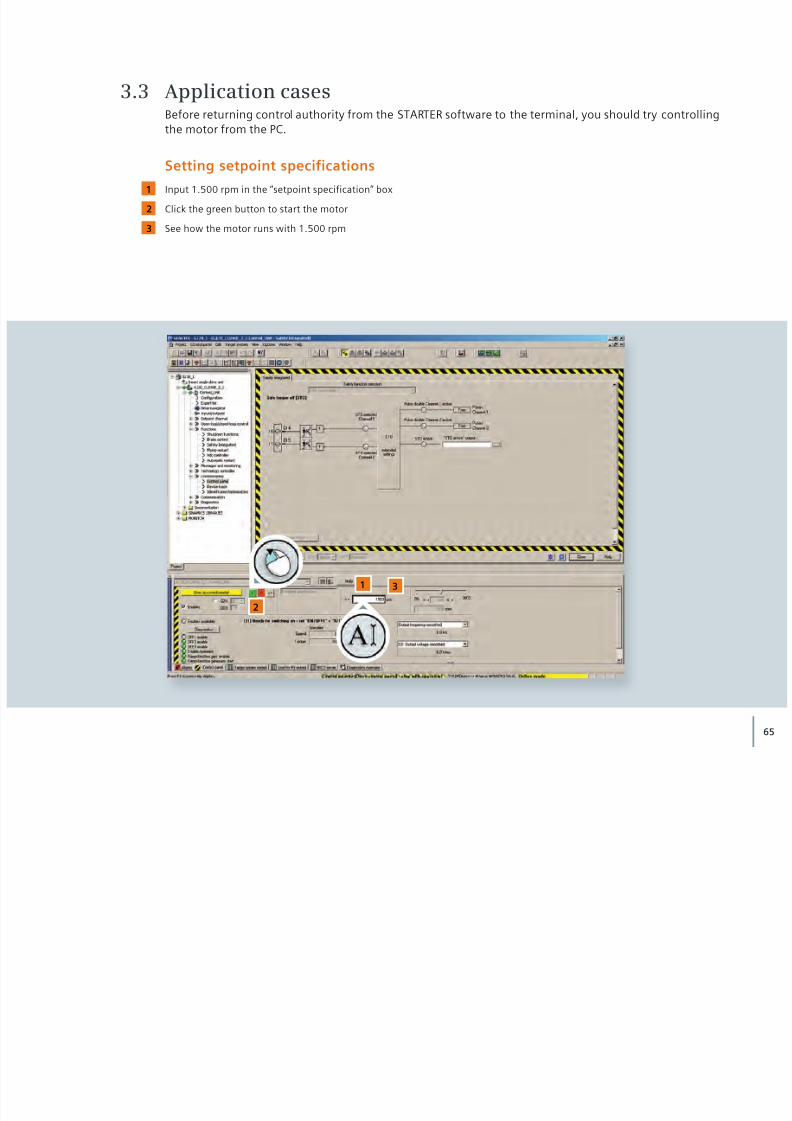
3.3 Application casesBefore returning control authority from the STARTER software to the terminal, you should try controllingthe motor from the PC.
Setting setpoint specificationsInput 1.500 rpm in the “setpoint specification” box
Click the green button to start the motor
See how the motor runs with 1.500 rpm
1
2
3
1 3
2

8/16/2019 G120C_Entrenamiento
http://slidepdf.com/reader/full/g120centrenamiento 66/76
66
Adjust the speed with the slider
Click the red button to s top the motor
Conclude the process by clicking “Give up control priority!”
All functions from the displayed control area in the STARTER will be deactivated. The control authorityhas been returned to the terminal.
4
5
6
STARTER software and PC: Application cases
4
56
8/16/2019 G120C_Entrenamiento
http://slidepdf.com/reader/full/g120centrenamiento 67/76
67
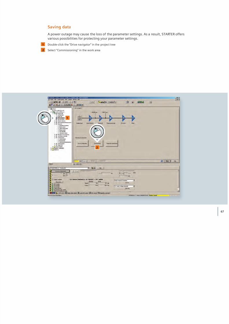
Saving data
A power outage may cause the loss of the parameter settings. As a result, STARTER offersvarious possibilities for protecting your parameter settings.
Double-click the “Drive navigator” in the project tree
Select “Commissioning” in the work area
1
2
1
2

8/16/2019 G120C_Entrenamiento
http://slidepdf.com/reader/full/g120centrenamiento 68/76
68
Select “Save data in drive (RAM to ROM)” to store the parameter settings in the converter’s EEPROM memory
STARTER software and PC: Application cases
3
3

8/16/2019 G120C_Entrenamiento
http://slidepdf.com/reader/full/g120centrenamiento 69/76
69
Because you have worked in online mode, no data whatsoever have been stored in your project.
Click “Save data to project” to save the parameter setting i n your project
Now you could disconnect the online connection to the converter by clicking the“Disconnect from target system” icon. In our example, please continue to remain online to restore theconverter to its factory settings.
4
4

8/16/2019 G120C_Entrenamiento
http://slidepdf.com/reader/full/g120centrenamiento 70/76
70 STARTER software and PC: Application cases
Restoring factory settings
Resetting your converter to factory settings might be helpful if you have experienced any problemsduring parameterization.
Double-click the “Drive navigator”
Select “Commissioning”
1
2
1
2

8/16/2019 G120C_Entrenamiento
http://slidepdf.com/reader/full/g120centrenamiento 71/76
71
Click “Factory setting”
The security query that is now displayed lets you know that all settings you have made will be reset.Using the checkbox query, you will have the opportunity to save your settings to the converter’s ROMmemory beforehand.
3
3
8/16/2019 G120C_Entrenamiento
http://slidepdf.com/reader/full/g120centrenamiento 72/76
72 STARTER software and PC: Application cases
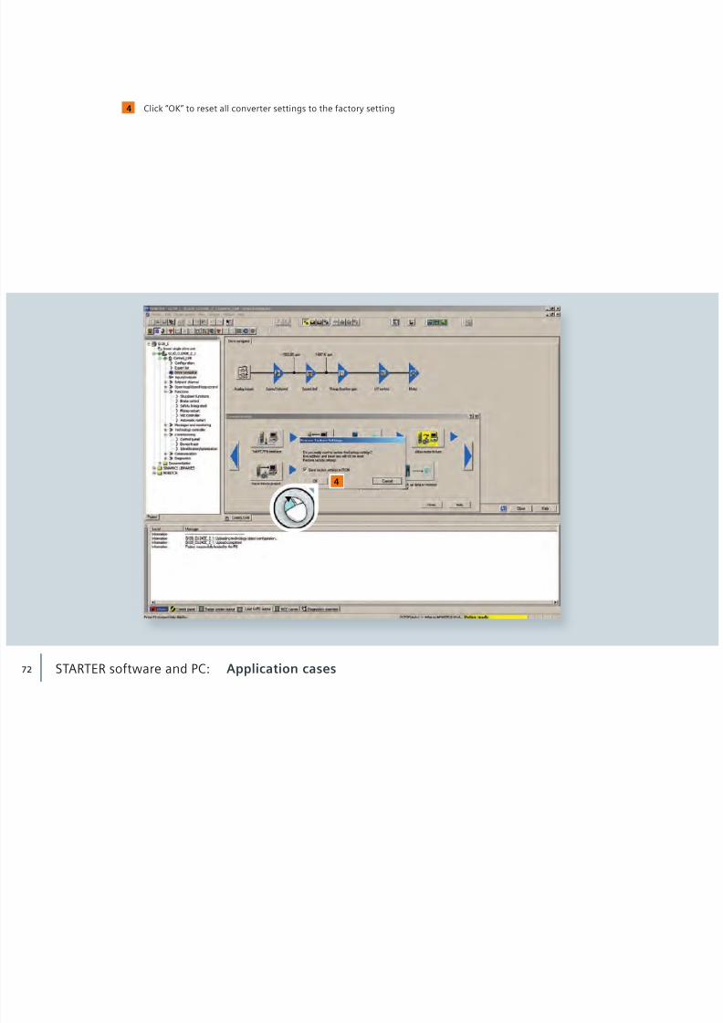
Click “OK” to reset all converter settings to the factory setting4
4
8/16/2019 G120C_Entrenamiento
http://slidepdf.com/reader/full/g120centrenamiento 73/76

8/16/2019 G120C_Entrenamiento
http://slidepdf.com/reader/full/g120centrenamiento 74/76

8/16/2019 G120C_Entrenamiento
http://slidepdf.com/reader/full/g120centrenamiento 75/76
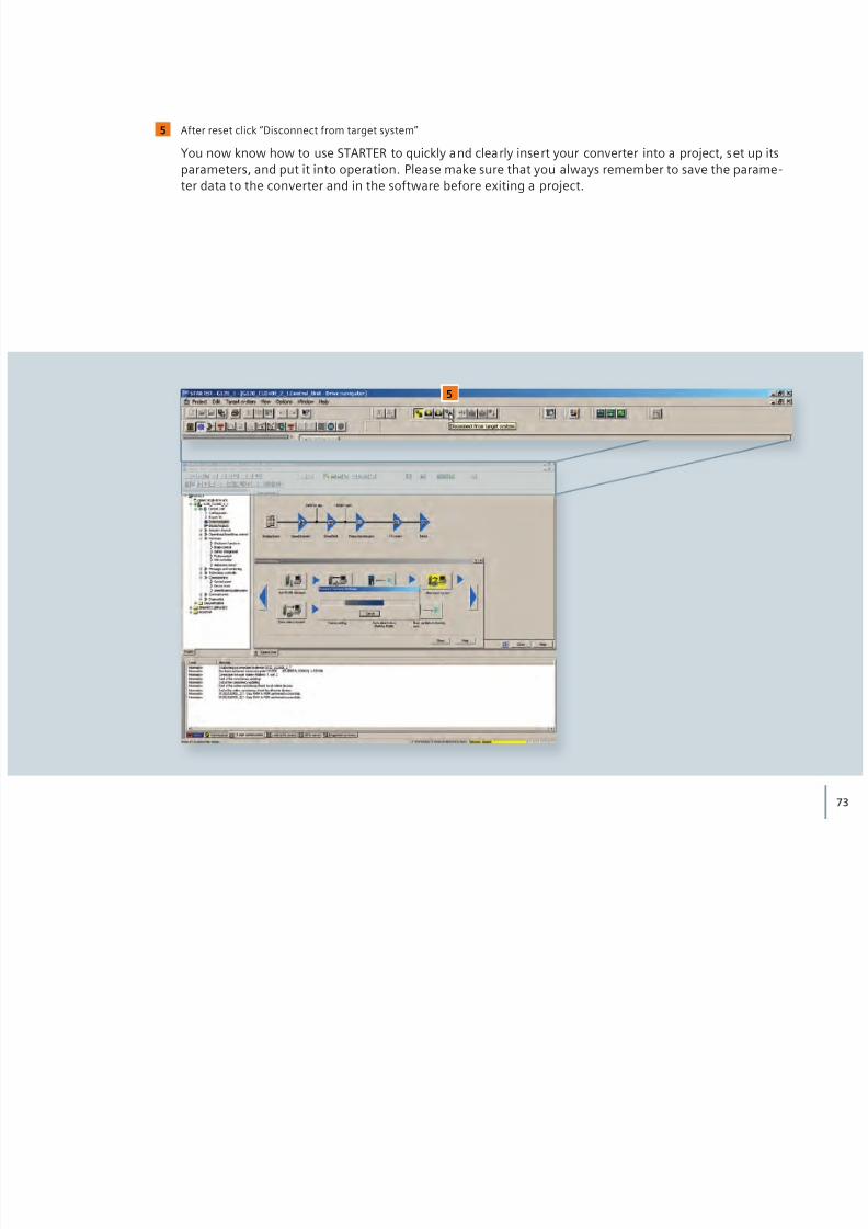
75
Download overview
Converter manual
http://support.automation.siemens.com/WW/view/en/49391037“Getting Started: SINAMICS G120C”
Additional information on parameters
http://support.automation.siemens.com/WW/view/en/49383082 „Parameter Manual: G120C” (Edition 01/2011)
Safety Integrated Function Manual
http://support.automation.siemens.com/WW/view/en/50736819
STARTER softwarehttp://support.automation.siemens.com/WW/view/en/26233208

8/16/2019 G120C_Entrenamiento
http://slidepdf.com/reader/full/g120centrenamiento 76/76
Siemens AGIndustry SectorDrive TechnologiesMotion Control
Subject to changeOrder No.: 6FC5095-0AA86-0BA0Dispo: 2120004/2012 HL 11076148 EN
Printed in Germany
© Siemens AG 2012