Document no. G1002r16 Copyright Neoptix, Inc. 1 T/Guard™ Fiber Optic Thermometer Systems For Industrial & Power Transformer Applications 1- to 16-Channel Systems (version 2.5) NeoLink Software Release 1.3 With Optional Modbus & Double-Calibration Support & TCPIP Bridge Support T/Guard-DL, -DL+ & -I: includes Data Logging option Neoptix, Inc. / Qualitrol LLC. 1415, rue Frank-Carrel, Suite 220 Québec, QC, G1N 4N7 Canada Tel: 418-687-2500 Fax: 418-687-2524 [email protected] Proprietary notice: Details of design and engineering are the exclusive property of Neoptix, Inc. and are strictly confidential. The information given herein is subject to change, at any time and without notice. All rights are reserved. The information in this document may not be reproduced or passed on in any manner without prior written consent of Neoptix, Inc. Neoptix, Inc. shall not be liable for technical or editorial errors or omissions contained herein; nor for incidental or consequential damages resulting from the furnishing, performance, or use of this material. All trademarks are the property of their respective owners. Part number: G1002R16 (November 2010)

Welcome message from author
This document is posted to help you gain knowledge. Please leave a comment to let me know what you think about it! Share it to your friends and learn new things together.
Transcript
Document no. G1002r16 Copyright Neoptix, Inc. 1
T/Guard™
Fiber Optic Thermometer Systems
For Industrial & Power Transformer Applications
1- to 16-Channel Systems (version 2.5) NeoLink Software Release 1.3
With Optional Modbus & Double-Calibration Support & TCPIP Bridge Support T/Guard-DL, -DL+ & -I: includes Data Logging option
Neoptix, Inc. / Qualitrol LLC. 1415, rue Frank-Carrel, Suite 220 Québec, QC, G1N 4N7 Canada Tel: 418-687-2500 Fax: 418-687-2524 [email protected]
Proprietary notice:
Details of design and engineering are the exclusive property of Neoptix, Inc. and are strictly confidential. The information given herein is subject to change, at any time and without notice. All rights are reserved. The information in this document may not be reproduced or passed on in any manner without prior written consent of Neoptix, Inc. Neoptix, Inc. shall not be liable for technical or editorial errors or omissions contained herein; nor for incidental or consequential damages resulting from the furnishing, performance, or use of this material. All trademarks are the property of their respective owners.
Part number: G1002R16 (November 2010)
Document no. G1002r16 Copyright Neoptix, Inc. 2
TABLE OF CONTENTS
1 LICENSE & LIMITED WARRANTY AGREEMENT ..........................................................................................4
2 INTRODUCTION ........................................................................................................................................................6 2.1 T/GUARD PRODUCT SPECIFICATIONS ..........................................................................................................................7 2.2 CALIBRATION..............................................................................................................................................................9 2.3 TRANSFORMER APPLICATIONS ....................................................................................................................................9
3 UNPACKING .............................................................................................................................................................10
4 T/GUARD™ THERMOMETER HARDWARE REFERENCE .........................................................................11 4.1 MECHANICAL INSTALLATION ...................................................................................................................................17
5 USING THE TEMPERATURE PROBES ..............................................................................................................18 5.1 CAUTION ...................................................................................................................................................................18 5.2 DESCRIPTION ............................................................................................................................................................18 5.3 WARNING..................................................................................................................................................................19 5.4 WORKING WITH LONG PROBES ..................................................................................................................................19 5.5 WORKING WITH CRYOGENIC PROBES ........................................................................................................................19 5.6 INSTALLING PROBES IN POWER TRANSFORMERS .......................................................................................................19
6 SERIAL COMMUNICATION DESCRIPTION ...................................................................................................20 6.1 USING NEOLINK CONSOLE .......................................................................................................................................20 6.2 USING HYPER TERMINAL IN WINDOWS ....................................................................................................................20 6.3 RS-232 HELP MENU...................................................................................................................................................21 6.4 DETAILED DESCRIPTION OF RS-232 COMMANDS ......................................................................................................21
6.4.1 Temperature logging commands .....................................................................................................................25 6.4.2 Recommended configuration, for transformer applications ............................................................................29 6.4.3 Interpretation of “y” command results ...........................................................................................................29
6.5 TYPICAL TEMPERATURE READING SEQUENCE...........................................................................................................30 6.6 ERROR CODES ...........................................................................................................................................................30
7 NEOLINK SOFTWARE PACKAGE .....................................................................................................................31 7.1 THE “LITE” VS. THE “PRO” VERSION .........................................................................................................................31
7.1.1 Differences between the 2 versions ..................................................................................................................31 7.2 GETTING STARTED WITH NEOLINK ...........................................................................................................................31
7.2.1 Hardware and software requirements .............................................................................................................31 7.2.2 Installing NeoLink ............................................................................................................................................32
7.3 A QUICK TOUR OF NEOLINK .....................................................................................................................................32 7.3.1 Working with the Configuration Window ........................................................................................................33
7.4 ACQUIRING AND VIEWING TEMPERATURE DATA ......................................................................................................35 7.4.1 Logging temperature data to a file ..................................................................................................................35 7.4.2 Viewing temperature data ................................................................................................................................38
7.5 THE NEOLINK CONSOLE ...........................................................................................................................................40 7.5.1 Console help menu ...........................................................................................................................................41 7.5.2 Switching between calibration types ................................................................................................................42
7.6 NEOLINK FUNCTIONS ................................................................................................................................................42 7.6.1 The File menu ..................................................................................................................................................42 7.6.2 The Window menu ............................................................................................................................................43 7.6.3 The Help Menu .................................................................................................................................................43
8 THE MODBUS OPTION ..........................................................................................................................................44 8.1 CONFIGURING THE MODBUS OPTION ........................................................................................................................44 8.2 SUPPORTED SERIAL TRANSMISSION MODE ................................................................................................................45 8.3 RTU TRANSMISSION MODE .......................................................................................................................................45 8.4 MODBUS FUNCTION CODE AND REGISTER ADDRESSES .............................................................................................45
Document no. G1002r16 Copyright Neoptix, Inc. 3
8.4.1 Read/Write, bit access ......................................................................................................................................45 8.4.2 Read only, bit access ........................................................................................................................................46 8.4.3 Read only, 16 bit access ...................................................................................................................................46 8.4.4 Write single register, 16 bit access ..................................................................................................................48 8.4.5 Modbus exception codes ..................................................................................................................................48
8.5 MODBUS AND THE SLEEP MODE ................................................................................................................................48 8.6 RS-485 CONNECTOR DEFINITION ..............................................................................................................................49
8.6.1 Connector pin-out for 2W-Modbus ..................................................................................................................49 8.6.2 Connector pin-out for optional 4W-Modbus ...................................................................................................50
8.7 EXCEL DATA-LOGGING APPLICATION .......................................................................................................................50 8.7.1 Modbus ActiveX installation ............................................................................................................................50 8.7.2 Using the Excel ModbusDataLogger utility ....................................................................................................51
8.8 USING OPTO-ISOLATORS, TO DEAL WITH GROUNDING PROBLEMS ............................................................................54
9 TCP/IP INTERFACE OPTION ...............................................................................................................................56 9.1 TCP/IP INTERFACE SPECIFICATIONS .........................................................................................................................56 9.2 TCP/IP INTERFACE INSTALLATION ...........................................................................................................................56
9.2.1 Hardware installation ......................................................................................................................................56 9.2.2 Software installation ........................................................................................................................................58
10 RS-485 CONVERTERS ........................................................................................................................................64 10.1 RS-485 TO USB CONVERTER ....................................................................................................................................64 10.2 RS-485 TO RS-232 CONVERTER ...............................................................................................................................64
Warning
Permanent damage may be done to the thermometer if the power supply connections are not done correctly. In particular, do not connect the power input (18-24VDC) to any of the analog output connectors. Note that the 20 mA analog output options are self-powered interfaces (by opposition to loop-powered interfaces), and thus do not require any external supply. Minimum loop impedance should be kept at 400Ω; internal impedance is approximately 0.7Ω. With 0-10 volt analog outputs, avoid shorting output leads together; as this may destroy the electronic drivers inside the unit; external impedance must be kept at all time at 10kΩ or more. Unit must be returned to Neoptix for repair, not field repairable. Fiber optic probes are fragile, and will break if the bending radius becomes less than 1cm, even temporarily. Furthermore, as T2 probe tips are fragile, exercise care to: Make sure the last ~1 cm of probes is free standing, and not pressurized by any glue, or by the spacers Avoid bending the last 1cm of probes. Furthermore, due to the unique construction of the Neoptix T2 type probes, it is important that you avoid applying glue to the last 1 cm of the probes during their installation in transformer windings. Probe breakages are not covered under the standard Neoptix warranty. To assure cleanliness of optical connectors, keep caps on unused connectors at all time. This is also required during operation, as parasitic light entering via unused connectors into the T/Guard module may cause false temperature readings, even on other channels.
The Neoptix T/Guard products are CE marking certified.

Document no. G1002r16 Copyright Neoptix, Inc. 4
1 LICENSE & LIMITED WARRANTY AGREEMENT Your T/Guard unit is guaranteed (Parts and Workmanship) from the date of purchase. Upon written notification of any defect, Neoptix will either repair or replace any faulty product or components thereof. A Return Authorization Number (RMA) must be obtained from Neoptix or authorized distributor prior to any merchandise return. Due to the unique nature of T/Guard probes, probes are not warranted. SOFTWARE DISCLAIMER OF WARRANTY and HARDWARE LIMITED WARRANTY: Neoptix, Inc. makes no representation or warranties with regard to this software product and instructional and reference materials, including, but not limited to the implied warranties of merchantability and fitness for a particular application. Neoptix, Inc. does not warrant, guarantee, or make any representations regarding the use, or the results of the use, of the software or written materials in terms of correctness, accuracy, reliability, currentness, or otherwise. Neoptix, Inc. shall not be liable for errors or omissions contained in its software or manuals, any interruptions of service, loss of business or anticipatory profits and/or for incidental or consequential damages in connection with the furnishing, performance or use of these materials even if Neoptix, Inc. has been advised of the possibility of such damages. The software and manuals are sold as is. The licensee assumes the entire risk as to the results and performance of the hardware and software. Neoptix, Inc. reserves the right to make changes to the specifications of the instruments, the software and content of this manual without obligation to notify any person or organization of such changes. The remaining of this section is applicable to the Neoptix NeoLink™ software package. You may ignore this information if you will not be using this software package. READ THIS AGREEMENT CAREFULLY BEFORE OPENING THE CD ASSOCIATED SOFTWARE PACKAGES: OPENING THE CD AND SOFTWARE PACKAGES INDICATES YOUR UNDERSTANDING AND ACCEPTANCE OF THIS AGREEMENT. If you do not agree to the terms contained below, return the product with the CD UNOPENED to your distributor and your purchase price will be refunded. Neoptix, Inc. agrees to grant and the LICENSEE agrees to accept on the following terms and conditions, a non-transferable (except as herein defined) and non-exclusive license(s) to the software program(s) (Licensed Programs) herein delivered with this agreement. TERM: This agreement shall remain in force until terminated by the LICENSEE upon one (1) month’s prior written notice, or by Neoptix, Inc. as provided below. Any license under this Agreement may be discontinued by the LICENSEE upon one month’s prior written notice. Neoptix, Inc. may discontinue any license or terminate this Agreement if the LICENSEE fails to comply with any of the terms and conditions of the Agreement or if Neoptix, Inc. is not reimbursed for the sale of this software in a timely manner. SOFTWARE LICENSE: Each program license granted under this Agreement authorizes the LICENSEE to use the Licensed Programs in machine-readable form on any single computer. A separate license is required for each single computer on which the Licensed Programs will be used. This Agreement and any of the licenses, programs or materials to which it applies may not be assigned, sub-licensed or otherwise transferred by the LICENSEE without prior written consent from Neoptix, Inc., except as herein after expressly provided. No right to print or copy, in whole or in part, the Licensed Programs is granted except as hereinafter expressly provided. You may make one (1) copy of the Licensed Programs solely for backup purposes. You must reproduce and include the copyright notice on the backup copy. You may physically transfer the Licensed Programs from one computer to another provided that the Licensed Programs are used on only one computer at a time.

Document no. G1002r16 Copyright Neoptix, Inc. 5
THE ABOVE ARE THE ONLY WARRANTIES OF ANY KIND, EITHER EXPRESSED OR IMPLIED, INCLUDING BUT NOT LIMITED TO THE IMPLIED WARRANTIES OR MERCHANTABILITY AND FITNESS FOR A PARTICULAR PURPOSE, THAT ARE MADE BY NEOPTIX, INC. ON THIS PRODUCT. BECAUSE SOME STATES DO NOT ALLOW THE EXCLUSION OR LIMITATION OF LIABILITY OR CONSEQUENTIAL OR INCIDENTAL DAMAGES, THE ABOVE LIMITATION MAY NOT APPLY TO YOU.
Document no. G1002r16 Copyright Neoptix, Inc. 6
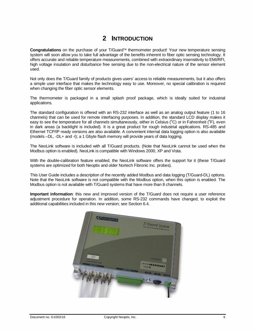
2 INTRODUCTION Congratulations on the purchase of your T/Guard thermometer product! Your new temperature sensing system will soon allow you to take full advantage of the benefits inherent to fiber optic sensing technology. It offers accurate and reliable temperature measurements, combined with extraordinary insensitivity to EMI/RFI, high voltage insulation and disturbance free sensing due to the non-electrical nature of the sensor element used. Not only does the T/Guard family of products gives users’ access to reliable measurements, but it also offers a simple user interface that makes the technology easy to use. Moreover, no special calibration is required when changing the fiber optic sensor elements. The thermometer is packaged in a small splash proof package, which is ideally suited for industrial applications. The standard configuration is offered with an RS-232 interface as well as an analog output feature (1 to 16 channels) that can be used for remote interfacing purposes. In addition, the standard LCD display makes it easy to see the temperature for all channels simultaneously, either in Celsius (oC) or in Fahrenheit (oF), even in dark areas (a backlight is included). It is a great product for rough industrial applications. RS-485 and Ethernet TCP/IP ready versions are also available. A convenient internal data logging option is also available (models –DL, -DL+ and -I); a 1 Gbyte flash memory will provide years of data logging. The NeoLink software is included with all T/Guard products. (Note that NeoLink cannot be used when the Modbus option is enabled). NeoLink is compatible with Windows 2000, XP and Vista. With the double-calibration feature enabled, the NeoLink software offers the support for it (these T/Guard systems are optimized for both Neoptix and older Nortech Fibronic Inc. probes). This User Guide includes a description of the recently added Modbus and data logging (T/Guard-DL) options. Note that the NeoLink software is not compatible with the Modbus option, when this option is enabled. The Modbus option is not available with T/Guard systems that have more than 8 channels. Important information: this new and improved version of the T/Guard does not require a user reference adjustment procedure for operation. In addition, some RS-232 commands have changed, to exploit the additional capabilities included in this new version; see Section 6.4.

Document no. G1002r16 Copyright Neoptix, Inc. 7
2.1 T/Guard product specifications
Resolution 0.1C Accuracy The Greater of 1C or 1% of reading
Calibrated Temperature Range
-40 to 200C
Supported probes Support for Nortech Fibronic inc. type probes Usable Temperature
Range -80 to 250C
Number of channels* 1 to 8 (option: up to 16) Probe length 1 to 300 meters
Response time Typically 0.3 second per channel (probe configuration dependent)
Unit User selection of C or F Operating temperature -30 to 70C, non-condensing Storage temperature -40 to 80C
LCD display Display of channel number and temperature readings Power 14 to 28VDC, 0.6A
(see note below, front panel) Size 280L x 170W x 60D mm
Weight 1.5 kg Standard interface* RS-232C or RS-485 (2W or 4W)
Analog output (4-20mA or 0-10V) Data logging* Up to 1GB (fixed memory)
DL+: With second RS-232 port Optional interface RS-485
TCP-IP (Ethernet) Modbus
Sensor Dielectric epoxy or silicone tipped optical fiber *: Selection must be specified at time of order. The following figure gives a description of some probe configurations and options that are available from Neoptix.
General Purpose Probe T1:

Document no. G1002r16 Copyright Neoptix, Inc. 8
Transformer Probe T2 (shown with feedthrough):
General Purpose Probe T2:
OFT Coupling (Feedthrough): (for transformer wall application, and other similar applications)

Document no. G1002r16 Copyright Neoptix, Inc. 9
ST Coupling (for other general-purpose applications)
ST-ST Extension Cable
Other options and configurations are also possible; contact Neoptix for more information.
2.2 Calibration Your T/Guard thermometer comes factory-calibrated. An annual re-calibration is recommended every 12 months or whenever performance verification indicates that calibration is necessary; NIST traceable calibration certificates are available. All calibrations are performed at the factory. Contact your Neoptix Representative for further information.
2.3 Transformer applications One of the main applications for the T/Guard product is monitoring temperature of hot spots in power transformers. Since its inception, Neoptix has developed expertise in this application, and is considered as a world leader in this field. The sister product of the T/Guard, the T/Guard+, is fully dedicated to the power transformer industry. Neoptix publishes a User Guide, called “Probe Installation Guide”, totally dedicated to the power transformer industry; do not hesitate to ask for your copy if you are working in this field.
Document no. G1002r16 Copyright Neoptix, Inc. 10
3 UNPACKING Before using your T/Guard thermometer, check the box content to be sure all items have been included. Your package should normally contain: T/Guard signal conditioner unit Mating connectors for the power input and for the analog output RS-232C interface cable (2 meters) User manual (this manual) (paper copy not included, supplied as a PDF document on CD) Neoptix NeoLink™ Pro software on CD (supplied with an unlocking key) Calibration Certificate. Options: Fiber optic temperature sensor probes Fiber optic extension cables Fiber optic coupling and feedthroughs RS-485 communication interface TCP/IP bridge communication interface, with Lantronix CD (may be on same CD as NeoLink) Modbus communication protocol Data logging option (T/Guard-DL and –I only) RS-232 to RS-485 converter Power supply module (universal input: 100-240VAC, 50/60Hz). Table top and DIN mounted models are
available Carrying case & accessories. Make sure all listed items have been received and are in good condition. Note any evidence of rough handling in transit; immediately report any damage to the shipping agent. Should a part be missing or damaged, please contact your distributor immediately. Returns must be made with the original packaging, accompanied by an authorization number (RMA). Your distributor will provide you with information concerning the return of merchandise. The carrier will not honor damage claims unless all shipping material is saved for inspection. After examining and removing contents, save packing material and carton in the event reshipment becomes necessary.
Document no. G1002r16 Copyright Neoptix, Inc. 11
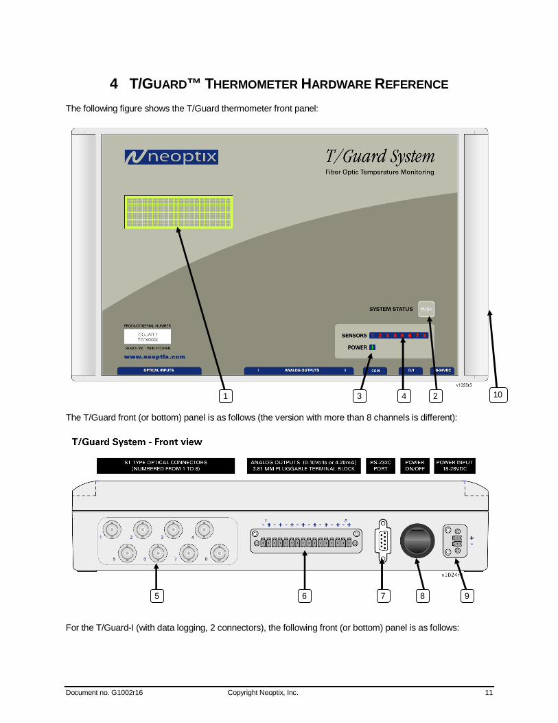
4 T/GUARD™ THERMOMETER HARDWARE REFERENCE The following figure shows the T/Guard thermometer front panel:
The T/Guard front (or bottom) panel is as follows (the version with more than 8 channels is different):
For the T/Guard-I (with data logging, 2 connectors), the following front (or bottom) panel is as follows:
8 9 6
4
7
3 2
5
1 10
Document no. G1002r16 Copyright Neoptix, Inc. 12
The following presents a full description of the user interface as well as detailed instructions on how to use the thermometer.
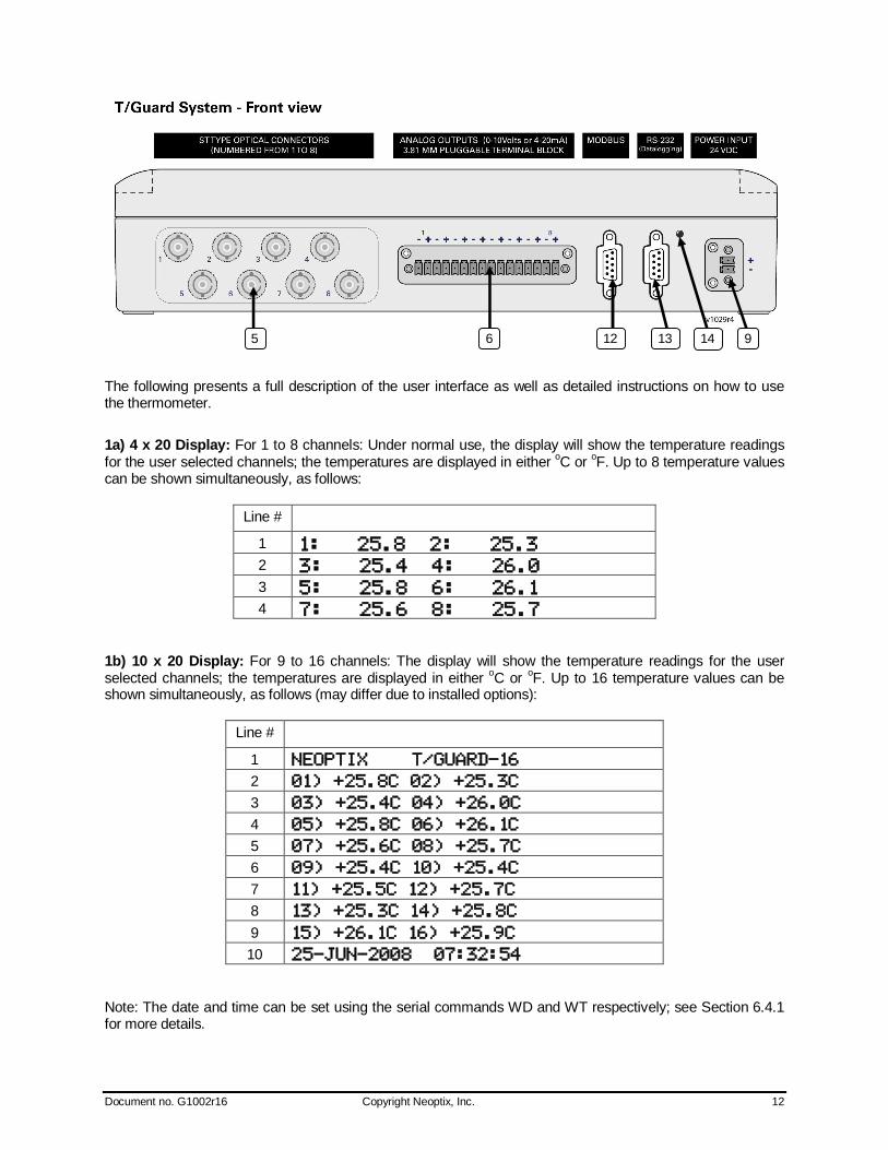
1a) 4 x 20 Display: For 1 to 8 channels: Under normal use, the display will show the temperature readings for the user selected channels; the temperatures are displayed in either oC or oF. Up to 8 temperature values can be shown simultaneously, as follows:
Line # 1
2
3
4
1b) 10 x 20 Display: For 9 to 16 channels: The display will show the temperature readings for the user selected channels; the temperatures are displayed in either oC or oF. Up to 16 temperature values can be shown simultaneously, as follows (may differ due to installed options):
Line # 1
2
3
4
5
6
7
8
9
10
Note: The date and time can be set using the serial commands WD and WT respectively; see Section 6.4.1 for more details.
13 9 6 12 5 14

Document no. G1002r16 Copyright Neoptix, Inc. 13
2) System Status key1: For 1 to 8 channels only. Furthermore, this function is not available with the T/Guard-I. This key can be used to temporarily display some probe related information. The following 4 information types will be sequentially displayed, by pressing this key multiple times. Normal display will return after 30 seconds of inactivity.
Max temperatures Displays maximum temperatures, for each channel. Min temperatures Displays minimum temperatures, for each channel. Power of probes Gives the probe signal strength, for each probe. See Section 6.4.3 for more
information. CCD time Gives the CCD integration time, for each channel. See Section 6.4.3 for more
information. Note: Holding the key pressed, while any of these values are displayed, can clear memorized minimum and maximum temperatures.
With the Modbus option, this key can be used to engage/disengage the Modbus option. To do this, hold this key down for a few seconds while the T/Guard is turned on. See item 8 “Power Switch” below for more information.
With the T/Guard-I, this key can be used to toggle between the “Modbus” mode and the “Service” mode. These two modes are exclusive, i.e. they cannot be used simultaneously. Hold the switch down for at least 3 seconds to change mode, until the green led changes (the led is lit in service mode, is not lit in Modbus mode). See items 12 to 14 below for more information.
3) Power status light.
4) Sensor status light(s): There are a total of up to 16 lights for this, one for each channel. These indicators inform you about the system status, as applicable to each channel. If any remains off, this indicates that either that channel is disabled (or not present for systems that have less than 8 channels) or there is a problem with that sensor (or with the optional patch cord connected to it). Check if all optical connectors are correctly mated or if the sensor fiber (or patch cord) is not broken.
A quickly flashing light indicates that the calibration table applicable to this channel is corrupted. If this happens, the integrity of the temperature readings for this channel is not guaranteed; please use precaution. Contact Neoptix for further information on how to resolve this issue.
5) Sensor connector(s): These are ST type connectors, mating to each of the 16 optical temperature sensors. If you need to extend a sensor fiber, you should use optional patch cords that are available from your Neoptix supplier.
Warning: The fiber type that is used with your T/Guard thermometer is of a special type, and it is recommended that you get ALL of your patch cords from Neoptix or a Neoptix authorized distributor.
6) Analog output connector(s): There are a total of 8 connection pairs (16 connection pairs, if more than 8 channels), one pair for each channel. Prior to shipment, your T/Guard thermometer was factory set to one of the following configurations: 4-20mA or 0-10V output. The minimum analog output value corresponds to minus 100°C and the maximum analog output value corresponds to 300°C. The thermometer normal range is from minus 80°C to 250°C, so a minimum value indicates an under-range error; likewise, a maximum value indicates an over-range error condition. Note: T/Guard thermometers that have extended range, such as cryogenic version, may differ; contact Neoptix for more information. If there is a sensor problem for a given channel, the analog output may take one of the following 3 states (refer to the RS-232 “o” command, Section 6.4):
1 This key was previously called “LCD BACKLIGHT”; with this new software, its functionality has also changed as described above. On 9 to 16 channel T/Guard, the key is a black key mounted on the side of the thermometer.
Document no. G1002r16 Copyright Neoptix, Inc. 14
a) It will toggle between the minimum and maximum values, at approximately 0.5 Hz; this indicates a sensor problem for that channel (“o0”). This is the default setting; to change it, you will need to use the RS-232 “o1” or “o2” command.
b) The analog output is forced to its maximum value (“o1”); this would indicate a “too-hot” situation. c) The analog output is forced to its minimum value (“o2”); this would indicate a “too-cold” situation.
Warning: 1- Do not connect any external voltages to these outputs; this may cause permanent damage to the thermometer unit. 2- Avoid shorting output leads together, as this may destroy the electronic drivers inside the unit.
Note: If the T/Guard unit is in “sleep” mode, the analog outputs will keep their values until the T/Guard acquires new temperature values.
16-position mating connectors are supplied with the T/Guard system.
7) RS-232 or RS-485 communication interface: This port is used to configure and extract information for the instrument. This DB-9 connector uses the same pin-out as a COM port on a PC computer. Use a simple pin-to-pin wired cable (not a null modem cable) to connect to a computer. See Section 6.4 for a complete description of the serial commands that are available.
A RS-485 interface is also available. This option would normally be used when the Modbus option is enabled. Refer to the Modbus Chapter 8 or contact Neoptix for more details. A RS-232 to RS-485 optional converter is also available from Neoptix; contact your representative or Neoptix for more details.
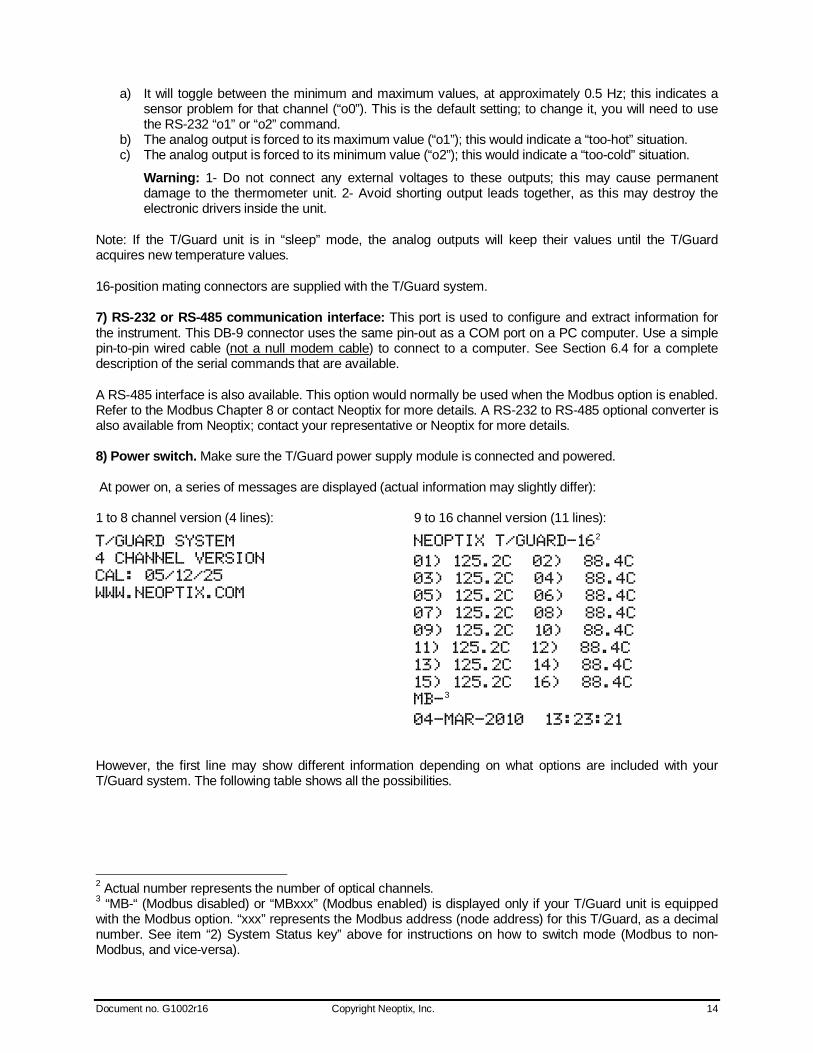
8) Power switch. Make sure the T/Guard power supply module is connected and powered. At power on, a series of messages are displayed (actual information may slightly differ): 1 to 8 channel version (4 lines): 9 to 16 channel version (11 lines):
2
3
However, the first line may show different information depending on what options are included with your T/Guard system. The following table shows all the possibilities.
2 Actual number represents the number of optical channels. 3 “MB-“ (Modbus disabled) or “MBxxx” (Modbus enabled) is displayed only if your T/Guard unit is equipped with the Modbus option. “xxx” represents the Modbus address (node address) for this T/Guard, as a decimal number. See item “2) System Status key” above for instructions on how to switch mode (Modbus to non-Modbus, and vice-versa).
Document no. G1002r16 Copyright Neoptix, Inc. 15
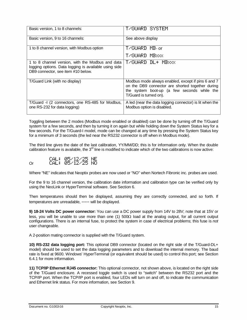
Basic version, 1 to 8 channels:
Basic version, 9 to 16 channels: See above display
1 to 8 channel version, with Modbus option - or
1 to 8 channel version, with the Modbus and data logging options. Data logging is available using side DB9 connector, see item #10 below.
T/Guard Link (with no display) Modbus mode always enabled, except if pins 6 and 7 on the DB9 connector are shorted together during the system boot-up (a few seconds while the T/Guard is turned on).
T/Guard -I (2 connectors, one RS-485 for Modbus, one RS-232 for data logging)
A led (near the data logging connector) is lit when the Modbus option is disabled.
Toggling between the 2 modes (Modbus mode enabled or disabled) can be done by turning off the T/Guard system for a few seconds, and then by turning it on again but while holding down the System Status key for a few seconds. For the T/Guard-I model, mode can be changed at any time by pressing the System Status key for a minimum of 3 seconds (the led near the RS232 connector is off when in Modbus mode).
The third line gives the date of the last calibration, YY/MM/DD; this is for information only. When the double calibration feature is available, the 3rd line is modified to indicate which of the two calibrations is now active:
Or
Where “NE” indicates that Neoptix probes are now used or “NO” when Nortech Fibronic inc. probes are used.
For the 9 to 16 channel version, the calibration date information and calibration type can be verified only by using the NeoLink or HyperTerminal software. See Section 6.
Then temperatures should then be displayed, assuming they are correctly connected, and so forth. If temperatures are unreadable, ----- will be displayed.
9) 18-24 Volts DC power connector: You can use a DC power supply from 14V to 28V; note that at 15V or less, you will be unable to use more than one (1) 500 load at the analog output, for all current output configurations. There is an internal fuse, to protect the system in case of electrical problems; this fuse is not user changeable.
A 2-position mating connector is supplied with the T/Guard system.
10) RS-232 data logging port: This optional DB9 connector (located on the right side of the T/Guard-DL+ model) should be used to set the data logging parameters and to download the internal memory. The baud rate is fixed at 9600. Windows’ HyperTerminal (or equivalent should be used) to control this port; see Section 6.4.1 for more information.
11) TCP/IP Ethernet RJ45 connector: This optional connector, not shown above, is located on the right side of the T/Guard enclosure. A recessed toggle switch is used to “switch” between the RS232 port and the TCP/IP port. When the TCP/IP port is enabled, four LEDs will turn on and off, to indicate the communication and Ethernet link status. For more information, see Section 9.

Document no. G1002r16 Copyright Neoptix, Inc. 16
12) RS-485 Modbus port (T/Guard-I only): This DB9 connector should be used for permanent Modbus connection (2-wire is standard). The Modbus communication is enabled only when the green led (see item 14) is not lit. 13) RS-232 Service port (T/Guard-I only): This DB9 connector should be used to connect to NeoLink, program parameters, including data logging parameters, and to download logged temperature data (see Section 6.4.1 below for more information). This mode is only active when the green led is lit. 14) Mode status indicator (T/Guard-I only): In normal operation (Modbus mode), this green led should be off. In data-logging mode, it must be on. Please note that the two modes of operation are exclusive, i.e. only one can be active at any given time. Use “System Status” key (item 2 above) to toggle between modes.
Document no. G1002r16 Copyright Neoptix, Inc. 17
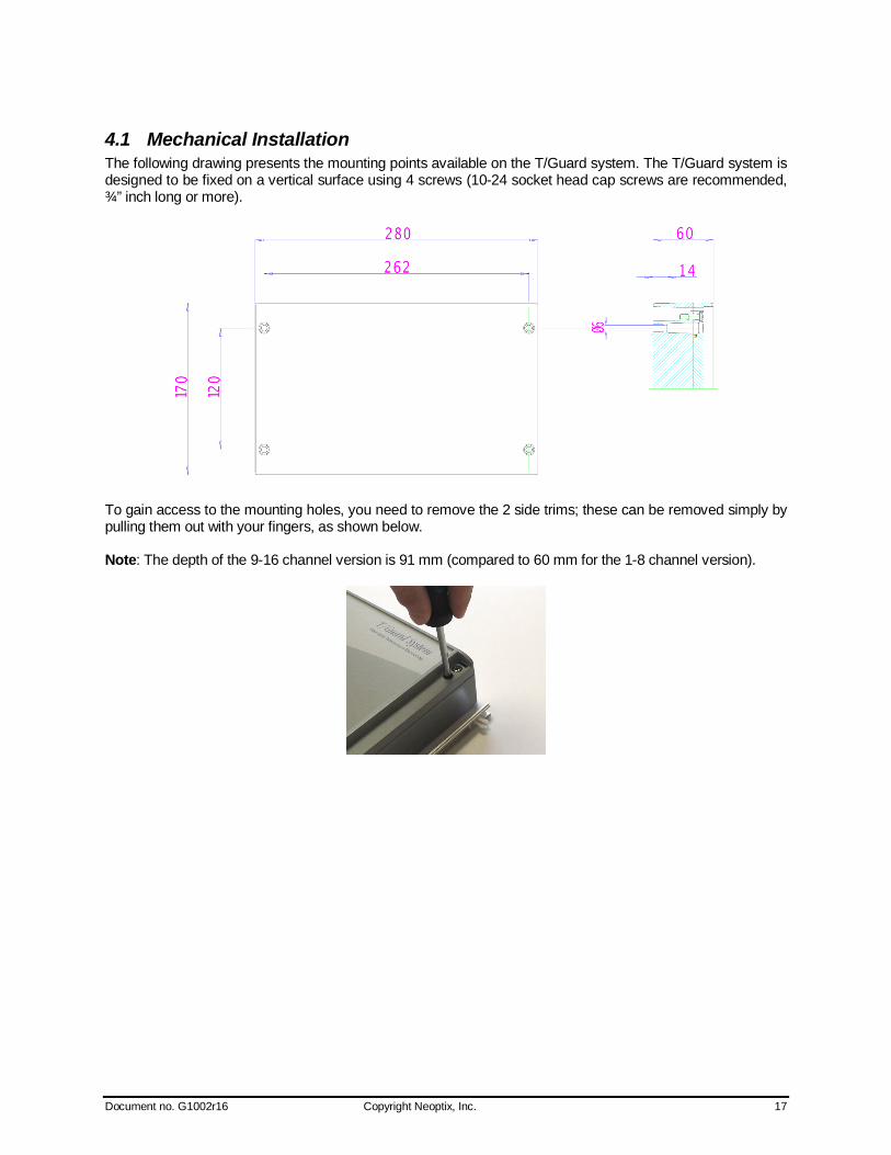
4.1 Mechanical Installation The following drawing presents the mounting points available on the T/Guard system. The T/Guard system is designed to be fixed on a vertical surface using 4 screws (10-24 socket head cap screws are recommended, ¾” inch long or more).
To gain access to the mounting holes, you need to remove the 2 side trims; these can be removed simply by pulling them out with your fingers, as shown below. Note: The depth of the 9-16 channel version is 91 mm (compared to 60 mm for the 1-8 channel version).
Document no. G1002r16 Copyright Neoptix, Inc. 18
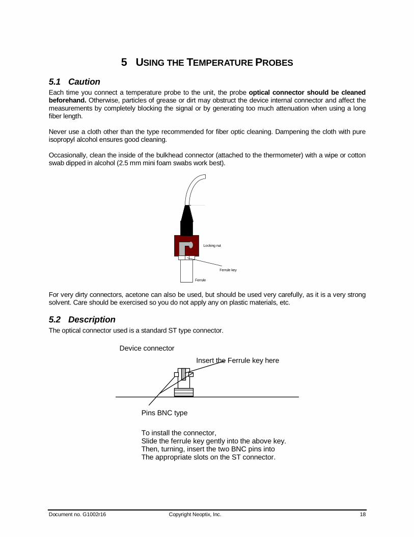
5 USING THE TEMPERATURE PROBES 5.1 Caution Each time you connect a temperature probe to the unit, the probe optical connector should be cleaned beforehand. Otherwise, particles of grease or dirt may obstruct the device internal connector and affect the measurements by completely blocking the signal or by generating too much attenuation when using a long fiber length. Never use a cloth other than the type recommended for fiber optic cleaning. Dampening the cloth with pure isopropyl alcohol ensures good cleaning. Occasionally, clean the inside of the bulkhead connector (attached to the thermometer) with a wipe or cotton swab dipped in alcohol (2.5 mm mini foam swabs work best).
Ferrule
Locking nut
Ferrule key
For very dirty connectors, acetone can also be used, but should be used very carefully, as it is a very strong solvent. Care should be exercised so you do not apply any on plastic materials, etc.
5.2 Description The optical connector used is a standard ST type connector.
Device connector
Insert the Ferrule key here
Pins BNC type
To install the connector,
Then, turning, insert the two BNC pins intoThe appropriate slots on the ST connector.
Slide the ferrule key gently into the above key.

Document no. G1002r16 Copyright Neoptix, Inc. 19
5.3 Warning The T1 probe is quite fragile and it must be handled carefully. Please note that any probe damages are not covered by the standard warranty. The probe tip is made of silicone rubber. Although silicone is resistant to a large number of chemical aggressors, strong acids or alkali may damage it, especially at high temperature and/or if used for extended periods of time. Warning: Solvents and fuel oils can cause problems for silicone rubber. Neoptix also manufactures probes that have their tips made of epoxy. Just like silicone, epoxy resin is resistant to a large number of chemical aggressors, strong acids or alkali may damage it, especially at high temperature and/or if used for extended periods of time. Contact your distributor for additional chemical compatibility information. Do not expose your probes to temperatures that are higher than specified. Permanent damage can be caused to probes that have been exposed to temperatures that are higher than their limits.
5.4 Working with long probes This note is important when using probes or extensions that have a combined length of 100 meters or more. Working with long probes or extensions presents special problems. To limit the amount of back reflection caused by the fiber optic connector located on the thermometer unit, you may have to use a matching gel optical couplant in the connector. This gel is a grease-like compound with high clarity, good resolution properties and a refractive index close to quartz. Apply the gel onto connector end faces. Avoid disconnecting the connectors for which gel has been used. In other words, it is recommended to use the gel only for permanent installations. If the connectors are disconnected many times, you may have to clean entirely the connector assemblies that have had the gel; this may require opening the instrument enclosure to remove the excess gel. Note that it is not required to use this gel with connectors that are far away from the thermometer electronic unit.
5.5 Working with cryogenic probes The use of a cryogenic probe required special attention. In particular, the probes become more brittle at very low temperatures. Avoid cycling the probes quickly between cryogenic temp and ambient temperatures, as this may cause material fatigue at the probe tips.
Warning
Always wear protective gloves and clothing when working with cryogenic material. Never use general purpose probes at cryogenic temperatures. Neoptix sells special probes that can be used at cryogenic temperatures. Please note that your T/Guard thermometer will require a special factory calibration to be used at cryogenic temperatures (below -80oC). Consult Neoptix for more information.
5.6 Installing probes in power transformers Neoptix offers a complete line of T2 type probes that are specifically designed to be installed inside transformer windings, to monitor temperatures of hot spots. Please refer to the Neoptix’ “Probe Installation Guide Inside Power Transformers” for recommendations and instructions on how to install and handle these probes, to maximize your success rate for this application.
Document no. G1002r16 Copyright Neoptix, Inc. 20
6 SERIAL COMMUNICATION DESCRIPTION You can communicate with your T/Guard thermometer via the standard RS-232 link. A description of the cable requirements is given above, under front panel item # 7. RS-232 functions (or commands) can be accessed with a simple terminal, or using NeoLink software package or simply with a computer and communication software (such as Windows Hyper Terminal). Your software should be set at 9600 Baud, 1 Stop-Bit and No-Parity. With the T/Guard-I, make sure the module is in service, or non-Modbus, mode before attempting using Hyper Terminal or NeoLink.
6.1 Using NeoLink Console The New NeoLink software package now includes a convenient console option that can be used to “exercise” your T/Guard serial communication protocol. With this console, there are almost no more reasons to use HyperTerminal or equivalent to use the serial commands that are described in this Section. Refer to the next Chapter for instructions on how to use NeoLink.
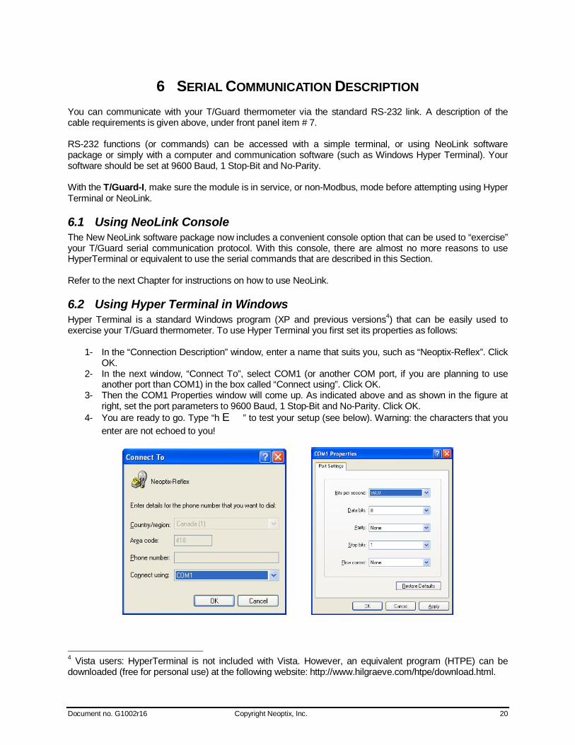
6.2 Using Hyper Terminal in Windows Hyper Terminal is a standard Windows program (XP and previous versions4) that can be easily used to exercise your T/Guard thermometer. To use Hyper Terminal you first set its properties as follows:
1- In the “Connection Description” window, enter a name that suits you, such as “Neoptix-Reflex”. Click OK.
2- In the next window, “Connect To”, select COM1 (or another COM port, if you are planning to use another port than COM1) in the box called “Connect using”. Click OK.
3- Then the COM1 Properties window will come up. As indicated above and as shown in the figure at right, set the port parameters to 9600 Baud, 1 Stop-Bit and No-Parity. Click OK.
4- You are ready to go. Type “h E” to test your setup (see below). Warning: the characters that you enter are not echoed to you!
4 Vista users: HyperTerminal is not included with Vista. However, an equivalent program (HTPE) can be downloaded (free for personal use) at the following website: http://www.hilgraeve.com/htpe/download.html.

Document no. G1002r16 Copyright Neoptix, Inc. 21
6.3 RS-232 help menu The following is the menu as displayed by the instrument when sending the “h” command. Note that the RS232 interface can also be used to upgrade the thermometer controlling firmware, without opening the thermometer case or changing any memory IC’s. Instructions to perform an upgrade are normally sent with the upgrade program (NeoProg); an IBM-PC compatible computer will be required to perform such firmware upgrade. Note: With the Modbus option enabled, this help menu is slightly different; see the Modbus chapter for more information. Furthermore, some commands may not be available on specific T/Guard models.
T/Guard-1 T/Guard-2, -4 or -8 Description
a a Ignore
b b Return enclosure temperature
c c[i] Ignore
N/A e[1;2; ... ;n] Enable channels to scan (if no argument, scan all)
f[j] f[i;j] Set point adjustment on channel [i] to [j]
gskip[i] gskip[i] Skip up to i marginal read cycles
h h Help menu (this screen)
H H Logging help menu (Note: Requires the data logging option)
i i Get factory and status information
n+o or n+e n+o or n+e Toggle calibration ( n+e for Neoptix, n+o for Nortech Fibronic inc.)
o[i] o[i] Analog out, if error (0:Max-Min 1Hz, 1:Max level, 2: Min level)
p[i] p[i] Sleep mode (p+ to sleep, p- for continuous scanning)
q q Scanning rate (q+ for fast/quick, q- for slow)
r r Ignore
s[j] s[i;j] Specify analog output Span [j] for channel [i]
t t[i] Get Temperature reading channel [i]
ta[i] ta[i] Continuous output to serial port (+ to enable, - to disable)
tb[nnnn] tb[nnnn] Ignore
u[i] u[i] Unit (c = oCelcius, f = oFahrenheit)
x x Ignore
wtune[i] wtune[i] Optimize CCD read time (wtune+ to enable, wtune- to disable) y y Signal strength
z[j] z[i;j] Temperature [j] for analog output Zero on channel [i].
6.4 Detailed description of RS-232 commands All commands must be terminated by a carriage return character ( E ). When more than one argument is required, each argument must be separated from the next one by a blank or space character. Characters are not echoed back to your controlling device. Commands are case sensitive; i.e., “h” is not the same command as “H”.
Document no. G1002r16 Copyright Neoptix, Inc. 22
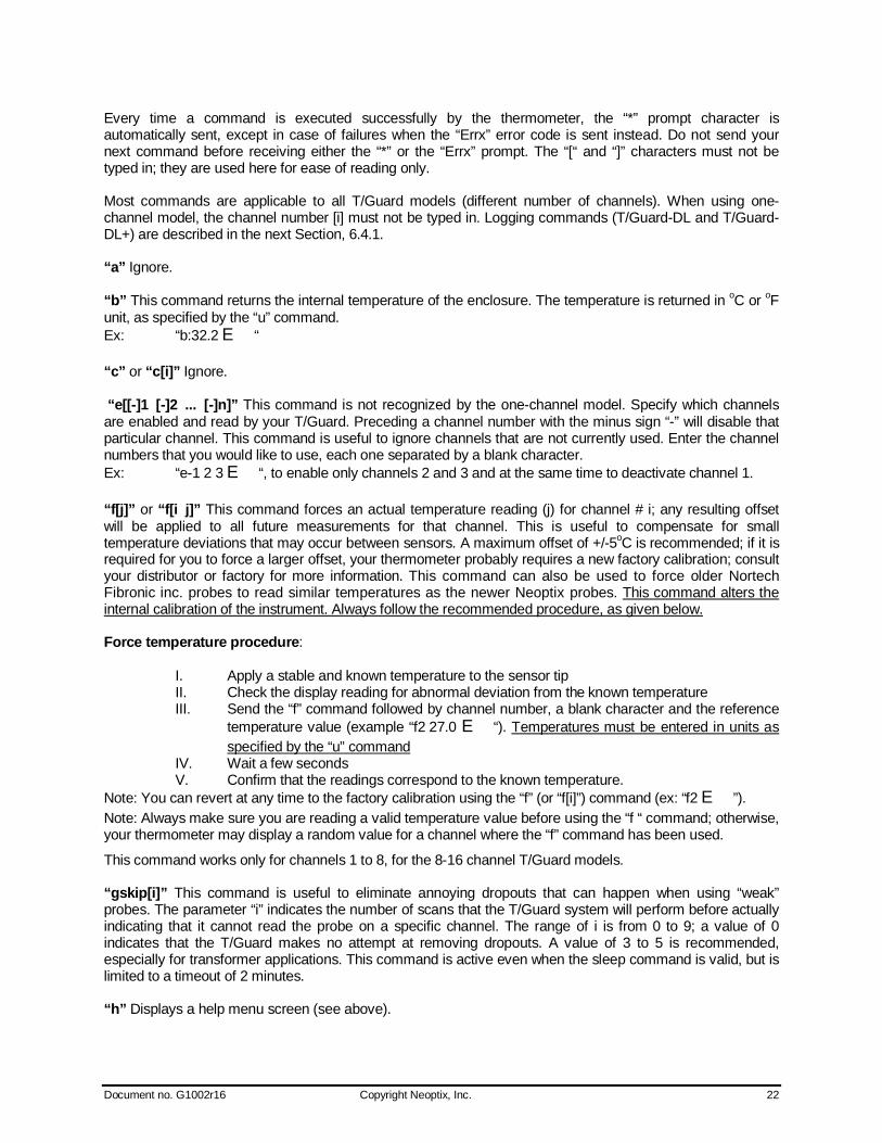
Every time a command is executed successfully by the thermometer, the “*” prompt character is automatically sent, except in case of failures when the “Errx” error code is sent instead. Do not send your next command before receiving either the “*” or the “Errx” prompt. The “[“ and “]” characters must not be typed in; they are used here for ease of reading only. Most commands are applicable to all T/Guard models (different number of channels). When using one-channel model, the channel number [i] must not be typed in. Logging commands (T/Guard-DL and T/Guard-DL+) are described in the next Section, 6.4.1. “a” Ignore. “b” This command returns the internal temperature of the enclosure. The temperature is returned in oC or oF unit, as specified by the “u” command. Ex: “b:32.2 E“ “c” or “c[i]” Ignore. “e[[-]1 [-]2 ... [-]n]” This command is not recognized by the one-channel model. Specify which channels are enabled and read by your T/Guard. Preceding a channel number with the minus sign “-” will disable that particular channel. This command is useful to ignore channels that are not currently used. Enter the channel numbers that you would like to use, each one separated by a blank character. Ex: “e-1 2 3 E“, to enable only channels 2 and 3 and at the same time to deactivate channel 1. “f[j]” or “f[i j]” This command forces an actual temperature reading (j) for channel # i; any resulting offset will be applied to all future measurements for that channel. This is useful to compensate for small temperature deviations that may occur between sensors. A maximum offset of +/-5oC is recommended; if it is required for you to force a larger offset, your thermometer probably requires a new factory calibration; consult your distributor or factory for more information. This command can also be used to force older Nortech Fibronic inc. probes to read similar temperatures as the newer Neoptix probes. This command alters the internal calibration of the instrument. Always follow the recommended procedure, as given below. Force temperature procedure:
I. Apply a stable and known temperature to the sensor tip II. Check the display reading for abnormal deviation from the known temperature III. Send the “f” command followed by channel number, a blank character and the reference
temperature value (example “f2 27.0 E“). Temperatures must be entered in units as specified by the “u” command
IV. Wait a few seconds V. Confirm that the readings correspond to the known temperature.
Note: You can revert at any time to the factory calibration using the “f” (or “f[i]”) command (ex: “f2 E”). Note: Always make sure you are reading a valid temperature value before using the “f “ command; otherwise, your thermometer may display a random value for a channel where the “f” command has been used.
This command works only for channels 1 to 8, for the 8-16 channel T/Guard models. “gskip[i]” This command is useful to eliminate annoying dropouts that can happen when using “weak” probes. The parameter “i” indicates the number of scans that the T/Guard system will perform before actually indicating that it cannot read the probe on a specific channel. The range of i is from 0 to 9; a value of 0 indicates that the T/Guard makes no attempt at removing dropouts. A value of 3 to 5 is recommended, especially for transformer applications. This command is active even when the sleep command is valid, but is limited to a timeout of 2 minutes. “h” Displays a help menu screen (see above).
Document no. G1002r16 Copyright Neoptix, Inc. 23
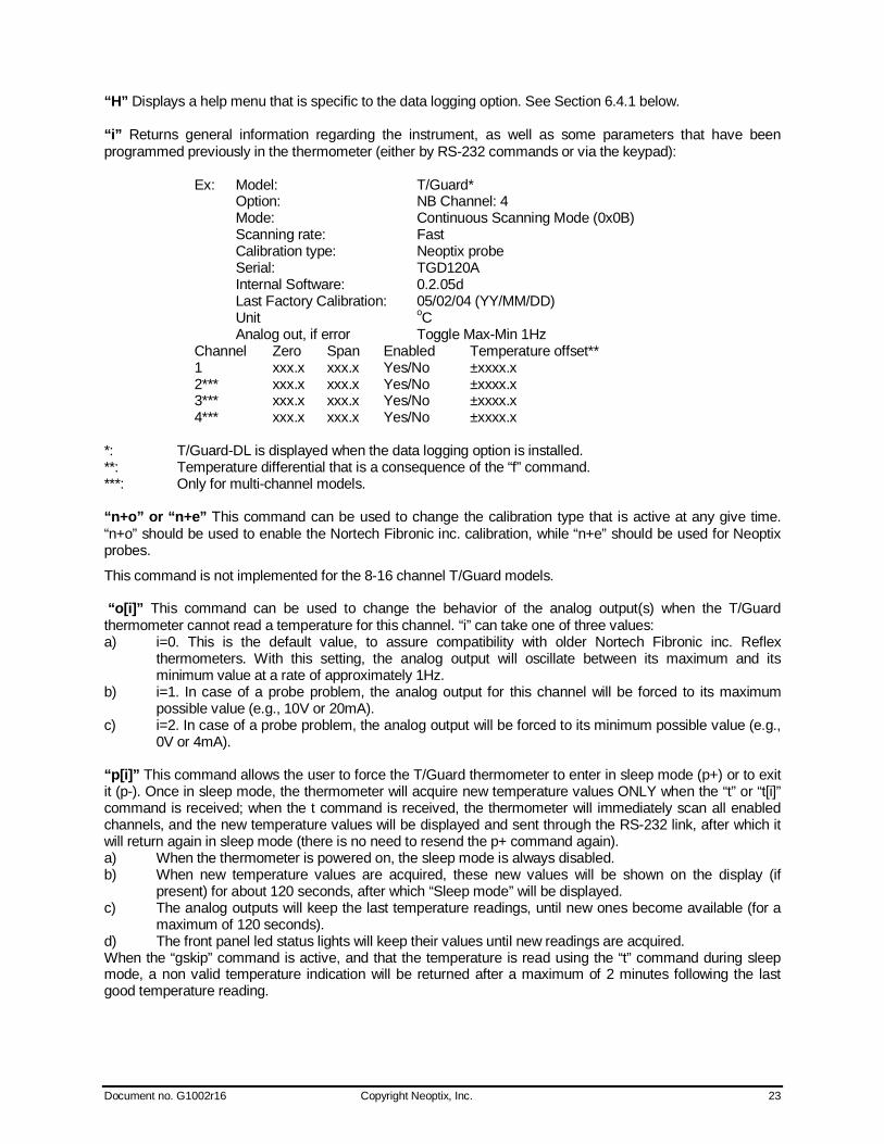
“H” Displays a help menu that is specific to the data logging option. See Section 6.4.1 below. “i” Returns general information regarding the instrument, as well as some parameters that have been programmed previously in the thermometer (either by RS-232 commands or via the keypad):
Ex: Model: T/Guard* Option: NB Channel: 4 Mode: Continuous Scanning Mode (0x0B) Scanning rate: Fast Calibration type: Neoptix probe Serial: TGD120A Internal Software: 0.2.05d Last Factory Calibration: 05/02/04 (YY/MM/DD) Unit oC Analog out, if error Toggle Max-Min 1Hz Channel Zero Span Enabled Temperature offset** 1 xxx.x xxx.x Yes/No ±xxxx.x 2*** xxx.x xxx.x Yes/No ±xxxx.x 3*** xxx.x xxx.x Yes/No ±xxxx.x 4*** xxx.x xxx.x Yes/No ±xxxx.x
*: T/Guard-DL is displayed when the data logging option is installed. **: Temperature differential that is a consequence of the “f” command. ***: Only for multi-channel models. “n+o” or “n+e” This command can be used to change the calibration type that is active at any give time. “n+o” should be used to enable the Nortech Fibronic inc. calibration, while “n+e” should be used for Neoptix probes.
This command is not implemented for the 8-16 channel T/Guard models. “o[i]” This command can be used to change the behavior of the analog output(s) when the T/Guard thermometer cannot read a temperature for this channel. “i” can take one of three values: a) i=0. This is the default value, to assure compatibility with older Nortech Fibronic inc. Reflex
thermometers. With this setting, the analog output will oscillate between its maximum and its minimum value at a rate of approximately 1Hz.
b) i=1. In case of a probe problem, the analog output for this channel will be forced to its maximum possible value (e.g., 10V or 20mA).
c) i=2. In case of a probe problem, the analog output will be forced to its minimum possible value (e.g., 0V or 4mA).
“p[i]” This command allows the user to force the T/Guard thermometer to enter in sleep mode (p+) or to exit it (p-). Once in sleep mode, the thermometer will acquire new temperature values ONLY when the “t” or “t[i]” command is received; when the t command is received, the thermometer will immediately scan all enabled channels, and the new temperature values will be displayed and sent through the RS-232 link, after which it will return again in sleep mode (there is no need to resend the p+ command again). a) When the thermometer is powered on, the sleep mode is always disabled. b) When new temperature values are acquired, these new values will be shown on the display (if
present) for about 120 seconds, after which “Sleep mode” will be displayed. c) The analog outputs will keep the last temperature readings, until new ones become available (for a
maximum of 120 seconds). d) The front panel led status lights will keep their values until new readings are acquired. When the “gskip” command is active, and that the temperature is read using the “t” command during sleep mode, a non valid temperature indication will be returned after a maximum of 2 minutes following the last good temperature reading.
Document no. G1002r16 Copyright Neoptix, Inc. 24
“q” “q” allows for selecting the fast (q+) or the slow (q-) acquisition mode. In slow mode, the last few temperatures are smoothed before being displayed or sent to the RS-232 port; this provides a better reading at the expense of being slower. “r” Ignore. “s[j]” or “s[i j]” This command will set the analog output span for the analog channel # i (if using a multi-channel thermometer, the “i” parameter specifies the channel to which the command is addressed). The “j” parameter specifies the span that can range from 1.0 to 1000.0, in temperature units that are defined by the last “u” command.
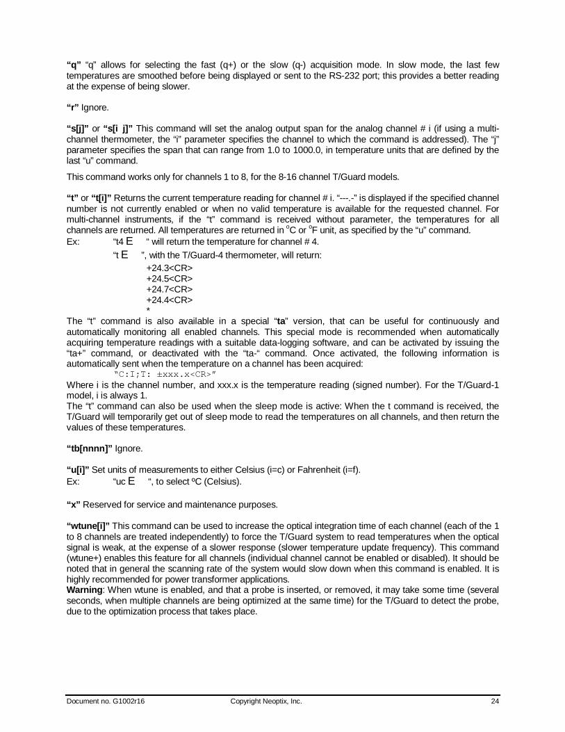
This command works only for channels 1 to 8, for the 8-16 channel T/Guard models. “t” or “t[i]” Returns the current temperature reading for channel # i. “---.-” is displayed if the specified channel number is not currently enabled or when no valid temperature is available for the requested channel. For multi-channel instruments, if the “t” command is received without parameter, the temperatures for all channels are returned. All temperatures are returned in oC or oF unit, as specified by the “u” command. Ex: “t4 E“ will return the temperature for channel # 4. “t E”, with the T/Guard-4 thermometer, will return: +24.3<CR> +24.5<CR> +24.7<CR> +24.4<CR> * The “t” command is also available in a special “ta” version, that can be useful for continuously and automatically monitoring all enabled channels. This special mode is recommended when automatically acquiring temperature readings with a suitable data-logging software, and can be activated by issuing the “ta+” command, or deactivated with the “ta-“ command. Once activated, the following information is automatically sent when the temperature on a channel has been acquired: “C:I;T: ±xxx.x<CR>” Where i is the channel number, and xxx.x is the temperature reading (signed number). For the T/Guard-1 model, i is always 1. The “t” command can also be used when the sleep mode is active: When the t command is received, the T/Guard will temporarily get out of sleep mode to read the temperatures on all channels, and then return the values of these temperatures. “tb[nnnn]” Ignore. “u[i]” Set units of measurements to either Celsius (i=c) or Fahrenheit (i=f). Ex: “uc E“, to select ºC (Celsius). “x” Reserved for service and maintenance purposes. “wtune[i]” This command can be used to increase the optical integration time of each channel (each of the 1 to 8 channels are treated independently) to force the T/Guard system to read temperatures when the optical signal is weak, at the expense of a slower response (slower temperature update frequency). This command (wtune+) enables this feature for all channels (individual channel cannot be enabled or disabled). It should be noted that in general the scanning rate of the system would slow down when this command is enabled. It is highly recommended for power transformer applications. Warning: When wtune is enabled, and that a probe is inserted, or removed, it may take some time (several seconds, when multiple channels are being optimized at the same time) for the T/Guard to detect the probe, due to the optimization process that takes place.
Document no. G1002r16 Copyright Neoptix, Inc. 25
“y” The “y” command can be used to confirm the “signal strength” or “power” of a probe and/or its connection. It can be used as a diagnostic tool to confirm the good operation of a probe and its patch cord (if applicable) connected to a channel. The returned value can be between 1.00 to approximately 3.00; a higher value is better. A minimum of 1.25 is normally required for a channel to return a valid temperature reading. See Section 6.4.3 for more information on how to interpret the command results. Ex: “y E”, with the T/Guard-4 thermometer, will return: CH1: 85%, ratio:1.91, lamp:110, CCD:150ms (auto*) +24.7 <CR> CH2: 76%, ratio:1.97, lamp:120, CCD:130ms (auto) +25.3 <CR> CH3: 0%, ratio:1.06**, lamp: 105, CCD:400ms (auto) ---.-- <CR> CH4: 66%, ratio:1.78, lamp: 90, CCD:180ms (auto) +24.9 <CR> *: Value: Auto (when wtune+ is active) or Fixed (when the wtune command is disabled). **: 0.3 to 1.1 indicates that no probe is detected for this channel. “z[j[“ or “z[i;j]” This command is used in conjunction with the “s” command, as it sets the temperature that corresponds to the analog zero (minimum value of analog output). For multi-channel models, the “i” parameter specifies the channel to which the command is addressed; valid values are 1 to 8 (the maximum is the number of channels for your specific unit). The “j” parameter specifies the zero temperature value, and can range from -100.0 to 1000.0, in units that are defined by the last “u” command. Factory default is –100.0; T/Guard thermometers that have been factory calibrated for cryogenic temperatures have a lower setting.
This command works only for channels 1 to 8, for the 8-16 channel T/Guard models.
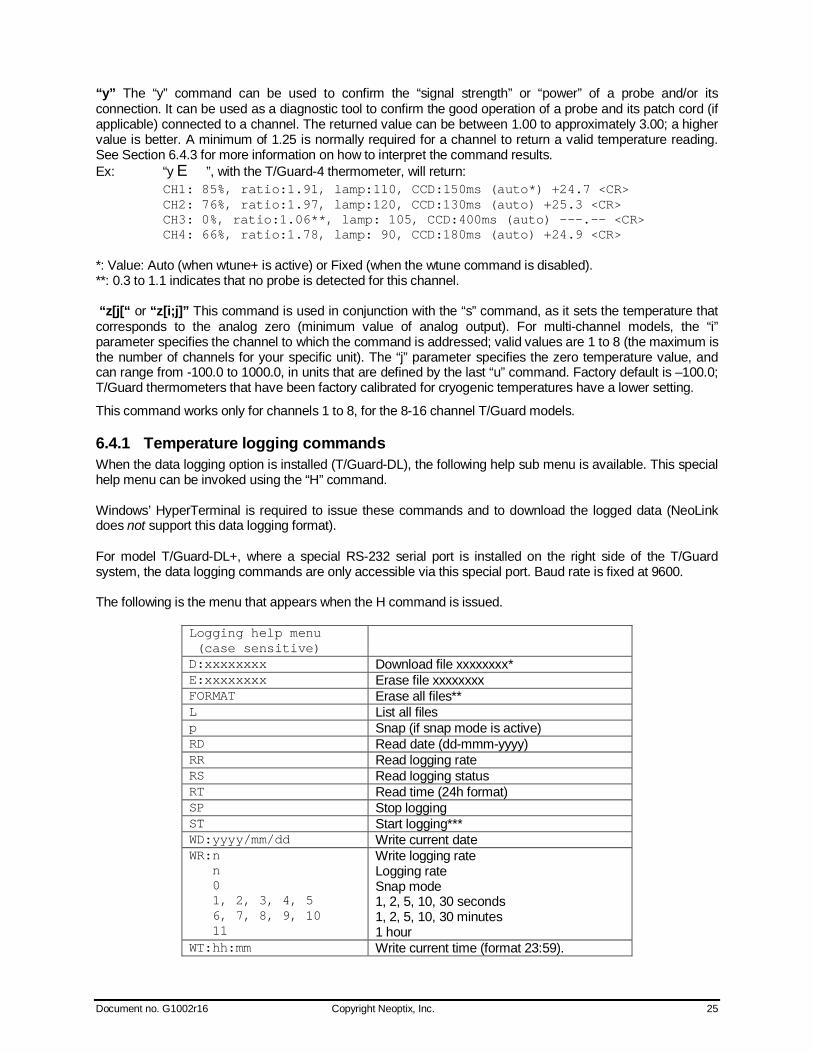
6.4.1 Temperature logging commands When the data logging option is installed (T/Guard-DL), the following help sub menu is available. This special help menu can be invoked using the “H” command. Windows’ HyperTerminal is required to issue these commands and to download the logged data (NeoLink does not support this data logging format). For model T/Guard-DL+, where a special RS-232 serial port is installed on the right side of the T/Guard system, the data logging commands are only accessible via this special port. Baud rate is fixed at 9600. The following is the menu that appears when the H command is issued.
Logging help menu (case sensitive)
D:xxxxxxxx Download file xxxxxxxx* E:xxxxxxxx Erase file xxxxxxxx FORMAT Erase all files** L List all files p Snap (if snap mode is active) RD Read date (dd-mmm-yyyy) RR Read logging rate RS Read logging status RT Read time (24h format) SP Stop logging ST Start logging*** WD:yyyy/mm/dd Write current date WR:n n 0 1, 2, 3, 4, 5 6, 7, 8, 9, 10 11
Write logging rate Logging rate Snap mode 1, 2, 5, 10, 30 seconds 1, 2, 5, 10, 30 minutes 1 hour
WT:hh:mm Write current time (format 23:59).
Document no. G1002r16 Copyright Neoptix, Inc. 26
*: Default file extension is always .neo; this extension is automatically added to the file name. Thus, there is no need to specify any extension. **: This will delete ALL files. Must be used with care! ***: Logging filenames are always automatically assigned, see next Section. “D:xxxxxxxx” This command will download file xxxxxxxx. All filenames must have 8 characters; extension (.neo) is optional. See next section for file naming conventions. A file can be downloaded while logging is active; however, you cannot download a file that is currently open for logging. See Section for downloading instructions. “E:xxxxxxxx” This command will erase file xxxxxxxx; extension (.neo) is optional. File is erased permanently. Warning: this will delete the file without further request; make sure file name is correctly entered before finishing the command with a E. “FORMAT” This command will format the internal T/Guard permanent memory. All files will be erased without further request…, must be used with care! “L” This command lists all files currently present in permanent memory (internal SD card). Please note that the files are listed according to the order they are in memory, which is not necessarily alphabetical. If a file is currently open (i.e., logging is active), that file will be listed as well. The size of each file is given, in Kbytes, for information. The last line indicates how many files were listed, along with the total memory size used by these files. An example follows: List of files: >07043001.NEO 1 KB >07043002.NEO 1 KB >07043003.NEO 8 KB >07050101.NEO 1 KB >07050102.NEO 10 KB >07050103.NEO 1 KB >07050104.NEO 23 KB >07050105.NEO 1 KB >07050106.NEO 2 KB >07050107.NEO 1 KB >07050108.NEO 1 KB >07050109.NEO 1 KB Total: 12 files, 47 KB “p” This will save in memory the correct temperature values, if logging rate is set to snap mode (n). “RD” Return current date. Format is dd-mmm-yyyy. “RR” Return current logging status. See command “WR” for more details. “RS” Return logging status. Will return either: Logging to file xxxxxxxx.neo, if logging is active Not logging, if currently not logging. “RT” Return current time. Format is hh:mm:ss. “SP” Stop logging, if active. Operation can be confirmed with the RS command. “ST” Start logging. Operation can be confirmed with the RS command. In case of a power failure, logging will always resume (irrespective of its previous setting) when power to the T/Guard-DL returns; in this case, the minimum logging rate is set to 1 minute (to avoid filling unduly the memory).

Document no. G1002r16 Copyright Neoptix, Inc. 27
“WD:yyyy/mm/dd” Write new date. “WR:n” Write logging rate, where n can have a value ranging from 0 to 11, as per the following table:
n Logging rate 0 Snap mode 1, 2, 3, 4, 5 1, 2, 5, 10, 30 seconds 6, 7, 8, 9, 10 1, 2, 5, 10, 30 minutes 11 1 hour
“WT:hh:mm” Write new time. Format is 24hr system, i.e., 23:59.
6.4.1.1 File naming convention File names are structured as follows: YYMMDDXX.NEO, where:
YY represents the current year (e.g., 06) MM represents the current month DD represents the current date XX is a sequence number that starts at “01”, and can go up to “99” .NEO is a fixed file extension.
Furthermore, file sizes are limited to 65500 lines, to ease their import to spreadsheet such as Microsoft Excel. When the 65500 limit is reached, a new file is open using the next available file sequence number. Typical file content may look like this:
A timestamp accompanies each temperature entry (24 hour time format). File format is tab delimited, offering an easy import path by Excel. As the sequence number is limited to 99, you are limited to a total of 99 logged files per day. Also, if you are logging temperatures when the clock reaches midnight on any given day, the next file that will have its name constructed based on the new date, and the sequence number will be reset to “01”.
6.4.1.2 File downloading instructions A file can be downloaded using the Xmodem file transfer protocol. HyperTerminal (with Vista, use HTPE) supports this file transfer format. Follow the following instructions step by step. Warning: The NeoLink console cannot be used to download files.
1- Make sure HyperTerminal is open and correctly configured.
2- Issue the download command, including the file name you want to download. Example: D:07043001.neo E (.neo extension in optional). Note: You cannot download a file that is currently open for logging.
3- From the HyperTerminal main menu, select Transfer. The following window will open:
Document no. G1002r16 Copyright Neoptix, Inc. 28
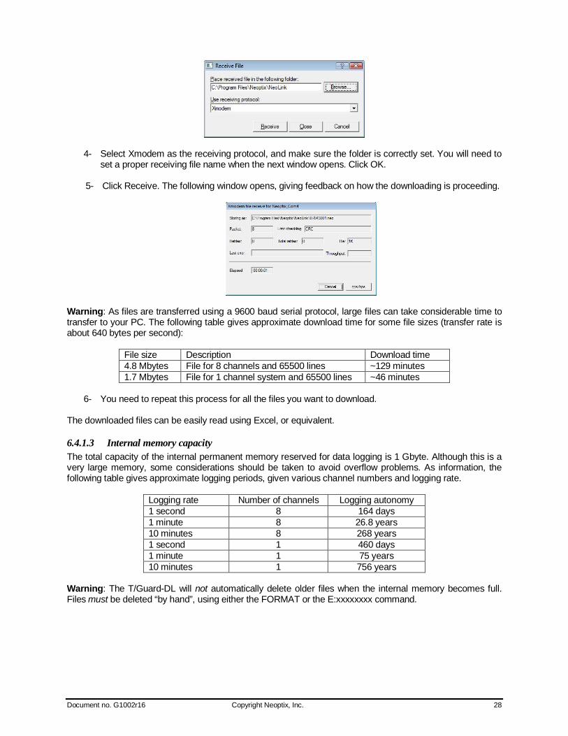
4- Select Xmodem as the receiving protocol, and make sure the folder is correctly set. You will need to set a proper receiving file name when the next window opens. Click OK.
5- Click Receive. The following window opens, giving feedback on how the downloading is proceeding.
Warning: As files are transferred using a 9600 baud serial protocol, large files can take considerable time to transfer to your PC. The following table gives approximate download time for some file sizes (transfer rate is about 640 bytes per second):
File size Description Download time 4.8 Mbytes File for 8 channels and 65500 lines ~129 minutes 1.7 Mbytes File for 1 channel system and 65500 lines ~46 minutes
6- You need to repeat this process for all the files you want to download.
The downloaded files can be easily read using Excel, or equivalent.
6.4.1.3 Internal memory capacity The total capacity of the internal permanent memory reserved for data logging is 1 Gbyte. Although this is a very large memory, some considerations should be taken to avoid overflow problems. As information, the following table gives approximate logging periods, given various channel numbers and logging rate.
Logging rate Number of channels Logging autonomy 1 second 8 164 days 1 minute 8 26.8 years 10 minutes 8 268 years 1 second 1 460 days 1 minute 1 75 years 10 minutes 1 756 years
Warning: The T/Guard-DL will not automatically delete older files when the internal memory becomes full. Files must be deleted “by hand”, using either the FORMAT or the E:xxxxxxxx command.

Document no. G1002r16 Copyright Neoptix, Inc. 29
6.4.2 Recommended configuration, for transformer applications For transformer applications, it is recommended that the following parameters be set as follows: Feature Benefit description Command Ignore bad scans This allows for better stability of the analog outputs, when
working with “weak” or “marginal” probes. gskip5
Fast scanning rate Precision of readings obtained with the fast scanning mode is enough for this application.
q+
Auto-tune CCD Optimize the CCD operation, especially useful when working with “weak” or “marginal” probes. Has the advantage also to lower the voltage on the internal lamps, thus improve long-term system reliability.
wtune+
Analog output zero Adjust the analog output zero setting, for each channel. Warning: this command must be sent individually for each channel.
z1 -50 z2 –50, etc.
Analog output span Adjust the analog output span setting, for each channel. Warning: this command must be sent individually for each channel.
s1 200 s2 200, etc.
Analog output, if no probes
Adjust the analog output behavior, when no probe is detected. Warning: this command must be sent individually for each channel.
See “o” command description, above
No sleep mode Sleep mode should be disabled (it is not required) p- Most of these command settings can be confirmed with the “i” command. The “wtune” command can be confirmed with the “y” command.
6.4.3 Interpretation of “y” command results The Neoptix T/Guard systems are fitted with a function that gives an evaluation about probe signal strength or signal power; in Neoptix jargon, this is called the “y” command. The easiest method to access this command is to use Windows’ HyperTerminal, or NeoLink’ Console; the Nomad, when in Engineering mode, can also be very useful to display this information. Typically, the “y” command will return the following information: CH1: 85%, ratio:1.83, lamp:90, CCD:150ms (auto) +24.5 CH1 indicates the channel number (typically 1 to 8, for an 8 channel T/Guard system) 1.83 is a signal strength (power) indicator that can span from about +0.3 to +2.7. You can interpret it approximately as follows:
0.3 to 1.07: no probe is detected 1.07 to 1.25: a probe is probably present, but exhibits a very weak signal; its reading is usually
rejected, as it is considered as unreliable 1.25 to 2.7: a good probe is present (the higher the power the more healthy the probe).
Lamp attenuation: gives an indication about the white light lamp intensity for this channel. It ranges from 210 (weak lamp) to 100 (intense lamp5). A weak lamp is usually preferred and indicates a “healthy” probe. CCD time: this is the CCD (charge couple device) optical integration time in millisecond; it can range from 50 to 500 ms. A weak probe will normally have a long integration time. The “%” number gives an approximate compounded power value that takes into consideration the ratio, the lamp attenuation and the CCD time. To summarize, a very good probe is characterized by a good power indicator (>1.8), then by a high lamp attenuation (>150) and finally by a short integration time (<200ms). Also, dirty connectors will contribute to lower probe strength; always assure that all fiber connections are clean before evaluating probe performance.
5 Some T/Guard+ uses a different nomenclature: “4v” corresponds to a strong lamp, while “2v” corresponds to a weak lamp.
Document no. G1002r16 Copyright Neoptix, Inc. 30
Warning: After a power-on or after changing (or exchanging) probes or extension cords, allow sufficient time for the T/Guard optimization process to complete before invoking the y command; it most cases, it may take as much as 1 minute for this optimization to complete, especially when the number of enabled channels is high, e.g., 8.
6.5 Typical temperature reading sequence Once all parameters have been set, the following sequence should normally be followed to extract temperature information from your Neoptix thermometer. 2 procedures can be used for this purpose. The first method consists in using the “ta” command (preferred), while the second sequence would be:
d) The host computer should send the “t” (or “t[i]”) command, followed by an E character. e) The thermometer responds by echoing the requested temperature values, as indicated
above; the transmission is terminated by a “*” character. f) When the “*” character is received, it is suggested to immediately terminate the dialog
session by having the host computer issue the “r” command followed by a E character.
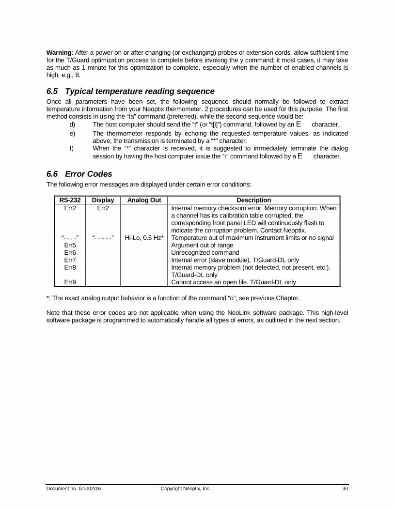
6.6 Error Codes The following error messages are displayed under certain error conditions:
RS-232 Display Analog Out Description Err2 Err2 Internal memory checksum error. Memory corruption. When
a channel has its calibration table corrupted, the corresponding front panel LED will continuously flash to indicate the corruption problem. Contact Neoptix.
“- - . -” “- - - - -” Hi-Lo, 0.5 Hz* Temperature out of maximum instrument limits or no signal Err5 Argument out of range Err6 Unrecognized command Err7 Internal error (slave module). T/Guard-DL only Err8 Internal memory problem (not detected, not present, etc.).
T/Guard-DL only Err9 Cannot access an open file. T/Guard-DL only
*: The exact analog output behavior is a function of the command “o”; see previous Chapter. Note that these error codes are not applicable when using the NeoLink software package. This high-level software package is programmed to automatically handle all types of errors, as outlined in the next section.

Document no. G1002r16 Copyright Neoptix, Inc. 31
7 NEOLINK SOFTWARE PACKAGE The NeoLink™ software package option allows using your thermometer system in a highly flexible manner. The built-in functions allow for temperature displaying and data logging, as well as exporting to a variety of standard spreadsheet packages.
7.1 The “Lite” vs. the “Pro” version NeoLink is now offered in two versions. The “Lite” version is now shipped as a standard item with every Neoptix thermometer. The “Pro” version includes more features and support more instruments and/or channels simultaneously. Contact your Neoptix Representative or the Neoptix factory to buy an unlocking code. Note: The T/Guard system is normally supplied with NeoLink Pro.
7.1.1 Differences between the 2 versions The “Lite” version exhibits the following limitations:
Only one instrument is supported (when scanning the COM ports (going from 1 to 32), the first instrument that is detected by NeoLink will be the active instrument).
Only 1 channel is supported. No DDE temperature data logging is supported. The Digital display is the same for both versions, i.e. it will display multiple channels for both
versions. The remaining of this Chapter describes the “Pro” version.
7.2 Getting started with NeoLink NeoLink was designed to acquire temperature readings from all models of the Neoptix T/Guard thermometer family. This versatile software package is designed to work with Microsoft Windows operating system; to fully exploit the capabilities of NeoLink, it is recommended to use it in conjunction to commercial spreadsheet software, such as Microsoft Excel. With the T/Guard-I, make sure the module is in service, or non-Modbus, mode before attempting using NeoLink.
7.2.1 Hardware and software requirements The following list includes the minimum requirements for running the NeoLink software:
o A Pentium class or higher CPU o SVGA or higher resolution display system supported by Windows o 512 MB of RAM memory (operating system dependent) o At least 40 MB of hard disk space o A CD disk drive (to load software) (if requested, the software can be supplied on diskettes) o A mouse or other Windows pointing device o A RS-232 interface (COM1 to COM32). Up to 4 thermometer units are supported, each one
requiring its own COM port o Windows 2000 or later, including Vista.
NeoLink works correctly with both half-duplex and full-duplex Neoptix thermometers. NeoLink is not compatible with older Nortech-Fibronic thermometers and with Neoptix thermometers that have been manufactured before August 2005.
Document no. G1002r16 Copyright Neoptix, Inc. 32
7.2.2 Installing NeoLink Before opening the CD and installing the software, please refer to the License and Limited Warranty Agreement at the beginning of this manual. You must have at least one, or more, properly installed T/Guard thermometer unit(s). NeoLink should as well detect other Neoptix thermometers, such as the Nomad, the Reflex and even the T/Guard+ (in “non-OPC” or “test” mode).
1- Start Windows, and make sure you are not running any other Windows program. 2- By inserting the CD in your computer, the SETUP application should automatically start; if not,
manually start it. 3- Follow the instructions that are displayed. 4- Restart your computer.
7.3 A quick tour of NeoLink 1- Connect your T/Guard unit(s) to free COM port(s). 2- Start NeoLink, if not already running. 3- The thermometers that are turned on and connected to your PC through a proper RS-232
connection should normally be automatically detected by NeoLink6 (this process takes a few seconds, for a typical installation).
4- If a thermometer is connected after NeoLink is started, you should click the “Refresh” button so NeoLink rescans the COM ports (1 to 32). If a thermometer is not automatically detected, make sure your RS-232 port and cable is correctly configured and that the unit is turned on.
NOTE: Some RS-232C connections may cause transmission failures. Particularly, we have experienced problems with the use of DB09 to DB25 converters and other similar so-called gender changers. Also, some USB to RS232 converter/adapter are known to cause problems; Neoptix recommends Keyspan converters (http://www.keyspan.com/products/homepage-Serial.spml). Limit your cable length to 10 meters.
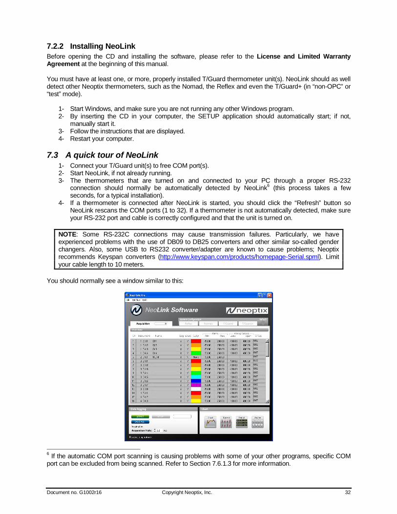
You should normally see a window similar to this:
6 If the automatic COM port scanning is causing problems with some of your other programs, specific COM port can be excluded from being scanned. Refer to Section 7.6.1.3 for more information.
Document no. G1002r16 Copyright Neoptix, Inc. 33
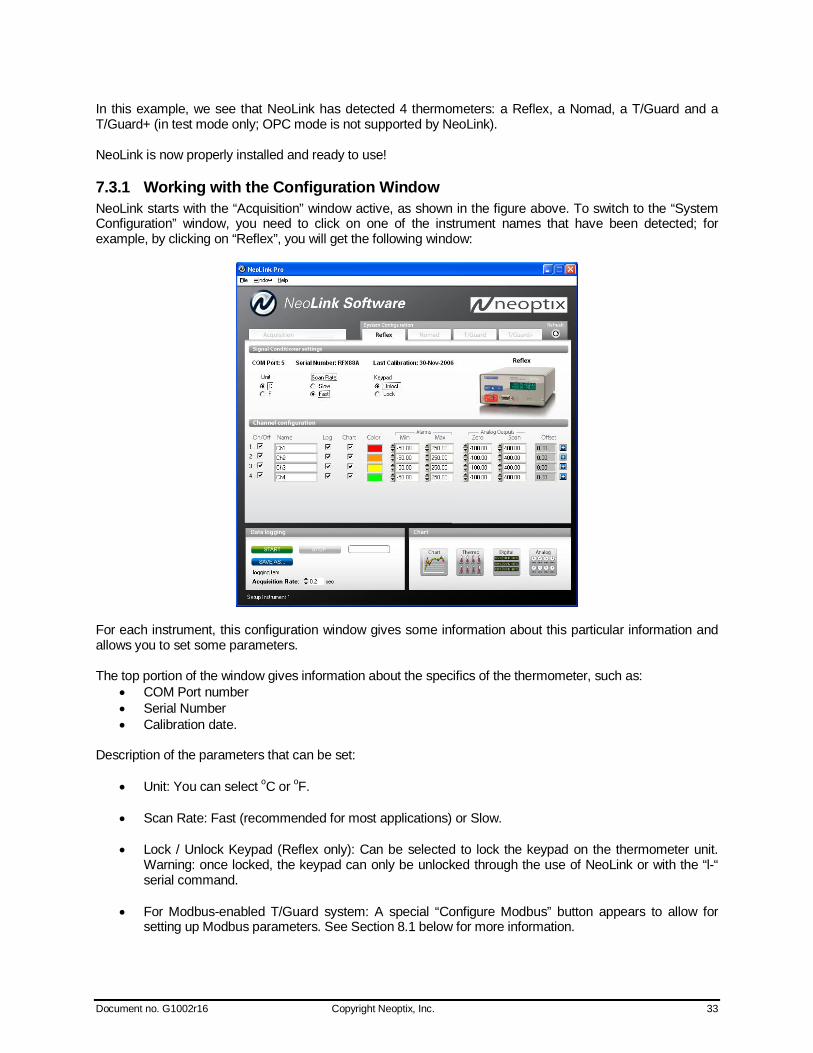
In this example, we see that NeoLink has detected 4 thermometers: a Reflex, a Nomad, a T/Guard and a T/Guard+ (in test mode only; OPC mode is not supported by NeoLink). NeoLink is now properly installed and ready to use!
7.3.1 Working with the Configuration Window NeoLink starts with the “Acquisition” window active, as shown in the figure above. To switch to the “System Configuration” window, you need to click on one of the instrument names that have been detected; for example, by clicking on “Reflex”, you will get the following window:
For each instrument, this configuration window gives some information about this particular information and allows you to set some parameters. The top portion of the window gives information about the specifics of the thermometer, such as:
COM Port number Serial Number Calibration date.
Description of the parameters that can be set:
Unit: You can select oC or oF.
Scan Rate: Fast (recommended for most applications) or Slow.
Lock / Unlock Keypad (Reflex only): Can be selected to lock the keypad on the thermometer unit. Warning: once locked, the keypad can only be unlocked through the use of NeoLink or with the “l-“ serial command.
For Modbus-enabled T/Guard system: A special “Configure Modbus” button appears to allow for setting up Modbus parameters. See Section 8.1 below for more information.

Document no. G1002r16 Copyright Neoptix, Inc. 34
Furthermore, for each channel, you can set the following parameters:
On / Off: You can turn on or off the temperature for each channel.
Name: Up to 16 characters. You can enter a probe name here that suits your application.
Log: If checked, the temperature data for this channel will be logged, when data logging is active.
Chart: If checked, the temperature data for this channel will be displayed when one of the 4 chart windows is open.
Color: This is the color of the curve that will be used when the Chart window is open.
Alarms, Min and Max: Allows setting alarm limits. When one of more alarms are detected, a
message is given at the bottom of the main window (must be in Acquisition mode). For a given channel, alarms are monitored only when its corresponding “Chart” or “Log” checkbox is checked, in the Configuration window pane. Alarms are monitored only when Acquisition is active.
Analog Outputs: Allows configuring the analog output parameters, Zero and Span. See Section 6.4
for a complete description of these parameters.
Offset: Allows adding an offset to this channel. See below.
7.3.1.1 Adjusting a temperature offset NeoLink allows you to add an offset to the temperature readings that are returned by a thermometer. This feature is equivalent to the “f” serial command, as described in Section 6.4, although its implementation in NeoLink is somewhat different than it is for the serial command. An offset can be useful for the following two cases:
1- To temporarily change the reading of a probe that is believed to be in error (one-point calibration procedure). This usually requires that a good temperature reference be available.
2- To force an offset to a reading, for example may want to monitor a temperature variation from a given set temperature. In this case, you can simply enter the “0” value as a forced temperature setting, and the resulting reading will give you a + or – deviation from the set temperature point.
Warning: Doing a temperature offset adjustment on a channel will alter its reading. In effect, it alters the thermometer own calibration. It must be used with care! To perform an offset adjustment, follow these instructions:
1- Click the “Offset Adjust” button ( ) that is just next to the channel number you want to calibrate. The following menu window is available:
2- Type in the “Set Point” box the actual temperature that you would like to force for this channel (this temperature is normally obtained using an accurate NIST-certified primary temperature reference).
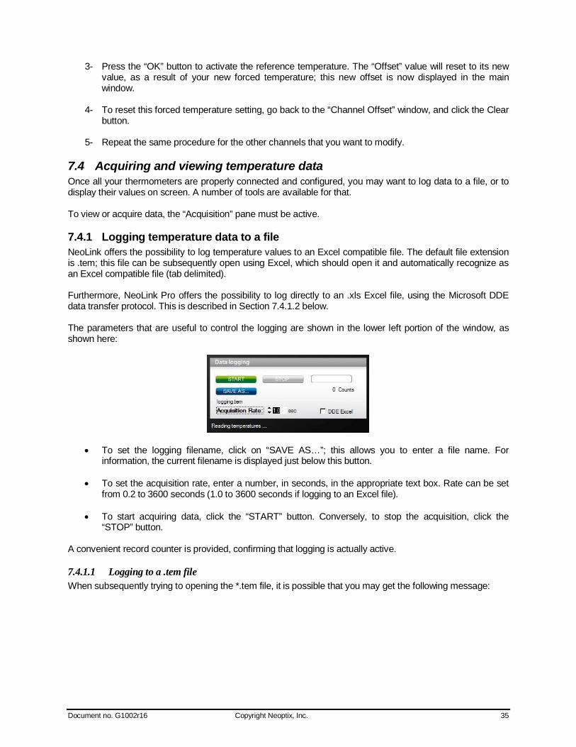
Document no. G1002r16 Copyright Neoptix, Inc. 35
3- Press the “OK” button to activate the reference temperature. The “Offset” value will reset to its new value, as a result of your new forced temperature; this new offset is now displayed in the main window.
4- To reset this forced temperature setting, go back to the “Channel Offset” window, and click the Clear button.
5- Repeat the same procedure for the other channels that you want to modify.
7.4 Acquiring and viewing temperature data Once all your thermometers are properly connected and configured, you may want to log data to a file, or to display their values on screen. A number of tools are available for that. To view or acquire data, the “Acquisition” pane must be active.
7.4.1 Logging temperature data to a file NeoLink offers the possibility to log temperature values to an Excel compatible file. The default file extension is .tem; this file can be subsequently open using Excel, which should open it and automatically recognize as an Excel compatible file (tab delimited). Furthermore, NeoLink Pro offers the possibility to log directly to an .xls Excel file, using the Microsoft DDE data transfer protocol. This is described in Section 7.4.1.2 below. The parameters that are useful to control the logging are shown in the lower left portion of the window, as shown here:
To set the logging filename, click on “SAVE AS…”; this allows you to enter a file name. For information, the current filename is displayed just below this button.
To set the acquisition rate, enter a number, in seconds, in the appropriate text box. Rate can be set
from 0.2 to 3600 seconds (1.0 to 3600 seconds if logging to an Excel file).
To start acquiring data, click the “START” button. Conversely, to stop the acquisition, click the “STOP” button.
A convenient record counter is provided, confirming that logging is actually active.
7.4.1.1 Logging to a .tem file When subsequently trying to opening the *.tem file, it is possible that you may get the following message:

Document no. G1002r16 Copyright Neoptix, Inc. 36
Select “Select the program from a list”, and click OK. In the next window, you should instruct Windows to always open this type of file with Microsoft Excel. If you get the following message, you should select “Read Only”.
In Excel, the data file should look like this:
Notes: 1) If a column shows “#######”, this means that this column is too narrow to display the data; use
your mouse to widen this column. 2) If you open a logging file during acquisition, the Excel window is not refreshed as the
acquisition is taking place. To get a more recent version of the file, close the Excel program, and start Excel again.
3) A value of -999.xx indicates that no reading is available for this channel. Check the probe connection.
If you stop the acquisition, and start it again with the same file name, the new values will simply be appended to the existing file content. However, a new 5-line header is inserted first, as shown here:
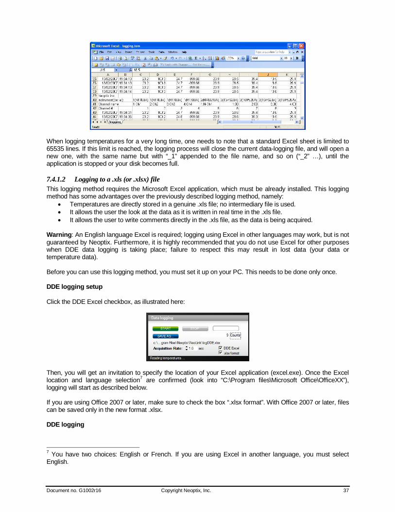
Document no. G1002r16 Copyright Neoptix, Inc. 37
When logging temperatures for a very long time, one needs to note that a standard Excel sheet is limited to 65535 lines. If this limit is reached, the logging process will close the current data-logging file, and will open a new one, with the same name but with “_1” appended to the file name, and so on (“_2” …), until the application is stopped or your disk becomes full.
7.4.1.2 Logging to a .xls (or .xlsx) file This logging method requires the Microsoft Excel application, which must be already installed. This logging method has some advantages over the previously described logging method, namely:
Temperatures are directly stored in a genuine .xls file; no intermediary file is used. It allows the user the look at the data as it is written in real time in the .xls file. It allows the user to write comments directly in the .xls file, as the data is being acquired.
Warning: An English language Excel is required; logging using Excel in other languages may work, but is not guaranteed by Neoptix. Furthermore, it is highly recommended that you do not use Excel for other purposes when DDE data logging is taking place; failure to respect this may result in lost data (your data or temperature data). Before you can use this logging method, you must set it up on your PC. This needs to be done only once. DDE logging setup Click the DDE Excel checkbox, as illustrated here:
Then, you will get an invitation to specify the location of your Excel application (excel.exe). Once the Excel location and language selection7 are confirmed (look into “C:\Program files\Microsoft Office\OfficeXX”), logging will start as described below. If you are using Office 2007 or later, make sure to check the box “.xlsx format”. With Office 2007 or later, files can be saved only in the new format .xlsx. DDE logging
7 You have two choices: English or French. If you are using Excel in another language, you must select English.

Document no. G1002r16 Copyright Neoptix, Inc. 38
Click the START button to start the logging process. The Excel application will open, and you will be able to see the data being written to the file. Do not close this Excel sheet; however you may minimize it without any problem. To stop logging, click the STOP button in NeoLink; this will automatically close the Excel sheet and application. Do not close the Excel application yourself! Otherwise, the DDE logging is very similar to logging to a .tem file, as described above. Acquisition rate is limited to 1 second.
7.4.2 Viewing temperature data Temperature values can be displayed on your computer screen in a number of ways. Click one of the four “Chart” button to active one or more of these windows.
Note that more than one window type can be displayed simultaneously; in addition, you can log temperatures to a file independently from these display windows. Note that each of these 2 modes have each then own acquisition time base.
7.4.2.1 Displaying temperature trends Click the “Chart” button to get the following window.
Adjust the “Refresh Rate” (minimum is 0.2 sec) and Min / Max to suit your viewing needs. Note that the setting of curve colors and other parameters must be done in the “System Configuration” window pane. Up to 64 trends can be displayed.
7.4.2.2 Displaying analog thermometers Click the “Thermo” button; the following window will appear.
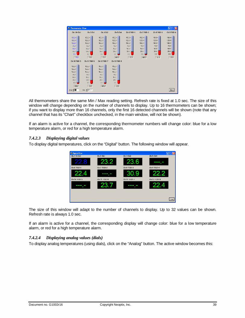
Document no. G1002r16 Copyright Neoptix, Inc. 39
All thermometers share the same Min / Max reading setting. Refresh rate is fixed at 1.0 sec. The size of this window will change depending on the number of channels to display. Up to 16 thermometers can be shown; if you want to display more than 16 channels, only the first 16 detected channels will be shown (note that any channel that has its “Chart” checkbox unchecked, in the main window, will not be shown). If an alarm is active for a channel, the corresponding thermometer numbers will change color: blue for a low temperature alarm, or red for a high temperature alarm.
7.4.2.3 Displaying digital values To display digital temperatures, click on the “Digital” button. The following window will appear.
The size of this window will adapt to the number of channels to display. Up to 32 values can be shown. Refresh rate is always 1.0 sec. If an alarm is active for a channel, the corresponding display will change color: blue for a low temperature alarm, or red for a high temperature alarm.
7.4.2.4 Displaying analog values (dials) To display analog temperatures (using dials), click on the “Analog” button. The active window becomes this:
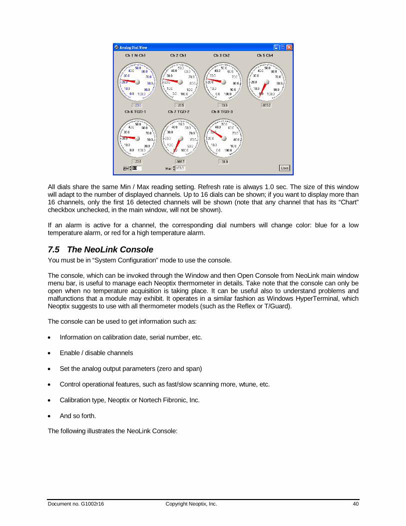
Document no. G1002r16 Copyright Neoptix, Inc. 40
All dials share the same Min / Max reading setting. Refresh rate is always 1.0 sec. The size of this window will adapt to the number of displayed channels. Up to 16 dials can be shown; if you want to display more than 16 channels, only the first 16 detected channels will be shown (note that any channel that has its “Chart” checkbox unchecked, in the main window, will not be shown). If an alarm is active for a channel, the corresponding dial numbers will change color: blue for a low temperature alarm, or red for a high temperature alarm.
7.5 The NeoLink Console You must be in “System Configuration” mode to use the console. The console, which can be invoked through the Window and then Open Console from NeoLink main window menu bar, is useful to manage each Neoptix thermometer in details. Take note that the console can only be open when no temperature acquisition is taking place. It can be useful also to understand problems and malfunctions that a module may exhibit. It operates in a similar fashion as Windows HyperTerminal, which Neoptix suggests to use with all thermometer models (such as the Reflex or T/Guard). The console can be used to get information such as: Information on calibration date, serial number, etc. Enable / disable channels Set the analog output parameters (zero and span) Control operational features, such as fast/slow scanning more, wtune, etc. Calibration type, Neoptix or Nortech Fibronic, Inc. And so forth. The following illustrates the NeoLink Console:

Document no. G1002r16 Copyright Neoptix, Inc. 41
Before sending commands and receiving information from a specific module, it is necessary to select the instrument you want to interrogate. Please note that only ONE instrument can be selected at a time; if the same command is to be sent to all thermometers, then, it is necessary to repeat the command for each individual module. You can use “Copy and Paste” Windows commands (such as the following shortcuts: ctl-c and ctl-v) to copy selected content of the console content to other Windows programs, such as Notepad, etc.
7.5.1 Console help menu The following is the menu as displayed by the instrument when sending the “h” command. This help menu can be used as a reminder of all available commands, for this specific instruments.
For a complete description of all commands, refer to Section 6.4 above.

Document no. G1002r16 Copyright Neoptix, Inc. 42
7.5.2 Switching between calibration types The NeoLink Console is a very useful tool that can easily be used to change the calibration types, for T/Guard system that have the double calibration feature enabled (Neoptix and older Nortech Fibronic, Inc. probes). One can simply enter the “n+o” to enable the Nortech-Fibronic calibration, or “n+e” for the Neoptix calibration. This is illustrated in the figure below:
7.6 NeoLink functions This section explains in details each one of the functions provided by the menus of the NeoLink software package. This Section only gives a brief overview of the commands that are possible; for operational details, please refer to the above Sections.
7.6.1 The File menu The File menu provides the user with basic functions to handle Configuration files.
7.6.1.1 Find Instruments (Refresh) This is equivalent to the “Refresh” button, found on the main window.
7.6.1.2 Disconnect Instruments This will release all COM ports, select this menu item. NeoLink becomes idle, and to bring it to life again requires you to click the “Refresh” button (or to select the Find Instruments (Refresh)” menu item
7.6.1.3 Advance serial port setting This command allows the user to force the exclusion of one or more COM ports from being scanned when clicking the “Refresh” button. This may be useful when one finds that the automatic COM port refresh feature of NeoLink is interfering with equipment that are using defined COM ports. You can check all ports that you want to exclude from the automatic scanning process. This window looks like this:
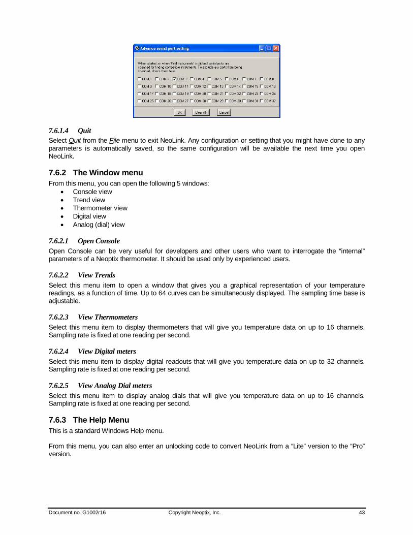
Document no. G1002r16 Copyright Neoptix, Inc. 43
7.6.1.4 Quit Select Quit from the File menu to exit NeoLink. Any configuration or setting that you might have done to any parameters is automatically saved, so the same configuration will be available the next time you open NeoLink.
7.6.2 The Window menu From this menu, you can open the following 5 windows:
Console view Trend view Thermometer view Digital view Analog (dial) view
7.6.2.1 Open Console Open Console can be very useful for developers and other users who want to interrogate the “internal” parameters of a Neoptix thermometer. It should be used only by experienced users.
7.6.2.2 View Trends Select this menu item to open a window that gives you a graphical representation of your temperature readings, as a function of time. Up to 64 curves can be simultaneously displayed. The sampling time base is adjustable.
7.6.2.3 View Thermometers Select this menu item to display thermometers that will give you temperature data on up to 16 channels. Sampling rate is fixed at one reading per second.
7.6.2.4 View Digital meters Select this menu item to display digital readouts that will give you temperature data on up to 32 channels. Sampling rate is fixed at one reading per second.
7.6.2.5 View Analog Dial meters Select this menu item to display analog dials that will give you temperature data on up to 16 channels. Sampling rate is fixed at one reading per second.
7.6.3 The Help Menu This is a standard Windows Help menu. From this menu, you can also enter an unlocking code to convert NeoLink from a “Lite” version to the “Pro” version.
Document no. G1002r16 Copyright Neoptix, Inc. 44
8 THE MODBUS OPTION The MODBUS protocol is a messaging structure developed by Modicon in 1979, used to establish master-slave / client-server communication between intelligent devices. It is a de-facto standard, truly open and the most widely used network protocol in the industrial manufacturing environment. The Modbus protocol provides an industry standard method that Modbus devices use for parsing messages. The Neoptix Modbus option has been developed to support Modbus over a Serial Line protocol. A master-slave type system has one node (the master node) that issues explicit commands to one of the “slave” nodes and processes responses. Slave nodes (such as the T/Guard system) will not transmit data without a request from the master node, and do not communicate with other slaves. At the physical level, Modbus over Serial Line systems may use different physical interface (RS485, RS232). RS485 two-wire interface is the most common. As an add-on option (contact Neoptix), RS485 four-wire interface may also be implemented. Furthermore, the Neoptix Modbus option has been successfully tested over a TCP/IP network, using a Lantronix device server. A RS232 serial interface may also be used as an interface, but when only short point-to-point communication is required, and this with only one slave device. Neoptix has experienced some communication problems when configuring multiple Modbus-RS-485 systems together. This is usually caused by unstable grounding problems, such as what can be encountered when dealing with power transformers. To solve these problems, your RS-485 lines should be opto-isolated before connecting them to the master Modbus bus. Refer to Section 8.8 for more information. This option is not available with the 8-16 channel T/Guard models (will be implemented in the future; contact Neoptix). Furthermore, the Modbus registers have been updated in July 2009; contact Neoptix to get an update (Neoprog is available for this purpose).
8.1 Configuring the Modbus option Enabling and configuring the Modbus option must be done when the T/Guard system is not in Modbus communication mode. When the Modbus option has been purchased, the help menu (see Section 6.3) is slightly modified, as the following line is added: mb: Modbus configuration tool, type: 'mb:?' for help; Typing “mb:?” gives: Modbus configuration tool mb:t,b,p,a<CR> Where t (type) : 0=RTU (default), 1=ASCII
b (baud) : 0=9600, 1=19200 p (parity) : 0=even (default), 1=odd, 2=none a (addr) : 1 to 247 (dec)
Example: mb:0,1,0,21 For RTU mode at 19200, even parity, Modbus address 21 (15hex) Current configuration is mb:0,1,0,45 Note for NeoLink software users: The Modbus parameters can also be set up using NeoLink. A special “Configure Modbus” button appears when NeoLink is connected to a Modbus-enabled T/Guard system.
Document no. G1002r16 Copyright Neoptix, Inc. 45
Once configured correctly, you can enter into Modbus mode by turning off the T/Guard for a few seconds and then turning it on but by holding down the System Status8 switch at the same time. Modbus mode should be confirmed if “MBxxx” is briefly displayed on the LCD display (xxx is the currently active Modbus address). You are now ready to connect the T/Guard to your Modbus enabled network.
8.2 Supported serial transmission mode The transmission mode defines the bit contents of the message bytes transmitted along the network, and how the message information is to be packed into the message stream and decoded. The current implementation of Neoptix-Modbus supports only the RTU mode; ASCII mode is a future option.
8.3 RTU transmission mode Coding system 8 bit binary Number of data bits per character 10 bits
start bits –1 data bits – 8 parity bits – 0 or 1(even or odd) stop bits – 1 (2 if no parity bit used)
Parity Not used or even or odd parity Bit transfer rate 9600 or 19200 Baud Duplex Full or Half Error checking CRC (cyclic redundancy check) Polynomial (CRC-16 101000000000001 Bit transfer order LSBit first, MSByte first End of message Idle line for 3.5 or more characters. The link layer includes the following properties /behaviors:
Slave address recognition Start / End of Frame detection CRC-16 generation / checking Transmit / receive message time-out Buffer overflow detection Framing error detection Idle line detection.
8.4 Modbus function code and register addresses Warnings:
Registers can only be read in groups of up to 16 registers. Multiple write to more than one register is not supported.
8.4.1 Read/Write, bit access Function codes: 0x01 (read coils), 0x05 (write single coil) or 0x0F (write multiple coils).
Address Register (hex) Name If 0 If 1 000019 0x00 Channel 1 enable Disable Enable 00002 0x01 Channel 2 enable Disable Enable 00003 0x02 Channel 3 enable Disable Enable 00004 0x03 Channel 4 enable Disable Enable 00005 0x04 Channel 5 enable Disable Enable 00006 0x05 Channel 6 enable Disable Enable
8 On older T/Guard system, this switch was called “LCD Backlight”. 9 Left-most digit indicates data type.

Document no. G1002r16 Copyright Neoptix, Inc. 46
00007 0x06 Channel 7 enable Disable Enable 00008 0x07 Channel 8 enable Disable Enable 00009 0x08 Scan speed Slow Fast 00010 0x09 Calibration type Neoptix Nortech Fibronic inc. 00011 0x0A Unit C F 00012 0x0B Sleep mode Scanning Sleep (lamps off) 00013 0x0C Wtune Disable Enable (optimize CCD
time) 00014 0x0D Reserved Valid Invalid 00015 0x0E Reserved Valid Invalid 00016 0x0F Reserved Valid Invalid
Writes can be made in “broadcast” mode or “unicast” mode.
8.4.2 Read only, bit access Function code: 0x02 (read discrete inputs).
Address Register (hex) Name If 0 If 1 10017 0x10 Channel 1 status No signal* Probe detected 10018 0x11 Channel 2 status No signal Probe detected 10019 0x12 Channel 3 status No signal Probe detected 10020 0x13 Channel 4 status No signal Probe detected 10021 0x14 Channel 5 status No signal Probe detected 10022 0x15 Channel 6 status No signal Probe detected 10023 0x16 Channel 7 status No signal Probe detected 10024 0x17 Channel 8 status No signal Probe detected 10025 0x18 Reserved Valid Invalid 10026 0x19 Reserved Valid Invalid 10027 0x1A Reserved Valid Invalid 10028 0x1B Reserved Valid Invalid 10029 0x1C Reserved Valid Invalid 10030 0x1D Reserved Valid Invalid 10031 0x1E Reserved Valid Invalid 10032 0x1F Reserved Valid Invalid
*: No probe detected, or defective probe.
8.4.3 Read only, 16 bit access Function code: 0x03 (read holding register). These registers can be read only (writing to them is not allowed, except for “zero” and “span” registers, see next Section).
Address Register (hex) Name Value 40033 0x20 Channel 1 temperature Signed 16 bit integer (temperature 1 * 10)10 40034 0x21 Channel 2 temperature Signed 16 bit integer (temperature 2 * 10) 40035 0x22 Channel 3 temperature Signed 16 bit integer (temperature 3 * 10) 40036 0x23 Channel 4 temperature Signed 16 bit integer (temperature 4 * 10) 40037 0x24 Channel 5 temperature Signed 16 bit integer (temperature 5 * 10) 40038 0x25 Channel 6 temperature Signed 16 bit integer (temperature 6 * 10) 40039 0x26 Channel 7 temperature Signed 16 bit integer (temperature 7 * 10) 40040 0x27 Channel 8 temperature Signed 16 bit integer (temperature 8 * 10) 40041 0x28 Internal temperature Signed 16 bit integer (temperature T/Guard * 10) 10Real temperatures can be calculated by dividing the integer numbers by 10. If probe has no signal, the value of –9996 is returned (or –999.6o); if channel is disabled, the value of –9995 is returned (or –999.5o).

Document no. G1002r16 Copyright Neoptix, Inc. 47
Address Register (hex) Name Value 40042 0x29 T/Guard number of channels Signed 16 bit integer 40043 0x2A Internal firmware version Signed 16 bit integer 40044 0x2B Internal firmware revision Signed 16 bit integer 40045 0x2C Device type11 Signed 16 bit integer 40046 0x2D ModeA12 Signed 16 bit integer 40047 0x2E ModeB Signed 16 bit integer 40048 0x2F Reserved 0x0000 40049 0x30 Channel 1 power Signed 16 bit integer (ratio * 100) 40050 0x31 Channel 2 power Signed 16 bit integer (ratio * 100) 40051 0x32 Channel 3 power Signed 16 bit integer (ratio * 100) 40052 0x33 Channel 4 power Signed 16 bit integer (ratio * 100) 40053 0x34 Channel 5 power Signed 16 bit integer (ratio * 100) 40054 0x35 Channel 6 power Signed 16 bit integer (ratio * 100) 40055 0x36 Channel 7 power Signed 16 bit integer (ratio * 100) 40056 0x37 Channel 8 power Signed 16 bit integer (ratio * 100) 40057 0x38 Channel 1 lamp attenuation Signed 16 bit integer 40058 0x39 Channel 2 lamp attenuation Signed 16 bit integer 40059 0x3A Channel 3 lamp attenuation Signed 16 bit integer 40060 0x3B Channel 4 lamp attenuation Signed 16 bit integer 40061 0x3C Channel 5 lamp attenuation Signed 16 bit integer 40062 0x3D Channel 6 lamp attenuation Signed 16 bit integer 40063 0x3E Channel 7 lamp attenuation Signed 16 bit integer 40064 0x3F Channel 8 lamp attenuation Signed 16 bit integer 40065 0x40 Channel 1 CCD time Signed 16 bit integer 40066 0x41 Channel 2 CCD time Signed 16 bit integer 40067 0x42 Channel 3 CCD time Signed 16 bit integer 40068 0x43 Channel 4 CCD time Signed 16 bit integer 40069 0x44 Channel 5 CCD time Signed 16 bit integer 40070 0x45 Channel 6 CCD time Signed 16 bit integer 40071 0x46 Channel 7 CCD time Signed 16 bit integer 40072 0x47 Channel 8 CCD time Signed 16 bit integer 40073 0x48 Reserved 0x0000 40074 0x49 Reserved 0x0000 40075 0x4A Reserved 0x0000 40076 0x4B Reserved 0x0000 40077 0x4C Reserved 0x0000 40078 0x4D Reserved 0x0000 40079 0x4E Reserved 0x0000 40080 0x4F Reserved 0x0000 40081 0x50 Channel 1 analog zero Signed 16 bit integer (temperature 1 * 10) 40082 0x51 Channel 2 analog zero Signed 16 bit integer (temperature 2 * 10) 40083 0x52 Channel 3 analog zero Signed 16 bit integer (temperature 3 * 10) 40084 0x53 Channel 4 analog zero Signed 16 bit integer (temperature 4 * 10) 40085 0x54 Channel 5 analog zero Signed 16 bit integer (temperature 5 * 10) 40086 0x55 Channel 6 analog zero Signed 16 bit integer (temperature 6 * 10) 40087 0x56 Channel 7 analog zero Signed 16 bit integer (temperature 7 * 10) 40088 0x57 Channel 8 analog zero Signed 16 bit integer (temperature 8 * 10) 40089 0x58 Channel 1 analog span Signed 16 bit integer (temperature 1 * 10) 40090 0x59 Channel 2 analog span Signed 16 bit integer (temperature 2 * 10) 40091 0x5A Channel 3 analog span Signed 16 bit integer (temperature 3 * 10)
11 T/Guard should return 2 or 11. T/Guard-Link should return 14. 12 For more information on ModeA and ModeB, contact Neoptix.
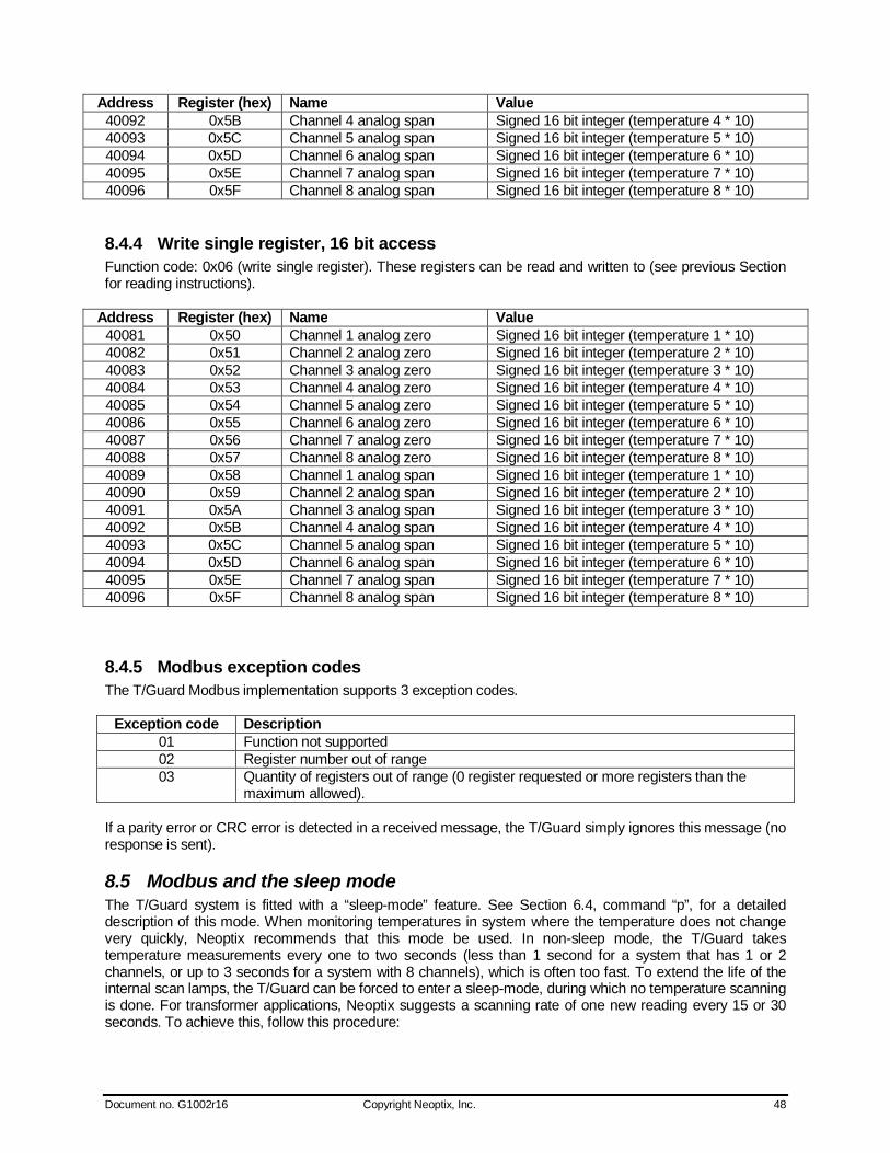
Document no. G1002r16 Copyright Neoptix, Inc. 48
Address Register (hex) Name Value 40092 0x5B Channel 4 analog span Signed 16 bit integer (temperature 4 * 10) 40093 0x5C Channel 5 analog span Signed 16 bit integer (temperature 5 * 10) 40094 0x5D Channel 6 analog span Signed 16 bit integer (temperature 6 * 10) 40095 0x5E Channel 7 analog span Signed 16 bit integer (temperature 7 * 10) 40096 0x5F Channel 8 analog span Signed 16 bit integer (temperature 8 * 10)
8.4.4 Write single register, 16 bit access Function code: 0x06 (write single register). These registers can be read and written to (see previous Section for reading instructions).
Address Register (hex) Name Value 40081 0x50 Channel 1 analog zero Signed 16 bit integer (temperature 1 * 10) 40082 0x51 Channel 2 analog zero Signed 16 bit integer (temperature 2 * 10) 40083 0x52 Channel 3 analog zero Signed 16 bit integer (temperature 3 * 10) 40084 0x53 Channel 4 analog zero Signed 16 bit integer (temperature 4 * 10) 40085 0x54 Channel 5 analog zero Signed 16 bit integer (temperature 5 * 10) 40086 0x55 Channel 6 analog zero Signed 16 bit integer (temperature 6 * 10) 40087 0x56 Channel 7 analog zero Signed 16 bit integer (temperature 7 * 10) 40088 0x57 Channel 8 analog zero Signed 16 bit integer (temperature 8 * 10) 40089 0x58 Channel 1 analog span Signed 16 bit integer (temperature 1 * 10) 40090 0x59 Channel 2 analog span Signed 16 bit integer (temperature 2 * 10) 40091 0x5A Channel 3 analog span Signed 16 bit integer (temperature 3 * 10) 40092 0x5B Channel 4 analog span Signed 16 bit integer (temperature 4 * 10) 40093 0x5C Channel 5 analog span Signed 16 bit integer (temperature 5 * 10) 40094 0x5D Channel 6 analog span Signed 16 bit integer (temperature 6 * 10) 40095 0x5E Channel 7 analog span Signed 16 bit integer (temperature 7 * 10) 40096 0x5F Channel 8 analog span Signed 16 bit integer (temperature 8 * 10)
8.4.5 Modbus exception codes The T/Guard Modbus implementation supports 3 exception codes.
Exception code Description 01 Function not supported 02 Register number out of range 03 Quantity of registers out of range (0 register requested or more registers than the
maximum allowed). If a parity error or CRC error is detected in a received message, the T/Guard simply ignores this message (no response is sent).
8.5 Modbus and the sleep mode The T/Guard system is fitted with a “sleep-mode” feature. See Section 6.4, command “p”, for a detailed description of this mode. When monitoring temperatures in system where the temperature does not change very quickly, Neoptix recommends that this mode be used. In non-sleep mode, the T/Guard takes temperature measurements every one to two seconds (less than 1 second for a system that has 1 or 2 channels, or up to 3 seconds for a system with 8 channels), which is often too fast. To extend the life of the internal scan lamps, the T/Guard can be forced to enter a sleep-mode, during which no temperature scanning is done. For transformer applications, Neoptix suggests a scanning rate of one new reading every 15 or 30 seconds. To achieve this, follow this procedure:

Document no. G1002r16 Copyright Neoptix, Inc. 49
1) Force the T/Guard to enter the sleep mode (register 0x0B) 2) Wait 15 or 30 seconds 3) Force the T/Guard to exit the sleep mode (register 0x0B) 4) Wait 3 seconds 5) Read the temperatures, on all channels 6) Return to step 1).
8.6 RS-485 connector definition
8.6.1 Connector pin-out for 2W-Modbus
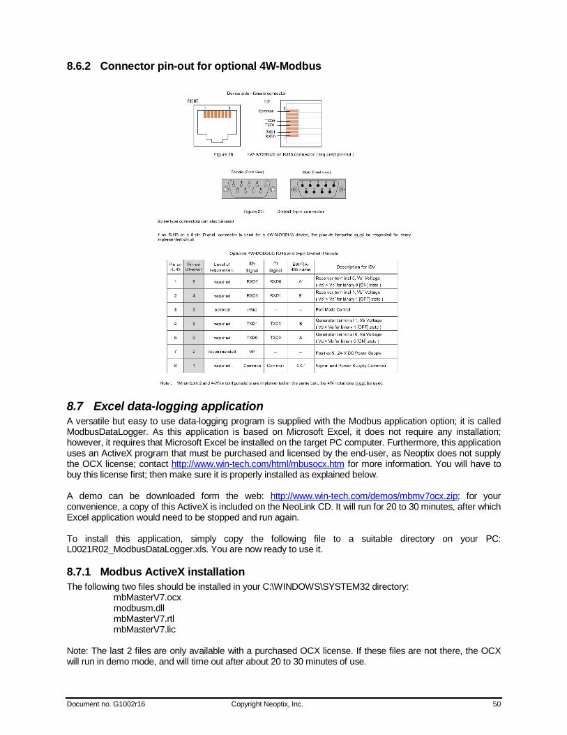
Document no. G1002r16 Copyright Neoptix, Inc. 50
8.6.2 Connector pin-out for optional 4W-Modbus
8.7 Excel data-logging application A versatile but easy to use data-logging program is supplied with the Modbus application option; it is called ModbusDataLogger. As this application is based on Microsoft Excel, it does not require any installation; however, it requires that Microsoft Excel be installed on the target PC computer. Furthermore, this application uses an ActiveX program that must be purchased and licensed by the end-user, as Neoptix does not supply the OCX license; contact http://www.win-tech.com/html/mbusocx.htm for more information. You will have to buy this license first; then make sure it is properly installed as explained below. A demo can be downloaded form the web: http://www.win-tech.com/demos/mbmv7ocx.zip; for your convenience, a copy of this ActiveX is included on the NeoLink CD. It will run for 20 to 30 minutes, after which Excel application would need to be stopped and run again. To install this application, simply copy the following file to a suitable directory on your PC: L0021R02_ModbusDataLogger.xls. You are now ready to use it.
8.7.1 Modbus ActiveX installation The following two files should be installed in your C:\WINDOWS\SYSTEM32 directory: mbMasterV7.ocx modbusm.dll mbMasterV7.rtl mbMasterV7.lic Note: The last 2 files are only available with a purchased OCX license. If these files are not there, the OCX will run in demo mode, and will time out after about 20 to 30 minutes of use.
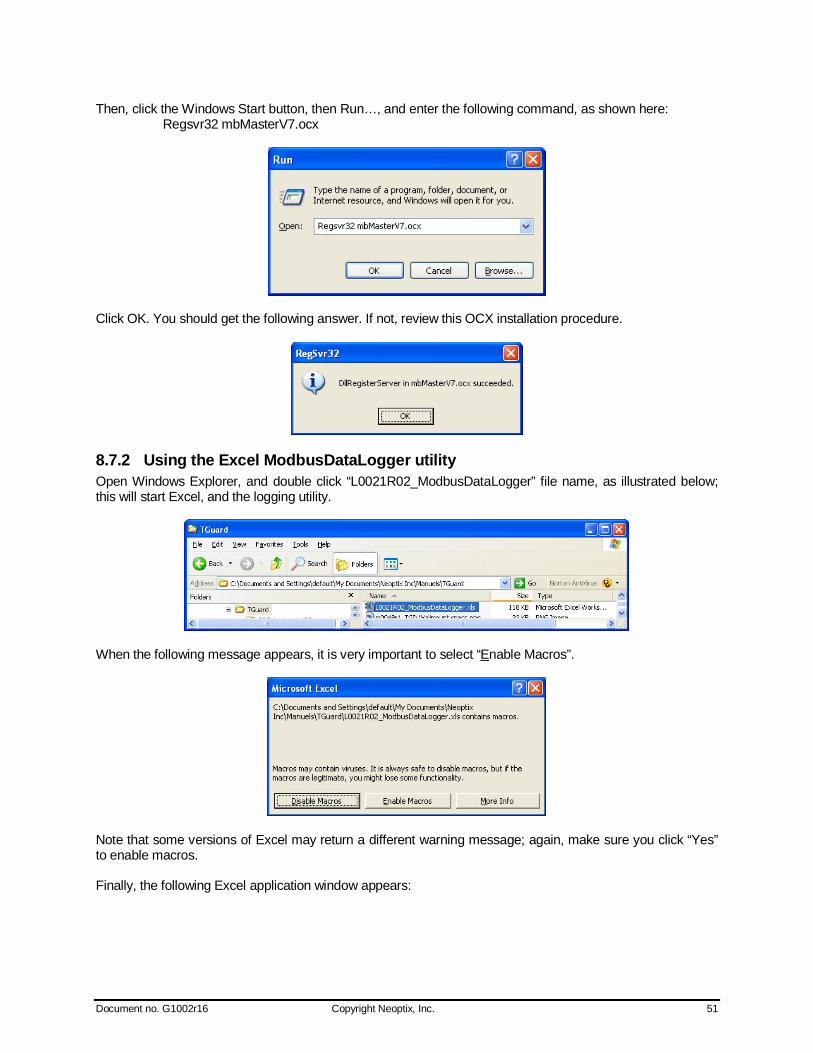
Document no. G1002r16 Copyright Neoptix, Inc. 51
Then, click the Windows Start button, then Run…, and enter the following command, as shown here: Regsvr32 mbMasterV7.ocx
Click OK. You should get the following answer. If not, review this OCX installation procedure.
8.7.2 Using the Excel ModbusDataLogger utility Open Windows Explorer, and double click “L0021R02_ModbusDataLogger” file name, as illustrated below; this will start Excel, and the logging utility.
When the following message appears, it is very important to select “Enable Macros”.
Note that some versions of Excel may return a different warning message; again, make sure you click “Yes” to enable macros. Finally, the following Excel application window appears:
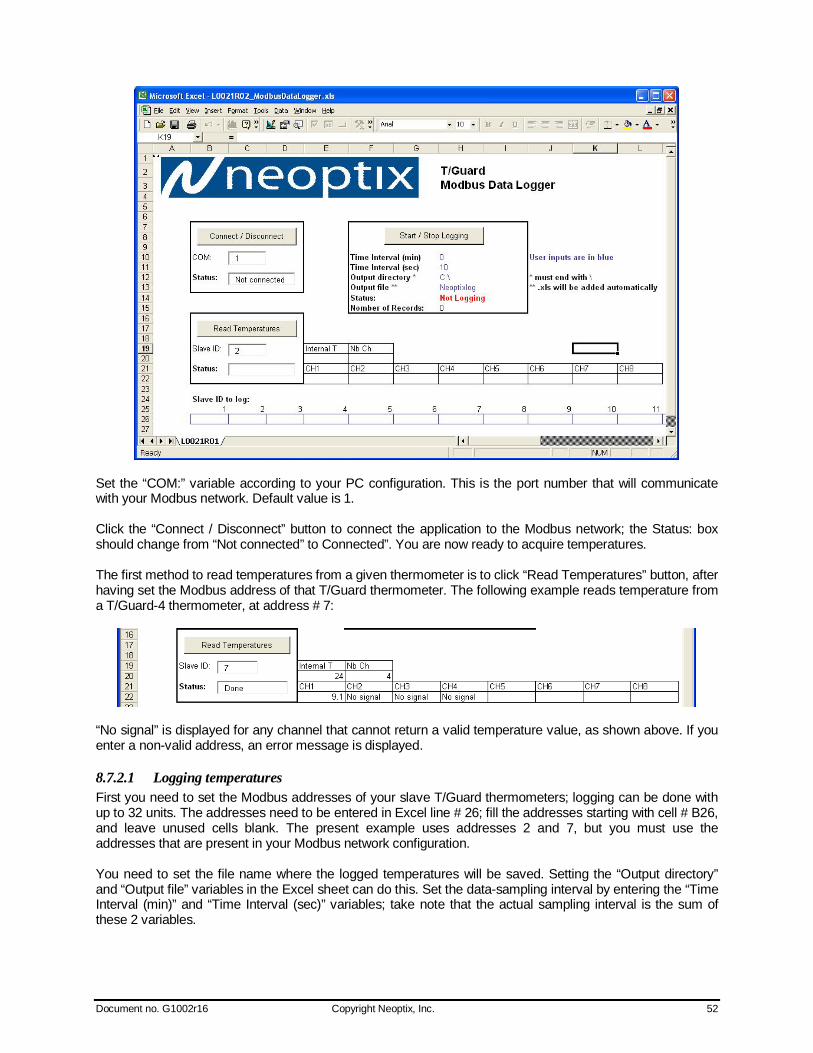
Document no. G1002r16 Copyright Neoptix, Inc. 52
Set the “COM:” variable according to your PC configuration. This is the port number that will communicate with your Modbus network. Default value is 1. Click the “Connect / Disconnect” button to connect the application to the Modbus network; the Status: box should change from “Not connected” to Connected”. You are now ready to acquire temperatures. The first method to read temperatures from a given thermometer is to click “Read Temperatures” button, after having set the Modbus address of that T/Guard thermometer. The following example reads temperature from a T/Guard-4 thermometer, at address # 7:
“No signal” is displayed for any channel that cannot return a valid temperature value, as shown above. If you enter a non-valid address, an error message is displayed.
8.7.2.1 Logging temperatures First you need to set the Modbus addresses of your slave T/Guard thermometers; logging can be done with up to 32 units. The addresses need to be entered in Excel line # 26; fill the addresses starting with cell # B26, and leave unused cells blank. The present example uses addresses 2 and 7, but you must use the addresses that are present in your Modbus network configuration. You need to set the file name where the logged temperatures will be saved. Setting the “Output directory” and “Output file” variables in the Excel sheet can do this. Set the data-sampling interval by entering the “Time Interval (min)” and “Time Interval (sec)” variables; take note that the actual sampling interval is the sum of these 2 variables.
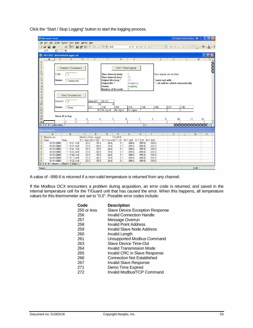
Document no. G1002r16 Copyright Neoptix, Inc. 53
Click the “Start / Stop Logging” button to start the logging process.
A value of –999.6 is returned if a non-valid temperature is returned from any channel. If the Modbus OCX encounters a problem during acquisition, an error code is returned, and saved in the internal temperature cell for the T/Guard unit that has caused the error. When this happens, all temperature values for this thermometer are set to “0.0”. Possible error codes include:
Code Description 255 or less Slave Device Exception Response 256 Invalid Connection Handle 257 Message Overrun 258 Invalid Point Address 259 Invalid Slave Node Address 260 Invalid Length 261 Unsupported Modbus Command 263 Slave Device Time-Out 264 Invalid Transmission Mode 265 Invalid CRC in Slave Response 266 Connection Not Established 267 Invalid Slave Response 271 Demo Time Expired 272 Invalid Modbus/TCP Command.
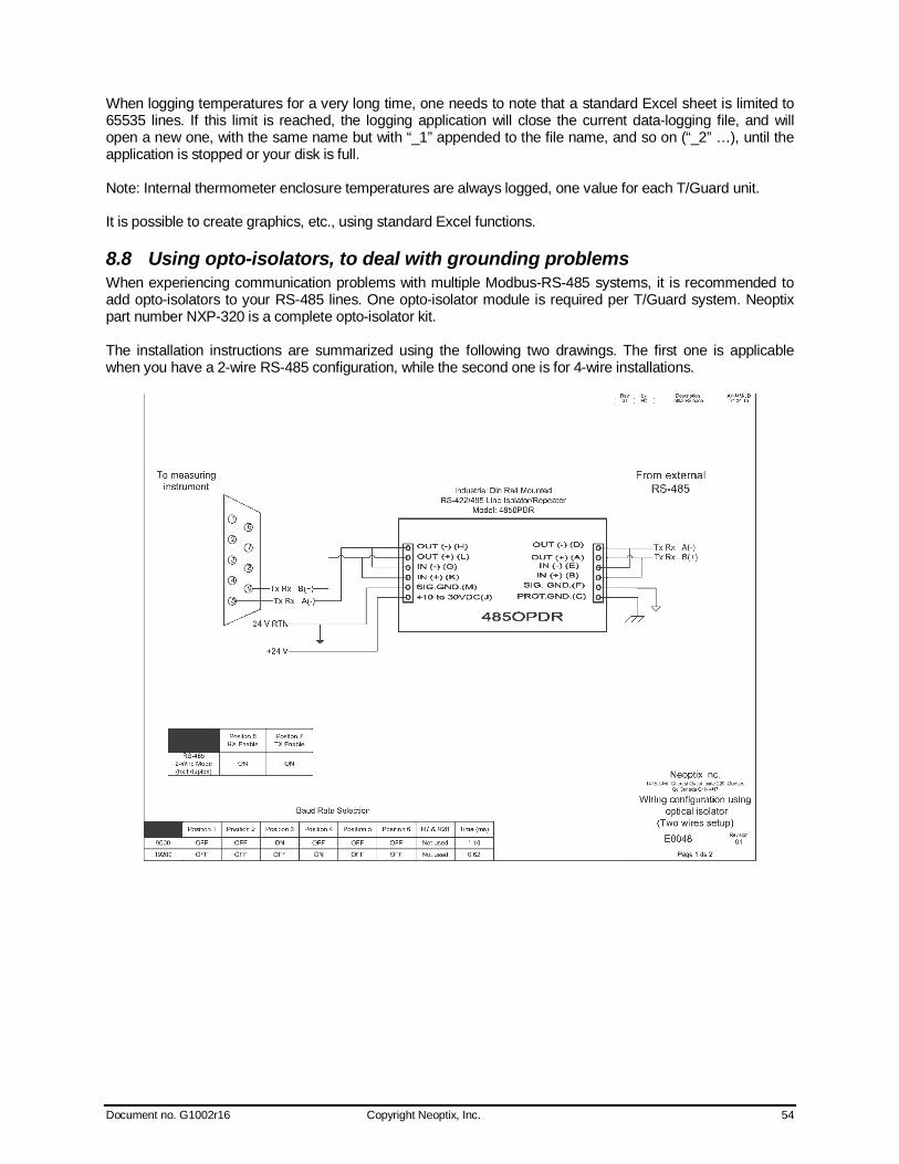
Document no. G1002r16 Copyright Neoptix, Inc. 54
When logging temperatures for a very long time, one needs to note that a standard Excel sheet is limited to 65535 lines. If this limit is reached, the logging application will close the current data-logging file, and will open a new one, with the same name but with “_1” appended to the file name, and so on (“_2” …), until the application is stopped or your disk is full. Note: Internal thermometer enclosure temperatures are always logged, one value for each T/Guard unit. It is possible to create graphics, etc., using standard Excel functions.
8.8 Using opto-isolators, to deal with grounding problems When experiencing communication problems with multiple Modbus-RS-485 systems, it is recommended to add opto-isolators to your RS-485 lines. One opto-isolator module is required per T/Guard system. Neoptix part number NXP-320 is a complete opto-isolator kit. The installation instructions are summarized using the following two drawings. The first one is applicable when you have a 2-wire RS-485 configuration, while the second one is for 4-wire installations.
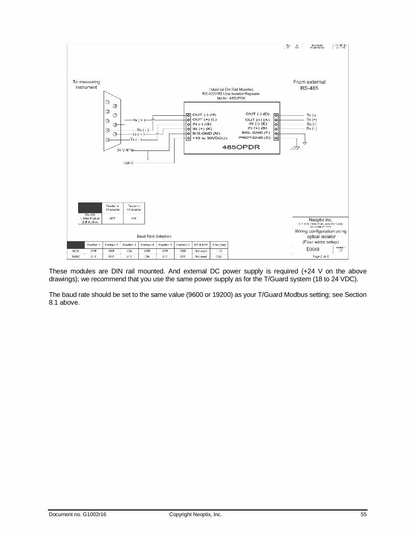
Document no. G1002r16 Copyright Neoptix, Inc. 55
These modules are DIN rail mounted. And external DC power supply is required (+24 V on the above drawings); we recommend that you use the same power supply as for the T/Guard system (18 to 24 VDC). The baud rate should be set to the same value (9600 or 19200) as your T/Guard Modbus setting; see Section 8.1 above.
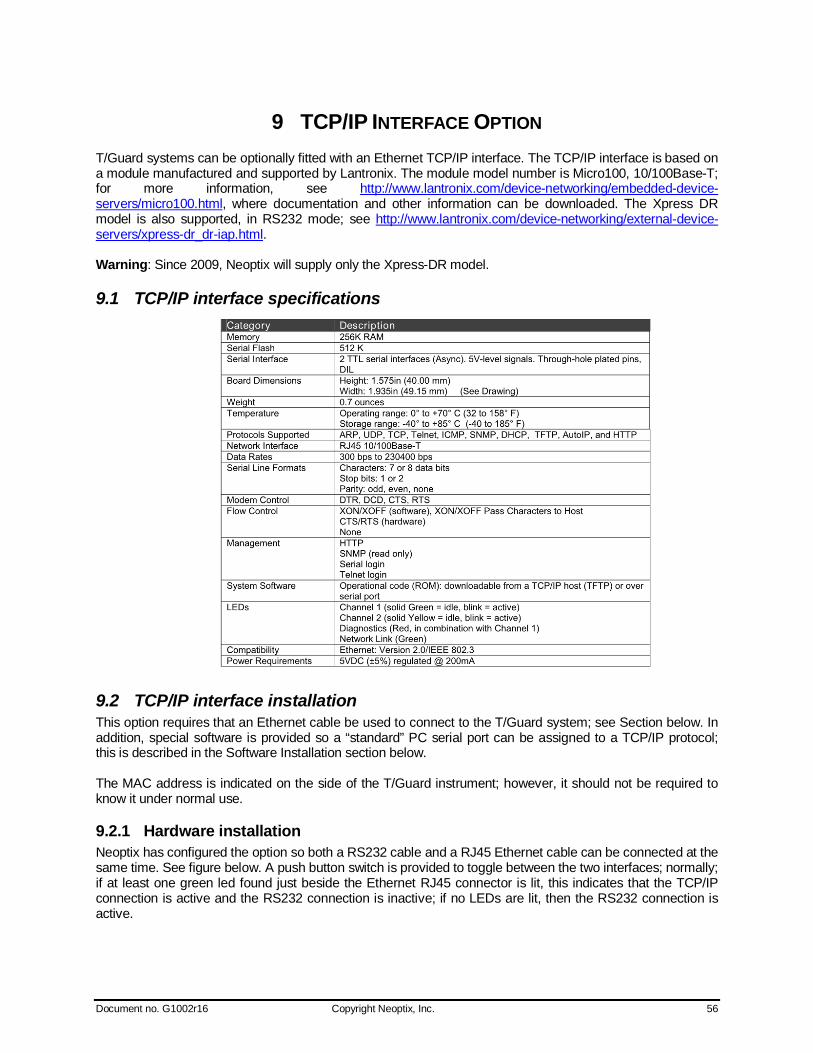
Document no. G1002r16 Copyright Neoptix, Inc. 56
9 TCP/IP INTERFACE OPTION T/Guard systems can be optionally fitted with an Ethernet TCP/IP interface. The TCP/IP interface is based on a module manufactured and supported by Lantronix. The module model number is Micro100, 10/100Base-T; for more information, see http://www.lantronix.com/device-networking/embedded-device-servers/micro100.html, where documentation and other information can be downloaded. The Xpress DR model is also supported, in RS232 mode; see http://www.lantronix.com/device-networking/external-device-servers/xpress-dr_dr-iap.html. Warning: Since 2009, Neoptix will supply only the Xpress-DR model.
9.1 TCP/IP interface specifications
9.2 TCP/IP interface installation This option requires that an Ethernet cable be used to connect to the T/Guard system; see Section below. In addition, special software is provided so a “standard” PC serial port can be assigned to a TCP/IP protocol; this is described in the Software Installation section below. The MAC address is indicated on the side of the T/Guard instrument; however, it should not be required to know it under normal use.
9.2.1 Hardware installation Neoptix has configured the option so both a RS232 cable and a RJ45 Ethernet cable can be connected at the same time. See figure below. A push button switch is provided to toggle between the two interfaces; normally; if at least one green led found just beside the Ethernet RJ45 connector is lit, this indicates that the TCP/IP connection is active and the RS232 connection is inactive; if no LEDs are lit, then the RS232 connection is active.
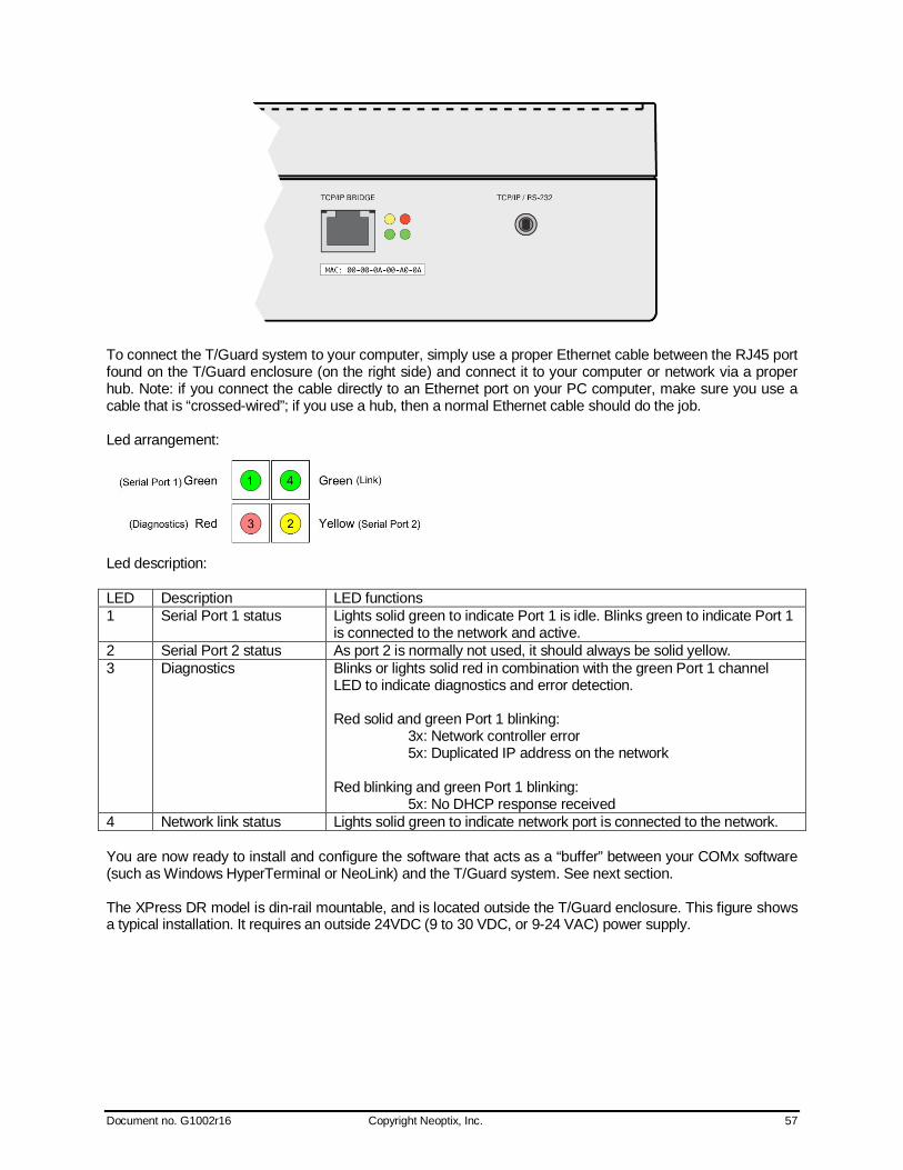
Document no. G1002r16 Copyright Neoptix, Inc. 57
To connect the T/Guard system to your computer, simply use a proper Ethernet cable between the RJ45 port found on the T/Guard enclosure (on the right side) and connect it to your computer or network via a proper hub. Note: if you connect the cable directly to an Ethernet port on your PC computer, make sure you use a cable that is “crossed-wired”; if you use a hub, then a normal Ethernet cable should do the job. Led arrangement:
Led description: LED Description LED functions 1 Serial Port 1 status Lights solid green to indicate Port 1 is idle. Blinks green to indicate Port 1
is connected to the network and active. 2 Serial Port 2 status As port 2 is normally not used, it should always be solid yellow. 3 Diagnostics Blinks or lights solid red in combination with the green Port 1 channel
LED to indicate diagnostics and error detection. Red solid and green Port 1 blinking: 3x: Network controller error 5x: Duplicated IP address on the network Red blinking and green Port 1 blinking: 5x: No DHCP response received
4 Network link status Lights solid green to indicate network port is connected to the network. You are now ready to install and configure the software that acts as a “buffer” between your COMx software (such as Windows HyperTerminal or NeoLink) and the T/Guard system. See next section. The XPress DR model is din-rail mountable, and is located outside the T/Guard enclosure. This figure shows a typical installation. It requires an outside 24VDC (9 to 30 VDC, or 9-24 VAC) power supply.
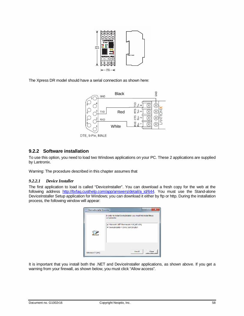
Document no. G1002r16 Copyright Neoptix, Inc. 58
The Xpress DR model should have a serial connection as shown here:
9.2.2 Software installation To use this option, you need to load two Windows applications on your PC. These 2 applications are supplied by Lantronix. Warning: The procedure described in this chapter assumes that
9.2.2.1 Device Installer The first application to load is called “DeviceInstaller”. You can download a fresh copy for the web at the following address http://ltxfaq.custhelp.com/app/answers/detail/a_id/644. You must use the Stand-alone DeviceInstaller Setup application for Windows; you can download it either by ftp or http. During the installation process, the following window will appear:
It is important that you install both the .NET and DeviceInstaller applications, as shown above. If you get a warning from your firewall, as shown below, you must click “Allow access”.
Black
Red
White

Document no. G1002r16 Copyright Neoptix, Inc. 59
Warning: The setup procedure that is described here assumes that your Lantronix bridge device is connected on a network where a DCHP server is present. This procedure will not directly work for an installation where your Lantronix device would be connected directly to your PC13. Once installed, run DeviceInstaller. Make sure the Lantronix device is on the network and powered up. You should get the following screen:
As you can see, DeviceInstaller has not found any Lantronix device. Click the Search icon. Depending on what you have on your network, here is a typical response from the search operation:
13 If you try to connect your Lantronix device directly to your PC (thus without a DHCP server), it might be useful to load a DHCP server on your PC; that way, the procedure described here will work even if you have no external DHCP server device., The following freeware can be very useful for this purpose: http://ruttkamp.gmxhome.de/dhcpsrv/dhcpsrv1.9.zip (do not run it as a service). the readme.txt file gives instructions on how to use this very useful program.
Take note of this IP address: this is the address of your Lantronix device.

Document no. G1002r16 Copyright Neoptix, Inc. 60
If DeviceInstaller does not find any Lantronix device, check the device for proper installation on the network. Now, we need to install the second software program, called CPR Manager (CPR = Com Port Redirector). Again, the best is to download a fresh copy from the Lantronix web site, at the following address: http://www.lantronix.com/device-networking/utilities-tools/com-port-redirector.html. Download the stand-alone CPR Setup application for Windows, either ftp or http. During installation, you will see this window, click Install.
Run the CPR Manager. You will get the following empty window:
Select “Tools” from the task bar, then “Launch CPR Manager”; the following window will open:
Click the “Add / Remove” button. The following sub-window opens, to allow you to select an appropriate Com port number. Neoptix suggests that you select a port number in the range or 15 to 30. In this example, we have selected port # 30.
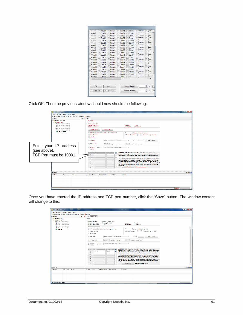
Document no. G1002r16 Copyright Neoptix, Inc. 61
Click OK. Then the previous window should now should the following:
Once you have entered the IP address and TCP port number, click the “Save” button. The window content will change to this:
Enter your IP address (see above). TCP Port must be 10001
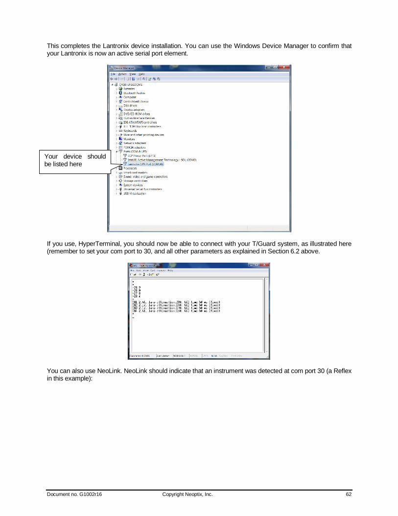
Document no. G1002r16 Copyright Neoptix, Inc. 62
This completes the Lantronix device installation. You can use the Windows Device Manager to confirm that your Lantronix is now an active serial port element.
If you use, HyperTerminal, you should now be able to connect with your T/Guard system, as illustrated here (remember to set your com port to 30, and all other parameters as explained in Section 6.2 above.
You can also use NeoLink. NeoLink should indicate that an instrument was detected at com port 30 (a Reflex in this example):
Your device should be listed here
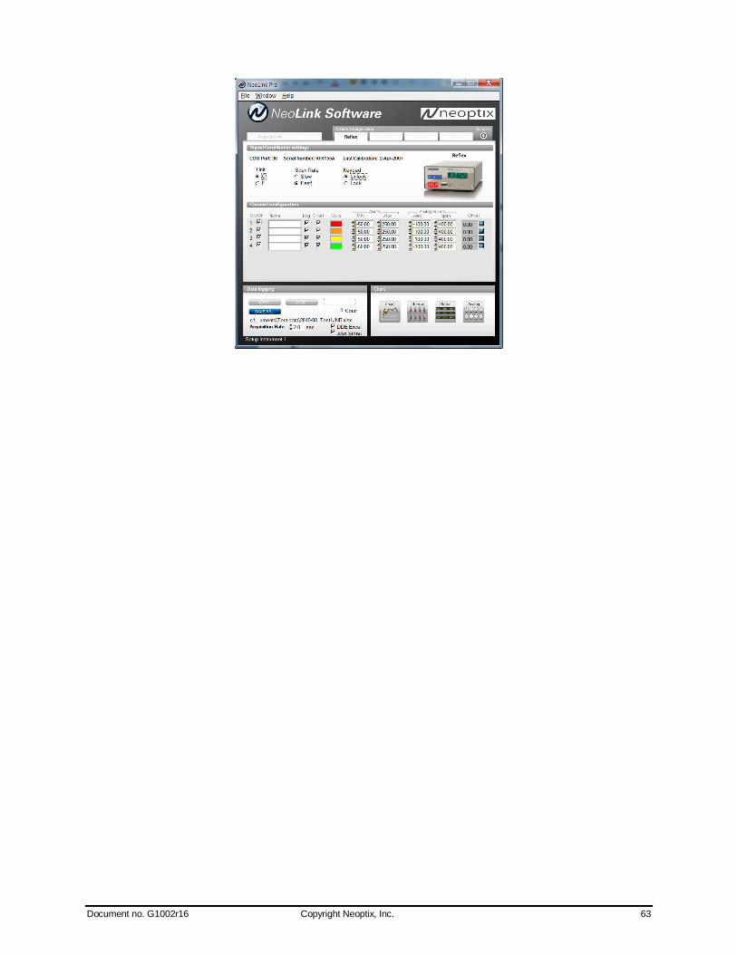
Document no. G1002r16 Copyright Neoptix, Inc. 63

Document no. G1002r16 Copyright Neoptix, Inc. 64
10 RS-485 CONVERTERS 10.1 RS-485 to USB converter As most PC computers today don’t have serial ports, Neoptix recommends using a RS-485 to USB converter (also called adapter). It works great with all T/Guard, T/Guard2 and T/Guard+ systems. This converter works for both 2W and 4W RS-485 installations; no external power supply is required. It also offers 2000V RMS optical isolation, which is great for electrically noisy applications or when grounding may be a problem. The following figure shows this adapter (when purchased form Neoptix, the adapter will be fitted with a DB9 connector suitable for use for both 2W and 4W applications):
Note that this converter requires a special software driver that needs to be installed before you use the device; you will find all details on the CD that comes with the unit. Furthermore, the converter has 4 dip switches that need to be configured depending on your exact installation: there are 2 possibilities, as follows:
a) If you have a 2W (2-wire, also called “half-duplex”) installation, then the four dip switches must be set as follows:
a. Switch 1 must be on (RS-485 mode) b. Switch 2 must be on (Echo Off) c. Switch 3 must be on (2 Wire mode) d. Switch 4 must be on (2 Wire mode).
b) If you have a 4W (4-wire, also called “full-duplex”) installation, then the four dip switches must be set
as follows: a. Switch 1 must be on (RS-485 mode) b. Switch 2 must be off (Echo On) c. Switch 3 must be off (4 Wire mode) d. Switch 4 must be off (4 Wire mode).
Warning: When dealing with very long cables (e.g., more than 300 meters), your RS-485 network might need a termination resistor (typically 120Ω). Consult Neoptix for more details.
10.2 RS-485 to RS-232 converter As an alternative solution, Neoptix offers (as an option) a convenient converter that can be used to link a T/Guard (or a T/Guard+) fitted with a RS-485 interface to a PC computer that has only a RS-232C interface port. This converter works with both 2W and 4W RS-485 installations. This converter does not need any software driver to be installed in your PC. The following figure shows this adapter.

Document no. G1002r16 Copyright Neoptix, Inc. 65
To PC ←
→To T/Guard
To use the converter, you will need a standard RS-232 cable that will attach your converter to your PC. Please note that PC’s that do not have an RS-232 interface built-in will need an additional RS-232 to USB adapter that you can buy at any local computer shop14. This converter has 4 dip switches that need to be configured depending on your specific installation. The setting details is the same as for the USB converter, see above section. The converter does not require any outside power supply; it is self-powered from the RS-232 signal lines. However, if termination resistors are used, an external power supply is required.
14 We have found that some RS-232 to USB adapters do not appropriately power up this RS-232 to RS-485 converter; for these, the converter may require an external 12VDC power module to operate properly.

Document no. G1002r16 Copyright Neoptix, Inc. 66
Neoptix, Inc. 1415, rue Frank-Carrel, Suite 220 Québec City, QC CANADA G1N 4N7 Tel: 418-687-2500 Fax: 418-687-2524 www.neoptix.com [email protected]
Printed in Canada
Related Documents