G-ZERO Mill Interactive Tutorial Copyright © 1985-2009 by Rapid Output Co. All Rights Reserved. (888) 656-1945 www.g-zero.com

Welcome message from author
This document is posted to help you gain knowledge. Please leave a comment to let me know what you think about it! Share it to your friends and learn new things together.
Transcript
1
G-ZERO Mill
Interactive Tutorial
Copyright © 1985-2009 by Rapid Output Co. All Rights Reserved.
(888) 656-1945www.g-zero.com

2
Before You BeginThis tutorial was designed using G-ZERO Mill v4.6 installed with the default settings. Newer versionsof G-ZERO will, of course, have a look that is slightly different, especially on some settings pages.Note 1: If you do not yet own our full working version, the G-ZERO Student version is recommendedfor users who intend to self-train using this Mill Tutorial Manual. You may download the Studentversion from our website by typing the following (exactly) into your web browser:http://www.g-zero.com/DownL/InstallMillStudent.exeNote 2: All files used in this tutorial are on your C:\MILL\TUTORIAL directory after installingthe Student version.
In this manual, each project starts with a list of the main topics covered in that assignment along with ablueprint of the part to be programmed. Usually, there are many ways to program a part; here, wedescribe just one solution.Projects in this tutorial follow a logical progression, so each project assumes you master the conceptspresented in previous projects.

3
Contents
1. Initial Tour 5
2. Drill Mania 13
3. Rectangle & Rounds 19
4. Rectangle & Rounds (revisions) 27
5. Turtle 33
6. Puzzle Plate 41
7. C-Gasket 47Program a source file with data taken from a DXF file. LoadCAD Reader and prepare DXF file (window, layer, zoom,origin). Define MAT’L using values from DXF file. Drill holesusing CAD Reader Single Pick. Mill pocket and cut profileusing CAD Reader Block Pick.
Multiple part setup using the MULTIPLY command. Face andconventional cutting. Program two unknown radii in a row.Enter an angle in degree/minute/second format. Reverse cutterpath.
Mill elaborate profile with unknown values. Mill pocket usingcircular ramping (MILL, ZMOVE, ROUND) and COMP withblend radii.
Open an existing source file. Create a copy of a source fileusing Save As. Print a source file. Editing commands.
Straight cut using MILL command. Mill rectangles (windowand pocket). Mill circles with the ROUND command. Roughcut with the STOCK command. Mill OD step (COMP,UNCOMP, LINE, RADIUS commands)
Start a new source file. Define the material. Drill a singlehole. Drill a full bolt-circle. Drill random holes. Drill holesarranged in a grid. Use the REPEAT command. Saveprogram and exit G-ZERO Mill.
Open G-ZERO Mill. Start a new source file. Use basiccommands. Use Help. Simple editing. View part. Save asource file. Convert a source file into G-code. Exit G-ZEROMill.

4
8. ToolType 53
9. Sideways Face 57
10. Odd Pizza 61
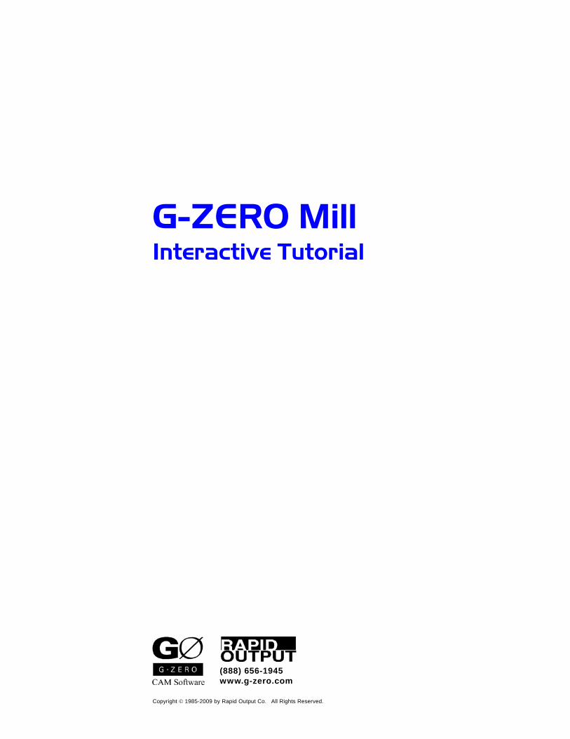
11. Scroll 65
12. Comprehensive 69
Use ROTATE to program geometry with dimension given in adifferent axis (rotated and shifted coordinates).
Use of the %#TL, %#TT, and %#TA variables to show accuratemodeling of specialized tools in the Solid Modeling environ-ment.
Use several ROTATE commands to program geometry withdimensions given in different axes (rotated coordinates). Useof blend-on and blend-off radii.
Define a geometry for subsequent multiple use (no cuttingperformed). Cut on a centerline. Smoothing (smooth points).
Mirror simple shapes. Review important concepts learned inprevious projects.

5
What you will learn:Open G-ZERO MillStart a new source fileUse basic commandsUse HelpSimple editingView partSave a source fileConvert a source file into G-codeExit G-ZERO Mill
G-ZERO Mill Tutorial - Project 1
Initial Tour
Project 1
TITLE:
MATERIAL:
DRAWING:
TOOL LIST:Initial Tour
0.5" Aluminum
M000INITIALS:
MCRAPID OUTPUT CO.30995 San Benito St.Hayward, CA 94544(510) 487-4012
Finish left and right side (.25" dia. HSS endmill)Drill holes (.25" dia. HSS drill)
3.00"
2.50"
1.00"
1.00"
2.00"
ø 0.25"(2x)
0.50"
Rapid Output Co.www.g-zero.com
888-656-1945

6 G-ZERO Mill Tutorial - Project 1
From the Start menu, choose (All) Programs.From the G-ZERO CAM \ Mill folder, select G-ZERO Mill v5 (or v4).
11111 Start G-ZERO Mill
22222 Start a new source file
From the File pull-down menu, select Open to open the “Source Fileto Open” window.Type Initial-Tour in the “File Name” box, and click the Open button.(Note that G-ZERO Mill accepts long file names)
Because the file does not exist, G-ZERO asks you if you want to createit. Click the Yes button.Note: G-ZERO Student version saves only 100 lines of your program to disc.
WARNING: You should never load a source from the full working version intothe Student version...you will likely lose important data.
33333 Use basic commands
Start your source code with a Material command that describes the size,thickness, and type of material of the part you are going to work on.Then, you need to describe the Tool you are going to use, and follow it bya cutting operation (e.g.: drill, mill) and the locations of the cut (e.g.:point, line, radius)You can invoke a command in two different ways:
(a) Use your mouse to select the command from the left graphic (orfull) menu. Example:
(b) Use the numeric key pad to key in the number that corresponds tothe specific command you want to enter, followed by the key.Example:
To answer the questions that correspond to each command, key in thevalue and/or comment requested followed by the key.
Note: Each section below starts with a line of source code followed by itscorresponding description or comment. For a detailed explanation ofeach command, see the G-ZERO Mill Reference Manual.
.
1 MAT’L xmin0 xmax3 ymin0 ymax2.5 thk.5 type0=ALUMALOYSelect the command 17) Mat’l and complete this command by answeringquestions about the material.According to the blueprint from the previous page, the dimensions of ourpart are x = 3 and y = 2.5 . We can set our origin (0;0) in the lower leftcorner of our part, so the dimensions will be: xmin = 0 , xmax = 3 ,ymin = 0 , and ymax = 2.5 .The thickness of the part as well as the type of material are also listed onthe blueprint. Note that when you are about to answer the type ofmaterial, G-ZERO pops-up a yellow menu with the choices you currentlyhave. You can either select it with your mouse, or key in the number thatcorresponds to your material.

7
2 TOOL 1 dia.25 flutes2 type0=HSS MILL rad0 *** CUT LEFT AND RIGHTSIDESDefine the tool for the first operation by selecting the 6) Tool command.Just like the MAT’L command, the TOOL command also provides youwith a list of tool types from which you can make your selection.At the end of this command, you can enter a comment that will appear inyour G-code file as a comment line.
3 MILL zrapid.1 zcut-.51 passes1 zret.1 zf45 xyf10A MILL command tells the spindle to rapid down at the next location to aset z-value (zrapid) above the work. The spindle then feeds down, at anappropriate feedrate, to the cutting plane (zcut).
4 POINT x-.125 y-.125Program a POINT to position the tool to start milling. The mill center isdirectly on the point; so, you need to calculate the tool radius offset.
5 POINT x-.125 y2.625 f5Program this POINT for a straight cut through the material.
6 MILL zrapid.1 zcut-1 passes1 zret.1 zf45 xyf10Now, we are ready to cut the right side of the material. This secondMILL command makes the spindle move to the retract plane and thencome down again at the next location.
7 POINT x3.125 y2.625Program a POINT to position the tool to start milling at the upper rightside of the part. The mill center is directly on the point; so, you need tocalculate the tool radius offset.
8 POINT x3.125 y-.125 f5Program this POINT for a straight cut through the material.
9 TOOL 2 dia.25 flutes2 type20=HSS DRILL rad0 *** DRILL HOLESNow, let’s change the Tool to drill holes. Select the TOOL command andanswer the questions using the information shown above .
10 DRILL g81=C’DRILL zrap.1 zcut-1 pecks3 tip0 zret.1 f11A DRILL command defines the z parameter for each drill cycle. G-ZERO automatically returns to z-retract position between each location.Select the DRILL command and answer the questions using the informa-tion shown above.
11 POINT x2 y1Program this POINT to the first hole to be drilled.
G-ZERO Mill Tutorial - Project 1

8
G-ZERO comes with a built-in Help system with descriptions of thecommands along with some programming tips. Let’s try.
Press the function key to open the Mill Commands Help.(Click the green underlined commands to view their respectivedescriptions)
Click the close icon on the upper right corner of the screen to exitthe Help window.
If you are in the middle of creating a command line, the key willdisplay the description of that specific command. To test it, let’s create anew line with the command POINT.
Select the POINT command.Now, that we are in the middle of this command, press the functionkey. Notice that it displays the descriptions of the POINT command.
Click the close icon on the upper right corner of the screen to exitthe Help window.
Press the key to undo the unfinished POINT command.
By now, your source code should look like this:
44444 Use Help
G-ZERO Mill Tutorial - Project 1
12 POINT x2 y2Program this POINT to this last hole.

9
Change a value: Let’s say we want to change the y value of the point inline 8 from -.125 to .2.
Use your mouse to click the value you want to change.Notice that the value you selected is highlighted and the workingscreen background turned to blue. This indicates that you are in the“editing” mode.Type in .2 to replace the highlighted value.Press the key to exit the “editing” mode.
Replace a value with another value on the screen: Now, we are going tochange the y value of the point in line 8 back to -.125 by replacing it withthe y value of the point in line 4.
Use your mouse to click the value you want to replace. The screenturns into “editing” mode.Use your mouse to click the y value (-.125) of the point in line 4.Notice that the y value of line 8 has been replaced.Press the key to exit the “editing” mode.
Delete last line: To delete the last line of your source code, just press the key.
While you are programming, you may want to look at a graphicalrepresentation of your source code. Let’s try it now.
Press F2 to redraw the entire source program.Press F3 to redraw the entire source program with the tool path.Press F4 to redraw the entire source program showing a slinky toolpath.Press F5 to display a wireframe isometric view of the part.Press F6 to display a solid view of the part.
F5 - Isometric F6 - Solid
F2 - Part F3 - Tool F4 - Slinky
55555 Simple editing
66666 View / redraw the part
G-ZERO Mill Tutorial - Project 1

10
Partial redraw: G-ZERO gives you the option of collapsing a completetool section. Let’s try redrawing just Tool 1.
Click the space on the left side of the number “2” of Line 2 tocollapse all tools. [Fig. 1] ( + also collapses the sourceprogram)Click the symbol left to the number “2” of Line 2 to show details ofTool 1. [Fig. 2, 3]Now press all the function keys previously introduced (F2 - F6) andsee that only Tool 1 is shown.
To see whole program again, press + keys.
Fig. 1 Fig. 3Fig. 2
Zoom: Zoom a section of your graphic to magnify its details. Follow theexample below:
Press to redraw the entire source program. [Fig. 4]Place your mouse cursor on the upper left corner of the area to bezoomed.Hold the left button of your mouse and drag it to frame the area to bezoomed. [Fig. 5]Release mouse and see how the framed area is zoomed in. [Fig. 6]
It is a good idea to frequently save your program to avoid losing informa-tion. Let’s do that now:
From the File pull-down menu, select Save.By default, G-ZERO Mill automatically saves your file every 3 minutes.Note: To save your file using another name, use Save As.
77777 Save a source file
Fig. 4 Fig. 6Fig. 5
G-ZERO Mill Tutorial - Project 1

11
Note: The STUDENT version does not support fully-functional Post Processors. The G-code format will bemostly correct, but the numbers will make ‘melted’ parts.
F12: Press F12 to open a dialogue box titled Post Processor to Open... (Note that post processors arecustomized and sold separately)
Post: Select a tool post (for example: xFADAL.P) and watch how G-ZERO creates the appropriate G-code for the machine selected. You may have to search in a folder called Sample Posts. G-ZEROalso saves the G-code file (extension .t) and displays it on your screen using Notepad, Wordpad,Codeshark, or any other text editor you might prefer. To exit the G-code editor, click the close icon
on the upper right corner of its window.
[ TOOL 1 dia.25 flutes2 type0=HSS MILLrad0 *** CUT LEFT AND RIGHTSIDES
[ Estimated run time for this tool = 1.35minutes.
[[ TOOL 2 dia.25 flutes2 type20=HSS DRILL
rad0 *** DRILL HOLES[ Estimated run time for this tool = .41
minutes.[[ Estimated time for this program = 1.76
minutes.%N.001O1
N1G90T1M6(CUT LEFT AND RIGHTSIDES)
N2(CUT LEFT AND RIGHT SIDES)N3G0E1X-.125Y-.125N4G0S5347M3N5H1Z.1M8N6G1Z-.51F45.N7Y2.625F5.N8G0Z.1
To exit G-ZERO Mill, click the close icon on the upper right corner ofits window.
Initial-Tour.t
88888 Convert a source file into G-code
99999 Exit G-ZERO
G-ZERO Mill Tutorial - Project 1
Note: Lines before the first % symbol are for your eyes only and are not sent to the CNC.
N9X3.125N10G1Z-1.F45.N11Y-.125F5.N12G0Z.1N13M9N14G0H0Z0M5N15M1
N16G90T2M6(DRILL HOLES)N17(DRILL HOLES)N18G0E1X2.Y1.N19G0S5347M3N20H2Z.1M8N21G81G99Z-1.R0.1F11.N22Y2.N23G0G80N24M9N25G0H0Z0M5N26M1
N27/G53X0Y4.M0N28G28E0N29M2%

12

13
Drill Mania
Project 2
What you will learn:Start a new source fileDefine the materialDrill a single hole (hole A)Drill a full bolt-circle (B holes)Drill random holes (C holes)Drill holes arranged in a grid (D holes)Use the REPEAT commandSave and exit G-ZERO Mill
G-ZERO Mill Tutorial - Project 2
TITLE:Drill Mania
RAPID OUTPUT CO.30995 San Benito St.Hayward, CA 94544(510) 487-4012
MATERIAL:
DRAWING:
REFERENCES:
1.5" 1018M001
- Holes: A: 0.375" dia. (thru) B: 1/4"-20 tap, 0.75" deep C: 0.25" x 0.5" deep with 90º x 0.41" dia. countersink D: 31/64" dia. flatbottom, 0.625" deep
Drill A (0.375" dia. drill)Drill B (0.201" dia. drill)Drill C (0.25" dia. drill)Drill D (31/64" dia. drill)Flatbottom Drill D (31/64" dia. drill)Tap B (1/4"-20)Countersink C (0.5" dia. x 90º)
INITIALS:MC
- B holes: 7 holes equally spaced on 3.146" dia. boltcircle
- All measurements in inches (not to scale)
RECOMMENDED OP & TOOL LIST:
12.0
00"
9.000"
3.48
8"
28°
R 2.300"
8.31
5"
1.398" 1.922"
6.005"
9.556" 2.444"
1.40
0"1.
011" 1.98
9"5.81
0"8.
032"
10.4
00"
0.812" 1.400"typ.
D D D D
D D D D
D D D D
B
C
B
A
C C
B
B
B
B
B
B
ø 3.146"
Rapid Output Co.www.g-zero.com
888-656-1945

14
From the Start menu, choose Programs.From the G-ZERO CAM\Mill folder, select G-ZERO Mill v5 or v4.From the File pull-down menu, select Open to open the “Source Fileto Open” window.Type Drill-Mania in the “File Name” box, and click the Open button.Because the file doesn’t exist, G-ZERO asks if you want to create it.Click the Yes button.
11111 Start a new source file
22222 Define the material
1 MAT’L xmin0 xmax12 ymin0 ymax12 thk1.5 type4=1018MAT’L is usually the first command of any source program. For G-ZERO to correctly display your part, you must describe the length andwidth of your material.The origin (0;0) of our part is in the lower left corner of the material. So,the “minimum” values are going to be 0 and the “maximum” values 12.The thickness of the material is listed in the blueprint.To answer the question for material type, G-ZERO displays a yellowwindow with all the current choices. You can either select a material withyour mouse, or just key in the corresponding number.Note: The material names from the yellow window must match exactlythe name of the corresponding .S files (speeds and feeds).
33333 Drill a single hole (Hole A)
2 TOOL 1 dia.375 flutes2 type20=HSS DRILL rad0 ***HOLE AA TOOL command is usually programmed after MAT’L and before aMILL or DRILL command. G-ZERO is programmed like a CNC: pick aTool, define the z information with a Mill or Drill command, then definethe contour/locations.You can get the tool information from the blueprint. Note that for thetype of tool, G-ZERO also displays a yellow window with all the currentchoices. You can either select a tool type with your mouse, or just key inthe corresponding number.The last question you are asked is to enter a comment to describe whatyou are going to do with the tool. Whatever you type in here will appearin your G-code file as a comment; example: HOLE A.
3 DRILL g83=PECK zrap.1 zcut-1.5 pecks6 tip1 zret.1 f1.4Use the DRILL command to define the z parameters for drilling hole A.G83 tells G-ZERO that this operation is a multi-peck cycle.G-ZERO automatically calculates and adds the drill tip length to zcutdepth (the drill pushes completely through the material) when tip=1.Feedrate is based upon the material and tool selected.
4 POINT x6.005 y5.81Program this point to locate the center of hole A. The x and y values aretaken from the blueprint.
G-ZERO Mill Tutorial - Project 2

15
44444 Drill a bolt-circle (B holes)
5 TOOL 2 dia.201 flutes2 type20=HSS DRILL rad0 ***B HOLESThis TOOL command cancels the current drill cycle and retracts thespindle to tool-change position to ready for a new tool. You can get thetool information from the blueprint.
6 DRILL g83=PECK zrap.1 zcut-.75 pecks.3 tip1 zret.1 f1.3Use the DRILL command to define the z parameters for drilling the Bholes. The tool automatically comes up to the z retract position anddown to the z rapid position (usually the same) at each location while indrill mode.You can enter the amount of each pecks (e.g.: .3) instead of the number ofpecks.
7 BOLTCRC dia3.146 x9.556 y3.488 num7 st270 qu270Now, we are going to program the full bolt-circle B (7 holes). If youcan’t figure out the start angle of the bolt-circle, look at the compass thatappears on the screen. Mentally place the compass on top of the bolt-circle with the compass center on top of the bolt-circle center. Notice thatthe bottom hole lines up with the 270° axis. Enter 270º for the first andlast hole of the bolt-circle. G-ZERO will calculate the angle for the lasthole on a FULL bolt-circle automatically if you just give the same angleyou gave for the first hole (first hole will not be drilled again).
8 BOLTCRC dia4.6 x9 y8.315 num1 st62 qu62To program a SINGLE hole bolt-circle, define the first and last hole anglewith the same value. In our case, we are going to enter 62° (which is thecomplement of 28º).
55555 Drill random holes (C holes)
9 TOOL 3 dia.25 flutes2 type20=HSS DRILL rad0 ***C HOLESNow, we are going to change tools and define the new parameters for theC holes. This TOOL command cancels the current drill cycle and retractsthe spindle to tool-change position to ready for a new tool. You can getthe tool information from the blueprint.
10 DRILL g81=C’DRILL zrap.1 zcut-.5 pecks1 tip0 zret.1 f1.5Use the DRILL command to define the new z parameters for the C holes.The tool automatically comes up to the z retract position and down to thez rapid position (usually the same) at each location while in drill mode.G81 tells G-ZERO that this operation is a single-peck cycle.
11 POINT x.812 y1.011Program this point to locate the center of the lower left C hole.
G-ZERO Mill Tutorial - Project 2

16
12 POINT x4.132 y1.011Program this point to locate the center of the lower right C hole.
13 POINT x2.21 y3Program this point to locate the center of the upper C hole.
66666 Drill holes arranged in a grid (D holes)
14 TOOL 4 dia.484375 flutes2 type20=HSS DRILL rad0 ***D HOLESNow, we are going to change tools and define the new parameters for theD holes. This TOOL command cancels the current drill cycle and retractsthe spindle to tool-change position to ready for a new tool. You can getthe tool information from the blueprint.
15 DRILL g81=C’DRILL zrap.1 zcut-.625 pecks1 tip0 zret.1 f1.1Use the DRILL command to define the new z parameters for the C holes.The tool automatically comes up to the z retract position and down to thez rapid position (usually the same) at each location while in drill mode.G81 tells G-ZERO that this operation is a single-peck cycle.
16 GRID num8 xnum4 x.812 xstp1.4 y10.4 ystp-1.4GRID is an automatic cycle that drills holes dimensioned in a typicalcolumn and/or row pattern, just like our D holes. We are going to startdrilling the top two rows of holes.The total number of holes to be drilled is 8, and the number of holes in x(number of columns) is 4. The center of the first hole (upper left) islocated at x=.812 and y=10.4.The incremental distance between the center of each hole in a row is 1.4(xstp) while the incremental distance between the center of each hole in acolumn is -1.4 (ystp). This y stepover is a negative value because itsdirection is toward the negative y axis.
17 GRID num4 xnum4 x.812 xstp1.4 y8.032 ystp0The GRID command can also drill a single line of evenly-spaced holes.In this case, the y stepover is zero because there is no stepover in y.
77777 Use of REPEAT command (Second operations)
18 ALL SECOND OPERATIONS START HEREUse comments for your own information or instructions to the operator.To enter a comment, just begin typing without choosing any command.
19 TOOL 5 dia.484375 flutes2 type0=HSS MILL rad0 ***FLAT BOTTOM DHOLESThe first time we drill the D holes, we used a regular angled tip drill.Now, we are going to change the drill to a flat bottomed drill (no angledtip) and drill all the D holes again.
G-ZERO Mill Tutorial - Project 2

17
20 DRILL g82=C’SINK zrap.1 zcut-.625 pecks5 tip0 zret.1 f1.1Use the DRILL command to define the new z parameters to finish thegrids.
21 REPEAT from16 thru17We can always re-use lines of codes in order to avoid retyping identicalcommands. In this case, we can repeat the two grid-command lines.
22 TOOL 6 dia.25 flutes2 type31=TAPMATIC NC/R rad0 ***TAP B HOLESNow, we need to program a new tool to change the drill for a tap opera-tion for the B holes.
23 DRILL g84=TAP zrap.2 zcut-.75 pecks20 tip0 zret.2Use the DRILL command to define the new z parameters to finish thebolt-circles holes.
24 REPEAT from7 thru8Tap both boltcircles by repeating lines 7 and 8. Using the REPEATcommand makes the source programs short and easy to edit whenevernecessary.
25 TOOL 7 dia.5 flutes2 type30=C’SINK rad0 ***C HOLES 1/2 IN. - 90 DEG.Change tools and define the new parameters to countersink the C holes.Select a tool larger than .410”.
26 DRILL g82=C’SINK zrap.1 zcut0 pecks90 tip.41 zret.1 f.5Use the DRILL command to define the new z parameters to countersinkthe C holes.
24 REPEAT from11 thru13Chamfer the C holes by repeating lines 11 through 13.
88888 Save program and exit G-ZERO Mill
By default, G-ZERO Mill saves your work every three minutes. How-ever, it is always a good practice to save your work whenever you thinkyou have spent a great deal of time on your program.To save your work, click the File pull-down menu and select Save.Note: G-ZERO Student version saves only 100 lines of your program to disc.
WARNING: You should never load a source from the full working version intothe Student version...you will likely lose important data.
Now, that you have finished and saved your project, you can exit theprogram by selecting Exit from the File pull-down menu.
G-ZERO Mill Tutorial - Project 2

18

19
Project 3
What you will learn:Straight cut using MILL commandMill rectangles (window and pocket)Mill circles with the ROUND commandRough cut with the STOCK commandMill OD step (COMP, UNCOMP, LINE,RADIUS commands)
MCM0020.875" 303 Stainless
REFERENCES:
INITIALS:DRAWING:
MATERIAL:RAPID OUTPUT CO.30995 San Benito St.Hayward, CA 94544(510) 487-4012
Rectangle & RoundsTITLE:A: 0.312" R on corners (thru)B: 0.312" R on corners (0.125" deep)C: 0.215" deepD: thruE: 0.25" dia. (thru)
RECOMMENDED OP & TOOL LIST:
Drill holes (0.25" dia. stub drill)Pockets (0.625" dia. endmill)OD step (1.5" dia. endmill)
2.06
2"
0.800"2.045" 5.000"
8.600" 2.100"12.400" +0.002"
-0.002"
0.800"
ø 2.300"
R 1.600"
3.045"6.487"
10.500"
0.50
0" 0.37
5"
8.48
0"6.
205"
1.60
0"
3.81
2"3.
399"
7.95
0"0.
625"
12.0
00"
2.00
0"
(STO
CK)
R 0.400"(4x)
A
B
C
D
E
E
0.62
5"
G-ZERO Mill Tutorial - Project 3
Rectangle & Rounds
Rapid Output Co.www.g-zero.com
888-656-1945

20
11111 Define material and drill E holes
1 MAT’L xmin-.5 xmax12.8 ymin-12.5 ymax.5 thk.875 type1=303Begin every source program with the MAT’L command. This commandtells G-ZERO important information about the size and proportions of thepart, the thickness and the type of material.
2 TOOL 1 dia.25 flutes2 type21=CARBIDE DRILL rad0 ***COBALT STUBDRILLDefine the tool for the first operation -- drilling the E holes.
3 DRILL g83=PECK zrap.1 zcut-.875 pecks5 tip1 zret.1 f2.8Use the DRILL command to define parameters to drill the holes.
4 POINT x10.5 y-9.95Program this point to locate the center of the lower E hole.
5 POINT x10.5 y-7.95Program this point to locate the center of the upper E hole.
22222 Straight cut using MILL command (Left and right edges of material)
6 TOOL 2 dia.625 flutes4 type1=CARBIDE MILL rad0 ***CUTTING MILLChange the drilling tool to a milling tool to get ready for the next opera-tion.
7 MILL zrapid.1 zcut-.9 passes1 zret.1 zf2.4 xyf5.3A MILL command tells the spindle to rapid down at next location to a setz-value (zrapid) above the work. The spindle then feeds down, at anappropriate feedrate, to the cutting plane (zcut).The spindle stays down at the cutting plane until one of three commandsis programmed:- TOOL: spindle retracts to the toolchange position.- MILL: spindle moves to the retract plane (zret) and moves to the
next location, and then come down.- ZMOVE: spindle moves up or down as commanded.The feedrates (z-feed and xy-feed) are based upon the material type, tooldiameter, number of flutes, and tool type. The suggested feedratesdisplayed at the bottom of the window come from the modifiable Feedand Speed charts.
8 POINT x-.3125 y-12.5This POINT command begins milling the left edge of the stock materialto its final size. Since the mill center is directly on the point, we mustcalculate the tool radius offset (half of .625).
G-ZERO Mill Tutorial - Project 3

21
9 POINT x-.3125 y.5 f5Program the last point of a straight cut through the material.
10 MILL zrapid.1 zcut-.9 passes1 zret.1 zf2.4 xyf5.3We need this MILL command to move the spindle to the retract planebefore moving to the next location.If this MILL command were not programmed here, the tool would cutthrough the material instead of rapiding above.
11 POINT x12.7125 y.5Program this POINT to position the tool to mill the right edge of thematerial. Remember to add the tool radius offset.
12 POINT x12.7125 y-12.5 f5Program the last point of a straight cut through the material.
13 MILL zrapid.1 zcut-.9 passes3 zret.1 zf2.4 xyf11This MILL command brings the tool up (at rapid) and ready it to comeover and down at next location.The value 3 for the number of passes divides the z-depth equally betweenthree passes.
14 RECT xmin2.045 xmax7.045 ymin-3.662 ymax-1.6 thru1RECT is an automatic cycle that mills 4-sided pockets or windows.Rectangle A is a window (cut through, thru=1), so the tool is going to cutalong the sides of the rectangle without cleaning the floor. In otherwords, the center of the rectangle is left in one piece.The corner radii of the rectangle are always equal to the radius of thecurrent tool.
15 MILL zrapid.1 zcut-.125 passes1 zret.1 zf2.4 xyf17.1Use the MILL command to define parameters to mill pocket.
16 RECT xmin8.6 xmax10.7 ymin-7.211 ymax-3.812 thru0Since rectangle B is a pocket (thru=0), the tool is going to cut startingfrom the center and spiral outward so that the center of rectangle is alsocleaned.Note: The normal climb-cut spirals counterclock-wise from centeroutward. If you rather have a conventional-cut (spirals clockwise fromcenter outward), then swap the xmin and xmax values. You can press the
key to view the tool path.The corner radii of the rectangle are always equal to the radius of thecurrent tool.
33333 Mill rectangles (window and pocket)
G-ZERO Mill Tutorial - Project 3

22
17 MILL zrapid.1 zcut-.215 passes1 zret.1 zf2.4 xyf13This MILL command brings the tool up (at rapid) and readies it to comeover and down at next location.
18 ROUND dia-2.3 x6.487 y-8.48 thru0The ROUND command mills a counterbore, circular pocket, window orstanding boss. A negative (-) diameter places the tool in the inside of thecircle. A positive (+) diameter places the tool in the outside of the circle(standing boss).To mill pocket C, we need a negative diameter with thru=0
44444 Mill circles with the ROUND command
19 STOCK xystk.02 zstk0STOCK leaves extra material on the cutting surfaces by setting thedistance the tool should stay away from the finished dimension of partwalls and/or floor for later cleanup.STOCK must be programmed before describing the contour’s cuttingpath. STOCK is ON until toggled OFF with another STOCK command.Note that the z depth value (in MILL command) as well as the contourvalues are given in finished dimensions. The amount of extra material iscontrolled by the STOCK command.In our case, we are using a xy stock of 0.02”, and z stock of 0” (since weare cutting through)
20 MILL zrapid.1 zcut-.9 passes3 zret.1 zf2.4 xyf11This MILL command brings the tool up (at rapid) and readies it to comeover and down at next location.
21 ROUND dia-3.2 x3.045 y-6.205 thru1Program this ROUND command to mill the circular shape D. Use anegative diameter to place the cutting tool in the inside of the round. Usethru=1 to cut from the center and spiral outward so that the center of theround is also cleaned.
22 STOCK xystk0 zstk0Toggle STOCK OFF by setting the xy and z stocks to zero.
23 MILL zrapid.1 zcut-.9 passes1 zret.1 zf2.4 xyf5.3Program this MILL command to reset its parameters for a finish cut.
24 REPEAT from21 thru21 ***Take a finish pass on round D by repeating the ROUND command online 21.
55555 Rough cut with the STOCK command
G-ZERO Mill Tutorial - Project 3

23
25 TOOL 3 dia1.5 flutes4 type1=CARBIDE MILL rad0 ***CUT OD STEPChange to a larger tool to mill the step around the contour.
26 STOCK xystk.01 zstk.005Program this STOCK command to tell G-ZERO the amount of stock toleave to the final wall and floor dimensions of the outside profile.
27 MILL zrapid.1 zcut-.375 passes1 zret.1 zf3.1 xyf21.8This MILL command brings the tool up and readies it to come over anddown at next location.
28 POINT x-1.25 y-11Program an “approach” POINT before the contour whenever possible; inother words, move the tool to a safe location (just off the part). Thisallows the machine’s cutter COMP to engage properly.
29 COMP angle90 cl/con1 lookahead0COMP (compensate or compute) is a powerful command that releasesyou from calculating geometry and offsets for cutter radius.We are going to start defining our contour from the lower left corner andgoing up and around the material. Therefore, the angle that our tool willbe moving as we first begin compensating for the radius of the cutter willbe 90º.Our tool is going to be on the left side of the cutting path, so the cutterdirection is climb (cl/con=1).Lookahead checks for gouges by the tool. In other words, if we are usingan oversized endmill to rough a contour, we will like to have G-ZEROcheck if the cutter fits into all the little nooks and crannies. However,since it takes quite a long time to process on long contours, we want tolimit its use. In our case, we don’t need it, so lookahead=0.
30 POINT x.8 y-11.375Program this POINT to bring the tool onto the contour. Note that wedon’t need to add offsets for tool radius because all cutter compensationcalculations are automatically done with the COMP command.
31 LINE angle90Give the angle (in decimal degrees) that your tool will be moving as ittravels along the line.
66666 Mill OD Step (COMP, UNCOMP, LINE, RADIUS commands)
G-ZERO Mill Tutorial - Project 3

24
32 RADIUS .4 type2 x.8 y-.625The next element we have in the contour is a radius.We use a positive value for the radius when the tool is going to cut on theoutside of the circle, and a negative radius when the tool is cutting alongthe inside of the circle. In this case, we need a positive 0.4 radius.There are three types of radii:- Center: both the x and y center dimensions of the radius are known.- Corner: the Radius is at the intersection Point (corner) of two lines and
both x and y values for the corner are known.- Unknown: one or none of the x and y center dimensions are known.In this case, it is a corner (type=2) radius with the corner point located atx=.8 and y=-.625. G-ZERO will calculate the center of theradius and display it later in parenthesis:32 RADIUS .4 type2 x.8 y-.625 (xc1.2 yc-1.025)
33 LINE angle0The tool will next travel along a horizontal line toward the upper rightcorner of the material; the angle will be 0º.
34 RADIUS .4 type2 x11.6 y-.625The next radius (upper right corner) is also a corner radius because it is atthe intersection of two lines and we know the values for the corner point.
35 LINE angle270The tool will next travel along a vertical line down toward the lower rightcorner of the material; the angle will be 270º.
36 RADIUS .4 type2 x11.6 y-11.375The next radius (lower right corner) is also a corner radius.
37 LINE angle180The tool will next travel along a horizontal line toward the lower leftcorner of the material; the angle will be 180º.
38 RADIUS .4 type2 x.8 y-11.375The next radius (lower left corner) is also a corner radius.
39 UNCOMP angle90UNCOMP tells G-ZERO to stop compensating (calculating) for cutterradius; in other words, it turns COMP OFF.Give the angle that your tool will be moving at the very end of thecontour.
G-ZERO Mill Tutorial - Project 3

25
40 POINT x-1.25 y-11 f30Program this “retract” POINT just off the part so the cutter pulls off thepart without leaving a dwell mark. The tool will move from the uncompangle on the radius to the retract point without stopping.
41 STOCK xystk0 zstk0Turn off STOCK in preparation for a finish pass (stock = zero)
42 REPEAT from28 thru40 ***To cut to finished dimensions, repeat the cutting path reusing source lines28 to 40.
77777 Save and exit
Now that you are done with this project, save your file and exit theprogram.
G-ZERO Mill Tutorial - Project 3

26

27
Project 4
What you will learn:Open an existing source fileCreate a copy of a source file using Save AsPrint a source fileEditing commands
MCM0020.875" 303 Stainless
REFERENCES:
INITIALS:DRAWING:
MATERIAL:RAPID OUTPUT CO.30995 San Benito St.Hayward, CA 94544(510) 487-4012
Rectangle & RoundsTITLE:A: 0.312" R on corners (thru)B: 0.312" R on corners (0.125" deep)C: 0.215" deepD: thruE: 0.25" dia. (thru)
RECOMMENDED OP & TOOL LIST:
Drill holes (0.25" dia. stub drill)Pockets (0.625" dia. endmill)OD step (1.5" dia. endmill)
2.06
2"
0.800"2.045" 5.000"
8.600" 2.100"12.400" +0.002"
-0.002"
0.800"
ø 2.300"
R 1.600"
3.045"6.487"
10.500"
0.50
0" 0.37
5"
8.48
0"6.
205"
1.60
0"
3.81
2"3.
399"
7.95
0"0.
625"
12.0
00"
2.00
0"
(STO
CK)
R 0.400"(4x)
A
B
C
D
E
E
0.62
5"
F
(Revised)
0.312" dia. (thru)
0.312"
Mill top surface (6.5" dia. shell mill)F: Machine to 32
R 0.312"
3.2" dia.
0.312" dia. (thru)
8.20
3"
4.0"
9.175"
G-ZERO Mill Tutorial - Project 4
Rectangle & Rounds
(revisions)
Rapid Output Co.www.g-zero.com
888-656-1945

28
11111 Open an existing file. Create a copy of a source file using Save As
Project 3 needs some revisions but we want to keep a copy of the file theway it is. To do so, we are going to open the Rectangles-and-Rounds filesaved in Project 3, and save it again using a different name.1. Open your source program Project-3.m (you may have used another
file name, such as Rectangles-and-Rounds). If you are startingG-ZERO, select the file Project-3.m in the “Source File to Open”window.
2. From the File pull-downmenu, select Save As.
3. Type the new file nameProject-4 (use othername if you wish) in theFile name section andclick the Save button.
Your Project-3.m is stillintact in your computer. A new file named Project-4.m was created andsaved in the same directory as Project-3.m. The new file Project-4.m isnow the active program; any change you make is going to affect the newfile.
22222 Print a source file
You may want to print the source program so you can see the lines thatneed changes.Use your mouse to select command 21) Print or you can just key in thecorresponding command number (21).G-ZERO will ask you a couple of questions to determine the range ofsource codes you want to print.In this case, we want to print the whole source program, from line 1 toline 42. Your current source program will be printed on the defaultprinter set up on your computer.Note that this command line (PRINT from1 thru42) is NOT added intoyour source program.(Another way to print the entire source program is by selecting the Printoption from the File pull-down menu).
33333 Replace two holes with one hole (Hole E)
Delete lines that correspond to the two E holes42 DELETE from4 thru 5
After checking the souce codes to identify the lines that correspond to theE holes (lines 4 and 5), we are going to delete these two lines.G-ZERO will ask to confirm this deletion. Click yes.
Note 1: this command line is NOT added into your source program.Note 2: Line numbers are not changed; line numbers 4 and 5 are skept.
G-ZERO Mill Tutorial - Project 4

29
Add a line for the new E hole42 INSERT after3
Use the INSERT command to tell G-ZERO you want to add one line ofcommand right after line 3. Note that this command line is NOT addedto your source program.Since you are in the “editing” mode, the working screen backgroundturned to blue. G-ZERO is now waiting for you to enter the commandline you want to add as line 4.
4 POINT x9.175 y-8.203Check the revised blueprint to get the values for the center of the newhole E.
Note: New point command is in line number4. Lines number 5 and 6 are skept (2 lineswere previously deleted). The rest of the linecodes are resequenced.
44444 Change value of a rectangle using the ALTER command (Rectangle A)
43 ALTER line15 from7.045 to6.045
Checking the source code, we can find out that the new line number forRectangle A is line 15.We need to change the value 7.045 to 6.045. G-ZERO displays awindow to confirm the value you want to change. You have 4 options forthis confirmation:
Yes: G-ZERO will change the incorrect value and look down theSource program for another occurrence of the same incorrectvalue.
No: G-ZERO will not change the incorrect value but will look downthe Source program for another occurrence of the same incorrectvalue.
Done: G-ZERO will not change the incorrect value and will not lookfor more occurrences.
All: G-ZERO will change the incorrect value and EVERY number inthe source that also matches the incorrect value — withoutdouble-checking. WARNING: Using “All” can be very danger-ous.
Click the Yes button to confirm this change.Note that this command line is NOT added to your source program.
G-ZERO Mill Tutorial - Project 4

30
55555 Change corner radii on step using the ALTER commandNow, we are going to change all 4 corner radii on the step (lines 33, 35,37 and 39) using one ALTER command.
43 ALTER line33 from.4 to.312Use the ALTER command to change the value .4 to .312 on line 33.G-ZERO displays a window to confirm the value you want to change.
Click the Yes button to confirm this change.G-ZERO displays a second screen to confirm another value .4 it found online 35.
Click the Yes button to confirm this change.G-ZERO displays a third screen to confirm another value .4 it found online 37.
Click the Yes button to confirm this change.G-ZERO displays a fourth screen to confirm another value .4 it found online 39.
Click the Yes button to confirm this change.
Note that this ALTER command line is NOT added to your sourceprogram.
G-ZERO Mill Tutorial - Project 4

31
66666 Change drill diameter using mouse and keypad (Hole E)
Another way to change a value is by using your mouse. To changediameter value .25 to .312 from line 2, follow these steps:1) Locate the value you need to change and select it with your mouse.
Now, the value you selected is highlighted and the working screenbackground turned to blue (you are in the “editing” mode).
2) Key in the new value .312. This will replace the highlighted valuewith the number you typed.
3) Press the key to exit the “editing” mode returning your workingscreen to black background.
77777 Change round diameter using mouse only (Round C same as Round D)
Now, we are going to replace the Round C diameter (-2.3) on line 19 withRound D diameter (-3.2) on line 22 using mouse only:1) Locate the value you need to change and select it with your mouse
(-2.3 from line 19). Now, the value you selected is highlighted andthe working screen background turned to blue (you are in the“editing” mode).
2) Use your mouse to select the value you want to change to (-3.2 fromline 22). Notice that the diameter on line 19 is replaced with the newvalue.
3) Press the key to exit the “editing” mode returning your workingscreen to black background.
88888 Machine top surface of the part (Move lines of codes)
To machine the top surface of the part, program the whole cuttingsequence (Tool, Mill, Points) at the end of the source program. Then,MOVE this sequence of commands after line 1 so that it becomes the firstcutting operation of the program.Program cutting sequence
44 TOOL 4 dia6.5 flutes8 type5=CARBIDE INSERT MILL rad0 *** SHELL MILL45 MILL zrapid.1 zcut0 passes1 zret.1 zf3.1 xyf21.846 POINT x-3.5 y-347 POINT x12 y-3 f3.948 POINT x12 y-9 f3.949 POINT x-3.5 y-9 f3.9
When you try to enter dia “6.5” and flutes “8”, G-ZERO may not allowyou to do it because you are attempting to enter a number outside thesystem's default limits. Since you are sure the numbers are valid, pressthe letter key to OVERRIDE, and then the key.
G-ZERO Mill Tutorial - Project 4
1
2

32
Move lines of code49 MOVE from44 thru49 after1
The line codes we need to move are from 44 to 49, and we want to movethem to the beginning of the program, right after the MAT’L command.Note that after you moved these lines, G-ZERO automatically renum-bered all lines and updated the line numbers inside the REPEAT com-mand.The MOVE command will not be added to your source program.
99999 Save and exit
Now that you are done with this project, save your file and exit theprogram.
G-ZERO Mill Tutorial - Project 4

33
What you will learn:Mill elaborate profile with unknown valuesMill pocket using circular ramping (MILL,ZMOVE, ROUND) and COMP with blend radii.
Turtle
Project 5
MCM003
0.625" 1018 Cold Roll
REFERENCES:
INITIALS:DRAWING:
MATERIAL:RAPID OUTPUT CO.30995 San Benito St.Hayward, CA 94544(510) 487-4012
TurtleTITLE:
Pocket: 0.3" deep Fillets and rounds 0.3"R
RECOMMENDED OP & TOOL LIST:
Rough OD (.75" dia. hogmill)Finish OD (.5" dia carbide endmill)Rough & Finish pocket (.25" dia HSS endmill)
60°
R 0.400"
R 0.400"
R 0.010" R 0.304" R 0.304"
R 0.625"R 0.100"
R 3.200"
35°
R 0.010"
7.745"
9.000"
R 0.400"
R 0.010"
3.16
7"
1.555"
8.000"
2.01
0"3.
500"35°
0.625"
0.300"
1.00
0"1.
700"
5.10
0"
2.000"0.500"
2.100"
3.900"
1.25
0"
4.300"
G-ZERO Mill Tutorial - Project 5
Rapid Output Co.www.g-zero.com
888-656-1945

34
11111 Mill elaborate profile with unknown values
732
8
910 11
12
13
14
15
16
17
1819 20
21
22
23
242526
27
28
29
30
31
PointLineRadius
1 MAT’L xmin-.5 xmax9.5 ymin-.5 ymax7.2 thk.625 type4=10182 TOOL 1 dia.75 flutes4 type6=HOGMILL rad0 ***ROUGH PROFILE3 STOCK xystk.025 zstk04 MILL zrapid.02 zcut-.65 passes1 zret.4 zf4.3 xyf10.5
Use the blueprint to get information for the MAT’L and TOOL com-mands.Since we are milling a rough profile first, we are programming thecommand STOCK with 0.025” of material left on part walls.
5 POINT x-.6 y-.6Remember to program an approach POINT to move the tool to a safelocation and allow the machine’s cutter COMP to engage properly. Sincewe are going to start cutting from the lower left corner of the material, asafe point will be (-.6;-.6).
6 COMP angle90 cl/con1 lookahead0COMP automatically calculates offsets for cutter radius. We are going tostart defining our contour from the lower left corner and go up andaround the material. Therefore, the angle that our tool will be moving aswe first begin compensating for the radius of the cutter will be 90º.Our tool will be on the left side of the cutting path, so the cutter directionis climb (cl/con=1).
The following graph shows the different elements we are going toprogram within the COMP-UNCOMP commands. The numbers shownin the graph indicates the source program line number used in thisproject.Note that each command is shown in a different color: POINT (green),LINE (blue), RADIUS (magenta).
G-ZERO Mill Tutorial - Project 5

35
7 POINT x0 y0This is the first point of the contour.
8 LINE angle90This line has angle 90º because the tool will be moving in that directionas it travels along the line.
9 RADIUS .01 type2 x0 y3.167The tool is cutting along the outside of the radius, so it has a positiveradius. It is a corner (type 2) radius with the intersection point at(0;3.167).
10 LINE angle0The tool will be moving horizontally towards the right in the 0º direction.
11 RADIUS -.4 type2 x1.555 y3.167The tool is cutting along the inside of the radius, so it has a negativeradius. It is a corner (type 2) radius with the intersection point at(1.555;3.167).
12 LINE angle90This line has angle 90º because the tool will be moving in that directionas it travels along the line.
13 RADIUS .4 type0The tool is cutting along the outside of the radius, so it has a positiveradius. It is an unknown radius because we do not know the (x;y) valuesof the center (nor corner) of this arc. Enter type=0 for unknown type andlet G-ZERO calculate the center of the arc (it will be listed on yoursource code in parenthesis after the next location is given).
14 RADIUS 3.2 type1 x4.3 y3.5The tool is cutting along the outside of the radius, so it has a positiveradius. We know the center of this radius (type 1) is located at (4.3;3.5).
15 LINE angle(The angle of this line is unknown. In this case, type the “open parenthe-sis” and G-ZERO automatically calculates the unknown angle after thenext known location is given.
16 POINT x8 y3.5Describe the intersection of two lines (sharp corner) as a point.
G-ZERO Mill Tutorial - Project 5

36
17 LINE angle270This line has angle 270º because the tool will be moving in that directionas it travels along the line.
18 RADIUS -.4 type2 x8 y2.01The tool is cutting along the inside of the radius, so it has a negativeradius. It is a corner (type 2) radius with the intersection point at(8;2.01).
19 LINE angle0The tool will be moving horizontally towards the right in the 0º direction.
20 RADIUS .1 type2 x9 y2.01The tool is cutting along the outside of the radius, so it has a positiveradius. It is a corner (type 2) radius with the intersection point at(9;2.01).
21 LINE angle270This line has angle 270º because the tool will be moving in that directionas it travels along the line.
22 RADIUS .01 type0The tool is cutting along the outside of the radius, so it has a positiveradius. It is an unknown radius because we do not know the (x;y) valuesof the center (nor corner) of this arc. Enter type=0 for unknown type andlet G-ZERO calculate the center of the arc (it will be listed on yoursource code in parenthesis after the next location is given).
23 LINE angle215The tool will be moving in a 215º direction.
24 POINT x7.745 y0Describe the intersection of two lines (sharp corner) as a Point.
25 LINE angle180This line has angle 180º because the tool will be moving horizontallytoward the left as it travels along the line.
26 RADIUS .304 type0The tool is cutting along the outside of the radius, so it has a positiveradius. This is an unknown radius, so enter type=0.
27 LINE angle120
215°
35°35°
60°30°
120°
G-ZERO Mill Tutorial - Project 5

37
The tool will be moving in a 120º direction.
28 RADIUS -.625 type1 x4.3 y1.25The tool is cutting along the inside of the radius, so it has a negativeradius. This is a center radius (type=1) with center of radius located at(4.3;1.25).
29 LINE angle240The tool will be moving in a 240º direction.
30 RADIUS .304 type0The tool is cutting along the outside of the radius, so it has a positiveradius. This is an unknown radius, so enter type=0.
31 LINE angle180The tool will be moving horizontally toward the lower left corner of thematerial in a 180º direction.
32 RADIUS .01 type2 x0 y0The tool is cutting along the outside of the radius, so it has a positiveradius. This is a corner radius (type 2) with the intersection point at(0;0).
33 UNCOMP angle90UNCOMP tells G-ZERO to stop compensating (calculating) for cutterradius; in other words, it turns COMP OFF.Give the angle that your tool will be moving at the very end of thecontour.
34 POINT x-.6 y-.6 f0Program this “retract” POINT to pull the cutter off the part withoutleaving a dwell mark.
35 TOOL 2 dia.5 flutes2 type1=CARBIDE MILL rad0 *** FINISH PROFILE36 MILL zrapid.02 zcut-.65 passes1 zret.1 zf7.3 xyf10.737 REPEAT from5 thru34
Change tools to finish the already roughed contour. (The TOOL com-mand resets STOCK to 0).To take a finish cut around the defined profile, repeat the cutting path byusing source lines starting at “approach” point through “retract” point.
60°30°
240°
G-ZERO Mill Tutorial - Project 5

38
22222 Mill pocket using circular ramping and COMP with blend radii
38 TOOL 3 dia.5 flutes2 type0=HSS MILL rad0 ***ROUGH AND FINISHPOCKETChange tools to rough and finish pocket.
39 MILL zrapid.02 zcut0 passes1 zret.1 zf2 xyf7.740 ZMOVE z-.3 ramp1 f541 ROUND dia-1.7 x3 y4 thru45
The MILL command brings the tool over (at rapid) and readies to comedown at the next location. Because the tool will be ramping into thepocket (using ZMOVE in line 40), we program this zcut = 0 (surface ofthe part). The tool will feed from the zrapid plane to the surface of thepart.Lines 40 and 41 describe a circular ramping from the surface of the part(z=0) to the floor of the pocket (z=-.3). ZMOVE controls the depth ofthe cut (0.3”) and the feedrate (5 inches per minute). ROUND makes it acircular ramping. In other words, the tool will start ramping from thesurface of the part (zcut=0) at 45º of the edge of the circle (thru = 45),make a circular cut while feeding into the pocket, and finish the rampingat the floor of the pocket (z=-.3) back to the 45º of the edge of the circle.Fig. 1 below shows how the tool feeds into the pocket in circular motion.
42 ROUGH stk.02 stp80 angle270 cleanup1The ROUGH command leaves cleanup STOCK (wall), and includes anoptional automatic cleanup pass so the STOCK and REPEAT commands(finish cut) are not necessary (unless you need to change tools for thefinish cut).We are going to define the stepover per pass as a percentage of the tool(80%). This means that the 0.5” tool will step 0.4” per pass. (If the stepvalue is 2 or smaller, G-ZERO will assume it is an absolute amount.)When defining the original ROUGH command, program the firstROUGH command before turning on COMP and program the identicalROUGH command after turning COMP off with UNCOMP. The firstand second ROUGH must be identical for G-ZERO to calculate aroughing cycle.G-ZERO automatically roughs the contour given between the first andsecond ROUGH commands. Actual roughing does not occur until thesecond ROUGH command is programmed.The roughing angle is the general direction of material removal, not theback and forth motion of the Tool. So, our angle of 270º indicates thatthe tool begins roughing at the top and finishes at the bottom of thepocket.
G-ZERO Mill Tutorial - Project 5
Fig.1: Side view
Fig.2: Top view

39
43 COMP angle270 cl/con1 lookahead0Program a COMP to tell G-ZERO to calculate offsets for cutter radiusand define the beginning of the cutter path.The angle 270º is the tangent angle to the blend-on RADIUS of the firstRADIUS command. As the tool starts cutting the inside of the RADIUS,the tool is moving down (270º).
44 RADIUS -.3 type1 x.8 y1.345 LINE angle046 RADIUS -.3 type1 x2 y1.347 LINE angle5548 RADIUS -.3 type049 LINE angle9050 RADIUS -.3 type2 x3.9 y5.151 LINE angle18052 RADIUS -.3 type2 x2.1 y5.153 LINE angle27054 RADIUS .3 type2 x2.1 y2.755 LINE angle18056 RADIUS -.3 type2 x.5 y2.757 LINE angle27058 RADIUS -.3 type1 x.8 y1.3
Program lines 44 to 58 to define the contour of the pocket. Refer to thegraph at the right to identify the elements (lines and arcs) you areprogramming. Note that the numbers correspond to the source code linenumbers. Lines are in blue and arcs (radii) in magenta.Because the tool is going to cut along the inside of all arcs (except forline 54) the value of the radii are negative (radius for line 54 is positive).Notice that line 44 and 58 program the same radius. This radius is calleda blend radius because it follows the COMP command (blend-on radius)or precedes the UNCOMP command (blend-off radius). All blend radiineed to be:
1) Always negative (tool is on the inside)2) Always dimensioned by its center (type=1)3) Always tangent to the first surface to be cut.4) At least twice the diameter of the tool to avoid a gouge.
59 UNCOMP angle15This UNCOMP command tells G-ZERO to stop compensating for cutterradius. The UNCOMP angle (15º) is the tangent angle from the radius(line 58). As the tool cuts around the inside of the blend-off radius itstops as it reaches 15º.
60 ROUGH stk.02 stp80 angle270 cleanup1Program this second ROUGH to “close” the pocket and activate thepocket roughing. G-ZERO will automatically zig-zag rough the contourprogrammed between the first and last ROUGH commands. Angle 270sets the tool stepping direction. (See Fig. 2 on previous page)(Lines 42 and 60 should be identical.)
55
LineRadius
56
57
44=58 45 46
47
48
49
505152
53
5435°
55°
G-ZERO Mill Tutorial - Project 5

40

41
MCM004
0.150" Aluminum
REFERENCES:
INITIALS:DRAWING:
MATERIAL:
RAPID OUTPUT CO.30995 San Benito St.Hayward, CA 94544(510) 487-4012
Puzzle PlateTITLE:
All undefined radii = 0.2"Mutiple part set-up (see diagram)
RECOMMENDED OP & TOOL LIST:
Flycut top surface (8.0" dia.)
Rough OD (0.375" hogmill)
Finish OD (0.375" carbide endmill)
4.250"5.445"
6.700"
7.600"
9.000"
2.12
5"
3.30
0"
3.50
0"
1.00
0"3.
625"
6.50
0"
1.625"
1.816"7.413"
0.934"
R 0.430"
45°
R 0.430"
1.12
5"
45° 38°17'47"
50°
15°
35"11"
7"
1.125"
0.100"
Project 6
Puzzle Plate
What you will learn:Multiple part setup using the MULTIPLYcommandFlycut using comment ZTOPConventional cuttingProgram two unknown radii in a rowEnter radius in degree/minute/secondformatReverse cutter path
G-ZERO Mill Tutorial - Project 6
Rapid Output Co.www.g-zero.com
888-656-1945

42
11111 Define material
1 ZTOP.022 MAT’L xmin-.5 xmax66.5 ymin-14 ymax.5 thk.13 type0=ALUMALOY
Since we are going to program a flycut over the whole material, we needto enter a ZTOP comment line right before the MAT’L command. In ourcase, we are going to show 0.02” of material to be cut. The thicknessgiven in the MAT’L command (thk=0.13) is the actual thickness of thepart after flycut.As you can see in the blueprint, the finished part is 9”x 6.5”. However,we are going to cut multiple parts, so the material command needs toreflect the dimension of the raw material.
This project includes a multiple part setup. Use Tool 1 as a flycutter overall twelve parts. Program Tools 2 and 3 for one part only and let MULTI-PLY generate the subroutines and loops in your G-code for the remainingparts.
22222 Flycut over whole material
3 TOOL 1 dia8 flutes6 type5=CARBIDE INSERT MILL rad0 ***FLYCUT ALL4 MILL zrapid.05 zcut0 passes1 zret.1 zf2.7 xyf115 POINT x-4.5 y-3.756 POINT x70.5 y-3.75 f107 POINT x70.5 y-11.7 f108 POINT x-4.5 y-11.7 f10
This tool cuts across the entire setup (6 parts across, 2 parts down). Theflycutter will NOT be included as a multiple part because this tool isprogrammed before the MULTIPLY command.The MILL command directs the flycutter to bring the material to a z-depth of 0 (zero) before the cutting.
33333 Program MULTIPLY command
9 MULTIPLY xn3 yn2 xs11 ys-7 gn2 gs35 sta0 ***This MULTIPLY command programs 12 identical parts: 2 groups (gn2),each one with 3 parts in a row (xn3) and 2 parts in a column (yn2).
35"11"
7"
Only one part is displayed on screen; the subroutines and loops for theremaining parts are generated by your post processor(s).MULTIPLY should be programmed immediately before the first toolincluded in the multiple parts. MULTIPLY stays in effect throughout theentire program and is automatically cancelled when the program termi-nates.
ZTOP.02
THK.13
G-ZERO Mill Tutorial - Project 6

43
44444 Rough Profile (with conventional cut, unknown radii, angle in degrees)
10 TOOL 2 dia.375 flutes4 type6=HOGMILL rad0 *** ROUGH PROFILE11 STOCK xystk.02 zstk012 MILL zrapid.02 zcut-.115 passes1 zret.1 zf13 xyf38.6
13 POINT x-.2 y-1Program an approach point just off the part to drop the cutter in a safelocation. The tool is centered directly on the coordinates (-.2;-1).
14 COMP angle270 cl/con2 lookahead0COMP automatically calculates offsets for cutter radius. The angle(270º) is the direction the tool will be traveling between line 15 and 16.Note that we introduced here conventional type of cut. This means thatthe tool will remain on the right side of the material during the cut (cl/con=2). To activate your CNC’s G42 cycle for conventional cutting, type42 instead of 2.
15 POINT x0 y-116 LINE angle27017 POINT x0 y-3.62518 LINE angle-40
19 RADIUS -.2 type020 LINE angle27021 POINT x1.625 y-5.37522 LINE angle27023 RADIUS .001 type0
Radii on lines 19 and 23 are unknown because the blueprint does notprovide the (x;y) locations of these radii. We cannot program twoconsecutive unkwnon radii (type=0) even if they are separated by a line.However, we can easily find the (x;y) values of a point within the lineand insert it as a “fake” point. This point could be x=1.625 and y=-(6.5-1.125)=-5.375.LINE commands from lines 20 and 22 should be identicals because theyare in fact the same line.
15PointLineRadius
16
1718
1920 22 21
232425 26 27
28
29 30 3231
3334
3536 37
38
39404142
43444546
47
48
495051
52
54 53
55
1.625"
1.12
5"
unknown radius
unknown radius
point in the line
50°
-40°
G-ZERO Mill Tutorial - Project 6
19
2021
2322

44
24 LINE angle28525 POINT x1.816 y-6.526 LINE angle027 POINT x2.75 y-6.528 LINE angle45
29 RADIUS -.2 type030 LINE angle031 POINT x4.5 y-5.37532 LINE angle033 RADIUS -.2 type0
Radii on lines 29 and 33 are unknown because the blueprint does notprovide the (x;y) locations of these radii. We cannot program twoconsecutive unkwnon radii (type=0) even if they are separated by a line.However, we can easily find the (x;y) values of a point within the lineand insert it as a “fake” point. The x value of this point could be between4.250 and 5.445 (see top dimensions on blueprint). A point on this line isx=4.5 and y=-(6.5-1.125)=-5.375.LINE commands from lines 30 and 32 should be identicals because theyare in fact the same line.
34 LINE angle-38.29639G-ZERO needs angles in decimal format. To program an angle dimen-sioned in degrees/minutes/seconds, type in the angle using the formatdd.mmss followed by the quote key to convert to decimal, and pressthe key.In this case, to program: -38º17’47”
type this: -38.1747”and G-ZERO will convert to: -38.29639
35 RADIUS .001 type2 x7.413 y-6.536 LINE angle037 RADIUS .43 type2 x9 y-6.538 LINE angle9039 POINT x9 y-2.12540 LINE angle18041 POINT x7.6 y-2.125
42 LINE angle(The angle of this line is unknown. By typing the open parenthesis key,G-ZERO automatically calculates the unknown angle after the nextknown location is program.In this case, the angle 240.3154 will appear after you enter the nextRADIUS command.
285°
15°
29 30 32
31
33
38°17'47"38°17'47"
G-ZERO Mill Tutorial - Project 6

45
43 RADIUS -.2 type1 x6.7 y-3.344 LINE angle18045 RADIUS -.2 type2 x4.25 y-3.546 LINE angle9047 RADIUS -.2 type048 LINE angle4549 RADIUS .43 type1 x5.445 y-.4350 LINE angle18051 RADIUS .2 type2 x1.125 y052 LINE angle27053 RADIUS -.2 type2 x1.125 y-154 LINE angle18055 POINT x0 y-156 UNCOMP angle18057 POINT x-.2 y-.8 f058 STOCK xystk0 zstk0
55555 Reverse cutter path
59 TOOL 3 dia.375 flutes2 type1=CARBIDE MILL rad0 ***REVERSE CUTTERPATH
60 MILL zrapid.02 zcut-.115 passes1 zret.1 zf9 xyf26.661 POINT x-.2 y-.862 COMP angle0 cl/con1 lookahead063 REPEAT from55 thru15 ***64 UNCOMP angle9065 POINT x-.2 y-1 f0
Since we are programming a reverse cutter path (opposite direction fromthe previous step), note these changes:The approach point in line 61 is the point used as retract point in line 57.COMP command uses climb cutting (cl/con=1) instead of conventionalcutting (cl/con=2) used in the previous step. The COMP start angle alsoneeds to be diffeent (0º) because the tool will be moving in the oppositedirection.Reversing the repeated order of the source lines describing the contourforces G-ZERO to create a cutter path in reverse order. (We are repeatingthe lines from the point before UNCOMP to the point after COMP)
G-ZERO Mill Tutorial - Project 6

46

47
TITLE:
MATERIAL:
DRAWING: TITLE:
REFERENCES:
RAPID OUTPUT CO.30995 San Benito St.Hayward, CA 94544(510) 487-4012
C-Gasket0.5" AluminumM010 MC
All fillets & rounds 0.25"R
1.250"
2.500"4.000"
5.500"
1.073"2.250"
3.829"
1.00
0"
2.43
0"
2.98
7"
3.25
0"
1.25
0"
2.42
7" 0.250"
71°33'54"
45°0'0"
0.300"0.500"
R 0.250"
R 0.125"(TYP.)
(TYP.)
(TYP.)
What you will learn:Load CAD Reader and open DXF filePrepare DXF file to import to source program(window, layer, zoom, origin)Define Material using values from DXF fileDrill holes using CAD Reader Single PickMill pocket using CAD Reader Block PickCut profile using CAD Reader Block Pick
C-Gasket
Project 7
G-ZERO Mill Tutorial - Project 7
Rapid Output Co.www.g-zero.com
888-656-1945

48
11111 Load CAD Reader and open DXF file
1 CAD C:\MILL\TUTORIAL\c-gasket.dxfAfter you start G-ZERO and open a new file (example: Project-7), press
(Tools | Cad F9) to open the C-Gasket.dxf file and load G-ZEROCAD Reader.After a few seconds, your DXF file will be loaded on the CAD Reader(G-ZERO CAD Import Interface) window.Notice that a line is added into your source file to establish a link to theDXF file.
If you have a DXF file (or DWG, or VCD, or GCD), you can get the datafor your geometry directly from the DXF file rather than digging intoyour blueprint.The first time you press , G-ZERO Mill loads CAD Reader (G-ZEROCAD Import Interface) and allows you to select the DXF file you want toload. Every subsequent time you press , G-ZERO Mill will close orreopen the CAD Reader.Note 1: In order to complete this project, you need the file C-Gasket.dxf
(located in the C:\MILL\Tutorial directory).Note 2: In this project, regular source codes are shown in blue, and
values/codes added from CAD Reader are shown in green.
22222 Prepare DXF file
WINDOW. Like any window, you can adjust the size and location ofyour CAD Reader window by dragging its edges. If you want (if the sizeof your monitor permits), you can place the CAD Reader window next tothe G-ZERO CAM programming window. In this case, you can just clickon the window you want to activate without the need of pressing toopen or close the CAD Reader window.
LAYER. Your DXF file is opened with all its layers.1. Click the Toggle Display of Layers button from the toolbar to display
the Layer Mgr. window.2. Make sure that the Short List check box (located at the bottom of the
Layer Mgr. window) is selected. At this point, 3 layers should bedisplayed: BORDER, DIMENSION and DRAWING.
3. Since we only need the DRAWING layer, we can make it the “current”layer and hide the rest.Select the DRAWING layer and click the pencil icon to make itcurrent.Select the DIMENSION layer and click the gray light bulb to hide it.Select the BORDER layer and click the gray light bulb to hide it.
4. You can now close the Layer Mgr. window by clicking on the ToggleDisplay of Layers button again.
ZOOM. Since we are going to work on the topview, click the Zoom Window button and createa yellow box around the area you want todisplay (example: click the upper left corner ofthe top view, hold and drag the mouse to thelower right corner of the top view to create theyellow box around it, and release your mouse)
Toggle Display of Layers
Zoom Window
G-ZERO Mill Tutorial - Project 7
Make current layer
Hide layer

49
33333 Define material using values from DXF file
2 MAT’L xmin0 xmax5.5 ymin-3.5 ymax.25 thk.5 type0=ALUMALOY1. Start the MAT’L command.2. Click the display options button next to the Pick button to list all the
Pick choices.3. Select Single Pick option.4. For xmin: click line R and press the key.5. For xmax: click line S and press the key.6. For ymin: click radius T (y value of the center of radius)
add the negative value of the radius ( .25) (See Reference in blueprint)and press the key.
7. For ymax: click radius U (y value of the center of radius)add the positive value of the radius ( .25) (See Reference in blueprint)and press the key.
8. For thk: Select Single Pickclick line V for the first line for Z0click line W for the Z depthand press the key.
9. Select the material type from the pop-up window to finish the MAT’Lcommand.
ORIGIN. It is very important to make sure that the coordinates of theDXF file match the coordinates of the source program. We are going touse in both cases the intersection of line A and line B as the origin ofcoordinates.1. Press (make sure that the CAD Reader window is currently
active).2. Click line A to pick the horizontal line that contains the origin.3. Click line B to pick the vertical line that contains the origin.You will see the new coordinates displayed with its origin in theintersection of lines A and B.Note 1: CAD Reader will display your entire drawing; if you need to
zoom in a section, use ZOOM WINDOW as described in theZOOM section on the previous page.
Note 2: The new coordinates are shown in a new layer (1023). If youwant to hide it, select layer 1023 and click the gray light bulb tohide it (see LAYER section on the previous page).
A
B
G-ZERO Mill Tutorial - Project 7
+y
+x
-x +x
+y
-y
R(xmin)
S(xmax)
T
U
W(Z depth)
V(Z0)
ymax = CAD Reader value + keyboard inputymax = y value of center of radius U + radius value from blueprint
ymin = CAD Reader value - keyboard inputymin = y value of center of radius T - radius value from blueprint

50
44444 Drill holes using CAD Reader Single Pick
3 TOOL 1 dia.25 flutes2 type20=HSS DRILL rad0 *** DRILL HOLESThe diameter of this tool will be the diameter of the hole we are going todrill. Therefore, we can get this value from the DXF file.1. Start the TOOL command, and enter 1 for the tool number.2. Select Single Pick.3. Click any circle to get its diameter and press the key.4. Program the rest of the TOOL command as you normally do.
4 DRILL g83=PECK zrap.1 zcut-.5 pecks2 tip1 zret.1 f27.8In this DRILL command, we can get the zcut value from the DXF file.1. Start programming the DRILL command as you normally would.2. For zcut: select Single Pick,
click line V for the first line for Z0 (See graphic on Mat’l section),click line W for the Z depth,and press the key.
3. Program the rest of the DRILL command as you normally do.5 POINT x1.25 y0
To define the center of the holes to drill, we are going to use the SinglePick option and select the appropriate circles in the CAD Reader window.1. Select the Single Pick option.2. Click the first circle (upper left) and see how line 5 is added into your
source program. Notice that the element you select is displayed ingreen so you can confirm that the correct object was picked.
6 POINT x4 y-17 POINT x3.8291 y-2.98728 POINT x1.0732 y-2.4268
Since you are still using the Single Pick mode, now click/pick the otherthree circles to add new lines in your source program to define the centerof the holes to be drilled.
G-ZERO Mill Tutorial - Project 7
55555 Mill pocket using CAD Reader Block Pick
9 TOOL 2 dia.375 flutes2 type1=CARBIDE MIL rad0 *** MILL POCKETProgram the TOOL command as you normally would.
10 MILL zrapid.1 zcut-.3 passes1 zret.1 zf33.9 xyf14.5In this MILL command, we can get the zcut valuefrom the DXF file.1. Start programming the MILL command as you
normally would.2. For zcut: Select Single Pick,
click line A for the first line for Z0,click line B for the Z depth,and press the key.
3. Program the rest of the MILL command as younormally would.
B(Z depth)
A(Z0)

51G-ZERO Mill Tutorial - Project 7
B
AC
11 ROUGH stk.02 stp80 angle270 cleanup1Program the ROUGH commands as you normally do.
12 COMP angle270 cl/con41 lookahead013 POINT x.25 y-.514 POINT x.25 y-1.146415 RADIUS -.25 type1 x.5 y-1.146416 POINT x-.3232 y-1.323217 POINT x2.1407 y-3.140718 RADIUS -.25 type1 x2.3175 y-2.96419 RADIUS -.25 type1 x5 y-2.069820 RADIUS -.25 type1 x.5 y-1.521 RADIUS .25 type1 x2.5 y-122 RADIUS -.25 type1 x2 y-.523 RADIUS -.25 type1 x.5 y-.524 UNCOMP angle270
To define the boundary of the pocket to rough, we are going to use theBlock Pick option, where we only select the first, second, and lastelements of the boundary. (Note that all lines and radii need to bephysically connected in the DXF file)1. Click the display options button next to the Pick button to list all the
Pick choices.2. Select the Block Pick option.3. Click line A as the first element of the block.4. Click radius B as the second element of the block. This second
element defines the direction of your cut, whether it will be climb cutor conventional cut.
5. Click radius C as the last element of the block.Now watch how all elements of the block are sequencially selected in theCAD Reader window and displayed in the viewport, and lines 12 to 24are added to your source program including the COMP and UNCOMPcommands.
25 ROUGH stk.02 stp80 angle270 cleanup1To finish roughing the pocket, program the ending ROUGH commandidentical to the initial ROUGH in line 11.

52
66666 Cut profile using CAD Reader Block Pick
26 TOOL 3 dia.5 flutes3 type1=CARBIDE MILL rad0 *** MILL PROFILE27 MILL zrapid.1 zcut-.52 passes1 zret.1 zf20 xyf1028 POINT x-.375 y-1.25
Program the TOOL and MILL commands as you normally do.Also program an approach point.
29 COMP angle90 cl/con41 lookahead030 POINT x0 y-1.2531 POINT x0 y-.2532 RADIUS .25 type1 x.25 y-.2533 RADIUS -.25 type1 x.817 y.2534 RADIUS .25 type1 x1.25 y035 RADIUS -.25 type1 x1.683 y-.2536 RADIUS .25 type1 x2.25 y-.2537 RADIUS -.25 type1 x2.75 y-.7538 RADIUS -.25 type1 x3.567 y-.7539 RADIUS .25 type1 x4 y-140 RADIUS -.25 type1 x4.433 y-.7541 RADIUS .25 type1 x5.25 y-1.2542 RADIUS .25 type1 x5.25 y-2.2543 RADIUS -.25 type1 x4.3189 y-3.087444 RADIUS .25 type1 x3.8291 y-2.987245 RADIUS -.25 type1 x3.4973 y-3.361346 RADIUS .25 type1 x2.25 y-3.2547 RADIUS -.25 type1 x1.2026 y-2.909748 RADIUS .25 type1 x1.0732 y-2.426849 RADIUS -.25 type1 x.5903 y-2.297450 RADIUS .25 type1 x.25 y-1.2551 UNCOMP angle90
To define the boundary of the profile, we are going to use the Block Pickoption, where we only select the first, second, and last elements of theboundary. (Note that all lines and radii need to be physically connectedin the DXF file)1. Click the display options button next to the Pick button to list all the
Pick choices.2. Select the Block Pick option.3. Click line A as the first element of the block.4. Click radius B as the second element of the block. This second
element defines the direction of your cut, whether it will be climb cutor conventional cut.
5. Click radius C as the last element of the block.Now watch how all elements of the block are sequencially selected in theCAD Reader window and displayed in the viewport, and lines 29 to 51are added to your source program including the COMP and UNCOMPcommands.
B
A
C
G-ZERO Mill Tutorial - Project 7

53
What you will learn:Use of the %#TL, %#TT, and %#TA variablesto show accurate modeling of specialized toolsin the Solid Modeling environment
ToolType
Project 8
G-ZERO Mill Tutorial - Project 8
Project 1 (Initial Tour) showed you how to use to display a solid viewof your current source program. However, if you are using specializedtools (such as tapered tools), the tools’ special shapes are not taken intoconsideration in the viewport unless you use the correct tool typevariables.These variables (or reserved words) are %#TL, %#TT, and %#TA andshould be used in any place inside the comment section of the TOOLcommands. In other words, they can be placed before, in the middle, orafter your normal tool comments.%#TL defines the length (in inches) of the tool to be displayed in the
viewport.%#TT defines the side cutting edge angle (angle between the side cutting
edge and a plane that is parallel to the side of the shank). In thecase of a dovetail cutter, this angle should be negative.
%#TA defines the end cutting edge angle (angle made by the end cuttingedge with respect to a plane perpendicular to the axis of the toolshank.
%#TA
%#TL
TOOL dia
TOOL rad
%#TT(positive value)
TOOL dia
%#TL
%#TL
%#TT(negative value)
TOOL dia

54
11111 Program Mat’l
1 MAT’L xmin0 xmax2 ymin0 ymax1 thk1 type0=ALUMALOYProgram a MAT’L command using the values provided here.
22222 Tool 1: 45º Dovetail -- %#TL, %#TT
2 TOOL 1 dia.5 flutes4 type1=CARBIDE MILL rad0 *** %#TL=.23 MILL zrapid.1 zcut-.125 passes1 zret.1 zf30 xyf304 POINT x.5 y-.35 POINT x.5 y1.3 f10
dia.5
%#TL=.2
45°%#TT=-45
Note that the diameter of the tool (0.5) is entered as you normally do inthe TOOL command when it asks: “What is the diameter of this tool?”Use %#TL in the comment section of the TOOL command to set the flutelength of the tool.Use %#TT in the comment section of the TOOL command to set the tooltaper, which is the angle between the side cutting edge and a plane that isparallel to the side of the shank. Note that, in this case, the tool taperangle is negative because it is a dovetail cutter.
G-ZERO Mill Tutorial - Project 8
%#TT=-45 DOVETAIL
33333 Tool 2: 3/16 thick Woodruff -- %#TL
6 TOOL 2 dia1 flutes12 type1=CARBIDE MILL rad0 *** %#TL=.18757 MILL zrapid.1 zcut-.6875 passes1 zret.1 zf30 xyf308 POINT x2.5 y-.69 COMP angle180 cl/con41 lookahead010 POINT x2.5 y.2511 RADIUS .125 type2 x.25 y.2512 POINT x.25 y1.113 UNCOMP angle0
dia1
%#TL=.1875
Note that the diameter of the tool is entered as you normally do in theTOOL command, when it asks: “What is the diameter of this tool?”To setup the correct display of a 3/16 thick woodruff, convert the fractioninto decimal (.1875), and enter %#TL=.1875 in the comment section ofthe TOOL command.Note that the tool taper defaults to zero, so it is not required to use %#TT.
WOODRUFF

55
44444 Tool 3: Use default tool length
14 TOOL 3 dia.25 flutes2 type1=CARBIDE MILL rad0 *** NOT USING ANY15 MILL zrapid.1 zcut-.05 passes1 zret.1 zf30 xyf3016 POINT x1.5 y.517 Z MOVE z-.2 ramp1 f1018 RECT xmin1 xmax1.75 ymin.25 ymax.75 thru0
When the tool you are using does not need to show specific tool length ortool taper, you don’t need to use any tool variables.The default tool length shown in the viewport is 1.
G-ZERO Mill Tutorial - Project 8
TOOL VARIABLES
55555 Tool 4: Countersink
19 TOOL 4 dia.5 flutes1 type30=C’SINK rad0 *** .2 DIA x 90 DEG C’SINK20 DRILL g82=C’SINK zrap.1 zcut0 pecks90 tip.2 zret.1 f9.221 GRID num4 xnum2 x.875 xstp1 y.25 ystp.5
When a countersink tool is used, the included angle and the depth of thecountersink is determined by the pecks and tip values of the DRILLcommand.
0.50" TOOL dia.5
0.20" C'sink dia. (DRILL tip.2)
90° Included angle 90º (DRILL pecks90)
66666 Tool 5: Thru holes
22 TOOL 5 dia.125 flutes2 type20=HSS DRILL rad0 *** THRU HOLES23 DRILL g81=DRILL zrap.1 zcut-1 pecks1 tip1 zret.1 f24.424 REPEAT from21 thru21 ***
Notice that the DRILL command overwrites the variable %#TA with itsown angle. If your drill has a non-standard tip angle, enter its angle inthe TIP section of the DRILL command.

56
77777 Tool 6: Tapered Endmill
25 TOOL 6 dia.5 flutes4 type1=CARBIDE MILL rad.0625 *** %#TL=1.2526 MILL zrapid.1 zcut-.75 passes1 zret.1 zf20 xyf1027 POINT x2.05 y-.328 COMP angle180 cl/con41 lookahead029 POINT x2.05 y.07530 RADIUS .05 type2 x.075 y.07531 POINT x.075 y1.0532 UNCOMP angle0
We can improve the way a tapered endmilllooks in a viewport using tool type variables.To setup a tool length of 1.25”, use%#TL=1.25.Use %#TT=5 to set the tool taper angle to 5º.
%#TT=5
88888 Tool 7: Deburr pocket
33 TOOL 7 dia.25 flutes1 type30=C’SINK rad0 *** DEBURR POCKET WITH 1/4”34 STOCK xystk-.045 zstk035 MILL zrapid.1 zcut-.1 passes1 zret.1 zf20 xyf1036 COMP angle0 cl/con41 lookahead037 POINT x1.5 y.2538 RADIUS -.125 type2 x1.75 y.2539 RADIUS -.125 type2 x1.75 y.7540 RADIUS -.125 type2 x1 y.7541 RADIUS -.125 type2 x1 y.2542 POINT x1.6 y.2543 UNCOMP angle0
To achieve a .02”x45º chamfer, we can add a negative STOCK to the tool(-.045) to make contact with the part.Use %#TA=45 to display a 45º chamfer tool.
CSINK %#TA=45
G-ZERO Mill Tutorial - Project 8
%#TL=1.25
dia.5
%#TT=55°
0.020"
0.125"
0.250"
0.100"
0.045"
45°
(STOCK xystk-.045)
(.02”x45º chamfer)
(TOOL dia.25)
(MILL xcut-.1)

57
What you will learn:Use ROTATE to program geometry withdimension given in a different axis (rotated andshifted coordinates).
Sideways Face
Project 9
G-ZERO Mill Tutorial - Project 9
1. Break all corners 0.005" R2. All radii = 0.15" R3. All holes .25" dia. thru with counterbore 0.375" dia. x 0.125" deep4. All measurements in inches (n.t.s.)MCM005
0.5" Nickel Alloy 4140
REFERENCES:
INITIALS:DRAWING:
MATERIAL:
RAPID OUTPUT CO.30995 San Benito St.Hayward, CA 94544(510) 487-4012
Sideways FaceTITLE:
1. Drill holes (.25" dia. stub drill)2. Counterbores (.25" dia. carbide endmill)3. Rough and Finish profile (.25" dia. 4-flute carbide endmill)
RECOMMENDED OP & TOOL LIST:
6.30
0"
4.42
0"
7.00
0"5.
990"
1.00
0"
1.000"
6.250"5.550"
5.156"3.875"
2.125"2.780"
3.500"
0.562"
1.350"
3.125"
1.130"
45°
55°
40°
1.480"1.0
40"
0.125"
0.500"
Rapid Output Co.www.g-zero.com
888-656-1945

58
11111 Drill Holes - Counterbore Holes
1 MAT’L xmin-7 xmax.5 ymin-.5 ymax7.5 thk.5 type3=41402 TOOL 1 dia.25 flutes2 type20=HSS DRILL rad0 *** STUB-DRILL HOLES3 DRILL g83=PECK zrap.02 zcut-.5 pecks3 tip1 zret.02 f44 POINT x-1 y15 POINT x-5.156 y4.426 POINT x-3.875 y5.997 TOOL 2 dia.25 flutes2 type1=CARBIDE MILL rad0 *** COUNTERBORE
HOLES8 MILL zrapid.02 zcut-.125 passes1 zret.1 zf9.2 xyf4.69 ROUND dia-.375 x-1 y1 thru010 MILL zrapid.02 zcut-.125 passes1 zret.1 zf9.2 xyf4.611 ROUND dia-.375 x-5.156 y4.42 thru012 MILL zrapid.02 zcut-.125 passes1 zret.1 zf9.2 xyf4.613 ROUND dia-.375 x-3.875 y5.99 thru0
Use information from blueprint to program the MAT’L command.Program the three holes with a DRILL and three POINT commands. Tocounterbore, use the MILL with ROUND commands instead of Drill andRepeat-Point commands.
22222 Mill Profile with different coordinates references
If you take a closer look at the blueprint on the first page of this project,you will find out that the dimensions are given according to threedifferent coordinates:1. Lines and arcs in BLACK shown above: center of coordinates in
lower right corner of part.2. Lines and arcs in RED shown above: center of coordinates rotated
40º, shifted -3.875” in x, and shifted 5.99” in y in relation to the firstcoordinates (lower right corner of the part).
3. Lines and arcs in MAGENTA shown above: center of coordinatesrotated 35º, shifted -5.156” in x, and shifted 4.42” in y in relation tothe first coordinates (lower right corner of the part).
We are going to use the first coordinates (lower right corner of part) asthe base to program the profile milling. As we reach the lines and arcswith dimensions based on a different coordinates, we program theROTATE command to make up for its difference.
40°
35°
3.875"
5.156"
4.42
0"
5.99
0"
xy
xy
G-ZERO Mill Tutorial - Project 9

59
14 TOOL 3 dia.25 flutes2 type1=CARBIDE MILL rad0 *** PROFILE15 MILL zrapid.02 zcut-.51 passes3 zret.1 zf9.2 xyf4.616 POINT x.5 y-.517 COMP angle180 cl/con1 lookahead018 POINT x0 y019 LINE angle18020 RADIUS .005 type0
Program an approach point at (.5;-.5) before the COMP command. Weare going to mill the profile using climb cut starting from the lower rightcorner of the part going in a counter-clockwise direction. Our center ofcoordinates will be the lower right corner of the part
21 ROTATE angle35 xpiv-5.156 ypiv4.4222 LINE angle9023 RADIUS .005 type2 x-1.13 y-3.12524 LINE angle025 RADIUS -.15 type2 x0 y-3.12526 LINE angle9027 RADIUS -.15 type2 x0 y-1.3528 LINE angle18029 RADIUS .005 type2 x-1.13 y-1.3530 LINE angle9031 RADIUS .005 type032 ROTATE angle0 xpiv0 ypiv0
Dimensions of elements (lines and arcs) shown in magenta on theprevious page are based on a coordinates shifted -5.156 in the x axis,shifted 4.42 in the y axis, and rotated 35º from the center of coordinates(lower right corner of part).Using this information, program the ROTATE command in line 21. Thenext ten lines and radii are going to be referred to this new (rotated andshifted) coordinates. In this way, we can enter the dimensions the way itappears on the blue print, and let G-ZERO do the calculations to make upfor the shifted and rotated values.
18,1920
22
23
PointLineRadius
24
262830
33
3537
40
42
44 46 48
50
52
55
25
27
29
31
34
36 38
4143
45
47
49
51
53
56
The numbers in thisillustration correspond tothe line numbers in thesource code below.
G-ZERO Mill Tutorial - Project 9

60
Make sure to program a ROTATE angle0 xpiv0 ypiv0 to tell G-ZERO toturn off ROTATE and go back to the original coordinates.
33 LINE angle 9034 RADIUS .005 type2 x-6.25 y6.335 LINE angle4536 RADIUS .005 type2 x-5.55 y737 LINE angle038 RADIUS .005 type0
The dimensions of the next 6 elements (lines and arcs) are referred to theoriginal coordinates (lower right corner of part). So, continue program-ming them as you would normally do.
39 ROTATE angle40 xpiv-3.875 ypiv5.9940 LINE angle27041 RADIUS .15 type2 x1.48 y-2.12542 LINE angle18043 RADIUS -.15 type2 x.562 y-2.12544 LINE angle27045 RADIUS -.15 type2 x.562 y-2.7846 LINE angle047 RADIUS .15 type2 x1.04 y-2.7848 LINE angle27049 RADIUS .15 type2 x1.04 y-3.550 LINE angle18051 RADIUS -.15 type2 x0 y-3.552 LINE angle27053 RADIUS .005 type054 ROTATE angle0 xpiv0 ypiv0
Dimensions of elements (lines and arcs) shown in red in the beginning ofthis section are based on a coordinates shifted -3.875 in the x axis, shifted5.99 in the y axis, and rotated 40º from the center of coordinates (lowerright corner of part).Using this information, program the ROTATE command in line 39. Thenext 14 lines and radii are going to be referred to this new (rotated andshifted) coordinates.When done, make sure to program a ROTATE angle0 xpiv0 ypiv0 to tellG-ZERO to turn off ROTATE and go back to the original coordinates.
55 LINE angle27056 RADIUS .005 type2 x0 y057 UNCOMP angle18058 POINT x-.2 y-.5 f0
Finish programming the profile with a LINE and RADIUS commandsusing the original coordinates.The UNCOMP angle 180º is the tangent angle from the final RADIUS(line 56). As the tool cuts around the outside of the RADIUS, it lasttouches the part as it faces left (180º).Program a retract point just off the part so the cutter pulls off the partwithout leaving a dwell mark.
2.125"2.780"
3.500"0.5
62"
1.480"1.0
40"
40°
xy
G-ZERO Mill Tutorial - Project 9

61G-ZERO Mill Tutorial - Project 10
What you will learn:Use several ROTATE commands to programgeometry with dimensions given in differentaxes (rotated coordinates).Use of blend-on and blend-off radii.
Odd Pizza
Project 10
MCM0060.125" Alumaloy
REFERENCES:
INITIALS:DRAWING:
MATERIAL:RAPID OUTPUT CO.30995 San Benito St.Hayward, CA 94544(510) 487-4012
Odd PizzaTITLE:
1. All measurements in inches (n.t.s.)2. All undimensioned radii = 0.150"3. 0.1"R (2 places)
RECOMMENDED OP & TOOL LIST:
Rough and Finish Profile(.187" dia. endmill)
0.400"
45°3.677
"
18°
30°
R 0.400"
R 0.100"
0.050"
R 4.000"
15°
R 2.000"
60°30°
0.500"
0.96
8"
0.968"
R 0.600"
R 4.000"
R 0.900"
45°
Rapid Output Co.www.g-zero.com
888-656-1945

62
11111 Original coordinates
1 MAT’L xmin-5 xmax5 ymin-5 ymax5 thk-.125 type0=ALUMALOY2 TOOL 1 dia.187 flutes2 type0=HSS MILL rad0 *** PROFILE CUT3 MILL zrapid.02 zcut-.13 passes1 zret.1 zf32.9 xyf11.44 POINT x4.5 y.55 COMP angle210 cl/con1 lookahead06 RADIUS -.5 type1 x4.5 y.57 RADIUS 4 type1 x0 y0
Round Material. Notice that we used a “negative” thickness in theMAT’L command. This is because we want the viewport to show a roundmaterial.Program an “approach Point” just off the part to drop the cutter in a safelocation (e.g.: x=4.5, y=.5).Blend-on Radius. We are programming a “blend-on” Radius (line 6) toensure that the tool does not leave a dwell mark. A blend-on Radius isnot part of the contour. Program a COMP angle of 210º so that as thetool starts cutting the Radius (line 6), it will begin cutting as it movesfrom 210º tangent position. It will cut around the inside of the blend-onRadius until the next programmed geometry (line 7).Changing the value of the COMP angle when using a blend-on Radiusdetermines where the tool starts on the blend-on Radius. Try it and see.
G-ZERO Mill Tutorial - Project 10
X
Y
X
X
X
Y
Y
Y
45°
-30°
18°
-- Original coordinates-- Coordinates rotated 45º-- Coordinates rotated -30º-- Coordinates rotated 18º
Tangent Line to this point is 210º 4” Radius (line 7)
.5” Blend-onRadius (line 6)
approach point(line 4)
Tool path

63
22222 Coordinates rotated 45º
8 ROTATE angle45 xpiv0 ypiv09 RADIUS .15 type010 LINE angle12011 RADIUS -.15 type1 x0 y-212 LINE angle24013 RADIUS -.15 type014 LINE angle27015 POINT x-.5 y-3.7516 LINE angle27017 RADIUS .15 type018 RADIUS 4 type1 x0 y019 RADIUS .15 type020 LINE angle9021 POINT x-3.677 y022 LINE angle9023 RADIUS .15 type0
Rotate. This section of the contour (the cutout in the 4th quadrant andthe flat in the 3rd) is dimensioned at a +45º angle to the XY plane.Line-Point-Line technique. Use this technique to let G-ZERO calculatethe locations of the 2 unknown Radii separated by a Line (lines 14-16 and20-22). Program any Point along the Line segment between the twounknown Radii.
33333 Coordinates rotated -30º
24 ROTATE angle-30 xpiv0 ypiv025 RADIUS 4 type1 x0 y026 RADIUS -.1 type027 RADIUS .4 type1 x-4.05 y028 RADIUS -.1 type029 RADIUS 4 type1x0 y030 RADIUS .15 type0
Rotate. Line 24 cancels the active Rotate and begins a new Rotatecommand. To program the bump in the 2nd quadrant, Rotate all follow-ing dimensions -30º. Since the pivot point is x0 y0, the origin remainsthe same.
30°
0.1" R
4.05"
0.05"
0.4" R4" R
X
X'
Y'
-30°
Y
X
X'Y'
45°
240° 120°
270°90°
Y
0.5"
60° 30°
45°
45°
2"
3.677"
G-ZERO Mill Tutorial - Project 10

64
44444 Coordinates rotated 18º
31 ROTATE angle18 xpiv0 ypiv032 RADIUS -.9 type1 x0 y4.4
Rotate. Line 31 cancels the active rotate and starts a new Rotate com-mand. To program the inside radius in the 2nd quadrant, Rotate the nextradius 18º. Since the pivot point is x0 y0, the origin remains the same.
55555 Back to Original Coordinates
33 ROTATE angle0 xpiv0 ypiv034 RADIUS .15 type035 RADIUS 4 type1 x0 y036 RADIUS .6 type037 LINE angle27038 RADIUS -.15 type2 x.968 y.96839 LINE angle040 RADIUS .15 type041 RADIUS 4 type1 x0 y042 RADIUS -.5 type1 x4.5 y043 UNCOMP angle0
Rotate OFF. The rest of the dimensions are based on the originalcoordinates. Turn Rotate OFF (cancel) by entering zeros for all thequestions.Blend-off Radius. Radius command in line 42 is a blend-off radius (noton the blue print) and we program it to prevent the tool from leaving adwell mark on the part. Un UNCOMP angle of 0º forces the cutter totravel a full quarter-arc on the blend-off radius.
4" R
0.6"R
0.968"
0.968"
4" R
X
Y
G-ZERO Mill Tutorial - Project 10
0.9"0.4"
4" 18°
4.4"
X'
Y'
X
Y
18°
Line (line39) Radius(line40)
Radius (line41)
.5” Blend-offRadius (line42)
Tool path
Tangent Line tothis point is 0º
65
MCM0070.5" Aluminum
REFERENCES:
INITIALS:DRAWING:
MATERIAL:RAPID OUTPUT CO.30995 San Benito St.Hayward, CA 94544(510) 487-4012
ScrollTITLE:
1. All measurements in inches (n.t.s.)2. Coordinates (see upper-left table)3. Pockets 0.25" deep (3)
RECOMMENDED OP & TOOL LIST:
1. Pockets - cut left to right (.1875" dia. endmill)2. Scroll (.25" ball endmill)3. OD (.625" dia. endmill)
A1.0"
6.0"
3.8"
R 0.4"
5.8"
0.5"0.5"
20° 20°
R 0.1"
0.25 DP (typ)
(typ)
2.6" 4.8"
3.5"
0.6" 0.9"
3.8"
R 0.8"
R 0.7"
B
C
DE F G
HI
J
0.8"
3.8"
R 0.4"R 0.4"
0.125" R
Detail A-A
A
A
1.75
"
X
Coordinates:
Y
-1.1-2.6A
-1.8-2.5B
-2.7-2.0C
-3.4-1.2D
-3.65-0.6E
-3.7-0.2F
-3.6 0.2G
-3.43 0.5H
-3.2 0.7I
-2.7 0.8J
Point
G-ZERO Mill Tutorial - Project 11
What you will learn:Define a geometry for subsequent multiple use(no cutting performed).Cut on a centerline.Smoothing (smooth points).
Scroll
Project 11
Rapid Output Co.www.g-zero.com
888-656-1945

66
11111 Define geometry
1 MAT’L xmin-3 xmax5 ymin-4.5 ymax6.5 thk.5 type0=ALUMALOY2 ROUGH stk.005 stp60 angle180 cleanup13 COMP angle270 cl/con1 lookahead04 POINT x-.5 y4.85 LINE angle2706 RADIUS -.1 type2 x-.5 y3.87 LINE angle08 RADIUS -.1 type2 x.5 y3.89 LINE angle9010 RADIUS -.1 type011 RADIUS .4 type1 x0 y5.812 RADIUS -.1 type013 LINE angle27014 POINT x-.5 y4.815 UNCOMP angle27016 ROUGH stk.005 stp60 angle180 cleanup1
Program the middle pocket before the first TOOL command so that it willNOT generate G-code. (We’ll later ROTATE and REPEAT these lines).POINT on line 4 brings the tool down on the left wall of the pocket. Thecomputer automatically calculates offsets for tool radius in COMP mode.POINT on line 14 uses the same coordinates as line 4 to ensure that thecutter makes a complete pass around the pocket profile.Note: numbers shown on graphic above, correspond to the source codeline number that is programmed for that particular geometry.
22222 Mill pockets using pre-defined geometry
17 TOOL 1 dia.1875 flutes2 type1=CARBIDE MILL rad0 *** POCKETS18 ROTATE angle20 xpiv0 ypiv019 MILL zrapid.05 zcut-.25 passes2 zret.1 zf44.5 xyf15.520 REPEAT from2 thru16 ***21 ROTATE angle0 xpiv0 ypiv022 REPEAT from19 thru20 ***23 ROTATE angle-20 xpiv0 ypiv024 REPEAT from19 thru20 ***
Left Pocket. To machine the left pocket, program a ROTATE +20ºaround the center of coordinates. Line 20 repeats the lines programmedbefore the first tool (lines 2 to 16) to Rough and finish the left pocket.Center Pocket. Line 21 cancels the Rotate on line 18 and readies torepeat lines 19 to 20 to Rough and finish the center pocket. (In this case,we are repeating the MILL command as well as the set of geometryprogrammed before the first TOOL command).Right Pocket. ROTATE on line 23 sets a new -20º rotated coordinatesaround the center of coordinates. Repeating lines 19 to 20 will repeat theMILL command and the pocket contour (lines 2 to 16) in order to Roughand finish the right pocket.
5, 13
67
8
9
1011
12
G-ZERO Mill Tutorial - Project 11
Override

67
33333 Cutting on a centerline (scroll)
25 TOOL 2 dia.25 flutes2 type1=CARBIDE MILL rad0 *** SCROLL26 MILL zrapid.05 zcut-.125 passes3.005 zret.1 zf37.7 xyf14.527 COMP angle270 cl/con0 lookahead028 RADIUS -.7 type1 x1 y.629 LINE angle (30 RADIUS .8 type1 x3.5 y.8531 UNCOMP angle270
Note: A TOOL change always cancels any active ROTATE commandautomatically.MILL passes. When G-ZERO prompts How many passes to full depth?,type 3.005. This tells G-ZERO to make three passes leaving .005 zStock.G-ZERO automatically makes a fourth pass to remove the remaining .005zStock.COMP cl/con. When you answer 0 (zero) for climb cut or conventionalcut, G-ZERO keeps the tool center directly on the defined toolpathinstead of compensating to the left or right. When cutting on thecenterline (cl/con0), inside (-) and outside (+) Radii are judged as if thetool were climb-cutting.Since we don’t know the angle of the line (between the two radius), justtype open parenthesis for angle and let G-ZERO calculate it for you.
44444 Cut profile
32 TOOL 3 dia.625 flutes4 type0=HSS MILL rad0 *** PROFILE33 MILL zrapid.05 zcut-.51 passes1 zret.1 zf15.6 xyf21.434 POINT x-2.9 y6.335 COMP angle0 cl/co1 lookahead036 POINT x-2.6 y637 LINE angle038 POINT x4.8 y639 LINE angle27040 POINT x4.8 y-3.841 LINE angle18042 POINT x3.8 y-3.843 LINE angle9044 RADIUS -.4 type2 x3.8 y-1.7545 LINE angle18046 RADIUS -.4 type2 x.8 y-1.7547 LINE angle27048 POINT x.8 y-2.749 UNCOMP angle270
G-ZERO Mill Tutorial - Project 11
Override
-.7 Radius(line28)
.8 Radius(line30)
Toolpath

68
50 COMP angle270 cl/con-1 lookahead051 POINT x.8 y-2.752 POINT x.7 y-3.253 POINT x.5 y-3.4354 POINT x.2 y-3.655 POINT x-.2 y-3.756 POINT x-.6 y-3.6557 POINT x-1.2 y-3.458 POINT x-2 y-2.759 POINT x-2.5 y-1.860 POINT x-2.6 y-1.161 UNCOMP angle90
Smoothing. COMP on line 50 is for smoothing only. When smoothing,program a MINUS sign in front of climb-cut/conventional-cut.Smooth can process POINTs only, so separate profiles that have Linesand /or Radii into separate COMP/UNCOMP groups.Note: Point J (.8;-2.7) is the end of the normal contour before smoothing(line 48), AND it is also the first Point to smooth (line 51). We mustprogram Point J again to include it in the smooth group of points.After UNCOMP is programmed, G-ZERO redraws the Points as asmoothed contour.
62 COMP angle90 cl/con1 lookahead063 POINT x-2.6 y-1.164 LINE angle9065 POINT x-2.6 y666 UNCOMP angle9067 POINT x-2.9 y6.37 f0
Note that the Point in line 63 is the same as the last point smoothed (line60). Programming this Point again ensures that the tool cuts correctlybetween Point A and the top corner of the profile.
AB
CD E F G H
IJ
65, 36 37 38
39
404142
43
44454647
64
48
63
Note: The numbers inillustration on the leftcorrespond to the linenumbers in the sourcecode.
Coordinates:X Y
A -2.6 -1.1B -2.5 -1.8C -2.0 -2.7D -1.2 -3.4E -.6 -3.65F -.2 -3.7G .2 -3.6H .5 -3.43I .7 -3.2J .8 -2.7
G-ZERO Mill Tutorial - Project 11

69
1. All measurements in inches (n.t.s.)2. All holes 0.257" dia. (thru) with 82º x 0.58" dia. countersink3. Break all corners (.001" fillet)4. Pockets are 0.25" deep (typical) with 0.3" R (typical)MCM008
0.5" Aluminum
REFERENCES:
INITIALS:DRAWING:
MATERIAL:RAPID OUTPUT CO.30995 San Benito St.Hayward, CA 94544(510) 487-4012
ComprehensiveTITLE:
1. Drill (.257" dia.)2. Countersink (.75" x 82º)3. Rough OD (.5" dia. endmill)4. Finish OD (.375" dia. endmill)5. Pockets (.5" dia. endmill)
RECOMMENDED OP & TOOL LIST:
1.173"
1.54"
3.36"
0.65"typ
0.65"
0.8"
2.0"
111°10'47"141.4°
R 0.25"
4.53"
2.36"
3.56
7"
1.083"
R 0.27"
25°
1.0"2.98"
4.118"
6°
R 0.8"1.74"
1.782"2.667"
4.36"
1.0"
R 5.862" R 3.9"
40° typ
R 0.3" typ
3.4"
5.0" R 0.4"
R 0.4"
4.0"
1.933"
R 0.2"
R 0.2"
ref. 4
R 0.2"
R 0.8"
3.1"
45°
18°
25°
R 0.005"
0.6" typ.
Comprehensive
Project 12
G-ZERO Mill Tutorial - Project 12
What you will learn:Mirror simple shapesReview important concepts learned in previousprojects
Rapid Output Co.www.g-zero.com
888-656-1945

70
11111 Stub Drill and Countersink
1 MAT’L xmin-6 xmax5.5 ymin-5.5 ymax5.5 thk.5 type0=ALUMALOY2 %MAXS50003 TOOL 1 dia.257 flutes2 type20=HSS DRILL rad0 *** STUB DRILL4 DRILL g81=C’DRILL zrap.1 zcut-.5 pecks1 tip1 zret.1 f27.15 POINT x0 y46 POINT x-1 y-3.267 ROTATE angle18 xpiv2.667 ypiv-3.5678 POINT x0 y1.1739 POINT x0 y010 ROTATE angle0 xpiv0 ypiv011 TOOL 2 dia.75 flutes1 type30=C’SINK rad0 *** COUNTERSINK12 DRILL g82=C’SINK zrap.05 zcut0 pecks82 tip.58 zret.05 f9.213 REPEAT from5 thru10
%MAXS. This % Command sets the maximum allowable rpm (spindlespeed) for all the tools in this program. Use %MAXS before the firstTool.Input Math Calculation.Y center coordinates ofhole B is not directlygiven in the blueprint.Enter the mathoperation -5+1.74and let G-ZEROcalculate it for you.Rotate. Centers ofholes C and D are at 18º.Hole D is the anchor ofthe angle and the pivotpoint (x2.667 y-3.567).Program a ROTATE to turnthe dimensions by +18º(counterclockwise is alwayspositive) and translate dimensions by 2.667 in X and -3.567 in Y.Countersink. Use a DRILL command (line12) to countersink the holes.Note that zcut0 is the surface of part, pecks82 is the angle of countersink(in degrees), and tip.58 is the diameter of the finished countersink.Repeat. Countersink the holes by reusing source lines 5 through 10using command REPEAT.
22222 Rough and Finish Profile
14 TOOL 3 dia.5 flutes4 type0=HSS MILL rad0 *** ROUGH PROFILE15 STOCK xystk.03 zstk0
Stock. Stock leaves extra material on the cutting surfaces by setting thedistance the tool should stay away from the finished dimension of partwalls and/or floor for later cleanup. STOCK must be programmed beforedescribing the contour’s cutting path.
G-ZERO Mill Tutorial - Project 12
18°
1.173"
1.0"
3.567"
2.667"
A
BC
D
5.0"
4.0"
1.74"
x = -1y = -5+1.74

71
16 MILL zrapid.05 zcut-.52 passes1 zret.1 zf3.8 xyf3.117 POINT x0 y-5.318 COMP angle180 cl/con1 lookahead019 POINT x0 y-520 LINE angle18021 RADIUS .8 type022 LINE angle9623 RADIUS .001 type2 x-4.118 y-3.424 LINE angle025 RADIUS -.4 type2 x-2.98 y-3.426 LINE angle9027 RADIUS -.4 type0
Program an “approach” Point just off the part (e.g.: x=0, y=-5.3) to drop thecutter in a safe location.Program COMP to offset for cutter Radius. The COMP angle (180º) isdetermined by the direction between the Point (line 19) and Radius (line21).
28 ROTATE angle65 xpiv-1 ypiv-3.2629 LINE angle9030 RADIUS .001 type2 x0 y4.5331 LINE angle032 RADIUS -.27 type2 x1.54 y4.5333 LINE angle9034 RADIUS .005 type035 ROTATE angle0 xpiv0 ypiv0
This section of the contour is dimensioned at a+65º (you can key in calculation 90-25) angle to the normal XY plane. Thepivot point of the angled dimensions is x=-1 and y=-3.26 (can be entered asa calculation: -5+1.74). The pivot point becomes a temporary origin.Remember to turn Rotate off by answering all the questions with 0 (zero).
G-ZERO Mill Tutorial - Project 12
1920, 18021
22
23 2426
25
2729
30
31
3233
36
34
37 38
39
41
43
4648
50
52
40 42
45
47
49
51
53
55
57
5961
5658
60
62
PointLineRadius
17 Approach Point
2.98"4.118"
R 0.8"
R 0.4"
R 0.4"
3.4"
5.0"
96º
X
Y
R 0.001"
6°
1.54"
4.53"
R 0.27"
X'
Y'
1.0"
-3.26"
X
Y
25°
65°
R 0.001"-5+1.74

72
36 RADIUS 5.862 type1 x0 y-137 LINE angle038 RADIUS .2 type039 LINE angle29540 RADIUS -.2 type2 x2.36 y3.141 LINE angle042 RADIUS .8 type1 x3.36 y2.343 LINE angle225
CalculationsLine 39.You canenter this line angle as acalculation (e.g.: 270+25) and letG-ZERO calculate it for you.Line 42. Y value can be entered as 3.1-.8Line 43. A calculation for this line angle can be: 270-45)
44 ROTATE angle45 xpiv3.36 ypiv2.345 RADIUS -.325 type1 x-1.675 y-1.12546 LINE angle047 RADIUS .325 type1 x-.875 y-1.77548 LINE angle18049 RADIUS -.325 type1 x-1.675 y-2.42550 LINE angle051 RADIUS .325 type1 x-.875 y-3.07552 LINE angle18053 RADIUS -.2 type054 ROTATE angle0 xpiv0 ypiv0
Rotate. This section of the contour is dimensioned at a +45º angle to thenormal XY plane. The pivot Point of the angled dimension is x3.36 y -2.3(y value can be entered as 3.1-.8). Program a ROTATE command to rotatedimensions +45º and translate by 3.36 in x and 2.3 in y. The pivot pointbecomes a temporary origin x0 y0.Calculations. Let G-ZERO make the calculations for you:Line 45. Radius = -.65/2 x = -2+(.65/2) y = -.8-(.65/2)Line 47. Radius = .65/2 x = -2+(.65/2)+.8 y = -.8-.65-(.65/2)Line 49. Radius = -.65/2 x = -2+(.65/2) y = -.8-.65-.65-(.65/2)Line 51. Radius = .65/2 x = -2+(.62/2)+.8 y = -.8-.65-.65-.65-(.65/2)
55 LINE angle27056 RADIUS .001 type2 x4.36 y-557 LINE angle18058 RADIUS .001 type059 LINE angle111.179760 RADIUS -.25 type1 x1.782 y-3.91761 LINE angle218.662 RADIUS .001 type063 LINE angle18064 POINT x0 y-565 UNCOMP angle18066 POINT x0 y-5.3 f20
G-ZERO Mill Tutorial - Project 12
111°10'47"141.4°R 0.25"
1.083"
4.36"
5.0"
1.782"
218.6°
3.36"
1.0"
R 5.862"
R 0.2"
R 0.8"
2.36"
25°
225°
270°
45°45°
25°R 0.2"
3.1"
.65".65"
0.8"
2.0"R 0.2"
45°
X
Y
X'Y'
3.36"
3.1"
.8"
typ.
45°

73
33333 Rough and Finish Pokets
70 TOOL 5 dia.5 flutes2 type0=HSS MILL rad0 *** RUF & FINISH POCKETS71 MILL zrapid.1 zcut-.25 passes2 zret.1 zf26.7 xyf10.772 ROUGH stk.005 stp.2 angle0 cleanup173 COMP angle90 cl/con41 lookahead074 POINT x-.6 y375 LINE angle9076 RADIUS -.3 type077 RADIUS -3.9 type1 x0 y078 RADIUS -.3 type079 LINE angle31080 RADIUS -.3 type1 x-.9 y2.23381 LINE angle9082 POINT x-.6 y383 UNCOMP angle9084 ROUGH stk.005 stp.2 angle180 cleanup1
Rough. Program a ROUGH command with cleanup=1 using dimensionsprovided on first page of this project.Define left pocket. POINT commands on lines 74 and 82 correspond to thestart and stop points. X and Y values of RADIUS in line 80 can be enteredas calculations: X = .6+.3 and Y = 1.933+.3
85 MIRROR RIGHT POCKET86 MILL zrapid.1 zcut-.25 passes2 zret.1 zf26.7 xyf10.787 ROUGH stk.005 stp.2 angle0 cleanup188 COMP angle270 cl/con41 lookahead089 REPEAT from-82 thru7490 UNCOMP angle27091 ROUGH stk.005 stp.2 angle0 cleanup1
Comment. Line 85 is a comment line. Comments describe the part oroperation, or give instructions to the operator. (Comments that beginwith can be sent to the CNC if the control can read them.)Mirror. To mirror a cutter path in the X axis, use a REPEAT commandwith a minus sign in front of the first value (from). (Since it is not anormal procedure to use a minus sign in REPEAT, you need to type before to override the system’s limitations. (To mirror in the Y axis,use a minus sign in front of the “thru” value). Note that you need toreverse the cut (from line 82 through 74) to reverse the direction yourcutter takes along a surface.
Angles in degrees/minutes/seconds. Line 59. To convert an angle definedin degrees/minutes/seconds, use the format dd.mmss and press the quotekey. In this case, to enter 111º10’47”, type 111.1047”. G-ZERO willconvert this number to the decimal format: 111.1797.Calculations. Line 60. Y value can be entered as calculation -5+1.083Line 61. Line angle can be entered as calculation 180+(180-141.4)
67 TOOL 4 dia.375 flutes4 type1=CARBIDE MILL rad0 *** FINISH PROFILE68 MILL zrapid.02 zcut-.52 passes1 zret.1 zf15.3 xy9.269 REPEAT from18 thru66
REPEAT. Finish the profile using the cutter path previously defined byreusing the source lines from COMP (line 18) through retract point afterUNCOMP (line 66).
G-ZERO Mill Tutorial - Project 12
Override
mil4-tutorial.p65 012201
74 8275
767778
79
80
8140°
310°

74
Related Documents