GUIDELINES ON ENVELOPE THERMAL TRANSFER VALUE FOR BUILDINGS Issued by Commissioner of Building Control Ver 1.01 February 2004

Welcome message from author
This document is posted to help you gain knowledge. Please leave a comment to let me know what you think about it! Share it to your friends and learn new things together.
Transcript

GUIDELINES
ON
ENVELOPE THERMAL TRANSFER VALUE
FOR
BUILDINGS
Issued by Commissioner of Building ControlVer 1.01
February 2004

Guidelines on ETTV i
History of amendments
S/N Brief description of changes Revision date1 Ver 1.0 – first issue 1 Jan 20042 Ver 1.01 - first revision
a) Paragraphs 3.1 and 3.2, decimal places for the values usedin the ETTV formula were rounded off as follows:Old value is 11.9, new value is 12Old value is 3.37, new value is 3.4Old value is 210.9, new value is 211
b) Paragraphs 11.2.1, 11.2.2 and 11.2.5 - SC formulaamended due to typo error.
c) Paragraphs 11.3.1 and 11.3.2 - formula amended due totypo error.
d) Paragraph 12.3 - new description added to make it clearer.
11 Feb 2004
Guidelines on ETTV ii
CONTENTSPage
Thermal Transfer Value Calculation
1 Introduction 12 Envelope thermal transfer value (ETTV) 13 Envelope thermal transfer value (ETTV) formula 24 Roof thermal transfer value (RTTV) 35 Roof thermal transfer value (RTTV) formula 3
Thermal Transmittance (U-Value) Calculation
6 Thermo-physical properties of building materials6.1 Thermal conductivity (K-value) 46.2 Thermal resistivity (r) 46.3 Thermal conductance (C) 56.4 Thermal resistance (R) 5
7 Thermal transmittance (U-value) 58 Surface air film resistance 69 Air space resistance 6
Shading Coefficient of Sun Shading Devices
10 Basic solar data10.1 Solar geometry 710.2 Shadow angles 810.3 Intensity of solar radiation 9
11 Shading coefficient11.1 Basic concept 911.2 Method of calculating effective shading coefficient
of external sun-shading device10
11.3 Determination of ‘G’ factor 1212 Examples
12.1 Example A - finding the effective shading coefficientof a sloping horizontal projection
16
12.2 Example B - finding the effective SC of an egg-crateshading device
17
12.3 Example C - finding the effective SC of a shadingdevice parallel to the wall
18
Guidelines on ETTV iii
CONTENTSPage
13 Keys for tables of effective shading coefficient of externalshading devices13.1 Key 1 - horizontal projections [Tables 10 to 13] 2013.2 Key 2 - vertical projections [Tables 14 to 17] 2013.3 Key 3 - egg-crate louvers [Tables 18 to 21] 21
14 Examples14.1 Window on South-West facing wall 2114.2 Window on West facing wall 21
Schedules of Tables
Table 1 – Solar Correction Factors (CF) for Walls 23Table 2 – Solar Correction Factors for Roofs 23Table 3 – Thermal Conductivity Values (K-Values) of Basic Materials 24Table 4 – Surface Film Resistances for Walls and Roofs 26Table 5 – Air Space Resistances for Walls and Roofs 27Table 6 – Solar data : North & South orientation 28Table 7 – Solar data : East & West orientation 29Table 8 – Solar data : North-East & North-West orientation 30Table 9 – Solar data : South-East & South-West orientation 31Table 10 – Effective shading coefficients of horizontal projection at
various angles of inclination : North & South orientation32
Table 11 – Effective shading coefficients of horizontal projection atvarious angles of inclination : East & West orientation
33
Table 12 – Effective shading coefficients of horizontal projection atvarious angles of inclination : North-East & North-Westorientation
34
Table 13 – Effective shading coefficients of horizontal projection atvarious angles of inclination : South-East & South-Westorientation
35
Table 14 – Effective shading coefficients of vertical projection atvarious angles of inclination : North & South orientation
36
Table 15 – Effective shading coefficients of vertical projection atvarious angles of inclination : East & West orientation
37
Table 16 – Effective shading coefficients of vertical projection atvarious angles of inclination : North-East & North-Westorientation
38
Table 17 – Effective shading coefficients of vertical projection atvarious angles of inclination : South-East & South-Westorientation
39
Guidelines on ETTV iv
CONTENTSPage
Table 18 – Effective shading coefficients of egg-crate louvers withinclined horizontal fins : North & South orientation
40
Table 19 – Effective shading coefficients of egg-crate louvers withinclined horizontal fins : East & West orientation
43
Table 20 – Effective shading coefficients of egg-crate louvers withinclined horizontal fins : North-East & North-West orientation
46
Table 21 – Effective shading coefficients of egg-crate louvers withinclined horizontal fins : South-East & South-West orientation
49

Building and Construction Authority
Guidelines on ETTV Page 1 of 51
THERMAL TRANSFER VALUE CALCULATION
1 Introduction
1.1 Since 1979, the Building Control Regulations had stipulated that all air-conditioned buildings must be designed to have an Overall Thermal TransferValue (OTTV) of not more than 45 W/m2. Although OTTV was a usefulindicator for the thermal performance of a building envelope, it had beenshown in later research works that it did not reflect accurately the relativeperformance of the different elements in an envelope system. Specifically, itunderestimated the solar radiation gain component through the fenestrationsystem and hence did not represent the full extent of heat gain through theenvelope.
1.2 A major review of the OTTV formula was carried out jointly by the BCAand NUS to come out with a new formula that could provide a more accuratemeasure of the thermal performance of building envelope. The new formulais given the name ‘Envelope Thermal Transfer Value’ (ETTV) to differentiate itfrom the original OTTV formula. Henceforth, OTTV is replaced by ETTV.
1.3 A similar review of the OTTV formula for roof was also conducted anda new formula, known as ‘Roof Thermal Transfer Value’ (RTTV), replaces theRoof OTTV formula.
2 Envelope Thermal Transfer Value (ETTV)
2.1 The ETTV is similar to OTTV in that it takes into consideration thethree basic components of heat gain through the external walls and windowsof a building. These are:
heat conduction through opaque walls,heat conduction through glass windows,solar radiation through glass windows.
2.2 These three components of heat input are averaged over the wholeenvelope area of the building to give an ETTV that represents moreaccurately the thermal performance of the envelope. For the purpose ofenergy conservation, the maximum permissible ETTV has been set at50 W/m2.

Building and Construction Authority
Guidelines on ETTV Page 2 of 51
3 Envelope Thermal Transfer Value (ETTV) Formula
3.1 The ETTV formula is given as follows:
)SC)(CF)(WWR(211U)WWR(4.3U)WWR1(12ETTV fw ++−=
where
ETTV : envelope thermal transfer value (W/m2)WWR : window-to-wall ratio (fenestration area / gross area of
exterior wall)Uw : thermal transmittance of opaque wall (W/m2 oK)Uf : thermal transmittance of fenestration (W/m2 oK)CF : correction factor for solar heat gain through fenestrationSC : shading coefficients of fenestration
3.2 Where more than one type of material and/or fenestration is used, therespective term or terms shall be expanded into sub-elements as shown:
where
Aw1, Aw2, Awn : areas of different opaque wall (m2)Af1, Af2, Afn : areas of different fenestration (m2)Ao : gross area of the exterior wall (m2)Uw1, Uw2, Uwn : thermal transmittances of opaque walls (W/m2 oK)Uf1, Uf2, Ufn : thermal transmittances of fenestrations (W/m2 oK)SCf1, SCf2, SCfn : shading coefficients of fenestrations
3.3 As walls at different orientations receive different amounts of solarradiation, it is necessary in general to first compute the ETTVs of individualwalls, then the ETTV of the whole building envelope is obtained by taking theweighted average of these values. To calculate the ETTV for the envelope ofthe whole building, the following formula shall be used:
on2o1o
non22o11o
AAA
ETTVAETTVAETTVAETTV ...
...+++
+++×+×=
where
Ao1, Ao2, Aon : gross areas of the exterior wall for each orientation (m2)
+×++×+×
=o
wnwn2w2w1w1w
A)UAUAUA(12
ETTV...
o
fnfn2f2f1f1f
o
fnfn2f2f1f1f
A)CF)(SCASCASCA(211
A)UAUAUA(4.3
...
...
×++×+×
+×++×+×

Building and Construction Authority
Guidelines on ETTV Page 3 of 51
3.4 The solar correction factors for walls are given in Table 1.
4 Roof Thermal Transfer Value (RTTV)
4.1 If the roof of an air-conditioned building is provided with skylight, theETTV concept is also applicable to its roof. To differentiate between the wallsand the roof, the term Roof Thermal Transfer Value (RTTV) is used instead.Similarly, RTTV takes into consideration the three basic components of heatgain through the opaque roof and skylight. These are:
heat conduction through opaque roof,heat conduction through skylight,solar radiation through skylight.
4.2 The maximum permissible RTTV has also been set at 50 W/m2.
5 Roof Thermal Transfer Value (RTTV) Formula
5.1 The RTTV formula is given as follows:
)SC)(CF)(SKR(485U)SKR(8.4U)SKR1(5.12RTTV sr ++−=
where
RTTV : roof thermal transfer value (W/m2)SKR : skylight ratio of roof (skylight area / gross area of roof)Ur : thermal transmittance of opaque roof (W/m2 oK)Us : thermal transmittance of skylight area (W/m2 oK)CF : solar correction factor for roofSC : shading coefficient of skylight portion of the roof
5.2 Similarly, when more than one type of material and or skylight is used,the respective term or terms shall be expanded into sub-elements, such as;
where
Ar1, Ar2, Arn : areas of different opaque roof (m2)As1, As2, Asn : areas of different skylight (m2)
+×++×+×
=o
rnrn2r2r1r1r
A)UA...UAUA(5.12
RTTV
o
snsn2s2s1s1s
o
snsn2s2s1s1s
A
)CF)(SCASCASCA(485A
)UAUAUA(8.4
...
...
×++×+×
+×++×+×

Building and Construction Authority
Guidelines on ETTV Page 4 of 51
Ao : gross area of roof (m2)Ur1, Ur2, Urn : thermal transmittances of opaque roofs (W/m2 oK)Us1, Us2, Usn : thermal transmittances of skylights (W/m2 oK)SCs1, SCs2, SCsn : shading coefficient of skylights
5.3 If a roof consists of different sections facing different orientations orpitched at different angles, the RTTV for the whole roof shall be calculated asfollows:
on2o1o
non22o11o
AAA
RTTVARTTVARTTVARTTV ...
...+++
×+×+×=
where
Ao1, Ao2, Aon :gross areas of the roof for each section (m2)
5.4 The solar correction factors for roof are given in Table 2.
THERMAL TRANSMITTANCE (U-VALUE) CALCULATION
6 Thermo-physical Properties of Building Materials
6.1 Thermal conductivity (K-value)
The ability of a material to transmit heat is measured by its thermalconductivity or K-value. The K-value of a material is defined as thequantity of heat transmitted under steady-state conditions through unitarea of the material of unit thickness in unit time when unit temperaturedifference exists between its opposite surfaces. It is expressed inW/m oK. Table 3 gives the K-values of some commonly used buildingmaterials.
6.2 Thermal resistivity (r)
The thermal resistivity of a material is the reciprocal of its thermalconductivity, i.e.
K1
r =
It may be defined as the time required for one unit of heat to passthrough unit area of a material of unit thickness when unit temperaturedifference exists between opposite faces. It is expressed as m oK/W.

Building and Construction Authority
Guidelines on ETTV Page 5 of 51
6.3 Thermal conductance (C)
Thermal conductance refers to specific thickness of a material orconstruction. It is the thermal transmission through unit area of amaterial per unit temperature difference between the hot and coldfaces. It is expressed in W/m2 oK and is given by:
bK
C =
where b is the thickness of the material (m)
6.4 Thermal resistance (R)
The thermal resistance of a material or construction is the reciprocal ofits thermal conductance. It refers to the thermal resistance of anysection or assembly of building components and is particularly useful incomputing the overall transfer of heat across the building section. It isexpressed as m2 oK/W and is given by:
Kb
C1
R ==
7 Thermal transmittance (U-value)
The thermal transmittance or U-value of a construction is defined asthe quantity of heat that flows through a unit area of a building section understeady-state conditions in unit time per unit temperature difference of the airon either side of the section. It is expressed in W/m2 oK and is given by:
TR1
U =
where RT is the total thermal resistance and is given by:
in
n
2
2
1
1oT R
Kb
Kb
Kb
RR ... +++++=
where
Ro : air film resistance of external surface (m2 oK/W)RI : air film resistance of internal surface (m2 oK/W)K1, K2,Kn : thermal conductivity of basic material (W/m oK)b1, b2, bn : thickness of basic material (m)

Building and Construction Authority
Guidelines on ETTV Page 6 of 51
8 Surface air film resistance
8.1 The transfer of heat to and from a surface of a body through air isimpeded by the presence of a thin layer of relatively motionless air at thesurface of the body. This offers resistance to the heat flow and results in atemperature drop across the layer of air.
8.2 Surface air film resistance is affected by wind velocity and thereforedifferent resistance values for outside and inside air films are given. Theseare defined as follows:
Ro : outside surface air film resistance (moving air)Ri : inside surface air film resistance (still air)
8.3 Table 4 gives the values of surface resistances for walls and roofs atdifferent positions of surface and for different surface emissivity values.
9 Air space resistance
9.1 Air is a relatively poor conductor of heat. Its presence as a gapbetween two layers of materials contributes further thermal resistance to thewhole construction. The U-value of a building section can therefore bemodified as follows:
TR1
U =
and
in
na
1
1oT R
Kb
RKb
RR ...... ++++++=
where
Ra : thermal resistance of air space
9.2 Reflective materials such as aluminium foil have high surfacereflectivity and low surface emissivity. If a reflective foil is inserted in an airspace with its reflective surface facing the space and against the direction ofheat flow as shown below, approximately 95% of the radiation will bereflected. This increases the thermal resistance of the air space.

Building and Construction Authority
Guidelines on ETTV Page 7 of 51
9.3 If the heat flow is reversed as shown below, the result would be thesame, as in this case, the low emissivity of the reflective surface emits onlyabout 5% of the absorbed heat as radiant energy.
9.4 Table 5 gives the values of air space resistances for walls and roofsat different positions and for different surface emissivity values inthe air space.
SHADING COEFFICIENT OF SUN SHADING DEVICES
10 Basic solar data
10.1 Solar geometry
The position of the sun can be specified by the angles illustratedbelow:

Building and Construction Authority
Guidelines on ETTV Page 8 of 51
These angles are (i) altitude (α, angle above the horizon) and (ii) azimuth (z,compass orientation of a vertical plane through the sun, measured clockwisefrom north). The orientation of a wall is the angle measured clockwise fromnorth of a plane normal to the wall and the wall-solar azimuth (τ) is the anglebetween the two planes.
10.2 Shadow angles
For the purpose of finding the shading effect of horizontal projections,fins, louvers, or canopies, the vertical shadow angle (VSA) is required. This isthe angle (θ1) between two planes viz, the horizontal plane and an inclinedplane projected through the sun as illustrated in the diagram below:
The vertical shadow angle is given by:
τα=θ sectantan 1
where
1θ : the vertical shadow angleα : the altitude of the sunτ : the wall-solar azimuth

Building and Construction Authority
Guidelines on ETTV Page 9 of 51
To calculate the shading coefficient of vertical fins and projections, thehorizontal shadow angle (HSA) has to be determined and it is given by thewall-solar azimuth angle (τ), i.e.
τ=θ2
where
2θ : the horizontal shadow angle
10.3 Intensity of solar radiation
To facilitate the calculation of the effective shading coefficient ofexternal shading devices, the intensities of diffuse, direct and total radiationtransmitted through a standard 3mm clear glass sheet are tabulated in Tables6 to 9 together with the horizontal and vertical shadow angles for March,June, September and December.
11 Shading coefficient
11.1 Basic concept
In the ETTV formula, the solar factor has been derived from the annualaverage of solar radiation transmitted through a 3mm clear glass window. Forother system of fenestration, the rate of solar heat gain is modified by theshading coefficient of the fenestration system which is defined as the ratio ofsolar heat gain through the fenestration system having combination of glazingand shading device to the solar heat gain through an unshaded 3mm clearglass. This ratio is a unique characteristic of each type of fenestration systemand is represented by the equation:
glass clear unshaded 3mm a through gain heat Solarncombinatio shading and glassany of gain heat Solar
SC =
In general, the shading coefficient of any fenestration system can beobtained by multiplying the shading coefficient of the glass (or effectiveshading coefficient of glass with solar control film where a solar control film isused on the glass) and the shading coefficient of the sun-shading devices asfollows:
21 SCSCSC ×=
where

Building and Construction Authority
Guidelines on ETTV Page 10 of 51
SC : shading coefficient of the fenestration systemSC1 : shading coefficient of glass or effective shading coefficient of
glass with solar control film where a solar control film is usedon the glass
SC2 : effective shading coefficient of external shading devices
Note: 1. For the purpose of ETTV calculation, the shading effect offered byinternal blind and curtain should be ignored.
The shading coefficient of the glass or effective shading coefficient of glasswith solar control film should be based on the manufacturer’s recommendedvalue.
The effective shading coefficient of external shading devices as given inTables 10 to 21 shall be used unless the type of shading device in question isnot included in the tables. In that case, the effective shading coefficient shallbe calculated from the basic solar data given in Tables 6 to 9 in accordancewith the method specified in Section 11.2.
11.2 Method of calculating effective shading coefficient of external sun-shading device
11.2.1 When a window is partially shaded by an external shadingdevice, it is assumed (for simplicity and for the purpose of ETTV computation)that the exposed portion receives the total radiation, IT, and the shadedportion receives only the diffuse radiation, Id.
The instantaneous heat gain due to solar radiation can then be expressed asfollows:
dseDe
dsTe
I)AA(IA
IAIAQ
×++×=
×+×=
where
Q : solar heat gainAe : exposed area of windowAs : shaded area of windowIT : total radiationID : direct radiationId : diffused radiation
Since
se AAA +=

Building and Construction Authority
Guidelines on ETTV Page 11 of 51
dDe IAIAQ
Therefore
×+×=
For an unshaded 3mm clear glass, the solar heat gain is given by A x IT. Bydefinition, the hourly Shading Coefficient, SC, of a shading device can beexpressed as:
T
dD
T
dDe
IIIG
IAIAIA
SC
+×=
××+×
=
where
AA
G e= the fraction of area exposed to direct solar radiation
11.2.2 To calculate the shading coefficient (SC) of a shading device for thewhole day, the hourly solar heat gain shall be computed and summed up forthe 12 daylight hours. The total solar heat gain is then divided by the sum ofthe total radiation, IT, through an unshaded 3mm clear glass for the samehours of the day, to obtain the SC for the day. Mathematically, thecomputation can be expressed as follows:
∑ ×
∑ ×+×= =
=
=
=12h
1hhT
12h
1hhdDe
day
)IA(
)IAIA(SC
where subscript ‘day’ and ‘h’ refers to daily & hourly respectively.
11.2.3 For simplicity, the SC of a shading device for a particular month canbe worked out basing on the solar data for a representative day of the month.
11.2.4 To determine the effective SC of a shading device, theoretically, thecomputation has to be carried out for 12 months of the year. However, as thecomputation involved is rather tedious and the degree of accuracy required isnot a critical factor, it is deemed sufficient to base the SC computation on 4representative months of the year, viz. March, June, September andDecember. The representative days of these 4 months are March 21, June22, September 23 and December 22.

Building and Construction Authority
Guidelines on ETTV Page 12 of 51
11.2.5 Further, since the solar data for March 21 and September 23 arealmost identical, it suffices to compute the solar heat gain for March anddouble it to take account of the heat gain for September. Mathematically, theeffective SC of a shading device is given by:
TDTSTJTM
dDDdDSdDJdDM
IIII)IIG()IIG()IIG()IIG(
SC Effective∑+∑+∑+∑
+×∑++×∑++×∑++×∑=
Where
M denotes MarchJ denotes JuneS denotes SeptemberD denotes December
11.2.6 The relevant solar data are given in Tables 6 to 9.
11.3 Determination of ‘G’ factor
The fraction of window area exposed to the sun (G) at any time for agiven orientation can be determined using solar geometry. With the VSA andHSA given, the G factor can be worked out graphically. For simple design, theG factor can also be calculated using plane trigonometry. In the followingexamples of calculating the G factor for simple horizontal overhangs, verticalfins and egg-crate sun-shades using trigonometry, the following convention isused:
n).orientatio wallof
left the to if negative, n;orientatio wallof right the to if (positive, HSA2
positive) (always VSA1
=θ=θ

Building and Construction Authority
Guidelines on ETTV Page 13 of 51
n)orientatio wallof left the to if negative, n;orientatio wallof right the to
if (positive, norientatio wallto respect withfin vertical of angle projection
reason). practical for positive (assume plane
horizontal to respect withsprojection horizontal of angle projection
2
1
=φ
=φ
11.3.1 For continuous horizontal projection fixed at window head level
)sintan(cosAP
1AA
AAA
)sintan(cosP
sin Ptancos PA
111e
se
111
111s
φ+θφ−=
−=
φ+θφ=
φ+θφ=
or
)sintan(cosR1G 11111 φ+φφ−=

Building and Construction Authority
Guidelines on ETTV Page 14 of 51
Where
s.projection horizontal for AP
R and AA
G 1e
1 ==
Notes:1. G1 ≥ 0
2. Table 10 to Table 13 give the SC of horizontal projections for arange of R1 values with φ1 ranging from 0o to 50o.
11.3.2 For continuous vertical fins in an array
222e
se
222
222s
sintancos AP
1AA
AAA
sintancos P
sin Ptancos P A
φ−φφ×−=
−=
φ−θφ=
φ−φφ=
or
22222 sintancos R1G φ−φφ−=
where
fins vertical for AP
R and AA
G 2e
2 ==

Building and Construction Authority
Guidelines on ETTV Page 15 of 51
Notes:1. G2 ≥ 02. Table 14 to Table 17 give the SC of vertical fins for a range of R2
values with φ2 ranging from 0o to 50o. φ2 is chosen for thesituation which gives the lower SC of the two possible values, vizpositive or negative φ2.
11.3.3 For egg-crate and combination fins made up of horizontal and verticalcomponents for which the horizontal component may be sloped.
222
11111
tanR1G
)sintan(cosR1G
θ−=
φ−φφ−=
Since G1 and G2 are independent of each other, the combined effect ofthe two components can be expressed as follows:
213 GGG ×=
Notes:1. G3 ≥ 0
2. Table 18 to Table 21 give the SC of combination fins for a range ofR1 and R2 values with φ1 ranging from 0o to 40o.

Building and Construction Authority
Guidelines on ETTV Page 16 of 51
12 Examples
The following examples are meant to illustrate how the SC of ashading device is calculated from first principle.
12.1 Example A
Find the effective shading coefficient (SC) of a sloping horizontalprojection 1m in length, inclined at 15o and located over a window of 2m inheight, in a North-East facing direction.
NE March 21 / September 23 June 22 December 22
Item θθ1 (1-G) ID Id Q θθ1 (1-G) ID Id Q θθ1 (1-G) ID Id Q
7 am 6 0.180 94 23 100 6 0.180 159 33 163 15 0.260 52 20 58
8 am 26 0.365 293 76 262 21 0.315 387 86 351 46 0.630 111 63 104
9 am 44 0.600 336 106 240 34 0.455 462 116 368 67 87 83 83
10 am 59 0.933 278 126 144 47 0.647 435 133 286 81 28 98 98
11 am 72 154 136 136 58 0.902 345 141 175 0 109 109
12 noon 83 31 136 136 68 216 141 141 0 116 116
1 pm 0 133 136 78 98 110 110 0 116 116
2 pm 0 123 123 88 29 116 116 0 108 108
3 pm 0 104 104 0 93 93 0 93 93
4 pm 0 85 85 0 76 76 0 73 73
5 pm 0 60 60 0 53 53 0 50 50
6 pm 0 28 28 0 23 23 0 20 20
∑Q = ∑(G x ID + Id) 1554 1955 1028
∑IT = ∑(ID + Id) 2322 3252 1227
SC (day) 0.669 0.601 0.838
φ1 = 15o
R1 = 1/2 = 0.5

Building and Construction Authority
Guidelines on ETTV Page 17 of 51
12.2 Example B
Find the effective SC of an egg-crate shading device having R1 = 0.4,Φ1 = 0, R2 = 0.4 in the North-facing direction.
June 22
Item θθ1 G1 θθ2 G2 G3 ID Id Q
7 am 15 0.893 67 0.058 0.050 60 25 28
8 am 41 0.652 65 0.142 0.093 145 63 76
9 am 55 0.429 63 0.215 0.092 187 91 108
10 am 62 0.248 57 0.384 0.095 208 114 134
11 am 66 0.102 45 0.600 0.061 219 131 144
12 noon 68 0.010 21 0.846 0.000 222 141 141
1 pm 68 0.010 -14 0.900 0.000 225 141 141
2 pm 66 0.102 -41 0.652 0.067 219 134 149
3 pm 63 0.215 -55 0.429 0.092 209 119 138
4 pm 57 0.384 -62 0.248 0.095 195 98 116
5 pm 44 0.614 -65 0.142 0.087 156 71 85
6 pm 21 0.847 -66 0.102 0.086 81 33 40
(June 22)
[ ]
395.0
32871300
SC Therefore
3287)I(
1300
I)IG(Q
T
dD3
=
=
=∑
=
+×∑=∑
(Annual) )I()I()I(2)IIG()xIIG()IIG(2
SC EffectiveTDTJTM
dDDdDJdDM
∑+∑+∑×××∑+×∑+××∑×
=
67.0
91236091
12273252)23222(10281955)15542(
=
=
++×++×
=

Building and Construction Authority
Guidelines on ETTV Page 18 of 51
The same procedure is repeated for March 21, September 23 andDecember 22 in order to work out the effective SC for the whole year.
12.3 Example C
Find the effective SC of a shading device parallel to the wall asshown in the diagram below. It is installed in a North-facing wall.
The glass window is shaded by a panel parallel to the wall. The shadowcast on the window varies according to the time of the day depending on thesun’s position and its vertical shadow angle (θ1).
For 68.2o < θ1 < 90o, the shading device is ineffective as sun rays strike thewindow directly without being obstructed. Hence, the shading coefficient istaken as 1. See figure (b).
For θ1 < 45o < 68.2o, the window is partially shaded by the upper portion ofthe strip. For θ1 = 45o, the window is totally shaded. See figure (c).
For θ1 < 45o, the window is partially shaded by the lower portion of the strip.See figure (d).
Fig (a)

Building and Construction Authority
Guidelines on ETTV Page 19 of 51
The shadow patterns for figure (c) and figure (d) can be worked out bysimple geometry.
Fig (b) Fig (c)
Fig (d)
Building and Construction Authority
Guidelines on ETTV Page 20 of 51
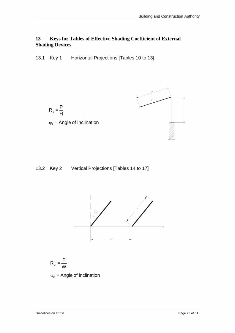
13 Keys for Tables of Effective Shading Coefficient of ExternalShading Devices
13.1 Key 1 Horizontal Projections [Tables 10 to 13]
13.2 Key 2 Vertical Projections [Tables 14 to 17]
ninclinatio of ngleA
WP
R
2
2
=φ
=
ninclinatio of Angle
HP
R
1
1
=φ
=

Building and Construction Authority
Guidelines on ETTV Page 21 of 51
13.3 Key 3 Egg-crate Louvers [Tables 18 to 21]
ninclinatio of ngleA1
WP
R
HP
R
2
1
=φ
=
=
14 Examples
14.1 Given : Window on South-West facing wall with a 0.3mhorizontal overhang.
Find : The effective shading coefficient if (a) height of windowis 0.6m; (b) height of window is 0.75m with the overhang inclined at30o to the horizontal.
Solution : Refer to Table 13
a) R1 = 0.5 SC = 0.698b) R1 = 0.4 SC = 0.669
14.2 Given : Window on West facing wall with a 0.3m horizontaloverhang and height of window is 0.75.
Find : The effective shading coefficient if the window is located0.2m below the overhang.

Building and Construction Authority
Guidelines on ETTV Page 22 of 51
Solution : Assuming the window has a height h and extends to theunderside of the overhang, the solar heat gain into the window can beexpressed as follows:
894.0SC
h)hSC()hSC(
SC
)5.1R( 200h,5051.0SC
)32.0R( 950h,8123.0SC
ioninterpolatby 11 Table From
)hSC()hSC(hSC
2
2
112
111
1
2211
=
×−×=
===
===
×+×=×
Building and Construction Authority
Guidelines on ETTV Page 23 of 51
Table 1: Solar Correction Factors (CF) for Walls
Pitch OrientationAngle N NE E SE S SW W NW
70o
1.17 1.33 1.47 1.35 1.21 1.41 1.56 1.38
75o
1.07 1.23 1.37 1.25 1.11 1.32 1.47 1.28
80o
0.98 1.14 1.30 1.16 1.01 1.23 1.39 1.20
85o
0.89 1.05 1.21 1.07 0.92 1.14 1.31 1.11
90o
0.80 0.97 1.13 0.98 0.83 1.06 1.23 1.03
95o
0.73 0.90 1.05 0.91 0.76 0.99 1.15 0.96
100o
0.67 0.83 0.97 0.84 0.70 0.92 1.08 0.89
105o
0.62 0.77 0.90 0.78 0.65 0.86 1.01 0.83
110o
0.59 0.72 0.83 0.72 0.61 0.80 0.94 0.78
115o
0.57 0.67 0.77 0.67 0.58 0.75 0.87 0.73
120o
0.55 0.63 0.72 0.63 0.56 0.71 0.81 0.69
Note: 1. The correction factors for other orientations and other pitch anglesmay be obtained by interpolation.
Table 2: Solar Correction Factors for Roofs
Pitch OrientationAngle N NE E SE S SW W NW
0o
1.00 1.00 1.00 1.00 1.00 1.00 1.00 1.00
5o
1.00 1.00 1.00 1.00 1.00 1.00 1.00 1.00
10o
0.99 0.99 1.00 1.00 1.00 0.99 0.99 0.99
15o
0.98 0.98 0.99 0.99 0.99 0.98 0.98 0.98
20o
0.96 0.97 0.98 0.98 0.97 0.97 0.97 0.96
25o
0.93 0.95 0.96 0.96 0.95 0.95 0.95 0.94
30o
0.91 0.92 0.94 0.94 0.93 0.93 0.93 0.91
35o
0.88 0.90 0.92 0.91 0.90 0.90 0.90 0.89
40o
0.84 0.87 0.89 0.88 0.87 0.87 0.87 0.85
45o
0.80 0.83 0.86 0.85 0.83 0.84 0.84 0.82
50o
0.76 0.80 0.83 0.82 0.79 0.80 0.81 0.78
55o
0.72 0.76 0.80 0.78 0.75 0.76 0.78 0.75
60o
0.67 0.72 0.76 0.74 0.70 0.73 0.74 0.71
65o
0.63 0.68 0.73 0.70 0.66 0.69 0.71 0.67

Building and Construction Authority
Guidelines on ETTV Page 24 of 51
Table 3: Thermal Conductivity Values (K-Values) of Basic Materials
S/No MaterialDensity(kg/m3)
K-value(W/m oK)
1 Asphalt, roofing 2240 1.226
2 Bitumen - 1.298
3 Brick
(a) dry (covered by plaster or tilesoutside)
1760 0.807
(b) common brickwall (brickwall directlyexposed to weather outside).
- 1.154
4 Concrete 2400 1.442
64 0.144
5 Concrete, lightweight 960 0.303
1120 0.346
1280 0.476
6 Cork board 144 0.042
7 Fibre board 264 0.052
8 Fibre glass (See Glass Wool andMineral Wool)
9 Glass, sheet 2512 1.053
10 Glass wool, mat or guilt (dry) 32 0.035
11 Gypsum plaster board 880 0.170
12 Hard board:
(a) Standard 1024 0.216
(b) medium 640 0.123
13 Metals:
(a) Aluminium alloy, typical 2672 211
(b) Copper, commercial 8784 385
(c) Steel 7840 47.6
14 Mineral wool, felt 32 - 104 0.035 - 0.032
15 Plaster:
(a) gypsum 1216 0.370

Building and Construction Authority
Guidelines on ETTV Page 25 of 51
Table 3: Thermal Conductivity Values (K-Values) of Basic Materials(Continue)
S/No MaterialDensity(kg/m3)
K-value(W/m oK)
(b) perlite 616 0.115
(c) sand / cement 1568 0.533
(d) vermiculite 640 - 960 0.202 - 0.303
16 Polystyrene, expanded 16 0.035
17 Polyurethane, foam 24 0.024
18 PVC flooring 1360 0.713
19 Soil, loosely packed 1200 0.375
20 Stone, tile:
(a) sand stone 2000 1.298
(b) granite 2640 2.927
(c) marble / terrazzo / ceramic / mosaic 2640 1.298
21 Tile, roof 1890 0.836
22 Timber:
(a) across grain softwood 608 0.125
(b) hardwood 702 0.138
(c) plywood 528 0.138
23 Vermiculite, loose granules 80-112 0.065
24 Wood chipboard 800 0.144
25 Woodwool slab 400 0.086
480 0.101

Guidelines on ETTV Page 26 of 51
Table 4: Surface Film Resistances for Walls and Roofs
Type of Surface Thermal Resistance(m2 oK /W)
A. Surface Film Resistances for Walls
1. Inside Surface (Ri) (a) High emissivity (b) Low emissivity 2. Outside surface (Ro) - High emissivity
0.1200.2990.044
B. Surface Film Resistances for Roofs
1. Inside surface (Ri) (a) High Emissivity (i) Flat roof (ii) Sloped roof 22½° (iii) Sloped roof 45°
(b) Low Emissivity (i) Flat roof (ii) Sloped roof 22½° (iii) Sloped roof 45°
2. Outside surface (Ro) - High emissivity Flat or sloped
0.1620.1480.133
0.8010.5950.391
0.055
Notes: 1. Ordinarily, high emissivity is assumed for surfaces of buildingmaterials with reasonably smooth finishing. Low emissivity appliesonly to internal surface if the surface is very reflective, such as thatof an aluminium foil.
2. Interpolation between the angle of slope from horizontal to 45° ispermitted. For angle beyond 45°, the value for 45° can be used; noextrapolation is needed.

Guidelines on ETTV Page 27 of 51
Table 5: Air Space Resistances for Walls and Roofs
Thermal Resistance (m2
oK/W)Type of Air Space5mm 20mm 100mm
A. Air Space Resistances (Ra) for walls
Vertical air space (Heat flowshorizontally)
(a) High emissivity(b) Low emissivity
0.1100.250
0.1480.578
0.1600.606
B. Air Space Resistances (Ra) for Roofs
Horizontal or sloping air space (Heatflows downwards)
(a) High emissivity(i) horizontal air space(ii) sloped air space 22½°(iii) sloped air space 45°
(b) Low emissivity(i) horizontal air space(ii) sloped air space 22½°(iii) sloped air space 45°
0.1100.1100.110
0.2500.2500.250
0.1480.1480.148
0.5720.5710.570
0.1740.1650.158
1.4231.0950.768
C. Attic space resistances (R attic)
(a) High emissivity(b) Low emissivity
0.4581.356
Notes:1. Ordinarily, high emissivity is assumed for air spaces bounded bybuilding materials of moderately smooth surfaces. Low emissivityonly applies where one or both sides of the air space are boundedby a reflective surface such as that of an aluminium foil.
2. Interpolation with the range of pitch angles from horizontal to 45° ispermitted. For angles beyond 45°, the value for 45° can be used;no extrapolation is needed.
3. Interpolation within the range of thickness from 5mm to 100mm ispermitted. For air spaces less than 5mm, extrapolation basing on
Guidelines on ETTV Page 28 of 51
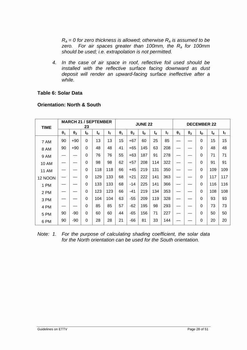
Ra = 0 for zero thickness is allowed; otherwise Ra is assumed to bezero. For air spaces greater than 100mm, the Ra for 100mmshould be used; i.e. extrapolation is not permitted.
4. In the case of air space in roof, reflective foil used should beinstalled with the reflective surface facing downward as dustdeposit will render an upward-facing surface ineffective after awhile.
Table 6: Solar Data
Orientation: North & South
MARCH 21 / SEPTEMBER23
JUNE 22 DECEMBER 22TIME
θθ1 θθ2 ID Id IT θθ1 θθ2 ID Id IT θθ1 θθ2 ID Id IT
7 AM
8 AM
9 AM
10 AM
11 AM
12 NOON
1 PM
2 PM
3 PM
4 PM
5 PM
6 PM
90
90
—
—
—
—
—
—
—
—
90
90
+90
+90
—
—
—
—
—
—
—
—
-90
-90
0
0
0
0
0
0
0
0
0
0
0
0
13
48
76
98
118
129
133
123
104
85
60
28
13
48
76
98
118
133
133
123
104
85
60
28
15
41
55
62
66
68
68
66
63
57
44
21
+67
+65
+63
+57
+45
+21
-14
-41
-55
-62
-65
-66
60
145
187
208
219
222
225
219
209
195
156
81
25
63
91
114
131
141
141
134
119
98
71
33
85
208
278
322
350
363
366
353
328
293
227
144
—
—
—
—
—
—
—
—
—
—
—
—
—
—
—
—
—
—
—
—
—
—
—
—
0
0
0
0
0
0
0
0
0
0
0
0
15
48
71
91
109
117
116
108
93
73
50
20
15
48
71
91
109
117
116
108
93
73
50
20
Note: 1. For the purpose of calculating shading coefficient, the solar datafor the North orientation can be used for the South orientation.
Guidelines on ETTV Page 29 of 51
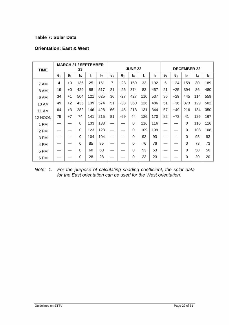
Table 7: Solar Data
Orientation: East & West
MARCH 21 / SEPTEMBER23 JUNE 22 DECEMBER 22TIME
θθ1 θθ2 ID Id IT θθ1 θθ2 ID Id IT θθ1 θθ2 ID Id IT
7 AM
8 AM
9 AM
10 AM
11 AM
12 NOON
1 PM
2 PM
3 PM
4 PM
5 PM
6 PM
4
19
34
49
64
79
—
—
—
—
—
—
+0
+0
+1
+2
+3
+7
—
—
—
—
—
—
136
429
504
435
282
74
0
0
0
0
0
0
25
88
121
139
146
141
133
123
104
85
60
28
161
517
625
574
428
215
133
123
104
85
60
28
7
21
36
51
66
81
—
—
—
—
—
—
-23
-25
-27
-33
-45
-69
—
—
—
—
—
—
159
374
427
360
213
44
0
0
0
0
0
0
33
83
110
126
131
126
116
109
93
76
53
23
192
457
537
486
344
170
116
109
93
76
53
23
6
21
36
51
67
82
—
—
—
—
—
—
+24
+25
+29
+36
+49
+73
—
—
—
—
—
—
159
394
445
373
216
41
0
0
0
0
0
0
30
86
114
129
134
126
116
108
93
73
50
20
189
480
559
502
350
167
116
108
93
73
50
20
Note: 1. For the purpose of calculating shading coefficient, the solar datafor the East orientation can be used for the West orientation.

Guidelines on ETTV Page 30 of 51
Table 8: Solar Data
Orientation: North-East & North-West
MARCH 21 / SEPTEMBER23 JUNE 22 DECEMBER 22TIME
θθ1 θθ2 ID Id IT θθ1 θθ2 ID Id IT θθ1 θθ2 ID Id IT
7 AM
8 AM
9 AM
10 AM
11 AM
12 NOON
1 PM
2 PM
3 PM
4 PM
5 PM
6 PM
6
26
44
59
72
83
—
—
—
—
—
—
+45
+45
+46
+47
+48
+52
—
—
—
—
—
—
94
293
336
278
154
31
0
0
0
0
0
0
23
76
106
126
136
136
133
123
104
85
60
28
117
369
442
404
290
167
133
123
104
85
60
28
6
21
34
47
58
68
78
88
—
—
—
—
+22
+20
+18
+12
-0
-24
-59
-86
—
—
—
—
159
387
462
435
345
216
98
29
0
0
0
0
33
86
116
133
141
141
110
116
93
76
53
23
192
473
578
568
486
357
208
145
93
76
53
23
15
46
67
81
—
—
—
—
—
—
—
—
+69
+70
+74
+81
—
—
—
—
—
—
—
—
52
111
87
28
0
0
0
0
0
0
0
0
20
63
83
98
109
116
116
108
93
73
50
20
72
174
170
126
109
116
116
108
93
73
50
20
Note: 1. For the purpose of calculating shading coefficient, the solar datafor the North-East orientation can be used for the North-Westorientation.

Guidelines on ETTV Page 31 of 51
Table 9: Solar Data
Orientation: South-East & South-West
MARCH 21 / SEPTEMBER23 JUNE 22 DECEMBER 22TIME
θθ1 θθ2 ID Id IT θθ1 θθ2 ID Id IT θθ1 θθ2 ID Id IT
7 AM
8 AM
9 AM
10 AM
11 AM
12 NOON
1 PM
2 PM
3 PM
4 PM
5 PM
6 PM
6
26
44
58
70
82
—
—
—
—
—
—
-45
-45
-44
-43
-42
-38
—
—
—
—
—
—
94
321
382
325
180
47
0
0
0
0
0
0
23
48
76
98
136
139
133
123
104
85
60
28
117
369
458
423
316
186
133
123
104
85
60
28
16
46
65
79
—
—
—
—
—
—
—
—
-68
-70
-72
-78
—
—
—
—
—
—
—
—
53
114
97
38
0
0
0
0
0
0
0
0
23
63
86
98
106
116
116
109
93
76
53
23
76
177
183
136
106
116
116
109
93
76
53
23
6
20
34
46
57
67
76
86
—
—
—
—
-21
-20
-16
-9
+4
+28
+60
+84
—
—
—
—
162
417
496
470
389
244
99
9
0
0
0
0
30
88
119
136
146
144
131
111
93
73
50
20
192
505
615
606
535
388
230
120
93
73
50
20
Note: 1. For the purpose of calculating shading coefficient, the solar datafor the South-East orientation can be used for the South-Westorientation.

Guidelines on ETTV Page 32 of 51
Table 10: Effective Shading Coefficients of Horizontal Projection atVarious Angles of Inclination
Orientation: North & South
R1 0o 10o 20o 30o 40o 50o
0.1 0.9380 0.9330 0.9300 0.9291 0.9303 0.93360.2 0.8773 0.8674 0.8613 0.8595 0.8619 0.86850.3 0.8167 0.8017 0.7927 0.7899 0.7935 0.80330.4 0.7560 0.7392 0.7288 0.7245 0.7263 0.73820.5 0.7210 0.7080 0.7001 0.6950 0.6927 0.69380.6 0.7041 0.6921 0.6848 0.6804 0.6774 0.67600.7 0.6923 0.6842 0.6775 0.6723 0.6689 0.66720.8 0.6871 0.6779 0.6702 0.6661 0.6641 0.66260.9 0.6819 0.6718 0.6670 0.6643 0.6621 0.66041.0 0.6767 0.6690 0.6655 0.6625 0.6600 0.65831.1 0.6731 0.6678 0.6640 0.6607 0.6584 0.65771.2 0.6713 0.6667 0.6625 0.6589 0.6577 0.65771.3 0.6705 0.6656 0.6611 0.6582 0.6577 0.65771.4 0.6698 0.6644 0.6596 0.6577 0.6577 0.65771.5 0.6690 0.6633 0.6588 0.6577 0.6577 0.65771.6 0.6683 0.6622 0.6582 0.6577 0.6577 0.65771.7 0.6675 0.6610 0.6577 0.6577 0.6577 0.65771.8 0.6667 0.6599 0.6577 0.6577 0.6577 0.65771.9 0.6660 0.6594 0.6577 0.6577 0.6577 0.65772.0 0.6652 0.6589 0.6577 0.6577 0.6577 0.65772.1 0.6645 0.6585 0.6577 0.6577 0.6577 0.65772.2 0.6637 0.6581 0.6577 0.6577 0.6577 0.65772.3 0.6630 0.6577 0.6577 0.6577 0.6577 0.65772.4 0.6622 0.6577 0.6577 0.6577 0.6577 0.65772.5 0.6614 0.6577 0.6577 0.6577 0.6577 0.65772.6 0.6607 0.6577 0.6577 0.6577 0.6577 0.65772.7 0.6604 0.6577 0.6577 0.6577 0.6577 0.65772.8 0.6601 0.6577 0.6577 0.6577 0.6577 0.65772.9 0.6599 0.6577 0.6577 0.6577 0.6577 0.65773.0 0.6596 0.6577 0.6577 0.6577 0.6577 0.6577

Guidelines on ETTV Page 33 of 51
Table 11: Effective Shading Coefficients of Horizontal Projection atVarious Angles of Inclination
Orientation: East & West
R1 0o 10o 20o 30o 40o 50o
0.1 0.9363 0.9268 0.9195 0.9147 0.9124 0.91290.2 0.8752 0.8565 0.8416 0.8309 0.8257 0.82570.3 0.8228 0.7947 0.7723 0.7563 0.7470 0.74480.4 0.7703 0.7330 0.7036 0.6820 0.6693 0.66640.5 0.7248 0.6842 0.6550 0.6231 0.6045 0.59460.6 0.6911 0.6424 0.6013 0.5691 0.5467 0.53490.7 0.6574 0.6006 0.5559 0.5249 0.5012 0.48510.8 0.6237 0.5693 0.5273 0.4923 0.4651 0.44670.9 0.5998 0.5463 0.4991 0.4608 0.4389 0.42371.0 0.5827 0.5232 0.4727 0.4442 0.4222 0.40621.1 0.5656 0.5002 0.4587 0.4296 0.4075 0.40101.2 0.5485 0.4828 0.4468 0.4151 0.4036 0.39691.3 0.5314 0.4739 0.4349 0.4089 0.3999 0.39631.4 0.5156 0.4650 0.4230 0.4059 0.3969 0.39631.5 0.5051 0.4561 0.4147 0.4029 0.3963 0.39631.6 0.4995 0.4472 0.4123 0.3999 0.3963 0.39631.7 0.4939 0.4383 0.4101 0.3974 0.3963 0.39631.8 0.4882 0.4294 0.4079 0.3963 0.3963 0.39631.9 0.4826 0.4237 0.4057 0.3963 0.3963 0.39632.0 0.4770 0.4204 0.4035 0.3963 0.3963 0.39632.1 0.4713 0.4190 0.4013 0.3963 0.3963 0.39632.2 0.4657 0.4176 0.3991 0.3963 0.3963 0.39632.3 0.4601 0.4163 0.3978 0.3963 0.3963 0.39632.4 0.4544 0.4149 0.3968 0.3963 0.3963 0.39632.5 0.4488 0.4135 0.3963 0.3963 0.3963 0.39632.6 0.4432 0.4122 0.3963 0.3963 0.3963 0.39632.7 0.4400 0.4108 0.3963 0.3963 0.3963 0.39632.8 0.4369 0.4094 0.3963 0.3963 0.3963 0.39632.9 0.4339 0.4081 0.3963 0.3963 0.3963 0.39633.0 0.4333 0.4067 0.3963 0.3963 0.3963 0.3963

Guidelines on ETTV Page 34 of 51
Table 12: Effective Shading Coefficients of Horizontal Projection atVarious Angles of Inclination
Orientation: North-East & North-West
R1 0o 10o 20o 30o 40o 50o
0.1 0.9273 0.9193 0.9137 0.9106 0.9101 0.91220.2 0.8630 0.8471 0.8355 0.8285 0.8263 0.82910.3 0.8054 0.7820 0.7644 0.7533 0.7489 0.75150.4 0.7563 0.7278 0.7055 0.6895 0.6803 0.67990.5 0.7171 0.6824 0.6546 0.6345 0.6228 0.61980.6 0.6787 0.6443 0.6165 0.5946 0.5793 0.57100.7 0.6549 0.6166 0.5842 0.5587 0.5420 0.53200.8 0.6327 0.5889 0.5563 0.5360 0.5200 0.50880.9 0.6105 0.5681 0.5412 0.5184 0.5026 0.49191.0 0.5922 0.5560 0.5261 0.5051 0.4900 0.48261.1 0.5809 0.5440 0.5148 0.4939 0.4840 0.47901.2 0.5722 0.5321 0.5046 0.4877 0.4809 0.47591.3 0.5634 0.5243 0.4971 0.4850 0.4782 0.47591.4 0.5547 0.5165 0.4921 0.4825 0.4759 0.47591.5 0.5466 0.5086 0.4894 0.4802 0.4759 0.47591.6 0.5413 0.5037 0.4874 0.4780 0.4759 0.47591.7 0.5359 0.5001 0.4854 0.4759 0.4759 0.47591.8 0.5306 0.4965 0.4837 0.4759 0.4759 0.47591.9 0.5253 0.4949 0.4821 0.4759 0.4759 0.47592.0 0.5200 0.4936 0.4804 0.4759 0.4759 0.47592.1 0.5162 0.4923 0.4787 0.4759 0.4759 0.47592.2 0.5141 0.4909 0.4770 0.4759 0.4759 0.47592.3 0.5119 0.4897 0.4759 0.4759 0.4759 0.47592.4 0.5097 0.4886 0.4759 0.4759 0.4759 0.47592.5 0.5075 0.4876 0.4759 0.4759 0.4759 0.47592.6 0.5053 0.4865 0.4759 0.4759 0.4759 0.47592.7 0.5047 0.4855 0.4759 0.4759 0.4759 0.47592.8 0.5042 0.4844 0.4759 0.4759 0.4759 0.47592.9 0.5036 0.4834 0.4759 0.4759 0.4759 0.47593.0 0.5031 0.4823 0.4759 0.4759 0.4759 0.4759

Guidelines on ETTV Page 35 of 51
Table 13: Effective Shading Coefficients of Horizontal Projection atVarious Angles of Inclination
Orientation: South-East & South-West
R1 0o 10o 20o 30o 40o 50o
0.1 0.9253 0.9167 0.9107 0.9072 0.9065 0.90860.2 0.8574 0.8405 0.8280 0.8203 0.8177 0.82040.3 0.7964 0.7715 0.7527 0.7406 0.7355 0.73770.4 0.7413 0.7100 0.6862 0.6692 0.6601 0.65970.5 0.6981 0.6615 0.6321 0.6109 0.5985 0.59510.6 0.6578 0.6179 0.5890 0.5663 0.5503 0.54170.7 0.6289 0.5891 0.5555 0.5289 0.5107 0.50040.8 0.6059 0.5604 0.5251 0.5044 0.4880 0.47650.9 0.5828 0.5372 0.5096 0.4863 0.4702 0.45921.0 0.5619 0.5248 0.4942 0.4727 0.4573 0.44931.1 0.5502 0.5124 0.4826 0.4613 0.4507 0.44591.2 0.5413 0.5003 0.4722 0.4551 0.4477 0.44291.3 0.5323 0.4923 0.4646 0.4516 0.4451 0.44291.4 0.5234 0.4843 0.4596 0.4492 0.4429 0.44291.5 0.5150 0.4763 0.4558 0.4471 0.4429 0.44291.6 0.5096 0.4714 0.4538 0.4449 0.4429 0.44291.7 0.5042 0.4678 0.4521 0.4429 0.4429 0.44291.8 0.4988 0.4642 0.4505 0.4429 0.4429 0.44291.9 0.4933 0.4610 0.4489 0.4429 0.4429 0.44292.0 0.4879 0.4598 0.4472 0.4429 0.4429 0.44292.1 0.4841 0.4585 0.4456 0.4429 0.4429 0.44292.2 0.4820 0.4572 0.4440 0.4429 0.4429 0.44292.3 0.4798 0.4562 0.4429 0.4429 0.4429 0.44292.4 0.4777 0.4552 0.4429 0.4429 0.4429 0.44292.5 0.4755 0.4542 0.4429 0.4429 0.4429 0.44292.6 0.4734 0.4532 0.4429 0.4429 0.4429 0.44292.7 0.4712 0.4521 0.4429 0.4429 0.4429 0.44292.8 0.4699 0.4511 0.4429 0.4429 0.4429 0.44292.9 0.4694 0.4501 0.4429 0.4429 0.4429 0.44293.0 0.4688 0.4491 0.4429 0.4429 0.4429 0.4429

Guidelines on ETTV Page 36 of 51
Table 14: Effective Shading Coefficients of Vertical Projection atVarious Angles of Inclination
Orientation: North & South
R2 0o 10o 20o 30o 40o 50o
0.1 0.9526 0.9534 0.9549 0.9571 0.9606 0.96380.2 0.9066 0.9082 0.9110 0.9155 0.9225 0.92890.3 0.8605 0.8630 0.8672 0.8739 0.8844 0.89400.4 0.8144 0.8177 0.8236 0.8325 0.8463 0.85910.5 0.7752 0.7800 0.7892 0.8005 0.8159 0.82770.6 0.7540 0.7563 0.7632 0.7768 0.7950 0.80780.7 0.7379 0.7434 0.7464 0.7560 0.7771 0.79200.8 0.7290 0.7306 0.7348 0.7423 0.7637 0.78070.9 0.7202 0.7230 0.7269 0.7319 0.7507 0.76991.0 0.7114 0.7183 0.7190 0.7246 0.7388 0.75951.1 0.7060 0.7137 0.7144 0.7173 0.7308 0.75231.2 0.7022 0.7091 0.7098 0.7099 0.7251 0.74511.3 0.7000 0.7045 0.7053 0.7055 0.7206 0.73791.4 0.6977 0.6999 0.7007 0.7022 0.7173 0.73071.5 0.6954 0.6961 0.6981 0.7003 0.7141 0.72361.6 0.6932 0.6939 0.6960 0.6983 0.7109 0.71731.7 0.6909 0.6916 0.6940 0.6964 0.7077 0.71311.8 0.6886 0.6894 0.6919 0.6945 0.7044 0.71051.9 0.6864 0.6889 0.6899 0.6926 0.7012 0.70782.0 0.6841 0.6886 0.6878 0.6907 0.6980 0.70522.1 0.6818 0.6884 0.6858 0.6888 0.6948 0.70562.2 0.6796 0.6881 0.6853 0.6869 0.6915 0.70002.3 0.6773 0.6879 0.6849 0.6849 0.6910 0.69792.4 0.6750 0.6876 0.6845 0.6830 0.6909 0.69672.5 0.6728 0.6873 0.6841 0.6811 0.6908 0.69542.6 0.6705 0.6871 0.6837 0.6792 0.6908 0.69422.7 0.6695 0.6868 0.6833 0.6773 0.6907 0.69302.8 0.6686 0.6866 0.6829 0.6754 0.6906 0.69172.9 0.6677 0.6863 0.6826 0.6735 0.6905 0.69053.0 0.6668 0.6860 0.6822 0.6716 0.6904 0.6893

Guidelines on ETTV Page 37 of 51
Table 15: Effective Shading Coefficients of Vertical Projection atVarious Angles of Inclination
Orientation: East & West
R2 0o 10o 20o 30o 40o 50o
0.1 0.9805 0.9751 0.9704 0.9653 0.9584 0.95200.2 0.9607 0.9499 0.9406 0.9302 0.9166 0.90380.3 0.9409 0.9247 0.9108 0.8952 0.8747 0.85550.4 0.9223 0.9007 0.8821 0.8614 0.8338 0.80780.5 0.9047 0.8774 0.8537 0.8275 0.7931 0.76060.6 0.8870 0.8543 0.8259 0.7939 0.7523 0.71330.7 0.8694 0.8313 0.7980 0.7616 0.7129 0.66710.8 0.8518 0.8090 0.7728 0.7312 0.6753 0.62270.9 0.8348 0.7884 0.7476 0.7014 0.6406 0.58231.0 0.8193 0.7678 0.7233 0.6747 0.6098 0.54931.1 0.8057 0.7471 0.7015 0.6511 0.5850 0.51841.2 0.7921 0.7287 0.6810 0.6320 0.5605 0.48801.3 0.7785 0.7120 0.6631 0.6135 0.5361 0.46331.4 0.7654 0.6960 0.6482 0.5949 0.5120 0.45771.5 0.7541 0.6826 0.6334 0.5764 0.4899 0.45261.6 0.7441 0.6696 0.6187 0.5579 0.4820 0.44741.7 0.7349 0.6589 0.6042 0.5397 0.4790 0.44221.8 0.7257 0.6485 0.5906 0.5220 0.4760 0.43711.9 0.7185 0.6381 0.5770 0.5065 0.4730 0.43192.0 0.7122 0.6276 0.5634 0.4982 0.4700 0.42682.1 0.7070 0.6172 0.5497 0.4966 0.4670 0.42212.2 0.7036 0.6076 0.5362 0.4950 0.4641 0.41852.3 0.7019 0.5987 0.5232 0.4934 0.4611 0.41582.4 0.7007 0.5897 0.5101 0.4918 0.4581 0.41452.5 0.6999 0.5808 0.4971 0.4902 0.4551 0.41322.6 0.6990 0.5718 0.4849 0.4886 0.4521 0.41192.7 0.6982 0.5629 0.4747 0.4870 0.4491 0.41052.8 0.6974 0.5539 0.4668 0.4859 0.4461 0.40922.9 0.6965 0.5450 0.4616 0.4850 0.4431 0.40823.0 0.6957 0.5360 0.4591 0.4841 0.4401 0.4080

Guidelines on ETTV Page 38 of 51
Table 16: Effective Shading Coefficients of Vertical Projection atVarious Angles of Inclination
Orientation: North-East & North-West
R2 0o 10o 20o 30o 40o 50o
0.1 0.9517 0.9445 0.9389 0.9346 0.9317 0.93140.2 0.9074 0.8931 0.8819 0.8729 0.8670 0.86500.3 0.8646 0.8436 0.8268 0.8131 0.8036 0.80050.4 0.8262 0.7991 0.7770 0.7585 0.7449 0.73810.5 0.7912 0.7573 0.7297 0.7066 0.6895 0.68090.6 0.7562 0.7155 0.6824 0.6546 0.6342 0.62390.7 0.7230 0.6740 0.6356 0.6043 0.5832 0.57010.8 0.6899 0.6352 0.6038 0.5836 0.5643 0.54930.9 0.6575 0.6158 0.5921 0.5683 0.5465 0.52961.0 0.6359 0.6069 0.5806 0.5530 0.5288 0.51041.1 0.6300 0.5981 0.5691 0.5380 0.5125 0.50051.2 0.6240 0.5892 0.5576 0.5241 0.5038 0.49581.3 0.6181 0.5803 0.5461 0.5146 0.4984 0.49151.4 0.6121 0.5715 0.5348 0.5091 0.4946 0.48981.5 0.6061 0.5626 0.5257 0.5050 0.4908 0.48841.6 0.6002 0.5537 0.5201 0.5028 0.4881 0.48691.7 0.5942 0.5449 0.5161 0.5006 0.4874 0.48541.8 0.5883 0.5365 0.5120 0.4985 0.4867 0.48401.9 0.5823 0.5291 0.5094 0.4963 0.4860 0.48252.0 0.5763 0.5235 0.5079 0.4941 0.4853 0.48112.1 0.5704 0.5198 0.5064 0.4939 0.4846 0.47982.2 0.5644 0.5166 0.5050 0.4936 0.4839 0.47952.3 0.5590 0.5135 0.5035 0.4933 0.4831 0.47912.4 0.5541 0.5104 0.5020 0.4931 0.4824 0.47882.5 0.5494 0.5073 0.5005 0.4928 0.4817 0.47852.6 0.5452 0.5042 0.4991 0.4925 0.4810 0.47812.7 0.5410 0.5027 0.4976 0.4923 0.4803 0.47782.8 0.5376 0.5014 0.4961 0.4920 0.4796 0.47752.9 0.5349 0.5002 0.4946 0.4917 0.4788 0.47723.0 0.5323 0.4989 0.4941 0.4914 0.4781 0.4768

Guidelines on ETTV Page 39 of 51
Table 17: Effective Shading Coefficients of Vertical Projection atVarious Angles of Inclination
Orientation: South-East & South-West
R2 0°° 10°° 20°° 30°° 40°° 50°°0.1 0.9528 0.9457 0.9396 0.9351 0.9317 0.93040.2 0.9081 0.8938 0.8815 0.8724 0.8654 0.86240.3 0.8650 0.8437 0.8253 0.8113 0.8005 0.79550.4 0.8257 0.7988 0.7746 0.7555 0.7395 0.73070.5 0.7907 0.7570 0.7269 0.7029 0.6829 0.67150.6 0.7561 0.7153 0.6791 0.6504 0.6264 0.61270.7 0.7229 0.6743 0.6313 0.5978 0.5698 0.55390.8 0.6897 0.6342 0.5861 0.5629 0.5412 0.52420.9 0.6565 0.5987 0.5700 0.5474 0.5235 0.50451.0 0.6233 0.5863 0.5584 0.5324 0.5059 0.48501.1 0.6056 0.5771 0.5470 0.5185 0.4894 0.47371.2 0.5983 0.5685 0.5357 0.5046 0.4792 0.46701.3 0.5915 0.5599 0.5244 0.4946 0.4717 0.46271.4 0.5853 0.5513 0.5130 0.4882 0.4677 0.45861.5 0.5791 0.5427 0.5037 0.4831 0.4642 0.45721.6 0.5730 0.5341 0.4966 0.4790 0.4612 0.45571.7 0.5668 0.5255 0.4915 0.4771 0.4583 0.45431.8 0.5606 0.5169 0.4876 0.4752 0.4577 0.45281.9 0.5547 0.5096 0.4836 0.4734 0.4571 0.45142.0 0.5499 0.5043 0.4796 0.4715 0.4565 0.44992.1 0.5451 0.4990 0.4772 0.4696 0.4558 0.44852.2 0.5403 0.4938 0.4757 0.4677 0.4552 0.44712.3 0.5355 0.4909 0.4741 0.4662 0.4546 0.44562.4 0.5307 0.4879 0.4726 0.4661 0.4540 0.44462.5 0.5258 0.4850 0.4711 0.4660 0.4534 0.44432.6 0.5210 0.4820 0.4695 0.4659 0.4528 0.44392.7 0.5168 0.4790 0.4680 0.4658 0.4522 0.44352.8 0.5135 0.4761 0.4665 0.4657 0.4516 0.44322.9 0.5110 0.4735 0.4649 0.4656 0.4510 0.44293.0 0.5084 0.4715 0.4634 0.4655 0.4504 0.4429

Guidelines on ETTV Page 40 of 51
Table 18: Effective Shading Coefficients of Egg-Crate Louvers withInclined Horizontal Fins
Orientation: North & South
R1 R2 0°° 10°° 20°° 30°° 40°°0.2 0.2 0.8125 0.8053 0.8011 0.8002 0.80250.2 0.4 0.7476 0.7432 0.7409 0.7409 0.74310.2 0.6 0.7086 0.7059 0.7047 0.7050 0.70680.2 0.8 0.6945 0.6926 0.6917 0.6920 0.69340.2 1.0 0.6850 0.6836 0.6829 0.6832 0.68430.2 1.2 0.6802 0.6790 0.6785 0.6787 0.67960.2 1.4 0.6779 0.6768 0.6764 0.6766 0.67740.2 1.6 0.6756 0.6747 0.6743 0.6744 0.67520.2 1.8 0.6733 0.6725 0.6722 0.6723 0.67290.4 0.2 0.7184 0.7070 0.7002 0.6977 0.69950.4 0.4 0.6808 0.6747 0.6716 0.6709 0.67270.4 0.6 0.6631 0.6604 0.6593 0.6594 0.66050.4 0.8 0.6601 0.6586 0.6581 0.6581 0.65870.4 1.0 0.6587 0.6580 0.6578 0.6578 0.65800.4 1.2 0.6582 0.6577 0.6577 0.6577 0.65770.4 1.4 0.6581 0.6577 0.6577 0.6577 0.65770.4 1.6 0.6581 0.6577 0.6577 0.6577 0.65770.4 1.8 0.6581 0.6577 0.6577 0.6577 0.65770.6 0.2 0.6840 0.6769 0.6728 0.6703 0.66870.6 0.4 0.6638 0.6618 0.6608 0.6602 0.65990.6 0.6 0.6577 0.6577 0.6577 0.6577 0.65770.6 0.8 0.6577 0.6577 0.6577 0.6577 0.65770.6 1.0 0.6577 0.6577 0.6577 0.6577 0.65770.6 1.2 0.6577 0.6577 0.6577 0.6577 0.65770.6 1.4 0.6577 0.6577 0.6577 0.6577 0.65770.6 1.6 0.6577 0.6577 0.6577 0.6577 0.65770.6 1.8 0.6577 0.6577 0.6577 0.6577 0.6577

Guidelines on ETTV Page 41 of 51
Table 18: Effective Shading Coefficients of Egg-Crate Louvers withInclined Horizontal Fins (Continue)
Orientation: North & South
R1 R2 0°° 10°° 20°° 30°° 40°°0.8 0.2 0.6740 0.6688 0.6645 0.6622 0.66120.8 0.4 0.6609 0.6598 0.6589 0.6584 0.65830.8 0.6 0.6577 0.6577 0.6577 0.6577 0.65770.8 0.8 0.6577 0.6577 0.6577 0.6577 0.65770.8 1.0 0.6577 0.6577 0.6577 0.6577 0.65770.8 1.2 0.6577 0.6577 0.6577 0.6577 0.65770.8 1.4 0.6577 0.6577 0.6577 0.6577 0.65770.8 1.6 0.6577 0.6577 0.6577 0.6577 0.65770.8 1.8 0.6577 0.6577 0.6577 0.6577 0.65771.0 0.2 0.6681 0.6638 0.6619 0.6603 0.65901.0 0.4 0.6595 0.6586 0.6584 0.6581 0.65791.0 0.6 0.6577 0.6577 0.6577 0.6577 0.65771.0 0.8 0.6577 0.6577 0.6577 0.6577 0.65771.0 1.0 0.6577 0.6577 0.6577 0.6577 0.65771.0 1.2 0.6577 0.6577 0.6577 0.6577 0.65771.0 1.4 0.6577 0.6577 0.6577 0.6577 0.65771.0 1.6 0.6577 0.6577 0.6577 0.6577 0.65771.0 1.8 0.6577 0.6577 0.6577 0.6577 0.65771.2 0.2 0.6651 0.6626 0.6603 0.6584 0.65771.2 0.4 0.6588 0.6585 0.6581 0.6578 0.65771.2 0.6 0.6577 0.6577 0.6577 0.6577 0.65771.2 0.8 0.6577 0.6577 0.6577 0.6577 0.65771.2 1.0 0.6577 0.6577 0.6577 0.6577 0.65771.2 1.2 0.6577 0.6577 0.6577 0.6577 0.65771.2 1.4 0.6577 0.6577 0.6577 0.6577 0.65771.2 1.6 0.6577 0.6577 0.6577 0.6577 0.65771.2 1.8 0.6577 0.6577 0.6577 0.6577 0.6577

Guidelines on ETTV Page 42 of 51
Table 18: Effective Shading Coefficients of Egg-Crate Louvers withInclined Horizontal Fins (Continue)
Orientation: North & South
R1 R2 0°° 10°° 20°° 30°° 40°°1.4 0.2 0.6642 0.6613 0.6587 0.6577 0.65771.4 0.4 0.6587 0.6583 0.6579 0.6577 0.65771.4 0.6 0.6577 0.6577 0.6577 0.6577 0.65771.4 0.8 0.6577 0.6577 0.6577 0.6577 0.65771.4 1.0 0.6577 0.6577 0.6577 0.6577 0.65771.4 1.2 0.6577 0.6577 0.6577 0.6577 0.65771.4 1.4 0.6577 0.6577 0.6577 0.6577 0.65771.4 1.6 0.6577 0.6577 0.6577 0.6577 0.65771.4 1.8 0.6577 0.6577 0.6577 0.6577 0.65771.6 0.2 0.6634 0.6601 0.6580 0.6577 0.65771.6 0.4 0.6586 0.6581 0.6578 0.6577 0.65771.6 0.6 0.6577 0.6577 0.6577 0.6577 0.65771.6 0.8 0.6577 0.6577 0.6577 0.6577 0.65771.6 1.0 0.6577 0.6577 0.6577 0.6577 0.65771.6 1.2 0.6577 0.6577 0.6577 0.6577 0.65771.6 1.4 0.6577 0.6577 0.6577 0.6577 0.65771.6 1.6 0.6577 0.6577 0.6577 0.6577 0.65771.6 1.8 0.6577 0.6577 0.6577 0.6577 0.65771.8 0.2 0.6626 0.6589 0.6577 0.6577 0.65771.8 0.4 0.6584 0.6579 0.6577 0.6577 0.65771.8 0.6 0.6577 0.6577 0.6577 0.6577 0.65771.8 0.8 0.6577 0.6577 0.6577 0.6577 0.65771.8 1.0 0.6577 0.6577 0.6577 0.6577 0.65771.8 1.2 0.6577 0.6577 0.6577 0.6577 0.65771.8 1.4 0.6577 0.6577 0.6577 0.6577 0.65771.8 1.6 0.6577 0.6577 0.6577 0.6577 0.65771.8 1.8 0.6577 0.6577 0.6577 0.6577 0.6577

Guidelines on ETTV Page 43 of 51
Table 19: Effective Shading Coefficients of Egg-Crate Louvers withInclined Horizontal Fins
Orientation: East & West
R1 R2 0°° 10°° 20°° 30°° 40°°0.2 0.2 0.8482 0.8306 0.8165 0.8064 0.80130.2 0.4 0.8212 0.8047 0.7914 0.7818 0.77690.2 0.6 0.7942 0.7788 0.7663 0.7572 0.75250.2 0.8 0.7672 0.7529 0.7412 0.7327 0.72820.2 1.0 0.7417 0.7284 0.7175 0.7095 0.70520.2 1.2 0.7190 0.7066 0.6965 0.6890 0.68500.2 1.4 0.6968 0.6852 0.6758 0.6688 0.66520.2 1.6 0.6786 0.6677 0.6589 0.6524 0.64900.2 1.8 0.6626 0.6523 0.6440 0.6379 0.63480.4 0.2 0.7513 0.7162 0.6883 0.6678 0.65560.4 0.4 0.7323 0.6993 0.6730 0.6535 0.64180.4 0.6 0.7133 0.6825 0.6577 0.6393 0.62800.4 0.8 0.6943 0.6656 0.6424 0.6251 0.61430.4 1.0 0.6754 0.6488 0.6271 0.6108 0.60060.4 1.2 0.6570 0.6322 0.6118 0.5967 0.58710.4 1.4 0.6389 0.6158 0.5968 0.5827 0.57380.4 1.6 0.6235 0.6017 0.5840 0.5708 0.56250.4 1.8 0.6096 0.5890 0.5723 0.5599 0.55230.6 0.2 0.6768 0.6307 0.5917 0.5611 0.53980.6 0.4 0.6626 0.6190 0.5822 0.5532 0.53290.6 0.6 0.6483 0.6073 0.5726 0.5452 0.52600.6 0.8 0.6341 0.5956 0.5630 0.5372 0.51910.6 1.0 0.6198 0.5840 0.5535 0.5293 0.51210.6 1.2 0.6056 0.5723 0.5439 0.5213 0.50520.6 1.4 0.5915 0.5607 0.5344 0.5134 0.49840.6 1.6 0.5788 0.5500 0.5254 0.5058 0.49170.6 1.8 0.5668 0.5398 0.5167 0.4983 0.4852

Guidelines on ETTV Page 44 of 51
Table 19: Effective Shading Coefficients of Egg-Crate Louvers withInclined Horizontal Fins (Continue)
Orientation: East & West
R1 R2 0°° 10°° 20°° 30°° 40°°0.8 0.2 0.6135 0.5615 0.5215 0.4881 0.46220.8 0.4 0.6033 0.5537 0.5157 0.4839 0.45930.8 0.6 0.5931 0.5459 0.5099 0.4798 0.45640.8 0.8 0.5829 0.5381 0.5041 0.4756 0.45340.8 1.0 0.5727 0.5304 0.4983 0.4714 0.45050.8 1.2 0.5625 0.5226 0.4925 0.4673 0.44760.8 1.4 0.5523 0.5148 0.4867 0.4631 0.44470.8 1.6 0.5421 0.5070 0.4809 0.4589 0.44180.8 1.8 0.5320 0.4992 0.4751 0.4548 0.43891.0 0.2 0.5744 0.5178 0.4695 0.4422 0.42121.0 0.4 0.5661 0.5123 0.4663 0.4401 0.42011.0 0.6 0.5578 0.5068 0.4631 0.4381 0.41911.0 0.8 0.5495 0.5014 0.4599 0.4361 0.41801.0 1.0 0.5412 0.4959 0.4567 0.4341 0.41701.0 1.2 0.5329 0.4904 0.4535 0.4321 0.41591.0 1.4 0.5246 0.4849 0.4503 0.4301 0.41491.0 1.6 0.5163 0.4795 0.4471 0.4280 0.41381.0 1.8 0.5080 0.4740 0.4439 0.4260 0.41281.2 0.2 0.5420 0.4791 0.4447 0.4144 0.40331.2 0.4 0.5354 0.4754 0.4426 0.4137 0.40301.2 0.6 0.5289 0.4717 0.4405 0.4130 0.40271.2 0.8 0.5223 0.4680 0.4384 0.4123 0.40241.2 1.0 0.5158 0.4643 0.4363 0.4117 0.40211.2 1.2 0.5092 0.4606 0.4342 0.4110 0.40181.2 1.4 0.5027 0.4569 0.4321 0.4103 0.40151.2 1.6 0.4961 0.4532 0.4300 0.4096 0.40121.2 1.8 0.4896 0.4495 0.4279 0.4089 0.4009

Guidelines on ETTV Page 45 of 51
Table 19: Effective Shading Coefficients of Egg-Crate Louvers withInclined Horizontal Fins (Continue)
Orientation: East & West
R1 R2 0°° 10°° 20°° 30°° 40°°1.4 0.2 0.5107 0.4621 0.4220 0.4055 0.39691.4 0.4 0.5058 0.4592 0.4210 0.4051 0.39691.4 0.6 0.5008 0.4563 0.4200 0.4047 0.39691.4 0.8 0.4959 0.4535 0.4190 0.4043 0.39691.4 1.0 0.4910 0.4506 0.4180 0.4039 0.39691.4 1.2 0.4860 0.4477 0.4170 0.4035 0.39691.4 1.4 0.4811 0.4449 0.4160 0.4031 0.39691.4 1.6 0.4762 0.4420 0.4150 0.4028 0.39691.4 1.8 0.4712 0.4391 0.4140 0.4024 0.39691.6 0.2 0.4951 0.4451 0.4117 0.3998 0.39631.6 0.4 0.4907 0.4431 0.4110 0.3997 0.39631.6 0.6 0.4863 0.4410 0.4103 0.3996 0.39631.6 0.8 0.4820 0.4390 0.4096 0.3995 0.39631.6 1.0 0.4776 0.4369 0.4089 0.3994 0.39631.6 1.2 0.4732 0.4349 0.4083 0.3993 0.39631.6 1.4 0.4688 0.4329 0.4076 0.3992 0.39631.6 1.6 0.4644 0.4308 0.4069 0.3991 0.39631.6 1.8 0.4600 0.4288 0.4062 0.3990 0.39631.8 0.2 0.4844 0.4281 0.4075 0.3963 0.39631.8 0.4 0.4805 0.4269 0.4070 0.3963 0.39631.8 0.6 0.4767 0.4257 0.4065 0.3963 0.39631.8 0.8 0.4728 0.4245 0.4061 0.3963 0.39631.8 1.0 0.4690 0.4233 0.4056 0.3963 0.39631.8 1.2 0.4651 0.4221 0.4051 0.3963 0.39631.8 1.4 0.4613 0.4208 0.4047 0.3963 0.39631.8 1.6 0.4574 0.4196 0.4042 0.3963 0.39631.8 1.8 0.4536 0.4184 0.4037 0.3963 0.3963

Guidelines on ETTV Page 46 of 51
Table 20: Effective Shading Coefficients of Egg-Crate Louvers withInclined Horizontal Fins
Orientation: North-East & North-West
R1 R2 0°° 10°° 20°° 30°° 40°°0.2 0.2 0.8019 0.7886 0.7788 0.7727 0.77050.2 0.4 0.7439 0.7331 0.7250 0.7198 0.71780.2 0.6 0.6944 0.6857 0.6790 0.6746 0.67270.2 0.8 0.6452 0.6384 0.6332 0.6298 0.62810.2 1.0 0.6024 0.5973 0.5935 0.5909 0.58970.2 1.2 0.5926 0.5880 0.5844 0.5820 0.58090.2 1.4 0.5829 0.5786 0.5754 0.5732 0.57220.2 1.6 0.5732 0.5693 0.5663 0.5644 0.56350.2 1.8 0.5634 0.5599 0.5573 0.5555 0.55480.4 0.2 0.7138 0.6898 0.6709 0.6573 0.64940.4 0.4 0.6724 0.6527 0.6371 0.6258 0.61920.4 0.6 0.6369 0.6207 0.6079 0.5986 0.59330.4 0.8 0.6013 0.5887 0.5787 0.5715 0.56730.4 1.0 0.5688 0.5593 0.5519 0.5466 0.54360.4 1.2 0.5613 0.5524 0.5455 0.5407 0.53800.4 1.4 0.5537 0.5456 0.5392 0.5348 0.53250.4 1.6 0.5462 0.5387 0.5329 0.5290 0.52700.4 1.8 0.5386 0.5318 0.5266 0.5231 0.52140.6 0.2 0.6479 0.6186 0.5951 0.5766 0.56360.6 0.4 0.6178 0.5934 0.5741 0.5588 0.54810.6 0.6 0.5920 0.5718 0.5560 0.5435 0.53480.6 0.8 0.5663 0.5502 0.5379 0.5282 0.52140.6 1.0 0.5416 0.5294 0.5204 0.5134 0.50850.6 1.2 0.5353 0.5240 0.5159 0.5095 0.50510.6 1.4 0.5289 0.5186 0.5113 0.5056 0.50180.6 1.6 0.5225 0.5132 0.5067 0.5017 0.49840.6 1.8 0.5161 0.5078 0.5022 0.4978 0.4950

Guidelines on ETTV Page 47 of 51
Table 20: Effective Shading Coefficients of Egg-Crate Louvers withInclined Horizontal Fins (Continue)
Orientation: North-East & North-West
R1 R2 0°° 10°° 20°° 30°° 40°°0.8 0.2 0.6089 0.5719 0.5445 0.5270 0.51330.8 0.4 0.5855 0.5551 0.5328 0.5182 0.50670.8 0.6 0.5652 0.5403 0.5225 0.5104 0.50100.8 0.8 0.5449 0.5255 0.5122 0.5027 0.49520.8 1.0 0.5252 0.5109 0.5019 0.4949 0.48950.8 1.2 0.5199 0.5070 0.4989 0.4927 0.48790.8 1.4 0.5147 0.5030 0.4960 0.4905 0.48630.8 1.6 0.5095 0.4991 0.4930 0.4883 0.48470.8 1.8 0.5042 0.4952 0.4900 0.4861 0.48311.0 0.2 0.5750 0.5440 0.5183 0.5005 0.48781.0 0.4 0.5579 0.5321 0.5105 0.4960 0.48561.0 0.6 0.5429 0.5218 0.5039 0.4922 0.48391.0 0.8 0.5279 0.5114 0.4972 0.4884 0.48221.0 1.0 0.5129 0.5010 0.4905 0.4847 0.48051.0 1.2 0.5087 0.4981 0.4888 0.4836 0.47991.0 1.4 0.5045 0.4952 0.4870 0.4825 0.47931.0 1.6 0.5002 0.4922 0.4852 0.4814 0.47871.0 1.8 0.4960 0.4893 0.4834 0.4803 0.47811.2 0.2 0.5577 0.5232 0.5002 0.4857 0.48021.2 0.4 0.5434 0.5144 0.4958 0.4838 0.47951.2 0.6 0.5309 0.5069 0.4922 0.4822 0.47871.2 0.8 0.5185 0.4994 0.4886 0.4806 0.47801.2 1.0 0.5060 0.4919 0.4850 0.4789 0.47731.2 1.2 0.5025 0.4900 0.4839 0.4785 0.47711.2 1.4 0.4990 0.4880 0.4827 0.4781 0.47691.2 1.6 0.4955 0.4860 0.4816 0.4777 0.47671.2 1.8 0.4919 0.4840 0.4804 0.4773 0.4765

Guidelines on ETTV Page 48 of 51
Table 20: Effective Shading Coefficients of Egg-Crate Louvers withInclined Horizontal Fins (Continue)
Orientation: North-East & North-West
R1 R2 0°° 10°° 20°° 30°° 40°°1.4 0.2 0.5424 0.5101 0.4894 0.4815 0.47591.4 0.4 0.5303 0.5039 0.4868 0.4805 0.47591.4 0.6 0.5199 0.4987 0.4846 0.4796 0.47591.4 0.8 0.5095 0.4936 0.4825 0.4786 0.47591.4 1.0 0.4991 0.4884 0.4803 0.4777 0.47591.4 1.2 0.4963 0.4868 0.4797 0.4774 0.47591.4 1.4 0.4935 0.4853 0.4791 0.4772 0.47591.4 1.6 0.4907 0.4837 0.4785 0.4770 0.47591.4 1.8 0.4879 0.4821 0.4779 0.4767 0.47591.6 0.2 0.5310 0.4994 0.4856 0.4777 0.47591.6 0.4 0.5208 0.4952 0.4838 0.4774 0.47591.6 0.6 0.5122 0.4917 0.4822 0.4771 0.47591.6 0.8 0.5036 0.4883 0.4806 0.4768 0.47591.6 1.0 0.4949 0.4848 0.4790 0.4765 0.47591.6 1.2 0.4926 0.4837 0.4785 0.4764 0.47591.6 1.4 0.4902 0.4825 0.4781 0.4763 0.47591.6 1.6 0.4879 0.4814 0.4777 0.4762 0.47591.6 1.8 0.4855 0.4803 0.4773 0.4761 0.47591.8 0.2 0.5221 0.4930 0.4826 0.4759 0.47591.8 0.4 0.5137 0.4897 0.4815 0.4759 0.47591.8 0.6 0.5067 0.4869 0.4803 0.4759 0.47591.8 0.8 0.4997 0.4841 0.4792 0.4759 0.47591.8 1.0 0.4926 0.4813 0.4780 0.4759 0.47591.8 1.2 0.4906 0.4806 0.4777 0.4759 0.47591.8 1.4 0.4885 0.4798 0.4775 0.4759 0.47591.8 1.6 0.4864 0.4791 0.4772 0.4759 0.47591.8 1.8 0.4843 0.4784 0.4769 0.4759 0.4759

Guidelines on ETTV Page 49 of 51
Table 21: Effective Shading Coefficients of Egg-Crate Louvers withInclined Horizontal Fins
Orientation: South-East & South-West
R1 R2 0°° 10°° 20°° 30°° 40°°0.2 0.2 0.7951 0.7808 0.7702 0.7634 0.76080.2 0.4 0.7351 0.7233 0.7144 0.7087 0.70640.2 0.6 0.6842 0.6745 0.6672 0.6623 0.66020.2 0.8 0.6340 0.6264 0.6205 0.6167 0.61490.2 1.0 0.5838 0.5782 0.5739 0.5710 0.56960.2 1.2 0.5669 0.5620 0.5581 0.5555 0.55420.2 1.4 0.5570 0.5525 0.5489 0.5465 0.54530.2 1.6 0.5471 0.5430 0.5397 0.5375 0.53640.2 1.8 0.5372 0.5334 0.5305 0.5285 0.52750.4 0.2 0.6979 0.6713 0.6510 0.6365 0.62850.4 0.4 0.6555 0.6334 0.6165 0.6044 0.59770.4 0.6 0.6193 0.6008 0.5868 0.5768 0.57130.4 0.8 0.5831 0.5683 0.5572 0.5492 0.54490.4 1.0 0.5469 0.5358 0.5275 0.5216 0.51850.4 1.2 0.5361 0.5263 0.5188 0.5135 0.51070.4 1.4 0.5286 0.5196 0.5127 0.5078 0.50530.4 1.6 0.5212 0.5129 0.5066 0.5022 0.49990.4 1.8 0.5137 0.5063 0.5005 0.4965 0.49440.6 0.2 0.6266 0.5923 0.5677 0.5483 0.53470.6 0.4 0.5959 0.5670 0.5466 0.5305 0.51920.6 0.6 0.5694 0.5452 0.5283 0.5150 0.50570.6 0.8 0.5430 0.5235 0.5101 0.4996 0.49230.6 1.0 0.5166 0.5018 0.4919 0.4842 0.47880.6 1.2 0.5091 0.4957 0.4868 0.4798 0.47510.6 1.4 0.5030 0.4905 0.4824 0.4761 0.47180.6 1.6 0.4969 0.4853 0.4780 0.4723 0.46850.6 1.8 0.4907 0.4801 0.4736 0.4685 0.4652

Guidelines on ETTV Page 50 of 51
Table 21: Effective Shading Coefficients of Egg-Crate Louvers withInclined Horizontal Fins (Continue)
Orientation: South-East & South-West
R1 R2 0°° 10°° 20°° 30°° 40°°0.8 0.2 0.5821 0.5434 0.5133 0.4954 0.48140.8 0.4 0.5586 0.5264 0.5016 0.4865 0.47470.8 0.6 0.5381 0.5114 0.4912 0.4787 0.46890.8 0.8 0.5176 0.4964 0.4808 0.4709 0.46310.8 1.0 0.4971 0.4815 0.4705 0.4630 0.45730.8 1.2 0.4914 0.4773 0.4675 0.4609 0.45570.8 1.4 0.4863 0.4734 0.4646 0.4587 0.45410.8 1.6 0.4812 0.4695 0.4616 0.4565 0.45250.8 1.8 0.4761 0.4656 0.4587 0.4543 0.45091.0 0.2 0.5448 0.5129 0.4864 0.4682 0.45521.0 0.4 0.5277 0.5009 0.4786 0.4637 0.45311.0 0.6 0.5125 0.4904 0.4719 0.4599 0.45141.0 0.8 0.4973 0.4800 0.4652 0.4561 0.44971.0 1.0 0.4822 0.4695 0.4585 0.4523 0.44801.0 1.2 0.4779 0.4666 0.4566 0.4512 0.44741.0 1.4 0.4738 0.4637 0.4548 0.4501 0.44681.0 1.6 0.4696 0.4608 0.4530 0.4490 0.44611.0 1.8 0.4654 0.4579 0.4512 0.4478 0.44551.2 0.2 0.5269 0.4915 0.4679 0.4532 0.44711.2 0.4 0.5125 0.4827 0.4636 0.4513 0.44641.2 0.6 0.5000 0.4751 0.4600 0.4497 0.44571.2 0.8 0.4874 0.4675 0.4564 0.4481 0.44501.2 1.0 0.4748 0.4600 0.4528 0.4465 0.44431.2 1.2 0.4713 0.4579 0.4516 0.4461 0.44411.2 1.4 0.4678 0.4559 0.4504 0.4456 0.44391.2 1.6 0.4643 0.4539 0.4493 0.4452 0.44381.2 1.8 0.4608 0.4519 0.4481 0.4447 0.4436

Guidelines on ETTV Page 51 of 51
Table 21: Effective Shading Coefficients of Egg-Crate Louvers withInclined Horizontal Fins (Continue)
Orientation: South-East & South-West
R1 R2 0°° 10°° 20°° 30°° 40°°1.4 0.2 0.5112 0.4781 0.4571 0.4483 0.44291.4 0.4 0.4991 0.4719 0.4545 0.4474 0.44291.4 0.6 0.4886 0.4668 0.4524 0.4465 0.44291.4 0.8 0.4781 0.4616 0.4502 0.4456 0.44291.4 1.0 0.4676 0.4564 0.4481 0.4447 0.44291.4 1.2 0.4647 0.4548 0.4474 0.4445 0.44291.4 1.4 0.4619 0.4532 0.4468 0.4442 0.44291.4 1.6 0.4590 0.4516 0.4462 0.4440 0.44291.4 1.8 0.4562 0.4500 0.4455 0.4438 0.44291.6 0.2 0.4995 0.4672 0.4522 0.4446 0.44291.6 0.4 0.4893 0.4631 0.4506 0.4443 0.44291.6 0.6 0.4806 0.4597 0.4491 0.4440 0.44291.6 0.8 0.4719 0.4563 0.4475 0.4437 0.44291.6 1.0 0.4633 0.4529 0.4460 0.4435 0.44291.6 1.2 0.4608 0.4517 0.4456 0.4434 0.44291.6 1.4 0.4584 0.4505 0.4452 0.4433 0.44291.6 1.6 0.4560 0.4493 0.4448 0.4432 0.44291.6 1.8 0.4536 0.4481 0.4444 0.4432 0.44291.8 0.2 0.4904 0.4609 0.4494 0.4429 0.44291.8 0.4 0.4821 0.4576 0.4483 0.4429 0.44291.8 0.6 0.4750 0.4549 0.4472 0.4429 0.44291.8 0.8 0.4680 0.4521 0.4461 0.4429 0.44291.8 1.0 0.4610 0.4493 0.4451 0.4429 0.44291.8 1.2 0.4588 0.4485 0.4448 0.4429 0.44291.8 1.4 0.4567 0.4477 0.4445 0.4429 0.44291.8 1.6 0.4545 0.4470 0.4442 0.4429 0.44291.8 1.8 0.4524 0.4462 0.4440 0.4429 0.4429
Related Documents