5 Gasification of Coal 5.1 Introduction Coal may become the major energy source among fossil resources in 21st century because of its abundantly availability throughout the world (Mochida and Sakanishi, 2000). Even though coal has a relatively high heating value of approximately 8000-14000 Btu/lb, its solid state has been a major reason for its inconvenience of use as a fuel. Also among the fossil resources, coal has the highest contents of carbon and contaminants, such as sulfur, nitrogen and other trace elements, which release global warming gases and pollutants such as CO2, NOx, SOx and Hg. The efficient and clean utilization of coal remains a challenging task and continues to be pursued extensively for its longer availability and least load on the global environment. With coal as the largest energy reserve left, energy specialists are banking on coal gasification to meet the energy needs of the future. The term coal gasification has been given to any process in which coal or char is react- ed with an oxidizer at high temperature to produce a fuel-rich product. The aim is to achieve the highest possible conversion of the carbon present in the starting material. Exceptions are those processes that need coke to meet the energy requirement. Most coals can be gasified in relatively high yields; however, younger coals, lignite to slightly caking hard coals, are preferentially employed. Air, oxygen, steam, carbon dioxide, or mixtures of these components are usually employed in the process as gasifying agents. Carbon monox- ide, hydrogen and methane, which are combustible gases, are the predominant products of gasification. Coal gasification technology can be utilized in four energy systems of potential impor- tance: (a) Production of gaseous fuel for electricity generation. (b) Manufacturing substitute natural gas for use as pipeline gas supplies. (c) Production of synthesis gas for subsequent production of alcohols, gasoline, plas- tics, etc. (d) Generation of gaseous fuel (low or medium Btu) for industrial purposes. Mixtures of carbon monoxide and hydrogen at various ratios in the total gas mixture are necessary for many of the syntheses. Chemicals to be directly processed from synthesis gas as well as other utilization of synthesis gas are illustrated in Fig. 5.1. This figure in- cludes processes that have already been commercialized or are currently under develop- ment. The rates and degrees of conversion for various gasification reactions are functions of temperature, pressure, gas composition and the nature of the coal being gasified. The rate of reaction is always higher at higher temperatures, whereas the equilibrium of the reaction may be favored at either higher or lower temperatures. The effect of pressure on the rate depends on the specific reaction. Gasification reactions like the carbon-hydrogen reaction

G a s i f i c a t i o n o f Co a l
Oct 25, 2015
Welcome message from author
This document is posted to help you gain knowledge. Please leave a comment to let me know what you think about it! Share it to your friends and learn new things together.
Transcript
5
Gasification of Coal
5.1 Introduction Coal may become the major energy source among fossil resources in 21st century because of its abundantly availability throughout the world (Mochida and Sakanishi, 2000). Even though coal has a relatively high heating value of approximately 8000-14000 Btu/lb, its solid state has been a major reason for its inconvenience of use as a fuel. Also among the fossil resources, coal has the highest contents of carbon and contaminants, such as sulfur, nitrogen and other trace elements, which release global warming gases and pollutants such as CO2, NOx, SOx and Hg. The efficient and clean utilization of coal remains a challenging task and continues to be pursued extensively for its longer availability and least load on the global environment. With coal as the largest energy reserve left, energy specialists are banking on coal gasification to meet the energy needs of the future.
The term coal gasification has been given to any process in which coal or char is react- ed with an oxidizer at high temperature to produce a fuel-rich product. The aim is to achieve the highest possible conversion of the carbon present in the starting material. Exceptions are those processes that need coke to meet the energy requirement. Most coals can be gasified in relatively high yields; however, younger coals, lignite to slightly caking hard coals, are preferentially employed. Air, oxygen, steam, carbon dioxide, or mixtures of these components are usually employed in the process as gasifying agents. Carbon monox- ide, hydrogen and methane, which are combustible gases, are the predominant products of gasification.
Coal gasification technology can be utilized in four energy systems of potential impor- tance:
(a) Production of gaseous fuel for electricity generation. (b) Manufacturing substitute natural gas for use as pipeline gas supplies. (c) Production of synthesis gas for subsequent production of alcohols, gasoline, plas-
tics, etc. (d) Generation of gaseous fuel (low or medium Btu) for industrial purposes. Mixtures of carbon monoxide and hydrogen at various ratios in the total gas mixture
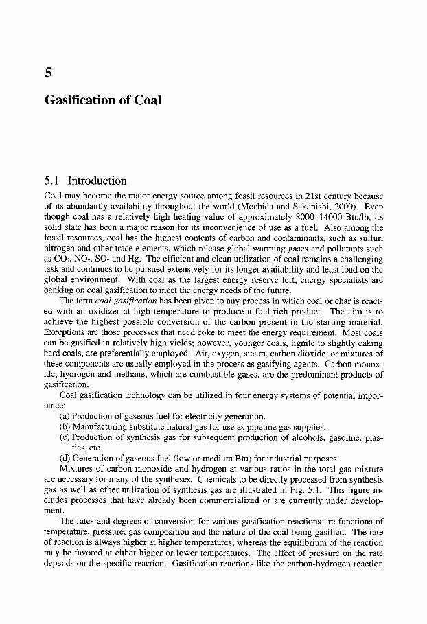
are necessary for many of the syntheses. Chemicals to be directly processed from synthesis gas as well as other utilization of synthesis gas are illustrated in Fig. 5.1. This figure in- cludes processes that have already been commercialized or are currently under develop- ment.
The rates and degrees of conversion for various gasification reactions are functions of temperature, pressure, gas composition and the nature of the coal being gasified. The rate of reaction is always higher at higher temperatures, whereas the equilibrium of the reaction may be favored at either higher or lower temperatures. The effect of pressure on the rate depends on the specific reaction. Gasification reactions like the carbon-hydrogen reaction
270 5 Gasification of Coal
I Coal j
Commercialized
I I Under development
l Coal I ~1 Gasification I
--II Methane II _1 Ethylene I v I
"J] Pr~ lene [
~[I Methanol II
_l Ethanol I v I
~lll Butanol 11
Ethylene glycol I 1
-I ~l Acetic acid [ -I I
=Ill Fuel oil II -~]1 Ammonia/urea [I
~[I Reducing gas [I
~111 Electricity II Fig. 5.1 Utilization of synthesis gas. [From JICA. I, 207 (1989)]
to produce methane are favored at high pressures (70 atm) and relatively low temperatures (760-930 ~ whereas low pressures and high temperatures favor the production of carbon monoxide and hydrogen.
The basic technical processes of coal gasification are distinguished into (1) gasification in the stationary or slowly moving fixed-bed (fixed-bed gasification); (2) reaction in the flu- idized-bed; (3) coal gasification using the entrained-bed principle; and (4) reaction in a molten bath of salt or metal (molten-bath gasification). Another important method of clas- sification is by the applied combustion and gasification temperature, and whether the ash from the solid fuel is discharged in liquid form (slag) or as a solid (ash).
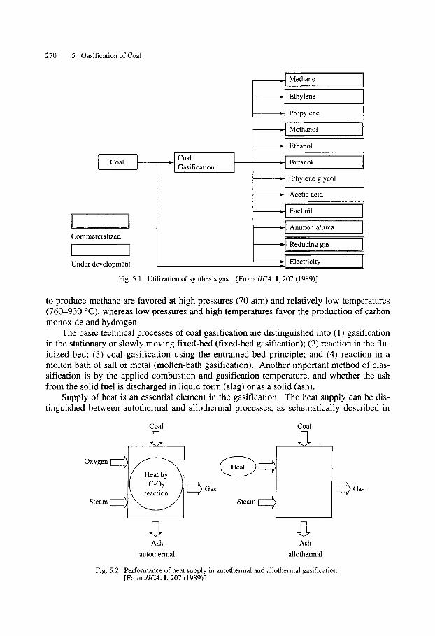
Supply of heat is an essential element in the gasification. The heat supply can be dis- tinguished between autothermal and allothermal processes, as schematically described in
Oxygen I
Steam
Coal Coal
Gas
Steam Oas
Ash Ash autothermal allothermal
Fig. 5.2 Performance of heat supply in autothermal and allothermal gasification. [From JICA. I, 207 (1989)]
5.2 Production of Gases Involving Gasification 271
Fig. 5.2. In the authothermal process, the heat for the endothermic gasification is supplied by the combustion of part of the feedstock with oxygen-containing gasifying agents, while in the allothermal process the heat necessary to achieve process temperature levels is sup- plied by external sources. The autothermal processes are subdivided according to whether the reactants are fed cocurrently or countercurrently. The essential advantage of the latter method lies in the more favorable heat utilization. One drawback is the mixing that occurs in certain circumstances of the gasification agent gas with the product gas, which contains a relatively large amount of methane and higher hydrocarbons. On the other hand, the al- lothermal processes can be characterized according to the way in which heat is introduced: via heat transport with solid or gaseous heat carriers, via heat conductance through the walls of the reaction chamber, or via an immersion heater. In the last case, a heat exchanger is present in the reaction chamber. However, this type of heat supply is technically very in- volved.
The type of coal being gasified is also important to the operation. Only a suspension- type gasifier can handle any type of coal; if caking coals are to be used in a fixed- or flu- idized-bed, special measures must be taken so that the coal does not agglomerate during gasification. In addition, the chemical composition, volatile content and moisture content of coal affect its processing during gasification.
5.2 Production of Gases Involving Gasification Depending on the heating value of the gases produced in the gasification processes, there are three types of gas mixtures, low, medium and high Btu gases (Speight, 1983).
Low-Btu gas. This type of gas consists of a mixture of carbon monoxide, hydrogen and some other gases with a heating value less than 300 Btu/scf. This type of gas is produced when air is used as the gasifying agent. Because oxygen is not separated, the product gas inevitably has many undesirable constituents such as nitrogen. This results in a low heating value of 150-300 Btu/scf. Sometimes gasification of coal is carried out in situ where min- ing by other techniques is not favorable. For such in situ gasification, low-Btu gas is a de- sired product. Low-Btu gas contains about 50%v/v nitrogen and some quantities of hydro- gen and carbon monoxide (combustible), carbon dioxide and some traces of methane. The presence of a high content of nitrogen and other noncombustible components, such as CO2 and H20, lowers the heating value of the gas. These components limit the applicability of low-Btu gas to chemical synthesis. The two major combustible components are hydrogen and carbon monoxide, whose ratio varies depending on the gasification conditions em- ployed. One of the most undesirable components is hydrogen sulfide, whose content is pro- portional to the sulfur content of the feed. It must be removed by washing procedures be- fore product gas can be used for useful purposes.
Medium-Btu gas. This gas consists predominantly of carbon monoxide and hydrogen with some methane and carbon dioxide and various other gases with a heating value in the range of 300-700 Btu/scf. Such a gas can be produced using pure oxygen rather than air as the gasifying agent. It is used primarily in the synthesis of methanol, higher hydrocarbons via Fischer-Tropsch synthesis, and a variety of chemicals. It can also be used directly as a fuel to raise steam or to drive a gas turbine. The H2/CO ratio in medium-Btu gas varies from 2:3 (CO rich) to more than 3:1 (He rich). The increased heating value is attributed to the higher methane and hydrogen content as well as to lower carbon dioxide contents.
High-Btu gas. This gas consists predominantly of methane ( > 95%), and because of this its heating value increases appreciably to around 900-1000 Btu/scf. It is compatible with natural gas and is also referred to as synthetic natural gas (SNG). It is usually pro-
272 5 Gasification of Coal
duced by the catalytic reaction of carbon monoxide and hydrogen.
3H2 + CO ---) CH4 -q- H20 (5.1)
The large quantities of H20 produced are removed by condensation and recirculated. The catalyst used for this process is prone to sulfur poisoning, and care must be taken to remove all the hydrogen sulfide prior to the reaction. This results in very pure product gas. The methanation reaction is highly exothermic in nature.
5.3 Physical and Chemical Principles When a coal is subjected to the gasification process, it is first dried by evaporation of the surface and inherent moisture. As the temperature rises, decomposition of the coal struc- ture (pyrolysis) occurs to give volatiles and chars.
Coal ---) Char + volatiles (5.2)
Volatiles include tars, oils, phenols, naphtha, methane, HzS and some CO and H2. This process itself requires heat other than that required to raise the coal to devolatilization tem- peratures.
The overall pyrolysis process is divided into three stages. First, the coal undergoes a sort of depolymerization reaction that leads to the formation of a metastable intermediate product. Second, the product then undergoes cracking and re-condensation, giving out pri- mary gases, oils and semichar. Finally, semichar is converted to char with evolution of hy- drogen. Normally, residue or char produced from the pyrolysis process represents from 55% to 70% of the original coal. At conventional temperatures of the gasification process, this initial gasification stage is completed in seconds. The subsequent gasification of coal chars is much slower, and it takes a longer time to obtain significant conversions under practical conditions.
In gasification processes, only a fraction of the carbon in coal is oxidized completely to CO2. The heat released by partial combustion provides the bulk of the energy necessary to break chemical bonds in the coal and raise the materials to reaction temperature. Fixed car- bon (char), which remains after devolatilization, is gasified by reaction with oxygen, steam, carbon dioxide and hydrogen, and the gases react among themselves to produce the final gas mixture. The water gas shift reaction is favored for the control of reaction temperatures and significantly affects the H2/CO ratio but has little effect on the heating value of the product.
Reactions that occur in the gasification system can be written as the following equa- tions, based on the assumption that the solid consists solely of carbon.
C + 02 = CO2 (exothermic; predominates at low temperature) (5.3)
C -Jr- 1/202 = CO (exothermic; predominates at high temperature) (5.4)
C + H20 z CO + H2 (endothermic; slower than the above reaction) (5.5)
C -q- C 0 2 - - 2CO (endothermic; slower than the above reaction) (5.6)
CO + 1/202 ---- C O 2 (exothermic) (5.7)
H20 -+- CO = H2 -+- CO2 (exothermic shift; rapid) (5.8)
CO -k- 3H2 = CH4 + H20 (exothermic methanation) (5.9)
5.3 Physical and Chemical Principles 273
70
6 0 - CO~. X ~ - ~i ~ ' ~ ]
50 ,, 1
40 / ,~I2
20 ,'
10~( 5
600 800 1,000 1,200
/ / / / / I: Fluidized bed /
" (Winkler) I /
I /
/ ,, II: Entrained Suspension (Koppers)
60 ~ ' ~ C O / ~ I f
"~ 50 ;r / I 20 bar
.~ 40 " \ . H 2 C @ ~ H �9 ~.~ ,~ �9
~, 30 \ ~/~/~'--m'-~'-'-k'~- - _ _ " ~ ~
20 '--,,
" C02 / ' C H 2 > ~ . . "~..-.<" ~ ,
600 800 1,000 1,200
III: Moving bed (Lurgi)
70
}0 b ~ a r i f 60 -~ . / / f
I / " 50 CO ,./
"" H20 ' ," /, / 40 xqr" / H2
c 0 2 \ / / 3O " \ / ~ .--. ~--------,--.-.~
20 ~ ' - - ~
10 CH4 j ~ . 1 l j
600 800 1,000 1,200
Equilibrium temperature (~
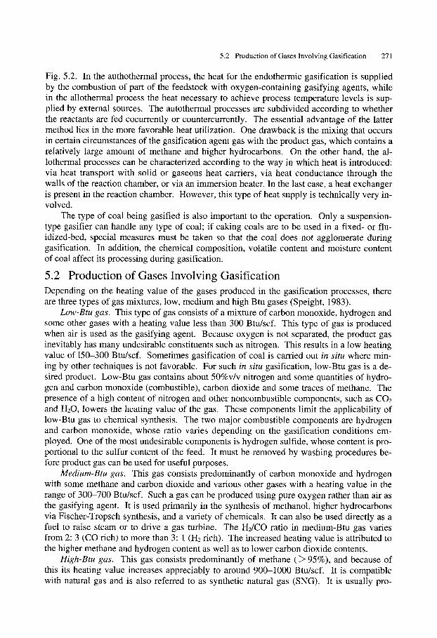
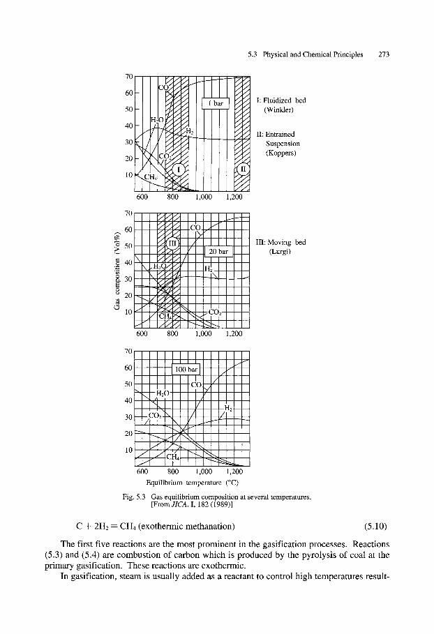
Fig. 5.3 Gas equilibrium composition at several temperatures. [From JICA. I, 182 (1989)]
C -+- 2 H 2 - CH4 (exothermic methanation) (5.10)
The first five reactions are the most prominent in the gasification processes. Reactions (5.3) and (5.4) are combustion of carbon which is produced by the pyrolysis of coal at the primary gasification. These reactions are exothermic.
In gasification, steam is usually added as a reactant to control high temperatures result-
274 5 Gasification of Coal �9
ing from combustion of carbon and to increase the heating value of the product gas, as shown in Eq. (5.5). This reaction, which is called "water gas reaction", is endothermic, and must rely on the heat release from the combustion of carbon for energy requirements. Further, the gas composition at equilibrium at above 1100 ~ (Fig. 5.3) shows carbon monoxide and hydrogen as dominant components, while at lower reaction temperatures, there is more carbon dioxide.
In order to produce a fuel-rich gas and to consume the remaining carbon, a much slow- er endothermic reaction Eq. (5.6), must occur. This reaction occurs preferentially at higher temperatures of above 900 ~
In a coal/steam/oxygen system, homogeneous reactions (with one another) of the ini- tially formed gas components are also very important, e.g., Eqs. (5.7) and (5.8). The first of these reactions causes the rapid consumption of oxygen, increases gas temperature and forces the requirement for slow, heterogeneous carbon reaction with CO2. The second, slightly exothermic water-gas shift reaction also produces CO2 from CO and tends to con- trol the final product distribution.
The methanation reactions (the last two reactions) favor high pressure and low temper- atures (see Fig. 5.3), but in most cases a methane concentration higher than equilibrium is predicted because methane is also formed during devolatilization. Methane formation in- creases the thermal efficiency of gasification and the heating value of the product, but it is not favorable for the production of synthesis gas.
The rate of trace elements such as sulfur and nitrogen is also important. Sulfur in coal is converted primarily to H2S under the reduction conditions of gasification. Approximately 5% to 15% of the sulfur is converted to COS, somewhat complicating the gas clean-up step. High temperatures and low pressure are favored in the conversion of nitrogen in coal to N2, while the opposite conditions are favored in the conversion of some of the nitrogen to NH3. Small amounts of HCN are also formed. Tars, oils and phenols, if they are not destroyed, contain some of the oxygen, nitrogen and sulfur from the coal as more complex molecules.
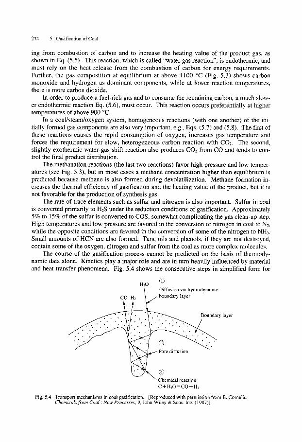
The course of the gasification process cannot be predicted on the basis of thermody- namic data alone. Kinetics play a major role and are in turn heavily influenced by material and heat transfer phenomena. Fig. 5.4 shows the consecutive steps in simplified form for
G HzO ~ . f Diffusion via hydrodynamic
CO H2 boundary layer
, Boundary layer
�9 <.2..(...
Chemical reaction C + H20 = CO + H2
Fig. 5.4 Transport mechanisms in coal gasification. [Reproduced with permission from B. Cornelis, Chemicals from Coal : New Processes, 9, John Wiley & Sons. lnc. (1987)]
5.4 Gasification Processes 275
1200 ~
II I III
1/T
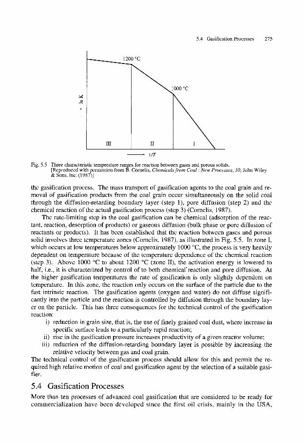
Fig. 5.5 Three characteristic temperature ranges for reaction between gases and porous solids. [Reproduced with permission from B. Cornelis, Chemicals from Coal : New Processes, 10, John Wiley & Sons. Inc. (1987)]
the gasification process. The mass transport of gasification agents to the coal grain and re- moval of gasification products from the coal grain occur simultaneously on the solid coal through the diffusion-retarding boundary layer (step 1), pore diffusion (step 2) and the chemical reaction of the actual gasification process (step 3) (Cornelis, 1987).
The rate-limiting step in the coal gasification can be chemical (adsorption of the reac- tant, reaction, desorption of products) or gaseous diffusion (bulk phase or pore diffusion of reactants or products). It has been established that the reaction between gases and porous solid involves three temperature zones (Cornelis, 1987), as illustrated in Fig. 5.5. In zone I, which occurs at low temperatures below approximately 1000 ~ the process is very heavily dependent on temperature because of the temperature dependence of the chemical reaction (step 3). Above 1000 ~ to about 1200 ~ (zone II), the activation energy is lowered to half, i.e., it is characterized by control of to both chemical'reaction and pore diffusion. At the higher gasification temperatures the rate of gasification is only slightly dependent on temperature. In this zone, the reaction only occurs on the surface of the particle due to the fast intrinsic reaction. The gasification agents (oxygen and water) do not diffuse signifi- cantly into the particle and the reaction is controlled by diffusion through the boundary lay- er on the particle. This has three consequences for the technical control of the gasification reaction:
i) reduction in grain size, that is, the use of finely grained coal dust, where increase in specific surface leads to a particularly rapid reaction;
ii) rise in the gasification pressure increases productivity of a given reactor volume; iii) reduction of the diffusion-retarding boundary layer is possible by increasing the
relative velocity between gas and coal grain. The technical control of the gasification process should allow for this and permit the re- quired high relative motion of coal and gasification agent by the selection of a suitable gasi- tier.
5.4 Gasification Processes More than ten processes of advanced coal gasification that are considered to be ready for commercialization have been developed since the first oil crisis, mainly in the USA,
276 5 Gasification of Coal
Germany, England and Japan. Gasification processes may be classified in a number of ways such as by the heat content of the gas produced, the gasifying agents employed, ash removal methods, method of gas solid contact, etc.
However, the most widely used classification is based on the mode of contact of gaseous and solid streams. The four main types of gasification processes under this mode of classification are (1) fixed bed, (2) fluidized bed, (3) entrained bed, and (4) molten bath.
5.4.1 Fixed-bed Gasifier
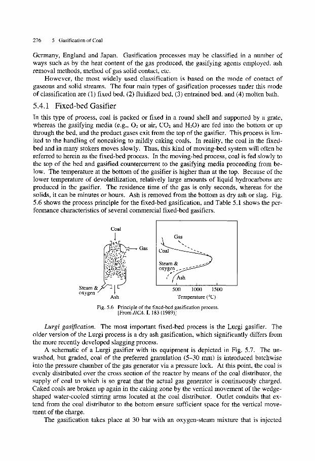
In this type of process, coal is packed or fixed in a round shell and supported by a grate, whereas the gasifying media (e.g., 02 or air, CO2 and H20) are fed into the bottom or up through the bed, and the product gases exit from the top of the gasifier. This process is lim- ited to the handling of noncaking to mildly caking coals. In reality, the coal in the fixed- bed and in many stokers moves slowly. Thus, this kind of moving-bed system will often be referred to herein as the fixed-bed process. In the moving-bed process, coal is fed slowly to the top of the bed and gasified countercurrent to the gasifying media proceeding from be- low. The temperature at the bottom of the gasifier is higher than at the top. Because of the lower temperature of devolatilization, relatively large amounts of liquid hydrocarbons are produced in the gasifier. The residence time of the gas is only seconds, whereas for the solids, it can be minutes or hours. Ash is removed from the bottom as dry ash or slag. Fig. 5.6 shows the process principle for the fixed-bed gasification, and Table 5.1 shows the per- formance characteristics of several commercial fixed-bed gasifiers.
Cial \ Gas
"" C ~ Gas " "
Steam & _ _ :_.,~-~'._/~ 7- oxygen
I I I
Steam 500 1000 1500 oxygen
Ash Temperature (~
Fig. 5.6 Principle of the fixed-bed gasification process. [FromJICA. I, 183 (1989)]
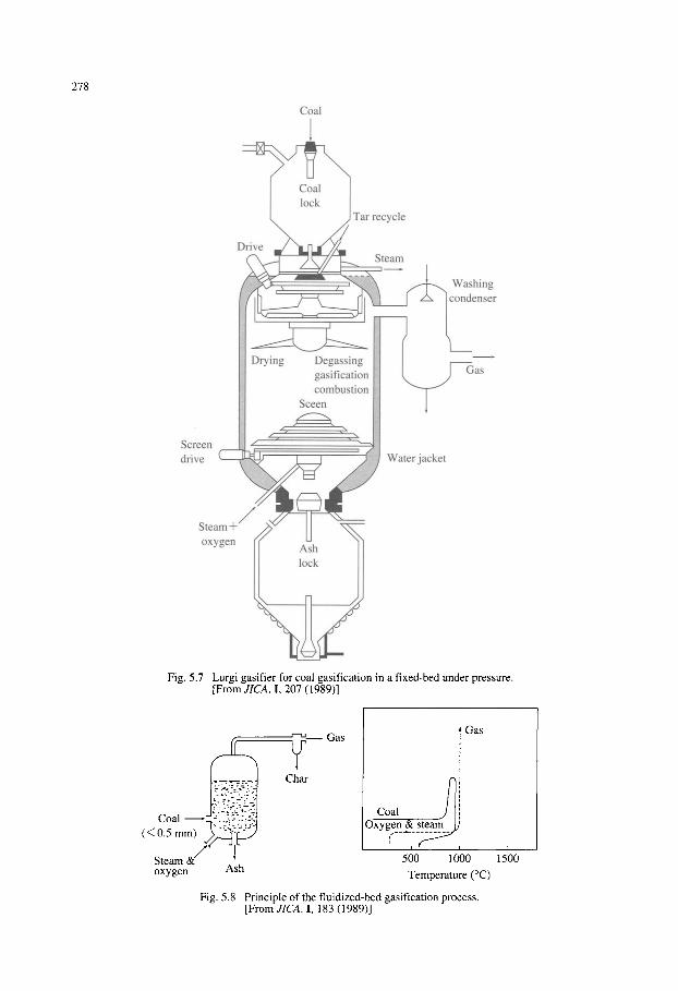
Lurgi gasification. The most important fixed-bed process is the Lurgi gasifier. The older version of the Lurgi process is a dry ash gasification, which significantly differs from the more recently developed slagging process.
A schematic of a Lurgi gasifier with its equipment is depicted in Fig. 5.7. The un- washed, but graded, coal of the preferred granulation (5-30 mm) is introduced batchwise into the pressure chamber of the gas generator via a pressure lock. At this point, the coal is evenly distributed over the cross section of the reactor by means of the coal distributor, the supply of coal to which is so great that the actual gas generator is continuously charged. Caked coals are broken up again in the caking zone by the vertical movement of the wedge- shaped water-cooled stirring arms located at the coal distributor. Outlet conduits that ex- tend from the coal distributor to the bottom ensure sufficient space for the vertical move- ment of the charge.
The gasification takes place at 30 bar with an oxygen-steam mixture that is injected
5.4 Gasification Processes 277
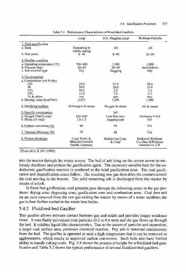
Table 5.1 Performance Characteristics of Fixed-Bed Gasifiers
Lurgi B.G. Slagging Lurgi Wellman-Galusha
1. Coal specification a. Rank Noncaking to All All
mildly caking b. Size (mm) 6-40 6--40 25-50
2. Gasifier condition a. Operating temperature (~ 700-900 1,500 1,000 b. Pressure (bar) 20-30 20-30 Atmospheric c. Ash removal type Dry Slagging Dry
3. Gas properties a. Composition (vol.%-dry)
CO 19.0 61.0 28.6 H2 39.0 28.0 15.0 CO2 30.0 2.6 3.4 CH4 11.0 7.6 2.7 N2 & others rest rest rest
b. Heating value (kcal/Nm 3) 2,247 3,290 1,500
4. Gasifying medium Air/oxygen & steam Oxygen & steam Air & steam
5. Specific consumption 247 a. Oxygen (Nm3/t-coal) 220-300 Less than non- Air/steam -- 6.0 b. Steam (t/t-coal) 1.0-1.5 slagging type 0.6
6. Carbon conversion (%) 85 99 NA
7. Thermal efficiency (%) 75 68 NA
8. Process developer Lurgi Kohle & British Gas Corp. McKwell-Wellman Mineralol-technik & Lurgi Co.,Ohio &Wellman GmbH, Germany Galusha Co.,UK
[From JICA. I, 207 (1989)]
into the reactor through the rotary screen. The bed of ash lying on the screen serves to uni- formly distribute and preheat the gasification agent. The necessary sensible heat for the en- dothermic gasification reaction is produced in the brief gasification zone. The coal gasifi- cation and degasification zones follow. The resulting raw gas then dries (in countercurrent) the coal moving to the bottom. The solid remaining ash is discharged from the reactor by means of a lock.
In fixed-bed gasification, coal granules pass through the following zones in the gas pro- ducer: drying zone, degassing zone, gasification zone and combustion zone. Coal dust and tar are next removed from the raw gas exiting the reactor by means of a water scrubber; the gas is then further cooled in the waste heat boiler.
5 .4 .2 F l u i d i z e d - b e d Gas i f i e r
This gasifier allows intimate contact between gas and solids and provides longer residence times. It uses finely pulverized coal particles (0.2 to 0.4 mm) and the gas flows up through the bed. It exhibits liquid-like characteristics. Due to the ascent of particles and separation, a larger coal surface area, promotes chemical reaction. Dry ash is removed continuously from the bed. The gasifier is operated at such a high temperature that it can be removed as agglomerates, which results in improved carbon conversion. Such beds also have limited ability to handle caking coals. Fig. 5.8 shows the process principle for a fluidized-bed gasi- fication and Table 5.2 shows the typical performance of several fluidized-bed gasifiers.
278
Coal
I
Tar recycle
Drive ~ / x ~ / ~ ~ ~ - - ~ <-'-'//-'~ Steam
~ , 1 z...._ff , [ , , ~ , _ _ / ~ Washing ' ' c l / x Itondenser
ff gasification i ~ _,fl t_,as I combustion i - ' - [ " -
Screen ~ drive Water jacket
Ste oxygen / Ash
lock
Fig. 5.7 Lurgi gasifier for coal gasification in a fixed-bed under pressure. [From JICA. I, 207 ( 1989)]
(< 0C5almm)"S~;~~
Steam&// [ oxygen Ash
r-'~_____ Gas
Char
Gas
Coal Oxygen &
( i 5()0 1000 Temperature (~
Fig. 5.8 Principle of the fluidized-bed gasification process. [From JICA. I, 183 (1989)]
i
1500
5.4 Gasification Processes 279
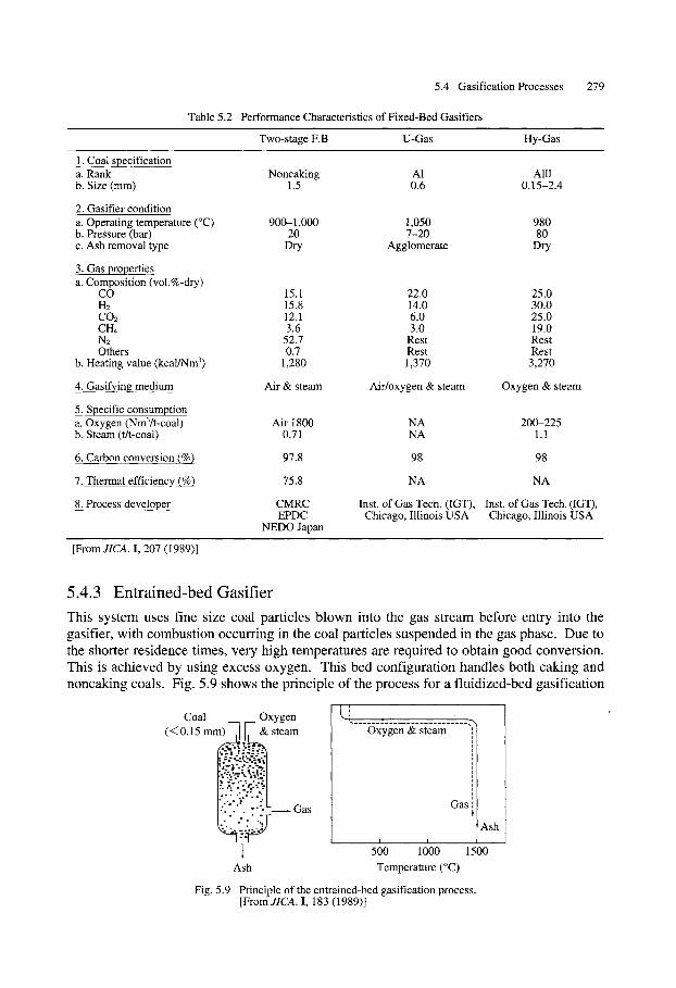
Table 5.2 Performance Characteristics of Fixed-Bed Gasifiers
Two-stage F.B U-Gas Hy-Gas
1. Coal specification a. Rank b. Size (mm)
2. Gasifier condition a. Operating temperature (~ b. Pressure (bar) c. Ash removal type
3. Gas properties a. Composition (vol.%-dry)
CO Ha CO2 CH4 N2 Others
b. Heating value (kcal/Nm 3)
4. Gasifying medium
5. Specific consumption a. Oxygen (Nm3/t-coal) b. Steam (t/t-coal)
6. Carbon conversion (%)
7. Thermal efficiency (%)
8. Process developer
Noncaking A1 Alll 1.5 0.6 0.15-2.4
900-1,000 1,050 980 20 7-20 80
Dry Agglomerate Dry
15.1 22.0 25.0 15.8 14.0 30.0 12.1 6.0 25.0 3.6 3.0 19.0
52.7 Rest Rest 0.7 Rest Rest
1,280 1,370 3,270
Air & steam Air/oxygen & steam Oxygen & steam
Air 1800 NA 200-225 0.71 NA 1.1
97.8 98 98
75.8 NA NA
CMRC Inst. of Gas Tech. (IGT), Inst. of Gas Tech. (IGT), EPDC Chicago, Illinois USA Chicago, Illinois USA
NEDO Japan
[From JICA. I, 207 (1989)]
5.4.3 Entrained-bed Gasifier
This system uses fine size coal particles blown into the gas stream before entry into the gasifier, with combustion occurring in the coal particles suspended in the gas phase. Due to the shorter residence times, very high temperatures are required to obtain good conversion. This is achieved by using excess oxygen. This bed configuration handles both caking and noncaking coals. Fig. 5.9 shows the principle of the process for a fluidized-bed gasification
/ I Coal Oxygen t..l .
(< 0.15 mm) ,11' & steam Oxygen & steam
:. -". �9 r..- "..
. Gas
I I
1 5 O0 1 000
Ash Temperature (~
Fig. 5.9 Principle of the entrained-bed gasification process. [FromJICA. I, 183 (1989)]
i
| | ! | | i | | | | | |
Gas',
Ash
15100 ....
280 5 Gasification of Coal
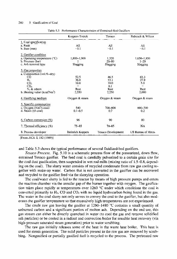
Table 5.3 Performance Characteristics of Entrained-Bed Gasifiers
Koppers-Totzek Texaco Babcock & Wilcox
1. Coal specification a. Rank All All All b. Size (mm) -0.1 -0.1 -0.1
2. Gasifier condition a. Operating temperature ( ~ 1,800-1,900 1,320 1,650-1,850 b. Pressure (bar) 1 20-80 1-20 c. Ash removal type Slagging Slagging Slagging
3. Gas properties a. Composition (vol.%-dry)
CO 52.5 46.5 65.3 H2 36.0 33.1 27.9 CO2 10.0 19.0 5.0 CH4 - 0.1 - N2 & others Rest Rest Rest
b. Heating value (kcal/Nm 3) 2,550 2,250 2,680
4. Gasifying medium Oxygen & steam Oxygen & steam Oxygen & steam
5. Specific consumption c. Oxygen (Nm3/t-coal) 540 700-800 600-700 d. Steam (t/t-coal) 0.1--0.5 0.7 0.2
6. Carbon conversion (%) 96 90 80
7. Thermal efficiency (%) 75-85 70-85 NA
8. Process developer Heinrich Koppers Texaco Development US Bureau of Mines
[From JICA. I, 182 (1989)]
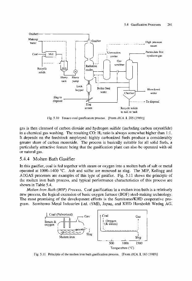
and Table 5.3 shows the typical performance of several fluidized-bed gasifiers. Texaco Process. Fig. 5.10 is a schematic process flow of the pressurized, down flow,
entrained Texaco gasifier. The feed coal is carefully pulverized to a certain grain size for the coal dust gasification, then suspended in wet rod mills (mixing ratio of 1.5-0.8, depend- ing on the coal). The slurry water consists of recycled condensate from raw gas cooling to- gether with make-up water. Carbon that is not converted in the gasifier can be recovered and recycled to the gasifier feed via the slurrying operation.
The coal/water slurry is fed to the reactor by means of high pressure pumps and enters the reaction chamber via the annular gap of the burner together with oxygen. The gasifica- tion takes place rapidly at temperatures over 1260 ~ under which conditions the coal is converted primarily to H2, CO and CO2 with no liquid hydrocarbon being found in the gas. The water in the coal slurry not only serves to convey the coal to the gasifier, but also mod- erates the gasifier temperature so that excessively high temperatures are not experienced.
The crude raw gas leaving the gasifier at 1260-1480 ~ contains a small quantity of unburned carbon and a significant portion of molten ash. Depending on the end use, this gas stream can either be directly quenched in water (to cool the gas and remove solidified ash particles) or be cooled in a radiant and convection boiler for sensible heat recovery (via high-pressure saturated steam generation) prior to water scrubbing.
The raw gas initially releases some of the heat in the waste heat boiler. This heat is used for steam generation. The solid particles present in the raw gas are removed by scrub- bing. Nongasified or partially gasified fuel is recycled to the process. The pretreated raw
5.4 Gasification Processes 281
Oxidant
Makeup ~ asifier water
[ I .~Convection Coal [...k...__..._d [ I - - - - - - - - - ~ Mill I------, , k,.~...,) : , cooler
m I Radiation ] [ scrubber[ [ Recycle [~_/J ]cooler, I ~ L__.__...A I
solids SlurrYtankT Slurrypump~l) ~ ]'~-i'J -.- - r - - ~ ' [ ' - ~
Lock ~ Boiler feed hopper water
Slag to disposal
Slag screen Recycle solids
to mill or tank
High-pressure steam
Particulate-free synthesis gas
Blowdown water
. . . . . . . . . To disposal
Fig. 5.10 Texaco coal gasification process. [From JICA. I, 205 (1989)]
gas is then cleansed of carbon dioxide and hydrogen sulfide (including carbon oxysulfide) in a chemical gas washing. The resulting CO: H2 ratio is always somewhat higher than 1:1. It depends on the feedstock employed: highly carbonized fuels produce a considerably greater share of carbon monoxide. The process is basically suitable for all solid fuels, a particularly attractive feature being that the gasification plant can also be operated with oil or natural gas.
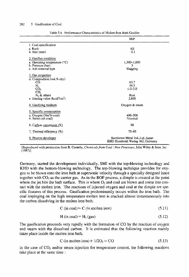
5 .4 .4 M o l t e n Bath Gasi f ier
In this gasifier, coal is fed together with steam or oxygen into a molten bath of salt or metal operated at 1000-1400 ~ Ash and sulfur are removed as slag. The MIP, Kellogg and ATGAS processes are examples of this type of gasifier. Fig. 5.11 shows the principle of the molten iron bath process, and typical performance characteristics of this process are shown in Table 5.4.
Molten Iron Bath (MIP) Process. Coal gasification in a molten iron bath is a relatively new process, the logical extension of basic oxygen furnace (BOF) steel-making technology. The most promising of the development efforts is the Sumitomo/KHD cooperative pro- gram. Sumitomo Metal Industries Ltd. (SMI), Japan, and KHD Humboldt Wedag AGI
I Coal (Pulverized) Gas Steam & I I oxygen
- --7 ,. - ~ Slag
Molten iron
Coal Gas I Oxygen ,A i (& steam) , i
I
500 10100 Temperature (~
Slag I
1500
Fig. 5.11 Principle of the molten iron bath gasification process. [From JICA. I, 183 (1989)]
282 5 Gasification of Coal
Table 5.4 Performance Characteristics of Molten-Iron Bath Gasifier
MIP
1. Coal specification a. Rank All b. Size (mm) -0.1
2. Gasifier condition a. Operating temperature (~ 1,300-1,600 b. Pressure (bar) 3 c. Ash removal type Slagging
3. Gas properties d. Composition (vol.%-dry)
CO 63.7 H2 34.5 CO2 1.0-3.0 CH4 N2 & others Rest
e. Heating value (kcal/Nm 3) 2,800
4. Gasifying medium Oxygen & steam
5. Specific consumption a. Oxygen (Nm3/t-coal) 400-500 b. Steam (t/t-coal) Nominal
6. Carbon conversion (%) 98
7. Thermal efficiency (%) 75-85
8. Process developer Sumitomo Metal Ind.,Ltd.,Japan KHD Humboldt Wedag AG, Germany
[Reproduced with permission from B. Cornelis, Chemicals from Coal : New Processes, John Wiley & Sons. Inc. (1987)]
Germany, started the development individually, SMI with the top-blowing technology and KHD with the bottom-blowing technology. The top-blowing technique provides for oxy- gen to be blown onto the iron bath at supersonic velocity through a specially designed lance together with CO2 as the carder gas. As in the BOF process, a dimple is created at the point where the jet hits the bath surface. This is where 02 and coal are blown and come into con- tact with the molten iron. The reactions of injected oxygen and coal at the dimple are spe- cific features of this process. Gasification predominantly occurs within the iron bath. The coal impinging on the high temperature molten iron is cracked almost instantaneously into the carbon dissolving in the molten iron bath.
C (in coa l )= C (in molten iron) (5.11)
H (in coa l )= H2 (gas) (5.12)
The gasification proceeds very rapidly with the formation of CO by the reaction of oxygen and steam with the dissolved carbon. It is estimated that the following reaction mainly takes place inside the molten iron bath.
C (in molten i ron)+ 1/202 = CO (5.13)
In the case of CO2 and/or steam injection for temperature control, the following reactions take place at the same time :
5.4 Gasification Processes 283
C (in molten iron)+ CO2 = 2CO
C (in molten iron)+ H20 = CO + H2
(5.14)
(5.15)
The molten iron bath process provides the following benefits. i) The molten iron bath completely cracks the blown coal in a short period of time
and not only generates hydrogen gas but also dissolves and absorbs the carbon pro- duced by cracking.
ii) The molten iron reacts with blown oxygen and carbon dioxide and becomes FeO, but this FeO is immediately reduced by carbon contained in the molten iron and becomes Fe while generating carbon monoxide gas.
iii) Even if an excessive amount of coal is fed into the molten iron bath, the molten iron dissolves and absorbs the excessive amount of carbon, preventing unoxidized carbon from escaping from the gasifier.
iv) Even if an excessive amount of oxygen is supplied, carbon contained in the molten iron bath reacts with the excess oxygen, preventing the generation of carbon diox- ide.
v) The molten iron dissolves and absorbs the sulfur contained in the coal, then trans- forms into molten slag.
KHD has developed the bottom-blowing technique since 1975. In the bottom-blowing technique, coal, oxygen, flux and a cooling gas are injected continuously through tuyeres into the bottom of a liquid iron bath. A solid porous metal called "mushroom" is formed above the tuyeres, which protects the tuyere tip. The exothermic oxidation of the iron at the gas/molten iron interface induces a relatively high temperature.
The liquid iron oxide formed outside this mushroom is continuously transferred into the liquid iron bulk, generating CO and H2 through the decomposition of injected coal and the reaction with dissolved carbon in molten iron. The gasification reaction is strongly af- fected by bath turbulence and the resulting wide dispersion of coal particles and iron oxide in the reactor.
In 1983 Sumitomo and KHD combined forces for larger scale testing and development of the process, which was named the Molten Iron Pure gas (MIP) process. A prototype test plant with a capacity of 240 tons of coal per day was built at MEFOS in Lulea, Sweden.
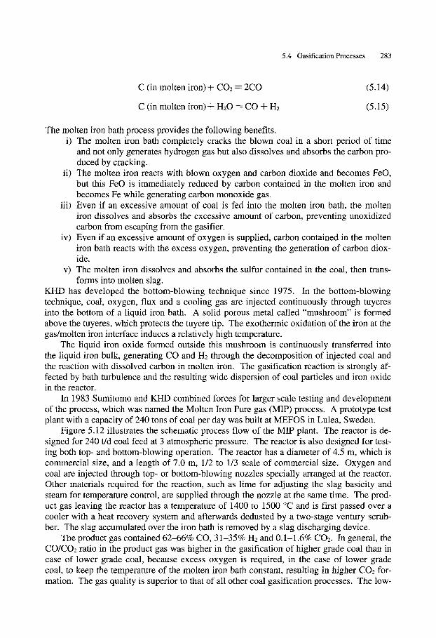
Figure 5.12 illustrates the schematic process flow of the MIP plant. The reactor is de- signed for 240 t/d coal feed at 3 atmospheric pressure. The reactor is also designed for test- ing both top- and bottom-blowing operation. The reactor has a diameter of 4.5 m, which is commercial size, and a length of 7.0 m, 1/2 to 1/3 scale of commercial size. Oxygen and coal are injected through top- or bottom-blowing nozzles specially arranged at the reactor. Other materials required for the reaction, such as lime for adjusting the slag basicity and steam for temperature control, are supplied through the nozzle at the same time. The prod- uct gas leaving the reactor has a temperature of 1400 to 1500 ~ and is first passed over a cooler with a heat recovery system and afterwards dedusted by a two-stage ventury scrub- ber. The slag accumulated over the iron bath is removed by a slag discharging device.
The product gas contained 62-66% CO, 31-35% H2 and 0.1-1.6% CO2. In general, the CO/CO2 ratio in the product gas was higher in the gasification of higher grade coal than in case of lower grade coal, because excess oxygen is required, in the case of lower grade coal, to keep the temperature of the molten iron bath constant, resulting in higher CO2 for- mation. The gas quality is superior to that of all other coal gasification processes. The low-
284 5 Gasification of Coal
Pulverlized coal Fine Lime storage bin storage bin
Feed system
Oxygen steam
Heat recovery system (Waste heat boiler)
Transporting gas ,Gasifying vessel
(Reactor)
Synthesis
Gas composition 65-70% CO 25-30% H2 0.3-2 % CO2
0-300 ppm COS H2S
Woler
Oxygen Slag Dust , Circulating water steam Sludge
Fig. 5.12 Molten iron bath coal gasification. (MIP Plant) [From JICA. I, 197 (1989)]
er content of sulfur compounds in the gas and zero tar formation are decisive advantages of the MIP coal gasification technology.
5.5 Measurement of Gasification Rate As gasification proceeds, the char loses mass. The burnout rate is used to determine the gasification reactivity. There are two ways in which the gasification rate can be considered:
1 dW 1 dx r . . . . ( 5 . 1 6 )
W dt ( 1 - x) dt
where r is the normalized gasification rate, t is time, W is the char mass at time t (dry ash free, daf), x is char conversion,
W o - W x = ~ ( 5 . 1 7 )
Wo
and Wo is the initial mass of char, and
1 dW dx r P ~ _ _ _ _ - - _ _
Wo dt dt ( 5 . 1 8 )
In this case r" is considered as the gasification rate.
5.6 Reactivity of Coal Char 285
When considering the reactivity of coal gasification, the behavior of the conversion versus time (x versus t) and that of the reaction rate versus conversion (r versus x or r" ver- sus x) are studied as char is reacting with CO2 or H20 at gasification temperatures (800- 1200 ~
In general, the curves of conversion against time show a similar shape, regardless of coal type and experimental conditions, as can be seen from the literature (for example, Lee and Kim, 1995; Shufen and Ruizheng, 1994; Kasaoka et al., 1987; Yang and Watkinson, 1994; and Alvarez et al., 1995). The curve is almost a straight line up to x -- 0.75.
On the other hand, there is no agreement regarding the variation of the gasification rate with conversion. Some authors have found a maximum rate for conversions between 20% and 60% (Dutta et al., 1977; Yang and Watkinson, 1994; Chi and Perlmutter, 1989; Gavalas, 1980; Bhatia and Permutter, 1980; and Hamilton et al., 1984). Others found a lin- ear decrease in gasification rate as reaction advances (Chin et al., 1983; and Adschiri et al., 1986). Finally, some studies regarding coal reactivity during gasification (for example, as given in studies by Matsui et al., 1987, and Schmal et al., 1983) do not consider gasification rate variation with conversion and only report the gasification rate at a specific value of conversion.
5.6 Reactivity of Coal Char Coal gasification involves two primary steps: (1) pyrolysis of coal to char and (2) subse- quent gasification of the char generated. In the first step, pyrolysis, the evolution of com- pounds of low molecular weight, mainly as tars and noncondensable gases, occurs at tem- perature between 300 and 500 ~ Normally, residue or char produced from the pyrolysis process represents from 55% to 70% of the original coal. At the usual temperatures of the gasification process, this initial gasification stage is completed in seconds. The subsequent gasification of coal chars is much slower, and it takes longer to obtain significant conver- sions under practical conditions. This has led to investigation of the gasification of car- bon/char by a large number of researchers.
Coal chars prepared by low-temperature devolatilization have a higher degree of crys- tallinity than the starting coal. However, the crystalline structure of coal char is significant- ly less ordered than that of graphite. The lower the coal pyrolysis temperature, the greater the disorder. In graphite, the building blocks are lamellar in structure held together by van der Waals forces. At the edge, crystallites have unpaired tr electrons which are susceptible to attack by oxidants. The edge carbon atoms are more reactive than basal carbon atoms. Active carbon sites are considered as dislocations or imperfections in the crystallite edges of carbon (Ismail, 1987). Numerous studies (e.g., Khan, 1987; Ismail, 1987; Walker, 1981; Laine 1963) have been reported on the reactivity of chars generated at different operating conditions, (e.g., different char formation temperatures, burnoff temperatures, oxygen par- tial pressures and particle sizes). Factors which influence the reactivity of coal char include the following: (a) concentration of carbon active sites, (b) catalysis by the inherently pre- sent minerals, and (c) the diffusion of the reactant and product gases within the pores of the devolatilized char (Walker, 1987). Coal chars are heterogeneous materials that can contain significant amounts of heteroatoms such as hydrogen, oxygen, nitrogen and sulfur, which may also influence the reactivity. While oxygen sites influence reactivity by electron ex- change, nitrogen and sulfur sites encourage ring attack due to concentration of the electrons (Ismail, 1987). It was demonstrated that the hydrogen content of char can play a significant role in reactivity, perhaps by providing a source of nascent-carbon sites (Khan, 1987).
Numerous studies considered the significance of active surface area for investigating
~ 286 5 Gasification of Coal
the reactivity of coal char or carbon in gasification and oxidation reactions. The technique used to determine the concentration of carbon active sites is oxygen chemisorption. The following discussion is aimed to review the importance of this technique for monitoring the reactive sites in coal char and provide an understanding of the detailed interactions between gas and solid.
5.6.1 The Role of Oxygen Chemisorption in Noncatalytic Gasification Reaction
It is well accepted that reactant gases (02, CO2, H20, H2) chemisorb dissociatively onto car- bon surfaces. On the other hand, the edge carbon atoms, the steps and the cleavage surfaces of the graphite crystals act as active sites (Miura, 1986). To relate these sites to the reactiv- ity of coal char, Walker et al. (1963) introduced the concept of active surface area (ASA). The technique used to determine ASA was derived from the amount of oxygen chemisorbed at 300 ~ with the assumption that the number of active sites is proportional to the amount of chemisorbed oxygen. It was found that 02 gasification rate is closely related to ASA (Walker et al., 1960, 1963). Laine et al. (1963) investigated the role of the active surface area in the carbon-oxygen reaction and observed that the unoccupied (i.e., available) active surface area was the major factor that determines the rate constant, rather than the conven- tional Brunauer-Emnmett-Teller (B.E.T.) surface area.
The change in reactivity of demineralized lignite chars with pyrolysis temperature could also be explained by a change in ASA, which in turn was related to the size of the graphite-like microstructures and the value of H/C (Radovic et al., 1983, 1985). Tucker et al. (1969) measured ASA gravimetrically and observed that the oxygen chemisorbed on the "armchair" carbon contributed to rapid gasification. Tong et al. (1982) and Ahmed and Back (1985) gasified a pure carbon film, prepared by the pyrolysis of CH4, and related the gasification reactivity to ASA. Although carbon-oxygen reactions have been widely inves- tigated and several mechanisms wave postulated, the exact mechanisms are not well under- stood. Several elementary reactions (shown below) have been used (Miura, 1989) to de- scribe the reaction mechanism:
Cf + 02 ---) C(O2) (5.19)
Cf + C(O2) ~ 2C(O) (5.20)
c(o) ~ c o (5.21)
Cf--F- C(O)--F- 02 ~ C02 ..ql_ C(O) (5.22)
c(o) + c(o2) ~ co2 + c(o) (5.23)
2C(O) ~ CO2 + Cf (5.24)
where Cf is a free active site on carbon, presumably edge carbon, and C(O2) and C(O) rep- resent molecular and atomic oxygen adsorbed on a site.
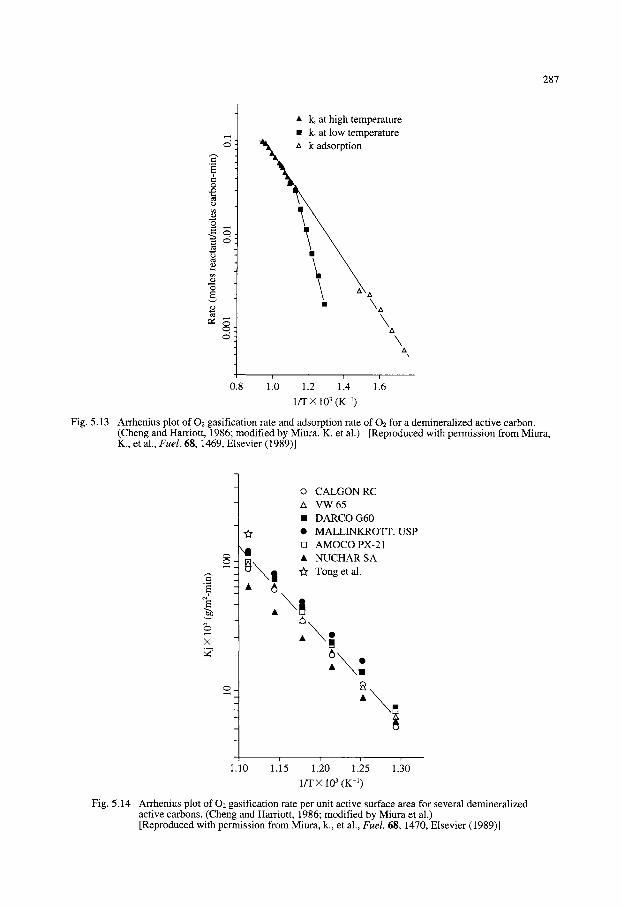
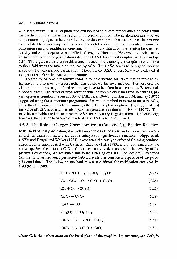
Generally, each researcher has proposed that the reactivity is proportional to the ASA measured by his own method, although the ASA is usually measured at temperatures lower than the reaction temperature. Cheng and Harriott (1986) attemped to clarify the relation- ship between chemisorption rate and reactivity. Fig. 5.13 shows the Arrhenius plots of gasification rates and chemisorption rates measured at temperatures lower than the reaction temperature. It can be seen that the controlling step of the gasification reaction changes
287
0
r
tD
0
tD t.., r~ ~D
0
tD
�9 k, at high temperature �9 k, at low temperature zx k adsorption
\ \ \
~ k A
\A \
A
\ A
i i i i '
0.8 1.0 1.2 1.4 1.6
l / T • 103 (K -1)
Fig. 5.13 Arrhenius plot of O2 gasification rate and adsorption rate of O2 for a demineralized active carbon. (Cheng and Harriott, 1986; modified by Miura. K. et al.) [Reproduced with permission from Miura, K., et al., Fuel. 68, 1469, Elsevier (1989)]
eq
•
xl
�9 6
1.10 1.15
o CALGON RC A VW65 �9 DARCO G60 �9 MALLINKROTT. USP [] AMOCO PX-21 �9 NUCHAR SA
Tong et al.
\ !
�9 m 6 , \ :
1.20 1.25 1. 0 l / T • 103 (K -1)
Fig. 5.14 Arrhenius plot of O2 gasification rate per unit active surface area for several demineralized active carbons. (Cheng and Harriott, 1986; modified by Miura et al.) [Reproduced with permission from Miura, k., et al., Fuel. 68, 1470, Elsevier (1989)]
288 5 Gasification of Coal
with temperature. The adsorption rate extrapolated to higher temperatures coincides with the gasification rate: this is the region of adsorption control. The gasification rate at lower temperatures is judged to be controlled by the desorption rate because the gasification rate extrapolated to lower temperatures coincides with the desorption rate calculated from the adsorption rate and equilibrium constant. From this consideration, the relation between re- activity and chemisorption was clarified. Cheng and Harriott (1986) replotted their data as an Arrhenius plot of the gasification rate per unit ASA for several samples, as shown in Fig. 5.14. This figure shows that the difference in reaction rate among the samples is within two to three fold when the rate is normalized by ASA. Thus ASA seems to be a good index of reactivity for noncatalytic gasification. However, the ASA in Fig. 5.14 was evaluated at temperatures below the reaction temperature.
To employ ASA as a reactivity index, a reliable method for its estimation must be es- tablished. Up to now, each researcher has employed his own method. Furthermore, the distribution in the strength of active site may have to be taken into account, as Waters et al. (1986) suggest. The effect of physisorption must be completely eliminated, because 02 ph- ysisorption is significant even at 200 ~ (Allardice, 1966). Causton and McEnanay (1985) suggested using the temperature programmed desorption method in v a c u o to measure ASA, since this technique completely eliminates the effect of physisorption. They reported that the value of ASA is constant at adsorption temperatures ranging from 100 to 250 ~ This may be a reliable method to measure ASA for noncatalytic gasification. Unfortunately, however, the relation between the reactivity and ASA was not discussed.
5.6.2 The Role of Oxygen Chemisorption in Catalytic Gasification Reaction
In the field of coal gasification, it is well known that salts of alkali and alkaline earth metals as well as transition metals are active catalysts for gasification reactions. Hippo et al. (1979) and Hengel and Walker (1984) investigated the catalytic effect of Ca using deminer- alized lignites impregnated with Ca salts. Radovic et al. (1983a and b) confirmed that the active species of calcium is CaO and that the reactivity decreases with the severity of the pyrolysis conditions, and attributed this to the sintering of CaO. Furthermore, they found that the turnover frequency per active CaO molecule was constant irrespective of the pyrol- ysis conditions. The following mechanism was considered for gasification catalyzed by CaO (Miura, 1989):
Cf + CaO + 02---) Ca02 -q-- Cf(O) (5.25)
Cb -'~ CaO + 02 ' ~ Ca02 -'l- Cb(O) (5.26)
2Cf + 02 ----) 2Cr(O) (5.27)
Cb(O) ~ Ce(O) (5.28)
Ce(O) ---) CO (5.29)
2 Cf (O)~ CO2 + Cf (5.30)
Ca02 + Cb ~ CaO -q- Cb(O) (5.31)
CaO2 + Cf----) CaO + Cf(O) (5.32)
where Cb is the carbon atom on the basal plane of the graphite-like structure, and Ca02 is
5.6 Reactivity of Coal Char 289
assumed to be either the superoxide or peroxide of Ca. Eq. (5.28) represents the surface diffusion of an oxygen atom adsorbed on the carbon of the basal plane to an active site. For noncatalytic conditions, this cycle reduces to one similar to the cycle proposed by Ahmed and Back (1985). Dispersion of CaO was estimated through measurement of the crystallite size of CaO by XRD, but the use of chemisorbed CO2 was also proposed. Solano et al. (1987) demonstrated that the amount of chemisorbed CO2 at 200 ~ is a satisfactory mea- sure of CaO dispersion.
Alkali metals such as Na and K have long been known to catalyze the gasification reac- tion of carbon. Attention has now focused on the role of adsorbed oxygen in catalytic gasi- fication. The nature of the oxide at the carbon surface, in particular the ratio of oxygen to metal, has been discussed in relation to the gasification mechanism.
As early as 1954, Sato et al. measured the amount of adsorbed oxygen on chars im- pregnated with K and Na salts as part of a study of char combustibility. They reported that atoms of K or Na act as active sites for oxygen adsorption, adsorption is dissociative and graphite adsorbs less oxygen than chars even if it is impregnated with the same amount of K or Na. This last observation suggests the importance of the edge carbon for the forma- tion of active sites for oxygen adsorption on carbonaceous materials.
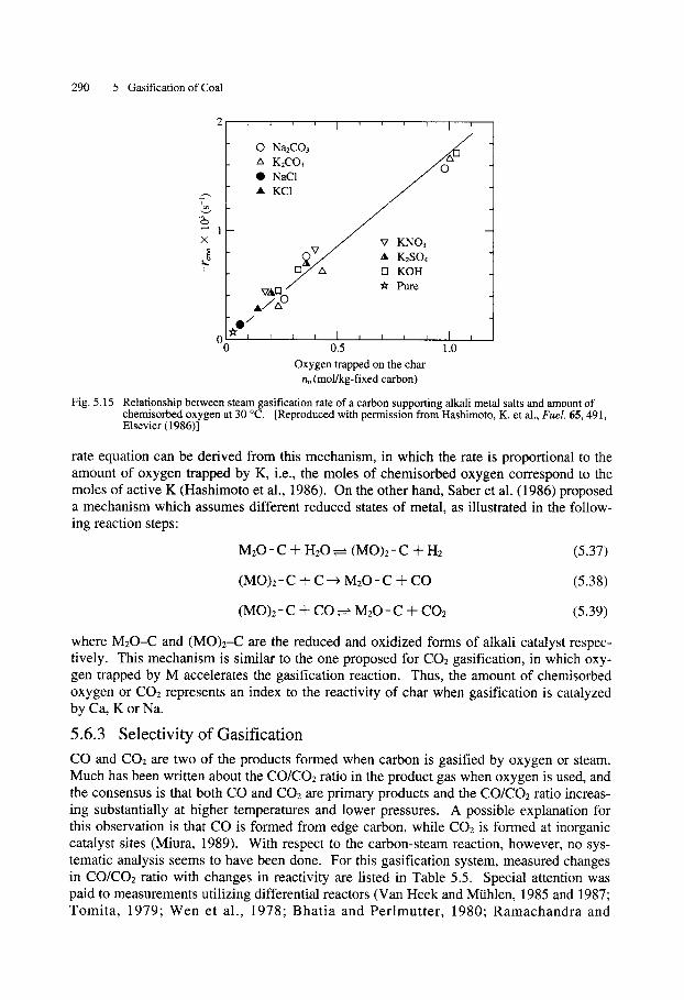
More recently, Yokoyama et al. (1980) gasified an activated carbon impregnated with K2CO3 in a batch recirculating flow reactor to measure the amount of oxygen trapped by the char during gasification. They found the gasification rate to be proportional to the amount of oxygen trapped and theorized that a redox cycle between K and K20 promotes the gasifi- cation. Ratcliffe and Vaughn (1985) proposed that the amount of CO2 chemisorbed at 300 ~ corresponds to the number of active potassium sites. According to these investigators, the number of sites determines the rate of gasification because the turnover frequency per active site remains constant during gasification. In other words, the gasification rate is di- rectly proportional to the amount of chemisorbed CO2. Hashimoto et al. (1986) investigat- ed the steam gasification of a carbon black impregnated with Na and K salts and found that the rate was proportional to the amount of oxygen trapped on the char. Their results are shown in Fig. 5.15. From FTIR analysis, they argue that oxygen appears to be trapped as K- O-C or Na-O-C on the surface. Several researchers claim the existence of a M-O-C struc- ture from either direct measurement (Mims and Pabst, 1983) or O/M value (Delannay et al., 1984; Sams and Shadman, 1986; Saber et al., 1986). Yuh and Wolf (1983 and 1984) also reported the existence of K-O-C and Na-O-C bonds from FTIR measurements.
In addition to studies of the role of oxygen, several contributions Freriks et al. (1981), Mims et al. (1982), and Cerfontain and Moulijn (1983) have been concerned with the iden- tification of the active species in the alkali metal catalyst. The mechanism of alkali metals- catalyzed gasification has been reviewed by McKee (1983), Kapteijn et al. (1984) and Moulijn et al. (1984). The mechanism presented by Wigmans et al. (1983) seems the most reasonable for steam gasification based on the observations noted above.
M + H20 ~ M(O)+ H2 (5.33)
M(O) + C ~ C(O) + M (5.34)
M(O) + C ( O ) ~ M + CO2 (5.35)
C(O) ~ CO (5.36)
where M is K or Na, M(O) is the M-O-C structure, and C(O) is chemisorbed oxygen. A
290 3 Gasification of Coal
. . . . I . . . . I '
0 NaECO3 / i
A K2CO3 / O ~ �9 NaC1
._, �9 KC1 / " - ~ ' ~ ' ~ ~
x / v KNO3 A Ir -
t3/ZX [] KOH _ /
v, tQ / ~ Pure A/zxO
/
~-i i i i I i i i i I i 00 0.5 1.0
Oxygen trapped on the char no (mol/kg-fixed carbon)
Fig. 5.15 Relationship between steam gasification rate of a carbon supporting alkali metal salts and amount of chemisorbed oxygen at 30 ~ [Reproduced with permission from Hashimoto, K. et al., Fuel. 65, 491, Elsevier (1986)]
rate equation can be derived from this mechanism, in which the rate is proportional to the amount of oxygen trapped by K, i.e., the moles of chemisorbed oxygen correspond to the moles of active K (Hashimoto et al., 1986). On the other hand, Saber et al. (1986) proposed a mechanism which assumes different reduced states of metal, as illustrated in the follow- ing reaction steps:
M 2 0 - C + H20 ~ (MO)2-C q- H2 (5.37)
(MO)2- C -+" C ~ M 2 0 - C -]- CO (5.38)
(MO)2- C "-F CO ~ M 2 0 - C -'F CO2 (5.39)
where M 2 0 - C and (MO)2-C are the reduced and oxidized forms of alkali catalyst respec- tively. This mechanism is similar to the one proposed for CO2 gasification, in which oxy- gen trapped by M accelerates the gasification reaction. Thus, the amount of chemisorbed oxygen or CO2 represents an index to the reactivity of char when gasification is catalyzed by Ca, K or Na.
5.6.3 Selectivity of Gasification CO and CO2 are two of the products formed when carbon is gasified by oxygen or steam. Much has been written about the CO/CO2 ratio in the product gas when oxygen is used, and the consensus is that both CO and CO2 are primary products and the CO/CO2 ratio increas- ing substantially at higher temperatures and lower pressures. A possible explanation for this observation is that CO is formed from edge carbon, while CO2 is formed at inorganic catalyst sites (Miura, 1989). With respect to the carbon-steam reaction, however, no sys- tematic analysis seems to have been done. For this gasification system, measured changes in CO/CO2 ratio with changes in reactivity are listed in Table 5.5. Special attention was paid to measurements utilizing differential reactors (Van Heek and Mtihlen, 1985 and 1987; Tomita , 1979; Wen et al., 1978; Bhatia and Perlmutter , 1980; Ramachandra and
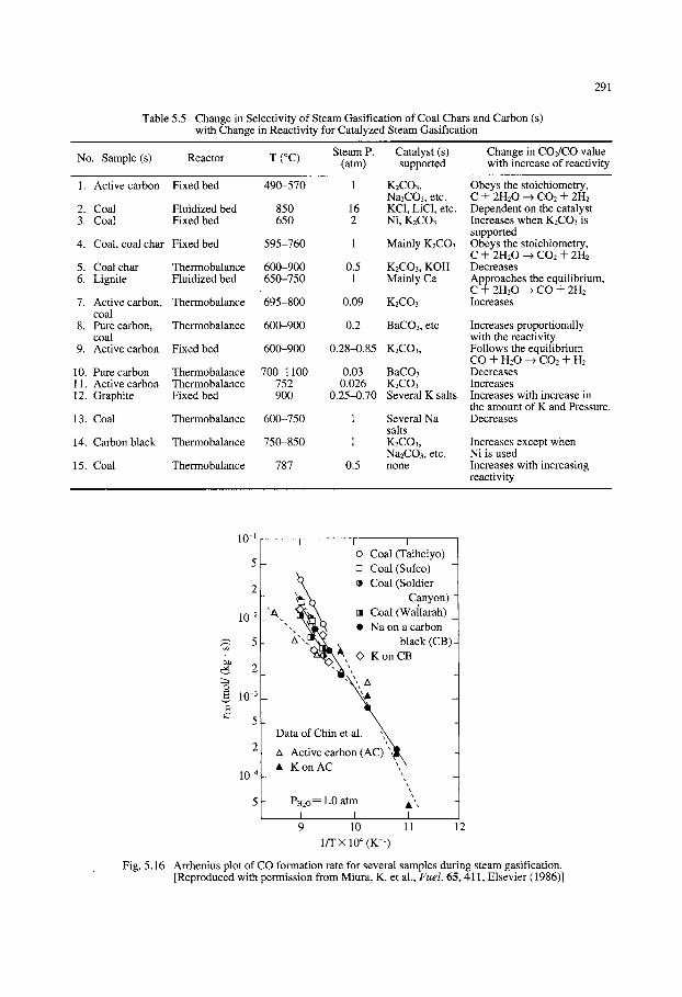
Table 5.5 Change in Selectivity of Steam Gasification of Coal Chars and Carbon (s) with Change in Reactivity for Catalyzed Steam Gasification
291
No. Sample (s) Steam P. Catalyst (s)
Reactor T (~ (atm) supported Change in CO2/CO value with increase of reactivity
1 .
2. 3.
4.
5. 6.
7.
8.
9.
10. 11. 12.
13.
14.
15.
Active carbon
Coal Coal
Coal, coal char
Coal char Lignite
Active carbon, coal Pure carbon, coal Active carbon
Pure carbon Active carbon Graphite
Coal
Carbon black
Coal
Fixed bed 490-570 1 K2CO3, NazCO3, etc.
Fluidized bed 850 16 KC1, LiC1, etc. Fixed bed 650 2 Ni, K2CO3
Fixed bed 595-760 1 Mainly K2CO3
Thermobalance 600-900 0.5 K2CO3, KOH Fluidized bed 650-750 1 Mainly Ca
Thermobalance 695-800 0.09 K2CO3
Thermobalance 600-900 0.2 BaCO3, etc
Fixed bed 600-900 0.28-0.85 K2CO3,
Thermobalance 700-1100 0.03 BaCO3 Thermobalance 752 0.026 K2CO3 Fixed bed 900 0.25-0.70 Several K salts
Thermobalance 600-750 1 Several Na salts
Thermobalance 750-850 1 K2CO3, Na2CO3, etc.
Thermobalance 787 0.5 none
Obeys the stoichiometry, C + 2H20 -4 CO2 .ql_ 2H2 Dependent on the catalyst Increases when K2CO3 is supported Obeys the stoichiometry, C + 2H20 -4 CO2 -F- 2H2 Decreases Approaches the equilibrium, C + 2H20 -4 CO + 2H2 Increases
Increases proportionally with the reactivity Follows the equilibrium CO + H20 -4 CO2 _ql_ H2 Decreases Increases Increases with increase in the amount of K and Pressure. Decreases
Increases except when Ni is used Increases with increasing reactivity
10-1
10 -2
~ 5
~ 2
o ,~ 10 -3
�9
5
1 0 . 4 _
5 -
I I I o Coal (Taiheiyo)
- [] Coal (Sufco) - �9 (Soldier Coal
'~ .~ Canyon)
"~ ~ k k [] Coal (Wa/larah) " ' , , , ~ �9 Na on a carbon -
z x ' - , ~ , black (CB)-
~ ,, ~ K on CB
- ,, ~ -
Data of Chin e
zx Active carbon (AC)" ,~ , - - , \
�9 K on AC ',
Pn2o = 1.0 atm I I 9 10
l/T)< 10 4 (K -1)
A", I
11 12
Fig. 5.16 Arrhenius plot of CO formation rate for several samples during steam gasification. [Reproduced with permission from Miura, K. et al., Fuel. 65, 411, Elsevier (1986)]
292 ~ Gasification of Coal
I I I O Coal (Taiheiyo)
2 [ - ~ x [] Coal (Sufco) -
x O x ~ Coal (Soldier 10 -~ N f 3 Canyon)
"[~, - ~ [] Coal (Wallarah)
5 - "'I~ ~ �9 Na on CB
2 ~ ~ N ( ~ , , d k <) K o n C B
~ , , � 9 " , ,
..~ 10 -2 _ ", �9
2
~s, 10 3 -- ",
A AC [ Chin ~ ' , , A �9 K on AC et al. I
5 - ,, - ~ Ptt2o = 1.0 atm
2 - ", - "a,
10 -4 I I I 9 10 11 12
1/TX 10 4 (K -~)
Fig. 5.17 Arrhenius plot of CO2 formation rate for several samples during steam gasification. [Reproduced with permission from Miura, K. et al., Fuel. 65, 41 l, Elsevier (1986)]
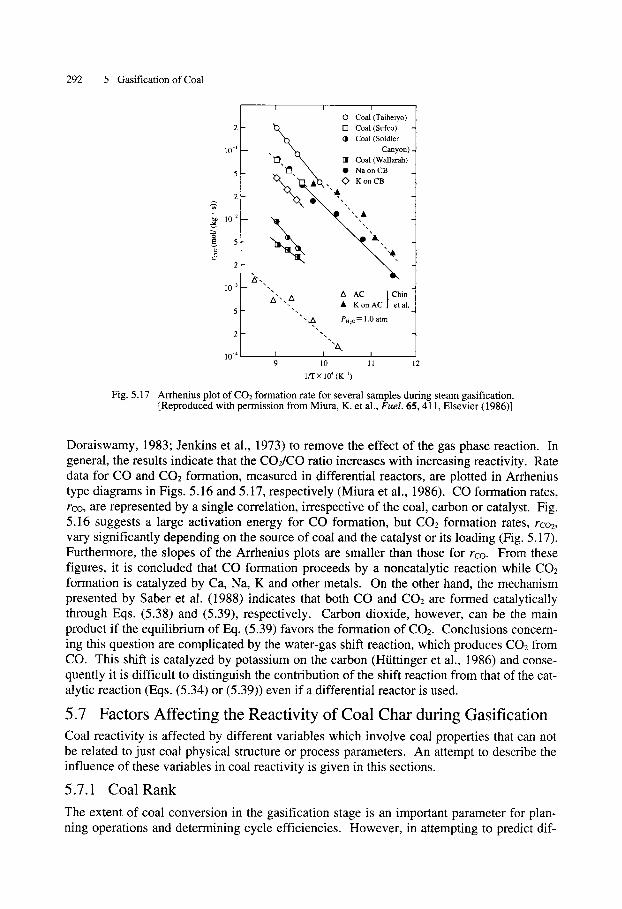
Doraiswamy, 1983; Jenkins et al., 1973) to remove the effect of the gas phase reaction. In general, the results indicate that the CO2/CO ratio increases with increasing reactivity. Rate data for CO and CO2 formation, measured in differential reactors, are plotted in Arrhenius type diagrams in Figs. 5.16 and 5.17, respectively (Miura et al., 1986). CO formation rates, rco, are represented by a single correlation, irrespective of the coal, carbon or catalyst. Fig. 5.16 suggests a large activation energy for CO formation, but CO2 formation rates, rco2, vary significantly depending on the source of coal and the catalyst or its loading (Fig. 5.17). Furthermore, the slopes of the Arrhenius plots are smaller than those for re�9 From these figures, it is concluded that CO formation proceeds by a noncatalytic reaction while CO2 formation is catalyzed by Ca, Na, K and other metals. On the other hand, the mechanism presented by Saber et al. (1988) indicates that both CO and CO2 are formed catalytically through Eqs. (5.38) and (5.39), respectively. Carbon dioxide, however, can be the main product if the equilibrium of Eq. (5.39) favors the formation of CO2. Conclusions concern- ing this question are complicated by the water-gas shift reaction, which produces CO2 from CO. This shift is catalyzed by potassium on the carbon (Htittinger et al., 1986) and conse- quently it is difficult to distinguish the contribution of the shift reaction from that of the cat- alytic reaction (Eqs. (5.34) or (5.39)) even if a differential reactor is used.
5.7 Factors Affecting the Reactivity of Coal Char during Gasification Coal reactivity is affected by different variables which involve coal properties that can not be related to just coal physical structure or process parameters. An attempt to describe the influence of these variables in coal reactivity is given in this sections.
5.7.1 Coal Rank
The extent of coal conversion in the gasification stage is an important parameter for plan- ning operations and determining cycle efficiencies. However, in attempting to predict dif-
5.7 Factors Affecting the Reactivity of Coal Char during Gasification 293
ferences in performance between coals, rank-dependent parameters have not always been found to be adequate.
Some authors have published work on the reactivities of various chars in gasification with air (Jenkins et al., 1973), CO2 (Hippo and Walker, 1975), H2 (Tomita et al., 1977) and H20 (Solano et al., 1979). They concluded that the reactivity of char generally increases with a decrease in the rank of parent coal in an oxidizing gas atmosphere. However, Takarada et al. (1983), in a study on the effect of a catalyst on different types of coals, found that noncatalytic gasification reactivity of lower rank coals is not always larger than that of higher-rank coals.
To provide some conclusive results on the effect of coal rank, it is necessary to collect the gasification reactivity of many coals with a wide range of carbon content. This was also done by Takarada et al. (1985a), who examined the reactivities of 34 coal chars of varying rank in steam gasification. They found that the reactivities of chars derived from caking coals and anthracites (carbon content > 78 wt%, daf) were very small compared with those from noncaking (lower rank) coals. The reactivities of low rank coal chars did not correlate with the carbon content of the parent coals.
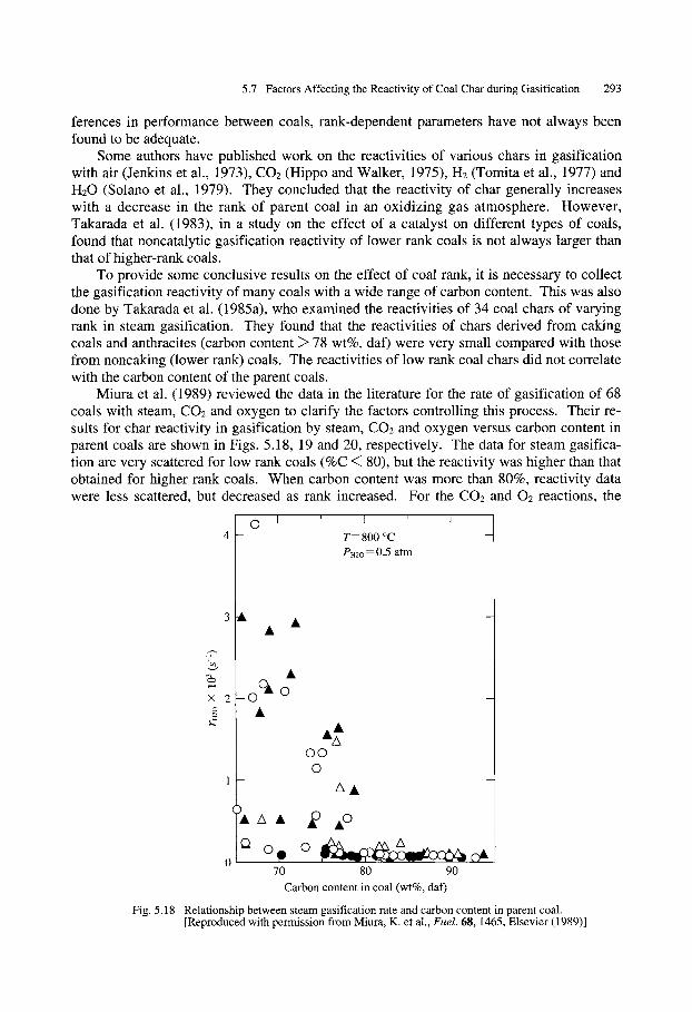
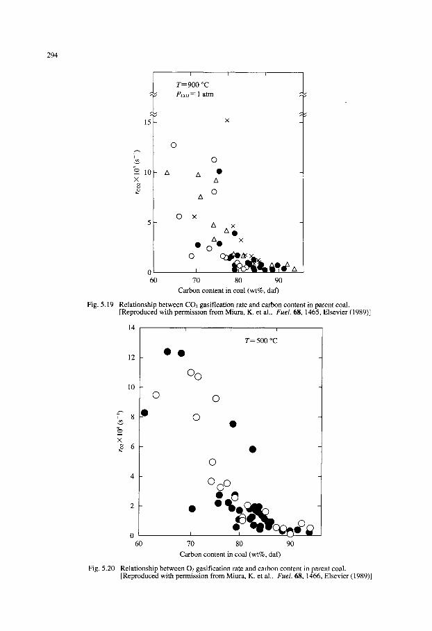
Miura et al. (1989) reviewed the data in the literature for the rate of gasification of 68 coals with steam, CO2 and oxygen to clarify the factors controlling this process. Their re- suits for char reactivity in gasification by steam, CO2 and oxygen versus carbon content in parent coals are shown in Figs. 5.18, 19 and 20, respectively. The data for steam gasifica- tion are very scattered for low rank coals (%C ~ 80), but the reactivity was higher than that obtained for higher rank coals. When carbon content was more than 80%, reactivity data were less scattered, but decreased as rank increased. For the CO2 and 02 reactions, the
L
O I 4 -
3 A A
_0 OA 0
A
I-
Cl �9 0 o 70
x 2
A
A
' I ' I
T = 800 ~ PH2O ~ 0 . 5 a t m
oo 0
AA
80 90 Carbon content in coal (wt%, daf)
Fig. 5.18 Relationship between steam gasification rate and carbon content in parent coal. [Reproduced with permission from Miura, K. et al., Fuel. 68, 1465, Elsevier (1989)]
294
1 5 -
~2 10 • 8
5
I
T=900 ~ Pco: = 1 atm
�9
- A A �9 A
O A
O
0 60 70 80 90
x A
A x 0
A 0 x �9 0
o
,
Carbon content in coal (wt%, daf)
Fig. 5.19 Relationship between CO2 gasification rate and carbon content in parent coal. [Reproduced with permission from Miura, K. et al., Fuel. 68, 1465, Elsevier (1989)]
T r ~
x
14
12
10
8_0
6 -
4 -
2 -
0 60
�9
O O
O O
�9
�9
O
I
T= 500 ~
O �9
O
I
70
m
80 90
Carbon content in coal (wt%, daf)
Fig. 5.20 Relationship between 02 gasification rate and carbon content in parent coal. [Reproduced with permission from Miura, K. et al., Fuel. 68, 1466, Elsevier (1989)]
5.7 Factors Affecting the Reactivity of Coal Char during Gasification 295
same behavior was found (Figs. 5.19 and 20). Such discrepancy found in the coal rank effect may indicate that there are other para-
meters which may more significantly control the gasification reactivity of coal. As re- vealed by Walker (1981), the reactivity of char is mainly controlled by the following three parameters: (1) the inherent mineral matter as a catalyst, (2) the number of active carbon sites and (3) the porosity. These parameters are discussed in detail below.
5 .7 .2 Inorgan ic Mine ra l M a t t e r
Coal contains various amounts of inorganic mineral matter (Si, A1, Fe, Na, K, Ti, Mg, etc.) in addition to the major organic constituents. Numerous investigators have examined rela- tionships between these inorganic components of coals and their reactivity. The general conclusion is that coal mineral matter, such as alkali and alkaline earth elements affects the reactivity of the chars of low rank coals.
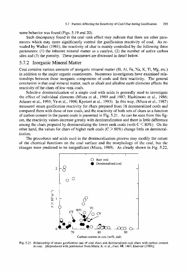
Selective demineralization of a single coal with acids is generally used to investigate the effect of individual elements (Miura et al., 1989 and 1987; Hashimoto et al., 1986; Adanez et al., 1993; Ye et al., 1998; Kyotani et al., 1993). In this way, (Miura et al., 1987) measured steam gasification reactivity for chars prepared from 18 demineralized coals and compared them with those of raw coals, and the reactivity of both sets of chars as a function of carbon content in the parent coals is presented in Fig. 5.21. As can be seen from this fig- ure, the reactivity values decrease greatly with demineralization and there is little difference among the chars prepared by demineralizing the lower rank coals (with C < 80%). On the other hand, the values for chars of higher rank coals (C > 80%) change little on demineral- ization.
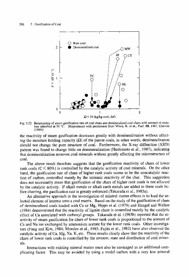
The procedures and acids used in the demineralization process may modify the nature of the chemical functions on the coal surface and the morphology of the coal, but the changes were predicted to be insignificant (Miura, 1989). As clearly shown in Fig. 5.22,
�9 �9
_.---,
x
2-8
I ' I ' I
O Raw coal Demineralized coal
�9 ( ) TC
CT WD 0 /
0 70 80 90
Carbon content in coal (wt%, daf)
Fig. 5.21 Relationship of steam gasification rate of coal chars and demineralized coal chars with carbon content in coal. [Reproduced with permission from Miura, K. et al., Fuel. 68, 1467, Elsevier (1989)]
296 5 Gasification of Coal
X k ,
' I '
0 2
O Raw coal Q Demineralized coal ,,..,0 MW
/ ' " JR O C T !
I
l / / I / ! I ! / I / /
f / / I I / ~
TC I / /(..) , - ~ I / i
! / / I / / I t ! I ' , C ) RL # I I T # / / I _ i I I I 0 , I I I : 1 I I
�9 o ii/ / :
1
,(-2 X 10 (kg/kg-coal, daf)
Fig. 5.22 Relationship of steam gasification rate of coal chars and demineralized coal chars with amount of mois- ture adsorbed at 30 ~ [Reproduced with permission from Miura, K. et al., Fuel. 68, 1467, Elsevier (1989)]
the reactivity of steam gasification decreases greatly with demineralization without affect- ing the moisture holding capacity (.(2) of the parent coals, in other words, demineralization should not change the pore structure of coal. Furthermore, the X-ray diffraction (XRD) pattern was found to change little on demineralization (Hashimoto et al., 1987), indicating that demineralization removes coal minerals without greatly affecting the microstructure of coal.
The above result therefore suggests that the gasification reactivity of chars of lower rank coals (C < 80%) is controlled by the catalytic activity of coal minerals. On the other hand, the gasification rate of chars of higher rank coals seems to be the noncatalytic reac- tion of carbon, controlled mainly by the intrinsic reactivity of the char. This suggestion does not necessarily mean that gasification of the chars of higher rank coals is not affected by the catalytic activity. If alkali metals or alkali earth metals are added to these coals be- fore charring, the gasification rate is greatly enhanced (Takarada et al., 1985a).
An alternative approach in the investigation of mineral matter effects is to load the se- lected element of interest onto a coal matrix. Based on the study of the gasification of chars of demineralized coals loaded with Ca or Mg, Hippo et al. (1979) and Hengel and Walker (1984) demonstrated that the reactivity of lignite chars is controlled mainly by the catalytic effect of Ca associated with carboxyl groups. Takarada et al. (1985b) reported that the re- activity of steam gasification for chars of lower rank coals is proportional to the amount of Ca and Na ion exchanged by ammonium acetate for the lower rank coals. Other investiga- tors (Fung and Kim, 1984; Morales et al., 1985; Fujita et al., 1982) have also observed the catalytic activity of Ca, Mg, Na. K, etc. These results clearly show that the reactivity of the chars of lower rank coals is controlled by the amount, state and distribution of coal miner- als.
Interactions with existing mineral matter must also be envisaged as an additional com- plicating factor. This may be avoided by using a model carbon with a very low mineral
5.7 Factors Affecting the Reactivity of Coal Char during Gasification 297
matter content, such as one produced from a polymer resin (Gonenc et al., 1990; Li et al., 1994). In this way, the effect of calcium has been found to increase up to a "saturation lev- el" of about 4% w/w, and to depend strongly on the degree of dispersion within the car- bonaceous matrix (Gonenc et al., 1990; Li et al., 1994).
5.7.3 T h e r m a l H i s to ry of C h a r
Several factors concerning pyrolysis may affect the reactivity, such as the volatile content, the temperature at which coal is pyrolyzed (Zhang et al., 1996), the extension of the pyroly- sis, the heating rate and the gas atmosphere at which the pyrolysis occurs (Miura et al., 1989).
Generally, gasification reactivity decreases with the severity of conditions employed for preparing char (Tp), i.e., higher Tp, longer holding time at Tp, and lower heating rate. These effects are generally larger for lower rank coals than for higher rank coals. Serio et al. (1987) reported that reactivities differ by a factor of 1000 among Zap lignite chars pre- pared using heating rates between 0.5 and 20 000 K s-1 and final temperatures between 400 and 900 ~ On the other hand, van Heek and Muhlen (1987) reported differences of only a factor of 2 for chars prepared from a bituminous coal between 700 and 900 ~ they found no difference for chars prepared from an anthracite between 700 and 800 ~ Kasaoka et al. (1987) reported differences of a factor of 1.5 to 10 for chars prepared be- tween 900 to 1300 ~ from ten coals ranging from 61.1 to 93.4 wt% C.
It is known that a graphite-like structure develops as the severity of the pyrolysis condi- tions increases, leading to a decrease in active carbon sites. Furthermore, metals that act as catalysts (Ca, Na, K, etc.) lose their activity by sintering, formation of intercalated com- pounds or stable aluminosilicates, or through vaporization (Kasaoka et al., 1987; Radovic et al., 1983 and 1984; Wigmans et al., 1983a, b). Therefore, the decrease in reactivity with in- creasing severity of pyrolysis is caused by decreases in the number of carbon active sites and in the catalytic activity.
Radovic et al. (1983 and 1984) tried to distinguish the two factors for a lignite. To ob- serve only the decrease in carbon active sites with pyrolysis conditions, they gasified chars prepared from a demineralized North Dakota lignite (Dem-char). Next, they prepared chars from a demineralized and Ca-loaded lignite (Dem+Ca-char). These chars were prepared as model samples to examine only the catalytic activity. In air at 0.1 MPa, the reactivity of the Dem+Ca-char was more than 30 times larger than the Dem-char when the chars were pre- pared by rapid pyrolysis (heating rate 104 K s-1) in an entrained-flow reactor at 1275 K. The effect of pyrolysis conditions on reactivity differed greatly between the chars. For ex- ample, between 975 and 1475 K, for a residence time of 1 h using slow pyrolysis (10 K min-1), the reactivity of Dem-char decreased by a factor of only about six, whereas that of Dem+Ca-char decreased by a factor of 100. Severe pyrolysis conditions enhance CaO sin- tering in the Dem+Ca-char, and therefore cause a decrease in its dispersion. From these studies, Radovic et al.(1983a, b, 1984a, b, c) state that the gasification reactivity of lignite chars depends on the concentration of inherent catalytic sites.
For chars prepared under much milder pyrolysis conditions, the number of carbon ac- tive sites may be more significant. Khan (1987) reported that char prepared from a high volatile bituminous coal at 500 ~ was much more reactive than high-temperature chars. The reactivity of the char was even higher than that of the parent coal. The significantly greater reactivity of such low-temperature chars is attributed to the greater hydrogen con- tent of the chars. Hydrogen-rich regions of coal char are preferentially oxidized, leaving behind highly reactive "nascent" carbon sites.
298 5 Gasification of Coal
Due to this strong influence of pyrolysis in gasification, it is used when determining coal reactivity to pyrolyze coal at the same temperature, as it will be gasified. Adanez and de Diego (1993) stated that although there is a theoretical mistake when kinetic constants are determined in compounds of different heat treatments, pyrolysis occurs at the same tem- perature of gasification in an industrial gasifier. Therefore, by making the pyrolysis tem- perature equal to the gasification temperature, laboratory work will become more represen- tative of industrial reactor work.
Chin et al. (1983) and Goyal et al. (1989) also considered that pyrolysis and gasifica- tion temperatures should be the same when coal reactivity is to be determined. Goyal et al. carried out a gasification of chars taken from a pilot U-GAS (fluidized bed) bituminous coal gasifier. The chars were first gasified at 980 ~ The authors found that the experi- mental kinetic constant (0.045 min-~) was lower than the theoretical value (0.0774 min-1). However, when the same chars were gasified at 1038 ~ experimental and theoretical con- stants matched very well. This means, as the authors suggest, that pyrolysis in the pilot U- gas gasifier occurs at 1038 ~
5 .7 .4 Po re S t ruc tu re
The first step in coal gasification is usually the rapid pyrolysis of coal to generate a highly porous char. Although the importance of pore structure has been pointed out by many in- vestigators, there has been little success in correlating reactivity with pore surface area or pore volume. Nevertheless, the relationship between char porosity and active sites concen- tration, as will be shown, suggests that pore structure is closely related to char reactivity.
Usually, the reaction rate of the char changes with conversion. This change would be related to changes in pore structure during reaction, but there is no unanimous approach. Adanez and de Diego (1993) did not find any variation in surface area as the reaction ad- vanced. On the other hand, Adshiri et al. (1986) considered that the gasification rate is pro- portional to the surface area during gasification.
There is no consensus either concerning the pore diameter where gasification reaction takes place. Dutta et al. (1977), Chi and Perlmutter (1989), Gavalas (1980) and Bhatia and Perlmutter (1980) found that the main contribution to the surface reaction area is made by the micropores. This overrides the effect of the macropores since the surface area originat- ed by the latter is insignificant. In other words, the surface area occupied by pores above 30 ~ is 10 m 2 g-1, while that occupied by pores below 20 A is more than 25 m 2 g-1 (Dutta et al., 1977).
On the other hand, Hurt et al. (1991) found that gasification occurs mainly outside the micropores, that is, on the macropore's surface. They maintain that this is not due to diffu- sion restrictions, since chars with a larger pore diameter do not have higher reactivity. They propose instead that there is a higher concentration of active sites in macropores than in micropores. Macropores might appear in crystallite edges or sites in contact with catalyt- ic active inorganic impurities, while micropores would be composed of basal planes, which are less reactive.
The above result is based on the fact that subbituminous coals, heat-treated up to 1200 ~ showed a decrease in reactive surface area from 510 down to 4 m 2 g-~ while the gasifi- cation rate was reduced only by a factor of about 4. During gasification, surface area in- creases from 4 up to 250 m g-1 while char reaction rate always decreases.
Clemens et al. (1995) showed that it is possible to achieve the same reaction rate of un- treated coal by adding a fraction (25%) of the calcium of untreated coal to acid-washed coals which go through steam gasification (900 ~ According to them, this could be ex-

5.7 Factors Affecting the Reactivity of Coal Char during Gasification 299
plained by the difference in reactivity between micropores and macropores. Although the relationship between reaction rate and surface area has been widely stud-
ied (Dutta et al., 1977; Yang and Watkinson, 1994; Chin et al., 1983; Alvarez et al., 1995; Kasaoka et al., 1987; Agarval and Sears, 1980; Kuo and Marsh, 1989; Hashimoto, 1986), there is no general agreement. Chin et al. (1983) and Adshiri et al. (1986) stated that reac- tion rate is proportional to surface area. However, most of the studies (Dutta et al., 1977; Yang and Watkinson, 1994; Alvarez et al., 1995; Kasaoka et al., 1987; Agarval and Sears, 1980; Kuo and Marsh, 1989; Hashimoto, 1986) found that surface area and reaction rate are not proportional. Proportionality is rather found between reaction rate and other parameters such as ASA (Active Surface Area). (Alvarez et al., 1995; Adschiri et al., 1986) or 12 (coal moisture holding capacity). (Alvarez et al., 1995; Kasaoka et al., 1987). ASA is related to the amount of oxygen chemisorbed by coal, and s with the total micropore volume (Miura, 1989). Parameters like ASA and s are apparently more related to the number of active sites on coal surfaces rather than to the total surface area. This is in accordance with new theories of gasification reaction.
5.7.5 Chemical Structure of Coal
The influence of the chemical structure of coal in gasification reactivity has not been as thoroughly studied as other coal properties. Most of the attempts to find a relationship be- tween reactivity and chemical structure have ended in numeric expressions relating fixed carbon, moisture holding capacity and reactivity (Yang and Watkins, 1994; Agarval and Sears, 1980).
From the molecular point of view, it is necessary to consider the role of active sites when the reactivity of carbonaceous materials is studied. In the case of carbon gasification with molecular oxygen, several authors (Walker et al., 1991; Skokova and Radovic, 1996; Moulijn and Kapteijn, 1995; Chen and Yang, 1993) have suggested the presence of oxygen on the basal plane of aromatic structures during gasification reactions. This oxygen is con- sidered to be an additional oxygen source in gasification reactions. Theoretical calculations based on molecular orbital theory suggest that when oxygen is placed in the basal plane, the C-C bond strength of the bridging atoms can be reduced by 30%. This means that the reac- tivity of carbonaceous material will also depend on the capability of trapping oxygen in the basal plane.
Chen and Yang (1993) showed that a potassium atom, forming a phenolate in the coal structure, will not reduce the bonding strength of C-C bridging atoms, but will reduce the net charge of the bridging C atom, and consequently the possibilities of trapping an oxygen atom in the basal plane will increase, thereby increasing reactivity.
The nature of oxygen-containing groups on carbon surface has been studied for many years; such surface groups can generally be categorized as acidic, neutral, basic, or inert (Voll and Boehm, 1971). Carboxy, phenolic and lactone groups have been proposed as acidic complexes; they are formed by oxidation at 400 ~ and decompose to give CO2 above 500 ~ Carbonyl and quinone groups are neutral or weakly acidic and decompose to CO around 750 ~ (Marchon, 1988). Basic surface groups include chromene or pyrone complexes and can persist on the surface at temperatures above 1000 ~ (Papirer, 1987). Aromatic ethers are generally inert and make up the majority of surface oxygen (1962).
Gasification in pure hydrogen also provides a unique environment for the accounting of oxygen present in the catalyst and carbon during gasification. For hydrogen gasification of wood char without adding a catalyst, Blackwood (1959) reported that the rate is linearly re- lated to the oxygen content of the char. For carbon film, Cao and Back (1982) reported that
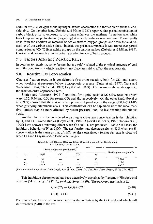
300 5 Gasification of Coal
addition of 0.1% oxygen to the hydrogen stream accelerated the formation of methane con- siderably. On the other hand, Zoheidi and Miller (1987) reported that partial combustion of carbon black prior to exposure to hydrogen enhances the methane formation rate, while high temperature pretreatment (degassing) drastically reduces reaction rate. These results arise from the addition or removal of active surface oxygen groups and from thermal an- nealing of the carbon active sites. Indeed, via pH measurements it was found that partial combustion at 400 ~ fixes acidic groups on the carbon surface (Zoheidi and Miller, 1987). Gasified and degassed carbons contain a predominance of basic groups.
5.8 Factors Affecting Reaction Rates In contrast to reactivity, some factors that are solely related to the physical structure of coal or to the conditions in which reactions take place are said to affect the reaction rate.
5.8.1 Reactive Gas Concentration
Char gasification reaction is considered a first-order reaction, both for CO2 and steam, when working at pressures below atmospheric pressure (Dutta et al., 1977; Yang and Watkinson, 1994; Chin et al., 1983; Goyal et al., 1989). For pressures above atmospheric, the reaction order approaches zero.
Shufen and Ruizhang (1994) found that for lignite coals at 1.6 MPa, reaction orders were 0.26, 0.34 and 0.50 for steam, CO2 and H2, respectively. On the other hand, Goyal et al. (1989) showed that there is no steam pressure dependence in the range of 0.7-2.8 MPa when gasifying bituminous coals. This contradiction can be explained since the more reac- tive lignites may be more affected by steam pressure than the less reactive bituminous coals.
Another factor to be considered regarding reactive gas concentration is the inhibition by H2 and CO. Some studies (Goyal et al., 1989; Agarval and Sears, 1980; Tanaka et al., 1995) have shown a retarding effect when CO and H2 are produced. Table 5.6 shows the inhibitory behavior of H2 and CO. The gasification rate decreases almost 42% when the H2 concentration is the same as that of H20. At the same time, a further decrease is observed when CO and CO2 are added to the reactive gas.
Table 5.6 Incidence of Reactive Gases Concentration in Char Gasification, P = 7.8 atm, T - - 1310.9 K
Reactive gas composition (%)
HE H20 CO CO2 N2 Gasification rate (min-1)
5 0 D _ _ 50 0.106 50 50 - - D - - 0.061 30 50.3 11.5 8.2 m 0.047
[Reproduced with permission from Goyal, A. et al., Am. Chem. Soc. Div. Fuel Chem. Prepr., 27 (1), 57 (1982)]
This inhibitive phenomenon has been extensively explained by Langmuir-Hinshelwood relations (Matsui et al., 1987; Agarval and Sears, 1980). The proposed mechanism is:
C + C O 2 ~ C ( O ) + C O (5.40)
C(O) -~ CO (5.41)
The main characteristic of this mechanism is the inhibition by the CO produced which will shift reaction (5.40) to the left.

5.8 Factors Affecting Reaction Rates 301
However, recently Moulijn and Kapteijn (1995) considered that the inhibitory mecha- nism does not fully explain the reduction of gasification rate by H2. Experimentally they found that gasification reaction stops almost completely when hydrogen concentration is more than 50%. This suggests that H2 is part of two different mechanisms during gasifica- tion, a reversible reaction which agrees with the Langmuir-Hinshelwood kinetics and an ir- reversible reaction which leads to the deactivation of the active sites. The proposed mecha- nism is:
Cf + H20 ~ C ( O ) + H2 (5.42)
Cf _qt_ H2 ~ Cf "" H2 [Inhibition] (5.43)
Cf "-F- H2 --'-) 2C-H [Deactivation] (5.44)
C(O) ~ CO .qL_ Cf (5.45)
5.8.2 P ressu re
Although the incidence of the partial pressure of the reactive gases in the char gasification rate has been exhaustively studied (Dutta et al., 1977; Yang and Watkinson, 1994; Chin et al., 1983; Adanez and DeDiego, 1993; Goyal et al., 1989; Chi and Perlmutter, 1989; Agarval and Sears, 1980; Tanaka et al., 1995), there is a dearth in the open literature con- cerning the influence of the total system pressure.
Schmal et al. (1983) found that total pressure affects gas composition during steam coal gasification at 850-1000 ~ in a fluidized bed. High pressures do not alter the system H2 concentration to any extent-from 61% at 0.1 MPa, to 58% at 1.0 MPa, but it increases methane concentration from 1.1% (0.1 MPa) to 2.0% (1.0 MPa). The CO/CO2 ratio also decreases for higher pressures.
In the same investigation, it was found that the gasification rate increases with total pressure and that its effect is more marked in the low pressure region. For example, the re- activity doubles its value when pressure is raised from 0.1 to 0.5 MPa. However, pressure values above 1.0 MPa do not produce a significant increase in gasification rate.
5.8.3 S a m p l e Size
When char reactivity is studied, laboratory experiments are generally done in such a way that diffusive restrictions can be avoided. The analysis is done by plotting char conversion against time for different particle sizes. Diffusion restrictions should be considered when burn-off curves begin to level off for larger particles. This means that particle size should be small enough so that no difference can be found in reactivity if a smaller particle is used for reactivity studies.
The particle size where diffusion restrictions can be neglected depends on coal type. Kovacik et al. (1991) found diffusion restrictions for subbituminous and bituminous coals at 900 ~ and particle size (about 74-105)/.tm. On the other hand, Matsui et al. (1987) did not find diffusion restrictions when working with subbituminous 710-/~m coal particles. Chin et al. (1983) worked with coal particles up to 1000/~m without finding any diffusion effect. Such differences have made every research team change the particle size in order to find the experimental conditions where diffusion restriction can be neglected.
Even though gasification processes of various types are in operation in industries world- wide, the research and development work now in progress to produce advanced environ-
302 5 Gasification of Coal
mentally acceptable gasification systems is considerable. There is a wide range of coal gasification research projects, ranging from bench scale to demonstration projects in progress. Even though the stabilization of oil prices in the 1980s contributed to reassess- ment for priorities for commercialization of processes, numerous demonstration studies have been completed and commercial plants have been installed for production of synthesis gas and substitute natural gas. Successful translation of demonstration and pilot-scale plants to commercial operation requires careful consideration of the design of gasifiers.
Many problems remain to be solved for optimum operation of gasification plants. One such problem involves quantifying or indexing the reactivity of coal. This is important be- cause reactivity is closely related to the efficiency of gasifiers.
It can be concluded that gasification of coal chars consists of noncatalytic and catalytic reactions. The gasification of chars of lower rank coals (C < 80%) proceeds mainly via the catalytic route, whereas that of chars of higher rank coals proceeds via a noncatalytic reac- tion sequence.
The rate of the noncatalytic reaction is related to the number of active sites associated with carbon atoms bonded to heteroatoms, nascent sites, dangling carbon atoms and edge carbon atoms. The number of active sites may be estimated from the amount of chemisorbed oxygen measured at 100 ~
Highly dispersed alkali and alkaline earth metals such as K, Na, Ca and Mg act as cata- lysts for gasification. The degree of dispersion, or the concentration of active metals, has been reported to correlate with the amount of chemisorbed oxygen or CO2, but more work needs to be performed.
The selectivity of steam gasification is thought to be intimately related to the relative importance of the catalytic and noncatalytic gasification sequences. However, this must be examined in relation to the water-gas shift reaction, which is catalyzed by alkali or alkaline earth metals.
The amount of chemisorbed oxygen is expected to be an index representing the reactiv- ity of coal chars, but to confirm its usefulness standardization of the measuring method and a more detailed study of the relationship of chemisorption to other char properties is re- quired.
The influence of coal rank, reactive gas concentration, system pressure and sample size in char reactivity and gasification rate has been widely studied and there is agreement among different authors. However, the incidence of factors such as thermal history of char, pore structure and coal chemical composition on char reactivity and gasification rate is not well defined and there remain some contradictions in the literature.
Related Documents