NATIONAL LASER USERS’ FACILITY AND EXTERNAL USERS’ PROGRAMS FY20 Annual Report 263 M. S. Wei Laboratory for Laser Energetics, University of Rochester In FY20, 22 Laser Basic Science (LBS) projects were allocated a total of 21.5 shot days for experiments at the Omega Laser Facility. A total of 186 target shots were conducted for sixteen LBS projects led by scientists from Lawrence Livermore National Laboratory (LLNL), Los Alamos National Laboratory (LANL), Lawrence Berkeley National Laboratory (LBNL), Princeton Plasma Physics Laboratory (PPPL), SLAC, and LLE (see Table I). The FY20 LBS experiments are summarized here. FY20 Laboratory Basic Science Program Table I: LBS experiments conducted at the Omega Laser Facility in FY20. Principal Investigator Institution Title F. Albert LLNL X-Ray Radiation Driven by Laser Wakefield Acceleration at OMEGA EP H. Chen LLNL Develop a Magnetic Mirror Trap for Laser-Produced Relativistic Electron–Positron Pairs H. Chen LLNL Laboratory Model of Particle Acceleration in Supernova Shocks F. Coppari * LLNL The Atomic Structure and Melting of New Solid and Superionic Water Ices at Multi-Megabar Pressures: Searching for Ice XIX T. Doeppner LLNL Experimental Measurement of Mutual Diffusivity in Warm Dense Matter K. Flippo LANL Quantifying the Path to Saturation in a Turbulent Magnetic Dynamo W. Fox PPPL Turbulent Transport in Magnetized HED Plasmas D. E. Fratanduono LLNL Investigating Giant Impacts Between Rocky Planets with High-Pressure Melting and Shock Equation-of-State Measurements on Complex Silicates L. Gao PPPL Effect of Laser Parameters on Magnetic Field Generation with Laser-Powered Capacitor Coils A. Gleason SLAC Viscosity Measurements Using Tracer Particles S. Jiang LLNL Characterizing Pressure Ionization in High-Density with X-Ray Line Emission Spectroscopy O. M. Mannion LLE Measuring the Gamow Energy Shift of Fusion Products in High-Temperature Plasmas M. Millot * LLNL Peering into the Ices Giant Planets Using Shocks On Pre-Compressed Water– Ammonia Mixtures: Superionic Ammonia Hydrates Z. L. Mohamed * LLE Study of Gamma-Ray Products from Reactions Relevant to Big Bang Nucleosynthesis P. M. Nilson LLE Terra Incognita: Testing the Predictions of Density Functional Theory (DFT) in Warm and Extremely Dense Plasmas A. Pak * LLNL Proton Radiography of Target Normal Sheath Acceleration Fields in the Long-Pulse Regime H. G. Rinderknecht * LLE Measuring the Triton Breakup Reaction T(n,2n)D R. Saha and J. R. Rygg * LLE Optical and X-Ray Scattering Measurements of Dense Lithium

Welcome message from author
This document is posted to help you gain knowledge. Please leave a comment to let me know what you think about it! Share it to your friends and learn new things together.
Transcript

NatioNal laser Users’ Facility aNd exterNal Users’ Programs
FY20 Annual Report 263
M. S. Wei
Laboratory for Laser Energetics, University of Rochester
In FY20, 22 Laser Basic Science (LBS) projects were allocated a total of 21.5 shot days for experiments at the Omega Laser Facility. A total of 186 target shots were conducted for sixteen LBS projects led by scientists from Lawrence Livermore National Laboratory (LLNL), Los Alamos National Laboratory (LANL), Lawrence Berkeley National Laboratory (LBNL), Princeton Plasma Physics Laboratory (PPPL), SLAC, and LLE (see Table I). The FY20 LBS experiments are summarized here.
FY20 Laboratory Basic Science Program
Table I: LBS experiments conducted at the Omega Laser Facility in FY20.
Principal Investigator Institution Title
F. Albert LLNL X-Ray Radiation Driven by Laser Wakefield Acceleration at OMEGA EP
H. Chen LLNL Develop a Magnetic Mirror Trap for Laser-Produced Relativistic Electron–Positron Pairs
H. Chen LLNL Laboratory Model of Particle Acceleration in Supernova Shocks
F. Coppari* LLNL The Atomic Structure and Melting of New Solid and Superionic Water Ices at Multi-Megabar Pressures: Searching for Ice XIX
T. Doeppner LLNL Experimental Measurement of Mutual Diffusivity in Warm Dense Matter
K. Flippo LANL Quantifying the Path to Saturation in a Turbulent Magnetic Dynamo
W. Fox PPPL Turbulent Transport in Magnetized HED Plasmas
D. E. Fratanduono LLNL Investigating Giant Impacts Between Rocky Planets with High-Pressure Melting and Shock Equation-of-State Measurements on Complex Silicates
L. Gao PPPL Effect of Laser Parameters on Magnetic Field Generation with Laser-Powered Capacitor Coils
A. Gleason SLAC Viscosity Measurements Using Tracer Particles
S. Jiang LLNL Characterizing Pressure Ionization in High-Density with X-Ray Line Emission Spectroscopy
O. M. Mannion LLE Measuring the Gamow Energy Shift of Fusion Products in High-Temperature Plasmas
M. Millot* LLNL Peering into the Ices Giant Planets Using Shocks On Pre-Compressed Water– Ammonia Mixtures: Superionic Ammonia Hydrates
Z. L. Mohamed* LLE Study of Gamma-Ray Products from Reactions Relevant to Big Bang Nucleosynthesis
P. M. Nilson LLE Terra Incognita: Testing the Predictions of Density Functional Theory (DFT) in Warm and Extremely Dense Plasmas
A. Pak* LLNL Proton Radiography of Target Normal Sheath Acceleration Fields in the Long-Pulse Regime
H. G. Rinderknecht* LLE Measuring the Triton Breakup Reaction T(n,2n)D
R. Saha and J. R. Rygg* LLE Optical and X-Ray Scattering Measurements of Dense Lithium

FY20 LaboratorY basic science Program
FY20 Annual Report264
During FY20, LLE issued a solicitation for LBS proposal for beam time in FY21. A total of 36 proposals were submitted requesting a total of 56 shot days, 260% exceeding the LBS allocation, showing strong interest and high demand of Omega facility time for basic high-energy-density (HED) science experiments from both National Nuclear Security Administration Inertial Confinement Fusion (NNSA ICF) and Office of Science laboratories. An independent LBS Proposal Review Committee consisting of 12 experts from university, national labs, and industry reviewed and ranked the proposals. Based on the Review Committee’s recommendation, 22 proposals were selected and allocated a total of 22.5 shot days (including one additional day from the contingency pool) for experiments at the Omega Laser Facility in FY21 as shown in Table II.
Table I: LBS experiments conducted at the Omega Laser Facility in FY20 (continued).
Principal Investigator Institution Title
R. Smith LLNL The Effect of Alloying on High-Pressure Phase Transformations: Diffusion Time Scales and Kinetics
C. Stoeckl LLE Development of New Experimental Platform LIANS on OMEGA EP for Deuteron- and Triton-Induced Nuclear Reactions
S. Zhao LBNL Extreme Deformation and Failure of High-Entropy Alloys by Laser Shock-Induced Compression and Tension
A. B. Zystra LLNL Implosions for Studying Solar CNO Reactions*Six FY20 LBS projects were postponed with shots rescheduled in FY21.
Table II: LBS experiments approved for target shots at the Omega Laser Facility in FY21.
Principal Investigator
Lead Institution
Title
F. Albert LLNL X-Ray Radiography with Sources Driven by Laser Wake-Field Acceleration
H. Chen LLNL Develop a Magnetic Mirror Trap for Laser-Produced Relativistic Electron–Positron Pairs
H. Chen LLNL Measuring Particle Transport in Turbulent Plasmas
F. Coppari LLNL Melting, Polymorphism, and Kinetics of Crystallization of Superionic Ice
T. Doeppner LANL Developing Fresnel Diffractive Radiography for Mutual Diffusion Measurements
C. J. Forrest LLE Inelastic Reactions of 14-MeV Neutrons from Lithium Isotopes
D. E. Fratanduono LLNL Investigating Giant Impacts on Rocky Planets with High-Pressure Melting and Shock Equation-of-State Measurements on Complex Silicates
L. Gao PPPL Investigation of Magnetic-Field Generation with Short-Pulse Laser-Powered Capacitor Coils
Y.-J. Kim LLNL Extreme Chemistry Inside Icy Planets: Shock Compression of Precompressed Ammonia–Water Mixtures
N. Lemos LLNL Proton Radiography of a Hybrid Laser Wakefield Accelerator Driven by a Picosecond, Kilojoule-Class Laser
L. Masse LLNL Evidencing the Transition from Landau–Darrieus Instability to Ablative Richtmyer– Meshkov Using Low-Density Foam Targets on OMEGA EP
P. M. Nilson LLE Atomic Physics at Petapascal Pressures
J. L. Peebles LLE Comparison and Validation of Dynamic Magnetic-Field Diagnostics on Laser-Driven Coils and MIFEDS
H. G. Rinderknecht LLE A Plasma Rectifier for Extreme Magnetic Fields, Efficient Electron Acceleration, and Bright X-Ray Sources
S. Singh LLNL Determination of High-Pressure Phase Transformation Mechanisms at the Atomic Scale

NatioNal laser Users’ Facility aNd exterNal Users’ Programs
FY20 Annual Report 265
Table II: LBS experiments approved for target shots at the Omega Laser Facility in FY21 (continued).
Principal Investigator
Lead Institution
Title
V. A. Smalyuk LLNL The Kelvin–Helmholtz Instability with a Magnetic Twist
C. Stoeckl LLE Development of New Experimental Platform LIANS on OMEGA EP for Deuteron and Triton-Induced Nuclear Reactions
G. Tabak LLE Extreme Physics of Hydrogen and Water in Planetary Interiors
W. Theobald LLE X-Ray Phase-Contrast Imaging of Imploding Strong Shock Waves
T. J. Weber LANL Understanding Collisional Interpenetration of Ion Species with Talbot–Lau Interferometry
S. Zhao LBNL Extreme Deformation of High-Entropy Alloys
A. B. Zylstra LLNL Big-Bang Nucleosynthesis Relevant to the Primordial 7Li Problem
Development of Self-Modulated Laser Wakefield Acceleration on OMEGA EPPrinciple Investigators: F. Albert, P. M. King,* N. Lemos, J. Williams, and H. Chen (LLNL); J. L. Shaw and D. H. Froula (LLE); and M. Sainclair and C. Joshi (University of California, Los Angeles)*Also University of Texas, Austin
X-ray backlighting is one of the most commonly used methods to look into the extreme temperatures, pressures, and densi-ties created during laser-driven high-energy-density science (HEDS) experiments. Over the years, much effort has gone into developing backlighting techniques to look into these states of matter, with new sources and diagnostics. The properties of an x-ray backlighter (flux, source size, spectrum, duration) required for an experiment depend on the application being studied and on the quantity being measured. The goal of the Wakefield-EP shot series is to develop a new type of x-ray source that could be advantageous for applications requiring broadband spectra, small source sizes (sub-50 nm), short duration (less than 10 ps), and x rays extending beyond 100 keV. Our proposed x-ray sources are based on laser wakefield acceleration (LWFA) of electrons in the self-modulated regime (SMLWFA). Specifically, we aim to develop three different x-ray sources based on betatron radiation, Compton scattering, and bremsstrahlung emission.
The WakefieldLBS-EP-20A shot day aimed at producing and detecting betatron radiation produced by SMLWFA using a modified version of the electron–positron proton spectrometer (EPPS) diagnostic. The modified EPPS used apertures enlarged to 5 mm (instead of 1 mm) and included a hole at the back of the magnet box, as well as a stack of nine image plates at the back of the ten-inch–manipulator (TIM) cart to detect betatron radiation. Initial analysis of these experiments shows that EPPS was successful at simultaneously recording electron, spectrum, profile, and x-ray data (Fig. 1).
The wakefield platform produced robust electron beam data, recording a >100-nC charge electron beam at each shot, as well as two-temperature spectra extending up to about 200 MeV (Fig. 1). Our data show that our signal-to-noise ratio needs to be improved for more-efficient x-ray detection. With the help of Monte Carlo simulations, we are working on additional diagnostic shielding enhancements for our next shot day in February 2021.
Developing a Magnetic Mirror Trap for Laser-Produced Relativistic Electron–Positron PairsPrinciple Investigators: H. Chen, J. von der Linden, M. Edwards, and A. Link (LLNL); G. Fiksel and L. Willingale (University of Michigan); and J. L. Peebles (LLE)
Creating a relativistic electron–positron pair plasma in a laboratory is of great interest to basic plasma science and to labora-tory astrophysics experiments that explore particle acceleration through collisionless shocks. The difficulties of such an endeavor are caused by the limited number of pairs that can be created and the limited strength of magnetic field that is necessary for the pair confinement.1,2 Using the award under the Laboratory Basic Science program, we designed and tested a mirror trap for laser-produced relativistic pairs.

FY20 LaboratorY basic science Program
FY20 Annual Report266
U2672JR
160 mrad
0
1010
1012
50 100Energy (MeV)
Parti
cles
/sr/M
eV
150 200
6 7 8 9
1 2
Betatron signal
3 4 5
Unfolded dataDetection limitFit1: A1 = 1.7 # 1013 (particles/sr/MeV), T1 = 19.1 (MeV)Fit2: A2 = 2.2 # 1012 (particles/sr/MeV), T2 = 50.1 (MeV)
(a)
(b)
Figure 1Results obtained during the Wakefield LBS-EP-20A shot day using the modified EPPS diagnostic. (a) An electron beam profile for each of our nine shots; (b) representative electron beam spectrum; (c) betatron x-ray signal measured on the rear image-plate stack of EPPS.
A schematic of the magnetic trap [shown in Fig. 2(a)] consists of the LLE’s magneto-inertial fusion electrical discharge sys-tem (MIFEDS) and a pair-generating target placed inside the magnetic mirrors. The target is irradiated by a high-intensity laser beam; the positrons and electrons are generated and, depending on their energy, will be either confined by the mirror magnetic field or allowed to escape. With the magnetic field at the mirror center at about 7 T, the simulations show that the trap can confine
15 mm 10 mm
e+
e–
–10 00
108
109
1010
1011
1012
1013
5 10 15 20 25 300
4
8
12
z coordinate (mm)Energy (MeV)
dNe/d
E (sr
–1 M
eV–1
)
(a) (b)
B (T
)
10
B = 0B = 13 T, shot averageB = 13 T, shot 32285
U2673JR
Figure 2(a) A magnetic mirror formed by MIFEDS can trap the low-energy (<3-MeV) pairs according to simulation. (b) Experimental data show that E < 3 MeV have indeed been well confined and only escape axially, the axial flux of 3 MeV < E < 15 < MeV is increased, and 15-MeV particles are focused by the magnetic field in this configuration.

NatioNal laser Users’ Facility aNd exterNal Users’ Programs
FY20 Annual Report 267
particles with a kinetic energy of less than 3 MeV, while particles with higher energies will partially or totally escape after one or more gyrations.
The experimental results appear to confirm these simulations, as shown in Fig. 2(b). The confinement studies were performed on electrons in this first experiment due to their higher numbers and easier detection. In principle, the positrons should behave the same as the electrons at the same energies, albeit having the opposite direction of rotation. Figure 2(b) shows clearly that with the magnetic field on, the axial flux of the low-energy electrons generated inside the trap is greatly increased, indicating that they are well confined in the radial direction and eventually only escape axially, as predicted.3
Investigating Giant Impacts Between Rocky Planets with Shock Equation-of-State Measurements on Natural SilicatesPrinciple Investigators: B. A. Chidester and S. T. Stewart (University of California, Davis); M. Millot and D. E. Fratanduono (LLNL); J. P. Townsend (SNL); and J. Li (University of Michigan)
The Earth and other rocky planets likely formed after a series of energetic collisions in the early solar system. Simulations of these impacts rely on accurate equations of state and phase diagrams of natural materials to determine the amount of melting, vaporization, and mixing that occurs in the aftermath of a giant impact. Combined with data collected at the Sandia Z Machine, this study is the first to measure the principal pressure–density–temperature (PtT) Hugoniot of the most-abundant minerals in Earth’s upper mantle—olivine [(Mg0.9,Fe0.1)2SiO4] and orthopyroxene [(Mg0.9,Fe0.1)SiO3]—to conditions relevant to giant impacts. Additionally, we collected the first shock-temperature measurements on wadsleyite, a high-pressure polymorph of olivine that exists in Earth’s transition zone.
We completed 15 shots on OMEGA EP in the one-day allocation, using alternating beams to increase the shot rate. Those data are combined with data collected in a previous shot allocation (FY19-SilicateEOS). As shown in Fig. 3(a), the olivine shock temperatures measured on OMEGA EP match those measured on the Sandia Z Machine and quantum molecular dynamics calculations. In Fig. 3(b), we show that natural olivine is very similar to synthetic forsterite, the magnesium endmember of this material (Mg2SiO4) (Ref. 4). PtT data on wadsleyite will provide a wealth of thermodynamic information for the olivine series, including the Grüneisen parameter that describes thermal pressure. The data collected on natural orthopyroxene will comple-ment our previous work on enstatite (MgSiO3) (Ref. 5). All of these data will be incorporated into analytical equations of state (ANEOS) for use in planetary impact simulations [dashed orange curve, Fig. 3(b)].6
Figure 3(a) T–Us data for natural olivine. Fit to OMEGA EP data in blue; data collected at the Sandia Z machine, on a gas gun (purple triangle);7 and quantum molecular dynamics simulations (#’s) included for comparison. (b) T–P curve on the olivine Hugoniot. Forsterite Hugoniot from Root et al. (2018);4 new forsterite ANEOS from Stewart (2019)6 included for comparison.
U2674JR
100
10
20
30
40
50
60
12 14 16 18Shock velocity, Us (km/s)
20 22 24 26 0 200 400 600 800Pressure, P (km/s)
Tem
pera
ture
, T (#
1000
K)
1000 1200 1400
(a) (b)
OMEGA EP dataFit, this studyThis study, Z machine
This study, QMDLuo et al.4
Forsterite, Root et al.1Forsterite ANEOS, Stewart3

FY20 LaboratorY basic science Program
FY20 Annual Report268
Fresnel Diffractive–Refractive Radiography for Measurements of Mutual Diffusivity in Warm Dense MatterPrincipal Investigators: T. Döppner, O. L. Landen, Y. Ping, L. Divol, and A. Saunders (LLNL); T. G. White, C. H. Allen, and M. Oliver (University of Nevada, Reno); and W. Theobald (LLE)
The experimental measurement of concentration-driven diffusion between two species in warm dense matter (WDM) is impor-tant for benchmarking instability growth simulations in ICF experiments.8 The scale length of this mutual diffusion is of the order of 1 nm, necessitating a diagnostic tool that can resolve density-gradient changes with sub-1-nm resolution. With two half-day campaigns on OMEGA-60 this year, we have developed a reliable x-ray radiography technique that is sensitive to Fresnel diffrac-tion signatures by using novel 1-nm-wide slits, which we have termed Fresnel diffractive–refractive radiography (FDR) [Fig. 4(a)].
Over two half-days, our experiments—MutualDiffusion-20A&B on OMEGA-60—progressed from imaging cold wire targets to sampling driven dynamic WDM systems, looking at the interface of isochorically heated Al and CH [(Figs. 4(b) and 4(c)]. Our preliminary analysis indicates that we captured changes in the CH as it expands, but further analysis is required to determine the change in the Al–CH interface. With an upcoming campaign on OMEGA-60 in February 2021, we plan to further refine the platform before converting it for use at the National Ignition Facility (NIF) for campaigns in FY22 and beyond.
U2675JR
(a) (b)4 nm W
10 nm Al in CH
10 nm Al
CH edge
(c)
00
1000
2000
Cou
nts (
arbi
trary
uni
ts)
3000
4000
100 200Distance in target plane (nm)300 400
1.0 nm
30.0
nm
1.0 nm
30.0
nm
1.0 nm
30.0
nm
0
0
1000
2000
3000
4000
100 200 300
W
CH
Al in CHAl
Ross pair strip 1Ross pair strip 2
Figure 4(a) Driven target configuration in a monolithic frame. The two detailed images are (left) a SEM image of a 1-nm-wide slit and (right) the driven target in the frame. (b) Radiographs and lineouts from a cold wire target, showing features from a variety of wires including strong refraction contrast at the CH surface. (c) Radiographs and lineouts of a driven target. The change of the CH signal across the strips is the rarefaction wave from expansion and can be used to cali-brate the x-ray drive by comparing to simulation.
Viscosity Measurements Using Tracer ParticlesPrincipal Investigators: A. E. Gleason (SLAC); D. N. Polsin, J. J. Ruby,* R. Rygg,*,† G. W. Collins,*,† P. M. Nilson, and R. Betti*,† (LLE); and J. K. Shang, H. A. Aluie, N. Acharya, and D. H. Kelley (Dept. of Mechanical Engineering, University of Rochester)*Also Dept. of Physics and Astronomy, University of Rochester†Also Dept. of Mechanical Engineering, University of Rochester
Viscosity has an important role in the evolution of hydrodynamic instabilities and the mixing between materials, especially at early times at scales smaller than of the order of 100 nm (Refs. 9 and 10). Our objective was to measure viscosity in a hydrocar-

NatioNal laser Users’ Facility aNd exterNal Users’ Programs
FY20 Annual Report 269
bon plastic (CH) at HED conditions, which is commonly employed in target fabrication for ICF and basic science experiments. In this experiment, we shock compressed the CH and imaged the deformation and movement of small, high-Z particles embed-ded in the target over time. The viscosity plays a role in how well a particle tracks the surrounding fluid and can be inferred by comparing trajectories of particles of different sizes and/or densities after a shock has passed. The experiment was a continuation of the pilot FY19 campaign and is part of a broader effort to develop an x-ray particle image velocimetry (XPIV) platform as a technique to measure more-complex flows.
Experimental ConfigurationThe target bulk was composed of particle-seeded epoxy (Stycast 1266, 1.12 g/cm3). Layers of epoxy were drilled with small
holes at the desired positions in which the high-Z particles were placed, backfilled, and assembled with adhesive. Each target contained three particle pairs, where each pair consisted of a large (60-nm) and small (40- or 50-nm) spherical particle aligned collinearly center-to-center, such that the impinging shock should pass through the center of both particles approximately simul-taneously. Particles were Ti or stainless steel (Cospheric). Particle pairs were 100 nm apart. A Kapton ablator and Au heat shield were placed on the drive side of the target. Targets were fabricated by Gryphon Technologies.
Drive beams (0.8 kJ, 7.4 ns) irradiated the Kapton ablator at the front of the target using 760-nm distributed phase plates, driving a shock through the target. Additional beams irradiated a copper backlighter with a 1-ns square pulse; a pinhole array (20 nm) and a gated x-ray framing camera were positioned on the P6–P7 axis opposite the backlighter [Fig. 5(a)]. Framing-camera strip-time delays were varied to obtain particle-shock interactions at different times. The 0.1-ns gate duration of the framing camera provided sufficient temporal resolution to locate the particle locations, with 20-km/s particle speeds (estimated from hydrodynamics simulations with FLASH) blurring location by only 2 nm. Shock speeds as a function of time were measured by VISAR (velocity interferometer system for any reflector).
ResultsParticles were clearly imaged with area backlighting at various times during target compression, as shown in Fig. 5(b). The
shock interface and deformation of the shocked particles were evident and agree well with a previous experiment at NOVA conducted by Klein et al.11 As part of this campaign, our team is concurrently developing a method to approximate the defor-mation resistance of the solid particles at early times with a modified ideal-gas equation of state in radiation-hydrodynamics code (FLASH). In Fig. 5(b), we show that particle shapes simulated by this equation-of-state (EOS) method agree well with the
Figure 5(a) Target configuration. (b) Stainless-steel particles at two times during CH target compression, obtained with an x-ray framing camera on OMEGA (Sept. 2020). The particle deformation (dark bodies, top) agrees well with FLASH simulations (particle outlines shown in white, bottom).
U2716JR
P6
TIM-1H2
(a) (b)
Drivebeams
ToXRFC
To VISAROATEL
18.3 ns
Rad
iogr
aph
Sim
ulat
ion
23.5 ns100 nm
P7
Shock front

FY20 LaboratorY basic science Program
FY20 Annual Report270
experimental images. Excellent VISAR data were obtained, and the timing of the radiography data will be correlated with the measured shock velocity. We estimate that a 480-GPa shock front in epoxy was achieved.
Image analysis to determine particle displacement is in progress.
Dissemination, Training, and Professional DevelopmentResults related to this effort were presented at the 2020 Stewardship Science Academic Programs (SSAP) Symposium
(February 2020) and Division of Plasma Physics Meeting (November 2020) by senior personnel and graduate students.
This work was performed under the auspices of the U.S. Department of Energy and NNSA under Grant DE-SC0019329 within the joint HEDLP program and the Stewardship Science Academic Alliances under Grant DE-NA003914.
LBS Campaign FY20—Magnetic-Field Generation with Laser-Powered Capacitor CoilsPrincipal Investigators: H. Ji, L. Gao, A. Chien, and S. Zhang (PPPL); E. G. Blackman (Dept. of Physics and Astronomy, Uni-versity of Rochester); P. M. Nilson (LLE); G. Fiksel (University of Michigan); and H. Chen (LLNL)
The LBS Campaign in FY20 focused on two main goals: (1) to optimize laser-powered capacitor coils12 as an external magnetic-field source generator and (2) to build a comprehensive lumped-circuit model for the capacitor coil platform, including important physics processes such as the laser–solid interaction, plasma effects, and electron distribution.
These goals were achieved in two major laser-drive regimes: UV long-pulse drive and IR short-pulse drive. In the UV case, the capacitor-coil target is driven by OMEGA EP Beamlines 3 and 4, while in the IR case, Beamline 1 in sidelighter mode is used to energize the target. In both cases, the capacitor-coil design consists of two parallel copper plates connected by a thin copper wire folded into a U-shaped coil. Experimental setups for UV and IR drives are shown in Figs. 6(a) and 6(b), respectively. Hot electrons are generated as the laser beam hits the back plate, building up a voltage difference between the plates and driving a large current through the connecting coil. This results in strong magnetic-field generation around the coil. The magnetic-field strength and coil current are inferred using TNSA (target normal sheath acceleration) proton radiography: measurement of the prolate void feature generated by the magnetic-field structure can be compared with synthetic radiographs from ray tracing.
Figure 6(a) OMEGA EP experimental setup for long-pulse drive of the capacitor coil. Beamlines 3 and 4 drive the main target, and the coil magnetic fields are diagnosed with TNSA protons driven by the backlighter. (b) OMEGA EP experimental setup for short-pulse drive of the capacitor coil. The sidelighter beam drives the main target at a 45° incidence angle, and the coil magnetic fields are diagnosed with TNSA proton radiography.
U2717JR
Target stalkTarget stalkTarget stalkTarget stalk
Main targetMain targetRCF pack
OU-ESMOU-ESM
RCF pack
TNSA targetTNSA target
LP beam 4
LP beam 3
(b)(a)
BacklighterBacklighter
Sidelighter
NatioNal laser Users’ Facility aNd exterNal Users’ Programs
FY20 Annual Report 271
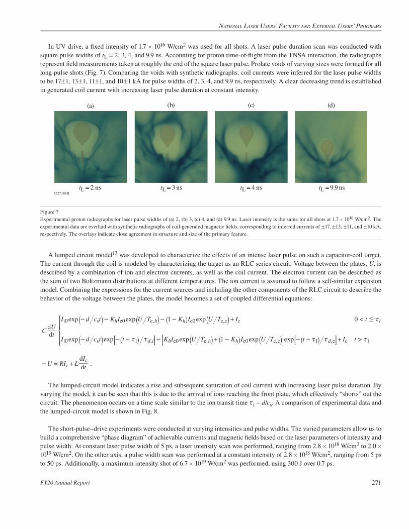
In UV drive, a fixed intensity of 1.7 # 1016 W/cm2 was used for all shots. A laser pulse duration scan was conducted with square pulse widths of tL = 2, 3, 4, and 9.9 ns. Accounting for proton time-of-flight from the TNSA interaction, the radiographs represent field measurements taken at roughly the end of the square laser pulse. Prolate voids of varying sizes were formed for all long-pulse shots (Fig. 7). Comparing the voids with synthetic radiographs, coil currents were inferred for the laser pulse widths to be 17!1, 13!1, 11!1, and 10!1 kA for pulse widths of 2, 3, 4, and 9.9 ns, respectively. A clear decreasing trend is established in generated coil current with increasing laser pulse duration at constant intensity.
U2718JRtL = 2 ns tL = 3 ns tL = 4 ns tL = 9.9 ns
(a) (b) (c) (d)
Figure 7Experimental proton radiographs for laser pulse widths of (a) 2, (b) 3, (c) 4, and (d) 9.9 ns. Laser intensity is the same for all shots at 1.7 # 1016 W/cm2. The experimental data are overlaid with synthetic radiographs of coil-generated magnetic fields, corresponding to inferred currents of !17, !13, !11, and !10 kA, respectively. The overlays indicate close agreement in structure and size of the primary feature.
A lumped circuit model13 was developed to characterize the effects of an intense laser pulse on such a capacitor-coil target. The current through the coil is modeled by characterizing the target as an RLC series circuit. Voltage between the plates, U, is described by a combination of ion and electron currents, as well as the coil current. The electron current can be described as the sum of two Boltzmann distributions at different temperatures. The ion current is assumed to follow a self-similar expansion model. Combining the expressions for the current sources and including the other components of the RLC circuit to describe the behavior of the voltage between the plates, the model becomes a set of coupled differential equations:
.
exp exp exp
exp exp exp exp exptU
I d c t K I U T K I U T I t
I d c t t K I U T K I U T t I t
U RI LtI
1 0
1dd
dd
<
>
, ,
, , ,
h h h l
d i h h h d
0 0 0
0 1 0 0 1 1
i s e e e e c c
i s e e e e,c e c
cc
- - - -
- - - - - - -
-
# x
x x x x x
+
+ +
= +
C
`
` _
` _
`
`
_ ` _
j
j i
j i
j
j
i j i8 9 8B C B
Z
[
\
]]]]]]]]]]]]
The lumped-circuit model indicates a rise and subsequent saturation of coil current with increasing laser pulse duration. By varying the model, it can be seen that this is due to the arrival of ions reaching the front plate, which effectively “shorts” out the circuit. The phenomenon occurs on a time scale similar to the ion transit time xi + d/cs. A comparison of experimental data and the lumped-circuit model is shown in Fig. 8.
The short-pulse–drive experiments were conducted at varying intensities and pulse widths. The varied parameters allow us to build a comprehensive “phase diagram” of achievable currents and magnetic fields based on the laser parameters of intensity and pulse width. At constant laser pulse width of 5 ps, a laser intensity scan was performed, ranging from 2.8 # 1018 W/cm2 to 2.0 # 1019 W/cm2. On the other axis, a pulse width scan was performed at a constant intensity of 2.8 # 1018 W/cm2, ranging from 5 ps to 50 ps. Additionally, a maximum intensity shot of 6.7 # 1019 W/cm2 was performed, using 300 J over 0.7 ps.

FY20 LaboratorY basic science Program
FY20 Annual Report272
Figure 8Lumped-circuit model simulations of coil current as a function of laser pulse duration, compared with experimental measurements. In the model, resistance is assumed constant for each run, but varied as a free parameter to account for temperature effects. R = 0.5 X provides the best match to experimental measurements but diverges at late time. R = 0.23 X matches the data point at t = 9.9 ns. In all cases, coil current is observed to eventually decay with increasing laser pulse width due to ion shorting.
U2719JR
00
5
10
15
20
25
30
35
2 4Time (ns)
Coi
l cur
rent
(kA
)
6 8 10
ExperimentR = 0.1 XR = 0.23 X
R = 0.5 XR = 1.0 X
Data analysis is ongoing, but preliminary results demonstrate great promise for short-pulse–driven capacitor coils as a platform for external magnetic field generation. TNSA proton radiographs for an intensity scan at constant laser energy are shown in Fig. 9. The radiographs demonstrate coil currents of 90!10, 85!10, and 75!10 kA for laser pulse widths of 100 ps, 50 ps, and 15 ps, respectively. For all shots, laser energy on target was 1 kJ. Despite the lower energy on target than the long-pulse drivers, higher coil currents were achieved. This represents a conversion efficiency of up to 11# larger than achievable with the long-pulse drive on OMEGA EP. With further data analysis, we hope to gain insight into hot-electron physics, as well as the mechanisms behind current generation to produce a self-consistent lumped-circuit model for short-pulse–driven capacitor coils.
U2720JRxL = 100 ps xL = 50 ps xL = 15 ps
(a) (b) (c)
Figure 9(a) 100-ps, (b) 50-ps, and (c) 15-ps pulse widths. Proton radiographs of the magnetic field generated by a short-pulse–driven interaction for various pulse widths. For all shots, laser energy on target was 1 kJ at best focus. The radiographs represent coil currents of 90!10, 85!10, and 75!10 kA, respectively.
This material is based upon work supported by the Department of Energy National Nuclear Security Administration under LBS Award Number L2034.
Characterizing Pressure Ionization in High-Density Mid-Z Materials with X-Ray Fluorescence SpectroscopyPrincipal Investigators: S. Jiang, Y. Ping, A. Lazicki Jenei, P. Sterne, P. Grabowski, H. Scott, R. Smith, R. Shepherd, B. Bachmann, and J. H. Eggert (LLNL); and S. B. Hansen (SNL)
This campaign comprised one day on OMEGA EP during FY20. In our previous campaigns, we had for the first time provided a direct benchmark between various isolated-atom and average-atom ionization models by measuring K-shell emission of Co. During the FY20 campaign, we have extended the method to L-shell emissions of mid-Z materials Tb and Dy.

NatioNal laser Users’ Facility aNd exterNal Users’ Programs
FY20 Annual Report 273
U2721JR
(a)
0.15
0.10
0.05
0.006960 7160
Lb3
Lb1
Lb2
PSLS
7360E (eV)
(b)
Short-pulselaser
Fluorescencelayer
IXTS 100 nm Al2
mm
Long-pulselaser driver
20 nmdiamond
3 nm Co 25 nm Tb or Dy
80 nmdiamond
Diamond
Secondary Altarget
e–
UndrivenDriven, 3300 JDriven, 6950 J
0.6
0.4
0.2
0.07150 7230
Lb3
Lb1
Lb4
PSLS
7350E (eV)
Tb Dy
UndrivenDriven, 6950 J
Figure 10(a) A schematic diagram of the experimental configuration. (b) Measured IXTS spectra of Tb and Dy L-line emissions. The spectra under different conditions are aligned with the Co Ka emission line.
A schematic of the experimental setup is displayed in Fig. 10(a). The fluorescence line emissions were induced by hot elec-trons generated through short-pulse, laser–solid interactions. A large, thick Al target was used to avoid heating from the short pulse. The high pressure was achieved by ramp compression using the long-pulse drivers, so that the temperature was kept low during the compression process. During the experiment, the pressure history was characterized with VISAR measurements. We have varied the driver energies to reach different densities. The target structure is also shown in Fig. 10(a). Despite the Tb or Dy layer under study, we have also included a thin Co layer as an energy reference. The main diagnostic used in this cam-paign was a high-resolution imaging x-ray Thomson spectrometer (IXTS) with a user-provided Ge crystal to accommodate the required energy range.
We have successfully measured the Co Ka fluorescence line and multiple Tb/Dy Lb lines with high signal-to-noise ratio as can be seen in Fig. 10(b). According to our previous Co study, the Co Ka line has negligible energy shift under the designed experi-mental conditions since the inner K, L shells are not greatly affected by pressure ionization; therefore, the measured spectra under various conditions can be aligned with the Co Ka peak. The M, N shells that are responsible for the multiple Lb emissions of Tb and Dy are much more prone to both the ionization pressure depression effect and the density-dependent plasma polarization effect. Under maximum compression, we have observed a +1-eV blue shift in Tb Lb1, a –3-eV red shift in Tb Lb2, and no shift in Tb Lb3. For Dy, a small +1-eV blue shift was observed in both its Lb1 and Lb3. While further analysis is still in progress, we have seen evidence of various competing effects in the measured line shifts, which can be used to directly benchmark various ionization models for mid-Z materials.

FY20 LaboratorY basic science Program
FY20 Annual Report274
Measurements of Shock Equation of State and Melting Temperature on Water–Ammonia MixturesPrincipal Investigators: Y.-J. Kim, S. Hamel, and M. Millot (LLNL); M. Bethkenhagen (Rostock University, Germany); M. Wadas (University of Michigan); and S. Stanley (Johns Hopkins University)
This SuperionicMix-20 Campaign aims at investigating the optical and thermodynamic properties of water–ammonia mixtures at the extreme pressure–temperature conditions that we expect in the deep interior of icy giant planets such as Uranus and Neptune. This work at the Omega Laser Facility expands on our recent discovery of superionic water ice (or ice XVIII)14,15 to reveal the possible existence of the superionic phase in the icy planet constituents (H:C:N:O) as well as its melting temperature.
We used a diamond-anvil cell (DAC) to increase the initial sample density at room temperature, achieve lower temperatures but higher compression under dynamic loading, and finally reach planetary interior conditions. With excellent laser performance and support, we collected 14 system shots in the two half-day allocations. Doppler velocimetry (VISAR) [Figs. 11(a) and 11(b)] and streaked optical pyrometry (SOP) [Fig. 11(c)] were used to track the shock-wave propagation through the precompressed sample and to document the pressure–density–temperature shock equation of state as well as the evolution of the optical proper-ties (reflectivity and absorption coefficient) along the shock Hugoniot curves using quartz.16
The ongoing data analysis will be used to improve our understanding of how the icy planet constituent of H:C:N:O mixtures behave at the extreme pressure–temperature condition inside the planets.
Figure 11Examples of [(a),(b)] VISAR and (c) SOP data showing the decaying shock along the 150-nm-thick water–ammonia mixture on OMEGA 60.
Experimental Study of the Dynamics of Expanding Magnetized Laser-Produced Plasma Principal Investigators: S. Malko,* W. Fox,† and A. Bhattacharjee† (PPPL); D. B. Schaeffer and A. Spitkovsky (Princeton Uni-versity); C. Johnson (Rowan University); G. Fiksel (University of Michigan); P. Knapp (SNL); A. Ciardi (Observatoire de Paris, Sorbonne Université and CNRS, France); and J. R. Davies (LLE)*Also Centro de Laseres Pulsados, Spain†Also Princeton University
The interaction of an expanding plasma with a magnetic field plays a key role in magnetized fusion schemes such as mag-netized liner inertial fusion (MagLIF),17 laboratory astrophysics experiments such as magnetic reconnection18 and magnetized collisionless shocks,19 and space-plasma experiments such as Active Magnetospheric Particle Tracer Explorers.20
U2722JR
10350
400
450
500
550
600
400
450
500
550
650
600
300
350
400
450
550
600
500
15 20Time (ns)
(c) SOP(b) VISAR (Channel 2)(a) VISAR (Channel 1)
25 3010 15 20Time (ns)
25 3010 15 20Time (ns)
25 30
Dia
mon
dQ
uartz
Sam
ple
Dia
mon
d
Posit
ion
(nm
)

NatioNal laser Users’ Facility aNd exterNal Users’ Programs
FY20 Annual Report 275
These topics motivate an understanding of magnetic-field transport properties in laser-produced HED; another aspect of interest is anomalous fast diffusion of plasma caused by strong plasma gradients, causing particles and field to mix and diffuse with respect to one another. These processes can determine the time and space scales over which plasma heat can be effectively confined by the magnetic field. Under certain conditions, the magnetic-field diffusion is enhanced by plasma instabilities, of either the lower-hybrid type, which have a short wavelength and result from the coupling of gradient-driven modes to the lower-hybrid range modes ~ + ~LH = (~ce~ci)
1/2, or the large-Larmor-radius Raleigh–Taylor (RT) instabilities, in which the magnetic field acts like a “light fluid” to decelerate an expanding “heavy” plasma (by its pressure force). Such instabilities may also be present in the MagLIF scheme, and by scaling using dimensionless parameters,21 we can study a set of common physics at smaller-scale facilities. Here we report on an experiment on OMEGA that focused on the study of the magnetic-field dynamics in HED plasma in a relevant regime (b > 1), covering the magnetic-field evolution time along with its diffusion and potential anomalous transport processes.
The schematic experimental setup on OMEGA is shown in Fig. 12. The magnetized laser-produced plasma is generated by ablating a CH plasma into a quasi-static magnetic field produced by the MIFEDS pulsed-power system. The evolution of the 2-D global topology of the magnetic fields was imaged with proton radiography by 3-MeV and 15-MeV protons, acquired at different plasma expansion times. A novel technique of the proton radiography was developed to obtain an absolute reference of undeflected beamlets for each shot. The corresponding local plasma parameters—electron temperature and density—were measured with 2~ Thomson scattering.
U2723JR
D3He backlighterp+ (3 MeV, 15 MeV)
CR-39(p+ 3 MeV)
Protonradiography
Plasmaplume
CH target
CR-39(p+ 15 MeV) IP (x rays)
Magneticfield ~ 4 T
z
y
Figure 12Schematic of the experimental setup showing the raw images obtained with a novel proton radiography technique. The CR-39 stack was composed of CR-39 for 3-MeV and 15-MeV protons and an image plate (IP) in the back of the stack for an x-ray image of the nickel mesh.
The magnetic-field dynamics in plasma has been explored for different laser energies and target orientations relative to field. Here we show the preliminary experimental results for one of the experimental configurations as shown in Fig. 12. In the experi-ment we observe the expanding plasma expelling the magnetic field out of its volume and forming a diamagnetic cavity. A clear magnetic-field temporal evolution in plasma can be seen in Fig. 13(a), which shows the path-integrated magnetic field #Bdl at different plasma expansion times, compared to the vacuum magnetic-field profile with no plasma, as calculated by a COMSOL model of the MIFEDS coil windings. The magnetic field is observed to be mostly expelled by the plasma between 20 ns (red curve) and 30 ns (green curve) and then gradually returns. The experimental radii of the diamagnetic cavity are estimated by fitting data with the synthetic magnetic field with artificial cavities of various sizes. These are compared with the radii obtained from GORGON 3-D magnetohydrodynamic (MHD) simulations in Fig. 13(b). GORGON 3-D MHD simulations were employed to qualitatively observe the effect in similar conditions. The preliminary analysis shows a rapid diamagnetic expansion followed by collapse, in qualitative agreement with GORGON 3-D MHD simulations.

FY20 LaboratorY basic science Program
FY20 Annual Report276
In summary, we have developed a novel technique of proton radiography with a reference x-ray image of the mesh for precise measurement of the magnetic field. Using this method, we have performed a characterization of the diamagnetic cavity formation and time evolution in b > 1 expanding plasma. The results, which were compared to the simulated magnetic-field dynamics in similar conditions with GORGON 3-D MHD, suggested a faster diffusion than predicted classically of 1 ns.
Measurements of the DT and DD Neutron Energy Spectrum in High-Temperature PlasmasPrincipal Investigators: O. M. Mannion, C. J. Forrest, V. Yu. Glebov, J. P. Knauer, P. W. McKenty, Z. L. Mohamed, S. P. Regan, and C. Stoeckl (LLE); P. Adrian, J. A. Frenje, M. Gatu Johnson, and N. Kabadi (Plasma Science and Fusion Center, MIT); B. D. Appelbe and A. J. Crilly (Imperial College London, UK); and W. Taitano (LANL)
The goal of ICF experiments is to generate a hot dense thermonuclear plasma that releases more energy from thermonuclear fusion than was required to initially assemble the plasma. A key parameter required to understand the performance of these experiments is the temperature of the hot fusing plasma. Traditionally, the temperature of the hot fusing plasma is determined from measuring the variance (second moment) of the DT and DD neutron energy spectra emitted from the target. The second moment of the neutron energy spectrum is altered if nonthermal motion of the fusing plasma exists within the hot spot and can result in the inferred temperature being higher than the true thermal temperature. Therefore, alternative techniques to infer the hot-spot temperature, such as electron–ion temperature measurements, are being pursued in the ICF community.
Motivated by this pursuit, we have executed a set of experiments that investigated a new method to infer the thermal ion tem-perature. In this method the Gamow velocity shift (first moment) of the neutron spectrum emitted from the hot fusing plasma22 is used to infer the plasma ion temperature. The Gamow velocity shift is not susceptible to nonthermal motion of the hot spot like the second moment is, so provides an alternative and robust method to infer the temperature of the plasma. In this work we have experimentally demonstrated this technique and have inferred the ion temperature from the Gamow velocity shift for plasmas between 2 to 18 keV. We found that good agreement exists between the first- and second-moment temperatures until the Knudsen number23,24 K Ln iim=` j approaches unity. For a Knudsen number that exceeds unity we see discrepancies between the two differ-ent temperature measurements, which is likely a sign that the ion velocity distribution within the fusing plasma is non-Maxwellian.
U2724JR Time (ns)
R b (m
m)
(b) Radius of diagmagnetic cavity
20 40301000
1
2
4
3
5
x position (mm)
yBdl
(T-m
m)
(a) Magnetic-field evolution
–1.0 0.0 0.5–0.5 1.0 1.5–1.50
10
20
30
40
50
60
70
80 Simulation (GORGON)COMSOL fit to experiment
COMSOL10 ns20 ns30 ns40 ns
Figure 13(a) The path-integrated magnetic field at each expansion time. (b) The radius of the diamagnetic cavity at each expansion time obtained in experiment (blue circles) and in GORGON 3-D MHD simulations (black circles).

NatioNal laser Users’ Facility aNd exterNal Users’ Programs
FY20 Annual Report 277
The goal of this work was to compare the first- and second-moment ion temperatures over a large range of ion temperatures. Therefore, a series of thin glass DT-filled targets were imploded on OMEGA using 1-ns and 600-ps square pulses with fill pres-sures of 5 and 10 atm. In these implosions a strong shock that is sent through the fuel heats the DT fuel. By varying the laser energy and fill pressure, ion temperatures were varied between 2 to 18 keV. The DT and DD neutron energy spectra produced from these plasmas were then measured using a suite of neutron time-of-flight (nTOF) detectors, and the first and second moments were inferred. A semi-relativistic neutron spectrum model22 was used to infer the plasma ion temperature from the first and second moments independently.
In these high-temperature experiments, kinetic effects have been observed in past experiments, indicating that the ion velocity distribution may not be Maxwellian in these plasmas. Therefore, a suite of secondary diagnostics were used to fully characterize the hot plasma conditions. This included charged-particle spectrometers such as the magnetic recoil spectrometer (MRS) and the charged-particle spectrometer (CPS), which measured the knock of the deuteron spectrum and were used to infer the hot spot’s areal density. The proton core imaging spectrometer diagnostic was run in x-ray imager mode and measured the morphology of the hot spot at different photon energies, which enable us to infer the hot-spot radius and the electron temperature. Finally, the neutron temporal diagnostic was used to measure the fusion reaction history. Using all of these measurements, along with the ion temperatures measured using the nTOF’s, the ion mean free paths in these experiments were determined. Finally, using the ion mean free path and hot-spot radius measurements, the plasma Knudsen number was inferred.
The ion temperatures inferred from the first and second moments are shown in Fig. 14 for both the DT and DD neutron spectra. Good agreement is observed between the inferred ion temperatures for all but the high-ion-temperature cases. In these high-temperature experiments, the Knudsen number exceeded unity as indicated in Fig. 15, which shows the ratio of the first- and second-moment inferred ion temperatures as a function of the Knudsen number. It is observed that for Knudsen numbers below 1, there is good agreement between the temperatures inferred using both methods. As the Knudsen number exceeds unity, a discrepancy is observed. In particular for the DT spectrum’s inferred temperature, the first-moment temperature appears to plateau, while the second-moment ion temperature continues to increase (see Fig. 14). Conversely for the DD inferred tempera-tures, the second-moment inferred ion temperature appears to plateau at high Knudsen number, while the first-moment inferred ion temperature continues to increase (see Fig. 14).
These experiments are currently being simulated using a Vlasov–Fokker–Plank (VFP) code25 developed at LANL, which should accurately capture the non-Maxwellian nature of these shock-drive implosions. A fully kinetic neutron spectrum calculation
Figure 14The inferred ion temperature from the first moment of the neutron spectrum as a function of the second moment of the neutron spectrum for the (a) DT and (b) DD neutron energy spectra.
E29534JR
(b)
Second moment temperature (keV)
Firs
t mom
ent t
empe
ratu
re (k
eV)
105 15 200Second moment temperature (keV)
105 15 2000
5
10
15
20(a)

FY20 LaboratorY basic science Program
FY20 Annual Report278
E29535JR
(b)
Nk
Rat
io
1.00.5 1.50.0Nk
1.00.5 1.50.0
0.6
0.8
1.0
1.2
1.4(a)
Figure 15The ratio of the inferred ion temperature from the first and second moments of the (a) DT and (b) DD neutron energy spectra as a function of the Knudsen number.
package has been developed to post-process the VFP simulation results and will be used to study the effect of non-Maxwellian distributions on the neutron energy spectrum. These experimental results will be used as key benchmarks of these fully kinetic simulations and will provide insights into the physics occurring in high-temperature fusing plasmas.
This material is based upon work supported by the Department of Energy National Nuclear Security Administration under Award Number DE-NA0003856, the University of Rochester, and the New York State Energy Research and Development Authority.
Extreme Atomic Physics: Changes in the Electronic Structure of Compressed MaterialsPrincipal Investigators: P. M. Nilson and S. X. Hu (LLE); and S. B. Hansen (SNL)
Understanding how atomic physics may be altered in HED conditions is important to the study of stellar interiors, planetary cores, and inertial fusion. Warm dense matter is just one type of system that is intrinsically challenging because the system’s thermal energy, Fermi energy, and Coulomb energy are all comparable, thereby causing traditional plasma approximations to no longer be valid. The goal of this campaign is to test the atomic-scale models that are used to estimate changes in the electronic structure of compressed materials and understand how atomic physics may be altered in these conditions.
To measure detailed x-ray spectroscopic features from dense, high-temperature matter, a self-backlit, spherical-implosion plat-form is being developed on the OMEGA Laser System. The target design uses a spherical shell with a CH ablator, a central CH layer doped with 4 at. % Cu, and an inner CH layer. The target contains a 20-atm D2Ar (1 at. %) fill and is assembled by direct laser ablation using a 27-kJ, 1-ns drive. Continuum emission generated in the core at bang time backlights the assembled shell. By actively manipulating the sample compression and heating, experiments are underway to study how the K-shell emission and absorption are altered in the imploding Cu-doped layer.
Figure 16 shows time-integrated x-ray emission and absorption spectra from two different targets. Figure 16(a) shows data from a 30-nm-thick shell containing a 10-nm CHCu (4 at. %) layer and a 3-nm inner CH layer. The measured spectrum shows the Cu K-shell emission and resonant self-absorption. Figure 16(b) shows data from a 30-nm-thick shell containing a 5-nm CHCu (4 at. %) layer and a 10-nm inner CH layer. The thicker inner layer protects the compressed Cu-doped layer from core heating, showing a clear absence of 1s–2p absorption. In addition to the development of high-resolution x-ray imaging of the buried layer, analyses of simultaneous time-integrated and time-resolved x-ray emission and absorption spectra are underway for comparison with model predictions. These data will be used to test modern density functional theory calculations and the atomic-scale models that are used to estimate changes in the electronic structure of highly compressed materials.

NatioNal laser Users’ Facility aNd exterNal Users’ Programs
FY20 Annual Report 279
This material is based upon work supported by the Department of Energy National Nuclear Security Administration under Award Number DE-NA0003856, the University of Rochester, and the New York State Energy Research and Development Authority.
Development of a New Experimental Platform LIANS on OMEGA EP for Deuteron- and Triton-Induced Nuclear ReactionsPrincipal Investigators: A. K. Schwemmlein,* C. Stoeckl, W. T. Shmayda, and W. U. Schröder* (LLE)*Also Dept. of Physics and Astronomy, University of Rochester
The OMEGA EP Laser System was used create a deuteron beam through TNSA with deuterated metal foils at intensities close to 1019 W/cm2. In previous experiments, deuteron beams were generated with this mechanism using either plastic26 or heavy water27,28 targets. Deuterium-doped titanium substrates were extensively studied29 previously on the Multi-Terawatt (MTW) laser to produce a controllable deuterium beam with yields exceeding 1011 deuterons per shot. Separate studies using deuterated plastic targets demonstrated the feasibility of nuclear science experiments on OMEGA EP.30
Using the deuteration technique successfully applied to MTW targets, a set of metal targets was prepared for the LBS cam-paign in February 2020. The unique beamline layout on OMEGA EP was exploited to obtain deuteron beam spectra with a single deuterated target in the sidelighter configuration and to perform nuclear reaction experiments with two deuterated targets in the backlighter configuration.
The OMEGA EP Thomson parabola ion energy (TPIE)31 analyzer was used as the main deuteron beam diagnostic for the single-target configuration, whereas the three existing nTOF scintillators were used to detect the reaction products of nuclear processes.
A striking difference between OMEGA EP deuteron beams and MTW beams is the much higher abundance of q/m = 1/2 spe-cies in the OMEGA EP beams. These high abundances are most likely caused by the contamination species carbon, oxygen, and nitrogen, which are pushed into their highest ionization states in the OMEGA EP experiments at laser energies >1 kJ. Titanium targets loaded with hydrogen and untreated targets were used to obtain a reliable background spectrum to be subtracted from the signal of a deuterated target. The background-corrected deuterium spectrum shown in Fig. 17 resembles the asymmetric Gauss-ian shape previously observed on MTW, except for increased noise due to the background. It is evident that higher laser energy predominantly increases the per deuteron energy, from below about 0.5 to +5 MeV, whereas the overall yields remain similar, in the low 1011 deuterons per shot regime.
E29536JR
(b)
Photon energy (eV)
Ambient Cu K edge
1s–2
p ab
sorp
tion
Cu KaAmbient
Cu K edgeCu Ka
Nor
mal
ized
sign
al(a)
85008000 9000 9500Photon energy (eV)
85008000 9000 95000.0
0.2
0.4
0.8
0.6
1.0
20 atm D2 Ar(1 at. %)
10 nm CH with 4 at. % Cu3 nm CH
17 nm CH5 nm CH with 4 at. % Cu
10 nm CH
15 nm CH
20 atm D2 Ar(1 at. %)
Figure 16Example time-integrated x-ray absorption features and fluorescent line emission from a laser-driven implosion containing a Cu-doped layer. The target designs are shown in the insets.
FY20 LaboratorY basic science Program
FY20 Annual Report280
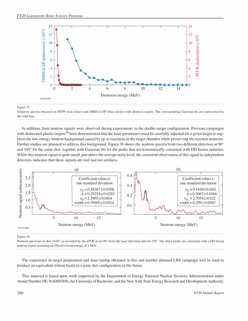
In addition, faint neutron signals were observed during experiments in the double-target configuration. Previous campaigns with deuterated plastic targets30 have demonstrated that the laser parameters must be carefully adjusted for a given target to sup-press the low-energy neutron background caused by (p, n) reactions in the target chamber while preserving the reaction neutrons. Further studies are planned to address this background. Figure 18 shows the neutron spectra from two different detectors at 90° and 150° for the same shot, together with Gaussian fits for the peaks that are kinematically consistent with DD fusion neutrons. While this neutron signal is quite small, just above the average noise level, the consistent observation of this signal in independent detectors indicates that these signals are real and not artifacts.
E29538JR Neutron energy (MeV)
0.4
0.3
0.2
0.1
Coefficient values!one standard deviation
= 0.1418!0.0161= 0.1067!0.0166= 2.7054!0.022= 0.259!0.0587
y0A
x0 width
Coefficient values!one standard deviation
5 10 15 Neutron energy (MeV)
5 10 15Neu
tron
signa
l (ar
bitra
ryun
its)
2.5
2.0
1.0
1.5
0.5
= 0.38367!0.0306= 0.29254!0.0293= 2.5903!0.0164= 0.39165!0.0524
y0A
x0width
(a) (b)
Figure 18Neutron spectrum of shot 33407 as recorded by the nTOF at (a) 90° from the laser direction and (b) 150°. The fitted peaks are consistent with a DD fusion neutron signal assuming an effective beam energy of 1 MeV.
The experience in target preparation and laser tuning obtained in this and another planned LBS campaign will be used to produce an equivalent tritium beam in a joint shot configuration in the future.
This material is based upon work supported by the Department of Energy National Nuclear Security Administration under Award Number DE-NA0003856, the University of Rochester, and the New York State Energy Research and Development Authority.
Figure 17Deuteron spectra obtained on MTW (red circles) and OMEGA EP (blue circles) with identical targets. The corresponding Gaussian fits are represented by the solid line.
E29537JR
OM
EGA
EP
deut
eron
s/sr (#10
11)
MTW
deu
tero
ns/sr
(#10
9 )
Deuteron energy (MeV)
0
2
4
6
8
10
12
14
0
2
4
6
8
10
12
14
20 4 6 8 10 12 14

NatioNal laser Users’ Facility aNd exterNal Users’ Programs
FY20 Annual Report 281
Measurement of High-Pressure Phase-Transformation Pressures in Fe-(11 wt%)Si and MgOPrincipal Investigators: R. Smith (LLNL); J. Wicks, M. Sim, and V. Rastogi (Johns Hopkins University); and X. Gong and J. R. Rygg (LLE)
The XRD-Alloy experiments on OMEGA-60 used six beams focused to 800-nm spots to dynamically compress 30-nm-thick samples of single-crystal MgO or 10-nm-thick powder samples of Fe-(11 wt%)Si over 8 ns, to pressures up to 800 GPa. Temporal laser pulse shaping delivered progressively stronger pressure to the sample over time. This ramp compression keeps the sample temperature relatively low and maintains the solid state to extreme levels of compression, avoiding the issue with shock compres-sion where large increases in entropy increase temperatures too high to constrain exoplanet interior conditions.
The MgO or Fe-(11 wt%)Si sample was sandwiched between two single-crystal diamond foils. Diamond served as an ideal material to couple laser energy into ramp-compression waves. The diamond/MgO/diamond target was positioned on a Ta pinhole placed over the front of the PXRDIP box (power x-ray diffraction with image plates), which contains x-ray–sensitive image-plate detectors along the inner five walls (Fig. 19). The pressure history of the sample and the time of peak compression are determined by VISAR view-ing the back of the sample through an aperture in the PXRDIP box. Pressure (P) and temperature (T) within the MgO sample can be simulated using the 1-D hydrocode HYADES, which models the coupling of the OMEGA 527-nm laser into our target geometry and calculates the 1-D hydrodynamic flow of P–T waves through the target assembly using equation-of-state descriptions of each layer.
Figure 19The PXRDIP setup on OMEGA-60. (Figure adapted from Ref. 32).
U2725JR
Direct x rays
ImageplatesImageplates
PXRDIP
Diffractedx rays
75 mm
VISAR2iTarget
package
50 mm
Laser beam
X-raysource(Cu foil)
At the time of peak compression, another 35 laser beams irradiate a Cu foil to produce a hot dense plasma of mainly He-like ions. This results in a strong quasi-monochromatic Hea x-ray source over 1 ns at x-ray energies of 8.3 keV. The x rays incident onto the compressed sample scatter in a transmission-diffraction pattern, which is recorded by the image-plate detectors. Peaks from the uncompressed Ta pinhole are also recorded, providing fiducial data that allow us to plot the image-plate data as diffraction angle versus azimuthal angle around the x-ray beam axis (Fig. 20).32 The angular position of diffracted sample peaks provide direct information of the atomic lattice spacing and crystal structure at a pressure determined through VISAR. By increasing the laser intensity on target the sample pressure increases, so a systematic series of these ramp-compression x-ray diffraction shots determines the onset pressure of phase transformations.
Investigating Magnetic Fields Generated in Collisionless Plasma-Flow Interactions Using Thomson ScatteringPrincipal Investigators: G. F. Swadling, H. S. Park, J. S. Ross, B. Pollock, and D. Higginson (LLNL); F. Fiuza and A. Grassi (SLAC); W. Rozmus and C. Bruulsema (Dept. of Physics, University of Alberta); and H. G. Rinderknecht (LLE)
The experiments conducted for the BFieldOTS-20A OMEGA Campaign focused on investigating the generation and amplifica-tion of spontaneous magnetic fields via the Weibel filamentation instability in collisionless, interpenetrating plasmas, extending previous work recently published.33 High-velocity (+1000-km/s) streams of plasma were generated by laser heating the surfaces
FY20 LaboratorY basic science Program
FY20 Annual Report282
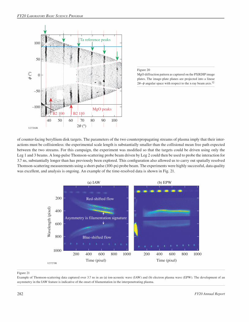
of counter-facing beryllium disk targets. The parameters of the two counterpropagating streams of plasma imply that their inter-actions must be collisionless: the experimental scale length is substantially smaller than the collisional mean free path expected between the two streams. For this campaign, the experiment was modified so that the targets could be driven using only the Leg 1 and 3 beams. A long-pulse Thomson-scattering probe beam driven by Leg 2 could then be used to probe the interaction for 3.7 ns, substantially longer than has previously been explored. This configuration also allowed us to carry out spatially resolved Thomson-scattering measurements using a short-pulse (100-ps) probe beam. The experiments were highly successful, data quality was excellent, and analysis is ongoing. An example of the time-resolved data is shown in Fig. 21.
U2726JR
100
–100
0
50
–50
2i (°)70605040 80 90 100
MgO peaksB2 100 B2 110
z (°
)
Ta reference peaks
Figure 20MgO diffraction pattern as captured on the PXRDIP image plates. The image-plate planes are projected into a linear 2i–z angular space with respect to the x-ray beam axis.32
U2727JR
200
400
600
1000
800
200 400 600 1000800
Wav
elen
gth
(pix
el)
Time (pixel) Time (pixel)
(a) IAW
Red-shifted flow
Blue-shifted flow
Asymmetry is filamentation signature
200 400 600 1000800
(b) EPW
Figure 21Example of Thomson-scattering data captured over 3.7 ns in an (a) ion-acoustic wave (IAW) and (b) electron plasma wave (EPW). The development of an asymmetry in the IAW feature is indicative of the onset of filamentation in the interpenetrating plasma.

NatioNal laser Users’ Facility aNd exterNal Users’ Programs
FY20 Annual Report 283
Extreme Deformation and Failure of High Entropy Alloys by Laser Shock-Induced Compression and TensionPrincipal Investigators: S. Zhao and A. Minor (LBNL); and C. Stan, C. E. Wehrenberg, and H.-S. Park (LLNL)
High-entropy alloys (HEA’s) are a class of metallic alloys containing three or more elements in significant atomic proportion. They exhibit generally high-yield strength and fracture toughness and are good candidates for engineering applications such as the aerospace industry. We are interested in the spall strength behavior of these materials and studied them under shock impact to several tens of GPa. The setup consisted of three independent targets that were shot individually, one of which was a spall velocimetry target and two of which were recovery tube spall targets (Fig. 22). Recovered samples were analyzed using electron microscopy (Fig. 23).
U2728JR
Velocimetrytarget
Recovery targets
(a)
Velo
city
(km
/s)Time (ns)
0.8
1.0
0.4
0.6
0.0
0.2
0 20 40 60
Leg ALeg B
(b)
Figure 22(a) Schematic of the experimental setup. Laser shocks were independently timed. (b) Typical spall velocimetry measurement. The beats are indicative of “ring-ing” in the sample, which is a marker of spall strength in samples.
U2729JR
Lase
r sho
ck
Com
pres
sion
crat
er
Tens
ile sp
all
Spal
l pla
ne
Grain boundary
Crack tip
VoidsVoid 1
Void 2
In the vicinity of thecrack tip
In the vicinity of thecrack tip
TBTBTBTB TBTB
(a) (b) (c) (d)
(e)
Twins
1 mm 100 nm 10 nm 5 nm
100 nm
Figure 23(a) Diagram of a spall event in a laser-driven sample. (b) Scanning electron microscopy (SEM) at the spall boundary, showing the formation of cracks and voids due to tension generated by shock unloading against vacuum. (c) Grain mapping of the crack tip, showing multiple grain boundaries. (d) Transmission electron microscopy (TEM) analysis of the grains near the crack tip, showing extensive twin formation and multiple stacking faults.
FY20 LaboratorY basic science Program
FY20 Annual Report284
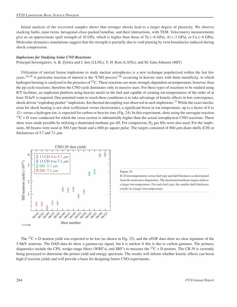
Figure 24D–D ion temperatures versus fuel type and shell thickness as determined from the neutronics diagnostics. The deuterated methane targets achieve a larger ion temperature. For each fuel type, the smaller shell thickness results in a larger ion temperature.
U2730JR
9834
298
34398
34998
35398
35598
34698
34798
35098
35498
35698
34598
35198
34898
352
Shot number
1
2
3
4
DD
neu
tron
yiel
d (#
1011
)
CNO-20 shot yields
13 CD 4 to 5.7 nm13 CD 4 to 7.1 nmDD 5.7 nmDD 7.1 nm
Initial analysis of the recovered samples shows that stronger shocks lead to a larger degree of plasticity. We observe stacking faults, nano twins, hexagonal-close-packed lamellae, and their interactions, with TEM. Velocimetry measurements give us an approximate spall strength of 10 GPa, which is higher than those of Ta (+8 GPa), Al (+3 GPa), or Cu (+8 GPa). Molecular dynamics simulations suggest that the strength is partially due to void pinning by twin boundaries induced during shock compression.
Implosions for Studying Solar CNO ReactionsPrincipal Investigators: A. B. Zylstra and J. Jeet (LLNL); Y. H. Kim (LANL); and M. Gatu Johnson (MIT)
Utilization of inertial fusion implosions to study nuclear astrophysics is a new technique popularized within the last few years.34,35 A particular reaction of interest is the “CNO process”36 occurring in heavier stars with finite metallicity, in which hydrogen burning is catalyzed in the presence of 12C. These reactions are more strongly dependent on temperature, however, than the pp cycle reactions; therefore the CNO cycle dominates only in massive stars. For these types of reactions to be studied using ICF facilities, an implosion platform using heavier nuclei in the fuel and capable of creating ion temperatures of the order of at least 30 keV is required. One potential route to reach these conditions is to take advantage of kinetic effects in low-convergence, shock-driven “exploding-pusher” implosions. Ion thermal decoupling was observed in such implosions.37 While the exact mecha-nism for shock heating is not clear (collisional versus electrostatic), a significant boost in ion temperature, up to a factor of 6 to 12# versus a hydrogen ion, is expected for carbon or heavier ions (Fig. 24). In this experiment, shots using the surrogate reaction 13C + D were conducted for which the cross section is substantially higher than the actual astrophysical CNO reactions. These shots were made possible by utilizing a deuterated methane gas fill. For comparison, D2 gas fills were also used. For the implo-sions, 60 beams were used at 300 J per beam and a 600-ps square pulse. The targets consisted of 860-nm-diam shells (CH) at thicknesses of 5.7 and 7.1 nm.
The 13C + D neutron yield was expected to be low (as shown in Fig. 25), and the nTOF data show no clear signature of the 5-MeV neutrons. The DAD data do show a gamma-ray signal, but it is unclear if this is due to carbon gammas. The primary diagnostics include the CPS, wedge-range filters (WRF’s), and SRF’s to measure the 13C + D protons. The CR-39 is currently being processed to determine the proton yield and energy spectrum. The results will inform whether kinetic effects can boost high-Z reaction yields and will provide a basis for designing future CNO experiments.

NatioNal laser Users’ Facility aNd exterNal Users’ Programs
FY20 Annual Report 285
Figure 25D–D neutron yields versus fuel type and shell thickness as determined from the neutronics diagnostics. The deuterated methane targets have a lower D–D neutron yield. For each target gas-fill type (D2 and 13C + D), the smaller shell thickness results in a lower D–D neutron yield.
REFERENCES
1. H. Chen et al., Phys. Rev. Lett. 114, 215001 (2015).
2. H. Chen et al., Phys. Plasmas 21, 040703 (2014).
3. G. Fiksel et al., Bull. Am. Phys. Soc. 64, NO08.00010 (2020).
4. S. Root et al., Geophys. Res. Lett. 45, 3865 (2018).
5. D. E. Fratanduono et al., Phys. Rev. B 97, 214105 (2018).
6. S. Stewart et al., AIP Conf. Proc. 2272, 080003 (2020).
7. S.-N. Luo et al., J. Geophys. Res. Solid Earth 109, B05205 (2004).
8. C. Wang et al., Phys. Plasmas 22, 102702 (2015).
9. V. A. Thomas and R. J. Kares, Phys. Rev. Lett. 109, 075004 (2012).
10. D. S. Clark et al., Phys. Plasmas 23, 056302 (2016).
11. R. I. Klein et al., Astrophys. J. 583, 245 (2003).
12. V. V. Korobkin and S. L. Motylev, Sov. Tech. Phys. Lett. 5, 474 (1979).
13. G. Fiksel et al., Appl. Phys. Lett. 109, 134103 (2016).
14. M. Millot et al., Nat. Phys. 14, 297 (2018).
9834
298
34398
34998
35398
35598
34698
34798
35098
35498
35698
34598
35198
34898
352
Shot number
9
10
11
12
13
14
15
16
17
18D
D io
n te
mpe
ratu
re (k
eV)
CNO-20 ion temperatures
U2731JR
13 CD 4 to 5.7 nm13 CD 4 to 7.1 nmDD 5.7 nmDD 7.1 nm
FY20 LaboratorY basic science Program
FY20 Annual Report286
15. M. Millot et al., Nature 569, 251 (2019).
16. S. Brygoo et al., J. Appl. Phys. 118, 195901 (2015).
17. S. A. Slutz et al., Phys. Plasmas 17, 056303 (2010).
18. D. B. Schaeffer et al., Phys. Rev. Lett. 119, 025001 (2017).
19. W. Fox et al., Physics Archive, https://arxiv.org/abs/2003.06351 (2020).
20. A. Valenzuela et al., Nature 320, 700 (1986).
21. D. D. Ryutov et al., Phys. Plasmas 19, 062706 (2012).
22. L. Ballabio, J. Källne, and G. Gorini, Nucl. Fusion 38, 1723 (1998).
23. K. Molvig et al., Phys. Rev. Lett. 109, 095001 (2012).
24. J. D. Huba, NRL Plasma Formulary, Naval Research Laboratory, Washington, DC, D 210.2:P 69/4/2009 (2009).
25. W. T. Taitano et al., Phys. Plasmas 25, 056310 (2018).
26. L. Torrisi et al., Phys. Scr. T161, 014026 (2014).
27. J. T. Morrison et al., Phys. Plasmas 19, 030707 (2012).
28. S. Karsch et al., Phys. Rev. Lett. 91, 015001 (2003).
29. A. Schwemmlein et al., “Optimizing Deuterated Metal Foils to Generate a High-Yield, Quasi-Monoenergetic Deuteron Beam Employing Target Normal Sheath Acceleration on the Multi-Terawatt Laser System at the Laboratory for Laser Energetics,” to be submitted to Nuclear Instruments and Methods A.
30. C. Stoeckl et al., Nucl. Instrum. Methods Phys. Res. B 453, 41 (2019).
31. C. C. Freeman et al., Rev. Sci. Instrum. 82, 073301 (2011).
32. J. K. Wicks et al., Sci. Adv. 4, eaao5864 (2018).
33. G. F. Swadling et al., Phys. Rev. Lett. 124, 215001 (2020).
34. A. B. Zylstra et al., Phys. Rev. Lett. 117, 035002 (2016).
35. A. B. Zylstra et al., Phys. Rev. C 101, 042802(R) (2020).
36. H. A. Bethe, Phys. Rev. 55, 434 (1939).
37. H. G. Rinderknecht et al., Phys. Rev. Lett. 114, 025001 (2015).
Related Documents