INSTITUTE FOR TELECOMMUNICATION SCIENCES OF THE NATIONAL TELECOMMUNICATIONS AND INFORMATION ADMINISTRATION ANNUAL TECHNICAL PROGRESS REPORT 1978 For the period from October 1, 1_ 977 through Sept. 30, 1978

Welcome message from author
This document is posted to help you gain knowledge. Please leave a comment to let me know what you think about it! Share it to your friends and learn new things together.
Transcript
INSTITUTE FOR TELECOMMUNICATION SCIENCES OF THE
NATIONAL TELECOMMUNICATIONS AND INFORMATION ADMINISTRATION
ANNUAL TECHNICAL PROGRESS REPORT 1978 For the period from October 1, 1_977 through Sept. 30, 1978
I OFFICE OF THE CHIEF COUNSEL
Gregg Skall, Chief Counsel
I OFFICE OF
TELECOMMUNICATIONS APPLICATIONS William Lucas
Associate Administrator
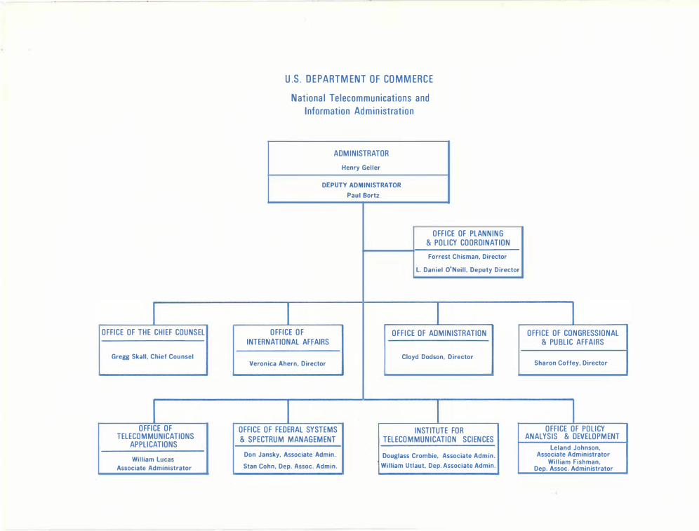
U.S. DEPARTMENT OF COMMERCE National Telecommunications and
Information Administration
ADMINISTRATOR Henry Geller
DEPUTY ADMINISTRATOR
Paul Bortz
OFFICE OF PLANNING & POLICY COORDINATION Forrest Chisman, Director
L. Daniel O'Neill, Deputy Director
I I OFFICE OF OFFICE OF ADMINISTRATION
INTERNATIONAL AFFAIRS Cloyd Dodson, Director
Veronica Ahern, Director
I I OFFICE OF FEDERAL SYSTEMS INSTITUTE FOR & SPECTRUM MANAGEMENT TELECOMMUNICATION SCIENCES
Don Jansky, Associate Admin. Douglass Crombie, Associate Admin.
Stan Cohn, Dep. Assoc. Admin. William Utlaut, Dep. Associate Admin.
I OFFICE OF CONGRESSIONAL
& PUBLIC AFFAIRS
Sharon Coffey, Director
I
I OFFICE OF POLICY I
ANALYSIS & DEVELOPMENT , Leland Johnson, I Associate Administrator
William Fishman, I Dep. Assoc. Administrator
ITS ANNUAL TECHNICAL PROGRESS REPORT 1978
For the period October 1, 1977 through Sept. 30, 1978
U.S. DEPARTMENT OF COMMERCE Juanita M. Kreps, Secretary
Henry Geller, Assistant Secretary for Communications and Information

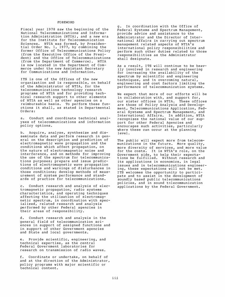
FOREWORD
Fiscal year 19 7 8 saw the beginning of the National Telecommunications and Information Administration (NTIA), and a new era for the Institute for Telecommunication Sciences. NTIA was formed, by Presidential Order No. 1 , 19 7 7 , by combining the former Office of Telecommunications Policy (from the Executive Office of the President) and the Office of Telecommunications (from the Department of Commerce). NTIA
is now located in the Department of Commerce under the new Assistant Secretary for Communications and Information.
ITS is one of the Offices of the new organization and is responsible, on behalf of the Administrator of NTIA, for the telecommunications technology research programs of NTIA and for providing technical research support to other elements of NTIA as well as other agencies on a reimbursable basis. To perform these functions it shall, as stated in Departmental Orders:
a. Conduct and coordinate technical analyses of telecommunications and information policy options.
b. Acquire, analyze, synthesize and disseminate data and perform research in general on the description and prediction of electromagnetic wave propagation and the conditions which affect propagation, on the nature of electromagnetic noise and interference, and on methods for improving the use of the spectrum for telecommunications purposes; prepare and issue predictions of electromagnetic wave propagation conditions and warnings of disturbances in those conditions; develop methods of measurement of system performance and standards of practice for telecommunications.
c. Conduct research and analysis of electromagnetic propagation; radio systems characteristics, and operating techniques affecting the utilization of electromagnetic spectrum, in coordination with specialized, related research and analysis performed by other Federal agencies in their areas of responsibility.
d. Conduct research and analysis in the general field of telecommunication sciences in support of assigned functions and in support of other Government agencies and State and local governments.
e. Provide scientific, engineering, and technical expertise, as the central Federal Government laboratories for research on transmission of radio waves.
f. Coordinate or undertake, on behalf of and at the direction of the Administrator, policy programs with major scientific or technical content.
g. In coordination with the Office of Federal Systems and Spectrum Management, provide advice and assistance to the Administrator and the Director of International Affairs in carrying out spectrum management related aspects of NTIA's international policy responsibilities and perform such other duties related to those responsibilities as the Administrator shall designate.
As a result, ITS will continue to be heavily involved in research and engineering for increasing the availability of the spectrum by scientific and engineering techniques, and in overcoming natural, engineering and cost factors limiting the performance of telecommunication systems.
We expect that more of our efforts will be in collaboration with, and support for, our sister offices in NTIA. These offices are those of Policy Analysis and Development, Telecommunications Application, Federal Systems and Spectrum Management, and International Affairs. In addition, NTIA recognizes the national value of our support for other Federal Agencies and encourages such activities, particularly where these can occur at the planning level.
The public will expect more from telecommunications in the future. More quality, more diversity of services, and more value for the costs. It is NTIA's role, on the Government side, to help their expectations be fulfilled. Without research and its applications in economics, in legal issues and in telecommunications engineering, these expectations will not be met. ITS welcomes the opportunity to participate and to assist in the development of soundly based public telecommunications policies, and in sound telecommunication applications by the Federal Government.
i ii

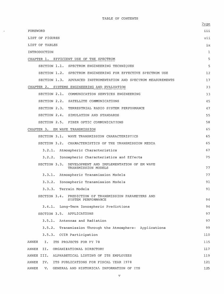
TABLE OF' CONTENTS
FOREWORD
LIST OF F I GURES
LIST OF TABLES
INTRODUCTION
CHAPTER 1 . EFFICIENT USE OF THE SPECTRUM
SECTION 1 . 1 . SPECTRUM ENGINEERING TECHNIQUES
SECTION 1 . 2 . SPECTRUM ENGINEERING FOR EFFECTIVE SPECTRUM USE
SECTION 1 . 3 . ADVANCED INSTRUMENTAT ION AND SPEC'l'RUM MEASUREMENTS
CHAPTER 2 . SYSTEMS ENGINEERING AND EVALUATION
SECTION 2 . 1 . COMMUNICATION SERVICE S ENGINEERING
SECTION 2 . 2 . SATELLITE COMMUNI CATIONS
SECTION 2 . 3 . TERRES TRIAL RADI O SYSTEM PERFORMANCE
SECTION 2 . 4 . SIMULATION AND STANDARDS
SECTION 2. 5 . FIBER OPTI C CO.MMUNI CA'UONS
CHAPTER 3 . EM WAVE TRANSMISS ION
SECTION 3 . 1 . WAVE TRANSMI S S ION CHARACTERI S'riCS
SECTION 3 . 2 . CHARACTERI STICS OF 'ri:IE 'l'RANSMISSION MEDIA
3 . 2 . 1 . Atmo spheric Characteri s t i c s
3 . 2 . 2 . Ionospheric Character i st i c s and E ffects
SECTION 3 . 3 . DEVELOPMENT AND IMPLEMENTATION OF EM WAVE TRANSMISS ION MODELS
3 . 3 . 1 . Atmospheric Transmiss ion Mode l s
3 . 3 . 2 . Ionospheric Transmi s s ion Models
3 . 3 . 3 . Terrain Mode l s
SECTION 3 . 4 . PRED ICTION O F TRANSMISS ION PARAME'I'ERS AND SYSTEM PERFORMANCE
3 . 4 . 1 . Long-Term Iono spher ic Prediction s
SECTION 3 . 5. APPL I CATIONS
3 . 5 . 1 . Antennas and Radiation
3 . 5 . 2 . Transmi s s ion Through the Atmosphere: Applications
3 . 5 . 3 . CCIR Partic ipat ion
ANNEX I . ITS PROJECTS FOR F'Y 7 8
ANNEX I I. ORGANIZATI ONAL DI RECTORY
ANNEX I I I . ALPHABETI CAL LISTING OF ITS EMPLOYEES
ANNEX IV. ITS PUBLICATIONS FOR FISCAL YEAR 1978
ANNEX V. GENERAL AND H I STORICAL INFORMATION OF I'l'S
v
i i i
vii
ix
1
5
5
1 2
17
33
33
45
47
5 5
5 8
65
6 5
65
67
75
77
77
91
91
9 4
94
9 7
97
9 9
llO
ll5
ll7
119
121
125

FIGURE
1 - l
l-2
l- 3
l - 4
l-5
l - 6
l - 7
l - 8
l - 9
l - 1 0
l - 1 1
l - 1 2
l - 1 3
2 - 1
2 - 2
2 - 3
2 - 4
2 -5
2 - 6
2 - 7
2 - 8
2 - 9
2 - 1 0
2 - 1 1
2 - 1 2
2 - 1 3
2 - 1 4
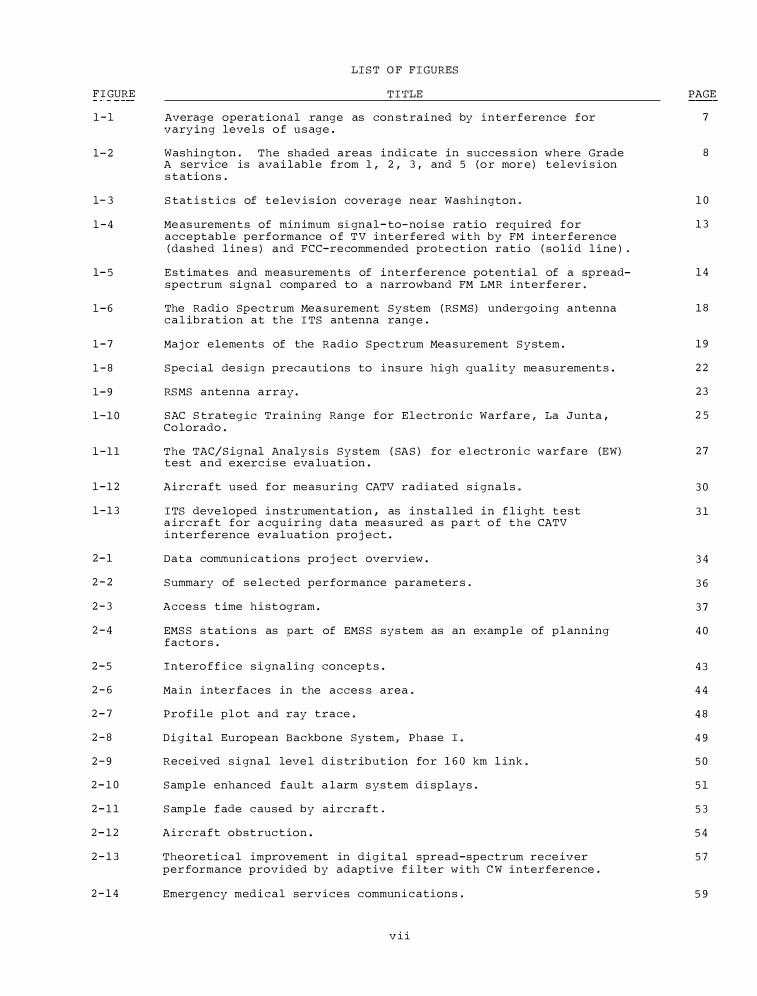
LIST O F FIGURES
TI'I'LE
Average operat ional range as con strained by interference for varying leve l s o f u s age .
Washington . The shaded areas indi c ate in succes s ion where Grade A service is ava i lable from 1 , 2 , 3 , and 5 ( o r mor e ) tel evi s ion s tation s .
Stat i s t i c s of te levis ion coverage near Washington.
Me as urement s of min imum signal- to-noi s e ratio required for acc eptabl e performance o f TV inter fered with b y FM inter ference ( dashed l ine s ) and FCC-recommended pro tection ratio ( so l id l ine ) .
E s t imates and measurements of inte rference potential of a spreadspectrum s igna l compared to a narrowband FM LMR interferer.
The Radio Spectrum Mea surement System ( RSMS) undergo ing antenna c a l ibrat ion at the ITS antenna range .
Maj or elements of the Radio Spe c trum Meas urement System .
Spe c i al de s ign precautions to insure high quality me asurement s .
RSMS antenna array.
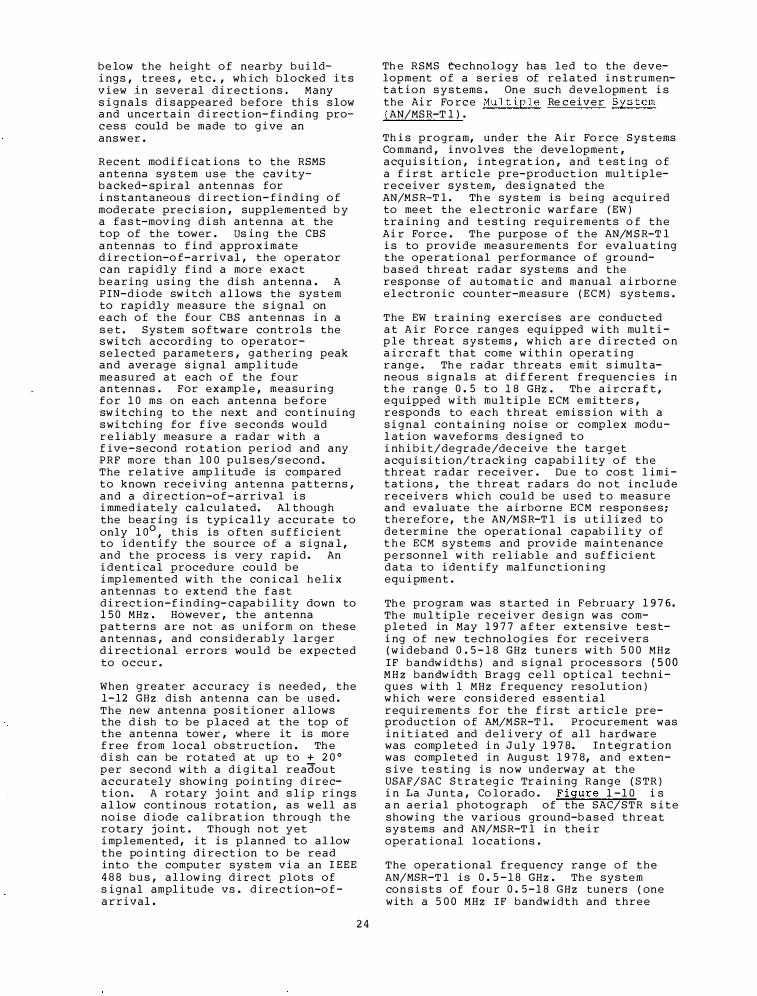
SAC Strategic Train ing Range for Electron ic Warfare , La Junta, Co lorado .
The TAC/Signal Analys i s System ( SAS) for electron i c warfare (EW) test and exerc i s e eva luation .
Aircraft used for measur ing CATV radiated signa l s .
ITS deve loped i n strumentation , as instal led in f l i ght · t e s t a ircraft for a cquiring data mea s ured as p a r t o f t h e CATV interference eva luation pro j e c t .
Data co��uni cat ions pro j ect overview .
Summary of s e l ected per formance parameter s .
Acce s s t ime h i s t ogram.
EMSS s tation s as part of EMSS s ys tem as an examp le of p l anning factor s .
Intero f f i c e s i gnaling concep t s .
Main inte r faces in the acce s s area .
Profile plot and ray trace .
D i gital European Backbone Sys tem , Phase I .
Received s i gnal leve l d i s tr ibut ion for 1 6 0 km l ink.
Sample enhanced fault a l arm s ystem di splays.
Samp le f ade c aused b y aircraft.
Aircraft obstruc tion .
Theoretical improvement in digital spread-spectrum rece iver per formance provided b y adaptive f i lter with CW interference .
Emergenc y medical servic e s communi c ations .
vii
PAGE
7
8
1 0
1 3
1 4
1 8
1 9
2 2
2 3
2 5
2 7
3 0
3 1
3 4
3 6
3 7
4 0
4 3
4 4
4 8
4 9
50
51
53
54
57
5 9
FIGURE
3-1
3 -2
3 - 3
3-4
3-5
3-6
3-7
3-·8
3-9
3· . . 1 0
3 ·-11
3 -1.2
3-1.3
3-14
3-15
3 - 1 6
3-17
3-18
3-19
3-2 0
3 -·2 1
3··23
3 -2 4
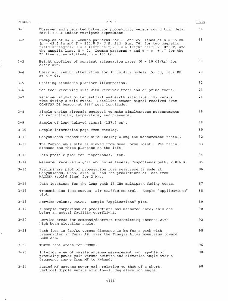
'l'ITLE
Obs erved and predi cted b i t-error probabi l i ty versus round trip delay fo r 1..5 GHz indoor mult ipath experiment.
Examp les of o2·-MS Zeeman patterns for 1 - and 2 5+ lines at h = 55 km (p = 42.5 Pa and T = 2 6 0.8 K; U.S. Std. Atm. 7 6 ) for two magnetic
field strengths, H z 3 ( l eft half) , H = 6 ( r ight half) x lo-5 T, and the un spl it l ine, H = 0. Zeeman patterns rr and o = a+ + o- for the 7- l ine at an alti tude, h = 100 km.
Height profi les of cons tant attenuation rate s ( 0 - 1 0 dB/km) for clear air.
Clear air zenith a ttenuai:ion for 3 humidi·ty mode ls ( 5, 50, 1 0 0 % RH at h = 0 ) .
Orb it ing standards p l atform i l lustrat ion.
Ten foot receiving di sh with receiver front end at p rime focus .
Rece ived s ignal on terre strial and earth s atellite link versus t�ne during a rain event. Sate l l ite beacon s ignal rece ived from COMS'.l'AR Dl beacon at 128° '\ve st longitude.
Single engine aircraft equipped to make s imul taneous mea s ur ements of refractivity, temperature, and pre s s ure.
Samp le of long del ayed s igna l ( 1 3 7.5 ms ) .
Sample information p age from cata log.
Canyonlands transmitter s i te looking along the mea s urement radi a l .
The C anyon lands site as viewed from Dead Horse Po int . The r adial cro s s e s the three p l ateaus on the left.
Path profile plot for Canyonlands, Utah.
Me a s ured received s ignal and noise levels, Canyonlands path, 2 . 0 MHz .
Pre l iminary plot of propagation l o s s measurements made at Canyon lands, Ut:ah, s i te (X) and · the predic·tions of los s from WAGNER ( soli d l ine ) for 2 l'1Hz.
Path locations for the long path 15 GHz multipath fading t e s t s .
Transmi s s ion loss curve s, air traffic control. Sample " appl i c ations " plot.
Service volume, 'rJ\CAN. Sampl e "app l i ca ·tions " plot .
A s ample compari son of predictions and mea sured data, this one being an actual facility overflight.
Service areas for comrnand/de s truc·t t.ransm:i. t ·t.ing an·tenna w.i th h igh beam elevation angle.
Pa th loss in dBU/Kw ve rsus di stance in km for a path with transmit:ter in Yuma, AZ, over the Tinajas Altas mountains toward Luke AF'B.
'.l'OPOG tape are as for CONUS.
Interior view of on s.i·te antenna mea surement van capable of providing power gain versus aximuth and elevation angle over a frequency range from MF' to X-band.
Buried MF antenna power ga in re lat ive to that of a short, vert ical dipo le versus azirnuth--1 3 deg elevat ion angle.
viii
PAGE
6 6
6 8
6 9
7 0
7 2
7 3
7 4
7 6
7 8
8 0
8 2
8 3
'34
85
8 6
8 7
8 8
8 9
9 0
9 2
9 5
9 6
9 8
9 8
FIGURE
3 - 2 5
3 - 2 6
3 - 2 7
3-28
3-29
3 - 3 0
TABLE
1 - 1
1 - 2 , 3 , 4
1 - 5
2 - l a & b
2 - 2
2":'3
3 - 1
3 - 2
3 - 3
3 - 4
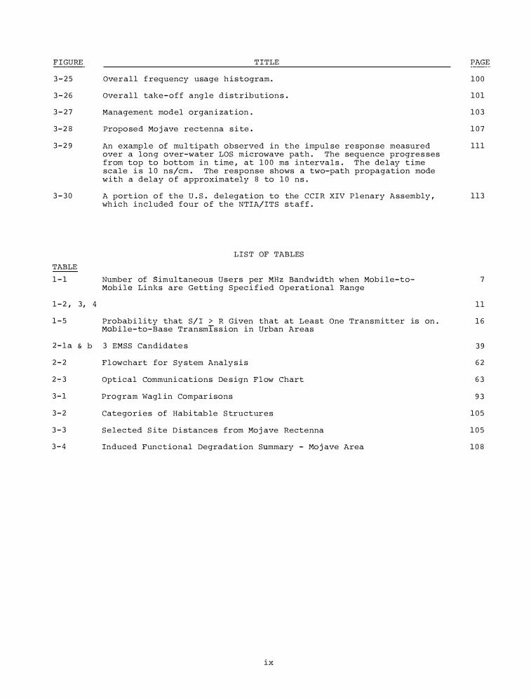
TITLE
Overall f requency usage h i s togram .
Overall take - o f f angle distribution s .
Management model organ i zat ion .
Propo sed Mo j ave rectenna s i te.
An exampl e of mul tipath observed in the impul se re spon se measured over a long over-water LOS microwave path . The sequence progre s ses from top to bottom in t ime , at 1 0 0 ms interva l s . The de lay t ime scale i s 1 0 ns/cm . The response shows a two-path propagation mode with a delay o f approximately 8 to 1 0 ns .
A port ion o f the U . S . delegation to the CCIR XIV Plenary Assembly , wh ich included four o f the NTIA/ITS staff .
LIST OF TABLES
Number of Simultaneous Users per MHz Bandwidth when Mobi le-toMob i le Links are Gett ing Spec i fi ed Operational Range
Probabi lity that S/I > R Given that at Least One Transmitter is on. Mdbile-to-Base Transmis s i on in Urban Areas
3 EMSS Candidate s
Flowchart for Sy stem Analy s i s
Opt ical Communi cations De s ign Flow Chart
Program Wagl in Compar i sons
Categories of Habi tab le S tructures
Se lec ted S i te D i stance s from Hoj ave Rectenna
Induced Functional Degradat ion Summary - Ho j ave Area
ix
PAGE
1 0 0
1 0 1
1 0 3
1 0 7
111
113
7
1 1
1 6
39
6 2
6 3
93
1 0 5
1 0 5
1 08
INTRODUC TION
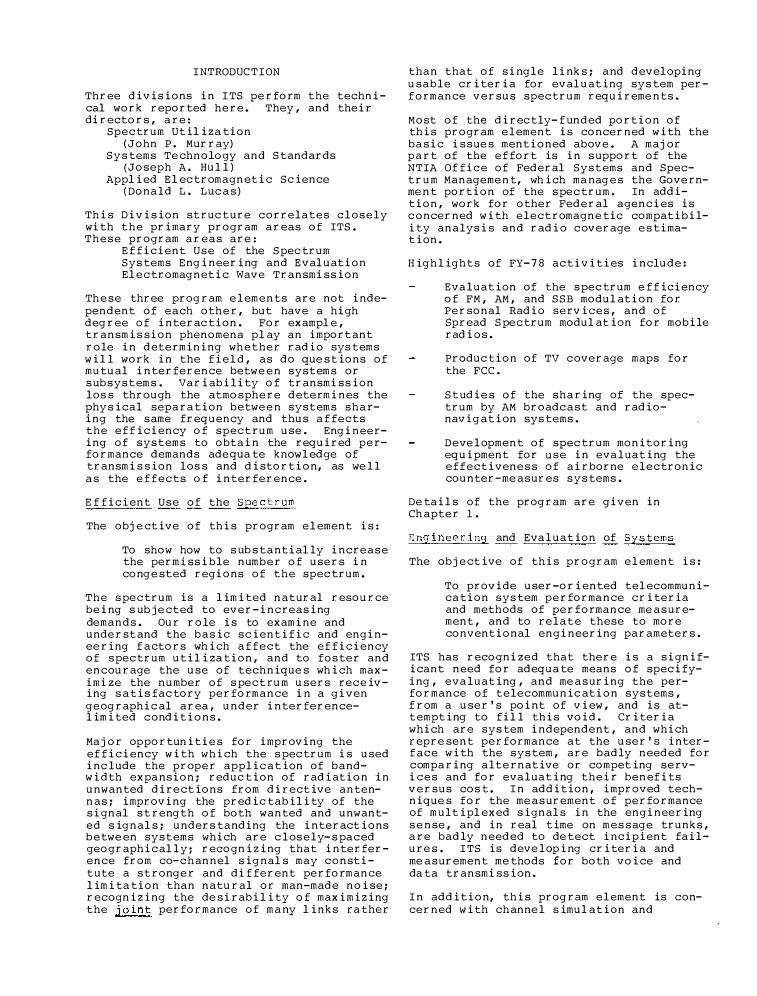
Three divisions in I TS pe rform the technical work reported here. They , and their directors , are :
Spec trum Util iza tion ( John P. Murray)
S y s tems Te chnology and S tandards ( Joseph A. Hul l )
Appl ied El ec tromagnetic Science ( Donald L. Luc a s )
This Division struc ture correlates c l osely with the primary program areas of ITS. These program areas are :
Ef ficient Use of the S pec trum Sys tems Eng ineering and Eval uation El ec tromagnetic Wave Transmission
Th e se three prog ram e l ements are not independent of each other, but have a high deg ree of interac tion. For exampl e , transmis sion phenomena pl ay an import ant role in determining wh ether radio sys tems wil l work in the fiel d , as do que stions of mutual interference betwe en systems or s ubsystems. Variability of transmission los s through the atmosphere determines the phy s ical separa tion betwe e n systems sharing the same frequency and thus a f fects the e f f iciency of spectrum use. Engineering of systems to obtain the required performance demands ade qua te knowl edge of transmis sion los s and distortion, as we l l a s the e f fects o f interference.
E f ficient Use of the S pe c trum
The obje ctive of this program el ement is :
To show how to s ub s tantial ly increase the permissible number of users in cong e sted regions of the spec trum.
The s pec trum is a l imited natural resource being s ub j e cted to ever-increasing demands. Our role is to examine and underst and the basic scientific and enginee ring f actors wh ich a f fect the ef ficiency of s pec trum util iza tion , and to fos ter and encourage the use of technique s wh ich maximize the number of s pectrum users receiving s a tis fac tory performance in a given geog raphic al area , under interferencel imited conditions.
Maj or opportunitie s for improving the ef ficiency with which the s pec trum is used inc lude the proper applic ation of bandwidth expansion; reduc tion of radiation in unwanted dire ctions from directive antennas; improving the predic tabil ity of the signal s t reng th of both wanted and unwanted s ignal s; unders tanding the interactions b e twe en systems which are c l os ely- s paced geographic al l y; recogniz ing that interference from co-channel sig nal s may constitute a stronger and dif ferent performance l imita tion than natural or man-made noise; recogniz ing the de sirabil ity of maximizing the joint performance of many l inks ra ther
than that of single links; and devel oping usable criteria for eval uating sys tem perf ormance versus spec trum requireme nts.
Most of the direc tly- f unded portion of this program e l ement is concerned with the ba sic issue s mentioned above. A maj or part of the e f fort is in s upport of the NTIA Of fic e of Federal Systems and Spectrum Management, wh ich ma nag e s the Governme nt portion of the s pec trum. In addition , work for other Federal agencies is c oncerned with electromagne tic compatibility analysis and radio coverage e s timation.
H ig h l ights of FY- 7 8 ac tivities include:
Eva l uation of the s pec trum e f ficiency of FM , AM , and S S B modul ation for Personal Radio services , and of Spread S pec trum modul at ion for mobile radios.
Produc tion of TV coverage maps for the FCC.
S t udie s of the sharing of the spectrum by AM broadc ast and radionavig ation sys tems.
Deve l opment of spec trum monitoring equipment for use in eva l uating the effectivene s s of airborne e l ectronic counter-me asures sys tems.
De tail s of the program are given in Ch apter 1.
Engineering and Eva l uation of S ys tems
The obj e ctive of this program el ement is:
To provide user-oriented tel ecommunica tion sys tem performance criteria and methods of performance me asurement , and to relate these to more conventional engineering parameters.
ITS has recognized that there is a significant need for adequa te means of specifying , eva l uating , and me asuring the performance of telecommunic ation systems , f rom a user ' s point of view , and is attempting to fil l this void. Criteria which are sys tem independent , and which repre sent performance at the user ' s interf ace with the sys tem , are badly needed for comparing alternative or competing services and for evaluating their benefits versus cos t. I n addition , improved technique s for the me asurement of performance of multipl exed signal s in the engineering s e nse , and in real time on mes sage trunks , are badly needed to de tect incipient fail ure s. I TS is deve loping criteria and me asurement me thods for both voice and da ta transmission.
I n addition, this prog ram el ement is concerned with ch anne l s imul ation and
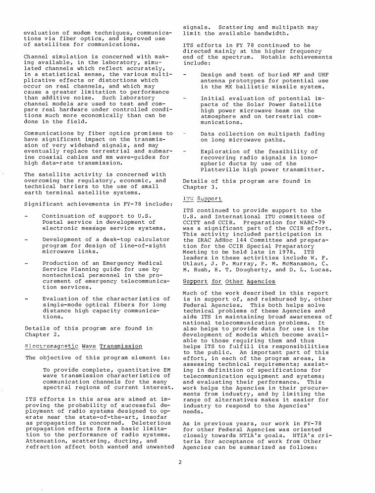
eval uation of modem technique s , communications via fiber optics , and improved use of satel lites for communications .
Ch annel simul a tion is concerned with making avail ab le , in the laboratory , simula ted channel s wh ich re flect accurately , in a statistical sense , the various mul tiplica tive e f fects or distortions which occur on real channels , and wh ich may cause a greater limita tion to performance than additive noise . Such l abora tory channel mode l s are used to test and compare real hardware under control led conditions much more economically than can be done in the field.
Com munications by fiber optics promises to have significant impact on the transmission of very wideband signal s , and may eventually repl ace terrestrial and s ubmarine coaxial cab les and mm wave-guide s for high data-rate transmis sion.
The satel lite activity is concerned with overcoming the regul a tory , e conomic , and technical barriers to the use of sma l l earth terminal sa tel lite sys tems .
Significant ach ievements in FY- 7 8 include :
C ontinuation of s upport to u.s. Pos tal service in development of el ectronic message service sys tems .
Development of a de sk-top calculator program for de s ign of l ine- of- s ight microwave links .
Production of an Emergency Medical Service Planning guide for use by nontechnical personnel in the procurement of emergency telecommunicat ion service s .
Eva l uation of the characteristics of s ing l e- mode optical fibers for l ong distance high capacity communications .
De tail s of this program are found in Chapter 2.
Electromagnetic wave Transmi s sion
The objective of this program el ement is :
To provide complete , quantitative EM wave transmis sion characteristics of communication channe ls for the many spectral regions of current intere s t .
I T S e f fort s i n this area are aimed at improving the probability of s ucce s s ful deployment of radio sys tems de signed to operate near the state-of-the-art , insofar as propaga tion is concerned . De leterious propagation e f fects form a basic limitation to the performance of radio sys tems . Attenuation, scatt ering , ducting , and refract ion affect both wanted and unwanted
2
signal s . Scatt ering and mul tipa th may limit the avail able bandwidth .
ITS e f forts in FY 7 8 continued to be directed mainly at the higher frequency end of the spectrum . Notab le achievements include :
De sign and test of buried MF and UHF antenna prototype s for potential use in the MX bal listic mis sil e system .
Initial eval uation of potential impacts of the Solar Power Satel lite high powe r microwave beam on the atmosphere and on terre s trial communications .
Da ta col lection on mul tipa th fading on long microwave paths .
Expl oration of the fea sibility of recovering radio signal s in ionos pheric ducts by use of the Plattevil le high power transmitter.
De tail s of this program are found in Chapter 3 .
ITS continued t o provide support to the u.s. and Internat ional ITU commit tees of CCITT and CCI R . Preparation for WARC - 7 9 wa s a significant part o f the CCIR e f fort . This activity included participation in the IRAC AdHoc 14 4 C ommittee and preparation for the C C I R Special Preparatory Meeting to be held l a te in 19 7 8 . ITS leaders in these activities include W . F . Utl aut , J . P . Murray , P . M . McManamon , c. M . Rush , H . T . Dough erty , and D . L . Luc a s .
S ueeort for Other Agencies
Much of the work described in this report is in support of , and reimbursed by , other Federal Agencie s . This both helps solve technical problems of these Agencie s and aids ITS in maintaining broad awarene s s of na tional te lecommunication problems . I t al so helps t o provide data for u s e i n the development of mode l s which become avail able to those requiring them and thus helps ITS to f ul f il l it s responsibilitie s to the public. An important part of this e f fort , in each of the program areas , is asses sing technical requireme nts; a s sisting in de f inition of specifications for telecommunica tion equipment and systems; and evaluating their performance . This work helps the Ag encies in their procurements from industry , and by l imiting the rang e of alternative s make s it ea sier for industry to re spond to the Agencie s' needs .
As in previous years , our work in FY- 7 8 for other Federal Agencies wa s oriented closely towards NTIA ' s goal s . NTIA ' s criteria for acceptance of work from Other Agencie s can be s ummarize d as follows :
1 . I t falls within the authority of the Secretary of Commerce to undertake the work.
2 . T h e work i s relevant t o na tional goals and commitments and has impact on these goals and commitments.
3. The work c annot be readily performed by the priva te sector ( with certain exceptions s uch a s un avoid able conflict o f interest , intolerable delays , excess ively higher cos t s , or unique facilities or capabilities within I T S ) •
4. The work contributes to NTIA ' s g oals.
5. The work does not conflict with other ongoing work within NTIA.
All these criteria mus t be met.
The revised criteria will continue to ensure that the work we do for Federal Agencies will be a proper f unction of Government and consis tent with the mis sion of NTIA and the Department of Commerce.
Ac knowledsement
R. B. Stoner was responsible for the preparation of the report , from ma terial provided by the As sociate Directors -J . P . Murray , J . A. H ull , and D. L. Lucas. H e wa s ably a s sis ted by other ITS s t a f f.
3

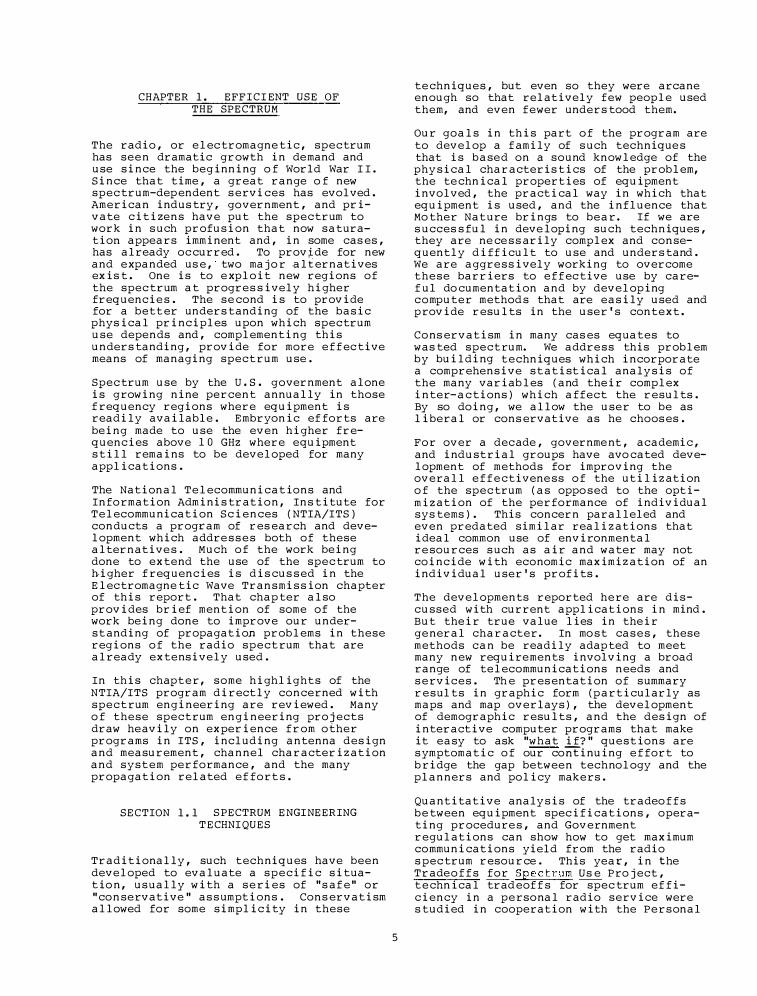
CHAPTER 1. EFFICIENT USE OF THE SPECTRUM
The radio , or elec tromagne tic , spectrum has seen dramatic growth in demand and use since the beginning o f World War I I . Since that time , a great range o f new spec trum-dep endent s ervices has evolved . American indus try , government , and private citizens have put the spectrum to work in s uch profusion that now saturation appears imminent and , in some cas es , has already oc curred . To prov�de for new and expanded us e , two maj o r aliernatives exis t . One is to exploit new regions of the spec trum at progres s ively higher frequencie s . The se cond is to provide for a bett er unders tanding of the basic phys ical principles upon which spectrum use depends and , complementing this unders tanding , provide for more eff ec tive means of managing spectrum use .
Spec trum use by the u.s. government alone is growing nine percent annually in those f requency regions where equipment is readily available . Embryonic ef forts are being made to use the even higher frequencies above 10 GHz where equipment s till remains to be developed for many applications .
The National Telecommunications and Information Adminis tration , Ins titute for Telecommunication Sciences ( NTIA/ITS ) conducts a program of res earch and development which addre s s e s both of these alternative s . Much o f the work being done to extend the use of the spec trum to nigher f requencies is dis cus s ed in the Electromagne tic Wave Transmis sion chapter of this report . That chap ter also provides brief mention of some of the work being done to improve our understanding of propagation problems in these regions o f the radio spectrum that are already extensively used .
In this chapter, some highlights of the NTIA/ITS program directly concerned with spectrum engineering are reviewed . Many o f these spectrum engineering pro� ects draw heavily on experience from other programs in ITS , including antenna design and measurement , channel characteriz ation and system performance , and the many propagation related ef fort s .
SECTION 1. 1 SPECTRUM ENGINEERING TECHNI QUES
Traditionally , such techniques have been developed to evaluate a specific situation, usually with a series of " s af e " or " conservative " as s umptions . Cons ervatism allowed for some simplicity in these
5
te chniques , but even so they were arcane enough so that relatively few people used them, and even fewer unders tood them.
Our goals in this part o f the program are to develop a family of s uch technique s that is based on a sound knowledge of the phy sical characteris tics of the problem, the te chnical properties of equipment involved , the practical way in which that equipment is used , and the influence that Mo ther Nature brings to bear. If we are s ucces s ful in developing such techniques , they are ne ce s s arily complex and consequently difficult to use and unders tand . We are aggressively working to overcome these barriers to eff ec tive use by caref ul do cumentation and by developing computer method s that are easily used and provide results in the user ' s context .
Cons ervatism in many cas es equates to was ted spectrum. We address this problem by building techniques which incorporate a comprehensive statistical analy sis of the many variables ( and their complex inter-ac tions ) which affect the results . By so doing , we allow the user to be as liberal or cons ervative as he choos es .
For over a decade , government , academic , and industrial groups have avo cated development of methods for improving the overall e f f e ctivene ss o f the utiliz ation o f the spec trum ( as oppo sed to the optimiz ation of the performance of individual sys tems ) . This concern paralleled and even predated similar realiz ations that ideal common use of environmental re sources s uch as air and water may not coincide with economic maximiz ation of an individual user ' s profits .
The developments reported here are dis cussed with current applications in mind . But their true value lies in their general character. In mo st cases , these methods can be readily adap ted to meet many new requirements involving a broad range of telecommunications needs and s ervices . Th e pres entation of summary results in graphic form ( particularly as maps and map overlays ) , the development of demographic results , and the design of interactive computer programs that make it easy to ask "what if? " questions are s ymptomatic o f our continuing e f fort to b ridge the gap between technology and the planners and policy makers .
Quantitative analy sis of the tradeo f f s be tween equipment specifications , operating procedure s , and Government regulations can show how to get maximum communications yield from the radio s pec trum resource . This year , in the Tradeo f f s for Spec trum Us e Pro j ect , te chnical trad eof f s for spec trum ef ficiency in a personal radio service were s tudied in cooperation with the Personal
Radio Pla nning Group ( PRPG ) of the Federal Communications Co mmis sion .
Citiz en ' s band radio channels are already badly conges ted in metropolitan areas , and the number of licensed sets is increasing several million per year. As a result , the Federal Co mmunica tions Commis sion has been s tudying the possibility of est ablishing a new Personal Radio Se rvice to supplement CB .
Earlier studies by PRPG had s elected the 2 20- 2 2 4 MHz and 900 MHz bands as candidates for a new personal radio service . De s ign parameters that might affect spe ctrum efficiency and service quality are modulation type , channel width , and radiated power . Th e different propagation characteris tics and ambient noise in the two frequency bands also affect the results .
Modulation types and channel wid ths considered were as follows : DoubleSideband Amplitude Modulation ( DSB-AM ) with a channel width of 10 kH z ; SingleSid eband AM ( S SB-AM ) with a channel width of five kH z ; and Frequency Modulation ( FM ) for channel widths of 15 , 2 5 , 50 and 100 kHz . Transmitter power was variable , but mo st calcula tions assumed five W . The average mobile s tation was assumed to have a quarter wave whip antenna mounted on the roof of a vehicle , between one and two meters above the ground. An average ba se st ation was assumed to have a 5/8 wavelength whip or a two-element Yagi antenna mounted five to ten meters above ground . Th e varia tion in inst allation heights and antenna types was accounted for by assuming that the effective radiated power had a st atistical dis tribution around these average ca ses .
A statistical propagation mo del, which depended on the terrain paramete1:· .6.h was used . Fairly smooth terrain or suburban development was represented by.6.h = 90 m , and rough terrain or urban development wa s repres ented by .t,.h = 200 m .
Trans ceivers were assumed to be dis tributed uniformly but randomly over a metropolitan are a , and users were as sumed to transmit at random times ( no courte sy ) . Th e density of users was varied to find the maximum number of users per channel for a desired quality of service .
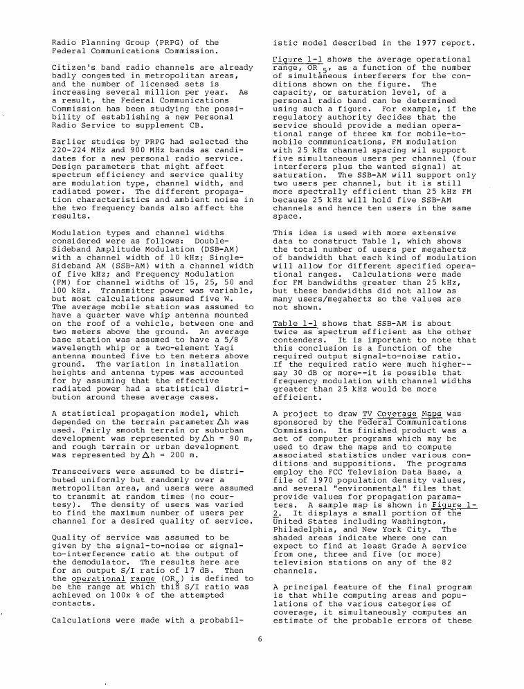
Quality of service was assumed to be given by the signal- to-noise or signalto-int erference ratio at the output of the demodula tor. Th e result s here are for an output S/I ratio of 1 7 dB . Then the operational range ( OR ) is defined to be the range at which thi� S/I ratio was achieved on lOOx % of the att empted contacts .
Calculations were made with a pro babil-
6
is tic model described in the 1 9 7 7 report .
Figure 1-l s hows the average opera tional range , OR 5 , as a function of the number of simultaneous interferers for the conditions s hown on the figure . Th e cap acity , or sa turation level, of a personal radio band can be determined us ing such a figure . Fo r example , if the regulatory authority decides that the service should provide a median operational range of three km for mobile-tomo bile commmunica tions , FM modulation with 2 5 k H z channel spacing wil support five simultaneous users per channel ( four interferers plus the wanted signal ) at saturation . Th e SSB-AM will support only two users per channel , but it is still more s pectrally efficient than 2 5 k H z FM because 2 5 k H z will hold five S S B-AM channels and hence ten users in the s ame s pace .
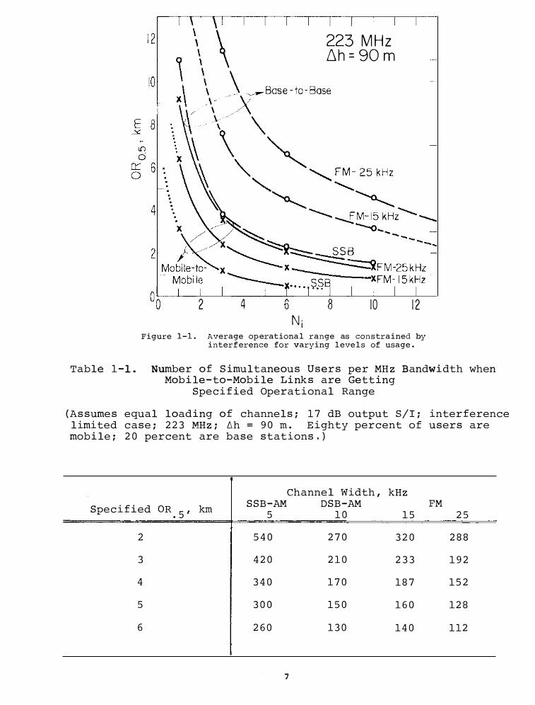
This idea is used with more extensive data to cons truct Table l , which shows the total number of users per megahertz of bandwidth that each kind of modula tion will allow for different specified operational ranges . Calcula tions were made for FM bandwid ths greater than 2 5 k H z , but these bandwid ths did no t allow as many users/meg ahertz so the values are no t shown .
Table l-1 s hows that SSB-AM is about twice as spectrum efficient as the other contenders . It is important to note tha t this conclusion is a function of the required output signal-to-noise ratio . .If the required ratio were much higher- say 30 dB or more- -it is possible that frequency modulation with channel wid ths greater than 2 5 k H z would be more efficient .
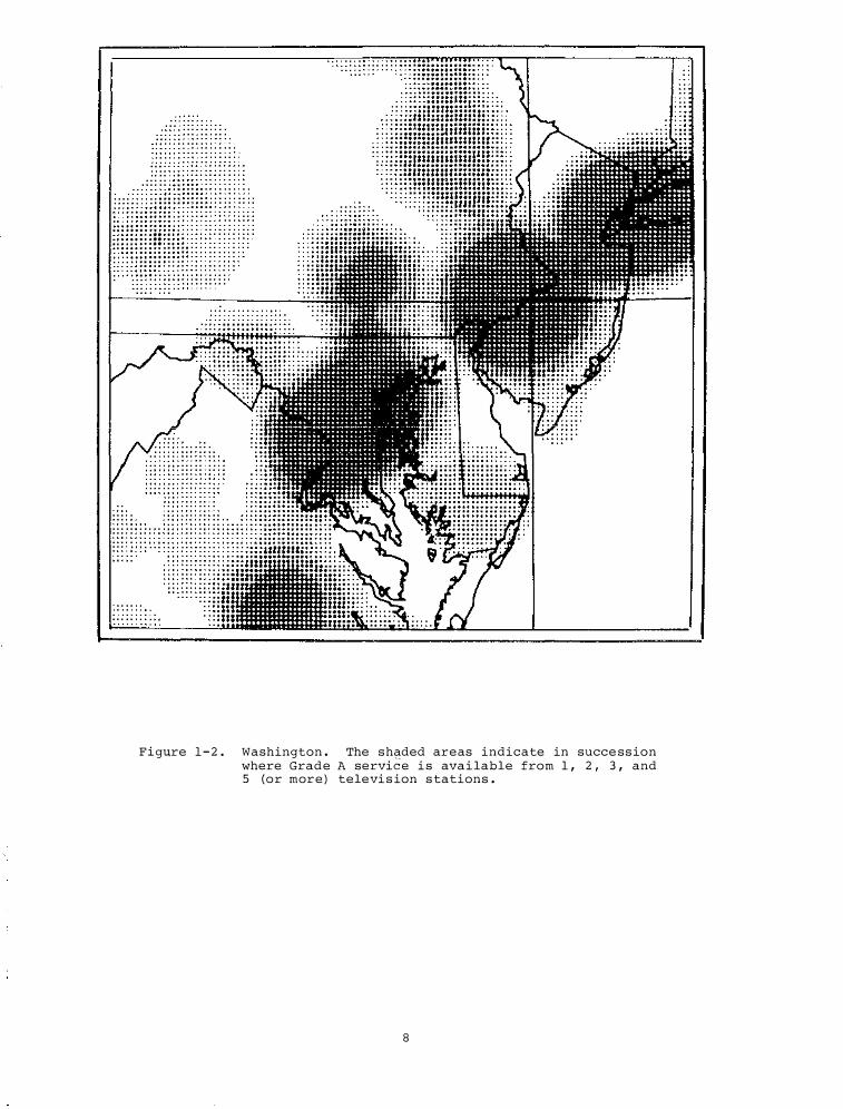
A pro j ect to draw TV Coverage Maps was sponsored by the Federal Communica tions Co mmis sion. Its finished product was a s e t of computer programs which may be used to draw the maps and to compute a s sociated statis tics under various conditions and suppo sitions . Th e programs employ the FCC Television Data Base , a file of 1 9 70 p opulation dens ity values , and several "environment.p.l" files that provide values for propagation paramaters . A sample map is shown in Figure l -2 . I t displays a s mall portion o f the United S t a tes including Was hington , Philadelphia , and New York City . Th e shaded areas indica te where one can expect to find at le ast Grade A service from one , three and five ( o r more ) television sta tions on any of the 8 2 channels .
A principal feature of the final program is that while computing areas and populations of the various categories of coverage , it simultaneously computes an es timate of the probable errors of these
2
223 MHz 6h = 90 m
4 6 8 Ni
10 12
Figure 1-1. Average operational range as constrained by interference for varying levels of usage.
Table 1-1. Number of Simultaneous Users per MHz Bandwidth when Mobile-to-Mobile Links are Getting
Specified Operational Range
(Assumes equal loading of channels; 17 dB output S/I; interference limited case; 223 MHz; 6h = 90 m. Eighty percent of users are mobile; 20 percent are base stations,)
Channel Width, kHz
Specified oR.5
, km SSB-AM DSB-AM FM
5 10 15 25
2 540 270 320 288
3 420 210 233 192
4 340 170 187 152
5 300 150 160 128
6 260 130 140 112
7
.. .. ..
..
..
.. ..
..
...
: : . ... :
. .. ... . .. . .. ...
Fig�re 1 - 2 . Washington . The shaded areas indicate in success ion where Grade A service i s avai lable from 1 , 2 , 3 , and 5 (or more) televi s ion s tations .
8
quantities . This , one should note , is not a trivial task . If for example , no one lives in a particular area then it does not matter how bad the es timates of received field streng ths are , the probable error of popul ation there will be zero . Clearly , the probable errors must somehow be re lated to the magnitude of popula tion densitie s . Sources of error include not only our ignorance of radio propagation los s e s , but also the inexactitude of some of the s ta tion parameters and susp ected errors in our environment al files .
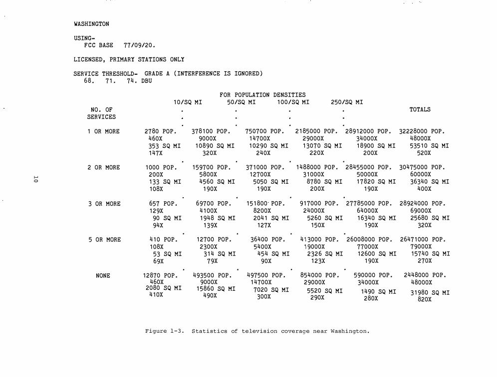
In Figure 1 - 3 is the output of statistics corresponding to the map in Figure 1 - 2 . Be low each computed value is a s econd value ( fol lowed by the letter " X " ) wh ich is the corre sponding probable error . Note that there are over two mil lion people in that region who do not receive Grade A s ervice from even one television s t ation.
This technique has broad future app lications in all broadca st s ituations , with FM as the mos t obvious example . Es timates of such coverage from satel lites alone or in combina tion with conventional broadcast facilities would be possible .
Spectrum planning techniques rely on some me asure of des ired system performance as a key factor in det ermining spectrumsharing potential . Such a perf ormance mea sure has been very dif ficult to find for voice communica tion .
An obj ective eval uation of receiver performance in terms of voice intel ligibil ity has long been a diff icult problem. In the pa st , both s ub j ective and ob j ective me asurement techniques have been used to a s s e s s the intelligibility of voice communica tion sys tems . Th e s ubj ective method involves trained speakers and list eners that dire ct ly s core the p ercentage of words that are correctly perceived. Unfortuna te l y , s ub j ective s coring methods are time consuming , dif ficult and expensive , and as a re sul t , are not used extensive ly .
One ob j e ctive method us ed in the past to me asure voice intelligibility has been the Articul ation Index {AI ) de fined as an average of the signa l- to-nois e ratio in s everal audio frequency bands . Several automated te chnique s to ob tain AI have been used. The two mos t we l l-known automatic te chnique s are the Speech Communication Index Meter ( S C IM ) and the Voice Int elligibility Anal ysis Set ( VIAS ) . Al though the AI technique is more practical than the s ub j e ctive AS technique , AI is not one -to-one corre lated with the s ub j ective measurement technique .
Recent ly a new ob j ective te chnique has
9
b een developed at ITS to me asure voice intelligibility . A dis tortion me asure is obtained us ing Linear Prediction Coding ( L PC ) , a math ematical te chnique widely known for its app lication to the ana ly sis and synth esis of speech . Th e feasibil ity of us ing LPC to develop an ob j e ctive intelligibility meas ure has been demons trated.
The ob j ective of this measurement task is to eva luate the potential of us ing the LPC me thod to obtain Ar ticul ation Scores ( AS ) s cores for different interference s ituations .
Re ceiver performance measurements have be en made on both a narrow-b and AM and FM receiver with int erference being nois e , a s imil ar type signa l {AM or FM ) , or pulsed co-channel signal . Th e AS , AI and LPC s cores wil l be measured and compared. The output of the proj ect wil l be pres ented in a let ter report .
A study ( AM Broadca st and Ra dio- l ocation Sh aring ) was undertaken at the reque st of the Federal Communication Commission ( FCC ) to provide technical da ta for determining the f easibility of extending the AM broadcast band from 1 6 1 5 k H z to 1 8 0 0 k H z , on an equal- status sharing b as is with ra dio-l ocation s ervice s . Th e s tudy was limited to cons ideration of one specific narrow-band radio- l ocation s y stem, the Decca Hi-Fix System, chosen b ecause of its widespread use in many areas . Th e basic methodology of the s t udy wa s to ca lculate the ratio R of the geographic distances from interfering transmitter to intended-receiver and de sired transmitter to intended- receiver. For interfe rence from a radio- l ocation transmit ter to a broadca st receiver , calcula tions were performed for signalto-interference ratios of 2 5 dB and 4 0 dB , and for two types of receivers having dif f erent pre-detection bandwidths . Th e results of these calculations are shown in Ta ble 1 - 2 and Table 1 - 3 . For interf erence from a broadcast transmitter to a radio-l ocation receiver, the ca l culations were based on a 1 dB reduction in e f fective S/N ratio at the radio- l ocation receiver. For this cas e , the s tudy also took into account the out-of-band e mis sions of the broadcast transmitters ( i . e . , due to harmonic and intermodula tion dis tortion products ) . Th e re sults of these calculations are p res ented in Ta ble 1 - 4 .
f-' 0
WASHINGTON
USING-FCC BASE 77/09/20.
LICENSED, PRIMARY STATIONS ONLY
SERVICE THRESHOLD- GRADE A (INTERFERENCE IS IGNORED) 68. 71. 74. DBU
NO. OF SERVICES
1 OR MORE
2 OR MORE
3 OR MORE
5 OR MORE
NONE
FOR POPULATION DENSITIES 10/SQ MI 50/SQ MI 100/SQ MI 250/SQ MI
. . . .
. . . . 2780 POP. 378100 POP. 750700 POP. 2185000 POP. 28912000 POP.
460X 9000X 14700X 29000X 34000X 353 SQ MI 10890 SQ MI 10290 SQ MI 13070 SQ MI 18900 SQ MI 147X 320X 240X 220X 200X
. . . . 1000 POP. 159700 POP. 371000 POP. 1488000 POP. 28455000 POP.
200X 5800X 12700X 31000X 50000X 133 SQ MI 4560 SQ MI 5050 SQ MI 8780 SQ MI 17820 SQ MI 108X 190X 190X 200X 190X
. . . 657 POP. 69700 POP. 151800-POP. 917000 POP. 27785000 POP. 129X 4100X 8200X 24000X 64000X
90 SQ MI 1948 SQ MI 2041 SQ MI 5260 SQ MI 16340 SQ MI 94X 139X 127X 150X 190X
. . . . 410 POP. 12700 POP. 36400 POP. 413000 POP. 26008000 POP. 108X 2300X 5400X 19000X 77000X
53 SQ MI 314 SQ MI 454 SQ MI 2326 SQ MI 12600 SQ MI 69X 79X 90X 123X 190X
. . . . 12870 POP. 493500 POP. 497500 POP. 854000 POP. 590000 POP.
460X 9000X 14700X 29000X 34000X 2080 SQ MI 15860 SQ MI 7020 SQ MI 5520 SQ MI 1490 SQ MI 410X 490X 300X 290X 280X
Figure 1 - 3 . S tatistics of television coverage near Washington .
TOTALS
32228000 POP. 48000X 53510 SQ MI
52 0X
30475000 POP. 60000X 36340 SQ MI
400X
28924000 POP. 69000X 25680 SQ MI
320X
26471000 POP. 79000X 15740 SQ MI
270X
2448000 POP. 48000X
31980 SQ MI 820X
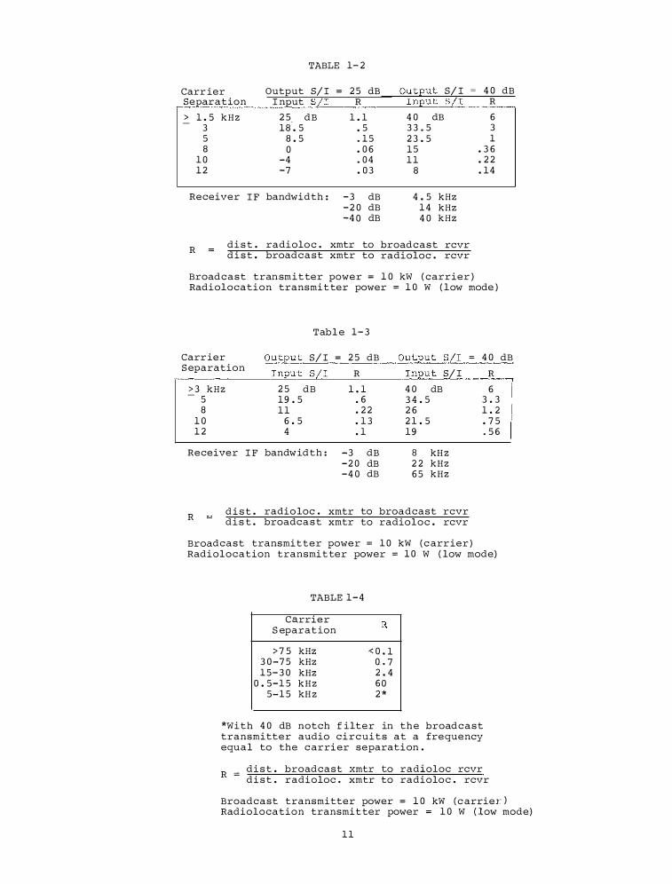
TABLE 1-2
Carr ier Output S/I = 25 dB Output S/I 40 dB Separation Input S/I R Input S/I R > 1.5 k H z 25 dB 1.1 40 dB 6
-18'. 5 3 . 5 33.5 3
5 8.5 .15 23.5 1 8 0 .06 15 .36
10 -4 .04 11 .22 12 -7 .03 8 .14
Receiver IF bandwidth : -3 dB 4.5 kHz -20 dB 14 kHz -40 dB 40 kHz
R di s t . radioloc . xmtr to broadcast rcvr d i s t . broadcast xmtr to radioloc . rcvr
Broadcast tran smitter power = 10 kW ( carrier ) Radiolocation transmit ter power = 10 W ( low mode )
Table 1-3
Carr ier Separation
Output S/I = 25 dB Input S/I R
Output S/I 40 dB Input S/I R
>3 kHz 25 dB 1.1 40 dB 6 -5 19.5 . 6 34.5 3.3 8 11 .22 26 1.2
10 6.5 .13 21.5 .75 12 4 .1 19 .56
Receiver IF bandw idth : -3 dB 8 kH z -20 dB 22 kHz -40 dB 65 kHz
R d i s t . radio loc . xmtr to broadcast rcvr di s t . broadca s t xmtr to radioloc . rcvr
Broadcast transmitter power = 10 kW ( c arr ier ) Radiolocation transmitter power = 10 W ( low mode)
TABLE 1-4
Ca,rrier S eparat ion
>75 kHz 30-75 kHz 15-30 kHz
0.5-15 kHz 5-15 kH z
<0.1 0..7 2.4 60 2*
*With 40 dB notch f ilter in the broadcast transmitter audio circuits at a frequency equal to the c arrier separation .
R _ di s t . broadcast xmtr to radioloc rcvr - d i s t . radioloc . xmtr to radioloc . rcvr
Broadcast transmitter power = 10 kW ( c arrier) Radiolocation transmit ter power = 10 W ( low mode)
11
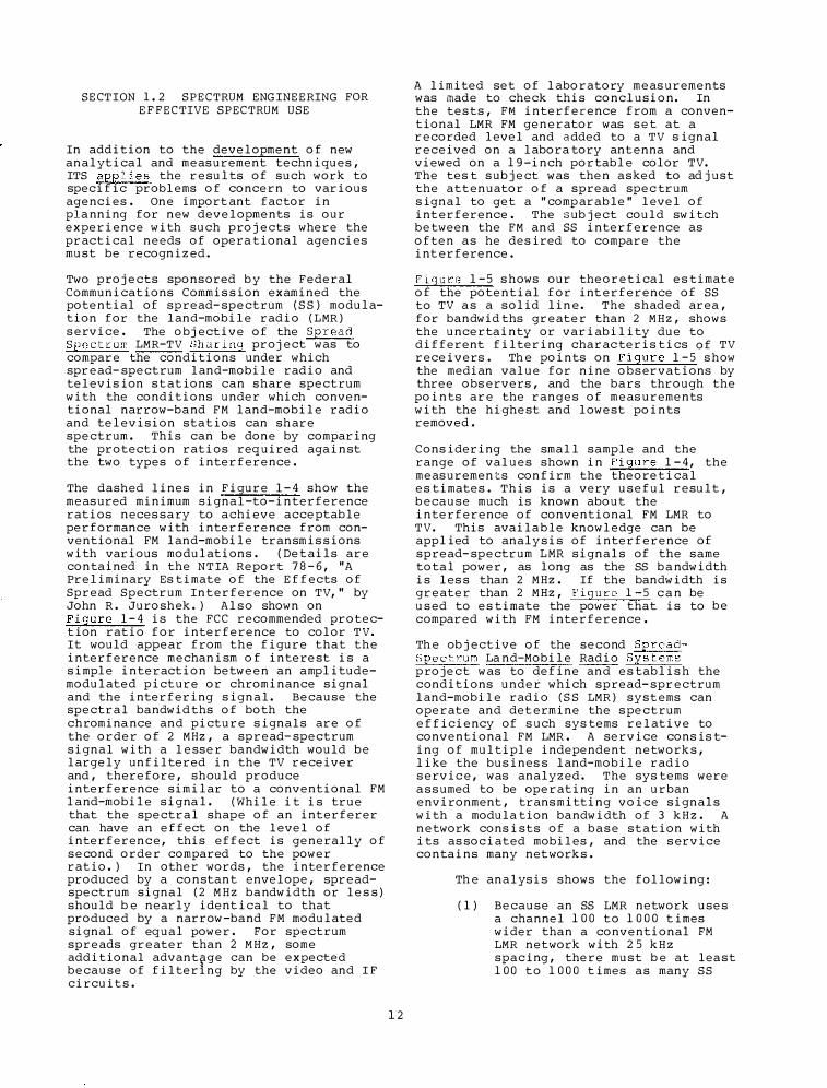
SECTION 1. 2 SPECTRUM ENG INEERING FOR EFFECTIVE SPECTRUM USE
In addition to the development of new analytical and measurement techniques , ITS applies the results of such work to specific problems of concern to various agencies . One import ant factor in planning for new developments is our experience with such proj ects where the practical needs of opera tional agencies must be recogniz ed .
Two proj ects sponsored b y the Federal Communications Commis sion examined the potential of spread- spectrum ( S S ) modulation for the land-mobile radio ( LMR ) service . The obj ective of the Spread Spect rum LMR-TV Sharing proj ect was to compare the conditions under which spread- spectrum land-mobile radio and televis ion st ations can share spectrum with the conditions under which conventional narrow-band FM land-mobile radio and television statios can sh are spectrum . This can be done by comparing the protection ratios req uired against the two types of interference .
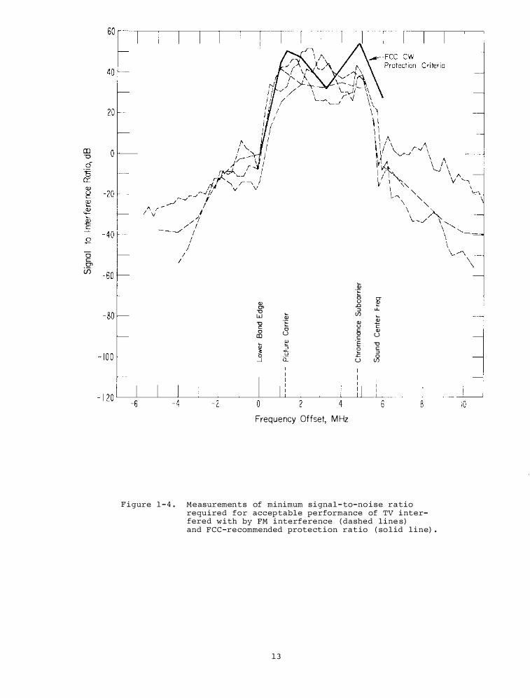
The dashed lines in Figure l- 4 show the measured minimum signal-to-interference ratios neces sary to achieve acceptable performance with interference from conventional FM land-mobile transmis sions with various modulations . ( Det ails are contained in the NTIA Report 7 8 - 6 , "A Preliminary Es timate of the Effects of Spread Spectrum Interference on TV, " by John R . Juroshek . ) Als o shown on Figure l- 4 is the FCC recommended protection ratio for interference to color TV. It would appear from the figure that the interference mechanism of interest is a simple interaction between an amplitudemodulated picture or chrominance signal and the interfering signal. Because the spectral bandwid ths of both the chromina nce and picture signals are of the order of 2 MHz , a spread- spectrum signal with a lesser bandwidth would be largely unfiltered in the TV receiver and , therefore , should produce interference similar to a conventional FM land-mobile signal. ( While it is true that the spectral shape of an interferer can have an effect on the level of interference, this effect is generally of second order compared to the power ratio . ) In other words , the interference produced by a constant envelope , spreadspectrum signal ( 2 M H z bandwidth or les s ) should b e nearly identical to that produced by a narrow-band FM modulated signal of equal power . For spectrum spreads greater than 2 MHz , some additional advant�ge can be expected because of filtering by the video and I F circuit s .
1 2
A limited set of laboratory meas urements was made to check this conclusion. In the tests , FM interference from a conventional LMR FM generator was set at a recorded level and added to a TV s ignal received on a labora tory antenna and viewed on a 1 9 -inch portable color TV. The tes t sub j ect was then asked to ad j ust the attenuator of a spread spec trum signal to get a "comp arable" level of interference . The sub j ect could switch between the FM and SS interference as often as he des ired to compare the int erference .
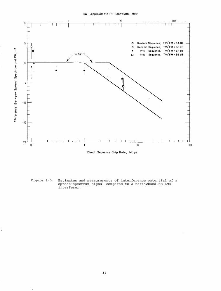
Figure l - 5 s hows our theoretical es timate of the potential for int erference of SS to TV a s a solid line. The shaded area , for bandwid ths greater than 2 MHz , shows the uncertainty or variability due to different filtering charac teris tics of TV receivers . Th e points on Figure l - 5 s how the median value for nine observations by three obs ervers , and the bars through the points are the ranges of meas urements with the highest and lowest points removed .
Cons idering the small sample and the range of values shown in Figure 1 - 4 , the measurements confirm the theoretical es timates . This is a very useful result , because much is known about the interference of conventional FM LMR to TV. This availa ble knowledge can be applied to analy sis of interference of spread- spectrum L MR signals of the same total power , as long as the SS b a ndwidth is les s than 2 MHz . If the bandwidth is greater than 2 MHz , Figure 1-5 c a n be used to es timate the power that is to be compared with FM interference .
Th e ob j ective of the second SpreadSpectrum La nd-Mobile Radio Systems project was to define and es tablis h the conditions under which spread- sprectrum land-mobile radio ( S S LMR ) systems can operate and det ermine the s pectrum efficiency of s uch sys tems relative to conventional FM LMR . A service cons is ting of multiple independent network s , like the busines s land-mobile radio service, was analyzed . The sys tems were assumed to be operating in an urban environment , trans mitting voice signals with a modula tion bandwidth of 3 k H z . A network cons ists of a base station with its as sociated mobiles , and the service contains many net work s .
Th e analysis shows the following :
( l ) Because an SS LMR network uses a channel 100 to 1000 t imes wider than a conventional FM LMR network with 2 5 k H z spacing , there must b e at least 100 to 1000 t imes as many SS
0 c: 0'> (15
<ll 0' "0 w -g 0 ro
"<ll .E 0 u
Frequency Offset, MHz
Q; .E 0 u ..0 :::l (j) <ll u § c .E 2 .c
u
"<ll c <ll u "0 c :::l �
Figure 1 - 4 . Measurements of minimum signal - to-noise ratio required for accep table performance of TV interfered with by FM interference ( dashed line s ) and FCC-recommended protection ratio ( so lid line) .
1 3
:E LL -o c 0 E ;: u Q) 0. (/) -o 0 � 0.
(/) c Q) Q) 3: Q)
CD Q) u c � � -a
BW -Approximate RF Bandwidth, MHz
0 Random Sequence, TV/FM =34d8 )( Random Sequence, TV/FM =39d8 • PRN Sequence, TV/FM = 34dB
0 PRN Sequence, TV/FM=39dB
0.1 10
Direct Sequence Chip Rote, Mb ps
Figure 1- 5 . E s t imates and measurements o f interference potential o f a spread-spectrum s ignal compared to a narrowband FM LMR interferer .
],4
100
networks operating on a channel for comparable spectrum efficiency.
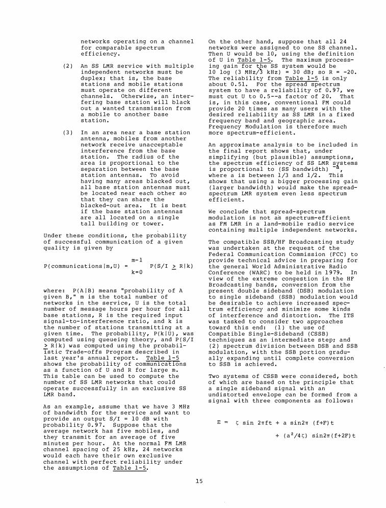
(2) An SS LMR service with multiple independent networks must be duplex; that is, the base stations and mobile stations must operate on different channels. Otherwise, an interfering base station will black out a wanted transmission from a mobile to another base station.
(3) In an area near a base station antenna, mobiles from another network receive unacceptable interference from the base station. The radius of the area is proportional to the separation between the base station antennas. To avoid having many areas blacked out, all base station antennas must be located near each other so that they can share the blacked-out area. It is best if the base station antennas are all located on a single tall building or tower.
Under these conditions, the probability of successful communication of a given quality is given by
m-1 P(communications/m,U) P(S/I 2:. R/k)
k=O
where: P(A/B) means "probability of A given B," m is the total number of networks in the service, U is the total number of message hours per hour for all base stations, R is the required input signal-to-interference ratio, and k is the number of stations transmitting at a given time. The probability, P(k/U), was computed using queueing theory, and P(S/I > R/k) was computed using the probabil
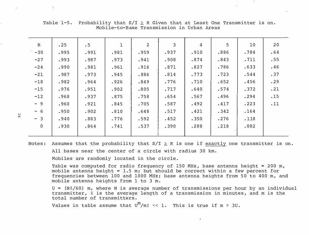
istic Trade-offs Program described in last year's annual report. Table 1-5 shows the probability of communications as a function of U and R for large m. This table can be used to compute the number of SS LMR networks that could operate successfully in an exclusive SS LMR band.
As an example, assume that we have 3 MHz of bandwidth for the service and want to provide an output S/I = 10 dB with probability 0.97. Suppose that the average network has five mobiles, and they transmit for an average of five minutes per hour. At the normal FM LMR channel spacing of 25 kHz, 24 networks would each have their own exclusive channel with perfect reliability under the assumptions of Table 1-5.
15
On the other hand, suppose that all 24 networks were assigned to one SS channel. Then U would be 10, using the definition of U in Table 1-5. The maximum processing gain for the SS system would be 10 log (3 MHz/� kHz) = 30 dB; so R = -20. The reliability from Table 1-5 is only about 0.51. For the spread spectrum system to have a reliability of 0.97, we must cut U to 0.5 --a factor of 20. That is, in this case, conventional FM could provide 20 times as many users with the desired reliability as SS LMR in a fixed frequency band and geographic area. Frequency Modulation is therefore much more spectrum-efficient.
An approximate analysis to be included in the final report shows that, under simplifying (but plausible) assumptions, the spectrum efficiency of SS LMR ��stems is proportional to (SS bandwidth) , where a is between 1/3 and 1/2. This shows that using a bigger processing gain (larger bandwidth) would make the spreadspectrum LMR system even less spectrum efficient.
We conclude that spread-spectrum modulation is not as spectrum-efficient as FM LMR in a land-mobile radio service containing multiple independent networks.
The compatible SSB/HF Broadcasting study was undertaken at the request of the Federal Communication Commission (FCC) to provide technical advice in preparing for the general World Administrative Radio Conference (WARC) to be held in 1979. In view of the extreme congestion in the HF Broadcasting bands, conversion from the .present double sideband (DSB) modulation to single sideband (SSB) modulation would be desirable to achieve increased spectrum efficiency and minimize some kinds of interference and distortion. The ITS was tasked to consider two approaches toward this end: ( 1) the use of Compatible Single-Sideband (CSSB) techniques as an intermediate step; and (2) spectrum division between DSB and SSB modulation, with the SSB portion gradually expanding until complete conversion to SSB is achieved.
Two systems of CSSB were considered, both of which are based on the principle that a single sideband signal with an undistorted envelope can be formed from a signal with three components as follows:
E s sin 2rrft + a sin2rr (f+F)t
+ (a2/4s) sin2rr(f+2F)t
I-' "'
R
-30
-27
-24
-21
-1 8
-15
-12
- 9
- 6
- 3
0
Tab le 1 -5. Probabi lity that S/I � R Given that at Least One Tran smitter i s on. Mobi le-to-Base Tran smi s sion in Urban Areas
.25 . 5 1 2 3 4 5 10 20
.995 .991 .9 81 .959 .937 .910 .8 86 .7 84 .64
.993 .987 .973 .941 .90 8 . 874 . 843 .711 .55
.990 .9 81 .961 .916 . 871 . 8 27 .7 86 .633 .46
.987 .973 .945 . 8 86 . 814 .773 .723 .544 .37
.9 82 .964 .926 . 849 .776 .710 .652 .456 .29
.976 .951 .902 .805 .717 .640 .574 .372 .21
.96 8 .937 . 875 .75 8 .654 .567 .496 .294 .15
.960 .921 . 845 .705 .5 87 .492 .417 .223 .11
.950 .902 . 8 10 .64 8 .517 .421 .342 .164
.9 40 . 8 83 .776 .592 .452 .350 .276 .118
.930 . 864 .741 .537 .390 .2 8 8 .21 8 .0 82
Note s : As sume s that the probabi lity that S/I � R i s one if exact ly one tran smitter is on.
A l l ba se s near the center of a circle with radius 30 km.
Mobi le s are randomly located in the circ le.
Table wa s computed for radio frequency of 150 MHz, base antenna height = 200 m, mobile antenna height = 1.5 m; but should be correct within a few percent for f requencies between 100 and 1000 MHz; ba se antenna height s from 50 to 400 m, and mobi le antenna height s f rom 1 to 3 m.
U = (N .Q,/60) m, where N i s average number of tran smi s sion s per hour by an individua l tran smitter, 9., i s the average length of a tran smi s sion in minute s, and m i s the total number of t ransmitter s.
Value s in table a s sume that Um
/m ! < < 1. Thi s i s true if m > 3U.
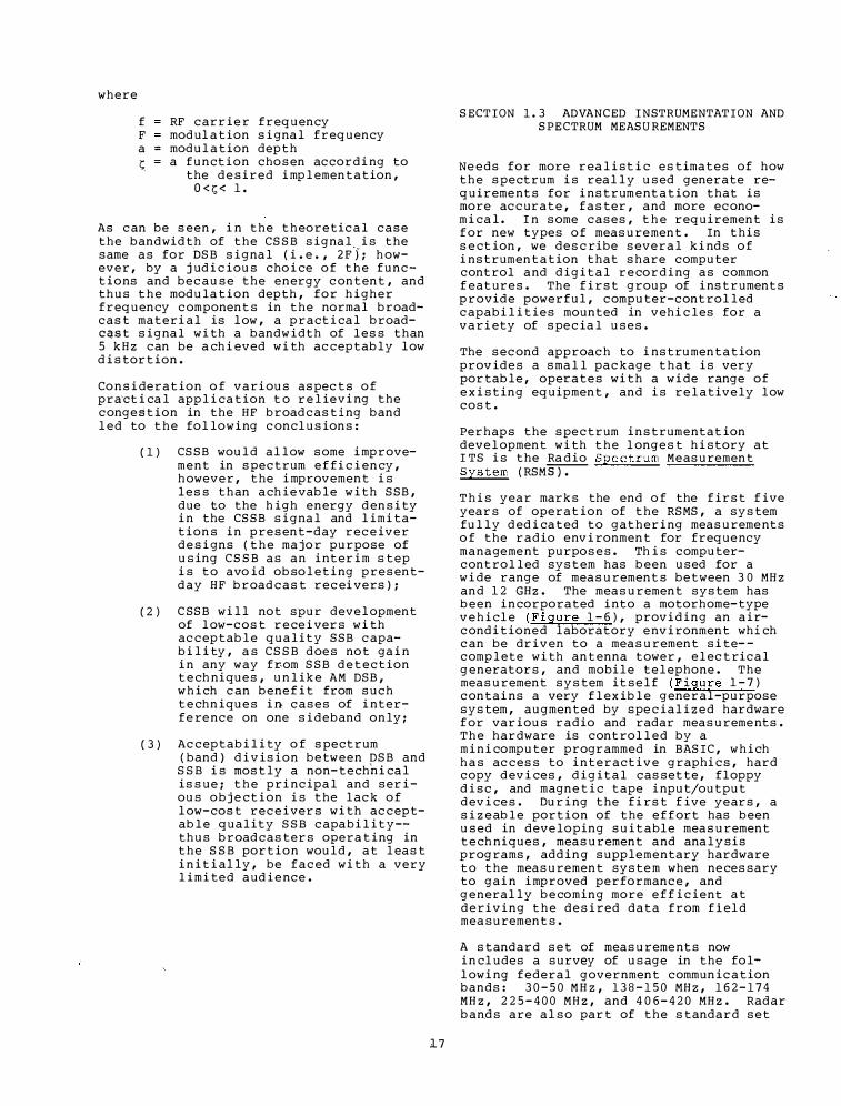
where
f RF carrier frequency F modulation s i gnal frequency a = modulation depth � = a function chosen accordi ng to
the desired i mplementation, O < r; < 1 .
As can be seen, i n the theoretical case the bandwidth of the CSSB signal. is the same as for DSB signal (i . e . , 2F ); however, by a j udicious cho i ce o f the functions and because the energy content, and thus the modulation depth, for higher frequency components in the normal broadcast materi al is low, a practical broadCqSt signal with a bandw idth of less than 5 kHz can be a chi eved w i th acceptably low d istortion .
Co nsi deration o f vari ous aspects o f pra·ct i cal appli cation t o relie:r i ng the conge stion in the HF broadcasti ng band led to the following conclusions :
( 1 )
( 2 )
( 3 )
CSSB would allow some i mprovement in spectrum e f f i c i ency, however, the i mprovement i s less than achievable w ith SSB, due to the h igh energy density i n the CSSB signal and limitations i n present-day rece iver desi gns (the ma jor purpose of using CSSB as an i nter i m step i s to avo id obsoleti ng presentday HF broadcast recei vers ) ;
CSSB will not spur development of low-cost rece i vers w i th acceptable quality SSB capab i lity, as CSSB does not ga i n i n any way fr-om SSB detection techniques, unlike AM DSB, which can bene f it from such techn iques i n cases of i nterfere nce on one sideband only;
Acceptability o f spectrum (band ) d i v ision between DSB and
SSB i s mostly a non-techn i cal issue; the pri ncipal and ser i ous obj e ction is the lack o f low-cost rece ivers with acceptable quality SSB capability-thus broadcasters operating in the SSB portion would, at least i n it i ally, be faced with a very limited aud i e nce .
1 7
SECTION 1 . 3 ADVANCED INSTRUMENTATION AND SPE CTRUM MEASUREMENTS
Ne eds for more realist i c estimates of how the spectrum is really used generate requireme nts for i nstrumentation that is more accurate, faster, and more econom i cal. In some cases, the requirement is f or new types o f measurement . In this sect ion, we describe several ki nds o f i nstrumentation that share computer control and digital recordi ng as common f eatures . The f irst group of i nstruments provide powerful, computer-controlled capabilities mounted in vehi cles for a vari ety of special uses .
The second approach to i nstrumentation prov ides a small package that is very portable, operates with a wide range of existing equipment, and is relatively low cost .
Perhaps the spectrum i nstrumentat ion development with the longest history at ITS is the Ra dio Spectrum Measurement System (RSM�
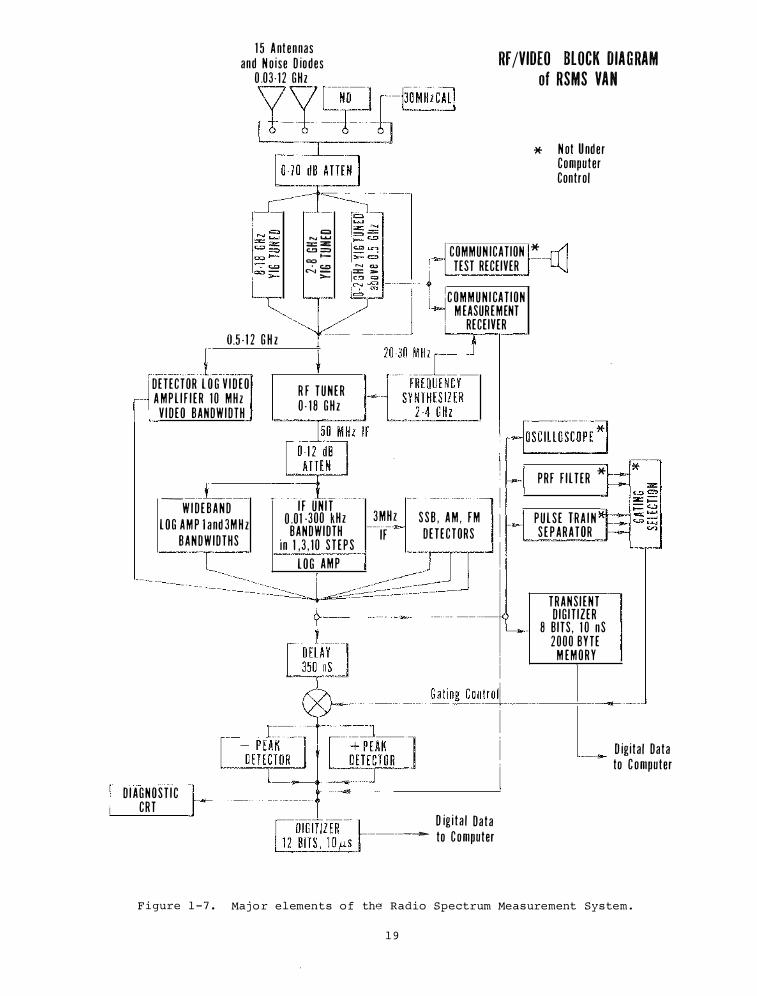
This year marks the end o f the f irst f ive years of operat ion of the RSMS, a system fully ded i cated to gatheri ng measureme nts o f the radio environment for freque ncy manageme nt purposes . Th is computercontrolled system has been used for a w i de range of measurements between 3 0 MHz and 1 2 GHz . The measurement system has been i ncorporated i nto a motorhome-type vehicle (Fi gure 1 - 6 ) , prov�ding an a i :conditioned laboratory e nvironment whi ch can be driven to a measurement site- complete with antenna tower, electrical generators, and mobile telephone . The measurement system itself (F igure 1 - 7 ) conta i ns a very flexible general-purpose system, augmented by specialized hardware f or various radio and radar measureme nts . The hardware is controlled by a m i n i computer programmed in BASIC, which has access to i nteractive graphics, hard copy dev i ces, digital cassette, floppy d isc, and magnetic tape i nput/output dev i ces . Dur i ng the f i rst f ive years, a sizeable portion of the effort has been used in developing suitable measurement techniques, measurement and analysis programs, adding supplementary hardware to the measurement syste m when necessary to ga i n i mproved performance, and generally becoming more e f f icien� at deriving the desired data from f i eld measurements .
A standard set of measureme nts now i n cludes a survey of usage in the followi ng federal government commun ication bands: 3 0 - 5 0 MHz, 1 3 8 - 1 5 0 MHz, 1 6 2 - 1 7 4 MHz, 2 2 5 - 4 0 0 MHz, and 4 0 6 - 4 2 0 MHz . Radar bands are also part of the standard set
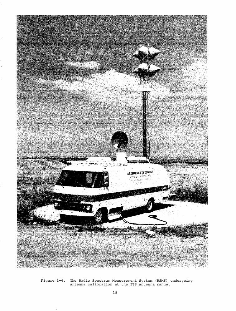
F i gure 1 - 6 . The Radio Spectrum Measurement System ( RSMS ) undergoing antenna c a l ibration at the ITS antenna range .
1 8
1 5 A nt ennas and N o ise D iodes
0 .03 · 12 GHz RF /VIDEO BLOCK DIAGRAM
of RSMS VAN
0.5 · 1 2 G H z
DETECTOR L O G V I D EO A MP L I F I E R 1 0 MH z V I D EO BANDWIDTH
_ __i __
W I D E B A N D L O G A M P l a nd 3M H z
BANDW IDTHS
D I AGNOST I C CRT
= ...... .......
�O M H z CAL! * N ot U nder
Computer Control
= z = = ..... ""' N � � � COMMUN ICATION * TEST RECEIVER
"'l"---� �J
R F T U N E R 0 - 1 8 G H z
C O M M U N I CAT ION M EASUREMENT
RECEIVER
I F UN I T 0 .01 -300 kH z 3MH z S S B , A M , FM BANDWIDTH IF DETECTORS
in 1 , 3 , 1 0 S T E P S L O G A M P
0---------------�
PRF F I LTER *
PULS E TRA I N S E P ARATOR
TRANS I ENT D IG IT IZER
8 B ITS , 1 0 nS 2000 BYTE
M EM O R Y
1---·-----G_at_in . .:::..g _Co_nt_ro41 ___ __,_ ______ .....J
L D igita l Data to C omputer
D ig i t a l Data -----. to Computer
F i gure 1 - 7 . Maj o r elements o f the Radio Spectrum Measurement Sys tem .
1 9
o f measureme n t s , i nc l ud i ng t h e 1030-1090 MHz , 1 2 1 �-1400 MHz , 2 700-3700 MHz , 5250-5925 M H z , and 8 . 5- 10 . 5 GH z b a nd s . Many or a l l of the preced i ng bands have been measu r ed in six large metropo l i t a n a r e a s a cross the U n i ted S t a t e s . M e a s u reme n t s have been repeated i n two o f the area s , g iv i ng a f i r s t look a t the g rowth o f u sage o v e r a four-year p e r i o d . I n t h e p a s t year , meas urements h a v e been made i n t e n c i t i e s i n t h e e a s t e r n h a l f o f t h e U . S . , i nc l u d i ng e x t e n s i v e measureme n t s a t E g l i n AFB , F l or i d a ; A t l a n t a , Ge org i a ; Nor f o l k , V i rg i n i a ; a nd Wash i ng ton , D. C .
I n add i t io n to the s tandard u s age meas urement s , the RSMS has o f t e n been cal l ed upon to h e l p solve par t i c u l a r · �robl ems . The fol low i ng examples w i l l s e rve to i l l u s t r a t e some of the s y s t em ' s spe c i a l capab i l i t i es . We expect t h a t t h e RSMS w i l l con t i nu e to r espond to r eq u e s t s for spec i a l a s s i s tance , espe c i a l ly wh en t h e capab i l i t i es of the RSMS c a n b e app l i ed w i th a marked advantage over l e s s e l a borate sys tems .
T h e emi s s ion spectra of many d i f ferent types o f radars have been measu red a s part o f a n e f fort to d e termine trade-o f f s b e tween var ious tech n i q u e s o f spect rum conservat ion in the radar band s . T h e s e measureme n t s have taken the RSMS to many p a r t s of t h e u.s. to o b s e rve pro totype radar s , crowd ed r a d a r env i ronment s , and many o ld e r radars in v a r i o u s s ta t e s of m a i ntenanc e .
T h e RSMS w a s u s e d i n a s tudy o f f a c tors cau s i ng pos s i b l e system mal funct ions i n t h e very crowd ed 1 030-1090 MHz air t r a f f i c control b e a con ( I F F ) band . Fo r t h i s work the RSMS was t i ed to a l a r g e FAA compu ter wh i ch proce s s ed a i r rou t e d a t a f rQm b e a con s i gna l s , wh i l e the RSMS s imul taneously measu red the s i g n a l e n v i ronment . By corre l a t i ng the s ig n a l e n v i ronment w i th comp u t e r proce s s i ng m a l f u n c t i ons , the RSMS was able to prov i d e some d a t a on the causes of some ma l fu n c t ions , as w e l l as to h e lp e s t imat e the amoun t o f improveme n t w i th v a r i ous f i xe s .
NASA asked for h e l p i n loca t i ng t h e cause of occas i on a l i nterf erence to recep t ion o f deepspace s ig n a l s a t i ts Go l d s tone commu n i ca t ion s i t e . Au toma t i c s u rv e i l lance programs were d e v i sed for the RSMS a nd opera ted o n a 2 4-hour/day b a s i s for f iv e week s . Th e s e prog r ams i nc l uded many features l ik e a u toma t i c d i r e c t ion f i n d i ng t o a s s i s t i n
2 0
i d e n t i f y i ng any unknown s i g na l s .
E a c h year h a s s e e n some new measurement h a r dware and s o f tware added to the RSMS for the purpo s e s of mak i ng b e t t e r , f as t er , more a ccurate measu rements . Th i s y e a r i mproveme n t s were made i n two areas , appa r e n t ly f i n i s h ing a long ch a i n of e vo l u t i onary deve lopments . Th e s e a re a s - a n tenna sys tem and commu n i cat ion b a nd measur emen t s - -w i l l be d i s cu s sed in the fol low i ng paragraph s .
LMR Measurement Te chniques
Us age su rvey s are made i n several l a nd-mob i l e r a d i o ( LMR ) and s i m i l ar commu n i c a t ion bands . In these b a nd s , s ig n a l s are usually nar rowb a n d vo i ce and the ass i gnme n t s are made a ccord i ng to a forma l band c h ann e l i z a t ion pl a n , w i th each channel separa ted from ad j a cent channe l s by a f i xed amoun t , typ ic a l l y 2 5 k H z . In theory , a u s a g e measurement i s v e r y s i mp l e--o n e m e r e l y h a s t o t u n e t o a freq u e n cy and mea s u r e how much of the t ime a s i gnal i s ther e . In pract i ce , i t may b e f a i r l y d i f f i cu l t to make s u ch a me asu rement e f f i c i e n t l y wh i l e a s su r i ng t h a t t h e measured d a t a i s a c cura t e . Th e problems come ma i n ly f rom t h e i nt e r a c t ion o f o c ca s ional l a rge s i g n a l s w i th the non- i d e a l c h a r a c te r i s t i cs o f pract i c a l m e a s u r ement system hardware .
La rge s i g n a l s w i l l cau se the h ardw a r e to generate spu r i o u s respons e s , c a l l ed i n t e rmodu l a t ion produ c t s , a t f reque n c i es r e l a ted t o t h e s u m and d i f fe r e n t freq u e n c i e s of v a r i o u s h armo n i cs o f t h e s t rong s i g na l s . I n add i t ion , no i s e on the me a s u reme n t sys tem l o c a l o s c i l l a to r w i l l s how u p a s a b a n d o f s i g na l s ad j a cent to a ny s t rong s i g na l . Th e s e spur ious r e sponses w i l l be measu red by the s y s tem as though they were real s i gna l s in t h e e n v i ronment . So f tware proc es s i ng o f the me a s u red data to separate the spurious s i gn a l s f rom t h e r e a l s i g n a l s is o f t e n e x tremely d i f f i cu l t , s i nce t h e m e a s u r ed d a t a on the l arge s i g na l popu l a t ion i s u s u a l ly not adeq u a t e to r e l i ab l y c a l c u l a t e quant i t a t i v e a mpl i tudes f o r the spurious r e spons e s .
Al though we a t t empted to remove spu r i ous s i gna l s from recorded data w i th s o f tware proce s s i ng in some o f o u r e a r l y LMR m easu remen t s , our p h i losophy h a s s h i f ted s trong l y toward r e a l- t i me s creen i ng a n d a na l y s i s o f the da t a . The cos t o f t ak i ng ma s s i v e amounts o f d a t a w i th compu ter-controlled s y s t ems i s so s ma l l t h a t i t i s o f t en pra c t i c a l to
merely throw away t h e data i f there is reason to s u spect that it may be contam i na t ed w i th s p u r i ous responses Accord i ng l y , t h e RSMS measu rement techniques now i n c l u d e s everal precaut ionary tests wh i c h are cont i n u a l l y ope r a t ed o n a r e a l-t ime bas i s to d e t e r m i n e whether data m i g h t be con t a m i n a t e d by spu r i ous r espon s es. Fo r t u n a t e l y , the mos t i mpo rtant t e s t i s a s i mp l e one , s i nce the po s s i b i l i ty of spu r i o us responses i s d i r e c t l y r e lated to peak power i n c i d e n t on the a c t ive components of the r e c e i ver.
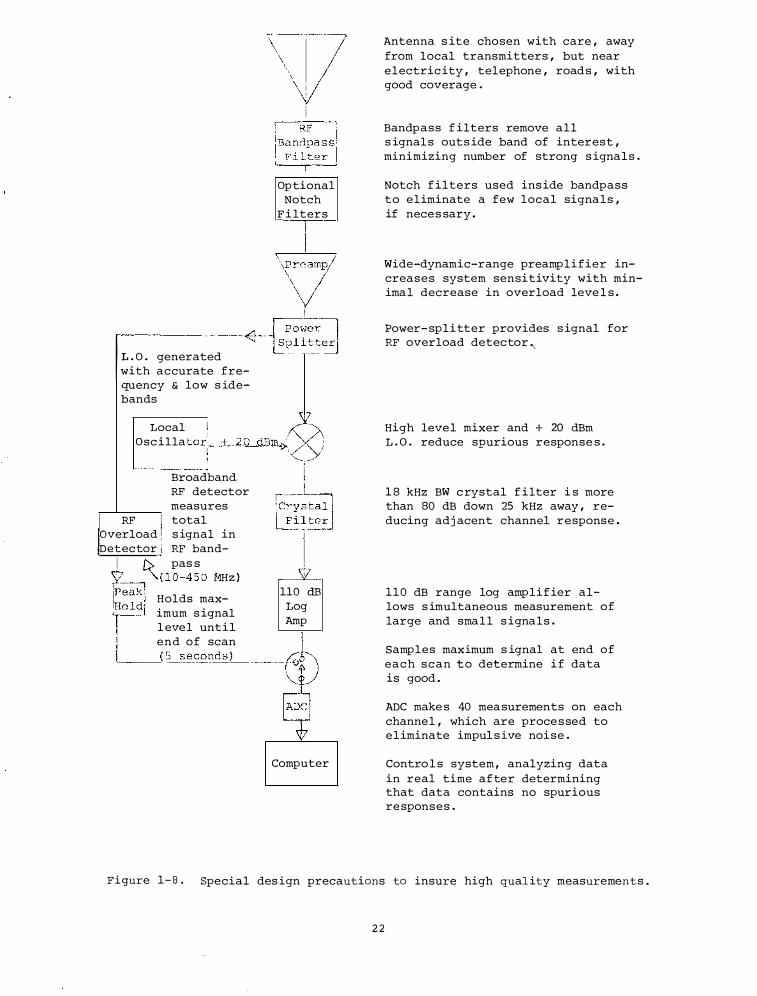
F i gure 1-8 s hows many o f the prec a u t ions wh i ch are taken to i ns u r e measurement q u a l i t y. Th ese precaut ions fall i nto three m a i n a reas : 1 . H i g h p e r formance measurement e q u i pm e nt , des igned to h ave f ew spu r i o u s responses ; 2. choi ce of a m e a s u r eme n t envi ronment to avo i d mos t s t rong s i gna l s ; 3. t e s t s wh i ch d i s ca r d po s s ibly wrong d a t a if 1. or 2. is no t su f f i c i ent. On e shou l d no t e t h a t a l l three of these precau t i o n s a r e i n t e r-r e l a ted compromi s es. Fo r e xa mp l e if one could b u i l d i de a l meas urement r e c i evers ( # 1 ) , it wou l d not be neces s ary to worry abo u t # 2 o r # 3. S i m i l a r l y , w i t h a s u f f i c i e n t ly b e n i g n mea s u reme n t e n v i ronment ( #2 ) , i t wo u l d not be n e c e s s a r y to employ # 1 or# 3.. In the real wor ld , none o f the preca u t i o n s can be made to work s u f f i c i en t l y w e l l to do the j ob by i t s e l f , and a l l mu s t be u s ed i n comb i n a t ion.
C a reful s e l e c t ion of a measurement s i te , avo i d i ng local t r a n sm i t t er s , i s t h e f i r s t s tep i n a s s u r i ng a r e l a t i ve l y easy m e a s u r ement envi ronm e n t. Good RF bandpas s f i l t ers e l i m i n a t e ou t-o f-band s trong s i g n a l s a nd n o t c h f i l t er s c a n b e u s e d t o e l i m i n a t e a f ew s trong , r e l a t ivelycon t i nuou s , i n-band s i g n a l s. Th e h i gh performa n c e measu reme n t e q u i pment i s a subsys tem des i gned a n d bu i l t by ITS w i t h c apab i l i t i e s i n s e l e c t ed L M R b a n d s b e low 5 00 M H z ( l a b e l ed " commu n i ca t i o n s me a s u rement r e c e i v e r " in F i g u r e 1 - 7 ) . Th i s speci a l i z e d sys tem make s a ccurate measu rements o v e r a n i ns t a n t aneous 1 10 d B dynami c range ( - 1 1 5 d Bm to - 5 dBm ) w i th a n 1 8 k H z r e c t a n g u l a r b a ndw i d th that i s down more than 8 0 d B 25 kHz away. E v e n i n t h i s s t ateo f- the-art sys t em , s ig n a l s l a rger t h a n abou t -40 dBm can cause i n t ermod respon s e s above s y s t em no i s e , wh i ch wo u l d ma s querade a s r e a l s i gna l s.
For the o c c a s i o n a l s i g n a l s s t rong e r t h a n -40 dBm, d a t a m e a s u red d u r i n g
2 1
t h e s e per iods i s s i mpl y i g nored. B e c a u s e s trong s i gna l s m i g h t occur o n frequenc i e s that ate not measu red o r a t t i mes whe n o t h e r frequ e n c i e s i n t h e b and are b e i ng measured , one c a n no t depend on the r e g u l a r meas u rement sys tem to prov i d e r e l i able peak s i g n a l power da ta. We u s e a s ep a r a t e RF w ideband de t e c tor , wh i ch l ooks at the e n t i re RF bandpass a l l t h e t ime , a s s u r i ng t h a t n o s trong s i g n a l s w i l l be m i s s ed. To s impl i fy t h e measu rement s o f twar e ; the peak v a l u e of a s i gnal dur i ng a f ives e cond s c a n is h e l d in a peak d e t e c tor and me a s u red only at the end o f a s can. I f a s t rong s i gnal is s e e n , all of t h e data for that s ca n is d e l e t ed.
Th i s comb i na t ion of ha rdware and s o f tware h a s a l lowed u s to g a th e r u n contaminated d a t a a t m a n y s i tes w h i ch wou ld have been u n s u i t a b l e for m e a s u r ements w i th a l e s s capable s y s t em. I n a r e c e n t s e r i e s o f LMR m e a s u remen t s , for exampl e , a l mo s t 2 5 % o f t h e d a t a w a s d e l e ted because o f s t rong s i gna l s , but we b e l i eve that t h e data wh i c h was r e t a i ned is comp l e t e l y free o f spu r i o u s re spons e s and accurately represents the s i g n a l env i ronment.
An t enna Sys tems
A s e cond area of i mproveme nt is the RSMS a n t enna system, wh i ch h a s been mod i f i ed to a l low cons i derably mo�e e f fe c t i ve d i rect ion-o f-a r r i v a l measu rements on unknown s i gn a l s ( F i gu r e 1 -9 ). Th e RSMS was des igned o r i g i na l l y w i th 1 - 12 GHz c a v i tyb a cked- sp i ra l ( C BS ) antennas and .1 5-4 GHz con i ca l h e l i x an tennas i n s e t s o f f o u r ( s e e F i gure 1 -6 ) . S i nce t h e s e antennas typ i c a l l y have 70-90° b e amw i d t h , the s e t of four cou l d b e a i med w i th 90° b e tween e a ch a nt enna to g i ve f a i r ly comp l e t e coverage f o r 3 60°. Two s e t s o f four were u s e d to get r i ght-hand and l e f t-h and c i r cu l a r pol a r i z a t ion. Th e s e a n t ennas have s e rved we l l i n o u r e a r l i e r mea s u remen t s and gave a v e r y p r i m i t ive d i r e c t ion-o f-a r r i v a l capab i l i ty ( by n o t i n g wh i ch antenna r e c e i ved the s i gnal bes t ) .
Th e RSMS a l so had a roof-moun ted E l A z p e d e s t a l carry i ng a 3 6 " , 1-12 GHz d i s h a n t enna s u i t a b l e for mor e p r e c i s e d i rect ion- f i nd i ng , a s we l l a s to i s o l a t e a s ig n a l for mo re d e t a i l e d analys i s. Th e d i s h was v e ry u s e f u l , but c l umsy , t u rn i ng o n l y a t one very s l ow r a t e ( 1°6-s e cond ) a nd turning o n l y + 200 b e fore need i ng to be s topped and r e ve r s ed. I n add i t ion , i t s pos i t ion o n the roof of the RSMS was o f t e n
I L . O . generated with accurate frequency & low s idebands
Local
Optional Notch
F i lters
I �rearnp 1
Osc ill a torj__±__2_Q_d.Em.£>
RF
Broadband. RF detector measures total
overload s ignal in Detector RF band
f),. pas s "-.( 10-450 �1Hz )
Holds maximum s ignal l eve l until end of scan
110 dB Log Amp
�----(�5�s�e�c��-----�'�
Computer
Antenna s ite chosen with care , away from local transmitters , but near electric ity , telephone , road s , with good coverage .
Bandpass f ilters remove all s ignal s outs ide band of interest , minimizing number of strong s ignals .
Notch f ilters used ins ide bandpass to eliminate a few local signals , if nece s sary .
Wide-dynamic-range preamplifier increases system sensitivity with minima l decrease in overload leve l s .
Power- splitter provides s ignal for RF overload detector .,
High leve l mixer and + 20 dBm L . O . reduce spurious response s .
1 8 kHz BW c rystal f ilter i s more than 80 dB down 25 kHz away , reducing adj acent channel response .
110 dB range log amplifier allows s imultaneous measurement of large and sma l l s ignals .
Samples maximum s ignal at end of each scan to determine i f data is good .
ADC make s 40 mea surements on each channel , which are proce s sed to e l iminate impul s ive noise .
Contro l s system , analyzing data in real time after determining that data contains no spurious re sponses .
Figure 1- 8 . Special des ign precautions to insure high qual ity measurements .
22
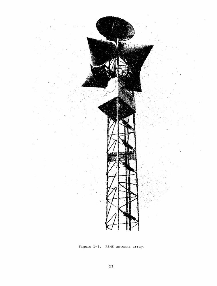
F i gure 1 - 9 . RSMS antenna array .
23
be low the height o f nea rby b u i ldi ngs , tre es , e t c . , wh ich b l o ck ed i t s v i ew i n s everal d i r e c t ions . Many s i gnals d i s appeared be fore th i s s low a nd unce r t a i n d i r e c t ion- f i nd i ng proc e s s could be made to g i ve an answer.
Recent mod i f i cat ions to the RSMS a nt e nna sys tem u s e the cav i tyb a cked- sp i r al an tennas for i ns tantaneou s d i rect ion- f i n d i ng o f mod erate pre c i s ion , supplemented b y a f a s t-mov i ng d i sh a n t e nna a t the top of the tower . Us i n g the CBS a n tennas to f i nd appro x imate d i r e c t ion-o f-a r r i v a l , the operator can rap i d l y f i nd a mor e e x a c t b e a r i ng u s i ng the d i s h an tenna . A P IN-d iode sw i t ch a l lows the sys t em to rap i d ly measure the s i g n a l on e a ch o f the four CBS a n t e nnas i n a s e t . Sys tem sof twa re controls the swi tch a ccord i ng to operators e l e cted parame t e r s , g a t her i ng peak and average s i g n a l ampl i tude me asu red a t each o f the four an tennas . For e x amp l e , measu r i n g f o r 10 ms on each ant enna be fore sw i t ch i ng to the next and co n t i n u i ng swi t ch i ng for f iv e s e conds would r e l i ab l y mea sure a radar w i th a f i ve-second ro t a t i on p e r i o d and any PRF more than 100 p u l s es/s e cond . The r e l a t ive amp l i tu d e is compared to known rece i v i ng a n tenna p a t t erns , and a d i r e c t ion-o f - a r r i v a l i s i mmed i a tely ca l c u l a t e d . Al though the bea r i ng i s typ i ca l l y accurate to only 10° , th is is o f t e n s u f f i c i e nt to i d e n t i fy the sou r ce of a s ig na l , and the process i s very r ap i d . An i d ent i ca l procedure cou l d be i mp l emented w i t h t h e con i ca l h e l i x an tennas t o e x t end t h e f a s t d i rect ion-f i n d i ng- c apa b i l i ty down to 1 50 MHz . However , t h e a n t e nna p a t terns are not a s u n i form on these a n tennas , and co n s i derably l arger d i re c t ional errors wo u l d be expected to occu r .
When greater a c curacy i s needed , the 1-12 GHz dish antenna can be u s ed . The new antenna pos i t ioner a l lows the d i sh to be pl aced a t the top of the an tenna tower , where it is more f ree from local o b s t r u c t ion . Th e d i s h can be rotated at up to + 2 0 ° p e r second w i t h a d i g i t a l readou t accurately show i ng po i n t i ng d i rect io n . A rotary jo i n t and s l i p r i ngs a l low con t i nous rotat ion , a s w e l l a s no i s e d iode ca l i br a t ion through t h e rotary j o i n t . Though n o t y e t i mp l emented , i t i s p l a n ned to a l low t h e po i n t i ng d i r e c t ion to be read into the compu t e r system v i a an I EEE 488 b u s , a l low i ng d i re c t plots of s i gnal ampl i tude vs . d i re c t ion-o f a r r i val .
24
Th e RSMS ee chno logy has l ed to the d e v elopment o f a s e r i e s of r e l a ted i n s t rument a t ion s y s t ems . On e such d e v e lopment i s the Ai r Fo rce M u l t iple Re c e i v e r System ( AN/MSR-T 1 ) •
Th i s program, under the A i r Fo r ce Sys t ems Co mmand , i nvolves the deve lopme nt , a cq u i s i t i on , i nt egrat ion , a nd t es t i ng o f a f i r s t art i c l e pre-prod u c t ion mu l t i p l er e c e i v e r sys tem, des ignated the AN/MSR-T l . Th e sys tem is b e i ng a cq u i r e d to me e t the e l e ctron i c warfare ( EW ) tra i n i ng and t e s t i ng req u i rements o f t h e Ai r Fo r c e . Th e purpose o f the AN/M S R-T l i s to pro v i d e me asuremen t s for eva l u a t i ng the ope r a t ional per formance o f grou ndb a s e d t h r e a t radar sys tems and the response of au toma t i c and manual a i rborne e l e c tron i c co u n t er-measure ( E C M ) sys tems .
The EW t ra i n i ng e x e r c i s e s are condu c t ed a t A i r Fo r ce ranges equ ipped w i th mu l t i p l e threat s y s t ems , w h i ch a r e d i re c ted o n a i rcra f t that come w i th i n opera t i ng r a ng e . Th e radar threats e m i t s imu l t aneous s ig n a l s at d i f ferent f requen c i e s i n t h e range 0 . 5 t o 1 8 GHz . Th e a i rcra f t , e q u i pped w i th mu l t ip l e ECM emi t t e r s , r esponds to e a c h threat em i s s ion w i th a s i g n a l con t a i n i ng no i s e or comp l e x modul at ion waveforms des i gned to i nh i b i t/degrade/de c e i v e the t a r g e t a cqu i s i t ion/t r a ck i ng capab i l i ty of t h e threat r a d a r rece iver . Du e to cos t l im i t a t ions , t h e t h r e a t radars do n o t i n c l u d e r e c e i ve r s w h i c h co u l d be u s e d t o meas u r e and e v a l u a t e the a i rborne ECM respon s e s ; t h e r e for e , t h e AN/MSR-T l i s u t i l i z ed to de termi ne the operat ional capab i l i ty o f t h e ECM s y s t ems and prov i d e m a i n t enance personnel w i th r e l i ab l e and s u f f i c i e n t d a t a to i de n t i fy ma l f u n c t i on i ng equ i pme n t .
Th e program was s tar ted i n February 1 97 6 . Th e mu l t ip l e r e c e i v e r d e s i g n was comp l e ted in May 1 977 a f ter e x t ens i v e t e s ti ng o f new technolog i e s for r e c e i v e r s ( w i deband 0 . 5 - 1 8 GHz t u n e r s w i t h 5 00 M H z I F b a ndw i d t h s ) and s ig n a l proce s sors ( 5 0 0 M H z bandw i dth Bragg c e l l op t i ca l t e c h n i q u e s w i th 1 MHz f requ ency resol u t ion ) w h i ch were cons i d e r e d e s s en t i a l r eq u i reme n t s for the f i r s t a r t i c l e preprod u c t i o n o f AM/M SR-T l . Procurement was i n i t i at ed and d e l i very of all h ardware was comp l e t e d i n J u l y 1 978. I n t eg r a t ion was comp l e t e d in Aug u s t 1 978, and e x tens i ve t e s t i ng is now underway a t the USAF/SAC S t ra teg i c Tr a i n i ng Range ( S TR ) i n La J u n t a , Co l orado . F igure 1 - 10 i s a n a e r i a l photograph of the SAC/STR s i t e show i n g the v a r i ou s grou nd-b a s e d t h r e a t sys tems and AN/MSR-T l i n the i r ope rat ional locat ions .
The opera t ional frequency range o f t h e AN/MSR-T l i s 0 . 5-18 GHz . Th e sys tem co n s i s t s of four 0 . 5 - 1 8 GHz tuners ( one with a 5 00 MHz IF bandw i d t h and t h r e e
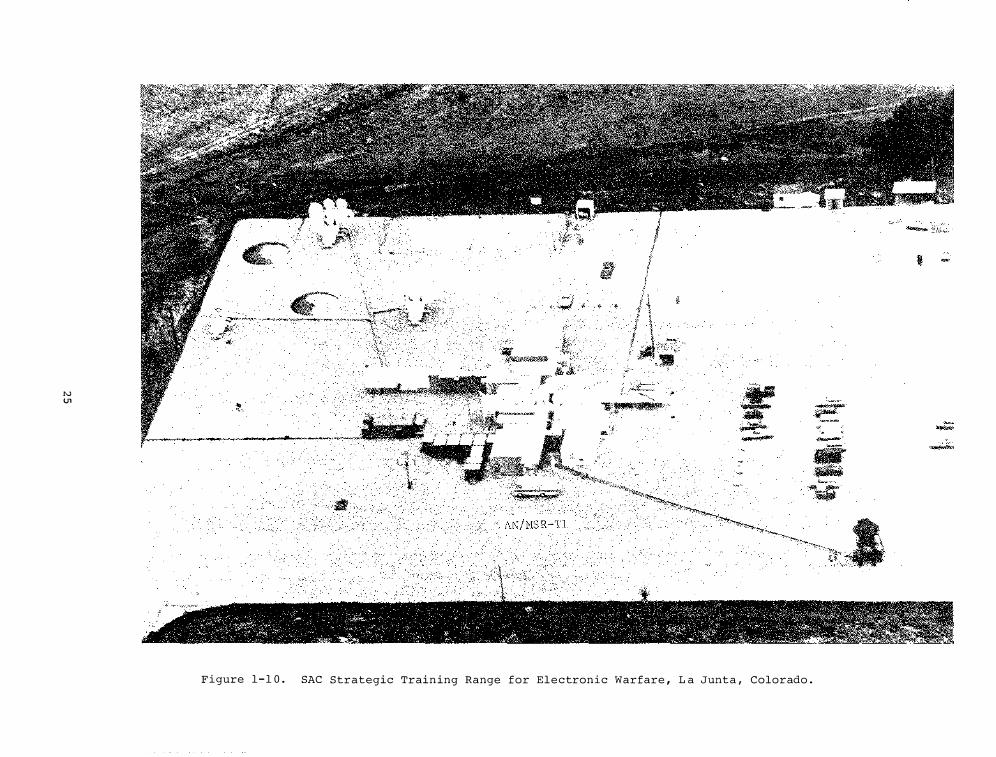
"' U1
Figure 1- 1 0 . SAC Strategic Train ing Range for Electronic Warfare , L a Junta , Colorado .
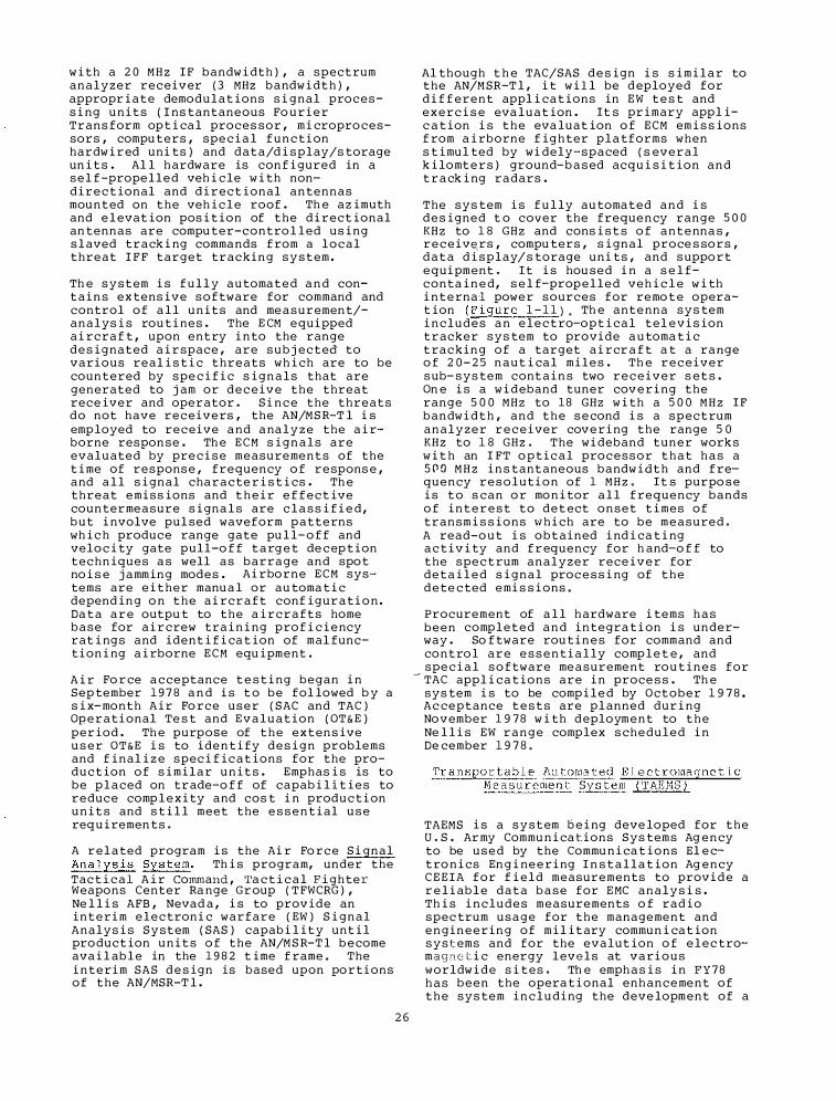
w i th a 2 0 M H z I F bandw i dth ) , a spect rum analyzer receiv er (3 MHz bandw i d t h ) , appropr i a t e demod u l a t ions s i g nal process i ng u n i t s ( I ns tantaneous Fo u r i e r Trans form op t i ca l proces sor , m i cropro cessors , compu ters , spe c i a l f u n c t i on hardw i r ed uni ts ) and d a t a/d i s p l ay/s torage un i t s . Al l h ardware is con f i gured in a s e l f-prope l l e d veh i c le w i th nond i r e c t ional and d i r e c t ional an tennas mou n t ed on the veh i c l e roof . Th e az imuth and e l evat ion pos i t ion of the d i rect ional an tennas are compu ter-contro l l ed us i ng s l aved track i ng comma nds f rom a l o c a l threat I F F target tracking s y s t em .
Th e s y s t em i s f u l l y a u toma t e d a n d cont a i n s ex tens i v e s o f tware for command and control of a l l u n i t s and me a s u r emen t/a n a l ys i s rou t i nes . The E CM e q u i pped a i rcra f t , upon entry i n to the range d e s i g nated a i r space , are s u b j e c t ed to v a r i o u s real i s t i c threats wh i ch are to be coun tered by spe c i f i c s i g n a l s that are generated to j am or d e c e i v e the threat rece iver and operator . S i n c e the threats do not have r e c e i v e rs , the AN/MSR-T l i s emp loyed to receive a nd a na l y z e the a i rborne respon se . Th e E C M s i g n a l s are evalu ated by pre c i s e measu reme n t s of the t i me of respons e , frequency o f r e spons e , and a l l s i gnal cha r a c te r i s t i cs . Th e threat e m i s s ions and t h e i r e f f e c t ive coun termeasure s i gna l s are c l a s s i f i e d , b u t i nvolve pul sed waveform p a t t e rns wh i c h produce range gate pu l l- o f f and velo c i ty gate p u l l -o f f t a rg e t de cep t ion techn iques a s well as barrage and spo t no i s e j amm ing modes . Ai rborne E C M systems are e i t her manu a l or au toma t i c depend i n g o n t h e a i r c r a f t conf i g u r a t i o n . Da t a a r e outpu t to the a i r c r a f t s home b a s e for a i r crew tra i n i ng prof i c i e ncy rat i ng s and ident i f i ca t ion of mal funct i on i ng a i rborne E C M equ ipment .
A i r Fo r ce a c ceptance t e s t i ng began i n Sep tember 1 9 7 8 a n d i s t o be fol lowed b y a s i x-month A i r Fo rce u s e r ( SAC and TAC ) Op e r a t i onal Te s t and E v a l u a t ion ( OT& E ) per iod . Th e purpose of t h e e x t en s ive u s e r OT&E i s to ide n t i fy d e s i g n problems and f i nal i z e spec i f i c a t ions for the prod u c t ion of s i m i l a r u n i t s . Emphas i s is to be p l a ced on tr ade-o f f of capab i l i t i e s to reduce comp l e x i ty and cos t i n prod u c t i on u n i t s and s t i l l meet the e s s e n t i al u s e req u i remen ts .
A r e l a ted program i s the Ai r Fo r c e S i gnal Ana lys i s Sys tem. Th i s program, under the Tac t i c a l A i r Command , 'l'a c t i c a l Figh ter Weapons Center Ra nge Gr oup ( T FWCRG ) , Ne l l i s AFB , Nevad a , i s to prov ide an i n t e r i m e l e c tron i c warfare ( EW ) S i g n a l Analys i s S y s t em ( SAS ) capab i l i t y unt i l product ion u n i t s o f the AN/M S R-T l b e come ava i l ab l e in the 1 9 8 2 t ime f rame . The i n t e r i m SAS d e s ign is based upon po r t i ons of the AN/MSR-T l .
2 6
Al though t h e TAC/SAS d e s ign i s s i m i l a r to the AN/M SR-T l , i t w i l l be d eployed for d i f f e r e n t appl i ca t ions in E W t e s t and e x e r c i s e eva l u a t ion . It s pr imary appl ic a t ion i s t h e eva luat ion o f ECM em i s s ions f rom a i rborne f ig h ter p l a tforms when s t imu l ted by w i dely-spaced ( s ev e r a l k i lomt e r s ) ground- b a s ed acq u i s i t ion a n d t r a ck i ng radars .
The sys tem i s f u l ly au toma ted a n d i s d e s igned t o cover the freque n cy range 5 0 0 KHz to 1 8 GHz and cons i s t s o f a n t e nna s , r e c e i v�rs , compu ters , s i gnal proce s so r s , d a t a d i s p l ay/ s torage u n i ts , and s uppo r t e q u i pment . I t i s hou sed i n a s e l fconta i n e d , s e l f-prop e l l e d veh i c l e w i th i n t e rnal powe r sources for remo t e operat ion ( F igure 1 - 1 1 ) . Th e ante nna sys tem i n c l u d e s a n e l e c t ro-opt i ca l tel e v i s ion t r acker sys tem to provide a u toma t i c t ra c k i n g of a target a i rcr a f t a t a range o f 2 0 - 2 5 n a u t i ca l m i l e s . Th e r e c e i v e r s ub-s ys tem cont a i n s two r e c e i v e r s e t s . On e i s a w i d eband tuner cov e r i ng the range 5 0 0 MHz to 18 GHz w i th a 5 0 0 M H z I F bandw i d t h , and t h e s e cond i s a s p e c t rum a n a l y z e r r e c e i ver cov e r i ng the range 5 0 KHz to 1 8 GHz . The w i deband t u n e r work s w i t h an I FT o p t i c a l processor t h a t h a s a 5 0 0 M H z i n s tant aneous bandw i d t h and f req u e n cy r e s o l u t i o n of 1 M H z . I t s purpo s e i s t o s can o r mo n i tor a l l f requency bands o f i n t e r e s t to d e t ect o n s e t t i mes of transm i s s ions w h i ch are to be m e a s u red . A read-o u t i s o b t a i ned i nd i ca t i ng a c t i v i ty and f r equency for h and-o f f to the spe c t rum analyzer rece i v e r for d e t a i l e d s i g n a l proc e s s i ng of t h e d e te c ted emi s s i ons .
Procurement of a l l h ardware i tems h a s b e e n comp l e t e d a n d i n tegra t i on i s underway . So f tware rou t i n e s for command and co n t ro l a r e e s s e n t i a l ly comp l e t e , and spe c i a l s o f tware me a s u r eme nt ro u t i n e s for
- TAC appl i ca t ions are i n proce s s . Th e sys tem i s to be comp i l e d by October 1 9 7 8 . Ac ceptance t e s t s are pl anned d u r i ng No v ember 1 9 7 8 w i th d eploym e n t to t h e Ne l l i s EW r a n g e complex s ch e d u l e d i n De cember 1 9 7 8 .
T r a n spor t a b l � Au toma ted E l e c t romagn e t i c M e a s u r emen� Sys tem ( TAEMS )
TAEMS i s a s y s t em b e i ng deve loped for the U . S . Ar my Commu n i ca t ions Sys tems Ag e n cy to be u s e d by the Commu n i ca t ions El e ct ro n i cs En g i ne e r i ng I n s t a l l a t ion Ag e n cy C E E I A for f i e l d measurements to prov i d e a r e l i ab l e d a t a b a s e for E MC a n a l y s i s . Th i s i n c l u d e s measurements o f rad io spec trum u s a g e for the manageme n t and e n g i n e e r i n g of m i l i t ary commu n i ca t ion s y s t ems and for the evalut ion o f e l e c tromagne t i c energy l ev e l s at v a r i o u s worldw i d e s i t es . Th e emph a s i s i n F Y 7 8 h a s b e e n the opera t i onal enh anceme n t of t h e sys tem i n c l u d i ng the deve lopment of a
Figure 1 - 1 1 . The TAC/S ignal Analys i s S y stem ( SAS ) for e lectronic warfare ( EW) te s t and exercise evaluation .
2 7
remote extension which al lows the operation of the down converte r/antenna s ubsys tem some 3 0 0 fe et f rom the TAEMS .
There are two four-whee l -drive sp ecial purpose vans that make up one system. One van is the Data Acquisition Van ( DAV ) which houses the computer-cont rol led EMC measur ement sys tem. Th e other van is the Maintenance and Ca libra tion Van ( MCV ) which hous es maintenance , ca l ibration , and other ancil liary equipment . Another F Y 7 8 proj ect in the area of application enhancements was to develop the required computer grid interface and opera ting software to pe rmit automa ted opera tion of the equipment in the MCV and DAV. Al ong with this ef fort wa s the development of a voltage tuned tracking filter and . sa tura tion detector to augment the ba s 1 c TAEMS capabilities with resp ect to pres e l ection and mixer sa turation be low 5 0 0 M H z .
Work has a l s o st arted on a pe rformance verification test set for the automated receiver sys tem. Th e test set is to be used to validate key prformance paramet ers and to pe riodica l l y ca l ibr ate the sys tem. Ba sed on pr eviou s l y es tablis hed verification limits , a routine wil l a l so be configured to indica te to the operator of the sys tem when any of these key performance paramet ers are out of specification and when corrective ca l ibra tion or maintenance needs to be initia ted.
Th e data obtained from verif ication measur ements wil l be a v a l uable record of sys tem performance and can be compared to subs equent tests to dis cover trends in ov era l l performance .
Key syst em per formance parameters to be checked are :
1 . Tuning accuracy 2 . S e l ectivity 3 . Tune/measure time 4 . Sensitivity 5 . Frequency respons e 6 . Re l ative ampl itude accur acy 7. Intermodula tion accuracy 8 . Isola tion 9. Absolute power ca l ibration
Per formance verification test routines wil l be cons tructed to verify the per formance of va rious subsys tems as we l l as the overa l l system. Th ese subsys tems include such units as the mul timode detector , wideband I F s ection , power me ter and source control .
The instrumentation dis cus sed so far has been la rge and sophisticated, both in design and opera tion . A compe l l ing need exis ts for automation and new technology in spectrum measurements at the other end of the sca l e - smal l , l ightweight, easy-
2 8
to-use sys tems that stil l p rovide digital re cords of the obs erva tions and perhaps s ome de gree of automatic control . One s uch proj ect requires the dev e lopment of a Manportable EMC Measurement Sys tem. This p rog ram is in its third ye�r under s ponsorship of the u.s. Army , Communications and Electronics En gineering Ins ta l l ation Ag ency ( CEEIA ) .
During this year , the microp roces sor deve lopment sys tem was upgraded to incl ude a CRT terminal , a high- speed l ine p rinter , and a one-hal f inch magnetic tape recorder . Th ese improvements a l low much easier , faster , and more accurate p rog ram deve lopment . The industry standard h a l f-inch magnetic tape a l so wil l a l low compatibility of da ta between va rious data analysis systems ( computers ) s uch as the CDC 6 0 0 0 .
Current work is being unde rtaken to improve the fie l d units by providing shock mounted ruggediz ed ch a s s is . Th e development system is being improved with the addition of a 1 9 77 ANS I St andard Fortran compiler .
Th e Automa ted Fie l d Int ensity Measurement Sys tem Proj ect is a further ef fort to p rovide smal l , modest-cost spect rum ins trumenta tion . Th e sys tem wil l be used to make ordinance and personnel h a z a rds measurements . Th e field intensity receivers used by the syst em are automatica l ly ca l ibrated. Th e operator then sp ecifies frequency scan width , r eceiver bandwidth , detector , etc. to the sys tem control l e r . Th e cont rol l e r sets the specified parameters , col l ects the measured da t a , stores it on magnetic tape , and computes s tatis tics of the col l ected da ta . Th e system has be en designed to operate unattended for long time periods ( 2 4 hour s , one week , etc. ) , depending upon how often data are to be col lected. Th e ma j or contribution f rom this proj ect is the development of app l ication s oftware which cou l d be utilized by other ag encies having similar ordinance haza rds measur ement requirements .
The U . S . Army Combat De velopment Engineering Command ( USACDEC ) at Fort HunterLigge tt , Ca l ifornia , is incr easing l y dependent upon radiating telecommunications systems to locate and monitor the l ocations of par ticipant s in mock military exercis es . Th e primary system currently in us e is the Range Measurement Syst em ( RMS ) , which utilizes a l a rge number of inter rogators and beacons to locate the par ticipants . When an interroga tor mal functions and begins tr ans mitting a continuous tone or when a local or remote source interferes with the RMS operation , the position da ta can be l os t .
To avo i d costly losses d u e to i n t e r f ere n ce , a Spe c t rum Mo n i to r i ng U n i t is b e i ng d e s igned and bu i l t w h i ch mee t s t h e fo l low i n g r eq u i reme n t s :
a ) capable of obs e r v i ng r a d i o s i g n a l s o v e r t h e a i r a t f r eq u e nc i e s b e twen 3 0 M H z a nd 1 8 GHz w i th emph a s i s on t h e RMS f r equ e n c i e s near 9 1 8 M H z ;
b ) capable o f d i r e c t ion- f i nd i ng for r a p i d l y and a cc u r a t e l y l o ca t i ng i nt e r f e r i ng sources , espe c i a l ly those a round 9 1 8 MHz ;
c ) capa b l e of f u l l ope rat ion w i th m i n i m a l t ra i n i ng by f i e l d person nel ;
d ) c apab l e of remo t e area operat ion in a four-w h e e l d r i ve v e h i c l e by a s i ng l e opera tor/d r iver ; and
e ) capable o f s e l f - ca l i br a t i o n and d i g i t a l ly -con t ro l led operat ion .
Th e Spe c tr um Mo n i tor i ng U n i t w i l l u t i l i z e a m i croprocessor-control led spectrum a n a l y z e r w i th d i r e c t iona l , omn i d i r ect io na l , and s t eerable a n t ennas to d e t ect and locate s i g n a l s or i n t e r f erence . B e c a u s e the commu n i ca t ions and d i s p l ays a r e remo ted from the opera t ional a r e a of t h e veh i c l e to the dr i v e r ' s pos i t ion , one per son w i l l be a b l e to d r i ve the veh i c le p l u s d i r e c t ion f i nd and locate an i n t e r f e r i ng sou r ce .
Th e Spectrum Mo n i to r i ng U n i t w i l l upgrade t h e USACDEC spectrum manageme nt capa b i l i t i e s f o r mak i ng spec trum o c cupancy s urveys , for impro v i ng spec trum u t i l i z at ion , and for i ns u r i ng t h a t local equ ipm e n t s are ope r a t i ng w i t h i n spec i f i c a t ions and a l lo c a t ions f o r frequency , b andw i d th , e t c .
A l o ng w i th the deve lopment o f new i ns t r u men t a t ion , NTIA/ I TS appl i e s t h i s eq u i pm e n t i n the measurement o f v a r ious spectrum proper t i es . A s e r i es o f l a boratory mea s u reme n t s were made iQ s u ppo r t of a number of other p ro j e c t s , mos t pa r t i cu l a r l y one t o d e f i n e Spread Spect rum I n t e r f e rence Character i s t i cs .
T h e pu rpose of t h i s pro j e c t h a s b e e n to s tudy spread-spect rum t e c h n i q u e s to de t e r m i n e i f they can be e f f i c i e n t l y and e f f e c t i v e l y app l i e d to commu n i ca t ions , spe c i f i ca l l y l and-mo b i l e rad io ; s pread spectrum has its o r i g i ns in rad a r , n a v i g a t ion , rad io l o ca t ion , and deep s p a ce commu n i ca t ions . An NTIA S p e c i a l Pu b l i ca t ion ent i t l � d , " S p r e a d S p e c t r u m : An Anno t at e d B i b l i6graph y " , NTIA S P 78- l , w a s p ub l i shed t o a l e r t i n t e r e s t e d readers a bo u t spread- s p e c t rum repo r t s wh i ch per-
2 9
t a i ned to one o f the folow i ng group i ngs :
1 ) t u to r i a l 2 ) app l i ca t ions 3 ) i n t e r f erence r e j ect ion 4 ) spread spec trum sys tem s tud i e s 5 ) mu l t ipath propagat ion 6 ) d i r e c t s eque nce/f requency-
hopp i ng/ch i rp techniques 7 ) mod u l a t i on/demod u l a t ion 8 ) synchro n i z a t ion/tra c k i ng 9 ) cod e s for spread spectrum.
On e task of the present pro j ect i s to make measurements of the i n t e r f e rence e f f e c t s of spread spectrum s i g na l s on narrow- b a nd FM . Th e spread spect rum s i g na l s are generated by p a s s i v e s u r f acea cou s t i c-wave d e v i ce s and by a c t i ve ps eudor andom no i s e generators . On e concern i s whether spread spectrum system can share f requency bands w i th the channe l i z e d FM system.
On e of the mos t comprehe n s i v e i n s t rument a t ion deve lopme nt and measu reme n t p ro j e c t s d e a l s w i th a s s e s sment o f t h e I n t e rf e r e nce P o t e n t i a l B e tween CATV a nd Ai r Tr a f f i c Co n t rol S y s t ems ope r a t i ng-in the 1 0 8 - 1 3 6 M H z b a nd s .
Le akage f rom a coa x i a l cable sys tem carrying CATV s i g n a l s at freq u e n c i e s u s e d f o r a i r n a v i g a t ion a n d control pos e s an i n t e r f e r e n ce pote n t i a l s t ud i ed by ITS for t h e FCC . A s e r i e s of f l ight t e s t s were per formed to measure the s i gnal l ev e l s r ad i a t i ng f r o m ope r a t i ng CATV s y s tems to a i r cr a f t i ns trumented to probe the a i rspace for RF s ig n a l s above the CATV s y s t ems .
F i gure 1 - 1 2 s hows an FAA a i r c r a f t u s e d i n the mea s u r ements and F i gure 1 - 1 3 s hows the I T S i ns t rume ntat ion mounted in the a i r cra f t for the mea su rement s .
The s i g n a l s a t 1 0 8 . 0 5 M H z or 1 1 8 . 0 MHz were i n troduced a t the head end o f the CATV s y s tem w h i l e the a i rcra f t f l ew a g r i d p a t t e r n over the CATV sys t em and r e corded t h e RF s i gnal l e akage w i th a very sens i t i ve , narrow-b and r e c e i ve r . At the s ame t i me , FCC g round crews measured the l e akage a t ground- l evel over a g r i d p a t t ern a long t h e CATV s ys tem.
Th i s pro j e c t has been a j o i nt program in coopera t i on w i t h the FAA , s everal CATV ope r a t i ng compa n i e s , and the FCC . Gr ound measu reme n t s were made by the FCC F i eld Op e r a t i ons B u r e a u . Th e FAA Na t ional Aerona u t i c a l Fa c i l i t i e s Exper iment Center p rov ided f l i g h t t e s t a i rcraft and o ther s uppor t .
The measu rement res u l t s w i l l b e u s e d by the FAA , t h e CATV i ndus try , and the FCC .
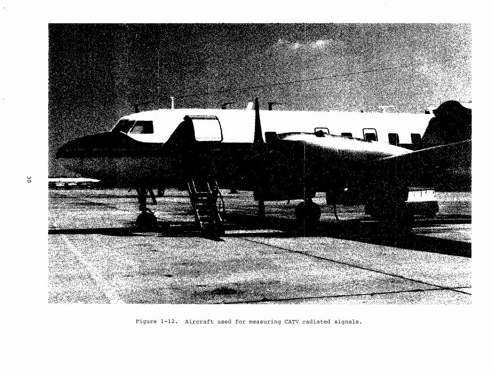
w 0
Figure 1 - 1 2 . Aircraft used for mea suring CATV radiated s ignal s .
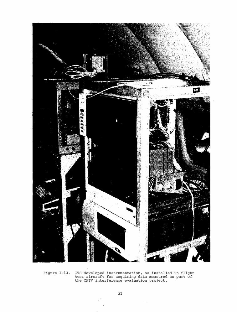
Figure 1-13. ITS developed instrumentation , as installed in flight test aircraft for acquiring data mea sured as part o f the CATV 'inter f erence eva luation proj ect .

CHAPTER 2 . SYSTEMS ENGINERING AND EVALUATION
The objective of this program subelement is to provide telecommunication system definitio n , designs , and consulting services to meet users ' requirements through measurement s , analy ses , and evaluations and to develop and dis seminate per formance criteria . T he resu l tant performance criteria and measurement methods are used by Federal agencies in p l anning , designing , specifying , procuring , leasing , and operating telecommunication systems . The pro j ect elements des cribed below gener ally dea l with existing or propo sed telecommunication sys tems and/or subsystems . S ection 2 . 1 addresses work relating to communication services engineering . Section 2 . 2 presents pro j ects oriented toward s atel lite communications . s ection 2 . 3 summarizes the terrestrial radio system performance ef forts . S ection 2 . 4 dea l s with radio channel simul ation and radio sys tem performance standards , and Section 2 . 5 presents related work in f iber optical communications .
SECTION 2 . 1 . COMMUNICATION SERVICE S ENGINEERING
Some of the systems techno logy pro j ects relate to es tablished or p l anned communication services . The services are either o f fered or leased by mis s ion agencies , and the engineering described here relates to the evaluation , performance criteria , or new techno logy required f or efficien t , co st-ef fective procurement , of fering , or establishing these services . Five proj ec t s are des cribed ; namely : Data Communications , E lectronic Mes sage Services , Acces s Area Digital Switching Systems , AM S tereo Broadcas ting , and Maritime Administration Assistanc e .
Data Communications . T here i s a growing need within the Federal Government for uniform means o f specifying and measuring the performance of data communication systems from the point of view of the digital services delivered to the end user . NTIA ' s Data Communications pro j ect has been undertaken to meet that need through the development of Federa l S tandards specifying univers a l ly applicable , user-oriented performance parameters and measurement methods . The pro j ect is being conducted in cooperation with the Federal Telecommunication S tandards Committee ( FTSC ) , an interdepartmental s tandards group organized by the National Communication System under the auspices of the Genera l Services Adminis tration ( GSA) . After approval , the standards developed under the pro j ect wil l be promulgated by GSA , and wil l be mandatory for use by a l l Federal agencies in specifying the end- to-end performance of data communic ation systems and services .
3 3
Pro j ect outputs are also being coordinated with the Amertcan National S tandards Ins titute , which is involved in the development of industry s tandards for data communication performance ; with the National Bureau of Standards , which is responsible f or the Federal Information Proces sing S t andards ( FIPS ) program; and with the Federa l communications Commission , which is considering the es tablishment o f performance s tandards for common c arrier s ervices under its Quality and Reliability Inquiry ( Docket 1 8 9 2 0 ) .
Figure 2 - 1 illustr ates the overall organization o f the Data Communications pro j ect . Maj or proj ect outputs wil l consist o f three related Federal Standards :
Federal Standard 1 0 3 3 - defines user-oriented , univer sally applicable performance p arameters for specifying data communication system per formance .
Federa l S tandard " l 0 3 3A " - wil l define s tandard mea surement methods to be used in conj unction with the s tandard parameter s in as ses sing delivered performance .
Federal S tandard " l 0 3 3B " - wil l define s tandard performance cla sses and requirements for interconnection of dis similar networks .
The Data Communications pro j ect is comprised of three ma j or pro j ect activities : Technology Applications ( consisting o f three consecutive phases ) , S tatis tical Analysis , and ARPA Network measurements . The Technology Applications ac tivity serves as a focal point for development o f each s tandard . Final results o f Technology Applications Phase l have been presented in a 2 -vo lume NTIA Report ( Seitz and McManamon , 1 9 7 8 ; Kimmett and Seitz , 1 9 7 8 ) . Interim results of this activity have also been presented in two artic les published earlier in FY 7 8 ( Seitz and McManamon , 1 9 7 7 a ; Seitz and McManamon , 1 9 7 7b ) .
The second ma j or Data Communications pro j ect activity , S tatistical Ana ly sis , is aimed at developing confidence limits and sample size requirements to standardize measurement of the selected performance parameter s . Prior work in this area has addres sed the measurement of bit error probability , and has produced definitive new methods of a s ses sing the statistical precision of such measurements . FY 7 8 efforts have extended these results to the b lock-oriented accuracy parameters ( Crow , 1 9 7 8 ) ; and have laid the foundation for the development of confidence limits for the time delay parameters .
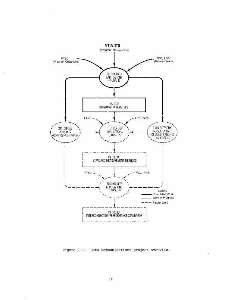
FTSC (Program Objectives)
NTIA / ITS (Program Management)
FS 1033 STANDARD PARAMETERS
FCC, ANSI (Related Work)
I �- - -- - - - ---- - -- - � I FS '1033A' I l STANDARD MEASUREMENT METHODS \ 1
L _ _ _ _ __ _ _ T - - - ----- � I FTSC ---- i ---- FCC, ANSI I
""' / I I , ..--- � - -J I I
/ " I "- I TECHNOLOGY \ - - - - - - --{ APPLICATIONS f-. - -- - - / \ (PHASE 3) J Legend "'---.. / - Completed Work
---- __.. / I -- Work in Progress
1 _ _ _ _ _ _ _ 1 _ _ _ _ _ _
��- Future Work
FS '10338' I INTERCONNECTION PERFORMANCE STANDARDS I L _ _ _ _ _ _ _ _ _ _ _ _ _ _ _j .
Figure 2 - 1 . Data communications pro j ect overview .
3 4
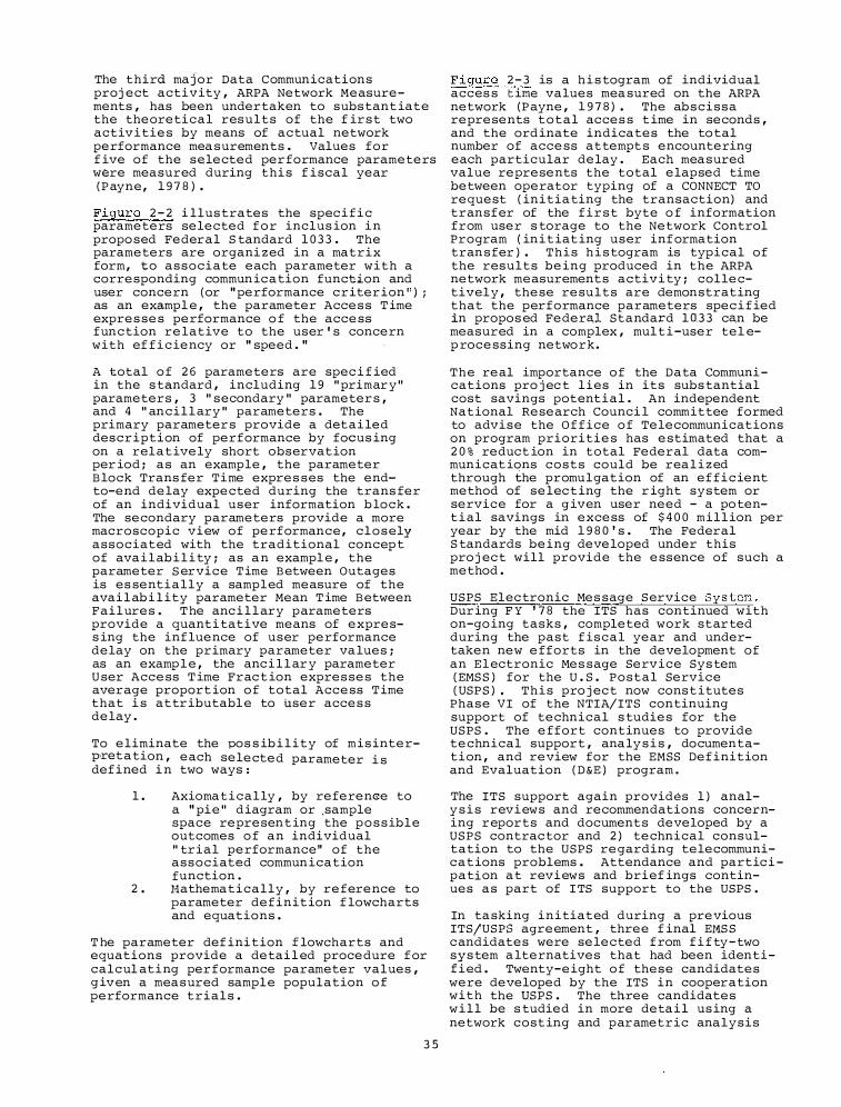
The third major Data Communications proj ect activ ity , ARPA Network Measurements , has been undertaken to subs tant iate the theoretical results of the f ir s t two activ ities by means of actual network performance mea surements . Values for f ive of the se lected per formance parameters were measured during thi s f iscal year ( P ayne, 1 9 7 8 ) .
F igure 2 - 2 i llus trates the spec i f i c parameters selected f o r inclus ion i n propo sed Federal S tandard 1 0 3 3 . The parameters are organi z ed in a matrix form , to associate each parameter with a corresponding commun ic a tion function and user concern (or " performance c r iter ion " ) ; as an exampl e , the parameter Acces s T ime expres ses performance o f the access function relative to the user ' s concern with ef f i c iency or " speed . "
A total o f 2 6 parameters are spec i f ied in the s tandard , including 1 9 " primar y " parameters , 3 " secondary " parameter s , and 4 " ancil l ary " parameters . The primary parameter s provide a detai led descr iption of performance by focus ing on a relatively short observation per iod ; as an example , the parameter B lock Trans fer Time expres ses the endto-end delay expected during the trans fer of an individual user information b lock . The secondary parameters provide a more macroscopic view of performance, c l o s ely associated with the traditional concep t of ava i l ab i l i ty ; as a n exampl e , the parameter s ervice T ime B etween Outages is es sentially a sampled measure of the avai l ab i l ity parameter Mean T ime B etween Failures . T he anc i l l ary parameters provide a quanti tative means of express ing the inf luence of user performance delay on the primary parameter va lues ; as an examp l e , the anc i l l ar y parameter U ser Access T ime Frac t ion expres ses the average proport ion o f total Access T ime that i s attr ibutabl e to user acces s delay .
To eliminate the pos s ib i l i t y of mis interpret a tion , each selected parameter i s def ined i n two ways :
l . Axiomatically , by reference to a " pie" diagram or .sample space represen t ing the p o s s ible outcomes o f an individual " trial performance" of the associated commun ication function .
2 . Hathematically , by reference to parameter def init ion f lowcharts and equations .
T he parameter def ini tion f lowcharts and equations provide a detai l ed procedure f or calcul ating per formance parameter values , g iv en a measured sample population o f performance trials .
3 5
F igure 2 - 3 is a h i s togram of individual acces s t ime values mea sured on the ARPA network (P ayne , 1 9 7 8 ) . The ab scissa represents total acces s t ime in seconds , and the ord inate indicates the to tal number of access attempt s encountering each particular delay . Each measured value represents the total elapsed time between operator typing of a CONNECT TO request ( initia ting the transaction) and transfer of the f i r s t byte o f information from user s torage to the Network Control Program ( in i t iat ing user inf ormation tran s fer ) . T h i s h i s togram is typical of the results being produced in the ARPA network measurements activ i ty ; collectivel y , these results are demonstrating that the performance parameters spec i f ied in propos ed Federal Standard 1 0.3 3 can be measured in a complex , mul t i -user tel ep rocessing network.
The real importance o f the Data Communi cations pro j ec t l ies in its subs tantial cost savings potential . An independent National Research Counci l committee formed to advise the O f f ice o f Telecommunications on program priorities has estimated that a 2 0 % reduct ion in total Federal data communicat ions costs could be rea l i z ed through the promulgation of an ef f i c ient method of selec t ing the r ight system or service for a g iven user need - a po tent i al savings in excess of $ 4 0 0 mill ion per year by the mid 1 9 8 0 ' s . The Federal S tandards being developed under this pro j ec t will provide the essence of such a method .
USPS Elec tronic Mes sage Service System . Dur ing F Y ' 7 8 the ITS has continued with on-go ing tasks , completed work star ted during the past f iscal year and undertaken new efforts in the development of an E l ectronic Mes sage Serv ice Sys tem (EMS S ) for the U . S . Postal Service (USPS ) • T h i s pro j ec t now cons t itutes
Phase VI of the NTIA/ITS continuing support of technical s tudies for the USPS . The effort continues to provide technical support , ana ly s i s , documentation , and review for the EMSS Def inition and Evaluation ( D &E ) program .
The ITS support again provides l ) analy s i s reviews and recommendations concerning reports and documents developed by a USPS contrac tor and 2 ) technical consultation to the USPS regarding telecommunic a t ions problems . Attendance and partic i pation a t reviews and brief ings continues as part of I TS support to the USPS .
In ta sking initiated during a previous ITS/USPS agreement , three f inal Er1S S c andidates were selected f rom f i f ty - two sys tem a lternatives that had been identified . Twenty-eight o f these candidates were developed by the ITS in cooperation with the USPS . The three candidates w i l l be s tudied in more deta i l us ing a network cost ing and parametric analysis
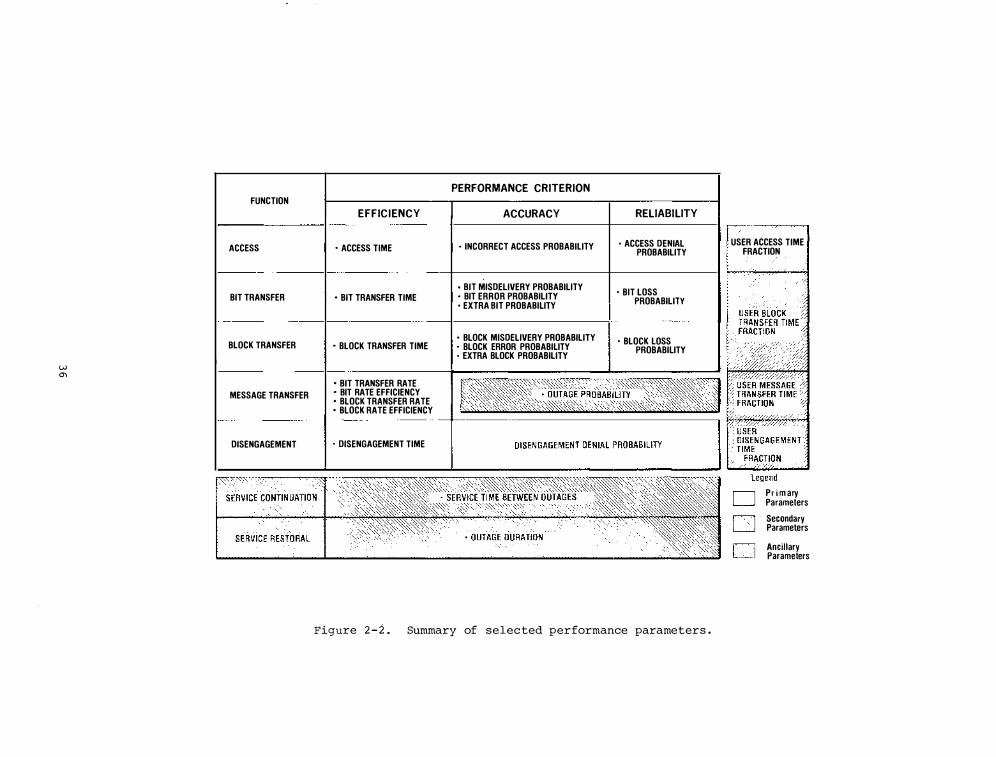
FUNCTION
ACCESS
BIT TRANSFER
BLOCK TRANSFER
I w 0'1
MESSAGE TRANSFER
DISENGAGEMENT
PERFORMANCE CRITERION I EFFICIENCY I ACCURACY RELIABILITY
I · ACCESS TIME I · INCORRECT ACCESS PROBABILITY • ACCESS DENIAL PROBABILITY
I · BIT TRANSFER TIME • BIT MISDELIVERY PROBABILITY
· BIT LOSS I · BIT ERROR PROBABILITY • EXTRA BIT PROBABILITY
PROBABILITY
I . BLOCK TRANSFER TIME , • BLOCK MISDELIVERY PROBABILITY
I ' BLOCK ERROR PROBABILITY • EXTRA BLOCK PROBABILITY
I . BLOCK LOSS PROBABILITY
I . BIT TRANSFER RATE • BIT RATE EFFICIENCY • BLOCK TRANSFER RATE • BLOCK RATE EFFICIENCY
I . DISENGAGEMENT TIME
,',' ,,
Figure 2 - 2 . Summary of selected performance parameters .
/
USER ACCESS TIME FRACTION
Pr i m ary Parameters
Secondary Paramet,ers
Ancillary Parameters
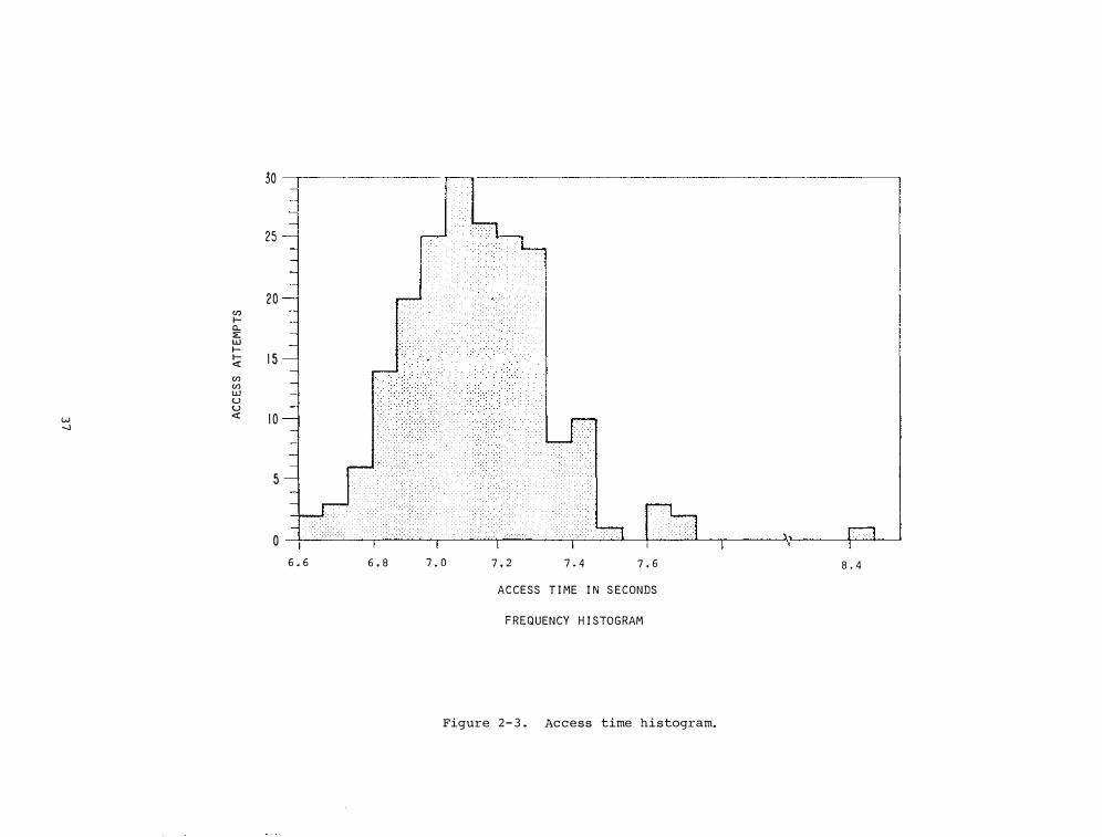
(f) I-a.. ::E LU I-I-<{ (f) (f) LU u u
w <{ -.J
30 --.-------
25
20
1 5
1 0
5
o r::::-: ·'"'"'"'"'"'"' :-:-:-:-:-:-:;:-.':"' · · · · -·- -·-·.·-:-:-.;-:,:-:- · ·.-.-.,.,.,.:-,·;:: -·-·.·.·.·.· · · ·.·.·.·.·.·-:-:-; :-·- · · · · · · . -:- : 1 1· · · · · · ·.-.-., 1 � r · ·.·.
l I
6 . 6 6 . 8 7 . 0 7 , 2 7 . 4 7 , 6 8 . 4
ACCESS T I ME I N S ECONDS
F REQUENCY H I STOGRAM
Figure 2 - 3 . Access time histogram.
computer mode l . Eventual s election of a final EMSS candidate will be based in part on these analy ses .
The character istics of the three candidates that were selec ted are summari zed in T able 2-la and 2 -lb . S tart , intermediate , and mature levels o f development are shown for candidates A and B , whi l e only the mature level i s shown for candidate C . Three o f over 90 input parameters to the parame tric analy s i s computer mode l a r e shown acro s s the top of the tables whi l e the other headings are for some o f the results of the analy s i s . The three input parameters are Annual Volume ( B illions ) , Number of Stations , and Number o f Public Terminals (Table 2-la) . Average Letter S i z e ( B i t s ) and S i z e of EMS S ta f f ( Table 2 - l a )
are computed i n the cour se of the algor ithm . S tations are defined a s fac i l i ties whi c h provide f o r cus tomer acc e s s as wel l as input , output , and proce s s ing capabi l i ty . S tations may have d i f ferent input and output conversion capab i l i ty for magnetic and paper media , and telecommunications .
Pub l i c terminals are def ined as owned or lea s ed by the USPS and are intended for acce s s to the EMSS by the general publ ic . They are dis tr ibuted for easy acces s in post o f f ice lobbies , pub lic buildings , shopping center s , and so forth . However , pub l i c terminals would only have an input mes sage capab i l i ty us ing f a c s imile and address entry by keyboard . The service would be limited compared to EMSS s tation s .
The annual mes sage volume along with the number of EMSS stations and publ ic terminals show the growth o f EMSS for Star t , Intermediate , and Mature candidates . A t ime f rame for thi s growth is the subj ec·t of future work .
Two of the import ant results are Cost/ 1 0 0 0 Messages and Cost/Megabi t , both do llar f igures ( Table 2 - lb) . In parentheses in thos e columns we also show the telecommuni c at ion cos t s which are a frac t ion of the mes sage co s t . The mes s age co st computed in c andidate A is 2 . 5 ¢ per me s s age , while the co s t o f transmitting that mes sage i s approximately 0 . 4 ¢ . Note that in candidate A. mes sage s i z e increases dramatically (more than doubles } , the number of stations and publ ic terminals that s erve the cus tomer also increas e , but the cost per message remains constant during intermed iate and mature phases .
The me ssage cost in candidate B ranges from 1 . 5 ¢ to double that as me s s age volume goes f rom 6 . 5 b i l lion to 3 5 bill ion piece s . The telecommunication cos t s increase from � . 2 3 ¢ to . 4 6 ¢ per me s s age . Also the inves tment co sts start at $ 1 9 4 mi l l ion and esca late to
3.8
over $ 2 b i l lion . One might pau se in cons ider ing this candidate . However , the i s sue of public s ervice enters the picture here . The number of stations increased from 25 to 1 5 0 0 . The se s tations o f fer a var i ety of services such as customer service and f a s ter speed of me s sage del ivery . The EMSS then becomes a trade-off between costs ( h idden and apparent ) and customer service and convenience .
Other work concerned i ·tself with an accuracy-co s t s tudy o f the EMSS wh ich mu st begin with the me ssage a s i t leaves the sender and end s with the mes sage as it reaches the recipient . Sources o f inaccuracy f o r d i g i t a l data such a s telecommunications a n d magnetic media , as well as paper media were taken into account . The sources included message error at i npu t , output , and a s the message proceeded through the system . Ac curacy , cost equations and a computer program that imp l ements cost-accuracy trade-of f s a r e reported i n OT Technical Memorandum 7 8 - 2 4 8 , "Accuracy-Co s t Study for the US PS E l e c tronic Me s s age S ervice System " by M . J . Miles .
Another contr ibut ion was the resolution o f message s i z e convers ion f ac tors used in the EMSS parametric analys i s computer mode l . The number o f bits per me s s age i s determined by f ac tors such as the me s sage origination and destination (e . g . , business -government , household ) ,
mes sage function ( e . g . , transac tion , correspondenc e ) , addr e s s , and alphanumeric and graphic character i s t ics .
Under current contracts w i th the USPS , the ITS i s involved in 1 ) Development o f EMSS P lanning Factors and 2 ) EMSS Network Pl anning Suppor t . These are descr ibed here .
The development of EMSS planning factors involves systems and service planning a s follows .
1 ) Deve lopment o f System Planning Factor s . Nece s s ary plans , planning f actor s , and support data for the EMSS s tudy are being p rovided . As s i s tance i s being g iven to the USPS in the development of a system plan that will lead to a work statement for the EMSS at i nception o f capab i l i ·ty ( I OC ) . An example of systems planning f ac tors involved are the interfaces existing between EMSS stations , exis ting USPS s t at ions , and USPS customer s ( F igure 2 -4 ) . A viable EMSS
requires that the se inter faces are compatible . Another planning factor implied in this f igure is the terrestrial satellite or hybrid networks
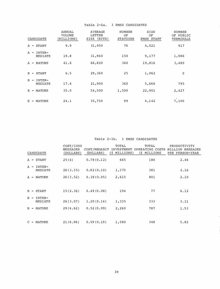
Table 2 -1a . 3 EMS S CANDIDATE S
ANNUAL AVERAGE NUMBER S I ZE NUMBER VOLUME LETTER OF OF OF PUBLIC
CANDIDATE ( B I LLIONS ) S I Z E ( BITS ) STATIONS EMSS STAFF TERMINALS
A - START 9 . 9 31 , 9 5 0 7 6 4 , 0 2 1 9 1 7
A - INTER-MEDIATE 1 9 . 8 3 1 , 9 6 0 1 5 0 9 , 1 7 7 1 , 9 8 6
A - MATURE 4 1 . 6 6 6 , 8 2 0 3 6 0 1 9 , 8 1 6 3 , 4 8 0
B - START 6 . 5 2 9 , 3 6 0 2 5 1 , 0 6 2 0
B - :tNTER-MEDIATE 1 7 . 6 2 1·, 9 0 0 3 6 0 5 , 6 6 6 7 9 5
B - MATURE 3 5 . 0 5 4 , 5 0 0 1 , 5 0 0 2 2 , 9 0 1 2 , 4 2 7
C - MATURE 2 4 . 1 3 5 , 7 5 0 9 9 4 , 1 4 2 7 , 1 0 0
Table 2 - 1b . 3 EMSS CANDI DATES
COST/ 1 0 0 0 TOTAL TOTAL PRODUCTIVITY MES SAGES COST/MEGABIT INVE S TMENT OPERATING COSTS MILLION MESSAGES
CANDIDATE ( DOLLARS ) (DOLLARS ) ( $ MILLIONS ) ( $ MILLIONS PER PERSON-YEAR
A - START . 2 5 ( 4 ) 0 . 7 8 ( 0 . 1 2 ) 6 6 5 1 8 0 2 . 4 6
A - INTER-MEDIATE 2 6 ( 3 . 3 5 ) 0 . 8 2 ( 0 , 1 0 ) 1 , 3 7 5 3 8 1 2 . 1 6
A - MATURE 2 6 ( 3 . 5 2 ) 0 . 3 8 ( 0 . 0 5 ) 2 , 6 1 5 8 0 1 2 . 1 0
B - START 1 5 ( 2 . 3 6 ) 0 . 4 9 (0 . 0 8 ) 1 9 4 7 7 6 . 1 2
B - INTER-MEDIATE 2 6 ( 3 . 0 7 ) 1 . 2 0 (0 . 1 4 ) 1 , 3 3 5 3 3 3 3 . 1 1
B - MATURE 2 9 ( 4 . 6 2 ) 0 . 5 2 (0 . 0 9 ) 2 , 2 6 0 7 8 7 1 . 5 3
C - MATURE 2 1 ( 6 . 9 6 ) 0 . 5 9 ( 0 . 1 9 ) 1 , 5 8 0 3 4 8 5 . 8 2
3 9
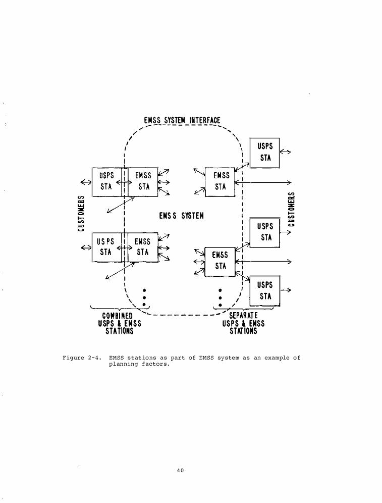
\.
EMSS SYSTEM INTERFACE / ,- - - - -
- - - - - - -- ..... ....... / ' , I \ I \ USPS I I I STA I
EMS S SYSTEM
I
U SPS STA
: I USPS \ e e I
\ • • / STA ' • , ·��·�./��==��
COMBtNED ', .._ - - - - .... - - - - - .... SEPARATE USPS l EMSS USPS l EMSS
STATIONS STATIONS
Figure 2 - 4 . EMSS s t at ions as part of EMSS system a s an example o f p l anning f actor s .
4 0
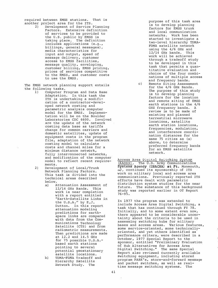
required between EMSS stations . That i s another proj ect area f o r t h e ITS .
2 ) Development o f S ervice P lann ing Factor s . Extens ive def inition of services to be provided to the u . s . pub l i c by EMSS is taking place . T he def inition includes app l i cations ( e . g . , billing s , general me s s age s ) , media character i s tics for input and output , speed of mes sage de l ivery , cus tomer access to EMSS f a c i l i t ies , mes sage qua l i ty , envelop ing , cu� tomer b i l l ing , EMSS pricing , pr1ces of services competi tive to the EMS S , and cus tomer costs to use the EMS S .
The EMSS network planning support enta i l s the following task s .
1 ) Computer Program and D ata Base Adaptation . I n this task the ITS is undertaking a modi f i cation of a contractor -deve loped network costing and parametric analy s i s computer model for the EMS S , Implementation will be on the Boulder Laboratories CDC 6 6 0 0 . I nvolved are the update of the network costing data base as tar i f f s change f o r common carr iers and domes t i c satellites , update of equipment cos t s in the program f ile , adaptation of the network cos t ing model to calculate co s t s and channel mi les for a minimum d i s tance network , fully interconnec ted networks , and mod i f ication of the computer mode l to r e f l ec t recent requirements .
2 ) Development o f Local/Trunk Network P lanning Factor s . This task is divided i nto the technical areas descr ibed below . a l Attenuation Asses sment of
1 2 / 1 4 GH z B ands . Thi s work i s near completion with a r eport entitled " E ar t h- S at e l l i te L inks in the U , S , A , ' ' by E , ,J , Dutton . I n thi s report attenuation modeling pred ictions for earths�ace links are compared w1 th data £rom the communications Technology Satellite (CTS ) and from radiometr ic measurements , Then predictions are made at 1 2 . 2 and 1 4 . 5 GH z tor 7 5 poss ible U , S . A , based earth s tations pointing to several potenti a l geo s tationary sate l l ite locations .
b l TDMA-FDMA T r adeo f f and Hierarchy Satel l i t e Network S tudy . T he
4 1
purpose o f thi s task area is to deve lop planning factors for EMSS trunk and local communication networks . Work has been started to inve s tigate a two- level hi erarchy TDMAFDMA sate l l ite network using the 4 / 6 GHz and 1 2/ 1 4 GHz bands . This work will be achieved through a tradeof f s tudy to be deve loped in this task that permits a quanti tative evaluation and c hoice of the four combinations of multiple access and f requency bands .
c ) Remote S i t ing Assessment for the 4/6 GHz Bands . The purpose of this study is to develop planning factors for the location and remote s i ting of EMSS earth stat ions in the 4/6 GHZ frequency bands . A review is to be made of exi s t ing and planned terrestrial microwave locations , sate l l ite earth s ta tion locations , f requenc ies , modulation , and interference coordination di stances for the same 75 c ities as ( a ) above , t o determine preferred f requency bands for an EMSS satellite network .
Acc e s s Area Digital Swi tching Sys tem (AADS S ) . The U . S . Army Communications
Sys tems Agency ( USACSA) a t Ft . Monmouth , �J , continued its sponsorship of ITS work on m i l i tary local and access area communication s . Previous ly repor ted ITS e f forts have dealt with parametric d i s tr ibu t ion system s tudies for the near future . The substance of thi s background study was reported earlier in OT Report 7 6 - 9 5 .
In 1 9 7 7 the program was extended to inc lude Acc e s s Area Digita l Switching , a task that has continued through FY 7 8 Initially , and to some extent even no� , there appeared to be cons iderable uncertainty about the criteria to be used in a s s e s s ing switching hubs for m i l i tary ba s e s and access areas . var ious features so�e s ervice-oriented , some technically-
'
or1 ented , and yet others iden t i f i ed as performance critera , were descr ibed in a October , 1 9 7 7 Special Report to the sponsor , entit led " Preliminary Evaluation Of Hub Alternatives for Access Area Digital Switching , " The same Special Re�o r t . also r�viewed currently avai lable sw1 tch1ng equ1pment , including s tored progr am PABX ' s , store-and-forward me ssage and packet switche s , as wel l as realtime mes sage switching systems . The
review paid particular attention to seven implementation a lternatives based on PABX technology . The more promi s ing options were s ingled out for l ater scrutiny .
NTIA Report 7 8 - 2 , "Access Area Switching and S ignal ing : Concepts , I s sues , and Alternatives " reflects two top ics o f work . F irst , i t describes and analyzes an a ttrac tive exampl e o f a s tored program-control led digital swi tch . Endowed with interchangeab le , analog/ digita l , line/trunk cards , as wel l as with remotable concentration modules , the prototype switch shows many advantages for the future acce s s area .
The second hal f of Report 7 8 - 2 deals with s ignaling functions and methods that are currently in common use for the remote control of circuit switches . F i gure 2 - 5 shows some of the intero f f ice s igna ling concepts . Part ( a ) depicts conventional associ ated s igna l ing , where individual s ignal ing units are a s s igned to individual trunks . P art ( b ) i l lustrates a more recent , and more economical deve lopment , cal led common-channel associated s ignal ing . Here a s igna l i ng l ine parallels a group of trunk s . All s ignal ing lines end in one or two s igna l ing termina ls , thus reduc ing signal ing hardware and cos t . P art ( c ) o f F igure 2 - 5 shows the nonassoci ated vers ion of common channel intero f f ice s ignal ing (CCI S ) , This f inal vers ion appears to be the s ignaling system of the future for North American telephony ,
With the advent of integrated data/voice sys tems , control s ignaling and network management involves a complex interplay between a l l the network e lements (terminals , l inks , mode switche s , and separate autonomous subnetworks ) , N ew advanced s ignal ing techniques and multi- leve l protoco l s are being developed to exercise automatic remote control o f processes that in turn contro l the traffic f l ows . New s ervice features and sys tem functions involve large commitments in software and associated hardware development . ITS work during the summer of 1 9 7 8 was concerned with such advanced s ignal ing aspects . Figure 2-6 i l lustrates the more s ignif icant AADSS sys tem interfaces . These interf aces have a var iety of transparency requirement s for control s ignal ing in the foreseen , 1 9 8 0 - 1 9 9 0 , analog-to-digital tran s i tion period .
This ITS work on advanced s ignal ing is summarized in a draft report , "Control S ignaling in the Mil itary Switching Environment . " As of August 1 9 7 8 , the draft was still in review . I t is s cheduled to be available in October , 1 9 7 8 . Various data communication protoco l s , such as the bit oriented S DLC , the byte or iented DDCMP , the character oriented BI SYNC , plus such packet protocols as
4 2
CCITT ' s X . 2 5 ( o r i t s equiva lent , SNAP ) have been considered and asses sed in l ight of AADSS unique requirements .
AM Stereophonic Broadca sting . on July 6 , 1977 , the Federal Communications Divis ion released a Noticy of Inquiry (No . 9 ) regarding AM s terophonic broadcasting a s a result of two petitions request ing adoption of rules to permit stereophonic broadcast ing by AM broadcas t s tation s .
Eventually , f ive competi tive sys tems were proposed , re spectively by Belar , Harr i s , Kahn , Magnavox , and Motorola . The ITS study focused on aspects which were not thought l ikely to be adequately treated by others , i . e . , the sponsors o f the various sys tems or the Nationa l AM S tereophonic Radio Committee ( NAMSRC ) .
In particular , ITS conducted anal y s i s o f spectral occupancy , effect on cover age range ( both monophonic and s tereophonic ) , and di s tortion a s a result o f restricted receiver pre-detection bandwidth and a s a result o f the e f fects o f s kywave and ground wave i nter f erence ( f ading ) under nighttime propagat ion condition s . Spectra l occupancy i s of importance a s it influences the pos s ib i l i ty o f achieving maximum spec trum uti l i za tion o f the avai lable broadcast band . Adoption o f stereophonic h� broadcas t ing would stimulate the produc tion of M1 receivers with synthes i z ed tuning and more w idespread inclus ion o f , for example , adj acent channel whi s t l e suppress ion f i l ter s , which would de facto preclude any future change of channel spacing . Coverage range (i . e . , monophonic and stereophonic S/N ratios a s compared to s tr aight monophonic transmission) and d i s tortion resulting from restricted receiver predetec tion bandwidths are , o f cour s e , of importance i n providing the best consumer service and are a l so of maj or importance to the broadcaster . Finally , per for-mance under condi tions o f nighttime propagation i s of importance to many rural l i s teners who a f ter sundown may be ful ly dependent on skywave r eception . The results of the ITS s tudies were submi tted to the FCC in Initial Comments on Docket No . 2 1 3 1 3 in January 1 9 7 8 , and in further Reply Comments in March 1 9 7 8 . At the t ime of wr i ting , a decis ion had no t yet been taken by the FCC .
MARAD A s s i s tance . S ince 1 9 7 3 , ITS has prov�ded a range of technical services to the U , S , Mar i t ime Admin i s tration (MARAD l , including test f ac i l ities and
as s i s tance , technical repre s en tation i n connection w i t h advanced communications proj ects , communication sys tems s tudies , and inputs to the CCI R . Some o f the specific e f forts in FY 7 8 are descr ibed in Lhe ;f; o llowing paragraphs .
l l I T S provided the technical input , and was the u . s . Spokesman , at the CCIR S tudy Group (Mob i l e
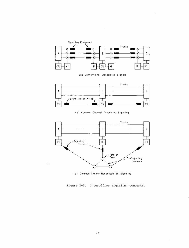
S i g na l i ng Equi pment
� -' � � T r u n k s
-1 - - f -
-x - - x -
( a ) Con ve n t i o n a l Associ ated S i g n a l s
Trunks
( b ) Com mon Channel Associated S i g na l i ng
( c l Common C h a n n e l N on a s soc i a t e d Signa l i ng
S i g na l i n g
Network
Figure 2 - 5 . Interoffice signaling concepts .
4 3
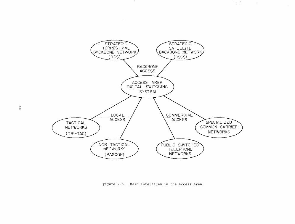
""' ""'
TACT ICAL NETWORKS ( TR I-TAC )
Figure 2- 6 . Main interfaces in the access area .
S ervic es ) F inal Meeting in January 1 9 7 8 on D igital S elec tive Call ing ( SELCALL ) and Direct P r inting for
the mob i l e mar i time services . These ef forts culminated in the revised Recommendations 4 9 3 - 1 ' ( SELCALL ) and 4 7 6 - 2 ( D irect P r inting ) which were approved by the XIVth P lenary Assembly of the CCI R in June 1 9 7 8 . I n add i t i on , ITS provided technical consulting to sever a l manufac turers re lating t o Recommendation 4 7 6 - 2 .
2 ) ITS , as techni c a l representative for MarAd , par�icipates in the work of the Radio Technical Commiss ion for Marine S ervice ( RTCM ) , Subcommittee for Automated VHF Mar i time Mobile Telephone Systems ( S C - 7 1 ) and has been a U . S . member to the CCIR I nter im Worki ng P ar ty 8/5 on the same sub j ec t . Some o f the results of the work accomp l i shed dur ing FY 7 8 is pub l i s hed i n NTIA Technical Report 7 8 - 4 , " I nter f a c ing the Automated Maritime Mobi l e Telephone System w i t h t h e u . s . P ublic Switched Telephone Networ k '' . Thi s report de ta i l s the un ique d i f f iculties in the u . s . marine communications f ield , such a s the heterogeneous makeup of communications ' providers ( i . e . , tel ephone company owned and independent coast stations ) , regulatory res tr i ctions , insuf fic i ent spec trum resource s , and economic con s ideration s . r t further discusses some of the charac ter istics of the U , S , telephone network a s it a f fects the automation of marit ime mob i le pub l ic correspondenc e s ervices and presents concepts for inter f ac ing the radio portion of such services with the pub l i c telephone network .
SECTION 2 . 2 . SATELLITE COMMUNI CATIONS
The main ef fort in the satellite communi ca tions program area during F Y 7 8 has been on the direct funded pro j ect which was initiated in FY 7 7 . On this pro j ect , the regulatory , economic , and techno logical barriers to the development of sma l l antenna earth- s tation sys tems have been stud ied . work has continued a t a low lev e l on sate l l ite communication re lated work sponsored by other F eder a l Agenc ies . For examp l e , the GOES ground terminal E quipment C er t i f ication has continued .
Direct S atell i te Communications , The long- term ob j ec tive of the D irect S atell i t e Communications pro j ec t is to contr ibute toward the goal o f increas ing the l ikel ihood o f s a t i s f a c tory systems perf ormance as a f fected by natural , engineering , and economic factors and to accelerate the use of direct communication satellites by lower ing barr iers to the use of sma l l earth s ta tions and
4 5
by ident i f ying and consol idating public service s ec tor needs .
The ob j ec t i�es for FY 7 8 were :
a . through studies and parti c ipation in WARC 7 9 preparations concerning future needs and uses of the 12 GHz frequency a l location , a s s i st in the resolu tion of regulatory , technica l , and economic barriers to the use o f sma l l earth s tations in coopera tion with NASA , other Fede.cal agenc ies , and U . S . indus try ;
b . mon i tor the progress o f NASA , PSSC , and o ther agenc ies in developing pub l i c s ervice sec tor satellite communication requirements to determine the po s s ible need for a pilot program of high-powered direct satellite communica tion sys tems with a s soc iated sma l l earth stati ons ; and
c . complete the anal y s i s o f technical barriers l imiting the earth station antenna s i z e requirements in the interf erence-free s ituation .
A s tudy was conducted which addressed some o f the past , current , and planned activities relating to the U . S . dome s t ic satellite communications service s , both f ixed- s a t e l l ite services and broadcasting - s a te l l i te s ervice s . S ince there is not yet a domestic U . S . broadca s t ingsatellite s ervice , the primary emphasis was on the f ixed-sate l l ite service . The results of this s tudy are reported in NTIA Report 7 8 - 9 .
The deve lopment of the u . s . dome s t ic satellite common-carrier sys tems was traced and the current status was presented . The general technical characteri s t i c s of the current-generation communicati on s a t e l l i te s were inc luded .
The technical des ign of these satell ite communication sys tems requires the use of relatively l arge earth station antennas . Typ ical minimum earth s tation antenna d i ameter for transmitting i s in the r ange o f 10 to 15 meters . Whi l e for a rece ive-only TV application , the earth station antenna diameter is typically 4 , 5 to 10 meter s , depending on geographical location and the required TV picture qua l i ty ,
An impo r tant a spect in consider ing the potent i a l for growth of sma l l antenna earth-s tation systems is the regulatory and frequency a l location c l imate in which such sys tems can develop . The frequency band having the greates t potential f o r accommodat ing smal l-antenna earth- s tation systems is the 1 2 / 1 4 GHz band . However , if thi s band deve lops Cas it appears to be deve loping) in the s ame manner a s the 4/6 GHz band has developed , the sma l l -antenna , earths tation system development will be
forec losed in the 1 2 / 1 4 GHz band a lso . The future growth potential for satell ite conununication sys tems i s one of the very important problems that needs s er ious cons ideration during preparation for the 1 9 7 9 WARC .
Some tar i f f information on the cost o f pr ivate- l ine service o f fered b y terrestr ial and sate l lite conunon carriers was studied . The capital equipment investment requirements for satel l i te commun ications is not dependent on the distance between the earth locations be ing served . However , the tar i f f rates on f i l e with the FCC are d i s tancedependent . This d i s tance-dependence of the tar i f f rates appears to be based on a competitive pr ic ing strategy , rather than on the cost of providing the s ervice .
The s tudy for determining minimum dimens ions of earth-station antenna s , carried over f rom FY 7 7 , wa s completed for various cases of s ingle carrier per transponder . The results of thi s study were reported in OT Report 7 8 - 1 4 5 .
Covered in thi s s tudy are FM TV , FDM"·FM telephony , mul tip lexed PCM-PSK telephony , and PSK digital-data transmi s s ion . Any other type of s ignal can be added without di f f iculty if the need exi s ts for the signal .
Although we have tried to determine actual values of minimum antenna d iameters for g iven types o f s igna l s , we have not been able to e l iminate a l l uncertainties in t h i s s tudy . F o r the reception of a TV s igna l , we have determined a range of values for the minimum antenna diameter . For telephony signa l s and digital -data s ignal s , we have calculated sample values that correspond to assumed s i zes of the system and as sumed values of the satellite E I RP , I f more spec i f i c values o f thes e sys tem parameters a r e known , we can narrow the unc ertainties .
Actual values of minimum antenna diameter are of the order of l m for the reception of FM-TV broadcasts in mos t places in the contiguous 48 s tates o f the United s tates , i f the broadcasts are done in the 1 2 -GHz band in accordance with the 1 9 7 7 WARC deci s ion . For mult i plexed telephony carrying 6 0 te l ephone channels or les s , the minimum antenna diameter i s about 5 m or less , if the sate l l i te E I RP ' s of 3 0 dBW and 40 dBW are avai l able for the 4 -GHz and 1 2 -GHz bands , r espectively . The s ame is true for digita l-data - signal transmis s ion of 3 Mb/s or les s . Except for the FM-TV case , however , the RF bandwidth i s only a small f raction o f the nominal 3 6 -MHz or 4 0 -MH z bandwidth of commercialsatel l i te transponqers . If a currently available commercia l -satellite transponder is to be used , e f f ec tive methods
4 6
o f its sharing by a number o f users mus t b e a s sumed and the effects on the min i mum antenna dimens ion determined .
In order that more direct users can be ac commodated in sate l l i te conunun ication s , it is e s s ential that one can e s t imate costs a s sociated with both earth s tation and satell ites for various services . The results of thi s s tudy are expec ted to be useful for such cost e s t imation .
Preparation in the Uni ted States for the 1 9 7 9 General World Admini s tr at ive Radio Conference ( 1 9 7 9 GWARC ) has been in progress s ince early 1 9 7 5 . These preparations are being conducted by two entities : ( 1 ) the Interdepartment Radio Adv isory
Committee ( I RAC ) Ad Hoc Committee 1 4 4 for the Government sector and ( 2 ) the Federal Communications Conuniss ion ( FCC) , by internal planning and solic itation of public commen t through the not.ice-ofi nquiry , for the non-Government sector . The ITS s tudied some techni c a l and economic a spects re lated to the f ixedsate l l i te and broadcasting- s ate l l ite services operating in the frequency
· range f rom 2 . 5 GHz to 1 4 . 5 GHz . These services operate i n por tions of thi s segment o f the spectrum des ignated for non-Government use in the United State s .
Thi s s tudy focused on the technical and economic i s sues a ssoc iated with spectrumand orbit-use planning for broadca s tingsatel l i te and f ixed- sate l l i te services i n the 2 . 5 to 2 . 6 9 GHz frequency band and in the frequency bands between 1 1 . 7 to 1 4 . 5 GHz . The key que stions addr e s s ed are :
o How should f lexibi l i ty for the 1 9 8 2 Broadc a s ting-Sate l l i te Regional Admin i s trative Radio Conference ( RARC ) for Region 2 be developed
and taken into account in p lanning for the 1 9 7 9 GWARC ?
o What new spectrum resources should be planned for the broadc a s t ings a te l l i te and f ixed-sate l l i te s ervices in the 1 1 . 7 to 1 4 . 5 GHz bands?
o How c an sma l l earth terminals be accommodated?
o How c an hybrid satellites i ntroduce greater f lexib i l i ty in planning for the 1 9 7 9 GWARC and 1 9 8 2 RARC?
o Why do orbit-div i s ion and spec trumdivision pol icies deve loped in prepara tion for the 1 9 7 7 WARC-BS need reexamination prior to the 1 9 7 9 GWARC ?
o What p lanning could be done to encourage uti l i zation o f the 2 . 5 to 2 . 6 9 GHz band?
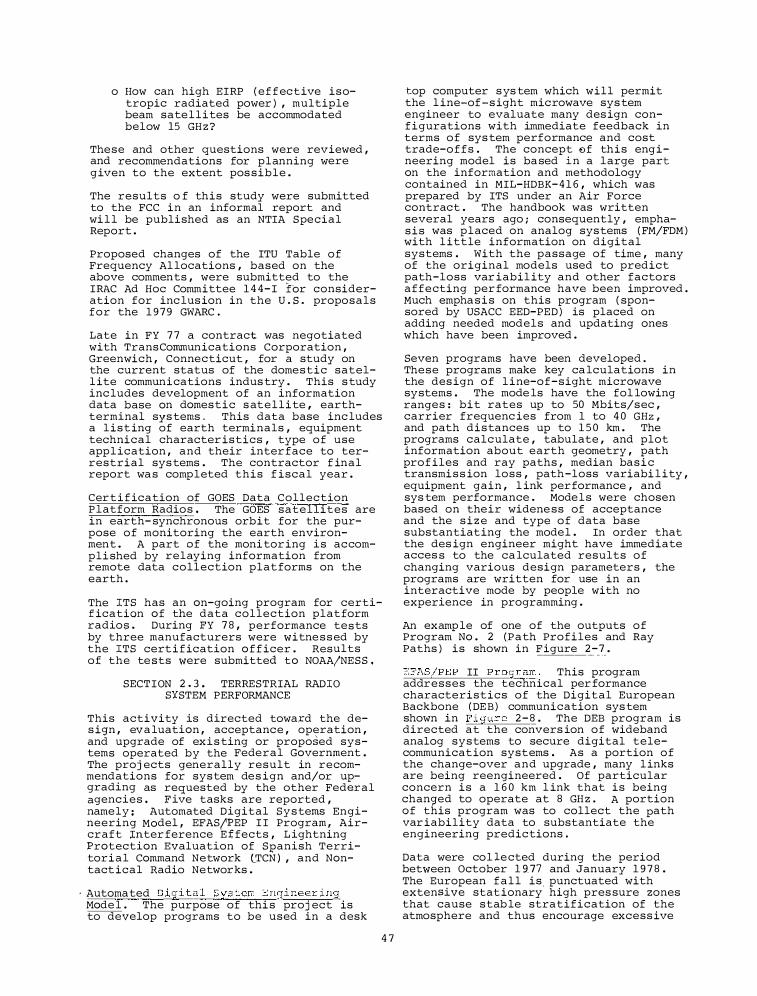
o How can high EIRP ( ef f ective isotropic radiated power ) , multiple beam satellites be accommodated below 15 GH z ?
These and other questions were reviewed , and recommendations for planning were given to the extent pos sible .
The results o f this study were submitted to the FCC in an informal report and wi l l be published as an NTIA Special Report .
Proposed changes of the ITU Table of Frequency Al locations , based on the above comments , were submitted to the IRAC Ad Hoc Committee 1 4 4-I for consideration for inc lus ion in the u . s . proposals for the 1 9 7 9 GWARC .
Late in FY 7 7 a contract was negotiated with TransCommunications Corporation , Greenwich , Connecticut , for a study on the current status of the domestic satell ite communications indus try . This s tudy inc ludes development of an information data base on domestic s atellite , earthterminal sys tems . This data base inc ludes a l isting of earth terminals , equipment technical character istics , type of use appl ication , and their inter face to terrestrial sys tems . The contractor f inal report wa s completed this f iscal year .
Cer t i f ication of GOES Data Collection Platform Radios . The GOES satellites are in earth- synchronous orbit for the purpose of monitoring the earth environment . A part of the moni tor ing is accompli shed by relaying information from remote data collection platforms on the earth .
The ITS has an on-going program for certif ication of the data collection platform radios . During FY 7 8 , performance tests by three manufacturers were witnessed by the ITS certification off icer . Results of the te sts were submitted to NOAA/NESS .
SECTION 2.3 . TERRESTRIAL RADIO SXSTEM PERFORMANCE
This activity is directed toward the des ign , eva luation , acceptance , operation , and upgrade of exis ting or proposed systems operated by the Federal Government . The proj ects generally result in recommendations for system des ign and/or upgrading as requested by the other Federal agencies . F ive tasks are reported , namely : Automated Digital Systems Engineering Model , EFAS/PEP I I Program , Aircraft Inter ference E ffects , L ightning Protection Evaluation of Spanish Territorial Command Network {_TCN ) , and Nontact ical Radio Networks .
· Automated Digital System Engineering Mode l . The purpose of thi s proj ect is to develop programs to be used in a desk
4 7
·top computer s ys tem which will permit the l ine-of -s ight microwave sys tem engineer to evaluate many des ign configurations with immediate feedback in terms of sys tem performance and cost trade-offs . The concept �f this eng ineering model is ba sed in a large part on the information and methodology contained in MIL-HDBK- 4 1 6 , which was prepared by ITS under an Air Force contract . The handbook was written several years ago ; consequently , emphasis was placed on analog systems ( FM/FDM ) with l ittle information on digital systems . With the passage of time , many of the original models used to predict path-loss var iabil ity and other factors affecting per formance have been improved . Much empha s i s on this program ( sponsored by USACC EED-PED ) is placed on adding needed models and updating ones which have been improved .
Seven programs have been developed . These programs make key ca lculations in the des ign of l ine-of-sight microwave systems . The mode ls have the fol lowing ranges : bit rates up to 50 Mbits/sec , carrier frequenc ies from 1 to 4 0 GHz , and path distances up to 1 5 0 km . The programs calculate , tabulate , and plot information about earth geometry , path prof iles and ray paths , median bas i c transmiss ion loss , path-loss variabi l ity , equipment gain , l ink performance , and sys tem performance . Models were chosen based on their widene ss of acceptance and the s i z e and type of data base substantiating the model . In order that the des ign engineer might have immediate acces s to the ca lculated results of changing various design parameters , the programs are written for use in an interactive mode by people with no experience in programming .
An examp le of one of the outputs of Program No . 2 (Path Profiles and Ray Paths ) is shown in Figure 2 - 7 .
EFAS/PEP II Program . This program addresses the technical per formance characteristics of the Digital European Backbone ( DE B ) communication sys tem shown in Figure 2 - 8 . The DEB program is directed at the convers ion of wideband analog systems to secure digital telecommunication systems . As a portion of the change-over and upgrade , many l inks are being reengineered . Of particular concern is a 1 6 0 km l ink that is being changed to operate at 8 GH z . A portion of this program was to collect the path var iability data to substantiate the engineering predictions .
Data were col lected during the period between October 1 9.77 and January 1 9 7 8 . The European fall is. punctuated with extensive stat ionary high pres sure zones that cause stab le stratification of the atmosphere and thus encourage excess ive
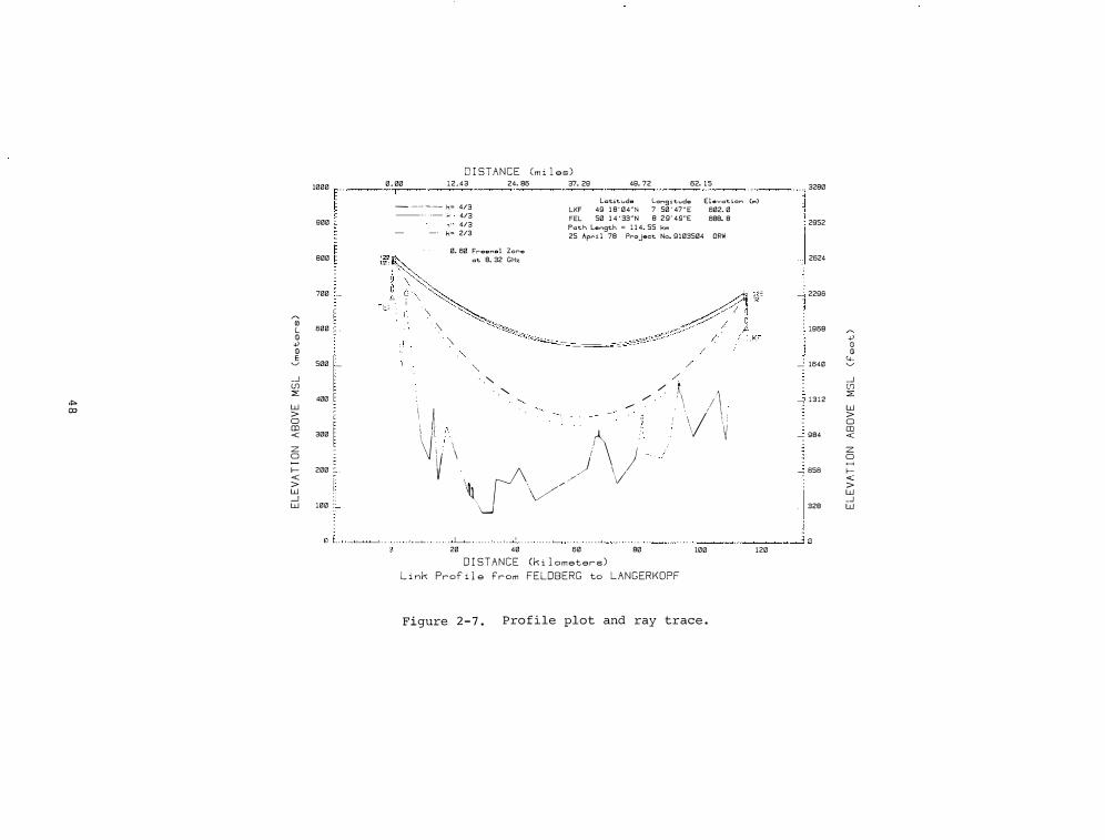
1000
900
800
700
00 600 L m +>
m E � 500
_j (f) ::<: .,. 400
00 w > 0 CD < 300
z 0
I- 200 < > w _j w 100
D I STANCE Cm i l es)
0 . 00 1 2 . 4 3 24. 86 37. 29 49. 72 62. 1 5 �
lc;titude long i tudo Elevation (rn) � ·�·- -·- k"" 4/3 ---- k o 4/3 ---- k· 4/3
LKF 49 1 8 ' 04"N 7 50 ' 47 " E FEL 50 1 4 ' 33"N 8 29' 49"E Path length "" 1 1 4. 55 krn
602. 0 688. 8
k"' 2/3 25 Ap�""i l 78 Project No. 9103504 ORW
! / �
0. 60 F rounu 1 Zorro at 8. 32 GHz
·" "
·"-"
. ·"-. . '- "'-
/ /
/ / �
/ / . . ' \ !\ \, "· A I r\
J � � \ � . . ' \ \ � I 1/ • I
' J t) ' ·�
\J\// J 20 40 60
D I STANCE (k i l ometers)
80 100
L i nk Prof i l e from FELDBERG to L A N G ERKOPF
Figure 2 - 7 . Profile plot and ray trace .
120
3280
2952
2624
2296
1968 � +> (!) m 4-1640 �
_j (f) ::<: 1312
w > 0 CD
984 <
z 0 �
656 I-< > w _j
328 w
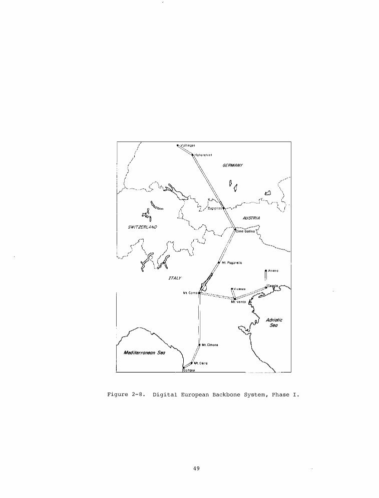
ITALY
Mt. Cimone Mediterranean Sea
GERMANY
AUSTRIA .... _ .. .,.--...... �, Cima Gallina '}"'
-� \ ...... ___ ...
.... ----..... �
Adriatic Sea
Figure 2- 8 . Digital European Backbone System , Phase I .
4 9
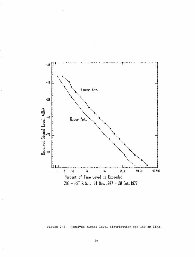
-
33
f I I I I I I jiill il I I" II I I I I"" I ( ( )'"' J ' '
-49
Lower Ant.
-SB
........ E a:::a -o ......... -69 ....-( Q) > (I) __,
....-( 0 &r78 .....
(f) -o
Q) > ...... Q) � -BlJ 0:::
� fill I I I I LJ I I , I I 1, II I I
10 53 91J 99 99. 9 99. 99 99. 999 Percent of Time Level is Exceeded ZUG - HST R. S. L. 14 Oct. 1977 - 20 Oct. 1977
Figure 2- 9 . Received signal level distribution for 1 6 0 km link .
5 0
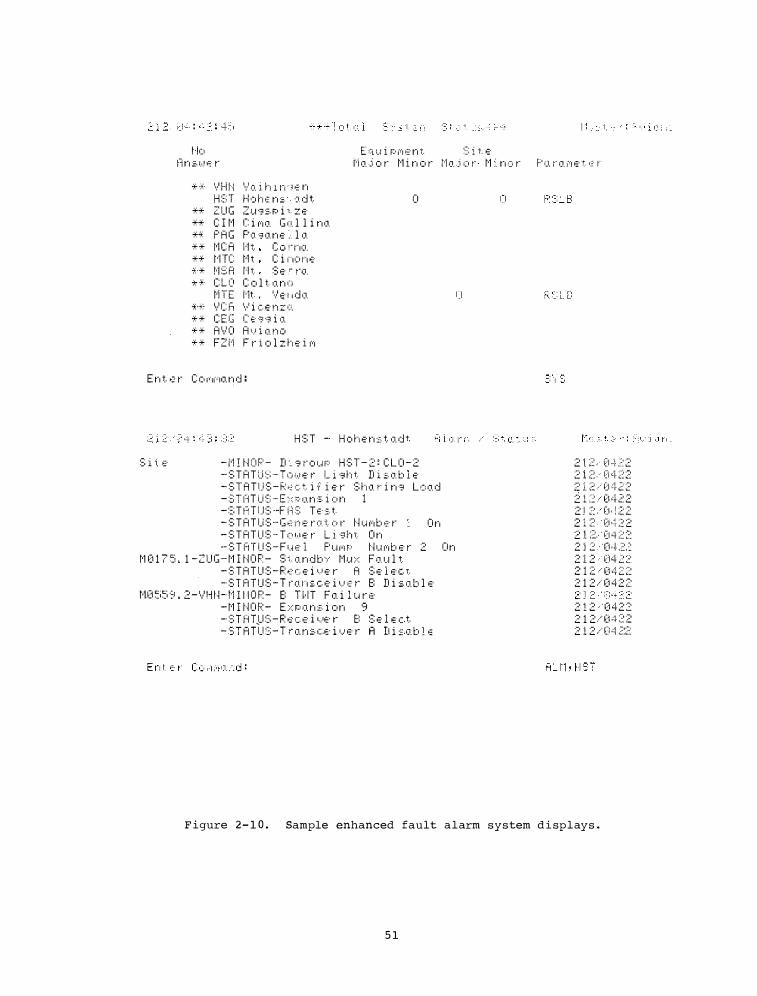
E q u i P M e n t S i t e t·lo t:i n :=. l ... ! s· �� M a j o r M i n o r M a j o r M i n o r P a r a M e t � r
* ·�· 1·,·' H l··i \:1 o. J. h l n ·· � E· n H ::: ·r f-k• f·� ·� n :::. '='- d t
** Z U G z u g s p i ,. z e ** C I M r i M a G a l l i n a *� P A G p� g a n e .. l a ** t·1 C A l'h C ·:· !TIO. ** tHC t·1 t C i i" 'O i·"; E· "·* t·1 ::; ri n t ::; .;;· ·- t·o. -:t- -t· C L C' C o l t o. n o
t·i T E 1··1t. \l �· ; ; d •J. *·�� 1•/ C h \·1 i c .::· n z (i. * * C E C C � . . ;t ·;;;i o. * * A \·1 0 A I..J i 1J. n 1:1 * * F Z M F r i o l z h e i M
0
E n t. •:· r C O f';f';o. n d :
S i i. E·
H S T - H o h e n s t. a d t
- M I N O P - D : s r o u P H S T - 2 : C L 0 - 2 - S T A T U S - T o w e r L i s h t D i s a b l e - S T A T U S - R � c t i f i e r S h a r i n s L o a d - :;:;r t'l T u ::>-· E :": r-:· o. n ::;. i o n 1 - ::; T �:: T i.J ::; --F H 3 T E· s. t. - S T A T U S - G e n e r a t o r N u M b e r O n - S T A T U S - T o w e r L i s h t O n - S T A T U S - F u e l P U M P N u M b e r 2 O n
M 0 1 7 5 . 1 - Z U G - M I N O R - S t a n d b Y M u x F a u l t - S T A T U S - R e c e i v e r A S e l e c t - S T A T U S - T r a n s c e i v e r 8 D i s a b l e
t·l0 �i5 ·::> . 2 - '·/H tH'1I I I O P - E: HIT F o. i l u r .:· - M I N O P - E x P a n s i o n 9
= :�:i�n: :�: =�� :�: �:� :;:�: �- ..... e ;: �e
i, � �:�. b 1 "
2 1 2 . i21 - i .? 2 2 i :::: . · Ci · 'i· Z� 2 �? 1 �� -·· ��1 :::1. 2 2 2 L:� .. 0 4 �� 2 2 1 ::� (1 · ! :2 2 2 1 ::: D ·L� 2 2 1 ;2. ' (l q ;:� ;::: 2 l 2 · · o .j . .2.� 2 1 2 ('14 2: 2 2 1 2 • 0 4 �: �-� 2 1 2 ..... 0 4 2 :�:
2 1 2 · ' 0 4 2 2 2 1 2 ..... 0 �+ �� :2 2 1 2 ./ (i .::l .?.:��
F igure 2- 1 0 . Sample enhanced fault alarm system d i splays .
5 1
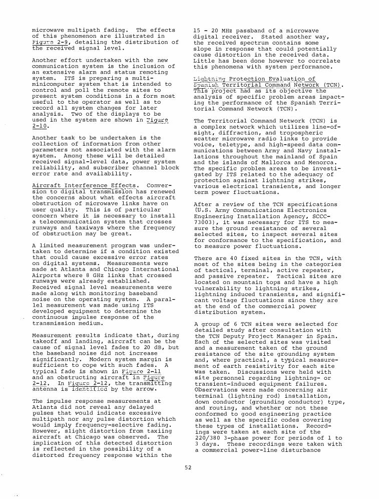
microwave mul t ipath f ading . The e f f ects of thi s phenomenon are i l lus trated i n Figur e 2 - 9 , detail ing the d i s tr ibution o f the received signal level .
Another ef fort undertaken with the new communication sys tem is the inclusion o f a n extens ive alarm and s tatus remoting system . ITS i s preparing a multiminicomputer system that i s intended to control and po l l the remote sites to preser.t system conditions in a form most useful to the operator as we l l as to record a l l system changes for later analys i s . Two of the displays to be used in the sys tem are shown i n Figure 2 -1 0 .
Another task to be undertaken i s the collec tion of informat ion f rom o ther parameter s not as soc iated with the a larm system . Among these will be detailed received signal -level data , power sys tem rel iabi l i ty , and subscr iber channe l block error rate and avai l ab i l i ty .
Aircr a f t Interference E f fects . Convers ion to digital transmiss ion has renewed the concerns about what ef fects aircraft obstruction o f microwave l i nks have on user qual ity . This i s of particular concern where it is neces s ary to insta l l a telecommuni cation sys tem that cros s e s runways and taxiways where the f requency of obstruct i on may be grea t .
A l imited measurement program was undertaken to determine if a condition exi s ted that could cause exc e s s ive error rates on digital sys tems . Measurements were made at Atlanta and C hi c ago I nternat ional Airports where 8 GHz l inks that cro s s ed runways were already e s tabl i shed . Received s ignal level measurements were made along with mon i toring bas eband no ise on the operating sys tem . A parallel measurement was made us ing I TS developed equipment to determine the cont inuous im.pulse response of the transmis s ion medium .
Measurement results indicate that , dur ing takeof f and landing , aircraft c an be the cause o f signal level fades to 20 dB , but the baseband no ise did not increase s ignif icantly . r1odern system margin is suf f ic ient to cope wi th such f ades . A typical f ade is shown in F igure 2 �11 and an obs truc ting aircraft in F igure 2 - 1 2 , In F igure 2 -1 2 , the transmitting antenna i s identified by the arrow .
The impulse response measurements at Atlanta did not reveal any delayed J?Ulses that 'I'Ould indicate exc e s s ive mul t ipath nor any pu l s e distortion which would imJ?lY frequency-selective f ading . However , s l ight dis tortion from tax i ing aircraft at Chicago was observed . The implication of this detec ted d i s tortion i s ref lected in the pos s ib i l ity of a distorted frequency response w i thin the
5 2
1 5 - 2 0 MHz pas sband o f a microwave digita l receiver . S tated another way , the received spec trum contains some s lope in r esponse that could potentially cause d i s tortion in the rece ived data . L ittle has been done however to correlate thi s phenomena w i th sys tem performance .
Lightning Protection Eva luation of Span ish Terr i tor ial Command N e twork ( TCN ) . Thi s pro j ect had as i t s o b j ective the analysis of spe c i f i c prob l em areas impacting the performance o f the Spanish Terr itorial Command Networ k ( TCN ) •
The Territorial Command N e twork ( TCN ) i s a complex network which u t i l i z e s l ine-ofs ight , diffrac tion , and tropospheric scatter microwave radio l inks to provide voi c e , tel etype , and high- speed data communications between Army and Navy installat ions throughout the ma inland of Spain and the i s lands o f Ma l lorca and Menorca . The spec i f i c problem areas to be inve stigated by ITS re lated to the adequacy o f protection against l ightning s tr ikes , various electrical trans ients , and longer term power f luctuations .
After a review o f the TCN spe c i f i c at ions CU , s , Army Communications E l e c tronics
Engineering Installat ion Agency , SCCC-7 3 0 0 3 ) , it was neces sary for ITS to measure the ground r e s i s tance of several sel ected s ites , to i nspect s everal s ites for conformance to the spec i f ic ation , and to measure power f luctuation s .
There are 4 0 f ixed s ites in the TCN , with mos t o f the s ites being i n the ca tegor ies of tact i ca l , terminal , active repeater , and pass ive repeater . Tactical s ites are located on mountain tops and have a high vul nerabi l i ty to l ightning strike s , l ightning induced transients , and s igni f i cant vo l tage f luctuations since they are at the end o f the commercial power d i s tr ibution system ,
A group of 6 TCN s it e s were s e lected for detailed s tudy a fter consultation with the TCN Deputy Pro j ec t Manager in Spain . Each of the selected s it e s was v i s i ted and a measurement taken of the ground re s i s tance of the s ite grounding sys tem and , where practic a l , a tyPic a l measurement o f earth r e s i s t ivity for each s ite was taken . D i s cus s ions were held with s i t e personnel regarding l ightning- or trans ient-induced equipment f a i lures . Obs ervations were made concerning air terminal ( l ightning rod) instal lation , down conductor (B"rounding conductor ) type , and routing , and whether or no t the se conformed to good engineering practice as we l l a s the spe c i f ic code s covering the se types of installat ions . Recordings were taken at each s ite o f the 2 2 0/ 3 8 0 3 -phase power for per iods of 1 to 3 days . Thes e recordings were taken with a commercial power-l ine d i s turbance
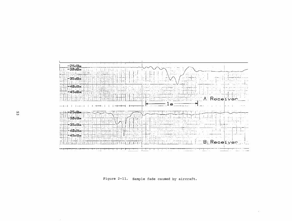
U1 w
=����=,,· . . · . , . . . 1, • • . :::� • . ; •••• w;:+ . . t •. :i:+l� . *l�i t.slL'+:ht 1 r . 1J ' i ::' 1H J •• ffiUrtn� .. 1 d ' ITD�' . , , , . ' Iii 11 •.
·
, . • • _, , • t+-tr+ • •. • .· . ··· A I ! · : ! I ' ,-t· . ' '
.• ;;;.h , . , ., · '' · - , . , • •t •F/:': ' • , ·• , ' ' ,- : , ! •:; j]i',- •Cf· ·•;c ;; ' : , , . ' .• ,;.1 · ' · '• I + - '' · · r ! T
�� . 1 lei• JC' 1 �I;'•! '! 'J IJW " j. · . �� 1 -ij, J. 1 1 , __ 1 .L f . ! .. J -; ! -i · I t · c·;+- · � � I TI: i;iJllr:.:3_ lad_ I sl
.' '�- -: ' ,,. , '"lctHti"tf:ill\frrr " I ' • '• i' iT i • ' ·, '· ·Tic •' ' ' rt ; ; Th
_, )' • JJ .• ��.t�r-.1 f,. - i i� ;-·! .
. ' . ' �' ]'1: ! 0 : ! j_+·· ·i _,+.i.� • : . . . : · ' : I ; . . . . ; ;; ' \'1/C\i.ll 'L i ] !• ! {:..,.: !;��· • • • · ; T: o7f�·tt+:'i[::- I J: . I . . . . . -'- -i .i.!..:. . ·'·- -1---,--
:t T " ' ' _ , . , , "" . ,, L , , "' ' •·'tilil\',"" �.�, , , · ' · I F· '" . ' " , , ' •. ' J"lV . l . . I I + I . I 1- .. s.�1:�::� ' ' :, . �::,. �% · ·::: . : :1f 111 � iiT· :�: ·:. � · · I : :· : ' ,' 'l: .f::]i����:hl'+Fii-q i f9 r I I1 I lit'*�4sde;,,' •m; ' · ' , , · ' "" '" ' ' " ,. , . ' , , ''" .... � ": ' ' '\, :;, l'! i IC b ' 'd:{Lbil''";·· +'ill + t"B j R e c eli """' J I ���� :m::.Jn:m.::r:r.'�· : :. ::· ,, ·:. :, ., : :::;r:., , , , ii , , • , "'"· I ' , , , , . "' , 1 , • . • . . , "' '· .. . .. . . . I . ·-'----
Figure 2 - 1 1 . Samp l e fade caused by aircraft .
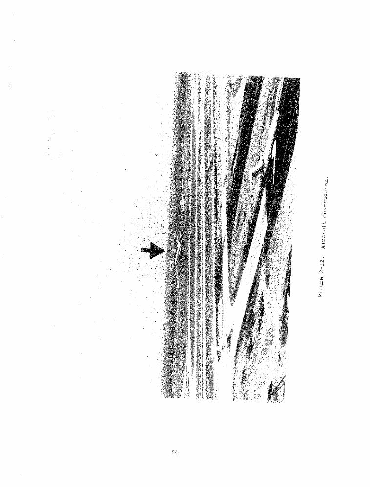
5 4
N ,...; I
N
ana ly z er that recorded slow average voltage ( 1 0 second moving average ) , S ag/Surge ( trans ients having a duration from 1 cyc le
to 1 0 seconds ) , impulses (spikes having a duration between 0 . 5 and 8 0 0 microseconds ) , and frequency variations (measured over a 1 second sampl ing period ) .
A report was submitted detailing the measurements taken , the conc lus ions reached , and the recommendations made for improving the system reliab i l i ty .
Non-tactical Radio S urvey . The United S tates Army , as well as other branches of the mil itary services , uses �ontactical radios for a great variety o f communi cation services o n their po sts and base s . These uses range from the networks common to each pos t that s erve the secur i ty and military police systems to the highly special i z ed need to communicate from the f loor to an overhead crane operator in a l arge a s s embly f ac i l i ty and the control necessary on a gunnery range .
The radio networks vary s igni f icantly in s i z e and complexity . Most of the sys tems operate in the VHF frequency range , u s ing FM ( 1 6F 3 ) voice modulation . A few operate in the UHF band , however , generally for app lications where the higher frequenc ies provide improved perfor-mance .
As a result of an earlier study per formed by a spec ial committe e , the u . s . Army Communications Command (ACOM ) at Fort Huachuca , �z , planned for an in-depth survey of the appl ications , s ervice concepts , and procurement procedure s used b y the Army in t h i s non- tactical communications f ield . The I ns titute for Telecommunication S ciences (ITS ) conducted this survey under the guidance and sponsorship of the Army . In order to provide a good statis tical sample that would be representative of the entire Army , a total of e ight installations in the u . s . were s e lected for the survey . Two locations in each of the following c l as s i f ications were selected :
1 . Headquarters 2 . Training Bases 3 . Depots 4 . Proving Grounds .
A team of two ITS eng ineers v i s i ted each of the s e installations . The local ACOM detachment served as ho sts and coordi nators for the vis i t ing team . I ntervi ew s e s s ions were scheduled and conducted with cogni z ant personnel for each network operating at the particu lar base . The latter were identif ied by the local ACOM staf f , and from frequency a s s i gnment records furni shed by the Army . Thes e survey interviews were conducted with tho s e in a management role , individua l user s , dispatchers (where appropr i ate ) ,
5 5
and operating and maintenance personnel . The obj ective o f thes e intervi ews was to collect data in the fol lowing areas :
1 . Con figuration of the network 2 . Equipment used 3 . Operational procedure s and
requirements 4 . Service obj ective and scope 5 . Coverage required and exper-
ienced 6 . Internet requirements 7 . Grade of servlce 8 . Maintenance procedures .
The re sponses and data col lected in thes e interviews have been compiled into a f inal report for the pro j ect sponsor . The results will be used in developing plans and techniques for new integrated communication networks on Army posts in the future . To further a s s i s t in this endeavor , the pro j ect also inc luded a survey of the non-tactical radio equipment commercially ava ilable today and in the near future .
SECTION 2 . 4 . S IMULATION AND STANDARDS
S imulation and s tandards ( inc luding handbooks and glossar i e s ) are combined in thi s program element . S imulation provides a rea l istic and repeatable method for evaluating and comparing the performance of d i f ferent subsys tem e l ements ( e . g . modems ) on an obj ective bas i s . Three tasks are described ; namely : MEECN S imulation , Radio System Glos sary Update , -and Et1S Technical Planning Guide .
MEECN S imulation . The obj ectives of thi s pro j ect are : l l To perform synchroniza tion tests on
the u . s . Air Force 6 1 6A and U . S . Navy Verdin VLF-LF d i g i ta l radio communic ation sys tems .
2 ) To develop and evaluate an experimental adaptive f i l ter that can be used in digital spread-spectrum rece ivers to suppress interference ( unwanted s ignal s ) .
The 6 1 6A and Verdin are sophis ticated systems that incorporate s everal modu lation techniques with a number of compatible modes of operation that are used in the Minimum E s s ential Emergency Communication Network (MEECN ) of the Department of Defens e . Near the end of FY 7 7 , laboratory tests were performed on the 6 1 6A and Verd in sys tems under ideal channel condi tions to determine the intra-system and inter -sys tem synchroni z at ion characteristics . The results of the synchroni zation tests are descr ibed in a class i fied report that was prepared dur ing the first quarter of FY 78 (Watter son , C . C . , 6 1 6A and Verdin Back-to-Back Compatibil ity Tests , Sets 1-3 ( U ) , OT Tech . Memo . 7 8 -2 4 6C , January 1 �7 8 , pp . 1 - 7 5 ( S ecret) u . s . Dept . of Commerc e , Boulder , CO 8 0 3 03 1 .
The des ign and cons truction of an exper imental adaptive f i l ter for the suppre s sion of unwanted- s ignal inter ference i n spread- spec trum receivers w a s undertaken and comple ted two years ago , in FY 7 6 . Laboratory experiments on the adaptive f i l ter , pl anned for FY 7 7 , were postponed because of other pro j ec t commi tments . Dur ing the last three quarter s of FY 7 8 , the experimental work with the adaptive f ilter was resumed and es sentially comp leted .
The performance of any digital receiving system with re spect to interference can genera l ly be improved by incorporat ing a suitable f i lter that automatically adapts or adj usts its respons e , according to the character i s t i c s of the interf erenc e , to increase the s i gnal-to - interference ratio . Adapt ive f i lters can be particularly ef fective in spread- spectrum receiver s , where the performance improvement they provide is an addi t ion to , and in some cases much greater than , the usual chipprocess ing gain . The improvement in receiver per formance that an adaptive f i lter can provide depends on the ratio of the bandwidth of the modu lation on the inter f erence to the bandwidth of the spread- spectrum s ignal . With CW interf erence , the bandwidth ratio i s zero , and the improvement i s idea l ly infinite . For other type s of interference , the improvement decreases as the bandwidth ratio increases , with relatively l ittle or no improvement remaining when the bandwidth ratio approaches one . To obtain the best performance , a practical adaptive f i lter mus t util i z e digital proce s s ing . For sma l l bandwidth radios , the improvement in receiver per formance is cons equently l imited by quantiz ing noise . I t was s hown that the theoretical improvement in the s ignal-to- interference power ratio in a digital spread- spectrum receiver with CW interference when limited by quan t i zing noise ;Ls
where b is the number of bits/ sampl e in the analog- to-dig ital conver s ion , ' c i s the reciprocal o f the chip rate , and f is the samp l ing rate . The equat ion i s s il lus trated in F igure 2 - 1 3 .
The exper imental adaptive f i lter was based on a relatively s imple delay-line model . Basically , i t i s a f i l ter which i s automatically tuned to max imi z e the s igna l-tointerference ratio at its output . During FY 7 8 , comprehens ive bench te s t s were performed on the adaptive f il ter under s imulated- s igna l and interference cond i t ions to determine the optimum values o f a number of adj u stable parameter s . Following the completion of the bench measurements , the adaptive f il ter was i ncorporated in the 6 1 6A receiving s y s tem , and a set of channe l - s imul ator experiments were made to determine the improvement in
5 6
rece iving- sys tem per formance provided by the adaptive f i lter with CW and FSK interference . The tes t s conf irmed expectations that dynamic nonl inear operation of the adaptive f i lter can provide greater improvement than qua s i - s tatic linear operat ion . A c l a s s i f ied NTIA Report ent i tl ed , " An Adaptive Rece iver Filter for I nterference Suppres s ion in Digital Spread-Spe c trum Radio Sys tems " ( U ) i s being prepared o n t h e design and character i s t i c s o f the adaptive f i l ter and the improvement observed in the 6 1 6A receiver per formance . The report will be printed early in FY 7 9 .
FED�STD� l 0 3 7 , Vocabulary on Telecommuni cations , Th i s i s the f i r s t Federal S tandard to provide a mutua l ly agreedupon telecommunication vocabulary for use by both the DoD and non-military Federal communi tie s . The terms and definitions in thi s s tandard are compatible with usage i n Federal s y s tems per formance s tandard s currently under review and w i l l form the nuc leus of a commonly under s tood l anguage for future s t andards within the FED-STD- 1 0 0 0 seri es . This s tandard i s a l s o to be adopted by the DoD to replace MIL-STD-1 8 8 -1 2 0 , Military Commun ication S tandard : Terms and Def initions , which formed the initial data base for this FED-STD . Thus , FED-sTD-1 0 3 7 will a l s o provide the definitive language for s ub s equent revi s ions of and additions to the MIL-STD - 18 8 series of sys tems performance standards . Continuous updating o f t h e glo s s ary i s anticipated in order t o keep abreast o f new technology deve lopments and app l ication s . This r eference l i s t of terms and definit ions will not only provide a common terminology for writ in� and interpreting commun ications standards , spec i f i cations , and contract s , but will a l s o a id in design ing , developing , operating , and ma intaining o f opera.t ional systems .
This work ha.s been funded by the National Communi cations system {_NCS ) I coordi nated v;La the S tanda.rds Branch o f the U . S . Army Commun;Lcat;i::ons-Electron i c s Engineer;Ln<;J Ins ta l l ation Agency (USACC/CEE1A) •
Utili z ing the computer-stored text o f J11L.,.STD.,..l 8 8 - 1 2 0 as the initial d a t a base , ITS has employed an existing word-proc e s s ing(text-editing computer software program to add more than 7 0 0 new terms and de finit ions to the initial 1 3 0 0 -term data base , These new entr i e s represent inputs from the non-DoD Federal Government 1 coord ina.ted through the NCS . The resultan t enlarged dra f t was d i s tr ibuted , i n early 1 !17 8 , to 7 5 reviewers , within DoD and non�:mi1 itary Federal Agenc ies , ;or critical comment , All r ev iewer comments were cons idered and resolved dur i ng two 2 -week reso lution committee meetings of a Federal Telecommunications s t andards Comm;Lttee (}'TS C t subcommittee , in which ITS was a particiJ?an t , in July and Augu s t ,
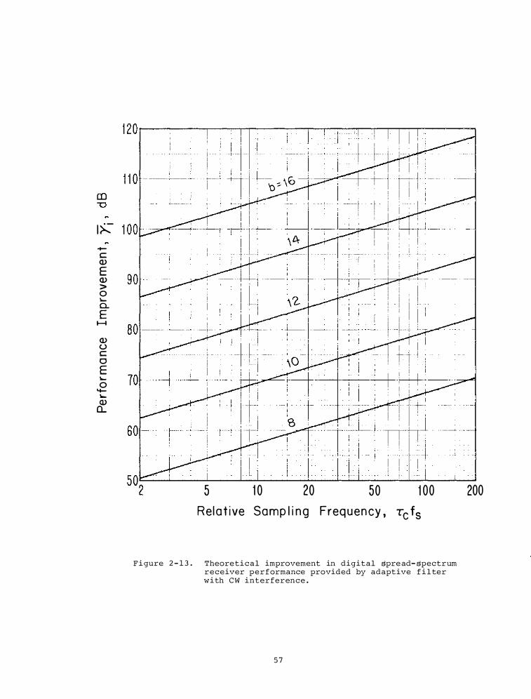
I� -c Cl) E Cl) > 0 '-0.. E
1-1
Cl) (.) c 0 E '-0
'+-"Q) Q_
5 1 0 20 50 1 00 R el a t i ve Samp l i n g Freq u e n cy , Tc f5
F i gure 2 - 1 3 . Theoretical improvement in digital spre ad- spectrum receiver performance provided by adaptive f i l ter with CW interference .
57
200
1 9 7 8 . ITS is current ly correcting the computer-stored dra f t to reflect these extens ive modi fications , and wi l l have photocompo sed text ready for publication in early FY 7 9 .
Technical P lanning Guide for Emergency Medical S ervices (EMS ) . The Emergency Medical S ervices Act of 1 9 7 3 (Amended 1 9 7 6 ) has made provis ions for the e stabl is hment of emergency medical service s y stems in some 3 0 0 reg ions of the u . s . The concept is to provide border-toborder emergency medic a l s ervices to reduce morb idity and trauma for a l l c i t i z ens . These systems cooperate w i t h t h e National H ig hway S afety A c t ( 1 9 6 6 ) provis ions which were des igned to provide s imilar services for highway accident s .
A s imple , prac tical communi cations pl anning guide has been prepared at the request of the Inter agency EMS Commun ications working Group , Chaired by NTIA . The guide i s intended t o provide the basic information needed by a non-technical planner (.e . g . hospital admini s trator or reg is tered nur s e ) who h a s respon s ib i l i ty a s part o f a regional EMS coun c i l or committee for planning , procur ing and evaluat ing appropriate communication equipment and f ac i l i t i e s to support a regional EMS system .
The guide has been prepared f rom mater ials recommended by the DHEW EMS Regional Consultant Team and f rom recommendations received at the three DHEW Tr i-regional Workshops of 1 9 7 7 . Guidance was also given by the I nteragency Working Group .
For the purposes of this guide , the func tion of the communications system are c i t i zen acces s , di spatch and medical supervi s ion during patient care and s tab i l i z a tion at the scene (providing medical supervis ion for paramedic per sonne l ) , and continued medical supervis ion during transport and del ivery of patients to an emergency rece iving room at an appropr i ate ho spita l . A diagram showing the communi ca t ion sys tem is shown in Figure 2 - 1 4 .
The guide s tre s s e s the need for def ining the EMS s y s tem and the required communi cation paths and surveying , unders t anding and secur ing cooperation f rom re lated publ ic safety communication r e sources (_e . g . police , f ire , civi l defen s e . , . ) of
the reg ion prior to the design and procurement of an EMS communication system . The rudiments of sys tem planning , procurement , and evaluation are presen t ed . Alternative sys tem approaches are di s cu s s ed . The guide i s not intended to replace the consult ing services needed for sys tem planning , but is intended to make the inter face between planner , consultants and suppliers (manuf acturer s ) more e ffective .
5 8
SECTION 2 . 5 . F I BER OPTIC COMMUNICATIONS
ITS has had an ac tive role in the rapidly growing f ield o f f iber optics communications . This role has inc luded such activities a s pub l is hing a f iber optics handbook , organ i z ing and c ha ir ing an Ad Hoc Opt ical C ommunications Task Force , providing consulting serv ices in f iber op tics to the Department of Defens e , deve loping a data base for an optical communications glos sary , and sending a Chief U . S . Delegate to the Interna t ional El ectro technical Comm i s s ion Subcommittee on Fiber Optic s . These activities are di s cus s ed i n detail below .
Optical Communications Task Force . In Fiscal Year 1 9 7 5 , an Ad Hoc Optical Communications Task Force (OCTF ) was formed . The creation o f the Task Force was insp ired by the OT mis s ion to " a s s i s t the Department o f Commerce in f o ster ing , serving , and promot ing the nat ion ' s economic deve lopment and techno logical advancement by improving man ' s comprehens ion o f telecommunication sc ience and by as suring e f fective use and growth of the nation ' s telecommuni cation resourc e s . " The Task Force work i s carried on today under NTIA ' s mi s s ion of s erving as a nationa l focus for Federal policy and dec i s ion-making in those areas vital to the new Age of In forma t ion .
ITS h a s a s sumed a role a s a catalys t in a s s i s ting other Government agenc i e s to more rapidly deve lop and apply advancing communication techno logi e s s uc h a s the emerg ing f iber opti c s communication tec hnology . The OCTF was deve loped to provide a forum for government and indus try technical worker s , potential users , and policy maker s to explore the app l ications , advantages , and potent ial problems in adopting and using optical communication technolog i e s .
The Task Force work has been wel l rece ived with the meetings wel l attended by representatives f rom indus try , univers i ties , and government . Frequently , the Ta sk Force partic ipants have benef ited from the introduction of top ics earlier than they would have been introduced i n a formal soci etal meeting . One such topic i n troduced i n this year ' s meet ing of the App l ications and User ' s Work ing Group was the top i c of us ing f iber optics communications in the hospital environment . Medical care costs i n the U . S . exceed $ 1 8 0 B i l l ion annual ly , and ho spita l c o s t s are about 4 0 % of thi s to ta l . C o s t e f fectiveness to promote qua l i ty health care in ho spita l s is understandably a l arge concern . The wide vari e ty o f communications , data proc es s ing , and wideband telemetry needs in a ho spita l makes i t an important arena for the i ntroduction of broadband communicat ion s ervices . F iber optical
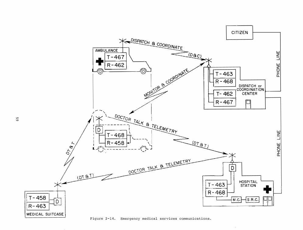
U1 1..0
T - 458 R - 463
M E D I C A L SU ITCAS E
AMBULANCE
T - 467 +I R - 462
DISPATCH a COORDINATE
@L--___ _
____ Docr0R
i\ '- - - - -,
\
F igure 2 - 1 4 . Emergency medical s ervices communications .
C ITIZEN
T - 463 R - 468
DISPATC H or
w z ....J. w z 0 I a...
I I COORDI NATION 1--_.J T- 4'62 CENTER
R - 467
HOS P I TA L STATION
w z _J w z 0 I a...
cables could be quite bene f i c i a l in provid ing the neces sary bandwidth , electromagnetic compatib i l i ty , smal ler s i z e , and non- electrical interfaces with patients .
The mo s t recent meeting empha s i z ed the rapid progress of f iber optics i nto app l ications . F iber opti c s has moved f rom the proof-of -technology s tage to sys tem-de f in i t ion and economic-evaluation s tages . The next several years have been forecast as years of rapid commer c i a l i z a tion . P robl ems fores een have s h i f ted from the problems of fea s i b i l i ty to prob lems of re l iabi l ity and to d i f f iculties as sociated with the deve lopment of performance criteria and s tandard s .
As Cha irman of the Applications and User ' s Working Group , the ITS representative a s s is ts the committee in acquir lng , analyz ing , synthes i z ing , and d i s seminating f iber opti c s inf ormat ion concerning the e f f i c ient use of the nation ' s telecommunication resources . Summary Reports of the meetings are prepared and supp lied to attendees .
Di sper s ion Character i s ti c s for Optical F iber s at Longer Wave length s . A series of s tudies were made to determine the upper l imits on bit rate for f iber optical systems . The constant push toward higher transmi s s ion rates and longer path lengths for f iber optical cable has required close attention to tho se f iber s tructures and material properties which relate to lower attenuation , greater coupl ing e f f iciency o f l ig ht into a f iber , and lower d i spers ion properties . As attenuation has s teadily been dr iven to lower value s , 2 or 3 dB(km , a ttention has recently turned to those properties of the optical waveguide which def ine the ultimate l imit of the data- hand l i ng capab i l ities of the f ibers or the di spers ion character i s t i c s o f the optical guide . A series o f theoretical s tudies was made at I TS o f f er ing methods for determining optimum ref ractive index pro f i l e s for mul t imode and monomode f iber s . Also , a method was obta ined for f inding the optimum operating wavelength for monomode graded-index f iber s . These s tudies have been prepared for various pub l ications and for presentation at several technical mee ting s . A br ief review of the more sign i f icant results i s presented as fol lows .
Optical waveguide attenuation due to Raleigh scatter ing reduces r apidly a s wavelengths increase . S catter ing losses at A ; 1 . 3 �m i s less than 20% o f the s cattering losses at A ; 0 . 8 5 � m . Taking into account the mater i a l , waveguiding , and modal properties of an optical waveguide , it can be s hown that pul s e spread c a n b e minimi zed f o r a vari e ty o f g l a s s mate r ia l s as opera ting wavel engths
6 0
are incr eased f rom A ; 0 . 8 5 �m t o A ; 1 . 2 or A ; 1 . 3 �m . S i nce both d i sper s ion and attenuation charac ter i st i c s improve at A > l �m , there is a strong reason for development of sources , detec tor s , and optical f iber s for opt imi z a t ion at thes e longer wavelengths . An added bene f i t i s the s l ightly l arger dimen s ion o f component s which should af fect s trength and reliab i l i ty . Sourc e s and detecto r s s t i l l r equire ma j o r improvements i n e f f i c iency and speed t o match component capab i l i ties at the pre sent wave lengths of interes t . Progr e s s along the s e lines ha s been encouraging .
International E lectrotechnical Comm i s sion Subcommittee o n F iber Opti c s . A member of the NT IA/ITS technical s ta f f w a s appo inted a s t h e C h i e f U . S . Delegate to the meeting o f the Internationa l Electrotechnical Commi s s ion ( IE C ) , Subcommi ttee on F ibre Opti c s . The I EC dea ls with components and te lecommun i cation sys tems in contrast t o t h e CCITT , which i s a treaty-related telecommunications commi ttee ; i . e . , the CCITT i s sponsored b y the S tate Department and dea l s w i th telecommunications ; the IEC is s ponsored by industry and deals with telecommunication hardware and sys tems . The f l ow of goods to dome s t i c and nondome s t i c markets is inf luenced direc tly by the U . S . po s i tion in the IEC . A s trong u . s . market position can b e s t be acquired by working within the framework of the IEC , The s ubcommittee met in Florence in June , 1 9 7 8 .
The u . s . introduced two key propo s a l s in an attempt to get an early s tart on the s tandardi z a t ion of terminal devices for optical sys tems . The propo s a l that succeeded in gaining initial approval was the one which would e levate the fiber optics work to full Committee s tatus . I t i s a s yet a subcommi t tee under the aegis of the Commi ttee on Cables , Wires , and Waveguide s for Telecommunication Equipment . If accepted at all l evel s of the IEC , the propos a l would a l low the new committee t o determine which terminal components ( now forming sub-a s s embl i e s of f iber s y s tems ) would be subj e c t to s tand�rd i z a tion .
The commercial ava i lab i l i ty of modul e s ac ting a s interfac es between t h e e lectronic and the optical worlds has made the s tandardi z at ion of these modul e s a high priority i t em ,
Fiber Opti c s Communica t ions G l o s s ary . F iber optics communications ( FOC ) technology has evolved extremely rapidly , and Government procurement of sys tems for operat ional deployment i s on the ;increase . ·Numerous s tandard s working groups , in both government and the private s ector , are actively engaged in creation of p er formance s tandards cover ing components and systems . Decade s o f
experi ence in other telecommunications areas have empirically demonstrated that the absence of a s tandardi zed vocabulary common to closely related s tandards inev itably results in amb i guities among such s tandard s . These amb i tuities may result not only in confusion for the systems des igners and user s , but also in increased and unnece s s ary c o s t s to the Government as the result of inadequate lydef ined procurement spe c i f i c at ions . MIL-STD - 1 8 8 - 1 2 0 , M i l itary Communication System S tandard : Terms and De flni tlons and FED-STD - 1 0 3 7 , Vocabu lary for Telecommunications , bot h coordlnated by ITS , have been directed toward a l l eviating the s e problems in a broad spectrum of te l ecommunicat ions areas . FOC terms and def initions have not as yet been included in the se s tandards .
Many technical terms , uni que to this new telecommun ications f ie ld , have been introduced f rom the d i s c l i p lines o f optics and phy s ic s , a r e new t o prac tical communica tions , and are used with var ious meanings by manu f a c turer s , researcher s , and procurement agencies . In recognition of thi s prob lem and the need to at least begin s tandardization of l anguage dur ing early formulation of per formance standards , ITS has comp iled a p r e l iminary voc abulary data base during FY 7 8 . This l imited e f fort has been conducted , us ing DoC funds , with the goal o f produc ing , within FY 7 9 , an Addendum to FED-STD·d 0 3 7 . The plan is to prepare a computer - s tored dra f t o f t h e i n i t i a l data base , t o fac i l i tate rev i s ion , and to circu l a te t h i s dra f t among k e y workers in t h e f ield , inc luding chairmen of a l l performance s tand-ards working group s for rev iew and add i t iona l input s . A revi sed and enl arged dra f t will then be submitted to a subcommittee of the F eder a l Telecommunications S tandards C ommittee lFTSC} for f inal review prior to pub l i c a tion as a Federal S tandard .
F iber Opt i c s Handbook . During FY 7 7 , a des i gn handbook for opt i c a l f iber communicatio n s y s tems was prepared by ITS for the u . s . Army , Communi c a tion E lectron i c s E ng ineering I n s t a l lation Agency (CEEIA ) , Fort Huachuc a , Ari zona . The
d r a f t of this handbook was del ivered to the sponsor for review and rev i sion at the end of FY 7 7 . During FY 7 8 , this handbook was rev i s ed , and comp leted for pub l i cation .
The emphas i s in the handbook i s toward the microwave eng ineer and sy stem ; i . e . , i t presents the de s ign aspects of a f iberoptic transmi s s ion channel that might be used to replace a n exist ing microwave l ink , or be con s idered a s an a lternative to a new link . The interface requirements with exi s ting communication s equipment i s d i s c u s sed .
6 1
The handbook i s entitled " D e s ign Handbook for Opt i c a l F iber S y stems " . I t i s wr i tten primarily f o r t h e communications eng ineer t�at has had l ittle or no prior experience with f iber-optic technology . Fundamental , (yet prac t i c a l ) des ign and performance data are presented for all o f the components required of a transmi s s ion s y s tem . The design procedures are a l s o presen ted in a sys tematic f a s h ion , pointing out those to be followed for both a power l imited de s ign and a di sper s ion l imited des ign . These procedures are summar i z ed in the ac companying tables a s an example . The actual design proce s s is iterative in nature (between the two regime s ) . This aspect is i l lustrated i n three appendices to the handbook , where actual des ign examples are presented .
The handbook will be pub l i s hed by the u . s . Army , and should be ava i lable sometime early in FY 7 9 .
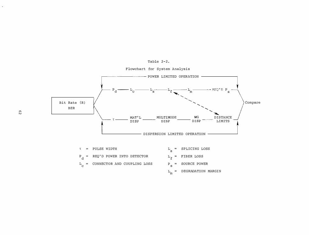
0"\ N
B i t Rate ( R ) BER
T =
p =
d L =
c
Table 2 - 2 .
F lowchart for System Analys i s
� POWER LIMITED OPERATION
Pd --- L L Lf L ---- REQ ' D P c s '-.. m s
t
....... .......
........ ....... .......
T ���L MU�i;�ODE D��p
....... .......
DI SPERSION LIMITED OPERATION
.......
PULSE WIDTH L = SPLICING LOSS
REQ ' D POWER INTO DETECTOR
CONNECTOR AND COUPLING LOS S
s L =
f p =
s
F IBER LOS S
SOURCE POWER
� DISTANCE
LIMITS
L = DEGRADATION MARGIN m
l Compare
t
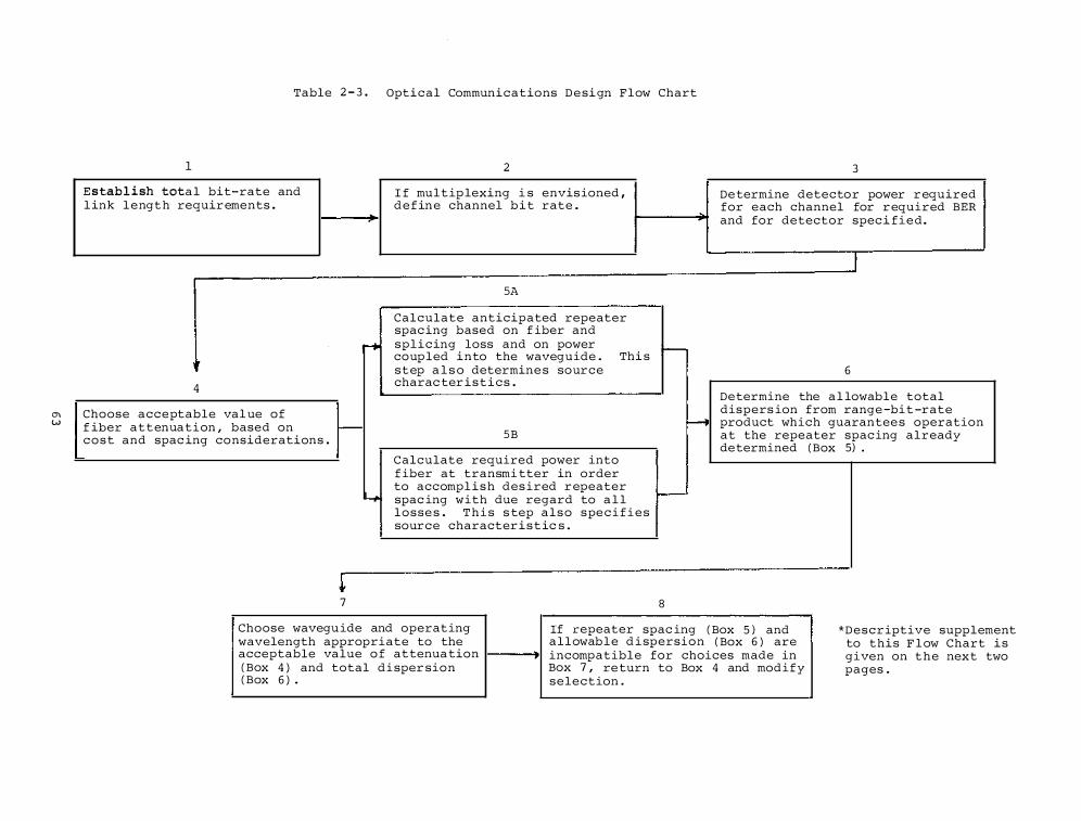
C) w
Table 2 - 3 . Optical Communications D e si gn Flow Chart
1
Estab l i sh tota l bit-rate and l ink l engt h requir ements .
• 4
r-+
2
I f mul t ip lexing i s envis ioned , defin e channel b i t rate .
SA
Calculate anticipated repeater spac ing based on f iber and splicing loss and on power coup led into the waveguide . Thi s step a l s o determine s source charac ter i s t i c s .
t--
3
De termine detector power r equired for each channel for r equired BER and for detector spec i fi e d .
6
Choose acceptable val ue of f iber attenuation , based on r-c o s t and spac ing considerations .
H Determine the a l lowable total dispers ion from range -bi t -rate product which guarantee s operation at the repeater spac ing already determined ( Box 5) .
4
� 7
SB
Calculate required power into f iber at transmi tter in order to accompl i s h des ired r epeater spac ing with due regard to a l l losse s . T h i s s tep a l s o spe c i f i e s source character i s t ic s .
I--
8
Choose wavegu ide and operating If repeater spac ing wavelength appropriate to the allowab l e d i spersion
( Box 5 ) and ( Box 6 ) are
acceptable value o f attenua tion incompatible for choices made in ( Box 4 ) and total di sper sion Box 7 , re turn to Box 4 and modify ( Box 6 ) . selection .
*Descriptive supplement to this F l ow Chart i s given on t h e next two pages .

CHAPTER 3 . EM WAVE TRANSMISS ION
The ground , the atmo sphere , and the ionosphere degrade radio waves in varying degre e s , depending on c ircumstance s . I t is the purpos e o f the EM Wave Transmi s s ion Program to s tudy these e f fects and provide mode l s to the sys tem d e s i gner that will aid him in providing more c o s t e f fective and spectrum e f f ic i ent design s . The phenomena which cause these detrimental e ffects on radio and optical sys tems are , in gener a l , f requency dependent ; therefore , spec i f i c s tudi e s and t e s t s are required for s pe c i f ic frequency ranges and application s .
Some o f the phenomena which e f fe c t radio s igna l s and are s tudi ed i n t h i s program are :
1 . Attenuation by atmospheric gase s , hydrometeors ( rain , s now , h ai l , c loud s , etc . ) , or ion i z ation .
2 . Scatter ing by hydrometeors or irregular i t i e s in the re fractive index o f t h e l ower atmo sphere or i onosphere .
3 . Refraction , ducting , and mul tipath , r e s ul ti ng from atmospheric o r ionosphe r i c l aye r s .
4 . Dispers ion , resulting f rom frequency dependent proper t i e s o f the atmosphere , i onosphere , and earth .
5 . Scintil lation o f amp l i tude , pha s e , polar i z ation , and angle o f arrival , resulting from turbul ence and irregular structure in the atmosphere and ionospher e .
6 . Reflection , s cattering , multipath , and lower atmo s phere perturbations resul t ing from terrain and man-made s tructur e s .
The e f fect upon any spec i f i c sys tem o f t h e above phenomena i s n o t o n l y h i ghly frequency dependent , but is also dependent upon the type of service required for the spec i fic app l ication .
One driving force behind the EM wave transmi s s ion p rogram is the need for more spectrum space . Therefore , thi s p rogr�m provides mode l s , techniques , and information to aid the sys tem d e s i gner and frequency manager in thei r decis ions for better spectrum use .
Exper imental or theoretical determinations of radio wave transmi s s ion characteri s t ic s , or the c hannel trans fe r func t ion , are reported i n Section 3 . 1 . Measurements of tran smi s s ion media proper t i e s and analyses o f c o l l e c t ions o f such data are i nc luded in Section 3 . 2 . S ection 3 . 3 d e s cr ibes the devel opment and t e s t ing of mod e l s which incorporate the tran smi s s ion i nformation
6 5
in engineering too l s . Predi ctions o f transmi s s i on charac teri s tics and system per formance are di scussed in Sec tion 3 . 4 . Section 3 . 5 reports on app l ications of the knowledge and too l s to speci fic prob lems of other government agenc i e s , s uc h as mine and fore s t s ervice communications .
SECTION 3 . 1 . WAVE TRANSMISS I ON CHARACTERI STICS
Exper imental determinations o f the e ffect o f the transmi s s ion media on electromagnetic wave transmi s s ion are reported in this section , in particular those e ffects produced by the atmosphere .
Broadband Transmi s sion in the 1 0 - 1 0 0 GHz Range . The obj ective or-thi s ma j or inhouse pro j ect is to develop a compl e te and quanti tative de scription of the transmis sion properties of the atmosphere at frequenc i e s between 1 0 and 1 0 0 GHz . Thi s description wi l l b e used t o improve design mode l s and provide engineering s t andards for the e f fects of the transmi s s ion proper t i e s on performance of wideband , highdata-rate sys tems . Progress made on the experimental phase is reported below .
Frequency Extens ion Res earch . S imultaneous measurements of s i gnal variab i l i ty were made at 9 . 6 , 2 8 . � , and 5 7 . 6 GH z over paths of 2 0 0 and 7 4 0 m. Although the 5 7 . 6 GH z s ignal showed some correlation with ambient temperature as would be expected , in general , the lower f requency s i gnals s howed greater var iabi l i ty . Digital data were transmitted at a 1 Gb/s rate using 3 0 . 3 or 5 9 . 1 GHz as the carrier . In both cases , bi t-error rates wer e cons i s tently l e s s than 1 in 10 8 except f o r times ( such as intense rain) where the rec e iver synchron i z ation became erratic .
A model for the e f fect of mul tipath on biterror rate was developed whi ch gives good agreement with direct measurements of this e f fect ( F igure 3 - 1 ) . A paper entitled "Experimental and Theoretical A s s e s sment of Mul t ipath E f fects on QPSK , " des cribing this development i s s c heduled for publ ication i n IEEE Transactions on Communication s , Octobe r , 1 9 7 8 . Instrumentation for obta ining correlgrams ( us ing a 1 Gb/s QPSK modem ) was developed . This will permit resolving mul t i path s i gnal components to l e s s than 1 ns and calculating channel transfer char ac ter i s tics over a band o f about 1 GH z .
A paper on deep s i gnal fading ( > 2 0 dB ) entitled " Fading at 9 . 6 GHz on an Experimental S imulated Aircraft-to-Ground Path , " by H . B . Jane s and M . C . Thomp s on was pub l i s hed in IEEE AP , September , 1 9 7 8 .
SECTION 3 . 2 . CHARACTERI STICS OF THE TRAN SMISS ION MEDIA
Thi s s e ct i on i s concerned with the s tudy
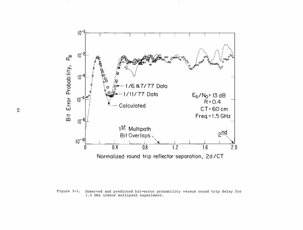
0'1 0'1
� �
>. -· --...c 0
...c 0 lo.-
a_ lo.-0 lo.-lo.-
w -(])
.· ·· . .. 1 0-2� �·�···�·· � � . ·· .. � :: ��x /\. ! X� � ." • !3' � � : X )l; .• • :: :>QXX '!- � : X : X "·X-,: ···?< : # � X : � : : ." )\1( •)< ,-p< X X X • •181 X • . • ?Ill' X . . a... . X' ·. •
: jJ � ... .. 10-41 i< � : ·.: I · · o · . �0 =� .;. � o :"o- 1 /6 8 7/ 77 Data
�
lo-6¥!
1 0-8�
• • X X • �- 1 / 1 1 / 77 Data
L_ Ca l cu l ated
Es / N0 = 13 d B R = 0. 4
C T = 60 c m Freq. = 1 .5 G H z
-
-
1 st Mul t ipath 2nd B i t Over laps ""-
1 1 �� I o-101 I I I I �I I I 1 6 2 .0 0 0 .4 0.8 1 . 2 . Norma l ized round tr i p ref lector separat ion , 2d / CT
F igure 3 - 1 . Observed and predicted b it�error probab i l ity versus round trip delay for 1 . 5 GHz indoor mul tipath experiment .
of tran smi s s ion med i a to help those who d e s i gn , construct , or use telecommunication sys tems to better unders tand the characte r i s t i c s of the med i a and their e f fects on radio s i gnal s . We f i r s t d i s cuss t h e nonion i zed atmosphere and then the iono s phere .
3 . 2 . 1 . Atmospheric Character i s ti c s
A n extens ive measurement s e r i e s on the oxygen microwave spectrum i n air has been completed . Out of 2 2 8 spectroscopic paramete r s , the mos t s i gn i f icant 1 3 2 have been measured with accurac i e s in the 0 . 5 to 3 percent r ange .
The improved spectroscopic data base character i z i n g the EHF properties of air was integrated i nto a radio path mode l ing scheme that predicts var ious propagation behavior s .
Atmospheric Medium C haracter i z ation and Model ing o f EHF Propagation in Air . -rE i s po s s ible to pred i c t the behavior of an EHF ( frequenc ies up to 3 0 0 GHz ) radio wave transve r s ing an a s s umed c lear , inhomoge neou s , nonturbulent atmosphere at various s l ant path angles 8 . Mo lecular absorption spectra of ma j or ( o2 , H 2 0 ) and minor ( e . g . , o3 , CO , N 2 0 ) air cons t i Euents cause frequency dependent s i gnal attenuation , pha se delay , ray bending , and medium noi s e . The interaction between radiation and air i s expre s sed through a complex refractivity N , which i s a function of f requency v , total pre s s ure p , partial water vapor pre s sure p , temperature T , earth magnetic f i e ld s�rength H ( o 2 -z eeman e f f ec t ) , and trace gas number dens i t i e s . The Ncalculati on takes into account 3 6 o2 lines , 6 H 2o lines plus a nonresonant specErum , and , i f needed , inc ludes trace g a s spectra (> 1 0 0 o3 , 2 CO , 6 4 N2o l in e s ) , which are
gener a l l y weak .
The oxygen microwave l ines s p l i t into many components under the i n f luence o f the earth ' s magnetic f i e ld . The components are s pread max . + 2 MHz around the unper turbed l ine centers , which become noticeable at a l t i tude s , h > 4 0 km ( see F i gure 3 - 2 ) . A con sequence o f the Z e eman s p l i t ting i s an anis otropic , pol ar i z ationdependent , complex refractivity N . Radio path mode l ing in the frequency band s v = 5 0 to 7 0 and 1 1 8 . 8 + 0 . 1 GHz requires the correc t re fractivity N ( v , H , h ) o f a i r f o r t h e h e i gh t range , h 4 0 to 1 1 0 km . A s tr a i ghtforward , con s i s tent , c alcul a t ion scheme was deve loped .
Assuming a d i s tribution o f the gas variabl e s for neutral air a s a funct i on o f height and the r adio path geometry ( groundto-ground , aircraf t , s a te l l i te , etc . l ink ) provides the b a s i s for calculating the various propagation e f fects . F igure 3 - 3 gives a n example o f height contour s for con s tant attenuation rates a s , for example ,
6 7
" needed in the a s s e s sment of atmospheric shielding capabi li ties . In the window ranges ( 3 0 - 5 0 , 7 0 - 1 1 0 , 1 2 5 - 1 5 0 GH z ) , molecular attenuation is mainly due to water vapor and conf ined to the f i r s t f i ve kilometers .
A tractable propagation mode l for the air ma s s emp loys a spherically s trat i fied atmosphere ( " onion-she l l " model of thin quasihomogenious layer s ) to be amenable to computer cal cul at ions of f ive integra l s : cumulative attenuation ( i . e . , transmi ttance ) , radio range , curved path length , and noi se temperature due to upwell ing and downwe l l ing radiation . These integra l s are eva luated by numerical integration . Results of this kind were publi shed in AGARD CP 2 3 8 , 4 4 /1- 1 8 ( 1 9 7 8 ) . Figure 3 -4 shows the excel lent agreement of the computer simulation with reported value s for c lear air zenith attenuation .
Orbi ting S t andards Platform ( OS P ) Prel immarl� In the continuing cooperative program by the Communicat ions Satel l i te Corporation ( COMSAT ) , NASA ' s Goddard Space F l ight C enter ( NASA/GSFC ) , the National Bureau o f S tandards ( NBS ) and NTIA ' s Institute for Telecommunication S c iences ( NTIA/ITS ) , a prel iminary defini tion of
the OSP has been accomp l i s hed . Briefly , the proposed Orbi ting Standards Platform ( OSP ) is the equivalent of a combined field-s trength meter and s ignal generator to be pl aced in orbit to meet the need for a read i l y acc e s s ib l e , relative ly economical , cal ibration fac i l i ty for earth s tations , large aperture antennas , and satellites .
A pre l iminary des cr iption of this OSP was dis tr ibuted with a ques tionnaire to a s ampling of the private , commerc i a l , and governmen t organi z at i ons that might constitute an OSP user community . The respons e s to t h i s OSP s urvey ver i fied the as sumption that the manufacturers and operators of s ate l l i te sys tem e lement s , sc ienti f i c r e search organi z ations , and the radio wave regul atory agenci e s would , in fact , cons ti tute an OSP user community . Further , this sampling sugge s t s the community i s s trongly s upportive ( 8 9 % of the respondees ) o f the OSP concept and has spec i f i c needs for the proposed OSP capabilities . Further , the user communi ty identified speci f i c scient i f i c s tudi e s that s hould be carried out b y a n OSP . They also identi f i ed the need to f i t the OSP into the present f requency a l location schedule on a noninterfering b a s i s ( OT Tech . Memorandum 7 8 - 2 4 9 , February 1 9 7 8 ) .
The OSP defini tion to date includes the specification of transmitting and receiving antennas of c al ibrated se l ec table gains and po l ar i z at i on , generated s ignals w i th known s table amp l i tude and phase characteristic s , c a l ibrated circuits for the ana ly s i s o f received s ignal s , and i s h ighly
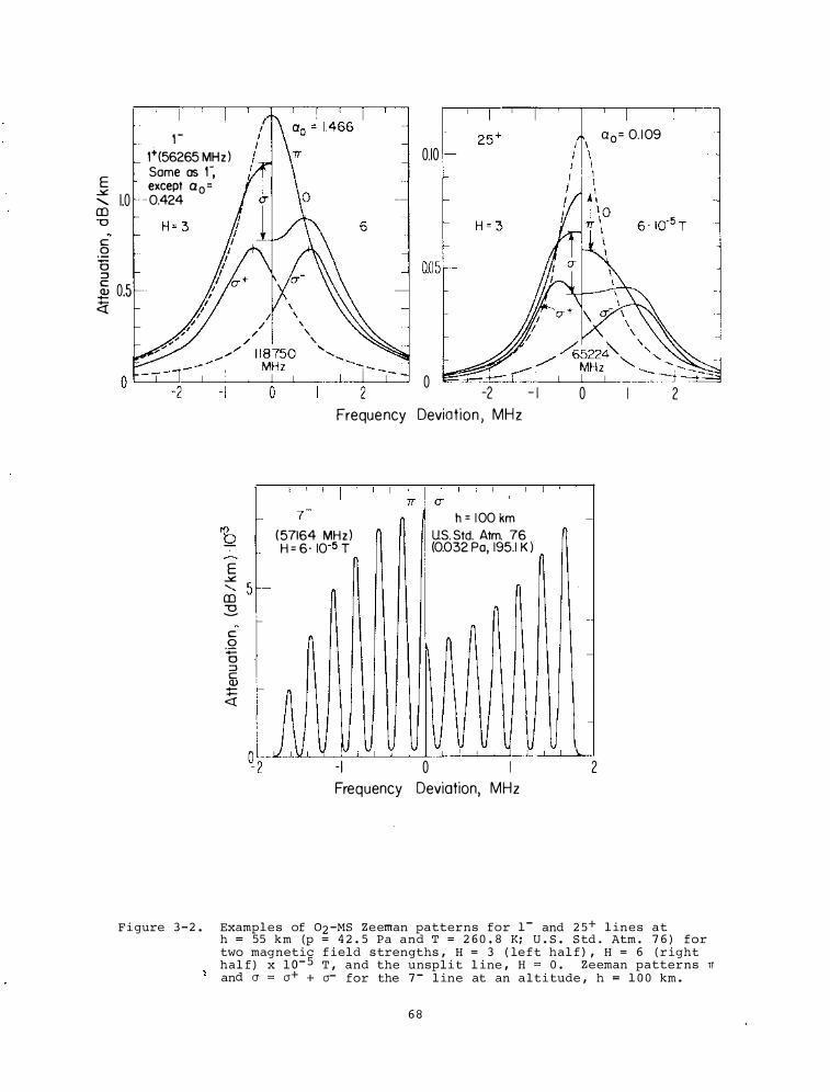
E .X ....... 1.0 CD "0 c 0
-0 :J .& 0.5 <t
, -1+(56265 MHz ) Some as 1-, except a 0 = 0.424
E .X
0.10
0 -2 - I
Freque ncy Deviation , MHz
1-( 57164 MHz )
1- H = 6 · I0-5 T
h = 1 00 km US. Std. Atm. 76 (0.032 Po, 195.1 K )
'- 5 -CD :g. c .Q
-0 :J a}
-�
. -
u v y - I 0 Frequency Deviation, MHz
I I I
0
-
-
-
-
-
-
2
a 0 = 0. 1 09
2
Figure 3 - 2 . Examples of 02 -MS Zeeman patterns for 1- and 2 5+ l ines at h = 55 km (p = 4 2 . 5 Pa and T = 2 6 0 . 8 K; U . S . S td . Atm . 7 6 ) for two magnetic f ield s trengths , H = 3 ( le f t hal f ) , H = 6 ( r ight hal f ) x l o- 5 T , and the unspl i t l ine , H = 0 . Zeeman patterns TI and a = a+ + a- for the 7 - l ine at an altitude , h = 1 0 0 km .
6 8
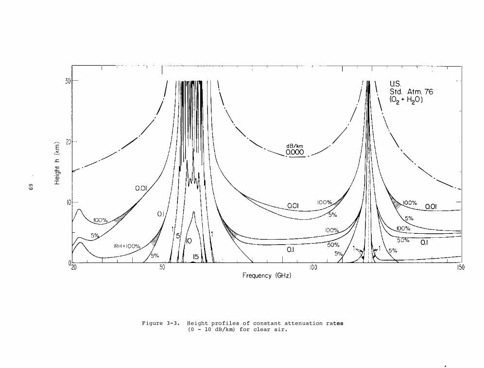
E ->:::
.!:: +-.!:: 0'>
"(L) m I 1.0
020
/ _.....-/
/ /'
' I '
I \ \ I ·\. I "" / �, d B/km _,/ ....__ oooo _.,.-
· - -
Frequency (GHz)
F igure 3 - 3 . Height profiles o f constant attenuation rates ( 0 - 10 dB/krn) for clear a i r .
\ ' \ ' \
us_ Std. Atm. 76
(02 + H20 )
\ ' ""'
� ·�
001
01
150
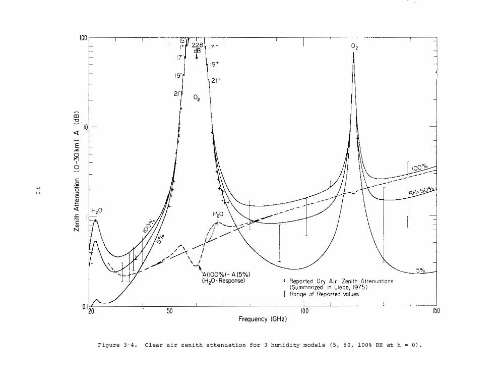
CD "'0
<( �
E .><: 0 1'0 I 0
C:: .Q -._] -0 0 ::> c <I)
+--<( £ ·c: <I) N
0.1 20
,:r '
2r 02 r
2 1+
,1i ..... , _ I' I ! / �
v ,..., �I / I ,.,�/__.\ I "" \ I /"" '"""\ _,-A{ IOO%) - A {5%) {H20- Response)
50 Frequency (GHz)
1 00
F igure 3 - 4 . C l ear a i r z enith attenuation for 3 humidity model s ( 5 , 5 0 , 1 0 0 % RH at h = 0 ) .
150
redundant s e l f-ca l ibrating and s e l f mon itor i ng [ P roc . Sympos i um O n Antenna Appl ications , September 1 9 7 8 ) . The OSP would traverse the geostationary orbit and be capable o f mea suring up- and downl ink earth s ta t ion s i gnal s , internally ver i fying the mea surement s , and te lemetering the resul t s , Figure 3 - 5 . P arameters wh ich are to be measured are pr imar i ly related to the r adiators o f the communications s y s tem and i nclude e ffective i sotropic radiated power ( E I RP ) , gain-totemperature ratio ( G/T) , gain , pattern , cro s s po l ar i z ation , transmi s s ion path properties , and s ide lobe s tructure , the latter inc luding both ampl i tude and polari zation characteri s t ic s .
A compan ion e arth s tation serves to perform approximately the s ame function with up- and down-l ink satellite s igna l s and a l s o to provide means for periodic recal ibration o f OSP . It s hould be emphas i zed that OSP does not act as a relay s tat ion in the sense of a commun ications sate l l ite (which receive s , ampl i f i e s , and re- transmi t s a s i gnal containing certain information ) , but rather i s a remote standards l aboratory which receives or gener a t e s a s i gnal and te lemeters relevant data about that s i gnal . Proce s s ing would be done by a designated government agency such as NBS or by the user himse l f , a s appropr i ate .
Sate l l i te Propagation Observations at � and 2 8 GHz . Future dome s t i c s ate l l i te -- - --communication s y s tems carrying h i gh den-s i ty tra f f i c w i l l use frequenc i e s up to 30 GH z because of the presently greater bandwidth ava i l able and because the s e frequen c i e s are not currently being heavily used .
Beacons at 1 9 and 2 8 GHz on s everal domes tic geos tat ionary s a te l l i tes have been launched . The obj ectives o f t h i s ITS program are to mon i tor the se beacons and collect a ttenuation and phase in formation . The data w i l l help to determine minimum power and other performance margins needed for future s atell ite communication s y s tems operating up to 3 0 GHz .
Colorado i s an excel l ent location for data col lection from the 19 and 28 GHz satel l i te s i gnals s i nc e currently there i s no other site planned west of the Mi s s i s s i pp i , and the Colorado s i te s hould provide optimum r e l i abi l i ty from e l evation angle con s ideration s .
The s at e l l ite beacon transmi s s ions w i l l originate from three sate l l ite s , e a c h w i t h a 1 9 and 2 8 G H z beacon . T h e 1 9 . 0 4 GH z beacon s ignal w i l l be swi tched between two orthogonal l i nearly polari zed ( i . e . , vertical and hori zonta l ) antennas a t a 1 kHz rate . The 2 8 . 5 6 GHz s i gnal wi l l be transmitted continuously from a l inearly polari z ed antenna (vertical only ) . The 19 and
7 1
... 2 8 GHz s i gna l s w i l l be coherent s ince they are derived from the same fundamental source .
The 1 9 and 2 8 GHz beacon transmi s s ions from COMSTAR beacons Dl , 02 , and 0 3 are be ing analyzed to learn the use ful channe l bandwidth at mic rowave and millimeter-wave carrier frequenc ies . Government , commercial , and s c i enti f i c interest in transmi ssion through the atmosphere at frequenc i e s above 1 0 GHz derives from the potential for employing thi s port ion o f the spectrum for sate l l i te communications and the promi se for frequency exten s ion . F i gure 3 - 6 shows the 1 0 foot receiving d i s h with the receiver front-end at the prime focus used in the experiment . Figure 3 - 7 shows t he one maj or source of s i gnal Impairment ; i . e . , a rain event on the performance o f a n earth- sate l l i te communications link . The correlation between received s i gnal s trength and rain rate provides information on the temporal variabi l i ty o f attenuation .
In mos t s a te l l i te communication sys tems , the s i gnal received by an earth terminal is red i s tributed to var ious terminals on the earth . A terres trial link operating at 2 8 . 8 GHz has i t s transmitting antennas located about 3 0 m from the 10 foot dish used in the 1 9 / 2 8 GHz COMSTAR sate l l i te beacon experiment . This terre s trial link provides in formation on ampli tude and delay dis tortion s i gnal impairments caused by the s ame me teor logical events , and nearly the s ame frequency , that e f fect the earth- sate l l i te link . F i gure 3-7 also shows the rece ived s i gnal s trength on the 2 8 . 8 GHz carrier used in the terrestrial l ink for the s ame rain event obs erved on the 2 8 . 5 GHz carrier on the earth-s ate l l i te l ink .
Depolari zation and Frequency Re-use . Fre quency re-use by introduc ing dual orthogonal l inear polar i z ations or opposi te-sense circular polari zation has the potential for nearly doubling the ava i lable a s s i gnments in the radio spectrum . This raises the po s s i bi l i ty o f an increased number o f as s ignments , such as addi tional TV s tations within a given geographical reg ion . That could have a s trong economi cal and social impact in the U. S .
Of cour s e , a full doubl i ng o f the avai lable a s s i gnments by frequency re-use could not be accomp l i s hed because there can be technical advantages of one po l ar i z ation over another in some frequency bands . Further , in some frequency bands , there are propagation mechani sms which change a transmi tted s i gnal ' s po larization . This depolar i z ation can arise from the s cattering , r e f l ection , and d i f fraction of radio waves by : irregular terrain , rainfa ll , clouds , and fog as we ll as the ionized layers , turbulence , and re fractivity s trat i f i cation o f the atmosphere . The bas ic requirement for a s s e s sing the impact o f
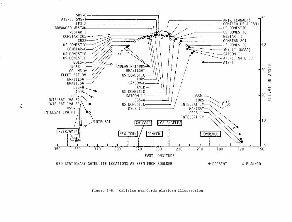
--.) N
SBS-8 ATS - 3 , SMS - 1 ====-=���������=-=-=-=-=--
L E S-8-ADVANC E D WESTAR===------
-=====
WESTAR I
AN I K ' CANA )
COMSTAR 202
CDMTECH ( us0� CAN )
CBSS
US DOMEST I C
U S DOMESTIC
US DOMEST I C
COMSTAR-C
WESTAR I I
US DOMESTI C ro
C OMSTAR 201
US DOMEST I C r � US DOMEST I C
GOES- I /
• . SM S I I (NOAA )
-SATCOM I
FL E ET SATCOM . BRAZ I LSAT
ATS - 1
BRAZ I LSAT US DOME ST I C
BRAZ I L SAT TORS
L E S - 9 SATCOM -C.-- ,
TORS ------. AN I K.--- I
I NTE LSAT I LES-6� US DOME ST I C
I NTE LSAT I �� ���� '. SATC��
s =l ___ __j
I NTELSAT I V�S � �� �� ) \ US ����Si � �---- 1
I I NTELSAT
3 5 0 330 3 1 0 2 90 2 7 0 250 230 2 1 0 1 90 1 70
50
40
w __.J
30 lCl z: cl::
z: 0
1-<:l:: >
20 w
1 0
0 1 50
__.J w
EAST LONG !TUDE
GEO-STAT I ONARY SATE L L ITE LOCAT I ONS AS S E EN FROM BOULDER • PRESENT o P LANNED
F igure 3 - 5 . Orbi t ing s tandards p l a t form i l lustration .
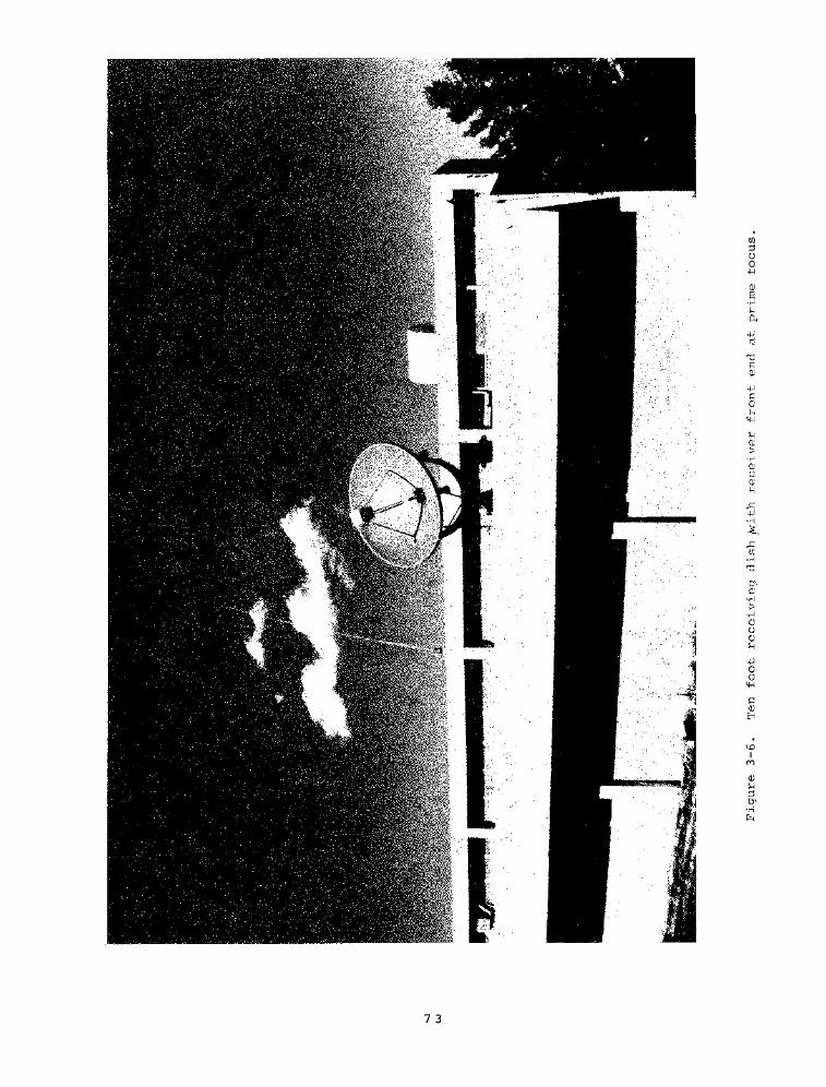
7 3
Cll ::l 0 0 -H
\.0 I M
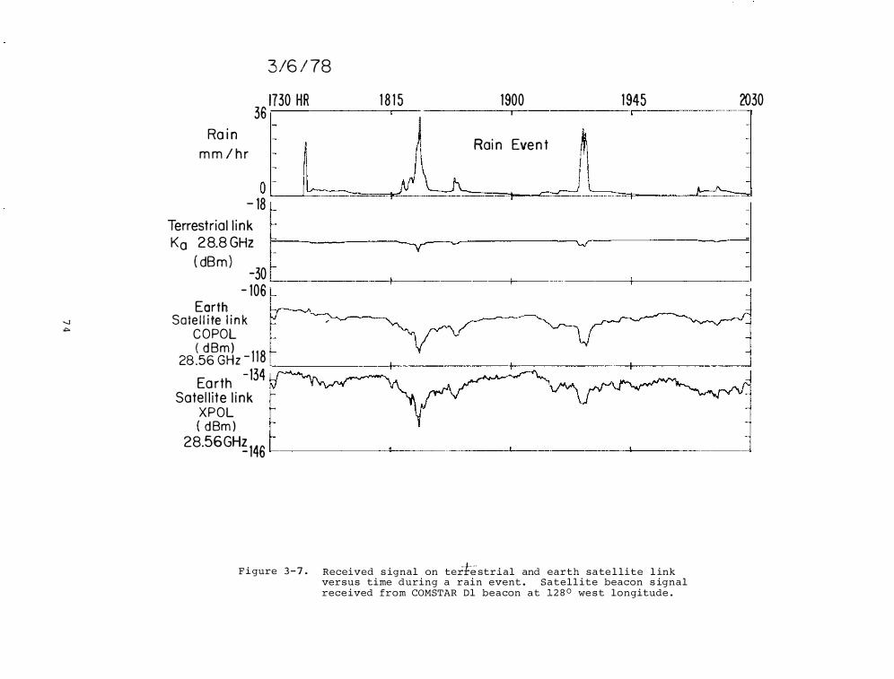
3/6 / 78
36 1730 HR -. 1 8 1 5 1900 2030 1 945
Ra i n
m m / h r
0 I I v-----_,.._ - 18 � I JV .....___. '--
Ka 28.8 GHz F-------- -
Rai n Eve n t
! ,.-.......c-=J ..__ I r--''====1
Terrestrial l i n k �
( dB m ) _ -30
- 106 Earth
-..] Sate l l i te l i n k � C O POL
( d Bm) 28 .56 GHz - 1 1 8
Ea rth -134
Satel l ite l i n k XPOL ( d Bm )
28.56GH�146
F i gure 3 - 7 . Received s ignal on tertestrial and earth sate l lite l ink versus time during a rain event . Satell ite beacon s ignal rece ived from COMSTAR Dl beacon at 1 2 8 0 we s t longitude .
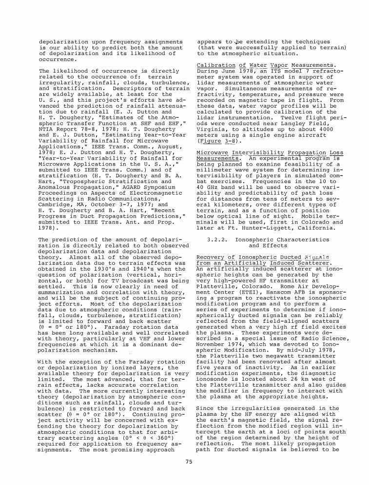
depolari zation upon frequency a s s i gnments is our abi l i ty to predict both the amount of depol a r i z ation and i ts l ikel ihood o f oc currence .
The l ikel ihood o f occurrence is directly re lated to the o ccurrence o f : terrain irregul arity , rainfal l , clouds , turbulence , and s trat i f i cation . Des criptors o f terrain are widely ava i lable , a t least for the U . S . , and this pro j ect ' s e f forts have advanced the prediction o f r a infall attenuat ion due to rainfall ( E . J. Dutton and H . T . Dougherty , " E s timates of the Atmospheric Transfer Func tion at SHF and EHF , " NTIA Report 7 8 - 8 , 1 9 7 8 ; H . T . Dougherty and E . J . Dutton , " E stimating Year- to-Year Variabi l i ty of Rainfall for Microwave Appl ications , " IEEE Trans . Comm . , August , 1 9 7 8 ; E . J . Dutton and H . T . Doughe rty , " Year-to-Year Variab i l i ty o f Rainfall f or Microwave App l i c at i ons in the U . S . A . , " submitted to IEEE Trans . Comm . ) and o f stra t i f i c ation ( H . T . Dougherty and B . A . Hart , " Tropos pheric Strat i f ication and Anomalous Propagat ion , " AGARD S ymposium Proceedings on Aspects of Elec tromagnet i c Scattering in Rad i o Communi c ations , Cambridge , MA , October 3 - 7 , 1 9 7 7 ; and H . T . Dougherty and B . A . H art , " Recent Progre s s in Duct Propagation Predictions , " submi tted to IEEE Trans . Ant . and Prop . 1 9 7 8 ) .
The prediction o f the amount o f depolarization i s directly related to both observed depo l ar i z ation data and depolar i z ation theory . Almo s t a l l o f the observed depolar i z at ion data due to terrain e f fects was obtained in the 1 9 3 0 ' s and 1 9 4 0 ' s when the que s tion of polar i zation (vertical , hor i zontal , or both ) f o r T V broadcast w a s being settled . Thi s is now c learly in need of summa r i z ation and correlation with theory , and will be the sub j ect o f c ontinuing project e f forts . Mos t of the depolari zation data due to atmosphe r i c conditions ( ra infal l , c l ouds , turbulence , s trati f i c ation ) is l imited to forward and back scatter (8 = o o or 1 8 0 ° ) . Faraday rotation data
has been long ava i l able and wel l corre lated with theory , particularly at VHF and lower frequencies at which it is a dominant depol a r i z ation mechanism.
With the exception o f the Faraday rotation or depol a r i z ation by ioni zed layers , the ava i l able theory for depo lar i z at ion i s very l imited . The mos t advanced , that for terrain e f fects , lacks accurate correl a tion with data . The more currently interesting theory ( depo l ar i z ation by a tmospheric condi tions such a s r a infa l l , c louds and turbulence ) i s restricted to f o rward and back scatter (8 = 0 ° or 1 8 0 ° ) . Continuing proj ect activity will be c oncerned with extending the theory for depo l ari z ation by atmo spher i c condi tions to that for arbitrary scattering angles ( 0 ° < 8 < 3 6 0 ° ) required for app l ication to frequency a s s i gnments . The m o s t promi s ing approach
7 5
appears to .�e extending the techniques ( that were success fully applied to terrain)
to the atmospheric s i tuation .
Cal ibration o f Water Vapor Measurements . Dur ing June 1 9 7 8 , an ITS model 7 re fractometer sys tem was operated in s upport of l idar measurements of atmospher ic water vapor . S imultaneous meas urements of refractivity , temperature , and pres sure were recorded on magnetic tape in f l ight . From thes e data , water vapor pro f i l e s will be calculated to provide c a l ibrati on of the lidar ins trumentation . Twelve f l i ght periods were conducted near Langley F ield , Virginia , to altitudes up to about 4 0 0 0 meters using a single engine a i rcraft ( F igure 3 - 8 ) .
Microwave Intervi sibi l i ty Propagation Los s Meas urement s . An exper imental program-rsbeing planned to examine feasibi l i ty of a mi l l imeter wave sys tem for determining interv i s i b i l i ty of p layers in s imulated combat exer c i ses . Frequencies in the 1 0 to 4 0 GHz band wi l l be used to obs erve vari abi l i ty and predictabi l i ty o f path loss for d i s tance s from tens of meters to several ki lometers , over d i fferent type s o f terrain , and as a function o f posi tion be l ow optical line o f s i ght . Mobile termina l s w i l l be used , f i r s t in Co lorado and l ater at Ft . Hunter-Liggett , Cali fornia .
3 . 2 . 2 . Ionospheric Character istics and E f fects
Recqvery o f I onospher ic Ducted S ignal s from a n Arti f i c ially Induced Sc atterer . An arti f i c i a l ly induced scatterer at ionospheric he ights can be generated by the very high-powered HF transmitter a t P l attevi l l e , Co lorado . Rome Air Development Center ( ETEI ) , Hans com AFB is s ponsoring a program to reactivate the iono spheric mod i f i cation program and to perform a series o f exper iments to determine i f ionospherically ducted s i gnals can be reliably r e f l ected from the field-aligned scatters generated when a very high rf f ield exc i tes the plasma . These exper iments were descr ibed in a special i s sue of Radio Science , November 1 9 7 4 , which wa s devoted to Ionos pheric Mod i f ication . By mid-July 1 9 7 8 , the Plattevi l l e two megawatt transmitter fac i l i ty had been renovated a fter a lmost f ive years of inactivity . As i n earl ier mod i f i cation experiments , the d i agnostic ionosonde i s located about 2 6 km wes t of the P l attevi lle transmi tter and a l so guides the modi fier in frequency to interact with the pla sma at the appropriate hei ghts .
S ince the i rregularities genera ted in the plasma by the HF energy are a l i gned with the earth ' s magnetic f ie ld , the s ignal ref lection from the mod i f ied region will intercept the earth at a loci o f points south o f the region determined by the . he ight of r e f lection . The mos t likely propagation path for ducted signals is believed to be
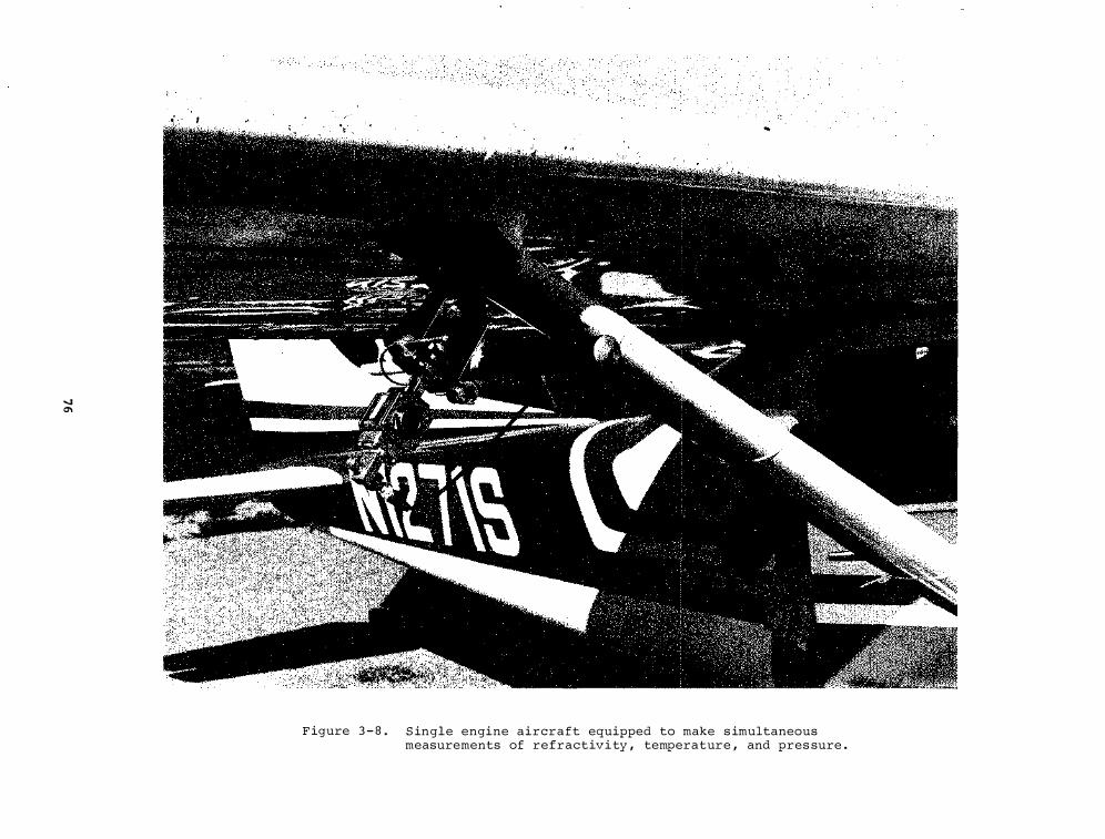
-..1 0\
'}
F igure 3 - 8 . S ingle engine aircraft equipped to make s imultaneous measurements of refractiv i ty , temperature , and pres sure .
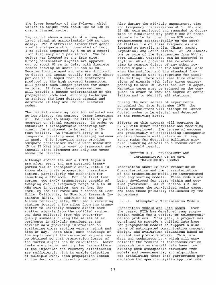
the lower boundary o f the F-l ayer , wh ich var i e s i n height from about 180 to 220 km over a d iurnal cyc le .
F i gure 3 - 9 s hows a s amp le of a long delayed s i gnal at approx imately 1 4 0 ms time de lay . The Plattev i l l e transmitter generated the s i gnals wh i c h cons i s ted of two , 1 ms pul s e s s eparated by 5 ms at a repe t i tion frequency o f 5 p e r second . The rece iver was located at the Erie s i te . Strong backsc atter s igna l s are apparent out to about 80 ms in delay with d i s c rete echoes s howi ng at about 3 8 and 53 ms . Because long delayed s i gnals are di f f icult to detect and appear usually for only s hort per i ods it is hoped that the sc atterers produced by the h igh powered transmitter wi l l permit much longer periods for obs ervat i ons . If true , the se observations wi l l provide a better unders tand ing of the propagation mode and l aunching techn ique to achieve the long del ayed s i gnals and determine i f they are i nduced elevated mode s .
The i n i t i a l receiving locat ion se lected was at Los Alamos , New Mexico . Other locations wi l l be tried to s tudy the e f fects o f path geometry on s i gnal parameter s . In order to estab l i s h a transportable rece iving termina l , the equipment is housed in a 1 9 -foot trai ler . An 8 -e lement array of a long-wire trave l ing wave ( Beverage ) antenna is used . Thi s long-wire array provides adequate per formance over a wide bandwidth ( 5 to 32 MH z ) and is easy to transport and install s ince e l ements are only one meter above the terrai n .
Although around the wor ld ( RTW ) s i gnals are o f ten seen , and are presumed trans ported v i a an ionosphe r i c duc t , l i ttle i s known about the i r propagation characteri s t i c s , part icularly the mechan i sm for launching a RTW mode . For the f i r s t tes t ser i e s , two FM/CW transmitters c apable o f sweeping over a f requency range o f 6 t o 3 0 M H z were in operation , one a t Ava , New York , by the Air Force and a second at Lost H i l l s , C a l i forn i a , by Stanford Re search Ins t i tute ( S RI ) . In add i t i on to the Los Alamos receiving s i te , SRI used a receiving station loca ted a few miles from the tran s mitter to i n i t i a l l y measure d i r e c t backsca tter s i gna l s f rom the modi f i ed region . The data col lected from the swept - frequency sounders dur ing the series o f exper imen t s in mid-July supplements the earl ier data providing i n forma t ion on scattering c ro s s sect ion versus height and t ime of day . From thi s , some knowledge o f the amp l i tude o f the recovered s i gnals can be obtai ned so that propagation losses of the ducted s i gnal can be calcula ted . Later t e s t s are pl anned using pulse transmitter s . I f the i n j ect ion and recovery e f f ic i enc i e s are s u f f i c iently h i gh t o enable detection o f multiple RTWs , then propagation l o s s e s in t h e duct c an be d i rectly reduced .
7 7
Also dur ing the mid-July exper iment , time and frequency transmi s s ions at 5 , 1 0 , and 15 MHz were monitored and recorded to determine i f cond i t ions may permit one of thes e s i gnals to be launched in an RTW mode . Transmitters geograph i c a l ly to the south of Pl attevi lle on these frequencies are loc ated at Hawa i i , Ind i a , Ch ina , Japan , Argent ina , and South Afr i c a . At Los Alamos , one or more of the frequenc i e s from WWV at Fort Collins , Col orado , can be obs erved at any t ime , wh ich provides the re ference time to meas ure delays o f any other rece ived s i gnal . Of the few hours ava i l able when the modi f i er and the standard frequency s i gnals were appropri ate for pos s i b l e duc t ing , there were real time obs ervations of s i gnals with delay t imes corre s ponding t o \tJWVH in Hawa i i and JJY in Japan . Magnetic tapes mus t be reduced on the computer in order to know the degree of correlation and to identify all s tations .
Dur ing the next series o f exper iments scheduled for late September 1 9 7 8 , the FM/CW transmitters wi l l attempt to launch duc ted mode s to be e j ec ted and detec ted at the receiving s i tes .
E f forts on this program wi ll continue in FY 7 9 with other transmi tter and receiving stations employed . The degree o f success and pred i c tably of e s tab l i sh i ng ionospher ic duc t i ng channe ls wi l l determine if long range radar for detecting bal l i s t i c mi ss i l e launching as we ll a s a commun i cation network could result .
SECTION 3 . 3 . DEVELOPMENT AND IMPLEMENTATION OF EM WAVE
TRANSMI SS ION MODELS
In formation about EM Wave Transmi s s ion C haracter i s ti c s and the characte r i s t i c s o f the transmi s s ion med i a a r e incorporated i nto engineering mode ls . The se mode ls are be ing developed for users within and outs ide government . As in Sect ion 3 . 2 , we f i r s t d i scuss the non- ioni zed med i a cases , and then those prima r i ly i n f luenced by the ionosphere .
3 . 3 . 1 . Atmospher i c Transmi s s i on Mode ls
Propagation Models and Data Bases . Over the year s , NTIA has deve loped many propagation mode l s for a vari ety of telecommun ication problems . This year , a pro j ect was continued to provide a uni f i ed data base for propagation mode l s to s upport a wide range o f ant i c ipated commun i cation concept , des ign , and evaluation s i tuations based on current and previous works . Th i s i s a data and techniques bank wh i c h wi l l consol idate the results of telecommun ication research i nto an overall data base , inc luding both atmospheric s tructure from mode l s and measurements , and algorithms for tran s l ating the s e i nto performance pred i c tions for spec i f i c system app l i cations .
-..] 00
;; i .. E ., _ .. = E .S ... .. 1!1 .... I> .. ... _ , .. ;;, "' "' g, o .... .... "' · u > .. "" "' ! �
0
Long Delayed Signal Transmitted from Platteville, Colorado
Receiver at Erie, Colorado 09/13/78
UT
� 5 ms--1
, _-1t---D-Transmitted Signal Envelope
PRF 5/sec C 6 0 0 Mw Peak
. Frequency = 13 . 7 5 MHz
.�
v�
I'\_ -\N�� �om �� � ------;00 "'"'----. ___..__.__, 160
� 140 1 2 0 100
. er (rns) 40 60 80 20
Figure 3 - 9 .
Delay Tl.me ·
From Tr�gg
Sample of long delayed s ignal ( 1 3 7 . 5 m s ) .
In FY 7 7 , concentrat ion was on the frequenc i e s be tween 10 and 1 0 0 GH z . I n FY 7 8 , e f forts to expand the d a t a base down to 1 0 0 MH z have been unde rtaken . The various mod e l s and a l go r i thms are i n tended to be upg raded as new and/or better i n format ion be come s ava i lable . I n s ucceeding f i s cal year s , i t is antic ipated that a comprehens ive l i brary of i n forma t i on w i l l exi s t wh i c h w i l l cover freque n c i e s from VLF through optic a l .
A repo r t enti t l ed "A P r e l iminary Cata log o f Programs and Data for 1 0 - 1 0 0 GHz Rad io Sys tem Pred i c t ions , " has been pub l i shed as OT Repor t 7 8 - 1 4 1 . An examp l e of what i s pre sent ly avai lable i n the beginning catalog is shown in F i gure 3 - 1 0 .
Computer programs and data b a s e s under the fol lowing four c a tegor i e s now exi s t in the data bank :
Category l . Computations o f Transmi s s ion Lo s s and Radar Returned Power .
Category 2 . Computations of Des i r ed/ Unde s i red S i gnal .
Category 3 . Computat io n s o f Atmo s pheric and Prec i p i ta t ion Paramete r s .
Category 4 . Data B a s e s and A s s o c i ated Programs .
Surface Wave Radio Propagation Measurel men t s -rn�he 1 0 0 to 2 0 0 0 k H z Band . Mea-suremen t s of sur face wave-propagat ion path l o s s and local g round c o ndu c t i v i ty were made over f our paths i n the 1 0 0 to 2 0 0 0 k H z band . The paths were o f lengths up to 52 km and were chosen to represent both extreme and typi c a l topography and conduc tivity cond i tions for short communica tion paths within the U . S . The s i te s s e lected for the mea surements were :
1 . Canyon l and s , Utah - - l arge variations i n topography w i th w e t r iver bottoms having sheer canyon wa l l s to h i gh , f l at p l ateau s ;
2 . San Franc i s co , C a l i forn i a -- l arge var iations in ground conduc t i v i ty with rather l eve l topography ;
3 . Santa Rita Range , Ar i z ona - - a long r idge w i th l i t t l e change i n topography a long l i n e s para l l e l to the r idge l ine ; and
4 . H i gh l and Range and Dry Lake Va l l ey , Nevada - - another r idge w i th large j un i per s , cedar s , and s im i l a r vegetat ion .
The f i r s t ob j ec t ive o f the measurement s pro j ec t w a s t o obtain propagation l o s s data , over various type s o f terra in , which could be u s ed to determine the s ui tabi l ity o f a propagation predi c t ion program for
7 9
e s t i ma t i ng the per formance o f a commun ication l i nk over the s ame path s . The measurements were made dur i n g the daytime in order to r e s t r i c t the mea s ur eme n t s to the surface wave mode of propaga tion . A companion pro j ec t compar e s the mea s urement re s u l t s to propaga tion pre d i c t i o n s made by program Y'IAGNE R , a theor e t i c a l predict ion program ( R . H . Ott , " An Al ternat ive Integra l Equation for Propagation Ove r I rregul a r T e r r a i n , " Rad io Science , Volume 6 , No . 4 , Apr i l 1 9 7 1 ) .
The s e cond obj e c ti ve was to d e s c r ibe propagation l o s s meas urement techniques which could be used by others to make s imi lar me a sur ements in the LF-MF ( l ow f requencymed i um frequency) bands . Thus i f program WAGNER is unab le to pred i c t the propagation l o s s values w i th s u f f i c ient accuracy , then the s e techniques could be u s ed to make f ie ld meas urements o f propagation loss and/or s i gn a l s trength i n s tead of mak i n g loss predictions w i th program WAGNER .
The third obj e c tive was to d evelop a procedure for mak i n g ground conduc t i vi ty measureme n t s and me a s ure the condu c tivi ty along the path that the propagat i o n measur emen t s were made . In order to make propaga tion l o s s pred i c t i on s , p ro gram WAGNER requi r e s frequency , ground conduct i v i ty , and path pro f i l e data for i nput . Two-dime n s ional path pro f i l e s are ava i l a b l e f rom topograph i c maps o f t h e areas where me a surements are made . Ground conduc t i v i ty data can be e s t i mated from geol o g i c a l maps and f rom FCC ground conduct iv i ty maps ( F ine , 1 9 5 3 ) ; however , i t was rea soned that if the ground conduc t i v i ty could be measured along the path rather than e s t imated , then the i n f luence of unc e r t a i n ground conduc t iv i ty va lues could be removed f rom the pred i ct i on proce s s . E l iminating conduc tivity a s a variable parame ter a l lows the pred i c tion p rogram to be t e s ted for i t s s e n s i t i v i ty to the twod imens io n a l path pro f i le data and compared wi th the propagation l o s s measuremen t s ; the meas ured l o s s e s are i n f l uenced by the three-d imens i onal terrain and not j us t the two - dimen s ional path pro f i l e u s ed in the pred i c t i on s . The requirement s for making ground conductivity measurements were tha t they be made i n s i tu wi thout des troy ing the l o c a l eco logy and that they be made at each o f the propagation l o s s measurement f requenc i e s .
Each s i te required approval from both the l o c a l Fede r a l o f f i c i a l s having l and j ur i s d i c t i o n a n d t h e regional Federal Frequency Managers ( in addit ion to I RAC approval ) to transmit on noninterfering t e s t f r equenc i e s .
Once the s i te was se lected and the t ransmitter locat i on and the rece iver mea s uremen t points were approved by local o f f i c i a l s at the s i tes , the path l o s s and conduc t iv i ty measurements were made . The
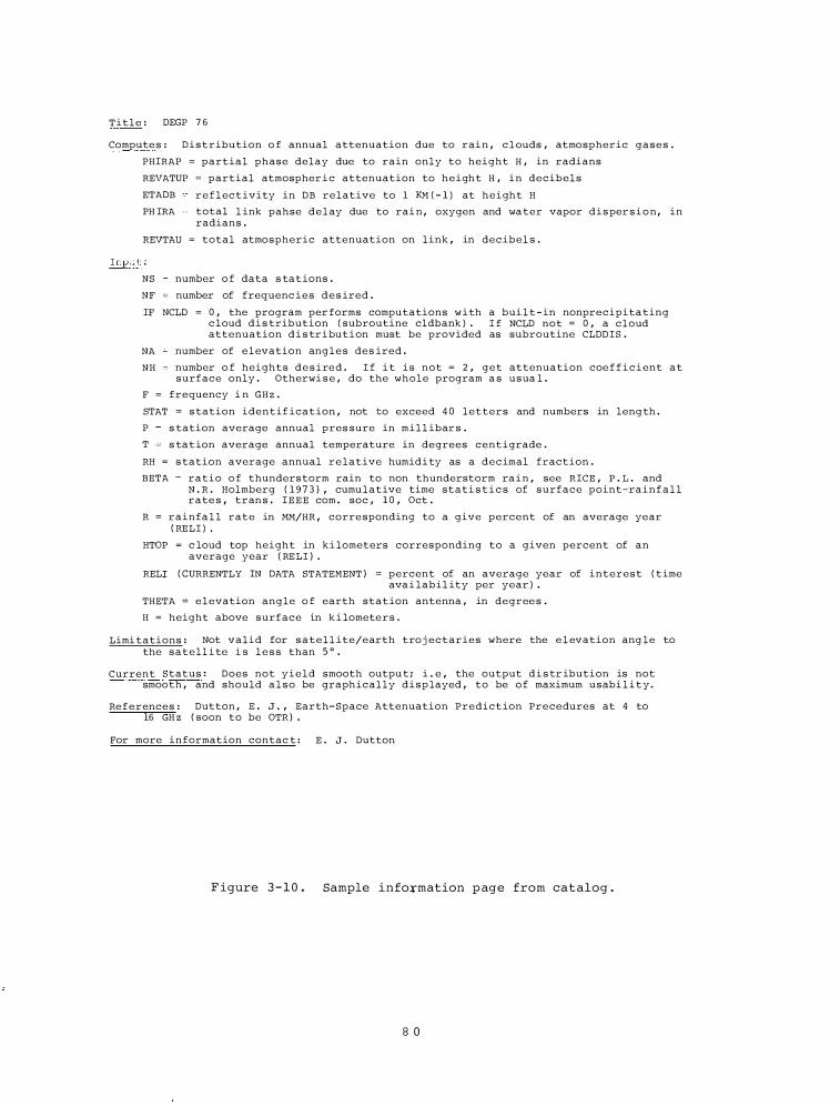
T i t l e : DEGP 7 6
Compute s : D i s t r ibution o f annual attenuation due to rai n , c l ouds , atmospheric g a s e s .
PHIRAP = partial phase delay due to rain only to height H , in radians
REVATUP = partial atmospher i c attenuation to h e i ght H , i n decibels
ETADB r e f l ec t ivity in DB r e l ative to 1 KM ( - 1 ) at h e i ght H
PH IRA total l ink pahse d e l ay due to rai n , oxygen and wa ter vapor d i s per s i o n , in radians .
REVTAU = total atmospheric attenuation on link , in decibel s .
Input :
NS
NF
number o f data s tat ions .
number of frequenc i e s d e s ired .
IF NCLD = 0 , the program per forms computations w i th a bui l t - in nonprecipita ting c loud d i s tribution ( subroutine cldbank ) . I f NCLD not = 0 , a cloud attenuation d i s tr i bu t i on must be provided as subroutine CLDD I S .
NA number of e l evation ang l e s des ired .
NH number o f heights d e s i re d . I f i t i s not = 2 , g e t attenuation coe f f i c i ent at surface only . Otherwi s e , do the whole program a s usua l .
F = frequency i n GHz .
STAT = s tation i d e n t i f icat ion , not to exceed 4 0 letters and numbers in leng th .
P s tation average annual pres sure in m i l l ibar s .
T s tat ion average annual temperature in degrees centigrade .
RH = s tation average annual r e lative humid i ty as a d e c imal fraction .
BETA r a t i o o f thunders torm rain to non thunderstorm ra i n , see RICE , P . L . and N . R . Holmberg ( 1 9 7 3 ) , cumu lative time stati s t i c s of surface point-ra i n f a l l rate s , tran s . I E E E com . soc , 1 0 , Oct .
R = r a i n fa l l rate in MM/HR , corre sponding to a give percent of an average year ( RELI ) .
HTOP = c loud top height in ki lometers corresponding to a given percent of an average year ( RELI ) .
RELI ( CURRENTLY IN DATA STATEMENT ) = percent of an average year of interest ( t ime ava i labil ity per year ) .
THETA = e l evation angle o f earth stat ion antenna , in degree s .
H = height above surface in k i lomete r s .
Limi tations : Not v a l i d for s a t e l l ite/earth tro j ectaries where the e l evation ang le to the s a t e l l i te i s l e s s than 5 ° .
Current Status : Does not y i e l d smooth outpu t ; i . e , the output d i s tr ibution is not smooth , and should a l s o be graphically d i s p layed , to be o f maximum usabi l i t y .
Re f e r ences : Dutton , E . J . , Earth-Space Attenuation Predict ion Precedures at 4 to 16 GH z ( soon to be OTR ) .
For more in formation contac t : E . J . Dutton
F igure 3 - 1 0 . Sample info�mation p age from catalog .
8 0
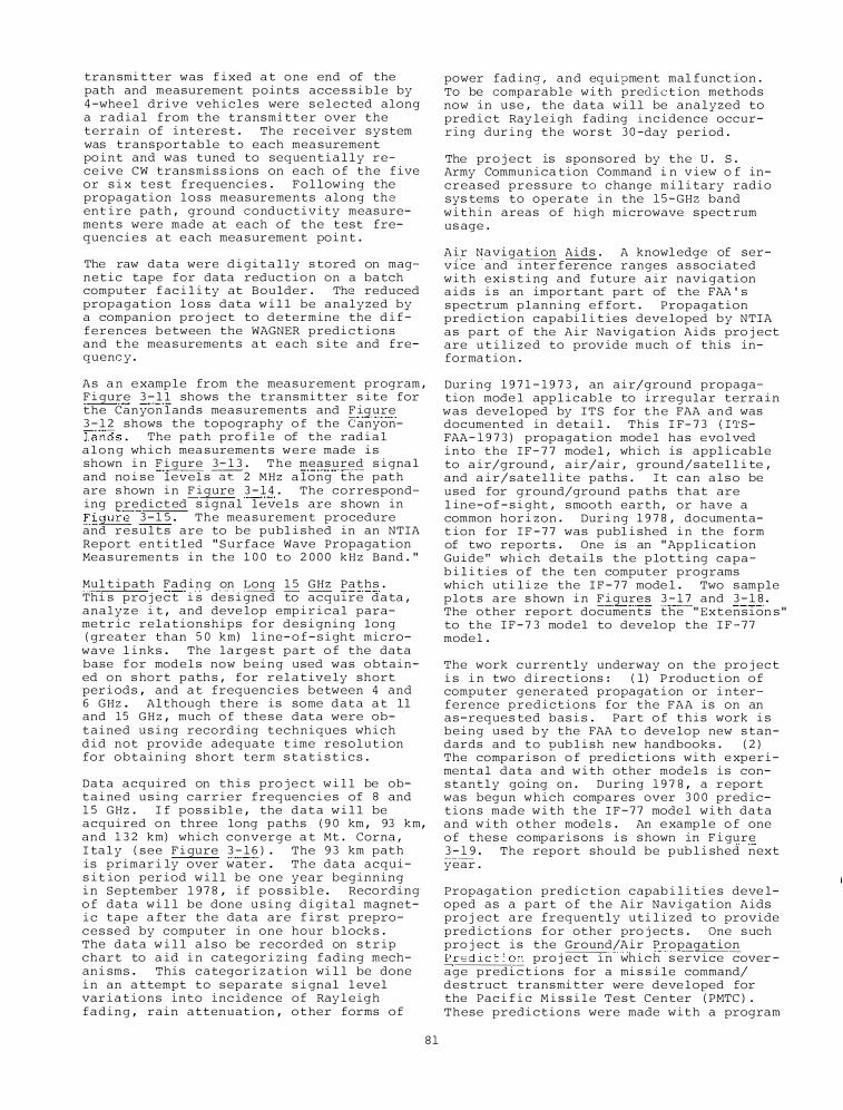
tran smi tter was f i xed a t one end of the path and measurement points acce s s i b l e by 4 -whe e l drive veh i c l e s were s e l e c ted along a r a d i a l from the transmi t t e r over the terr a i n of intere s t . The r e c e i ve r system was transportable to each mea surement po i n t and was tuned to seque n t i a l l y rec e ive CW transmi s s ions on each o f the f ive or s i x t e s t frequenc i e s . F o l l ow i ng the propagation l o s s measureme n t s along the ent i r e path , ground cond u c t i v ity measuremen t s were made at each of the test frequenc i e s a t e ach mea s ur ement po i n t .
The raw data were d i gi t a l l y s tored on magn e t i c tape for data reduc t i o n on a ba tch computer f ac i l i ty at Boulder . The reduced propagation l o s s data w i l l be analyzed by a compan i o n pro j ec t to d e termine the d i f ferences b e tween the WAGNER pred i c t ions and the mea s urements a t each s i te and frequenc y .
A s a n e xamp l e from the mea s u r ement program , F i gure 3 - l l shows the transmitter s i te for the Canyon l ands me a s urements and F igure 3 - 1 2 shows the topography o f the Canyonland s . The path pro f i l e of the rad i a l a l o n g wh i c h mea sureme n t s w e r e made i s shown i n F i gure 3 - 1 3 . T h e measured s i gna l and no i s e level s�2 MHz a long the path are s hown i n F i gure 3 - 1 4 . The corresponding predic t ed s i gnal l e ve l s are s hown in F i gure 3 - 1 5 . The me a sureme n t procedure and r e s u l t s are to be publ i s hed in an NTIA Report e n t i t l ed " S urface Wave Propagat ion Mea s ureme n t s i n the 1 0 0 to 2 0 0 0 k H z Band . "
Mul t i p ath F a d i n g on Long 1 5 GHz Paths . Thi s pro j e c t i s de s i gned to acquire d a ta , analy z e i t , and deve lop emp i r i c a l parame t r i c r e l a t ionships for d e s i gn i n g long ( greater than 5 0 km) l i ne - o f - s i ght micro
wave l i nks . The large s t part o f the data base for mod e l s now b e i n g used was obtained on s hort path s , for r e l a t ive ly short per i od s , and a t frequenc i e s between 4 and 6 GHz . Al though there is some data a t ll and 15 G H z , much o f the s e data were obt a i ned u s i ng record i ng t e c h n i ques wh i c h d i d not prov ide adequate t ime resolut i on for o b t a i n i n g short term s t a t i s t i c s .
Data acquired on th i s pro j e c t w i l l be obt a i ne d u s i n g c a r r i e r frequen c i e s of 8 and 1 5 GHz . I f pos s ibl e , the d a t a w i l l be acqui red on three long paths ( 9 0 km , 93 km, and 1 3 2 km) whi c h converge a t Mt . Corna , I ta l y ( s e e F i gure 3 - 1 6 ) . The 9 3 km path is primar i ly over water . The data acquis i t ion per iod w i l l b e o n e year beginning i n S e ptember 1 9 7 8 , if p o s s i bl e . Reco rding o f data w i l l be done u s i n g d i g i t a l magneti c tape a fter the data are f i r s t preproc e s s e d by computer in one hour b lock s . The d a t a w i l l a l s o be recorded on s t r ip chart to a id i n categor i z i n g fading mechan i sms . This c a tegor i z a t i o n wi l l be done i n an a ttempt to s eparate s i gnal l ev e l var i a t i o n s into inc idence o f Ray l e igh f a d i n g , rain attenuat i on , o t her forms o f
8 1
power fad i ng , a n d eq uipme nt mal funct ion . To be comparable w i th pred i c t ion methods now in u s e , the data w i l l be analyzed to pred i c t Ray l e i gh fading inc idence occurring dur i n g the wor s t 3 0 -day period .
The pro j e c t is sponsored by the U . S . Army Communica tion Command i n v i ew o f increased p r e s s ure to change m i l i tary radio sys tems to operate i n the 1 5 -GHz band w i t h i n areas of high microwave spect rum us age .
A i r Naviga t i on Aids . A knowl edge of service and inter ference ranges a s soc iated with e x i s t i ng and future a i r navi gation a i d s i s an important part of the FAA ' s spectrum planning e f fort . Propagation pred i c t i o n capabi l i t i e s deve loped by NTIA a s part o f the A i r Navigat ion Aids pro j ect are u t i l i z e d to prov ide much o f this information .
Dur i n g 1 9 7 1 - 1 9 7 3 , an a i r/ground propagation mode l app l i c able to irregular terra i n w a s deve l oped by I T S for t h e FAA a n d was documented in deta i l . This I F- 7 3 ( I TSFAA - 1 9 7 3 ) propagat ion mode l has evo l ved i n to the I F - 7 7 mode l , whi c h is appl i c able to a i r/ground , a i r/ai r , ground/sate l l i te , and a i r/sate l l i te paths . I t c a n a l s o be used for ground/ground paths that are l in e -o f - s i ght , smooth earth , or have a common hor i z on . Dur i ng 1 9 7 8 , documentat ion for I F - 7 7 was publ i shed i n the form of two reports . One is an " Ap p l i cation Gu ide " wh i c h details the p lo t t i ng capab i l i t i e s o f the ten computer programs whi c h ut i l i z e the I F - 7 7 mode l . Two s ample p l o t s are s hown i n F i gure s 3 - 1 7 and 3 - 1 8 . The other report documents the " Extension s " to the I F - 7 3 mod e l to develop the I F - 7 7 mode l .
The work currently underway on the pro j ec t i s i n two d i r e c t ions : ( l ) P roduc t ion o f computer genera ted propagat i on or i nterference p r e d i c tions for the FAA is on an a s - reque s ted bas i s . Part o f t h i s work i s being used b y the FAA t o deve lop new s tandards and to pub l i sh new handboo k s . ( 2 ) The comp a r i s o � o f pre d i c t i on s with e xp e r i men t a l data a n d w i th other mode l s i s constantly going on . During 1 9 7 8 , a r eport was begun which compares over 3 0 0 predictions made w i th the I F - 7 7 mode l w i th data and w i th other mode l s . An e xamp l e o f one o f the s e comp a r i s ons i s s hown in F i gure 3 - 1 9 . The report should be pub l i shed next year .
Propaga t i o n pred i c tion capab i l i ti e s deve loped as a part o f the Air Nav i ga t i on Aids pro j ec t are frequently uti l i z e d to provide pre d i c t i o n s for other pro j ec t s . One s uch pro j ec t is the Ground/A i r Propagation Predict ion pro j e c t i n wh i c h s ervice cover age predi c t ions for a mi s s i l e command/ d e s truct transmi tter were deve loped for the Pac i f i c M i s s i l e T e s t Cen ter ( PMTC ) . These predi c t i o n s were made with a program
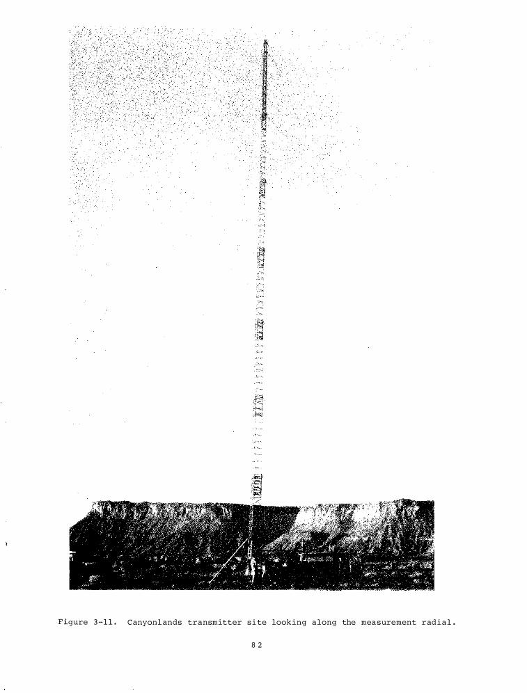
F igure 3 - 1 1 . C anyonl ands transmitter s i te looking along the mea surement radial .
8 2
ro w
F i gure 3 - 1 2 . The Canyonlands s ite as viewed f rom Dead Horse Point . The radi a l crosses the three p lateaus on the l e f t .
A.
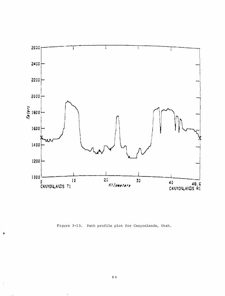
() '-
25o o ......--- -�---�----�-----,----·
� 1 80 0 �
1 60 0
1 4 0 0
1 200
1 0 0 0 1 0 1 0 CANYONLANDS T l
4 0 4 9 . b CANYONLANDS R I
F i gure 3 -1 3 . Path pro f i le plot for Canyonlands , Utah .
8 4
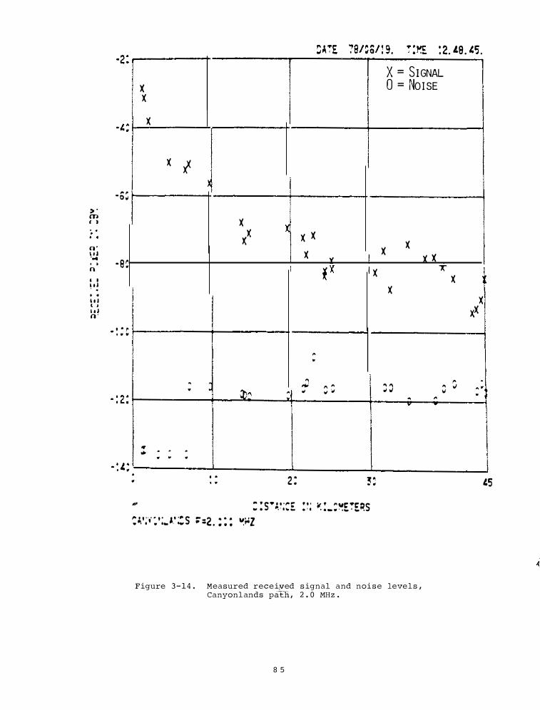
,. � · o o� > ' m ' )
. •
o · , , ... · S C . • n ' I \ ' ' . . . I l l t ' I t I n ·
• ' Ill ,.. . . .
�.'�.- ' 2 1.8 l,f: - • • • "J .
X = SIGNAL X 0 = Noi sE X
X
X l �
X X l X X X
X X X X 'i f X X �
X X
X xx
,. ..
� ., 'I � .
J ,.., " ,. " " " .; .. .. .. �0 ,. " " . .., .; ,; "' .. ..,, .. "
v
• • . . .
" .. "
. . 2 : -.: � " . "
H : : s·:.� ;:E . . . li: ! .. :�E�E�S . . .
� �'; ., : ' : .. A.' : S ;":2 . : : : �;oz
Figure 3 - 1 4 . Measured rece i�ed s ignal and noi s e leve l s , Canyonl ands patli , 2 . 0 MHz .
8 5
1.5
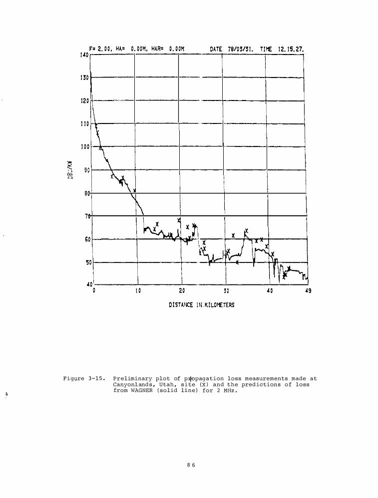
F: 2. 0 0 , HA= O . O OM, HAR= O . O OH . . . . DATE 78/03/3 1 TIH£ 1 2 1 5 27 I .tO
1 30
120
\ \ 1 1 0
1 0 0
ao
70
60
so
.£0 0
\ �'
\ 1\
I 0
l( )
�j :� ['r �
'
20
l( � � ·· , � �., f�
.£ 0 .£9 D ISTANCE IN . K ILOHETERS
Figure 3 - 1 5 . Preliminary plot of p�opagation loss measurements made at Canyonl and s , Utah , s ite ( X ) and the pred ictions o f loss from WAGNER ( so l id line ) for 2 MHz .
8 6
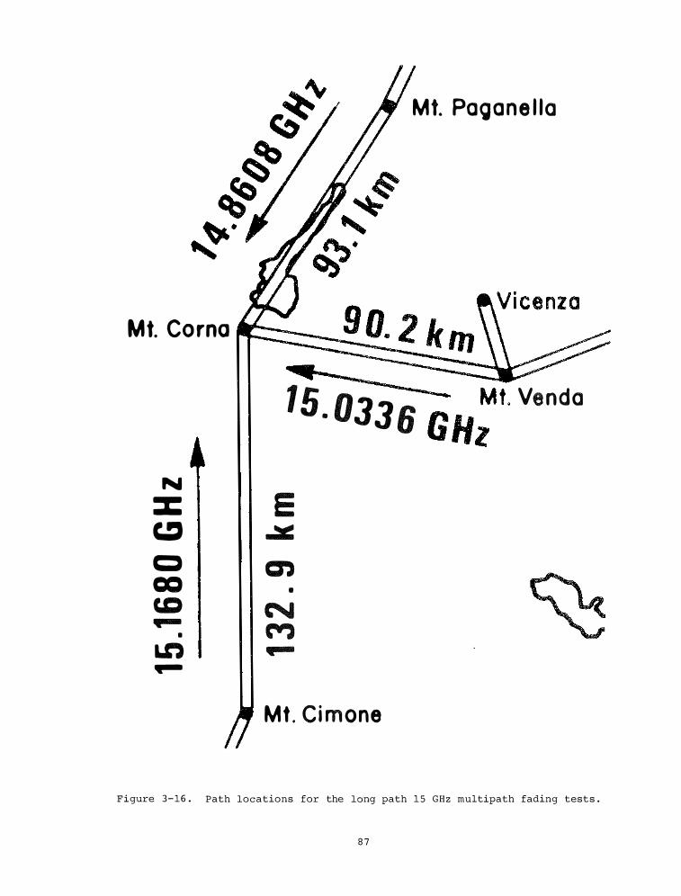
Mt. Paoane I I a
Mt. Corna Cl
15. 0336 iiH;t. Venda
N :c E c:J ...::.:: C) en ca •
c.Q � ..... (¥) •
Ln ..... .....
Mt . Ci mone
Figure 3-16 . Path locations for the long path 1 5 GHz multipath fading tests .
8 7
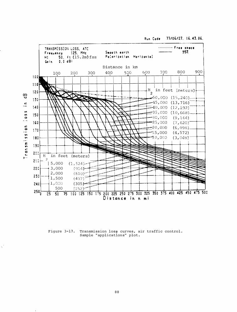
c:: 0
TRANSM I S S I ON L O S S , A T C r r e � �o� e n c y 1 25 . MHz H 1 5 0 . f t ( 15 . 2m) f s s Go i n 0 . 0 d B i
R �o� n C o d t 71/06/27 . 1 6 . 4 3 . 0 6 .
. . . . . . . . . . . . . . . r r e e S P CIC 8 Smoo t � e o r t k 957.
P o i o r i z o t i on H o r i z on t a l
Distance in km 800 900 1oo 2qo 3 oo 4oo 590 6po 7()0
I I 0 1 0 0� 1 2 0 :��:::.: , _.......:.::· !· · ··· · · · · · · -
H2
in feet (meter s ) �
-= JC >-""' . - - ,· ·· - � - - - · - · · ·!- · ·· · · �
1 3 0 i"\_ · ··•· · ·· · ·'"'0 , 000 ( 1 5 , 240 )-+---l
1 4 0
1 5 0
1 6 0
1 7 0
\"\�\\ '\: ' � "�"��--�::::.J-45 , 000 ( 1 3 , 7 16 )"" " " . . . .
\\\\[\ \ \ "� "�"'�� ����: ��� ��� : ��� ,,'_ --+---l \\\�\ \ \ \ \ \\ y� -� 0 , 000 ( 9 , 144 )
\\ ,\ \ \ ' \ \ � 5 , 000 ( 7 , 62 0 )---1---i \\ !\ \ \. \ \ •"J O , O O O ( 6 , 096 ) _-+---4
\��' \ \ !\ \ 1\ !\ \\ 5 , 000 ( 4 , 5 7 2 )
: :: "���--., _:o;;;:::: �;., ...... �,""� -L O , O O O ( 3 , 048 ) -+--l
����:::_::::::��I:S:5� 2 0 0 ���-4-�-��--� ��������������t--r-1
2 1 0 f--H
2 in feet (meters ) -����;:::R����� 5 , 000 ( 1 , 524 )--::v--�--�-- -....;:����:::§��
220 t-- 3 , 000 ( 914 , _.-f- - -- � - :""'-- � 2 , 000 ( 610 )::: ---� --� __.v- !iii.:;;;��:::::: 2 3 0 - 1 , 500 ( 457 ) - _.-f--"" --�- ..... �� 24 0 - 1 , 000 ( 305 _....f.-- � ��
500 ( 152 )--� 250o 2' s o 75 1 o o 1 2s 1 !> o 1 rs 2 0 0 22s 2! o 2 s 3 o o 3:: " 3!i o 3 i5 .c o o 425 4! o 4 '5 s o
D i s t a n c e i n n m i
F igure 3 - 1 7 . Tran smi s s ion los f curve s , air traff i c contro l . S ample " applicatlon s " p lot .
8 8
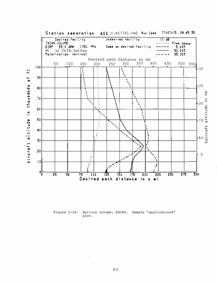
I 0 0 ....
......
...... 9 0 0
.., "Q 8 0
c: a ..,
7 0 ::J 0
.c. ..... b O c:
... 5 0 "Q
::J .....
.c o .....
a 3 0
..... ......
a 2 0 �
u �
< I 0
S t a t i o n s e p a r a t i o n 4 0 0 . n mi ( 74 l . km) Run C o d e 7 7 / 0 7 / 1 3 . 0 8 . 45 . 35 .
D e s i r e d f oc i l i t � Vr. d e s i r td f o c i l i t � I I dB TACAN VOLVME . . . . . . . . . . . . . . . F' r u H I C t E I RP 3 9 . 0 dBW 1 1 5 0 . MHz S o•• O S d e s i r e d f oc i l i t � - - - - - 5 . 0 0 1. H I 3 0 ft ( 9 . 1m) f s s 5 0 . 0 0 7. Po I o r i z o t i o n Ve r t i c o l I I I I I I I I 95 . 0 0 1.
Des ired path distance in km 5 0 100 150 2 00 2 50 3 00 3 5 0 4 0 0 4 50 5 0 0 5 5 0 .
I \ I
,\ \ I ' I I \ I \ \ I \ I ' I I '
I \ I �, I I I ' I \ ' I I ' I '
I I ' I• \ I , : I
I I I I I I \ . I \ \ I l l . I I \
· · · ·""' I i
"" \ I I I I 1 1 ::) I I I I
I ' ' �·. \
v ' . . ' ; • • \ • • . . \
; . . .. 1 I
i • • I i .
� ;
�
r
25 50 15 I 0 0 1 25 15 0 1 75 2 0 0 225 250 275 3 0 0 D e s i r e d p a t h d i s t a � c e i � � IIi
F i gure 3 - 1 8 . Service vol ume , 'fACAN . Samp l e " applications " plot .
8 9
3 0
2 5
2 0
5
� c ·rl
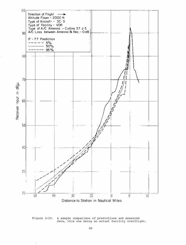
::i_ CD u
c
-::J a. c
'-<l> >
·w (.) <l> a:
1 0 0�----------------------�------�------�----�--� Direction of F l ight -----.
Alt i t ude Flown - 2000 ft. Ty pe of A i rcraf t - DC - 3 Ty p e of Fa c i l i ty - VOR Ty pe of A /C Antenna - C o l l i ns 37 J-3
90 A/C Loss between Ante n na 8 Rec . - 0 d B H--·----lf-------ll\f-\----+-----1 I F - 7 7 P redict ion - - - - - 5°/o . . . . . . . . . . . . . .. 50°/o - - - - - - 95 %
( � BOr-�-------+------�------+-------�----�4-----�----l i
70
60
50
f:
a ) If f
f! I ;/ I
;.:>-1
J Jil
D ista n ce to Stat ion i n Naut i c a l M i l e s
\ \
F i gure 3 - 1 9 . A sample comp ar ison o f predictions and mea sured data , this one being an actual facility over f l i ght .
9 0
modi fied to ( l ) approximate the c ircul arly po larized transmitter antenna pattern , and ( 2 ) inc lude mi s s i le receiving antenna gain
stati s t i c s for a random orientation in the calculation o f s i gnal level variabi l i ty . Figure 3 - 2 0 is a s ample of the pred ic t ions provided . I t s hows the air space ( service area s ) in whi c h d i f ferent rece ived power leve l s at the m i s s i l e would be expec ted to be available for at least 9 9 . 9 % o f the transmi s s ion t ime .
Hydro-Quebec i s p lanning an exten s ive moderni zation of i t s l and mobi le radio s y s tem . Under this pro j ect , entit led Mob i l e Aids , ITS wi l l devise computer aids to help the d e s i gn of the new sys tem and will supply these aids in the form of computer programs able to operate at the sponsor ' s f a c i l ity .
In FY 7 8 , we have suppl i ed the s ponsor with programs to e s t imate rece ived s ignal l eve l s on po int-to-point communica tions l inks , from a mob i l e base s ta t ion to a s equence o f points a long a road , and from a mob i l e b a s e s ta t ion t o an entire area . A l l o f t h e s e use a f i l e o f digiti zed topography which is soon to be implemented .
In a pro j ect devoted to VHF/UHF Mode l Deve lopment for Urban and Rural communication s , we comp l e ted an extens ive s tudy of what is known or surmi s ed about propagat ion in rural areas . The report that describes this s tudy also di scus ses the Longley-Rice model o f propagation and gives sugge s t ions a s to how i t may be modi fi ed to include an " urban f ac tor . "
In other directions , this s ame pro j ect h a s begun assembl ing measured d a t a i n t o a computer readable form . The emphas i s here i s o n r adio data ( inc luding i t s var iab i l i ty ) i n o r near the UHF televi s ion band , for there i s s t i l l controversy over what engineering parameters one should use in this impor tant part o f the spectrum . In addit ion , the p ro j ect now has underway the preparation of s everal papers on the general subj e c t o f variab i l i ty .
The s econd phase o f a s tudy o f Power F ading S t at i s t i c s i s underway . Sponsored b y the Electromagnetic Compatibi l i ty Ana l y s i s Center , Department o f Defense , t h e purpos e i s to p u t on a f irm foundation o n e aspect of the engineering des i gn o f microwave l inks . Heretofore , c a lculations of the magni tude o f long-term ( powe r ) fading has been based on techniques developed ten years ago when there were f ew accumulated data at f requenc ies above 1 GH z .
In this s econd phase we are collecting together a l l the newly avai l able data . We will compare these data with the present day techniques and s ugge s t whatever adj us tments seem necessary .
9 1
3 . 3 . 2 . Iono spheric Transmi s s i on Models
Computer programs developed by ITS for predicting ionospheric transmis s ion and the per formance of HF r adio sys tems are used by government agenc ies and commercial firms in the U. S . and other nations . A continuous program is c arr ied on to upgrade and expand predi c t ions services to f i t users needs .
Normal day-to-day and hour- to-hour departures of critical frequencies ( foF2 ) and other ionospheric character i s t i c s from observed median values have a signi f icant e f fect upon the range of u s e ful frequenc i e s on HF communication circuits . Even greater e ffects result from dis turbances in the earth ' s magnetic f i e ld and from certain forms of activity on the sun .
Development and Improvement of Predict ion Formats . The ICA/VOA , in maintaining and improving i t s worldwide broadca s t schedules on h i gh frequenc ies , requires predictions of its expected broadca s t coverage we ll in advance to prepare for its broadcast schedules . Predictions have been del ivered on s c hedule , and VOA continues to make occasional use of their programs by remote acces s . Work has been done and will cont inue to adapt the new HF predictions pro gram ( IONCAP ) to VOA ' s needs . I ONCAP output will be compared with HFMUFES ( the present program) output , and both wi l l be checked ( by VOA) against mon i toring results .
3 . 3 . 3 . Terrain Models
Ground Wave Propagation Over Irregular , Inhomogeneous Terrain : Compari sons o f Calculations and Mea s urement s . A method for calculating the ground-wave field over irregular , i nhomogeneous terrain was developed by R. H . Ott , and several comparisons with al ternative analytical methods were made for ide a l i z ed terrain profiles l ike concave parabolas , sea-landsea paths , and Gau s s i an ridge s . The excell ent agreement between methods like Fock currents for concave surface s , class ical res idue serie s , an integral equation developed by Huf ford , with Ott ' s alternative method based upon an el em�ntary function ( closely related to the Sommerfeld Flatearth attenua tion function) for the parabo l ic wave equation provided encouragement for the use fulne s s of Ott ' s method and the associated a l gorithm .
The res earch on this program in FY 7 8 extended and mod i f ied the original algorithm and compared the computed field s trength with obs erved values obtained on 9 s eparate paths shown in Table 3 - 1 . The polar i z ation was vertical for all paths i n Table 3 - 1 except t h e Buf f a lo path .
As an example of the compari son between the predicted and measured field strength
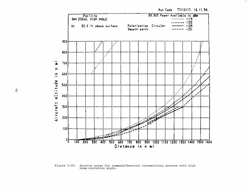
'V N
Rur. Code 77/ 1 0 / 1 7 . 1 6. l i . 54.
Fac i l i ty 99. 907. Powe r A v a i l ab l e i r. dBW SAN DIEGO, H I GH ANGLE · ·············• � 1 1 9
Hl
90 0
8 0 0
& 7 0 0
c::
c:: 6 0 0 -
., "0
5 0 0 � ....
.... 4 0 0 G
.... -
3 0 0 0 � u �
2 0 0 -<
1 0 0
0 .. . .. ..
F i gure 3 - 2 0 .
I r r I I I I I • t 22 2 0 . 0 f t above s u r face Po l a r i z a t i on C i r c u l a r - 1 25
S111o o t ll e a r th - - - - - � t 3 !
' I .· I .· : • f . ' .·
.·
.·
! ..... ' • I .. : ••
: • •
I y • • •'
v "'
.....
..... ·· • �"' , •
. .
·/
A a a
.··
v '/' , i"' .. . • .· ' "' .. ··
. . "' .. -. . ,
� � :/ .. • ... ...
.... · ··:·. �
� �..r;Ji" � ·� " . ; .... ... ··· _ ... ...
� J.V': .. , ,
·� , , ., ..... �····· "
.. ...... - - - . - - - - . - - . -- . - . . - - . � - - -
Q j s t CBf\ C 8 i f\ f\ M i � A - - - - - - - - - - - - ... ...
Service areas for command/de s truct transmitting antenna with high beam elevation angle .
"'
.. - - - · - -0
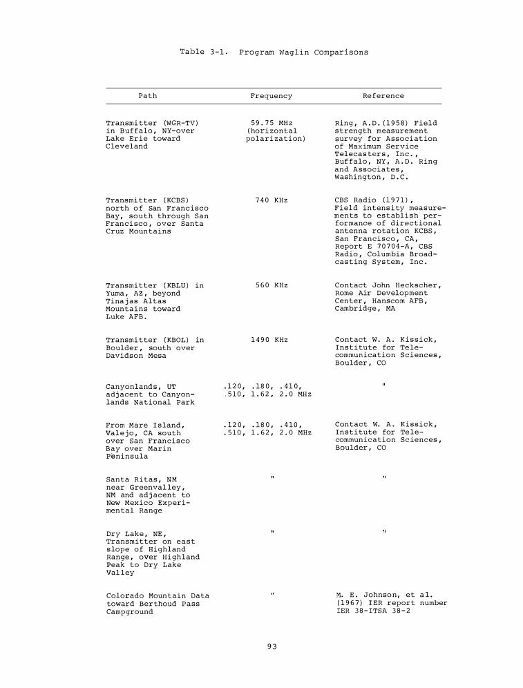
T a b l e 3 - 1 . P r o g r am Wag l i n Compar i s o n s
Path
Tran_smi tter (WGR-TV ) in Buffalo , NY-over Lake E r i e toward Cleveland
Transmi tter ( KCBS ) north o f San Franc isco Bay , south through San Fran c i sco , over Santa Cruz Mountains
Transmitter ( KBLU ) in Yuma , A Z , beyond Tina j as Altas Mount a i n s toward Luke AFB .
Transmi tter ( KBOL ) in Boulder , south over Davidson Mesa
Canyonland s , UT adj acent to Canyonlands National Park
From Mare I s land , Va l e j o , CA south over San Fran c i s c o B a y over Marin Peninsula
Santa Ritas , NM near Greenva l ley , NM and ad j acent to New Mexico Experimental Range
Dry Lake , NE , Transmitter on e a s t s lope o f Highland Range , over H i gh l and Peak to Dry Lake Val ley
Colorado Mountain Data toward Ber thoud Pass Campground
Frequency
5 9 . 7 5 MH Z ( hori zontal
pol a r i z a t i on )
7 4 0 KHz
5 6 0 KHz
1 4 9 0 KHz
. 1 2 0 , . 1 8 0 , . 4 1 0 , . 5 1 0 , 1 . 6 2 , 2 . 0 MH Z
. 1 2 0 , . 1 8 0 , . 4 1 0 ,
. 5 1 0 , 1 . 6 2 , 2 . 0 MHZ
9 3
Re ference
Ring , A . D . ( 1 9 5 8 ) F i e l d s t rength measurement survey for Associ at ion of Max imum Service Telecas ter s , Inc . , Buf falo , NY , A . D . Ring and Associate s , Washington , D . C .
CBS Radio ( 1 9 7 1 ) , F i e l d intens i ty mea s urements to e s t abl i s h performance o f directional antenna rotation KCBS , S an Fran c i s c o , CA , Report E 7 0 7 0 4 -A , CBS Radio , Columbia Broadc a s t ing Sys tem , Inc .
Contact John Heckscher , Rome Air Development Center , Hanscom AFB , Cambr idge , MA
Contact W . A . K i s s i ck , I n s t i tute for Te l e communication S c i enc e s , Boulder , CO
Contact W. A . K i s s i c k , I n s t i tute for Te l e communication Sc iences , Boulder , CO
M. E . Johnso n , et a l . ( 1 9 6 7 ) I ER report number IER 3 8 - ITSA 3 8 - 2
versus d i s tance cons ider the Luke- Yuma path . RADC per s onnel made a number o f field s trength measurements i n an area southeast o f Yuma , Ar i zona , using as a source the Y uma commercial broadcast station KBLU ( 5 6 0 kHz ) . The path pro f i l e i s shown o n t h e l ower portion o f F igure 3 - 2 1 . The path c x.-osses a minor ridge (Vopok_i __
Ridge ) at about 4 5 km and , later on , a hi gher ridge ( Tinaj as Altas Mountains ) at about 6 5 km . The electrical ground constant:s used in PROGRAM WAGL IN are shown in the upper r ight hand corner of Figure 3 - 2 1 . In Figure 3 - 2 1 i s a plot o f the predicted path 16SS1solid curve ) in terms of " D BU/KW " ( dB above 1 microvo l t per meter for 1 kw radi ated from a hal f-wave dipole in free space ) , together with measured DBU repre sented by crosses . The pred ic tions appear to agree very we l l with the observed values .
Automated D i gital Topographic Data Techniques . The Automated Digital Topographic Data Techniques pro j ec t designed and w i l l improve a d i g i t a l terrain e levation data base along with the related software . It i s primarily to be used by USACEEIA in carrying out i t s worldwide respon s i b i l i ty for planning , trouble shooting , and install ing routine and s trategic communication sys tems . Methods for predict ing the per formance o f communication systems generally o f frequenc ies above 30 MH z require terrain information der ived from prof i les along a large number of potential propagation paths ( see Figure 3 - 2 2 ) . These require a rapid and accurate means of automatically generating these profiles from data stored on magnetic tapes or disks . To sati s fy this requirement , ITS has desi gned a d i gital terrain elevation data base ( TOPOG) tha t :
1 . provides s igni f icantly greater de tail than can be obtained from the data base currently being used by the sponsor ;
2 . can readily expand toward global coverage as addi tional data become available ;
3 . can be generated in a reasonably e f f icient way from exis ting and proj ec ted sources of raw data ;
4 . can be u t i l i zed in an acceptably e f fic i ent manner in pro f i l e generation and other telecommunications app l ication s ; and
5 . minimi zes s torage space requi rements sub j e c t to constraints imposed by cond itions ( 1 ) and ( 4 ) above .
After a prel iminary s tudy in FY 7 7 o f several alternativ� methodologies o f creating and returning datum f rom data base s , the result was a data base con s i s t i n g o f t h e e levations at t h e nodes o f a
9 4
global grid o f paral l e l s and meridians who se ba s i c va lue i s 3 se conds . The primary source o f raw data for the pres ent will be the so-cal led S tandard Digi tal Terrain Elevation Data Fi les being produced by the Defense Mapping Agency . The DMA tapes are not in a usable format for easily extracting terrain pro f i l e dat a . CONUS wi l l b e covered b y about 7 5 TOPOG tapes ( 1 6 0 0 bpi , 2 4 0 0 ' reels ) versus about 1 1 0 DMA tapes .
In FY 7 8 , the pro j ec t has deve loped ( 1 ) software for generating TOPOG records and tapes f rom DMA Standard F i les ( P ROGRAM GENTOP ) , and ( 2 ) a bas ic retr ieval subprogram ( ELVAT ) which , when given the latitude and longitude of an arbi trary po i nt on the earth ' s surface , u t i l i z e s TOPOG to return the e l evation of that point or informs the user that TOPOG does not contain the nec e s s ary data .
SECTION 3 . 4 . PREDICTION OF TRANSMI S S I ON PARAMETERS AND SYSTEM PERFORMANCE
Completed engineering mode ls for EM wave transmi s s i on calculations are del ivered to spon soring and reques ting agencies for the ir use . Fol lowing are representative uses of the se s ervice s .
3 . 4 . 1 . Long-Term Ionospheric Predicti ons
The ICA/VOA requires regular predictions of " circui t " per formance as an aid i n p lanning appropriately for the continuation o f its world-wide H F bro adcas t s .
The Radio Propagation Predictions pro j ect provides the VOA every second month with HF circuit performance predictions for about 1 8 0 broadcast circuits 8 months in advance . For about 1 5 0 of these circuits ( from T inang , Kavala , Greenville , Woo ferton , Monrovia , Munich , and Tangier ) , the predic tions inc lude selec tion o f optimum transmi tting antenna .
CDC 6 6 0 0 f i le s have been mai n tained for local batch processing and , under the VOA Time Share Service , they are avai lable-for use by means of remote acce s s from a remote TELEX termina l . Program f i l e s have been prepared and maintained to help i n ( 1 ) preparation o f input data f o r t h e pre
diction program , and ( 2 ) to give great circle d i s tances and bearings for arbi trary circui t terminal locations . F i le s are also ma intai ned on the XDS 9 4 0 for i nteractive time- share access by VOA to the prediction program .
In addition to VOA , there are other government agencies and industrial organ i z ations requiring Numerical Predict ion Service s . This pro j ect provides H F radio propagation predictions and computer programs on a co s t reimbursable bas i s .
HF radio propagation predictions were pro-
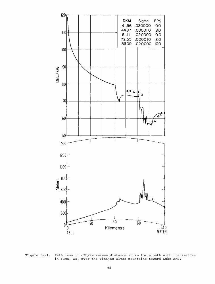
120 DKM Sigma EPS
4 1 .36 .020000 10.0
1 1 0 44.87 . 0000 1 0 8.0 6 1 . 1 I . 0 2 0000 10.0
72 .5 5 .0000 1 0 8.0 83.00 .02 0 000 1 0.0
100
� sor-���--�---+---r--�--4---� .::.::. ........ :::) (!) 0
K i l ometers 83.0 WATER
F i gure 3- 2 1 . Path loss i n dBU/Kw versus d i stance i n km for a path with transmitte� in Yuma , AZ , over the Tina j a s Altas mountains toward Luke AFB .
9 5
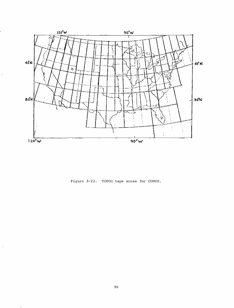
Figure 3 - 2 2 . TOPOG tape are as for CONUS .
9 6
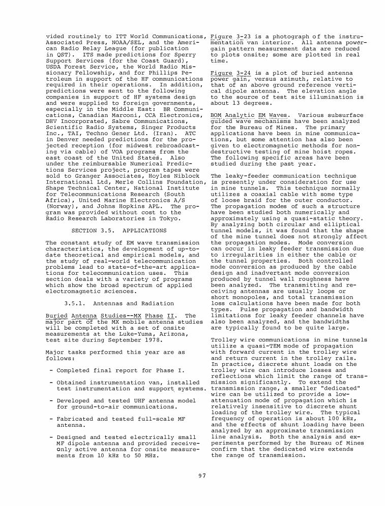
vided routinely to ITT World Communications , Assoc iated Pres s , NOAA/SEL , and the American Radio Re lay League ( for pub l ication in QST ) . ITS made pred i c t ions for Sperry Support Services ( for the Coas t Guard ) , USDA Fore st Service , the World Radio Mis sionary Fel lowship , and for Phi l l ips Petrol eum in support of the HF commun ications required in their operations . In addition , predictions were sent to the following companie s in support of H F sys tems de s i gn and were suppl ied to foreign governments , espec i a l ly in the Midd le East : BR Communi cat ions , Canadian Marcon i , CCA Electronic s , DHV Incorporated , Sabre Communications , Sc ienti f i c Radio Sys tems , S inger Produc ts Inc . , TAI , Techno Gener Ltd . ( I ran ) . ATC in Denver needed pred i c t ions for the proj ected reception ( for midwes t rebroadcas ting via cab l e ) o f VOA program� f rom the east coast of the United S tates . Also under the reimbursable Numerical Predictions Services pro j ect , program tapes were sold to Granger Associ ates , Hayles Niblock International Ltd , Mer l e Collins Foundation , Shape Technical Center , National Institute for Telecommunications Re search ( S outh Africa ) , Uni ted Marine Electronics A/S ( Norway ) , and Johns Hopkins APL . The pro
gram was provided wi thout cost to the Radi o Research Laboratories i n Tokyo .
SECTION 3 . 5 . APPLICATIONS
The cons tant s tudy of EM wave transmi s s ion characte r i s t ics , the development o f up- todate theoretical and empirical model s , and the s tudy of real-world telecommunication problems lead to s tate-o f - the-art app l ications for telecommunication uses . This sec t ion deals with a variety o f programs which s how the broad spec trum of appl ied e l ectromag�etic s c i ences .
3 . 5 . 1 . Antennas and Rad iation
Buried Antenna S tudies --MX Phase I I . The ma j o r part of the MX mob i l e antenna studies will be comp leted with a s e t o f ons ite measurements at the Luke-Yuma , Ari zona , test s i te during S eptember 1 9 7 8 .
Maj or tasks performed this year are as fol lows :
- Completed final report for Phase I .
- Obtained ins trumentation van , instal l ed test instrumentation and support, sys tems .
- Deve loped and tes ted UHF antenna model for ground-to-air commun ications .
- Fabr icated and tested full-scale MF antenna .
- D e s i gned and t e s ted e l ectrically sma l l M F dipole antenna a n d provided rec eiveonly active antenna for ons i te measurements from 10 kHz to 50 MH z .
9 7
Figure 3 - 2 3 is a photograph o f the ins trumentation van interior . A l l antenna pow�rgain pattern measurement data are reduced to plots onsite ; some are plotted in real time .
Figure 3 - 2 4 is a plot of bur ied antenna power ga in; versus a z imuth , rel ative to that of an above ground re fe rence vertical dipole antenna . The e levation angle to the source o f tes t s i te i l lumination i s about 1 3 degree s .
BOM Analytic EM Waves . Various subsurface guided wave mechanisms have been analy zed for the Bureau o f Mines . The primary app l ications have been in mine communications , but some attention has also been given to electromagnetic methods for nondes truc tive testing of mine hoi s t ropes . The fol l owing speci f ic areas have been s tudi ed during the past year .
The leaky - feeder communication technique is presently under consideration for use in mine tunne l s . Thi s technique normally uti l i z e s a coaxial cable with some type of loose braid for the outer conduc tor . The propagation modes of s uc h a s tructure have been s tudied both numerically and approximately using a qua s i - s tatic theory . By analyz ing bot h c ircul ar and e l liptical tunnel mode l s , it was found that the shape of the mine tunnel does not s t rongly a f fect the propagation mode s . Mode conver s ion can occur in leaky feeder transmi s s ion due to i rregul arities in e i ther the cable or the tunnel propertie s . Both control led mode conver sion as produced by the cable de s i gn and inadvertant mode convers ion produced by tunnel wa ll roughnes s have been analy zed . The transmi tting and receiving antennas are usua l ly loops or short monopoles , and total transmi s s ion loss calculations have been made for both type s . Pulse propagation and bandwidth l imi tations for leaky feeder channe l s have also been analy z ed , and the bandwidths are typi c a l ly found to be quite l arge .
Tro l ley wire communications in mine tunne ls ut i l i z e a quasi-TEM mode of p ropagation with forward current in the tro l l ey wire and return current in the trolley rai l s . In practice , dis crete shunt loads on the tro l ley wire can introduce losses and reflections whi c h limit the range of trans mi s s ion signif icantly . To extend the transmi s s ion range , a smal ler " dedicated " wire can b e uti l i zed to provide a lowattenuation mode of propagat ion which i s relatively insens itive to discrete s hunt loading of the trolley wir e . The typical frequency of operation i s about 1 0 0 kHz , and the e f fects of shunt loading have been anal y z ed by an approximate transmi s s ion line analy s i s . Both the analy s i s and experimen t s per formed by the Bureau of Mines con f i rm that the dedi cated wire extends the range of transmi s sion .
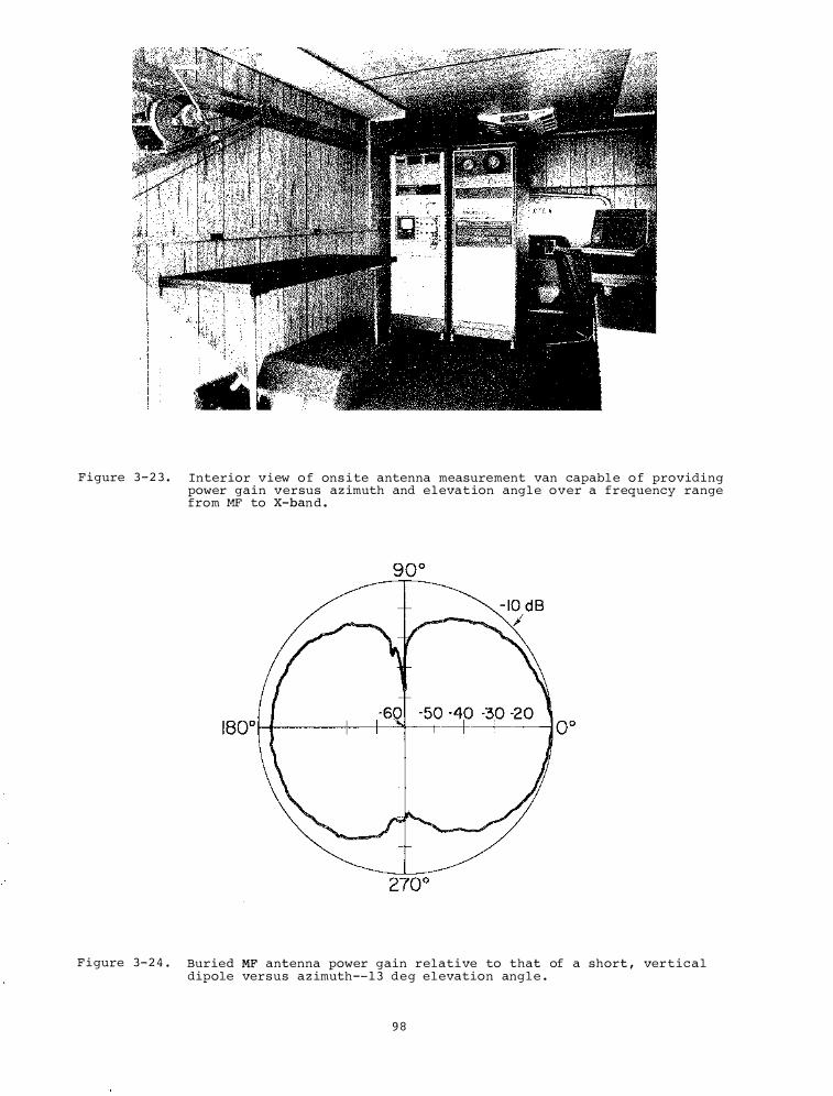
Figure 3 - 2 3 . Interior view o f ons i te antenna measurement van capabl e o f providing power gain versus az imuth and elevat ion angl e over a frequency range from MF to X-ban d .
F i gure 3- 2 4 . Buried MF antenna power gain relative to that of a short , vertical dipole versus az imuth-- 1 3 deg elevation ang l e .
9 8
In order to bring together workers in var ious areas o f subsur face propaga tion , ITS organ i z ed and ho s ted a workshop on EM Guided Waves in Mine Environments , March 2 8 - 3 0 . Some o f the topic s discussed were ELF propagation through the earth , MF pro pagation in coal seams , HF propagat ion on leaky feeder s , and UHF propagation in empty tunne l s . Numerous · foreign countries were represented , and a conference proceedings has been pub l i s hed .
A rel ated topic in mine s a fety involves nondes tructive testing of mine hoi s t ropes . A review o f electromagnetic methods for nondes tructive testing o f s teel wire rope s was conducted , and the theoretical l imita tions of s uc h methods have been s tudi ed . The past theory has been h i ghly idea l i z ed and generally restric ted to two dimens iona l analyses . More rea l i s t i c three dimens ional rope f laws and both so lenoid and toro idal rope excitat ion have been analyzed . The d i f f icult problem o f character i z ing the anisotropic properties o f an actual s tranded rope has a l s o been addre s s ed .
Future work on mine commun i c ations will cont inue . An important problem i s propagat ion f rom a tunnel into cross cuts . Also the transmi s s ion o f s i gnal s a long metal dr i l l rods and the input power requirements w i l l be s tudied . Coupl ing o f r adio s igna l s to blas ting cap c i rcuits continues to be a s afety p roblem wh ich requires further s tudy . Work wi l l also cont inue on the non-destruc tive testing of mine hoi s t rope s . The goal i s t o determine optimum exc i tation and sensing conf igurations .
Kodiak S ite S tudy . The U . S . Coast Guard communication s tation Kodiak i s loca ted on Kodiak I s l and , Alaska , and due to its location i s very critical to nautical communi cations i n the northern P ac i f i c and the Ala skan region . The re spons i b i l i ties of communication s tation Kodiak currently inc lude : communi c ation to/from a l l Coast Guard ves s e l s i n the Northern Pac i f i c/ Alaskan region inc luding a i rcraft on all routine and emergency m i s s ions , reports from fore ign f i shing ves s e l s regarding location and catch within the 2 0 0 -mi l e l imi t , continuous guard on s everal MF and HF distress and c a l l ing frequenc ies , cont inuous mon i tor o f the AMVER ( Automated Merchant Ve ssel Reporting ) system , and a s sor ted other duties as n eeded such as phone patche s , l and l ines , etc .
The pro j ected future operational requi rements for communication s tation Kod iak indicate a greatly i ncrea s ed l evel of act ivity due to a variety of f actors . Some o f . these factors are increased o i l exploration and tanker t r a f f i c , an increase i n the number of Coast Guard patrol ve s s e l s and aircraft i n the Ala skan region , a pos s ible 2 0 0 -mi l e pol lution contro l , and other s .
9 9
Due t o the s trategic location o f the commun ica tion s tation and the need for improvement of the physical p l ant , I TS �as reque s ted to undertake a s tudy o f the antenna s i t i ng at the commun ication station . The s tudy was begun last f i scal year . An unpub l i s hed report was prepared tha t addressed the question of both MF and HF propagation to var ious regions of the Northern Pac i fic/Alaskan region considering the location of the communication station with regards to the ocean areas and the topography of Kodiak I s land . Surface wave propagat ion predictions were made for the MF frequencies and were descr ibed in last year ' s ITS Annual Report .
Skywave propagation predictions were made for the HF frequencies , cons idering the ocean regions of interest and a set o f seasona l , diurnal , and solar activity conditions . One output of these predic tions i s a h i s togram o f the optimum frequency use . In addition , the associ ated d i s tribut ions o f take-off angle for each frequency were computed . The f requency use h i s togram is shown in F i gure 3 - 2 5 and the set of a s s o c i ated take off angle distribut ions i s shown in Figure 3 - 2 6 . These particular f i gures include the e f fects o f a l l the seasonal , diurnal , and solar activity cond i t ion s ; however h i s tograms and dis tributions were also developed for the subset of sea sonal , diurna l , and solar activity cond itions .
Predi ctions such as those j us t described are used in determining the parameters required o f the antenna system. The greates t problem at the Kodiak transmi tter s ite is the local topography . The hori zon elevation angle as observed from the center of the Buskin Tabl e s i te can be a s high as 1 2 ° .
A site survey was made to determine the s tation operations and to view the topographi c s i tuation . ITS has reviewed the predicted dat a , the exi sting phy s i ca l plant , and topography and made recommendations to optimi ze the antenna types and s i ting for best communication .
3 . 5 . 2 . Transmi s s ion Through the Atmo sphere : Appl i c ations
DOE SECOM Technical Support . This program supports the ERDA Mater iel Transportation SAFEGUARDS programs with the ma j or thrust concerning systems engineering support to the functional enhancement and evaluation of the c apabi lities of the exis ting SECOM communi cations sys tem . The program was initiated in FY 7 6 , and concerned the development and implementation of an improved HF propagation mode l , mobi le antenna evaluation , and the initial des igns of a sys tem management mode l .
'I'he propagation model is a modi fi ed vers ion of a newly developed HF model i nc lud-
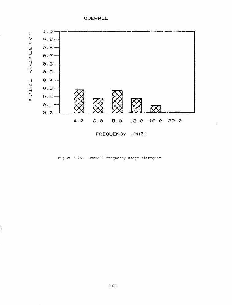
OVERALL
F 1 . 0 R (._� . 9 E Q 0 . 8 u
0 . 7 E ti
0 . 6 c: y 0 . 5
u 0 . 4
5 0 . 3 A
G 0 . 2 E 0 . 1 0 . 0
4 . 0 6 . 0 8 . 0 1 2 . 0 1 6 . 0 2 2 . 0
FREQUENCY C MH Z )
Figure 3 - 2 5 . Overa l l frequency usage h i s togram .
1 0 0
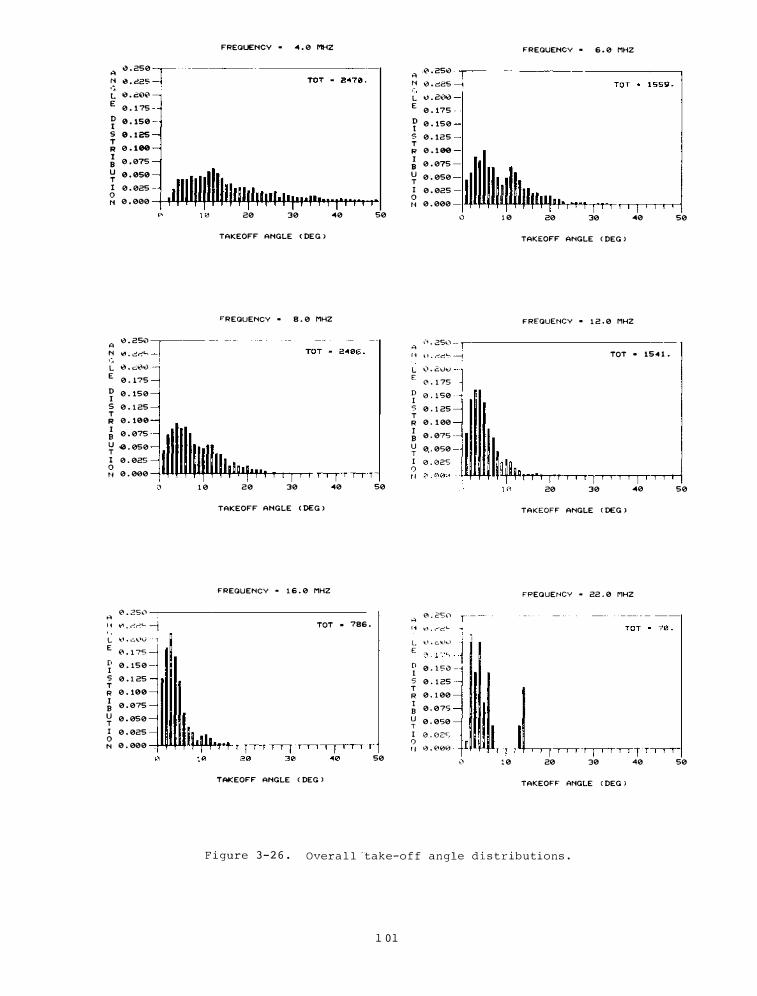
FREQUENCY . 4 . 0 MHZ FREQUENCY . 6 . 0 MHZ
A <3 . 250
A .1'\ . 250
N 0 . d25 N 0 . o<25 ·� ·�· t. 0 . C:00 L " . "''"" E 0 . 1 75 E
0 . 175 D 0 . 150 D 0 . 150 I t 5 0 . 1 25 5 0 . 125 T T R 0 . 100 R 0 . 1 00 I
0 . 075 I 0 . 075 B B u 0 . 050 u 0 . 050 T T I 0 . 025 I 0 . 025 0 0
N 0 . 000 N 0 . 000
0 1 0 20 30 40 50 0 1 0 20 30 40 50
TAKEOFF ANGLE < DEG l TAKEOFF ANGLE C DEG l
"REQUENCY . 8 . 0 MHZ FREQUENCY . 1 2 . 0 MHZ
�-� . 25\."'l --A 0 . 250 A N lt't • .::!l"1"'- " l1 . ,��� : TOT . 154 1 • ,:-, L e . c�� L '-'� · 21JI() E
0 . 175 E 0 . 1 75
D 0 . 150 D 0 . 1 50 I I 5 0 . 1 25 5 0 . 1 25 T T R 0 . 100 R 0 . 1 00 I
0 . 075 I 0 . 075 B B u -0 . 050 u 0, . 050 T T
I 0 . 025 I 0 . 025 0 0 N 0 . 000 t l
0 1 0 20 30 40 50 1 0 20 30 40 50
TAKEOFF ANGLE C DEG > TAKEOFF ANGLE C DEG >
FREQUENCY • 1 6 . 0 MHZ FREQUENCY • 22 . 0 MHZ
H � . 25ft.") " " · "'"''"' -i TOT • 786 .
.. 0 . 2Sl) --r--, . \'_, . _-·c:L
---------------- ------ --- ----
L �t.t . c.\..'V E
€\ . 1 75
L !(..t . c;.l(.llr,) E
D 0 . 150 I 5 0 . 1 25 T
R 0 . 100 I
0 . 075 B u 0 . 050 T
I 0 . 025 0 N 0 . 000
D 0 . 1 50 I s 0 . 1 25 T
R 0 . 1 00 I
0 . 075 B u 0 . 050 T I 0 . 02S 0 I I 0 . 000
0 50 ,) 1 0 20 30 40 50
TAKEOFF ANGLE C DEG > TAKEOFF ANGLE C DEG >
F i gure 3 - 2 6 . Overa l l ·take-o f f angle d i s t r ibutions .
1 0 1
ing a d e f i n i t ion of mu l tipath modes and temporal variations of ionosphe ric parame ters that would be u s e ful to pred ict error rates i n digital transmi s s ion . This model i s i n s tal led on the SANDIA Corporation computer fac i l i ty . DoE app l i cat ions inc lude SECOM mi s s ion p l anning to a s s i s t in frequency s e l e c tion and commun i cat ions f ac i l ity s chedul ing to maximi ze probab i l i t i e s o f communi cations sys tems per formance . Rea l t ime s upport applications are a l s o i ntended to a s s i s t i n ident i fying unant i c ipated propagat ion-related probl ems and to provide guidance in contro l func tions for the SECOM sys tem , part i c u l arly i n f requency s e l e c t i on and s i te antenna and proces s i n g control actions . Future app l i cations w i l l a l s o i nvo lve mul t iple parametric s o ftware control features and s i gnal d i s cr imination where intentional or unintentional inter ference events could occur .
The management model concerns prima r i l y an organ i zation o f the ope rational and funct ional timel ines for the transport operat i on s , intraconvoy commun i c ations , and SECOM sys tem . Thi s provided iden t i f ication o f normal , unintentional acc ident , and phys ical threat c i rcumstances w i th appropri ate event s iden t i f ied and commun ications support l inkage s .
The emphas i s in the management model concerns the deve lopment of the programs and s upport ing routines for the transport operations and the l inkages to the communications event mode l s . Communicat ions mod e l s i n c l ude VHF a n d t h e HF propagation modes , and sys tem scoring mod e l s for the relay s i te and veh i c l e equipments . The scoring pro c e s s deve lops the pa tterns o f d i g i t a l e r r o r s w i t h rela tion to t h e addre s s , ver i f i c at ion/authentication , a n d d a t a components . Thi s segmentation is necessary to a l low d i re c t coup l i n g to the operations event model and , i n the case of a phy s i c a l threat s i tuation , deve lop commun i c ations per formance relat ionships for s upport forces and units that protec t the transport vehic l e s .
S ince the communications s upport to the transport veh i c l e s must i n c l ude the mul t i convoy commun ications operation s , the even t and techn i c a l charac ter i s t i c mod e l s f o r t h e VHF sys tems h ave a l s o b e e n des i gn ed . This sys tem has only vo i c e mode w i th l i t t l e protection from external deception or inter ference . D i f ferent modes of operation i n c l ud ing r e l ay con f i gurations have been exami ned , and recommendations s ubm i t ted indicating rel i ab i l i ty advantages for d i f f erent opt ions i n procedure and con f i gurat ion . The b a s i c management mode l organ i z a t ion i s d iagrammed i n F igure 3 - 2 7 .
The S P S EMC A s s e s smen t P ro j ec t has as i t s obj e c tive a prel iminary a s s e s sment o f the impact of operation of a Solar Power Satell ite ( S P S ) on the ionosphere , a tmo sphere ,
and telecommuni c ation sys tems . The results o f the s tudy undertaken i n s uppo rt o f thi s pro j ec t indica ted that s i gn i f icant e ff ec t s t o t h e ionosphere and tele commun i ca t i on sys tems a s s o c i ated with SPS opera t i on could give r i s e to ionospher i c heating and the high energies a s s o c i a ted wi th the SPS power beam could result i n s i gn i f i cant interference to a number of te l ecommun i c a tion use r s .
As a r e s u l t o f the prel iminary s tudy conducted by ITS , the Depar tmen t of Ener gy imp l emented a deta i l ed techn i c a l program of research and deve lopmen t a imed a t e s tabl i s hi n g the environmental impact of SPS operation . ITS has program management re spon s i b i l i ty for the I onosphe r i c Mod i f i cation a s pects o f SPS . This work i s carried out under the SPS Ionosphe r i c Mod i f i cat ion Pro j ect .
The S o l a r Power Sate l l i te i s envi s i oned to operate a t a frequency o f 2 . 4 5 GHz s upplying between 5 to 1 0 GW o f power to a ground receive r s i te . The sys tem concept u t i l i z e s a s a te l l i te i n geosynchronous orb i ts that conve r t s solar rad i an t energy to microwave energy . T h i s microwave energy i s transmitted from the sate l l i te to a ground station and then i s converted in de power and p a s s ed through a power grid .
The l a r ge amoun t s of energy i nvo lved can g ive r i s e to s i gni f i cant ionosphe r i c heating and s ubsequent modi f i c a t i o n . As part o f the s upport ITS is providing to DoE , a commi ttee o f nation a l l y prominent experts has been fo rmed ( under ITS c h a i rman s h i p ) t o d evelop a nationally o r i ented program devoted to a s s e s s the imp a c t of t he S P S ope ration on t h e ionosphe r e a n d t e l e commun i cations users whose sys tems are impacted by the ionosphere . It i s a n t i c ipa ted that the ITS operated P l a t tevi l l e Heater Fac i l i ty wi l l b e u t i l i zed t o s imu late S P S heating e f fe c t s . Work i s being undertaken to define the character i s ti c s o f the heater f ac i l i ty i n order to a s s ure that the energy leve l s emp loyed i n ground -based s i mu l a t ions o f SPS operation are commen s ur a te w i th SPS power leve l s .
ITS i s a l s o working in con j un c t ion w i t h NOAA a n d NCAR t o deve lop r e a l i s ti c , accurate nume r i c a l mod e l s o f the ionosphere and its variations under cond i t ions o f intense i onosphe r i c heat ing . These mode ls are used i n con j unction w i th tele commun ic a t i ons ' sys tem s imul a t ion progr ams to determi n e , f rom a theoreti c a l vi ewpo i n t , SPS impac t on the per formance o f s e l e c ted radio c i rc u i t s .
SPS H I Q S tudy . The que s t i o n was r a i s ed as-to-whether local free space f i eld strength maxima ( hot spot s ) i n s ide habitable s tructures expo s ed to 2 . 4 5 GHz SPS rad i a t i on can e xceed the u n i form power den s i t y o f the inci dent trave l in g S P S coherent p l ane wave radiation .
1 0 2
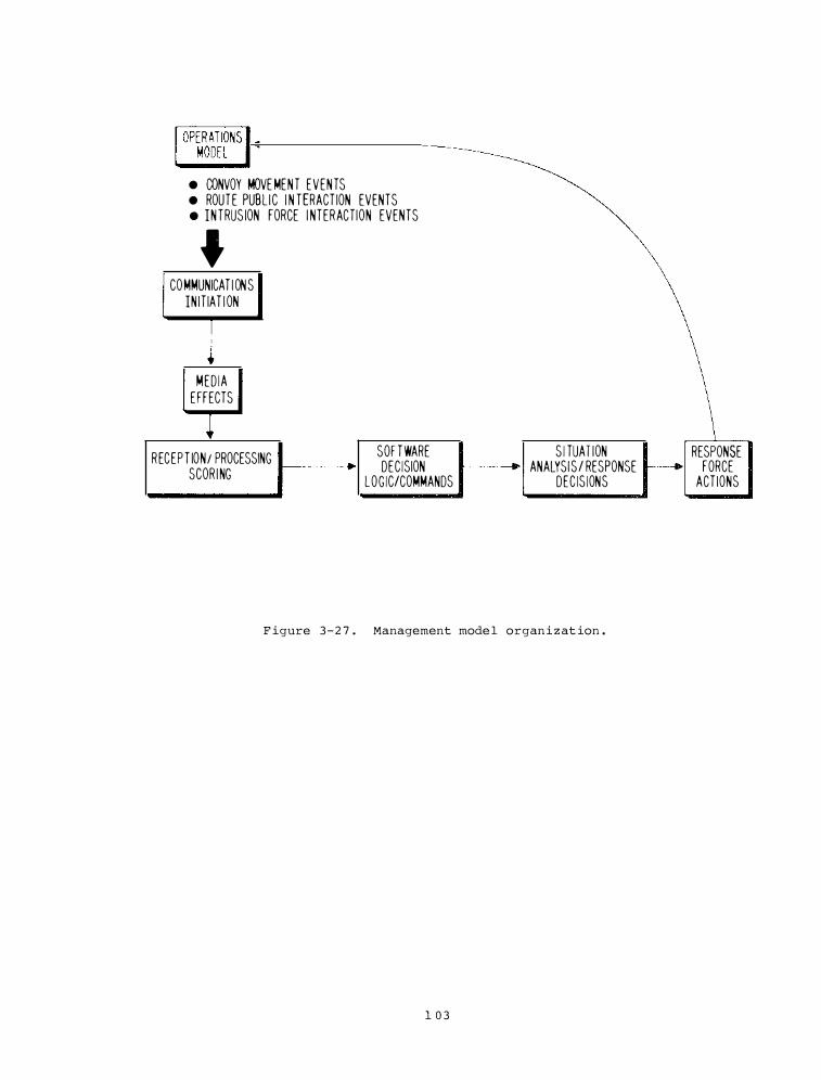
• CONVOY MOVE MENT EVENTS • ROUTE PUBL IC I N TERACT ION EVENTS • INTRUS ION FORCE I NTERACTION EVENTS
• COMMUNICAT I ONS
IN IT IAT I ON
MED IA
EFFECTS
RECEPT ION/ PROCESSING II----_.
SCOR I NG
SOF TWARE S I TUAT ION RESPONSE DEC ISION IIJ---+ ANALYSIS / RESPONSE 11---_.1 FORCE
LOG IC/COMMANDS DEC IS IONS ACT IONS
F igure 3 - 2 7 . Management mode l organ i z at ion .
1 0 3
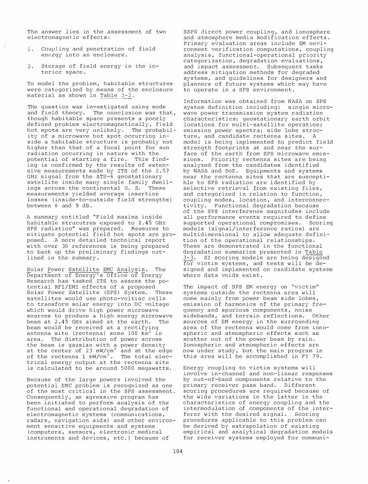
The an swer l i e s in the a s s e s s ment of two e l e c tromag netic e f fec t s :
1 . Coup l ing and pen etration o f field energy into an enc losure .
2 . Storage o f f i e ld energy i n the i n t e r i o r s pace .
To mode l the prob l em , habitable s tructures were catego r i zed by means o f the enclo s ure mate r i a l a s shown in Tab l e 3 - 2 .
The que s t ion was i nves t iga ted u s i n g mode and f i eld theory . The conc l u s ion was that , though hab i table space presents a poorly de f i ned problem e l e c tromagne t i c a l l y , f i e l d h o t s p o t s are very u n l i k e l y . The probab i l i ty o f a microwave h o t s p o t occurring i n s ide a habi table s truc ture i s probably not h i gher than that o f a focal point for sun rad i a t i on occurring in na ture w i th the poten t i a l of s tarting a f i re . Thi s f indi n g is con f i rmed by the r e s u l t s o f extens i ve measurements made by ITS of the 2 . 5 7 GHz s i gnal from the ATS - 6 geostati onary s a te l l i te i n s i d e many s i ng l e family dwe l l ings acro s s the continental U . S . The s e measurements yi e lded average i n s ert ion l o s s e s ( in s i de - to-outs ide f ie ld s trengths ) be twe en 6 and 9 dB .
A summary e n t i t l ed " F ie l d maxima i n s ide habitable s trucutres e xpo sed to 2 . 4 5 GH z SPS rad i a t i o n " was prepared . Measures to m i t i gate poten t i a l f i e l d hot spots are proposed . A more d e t a i l e d techn ical report wi th over 30 re ferences is being prepared to back up the prel iminary f i nd ings outl i ned i n the summary .
Solar Powe r Sate l l i te EMC Analys i s . The Department o f Energy ' s O f f i c e o f Energy Re search has tasked ITS to a s s e s s the potential RF I /EMI e f f e c t s of a propo sed S o l ar Power Sate l l i t e ( S PS ) System . The s e s a te l l i tes wou ld u s e photo-vo l ti a c c e l l s t o trans form solar energy i n to D C vo l tage wh i c h would dr ive h i gh powe r microwave sources to produce a h i g h energy microwave beam at 2 . 4 5 GH z a imed at the earth . The beam would be rece ived at a r e c t i fying antenna s i te ( rectenna ) some 1 0 0 km 2 i n area . The d i s tribut ion o f powe r across the beam is gau s i a n with a powe r dens i ty a t the center of 2 3 mW/cm 2 and at the edge o f the rectenna 1 mW/cm 2 • The total e l e c t r i c a l energy output a t the rec tenna s i te is ca l c u lated to be around 5 0 0 0 megawatts .
Because of the large power s i nvolved the po tent i a l EMC prob lem i s recogn i z ed a s one o f the mo s t c r i t i c a l in the SPS a s s e s sment . Consequent l y , an agre s s ive program has been i n i t i ated to per form analys i s o f the functional and operational degradation o f e l e c tromagne t i c s y s tems ( commun ications , radar s , navigation a id s ) and other environment s e n s i t ive equipments and sys tems ( computer s , s en s ors , e l e c tronic med i c a l i n s truments and device s , e tc . ) because o f
1 0 4
SSPS d i r e c t powe r coupl i n g , a n d i onosphere and atmosphere med i a mod i f i c a ti o n e f f ects . P r imary evaluat i on areas i n c l ude EM envi ronment ver i f i cation compu t a t i on s , coup l i ng analy s i s , func t iona l -oper a t i on a l p r i o r i ty cat egor i z a t ion , degrada t i on eva l u a t ions , and impact a s s e s smen t . S ub s equent t a s k s addr e s s m i t igation methods for degr aded sy s tems , and guide l i n e s for d e s igners and pl anners o f future sys tems wh i c h may have to operate in a SPS envi ronme n t .
I n forma t i on wa s obtained from NASA on SPS sys tem d e f i n i tion i n c l ud i n g : s in g l e microwave power transmi s s i on s y s tem r a d i a tion character i s t i c s ; geostationary earth orb i t locations f o r mul t i - s a te l l i t e operation ; emi s s ion power spectra ; s i de lobe s tructure , and candidate rectenna s it e s . A mod e l i s b e i n g imp l emented to predict f i e ld s trength footpr ints at and near the surface o f the earth from SPS m i c rowave emi s s ions . P r i o r i ty rectenna s i te s a r e b e i ng analyzed f rom the candidates i de n t i f i ed by NASA and DoE . Equipme n t s and s y s tems near the rectenna s i te s th at are sus cept i ble t o S P S radiation a r e i de nt i f i e d by s e lect ive retrieval from e x i s t i n g f i l e s , and catego r i z e d i n r e l a t ion to funct i on , coup l i ng mode s , location , and i n terconne ctivi ty . Func tional degrad a ti o n because o f the S P S inter ference mag n i tud e s i n c lude all per formance events required to d e f ine s uppor ted operational comp romi s e s . Scor i ng mod e l s ( s i gn a l / i n ter ference r a ti o s ) are mu l t i d i me n s ional to a l l ow adequate d e f i n i t i o n o f t h e operational r e l at ionshi p s . The s e are demons trated i n the funct ional degrad a tion s umma r i e s presented in Table 3 - 3 . SI scoring mode l s are b e i n g de s i gn ed for v i c t i m sys tems , and t e s t s w i l l be des i gned and imp l emented on candidate sys tems whe r e d a t a vo i d s exi s t .
The impa c t of SPS EM energy on " v i c t im " sys tems outside the rectenna a r e a wi l l come mainly f rom power beam s ide lobe s , emi s s i o n o f harmon i c s o f the p r imary frequency and spurious compone n t s , no i s e s i deband s , and terra i n r e f l e c t ion s . Other sour c e s o f EM energy i n the s urroun d i ng area o f the rec tenna wou l d come f rom i on osphe r i c and atmosphe r i c e f f e c t s s uc h as scatter out o f the power beam by rai n . Iono spher i c and atmospher i c e f fe c t s are now under s tudy , but the ma i n program in th i s area wi l l be accomp l i shed in F Y 7 9 .
Ener gy coup l i n g to v i c t i m s y s tems w i l l i nvolve i n - channel and non- l i near responses by out-of -band components r e l a t ive t o the primary rece iver p a s s band . D i f ferent scor i ng procedures are required because of the wide variations in the l a t ter in the character i s ti c s o f energy coup l i n g a nd t he intermodulation of compone n t s o f the interferer w i th the des i red s i gnal . Scoring proc edures appl icable to thi s problem can be d e r ived by extrapo lation o f exi s t i ng emp i r i c a l and analyt i c a l degrad a t i on mod e l s for rece iver sys tems emp loyed f o r commun i -
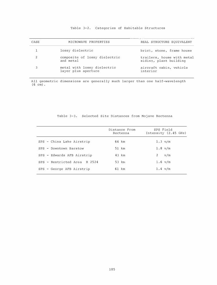
CASE
l
2
3
Tab l e 3 - 2 . Categor i e s of Habi table S t ructures
MICROWAVE PROPERT I E S
lo s s y d i e l ec t r i c
compo s i te o f l o s s y d i e l e c t r i c and me ta l
me t a l with l o s s y d i e l e c t r i c layer p l u s aperture
REAL S TRUCTURE EQUIVALENT
b r i c k , s tone , frame hou s e
t r a i l e r s , house w i th metal s i d i n g , plant bu i ld i ng
a i rc r a f t cabi n , veh i c l e i n t e r i o r
A l l geome tric d imen s io n s are gen e ra l ly much l a r g e r t h a n one ha l f -wave l ength ( 6 em) .
Tab l e 3 - 3 . S e l ected S i t e D i s tances from Mo j ave Rectenna
D i s tance From S P S F i e l d Rectenna I n t en s i ty ( 2 . 4 5 GH z )
S P S - China Lake A i r s t r ip 6 4 km 1 . 3 v/m
SPS - Downtown Bars tow 5 1 km 1 . 8 v/m
S P S - Edwards AFB A i r s t r ip 4 3 km 2 v/m
S P S - Re s tr i c ted Are a R 2 5 2 4 5 3 krn 1 . 6 v/m
SPS - George AFB A i r s tr ip 6 1 km 1 . 4 v/m
1 0 5
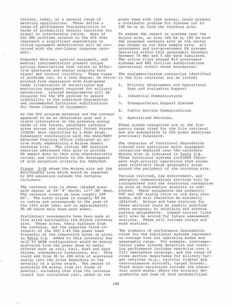
cations , radar , or a general range o f me tering app l i c a t i ons . The se d e f ine a range o f per formance character i s ti c s i n terms o f probab i l i ty den s i ty func tions for s i gna l to i nterference ratios . Mo s t of the EMC prob l ems re lated to the SPS that repre sent a s i gn i f icant expendi ture in victim equipment mod i f i c a tion wi l l be concerned w i th the non- l inear response category .
Compu ter devi c e s , opti c a l equipment , and med ical ins trumentation present unique scoring descr ipt ives that relate to e f fect ive apertures and energy coup l ing i n to s i gnal and control c i rcui try . These types o f probl ems c a n , to a l e s s degree , be extrapolated from experience w i th hi gh-power radar i l lumi nation of surve i l lance and mon i toring equ ipment required for m i l i tary operat ions . Limi ted mea surements w i l l be required for the S P S prob l em to a s sure cred ibil ity in the pred i ct ed d egradation and recommended functional mod i f ic a t ions for the s e c l a s s e s of equipmen t .
A s the SPS program advanced and the concept appeared to be an obta inable goal and a viable a l t ernat ive to the pres s i n g energy needs o f the future , candidate r ec tenna s i t e s across the continental United States ( CONUS ) were iden t i f ied by a NASA study .
Subsequent coord ination w i th the NASA/MSFC Advanced P l anning O f f i c e i nd i c ated an act ive study empha s i z ing a Mo j ave desert rectenna s i te . The initial EMC ana l y s i s exerc i s e addressed this s i t e to provide EM impac t data to this s i te charac ter i s t i c review , and contribute to the development o f s i te s e l ec t ion cr i teria for NASA/DoE .
F i gure 3 - 2 8 s hows the Mo j ave s i te and the surround ing area wh ich wou ld be impacted by SPS emi s s ions outside the rec tenna enclosure .
The rect enna s i te i s s hown ( shaded area ) with center at 3 5 ° 8 ' North , 1 1 7 ° 3 0 ' Wes t . The rectenna cover s an area roughly 1 0 0 km 2 • The outer e l ipse i s roughly 4 9 km in radius and corre s ponds to the peak o f t h e l O th s ide lobe , a n d i s approx ima tely 4 5 dB below ma in beam peak power .
Prel iminary a s s e s smen t s have been made a t five s i t e s s urround ing t h e Moj ave rectenna s i t e . Those s i te s , their d i s tance f rom the rec tenna , and the expec ted f i e l d intens i ty o f the SPS 2 . 4 5 GHz power beam frequency at the respect ive s i t e s is given in Tab le 3 - 3 . Added t o thi s intens i ty due on ly-to--beam c o n f i guration would be energy scattered from the power beam by med i a e f fects such a s rain , h a i l , d u s t and sand storms , atmosphe r i c turbu l enc e , etc . This could add from 20 to 1 0 0 mV/m o f scattered energy into the s i tes depending on the severity o f a g iven s torm . The amount o f potential E M energy f rom a l l forms o f scatter , inc lud ing t h a t f rom t h e rec tenna i t s e l f ( not c a l cul ated y e t ) , added to the
power beam s ide lobe energy , could present a formidable probl em for sys tems out to 1 0 0 km or so from the rectenna s i te .
To a s s e s s the impac t on systems near the Mo j ave s i te , an area 1 4 5 km by 1 4 5 km w i th the propo sed rectenna s i te at the center was chosen as our data s ampl e are a . A l l government and non-government EM systems operating w i th i n this geograph i c boundary be tween 7 5 MH z and 5 GH z were tabu l ated . The active f i le s s howed 8 1 3 government systems and 6 8 5 civi l i an autho r i z at i ons operational within the s e boundaries .
The equipment/sys tem c ategor i e s ident i f ied in the f i l e retr ieval are a s l i s ted :
1 . M i l i tary Development and Operational T e s t and Eva luation S upport
2 . I ndustrial Communi c a t ions
3 . Transportation Support Sys tems
4 . Publ i c Service Commun i ca t i ons
5. S pec i a l i zed Servi c e s .
The s e sys tem categor i e s a r e i n the frequency r ange c i ted for the f i l e retrieval and are susceptible to SPS power den s i t i e s previous ly d i s p l ayed .
The character of f unc t i o n a l degradation induced i nto particular ma j or equipment catego r i e s dep loyed near the candidate Moj ave s i te is indicated i n Table 3 - 4 . Tho s e functional systems i n c luded r epresent high p r i o r i ty operat ions that encomp a s s rel ative ly large geographi c areas around the per iphery o f the rec tenna s i te .
Var ious r a i l road , l aw enforcemen t , and emergency communications s ervices w i l l be i ncorporated into the func t ional c ategor i e s a s soon as degrada tion analy s i s i s comp l eted . The s e equipments u s e presently VHF and UHF analog voi c e or low data rate modes , and will therefore be m i n ima l l y affected . Re lays and b a s e s ta tions for the s e servic e s could be r e ad i ly mod i f ied where necess ary by s h i e l d i n g and antenna pattern ad j us tmen t s . Common c a r r i er l inks wi l l a l s o be scored for future a s s e s sment analy s i s . The s e w i l l i n c l ud e r e l ays and mode station s .
The e l ement s of per formance degradation c i ted for the func t ional sys tems repre s en t a n average over a l l oper a t i n g modes and geograph i c r ange . For exampl e , i n s trumentation r adar sys tems detect i on and tracking per f ormance inc ludes oper a t i on over a f u l l hemi sphere coverage , and the r ange o f cro s s section magni tudes for m i l i ta ry target veh i c l e s ( e . g . , t a c t i c a l f i ghter and recon n a i s sance a i rcra f t , target drones ) . Track score var i a t ions i n c l ude low e levation angle mode s , whe r e the accur acy degrada t i o n and l o s s o f lock probabi l i ti e s
1 0 6
N
1
I I P30
F igure 3 - 2 8 . P roposed Mo j ave rectenna s i te .
1 0 7
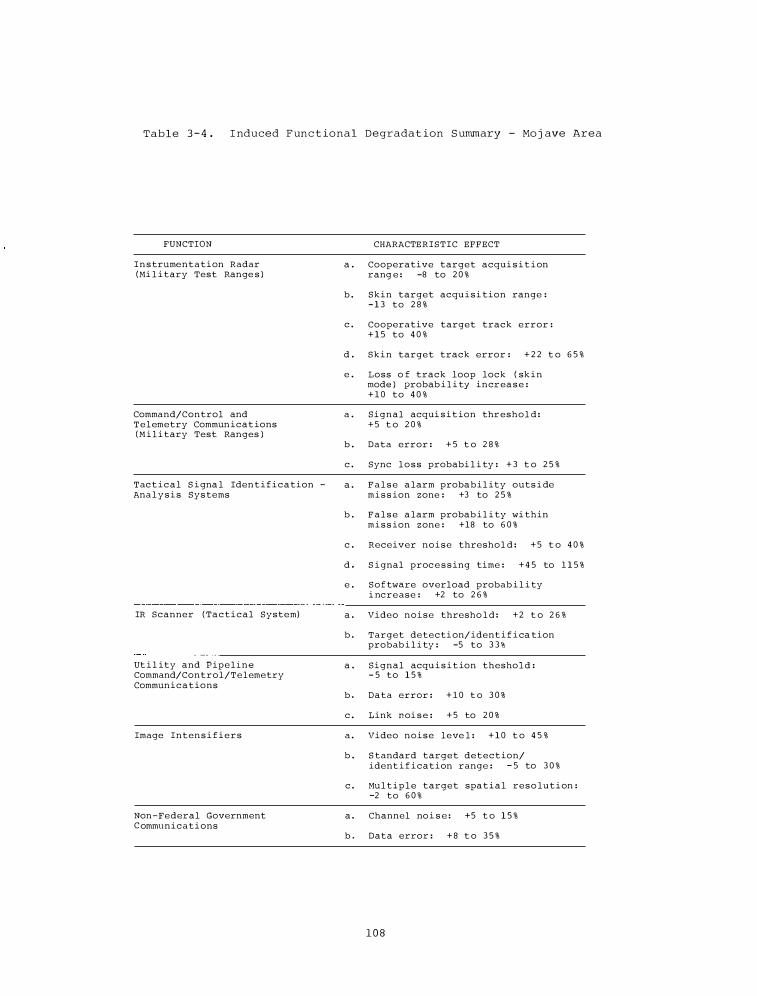
Table 3 - 4 . I nduced F unc t ional Degradat ion S ummary - Mo j ave Area
FUNCTION
I n s trumentation Radar (Mi l i tary Test Range s )
Command/Control and T e l emetry Commun icat ions ( M i l i tary Test Ranges )
Tac t i c a l S i gna l Iden t i f i c a tion -Ana l y s i s Sys tems
-------·----------
IR Scanner ( Ta c t i c a l System)
Ut i l ity and Pipe l i n e Command/Control/Telemetry Commun i c a t ions
Image Inten s i f i e r s
Non -Federal Government C ommunicati ons
CHARACTE R I S T I C EFFECT
a . Cooperative target acqui s i t i on rang e : -8 to 2 0 %
b . Skin target acqu i s i tion range : - 1 3 to 2 8 %
c . Cooperative target track error : + 1 5 to 4 0 %
d . S k i n target track error : + 2 2 t o 6 5 %
e . Loss o f track loop lock ( sk i n mode ) probab i l i ty incr ea s e : + 1 0 to 4 0 %
a . Signal acqui s i t ion thr esho l d : + 5 t o 2 0 %
b . Data error : + 5 t o 2 8 %
c . Sync l o s s probabi l i ty : + 3 t o 2 5 %
a . F a l s e a larm proba b i l ity outs i de m i s s ion zone : +3 to 2 5 %
b . F a l s e a larm probab i l i ty wi thin m i s s ion zone : +18 to 6 0 %
c . Receiver n o i s e thresho l d : + 5 t o 4 0 %
d . S i gnal proc e s s ing time : + 4 5 to 1 1 5 %
e . S o f tware overload probab i l i ty i nc r e ase : +2 to 2 6 %
a . Video n o i s e thresho l d : + 2 t o 2 6 %
b . Target detecti on/ ident i f i ca tion probab i l i ty : -5 to 3 3 %
a . Signal acqu i s i t ion thesho l d : - 5 to 1 5 %
b . Data error : + 1 0 t o 3 0 %
c . Link noi s e : + 5 to 2 0 %
a . Video n o i s e leve l : + 1 0 t o 4 5 %
b . S tandard target detection/ ident i f i cation range : - 5 to 3 0 %
c . Mu l t i p l e target spa t i a l res o lu t i on : -2 to 6 0 %
a . Channel no i s e : + 5 t o 1 5 %
b . Data error : + 8 t o 3 5 %
1 0 8
expand by greater mar g i n s becau s e o f propagation f a c tor s . On-axi s radar c o n f igurations a r e a l so repres ented s i n c e th i s mode wi l l probably b e i ncreas ingly employed for these test range appl i c a t i on s . The track e r ror scores i n c lude normal smoo thing , pred i c t ion f i l t e r i n g , and coordinate compu tations i n r e a l t ime and postm i s s ion proc e s s i n g so f twa r e .
The commun i cat ions sys tem degradat i on c i ted i n c lude s i ngle c hanne l , and frequency and t ime-mu l t i p l exed un i t s operated by the mi l i tary t e s t range s , the S tate of C a l i forn i a , l o c a l county and mun i c i pa l governmen t s , and r e source control and service indus t r i e s .
These ope r a t i o n a l c omprom i s e s and the spec i f i c areas o f func tional degradat i on wi l l b e expanded t o provi d e the ba s i s for s ubsequent r e commendations in equipmen t and sys tem operations to a s sure an acceptable level o f per formance when i l l umina ted by th i s h i gh power sour c e .
For t h i s Mo j ave s i te and others having a s i m i l a r ope r a t i o n a l m i l i ta ry/c i v i l sys tem rat i o , mod i f i c ation recommend ations w i l l emph a s i z e t h e c iv i l ian area . Suppor t equipment ( e . g . , radars , t e l emetry , TV , e tc . ) can be mod i f i ed for oper a t ion w i t h i n a r a n g e o f 4 0 - 5 0 km f rom the r e c tenna s i te , a s s uming no med i a induced i n s tabi l i t i e s i n the S P S array contro l . M i l i t ary oper a t i on a l EM sys tems cannot be mod i f i ed because o f the unacceptable p robab i l i ty o f operat i o n a l c omprom i s e ; sys tem per formance or procedures in the T e s t and Evaluation exe r c i s e s wou ld have l i tt l e or a deceptive re l a t ion to combat operations .
Muc h of the ma j or work of t h i s present program wi l l be a c comp l i s hed i n FY 79 inc l uding the deve lopmen t o f m i t i g a t i n g strate g i e s t h a t wou ld a l low mo s t c l a s s e s o f sys tems to operate s a t i s f a c to r i ly i n an S P S induced E M env ironment .
The pre l iminary a s s e s sment of S P S m i c r o wave emi s s i ons on " v i c t im " systems a s given here d emons trate the operational d e gradation that would occur to e l ectroni c s y s tems i n t h e S P S generated envi ronment within approxima t e ly 1 0 0 km of the r e ctenna s i te . The Mo j ave s i te eva luation s hows a wide range o f per formance degrada t i o n , p a r t i c u l a r l y i n tho s e sys tems operated by the mi l i tary . The ba s i c functional and ope r a t i o n a l impac ts of SPS are o f such magni tude that i n many i n s tanc e s they r e p r e s e n t u n a c c eptable or impo s s i b l e compromi s e s and b i a s e s to p roper t e s t and evaluation exer c i s e s per formed by the involved f ac i l i t i e s .
As men t ioned previou s l y , the eva l u a t i on o f the Moj ave c andidate r e c t enna s i te provided impact data to NASA and contr ibuted to e s t ab l i sh i n g s i te s e l e c t ion and eva luation c r i t e r i a , and a l l owed a l imited exer c i s e
1 0 9
of the data retrieval and analys i s procedures req u i r ed for the EMC analy s i s of a l l candidate CONUS s i t e s . Thi s Mo j ave s i te o r i g i n a l l y cons idered by NASA a l lowed a reasonable rectenna i s o l at i on from areas of even mod e s t population dens i ty , but presents s e r ious i n terference impac t s upon sur face and a i r c r a f t e l e c tronic systems . At this s i te , mi l i tary operations represent the ma j o r i ty of the inter ference probl ems , the degraded s y s t ems being i n tegral components o f comp l e x Development and Ope rational Test and Eva luation prog rams . The s e mi l i tary programs requ i r e the degree of i s o l a tion a f f orded by the Mo j ave region .
Based on the probable operational system degradat ions near the Moj ave s i te and the inabi l i ty to e s tab l i s h mitigating s trategies wi thout unacceptab l e probab i l i ty of operat ional compromi s e , a second s i te nor th and e a s t o f the o r i g i nal s i te was propo sed by ITS . A cur sory look at the " vi c tim" sys t ems surround ing the new s i te indicates d i f ferent func tional c l a s s e s whi c h l e n d thems elves to m i t i gating strateg i e s . Mod i f i c a t ions to most o f these equ ipments could be ac comp l i shed to produce compati bi l i ty in the SPS generated environmen t s .
The func tional degrada t i on of m i l i tary , non-de fense gove rnment , and commer c i a l sys tems i n t h e Mo j ave a r e a i s bas i c a l ly charac t e r i s t i c o f the e f fects that w i l l be encoun tered i n other CONUS areas . Operational imp l i c at i ons and therefore the a s s o c i a ted ec onomic impact wi l l vary s i g n i f i c antly b e c a u s e o f t h e d i f fe r i n g organ i z a t ions and sys tems s upported by the degraded equi pments . Operational- func tional rel ationships wi l l exhi b i t d i f fering sens i t i v i t i e s .
The Mo j ave area lends i t s e l f we l l to res i t ing because o f the large expan s e of open , f l at t e r r a i n . The deve lopmen t o f n e w s i t e s i n mo s t geograph i c a r e a s would not be a s s i mp l e , i f not impo s s i b l e , due to popul a t i o n d e n s i ty , terrain features , " v i c t i m " sys tem dens i ty , etc .
Gener a l ly the northern and eas tern CONUS regions w i l l have a sma l l e r mi l i tary-non defense equ ipme n t concentration in the rectenna areas than the o r i g i n a l Mo j ave s i te r ev i ewed . The s e r e gions w i l l a l so inc lude ma j o r transportat ion and comme rc i a l communi c a t i ons fac i l i t i e s . Because o f the popu lation and bus i n e s s dens i t i e s , the to t a l number of a f f e c ted systems i n the various ope rational c ategor i e s w i l l b e larger .
A v a l i d demon s tration o f rec tenna s i te EMC analys i s and impact eva l uation has been deve loped . Thi s has shown to be fundament a l in mak i n g s i te s e l e c t i ons , w i l l help determine system p e r formance impacts , and help develop m i t i g a t i ng s trategies for v i c t im sys tems . Seve r a l s i te evaluations
in various geograph i c a l locat ions , par t i cularly in northern and e a s tern CONUS regions wi l l be c a rr i ed out to e s t ab l i sh a data base to be u s ed in setting s i te s e l e c t i o n cr i te r i a and geograph i c a l ly or iented mitigating s tr a teg i e s .
RADC Consul t ing . The U . S . Air Force i s deve loping d i g i ta l commun icat ion equipment for app l icat ion to tropospheric s catter radio systems in Europe . This pro j ec t i s a con s u l t ing and advi sory e f fort t o a s s i s t the A i r Force in testing and evalua t i n g t h e communications equipment , and i t s performance over the propo sed l i nks . The work is performed as reque sted by RADC , and invo lves a broad spectrum of expe r t i s e from t h e ITS sta f f .
Mic rowave Propagat ion for D i g i t a l Rad i o . The U . s . Navy Pac i f i c Mi s s i l e Test Center ( PMTC ) at Pt . Mugu , C a l i fornia oper ates a
network of microwave and other commun i c a tion sys tems i n support o f t h e t e s t center mi s s i on s . Future plans for the mic rowave sys tem inc lude convers ion to a l l d i g i ta l tran smi s s ion . However , some o f t h e l i nks are over-water paths extending f rom h i gh locations a long the coast to termi n a l s in the Channel I s lands .
From past exper ience , i t i s known that severe propagation cond i t ions exi s t in the P t . Mugu region . These cond i t ions are prima r i l y caused by meteqro logical factors such a s deep r e fract ive layers w i th very h i gh negat ive gradients . The s e layers develop due to a h i gh marine l ayer o f a i r at the c o a s t l i ne . The propagation i s characteri zed b y deep s i gnal fading , caused by a mixture of power fading and mul t i path s i gnal s . In o rder to de termine the d i g i t a l d a t a rate t h a t the se c ircuits w i l l support under such condi t ions , the I T S was tasked by the PMTC to conduct some experi ments over a l i nk be tween Laguna Peak and S an N i cholas I s land , a d i s tance o f approximately 65 mi l e s over water . The exper iment con s i s ted of three meas urements as f o l l ows :
1 . The impu l s e response o f the tran smi s s ion channe l .
2 . B i t -error-rate ( BE R ) per formance measurements .
3 . Fading s t a t i s t i c s on a pair o f rec e iving antennas oriented for angle divers i t y .
The f i r s t two measurements were per formed u s i ng the ITS p seudo-random n o i s e ( PN ) probe ( R . F . L i n f i e l d , R . W . Hubbard , and L . E . Pratt , " Tr ansmi s s ion Channe l Chara c ter i za t ion b y Impul s e Re sponse Mea s urements , " OT Report 7 6 - 9 6 , 1 9 7 6 ) . The b i nary bit stream u s e d as t h e test s i gnal i n th i s ins trument i s corre l a ted w i t h a replica si gna l at the rece iver to deve lop the impu l s e response . Thi s output of the rece iver ind i cates mu l t ipath reception
dire c t ly in the t ime doma i n , and at a data rate that can be conven iently recorded on analog magnetic t ape . The pr imary data from this phase o f the mea s urements uses a clock rate of 1 5 0 Mb/ s , providing a total resolution of approxima tely 6 ns in the impu l s e response . However , d e l ayed components l e s s than this va lue are e a s i l y d i s t ingu i s hed in t h e outpu t . T h e s ame b i t str eam i s detected from t h e h i -phase mod u lated s i gna l , and f e d to a commercial error ana l y z er for the s econd pha se above . In this c a s e , the c lock rate o f the system was reduced to ei ther 10 Mb/ s or 50 Mb/s ; rates that are more commensurate with the des ired data rate for the proposed PMTC sy s tem . However , the resolut i on of the impul s e re sponse is l e s s at the lower c lock rate s . There fore , mo s t of the data were measured i n tandem bloc k s . The h i gh c lock rate was f i r s t used to observe channel cond i t ions for a period of t ime , the c lock rate was then reduced to obtain a me as ure o f BER performance under the varying cond i tions .
Mea surements we re be gun i n August 1 9 7 8 to capture the wor s t propagation cond i t ions that have h i s t o r i c a l l y preva i led dur ing that month . The meas urements w i l l not be completed unt i l early in the c a l endar year 1 9 7 9 . Prel iminary analys e s o f the Augus t data ind i cate that the s trong surface duc t s in the region g ive r i s e to very s evere mul t ipath propagation a s we l l a s f l a t power fading . Delay s o f up to 2 0 n s h ave been obs erved in the impu l s e data for the multipath components . I n add i tion , i t i s frequently found that t h e d e l ayed component is of much greater magn i t ude . The t ime var iabi l i ty i s a l s o a s i gn i f icant f ac tor , as the s tronger component both leads and lags in the response . Changes o f this type cause synchron i z ing problems in d i g i t a l systems . I t appe ars that space diver s i ty i s e f fec tive mo s t of the t ime . However , there are occasions when the mu l ti path structure is obs erved on the spaced receiving antennas almo s t s imul t a neous ly . D a t a f rom t h e t i l ted beam expe r i ment have n o t been ana l y z ed a s yet . These results wi l l be pub l i s hed in a f inal report in FY 7 9 . An e xamp l e o f the impul s e response during a short per iod of s trong mul tipath i s shown in F igure 3 - 2 9 , whi ch presents a sequence o f responses measured 1 0 0 ms apart .
3 . 5 . 3 . C C I R Parti c ip ation
Support to the I n ternational T e lecommunications Union ' s ( I T U ) adv i sory I n te rnational Radio Cons u l tat ive Committee ( C C I R ) w a s provided b y ITS personnel in t h e f i e l d s o f tropo spheric ( S tudy Group 5 ) and ionospheric ( S tudy Group 6) propagation . The U . S . National Cha i rmen of C C I R S t udy Groups 5 and 6 , Drs . H . T . Dougherty and C . M . Rus h , are both members of I TS ' s App l i e d Electromagnetic S c i e nce D i vi s ion .
1 1 0
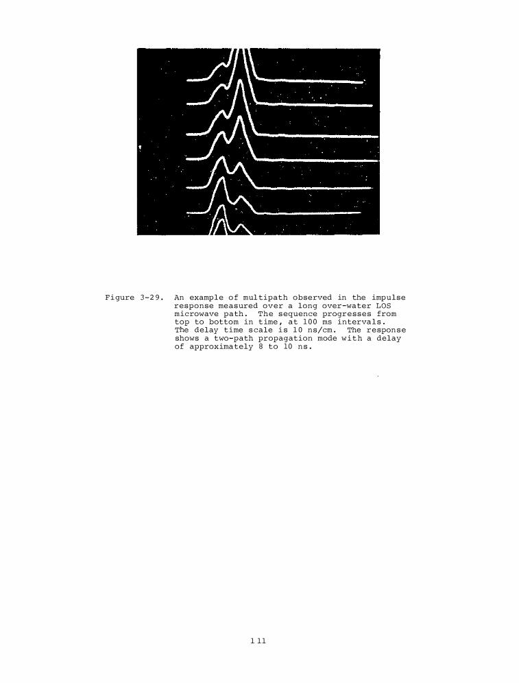
F i gure 3 - 2 9 . An example o f mul tipath observed in the impulse response measured over a long over-water LOS microwave path . The s equence progresses from top to bottom in t ime , at 1 0 0 ms interva l s . The delay time s cale i s 1 0 ns/cm . The respon s e shows a two-path propagation mode w i t h a delay of approxima tely 8 to 10 n s .
1 1 1
In add i t ion , numerous ITS personne l ac tive ly partic ipate in the CCIR . For e xamp l e , at the F i n a l Mee t i ng o f S tudy Group 6 held at Geneva i n January 1 9 7 8 , there were four ( 4 ) ITS s ta f f personn e l a s members of the
U . s . d e l egat ion (which totaled 9 ) .
Are a s of s pe c i f i c concern to CC I R in wh ich ITS per sonne l play key roles i n c l ude : iono spheric mapp i ng ; ionosphe r i c operational cons ideration s ; s kywave field s trength c a l cu l ations at frequen c i e s above 1 . 6 MH z ; mic rowave sys tem d e s ign ; fading phenomenon on LO S l inks ; the role o f ra i n f a l l in mic rowave sys tem per formanc e and interferenc e ; and the ionosphe r i c and troposphe r i c a s pects o f r a d i o n o i s e .
ITS personnel part i c i pated in the International T e l ecommunications Union ( I T U ) Advi sory I nternational Rad io Consultat ive Commi ttee ( C C I R ) XIV P l enary A s s emb ly that was held at Kyoto , Japan , i n June 1 9 7 8 . F i gure 3 - 3 0 is a photograph o f part o f t h e U . S . d e l e gation to that meeting .
I n add ition , ITS personnel have been particularly act ive i n the preparations for the CC I R Spec i a l Preparatory Meeting ( SPM) scheduled for Geneva i n Oc tober and November 1 9 7 8 . These preparations inc luded the a s s emb ly of U . S . document s a s i nputs to the S PM and the rev i ew o f i nput documen t s provided by other nations . The obj ec t ive o f the SPM i s a report to the General Wor l d Adm i n i s trative Rad io Conference ( GWARC - 7 9 ) to be h e ld i n Geneva in 1 9 7 9 . The ITS- supported e f forts s e rve the ob j ect ive o f preparing a receptive atmo s phere for adoption by the SPM o f u . s . - supported quantitative techn i c a l a s s i s tance for the u s e o f t h e po l i cy makers of the ITU .
1 1 2
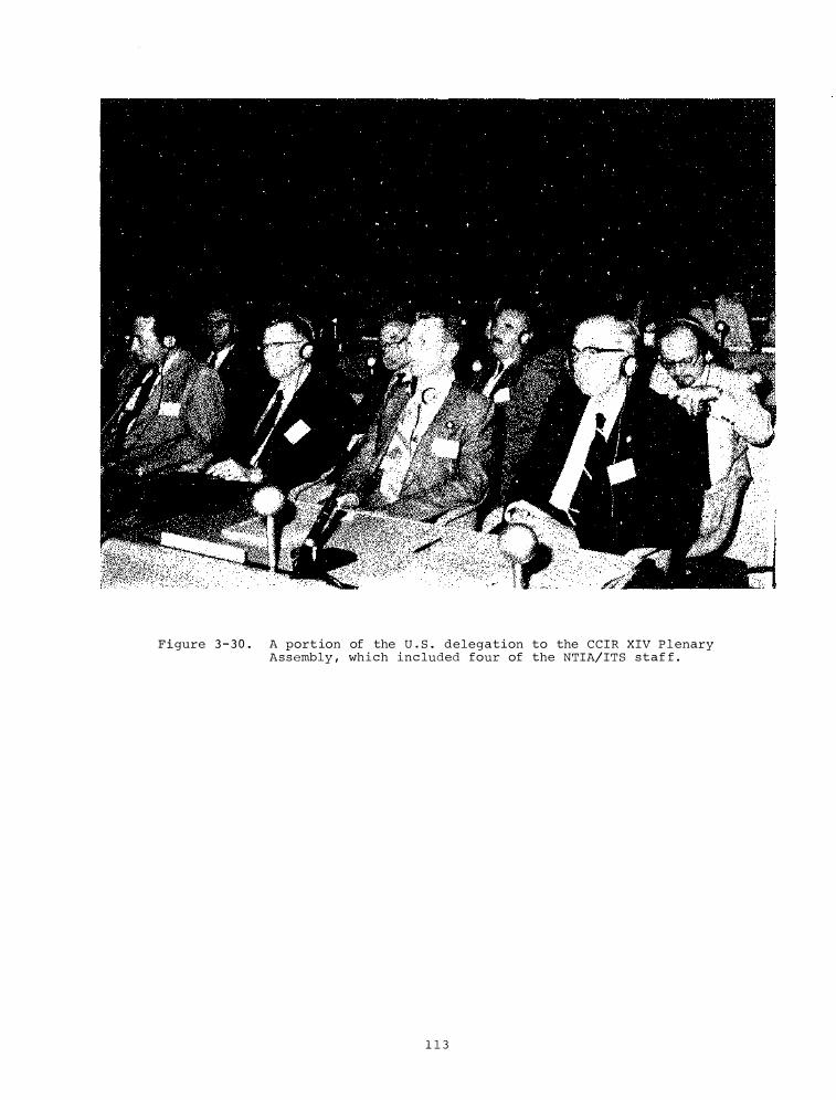
F i gure 3 - 3 0 . A port ion of the U . S . delegation to the CCIR XIV P l enary Assembly , which inc luded four of the NTIA/ITS staf f .
1 1 3

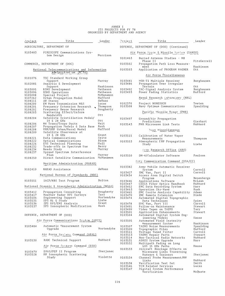
ANNEX I I T S PROJECTS FOR FY 7 8
ORGAN I Z E D B Y DEPARTMENT AND AGENCY
T i t l e
AGRI CULTURE , DEPARTMENT O F
9 1 0 3 4 8 3 F I RE SCOPE Commun i c a t ions Sys tem D e s ign
COMMERCE , DEPARTMENT OF (DOC)
L e ader
"lor r i s on
National T e l e c ommun i c a t ions and I nforma t ion Admi n 1 s t r a t 1 on (NT IA)
9 1 0 1 0 7 6
9 1 0 2 0 8 5
9 1 0 3 0 9 5 9 1 0 3 0 9 6 9 1 0 5 0 9 8 9 1 0 7 2 6 2 9 1 0 8 1 1 1 9 1 0 8 2 0 0 9 1 0 8 2 0 1 9 1 0 8 2 0 2 9 1 0 8 2 0 3
9 1 0 8 2 0 4
9 1 0 8 2 0 6 9 1 0 8 2 0 7 9 1 0 8 2 0 8 9 1 0 8 2 0 9
9 1 0 8 2 2 1 9 1 0 8 2 2 2 9 1 0 8 2 2 6 9 1 0 8 2 3 2 9 1 0 8 2 3 4 9 1 0 8 2 3 7
9 1 0 8 2 5 0
9 1 0 2 4 1 9
9 1 0 3 5 5 1
TSC St andard Wo rking Group Support
Ana lys i s & Deve l opme n t Support
RSMS Deve l opment RS�!S Ope r a t i ons Spec i a l Proj e c t Urban Propa g a t i on Model A�l Stereo
Hurray
Haakinson � lathe son �Ia the son �lcManamon Hufford deHaas Lucas EM Wave Transmi s s ion M & S
Frequency Extens ion Re s e arch Frequency Reu s e Re s e arch S c a t t e r ing E f fe c t / I n form
,. Thomp s on Dougherty
Bandwidth S a t e l l i te S c i n t i l l a t i o n Ho del/
1 9 & 2 8 GHz "'W Tran s /Trope Ducts Prop a g a t i on l!od e l s f1 D a t a Base VHF/UHF Urban/Ru r a l Mod e l S a te l l i t e O b s e r vance a t
1 9 & 2 8 GHz D at a C ommun i c a ti ons Opt i c a l Commun i c a t i ons EMS Techn i c a l P l anning Trade - o ffs in Spec trum U s e N e e d s Study Spread Spe ct rum I n t e r fe rence
P l an D i rect S a t e l l i t e C ommuni c a t i o n
:>ia r i t ime Admini s tr a t ion UIARAD)
MAR.A.D A s s i s tance
N a t i onal Bureau of S t andards (NBS )
IACP/NBS T e s t Prog ram
O t t
O t t Wa i t Rus h Hufford
Grant S e i t z Bl oom H u l l Be rry Hurray
rturray �1c�1anamon
de Haas
Bol ton
N a t i on a l Oc eanic & Atmosph e r i c Admini s tr a t i on (NOAA)
9 1 0 3 4 1 2 9 1 0 3 4 1 7 9 1 0 3 5 0 6 9 1 0 3 5 3 5 9 1 0 3 5 3 6 9 1 0 3 5 3 7
Prop a g a t i o n Consul t i ng Weather Radar R F I Surveys Engineering Suppo r t S P S Hi Q St udy SPS R F I /EMI Analy s i s SPS I on o s p h e r i c Mod i fi c a t i on
DEFENSE , DEPARHIENT OF (DOD)
Dougherty Tary Wortendyke L i e b e Grant Rus h
A i r F o r c e Commun i c a t ions Sys t e m (AFCS)
9 1 0 3 4 8 4
9 1 0 3 5 3 0
9 1 0 3 4 7 9 9 1 0 3 5 2 8
Automat i c �!ea s urement S y s t em Upgrade
Air Force Sys t ems Command (AFAL )
RADC Techn i c a l Support
A i r Force Sys t ems Command ( E S D )
E FAS/PEP I I Program HF I onospheric S c a t t ering
Study
Wortendyke
Hubbard
Skerj anec
V i o l e t t e
1 1 5
T i t l e Leader
DEFENS E , DEPARTMENT O F (DOD) ( Continuecl)
A i r Force Space & M i s s i l e Sys tem (SAMSO)
9 1 0 1 4 6 3
9 1 0 3 5 0 2
9 1 0 3 5 0 3
9 1 0 3 4 4 1 9 1 0 34 8 6
9 1 0 3 4 9 2 9 1 0 3 4 9 3
9 1 0 2 3 7 0 9 1 0 3 5 0 8
9 1 0 3 4 9 7
9 1 0 3 5 4 3
9 1 0 3 5 1 5
9 1 0 3 5 5 3
9 1 0 3 5 5 0
9 1 0 3 3 8 2
9 1 0 3 4 2 7 9 1 0 34 3 4
9 1 0 34 4 6 9 1 0 3 4 4 7 9 1 0 3 4 5 2 9 1 0 34 6 3 9 1 0 3 4 6 5 9 1 0 3 4 7 0 9 1 0 3 4 7 4
9 1 0 3 4 7 8 9 1 0 3 4 9 1 9 1 0 3 4 9 9 9 1 0 3 5 0 1 9 1 0 3 5 0 4
9 1 0 3 5 0 5
9 1 0 3 5 0 7 9 1 0 3 5 0 9 9 1 0 3 5 l l 9 1 0 3 5 1 3 9 1 0 3 5 1 4 9 1 0 3 5 3 1 9 1 0 3 5 3 2
9 1 0 3 5 3 3
9 1 0 3 5 3 4
9 1 0 3 5 3 8 9 1 0 3 5 4 6 9 1 0 3 5 4 7
Bur i e d Antenna S t u d i e s - MX P h a s e I I F i t z G erre l l
P ropagat i on Path L o s s M e a s ure -ment Haakinson
App l i ca t i on o f PROGAAM WAGNER O t t
A i r Force 0i s c e l l aneous
MSR - T l Mul t i p l e Rece iver Propagation Over I rregular
T e rrain TAC - S i gnal Analy s i s Sys t em Power F ading S t a t i s t i c s
Naval Res earch Laboratory (NRL)
Proj e c t NONESUCH Navy Opt imum Commun i c a t i ons
Paci fic 'li s s i l e Range (PMR)
Ground/Air Prop a g a t i on P r e d i c t i ons
PMR Mic rowave Link T e s t s
Navy M i s ce l l aneous
C a l ib r a t i on o f Water Vapor Measurements
Atmo spheric f.HF Propa g a t i on Study
Army Research Office (ARO)
DM- 4 / C a l culator Software
Barghausen
Ott Barghausen Hufford
Tve t en Spaul ding
G i e rhart Hubbard
Thomp s on
L ie b e
P a ul s on
Army C ommun i c a t i on C ommand (USA/C C )
Army Mob i l e Automa t i c Receiver Sys t em
I'MC Van , Part I I Acces s Area D i g i t a l Swi tch
Program App l i c a t ions So ftware C E E I A F i b e r Op t i c s Handbook EMC D a t a Recording S y s t em Ope r a t i on Sky- Wave EMC C o s i t e Ana l y s i s C apab i l i ty EMC Remo t e Extens ion Au tomated D i g i t a l Topograph i c
D a t a Techniques H!C Van , Part I I I F o l l ow - on Maint enance \'ideo Tapes on TAEHS App l i cat ion Enhancements Automated D i g i t a l Sys tem Eng -
ineering �lodel s Automated F i e l d I n s tn s i ty
Measurement Sys te� TAEMS N o i s e Measurements Topograp h i c F i l e s Vo l t a g e Tuned P i l t e r TAEMS Repair Parts Non - Ta c t i c a l Radio Networks ADRES Sys t em Upgrade Mul t ipath Fading on Long
LOS 15 GHz Paths Aircraft Blockage E f fe c t s on
M i crowave L inks Traversing Runways & Taxiways
Chann e l Probe Measurement /MW Links
Ver i fi c a t i on Test S e t T C N R e l at e d Services D i g i t a l System Perfo rmance
Veri f i c a t i on
C arro l l C arro l l
Ne s enbergs McLean Hubb ard llarr Rush Adams D iede
S p i e s C arrol l St ewart T ary S t ewart
fiau s e
Haakinson Spaul ding Hufford C arro l l S t ewart Hubb ard Harr
Haus e
Skerj anec
Hubbard Smith Lucas
McQuate
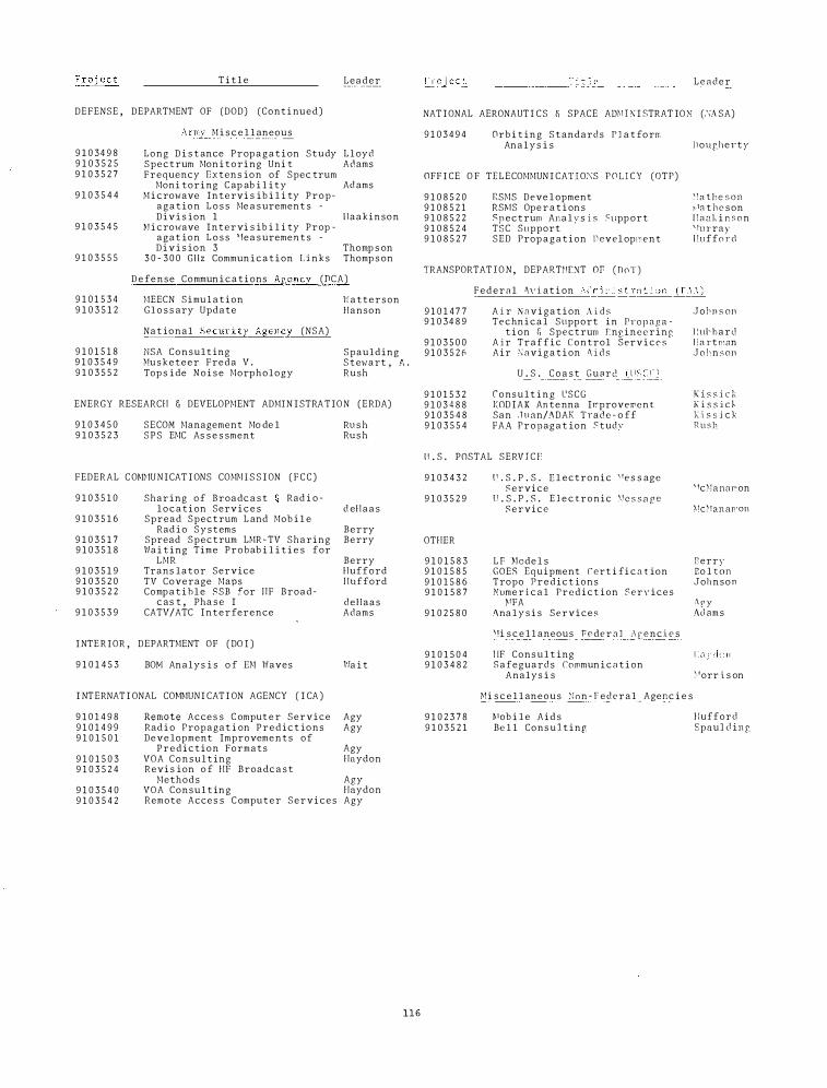
T i t l e Leader
DEFENSE , DEPARTMENT OF (DOD) (Cont i nued)
9 1 0 34 9 8 9 1 0 3 5 2 5 9 1 0 3 5 2 7
9 1 0 3 5 4 4
9 1 0 3 5 4 5
9 1 0 3 5 5 5
9 1 0 1 5 3 4 9 1 0 3 5 1 2
Army M i s c e l l aneous
Long D i s t ance Prop a g a t i on Study L l oyd Spectrum Mon i toring Uni t Adams Frequency Dxtens ion of Spec trum
Moni toring C ap ab i l i t y Ad ams M i crowave Intervi s ib i l i ty P r o p
a g a t ion L o s s Me a s urement s -D i v i s ion 1 l laakinson
M i crowave Intervi s ib i l i ty Prop -agat ion L o s s ;\,1ea s uremen t s -D i v i s ion 3 Thomp s on
3 0 - 3 0 0 Gl lz Commun i c a t i on Links Thomp s on
D e fense Commun i c a t i ons Agency (DCA)
1-!EECN Simu l a t i on G l o s s ary Update
l'i a t t e r s on Hanson
9 1 0 1 5 1 8 9 1 0 3 5 4 9 9 1 0 3 5 5 2
Nat ional Secur i ty Agency (NSA)
NSA Consult ing 0!usketeer Freda V . Top s ide N o i s e Morphology
Spaulding S t e·h·art , A . Rush
ENERGY RESEARCH & DEVELOPMENT ADMIN I STRA T I O N (ERDA)
9 1 0 3 4 5 0 9 1 0 3 5 2 3
SECOM Management Mo de l S P S EMC As s e s sment
FEDERAL C O�Jlc!U N I CAT I ONS COMm S S I ON ( F C C )
9 1 0 3 5 1 0
9 1 0 3 5 1 6
9 1 0 3 5 1 7 9 1 0 3 5 1 8
9 1 0 3 5 1 9 9 1 0 3 5 2 0 9 1 0 3 5 2 2
9 1 0 3 5 3 9
Shar ing o f Broadc a s t Rad i o l o c a t i on Serv i c e s
Spread Spectrum L and Mob i l e Rad i o S y s t ems
Spread Spectrum LMR - TV Sharing Wa i t ing Time Probab i l i t i e s for
LMR Trans lator Service TV Coverage Maps Comp a t i h l e SSB for ! IF Broad
c as t , Pha s e I CATV/ATC I n t e r ference
I NTE R I OR , DEPARTMENT OF ( DO I )
9 1 0 1 4 5 3 BO�! Analys i s o f H! Waves
I NTERNAT I ONAL CO�!li!UNI CAT I ON AGENCY ( I CA )
9 1 0 1 4 9 8 9 1 0 1 4 9 9 9 1 0 1 5 0 1
9 1 0 1 5 0 3 9 1 0 3 5 2 4
9 1 0 3 5 4 0 9 1 0 3 5 4 2
Remote Acces s C omput e r Service Rad i o Propagat i on P r e d i c t ions Deve lopment Improvements of
P r e d i c t ion Formats VOA C o n s u l t ing Revi s ion o f HF Broadc a s t
Methods VOA Consu l t in g Remote Acces s C omputer Services
Rus h Rus h
d eH a a s
Berry Berry
Berry Hufford Hufford
deHaas Adams
1'/a i t
Agy Agy
Agy Haydon
Agy Haydon Agy
1 1 6
_____ __::Ti t l_;_c ____ _ L e a d e r
NAT I ONAL AERONAUT I CS f, SPACE Ami F \ I STRAT ION (.\i\SA)
9 1 0 3 4 9 4 Orb i t in g S t andards P l a t fo rm Ana l y s i s
OFF I CE O F TELECOMMUN I CATI O:\S P O L I C Y (OTP)
9 1 0 8 5 2 0 9 1 0 8 5 2 1 9 1 0 8 5 2 2 9 1 0 8 5 2 4 9 1 0 8 5 2 7
RSMS Deve l opment RS�IS Ope r a t i ons Snectrum A11 a l v s i s Stlpp ort TSC Support ·
SED Prop a g a t i on n evel oproent
TRANSPORTAT I O N , DEPARTI��T Of (DoT)
l lougherty
� :a t h e s o n �.tn t h c s on ! Iaal, i n s on ' ftn· ray l !ufforcl
F e d e r a l �\" i. at i on M m 1 n i_:;_t:ra t i on J.I:_c\A)
9 1 0 1 4 7 7 9 1 0 34 8 9
9 1 0 3 5 0 0 9 1 0 3 5 2 1i
9 1 0 1 5 3 2 9 1 0 3 4 8 8 9 1 0 3 5 4 8 9 1 0 3 5 5 4
A i r N a v i g a t i on � i d s Techn i c a l Support in Prop a g a
t i on & Spectrum r:nr,ineering A 1 r Traffic Control Servi c e s Air �avig a t i on � i d s
U . S . C o a s t G u a r d (USCG�
Cons u l t i n g L'SCG KOD IAK An tenna Improvement San Ju on/ADAK Trade - o ff FAA Propag a t ion � tudy
l l . S . POSTAL SERV I C f:
9 1 0 3 4 3 2
9 1 0 3 5 2 9
OTHER
9 1 0 1 5 8 3 9 1 0 1 5 8 5 9 1 0 1 5 8 6 9 1 0 1 5 8 7
9 1 0 2 5 8 0
9 1 0 1 5 0 4 9 1 0 3 4 8 2
9 1 0 2 3 7 8 9 1 0 3 5 2 1
l' . S . P . S . E l ectronic "e s s age Service
U . S . P . S . E l e c tronic \!c s s a r e Service
L f Hode l s GOES Equipment rert i fi c o t ion Tropo P r e d i c t ions Nume r i c a l Predict ion Services
PFA Ana l y s i s Services
'!i s c e l l aneous T'ede r o l J\ renc .i e s
IIF Cons u l t ing S a feguards Commun i c a t i on
Analys i s
�1i s c e l l aneous �on - F e d e r a l Agenc i e s
�'ob i l e A i d s Be l l Cons u l t inr
Jobn s on
J iul" h a r c! l l a rt r.:on J o h n s on
K i s s i c k K i s s i d I( i. s s j c k R u s h
' fc�·ianaron
01c�fan aJron
Eerry Bo l ton Johnson
;\ p y !\;l ams
>'orr i s on
f luff ore! Spaul cl i n g
ANNEX I I ORGANI ZATI ONAL D IRECTORY
I N S T I TUTE FOR TELECOMMUNI CA T I ON S C I ENCES NAT I ONAL TELECOMMUN I CA T I ONS AND I NFORMATI ON ADM I N I STRAT I O N , DEPARTMENT OF COMMERCE
3 2 5 Broadway , Boulder , C o lorado 8 0 3 0 3 ( 3 0 3 ) 4 9 9 - 1 0 0 0 ( FTS d i a l 3 2 3 + exten s i on)
D I RE CTOR ' S O F F I C E (0/D)
NAME
C ROMB I E , Dougl a s s D . ( D i r e c t o r )
UTLAU T , \'Ii l l i a m F . ( Deputy D i r e c t o r )
WALTERS , Wi l l l am D . ( Budget a n d Accounting Officer)
STONE R , Rus s e l l B . (Pub l i c a t ion and T e c hn i c a l I nformat i on Officer)
\'I A I T , .James R . ( C on s u l t ant , a l s o w i th NOAA and C I RE S )
WI EDER , Bernard (As s i s t ant t o t h e Director f o r Program Deve l opment )
D IV I S I ON l - SPECTRUM UT I L I ZAT I ON
"!URRAY , .John P . (As s o c i a t e D i re c t o r )
1 . 1 R a d i o Spe c t rm1 Occupancy �!A THE SON , Robert .J .
1 . 2 Antenna P e r formance F 1 t zGERRE L L , R i chard G .
1 . 3 E�C Analy s i s & D e ve l opment ADAMS , .Jean E .
1 . 4 VHF/UHF Mod e l s li Mob i l e Sys t ems HUFFORD , George A .
D IV I S I ON 2 - SYSTH!S TECHNOLOGY & STMIDARDS
HULL , .Jos eph A . (As s oc i at e D i r e c t o r )
2 . 1 Chann e l Charact e r i z a t i o n HUBBARD , Rober t 1'1 .
2 . 2 N e w T e c hno l ogy Deve lopment BLOOM , L o u i s R .
2 . 3 Systems Engineering & Analy s i s HUL L , .Jo s eph A . (Act 1 ng)
2 . 4 Sys tems Techno l o gy deHAAS , Thi j s
2 . 5 Sys tems A s s e s sment Md!ANAMON , P e t e r M .
D I V I S I ON 3 - APPL I E D ELECTROMAGNETI C S C I ENCE
LUCAS , Don a l d L . (As s oc i a t e D i re c to r )
3 . 1 Spe c t rum E x t ens ion Re s e arch & An a ly s i s THOMPSON , �!OODY C .
3 . 3 Advanced Commun i c at i o n Technol ogy & Appl i c at i ons GRANT , \'il l l l am B .
3 . 4 Advanced LUCAS ,
117
EXT .
4 2 1 5
3 5 0 0
4 4 1 4
3 5 7 2
6 4 7 1
3 4 8 4
4 1 6 2
3 2 9 3
3 7 3 7
4 3 0 1
3 4 5 7
4 1 36
3 4 1 4
3 4 8 5
4 1 3 6
3 7 2 8
3 5 7 0
3 8 2 1
3 5 0 8
3 4 6 0
3 7 2 9
3 8 2 1
ROOM
3 0 2 0
3 0 2 0
3 0 1 9
3 0 0 9
2 2 7
3 0 1 4
4 5 3 3
2 2 2 1
4 5 2 4D
4 5 1 7
4 5 2 3
2 0 3 4
2 2 4 3
2 2 4 S A
2 0 3 4
2 0 3 0
2 2 3 7
3 4 2 1
3 4 4 2A
3 4 1 1
3 4 4 7
3 4 2 1
(RB 1 )

Name
ADM!S , J e an E . ADAMS , Steven l'' AGY , Vaughn L . A K H!A , IIi r o s h i ALLEN , Kenneth C .
BARGHAUSEN , Al fred F . BEASLEY , Ke i t h R . BEERY , We s l ey M . BERRY , Janet S . BERRY , L e s l i e A .
BLOO�! , Louis R . BOLTON , Earl C . BROOKS , Minni e
CANADA Y , L o i s S . CARROLL , John C . CIIAVE Z , Richard C H I LTON , Charles J . C OLEMAN , Susan J .
COURTNEY , Brenda L . C RO�B I E , Doug l a s s D . C RO W , Edwin L . C URLANDER , John L .
deHAAS , Thij s DEL P I Z Z O , Rose M . D I EDE , Arthur I I . DOUGHERTY , l laro l d T . D ROU I L LARD , P a t r i c i a I I .
DUTTON , Evan J .
E S PE LAND , Ri chard H .
FALCON , Gl enn D . FARROW , J o s ep h E . F i t zGERRI'LL , Richard G . F R I T Z , Ol i ve H .
GALLAl'IA , Rob e r t L . GAMAUF , Kenneth J . G E I S S I NGER , Marc i a L . G I BSON , Beve r l e J . G I ERHART , Gary D .
G LEN , Donald V . GODW I N , John R . GOULD , Beverly A . GRANT , Wi l l i am B . GRAY , Eve lyn P .
HAAK I NSON , E l don J . HAIDLE , Leroy L . HANSE N , Rut h B . HANSON , A . G l enn HARMAN , John M .
HAR R , Thomas A . , Jr . EARn1AN , Wi l l i am J . IIAU S E , Laurance G . HAYDON , George W . H I L DEBRANDT , Thomas H .
ANNEX I I I INST I TUTE FOR TE LFCO�rr�N I CAT I ON S C I ENCES
NAT I ONAL TELFCONt.IUN I CA T I ONS AND I N FORMAT I OK ADHI N I STRAT I Oi\ DE PARTI!ENT OF C0�1mRCE
Alphabe t i cal L i s t ing of ITS Emp l o y e e s
Ext .
4 3 0 1 3 5 1 3 3 6 5 9 3 3 9 2 3 5 1 3
3 3 8 4 3 7 3 1 3 5 0 1 4 1 2 9 4 4 7 4
3 4 8 5 3 1 0 4 3 9 2 9
3 6 3 4 3 6 0 1 3 5 8 4 3 8 1 5 3 8 8 3
4 1 6 2 4 2 1 5 3 4 5 2 3 3 5 8
3 7 2 8 4 1 6 2 3 1 0 3 3 9 1 3 4 3 3 7
3 6 4 6
3 8 8 2
4 3 6 1 3 6 0 7 3 7 3 7 3 7 7 8
3 7 6 1 3 6 7 7 3 5 0 0 4 2 1 5 3 2 9 2
3 8 9 3 4 3 0 2 3 5 8 8 3 7 2 9 3 3 0 7
4 3 0 4 3 2 3 3 3 5 1 3 4 4 4 9 3 6 5 5
4 1 9 1 3 6 0 6 3 9 4 5 3 5 8 3 3 1 7 5
September 1 , 1 9 7 8
Room
4 5 1 7 3 4 4 2 3 4 4 1 2 2 1 0t r 3 4 4 2 B
3 4 4 3 4 5 2 4A 3 4 6 3 4 5 1 8A 4 5 2 8 B
2 2 4 5A 2 2 3 6 " 3 4 5 1
3 4 1 7 3 4 5 9 3 4 3 0 3 4 2 0 3 4 5 0
4 5 3 0 3 0 2 0 2 2 1 0 3 4 5 0
2 0 3 0 4 5 2 7 3 4 5 8 B 3 4 5 3 3 0 1 5
3 4 5 4 C
3 4 1 0/1
2 2 2 2 C 2 2 3 0 4 5 2 4D 2 2 1 3
2 2 1 7 3 4 3 0 3 0 2 0 3 0 2 0 2 2 2 2H
2 2 1 0 4 5 1 5 4 5 2 5 3 4 4 7 2 2 1 0 B
4 5 1 1 4 5 2 4 B 3 4 4 2 C 2 2 2 3 2 0 3 0
4 5 1 8 B 2 2 1 0D 2 2 3 0 B 3 4 2 0 C 2 2 3 0
1 1 9
[-!arne
l ! I L L , D 8 v i d 1\ . I 'OROI•: I T Z , Renee P . I 10\vARD , � 1 1 en 0 . l !UBBARD , Reb e r t 1•.' . J!UFFORD , G e o r g e •\ .
! lULL , J o s eph A . 1 \l'NT , Howard ll . IIYOVi\LT I , Duane I .
JEFFREYS , C h a r l ene f . JENK INGS , Rnymond D . JOH)';SON , �18 rv r : llen .JUNFAU , Robert I . JUROSIIFK , J o hn !\ ,
K H I' II'TT , F . G e o r f e K I SS I C K , V i 1 1 i am A .
LANGER , Susan K . LAWRENCE , Vincent S . LAYTON , Donalr1 1 ' . L I EJJE , I lans J . L I N F I ELD , Robe r t F .
LLOYD , .John L . LONGLEY , Anita G . Lli BE:i , Rob e r t A . LUCAS , Donald L .
� 1ADONNA , {�ancy r!AJOR , J e anne C . r1ARLER , F . Gene MATHESON , Robe r t J . HART I N , W i l l i am L .
MAYEDA , Kathy r: . �IE LLECKE R , C a r l ene '1 . l.·!ENDOZA , .John R . H I LES , lla r t i n .T . ' l i LLER , C h a r l e s ' ' .
IJ I N I STER , Carl hl H I T Z , A l b e r t P . ) IOLLARD , Jean R . I'ONTGOHERY , c a r o l e .J . MORRI SON , Ernest L .
HURAHATA , Sueki MURRAY , .John P . McCARROLL , P a t r i c i a A . McCOY , E l i z a b e th L . t.lcLEAN , Robe r t A .
HcHANAHON , P e t e r I I . McQUATE , P a u l L .
NfSENllERG S , Mar t in NFY , Linda
OLSON , Marylyn N . OTT , Rando lph II .
L > t . P o OJ'l
3 4 7 2 2 2 0 9 4 1 6 2 -1 5 2 0
3 4 8 5 2 2 4 5
3 4 1 4 2 2 4 3
3 4 5 7 4 5 2 3
4 1 3 6 2 0 3 4
3 7 7 8 2 2 1 3 3 4 4 7 3 4 5 1
4 4 1 4 ) f\ :2 ] 3 2 3 3 4 5 2 4 C 3 5 8 7 4 5 2 2 ('
4 2 0 2 2 2 2 2
4 3 6 2 4 5 2 81\
3 9 4 5 2 2 3 0 E
4 2 5 8 4 5 2 0 C:
4 16 2 4 5 2 7 4 2 0 2 2 2 2 2 3 5 8 4 3 4 3 0
3 3 1 0 3 4 2 6 4 2 4 3 2 � 3 6 A
3 7 0 1 3 4 1 9' 1
3 ·1 7 0 4 5 2 1
4 1 2 5 •1 5 2 0A
3 8 2 1 34 2 5
3 8 2 1 3 � 2 1 4 1 2 2 4 5 2 0 B
3 4 1 2 34 4 6 !3 3 2 9 3 2 2 2 1 3 1 9 5 3 4 2 4
3 9 9 8 3 4 2 0 3 3 3 0 3 4 5 8A
3 5 8 4 3 4 3 0 3 5 0 6 2 2 4 6 4 4 9 6 3 4 5 4A
3 8 0 5 2 2 4 2
3 5 1 3 3 4 4 2 3 8 2 1 3 4 2 1 3 2 9 1 2 2 1 9 4 2 1 5 3 (1 1 3
3 5 1 3 3 4 4 2 4 1 6 2 4 5 3 3 3 8 8 3 3 4 4 9
4 2 8 1 2 2 4 5 H6 2 34 6 2
3 5 7 0 2 2 1 8 3 7 7 8 2 2 1 3
3 3 3 7 2 2 1 0)! 3 3 9 6 4 5 2 4A
4 1 3 6 2 0 3 0 3 3 5 3 3 4 6 7
Name Ext . Room Name Ext . Room
PAULSON , Sara J . 3 8 7 4 4 5 1 9 TARY , John J . 3 7 0 2 3 4 5 0 PAYNE , Judd A . 3 2 0 0 2 2 1 4A TELFE R , T h e lma L . 4 1 6 2 4 5 2 9 PH I LL I PS , Robert E . 4 1 2 5 4 5 2 0A TETERS , Larry R . 4 4 3 0 3 4 1 n1 POKEMPNER , Margo 3 4 6 0 3 4 1 3 THOMPSON , Barbara D . 3 8 2 1 3 4 2 1 PRATT , Lauren E . 3 8 2 6 2 2 34 B THOMPSON , Moody C . , Jr . 3 5 0 8 3 4 4 2A
RANDELL , Ho l ly L . 3 7 8 6 4 5 1 5 TVETEN , Lowe l l H . 3 6 2 1 3 4 4 5 REASONER , R i t a K . 3 1 8 4 4 5 2 2A ROAC H , David L . 3 2 5 3 4 5 2 4 ROS I CH , Rayner K . 3 1 0 9 3 4 1 5)1 UTLAUT , W i l l i am F . 3 5 0 0 3 0 2 0 RUSH , C h a r l e s )1 . 3 4 6 0 3 4 l l
VanSTORY , C a r o l B . 3 2 6 7 3 0 1 7 RUSSELL , Jane L . 3 3 8 7 4 5 2 4B VAUGHAN , Margo S . 4 1 2 9 4 5 1 8
V I OLETTE , Edmond J . 3 7 0 3 3 4 4 6A VOGLER , Le\\r i s E . 3 6 6 8 3 4 5 0
SANCHE Z , P a t r i c i a A . 4 1 6 6 2 2 1 8 SAUER , J o s ep h A . 4 1 2 2 4 5 2 0B SE I T Z , Neal B . 3 1 0 6 2 2 1 4 WALLER , Freda L . 3 6 1 8 2 0 3 0 SE XTON , Alma B . 3 8 8 3 3 4 4 9 WALTERS , Wi l l i am D . 4 4 1 4 3 0 1 9 SHELTON , Lenora J . 3 5 7 2 3 0 l l WARNER , B i l l i e D . 4 4 9 6 3 4 5 4 B
WASHBURN , James s . 3 7 9 8 3 4 1 3M WASSON , . Gene F . 3 5 8 4 3 4 3 0
SKERJANEC , R i c hard E . 3 1 5 7 2 2 3 0 S)JI LLEY , John D . 4 2 1 8 2 2 2 ZM SMITH , Dean 3 6 6 1 2 2 2 3 WATTERSON , C l ark C . 3 5 3 6 2 2 4 1 SPAUL D I NG , Ar thur D . 4 2 0 1 2 2 2 2A WEBER , Bradley D . 3 3 5 8 34 s o S P I E S , Kenneth P . 4 2 7 5 4 5 1 6B l'.'ELCfl , Wi l l iam )' . , I I I 4 3 2 1 3 4 5 8A
WELLS , Paul I . 4 3 6 8 2 2 3 5 W I EDER , Be rnard 3 4 8 4 30 1 4
STEARNS , C h a r l e s 0 . ' I I I 3 8 8 3 3 4 5 0 STEELE , Franc i s K . 3 8 1 5 3 4 2 0 STEWART , Arthur C . 3 9 9 8 3 4 1 9 WORTENDYKE , David R . 4 2 4 1 2 2 34 STEWART , Frank G . 3 3 36 3 4 5 0C STOEBE , Suz anne H . 3 5 6 2 3 4 1 3
STONEHOCKE R , Garth H . 3 7 5 6 4 5 1 6 D STON E R , Rus s e l l B . 3 5 7 2 3 0 0 9
1 2 0
ANNEX IV ITS PUBLICATIONS - FISCAL YEAR 1 9 7 8
Agy , V . L . , K . D . Boggs , C . M . Me l lecke r , and G . W . Haydon ( 1 9 7 7 ) , F Y 7 7 progress report t o United States I nformation Agency , Voice o f America Contract IA- 1 8 2 1 2- 2 3 , OT Techni c a l Memorandum 7 7 - 2 4 5 , December , 2 7 pp .
Akima , H . ( 1 9 7 8 ) , Noise power due to digital errors in a PCM telephone channe l , OT Report 7 8 - 1 3 9 , January , 4 0 pp . (NTIS Acces s . No . PB 2 7 7 4 4 7 /A S )
Akima , H . ( 1 9 7 8 ) , Minimum antenna dimensions for sate l l ite -communications earth stations , OT Report 7 8 - 14 5 , Apri l , 9 2 pp . (NTIS Acc e s s . No . PB 2 8 2 1 0 9/AS )
Akima , H . ( 1 9 7 8 ) , A method of bivariate interpolation and smooth surface fitting for irregularly d i stributed data points , ACM Trans . Math. Software i' No . 2 , June , pp . 1 4 8 - 1 5 9
Akima , H . ( 1 9 7 8 ) , Algorithm 5 2 6 : B ivariate interpolation and smooth surface fitting for irregul a r ly d i s tributed data points { E l } , ACM Trans . Math . Software i' No . 2 , June , pp . 1 6 0 - 1 6 4
Arora , R . K . , and J . R . Wait ( 1 9 7 8 ) , Refraction theories o f radio wave propagation through the troposphere--A review, Radio S c i . 1 3 , No . 3 , May-June , pp . 5 9 9 - 6 0 0
Berry , L . A . ( 1 9 7 7 ) , Spectrum metr ics and spectrum e f f ic i ency : Proposed definitions , IEEE Trans . El ectromagnetic Compati b i l ity EMC - 1 9 , No . 3 , August , pp. 2 5 4 - 2 6 0
------
Berry , L . A . ( 1 9 7 8 ) , User ' s guide to low-frequency radio coverage programs , OT Technical Hemorandum 7 8 - 2 4 7 , January , 91 pp .
Berry , L . A . ( 1 9 7 8 ) , E f fects of local and skywave interfe rence on CB radio rang e , NTIA Report 7 8 - l , May , 9 4 pp . (NTIS Acce s s . No . PB 2 8 2 8 8 9/AS)
Berry , L. A . ( 1 9 7 8 ) , Technic a l tradeo f f s for spectrum e f f i c iency in a personal radio service , Proc . of 1 9 7 8 IEEE International Sympos ium on E l e ctromagnetic Compat ibility , Atlant a , GA , June 2 0- 2 2 , pp . l - 6
Bloom , L . R . , A . G . Hanson , a n d L . G . Hause ( 1 9 7 7 ) , Digital transmi s s ion via coax i a l , twinaxial , and fiber optical cables , U . S . Army/CommunicationsElectronics Engineering I n s t a l lation Agency Report CCC-CED-XET , October , 1 4 0 pp.
Crombie , D . D . , K. Hasselmann , and W. Sell ( 1 9 7 8 ) , High- frequency radar observations of sea waves travelling in opposition to the wind , BoundaryLayer Meteorology 1 3 , pp . 4 5 - 54
Crow, E . L . ( 1 9 7 8 ) , Relations between b i t and block error probab i l ities under Markov dependence , OT Report 7 8 - 1 4 3 , Marc h , 22 pp . (NTIS Acces s . No . PB 2 8 1 5 4 5/AS)
Crow , E. L . , and M . J. Miles ( 1 9 7 7 ) , Data analy s i s a n d test d e s i g n for measuring error rate s , Proc . of International Symposium on �leasurements in Telecommunications , Lannion , France , Oct . 3 - 7 , pp . 1 2 5 - 1 3 0
Crow, E . L . , and M . J . Miles ( 1 9 7 7 ) , Statistical anal y s i s and design o f experiments for determining digital error rates , Pro c . o f International Meeting on Data Transmi s s ion , Liege , B e l gium, November 2 1- 2 2 , !' pp . 1 1 9 - 1 2 6
Dougherty , H . T . ( 1 9 7 8 ) , The OSP survey response , OT Technical Memorandum 7 8 - 2 4 9 , February , 4 4 4 pp .
Dougherty , H . T . , and E . J . Dutton ( 1 9 7 8 ) , Estimating year-to-year variability of rainfa l l for microwave appl ication s , IEEE Trans . Commun. �' No . 8, Augus t , pp . 1 3 2 1 - 1 3 2 4
1 2 1
Dougherty , H . T . , A . J . Estin , W . L . Morgan , and J . J . Woodru f f ( 1 9 7 8 ) , The Orbiting Standards Platform , Proc . o f 1 9 7 8 Antenna Applications Symp . , Univ . o f I l l inois Electrical Engineering Dept . , Mont icello , I L , Sept . 2 0 - 2 2
Dougherty , H . T . , and B . A . Hart ( 1 9 7 7 ) , Tropospheric strati f ication and anoma lous propagation , Proc . of AGARD E lectromagnetic Wave Propagation Panel on Aspects o f Electromagnetic Scattering in Radio communication s , Cambridge , MA, Oct . 3 - 6
Dutton , E . J . ( 1 9 7 7 ) , Precipitation variab i l i ty in the U . S . A . for mic rowave terrestrial system desig n , OT Report 7 7 - 1 3 4 , November , 1 3 0 pp . (NTIS Acce s s . No . AD A0 4 9 0 4 l )
Dutton, E . J . ( 1 9 7 8 ) , Some influences o f rainfa l l on sate l l i te/ground microwave system installat ion costs , OT Report 7 8 - 1 4 2 , March , 35 pp . (NTIS Acce s s . No . PB 2 8 0 2 7 2/AS)
Dutton , E . J . , and H . T . Dougherty ( 1 9 7 8 ) , Estimates o f the atmospheric transfer function at SHF and EHF , NTIA Report 7 8 - 8 , Augu st , 32 pp . (NTIS Acces s . No . not yet available)
FitzGerre l l , R. G . , J. R. Juroshek , and R. D . Jennings ( 1 9 7 7 ) , Earth station antenna measurements , OT Report 7 7 - 1 2 9 , October , 88 pp . (NTIS Acces s . No . PB 2 7 4 4 7 0/AS )
Gal lawa , R . L . ( 1 9 7 7 ) , Component development in f iber waveguide technology , Proc . of First International Telecommun ication Expos ition , Atlant a , GA , October 9 - 1 5 , �' pp . 7 1 5 - 7 1 9
Gallawa , R . L . , and W . J . Hartman ( 1 9 7 7 ) , Operationa l and cost considerations in the use of optical waveguides in a local information transfer system , OT Report 7 7 - 1 3 3 , November , 79 pp . (NTIS Acce s s . No . PB 2 7 5 2 9 1/AS )
Gierhart, G . D . , and M. E . Johnson ( 1 9 7 8 ) , Propagation model ( 0 . 1 to 20 GHz ) extensions for 1 9 7 7 computer programs , U . S . Dept . of Transportation report FAA-RD- 7 7 - 1 2 9 , May , 9 1 pp . (NT I S Acce s s . N o . ADA 0 5 5 6 0 5 )
Haakinson , E . J . ( 1 9 7 8 ) , Spread spectrum : An annotated bibl iography , NTIA Special Pub l ication 7 8 - l , May , 8 1 pp . (NTIS Acce s s . No . PB 2 8 3 9 6 4/AS )
Haakinson, E . J . , and R. D . Jennings ( 1 9 7 8 ) , Land mobi l e radio system performance model for VHF and higher frequencies over irregular terra in , Proc . of 2 8 th IEEE Vehicular Technology Conferenc e , Denver , CO , March 2 2 - 2 4 , pp . 5 1 2 - 5 17
Hartman , W . J . , and D . Smith ( 19 7 7 ) , T i l t ing antennas to reduce line-of-sight microwave link fading , IEEE Trans . Ant . Prop . AP-2 5 , No . 5 , September , pp . 6 4 2 - 6 4 5
-----
Hatf ield , D . N . ( 19 7 7 ) , Measures of spectral e f f i c iency in land mobi le radio , IEEE Trans . Electromagnetic Compatibility � ' N o . 3 , August , pp. 2 6 6 - 2 6 8
Haydon , G . W . ( 19 7 8 ) , Theoretical compatibil ity between high frequency broadcasting and the high frequency fixed services , OT Technical Memorandum 7 8 - 2 5 2 , Apri l , 98 pp .
Hi l l , D . A . , and J . R. Wait ( 1 9 7 7 ) , E f f e ct of a lossy j acket on the external fields of a coaxial cab le with an interrupted shield , IEEE Trans . Ant . Prop . AP- 2 5 , No . 5 , September , p . 7 2 6
--
Hi l l , D . A . , and J . R . Wait ( 1 9 7 7 ) , Analysis of radio frequency transmission in a semicircular mine tunnel containing two axial conductor s , IEEE Tran s . Commun . COM- 2 5 , No . 9 , September , pp. 1 0 4 6 - 1 0 5 0
-----
H i l l , D . A . , and J . R . Wait � 1 9 7 7 ) , E l ectromagnetic scattering from an unbonded rectangular wire mesh located near the air-ground L1terface , IEEE Tran s . Electromagnetic Compatibility EMC- 1 9 , No . 4 , November , pp . 4 0 2 - 4 0 6
------
Hi l l , D . A . , and J . R . Wait ( 1 9 7 7 ) , Ana lysis of alternating current excitation of a wire rope by a toroidal coi l , J. App l . Phys . 4 8 , No . 1 2 , Decembe r , pp . 4 8 9 3- 4 8 9 7
--
H i l l , D . A . , and J . R . Wait ( 1 9 7 8 ) , The impedance of dipoles in a circular tunnel \Vith an axial conductor, IEEE Trans . Geosc i . El ectron . GE- 1 6 , No . 2 , Apri l , pp . 1 1 8 - 1 2 6
------
Hi l l , D . A . , and J . R . Wait ( 1 9 7 8 ) , Scattering by a s lender void in a homogeneous conducting wire rope , Appl . Phys . 1 6 , pp . 3 9 1 - 3 9 8
H i l l , D . A . , and J . R . Wait ( 1 9 7 8 ) , Surface wave propagation on a rectangular bonded wire mesh located over the ground , Radio Sci . 1 3 , No . 5 , September-October
--
Howard , A. Q . , Jr . ( 1 9 7 7 ) , Microbend losses in mult imode optical fibers , OT Report 7 7 - 1 3 6 , November , 5 1 pp . (NTIS Acce s s . No . PB 2 7 5 3 8 7/AS )
Hubbard , R . W. ( 1 9 7 7 ) , Measurements in mi crowave telecommunication systems using a p seudo- random noise ( PN ) probe , Proc . of International Sympos i um on Measurements in Telecommunications , Lannion , France , Oct . 3 - 7 , pp . 5 1 4 - 5 1 9
Hubbard , R . W . , R . F . Lin f i e l d , and W . J . Ilartman ( 1 9 7 8 ) , Measuring characteristics of microwave
mobile channe l s , Proc . of 2 8 t h IEEE Vehicular Technology Conference , Denver , CO, March 2 2 - 2 4 , pp . 5 1 9 - 5 2 6
Hubbard, R . W . , R . F . Linfi e l d , and W . J . Hartman ( 1 9 7 8 ) , Measuring characteristics of microwave
mob i l e channe l s , NTIA Report 7 8 - 5 , June , 53 pp. (NTIS Acce s s . No . PB 2 8 3 9 4 4/AS )
Janes , H . B . , J . T . Col l in s , and F . K . Steele ( 1 9 7 8 ) , A Prel iminary catalog of programs and data for 1 0 - 1 0 0 GHz radio system prediction s , OT Report 7 8 - 1 4 1 , March , 50 pp . (NTIS Acce s s . No . PB 2 8 0 7 7 4 /AS)
Janes , H. B . , and M . C. Thompson , Jr. ( 1 9 7 8 ) , Fading at 9 . 6 GHz on an exper imentally s imulated aircraft-to-ground path , IEEE Tran s . Ant . Prop . AP- 2 6 , No . 5 , September , pp . 7 1 5 - 7 1 9
Jennings , R . D . , and S . J . Paul son ( 1 9 7 7 ) , Communication system per formance model for VHF and higher frequenc i e s , OT Report 7 7 - 12 8 , October , 1 7 5 pp . (NTIS Acce s s . No . PB 2 7 4 4 5 8/AS )
Johnson , M. E . , and G . D . Gierhart ( 1 9 7 8 ) , App l ications guide for propagation and interference analysis computer programs ( 0 . 1 to 20 GHz ) , U . S . Dept . o f Transportation report FAA-RD - 7 7 - 6 0 , �larch , 1 8 4 pp . (NTIS Acc es s . No . ADA 0 5 3 2 4 2 )
Johnson, M . E . , and G . D . Gierhart ( 1 9 7 8 ) , Aerospace propagation prediction capab i l ities as sociated with the IF- 7 7 model , Proc . of AGARD meeting of Electromagnetic Wave Propagation Pane l , Ottawa , Canada , April 2 4 - 2 8 , p p . 4 7 - l - 4 7 - 1 3
Johnson , R . B . ( 1 9 7 7 ) , Federal regulations relevant to the structural development of telecommunications industrie s , OT Report 7 7 - 1 3 5 , November , 6 5 pp . (NTIS Acce s s . No . PB 2 7 5 2 3 8/AS )
Juroshek , J . R . , G . E . Wa s son , and G . H . Stonehocker ( 1 9 7 8 ) , Flight tests of digital data transmi s s ion , IEEE Tran s . Aerospace E lectron . Systems AES - 1 4 , No . 2 , March , pp . 4 0 3 - 4 1 0
------
Kimrnett , F . G . , :and N . B . Seitz ( 1 9 7 8 ) , Digital communication performance parameters for proposed Federal Standard 1 0 3 3 , Volume I I : Application Example s , NTIA Report 7 8 - 4 , May , 66 pp . (NTIS Acce s s . No . PB 2 8 4 2 3 5/AS )
1 2 2
K i s sick , w . A . , and G . H . Stonehocker ( 1 9 7 7 ) , E l e c tromagnetic Cos ite Analys i s ( EMCAN) Mod e l --Part I : The feasibil ity study, OT Report 7 7 - 1 3 0 , Octobe r , 75 pp . (NT I S Acces s . No . PB 2 7 5 0 8 6/AS)
Liebe , H . J . , and G. G . Gimme stad ( 1 9 7 8 ) , Calculation o f c lear air EHF refractivity , Radio Sci . 1 3 , No . 2 , March-Apri l , pp . 2 4 5 - 2 5 1
--
Linfie l d , R . F . ( 1 9 7 7 ) , Radio channel capacity l imitation s , OT Report 7 7 - 1 3 2 , November , 9 1 pp . (NTIS Acces s . No . PB 2 7 5 2 3 9/AS )
Linf ield , R . F . , and T . de Haas ( 1 9 7 8 ) , Interfacing the Automated Maritime Mobi l e Tel ephone System with the U . S . public switched telephone network , NTIA Report 7 8 - 7 , August , 66 pp . (NTIS Acce s s . No . not yet avai labl e )
Linf i e l d , R . F . , and M . Nesenbergs ( 1 9 7 8 ) , Acc e s s a r e a switching and signaling : Concept s , i s s ue s , and a l ternatives , NTIA Report 7 8 - 2 , May , 1 4 6 pp . (NTIS Acce s s . N o . PB 2 8 3 4 6 4 /A S )
Longley, A . G . ( 1 9 7 8 ) , Radio propagation i n urban areas , Proc . of 2 8 th IEEE Vehicular Technology Conference , Denver , CO , March 2 2 - 2 4 , pp . 5 0 3 - 5 1 1
Long l ey , A . G . ( 1 9 7 8 ) , Radio propagation i n urban areas , OT Report 7 8 - 1 4 4 , Apri l , 55 pp . (NTIS Acce s s . No. PB 2 8 2 1 0 9 /AS )
Ma , M . T . , and R . G . FitzGerre l l ( 1 9 7 7 ) , Des ign of a van-top low-profile HF antenna , 0'1' Report 7 7 - 1 3 1 , October , 4 2 pp . (NTIS Acce s s . No . PB 2 7 5 0 9 1/AS )
Ma , M . T . , and R . A . McLean ( 1 9 7 8 ) , Application scenario for electromagnetic radiation hazards , OT Technical Memorandum 7 8 - 2 5 0 , March , 1 0 4 pp .
Hathe son, R . J . ( 1 9 7 7 ) , A Radio Spectrum Measurement Sys tem for frequency management dat a , IEEE Trans . E l ectromagnetic Compatibility EHC- 1 9 , No . 3 , Augus t , p p . 2 2 5 - 2 3 0
------
Hatheson , R . J . ( 1 9 7 7 ) , A Radio Spectrum Heas urement System for frequency management data , Proc . of I nternational Sympo sium on Measurements in Telecommunications , Lannion, France , Oct . 3 - 7 , p p . 5 4 0 - 5 4 5
Matheson, R . J . ( 1 9 7 8 ) , Automated spectrum analy s i s , Proc . IEEE �' No . 4 , Apri l , pp . 3 9 2 - 4 0 2
Middleton , D . ( 1 9 7 8 ) , Statistical-phys ical models of man-made and natural radio noi s e , Part I I I . Fir st-order probability models of the instantaneous amplitude of C l a s s B interferenc e , NTIA Contractor Report 7 8 -l , June , 7 4 pp . (NTIS Acces s . No . PB 2 8 4 8 6 2 /A S )
�li l e s , M . J . ( 1 9 7 8 ) , Accuracy-cost study f o r the USPS E l e c tronic Message Service System , OT Technical Memorandum 7 8 -2 4 8 , February , 40 pp .
Minor , P . C . , and L . E . Wood ( 1 9 7 7 ) , A new state of the art in Ef1C field measurement instrumentation , IEEE Tran s . Electromagnetic Compatibil ity �· No . 3 , August, pp . 2 3 0 - 2 3 6
Nesenberg s , f1 . ( 1 9 7 8 ) , Bounds o n the number o f poss i b l e di stinct network s , IEEE Trans . Cornrnun . COH- 2 6 , No . 8 , August , pp . 1 3 1 5 - 1 3 1 8
Newton, c . w . , R . c . Mille r , E . R . F o s s e , D . R . Booke r , and P . M . McManamon ( 1 9 7 8 ) , Severe thunderstorms : Their nature and ·their effects on society , Interdisciplinary S c i . Rev . l• No . l , pp . 7 1 - 8 5
Ott , R . H . , and M . C . Thompson ( 1 9 7 7 ) , Coherence bandwidth in turbulenc e , Ann . Telecomrnun i c . E• No s . 1 1- 1 2 , November-December , pp . 5 3 6 - 5 4 0
Ott , R . H . , and M . C . Thompson , J r . ( 1 9 7 8 ) , Atmos pher i c amplitude spectra i n an absorption region , IEEE Trans . Ant . Prop . AP-2 6 , No . 2 , March , pp . 3 2 9 - 3 3 2
Payne , J . A . ( 1 9 7 8 ) , ARPANET Host to Host access and di sengagement measurements , NTIA Report 7 8 - 3 , May , 6 3 pp . (NTIS Acce ss . No . PB2 8 3 5 5 4/AS )
S a i lors , D . B . , c. P . Kug e l , and G . W . Haydon ( 1 9 7 7 ) , Predicting the compatibility of high frequency sky-wave communication systems , IEEE Tran s . E l ectromagnetic Compatibility EMC- 1 9 , N o . 3 , August , pp . 3 3 2 - 3 4 3
------
Seidel , D . B . , and J . R. Wait ( 19 7 8 ) , Transmission modes in a braided coaxial cable and coupling to a tunnel envi ronment , IEEE Trans . Microwave Theory Tech. MTT- 2 6 , No . 7 , July , pp . 4 9 4 - 4 9 9
Seitz , N . B . , and P . M . McManamon ( 19 7 7 ) , Digital commun ication per formance parameters , Pro c . of F i r s t International Tel ecommunication Expo s i tion , Atlanta , GA, October 9 - 1 5 , �. pp . 5 7 7 - 5 8 6
Seitz , N . B . , and P . M . McManamon ( 1 9 7 7 ) , A systematic approach to the development of performance paramete r s , Proc . of First International Telecommunication Exposition , Atlant a , GA , October 9 - 1 5 , �. pp . 8 5 9 - 8 6 5
Seitz , N . B . , and P . M . �lcllanamon ( 1 9 7 8 ) , Digital commun i cation performance parameters for proposed Federal Standard 1 0 3 3 , Volume I : Standard Parameters , NTIA Report 7 8 - 4 , 11ay , 1 7 5 pp . (NTIS Access . No. PB 2 8 3 5 8 0 /AS )
Spaulding , A . D . , and G . H . Hagn ( 1 9 7 7 ) , On the definit ion and e s t imation of spec trum occupancy , IEEE Trans . Electromagnetic Compatibil ity EMC- 1 9 , No . 3 , August , pp . 2 6 9 - 2 8 0
Spaulding , A . D . , and G . H . Hagn ( 1 9 7 8 ) , Worldwide minimum environmental radio noise leve l s ( 0 . 1 Hz to 1 0 0 GHz ) , Proc . of 1 9 7 8 Symposium on the E f fects of the Ionosphere on Space and Terrestrial Systems , Washington , D . C . , January 2 4 - 2 6 , Naval Research Laboratory, O f f ice of Naval Research
Spaulding , A . D . , and D. Middleton ( 19 7 7 ) , Optimum reception in an impuls ive interference environment--Part I : Coherent detection, IEEE Trans . Commun . COM- 2 5 , No . 9 , September , pp . 9 1 0 - 9 2 3
Spaulding , A . D . , and D . Middleton ( 1 9 7 7 ) , Optimum reception in an impulsive interference environment--Part I I : Incoherent reception , IEEE Trans . Commun . COM- 2 5 , No . 9 , Septembe r , pp . 9 2 4 - 9 3 4
Steele , F . K . , and A . H . Diede ( 1 9 7 7 ) , A comparison of nighttime propagation anoma lies observed a t two very low frequencie s , Radio S c i . 1 2 , No . 5 , September-October , pp . 7 9 1 - 7 9 6
--
Utlaut , W . F . ( 1 9 7 8 ) , Spread-spec trum principles and possible application to spectrum utilization and a l location, ITU Telecommun . J . 4 5 , No . 1 ,
AVAILABILITY OF PUBLICATIONS -
OT/NTIA Reports , Spec ial Publications , and Contractor Reports are avai lable from the National Technical In formation Service . Order by accession number shown in pub l i cations l i sting . Technical Memo randa are not generally avai lable , but additional information may be secured by contacting the author . Reque sts for copies of j ournal arti cles should be addressed to the j ournal .
ADDENDUM :
Jane s , H . B . ( 1 9 7 8 ) , Notes on power spectrum analysis using a desktop computer , NTIA Techn ical Memorandum / 8 - 2 , September , 2 8 pp .
Hiddleton , D . ( 1 9 7 8 ) , Statistica l-physical mode l s of man-made and natural radio noise : Part IV . Determination of the first-order parameters of Class A and B interference , NTIA Contractor Report 7 8 - 2 , September , 5 8 pp . (NTIS Access . No . not yet avai lab l e )
Juroshek , J . R . ( 1 9 7 8 ) , A prel iminary estimate o f the e f f e c t s of spread-spectrum interference on TV, NTIA Report 7 8 - 6 , June , 26 pp .
January , pp . 2 0 - 3 2 ; IEEE Com soc-Mag , Sept . , pp . 2 1 - 3 0
Wait , J . R . , and D . A . H i l l ( 1 9 7 8 ) , Analysis of the dedicated communication line in a mine tunnel for a shunt-loaded trolley w i r e , IEEE Trans . Commun . COM-�, No . 3 , March, pp . 3 5 5 - 3 6 1
Watterson , C . C . ( 1 9 7 8 ) , 6 1 6A and Verdin back-to-back compatib i l i ty tests , sets 1-3 ( U ) , OT Technical Memorandum 7 8- 2 4 6C ( SECRET ) , January, 9 4 pp .
We l l s , P . I . ( 1 9 7 7 ) , The attenuation of UHF radio signals by house s , IEEE Trans . Vehicular Tech. VT- 2 6 , No . 4 , November , pp . 3 5 8 - 3 6 2
We ll s , P . I . ( 1 9 7 8 ) , Current activities i n sma l l earth terminal satell ite domestic telecommunications , NTIA Report 7 8- 9 , Augu s t , 136 pp .
1 2 3

ANNEX V
GENERAL AND H I S TORICAL INFORMAT ION OF ITS
The Inst i tute for Telecommun ication Science s , largest component o f the National Telecommunications and In format ion Admin istration , i s located at the Boulder Laborator i e s of the Department of Commerce and has (as of Sept . 3 0 , 1 9 7 8 ) a ful l - t ime permanent s t a f f of 1 0 0 and other s t a f f o f 4 5 . In FY 1 9 7 8 , its support con s i s ted o f $ 1 . 9 mill ion o f direct funding from Comme rce and $ 7 . 5 mi l l ion in work sponsored by other Federal agencies .
The Boulder Labor ator ies inc lude research and eng ineer ing c omponents of the National Bureau o f S t andards , the National Oceanic and Atmo spheric Admin istratio n , and the Nationa l Telecommunications and I nformation Admi n i s tration . Common admin i s trat ive services are the rule in the Boulder Laborator ies . The Radio Bui l ding , which houses ITS , i s on the National Bureau o f S tandards campus at 3 2 5 Broadway . I n add ition to ITS , the National Telecommun ications and I n formation Admin i s trat ion a l so has its Boulder D ivi s ion of the O f f ice of Pol icy Analysis arid Deve lopment loc ated in the 3 0th Street Build ing o f f B a s e l ine Road in Boulder .
The fol lowing brief hi s tory shows i t s NBS beg inning s . The Radio Sect ion of the National Bureau of Standards wa s founded pr ior to Wor ld War I , and played a maj or role in the evolut ion of our understand ing o f radio propagation . Dr . J . H . Dell inger , its director for mo st of the period up unt i l World War I I , was strong ly convinced o f the importance o f research and gave it practical app l i c at ion as first Chairman of the Study Group on Ionosphere P ropagat ion in the CCI R .
Duri ng World War I I , the I nter s ervice Radio Propagation Laboratory ( IRPL ) was organ i z ed at the National Bureau o f Standards , under the direction of Dr . Dell inger . H i s group provided a common focus for m i l i tary needs in propagation dur ing the war . In 1 9 4 6 , the Central Radio P ropagat ion Laboratory ( CRPL ) wa s estab l i shed , and in its early years had direct ties with the Defense Department ; for examp l e , senior o f f ic i a l s of DoD would appear before Congre s s to defend the CRPL budget . In 1 9 4 9 , Congress ional concern for the vulnerab i l ity of government l aboratories located in Wash ington , D . C . , and the crowding of the NBS Connecticut Avenue campus made it advisab l e for the radio research work to be taken e l s ewhere .
Three s ites , one in C a l i fornia , one in Colorado , and one in I l l i no i s , were cons idered , and Boulder , Co lorado , was selected . The f ir s t group from CRP L , which at that time inc luded rad io s tandards work , moved to Colorado in 1 9 5 1 , and the move
was completed in 1 9 5 4 , dur ing which year Pres ident E i senhower dedicated the NBS Radio Building . The Radio S tandards program left CRPL at the time of the move to Boulder , and has pursued a para l le l existence at Boulder in NBS s ince that t ime .
In 1 9 5 4 , CRPL con s i s ted of two research div i s ion s : Rad io Propag ation Physics and Radio Propagat ion Engineering . The Radio Sys tems Divis ion was formed in 19 5 9 . In 1 9 6 0 , the Upper Atmosphere and Space Phy s i c s Divi sion and the Ionosphere Re search and Propagation Divis ion were formed from the Radio Propagation Phy s i c s Division . In 1 9 6 2 , CRPL rece ived a full- time Director , Dr . C . Gordon Littl e . In 1 9 6 5 , Dr . H . Herbert Holloman , first Assi stant Secretary for S c ience and Technology in Commerce , imp l emented a dec i s ion to un i fy geophy s i c s in Commerce with the creation of the Environmental Science Services Admin i stration ( E SSA) , made up of the Weather Bureau , the Coast and Geodetic Survey , and the Central Rad io Propagation Laboratory . At that time , the CRPL was renamed the Institute for Telecommun ication S c ience s and Aeronomy ( I TSA) . In 1 9 6 7 , the Inst itute for Telecommun icat ion Sc iences came into being . I t contained the telecommunications-or iented activities of ITSA . Dr . E . K . Smith served a s an interim Director for one year and wa s fol lowed by R . c . Kirby who was Director for the ensuing three years .
Meanwhile , in Washington , ma j or attention was being given to the organ i z ation of te lecommunic ations in the Federal es tabl i shment , and the Department of Commerce estab l i shed an O f f ice of Telecommun icat ions in 1 9 6 7 . Reorgan i z ation P lan No . 1 o f 1 9 7 0 and Execut ive Order 1 1 5 5 6 estab l i shed the O f f ice of Telecommunications Policy ( OTP ) in the Executive Office o f the President , and a s s igned addi tional re spon s i b i l i ties t o the Secretary o f Commerce in support of OTP . To meet the se respon s i bi l itie s , t h e Office of Telecommun ications ( OT ) was g iven expanded responsibilities
on September 2 0 , 1 9 7 0 , and ITS , along with its programs , property , personnel , and f i scal resources was tran s ferred to OT .
In 19 7 1 , Doug l a s s D . Crombie became Director o f ITS . ITS has shi fted from its strong emphas i s on radio wave propagation and antenna s s ince 1 9 7 0 , in the direction of appl ications in spectrum management and in telecommun ication systems .
In March 1 9 7 8 , Pres ident Carter s igned Executive Order 1 2 0 4 6 which establi shed the National telecommun ications and Information Administration and merged some of the functions o f the O f f ice of Telecommunications Policy with those of the O f f ice
1 2 5
of T e l e commun i c a t i on s in the new agency . ITS was a s s igned the respon s ib i l ity o f managing t h e te lecommun i c a t i o n s technology research programs o f NTIA and providing rese arch s uppo rt to other e l ements o f NTIA a s we l l a s othe � agenc i e s on a re imburs able b a s i s . Among other a s s igned task s , the I n s t i tute was to rema in " . . . the centra l Federal Government l aborator i e s f o r research o n transmi s s ion o f radio wave S a 11
ITS and i t s prede c e s s or organi z ations have alway s pl ayed a s trong ro l e in pertinent s c i e n t i f i c ( URS I ) , pro fe s s ional ( I EEE ) , national ( I RAC ) , and international ( CC I R ) governmental activit i e s . T h e D i rector o f C C I R from 1 9 6 6 to 1 9 7 4 was J a c k W . Herbstre i t , a former Deputy D i rector of CRPL and I TSA , and the c urrent C C I R D i rector i s Richard C . K i rby , forme r l y D i rector o f ITS . At the present t ime , the u . s . preparatory work for three o f the e l even Study Groups o f CCIR is directed by members o f ITS ( U . S . S tudy Groups 1 , 3 , and 5 ) , and s t a f f
members o f I T S partic ip ate in many o f the other Study Group s . I T S a c t ive ly s upports the I nterdepartment Radio Advisory Committee ( IRAC ) , and the C h a i rmen o f i t s Standards Wo rking Group ( J . A . Hul l ) and the Propagation Wo rking Group ( W . F . U t laut ) of the Techn i c a l S ubcomm i ttee are members o f I TS management .
The work wh ich I T S doe s for other agen c i e s in the government derives i t s legal autho r i t i e s from 1 5 U . S . C . 2 7 2 ( e ) " Advi sory Servi c e s t o Government Agen c i e s on S c i e n t i f i c and Techn i c a l Problems " and 15 u . s . c . 2 7 2 ( f ) " Inven t i o n and Devel opment of Devi c e s to S erve Spec i a l Needs o f Government . " A s a matter o f Federa l po l icy , NTIA d o e s n o t accept work more appropriately done by other non-government or government organ i z at i on s . It i s a l s o a matter of po l i cy that a l l sponsored work r e i n force NTIA ' s overa l l program and that i t be c lear that other agenc ie s , indu s t r i e s , or univers i t i e s c o u l d not s erve equ a l l y we l l or bette r .
Wi thin the se p o l i cy guide s , I T S a s p i r e s to be ing the Federal l aboratory for research in telecommun i c a t i on s . It is c l e ar that the government has a re spon s ib i l i ty to pursue long-range stud i e s i n te lecommuni cations which are not econom i c a l l y pro f ita b l e for industry . It i s a l so c l e a r that the government mus t have i t s own , independent l aborator i e s to a s s e s s the s ign i f i cance of r e s e arch conducted e l sewhere . Towards the se end s , I T S strives to ma i n t a i n a knowledgeable s t a f f that i s \vorking on the front i e r s o f t echnol ogy and is in touch with the t e l e commun i c a t ions probl ems of the Federal Government . I t s programs and future d i r e c t ions are succinctly g iven in the Foreword and I ntroduct i on of t h i s report b y ITS D i r e c t o r D . D . Cromb i e .
1 2 6
The Department o f D e f e n s e h a s l ong been the pr imary source o f advanced tec hno logy . At the present time , the l a r g e s t part o f the other agency spons o r s h i p o f I T S comes from needs of the Department of Defen s e . However , there is a l s o a c l ear need for re levance to national goa l s on the c iv i l i a n s ide o f the Federal e s t ab l i shment . ITS i s there fore moving to i n c r e a s e i t s work with the c i v i l s ide o f t h e Federal Government . The agen c i e s in the c iv i l ian se ctor are frequently also in the high technology are a ; for examp l e , the FAA and NAS A , for which ITS h a s done , and continues , very important work in navigat ion , col l i s ion avo idance , s a t e l l ite communi c a tion s , a n d r e l ated work .
f:r U,&, GOV E R N M ENT P R I N T I N G O F F I C E : 1 9 7 8�0· 6 7 7 · 2 5 t /1 63
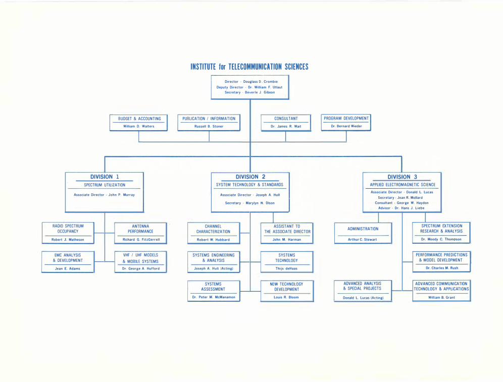
INSTITUTE for TELECOMMUNICATION SCIENCES Director - Douglass 0 . Crombie
Deputy Director - Or. William F. Utlaut
Secretary - Beverle J. Gibson
I BUDGET & ACCOUNTING I PUBLICATION I INFORMATION CONSULTANT I I PROGRAM DEVELOPMENT I William D. Walters Russell B. Stoner Or. James R. Wait Dr. Bernard Wieder
I I I I
DIVISION 1 DIVISION 2 DIVISION 3 SPECTRUM UTILIZATION SYSTEM TECHNOLOGY & STANDARDS APPLIED ELECTROMAGNETIC SCIENCE
Associate Director - John P. Murray Associate Director · Joseph A. Hull Associate Director - Donald L lucas
Secretary - Jean R. Mollard
Secretary - Marylyn N. Olson Consultant · George W. Haydon
Advisor · Dr. Hans J. Liebe
I I I RADIO SPECTRUM ANTENNA CHANNEL ASSISTANT TO
ADMINISTRATION SPECTRUM EXTENSION
OCCUPANCY PERFORMANCE CHARACTERIZATION THE ASSOCIATE DIRECTOR RESEARCH & ANALYSIS I--Robert J. Matheson Richard G. FitzGerrell Robert W. Hubbard John M. Harman Arthur C. Stewart Dr. Moody C. Thompson
EMC ANALYSIS VHF I UHF MODELS SYSTEMS ENGINEERING SYSTEMS PERFORMANCE PREDICTIONS ! & DEVELOPMENT & MOBILE SYSTEMS & ANALYSIS TECHNOLOGY - & MODEL DEVELOPMENT !
Jean E. Adams Or. George A. Hufford Joseph A. Hull (Acting) Thijs deHaas Or. Charles M. Rush
SYSTEMS NEW TECHNOLOGY ADVANCED ANALYSIS ADVANCED COMMUNICATION
ASSESSMENT DEVELOPMENT & SPECIAL PROJECTS TECHNOLOGY & APPLICATIONS
Dr. Peter M. McManamon louis R. Bloom Donald L. lucas (Acting) William 8. Grant
Related Documents