USER'S MANUAL - Positioning Control Edition FX3U/FX3UC SERIES PROGRAMMABLE CONTROLLERS FX3UC Main Unit [Japanese Model (Sink Output)] Transistor Output Line Driver Output FX3U-2HSY-ADP

Welcome message from author
This document is posted to help you gain knowledge. Please leave a comment to let me know what you think about it! Share it to your friends and learn new things together.
Transcript
USER'S MANUAL - Positioning Control Edition
FX3U/FX3UC SERIES PROGRAMMABLE CONTROLLERS
FX3UC Main Unit [Japanese Model (Sink Output)]
Transistor Output
Line Driver OutputFX3U-2HSY-ADP

Safety Precautions(Read these precautions before using.)
Before installing, operating, maintenance or inspecting this product, thoroughly read and understand thismanual and the associated manuals. Also pay careful attention to handle the module properly and safety.
This manual classifies the safety precautions into two categories: and .
Depending on circumstances, procedures indicated by may also be linked to serious results.In any case, it is important to follow the directions for usage.Store this manual in a safe place so that you can take it out and read it whenever necessary. Always forwardit to the end user.
1. DESIGN PRECAUTIONS
Indicates that incorrect handling may cause hazardous conditions, resulting indeath or severe injury.
Indicates that incorrect handling may cause hazardous conditions, resulting inmedium or slight personal injury or physical damage.
Reference
• Provide a safety circuit on the outside of the PLC so that the whole system operates to ensure thesafety even when external power supply trouble or PLC failure occurs.Otherwise, malfunctions or output failures may result in an accident.1) An emergency stop circuit, a protection circuit, an interlock circuit for opposite movements,
such as normal and reverse rotations, and an interlock circuit for preventing damage to themachine at the upper and lower positioning limits should be configured on the outside of thePLC.
2) When the PLC CPU detects an error, such as a watch dog timer error, during self-diagnosis, alloutputs are turned off. When an error that cannot be detected by the PLC CPU occurs in aninput/output control block, output control may be disabled.Design external circuits and mechanisms to ensure safe operations of the machine in such acase.
3) When some sort of error occurs in a relay, triac or transistor of the output unit, output may bekept on or off.For output signals that may lead to serious accidents, design external circuits and mechanismsto ensure safe operations of the machine in such cases.
B-4B-14B-67
Reference
• Do not bundle the control line together with the main circuit or power line. Do not lay the controlline near them.As a rule, lay the control line at least 100mm(3.94") or more away from the maincircuit or power line.Noise may cause malfunctions.
• Install in a manner which prevents excessive force from being applied to the built-in connectorsdedicated to programming, power connectors and I/O connectors.Failure to do so may result in wire breakage or failure of the PLC.
B-4B-14B-67
(1)
Safety Precautions(Read these precautions before using.)
2. WIRING PRECAUTIONS
Reference
• Cut off all phases of the power source externally before installation or wiring work in order to avoidelectric shock or damage of product.
• Make sure to attach the terminal cover offered as an accessory to the product before turning onthe power or starting the operation after installation or wiring work.Failure to do so may cause electric shock.
B-4B-22B-67
Reference
• Connect the AC power supply wiring to the dedicated terminals described in this manual.If an AC power supply is connected to a DC input/output terminal or DC power supply terminal, thePLC will be burnt out.
• Connect the DC power supply wiring to the dedicated terminals described in this manual.If an AC power supply is connected to a DC input/output terminal or DC power supply terminal, thePLC will be burnt out.
• Do not wire vacant terminals externally.Doing so may damage the product.
• Perform class D grounding (grounding resistance: 100Ω or less) to the grounding terminal in theFX3U Series main unit with a 2mm2 or thicker wire.Do not connect the grounding terminal at the same point as a heavy electrical system (refer to themanual of the PLC main unit).
• Perform class D grounding (grounding resistance: 100Ω or less) to the grounding terminal in theFX3UC Series main unit with a wire as thick as possible.Do not connect the grounding terminal at the same point as a heavy electrical system (refer to themanual of the PLC main unit).
• When drilling screw holes or wiring, cutting chips or wire chips should not enter ventilation slits.such an accident may cause fire, failures or malfunctions.
• Use the product in such a status that excessive force is not applied on I/O connectors.Failure to do so may result in wire breakage or failure of the PLC.
• Fit the I/O cables securely to the designated connectors.Contact failures may cause malfunctions.
• Perform wiring properly to the FX3U Series main unit and FX0N/FX2N Series extension equipmentof the terminal block type in accordance with the following precautions.Failure to do so may cause electric shock, short-circuit, wire breakage, or damages to the product.- The disposal size of the cable end should follow the dimensions described in this manual.- Tightening torque should be between 0.5 to 0.8 N•m.
• Observe the following items to wire the lines to the European terminal board. Ignorance of thefollowing items may cause electric shock, short circuit, disconnection, or damage of the product.- The disposal size of the cable end should follow the dimensions described in this manual.- Tightening torque should be between 0.22 to 0.25 N•m.- Twist the end of strand wire and make sure there is no loose wires. - Do not solder-plate the electric wire ends.- Do not connect electric wires of unspecified size or beyond the specified number of electric
wires.- Fix the electric wires so that the terminal block and connected parts of electric wires are not
directly stressed.• Properly perform wiring to the FX Series terminal blocks following the precautions below in order to
prevent electrical shock, short-circuit, breakage of wire, or damage to the product:- The disposal size of the cable end should follow the dimensions described in this manual.- Tightening torque should be between 0.5 to 0.8 N•m.
B-4B-22B-67
(2)
Safety Precautions(Read these precautions before using.)
3. STARTUP AND MAINTENANCE PRECAUTIONS
4. DISPOSAL PRECAUTIONS
5. TRANSPORTATION PRECAUTIONS
Reference
• Do not touch any terminal while the PLC's power is on.Doing so may cause electrical shock or malfunctions.
• Before cleaning or retightening terminals, externally cut off all phases of the power supply.Failure to do so may expose you to shock hazard.
• Before modifying the program under operation or performing operation for forcible output, runningor stopping, carefully read the manual, and sufficiently ensure the safety.An operation error may damage the machine or cause accidents.
B-5B-68
Reference
• Do not disassemble or modify the PLC.Doing so may cause failures, malfunctions or fire.For repair, contact your local Mitsubishi Electric distributor.
• Before connecting or disconnecting any extension cable, turn off power.Failure to do so may cause unit failure or malfunctions.
• Before attaching or detaching the following devices, turn off power.Failure to do so may cause device failure or malfunctions.- Peripheral devices, expansion boards and special adapters- I/O extension blocks/units and terminal blocks
B-5B-68
Reference
• Please contact a company certified in the disposal of electronic waste for environmentally saferecycling and disposal of your device. B-14
Reference
• Before transporting the PLC, turn on the PLC to check that the BATT LED lamp is off and checkthe battery life.If the PLC is transported with the BATT LED lamp on or the battery exhausted, the backed up datamay be unstable during transportation.
• The PLC is precision equipment. During transportation, avoid impacts larger than that is specifiedin the manual of the PLC main unit. Failure to do so may cause failures in the PLC. After transportation, check the operations of the PLC.
B-14
(3)

(4)
FX3U/FX3UC Series PLC User's Manual - Positioning Control Edition
FX3U/FX3UC Series Programmable Controllers
User's Manual [Positioning Control Edition]
Foreword
This manual describes "positioning" function of the MELSEC-F FX3U/FX3UC Series PLC and should be read and understood before attempting to install or use the unit.Store this manual in a safe place so that you can take it out and read it whenever necessary. Always forward it to the end user.
© 2005 MITSUBISHI ELECTRIC CORPORATION
Manual number JY997D16801
Manual revision A
Date 7/2005
This manual confers no industrial property rights or any rights of any other kind, nor does it confer any patentlicenses. Mitsubishi Electric Corporation cannot be held responsible for any problems involving industrial propertyrights which may occur as a result of using the contents noted in this manual.
1
FX3U/FX3UC Series PLC User's Manual - Positioning Control Edition
Outline Precautions• This manual provides information for the use of the FX3U Series Programmable Controllers. The manual
has been written to be used by trained and competent personnel. The definition of such a person or persons is as follows;
1) Any engineer who is responsible for the planning, design and construction of automatic equipmentusing the product associated with this manual should be of a competent nature, trained and qualifiedto the local and national standards required to fulfill that role. These engineers should be fully aware ofall aspects of safety with regards to automated equipment.
2) Any commissioning or service engineer must be of a competent nature, trained and qualified to thelocal and national standards required to fulfill that job. These engineers should also be trained in theuse and maintenance of the completed product. This includes being completely familiar with allassociated documentation for the said product. All maintenance should be carried out in accordancewith established safety practices.
3) All operators of the completed equipment should be trained to use that product in a safe andcoordinated manner in compliance to established safety practices. The operators should also befamiliar with documentation which is connected with the actual operation of the completed equipment.
Note: the term 'completed equipment' refers to a third party constructed device which contains or uses the product associated with this manual
• This product has been manufactured as a general-purpose part for general industries, and has not been designed or manufactured to be incorporated in a device or system used in purposes related to human life.
• Before using the product for special purposes such as nuclear power, electric power, aerospace, medicine or passenger movement vehicles, consult with Mitsubishi Electric.
• This product has been manufactured under strict quality control. However when installing the product where major accidents or losses could occur if the product fails, install appropriate backup or failsafe functions in the system.
• When combining this product with other products, please confirm the standard and the code, or regulations with which the user should follow. Moreover, please confirm the compatibility of this product to the system, machine, and apparatus with which a user is using.
• If in doubt at any stage during the installation of the product, always consult a professional electrical engineer who is qualified and trained to the local and national standards. If in doubt about the operation or use, please consult the nearest Mitsubishi Electric distributor.
• Since the examples indicated by this manual, technical bulletin, catalog, etc. are used as a reference, please use it after confirming the function and safety of the equipment and system. Mitsubishi Electric will accept no responsibility for actual use of the product based on these illustrative examples.
• This manual content, specification etc. may be changed without a notice for improvement.• The information in this manual has been carefully checked and is believed to be accurate; however, if you
have noticed a doubtful point, a doubtful error, etc., please contact the nearest Mitsubishi Electric distributor.
Registration
• Microsoft® and Windows® are either registered trademarks or trademarks of Microsoft Corporation in the United States and/or other countries.
• The company name and the product name to be described in this manual are the registered trademarks or trademarks of each company.
2
FX3U/FX3UC Series PLC User's Manual - Positioning Control Edition Table of Contents
Table of Contents
SAFETY PRECAUTIONS .................................................................................................... 1Functions and Use of This Manual .......................................................................................... 9Related Manuals ...................................................................................................................... 10Generic Names and Abbreviations Used in Manuals .......................................................... 12
A. Common Items
Description of Manual (Common Items) ............................................................................. A-2
1. Introduction A-3
1.1 Outline..........................................................................................................................................A-31.2 Introduction of Products Needed for Positioning..........................................................................A-4
1.2.1 List of Models ...............................................................................................................................A-41.2.2 Main Unit (Transistor Output) .......................................................................................................A-51.2.3 Special Adapter ............................................................................................................................A-51.2.4 Special Function Unit/Block..........................................................................................................A-6
2. Unit Connection A-8
2.1 FX3U PLC ....................................................................................................................................A-82.2 FX3UC PLC ..................................................................................................................................A-92.3 Individual Operation of Special Function Unit (FX2N-10GM, FX2N-20GM) ...............................A-10
3. Comparison of Specifications A-11
3.1 Comparison of Performance Specifications ...............................................................................A-113.1.1 Incorporated Positioning Function [Main Unit (Transistor Output),
High-Speed Output Special Adapter (FX3U-2HSY-ADP)] .....................................................A-113.1.2 Pulse Output Special Function Block [FX2N-1PG(-E), FX2N-10PG] ..........................................A-123.1.3 Positioning Special Function Unit [FX2N-10GM, FX2N-20GM]...................................................A-13
3.2 Comparison of Operation Modes ...............................................................................................A-14
3
FX3U/FX3UC Series PLC User's Manual - Positioning Control Edition Table of Contents
B. Built-in Positioning Function
Description of Manual (Built-in Positioning Function) ...................................................... B-2
1. Outline B-3
1.1 Features .......................................................................................................................................B-31.2 Setup Procedure for Positioning Control......................................................................................B-41.3 Version Numbers of Compatible PLCs ........................................................................................B-71.4 Version Numbers of Compatible Programming Tools..................................................................B-81.5 Assignment of Input/Output Numbers ..........................................................................................B-8
1.5.1 Assignment of Input Numbers ......................................................................................................B-81.5.2 Assignment of Output Numbers .................................................................................................B-101.5.3 Connection of High-Speed Output Special Adapter ...................................................................B-12
2. Specifications B-14
2.1 General Specifications ...............................................................................................................B-152.2 Power Supply Specifications......................................................................................................B-152.3 Performance Specifications .......................................................................................................B-162.4 Input Specifications ....................................................................................................................B-17
2.4.1 FX3U Series main unit (24V DC Input) .......................................................................................B-172.4.2 FX3UC Series main unit (24V DC Input).....................................................................................B-18
2.5 Output Specifications .................................................................................................................B-192.5.1 FX3UC Series main unit (Transistor Output)...............................................................................B-192.5.2 High-Speed Output Special Adapter [FX3U-2HSY-ADP] ...........................................................B-20
2.6 List of Functions .........................................................................................................................B-21
3. Connection of Input/Output Lines and Tightening Torques B-22
3.1 Terminal Board (M3, M3.5) ........................................................................................................B-233.1.1 Terminal Screw Size...................................................................................................................B-233.1.2 Termination.................................................................................................................................B-23
3.2 European Terminal Board ..........................................................................................................B-243.2.1 Cable ..........................................................................................................................................B-243.2.2 Termination of Cable End...........................................................................................................B-243.2.3 Tool.............................................................................................................................................B-24
3.3 Connector...................................................................................................................................B-253.3.1 Cable Connection To Input/Output Connector ...........................................................................B-253.3.2 Setup of Input/Output Connection Connector.............................................................................B-25
4. Before Programming B-27
4.1 List of Related Devices ..............................................................................................................B-274.1.1 Special Auxiliary Relays .............................................................................................................B-274.1.2 Special Data Registers ...............................................................................................................B-28
4.2 Setting of Various Items Regarding Speeds ..............................................................................B-294.2.1 Setting of Various Items Regarding Instructions and Speeds ....................................................B-294.2.2 Setting of Output Pulse Frequency (DVIT, PLSV, DRVI, and DRVA Instructions).....................B-314.2.3 Setting of Zero Return Speed (DSZR/ZRN Instruction)..............................................................B-324.2.4 Setting of Creep Speed (DSZR/ZRN Instruction) .......................................................................B-334.2.5 Setting of Maximum Speed ........................................................................................................B-334.2.6 Setting of Bias Speed.................................................................................................................B-344.2.7 Setting of Acceleration Time.......................................................................................................B-344.2.8 Setting of Deceleration Time ......................................................................................................B-34
4
FX3U/FX3UC Series PLC User's Manual - Positioning Control Edition Table of Contents
4.3 Various Flags for Operation Commands....................................................................................B-354.3.1 Forward Rotation Limit and Reverse Rotation Limit ...................................................................B-354.3.2 Immediate Stoppage of Pulse Output (Pulse Output Stop Command Flag) ..............................B-364.3.3 Designation of Zero Return Direction (DSZR/ZRN Instruction) ..................................................B-364.3.4 CLEAR Signal Output (DSZR/ZRN Instruction)..........................................................................B-384.3.5 Change in Logic of Near-Point (DOG) Signal (DSZR Instruction) ..............................................B-394.3.6 Change in Logic of Zero-Phase Signal (DSZR Instruction) ........................................................B-394.3.7 Designation of interrupt input Signal for DVIT Instruction...........................................................B-404.3.8 Change in Logic of interrupt input Signal (DVIT Instruction) ......................................................B-414.3.9 Acceleration/Deceleration by PLSV Instruction ..........................................................................B-42
4.4 Flag for Monitoring of Current Value and Operation ..................................................................B-434.4.1 Current Value .............................................................................................................................B-434.4.2 Completion of Execution of Instruction ("Instruction execution complete" Flag,
"Instruction execution abnormal end" Flag) ...........................................................................B-444.4.3 "Pulse Output Monitor" (BUSY/READY) Flag.............................................................................B-444.4.4 "Positioning Instruction Activation" Flag .....................................................................................B-44
4.5 Setting of Various Items on PLC Side........................................................................................B-454.5.1 Setting of Common Items Using Program..................................................................................B-454.5.2 Setting of High-Speed Output Special Adapter ..........................................................................B-49
4.6 Setting of Various Items on Servo Amplifier (Drive Unit) Side ...................................................B-514.6.1 Setting of Command Pulse Input Method...................................................................................B-514.6.2 Setting of Electronic Gear (For MELSERVO Series)..................................................................B-554.6.3 Setting of "Servo Ready" Signal (MELSERVO MR-C Series) ....................................................B-56
4.7 Items To Be Observed in Programming.....................................................................................B-574.7.1 Positioning Instruction Activation Timing ....................................................................................B-574.7.2 STOP instruction ........................................................................................................................B-594.7.3 Correction of Backlash ...............................................................................................................B-594.7.4 "Instruction execution complete" Flag of Positioning Instruction and Completion of
Positioning .............................................................................................................................B-594.7.5 Operation Error Flag...................................................................................................................B-624.7.6 Writing Data in RUN Mode .........................................................................................................B-62
4.8 Items To Be Observed in Use of Main Unit (Transistor Output).................................................B-634.9 Caution for Using the High-Speed Output Special Adapter (FX3U-2HSY-ADP)........................B-634.10 Format and Execution of Applied Instruction ...........................................................................B-65
5. Operation Test B-67
5.1 Test Procedure...........................................................................................................................B-695.2 Creation of Test Program...........................................................................................................B-73
6. Mechanical Zero Return (DSZR/ZRN Instruction) B-75
6.1 Types of Mechanical Zero Return Instructions...........................................................................B-756.2 DOG Search Zero Return (DSZR Instruction)............................................................................B-76
6.2.1 Instruction Format.......................................................................................................................B-766.2.2 List of Related devices ...............................................................................................................B-776.2.3 Function and Operation ..............................................................................................................B-796.2.4 Important Points .........................................................................................................................B-85
6.3 Zero Return (ZRN Instruction)....................................................................................................B-866.3.1 Instruction Format.......................................................................................................................B-866.3.2 List of Related devices ...............................................................................................................B-876.3.3 Function and operation...............................................................................................................B-886.3.4 Important Points .........................................................................................................................B-92
5
FX3U/FX3UC Series PLC User's Manual - Positioning Control Edition Table of Contents
7. Absolute Position Detection System (Absolute Current Value Read)-ABS Instruction B-93
7.1 Instruction Format ......................................................................................................................B-937.2 List of Related Devices ..............................................................................................................B-947.3 Function and Operation..............................................................................................................B-947.4 Initial Zero Return.......................................................................................................................B-957.5 Important Points .........................................................................................................................B-95
8. 1-Speed Positioning - DRVI/DRVA Instruction B-96
8.1 Incremental Method and Absolute Method ................................................................................B-968.2 Drive to Increment - DRVI Instruction ........................................................................................B-98
8.2.1 Instruction Format.......................................................................................................................B-988.2.2 List of Related Devices...............................................................................................................B-998.2.3 Function and Operation ............................................................................................................B-1018.2.4 Important Points .......................................................................................................................B-102
8.3 Drive To Absolute (DRVA Instruction)......................................................................................B-1038.3.1 Instruction Format.....................................................................................................................B-1038.3.2 List of Related Devices.............................................................................................................B-1058.3.3 Function and Operation ............................................................................................................B-1068.3.4 Important Points .......................................................................................................................B-107
9. One-speed Interrupt constant quantity feed -DVIT Instruction B-108
9.1 Instruction Format ....................................................................................................................B-1089.2 List of Related Devices ............................................................................................................B-1109.3 Function and Operation............................................................................................................B-1129.4 Important Points .......................................................................................................................B-117
10. Variable Speed Operation (Variable Speed Pulse Output)-PLSV Instruction B-119
10.1 Instruction Format ..................................................................................................................B-11910.2 List of Related Devices ..........................................................................................................B-12110.3 Function and Operation..........................................................................................................B-122
10.3.1 Operation without Acceleration/Deceleration (M8338 = OFF)................................................B-12210.3.2 Operation with Acceleration/Deceleration (M8338 = ON) ......................................................B-123
10.4 Important Points .....................................................................................................................B-125
11. Batch Data Positioning Mode (TBL Instruction) B-126
11.1 Instruction Format ..................................................................................................................B-12611.2 List of Related Devices ..........................................................................................................B-12711.3 Function and Operation..........................................................................................................B-12911.4 Positioning Parameter Setting................................................................................................B-130
11.4.1 Positioning Parameter Setting Using GX Developer ..............................................................B-13011.4.2 Changing of Set Positioning Parameters (Number of Pulses and Frequency).......................B-135
6
FX3U/FX3UC Series PLC User's Manual - Positioning Control Edition Table of Contents
12. Examples of Programs B-137
12.1 Input/Output Assignment........................................................................................................B-13812.2 Programs for Forward/Reverse Rotation (Relay Ladder Program)........................................B-140
12.2.1 Example of Program...............................................................................................................B-14012.3 Programs for Forward/Reverse Rotation (Step Ladder (STL) Program)................................B-143
12.3.1 Example of Program...............................................................................................................B-14312.4 Positioning Using Batch Setting Method ................................................................................B-147
12.4.1 Setting Using GX Developer...................................................................................................B-14712.4.2 Operation Program.................................................................................................................B-149
12.5 Program for Reading Current ABS Value Using ABS Instruction ..........................................B-152
13. Troubleshooting B-153
13.1 LED Indicator Lamp Check ....................................................................................................B-15313.1.1 POWER Indicator Lamp (Statuses: ON, flashing, OFF).........................................................B-15313.1.2 RUN Indicator Lamp (Statuses: ON, OFF) .............................................................................B-15313.1.3 BATT Indicator Lamp (Statuses: ON, OFF)............................................................................B-15413.1.4 ERROR indicator lamp (Statuses: ON, flashing, OFF)...........................................................B-15413.1.5 Pulse Output Destination Device and Rotation Direction Output Indicator Lamp...................B-155
13.2 Error Check ............................................................................................................................B-15713.2.1 Error Code Check Method......................................................................................................B-15713.2.2 Error Codes ............................................................................................................................B-158
13.3 If the Servo Motor or the Stepping Motor Does Not Operate .................................................B-15913.4 If Operation Is Stopped at a Wrong Position..........................................................................B-160
7
FX3U/FX3UC Series PLC User's Manual - Positioning Control Edition Table of Contents
Appendix: Example Connection
Description of Manual (Example of Connection) .......................................................... Apx.-2
Appendix 1. MELSERVO-J3 Series Apx.-3
Appendix 1-1 Main Unit (Transistor Output) .........................................................................Apx.-3Appedix 1-1-1 Sink Input and Sink Output .......................................................................................Apx.-3
Appendix 1-2 High-Speed Output Special Adapter ..............................................................Apx.-5Appedix 1-2-1 Sink Input, Sink Output (Transistor), and Differential Line Driver Output..................Apx.-5
Appendix 1-3 Absolute Position Detection (Transistor Output) ............................................Apx.-6Appendix 1-3-1 Sink Input and Sink Output .....................................................................................Apx.-6
Appendix 2. MELSERVO-J2 (-Super) Series Apx.-8
Appendix 2-1 Main Unit (Transistor Output) .........................................................................Apx.-8Appendix 2-1-1 Sink Input and Sink Output .....................................................................................Apx.-8
Appendix 2-2 High-Speed Output Special Adapter ............................................................Apx.-10Appendix 2-2-1 Sink Input, Sink Output (Transistor), and Differential Line Driver Output..............Apx.-10
Appendix 2-3 Absolute Position Detection (Transistor Output) ..........................................Apx.-11Appendix 2-3-1 Sink Input and Sink Output ...................................................................................Apx.-11
Appendix 3. MELSERVO-H Series Apx.-13
Appendix 3-1 Main Unit (Transistor Output) .......................................................................Apx.-13Appendix 3-1-1 Sink Input and Sink Output ...................................................................................Apx.-13
Appendix 3-2 Absolute Position Detection (Transistor Output) ..........................................Apx.-14Appendix 3-2-1 Sink Input and Sink Output ...................................................................................Apx.-14
Appendix 4. MELSERVO-C Series Apx.-15
Appendix 4-1 Main Unit (Transistor Output) .......................................................................Apx.-15Appendix 4-1-1 Sink Input and Sink Output ...................................................................................Apx.-15
Appendix 4-2 High-Speed Output Special Adapter ............................................................Apx.-17Appendix 4-2-1 Sink Input, Sink Output, and Differential Line Driver Output .................................Apx.-17
Warranty...................................................................................................................................... i
Revised History ......................................................................................................................... ii
8
FX3U/FX3UC Series PLC User's Manual - Positioning Control Edition Functions and Use of This Manual
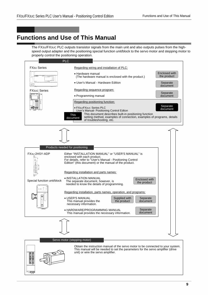
Functions and Use of This ManualThe FX3U/FX3UC PLC outputs transistor signals from the main unit and also outputs pulses from the high-speed output adapter and the positioning special function unit/block to the servo motor and stepping motor to properly control the positioning operation.
PLC
FX3UC Series
Regarding wiring and installation of PLC:
• Hardware manual (The hardware manual is enclosed with the product.)
• User's Manual - Hardware Edition
Regarding sequence program:
• Programming manual
Enclosed withthe product
Separatedocument
Separatedocument
Regarding positioning function:
• FX3U/FX3UC Series PLCUser's Manual- Positioning Control Edtion
Separatedocument
This document describes built-in positioning functionsetting method, examples of connection, examples of programs, detailsof troubleshooting, etc.
Thisdocument
FX3U Series
Products needed for positioning
FX3U-2HSY-ADP
Special function unit/block
Regarding installation, parts names, operation, and programs:
• USER'S MANUAL This manual provides the necessary information.
• HARDWARE/PROGRAMMING MANUAL This manual provides the necessary information.
Regarding installation and parts names:
• INSTALLATION MANUAL The separate document, however, is needed to know the details of programming.
Enclosed withthe product
Either "INSTALLATION MANUAL" or "USER'S MANUAL" isenclosed with each product.For details, refer to "User's Manual - Positioning ControlEdition" (this document) or the manual of the product.
Supplied withthe product
Separatedocument
Separatedocument
POWERERROR
FP
PGORP
f Bf A
ST ART
CLR
DOGX1
X0FX2N-10PG
Servo motor (stepping motor)
Obtain the instruction manual of the servo motor to be connected to your system.This manual will be needed to set the parameters for the servo amplifier (driveunit) or wire the servo amplifier.
9
FX3U/FX3UC Series PLC User's Manual - Positioning Control Edition Related Manuals
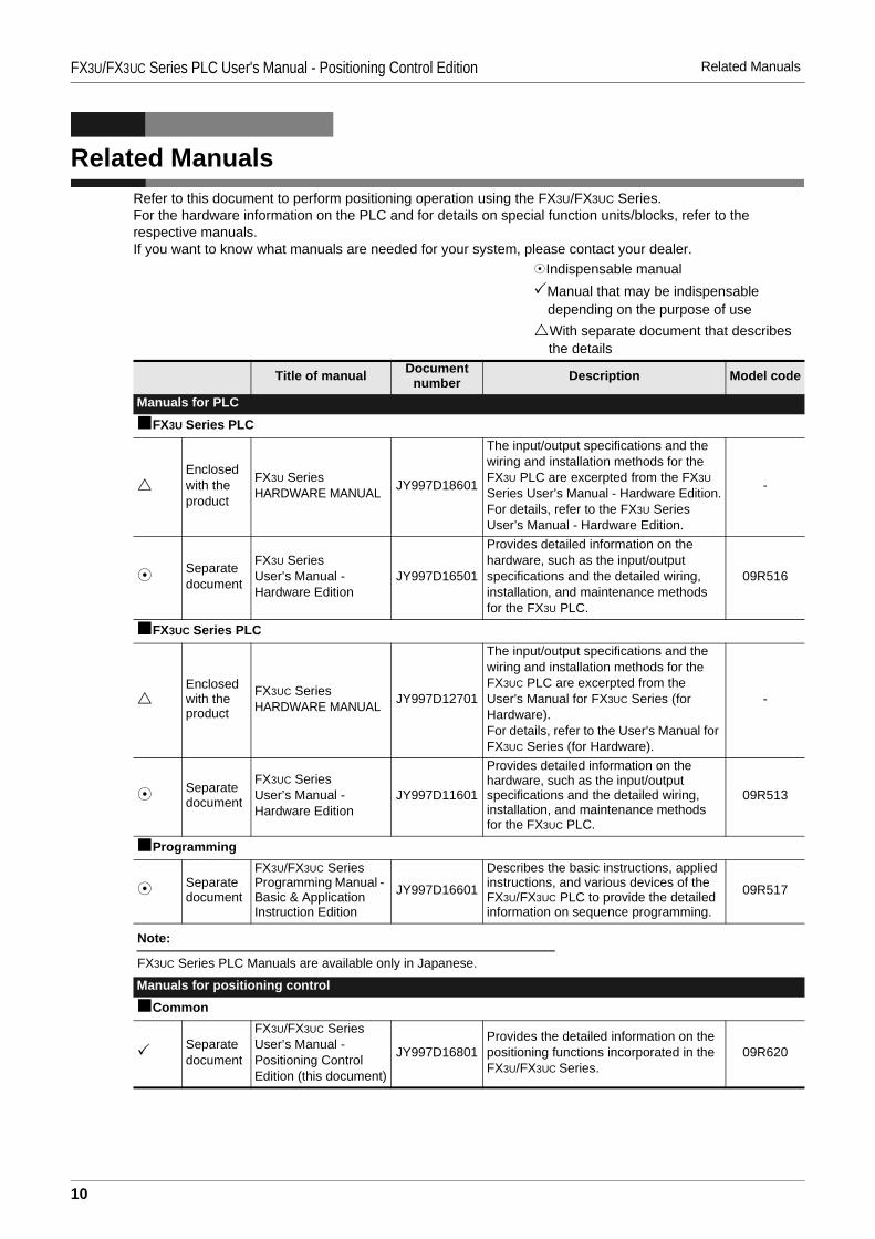
Related ManualsRefer to this document to perform positioning operation using the FX3U/FX3UC Series.For the hardware information on the PLC and for details on special function units/blocks, refer to the respective manuals.If you want to know what manuals are needed for your system, please contact your dealer.
Indispensable manualManual that may be indispensable depending on the purpose of useWith separate document that describes the details
Title of manual Document number Description Model code
Manuals for PLCFX3U Series PLC
Enclosed with the product
FX3U SeriesHARDWARE MANUAL JY997D18601
The input/output specifications and the wiring and installation methods for the FX3U PLC are excerpted from the FX3U Series User’s Manual - Hardware Edition.For details, refer to the FX3U Series User’s Manual - Hardware Edition.
-
Separate document
FX3U SeriesUser’s Manual - Hardware Edition
JY997D16501
Provides detailed information on the hardware, such as the input/output specifications and the detailed wiring, installation, and maintenance methods for the FX3U PLC.
09R516
FX3UC Series PLC
Enclosed with the product
FX3UC SeriesHARDWARE MANUAL JY997D12701
The input/output specifications and the wiring and installation methods for the FX3UC PLC are excerpted from the User's Manual for FX3UC Series (for Hardware).For details, refer to the User's Manual for FX3UC Series (for Hardware).
-
Separate document
FX3UC SeriesUser’s Manual - Hardware Edition
JY997D11601
Provides detailed information on the hardware, such as the input/output specifications and the detailed wiring, installation, and maintenance methods for the FX3UC PLC.
09R513
Programming
Separate document
FX3U/FX3UC SeriesProgramming Manual - Basic & Application Instruction Edition
JY997D16601
Describes the basic instructions, applied instructions, and various devices of the FX3U/FX3UC PLC to provide the detailed information on sequence programming.
09R517
Manuals for positioning controlCommon
Separate document
FX3U/FX3UC SeriesUser’s Manual - Positioning Control Edition (this document)
JY997D16801Provides the detailed information on the positioning functions incorporated in the FX3U/FX3UC Series.
09R620
Note:
FX3UC Series PLC Manuals are available only in Japanese.
10
FX3U/FX3UC Series PLC User's Manual - Positioning Control Edition Related Manuals
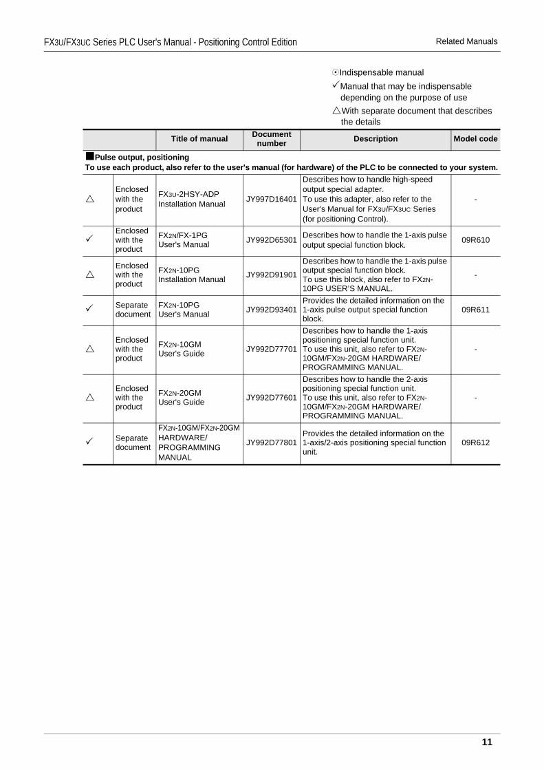
Pulse output, positioningTo use each product, also refer to the user's manual (for hardware) of the PLC to be connected to your system.
Enclosed with the product
FX3U-2HSY-ADPInstallation Manual JY997D16401
Describes how to handle high-speed output special adapter.To use this adapter, also refer to the User's Manual for FX3U/FX3UC Series (for positioning Control).
-
Enclosed with the product
FX2N/FX-1PGUser's Manual JY992D65301 Describes how to handle the 1-axis pulse
output special function block. 09R610
Enclosed with the product
FX2N-10PGInstallation Manual JY992D91901
Describes how to handle the 1-axis pulse output special function block.To use this block, also refer to FX2N-10PG USER’S MANUAL.
-
Separate document
FX2N-10PGUser's Manual JY992D93401
Provides the detailed information on the 1-axis pulse output special function block.
09R611
Enclosed with the product
FX2N-10GMUser's Guide JY992D77701
Describes how to handle the 1-axis positioning special function unit.To use this unit, also refer to FX2N-10GM/FX2N-20GM HARDWARE/PROGRAMMING MANUAL.
-
Enclosed with the product
FX2N-20GMUser's Guide JY992D77601
Describes how to handle the 2-axis positioning special function unit.To use this unit, also refer to FX2N-10GM/FX2N-20GM HARDWARE/PROGRAMMING MANUAL.
-
Separate document
FX2N-10GM/FX2N-20GMHARDWARE/PROGRAMMINGMANUAL
JY992D77801Provides the detailed information on the 1-axis/2-axis positioning special function unit.
09R612
Indispensable manualManual that may be indispensable depending on the purpose of useWith separate document that describes the details
Title of manual Document number Description Model code
11
FX3U/FX3UC Series PLC User's Manual - Positioning Control Edition Generic Names and Abbreviations Used in Manuals
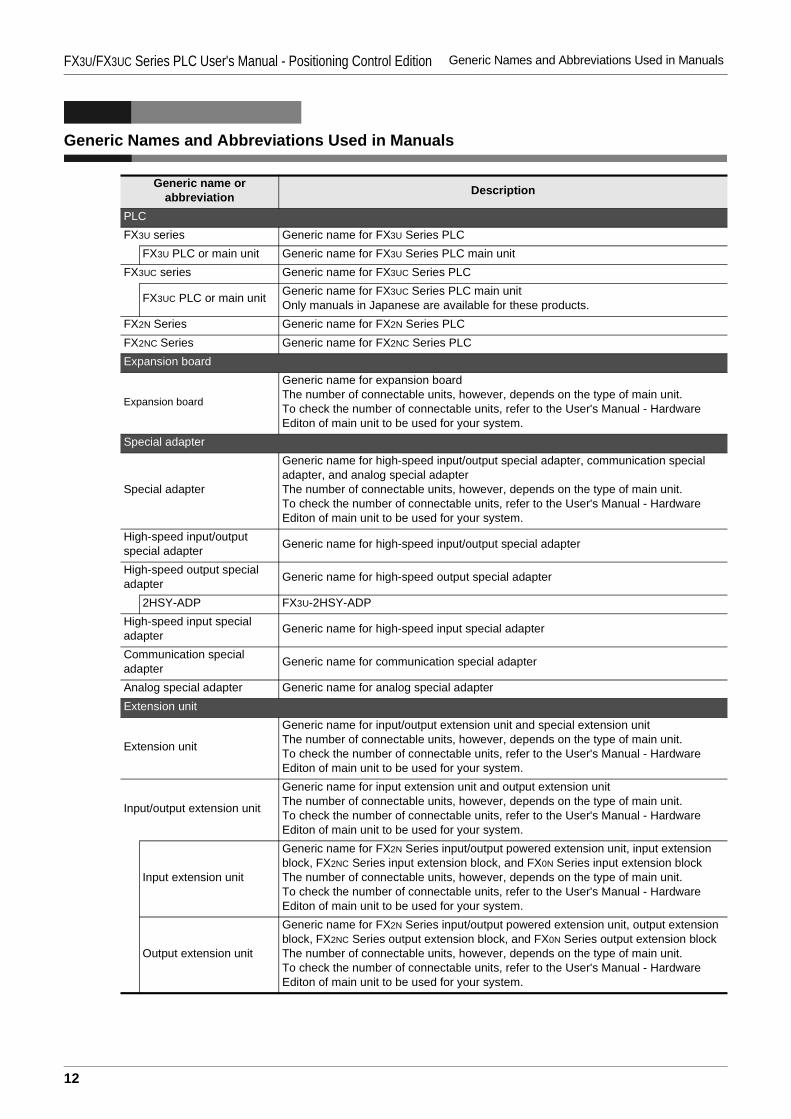
Generic Names and Abbreviations Used in Manuals
Generic name or abbreviation Description
PLCFX3U series Generic name for FX3U Series PLC
FX3U PLC or main unit Generic name for FX3U Series PLC main unitFX3UC series Generic name for FX3UC Series PLC
FX3UC PLC or main unit Generic name for FX3UC Series PLC main unitOnly manuals in Japanese are available for these products.
FX2N Series Generic name for FX2N Series PLCFX2NC Series Generic name for FX2NC Series PLCExpansion board
Expansion board
Generic name for expansion boardThe number of connectable units, however, depends on the type of main unit.To check the number of connectable units, refer to the User's Manual - Hardware Editon of main unit to be used for your system.
Special adapter
Special adapter
Generic name for high-speed input/output special adapter, communication special adapter, and analog special adapterThe number of connectable units, however, depends on the type of main unit.To check the number of connectable units, refer to the User's Manual - Hardware Editon of main unit to be used for your system.
High-speed input/output special adapter Generic name for high-speed input/output special adapter
High-speed output special adapter Generic name for high-speed output special adapter
2HSY-ADP FX3U-2HSY-ADPHigh-speed input special adapter Generic name for high-speed input special adapter
Communication special adapter Generic name for communication special adapter
Analog special adapter Generic name for analog special adapterExtension unit
Extension unit
Generic name for input/output extension unit and special extension unitThe number of connectable units, however, depends on the type of main unit.To check the number of connectable units, refer to the User's Manual - Hardware Editon of main unit to be used for your system.
Input/output extension unit
Generic name for input extension unit and output extension unitThe number of connectable units, however, depends on the type of main unit. To check the number of connectable units, refer to the User's Manual - Hardware Editon of main unit to be used for your system.
Input extension unit
Generic name for FX2N Series input/output powered extension unit, input extension block, FX2NC Series input extension block, and FX0N Series input extension blockThe number of connectable units, however, depends on the type of main unit.To check the number of connectable units, refer to the User's Manual - Hardware Editon of main unit to be used for your system.
Output extension unit
Generic name for FX2N Series input/output powered extension unit, output extension block, FX2NC Series output extension block, and FX0N Series output extension blockThe number of connectable units, however, depends on the type of main unit.To check the number of connectable units, refer to the User's Manual - Hardware Editon of main unit to be used for your system.
12
FX3U/FX3UC Series PLC User's Manual - Positioning Control Edition Generic Names and Abbreviations Used in Manuals
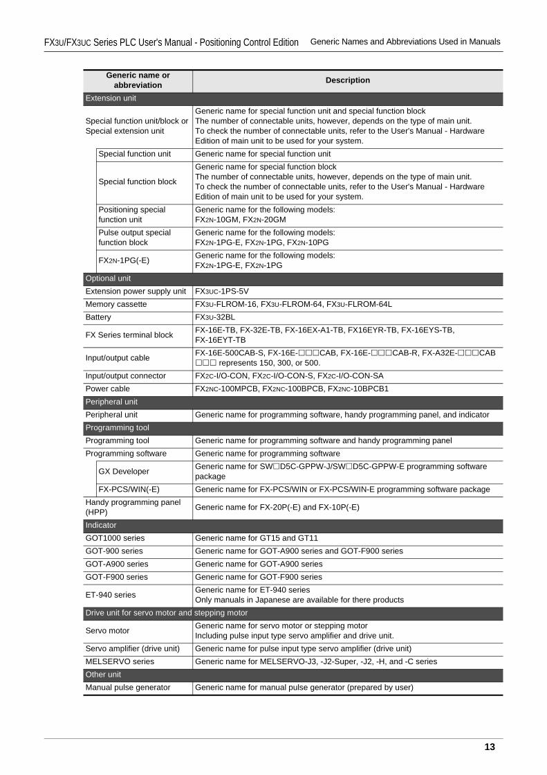
Extension unit
Special function unit/block orSpecial extension unit
Generic name for special function unit and special function blockThe number of connectable units, however, depends on the type of main unit.To check the number of connectable units, refer to the User's Manual - Hardware Edition of main unit to be used for your system.
Special function unit Generic name for special function unit
Special function block
Generic name for special function blockThe number of connectable units, however, depends on the type of main unit.To check the number of connectable units, refer to the User's Manual - Hardware Edition of main unit to be used for your system.
Positioning special function unit
Generic name for the following models:FX2N-10GM, FX2N-20GM
Pulse output special function block
Generic name for the following models:FX2N-1PG-E, FX2N-1PG, FX2N-10PG
FX2N-1PG(-E) Generic name for the following models:FX2N-1PG-E, FX2N-1PG
Optional unitExtension power supply unit FX3UC-1PS-5VMemory cassette FX3U-FLROM-16, FX3U-FLROM-64, FX3U-FLROM-64LBattery FX3U-32BL
FX Series terminal block FX-16E-TB, FX-32E-TB, FX-16EX-A1-TB, FX16EYR-TB, FX-16EYS-TB, FX-16EYT-TB
Input/output cable FX-16E-500CAB-S, FX-16E- CAB, FX-16E- CAB-R, FX-A32E- CAB represents 150, 300, or 500.
Input/output connector FX2C-I/O-CON, FX2C-I/O-CON-S, FX2C-I/O-CON-SAPower cable FX2NC-100MPCB, FX2NC-100BPCB, FX2NC-10BPCB1Peripheral unitPeripheral unit Generic name for programming software, handy programming panel, and indicatorProgramming toolProgramming tool Generic name for programming software and handy programming panelProgramming software Generic name for programming software
GX Developer Generic name for SW D5C-GPPW-J/SW D5C-GPPW-E programming software package
FX-PCS/WIN(-E) Generic name for FX-PCS/WIN or FX-PCS/WIN-E programming software packageHandy programming panel (HPP) Generic name for FX-20P(-E) and FX-10P(-E)
IndicatorGOT1000 series Generic name for GT15 and GT11GOT-900 series Generic name for GOT-A900 series and GOT-F900 seriesGOT-A900 series Generic name for GOT-A900 seriesGOT-F900 series Generic name for GOT-F900 series
ET-940 series Generic name for ET-940 seriesOnly manuals in Japanese are available for there products
Drive unit for servo motor and stepping motor
Servo motor Generic name for servo motor or stepping motorIncluding pulse input type servo amplifier and drive unit.
Servo amplifier (drive unit) Generic name for pulse input type servo amplifier (drive unit)MELSERVO series Generic name for MELSERVO-J3, -J2-Super, -J2, -H, and -C seriesOther unitManual pulse generator Generic name for manual pulse generator (prepared by user)
Generic name or abbreviation Description
13

FX3U/FX3UC Series PLC User's Manual - Positioning Control Edition Generic Names and Abbreviations Used in Manuals
ManualManual for FX3U hardware FX3U Series User's Manual - Hardware EditionManual for FX3UC hardware This manual is available only in Japanese.Programming manual FX3U/FX3UC Series Programming Manual - Basic and Applied Instructions EditionCommunication control manual FX Series User's Manual - Data Communication Edition
Analog control manual FX3U/FX3UC Series User's Manual - Analog Control EditionPositioning control manual FX3U/FX3UC Series User's Manual - Positioning Control Edition
Generic name or abbreviation Description
14
A
Comm
on Items
B
Built-in Positioning Function
Apx.
Example
ConnectionFX3U/FX3UC Series PLC User's Manual - Positioning Control EditionCommon Items
FX3U/FX3UC Series Programmable Controllers
User’s Manual [Positioning Control Edition]A. Common Items
Foreword
"Common Items" describes the outline of "positioning" function incorporated in the MELSEC-F FX3U/FX3UC Series PLC and should be read and understood before attempting to install or use the unit.Store this manual in a safe place so that you can take it out and read it whenever necessary. Always forward it to the end user.
© 2005 MITSUBISHI ELECTRIC CORPORATION
This manual confers no industrial property rights or any rights of any other kind, nor does it confer any patentlicenses. Mitsubishi Electric Corporation cannot be held responsible for any problems involving industrial propertyrights which may occur as a result of using the contents noted in this manual.
A - 1
FX3U/FX3UC Series PLC User's Manual - Positioning Control EditionCommon Items
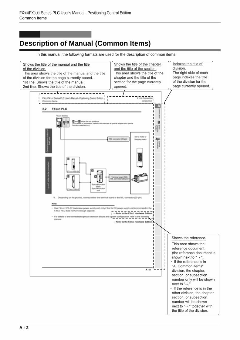
Description of Manual (Common Items)In this manual, the following formats are used for the description of common items:
A - 2
1 Introduction1.1 Outline
FX3U/FX3UC Series PLC User's Manual - Positioning Control EditionCommon Items
A
Comm
on Items
B
Built-in Positioning Function
Apx.
Example
Connection
1. Introduction
This manual describes the positioning control for the FX3U/FX3UC PLC.In this chapter, various products needed for positioning are described.
1.1 Outline
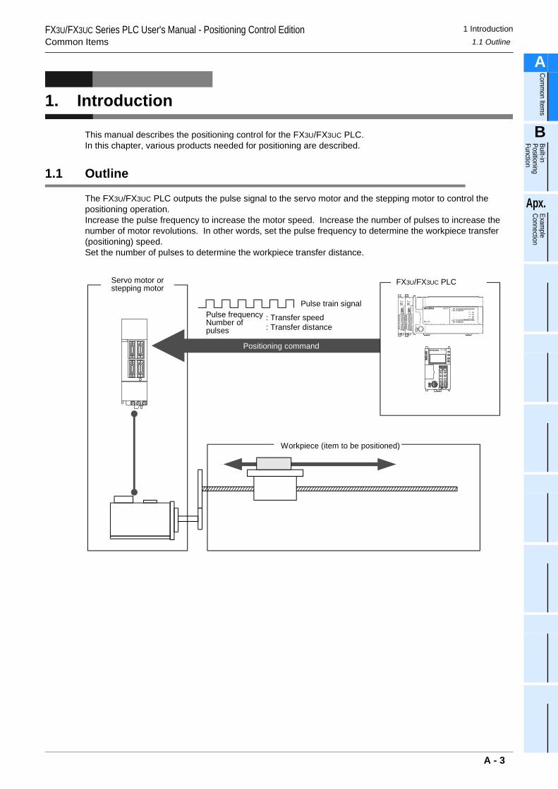
The FX3U/FX3UC PLC outputs the pulse signal to the servo motor and the stepping motor to control the positioning operation.Increase the pulse frequency to increase the motor speed. Increase the number of pulses to increase the number of motor revolutions. In other words, set the pulse frequency to determine the workpiece transfer (positioning) speed. Set the number of pulses to determine the workpiece transfer distance.
Pulse train signalPulse frequencyNumber ofpulses
: Transfer speed: Transfer distance
Positioning command
FX3U/FX3UC PLCServo motor orstepping motor
Workpiece (item to be positioned)
A - 3
1 Introduction1.2 Introduction of Products Needed for Positioning
FX3U/FX3UC Series PLC User's Manual - Positioning Control EditionCommon Items
1.2 Introduction of Products Needed for Positioning
To control the positioning operation, use the positioning function incorporated in main unit (including special adapters), and also the special function units/blocks. The function, however, depends on the unit. Select units optimum for the purpose of use.
1.2.1 List of Models
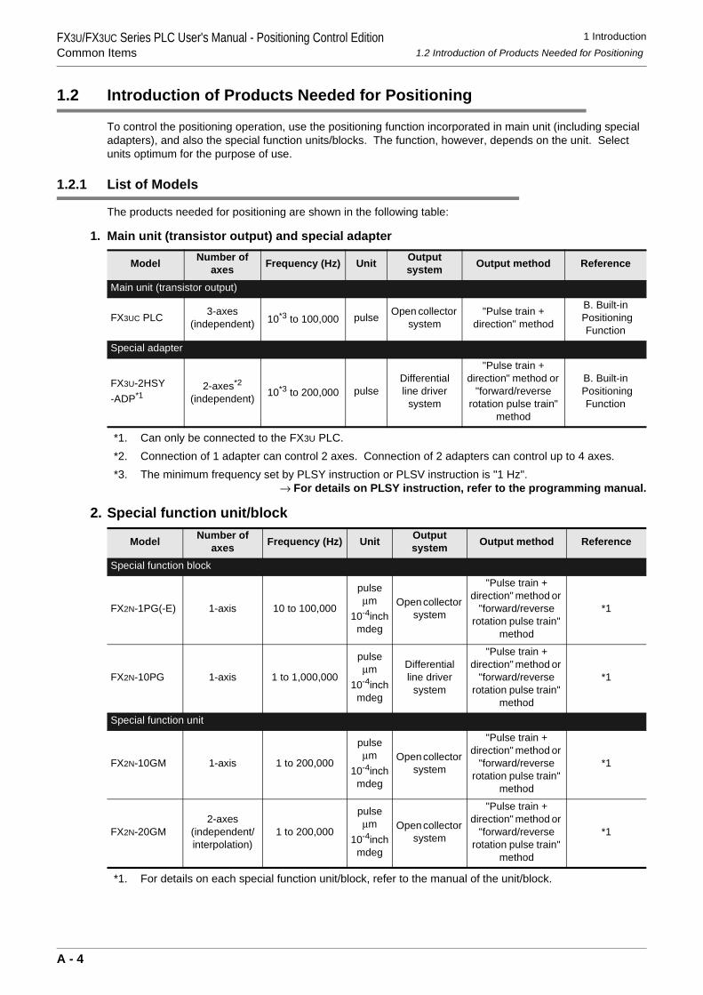
The products needed for positioning are shown in the following table:
1. Main unit (transistor output) and special adapter
*1. Can only be connected to the FX3U PLC.*2. Connection of 1 adapter can control 2 axes. Connection of 2 adapters can control up to 4 axes.*3. The minimum frequency set by PLSY instruction or PLSV instruction is "1 Hz".
→ For details on PLSY instruction, refer to the programming manual.
2. Special function unit/block
*1. For details on each special function unit/block, refer to the manual of the unit/block.
Model Number of axes Frequency (Hz) Unit Output
system Output method Reference
Main unit (transistor output)
FX3UC PLC 3-axes(independent) 10*3 to 100,000 pulse Open collector
system"Pulse train +
direction" method
B. Built-in Positioning
Function
Special adapter
FX3U-2HSY-ADP*1
2-axes*2 (independent) 10*3 to 200,000 pulse
Differential line driver
system
"Pulse train + direction" method or
"forward/reverse rotation pulse train"
method
B. Built-in Positioning
Function
Model Number of axes Frequency (Hz) Unit Output
system Output method Reference
Special function block
FX2N-1PG(-E) 1-axis 10 to 100,000
pulseµm
10-4inchmdeg
Open collector system
"Pulse train + direction" method or
"forward/reverse rotation pulse train"
method
*1
FX2N-10PG 1-axis 1 to 1,000,000
pulseµm
10-4inchmdeg
Differential line driver
system
"Pulse train + direction" method or
"forward/reverse rotation pulse train"
method
*1
Special function unit
FX2N-10GM 1-axis 1 to 200,000
pulseµm
10-4inchmdeg
Open collector system
"Pulse train + direction" method or
"forward/reverse rotation pulse train"
method
*1
FX2N-20GM2-axes
(independent/interpolation)
1 to 200,000
pulseµm
10-4inchmdeg
Open collector system
"Pulse train + direction" method or
"forward/reverse rotation pulse train"
method
*1
A - 4
1 Introduction1.2 Introduction of Products Needed for Positioning
FX3U/FX3UC Series PLC User's Manual - Positioning Control EditionCommon Items
A
Comm
on Items
B
Built-in Positioning Function
Apx.
Example
Connection
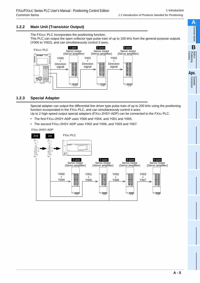
1.2.2 Main Unit (Transistor Output)
The FX3UC PLC incorporates the positioning function.This PLC can output the open collector type pulse train of up to 100 kHz from the general-purpose outputs (Y000 to Y002), and can simultaneously control 3 axes.
1.2.3 Special Adapter
Special adapter can output the differential line driver type pulse train of up to 200 kHz using the positioning function incorporated in the FX3U PLC, and can simultaneously control 4 axes.Up to 2 high-speed output special adapters (FX3U-2HSY-ADP) can be connected to the FX3U PLC.• The first FX3U-2HSY-ADP uses Y000 and Y004, and Y001 and Y005.• The second FX3U-2HSY-ADP uses Y002 and Y006, and Y003 and Y007.
Y000+
Directionsignal
Y001+
Directionsignal
Y002+
Directionsignal
FX3UC PLC1-axis 2-axes 3-axes
Servo motor(Servo amplifier)
Servo motor(Servo amplifier)
Servo motor(Servo amplifier)
FX3U PLC
FX3U-2HSY-ADP
Y000+
Y004
Y001+
Y005
Y002+
Y006
1st
2-axes 3-axes
2nd
1-axis
Y003+
Y007
4-axesServo motor
(Servo amplifier)Servo motor
(Servo amplifier)Servo motor
(Servo amplifier)Servo motor
(Servo amplifier)
A - 5
1 Introduction1.2 Introduction of Products Needed for Positioning
FX3U/FX3UC Series PLC User's Manual - Positioning Control EditionCommon Items
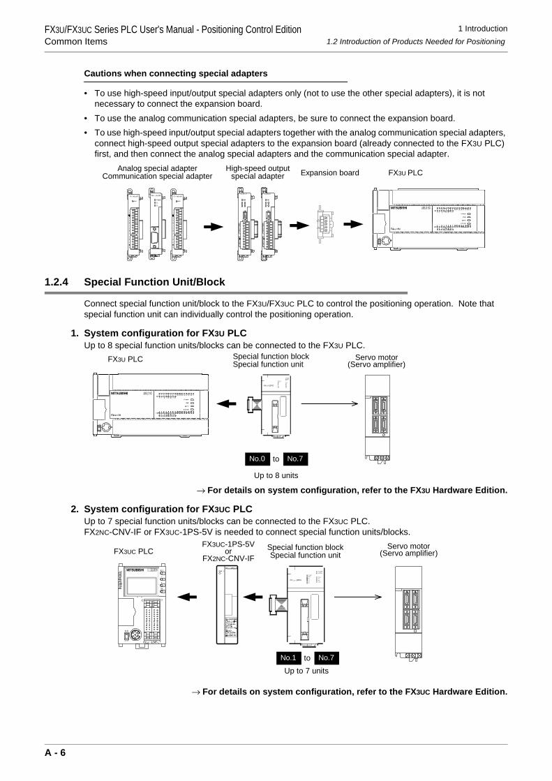
Cautions when connecting special adapters
• To use high-speed input/output special adapters only (not to use the other special adapters), it is not necessary to connect the expansion board.
• To use the analog communication special adapters, be sure to connect the expansion board.• To use high-speed input/output special adapters together with the analog communication special adapters,
connect high-speed output special adapters to the expansion board (already connected to the FX3U PLC) first, and then connect the analog special adapters and the communication special adapter.
1.2.4 Special Function Unit/Block
Connect special function unit/block to the FX3U/FX3UC PLC to control the positioning operation. Note that special function unit can individually control the positioning operation.
1. System configuration for FX3U PLCUp to 8 special function units/blocks can be connected to the FX3U PLC.
→ For details on system configuration, refer to the FX3U Hardware Edition.
2. System configuration for FX3UC PLCUp to 7 special function units/blocks can be connected to the FX3UC PLC.FX2NC-CNV-IF or FX3UC-1PS-5V is needed to connect special function units/blocks.
→ For details on system configuration, refer to the FX3UC Hardware Edition.
RD
RDA
RDB
SDA
SDB
SG
SD
FX3U PLCExpansion boardHigh-speed outputspecial adapter
Analog special adapterCommunication special adapter
Special function blockSpecial function unit
No.0 No.7to
Up to 8 units
FX3U PLC
POWERERROR
FP
PGORP
f Bf A
ST ART
CLR
DOGX1
X0FX2N-10PG
Servo motor(Servo amplifier)
FX3UC PLCFX3UC-1PS-5V
orFX2NC-CNV-IF
Special function blockSpecial function unit
No.1 No.7toUp to 7 units
POWERERROR
FPPGO
RP
f Bf A
ST ART
CLR
DOG
X1X0
FX 2N -10PG
Servo motor(Servo amplifier)
A - 6
1 Introduction1.2 Introduction of Products Needed for Positioning
FX3U/FX3UC Series PLC User's Manual - Positioning Control EditionCommon Items
A
Comm
on Items
B
Built-in Positioning Function
Apx.
Example
Connection
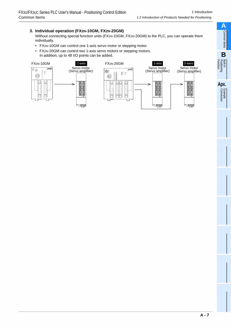
3. Individual operation (FX2N-10GM, FX2N-20GM)Without connecting special function units (FX2N-10GM, FX2N-20GM) to the PLC, you can operate them individually.• FX2N-10GM can control one 1-axis servo motor or stepping motor.• FX2N-20GM can control two 1-axis servo motors or stepping motors.
In addition, up to 48 I/O points can be added.
Servo motor(Servo amplifier)
2-axesServo motor
(Servo amplifier)
1-axisServo motor
(Servo amplifier)
1-axisFX2N-10GM FX2N-20GM
A - 7
FX3U/FX3UC Series PLC User's Manual - Positioning Control EditionCommon Items
2 Unit Connection2.1 FX3U PLC
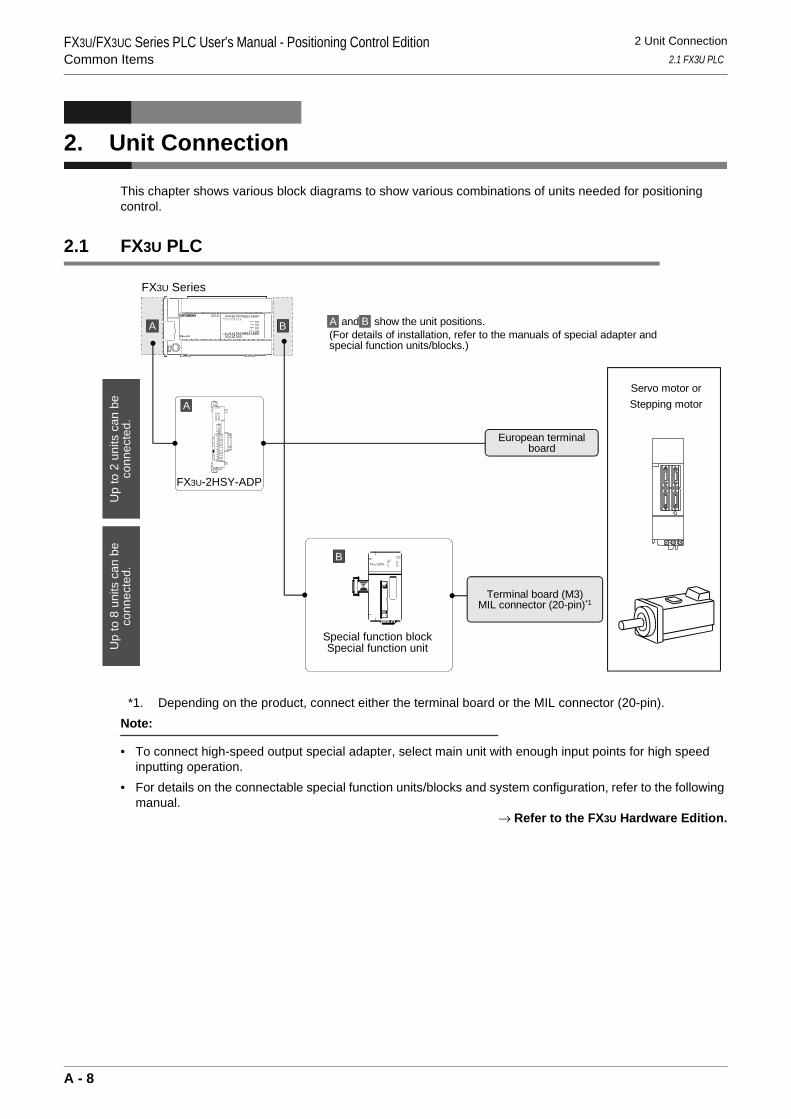
2. Unit Connection
This chapter shows various block diagrams to show various combinations of units needed for positioning control.
2.1 FX3U PLC
*1. Depending on the product, connect either the terminal board or the MIL connector (20-pin). Note:
• To connect high-speed output special adapter, select main unit with enough input points for high speed inputting operation.
• For details on the connectable special function units/blocks and system configuration, refer to the following manual.
→ Refer to the FX3U Hardware Edition.
Up
to 2
uni
ts c
an b
eco
nnec
ted.
Servo motor orStepping motor
European terminalboard
FX3U Series
A B
Special function blockSpecial function unit
Terminal board (M3)MIL connector (20-pin)*1
B and show the unit positions.(For details of installation, refer to the manuals of special adapter andspecial function units/blocks.)
A
FX3U-2HSY-ADP
A
B
Up
to 8
uni
ts c
an b
eco
nnec
ted.
FX2N-10PGf Bf A
STARTDOG
X1X0
POWERERROR
FPPGO
RPCLR
A - 8
FX3U/FX3UC Series PLC User's Manual - Positioning Control EditionCommon Items
2 Unit Connection2.2 FX3UC PLC
A
Comm
on Items
B
Built-in Positioning Function
Apx.
Example
Connection
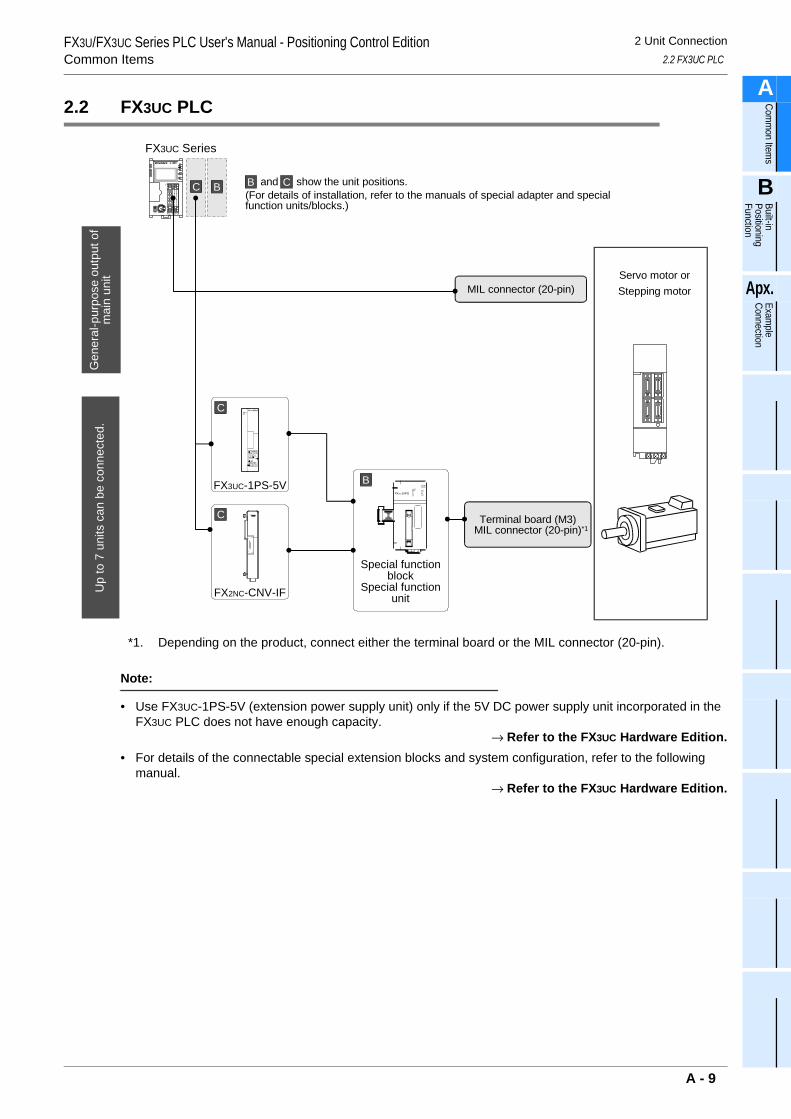
2.2 FX3UC PLC
*1. Depending on the product, connect either the terminal board or the MIL connector (20-pin).
Note:
• Use FX3UC-1PS-5V (extension power supply unit) only if the 5V DC power supply unit incorporated in the FX3UC PLC does not have enough capacity.
→ Refer to the FX3UC Hardware Edition.• For details of the connectable special extension blocks and system configuration, refer to the following
manual.→ Refer to the FX3UC Hardware Edition.
MIL connector (20-pin)
FX3UC Series
C B
Up
to 7
uni
ts c
an b
e co
nnec
ted.
C and show the unit positions.(For details of installation, refer to the manuals of special adapter and specialfunction units/blocks.)
B
FX3UC-1PS-5V
Servo motor orStepping motor
Special functionblock
Special functionunit
Terminal board (M3)MIL connector (20-pin)
FX2NC-CNV-IF
Gen
eral
-pur
pose
out
put o
fm
ain
unit
C
C
BFX2N-10PG
f Bf A
STARTDOG
X1X0
POWERERROR
FPPGO
RPCLR
*1
A - 9
FX3U/FX3UC Series PLC User's Manual - Positioning Control EditionCommon Items
2 Unit Connection2.3 Individual Operation of Special Function Unit (FX2N-10GM, FX2N-20GM)
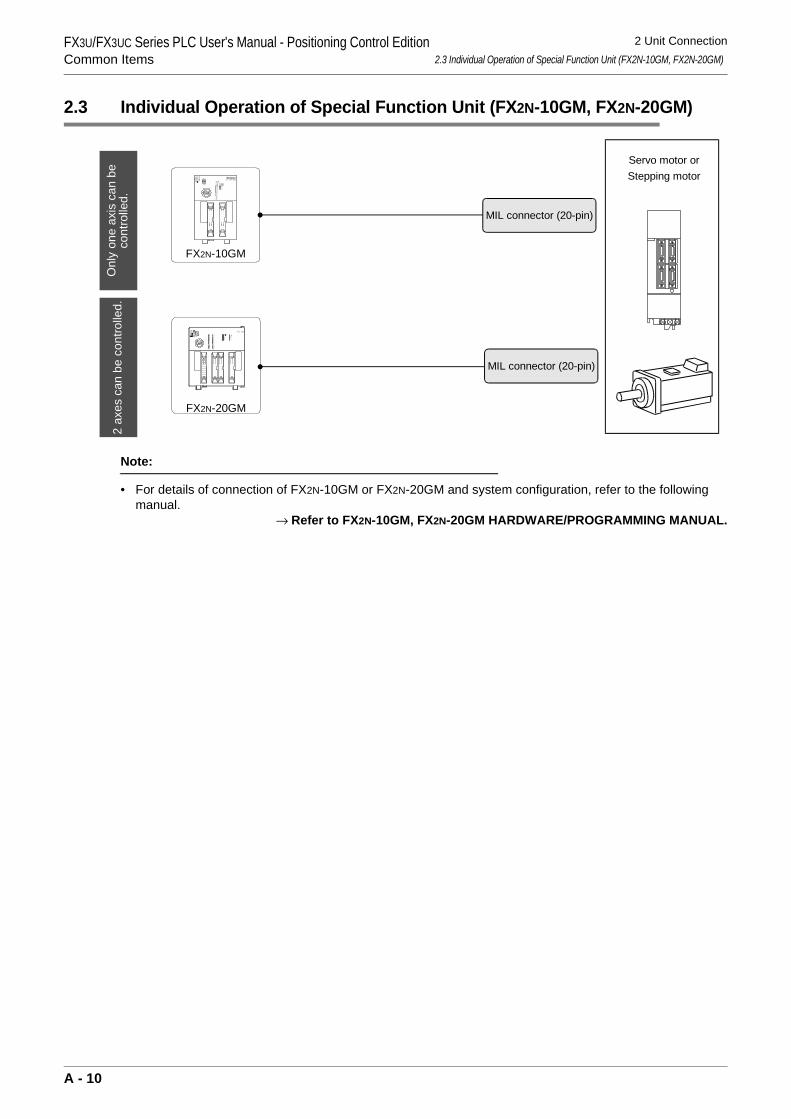
2.3 Individual Operation of Special Function Unit (FX2N-10GM, FX2N-20GM)
Note:
• For details of connection of FX2N-10GM or FX2N-20GM and system configuration, refer to the following manual.
→ Refer to FX2N-10GM, FX2N-20GM HARDWARE/PROGRAMMING MANUAL.
Onl
y on
e ax
is c
an b
eco
ntro
lled.
Servo motor orStepping motor
MIL connector (20-pin)
MIL connector (20-pin)
FX2N-10GM
2 ax
es c
an b
e co
ntro
lled.
FX2N-20GM
A - 10
3 Comparison of Specifications3.1 Comparison of Performance Specifications
FX3U/FX3UC Series PLC User's Manual - Positioning Control EditionCommon Items
A
Comm
on Items
B
Built-in Positioning Function
Apx.
Example
Connection
3. Comparison of Specifications
The specifications of each product needed for positioning are shown below. Select products optimum for your system.
3.1 Comparison of Performance Specifications
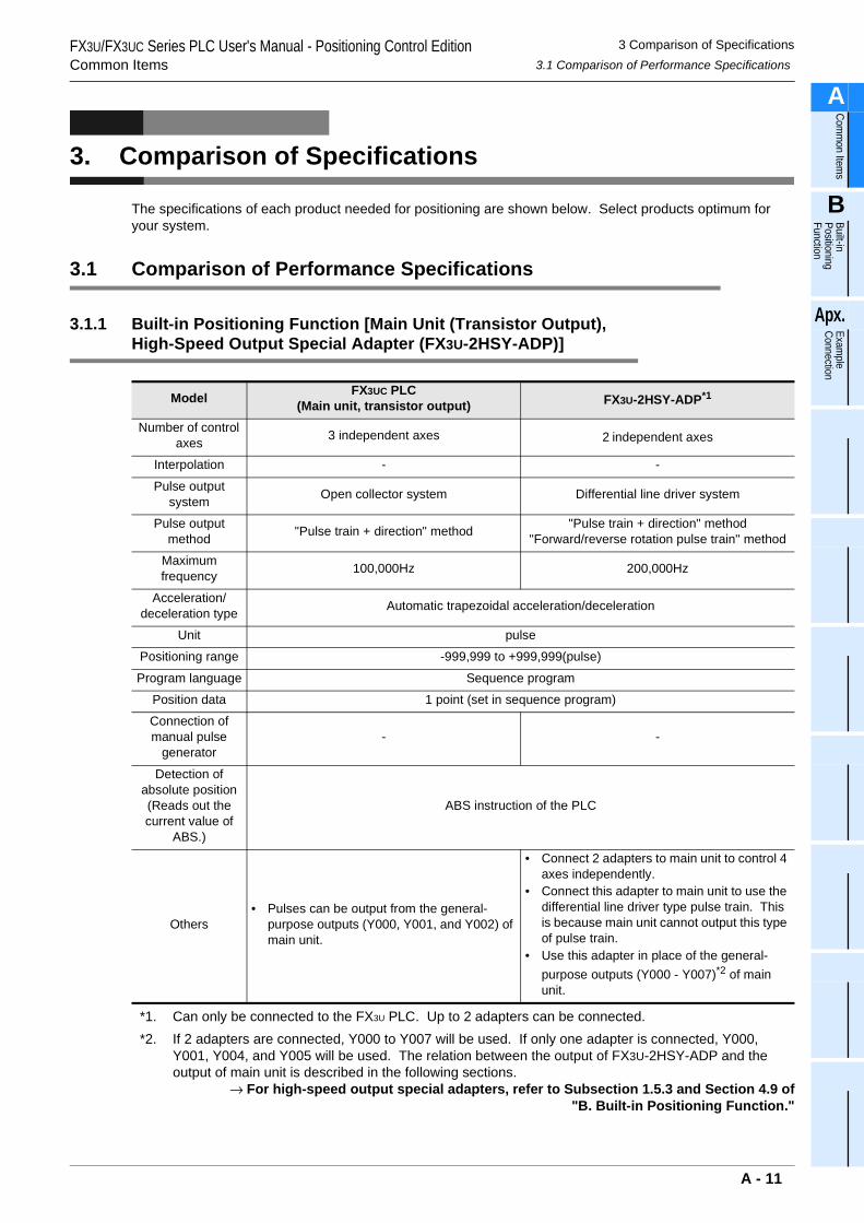
3.1.1 Built-in Positioning Function [Main Unit (Transistor Output), High-Speed Output Special Adapter (FX3U-2HSY-ADP)]
*1. Can only be connected to the FX3U PLC. Up to 2 adapters can be connected.*2. If 2 adapters are connected, Y000 to Y007 will be used. If only one adapter is connected, Y000,
Y001, Y004, and Y005 will be used. The relation between the output of FX3U-2HSY-ADP and the output of main unit is described in the following sections.
→ For high-speed output special adapters, refer to Subsection 1.5.3 and Section 4.9 of"B. Built-in Positioning Function."
Model FX3UC PLC(Main unit, transistor output) FX3U-2HSY-ADP*1
Number of control axes 3 independent axes 2 independent axes
Interpolation - -
Pulse outputsystem Open collector system Differential line driver system
Pulse output method "Pulse train + direction" method "Pulse train + direction" method
"Forward/reverse rotation pulse train" method
Maximumfrequency 100,000Hz 200,000Hz
Acceleration/deceleration type Automatic trapezoidal acceleration/deceleration
Unit pulse
Positioning range -999,999 to +999,999(pulse)
Program language Sequence program
Position data 1 point (set in sequence program)
Connection of manual pulse
generator- -
Detection ofabsolute position(Reads out the current value of
ABS.)
ABS instruction of the PLC
Others• Pulses can be output from the general-
purpose outputs (Y000, Y001, and Y002) of main unit.
• Connect 2 adapters to main unit to control 4 axes independently.
• Connect this adapter to main unit to use the differential line driver type pulse train. This is because main unit cannot output this type of pulse train.
• Use this adapter in place of the general-purpose outputs (Y000 - Y007)*2 of main unit.
A - 11
3 Comparison of Specifications3.1 Comparison of Performance Specifications
FX3U/FX3UC Series PLC User's Manual - Positioning Control EditionCommon Items
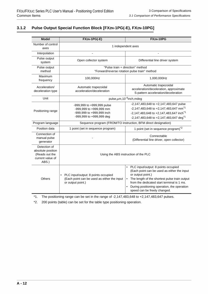
3.1.2 Pulse Output Special Function Block [FX2N-1PG(-E), FX2N-10PG]
*1. The positioning range can be set in the range of -2,147,483,648 to +2,147,483,647 pulses.*2. 200 points (table) can be set for the table type positioning operation.
Model FX2N-1PG(-E) FX2N-10PGNumber of control
axes 1 independent axes
Interpolation - -
Pulse outputsystem Open collector system Differential line driver system
Pulse output method
"Pulse train + direction" method"Forward/reverse rotation pulse train" method
Maximumfrequency 100,000Hz 1,000,000Hz
Acceleration/deceleration type
Automatic trapezoidalacceleration/deceleration
Automatic trapezoidalacceleration/deceleration, approximate
S-pattern acceleration/deceleration
Unit pulse,µm,10-4inch,mdeg
Positioning range
-999,999 to +999,999 pulse-999,999 to +999,999 mm-999,999 to +999,999 inch-999,999 to +999,999 deg
-2,147,483,648 to +2,147,483,647 pulse-2,147,483,648 to +2,147,483,647 mm*1
-2,147,483,648 to +2,147,483,647 inch*1
-2,147,483,648 to +2,147,483,647 deg*1
Program language Sequence program (FROM/TO instruction, BFM direct designation)
Position data 1 point (set in sequence program) 1 point (set in sequence program)*2
Connection of manual pulse
generator- Connectable
(Differential line driver, open collector)
Detection ofabsolute position(Reads out the current value of
ABS.)
Using the ABS instruction of the PLC
Others• PLC input/output: 8 points occupied
(Each point can be used as either the input or output point.)
• PLC input/output: 8 points occupied(Each point can be used as either the input or output point.)
• The length of the shortest pulse train output from the dedicated start terminal is 1 ms.
• During positioning operation, the operation speed can be freely changed.
A - 12
3 Comparison of Specifications3.1 Comparison of Performance Specifications
FX3U/FX3UC Series PLC User's Manual - Positioning Control EditionCommon Items
A
Comm
on Items
B
Built-in Positioning Function
Apx.
Example
Connection
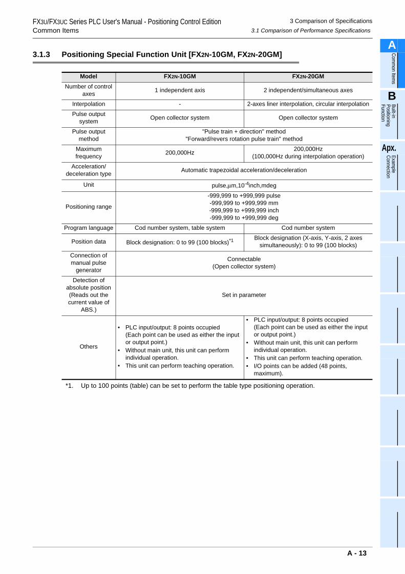
3.1.3 Positioning Special Function Unit [FX2N-10GM, FX2N-20GM]
*1. Up to 100 points (table) can be set to perform the table type positioning operation.
Model FX2N-10GM FX2N-20GMNumber of control
axes 1 independent axis 2 independent/simultaneous axes
Interpolation - 2-axes liner interpolation, circular interpolation
Pulse outputsystem Open collector system Open collector system
Pulse output method
"Pulse train + direction" method"Forward/revers rotation pulse train" method
Maximumfrequency 200,000Hz 200,000Hz
(100,000Hz during interpolation operation)
Acceleration/deceleration type Automatic trapezoidal acceleration/deceleration
Unit pulse,µm,10-4inch,mdeg
Positioning range
-999,999 to +999,999 pulse-999,999 to +999,999 mm-999,999 to +999,999 inch-999,999 to +999,999 deg
Program language Cod number system, table system Cod number system
Position data Block designation: 0 to 99 (100 blocks)*1 Block designation (X-axis, Y-axis, 2 axes simultaneously): 0 to 99 (100 blocks)
Connection of manual pulse
generator
Connectable(Open collector system)
Detection ofabsolute position(Reads out the current value of
ABS.)
Set in parameter
Others
• PLC input/output: 8 points occupied(Each point can be used as either the input or output point.)
• Without main unit, this unit can perform individual operation.
• This unit can perform teaching operation.
• PLC input/output: 8 points occupied(Each point can be used as either the input or output point.)
• Without main unit, this unit can perform individual operation.
• This unit can perform teaching operation.• I/O points can be added (48 points,
maximum).
A - 13
3 Comparison of Specifications3.2 Comparison of Operation Modes
FX3U/FX3UC Series PLC User's Manual - Positioning Control EditionCommon Items
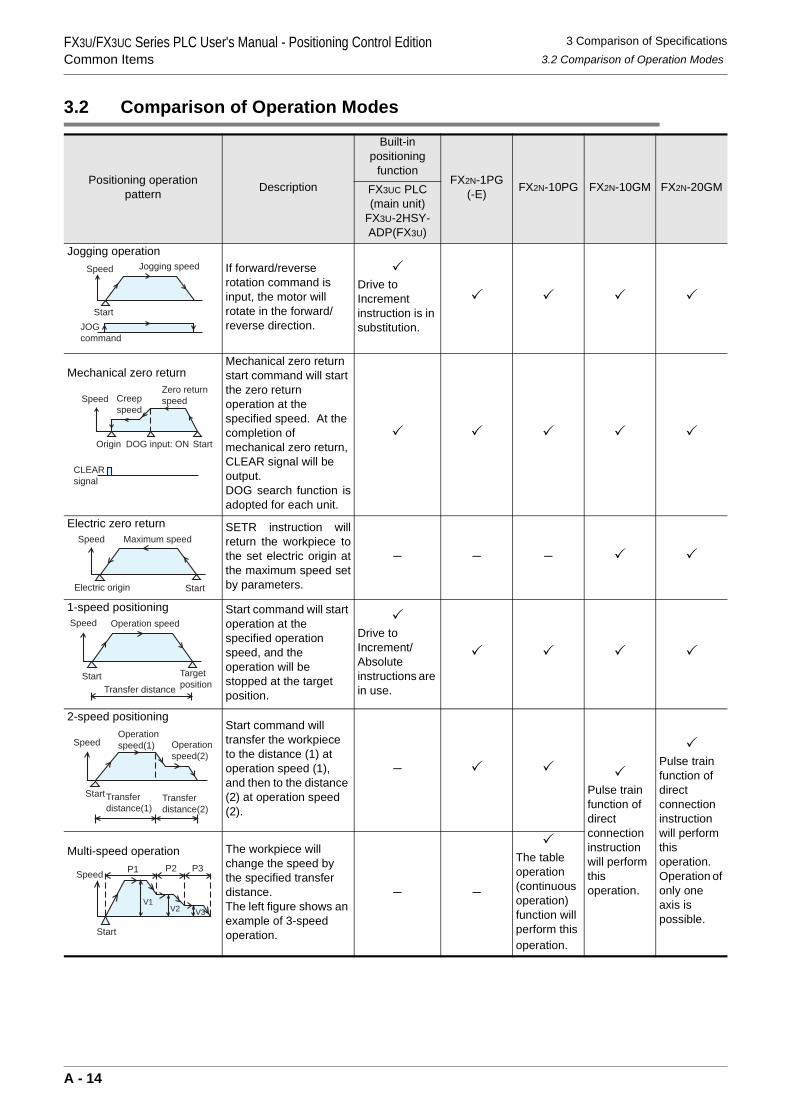
3.2 Comparison of Operation Modes
Positioning operationpattern Description
Built-inpositioning
functionFX2N-1PG
(-E) FX2N-10PG FX2N-10GM FX2N-20GMFX3UC PLC (main unit)
FX3U-2HSY-ADP(FX3U)
Jogging operationIf forward/reverse rotation command is input, the motor will rotate in the forward/reverse direction.
Drive to Increment instruction is in substitution.
Mechanical zero returnMechanical zero return start command will start the zero return operation at the specified speed. At the completion of mechanical zero return, CLEAR signal will be output.DOG search function isadopted for each unit.
Electric zero return SETR instruction willreturn the workpiece tothe set electric origin atthe maximum speed setby parameters.
− − −
1-speed positioning Start command will start operation at the specified operation speed, and the operation will be stopped at the target position.
Drive to Increment/Absolute instructions are in use.
2-speed positioningStart command will transfer the workpiece to the distance (1) at operation speed (1), and then to the distance (2) at operation speed (2).
−Pulse train function of direct connection instruction will perform this operation.
Pulse train function of direct connection instruction will perform this operation.Operation of only one axis is possible.
Multi-speed operation The workpiece will change the speed by the specified transfer distance.The left figure shows an example of 3-speed operation.
− −
The table operation (continuous operation) function will perform this operation.
Speed Jogging speed
StartJOGcommand
Zero returnspeedCreep
speedSpeed
CLEARsignal
Origin DOG input: ON Start
Speed
Electric origin Start
Maximum speed
Speed
StartTransfer distance
Operation speed
Targetposition
Speed
Start
Operationspeed(1) Operation
speed(2)
Transferdistance(1)
Transferdistance(2)
Start
Speed P1 P2 P3
V1V2 V3
A - 14
3 Comparison of Specifications3.2 Comparison of Operation Modes
FX3U/FX3UC Series PLC User's Manual - Positioning Control EditionCommon Items
A
Comm
on Items
B
Built-in Positioning Function
Apx.
Example
Connection
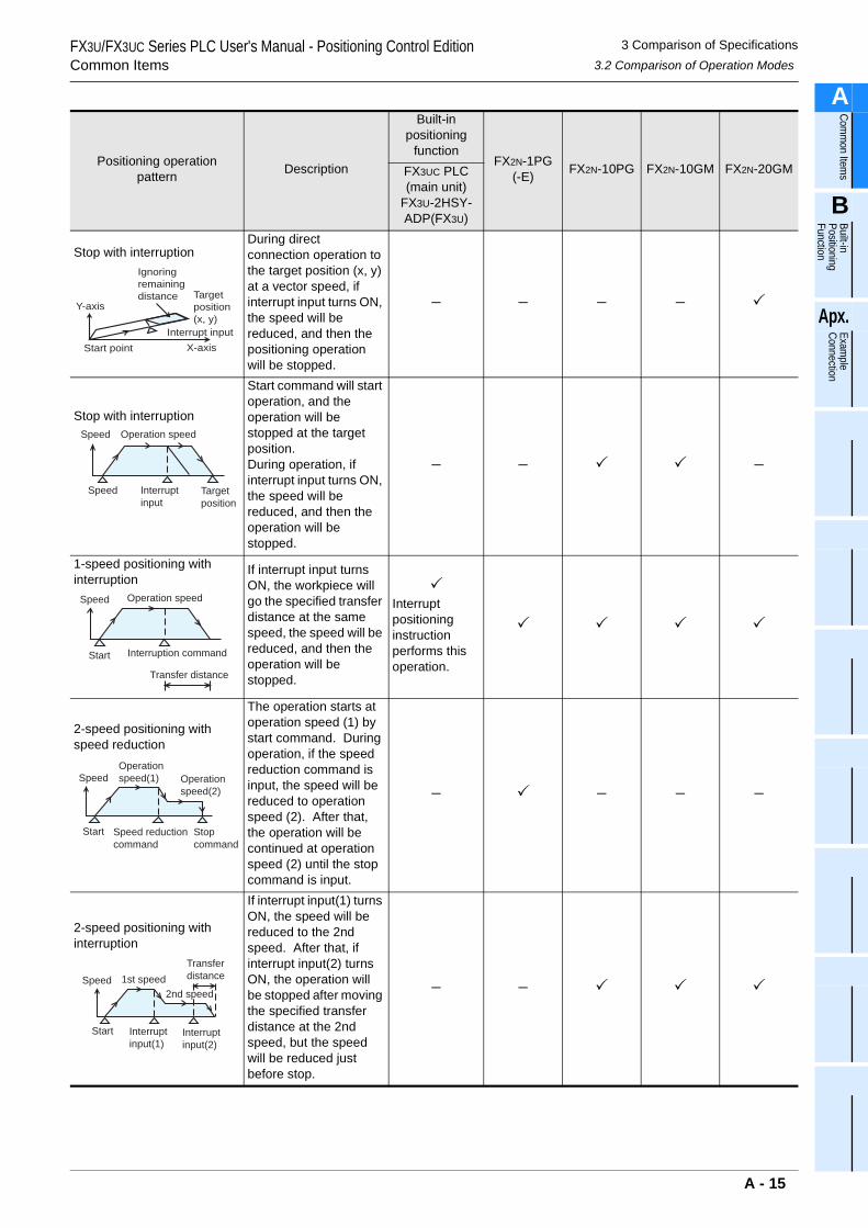
Stop with interruptionDuring direct connection operation to the target position (x, y) at a vector speed, if interrupt input turns ON, the speed will be reduced, and then the positioning operation will be stopped.
− − − −
Stop with interruption
Start command will start operation, and the operation will be stopped at the target position.During operation, if interrupt input turns ON, the speed will be reduced, and then the operation will be stopped.
− − −
1-speed positioning with interruption
If interrupt input turns ON, the workpiece will go the specified transfer distance at the same speed, the speed will be reduced, and then the operation will be stopped.
Interrupt positioning instruction performs this operation.
2-speed positioning with speed reduction
The operation starts at operation speed (1) by start command. During operation, if the speed reduction command is input, the speed will be reduced to operation speed (2). After that, the operation will be continued at operation speed (2) until the stop command is input.
− − − −
2-speed positioning with interruption
If interrupt input(1) turns ON, the speed will be reduced to the 2nd speed. After that, if interrupt input(2) turns ON, the operation will be stopped after moving the specified transfer distance at the 2nd speed, but the speed will be reduced just before stop.
− −
Positioning operationpattern Description
Built-inpositioning
functionFX2N-1PG
(-E) FX2N-10PG FX2N-10GM FX2N-20GMFX3UC PLC (main unit)
FX3U-2HSY-ADP(FX3U)
Start point X-axisInterrupt input
Y-axisTarget position(x, y)
Ignoring remainingdistance
Speed
Speed Interruptinput
Targetposition
Operation speed
Speed
Start
Operation speed
Interruption command
Transfer distance
Speed
Start Speed reductioncommand
Stopcommand
Operationspeed(1) Operation
speed(2)
Speed
Start
1st speed
Interruptinput(1)
Interruptinput(2)
2nd speed
Transferdistance
A - 15
3 Comparison of Specifications3.2 Comparison of Operation Modes
FX3U/FX3UC Series PLC User's Manual - Positioning Control EditionCommon Items
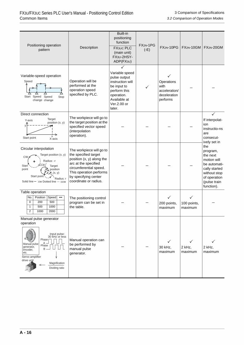
Variable-speed operationOperation will be performed at the operation speed specified by PLC.
Variable speed pulse output instruction will be input to perform this operation.Available at Ver.2.00 or later.
Operations with acceleration/deceleration performs
− −
Direct connectionThe workpiece will go to the target position at the specified vector speed (interpolation operation).
− − − −If interpolat-ion instructio-ns are consecut-ively set in the program, the next motion will be automati-cally started without stop of operation (pulse train function).
Circular interpolation The workpiece will go to the specified target position (x, y) along the arc at the specified circumferential speed.This operation performs by specifying center coordinate or radius.
− − − −
Table operation
The positioning control program can be set in the table.
− − 200 points, maximum
100 points, maximum
−
Manual pulse generator operation
Manual operation can be performed by manual pulse generator.
− − 30 kHz, maximum
2 kHz, maximum
2 kHz, maximum
Positioning operationpattern Description
Built-inpositioning
functionFX2N-1PG
(-E) FX2N-10PG FX2N-10GM FX2N-20GMFX3UC PLC (main unit)
FX3U-2HSY-ADP(FX3U)
Speed
Start Speedchange
Speedchange
Stop
X-axis
Y-axis
Start point
Target position (x, y)
x
y
CW
Startpoint
Target position (x, y)
:cw Dotted lineSolid line :ccwRadius: r
Start point
CCW Targetposition (x, y)
Radius: -r
No. Position Speed •••0 200 5001 500 10002 1000 2000
Magnification
Dividing ratio
Input pulse:30 kHz or less
PhaseA
PhaseB
Servo amplifierdrive unit
Manual pulsegenerator,encoder,etc.
A
- 16
FX3U/FX3UC Series PLC User's Manual - Positioning Control EditionBuilt-in Positioning Function
A
Comm
on Items
B
Built-in Positioning Function
Apx.
Example
Connection
FX3U/FX3UC Series Programmable Controllers
User’s Manual [Positioning Control Edition]B. Built-in Positioning Function
Foreword
"B. Built-in Positioning Function" describes "positioning" function incorporated in the MELSEC-F FX3U/FX3UC Series PLC and should be read and understood before attempting to install or use the unit.Also, store this manual in a safe place so that you can take it out and read it whenever necessary. Always forward it to the end user.
© 2005 MITSUBISHI ELECTRIC CORPORATION
This manual confers no industrial property rights or any rights of any other kind, nor does it confer any patentlicenses. Mitsubishi Electric Corporation cannot be held responsible for any problems involving industrial propertyrights which may occur as a result of using the contents noted in this manual.
B - 1
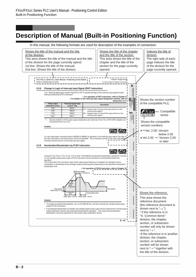
FX3U/FX3UC Series PLC User's Manual - Positioning Control EditionBuilt-in Positioning Function
Description of Manual (Built-in Positioning Function)In this manual, the following formats are used for description of the examples of connection:
Shows the title of the manual and the titleof the division.This area shows the title of the manual and the titleof the division for the page currently opend.1st line: Shows the title of the manual.2nd line: Shows the title of the division.
Shows the title of the chapterand the title of the section.This area shows the title of thechapter and the title of the section for the page currentlyopened.
Indexes the title ofdivision.The right side of eachpage indexes the titleof the division for thepage currently opened.
Shows the version numberof the compatible PLC.
Compatibleseries
Shows the compatibleversion numbers.
Ver. 2.00: Version below 2.00
Ver.2.00 : Version 2.00 or later
Shows the reference.
This area shows thereference document(the reference document isshown next to " "). If the reference is in "A. Common items" division, the chapter, section, or subsectionnumber will only be shown next to " ". If the reference is in another division, the chapter,section, or subsectionnumber will be shown next to " " together withthe title of the division.
B - 2
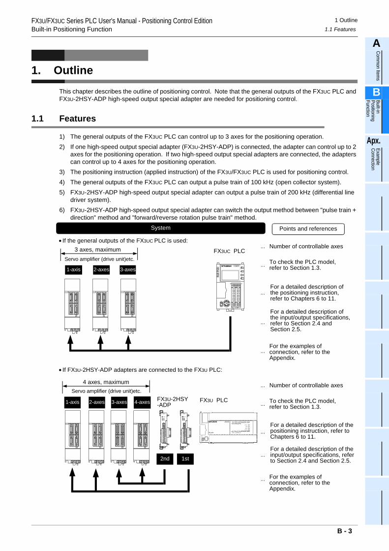
1 Outline1.1 Features
FX3U/FX3UC Series PLC User's Manual - Positioning Control EditionBuilt-in Positioning Function
A
Comm
on Items
B
Built-in Positioning Function
Apx.
Example
Connection
1. OutlineThis chapter describes the outline of positioning control. Note that the general outputs of the FX3UC PLC and FX3U-2HSY-ADP high-speed output special adapter are needed for positioning control.
1.1 Features
1) The general outputs of the FX3UC PLC can control up to 3 axes for the positioning operation.2) If one high-speed output special adapter (FX3U-2HSY-ADP) is connected, the adapter can control up to 2
axes for the positioning operation. If two high-speed output special adapters are connected, the adapters can control up to 4 axes for the positioning operation.
3) The positioning instruction (applied instruction) of the FX3U/FX3UC PLC is used for positioning control.4) The general outputs of the FX3UC PLC can output a pulse train of 100 kHz (open collector system).5) FX3U-2HSY-ADP high-speed output special adapter can output a pulse train of 200 kHz (differential line
driver system).6) FX3U-2HSY-ADP high-speed output special adapter can switch the output method between "pulse train +
direction" method and "forward/reverse rotation pulse train" method.System
...
For a detailed description ofthe input/output specifications,refer to Section 2.4 andSection 2.5.
... To check the PLC model,refer to Section 1.3.
Points and references
...
1-axis 2-axes 3-axes
FX3UC PLC
• If the general outputs of the FX3UC PLC is used:3 axes, maximum ... Number of controllable axes
For the examples ofconnection, refer to theAppendix.
...For a detailed description ofthe positioning instruction,refer to Chapters 6 to 11.
• If FX3U-2HSY-ADP adapters are connected to the FX3U PLC:
...For a detailed description of theinput/output specifications, referto Section 2.4 and Section 2.5.
... To check the PLC model,refer to Section 1.3.
...
1-axis 2-axes 3-axes FX3U PLC
4 axes, maximum
For the examples ofconnection, refer to theAppendix.
...For a detailed description of thepositioning instruction, refer toChapters 6 to 11.
4-axes FX3U-2HSY-ADP
... Number of controllable axes
Servo amplifier (drive unit)etc.
Servo amplifier (drive unit)etc.
2nd 1st
B - 3
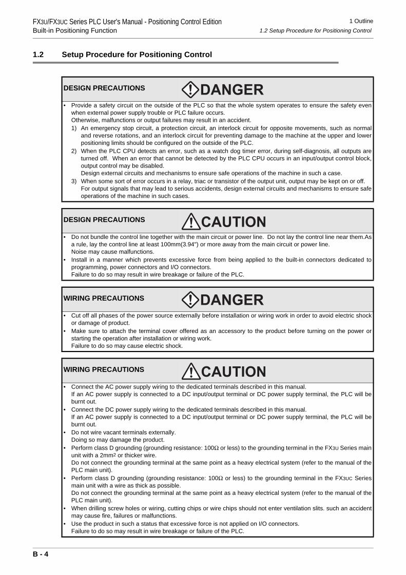
1 Outline1.2 Setup Procedure for Positioning Control
FX3U/FX3UC Series PLC User's Manual - Positioning Control EditionBuilt-in Positioning Function
1.2 Setup Procedure for Positioning Control
DESIGN PRECAUTIONS
• Provide a safety circuit on the outside of the PLC so that the whole system operates to ensure the safety evenwhen external power supply trouble or PLC failure occurs.Otherwise, malfunctions or output failures may result in an accident.1) An emergency stop circuit, a protection circuit, an interlock circuit for opposite movements, such as normal
and reverse rotations, and an interlock circuit for preventing damage to the machine at the upper and lowerpositioning limits should be configured on the outside of the PLC.
2) When the PLC CPU detects an error, such as a watch dog timer error, during self-diagnosis, all outputs areturned off. When an error that cannot be detected by the PLC CPU occurs in an input/output control block,output control may be disabled.Design external circuits and mechanisms to ensure safe operations of the machine in such a case.
3) When some sort of error occurs in a relay, triac or transistor of the output unit, output may be kept on or off.For output signals that may lead to serious accidents, design external circuits and mechanisms to ensure safeoperations of the machine in such cases.
DESIGN PRECAUTIONS
• Do not bundle the control line together with the main circuit or power line. Do not lay the control line near them.Asa rule, lay the control line at least 100mm(3.94") or more away from the main circuit or power line.Noise may cause malfunctions.
• Install in a manner which prevents excessive force from being applied to the built-in connectors dedicated toprogramming, power connectors and I/O connectors.Failure to do so may result in wire breakage or failure of the PLC.
WIRING PRECAUTIONS
• Cut off all phases of the power source externally before installation or wiring work in order to avoid electric shockor damage of product.
• Make sure to attach the terminal cover offered as an accessory to the product before turning on the power orstarting the operation after installation or wiring work.Failure to do so may cause electric shock.
WIRING PRECAUTIONS
• Connect the AC power supply wiring to the dedicated terminals described in this manual.If an AC power supply is connected to a DC input/output terminal or DC power supply terminal, the PLC will beburnt out.
• Connect the DC power supply wiring to the dedicated terminals described in this manual.If an AC power supply is connected to a DC input/output terminal or DC power supply terminal, the PLC will beburnt out.
• Do not wire vacant terminals externally.Doing so may damage the product.
• Perform class D grounding (grounding resistance: 100Ω or less) to the grounding terminal in the FX3U Series mainunit with a 2mm2 or thicker wire.Do not connect the grounding terminal at the same point as a heavy electrical system (refer to the manual of thePLC main unit).
• Perform class D grounding (grounding resistance: 100Ω or less) to the grounding terminal in the FX3UC Seriesmain unit with a wire as thick as possible.Do not connect the grounding terminal at the same point as a heavy electrical system (refer to the manual of thePLC main unit).
• When drilling screw holes or wiring, cutting chips or wire chips should not enter ventilation slits. such an accidentmay cause fire, failures or malfunctions.
• Use the product in such a status that excessive force is not applied on I/O connectors.Failure to do so may result in wire breakage or failure of the PLC.
B - 4
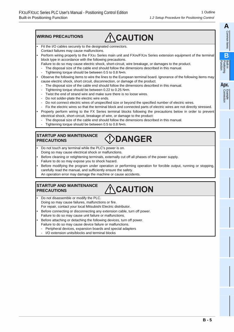
1 Outline1.2 Setup Procedure for Positioning Control
FX3U/FX3UC Series PLC User's Manual - Positioning Control EditionBuilt-in Positioning Function
A
Comm
on Items
B
Built-in Positioning Function
Apx.
Example
Connection
• Fit the I/O cables securely to the designated connectors.Contact failures may cause malfunctions.
• Perform wiring properly to the FX3U Series main unit and FX0N/FX2N Series extension equipment of the terminalblock type in accordance with the following precautions.Failure to do so may cause electric shock, short-circuit, wire breakage, or damages to the product.- The disposal size of the cable end should follow the dimensions described in this manual.- Tightening torque should be between 0.5 to 0.8 N•m.
• Observe the following items to wire the lines to the European terminal board. Ignorance of the following items maycause electric shock, short circuit, disconnection, or damage of the product.- The disposal size of the cable end should follow the dimensions described in this manual.- Tightening torque should be between 0.22 to 0.25 N•m.- Twist the end of strand wire and make sure there is no loose wires. - Do not solder-plate the electric wire ends.- Do not connect electric wires of unspecified size or beyond the specified number of electric wires.- Fix the electric wires so that the terminal block and connected parts of electric wires are not directly stressed.
• Properly perform wiring to the FX Series terminal blocks following the precautions below in order to preventelectrical shock, short-circuit, breakage of wire, or damage to the product:- The disposal size of the cable end should follow the dimensions described in this manual.- Tightening torque should be between 0.5 to 0.8 N•m.
STARTUP AND MAINTENANCE PRECAUTIONS
• Do not touch any terminal while the PLC's power is on.Doing so may cause electrical shock or malfunctions.
• Before cleaning or retightening terminals, externally cut off all phases of the power supply.Failure to do so may expose you to shock hazard.
• Before modifying the program under operation or performing operation for forcible output, running or stopping,carefully read the manual, and sufficiently ensure the safety.An operation error may damage the machine or cause accidents.
STARTUP AND MAINTENANCE PRECAUTIONS
• Do not disassemble or modify the PLC.Doing so may cause failures, malfunctions or fire.For repair, contact your local Mitsubishi Electric distributor.
• Before connecting or disconnecting any extension cable, turn off power.Failure to do so may cause unit failure or malfunctions.
• Before attaching or detaching the following devices, turn off power.Failure to do so may cause device failure or malfunctions.- Peripheral devices, expansion boards and special adapters- I/O extension units/blocks and terminal blocks
WIRING PRECAUTIONS
B - 5
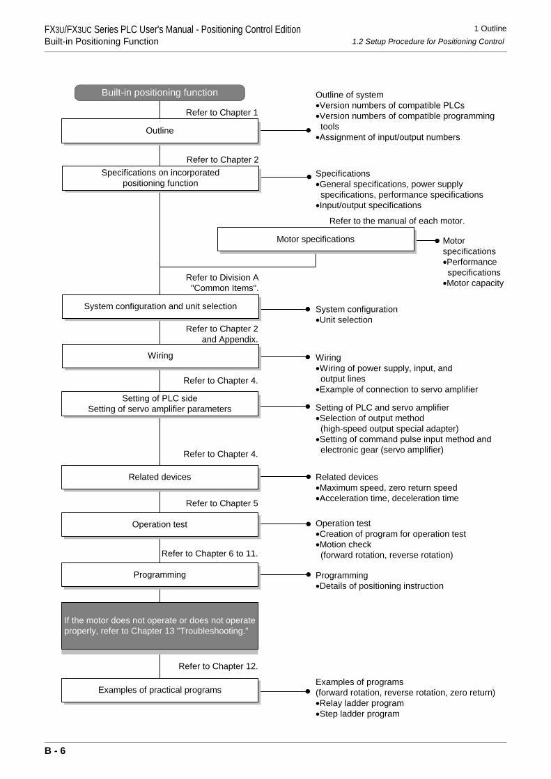
1 Outline1.2 Setup Procedure for Positioning Control
FX3U/FX3UC Series PLC User's Manual - Positioning Control EditionBuilt-in Positioning Function
Setting of PLC and servo amplifier•Selection of output method (high-speed output special adapter)•Setting of command pulse input method and electronic gear (servo amplifier)
Specifications on incorporatedpositioning function
Refer to Chapter 2
System configuration and unit selection
Wiring
Refer to Chapter 2and Appendix.
Built-in positioning function
Examples of practical programs
Refer to Division A"Common Items".
Operation test
Refer to Chapter 5
If the motor does not operate or does not operateproperly, refer to Chapter 13 "Troubleshooting."
Refer to Chapter 12.
Outline
Refer to Chapter 1
Setting of PLC sideSetting of servo amplifier parameters
Refer to Chapter 4.
Motorspecifications•Performance specifications•Motor capacity
Programming
Refer to Chapter 6 to 11.
Motor specifications
Refer to the manual of each motor.
Related devices
Refer to Chapter 4.
Outline of system•Version numbers of compatible PLCs•Version numbers of compatible programming tools•Assignment of input/output numbers
Specifications•General specifications, power supply specifications, performance specifications•Input/output specifications
System configuration•Unit selection
Wiring•Wiring of power supply, input, and output lines•Example of connection to servo amplifier
Related devices•Maximum speed, zero return speed•Acceleration time, deceleration time
Operation test•Creation of program for operation test•Motion check (forward rotation, reverse rotation)
Programming•Details of positioning instruction
Examples of programs(forward rotation, reverse rotation, zero return)•Relay ladder program•Step ladder program
B - 6
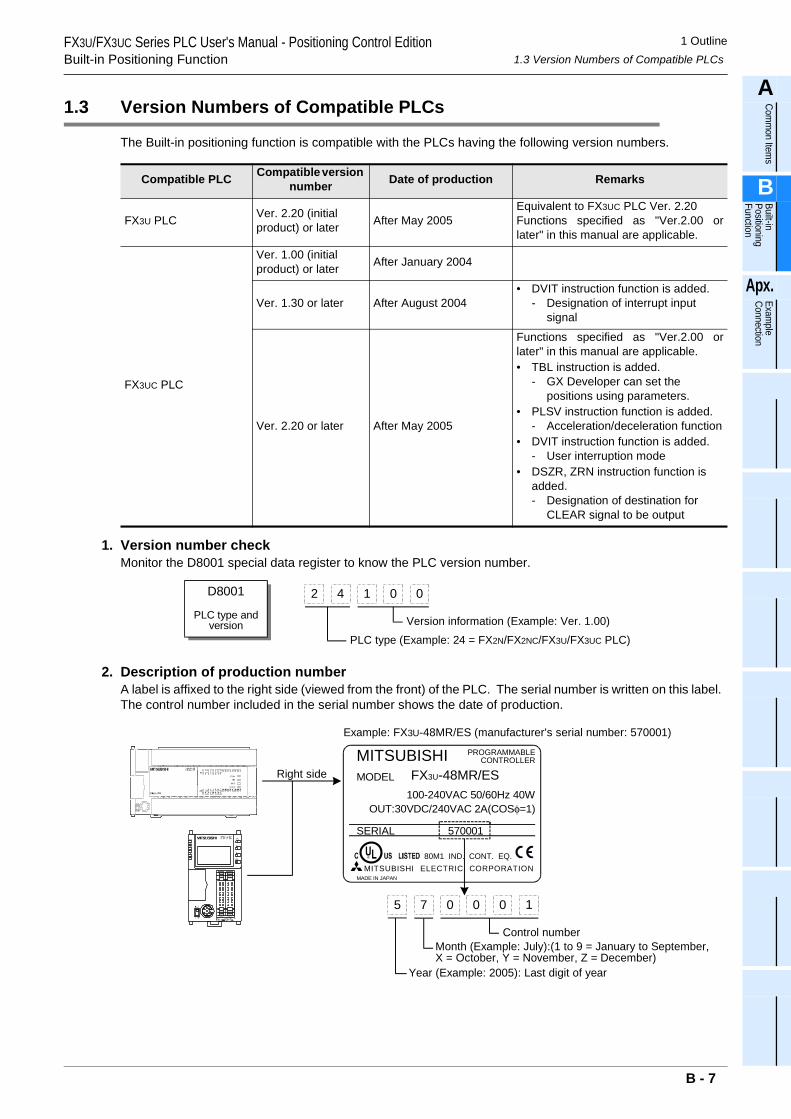
1 Outline1.3 Version Numbers of Compatible PLCs
FX3U/FX3UC Series PLC User's Manual - Positioning Control EditionBuilt-in Positioning Function
A
Comm
on Items
B
Built-in Positioning Function
Apx.
Example
Connection
1.3 Version Numbers of Compatible PLCs
The Built-in positioning function is compatible with the PLCs having the following version numbers.
1. Version number checkMonitor the D8001 special data register to know the PLC version number.
2. Description of production numberA label is affixed to the right side (viewed from the front) of the PLC. The serial number is written on this label. The control number included in the serial number shows the date of production.
Compatible PLC Compatible version number Date of production Remarks
FX3U PLC Ver. 2.20 (initial product) or later After May 2005
Equivalent to FX3UC PLC Ver. 2.20Functions specified as "Ver.2.00 orlater" in this manual are applicable.
FX3UC PLC
Ver. 1.00 (initial product) or later After January 2004
Ver. 1.30 or later After August 2004• DVIT instruction function is added.
- Designation of interrupt input signal
Ver. 2.20 or later After May 2005
Functions specified as "Ver.2.00 orlater" in this manual are applicable.• TBL instruction is added.
- GX Developer can set the positions using parameters.
• PLSV instruction function is added.- Acceleration/deceleration function
• DVIT instruction function is added.- User interruption mode
• DSZR, ZRN instruction function is added.- Designation of destination for
CLEAR signal to be output
D8001
PLC type andversion
2 4 1 0 0
Version information (Example: Ver. 1.00)PLC type (Example: 24 = FX2N/FX2NC/FX3U/FX3UC PLC)
Right side
5 7 0 0 0
Control number
Year (Example: 2005): Last digit of year
1
Month (Example: July):(1 to 9 = January to September,X = October, Y = November, Z = December)
MITSUBISHIMODEL
100-240VAC 50/60Hz 40W
SERIAL
FX3U-48MR/ES
PROGRAMMABLECONTROLLER
570001
OUT:30VDC/240VAC 2A(COSφ=1)
80M1 IND. CONT. EQ.MITSUBISHI ELECTRIC CORPORATION
MADE IN JAPAN
Example: FX3U-48MR/ES (manufacturer's serial number: 570001)
B - 7
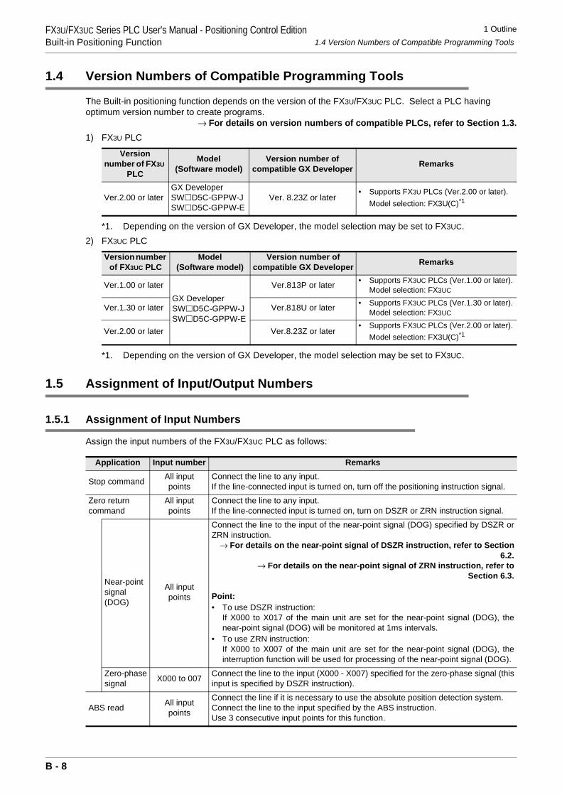
1 Outline1.4 Version Numbers of Compatible Programming Tools
FX3U/FX3UC Series PLC User's Manual - Positioning Control EditionBuilt-in Positioning Function
1.4 Version Numbers of Compatible Programming Tools
The Built-in positioning function depends on the version of the FX3U/FX3UC PLC. Select a PLC having optimum version number to create programs.
→ For details on version numbers of compatible PLCs, refer to Section 1.3.1) FX3U PLC
*1. Depending on the version of GX Developer, the model selection may be set to FX3UC.2) FX3UC PLC
*1. Depending on the version of GX Developer, the model selection may be set to FX3UC.
1.5 Assignment of Input/Output Numbers
1.5.1 Assignment of Input Numbers
Assign the input numbers of the FX3U/FX3UC PLC as follows:
Version number of FX3U
PLC
Model(Software model)
Version number of compatible GX Developer Remarks
Ver.2.00 or laterGX DeveloperSW D5C-GPPW-JSW D5C-GPPW-E
Ver. 8.23Z or later• Supports FX3U PLCs (Ver.2.00 or later).
Model selection: FX3U(C)*1
Version number of FX3UC PLC
Model(Software model)
Version number of compatible GX Developer Remarks
Ver.1.00 or laterGX DeveloperSW D5C-GPPW-JSW D5C-GPPW-E
Ver.8.13P or later • Supports FX3UC PLCs (Ver.1.00 or later).Model selection: FX3UC
Ver.1.30 or later Ver.8.18U or later • Supports FX3UC PLCs (Ver.1.30 or later).Model selection: FX3UC
Ver.2.00 or later Ver.8.23Z or later• Supports FX3UC PLCs (Ver.2.00 or later).
Model selection: FX3U(C)*1
Application Input number Remarks
Stop command All input points
Connect the line to any input.If the line-connected input is turned on, turn off the positioning instruction signal.
Zero return command
All input points
Connect the line to any input.If the line-connected input is turned on, turn on DSZR or ZRN instruction signal.
Near-point signal (DOG)
All input points
Connect the line to the input of the near-point signal (DOG) specified by DSZR orZRN instruction.
→ For details on the near-point signal of DSZR instruction, refer to Section6.2.
→ For details on the near-point signal of ZRN instruction, refer toSection 6.3.
Point:• To use DSZR instruction:
If X000 to X017 of the main unit are set for the near-point signal (DOG), thenear-point signal (DOG) will be monitored at 1ms intervals.
• To use ZRN instruction:If X000 to X007 of the main unit are set for the near-point signal (DOG), theinterruption function will be used for processing of the near-point signal (DOG).
Zero-phase signal X000 to 007 Connect the line to the input (X000 - X007) specified for the zero-phase signal (this
input is specified by DSZR instruction).
ABS read All input points
Connect the line if it is necessary to use the absolute position detection system.Connect the line to the input specified by the ABS instruction.Use 3 consecutive input points for this function.
B - 8
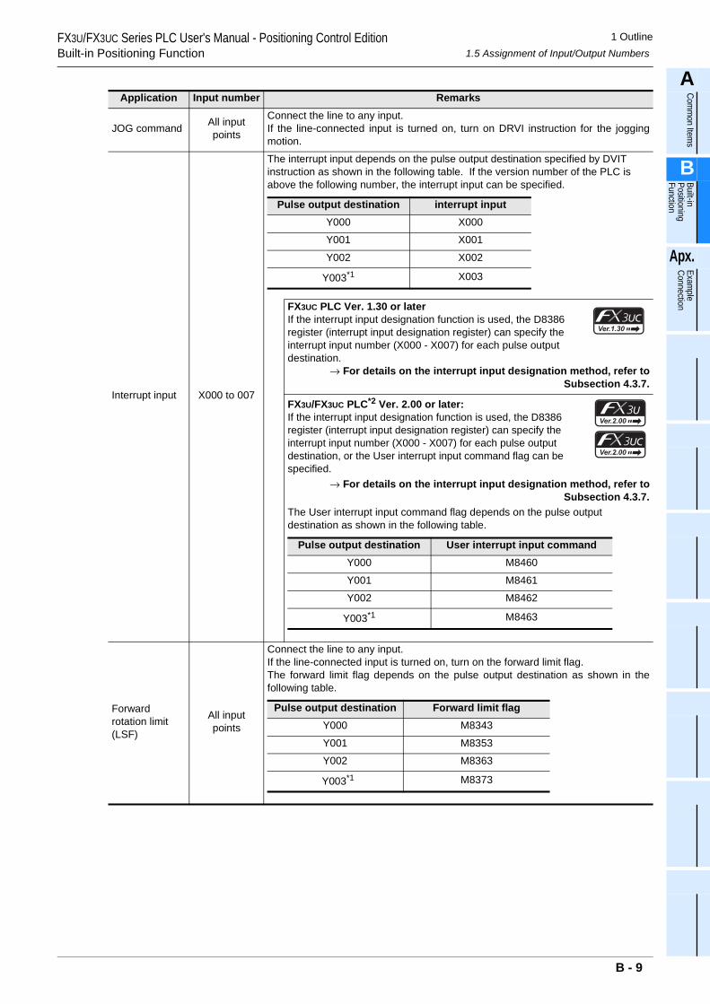
1 Outline1.5 Assignment of Input/Output Numbers
FX3U/FX3UC Series PLC User's Manual - Positioning Control EditionBuilt-in Positioning Function
A
Comm
on Items
B
Built-in Positioning Function
Apx.
Example
Connection
JOG command All input points
Connect the line to any input.If the line-connected input is turned on, turn on DRVI instruction for the joggingmotion.
Interrupt input X000 to 007
The interrupt input depends on the pulse output destination specified by DVIT instruction as shown in the following table. If the version number of the PLC is above the following number, the interrupt input can be specified.
FX3UC PLC Ver. 1.30 or laterIf the interrupt input designation function is used, the D8386 register (interrupt input designation register) can specify the interrupt input number (X000 - X007) for each pulse output destination.
→ For details on the interrupt input designation method, refer toSubsection 4.3.7.
FX3U/FX3UC PLC*2 Ver. 2.00 or later:If the interrupt input designation function is used, the D8386 register (interrupt input designation register) can specify the interrupt input number (X000 - X007) for each pulse output destination, or the User interrupt input command flag can be specified.
→ For details on the interrupt input designation method, refer toSubsection 4.3.7.
The User interrupt input command flag depends on the pulse output destination as shown in the following table.
Forward rotation limit (LSF)
All input points
Connect the line to any input.If the line-connected input is turned on, turn on the forward limit flag.The forward limit flag depends on the pulse output destination as shown in thefollowing table.
Application Input number Remarks
Pulse output destination interrupt inputY000 X000
Y001 X001
Y002 X002
Y003*1 X003
Pulse output destination User interrupt input commandY000 M8460
Y001 M8461
Y002 M8462
Y003*1 M8463
Pulse output destination Forward limit flagY000 M8343
Y001 M8353
Y002 M8363
Y003*1 M8373
B - 9
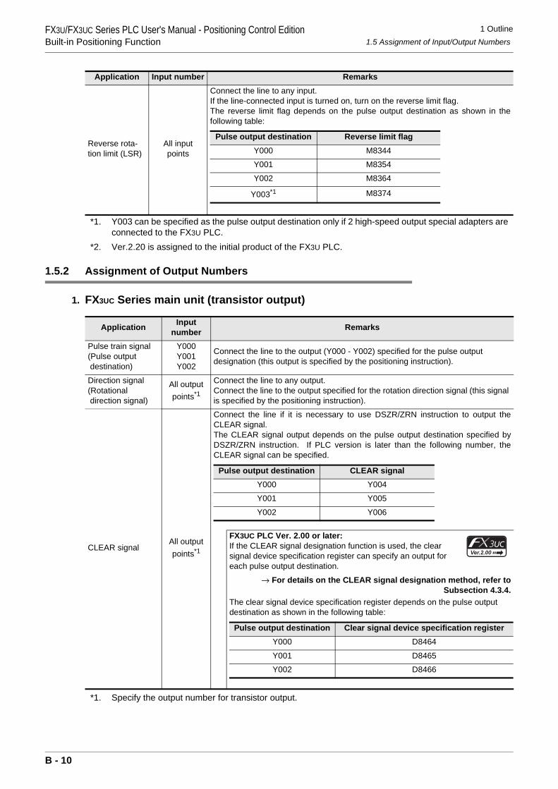
1 Outline1.5 Assignment of Input/Output Numbers
FX3U/FX3UC Series PLC User's Manual - Positioning Control EditionBuilt-in Positioning Function
*1. Y003 can be specified as the pulse output destination only if 2 high-speed output special adapters are connected to the FX3U PLC.
*2. Ver.2.20 is assigned to the initial product of the FX3U PLC.
1.5.2 Assignment of Output Numbers
1. FX3UC Series main unit (transistor output)
*1. Specify the output number for transistor output.
Reverse rota-tion limit (LSR)
All input points
Connect the line to any input.If the line-connected input is turned on, turn on the reverse limit flag.The reverse limit flag depends on the pulse output destination as shown in thefollowing table:
Application Input number Remarks
Pulse train signal(Pulse output destination)
Y000Y001Y002
Connect the line to the output (Y000 - Y002) specified for the pulse output designation (this output is specified by the positioning instruction).
Direction signal(Rotational direction signal)
All output points*1
Connect the line to any output.Connect the line to the output specified for the rotation direction signal (this signal is specified by the positioning instruction).
CLEAR signalAll output points*1
Connect the line if it is necessary to use DSZR/ZRN instruction to output theCLEAR signal.The CLEAR signal output depends on the pulse output destination specified byDSZR/ZRN instruction. If PLC version is later than the following number, theCLEAR signal can be specified.
FX3UC PLC Ver. 2.00 or later:If the CLEAR signal designation function is used, the clear signal device specification register can specify an output for each pulse output destination.
→ For details on the CLEAR signal designation method, refer toSubsection 4.3.4.
The clear signal device specification register depends on the pulse output destination as shown in the following table:
Application Input number Remarks
Pulse output destination Reverse limit flagY000 M8344
Y001 M8354
Y002 M8364
Y003*1 M8374
Pulse output destination CLEAR signalY000 Y004
Y001 Y005
Y002 Y006
Pulse output destination Clear signal device specification registerY000 D8464
Y001 D8465
Y002 D8466
B - 10
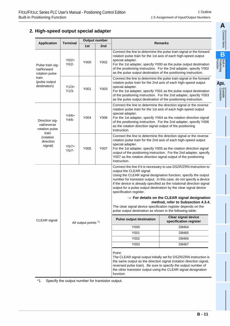
1 Outline1.5 Assignment of Input/Output Numbers
FX3U/FX3UC Series PLC User's Manual - Positioning Control EditionBuilt-in Positioning Function
A
Comm
on Items
B
Built-in Positioning Function
Apx.
Example
Connection
2. High-speed output special adapter
*1. Specify the output number for transistor output.
Application TerminalOutput number
Remarks1st 2nd
Pulse train sig-nal/forward rotation pulse train(pulse output destination)
Y0/2+Y0/2- Y000 Y002
Connect the line to determine the pulse train signal or the forward rotation pulse train for the 1st axis of each high-speed output special adapter.For the 1st adapter, specify Y000 as the pulse output destination of the positioning instruction. For the 2nd adapter, specify Y002 as the pulse output destination of the positioning instruction.
Y1/3+Y1/3- Y001 Y003
Connect the line to determine the pulse train signal or the forward rotation pulse train for the 2nd axis of each high-speed output special adapter.For the 1st adapter, specify Y001 as the pulse output destination of the positioning instruction. For the 2nd adapter, specify Y003 as the pulse output destination of the positioning instruction.
Direction sig-nal/reverse
rotation pulse train
(rotation direction signal)
Y4/6+Y4/6- Y004 Y006
Connect the line to determine the direction signal or the reverse rotation pulse train for the 1st axis of each high-speed output special adapter.For the 1st adapter, specify Y004 as the rotation direction signal of the positioning instruction. For the 2nd adapter, specify Y006 as the rotation direction signal output of the positioning instruction.
Y5/7+Y5/7- Y005 Y007
Connect the line to determine the direction signal or the reverse rotation pulse train for the 2nd axis of each high-speed output special adapter.For the 1st adapter, specify Y005 as the rotation direction signal output of the positioning instruction. For the 2nd adapter, specify Y007 as the rotation direction signal output of the positioning instruction.
CLEAR signalAll output points *1
Connect the line if it is necessary to use DSZR/ZRN instruction to output the CLEAR signal.Using the CLEAR signal designation function, specify the output number for transistor output. In this case, do not specify a device if the device is already specified as the rotational direction signal output for a pulse output destination by the clear signal device specification register.
→ For details on the CLEAR signal designationmethod, refer to Subsection 4.3.4.
The clear signal device specification register depends on the pulse output destination as shown in the following table:
Point:The CLEAR signal output initially set for DSZR/ZRN instruction is the same output as the direction signal (rotation direction signal, reversed pulse train). Be sure to specify the output number of the other transistor output using the CLEAR signal designation function.
Pulse output destination Clear signal device specification register
Y000 D8464
Y001 D8465
Y002 D8466
Y003 D8467
B - 11
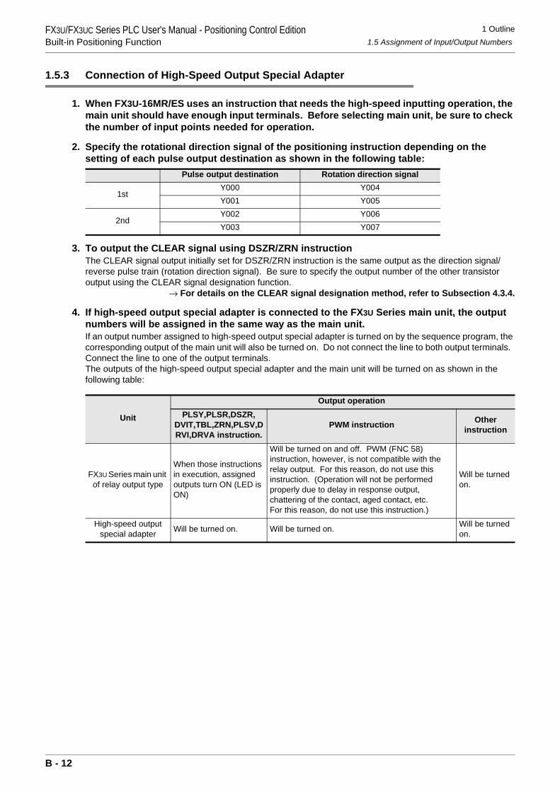
1 Outline1.5 Assignment of Input/Output Numbers
FX3U/FX3UC Series PLC User's Manual - Positioning Control EditionBuilt-in Positioning Function
1.5.3 Connection of High-Speed Output Special Adapter
1. When FX3U-16MR/ES uses an instruction that needs the high-speed inputting operation, the main unit should have enough input terminals. Before selecting main unit, be sure to check the number of input points needed for operation.
2. Specify the rotational direction signal of the positioning instruction depending on the setting of each pulse output destination as shown in the following table:
3. To output the CLEAR signal using DSZR/ZRN instructionThe CLEAR signal output initially set for DSZR/ZRN instruction is the same output as the direction signal/reverse pulse train (rotation direction signal). Be sure to specify the output number of the other transistor output using the CLEAR signal designation function.
→ For details on the CLEAR signal designation method, refer to Subsection 4.3.4.
4. If high-speed output special adapter is connected to the FX3U Series main unit, the output numbers will be assigned in the same way as the main unit.If an output number assigned to high-speed output special adapter is turned on by the sequence program, the corresponding output of the main unit will also be turned on. Do not connect the line to both output terminals. Connect the line to one of the output terminals.The outputs of the high-speed output special adapter and the main unit will be turned on as shown in the following table:
Pulse output destination Rotation direction signal
1stY000 Y004Y001 Y005
2ndY002 Y006Y003 Y007
Unit
Output operationPLSY,PLSR,DSZR,
DVIT,TBL,ZRN,PLSV,DRVI,DRVA instruction.
PWM instruction Otherinstruction
FX3U Series main unit of relay output type
When those instructions in execution, assigned outputs turn ON (LED is ON)
Will be turned on and off. PWM (FNC 58) instruction, however, is not compatible with the relay output. For this reason, do not use this instruction. (Operation will not be performed properly due to delay in response output, chattering of the contact, aged contact, etc. For this reason, do not use this instruction.)
Will be turned on.
High-speed output special adapter Will be turned on. Will be turned on. Will be turned
on.
B - 12
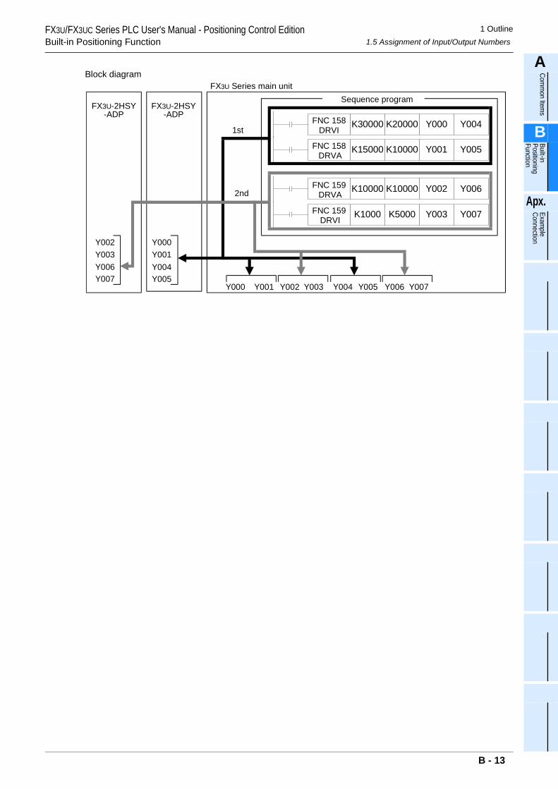
1 Outline1.5 Assignment of Input/Output Numbers
FX3U/FX3UC Series PLC User's Manual - Positioning Control EditionBuilt-in Positioning Function
A
Comm
on Items
B
Built-in Positioning Function
Apx.
Example
Connection
Block diagramFX3U Series main unit
Y000 Y001 Y002 Y003 Y004 Y005 Y006 Y007
FX3U-2HSY-ADP
Y000Y001Y004Y005
FX3U-2HSY-ADP
Y002Y003Y006Y007
Sequence program
FNC 158 DRVA
K15000 K10000 Y001 Y005
FNC 159 DRVA
K10000 K10000 Y002 Y006
FNC 158DRVI
K30000 K20000 Y000 Y004
FNC 159 DRVI
K1000 K5000 Y003 Y007
1st
2nd
B - 13
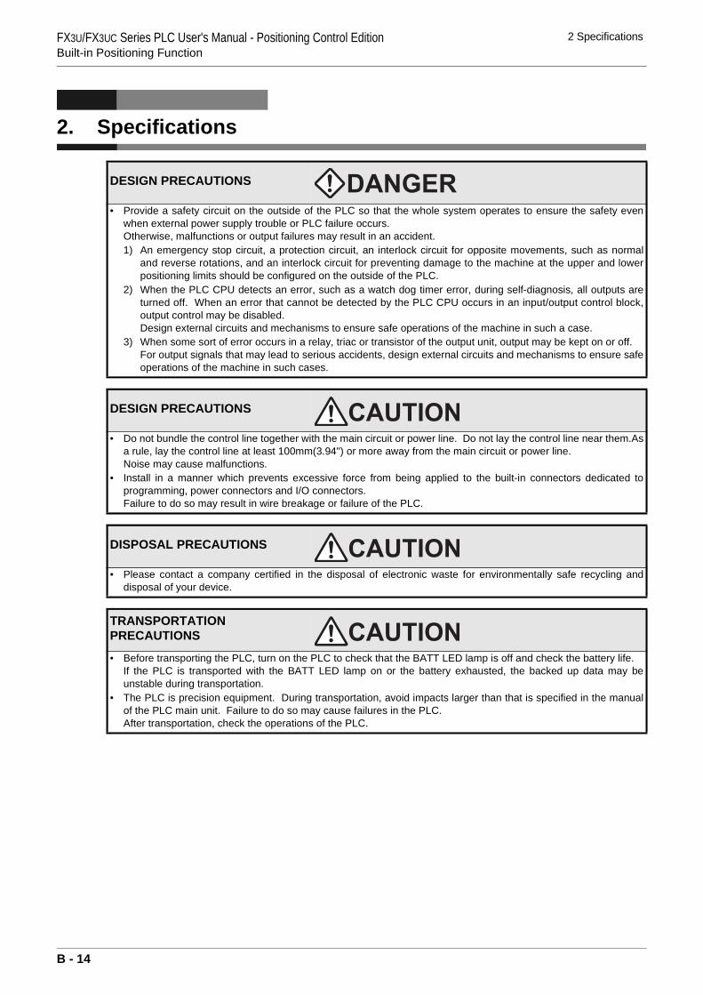
FX3U/FX3UC Series PLC User's Manual - Positioning Control EditionBuilt-in Positioning Function
2 Specifications
2. Specifications
DESIGN PRECAUTIONS
• Provide a safety circuit on the outside of the PLC so that the whole system operates to ensure the safety evenwhen external power supply trouble or PLC failure occurs.Otherwise, malfunctions or output failures may result in an accident.1) An emergency stop circuit, a protection circuit, an interlock circuit for opposite movements, such as normal
and reverse rotations, and an interlock circuit for preventing damage to the machine at the upper and lowerpositioning limits should be configured on the outside of the PLC.
2) When the PLC CPU detects an error, such as a watch dog timer error, during self-diagnosis, all outputs areturned off. When an error that cannot be detected by the PLC CPU occurs in an input/output control block,output control may be disabled.Design external circuits and mechanisms to ensure safe operations of the machine in such a case.
3) When some sort of error occurs in a relay, triac or transistor of the output unit, output may be kept on or off.For output signals that may lead to serious accidents, design external circuits and mechanisms to ensure safeoperations of the machine in such cases.
DESIGN PRECAUTIONS
• Do not bundle the control line together with the main circuit or power line. Do not lay the control line near them.Asa rule, lay the control line at least 100mm(3.94") or more away from the main circuit or power line.Noise may cause malfunctions.
• Install in a manner which prevents excessive force from being applied to the built-in connectors dedicated toprogramming, power connectors and I/O connectors.Failure to do so may result in wire breakage or failure of the PLC.
DISPOSAL PRECAUTIONS
• Please contact a company certified in the disposal of electronic waste for environmentally safe recycling anddisposal of your device.
TRANSPORTATION PRECAUTIONS
• Before transporting the PLC, turn on the PLC to check that the BATT LED lamp is off and check the battery life.If the PLC is transported with the BATT LED lamp on or the battery exhausted, the backed up data may beunstable during transportation.
• The PLC is precision equipment. During transportation, avoid impacts larger than that is specified in the manualof the PLC main unit. Failure to do so may cause failures in the PLC. After transportation, check the operations of the PLC.
B - 14
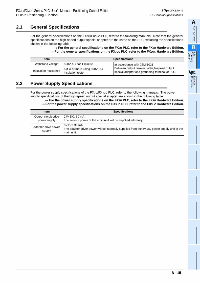
FX3U/FX3UC Series PLC User's Manual - Positioning Control EditionBuilt-in Positioning Function
2 Specifications2.1 General Specifications
A
Comm
on Items
B
Built-in Positioning Function
Apx.
Example
Connection
2.1 General Specifications
For the general specifications on the FX3U/FX3UC PLC, refer to the following manuals. Note that the general specifications on the high-speed output special adapter are the same as the PLC excluding the specifications shown in the following table.
→ For the general specifications on the FX3U PLC, refer to the FX3U Hardware Edition.→ For the general specifications on the FX3UC PLC, refer to the FX3UC Hardware Edition.
2.2 Power Supply Specifications
For the power supply specifications of the FX3U/FX3UC PLC, refer to the following manuals. The power supply specifications of the high-speed output special adapter are shown in the following table.
→ For the power supply specifications on the FX3U PLC, refer to the FX3U Hardware Edition.→ For the power supply specifications on the FX3UC PLC, refer to the FX3UC Hardware Edition.
Item SpecificationsWithstand voltage 500V AC, for 1 minute In accordance with JEM-1021
Between output terminal of high-speed output special adapter and grounding terminal of PLC.Insulation resistance 5M Ω or more using 500V DC
insulation tester
Item SpecificationsOutput circuit drive
power supply24V DC, 60 mAThe service power of the main unit will be supplied internally.
Adapter drive power supply
5V DC, 30 mAThe adapter driver power will be internally supplied from the 5V DC power supply unit of themain unit.
B - 15
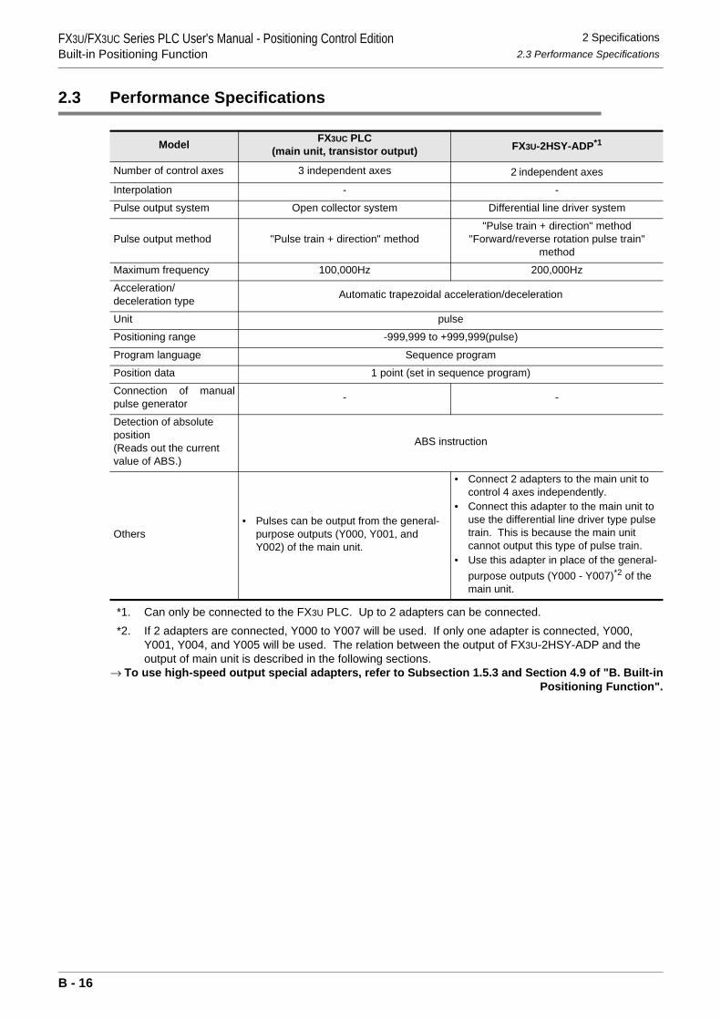
FX3U/FX3UC Series PLC User's Manual - Positioning Control EditionBuilt-in Positioning Function
2 Specifications2.3 Performance Specifications
2.3 Performance Specifications
*1. Can only be connected to the FX3U PLC. Up to 2 adapters can be connected.*2. If 2 adapters are connected, Y000 to Y007 will be used. If only one adapter is connected, Y000,
Y001, Y004, and Y005 will be used. The relation between the output of FX3U-2HSY-ADP and the output of main unit is described in the following sections.
→ To use high-speed output special adapters, refer to Subsection 1.5.3 and Section 4.9 of "B. Built-inPositioning Function".
Model FX3UC PLC(main unit, transistor output) FX3U-2HSY-ADP*1
Number of control axes 3 independent axes 2 independent axes
Interpolation - -
Pulse output system Open collector system Differential line driver system
Pulse output method "Pulse train + direction" method"Pulse train + direction" method
"Forward/reverse rotation pulse train" method
Maximum frequency 100,000Hz 200,000Hz
Acceleration/deceleration type Automatic trapezoidal acceleration/deceleration
Unit pulse
Positioning range -999,999 to +999,999(pulse)
Program language Sequence program
Position data 1 point (set in sequence program)
Connection of manualpulse generator - -
Detection of absolute position(Reads out the current value of ABS.)
ABS instruction
Others• Pulses can be output from the general-
purpose outputs (Y000, Y001, and Y002) of the main unit.
• Connect 2 adapters to the main unit to control 4 axes independently.
• Connect this adapter to the main unit to use the differential line driver type pulse train. This is because the main unit cannot output this type of pulse train.
• Use this adapter in place of the general-purpose outputs (Y000 - Y007)*2 of the main unit.
B - 16
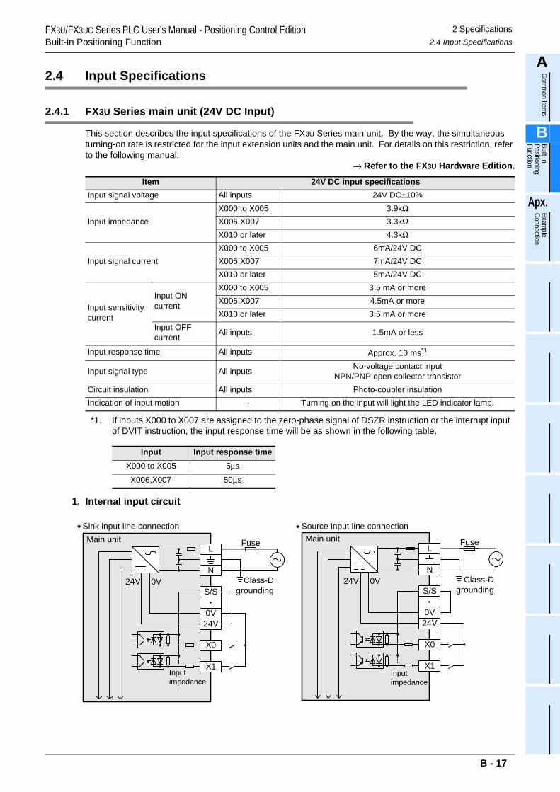
FX3U/FX3UC Series PLC User's Manual - Positioning Control EditionBuilt-in Positioning Function
2 Specifications2.4 Input Specifications
A
Comm
on Items
B
Built-in Positioning Function
Apx.
Example
Connection
2.4 Input Specifications
2.4.1 FX3U Series main unit (24V DC Input)
This section describes the input specifications of the FX3U Series main unit. By the way, the simultaneous turning-on rate is restricted for the input extension units and the main unit. For details on this restriction, refer to the following manual:
→ Refer to the FX3U Hardware Edition.
*1. If inputs X000 to X007 are assigned to the zero-phase signal of DSZR instruction or the interrupt input of DVIT instruction, the input response time will be as shown in the following table.
1. Internal input circuit
Item 24V DC input specificationsInput signal voltage All inputs 24V DC±10%
Input impedanceX000 to X005 3.9kΩX006,X007 3.3kΩX010 or later 4.3kΩ
Input signal currentX000 to X005 6mA/24V DCX006,X007 7mA/24V DCX010 or later 5mA/24V DC
Input sensitivity current
Input ON current
X000 to X005 3.5 mA or moreX006,X007 4.5mA or moreX010 or later 3.5 mA or more
Input OFF current All inputs 1.5mA or less
Input response time All inputs Approx. 10 ms*1
Input signal type All inputs No-voltage contact inputNPN/PNP open collector transistor
Circuit insulation All inputs Photo-coupler insulationIndication of input motion - Turning on the input will light the LED indicator lamp.
Input Input response timeX000 to X005 5µs
X006,X007 50µs
X0
S/S
0V24V
Main unit
N
L
X1
24V 0V
Fuse
Class-Dgrounding
Inputimpedance
Sink input line connection
X0
S/S
0V24V
Main unit
N
L
X1
24V 0V
Fuse
Class-Dgrounding
Inputimpedance
Source input line connection
B - 17
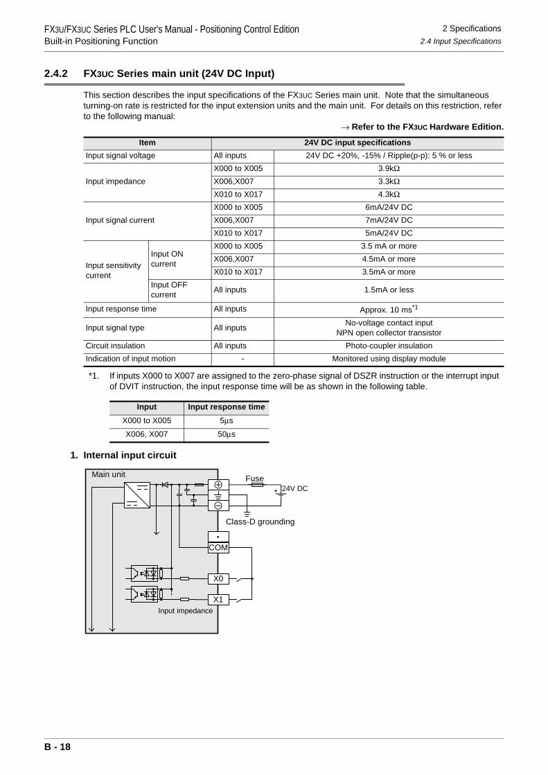
FX3U/FX3UC Series PLC User's Manual - Positioning Control EditionBuilt-in Positioning Function
2 Specifications2.4 Input Specifications
2.4.2 FX3UC Series main unit (24V DC Input)
This section describes the input specifications of the FX3UC Series main unit. Note that the simultaneous turning-on rate is restricted for the input extension units and the main unit. For details on this restriction, refer to the following manual:
→ Refer to the FX3UC Hardware Edition.
*1. If inputs X000 to X007 are assigned to the zero-phase signal of DSZR instruction or the interrupt input of DVIT instruction, the input response time will be as shown in the following table.
1. Internal input circuit
Item 24V DC input specificationsInput signal voltage All inputs 24V DC +20%, -15% / Ripple(p-p): 5 % or less
Input impedanceX000 to X005 3.9kΩX006,X007 3.3kΩX010 to X017 4.3kΩ
Input signal currentX000 to X005 6mA/24V DCX006,X007 7mA/24V DCX010 to X017 5mA/24V DC
Input sensitivity current
Input ON current
X000 to X005 3.5 mA or moreX006,X007 4.5mA or moreX010 to X017 3.5mA or more
Input OFF current All inputs 1.5mA or less
Input response time All inputs Approx. 10 ms*1
Input signal type All inputs No-voltage contact inputNPN open collector transistor
Circuit insulation All inputs Photo-coupler insulationIndication of input motion - Monitored using display module
Input Input response timeX000 to X005 5µs
X006, X007 50µs
X0
Main unit
X1
Fuse
Class-D grounding
Input impedance
24V DC
COM
B - 18
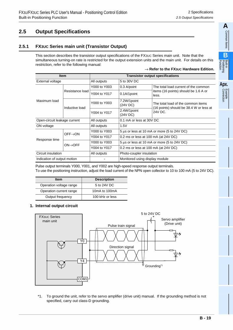
FX3U/FX3UC Series PLC User's Manual - Positioning Control EditionBuilt-in Positioning Function
2 Specifications2.5 Output Specifications
A
Comm
on Items
B
Built-in Positioning Function
Apx.
Example
Connection
2.5 Output Specifications
2.5.1 FX3UC Series main unit (Transistor Output)
This section describes the transistor output specifications of the FX3UC Series main unit. Note that the simultaneous turning-on rate is restricted for the output extension units and the main unit. For details on this restriction, refer to the following manual:
→ Refer to the FX3UC Hardware Edition.
Pulse output terminals Y000, Y001, and Y002 are high-speed response output terminals.To use the positioning instruction, adjust the load current of the NPN open collector to 10 to 100 mA (5 to 24V DC).
1. Internal output circuit
*1. To ground the unit, refer to the servo amplifier (drive unit) manual. If the grounding method is not specified, carry out class-D grounding.
Item Transistor output specificationsExternal voltage All outputs 5 to 30V DC
Maximum load
Resistance loadY000 to Y003 0.3 A/point The total load current of the common
items (16 points) should be 1.6 A or less.Y004 to Y017 0.1A/1point
Inductive loadY000 to Y003 7.2W/1point
(24V DC) The total load of the common items(16 points) should be 38.4 W or less at 24V DC.Y004 to Y017 2.4W/1point
(24V DC)Open-circuit leakage current All outputs 0.1 mA or less at 30V DCON voltage All outputs 1.5V
Response timeOFF→ON
Y000 to Y003 5 µs or less at 10 mA or more (5 to 24V DC)Y004 to Y017 0.2 ms or less at 100 mA (at 24V DC)
ON→OFFY000 to Y003 5 µs or less at 10 mA or more (5 to 24V DC)Y004 to Y017 0.2 ms or less at 100 mA (at 24V DC)
Circuit insulation All outputs Photo-coupler insulationIndication of output motion - Monitored using display module
Item DescriptionOperation voltage range 5 to 24V DC
Operation current range 10mA to 100mA
Output frequency 100 kHz or less
Y0
Y4
FX3UC Seriesmain unit
Grounding*1
Servo amplifier(Drive unit)Pulse train signal
Direction signal
5 to 24V DC
COM1
B - 19
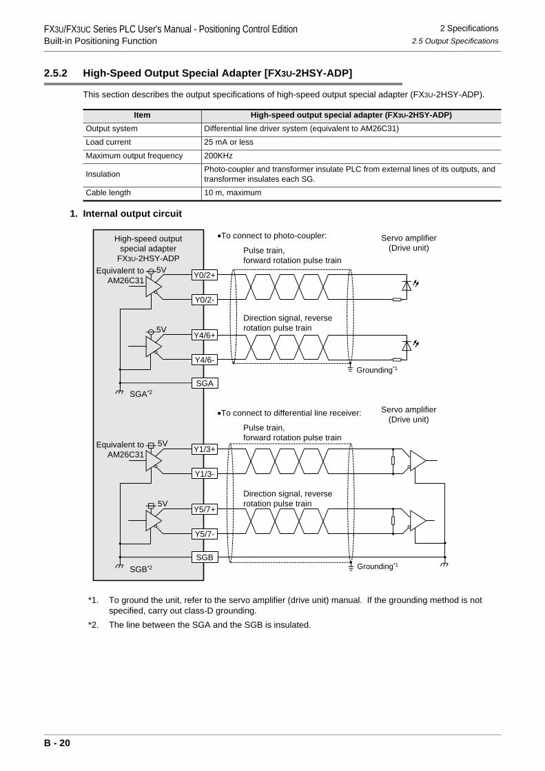
FX3U/FX3UC Series PLC User's Manual - Positioning Control EditionBuilt-in Positioning Function
2 Specifications2.5 Output Specifications
2.5.2 High-Speed Output Special Adapter [FX3U-2HSY-ADP]
This section describes the output specifications of high-speed output special adapter (FX3U-2HSY-ADP).
1. Internal output circuit
*1. To ground the unit, refer to the servo amplifier (drive unit) manual. If the grounding method is not specified, carry out class-D grounding.
*2. The line between the SGA and the SGB is insulated.
Item High-speed output special adapter (FX3U-2HSY-ADP)Output system Differential line driver system (equivalent to AM26C31)
Load current 25 mA or less
Maximum output frequency 200KHz
Insulation Photo-coupler and transformer insulate PLC from external lines of its outputs, and transformer insulates each SG.
Cable length 10 m, maximum
Y0/2+
SGA
High-speed outputspecial adapter
FX3U-2HSY-ADP
Y0/2-
Y4/6+
Y4/6-
Equivalent toAM26C31
Grounding*1
Servo amplifier(Drive unit)
•To connect to photo-coupler:
Pulse train,forward rotation pulse train
Direction signal, reverserotation pulse train
Y1/3+
SGB
Y1/3-
Y5/7+
Y5/7-
Equivalent toAM26C31
Grounding*1
Servo amplifier(Drive unit)
•To connect to differential line receiver:
Pulse train,forward rotation pulse train
Direction signal, reverserotation pulse train
SGA*2
SGB*2
5V
5V
5V
5V
B - 20
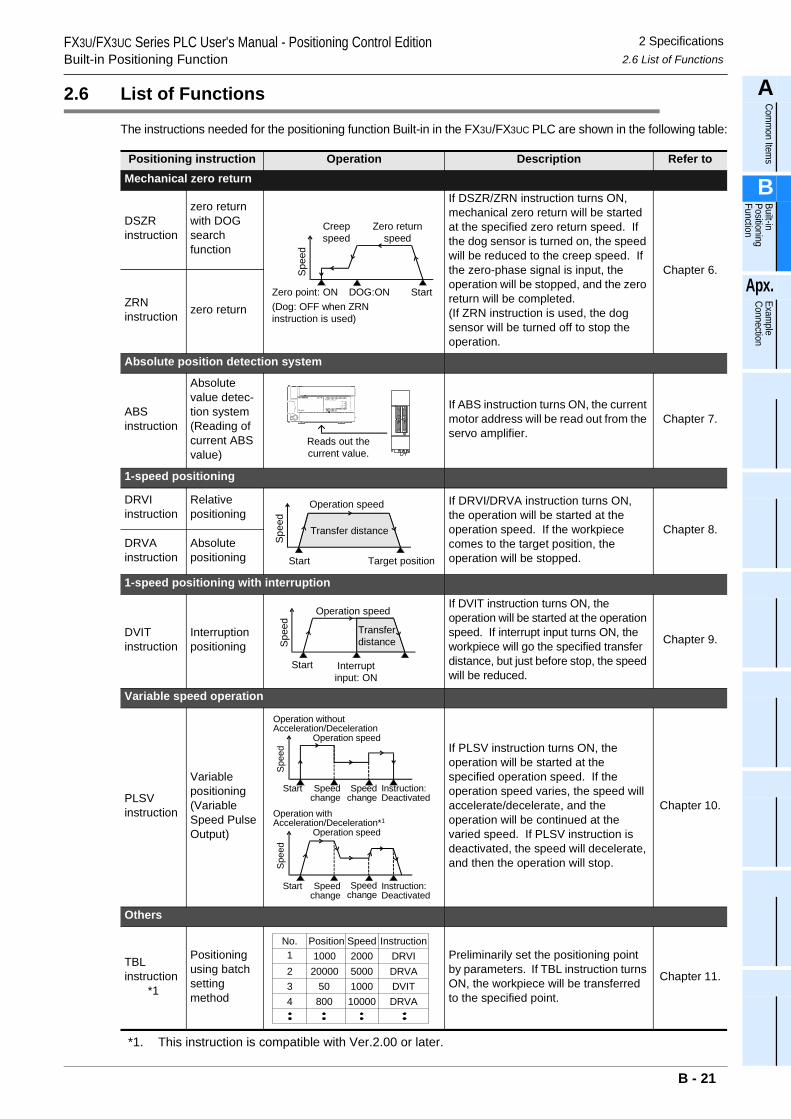
FX3U/FX3UC Series PLC User's Manual - Positioning Control EditionBuilt-in Positioning Function
2 Specifications2.6 List of Functions
A
Comm
on Items
B
Built-in Positioning Function
Apx.
Example
Connection
2.6 List of Functions
The instructions needed for the positioning function Built-in in the FX3U/FX3UC PLC are shown in the following table:
*1. This instruction is compatible with Ver.2.00 or later.
Positioning instruction Operation Description Refer toMechanical zero return
DSZR instruction
zero return with DOG searchfunction
If DSZR/ZRN instruction turns ON, mechanical zero return will be started at the specified zero return speed. If the dog sensor is turned on, the speed will be reduced to the creep speed. If the zero-phase signal is input, the operation will be stopped, and the zero return will be completed.(If ZRN instruction is used, the dog sensor will be turned off to stop the operation.
Chapter 6.
ZRN instruction zero return
Absolute position detection system
ABS instruction
Absolute value detec-tion system(Reading of current ABS value)
If ABS instruction turns ON, the current motor address will be read out from the servo amplifier.
Chapter 7.
1-speed positioning
DRVI instruction
Relativepositioning
If DRVI/DRVA instruction turns ON, the operation will be started at the operation speed. If the workpiece comes to the target position, the operation will be stopped.
Chapter 8.DRVA instruction
Absolute positioning
1-speed positioning with interruption
DVIT instruction
Interruption positioning
If DVIT instruction turns ON, the operation will be started at the operation speed. If interrupt input turns ON, the workpiece will go the specified transfer distance, but just before stop, the speed will be reduced.
Chapter 9.
Variable speed operation
PLSV instruction
Variable positioning(Variable Speed Pulse Output)
If PLSV instruction turns ON, the operation will be started at the specified operation speed. If the operation speed varies, the speed will accelerate/decelerate, and the operation will be continued at the varied speed. If PLSV instruction is deactivated, the speed will decelerate, and then the operation will stop.
Chapter 10.
Others
TBL instruction
*1
Positioning using batch setting method
Preliminarily set the positioning point by parameters. If TBL instruction turns ON, the workpiece will be transferred to the specified point.
Chapter 11.
Spe
edStartDOG:ONZero point: ON
Zero returnspeed
Creepspeed
(Dog: OFF when ZRNinstruction is used)
Reads out thecurrent value.
Spee
d
Start Target position
Operation speed
Transfer distance
Spe
ed
Start Interruptinput: ON
Operation speed
Transferdistance
Spe
ed
Start Speedchange
Operation speed
Speedchange
Instruction:Deactivated
Operation speed
Spe
ed
Start Speedchange
Speedchange
Instruction:Deactivated
Operation withoutAcceleration/Deceleration
Operation withAcceleration/Deceleration*1
Position Speed InstructionNo.1234
100020000
50800
20005000100010000
DRVI
DVITDRVA
DRVA
B - 21
3 Connection of Input/Output Lines and TighteningFX3U/FX3UC Series PLC User's Manual - Positioning Control EditionBuilt-in Positioning Function
3. Connection of Input/Output Lines and Tightening Torques
This chapter describes how to connect the input/output lines and the terminal tightening torques.
WIRING PRECAUTIONS
• Cut off all phases of the power source externally before installation or wiring work in order to avoid electric shockor damage of product.
• Make sure to attach the terminal cover offered as an accessory to the product before turning on the power orstarting the operation after installation or wiring work.Failure to do so may cause electric shock.
WIRING PRECAUTIONS
• Connect the AC power supply wiring to the dedicated terminals described in this manual.If an AC power supply is connected to a DC input/output terminal or DC power supply terminal, the PLC will beburnt out.
• Connect the DC power supply wiring to the dedicated terminals described in this manual.If an AC power supply is connected to a DC input/output terminal or DC power supply terminal, the PLC will beburnt out.
• Do not wire vacant terminals externally.Doing so may damage the product.
• Perform class D grounding (grounding resistance: 100Ω or less) to the grounding terminal in the FX3U Series mainunit with a 2mm2 or thicker wire.Do not connect the grounding terminal at the same point as a heavy electrical system (refer to the manual of thePLC main unit).
• Perform class D grounding (grounding resistance: 100Ω or less) to the grounding terminal in the FX3UC Seriesmain unit with a wire as thick as possible.Do not connect the grounding terminal at the same point as a heavy electrical system (refer to the manual of thePLC main unit).
• When drilling screw holes or wiring, cutting chips or wire chips should not enter ventilation slits. such an accidentmay cause fire, failures or malfunctions.
• Use the product in such a status that excessive force is not applied on I/O connectors.Failure to do so may result in wire breakage or failure of the PLC.
• Fit the I/O cables securely to the designated connectors.Contact failures may cause malfunctions.
• Perform wiring properly to the FX3U Series main unit and FX0N/FX2N Series extension equipment of the terminalblock type in accordance with the following precautions.Failure to do so may cause electric shock, short-circuit, wire breakage, or damages to the product.- The disposal size of the cable end should follow the dimensions described in this manual.- Tightening torque should be between 0.5 to 0.8 N•m.
• Observe the following items to wire the lines to the European terminal board. Ignorance of the following items maycause electric shock, short circuit, disconnection, or damage of the product.- The disposal size of the cable end should follow the dimensions described in this manual.- Tightening torque should be between 0.22 to 0.25 N•m.- Twist the end of strand wire and make sure there is no loose wires. - Do not solder-plate the electric wire ends.- Do not connect electric wires of unspecified size or beyond the specified number of electric wires.- Fix the electric wires so that the terminal block and connected parts of electric wires are not directly stressed.
• Properly perform wiring to the FX Series terminal blocks following the precautions below in order to preventelectrical shock, short-circuit, breakage of wire, or damage to the product:- The disposal size of the cable end should follow the dimensions described in this manual.- Tightening torque should be between 0.5 to 0.8 N•m.
B - 22
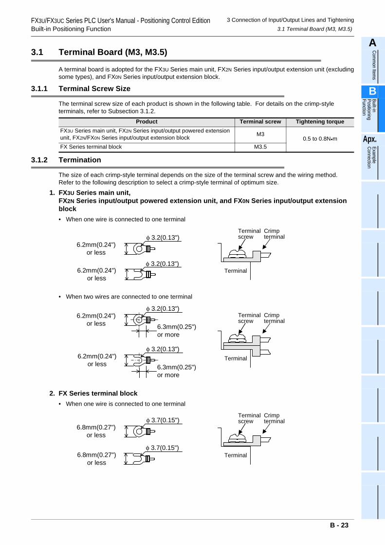
3 Connection of Input/Output Lines and Tightening3.1 Terminal Board (M3, M3.5)
FX3U/FX3UC Series PLC User's Manual - Positioning Control EditionBuilt-in Positioning Function
A
Comm
on Items
B
Built-in Positioning Function
Apx.
Example
Connection
3.1 Terminal Board (M3, M3.5)
A terminal board is adopted for the FX3U Series main unit, FX2N Series input/output extension unit (excludingsome types), and FX0N Series input/output extension block.
3.1.1 Terminal Screw Size
The terminal screw size of each product is shown in the following table. For details on the crimp-style terminals, refer to Subsection 3.1.2.
3.1.2 Termination
The size of each crimp-style terminal depends on the size of the terminal screw and the wiring method.Refer to the following description to select a crimp-style terminal of optimum size.
1. FX3U Series main unit, FX2N Series input/output powered extension unit, and FX0N Series input/output extension block• When one wire is connected to one terminal
• When two wires are connected to one terminal
2. FX Series terminal block• When one wire is connected to one terminal
Product Terminal screw Tightening torqueFX3U Series main unit, FX2N Series input/output powered extension unit, FX2N/FX0N Series input/output extension block M3
0.5 to 0.8N•mFX Series terminal block M3.5
TerminalTerminal
Terminalscrew
Crimpterminal
6.2mm(0.24")or less
φ 3.2(0.13")
6.2mm(0.24")or less
φ 3.2(0.13")
Terminalscrew
Crimpterminal
Terminal
6.2mm(0.24")or less
φ 3.2(0.13")
6.3mm(0.25")or more
6.2mm(0.24")or less
φ 3.2(0.13")
6.3mm(0.25")or more
6.8mm(0.27")or less
φ 3.7(0.15")TerminalTerminal
Terminalscrew
Crimpterminal
6.8mm(0.27")or less
φ 3.7(0.15")
B - 23
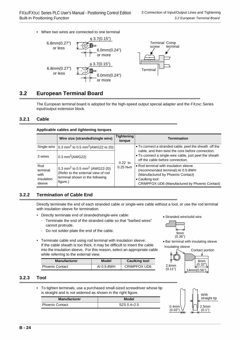
3 Connection of Input/Output Lines and Tightening3.2 European Terminal Board
FX3U/FX3UC Series PLC User's Manual - Positioning Control EditionBuilt-in Positioning Function
• When two wires are connected to one terminal
3.2 European Terminal Board
The European terminal board is adopted for the high-speed output special adapter and the FX2NC Series input/output extension block.
3.2.1 Cable
Applicable cables and tightening torques
3.2.2 Termination of Cable End
Directly terminate the end of each stranded cable or single-wire cable without a tool, or use the rod terminal with insulation sleeve for termination.• Directly terminate end of stranded/single-wire cable:
- Terminate the end of the stranded cable so that "barbed wires" cannot protrude.
- Do not solder-plate the end of the cable.
• Terminate cable end using rod terminal with insulation sleeve:If the cable sheath is too thick, it may be difficult to insert the cable into the insulation sleeve. For this reason, select an appropriate cable while referring to the external view.
3.2.3 Tool
• To tighten terminals, use a purchased small-sized screwdriver whose tip is straight and is not widened as shown in the right figure.
Wire size (stranded/single wire) Tightening torque Termination
Single-wire 0.3 mm2 to 0.5 mm2(AWG22 to 20)
0.22 to0.25 N•m
• To connect a stranded cable, peel the sheath off the cable, and then twist the core before connection.
• To connect a single-wire cable, just peel the sheath off the cable before connection.
2-wires 0.3 mm2(AWG22)
Rod terminal with insulation sleeve
0.3 mm2 to 0.5 mm2 (AWG22-20)(Refer to the external view of rod terminal shown in the following figure.)
• Rod terminal with insulation sleeve(recommended terminal):AI 0.5-8WH(Manufactured by Phoenix Contact)
• Caulking tool:CRIMPFOX UD6 (Manufactured by Phoenix Contact)
Manufacturer Model Caulking toolPhoenix Contact AI 0.5-8WH CRIMPFOX UD6
Manufacturer ModelPhoenix Contact SZS 0.4×2.5
6.8mm(0.27")or less
φ 3.7(0.15")
6.0mm(0.24")or more
Terminalscrew
Crimpterminal
Terminal
6.8mm(0.27")or less
φ 3.7(0.15")
6.0mm(0.24")or more
9mm(0.36")
• Stranded wire/solid wire
8mm(0.32")
Contact portion
14mm(0.56")2.6mm(0.11")
Insulating sleeve• Bar terminal with insulating sleeve
0.4mm(0.02")
2.5mm(0.1")
Withstraight tip
B - 24
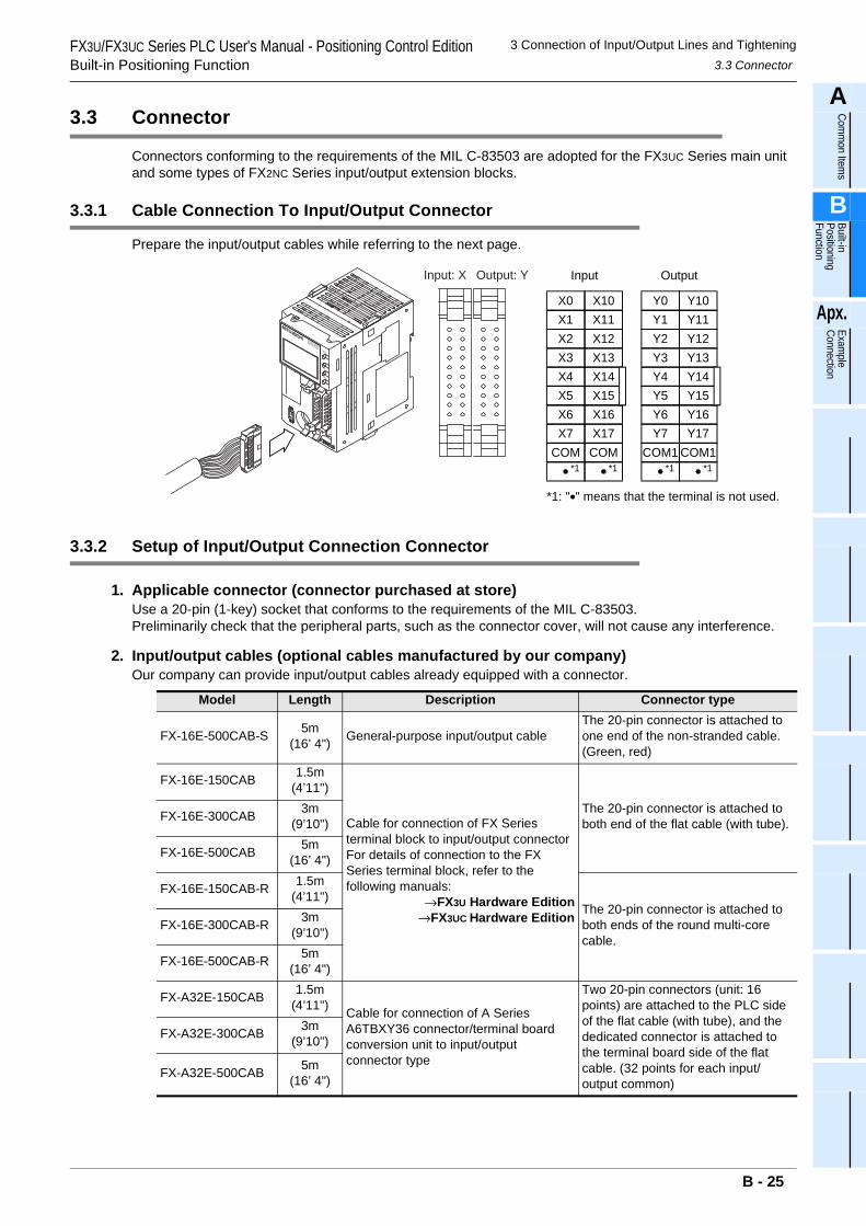
3 Connection of Input/Output Lines and Tightening3.3 Connector
FX3U/FX3UC Series PLC User's Manual - Positioning Control EditionBuilt-in Positioning Function
A
Comm
on Items
B
Built-in Positioning Function
Apx.
Example
Connection
3.3 Connector
Connectors conforming to the requirements of the MIL C-83503 are adopted for the FX3UC Series main unit and some types of FX2NC Series input/output extension blocks.
3.3.1 Cable Connection To Input/Output Connector
Prepare the input/output cables while referring to the next page.
3.3.2 Setup of Input/Output Connection Connector
1. Applicable connector (connector purchased at store)Use a 20-pin (1-key) socket that conforms to the requirements of the MIL C-83503.Preliminarily check that the peripheral parts, such as the connector cover, will not cause any interference.
2. Input/output cables (optional cables manufactured by our company)Our company can provide input/output cables already equipped with a connector.
Model Length Description Connector type
FX-16E-500CAB-S 5m(16’ 4") General-purpose input/output cable
The 20-pin connector is attached to one end of the non-stranded cable. (Green, red)
FX-16E-150CAB 1.5m(4’11")
Cable for connection of FX Series terminal block to input/output connectorFor details of connection to the FX Series terminal block, refer to the following manuals:
→FX3U Hardware Edition→FX3UC Hardware Edition
The 20-pin connector is attached to both end of the flat cable (with tube).FX-16E-300CAB 3m
(9’10")
FX-16E-500CAB 5m(16’ 4")
FX-16E-150CAB-R 1.5m(4’11")
The 20-pin connector is attached to both ends of the round multi-core cable.
FX-16E-300CAB-R 3m(9’10")
FX-16E-500CAB-R 5m(16’ 4")
FX-A32E-150CAB 1.5m(4’11") Cable for connection of A Series
A6TBXY36 connector/terminal board conversion unit to input/output connector type
Two 20-pin connectors (unit: 16 points) are attached to the PLC side of the flat cable (with tube), and the dedicated connector is attached to the terminal board side of the flat cable. (32 points for each input/output common)
FX-A32E-300CAB 3m(9’10")
FX-A32E-500CAB 5m(16’ 4")
X0X1X2X3X4X5X6X7
COM
X10X11X12X13X14X15X16X17
COM
Y0Y1Y2Y3Y4Y5Y6Y7
COM1
Y10Y11Y12Y13Y14Y15Y16Y17
COM1
Input Output
*1 *1 *1 *1
*1: "•" means that the terminal is not used.
Input: X Output: Y
B - 25
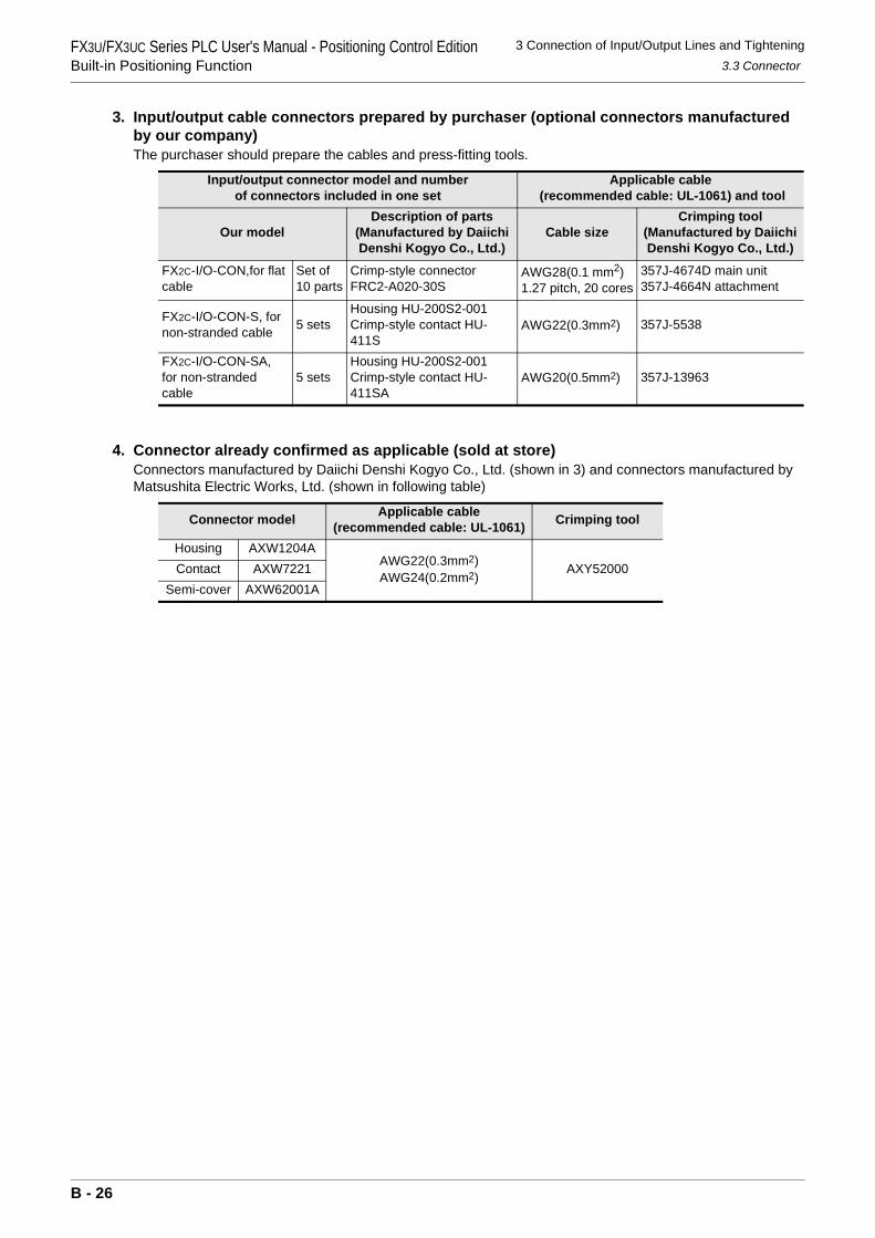
3 Connection of Input/Output Lines and Tightening3.3 Connector
FX3U/FX3UC Series PLC User's Manual - Positioning Control EditionBuilt-in Positioning Function
3. Input/output cable connectors prepared by purchaser (optional connectors manufactured by our company)The purchaser should prepare the cables and press-fitting tools.
4. Connector already confirmed as applicable (sold at store)Connectors manufactured by Daiichi Denshi Kogyo Co., Ltd. (shown in 3) and connectors manufactured by Matsushita Electric Works, Ltd. (shown in following table)
Input/output connector model and number of connectors included in one set
Applicable cable (recommended cable: UL-1061) and tool
Our modelDescription of parts
(Manufactured by Daiichi Denshi Kogyo Co., Ltd.)
Cable sizeCrimping tool
(Manufactured by Daiichi Denshi Kogyo Co., Ltd.)
FX2C-I/O-CON,for flat cable
Set of 10 parts
Crimp-style connector FRC2-A020-30S
AWG28(0.1 mm2)1.27 pitch, 20 cores
357J-4674D main unit357J-4664N attachment
FX2C-I/O-CON-S, for non-stranded cable 5 sets
Housing HU-200S2-001Crimp-style contact HU-411S
AWG22(0.3mm2) 357J-5538
FX2C-I/O-CON-SA, for non-stranded cable
5 setsHousing HU-200S2-001Crimp-style contact HU-411SA
AWG20(0.5mm2) 357J-13963
Connector model Applicable cable(recommended cable: UL-1061) Crimping tool
Housing AXW1204AAWG22(0.3mm2)AWG24(0.2mm2)
AXY52000Contact AXW7221Semi-cover AXW62001A
B - 26
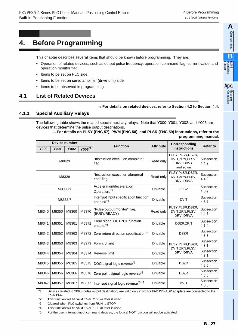
FX3U/FX3UC Series PLC User's Manual - Positioning Control EditionBuilt-in Positioning Function
4 Before Programming4.1 List of Related Devices
A
Comm
on Items
B
Built-in Positioning Function
Apx.
Example
Connection
4. Before Programming
This chapter describes several items that should be known before programming. They are:• Operation of related devices, such as output pulse frequency, operation command flag, current value, and
operation monitor flag.• Items to be set on PLC side• Items to be set on servo amplifier (drive unit) side• Items to be observed in programming
4.1 List of Related Devices
→ For details on related devices, refer to Section 4.2 to Section 4.4.
4.1.1 Special Auxiliary Relays
The following table shows the related special auxiliary relays. Note that Y000, Y001, Y002, and Y003 are devices that determine the pulse output destinations.
→ For details on PLSY (FNC 57), PWM (FNC 58), and PLSR (FNC 59) instructions, refer to theprogramming manual.
Device numberFunction Attribute Corresponding
instructions Refer toY000 Y001 Y002 Y003*1
M8029 "Instruction execution complete" flag Read only
PLSY,PLSR,DSZR,DVIT,ZRN,PLSV,
DRVI,DRVA and so on.
Subsection 4.4.2
M8329 "Instruction execution abnormal end" flag Read only
PLSY,PLSR,DSZR,DVIT,ZRN,PLSV,
DRVI,DRVA
Subsection 4.4.2
M8338*2Acceleration/deceleration Operation.*3
Drivable PLSV Subsection 4.3.9
M8336*4 Interrupt input specification function enabled*3 Drivable DVIT Subsection
4.3.7
M8340 M8350 M8360 M8370 "Pulse output monitor" flag.(BUSY/READY) Read only
PLSY,PLSR,DSZR,DVIT,ZRN,PLSV,
DRVI,DRVA
Subsection 4.4.3
M8341 M8351 M8361 M8371 Clear signal OUTPUT function enable.*3 Drivable DSZR,ZRN Subsection
4.3.4
M8342 M8352 M8362 M8372 Zero return direction specification.*3 Drivable DSZR Subsection 4.3.3
M8343 M8353 M8363 M8373 Forward limit Drivable PLSY,PLSR,DSZR,DVIT,ZRN,PLSV,
DRVI,DRVA
Subsection 4.3.1
M8344 M8354 M8364 M8374 Reverse limit Drivable Subsection 4.3.1
M8345 M8355 M8365 M8375 DOG signal logic reverse*3 Drivable DSZR Subsection 4.3.5
M8346 M8356 M8366 M8376 Zero point signal logic reverse*3 Drivable DSZR Subsection 4.3.6
M8347 M8357 M8367 M8377 Interrupt signal logic reverse*3,*5 Drivable DVIT Subsection 4.3.8
*1. Devices related to Y003 (pulse output destination) are valid only if two FX3U-2HSY-ADP adapters are connected to the FX3U PLC.
*2. This function will be valid if Ver. 2.00 or later is used.*3. Cleared when PLC switches from RUN to STOP*4. This function will be valid if Ver. 1.30 or later is used.*5. For the user interrupt input command devices, the logical NOT function will not be activated.
B - 27
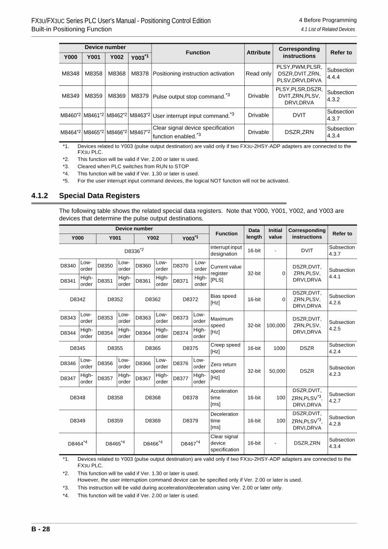
FX3U/FX3UC Series PLC User's Manual - Positioning Control EditionBuilt-in Positioning Function
4 Before Programming4.1 List of Related Devices
4.1.2 Special Data Registers
The following table shows the related special data registers. Note that Y000, Y001, Y002, and Y003 are devices that determine the pulse output destinations.
*1. Devices related to Y003 (pulse output destination) are valid only if two FX3U-2HSY-ADP adapters are connected to the FX3U PLC.
*2. This function will be valid if Ver. 1.30 or later is used.However, the user interruption command device can be specified only if Ver. 2.00 or later is used.
*3. This instruction will be valid during acceleration/deceleration using Ver. 2.00 or later only.*4. This function will be valid if Ver. 2.00 or later is used.
M8348 M8358 M8368 M8378 Positioning instruction activation Read onlyPLSY,PWM,PLSR,DSZR,DVIT,ZRN,PLSV,DRVI,DRVA
Subsection 4.4.4
M8349 M8359 M8369 M8379 Pulse output stop command.*3 DrivablePLSY,PLSR,DSZR,DVIT,ZRN,PLSV,
DRVI,DRVA
Subsection 4.3.2
M8460*2 M8461*2 M8462*2 M8463*2 User interrupt input command.*3 Drivable DVIT Subsection 4.3.7
M8464*2 M8465*2 M8466*2 M8467*2Clear signal device specification function enabled.*3
Drivable DSZR,ZRN Subsection 4.3.4
Device numberFunction Data
lengthInitial value
Correspondinginstructions Refer to
Y000 Y001 Y002 Y003*1
D8336*2 interrupt input designation 16-bit - DVIT Subsection
4.3.7
D8340 Low-order D8350 Low-
order D8360 Low-order D8370 Low-
order Current value register[PLS]
32-bit 0DSZR,DVIT,ZRN,PLSV,DRVI,DRVA
Subsection4.4.1
D8341 High-order D8351 High-
order D8361 High-order D8371 High-
order
D8342 D8352 D8362 D8372 Bias speed[Hz] 16-bit 0
DSZR,DVIT,ZRN,PLSV,DRVI,DRVA
Subsection4.2.6
D8343 Low-order D8353 Low-
order D8363 Low-order D8373 Low-
order Maximum speed[Hz]
32-bit 100,000DSZR,DVIT,ZRN,PLSV,DRVI,DRVA
Subsection4.2.5
D8344 High-order D8354 High-
order D8364 High-order D8374 High-
order
D8345 D8355 D8365 D8375 Creep speed [Hz] 16-bit 1000 DSZR Subsection
4.2.4
D8346 Low-order D8356 Low-
order D8366 Low-order D8376 Low-
order Zero return speed[Hz]
32-bit 50,000 DSZR Subsection4.2.3
D8347 High-order D8357 High-
order D8367 High-order D8377 High-
order
D8348 D8358 D8368 D8378Acceleration time[ms]
16-bit 100DSZR,DVIT,ZRN,PLSV*3,DRVI,DRVA
Subsection4.2.7
D8349 D8359 D8369 D8379Deceleration time[ms]
16-bit 100DSZR,DVIT,ZRN,PLSV*3,DRVI,DRVA
Subsection4.2.8
D8464*4 D8465*4 D8466*4 D8467*4Clear signal device specification
16-bit - DSZR,ZRN Subsection4.3.4
Device numberFunction Attribute Corresponding
instructions Refer toY000 Y001 Y002 Y003*1
*1. Devices related to Y003 (pulse output destination) are valid only if two FX3U-2HSY-ADP adapters are connected to the FX3U PLC.
*2. This function will be valid if Ver. 2.00 or later is used.*3. Cleared when PLC switches from RUN to STOP*4. This function will be valid if Ver. 1.30 or later is used.*5. For the user interrupt input command devices, the logical NOT function will not be activated.
B - 28
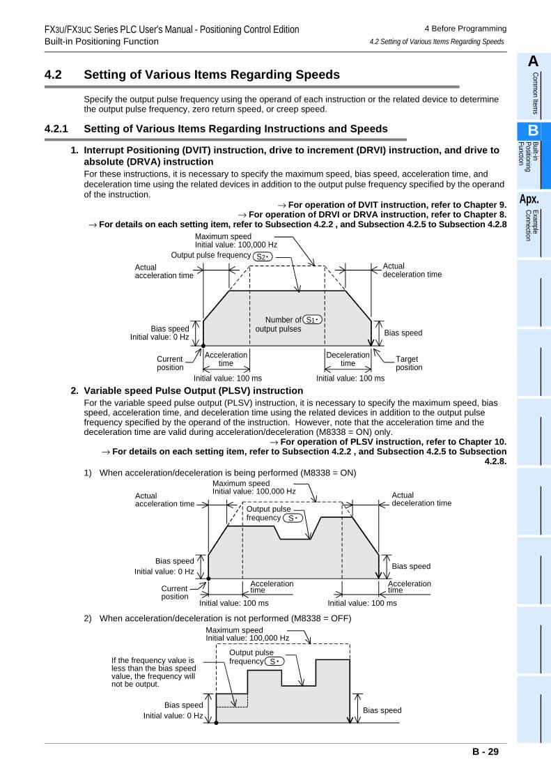
FX3U/FX3UC Series PLC User's Manual - Positioning Control EditionBuilt-in Positioning Function
4 Before Programming4.2 Setting of Various Items Regarding Speeds
A
Comm
on Items
B
Built-in Positioning Function
Apx.
Example
Connection
4.2 Setting of Various Items Regarding Speeds
Specify the output pulse frequency using the operand of each instruction or the related device to determine the output pulse frequency, zero return speed, or creep speed.
4.2.1 Setting of Various Items Regarding Instructions and Speeds
1. Interrupt Positioning (DVIT) instruction, drive to increment (DRVI) instruction, and drive to absolute (DRVA) instructionFor these instructions, it is necessary to specify the maximum speed, bias speed, acceleration time, and deceleration time using the related devices in addition to the output pulse frequency specified by the operand of the instruction.
→ For operation of DVIT instruction, refer to Chapter 9.→ For operation of DRVI or DRVA instruction, refer to Chapter 8.
→ For details on each setting item, refer to Subsection 4.2.2 , and Subsection 4.2.5 to Subsection 4.2.8
2. Variable speed Pulse Output (PLSV) instructionFor the variable speed pulse output (PLSV) instruction, it is necessary to specify the maximum speed, bias speed, acceleration time, and deceleration time using the related devices in addition to the output pulse frequency specified by the operand of the instruction. However, note that the acceleration time and the deceleration time are valid during acceleration/deceleration (M8338 = ON) only.
→ For operation of PLSV instruction, refer to Chapter 10.→ For details on each setting item, refer to Subsection 4.2.2 , and Subsection 4.2.5 to Subsection
4.2.8.1) When acceleration/deceleration is being performed (M8338 = ON)
2) When acceleration/deceleration is not performed (M8338 = OFF)
Actualacceleration time
Bias speed
Accelerationtime
Initial value: 100 ms
Decelerationtime
Number ofoutput pulses
Maximum speedInitial value: 100,000 Hz
Actualdeceleration time
Bias speed
Currentposition
Targetposition
Initial value: 100 ms
Initial value: 0 Hz
S1
Output pulse frequency S2
Bias speed
Accelerationtime
Initial value: 100 ms
Output pulsefrequency
Maximum speedInitial value: 100,000 Hz Actual
deceleration time
Bias speed
Initial value: 100 ms
Initial value: 0 Hz
S
Currentposition
Accelerationtime
Actualacceleration time
Bias speed
Output pulsefrequency
Bias speedInitial value: 0 Hz
S
Maximum speedInitial value: 100,000 Hz
If the frequency value isless than the bias speedvalue, the frequency willnot be output.
B - 29
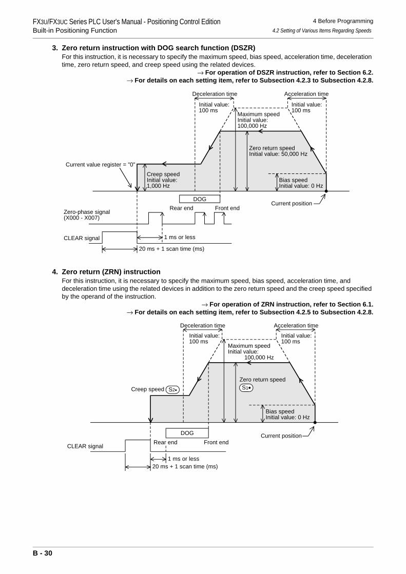
FX3U/FX3UC Series PLC User's Manual - Positioning Control EditionBuilt-in Positioning Function
4 Before Programming4.2 Setting of Various Items Regarding Speeds
3. Zero return instruction with DOG search function (DSZR)For this instruction, it is necessary to specify the maximum speed, bias speed, acceleration time, deceleration time, zero return speed, and creep speed using the related devices.
→ For operation of DSZR instruction, refer to Section 6.2.→ For details on each setting item, refer to Subsection 4.2.3 to Subsection 4.2.8.
4. Zero return (ZRN) instructionFor this instruction, it is necessary to specify the maximum speed, bias speed, acceleration time, and deceleration time using the related devices in addition to the zero return speed and the creep speed specified by the operand of the instruction.
→ For operation of ZRN instruction, refer to Section 6.1.→ For details on each setting item, refer to Subsection 4.2.5 to Subsection 4.2.8.
Maximum speedInitial value:100,000 Hz
Zero return speedInitial value: 50,000 Hz
Deceleration time
Bias speedInitial value: 0 Hz
Acceleration time
DOG
Creep speedInitial value:1,000 Hz
CLEAR signal
Zero-phase signal(X000 - X007)
Front endRear end
1 ms or less
20 ms + 1 scan time (ms)
Current value register = "0"
Initial value:100 ms
Current position
Initial value:100 ms
20 ms + 1 scan time (ms)
Zero return speed
Deceleration time Acceleration time
DOG
Creep speed
CLEAR signal Front endRear end
1 ms or less
S2• S1•
Maximum speedInitial value: 100,000 Hz
Initial value:100 ms
Bias speedInitial value: 0 Hz
Current position
Initial value:100 ms
B - 30
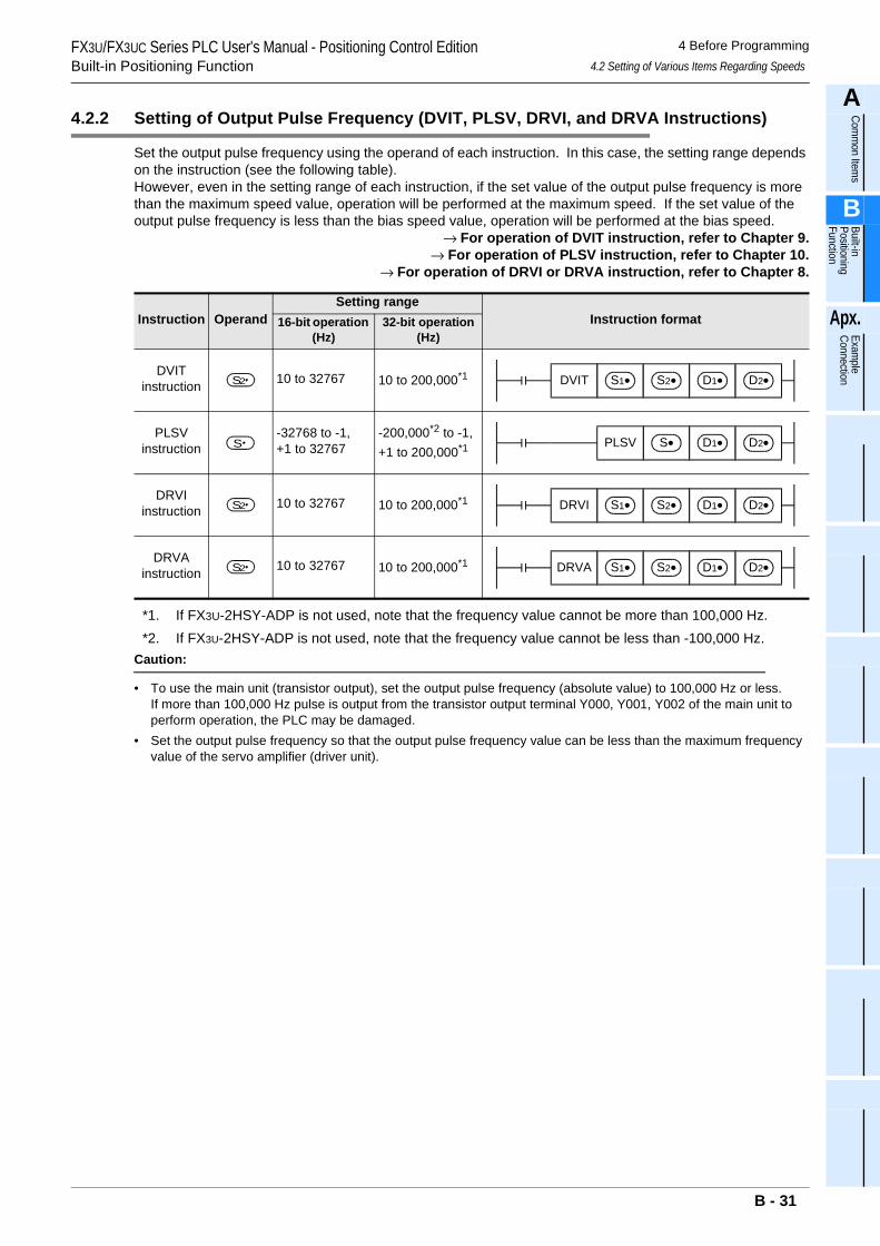
FX3U/FX3UC Series PLC User's Manual - Positioning Control EditionBuilt-in Positioning Function
4 Before Programming4.2 Setting of Various Items Regarding Speeds
A
Comm
on Items
B
Built-in Positioning Function
Apx.
Example
Connection
4.2.2 Setting of Output Pulse Frequency (DVIT, PLSV, DRVI, and DRVA Instructions)
Set the output pulse frequency using the operand of each instruction. In this case, the setting range depends on the instruction (see the following table).However, even in the setting range of each instruction, if the set value of the output pulse frequency is more than the maximum speed value, operation will be performed at the maximum speed. If the set value of the output pulse frequency is less than the bias speed value, operation will be performed at the bias speed.
→ For operation of DVIT instruction, refer to Chapter 9.→ For operation of PLSV instruction, refer to Chapter 10.
→ For operation of DRVI or DRVA instruction, refer to Chapter 8.
*1. If FX3U-2HSY-ADP is not used, note that the frequency value cannot be more than 100,000 Hz.*2. If FX3U-2HSY-ADP is not used, note that the frequency value cannot be less than -100,000 Hz.
Caution:
• To use the main unit (transistor output), set the output pulse frequency (absolute value) to 100,000 Hz or less.If more than 100,000 Hz pulse is output from the transistor output terminal Y000, Y001, Y002 of the main unit to perform operation, the PLC may be damaged.
• Set the output pulse frequency so that the output pulse frequency value can be less than the maximum frequency value of the servo amplifier (driver unit).
Instruction OperandSetting range
Instruction format16-bit operation (Hz)
32-bit operation (Hz)
DVITinstruction 10 to 32767 10 to 200,000*1
PLSVinstruction
-32768 to -1,+1 to 32767
-200,000*2 to -1,+1 to 200,000*1
DRVIinstruction 10 to 32767 10 to 200,000*1
DRVAinstruction 10 to 32767 10 to 200,000*1
S2 DVIT S1• S2• D1• D2•
S PLSV S• D1• D2•
S2 DRVI S1• S2• D1• D2•
S2 DRVA S1• S2• D1• D2•
B - 31
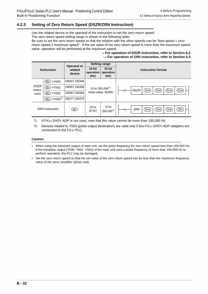
FX3U/FX3UC Series PLC User's Manual - Positioning Control EditionBuilt-in Positioning Function
4 Before Programming4.2 Setting of Various Items Regarding Speeds
4.2.3 Setting of Zero Return Speed (DSZR/ZRN Instruction)
Use the related device or the operand of the instruction to set the zero return speed.The zero return speed setting range is shown in the following table.Be sure to set the zero return speed so that the relation with the other speeds can be "bias speed ≤ zero return speed ≤ maximum speed". If the set value of the zero return speed is more than the maximum speed value, operation will be performed at the maximum speed.
→ For operation of DSZR instruction, refer to Section 6.2.→ For operation of ZRN instruction, refer to Section 6.3.
*1. If FX3U-2HSY-ADP is not used, note that this value cannot be more than 100,000 Hz.*2. Devices related to Y003 (pulse output destination) are valid only if two FX3U-2HSY-ADP adapters are
connected to the FX3U PLC.
Caution:
• When using the transistor output of main unit, set the pulse frequency for zero return speed less than 100,000 Hz.If the transistor output (Y000, Y001, Y002) of the main unit uses a pulse frequency of more than 100,000 Hz to perform operation, the PLC may be damaged.
• Set the zero return speed so that the set value of the zero return speed can be less than the maximum frequency value of the servo amplifier (driver unit).
InstructionOperand or
related device
Setting range
Instruction format16-bit operation
(Hz)
32-bit operation
(Hz)
DSZR instru-ction
=Y000 D8347,D8346
10 to 200,000*1
Initial value: 50000=Y001 D8357,D8356
=Y002 D8367,D8366
=Y003*2 D8377,D8376
ZRN instruction 10 to 32767
10 to 200,000*1
D1
DSZR S1• S2• D1• D2• D1
D1
D1
S1 ZRN S1• S2• S3• D•
B - 32
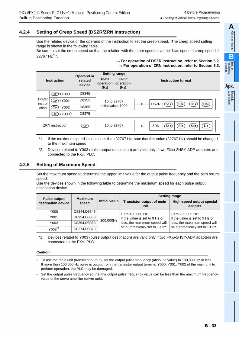
FX3U/FX3UC Series PLC User's Manual - Positioning Control EditionBuilt-in Positioning Function
4 Before Programming4.2 Setting of Various Items Regarding Speeds
A
Comm
on Items
B
Built-in Positioning Function
Apx.
Example
Connection
4.2.4 Setting of Creep Speed (DSZR/ZRN Instruction)
Use the related device or the operand of the instruction to set the creep speed. The creep speed setting range is shown in the following table.Be sure to set the creep speed so that the relation with the other speeds can be "bias speed ≤ creep speed ≤ 32767 Hz*1".
→ For operation of DSZR instruction, refer to Section 6.2.→ For operation of ZRN instruction, refer to Section 6.3.
*1. If the maximum speed is set to less than 32767 Hz, note that this value (32767 Hz) should be changed to the maximum speed.
*2. Devices related to Y003 (pulse output destination) are valid only if two FX3U-2HSY-ADP adapters are connected to the FX3U PLC.
4.2.5 Setting of Maximum Speed
Set the maximum speed to determine the upper limit value for the output pulse frequency and the zero return speed.Use the devices shown in the following table to determine the maximum speed for each pulse output destination device.
*1. Devices related to Y003 (pulse output destination) are valid only if two FX3U-2HSY-ADP adapters are connected to the FX3U PLC.
Caution:
• To use the main unit (transistor output), set the output pulse frequency (absolute value) to 100,000 Hz or less.If more than 100,000 Hz pulse is output from the transistor output terminal Y000, Y001, Y002 of the main unit to perform operation, the PLC may be damaged.
• Set the output pulse frequency so that the output pulse frequency value can be less than the maximum frequency value of the servo amplifier (driver unit).
InstructionOperand or
related device
Setting range
Instruction format16-bit operation
(Hz)
32-bit operation
(Hz)
DSZR instru-ction
=Y000 D8345
10 to 32767Initial value: 1000
=Y001 D8355
=Y002 D8365
=Y003*2 D8375
ZRN instruction 10 to 32767
Pulse output destination device
Maximum speed Initial value
Setting rangeTransistor output of main
unitHigh-speed output special
adapterY000 D8344,D8343
100,000Hz
10 to 100,000 Hz:If the value is set to 9 Hz or less, the maximum speed will be automatically set to 10 Hz.
10 to 200,000 Hz:If the value is set to 9 Hz or less, the maximum speed will be automatically set to 10 Hz.
Y001 D8354,D8353Y002 D8364,D8363
Y003*1 D8374,D8373
D1
DSZR S1• S2• D1• D2• D1
D1
D1
S2 ZRN S1• S2• S3• D•
B - 33
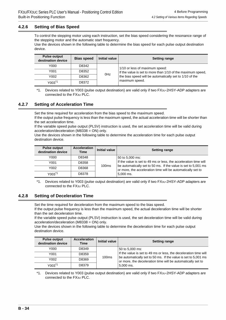
FX3U/FX3UC Series PLC User's Manual - Positioning Control EditionBuilt-in Positioning Function
4 Before Programming4.2 Setting of Various Items Regarding Speeds
4.2.6 Setting of Bias Speed
To control the stepping motor using each instruction, set the bias speed considering the resonance range of the stepping motor and the automatic start frequency.Use the devices shown in the following table to determine the bias speed for each pulse output destination device.
*1. Devices related to Y003 (pulse output destination) are valid only if two FX3U-2HSY-ADP adapters are connected to the FX3U PLC.
4.2.7 Setting of Acceleration Time
Set the time required for acceleration from the bias speed to the maximum speed.If the output pulse frequency is less than the maximum speed, the actual acceleration time will be shorter than the set acceleration time.If the variable speed pulse output (PLSV) instruction is used, the set acceleration time will be valid during acceleration/deceleration (M8338 = ON) only.Use the devices shown in the following table to determine the acceleration time for each pulse output destination device.
*1. Devices related to Y003 (pulse output destination) are valid only if two FX3U-2HSY-ADP adapters are connected to the FX3U PLC.
4.2.8 Setting of Deceleration Time
Set the time required for deceleration from the maximum speed to the bias speed.If the output pulse frequency is less than the maximum speed, the actual deceleration time will be shorter than the set deceleration time.If the variable speed pulse output (PLSV) instruction is used, the set deceleration time will be valid during acceleration/deceleration (M8338 = ON) only.Use the devices shown in the following table to determine the deceleration time for each pulse output destination device.
*1. Devices related to Y003 (pulse output destination) are valid only if two FX3U-2HSY-ADP adapters are connected to the FX3U PLC.
Pulse output destination device Bias speed Initial value Setting range
Y000 D8342
0Hz
1/10 or less of maximum speed:If the value is set to more than 1/10 of the maximum speed, the bias speed will be automatically set to 1/10 of the maximum speed.
Y001 D8352Y002 D8362
Y003*1 D8372
Pulse output destination device
Acceleration Time Initial value Setting range
Y000 D8348
100ms
50 to 5,000 ms:If the value is set to 49 ms or less, the acceleration time will be automatically set to 50 ms. If the value is set to 5,001 ms or more, the acceleration time will be automatically set to 5,000 ms.
Y001 D8358Y002 D8368
Y003*1 D8378
Pulse output destination device
Acceleration Time Initial value Setting range
Y000 D8349
100ms
50 to 5,000 ms:If the value is set to 49 ms or less, the deceleration time will be automatically set to 50 ms. If the value is set to 5,001 ms or more, the deceleration time will be automatically set to 5,000 ms.
Y001 D8359Y002 D8369
Y003*1 D8379
B - 34
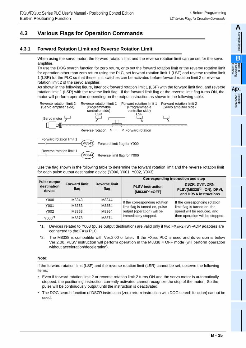
FX3U/FX3UC Series PLC User's Manual - Positioning Control EditionBuilt-in Positioning Function
4 Before Programming4.3 Various Flags for Operation Commands
A
Comm
on Items
B
Built-in Positioning Function
Apx.
Example
Connection
4.3 Various Flags for Operation Commands
4.3.1 Forward Rotation Limit and Reverse Rotation Limit
When using the servo motor, the forward rotation limit and the reverse rotation limit can be set for the servo amplifier.To use the DOG search function for zero return, or to set the forward rotation limit or the reverse rotation limit for operation other than zero return using the PLC, set forward rotation limit 1 (LSF) and reverse rotation limit 1 (LSR) for the PLC so that these limit switches can be activated before forward rotation limit 2 or reverse rotation limit 2 of the servo amplifier.As shown in the following figure, interlock forward rotation limit 1 (LSF) with the forward limit flag, and reverse rotation limit 1 (LSR) with the reverse limit flag. If the forward limit flag or the reverse limit flag turns ON, the motor will perform operation depending on the output instruction as shown in the following table.
Use the flag shown in the following table to determine the forward rotation limit and the reverse rotation limit for each pulse output destination device (Y000, Y001, Y002, Y003).
*1. Devices related to Y003 (pulse output destination) are valid only if two FX3U-2HSY-ADP adapters are connected to the FX3U PLC.
*2. The M8338 is compatible with Ver.2.00 or later. If the FX3UC PLC is used and its version is belowVer.2.00, PLSV instruction will perform operation in the M8338 = OFF mode (will perform operationwithout acceleration/deceleration).
Note:
If the forward rotation limit (LSF) and the reverse rotation limit (LSR) cannot be set, observe the following items:• Even if forward rotation limit 2 or reverse rotation limit 2 turns ON and the servo motor is automatically
stopped, the positioning instruction currently activated cannot recognize the stop of the motor. So the pulse will be continuously output until the instruction is deactivated.
• The DOG search function of DSZR instruction (zero return instruction with DOG search function) cannot be used.
Pulse output destination
device
Forward limit flag
Reverse limit flag
Corresponding instruction and stop
PLSV instruction(M8338*2 =OFF)
DSZR, DVIT, ZRN, PLSV(M8338*2 =ON), DRVI,
and DRVA instructionsY000 M8343 M8344
If the corresponding rotation limit flag is turned on, pulse output (operation) will be immediately stopped.
If the corresponding rotation limit flag is turned on, the speed will be reduced, and then operation will be stopped.
Y001 M8353 M8354Y002 M8363 M8364
Y003*1 M8373 M8374
Reverse rotation limit 2(Servo amplifier side)
Forward rotation limit 2(Servo amplifier side)
Forward rotation limit 1(Programmablecontroller side)
LSF
Reverse rotation limit 1(Programmablecontroller side)
LSR
Reverse rotation Forward rotation
Servo motor
Forward rotation limit 1M8343 Forward limit flag for Y000
Reverse rotation limit 1M8344 Reverse limit flag for Y000
B - 35
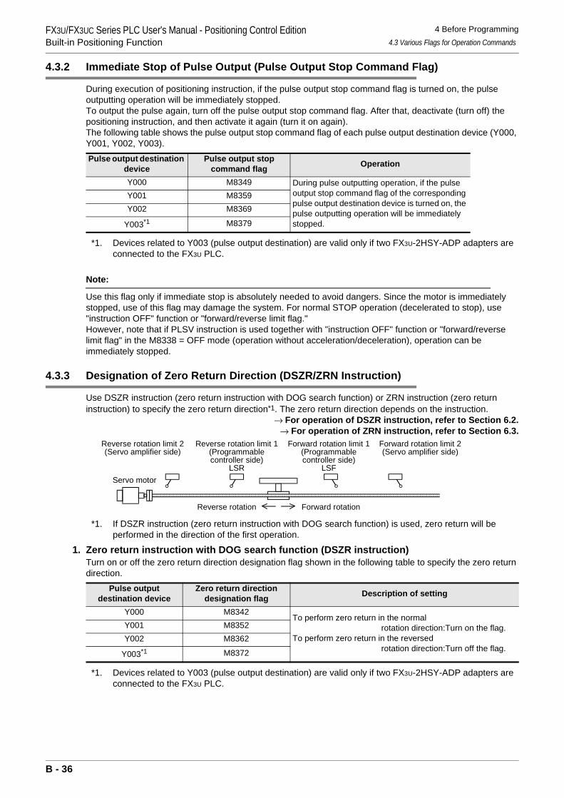
FX3U/FX3UC Series PLC User's Manual - Positioning Control EditionBuilt-in Positioning Function
4 Before Programming4.3 Various Flags for Operation Commands
4.3.2 Immediate Stop of Pulse Output (Pulse Output Stop Command Flag)
During execution of positioning instruction, if the pulse output stop command flag is turned on, the pulse outputting operation will be immediately stopped.To output the pulse again, turn off the pulse output stop command flag. After that, deactivate (turn off) the positioning instruction, and then activate it again (turn it on again).The following table shows the pulse output stop command flag of each pulse output destination device (Y000, Y001, Y002, Y003).
*1. Devices related to Y003 (pulse output destination) are valid only if two FX3U-2HSY-ADP adapters are connected to the FX3U PLC.
Note:
Use this flag only if immediate stop is absolutely needed to avoid dangers. Since the motor is immediately stopped, use of this flag may damage the system. For normal STOP operation (decelerated to stop), use "instruction OFF" function or "forward/reverse limit flag."However, note that if PLSV instruction is used together with "instruction OFF" function or "forward/reverse limit flag" in the M8338 = OFF mode (operation without acceleration/deceleration), operation can be immediately stopped.
4.3.3 Designation of Zero Return Direction (DSZR/ZRN Instruction)
Use DSZR instruction (zero return instruction with DOG search function) or ZRN instruction (zero return instruction) to specify the zero return direction*1. The zero return direction depends on the instruction.
→ For operation of DSZR instruction, refer to Section 6.2.→ For operation of ZRN instruction, refer to Section 6.3.
*1. If DSZR instruction (zero return instruction with DOG search function) is used, zero return will be performed in the direction of the first operation.
1. Zero return instruction with DOG search function (DSZR instruction)Turn on or off the zero return direction designation flag shown in the following table to specify the zero return direction.
*1. Devices related to Y003 (pulse output destination) are valid only if two FX3U-2HSY-ADP adapters are connected to the FX3U PLC.
Pulse output destination device
Pulse output stop command flag Operation
Y000 M8349 During pulse outputting operation, if the pulse output stop command flag of the corresponding pulse output destination device is turned on, the pulse outputting operation will be immediately stopped.
Y001 M8359Y002 M8369
Y003*1 M8379
Pulse output destination device
Zero return direction designation flag Description of setting
Y000 M8342To perform zero return in the normal
rotation direction:Turn on the flag.To perform zero return in the reversed
rotation direction:Turn off the flag.
Y001 M8352Y002 M8362
Y003*1 M8372
Reverse rotation limit 2(Servo amplifier side)
Reverse rotation limit 1(Programmablecontroller side)
LSR
Forward rotation limit 2(Servo amplifier side)
Forward rotation limit 1(Programmablecontroller side)
LSF
Reverse rotation Forward rotation
Servo motor
B - 36
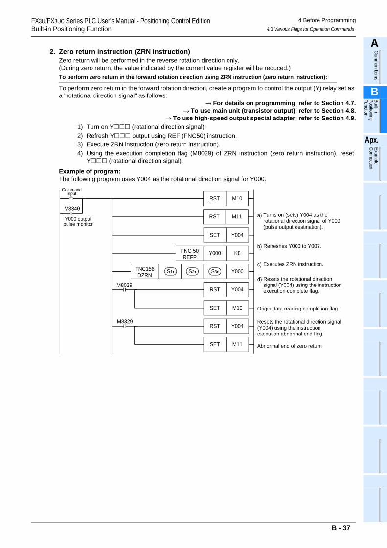
FX3U/FX3UC Series PLC User's Manual - Positioning Control EditionBuilt-in Positioning Function
4 Before Programming4.3 Various Flags for Operation Commands
A
Comm
on Items
B
Built-in Positioning Function
Apx.
Example
Connection
2. Zero return instruction (ZRN instruction)Zero return will be performed in the reverse rotation direction only.(During zero return, the value indicated by the current value register will be reduced.)To perform zero return in the forward rotation direction using ZRN instruction (zero return instruction):
To perform zero return in the forward rotation direction, create a program to control the output (Y) relay set as a "rotational direction signal" as follows:
→ For details on programming, refer to Section 4.7.→ To use main unit (transistor output), refer to Section 4.8.
→ To use high-speed output special adapter, refer to Section 4.9.1) Turn on Y (rotational direction signal).2) Refresh Y output using REF (FNC50) instruction.3) Execute ZRN instruction (zero return instruction).4) Using the execution completion flag (M8029) of ZRN instruction (zero return instruction), reset
Y (rotational direction signal).
Example of program:The following program uses Y004 as the rotational direction signal for Y000.
Commandinput
Turns on (sets) Y004 as therotational direction signal of Y000(pulse output destination).
M8340
Y000 outputpulse monitor
K8Y000
Y000
Y004RST
Refreshes Y000 to Y007.
Executes ZRN instruction.
Resets the rotational directionsignal (Y004) using the instructionexecution complete flag.
Y004SET
FNC 50REFP
FNC156DZRN
S1• S2• S3•
M8029
M11RST
M10RST
M10SET Origin data reading completion flag
Resets the rotational direction signal(Y004) using the instructionexecution abnormal end flag.
Y004RSTM8329
M11SET Abnormal end of zero return
a)
b)
c)
d)
B - 37
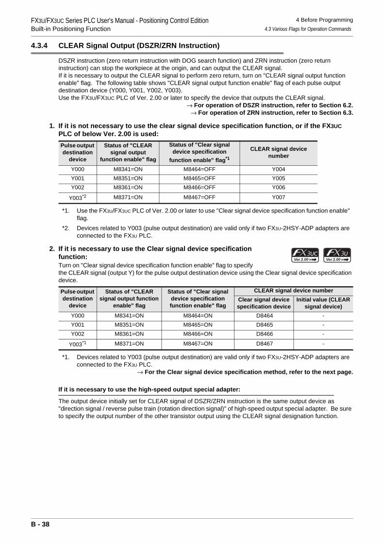
FX3U/FX3UC Series PLC User's Manual - Positioning Control EditionBuilt-in Positioning Function
4 Before Programming4.3 Various Flags for Operation Commands
4.3.4 CLEAR Signal Output (DSZR/ZRN Instruction)
DSZR instruction (zero return instruction with DOG search function) and ZRN instruction (zero return instruction) can stop the workpiece at the origin, and can output the CLEAR signal.If it is necessary to output the CLEAR signal to perform zero return, turn on "CLEAR signal output function enable" flag. The following table shows "CLEAR signal output function enable" flag of each pulse output destination device (Y000, Y001, Y002, Y003).Use the FX3U/FX3UC PLC of Ver. 2.00 or later to specify the device that outputs the CLEAR signal.
→ For operation of DSZR instruction, refer to Section 6.2.→ For operation of ZRN instruction, refer to Section 6.3.
1. If it is not necessary to use the clear signal device specification function, or if the FX3UC PLC of below Ver. 2.00 is used:
*1. Use the FX3U/FX3UC PLC of Ver. 2.00 or later to use "Clear signal device specification function enable" flag.
*2. Devices related to Y003 (pulse output destination) are valid only if two FX3U-2HSY-ADP adapters are connected to the FX3U PLC.
2. If it is necessary to use the Clear signal device specification function:Turn on "Clear signal device specification function enable" flag to specify the CLEAR signal (output Y) for the pulse output destination device using the Clear signal device specification device.
*1. Devices related to Y003 (pulse output destination) are valid only if two FX3U-2HSY-ADP adapters are connected to the FX3U PLC.
→ For the Clear signal device specification method, refer to the next page.
If it is necessary to use the high-speed output special adapter:
The output device initially set for CLEAR signal of DSZR/ZRN instruction is the same output device as "direction signal / reverse pulse train (rotation direction signal)" of high-speed output special adapter. Be sure to specify the output number of the other transistor output using the CLEAR signal designation function.
Pulse output destination
device
Status of "CLEAR signal output
function enable" flag
Status of "Clear signal device specification
function enable" flag*1
CLEAR signal device number
Y000 M8341=ON M8464=OFF Y004Y001 M8351=ON M8465=OFF Y005Y002 M8361=ON M8466=OFF Y006
Y003*2 M8371=ON M8467=OFF Y007
Pulse output destination
device
Status of "CLEAR signal output function
enable" flag
Status of "Clear signal device specification function enable" flag
CLEAR signal device numberClear signal device specification device
Initial value (CLEAR signal device)
Y000 M8341=ON M8464=ON D8464 -Y001 M8351=ON M8465=ON D8465 -Y002 M8361=ON M8466=ON D8466 -
Y003*1 M8371=ON M8467=ON D8467 -
B - 38
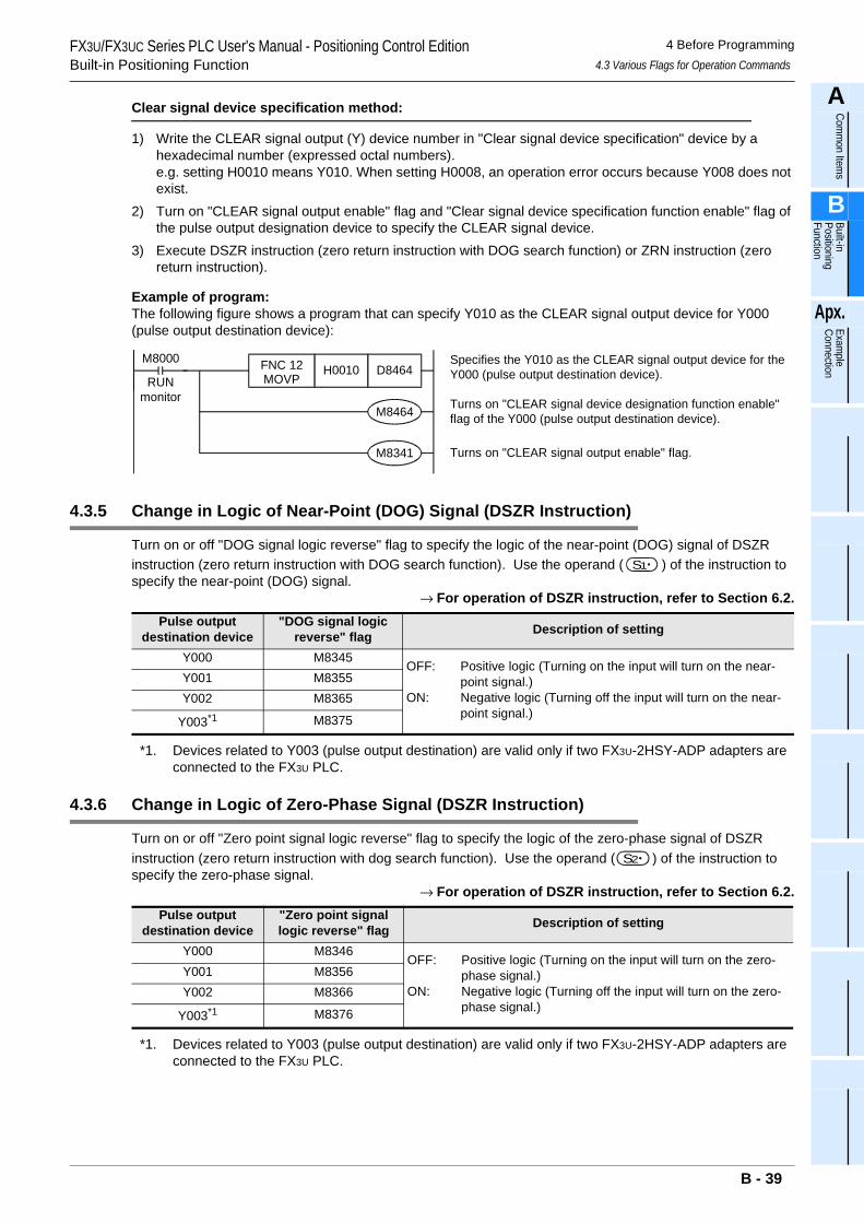
FX3U/FX3UC Series PLC User's Manual - Positioning Control EditionBuilt-in Positioning Function
4 Before Programming4.3 Various Flags for Operation Commands
A
Comm
on Items
B
Built-in Positioning Function
Apx.
Example
Connection
Clear signal device specification method:
1) Write the CLEAR signal output (Y) device number in "Clear signal device specification" device by a hexadecimal number (expressed octal numbers).e.g. setting H0010 means Y010. When setting H0008, an operation error occurs because Y008 does not exist.
2) Turn on "CLEAR signal output enable" flag and "Clear signal device specification function enable" flag of the pulse output designation device to specify the CLEAR signal device.
3) Execute DSZR instruction (zero return instruction with DOG search function) or ZRN instruction (zero return instruction).
Example of program:The following figure shows a program that can specify Y010 as the CLEAR signal output device for Y000 (pulse output destination device):
4.3.5 Change in Logic of Near-Point (DOG) Signal (DSZR Instruction)
Turn on or off "DOG signal logic reverse" flag to specify the logic of the near-point (DOG) signal of DSZR instruction (zero return instruction with DOG search function). Use the operand ( ) of the instruction to specify the near-point (DOG) signal.
→ For operation of DSZR instruction, refer to Section 6.2.
*1. Devices related to Y003 (pulse output destination) are valid only if two FX3U-2HSY-ADP adapters are connected to the FX3U PLC.
4.3.6 Change in Logic of Zero-Phase Signal (DSZR Instruction)
Turn on or off "Zero point signal logic reverse" flag to specify the logic of the zero-phase signal of DSZR instruction (zero return instruction with dog search function). Use the operand ( ) of the instruction to specify the zero-phase signal.
→ For operation of DSZR instruction, refer to Section 6.2.
*1. Devices related to Y003 (pulse output destination) are valid only if two FX3U-2HSY-ADP adapters are connected to the FX3U PLC.
Pulse output destination device
"DOG signal logic reverse" flag Description of setting
Y000 M8345OFF: Positive logic (Turning on the input will turn on the near-
point signal.)ON: Negative logic (Turning off the input will turn on the near-
point signal.)
Y001 M8355Y002 M8365
Y003*1 M8375
Pulse output destination device
"Zero point signal logic reverse" flag Description of setting
Y000 M8346OFF: Positive logic (Turning on the input will turn on the zero-
phase signal.)ON: Negative logic (Turning off the input will turn on the zero-
phase signal.)
Y001 M8356Y002 M8366
Y003*1 M8376
M8000
RUNmonitor
Specifies the Y010 as the CLEAR signal output device for theY000 (pulse output destination device).
Turns on "CLEAR signal device designation function enable"flag of the Y000 (pulse output destination device).
Turns on "CLEAR signal output enable" flag.
D8464H0010FNC 12MOVP
M8464
M8341
S1
S2
B - 39
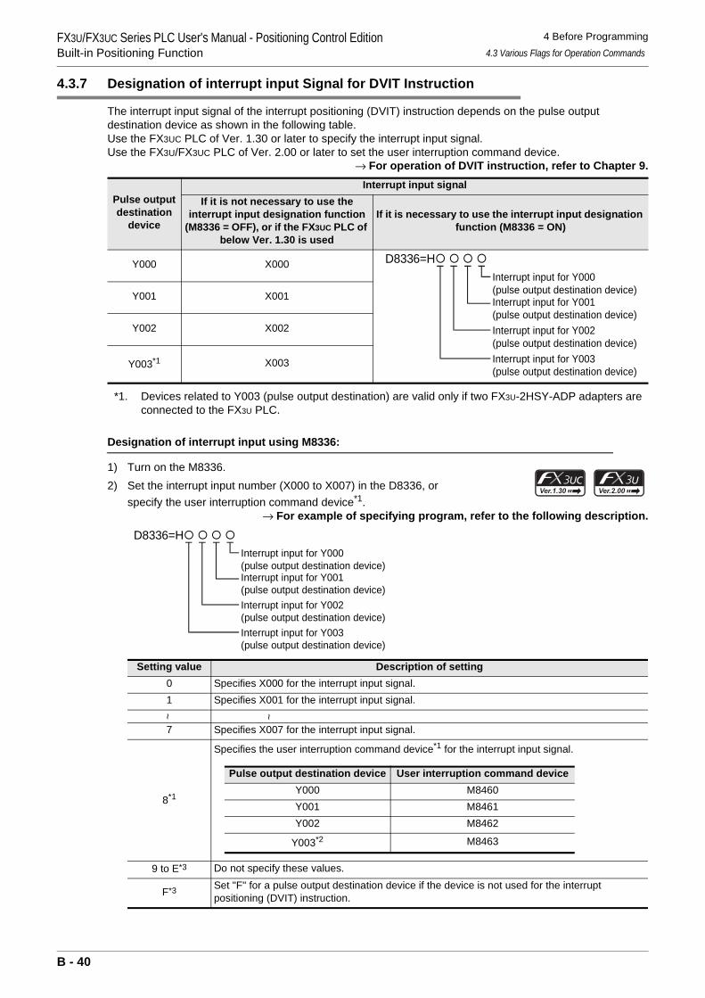
FX3U/FX3UC Series PLC User's Manual - Positioning Control EditionBuilt-in Positioning Function
4 Before Programming4.3 Various Flags for Operation Commands
4.3.7 Designation of interrupt input Signal for DVIT Instruction
The interrupt input signal of the interrupt positioning (DVIT) instruction depends on the pulse output destination device as shown in the following table.Use the FX3UC PLC of Ver. 1.30 or later to specify the interrupt input signal.Use the FX3U/FX3UC PLC of Ver. 2.00 or later to set the user interruption command device.
→ For operation of DVIT instruction, refer to Chapter 9.
*1. Devices related to Y003 (pulse output destination) are valid only if two FX3U-2HSY-ADP adapters are connected to the FX3U PLC.
Designation of interrupt input using M8336:
1) Turn on the M8336.2) Set the interrupt input number (X000 to X007) in the D8336, or
specify the user interruption command device*1.→ For example of specifying program, refer to the following description.
Pulse output destination
device
Interrupt input signalIf it is not necessary to use the
interrupt input designation function (M8336 = OFF), or if the FX3UC PLC of
below Ver. 1.30 is used
If it is necessary to use the interrupt input designation function (M8336 = ON)
Y000 X000
Y001 X001
Y002 X002
Y003*1 X003
Setting value Description of setting0 Specifies X000 for the interrupt input signal.1 Specifies X001 for the interrupt input signal.
~ ~
7 Specifies X007 for the interrupt input signal.
8*1
Specifies the user interruption command device*1 for the interrupt input signal.
9 to E*3 Do not specify these values.
F*3 Set "F" for a pulse output destination device if the device is not used for the interrupt positioning (DVIT) instruction.
D8336=H Interrupt input for Y000(pulse output destination device)Interrupt input for Y001(pulse output destination device)Interrupt input for Y002(pulse output destination device)Interrupt input for Y003(pulse output destination device)
D8336=H Interrupt input for Y000(pulse output destination device)Interrupt input for Y001(pulse output destination device)Interrupt input for Y002(pulse output destination device)Interrupt input for Y003(pulse output destination device)
Pulse output destination device User interruption command deviceY000 M8460Y001 M8461Y002 M8462
Y003*2 M8463
B - 40
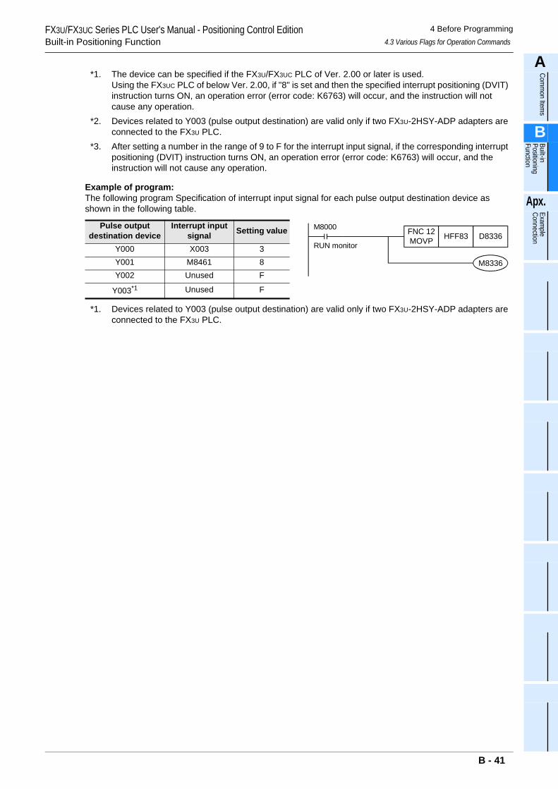
FX3U/FX3UC Series PLC User's Manual - Positioning Control EditionBuilt-in Positioning Function
4 Before Programming4.3 Various Flags for Operation Commands
A
Comm
on Items
B
Built-in Positioning Function
Apx.
Example
Connection
*1. The device can be specified if the FX3U/FX3UC PLC of Ver. 2.00 or later is used.Using the FX3UC PLC of below Ver. 2.00, if "8" is set and then the specified interrupt positioning (DVIT) instruction turns ON, an operation error (error code: K6763) will occur, and the instruction will not cause any operation.
*2. Devices related to Y003 (pulse output destination) are valid only if two FX3U-2HSY-ADP adapters are connected to the FX3U PLC.
*3. After setting a number in the range of 9 to F for the interrupt input signal, if the corresponding interrupt positioning (DVIT) instruction turns ON, an operation error (error code: K6763) will occur, and the instruction will not cause any operation.
Example of program:The following program Specification of interrupt input signal for each pulse output destination device as shown in the following table.
*1. Devices related to Y003 (pulse output destination) are valid only if two FX3U-2HSY-ADP adapters are connected to the FX3U PLC.
Pulse output destination device
Interrupt input signal Setting value
Y000 X003 3Y001 M8461 8Y002 Unused F
Y003*1 Unused F
RUN monitor
FNC 12MOVP HFF83 D8336
M8000
M8336
B - 41
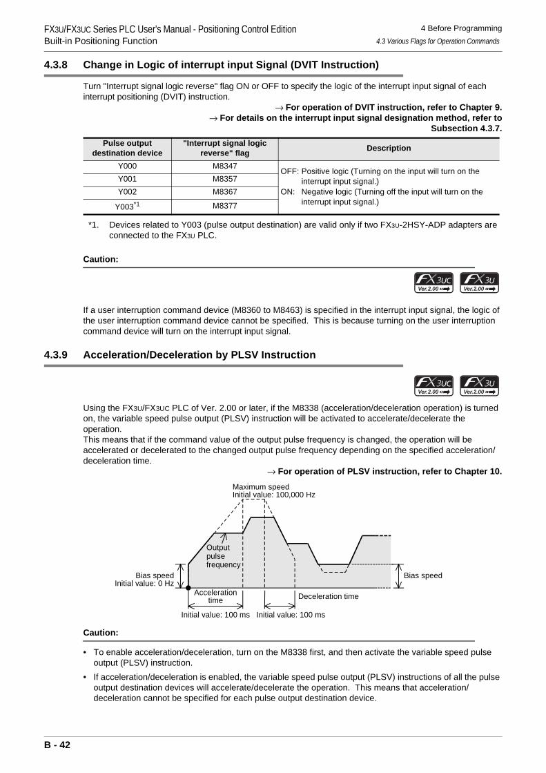
FX3U/FX3UC Series PLC User's Manual - Positioning Control EditionBuilt-in Positioning Function
4 Before Programming4.3 Various Flags for Operation Commands
4.3.8 Change in Logic of interrupt input Signal (DVIT Instruction)
Turn "Interrupt signal logic reverse" flag ON or OFF to specify the logic of the interrupt input signal of each interrupt positioning (DVIT) instruction.
→ For operation of DVIT instruction, refer to Chapter 9.→ For details on the interrupt input signal designation method, refer to
Subsection 4.3.7.
*1. Devices related to Y003 (pulse output destination) are valid only if two FX3U-2HSY-ADP adapters are connected to the FX3U PLC.
Caution:
If a user interruption command device (M8360 to M8463) is specified in the interrupt input signal, the logic of the user interruption command device cannot be specified. This is because turning on the user interruption command device will turn on the interrupt input signal.
4.3.9 Acceleration/Deceleration by PLSV Instruction
Using the FX3U/FX3UC PLC of Ver. 2.00 or later, if the M8338 (acceleration/deceleration operation) is turned on, the variable speed pulse output (PLSV) instruction will be activated to accelerate/decelerate the operation.This means that if the command value of the output pulse frequency is changed, the operation will be accelerated or decelerated to the changed output pulse frequency depending on the specified acceleration/deceleration time.
→ For operation of PLSV instruction, refer to Chapter 10.
Caution:
• To enable acceleration/deceleration, turn on the M8338 first, and then activate the variable speed pulse output (PLSV) instruction.
• If acceleration/deceleration is enabled, the variable speed pulse output (PLSV) instructions of all the pulse output destination devices will accelerate/decelerate the operation. This means that acceleration/deceleration cannot be specified for each pulse output destination device.
Pulse output destination device
"Interrupt signal logic reverse" flag Description
Y000 M8347 OFF: Positive logic (Turning on the input will turn on the interrupt input signal.)
ON: Negative logic (Turning off the input will turn on the interrupt input signal.)
Y001 M8357Y002 M8367
Y003*1 M8377
Bias speed
Accelerationtime
Initial value: 100 ms
Deceleration time
Outputpulsefrequency
Maximum speedInitial value: 100,000 Hz
Initial value: 100 ms
Initial value: 0 HzBias speed
B - 42
FX3U/FX3UC Series PLC User's Manual - Positioning Control EditionBuilt-in Positioning Function
4 Before Programming4.4 Current Value and Flag for Monitoring of Operation
A
Comm
on Items
B
Built-in Positioning Function
Apx.
Example
Connection
4.4 Current Value and Flag for Monitoring of Operation
4.4.1 Current Value
During positioning operation, use the current value register to check the current value. The current value will be increased or decreased depending on the rotation direction. The following table shows the current value register (32-bit) of each pulse output destination device (Y000, Y001, Y002, Y003).
*1. Devices related to Y003 (pulse output destination) are valid only if two FX3U-2HSY-ADP adapters are connected to the FX3U PLC.
Caution:
The current value will be counted in the range of -2,147,483,648 to 2,147,483,647. If the current value exceeds this range, the following value will be indicated. Be careful not to exceed the later range.• If the current value is increased past the maximum value, the minimum value will be indicated.• If the current value is decreased below the minimum value, the maximum value will be indicated.
Necessity of zero return:
If the specified forward rotation pulse or the reverse rotation pulse is output, the current value register will increase or reduce the current value. Upon turning off the power of the PLC, however, the current value stored in the current value register will be erased. For this reason, after turning the power on again, be sure to adjust the current value of the current value register to the current position of the machine. For this adjustment, use the zero return instruction or the Absolute Current Value Read instruction (absolute position detection system) shown below:
→ For details on DSZR instruction, refer to Section 6.2.→ For details on ZRN instruction, refer to Section 6.3.
→ For details on ABS instruction, refer to Chapter 7.
*2. The absolute position detection function is adopted for the MR-H A, MR-J2 A MR-J2S A, or MR-J3 A servo amplifiers. If one of these servo amplifiers is adopted and mechanical zero return is performed only once just before turning off the power, the current value will not be erased even after power-off.After turning on the power again, read out the stored current value using ABS (FNC155) instruction of the PLC. This means that the current value can be obtained without performing zero return just after turning on the power again.
Pulse output destination device Current value register (32-bit)Y000 D8341,D8340Y001 D8351,D8350Y002 D8361,D8360
Y003*1 D8371,D8370
Instruction DescriptionDSZR(FNC150) Zero return instruction with DOG search functionZRN(FNC156) Zero return instruction (without DOG search function)
ABS(FNC155)*2 Absolute Current Value Read instruction
B - 43
FX3U/FX3UC Series PLC User's Manual - Positioning Control EditionBuilt-in Positioning Function
4 Before Programming4.4 Current Value and Flag for Monitoring of Operation
4.4.2 Completion of Execution of Instruction ("Instruction execution complete" Flag, "Instruction execution abnormal end" Flag)
Use "Instruction execution complete" flag or "Instruction execution abnormal end" flag to check whether execution of the positioning instruction is completed properly."Instruction execution complete" flag and "Instruction execution abnormal end" flag can be turned on or off for each instruction. Use these flags just after execution of each instruction.
→ For details on programming, refer to Subsection 4.7.4.• "Instruction execution complete" flag: Will be turned on if the instruction is executed properly.• "Instruction execution abnormal end" flag: Will be turned on if the instruction is not executed properly.
Caution:
If "Instruction execution complete" flag or "Instruction execution abnormal end" flag is turned on, then the execution of the instruction (pulse outputting operation, etc.) is completed. However, it is not certain whether the servo motor is stopped. Check "positioning completion" signal or "servo ready" signal of the servo amplifier (drive unit) to check whether the servo motor is stopped.
4.4.3 "Pulse Output Monitor" (BUSY/READY) Flag
Use "pulse output monitor" (BUSY/READY) flag to check whether the pulse is being output to the pulse output destination device. The following table shows "pulse output monitor" (BUSY/READY) flag of each pulse output destination device (Y000, Y001, Y002, Y003).
*1. Devices related to Y003 (pulse output destination) are valid only if two FX3U-2HSY-ADP adapters are connected to the FX3U PLC.
4.4.4 "Positioning Instruction Activation" Flag
Use "positioning instruction activation" flag of each pulse output destination device to check whether or not the positioning instruction is being executed for the pulse output destination. Use this flag to prevent simultaneous activation of two or more positioning instructions in the same pulse output destination device.
*1. Devices related to Y003 (pulse output destination) are valid only if two FX3U-2HSY-ADP adapters are connected to the FX3U PLC.
Pulse output destination device
"Pulse output monitor"(BUSY/READY) flag Statuses of flag and pulse
Y000 M8340
Outputting pulse (BUSY):Flag = ONPulse outputting stopped (READY):Flag = OFF
Y001 M8350Y002 M8360
Y003*1 M8370
Pulse output destination device
"Positioning instruction Activation" flag Statuses of flag and pulse
Y000 M8348 ON: The positioning instruction is being activated for the corresponding pulse output destination.(Even after completing execution of the instruction, if the instruction is still activated, the flag will not be turned off.)
OFF: The positioning instruction is not being activated for the corresponding pulse output destination.
Y001 M8358Y002 M8368
Y003*1 M8378
B - 44
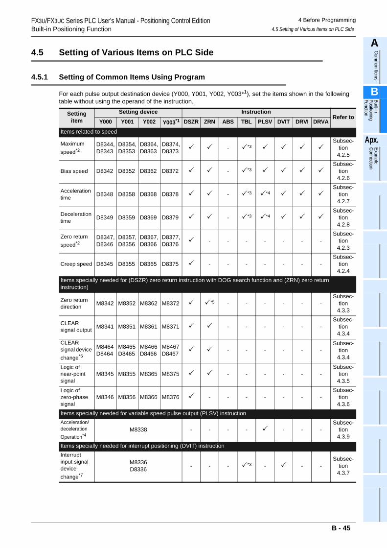
FX3U/FX3UC Series PLC User's Manual - Positioning Control EditionBuilt-in Positioning Function
4 Before Programming4.5 Setting of Various Items on PLC Side
A
Comm
on Items
B
Built-in Positioning Function
Apx.
Example
Connection
4.5 Setting of Various Items on PLC Side
4.5.1 Setting of Common Items Using Program
For each pulse output destination device (Y000, Y001, Y002, Y003*1), set the items shown in the following table without using the operand of the instruction.
Setting item
Setting device InstructionRefer to
Y000 Y001 Y002 Y003*1 DSZR ZRN ABS TBL PLSV DVIT DRVI DRVA
Items related to speed
Maximum speed*2
D8344,D8343
D8354,D8353
D8364,D8363
D8374,D8373 - *3
Subsec-tion
4.2.5
Bias speed D8342 D8352 D8362 D8372 - *3Subsec-
tion 4.2.6
Acceleration time D8348 D8358 D8368 D8378 - *3 *4
Subsec-tion
4.2.7
Deceleration time D8349 D8359 D8369 D8379 - *3 *4
Subsec-tion
4.2.8
Zero return speed*2
D8347,D8346
D8357,D8356
D8367,D8366
D8377,D8376 - - - - - - -
Subsec-tion
4.2.3
Creep speed D8345 D8355 D8365 D8375 - - - - - - -Subsec-
tion 4.2.4
Items specially needed for (DSZR) zero return instruction with DOG search function and (ZRN) zero return instruction)
Zero return direction M8342 M8352 M8362 M8372 *5 - - - - - -
Subsec-tion
4.3.3
CLEAR signal output M8341 M8351 M8361 M8371 - - - - - -
Subsec-tion
4.3.4CLEAR signal device change*6
M8464D8464
M8465D8465
M8466D8466
M8467D8467 - - - - - -
Subsec-tion
4.3.4
Logic of near-point signal
M8345 M8355 M8365 M8375 - - - - - -Subsec-
tion 4.3.5
Logic of zero-phase signal
M8346 M8356 M8366 M8376 - - - - - - -Subsec-
tion 4.3.6
Items specially needed for variable speed pulse output (PLSV) instructionAcceleration/deceleration Operation*4
M8338 - - - - - - -Subsec-
tion 4.3.9
Items specially needed for interrupt positioning (DVIT) instructionInterrupt input signal device change*7
M8336D8336 - - - *3 - - -
Subsec-tion
4.3.7
B - 45
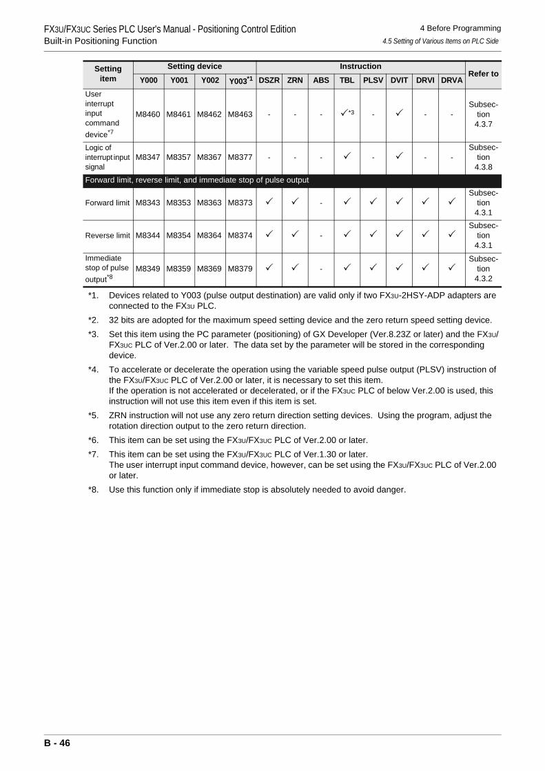
FX3U/FX3UC Series PLC User's Manual - Positioning Control EditionBuilt-in Positioning Function
4 Before Programming4.5 Setting of Various Items on PLC Side
*1. Devices related to Y003 (pulse output destination) are valid only if two FX3U-2HSY-ADP adapters are connected to the FX3U PLC.
*2. 32 bits are adopted for the maximum speed setting device and the zero return speed setting device.*3. Set this item using the PC parameter (positioning) of GX Developer (Ver.8.23Z or later) and the FX3U/
FX3UC PLC of Ver.2.00 or later. The data set by the parameter will be stored in the corresponding device.
*4. To accelerate or decelerate the operation using the variable speed pulse output (PLSV) instruction of the FX3U/FX3UC PLC of Ver.2.00 or later, it is necessary to set this item.If the operation is not accelerated or decelerated, or if the FX3UC PLC of below Ver.2.00 is used, this instruction will not use this item even if this item is set.
*5. ZRN instruction will not use any zero return direction setting devices. Using the program, adjust the rotation direction output to the zero return direction.
*6. This item can be set using the FX3U/FX3UC PLC of Ver.2.00 or later.*7. This item can be set using the FX3U/FX3UC PLC of Ver.1.30 or later.
The user interrupt input command device, however, can be set using the FX3U/FX3UC PLC of Ver.2.00 or later.
*8. Use this function only if immediate stop is absolutely needed to avoid danger.
User interrupt input command device*7
M8460 M8461 M8462 M8463 - - - *3 - - -Subsec-
tion 4.3.7
Logic of interrupt input signal
M8347 M8357 M8367 M8377 - - - - - -Subsec-
tion 4.3.8
Forward limit, reverse limit, and immediate stop of pulse output
Forward limit M8343 M8353 M8363 M8373 -Subsec-
tion 4.3.1
Reverse limit M8344 M8354 M8364 M8374 -Subsec-
tion 4.3.1
Immediate stop of pulse output*8
M8349 M8359 M8369 M8379 -Subsec-
tion 4.3.2
Setting item
Setting device InstructionRefer to
Y000 Y001 Y002 Y003*1 DSZR ZRN ABS TBL PLSV DVIT DRVI DRVA
B - 46
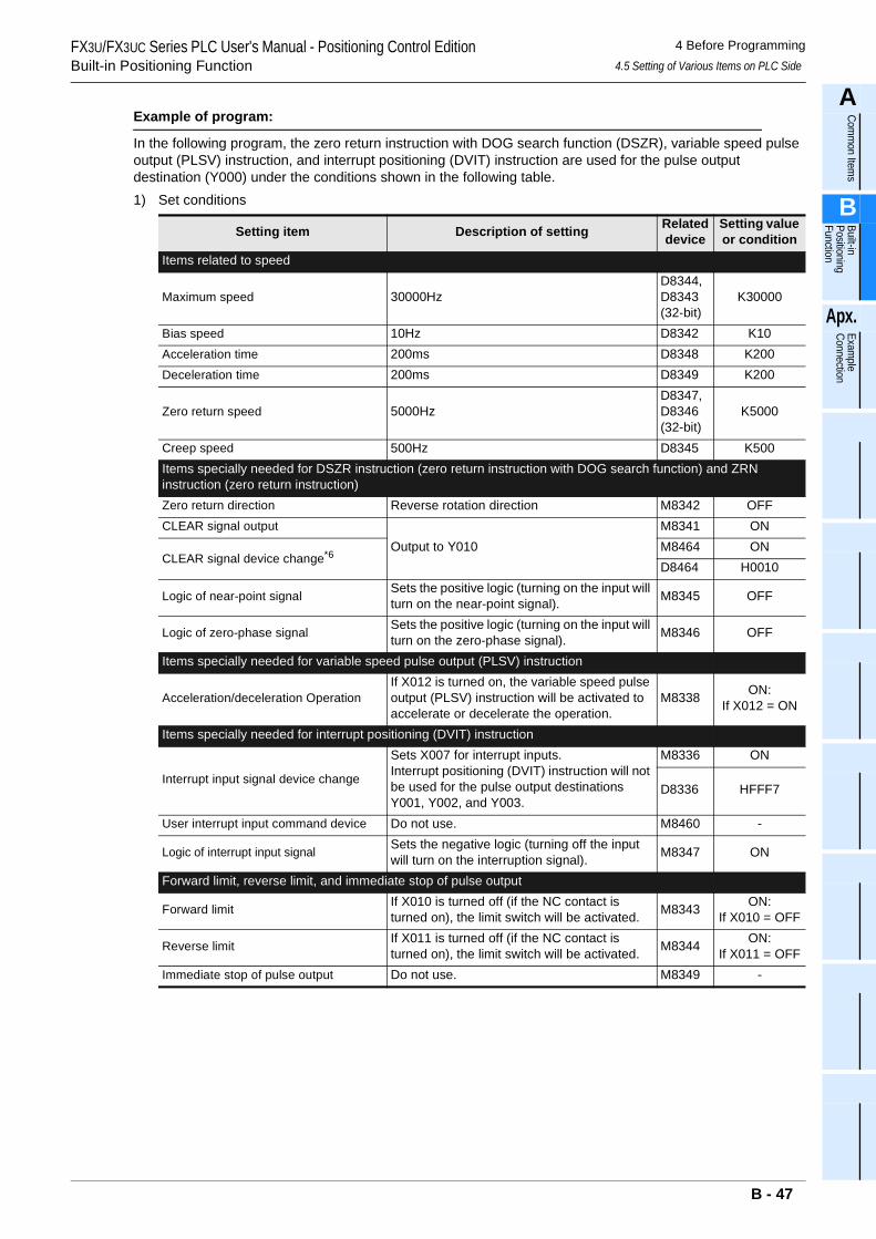
FX3U/FX3UC Series PLC User's Manual - Positioning Control EditionBuilt-in Positioning Function
4 Before Programming4.5 Setting of Various Items on PLC Side
A
Comm
on Items
B
Built-in Positioning Function
Apx.
Example
Connection
Example of program:
In the following program, the zero return instruction with DOG search function (DSZR), variable speed pulse output (PLSV) instruction, and interrupt positioning (DVIT) instruction are used for the pulse output destination (Y000) under the conditions shown in the following table.1) Set conditions
Setting item Description of setting Related device
Setting value or condition
Items related to speed
Maximum speed 30000HzD8344, D8343(32-bit)
K30000
Bias speed 10Hz D8342 K10Acceleration time 200ms D8348 K200Deceleration time 200ms D8349 K200
Zero return speed 5000HzD8347,D8346(32-bit)
K5000
Creep speed 500Hz D8345 K500Items specially needed for DSZR instruction (zero return instruction with DOG search function) and ZRN instruction (zero return instruction)Zero return direction Reverse rotation direction M8342 OFFCLEAR signal output
Output to Y010M8341 ON
CLEAR signal device change*6M8464 OND8464 H0010
Logic of near-point signal Sets the positive logic (turning on the input will turn on the near-point signal). M8345 OFF
Logic of zero-phase signal Sets the positive logic (turning on the input will turn on the zero-phase signal). M8346 OFF
Items specially needed for variable speed pulse output (PLSV) instruction
Acceleration/deceleration OperationIf X012 is turned on, the variable speed pulse output (PLSV) instruction will be activated to accelerate or decelerate the operation.
M8338 ON:If X012 = ON
Items specially needed for interrupt positioning (DVIT) instruction
Interrupt input signal device change
Sets X007 for interrupt inputs.Interrupt positioning (DVIT) instruction will not be used for the pulse output destinations Y001, Y002, and Y003.
M8336 ON
D8336 HFFF7
User interrupt input command device Do not use. M8460 -
Logic of interrupt input signal Sets the negative logic (turning off the input will turn on the interruption signal). M8347 ON
Forward limit, reverse limit, and immediate stop of pulse output
Forward limit If X010 is turned off (if the NC contact is turned on), the limit switch will be activated. M8343 ON:
If X010 = OFF
Reverse limit If X011 is turned off (if the NC contact is turned on), the limit switch will be activated. M8344 ON:
If X011 = OFFImmediate stop of pulse output Do not use. M8349 -
B - 47
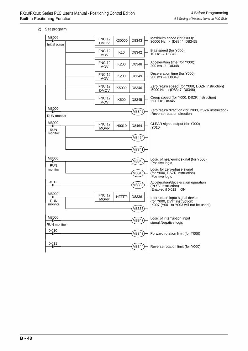
FX3U/FX3UC Series PLC User's Manual - Positioning Control EditionBuilt-in Positioning Function
4 Before Programming4.5 Setting of Various Items on PLC Side
2) Set program
Zero return direction (for Y000, DSZR instruction):Reverse rotation directionM8342
M8000
RUN monitor
M8002 Maximum speed (for Y000):30000 Hz → (D8344, D8343)
Initial pulse
Bias speed (for Y000):10 Hz → D8342
Acceleration time (for Y000):200 ms → D8348
Deceleration time (for Y000):200 ms → D8349
Zero return speed (for Y000, DSZR instruction):5000 Hz → (D8347, D8346)
Creep speed (for Y000, DSZR instruction):500 Hz, D8345
D8343K30000FNC 12DMOV
D8342K10FNC 12MOV
D8348K200
D8349K200
D8346K5000
D8345K500
FNC 12DMOV
FNC 12MOV
FNC 12MOV
FNC 12MOV
M8000 CLEAR signal output (for Y000):Y010
RUNmonitor
D8464H0010FNC 12MOVP
Logic of near-point signal (for Y000):Positive logicM8345
M8000
Logic for zero-phase signal(for Y000, DSZR instruction):Positive logic
M8346
Acceleration/deceleration operation(PLSV instruction):Enabled if X012 = ON
M8338X012
M8000Interruption input signal device(for Y000, DVIT instruction):X007 (Y001 to Y003 will not be used.)
RUNmonitor
D8336HFFF7FNC 12MOVP
Logic of interruption inputsignal:Negative logicM8347
M8000
RUN monitor
Forward rotation limit (for Y000)M8343X010
Reverse rotation limit (for Y000)M8344X011
RUNmonitor
M8464
M8341
M8336
B - 48
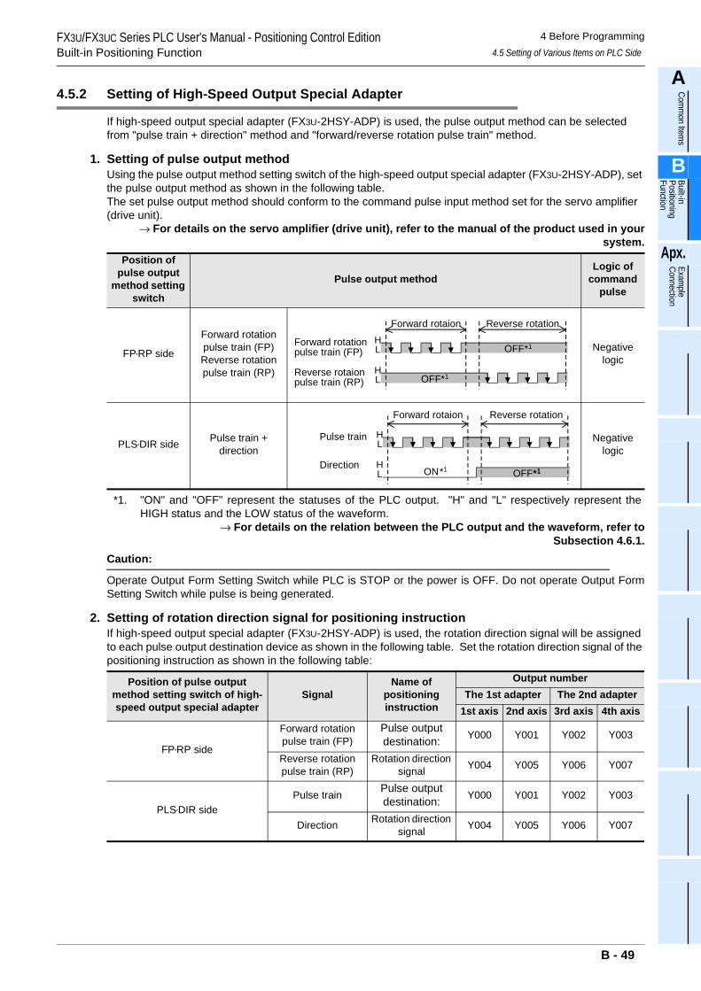
FX3U/FX3UC Series PLC User's Manual - Positioning Control EditionBuilt-in Positioning Function
4 Before Programming4.5 Setting of Various Items on PLC Side
A
Comm
on Items
B
Built-in Positioning Function
Apx.
Example
Connection
4.5.2 Setting of High-Speed Output Special Adapter
If high-speed output special adapter (FX3U-2HSY-ADP) is used, the pulse output method can be selected from "pulse train + direction" method and "forward/reverse rotation pulse train" method.
1. Setting of pulse output methodUsing the pulse output method setting switch of the high-speed output special adapter (FX3U-2HSY-ADP), set the pulse output method as shown in the following table.The set pulse output method should conform to the command pulse input method set for the servo amplifier (drive unit).
→ For details on the servo amplifier (drive unit), refer to the manual of the product used in yoursystem.
*1. "ON" and "OFF" represent the statuses of the PLC output. "H" and "L" respectively represent theHIGH status and the LOW status of the waveform.
→ For details on the relation between the PLC output and the waveform, refer toSubsection 4.6.1.
Caution:
Operate Output Form Setting Switch while PLC is STOP or the power is OFF. Do not operate Output FormSetting Switch while pulse is being generated.
2. Setting of rotation direction signal for positioning instructionIf high-speed output special adapter (FX3U-2HSY-ADP) is used, the rotation direction signal will be assigned to each pulse output destination device as shown in the following table. Set the rotation direction signal of the positioning instruction as shown in the following table:
Position of pulse output
method setting switch
Pulse output methodLogic of
command pulse
FP•RP side
Forward rotation pulse train (FP)Reverse rotation pulse train (RP)
Negative logic
PLS•DIR side Pulse train +direction
Negative logic
Position of pulse output method setting switch of high-speed output special adapter
SignalName of
positioning instruction
Output numberThe 1st adapter The 2nd adapter
1st axis 2nd axis 3rd axis 4th axis
FP•RP side
Forward rotation pulse train (FP)
Pulse output destination: Y000 Y001 Y002 Y003
Reverse rotation pulse train (RP)
Rotation direction signal Y004 Y005 Y006 Y007
PLS•DIR sidePulse train Pulse output
destination: Y000 Y001 Y002 Y003
Direction Rotation direction signal Y004 Y005 Y006 Y007
OFFForward rotationpulse train (FP)
Reverse rotaionpulse train (RP)
Forward rotaion Reverse rotation
*1
OFF*1HL
HL
OFF
Pulse train
Direction
Forward rotaion Reverse rotation
HL
HL
*1ON*1 *1
B - 49
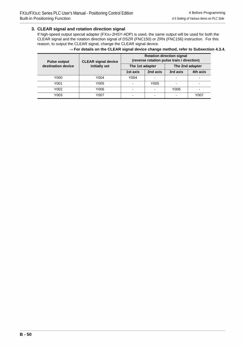
FX3U/FX3UC Series PLC User's Manual - Positioning Control EditionBuilt-in Positioning Function
4 Before Programming4.5 Setting of Various Items on PLC Side
3. CLEAR signal and rotation direction signalIf high-speed output special adapter (FX3U-2HSY-ADP) is used, the same output will be used for both the CLEAR signal and the rotation direction signal of DSZR (FNC150) or ZRN (FNC156) instruction. For this reason, to output the CLEAR signal, change the CLEAR signal device.
→ For details on the CLEAR signal device change method, refer to Subsection 4.3.4.
Pulse output destination device
CLEAR signal device initially set
Rotation direction signal(reverse rotation pulse train / direction)
The 1st adapter The 2nd adapter1st axis 2nd axis 3rd axis 4th axis
Y000 Y004 Y004 - - -Y001 Y005 - Y005 - -Y002 Y006 - - Y006 -Y003 Y007 - - - Y007
B - 50
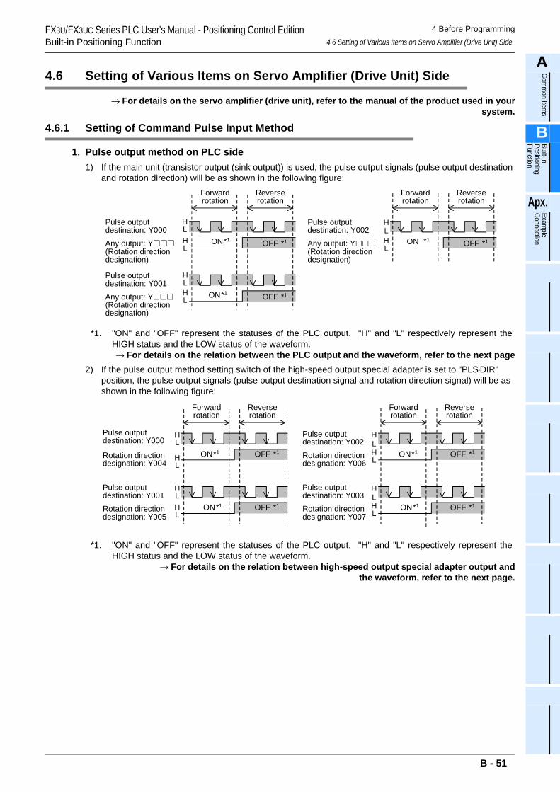
FX3U/FX3UC Series PLC User's Manual - Positioning Control EditionBuilt-in Positioning Function
4 Before Programming4.6 Setting of Various Items on Servo Amplifier (Drive Unit) Side
A
Comm
on Items
B
Built-in Positioning Function
Apx.
Example
Connection
4.6 Setting of Various Items on Servo Amplifier (Drive Unit) Side
→ For details on the servo amplifier (drive unit), refer to the manual of the product used in yoursystem.
4.6.1 Setting of Command Pulse Input Method
1. Pulse output method on PLC side1) If the main unit (transistor output (sink output)) is used, the pulse output signals (pulse output destination
and rotation direction) will be as shown in the following figure:
*1. "ON" and "OFF" represent the statuses of the PLC output. "H" and "L" respectively represent theHIGH status and the LOW status of the waveform.→ For details on the relation between the PLC output and the waveform, refer to the next page
2) If the pulse output method setting switch of the high-speed output special adapter is set to "PLS•DIR" position, the pulse output signals (pulse output destination signal and rotation direction signal) will be as shown in the following figure:
*1. "ON" and "OFF" represent the statuses of the PLC output. "H" and "L" respectively represent theHIGH status and the LOW status of the waveform.
→ For details on the relation between high-speed output special adapter output andthe waveform, refer to the next page.
Pulse outputdestination: Y000Any output: Y(Rotation directiondesignation)
Pulse outputdestination: Y001Any output: Y(Rotation directiondesignation)
Pulse outputdestination: Y002Any output: Y(Rotation directiondesignation)
Forwardrotation
Reverserotation
Forwardrotation
Reverserotation
ON*1
HL
HL
ON*1
HL
HL
OFF *1
OFF *1 HL
HL
ON *1 OFF *1
Rotation directiondesignation: Y004
Pulse outputdestination: Y001Rotation directiondesignation: Y005
Pulse outputdestination: Y002
Rotation directiondesignation: Y006
Pulse outputdestination: Y003Rotation directiondesignation: Y007
Pulse outputdestination: Y000
Forwardrotation
Reverserotation
Forwardrotation
Reverserotation
OFF *1
OFF *1
OFF *1
OFF *1
ON*1
ON*1
ON*1
ON*1
HL
HL
HL
HL
HL
HL
HL
HL
B - 51
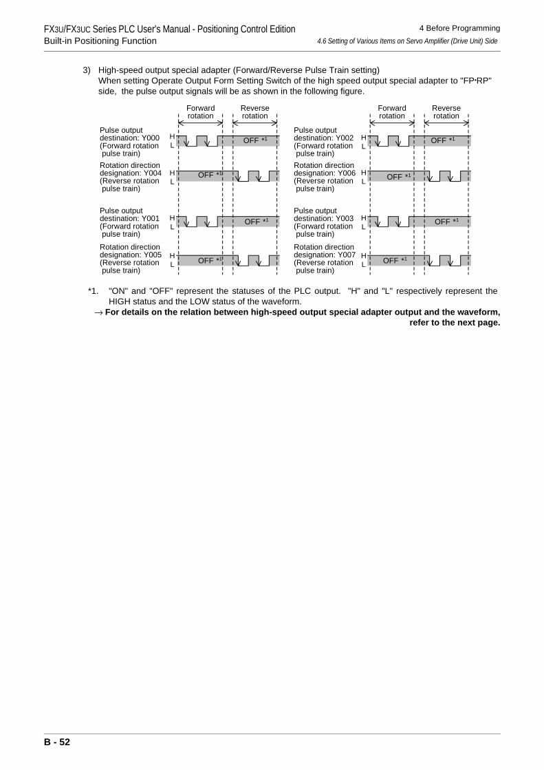
FX3U/FX3UC Series PLC User's Manual - Positioning Control EditionBuilt-in Positioning Function
4 Before Programming4.6 Setting of Various Items on Servo Amplifier (Drive Unit) Side
3) High-speed output special adapter (Forward/Reverse Pulse Train setting)When setting Operate Output Form Setting Switch of the high speed output special adapter to "FP•RP" side, the pulse output signals will be as shown in the following figure.
*1. "ON" and "OFF" represent the statuses of the PLC output. "H" and "L" respectively represent theHIGH status and the LOW status of the waveform.
→ For details on the relation between high-speed output special adapter output and the waveform,refer to the next page.
HL
HL
HL
HL
OFF *1
OFF *1 OFF *1
OFF *1
Forwardrotation
Reverserotation
Forwardrotation
Reverserotation
OFF *1HL
HL
HL
HL
OFF *1
OFF *1
OFF *1Pulse outputdestination: Y002(Forward rotation pulse train)Rotation directiondesignation: Y006(Reverse rotation pulse train)
Pulse outputdestination: Y003(Forward rotation pulse train)Rotation directiondesignation: Y007(Reverse rotation pulse train)
Pulse outputdestination: Y001(Forward rotation pulse train)Rotation directiondesignation: Y005(Reverse rotation pulse train)
Pulse outputdestination: Y000(Forward rotation pulse train)Rotation directiondesignation: Y004(Reverse rotation pulse train)
B - 52
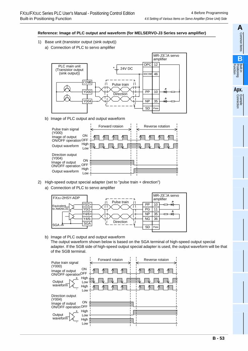
FX3U/FX3UC Series PLC User's Manual - Positioning Control EditionBuilt-in Positioning Function
4 Before Programming4.6 Setting of Various Items on Servo Amplifier (Drive Unit) Side
A
Comm
on Items
B
Built-in Positioning Function
Apx.
Example
Connection
Reference: Image of PLC output and waveform (for MELSERVO-J3 Series servo amplifier)
1) Base unit (transistor output (sink output))a) Connection of PLC to servo amplifier
b) Image of PLC output and output waveform
2) High-speed output special adapter (set to "pulse train + direction")a) Connection of PLC to servo amplifier
b) Image of PLC output and output waveformThe output waveform shown below is based on the SGA terminal of high-speed output special adapter. If the SGB side of high-speed output special adapter is used, the output waveform will be that of the SGB terminal.
PP 10
DOCOM 46
OPC 12
NP 35
24V DC
Pulse train
Direction
SD Plate
COM0
Y000
Y004
MR-J3 A servoamplifier
PLC main unit(Transistor output
(sink output))
Pulse train signal(Y000)
Direction output(Y004)
Image of outputON/OFF operationOutput waveform
Image of outputON/OFF operationOutput waveform
ONOFFHighLow
Forward rotaion Reverse rotation
ONOFFHighLow
Y0/2+
FX3U-2HSY-ADP
Y0/2-
SGA
Y4/6+Y4/6-
Equivalentto AM26C31
SGA
Pulse train
DirectionSD Plate
MR-J3 A servoamplifier
NP 35
PP 10PG 11
NG 36
Pulse train signal(Y000)
Direction output(Y004)
Image of outputON/OFF operation
Outputwaveform
Forward rotaion Reverse rotaion
ONOFFHighLowHighLow
ONOFFHighLowHighLow
Image of outputON/OFF operation
Outputwaveform
+
-
+
-
B - 53
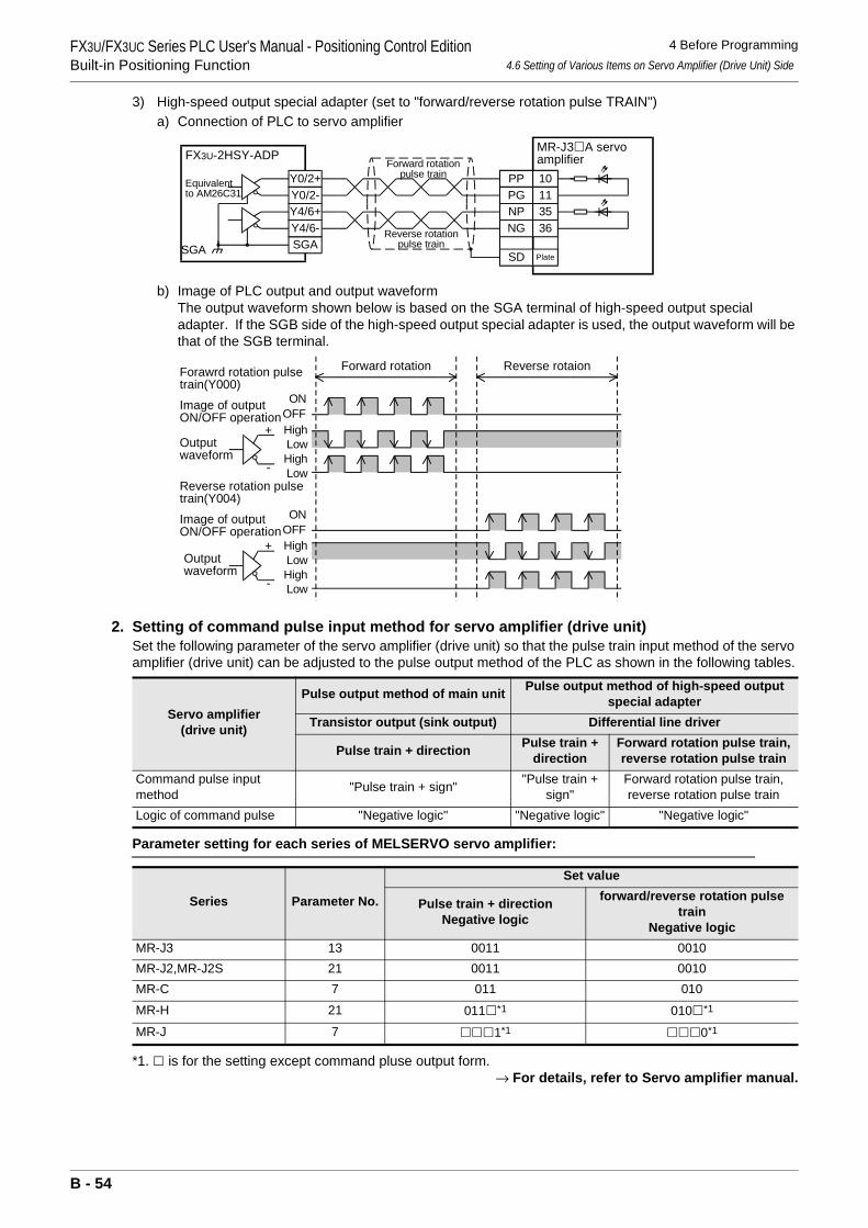
FX3U/FX3UC Series PLC User's Manual - Positioning Control EditionBuilt-in Positioning Function
4 Before Programming4.6 Setting of Various Items on Servo Amplifier (Drive Unit) Side
3) High-speed output special adapter (set to "forward/reverse rotation pulse TRAIN")a) Connection of PLC to servo amplifier
b) Image of PLC output and output waveformThe output waveform shown below is based on the SGA terminal of high-speed output special adapter. If the SGB side of the high-speed output special adapter is used, the output waveform will be that of the SGB terminal.
2. Setting of command pulse input method for servo amplifier (drive unit)Set the following parameter of the servo amplifier (drive unit) so that the pulse train input method of the servo amplifier (drive unit) can be adjusted to the pulse output method of the PLC as shown in the following tables.
Parameter setting for each series of MELSERVO servo amplifier:
*1. is for the setting except command pluse output form.→ For details, refer to Servo amplifier manual.
Servo amplifier(drive unit)
Pulse output method of main unit Pulse output method of high-speed output special adapter
Transistor output (sink output) Differential line driver
Pulse train + direction Pulse train + direction
Forward rotation pulse train, reverse rotation pulse train
Command pulse input method "Pulse train + sign" "Pulse train +
sign"Forward rotation pulse train, reverse rotation pulse train
Logic of command pulse "Negative logic" "Negative logic" "Negative logic"
Series Parameter No.
Set value
Pulse train + directionNegative logic
forward/reverse rotation pulse train
Negative logicMR-J3 13 0011 0010MR-J2,MR-J2S 21 0011 0010MR-C 7 011 010MR-H 21 011 *1 010 *1
MR-J 7 1*1 0*1
Y0/2+
FX3U-2HSY-ADP
Y0/2-
SGA
Y4/6+Y4/6-
Equivalentto AM26C31
SGA
Forward rotationpulse train
Reverse rotationpulse train
SD Plate
MR-J3 A servoamplifier
NP 35
PP 10PG 11
NG 36
Forawrd rotation pulsetrain(Y000)
Forward rotation Reverse rotaion
Reverse rotation pulsetrain(Y004)
Image of outputON/OFF operation
Outputwaveform
ONOFFHighLowHighLow
ONOFFHighLowHighLow
Image of outputON/OFF operation
Outputwaveform
+
-
+
-
B - 54
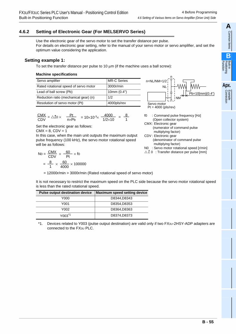
FX3U/FX3UC Series PLC User's Manual - Positioning Control EditionBuilt-in Positioning Function
4 Before Programming4.6 Setting of Various Items on Servo Amplifier (Drive Unit) Side
A
Comm
on Items
B
Built-in Positioning Function
Apx.
Example
Connection
4.6.2 Setting of Electronic Gear (For MELSERVO Series)
Use the electronic gear of the servo motor to set the transfer distance per pulse.For details on electronic gear setting, refer to the manual of your servo motor or servo amplifier, and set the optimum value considering the application.
Setting example 1:To set the transfer distance per pulse to 10 µm (if the machine uses a ball screw):
Machine specifications
Set the electronic gear as follows:CMX = 8, CDV = 1In this case, when the main unit outputs the maximum output pulse frequency (100 kHz), the servo motor rotational speed will be as follows:
It is not necessary to restrict the maximum speed on the PLC side because the servo motor rotational speed is less than the rated rotational speed.
*1. Devices related to Y003 (pulse output destination) are valid only if two FX3U-2HSY-ADP adapters are connected to the FX3U PLC.
Servo amplifier MR-C SeriesRated rotational speed of servo motor 3000r/minLead of ball screw (Pb) 10mm (0.4")Reduction ratio (mechanical gear) (n) 1/2Resolution of servo motor (Pt) 4000pls/rev
Pulse output destination device Maximum speed setting deviceY000 D8344,D8343Y001 D8354,D8353Y002 D8364,D8363
Y003*1 D8374,D8373
f0 : Command pulse frequency [Hz] (Open collector system)CMX: Electronic gear (numerator of command pulse multiplying factor)CDV : Electronic gear (denominator of command pulse multiplying factor)N0 : Servo motor rotational speed [r/min] 0 : Transfer distance per pulse [mm]
Servo motorPt = 4000 (pls/rev)
n
Pb=10[mm](0.4")
n=NL/NM=1/2NL
NM
= 0 ×n×Pb
Pt1/2×104000CMX
CDV = 10×10-3× =18
×CMXCDV
N0 = 60Pt
× f0
=18 × 60
4000× 100000
= 12000r/min > 3000r/min (Rated rotational speed of servo motor)
B - 55
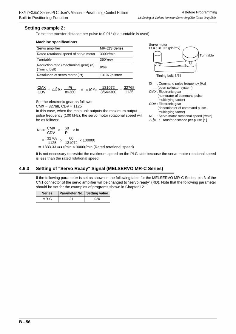
FX3U/FX3UC Series PLC User's Manual - Positioning Control EditionBuilt-in Positioning Function
4 Before Programming4.6 Setting of Various Items on Servo Amplifier (Drive Unit) Side
Setting example 2:To set the transfer distance per pulse to 0.01° (if a turntable is used):
Machine specifications
Set the electronic gear as follows:CMX = 32768, CDV = 1125In this case, when the main unit outputs the maximum output pulse frequency (100 kHz), the servo motor rotational speed will be as follows:
It is not necessary to restrict the maximum speed on the PLC side because the servo motor rotational speed is less than the rated rotational speed.
4.6.3 Setting of "Servo Ready" Signal (MELSERVO MR-C Series)
If the following parameter is set as shown in the following table for the MELSERVO MR-C Series, pin 3 of the CN1 connector of the servo amplifier will be changed to "servo ready" (RD). Note that the following parameter should be set for the examples of programs shown in Chapter 12.
Servo amplifier MR-J2S SeriesRated rotational speed of servo motor 3000r/minTurntable 360°/revReduction ratio (mechanical gear) (n)(Timing belt) 8/64
Resolution of servo motor (Pt) 131072pls/rev
Series Parameter No. Setting valueMR-C 21 020
Turntable
Timing belt: 8/64
Servo motorPt = 131072 (pls/rev)
f0 : Command pulse frequency [Hz] (open collector system)CMX: Electronic gear (numerator of command pulse multiplying factor)CDV : Electronic gear (denominator of command pulse multiplying factor)N0 : Servo motor rotational speed [r/min]
0 : Transfer distance per pulse [° ]
= 0 ×n×360
Pt8/64×360131072CMX
CDV = 1×10⁻²× =112532768
×CMXCDV
N0 = 60Pt
× f0
= × × 100000
1333.33 ••• r/min < 3000r/min (Rated rotational speed)1125
32768131072
60
..
B - 56
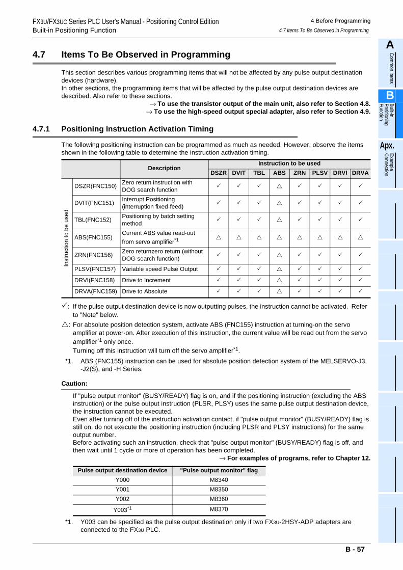
FX3U/FX3UC Series PLC User's Manual - Positioning Control EditionBuilt-in Positioning Function
4 Before Programming4.7 Items To Be Observed in Programming
A
Comm
on Items
B
Built-in Positioning Function
Apx.
Example
Connection
4.7 Items To Be Observed in Programming
This section describes various programming items that will not be affected by any pulse output destination devices (hardware).In other sections, the programming items that will be affected by the pulse output destination devices are described. Also refer to these sections.
→ To use the transistor output of the main unit, also refer to Section 4.8.→ To use the high-speed output special adapter, also refer to Section 4.9.
4.7.1 Positioning Instruction Activation Timing
The following positioning instruction can be programmed as much as needed. However, observe the items shown in the following table to determine the instruction activation timing.
: If the pulse output destination device is now outputting pulses, the instruction cannot be activated. Refer to "Note" below.
: For absolute position detection system, activate ABS (FNC155) instruction at turning-on the servo amplifier at power-on. After execution of this instruction, the current value will be read out from the servo amplifier*1 only once.Turning off this instruction will turn off the servo amplifier*1.
*1. ABS (FNC155) instruction can be used for absolute position detection system of the MELSERVO-J3, -J2(S), and -H Series.
Caution:
If "pulse output monitor" (BUSY/READY) flag is on, and if the positioning instruction (excluding the ABS instruction) or the pulse output instruction (PLSR, PLSY) uses the same pulse output destination device, the instruction cannot be executed.Even after turning off of the instruction activation contact, if "pulse output monitor" (BUSY/READY) flag is still on, do not execute the positioning instruction (including PLSR and PLSY instructions) for the same output number.Before activating such an instruction, check that "pulse output monitor" (BUSY/READY) flag is off, and then wait until 1 cycle or more of operation has been completed.
→ For examples of programs, refer to Chapter 12.
*1. Y003 can be specified as the pulse output destination only if two FX3U-2HSY-ADP adapters are connected to the FX3U PLC.
DescriptionInstruction to be used
DSZR DVIT TBL ABS ZRN PLSV DRVI DRVA
Inst
ruct
ion
to b
e us
ed
DSZR(FNC150) Zero return instruction with DOG search function
DVIT(FNC151) Interrupt Positioning (interruption fixed-feed)
TBL(FNC152) Positioning by batch setting method
ABS(FNC155)Current ABS value read-out from servo amplifier*1
ZRN(FNC156) Zero returnzero return (without DOG search function)
PLSV(FNC157) Variable speed Pulse Output
DRVI(FNC158) Drive to Increment
DRVA(FNC159) Drive to Absolute
Pulse output destination device "Pulse output monitor" flagY000 M8340Y001 M8350Y002 M8360
Y003*1 M8370
B - 57
FX3U/FX3UC Series PLC User's Manual - Positioning Control EditionBuilt-in Positioning Function
4 Before Programming4.7 Items To Be Observed in Programming
Use with PLSY (FNC57) and PLSR (FNC59) instructions:
In addition to the later-described positioning instructions, there are other instructions that need outputting of pulses. They are pulse output instructions FNC57 (PLSY) and FNC59 (PLSR).• Do not use the same output number for both the positioning instruction (FNC150 - FNC159) and the pulse
output instruction (FNC57 or FNC59).• Use of a positioning instruction together with PLSY or PLSR instruction will complicate the operation of the
register that controls the number of output pulses (see the following table). For this reason, it is recommended that a positioning instruction should be used in place of PLSY or PLSR instruction.
→ For details on the related devices, refer to Section 4.1 to Section 4.4.
*1. Y003 can be specified as the pulse output destination only if two FX3U-2HSY-ADP adapters are connected to the FX3U PLC.
• If it is necessary to use a positioning instruction (FNC150 to FNC159) together with a pulse output instruction (FNC57 or FNC59), use the following positioning instruction in place of the pulse output instruction:- FNC57(PLSY), FNC59(PLSR)→FNC158(DRVI)
Pulse output destination device
Current value registerFor FNC150 - FNC159 instructions For FNC57 and FNC59 instructions
Y000 D8341,D8340 D8141,D8140Y001 D8351,D8350 D8143,D8142Y002 D8361,D8360 -
Y003*1 D8371,D8370 -
B - 58
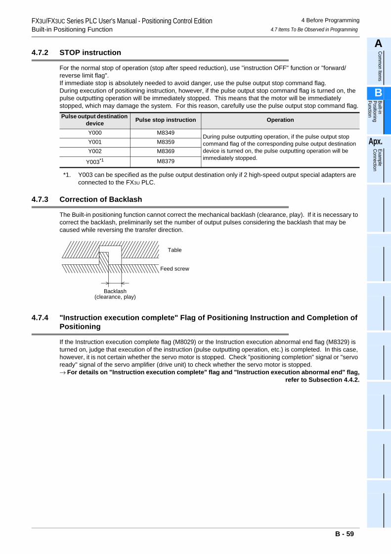
FX3U/FX3UC Series PLC User's Manual - Positioning Control EditionBuilt-in Positioning Function
4 Before Programming4.7 Items To Be Observed in Programming
A
Comm
on Items
B
Built-in Positioning Function
Apx.
Example
Connection
4.7.2 STOP instruction
For the normal stop of operation (stop after speed reduction), use "instruction OFF" function or "forward/reverse limit flag".If immediate stop is absolutely needed to avoid danger, use the pulse output stop command flag.During execution of positioning instruction, however, if the pulse output stop command flag is turned on, the pulse outputting operation will be immediately stopped. This means that the motor will be immediately stopped, which may damage the system. For this reason, carefully use the pulse output stop command flag.
*1. Y003 can be specified as the pulse output destination only if 2 high-speed output special adapters are connected to the FX3U PLC.
4.7.3 Correction of Backlash
The Built-in positioning function cannot correct the mechanical backlash (clearance, play). If it is necessary to correct the backlash, preliminarily set the number of output pulses considering the backlash that may be caused while reversing the transfer direction.
4.7.4 "Instruction execution complete" Flag of Positioning Instruction and Completion of Positioning
If the Instruction execution complete flag (M8029) or the Instruction execution abnormal end flag (M8329) is turned on, judge that execution of the instruction (pulse outputting operation, etc.) is completed. In this case, however, it is not certain whether the servo motor is stopped. Check "positioning completion" signal or "servo ready" signal of the servo amplifier (drive unit) to check whether the servo motor is stopped.→ For details on "Instruction execution complete" flag and "Instruction execution abnormal end" flag,
refer to Subsection 4.4.2.
Pulse output destination device Pulse stop instruction Operation
Y000 M8349During pulse outputting operation, if the pulse output stop command flag of the corresponding pulse output destination device is turned on, the pulse outputting operation will be immediately stopped.
Y001 M8359Y002 M8369
Y003*1 M8379
Table
Feed screw
Backlash(clearance, play)
B - 59
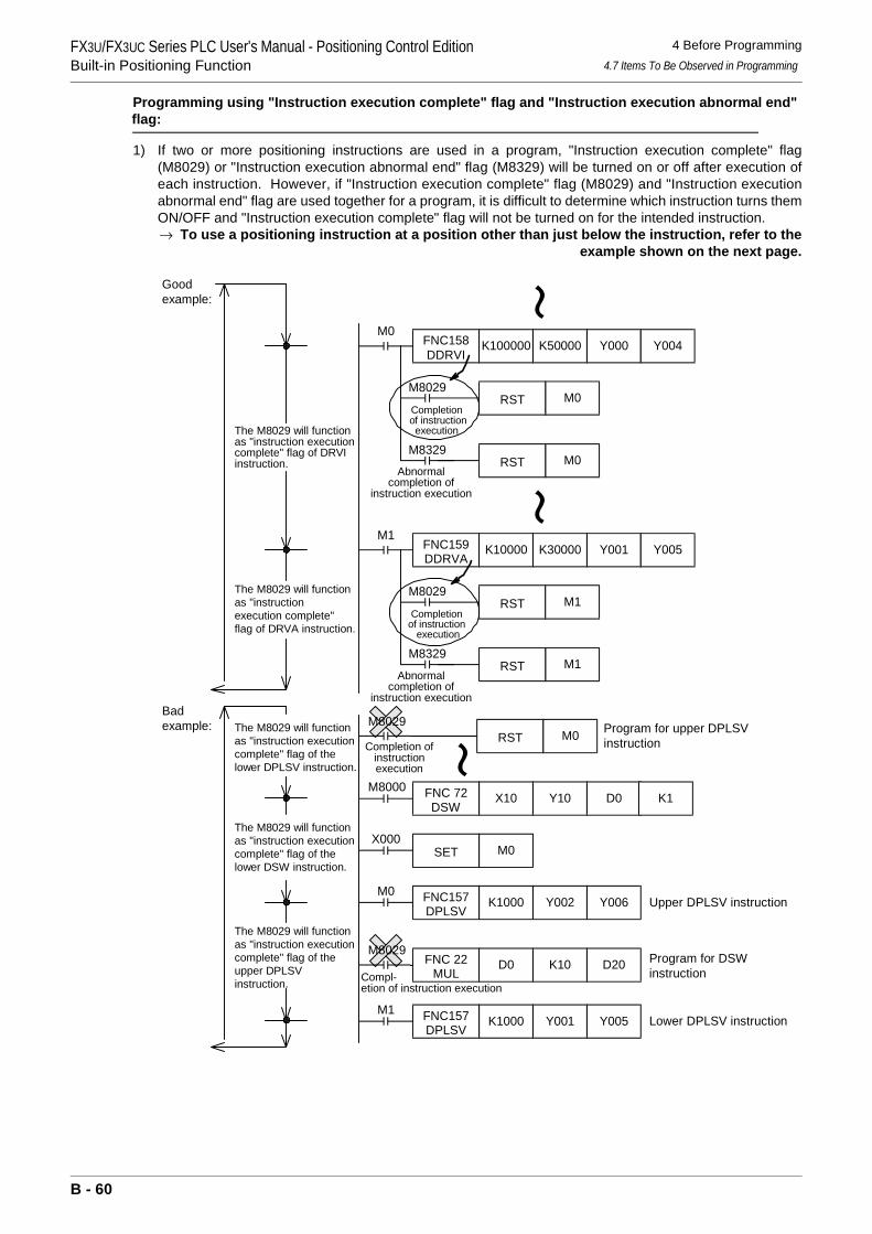
FX3U/FX3UC Series PLC User's Manual - Positioning Control EditionBuilt-in Positioning Function
4 Before Programming4.7 Items To Be Observed in Programming
Programming using "Instruction execution complete" flag and "Instruction execution abnormal end" flag:
1) If two or more positioning instructions are used in a program, "Instruction execution complete" flag(M8029) or "Instruction execution abnormal end" flag (M8329) will be turned on or off after execution ofeach instruction. However, if "Instruction execution complete" flag (M8029) and "Instruction executionabnormal end" flag are used together for a program, it is difficult to determine which instruction turns themON/OFF and "Instruction execution complete" flag will not be turned on for the intended instruction.→ To use a positioning instruction at a position other than just below the instruction, refer to the
example shown on the next page.
Badexample:
The M8029 will functionas "instruction executioncomplete" flag of thelower DSW instruction.
The M8029 will functionas "instruction executioncomplete" flag of theupper DPLSVinstruction.
The M8029 will functionas "instruction executioncomplete" flag of thelower DPLSV instruction.
RST M0
FNC 22MUL
D0 K10 D20
M8000X10 Y10 D0
Completion ofinstructionexecution
FNC 72DSW
K1
X000M0SET
M0K1000 Y002 Y006FNC157
DPLSV
M8029
M8029
Compl-etion of instruction execution
M1K1000 Y001 Y005FNC157
DPLSV
Program for upper DPLSVinstruction
Program for DSWinstruction
Upper DPLSV instruction
Lower DPLSV instruction
M0FNC158DDRVI
K100000 K50000 Y000 Y004
M0M8029
Completion of instruction
execution
M1FNC159DDRVA
K10000 K30000 Y001
RST M1M8029
M8329The M8029 will functionas "instruction executioncomplete" flag of DRVIinstruction.
The M8029 will functionas "instructionexecution complete"flag of DRVA instruction.
Goodexample:
Abnormalcompletion of
instruction execution
M0
Y005
RST
RST
Completionof instruction
execution
M8329M1RST
Abnormalcompletion of
instruction execution
B - 60
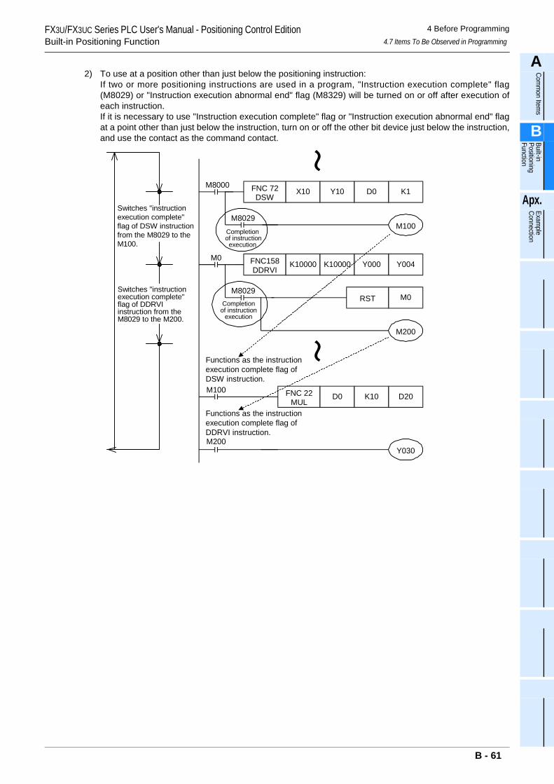
FX3U/FX3UC Series PLC User's Manual - Positioning Control EditionBuilt-in Positioning Function
4 Before Programming4.7 Items To Be Observed in Programming
A
Comm
on Items
B
Built-in Positioning Function
Apx.
Example
Connection
2) To use at a position other than just below the positioning instruction:If two or more positioning instructions are used in a program, "Instruction execution complete" flag(M8029) or "Instruction execution abnormal end" flag (M8329) will be turned on or off after execution ofeach instruction.If it is necessary to use "Instruction execution complete" flag or "Instruction execution abnormal end" flagat a point other than just below the instruction, turn on or off the other bit device just below the instruction,and use the contact as the command contact.
M8000 FNC 72DSW
X10 Y10 D0 K1
FNC 22MUL
D0 K10 D20
M8029Completion
of instructionexecution
M0 FNC158DDRVI
K10000 K10000 Y000
M8029Completion
of instructionexecution
Switches "instructionexecution complete"flag of DSW instructionfrom the M8029 to theM100.
M100
M200
Switches "instructionexecution complete"flag of DDRVIinstruction from theM8029 to the M200.
M100
Functions as the instructionexecution complete flag ofDSW instruction.
RST M0
M200
Functions as the instructionexecution complete flag ofDDRVI instruction.
Y030
Y004
B - 61
FX3U/FX3UC Series PLC User's Manual - Positioning Control EditionBuilt-in Positioning Function
4 Before Programming4.7 Items To Be Observed in Programming
4.7.5 Operation Error Flag
If an applied instruction (including positioning instructions) of the FX3U/FX3UC PLC has an error (construction error, device designation error, numbering range error, etc.), an operation error may occur during operation. If an operation error occurs, the following flag will be turned on, and the error data will be stored.
1. Operation error
• If an operation error occurs, the M8067 will be turned on, and the operation error code will be stored in the D8067, and the error detected step number*1 will be stored in the D8315 and D8314 (32-bit).
*1.If the error detected step number is 32767 or less, the error step number can be also checked using the D8069 (16-bit).
• If an operation error occurs at the other step, the error code and the error step number of the instruction will be sequentially updated. (If the error status is canceled, the error flag will be turned off.)
• If the PLC once stopped is restarted without canceling the error status, the error status will be automatically canceled, but immediately after that, the error flag will be turned on again.
2. Operation error latch
• If an operation error occurs, the M8068 will be turned on, and the error detected step number*1 will be stored in the D8313 and D8312.
*1.If the operation error detected step number is 32767 or less, the error step number can be also checked using the D8068 (16-bit).
• If a new error is caused by the other instruction, the error data will not be updated, and the operation will be continued until "forced reset" command is input or the power is turned off.
4.7.6 Write during RUN
Do not change program if a positioning instruction (FNC150, FNC151, FNC156 to FNC159) is being executed (pulses are being output) in the RUN mode. Operations will be performed as shown in the following table if program is change during execution of instruction in RUN mode.
*1. This instruction is compatible with Ver.2.00 or later. If the FX3UC PLC is used and its version is below Ver.2.00, operation will be performed withoutacceleration/deceleration.
Error flag Error code storage device Error detected step number storage device (32-bit)M8067 D8067 D8315,D8314
Error flag Error code storage device Error detected step number storage device (32-bit)M8068 - D8313,D8312
Instruction If program is change in circuit block including currently-activated instruction
DSZR(FNC150)Decelerates and stops pulse output.
DVIT(FNC151)TBL(FNC152) Program cannot be change in the RUN mode.ZRN(FNC156) Decelerates and stops pulse output.
PLSV(FNC157)
During operation with acceleration/deceleration*1 Decelerates and stops pulse output.During operation without acceleration/deceleration Immediately stops pulse output.
DRVI(FNC158)DRVA(FNC159) Decelerates and stops pulse output.
B - 62
FX3U/FX3UC Series PLC User's Manual - Positioning Control EditionBuilt-in Positioning Function
4 Before Programming4.8 Items To Be Observed in Use of Main Unit (Transistor Output)
A
Comm
on Items
B
Built-in Positioning Function
Apx.
Example
Connection
4.8 Items To Be Observed in Use of Main Unit (Transistor Output)
1. Pulse output destination devicesUse Y000, Y001, and Y002 transistor outputs of the main unit as the pulse output destination devices.Do not use Y003 transistor output of the main unit for the positioning instructions. If Y003 is used for a positioning instruction, the PLC may be damaged.
2. Pulse output methodAdjust the pulse output method of the transistor output of the main unit so that the pulse output method can conform to the command pulse input method of the servo amplifier (drive unit).If the pulse output method is not properly adjusted, the servo amplifier (drive unit) may not perform the intended operation.
→ For details on the servo amplifier (drive unit), refer to the manual of the product used in yoursystem.
→ For details on the pulse output method of the main unit, refer to Subsection 4.6.1.
3. Output pulse frequency (including zero return speed)If the transistor output Y000, Y001, Y002 of main unit uses the pulse frequency of more than 100,000 Hz to perform operation, the PLC may be damaged.The output pulse frequency and the zero return speed should be equal to or less than the maximum frequency of the servo amplifier (drive unit).
4. Load currentTo use a positioning instruction for Y000, Y001, or Y002 transistor output of the main unit, adjust the load current of the open collector transistor output to 10 to 100 mA (5 to 24V DC).
4.9 Caution for Using the High-Speed Output Special Adapter (FX3U-2HSY-ADP)
1. Output terminals to be usedIf the high-speed output special adapter is connected, output numbers will be assigned in the same way as the main unit as shown in the following table. Use the output terminals of one side (main unit side or high-speed output special adapter side), and do not connect lines to the output terminals of unused side.The outputs of high-speed output special adapter and the main unit will operate as follows.
Assignment of output numbers
Item DescriptionOperation voltage range 5 to 24V DCOperation current range 10 to 100mAOutput pulse frequency 100 kHz or less
Position of pulse output method setting switch of high-speed
output special adapterSignal
Name of positioning instruction
Output numberThe 1st adapter The 2nd adapter
1st axis 2nd axis 3rd axis 4th axis
FP•RP side
Forward rotation pulse train (FP)
Pulse output destination Y000 Y001 Y002 Y003
Reverse rotation pulse train (RP)
Rotationdirection signal Y004 Y005 Y006 Y007
PLS•DIR sidePulse train Pulse output
destination Y000 Y001 Y002 Y003
Direction Rotationdirection signal Y004 Y005 Y006 Y007
B - 63
FX3U/FX3UC Series PLC User's Manual - Positioning Control EditionBuilt-in Positioning Function
4 Before Programming4.9 Caution for Using the High-Speed Output Special Adapter (FX3U-2HSY-ADP)
Operation of output
• If an output number of the high-speed output special adapter is used (if an output of high-speed output special adapter is connected), do not use (connect) the corresponding output terminal of the main unit.
• If an output number of the main unit is used (if an output of the main unit is connected), do not use (connect) the corresponding output terminal of the high-speed output special adapter.
2. Rotation direction signal of positioning instructionIf FX3U-2HSY-ADP high-speed output special adapter is used, the rotational direction signal will be assigned to each pulse output destination device as shown in the following table. Do not assign any other outputs to these devices using positioning instructions, etc.
→ For details, refer to Subsection 4.5.2.
3. CLEAR signal and rotation direction signalIf FX3U-2HSY-ADP high-speed output special adapter is used, the same outputs will be used for both the CLEAR signal and rotation direction signal of DSZR (FNC150) or ZRN (FNC156) instruction as shown in the table above.For this reason, to output the CLEAR signal, change the CLEAR signal device.
→ For details on the CLEAR signal device change method, refer to Subsection 4.3.4.
4. Pulse output method for high-speed output special adapterAdjust the pulse output method of the high-speed output special adapter (FX3U-2HSY-ADP) so that the pulse output method can conform to the command pulse input method of the servo amplifier (drive unit).If the pulse output method is not properly adjusted, the servo amplifier (drive unit) may not perform the intended operation.→ For details on the servo amplifier (drive unit), refer to the manual of the product to be used for your
system.→ For details on the pulse output method, refer to Subsection 4.6.1 or Subsection 4.5.2.
5. Output pulse frequency (including zero return speed)Set the output pulse frequency and the zero return speed so that these values can be less than the maximum frequency value of the servo amplifier (driver unit).
Operation of outputInstruction for outputting pulse train at high speed Other instructions
Main unit of relay output type If the instruction turns ON, the corresponding output will be turned on (the corresponding LED will be turned on). Can be activated.
High-speed output special adapter Can be activated. Can be activated.
Pulse output destination device
Rotation direction signal(reverse rotation pulse train / direction) Initial setting of
CLEAR signalThe 1st adapter The 2nd adapter1st axis 2nd axis 3rd axis 4th axis
Y000 Y004 - - - Y004Y001 - Y005 - - Y005Y002 - - Y006 - Y006Y003 - - - Y007 Y007
B - 64
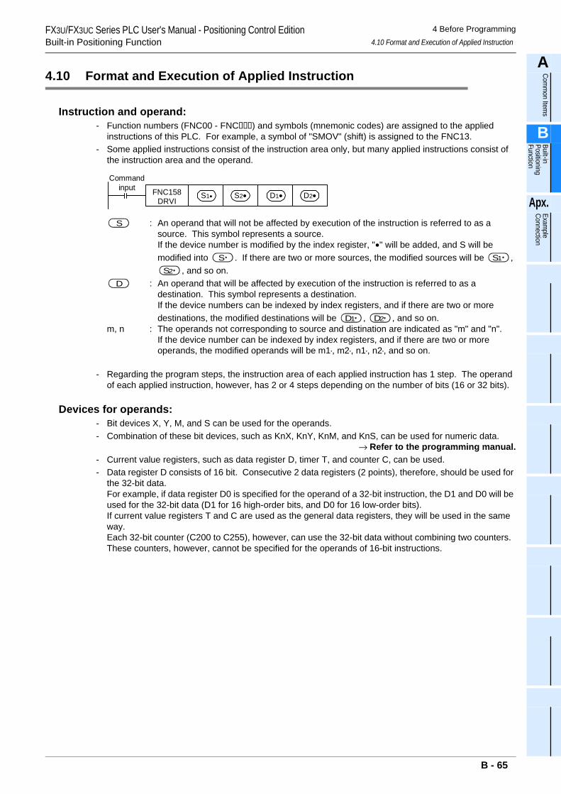
FX3U/FX3UC Series PLC User's Manual - Positioning Control EditionBuilt-in Positioning Function
4 Before Programming4.10 Format and Execution of Applied Instruction
A
Comm
on Items
B
Built-in Positioning Function
Apx.
Example
Connection
4.10 Format and Execution of Applied Instruction
Instruction and operand:- Function numbers (FNC00 - FNC) and symbols (mnemonic codes) are assigned to the applied
instructions of this PLC. For example, a symbol of "SMOV" (shift) is assigned to the FNC13.- Some applied instructions consist of the instruction area only, but many applied instructions consist of
the instruction area and the operand.
: An operand that will not be affected by execution of the instruction is referred to as a source. This symbol represents a source.If the device number is modified by the index register, "•" will be added, and S will be modified into . If there are two or more sources, the modified sources will be ,
, and so on.: An operand that will be affected by execution of the instruction is referred to as a
destination. This symbol represents a destination.If the device numbers can be indexed by index registers, and if there are two or more destinations, the modified destinations will be , , and so on.
m, n : The operands not corresponding to source and distination are indicated as "m" and "n".If the device number can be indexed by index registers, and if there are two or more operands, the modified operands will be m1•, m2•, n1•, n2•, and so on.
- Regarding the program steps, the instruction area of each applied instruction has 1 step. The operand of each applied instruction, however, has 2 or 4 steps depending on the number of bits (16 or 32 bits).
Devices for operands:- Bit devices X, Y, M, and S can be used for the operands.- Combination of these bit devices, such as KnX, KnY, KnM, and KnS, can be used for numeric data.
→ Refer to the programming manual.- Current value registers, such as data register D, timer T, and counter C, can be used.- Data register D consists of 16 bit. Consecutive 2 data registers (2 points), therefore, should be used for
the 32-bit data.For example, if data register D0 is specified for the operand of a 32-bit instruction, the D1 and D0 will be used for the 32-bit data (D1 for 16 high-order bits, and D0 for 16 low-order bits).If current value registers T and C are used as the general data registers, they will be used in the same way.Each 32-bit counter (C200 to C255), however, can use the 32-bit data without combining two counters. These counters, however, cannot be specified for the operands of 16-bit instructions.
Commandinput FNC158
DRVIS1• S2• D1• D2•
S
S S1
S2
D
D1 D2
B - 65
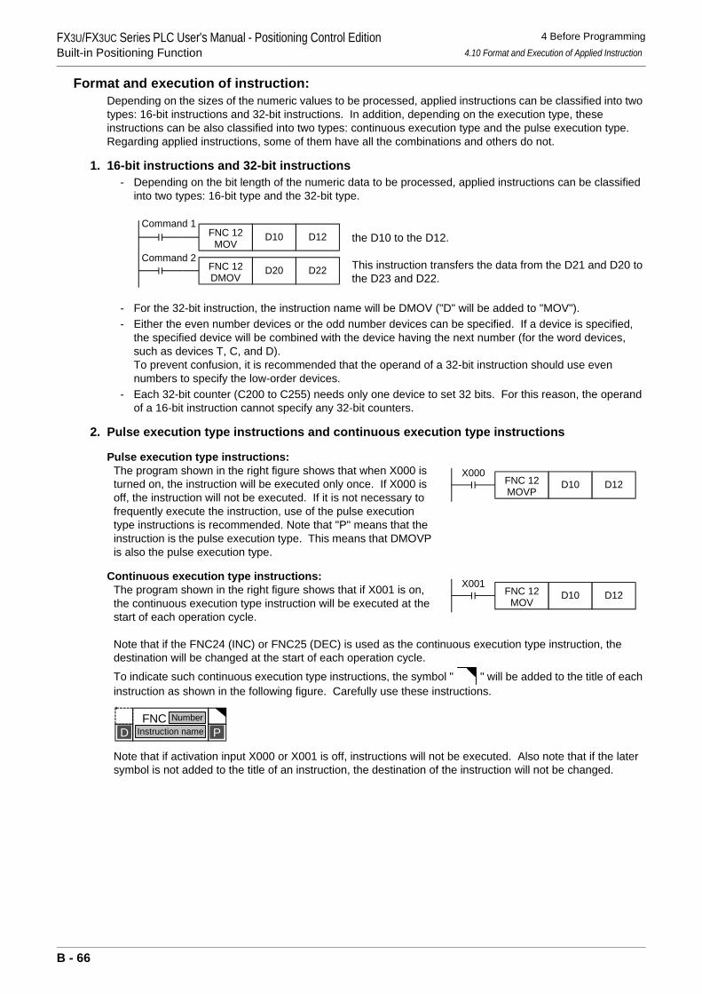
FX3U/FX3UC Series PLC User's Manual - Positioning Control EditionBuilt-in Positioning Function
4 Before Programming4.10 Format and Execution of Applied Instruction
Format and execution of instruction:Depending on the sizes of the numeric values to be processed, applied instructions can be classified into two types: 16-bit instructions and 32-bit instructions. In addition, depending on the execution type, these instructions can be also classified into two types: continuous execution type and the pulse execution type.Regarding applied instructions, some of them have all the combinations and others do not.
1. 16-bit instructions and 32-bit instructions- Depending on the bit length of the numeric data to be processed, applied instructions can be classified
into two types: 16-bit type and the 32-bit type.
the D10 to the D12.
This instruction transfers the data from the D21 and D20 to the D23 and D22.
- For the 32-bit instruction, the instruction name will be DMOV ("D" will be added to "MOV").- Either the even number devices or the odd number devices can be specified. If a device is specified,
the specified device will be combined with the device having the next number (for the word devices, such as devices T, C, and D).To prevent confusion, it is recommended that the operand of a 32-bit instruction should use even numbers to specify the low-order devices.
- Each 32-bit counter (C200 to C255) needs only one device to set 32 bits. For this reason, the operand of a 16-bit instruction cannot specify any 32-bit counters.
2. Pulse execution type instructions and continuous execution type instructions
Pulse execution type instructions:The program shown in the right figure shows that when X000 is turned on, the instruction will be executed only once. If X000 is off, the instruction will not be executed. If it is not necessary to frequently execute the instruction, use of the pulse execution type instructions is recommended. Note that "P" means that the instruction is the pulse execution type. This means that DMOVP is also the pulse execution type.
Continuous execution type instructions:The program shown in the right figure shows that if X001 is on, the continuous execution type instruction will be executed at the start of each operation cycle.
Note that if the FNC24 (INC) or FNC25 (DEC) is used as the continuous execution type instruction, the destination will be changed at the start of each operation cycle.
To indicate such continuous execution type instructions, the symbol " " will be added to the title of each instruction as shown in the following figure. Carefully use these instructions.
Note that if activation input X000 or X001 is off, instructions will not be executed. Also note that if the later symbol is not added to the title of an instruction, the destination of the instruction will not be changed.
Command 1FNC 12
MOVD10 D12
Command 2FNC 12DMOV
D20 D22
X000FNC 12MOVP
D10 D12
X001FNC 12
MOVD10 D12
PFNC 12
MOVNumber
Instruction nameD
B - 66
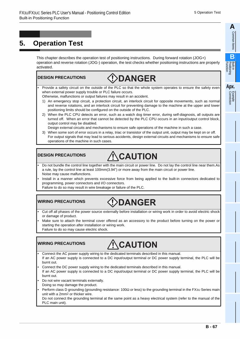
FX3U/FX3UC Series PLC User's Manual - Positioning Control EditionBuilt-in Positioning Function
5 Operation Test
A
Comm
on Items
B
Built-in Positioning Function
Apx.
Example
Connection
5. Operation Test
This chapter describes the operation test of positioning instructions. During forward rotation (JOG+) operation and reverse rotation (JOG-) operation, the test checks whether positioning instructions are properly activated.
DESIGN PRECAUTIONS
• Provide a safety circuit on the outside of the PLC so that the whole system operates to ensure the safety evenwhen external power supply trouble or PLC failure occurs.Otherwise, malfunctions or output failures may result in an accident.1) An emergency stop circuit, a protection circuit, an interlock circuit for opposite movements, such as normal
and reverse rotations, and an interlock circuit for preventing damage to the machine at the upper and lowerpositioning limits should be configured on the outside of the PLC.
2) When the PLC CPU detects an error, such as a watch dog timer error, during self-diagnosis, all outputs areturned off. When an error that cannot be detected by the PLC CPU occurs in an input/output control block,output control may be disabled.Design external circuits and mechanisms to ensure safe operations of the machine in such a case.
3) When some sort of error occurs in a relay, triac or transistor of the output unit, output may be kept on or off.For output signals that may lead to serious accidents, design external circuits and mechanisms to ensure safeoperations of the machine in such cases.
DESIGN PRECAUTIONS
• Do not bundle the control line together with the main circuit or power line. Do not lay the control line near them.Asa rule, lay the control line at least 100mm(3.94") or more away from the main circuit or power line.Noise may cause malfunctions.
• Install in a manner which prevents excessive force from being applied to the built-in connectors dedicated toprogramming, power connectors and I/O connectors.Failure to do so may result in wire breakage or failure of the PLC.
WIRING PRECAUTIONS
• Cut off all phases of the power source externally before installation or wiring work in order to avoid electric shockor damage of product.
• Make sure to attach the terminal cover offered as an accessory to the product before turning on the power orstarting the operation after installation or wiring work.Failure to do so may cause electric shock.
WIRING PRECAUTIONS
• Connect the AC power supply wiring to the dedicated terminals described in this manual.If an AC power supply is connected to a DC input/output terminal or DC power supply terminal, the PLC will beburnt out.
• Connect the DC power supply wiring to the dedicated terminals described in this manual.If an AC power supply is connected to a DC input/output terminal or DC power supply terminal, the PLC will beburnt out.
• Do not wire vacant terminals externally.Doing so may damage the product.
• Perform class D grounding (grounding resistance: 100Ω or less) to the grounding terminal in the FX3U Series mainunit with a 2mm2 or thicker wire.Do not connect the grounding terminal at the same point as a heavy electrical system (refer to the manual of thePLC main unit).
B - 67
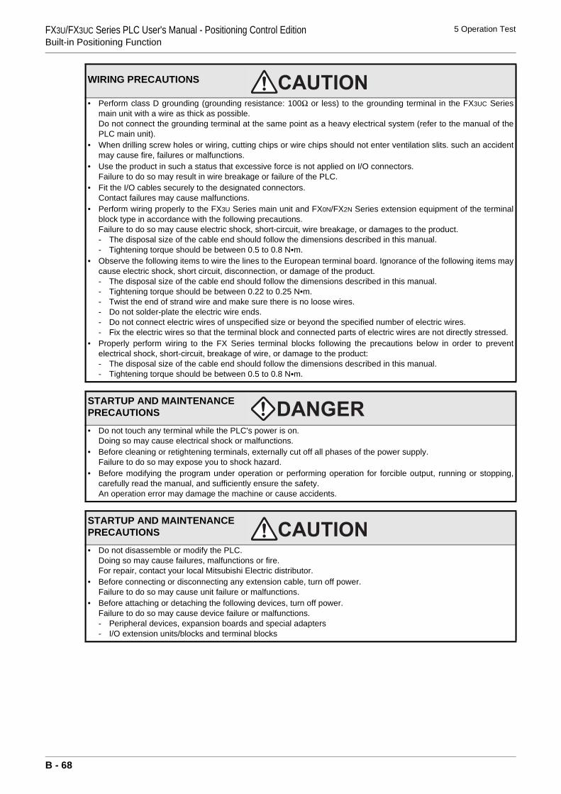
FX3U/FX3UC Series PLC User's Manual - Positioning Control EditionBuilt-in Positioning Function
5 Operation Test
• Perform class D grounding (grounding resistance: 100Ω or less) to the grounding terminal in the FX3UC Seriesmain unit with a wire as thick as possible.Do not connect the grounding terminal at the same point as a heavy electrical system (refer to the manual of thePLC main unit).
• When drilling screw holes or wiring, cutting chips or wire chips should not enter ventilation slits. such an accidentmay cause fire, failures or malfunctions.
• Use the product in such a status that excessive force is not applied on I/O connectors.Failure to do so may result in wire breakage or failure of the PLC.
• Fit the I/O cables securely to the designated connectors.Contact failures may cause malfunctions.
• Perform wiring properly to the FX3U Series main unit and FX0N/FX2N Series extension equipment of the terminalblock type in accordance with the following precautions.Failure to do so may cause electric shock, short-circuit, wire breakage, or damages to the product.- The disposal size of the cable end should follow the dimensions described in this manual.- Tightening torque should be between 0.5 to 0.8 N•m.
• Observe the following items to wire the lines to the European terminal board. Ignorance of the following items maycause electric shock, short circuit, disconnection, or damage of the product.- The disposal size of the cable end should follow the dimensions described in this manual.- Tightening torque should be between 0.22 to 0.25 N•m.- Twist the end of strand wire and make sure there is no loose wires. - Do not solder-plate the electric wire ends.- Do not connect electric wires of unspecified size or beyond the specified number of electric wires.- Fix the electric wires so that the terminal block and connected parts of electric wires are not directly stressed.
• Properly perform wiring to the FX Series terminal blocks following the precautions below in order to preventelectrical shock, short-circuit, breakage of wire, or damage to the product:- The disposal size of the cable end should follow the dimensions described in this manual.- Tightening torque should be between 0.5 to 0.8 N•m.
STARTUP AND MAINTENANCE PRECAUTIONS
• Do not touch any terminal while the PLC's power is on.Doing so may cause electrical shock or malfunctions.
• Before cleaning or retightening terminals, externally cut off all phases of the power supply.Failure to do so may expose you to shock hazard.
• Before modifying the program under operation or performing operation for forcible output, running or stopping,carefully read the manual, and sufficiently ensure the safety.An operation error may damage the machine or cause accidents.
STARTUP AND MAINTENANCE PRECAUTIONS
• Do not disassemble or modify the PLC.Doing so may cause failures, malfunctions or fire.For repair, contact your local Mitsubishi Electric distributor.
• Before connecting or disconnecting any extension cable, turn off power.Failure to do so may cause unit failure or malfunctions.
• Before attaching or detaching the following devices, turn off power.Failure to do so may cause device failure or malfunctions.- Peripheral devices, expansion boards and special adapters- I/O extension units/blocks and terminal blocks
WIRING PRECAUTIONS
B - 68
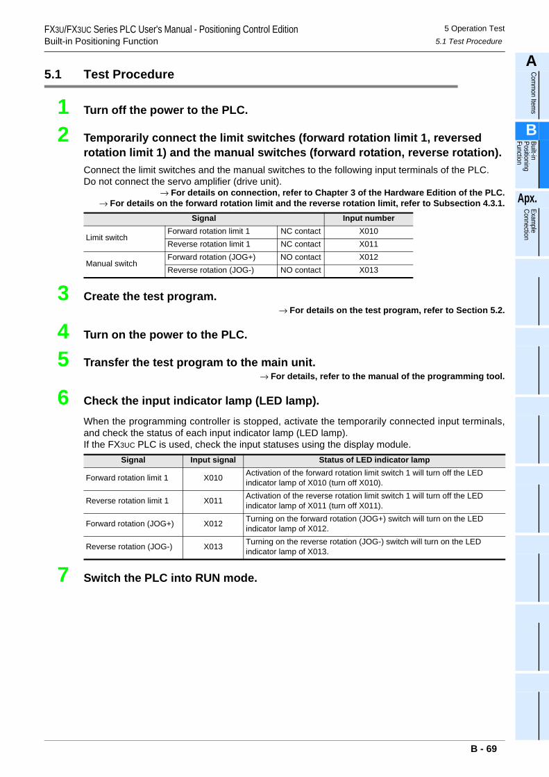
FX3U/FX3UC Series PLC User's Manual - Positioning Control EditionBuilt-in Positioning Function
5 Operation Test5.1 Test Procedure
A
Comm
on Items
B
Built-in Positioning Function
Apx.
Example
Connection
5.1 Test Procedure
1 Turn off the power to the PLC.
2 Temporarily connect the limit switches (forward rotation limit 1, reversed rotation limit 1) and the manual switches (forward rotation, reverse rotation).Connect the limit switches and the manual switches to the following input terminals of the PLC.Do not connect the servo amplifier (drive unit).
→ For details on connection, refer to Chapter 3 of the Hardware Edition of the PLC.→ For details on the forward rotation limit and the reverse rotation limit, refer to Subsection 4.3.1.
3 Create the test program.→ For details on the test program, refer to Section 5.2.
4 Turn on the power to the PLC.
5 Transfer the test program to the main unit.→ For details, refer to the manual of the programming tool.
6 Check the input indicator lamp (LED lamp).When the programming controller is stopped, activate the temporarily connected input terminals,and check the status of each input indicator lamp (LED lamp).If the FX3UC PLC is used, check the input statuses using the display module.
7 Switch the PLC into RUN mode.
Signal Input number
Limit switchForward rotation limit 1 NC contact X010Reverse rotation limit 1 NC contact X011
Manual switchForward rotation (JOG+) NO contact X012Reverse rotation (JOG-) NO contact X013
Signal Input signal Status of LED indicator lamp
Forward rotation limit 1 X010 Activation of the forward rotation limit switch 1 will turn off the LED indicator lamp of X010 (turn off X010).
Reverse rotation limit 1 X011 Activation of the reverse rotation limit switch 1 will turn off the LED indicator lamp of X011 (turn off X011).
Forward rotation (JOG+) X012 Turning on the forward rotation (JOG+) switch will turn on the LED indicator lamp of X012.
Reverse rotation (JOG-) X013 Turning on the reverse rotation (JOG-) switch will turn on the LED indicator lamp of X013.
B - 69
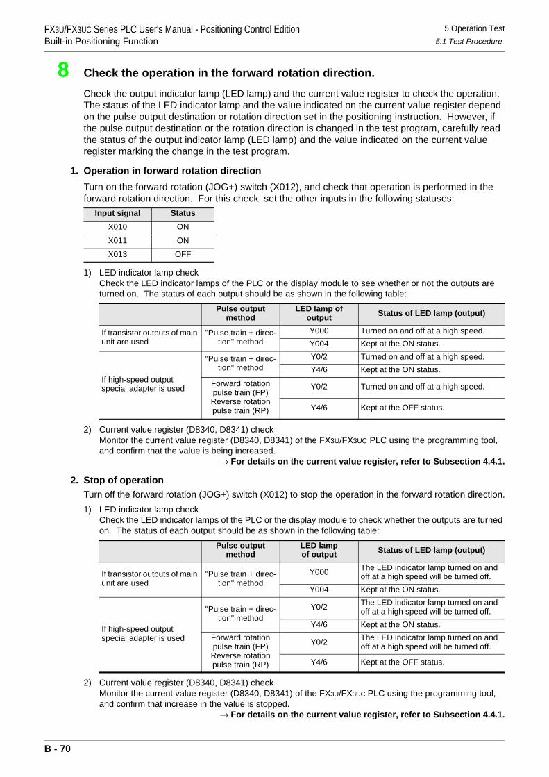
FX3U/FX3UC Series PLC User's Manual - Positioning Control EditionBuilt-in Positioning Function
5 Operation Test5.1 Test Procedure
8 Check the operation in the forward rotation direction.
Check the output indicator lamp (LED lamp) and the current value register to check the operation. The status of the LED indicator lamp and the value indicated on the current value register depend on the pulse output destination or rotation direction set in the positioning instruction. However, if the pulse output destination or the rotation direction is changed in the test program, carefully read the status of the output indicator lamp (LED lamp) and the value indicated on the current value register marking the change in the test program.
1. Operation in forward rotation directionTurn on the forward rotation (JOG+) switch (X012), and check that operation is performed in the forward rotation direction. For this check, set the other inputs in the following statuses:
1) LED indicator lamp checkCheck the LED indicator lamps of the PLC or the display module to see whether or not the outputs are turned on. The status of each output should be as shown in the following table:
2) Current value register (D8340, D8341) checkMonitor the current value register (D8340, D8341) of the FX3U/FX3UC PLC using the programming tool, and confirm that the value is being increased.
→ For details on the current value register, refer to Subsection 4.4.1.
2. Stop of operationTurn off the forward rotation (JOG+) switch (X012) to stop the operation in the forward rotation direction.1) LED indicator lamp check
Check the LED indicator lamps of the PLC or the display module to check whether the outputs are turned on. The status of each output should be as shown in the following table:
2) Current value register (D8340, D8341) checkMonitor the current value register (D8340, D8341) of the FX3U/FX3UC PLC using the programming tool, and confirm that increase in the value is stopped.
→ For details on the current value register, refer to Subsection 4.4.1.
Input signal StatusX010 ON
X011 ON
X013 OFF
Pulse output method
LED lamp of output Status of LED lamp (output)
If transistor outputs of main unit are used
"Pulse train + direc-tion" method
Y000 Turned on and off at a high speed.Y004 Kept at the ON status.
If high-speed output special adapter is used
"Pulse train + direc-tion" method
Y0/2 Turned on and off at a high speed.Y4/6 Kept at the ON status.
Forward rotation pulse train (FP)Reverse rotation pulse train (RP)
Y0/2 Turned on and off at a high speed.
Y4/6 Kept at the OFF status.
Pulse output method
LED lampof output Status of LED lamp (output)
If transistor outputs of main unit are used
"Pulse train + direc-tion" method
Y000 The LED indicator lamp turned on and off at a high speed will be turned off.
Y004 Kept at the ON status.
If high-speed output special adapter is used
"Pulse train + direc-tion" method
Y0/2 The LED indicator lamp turned on and off at a high speed will be turned off.
Y4/6 Kept at the ON status.Forward rotation pulse train (FP)Reverse rotation pulse train (RP)
Y0/2 The LED indicator lamp turned on and off at a high speed will be turned off.
Y4/6 Kept at the OFF status.
B - 70
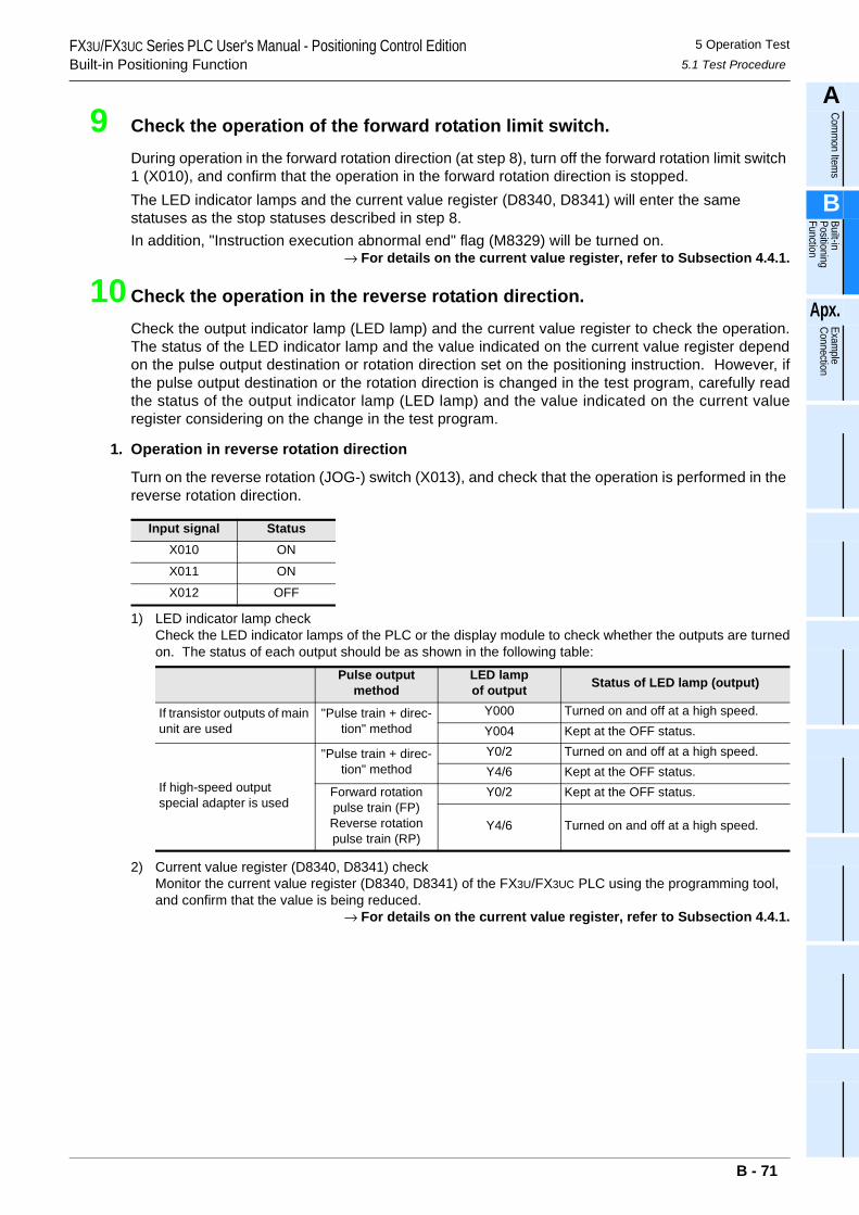
FX3U/FX3UC Series PLC User's Manual - Positioning Control EditionBuilt-in Positioning Function
5 Operation Test5.1 Test Procedure
A
Comm
on Items
B
Built-in Positioning Function
Apx.
Example
Connection
9 Check the operation of the forward rotation limit switch.
During operation in the forward rotation direction (at step 8), turn off the forward rotation limit switch 1 (X010), and confirm that the operation in the forward rotation direction is stopped.The LED indicator lamps and the current value register (D8340, D8341) will enter the same statuses as the stop statuses described in step 8.In addition, "Instruction execution abnormal end" flag (M8329) will be turned on.
→ For details on the current value register, refer to Subsection 4.4.1.
10 Check the operation in the reverse rotation direction.
Check the output indicator lamp (LED lamp) and the current value register to check the operation.The status of the LED indicator lamp and the value indicated on the current value register dependon the pulse output destination or rotation direction set on the positioning instruction. However, ifthe pulse output destination or the rotation direction is changed in the test program, carefully readthe status of the output indicator lamp (LED lamp) and the value indicated on the current valueregister considering on the change in the test program.
1. Operation in reverse rotation direction
Turn on the reverse rotation (JOG-) switch (X013), and check that the operation is performed in the reverse rotation direction.
1) LED indicator lamp checkCheck the LED indicator lamps of the PLC or the display module to check whether the outputs are turnedon. The status of each output should be as shown in the following table:
2) Current value register (D8340, D8341) checkMonitor the current value register (D8340, D8341) of the FX3U/FX3UC PLC using the programming tool, and confirm that the value is being reduced.
→ For details on the current value register, refer to Subsection 4.4.1.
Input signal StatusX010 ON
X011 ON
X012 OFF
Pulse output method
LED lampof output Status of LED lamp (output)
If transistor outputs of main unit are used
"Pulse train + direc-tion" method
Y000 Turned on and off at a high speed.Y004 Kept at the OFF status.
If high-speed output special adapter is used
"Pulse train + direc-tion" method
Y0/2 Turned on and off at a high speed.Y4/6 Kept at the OFF status.
Forward rotation pulse train (FP)Reverse rotation pulse train (RP)
Y0/2 Kept at the OFF status.
Y4/6 Turned on and off at a high speed.
B - 71
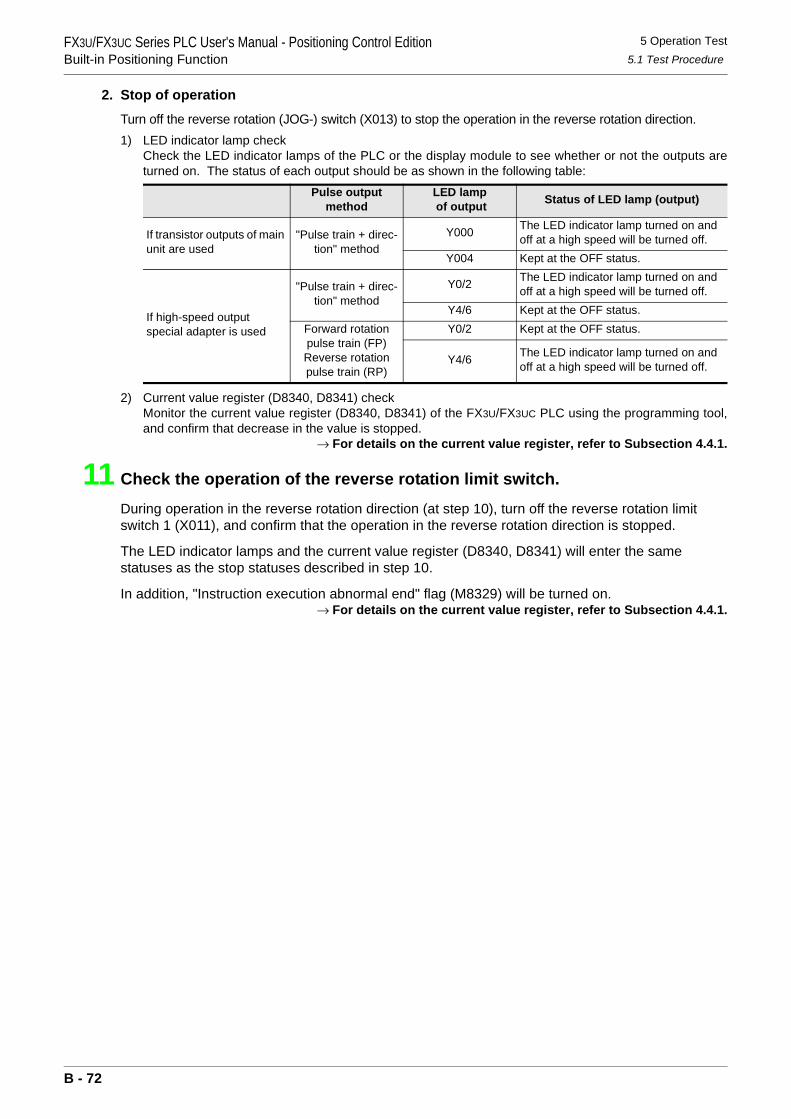
FX3U/FX3UC Series PLC User's Manual - Positioning Control EditionBuilt-in Positioning Function
5 Operation Test5.1 Test Procedure
2. Stop of operation
Turn off the reverse rotation (JOG-) switch (X013) to stop the operation in the reverse rotation direction.1) LED indicator lamp check
Check the LED indicator lamps of the PLC or the display module to see whether or not the outputs areturned on. The status of each output should be as shown in the following table:
2) Current value register (D8340, D8341) checkMonitor the current value register (D8340, D8341) of the FX3U/FX3UC PLC using the programming tool,and confirm that decrease in the value is stopped.
→ For details on the current value register, refer to Subsection 4.4.1.
11 Check the operation of the reverse rotation limit switch.
During operation in the reverse rotation direction (at step 10), turn off the reverse rotation limit switch 1 (X011), and confirm that the operation in the reverse rotation direction is stopped.
The LED indicator lamps and the current value register (D8340, D8341) will enter the same statuses as the stop statuses described in step 10.
In addition, "Instruction execution abnormal end" flag (M8329) will be turned on.→ For details on the current value register, refer to Subsection 4.4.1.
Pulse output method
LED lamp of output Status of LED lamp (output)
If transistor outputs of main unit are used
"Pulse train + direc-tion" method
Y000 The LED indicator lamp turned on and off at a high speed will be turned off.
Y004 Kept at the OFF status.
If high-speed output special adapter is used
"Pulse train + direc-tion" method
Y0/2 The LED indicator lamp turned on and off at a high speed will be turned off.
Y4/6 Kept at the OFF status.Forward rotation pulse train (FP)Reverse rotation pulse train (RP)
Y0/2 Kept at the OFF status.
Y4/6 The LED indicator lamp turned on and off at a high speed will be turned off.
B - 72
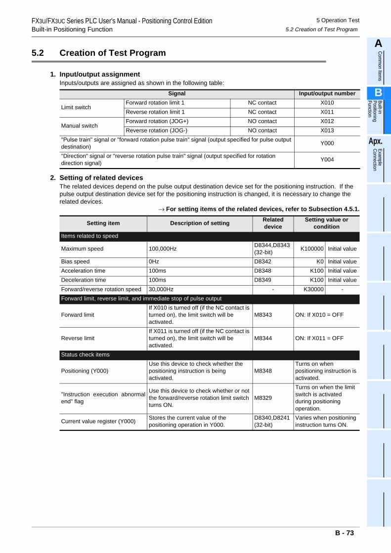
FX3U/FX3UC Series PLC User's Manual - Positioning Control EditionBuilt-in Positioning Function
5 Operation Test5.2 Creation of Test Program
A
Comm
on Items
B
Built-in Positioning Function
Apx.
Example
Connection
5.2 Creation of Test Program
1. Input/output assignmentInputs/outputs are assigned as shown in the following table:
2. Setting of related devicesThe related devices depend on the pulse output destination device set for the positioning instruction. If the pulse output destination device set for the positioning instruction is changed, it is necessary to change the related devices.
→ For setting items of the related devices, refer to Subsection 4.5.1.
Signal Input/output number
Limit switchForward rotation limit 1 NC contact X010Reverse rotation limit 1 NC contact X011
Manual switchForward rotation (JOG+) NO contact X012Reverse rotation (JOG-) NO contact X013
"Pulse train" signal or "forward rotation pulse train" signal (output specified for pulse output destination) Y000
"Direction" signal or "reverse rotation pulse train" signal (output specified for rotation direction signal) Y004
Setting item Description of setting Related device
Setting value or condition
Items related to speed
Maximum speed 100,000Hz D8344,D8343(32-bit) K100000 Initial value
Bias speed 0Hz D8342 K0 Initial valueAcceleration time 100ms D8348 K100 Initial valueDeceleration time 100ms D8349 K100 Initial valueForward/reverse rotation speed 30,000Hz - K30000 -Forward limit, reverse limit, and immediate stop of pulse output
Forward limitIf X010 is turned off (if the NC contact is turned on), the limit switch will be activated.
M8343 ON: If X010 = OFF
Reverse limitIf X011 is turned off (if the NC contact is turned on), the limit switch will be activated.
M8344 ON: If X011 = OFF
Status check items
Positioning (Y000)Use this device to check whether the positioning instruction is being activated.
M8348Turns on when positioning instruction is activated.
"Instruction execution abnormalend" flag
Use this device to check whether or not the forward/reverse rotation limit switch turns ON.
M8329
Turns on when the limit switch is activated during positioning operation.
Current value register (Y000) Stores the current value of the positioning operation in Y000.
D8340,D8241(32-bit)
Varies when positioning instruction turns ON.
B - 73
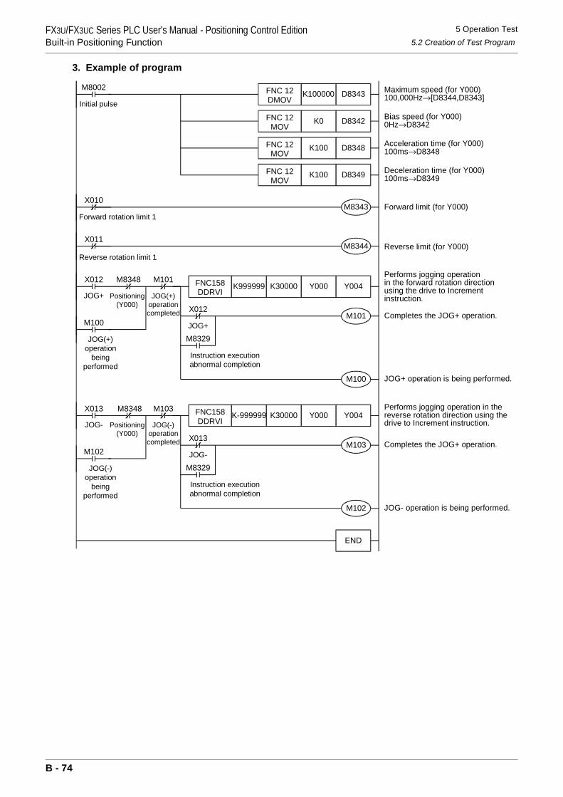
FX3U/FX3UC Series PLC User's Manual - Positioning Control EditionBuilt-in Positioning Function
5 Operation Test5.2 Creation of Test Program
3. Example of program
Performs jogging operationin the forward rotation directionusing the drive to Incrementinstruction.
M8002 Maximum speed (for Y000)100,000Hz→[D8344,D8343]
Bias speed (for Y000)0Hz→D8342
Acceleration time (for Y000)100ms→D8348
Deceleration time (for Y000)100ms→D8349
D8343K100000FNC 12DMOV
D8342K0FNC 12MOV
D8348K100
D8349K100
FNC 12MOV
FNC 12MOV
X012
JOG+
M8348
Positioning(Y000)
M101
JOG(+)operationcompleted
Y004Y000FNC158DDRVI
K30000K999999
X012
JOG+
M8329
Instruction executionabnormal completion
M101
Forward limit (for Y000)M8343X010
Reverse limit (for Y000)M8344X011
Completes the JOG+ operation.
X013
JOG-
M8348
Positioning(Y000)
M103Y004Y000FNC158
DDRVIK30000K-999999
X013
JOG-
M8329
Instruction executionabnormal completion
M103
Performs jogging operation in thereverse rotation direction using thedrive to Increment instruction.
Completes the JOG+ operation.
END
Initial pulse
Forward rotation limit 1
Reverse rotation limit 1
JOG(-)operationcompleted
M100
JOG(+)operation
beingperformed
M100 JOG+ operation is being performed.
M102 JOG- operation is being performed.
M102
JOG(-)operation
beingperformed
B - 74
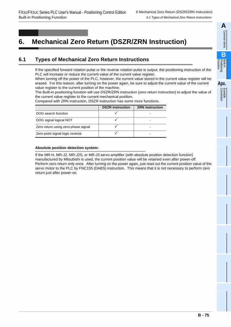
FX3U/FX3UC Series PLC User's Manual - Positioning Control EditionBuilt-in Positioning Function
6 Mechanical Zero Return (DSZR/ZRN Instruction)6.1 Types of Mechanical Zero Return Instructions
A
Comm
on Items
B
Built-in Positioning Function
Apx.
Example
Connection
6. Mechanical Zero Return (DSZR/ZRN Instruction)
6.1 Types of Mechanical Zero Return Instructions
If the specified forward rotation pulse or the reverse rotation pulse is output, the positioning instruction of the PLC will increase or reduce the current value of the current value register.When turning off the power of the PLC, however, the current value stored in the current value register will be erased. For this reason, after turning on the power again, be sure to adjust the current value of the current value register to the current position of the machine.The Built-in positioning function will use DSZR/ZRN instruction (zero return instruction) to adjust the value of the current value register to the current mechanical position.Compared with ZRN instruction, DSZR instruction has some more functions.
Absolute position detection system:
If the MR-H, MR-J2, MR-J2S, or MR-J3 servo amplifier (with absolute position detection function) manufactured by Mitsubishi is used, the current position value will be retained even after power-off.Perform zero return only once. After turning on the power again, just read out the current position value of the servo motor to the PLC by FNC155 (DABS) instruction. This means that it is not necessary to perform zero return just after power-on.
DSZR instruction ZRN instruction
DOG search function -
DOG signal logical NOT -
Zero return using zero-phase signal -
Zero point signal logic reverse -
B - 75
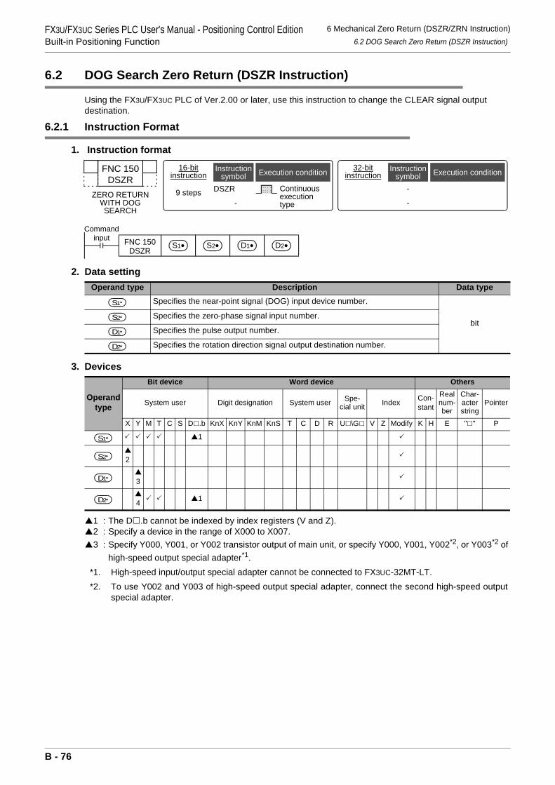
FX3U/FX3UC Series PLC User's Manual - Positioning Control EditionBuilt-in Positioning Function
6 Mechanical Zero Return (DSZR/ZRN Instruction)6.2 DOG Search Zero Return (DSZR Instruction)
6.2 DOG Search Zero Return (DSZR Instruction)
Using the FX3U/FX3UC PLC of Ver.2.00 or later, use this instruction to change the CLEAR signal output destination.
6.2.1 Instruction Format
1. Instruction format
2. Data setting
3. Devices
1 : The D .b cannot be indexed by index registers (V and Z).2 : Specify a device in the range of X000 to X007.3 : Specify Y000, Y001, or Y002 transistor output of main unit, or specify Y000, Y001, Y002*2, or Y003*2 of
high-speed output special adapter*1.*1. High-speed input/output special adapter cannot be connected to FX3UC-32MT-LT.*2. To use Y002 and Y003 of high-speed output special adapter, connect the second high-speed output
special adapter.
Operand type Description Data typeSpecifies the near-point signal (DOG) input device number.
bitSpecifies the zero-phase signal input number.
Specifies the pulse output number.
Specifies the rotation direction signal output destination number.
Operand type
Bit device Word device Others
System user Digit designation System user Spe-cial unit Index Con-
stant
Real num-ber
Char-acter string
Pointer
X Y M T C S D .b KnX KnY KnM KnS T C D R U \G V Z Modify K H E " " P
1
2
3
4 1
FNC 150DSZR
ZERO RETURNWITH DOGSEARCH
16-bitinstruction
9 steps DSZR
-
Continuousexecutiontype
Instructionsymbol Execution condition 32-bit
instruction
-
-
Instructionsymbol Execution condition
Commandinput FNC 150
DSZRS2•S1• D1• D2•
S1
S2
D1
D2
S1
S2
D1
D2
B - 76
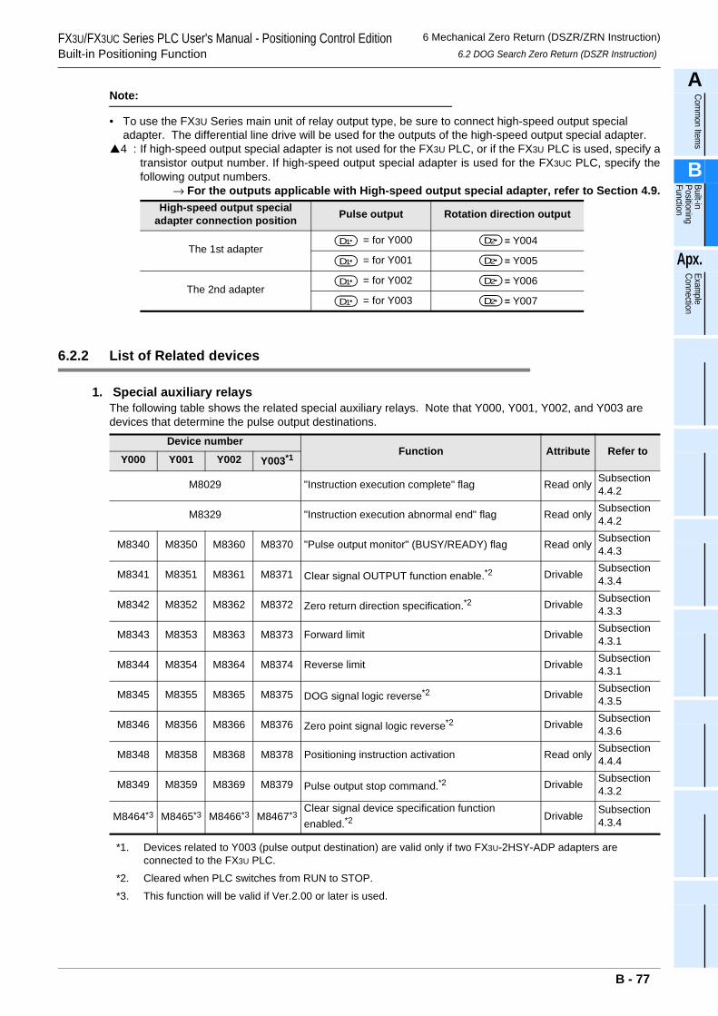
FX3U/FX3UC Series PLC User's Manual - Positioning Control EditionBuilt-in Positioning Function
6 Mechanical Zero Return (DSZR/ZRN Instruction)6.2 DOG Search Zero Return (DSZR Instruction)
A
Comm
on Items
B
Built-in Positioning Function
Apx.
Example
Connection
Note:
• To use the FX3U Series main unit of relay output type, be sure to connect high-speed output special adapter. The differential line drive will be used for the outputs of the high-speed output special adapter.4 : If high-speed output special adapter is not used for the FX3U PLC, or if the FX3U PLC is used, specify a
transistor output number. If high-speed output special adapter is used for the FX3UC PLC, specify thefollowing output numbers.
→ For the outputs applicable with High-speed output special adapter, refer to Section 4.9.
6.2.2 List of Related devices
1. Special auxiliary relaysThe following table shows the related special auxiliary relays. Note that Y000, Y001, Y002, and Y003 are devices that determine the pulse output destinations.
*1. Devices related to Y003 (pulse output destination) are valid only if two FX3U-2HSY-ADP adapters are connected to the FX3U PLC.
*2. Cleared when PLC switches from RUN to STOP.
*3. This function will be valid if Ver.2.00 or later is used.
High-speed output special adapter connection position Pulse output Rotation direction output
The 1st adapter= for Y000 = Y004
= for Y001 = Y005
The 2nd adapter= for Y002 = Y006
= for Y003 = Y007
Device numberFunction Attribute Refer to
Y000 Y001 Y002 Y003*1
M8029 "Instruction execution complete" flag Read only Subsection 4.4.2
M8329 "Instruction execution abnormal end" flag Read only Subsection 4.4.2
M8340 M8350 M8360 M8370 "Pulse output monitor" (BUSY/READY) flag Read only Subsection 4.4.3
M8341 M8351 M8361 M8371 Clear signal OUTPUT function enable.*2 Drivable Subsection 4.3.4
M8342 M8352 M8362 M8372 Zero return direction specification.*2 Drivable Subsection 4.3.3
M8343 M8353 M8363 M8373 Forward limit Drivable Subsection 4.3.1
M8344 M8354 M8364 M8374 Reverse limit Drivable Subsection 4.3.1
M8345 M8355 M8365 M8375 DOG signal logic reverse*2 Drivable Subsection 4.3.5
M8346 M8356 M8366 M8376 Zero point signal logic reverse*2 Drivable Subsection 4.3.6
M8348 M8358 M8368 M8378 Positioning instruction activation Read only Subsection 4.4.4
M8349 M8359 M8369 M8379 Pulse output stop command.*2 Drivable Subsection 4.3.2
M8464*3 M8465*3 M8466*3 M8467*3Clear signal device specification function enabled.*2
Drivable Subsection 4.3.4
D1 D2
D1 D2
D1 D2
D1 D2
B - 77
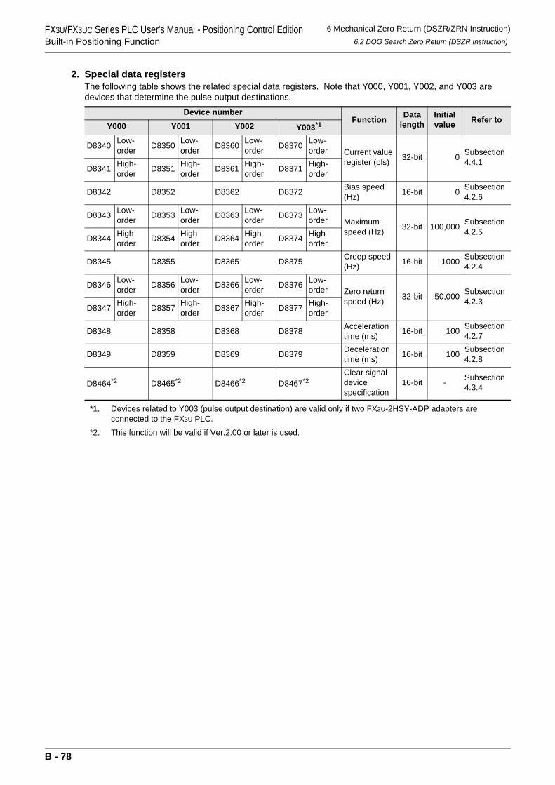
FX3U/FX3UC Series PLC User's Manual - Positioning Control EditionBuilt-in Positioning Function
6 Mechanical Zero Return (DSZR/ZRN Instruction)6.2 DOG Search Zero Return (DSZR Instruction)
2. Special data registersThe following table shows the related special data registers. Note that Y000, Y001, Y002, and Y003 are devices that determine the pulse output destinations.
*1. Devices related to Y003 (pulse output destination) are valid only if two FX3U-2HSY-ADP adapters are connected to the FX3U PLC.
*2. This function will be valid if Ver.2.00 or later is used.
Device numberFunction Data
lengthInitial value Refer to
Y000 Y001 Y002 Y003*1
D8340 Low-order D8350 Low-
order D8360 Low-order D8370 Low-
order Current value register (pls) 32-bit 0 Subsection
4.4.1D8341 High-
order D8351 High-order D8361 High-
order D8371 High-order
D8342 D8352 D8362 D8372 Bias speed (Hz) 16-bit 0 Subsection
4.2.6
D8343 Low-order D8353 Low-
order D8363 Low-order D8373 Low-
order Maximum speed (Hz) 32-bit 100,000 Subsection
4.2.5D8344 High-
order D8354 High-order D8364 High-
order D8374 High-order
D8345 D8355 D8365 D8375 Creep speed (Hz) 16-bit 1000 Subsection
4.2.4
D8346 Low-order D8356 Low-
order D8366 Low-order D8376 Low-
order Zero return speed (Hz) 32-bit 50,000 Subsection
4.2.3D8347 High-
order D8357 High-order D8367 High-
order D8377 High-order
D8348 D8358 D8368 D8378 Acceleration time (ms) 16-bit 100 Subsection
4.2.7
D8349 D8359 D8369 D8379 Deceleration time (ms) 16-bit 100 Subsection
4.2.8
D8464*2 D8465*2 D8466*2 D8467*2Clear signal device specification
16-bit - Subsection 4.3.4
B - 78
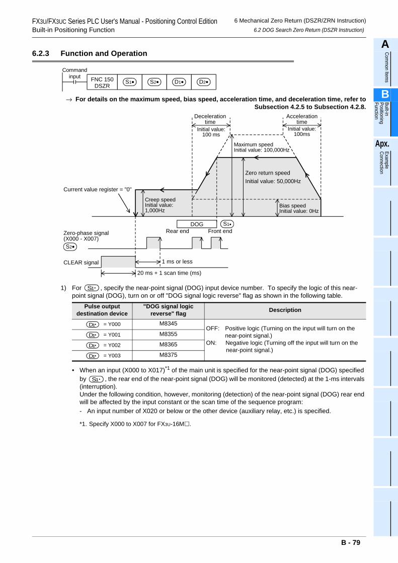
FX3U/FX3UC Series PLC User's Manual - Positioning Control EditionBuilt-in Positioning Function
6 Mechanical Zero Return (DSZR/ZRN Instruction)6.2 DOG Search Zero Return (DSZR Instruction)
A
Comm
on Items
B
Built-in Positioning Function
Apx.
Example
Connection
6.2.3 Function and Operation
→ For details on the maximum speed, bias speed, acceleration time, and deceleration time, refer toSubsection 4.2.5 to Subsection 4.2.8.
1) For , specify the near-point signal (DOG) input device number. To specify the logic of this near-point signal (DOG), turn on or off "DOG signal logic reverse" flag as shown in the following table.
• When an input (X000 to X017)*1 of the main unit is specified for the near-point signal (DOG) specified by , the rear end of the near-point signal (DOG) will be monitored (detected) at the 1-ms intervals (interruption).Under the following condition, however, monitoring (detection) of the near-point signal (DOG) rear end will be affected by the input constant or the scan time of the sequence program:- An input number of X020 or below or the other device (auxiliary relay, etc.) is specified.
*1. Specify X000 to X007 for FX3U-16M .
Pulse output destination device
"DOG signal logic reverse" flag Description
= Y000 M8345OFF: Positive logic (Turning on the input will turn on the
near-point signal.)ON: Negative logic (Turning off the input will turn on the
near-point signal.)
= Y001 M8355
= Y002 M8365
= Y003 M8375
Commandinput FNC 150
DSZRS2•S1• D1• D2•
Maximum speedInitial value: 100,000Hz
Zero return speedInitial value: 50,000Hz
Decelerationtime
Bias speedInitial value: 0Hz
Accelerationtime
Creep speedInitial value:1,000Hz
CLEAR signal
Zero-phase signal(X000 - X007)
1 ms or less
20 ms + 1 scan time (ms)
S2•
Current value register = "0"
Initial value:100 ms
Initial value:100ms
DOG S1•
Front endRear end
S1
D1
D1
D1
D1
S1
B - 79
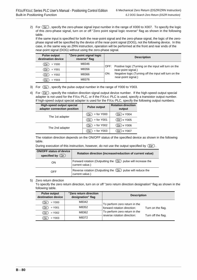
FX3U/FX3UC Series PLC User's Manual - Positioning Control EditionBuilt-in Positioning Function
6 Mechanical Zero Return (DSZR/ZRN Instruction)6.2 DOG Search Zero Return (DSZR Instruction)
2) For , specify the zero-phase signal input number in the range of X000 to X007. To specify the logicof this zero-phase signal, turn on or off "Zero point signal logic reverse" flag as shown in the followingtable.If the same input is specified for both the near-point signal and the zero-phase signal, the logic of the zero-phase signal will be specified by the device of the near-point signal (DOG), not the following device. In this case, in the same way as ZRN instruction, operation will be performed at the front and rear ends of the near-point signal (DOG) without using the zero-phase signal.
3) For , specify the pulse output number in the range of Y000 to Y003.
4) For , specify the rotation direction signal output device number. If the high-speed output special adapter is not used for the FX3U PLC, or if the FX3UC PLC is used, specify a transistor output number.If high-speed output special adapter is used for the FX3U PLC, specify the following output numbers.
The rotation direction depends on the ON/OFF status of the specified device as shown in the following table.During execution of this instruction, however, do not use the output specified by .
5) Zero return directionTo specify the zero return direction, turn on or off "zero return direction designation" flag as shown in the following table.
Pulse output destination device
"Zero point signal logic reverse" flag Description
= Y000 M8346OFF: Positive logic (Turning on the input will turn on the
near-point signal.)ON: Negative logic (Turning off the input will turn on the
near-point signal.)
= Y001 M8356
= Y002 M8366
= Y003 M8376
High-speed output special adapter connection position Pulse output Rotation direction
output
The 1st adapter= for Y000 = Y004
= for Y001 = Y005
The 2nd adapter= for Y002 = Y006
= for Y003 = Y007
ON/OFF status of device specified by
Rotation direction (increase/reduction of current value)
ON Forward rotation (Outputting the pulse will increase the current value.)
OFF Reverse rotation (Outputting the pulse will reduce the current value.)
Pulse output destination device
"Zero return direction designation" flag Description
= Y000 M8342To perform zero return in theforward rotation direction: Turn on the flag.To perform zero return in thereverse rotation direction: Turn off the flag.
= Y001 M8352
= Y002 M8362
= Y003 M8372
S2
D1
D1
D1
D1
D1
D2
D1 D2
D1 D2
D1 D2
D1 D2
D2
D2
D1
D1
D1
D1
D1
D1
B - 80
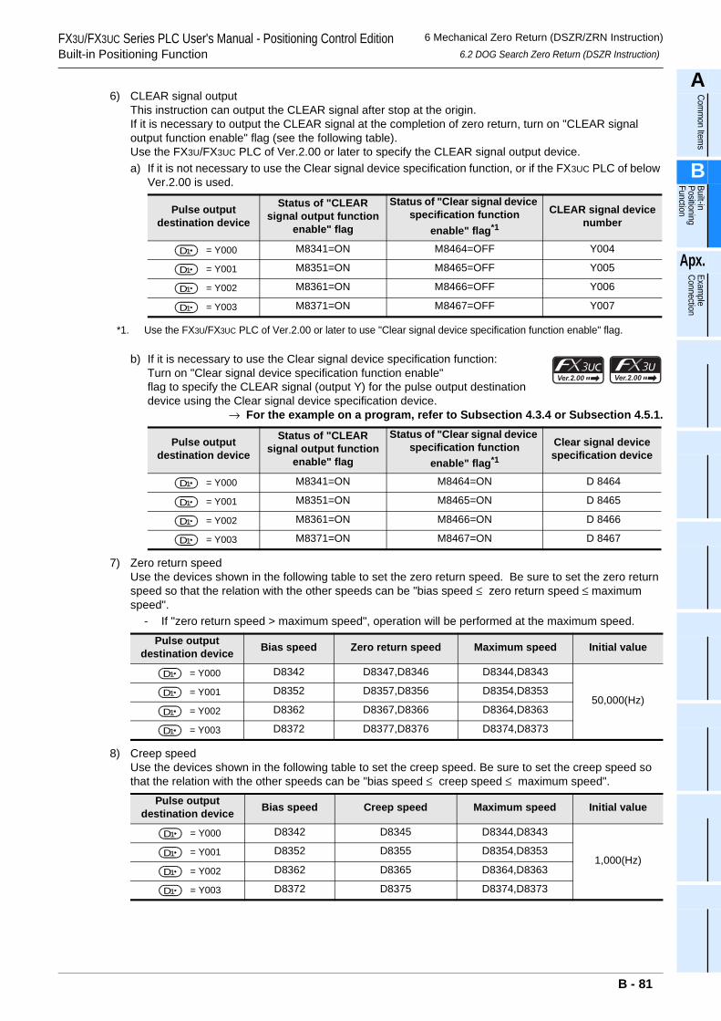
FX3U/FX3UC Series PLC User's Manual - Positioning Control EditionBuilt-in Positioning Function
6 Mechanical Zero Return (DSZR/ZRN Instruction)6.2 DOG Search Zero Return (DSZR Instruction)
A
Comm
on Items
B
Built-in Positioning Function
Apx.
Example
Connection
6) CLEAR signal outputThis instruction can output the CLEAR signal after stop at the origin.If it is necessary to output the CLEAR signal at the completion of zero return, turn on "CLEAR signal output function enable" flag (see the following table).Use the FX3U/FX3UC PLC of Ver.2.00 or later to specify the CLEAR signal output device.a) If it is not necessary to use the Clear signal device specification function, or if the FX3UC PLC of below
Ver.2.00 is used.
*1. Use the FX3U/FX3UC PLC of Ver.2.00 or later to use "Clear signal device specification function enable" flag.
b) If it is necessary to use the Clear signal device specification function:Turn on "Clear signal device specification function enable"flag to specify the CLEAR signal (output Y) for the pulse output destination device using the Clear signal device specification device.
→ For the example on a program, refer to Subsection 4.3.4 or Subsection 4.5.1.
7) Zero return speedUse the devices shown in the following table to set the zero return speed. Be sure to set the zero return speed so that the relation with the other speeds can be "bias speed ≤ zero return speed ≤ maximum speed".
- If "zero return speed > maximum speed", operation will be performed at the maximum speed.
8) Creep speedUse the devices shown in the following table to set the creep speed. Be sure to set the creep speed so that the relation with the other speeds can be "bias speed ≤ creep speed ≤ maximum speed".
Pulse output destination device
Status of "CLEAR signal output function
enable" flag
Status of "Clear signal device specification function
enable" flag*1
CLEAR signal device number
= Y000 M8341=ON M8464=OFF Y004
= Y001 M8351=ON M8465=OFF Y005
= Y002 M8361=ON M8466=OFF Y006
= Y003 M8371=ON M8467=OFF Y007
Pulse output destination device
Status of "CLEAR signal output function
enable" flag
Status of "Clear signal device specification function
enable" flag*1
Clear signal device specification device
= Y000 M8341=ON M8464=ON D 8464
= Y001 M8351=ON M8465=ON D 8465
= Y002 M8361=ON M8466=ON D 8466
= Y003 M8371=ON M8467=ON D 8467
Pulse output destination device Bias speed Zero return speed Maximum speed Initial value
= Y000 D8342 D8347,D8346 D8344,D8343
50,000(Hz) = Y001 D8352 D8357,D8356 D8354,D8353
= Y002 D8362 D8367,D8366 D8364,D8363
= Y003 D8372 D8377,D8376 D8374,D8373
Pulse output destination device Bias speed Creep speed Maximum speed Initial value
= Y000 D8342 D8345 D8344,D8343
1,000(Hz) = Y001 D8352 D8355 D8354,D8353
= Y002 D8362 D8365 D8364,D8363
= Y003 D8372 D8375 D8374,D8373
D1
D1
D1
D1
D1
D1
D1
D1
D1
D1
D1
D1
D1
D1
D1
D1
B - 81
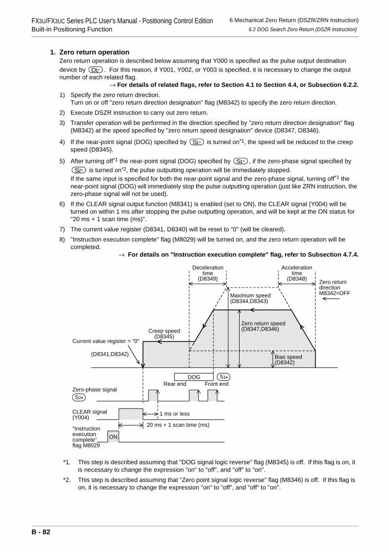
FX3U/FX3UC Series PLC User's Manual - Positioning Control EditionBuilt-in Positioning Function
6 Mechanical Zero Return (DSZR/ZRN Instruction)6.2 DOG Search Zero Return (DSZR Instruction)
1. Zero return operationZero return operation is described below assuming that Y000 is specified as the pulse output destination device by . For this reason, if Y001, Y002, or Y003 is specified, it is necessary to change the output number of each related flag.
→ For details of related flags, refer to Section 4.1 to Section 4.4, or Subsection 6.2.2.1) Specify the zero return direction.
Turn on or off "zero return direction designation" flag (M8342) to specify the zero return direction.2) Execute DSZR instruction to carry out zero return.3) Transfer operation will be performed in the direction specified by "zero return direction designation" flag
(M8342) at the speed specified by "zero return speed designation" device (D8347, D8346).
4) If the near-point signal (DOG) specified by is turned on*1, the speed will be reduced to the creep speed (D8345).
5) After turning off*1 the near-point signal (DOG) specified by , if the zero-phase signal specified by is turned on*2, the pulse outputting operation will be immediately stopped.
If the same input is specified for both the near-point signal and the zero-phase signal, turning off*1 the near-point signal (DOG) will immediately stop the pulse outputting operation (just like ZRN instruction, the zero-phase signal will not be used).
6) If the CLEAR signal output function (M8341) is enabled (set to ON), the CLEAR signal (Y004) will be turned on within 1 ms after stopping the pulse outputting operation, and will be kept at the ON status for "20 ms + 1 scan time (ms)".
7) The current value register (D8341, D8340) will be reset to "0" (will be cleared).8) "Instruction execution complete" flag (M8029) will be turned on, and the zero return operation will be
completed.→ For details on "Instruction execution complete" flag, refer to Subsection 4.7.4.
*1. This step is described assuming that "DOG signal logic reverse" flag (M8345) is off. If this flag is on, it is necessary to change the expression "on" to "off", and "off" to "on".
*2. This step is described assuming that "Zero point signal logic reverse" flag (M8346) is off. If this flag is on, it is necessary to change the expression "on" to "off", and "off" to "on".
D1
S1
S1
S2
Maximum speed(D8344,D8343)
Zero return speed(D8347,D8346)
Decelerationtime
(D8349)
Bias speed(D8342)
Accelerationtime
(D8348)
DOG
Creep speed(D8345)
CLEAR signal(Y004)
Zero-phase signalS2•
S1•
Current value register = "0"
Zero returndirectionM8342=OFF
(D8341,D8342)
ON"Instructionexecutioncomplete"flag M8029
Front endRear end
1 ms or less
20 ms + 1 scan time (ms)
B - 82
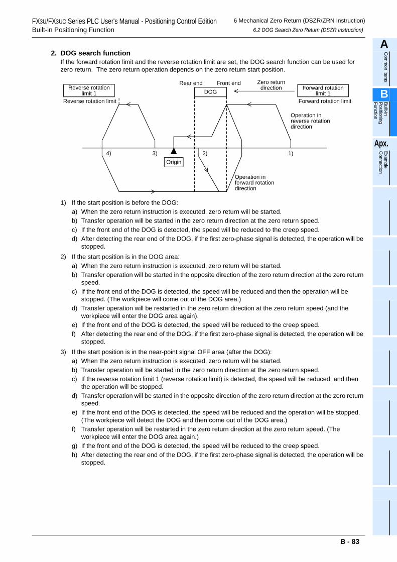
FX3U/FX3UC Series PLC User's Manual - Positioning Control EditionBuilt-in Positioning Function
6 Mechanical Zero Return (DSZR/ZRN Instruction)6.2 DOG Search Zero Return (DSZR Instruction)
A
Comm
on Items
B
Built-in Positioning Function
Apx.
Example
Connection
2. DOG search functionIf the forward rotation limit and the reverse rotation limit are set, the DOG search function can be used for zero return. The zero return operation depends on the zero return start position.
1) If the start position is before the DOG:a) When the zero return instruction is executed, zero return will be started.b) Transfer operation will be started in the zero return direction at the zero return speed.c) If the front end of the DOG is detected, the speed will be reduced to the creep speed.d) After detecting the rear end of the DOG, if the first zero-phase signal is detected, the operation will be
stopped.2) If the start position is in the DOG area:
a) When the zero return instruction is executed, zero return will be started.b) Transfer operation will be started in the opposite direction of the zero return direction at the zero return
speed.c) If the front end of the DOG is detected, the speed will be reduced and then the operation will be
stopped. (The workpiece will come out of the DOG area.)d) Transfer operation will be restarted in the zero return direction at the zero return speed (and the
workpiece will enter the DOG area again).e) If the front end of the DOG is detected, the speed will be reduced to the creep speed.f) After detecting the rear end of the DOG, if the first zero-phase signal is detected, the operation will be
stopped.3) If the start position is in the near-point signal OFF area (after the DOG):
a) When the zero return instruction is executed, zero return will be started.b) Transfer operation will be started in the zero return direction at the zero return speed.c) If the reverse rotation limit 1 (reverse rotation limit) is detected, the speed will be reduced, and then
the operation will be stopped.d) Transfer operation will be started in the opposite direction of the zero return direction at the zero return
speed.e) If the front end of the DOG is detected, the speed will be reduced and the operation will be stopped.
(The workpiece will detect the DOG and then come out of the DOG area.)f) Transfer operation will be restarted in the zero return direction at the zero return speed. (The
workpiece will enter the DOG area again.)g) If the front end of the DOG is detected, the speed will be reduced to the creep speed.h) After detecting the rear end of the DOG, if the first zero-phase signal is detected, the operation will be
stopped.
Zero returndirection
1)2)3)
Operation inreverse rotationdirection
Operation inforward rotationdirection
Reverse rotationlimit 1 DOG
Forward rotationlimit 1
Origin
Reverse rotation limit Forward rotation limit
4)
Front endRear end
B - 83

FX3U/FX3UC Series PLC User's Manual - Positioning Control EditionBuilt-in Positioning Function
6 Mechanical Zero Return (DSZR/ZRN Instruction)6.2 DOG Search Zero Return (DSZR Instruction)
4) If the limit switch in the zero return direction turns ON (if the start position is at forward rotation limit 1 orreverse rotation limit 1):a) When the zero return instruction is executed, zero return will be started.b) Transfer operation will be started in the opposite direction of the zero return direction at the zero return
speed.c) If the front end of the DOG is detected, the speed will be reduced and then the operation will be
stopped. (The workpiece will detect the DOG and then come out of the DOG area.)d) Transfer operation will be restarted in the zero return direction at the zero return speed (and the
workpiece will enter the DOG area again).e) If the front end of the DOG is detected, the speed will be reduced to the creep speed.f) After detecting the rear end of the DOG, if the first zero-phase signal is detected, the operation will be
stopped.
B - 84
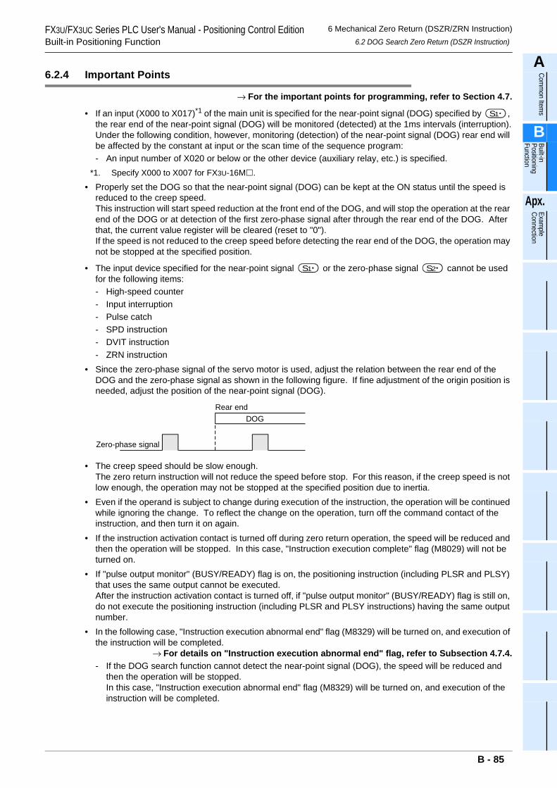
FX3U/FX3UC Series PLC User's Manual - Positioning Control EditionBuilt-in Positioning Function
6 Mechanical Zero Return (DSZR/ZRN Instruction)6.2 DOG Search Zero Return (DSZR Instruction)
A
Comm
on Items
B
Built-in Positioning Function
Apx.
Example
Connection
6.2.4 Important Points
→ For the important points for programming, refer to Section 4.7.
• If an input (X000 to X017)*1 of the main unit is specified for the near-point signal (DOG) specified by , the rear end of the near-point signal (DOG) will be monitored (detected) at the 1ms intervals (interruption).Under the following condition, however, monitoring (detection) of the near-point signal (DOG) rear end will be affected by the constant at input or the scan time of the sequence program:- An input number of X020 or below or the other device (auxiliary relay, etc.) is specified.
*1. Specify X000 to X007 for FX3U-16M .
• Properly set the DOG so that the near-point signal (DOG) can be kept at the ON status until the speed is reduced to the creep speed.This instruction will start speed reduction at the front end of the DOG, and will stop the operation at the rear end of the DOG or at detection of the first zero-phase signal after through the rear end of the DOG. After that, the current value register will be cleared (reset to "0").If the speed is not reduced to the creep speed before detecting the rear end of the DOG, the operation may not be stopped at the specified position.
• The input device specified for the near-point signal or the zero-phase signal cannot be used for the following items:- High-speed counter- Input interruption- Pulse catch- SPD instruction- DVIT instruction- ZRN instruction
• Since the zero-phase signal of the servo motor is used, adjust the relation between the rear end of the DOG and the zero-phase signal as shown in the following figure. If fine adjustment of the origin position is needed, adjust the position of the near-point signal (DOG).
• The creep speed should be slow enough.The zero return instruction will not reduce the speed before stop. For this reason, if the creep speed is not low enough, the operation may not be stopped at the specified position due to inertia.
• Even if the operand is subject to change during execution of the instruction, the operation will be continued while ignoring the change. To reflect the change on the operation, turn off the command contact of the instruction, and then turn it on again.
• If the instruction activation contact is turned off during zero return operation, the speed will be reduced and then the operation will be stopped. In this case, "Instruction execution complete" flag (M8029) will not be turned on.
• If "pulse output monitor" (BUSY/READY) flag is on, the positioning instruction (including PLSR and PLSY) that uses the same output cannot be executed.After the instruction activation contact is turned off, if "pulse output monitor" (BUSY/READY) flag is still on, do not execute the positioning instruction (including PLSR and PLSY instructions) having the same output number.
• In the following case, "Instruction execution abnormal end" flag (M8329) will be turned on, and execution of the instruction will be completed.
→ For details on "Instruction execution abnormal end" flag, refer to Subsection 4.7.4.- If the DOG search function cannot detect the near-point signal (DOG), the speed will be reduced and
then the operation will be stopped.In this case, "Instruction execution abnormal end" flag (M8329) will be turned on, and execution of the instruction will be completed.
S1
S1 S2
DOGRear end
Zero-phase signal
B - 85
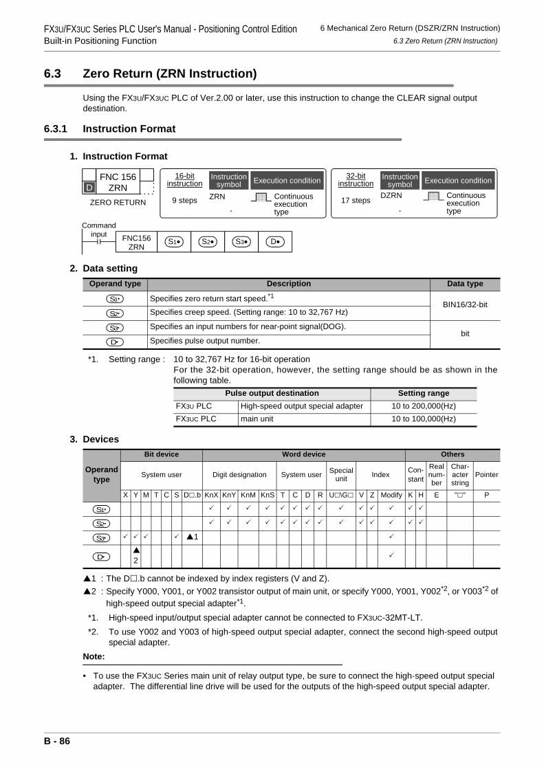
FX3U/FX3UC Series PLC User's Manual - Positioning Control EditionBuilt-in Positioning Function
6 Mechanical Zero Return (DSZR/ZRN Instruction)6.3 Zero Return (ZRN Instruction)
6.3 Zero Return (ZRN Instruction)
Using the FX3U/FX3UC PLC of Ver.2.00 or later, use this instruction to change the CLEAR signal output destination.
6.3.1 Instruction Format
1. Instruction Format
2. Data setting
*1. Setting range : 10 to 32,767 Hz for 16-bit operationFor the 32-bit operation, however, the setting range should be as shown in thefollowing table.
3. Devices
1 : The D .b cannot be indexed by index registers (V and Z).2 : Specify Y000, Y001, or Y002 transistor output of main unit, or specify Y000, Y001, Y002*2, or Y003*2 of
high-speed output special adapter*1.*1. High-speed input/output special adapter cannot be connected to FX3UC-32MT-LT.*2. To use Y002 and Y003 of high-speed output special adapter, connect the second high-speed output
special adapter.Note:
• To use the FX3UC Series main unit of relay output type, be sure to connect the high-speed output special adapter. The differential line drive will be used for the outputs of the high-speed output special adapter.
Operand type Description Data type
Specifies zero return start speed.*1BIN16/32-bit
Specifies creep speed. (Setting range: 10 to 32,767 Hz)
Specifies an input numbers for near-point signal(DOG).bit
Specifies pulse output number.
Pulse output destination Setting rangeFX3U PLC High-speed output special adapter 10 to 200,000(Hz)FX3UC PLC main unit 10 to 100,000(Hz)
Operand type
Bit device Word device Others
System user Digit designation System user Special unit Index Con-
stant
Real num-ber
Char-acter string
Pointer
X Y M T C S D .b KnX KnY KnM KnS T C D R U \G V Z Modify K H E " " P
1
2
FNC 156ZRN
ZERO RETURN
D16-bit
instruction
9 steps ZRN
-
Continuousexecutiontype
Instructionsymbol Execution condition 32-bit
instructionInstruction
symbol Execution condition
DZRN
-
Continuousexecutiontype
17 steps
Commandinput FNC156
ZRNS1• S2• S3• D•
S1
S2
S3
D
S1
S2
S3
D
B - 86
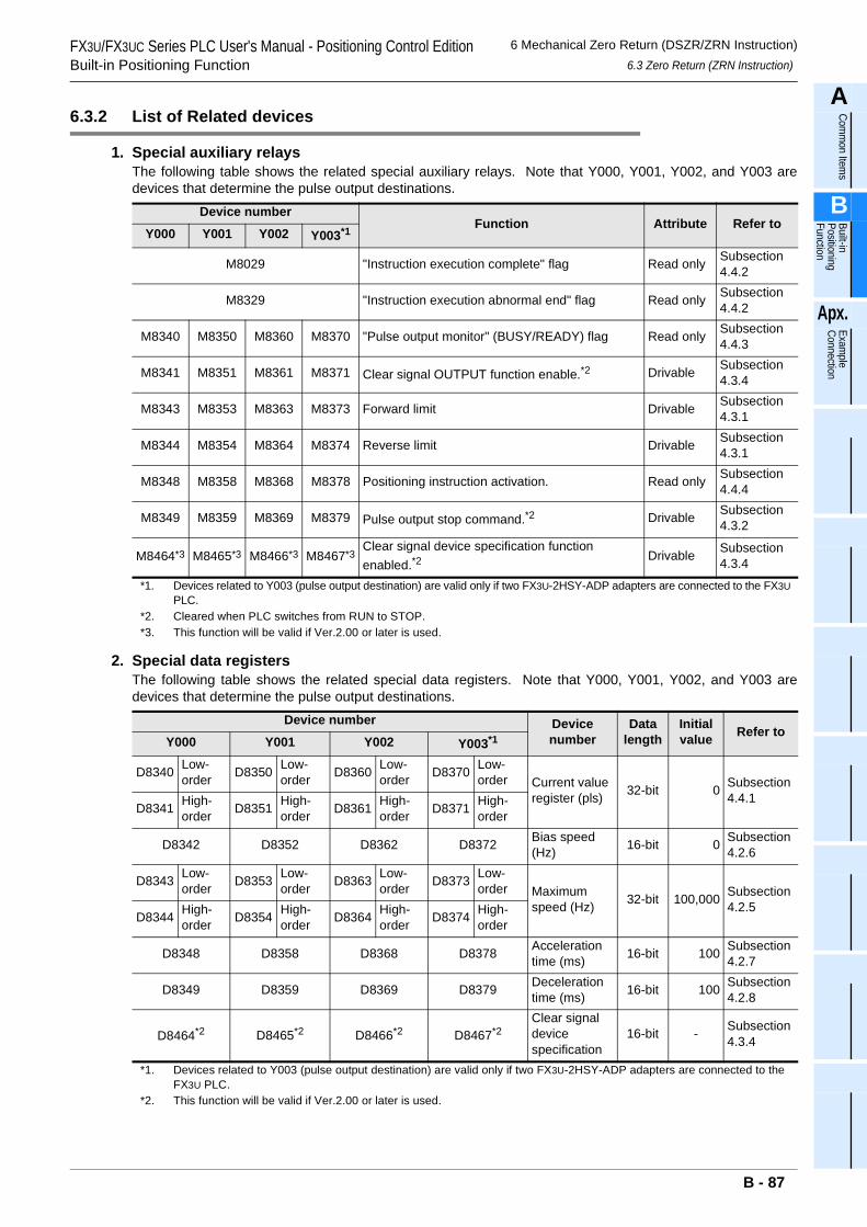
FX3U/FX3UC Series PLC User's Manual - Positioning Control EditionBuilt-in Positioning Function
6 Mechanical Zero Return (DSZR/ZRN Instruction)6.3 Zero Return (ZRN Instruction)
A
Comm
on Items
B
Built-in Positioning Function
Apx.
Example
Connection
6.3.2 List of Related devices
1. Special auxiliary relaysThe following table shows the related special auxiliary relays. Note that Y000, Y001, Y002, and Y003 aredevices that determine the pulse output destinations.
*1. Devices related to Y003 (pulse output destination) are valid only if two FX3U-2HSY-ADP adapters are connected to the FX3U PLC.
*2. Cleared when PLC switches from RUN to STOP.*3. This function will be valid if Ver.2.00 or later is used.
2. Special data registersThe following table shows the related special data registers. Note that Y000, Y001, Y002, and Y003 aredevices that determine the pulse output destinations.
*1. Devices related to Y003 (pulse output destination) are valid only if two FX3U-2HSY-ADP adapters are connected to the FX3U PLC.
*2. This function will be valid if Ver.2.00 or later is used.
Device numberFunction Attribute Refer to
Y000 Y001 Y002 Y003*1
M8029 "Instruction execution complete" flag Read only Subsection 4.4.2
M8329 "Instruction execution abnormal end" flag Read only Subsection 4.4.2
M8340 M8350 M8360 M8370 "Pulse output monitor" (BUSY/READY) flag Read only Subsection 4.4.3
M8341 M8351 M8361 M8371 Clear signal OUTPUT function enable.*2 Drivable Subsection 4.3.4
M8343 M8353 M8363 M8373 Forward limit Drivable Subsection 4.3.1
M8344 M8354 M8364 M8374 Reverse limit Drivable Subsection 4.3.1
M8348 M8358 M8368 M8378 Positioning instruction activation. Read only Subsection 4.4.4
M8349 M8359 M8369 M8379 Pulse output stop command.*2 Drivable Subsection 4.3.2
M8464*3 M8465*3 M8466*3 M8467*3Clear signal device specification function enabled.*2
Drivable Subsection 4.3.4
Device number Device number
Data length
Initial value Refer to
Y000 Y001 Y002 Y003*1
D8340 Low-order D8350 Low-
order D8360 Low-order D8370 Low-
order Current value register (pls) 32-bit 0 Subsection
4.4.1D8341 High-
order D8351 High-order D8361 High-
order D8371 High-order
D8342 D8352 D8362 D8372 Bias speed (Hz) 16-bit 0 Subsection
4.2.6
D8343 Low-order D8353 Low-
order D8363 Low-order D8373 Low-
order Maximum speed (Hz) 32-bit 100,000 Subsection
4.2.5D8344 High-
order D8354 High-order D8364 High-
order D8374 High-order
D8348 D8358 D8368 D8378 Acceleration time (ms) 16-bit 100 Subsection
4.2.7
D8349 D8359 D8369 D8379 Deceleration time (ms) 16-bit 100 Subsection
4.2.8
D8464*2 D8465*2 D8466*2 D8467*2Clear signal device specification
16-bit - Subsection 4.3.4
B - 87
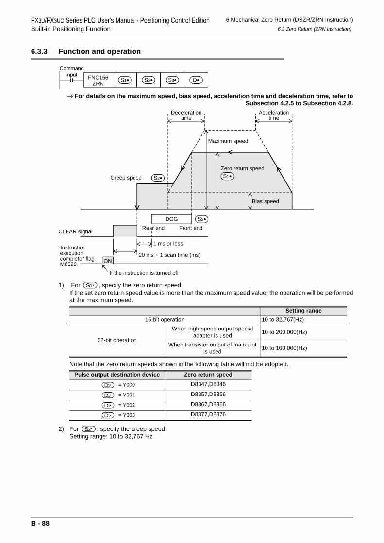
FX3U/FX3UC Series PLC User's Manual - Positioning Control EditionBuilt-in Positioning Function
6 Mechanical Zero Return (DSZR/ZRN Instruction)6.3 Zero Return (ZRN Instruction)
6.3.3 Function and operation
→ For details on the maximum speed, bias speed, acceleration time and deceleration time, refer toSubsection 4.2.5 to Subsection 4.2.8.
1) For , specify the zero return speed. If the set zero return speed value is more than the maximum speed value, the operation will be performedat the maximum speed.
Note that the zero return speeds shown in the following table will not be adopted.
2) For , specify the creep speed.Setting range: 10 to 32,767 Hz
Setting range16-bit operation 10 to 32,767(Hz)
32-bit operation
When high-speed output special adapter is used 10 to 200,000(Hz)
When transistor output of main unit is used 10 to 100,000(Hz)
Pulse output destination device Zero return speed
= Y000 D8347,D8346
= Y001 D8357,D8356
= Y002 D8367,D8366
= Y003 D8377,D8376
Commandinput FNC156
ZRNS1• S2• S3• D•
Maximum speed
Zero return speed
Decelerationtime
Bias speed
Accelerationtime
DOG
Creep speed
CLEAR signalFront endRear end
1 ms or less
20 ms + 1 scan time (ms)
S3•
S2•
ON
"Instruction execution complete" flag M8029
If the instruction is turned off
S1•
S1
D1
D1
D1
D1
S2
B - 88
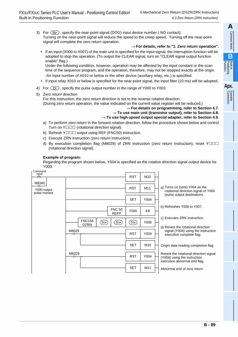
FX3U/FX3UC Series PLC User's Manual - Positioning Control EditionBuilt-in Positioning Function
6 Mechanical Zero Return (DSZR/ZRN Instruction)6.3 Zero Return (ZRN Instruction)
A
Comm
on Items
B
Built-in Positioning Function
Apx.
Example
Connection
3) For , specify the near-point signal (DOG) input device number ( NO contact).Turning on the near-point signal will reduce the speed to the creep speed. Turning off the near-point signal will complete the zero return operation.
→ For details, refer to "1. Zero return operation".• If an input (X000 to X007) of the main unit is specified for the input signal, the interruption function will be
adopted to stop the operation. (To output the CLEAR signal, turn on "CLEAR signal output function enable" flag.)Under the following condition, however, operation may be affected by the input constant or the scan time of the sequence program, and the operation, therefore, may not be stopped exactly at the origin.-An input number of X010 or below or the other device (auxiliary relay, etc.) is specified.
• If input relay X010 or below is specified for the near-point signal, the input filter (10 ms) will be adopted.
4) For , specify the pulse output number in the range of Y000 to Y003.5) Zero return direction
For this instruction, the zero return direction is set to the reverse rotation direction.(During zero return operation, the value indicated on the current value register will be reduced.)
→ For details on programming, refer to Section 4.7.→ To use main unit (transistor output), refer to Section 4.8.
→ To use high-speed output special adapter, refer to Section 4.9.a) To perform zero return in the forward rotation direction, follow the procedure shown below and control
Turn on Y (rotational direction signal).b) Refresh Y output using REF (FNC50) instruction.c) Execute ZRN instruction (zero return instruction).d) By execution completion flag (M8029) of ZRN instruction (zero return instruction), reset Y
(rotational direction signal).
Example of program:Regarding the program shown below, Y004 is specified as the rotation direction signal output device for Y000.
S3
D
Commandinput
Turns on (sets) Y004 as therotational direction signal of Y000(pulse output destination).
M8340
Y000 outputpulse monitor
K8Y000
Y000
Y004RST
Refreshes Y000 to Y007.
Executes ZRN instruction.
Resets the rotational directionsignal (Y004) using the instructionexecution complete flag.
Y004SET
FNC 50REFP
FNC156DZRN
S1• S2• S3•
M8029
M11RST
M10RST
M10SET Origin data reading completion flag
Resets the rotational direction signal(Y004) using the instructionexecution abnormal end flag.
Y004RSTM8329
M11SET Abnormal end of zero return
a)
b)
c)
d)
B - 89
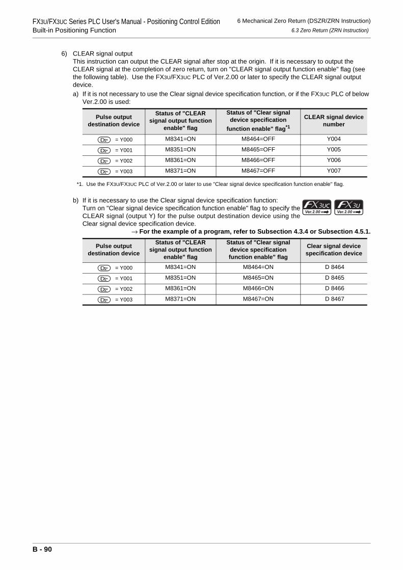
FX3U/FX3UC Series PLC User's Manual - Positioning Control EditionBuilt-in Positioning Function
6 Mechanical Zero Return (DSZR/ZRN Instruction)6.3 Zero Return (ZRN Instruction)
6) CLEAR signal outputThis instruction can output the CLEAR signal after stop at the origin. If it is necessary to output the CLEAR signal at the completion of zero return, turn on "CLEAR signal output function enable" flag (see the following table). Use the FX3U/FX3UC PLC of Ver.2.00 or later to specify the CLEAR signal output device.a) If it is not necessary to use the Clear signal device specification function, or if the FX3UC PLC of below
Ver.2.00 is used:
*1. Use the FX3U/FX3UC PLC of Ver.2.00 or later to use "Clear signal device specification function enable" flag.
b) If it is necessary to use the Clear signal device specification function:Turn on "Clear signal device specification function enable" flag to specify theCLEAR signal (output Y) for the pulse output destination device using theClear signal device specification device.
→ For the example of a program, refer to Subsection 4.3.4 or Subsection 4.5.1.
Pulse output destination device
Status of "CLEAR signal output function
enable" flag
Status of "Clear signal device specification
function enable" flag*1
CLEAR signal device number
= Y000 M8341=ON M8464=OFF Y004
= Y001 M8351=ON M8465=OFF Y005
= Y002 M8361=ON M8466=OFF Y006
= Y003 M8371=ON M8467=OFF Y007
Pulse output destination device
Status of "CLEAR signal output function
enable" flag
Status of "Clear signal device specification function enable" flag
Clear signal device specification device
= Y000 M8341=ON M8464=ON D 8464
= Y001 M8351=ON M8465=ON D 8465
= Y002 M8361=ON M8466=ON D 8466
= Y003 M8371=ON M8467=ON D 8467
D1
D1
D1
D1
D1
D1
D1
D1
B - 90
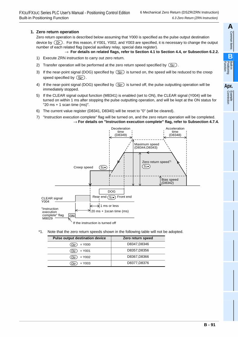
FX3U/FX3UC Series PLC User's Manual - Positioning Control EditionBuilt-in Positioning Function
6 Mechanical Zero Return (DSZR/ZRN Instruction)6.3 Zero Return (ZRN Instruction)
A
Comm
on Items
B
Built-in Positioning Function
Apx.
Example
Connection
1. Zero return operationZero return operation is described below assuming that Y000 is specified as the pulse output destination device by . For this reason, if Y001, Y002, and Y003 are specified, it is necessary to change the output number of each related flag (special auxiliary relay, special data register).
→ For details on related flags, refer to Section 4.1 to Section 4.4, or Subsection 6.2.2.1) Execute ZRN instruction to carry out zero return.
2) Transfer operation will be performed at the zero return speed specified by .
3) If the near-point signal (DOG) specified by is turned on, the speed will be reduced to the creep speed specified by .
4) If the near-point signal (DOG) specified by is turned off, the pulse outputting operation will be immediately stopped.
5) If the CLEAR signal output function (M8341) is enabled (set to ON), the CLEAR signal (Y004) will be turned on within 1 ms after stopping the pulse outputting operation, and will be kept at the ON status for "20 ms + 1 scan time (ms)".
6) The current value register (D8341, D8340) will be reset to "0" (will be cleared).7) "Instruction execution complete" flag will be turned on, and the zero return operation will be completed.
→ For details on "Instruction execution complete" flag, refer to Subsection 4.7.4.
*1. Note that the zero return speeds shown in the following table will not be adopted.Pulse output destination device Zero return speed
= Y000 D8347,D8346
= Y001 D8357,D8356
= Y002 D8367,D8366
= Y003 D8377,D8376
D
S1
S3
S2
S3
Maximum speed(D8344,D8343)
Zero return speed*1
Decelerationtime
(D8349)
Bias speed(D8342)
Accelerationtime
(D8348)
DOG
Creep speed
CLEAR signalY004
Front endRear end
1 ms or less
20 ms + 1scan time (ms)
S2•
ON
"Instruction execution complete" flag M8029
If the instruction is turned off
S1•
S2•
D1
D1
D1
D1
B - 91
FX3U/FX3UC Series PLC User's Manual - Positioning Control EditionBuilt-in Positioning Function
6 Mechanical Zero Return (DSZR/ZRN Instruction)6.3 Zero Return (ZRN Instruction)
6.3.4 Important Points
→ For the important points of programming, refer to Section 4.7.
• If an input (X000 to X007) of the main unit is specified for the near-point input signal specified by , the interruption function will be adopted to stop the operation.Under the following condition, however, operation may be affected by the input constant or the scan time of the sequence program.- An input number of X010 or below or the other device (auxiliary relay, etc.) is specified.
If input relay X010 or below is specified for the near-point signal, the input filter (10 ms) will be adopted.
• If an input (X000 to X007) is specified for the near-point signal , the input cannot be used for the following items:- High-speed counter- Input interruption- Pulse catch- SPD instruction- DSZR instruction- DVIT instruction
• Properly set the DOG so that the near-point signal (DOG) can be kept at the ON status until the speed is reduced to the creep speed.This instruction will start speed reduction to the creep speed at the front end of the DOG, and will stop the operation at the rear end of the DOG. After that, the current value register will be cleared (reset to "0").If the speed is not reduced to the creep speed before detecting the rear end of the DOG, the operation may not be stopped at the specified position.
• The creep speed should be low enough.The zero return instruction will not reduce the speed before stop. For this reason, if the creep speed is not low enough, the operation may not be stopped at the specified position due to inertia.
• The DOG search function is not adopted for this instruction. For this reason, start the zero return operation on the front side of the near-point signal. If it is necessary to use the DOG search function, use the DSZR instruction.
• The zero-phase signal of servo motor cannot be used. For this reason, if fine adjustment of the origin position is needed, adjust the position of the near-point signal (DOG).
• If the instruction activation contact is turned off during zero return operation, the speed will be reduced and then the operation will be stopped. In this case, "Instruction execution complete" flag (M8029) will not be turned on.
• While "pulse output monitor" (BUSY/READY) flag is on, the positioning instruction (including PLSR and PLSY) that uses the same output cannot be executed.After the instruction activation contact is turned off, if "pulse output monitor" (BUSY/READY) flag is still on, do not execute the positioning instruction (including PLSR and PLSY instructions) having the same output number.
• In the following case, "Instruction execution abnormal end" flag (M8329) will be turned on, and execution of the instruction will be completed.
→ For details on "Instruction execution abnormal end" flag, refer to Subsection 4.7.4.- If the forward limit flag or the reverse limit flag is turned on, the speed will be reduced and then the
operation will be stopped. In this case, "Instruction execution abnormal end" flag (M8329) will be turned on when completing execution of the instruction.
- If the limit flag (forward limit flag or reverse limit flag) on the opposite side of the operation direction is turned on, the speed will be reduced and then the operation will be stopped.In this case, "Instruction execution abnormal end" flag (M8329) will be turned on when completing execution of the instruction.
S3
S3
B - 92
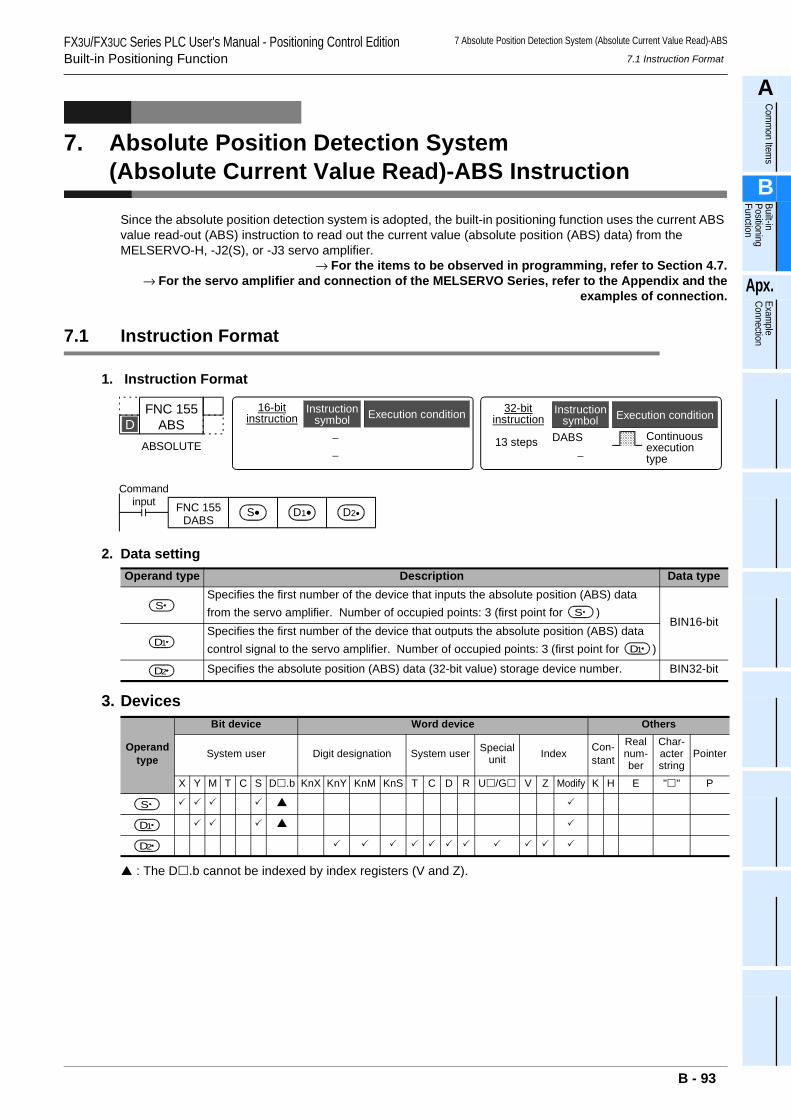
7 Absolute Position Detection System (Absolute Current Value Read)-ABS
7.1 Instruction FormatFX3U/FX3UC Series PLC User's Manual - Positioning Control EditionBuilt-in Positioning Function
A
Comm
on Items
B
Built-in Positioning Function
Apx.
Example
Connection
7. Absolute Position Detection System (Absolute Current Value Read)-ABS Instruction
Since the absolute position detection system is adopted, the built-in positioning function uses the current ABS value read-out (ABS) instruction to read out the current value (absolute position (ABS) data) from the MELSERVO-H, -J2(S), or -J3 servo amplifier.
→ For the items to be observed in programming, refer to Section 4.7.→ For the servo amplifier and connection of the MELSERVO Series, refer to the Appendix and the
examples of connection.
7.1 Instruction Format
1. Instruction Format
2. Data setting
3. Devices
: The D .b cannot be indexed by index registers (V and Z).
Operand type Description Data typeSpecifies the first number of the device that inputs the absolute position (ABS) data from the servo amplifier. Number of occupied points: 3 (first point for )
BIN16-bitSpecifies the first number of the device that outputs the absolute position (ABS) data control signal to the servo amplifier. Number of occupied points: 3 (first point for )
Specifies the absolute position (ABS) data (32-bit value) storage device number. BIN32-bit
Operand type
Bit device Word device Others
System user Digit designation System user Special unit Index Con-
stant
Real num-ber
Char-acter string
Pointer
X Y M T C S D .b KnX KnY KnM KnS T C D R U /G V Z Modify K H E " " P
FNC 155ABS
ABSOLUTE
DDABS
−
32-bitinstruction
Instructionsymbol Execution condition
13 steps Continuousexecutiontype
−−
16-bitinstruction
Instructionsymbol Execution condition
Commandinput FNC 155
DABSS• D1• D2•
S S
D1 D1
D2
S
D1
D2
B - 93
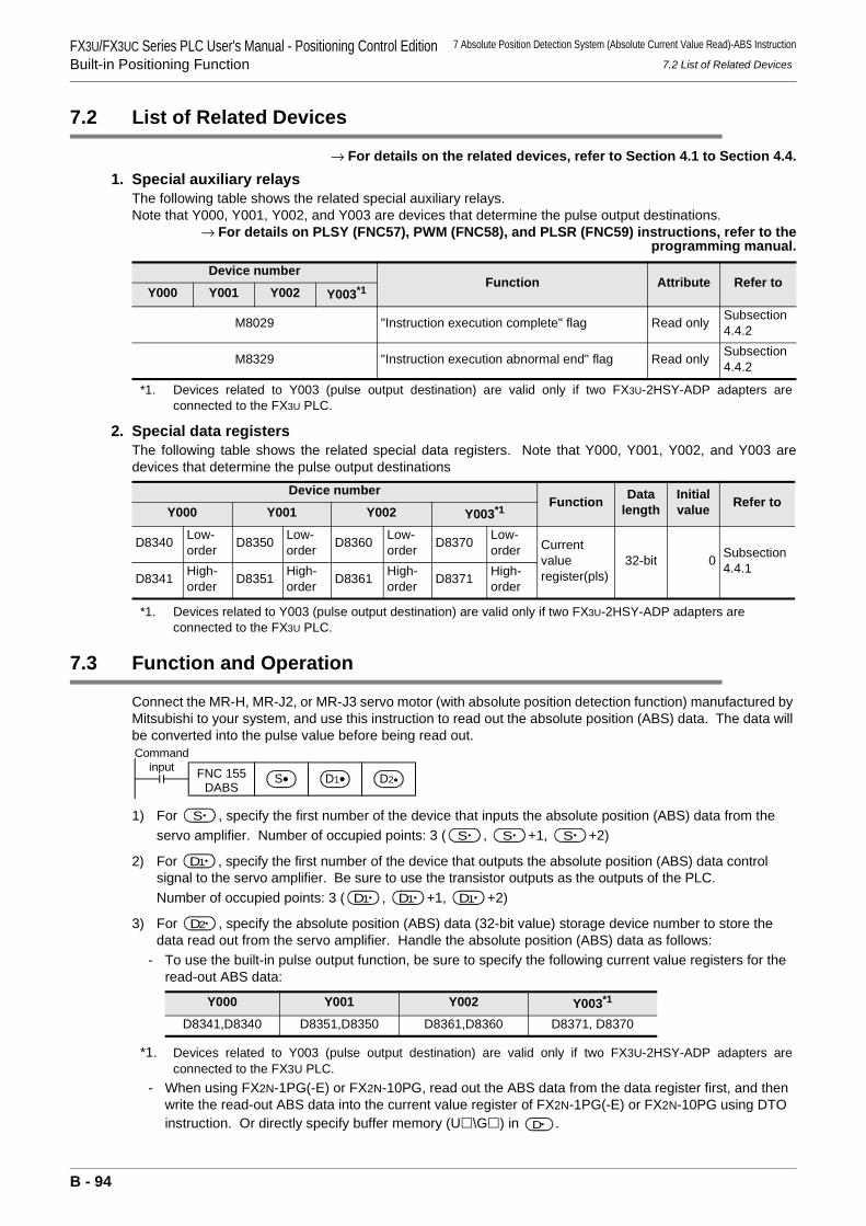
FX3U/FX3UC Series PLC User's Manual - Positioning Control EditionBuilt-in Positioning Function
7 Absolute Position Detection System (Absolute Current Value Read)-ABS Instruction
7.2 List of Related Devices
7.2 List of Related Devices
→ For details on the related devices, refer to Section 4.1 to Section 4.4.1. Special auxiliary relays
The following table shows the related special auxiliary relays. Note that Y000, Y001, Y002, and Y003 are devices that determine the pulse output destinations.
→ For details on PLSY (FNC57), PWM (FNC58), and PLSR (FNC59) instructions, refer to theprogramming manual.
*1. Devices related to Y003 (pulse output destination) are valid only if two FX3U-2HSY-ADP adapters areconnected to the FX3U PLC.
2. Special data registersThe following table shows the related special data registers. Note that Y000, Y001, Y002, and Y003 aredevices that determine the pulse output destinations
*1. Devices related to Y003 (pulse output destination) are valid only if two FX3U-2HSY-ADP adapters are connected to the FX3U PLC.
7.3 Function and Operation
Connect the MR-H, MR-J2, or MR-J3 servo motor (with absolute position detection function) manufactured by Mitsubishi to your system, and use this instruction to read out the absolute position (ABS) data. The data will be converted into the pulse value before being read out.
1) For , specify the first number of the device that inputs the absolute position (ABS) data from the servo amplifier. Number of occupied points: 3 ( , +1, +2)
2) For , specify the first number of the device that outputs the absolute position (ABS) data control signal to the servo amplifier. Be sure to use the transistor outputs as the outputs of the PLC.Number of occupied points: 3 ( , +1, +2)
3) For , specify the absolute position (ABS) data (32-bit value) storage device number to store the data read out from the servo amplifier. Handle the absolute position (ABS) data as follows:
- To use the built-in pulse output function, be sure to specify the following current value registers for the read-out ABS data:
*1. Devices related to Y003 (pulse output destination) are valid only if two FX3U-2HSY-ADP adapters areconnected to the FX3U PLC.
- When using FX2N-1PG(-E) or FX2N-10PG, read out the ABS data from the data register first, and then write the read-out ABS data into the current value register of FX2N-1PG(-E) or FX2N-10PG using DTO instruction. Or directly specify buffer memory (U \G ) in .
Device numberFunction Attribute Refer to
Y000 Y001 Y002 Y003*1
M8029 "Instruction execution complete" flag Read only Subsection 4.4.2
M8329 "Instruction execution abnormal end" flag Read only Subsection 4.4.2
Device numberFunction Data
lengthInitial value Refer to
Y000 Y001 Y002 Y003*1
D8340 Low-order D8350 Low-
order D8360 Low-order D8370 Low-
order Currentvalueregister(pls)
32-bit 0 Subsection 4.4.1
D8341 High-order D8351 High-
order D8361 High-order D8371 High-
order
Y000 Y001 Y002 Y003*1
D8341,D8340 D8351,D8350 D8361,D8360 D8371, D8370
Commandinput FNC 155
DABSS• D1• D2•
S S S S
D1
D1 D1 D1
D2
D
B - 94
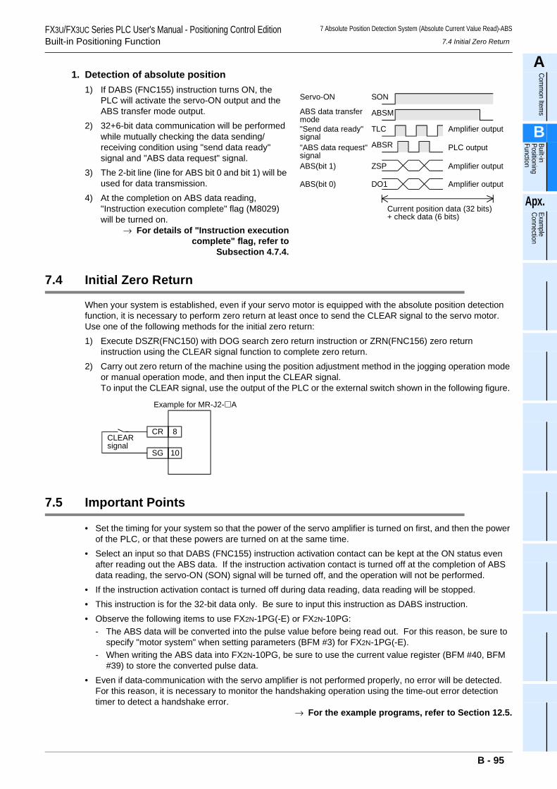
7 Absolute Position Detection System (Absolute Current Value Read)-ABS
7.4 Initial Zero ReturnFX3U/FX3UC Series PLC User's Manual - Positioning Control EditionBuilt-in Positioning Function
A
Comm
on Items
B
Built-in Positioning Function
Apx.
Example
Connection
1. Detection of absolute position1) If DABS (FNC155) instruction turns ON, the
PLC will activate the servo-ON output and the ABS transfer mode output.
2) 32+6-bit data communication will be performed while mutually checking the data sending/receiving condition using "send data ready" signal and "ABS data request" signal.
3) The 2-bit line (line for ABS bit 0 and bit 1) will be used for data transmission.
4) At the completion on ABS data reading, "Instruction execution complete" flag (M8029) will be turned on.
→ For details of "Instruction executioncomplete" flag, refer to
Subsection 4.7.4.
7.4 Initial Zero Return
When your system is established, even if your servo motor is equipped with the absolute position detection function, it is necessary to perform zero return at least once to send the CLEAR signal to the servo motor.Use one of the following methods for the initial zero return:1) Execute DSZR(FNC150) with DOG search zero return instruction or ZRN(FNC156) zero return
instruction using the CLEAR signal function to complete zero return.2) Carry out zero return of the machine using the position adjustment method in the jogging operation mode
or manual operation mode, and then input the CLEAR signal.To input the CLEAR signal, use the output of the PLC or the external switch shown in the following figure.
7.5 Important Points
• Set the timing for your system so that the power of the servo amplifier is turned on first, and then the power of the PLC, or that these powers are turned on at the same time.
• Select an input so that DABS (FNC155) instruction activation contact can be kept at the ON status even after reading out the ABS data. If the instruction activation contact is turned off at the completion of ABS data reading, the servo-ON (SON) signal will be turned off, and the operation will not be performed.
• If the instruction activation contact is turned off during data reading, data reading will be stopped.• This instruction is for the 32-bit data only. Be sure to input this instruction as DABS instruction.• Observe the following items to use FX2N-1PG(-E) or FX2N-10PG:
- The ABS data will be converted into the pulse value before being read out. For this reason, be sure to specify "motor system" when setting parameters (BFM #3) for FX2N-1PG(-E).
- When writing the ABS data into FX2N-10PG, be sure to use the current value register (BFM #40, BFM #39) to store the converted pulse data.
• Even if data-communication with the servo amplifier is not performed properly, no error will be detected. For this reason, it is necessary to monitor the handshaking operation using the time-out error detection timer to detect a handshake error.
→ For the example programs, refer to Section 12.5.
Servo-ON SON
ABS data transfermode
ABSM
TLC
ABSR
ZSP
DO1
"Send data ready"signal"ABS data request"signalABS(bit 1)
ABS(bit 0)
Current position data (32 bits)+ check data (6 bits)
Amplifier output
PLC output
Amplifier output
Amplifier output
CR 8
SG 10
Example for MR-J2- A
CLEARsignal
B - 95
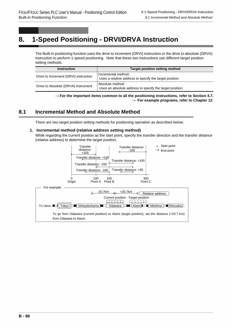
FX3U/FX3UC Series PLC User's Manual - Positioning Control EditionBuilt-in Positioning Function
8 1-Speed Positioning - DRVI/DRVA Instruction8.1 Incremental Method and Absolute Method
8. 1-Speed Positioning - DRVI/DRVA Instruction
The Built-in positioning function uses the drive to increment (DRVI) instruction or the drive to absolute (DRVA) instruction to perform 1-speed positioning. Note that these two instructions use different target position setting methods.
→ For the important items common to all the positioning instructions, refer to Section 4.7.→ For example programs, refer to Chapter 12.
8.1 Incremental Method and Absolute Method
There are two target position setting methods for positioning operation as described below:
1. Incremental method (relative address setting method)While regarding the current position as the start point, specify the transfer direction and the transfer distance (relative address) to determine the target position.
Instruction Target position setting method
Drive to Increment (DRVI) instruction Incremental method: Uses a relative address to specify the target position.
Drive to Absolute (DRVA) instrument Absolute method: Uses an absolute address to specify the target position.
150Point B
Transfer distance: -100
300Point C
100Point A
0Origin
Start pointEnd point
To Ueno
Current position Target position
To go from Odawara (current position) to Atami (target position), set the distance (+20.7 km)from Odawara to Atami.
Transfer distance: +50
Transfer distance: -150Transfer distance: +100
Transfer distance: +100
Transferdistance:
+100
Transfer distance:-100
+20.7km-20.7km Relative address
For example:
ShizuokaMishimaAtamiOdawaraShinyokohamaTokyo
B - 96
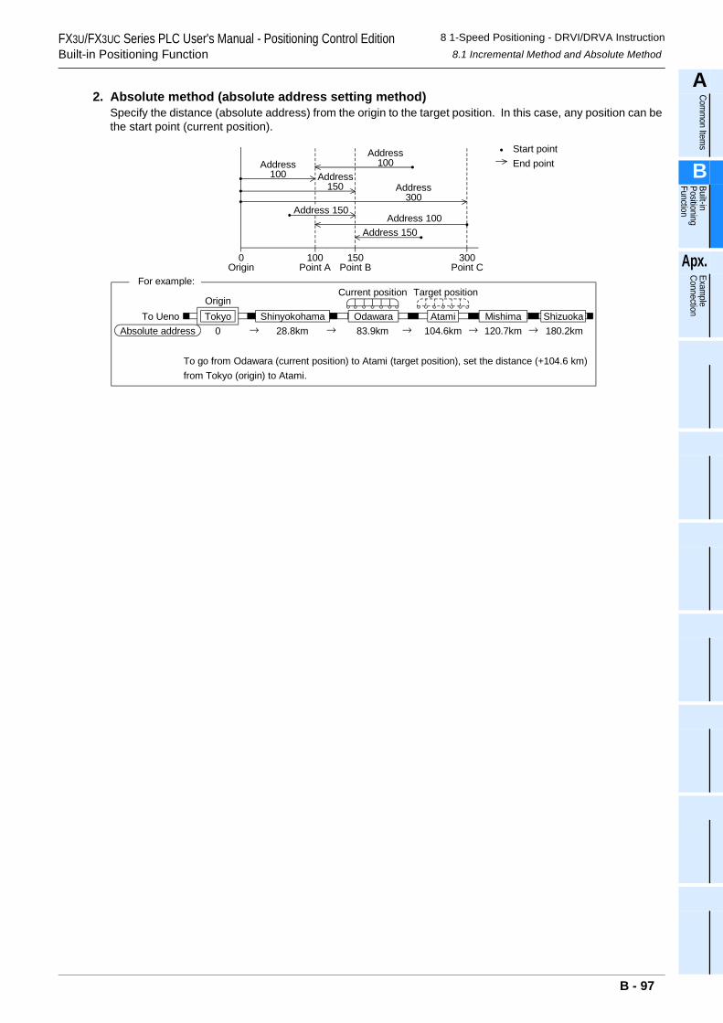
FX3U/FX3UC Series PLC User's Manual - Positioning Control EditionBuilt-in Positioning Function
8 1-Speed Positioning - DRVI/DRVA Instruction8.1 Incremental Method and Absolute Method
A
Comm
on Items
B
Built-in Positioning Function
Apx.
Example
Connection
2. Absolute method (absolute address setting method)Specify the distance (absolute address) from the origin to the target position. In this case, any position can be the start point (current position).
Address100
Address150
Address100
Address 150
Address 150Address 100
Address300
300Point C
150Point B
100Point A
0Origin
Start pointEnd point
ShizuokaMishimaAtamiOdawaraShinyokohamaTokyoOrigin
To UenoAbsolute address 0 28.8km
Current position
83.9km→ 104.6km 120.7km 180.2km
Target position
To go from Odawara (current position) to Atami (target position), set the distance (+104.6 km)from Tokyo (origin) to Atami.
For example:
→ → → →
B - 97
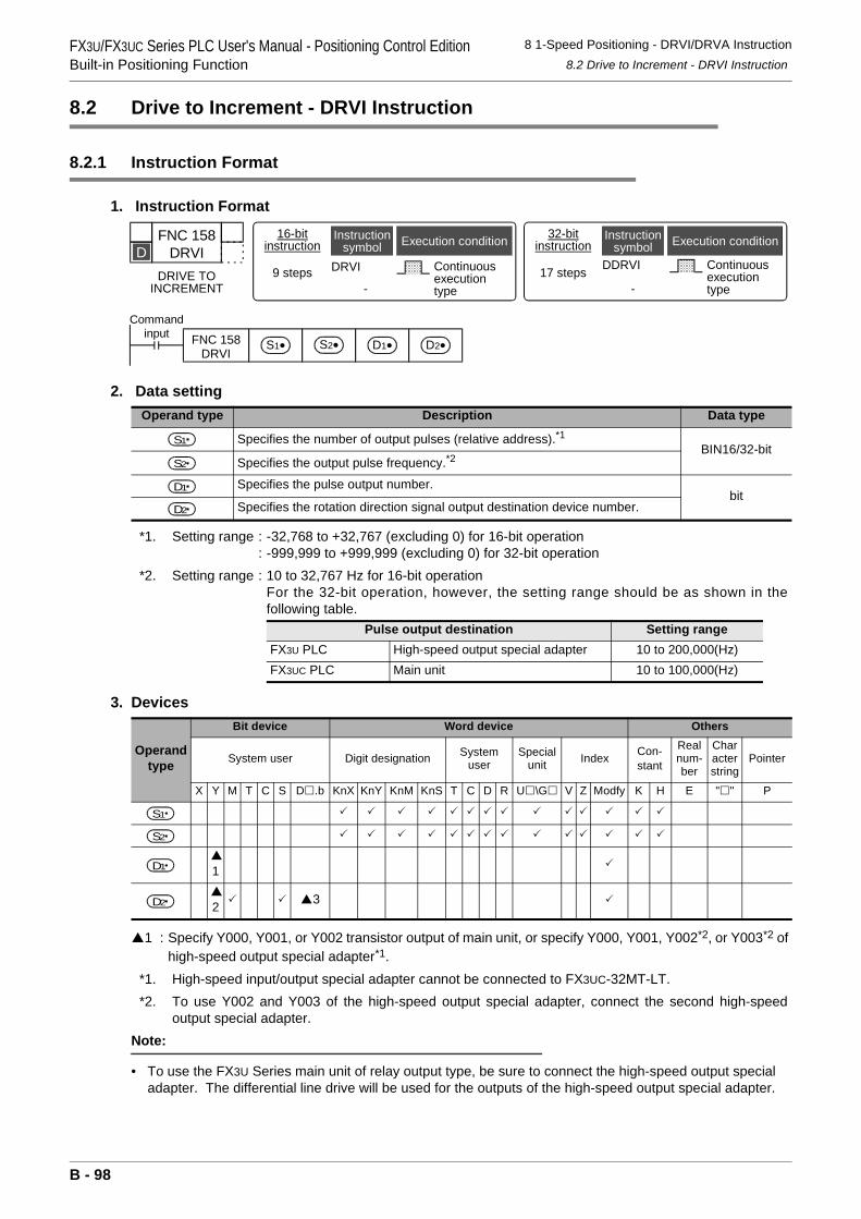
FX3U/FX3UC Series PLC User's Manual - Positioning Control EditionBuilt-in Positioning Function
8 1-Speed Positioning - DRVI/DRVA Instruction8.2 Drive to Increment - DRVI Instruction
8.2 Drive to Increment - DRVI Instruction
8.2.1 Instruction Format
1. Instruction Format
2. Data setting
*1. Setting range : -32,768 to +32,767 (excluding 0) for 16-bit operation: -999,999 to +999,999 (excluding 0) for 32-bit operation
*2. Setting range : 10 to 32,767 Hz for 16-bit operationFor the 32-bit operation, however, the setting range should be as shown in thefollowing table.
3. Devices
1 : Specify Y000, Y001, or Y002 transistor output of main unit, or specify Y000, Y001, Y002*2, or Y003*2 of high-speed output special adapter*1.
*1. High-speed input/output special adapter cannot be connected to FX3UC-32MT-LT.*2. To use Y002 and Y003 of the high-speed output special adapter, connect the second high-speed
output special adapter.Note:
• To use the FX3U Series main unit of relay output type, be sure to connect the high-speed output special adapter. The differential line drive will be used for the outputs of the high-speed output special adapter.
Operand type Description Data type
Specifies the number of output pulses (relative address).*1BIN16/32-bit
Specifies the output pulse frequency.*2
Specifies the pulse output number.bit
Specifies the rotation direction signal output destination device number.
Pulse output destination Setting rangeFX3U PLC High-speed output special adapter 10 to 200,000(Hz)FX3UC PLC Main unit 10 to 100,000(Hz)
Operand type
Bit device Word device Others
System user Digit designation System user
Special unit Index Con-
stant
Real num-ber
Character string
Pointer
X Y M T C S D .b KnX KnY KnM KnS T C D R U \G V Z Modfy K H E " " P
1
2 3
FNC 158DRVI
DRIVE TOINCREMENT
D16-bit
instruction
9 steps DRVI
-
Continuousexecutiontype
Instructionsymbol Execution condition 32-bit
instructionInstruction
symbol Execution condition
DDRVI
-
Continuousexecutiontype
17 steps
Commandinput FNC 158
DRVIS1• S2• D1• D2•
S1
S2
D1
D2
S1
S2
D1
D2
B - 98
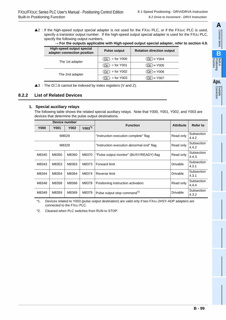
FX3U/FX3UC Series PLC User's Manual - Positioning Control EditionBuilt-in Positioning Function
8 1-Speed Positioning - DRVI/DRVA Instruction8.2 Drive to Increment - DRVI Instruction
A
Comm
on Items
B
Built-in Positioning Function
Apx.
Example
Connection
2 : If the high-speed output special adapter is not used for the FX3U PLC, or if the FX3UC PLC is used,specify a transistor output number. If the high-speed output special adapter is used for the FX3U PLC,specify the following output numbers.
→ For the outputs applicable with High-speed output special adapter, refer to section 4.9.
3 : The D .b cannot be indexed by index registers (V and Z).
8.2.2 List of Related Devices
1. Special auxiliary relaysThe following table shows the related special auxiliary relays. Note that Y000, Y001, Y002, and Y003 are devices that determine the pulse output destinations.
High-speed output special adapter connection position Pulse output Rotation direction output
The 1st adapter= for Y000 = Y004
= for Y001 = Y005
The 2nd adapter= for Y002 = Y006
= for Y003 = Y007
Device numberFunction Attribute Refer to
Y000 Y001 Y002 Y003*1
M8029 "Instruction execution complete" flag Read only Subsection 4.4.2
M8329 "Instruction execution abnormal end" flag Read only Subsection 4.4.2
M8340 M8350 M8360 M8370 "Pulse output monitor" (BUSY/READY) flag Read only Subsection 4.4.3
M8343 M8353 M8363 M8373 Forward limit Drivable Subsection 4.3.1
M8344 M8354 M8364 M8374 Reverse limit Drivable Subsection 4.3.1
M8348 M8358 M8368 M8378 Positioning instruction activation. Read only Subsection 4.4.4
M8349 M8359 M8369 M8379 Pulse output stop command*2 Drivable Subsection 4.3.2
*1. Devices related to Y003 (pulse output destination) are valid only if two FX3U-2HSY-ADP adapters are connected to the FX3U PLC.
*2. Cleaned when PLC switches from RUN to STOP.
D1 D2
D1 D2
D1 D2
D1 D2
B - 99
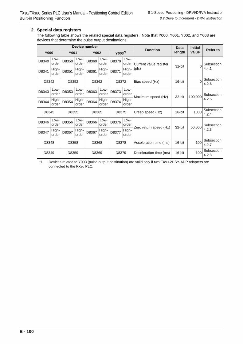
FX3U/FX3UC Series PLC User's Manual - Positioning Control EditionBuilt-in Positioning Function
8 1-Speed Positioning - DRVI/DRVA Instruction8.2 Drive to Increment - DRVI Instruction
2. Special data registersThe following table shows the related special data registers. Note that Y000, Y001, Y002, and Y003 are devices that determine the pulse output destinations.
*1. Devices related to Y003 (pulse output destination) are valid only if two FX3U-2HSY-ADP adapters are connected to the FX3U PLC.
Device numberFunction Data
lengthInitial value Refer to
Y000 Y001 Y002 Y003*1
D8340 Low-order D8350 Low-
order D8360 Low-order D8370 Low-
order Current value register (pls) 32-bit 0 Subsection
4.4.1D8341 High-
order D8351 High-order D8361 High-
order D8371 High-order
D8342 D8352 D8362 D8372 Bias speed (Hz) 16-bit 0 Subsection4.2.6
D8343 Low-order D8353 Low-
order D8363 Low-order D8373 Low-
orderMaximum speed (Hz) 32-bit 100,000 Subsection
4.2.5D8344 High-
order D8354 High-order D8364 High-
order D8374 High-order
D8345 D8355 D8365 D8375 Creep speed (Hz) 16-bit 1000 Subsection4.2.4
D8346 Low-order D8356 Low-
order D8366 Low-order D8376 Low-
orderZero return speed (Hz) 32-bit 50,000 Subsection
4.2.3D8347 High-
order D8357 High-order D8367 High-
order D8377 High-order
D8348 D8358 D8368 D8378 Acceleration time (ms) 16-bit 100 Subsection4.2.7
D8349 D8359 D8369 D8379 Deceleration time (ms) 16-bit 100 Subsection4.2.8
B - 100
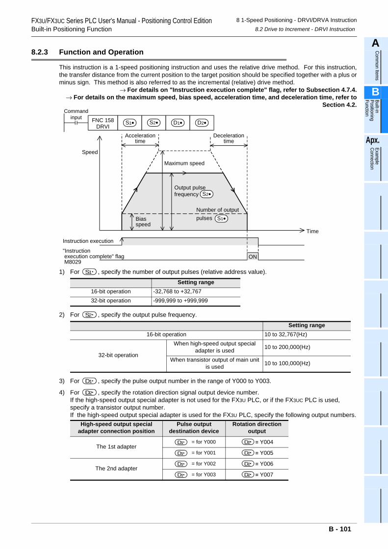
FX3U/FX3UC Series PLC User's Manual - Positioning Control EditionBuilt-in Positioning Function
8 1-Speed Positioning - DRVI/DRVA Instruction8.2 Drive to Increment - DRVI Instruction
A
Comm
on Items
B
Built-in Positioning Function
Apx.
Example
Connection
8.2.3 Function and Operation
This instruction is a 1-speed positioning instruction and uses the relative drive method. For this instruction,the transfer distance from the current position to the target position should be specified together with a plus orminus sign. This method is also referred to as the incremental (relative) drive method.
→ For details on "Instruction execution complete" flag, refer to Subsection 4.7.4.→ For details on the maximum speed, bias speed, acceleration time, and deceleration time, refer to
Section 4.2.
1) For , specify the number of output pulses (relative address value).
2) For , specify the output pulse frequency.
3) For , specify the pulse output number in the range of Y000 to Y003.
4) For , specify the rotation direction signal output device number.If the high-speed output special adapter is not used for the FX3U PLC, or if the FX3UC PLC is used, specify a transistor output number.If the high-speed output special adapter is used for the FX3U PLC, specify the following output numbers.
Setting range16-bit operation -32,768 to +32,76732-bit operation -999,999 to +999,999
Setting range16-bit operation 10 to 32,767(Hz)
32-bit operation
When high-speed output special adapter is used 10 to 200,000(Hz)
When transistor output of main unit is used 10 to 100,000(Hz)
High-speed output special adapter connection position
Pulse output destination device
Rotation direction output
The 1st adapter = for Y000 = Y004
= for Y001 = Y005
The 2nd adapter = for Y002 = Y006
= for Y003 = Y007
Commandinput FNC 158
DRVIS1• S2• D1• D2•
Output pulsefrequency
Time
Speed
Instruction execution
Number of outputpulses S1•
S2•
"Instruction execution complete" flag M8029
ON
Maximum speed
Decelerationtime
Biasspeed
Accelerationtime
S1
S2
D1
D2
D1 D2
D1 D2
D1 D2
D1 D2
B - 101
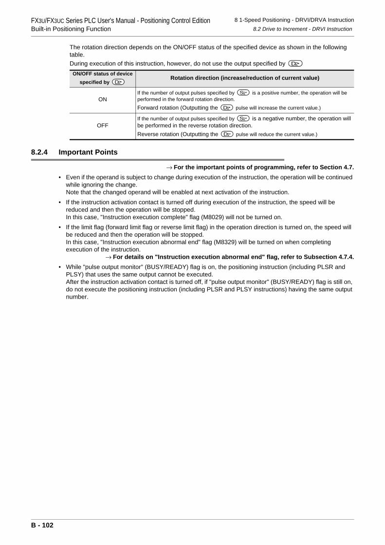
FX3U/FX3UC Series PLC User's Manual - Positioning Control EditionBuilt-in Positioning Function
8 1-Speed Positioning - DRVI/DRVA Instruction8.2 Drive to Increment - DRVI Instruction
The rotation direction depends on the ON/OFF status of the specified device as shown in the following table.During execution of this instruction, however, do not use the output specified by
8.2.4 Important Points
→ For the important points of programming, refer to Section 4.7.• Even if the operand is subject to change during execution of the instruction, the operation will be continued
while ignoring the change.Note that the changed operand will be enabled at next activation of the instruction.
• If the instruction activation contact is turned off during execution of the instruction, the speed will be reduced and then the operation will be stopped.In this case, "Instruction execution complete" flag (M8029) will not be turned on.
• If the limit flag (forward limit flag or reverse limit flag) in the operation direction is turned on, the speed will be reduced and then the operation will be stopped.In this case, "Instruction execution abnormal end" flag (M8329) will be turned on when completing execution of the instruction.
→ For details on "Instruction execution abnormal end" flag, refer to Subsection 4.7.4.• While "pulse output monitor" (BUSY/READY) flag is on, the positioning instruction (including PLSR and
PLSY) that uses the same output cannot be executed.After the instruction activation contact is turned off, if "pulse output monitor" (BUSY/READY) flag is still on, do not execute the positioning instruction (including PLSR and PLSY instructions) having the same output number.
ON/OFF status of device specified by
Rotation direction (increase/reduction of current value)
ONIf the number of output pulses specified by is a positive number, the operation will be performed in the forward rotation direction.
Forward rotation (Outputting the pulse will increase the current value.)
OFFIf the number of output pulses specified by is a negative number, the operation will be performed in the reverse rotation direction.Reverse rotation (Outputting the pulse will reduce the current value.)
D2
D2
S1
D1
S1
D1
B - 102
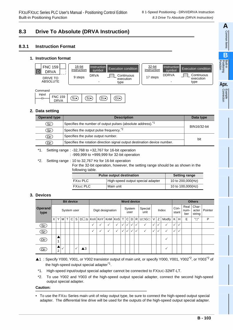
FX3U/FX3UC Series PLC User's Manual - Positioning Control EditionBuilt-in Positioning Function
8 1-Speed Positioning - DRVI/DRVA Instruction8.3 Drive To Absolute (DRVA Instruction)
A
Comm
on Items
B
Built-in Positioning Function
Apx.
Example
Connection
8.3 Drive To Absolute (DRVA Instruction)
8.3.1 Instruction Format
1. Instruction format
2. Data setting
*1. Setting range : -32,768 to +32,767 for 16-bit operation: -999,999 to +999,999 for 32-bit operation
*2. Setting range : 10 to 32,767 Hz for 16-bit operationFor the 32-bit operation, however, the setting range should be as shown in the following table.
3. Devices
1 : Specify Y000, Y001, or Y002 transistor output of main unit, or specify Y000, Y001, Y002*2, or Y003*2 of the high-speed output special adapter*1.
*1. High-speed input/output special adapter cannot be connected to FX3UC-32MT-LT.*2. To use Y002 and Y003 of the high-speed output special adapter, connect the second high-speed
output special adapter.Caution:
• To use the FX3U Series main unit of relay output type, be sure to connect the high-speed output special adapter. The differential line drive will be used for the outputs of the high-speed output special adapter.
Operand type Description Data type
Specifies the number of output pulses (absolute address).*1BIN16/32-bit
Specifies the output pulse frequency.*2
Specifies the pulse output number.bit
Specifies the rotation direction signal output destination device number.
Pulse output destination Setting rangeFX3U PLC High-speed output special adapter 10 to 200,000(Hz)FX3UC PLC Main unit 10 to 100,000(Hz)
Operand type
Bit device Word device Others
System user Digit designation System user
Special unit Index Con-
stant
Real num-ber
Char-acter string
Pointer
X Y M T C S D .b KnX KnY KnM KnS T C D R U \G V Z Modfy K H E " " P
1
23
FNC 159DRVA
DRIVE TOABSOLUTE
D16-bit
instruction
9 steps DRVA
-
Continuousexecutiontype
Instructionsymbol Execution condition 32-bit
instructionInstruction
symbol Execution condition
DDRVA
-
Continuousexecutiontype
17 steps
Commandinput
FNC 159DRVA
S1• S2• D1• D2•
S1
S2
D1
D2
S1
S2
D1
D2
B - 103
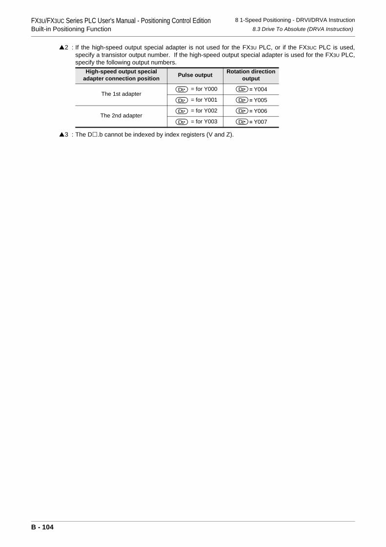
FX3U/FX3UC Series PLC User's Manual - Positioning Control EditionBuilt-in Positioning Function
8 1-Speed Positioning - DRVI/DRVA Instruction8.3 Drive To Absolute (DRVA Instruction)
2 : If the high-speed output special adapter is not used for the FX3U PLC, or if the FX3UC PLC is used,specify a transistor output number. If the high-speed output special adapter is used for the FX3U PLC,specify the following output numbers.
3 : The D .b cannot be indexed by index registers (V and Z).
High-speed output special adapter connection position Pulse output Rotation direction
output
The 1st adapter= for Y000 = Y004
= for Y001 = Y005
The 2nd adapter= for Y002 = Y006
= for Y003 = Y007
D1 D2
D1 D2
D1 D2
D1 D2
B - 104
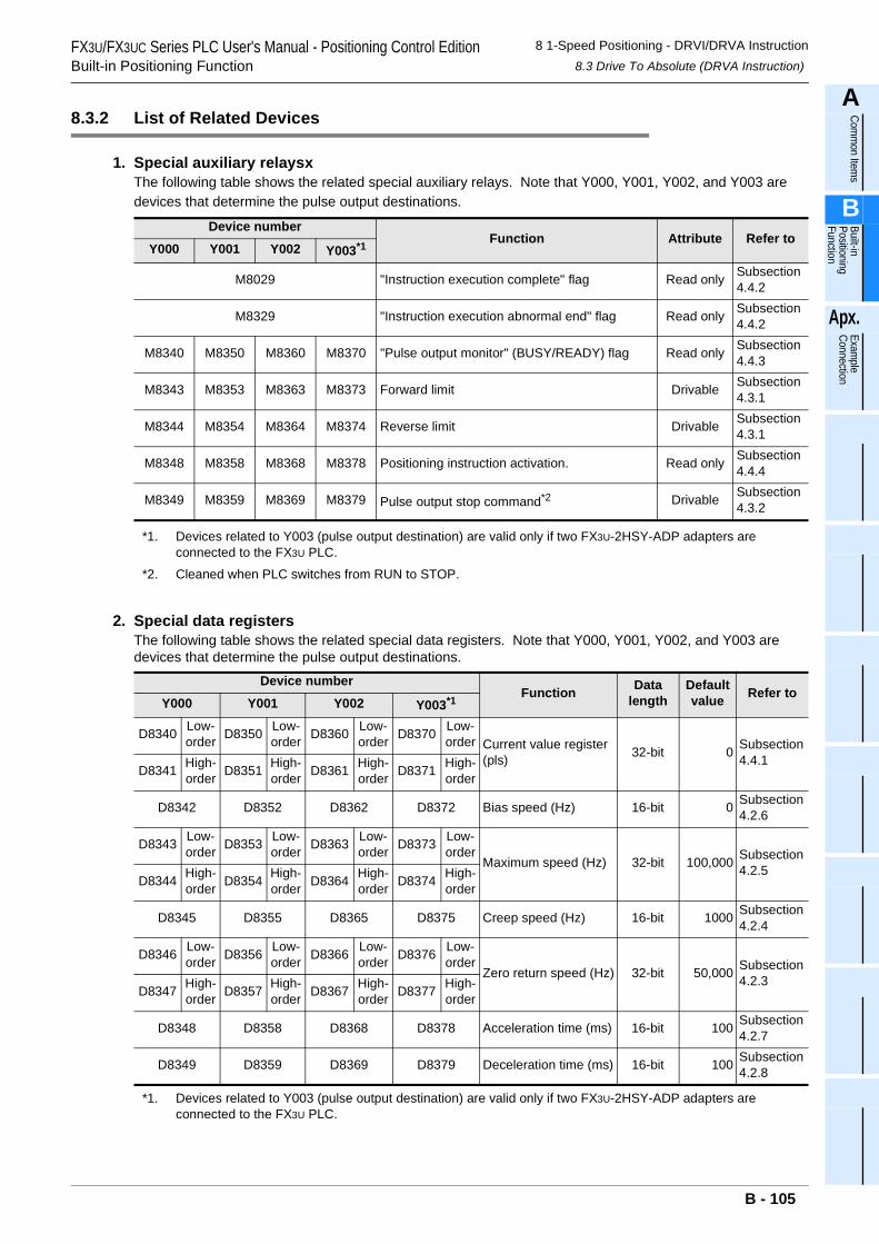
FX3U/FX3UC Series PLC User's Manual - Positioning Control EditionBuilt-in Positioning Function
8 1-Speed Positioning - DRVI/DRVA Instruction8.3 Drive To Absolute (DRVA Instruction)
A
Comm
on Items
B
Built-in Positioning Function
Apx.
Example
Connection
8.3.2 List of Related Devices
1. Special auxiliary relaysxThe following table shows the related special auxiliary relays. Note that Y000, Y001, Y002, and Y003 are devices that determine the pulse output destinations.
*1. Devices related to Y003 (pulse output destination) are valid only if two FX3U-2HSY-ADP adapters are connected to the FX3U PLC.
*2. Cleaned when PLC switches from RUN to STOP.
2. Special data registersThe following table shows the related special data registers. Note that Y000, Y001, Y002, and Y003 are devices that determine the pulse output destinations.
*1. Devices related to Y003 (pulse output destination) are valid only if two FX3U-2HSY-ADP adapters are connected to the FX3U PLC.
Device numberFunction Attribute Refer to
Y000 Y001 Y002 Y003*1
M8029 "Instruction execution complete" flag Read only Subsection4.4.2
M8329 "Instruction execution abnormal end" flag Read only Subsection4.4.2
M8340 M8350 M8360 M8370 "Pulse output monitor" (BUSY/READY) flag Read only Subsection4.4.3
M8343 M8353 M8363 M8373 Forward limit Drivable Subsection4.3.1
M8344 M8354 M8364 M8374 Reverse limit Drivable Subsection4.3.1
M8348 M8358 M8368 M8378 Positioning instruction activation. Read only Subsection4.4.4
M8349 M8359 M8369 M8379 Pulse output stop command*2 Drivable Subsection4.3.2
Device numberFunction Data
lengthDefaultvalue Refer to
Y000 Y001 Y002 Y003*1
D8340 Low-order D8350 Low-
order D8360 Low-order D8370 Low-
order Current value register (pls) 32-bit 0 Subsection
4.4.1D8341 High-
order D8351 High-order D8361 High-
order D8371 High-order
D8342 D8352 D8362 D8372 Bias speed (Hz) 16-bit 0 Subsection4.2.6
D8343 Low-order D8353 Low-
order D8363 Low-order D8373 Low-
orderMaximum speed (Hz) 32-bit 100,000 Subsection
4.2.5D8344 High-
order D8354 High-order D8364 High-
order D8374 High-order
D8345 D8355 D8365 D8375 Creep speed (Hz) 16-bit 1000 Subsection4.2.4
D8346 Low-order D8356 Low-
order D8366 Low-order D8376 Low-
orderZero return speed (Hz) 32-bit 50,000 Subsection
4.2.3D8347 High-
order D8357 High-order D8367 High-
order D8377 High-order
D8348 D8358 D8368 D8378 Acceleration time (ms) 16-bit 100 Subsection4.2.7
D8349 D8359 D8369 D8379 Deceleration time (ms) 16-bit 100 Subsection4.2.8
B - 105
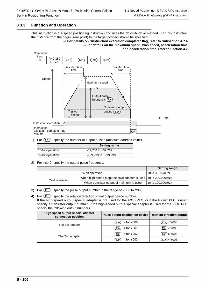
FX3U/FX3UC Series PLC User's Manual - Positioning Control EditionBuilt-in Positioning Function
8 1-Speed Positioning - DRVI/DRVA Instruction8.3 Drive To Absolute (DRVA Instruction)
8.3.3 Function and Operation
This instruction is a 1-speed positioning instruction and uses the absolute drive method. For this instruction,the distance from the origin (zero point) to the target position should be specified.
→ For details on "Instruction execution complete" flag, refer to Subsection 4.7.4.→ For details on the maximum speed, bias speed, acceleration time,
and deceleration time, refer to Section 4.2.
1) For , specify the number of output pulses (absolute address value).
2) For , specify the output pulse frequency.
3) For , specify the pulse output number in the range of Y000 to Y003.
4) For , specify the rotation direction signal output device number.If the high-speed output special adapter is not used for the FX3U PLC, or if the FX3UC PLC is used,specify a transistor output number. If the high-speed output special adapter is used for the FX3U PLC,specify the following output numbers.
Setting range16-bit operation -32,768 to +32,76732-bit operation -999,999 to +999,999
Setting range16-bit operation 10 to 32,767(Hz)
32-bit operationWhen high-speed output special adapter is used 10 to 200,000(Hz)
When transistor output of main unit is used 10 to 100,000(Hz)
High-speed output special adapter connection position Pulse output destination device Rotation direction output
The 1st adapter = for Y000 = Y004
= for Y001 = Y005
The 2nd adapter = for Y002 = Y006
= for Y003 = Y007
Speed
Instruction execution
ON
Time
"Instruction execution complete" flag M8029
Maximum speed
Decelerationtime
Biasspeed
Accelerationtime
Output pulsefrequency
Number of outputpulses S1•
S2•
Commandinput
FNC 159DRVA
S1• S2• D1• D2•
S1
S2
D1
D2
D1 D2
D1 D2
D1 D2
D1 D2
B - 106
FX3U/FX3UC Series PLC User's Manual - Positioning Control EditionBuilt-in Positioning Function
8 1-Speed Positioning - DRVI/DRVA Instruction8.3 Drive To Absolute (DRVA Instruction)
A
Comm
on Items
B
Built-in Positioning Function
Apx.
Example
Connection
The rotation direction depends on the ON/OFF status of the specified device as shown in the followingtable.During execution of this instruction, however, do not use the output specified by
8.3.4 Important Points
→ For the important points of programming, refer to Section 4.7.• Even if the operand is subject to change during execution of the instruction, the operation will be continued
while ignoring the change.Note that the changed operand will be enabled at next activation of the instruction.
• If the instruction activation contact is turned off during execution of the instruction, the speed will be reduced and then the operation will be stopped.In this case, "Instruction execution complete" flag (M8029) will not be turned on.
• If the limit flag (forward limit flag or reverse limit flag) in the operation direction is turned on, the speed will be reduced and then the operation will be stopped. In this case, "Instruction execution abnormal end" flag (M8329) will be turned on when completing execution of the instruction.
→ For details on "Instruction execution abnormal end" flag, refer to Subsection 4.7.4.• If "pulse output monitor" (BUSY/READY) flag is on, the positioning instruction (including PLSR and PLSY)
that uses the same output cannot be executed.After the instruction activation contact is turned off, if "pulse output monitor" (BUSY/READY) flag is still on, do not execute the positioning instruction (including PLSR and PLSY instructions) having the same output number.
ON/OFF status of device specified by
Rotation direction (increase/reduction of current value)
ON Forward rotation (Outputting the pulse will increase the current value.)
The rotation direction (normal or reverse rotation) depends on which value is larger; the number of output pulses specified by
(absolute address) or the value indicated on the current value register.
OFF Reverse rotation (Outputting the pulse will reduce the current value.)
D2
D2
D1
S D1
B - 107
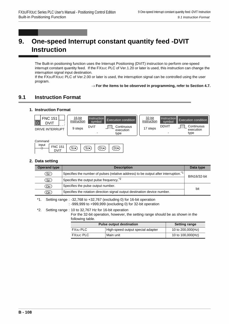
FX3U/FX3UC Series PLC User's Manual - Positioning Control EditionBuilt-in Positioning Function
9 One-speed Interrupt constant quantity feed -DVIT Instruction9.1 Instruction Format
9. One-speed Interrupt constant quantity feed -DVIT Instruction
The Built-in positioning function uses the Interrupt Positioning (DVIT) instruction to perform one-speed interrupt constant quantity feed. If the FX3UC PLC of Ver.1.20 or later is used, this instruction can change the interruption signal input destination.If the FX3U/FX3UC PLC of Ver.2.00 or later is used, the interruption signal can be controlled using the user program.
→ For the items to be observed in programming, refer to Section 4.7.
9.1 Instruction Format
1. Instruction Format
2. Data setting
*1. Setting range : -32,768 to +32,767 (excluding 0) for 16-bit operation: -999,999 to +999,999 (excluding 0) for 32-bit operation
*2. Setting range : 10 to 32,767 Hz for 16-bit operationFor the 32-bit operation, however, the setting range should be as shown in the following table.
Operand type Description Data type
Specifies the number of pulses (relative address) to be output after interruption.*1BIN16/32-bit
Specifies the output pulse frequency.*2
Specifies the pulse output number.bit
Specifies the rotation direction signal output destination device number.
Pulse output destination Setting rangeFX3U PLC High-speed output special adapter 10 to 200,000(Hz)FX3UC PLC Main unit 10 to 100,000(Hz)
FNC 151DVIT
DRIVE INTERRUPT
D16-bit
instruction
9 steps DVIT
-
Continuousexecutiontype
Instructionsymbol Execution condition 32-bit
instructionInstruction
symbol Execution condition
DDVIT
-
Continuousexecutiontype
17 steps
Commandinput FNC 151
DVITS2•S1• D1• D2•
S1
S2
D1
D2
B - 108
FX3U/FX3UC Series PLC User's Manual - Positioning Control EditionBuilt-in Positioning Function
9 One-speed Interrupt constant quantity feed -DVIT Instruction9.1 Instruction Format
A
Comm
on Items
B
Built-in Positioning Function
Apx.
Example
Connection
3. Devices
1 : Specify Y000, Y001, or Y002 transistor output of the main unit, or specify Y000, Y001, Y002*2, or Y003*2 of the high-speed output special adapter*1.
*1. High-speed input/output special adapter cannot be connected to FX3UC-32MT-LT.*2. To use Y002 and Y003 of the high-speed output special adapter, connect the second high-speed
output special adapter.Point:
• To use the FX3U Series main unit of relay output type, be sure to connect high-speed output special adapter. The differential line drive will be used for the outputs of the high-speed output special adapter.2 : If the high-speed output special adapter is not used for the FX3U PLC, or if the FX3UC PLC is used,
specify a transistor output number. If the high-speed output special adapter is used for the FX3U PLC,specify the following output numbers.
→ For the outputs applicable with High-speed output special adapter, refer to section 4.9.
3 : The D .b cannot be indexed by index registers (V and Z).
Operand type
Bit device Word device Others
System user Digit designation System user Special unit Index Con-
stant
Real num-ber
Char-acter string
Pointer
X Y M T C S D .b KnX KnY KnM KnS T C D R U \G V Z Modify K H E " " P
1
2 3
High-speed output special adapter connection position Pulse output Rotation direction output
The 1st adapter= for Y000 = Y004
= for Y001 = Y005
The 2nd adapter= for Y002 = Y006
= for Y003 = Y007
S1
S2
D1
D2
D1 D2
D1 D2
D1 D2
D1 D2
B - 109
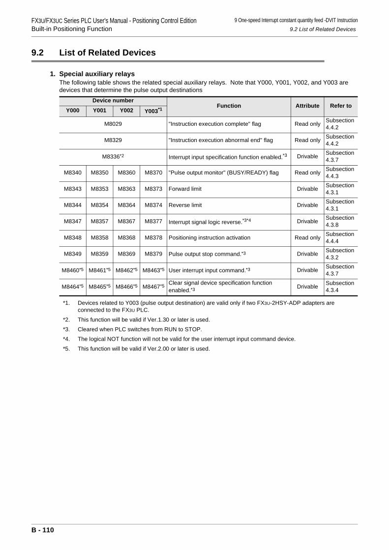
FX3U/FX3UC Series PLC User's Manual - Positioning Control EditionBuilt-in Positioning Function
9 One-speed Interrupt constant quantity feed -DVIT Instruction9.2 List of Related Devices
9.2 List of Related Devices
1. Special auxiliary relaysThe following table shows the related special auxiliary relays. Note that Y000, Y001, Y002, and Y003 are devices that determine the pulse output destinations
*1. Devices related to Y003 (pulse output destination) are valid only if two FX3U-2HSY-ADP adapters are connected to the FX3U PLC.
*2. This function will be valid if Ver.1.30 or later is used.
*3. Cleared when PLC switches from RUN to STOP.
*4. The logical NOT function will not be valid for the user interrupt input command device.
*5. This function will be valid if Ver.2.00 or later is used.
Device numberFunction Attribute Refer to
Y000 Y001 Y002 Y003*1
M8029 "Instruction execution complete" flag Read only Subsection 4.4.2
M8329 "Instruction execution abnormal end" flag Read only Subsection 4.4.2
M8336*2 Interrupt input specification function enabled.*3 Drivable Subsection 4.3.7
M8340 M8350 M8360 M8370 "Pulse output monitor" (BUSY/READY) flag Read only Subsection 4.4.3
M8343 M8353 M8363 M8373 Forward limit Drivable Subsection 4.3.1
M8344 M8354 M8364 M8374 Reverse limit Drivable Subsection 4.3.1
M8347 M8357 M8367 M8377 Interrupt signal logic reverse.*3*4 Drivable Subsection 4.3.8
M8348 M8358 M8368 M8378 Positioning instruction activation Read only Subsection 4.4.4
M8349 M8359 M8369 M8379 Pulse output stop command.*3 Drivable Subsection 4.3.2
M8460*5 M8461*5 M8462*5 M8463*5 User interrupt input command.*3 Drivable Subsection 4.3.7
M8464*5 M8465*5 M8466*5 M8467*5 Clear signal device specification function enabled.*3 Drivable Subsection
4.3.4
B - 110
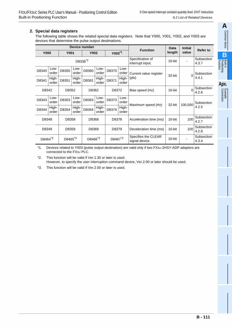
FX3U/FX3UC Series PLC User's Manual - Positioning Control EditionBuilt-in Positioning Function
9 One-speed Interrupt constant quantity feed -DVIT Instruction9.2 List of Related Devices
A
Comm
on Items
B
Built-in Positioning Function
Apx.
Example
Connection
2. Special data registersThe following table shows the related special data registers. Note that Y000, Y001, Y002, and Y003 are devices that determine the pulse output destinations.
*1. Devices related to Y003 (pulse output destination) are valid only if two FX3U-2HSY-ADP adapters are connected to the FX3U PLC.
*2. This function will be valid if Ver.1.30 or later is used.However, to specify the user interruption command device, Ver.2.00 or later should be used.
*3. This function will be valid if Ver.2.00 or later is used.
Device numberFunction Data
lengthInitial value Refer to
Y000 Y001 Y002 Y003*1
D8336*2 Specification of interrupt input. 16-bit - Subsection
4.3.7
D8340 Low-order D8350 Low-
order D8360 Low-order D8370 Low-
order Current value register (pls) 32-bit 0 Subsection
4.4.1D8341 High-
order D8351 High-order D8361 High-
order D8371 High-order
D8342 D8352 D8362 D8372 Bias speed (Hz) 16-bit 0 Subsection4.2.6
D8343 Low-order D8353 Low-
order D8363 Low-order D8373 Low-
orderMaximum speed (Hz) 32-bit 100,000 Subsection
4.2.5D8344 High-
order D8354 High-order D8364 High-
order D8374 High-order
D8348 D8358 D8368 D8378 Acceleration time (ms) 16-bit 100 Subsection4.2.7
D8349 D8359 D8369 D8379 Deceleration time (ms) 16-bit 100 Subsection4.2.8
D8464*3 D8465*3 D8466*3 D8467*3 Specifies the CLEAR signal device. 16-bit - Subsection
4.3.4
B - 111
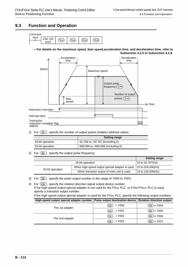
FX3U/FX3UC Series PLC User's Manual - Positioning Control EditionBuilt-in Positioning Function
9 One-speed Interrupt constant quantity feed -DVIT Instruction9.3 Function and Operation
9.3 Function and Operation
→ For details on the maximum speed, bias speed,acceleration time, and deceleration time, refer toSubsection 4.2.5 to Subsection 4.2.8.
1) For , specify the number of output pulses (relative address value).
2) For , specify the output pulse frequency.
3) For , specify the pulse output number in the range of Y000 to Y003.
4) For , specify the rotation direction signal output device number.If the high-speed output special adapter is not used for the FX3U PLC, or if the FX3UC PLC is used, specify a transistor output number.If the high-speed output special adapter is used for the FX3U PLC, specify the following output numbers.
Setting range16-bit operation -32,768 to +32,767 (excluding 0)32-bit operation -999,999 to +999,999 (excluding 0)
Setting range16-bit operation 10 to 32,767(Hz)
32-bit operationWhen high-speed output special adapter is used 10 to 200,000(Hz)
When transistor output of main unit is used 10 to 100,000(Hz)
High-speed output special adapter number Pulse output destination device Rotation direction output
The 1st adapter = Y000 = Y004
= Y001 = Y005
The 2nd adapter = Y002 = Y006
= Y003 = Y007
Commandinput FNC 151
DVITS2•S1• D1• D2•
ON
Instruction execution
Interrupt input
Time
Speed
"Instruction execution complete" flag M8029
Maximum speed
Decelerationtime
Biasspeed
Accelerationtime
Output pulsefrequency
Number of outputpulses S1•
S2•
S1
S2
D1
D2
D1 D2
D1 D2
D1 D2
D1 D2
B - 112
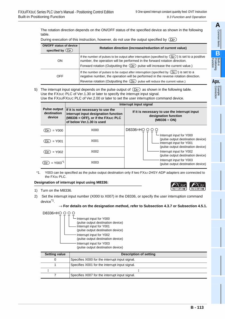
FX3U/FX3UC Series PLC User's Manual - Positioning Control EditionBuilt-in Positioning Function
9 One-speed Interrupt constant quantity feed -DVIT Instruction9.3 Function and Operation
A
Comm
on Items
B
Built-in Positioning Function
Apx.
Example
Connection
The rotation direction depends on the ON/OFF status of the specified device as shown in the following table.During execution of this instruction, however, do not use the output specified by
5) The interrupt input signal depends on the pulse output of as shown in the following table.Use the FX3UC PLC of Ver.1.30 or later to specify the interrupt input signal.Use the FX3U/FX3UC PLC of Ver.2.00 or later to set the user interruption command device.
*1. Y003 can be specified as the pulse output destination only if two FX3U-2HSY-ADP adapters are connected to the FX3U PLC.
Designation of interrupt input using M8336:
1) Turn on the M8336.2) Set the interrupt input number (X000 to X007) in the D8336, or specify the user interruption command
device*1.→ For details on the designation method, refer to Subsection 4.3.7 or Subsection 4.5.1.
ON/OFF status of device specified by
Rotation direction (increase/reduction of current value)
ONIf the number of pulses to be output after interruption (specified by ) is set to a positive number, the operation will be performed in the forward rotation direction.Forward rotation (Outputting the pulse will increase the current value.)
OFFIf the number of pulses to be output after interruption (specified by ) is set to a negative number, the operation will be performed in the reverse rotation direction.Reverse rotation (Outputting the pulse will reduce the current value.)
Pulse output destination
device
Interrupt input signalIf it is not necessary to use the interrupt input designation function (M8336 = OFF), or if the FX3UC PLC of below Ver.1.30 is used
If it is necessary to use the interrupt input designation function
(M8336 = ON)
= Y000 X000
= Y001 X001
= Y002 X002
= Y003*1 X003
Setting value Description of setting0 Specifies X000 for the interrupt input signal.1 Specifies X001 for the interrupt input signal.
... ...
7 Specifies X007 for the interrupt input signal.
D2
D2
S1
D1
S1
D1
D1
D1 D8336=H Interrupt input for Y000(pulse output destination device)Interrupt input for Y001(pulse output destination device)Interrupt input for Y002(pulse output destination device)Interrupt input for Y003(pulse output destination device)
D1
D1
D1
D8336=H Interrupt input for Y000(pulse output destination device)Interrupt input for Y001(pulse output destination device)Interrupt input for Y002(pulse output destination device)Interrupt input for Y003(pulse output destination device)
B - 113
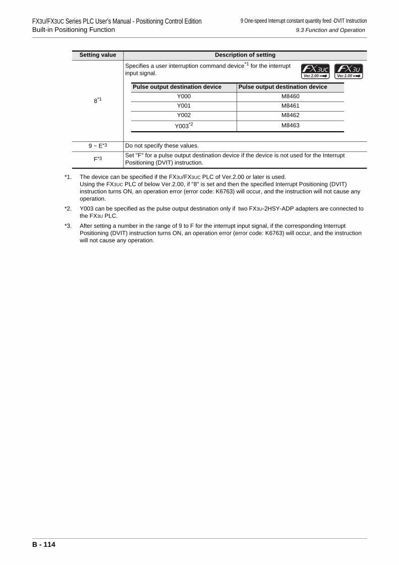
FX3U/FX3UC Series PLC User's Manual - Positioning Control EditionBuilt-in Positioning Function
9 One-speed Interrupt constant quantity feed -DVIT Instruction9.3 Function and Operation
*1. The device can be specified if the FX3U/FX3UC PLC of Ver.2.00 or later is used.Using the FX3UC PLC of below Ver.2.00, if "8" is set and then the specified Interrupt Positioning (DVIT) instruction turns ON, an operation error (error code: K6763) will occur, and the instruction will not cause any operation.
*2. Y003 can be specified as the pulse output destination only if two FX3U-2HSY-ADP adapters are connected to the FX3U PLC.
*3. After setting a number in the range of 9 to F for the interrupt input signal, if the corresponding Interrupt Positioning (DVIT) instruction turns ON, an operation error (error code: K6763) will occur, and the instruction will not cause any operation.
8*1
Specifies a user interruption command device*1 for the interrupt input signal.
9 ~ E*3 Do not specify these values.
F*3 Set "F" for a pulse output destination device if the device is not used for the Interrupt Positioning (DVIT) instruction.
Setting value Description of setting
Pulse output destination device Pulse output destination deviceY000 M8460Y001 M8461Y002 M8462
Y003*2 M8463
B - 114
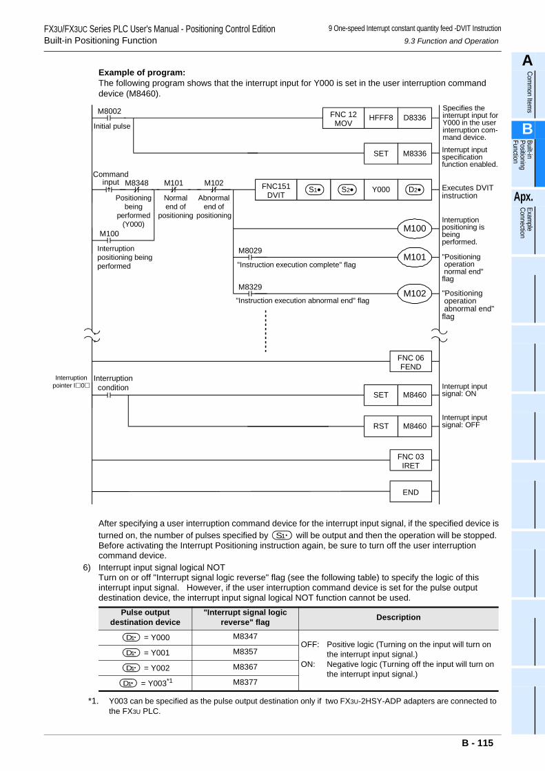
FX3U/FX3UC Series PLC User's Manual - Positioning Control EditionBuilt-in Positioning Function
9 One-speed Interrupt constant quantity feed -DVIT Instruction9.3 Function and Operation
A
Comm
on Items
B
Built-in Positioning Function
Apx.
Example
Connection
Example of program:The following program shows that the interrupt input for Y000 is set in the user interruption command device (M8460).
After specifying a user interruption command device for the interrupt input signal, if the specified device is turned on, the number of pulses specified by will be output and then the operation will be stopped. Before activating the Interrupt Positioning instruction again, be sure to turn off the user interruption command device.
6) Interrupt input signal logical NOTTurn on or off "Interrupt signal logic reverse" flag (see the following table) to specify the logic of this interrupt input signal. However, if the user interruption command device is set for the pulse output destination device, the interrupt input signal logical NOT function cannot be used.
*1. Y003 can be specified as the pulse output destination only if two FX3U-2HSY-ADP adapters are connected to the FX3U PLC.
Pulse output destination device
"Interrupt signal logic reverse" flag Description
= Y000 M8347OFF: Positive logic (Turning on the input will turn on
the interrupt input signal.)ON: Negative logic (Turning off the input will turn on
the interrupt input signal.)
= Y001 M8357
= Y002 M8367
= Y003*1 M8377
M8002 Specifies theinterrupt input forY000 in the userinterruption com-mand device.
M8336SET
Y000
Interrupt inputspecificationfunction enabled.
Executes DVITinstruction
D8336HFFF8FNC 12MOV
FNC151DVIT
S1• S2•
M8029
M8329
Initial pulse
Commandinput
D2•M8348
Positioningbeing
performed(Y000)
M101
Normalend of
positioning
M102
Abnormalend of
positioning
M100 M100
M101
M102
Interruptionpositioning isbeingperformed.
"Positioning operation normal end"flag
"Positioning operation abnormal end"flag
"Instruction execution complete" flag
"Instruction execution abnormal end" flag
Interruptionpositioning beingperformed
M8460
Interruptioncondition Interrupt input
signal: ON
FNC 06FEND
Interruptionpointer I 0
SET
M8460RSTInterrupt inputsignal: OFF
FNC 03IRET
END
S1
D1
D1
D1
D1
B - 115
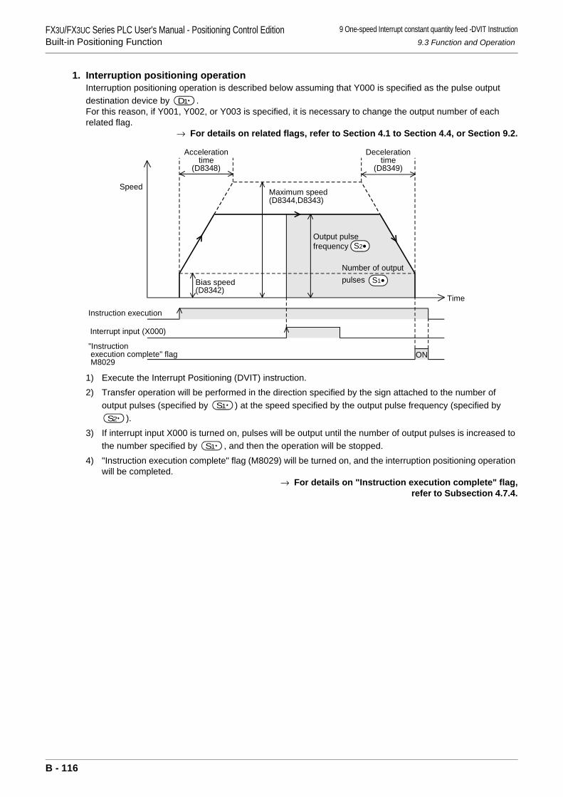
FX3U/FX3UC Series PLC User's Manual - Positioning Control EditionBuilt-in Positioning Function
9 One-speed Interrupt constant quantity feed -DVIT Instruction9.3 Function and Operation
1. Interruption positioning operationInterruption positioning operation is described below assuming that Y000 is specified as the pulse output destination device by .For this reason, if Y001, Y002, or Y003 is specified, it is necessary to change the output number of each related flag.
→ For details on related flags, refer to Section 4.1 to Section 4.4, or Section 9.2.
1) Execute the Interrupt Positioning (DVIT) instruction.2) Transfer operation will be performed in the direction specified by the sign attached to the number of
output pulses (specified by ) at the speed specified by the output pulse frequency (specified by ).
3) If interrupt input X000 is turned on, pulses will be output until the number of output pulses is increased to the number specified by , and then the operation will be stopped.
4) "Instruction execution complete" flag (M8029) will be turned on, and the interruption positioning operation will be completed.
→ For details on "Instruction execution complete" flag, refer to Subsection 4.7.4.
D1
Decelerationtime
(D8349)
Bias speed(D8342)
ON
Speed
Accelerationtime
(D8348)
Instruction execution
Interrupt input (X000)
"Instruction execution complete" flag M8029
Maximum speed(D8344,D8343)
Time
Output pulsefrequency
Number of outputpulses S1•
S2•
S1
S2
S1
B - 116
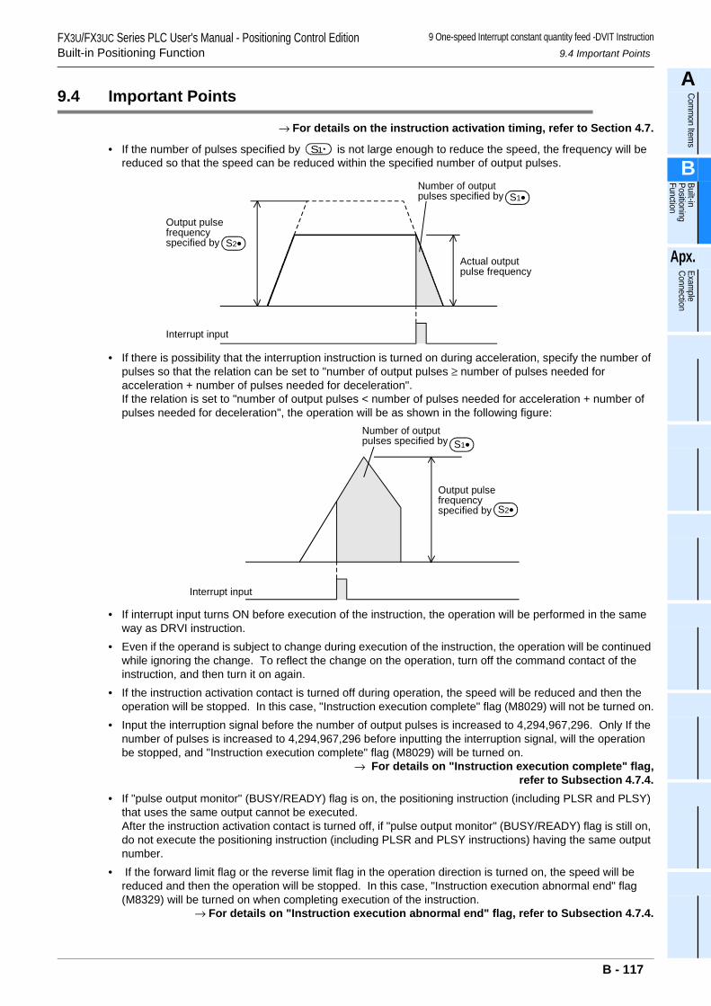
FX3U/FX3UC Series PLC User's Manual - Positioning Control EditionBuilt-in Positioning Function
9 One-speed Interrupt constant quantity feed -DVIT Instruction9.4 Important Points
A
Comm
on Items
B
Built-in Positioning Function
Apx.
Example
Connection
9.4 Important Points
→ For details on the instruction activation timing, refer to Section 4.7.
• If the number of pulses specified by is not large enough to reduce the speed, the frequency will be reduced so that the speed can be reduced within the specified number of output pulses.
• If there is possibility that the interruption instruction is turned on during acceleration, specify the number of pulses so that the relation can be set to "number of output pulses ≥ number of pulses needed for acceleration + number of pulses needed for deceleration".If the relation is set to "number of output pulses < number of pulses needed for acceleration + number of pulses needed for deceleration", the operation will be as shown in the following figure:
• If interrupt input turns ON before execution of the instruction, the operation will be performed in the same way as DRVI instruction.
• Even if the operand is subject to change during execution of the instruction, the operation will be continued while ignoring the change. To reflect the change on the operation, turn off the command contact of the instruction, and then turn it on again.
• If the instruction activation contact is turned off during operation, the speed will be reduced and then the operation will be stopped. In this case, "Instruction execution complete" flag (M8029) will not be turned on.
• Input the interruption signal before the number of output pulses is increased to 4,294,967,296. Only If the number of pulses is increased to 4,294,967,296 before inputting the interruption signal, will the operation be stopped, and "Instruction execution complete" flag (M8029) will be turned on.
→ For details on "Instruction execution complete" flag, refer to Subsection 4.7.4.• If "pulse output monitor" (BUSY/READY) flag is on, the positioning instruction (including PLSR and PLSY)
that uses the same output cannot be executed.After the instruction activation contact is turned off, if "pulse output monitor" (BUSY/READY) flag is still on, do not execute the positioning instruction (including PLSR and PLSY instructions) having the same output number.
• If the forward limit flag or the reverse limit flag in the operation direction is turned on, the speed will be reduced and then the operation will be stopped. In this case, "Instruction execution abnormal end" flag (M8329) will be turned on when completing execution of the instruction.
→ For details on "Instruction execution abnormal end" flag, refer to Subsection 4.7.4.
S1
Output pulsefrequencyspecified by S2•
S1•
Actual outputpulse frequency
Number of outputpulses specified by
Interrupt input
Output pulsefrequencyspecified by S2•
S1•Number of outputpulses specified by
Interrupt input
B - 117

FX3U/FX3UC Series PLC User's Manual - Positioning Control EditionBuilt-in Positioning Function
9 One-speed Interrupt constant quantity feed -DVIT Instruction9.4 Important Points
• The interrupt input cannot be used for the following items:Interrupt inputs can be specified in Ver.1.30 or later.- High-speed counter- Input interruption- Pulse catch- SPD instruction- DSZR instruction- ZRN instruction
B - 118
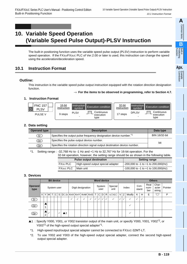
FX3U/FX3UC Series PLC User's Manual - Positioning Control EditionBuilt-in Positioning Function
10 Variable Speed Operation (Variable Speed Pulse Output)-PLSV Instruction
10.1 Instruction Format
A
Comm
on Items
B
Built-in Positioning Function
Apx.
Example
Connection
10. Variable Speed Operation (Variable Speed Pulse Output)-PLSV Instruction
The built-in positioning function uses the variable speed pulse output (PLSV) instruction to perform variable speed operation. If the FX3U/FX3UC PLC of Ver.2.00 or later is used, this instruction can change the speed using the acceleration/deceleration speed.
10.1 Instruction Format
Outline:This instruction is the variable speed pulse output instruction equipped with the rotation direction designation function.
→ For the items to be observed in programming, refer to Section 4.7.
1. Instruction Format
2. Data setting
*1. Setting range : -32,768 Hz to -1 Hz and +1 Hz to 32,767 Hz for 16-bit operation. For the 32-bit operation, however, the setting range should be as shown in the following table.
3. Devices
1 : Specify Y000, Y001, or Y002 transistor output of the main unit, or specify Y000, Y001, Y002*2, or Y003*2 of the high-speed output special adapter*1.
*1. High-speed input/output special adapter cannot be connected to FX3UC-32MT-LT.*2. To use Y002 and Y003 of the high-speed output special adapter, connect the second high-speed
output special adapter.
Operand type Description Data type
Specifies the output pulse frequency designation device number.*1 BIN 16/32-bit
Specifies the pulse output device number.bit
Specifies the rotation direction signal output destination device number.
Pulse output destination Setting rangeFX3U PLC High-speed output special adapter -200,000 to -1 to +1 to 200,000(Hz)FX3UC PLC Main unit -100,000 to -1 to +1 to 100,000(Hz)
Operand type
Bit device Word device Others
System user Digit designation System user
Special unit Index Con-
stantr
Real num-ber
Char-acter string
Pointer
X Y M T C S D .b KnX KnY KnM KnS T C D R U \G V Z Modfy K H E " " P
1
23
32-bitinstruction
17 steps DPLSV Continuousexecutiontype
Instructionsymbol Execution condition
-
FNC 157PLSV
PULSE V
D16-bit
instruction
9 steps PLSV Continuousexecutiontype
Instructionsymbol Execution condition
-
S
D1
D2
S
D1
D2
B - 119
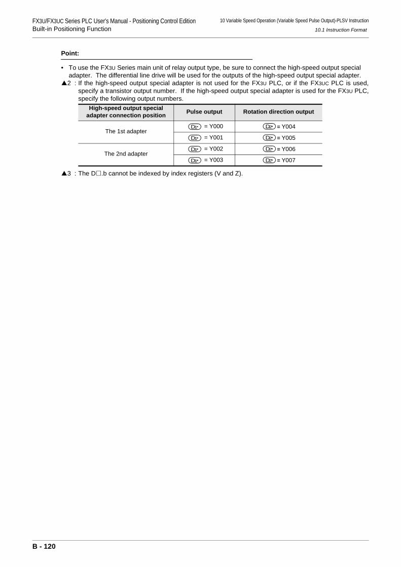
FX3U/FX3UC Series PLC User's Manual - Positioning Control EditionBuilt-in Positioning Function
10 Variable Speed Operation (Variable Speed Pulse Output)-PLSV Instruction
10.1 Instruction Format
Point:
• To use the FX3U Series main unit of relay output type, be sure to connect the high-speed output special adapter. The differential line drive will be used for the outputs of the high-speed output special adapter.2 : If the high-speed output special adapter is not used for the FX3U PLC, or if the FX3UC PLC is used,
specify a transistor output number. If the high-speed output special adapter is used for the FX3U PLC,specify the following output numbers.
3 : The D .b cannot be indexed by index registers (V and Z).
High-speed output special adapter connection position Pulse output Rotation direction output
The 1st adapter= Y000 = Y004
= Y001 = Y005
The 2nd adapter= Y002 = Y006
= Y003 = Y007
D1 D2
D1 D2
D1 D2
D1 D2
B - 120
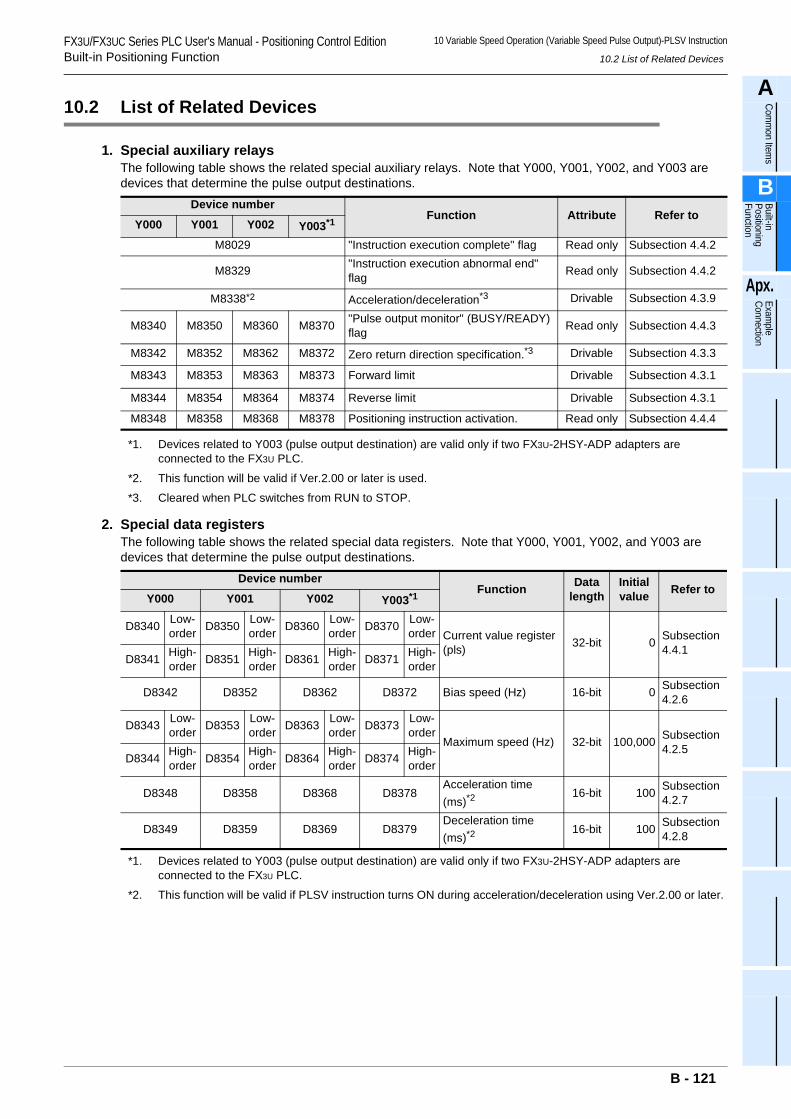
FX3U/FX3UC Series PLC User's Manual - Positioning Control EditionBuilt-in Positioning Function
10 Variable Speed Operation (Variable Speed Pulse Output)-PLSV Instruction
10.2 List of Related Devices
A
Comm
on Items
B
Built-in Positioning Function
Apx.
Example
Connection
10.2 List of Related Devices
1. Special auxiliary relaysThe following table shows the related special auxiliary relays. Note that Y000, Y001, Y002, and Y003 are devices that determine the pulse output destinations.
*1. Devices related to Y003 (pulse output destination) are valid only if two FX3U-2HSY-ADP adapters are connected to the FX3U PLC.
*2. This function will be valid if Ver.2.00 or later is used.
*3. Cleared when PLC switches from RUN to STOP.
2. Special data registersThe following table shows the related special data registers. Note that Y000, Y001, Y002, and Y003 are devices that determine the pulse output destinations.
*1. Devices related to Y003 (pulse output destination) are valid only if two FX3U-2HSY-ADP adapters are connected to the FX3U PLC.
*2. This function will be valid if PLSV instruction turns ON during acceleration/deceleration using Ver.2.00 or later.
Device numberFunction Attribute Refer to
Y000 Y001 Y002 Y003*1
M8029 "Instruction execution complete" flag Read only Subsection 4.4.2
M8329 "Instruction execution abnormal end" flag Read only Subsection 4.4.2
M8338*2 Acceleration/deceleration*3 Drivable Subsection 4.3.9
M8340 M8350 M8360 M8370 "Pulse output monitor" (BUSY/READY) flag Read only Subsection 4.4.3
M8342 M8352 M8362 M8372 Zero return direction specification.*3 Drivable Subsection 4.3.3
M8343 M8353 M8363 M8373 Forward limit Drivable Subsection 4.3.1
M8344 M8354 M8364 M8374 Reverse limit Drivable Subsection 4.3.1
M8348 M8358 M8368 M8378 Positioning instruction activation. Read only Subsection 4.4.4
Device numberFunction Data
lengthInitial value Refer to
Y000 Y001 Y002 Y003*1
D8340 Low-order D8350 Low-
order D8360 Low-order D8370 Low-
order Current value register (pls) 32-bit 0 Subsection
4.4.1D8341 High-
order D8351 High-order D8361 High-
order D8371 High-order
D8342 D8352 D8362 D8372 Bias speed (Hz) 16-bit 0 Subsection 4.2.6
D8343 Low-order D8353 Low-
order D8363 Low-order D8373 Low-
orderMaximum speed (Hz) 32-bit 100,000 Subsection
4.2.5D8344 High-
order D8354 High-order D8364 High-
order D8374 High-order
D8348 D8358 D8368 D8378Acceleration time (ms)*2
16-bit 100 Subsection 4.2.7
D8349 D8359 D8369 D8379Deceleration time (ms)*2
16-bit 100 Subsection 4.2.8
B - 121
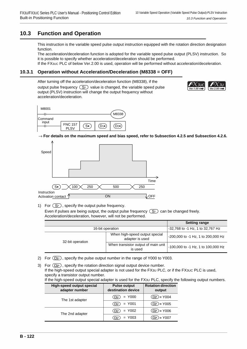
FX3U/FX3UC Series PLC User's Manual - Positioning Control EditionBuilt-in Positioning Function
10 Variable Speed Operation (Variable Speed Pulse Output)-PLSV Instruction
10.3 Function and Operation
10.3 Function and Operation
This instruction is the variable speed pulse output instruction equipped with the rotation direction designation function.The acceleration/deceleration function is adopted for the variable speed pulse output (PLSV) instruction. So it is possible to specify whether acceleration/deceleration should be performed.If the FX3UC PLC of below Ver.2.00 is used, operation will be performed without acceleration/deceleration.
10.3.1 Operation without Acceleration/Deceleration (M8338 = OFF)
After turning off the acceleration/deceleration function (M8338), if the output pulse frequency value is changed, the variable speed pulse output (PLSV) instruction will change the output frequency without acceleration/deceleration.
→ For details on the maximum speed and bias speed, refer to Subsection 4.2.5 and Subsection 4.2.6.
1) For , specify the output pulse frequency.Even if pulses are being output, the output pulse frequency can be changed freely.Acceleration/deceleration, however, will not be performed.
2) For , specify the pulse output number in the range of Y000 to Y003.
3) For , specify the rotation direction signal output device number.If the high-speed output special adapter is not used for the FX3U PLC, or if the FX3UC PLC is used, specify a transistor output number.If the high-speed output special adapter is used for the FX3U PLC, specify the following output numbers.
Setting range16-bit operation -32,768 to -1 Hz, 1 to 32,767 Hz
32-bit operation
When high-speed output special adapter is used -200,000 to -1 Hz, 1 to 200,000 Hz
When transistor output of main unit is used -100,000 to -1 Hz, 1 to 100,000 Hz
High-speed output special adapter number
Pulse output destination device
Rotation direction output
The 1st adapter = Y000 = Y004
= Y001 = Y005
The 2nd adapter = Y002 = Y006
= Y003 = Y007
S
M8001
FNC 157PLSV
S• D1• D2•
M8338Command
input
ON
S• 100 250 500 250
Speed
Time
OFFInstructionActivation contact
S S
D1
D2
D1 D2
D1 D2
D1 D2
D1 D2
B - 122
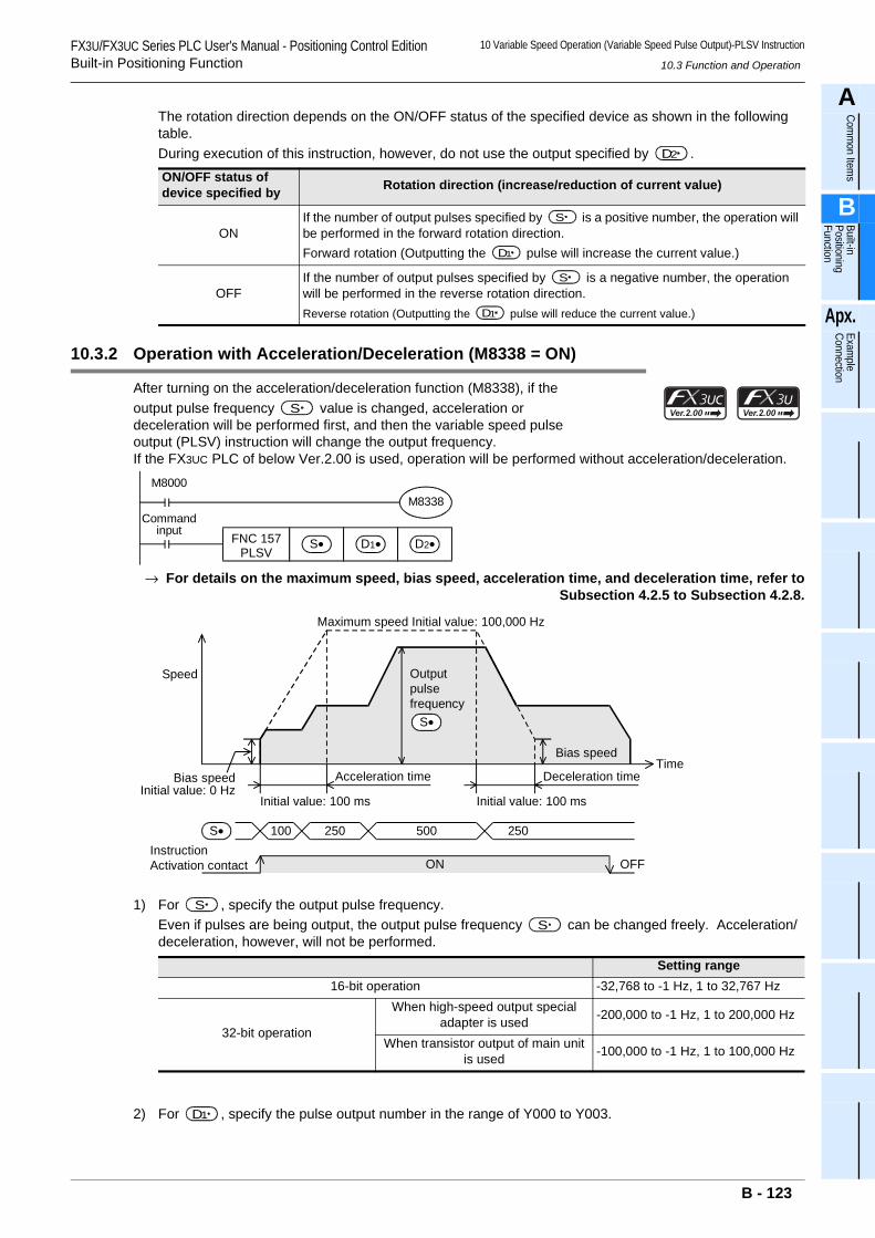
FX3U/FX3UC Series PLC User's Manual - Positioning Control EditionBuilt-in Positioning Function
10 Variable Speed Operation (Variable Speed Pulse Output)-PLSV Instruction
10.3 Function and Operation
A
Comm
on Items
B
Built-in Positioning Function
Apx.
Example
Connection
The rotation direction depends on the ON/OFF status of the specified device as shown in the following table.During execution of this instruction, however, do not use the output specified by .
10.3.2 Operation with Acceleration/Deceleration (M8338 = ON)
After turning on the acceleration/deceleration function (M8338), if the output pulse frequency value is changed, acceleration or deceleration will be performed first, and then the variable speed pulse output (PLSV) instruction will change the output frequency.If the FX3UC PLC of below Ver.2.00 is used, operation will be performed without acceleration/deceleration.
→ For details on the maximum speed, bias speed, acceleration time, and deceleration time, refer toSubsection 4.2.5 to Subsection 4.2.8.
1) For , specify the output pulse frequency.Even if pulses are being output, the output pulse frequency can be changed freely. Acceleration/deceleration, however, will not be performed.
2) For , specify the pulse output number in the range of Y000 to Y003.
ON/OFF status of device specified by Rotation direction (increase/reduction of current value)
ONIf the number of output pulses specified by is a positive number, the operation will be performed in the forward rotation direction.Forward rotation (Outputting the pulse will increase the current value.)
OFFIf the number of output pulses specified by is a negative number, the operation will be performed in the reverse rotation direction.Reverse rotation (Outputting the pulse will reduce the current value.)
Setting range16-bit operation -32,768 to -1 Hz, 1 to 32,767 Hz
32-bit operation
When high-speed output special adapter is used -200,000 to -1 Hz, 1 to 200,000 Hz
When transistor output of main unit is used -100,000 to -1 Hz, 1 to 100,000 Hz
D2
S
D1
S
D1
S
M8000
FNC 157PLSV
S• D1• D2•
M8338Command
input
ON
S• 100 250 500 250
Speed
Time
OFFInstructionActivation contact
Maximum speed Initial value: 100,000 Hz
Outputpulsefrequency
S•
Deceleration timeAcceleration timeBias speedInitial value: 0 Hz
Bias speed
Initial value: 100 ms Initial value: 100 ms
S S
D1
B - 123
FX3U/FX3UC Series PLC User's Manual - Positioning Control EditionBuilt-in Positioning Function
10 Variable Speed Operation (Variable Speed Pulse Output)-PLSV Instruction
10.3 Function and Operation
3) For , specify the rotation direction signal output device number.If the high-speed output special adapter is not used for the FX3U PLC, or if the FX3UC PLC is used, specify a transistor output number.If the high-speed output special adapter is used for the FX3U PLC, specify the following output numbers.
The rotation direction depends on the ON/OFF status of the specified device as shown in the following table.During execution of this instruction, however, do not use the output specified by .
High-speed output special adapter number
Pulse output destination device
Rotation direction output
The 1st adapter = Y000 = Y004
= Y001 = Y005
The 2nd adapter = Y002 = Y006
= Y003 = Y007
ON/OFF status of device specified by
Rotation direction (increase/reduction of current value)
ONIf the number of output pulses specified by is a positive number, the operation will be performed in the forward rotation direction.Forward rotation (Outputting the pulse will increase the current value.)
OFFIf the number of output pulses specified by is a negative number, the operation will be performed in the reverse rotation direction.Reverse rotation (Outputting the pulse will reduce the current value.)
D2
D1 D2
D1 D2
D1 D2
D1 D2
D2
D2
S
D1
S
D1
B - 124
FX3U/FX3UC Series PLC User's Manual - Positioning Control EditionBuilt-in Positioning Function
10 Variable Speed Operation (Variable Speed Pulse Output)-PLSV Instruction
10.4 Important Points
A
Comm
on Items
B
Built-in Positioning Function
Apx.
Example
Connection
10.4 Important Points
→ For the important points of programming, refer to Section 4.7.
• During pulse output operation, if the output pulse frequency is changed to "K0", the PLC will reduce the speed and then stop the pulse outputting operation if the acceleration/deceleration function turns ON. However, if the acceleration/deceleration function is not activated, the PLC will immediately stop the pulse outputting operation.Before outputting the pulses again, check that "pulse output monitor" (BUSY/READY) flag is off, and then wait until 1 or more cycles of operation have been completed. After that, set (change) the output pulse frequency to a value other than "K0".
• During pulse outputting operation, do not change the sign attached to the output pulse frequency value .If it is necessary to change the sign, stop the servo motor first by setting the output pulse frequency value
to "K0". After checking stop of the servo motor using the SERVO READY signal, change the sign attached to the output pulse frequency value .If the sign attached to the output pulse frequency value is changed during pulse outputting operation, the operation may be changed as follows, and the machine, therefore, may be damaged:
1) The pulse outputting operation may be stopped.2) "Pulse output monitor" (BUSY/READY) flag may be turned off.
(The pulse outputting operation may be stopped, but the motor may not be stopped immediately.)3) Operation may be performed in the specified direction at the frequency specified by the output
pulse frequency value .• If the acceleration/deceleration function turns ON, turning off the instruction activation contact during pulse
outputting operation will reduce the speed first and then stop the operation. If the acceleration/deceleration function is not activated, turning off the instruction activation contact during pulse outputting operation will immediately stop the operation. In this case, "Instruction execution complete" flag (M8029) will not be turned on.
• If the limit flag (forward limit flag or reverse rotation limit flag) in the operation direction is turned on, the operation will be immediately stopped. In this case, "Instruction execution abnormal end" flag (M8329) will be turned on when completing execution of the instruction.
→ For details on "Instruction execution abnormal end" flag, refer to Subsection 4.7.4.• If "pulse output monitor" (BUSY/READY) flag is on, the positioning instruction (including PLSR and PLSY)
that uses the same output cannot be executed.After the instruction activation contact is turned off, if "pulse output monitor" (BUSY/READY) flag is still on, do not execute the positioning instruction (including PLSR and PLSY instructions) having the same output number.
• After executing the instruction, the output of the rotation direction signal will be turned off.
1. Important items for FX3UC PLC of below Ver.2.00
• Acceleration/deceleration will not be performed at starting or stopping operation. For this reason, if it is necessary to use the cushion start function or the cushion stop function, increase or reduce the output pulse frequency value using FNC67 (RAMP) instruction, etc.
2. Important items for FX3U/FX3UC PLC of Ver.2.00 or later
• If acceleration/deceleration is enabled, the variable speed pulse output (PLSV) instructions of all the pulse output destination devices will accelerate/decelerate the operation. This means that acceleration/deceleration cannot be specified for each pulse output destination device.
S
S
S S
S
S
S
B - 125
FX3U/FX3UC Series PLC User's Manual - Positioning Control EditionBuilt-in Positioning Function
11 Batch Data Positioning Mode (TBL Instruction)11.1 Instruction Format
11. Batch Data Positioning Mode (TBL Instruction)
If GX Developer Ver.8.23Z or later is used, the positioning instructions shown below can be preliminarily set in the positioning tables. After that, if a table is specified, the positioning operation of the specified table will be performed.
11.1 Instruction Format
1. Instruction Format
2. Data setting
3. Devices
1 : Specify Y000, Y001, or Y002 transistor output of main unit, or specify Y000, Y001, Y002*2, or Y003*2 of the high-speed output special adapter*1.
*1. High-speed input/output special adapter cannot be connected to FX3UC-32MT-LT.*2. To use Y002 and Y003 of the high-speed output special adapter, connect the second high-speed
output special adapter.Point:
To use the FX3U Series main unit of relay output type, be sure to connect the high-speed output special adapter. The differential line drive will be used for the outputs of the high-speed output special adapter.
Instruction DescriptionDVIT(FNC151) One-speed interrupt constant quantity feed (Interrupt positioning)PLSV(FNC157) Variable speed operation (Variable Speed Pulse Output)DRVI(FNC158) 1-speed
positioningDrive to Increment
DRVA(FNC159) Drive to Absolute
Operand type Description Data type
Specifies the pulse output number. Bit
n Specifies the table number (1 to 100) to be executed. BIN 32-bit
Operandtype
Bit device Word device Others
System user Digit designation System user Special unit Index Con-
stantr
Real num-ber
Char-acter string
Pointer
X Y M T C S D .b KnX KnY KnM KnS T C D R U \G V Z Modify K H E " " P
1n
32-bitinstruction
17 steps DTBL Continuousexecutiontype
Instructionsymbol Execution condition
-
16-bitinstruction
--
Instructionsymbol Execution conditionFNC 152
TBLTABLE
D
Commandinput FNC152
DTBLD n
D
D
B - 126
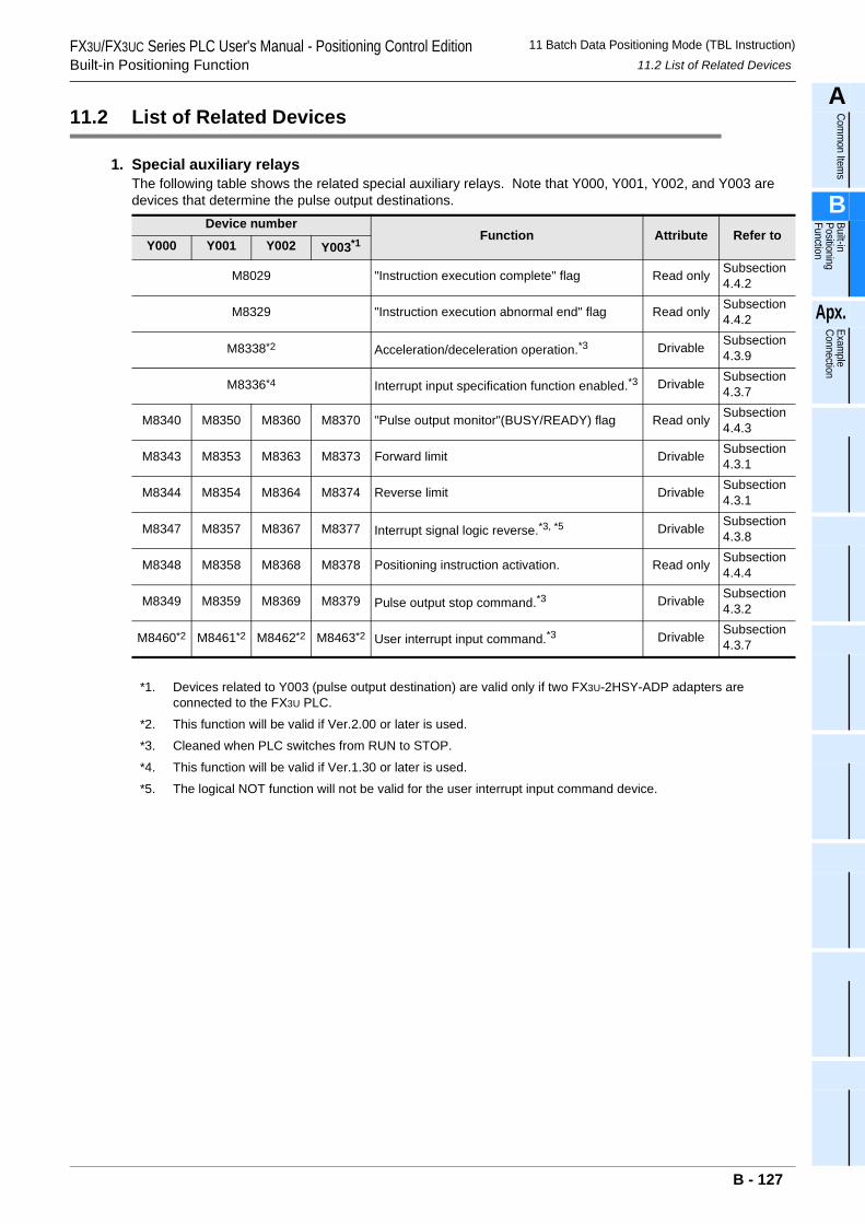
FX3U/FX3UC Series PLC User's Manual - Positioning Control EditionBuilt-in Positioning Function
11 Batch Data Positioning Mode (TBL Instruction)11.2 List of Related Devices
A
Comm
on Items
B
Built-in Positioning Function
Apx.
Example
Connection
11.2 List of Related Devices
1. Special auxiliary relaysThe following table shows the related special auxiliary relays. Note that Y000, Y001, Y002, and Y003 are devices that determine the pulse output destinations.
Device numberFunction Attribute Refer to
Y000 Y001 Y002 Y003*1
M8029 "Instruction execution complete" flag Read only Subsection 4.4.2
M8329 "Instruction execution abnormal end" flag Read only Subsection 4.4.2
M8338*2 Acceleration/deceleration operation.*3 Drivable Subsection 4.3.9
M8336*4 Interrupt input specification function enabled.*3 Drivable Subsection 4.3.7
M8340 M8350 M8360 M8370 "Pulse output monitor"(BUSY/READY) flag Read only Subsection 4.4.3
M8343 M8353 M8363 M8373 Forward limit Drivable Subsection 4.3.1
M8344 M8354 M8364 M8374 Reverse limit Drivable Subsection 4.3.1
M8347 M8357 M8367 M8377 Interrupt signal logic reverse.*3, *5 Drivable Subsection 4.3.8
M8348 M8358 M8368 M8378 Positioning instruction activation. Read only Subsection 4.4.4
M8349 M8359 M8369 M8379 Pulse output stop command.*3 Drivable Subsection 4.3.2
M8460*2 M8461*2 M8462*2 M8463*2 User interrupt input command.*3 Drivable Subsection 4.3.7
*1. Devices related to Y003 (pulse output destination) are valid only if two FX3U-2HSY-ADP adapters are connected to the FX3U PLC.
*2. This function will be valid if Ver.2.00 or later is used.
*3. Cleaned when PLC switches from RUN to STOP.
*4. This function will be valid if Ver.1.30 or later is used.
*5. The logical NOT function will not be valid for the user interrupt input command device.
B - 127
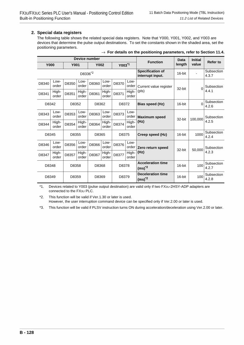
FX3U/FX3UC Series PLC User's Manual - Positioning Control EditionBuilt-in Positioning Function
11 Batch Data Positioning Mode (TBL Instruction)11.2 List of Related Devices
2. Special data registersThe following table shows the related special data registers. Note that Y000, Y001, Y002, and Y003 are devices that determine the pulse output destinations. To set the constants shown in the shaded area, set the positioning parameters.
→ For details on the positioning parameters, refer to Section 11.4.
*1. Devices related to Y003 (pulse output destination) are valid only if two FX3U-2HSY-ADP adapters are connected to the FX3U PLC.
*2. This function will be valid if Ver.1.30 or later is used.However, the user interruption command device can be specified only if Ver.2.00 or later is used.
*3. This function will be valid if PLSV instruction turns ON during acceleration/deceleration using Ver.2.00 or later.
Device numberFunction Data
lengthInitial value Refer to
Y000 Y001 Y002 Y003*1
D8336*2 Specification of interrupt input. 16-bit - Subsection
4.3.7
D8340 Low-order D8350 Low-
order D8360 Low-order D8370 Low-
order Current value register (pls) 32-bit 0 Subsection
4.4.1D8341 High-
order D8351 High-order D8361 High-
order D8371 High-order
D8342 D8352 D8362 D8372 Bias speed (Hz) 16-bit 0 Subsection4.2.6
D8343 Low-order D8353 Low-
order D8363 Low-order D8373 Low-
order Maximum speed (Hz) 32-bit 100,000 Subsection
4.2.5D8344 High-
order D8354 High-order D8364 High-
order D8374 High-order
D8345 D8355 D8365 D8375 Creep speed (Hz) 16-bit 1000 Subsection4.2.4
D8346 Low-order D8356 Low-
order D8366 Low-order D8376 Low-
order Zero return speed (Hz) 32-bit 50,000 Subsection
4.2.3D8347 High-
order D8357 High-order D8367 High-
order D8377 High-order
D8348 D8358 D8368 D8378Acceleration time (ms)*2
16-bit 100 Subsection4.2.7
D8349 D8359 D8369 D8379Deceleration time (ms)*2
16-bit 100 Subsection4.2.8
B - 128
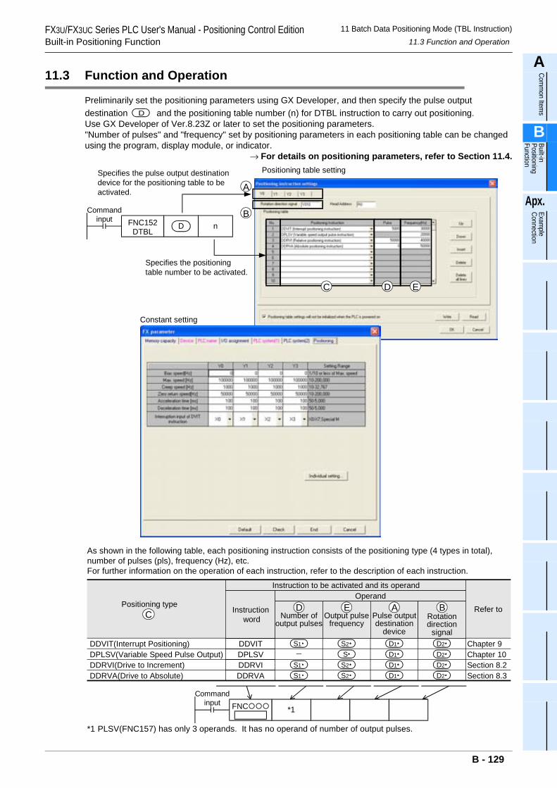
FX3U/FX3UC Series PLC User's Manual - Positioning Control EditionBuilt-in Positioning Function
11 Batch Data Positioning Mode (TBL Instruction)11.3 Function and Operation
A
Comm
on Items
B
Built-in Positioning Function
Apx.
Example
Connection
11.3 Function and Operation
Preliminarily set the positioning parameters using GX Developer, and then specify the pulse output destination and the positioning table number (n) for DTBL instruction to carry out positioning.Use GX Developer of Ver.8.23Z or later to set the positioning parameters."Number of pulses" and "frequency" set by positioning parameters in each positioning table can be changed using the program, display module, or indicator.
→ For details on positioning parameters, refer to Section 11.4.
D
Commandinput FNC152
DTBLD n
Specifies the pulse output destinationdevice for the positioning table to beactivated.
Positioning table setting
Specifies the positioningtable number to be activated.
Constant setting
As shown in the following table, each positioning instruction consists of the positioning type (4 types in total),number of pulses (pls), frequency (Hz), etc.For further information on the operation of each instruction, refer to the description of each instruction.
C D E
A
B
*1 PLSV(FNC157) has only 3 operands. It has no operand of number of output pulses.
*1
Commandinput FNC
DDVIT(Interrupt Positioning)DPLSV(Variable Speed Pulse Output)DDRVI(Drive to Increment)DDRVA(Drive to Absolute)
CPositioning type Refer to
Instruction to be activated and its operandOperand
Chapter 9Chapter 10Section 8.2Section 8.3
Number ofoutput pulses
Output pulsefrequency
Pulse outputdestination
device
Rotationdirection
signal
D E A B
S1
S1
S1
S2
S2
S2
D1
D1
D1
D1
D2
D2
D2
D2
S
Instruction word
DDVITDPLSVDDRVIDDRVA
B - 129
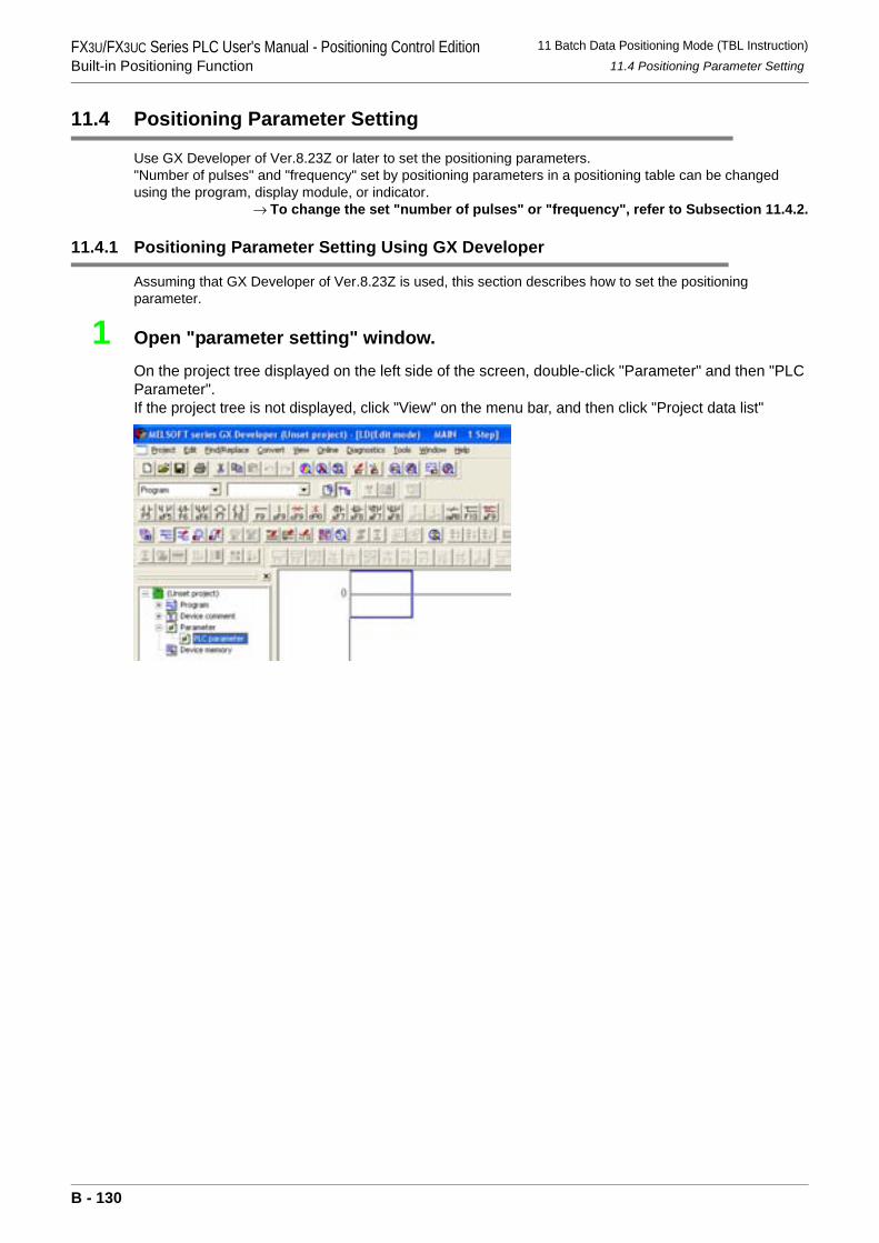
FX3U/FX3UC Series PLC User's Manual - Positioning Control EditionBuilt-in Positioning Function
11 Batch Data Positioning Mode (TBL Instruction)11.4 Positioning Parameter Setting
11.4 Positioning Parameter Setting
Use GX Developer of Ver.8.23Z or later to set the positioning parameters."Number of pulses" and "frequency" set by positioning parameters in a positioning table can be changed using the program, display module, or indicator.
→ To change the set "number of pulses" or "frequency", refer to Subsection 11.4.2.
11.4.1 Positioning Parameter Setting Using GX Developer
Assuming that GX Developer of Ver.8.23Z is used, this section describes how to set the positioning parameter.
1 Open "parameter setting" window.
On the project tree displayed on the left side of the screen, double-click "Parameter" and then "PLC Parameter".If the project tree is not displayed, click "View" on the menu bar, and then click "Project data list"
B - 130
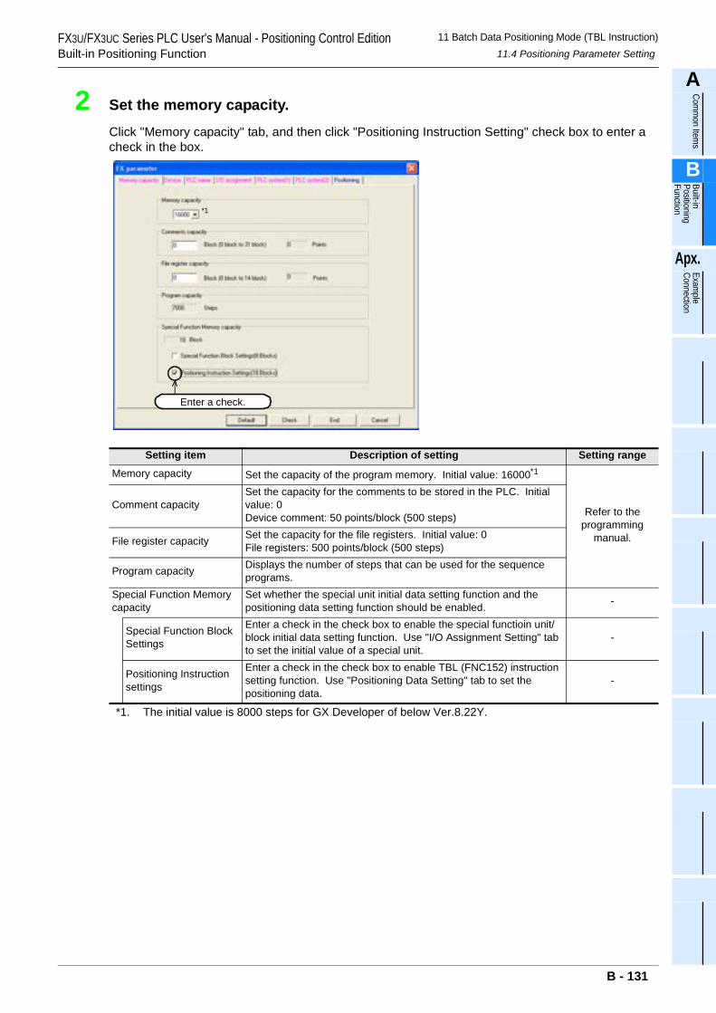
FX3U/FX3UC Series PLC User's Manual - Positioning Control EditionBuilt-in Positioning Function
11 Batch Data Positioning Mode (TBL Instruction)11.4 Positioning Parameter Setting
A
Comm
on Items
B
Built-in Positioning Function
Apx.
Example
Connection
2 Set the memory capacity.
Click "Memory capacity" tab, and then click "Positioning Instruction Setting" check box to enter a check in the box.
*1. The initial value is 8000 steps for GX Developer of below Ver.8.22Y.
Setting item Description of setting Setting range
Memory capacity Set the capacity of the program memory. Initial value: 16000*1
Refer to theprogramming
manual.
Comment capacitySet the capacity for the comments to be stored in the PLC. Initial value: 0Device comment: 50 points/block (500 steps)
File register capacity Set the capacity for the file registers. Initial value: 0File registers: 500 points/block (500 steps)
Program capacity Displays the number of steps that can be used for the sequence programs.
Special Function Memory capacity
Set whether the special unit initial data setting function and the positioning data setting function should be enabled. -
Special Function Block Settings
Enter a check in the check box to enable the special functioin unit/block initial data setting function. Use "I/O Assignment Setting" tab to set the initial value of a special unit.
-
Positioning Instruction settings
Enter a check in the check box to enable TBL (FNC152) instruction setting function. Use "Positioning Data Setting" tab to set the positioning data.
-
Enter a check.
*1
B - 131
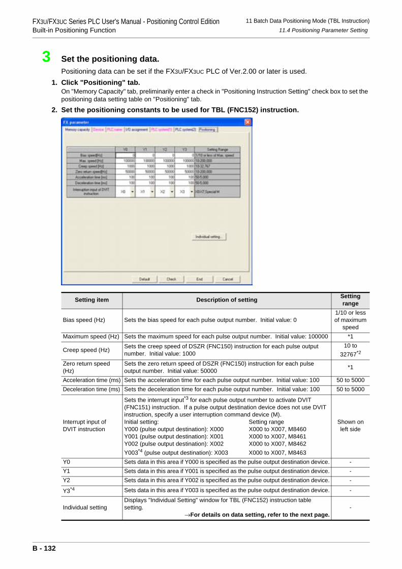
FX3U/FX3UC Series PLC User's Manual - Positioning Control EditionBuilt-in Positioning Function
11 Batch Data Positioning Mode (TBL Instruction)11.4 Positioning Parameter Setting
3 Set the positioning data.Positioning data can be set if the FX3U/FX3UC PLC of Ver.2.00 or later is used.
1. Click "Positioning" tab.On "Memory Capacity" tab, preliminarily enter a check in "Positioning Instruction Setting" check box to set the positioning data setting table on "Positioning" tab.
2. Set the positioning constants to be used for TBL (FNC152) instruction.
Setting item Description of setting Setting range
Bias speed (Hz) Sets the bias speed for each pulse output number. Initial value: 01/10 or less of maximum
speedMaximum speed (Hz) Sets the maximum speed for each pulse output number. Initial value: 100000 *1
Creep speed (Hz) Sets the creep speed of DSZR (FNC150) instruction for each pulse output number. Initial value: 1000
10 to 32767*2
Zero return speed (Hz)
Sets the zero return speed of DSZR (FNC150) instruction for each pulse output number. Initial value: 50000 *1
Acceleration time (ms) Sets the acceleration time for each pulse output number. Initial value: 100 50 to 5000Deceleration time (ms) Sets the deceleration time for each pulse output number. Initial value: 100 50 to 5000
Interrupt input of DVIT instruction
Sets the interrupt input*3 for each pulse output number to activate DVIT (FNC151) instruction. If a pulse output destination device does not use DVIT instruction, specify a user interruption command device (M).Initial setting: Setting rangeY000 (pulse output destination): X000 X000 to X007, M8460Y001 (pulse output destination): X001 X000 to X007, M8461Y002 (pulse output destination): X002 X000 to X007, M8462Y003*4 (pulse output destination): X003 X000 to X007, M8463
Shown on left side
Y0 Sets data in this area if Y000 is specified as the pulse output destination device. -Y1 Sets data in this area if Y001 is specified as the pulse output destination device. -Y2 Sets data in this area if Y002 is specified as the pulse output destination device. -
Y3*4 Sets data in this area if Y003 is specified as the pulse output destination device. -
Individual settingDisplays "Individual Setting" window for TBL (FNC152) instruction table setting.
→For details on data setting, refer to the next page.-
B - 132
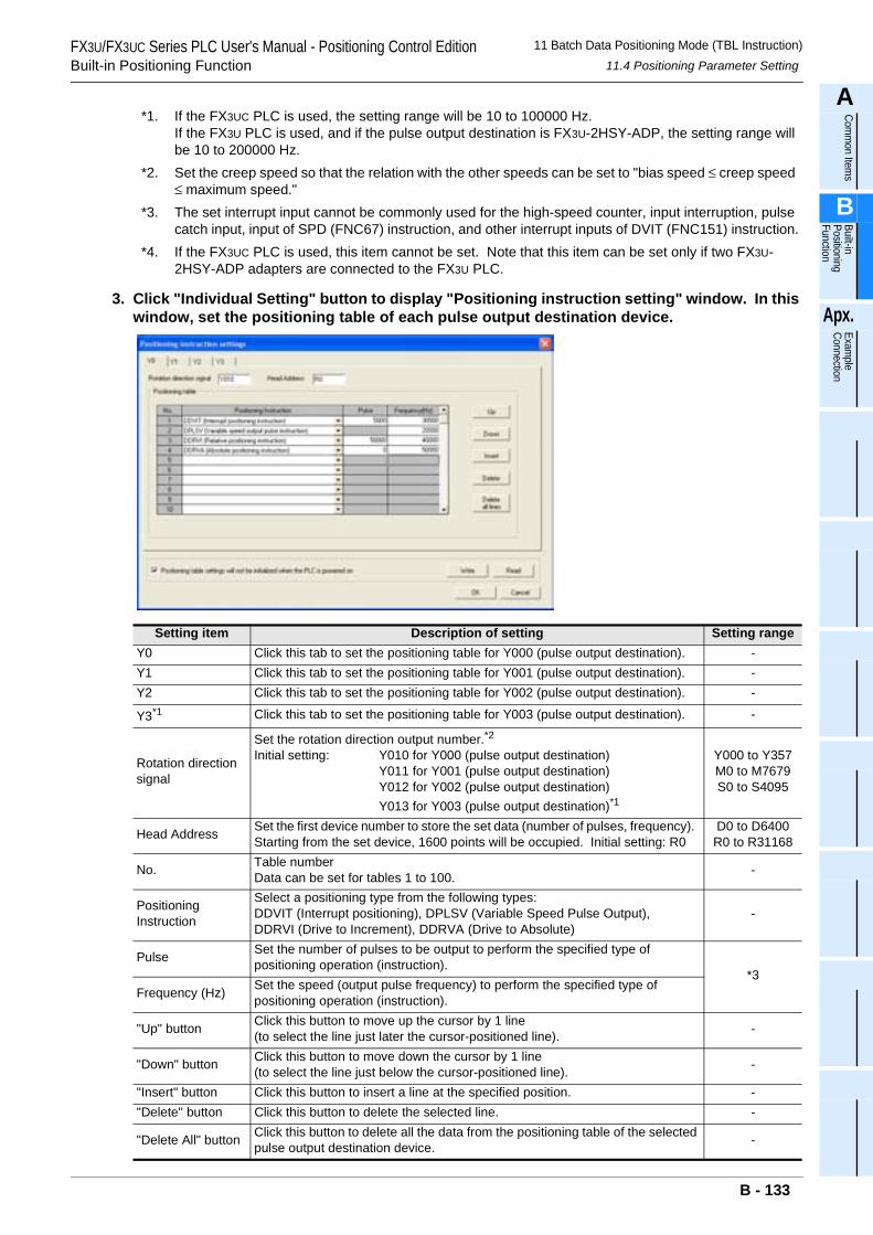
FX3U/FX3UC Series PLC User's Manual - Positioning Control EditionBuilt-in Positioning Function
11 Batch Data Positioning Mode (TBL Instruction)11.4 Positioning Parameter Setting
A
Comm
on Items
B
Built-in Positioning Function
Apx.
Example
Connection
*1. If the FX3UC PLC is used, the setting range will be 10 to 100000 Hz.If the FX3U PLC is used, and if the pulse output destination is FX3U-2HSY-ADP, the setting range will be 10 to 200000 Hz.
*2. Set the creep speed so that the relation with the other speeds can be set to "bias speed ≤ creep speed ≤ maximum speed."
*3. The set interrupt input cannot be commonly used for the high-speed counter, input interruption, pulse catch input, input of SPD (FNC67) instruction, and other interrupt inputs of DVIT (FNC151) instruction.
*4. If the FX3UC PLC is used, this item cannot be set. Note that this item can be set only if two FX3U-2HSY-ADP adapters are connected to the FX3U PLC.
3. Click "Individual Setting" button to display "Positioning instruction setting" window. In this window, set the positioning table of each pulse output destination device.
Setting item Description of setting Setting rangeY0 Click this tab to set the positioning table for Y000 (pulse output destination). -Y1 Click this tab to set the positioning table for Y001 (pulse output destination). -Y2 Click this tab to set the positioning table for Y002 (pulse output destination). -
Y3*1 Click this tab to set the positioning table for Y003 (pulse output destination). -
Rotation direction signal
Set the rotation direction output number.*2Initial setting: Y010 for Y000 (pulse output destination)
Y011 for Y001 (pulse output destination)Y012 for Y002 (pulse output destination)Y013 for Y003 (pulse output destination)*1
Y000 to Y357M0 to M7679S0 to S4095
Head Address Set the first device number to store the set data (number of pulses, frequency). Starting from the set device, 1600 points will be occupied. Initial setting: R0
D0 to D6400R0 to R31168
No. Table numberData can be set for tables 1 to 100. -
Positioning Instruction
Select a positioning type from the following types:DDVIT (Interrupt positioning), DPLSV (Variable Speed Pulse Output),DDRVI (Drive to Increment), DDRVA (Drive to Absolute)
-
Pulse Set the number of pulses to be output to perform the specified type of positioning operation (instruction).
*3Frequency (Hz) Set the speed (output pulse frequency) to perform the specified type of
positioning operation (instruction).
"Up" button Click this button to move up the cursor by 1 line(to select the line just later the cursor-positioned line). -
"Down" button Click this button to move down the cursor by 1 line(to select the line just below the cursor-positioned line). -
"Insert" button Click this button to insert a line at the specified position. -"Delete" button Click this button to delete the selected line. -
"Delete All" button Click this button to delete all the data from the positioning table of the selected pulse output destination device. -
B - 133
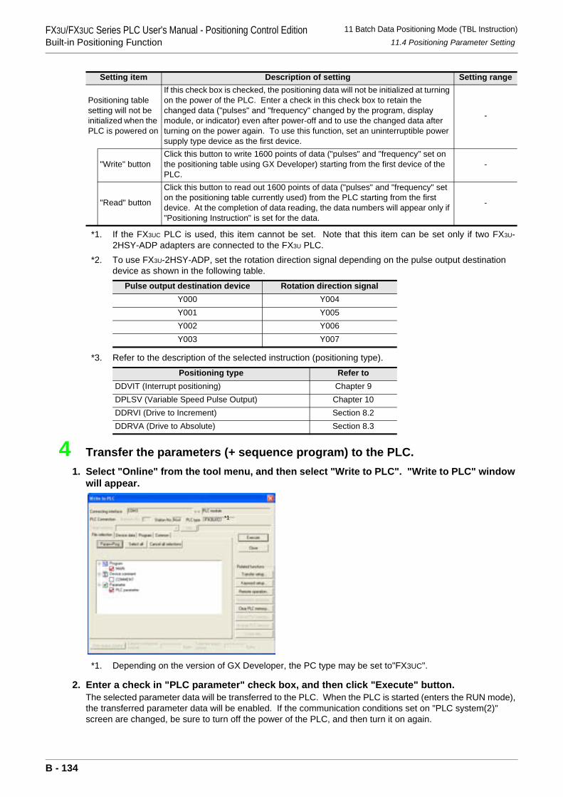
FX3U/FX3UC Series PLC User's Manual - Positioning Control EditionBuilt-in Positioning Function
11 Batch Data Positioning Mode (TBL Instruction)11.4 Positioning Parameter Setting
*1. If the FX3UC PLC is used, this item cannot be set. Note that this item can be set only if two FX3U-2HSY-ADP adapters are connected to the FX3U PLC.
*2. To use FX3U-2HSY-ADP, set the rotation direction signal depending on the pulse output destination device as shown in the following table.
*3. Refer to the description of the selected instruction (positioning type).
4 Transfer the parameters (+ sequence program) to the PLC.1. Select "Online" from the tool menu, and then select "Write to PLC". "Write to PLC" window
will appear.
*1. Depending on the version of GX Developer, the PC type may be set to"FX3UC".
2. Enter a check in "PLC parameter" check box, and then click "Execute" button.The selected parameter data will be transferred to the PLC. When the PLC is started (enters the RUN mode), the transferred parameter data will be enabled. If the communication conditions set on "PLC system(2)" screen are changed, be sure to turn off the power of the PLC, and then turn it on again.
Positioning table setting will not be initialized when the PLC is powered on
If this check box is checked, the positioning data will not be initialized at turning on the power of the PLC. Enter a check in this check box to retain the changed data ("pulses" and "frequency" changed by the program, display module, or indicator) even after power-off and to use the changed data after turning on the power again. To use this function, set an uninterruptible power supply type device as the first device.
-
"Write" buttonClick this button to write 1600 points of data ("pulses" and "frequency" set on the positioning table using GX Developer) starting from the first device of the PLC.
-
"Read" button
Click this button to read out 1600 points of data ("pulses" and "frequency" set on the positioning table currently used) from the PLC starting from the first device. At the completion of data reading, the data numbers will appear only if "Positioning Instruction" is set for the data.
-
Pulse output destination device Rotation direction signalY000 Y004Y001 Y005Y002 Y006Y003 Y007
Positioning type Refer toDDVIT (Interrupt positioning) Chapter 9DPLSV (Variable Speed Pulse Output) Chapter 10DDRVI (Drive to Increment) Section 8.2DDRVA (Drive to Absolute) Section 8.3
Setting item Description of setting Setting range
*1
B - 134
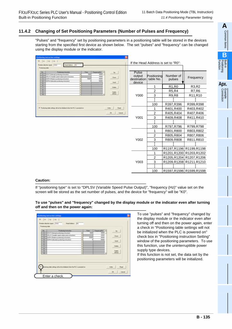
FX3U/FX3UC Series PLC User's Manual - Positioning Control EditionBuilt-in Positioning Function
11 Batch Data Positioning Mode (TBL Instruction)11.4 Positioning Parameter Setting
A
Comm
on Items
B
Built-in Positioning Function
Apx.
Example
Connection
11.4.2 Changing of Set Positioning Parameters (Number of Pulses and Frequency)
"Pulses" and "frequency" set by positioning parameters in a positioning table will be stored in the devices starting from the specified first device as shown below. The set "pulses" and "frequency" can be changed using the display module or the indicator.
Caution:
If "positioning type" is set to "DPLSV (Variable Speed Pulse Output)", "frequency (Hz)" value set on the screen will be stored as the set number of pulses, and the device for "frequency" will be "K0".
To use "pulses" and "frequency" changed by the display module or the indicator even after turning off and then on the power again:
To use "pulses" and "frequency" changed by the display module or the indicator even after turning off and then on the power again, enter a check in "Positioning table settings will not be initialized when the PLC is powered on" check box in "Positioning instruction Setting" window of the positioning parameters. To use this function, use the uninterruptible power supply type devices.If this function is not set, the data set by the positioning parameters will be initialized.
Frequency
If the Head Address is set to "R0":
Pulseoutput
destinationdevice
Positioningtable No.
Number ofpulses
R1,R0 R3,R2R5,R4 R7,R6R9,R8 R11,R10
R397,R396 R399,R398R401,R400 R403,R402R405,R404 R407,R406R409,R408 R411,R410
R797,R796 R799,R798R801,R800 R803,R802R805,R804 R807,R806R809,R808 R811,R810
R1197,R1196 R1199,R1198R1201,R1200 R1203,R1202
123
100123
100123
100123
100
Y000
Y001
Y002
Y003R1205,R1204R1209,R1208
R1597,R1596
R1207,R1206R1211,R1210
R1599,R1598
Enter a check.
B - 135
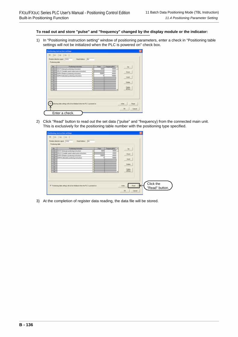
FX3U/FX3UC Series PLC User's Manual - Positioning Control EditionBuilt-in Positioning Function
11 Batch Data Positioning Mode (TBL Instruction)11.4 Positioning Parameter Setting
To read out and store "pulse" and "frequency" changed by the display module or the indicator:
1) In "Positioning instruction setting" window of positioning parameters, enter a check in "Positioning table settings will not be initialized when the PLC is powered on" check box.
2) Click "Read" button to read out the set data ("pulse" and "frequency) from the connected main unit.This is exclusively for the positioning table number with the positioning type specified.
3) At the completion of register data reading, the data file will be stored.
Enter a check.
Click the "Read" button.
B - 136
FX3U/FX3UC Series PLC User's Manual - Positioning Control EditionBuilt-in Positioning Function
12 Examples of Programs
A
Comm
on Items
B
Built-in Positioning Function
Apx.
Example
Connection
12. Examples of Programs
Assuming that the MELSERVO Series 1-axis servo amplifier is used for control, this chapter shows various examples of programs.For the connection examples of MELSERVO-C, -J2(S), -H, and -J3 Series, refer to the following chapters and manuals.
→ Refer to Chapter 3 and the examples of connection shown in the Appendix.→ Refer to the FX3U Hardware Edition.
→ Refer to the FX3UC Hardware Edition.→ Refer to the manual of your servo amplifier.
Operation InstructionExamples of programs Description
of instruction
Relay ladder program
Step ladder program
Mechanical zero return
DOG Search Zero Return DSZR(FNC150) Subsection 12.2.1 Subsection 12.3.1 Section 6.2
Absolute value detection
Reading of current ABS value ABS(FNC155) Section 12.5 - Chapter 7
1-speed positioningDrive to Increment DRVI(FNC158) Subsection 12.2.1 Subsection 12.3.1 Section 8.2Drive to Absolute DRVA(FNC159) Subsection 12.2.1 Subsection 12.3.1 Section 8.3
Batch data positioning mode TBL(FNC152) Section 12.4 - Chapter 11
B - 137
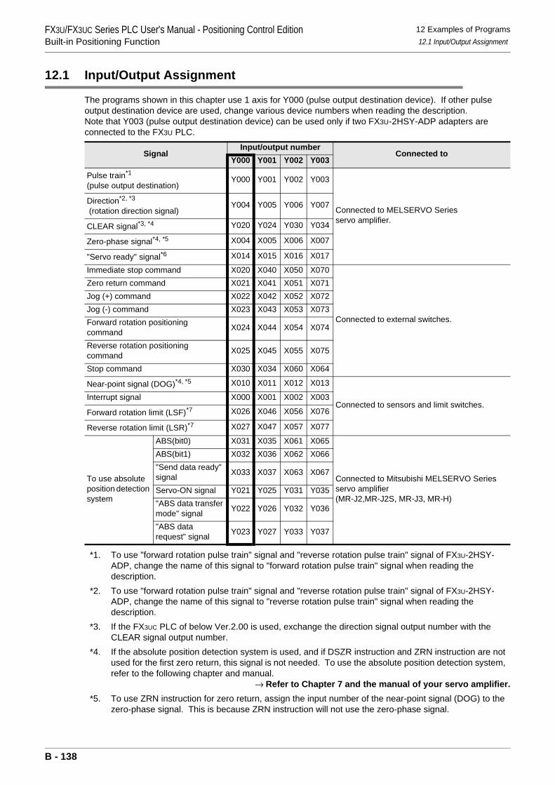
FX3U/FX3UC Series PLC User's Manual - Positioning Control EditionBuilt-in Positioning Function
12 Examples of Programs12.1 Input/Output Assignment
12.1 Input/Output Assignment
The programs shown in this chapter use 1 axis for Y000 (pulse output destination device). If other pulse output destination device are used, change various device numbers when reading the description.Note that Y003 (pulse output destination device) can be used only if two FX3U-2HSY-ADP adapters are connected to the FX3U PLC.
*1. To use "forward rotation pulse train" signal and "reverse rotation pulse train" signal of FX3U-2HSY-ADP, change the name of this signal to "forward rotation pulse train" signal when reading the description.
*2. To use "forward rotation pulse train" signal and "reverse rotation pulse train" signal of FX3U-2HSY-ADP, change the name of this signal to "reverse rotation pulse train" signal when reading the description.
*3. If the FX3UC PLC of below Ver.2.00 is used, exchange the direction signal output number with the CLEAR signal output number.
*4. If the absolute position detection system is used, and if DSZR instruction and ZRN instruction are not used for the first zero return, this signal is not needed. To use the absolute position detection system, refer to the following chapter and manual.
→ Refer to Chapter 7 and the manual of your servo amplifier.*5. To use ZRN instruction for zero return, assign the input number of the near-point signal (DOG) to the
zero-phase signal. This is because ZRN instruction will not use the zero-phase signal.
SignalInput/output number
Connected toY000 Y001 Y002 Y003
Pulse train*1
(pulse output destination)Y000 Y001 Y002 Y003
Connected to MELSERVO Seriesservo amplifier.
Direction*2, *3
(rotation direction signal)Y004 Y005 Y006 Y007
CLEAR signal*3, *4 Y020 Y024 Y030 Y034
Zero-phase signal*4, *5 X004 X005 X006 X007
"Servo ready" signal*6 X014 X015 X016 X017
Immediate stop command X020 X040 X050 X070
Connected to external switches.
Zero return command X021 X041 X051 X071Jog (+) command X022 X042 X052 X072Jog (-) command X023 X043 X053 X073Forward rotation positioning command X024 X044 X054 X074
Reverse rotation positioning command X025 X045 X055 X075
Stop command X030 X034 X060 X064
Near-point signal (DOG)*4, *5 X010 X011 X012 X013
Connected to sensors and limit switches.Interrupt signal X000 X001 X002 X003
Forward rotation limit (LSF)*7 X026 X046 X056 X076
Reverse rotation limit (LSR)*7 X027 X047 X057 X077
To use absolute position detection system
ABS(bit0) X031 X035 X061 X065
Connected to Mitsubishi MELSERVO Series servo amplifier(MR-J2,MR-J2S, MR-J3, MR-H)
ABS(bit1) X032 X036 X062 X066"Send data ready" signal X033 X037 X063 X067
Servo-ON signal Y021 Y025 Y031 Y035"ABS data transfer mode" signal Y022 Y026 Y032 Y036
"ABS data request" signal Y023 Y027 Y033 Y037
B - 138
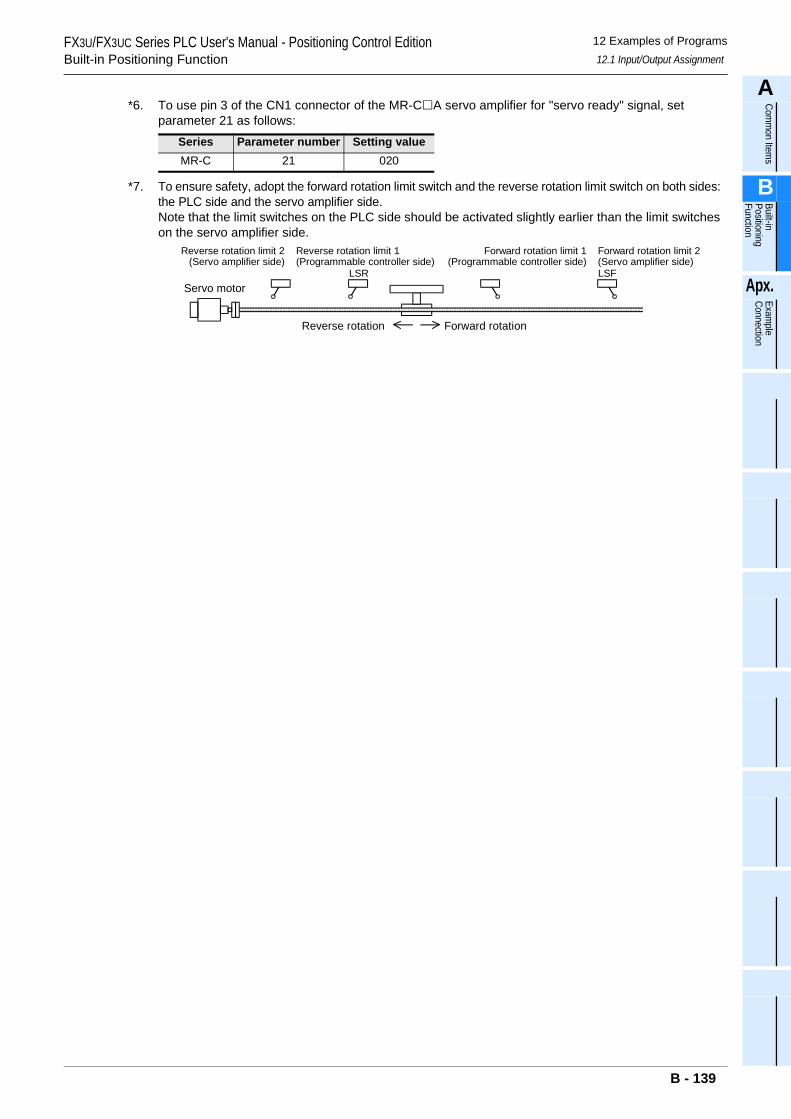
FX3U/FX3UC Series PLC User's Manual - Positioning Control EditionBuilt-in Positioning Function
12 Examples of Programs12.1 Input/Output Assignment
A
Comm
on Items
B
Built-in Positioning Function
Apx.
Example
Connection
*6. To use pin 3 of the CN1 connector of the MR-C A servo amplifier for "servo ready" signal, set parameter 21 as follows:
*7. To ensure safety, adopt the forward rotation limit switch and the reverse rotation limit switch on both sides: the PLC side and the servo amplifier side.Note that the limit switches on the PLC side should be activated slightly earlier than the limit switches on the servo amplifier side.
Series Parameter number Setting valueMR-C 21 020
Reverse rotation limit 2(Servo amplifier side)
Reverse rotation limit 1(Programmable controller side)
Forward rotation limit 2(Servo amplifier side)
Forward rotation limit 1(Programmable controller side)
Reverse rotation Forward rotation
Servo motorLSFLSR
B - 139
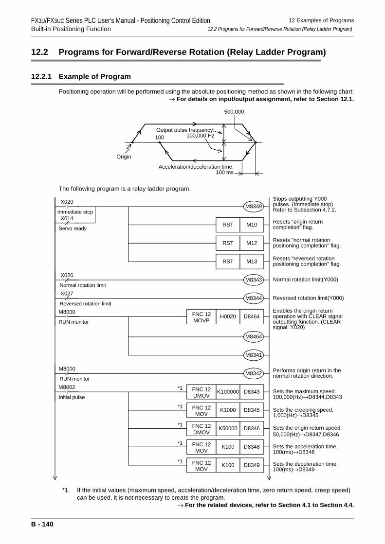
FX3U/FX3UC Series PLC User's Manual - Positioning Control EditionBuilt-in Positioning Function
12 Examples of Programs12.2 Programs for Forward/Reverse Rotation (Relay Ladder Program)
12.2 Programs for Forward/Reverse Rotation (Relay Ladder Program)
12.2.1 Example of Program
Positioning operation will be performed using the absolute positioning method as shown in the following chart:→ For details on input/output assignment, refer to Section 12.1.
The following program is a relay ladder program.
*1. If the initial values (maximum speed, acceleration/deceleration time, zero return speed, creep speed) can be used, it is not necessary to create the program.
→ For the related devices, refer to Section 4.1 to Section 4.4.
100
Origin
Output pulse frequency:100,000 Hz
Acceleration/deceleration time:100 ms
500,000
X020 Stops outputting Y000pulses. (Immediate stop)Refer to Subsection 4.7.2.
Enables the origin returnoperation with CLEAR signaloutputting function. (CLEARsignal: Y020)
Performs origin return in thenormal rotation direction.
M8349
M8341
X014Immediate stop
Servo ready
M8000
Initial pulse
M8342
M8002D8343K100000FNC 12
DMOV
D8345K1000FNC 12MOV
D8346K50000FNC 12DMOV
D8348K100FNC 12MOV
D8349K100FNC 12MOV
Sets the maximum speed.100,000(Hz)→D8344,D8343
Sets the origin return speed.50,000(Hz)→D8347,D8346
Sets the acceleration time.100(ms)→D8348
Sets the deceleration time.100(ms)→D8349
Sets the creeping speed.1,000(Hz)→D8345
M8000
RUN monitor
RUN monitor
*1
*1
*1
*1
M10RST
M12RST
M13RST
M8343
M8344
X026
Normal rotation limitX027
Reversed rotation limit
Resets "origin returncompletion" flag.
Resets "normal rotationpositioning completion" flag.
Resets "reversed rotationpositioning completion" flag.
Normal rotation limit(Y000)
Reversed rotation limit(Y000)
*1
D8464H0020FNC 12MOVP
M8464
B - 140
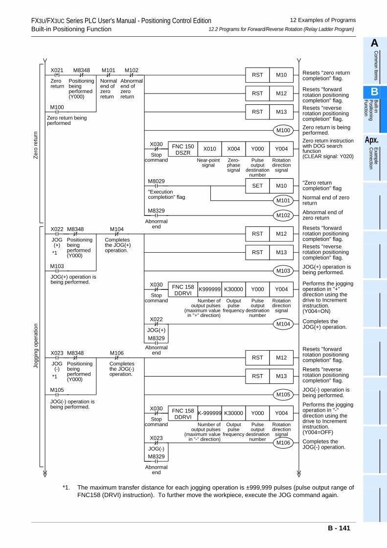
FX3U/FX3UC Series PLC User's Manual - Positioning Control EditionBuilt-in Positioning Function
12 Examples of Programs12.2 Programs for Forward/Reverse Rotation (Relay Ladder Program)
A
Comm
on Items
B
Built-in Positioning Function
Apx.
Example
Connection
*1. The maximum transfer distance for each jogging operation is ±999,999 pulses (pulse output range ofFNC158 (DRVI) instruction). To further move the workpiece, execute the JOG command again.
Zeroreturn
M8348
Positioningbeingperformed(Y000)
M10RST
M12RST
M13RST
X021 M101
Normalend ofzeroreturn
M100
Zero return beingperformed
M102
Abnormalend ofzeroreturn
M100
Y004Y000X004X010FNC 150DSZR
M8029
"Executioncompletion" flag
M10SET
M101
M102M8329
Abnormalend
JOG(+)
M8348M12RST
X022 M104
Completesthe JOG(+)operation.
Positioningbeingperformed(Y000) M13RST
M103
Y004Y000K30000K999999FNC 158DDRVI
Near-pointsignal
Zero-phasesignal
Pulseoutput
destinationnumber
Rotationdirection
signal
Number ofoutput pulses
(maximum valuein "+" direction)
Outputpulse
frequency
Pulseoutput
destinationnumber
Rotationdirection
signal
M103
JOG(+) operation isbeing performed.
X022
JOG(+)M104
M8329Abnormal
end
Zero
retu
rnJo
ggin
g op
erat
ion
JOG(-)
M8348M12RST
X023 M106
Completesthe JOG(-)operation.
Positioningbeingperformed(Y000) M13RST
M105
Y004Y000K30000K-999999FNC 158DDRVI
Number ofoutput pulses
(maximum valuein "-" direction)
Outputpulse
frequency
Pulseoutput
destinationnumber
Rotationdirection
signal
M105
JOG(-) operation isbeing performed.
X023
JOG(-)M106
M8329
Abnormalend
X030
Stopcommand
X030
Stopcommand
X030
Stopcommand
*1
*1
Resets "zero returncompletion" flag.
Resets "forwardrotation positioningcompletion" flag.Resets "reverserotation positioningcompletion" flag.Zero return is beingperformed.Zero return instructionwith DOG searchfunction(CLEAR signal: Y020)
Resets "forwardrotation positioningcompletion" flag.Resets "reverserotation positioningcompletion" flag.JOG(+) operation isbeing performed.
Performs the joggingoperation in "+"direction using thedrive to Incrementinstruction.(Y004=ON)
"Zero returncompletion" flagNormal end of zeroreturnAbnormal end ofzero return
Completes theJOG(+) operation.
Resets "forwardrotation positioningcompletion" flag.Resets "reverserotation positioningcompletion" flag.JOG(-) operation isbeing performed.
Performs the joggingoperation in "-"direction using thedrive to Incrementinstruction.(Y004=OFF)Completes theJOG(-) operation.
B - 141
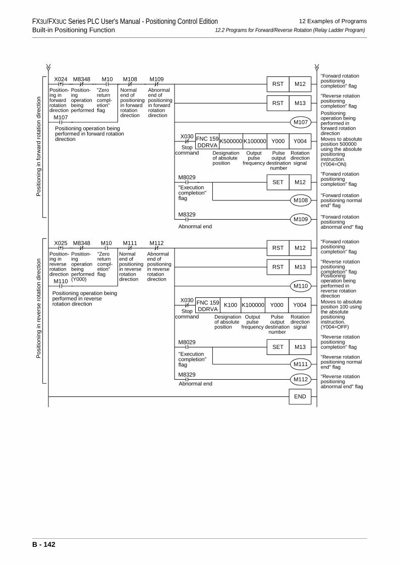
FX3U/FX3UC Series PLC User's Manual - Positioning Control EditionBuilt-in Positioning Function
12 Examples of Programs12.2 Programs for Forward/Reverse Rotation (Relay Ladder Program)
Position-ing inforwardrotationdirection
M8348
Position-ingoperationbeingperformed
X024
M107
Positioning operation beingperformed in forward rotationdirection
M107
M8029
"Executioncompletion"flag M108
M109M8329
Abnormal end
M10
"Zeroreturncompl-etion"flag
M108
Normalend ofpositioningin forwardrotationdirection
M109
Abnormalend ofpositioningin forwardrotationdirection
Posi
tioni
ng in
forw
ard
rota
tion
dire
ctio
n
M110
M8029
"Executioncompletion"flag M111
M112M8329Abnormal end
Position-ing inreverserotationdirection
M8348
Position-ingoperationbeingperformed(Y000)
X025
M110
Positioning operation beingperformed in reverserotation direction
M10
"Zeroreturncompl-etion"flag
M111
Normalend ofpositioningin reverserotationdirection
M112
Abnormalend ofpositioningin reverserotationdirection
Posi
tioni
ng in
reve
rse
rota
tion
dire
ctio
n
X030
Stopcommand
M12RST
M13RST
Y004Y000K100000K500000FNC 159DDRVA
M12SET
M12RST
M13RST
Y004Y000K100000K100
M13SET
END
X030
Stopcommand
FNC 159DDRVA
Designationof absoluteposition
Outputpulse
frequency
Pulseoutput
destinationnumber
Rotationdirection
signal
Designationof absoluteposition
Outputpulse
frequency
Pulseoutput
destinationnumber
Rotationdirection
signal
"Forward rotationpositioningcompletion" flag
"Reverse rotationpositioningcompletion" flagPositioningoperation beingperformed inforward rotationdirectionMoves to absoluteposition 500000using the absolutepositioninginstruction.(Y004=ON)
"Forward rotationpositioningcompletion" flag
"Forward rotationpositioning normalend" flag
"Forward rotationpositioningabnormal end" flag
"Forward rotationpositioningcompletion" flag
"Reverse rotationpositioningcompletion" flagPositioningoperation beingperformed inreverse rotationdirectionMoves to absoluteposition 100 usingthe absolutepositioninginstruction.(Y004=OFF)
"Reverse rotationpositioningcompletion" flag
"Reverse rotationpositioning normalend" flag
"Reverse rotationpositioningabnormal end" flag
B - 142
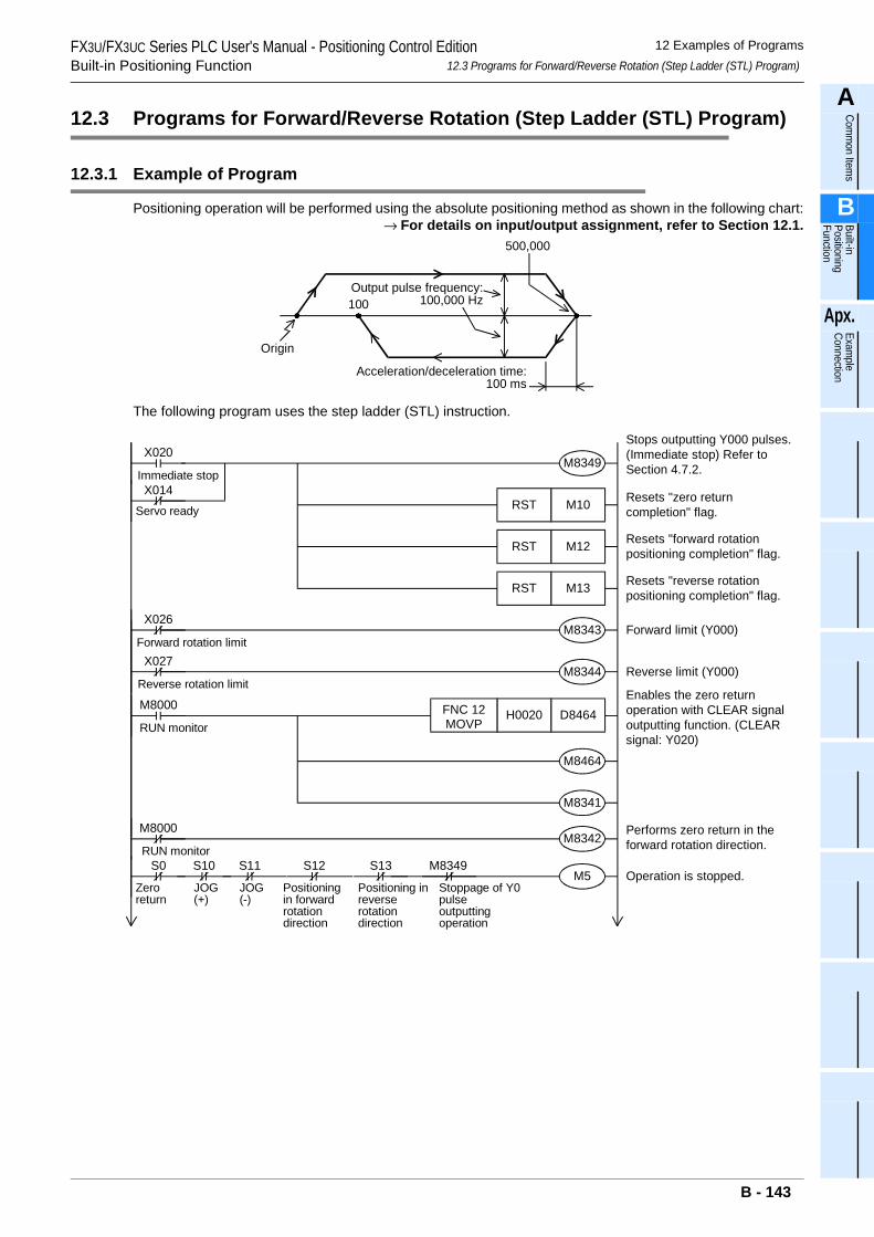
FX3U/FX3UC Series PLC User's Manual - Positioning Control EditionBuilt-in Positioning Function
12 Examples of Programs12.3 Programs for Forward/Reverse Rotation (Step Ladder (STL) Program)
A
Comm
on Items
B
Built-in Positioning Function
Apx.
Example
Connection
12.3 Programs for Forward/Reverse Rotation (Step Ladder (STL) Program)
12.3.1 Example of Program
Positioning operation will be performed using the absolute positioning method as shown in the following chart:→ For details on input/output assignment, refer to Section 12.1.
The following program uses the step ladder (STL) instruction.
100
Origin
Output pulse frequency:100,000 Hz
Acceleration/deceleration time:100 ms
500,000
Enables the zero returnoperation with CLEAR signaloutputting function. (CLEARsignal: Y020)
Performs zero return in theforward rotation direction.
Operation is stopped.
M8000
M8342
M5S0
Zeroreturn
S10 S11 S12 S13 M8349
JOG(+)
JOG(-)
Positioningin forwardrotationdirection
Positioning inreverserotationdirection
Stoppage of Y0pulseoutputtingoperation
M8000
RUN monitor
RUN monitor
X020Stops outputting Y000 pulses.(Immediate stop) Refer toSection 4.7.2.M8349
X014Immediate stop
Servo ready M10RST
M12RST
M13RST
M8343
M8344
X026
Forward rotation limitX027
Reverse rotation limit
Resets "zero returncompletion" flag.
Resets "forward rotationpositioning completion" flag.
Resets "reverse rotationpositioning completion" flag.
Reverse limit (Y000)
M8341
D8464H0020FNC 12MOVP
M8464
Forward limit (Y000)
B - 143
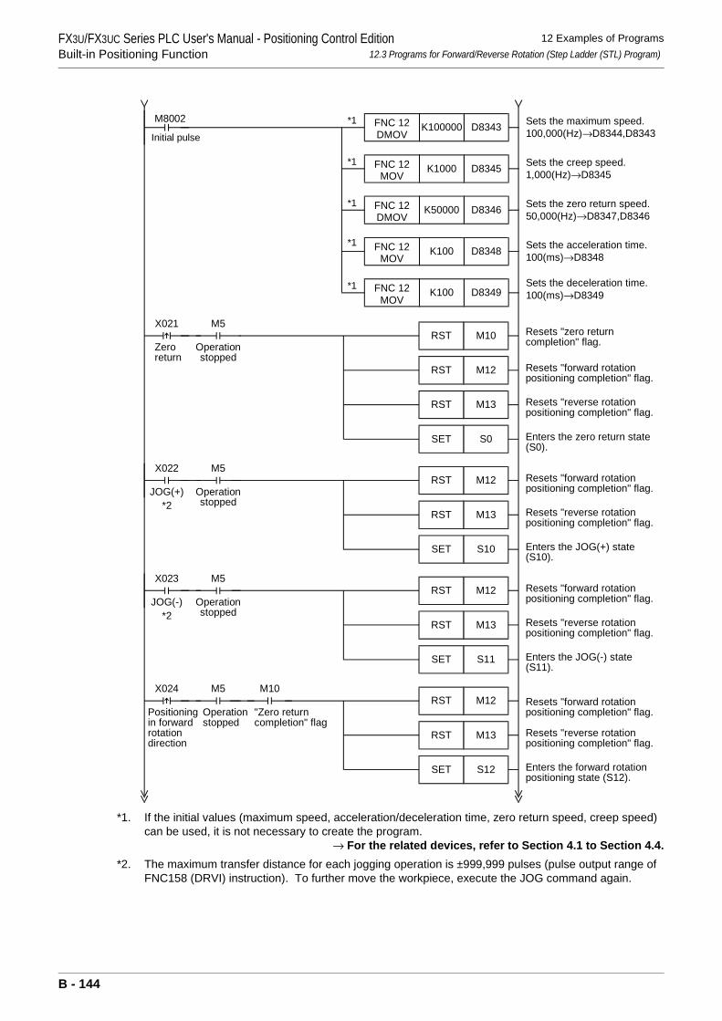
FX3U/FX3UC Series PLC User's Manual - Positioning Control EditionBuilt-in Positioning Function
12 Examples of Programs12.3 Programs for Forward/Reverse Rotation (Step Ladder (STL) Program)
*1. If the initial values (maximum speed, acceleration/deceleration time, zero return speed, creep speed) can be used, it is not necessary to create the program.
→ For the related devices, refer to Section 4.1 to Section 4.4.*2. The maximum transfer distance for each jogging operation is ±999,999 pulses (pulse output range of
FNC158 (DRVI) instruction). To further move the workpiece, execute the JOG command again.
Zeroreturn
M5
Operationstopped
X022
JOG(+)
M5
Operationstopped
Positioningin forwardrotationdirection
M5
Operationstopped
M10
"Zero returncompletion" flag
X023
JOG(-)
M5
Operationstopped
M10RST
M12RST
M13RST
S0SET
M12RST
M13RST
S10SET
M12RST
M13RST
S12SET
M12RST
M13RST
S11SET
X021
X024
*2
*2
Initial pulse
M8002D8343K100000FNC 12
DMOV
D8345K1000FNC 12MOV
D8346K50000FNC 12DMOV
D8348K100FNC 12MOV
D8349K100FNC 12MOV
*1
*1
*1
*1
*1
Resets "zero returncompletion" flag.
Resets "forward rotationpositioning completion" flag.
Resets "reverse rotationpositioning completion" flag.
Enters the zero return state(S0).
Resets "forward rotationpositioning completion" flag.
Resets "reverse rotationpositioning completion" flag.
Resets "forward rotationpositioning completion" flag.
Resets "reverse rotationpositioning completion" flag.
Resets "forward rotationpositioning completion" flag.
Resets "reverse rotationpositioning completion" flag.
Enters the JOG(+) state(S10).
Enters the JOG(-) state(S11).
Enters the forward rotationpositioning state (S12).
Sets the maximum speed.100,000(Hz)→D8344,D8343
Sets the zero return speed.50,000(Hz)→D8347,D8346
Sets the acceleration time.100(ms)→D8348
Sets the deceleration time.100(ms)→D8349
Sets the creep speed.1,000(Hz)→D8345
B - 144
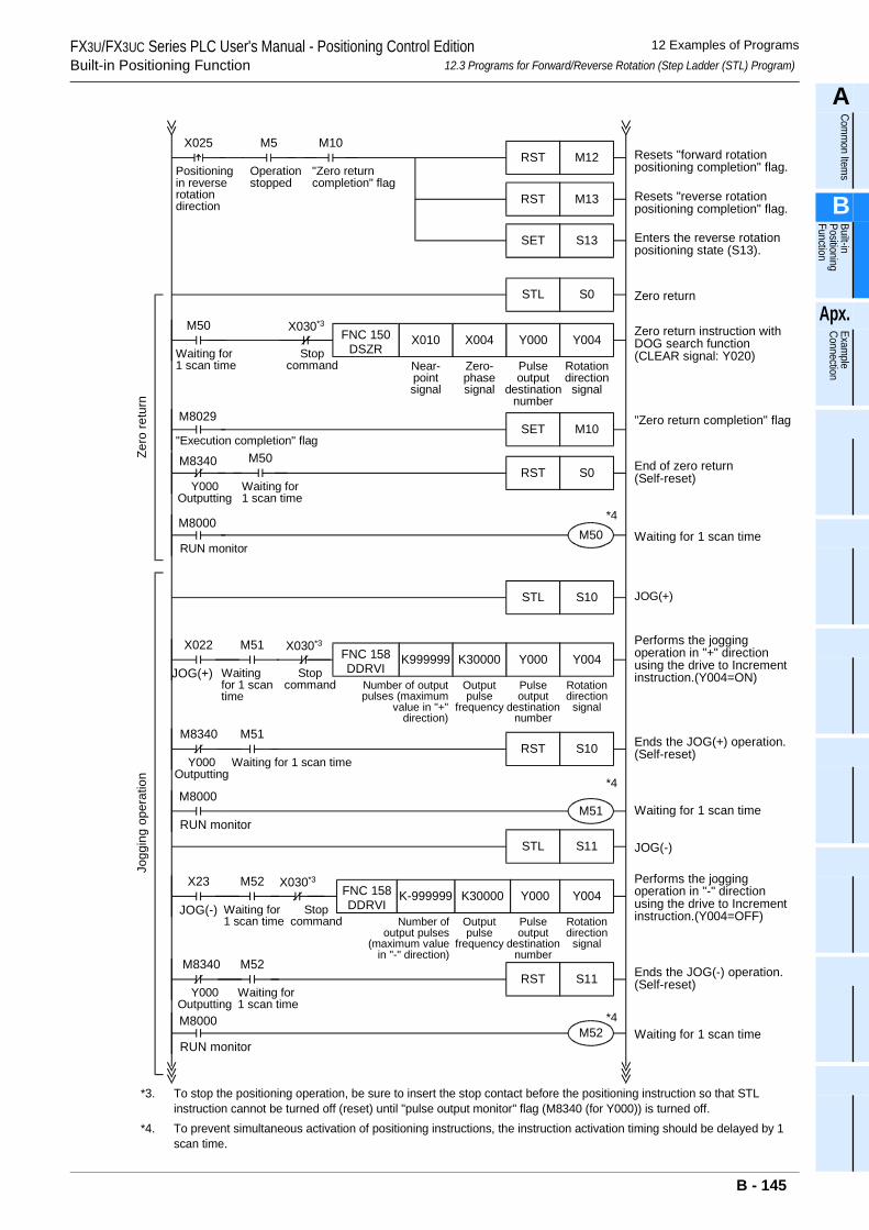
FX3U/FX3UC Series PLC User's Manual - Positioning Control EditionBuilt-in Positioning Function
12 Examples of Programs12.3 Programs for Forward/Reverse Rotation (Step Ladder (STL) Program)
A
Comm
on Items
B
Built-in Positioning Function
Apx.
Example
Connection
*3. To stop the positioning operation, be sure to insert the stop contact before the positioning instruction so that STL instruction cannot be turned off (reset) until "pulse output monitor" flag (M8340 (for Y000)) is turned off.
*4. To prevent simultaneous activation of positioning instructions, the instruction activation timing should be delayed by 1 scan time.
M8340
Y000Outputting
M50
Waiting for1 scan time
X022
JOG(+)
M51
Zero return
Zero return instruction withDOG search function(CLEAR signal: Y020)
"Zero return completion" flag
End of zero return(Self-reset)
Ends the JOG(+) operation.(Self-reset)
Performs the joggingoperation in "-" directionusing the drive to Incrementinstruction.(Y004=OFF)
Ends the JOG(-) operation.(Self-reset)
Performs the joggingoperation in "+" directionusing the drive to Incrementinstruction.(Y004=ON)
S0STL
Y004Y000
M10SET
S0RST
S10RST
M50
Waiting for1 scan time
M8029
"Execution completion" flag
X004X010FNC 150DSZR
Rotationdirection
signal
Pulseoutput
destinationnumber
Zero-phasesignal
Near-pointsignal
M50
S10STL
Y004Y000K30000K999999FNC 158DDRVI
Rotationdirection
signal
Pulseoutput
destinationnumber
Outputpulse
frequency
Number of outputpulses (maximum
value in "+"direction)
M51
S11STL JOG(-)
Y004Y000K30000K-999999FNC 158DDRVI
Rotationdirection
signal
Pulseoutput
destinationnumber
Outputpulse
frequency
Number ofoutput pulses
(maximum valuein "-" direction)
S11RST
M52
Waiting for 1 scan timeM8000
RUN monitor
M8340
Y000Outputting
M51
Waiting for 1 scan time
Waitingfor 1 scantime
M8000
RUN monitor
X23
JOG(-)
M52
Waiting for1 scan time
M8340
Y000Outputting
M52
Waiting for1 scan time
M8000
RUN monitor
*4
*4
*4
Zero
retu
rnJo
ggin
g op
erat
ion
JOG(+)
Waiting for 1 scan time
Waiting for 1 scan time
X030*3
Stopcommand
X030*3
Stopcommand
X030*3
Stopcommand
M5
Operationstopped
M10
"Zero returncompletion" flag
Resets "forward rotationpositioning completion" flag.
Resets "reverse rotationpositioning completion" flag.
Enters the reverse rotationpositioning state (S13).
M12RST
M13RST
S13SET
Positioningin reverserotationdirection
X025
B - 145
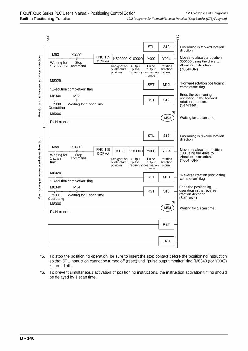
FX3U/FX3UC Series PLC User's Manual - Positioning Control EditionBuilt-in Positioning Function
12 Examples of Programs12.3 Programs for Forward/Reverse Rotation (Step Ladder (STL) Program)
*5. To stop the positioning operation, be sure to insert the stop contact before the positioning instructionso that STL instruction cannot be turned off (reset) until "pulse output monitor" flag (M8340 (for Y000))is turned off.
*6. To prevent simultaneous activation of positioning instructions, the instruction activation timing shouldbe delayed by 1 scan time.
M8340
Y000Outputting
M53
Waiting for 1 scan time
Moves to absolute position500000 using the drive toAbsolute instruction.(Y004=ON)
"Forward rotation positioningcompletion" flag
Ends the positioningoperation in the forwardrotation direction.(Self-reset)
S12STL
Y004Y000
M12SET
S12RST
M53
Waiting for1 scan time
M8029
"Execution completion" flag
K100000K500000FNC 159DDRVA
Rotationdirection
signal
Pulseoutput
destinationnumber
Outputpulse
frequency
Designationof absoluteposition
M53
M13SET
M54
M8000
RUN monitor
M8340
Y000Outputting
M54
Waiting for 1 scan time
*6
*6
Posi
tioni
ng in
forw
ard
rota
tion
dire
ctio
nPo
sitio
ning
in re
vers
e ro
tatio
n di
rect
ion
S13RST
RET
END
Ends the positioningoperation in the reverserotation direction.(Self-reset)
S13STL Positioning in reverse rotationdirection
Y004Y000M54
Waiting for1 scantime
K100000K100FNC 159DDRVA
Rotationdirection
signal
Pulseoutput
destinationnumber
Outputpulse
frequency
Designationof absoluteposition
"Reverse rotation positioningcompletion" flag
Moves to absolute position100 using the drive toAbsolute instruction.(Y004=OFF)
M8029
"Execution completion" flag
M8000
RUN monitor
Positioning in forward rotationdirection
Waiting for 1 scan time
Waiting for 1 scan time
X030*5
Stopcommand
X030*5
Stopcommand
B - 146
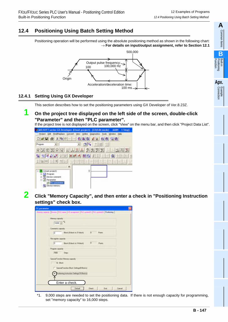
FX3U/FX3UC Series PLC User's Manual - Positioning Control EditionBuilt-in Positioning Function
12 Examples of Programs12.4 Positioning Using Batch Setting Method
A
Comm
on Items
B
Built-in Positioning Function
Apx.
Example
Connection
12.4 Positioning Using Batch Setting Method
Positioning operation will be performed using the absolute positioning method as shown in the following chart:→ For details on input/output assignment, refer to Section 12.1
12.4.1 Setting Using GX Developer
This section describes how to set the positioning parameters using GX Developer of Ver.8.23Z.
1 On the project tree displayed on the left side of the screen, double-click "Parameter" and then "PLC parameter". If the project tree is not displayed on the screen, click "View" on the menu bar, and then click "Project Data List".
2 Click "Memory Capacity", and then enter a check in "Positioning Instruction settings" check box.
*1. 9,000 steps are needed to set the positioning data. If there is not enough capacity for programming,set "memory capacity" to 16,000 steps.
100
Origin
Output pulse frequency:100,000 Hz
Acceleration/deceleration time:100 ms
500,000
Enter a check.
*1
B - 147
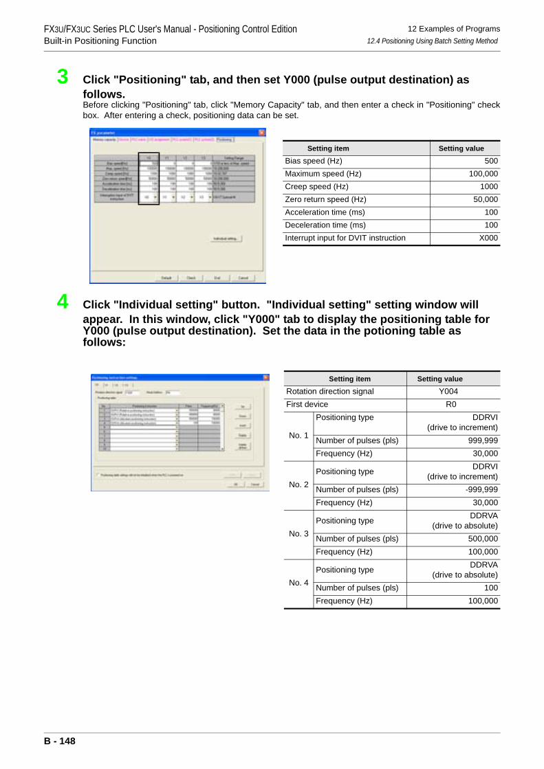
FX3U/FX3UC Series PLC User's Manual - Positioning Control EditionBuilt-in Positioning Function
12 Examples of Programs12.4 Positioning Using Batch Setting Method
3 Click "Positioning" tab, and then set Y000 (pulse output destination) as follows.Before clicking "Positioning" tab, click "Memory Capacity" tab, and then enter a check in "Positioning" checkbox. After entering a check, positioning data can be set.
4 Click "Individual setting" button. "Individual setting" setting window will appear. In this window, click "Y000" tab to display the positioning table for Y000 (pulse output destination). Set the data in the potioning table as follows:
Setting item Setting value
Bias speed (Hz) 500Maximum speed (Hz) 100,000Creep speed (Hz) 1000Zero return speed (Hz) 50,000Acceleration time (ms) 100Deceleration time (ms) 100Interrupt input for DVIT instruction X000
Setting item Setting value
Rotation direction signal Y004First device R0
No. 1
Positioning type DDRVI(drive to increment)
Number of pulses (pls) 999,999Frequency (Hz) 30,000
No. 2Positioning type DDRVI
(drive to increment)Number of pulses (pls) -999,999Frequency (Hz) 30,000
No. 3Positioning type DDRVA
(drive to absolute)Number of pulses (pls) 500,000Frequency (Hz) 100,000
No. 4Positioning type DDRVA
(drive to absolute)Number of pulses (pls) 100Frequency (Hz) 100,000
B - 148
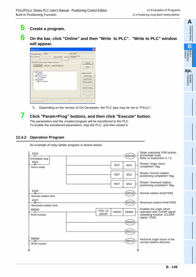
FX3U/FX3UC Series PLC User's Manual - Positioning Control EditionBuilt-in Positioning Function
12 Examples of Programs12.4 Positioning Using Batch Setting Method
A
Comm
on Items
B
Built-in Positioning Function
Apx.
Example
Connection
5 Create a program.
6 On the bar, click "Online" and then "Write to PLC". "Write to PLC" window will appear.
*1. Depending on the version of GX Developer, the PLC type may be set to "FX3UC".
7 Click "Param+Prog" buttons, and then click "Execute" button.The parameters and the created program will be transferred to the PLC.To enable the transferred parameters, stop the PLC, and then restart it.
12.4.2 Operation Program
An example of relay ladder program is shown below:
*1
X020M8349
M8341
X014Immediate stop
Servo ready
M8000
M8342M8000
RUN monitor
RUN monitor
M10RST
M12RST
M13RST
M8343
M8344
X026
Normal rotation limitX027
Reversed rotation limit
D8464H0020FNC 12MOVP
M8464
Stops outputting Y000 pulses.(Immediate stop)Refer to Subsection 4.7.2.
Enables the origin returnoperation with CLEAR signaloutputting function. (CLEARsignal: Y020)
Performs origin return in thenormal rotation direction.
Resets "origin returncompletion" flag.
Resets "normal rotationpositioning completion" flag.
Resets "reversed rotationpositioning completion" flag.
Normal rotation limit(Y000)
Reversed rotation limit(Y000)
B - 149
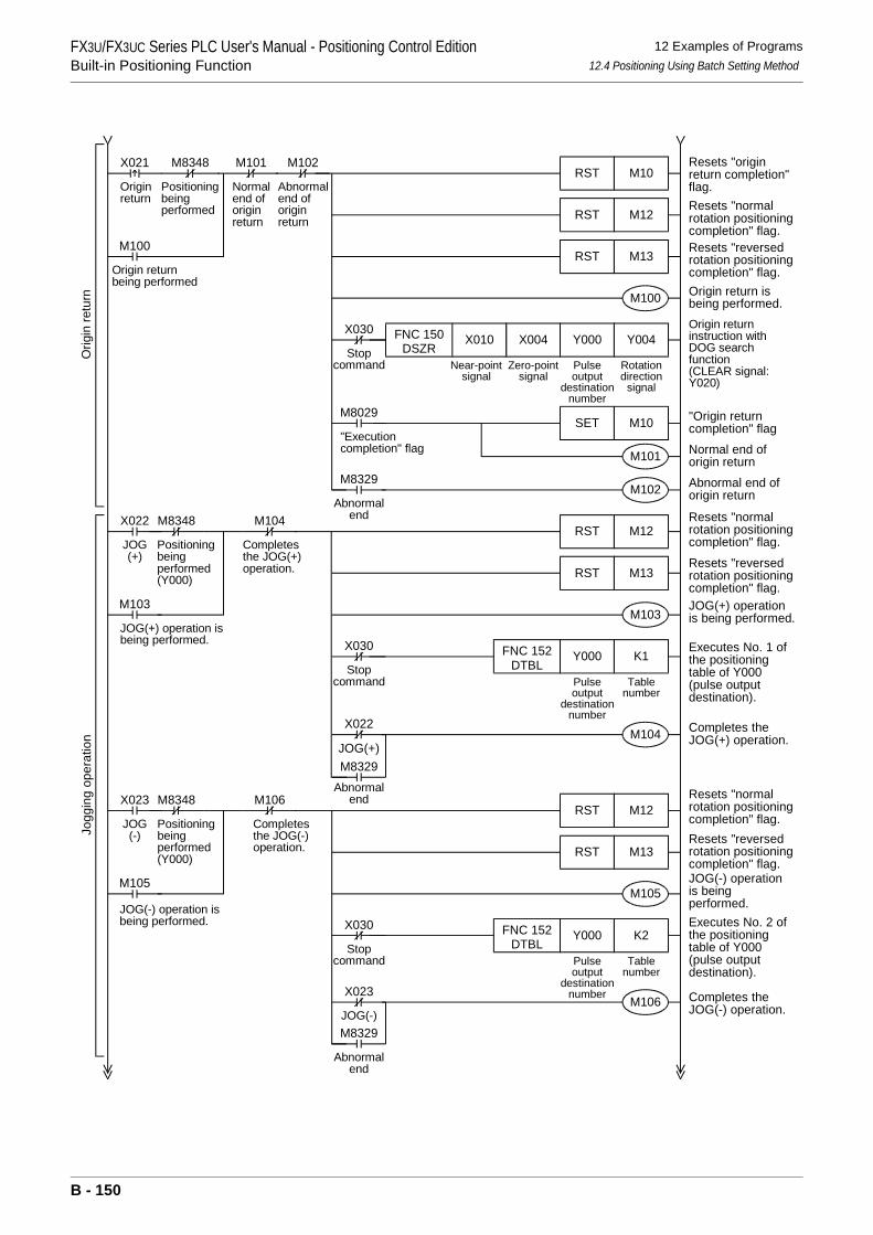
FX3U/FX3UC Series PLC User's Manual - Positioning Control EditionBuilt-in Positioning Function
12 Examples of Programs12.4 Positioning Using Batch Setting Method
Originreturn
M8348
Positioningbeingperformed
M10RST
M12RST
M13RST
X021 M101
Normalend oforiginreturn
M100
Origin returnbeing performed
M102
Abnormalend oforiginreturn
M100
Y004Y000X004X010FNC 150DSZR
M8029
"Executioncompletion" flag
M10SET
M101
M102M8329
Abnormalend
JOG(+)
M8348M12RST
X022 M104
Completesthe JOG(+)operation.
Positioningbeingperformed(Y000) M13RST
M103
K1Y000FNC 152DTBL
Near-pointsignal
Zero-pointsignal
Pulseoutput
destinationnumber
Rotationdirection
signal
Pulseoutput
destinationnumber
Tablenumber
M103
JOG(+) operation isbeing performed.
X022
JOG(+)M104
M8329Abnormal
end
Orig
in re
turn
Jogg
ing
oper
atio
n
JOG(-)
M8348M12RST
X023 M106
Completesthe JOG(-)operation.
Positioningbeingperformed(Y000) M13RST
M105
K2Y000FNC 152DTBL
Pulseoutput
destinationnumber
Tablenumber
M105
JOG(-) operation isbeing performed.
X023
JOG(-)M106
M8329
Abnormalend
X030
Stopcommand
X030
Stopcommand
X030
Stopcommand
Resets "originreturn completion"flag.Resets "normalrotation positioningcompletion" flag.Resets "reversedrotation positioningcompletion" flag.Origin return isbeing performed.Origin returninstruction withDOG searchfunction(CLEAR signal:Y020)
Resets "normalrotation positioningcompletion" flag.
Resets "reversedrotation positioningcompletion" flag.JOG(+) operationis being performed.
Executes No. 1 ofthe positioningtable of Y000(pulse outputdestination).
"Origin returncompletion" flagNormal end oforigin returnAbnormal end oforigin return
Completes theJOG(+) operation.
Resets "normalrotation positioningcompletion" flag.Resets "reversedrotation positioningcompletion" flag.JOG(-) operationis beingperformed.Executes No. 2 ofthe positioningtable of Y000(pulse outputdestination).
Completes theJOG(-) operation.
B - 150
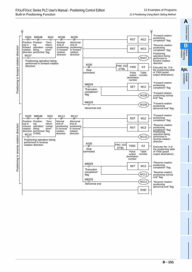
FX3U/FX3UC Series PLC User's Manual - Positioning Control EditionBuilt-in Positioning Function
12 Examples of Programs12.4 Positioning Using Batch Setting Method
A
Comm
on Items
B
Built-in Positioning Function
Apx.
Example
Connection
Position-ing inforwardrotationdirection
M8348
Position-ingoperationbeingperformed
X024
M107
Positioning operation beingperformed in forward rotationdirection
M107
M8029
"Executioncompletion"flag M108
M109M8329
Abnormal end
M10
"Zeroreturncompl-etion"flag
M108
Normalend ofpositioningin forwardrotationdirection
M109
Abnormalend ofpositioningin forwardrotationdirection
Posi
tioni
ng in
forw
ard
rota
tion
dire
ctio
n
M110
M8029
"Executioncompletion"flag M111
M112M8329Abnormal end
Position-ing inreverserotationdirection
M8348
Position-ingoperationbeingperformed(Y000)
X025
M110
Positioning operation beingperformed in reverserotation direction
M10
"Zeroreturncompl-etion"flag
M111
Normalend ofpositioningin reverserotationdirection
M112
Abnormalend ofpositioningin reverserotationdirection
Posi
tioni
ng in
reve
rse
rota
tion
dire
ctio
n
X030
Stopcommand
M12RST
M13RST
K3Y000FNC 152DTBL
M12SET
M12RST
M13RST
K4Y000
M13SET
END
X030
Stopcommand
FNC 152DTBL
Pulseoutput
destinationnumber
Tablenumber
Pulseoutput
destinationnumber
Tablenumber
"Forward rotationpositioningcompletion" flag
"Reverse rotationpositioningcompletion" flagPositioningoperation beingperformed inforward rotationdirection
"Forward rotationpositioningcompletion" flag
"Forward rotationpositioning normalend" flag
"Forward rotationpositioningabnormal end" flag
"Forward rotationpositioningcompletion" flag
"Reverse rotationpositioningcompletion" flagPositioningoperation beingperformed inreverse rotationdirection
Executes No. 4 ofthe positioning tableof Y000 (pulseoutput destination).
"Reverse rotationpositioningcompletion" flag
"Reverse rotationpositioning normalend" flag
"Reverse rotationpositioningabnormal end" flag
Executes No. 3 ofthe positioning tableof Y000 (pulseoutput destination).
B - 151
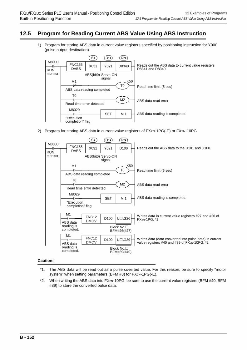
FX3U/FX3UC Series PLC User's Manual - Positioning Control EditionBuilt-in Positioning Function
12 Examples of Programs12.5 Program for Reading Current ABS Value Using ABS Instruction
12.5 Program for Reading Current ABS Value Using ABS Instruction
1) Program for storing ABS data in current value registers specified by positioning instruction for Y000 (pulse output destination)
2) Program for storing ABS data in current value registers of FX2N-1PG(-E) or FX2N-10PG
Caution:
*1. The ABS data will be read out as a pulse coverted value. For this reason, be sure to specify "motorsystem" when setting parameters (BFM #3) for FX2N-1PG(-E).
*2. When writing the ABS data into FX2N-10PG, be sure to use the current value registers (BFM #40, BFM#39) to store the converted pulse data.
M8000
RUNmonitor
FNC155DABS
X031 Y021 D8340
S• D1• D2•
Reads out the ABS data to current value registersD8341 and D8340.
Read time limit (5 sec)
ABS data read error
ABS data reading is completed.
ABS data reading completed
T0
Read time error detected
M8029
"Executioncompletion" flag
T0
M2
M 1SET
K50M1
ABS(bit0) Servo-ONsignal
M8000
RUNmonitor
FNC155DABS
X031 Y021 D100
S• D1• D2•
Reads out the ABS data to the D101 and D100.
Read time limit (5 sec)
ABS data read error
ABS data reading is completed.
Writes data (data converted into pulse data) in currentvalue registers #40 and #39 of FX2N-10PG. *2
Writes data in current value registers #27 and #26 ofFX2N-1PG. *1
ABS data reading completed
T0
Read time error detected
M8029
"Executioncompletion" flag
T0
M2
M 1SET
K50M1
M1
ABS datareading iscompleted.
D100 U \G39FNC12DMOV
Block No.BFM#39(#40)
M1
ABS datareading iscompleted.
FNC12DMOV
D100 U \G26
Block No.BFM#26(#27)
ABS(bit0) Servo-ONsignal
B - 152
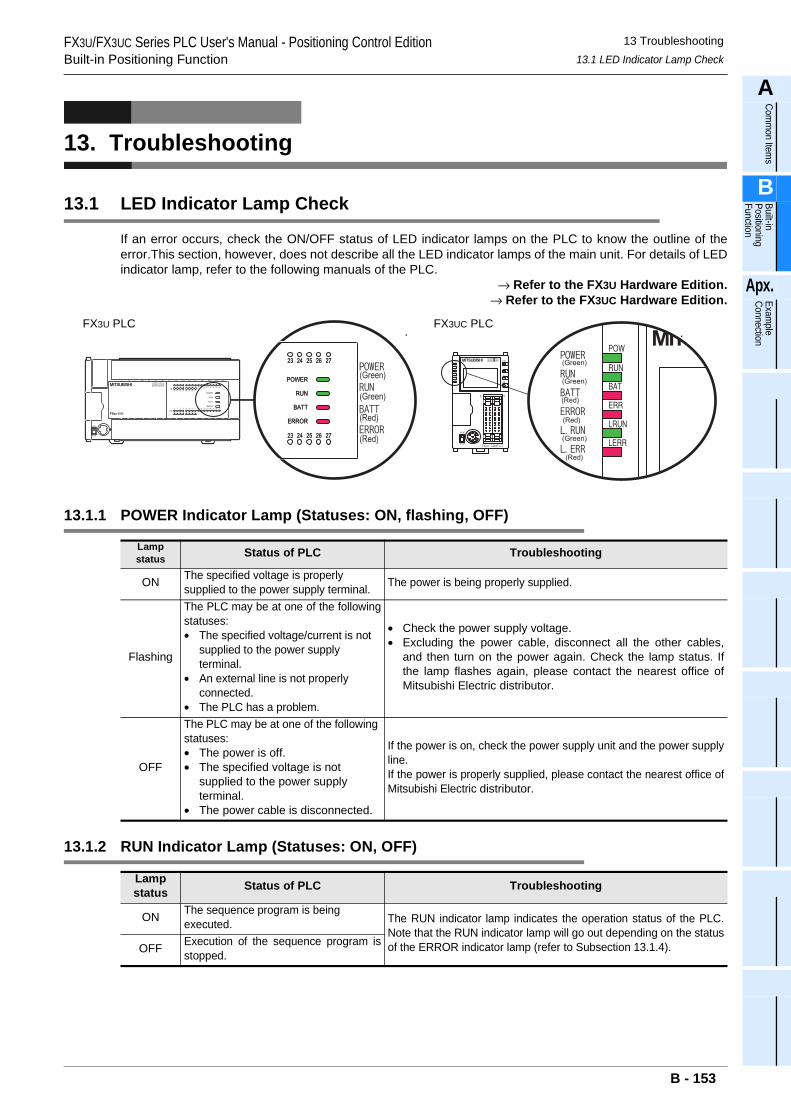
FX3U/FX3UC Series PLC User's Manual - Positioning Control EditionBuilt-in Positioning Function
13 Troubleshooting13.1 LED Indicator Lamp Check
A
Comm
on Items
B
Built-in Positioning Function
Apx.
Example
Connection
13. Troubleshooting
13.1 LED Indicator Lamp Check
If an error occurs, check the ON/OFF status of LED indicator lamps on the PLC to know the outline of theerror.This section, however, does not describe all the LED indicator lamps of the main unit. For details of LEDindicator lamp, refer to the following manuals of the PLC.
→ Refer to the FX3U Hardware Edition.→ Refer to the FX3UC Hardware Edition.
13.1.1 POWER Indicator Lamp (Statuses: ON, flashing, OFF)
13.1.2 RUN Indicator Lamp (Statuses: ON, OFF)
Lamp status Status of PLC Troubleshooting
ON The specified voltage is properly supplied to the power supply terminal. The power is being properly supplied.
Flashing
The PLC may be at one of the followingstatuses:• The specified voltage/current is not
supplied to the power supply terminal.
• An external line is not properly connected.
• The PLC has a problem.
• Check the power supply voltage.• Excluding the power cable, disconnect all the other cables,
and then turn on the power again. Check the lamp status. Ifthe lamp flashes again, please contact the nearest office ofMitsubishi Electric distributor.
OFF
The PLC may be at one of the following statuses:• The power is off.• The specified voltage is not
supplied to the power supply terminal.
• The power cable is disconnected.
If the power is on, check the power supply unit and the power supplyline.If the power is properly supplied, please contact the nearest office ofMitsubishi Electric distributor.
Lamp status Status of PLC Troubleshooting
ON The sequence program is being executed. The RUN indicator lamp indicates the operation status of the PLC.
Note that the RUN indicator lamp will go out depending on the statusof the ERROR indicator lamp (refer to Subsection 13.1.4).OFF Execution of the sequence program is
stopped.
FX3U PLC FX3UC PLC
B - 153
FX3U/FX3UC Series PLC User's Manual - Positioning Control EditionBuilt-in Positioning Function
13 Troubleshooting13.1 LED Indicator Lamp Check
13.1.3 BATT Indicator Lamp (Statuses: ON, OFF)
13.1.4 ERROR indicator lamp (Statuses: ON, flashing, OFF)
Lamp status Status of PLC Troubleshooting
ON The voltage of the battery is too low. Immediately replace the battery (refer to the manual of the PLC).
OFF The battery supplies the voltage specified by the D8006 or more. The PLC has no problems.
Lamp status Status of PLC Troubleshooting
ONThe watchdog timer error may bedetected, or the hardware of the PLCmay be damaged.
1) Stop the PLC, and then turn on the power again.If theERROR indicator lamp goes out, check if a watchdog timererror has been detected, and take one of the followingmeasures.
- Review the program.The maximum value of the scanning time (D8012) should not be larger than the set value of the watchdog timer (D8000).
- The interrupt input and the pulse catch input should not be turned on and off too frequently during 1 scan time.
- The frequency of the pulse input to the high-speed counter should not exceed the specified range (duty:50%)
- Add several WDT instructions.Set several WDT instructions in the program so that the watchdog timer can be reset several times during 1 scan time.
- Change the set value of the watchdog timer.Using the program, change the set value of the watchdog timer (D8000) so that the set value of the watchdog timer (D8000) can be larger than the maximum value of the scanning time (D8012).
2) Remove the PLC, and put it on a workbench. Supply anothersource of power to the PLC.If the ERROR indicator lamp does not light, the cause of theproblem may be noise. In this case, take the followingmeasures.
- Check the grounding line, and change the wiring route and the installation place.
- Adopt a noise filter for the power supply line.3) If taking measures 1) and 2) does not turn off the ERROR
indicator lamp, please contact the nearest office of MitsubishiElectric distributor.
Flashing
The PLC has one of the followingerrors:• Parameter error• Syntax error• Circuit error
Diagnose the PLC (PC), or check the programs using the programming tool.For countermeasures, refer to the following manual of the appliedPLC.
→ Programming manual
OFF Errors that can stop the PLC are not detected.
If an operation error is detected on the PLC, diagnose the PLC(PC), or check the programs using the programming tool. Thereis a strong possibility that "I/O configuration error", "parallel link/communication error", or "operation error" has been detected.
B - 154
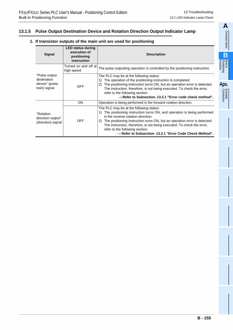
FX3U/FX3UC Series PLC User's Manual - Positioning Control EditionBuilt-in Positioning Function
13 Troubleshooting13.1 LED Indicator Lamp Check
A
Comm
on Items
B
Built-in Positioning Function
Apx.
Example
Connection
13.1.5 Pulse Output Destination Device and Rotation Direction Output Indicator Lamp
1. If transistor outputs of the main unit are used for positioning
Signal
LED status during execution of positioning instruction
Description
"Pulse output destination device" (pulse train) signal
Turned on and off athigh speed The pulse outputting operation is controlled by the positioning instruction.
OFF
The PLC may be at the following status:1) The operation of the positioning instruction is completed.2) The positioning instruction turns ON, but an operation error is detected.
The instruction, therefore, is not being executed. To check the error, refer to the following section:
→ Refer to Subsection. 13.2.1 "Error code check method".
"Rotation direction output" (direction) signal
ON Operation is being performed in the forward rotation direction.
OFF
The PLC may be at the following status:1) The positioning instruction turns ON, and operation is being performed
in the reverse rotation direction.2) The positioning instruction turns ON, but an operation error is detected.
The instruction, therefore, is not being executed. To check the error, refer to the following section:
→ Refer to Subsection. 13.2.1 "Error Code Check Method".
B - 155
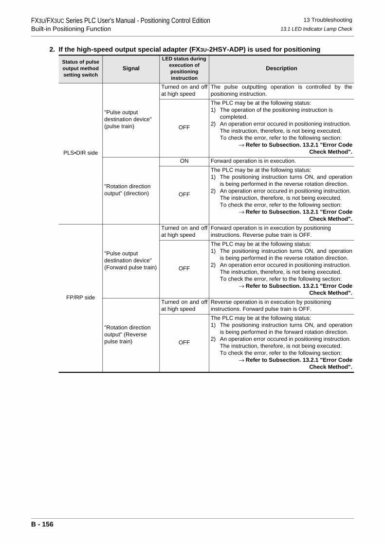
FX3U/FX3UC Series PLC User's Manual - Positioning Control EditionBuilt-in Positioning Function
13 Troubleshooting13.1 LED Indicator Lamp Check
2. If the high-speed output special adapter (FX3U-2HSY-ADP) is used for positioning
Status of pulse output method setting switch
SignalLED status during
execution of positioning instruction
Description
PLS•DIR side
"Pulse output destination device" (pulse train)
Turned on and offat high speed
The pulse outputting operation is controlled by thepositioning instruction.
OFF
The PLC may be at the following status:1) The operation of the positioning instruction is
completed.2) An operation error occured in positioning instruction.
The instruction, therefore, is not being executed.To check the error, refer to the following section:
→ Refer to Subsection. 13.2.1 "Error CodeCheck Method".
"Rotation direction output" (direction)
ON Forward operation is in execution.
OFF
The PLC may be at the following status:1) The positioning instruction turns ON, and operation
is being performed in the reverse rotation direction.2) An operation error occured in positioning instruction.
The instruction, therefore, is not being executed.To check the error, refer to the following section:
→ Refer to Subsection. 13.2.1 "Error CodeCheck Method".
FP/RP side
"Pulse output destination device" (Forward pulse train)
Turned on and offat high speed
Forward operation is in execution by positioning instructions. Reverse pulse train is OFF.
OFF
The PLC may be at the following status:1) The positioning instruction turns ON, and operation
is being performed in the reverse rotation direction.2) An operation error occured in positioning instruction.
The instruction, therefore, is not being executed.To check the error, refer to the following section:
→ Refer to Subsection. 13.2.1 "Error CodeCheck Method".
"Rotation direction output" (Reverse pulse train)
Turned on and offat high speed
Reverse operation is in execution by positioning instructions. Forward pulse train is OFF.
OFF
The PLC may be at the following status:1) The positioning instruction turns ON, and operation
is being performed in the forward rotation direction.2) An operation error occured in positioning instruction.
The instruction, therefore, is not being executed.To check the error, refer to the following section:
→ Refer to Subsection. 13.2.1 "Error CodeCheck Method".
B - 156
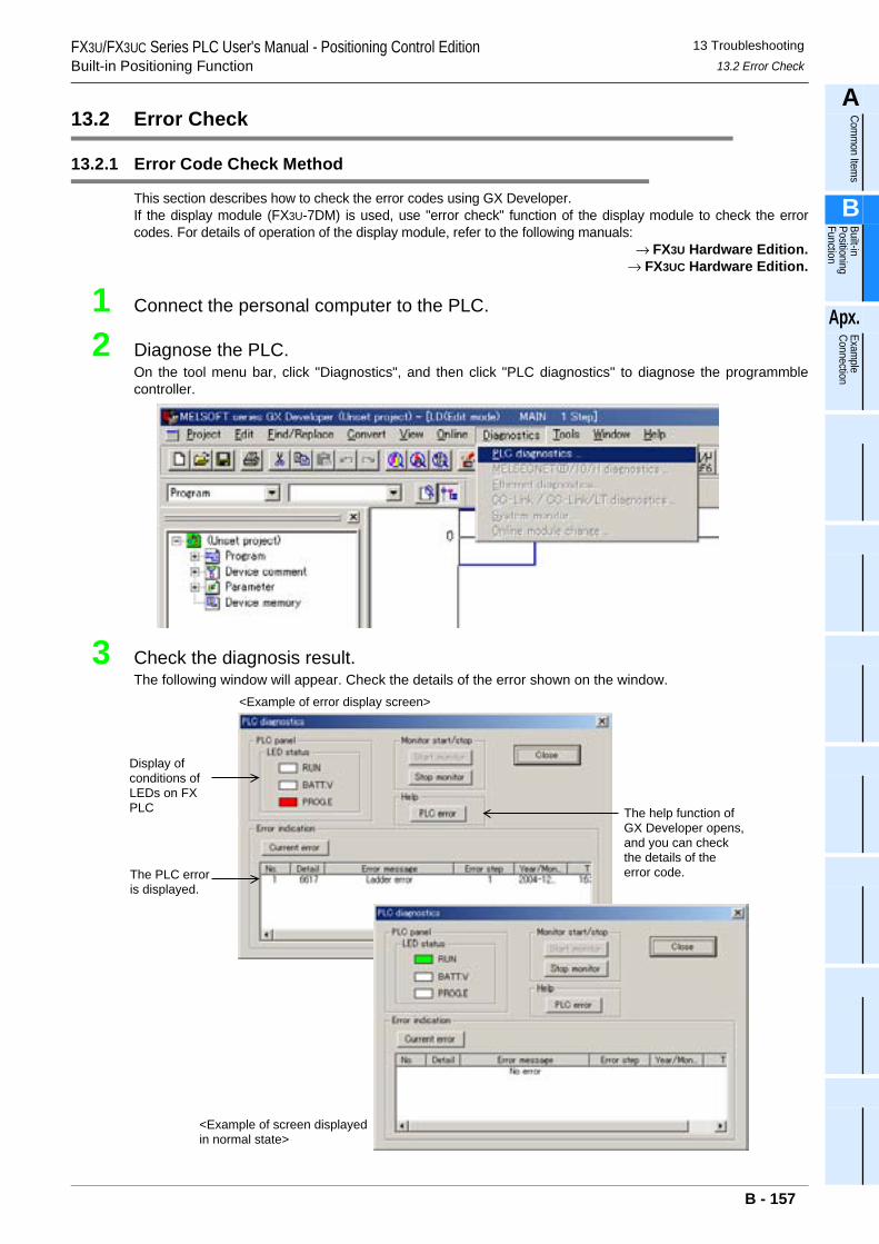
FX3U/FX3UC Series PLC User's Manual - Positioning Control EditionBuilt-in Positioning Function
13 Troubleshooting13.2 Error Check
A
Comm
on Items
B
Built-in Positioning Function
Apx.
Example
Connection
13.2 Error Check
13.2.1 Error Code Check Method
This section describes how to check the error codes using GX Developer.If the display module (FX3U-7DM) is used, use "error check" function of the display module to check the errorcodes. For details of operation of the display module, refer to the following manuals:
→ FX3U Hardware Edition.→ FX3UC Hardware Edition.
1 Connect the personal computer to the PLC.
2 Diagnose the PLC.On the tool menu bar, click "Diagnostics", and then click "PLC diagnostics" to diagnose the programmblecontroller.
3 Check the diagnosis result.The following window will appear. Check the details of the error shown on the window.
The help function of GX Developer opens, and you can check the details of the error code.
Display of conditions of LEDs on FX PLC
The PLC error is displayed.
<Example of screen displayed in normal state>
<Example of error display screen>
B - 157
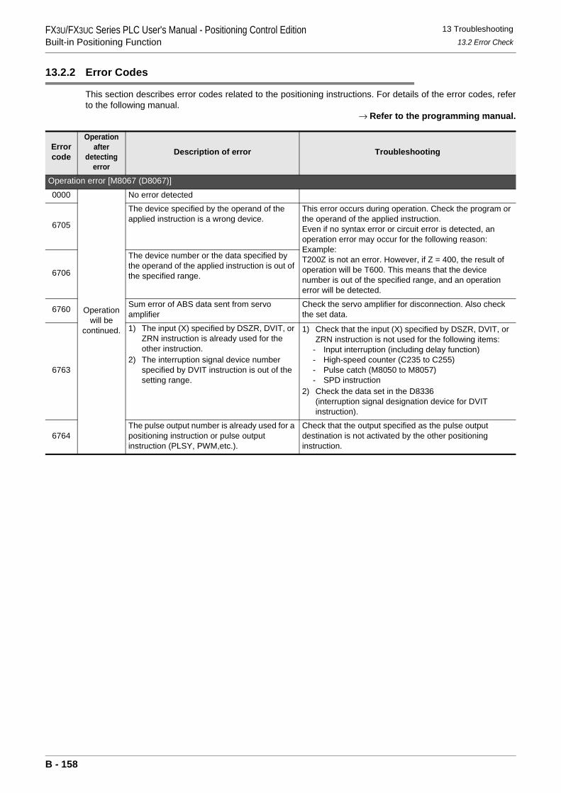
FX3U/FX3UC Series PLC User's Manual - Positioning Control EditionBuilt-in Positioning Function
13 Troubleshooting13.2 Error Check
13.2.2 Error Codes
This section describes error codes related to the positioning instructions. For details of the error codes, referto the following manual.
→ Refer to the programming manual.
Error code
Operation after
detecting error
Description of error Troubleshooting
Operation error [M8067 (D8067)]0000
Operation will be
continued.
No error detected
6705
The device specified by the operand of the applied instruction is a wrong device.
This error occurs during operation. Check the program or the operand of the applied instruction.Even if no syntax error or circuit error is detected, an operation error may occur for the following reason:Example:T200Z is not an error. However, if Z = 400, the result of operation will be T600. This means that the device number is out of the specified range, and an operation error will be detected.
6706
The device number or the data specified by the operand of the applied instruction is out of the specified range.
6760 Sum error of ABS data sent from servo amplifier
Check the servo amplifier for disconnection. Also check the set data.
6763
1) The input (X) specified by DSZR, DVIT, or ZRN instruction is already used for the other instruction.
2) The interruption signal device number specified by DVIT instruction is out of the setting range.
1) Check that the input (X) specified by DSZR, DVIT, or ZRN instruction is not used for the following items:
- Input interruption (including delay function)- High-speed counter (C235 to C255)- Pulse catch (M8050 to M8057)- SPD instruction
2) Check the data set in the D8336 (interruption signal designation device for DVIT instruction).
6764The pulse output number is already used for a positioning instruction or pulse output instruction (PLSY, PWM,etc.).
Check that the output specified as the pulse output destination is not activated by the other positioning instruction.
B - 158
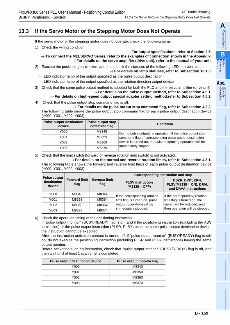
FX3U/FX3UC Series PLC User's Manual - Positioning Control EditionBuilt-in Positioning Function
13 Troubleshooting13.3 If the Servo Motor or the Stepping Motor Does Not Operate
A
Comm
on Items
B
Built-in Positioning Function
Apx.
Example
Connection
13.3 If the Servo Motor or the Stepping Motor Does Not Operate
If the servo motor or the stepping motor does not operate, check the following items.1) Check the wiring condition.
→ For output specifications, refer to Section 2.5.→ To connect the MELSERVO Series, refer to the examples of connection shown in the Appendix.
→ For details on the servo amplifier (drive unit), refer to the manual of your unit.2) Execute the positioning instruction, and then check the statuses of the following LED indicator lamps.
→ For details on lamp statuses, refer to Subsection 13.1.5.- LED indicator lamp of the output specified as the pulse output destination - LED indicator lamp of the output specified as the rotation direction output device
3) Check that the same pulse output method is adopted for both the PLC and the servo amplifier (drive unit).→ For details on the pulse output method, refer to Subsection 4.6.1.
→ For details on high-speed output special adapter setting method,refer to Subsection 4.5.2.4) Check that the pulse output stop command flag is off.
→ For details on the pulse output stop command flag, refer to Subsection 4.3.2.The following table shows the pulse output stop command flag of each pulse output destination device(Y000, Y001, Y002, Y003).
5) Check that the limit switch (forward or reverse rotation limit switch) is not activated.→ For details on the normal and reverse rotation limits, refer to Subsection 4.3.1.
The following table shows the forward and reverse limit flags of each pulse output destination device(Y000, Y001, Y002, Y003).
6) Check the operation timing of the positioning instruction.If "pulse output monitor" (BUSY/READY) flag is on, and if the positioning instruction (excluding the ABSinstruction) or the pulse output instruction (PLSR, PLSY) uses the same pulse output destination device,the instruction cannot be executed.After the instruction activation contact is turned off, if "pulse output monitor" (BUSY/READY) flag is stillon, do not execute the positioning instruction (including PLSR and PLSY instructions) having the sameoutput number.Before activating such an instruction, check that "pulse output monitor" (BUSY/READY) flag is off, andthen wait until at least 1 scan time is completed.
Pulse output destination device
Pulse output stop command flag Operation
Y000 M8349 During pulse outputting operation, if the pulse output stop command flag of corresponding pulse output destination device is turned on, the pulse outputting operation will be immediately stopped.
Y001 M8359Y002 M8369Y003 M8379
Pulse output destination
device
Forward limit flag
Reverse limit flag
Corresponding instruction and stop
PLSV instruction(M8338 = OFF)
DSZR, DVIT, ZRN, PLSV(M8338 = ON), DRVI,
and DRVA instructionsY000 M8343 M8344 If the corresponding rotation
limit flag is turned on, pulse output (operation) will be immediately stopped.
If the corresponding rotation limit flag is turned on, the speed will be reduced, and then operation will be stopped.
Y001 M8353 M8354Y002 M8363 M8364Y003 M8373 M8374
Pulse output destination device Pulse output monitor flagY000 M8340Y001 M8350Y002 M8360Y003 M8370
B - 159
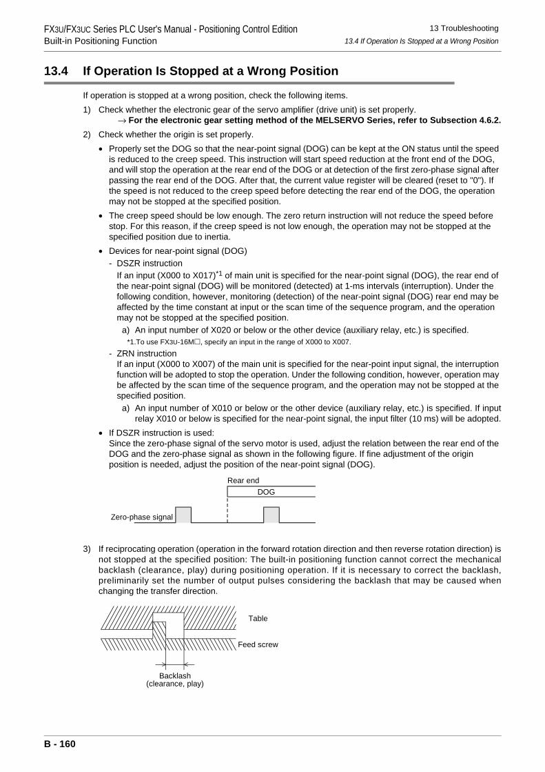
FX3U/FX3UC Series PLC User's Manual - Positioning Control EditionBuilt-in Positioning Function
13 Troubleshooting13.4 If Operation Is Stopped at a Wrong Position
13.4 If Operation Is Stopped at a Wrong Position
If operation is stopped at a wrong position, check the following items.1) Check whether the electronic gear of the servo amplifier (drive unit) is set properly.
→ For the electronic gear setting method of the MELSERVO Series, refer to Subsection 4.6.2.2) Check whether the origin is set properly.
• Properly set the DOG so that the near-point signal (DOG) can be kept at the ON status until the speed is reduced to the creep speed. This instruction will start speed reduction at the front end of the DOG, and will stop the operation at the rear end of the DOG or at detection of the first zero-phase signal after passing the rear end of the DOG. After that, the current value register will be cleared (reset to "0"). If the speed is not reduced to the creep speed before detecting the rear end of the DOG, the operation may not be stopped at the specified position.
• The creep speed should be low enough. The zero return instruction will not reduce the speed before stop. For this reason, if the creep speed is not low enough, the operation may not be stopped at the specified position due to inertia.
• Devices for near-point signal (DOG)- DSZR instruction
If an input (X000 to X017)*1 of main unit is specified for the near-point signal (DOG), the rear end of the near-point signal (DOG) will be monitored (detected) at 1-ms intervals (interruption). Under the following condition, however, monitoring (detection) of the near-point signal (DOG) rear end may be affected by the time constant at input or the scan time of the sequence program, and the operation may not be stopped at the specified position.
a) An input number of X020 or below or the other device (auxiliary relay, etc.) is specified.*1.To use FX3U-16M , specify an input in the range of X000 to X007.
- ZRN instructionIf an input (X000 to X007) of the main unit is specified for the near-point input signal, the interruption function will be adopted to stop the operation. Under the following condition, however, operation may be affected by the scan time of the sequence program, and the operation may not be stopped at the specified position.
a) An input number of X010 or below or the other device (auxiliary relay, etc.) is specified. If inputrelay X010 or below is specified for the near-point signal, the input filter (10 ms) will be adopted.
• If DSZR instruction is used:Since the zero-phase signal of the servo motor is used, adjust the relation between the rear end of the DOG and the zero-phase signal as shown in the following figure. If fine adjustment of the origin position is needed, adjust the position of the near-point signal (DOG).
3) If reciprocating operation (operation in the forward rotation direction and then reverse rotation direction) isnot stopped at the specified position: The built-in positioning function cannot correct the mechanicalbacklash (clearance, play) during positioning operation. If it is necessary to correct the backlash,preliminarily set the number of output pulses considering the backlash that may be caused whenchanging the transfer direction.
DOGRear end
Zero-phase signal
Table
Feed screw
Backlash(clearance, play)
B - 160
FX3U/FX3UC Series PLC User's Manual - Positioning Control EditionExample Connection
A
Comm
on Items
B
Built-in Positioning Function
Apx.
Example
Connection
FX3U/FX3UC Series Programmable Controllers
User's Manual [Positioning Control Edition]Appendix: Example Connection
Foreword
To use the positioning function of the MELSEC-F FX3U/FX3UC Series PLC described in this manual, the PLC should be connected to a servo amplifier drive unit. The Appendix, therefore, describes how to connect the PLC to a servo amplifier drive unit and should be read and understood before attempting to install or use the unit.Store this manual in a safe place so that you can take it out and read it whenever necessary. Always forward it to the end user.
© 2005 MITSUBISHI ELECTRIC CORPORATION
This manual confers no industrial property rights or any rights of any other kind, nor does it confer any patentlicenses. Mitsubishi Electric Corporation cannot be held responsible for any problems involving industrial propertyrights which may occur as a result of using the contents noted in this manual.
Apx. - 1
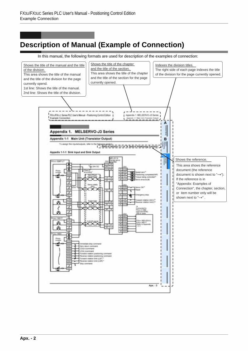
FX3U/FX3UC Series PLC User's Manual - Positioning Control EditionExample Connection
Description of Manual (Example of Connection)In this manual, the following formats are used for description of the examples of connection:
Shows the title of the manual and the titleof the division.This area shows the title of the manualand the title of the division for the pagecurrently opend.1st line: Shows the title of the manual.2nd line: Shows the title of the division.
Shows the title of the chapterand the title of the section.This area shows the title of the chapter and the title of the section for the pagecurrently opened.
Indexes the division titles.The right side of each page indexes the titleof the division for the page currently opened.
Shows the reference.
This area shows the reference document (the reference document is shown next to " ").If the reference is in "Appendix: Examples of Connection", the chapter, section, or item number only will be shown next to " " .
Apx. - 2
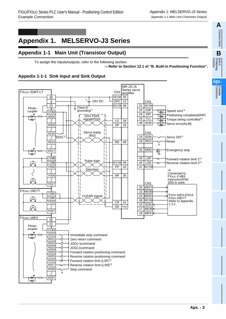
FX3U/FX3UC Series PLC User's Manual - Positioning Control EditionExample Connection
Appendix 1: MELSERVO-J3 SeriesAppendix 1-1 Main Unit (Transistor Output)
A
Comm
on Items
B
Built-in Positioning Function
Apx.
Example
Connection
Appendix 1. MELSERVO-J3 Series
Appendix 1-1 Main Unit (Transistor Output)To assign the inputs/outputs, refer to the following section.
→ Refer to Section 12.1 of "B. Built-in Positioning Function".
Appedix 1-1-1 Sink Input and Sink Output
LGOP
DOCOMPP
CN1
3433
4610
DOCOM
DICOM
46
20OPC 12
NP 35
RD 49
DICOMZSPINP
212324
TLC25ALM48
CN1
SONRES
EMG
1519
42
LSP43LSN44
CN1
DOCOM47
ABSTABSB0ABSB1
252223
D0COM46SON15ABSMABSR
1718
CN1
FX2N-16EX-ES/ULFX2N-16EYTRefer to Appendix1.3.1.
24V DC
CR 41SD Plate
DOG*2
COM
X004
X017
FX3UC-32MT-LT
X010
X014
X000
COM0COM0Y000
Y017
Y004
COMX020
FX2NC-16EX
X021X022X023X024
X026X027
X037
X025
X030
COM1FX2NC-16EYT
Y020
Y027
COM1
Photo-coupler
Photo-coupler
Immediate stop commandZero return commandJOG(+)commandJOG(-)commandForward rotation positioning command
Forward rotation limit (LSF)*3
Reverse rotation limit (LSR)*3
Reverse rotation positioning command
Stop command
Class-Dgrounding*1
Zero Pointsignal(PG0)
Servo ready(RD)
Pulse train
CLEAR signal
MR-J3 ASeries servoamplifier
Speed zero*4
Positioning completed(INP)Torque being controlled*4
Servo error(ALM)
*4Connected toFX3UC if ABSinstruction(FNC155) is used.
Servo ON*4
Reset
Emergency stop
Forward rotation limit 2*3
Reverse rotation limit 2*3
Direction
Apx. - 3
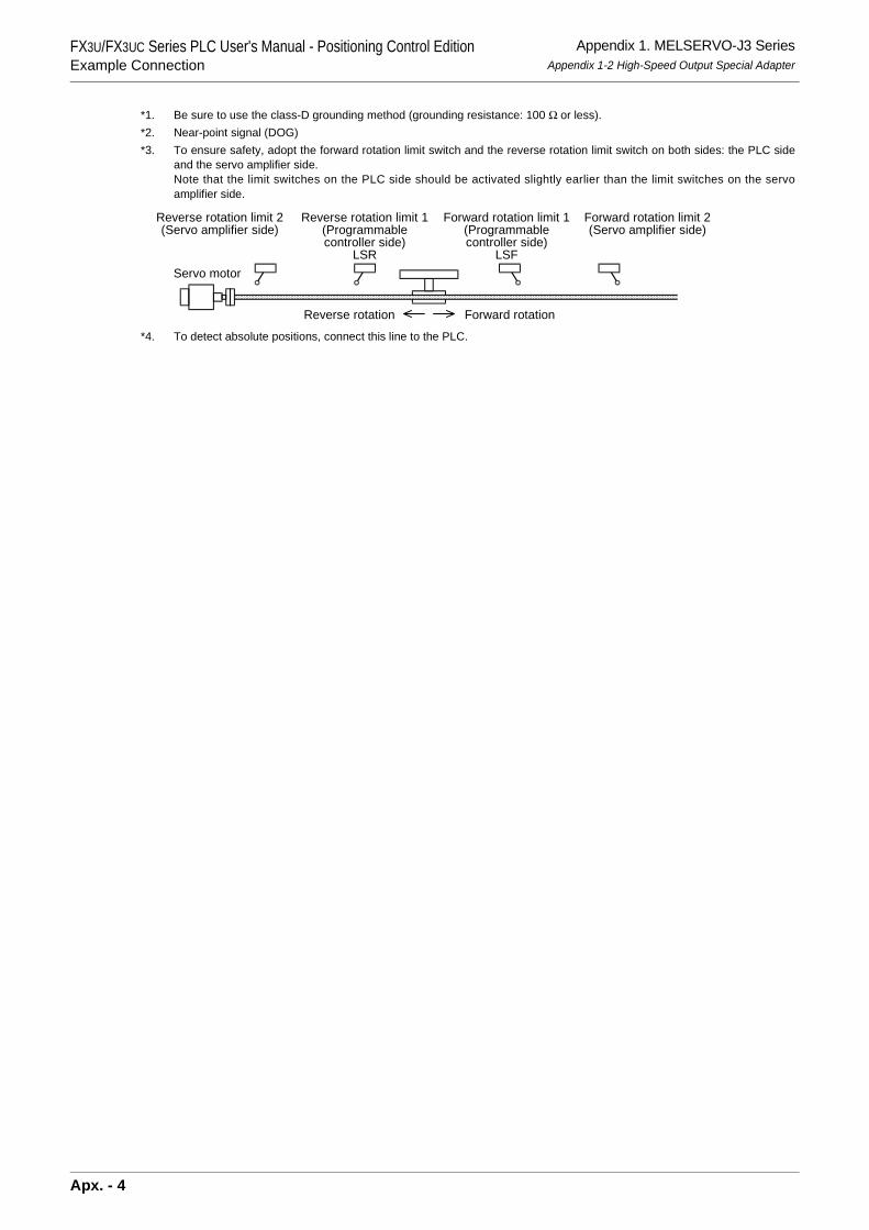
FX3U/FX3UC Series PLC User's Manual - Positioning Control EditionExample Connection
Appendix 1. MELSERVO-J3 SeriesAppendix 1-2 High-Speed Output Special Adapter
*1. Be sure to use the class-D grounding method (grounding resistance: 100 Ω or less).*2. Near-point signal (DOG)*3. To ensure safety, adopt the forward rotation limit switch and the reverse rotation limit switch on both sides: the PLC side
and the servo amplifier side.Note that the limit switches on the PLC side should be activated slightly earlier than the limit switches on the servoamplifier side.
*4. To detect absolute positions, connect this line to the PLC.
Reverse rotation limit 2(Servo amplifier side)
Reverse rotation limit 1(Programmablecontroller side)
LSR
Forward rotation limit 2(Servo amplifier side)
Forward rotation limit 1(Programmablecontroller side)
LSF
Reverse rotation Forward rotation
Servo motor
Apx. - 4
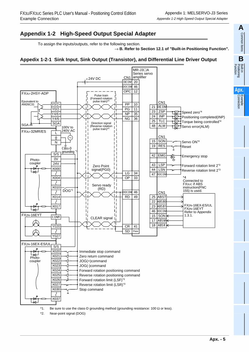
FX3U/FX3UC Series PLC User's Manual - Positioning Control EditionExample Connection
Appendix 1: MELSERVO-J3 SeriesAppendix 1-2 High-Speed Output Special Adapter
A
Comm
on Items
B
Built-in Positioning Function
Apx.
Example
Connection
Appendix 1-2 High-Speed Output Special Adapter
To assign the inputs/outputs, refer to the following section.→ B. Refer to Section 12.1 of "Built-in Positioning Function".
Appedix 1-2-1 Sink Input, Sink Output (Transistor), and Differential Line Driver Output
*1. Be sure to use the class-D grounding method (grounding resistance: 100 Ω or less).*2. Near-point signal (DOG)
Y0/2+
FX3U-2HSY-ADP
Y0/2-
SGA
Y4/6+Y4/6-
Epuivalent toAM26C31
SGA
Pulse train(Forward rotation
pulse train)*5
LGOP
DOCOM
SD
3433
46
41Plate
DOCOMDICOM
4620
CN1
OPC 12
DICOMZSPINP
212324
TLC25ALM48
CN1
SONRES
EMG
1519
42
LSP43LSN44
CN1
DOCOM47
ABSTABSB0ABSB1
25222346
SON15ABSMABSR
1718
CN1
FX2N-16EX-ES/ULFX2N-16EYTRefer to Appendix1.3.1.
NP 35
RD 49
CR
PP 10PG 11
NG 36
DOCOM
S/SX020
FX2N-16EX-ES/UL
X021X022X023X024
X026X027
X037
X025
X030
COM1FX2N-16EYT
Y020
Y027
DOG*2
X004
X017
FX3U-32MR/ES
X010
X014
X00024V0VS/S
N
L100V to240V AC
24V DC
Photo-coupler
Photo-coupler
Class-Dgrounding *1
Zero Pointsignal(PG0)
Servo ready(RD)
CLEAR signal
MR-J3 ASeries servoamplifier
Speed zero*4
Positioning completed(INP)Torque being controlled*4
Servo error(ALM)
*4Connected toFX3UC if ABSinstruction(FNC155) is used.
Servo ON*4
Reset
Emergency stop
Forward rotation limit 2*3
Reverse rotation limit 2*3
Immediate stop commandZero return commandJOG(+)commandJOG(-)commandForward rotation positioning command
Forward rotation limit (LSF)*3
Reverse rotation limit (LSR)*3
Reverse rotation positioning command
Stop command
Direction signal(Reverse rotation
pulse train)*5
Apx. - 5
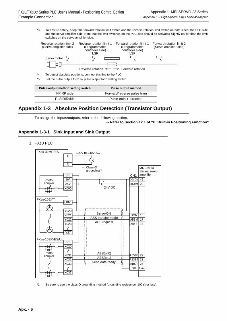
FX3U/FX3UC Series PLC User's Manual - Positioning Control EditionExample Connection
Appendix 1. MELSERVO-J3 SeriesAppendix 1-2 High-Speed Output Special Adapter
*3. To ensure safety, adopt the forward rotation limit switch and the reverse rotation limit switch on both sides: the PLC sideand the servo amplifier side. Note that the limit switches on the PLC side should be activated slightly earlier than the limitswitches on the servo amplifier side.
*4. To detect absolute positions, connect this line to the PLC.*5. Set the pulse output form by pulse output form setting switch.
Appendix 1-3 Absolute Position Detection (Transistor Output)To assign the inputs/outputs, refer to the following section.
→ Refer to Section 12.1 of "B. Built-in Positioning Function"
Appendix 1-3-1 Sink Input and Sink Output
1. FX3U PLC
*1. Be sure to use the class-D grounding method (grounding resistance: 100 Ω or less).
Pulse output method setting switch Pulse output method
FP•RP side Forward/reverse pulse trainPLS•DIRside Pulse train + direction
Reverse rotation limit 2(Servo amplifier side)
Reverse rotation limit 1(Programmablecontroller side)
LSR
Forward rotation limit 2(Servo amplifier side)
Forward rotation limit 1(Programmablecontroller side)
LSF
Reverse rotation Forward rotation
Servo motor
FX3U-32MR/ES
X00024V0VS/S
N
L100V to 240V AC
COM1FX2N-16EYT
Y020
Y27
Y021Y022Y023
ABS(bit0)ABS(bit1)
DOCOM 46
22
DICOM 20
ABST 25
ABSB1 23
SD Plate
CN1
SON 15
ABSR 18ABSM 17
ABSB0 22
ABST 25ABSB1 23
S/SX020
FX2N-16EX-ES/UL
X031X032X033
X037
24V DC
Photo-coupler
Photo-coupler
Class-Dgrounding *1
Servo-ONABS transfer mode
ABS request
MR-J3 ASeries servoamplifier
Send data ready
Apx. - 6
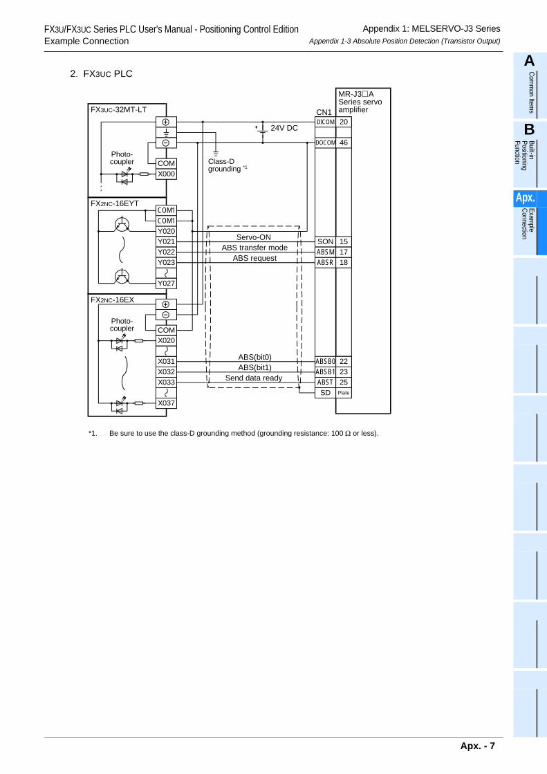
FX3U/FX3UC Series PLC User's Manual - Positioning Control EditionExample Connection
Appendix 1: MELSERVO-J3 SeriesAppendix 1-3 Absolute Position Detection (Transistor Output)
A
Comm
on Items
B
Built-in Positioning Function
Apx.
Example
Connection
2. FX3UC PLC
*1. Be sure to use the class-D grounding method (grounding resistance: 100 Ω or less).
FX3UC-32MT-LT
DOCOM 46
22
DICOM 20
ABST 2523
SD Plate
CN1
24V DC
COM1FX2NC-16EYT
Y020
Y027
COM1
Y021Y022Y023
COMX000
COMX020
FX2NC-16EX
X031X032X033
X037
SON 15
ABSR 18ABSM 17
ABSB0 22
ABST 25ABSB1 23
Photo-coupler
Photo-coupler
Class-Dgrounding *1
ABS(bit0)ABS(bit1)
Servo-ONABS transfer mode
ABS request
Send data ready
MR-J3 ASeries servoamplifier
Apx. - 7
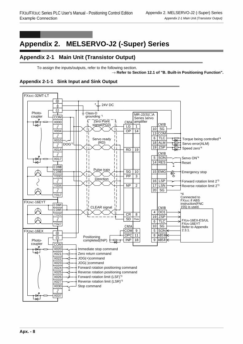
FX3U/FX3UC Series PLC User's Manual - Positioning Control EditionExample Connection
Appendix 2. MELSERVO-J2 (-Super) SeriesAppendix 2-1 Main Unit (Transistor Output)
Appendix 2. MELSERVO-J2 (-Super) Series
Appendix 2-1 Main Unit (Transistor Output)
To assign the inputs/outputs, refer to the following section.→ Refer to Section 12.1 of "B. Built-in Positioning Function".
Appendix 2-1-1 Sink Input and Sink Output
LGOP
SGPP
CR
NP
SD
CN1A
SONRES
EMG
514
15
LSP16LSN17
CN1B
SG20
DO1ZSPTLC
4196
SG10SON5ABSMABSR
89
CN1B
SGCOM
1013
CN1B
ZSP19
TLC6ALM18
COMOPCINP
RD
Plate
114
103
8
2
91118
19
CN1A
FX2N-16EX-ES/ULFX2N-16EYTRefer to Appendix2.3.1.
24V DC
COMX020
FX2NC-16EX
X021X022X023X024
X026X027
X037
X025
X030
COM1FX2NC-16EYT
Y020
Y027
COM1
DOG*2
COM
X004
X017
FX3UC-32MT-LT
X010
X014
X000
COM0COM0Y000
Y017
Y004
Photo-coupler
Photo-coupler
Class-Dgrounding *1
Zero Pointsignal(PG0)
Servo ready(RD)
Pulse train
CLEAR signal
Positioningcompleted(INP)
Speed zero*4
Torque being controlled*4
Servo error(ALM)
MR-J2(S) ASeries servoamplifier
*4Connected toFX3UC if ABSinstruction(FNC155) is used.
Servo ON*4
Reset
Emergency stop
Forward rotation limit 2*3
Reverse rotation limit 2*3
Immediate stop commandZero return commandJOG(+)commandJOG(-)commandForward rotation positioning command
Forward rotation limit (LSF)*3
Reverse rotation limit (LSR)*3
Reverse rotation positioning command
Stop command
Direction
Apx. - 8
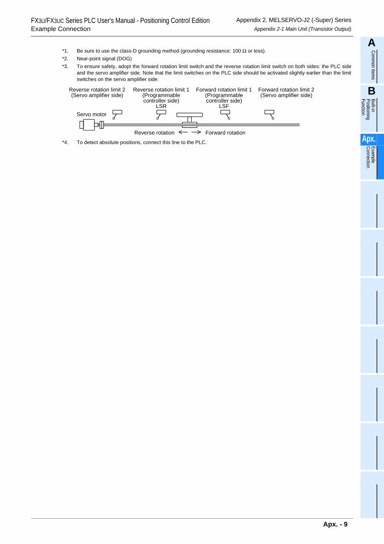
FX3U/FX3UC Series PLC User's Manual - Positioning Control EditionExample Connection
Appendix 2. MELSERVO-J2 (-Super) SeriesAppendix 2-1 Main Unit (Transistor Output)
A
Comm
on Items
B
Built-in Positioning Function
Apx.
Example
Connection
*1. Be sure to use the class-D grounding method (grounding resistance: 100 Ω or less).*2. Near-point signal (DOG)*3. To ensure safety, adopt the forward rotation limit switch and the reverse rotation limit switch on both sides: the PLC side
and the servo amplifier side. Note that the limit switches on the PLC side should be activated slightly earlier than the limitswitches on the servo amplifier side.
*4. To detect absolute positions, connect this line to the PLC.
Reverse rotation limit 2(Servo amplifier side)
Reverse rotation limit 1(Programmablecontroller side)
LSR
Forward rotation limit 2(Servo amplifier side)
Forward rotation limit 1(Programmablecontroller side)
LSF
Reverse rotation Forward rotation
Servo motor
Apx. - 9
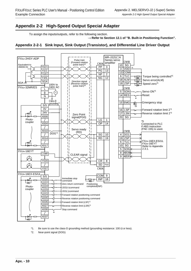
FX3U/FX3UC Series PLC User's Manual - Positioning Control EditionExample Connection
Appendix 2. MELSERVO-J2 (-Super) SeriesAppendix 2-2 High-Speed Output Special Adapter
Appendix 2-2 High-Speed Output Special Adapter
To assign the inputs/outputs, refer to the following section.→ Refer to Section 12.1 of "B. Built-in Positioning Function".
Appendix 2-2-1 Sink Input, Sink Output (Transistor), and Differential Line Driver Output
*1. Be sure to use the class-D grounding method (grounding resistance: 100 Ω or less).*2. Near-point signal (DOG)
LGOP
SG
CR
NP
SD
CN1A
SONRES
EMG
514
15
LSP16LSN17
CN1B
SG20
DO1ZSPTLC
4196
SG10SON5ABSMABSR
89
CN1B
VDDCOM
313
CN1B
ZSP19
TLC6ALM18
COMINP
RD
Plate
114
10
8
2
918
19
CN1A
FX2N-16EX-ES/ULFX2N-16EYTRefer to Appendix2.3.1.
COM1FX2N-16EYT
Y020
Y027
Y0/2+
FX3U-2HSY-ADP
Y0/2-
SGA
Y4/6+Y4/6-
SGA
DOG*2
X004
X017
FX3U-32MR/ES
X010
X014
X00024V0VS/S
N
L100V to240V AC
PP 3PG 13
NG 12
S/SX020
FX2N-16EX-ES/UL
X021X022X023X024
X026X027
X037
X025
X030
SG10*4
Photo-coupler
Photo-coupler
Class-Dgrounding*1
Zero Pointsignal(PG0)
Servo ready(RD)
CLEAR signal
Immediate stopcommandZero return commandJOG(+)commandJOG(-)commandForward rotation positioning command
Forward rotation limit (LSF)*3
Reverse rotation limit (LSR)*3
Reverse rotation positioning command
Stop command
Positioningcompleted(INP)
MR-J2(S) ASeries servoamplifier
Speed zero*5
Torque being controlled*5
Servo error(ALM)
*5Connected to PLCif ABS instruction(FNC 155) is used.
Servo ON*5
Reset
Emergency stop
Forward rotation limit 2*3
Reverse rotation limit 2*3
Epuivalent toAM26C31
Pulse train(Forward rotation
pulse train)*6
Direction signal(Reverse rotation
pulse train)*6
Apx. - 10
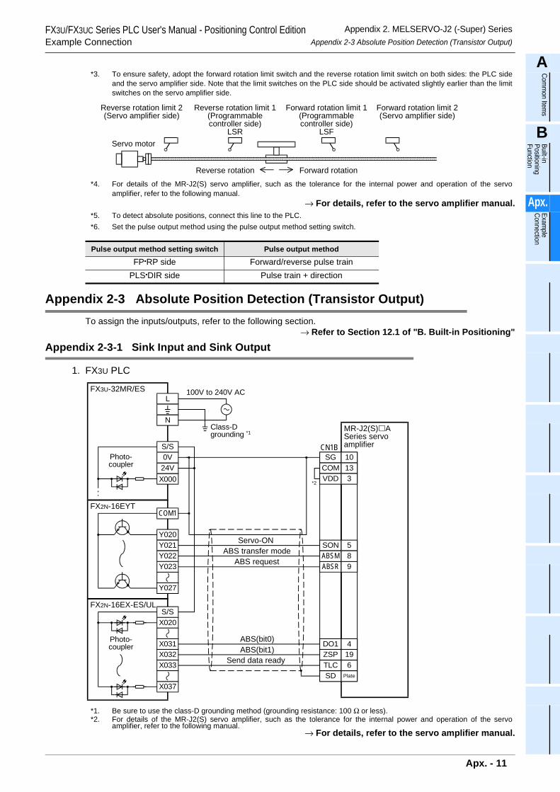
FX3U/FX3UC Series PLC User's Manual - Positioning Control EditionExample Connection
Appendix 2. MELSERVO-J2 (-Super) SeriesAppendix 2-3 Absolute Position Detection (Transistor Output)
A
Comm
on Items
B
Built-in Positioning Function
Apx.
Example
Connection
*3. To ensure safety, adopt the forward rotation limit switch and the reverse rotation limit switch on both sides: the PLC sideand the servo amplifier side. Note that the limit switches on the PLC side should be activated slightly earlier than the limitswitches on the servo amplifier side.
*4. For details of the MR-J2(S) servo amplifier, such as the tolerance for the internal power and operation of the servoamplifier, refer to the following manual.
→ For details, refer to the servo amplifier manual.*5. To detect absolute positions, connect this line to the PLC.*6. Set the pulse output method using the pulse output method setting switch.
Appendix 2-3 Absolute Position Detection (Transistor Output)To assign the inputs/outputs, refer to the following section.
→ Refer to Section 12.1 of "B. Built-in Positioning"
Appendix 2-3-1 Sink Input and Sink Output
1. FX3U PLC
*1. Be sure to use the class-D grounding method (grounding resistance: 100 Ω or less).*2. For details of the MR-J2(S) servo amplifier, such as the tolerance for the internal power and operation of the servo
amplifier, refer to the following manual.→ For details, refer to the servo amplifier manual.
Pulse output method setting switch Pulse output method
FP•RP side Forward/reverse pulse trainPLS•DIR side Pulse train + direction
Reverse rotation limit 2(Servo amplifier side)
Reverse rotation limit 1(Programmablecontroller side)
LSR
Forward rotation limit 2(Servo amplifier side)
Forward rotation limit 1(Programmablecontroller side)
LSF
Reverse rotation Forward rotation
Servo motor
FX3U-32MR/ES
X00024V0VS/S
N
L100V to 240V AC
COM1FX2N-16EYT
Y020
Y027
Y021Y022Y023
SD Plate
SON
ABSRABSM
SGCOM
CN1B1013
5
98
DO1
TLCZSP
4
619
S/SX020
FX2N-16EX-ES/UL
X031X032X033
X037
VDD 3*2
Photo-coupler
Photo-coupler
Class-Dgrounding *1
ABS(bit0)ABS(bit1)
Servo-ONABS transfer mode
ABS request
Send data ready
MR-J2(S) ASeries servoamplifier
Apx. - 11
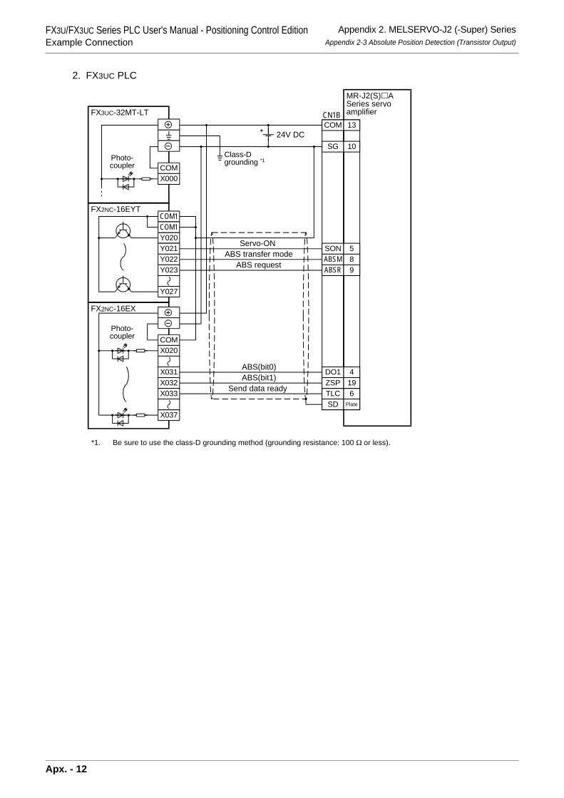
FX3U/FX3UC Series PLC User's Manual - Positioning Control EditionExample Connection
Appendix 2. MELSERVO-J2 (-Super) SeriesAppendix 2-3 Absolute Position Detection (Transistor Output)
2. FX3UC PLC
*1. Be sure to use the class-D grounding method (grounding resistance: 100 Ω or less).
FX3UC-32MT-LT
SD Plate
COM1FX2NC-16EYT
Y020
Y027
COM1
Y021Y022Y023
COMX000
COMX020
FX2NC-16EX
X031X032X033
X037
SON
ABSRABSM
CN1B
SG
COM
10
13
5
98
DO1
TLCZSP
4
619
Photo-coupler
Photo-coupler
24V DC
Class-Dgrounding *1
ABS(bit0)ABS(bit1)
Servo-ONABS transfer mode
ABS request
Send data ready
MR-J2(S) ASeries servoamplifier
Apx. - 12
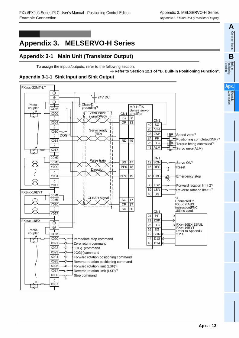
FX3U/FX3UC Series PLC User's Manual - Positioning Control EditionExample Connection
Appendix 3. MELSERVO-H SeriesAppendix 3-1 Main Unit (Transistor Output)
A
Comm
on Items
B
Built-in Positioning Function
Apx.
Example
Connection
Appendix 3. MELSERVO-H Series
Appendix 3-1 Main Unit (Transistor Output)
To assign the inputs/outputs, refer to the following section.→ Refer to Section 12.1 of "B. Built-in Positioning Function".
Appendix 3-1-1 Sink Input and Sink Output
DOG*2
COM
X004
X017
FX3UC-32MT-LT
X010
X014
X000
COM0COM0Y000
Y017
Y004
LGOP
SGPP0
NPO
SD
CN12833
4718
19
50
SG40CN1
VIN
PFZSP
20
2423
TLC25ALM48
SONRES
EMG
1215
46
LSP38LSN39
CN1
SG40
PFZSPTLC
242325
SG16SON12D13D14
4445
CN1
CR 37SG 17
RD 49
FX2N-16EX-ES/ULFX2N-16EYTRefer to Appendix3.2.1.COM
X020
FX2NC-16EX
X021X022X023X024
X026X027
X037
X025
X030
COM1FX2NC-16EYT
Y020
Y027
COM1
Photo-coupler
Photo-coupler
24V DC
Class-Dgrounding*1
Zero Pointsignal(PG0)
Servo ready(RD)
Pulse train
CLEAR signal
MR-H ASeries servoamplifier
Immediate stop commandZero return commandJOG(+)commandJOG(-)commandForward rotation positioning command
Forward rotation limit (LSF)*3
Reverse rotation limit (LSR)*3
Reverse rotation positioning command
Stop command
Speed zero*4
Positioning completed(INP)*4
Torque being controlled*4
Servo error(ALM)
*4Connected toFX3UC if ABSinstruction(FNC155) is used.
Servo ON*4
Reset
Emergency stop
Forward rotation limit 2*3
Reverse rotation limit 2*3
Direction
Apx. - 13
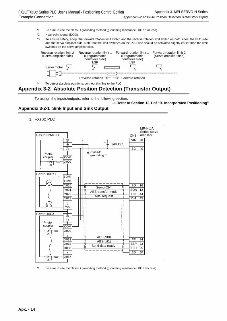
FX3U/FX3UC Series PLC User's Manual - Positioning Control EditionExample Connection
Appendix 3. MELSERVO-H SeriesAppendix 3-2 Absolute Position Detection (Transistor Output)
*1. Be sure to use the class-D grounding method (grounding resistance: 100 Ω or less).*2. Near-point signal (DOG)*3. To ensure safety, adopt the forward rotation limit switch and the reverse rotation limit switch on both sides: the PLC side
and the servo amplifier side. Note that the limit switches on the PLC side should be activated slightly earlier than the limitswitches on the servo amplifier side.
*4. To detect absolute positions, connect this line to the PLC.
Appendix 3-2 Absolute Position Detection (Transistor Output)
To assign the inputs/outputs, refer to the following section.→ Refer to Section 12.1 of "B. Incorporated Positioning"
Appendix 3-2-1 Sink Input and Sink Output
1. FX3UC PLC
*1. Be sure to use the class-D grounding method (grounding resistance: 100 Ω or less).
Reverse rotation limit 2(Servo amplifier side)
Reverse rotation limit 1(Programmablecontroller side)
LSR
Forward rotation limit 2(Servo amplifier side)
Forward rotation limit 1(Programmablecontroller side)
LSF
Reverse rotation Forward rotation
Servo motor
SD
SG
PF
40
24
VIN 20
SG 16
TLC 25ZSP 23
SON 12
DI4 45DI3 44
50
CN1FX3UC-32MT-LT
COM1FX2NC-16EYT
Y020
Y27
COM1
Y021Y022Y023
COMX000
COMX020
FX2NC-16EX
X031X032X033
X037
Photo-coupler
Photo-coupler
24V DC
Class-Dgrounding *1
ABS(bit0)ABS(bit1)
Servo-ONABS transfer mode
ABS request
Send data ready
MR-H ASeries servoamplifier
Apx. - 14
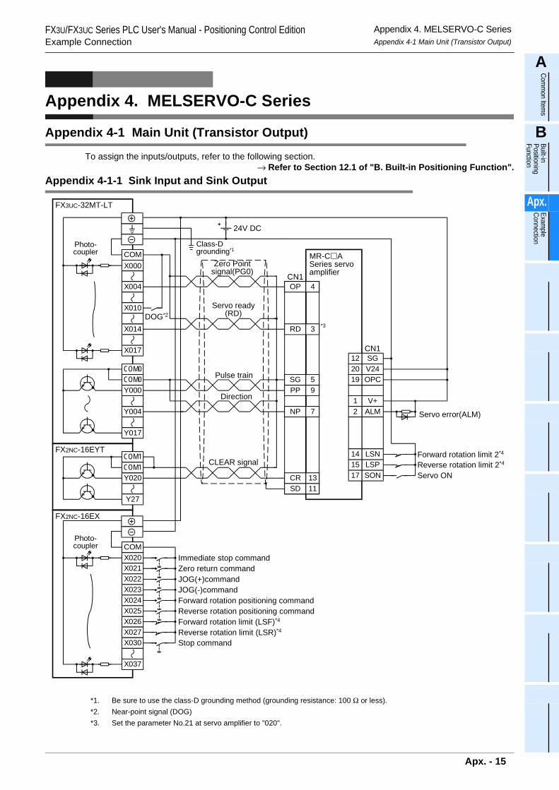
FX3U/FX3UC Series PLC User's Manual - Positioning Control EditionExample Connection
Appendix 4. MELSERVO-C SeriesAppendix 4-1 Main Unit (Transistor Output)
A
Comm
on Items
B
Built-in Positioning Function
Apx.
Example
Connection
Appendix 4. MELSERVO-C Series
Appendix 4-1 Main Unit (Transistor Output)
To assign the inputs/outputs, refer to the following section.→ Refer to Section 12.1 of "B. Built-in Positioning Function".
Appendix 4-1-1 Sink Input and Sink Output
*1. Be sure to use the class-D grounding method (grounding resistance: 100 Ω or less).*2. Near-point signal (DOG)*3. Set the parameter No.21 at servo amplifier to "020".
OP
SGPP
CR
NP
SD
CN14
59
13
7
11
SG
V+ALM
12
12
SONLSPLSN
171514
CN1
V2420OPC19
RD 3 *3DOG*2
COM
X004
X017
FX3UC-32MT-LT
X010
X014
X000
COM0COM0Y000
Y017
Y004
COMX020
FX2NC-16EX
X021X022X023X024
X026X027
X037
X025
X030
COM1FX2NC-16EYT
Y020
Y27
COM1
Photo-coupler
Photo-coupler
Immediate stop commandZero return commandJOG(+)commandJOG(-)commandForward rotation positioning command
Forward rotation limit (LSF)*4
Reverse rotation limit (LSR)*4
Reverse rotation positioning command
Stop command
24V DC
Class-Dgrounding*1
Zero Pointsignal(PG0)
Servo ready(RD)
Pulse train
CLEAR signal
MR-C ASeries servoamplifier
Servo error(ALM)
Servo ON
Forward rotation limit 2*4
Reverse rotation limit 2*4
Direction
Apx. - 15
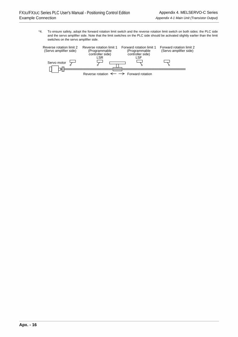
FX3U/FX3UC Series PLC User's Manual - Positioning Control EditionExample Connection
Appendix 4. MELSERVO-C SeriesAppendix 4-1 Main Unit (Transistor Output)
*4. To ensure safety, adopt the forward rotation limit switch and the reverse rotation limit switch on both sides: the PLC sideand the servo amplifier side. Note that the limit switches on the PLC side should be activated slightly earlier than the limitswitches on the servo amplifier side.
Reverse rotation limit 2(Servo amplifier side)
Reverse rotation limit 1(Programmablecontroller side)
LSR
Forward rotation limit 2(Servo amplifier side)
Forward rotation limit 1(Programmablecontroller side)
LSF
Reverse rotation Forward rotation
Servo motor
Apx. - 16
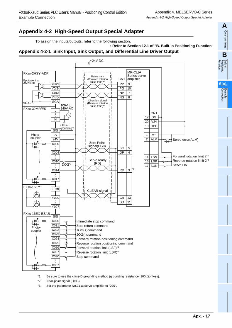
FX3U/FX3UC Series PLC User's Manual - Positioning Control EditionExample Connection
Appendix 4. MELSERVO-C SeriesAppendix 4-2 High-Speed Output Special Adapter
A
Comm
on Items
B
Built-in Positioning Function
Apx.
Example
Connection
Appendix 4-2 High-Speed Output Special Adapter
To assign the inputs/outputs, refer to the following section.→ Refer to Section 12.1 of "B. Built-in Positioning Function"
Appendix 4-2-1 Sink Input, Sink Output, and Differential Line Driver Output
*1. Be sure to use the class-D grounding method (grounding resistance: 100 Ωor less).*2. Near-point signal (DOG)*3. Set the parameter No.21 at servo amplifier to "020".
OPSG
PP
CR
NP
SD
CN1
45
9
13
7
11
SG
V+ALM
12
12
SONLSPLSN
171514
CN1
V2420OPC19
RD 3 *3
PG 10
NG 8
Y0/2+
FX3U-2HSY-ADP
Y0/2-
SGA
Y4/6+Y4/6-
SGA
DOG*2
X004
X017
FX3U-32MR/ES
X010
X014
X00024V0VS/S
N
L100V to240V AC
24V DC
COM1FX2N-16EYT
Y020
Y027
S/SX020
FX2N-16EX-ES/UL
X021X022X023X024
X026X027
X037
X025
X030
Photo-coupler
Photo-coupler
Class-Dgrounding*1
Immediate stop commandZero return commandJOG(+)commandJOG(-)commandForward rotation positioning command
Forward rotation limit (LSF)*4
Reverse rotation limit (LSR)*4
Reverse rotation positioning command
Stop command
Zero Pointsignal(PG0)
Servo ready(RD)
CLEAR signal
MR-C ASeries servoamplifier
Servo error(ALM)
Servo ON
Forward rotation limit 2*4
Reverse rotation limit 2*4
Epuivalent toAM26C31
Pulse train(Forward rotation
pulse train)*5
Direction signal(Reverse rotation
pulse train)*5
Apx. - 17
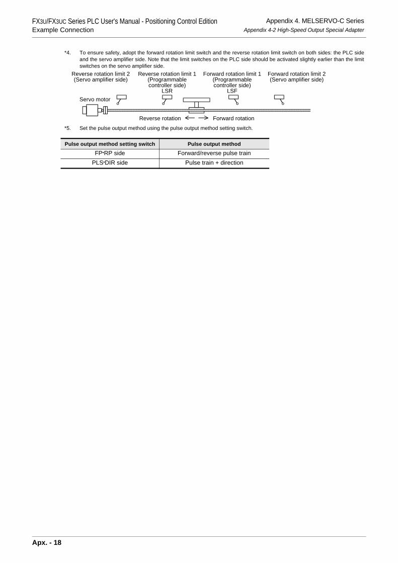
FX3U/FX3UC Series PLC User's Manual - Positioning Control EditionExample Connection
Appendix 4. MELSERVO-C SeriesAppendix 4-2 High-Speed Output Special Adapter
*4. To ensure safety, adopt the forward rotation limit switch and the reverse rotation limit switch on both sides: the PLC sideand the servo amplifier side. Note that the limit switches on the PLC side should be activated slightly earlier than the limitswitches on the servo amplifier side.
*5. Set the pulse output method using the pulse output method setting switch.
Pulse output method setting switch Pulse output method
FP•RP side Forward/reverse pulse trainPLS•DIR side Pulse train + direction
Reverse rotation limit 2(Servo amplifier side)
Reverse rotation limit 1(Programmablecontroller side)
LSR
Forward rotation limit 2(Servo amplifier side)
Forward rotation limit 1(Programmablecontroller side)
LSF
Reverse rotation Forward rotation
Servo motor
Apx. - 18
FX3U/FX3UC Series PLC User's Manual - Positioning Control Edition Warranty
WarrantyPlease confirm the following product warranty details before using this product.
1. Gratis Warranty Term and Gratis Warranty Range If any faults or defects (hereinafter "Failure") found to bethe responsibility of Mitsubishi occurs during use of theproduct within the gratis warranty term, the product shall berepaired at no cost via the sales representative orMitsubishi Service Company. However, if repairs arerequired onsite at domestic or overseas location, expensesto send an engineer will be solely at the customer'sdiscretion. Mitsubishi shall not be held responsible for anyre-commissioning, maintenance, or testing on-site thatinvolves replacement of the failed module.
[Gratis Warranty Term] The gratis warranty term of the product shall be for oneyear after the date of purchase or delivery to a designatedplace. Note that after manufacture and shipment fromMitsubishi, the maximum distribution period shall be six (6)months, and the longest gratis warranty term aftermanufacturing shall be eighteen (18) months. The gratiswarranty term of repair parts shall not exceed the gratiswarranty term before repairs.
[Gratis Warranty Range] 1) The range shall be limited to normal use within the
usage state, usage methods and usage environment,etc., which follow the conditions and precautions, etc.,given in the instruction manual, user's manual andcaution labels on the product.
2) Even within the gratis warranty term, repairs shall becharged for in the following cases. a) Failure occurring from inappropriate storage or
handling, carelessness or negligence by the user.Failure caused by the user's hardware or softwaredesign.
b) Failure caused by unapproved modifications, etc.,to the product by the user.
c) When the Mitsubishi product is assembled into auser's device, Failure that could have beenavoided if functions or structures, judged asnecessary in the legal safety measures the user'sdevice is subject to or as necessary by industrystandards, had been provided.
d) Failure that could have been avoided ifconsumable parts (battery, backlight, fuse, etc.)designated in the instruction manual had beencorrectly serviced or replaced.
e) Relay failure or output contact failure caused byusage beyond the specified Life of contact(cycles).
f) Failure caused by external irresistible forces suchas fires or abnormal voltages, and failure causedby force majeure such as earthquakes, lightning,wind and water damage.
g) Failure caused by reasons unpredictable bysc ient i f ic technology standards a t t ime ofshipment from Mitsubishi.
h) Any other failure found not to be the responsibilityof Mitsubishi or that admitted not to be so by theuser.
2. Onerous repair term after discontinuation of production 1) Mitsubishi shall accept onerous product repairs for
seven (7) years after production of the product isdiscontinued.Discontinuation of production shall be notified withMitsubishi Technical Bulletins, etc.
2) Product supply (including repair parts) is not availableafter production is discontinued.
3. Overseas service Overseas, repairs shall be accepted by Mitsubishi's localoverseas FA Center. Note that the repair conditions ateach FA Center may differ.
4. Exclusion of loss in opportunity and secondary loss from warranty liability Regardless of the gratis warranty term, Mitsubishi shall notbe liable for compensation of damages caused by anycause found not to be the responsibility of Mitsubishi, lossin opportunity, lost profits incurred to the user or thirdperson by Failures of Mitsubishi products, specialdamages and secondary damages whether foreseeable ornot , compensation for accidents, and compensation fordamages to products other than Mitsubishi products,replacement by the user, maintenance of on-siteequipment, start-up test run and other tasks.
5. Changes in product specifications The specifications given in the catalogs, manuals ortechnical documents are subject to change without priornotice.
6. Product application 1) In using the Mitsubishi MELSEC programmable logic
controller, the usage conditions shall be that theapplication will not lead to a major accident even if anyproblem or fault should occur in the programmablelogic controller device, and that backup and fail-safefunctions are systematically provided outside of thedevice for any problem or fault.
2) The Mitsubishi programmable logic controller hasbeen designed and manufactured for applications ingeneral industries, etc. Thus, applications in which thepublic could be affected such as in nuclear powerplants and other power plants operated by respectivepower companies, and applications in which a specialquality assurance system is required, such as forRailway companies or Public service purposes shallbe excluded from the programmable logic controllerapplications. In addition, applications in which human l ife orproperty that could be greatly affected, such as inaircraft, medical applications, incineration and fueldevices, manned transportation, equipment forrecreation and amusement, and safety devices, shallalso be excluded from the programmable logiccontroller range of applications. However, in certain cases, some applications may bepossible, providing the user consults their localMitsubishi representative outl ining the specialrequirements of the project, and providing that allparties concerned agree to the special circumstances,solely at the users discretion.
i
FX3U/FX3UC Series PLC User's Manual - Positioning Control Edition Revised History
Revised History
Date Revision Discription7/2005 A First Edition
ii

HEAD OFFICE: MITSUBISHI DENKI BLDG MARUNOUCHI TOKYO 100-8310HIMEJI WORKS: 840, CHIYODA CHO, HIMEJI, JAPAN
JY997D16801A(MEE)
Effective July 2005Specifications are subject to change without notice.
USER'S MANUAL - Positioning Control Edition
FX3U/FX3UC SERIES PROGRAMMABLE CONTROLLERS
MODEL FX3U-U-POS-E
MODEL CODE 09R620
Related Documents