FX2N/FX2NC FUNCTION EXPANSION MEMORY HARDWARE MANUAL JY997D00401C This manual contains text, diagrams and explanations which will guide the reader in the correct installation and operation of the FX 2N /FX 2NC Function Expansion Memory. It should be read and understood before attempting to install or use the unit. Further information can be found in the FX 2N or FX 2NC series PLC hardware manuals. Guidelines for the safety of the user and protection of the FX2N/FX2NC Function Expansion Memory • If in doubt at any stage during the installation of the FX 2N /FX 2NC Function Expansion Memory always consult a professional electrical engineer who is qualified and trained to the local and national standards. If in doubt about the operation or use of the FX 2N /FX 2NC Function Expansion Memory please consult the nearest Mitsubishi Electric distributor. • Under no circumstances will Mitsubishi Electric be liable or responsible for any consequential damage that may arise as a result of the installation or use of this equipment. • All examples and diagrams shown in this manual are intended only as an aid to understanding the text, not to guarantee operation. Mitsubishi Electric will accept no responsibility for actual use of the product based on these illustrative examples. • Owing to the very great variety in possible application of this equipment, you must satisfy yourself as to its suitability for your specific application. Note’s on the symbology used in this manual At various times through out this manual certain symbols will be used to highlight points of information which are intended to ensure the user’s personal safety and protect the integrity of the equipment. Whenever any of the following symbols are encountered, its associated note must be read and understood. Each of the symbols used will now be listed with a brief description of its meaning. Hardware warnings 1) Indicates that the identified danger WILL cause physical and property damage. 2) Indicates that the identified danger could POSSIBLY cause physical and property damage. Associated Manuals : Indispensable manual : Either manual is necessary 1. Product Outline 1.1 Features FX 2N -ROM-E1 and FX 2NC -ROM-CE1 are optional memories for the FX 2N or FX 2NC Series PLC to add external ROM instruction. In the products, system programs to add external ROM instruction, EXTR (FNC 180), and the EEPROM memory which can be used as a PLC program area are built in. 1.2 Programming Tools Applicable for EXTR (FNC 180) Instruction Manual name Manual number Description FX 2N Hardware Manual JY992D66301 (included with product) Describes the contents related to the hardware such as specification, wiring and mounting of the FX 2N Series PLC. FX 2NC Hardware Manual JY992D76401 (included with product) Describes the contents related to the hardware such as specification, wiring and mounting of the FX 2NC Series PLC. FX 1S /FX 1N /FX 2N /FX 2NC Programming Manual II JY992D88101 (sent separately) Describes the instructions in the FX 1S /FX 1N / FX 2N /FX 2NC Series PLC. FX USER’S MANUAL -Data Communication Edition JY997D16901 (sent separately) Describes the contents related to communication available in FX Series PLC such as wiring, communication setting and program examples. (Make sure to read this manual.) Model name Version GX Developer SW7 or later FX-PCS/WIN-E 3.10 or later FX-10P-E 4.10 or later FX-20P-E (FX-20P-MFXD-E) 5.10 or later

Welcome message from author
This document is posted to help you gain knowledge. Please leave a comment to let me know what you think about it! Share it to your friends and learn new things together.
Transcript

FX-PCS/WIN-E 3.10 or later
FX-10P-E 4.10 or later
FX-20P-E (FX-20P-MFXD-E) 5.10 or later
ation
gram error may flash when used for the first time because the EEPROM (user program memory) isialized. In the personal computer or FX-20P (off-line mode), transfer and write a program in thatIn the FX-10P or FX-20P (online mode), execute all NOP write to erase the contents. iting a program, make sure to verify.
memory protect switch to OFF before writing a program. During normal operation, it is recommended to ON to prevent erroneous write.nstalled in the FX2N or FX2NC Series PLC version 3.00 or later, the EXTR (FNC 180) instruction and-step EEPROM and clock function can be used.led in the FX2N or FX2NC Series PLC earlier than version 3.00, only the 16k-step EEPROM and clock can be used.
ter Communication Function
hen handling the PLC or inverter, follow the notices indicated in each manual which iscluded with the main unit in order to avoid electric shock, fire, a damage or an accident.
ake sure to perform class D grounding of the ground terminal of communication equipment fore PLC together with that of the PLC main unit. Ground the shield of a shielded cable at one
oint on the PLC. Do not, however, ground at the same point as high voltage line. If grounding isperfect, effects of noise or surge induction takes place, and it may cause a communication
rror or erroneous operation.
he signal cables must not be laid near or bundled with the main circuit lines, high voltage powerables or load carrying wires. Otherwise effects of noise or surge induction are likely to takelace, and it may cause a communication error or erroneous operation.eep a safe distance of more than 100mm (3.94") from these wires.
ne of Functions and System Configuration
g K10 to K13 of the EXTR (FNC 180) instruction, operation monitoring, control value write ormonitoring and change in the A500/E500/S500 (with RS-485 communication function) SeriesHI TRANSISTORIZED INVERTER can be performed.ls of programming and setting can be found in the FX Series User’s Manual - Dataation Edition, JY997d16901.
xtension distance
cting with one inverter
Using interface Extension distance
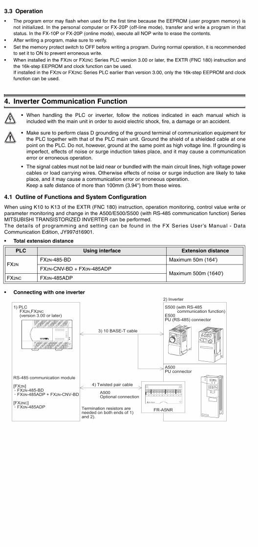
FX2N-485-BD Maximum 50m (164')
FX2N-CNV-BD + FX0N-485ADPMaximum 500m (1640')
FX0N-485ADP
,FX2NCion 3.00 or later)
communication module
485-BD485ADP + FX2N-CNV-BD
485ADP
S500 (with RS-485 communication function)E500PU (RS-485) connector
2) Inverter
A500PU connector
3) 10 BASE-T cable
4) Twisted pair cable
A500Optional connection
Termination resistors areneeded on both ends of 1)and 2).
FR-A5NR
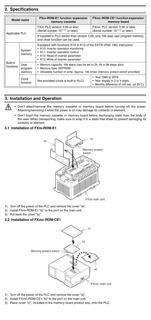
3) Place cover "c)", included in the memory board product box, onto the PLC.
which are intended to ensure the user’s personal safety and protect the integrity of the equipment.Whenever any of the following symbols are encountered, its associated note must be read andunderstood. Each of the symbols used will now be listed with a brief description of its meaning.Hardware warnings
1) Indicates that the identified danger WILL cause physical and property damage.
2) Indicates that the identified danger could POSSIBLY cause physical and property damage.
Associated Manuals
: Indispensable manual: Either manual is necessary
1. Product Outline1.1 FeaturesFX2N-ROM-E1 and FX2NC-ROM-CE1 are optional memories for the FX2N or FX2NC Series PLC to addexternal ROM instruction.In the products, system programs to add external ROM instruction, EXTR (FNC 180), and the EEPROMmemory which can be used as a PLC program area are built in.
1.2 Programming Tools Applicable for EXTR (FNC 180) Instruction
Manual name Manual number Description
FX2N Hardware Manual JY992D66301(included with product)
Describes the contents related to the hardware such as specification, wiring and mounting of the FX2N Series PLC.
FX2NC Hardware Manual JY992D76401(included with product)
Describes the contents related to the hardware such as specification, wiring and mounting of the FX2NC Series PLC.
FX1S/FX1N/FX2N/FX2NC
Programming Manual IIJY992D88101
(sent separately)Describes the instructions in the FX1S/FX1N/FX2N/FX2NC Series PLC.
FX USER’S MANUAL-Data Communication Edition
JY997D16901(sent separately)
Describes the contents related to communication available in FX Series PLC such as wiring, communication setting and program examples.(Make sure to read this manual.)
Model name Version
GX Developer SW7 or later
1) Turn off the power of the PLC and remove the cover "a)".2) Install FX2N-ROM-E1 "b)" to the port on the main unit. 3) Put back the cover "a)".
3.2 Installation of FX2NC-ROM-CE1
1) Turn off the power of the PLC and remove the cover "a)".2) Install FX2NC-ROM-CE1 "b)" to the port on the main unit.
# $ " %
! " # $ " %
&
"
• Conne
FX2N
FX2NC
1) PLC FX2N (vers
RS-485
[FX2N] FX2N- FX0N-
[FX2NC] FX0N-
.
.
.
FX2N/FX2NC FUNCTION EXPANSION MEMORY
HARDWARE MANUAL
JY997D00401C
This manual contains text, diagrams and explanations which will guide the reader in the correct installationand operation of the FX2N/FX2NC Function Expansion Memory. It should be read and understood beforeattempting to install or use the unit. Further information can be found in the FX2N or FX2NC series PLChardware manuals.Guidelines for the safety of the user and protection of the FX2N/FX2NC Function Expansion Memory• If in doubt at any stage during the installation of the FX2N/FX2NC Function Expansion Memory always
consult a professional electrical engineer who is qualified and trained to the local and national standards.If in doubt about the operation or use of the FX2N/FX2NC Function Expansion Memory please consult thenearest Mitsubishi Electric distributor.
• Under no circumstances will Mitsubishi Electric be liable or responsible for any consequential damagethat may arise as a result of the installation or use of this equipment.
• All examples and diagrams shown in this manual are intended only as an aid to understanding thetext, not to guarantee operation. Mitsubishi Electric will accept no responsibility for actual use of theproduct based on these illustrative examples.
• Owing to the very great variety in possible application of this equipment, you must satisfy yourself asto its suitability for your specific application.
Note’s on the symbology used in this manualAt various times through out this manual certain symbols will be used to highlight points of information
2. Specifications
3. Installation and Operation
• Don’t attach/remove the memory cassette or memory board before turning off the power.Attaching/removing it while the power is on may damage its contents or element.
• Don’t touch the memory cassette or memory board before discharging static from the body ofthe user. When transporting, make sure to wrap it in a static-free sheet to prevent damaging itscontents or element.
3.1 Installation of FX2N-ROM-E1
Model nameFX2N-ROM-E1 function expansion
memory cassetteFX2NC-ROM-CE1 function expansion
memory board
Applicable PLC
FX2N PLC version 3.00 or later(Serial number 15**** or later)
FX2NC PLC version 3.00 or later(Serial number 15**** or later)
If installed in PLC earlier than version 3.00, only 16k-step user program memory and clock function can be used.
Built-in functions
Systemmemory
Equipped with functions K10 to K13 of the EXTR (FNC 180) instruction• K10: Inverter operation monitoring• K11: Inverter operation control• K12: Read of inverter parameter• K13: Write of inverter parameter
Userprogrammemory
• Memory capacity: 16k steps (can be set to 2k, 4k or 8k steps also)• Memory type: EEPROM• Allowable number of write: Approx. 10k times (memory protect switch provided)
Clockfunction
Not provided (clock is built in PLC)• Year 1980 to 2079• Year display in 2 or 4 digits• Monthly difference of ±45 sec. (at 25°C)
! "
&
3.3 Oper
• The pronot initstatus.
• After wr• Set the
to set it• When i
the 16kIf instalfunction
4. Inver
• Win
• Mthpime
• TcpK
4.1 Outli
When usinparameter MITSUBISThe detaiCommunic
• Total e
PLC
FX2N/FX2NC FUNCTION EXPANSION MEMORY
HARDWARE MANUAL
JY997D00401C
This manual contains text, diagrams and explanations which will guide the reader in the correct installationand operation of the FX2N/FX2NC Function Expansion Memory. It should be read and understood beforeattempting to install or use the unit. Further information can be found in the FX2N or FX2NC series PLChardware manuals.Guidelines for the safety of the user and protection of the FX2N/FX2NC Function Expansion Memory• If in doubt at any stage during the installation of the FX2N/FX2NC Function Expansion Memory always
consult a professional electrical engineer who is qualified and trained to the local and national standards.If in doubt about the operation or use of the FX2N/FX2NC Function Expansion Memory please consult thenearest Mitsubishi Electric distributor.
• Under no circumstances will Mitsubishi Electric be liable or responsible for any consequential damagethat may arise as a result of the installation or use of this equipment.
• All examples and diagrams shown in this manual are intended only as an aid to understanding thetext, not to guarantee operation. Mitsubishi Electric will accept no responsibility for actual use of theproduct based on these illustrative examples.
• Owing to the very great variety in possible application of this equipment, you must satisfy yourself asto its suitability for your specific application.
Note’s on the symbology used in this manualAt various times through out this manual certain symbols will be used to highlight points of informationwhich are intended to ensure the user’s personal safety and protect the integrity of the equipment.Whenever any of the following symbols are encountered, its associated note must be read andunderstood. Each of the symbols used will now be listed with a brief description of its meaning.Hardware warnings
1) Indicates that the identified danger WILL cause physical and property damage.
2) Indicates that the identified danger could POSSIBLY cause physical and property damage.
Associated Manuals
: Indispensable manual: Either manual is necessary
1. Product Outline1.1 FeaturesFX2N-ROM-E1 and FX2NC-ROM-CE1 are optional memories for the FX2N or FX2NC Series PLC to addexternal ROM instruction.In the products, system programs to add external ROM instruction, EXTR (FNC 180), and the EEPROMmemory which can be used as a PLC program area are built in.
1.2 Programming Tools Applicable for EXTR (FNC 180) Instruction
Manual name Manual number Description
FX2N Hardware Manual JY992D66301(included with product)
Describes the contents related to the hardware such as specification, wiring and mounting of the FX2N Series PLC.
FX2NC Hardware Manual JY992D76401(included with product)
Describes the contents related to the hardware such as specification, wiring and mounting of the FX2NC Series PLC.
FX1S/FX1N/FX2N/FX2NC
Programming Manual IIJY992D88101
(sent separately)Describes the instructions in the FX1S/FX1N/FX2N/FX2NC Series PLC.
FX USER’S MANUAL-Data Communication Edition
JY997D16901(sent separately)
Describes the contents related to communication available in FX Series PLC such as wiring, communication setting and program examples.(Make sure to read this manual.)
Model name Version
GX Developer SW7 or later
FX-PCS/WIN-E 3.10 or later
FX-10P-E 4.10 or later
FX-20P-E (FX-20P-MFXD-E) 5.10 or later
1) Turn off the power of the PLC and remove the cov2) Install FX2N-ROM-E1 "b)" to the port on the main u3) Put back the cover "a)".
3.2 Installation of FX2NC-ROM-CE1
1) Turn off the power of the PLC and remove the cov2) Install FX2NC-ROM-CE1 "b)" to the port on the ma3) Place cover "c)", included in the memory board pro
! " # $ " %
er "a)".nit.
er "a)".
! " # $ " %
&
"
• Connecting with one inverter
FX2NFX2N-485-BD Maximum 50m (164')
FX2N-CNV-BD + FX0N-485ADPMaximum 500m (1640')
FX2NC FX0N-485ADP
1) PLC FX2N,FX2NC (version 3.00 or later)
RS-485 communication module
[FX2N] FX2N-485-BD FX0N-485ADP + FX2N-CNV-BD
[FX2NC] FX0N-485ADP
S500 (with RS-485 communication function)E500PU (RS-485) connector
2) Inverter
A500PU connector
3) 10 BASE-T cable
4) Twisted pair cable
A500Optional connection
Termination resistors areneeded on both ends of 1)and 2).
.
.
.FR-A5NR
2. Specifications
3. Installation and Operation
• Don’t attach/remove the memory cassette or memory board before turning off the power.Attaching/removing it while the power is on may damage its contents or element.
• Don’t touch the memory cassette or memory board before discharging static from the body ofthe user. When transporting, make sure to wrap it in a static-free sheet to prevent damaging itscontents or element.
3.1 Installation of FX2N-ROM-E1
Model nameFX2N-ROM-E1 function expansion
memory cassetteFX2NC-ROM-CE1 function expansion
memory board
Applicable PLC
FX2N PLC version 3.00 or later(Serial number 15**** or later)
FX2NC PLC version 3.00 or later(Serial number 15**** or later)
If installed in PLC earlier than version 3.00, only 16k-step user program memory and clock function can be used.
Built-in functions
Systemmemory
Equipped with functions K10 to K13 of the EXTR (FNC 180) instruction• K10: Inverter operation monitoring• K11: Inverter operation control• K12: Read of inverter parameter• K13: Write of inverter parameter
Userprogrammemory
• Memory capacity: 16k steps (can be set to 2k, 4k or 8k steps also)• Memory type: EEPROM• Allowable number of write: Approx. 10k times (memory protect switch provided)
Clockfunction
Not provided (clock is built in PLC)• Year 1980 to 2079• Year display in 2 or 4 digits• Monthly difference of ±45 sec. (at 25°C)
&
3.3 Operation
• The program error may flash when used for the first time because the EEPROM (user program memory) isnot initialized. In the personal computer or FX-20P (off-line mode), transfer and write a program in thatstatus. In the FX-10P or FX-20P (online mode), execute all NOP write to erase the contents.
• After writing a program, make sure to verify.• Set the memory protect switch to OFF before writing a program. During normal operation, it is recommended
to set it to ON to prevent erroneous write.• When installed in the FX2N or FX2NC Series PLC version 3.00 or later, the EXTR (FNC 180) instruction and
the 16k-step EEPROM and clock function can be used.If installed in the FX2N or FX2NC Series PLC earlier than version 3.00, only the 16k-step EEPROM and clockfunction can be used.
4. Inverter Communication Function
• When handling the PLC or inverter, follow the notices indicated in each manual which isincluded with the main unit in order to avoid electric shock, fire, a damage or an accident.
• Make sure to perform class D grounding of the ground terminal of communication equipment forthe PLC together with that of the PLC main unit. Ground the shield of a shielded cable at onepoint on the PLC. Do not, however, ground at the same point as high voltage line. If grounding isimperfect, effects of noise or surge induction takes place, and it may cause a communicationerror or erroneous operation.
• The signal cables must not be laid near or bundled with the main circuit lines, high voltage powercables or load carrying wires. Otherwise effects of noise or surge induction are likely to takeplace, and it may cause a communication error or erroneous operation.Keep a safe distance of more than 100mm (3.94") from these wires.
4.1 Outline of Functions and System Configuration
When using K10 to K13 of the EXTR (FNC 180) instruction, operation monitoring, control value write orparameter monitoring and change in the A500/E500/S500 (with RS-485 communication function) SeriesMITSUBISHI TRANSISTORIZED INVERTER can be performed.The details of programming and setting can be found in the FX Series User’s Manual - DataCommunication Edition, JY997d16901.
• Total extension distance
PLC Using interface Extension distance
in unit. duct box, onto the PLC.
FX2N/FX2NC FUNCTION EXPANSION MEMORY
HARDWARE MANUAL
JY997D00401C
This manual contains text, diagrams and explanations which will guide the reader in the correct installationand operation of the FX2N/FX2NC Function Expansion Memory. It should be read and understood beforeattempting to install or use the unit. Further information can be found in the FX2N or FX2NC series PLChardware manuals.Guidelines for the safety of the user and protection of the FX2N/FX2NC Function Expansion Memory• If in doubt at any stage during the installation of the FX2N/FX2NC Function Expansion Memory always
consult a professional electrical engineer who is qualified and trained to the local and national standards.If in doubt about the operation or use of the FX2N/FX2NC Function Expansion Memory please consult thenearest Mitsubishi Electric distributor.
• Under no circumstances will Mitsubishi Electric be liable or responsible for any consequential damagethat may arise as a result of the installation or use of this equipment.
• All examples and diagrams shown in this manual are intended only as an aid to understanding thetext, not to guarantee operation. Mitsubishi Electric will accept no responsibility for actual use of theproduct based on these illustrative examples.
• Owing to the very great variety in possible application of this equipment, you must satisfy yourself asto its suitability for your specific application.
Note’s on the symbology used in this manualAt various times through out this manual certain symbols will be used to highlight points of informationwhich are intended to ensure the user’s personal safety and protect the integrity of the equipment.Whenever any of the following symbols are encountered, its associated note must be read andunderstood. Each of the symbols used will now be listed with a brief description of its meaning.Hardware warnings
1) Indicates that the identified danger WILL cause physical and property damage.
2) Indicates that the identified danger could POSSIBLY cause physical and property damage.
Associated Manuals
: Indispensable manual: Either manual is necessary
1. Product Outline1.1 FeaturesFX2N-ROM-E1 and FX2NC-ROM-CE1 are optional memories for the FX2N or FX2NC Series PLC to addexternal ROM instruction.In the products, system programs to add external ROM instruction, EXTR (FNC 180), and the EEPROMmemory which can be used as a PLC program area are built in.
1.2 Programming Tools Applicable for EXTR (FNC 180) Instruction
Manual name Manual number Description
FX2N Hardware Manual JY992D66301(included with product)
Describes the contents related to the hardware such as specification, wiring and mounting of the FX2N Series PLC.
FX2NC Hardware Manual JY992D76401(included with product)
Describes the contents related to the hardware such as specification, wiring and mounting of the FX2NC Series PLC.
FX1S/FX1N/FX2N/FX2NC
Programming Manual IIJY992D88101
(sent separately)Describes the instructions in the FX1S/FX1N/FX2N/FX2NC Series PLC.
FX USER’S MANUAL-Data Communication Edition
JY997D16901(sent separately)
Describes the contents related to communication available in FX Series PLC such as wiring, communication setting and program examples.(Make sure to read this manual.)
Model name Version
GX Developer SW7 or later
FX-PCS/WIN-E 3.10 or later
FX-10P-E 4.10 or later
FX-20P-E (FX-20P-MFXD-E) 5.10 or later
2. Specifications
3. Installation and Operation
• Don’t attach/remove the memory cassette or memory board before turning off the power.Attaching/removing it while the power is on may damage its contents or element.
• Don’t touch the memory cassette or memory board before discharging static from the body ofthe user. When transporting, make sure to wrap it in a static-free sheet to prevent damaging itscontents or element.
3.1 Installation of FX2N-ROM-E1
1) Turn off the power of the PLC and remove the cover "a)".2) Install FX2N-ROM-E1 "b)" to the port on the main unit. 3) Put back the cover "a)".
3.2 Installation of FX2NC-ROM-CE1
1) Turn off the power of the PLC and remove the cover "a)".2) Install FX2NC-ROM-CE1 "b)" to the port on the main unit. 3) Place cover "c)", included in the memory board product box, onto the PLC.
Model nameFX2N-ROM-E1 function expansion
memory cassetteFX2NC-ROM-CE1 function expansion
memory board
Applicable PLC
FX2N PLC version 3.00 or later(Serial number 15**** or later)
FX2NC PLC version 3.00 or later(Serial number 15**** or later)
If installed in PLC earlier than version 3.00, only 16k-step user program memory and clock function can be used.
Built-in functions
Systemmemory
Equipped with functions K10 to K13 of the EXTR (FNC 180) instruction• K10: Inverter operation monitoring• K11: Inverter operation control• K12: Read of inverter parameter• K13: Write of inverter parameter
Userprogrammemory
• Memory capacity: 16k steps (can be set to 2k, 4k or 8k steps also)• Memory type: EEPROM• Allowable number of write: Approx. 10k times (memory protect switch provided)
Clockfunction
Not provided (clock is built in PLC)• Year 1980 to 2079• Year display in 2 or 4 digits• Monthly difference of ±45 sec. (at 25°C)
! " # $ " %
&
! " # $ " %
&
"
3.3 Operation
• The program error may flash when used for the first timnot initialized. In the personal computer or FX-20P (status. In the FX-10P or FX-20P (online mode), execute
• After writing a program, make sure to verify.• Set the memory protect switch to OFF before writing a p
to set it to ON to prevent erroneous write.• When installed in the FX2N or FX2NC Series PLC versio
the 16k-step EEPROM and clock function can be used.If installed in the FX2N or FX2NC Series PLC earlier thafunction can be used.
4. Inverter Communication Function
• When handling the PLC or inverter, follow included with the main unit in order to avoid el
• Make sure to perform class D grounding of thethe PLC together with that of the PLC main upoint on the PLC. Do not, however, ground at timperfect, effects of noise or surge inductionerror or erroneous operation.
• The signal cables must not be laid near or buncables or load carrying wires. Otherwise effeplace, and it may cause a communication erroKeep a safe distance of more than 100mm (3.
4.1 Outline of Functions and System Configur
When using K10 to K13 of the EXTR (FNC 180) instruparameter monitoring and change in the A500/E500/S5MITSUBISHI TRANSISTORIZED INVERTER can be peThe details of programming and setting can be foCommunication Edition, JY997d16901.
• Total extension distance
• Connecting with one inverter
PLC Using interface
FX2NFX2N-485-BD
FX2N-CNV-BD + FX0N-485ADP
FX2NC FX0N-485ADP
1) PLC FX2N,FX2NC (version 3.00 or later)
RS-485 communication module
[FX2N] FX2N-485-BD FX0N-485ADP + FX2N-CNV-BD
[FX2NC] FX0N-485ADP
3) 10 BASE-T ca
4) Twisted pair cable
A500Optional connec
Termination resistors areneeded on both ends of 1and 2).
.
.
.
e because the EEPROM (user program memory) isoff-line mode), transfer and write a program in that all NOP write to erase the contents.
rogram. During normal operation, it is recommended
n 3.00 or later, the EXTR (FNC 180) instruction and
n version 3.00, only the 16k-step EEPROM and clock
the notices indicated in each manual which isectric shock, fire, a damage or an accident.
ground terminal of communication equipment fornit. Ground the shield of a shielded cable at onehe same point as high voltage line. If grounding is takes place, and it may cause a communication
dled with the main circuit lines, high voltage powercts of noise or surge induction are likely to taker or erroneous operation.94") from these wires.
ation
ction, operation monitoring, control value write or00 (with RS-485 communication function) Seriesrformed.und in the FX Series User’s Manual - Data
Extension distance
Maximum 50m (164')
Maximum 500m (1640')
S500 (with RS-485 communication function)E500PU (RS-485) connector
2) Inverter
A500PU connector
ble
tion
) FR-A5NR

uct is designed for use in industrial applications.
HEAD OFFICE : TOKYO BUILDING, 2-7-3 MARUNOUCHI, CHIYODA-KU, TOKYO 100-8310, JAPAN
ual confers no industrial property rights or any rights of any other kind, nor does it confer anyenses. Mitsubishi Electric Corporation cannot be held responsible for any problems involvingproperty rights which may occur as a result of using the contents noted in this manual.
imum 8 inverters)
SE-T) available on the market.
as 10 BASE-T cable)
0Ω and 1/4W prepared by the user
. . .
sistor
onl
5
4
3
6
1
Inverter
RDB
RDA
SDA
SDB
SG
PU (RS-485)connector
5 4 3 6 1
Distributionterminal
5 4 3 6 1
5
4
3
6
1
5
4
3
6
1
Inverter
RDB
RDA
SDA
SDB
SG
PU (RS-485)connector
5 4 3 6 1
Distributionterminal
5 4 3 6 1
5
4
3
6
1
5
4
3
6
1
100Ω 1/4W terminal resistor(prepared by the user) attached tothe remotest inverter from PLC
DR SG A B C
sed to connect to PLC RS-485 communication module
Manual number : JY997D00401
Manual revision : C
Date : July 2016
Attention
This prod
This manpatent licindustrial
4.2 Wiring
Wiring for PU (RS-485) Connector
• Pin layout of PU (RS-485) connector
Caution:
The pin number 2 and 8 are for the power supply for an operation panel or parameter unit. DONOT use when connecting two or more inverters.
• Connecting with one inverter
Pin number Signal name Note
1 SG
2 P5S Not to be used
3 RDA
4 SDB
5 SDA
6 RDB
7 SG
8 P5S Not to be used
Modular jack
Viewing from frontface of inverter
(receptacle side)
PLC
RDA
RDB
SDA
SDB
LINKSG
24+
24G
RDA
RDB
SDA
SDB
SG
FX0N-485ADP FX2N-485-BD
100Ω 1/4W terminal resistor(prepared by the user)
110Ω terminal resistor
24V DC50mA 10 BASE-T cable
FG
Class D grounding Inverter
RDB
RDA
SDA
SDB
SG
PU (RS-485)connector
5 4 3 6 1
Distributionterminal
5 4 3 6 1
5
4
3
6
1
5
4
3
6
1
• Connecting with two or more inverters (Maximum 8 inverters)
• Applicable equipment
- Cable: Use the twisted pair cables (0.3mm2 or more, 3 pairs)
- Terminal resistor : On the PLC side, 110ΩOn the inverter side, a chip for connecting terminal resistor only to the remotestFR-A5NR from the PLC (between RDB and RDR)
A chip for connecting terminalresistor
Twisted pair cable(0.3mm2 or more)
0.3mm2 or more
RDB
RDA
SDA
SDB
SG
FR-A5NR
RDR
Inverter
RDA
RDB
SDA
SDB
LINKSG
24+
24G
RDA
RDB
SDA
SDB
SG
FX0N-485ADP FX2N-485-BD
24V DC50mA
FG
Class D grounding
PLC
110Ω terminal resistor
Twisted pair cable (0.3mm2 or more)
. . . . .
A chip forconnecting
terminalresistor
attached tothe remotestinverter from
PLC
Class Dgrounding
Class D grounding
RDA
RDB
SDA
SDB
LINKSG
24+
24G
RDA
RDB
SDA
SDB
SG
FX0N-485ADP FX2N-485-BD
24V DC50mA
FG
Class D grounding0.3mm2
or more
PLCRDB
RDA
SDA
SDB
SG
FR-A5NR
RDR
Inverter
RDB
RDA
SDA
SDB
SG
FR-A5NR
RDR
Inverter
RDB
RDA
SDA
SDB
SG
FR-A5NR
RDR
Inverter
110Ω terminal resistor
• Connecting with two or more inverters (Maximum 8 inverters)
1) PLC FX2N, FX2NC (version 3.00 or later)
RS-485 communication module
[FX2N] FX2N-485-BD FX0N-485ADP + FX2N-CNV-BD
[FX2NC] FX0N-485ADP
2) Inverter S500 (with RS-485 communication function), E500, A500 series PU (RS-485) connector
Inverter
PU (RS-485)connector
Inverter Inverter
Terminalresistor
. . . . .
Station number 0 Station number 1 Station number 7
3) 10 BASE-T cable
DistributionterminalTerminal
resistor
.
.
.PU (RS-485)
connectorPU (RS-485)
connector
1) PLC FX2N, FX2NC (version 3.00 or later)
RS-485 communication module
[FX2N] FX2N-485-BD FX0N-485ADP + FX2N-CNV-BD
[FX2NC] FX0N-485ADP
2) Inverter A500 + FR-A5NR (optional)
Inverter
Terminalresistor
. . . . .
Station number 0
3) Twisted pair cableTerminalresistor
InverterStation number 1
InverterStation number 7
FR-A5NR FR-A5NR FR-A5NR
.
.
.
• Connecting with two or more inverters (Max
• Applicable equipment
Use the connectors and cables for LAN (10 BA
- Connector: RJ45 connector
- Cable: Cable conforming to EIA568 (such
- Terminal resistor: On the PLC side, 110ΩOn the inverter side, 10
Wiring for FR-A5NR
• Terminal layout
• Connecting with one inverter
PLC
RDA
RDB
SDA
SDB
LINKSG
24+
24G
RDA
RDB
SDA
SDB
SG
FX0N-485ADP FX2N-485-BD
24V DC50mA
FG
Class D grounding
110Ω terminal re
10 BASE-Tcable
Inverter
RDB
RDA
SDA
SDB
SG
PU (RS-485)connector
5 4 3 6 1
Distributitermina
5 4 3 6 1
5
4
3
6
1
Terminal blockscrew size M3 (0.12")
Terminal symbol
SDBSDA RDA RDB R
U

• Connecting with two or more inverters (Maximum 8 inverters)
4.2 Wiring
Wiring for PU (RS-485) Connector
• Pin layout of PU (RS-485) connector
Caution:
The pin number 2 and 8 are for the power supply for an operation panel or parameter unit. DONOT use when connecting two or more inverters.
• Connecting with one inverter
Pin number Signal name Note
1 SG
2 P5S Not to be used
3 RDA
4 SDB
5 SDA
6 RDB
7 SG
8 P5S Not to be used
1) PLC FX2N, FX2NC (version 3.00 or later)
RS-485 communication module
[FX2N] FX2N-485-BD FX0N-485ADP + FX2N-CNV-BD
[FX2NC] FX0N-485ADP
2) Inverter S500 (with RS-485 communication function), E500, A500 series PU (RS-485) connector
Inverter
PU (RS-485)connector
Inverter Inverter
Terminalresistor
. . . . .
Station number 0 Station number 1 Station number 7
3) 10 BASE-T cable
DistributionterminalTerminal
resistor
.
.
.PU (RS-485)
connectorPU (RS-485)
connector
1) PLC FX2N, FX2NC (version 3.00 or later)
RS-485 communication module
[FX2N] FX2N-485-BD FX0N-485ADP + FX2N-CNV-BD
[FX2NC] FX0N-485ADP
2) Inverter A500 + FR-A5NR (optional)
Inverter
Terminalresistor
. . . . .
Station number 0
3) Twisted pair cableTerminalresistor
InverterStation number 1
InverterStation number 7
FR-A5NR FR-A5NR FR-A5NR
.
.
.
Modular jack
Viewing from frontface of inverter
(receptacle side)
PLC
RDA
RDB
SDA
SDB
LINKSG
24+
24G
RDA
RDB
SDA
SDB
SG
FX0N-485ADP FX2N-485-BD
100Ω 1/4W terminal resistor(prepared by the user)
110Ω terminal resistor
24V DC50mA 10 BASE-T cable
FG
Class D grounding Inverter
RDB
RDA
SDA
SDB
SG
PU (RS-485)connector
5 4 3 6 1
Distributionterminal
5 4 3 6 1
5
4
3
6
1
5
4
3
6
1
Attention
This product is designed for use in industrial applications.
This manual confers no industrial property rights or any rights of any other kind, nor does it confer anypatent licenses. Mitsubishi Electric Corporation cannot be held responsible for any problems involvingindustrial property rights which may occur as a result of using the contents noted in this manual.
• Connecting with two or more inverters (Maximum 8 inverters)
• Applicable equipment
- Cable: Use the twisted pair cables (0.3mm2 or more, 3 pairs)
- Terminal resistor : On the PLC side, 110ΩOn the inverter side, a chip for connecting terminal resistor only to the remotestFR-A5NR from the PLC (between RDB and RDR)
A chip for connecting terminalresistor
Twisted pair cable(0.3mm2 or more)
0.3mm2 or more
RDB
RDA
SDA
SDB
SG
FR-A5NR
RDR
Inverter
RDA
RDB
SDA
SDB
LINKSG
24+
24G
RDA
RDB
SDA
SDB
SG
FX0N-485ADP FX2N-485-BD
24V DC50mA
FG
Class D grounding
PLC
110Ω terminal resistor
Twisted pair cable (0.3mm2 or more)
. . . . .
A chip forconnecting
terminalresistor
attached tothe remotestinverter from
PLC
Class Dgrounding
Class D grounding
RDA
RDB
SDA
SDB
LINKSG
24+
24G
RDA
RDB
SDA
SDB
SG
FX0N-485ADP FX2N-485-BD
24V DC50mA
FG
Class D grounding0.3mm2
or more
PLCRDB
RDA
SDA
SDB
SG
FR-A5NR
RDR
Inverter
RDB
RDA
SDA
SDB
SG
FR-A5NR
RDR
Inverter
RDB
RDA
SDA
SDB
SG
FR-A5NR
RDR
Inverter
110Ω terminal resistor
Manual number : JY997D00401
Manual revision : C
Date : July 2016
• Connecting with two or more inverters (Maximum 8 inverters)
• Applicable equipment
Use the connectors and cables for LAN (10 BASE-T) available on the market.
- Connector: RJ45 connector
- Cable: Cable conforming to EIA568 (such as 10 BASE-T cable)
- Terminal resistor: On the PLC side, 110ΩOn the inverter side, 100Ω and 1/4W prepared by the user
Wiring for FR-A5NR
• Terminal layout
• Connecting with one inverter
. . .
PLC
RDA
RDB
SDA
SDB
LINKSG
24+
24G
RDA
RDB
SDA
SDB
SG
FX0N-485ADP FX2N-485-BD
24V DC50mA
FG
Class D grounding
110Ω terminal resistor
10 BASE-Tcable
Inverter
RDB
RDA
SDA
SDB
SG
PU (RS-485)connector
5 4 3 6 1
Distributionterminal
5 4 3 6 1
5
4
3
6
1
5
4
3
6
1
Inverter
RDB
RDA
SDA
SDB
SG
PU (RS-485)connector
5 4 3 6 1
Distributionterminal
5 4 3 6 1
5
4
3
6
1
5
4
3
6
1
Inverter
RDB
RDA
SDA
SDB
SG
PU (RS-485)connector
5 4 3 6 1
Distributionterminal
5 4 3 6 1
5
4
3
6
1
5
4
3
6
1
100Ω 1/4W terminal resistor(prepared by the user) attached tothe remotest inverter from PLC
Terminal blockscrew size M3 (0.12")
Terminal symbol
SDBSDA RDA RDB RDR SG A B C
Used to connect to PLC RS-485 communication module
HEAD OFFICE : TOKYO BUILDING, 2-7-3 MARUNOUCHI, CHIYODA-KU, TOKYO 100-8310, JAPAN

• Connecting with two or more inverters (Maximum 8 inverters)
4.2 Wiring
Wiring for PU (RS-485) Connector
• Pin layout of PU (RS-485) connector
Caution:
The pin number 2 and 8 are for the power supply for an operation panel or parameter unit. DONOT use when connecting two or more inverters.
• Connecting with one inverter
Pin number Signal name Note
1 SG
2 P5S Not to be used
3 RDA
4 SDB
5 SDA
6 RDB
7 SG
8 P5S Not to be used
1) PLC FX2N, FX2NC (version 3.00 or later)
RS-485 communication module
[FX2N] FX2N-485-BD FX0N-485ADP + FX2N-CNV-BD
[FX2NC] FX0N-485ADP
2) Inverter S500 (with RS-485 communication function), E500, A500 series PU (RS-485) connector
Inverter
PU (RS-485)connector
Inverter Inverter
Terminalresistor
. . . . .
Station number 0 Station number 1 Station number 7
3) 10 BASE-T cable
DistributionterminalTerminal
resistor
.
.
.PU (RS-485)
connectorPU (RS-485)
connector
1) PLC FX2N, FX2NC (version 3.00 or later)
RS-485 communication module
[FX2N] FX2N-485-BD FX0N-485ADP + FX2N-CNV-BD
[FX2NC] FX0N-485ADP
2) Inverter A500 + FR-A5NR (optional)
Inverter
Terminalresistor
. . . . .
Station number 0
3) Twisted pair cableTerminalresistor
InverterStation number 1
InverterStation number 7
FR-A5NR FR-A5NR FR-A5NR
.
.
.
Modular jack
Viewing from frontface of inverter
(receptacle side)
PLC
RDA
RDB
SDA
SDB
LINKSG
24+
24G
RDA
RDB
SDA
SDB
SG
FX0N-485ADP FX2N-485-BD
100Ω 1/4W terminal resistor(prepared by the user)
110Ω terminal resistor
24V DC50mA 10 BASE-T cable
FG
Class D grounding Inverter
RDB
RDA
SDA
SDB
SG
PU (RS-485)connector
5 4 3 6 1
Distributionterminal
5 4 3 6 1
5
4
3
6
1
5
4
3
6
1
• Connecting with two or more inverters (Maximum 8 inverters)
• Applicable equipment
Use the connectors and cables for LAN (10 BASE-T) available on the market.
- Connector: RJ45 connector
- Cable: Cable conforming to EIA568 (such as 10 BASE-T cable)
- Terminal resistor: On the PLC side, 110ΩOn the inverter side, 100Ω and 1/4W prepared by the user
Wiring for FR-A5NR
• Terminal layout
• Connecting with one inverter
• Connecting with two or more inverters (Maximum 8 inverters)
• Applicable equipment
- Cable: Use the twisted pair cables (0.3mm2 or more, 3 pairs)
- Terminal resistor : On the PLC side, 110ΩOn the inverter side, a chip for connecting terminal resistor only to the remotestFR-A5NR from the PLC (between RDB and RDR)
. . .
PLC
RDA
RDB
SDA
SDB
LINKSG
24+
24G
RDA
RDB
SDA
SDB
SG
FX0N-485ADP FX2N-485-BD
24V DC50mA
FG
Class D grounding
110Ω terminal resistor
10 BASE-Tcable
Inverter
RDB
RDA
SDA
SDB
SG
PU (RS-485)connector
5 4 3 6 1
Distributionterminal
5 4 3 6 1
5
4
3
6
1
5
4
3
6
1
Inverter
RDB
RDA
SDA
SDB
SG
PU (RS-485)connector
5 4 3 6 1
Distributionterminal
5 4 3 6 1
5
4
3
6
1
5
4
3
6
1
Inverter
RDB
RDA
SDA
SDB
SG
PU (RS-485)connector
5 4 3 6 1
Distributionterminal
5 4 3 6 1
5
4
3
6
1
5
4
3
6
1
100Ω 1/4W terminal resistor(prepared by the user) attached tothe remotest inverter from PLC
Terminal blockscrew size M3 (0.12")
Terminal symbol
SDBSDA RDA RDB RDR SG A B C
Used to connect to PLC RS-485 communication module
A chip for connecting terminalresistor
Twisted pair cable(0.3mm2 or more)
0.3mm2 or more
RDB
RDA
SDA
SDB
SG
FR-A5NR
RDR
Inverter
RDA
RDB
SDA
SDB
LINKSG
24+
24G
RDA
RDB
SDA
SDB
SG
FX0N-485ADP FX2N-485-BD
24V DC50mA
FG
Class D grounding
PLC
110Ω terminal resistor
Twisted pair cable (0.3mm2 or more)
. . . . .
A chip forconnecting
terminalresistor
attached tothe remotestinverter from
PLC
Class Dgrounding
Class D grounding
RDA
RDB
SDA
SDB
LINKSG
24+
24G
RDA
RDB
SDA
SDB
SG
FX0N-485ADP FX2N-485-BD
24V DC50mA
FG
Class D grounding0.3mm2
or more
PLCRDB
RDA
SDA
SDB
SG
FR-A5NR
RDR
Inverter
RDB
RDA
SDA
SDB
SG
FR-A5NR
RDR
Inverter
RDB
RDA
SDA
SDB
SG
FR-A5NR
RDR
Inverter
110Ω terminal resistor
Attention
This product is designed for use in industrial applications.
HEAD OFFICE : TOKYO BUILDING, 2-7-3 MARUNOUCHI, CHIYODA-KU, TOKYO 100-8310, JAPAN
This manual confers no industrial property rights or any rights of any other kind, nor does it confer anypatent licenses. Mitsubishi Electric Corporation cannot be held responsible for any problems involvingindustrial property rights which may occur as a result of using the contents noted in this manual.
Manual number : JY997D00401
Manual revision : C
Date : July 2016

FX-PCS/WIN-E 3.10 or later
FX-10P-E 4.10 or later
FX-20P-E (FX-20P-MFXD-E) 5.10 or later
ation
gram error may flash when used for the first time because the EEPROM (user program memory) isialized. In the personal computer or FX-20P (off-line mode), transfer and write a program in thatIn the FX-10P or FX-20P (online mode), execute all NOP write to erase the contents. iting a program, make sure to verify.
memory protect switch to OFF before writing a program. During normal operation, it is recommended to ON to prevent erroneous write.nstalled in the FX2N or FX2NC Series PLC version 3.00 or later, the EXTR (FNC 180) instruction and-step EEPROM and clock function can be used.led in the FX2N or FX2NC Series PLC earlier than version 3.00, only the 16k-step EEPROM and clock can be used.
ter Communication Function
hen handling the PLC or inverter, follow the notices indicated in each manual which iscluded with the main unit in order to avoid electric shock, fire, a damage or an accident.
ake sure to perform class D grounding of the ground terminal of communication equipment fore PLC together with that of the PLC main unit. Ground the shield of a shielded cable at one
oint on the PLC. Do not, however, ground at the same point as high voltage line. If grounding isperfect, effects of noise or surge induction takes place, and it may cause a communication
rror or erroneous operation.
he signal cables must not be laid near or bundled with the main circuit lines, high voltage powerables or load carrying wires. Otherwise effects of noise or surge induction are likely to takelace, and it may cause a communication error or erroneous operation.eep a safe distance of more than 100mm (3.94") from these wires.
ne of Functions and System Configuration
g K10 to K13 of the EXTR (FNC 180) instruction, operation monitoring, control value write ormonitoring and change in the A500/E500/S500 (with RS-485 communication function) SeriesHI TRANSISTORIZED INVERTER can be performed.ls of programming and setting can be found in the FX Series User’s Manual - Dataation Edition, JY997d16901.
xtension distance
cting with one inverter
Using interface Extension distance
FX2N-485-BD Maximum 50m (164')
FX2N-CNV-BD + FX0N-485ADPMaximum 500m (1640')
FX0N-485ADP
,FX2NCion 3.00 or later)
communication module
485-BD485ADP + FX2N-CNV-BD
485ADP
S500 (with RS-485 communication function)E500PU (RS-485) connector
2) Inverter
A500PU connector
3) 10 BASE-T cable
4) Twisted pair cable
A500Optional connection
Termination resistors areneeded on both ends of 1)and 2).
FR-A5NR
3) Place cover "c)", included in the memory board product box, onto the PLC.
which are intended to ensure the user’s personal safety and protect the integrity of the equipment.Whenever any of the following symbols are encountered, its associated note must be read andunderstood. Each of the symbols used will now be listed with a brief description of its meaning.Hardware warnings
1) Indicates that the identified danger WILL cause physical and property damage.
2) Indicates that the identified danger could POSSIBLY cause physical and property damage.
Associated Manuals
: Indispensable manual: Either manual is necessary
1. Product Outline1.1 FeaturesFX2N-ROM-E1 and FX2NC-ROM-CE1 are optional memories for the FX2N or FX2NC Series PLC to addexternal ROM instruction.In the products, system programs to add external ROM instruction, EXTR (FNC 180), and the EEPROMmemory which can be used as a PLC program area are built in.
1.2 Programming Tools Applicable for EXTR (FNC 180) Instruction
Manual name Manual number Description
FX2N Hardware Manual JY992D66301(included with product)
Describes the contents related to the hardware such as specification, wiring and mounting of the FX2N Series PLC.
FX2NC Hardware Manual JY992D76401(included with product)
Describes the contents related to the hardware such as specification, wiring and mounting of the FX2NC Series PLC.
FX1S/FX1N/FX2N/FX2NC
Programming Manual IIJY992D88101
(sent separately)Describes the instructions in the FX1S/FX1N/FX2N/FX2NC Series PLC.
FX USER’S MANUAL-Data Communication Edition
JY997D16901(sent separately)
Describes the contents related to communication available in FX Series PLC such as wiring, communication setting and program examples.(Make sure to read this manual.)
Model name Version
GX Developer SW7 or later
1) Turn off the power of the PLC and remove the cover "a)".2) Install FX2N-ROM-E1 "b)" to the port on the main unit. 3) Put back the cover "a)".
3.2 Installation of FX2NC-ROM-CE1
1) Turn off the power of the PLC and remove the cover "a)".2) Install FX2NC-ROM-CE1 "b)" to the port on the main unit.
# $ " %
! " # $ " %
&
"
• Conne
FX2N
FX2NC
1) PLC FX2N (vers
RS-485
[FX2N] FX2N- FX0N-
[FX2NC] FX0N-
.
.
.
FX2N/FX2NC FUNCTION EXPANSION MEMORY
HARDWARE MANUAL
JY997D00401C
This manual contains text, diagrams and explanations which will guide the reader in the correct installationand operation of the FX2N/FX2NC Function Expansion Memory. It should be read and understood beforeattempting to install or use the unit. Further information can be found in the FX2N or FX2NC series PLChardware manuals.Guidelines for the safety of the user and protection of the FX2N/FX2NC Function Expansion Memory• If in doubt at any stage during the installation of the FX2N/FX2NC Function Expansion Memory always
consult a professional electrical engineer who is qualified and trained to the local and national standards.If in doubt about the operation or use of the FX2N/FX2NC Function Expansion Memory please consult thenearest Mitsubishi Electric distributor.
• Under no circumstances will Mitsubishi Electric be liable or responsible for any consequential damagethat may arise as a result of the installation or use of this equipment.
• All examples and diagrams shown in this manual are intended only as an aid to understanding thetext, not to guarantee operation. Mitsubishi Electric will accept no responsibility for actual use of theproduct based on these illustrative examples.
• Owing to the very great variety in possible application of this equipment, you must satisfy yourself asto its suitability for your specific application.
Note’s on the symbology used in this manualAt various times through out this manual certain symbols will be used to highlight points of information
2. Specifications
3. Installation and Operation
• Don’t attach/remove the memory cassette or memory board before turning off the power.Attaching/removing it while the power is on may damage its contents or element.
• Don’t touch the memory cassette or memory board before discharging static from the body ofthe user. When transporting, make sure to wrap it in a static-free sheet to prevent damaging itscontents or element.
3.1 Installation of FX2N-ROM-E1
Model nameFX2N-ROM-E1 function expansion
memory cassetteFX2NC-ROM-CE1 function expansion
memory board
Applicable PLC
FX2N PLC version 3.00 or later(Serial number 15**** or later)
FX2NC PLC version 3.00 or later(Serial number 15**** or later)
If installed in PLC earlier than version 3.00, only 16k-step user program memory and clock function can be used.
Built-in functions
Systemmemory
Equipped with functions K10 to K13 of the EXTR (FNC 180) instruction• K10: Inverter operation monitoring• K11: Inverter operation control• K12: Read of inverter parameter• K13: Write of inverter parameter
Userprogrammemory
• Memory capacity: 16k steps (can be set to 2k, 4k or 8k steps also)• Memory type: EEPROM• Allowable number of write: Approx. 10k times (memory protect switch provided)
Clockfunction
Not provided (clock is built in PLC)• Year 1980 to 2079• Year display in 2 or 4 digits• Monthly difference of ±45 sec. (at 25°C)
! "
&
3.3 Oper
• The pronot initstatus.
• After wr• Set the
to set it• When i
the 16kIf instalfunction
4. Inver
• Win
• Mthpime
• TcpK
4.1 Outli
When usinparameter MITSUBISThe detaiCommunic
• Total e
PLC

uct is designed for use in industrial applications.
HEAD OFFICE : TOKYO BUILDING, 2-7-3 MARUNOUCHI, CHIYODA-KU, TOKYO 100-8310, JAPAN
ual confers no industrial property rights or any rights of any other kind, nor does it confer anyenses. Mitsubishi Electric Corporation cannot be held responsible for any problems involvingproperty rights which may occur as a result of using the contents noted in this manual.
imum 8 inverters)
SE-T) available on the market.
as 10 BASE-T cable)
0Ω and 1/4W prepared by the user
. . .
sistor
onl
5
4
3
6
1
Inverter
RDB
RDA
SDA
SDB
SG
PU (RS-485)connector
5 4 3 6 1
Distributionterminal
5 4 3 6 1
5
4
3
6
1
5
4
3
6
1
Inverter
RDB
RDA
SDA
SDB
SG
PU (RS-485)connector
5 4 3 6 1
Distributionterminal
5 4 3 6 1
5
4
3
6
1
5
4
3
6
1
100Ω 1/4W terminal resistor(prepared by the user) attached tothe remotest inverter from PLC
DR SG A B C
sed to connect to PLC RS-485 communication module
Manual number : JY997D00401
Manual revision : C
Date : July 2016
Attention
This prod
This manpatent licindustrial
4.2 Wiring
Wiring for PU (RS-485) Connector
• Pin layout of PU (RS-485) connector
Caution:
The pin number 2 and 8 are for the power supply for an operation panel or parameter unit. DONOT use when connecting two or more inverters.
• Connecting with one inverter
Pin number Signal name Note
1 SG
2 P5S Not to be used
3 RDA
4 SDB
5 SDA
6 RDB
7 SG
8 P5S Not to be used
Modular jack
Viewing from frontface of inverter
(receptacle side)
PLC
RDA
RDB
SDA
SDB
LINKSG
24+
24G
RDA
RDB
SDA
SDB
SG
FX0N-485ADP FX2N-485-BD
100Ω 1/4W terminal resistor(prepared by the user)
110Ω terminal resistor
24V DC50mA 10 BASE-T cable
FG
Class D grounding Inverter
RDB
RDA
SDA
SDB
SG
PU (RS-485)connector
5 4 3 6 1
Distributionterminal
5 4 3 6 1
5
4
3
6
1
5
4
3
6
1
• Connecting with two or more inverters (Maximum 8 inverters)
• Applicable equipment
- Cable: Use the twisted pair cables (0.3mm2 or more, 3 pairs)
- Terminal resistor : On the PLC side, 110ΩOn the inverter side, a chip for connecting terminal resistor only to the remotestFR-A5NR from the PLC (between RDB and RDR)
A chip for connecting terminalresistor
Twisted pair cable(0.3mm2 or more)
0.3mm2 or more
RDB
RDA
SDA
SDB
SG
FR-A5NR
RDR
Inverter
RDA
RDB
SDA
SDB
LINKSG
24+
24G
RDA
RDB
SDA
SDB
SG
FX0N-485ADP FX2N-485-BD
24V DC50mA
FG
Class D grounding
PLC
110Ω terminal resistor
Twisted pair cable (0.3mm2 or more)
. . . . .
A chip forconnecting
terminalresistor
attached tothe remotestinverter from
PLC
Class Dgrounding
Class D grounding
RDA
RDB
SDA
SDB
LINKSG
24+
24G
RDA
RDB
SDA
SDB
SG
FX0N-485ADP FX2N-485-BD
24V DC50mA
FG
Class D grounding0.3mm2
or more
PLCRDB
RDA
SDA
SDB
SG
FR-A5NR
RDR
Inverter
RDB
RDA
SDA
SDB
SG
FR-A5NR
RDR
Inverter
RDB
RDA
SDA
SDB
SG
FR-A5NR
RDR
Inverter
110Ω terminal resistor
• Connecting with two or more inverters (Maximum 8 inverters)
1) PLC FX2N, FX2NC (version 3.00 or later)
RS-485 communication module
[FX2N] FX2N-485-BD FX0N-485ADP + FX2N-CNV-BD
[FX2NC] FX0N-485ADP
2) Inverter S500 (with RS-485 communication function), E500, A500 series PU (RS-485) connector
Inverter
PU (RS-485)connector
Inverter Inverter
Terminalresistor
. . . . .
Station number 0 Station number 1 Station number 7
3) 10 BASE-T cable
DistributionterminalTerminal
resistor
.
.
.PU (RS-485)
connectorPU (RS-485)
connector
1) PLC FX2N, FX2NC (version 3.00 or later)
RS-485 communication module
[FX2N] FX2N-485-BD FX0N-485ADP + FX2N-CNV-BD
[FX2NC] FX0N-485ADP
2) Inverter A500 + FR-A5NR (optional)
Inverter
Terminalresistor
. . . . .
Station number 0
3) Twisted pair cableTerminalresistor
InverterStation number 1
InverterStation number 7
FR-A5NR FR-A5NR FR-A5NR
.
.
.
• Connecting with two or more inverters (Max
• Applicable equipment
Use the connectors and cables for LAN (10 BA
- Connector: RJ45 connector
- Cable: Cable conforming to EIA568 (such
- Terminal resistor: On the PLC side, 110ΩOn the inverter side, 10
Wiring for FR-A5NR
• Terminal layout
• Connecting with one inverter
PLC
RDA
RDB
SDA
SDB
LINKSG
24+
24G
RDA
RDB
SDA
SDB
SG
FX0N-485ADP FX2N-485-BD
24V DC50mA
FG
Class D grounding
110Ω terminal re
10 BASE-Tcable
Inverter
RDB
RDA
SDA
SDB
SG
PU (RS-485)connector
5 4 3 6 1
Distributitermina
5 4 3 6 1
5
4
3
6
1
Terminal blockscrew size M3 (0.12")
Terminal symbol
SDBSDA RDA RDB R
U
Related Documents