FW1637 0618 Supersedes 0817 Flint & Walling 4” Submersible Motors provide quality in the details: • Nitrile rubber shaft seal . . . three-part design protects motor from contamination • Stainless steel shaft . . . features polished bearing journals for extended bearing life • Copper-wound stator for superior performance • Stainless steel carbon graphite Kingsbury thrust bearing . . . provides self-aligning axial support up to 700 lbs. for reliable operation • Stainless steel shell . . . hermetically sealed for maximum corrosion resistance • Precision-ground radial bearings . . . for high load capability and long life Motors: 1/2 through 2 HP 2-Wire and 3-Wire Single Phase Control Boxes: 1/2 through 2 HP Motor Application Guide 4” SUBMERSIBLE MOTORS AND CONTROL BOXES C US LR90197 Drinking Water NSF/ANSI 61 024601 D

Welcome message from author
This document is posted to help you gain knowledge. Please leave a comment to let me know what you think about it! Share it to your friends and learn new things together.
Transcript

FW1637 0618
Supersedes 0817
Flint & Walling 4” Submersible Motors provide quality in the details:
• Nitrile rubber shaft seal . . . three-part design protects motor from contamination
• Stainless steel shaft . . . features polished bearing journals for extended bearing life
• Copper-wound stator for superior performance
• Stainless steel carbon graphite Kingsbury thrust bearing . . . provides self-aligning axial support up to 700 lbs. for reliable operation
• Stainless steel shell . . . hermetically sealed for maximum corrosion resistance
• Precision-ground radial bearings . . . for high load capability and long life
Motors: 1/2 through 2 HP
2-Wire and 3-Wire Single Phase
Control Boxes: 1/2 through 2 HP
Motor Application Guide
4” SUBMERSIBLE MOTORS AND CONTROL BOXES
C USLR90197
Drinking WaterNSF/ANSI 61
024601 D

Flint & Walling, Inc. • 95 N Oak St. • Kendallville, IN 46755 • 800-345-9422 • www.FlintandWalling.com © Flint & Walling. All rights reserved. 2
4” Submersible Motors
STAINLESS STEEL MOTORS
Stainless Steel Shaft - Stainless Steel Shaft - Features polished bearing
journals for extended bearing life.
Spline – Spline – NEMA design resists mechanical wear.
Shaft Seal System - Shaft Seal System - Three-part design protects
motor from contamination.
Lead Assembly – Lead Assembly – 4 ft., field-serviceable encapsulated cordset protects leads from water intrusion.
Shell and Stator Ends - Shell and Stator Ends - Stainless steel and hermetically sealed for maximum corrosion resistance.
Stator End bells – Stator End bells – Robust cast construction for precision
bearing alignment and long life.
Internal Fill Solution – Internal Fill Solution – NSF approved water based,
proprietary lubricating system for superior motor cooling and extended
bearing life. (Not shown)
Stator Assembly – Stator Assembly – Encapsulated for maximum thermal conductivity, mechanical integrity and vibration resistance.
Radial bearings – Radial bearings – Precision ground for high load capability and long life.
Die Cast Rotor – Die Cast Rotor – Precision machined for maximum motor efficiency.
Kingsbury Kingsbury Thrust Bearing - Thrust Bearing -
Provides self-aligning axial support up to
700 lbs. for reliable operation.
Laser-welded Stator - Laser-welded Stator - Prevents water intrusion
Copper Wound Stator – Copper Wound Stator – For superior performance
TESTED. TO THE CORE.

Flint & Walling, Inc. • 95 N Oak St. • Kendallville, IN 46755 • 800-345-9422 • www.FlintandWalling.com © Flint & Walling. All rights reserved. 3
4” Submersible Motors
E MOTORS
Stainless Steel Shaft - Stainless Steel Shaft - Features polished bearing
journals for extended bearing life.
Spline – Spline – NEMA design resists mechanical wear.
Shaft Seal System - Shaft Seal System - Three-part design protects
motor from contamination.
Lead Assembly – Lead Assembly – 4 ft., field-serviceable encapsulated cordset protects leads from water intrusion.
Stator Ends - Stator Ends - Coated carbon steel, hermetically sealed for maximum corrosion resistance.
Stator End bells – Stator End bells – Robust construction for precision
bearing alignment and long life.
Internal Fill Solution – Internal Fill Solution – NSF approved water based,
proprietary lubricating system for superior motor cooling and extended
bearing life. (Not shown)
Stator Assembly – Stator Assembly – Encapsulated for maximum thermal conductivity, mechanical integrity and vibration resistance.
Radial bearings – Radial bearings – Precision ground for high load capability and long life.
Die Cast Rotor – Die Cast Rotor – Precision machined for maximum motor efficiency.
Kingsbury Kingsbury Thrust Bearing - Thrust Bearing -
Provides self-aligning axial support up to
700 lbs. for reliable operation.
Laser-welded Stator - Laser-welded Stator - Prevents water intrusion
Copper Wound Stator – Copper Wound Stator – For superior performance
TESTED. TO THE CORE.

Flint & Walling, Inc. • 95 N Oak St. • Kendallville, IN 46755 • 800-345-9422 • www.FlintandWalling.com © Flint & Walling. All rights reserved. 4
4” Submersible Motors
STORAGE AND HANDLING
Long and reliable motor life is supported by Flint & Walling proprietary NSF food safe internal motor fill solution, acting as a lubrication solution for the bearing system and shaft lip seal. The anti-corrosive additives prevent internal corrosion and promote long running life.
Long term storage should be limited to 115° F. During horizontal storage, fill solution may weep thru the check valve, creating slight loss of liquid. This is not a concern for the running performance of the motor. Cold storage down to -30° F will not damage the motor due to the anti-freeze protection provided by the fill solution.
INSTALLATION – VERTICAL VS. HORIZONTAL POSITION
The pump is designed to be vertically positioned with the pump end up. The pump applies down thrust onto the motor, which seats the axial bearing firmly into the running position. If the application requires the pump to be placed horizontally, it is important to provide a minimum 10 degree angle (motor in the down position), decrease the starts per day, and avoid open flow pump applications to prevent motor bearing damage. Depending upon the specific application, this will minimize the impact to motor life.
Pump
Motor
PumpMotor
10° Angle
Typical Installation Horizontal Installation at 10° Angle IL1793
DROP PIPE INSTALLATION
Drop pipe threads and pump discharge must be tightened to 20 lb-ft to withstand loosening caused by rotational inertia generated from the starting torque of the pump.
To center the pump and protect the wire, a submersible cable guard is recommended. A torque arrestor is also suggested to minimize pump twisting caused by motor start torque. Plastic pipe installations should always use torque arrestors.
CHECK VALVE INSTALLATION
The F&W pump has a pre-assembled check valve within the discharge. Check valves effectively hold a column of water within the drop pipe which maintains water within the system. This prevents back spinning and water hammer. Additional check valves are required every 100 feet of vertical drop and one additional check valve within the horizontal run from the well site to the point of use.
Discharge Pipe
Spring-Loaded Check Valve (Recommended every 100 ft.)
Safety Rope
Well Seal or Pitless Adapter
Well Casing
Torque ArrestorDrop Pipe
Electrical Cable (Secured to droppipe with tape or clamps every 10 ft.)
MAX WATER TEMPERATURE LIMITS
Submersible motors are designed to run within 86ºF. water temperature without the need for a flow inducer sleeve.
If water temperature exceeds 86ºF, installed in a large body of water, storage tank or large well casing, contact F&W Technical Service at 1-800-742-5044 for flow inducer sleeve application.

Flint & Walling, Inc. • 95 N Oak St. • Kendallville, IN 46755 • 800-345-9422 • www.FlintandWalling.com © Flint & Walling. All rights reserved. 5
4” Submersible Motors
CHECK VALVE INSTALLATION
The F&W pump has a pre-assembled check valve within the discharge. Check valves effectively hold a column of water within the drop pipe which maintains water within the system. This prevents back spinning and water hammer. Additional check valves are required every 100 feet of vertical drop and one additional check valve within the horizontal run from the well site to the point of use.
Discharge Pipe
Spring-Loaded Check Valve (Recommended every 100 ft.)
Safety Rope
Well Seal or Pitless Adapter
Well Casing
Torque ArrestorDrop Pipe
Electrical Cable (Secured to droppipe with tape or clamps every 10 ft.)
MAX WATER TEMPERATURE LIMITS
Submersible motors are designed to run within 86ºF. water temperature without the need for a flow inducer sleeve.
If water temperature exceeds 86ºF, installed in a large body of water, storage tank or large well casing, contact F&W Technical Service at 1-800-742-5044 for flow inducer sleeve application.
GROUNDING CONTROL BOXES AND PANELS
The National Electric Code requires that all control boxes and panel-grounding terminals be connected to the supply ground. A wire at least as large as the line conductor must be used to connect the grounding terminal to the electrical supply ground if the circuit has no grounding conductor and no metal conduit from the box to the supply panel.
Line Voltage Ground
Pressure SwitchFuseBox
Ground
Well Casing
Note: It is recommended that all electrical work is completed by a licensed and trained professional. Follow all local and national codes.
WARNING: Failure to ground the box frame can result in a fatal electrical shock hazard if a circuit fault occurs.
WARNING: Serious or fatal electrical shock may result from failure to connect all metal plumbing, and the motor if outside a drilled well, to the power supply grounding terminal with wire no smaller than motor cable wires.
WARNING: This motor has not been approved for use in swimming areas.
PROPER GROUNDING OF SUBMERSIBLE MOTORS
1. The purpose of grounding any electrical apparatus is to prevent an electrical shock hazard if exposed metal becomes connected to an electrical circuit. This can occur from physical damage, or a breakdown in the insulation. Grounding prevents shock hazard by keeping exposed metal from reaching a voltage level which could endanger anyone coming in contact with the electrical equipment. Fault current is “drained” by the ground conductor, and if the fault is severe enough, the circuit will be opened by the fuse or circuit breaker.
2. Section 250-43 item (K) of the U.S. National Electrical Code (NEC) requires that motor operated water pumps, including the submersible type, regardless of voltage, shall be grounded. Section 26-954 of the Canadian Electrical Code specifically discusses grounding requirements for
submersible pumps. Additional codes may vary in different states and localities, but all applicable national, state, and local codes should always be followed. Code questions should be directed to your local electrical inspector.
NOTE: Always disconnect all power when making ohmmeter checks and while pulling or installing a pump.
3. The submersible motor is normally grounded as follows:a. Run an extra wire with the motor power conductors.
This wire must be sized to meet Table 250-95 in the U.S. National Electrical Code.
b. The ground wire may be insulated or bare. If insulated, it must be green with or without yellow stripe(s). The ground wire may be part of, or separate from, the supply cable. It may be continuous or spliced above the pump along with the supply cable.
c. Connect the green or bare ground wire to the green ground wire of the submersible motor lead wire assembly.
d. Connect the other end of ground wire to the power supply grounding terminal or to the control panel ground bar if it is connected to the power supply ground.
e. All connections should be tight and corrosion resistant. Screws, lugs, or clamps should be made of corrosion resistant material.
In abnormally corrosive water, the ground wire connection could be compromised. In a corrosive water application, F&W advises the use of a GFCI with a 10m A trip point. Route the ground wire through the current sensing device with the motor supply leads to provide additional protection.
2-WIRE (PLUS GROUND) MOTOR OPERATION.
The 2 - wire motor has an internal switch designed to energize the start winding during motor start up. A control box should not be used.
The 2 - wire switch design requires a minimum time of 10 seconds between starts after power is removed from the motor. This is to insure that the internal switch resets, places the start winding into the circuit, and allows proper restart of the motor.

Flint & Walling, Inc. • 95 N Oak St. • Kendallville, IN 46755 • 800-345-9422 • www.FlintandWalling.com © Flint & Walling. All rights reserved. 6
4” Submersible Motors
MAXIMUM COPPER CABLE LENGTHS IN FEET (SERVICE ENTRANCE TO MOTOR)
60°C Insulation
VOLTS HP
WIRE SIZE (AWG)14 12 10 8 6 4 3 2 1 0 00 000 0000
LENGTH IN FEET115 1/2 105 160 265 400 625 950 1150 1470 1780 2140 2475 3010 3510
230
1/2 420 650 1070 1615 2500 3810 4620 5880 7115 85703/4 315 485 800 1210 1875 2855 3465 4410 5335 6425 7425
1 245 375 615 930 1440 2200 2665 3390 4105 4945 5710
1.5 (3W) 205 320 530 800 1240 1905 2320 2965 3615 4375 50851.5 (2W) 190 295 490 740 1145 1745 2115 2690 3260 3925 4535
2 160 250 415 635 1000 1550 1905 2465 3060 3750 4415
75°C Insulation
VOLTS HPWIRE SIZE (AWG)
14 12 10 8 6 4 3 2 1 0 00 000 0000LENGTH IN FEET
115 1/2 100 155 255 385 595 910 1105 1410 1710 2060 2384 2905 3400
230
1/2 400 620 1020 1540 2390 3645 4420 5635 6836 8245
3/4 300 465 765 1155 1790 2735 3315 4230 5130 6185 7155 8720
1 230 355 590 890 1380 2100 2250 3255 3945 4755 5500 6705 78451.5 (3W) 200 305 505 765 1190 1825 2220 2840 3470 4205 4890 6010 70851.5 (2W) 185 280 465 705 1095 1670 2025 2580 3130 3775 4368 5325 6230
2 155 240 395 605 955 1480 1820 2360 2925 3590 4230 5315 6395
Lengths listed meet the NEC ampacity requirements for either individual conductors or jackets 60°C or 75°C cable and can be in conduit or direct buried.NEC and local codes should be followed and observed for any other cable being used.Cable lengths listed are calculated to allow a 5% voltage drop per NEC for alternating current. If a 3% voltage drop is desired, the values listed should be multiplied by 0.6 to obtain the maximum cable length.
Ø3-3/4
15/16
1-1/2
"L"
LEAD: 14AWG XLP
STUDS: 5/16-24 UNF-2A
IL1841
MOTOR DIMENSIONS
“L”
HP Wire SS E1/2 2 and 3 10.10 10.473/4 2 and 3 11.23 11.601 2 and 3 12.10 12.47
1-1/2 2 15.56 N/A1-1/2 3 14.06 14.35
2 3 15.56 N/A
Flint & Walling, Inc. • 95 N Oak St. • Kendallville, IN 46755 • 800-345-9422 • www.FlintandWalling.com © Flint & Walling. All rights reserved. 7
4” Submersible Motors
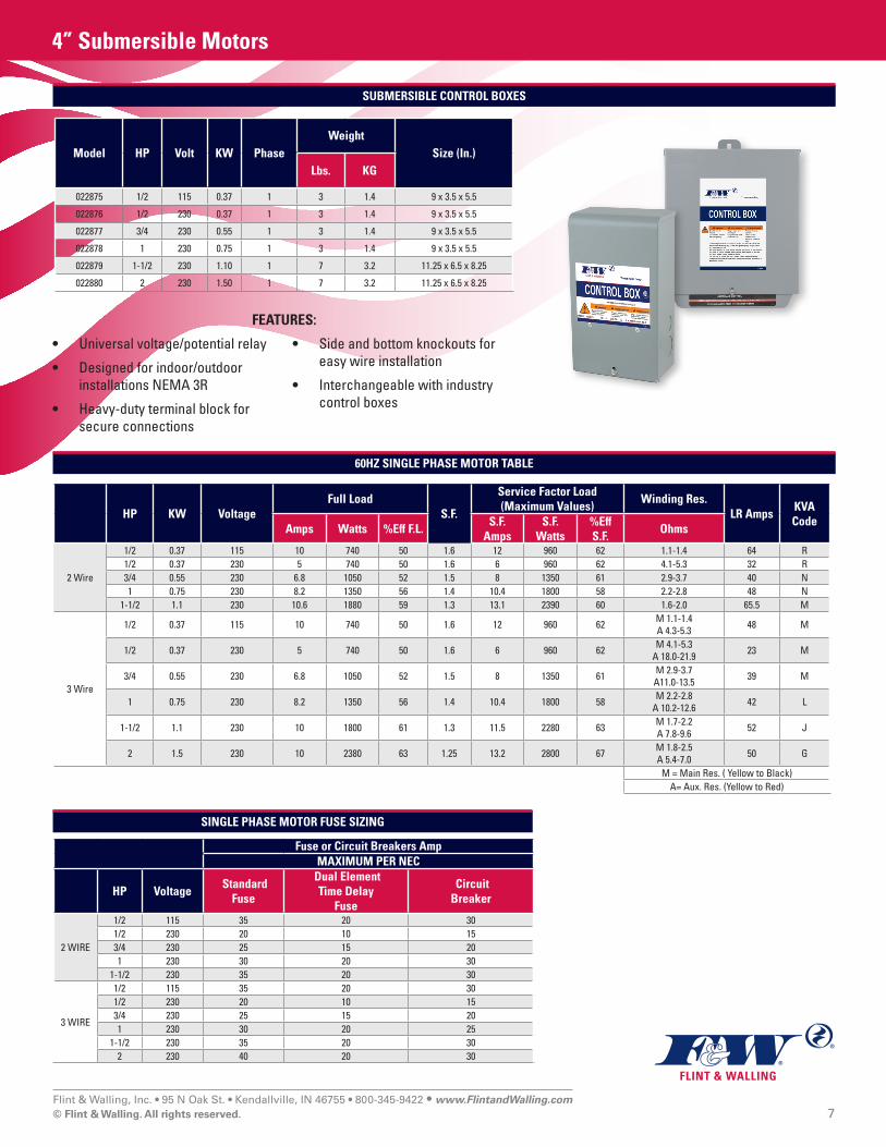
HP KW VoltageFull Load
S.F.
Service Factor Load (Maximum Values)
Winding Res. LR Amps
KVA Code
Amps Watts %Eff F.L.S.F.
AmpsS.F.
Watts%Eff S.F.
Ohms
2 Wire
1/2 0.37 115 10 740 50 1.6 12 960 62 1.1-1.4 64 R1/2 0.37 230 5 740 50 1.6 6 960 62 4.1-5.3 32 R3/4 0.55 230 6.8 1050 52 1.5 8 1350 61 2.9-3.7 40 N1 0.75 230 8.2 1350 56 1.4 10.4 1800 58 2.2-2.8 48 N
1-1/2 1.1 230 10.6 1880 59 1.3 13.1 2390 60 1.6-2.0 65.5 M
3 Wire
1/2 0.37 115 10 740 50 1.6 12 960 62 M 1.1-1.4 A 4.3-5.3 48 M
1/2 0.37 230 5 740 50 1.6 6 960 62 M 4.1-5.3 A 18.0-21.9 23 M
3/4 0.55 230 6.8 1050 52 1.5 8 1350 61 M 2.9-3.7 A11.0-13.5 39 M
1 0.75 230 8.2 1350 56 1.4 10.4 1800 58 M 2.2-2.8 A 10.2-12.6 42 L
1-1/2 1.1 230 10 1800 61 1.3 11.5 2280 63 M 1.7-2.2 A 7.8-9.6 52 J
2 1.5 230 10 2380 63 1.25 13.2 2800 67 M 1.8-2.5 A 5.4-7.0 50 G
M = Main Res. ( Yellow to Black)A= Aux. Res. (Yellow to Red)
Fuse or Circuit Breakers AmpMAXIMUM PER NEC
HP Voltage Standard
Fuse
Dual Element Time Delay
Fuse
Circuit Breaker
2 WIRE
1/2 115 35 20 301/2 230 20 10 153/4 230 25 15 201 230 30 20 30
1-1/2 230 35 20 30
3 WIRE
1/2 115 35 20 301/2 230 20 10 153/4 230 25 15 201 230 30 20 25
1-1/2 230 35 20 302 230 40 20 30
60HZ SINGLE PHASE MOTOR TABLE
SINGLE PHASE MOTOR FUSE SIZING
SUBMERSIBLE CONTROL BOXES
Model HP Volt KW PhaseWeight
Size (In.)Lbs. KG
022875 1/2 115 0.37 1 3 1.4 9 x 3.5 x 5.5
022876 1/2 230 0.37 1 3 1.4 9 x 3.5 x 5.5
022877 3/4 230 0.55 1 3 1.4 9 x 3.5 x 5.5
022878 1 230 0.75 1 3 1.4 9 x 3.5 x 5.5
022879 1-1/2 230 1.10 1 7 3.2 11.25 x 6.5 x 8.25
022880 2 230 1.50 1 7 3.2 11.25 x 6.5 x 8.25
FEATURES:
• Universal voltage/potential relay
• Designed for indoor/outdoor installations NEMA 3R
• Heavy-duty terminal block for secure connections
• Side and bottom knockouts for easy wire installation
• Interchangeable with industry control boxes
Flint & Walling, Inc. • 95 N Oak St. • Kendallville, IN 46755 • 800-345-9422 • www.FlintandWalling.com © Flint & Walling. All rights reserved. 8
4” Submersible Motors
GENERATOR SIZING
Careful consideration needs to be made when sizing a engine driven generator for use with a well pump. Generators need to be sized to supply a minimum of 65% of the rated motor voltage during motor starting to ensure sufficient starting torque.
The type of the generator makes a difference when selecting a generator to power a well pump. Two types of generators are available: Internally regulated and externally regulated. Internally regulated generators have an additional winding within the generator. The additional winding automatically adjusts the output voltage by monitoring the output current. The majority of generators on the market today are externally regulated. These generators use an external voltage regulator that monitors the output voltage. When a motor starts up and the voltage drops, the regulator boosts the output voltage of the generator.
When operating a pump with a generator, the generator needs to be started in advance of starting the pump motor. In addition, to help prevent motor bearing damage, stop the pump before turning off the generator.
The table below only represents typical minimum generator requirements for starting and running a submersible motor. Contact the generator manufacturer for detailed sizing considerations.
WARNING: Transfer switches are required when a generator is used as a back-up on power lines. Consult your power provider for proper use and approval.
ENGINE DRIVEN GENERATORS
Motor HP RatingExternally Regulated Internally Regulated
KW KVA KW KVA1/2 2 2.5 1.5 1.93/4 3 3.8 2 2.51 4 5 2.5 3.2
1.5 5 6.3 3 3.82 7.5 9.4 4 5
Note: The table provided applies to 3-Wire motors. If sizing for 2-Wire motors, multiply the value shown by 1.5.
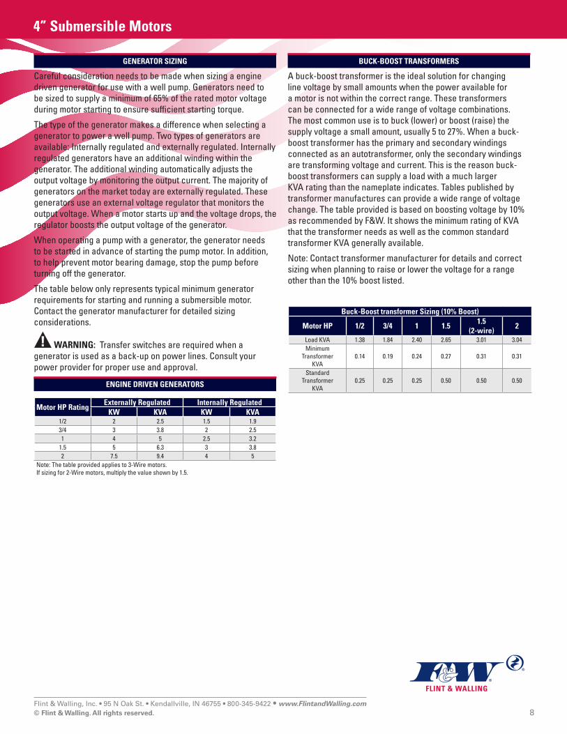
BUCK-BOOST TRANSFORMERS
A buck-boost transformer is the ideal solution for changing line voltage by small amounts when the power available for a motor is not within the correct range. These transformers can be connected for a wide range of voltage combinations. The most common use is to buck (lower) or boost (raise) the supply voltage a small amount, usually 5 to 27%. When a buck-boost transformer has the primary and secondary windings connected as an autotransformer, only the secondary windings are transforming voltage and current. This is the reason buck-boost transformers can supply a load with a much larger KVA rating than the nameplate indicates. Tables published by transformer manufactures can provide a wide range of voltage change. The table provided is based on boosting voltage by 10% as recommended by F&W. It shows the minimum rating of KVA that the transformer needs as well as the common standard transformer KVA generally available.
Note: Contact transformer manufacturer for details and correct sizing when planning to raise or lower the voltage for a range other than the 10% boost listed.
Buck-Boost transformer Sizing (10% Boost)
Motor HP 1/2 3/4 1 1.51.5
(2-wire)2
Load KVA 1.38 1.84 2.40 2.65 3.01 3.04Minimum
Transformer KVA
0.14 0.19 0.24 0.27 0.31 0.31
Standard Transformer
KVA 0.25 0.25 0.25 0.50 0.50 0.50

Flint & Walling, Inc. • 95 N Oak St. • Kendallville, IN 46755 • 800-345-9422 • www.FlintandWalling.com © Flint & Walling. All rights reserved. 9
4” Submersible Motors
CYCLING ON / OFF
Motor life can be reduced with excessive cycling of the pump due to the current in-rush at start up. Frequent starts increase motor temperature, create bearing and seal wear, and shaft spline fatigue. While typical residential cycling is estimated at 25 to 50 starts per 24 hour period, recommended maximum starts for longer life should not exceed 1 start per 5 minutes.
SHAFT HEIGHT
IL1804
SUBMERSIBLE MOTORSHAFT HEIGHTGAUGE
4 IN.
6 IN.
With the gauge restingat it’s center point fromthe vertical motor shaft,the bottom edge of the
appropriate motordiameter should clearthe face of the motor.
With the 024456 gauge resting at it’s center point from the vertical motor shaft, the bottom edge of the appropriate motor diameter should clear the face of the motor.
IDENTIFICATION OF CABLE COLOR
(Single Phase Only)
If the colors on the individual drop cables cannot be determined and the leads cannot be positively identified, proceed as follows:
1. Disconnect all three drop cables from the control box. For temporary identification, tie a numbered tag to each cable (1, 2, 3).
2. Using an ohmmeter, check the resistance between cables as follows:
Unknown Value Known ValueCable 1 to Cable 2Cable 1 to Cable 3Cable 2 to Cable 3
Lowest - Black to YellowIntermed. - Red to Yellow
Highest - Black to Red
NOTE: The “yellow” cable is giving the lowest and intermediate readings and the “red” cable gives highest and intermediate readings.
Example:
- 1 to 2 gives 7 ohms (highest reading)
- 1 to 3 gives 5 ohms (intermediate reading)
- 2 to 3 gives 2 ohms (lowest reading)
- Cable 3 gave both intermediate and lowest reading
- Cable 3 is the yellow cable
- Cable 1 gave both highest and intermediate readings
- Cable 1 is the red cable
- Cable 2 is the black cable
The actual ohm values are not important. The method works regardless of the actual ohm readings; what matters is which reading is highest, which intermediate, and which lowest.

Flint & Walling, Inc. • 95 N Oak St. • Kendallville, IN 46755 • 800-345-9422 • www.FlintandWalling.com © Flint & Walling. All rights reserved. 10
4” Submersible Motors
CAUTION: Turn power off and discharge capacitors before using ohmmeter.TEST PROCEDURE
General Procedures Disconnect line. Inspect for damaged or burned parts, loose connections, etc. Check for misconnections using diagram in control box. If problem has not been found, check motor per Motor Data Chart and control box as indicated below.
Use of Ohmmeter Use a calibrated or certified digital multimeter.
Ground (Insulation Resis-tance) Test
Multimeter selected to highest OHM meter scale.Terminal connections: Multimeter lead to “ground” terminal on control box and touch other lead to each of the other terminals on terminal board.Multimeter reading should indicate (∞) or max open circuit limits.
Overload Protector Multimeter selected to lowest OHM meter scale. Terminal connections: Connect one multimeter lead to Terminal Black and other lead to L1.Multimeter reading: Should be 0 to 0.5 ohms maximum.
Capacitor Tests
Start CapacitorMultimeter selected to 10k – 20k Ohm meter scale.Terminal Connections: One multimeter lead to relay terminal #1 and the other to black terminal on the terminal board.Ohm reading: The multimeter will briefly read a low resistance and climb back to infinity/max open circuit reading.If reading is not as above, the capacitor is likely shorted or open and needs to be replaced.Run CapacitorMultimeter selected to 10k – 20k Ohm meter scale.Disconnect the Red lead from the run capacitor terminal.Terminal Connections: One multimeter lead to the terminal on the capacitor that the red lead was connected to and the other to black terminal on the terminal board.Ohm reading: The multimeter will briefly read a low resistance and climb back to the infinity/max open circuit reading.If reading is not as above the capacitor is likely shorted or open and needs to be replaced.Caution: The tests in this guide for capacitors and relays should be considered indicative, but not irrefutable. A capac-itor for example may not show as open or shorted, but may have lost some of its capacitance and may no longer be capable of performing its purpose.
Relay Coil Test(potential relays only)
Multimeter selected to 10k – 20k Ohm meter scale.Terminal Connections: Connect one multimeter lead to #2 and the other to #5 on the relay.For 230 Volt boxes, the meter should read 4.5-7.0 K Ohms. For 115 Volt boxes, the meter should read 2.9 4.9 K Ohms.
Relay Contact TestMultimeter selected to lowest Ohm meter scale.Terminal Connections: Connect one multimeter lead to #1 and the other to #2 on the relay.The meter should read Zero ohms.
SINGLE PHASE CONTROL BOX CHECKING AND REPAIRING PROCEDURES

Flint & Walling, Inc. • 95 N Oak St. • Kendallville, IN 46755 • 800-345-9422 • www.FlintandWalling.com © Flint & Walling. All rights reserved. 11
4” Submersible Motors
MULTIMETER TESTS
Insulation and Continuity Test
1. This test is recommended when the splicing is complete and pump is being test run in a tank of water. This test can be repeated after installation in well, but before the final electrical hook-up is made to the control box or pressure switch.
2. Confirm multimeter ohmmeter function by clipping the leads together and verifying resistance readings <0.2Ω
3. Clip one multimeter lead to bare cable end.4. Clip the other lead to motor ground wire with pump and
cable submerged.5. A reading of less than 1,000,000 ohms indicates that cable or
splice is grounded. Slowly raise cable from the water at the multimeter end. When trouble spot moves clear of the water, OHM reading will increase towards (∞) or max open reading of multimeter. In an old installation with the pump in the well, a reading of 20,000 ohms or less indicates a breakdown in the insulation; in this case pull the pump.
POWER
OFF ON
LOGIC
hFE
HI
LO LOGIC
DCV
ACV
ACA
DCA
V-Ω COM mA 10A
1000VDC750VAC MAX
500VMAX 10A MAX
IL0098
POWER
OFF ON
LOGIC
hFE
HI
LO LOGIC
DCV
ACV
ACA
DCA
V-Ω COM mA 10A
1000VDC750VAC MAX
500VMAX 10A MAX
POWER
OFF ON
LOGIC
hFE
HI
LO LOGIC
DCV
ACV
ACA
DCA
V-Ω COM mA 10A
1000VDC750VAC MAX
500VMAX 10A MAX
IL0099

Flint & Walling, Inc. • 95 N Oak St. • Kendallville, IN 46755 • 800-345-9422 • www.FlintandWalling.com © Flint & Walling. All rights reserved. 12
4” Submersible Motors
Symptom Possible Cause(s) Corrective Action
Circuit breaker trips or fuses blow when motor starts.
1. Incorrect voltage 1. Contact power company if voltage is incorrect after first check-ing for correct wire size. See Wire Size Chart.
2. Incorrect fuses or circuit breaker. 2. Replace with correctly sized components.3. Defective pressure switch 3. Replace pressure switch or clean contacts.4. Control box malfunction 4. Correct faulty wiring or tighten loose contacts.5. Bound pump 5. Sand bound pump can sometimes be corrected by temporarily
reversing black and red leads in control box then returning to normal. If pump does not rotate freely, it must be pulled and cleaned or realigned and the well condition corrected.
6. Defective cable or motor winding 6. The pump must be pulled and the cable disconnected and inspected. Damaged cable should be correctly spliced or replaced. If cable is good, the motor winding is grounded
7. Shorted or open motor winding 7. The pump must be pulled and motor or drop cable repaired or replaced.
Motor runs but circuit breaker, fuses or motor overload trips.
1. Incorrect voltage 1. Contact power company.2. Overheated protectors 2. Shade box, provide ventilation or move box away from heat
source.3. Improperly wired control box 3. Confirm motor and line connections.4. Defective motor or cable 4. If ground, short or open circuit is indicated pump must be
pulled for repair.5. Defective pump 5. Pull pump, clean and repair to ensure pump staging is free of
excess sand or debris.
Motor does not start and circuit breaker or fuses not tripped.
1. No power 1. Replace fuses or reset circuit breaker. Contact powercompany if no power is reaching box.
2. Defective pressure switch 2. Clean contact points or replace switch.3. Defective wiring 3. Correct faulty wiring or connections/splices.
Pump runs, but delivers little or no water.
1. Air locked pump 1. Not enough water over pump. Raise and lower the pump at a fast rate to purge air from pump body.
2. Low water level in well 2. Throttle pump delivery through restricting valve. Lower pump setting if depth of well is adequate.
3. Check valve stuck or installed improperly 3. Replace or reinstall properly, ensure water check valve arrow oriented with flow.
4. Leak in drop pipe 4. Raise pipe, check for leak and replace damaged section.5. Pump screen blocked 5. Clean screen and reset at less depth. It may be necessary to
clean well.6. Worn pump 6. Pull pump and replace staging or pump end.
Pump keeps running 1. Pressure switch 1. Clean points or replace switch. Verify pressure switch setting and function.
2. Low level well 2. Throttle pump output or reset pump to lower level. Do not lower if sand may clog pump.
3. Leak in system 3. Replace damaged section. Replace all piping and joints to eliminate leaks.
4. Misapplied pump 4. Verify pump depth/static water level vs. pump performance curve. For guidance, contact Tech Support at 1-800-742-5044.
Pump starts too often 1. Pressure switch 1. Reset limits or replace switch.2. Leak in system 2. Repair or replace tank or pipes.3. Check valve 3. Replace if column of water leaking by check valve.4. Water-logged tank 4. Replace tank.5. Pressure tank too small 5. Install larger tank.
TROUBLESHOOTING CHART
Related Documents