22 Int. J. Electric and Hybrid Vehicles, Vol. 7, No. 1, 2015 Copyright © 2015 Inderscience Enterprises Ltd. Fuzzy controlled evaporative battery thermal management system for EV/HEV Ataur Rahman*, Farhana Nur and M.N.A. Hawlader Faculty of Engineering, Department of Mechanical Engineering, International Islamic University Malaysia, Kuala Lumpur 50728, Malaysia Email: [email protected] Email: [email protected] Email: [email protected] Email: [email protected] *Corresponding author Rafia Afroz Faculty of Economics and Management Science, Department of Economics, International Islamic University Malaysia (IIUM), Kuala Lumpur 50728, Malaysia Email: [email protected] Abstract: Electrical car battery voltage changes significantly to meet the power demands while the car is in acceleration and at the time of momentary peak load. The peak load periods generate powerful electrical currents, causing significant warming of the Li-ion cells owing to internal resistance. At a battery operating temperature of 40ºC and above, the battery life span is reduced. The rationale of this study is to develop an innovative evaporative battery cooling thermal management system (EC-BThMS) to control the battery temperature in the range of 20–40ºC to increase the battery life span. The EC-BThMS is able to control the battery temperature in the range of 20–40ºC both in charging and discharging mode. The experimental EC-BThMS has been constructed and compared with air cooling battery thermal management systems (AC-BThMS) by using Proton Saga EV. Result shows that that the EV with EC-BThMS can save 17.69% more energy than with AC-BThM 1 and 23% more than with AC-BThMS 2 . Keywords: EV/HEV; battery thermal management system; fuzzy control; cell of battery. Reference to this paper should be made as follows: Rahman, A., Nur, F., Hawlader, M.N.A. and Afroz, R. (2015) ‘Fuzzy controlled evaporative battery thermal management system for EV/HEV’, Int. J. Electric and Hybrid Vehicles, Vol. 7, No. 1, pp.22–39. Biographical notes: Ataur Rahman, PhD is a Professor in the Department of Mechanical Engineering, Faculty of Engineering, International Islamic University Malaysia since 2006. His research interests are green transportation

Welcome message from author
This document is posted to help you gain knowledge. Please leave a comment to let me know what you think about it! Share it to your friends and learn new things together.
Transcript

22 Int. J. Electric and Hybrid Vehicles, Vol. 7, No. 1, 2015
Copyright © 2015 Inderscience Enterprises Ltd.
Fuzzy controlled evaporative battery thermal management system for EV/HEV
Ataur Rahman*, Farhana Nur and M.N.A. Hawlader Faculty of Engineering, Department of Mechanical Engineering, International Islamic University Malaysia, Kuala Lumpur 50728, Malaysia Email: [email protected] Email: [email protected] Email: [email protected] Email: [email protected] *Corresponding author
Rafia Afroz Faculty of Economics and Management Science, Department of Economics, International Islamic University Malaysia (IIUM), Kuala Lumpur 50728, Malaysia Email: [email protected]
Abstract: Electrical car battery voltage changes significantly to meet the power demands while the car is in acceleration and at the time of momentary peak load. The peak load periods generate powerful electrical currents, causing significant warming of the Li-ion cells owing to internal resistance. At a battery operating temperature of 40ºC and above, the battery life span is reduced. The rationale of this study is to develop an innovative evaporative battery cooling thermal management system (EC-BThMS) to control the battery temperature in the range of 20–40ºC to increase the battery life span. The EC-BThMS is able to control the battery temperature in the range of 20–40ºC both in charging and discharging mode. The experimental EC-BThMS has been constructed and compared with air cooling battery thermal management systems (AC-BThMS) by using Proton Saga EV. Result shows that that the EV with EC-BThMS can save 17.69% more energy than with AC-BThM1 and 23% more than with AC-BThMS2.
Keywords: EV/HEV; battery thermal management system; fuzzy control; cell of battery.
Reference to this paper should be made as follows: Rahman, A., Nur, F., Hawlader, M.N.A. and Afroz, R. (2015) ‘Fuzzy controlled evaporative battery thermal management system for EV/HEV’, Int. J. Electric and Hybrid Vehicles, Vol. 7, No. 1, pp.22–39.
Biographical notes: Ataur Rahman, PhD is a Professor in the Department of Mechanical Engineering, Faculty of Engineering, International Islamic University Malaysia since 2006. His research interests are green transportation
Fuzzy controlled evaporative battery thermal management system 23
system: EV/HEV, hybrid engine, intelligent power train for hybrid and electrical vehicle, intelligent steering system and traction control system, electromagnetic actuated CVT and intelligent air-cushion vehicle for swamp and peat terrain. He has worked in The University of Tokyo, Japan, as a Visiting Fellow on the development of integrated instrumentation systems for Autonomous Vehicles. He has published more than 120 including journal articles, books and patents.
Farhana Nur is a PhD student on Engineering. She is currently doing research on “Intelligent System Development on Controlling Temperature of EV battery”. She has got her MSC on Control Engineering and BSc (Honour) in Mechatronics Engineering.
M.N.A. Hawlader, PhD is a Professor in the Department of Mechanical Engineering, Faculty of Engineering, International Islamic University Malaysia since 2010. Prior joint in International Islamic University Malaysia he was in National University of Singapore since 1979. He is expert on renewable energy and energy system. He has published more than 200 including journal articles, books and patents.
Rafia Afroz, PhD is an Assoc. Professor, Department of Economics, Faculty of Economics and management Science, International Islamic University Malaysia since 2008. She was also appointed as Senior Lecturer in university Malaysia Sarawak in 2007. She has received JSPS Post-Doctoral Fellowship in the University of Tokyo, Japan in 2005. She has published more than 30 articles in Journals and proceedings. Recently, she published one book entitled “The Peat Swamp: Productivity, Traficability and Mechanization” by Nova Science Publisher. Her area of research interest is environmental valuation, waste management, input output analysis and climate change.
This paper is a revised and expanded version of a paper entitled ‘Noble Evaporative battery cooling thermal management system for EV/HEVs’ presented at Proceedings of the 2014 International Conference on Industrial Engineering and Operations Management, Bali, Indonesia, 7–9 January, 2014.
1 Introduction
One of the biggest obstacles faced by the EVs development is to maintain battery temperature at an appropriate level. This is important not only to maintain the performance and capacity of the battery, but also to ensure the battery safety and life span. Electric cars need to be equipped with high power battery pack for traction. The momentary peak load periods generate powerful electrical currents, causing significant warming of the Li-ion cells owing to internal resistance. Lithium-ion battery should be operated in the desired range of 25–35°C, which could lead to balanced utilisation of the active material and potentially to improve the performance and span the battery life. Charging and discharging processes of a battery will produce heat. An enormous amount of heat is generated especially during the high rate discharges. If this heat cannot be dissipated immediately, then the battery temperature rises dramatically within a short period of time (Li and Wang, 2010). Heat behaviour of Li-ion battery during rapid charge and discharge cycles had been studied by Onda et al. (2006). They reported that much
24 A. Rahman et al.
heat generation happens during rapid charge and discharge cycles that make the battery temperature rise significantly. Heat control and management is one of the most important issues in the lithium-ion batteries at high temperature or high charge/discharge rate will lower charge/discharge efficiency and lower the battery life or even cause safety problem, as reported by Xiangzhe and Hongbin (2005), Benger et al. (2009), Wang et al. (2009) and Chen and Evans (1994).
Dominko et al. (2005), Al-Hallaj et al. (2000), Duan and Naterer (2010) and Heckenberger (2009) were studied on electrochemistry and structures of LiFePO4 material. They have reported that the Li-ion battery capacity drops seriously.
Fuzzy controlled evaporative battery thermal management system under low temperature. It drops ~17–22% when the battery cells temperature is –20ºC. The anode material starts decomposing and reacting with the electrolyte under a higher temperature of ~172ºC. According to Albright (2012) for LiFePO4 battery application, maximum recommended battery temperature is 40ºC. Battery temperature above 40ºC will reduce battery life slightly, and significantly reduce if the battery temperature goes beyond 60ºC. Furthermore, the findings of Kruger et al. (2009) and Li and Wang (2010) reported that Li-ion battery performs better at the preferred temperature range of 20–40ºC, which provides a close to maximum power capability and acceptable thermal ageing rates. Pesaran (2001) asserts that the battery life cycle would get shorter at temperatures more than 60ºC.
Battery pack imbalances can reduce performance and can also damage the battery and/or reduce life. To optimise performance of a battery pack, the goal of a thermal management system is to deliver an optimum average temperature with even temperature distribution and uniformity with small temperature variations within a battery module (Pesaran et al., 1999; Pesaran, 2001; Onda et al., 2006; Rahman et al., 2014). Hence, significant importance has been placed on thermal management of Li-ion battery cells to keep the batteries operating at a desirable temperature range, to prevent the batteries from exceeding a high temperature and to achieve the desired life span (Heckenberger, 2009). Thermal management of a battery pack is typically accomplished with the combination of two approaches:
• a cooling system is designed to absorb heat from the battery pack
• the battery controller adjusts the vehicle’s use of the battery pack based on the conditions in the batteries.
Sabbah et al. (2008) studied an air-cooling battery thermal management system. They reported that air cooling system is not a proper thermal management system to keep the temperature of the cell in the desirable operating range without expending significant fan power. Pesaran et al. (1999) conducted a study on battery thermal management system of EV and they recommended liquid cooling system. However, the main weakness of the liquid cooling system is the possibility of liquid leaking which causes electric short-circuit and in severe case eventually could cause a fire in the car. Heckenberger (2009) has performed a study of integrating between the air conditioning system’s refrigerant with the battery cooling, which has been implemented in the Li-ion battery cooling for the Mercedez-Benz S400 Blue Hybrid. He reported that more energy is needed by cooling process via a refrigerant circuit, when compared with an operation by a coolant circuit.
Fuzzy controlled evaporative battery thermal management system 25
This study presents an intelligent control evaporative battery thermal management system which will be able to maintain the battery temperature in the range of 25–400C to achieve the desired life span and to save the energy of the system by controlling compressor with the response of the thermocouples.
2 Mathematical modelling
This section presents mathematical model for predicting heat generation and temperature distribution within the battery pack. The procedure begins with a study about how heat can be formed from a battery either during charge or discharge process. Subsequently, identification of process involved for heat dissipation plays a very important role which might be the rate of flow of refrigerant to the battery evaporator. This section also presents the mathematical model of power consumption of the compressor to maintain the desired refrigerant flow. Furthermore, the mathematical model also describes the traction power requirement for the Proton Saga vehicle during operation on the roads.
2.1 Heat generation from the battery modules
Electric current flows in and out from the battery during charging and discharging, respectively, causes heat which due to the
• entropy change from electrochemical reaction (Pesaran et al., 1999; Krüger et al., 2009; Bergveld, 2001)
• Joule’s effect (Ohmic heating) caused by internal electric resistance inside the cell
• polarisation resistance as energy is required for the diffusion and movement of atoms in the battery reaction process.
The foregoing information includes generation factors; however, the magnitude of heat generated depends to a great extent on the battery electro-chemistry, state of charge (SOC) and state of discharge (SOD) and temperature of the cell.
Total heat rate Qgen generated inside a battery cell due to electrochemical reactions Qelec, polarisation resistance Qpolar and Joule’s effects Qjoule can be expressed as follows:
∆energy gen out ,inQ Q Q Q= + − (1)
where ∆energyQ is the rate of energy increment stored within the battery cell, Qin is the rate of energy transfer into the cell, Qgen is the rate of energy generation and Qout is the rate of energy transfer out of the cell. It is assumed that there is no heat transfer energy transfer from cell to cell, QinQgen= 0; therefore, the overall energy balance on a battery module can be expressed as
∆energy gen outQ Q Q= −
Considering Qout equals to Qconv, equation (1) can be expressed by

26 A. Rahman et al.
( ) ( ) ( ) ( )batt( ) 2∆energy batt( ) .i i
i m s ib d b d b di ii
T SQ I I I R h A T T
n Fη ∞
∆ = ⋅ + + − −
∑ ∑ (2)
The change in energy storage due to temperature change over time t when the vehicle is operated, or current is drawn from the battery can be expressed as;
( )∆energy accud d .d d
tp
UQ Q Vc T
t tρ= = = (3)
The term Qaccu is called heat accumulation associated with the rate of change in the internal thermal energy of the battery module, whether the energy is stored or released over time. ρ and cp are the mass density and the specific heat capacity, respectively, of the battery module material and V is the volume of the module.
The above overall energy equation used to calculate the average module temperature Tbatt over time can then be written as
( ) ( ) ( ) ( ) ( )batt ( ) 2batt ( )
d .d
i ip i m s ib d b d b d
i ii
T SVc T I I I R h A T T
t n Fρ η ∞
∆ = + + − −
∑ ∑ (4)
Therefore, by replacing the battery module mass m into the above equation, the overall energy equation used to calculate the average module temperature Tbatt can be expressed as follows:
( ) ( ) ( ) ( )batt ( ) 2batt ( ) batt ( ) batt ( )
1 i if i i m s ib d b d b di
ip i
T ST T I I I R h A T T
mc n Fη ∞
∆ = + ⋅ + + − −
∑ ∑
(5)
The discharge current (Ib(d)) from the battery can be estimated by incorporating the traction equation of Rahman et al. (2011):
( )( )
[ ]
( )
22
vol)
d 10.005 0.01 0.09 sind 100 2
a Df
t p
b dmm
Cv V m mm A V Vt P g g
IV
ρ θ
η
+ + + + + =
(6)
where m is the mass of the vehicle in kg, g is the gravitational acceleration constant, m/s2, µr is the adhesion coefficient of the road, Pt(p) is the tyre pneumatic pressure in kN/m2, θ is the slope angle with respect to the horizon in deg., where ρa is the air density in kg/m3, CD is the coefficient of aerodynamic resistance, Af is the frontal area of the vehicle in m2 and V is the travelling speed of the vehicle relative to the wind in m/s and Vm(vol) is the motor rating voltage in volts.
For the simulation: the adhesion coefficient value µr of 0.02, highest gradient sinθg = G equals to 3.67%, air density ρa equals to 1.164 kg/m3 and maximum travelling speed Vmax of 120 km/h has been considered. Vm(vol) is the motor rating voltage in this study has been considered as 100 V. The maximum power needs for the vehicle to mobile on 3.67% gradient with maximum speed of 120 km/h has been presented in Table 1.
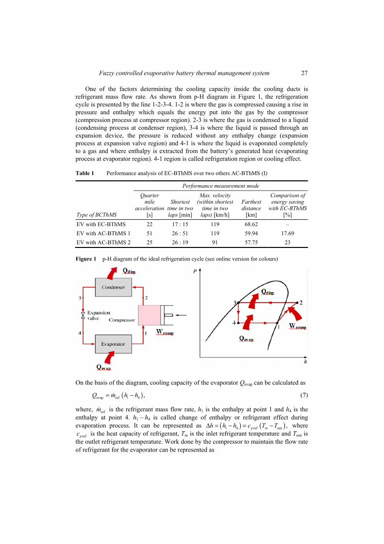
Fuzzy controlled evaporative battery thermal management system 27
One of the factors determining the cooling capacity inside the cooling ducts is refrigerant mass flow rate. As shown from p-H diagram in Figure 1, the refrigeration cycle is presented by the line 1-2-3-4. 1-2 is where the gas is compressed causing a rise in pressure and enthalpy which equals the energy put into the gas by the compressor (compression process at compressor region). 2-3 is where the gas is condensed to a liquid (condensing process at condenser region), 3-4 is where the liquid is passed through an expansion device, the pressure is reduced without any enthalpy change (expansion process at expansion valve region) and 4-1 is where the liquid is evaporated completely to a gas and where enthalpy is extracted from the battery’s generated heat (evaporating process at evaporator region). 4-1 region is called refrigeration region or cooling effect.
Table 1 Performance analysis of EC-BThMS over two others AC-BThMS (I)
Type of BCThMS
Performance measurement mode Quarter
mile acceleration
[s]
Shortest time in two laps [min]
Max. velocity (within shortest
time in two laps) [km/h]
Farthest distance
[km]
Comparison of energy saving
with EC-BThMS [%]
EV with EC-BThMS 22 17 : 15 119 68.62 – EV with AC-BThMS 1 51 26 : 51 119 59.94 17.69 EV with AC-BThMS 2 25 26 : 19 91 57.75 23
Figure 1 p-H diagram of the ideal refrigeration cycle (see online version for colours)
On the basis of the diagram, cooling capacity of the evaporator Qevap can be calculated as
( )evap ref 1 4 ,Q m h h= − (7)
where, refm is the refrigerant mass flow rate, h1 is the enthalpy at point 1 and h4 is the enthalpy at point 4. h1 – h4 is called change of enthalpy or refrigerant effect during evaporation process. It can be represented as ( ) ( )1 4 ref out ,p inh h h c T T∆ = − = − where
refpc is the heat capacity of refrigerant, Tin is the inlet refrigerant temperature and Tout is the outlet refrigerant temperature. Work done by the compressor to maintain the flow rate of refrigerant for the evaporator can be represented as

28 A. Rahman et al.
( )comp ref 2 1 ,W m h h= − (8)
where, h2 is the enthalpy at point 2. Assuming that the heat received by the refrigerant is equal to the heat generation from the battery, Equation (12) can now be rewritten as follows, evap gen .Q Q= Hence, the refrigerant mass flow rate can be expressed as follows:
( )
2batt
ref1 4
iii i
i
T S I I Rn F
mh h
η− ∆ + +=
−
∑ ∑ (9)
Power consumption by the compressor can be defined as
( )( ) ref 2 11
in ccm c
P m h hη η
= − (10)
where, ηcm and ηc are the efficiency of the compressor and compressor, respectively, Pin(c) is the power by compressor motor in kW.
3 Cooling system development
The main power source of EVs is from the battery pack, which consists of a number of battery modules. The electric discharge current drawn from the battery modules is used to propel the vehicle and to operate the battery thermal management system. The size and number of modules to be used in the battery pack depends on the required power of the vehicle. The first step conducted on the development of the battery pack is the estimation of vehicle power requirement. The battery pack has been design based on the power requirement of the vehicle. Battery pack has been design by using module of LiFePO4 has a normal capacity 86 Ah @ 0.5 C, nominal voltage of 7.5 V and impedance of 1.64 mΩ, power density 1.813 W/kg@ 25ºC, maximum continuous discharge current 460 A @ 25ºC, discharging cut-off voltage 6.00 ± 0.05 V, maximum charging current 172 A and charging cut-off voltage 8.3 ± 0.05 V, working temperature –25ºC to 50ºC. Furthermore, each of the modules consists of two (2) cells in series and two (2) in parallel connections.
The EC-BThMS has been built with independent cooling ducts, compressor, condenser and expansion valve. The cooling ducts were fabricated by using copper in a rectangular hollow shape. The size of each cooling duct is 360 mm length by 184 mm height with 10 mm width (inner space) and 1 mm of wall thickness as shown in Figure 2. The cooling ducts were designed in such way as to cover both side surfaces of the battery modules thoroughly. Additionally, the width of the cooling ducts should not over than 10 mm in order to exactly suit with the size of the vehicle trunk compartment. The cooling ducts and modules were placed in a case made by aluminium. Figure 2(a) shows the isometric view of the cooling ducts with inlet and outlet pipes. In this cooling system, the R-134a refrigerant was used as the medium of cooling. The refrigerant flowing through the cooling ducts from an inlet port (primary pipe and secondary inlet pipes) located at the bottom of each ducts and escape from the ducts through an outlet port located at the upper of the ducts. There were 14 units of secondary inlet and outlet pipes, respectively, made from 5 mm (internal diameter) of copper pipe. They were attached

Fuzzy controlled evaporative battery thermal management system 29
together at the cooling duct in a parallel position in order to have the same pressure of refrigerant enters into the cooling ducts. All the secondary inlet and outlet pipes are connected to one primary inlet pipe and primary outlet pipe, respectively, before linked to the hoses, as shown in Figure 2(b).
Figure 2 Developed EC-BThMS: (a) theoretical model and (b) developed final EC-BThMS (see online version for colours)
(a) (b)
4 Control strategy
Figure 3 shows the EC-BThMS Fuzzy Intelligent Control System (FICS) that has been developed based on the concepts of Rahman et al. (2012) and Rahman and Azmi (2013). The FICS activates with the response of a set of thermo couples. Each of set thermocouples is used to monitor the temperature of battery modules. Fuzzy logic controller (FLC) is used to maintain the power delivered from the battery pack to the DC motor of the compressor DC motor for its optimal operating point. Hence, power management of EC-BThMSis established in order to minimise power consumption, while enhancing or maintaining the battery safety and life span. In this case, the FLC is used which can effectively control the motor’s output torque. At any particular point, the power supply from the battery to the DC motor is determined based on the torque and speed demand of the compressor motor to develop the desired flow rate of refrigerant. The optimal power supply from the battery to the DC motor for optimal torque is adjusted initially with the battery pack adjusting mechanism which is mainly based on the initial temperature of the battery module (Rahman et al., 2011). The battery power adjusting mechanism controls the variable power input (P) to the motor of compressor to develop the torque (Tp) with FLC. It is noted that the sensing inputs of the battery module temperature which depends on the vehicle speed and battery SoD.
Consider a system with the plant model (Motor) of the form:
,p p p pT a y b P= − + (11)
where P is the control variable power kW, and Tp is the measured state output torque in Nm, ap and bp are unknown coefficients. In the model, voltage supply to the motor makes constant by using DC–DC inverter while the current supply is controlled by a FLC which depends on the response of the thermocouples. In the equation, eventually, the

30 A. Rahman et al.
current is considered as a controlled variable. Assuming that it is desired to obtain a closed – loop system described by
,m m m mT a y b r= − + (12)
where, r(i.e., Ib) is the control variable, and Tm is the reference torque in Nm, am and bm are known coefficients. After knowing the parameters of the plant, the following control law gives the model as follows:
( ) ( ) ( ) ,pP t br t aT t= − (13)
With ; .m pm
p p
a abb a
b b−
= =
The error variable of the control model is
( ) ( ) ( ).p me t T t T t= − (14)
Figure 3 Fuzzy logic controlling block diagram (see online version for colours)
The rate of change of the error can be defined as
( ) ( ) ( ) ( ) ( )
( ) ( ) ( ) ( ) ( )
dd
.
p p p m m m
m m p p p p m
e ta T t b P t a T t b r t
ta e t a a b a t T t b b t b r t
= − + − − +
= − + − − + −
(15)
Equation (14) indicates that the error of the control model will be zero if a(t) and b(t) are zero. The emphasis is given to construct a battery pack adjustment mechanism in model which drives the parameters a(t) and b(t) to appropriate values, such as the resulting control law for the motor forces Tp(t) to follow the model output Tm(t). To achieve this target, the Lyapunov function is introduced,
( ) ( ) ( )( ) ( )( )2 221 1 1, , ,2 p p m p m
p p
V e a b e t b a t a a b b t bb bγ γ
= + + − + −
, (16)

Fuzzy controlled evaporative battery thermal management system 31
where, γ > 0. This function will be zero when e (t) is zero and the controller parameters a(t) and b(t) are equal to the optimal values.
4.1 Implementation of FLC
In the control system of the EC-BThMS, temperature of the battery (Tbat) is selected as the controlled variable, and mass flow rate of refrigerant ref( )m to the battery evaporator as the regulated variable through the operation of the compressor with 24 V DC motor. On the basis of the difference between measured value (Tbat(m)) and reference value (Tbat(r)), the regulation variable, i.e., mass flow rate of refm has been regulated. Hence, the resultant deviation, i.e., temperature error (TE) e and the rate of temperature error (RTE) e are continuously measured in operation. From the dynamic of the system, if the measured temperature is less than the desired temperature, then it is necessary to increase the flow rate of refrigerant by regulating current flow to the motor. This knowledge of this system behaviour allows formulating a set of general rules that are described.
The units of the used factors are: TE (C), TPE (C/s) and MFR (kg/s). For the two inputs and one output, a fuzzy associated memory or decision (also called decision rule) is formed as regulation rules. A total of 25 rules were formed. Parts of the developed fuzzy rules are shown in Table 1. For fuzzification, the linguistic variables large negative error (LNTE), small negative error (SNTE), zero error (ZTE), small positive error (SPE) and large positive error (LPTE) are used for the temperature error (TE); the large negative rate of error (LNRTE), small negative rate of error (SNRTE), zero rate of error (ZRTE), small rate of error (SPRTE) and large positive rate of error (LPRTE) are used for the rate of temperature error (RPE). Similarly, the linguistic variables very little mass flow rate of refrigerant (VL refm ), little mass flow of refrigerant (Li refm ), medium mass flow rate-of-refrigerant (M refm ), large mass flow rate-of-refrigerant (L refm ) are used for the flow rate-of-refrigerant ref( )m as output parameter. Once the inputs are fuzzified, the FIS refers to a set of user defined if-then rules to decide on a fuzzy output. Schematic representation of fuzzy logic expert system for flow rate modelling is shown in Figure 4.
5 Performance investigation
This section presents the performance investigation of developed evaporative thermal management system (EC-BThMS) for EV/HEV both in theoretically and experimentally.
5.1 Performance investigation: theoretically
Theoretically discussion has been made on the EC-BThMS by considering the discharging current drawn in the range of 40–400 amp by the AC induction motor to propel the Proton Saga with maximum speed of 126 km/h and maximum operation time 90 min. The EC-BThMS has been developed from this study for a battery pack of Proton Saga to operate for maximum 90 min. Figure 5 shows the heat generation within the battery modules according to each factor of heat source at different battery cycle. Result shows that the main contribution of heat generation is due to resistive heat (Joule effect, 2 ).jeQ i R= The heat developed due to Joule effect indicates that the heat

32 A. Rahman et al.
developed into battery increases with the square of the current as the internal resistance of the battery is constant. Thus, the more discharge current drawn from battery modules, the more heat will be produced from the battery cells. The heat generation due to polarisation is neglected in the simulation as it is found very small which also can be supported (Bergveld, 2001).
Figure 4 Schematic representation of fuzzy logic expert system
Figure 5 Estimation of heat generation for each factor at different battery cycle
Fuzzy controlled evaporative battery thermal management system 33
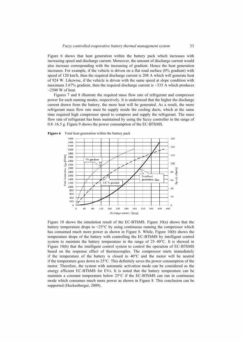
Figure 6 shows that heat generation within the battery pack which increases with increasing speed and discharge current. Moreover, the amount of discharge current would also increase corresponding with the increasing of gradient. Hence the heat generation increases. For example, if the vehicle is driven on a flat road surface (0% gradient) with speed of 120 km/h, then the required discharge current is 208 A which will generate heat of 924 W. Likewise, if the vehicle is driven with the same speed at slope condition with maximum 3.67% gradient, then the required discharge current is ~335 A which produces ~2500 W of heat.
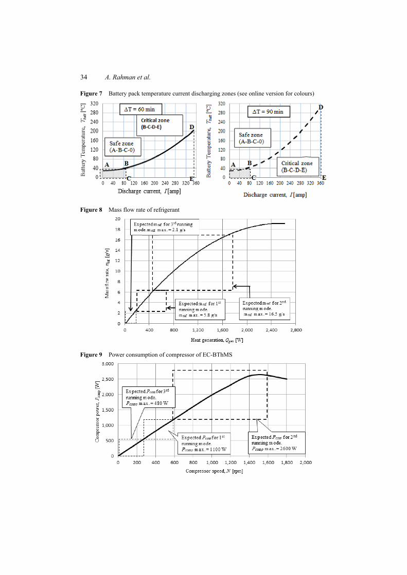
Figures 7 and 8 illustrate the required mass flow rate of refrigerant and compressor power for each running modes, respectively. It is understood that the higher the discharge current drawn from the battery, the more heat will be generated. As a result, the more refrigerant mass flow rate must be supply inside the cooling ducts, which at the same time required high compressor speed to compress and supply the refrigerant. The mass flow rate of refrigerant has been maintained by using the fuzzy controller in the range of 0.8–16.5 g. Figure 9 shows the power consumption of the EC-BThMS.
Figure 6 Total heat generation within the battery pack
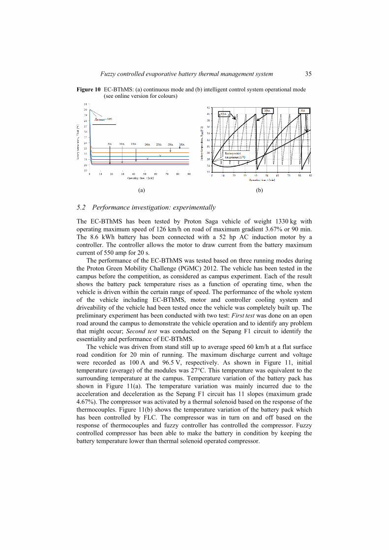
Figure 10 shows the simulation result of the EC-BThMS. Figure 10(a) shows that the battery temperature drops to <25°C by using continuous running the compressor which has consumed much more power as shown in Figure 8. While, Figure 10(b) shows the temperature drops of the battery with controlling the EC-BThMS by intelligent control system to maintain the battery temperature in the range of 25–40°C. It is showed in Figure 10(b) that the intelligent control system to control the operation of EC-BThMS based on the response effect of thermocouples. The compressor starts immediately if the temperature of the battery is closed to 40°C and the motor will be neutral if the temperature goes down to 25°C. This definitely saves the power consumption of the motor. Therefore, the system with automatic activation mode can be considered as the energy efficient EC-BThMS for EVs. It is noted that the battery temperature can be maintain a constant temperature below 25°C if the EC-BThMS can run in continuous mode which consumes much more power as shown in Figure 8. This conclusion can be supported (Heckenberger, 2009).
34 A. Rahman et al.
Figure 7 Battery pack temperature current discharging zones (see online version for colours)
Figure 8 Mass flow rate of refrigerant
Figure 9 Power consumption of compressor of EC-BThMS
Fuzzy controlled evaporative battery thermal management system 35
Figure 10 EC-BThMS: (a) continuous mode and (b) intelligent control system operational mode (see online version for colours)
(a) (b)
5.2 Performance investigation: experimentally
The EC-BThMS has been tested by Proton Saga vehicle of weight 1330 kg with operating maximum speed of 126 km/h on road of maximum gradient 3.67% or 90 min. The 8.6 kWh battery has been connected with a 52 hp AC induction motor by a controller. The controller allows the motor to draw current from the battery maximum current of 550 amp for 20 s.
The performance of the EC-BThMS was tested based on three running modes during the Proton Green Mobility Challenge (PGMC) 2012. The vehicle has been tested in the campus before the competition, as considered as campus experiment. Each of the result shows the battery pack temperature rises as a function of operating time, when the vehicle is driven within the certain range of speed. The performance of the whole system of the vehicle including EC-BThMS, motor and controller cooling system and driveability of the vehicle had been tested once the vehicle was completely built up. The preliminary experiment has been conducted with two test: First test was done on an open road around the campus to demonstrate the vehicle operation and to identify any problem that might occur; Second test was conducted on the Sepang F1 circuit to identify the essentiality and performance of EC-BThMS.
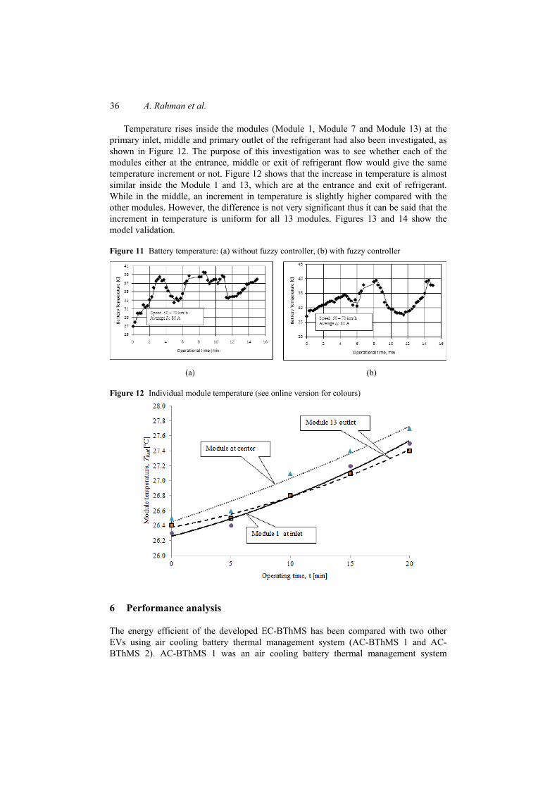
The vehicle was driven from stand still up to average speed 60 km/h at a flat surface road condition for 20 min of running. The maximum discharge current and voltage were recorded as 100 A and 96.5 V, respectively. As shown in Figure 11, initial temperature (average) of the modules was 27°C. This temperature was equivalent to the surrounding temperature at the campus. Temperature variation of the battery pack has shown in Figure 11(a). The temperature variation was mainly incurred due to the acceleration and deceleration as the Sepang F1 circuit has 11 slopes (maximum grade 4.67%). The compressor was activated by a thermal solenoid based on the response of the thermocouples. Figure 11(b) shows the temperature variation of the battery pack which has been controlled by FLC. The compressor was in turn on and off based on the response of thermocouples and fuzzy controller has controlled the compressor. Fuzzy controlled compressor has been able to make the battery in condition by keeping the battery temperature lower than thermal solenoid operated compressor.
36 A. Rahman et al.
Temperature rises inside the modules (Module 1, Module 7 and Module 13) at the primary inlet, middle and primary outlet of the refrigerant had also been investigated, as shown in Figure 12. The purpose of this investigation was to see whether each of the modules either at the entrance, middle or exit of refrigerant flow would give the same temperature increment or not. Figure 12 shows that the increase in temperature is almost similar inside the Module 1 and 13, which are at the entrance and exit of refrigerant. While in the middle, an increment in temperature is slightly higher compared with the other modules. However, the difference is not very significant thus it can be said that the increment in temperature is uniform for all 13 modules. Figures 13 and 14 show the model validation.
Figure 11 Battery temperature: (a) without fuzzy controller, (b) with fuzzy controller
(a) (b)
Figure 12 Individual module temperature (see online version for colours)
6 Performance analysis
The energy efficient of the developed EC-BThMS has been compared with two other EVs using air cooling battery thermal management system (AC-BThMS 1 and AC-BThMS 2). AC-BThMS 1 was an air cooling battery thermal management system

Fuzzy controlled evaporative battery thermal management system 37
equipped with eight fans at the battery pack, while AC-BThMS was equipped with 12 fans. For both of the systems, cold air is drawn from surrounding air and blown to the battery modules by fans. For these AC-BThMS, the all fans for air blowing were kept running during operation of the vehicles. The result of the cooling systems has been shown in Table 1. Result shows that the EV with EC-BThMS can save 17.69% more energy than the EV with AC-BThM 1 and 23% than the EV with AC-BThMS 2. This is because the potentiality of the EC-BThMS which is able to maintain the temperature of the battery pack in the range of 20–40ºC.
Figure 13 Temperature profile between experimental and simulation (see online version for colours)
Figure 14 Correlation between actual and predicted value of temperature profile (see online version for colours)
38 A. Rahman et al.
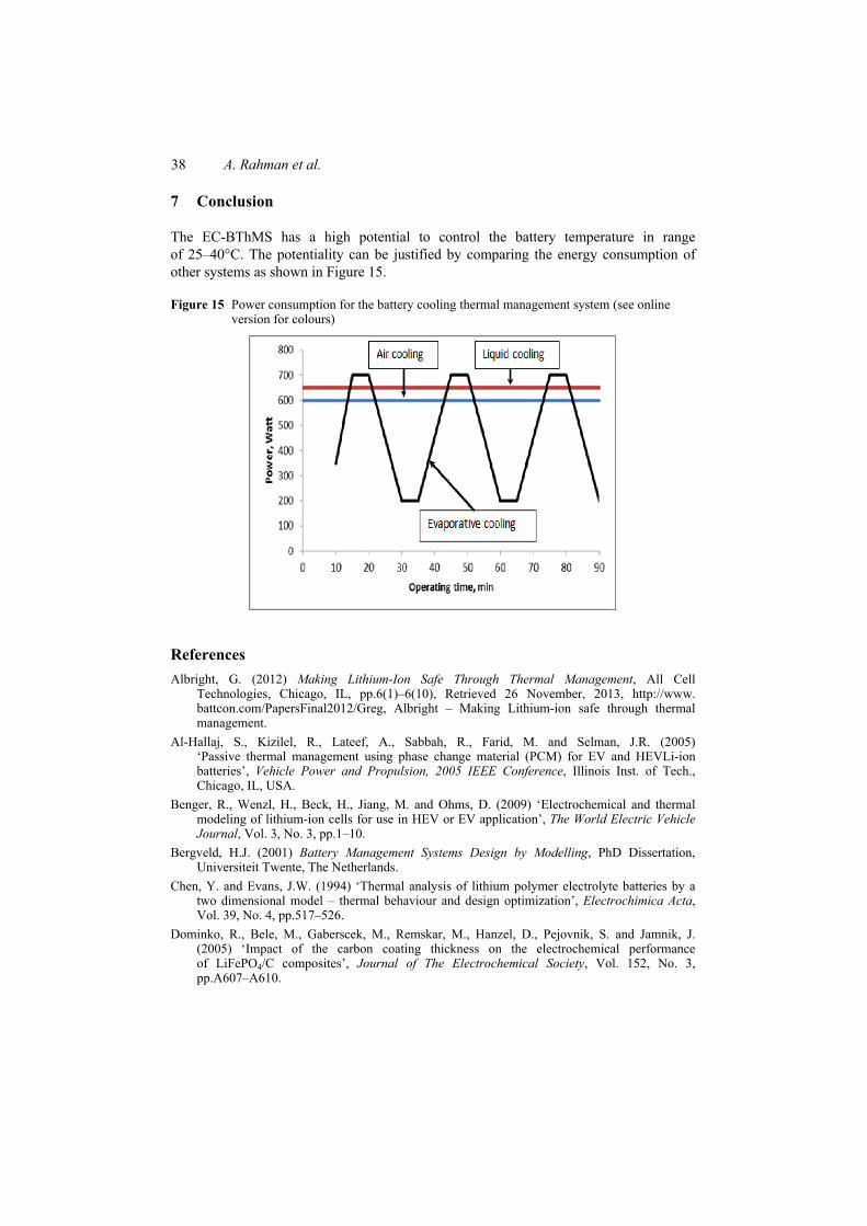
7 Conclusion
The EC-BThMS has a high potential to control the battery temperature in range of 25–40°C. The potentiality can be justified by comparing the energy consumption of other systems as shown in Figure 15.
Figure 15 Power consumption for the battery cooling thermal management system (see online version for colours)
References Albright, G. (2012) Making Lithium-Ion Safe Through Thermal Management, All Cell
Technologies, Chicago, IL, pp.6(1)–6(10), Retrieved 26 November, 2013, http://www. battcon.com/PapersFinal2012/Greg, Albright – Making Lithium-ion safe through thermal management.
Al-Hallaj, S., Kizilel, R., Lateef, A., Sabbah, R., Farid, M. and Selman, J.R. (2005) ‘Passive thermal management using phase change material (PCM) for EV and HEVLi-ion batteries’, Vehicle Power and Propulsion, 2005 IEEE Conference, Illinois Inst. of Tech., Chicago, IL, USA.
Benger, R., Wenzl, H., Beck, H., Jiang, M. and Ohms, D. (2009) ‘Electrochemical and thermal modeling of lithium-ion cells for use in HEV or EV application’, The World Electric Vehicle Journal, Vol. 3, No. 3, pp.1–10.
Bergveld, H.J. (2001) Battery Management Systems Design by Modelling, PhD Dissertation, Universiteit Twente, The Netherlands.
Chen, Y. and Evans, J.W. (1994) ‘Thermal analysis of lithium polymer electrolyte batteries by a two dimensional model – thermal behaviour and design optimization’, Electrochimica Acta, Vol. 39, No. 4, pp.517–526.
Dominko, R., Bele, M., Gaberscek, M., Remskar, M., Hanzel, D., Pejovnik, S. and Jamnik, J. (2005) ‘Impact of the carbon coating thickness on the electrochemical performance of LiFePO4/C composites’, Journal of The Electrochemical Society, Vol. 152, No. 3, pp.A607–A610.

Fuzzy controlled evaporative battery thermal management system 39
Duan, X. and Naterer, G.F. (2010) ‘Heat transfer in phase change materials for thermal management of electric vehicle battery modules’, International Journal of Heat and Mass Transfer, Vol. 53, Nos. 23–24, pp.5176–5182.
Heckenberger, T. (2009) ‘Li-ion battery cooling: more than just another cooling task’, Technical Press Day 2009, pp.4–9.
Krüger, I., Sievers, M. and Schmitz, G. (2009) ‘Thermal modeling of automotive lithium ion cells using the finite elements method in modelica’, Proceedings 7th Modelica Conference, COMO, Italy, pp.20–22.
Li, M. and Wang, F. (2010) ‘Thermal performance analysis of the lithium-ion batteries’, The 11th International Conference on Parallel and Distributed Computing, Application and Technologies, pp.483–486.
Onda, K., Ohshima, T., Nakayama, M., Fukuda, K. and Araki, T. (2006) ‘Thermal behavior of small lithium-ion battery during rapid charge and discharge cycles’, Journal of Power Sources, Vol. 158, No. 1, pp.535–542.
Pesaran, A.A. (2001) ‘Battery thermal management in EVs and HEVs: issues and solutions’, Advanced Automotive Battery Conference, 5–8 February, 2001, Las Vegas.
Pesaran, A.A., Burch, S. and Keyser, M. (1999) ‘An approach for designing thermal management systems for electric and hybrid vehicle battery packs preprint’, Fourth Vehicle Thermal.
Rahman, A. and Azmi, Y. (2013) ‘Performance investigation of an advanced tracked prime mover on the low bearing soil’, Journal of Terramechanics, Vol. 50, pp.233–244.
Rahman, A. Rafia, A. and Yahya, A (2012) The Peat Swamp: Productivity, Traficability and Mechanism, Nova Publication, USA.
Rahman, A., Helmi, A. and Hawlader, M.N.A. (2014) ‘Noble evaporative battery cooling thermal management system for EV/HEVs’, Proceedings of the 2014 International Conference on Industrial Engineering and Operations Management, 7–9 January, 2014, Bali, Indonesia.
Rahman, A., Mohiuddin, A.K.M. and Sany, I.I. (2011) ‘A study on the development of traction control system of a golf car’, Int. J. of Electrical and Hybrid Vehicle, Vol. 3, No. 1, pp.47–61.
Sabbah, R., Kizilel, R., Selman, J.R. and Al-Hallaj, S. (2008) ‘Active (air-cooled) vs. passive (phase change material) thermal management of high power lithium-ion packs: limitation of temperature rise and uniformity of temperature distribution’, Journal of Power Sources, Vol. 182, No. 2, pp.630–638.
Wang, H., Chunyu, D.U. and Wang, C. (2009) ‘Study of low temperature performance of li-ion battery’, Battery Bimonthly, Vol. 139, No. 14, pp.208–210.
Xiangzhe, L. and Hongbin, P. (2005) ‘Study on the uniformity of storage batteries’, Chinese Battery Industry, Vol. 10, No. 5, pp.285–289.
Related Documents