FUTEBOL UNIVBRIS User Manual Authors Carlos Colman Meixner – University of Bristol, UK Reza Nejabati – University of Bristol, UK Version 0.1 Abstract This document is a manual for users of the FUTEBOL University of Bristol (UNIVBRIS) testbed. It describes simple tutorial how to use the resources of UNIVBRIS testbed. Using those examples, the user will be able to build his/her own experiments. This project has received funding from the European Union's Horizon 2020 for research, technological development, and demonstration under grant agreement no. 688941 (FUTEBOL), as well from the Brazilian Ministry of Science, Technology and Innovation (MCTI) through RNP and CTIC.

Welcome message from author
This document is posted to help you gain knowledge. Please leave a comment to let me know what you think about it! Share it to your friends and learn new things together.
Transcript

FUTEBOL UNIVBRIS User Manual
Authors Carlos Colman Meixner – University of Bristol, UK
Reza Nejabati – University of Bristol, UK
Version 0.1
Abstract This document is a manual for users of the FUTEBOL University of Bristol
(UNIVBRIS) testbed. It describes simple tutorial how to use the resources of
UNIVBRIS testbed. Using those examples, the user will be able to build
his/her own experiments.
This project has received funding from the European Union's
Horizon 2020 for research, technological development, and
demonstration under grant agreement no. 688941 (FUTEBOL),
as well from the Brazilian Ministry of Science, Technology and
Innovation (MCTI) through RNP and CTIC.

FUTEBOL – H2020 688941
University of Bristol Testbed User Manual
© FUTEBOL Consortium 2016-2019 Page 2 of 18
Document Revision History
Version Date Description of change List of contributors(s)
V0.1 02/02/2017 Basic tutorial Carlos Colman Meixner –
University of Bristol, UK.

FUTEBOL – H2020 688941
University of Bristol Testbed User Manual
© FUTEBOL Consortium 2016-2019 Page 3 of 18
Table of Contents
1 - Introduction .................................................................................................................. 4
1.1- User requirements and preliminary steps ............................................................ 4
1.2- Resources available ............................................................................................ 4
2 - Overall Description of the Testbed ............................................................................... 5
2.1 – Available components ........................................................................................... 5
2.2 - Testbed topology ................................................................................................... 5
2.3 – Experimenter ......................................................................................................... 7
3 – Experiment tutorial ....................................................................................................... 7
3.1 – Defining an experiment ......................................................................................... 7
3.2 – Writing a RSpec script. .......................................................................................... 8
3.3 - Running an experiment ........................................................................................ 12
3.4 – Defining a flow script. .......................................................................................... 12

FUTEBOL – H2020 688941
University of Bristol Testbed User Manual
© FUTEBOL Consortium 2016-2019 Page 4 of 18
1 - Introduction
This document introduces a guide for users willing to run experiments on the FUTEBOL
testbed in the University of Bristol (UNIVBRIS). The first part introduces briefly the user’s
requirements and resources available for experiments. The second part introduces some
essentials steps followed by a simple tutorial with an example.
1.1- User requirements and preliminary steps
For experienced users with jFed application please go directly to step 3. For users not
familiarized with jFed application please complete the following steps before continuing.
Step 1: Read and follow the instructions in the website: http://jfed.iminds.be/get_started/
Step 2: Log in (Fig.1(b,c)) your local jFed application (Attention: please be sure to have a
username properly created and all dependencies properly installed and running) by selecting
the option “Fed4FIRE credentials” option (Fig. 1(a)).
a)
b)
c)
Figure 1 – Example of jFed Login process. a) jFed first screen. (b) (c) Login screens.
Step 3: Create new experiments (to be introduced in the tutorial of section 3).
1.2- Resources available
To understand how the FUTEBOL testbed reserves resources please check the deliverables
related to Work Package 4 - Converged Optical/Wireless Control Framework. Those can be
obtained in the main FUTEBOL web site at http://www.ict-futebol.org.br.
Any issues about the content of this manual, or any clarification or better explanation please
contact the FUTEBOL University of Bristol at [email protected].

FUTEBOL – H2020 688941
University of Bristol Testbed User Manual
© FUTEBOL Consortium 2016-2019 Page 5 of 18
2 - Overall Description of the Testbed
The University of Bristol testbed is a virtual infrastructure (VI) formed by software-defined-network (SDN) controllers which are functional with a convergent orchestrator. The testbed is designed to perform experiments with Open Flow protocol between optical switches and ethernet packet switches. In this section we introduce; (i) the available components of the testbed; (ii) the physical topology and logical topology of the testbed; and (iii) the experiment environment from the side of the user.
2.1 – Available components
The testbed has hardware components and software components.
a) Hardware components
Each network component has a dispositive id, “dpid” and an OpenFlow ID.
a)
NEC A
dpid: 05:00:00:00:00:00:00:01 Openflow ID: 360287970189639681
NEC B
dpid: 05:00:00:00:00:00:00:02 Openflow ID: 360287970189639682
NEC C
dpid: 05:00:00:00:00:00:00:03 Openflow ID: 360287970189639683
NEC D
dpid: 05:00:00:00:00:00:00:04 Openflow ID: 360287970189639684
b)
Figure 2: Network equipment available in the University of Bristol Testbed. a) OpenFlow Enable
Optical switches ADVA FSP 3000 DWDM ROADM. b) OpenFlow Enable Ethernet switches NEC
IP8800.
Physical servers for running virtual machines, experiment orchestrator, VTAM,
OFAM, Flow visor, and VNFs e.g. for video streaming.
b) Software component Virtual machines are created in two servers running XEN virtualization system (their
internal names are: cseedelphi and cseebosra).
2.2 - Testbed topology
In this sub-section we introduce the testbed physical and logical topology.
ADVA Node 1
dpid: 00:00:00:00:0a:21:00:0a Openflow ID: 169934858
ADVA Node 2
dpid: 00:00:00:00:0b:21:00:0a Openflow ID: 186712074
ADVA Node 3
dpid: 00:00:00:00:0c:21:00:0a Openflow ID: 203489290

FUTEBOL – H2020 688941
University of Bristol Testbed User Manual
© FUTEBOL Consortium 2016-2019 Page 6 of 18
dpid: 00:00:00:00:0c:21:00:0a
Openflow ID: 203489290
dpid: 00:00:00:00:0b:21:00:0a
Op enflow ID: 186712074
ADVA NODE 2
ADVA NODE 3dpid: 00:00:00:00:0a:21:00:0a
Openflow ID: 169934858
ADVA NODE 1
p: 2 (OL2)p: 1 (OL1)
p: 3 (OL3)p: 1 (OL1)
p: 1 (OL1)
p: 1014 p: 1008 p: 1007 p: 1010
GBE0/25GBE0/26GBE0/25GBE0/26
NEC Cdpid: 05:00:00:00:00:00:00:03
Openflow ID: 360287970189639683
dpid: 05:00:00:00:00:00:00:04
Openflow ID: 360287970189639684
NEC D
dpid: 05:00:00:00:00:00:00:02
Openflow ID: 360287970189639682
NEC Bdpid: 05:00:00:00:00:00:00:01
Openflow ID: 360287970189639681
NEC A
GBE0/15
GBE0/16
GBE0/7GBE0/16GBE0/11
GBE0/17
GBE0/9 GBE0/5
GBE0/16
GBE0/5
GBE0/22GBE0/13
GBE0/6
Eth2
GBE0/8
Eth2
Optical Domain
Packet Domain
CSEEDELPHI
CSEEBORSHA
Ethernet Cabling (UTP Cat 5)
Optical Cabling (Fibre optics)
Physical Server hosting
Virtual Machines
Figure 3: Physical topology of the available equipment.
Openflow ID: 203489290
Optical Domain
Packet Domain
Openflow ID: 186712074
Openflow ID: 169934858
Openflow ID: 360287970189639684
Openflow ID: 360287970189639682
Op enflow ID: 360287970189639683
Openflow ID: 360287970189639681
CSEEBORSHA
CSEEDELPHI
OpenFlow Swich
Fixed Network Link
Virtual Mach ine (VM)
Cluster of VMs in
Physical Machine
or Server
ADVA NODE 2
ADVA NODE 1 ADVA NODE 3
NEC D
NEC B
NEC C
NEC A
Figure 4: Logical topology
FUTEBOL – H2020 688941
University of Bristol Testbed User Manual
© FUTEBOL Consortium 2016-2019 Page 7 of 18
2.3 – Experimenter
In this sub-section we introduce the main functionalities from JfFed experimenter frequently
used in the experiments (Fig.4).
Figure 4: Logical topology.
a) New: creates a new experiment b) Open: opens an existing experiment. c) Open ESpect: opens the file with experiment specification. d) Save the experiment. e) Run, Update, Terminates or stops, and Recover an experiment.
3 – Experiment tutorial
In this section we introduce step-by-step a short tutorial for beginners and intermediate
experimenters.
3.1 – Defining an experiment
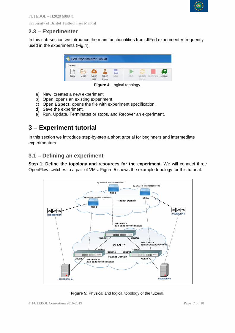
Step 1: Define the topology and resources for the experiment. We will connect three
OpenFlow switches to a pair of VMs. Figure 5 shows the example topology for this tutorial.
Switch NEC C
dpid: 05:00:00:00:00:00:00:03
CSEEDELPHICSEEBORSHA
NEC D
NEC A
NEC C
CSEEDELPHICSEEBORSHA
Switch NEC A
dpid: 05:00:00:00:00:00:00:01VLAN 57
Switch NEC D
dpid: 05:00:00:00:00:00:00:04
Packet Domain
Openflow ID: 360287970189639684
Openflow ID: 360287970189639683
Op enflow ID: 360287970189639681
GBE0/6
GBE0/22GBE0/16
GBE0/8
GBE0/5 GBE0/13
GBE0/15GBE0/16
Packet Domain
Figure 5: Physical and logical topology of the tutorial.

FUTEBOL – H2020 688941
University of Bristol Testbed User Manual
© FUTEBOL Consortium 2016-2019 Page 8 of 18
Step 2: Run the jFed experimenter by logging with our fed4fire username (Section 1)
Step 3: Create the experiment by clicking the option “New” as show in the (Fig. 6).
Figure 6: Create a “New” experiment
jFed Experimenter toolkit (Fig. 7) will create an empty file for the experiment specification
“ESpec”. Two options are available for experimenters, graphical (Topology Editor) and text
based (Rspec Editor)
Figure 7: Create a “New” experiment
Text based requires knowledge of the RSpec language and knowledge of the equipment
available in the University of Bristol testbed. Between Step 4 and 10 we introduce how to
write a basic RSpec script for the proposed example.
3.2 – Writing a RSpec script.
Step 4: Click on “RSpec Editor” to open the following interface (Fig.8).
Figure 8: Rspec editor.
Step 5: Add the correct header and define the main section for the RSpec.

FUTEBOL – H2020 688941
University of Bristol Testbed User Manual
© FUTEBOL Consortium 2016-2019 Page 9 of 18
The header generated by default is essential for the experiment, please be sure that jFed
generate this header, if not please type it in the RSpec editor the example of Fig 9.
Figure 9: Header and RSpec initialization
Step 6: Define the sliver right after the beginning of the RSpec section. The structure follows the next example. The email of the administrator, description of the experiment, and then close sliver line (Fig. 10).
Figure 10: Sliver definition.
Step 7: Select the OpenFlow controller and group of resources available.
After the sliver line, define the OpenFlow controller using the ip-address 10.0.0.72 and TCP
port 6633. Some experiments can use primary and secondary controllers. In this example
we use only a primary controller and one OpenFlow “packet” group for ethernet protocol
layer 2 (Pag. 11). Please don’t forget to add the line closing the group.
Figure 11: Controller and group definition.
Step 8: Select the equipment to be use in the experiment.
In this step we add the three OpenFlow enabled switches following the physical topology
defined in step 1 (Fig.12). It is important to define each component and physical connectivity.

FUTEBOL – H2020 688941
University of Bristol Testbed User Manual
© FUTEBOL Consortium 2016-2019 Page 10 of 18
Switch NEC C
dpid: 05:00:00:00:00:00:00:03
CSEEDELPHICSEEBORSHA
Switch NEC A
dpid: 05:00:00:00:00:00:00:01VLAN 57
Switch NEC D
dpid: 05:00:00:00:00:00:00:04
Packet DomainGBE0/6
GBE0/22GBE0/16
GBE0/8
GBE0/5 GBE0/13
GBE0/15GBE0/16
Figure 12: Physical topology used in this tutorial.
Step 9: Define each switch.
Figure 13: Example of switch definition.
The Fig. 13 presents the set of commands used to define the switch NEC A. To define a
switch is necessary to add the line “openflow:datapath” with component “manager_id” which
is the resource call from aggregator manager “ofam” running in the University of Bristol
“univbris” testbed. Them, “dpid” which is” 05:00:00:00:00:00:00:01”.
In the next two or more lines we add ports from the equipment for the experiment by adding
the command “openflow:port”, switch port name”GBE0/13” and number “13”. A full example
of a group “packet” of three switches of the proposed diagram with one controller is
introduced in Fig. 14.
Figure 14: Definition of three switches.

FUTEBOL – H2020 688941
University of Bristol Testbed User Manual
© FUTEBOL Consortium 2016-2019 Page 11 of 18
Step 10: Define the special network parameters be used by or between the switches. In this section we use the command “openflow:match”, to define the VLAN tag case between the Giga Ethernet switches or the wavelength to be used in the Optical Switches (See example in Fig. 15).
Figure 15: VLAN definition using the command match.
The set of commands “openflow:match” uses a “openflow:use-group” to associate the group
of equipment. In this example the group “packet” uses the VLAN 57 to assign flows. The
value “57” to the command “openflow:dl_vlan”.
Step 11: Putting together the RSpec.
Figure 16: Full RSpec.

FUTEBOL – H2020 688941
University of Bristol Testbed User Manual
© FUTEBOL Consortium 2016-2019 Page 12 of 18
3.3 - Running an experiment
Step 11: Start running the Rspect script by clicking “run” icon. Before the “sliver” is submitted to the name and project need to be selected. The name is selected by the user, and the name in this case is “FUTEBOL”. The last step is to choose the duration of the experiment. The duration can be placed in days, hours, and minutes, as show in Fig.17.
Figure 17: Schedule
After the schedule is defined the Kick off screen (Fig.18), the command “start experiment” button will submit a sliver authorization request in the “OFAM”. Ones the administrator of the UNIVBRIS Testbed authorize the sliver the resources will be available for experimentation.
Figure 18: Kickoff screen.
This will be the last step after click on “Run” icon to submit the experiment. We call
OPENFLOW we will run in the project of FUTEBOL for 2 hours.The controller web interface
will show the following status after the switches are ready for experimentation (This diagram
will be soon available for experimenters through jFed).
3.4 – Defining a flow script.
Step 12: Define the flows between switches.
In this example we use a flow between VMs in cseedelphi to cseebosra using the three
switches (Fig. 17).

FUTEBOL – H2020 688941
University of Bristol Testbed User Manual
© FUTEBOL Consortium 2016-2019 Page 13 of 18
NEC D NEC A
NEC COpenflow ID: 360287970189639684
Openflow ID: 360287970189639683
Openflow ID: 360287970189639681
Figure 17: OpenFlow switches
Step 13: Create an empty script.
To allocate this flow we need to write a script for the OpenFlow controller. With script editor
create a file “MyFirstFlow.sh”.
Step 14: Recall the information of the controller and parameters of the network.
Controller Ip address “10.0.0.72” and port “8181”. The switches use the VLAN 57.
Step 15: Recall the information of each Open Flow switch.
a) Switch NEC A
- Open Flow ID: 360287970189639681.
- Ports: “6” which connects to cseebosra server. “13” and “22” that connect the
switches NEC A and NEC C.
b) Switch NEC C
- Openflow ID: 360287970189639683.
- Ports: “15” which connects to switch NEC A. “16” which connects the NEC C.
c) Switch NEC D
- Openflow ID: 360287970189639684.
- Ports: “5” which connects to switch NEC D. “16” which connects the NEC A. “8” is
connecting cseebosra server.
Step 15: Define the flow rules
To write the script we need to define some basic rules, to be added later in the scripts.
NEC D NEC A
NEC C
Port 8 Port 5
Port 16 Port 15
Port 13
Port 6
Figure 18: Flow and ports

FUTEBOL – H2020 688941
University of Bristol Testbed User Manual
© FUTEBOL Consortium 2016-2019 Page 14 of 18
Using Fig.18 and the information recalled we define the flow name and rules to write in the
script.
a) Switch NEC A
- Open Flow ID: 360287970189639681.
- Ports: “6” which connects to cseebosra server. “13” and “22” that connect the
switches NEC A and NEC C.
- Flow name: “MyFlow”.
- Flow rule: input port “6” and output port “13”.
b) Switch NEC C
- Openflow ID: 360287970189639683.
- Ports: “15” which connects to switch NEC A. “16” which connects the NEC C.
- Flow name: “MyFlow”.
- Flow rule: input port “16” and output port “15”.
-
c) Switch NEC D
- Openflow ID: 360287970189639684.
- Ports: “5” which connects to switch NEC D. “16” which connects the NEC A. “8” is
connecting cseebosra server.
- Flow name: “MyFlow”.
- Flow rule: input port “5” and output port “8”.
Using this information, we go to script editor and proceed to write.
Step 16: Writing the script to add the flows into a switch NEC A.
If the reader wants to go deeper with CURL scripts for Open Daylight SDN Controller
RESCONF we recommend the following site:
https://wiki.opendaylight.org/view/OpenDaylight_OpenFlow_Plugin:End_to_End_Flows.
To simplify our tutorial, we will write down a simple script based on our three-switch
example. To explain the most important parameters we first present the header and body
used for the switch NEC A:
a) Header script switch NEC A
The header basically defines the type “CURL” of request, “X” or HTTP and the command
“POST”.
curl -X POST
-H "Authorization: Basic YWRtaW46YWRtaW4="
-H "Content-Type: application/json"
-H "Accept: application/json"
-H "Cache-Control: no-cache"
-H "Postman-Token: 278684b2-43df-f765-ef93-18210ae549c6"

FUTEBOL – H2020 688941
University of Bristol Testbed User Manual
© FUTEBOL Consortium 2016-2019 Page 15 of 18
b) Body script switch NEC A
The body specifies the parameter “Input”.
-d ' {"input":
{
"node":"/opendaylight-inventory:nodes/opendaylight-inventory:node[opendaylight-inventory:
id=\"openflow:360287970189639681\"]",
The parameter “node” is associated to the OpenFlow ID.
"installHw": "true",
"priority": "500",
"match":{"in-port": "6","vlan-match":{"vlan-id": {"vlan-id": "57"}}},
"instructions":{"instruction":[{"order":"0”, "apply-actions":{"action":[ {"output-action":
{"output-node-connector": "13"}, "order": "0"}]}}]},
"flow-name": "MyFlow",
"table_id": "0"
The set of parameters of the command “match” and “instructions” add the rules for the flow; input port “in-port”, output ports, VLAN tag “vlan-match” and “apply-actions” into the traffic. The “action” defines how the traffic will flow between input and output ports, “output-node-connection” parameter is used. Finally, the “flow-name” defines the name of the applied rule. The rule for NEC A, is “in-port”: “6” and “output-node-connector”:”13”, means receive the flow traffic from port “6” and send it to the port “13”.
}
} ' "http://10.0.0.72:8181/restconf/operations/sal-flow:add-flow"
After we define all rules and close the body of the script, we add the “ip address” and “TCP
port” of the controller and the RESTCONF command “add-flow” to apply the rules.
Step 17: Writing the script to add the flows into a switches NEC C and NEC D.
To complete the full configuration, we define the remain scripts for the other two switches.
curl -X POST
-H "Authorization: Basic YWRtaW46YWRtaW4="
-H "Content-Type: application/json"
-H "Accept: application/json"
-H "Cache-Control: no-cache"
-H "Postman-Token: 278684b2-43df-f765-ef93-18210ae549c6"
-d ' {"input":
{
"node":"/opendaylight-inventory:nodes/opendaylight-inventory:node[opendaylight-inventory:
id=\"openflow:360287970189639684\"]",
"installHw": "true",
"priority": "500",

FUTEBOL – H2020 688941
University of Bristol Testbed User Manual
© FUTEBOL Consortium 2016-2019 Page 16 of 18
"match":{"in-port": "16","vlan-match":{"vlan-id": {"vlan-id": "57"}}},
"instructions":{"instruction":[{"order":"0”, "apply-actions":{"action":[ {"output-action":
{"output-node-connector": "15"}, "order": "0"}]}}]},
"flow-name": "MyFlow",
"table_id": "0"
}
} ' "http://10.0.0.72:8181/restconf/operations/sal-flow:add-flow"
The flow in the switch NEC C uses “in-port” “16” and “output-node-connector”: “15” means,
all traffic received in the port 16 need to be send to the port 15.
Step 18: Writing the script to add the flows into a switch NEC D
curl -X POST
-H "Authorization: Basic YWRtaW46YWRtaW4="
-H "Content-Type: application/json"
-H "Accept: application/json"
-H "Cache-Control: no-cache"
-H "Postman-Token: 278684b2-43df-f765-ef93-18210ae549c6"
-d ' {"input":
{
"node":"/opendaylight-inventory:nodes/opendaylight-inventory:node[opendaylight-inventory:
id=\"openflow:360287970189639681\"]",
"installHw": "true",
"priority": "500",
"match":{"in-port": "8","vlan-match":{"vlan-id": {"vlan-id": "57"}}},
"instructions":{"instruction":[{"order":"0”, "apply-actions":{"action":[ {"output-action":
{"output-node-connector": "5"}, "order": "0"}]}}]},
"flow-name": "MyFlow",
"table_id": "0"
}
} ' "http://10.0.0.72:8181/restconf/operations/sal-flow:add-flow"
The flow in the switch NEC D uses “in-port” “8” and “output-node-connector” “5” means all
traffic received in the port 8 needs to be send to the port 5.
Step 19: Run the script.
Then we combine all three scripts in our file “MyFirstFlow.sh”, save and run it in the testbed.
Ones we have running the “RSpec” and our script, we have our network set up.

FUTEBOL – H2020 688941
University of Bristol Testbed User Manual
© FUTEBOL Consortium 2016-2019 Page 17 of 18
### MyFirstFlow.sh ##
#### NEC A ###
curl -X POST
-H "Authorization: Basic YWRtaW46YWRtaW4="
-H "Content-Type: application/json"
-H "Accept: application/json"
-H "Cache-Control: no-cache"
-H "Postman-Token: 278684b2-43df-f765-ef93-18210ae549c6"
-d ' {"input":
{
"node":"/opendaylight-inventory:nodes/opendaylight-inventory:node[opendaylight-inventory:
id=\"openflow:360287970189639681\"]",
"installHw": "true",
"priority": "500",
"match":{"in-port": "6","vlan-match":{"vlan-id": {"vlan-id": "57"}}},
"instructions":{"instruction":[{"order":"0”, "apply-actions":{"action":[ {"output-action":
{"output-node-connector": "13"}, "order": "0"}]}}]},
"flow-name": "MyFlow",
"table_id": "0"
}
} ' "http://10.0.0.72:8181/restconf/operations/sal-flow:add-flow"
### NEC C ###
curl -X POST
-H "Authorization: Basic YWRtaW46YWRtaW4="
-H "Content-Type: application/json"
-H "Accept: application/json"
-H "Cache-Control: no-cache"
-H "Postman-Token: 278684b2-43df-f765-ef93-18210ae549c6"
-d ' {"input":
{
"node":"/opendaylight-inventory:nodes/opendaylight-inventory:node[opendaylight-inventory:
id=\"openflow:360287970189639684\"]",
"installHw": "true",
"priority": "500",
"match":{"in-port": "16","vlan-match":{"vlan-id": {"vlan-id": "57"}}},
"instructions":{"instruction":[{"order":"0”, "apply-actions":{"action":[ {"output-action":
{"output-node-connector": "15"}, "order": "0"}]}}]},

FUTEBOL – H2020 688941
University of Bristol Testbed User Manual
© FUTEBOL Consortium 2016-2019 Page 18 of 18
"flow-name": "MyFlow",
"table_id": "0"
}
} ' "http://10.0.0.72:8181/restconf/operations/sal-flow:add-flow"
### NEC D ###
curl -X POST
-H "Authorization: Basic YWRtaW46YWRtaW4="
-H "Content-Type: application/json"
-H "Accept: application/json"
-H "Cache-Control: no-cache"
-H "Postman-Token: 278684b2-43df-f765-ef93-18210ae549c6"
-d ' {"input":
{
"node":"/opendaylight-inventory:nodes/opendaylight-inventory:node[opendaylight-inventory:
id=\"openflow:360287970189639681\"]",
"installHw": "true",
"priority": "500",
"match":{"in-port": "8","vlan-match":{"vlan-id": {"vlan-id": "57"}}},
"instructions":{"instruction":[{"order":"0”, "apply-actions":{"action":[ {"output-action":
{"output-node-connector": "5"}, "order": "0"}]}}]},
"flow-name": "MyFlow",
"table_id": "0"
}
} ' "http://10.0.0.72:8181/restconf/operations/sal-flow:add-flow"
## End script ##
Related Documents