Chapter –27 Fusion welding Process

Fusion Welding Process, Chapter 27
Oct 23, 2015
fusion weld
Welcome message from author
This document is posted to help you gain knowledge. Please leave a comment to let me know what you think about it! Share it to your friends and learn new things together.
Transcript

Chapter –27
Fusion welding Process

Topics to DiscussTopics to Discuss
• Introduction• Oxyfuel Gas welding • Arc-Welding Processes:Consumable electrode• Electrodes• Arc-Welding Processes:Non Consumable Process• Thermit Welding• Electron Beam Welding• Laser Beam Welding• Cutting • Welding Safety
Introduction Introduction
• Definition : Fusion Welding is defined as melting together and coalescing materials by means of heat
• Energy is supplied by thermal or electrical means
• Fusion welds made without filler metals are known as autogenous welds

Oxyfuel Gas WeldingOxyfuel Gas Welding
Fig : Three basic types of oxyacetylene flames used in oxyfuel-gas welding and cutting operations: (a) neutral flame; (b) oxidizing flame; (c) carburizing, or reducing flame. The gas mixture in (a) is basically equal volumes of oxygen and acetylene.
Oxyfuel Gas WeldingOxyfuel Gas Welding
• Welding process that uses fuel gas combined with oxygen to produce flame
• This flame heat melts the metals at the joint
• Acetylene fuel is used in gas welding process
Primary combustion process
C2H2 + O2 2CO + H2 + heat
• This reaction dissociates into carbon monoxide and hydrogen.
Secondary combustion process
2CO + H2 + 1.5 O2 2CO2 + H2O + heat

Types of flamesTypes of flames
• Neutral flame• Oxidising flame• Carburising flame Filler Metals :
• Additional material to weld the weld zone• Available as rod or wire • They can be used bare or coated with flux• The purpose of the flux is to retard the
Torch Used in Oxyacetylene WeldingTorch Used in Oxyacetylene Welding
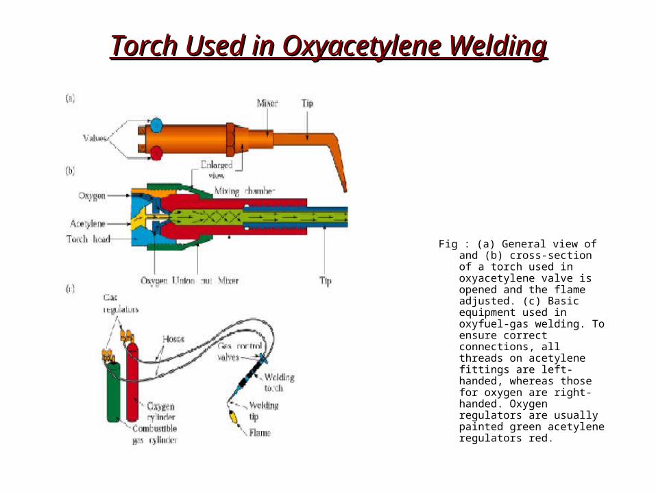
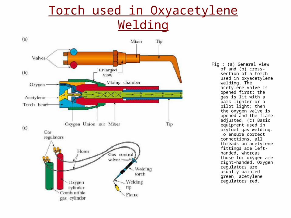
Fig : (a) General view of and (b) cross-section of a torch used in oxyacetylene valve is opened and the flame adjusted. (c) Basic equipment used in oxyfuel-gas welding. To ensure correct connections, all threads on acetylene fittings are left-handed, whereas those for oxygen are right-handed. Oxygen regulators are usually painted green acetylene regulators red.
Welding practice & equipmentWelding practice & equipment
STEPS :
• Prepare the edges to be joined and maintain the proper position
• Open the acetylene valve and ignite the gas at tip of the torch
• Hold the torch at about 45deg to the work piece plane
• Inner flame near the work piece and filler rod at about 30 – 40 deg
• Touch filler rod at the joint and control the movement according to the flow of the material
Torch used in Oxyacetylene Welding
Fig : (a) General view of and (b) cross-section of a torch used in oxyacetylene welding. The acetylene valve is opened first; the gas is lit with a park lighter or a pilot light; then the oxygen valve is opened and the flame adjusted. (c) Basic equipment used in oxyfuel-gas welding. To ensure correct connections, all threads on acetylene fittings are left-handed, whereas those for oxygen are right-handed. Oxygen regulators are usually painted green, acetylene regulators red.

Pressure-Gas Welding ProcessPressure-Gas Welding Process
Fig : Schematic illustration of the pressure-gas welding process.

Arc welding process : Consumable electrodeArc welding process : Consumable electrode
• Process goes with the consumable electrode or non consumable electrode
• Arc produced between the tip of the electrode & work piece
• Arc temperature about 30000 deg• Oldest ,simple & versatile• 50 % of industry uses this process• heat generated heats the electrode & immediate area of
the base projected by arc• weld forms when molten metal ,mixture of base metal
and electrode metal and substance from the coating on the electrode solidifies
• electrodes are in the shape of thin,long stick, so the process is known as stick welding
Shielded metal arc welding processShielded metal arc welding process
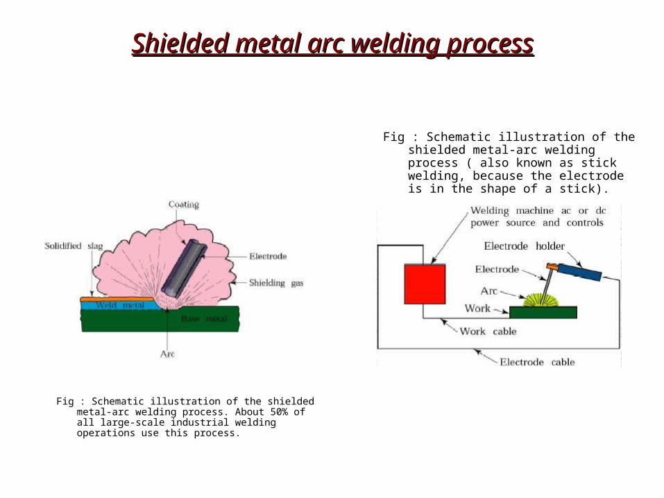
Fig : Schematic illustration of the shielded metal-arc welding process. About 50% of all large-scale industrial welding operations use this process.
Fig : Schematic illustration of the shielded metal-arc welding process ( also known as stick welding, because the electrode is in the shape of a stick).

Submerged arc welding:Submerged arc welding:
Fig : Schematic illustration of the submerged-arc welding process and equipment. The unfused flux is recovered and reused .
Submerged arc welding:Submerged arc welding:
• Weld arc is shielded by a granular flux ,consisting of silica, lime, manganese oxide, calcium fluoride and other compounds.
• Flux is fed into the weld zone by gravity flow through nozzle
• Thick layer of flux covers molten metal
• Flux acts as a thermal insulator ,promoting deep penetration of heat into the work piece
• Consumable electrode is a coil of bare round wire fed automatically through a tube
• Power is supplied by 3-phase or 2-phase power lines

Gas metal arc welding:Gas metal arc welding:
• GMAW is a metal inert gas welding (MIG)
• Weld area shielded by an effectively inert atmosphere of argon,helium,carbon dioxide,various other gas mixtures
• Metal can be transferred by 3 methods :
• Spray transfer
• Globular transfer
• Short circuiting
Process capabilities
• GMAV process is suitable for welding a variety of ferrous and non-ferrous metals
• Process is versatile ,rapid,economical,welding productivity is double that of SMAW

Gas Metal-Arc WeldingGas Metal-Arc Welding
Fig : Schematic illustration of the gas metal-arc welding process, formerly known as MIG (for metal inert gas) welding.
Equipment used in Metal-Arc Welding OperationsEquipment used in Metal-Arc Welding Operations
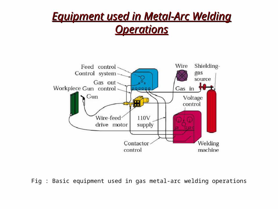
Fig : Basic equipment used in gas metal-arc welding operations
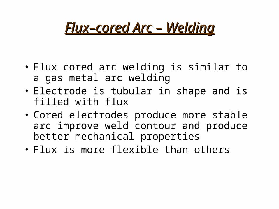
Flux–cored Arc – WeldingFlux–cored Arc – Welding
• Flux cored arc welding is similar to a gas metal arc welding
• Electrode is tubular in shape and is filled with flux• Cored electrodes produce more stable arc improve
weld contour and produce better mechanical properties
• Flux is more flexible than others
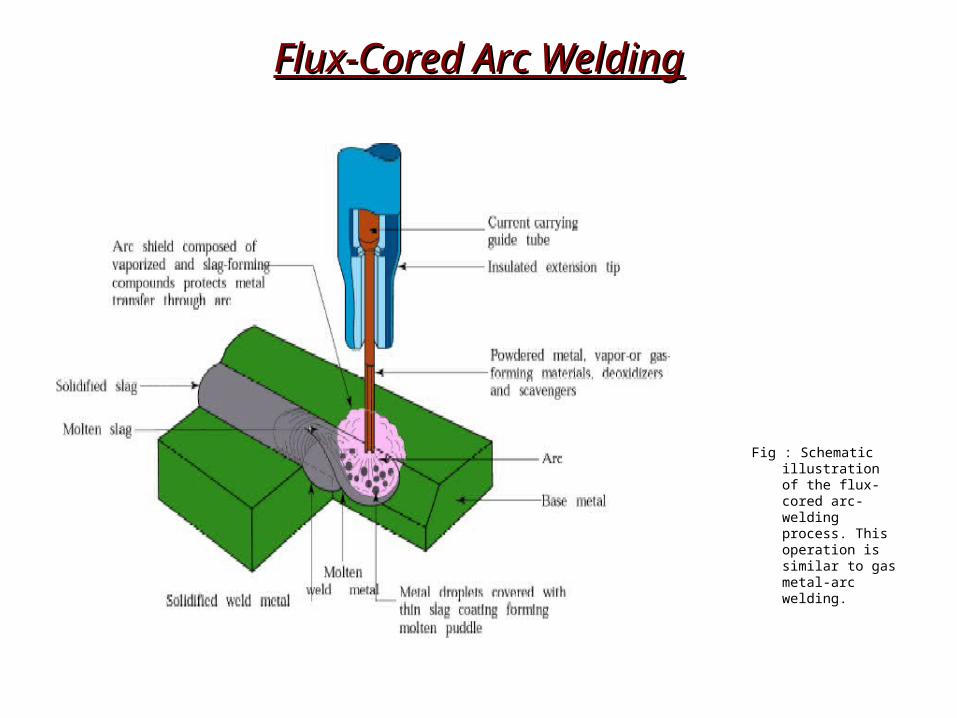
Flux-Cored Arc WeldingFlux-Cored Arc Welding
Fig : Schematic illustration of the flux-cored arc-welding process. This operation is similar to gas metal-arc welding.

Electro gas Welding :Electro gas Welding :
• EGW is welding the edges of sections vertically in one pass with the pieces placed edge to edge
• Weld metal is deposited into weld cavity between the two pieces to be joined
• Mechanical drives moves shoes upwards
• Single and multiple electrodes are fed through a conduit and a continuous arc is maintained using flux-cored electrodes at up to 750 A
Process capabilities :• Weld thickness ranges from 12mm to 75mm
• Metals welded are steels, titanium, aluminum alloys
• Applications are construction of bridges, pressure vessels, thick walled and large diameter pipes, storage tanks and ships.
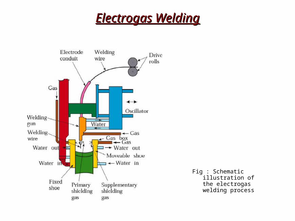
Electrogas WeldingElectrogas Welding
Fig : Schematic illustration of the electrogas welding process
Electroslag Welding:Electroslag Welding:
• Similar to Electro gas welding
• Difference is Arc is started between electrode tip and bottom part of the part to be welded
• Flux added first and then melted by the heat on the arc
• Molten slag reaches the tip of the electrode and the arc is extinguished
• Heat is then continuously produced by electrical resistance of the molten slag
• Single or multiple solid as well as flux-cored electrodes may be used
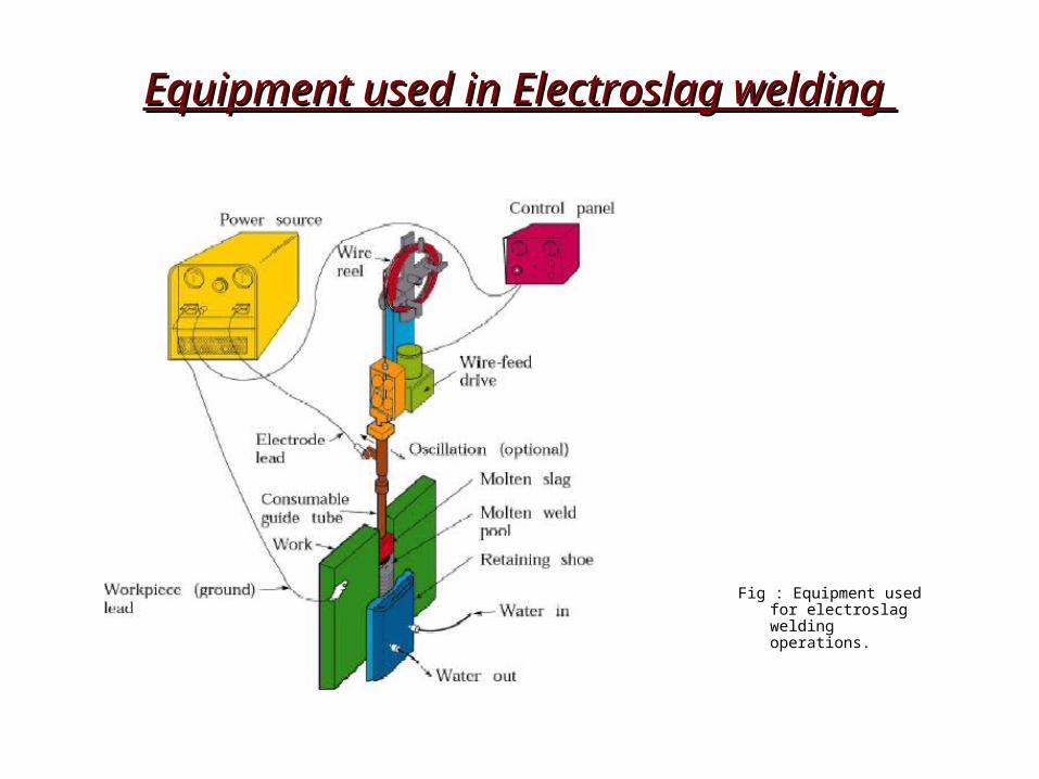
Equipment used in Electroslag welding Equipment used in Electroslag welding
Fig : Equipment used for electroslag welding operations.

THE END
Related Documents