FUSION TECHNOLOGY Annual Report of the Association CEA/EURATOM 1997 Compiled by : P. MAGAUD and F. LE VAGUERES FR9800883 ASSOCIATION CEA/EURATOM DSM/DRFC CEA CADARACHE 13108 Saint-Paul-Lez-Durance (France)

Welcome message from author
This document is posted to help you gain knowledge. Please leave a comment to let me know what you think about it! Share it to your friends and learn new things together.
Transcript
FUSION TECHNOLOGY
Annual Report of theAssociation CEA/EURATOM
1997Compiled by : P. MAGAUD and F. LE VAGUERES
FR9800883
ASSOCIATION CEA/EURATOMDSM/DRFC
CEA CADARACHE13108 Saint-Paul-Lez-Durance (France)

We regret thatsome of the pagesin this report may
not be up to theproper legibilitystandards, eventhough the best
possible copy wasused for scanning
FUSION TECHNOLOGY
Annual Report of theAssociation CEA/EURATOM
1997
Compiled by : P. MAGAUD and F. LE VAGUERES
ASSOCIATION CEA/EURATOMDSM/DRFC
CEA CADARACHE13108 Saint-Paul-Lez-Durance (France)
Tel. : 33-4 42 25 46 59Fax : 33-4 42 25 64 21
Cover: Transverse cross section of one of the Toroidal Field model coil joint(Solid copper-steel box made by explosive bonding)
- I -
CONTENTSpage
INTRODUCTION i
BASIC MACHINE PROGRAMME 3
PLASMA FACING COMPONENTS
CNET 95-375 High heat flux tests of NET-ITER divertor mock-ups 5
CNET 96-412 ITER outboard baffle : design, analysis, technical specifications & follow-up
of fabrication & testing of mock-ups and prototypes 7
T212 Interfacial fracture toughness of Cu/SS joints 11
T216 Development and characterization of Be/Cu alloy HIP joint 15
T221-1 Thermo-mechanical characterization of CFCs 19
T222 Manufacture and testing of permanent components optimisation of cooling systemCompletion of critical heat flux and thermal hydraulic testing of swirl andvapotron tubes for ITER high heat flux components 23
T222.4ter Manufacture and testing of permanent components optimisation of cooling systemCritical heat flux and thermo-hydr. of representative elements;Non destructive testing, calibrated defects, heat Joad influence 29
VACUUM VESSEL and SHIELD
NWC 2-2 Aqueous corrosionT10 Aqueous corrosion of in-vessel component structural materialsT217 Aqueous stress corrosion, irradiation assisted stress corrosion cracking and
corrosion fatigue tests of stainless steel and Cu alloys 33
T214 Irradiation testing of stainless steel including weldmentsand rewelding of irradiated materials 35
T224 Development of a thermal bond layer 37
T330 Water radiolvsis irradiation tests 41
- I I -
MAGNETS
CNET 94-345 Design study on ITER joints 43
CNET 96-409 ITER cryoplant design evaluation Y 45
CNET 96-432 Technical specifications for modelling, testing and analysis
of full size ITER joints 47
M29 Conductor fabrication - ITER Conductor R&D and monitoring 51
M30 Conductor fabrication - ITER Conductor R&D coordination 55
M40 Design work on magnet R&D 57
M48 Winding and insulation development 61
M53 80K ITER shield performances measurement 63
REMOTE HANDLING
T216-1 Attachment of blanket modules to the back-plate 65
T329-1 Bore tooling for divertor cooling pipe 67
T329-2 Magnet feeder lines and cryogenic connectors maintenance 69
T329-3 Ex-vessel transporter 73
TRITIUM
CNET 96-427 Characteristics of jet dust after divertor operation 77
SAFETY
SEA 1-11 Safety approach and documentation support assessment of ITER 83
SEA 1-12 Safety assessment of confinement 85
SEA 1-2 Safety approach and documentation support 89
SEA 3-1 Integrated safety analysis code system ISAS 93
SEA 3-5 In vessel safety 95
SEA 4-1 Design basis accidents and beyond design basis accidents 99
-III-
SEP 1-1 Corrosion products inventory 103
SEP 3-1 Waste characterisation and strategy 105
SEP 3-3 Decommissioning strategy of ITER 107
LONG TERM PROGRAMME m
BLANKET PROGRAMME
CNET 97-454 Contribution to the preliminary design of the ITER breeding blanket 113
Liquid Metal Blanket
WP-A1-1.1 DEMO blanket feasibility and design, segment design and analysis 117
WP-A2-1.1 Test blanket module feasibility and design, design and analysis 121
WP-A2-2.1 Test blanket module feasibility and design, TBM subsystems 125
WP-A2-3.1 Test blanket module feasibility and design, interfacewith ITER and test program 129
WP-A2-4.1 Test blanket module blanket feasibility and design, maintenance, support,
remote handling, waste disposal 133
WP-A3-1.1 ITER test module fabrication : double wall tube development and fabrication 137
WP-A3-2.1 Double-wall tube out-of-pile testing 139
WP-A3-4.1 ITER test module fabrication 143
WP-A3-9.1 Development of minor components and instrumentation 145
WP-A4-1.1 Tritium control & permeation barriers permeation barriers fabrication
and characterisation 147
WP-A4-2.1 Permeation barriers out of pile testing 151
WP-A5-1 Tritium extraction from Pb-17Li 155
WP-A6-1.1 Safety analysis for DEMO reactor 159
WP-A6-2.1 Safety analysis of ITER test modules - Definition of safety'approach 163
WP-A7-1.1 Reliability data base for blanket systems 167
WP-A7-2.2 ITER test module system reliability 169
-IV-
WP-A9-2.2 Pbl7LiAVater interaction 173
WP-A9-3.1 Pb-17LiAVater interactions, definition of countermeasures 177
WP-A10-2.2 Experimental demonstration of MHD phenomena 179
Solid Breeder Blanket
WP-B1-1.2 DEMO-blanket: segment design & analysis 183
WP-B2-1 ITER test module feasibility and design 185
WP-B3-1.2 Feasibility & fabrication ofHCPB ITER test module first wall 187
WP-B6-1.3 Safety analysis of ITER test modules - Definition of safety approach 163
WP-B7-1.1 Reliability data base for blanket systenis 167
WP-B7-2.3 ITER test module system reliability 191
WP-B8-2 Development of Li2Zr03 and Li2Ti03 pebbles 193
MATERIALS
SM 1-2.4 Irradiation experiments - Pie of samples irradiated in HFR-Phase 1A 197
SM 2-1.1 Metallurgical and mechanical characterisation of RA F/M steels 199
SM 2-2.3 Creep properties of base metal - F82H steel 203
SM 2-3.1 Metallurgical and mechanical characterisation of F82H weldments 205
SM 3-5.1 General corrosion in two water environment 209
SM 4-1.1 Sensibility to weld cracking/general weldability behaviour 211
SM 4-4.1 Transition weldment qualification 215
SM 5-1.2 Evaluation for application of mechanical design codes for fusion materials 217
SM 5-3.1 Procurement specification and specification verification of a new heat 219
SM 6-4.2 Mechanistic investigations of low activation martensitic steels 221
WP 3-3.3 Characterisation of material, specific tests and performance considerationsof low activation ceramic compounds (LACC) such as SiCj/SiC 225
WP 5 Coordination 229
- V -
SAFETY
SEAFP2-21 Improved coverage of events - Event sequence analysis 233
SEAFP 2-22 Improved coverage of events - t
SEAFP 2 : Response of model 1 concept (helium cooled)to loss of coolant accidents inside the vacuum vessel (in-vessel LOCA) 237
SEAFP 3-11 Improved containment concepts 239
SEAFP 3-12 Safety analysis to improve containments concepts 243
SEAL 4.3 Accident sequence analysis 247
SOCIO-ECQNOMICS
SERF 0-3 Long term scenarios 249
UNDERLYING TECHNOLOGY PROGRAMME 251
PLASMA FACING COMPONENTS
UT-PFC&C-HFW Transparent polycristalline ceramic windows 253
UT-PFC&C-HIP Mechanical behaviour of HIP joints 257
UT-PFC&C-PS B/C and composites coatings 259
UT-PFC&C-SiC Composite materials for PFC 261
UT-SM&C-A4 Assesment of laser weldability of internal components materials 265
UT-SM&C-CM1 Study of elementary defects created in various fusion materials by irradiation 267
VACUUM VESSEL & SHIELD
UT-N-DPA Displacement per atom modelling 269
UT-N-NDA Nuclear data assessment 271
UT-SM&C-CM3 Interation between the deformation dislocation network and irradiation 275
UT-SM&C-COR Metal and oxide thermodynamic stability and solubility in water cooling system . 279
-VI-
UT-SM&C-FCC FLICA & CASTEM coupling 281
UT-SM&C-GAL Compatibility of some alloys and refractory metals with liquid gallium 283
UT-SM&C-HIP Solid and powder fflP technologies development 287
UT-SM&C-LAM1 Low activation materials - Mechanisms of embrittlement -9/1 lCrWTaVmartensitic materials 291
UT-SM&C-LAM2 Irradiated behaviour of reduced activation (RA)
martensitic steels after neutron irradiation at 325°C 297
UT-SM&C-REL Reliability modelling 303
UT-SM&C-WI Design work and analysis of basic machine vacuum vessel and internals 307
REMOTE HANDLING
UT-RHl Technology and control for hydraulic manipulator 313
UT-RH2 Graphical programming for remote handling 317
TRITIUM
UT-Tl Separation of the D/T mixture from helium in fusion reactors usingsuperpermeable membranes 321
SAFETY
UT-S2 Evaluation and mitigation of the hydrogen hazard in a fusion reactor 325
UT-S3 Modelling of heat exchanges for high flux components in a fusion reactor duringaccidental conditions 329
BLANKETS
UT-SM&C-BLK Helium cooled pebble bed blanket 333
UT-SM&C-LiPb Purification of liquid metals 337
UT-SM&C-LME Liquid metal embrittlement 339
UT-SM&C-PB Fabrication of permeation barriers using CVD processes 341
UT-SM&C-PBM Pebble bed thermo-mechanica! modelling 345
-1 -
INTRODUCTIONThe research and development work performed by the French EURATOM-CEA Association for fusion technology is part
of the Fusion Programme of the European Community. This report compiles the work carried out during the year 1997 asfollows: C7~ , j " ", , 7~. ~, .'" .' ,
• The ITER CEA activities and related developments are described in the first sectionY '.• The second part is dedicated to the Long Term activities as Blankets and material developments, long term safety,
socio-economic problem.• The Underlying Technology activities are compiled in the third part of this report^ ( • i-:' >u>.i , i^^-f [^.4 ^ J• And the fourth part describes the inertia] confinement studies.
In each section, the tasks are sorted out to respect the European presentation. For an easy reading, appendix 4 gives the list oftasks in alphabetical order with a page reference list.
The CEA is in charge of the French Technology programme. Four specific organisational directions of the CEA, located onfour sites (see appendix 5), are involved in this programme:
• Advanced Technologies Direction (DTA), for Material and Remote Handling tasks• Nuclear Reactors Direction (DRN), for Blanket design, Neutronic problems, Safety tasks• The Physical Sciences Direction (DSM) uses the competence of the Tore Supra team in the Magnet design, Plasma
Facing Component field and Cryogenic technologies.• And the Nuclear Protection and Safety Institute for specific safety activities
The CEA programme is completed by collaborations with industry (Technicatome, COMEX-Nucleaire) and externallaboratories (Ecole Polytechnique, University of Paris XI, University of Toulouse).
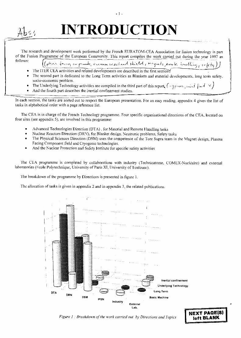
The breakdown of the programme by Directions is presented in figure 1.
The allocation of tasks is given in appendix 2 and in appendix 3, the related publications.
DTADRN
DSMIPSN
Industry
Inertial confinement
Underlying Technology
Long Term
Basic Machine
ExternalLab.
Figure 1 : Breakdown of the work carried out by Directions and TopicsNEXT PAOE(S)
left BLANK
- 3 -
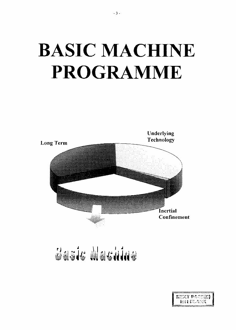
BASIC MACHINEPROGRAMME
Long Term
UnderlyingTechnology
I initialConfinement
;VV•mitii
- 5 -
CNET 95-375
Task Title : HIGH HEAT FLUX TESTS OF NET-ITER DIVERTOR MOCK-UPS
Subtitle : 200 kW electron beam gun test
INTRODUCTION
The FE 200 high heat flux test facility is operated jointly byCEA and FRAMATOME since 1991. It is located in thetown of Le Creusot.
This facility is devoted to the testing of water cooled largecomponent under various heat fluxes (from # 0.2 to 100MW/m2). The power deposition is done by a sweepedelectron beam which can deliver up to 200 kW. Thiselectron beam is derived from a welding machine andtherefore allowes a large reproducibility of the beamcharacteristics. Consequently this test facility is very welladapted for thermomechanical fatigue testing.
The cooling loop is pressurized to 4 Mpa and has a waterflow capability of 6 kg/s with a mock-up pressure drop of0.4 Mpa. The water temperature can be adjusted beetwen50 and 230 °C.
A large vacuum vessel (8 m3) allow the installation of largemock-ups.
The test facility is also equiped with all the diagnosticsrequired for high heat flux testing:
Pyrometers, infrared camera, CCD camera, thermocouples,strain gages, displacement sensors, calorimetriquemeasurements.
Since the start up this facility has tested around 100 mock-ups.
1997 ACTIVITY
The year 1997 was marked by two large interruptionstotalizing 26 weeks. The first inactivity period (16 weeks)was due to a lack of mock-ups to be tested and the second(10 weeks) was devoted to the transfert of the test facility ina new location.
Never the less 14 actively cooled mock-ups where tested inthe remaining part of the year.
1) ITER baffle SMS2A elements where caracterized. Thismock-up was manufactured with a hipped CFC tiles ona DS copper heat sink with a 316 stainless steel strongback. The results where deceiving with many tile(NS31) detachment at very low heat flux (4 MW/m2).
The remaining tiles (NB 31 and Dunlop showedanoumalously high surface temperature at 9 MW/m2
during the fatigue testing. The defects were previouslydetected by the SATIR testing done at DRFC.
2) Two tungsten plasma sprayed divertor elementsmanufactured by ENEA were evaluated on 1 mock-up.
One of the coatings survived 1000 cycles at 2 MW/m2
with no severe damage. The mean surface temperaturewas lower than 800°C.
3) The comparative performances under critical heat fluxof 7 geometries (assembled on 4 mock-ups) wasevaluated under ITER divertor hydraulic conditions.Flat and peaked heat flux profiles were imposed.
The best results were obtained on the hypervapotrongeometry with a flat incident critical heat flux of 35MW/m2. This value was increased to 43 MW/m2 with apeaked profile.
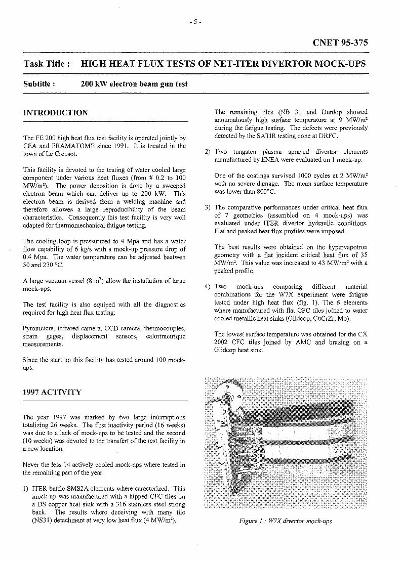
4) Two mock-ups comparing different materialcombinations for the W7X experiment were fatiguetested under high heat flux (fig. 1). The 6 elementswhere manufactured with flat CFC tiles joined to watercooled metallic heat sinks (Glidcop, CuCrZr, Mo).
The lowest surface temperature was obtained for the CX2002 CFC tiles joined by AMC and brazing on aGlidcop heat sink.
Figure 1: W7X divertor mock-ups
- 6 -
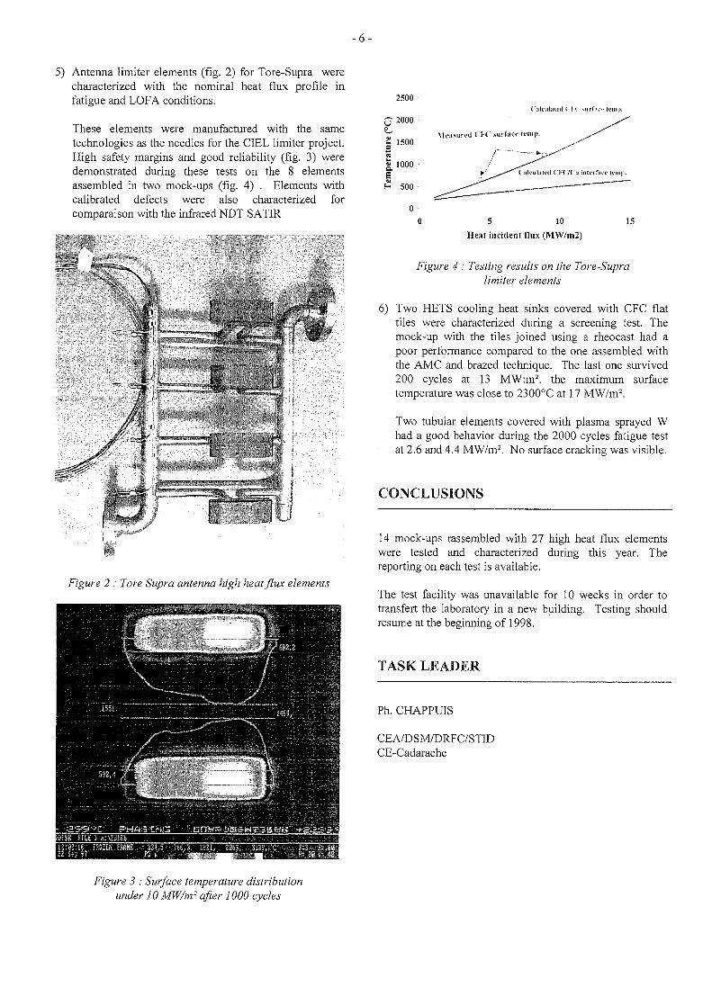
5) Antenna limiter elements (fig. 2) for Tore-Supra werecharacterized with the nominal heat flux profile infatigue and LOFA conditions.
These elements were manufactured with the sametechnologies as the needles for the CIEL limiter project.High safety margins and good reliability (fig. 3) weredemonstrated during these tests on the 8 elementsassembled in two mock-ups (fig. 4) . Elements withcalibrated defects were also characterized forcomparaison with the infrared NDT SATIR
2500
Figure 2 : Tore Supra antenna high heat flux elements
O 2000
1500
§_ 1000 -
H 500
00 5 10 15
Heat incident flux (MW/m2)
Figure 4 : Testing results on the Tore-Supralimiter elements
6) Two HETS cooling heat sinks covered with CFC flattiles were characterized during a screening test. Themock-up with the tiles joined using a rheocast had apoor performance compared to the one assembled withthe AMC and brazed technique. The last one survived200 cycles at 13 MW:m2. the maximum surfacetemperature was close to 2300°C at 17 MW/m2.
Two tubular elements covered with plasma sprayed Whad a good behavior during the 2000 cycles fatigue testat 2.6 and 4.4 MW/m2. No surface cracking was visible.
CONCLUSIONS
14 mock-ups rassembled with 27 high heat flux elementswere tested and characterized during this year. Thereporting on each test is available.
The test facility was unavailable for 10 weeks in order totransfert the laboratory in a new building. Testing shouldresume at the beginning of 1998.
TASK LEADER
Ph. CHAPPUIS
CEA/DSM/DRFC/STIDCE-Cadarache
Figure 3 : Surface temperature distributionunder 10 MW/m- after 1000 cycles
- 7 -
CNET 96-412
Task Title : ITER OUTBOARD BAFFLE : DESIGN, ANALYSIS, TECHNICALSPECIFICATIONS & FOLLOW-UP OF FABRICATION &TESTING OF MOCK-UPS AND PROTOTYPES
INTRODUCTION 1997 ACTIVITIES
The ITER BAfile (BA) modules, which are the inboardand outboard bottom row of shielding blanket modules,have the main function of avoiding particle back-flow fromthe divertor chamber. For this reason they are consideredto belong to the divertor system. As a consequence, the BAFirst Wall (FW) is submitted to an high thermal flux andits design needs the use of high-heat-flux componenttechnology. The activities have been focused on theoutboard BA-FW because of the more severe heat flux loadconditions and the more complex overall geometrycompared to the inboard one.
This contract, running from March 1996 to June 1998,covers the second phase of the ITER T232.10 subtask. Itincludes design and analysis of the BA-FW mock-ups, theprediction of the results on the mock-ups tests, theinterpretation of the obtained experimental results, and thefollow-up of the mock-ups manufacturing. In order tocover all the required expertises, these activities aresupported by an established collaboration betweenmembers of different CEA Departments, in particularDMT, DRFC, DER, and DEM/SGM. Moreover, the workis performed in close collaboration with industry(EFET/Framatome).
Because of the new attaclunent system developed for theprimary shielding modules by the ITER JCT at the end of1996, significant design modifications for most in-vesselcomponents have been required. In particular, themodularity of the shielding blanket has been modified. Foran almost unchanged total number of modules, the newpoloidal segmentation has been increased to 26 modules.Both inner and outer baffles are now formed by twomodules, the lower and the upper baffles. Moreover,because the new ITER shielding blanket envisages frontalpenetrations of 30 mm of diameter, the existing concept ofbelt-limiter using three rows of outboard shielding modulesis no more acceptable. The main reason is the very highheat loads at which the armour material around the frontalholes will be submitted (15-20 MW/m2, mainly located onthe hole side walls). For this reason, a new concept oflimiter, a port-limiter, which will be located in thehorizontal ports and which can then be easily replacedduring ITER BPP operations, has been preliminarydesigned by the ITER JCT. Reasonable heat loads (peakvalues of 10-15 MW/m2) can be obtained with twoidentical limiters located in two toroidally-oppositehorizontal ports.
The design modifications for the ITER shielding blankethad a significant impact on the activities planned in thiscontract. The main consequences have been a testingprogram delay and a modification of the R&D and testingstrategy as defined in [1]. In fact, because of the change ofthe baffle design (in line with the shielding blanket), thebaffle prototype design had also to be changed. Thesedesign changes lead to a delay of about 6 months, to beadded to the delay of 6 months already present in thesmall-size mock-ups testing.
In order to recover these delays, at least partially, the EUHT decided to modify the successive R&D and testingstrategy : a call for tender for a baffle prototype has beendirectly launched without having intermediate steps (i.e.,medium-scale mock-ups). In order to ensure that onlyproven technology will be used, it was decided to includein the call for tender the need of having an intermediatehold point where the tenderer has to prove the technologyhe intends to use (by mean of dedicated medium-scalemock-ups to be tested under thermo-mechanical cycling).This hold point therefore replaces the previousindependent intermediate step.
The 1997 activities have been focused on two main items :the collection and interpretation of the results for thethermo-mechanical fatigue tests of the BA-FW small-scalemock-ups and the preparation of the design of the BA-prototype.
RESULTS COLLECTION AND INTERPRETATIONOF SMALL-SCALE BAFFLE-FW MOCK-UPSTESTING [2]
One small-scale mock-up has been tested in the Julichelectron-beam JUDITH :
Mock-up 1 (fabricated by CEA/SGM) : one straight 3-tubesmock-up using Glidcop heat sink with Glidcop coolingtubes (and swirl tape), 50-mm-thick steel shield includingHIPed steel tubes, and Be tiles (4 mm-thick) using solidHIP as joint technique.
Four small-scale mock-ups have been tested in the LeCreusot electron-beam EB-200 :
- 8 -
Mock-up 2A (fabricated by CEA/SGM) : one straight 3-tubes mock-up using Giidcop heat sink with Giidcopcooling tubes (and swirl tape), 50-mm-thick steel shieldincluding HIPed steel tubes, and CFC tiles (SEP-NB31,SEP-NS31, and Dunlop Concept 2, 10 mm-thick tiles)using brazing as joint technique.
Mock-up 3A (fabricated by CEA/SGM): one straight 3-tubes mock-up using Giidcop heat sink with Glidcopcooling tubes (and swirl tape), 50-mm-thick steel shieldincluding HIPed steel tubes, and 10 mm-thick W tiles (W-l%La2O3) using solid HIP with OFHC interlayer as jointtechnique. This mock-up is the only one having a 0.5 mm-thick steel liner in the cooling tubes.
Mock-up 2B (fabricated by Plansee): one straight single-tube mock-up using Giidcop heat sink with drilled coolingchannel (and swirl tape), 50-mm-thick steel shield, andboth CFC (SEP-NS31 & Dunlop-C2) and W (W-1%La2O3) 10 mm-thick tiles using AMC/EB joint.
Mock-up 3B (fabricated by Plansee) : the same as 2B butusing CuCrZr as heat sink.
Fatigue Testing Strategy ,
BA-FW is expected to be submitted to ~13,000 cycles (theITER BPP duration) at a maximum heat flux of 3 MW/m2
(-3000 cycles up to 10-15 MW/m2 for port-limiters).
Perform such a number of cycles for mock-ups testing willlead to a too long testing time. A possible accelerationtechnique is to use a correlation heat load/number of cyclesdetermined in the past for Cu/steel joints. This correlationindicate that an increase of the heat load of a factor twowould mean an increase of the number of cycles of a factor10. Taking into account, at least partially, such a roughcorrelation, the following general testing program wasdefined:
- initial 100 cycles at 5 MW/m2 for detecting anysignificant fabrication defects;
- run of 1000 cycles at ~9 MW/m2 for a reference fatiguetest;
- run of 1000 cycles at the maximum acceptable heatload corresponding to the maximum acceptable tilematerial temperature. This final test is used to getsomehow the limit of the joint. The results- will also berelevant also for limiter and divertor application.
Main results and Preliminary Interpretation
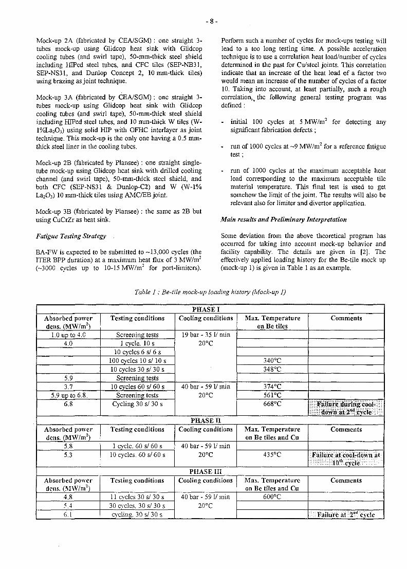
Some deviation from the above theoretical program hasoccurred for taking into account mock-up behavior andfacility capability. The details are given in [2]. Theeffectively applied loading history for the Be-tile mock up(mock-up 1) is given in Table 1 as an example.
Table 1: Be-tile mock-up loading history (Mock-up 1)
PHASE IAbsorbed powerdens. (MW/m2)
1.0 up to 4.04.0
5.93.7
5.9 up to 6.86.8
Testing conditions
Screening tests1 cycle. 10 s
10 cycles 6 s/ 6 s100 cycles 10 s/10 s10 cycles 30 s/30 s
Screening tests10 cycles 60 s/ 60 s
Screening testsCycling 30 s/ 30 s
Cooling conditions
19 bar - 35 1/ min20°C
40bar-591/min20°C
Max. Temperatureon Be tiles
340°C348°C
374°C561°C668°C
Comments
Failure during cool-down at 2nd cycle
PHASE nAbsorbed powerdens. (MW/m2)
5.85.3
Testing conditions
1 cycle. 60 s/ 60 s10 cycles. 60 s/60s
Cooling conditions
40 bar - 59 1/ min20°C
Max. Temperatureon Be tiles and Cu
435°C
Comments
Failure at cool-down at10th cycle
PHASE IIIAbsorbed powerdens. (MW/m2)
4.85.46.1
Testing conditions
11 cycles 30 s/ 30 s30 cycles. 30 s/ 30 scycling. 30 s/ 30 s
Cooling conditions
40 bar - 59 1/ min20°C
Max. Temperatureon Be tiles and Cu
600°C
Comments
:i Failure at ;2D-cycle
- 9 -
In all tests, the temperature has been measured at the tilesurface by means of a pyrometer and throughout the mock-up thickness by means of several thermo-couples insertedfrom the back (S-type -T<1500 C- or K-type -T<1100 C-).
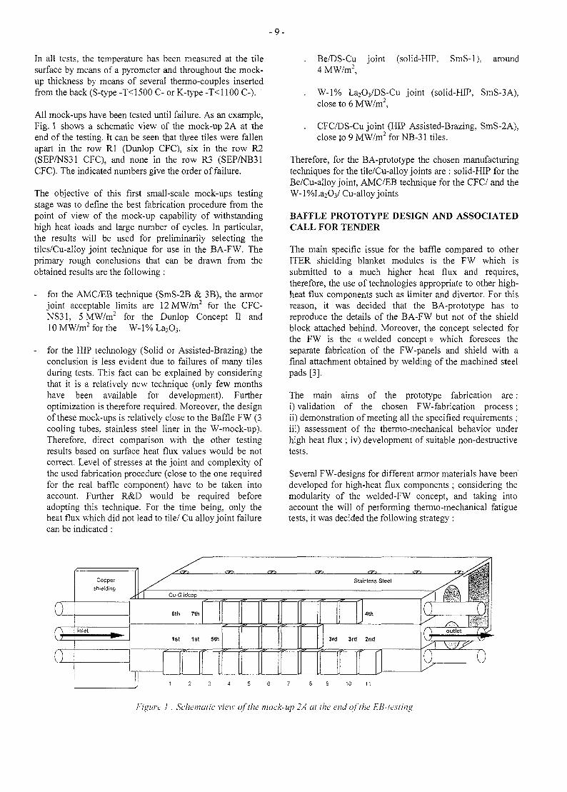
All mock-ups have been tested until failure. As an example,Fig. 1 shows a schematic view of the mock-up 2A at theend of the testing. It can be seen that three tiles were fallenapart in the row Rl (Dunlop CFC), six in the row R2(SEP/NS31 CFC), and none in the row R3 (SEP/NB31CFC). The indicated numbers give the order of failure.
The objective of this first small-scale mock-ups testingstage was to define the best fabrication procedure from thepoint of view of the mock-up capability of withstandinghigh heat loads and large number of cycles. In particular,the results will be used for preliminarily selecting thetiles/Cu-alloy joint technique for use in the BA-FW. Theprimary rough conclusions that can be drawn from theobtained results are the following :
- for the AMC/EB technique (SmS-2B & 3B), the armorjoint acceptable limits are 12 MW/m2 for the CFC-NS31, 5MW/m2 for the Dunlop Concept II and10 MW/m2 for the W-l % La2O3.
- for the HIP technology (Solid or Assisted-Brazing) theconclusion is less evident due to failures of many tilesduring tests. This fact can be explained by consideringthat it is a relatively new technique (only few monthshave been available for development). Furtheroptimization is therefore required. Moreover, the designof these mock-ups is relatively close to the Baffle FW (3cooling tubes, stainless steel liner in the W-mock-up).Therefore, direct comparison with the other testingresults based on surface heat flux values would be notcorrect. Level of stresses at the joint and complexity ofthe used fabrication procedure (close to the one requiredfor the real baffle component) have to be taken intoaccount. Further R&D would be required beforeadopting this technique. For the time being, only theheat flux which did not lead to tile/ Cu alloy joint failurecan be indicated :
Be/DS-Cu4 MW/m2,
joint (solid-HIP, SmS-1), around
. W-1% La2O3/DS-Cu joint (solid-HIP, SmS-3A),close to 6 MW/m2,
. CFC/DS-Cu joint (HIP Assisted-Brazing, SmS-2A),close to 9 MW/m2 for NB-31 tiles.
Therefore, for the BA-prototype the chosen manufacturingtechniques for the tile/Cu-alloy joints are : solid-HIP for theBe/Cu-alloy joint, AMC/EB technique for the CFC/ and theW-l%La2O3/ Cu-alloy joints
BAFFLE PROTOTYPE DESIGN AND ASSOCIATEDCALL FOR TENDER
The main specific issue for the baffle compared to otherITER shielding blanket modules is the FW which issubmitted to a much higher heat flux and requires,therefore, the use of technologies appropriate to other high-heat flux components such as limiter and divertor. For thisreason, it was decided that the BA-prototype has toreproduce the details of the BA-FW but not of the shieldblock attached behind. Moreover, the concept selected forthe FW is the «welded concept» which foresees theseparate fabrication of the FW-panels and shield with afinal attachment obtained by welding of the machined steelpads [3].
The main aims of the prototype fabrication are :i) validation of the chosen FW-fabrication process;ii) demonstration of meeting all the specified requirements ;iii) assessment of the thermo-mechanical behavior underhigh heat flux ; iv) development of suitable non-destructivetests.
Several FW-designs for different armor materials have beendeveloped for high-heat flux components ; considering themodularity of the welded-FW concept, and taking intoaccount the will of performing thermo-mechanical fatiguetests, it was decided the following strategy :
Coppershielding
Cu-Glidcop
6th 7th
1st 1st 5th 3rd 3rd 2nd
Figure ! : Schematic view of the mock-up 2A al the end ofihe EB-iesting
- 1 0 -
a) the prototype should present the typical curvatures of abaffle module but have a relatively limited size in orderto be acceptable for existing testing facilities; theacceptable size is a component with a widthcorresponding to four FW-panels, an height equal tothat of the ITER baffle and a thickness of about500 mm;
b) all available armor materials (Be, CFC, and W) shouldbe tested ; CFC and W armors can be tested in EB200but not Be-armor which has to be tested in JET neutralbeam facility; therefore, it was decided to manufacturetwo prototypes, one using CFC and W armors ; theother one using Be-armor;
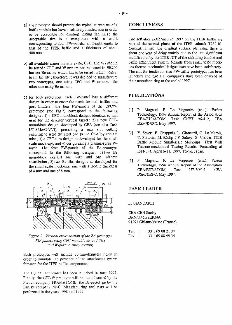
c) for both prototypes, each FW-panel has a differentdesign in order to cover the needs for both baffles andport limiters; the four FW-panels of the CFCAVprototype (see Fig 2) correspond to the followingdesigns : 1) a CFC-monoblock designs identical to thatused for the divertor vertical target; 2) a new CFC-monoblock design, developed by CEA (see also TaskUT-SM&C-WI), presenting a rear slot cuttingenabling to weld the steel pad to the Cu-alloy coolanttube; 3) a CFC-tiles design as developed for the smallscale mock-ups, and 4) design using a plasma-spray W-layer. The four FW-panels of the Be-protorypecorrespond to the following designs: 1) two Bemonoblock designs one with and one withoutcastellation; 2) two Be-tiles designs as developed forthe small scale mock-ups, one with a Be-tile thicknessof 4 mm and one of 8 mm.
CONCLUSIONS
The activities performed in 1997 on the ITER baffle arepart of the second phase of the ITER subtask T232.10.Comparing with the original subtask planning, there isabout one year of delay mainly due to the late significantmodification by the ITER JCT of the shielding blanket andbaffle attachment system. Results from small scale mock-ups thermo-mechanical fatigue tests have been satisfactory.The call for tender for two FW-baffle prototypes has beenlaunched and two EU companies have been charged oftheir manufacturing at the end of 1997.
PUBLICATIONS
[1] P. Magaud, F. Le Vagueres (eds.), FusionTechnology, 1996 Annual Report of the AssociationCEA/EURATOM, Task CNET 96-412, CEADSM/DRFC, May 1997.
[2] Y. Severi, P. Chappuis, L. Giancarli, G. Le Marois,Y. Poitevin, M. Rodig, J.F. Salavy, G. Vieider, ITERBaffle Module Small-scale Mock-ups: First WallThermo-mechanical Testing Results, Proceeding ofISFNT-4, April 6-11, 1997, Tokyo, Japan.
[3] P. Magaud, F. Le Vagueres (eds.), FusionTechnology, 1996 Annual Report of the AssociationCEA/EURATOM, Task UT-WI-1, CEADSM/DRFC, May 1997.
TASK LEADER
Figure 2 : Vertical cross-section of the BA-prototypeFW-panels using CFC monoblocks and tiles
and W-plasma spray coating
Both prototypes will include 30 nun-diameter holes inorder to simulate the presence of the attachment systemforeseen for the ITER baffle components.
The EU call for tender has been launched in June 1997.Finally, the CFC/W prototype will be manufactured by theFrench company FRAMATOME, the Be-prolotype by theBritish company NNC. Manufacturing and tests will beperformed in the years 1998 and 1999.
L. GIANCARLI
CEA CEN SaclayDRN/DMT/SERMA91191 Gif-sur-Yvette (France)
Tel. : + 33 1 69 08 21 37Fax : + 33 1 69 08 99 35
-11 -
T212
Task Title : INTERFACIAL FRACTURE TOUGHNESS OF Cu/SS JOINTS
Subtitle : Fracture mechanics analysis on solid HIP Cu/SS bi-metallics joints
INTRODUCTION
The two main objectives of task T212b are to developfracture mechanics testing on bi-material components undermixte mode loading, and to determine the interfacialfracture toughness of DS-Cu Glidcop/316LN SS bondedjoint. The tests will be performed at 300°C, which is in therange of ITER working temperature. The bondedcomponents are manufactured by solid-state bonding underHot Isostatic Pressing (HIP).
The work program is divided into two main parts: tests onbimaterial specimens without internal defect but undervarious types of solicitation (tensile and shear), tests onbimaterial specimens with internal defect. All the tests areconducted at 300°C, either under air or under vacuum. Theresults of the tests are analysed using finite elementcalculation.
1997 ACTIVITY
TESTS ON BIMATERIAL SPECIMENS WITHOUTINTERNAL DEFECT
Tensile tests performed on standard axisymmetricbimaterial specimens have shown that fracture alwaysoccurred in the glidcop, at about 1 mm from the interface inthe Glidcop side. It was thus necessary to use otherspecimens to determine the strength of the joint [1]. Twodifferent designs of specimens have been chosen :
axisymmetric notched specimens with various notchradii which develop stress concentration along the jointand allow various stress states (especially various stresstriaxiality);
flat specimens for which the orientation of the joint isinclined to the axis of loading (angle 45°) whichdevelop shear stresses along the joint.
Axsymmetric notched specimens
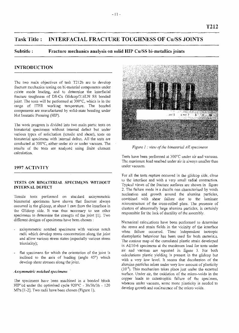
The specimens have been machined in a bonded blockHIP'ed under the optimised cycle 920°C - 3h/3h/3h - 120MPa [1-2]. Two radii have been chosen (Figure 1).
• !
V :
10
Figure 1: view of the bimalerial AE specimens
Tests have been performed at 300°C under air and vacuum.The maximum load reached under air is always smaller thanunder vacuum.
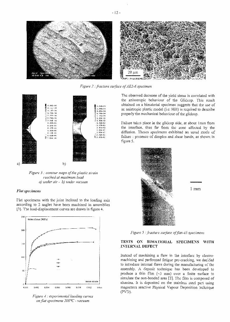
For all the tests rapture occurred in the glidcop side, closeto the interface and with a very small radial contraction.Typical views of the fracture surfaces are shown in figure2. The failure mode is a ductile one characterised by voidsnucleation and growth around the alumina particles,combined with shear failure due to the laminatemicrostructure of the cross-rolled plate. The presence ofclusters of abnormally large alumina particles, is certainlyresponsible for the lack of ductility of the assembly.
Numerical calculations have been performed to determinethe stress and strain fields in the vicinity of the interfacewhen failure occurred. Time independent isotropicelastoplastic behaviour has been used for both materials.The contour map of the cumulated plastic strain developedin AE10-6 specimens at the maximum load for tests underair and vacuum are reported in figure 3. For bothcalculations plastic yielding is present in the glidcop butwith a very low level. It seems that decohesion of thealumina particles arises under very low amount of plasticity(10"4). This mechanism takes place just under the externalsurface. Under air, the oxidation of the micro-voids in thecopper leads to catastrophic failure of the specimen,whereas under vacuum, some more plasticity is needed todevelop growth and coalescence of the micro voids.
- 12-
Figure 2 '.fracture surface of A E2-6 specimen
'8E-06,E-05
IE~04
:-od'E-04
E-04
E-04
E-04
E-04
E-04
•E-04
.E-04
• H-04
1 9.05E-05I 3.5QE-Q4j] 6.10E-04»| 6. 5CE-04i'i 1. 13E-03J 1.39E-03J 1.65E-03
.E-03
2.2.43
a3;
E-03E-03E-03'E-03E-03E-03
b)
Figure 3 : contour maps of the plastic strainreached at maximum load
a) under air - b) under vacuum
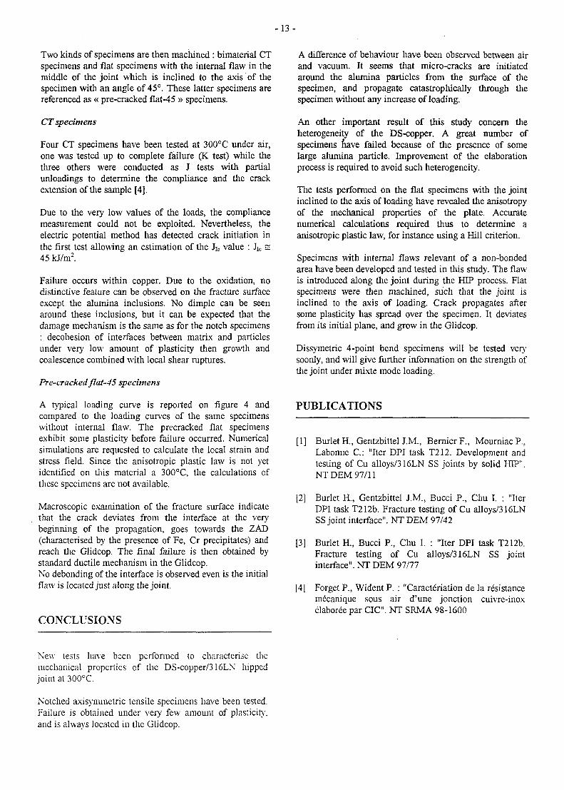
Flat specimens
Flat specimens with the joint inclined to the loading axisaccording to 2 angles have been machined in assemblies[3]. The load-displacement curves are drawn in figure 4.
200
150
00
50
mean stress (MPa)
1
j ^ . n
mean strain
0.000 0.002 0.004 0.006 0.008 0.010 0.012 0.0M
Figure 4 : experimental loading curveson flat specimens 300°C - vacuum
The observed decrease of the yield stress is correlated withthe anisotropic behaviour of the Glidcop. This resultobtained on a bimaterial specimen suggests that the use ofan anistropic plastic model (i.e: Hill) is required to describeproperly the mechanical behaviour of the glidcop.
Failure takes place in the glidcop side, at about lmm fromthe interface, thus far from the zone affected by thediffusion. Theses specimens exhibited an usual mode offailure : presence of dimples and shear bands, as shown infigure 5.
1 mm
Figure 5 : fracture surface offlat-45 specimens
TESTS ON BIMATERIAL SPECIMENS WITHINTERNAL DEFECT
Instead of machining a flaw in the interface by electro-machining and performed fatigue pre-cracking, we decidedto introduce internal flaws during the manufacturing of theassembly. A deposit technique has been developed toproduce a thin film (~3 mm) over a finite surface tosimulate the non-bonded area [2]. The film is composed ofalumina. It is deposited on the stainless steel part usingmagnetron reactive Physical Vapour Deposition technique(PVD).
- 1 3 -
Two kinds of specimens are then machined : bimaterial CTspecimens and flat specimens with the internal flaw in themiddle of the joint which is inclined to the axis of thespecimen with an angle of 45°. These latter specimens arereferenced as « pre-cracked flat-45 » specimens.
CT specimens
Four CT specimens have been tested at 300°C under air,one was tested up to complete failure (K test) while thethree others were conducted as J tests with partialunloadings to determine the compliance and the crackextension of the sample [4].
Due to the very low values of the loads, the compliancemeasurement could not be exploited. Nevertheless, theelectric potential method has detected crack initiation inthe first test allowing an estimation of the Jic value : Jic =45 kJ/m2.
Failure occurs within copper. Due to the oxidation, nodistinctive feature can be observed on the fracture surfaceexcept the alumina inclusions. No dimple can be seenaround these inclusions, but it can be expected that thedamage mechanism is the same as for the notch specimens: decohesion of interfaces between matrix and particlesunder very low amount of plasticity then growth andcoalescence combined with local shear ruptures.
Pre-cracked flat-45 specimens
A typical loading curve is reported on figure 4 andcompared to the loading curves of the same specimenswithout internal flaw. The precracked flat specimensexhibit some plasticity before failure occurred. Numericalsimulations are requested to calculate the local strain andstress field. Since the anisotropic plastic law is not yetidentified on this material a 300°C, the calculations ofthese specimens are not available.
Macroscopic examination of the fracture surface indicatethat tiie crack deviates from the interface at the verybeginning of the propagation, goes towards the ZAD(characterised by the presence of Fe, Cr precipitates) andreach the Glidcop. The final failure is then obtained bystandard ductile mechanism in the Glidcop.No debonding of the interface is observed even is the initialflaw is located just along the joint.
CONCLUSIONS
A difference of behaviour have been observed between airand vacuum. It seems that micro-cracks are initiatedaround the alumina particles from the surface of thespecimen, and propagate catastrophically through thespecimen without any increase of loading.
An other important result of this study concern theheterogeneity of the DS-copper. A great number ofspecimens nave failed because of the presence of somelarge alumina particle. Improvement of the elaborationprocess is required to avoid such heterogeneity.
The tests performed on the flat specimens with the jointinclined to the axis of loading have revealed the anisotropyof the mechanical properties of the plate. Accuratenumerical calculations required thus to determine aanisotropic plastic law, for instance using a Hill criterion.
Specimens with internal flaws relevant of a non-bondedarea have been developed and tested in this study. The flawis introduced along the joint during the HTP process. Flatspecimens were then machined, such that the joint isinclined to the axis of loading. Crack propagates aftersome plasticity has spread over the specimen. It deviatesfrom its initial plane, and grow in the Glidcop.
Dissymetric 4-point bend specimens will be tested verysoonly, and will give further information on the strength ofthe joint under mixte mode loading.
PUBLICATIONS
[1] Burlet H., Gentzbittel J.M., BernierF., MourniacP.,Labonne C: "Iter DPI task T212. Development andtesting of Cu alloys/316LN SS joints by solid HIP".NT DEM 97/11
[2] Burlet H , Gentzbittel J.M., Bucci P., Chu I. : "IterDPI task T212b. Fracture testing of Cu alloys/316LNSS joint interface". NT DEM 97/42
[3] Burlet H., Bucci P., Chu I. : "Iter DPI task T212b.Fracture testing of Cu alloys/316LN SS jointinterface". NT DEM 97/77
[41 Forget P., Wident P. : "Caracteriation de la resistancemecanique sous air d'une jonction cuivre-inoxelaboree par CIC". NT SRMA 98-1600
New tests have been performed to characterise themechanical properties of the DS-copper/316LN hippedjoint at 300°C.
Notched axisymmetric tensile specimens have been tested.Failure is obtained under very few amount of plasticity,and is always located in the Glidcop.

- 1 4 -
TASK LEADER
H. BURLET
DTA/DEM/SGMCEA grenoble 17, rue des Martyrs38054 Grenoble Cedex 9
Tel. : 04 76 88 94 96Fax : 04 76 88 94 63
e-mail: [email protected]
- 1 5 -
T216
Task Title : DEVELOPMENT AND CHARACTERIZATION OF Be/Cu ALLOYHIP JOINT
Subtitle : Development and characterization of Be/Cu alloy HIP joint, to improve theirmechanical properties
INTRODUCTION 1997 ACTIVITY
During year 96, the main goal was to fabricate a smallscale mock-up "stainless steel-Glidcop -beryllium" inorder to perform fatigue tests at the Mich facility. Somepreliminary tests on small size specimens were performedbefore the final mock-up fabrication in order to validate thejoining process.
The present study is focused on the development andcharacterisation of Be/Cu joining by Hot Isostatic Pressingdiffusion Bonding (HIPB) that is necessary for primarywall, limiters and baffle modules.
Beryllium-copper alloy junctions must withstand high in-service temperature of, at least, 300°C depending on thedesign of components. This working temperature mayreach higher temperature values during transient events.
Hot Isostatic Pressing diffusion Bonding is a process thatproduces solid-state joining by diffusion under pressureand temperature. Hot Isostatic Pressing diffusion Bonding(HIPB) is particularly suitable for large surface to be joinedand for complex or intricate geometry.
Moreover, HIPB allows high quality junction that isnecessary for a good heat transfer through the interface.Direct diffusion bonding between dissimilar materials maybe sometimes difficult to achieve. Thus, interlayers areused to facilitate bonding or to prevent the formation ofbrittle phases at the interface.
Last year, the HIPB process conditions (120 MPa, 850°Cfor the plateau) and the titanium interlayer thickness of50um was fixed, but the process conditions were too strict,especially the HIPB temperature was too close to theminimum Cu-Be liquidus.
Thus, the goal of the present work is to make the processmore flexible by an evaluation of other process conditionsand change of the interlayer compositions.
We will recall in a first part the results obtained duringyear 1996 : these results were the starting point of thepresent study.
A complete analysis of the joining issues has beenperformed during the present work. Some solutions havebeen already tested.
SUMMARY OF PREVIOUS WORK
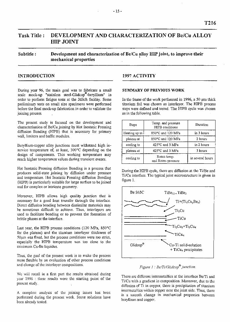
In the frame of the work performed in 1996, a 50 um thicktitanium foil was chosen as interlayer. The HJPB processsteps were defined and tested. The HIPB cycle was chosenas in the following table.
Steps
Heating up to
plateau at
cooling to
plateau at
cooling to
Temp, and pressureHEPB conditions
850°C and 120 MPa
850°C and 120 MPa
425°C and 3 MPa
425°C and 3 MPa
Room temp,and Room pressure
Duration
in 3 hours
2 hours
in 2 hours
3 hours
in several hours
During the HIPB cycle, there are diffusion at the Ti/Be andTi/Cu interface. The typical joint microstructure is given infigure 1.
Be S65C
' <»__/-—^ </ "^—^—^-—y
Glidcop®
TiBe12 + TiBe2
•—*>—/ Ti+(TixCuyBez)
x ^ Ti2Cu
^ — - T i C u
* ^Ti2Cu3+Ti3Ca,
Cu-Ti solid-solution+ TiCiL) precipitates
Figure 1 : Be/Ti/Glidcop junction.
There are different intermetallics at the interface Be/Ti andTi/Cu with a gradient in composition. Moreover, due to diediffusion of Ti in copper, there is precipitation of titaniumintermetallics within copper near the joint side. Thus, thereis a smooth change in mechanical properties betweenberyllium and copper.
- 1 6 -
The room temperature ultimate shear resistance of the jointwas found to be 108 MPa. That can be compared toultimate shear resistance for the bulk Be S65C andGlidcop® ones tested in the same conditions : respectively,268 MPa and 218 MPa.
ANALYSIS OF THE BE/CU JOINING ISSUES:JUNCTION DESIGN
In order to improve the Be/Cu joining techniques, it wasnecessary to performed a complete analysis of the differentissues encountered.
The thermal and mechanical properties of a joint aremainly dependent on the interface microstructure and itsstability under service conditions. Thus, the joining processas well some mechanical and metallurgical aspects have tobe considered for the design of high resistanceBe/Glidcop® joints and for the determination of the H3PBjoining cycle.
Process point of view
The temperature range for the joining process is given bythe following limitations :
- avoid the sensitisation region to stress corrosioncracking of 316 Stainless steel that is roughly between650°C and 720°C (the copper/beryllium junction willbe performed after the copper/stainless steel junction),
- process below 860°C, because the minimum liquidustemperature of the Cu-Be binary diagram is 860°C.
Below 650°C, aluminium can be used, only the 730-850°Ctemperature range will be considered for HIPB.
Mechanical point of view
One of the main problems in dissimilar joining is theoccurrence of residual stresses during the cooling downdue to the difference between the Coefficient of ThermalExpansion (CTE) for the two joined materials.
When residual stresses are calculated, it can be shown thatthe highest Von Mises equivalent stress in Be or inGlidcop is lower than respectively the yield stress of Beand Glidcop®.
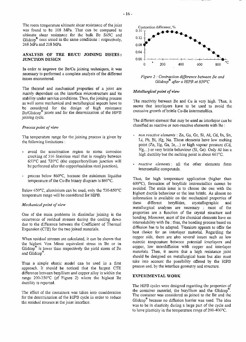
Thus a simple elastic model can be used in a firstapproach. It should be noticed that the largest CTEdifference between beryllium and copper alloy is within therange 200-350°C (cf Figure 2) where the highest Beductility is reported.
The effect of the containers was taken into considerationfor the determination of the HIPB cycle in order to reducethe residual stresses at the joint interface.
Contraction difference, %0.16 T - • - - • - •
200 400 600 800
Figure 2 : Contraction difference between Be andGlidcop® after a HIPB at 850°C
Metallurgical point of view
The reactivity between Be and Cu is very high. Thus, itseems that interlayers have to be used to avoid theexcessive growth of brittle Cu-Be intermetallics.
The different element that may be used as interlayer can beclassified as reactive or non-reactive elements with Be :
- non reactive elements : Zn, Ga, Ge, Si, Al, Cd, In, Sn,Li, Pb, Bi, Hg, Na. These elements have low meltingpoint (Zn, Hg, Ga, In,...) or high vapour pressure (Cd,Hg,...) or very brittle behaviour (Si, Ge). Only Al has ahigh ductility but the melting point is about 661°C.
- reactive elements: all the other elements formintermetallic compounds.
Thus, for high temperature application (higher than600°C), formation of beryllide intermetallics cannot beavoided. The main issue is to choose the one with thehighest ductile behaviour or the less brittle. As almost noinformation is available on the mechanical properties ofthese different beryllides, crystallographic andmetallurgical analyses are necessary : most of theproperties are a function of the crystal structure andbonding. Moreover, most of the chemical elements have nointersolubility with Be : thus, the bonding process based ondiffusion has to be adapted. Titanium appears to offer thebest choice for an interlayer material. Regarding thecopper side, there are also several issues such as loweutectic temperature between potential interlayers andcopper, low interdiffusion with copper and interlayermaterials. Then, it seems that a high resistance jointshould be designed on metallurgical basis but also musttake into account the possibility offered by the HIPBprocess and, by the interface geometry and structure.
EXPERIMENTAL WORK
The HEPB cycles were designed regarding the properties ofthe container material, the beryllium and the Glidcop •The container was considered as joined to the Be and theGlidcop because no diffusion barrier was used. The ideawas to be in elasticity during a large part of the cycle andto have plasticity in the temperature range of 200-400°C.
- 1 7 -
Pure titanium and titanium base alloys were tested asinterlayers. Two different thicknesses were tested for puretitanium. The minimum thickness is 30 um : below thatvalue, all the titanium is transformed into copper-titaniumand beryllium titanium intermetallics. For higher value,titanium with some beryllium and copper remains betweenthe copper-titanium and the beryllium-titaniumintermetallics. It seems that this layer is necessary for thestrength of the joint : this should act as compliant layer.Larger thickness (lOOum) doesn't seem to improvementsignificantly the resistance of the joint.
The effect of additions in titanium is still under evaluationfrom a metallurgical point of view.
TASK LEADER
F. SAINT-ANTONIN
DTA/DEM/SGMCEA grenoble 17, rue des Martyrs38054 Grenpble Cedex 9
Tel.Fax
04 76 88 54 7704 76 88 95 38
e-mail: [email protected]
CONCLUSIONS
The sensitivity to interlayer thicknesses, chemicalcomposition of titanium base alloy used as interlayers andHIPB parameters was evaluated. The thickness of puretitanium should be between 30 um and 100 um. The effectof alloying element is still under evaluation. Six mock -upswill be fabricated in order to evaluate the thermal -fatigueresistance of such joints under high heat flux.
PUBLICATIONS
[1] F. Saint-Antonin, G. Bourgeois, P. Bucci, H. Burlet,C. Dellis, P. Revirand, "Small scale testing ofFW/BSmodules. Sub-task 1 : mock-up fabrication andtesting", ITER Task T216a, Note Technique DEMn°64/96, 30 Dec. 1996.
[2] F. Saint-Antonin, G. Bourgeois, P. Bucci, H. Burlet,"Development and characterisation of Be/Cu alloyHIP joint", ITER Task T2I6a, Note Technique DEMn°80/97, 29 Dec. 1997.
[3] F. Saint-Antonin, P. Bucci, D. Barberi, H. Burlet, A.Laille, G. Le Marois, "Development of Be/GIidcop®joint obtained by Hot Isostatic Pressing diffusionbonding for high in-sen'ice temperature", 3rd
International Beryllium Workshop, 22-24 October1997, Mito (Japan).
[4] F. Saint-Antonin. D. Barberi, G. Le Marois, A.Laille, "Development and characterisation ofBe/Glidcop® joint obtained by Hot Isostatic Pressingfor high temperature working conditions", 8th Int.Conf. on Fusion Reactor Materials, Oct. 26-31, 1997,Sendai (Japon) in press.
- 1 9 -
T221-1
Task Title: THERMO-MECHANICAL CHARACTERIZATION OF CFCs
Subtitle: Pre and post irradiation of high thermal conductivity and Si doped CFCs
INTRODUCTION
The validation of water cooled divertor with monoblock c-armor needs to use advanced carbon fibers composites(CFCs) with high thermal conductivities (K > 175 W/m.Kat 800°C). The aim of this task is in one hand to know thebehaviour of these materials when they are neutronirradiated in the range: 0.3 to 0.35 dpa.g at two irradiationtemperatures 335°C and 775 °C, in the other hand it is tomeasure the thermal conductivity of Si doped CFCs afterthermal shock tests. Moreover a study of thermal annealingeffects on the thermal conductivity of irradiated CFCs hasbeen carried out.
1997 ACTIVITIES
POST-IRRADIATION PROPERTIESTHERMAL CONDUCTIVITIES CFCs
OF HIGH
The CFCs samples have been irradiated in HFR (PETTEN)at 335°C and 775°C with a neutron damage includedbetween 0.3 and 0.35 dpa.g. The irradiation started on thedecember 21st 1995 and ended on the february 12th 1996.Dimensional, heat capacity and thermal conductivitymeasurements of irradiated materials have been carried
out. Post-irradiation results allow to draw the firstfollowing conclusions:
- For all the irradiated materials (DUNLOP concept 1and concept 2, N112, N312B, NS11 and RGTi(91));after irradiation at 335°C or 775°C, the dimensional
ALchanges are very low (-0.55% < 7— <+O.38%) . The
^0NS11 silicon doped CFC shows a particularly good
ALdimensional behaviour (- 0.07 % < 7— < +0.12 %).
L0For the different CFCs and RGTi(91) graphite heat
capacity changes T T j are included between -0.5%
and 1.7 % after irradiation at 335°C/0.31 dpa.g.
After irradiation at 775°C/0.35 dpa.g Qp are ranged
between -3.4% and 2.6 %. These values are very closeto the uncertainty on the Cp measurement (+ 2.5 %).
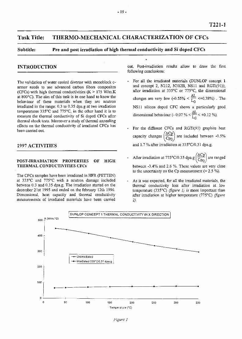
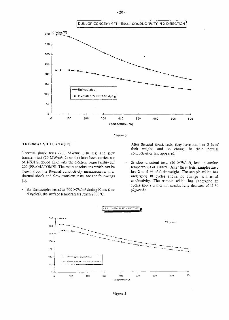
As it was expected, for all the irradiated materials, thethermal conductivity loss after irradiation at lowtemperature (335°C) /figure 1) is more important thanafter irradiation at higher temperature (775°C) (figure2).
DUNLOP CONCEPT 1 THERMAL CONDUCTIVITY IN X DIRECTION
-K <w/m-"c>
400 -
300 •
200 -
100 -
-Unirradiated-Irradiated 335*C/0.31 dpa.g
50 100 150 200
Temperature ("C)
250 300 350
Figure 1
- 2 0 -
DUNLOP CONCEPT 1 THERMAL CONDUCTIVITY IN X DIRECTION
K (W/m.*C)
350 ••
300 -•
250 ••
200 ••
150--
100 --
50 --
-Unirradiated
-Irradiated 775'C/0.35 dpa.g
100 200 300 400 500 600
Temperature (°C)
700 800
Figure 2
THERMAL SHOCK TESTS
Thermal shock tests (700 MW/m2 ; 10 ms) and slowtransient test (20 MW/m2; 2s or 4 s) have been carried outon NS31 Si doped CFC with the electron beam facility FE200 (FRAMATOME). The main conclusions which can bedrawn from the thermal conductivity measurements atterthermal shock and slow transient tests, are the followings[1]:
- for the samples tested at 700 MW/m2 during 10 ms (1 or5 cycles), the surface temperatures reach 2900°C.
After thermal shock tests, they have lost 1 or 2 % oftheir weight, and no change in their thermalconductivities has appeared.
2s slow transient tests (20 MW/m2), lead to surfacetemperatures of 2500°C. After these tests, samples havelost 2 or 4 % of their weight. The sample which hasundergone 10 cycles shows no change in thermalconductivity. The sample which has undergone 22cycles shows a thermal conductivity decrease of 12 %(figure 3).
| N S 31 THERMAL C O N O U C T I V I T Y | |
300
250 •
2C0 -
150 -
Y3 sample
100 300 400 500
Temperature [°C1
600 700 800
Figure 3
-21 -
- 20 cycles of 4s slow transient tests (20 MW/m2) lead tothe destruction of the sample. 10 cycles lead to surfacetemperatures of 2800°C. After such a test, the samplehas lost 41 % of its weight, but thermal conductivityloss at 800°C is only 12 %.
- It seems that NS31 keeps its good thermal conductivityafter thermal shock tests.
- Under 10~4 mbar vacuum graphite sublimation occursat temperatures beyond 2200°C.
THERMAL ANNEALING EFFECTS
The effect of the thermal annealing on the thermalconductivity of CFCs irradiated at 400°C, 600°C, 800°Cand 1000°C with a damage ranging from 0.4 to 1.9 dpa.ghas been studied in 1996 and 1997 and the followingconclusions can be drawn [2]:
- Isochronal annealings (1 hour) by temperature step of100°C of A05 CFC irradiated at 400°C/0.85 dpa.g showthat the thermal conductivity begins to increase forannealing temperature of 900°C and that the initialthermal conductivity is recovered for an annealingtemperature of 2000°C.
Isothermal annealings at 1200°C and 2000°C duringdifferent times from 10 minutes to 5 hours show tliatthe recover of the thermal conductivity at theseannealing temperatures is maximum for an annealingtime of 1 hour.
After annealing, the thermal conductivity recovery ofMKC (CFC with very high thermal conductivity Ko(400°C)*= 358 W/m K) shows the same behaviour thanfor A05 (Ko(400°C) = 178 W/m K).
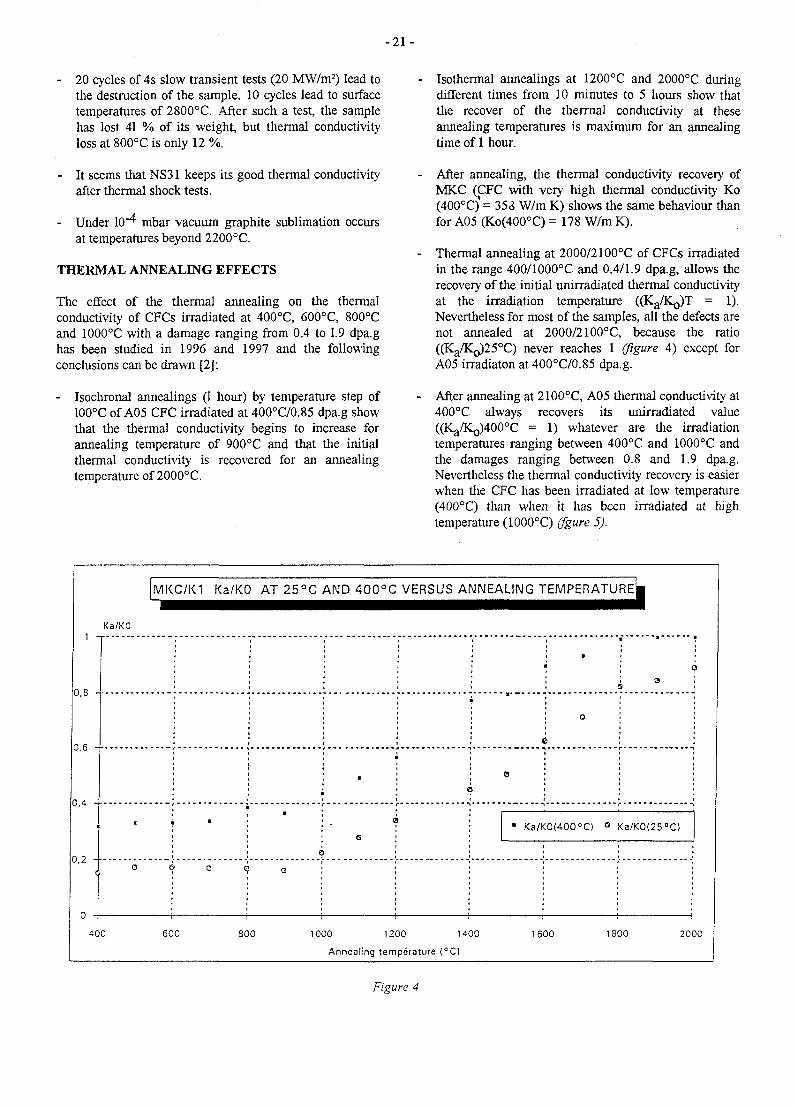
Thermal annealing at 2000/2100°C of CFCs irradiatedin the range 400/1000°C and 0.4/1.9 dpa.g, allows therecovery of the initial unirradiated thermal conductivityat the irradiation temperature ((Kg/K^T = 1).Nevertheless for most of the samples, all the defects arenot annealed at 2000/2100°C, because the ratio((Ka/Ko)25°C) never reaches 1 (figure 4) except forA05 irradiaton at 400°C/0.85 dpa.g.
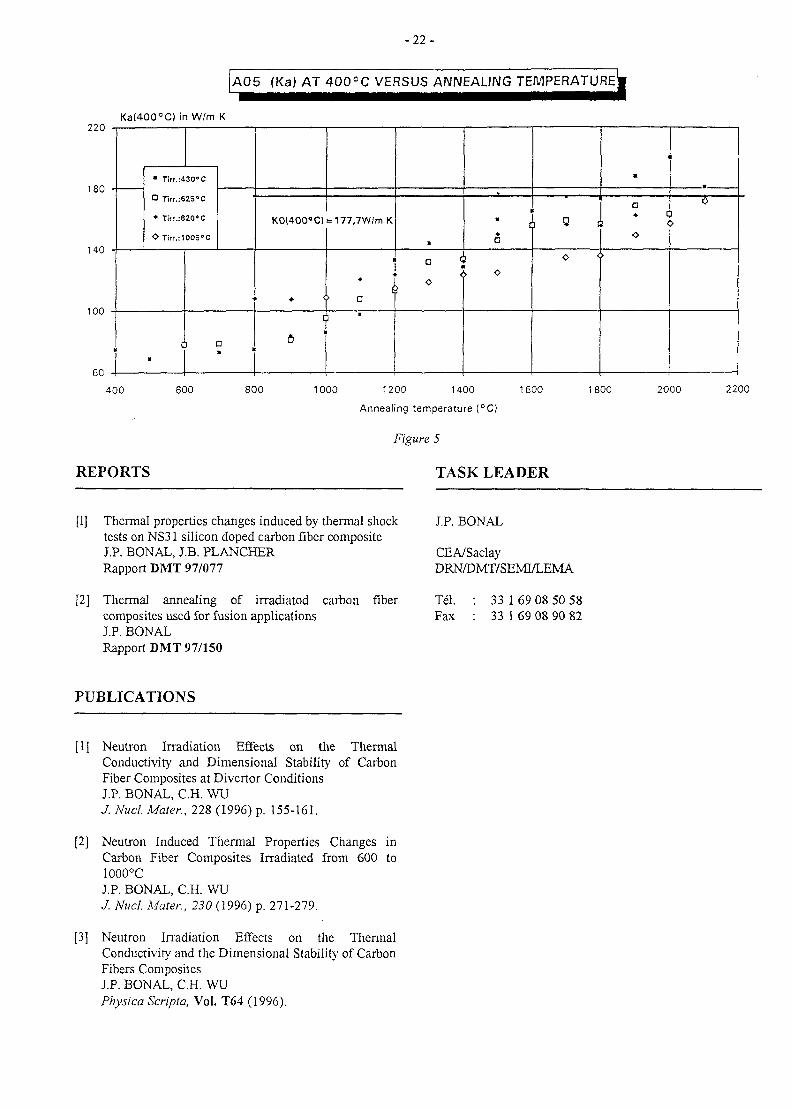
After annealing at 2100°C, A05 thermal conductivity at400°C always recovers its unirradiated value((Ka/KQ)400°C = 1) whatever are the irradiationtemperatures ranging between 400°C and 1000°C andthe damages ranging between 0.8 and 1.9 dpa.g.Nevertheless the thermal conductivity recovery is easierwhen the CFC has been irradiated at low temperature(400°C) than when it has been irradiated at hightemperature (1000°C) (fgure 5).
0,8 -
0,6 -
0,4 -
•
0.2 -
<
MKC/K1 Ka/KO AT 25°C AND 400°C VERSUS ANNEALING TEMPERATURE^
Ka/KO
• 1
0 C
•
0
•
c
©
<
o
• •
o
3
• Ka/K0(4OO°C) ° Ka/K0(25°C)
400 600 800 1000 1200 1400 1600 1800 2000
Annealing temperature (°C)
Figure 4
-22 -
A05 (Ka) AT 400°C VERSUS ANNEALING TEMPERATURE^
180 -
140 -
100 -
1
60 -
Ka(400°C) in W/m
• "rirr.:4301)C
D Tirr.:62S°C
• Ti(f.:620''C
O Tirr.:100S°C
K
•
Da
K0(400<"C)
• <
= 177,7W/m K
1
1 *
•
° ]o
1
" :
a
> o
o *
u
D« c
I <
o>
400 600 800 1000 1200 1400
Annealing temperature (°C)
1600 1800 2000 2200
REPORTS
Figure 5
TASK LEADER
[1] Thermal properties changes induced by thermal shocktests on NS31 silicon doped carbon fiber compositeJ.P. BONAL, IB . PLANCHERRapport DMT 97/077
[2] Thermal annealing of irradiated carbon fibercomposites used for fusion applicationsJ.P. BONALRapport DMT 97/150
J.P. BONAL
CEA/SaclayDRN/DMT/SEMI/LEMA
Tel. : 33 169 08 50 58Fax : 33 1 69 08 90 82
PUBLICATIONS
[1] Neutron Irradiation Effects on the ThermalConductivity and Dimensional Stability of CarbonFiber Composites at Divertor ConditionsJ.P. BONAL, C.H. WUJ. Nucl. Mater., 228 (1996) p. 155-161.
[2] Neutron Induced Thermal Properties Changes inCarbon Fiber Composites Irradiated from 600 to1000°CJ.P. BONAL, C.H. WUJ. Nucl. Mater., 230 (1996) p. 271-279.
[3] Neutron Irradiation Effects on the ThermalConductivity and the Dimensional Stability of CarbonFibers CompositesJ.P. BONAL, C.H. WUPhysica Scripta, Vol. T64 (1996).
- 2 3 -
T222
Task Title : MANUFACTURE AND TESTING OF PERMANENTCOMPONENTS OPTIMISATION OF COOLING SYSTEM
Subtitle : Completion of critical heat flux and thermal hydraulic testing of swirl andvapotron tubes for ITER high heat flux components
INTRODUCTION Pressure drop coefficient A. is defined as following :
The previous study in 1996 [1 ; 2] was focused on thethermal behaviour of various tubes : smooth tubes, swirlrubes, hypervapotrons and annular flows. The swirl tubewas selected as giving promising results and allowing atube-in-tile concept, relevant to 20 MW/m2 incident heatfluxes, to be developed (cf. [3]) . The aim of this study wasto investigate more about pressure drop and critical heatflux (CHF) for such tubes.
1997 ACTIVITY
D
with : L s w , Vsw swirled length and swirled velocity
D H hydraulic diameter of the tube
p{ density of the liquid
and experimental value of X is fitted with a classic powerexpression, comparable with literature:
PRESSURE DROP MEASUREMENTS AND CORRE-LATIONS
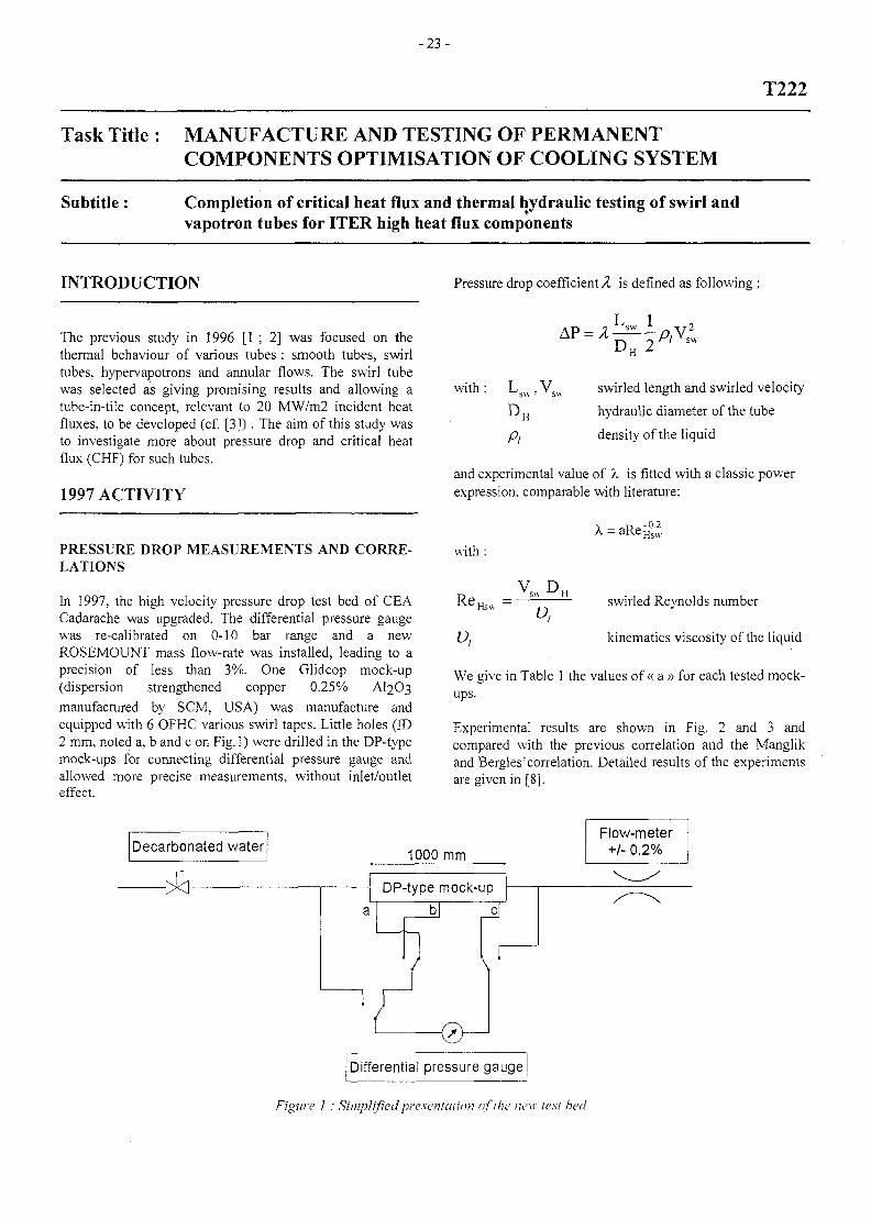
In 1997, the high velocity pressure drop test bed of CEACadarache was upgraded. The differential pressure gaugewas re-calibrated on 0-10 bar range and a newROSEMOUNT mass flow-rate was installed, leading to aprecision of less than 3%. One Glidcop mock-up(dispersion strengthened copper 0.25% AI2O3manufactured by SCM, USA) was manufacture andequipped with 6 OFHC various swirl tapes. Little holes (ID2 mm, noted a, b and c on Fig. 1) were drilled in the DP-typemock-ups for connecting differential pressure gauge andallowed more precise measurements, without inlet/outleteffect.
with :
U,
swirled Reynolds number
kinematics viscosity of the liquid
We give in Table 1 the values of « a » for each tested mock-ups.
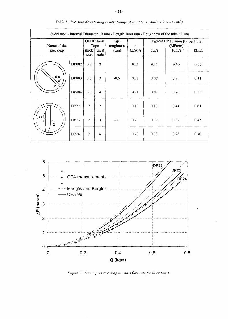
Experimental results are shown in Fig. 2 and 3 andcompared with the previous correlation and the Manglikand Bergles'correlation. Detailed results of the experimentsare given in [8].
Decarbonated water 1000 mm
Flow-meter+/- 0.2%
Differential pressure gauge
Figure 1 : Simplified presentation of the new lest bed
- 2 4 -
Table 1: Pressure drop testing results (range of validity is: 4m/s < V < —12 m/s)
Swirl tube - Internal Diameter 10 mm - Length 1000 mm - Roughness of the tube : 1 jam
Name of themock-up
OFHC swirlTape
thickness
twistratio
Taperoughness
(jam)a
CEA98
Typical DP at room temperature(MPa/m)
5m/s lOm/s 12m/s
DP082 0.8 0.21 0.11
DP083 0.8 -0.5 0.21 0.09
DP084 0.8 0.21 0.07
0.40
0.29
0.26
0.56
0.41
0.35
DP22 0.19 0.13
DP23 0.20 0.09
DP24 0.20 0.08
0.44
0.32
0.28
0.61
0.45
0.40
6
5 -
4 -
Q.
2 -
1 -
CEA measurements
•Manglik and Bergles•CEA 98
. - • & . -
0,2 0,4
Q (kg/s)
0,6
DR23 .
0,8
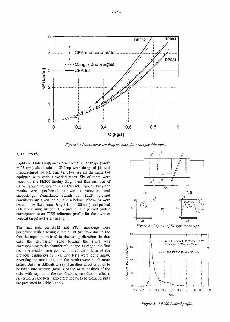
Figure 2 : Lineic pressure drop vs. mass flow rate for thick tapes
- 2 5 -
4 -
CO
< 2-
1 -
DP083
« CEA measurements
Manglik and Bergles•CEA 98
0,2 0,4 0,6
Q (kg/s)
0,8
Figure 3 : Lineic pressure drop vs. mass flow rate for thin tapes
CHF TESTS A B
IIEight swirl tubes with an external rectangular shape (width= 23 mm) also made of Glidcop were designed [4] andmanufactured [5] (cf. Fig. 4). They are all the same butequipped with various swirled tapes. Six of them weretested on the FE200 facility (high heat flux test bed ofCEA/Framatome, located in Le Creusot, France). Fifty oneresults were performed at various velocities andsubcoolings. Remarkable results for ITER relevantconditions are given table 3 and 4 below. Mock-ups weretested under flat (heated length Lh = 100 mm) and peaked(Lh = 200 mm) incident flux profile. The peaked profilecorresponds to an ITER reference profile for the divertorvertical target and is given Fig. 5.
The first tests on ST22 and ST24 mock-ups wereperformed with a wrong direction of the flow due to thefact the tape was swirled in the wrong direction. In thatcase the depression zone belu'nd the swirl wascorresponding to the chamfer of the tape. During these firsttests the results were poor compared with those of theprevious campaigns [1 ; 2]. The tests were done again,reversing the mock-ups, and the results were much morebetter. But it is difficult to say if another effect has not tobe taken into account (loosing of the swirl, position of thetwist with regards to the castellations, castellation effect).Nevertheless the twist ratio effect seems to be clear. Resultsare presented in Table 3 and 4.
!
:
, A
* 20 */
1i
300
A-A B-B
ID10
23 23
Figure 4 : Lay-out ofST-type mock-ups
30
047
h/ --\5\.\\_
45
20
15 --
1 0 •-
I"6
11 —•— A.Kukushkin, H.D.Pacher 1997ill Transient Reference Case
j j - - - 1997 FE200 Peaked Profile
': Y I : :
-0,2 -0,1 0 0.1 0,2 0,3 0 / 0.5 0,6 0.7 0,8X(m)
Figure 5 : FE200 Peaked profile
- 2 6 -
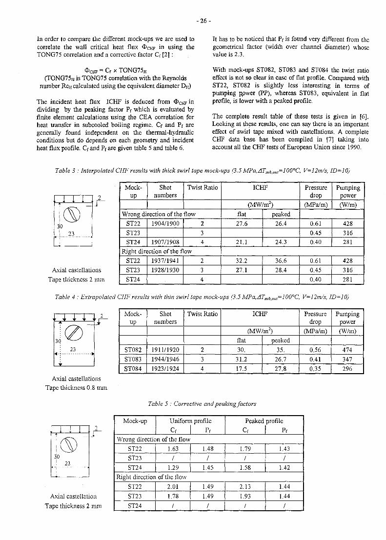
In order to compare the different mock-ups we are used tocorrelate the wall critical heat flux OCHF in using theTONG75 correlation and a corrective factor Cf [2] :
<J>CHF = Cr * TONG75H
(TONG75H is TONG75 correlation with the Reynoldsnumber Ren calculated using the equivalent diameter DH)
The incident heat flux ICHF is deduced from <DCHF *n
dividing by the peaking factor Pf which is evaluated byfinite element calculations using the CEA correlation forheat transfer in subcooled boiling regime. Q and Pf aregenerally found independent on the thermal-hydraulicconditions but do depends on each geometry and incidentheat flux profile. Cf and Pf are given table 5 and table 6.
It has to be noticed that Pf is found very different from thegeometrical factor (width over channel diameter) whosevalue is 2.3.
With mock-ups ST082, ST083 and ST084 the twist ratioeffect is not so clear in case of flat profile. Compared withST22, ST082 is slightly less interesting in terms ofpumping Rower (PP), whereas ST083, equivalent in flatprofile, is lower with a peaked profile.
The complete result table of these tests is given in [6].Looking at these results, one can say there is an importanteffect of swirl tape mixed with castellations. A completeCHF data base has been compiled in [7] taking intoaccount all the CHF tests of European Union since 1990.
Table 3 : Interpolated CHF results with thick swirl tape mock-ups (3.5 MPa, AT^^^l 00°C, V= 12m/s, 1D=1
Mock-up
Shotnumbers
Twist Ratio
Wrong direction of the flow
ST22
ST23ST24
1904/1900
1907/1908
2
34
Right direction of the flow
ST22
ST23
ST24
1937/1941
1928/1930
2
3
4
ICHF
(MW/m2)
flat
27.6
21.1
peaked
26.4
24.3
Pressuredrop
(MPa/m)
Pumpingpower
(W/m)
0.61
0.450.40
428
316281
32.2
27.1
36.6
28.4
0.61
0.45
0.40
428
316
281
Axial castellations
Tape thickness 2 mm
Table 4 : Extrapolated CHF results with thin swirl tape mock-ups (3.5 MPa,ATsubiOM=100°C, V=12m/s, 1D=1O)
2
30
23
Mock-up
ST082
ST083
ST084
Shotnumbers
1911/1920
1944/1946
1923/1924
Twist Ratio
2
3
4
ICHF
(MW/m2)
flat
30.
31.2
17.5
peaked
35.
26.7
27.8
Pressuredrop
(MPa/m)
0.56
0.41
0.35
Pumpingpower
(W/m)
474
347
296
Axial castellationsTape thickness 0.8 mm
Table 5 : Corrective and peaking factors
Axial castellation
Tape thickness 2 mm
Mock-up Uniforn
cf
i profile
Pf
Peaked
cf
profile
PfWrong direction of the flow
ST22
ST23
ST24
1.63
/
1.29
1.48
/
1.45
1.79
/
1.58
1.43
/
1.42
Right direction of the flow
ST22
ST23
ST24
2.01
1.78
/
1.49
1.49
/
2.13
1.93
/
1.44
1.44
/
- 2 7 -
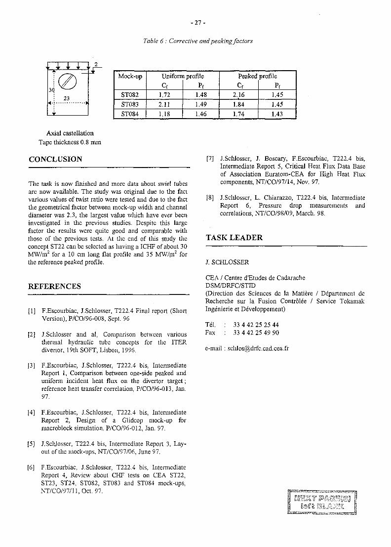
Table 6: Corrective and peaking factors
Mock-up
ST082
ST083
ST084
Uniforn
Cf
1.72
2.11
1.18
i profile
Pf1.48
1.49
1.46
Peaked
cf2.16
1.84
1.74
profile
Pf
1.45
1.45
1.43
Axial castellationTape thickness 0.8 mm
CONCLUSION
The task is now finished and more data about swirl tubesare now available. The study was original due to the factvarious values of twist ratio were tested and due to the factthe geometrical factor between mock-up width and channeldiameter was 2.3, the largest value which have ever beeninvestigated in the previous studies. Despite this largefactor the results were quite good and comparable withthose of the previous tests. At the end of this study theconcept ST22 can be selected as having a ICHF of about 30MW/m2 for a 10 cm long flat profile and 35 MW/m2 forthe reference peaked profile.
REFERENCES
[1] F.Escourbiac, J.Schlosser, T222.4 Final report (ShortVersion), P/CO/96-008, Sept. 96
[2] J.Schlosser and al, Comparison between variousthermal hydraulic tube concepts for the ITERdivertor, 19th SOFT, Lisbon, 1996.
[3] F.Escourbiac, J.Schlosser, T222.4 bis, IntermediateReport 1, Comparison between one-side peaked anduniform incident heat flux on the divertor target;reference heat transfer correlation, P/CO/96-013, Jan.97.
[4] F.Escourbiac, J.Schlosser, T222.4 bis, IntermediateReport 2, Design of a Glidcop mock-up formacroblock simulation, P/CO/96-012, Jan. 97.
[5] J.Schlosser, T222.4 bis, Intermediate Report 3, Lay-out of die mock-ups, NT/CO/97/06, June 97.
[6] F.Escourbiac, J.Schlosser, T222.4 bis, IntermediateReport 4, Review about CHF tests on CEA ST22,ST23, ST24, ST082, ST083 and ST084 mock-ups,NT/CO/97/ll,Oct. 97.
[7] J.Schlosser, J. Boscary, F.Escourbiac, T222.4 bis,Intermediate Report 5, Critical Heat Flux Data Baseof Association Euratom-CEA for High Heat Fluxcomponents, NT/CO/97/14, Nov. 97.
[8] J.Schlosser, L. Chiarazzo, T222.4 bis, IntermediateReport 6, Pressure drop measurements andcorrelations, NT/CO/98/09, March. 98.
TASK LEADER
J. SCHLOSSER
CEA / Centre d'Etudes de CadaracheDSM/DRFC/STID(Direction des Sciences de la Matiere / Departement deRecherche sur la Fusion Controlee / Sendee TokamakIngenierie et Developpement)
Tel. : 33 4 42 25 25 44Fax : 33 4 42 25 49 90
e-mail: [email protected]
- 2 9 -
T222.4ter
Task Title: MANUFACTURE AND TESTING OF PERMANENTCOMPONENTS OPTIMISATION OF COOLING SYSTEM
Subtitle : Critical heat flux and thermo-hydr. of representative elements (continuation T222.4);Non destructive testing, calibrated defects, heat load influence (T222.15)
INTRODUCTION
The task T222.4ter is the continuation of task T222.4bis inwhich a concept of swirl tube mock-up was selected (ST22)for the vertical target of the ITER divertor after CHF(critical heat flux) tests on the FE200 facility. The idea ofthis new task is to continue the investigations of such aconcept for qualification. The task started in September1997 and it is divided in several parts :
- perform same tests as in the FE200 (round robin tests)in two other laboratories : SANDIA in US and JAERIin Japan,
- manufacture a CHF upgraded mock-up and test it onthe FE200,
- test a prototypical mock-up manufactured by Plansee,the mock-up being a tube-in-tile concept (tile is madeof Si doped carbon fibre composite) and the coolingchannel being equipped with a swirl tape,
- define calibrated defects to be performed on a newprototypical mock-up and test it on the FE200 in orderto investigate the limits due to the defects.
1997 ACTIVITY
ROUND ROBIN TESTS
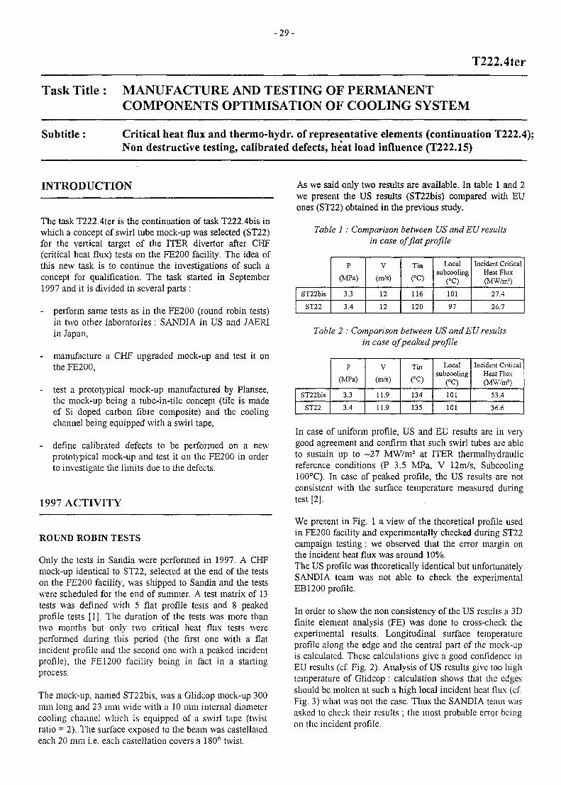
Only the tests in Sandia were performed in 1997. A CHFmock-up identical to ST22, selected at the end of the testson the FE200 facility, was shipped to Sandia and the testswere scheduled for the end of summer. A test matrix of 13tests was defined with 5 flat profile tests and 8 peakedprofile tests [1J. The duration of the tests was more thantwo months but only two critical heat flux tests wereperformed during this period (the first one with a flatincident profile and the second one with a peaked incidentprofile), the FE1200 facility being in fact in a startingprocess.
The mock-up, named ST22bis, was a Glidcop mock-up 300mm long and 23 mm wide with a 10 mm internal diametercooling channel which is equipped of a swirl tape (twistratio = 2). The surface exposed to the beam was castellatedeach 20 mm i.e. each castellation covers a 180° twist.
As we said only two results are available. In table 1 and 2we present the US results (ST22bis) compared with EUones (ST22) obtained in the previous study.
Table 1 : Comparison between US and EU resultsin case of flat profile
ST22bis
ST22
P
(MPa)
3.3
3.4
V
(m/s)
12
12
Tin
(°C)
116
120
Localsubcooling
(°C)
101
97
Incident CriticalHeat Flux(MW/m1)
27.4
26.7
Table 2 : Comparison between US and EU resultsin case of peaked profile
ST22bis
ST22
P
(MPa)
3.3
3.4
V
(m/s)
11.9
11.9
Tin
(°C)
134
135
Localsubcooling
<°C)
101
101
Incident CriticalHeat Flux(MW/m1)
53.4
36.6
In case of uniform profile, US and EU results are in verygood agreement and confirm that such swirl tubes are ableto sustain up to -27 MW/m2 at ITER thermalhydraulicreference conditions (P 3.5 MPa, V 12m/s, Subcooling100°C). In case of peaked profile, the US results are notconsistent with the surface temperature measured duringtest [2],
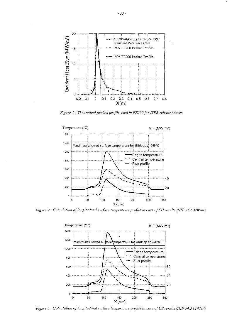
We present in Fig. 1 a view of the theoretical profile usedin FE200 facility and experimentally checked during ST22campaign testing : we observed that the error margin onthe incident heat flux was around 10%.The US profile was theoretically identical but unfortunatelySANDIA team was not able to check the experimentalEB1200 profile.
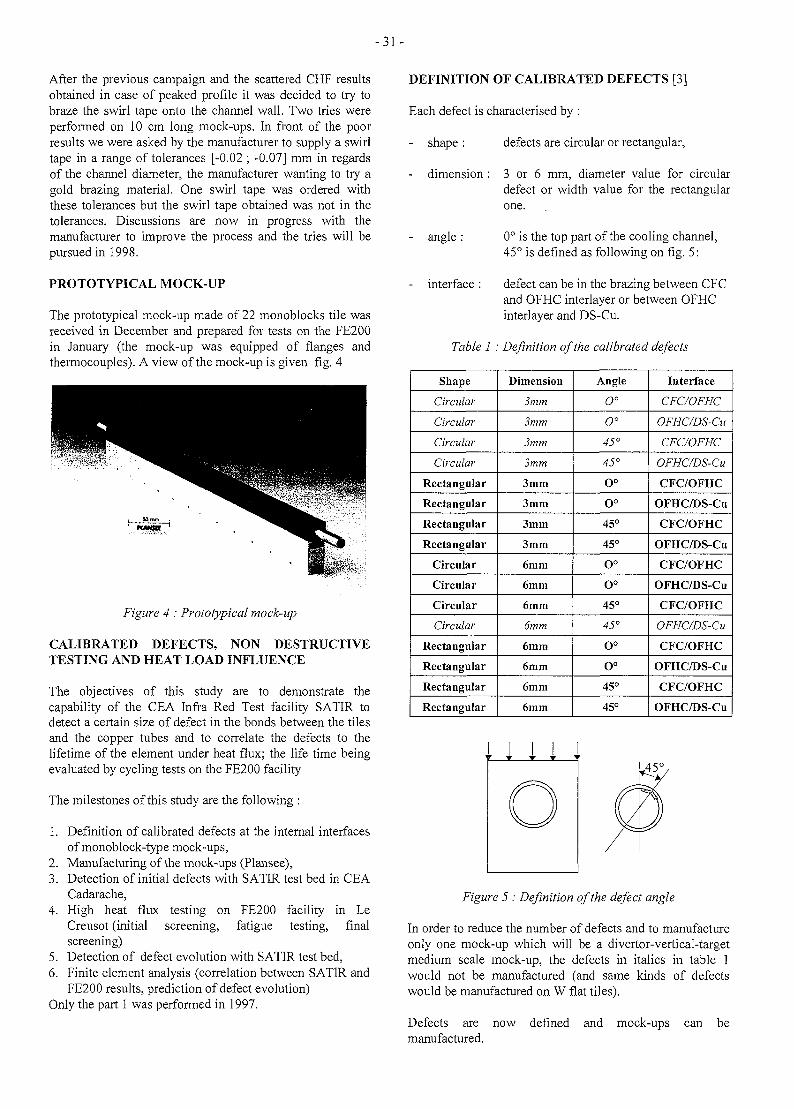
In order to show the non consistency of the US results a 3Dfinite element analysis (FE) was done to cross-check theexperimental results. Longitudinal surface temperatureprofile along the edge and the central part of the mock-upis calculated. These calculations give a good confidence inEU results (cf. Fig. 2). Analysis of US results give too hightemperature of Glidcop : calculation shows that the edgesshould be molten at such a high local incident heat flux (cf.Fig. 3) what was not the case. Thus the SANDIA team wasasked to check their results ; the most probable error beingon the incident profile.
- 3 0 -
-0,2 -0,1 0 0,1 0,2 0,3 0,4 0,5 0,6 0,7 0,8X(m)
Figure 1 : Theoretical peaked profile used in FE200 for ITER relevant cases
Temperature (°C)
1400
IHF (MW/m2)
1200 •
1000 -
800 -
600 -
400 -
200 -
0
Maximumiallowed surface temperature for Glidcop :
Edges temperature....." " Central temperature
— 'Flux profile
1050°C
40
20
100 250 300150 200
X(mm)
Figure 2 : Calculation of longitudinal surface temperature profile in case of EU results (IHF36.6 MW/m7)
Temperature (°C)
1400
1200 -
1000 •
IHF (MW/m2)
Maximumiallowed surface\emperature for Glidcop :
Edges temperature" " Central temperature— 'Flux profile
50 100 150 200
X(mm)250 300
Figure 3 : Calculation of longitudinal surface temperature profile in case of US results (IHF 54.3 MW/m7)
-31 -
After the previous campaign and the scattered CHF resultsobtained in case of peaked profile it was decided to try tobraze the swirl tape onto the channel wall. Two tries wereperformed on 10 cm long mock-ups. In front of the poorresults we were asked by the manufacturer to supply a swirltape in a range of tolerances [-0.02 ; -0.07] mm in regardsof the channel diameter, the manufacturer wanting to try agold brazing material. One swirl tape was ordered withthese tolerances but the swirl tape obtained was not in thetolerances. Discussions are now in progress with themanufacturer to improve the process and the tries will bepursued in 1998.
PROTOTYPICAL MOCK-UP
The prototypical mock-up made of 22 monoblocks tile wasreceived in December and prepared for tests on the FE200in January (the mock-up was equipped of flanges andthermocouples). A view of the mock-up is given fig. 4
i '
Figure 4 : Prototypical mock-up
CALIBRATED DEFECTS, NON DESTRUCTIVETESTING AND HEAT LOAD INFLUENCE
The objectives of this study are to demonstrate thecapability of the CEA Infra Red Test facility SATIR todetect a certain size of defect in the bonds between the tilesand the copper tubes and to correlate the defects to thelifetime of the element under heat flux; the life time beingevaluated by cycling tests on the FE200 facility
The milestones of this study are the following :
1. Definition of calibrated defects at the internal interfacesof monoblock-type mock-ups,
2. Manufacturing of the mock-ups (Plansee),3. Detection of initial defects with SATIR test bed in CEA
Cadarache,4. High heat flux testing on FE200 facility in Le
Creusot (initial screening, fatigue testing, finalscreening)
5. Detection of defect evolution with SATIR test bed,6. Finite element analysis (correlation between SATIR and
FE200 results, prediction of defect evolution)Only the part 1 was performed in 1997.
DEFINITION OF CALIBRATED DEFECTS [3]
Each defect is characterised by :
shape : defects are circular or rectangular,
dimension : 3 or 6 mm, diameter value for circulardefect or width value for the rectangularone.
- angle : 0° is the top part of the cooling channel,45° is defined as following on fig. 5:
interface : defect can be in the brazing between CFCand OFHC interlayer or between OFHCinterlayer and DS-Cu.
Table 1: Definition of the calibrated defects
Shape
Circular
Circular
Circular
Circular
Rectangular
Rectangular
Rectangular
Rectangular
Circular
Circular
Circular
Circular
Rectangular
Rectangular
Rectangular
Rectangular
Dimension
3mm
3mm
3mm
3mm
3mm
3mm
3mm
3mm
6mm
6mm
6mm
6mm
6mm
6mm
6mm
6mm
Angle
O°
O°
45°
45°
O°
O°
45°
45°
O°
o°45°
45°
O°
O°
45°
45°
Interface
CFC/OFHC
OFHC/DS-Cu
CFC/OFHC
OFHC/DS-Cu
CFC/OFHC
OFHC/DS-Cu
CFC/OFHC
OFHC/DS-Cu
CFC/OFHC
OFHC/DS-Cu
CFC/OFHC
OFHC/DS-Cu
CFC/OFHC
OFHC/DS-Cu
CFC/OFHC
OFHC/DS-Cu
Figure 5 : Definition of the defect angle
In order to reduce the number of defects and to manufactureonly one mock-up which will be a divertor-vertical-targetmedium scale mock-up, the defects in italics in table 1would not be manufactured (and same kinds of defectswould be manufactured on W flat tiles).
Defects are now defined and mock-ups can bemanufactured.
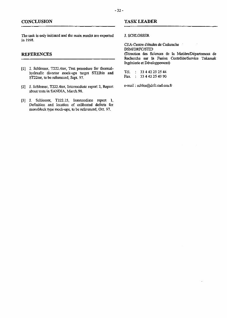
- 32 -
CONCLUSION TASK LEADER
The task is only initiated and the main results are expectedin 1998.
REFERENCES
[1] J. Schlosser, T222.4ter, Test procedure for thermal-hydraulic divertor mock-ups target ST22bis andST22ter, to be referenced, Sept. 97.
[2] J. Schlosser, T222.4ter, Intermediate report 2, Reportabout tests in SANDIA, March 98.
[3] J. Schlosser, T222.15, Intermediate report 1,Definition and location of calibrated defects formonoblock type mock-ups, to be referenced, Oct. 97.
J. SCHLOSSER
CEA-Centre d'e"tudes de CadaracheDSM/DRFC/STID(Direction des Sciences de la Matiere/D6partement deRecherche sur la Fusion Controls/Service TokamakIng&iierie et Dewloppement)
Tel. : 33 4 42 25 25 44Fax. : 33 4 42 25 49 90
e-mail: [email protected]
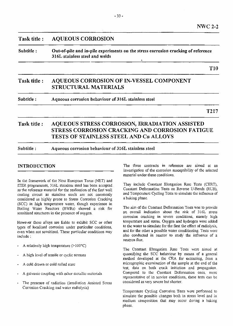
- 3 3 -
NWC2-2
Task title:
Subtitle:
Task title:
Subtitle :
AQUEOUS CORROSION
Out-of-pile and in-pile experiments on the stress corrosion cracking of reference316L stainless steel and welds
AQUEOUS CORROSION OF IN-VESSEL COMPONENTSTRUCTURAL MATERIALS
Aqueous corrosion behaviour of 316L stainless steel
T10
T217
Task title : AQUEOUS STRESS CORROSION, IRRADIATION ASSISTEDSTRESS CORROSION CRACKING AND CORROSION FATIGUETESTS OF STAINLESS STEEL AND Cu ALLOYS
Subtitle : Aqueous corrosion behaviour of 316L stainless steel
INTRODUCTION
In the framework of the Next European Torus (NET) andITER programmes, 316L stainless steel has been acceptedas the reference material for the realisation of the first wallcooling circuit as stainless steels are not commonlyconsidered as highly prone to Stress Corrosion Cracking(SCC) in liigh temperature water, though experience inBoiling Water Reactors (BWRs) showed a risk forsensitized structures in the presence of oxygen.
However these alloys are liable to exhibit SCC or othertypes of localized corrosion under particular conditions,even when not sensitized. These particular conditions mayinclude:
- A relatively high temperature (> 100°C)
- A high level of tensile or cyclic stresses
- A cold drawn or cold rolled state
A galvanic coupling with other metallic materials
- The presence of radiation (Irradiation Assisted StressCorrosion Cracking and water radiolysis)
The three contracts in reference are aimed at aninvestigation of the corrosion susceptibility of the selectedmaterial under these conditions.
They include Constant Elongation Rate Tests (CERT),Constant Deformation Tests on Reverse U-Bends (RUB),and Temperature Cycling Tests to simulate the influence ofa baking phase.
The aim of the Constant Deformation Tests was to providean overall indication about the risk of 316L stresscorrosion cracking in severe conditions, namely hightemperature and stress. Oxygen and hydrogen were addedto the water to simulate for the first the effect of radiolysis,and for the other a possible water conditioning. Tests werealso conducted in reactor to study the influence of aneutron flux.
The Constant Elongation Rate Tests were aimed atquantifying the SCC behaviour by means of a generalmethod developed at the CEA for extracting, from amicrographic examination of the sample at the end of thetest, data on both crack initiation and propagation.Compared to the Constant Deformation ones, morerepresentative of in service conditions, these tests can beconsidered as very severe but shorter.
Temperature Cycling Corrosion Tests were performed tosimulate the possible changes both in stress level and inmedium composition that may occur during a bakingphase.
- 3 4 -
1997 ACTIVITIES CONCLUSIONS
TASK NWC 2.2
In 1994, three cycles of irradiation were performed onRUB specimens in water plus hydrogen at 200°C. Due to aproblem in the test loop fitted to the OSIRIS reactor, thesetests, of a planned duration of six cycles, were theninterrupted. After many attempts at solving the problems,the experiment was definitively stopped in 1996. Thesamples are presently under examination by the hot celllaboratories. The final report on this task will be submittedby June 1998.
TASK T 10
The only experiment remaining in this task concerns theinfluence of a baking phase.
The sample consists in a sealed capsule made of a 316Ltube section and containing the test solution. Cyclicstresses will be produced together with a change in the testmedium from liquid and vapour to vapour alone by cyclingthe temperature.
In 1995, preliminary experiments were conducted todetermine the best wall thickness of the capsule (stresslevels) and the best temperature range and solution volume(stress levels and phase changes). Following the results ofthese experiments, the tests conditions were as follows :
- Test medium : H2O + 150 ppb Cl"
- Cycles: 30 cycles of 1 day at 200°C + 6 days at 350°C(up to 300°C : two-phase medium (liquid + vapour),above 300° vapour alone)
- Stress levels : 30 MPa at 200°C and 200 MPa at 350°C.
These test will be achieved in April 1998 and the finalreport of this task will be submitted by June 1998.
TASK T 217
Due to the impossibility to obtain the HIP specimens, itwas decided in agreement with the NET Coordinator tocancel this task.
All the experiments performed up to now seem to showthat there is a risk of Stress Corrosion Cracking only in thecase of a chloride pollution. Copper pollution also tends toproduce localized corrosion, especially on sensitizedspecimens.,
The influence of irradiation (neutron flux, water radiolysis)could not be clearly assessed by the OSIRIS reactor tests.
BIBLIOGRAPHY
[1] M. HELIE, "ITER Task CTA-EU-T10 - Progressreport on 316L SS In-pile Corrosion Testing",RT SCECF 442 (December 1997)
TASK LEADER
M. HELIE
CEA/DTA/CEREM/DECM/SCECFCE FONTENAY AUX ROSES
Tel. 33 146 54 78 01
- 3 5 -
T214
Task Title : IRRADIATION TESTING OF STAINLESS STEEL INCLUDINGWELDMENTS AND REWELDING OF IRRADIATED MATERIALS
INTRODUCTION CONCLUSIONS
High Internal Pressure (HIP) bonding is one of theadvanced diffusion bonding technologies selected by ITERto manufacture blanket and shield modules. In task T214of the ITER project, CEA/CEREM has in charge themanufacturing and the characterization before irradiationof 316 L ITER Grade stainless steel HIPped junctions.
In 1996, the characterization of the first HIP joint hasshown low values of impact properties but acceptablevalues for tensile and low-cycle fatigue properties. Thisbehaviour was explained by the presence of oxides andimpurities at the joint surface. So a second manufacturingwas performed.
1997 ACTIVITY
1997,the last year of the ITER T214 Task, was devoted tothe manufacturing and characterization of the second HIPjoint by CEREM Grenoble.
The chemical coumpound of the material used for thesecond joint is in agreement with the ITER specification.The HIP conditions were :
- gradual increase of temperature and pressure for 4hours
- 2 hours hold at 1100°C and 100 MPa pressure- cooling and depressurizing in 4 hours
Non destructive examinations and metallographicobservations concluded to a good joining. A part of thisjoint has been sent to Russian Federation for irradiationand PIE testing.
Tensile specimens normal to the joint plane tested at 20and 300°C broke out of the joint. The tensile properties aresimilar to these measured on a plain material which hasfollowed a similar heat treatment (1100°C - 2h) and forsome specimens they are just above the RCC-MRspecifications. The yield stress is lower than for the basemetal due to the enlargement of the grain size.
Impact tests were performed at 20 and 300°C. At 20°C, thefracture energy is always above the RCC-MR specification(>120J/cm2) but presents a large scatter ranging from 137to 282 J/cm2 for six specimens. Fractographicexaminations reveal large dimple (~ 50 jj.m) on the fracturesurface which is the joint plane.
The improvement of the surface preparation beforeHIPping and the use of a vacuum melted 316L (ITERgrade) have increased the quality of the joint compared tothe first manufacturing. Tensile and impact properties arehigher than for the first joint and stay above the minimumrequired by the RCC-MR. HIPping conditions are not farfrom optimised conditions.
REPORTS ET PUBLICATIONS
[1] International Colloquium, Processing on StainlessSteelsMons, Belgium, April 1997R. Couturier, J.M. Genzbittel, H. Burlet, F. Moret
[2] "Mechanical Properties of HDP Bonded Joints of316LNSteel"Progress Report ITER Task T214NT DEM/CEA N°97/25J.M. Gentzbittel, G. Nombalais; B. Ricetti, H. Burlet.
[3] "Mechanical Properties of HIP Bonded Joints of316LNSteel"Progress Report ITER Task T214: Sub-tasks CEA-9,CEA-10, CEA-11NT DEM/CEA N°97/66J.M. Gentzbittel, G. Nombalais; B. Ricetti, H. Burlet.
TASK LEADER
Bernard MARINI
DTA/CEREM/DECM/SRMA/LEMC.E. Saclay
Tel.Fax
01 69 08 85 9901 69 08 7167
e-mail : [email protected]
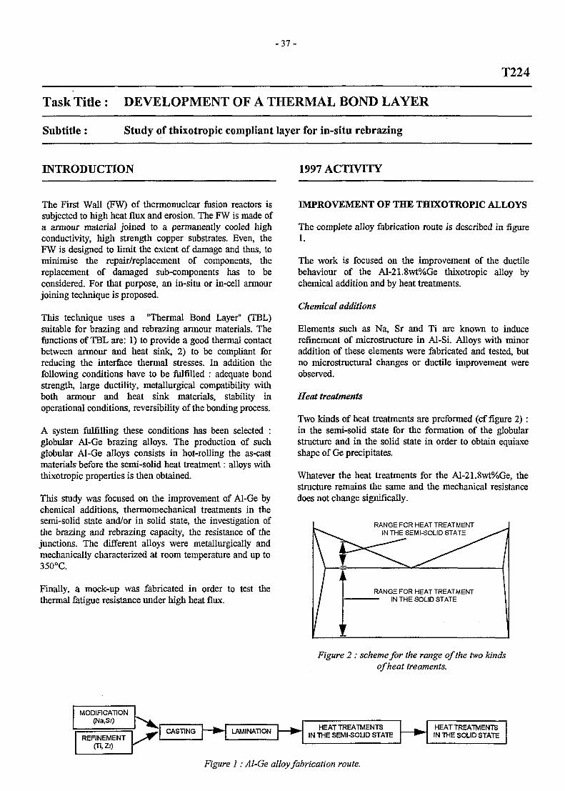
- 3 7 -
T224
Task Title : DEVELOPMENT OF A THERMAL BOND LAYER
Subtitle: Study of thixotropic compliant layer for in-situ rebrazing
INTRODUCTION 1997 ACTIVITY
The First Wall (FW) of thermonuclear fusion reactors issubjected to high heat flux and erosion. The FW is made ofa armour material joined to a permanently cooled highconductivity, high strength copper substrates. Even, theFW is designed to limit the extent of damage and thus, tominimise the repair/replacement of components, thereplacement of damaged sub-components has to beconsidered. For that purpose, an in-situ or in-cell armourjoining technique is proposed.
This technique uses a "Thermal Bond Layer" (TBL)suitable for brazing and rebrazing armour materials. Thefunctions of TBL are: 1) to provide a good thermal contactbetween armour and heat sink, 2) to be compliant forreducing the interface thermal stresses. In addition thefollowing conditions have to be fulfilled : adequate bondstrength, large ductility, metallurgical compatibility withboth armour and heat sink materials, stability inoperational conditions, reversibility of the bonding process.
A system fulfilling these conditions has been selected :globular Al-Ge brazing alloys. The production of suchglobular Al-Ge alloys consists in hot-rolling the as-castmaterials before the semi-solid heat treatment: alloys withthixotropic properties is then obtained.
This study was focused on the improvement of Al-Ge bychemical additions, thermomechanical treatments in thesemi-solid state and/or in solid state, the investigation ofthe brazing and rebrazing capacity, the resistance of thejunctions. The different alloys were metallurgically andmechanically characterized at room temperature and up to350°C.
Finally, a mock-up was fabricated in order to test thethermal fatigue resistance under high heat flux.
IMPROVEMENT OF THE THIXOTROPIC ALLOYS
The complete alloy fabrication route is described in figure1.
The work is focused on the improvement of the ductilebehaviour of the Al-21.8wt%Ge thixotropic alloy bychemical addition and by heat treatments.
Chemical additions
Elements such as Na, Sr and Ti are known to inducerefinement of microstructure in Al-Si. Alloys with minoraddition of these elements were fabricated and tested, butno microstructural changes or ductile improvement wereobserved.
Heat treatments
Two kinds of heat treatments are preformed (cf figure 2) :in the semi-solid state for the formation of the globularstructure and in the solid state in order to obtain equiaxeshape of Ge precipitates.
Whatever the heat treatments for the Al-21.8wt%Ge, thestructure remains the same and the mechanical resistancedoes not change significally.
RANGE FOR HEAT TREATMENTIN THE SEMI-SOLID STATE
RANGE FOR HEAT TREATMENT
Figure 2: scheme for the range of the two kindsof heat treaments.
MODIFICATION(Na,Sr)
REFINEMENT(Ti,Zr)
CASTING LAMINATIONHEATTREATMENTS
IN THE SEMI-SOUD STATE — • HEAT TREATMENTSIN THE SOLID STATE
Figure 1: Al-Ge alloy fabrication route.
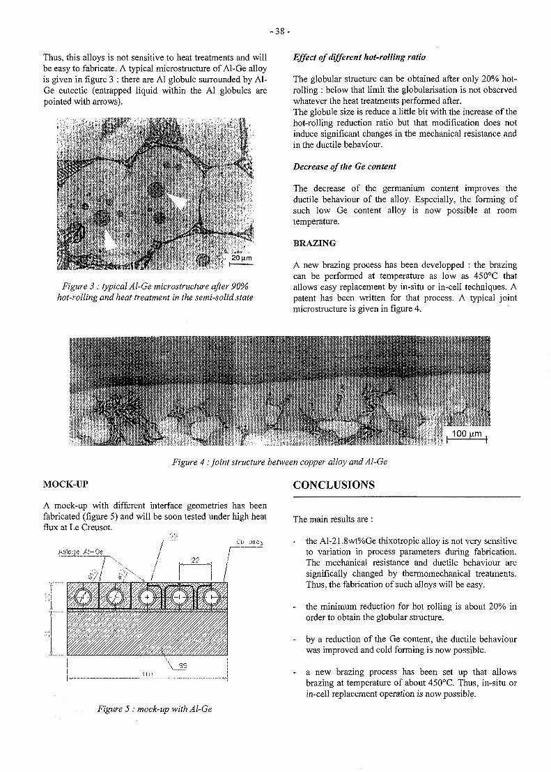
Thus, this alloys is not sensitive to heat treatments and willbe easy to fabricate. A typical microstructure of Al-Ge alloyis given in figure 3 : there are Al globule surrounded by Al-Ge eutectic (entrapped liquid within the Al globules arepointed with arrows).
Figure 3 : typical Al-Ge microstructure after 90%hot-rolling and heat treatment in the semi-solid state
Effect of different hot-rolling ratio
The globular structure can be obtained after only 20% hot-rolling : below that limit the globularisation is not observedwhatever the heat treatments performed after.The globule size is reduce a little bit with the increase of thehot-rolling reduction ratio but that modification does notinduce significant changes in the mechanical resistance andin the ductile behaviour.
Decrease of the Ge content
The decrease of the germanium content improves theductile behaviour of the alloy. Especially, the forming ofsuch low Ge content alloy is now possible at roomtemperature.
BRAZING
A new brazing process has been developped : the brazingcan be performed at temperature as low as 450°C thatallows easy replacement by in-situ or in-cell techniques. Apatent has been written for that process. A typical jointmicrostructure is given in figure 4.
• • • • >
MOCK-UP
Figure 4 : joint structure between copper alloy and Al-Ge
CONCLUSIONS
i- i
A mock-up with different interface geometries has beenfabricated (figure 5) and will be soon tested under high heatflux at Le Creusot.
The main results are :
- the Al-21.8wt%Ge thixotropic alloy is not very sensitiveto variation in process parameters during fabrication.The mechanical resistance and ductile behaviour aresignifically changed by thermomechanical treatments.Thus, the fabrication of such alloys will be easy.
- the minimum reduction for hot rolling is about 20% inorder to obtain the globular structure.
- by a reduction of the Ge content, the ductile behaviourwas improved and cold forming is now possible.
- a new brazing process has been set up that allowsbrazing at temperature of about 450°C. Thus, in-situ orin-cell replacement operation is now possible.
Figure 5 : mock-up with Al-Ge
- 3 9 -
The future direction of Al-Ge development will be focusedon cold and/or hot forming for complex shape bycompression or extrusion.
PUBLICATIONS
[1] J. Valer, P. Meneses, F. Saint-Antonin, M. Suery, G.Le Marois, "Development of a thermal bond layer :Study of compliant layer for in-situ rebrazing. Statuson the Improvement of the thixotropic alloy", ITERTask T224, Note Technique n°55/97, 1 October, 1997.
[2] J. Valer, P. Meneses, F. Saint-Antonin, M. Sue"ry, G.Le Marois, " Development of a thermal bond layer :Study of compliant layer for in-situ rebrazing. Dataproperties review on Al-Ge alloys", ITER Task T224,Note Technique n°79/97, 23 Dec. 1997.
[3] J. Valer, P. Meneses, F. Saint-Antonin, M. Suery,"Influence of processing on microstructure and semi-solid behavior ofAl-ge alloys", Conference on Semi-Solid Processing of Alloys and Composites, Colorado(USA), 23-25 June 1998.
[4] J. Valer, P. Meneses, F. Saint-Antonin, M. Sue'ry,"Developpement d'une brasure base Al-Ge acomportement thixotrope", Journees Franco-Espagnoles, Grenoble (France), 27-29 nov. 1997.
[5] J. Valer, P. Meneses, F. Saint-Antonin, M. Suery,"Status on the development of Al-Ge thixotropicbrazing alloys for plasma facing components", 20thSOFT Congress, Marseille (France) 7-11 sept. 1998.
TASK LEADER
F. SAINT-ANTONIN
DTA/DEM/SGMCEA grenoble 17, rue des Martyrs38054 Grenoble Cedex 9
Tel.Fax
04 76 88 54 770416 88 95 38
e-mail: antonin(8>chartreuse.cea.fr
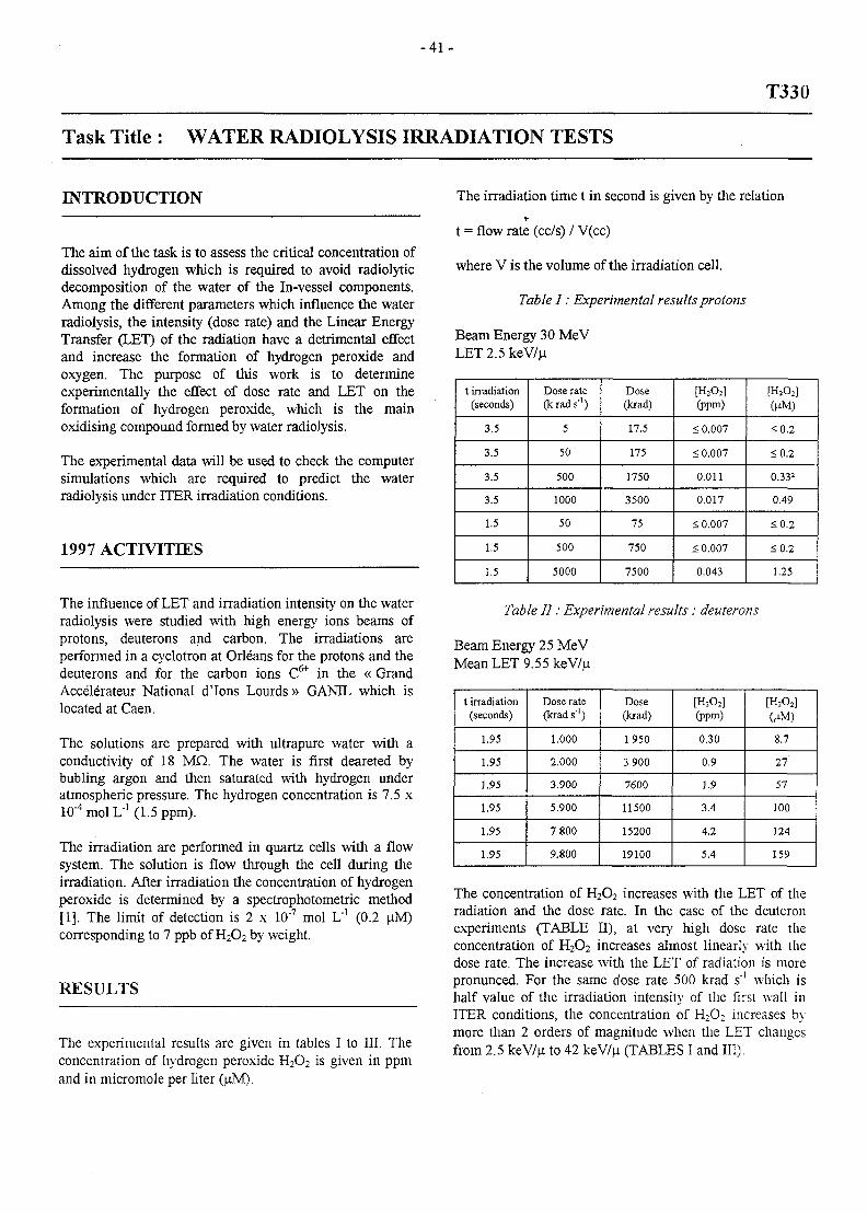
- 4 1 -
T330
Task Title : WATER RADIOLYSIS IRRADIATION TESTS
INTRODUCTION
The aim of the task is to assess the critical concentration ofdissolved hydrogen which is required to avoid radiolyticdecomposition of the water of the In-vessel components.Among the different parameters which influence the waterradiolysis, the intensity (dose rate) and the Linear EnergyTransfer (LET) of the radiation have a detrimental effectand increase the formation of hydrogen peroxide andoxygen. The purpose of this work is to determineexperimentally the effect of dose rate and LET on theformation of hydrogen peroxide, which is the mainoxidising compound formed by water radiolysis.
The experimental data will be used to check the computersimulations which are required to predict the waterradiolysis under ITER irradiation conditions.
1997 ACTIVITIES
The influence of LET and irradiation intensity on the waterradiolysis were studied with high energy ions beams ofprotons, deuterons and carbon. The irradiations areperformed in a cyclotron at Orleans for the protons and thedeuterons and for the carbon ions C6+ in the « GrandAccel6rateur National d'lons Lourds » GANIL which islocated at Caen.
The solutions are prepared with ultrapure water with aconductivity of 18 MQ. The water is first deareted bybubling argon and then saturated with hydrogen underatmospheric pressure. The hydrogen concentration is 7.5 x10"4 mol L"1 (1.5 ppm).
The irradiation are performed in quartz cells with a flowsystem. The solution is flow through the cell during theirradiation. After irradiation the concentration of hydrogenperoxide is determined by a spectrophotometric method[1]. The limit of detection is 2 x 10"7 mol L'1 (0.2 uM)corresponding to 7 ppb of H2O2 by weight.
RESULTS
The experimental results are given in tables I to III. Theconcentration of hydrogen peroxide H2O2 is given in ppmand in micromole per liter (uM).
The irradiation time t in second is given by the relation
t = flow rate (cc/s) / V(cc)
where V is the volume of the irradiation cell.
Table I: Experimental results protons
Beam Energy 30 MeVLET 2.5 keV/p.
t irradiation(seconds)
3.5
3.5
3.5
3.5
1.5
1.5
1.5
Dose rale(krads"1)
5
50
500
1000
50
500
5000
Dose(krad)
17.5
175
1750
3500
75
750
7500
[H2O2](ppm)
< 0.007
< 0.007
0.011
0.017
< 0.007
< 0.007
0.043
[H2O2](HM)
<0.2
<0.2
0.332
0.49
<0.2
<0.2
1.25
Table II: Experimental results : deuterons
Beam Energy 25 MeVMean LET 9.55 keV/u
t irradiation(seconds)
1.95
1.95
1.95
1.95
1.95
1.95
Dose rate(krad s"')
1.000
2.000
3.900
5.900
7 800
9.800
Dose(krad)
1950
3 900
7600
11500
15200
19100
[H2O2](ppm)
0.30
0.9
1.9
3.4
4.2
5.4
[H2O2]
OM)
8.7
27
57
100
124
159
The concentration of H2O2 increases with the LET of theradiation and the dose rate. In the case of the deuteronexperiments (TABLE II), at very high dose rate theconcentration of H2O2 increases almost linearly with thedose rate. The increase with the LET of radiation is morepronunced. For the same dose rate 500 krad s"' which ishalf value of the irradiation intensity of the first wall inITER conditions, the concentration of H2O: increases bymore than 2 orders of magnitude when the LET changesfrom 2.5 keV/u to 42 keV/n (TABLES I and III).
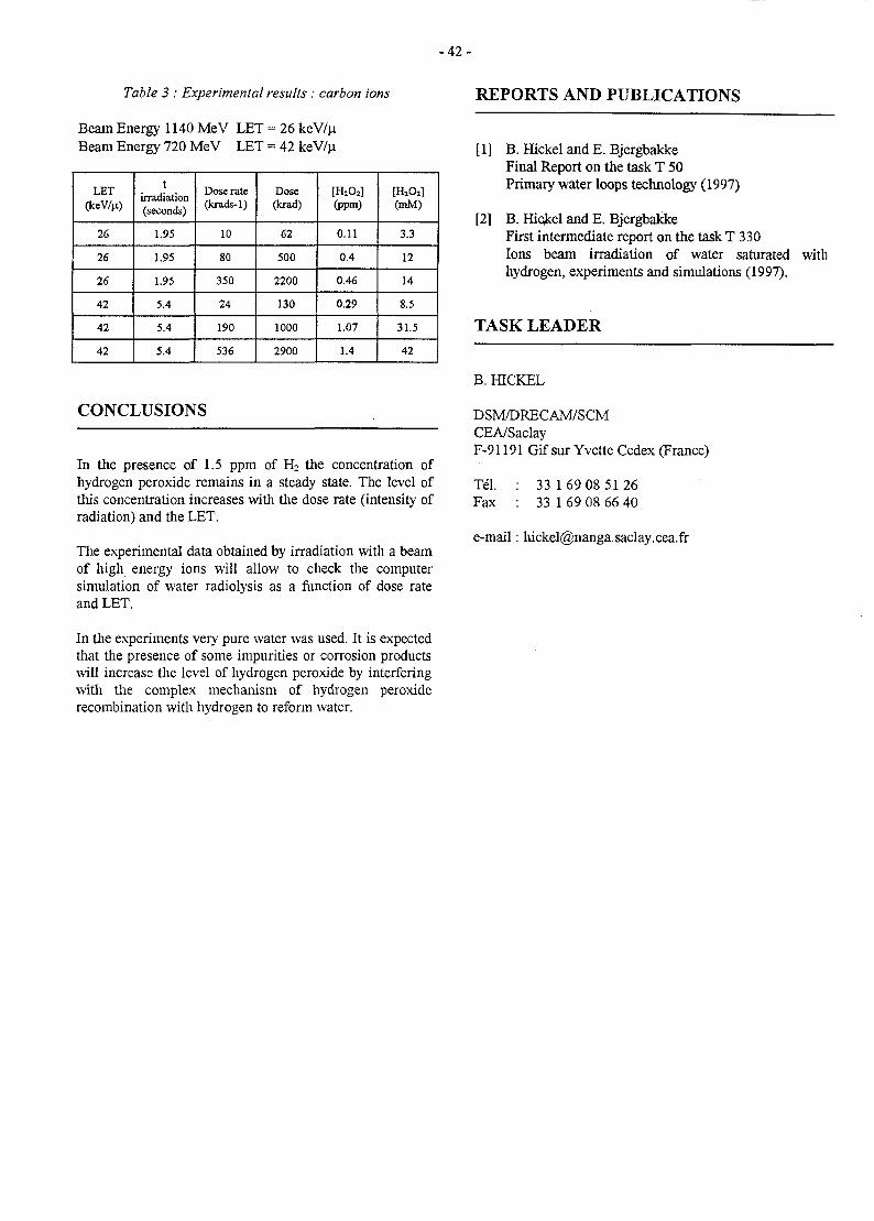
- 4 2 -
Table 3 : Experimental results : carbon ions
Beam Energy 1140 MeV LET = 26 keV/p.Beam Energy 720 MeV LET = 42 keV/n
LET(keV/n)
26
26
26
42
42
42
tirradiation(seconds)
1.95
1.95
1.95
5.4
5.4
5.4
Dose rate(krads-1)
10
80
350
24
190
536
Dose(krad)
62
500
2200
130
1000
2900
[H2O2](ppm)
0.11
0.4
0.46
0.29
1.07
1.4
[H2O2](mM)
3.3
12
14
8.5
31.5
42
CONCLUSIONS
In the presence of 1.5 ppm of H2 the concentration ofhydrogen peroxide remains in a steady state. The level ofthis concentration increases with the dose rate (intensity ofradiation) and the LET.
The experimental data obtained by irradiation with a beamof high energy ions will allow to check the computersimulation of water radiolysis as a function of dose rateand LET.
REPORTS AND PUBLICATIONS
[1] B. Hickel and E. BjergbakkeFinal Report on the task T 50Primary water loops technology (1997)
[2] B. Hickel and E. BjergbakkeFirst intermediate report on the task T 330Ions beam irradiation of water saturated withhydrogen, experiments and simulations (1997).
TASK LEADER
B. HICKEL
DSM/DRECAM/SCMCEA/SaclayF-91191 Gif sur Yvette Cedex (France)
Tel. : 33 169 08 5126Fax : 33 1 69 08 66 40
e-mail : [email protected]
In the experiments very pure water was used. It is expectedthat the presence of some impurities or corrosion productswill increase the level of hydrogen peroxide by interferingwith the complex mechanism of hydrogen peroxiderecombination with hydrogen to reform water.
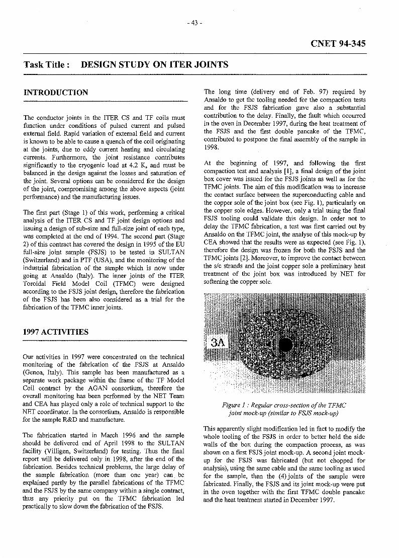
- 4 3 -
CNET 94-345
Task Title : DESIGN STUDY ON ITER JOINTS
INTRODUCTION
The conductor joints in the ITER CS and TF coils mustfunction under conditions of pulsed current and pulsedexternal field. Rapid variation of external field and currentis known to be able to cause a quench of the coil originatingat the joints, due to eddy current heating and circulatingcurrents. Furthermore, the joint resistance contributessignificantly to the cryogenic load at 4.2 K, and must bebalanced in the design against the losses and saturation ofthe joint. Several options can be considered for the designof the joint, compromising among the above aspects (jointperformance) and the manufacturing issues.
The first part (Stage 1) of this work, performing a criticalanalysis of the ITER CS and TF joint design options andissuing a design of sub-size and full-size joint of each type,was completed at the end of 1994. The second part (Stage2) of this contract has covered the design in 1995 of the EUfull-size joint sample (FSJS) to be tested in SULTAN(Switzerland) and in PTF (USA), and the monitoring of theindustrial fabrication of the sample which is now undergoing at Ansaldo (Italy). The inner joints of the ITERToroidal Field Model Coil (TFMC) were designedaccording to the FSJS joint design, therefore the fabricationof the FSJS has been also considered as a trial for thefabrication of the TFMC inner joints.
1997 ACTIVITIES
Our activities in 1997 were concentrated on the technicalmonitoring of the fabrication of the FSJS at Ansaldo(Genoa, Italy). This sample has been manufactured as aseparate work package within the frame of the TF ModelCoil contract by the AGAN consortium, therefore theoverall monitoring has been performed by the NET Teamand CEA has played only a role of technical support to theNET coordinator. In the consortium, Ansaldo is responsiblefor the sample R&D and manufacture.
The fabrication started in March 1996 and the sampleshould be delivered end of April 1998 to the SULTANfacility (Villigen, Switzerland) for testing. Thus the finalreport will be delivered only in 1998, after the end of thefabrication. Besides technical problems, the large delay ofthe sample fabrication (more than one year) can beexplained partly by the parallel fabrications of the TFMCand the FSJS by the same company within a single contract,thus any priority put on the TFMC fabrication ledpractically to slow down the fabrication of the FSJS.
The long time (delivery end of Feb. 97) required byAnsaldo to get the tooling needed for the compaction testsand for the FSJS fabrication gave also a substantialcontribution to the delay. Finally, the fault which occurredin the oven in December 1997, during the heat treatment ofthe FSJS and the first double pancake of the TFMC,contributed to postpone the final assembly of the sample in1998.
At the beginning of 1997, and following the firstcompaction test and analysis [1], a final design of the jointbox cover was issued for the FSJS joints as well as for theTFMC joints. The aim of this modification was to increasethe contact surface between the superconducting cable andthe copper sole of the joint box (see Fig. 1), particularly onthe copper sole edges. However, only a trial using the finalFSJS tooling could validate this design. In order not todelay the TFMC fabrication, a test was first carried out byAnsaldo on the TFMC joint, the analyse of this mock-up byCEA showed that the results were as expected (see Fig. 1),therefore the design was frozen for both the FSJS and theTFMC joints [2], Moreover, to improve the contact betweenthe s/c strands and the joint copper sole a preliminary heattreatment of the joint box was introduced by NET forsoftening the copper sole.
3A
Figure 1: Regular cross-section of the TFMCjoint mock-up (similar to FSJS mock-up)
This apparently slight modification led in fact to modify thewhole tooling of the FSJS in order to better hold the sidewalls of the box during the compaction process, as wasshown on a first FSJS joint mock-up. A second joint mock-up for the FSJS was fabricated (but not chopped foranalysis), using the same cable and the same tooling as usedfor the sample, then the (4) joints of the sample werefabricated. Finally, the FSJS and its joint mock-up were putin the oven together with the first TFMC double pancakeand the heat treatment started in December 1997.
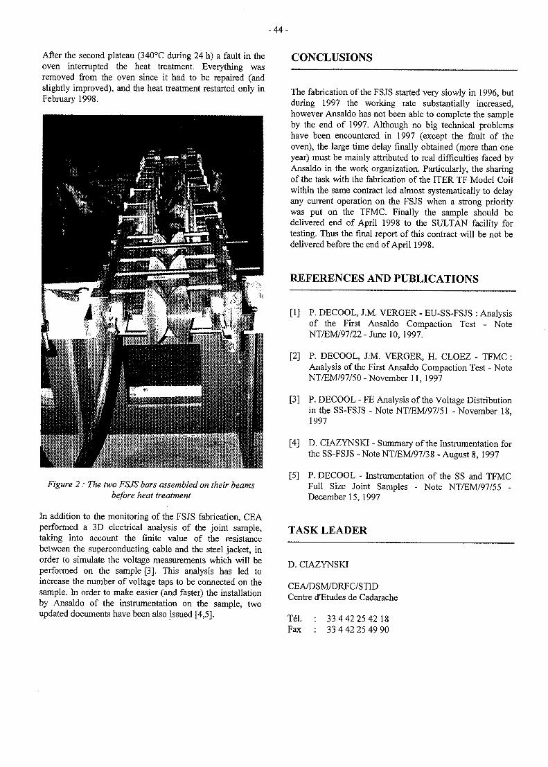
- 4 4 -
After the second plateau (340°C during 24 h) a fault in theoven interrupted the heat treatment. Everything wasremoved from the oven since it had to be repaired (andslightly improved), and the heat treatment restarted only inFebruary 1998.
CONCLUSIONS
Figure 2 : The two FSJS bars assembled on their beamsbefore heat treatment
In addition to the monitoring of the FSJS fabrication, CEAperformed a 3D electrical analysis of the joint sample,taking into account the finite value of the resistancebetween the superconducting cable and the steel jacket, inorder to simulate the voltage measurements which will beperformed on the sample [3]. This analysis has led toincrease the number of voltage taps to be connected on thesample. In order to make easier (and faster) the installationby Ansaldo of the instrumentation on the sample, twoupdated documents have been also issued [4,5].
The fabrication of the FSJS started very slowly in 1996, butduring 1997 the working rate substantially increased,however Ansaldo has not been able to complete the sampleby the end of 1997. Although no big technical problemshave been encountered in 1997 (except the fault of theoven), the large time delay finally obtained (more than oneyear) must be mainly attributed to real difficulties faced byAnsaldo in the work organization. Particularly, the sharingof the task with the fabrication of the ITER TF Model Coilwithin the same contract led almost systematically to delayany current operation on the FSJS when a strong prioritywas put on the TFMC. Finally the sample should bedelivered end of April 1998 to the SULTAN facility fortesting. Thus the final report of this contract will be not bedelivered before the end of April 1998.
REFERENCES AND PUBLICATIONS
[1] P. DECOOL, J.M. VERGER - EU-SS-FSJS : Analysisof the First Ansaldo Compaction Test - NoteNT/EM/97/22 - June 10,1997.
[2] P. DECOOL, J.M. VERGER, H. CLOEZ - TFMC :Analysis of the First Ansaldo Compaction Test - NoteNT/EM/97/50 - November 11, 1997
[3] P. DECOOL - FE Analysis of the Voltage Distributionin the SS-FSJS - Note NT/EM/97/51 - November 18,1997
[4] D. CIAZYNSKI - Summary of the Instrumentation forthe SS-FSJS - Note NT/EM/97/38 - August 8, 1997
[5] P. DECOOL - Instrumentation of the SS and TFMCFull Size Joint Samples - Note NT/EM/97/55 -December 15,1997
TASK LEADER
D. CIAZYNSKI
CEA/DSM/DRFC/STIDCentre d'Etudes de Cadarache
Tel. : 33 4 42 25 42 18Fax : 33 4 42 25 49 90
- 4 5 -
CNET 96-409
Task Title : ITER CRYOPLANT DESIGN EVALUATION
INTRODUCTION
The ITER cryoplant can be considered as a quite largeextrapolation with respect to the worldwide previouslybuilt and tested helium refrigeration plants.
The total cooling capacity of about 120 KW is around 6time larger than the largest existing helium refrigerators.
The typical working conditions of a tokamak machinecaracterized by a pulsed cryogenic load are quiteincompatible with a safe and efficient operation of thecryogenic refrigerators.
A large scattering between the various operating duties(cooling down, standby or full power operation) asks for alarge operational flexibility.
Due to the relevant experience available within theEUROPEAN COMMUNITY, first, for the design andoperation of the TORE SUPRA tokamak, then, for thebuilding at CERN of large cryogenic plants for the LEPand LHC particule accelerators with the support ofindustrial firms (Air Liquide and Linde), the ITER jointcentral team has requested support from the EUROPEANhome team to get technical assistance for the ITERcryoplant design.
1997 ACTIVITY
DESCRIPTION OF ACTIVITY
The main topics reported here after were investigated in afruitfull collaboration between, on one side, theEUROPEAN COMMUNITY represented by :
- le Service des Basses Temperatures - CEA Grenoble,France,
- the LHC cryogenic group at CERN for visits anddiscutions and
on the other side, the Naka joint central team with :
- The cryogenic group.
- The magnet group.
Pulsed operation and cooling capacity adjustment:
t
The very large energy dissipated in the cryogenic systemafter every pulsed operation (45 MJ in the conductors and65 MJ in cases and structures) has to be stored for a whilebefore releasing to the refrigerator working as much aspossible with constant load.
The use of additional helium storage dewar operated atconstant volume was first investigated but finally notrecommended (several hundred cubic meters needed).
The adopted solution was to keep the pulsed energy storedwhere it is deposited (coils, cases and structures) thenremoving it by controling several independant coolingcircuits with the relevant algorithm and the adequathierarchy in order to avoid coil quenching (priority givento the more dangerous cooling circuits) while keepingconstant load to the refrigerator (cooling power shifted intime from one cooling circuit to the other).
A second issue was to provide the capability for therefrigerator to adapt its cooling capacity to the right valueresulting from the operating scenario in concern with theexperimental parameters applied to the machine.
Taking into account the industrial experience validated inEurope (mainly at CERN) the solution was to use threedifferent ways with graduated time constant:
- For short period of time or for periodic capacity check :Electrical heater.
- For few hours transient regimes : LHe storage dewarwith warying liquid level.
- For daily adjustment versus expected operatingscenario: cooling cycle operating pressure (orcorresponding mass flow rate) adjusted from 11 b forstandby to 19 b for normal operation.
(See for reference : ITER cryoplant and magnet systemcontrol for pulsed operation. Note SBT/CT/97-32. July1997 by G. Claudet, P. Roussel and V. Kalinin).
80 K refrigeration plant for ITER thermal shields
The needed 80 K refrigeration capacity is 500 KW innormal operation with an additional load of 300 KW forplasma vessel baking.
To avoid risk of activation, nitrogen has to be avoidedinside the machine where only helium can be accepted as acoolant.
- 4 6 -
In close contact with industry (Air Liquide subcontract) aproposal was given in which the main parts are :
- A helium closed loop with a 5 kg/s room temperaturecirculator, a counterfiow heat exchanger and a 80 Kcooling cryostat with heat transfer capability fromhelium loop to liquid nitrogen.
- A 500 KW nitrogen refrigeration cycle using highefficiency and high reliability technics currentlyadopted for large size air separation plants.
- Additional liquid nitrogen consumption can beaccepted for providing extra 300 KW refrigerationcapacity for plasma vessel baking by about one day timeto time.
The corresponding LN2 consumption of about 80.000 1 canbe in situ produced from air processing plant but can bepreferably buy on the market and stored in a 100.000 1storage dewar.
Fast cooling of the torus cryopumps
Due to tritium inventory any of the 16 cryopanels has to beregenerated by degassing near 80 K then cooled again at 4K in a time cycle of about 5 minutes.
In the previously proposed solution using 300 K heliumgaz for fast heating and liquid helium filling for fastcooling the equivalent power consumption at 4 K was 37KW.
A more advanced proposal was made to save energy byconsidering serial coupling between one pump to be heatedand an other one to be cooled in order to directly transferenthalpy from one to the other.
This new solution expected to limit the power consumptionin between 6 to 10 KW is presently investigated by theEuropean home team with the Grenoble group as aconsultant.
Detailed design and lay out
Technical assistance was given to the JCT Naka group bytransmitting information concerning key issues in thecryoplant and cryodistribution system.
The lay out of compressor set stations and the size andshape of cold boxes was addressed by taking into accountthe European state of the art.
The general concept and design of transfer lines andmanifolds as well as of auxiliary cryostat cold boxes wasreviewed and discussed.
Detailed design description writting and cost estimate
The final version of the document DDD 3.4 (cryoplant andcryodistribution system) was analysed and reviewed inclose contact with the JCT Naka group.
Two specific topics were more specially addressed :
- The needed R and D programm with three mainpoints:
. Operational experience with cold pumps orcirculators.
. Current leads at nominal size with variable crosssection and self controlled coolant flow rate.
. Behaviour of large size cold boxes operated inparallel connexion with transient regimes to befaced with.
- The cost estimate for the cryoplant and cryodistributionsystem was assessed on the basis of the Europeanmarket giving as a result a cost saving of about 45%with respect to the previous one, thanks to the newdesign options based on previous experience andexisting standards.
TASK LEADER
Gerard CLAUDET
DSM/DRFMC/Service des Basses TemperaturesCEA Grenoble38054 GRENOBLE Cedex 9, France.
Tel.Fax
04 76 88 43 6004 76 88 5186
e-mail: claudet @ drfmc.ceng.cea.fr
- 4 7 -
CNET 96-432
Task Title: TECHNICAL SPECIFICATIONS FOR MODELLING, TESTINGAND ANALYSIS OF FULL SIZE ITER JOINTS
INTRODUCTION
In the frame of the NET contract #94-345, CEA was incharge of designing the EU proposal of joints for ITER.Within this contract a full size prototype sample (FSJS)was designed. Two joint samples are now beingmanufactured in industry, the so-called SS-FSJS andTFMC-FSJS, in the frame of the TF Model Coilmanufacture, under technical monitoring by CEA. Duringthis phase an important experience has been gained onjoint designing. Considerations on manufacturing processand assembly in relation with heat treatment, analyses ofpulsed field losses and DC electrical resistance, have led tothe present twin box concept which has been retained byITER. Taking into account this concept, further work isneeded to model the behaviour of such a joint, as well inDC as in AC conditions. This work has to be done in astrong coordination with the test of the manufactured jointsin order to assess the model with the experiments.
Contract 96-432 is dedicated to the modelling of the DCbehaviour of the joint and to interpretation and analysis oftest results of the two above full size joints. In addition,this contract covers the participation of CEA in the testsand in the data analyses of these two EU full-size jointsamples : the SS-FSJS in PTF (MIT, Boston) and inSULTAN (Villigen, Switzerland), and the TFMC-FSJS inSULTAN.
1997 ACTIVITIES
Our activities in 1997 were concentrated on the DCmodelling of the joint and the application to ITER ToroidalField coils, since the fabrication of the first sample (SS-FSJS) could not be completed in 1997 at Ansaldo (seeCNET 94-345).
PART (I) : PRELIMINARY ASSESSMENT OF THEAVAILABLE ANALYSIS METHODS : SELECTIONOF MODELLING TECHNIQUES [1]
A DC electrical model for the joint has been built. Thismodel is based on the statistics of contact points betweenthe superconducting strands and the copper sole of thejoint box. Geometrical measurements performed on a 144strand cable, similar to an ITER main subcable, have led tothe statistics of contact points per strand in this cable. Themain results are a substantial proportion of unconnectedstrands (20% to 40%, depending on cable connected
length) and a standard deviation in the range of the meanvalue. Then assuming the joint resistance of each strand tobe proportional to the number of contact points, which is arealistic hypothesis, we have been able to draw thestatistics for the joint resistance per strand. This processhas finally led to a series resistance distribution to beassociated with the cable strands. Moreover, in order to getresults more relevant to the ITER coils, the basic resultshad to be interpolated taking into account the expectedcontact length between a main subcable and the coppersole in an ITER joint.
The main problem to be solved for the ITER coils is theprediction of the current distribution among the strands ofthe cable, particularly at the peak magnetic field location.Indeed, an uneven current distribution means overloadedstrands which can lead eventually to a degradation of thewhole cable performances. In order to estimate the currentdistribution along a conductor length, one must model thewhole length associated with one half-joint at each end.Our preliminary study lias been completed by such acalculation in the case when no superconducting strand issaturated in current (linear analysis), i.e. when the voltagedrops along the s/c strands can be neglected [1].
From this analysis, it could be concluded that highoverloaded factors (> 2) can be expected in a substantialproportion (» 20%) of strands in the peak field length ofthe ITER TF coils. This result is partly due to the fact thatthe peak field length is close to the inner joint of the coil,thus the proportion drops to 6.5% in the mid-length of thepancake thanks to current redistribution throughinterstrand resistances. However, it should be noted thatsuch a result is only valid up to 40% of the of the averagecritical current while the ITER TF coils will operate atabout 60% of their critical current, therefore only a non-linear analysis can be used to predict the currentdistribution in ITER coils at their nominal operatingconditions.
A simplified electrical model has been proposed in [1] inorder to reduce the size of the electrical network needed forthe non-linear analysis. The idea has been to group thestrands into statistical bundles associated with seriesresistance distributions at joints. A preliminary assessmenthas shown that at least six bundles were needed to get areasonable accuracy, an eight bundle model can lead to animprovement of accuracy without increasing too much thefinal size of the network, but a subsequent improvementcan only be obtained by going up to twenty bundles whichnot worth increasing so much the computing time at thisearly stage of the study.
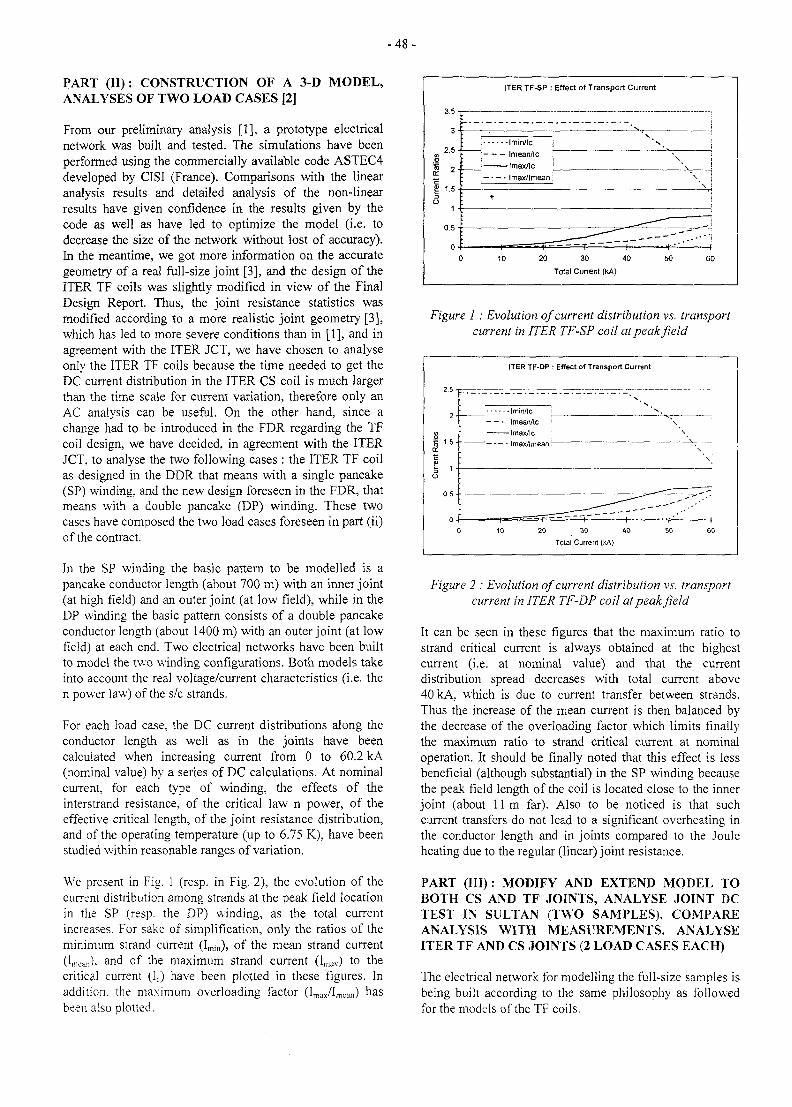
- 4 8 -
PART (II): CONSTRUCTION OF A 3-D MODEL,ANALYSES OF TWO LOAD CASES [2]
From our preliminary analysis [1], a prototype electricalnetwork was built and tested. The simulations have beenperformed using the commercially available code ASTEC4developed by CISI (France). Comparisons with the linearanalysis results and detailed analysis of the non-linearresults have given confidence in the results given by thecode as well as have led to optimize the model (i.e. todecrease the size of the network without lost of accuracy).In the meantime, we got more information on the accurategeometry of a real full-size joint [3], and the design of theITER TF coils was slightly modified in view of the FinalDesign Report. Thus, the joint resistance statistics wasmodified according to a more realistic joint geometry [3],which has led to more severe conditions than in [1], and inagreement with the ITER JCT, we have chosen to analyseonly the ITER TF coils because the time needed to get theDC current distribution in the ITER CS coil is much largerthan the time scale for current variation, therefore only anAC analysis can be useful. On the other hand, since achange had to be introduced in the FDR regarding the TFcoil design, we have decided, in agreement with the ITERJCT. to analyse the two following cases : the ITER TF coilas designed in the DDR that means with a single pancake(SP) winding, and the new design foreseen in the FDR, thatmeans with a double pancake (DP) winding. These twocases have composed the two load cases foreseen in part (ii)of the contract.
In the SP winding the basic pattern to be modelled is apancake conductor length (about 700 m) with an inner joint(at high field) and an outer joint (at low field), while in theDP winding the basic pattern consists of a double pancakeconductor length (about 1400 m) with an outer joint (at lowfield) at each end. Two electrical networks have been builtto model the two winding configurations. Both models takeinto account the real voltage/current characteristics (i.e. then power law) of the s/c strands.
For each load case, the DC current distributions along theconductor length as well as in the joints have beencalculated when increasing current from 0 to 60.2 kA(nominal value) by a series of DC calculations. At nominalcurrent, for each type of winding, the effects of theinterstrand resistance, of the critical law n power, of theeffective critical length, of the joint resistance distribution,and of the operating temperature (up to 6.75 K), have beenstudied within reasonable ranges of variation.
We present in Fig. 1 (resp. in Fig. 2), the evolution of thecurrent distribution among strands at the peak field locationin the SP (resp. the DP) winding, as the total currentincreases. For sake of simplification, only the ratios of theminimum strand current (Imin), of the mean strand current(Imean)- and °f t n e maximum strand current (lmax) to thecritical current (Ic) have been plotted in these figures. Inaddition, the maximum overloading factor (Imax/lmean) hasbeen also plotted.
ITER TF-SP : Effect of Transport Current
3.5
3
2.5
g 1.5
o1
0.5
0
! Imin/lc
; Imean/lc
\ Imax/tc: Imax/lmean
r
T "
_ — -, ""
N
\
\
" " " . - • • • '
• • • > " (
20 30 40
Total Current (kA)
Figure 1 : Evolution of current distribution vs. transportcurrent in ITER TF-SP coil at peak field
ITER TF-DP : Effect of Transport Current
2.5 TL
2•Imin/lc
tmean/lc !
Imax/lc :
~ —' — Imax/lmean
20 30 40
Tolal Current (kA)
Figure 2 : Evolution of current distribution vs. transportcurrent in ITER TF-DP coil at peak field
It can be seen in these figures that the maximum ratio tostrand critical current is always obtained at the highestcurrent (i.e. at nominal value) and that the currentdistribution spread decreases with total current above40 kA, which is due to current transfer between strands.Thus the increase of the mean current is then balanced bythe decrease of the overloading factor which limits finallythe maximum ratio to strand critical current at nominaloperation. It should be finally noted that this effect is lessbeneficial (although substantial) in the SP winding becausethe peak field length of the coil is located close to the innerjoint (about 11 m far). Also to be noticed is that suchcurrent transfers do not lead to a significant overheating inthe conductor length and in joints compared to the Jouleheating due to the regular (linear) joint resistance.
PART a i l ) : MODIFY AND EXTEND MODEL TOBOTH CS AND TF JOINTS, ANALYSE JOINT DCTEST IN SULTAN (TWO SAMPLES), COMPAREANALYSIS WITH MEASUREMENTS. ANALYSEITER TF AND CS JOINTS (2 LOAD CASES EACH)
The electrical network for modelling the full-size samples isbeing built according to the same philosophy as followedfor the models of the TF coils.
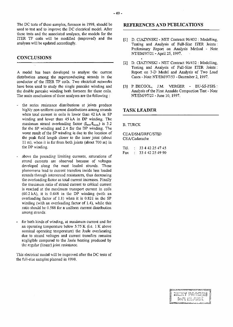
- 4 9 -
The DC tests of these samples, foreseen in 1998, should beused to test and to improve the DC electrical model. Afterthese tests and the associated analyses, the models for theITER TF coils will be modified (improved) and theanalyses will be updated accordingly.
CONCLUSIONS
A model has been developed to analyse the currentdistribution among the superconducting strands in theconductor of the ITER TF coils. Two electrical networkshave been used to study the single pancake winding andthe double pancake winding both foreseen for these coils.The main conclusions of these analyses are the following :
- the series resistance distributions at joints producehighly non-uniform current distributions among strandswhen total current in coils is lower than 42 kA in SPwinding and lower than 45 kA in DP winding. Themaximum strand overloading factor (I,nax/Imean) is 3.2for the SP winding and 2.4 for the DP winding. Theworst result of the SP winding is due to the location ofthe peak field length closer to the inner joint (about11 m), when it is far from both joints (about 700 m) inthe DP winding.
- above the preceding limiting currents, saturations ofstrand currents are observed because of voltagesdeveloped along the most loaded strands. Thesephenomena lead to current transfers inside less loadedstrands through interstrand resistances, thus decreasingthe overloading factor as total current increases. Finallythe maximum ratio of strand current to critical currentis reached at the maximum transport current in coils(60.2 kA), it is 0.648 in the DP winding (with anoverloading factor of 1.1) when it is 0.821 in the SPwinding (with an overloading factor of 1.4), while thisratio should be 0.588 for a uniform current distributionamong strands.
- for both kinds of winding, at maximum current and foran operating temperature below 5.75 K (i.e. 1 K abovenominal operating temperature) the Joule overheatingdue to strand voltages and current transfers remainsnegligible compared to the Joule heating produced bythe regular (linear) joint resistance.
This electrical model will be improved after the DC tests ofthe full-size samples planned in 1998.
REFERENCES AND PUBLICATIONS
[1] D. CIAZYNSKI - NET Contract 96/432 : Modelling,Testing and Analysis of Full-Size ITER Joints:Preliminary Report on Analysis Method - NoteNT/EM/97/21 - April 25, 1997.
r
[2] D. CIAZYNSKI - NET Contract 96/432 : Modelling,Testing and Analysis of Full-Size ITER Joints :Report on 3-D Model and Analysis of Two LoadCases - Note NT/EM/97/53 - December 2, 1997.
[3] P. DECOOL, J.M. VERGER - EU-SS-FSJS:Analysis of the First Ansaldo Compaction Test - NoteNT/EM/97/22 - June 10, 1997.
TASK LEADER
B. TURCK
CEA/DSM/DRFC/STEDCEA/Cadarache
Tel. : 33 4 42 25 47 45Fax : 33 4 42 25 49 90
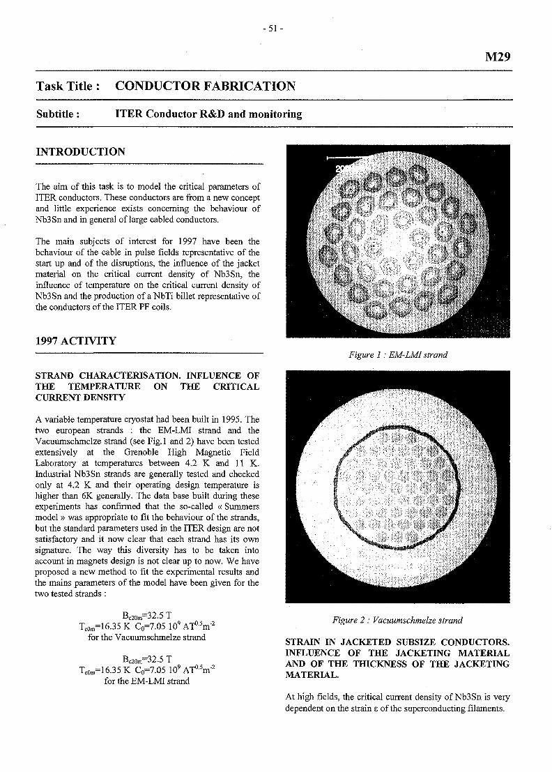
- 5 1 -
M29
Task Title : CONDUCTOR FABRICATION
Subtitle : ITER Conductor R&D and monitoring
INTRODUCTION
The aim of this task is to model the critical parameters ofITER conductors. These conductors are from a new conceptand little experience exists concerning the behaviour ofNb3Sn and in general of large cabled conductors.
The main subjects of interest for 1997 have been thebehaviour of the cable in pulse fields representative of thestart up and of the disruptions, the influence of the jacketmaterial on the critical current density of Nb3Sn, theinfluence of temperature on the critical current density ofNb3Sn and the production of aNbTi billet representative ofthe conductors of the ITER PF coils.
1997 ACTIVITY
STRAND CHARACTERISATION. INFLUENCE OFTHE TEMPERATURE ON THE CRITICALCURRENT DENSITY
A variable temperature cryostat had been built in 1995. Thetwo european strands : the EM-LMI strand and theVacuumschmelze strand (see Fig.l and 2) have been testedextensively at the Grenoble High Magnetic FieldLaboratory at temperatures between 4.2 K and 11 K.Industrial Nb3Sn strands are generally tested and checkedonly at 4.2 K and their operating design temperature ishigher than 6K generally. The data base built during theseexperiments has confirmed that the so-called « Summersmodel» was appropriate to fit the behaviour of the strands,but the standard parameters used in the ITER design are notsatisfactory and it now clear that each strand has its ownsignature. The way this diversity has to be taken intoaccount in magnets design is not clear up to now. We haveproposed a new method to fit the experimental results andthe mains parameters of the model have been given for thetwo tested strands:
Bc2Ora=32.5 TTc0m=16.35K C0=7.05 10'
for the Vacuumschmelze strandATa5m"2
Bc20m=32.5 TTc0m=16.35K C0=7.05 109ATa5m":
for the EM-LMI strand
Figure 1: EM-LMI strand
Figure 2 : Vacuumschmelze strand
STRAIN IN JACKETED SUBSIZE CONDUCTORS.INFLUENCE OF THE JACKETING MATERIALAND OF THE THICKNESS OF THE JACKETINGMATERIAL.
At high fields, the critical current density of Nb3Sn is verydependent on the strain e of the superconducting filaments.
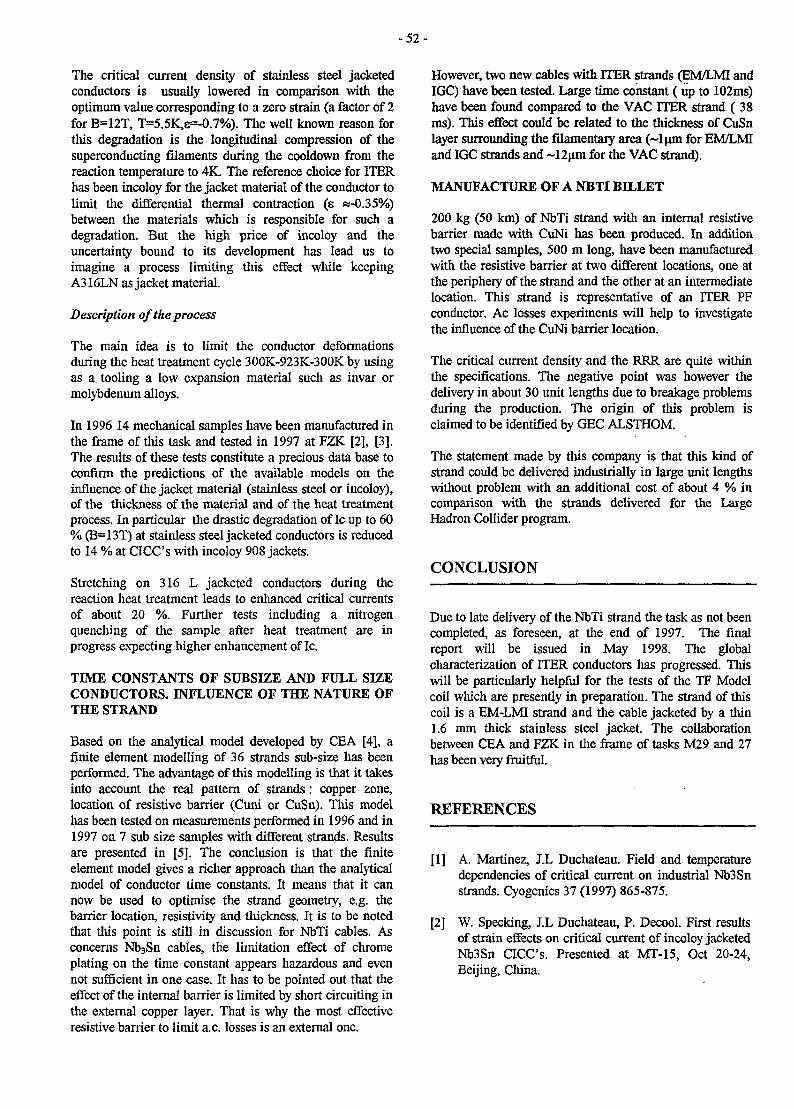
- 5 2 -
The critical current density of stainless steel jacketedconductors is usually lowered in comparison with theoptimum value corresponding to a zero strain (a factor of 2for B=12T, T=5.5K,8=-0.7%). The well known reason forthis degradation is the longitudinal compression of thesuperconducting filaments during the cooldown from thereaction temperature to 4K. The reference choice for ITERhas been incoloy for the jacket material of the conductor tolimit the differential thermal contraction (e «-0.35%)between the materials which is responsible for such adegradation. But the high price of incoloy and theuncertainty bound to its development has lead us toimagine a process limiting this effect while keepingA316LN as jacket material.
Description of the process
The main idea is to limit the conductor deformationsduring the heat treatment cycle 300K-923K-300K by usingas a tooling a low expansion material such as invar ormolybdenum alloys.
In 1996 14 mechanical samples have been manufactured inthe frame of this task and tested in 1997 at FZK [2], [3].The results of these tests constitute a precious data base toconfirm the predictions of the available models on theinfluence of the jacket material (stainless steel or incoloy),of the thickness of the material and of the heat treatmentprocess. In particular the drastic degradation of Ic up to 60% (B=13T) at stainless steel jacketed conductors is reducedto 14 % at CICC's with incoloy 908 jackets.
Stretching on 316 L jacketed conductors during thereaction heat treatment leads to enhanced critical currentsof about 20 %. Further tests including a nitrogenquenching of the sample after heat treatment are inprogress expecting higher enhancement of Ic.
TIME CONSTANTS OF SUBSIZE AND FULL SIZECONDUCTORS. INFLUENCE OF THE NATURE OFTHE STRAND
Based on the analytical model developed by CEA [4], afinite element modelling of 36 strands sub-size has beenperformed. The advantage of this modelling is that it takesinto account the real pattern of strands: copper zone,location of resistive barrier (Cuni or CuSn). This modelhas been tested on measurements performed in 1996 and in1997 on 7 sub size samples with different strands. Resultsare presented in [5]. The conclusion is that the finiteelement model gives a richer approach than the analyticalmodel of conductor time constants. It means that it cannow be used to optimise the strand geometry, e.g. thebarrier location, resistivity and thickness. It is to be notedthat this point is still in discussion for NbTi cables. Asconcerns Nb3Sn cables, the limitation effect of chromeplating on the time constant appears hazardous and evennot sufficient in one case. It has to be pointed out that theeffect of the internal barrier is limited by short circuiting inthe external copper layer. That is why the most effectiveresistive barrier to limit a.c. losses is an external one.
However, two new cables with ITER strands (EM/LMI andIGC) have been tested. Large time constant (up to 102ms)have been found compared to the VAC ITER strand ( 38ms). This effect could be related to the thickness of CuSnlayer surrounding the filamentary area (~lum for EM/LMIand IGC strands and ~12um for the VAC strand).
MANUFACTURE OF A NBTT BILLET
200 kg (50 km) of NbTi strand with an internal resistivebarrier made with CuNi has been produced. In additiontwo special samples, 500 m long, have been manufacturedwith the resistive barrier at two different locations, one atthe periphery of the strand and the other at an intermediatelocation. This strand is representative of an ITER PFconductor. Ac losses experiments will help to investigatethe influence of the CuNi barrier location.
The critical current density and the RRR are quite withinthe specifications. The negative point was however thedelivery in about 30 unit lengths due to breakage problemsduring the production. The origin of this problem isclaimed to be identified by GEC ALSTHOM.
The statement made by this company is that this kind ofstrand could be delivered industrially in large unit lengthswithout problem with an additional cost of about A % incomparison with the strands delivered for the LargeHadron Collider program.
CONCLUSION
Due to late delivery of the NbTi strand the task as not beencompleted, as foreseen, at the end of 1997. The finalreport will be issued in May 1998. The globalcharacterization of ITER conductors has progressed. Thiswill be particularly helpful for the tests of the TF Modelcoil which are presently in preparation. The strand of thiscoil is a EM-LMI strand and the cable jacketed by a thin1.6 mm thick stainless steel jacket The collaborationbetween CEA and FZK in the frame of tasks M29 and 27has been very fruitful.
REFERENCES
[1] A. Martinez, J.L Duchateau. Field and temperaturedependencies of critical current on industrial Nb3Snstrands. Cyogenics 37 (1997) 865-875.
[2] W. Specking, J.L Duchateau, P. Decool. First resultsof strain effects on critical current of incoloy jacketedNb3Sn CICC's. Presented at MT-15, Oct 20-24,Beijing, China.
- 5 3 -
[3] W. Specking, J.L Duchateau, P. Decool. Critical TASK LEADERcurrent vs strain tests on EU strands and subsize cablein conduits with stainless steel and incoloy jackets.ITER Task GB5-M27 Final report October 1997. JL DUCHATEAU
[4] T. Schild, D. Ciazynski. A model for calculating a.c CEA/DRFC/STIDlosses in multistage superconducting cables. CadaracheCryogenics 1996 Volume 36, Number 12. p. 1039.
Tel. : 33 442 25 49 67[5] T Schild, S. Negroni, D. Ciazynski, J.L Duchateau. fax : 33 442 25 49 90
Experimental checking of an a.c losses model forsuperconducting twisted cable-in-conduit. Presentedat ICMC, July 1997, Portland, Oregon, US.
- 5 5 -
M30
Task Title : CONDUCTOR FABRICATION
Subtitle : ITER Conductor R&D coordination
INTRODUCTION
The frame of this task is the coordination of the Europeanactivity in the field of ITER magnet R&D.
This coordination consists in monitoring the tasks ofseveral European laboratories and industry and inpreparing new tasks in relation with ITER tasks . For 1997the laboratories and industries included in this activitywere : University of Twente, University of Padova,University of Create, University of Torino, CEACadarache, CEA Saclay, FZK, ENEA ,CRPP andOutokumpu. About 20 different contracts have beencovered.
Meetings were organised in the different laboratories andindustries to monitor the fabrications, to prepare theexperiments or to discuss the results. A central meetingwas organised in September 1997 at Cadarache.
1997 ACTIVITY
PRESENTATION OF THE ACTIVITY
1) Conductor performances
- A publication has been accepted at Cryogenics (CEACadarache) describing the behaviour of the two Nb3Sneuropean strands based on the Summers model. Thefitting parameters of the model has been chosen afterexperiments in a variable temperature cryostat used inthe High Field test facility of CNRS Grenoble.
- Extensive tests concerning the losses in varying fieldshave been performed on subsize and full size ITERconductors at Twente University. It has been pointedout that the conductor time constant changes along thehistory of the conductor. Starting from the so calledvirgin state just after the heat treatment the timeconstant decreases when the conductor is subjected tobending or pressing representative of electromagneticloading. The conductor time constant (m) is nowexpected to be in the range 50 ms -100 ms.
- Time constant of subsize and full size conductors.Influence of the nature of the strand : based on theanalytical model developed by CEA, a finite elementmodelling of 36 strands sub-size has been performed.The advantage of this modelling is that it takes intoaccount the real pattern of strands: copper zone,
location of resistive barrier (Cuni or CuSn). This modelhas been tested on measurements performed in 1996and in 1997 on 7 subsize samples with differentstrands. As concerns M^Sn cables, the limitation effectof chrome plating on the time constant appearshazardous and even not sufficient in one case. It has tobe pointed out that the effect of the internal barrier islimited by short circuiting in the external copper layer.That is why the most effective resistive barrier to limita.c. losses is an external one.
2) Jacket material mechanical properties evaluation atFZK-ITP (comparison of stainless steel and incoloy)
Extensive mechanical tests have been performed at FZK onthe 14 samples manufactured by CEA Cadarache. The database obtained from these tests is precious to confirm themodels. The critical current of incoloy jacketed(prestrain=-0.3 %) is better than the critical current ofstainless steel conductors (prestrain =-0.7%).
The parameter of the Summers model concerning themechanical behaviour as well in compression as in tensioncan be fitted using this data base.
Three plates of incoloy (one ton each) have been ordered toINCO by CEA and received at the end of 1997. Explosivebonding on a copper plate has been performed. Sampleshave now to be tested at low temperature to characterisethe bonding. This process could be then applied tomanufactured connection boxes made of incoloy andcopper.
3) Test coil performances
- Ramp rate studies on the 12 T CICC magnet at ENEAFrascati and losses measurement have allowed to pintout a decrease of the conductor time constant along thetime through magnet cycling. This confirms themeasurements by University of Twente.
- Quell experiments at Sultan test facility (CRPP)
The experiments performed in Quell, have beenmodelled using the two hydraulic codes Gandalf andMithrandir. The result of the simulation is satisfactoryand proves that the codes can be quite predictive todescribe the quench behaviour of ITER. It is to be notedthat Mithrandir developed by the University of Torinois able to give a more accurate description of the dualchannel behavior, the price to be paid being an increaseof the calculation time. For both codes the externalhydraulic circuit which closes the circuit is nowsimulated.
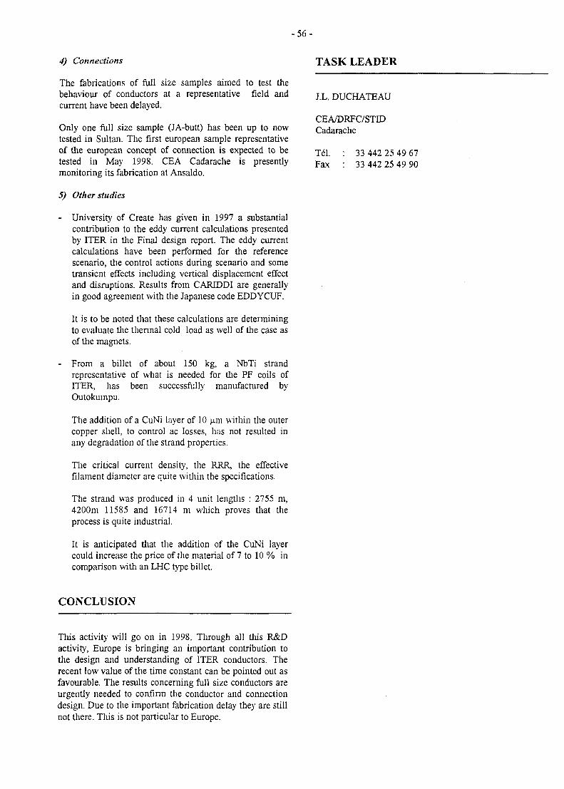
- 5 6 -
4) Connections
The fabrications of fall size samples aimed to test thebehaviour of conductors at a representative field andcurrent have been delayed.
Only one full size sample (JA-butt) has been up to nowtested in Sultan. The first european sample representativeof the european concept of connection is expected to betested in May 1998. CEA Cadarache is presentlymonitoring its fabrication at Ansaldo.
5) Other studies
- University of Create has given in 1997 a substantialcontribution to the eddy current calculations presentedby ITER in the Final design report. The eddy currentcalculations have been performed for the referencescenario, the control actions during scenario and sometransient effects including vertical displacement effectand disruptions. Results from CARIDDI are generallyin good agreement with the Japanese code EDDYCUF.
It is to be noted that these calculations are determiningto evaluate the thermal cold load as well of the case asof the magnets.
- From a billet of about 150 kg, a NbTi strandrepresentative of what is needed for the PF coils ofITER, has been successfully manufactured byOutokumpu.
The addition of a CuNi layer of 10 ujn within the outercopper shell, to control ac losses, has not resulted inany degradation of the strand properties.
The critical current density, the RRR, the effectivefilament diameter are quite within the specifications.
The strand was produced in 4 unit lengths : 2755 m,4200m 11585 and 16714 m which proves that theprocess is quite industrial.
It is anticipated that the addition of the CuNi layercould increase the price of the material of 7 to 10 % incomparison with an LHC type billet.
TASK LEADER
J.L. DUCHATEAU
CEA/DRFC/STIDCadarache
Tel. : 33 442 25 49 67Fax : 33 442 25 49 90
CONCLUSION
This activity will go on in 1998. Through all this R&Dactivity, Europe is bringing an important contribution tothe design and understanding of ITER conductors. Therecent low value of the time constant can be pointed out asfavourable. The results concerning full size conductors areurgently needed to confinn the conductor and connectiondesign. Due to the important fabrication delay they are stillnot there. This is not particular to Europe.
- 5 7 -
M40
Task Title : DESIGN WORK ON MAGNET R&D
INTRODUCTION
The aim of the task is to perform the design work linked tothe R&D for the magnet program in Europe, in closecooperation with the other european laboratories. Thisincludes the design, the analysis of the ITER TF Model Coil(TFMC), the participation to the follow-up of itsmanufacture and to the tests to be performed in the TOSKAfacility at FzK (Karlsruhe, Germany). The conceptualdesign of the TFMC, issued in 1995 [1] relies on themanufacture of a 3.8 m long racetrack coil, including themain features of an ITER TF coil, which will be tested inadjacent position to the EU LCT Coil. The AGANconsortium (Ansaldo, GEC Alsthom, ACCEL, PreussagNoell) was selected as manufacturer at the end of 1995.
Ansaldo (Genoa, Italy) is in charge of the manufacture ofthe five double pancakes; GEC Alsthom (Belfort, France) isin charge of building the coil by assembling the doublepancakes and inserting them inside a stainless steel case;Preussag Noell (Wurzburg, Germany) is in charge on onehand of the delivery to Ansaldo of the radial plates intowhich the conductor is wound, and on another hand of themanufacture of the Intercoil Structure (ICS) and theassembly of the TFMC with the ICS and the LCT Coil;ACCEL is in charge of the management of the consortiumand of the analyses. The delivery of the coil in Karlsruheand the tests are scheduled for 1999.
1997 ACTIVITIES
TF MODEL COIL ENGINEERING DESIGN
The AGAN consortium developed the Engineering Designand performed the related analyses, starting from theConceptual Design, with the aim of allowing safe andreliable operation of the TFMC Coil at 80kA while keepingthe overall weight of the test assembly below the cranecapacity of 130 t. CEA and FzK participated with NET tothe assessment of the Engineering Design and of the linkedanalyses. The examination of the results of the FiniteElement Analyses (FEA) showed that the stresses in someareas would be rather high if both coils were to be operatedat maximum current (80 kA in TFMC and 16 kA in LCTCoil). It was then decided by ITER/JCT to limit the currentin the TFMC to 70 kA when the LCT Coil will be operatedat 16 kA. One of the concerns was in particular to avoidoverstressing the LCT Coil, which is comparatively to theTFMC much less stiff, owing to its thinner casing.
Recommendations were made by CEA and FzK to modifythe Engineering Design so as to decrease the stresses in themost stressed areas of the'TFMC and the ICS, in particularthe outer joints and the side wedges. In addition it wasproposed by FzK to modify the supporting areas of the LCTcoil so as to limit its deformation. A revised EngineeringDesign was then issued by AGAN and new FEA have beenundertaken to assess its reliability.
Figure 1: TFMC Engineering Design
Table 1 : TFMC operating conditions
Coil current
LCT current
Peak field
TF coil
60 kA
12.5 T
TFMCalone
80 kA
OkA
7.70 T
TFMCNominaloperation
60 kA
16kA
7.99 T
TFMCExtendedoperation
70 kA
16 kA
8.9 T
TF MODEL COIL EDDY CURRENT ANALYSIS
The TFMC will be tested in the TOSKA facility in anadjacent nearly parallel position to the LCT Coil. In case ofa quench, a safety discharge is triggered which dumps themagnetic energy of the coil into a set of resistors.
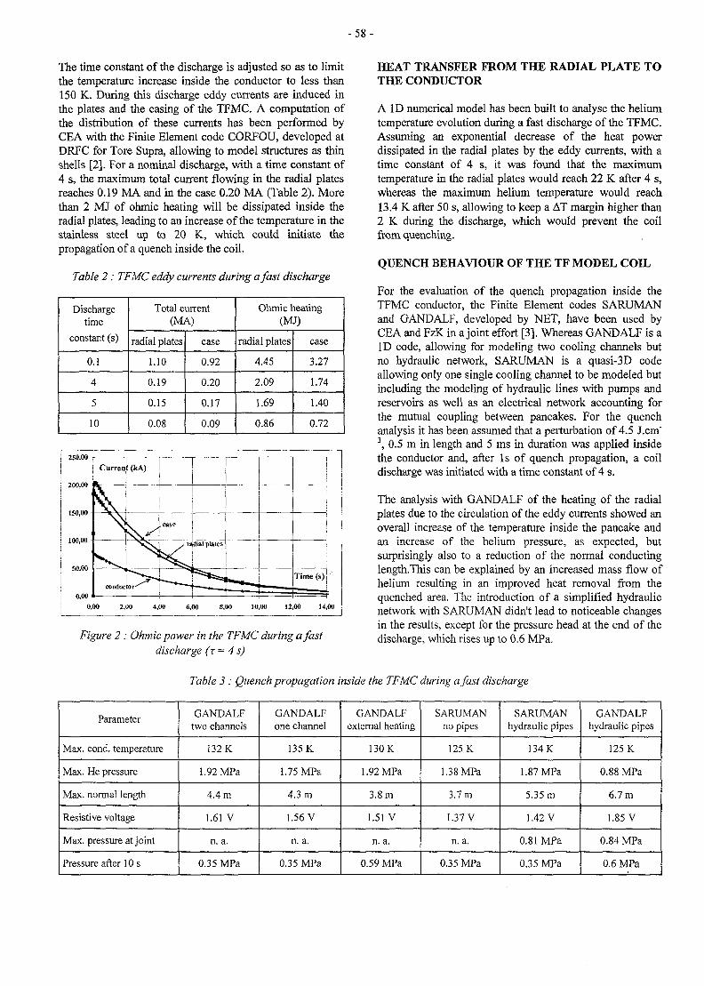
- 5 8 -
The time constant of the discharge is adjusted so as to limitthe temperature increase inside the conductor to less than150 K. During this discharge eddy currents are induced inthe plates and the casing of the TFMC. A computation ofthe distribution of these currents has been performed byCEA with the Finite Element code CORFOU, developed atDRFC for Tore Supra, allowing to model structures as thinshells [2]. For a nominal discharge, with a time constant of4 s, the maximum total current flowing in the radial platesreaches 0.19 MA and in the case 0.20 MA (Table 2). Morethan 2 MJ of ohmic heating will be dissipated inside theradial plates, leading to an increase of the temperature in thestainless steel up to 20 K, which could initiate thepropagation of a quench inside the coil.
Table 2: TFMC eddy currents during a fast discharge
Dischargetime
constant (s)
0.1
4
5
10
Total current(MA)
radial plates
1.10
0.19
0.15
0.08
case
0.92
0.20
0.17
0.09
Ohmic heating(MJ)
radial plates
4.45
2.09
1.69
0.86
case
3.27
1.74
1.40
0.72
0,00 2,00 4,00 6,00 8,00 10,00 12,00 14,00
Figure 2 : Ohmic power in the TFMC during a fastdischarge (z= 4 s)
HEAT TRANSFER FROM THE RADIAL PLATE TOTHE CONDUCTOR
A I D numerical model has been built to analyse the heliumtemperature evolution during a fast discharge of the TFMC.Assuming an exponential decrease of the heat powerdissipated in the radial plates by the eddy currents, with atime constant of 4 s, it was found that the maximumtemperature in the radial plates would reach 22 K after 4 s,whereas the maximum helium temperature would reach13.4 K after 50 s, allowing to keep a AT margin higher than2 K during the discharge, which would prevent the coilfrom quenching.
QUENCH BEHAVIOUR OF THE TF MODEL COIL
For the evaluation of the quench propagation inside theTFMC conductor, the Finite Element codes SARUMANand GANDALF, developed by NET, have been used byCEA and FzK in a joint effort [3]. Whereas GANDALF is aID code, allowing for modeling two cooling channels butno hydraulic network, SARUMAN is a quasi-3D codeallowing only one single cooling channel to be modeled butincluding the modeling of hydraulic lines with pumps andreservoirs as well as an electrical network accounting forthe mutual coupling between pancakes. For the quenchanalysis it has been assumed that a perturbation of 4.5 J.cm"3, 0.5 m in length and 5 ms in duration was applied insidethe conductor and, after Is of quench propagation, a coildischarge was initiated with a time constant of 4 s.
The analysis with GANDALF of the heating of the radialplates due to the circulation of the eddy currents showed anoverall increase of the temperature inside the pancake andan increase of the helium pressure, as expected, butsurprisingly also to a reduction of the normal conductinglength.This can be explained by an increased mass flow ofhelium resulting in an improved heat removal from thequenched area. The introduction of a simplified hydraulicnetwork with SARUMAN didn't lead to noticeable changesin the results, except for the pressure head at the end of thedischarge, which rises up to 0.6 MPa.
Table 3 : Quench propagation inside the TFMC during a fast discharge
Parameter
Max. cond. temperature
Max. He pressure
Max. normal length
Resistive voltage
Max. pressure at joint
Pressure after 10 s
GANDALFtwo channels
132 K
1.92 MPa
4.4 m
1.61 V
n. a.
0.35 MPa
GANDALFone channel
135 K
1.75 MPa
4.3 m
1.56 V
n. a.
0.35 MPa
GANDALFexternal heating
130 K
1.92 MPa
3.8 m
1.51 V
n. a.
0.59 MPa
SARUMANno pipes
125 K
1.38 MPa
3.7 m
1.37 V
n. a.
0.35 MPa
SARUMANhydraulic pipes
134 K
1.87 MPa
5.35 m
1.42 V
0.81 MPa
0.35 MPa
GANDALFhydraulic pipes
125 K
0.88 MPa
6.7 m
1.85 V
0.84 MPa
0.6 MPa
- 5 9 -
The addition of the helium pipes leads to an increase of thenormal length by about 50%. In order to allow for a betterreliability of the thermal-hydraulic calculations a test standhas been installed at CEA to measure the pressure dropinside a piece of TFMC conductor enabling thus thedetermination of the friction factor of the central channel aswell as of the annular area.
MANUFACTURE OF THE TF MODEL COIL
The main activity concerning the manufacture of the TFMC[4] during the year 1997 was the procurement of thetoolings for the manufacture of the double pancakes and therelated R&D.
The first radial plate was delivered to Ansaldo, which willenable the manufacture of a prototype double pancake,using a dummy copper conductor.
The winding line was installed at Ansaldo and the windingof the first pancakes was performed, starting with thedummy pancakes (Fig. 3).
The oven for heat treatment of the Nb3Sn conductor wasinstalled at Ansaldo in June 1997 and the first heattreatment completed on a 3 turn length of conductor inAugust (Fig. 4).
CEA participated actively in the starting operation of theoven by the installation of a control system of the impuritycontent of the oven atmosphere and the conductoratmosphere, allowing continuous recording of water,oxygene and hydrocabons during operation. After heattreatment, it turned out that the 3 turn length of conductorhad increased in length by 0.5%, preventing the transferinside the radial plate.
It was then decided to remachine the winding moulds tosmaller radii so as to take into account this phenomenonand allow further insertion of the pancakes into the radialplates. The heat treatment of the pancakes of the firstdouble pancake of the TFMC started at the end ofNovember 1997, but was interrupted during the plateau at340°C on 1st December, due to a short circuit caused by abreakdown of the fan.
After investigation of the origin of the breakdown, a repairhas been undertaken, but the heat treatment couldn't restartin 1997. Insulation and transfer of the pancakes of thedummy double pancake was performed in Autumn 1997(Fig. 5), but an error of positioning of 70 mm was observedon the outer joint of the second pancake, the origin of whichwas later imputed to a wrong positioning of the inner jointfrom which started the transfer.
Continuous checking of the position of the conductor willbe performed for the transfer of the superconductingpancakes.
Figure 3 : Winding of the pancakes of the TFMC
I 0 50 100 150 200 250 300 350 400 450 500 550; heures
I CYCLE DE TRAITEMENT THERMIQUE
Figure 4: Heat treatment of the pancakes of the TFMC
Figure 5 : Insulation and transfer of the pancakesof the TFMC
- 6 0 -
CONCLUSION TASK LEADER
The analyses of the Engineering Design of the TFMC,carried out by the AGAN consortium, led to limit thecurrent of the TFMC to 70 kA when it will be operatedwith the LCT Coil at 16 kA, in order to avoid too highstresses to occur inside coil and structure. Analyses of theeddy currents flowing inside the TFMC have beenperformed by CEA as well as analyses of the heat transferfrom the plates to the conductor and quench propagation.The manufacturing line of the double pancakes has startedoperation at Ansaldo.
P. LBEYRE
CEA/DSM/DRFC/STIDCEA/Cadarache
Tel : 33 4 42 25 46 03Fax : 33 4 42 25 49 90
e-mail: [email protected]
REFERENCES
[1] Conceptual design of the ITER TF Model Coil, P.Libeyre et al., IEEE Trans, on Mag., vol. 32, pp2260-2263, 1996
[2] Prediction of eddy currents in the ITER TF ModelCoil experiment using the code CORFOU, P. Hertoutet al., ISTET97, Palerme, Italy, June 1997
[3] Numerical evaluation of the quench behaviour of theITER Toroidal Field Model Coil, R. Heller et al.,ICMC97, Portland OR, USA, July 1997
[4] Construction of a Toroidal Field Model Coil forITER, E. Salpietro et al., MT15, Beijing, China,October 1997
- 6 1 -
M48
Task Title : WINDING AND INSULATION DEVELOPMENT
Subtitle: Joint Development
INTRODUCTION
The Task is segmented with different three parts, the firstpart deals with measurements of ITER strand criticalcurrents under field having angles with regard to the wireaxis, the second part is concerned with modification of theCadarache test facility for testing subsize joints underparallel field and with the test of an already existingsubsize joint sample (from task MWIN-2) under parallelfield, this part also covers an extra test on a modifiedsubsize joint sample for the TF Model Coil. The third partis devoted to development and characterization tests of anincoloy-copper plate bonded with the explosive method,foreseen for ITER joints fabrication. In this part one extraton of incoloy has been ordered will be transfered toindustry within the frame of the EU incoloy R&Dprogramme for ITER.
1997 ACTIVITIES
1 - PART 1 : TESTS OF NB3SN STRANDS UNDERVARIOUS FIELD ANGLES
Critical currents of a "bronze route" strand manufacturedby Vaccuumchmelze and an "internal tin" strandmanufactured by Europa Metalli have been measured as afunction of the field orientation for field strengths between4T and 20T (see Figure 1 the normalized critical current asa function of the field angle). Below 15T, the criticalcurrent is improved by a factor of 3.5, respectively 2.3,from the perpendicular to the parallel orientation for the"bronze route", resp. "internal tin", strand. A law ofcritical current for any field orientation as a function of thecritical current for perpendicular field has been proposedfor each strand taken from a paper written by Takayasu.
msin(a) + n
The (m,n) coefficients have been calculated for each strand(see Table 1).
Table I : Coefficient m andn for VACand EM-LA41 strands
Strand
VAC("bronze route")
EM-LMI ("internal tin")
m
0.83
0.65
n
0.19
0.36
R!
0.9985
0.9950
This law is only available for field strengths below 15T.The agreement of our measurements on the "internal tin"strand with older measurements performed by MTT with another "internal tin" strand made by an an othermanufacturer seems to show that this law is valid for agiven process. Above 15T, a decrease of the normalizedcurrent as a function of the field has been observed.
3.5
3.0
2.5
2.0
§ 1.51.0
0.5
II •
• ±
+ "bronze route"strand
• "internal tin"strand
20 40 60 80 100
Strand versus field angle
Figure 1: Normalized critical currentas a function of the field angle at 12T
2 - PART 2
Completion of tests of one modified MWIN-2 subsizejoint sample for the TFMC
The TF Model Coil outer electrical connections betweendouble-pancakes located on the external straight part of thepancakes have to be electrically connected after stackingof the double-pancakes. Misalignment problems mayoccur between the copper soles to be connected. To solvethis problem, AGAN has proposed a solution consisting inthe insertion of glass insulation in between the twomisaligned copper soles and in realizing the electricalconnection by drilling holes through the copper solesparallel to the copper faces and tin soft soldering copperpins inside the holes. This solution has been applied byGEC ALSTHOM on a subsize joint previously tested atCEA in order to check if the joint resistance is modified bysuch a modification.
Joint resistance and quench temperature measurement havebeen performed in the Cadarache test facility JOSEFAdevoted to subsizes joint measurement. As a general result,the voltage measurement has been found to be independentof current (up to 8kA) and of temperature (up to UK), onlya slight magneto-resistance effect has been observed. Nodegradation of the quench temperature or of the jointresistance up to 3.4T has been found.
- 6 2 -
Modification of the Cadarache joint test facility to allowparallel field testing
The Cadarache joint test facility previously developedwithin the task MWIN-2 for tests of subsize joints undertransverse field has been modified by the addition of anextra assembly where the dipole has been replaced by asolenoid. This NbTi helium bath cooled solenoid has amaximum field of 2T over about 500mm length with anavailable bore of 80mm. It allows to test under parallelfield the electrical resistance and AC losses of subsizejoints developed within the task MWIN-2. The facilityJOSEFA available in Cadarache is now able to performtests on subsize samples like joints both in transverse andparallel field.
Completion of test of one MWIN-2 (Phase II) sampleunder parallel field
The test is planned in 1998.
3 - PART 3
Fabrication of an incoloy-copper plate by explosivebonding
In the lap joint design of the EUHT, the copper plate isjoined to the joint box by explosive bonding. The previousexperience of steel to copper explosive bonding will beextended to the incoloy, so that the need for a steel-incoloyweld is eliminated. Plates joining will be done at theindustrial vendor.
A minimum possible quantity of three incoloy plates (oneton each) has been bought to US vendor. One of theseplates will be used in the frame of the incoloy R&Dprogram, and the manufacture of incoloy jacketedpancakes and incoloy full size joint sample (contractbetween NET and AGAN). One of the other plates hasbeen successfully explosive bonded by industry. No defectson the bonding has been detected by Ultra Soundexamination.
Characterization of the incoloy-copper assembly
Samples for bending, tensile and shear tests have beendesigned. Due to the delay for the furniture of incoloyplates, the mechanical characterization of the bimetallicassembly will be performed within the year 1998.
CONCLUSION
Due to the important delivery delay of the Incoloy plates,the task is expected to be completed only in july 1998. Atthis time, the Incoloy-Copper bonding will be fullycharacterized and it will be possible to confirm the validityof the concept.
REPORTS AND PUBLICATIONS
[1] T. SCHILD, H. CLOEZ - Final report M48 part 1:Tests of two Nb3Sn ITER strands under various fieldangles - Note NT/EM/97.40, September 22, 1997
[2] P. DECOOL- Task M48: Test of one modifiedMWIN-2 subsize joint sample for the TFMC - NoteNT/EM/97.08, February 17, 1997
[3] (submitted to Cryogenics)
TASK LEADER
P. DECOOL
CE AID SM/DRFC/STIDCentre d'Etudes de Cadarache
Tel. : 33 4 42 25 43 50Fax : 33 4 42 25 49 90
e-mail : [email protected]
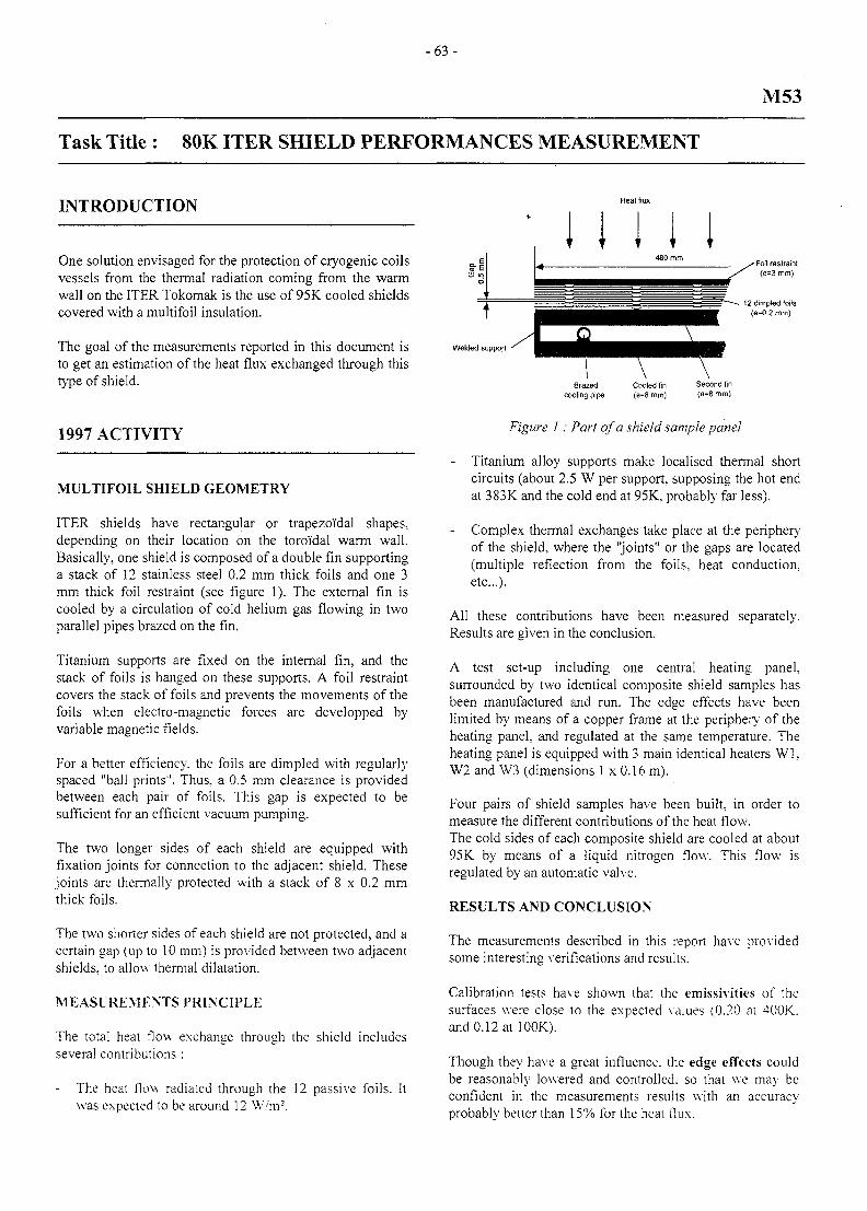
- 6 3 -
M53
Task Title : 80K ITER SHIELD PERFORMANCES MEASUREMENT
INTRODUCTION
One solution envisaged for the protection of cryogenic coilsvessels from the thermal radiation coming from the warmwall on the ITER Tokomak is the use of 95K cooled shieldscovered with a multifoil insulation.
The goal of the measurements reported in this document isto get an estimation of the heat flux exchanged through thistype of shield.
1997 ACTIVITY
MULTIFOIL SHIELD GEOMETRY
ITER shields have rectangular or trapezoi'dal shapes,depending on their location on the toroidal warm wall.Basically, one shield is composed of a double fin supportinga stack of 12 stainless steel 0.2 mm thick foils and one 3mm thick foil restraint (see figure 1). The external fin iscooled by a circulation of cold helium gas flowing in twoparallel pipes brazed on the fin.
Titanium supports are fixed on the internal fin, and thestack of foils is hanged on these supports. A foil restraintcovers the stack of foils and prevents the movements of thefoils when electro-magnetic forces are developped byvariable magnetic fields.
For a better efficiency, the foils are dimpled with regularlyspaced "ball prints". Thus, a 0.5 mm clearance is providedbetween each pair of foils. This gap is expected to besufficient for an efficient vacuum pumping.
The two longer sides of each shield are equipped withfixation joints for connection to the adjacent shield. Thesejoints are thermally protected with a stack of 8 x 0.2 mmthick foils.
The two shorter sides of each shield are not protected, and acertain gap (up to 10 mm) is provided between two adjacentshields, to allow thermal dilatation.
MEASUREMENTS PRINCIPLE
The total heat flow exchange through the shield includesseveral contributions :
The heat flow radiated through the 12 passive foils. Itwas expected to be around 12 W/m2.
I I I I I
Welded support
Figure I: Part of a shield sample panel
Titanium alloy supports make localised thermal shortcircuits (about 2.5 W per support, supposing the hot endat 383K and the cold end at 95K, probably far less).
Complex thermal exchanges take place at the peripheryof the shield, where the "joints" or the gaps are located(multiple reflection from the foils, heat conduction,etc.) .
All these contributions have been measured separately.Results are given in the conclusion.
A test set-up including one central heating panel,surrounded by two identical composite shield samples hasbeen manufactured and run. The edge effects have beenlimited by means of a copper frame at the periphery of theheating panel, and regulated at the same temperature. Theheating panel is equipped with 3 main identical heaters Wl,W2 and W3 (dimensions 1 x 0.16 m).
Four pairs of shield samples have been built, in order tomeasure the different contributions of the heat flow.The cold sides of each composite shield are cooled at about95K by means of a liquid nitrogen flow. This flow isregulated by an automatic valve.
RESULTS AND CONCLUSION
The measurements described in this report have providedsome interesting verifications and results.
Calibration tests have shown that the emissivities of thesurfaces were close to the expected values (0.20 at 400K.and 0.12 at 100K).
Though they have a great influence, the edge effects couldbe reasonably lowered and controlled, so that we may beconfident in the measurements results with an accuracyprobably better than 15% for the heat flux.
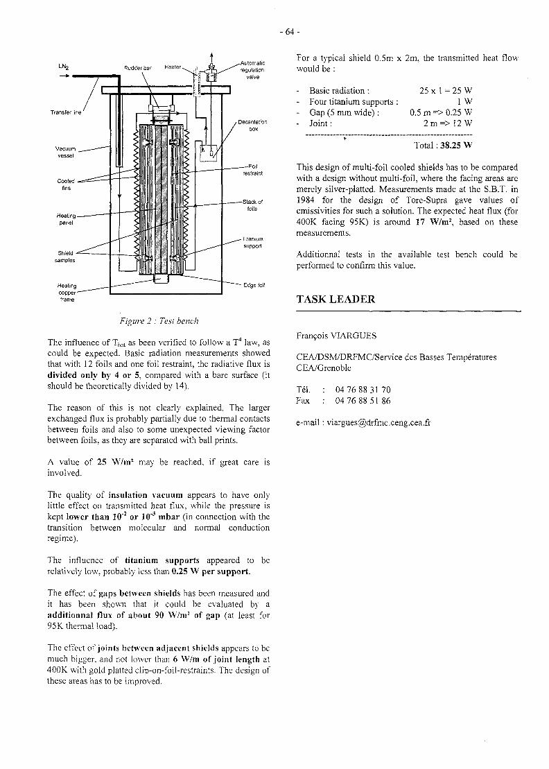
- 6 4 -
LNj Rudder bar Healer
Transfer line
• Edge foil
Figure 2 : Test bench
The influence of Thot as been verified to follow a T4 law, ascould be expected. Basic radiation measurements showedthat with 12 foils and one foil restraint, the radiative flux isdivided only by 4 or 5, compared with a bare surface (itshould be theoretically divided by 14).
The reason of this is not clearly explained. The largerexchanged flux is probably partially due to thermal contactsbetween foils and also to some unexpected viewing factorbetween foils, as they are separated with ball prints.
A value of 25 W/m1 may be reached, if great care isinvolved.
For a typical shield 0.5m x 2m, the transmitted heat flowwould be :
Basic radiation:Four titanium supportsGap (5 mm wide):Joint:
25 x 1 = 25 W1 W
0.5 m => 0.25 W2 m = > 1 2 W
Total : 38.25 W
This design of multi-foil cooled shields has to be comparedwith a design without multi-foil, where the facing areas aremerely silver-platted. Measurements made at the S.B.T. in1984 for the design of Tore-Supra gave values ofemissivities for such a solution. The expected heat flux (for400K facing 95K) is around 17 W/m2, based on thesemeasurements.
Additionnal tests in the available test bench could beperformed to confirm this value.
TASK LEADER
Fran?ois VIARGUES
CEA/DSM/DRFMC/Service des Basses TemperaturesCEA/Grenoble
Tel.Fax
04 76 88 31 7004 76 88 51 86
e-mail: [email protected]
The quality of insulation %'acuum appears to have onlylittle effect on transmitted heat flux, while the pressure iskept lower than 10"2 or 10"3 mbar (in connection with thetransition between molecular and normal conductionregime).
The influence of titanium supports appeared torelatively low, probably less than 0.25 W per support.
be
The effect of gaps between shields has been measured andit has been shown that it could be evaluated by aadditionnal flux of about 90 YV7m2 of gap (at least for95K thermal load).
The effect of joints between adjacent shields appears to bemuch bigger, and not lower than 6 \\7m of joint length at400K with gold platted clip-on-foil-restraints. The design ofthese areas has to be improved.
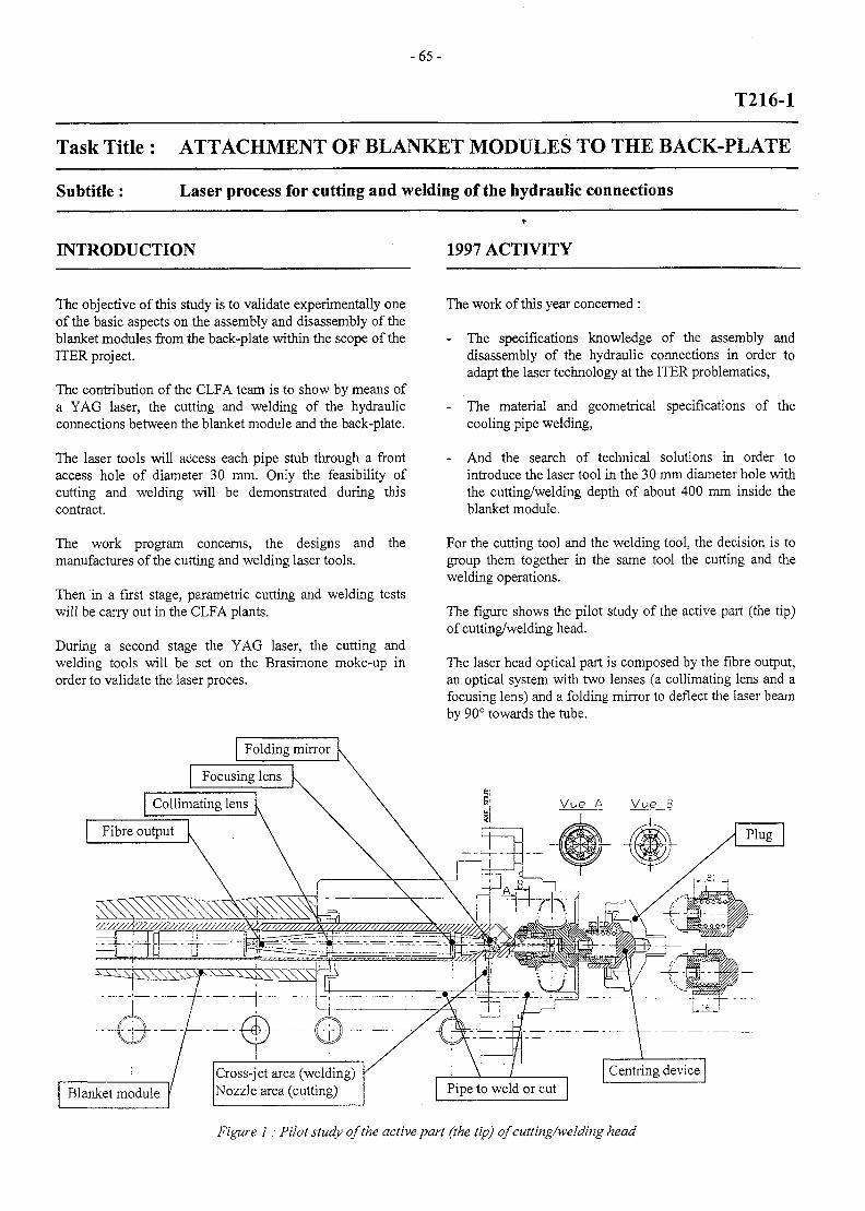
- 6 5 -
T216-1
Task Title : ATTACHMENT OF BLANKET MODULES TO THE BACK-PLATE
Subtitle: Laser process for cutting and welding of the hydraulic connections
INTRODUCTION 1997 ACTIVITY
The objective of this study is to validate experimentally oneof the basic aspects on the assembly and disassembly of theblanket modules from the back-plate within the scope of theITER project.
The contribution of the CLFA team is to show by means ofa YAG laser, the cutting and welding of the hydraulicconnections between the blanket module and the back-plate.
The laser tools will access each pipe stub through a frontaccess hole of diameter 30 mm. Only the feasibility ofcutting and welding will be demonstrated during thiscontract.
The work program concerns, the designs and themanufactures of the cutting and welding laser tools.
Then in a first stage, parametric cutting and welding testswill be carry out in the CLFA plants.
During a second stage the YAG laser, the cutting andwelding tools will be set on the Brasimone moke-up inorder to validate the laser proces.
Folding mirror
The work of this year concerned :
- The specifications knowledge of the assembly anddisassembly of the hydraulic connections in order toadapt the laser technology at the ITER problematics,
- The material and geometrical specifications of thecooling pipe welding,
- And the search of technical solutions in order tointroduce the laser tool in the 30 mm diameter hole withthe cutting/welding depth of about 400 mm inside theblanket module.
For the cutting tool and the welding tool, the decision is togroup them together in the same tool the cutting and thewelding operations.
The figure shows the pilot study of the active part (the tip)of cutting/welding head.
The laser head optical part is composed by the fibre output,an optical system with two lenses (a collimating lens and afocusing lens) and a folding mirror to deflect the laser beamby 90° towards the tube.
Focusing lens
Collimating lens
Fibre output
Vue B
Blanket moduleCross-jet area (welding)Nozzle area (cutting) Pipe to weld or cut
Centring device
Figure 1: Pilot study of the active part (the tip) of cutting/welding head
- 6 6 -
For the tool centring (the tip part), an adjustable systemtakes place into the hole inside the plug.
The only difference between the cutting and welding tool islocated near the laser interaction area (not represented onthe drawing).
For the cutting operation a special nozzle will be set inorder to use the cutting operation by multiple strokesrealised during the previous contract [1].
For the welding operation a cross-jet will be set in order toprotect the folding mirror inside the laser tool.
The basic design of the cutting/welding tool is now ended.The detailed design is starting up.
EXTERNAL REFERENCES
[1] J.P. Alfilte, T.Dubois, B. Stockmann, MITER project :Orbital cutting inside a 50 mm diameter tube bymeans of a pulsed YAG laser", DPSA/DDR/97-NT004/JPA, T329-1 (C.E.A. V, 2052,112), december97 v
[2] Ph Aubert, "Hot cracking sensitivity to 316 LN and316LN ITER grade austenitic stainless steels weldedby YAG laser", DPSA/CLFA/97-NT008/PhA/NA,december 97
TASK LEADER
CONCLUSION Mr AUBERT and ALFILLE
The work carried out in 97 consisted in the specificationsknowledge, the cooling pipe welding specifications (2) andthe find out of technical solutions in order to introduce thelaser tool in the 30 mm diameter hole with thecutting/welding depthof of about 400 mm inside themodule.
The basic design of the cutting/welding tool is now ended.The detailed design is starting up.
DTA/DPSA/CLFAFontenay
Tel. :Fax :
aux
0101
Roses
4242
3131
9897
9147
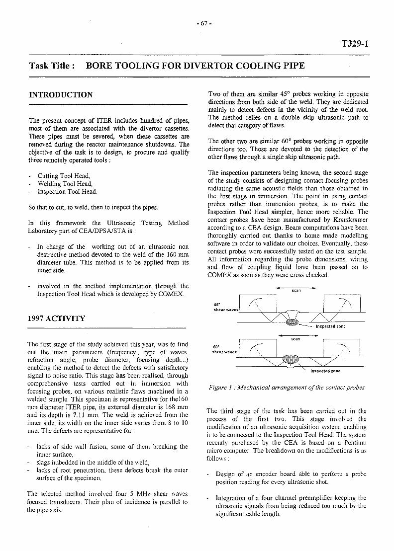
- 6 7 -
T329-1
Task Title : BORE TOOLING FOR DIVERTOR COOLING PIPE
INTRODUCTION
The present concept of ITER includes hundred of pipes,most of them are associated with the divertor cassettes.These pipes must be severed, when these cassettes areremoved during the reactor maintenance shutdowns. Theobjective of the task is to design, to procure and qualifythree remotely operated tools:
- Cutting Tool Head,- Welding Tool Head,- Inspection Tool Head.
So that to cut, to weld, then to inspect the pipes.
In this framework the Ultrasonic Testing MethodLaboratory part of CEA/DPSA/STA is :
- In charge of the working out of an ultrasonic nondestructive method devoted to the weld of the 160 mmdiameter tube. This method is to be applied from itsinner side.
- involved in the method implementation through theInspection Tool Head which is developed by COMEX.
1997 ACTIVITY
The first stage of the study achieved tills year, was to findout the main parameters (frequency, type of waves,refraction angle, probe diameter, focusing depth...)enabling the method to detect the defects with satisfactorysignal to noise ratio. This stage has been realised, throughcomprehensive tests carried out in immersion withfocusing probes, on various realistic flaws machined in awelded sample. This specimen is representative for thel60mm diameter ITER pipe, its external diameter is 168 mmand its depth is 7.11 mm. The weld is achieved from theinner side, its width on the inner side varies from 8 to 10mm. The defects are representative for :
lacks of side wall fusion, some of them breaking theinner surface,
- slags imbedded in the middle of the weld,- lacks of root penetration, these defects break the outer
surface of the specimen.
The selected method involved four 5 MHz shear wavesfocused transducers. Their plan of incidence is parallel tothe pipe axis.
Two of them are similar 45° probes working in oppositedirections from both side of the weld. They are dedicatedmainly to detect defects in the vicinity of the weld root.The method relies on a double skip ultrasonic path todetect that category of flaws.
The other two are similar 60° probes working in oppositedirections too. Those are devoted to the detection of theother flaws through a single skip ultrasonic path.
The inspection parameters being known, the second stageof the study consists of designing contact focusing probesradiating the same acoustic fields than those obtained inthe first stage in immersion. The point in using contactprobes rather than immersion probes, is to make theInspection Tool Head simpler, hence more reliable. Thecontact probes have been manufactured by Krautkrameraccording to a CEA design. Beam computations have beenthoroughly carried out thanks to home made modellingsoftware in order to validate our choices. Eventually, thesecontact probes were successfully tested on the test sample.All information regarding the probe dimensions, wiringand flow of coupling liquid have been passed on toCOMEX as soon as they were cross checked.
Inspected zone
Figure 1: Mechanical arrangement of the contact probes
The third stage of the task has been carried out in theprocess of the first two. This stage involved themodification of an ultrasonic acquisition system, enablingit to be connected to the Inspection Tool Head. The systemrecently purchased by the CEA is based on a Pentiummicro computer. The breakdown on the modifications is asfollows :
- Design of an encoder board able to perform a probeposition reading for every ultrasonic shot.
- Integration of a four channel preamplifier keeping theultrasonic signals from being reduced too much by thesignificant cable length.
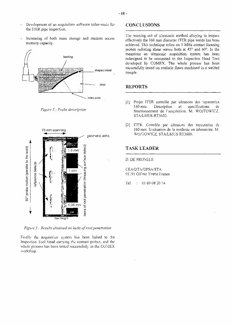
- 6 8 -
Development of an acquisition software tailor-made forthe ITER pipe inspection.
Increasing of both mass storage and random accessmemory capacity.
backing
shaped cristal
shoe
index point
Figure 2 : Probe description
CONCLUSIONS
The working out of ultrasonic method alloying to inspecteffectively the 160 mm diameter ITER pipe welds has beenachieved. This technique relies on 5 MHz contact focusingprobes radiating shear waves both at 45° and 60°. In themeantime an ultrasonic acquisition system has beenredesigned to be connected to the Inspection Head Tooldeveloped by COMEX. The whole process has beensuccessfully tested on realistic flaws machined in a weldedsample.
REPORTS
[1] Projet ITER controle par ultrasons des tuyauteries160 mm. Description et specifications defonctionnement de Tacquisition. M. WOJTOWICZ.STA/LMUS RT3602.
73 mm scanning•<
wel
d)
*CD
o
llel
TOTOa.cg"oE<u
X!oa.
0
CMO>
I
B /o
•a<a -^_o ^c
"" \
r
geometric echo
flaw height
Figure 3 : Results obtained on lacks of root penetration
Finally the acquisition system has been linked to theInspection Tool Head carrying the contact probes, and thewhole process has been tested successfully in the COMEXworkshop.
[2] ITER. Controle par ultrasons des tuyauteries de160 mm. Evaluation de la methode en laboratoire. M.WOJTOWICZ. STA/LMUS RT3669.
TASK LEADER
D. DE PRUNELE
CEA/DTA/DPSA/STA91191 Gif sur Yvette France
Tel. 01 69 08 20 14
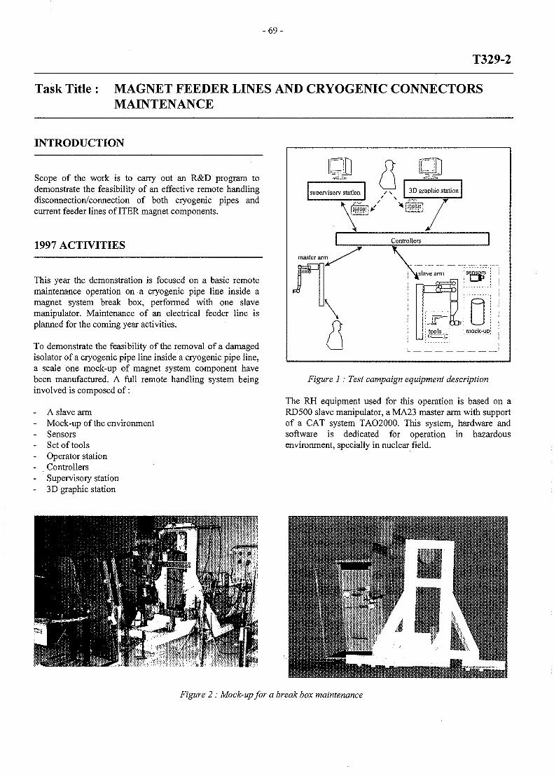
-69-
T329-2
Task Title : MAGNET FEEDER LINES AND CRYOGENIC CONNECTORSMAINTENANCE
INTRODUCTION
Scope of the work is to carry out an R&D program todemonstrate the feasibility of an effective remote handlingdisconnection/connection of both cryogenic pipes andcurrent feeder lines of ITER magnet components.
1997 ACTIVITIES
This year the demonstration is focused on a basic remotemaintenance operation on a cryogenic pipe line inside amagnet system break box, performed with one slavemanipulator. Maintenance of an electrical feeder line isplanned for the coming year activities.
To demonstrate the feasibility of the removal of a damagedisolator of a cryogenic pipe line inside a cryogenic pipe line,a scale one mock-up of magnet system component havebeen manufactured. A full remote handling system beinginvolved is composed of:
- A slave armMock-up of the environment
- Sensors- Set of tools- Operator station
Controllers- Supervisory station- 3D graphic station
D 1supervisory station
ftf\(J
/ s' \
n"SOT
3D graphic station
Figure 1: Test campaign equipment description
The RH equipment used for this operation is based on aRD500 slave manipulator, a MA23 master arm with supportof a CAT system TAO2000. This system, hardware andsoftware is dedicated for operation in hazardousenvironment, specially in nuclear field.
' I I ' I'I j ,i • ! • i , ,
* " I ' I •• ,j i ,'•,• • i
•• • • • • • .
Figure 2 : Mock-up for a break box maintenance
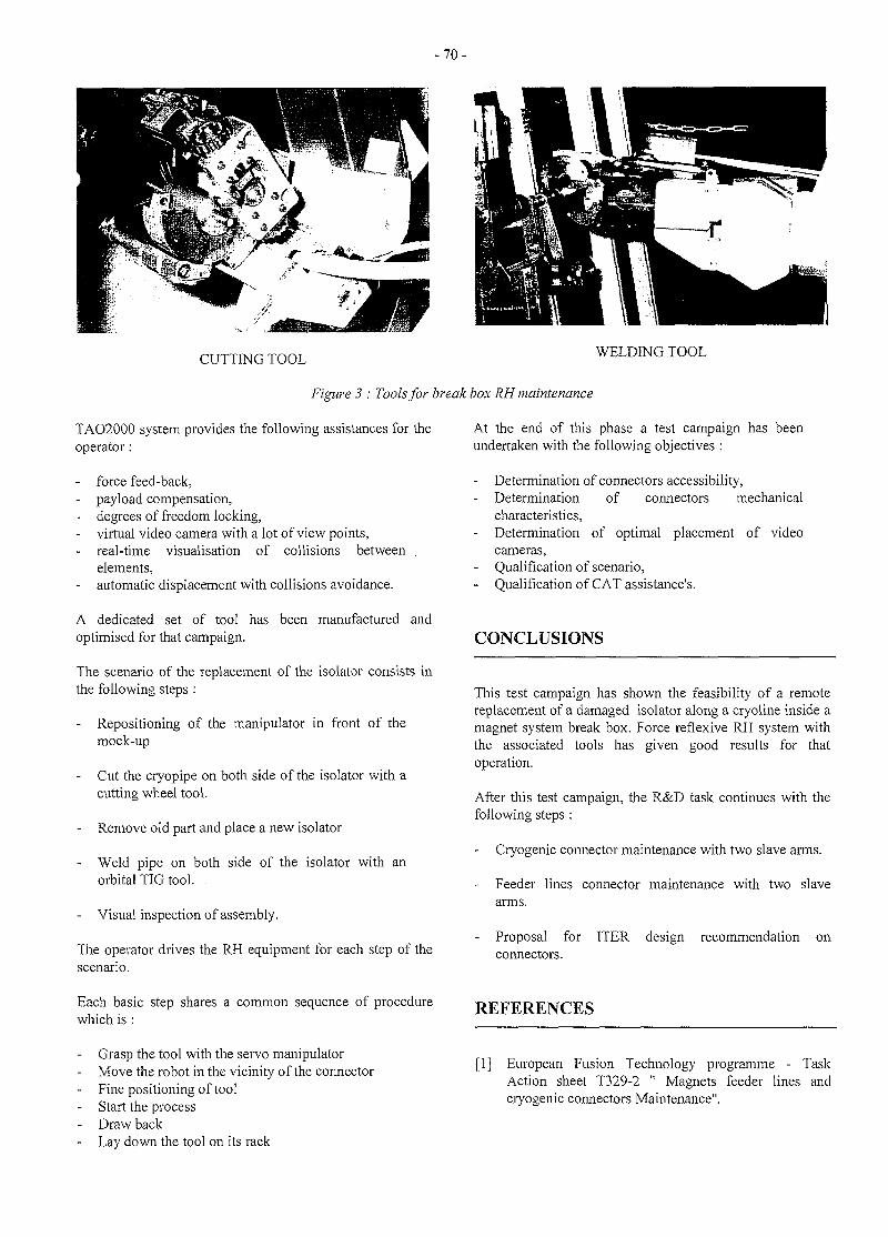
- 7 0 -
CUTTING TOOL WELDING TOOL
Figure 3 : Tools for break box RH maintenance
TAO2000 system provides the following assistances for theoperator:
force feed-back,payload compensation,degrees of freedom locking,
- virtual video camera with a lot of view points,real-time visualisation of collisions betweenelements,automatic displacement with collisions avoidance.
A dedicated set of tool has been manufactured andoptimised for that campaign.
The scenario of the replacement of the isolator consists inthe following steps:
- Repositioning of the manipulator in front of themock-up
Cut the cryopipe on both side of the isolator with acutting wheel tool.
Remove old part and place a new isolator
- Weld pipe on both side of the isolator with anorbital TIG tool.
- Visual inspection of assembly.
The operator drives the RH equipment for each step of thescenario.
Each basic step shares a common sequence of procedurewhich is :
Grasp the tool with the servo manipulator- Move the robot in the vicinity of the connector- Fine positioning of tool- Start the process
Draw back- Lay down the tool on its rack
At the end of this phase a test campaign has beenundertaken with the following objectives :
Determination of connectors accessibility,- Determination of connectors mechanical
characteristics,- Determination of optimal placement of video
cameras,Qualification of scenario,Qualification of CAT assistance's.
CONCLUSIONS
This test campaign has shown the feasibility of a remotereplacement of a damaged isolator along a cryoline inside amagnet system break box. Force reflexive RH system withthe associated tools has given good results for thatoperation.
After this test campaign, the R&D task continues with thefollowing steps :
Cryogenic connector maintenance with two slave arms.
Feeder lines connector maintenance with two slavearms.
- Proposal for ITER design recommendation onconnectors.
REFERENCES
[1] European Fusion Technology programme - TaskAction sheet T329-2 " Magnets feeder lines andcryogenic connectors Maintenance".
- 7 1 -
[2] EFET/TR/N083 Issue P02, "Remote disconnectionand connection of super-conducting magnet cryogenicpipe and current feeder line components".
[3] NET TASK : 93/851BP1995 "MAGNETSMAINTENANCE" Maintenance procedures and RHequipment"
[4] NET TASK : 93/851BP1995 "MAGNETSMAINTENANCE" Maintenance procedures and RHequipment - Central solenoid maintenance"
PUBLICATIONS
TASK LEADER
Eric VILLEDIEU
CEA/DTA/DPSCENFARBP692265 Fontenay aux Roses CEDEX
Tel.Fax
01 46 54 75 5801 46 54 75 80
e-mail: villedie@ cyborg.cea.fr
CEA/DPSA/STR- ref. str/lam/96.116 rel. 0 "Magnet feederlines and cryogenic connectors Maintenance- T329-2"-Task Report-Detailed technical specifications. JPFRICONNEAU, Nov 96.
CEA/DPSA/STR- ref. str/lam/97.089 rel. 0 "Magnet feederlines and cryogenic connectors Maintenance- T329-2"-Intermediate Task Report-. J. JOUAN, JP FRICONNEAU,July 97.
CEA/DPSA/STR- ref. str/lam/97.138 rel. 0 "Magnet feederlines and cryogenic connectors Maintenance- T329-2"-Cryogenic line maintenance with one manipulator-. J.JOUAN, JP FRICONNEAU, Dec. 97.
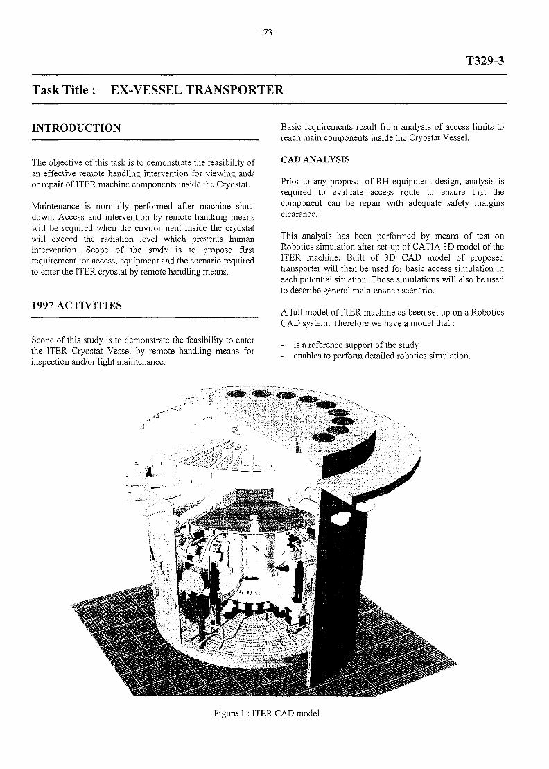
- 7 3 -
T329-3
Task Title : EX-VESSEL TRANSPORTER
INTRODUCTION
The objective of this task is to demonstrate the feasibility ofan effective remote handling intervention for viewing and/or repair of ITER machine components inside the Cryostat.
Maintenance is normally performed after machine shut-down. Access and intervention by remote handling meanswill be required when the environment inside the cryostatwill exceed the radiation level which prevents humanintervention. Scope of the study is to propose firstrequirement for access, equipment and the scenario requiredto enter the ITER cryostat by remote handling means.
1997 ACTIVITIES
Scope of this study is to demonstrate the feasibility to enterthe ITER Cryostat Vessel by remote handling means forinspection and/or light maintenance.
Basic requirements result from analysis of access limits toreach main components inside the Cryostat Vessel.
CAD ANALYSIS
Prior to any proposal of RH equipment design, analysis isrequired to evaluate access route to ensure that thecomponent can be repair with adequate safety marginsclearance.
This analysis has been performed by means of test onRobotics simulation after set-up of CATIA 3D model of theITER machine. Built of 3D CAD model of proposedtransporter will then be used for basic access simulation ineach potential situation. Those simulations will also be usedto describe general maintenance scenario.
A full model of ITER machine as been set up on a RoboticsCAD system. Therefore we have a model that:
is a reference support of the study- enables to perform detailed robotics simulation.
-rf
Figure 1 : ITER CAD model
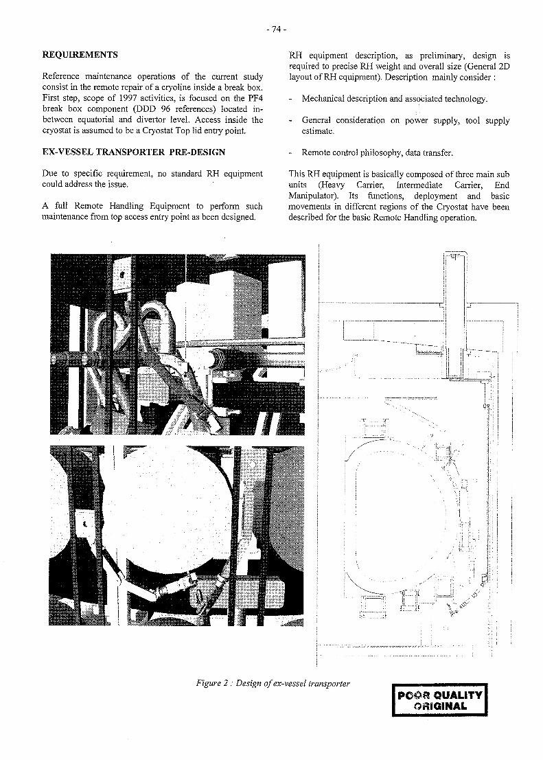
- 7 4 -
REQUIREMENTS
Reference maintenance operations of the current studyconsist in the remote repair of a cryoline inside a break box.First step, scope of 1997 activities, is focused on the PF4break box component (DDD 96 references) located in-between equatorial and divertor level. Access inside thecryostat is assumed to be a Cryostat Top lid entry point.
EX-VESSEL TRANSPORTER PRE-DESIGN
Due to specific requirement, no standard RH equipmentcould address the issue.
A full Remote Handling Equipment to perform suchmaintenance from top access entry point as been designed.
RH equipment description, as preliminary, design isrequired to precise RH weight and overall size (General 2Dlayout of RH equipment). Description mainly consider :
- Mechanical description and associated technology.
- General consideration on power supply, tool supplyestimate.
- Remote control philosophy, data transfer.
This RH equipment is basically composed of three main subunits (Heavy Carrier, Intermediate Carrier, EndManipulator). Its functions, deployment and basicmovements in different regions of the Cryostat have beendescribed for the basic Remote Handling operation.
rm'
c-Cj -
/ it.:il:
<V
iX:~-it
Figure 2 : Design of ex-vessel transporter
QUALITYORIGINAL
- 7 5 -
CONCLUSIONS PUBLICATIONS
It has been demonstrated the feasibility to perform theproposed maintenance of PF4 break box with minimuminterference with ITER design. A detailed description ofthe Ex-Vessel Transporter have been successfullyproposed.
CAD Advance software package are powerful tools whichallows maintenance concepts to be evaluated at an earlierstage [6].
CEA/DPSA/STR- ref. str/lam/96.117'Analysis of thepresent access limit for Remote Handling requirements1-'Ex. Vessel Transporter - T329-3 - Intermediate Taskreport1, J-P FRICONNEAU, March 1997,
CEA/DPSA/STR- ref. str/lam/97.126 'Detailed Descriptionof Top Access Transporter1 -'Ex. Vessel Transporter -T329-3 - Intermediate task report', J-P FRICONNEAU,Feb 1998,
REFERENCES TASK LEADER
[1] Fusion Engineering and Design, N E T Pre-designTorus by THE NET TEAM. Volume 21 (1993).
[2] ITER MAGNET MAINTENANCE - Maintenanceprocedures and RH equipment - Final report. EFET.NET TASK : 93/851-BP-1995-P214-410
[3] ITER MAGNET MAINTENANCE - Maintenanceprocedures and RH equipment - Central solenoidmaintenance - Final report. EFET. NET TASK :93/851-BP-1995 -095010
[4] DDD , November, 1996
[5] ITET/NET/CEA - T329-2 'Maintenance of Magnetfeeder line and cryogenic connectors.' Task of RemoteHandling field.
[6] HoIIoway C. and Millard J.W.F., Remote Handlingfor Fusion Machines, 17 Th SOFT, May 1992.
Eric VILLEDIEU
CEA/DTA/DPSCENFARBP692265 Fontenay aux Roses CEDEX
Tel.Fax
01 46 54 75 5801 46 54 75 80
e-mail: villedie@ cyborg.cea.fr
-77 -
CNET 96-427
Task Title : CHARACTERISTICS OF JET DUST AFTER DIVERTOROPERATION
INTRODUCTION
When a tokamaks machine is functioning the first wallundergoes erosion. The erosion products may be activated, maybe chemically toxic or reactive and contain tritium. Theytherefore constitute a source of danger for the staff and theenvironment, as well as a source of plasma poisoning.
In the framework of the ITER programme, this study gives themain characteristics of the erosion products collected from thefirst wall of the JET. It is the fourth sampling and analysisoperation, the previous ones being carried out in 1986 [1], 1989[2] and 1992 [3]. This operation differs from the others asregards the following points:
- After 1993 the configuration of the first wall was modifiedand a Divertor was installed. It is a MARK II type.
- The samples are composed of dusts, debris and, for the firsttime, flakes of film, recuperated from the metal parts of theDivertor. Samples of aerosols were not taken.
- Particle size analysis, the measuring of the specific surfacearea and microscopies were added to the usual analyses.
1997 ACTIVITIES
SAMPLING
The samples were taken on Thursday 3 October 1996 just afterthe torus was put under atmospheric pressure. They werecarried out by the "First Wall division" teams.
Three types of samples were taken and defined according totheir place of origin and their methods of collection from thefirst wall.
- Dusts are finely divided substances, deposited on the walland weakly linked. The sample is taken by moist smears.They are of micrometric dimension.
- Debris are fragments of elements forming the wall, forexample, pieces of tile. They are taken by suction. Theirdimensions range from micrometric to millimetric.
- Flakes are residues obtained by brushing a film placed onthe Divertor. They are of millimetric dimension.
Dusts
The dusts are collected by means of discs of moist clothmounted on prehensile instruments. These are designed toapply a constant pressure to the smears and to give a rotatingmovement to the cloth. There are two smear sizes: 0.95 and8.55 cm2. Taking into account the large number of analysesand the small amount of substances collected, 5 contiguoussmears were taken for 12 different locations. These locations,chosen by the First Wall division team.
The sample number is defined by the indication of the place ofsampling in a shortened form, i.e.:
- The sample comes from the Divertor (Div), either the innerwall (Inner wall) or the outer wall (Outer wall). The samplecomes from the erosion area (Ero) on the tile directlysubmitted to particle flow, or in the deposition area (Depo),i.e. in the shadow area. The indication of the octant (Oct)where the tile is located. For the Divertor the indication ofthe tile number.
To obtain a sufficient quantity of samples necessary for certaintypes of analysis, such as the measuring of the particle size andthe specific surface area, a cloth with a larger surface area, afew dm2, was used for smears taken from the 10 Divertor tiles.
Debris
During the previous sampling operations, we collected debrison the torus floor using a cyclone connected to a vacuumsuction. We repeated the same type of sampling method for theDivertor, on the inner wall and on the outer wall, with severalcyclones with different cutting diameters. These cuttingdiameters were successively > 5 \xm, > 2.5 jam, > 0.6 urn.
Flakes
These samples were composed of flakes obtained frombrushing the metal parts of the Divertor. A film was depositedon these metal parts. The fragment sample was taken manuallyafter brushing. The sample of # 20 mg was divided for thedifferent analyses.
ANALYSIS TECHNIQUES
The samples were analyzed to determine the characteristics ofthe elements present, in particular.
Carbon ; Beryllium and Nickel ; Chrome, Cobalt and Iron ;Tritium activity ; y activity ; Particle size analysis'; Specificsurface area and Morphology.
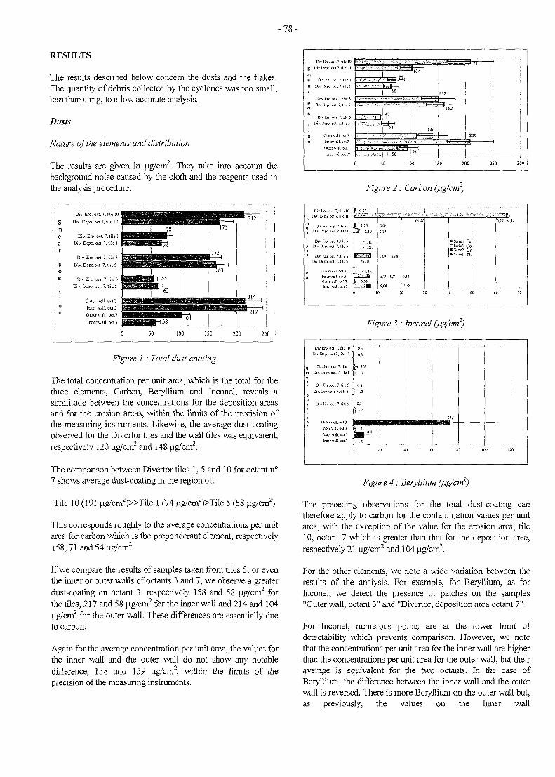
- 7 8 -
RESULTS
The results described below concern the dusts and the flakes.The quantity of debris collected by the cyclones was too small,less than a mg, to allow accurate analysis.
Dusts
Nature of the elements and distribution
The results are given in ug/cm2. They take into account thebackground noise caused by the cloth and the reagents used inthe analysis procedure.
smear
P0
s
ti0n
Div. Ero. oct. 7. lile I gffiggj$
Div.Dcpo.oct.7,iilcl pjlig
Div. Ero. oct. 3, tile 5 pjjjj&e
Div.Depo.oct.7,titcS " p j ^
1Div. Ero. oci. 7, lile 5 tggSg
Div. Dcpo. oci. 7, tile 5 J g ^ l i
Outer wall, oct.3 jJBJg
Inner wall, oct.3 jjjjgjgj
Outer wall, oct.? jBBKft
lnnerwall,oct.7 J | | ^ |
0
I 78
UiimplU .1i
imHMi#iriiimilill mm^O^Mi i i i l l l f l i IMM1
62
MiWt'WWlllte«iaBBa
50 100
ma
170
| 152 ^
10J
^ 2 1 7
150 200 250
Figure 1: Total dust-coating
The total concentration per unit area, which is the total for thethree elements, Carbon, Beryllium and Inconel, reveals asimilitude between the concentrations for the deposition areasand for the erosion areas, within the limits of the precision ofthe measuring instruments. Likewise, the average dust-coatingobserved for the Divertor tiles and the wall tiles was equivalent,respectively 120 ug/cm2 and 148 ug/cm2.
The comparison between Divertor tiles 1, 5 and 10 for octant n°7 shows average dust-coating in the region of:
Tile 10 (191 ug/cm2)»Tile 1 (74 ug/cm2)>Tile 5 (58 ug/cm2)
This corresponds roughly to the average concentrations per unitarea for carbon which is the preponderant element, respectively158,71 and 54 ug/cm2.
If we compare the results of samples taken from tiles 5, or eventhe inner or outer walls of octants 3 and 7, we observe a greaterdust-coating on octant 3: respectively 158 and 58 ug/cm2 forthe tiles, 217 and 58 ug/cm2 for the inner wall and 214 and 104ug/cm2 for the outer wall. These differences are essentially dueto carbon.
Again for the average concentration per unit area, the values forthe inner wall and the outer wall do not show any notabledifference, 138 and 159 ug/cm2, within the limits of theprecision of the measuring instruments.
Smea
r
Mositi0
niv
Div
D
Dn
ft
Di\
Di
Div.
IW.OEI.7.
•kW oci 1,
IX-po oci. 7
• ,™.» ,
• I-ro oci. 7
X-no. oci. 7.
Oitetvv^ll,
llUK! Will,
k l O
Uk 1
lilc 1
ulttS
lilc 5
ik 5
oci7
' •—f- ' ',"!,,„
66
61140
'^•••vX-rj-fcrt-H 50 r 1
152
| 1
162
0 50 100 150 2Q0 250
•
300
Figure 2: Carbon (/ug/cm2)
Dn
? U
a D i v
Di> Div
DiDiv
[•TO O
'. lit).
.FJO.iX-po.
X'po
Inner
lime
«.7.l i fclO 1
oci 7, tile Ix l 1. lile 1 .
cl. 3.1.1c 5 .cl 7. lilc 5 .
wi 7, lilc S
vaJl.oct.3
WTJI.OCI.7
I
0J3 "|
2 ''219
< 1. D
fl^ • 0 S i a
0.04
0.1 A
1,07
5,79
5,05
10
6.18
0,84
|
0
2
20
I I
15
64.S6
30 A
DScrirf CO
WSiriel N i
0 so
CU9 0.56
60 70
Figure 3 : Inconel (fig/cm2)
Div.j-ro.oci T.liiclO '
Div Dcpo.oclJ.lilc 10
Div.l-jii oci. 7. lilc 1
n Div Ifcpo. oci. 7. lilc 1
Div.Rro.oci 3.itlcS
Div.Dcpo.oci 7, lilc 5
Div.l-ro.oct. 7.nIcS
Inner wH\. oci.3
OuicrMnll.oci.7
Inner wdl.ocl.7
0,6; 0.8
<U 1.9
'.1
\z
0.3
M
1.0
73.7
0 20 JO 60 80 100 120
Figure 4 : Beryllium (jug/cm2)
The preceding observations for the total dust-coating cantherefore apply to carbon for the contamination values per unitarea, with the exception of the value for the erosion area, tile10, octant 7 which is greater than that for the deposition area,respectively 21 ug/cm2 and 104 ug/cm2.
For the other elements, we note a wide variation between theresults of the analysis. For example, for Beryllium, as forInconel, we detect the presence of patches on the samples"Outer wall, octant 3" and "Divertor, deposition area octant 7".
For Inconel, numerous points are at the lower limit ofdetectability which prevents comparison. However, we notethat the concentrations per unit area for the inner wall are higherthan the concentrations per unit area for the outer wall, but theiraverage is equivalent for the two octants. In the case ofBeryllium, the difference between the inner wall and the outerwall is reversed. There is more Beryllium on the outer wall but,as previously, the values on the Inner wall
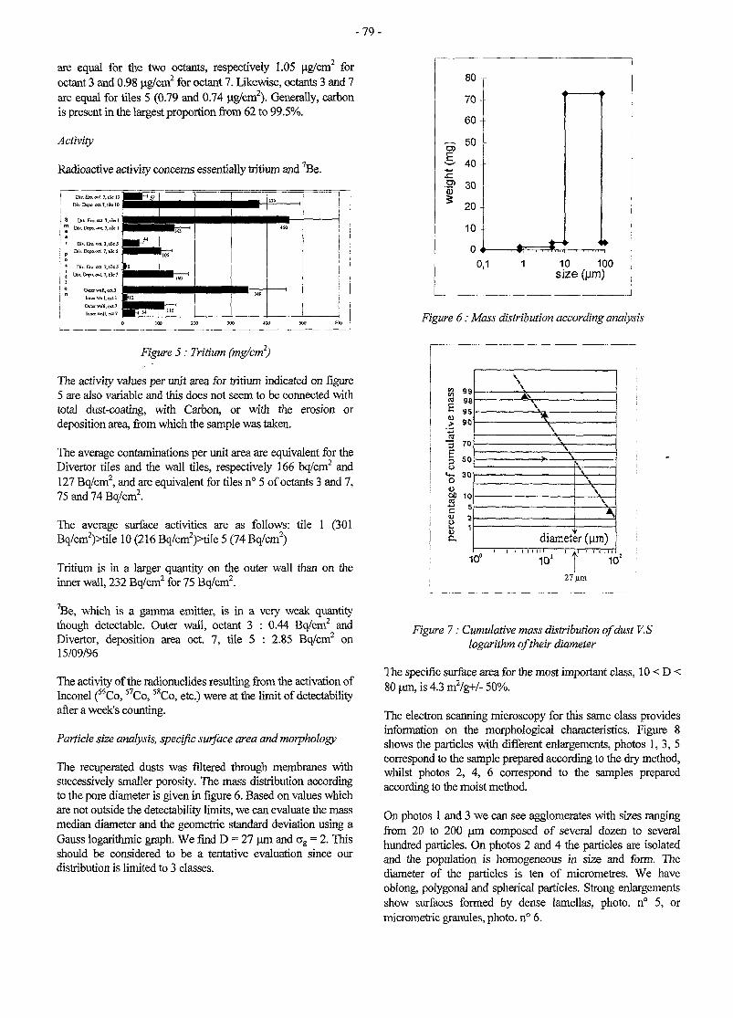
- 7 9 -
are equal for the two octants, respectively 1.05 ug/cm2 foroctant 3 and 0.98 ug/cm2 for octant 7. Likewise, octants 3 and 7are equal for tiles 5 (0.79 and 0.74 ug/cm2). Generally, carbonis present in the largest proportion from 62 to 99.5%.
Activity
Radioactive activity concerns essentially tritium and 7Be.
Figure 5: Tritium (mg/cm2)
The activity values per unit area for tritium indicated on figure5 are also variable and this does not seem to be connected withtotal dust-coating, with Carbon, or with the erosion ordeposition area, from which the sample was taken.
The average contaminations per unit area are equivalent for theDivertor tiles and the wall tiles, respectively 166 bq/cm2 and127 Bq/cm2, and are equivalent for tiles n° 5 of octants 3 and 7,75 and 74 Bq/cm2.
The average surface activities are as follows: tile 1 (301Bq/cm2)>tile 10 (216 Bq/cm2)>tile 5 (74 Bq/cm2)
Tritium is in a larger quantity on the outer wall than on theinner wall, 232 Bq/cm2 for 75 Bq/cm2.
7Be, which is a gamma emitter, is in a very weak quantitythough detectable. Outer wall, octant 3 : 0.44 Bq/cm2 andDivertor, deposition area oct 7, tile 5 : 2.85 Bq/cm2 on15/09/96
The activity of the radionuclides resulting from the activation ofInconel (^Co, 57Co, 58Co, etc.) were at the limit of detectabilityafter a week's counting.
Particle size analysis, specific surface area and morphology
The recuperated dusts was filtered through membranes withsuccessively smaller porosity. The mass distribution accordingto the pore diameter is given in figure 6. Based on values whichare not outside the detectability limits, we can evaluate the massmedian diameter and the geometric standard deviation using aGauss logarithmic graph. We find D = 27 urn and ag = 2. Thisshould be considered to be a tentative evaluation since ourdistribution is limited to 3 classes.
Figure 6: Mass distribution according analysis
c 98
S 90
CO3
10
diameter (um)
10°~i 11 l~ .Ti'J'
1O1
27 urn
Figure 7: Cumulative mass distribution of dust V.Slogarithm of their diameter
The specific surface area for the most important class, 10 < D <80 um, is 4.3 m2/g+/- 50%.
The electron scanning microscopy for this same class providesinformation on the morphological characteristics. Figure 8shows the particles with different enlargements, photos 1, 3, 5correspond to the sample prepared according to the dry method,whilst photos 2, 4, 6 correspond to the samples preparedaccording to the moist method.
On photos 1 and 3 we can see agglomerates with sizes rangingfrom 20 to 200 um composed of several dozen to severalhundred particles. On photos 2 and 4 the particles are isolatedand the population is homogeneous in size and form. Thediameter of the particles is ten of micrometres. We haveoblong, polygonal and spherical particles. Strong enlargementsshow surfaces formed by dense lamellas, photo. n° 5, ormicrometric granules, photo. n° 6.
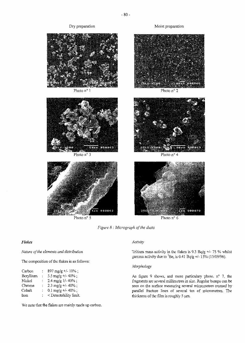
- 8 0 -
Dry preparation
Photo n° 1
Photo n° 3
Moist preparation
' ' V ^ ' - Y ' - v ''I''.-7'1*'
Photo n° 2
Figure 8: Micrograph of the dusts
Flakes
Nature of the elements and distribution
The composition of the flakes is as follows:
CarbonBerylliumNickelChromeCobaltIron
897mg/g+/-10%;5.5mg/g+/-40%;2.4 mg/g 1/- 40% ;2.3mg/g+/-40%;0.1mg/g+/-40%;< Detectability limit
Activity
Tritium mass activity in the flakes is 9.3 Bq/g +/- 75 % whilstgamma activity due to 7Be, is 0.41 Bq/g +/-15% (15/09/96).
Morphology
As figure 9 shows, and more particulary photo. n° 7, thefragments are several millimetres in size. Regular bumps can beseen on the surface measuring several micrometres crossed byparallel fracture lines of several ten of micrometres. Thethickness of the film is roughly 5 um.
We note that the flakes are mainly made up carbon.
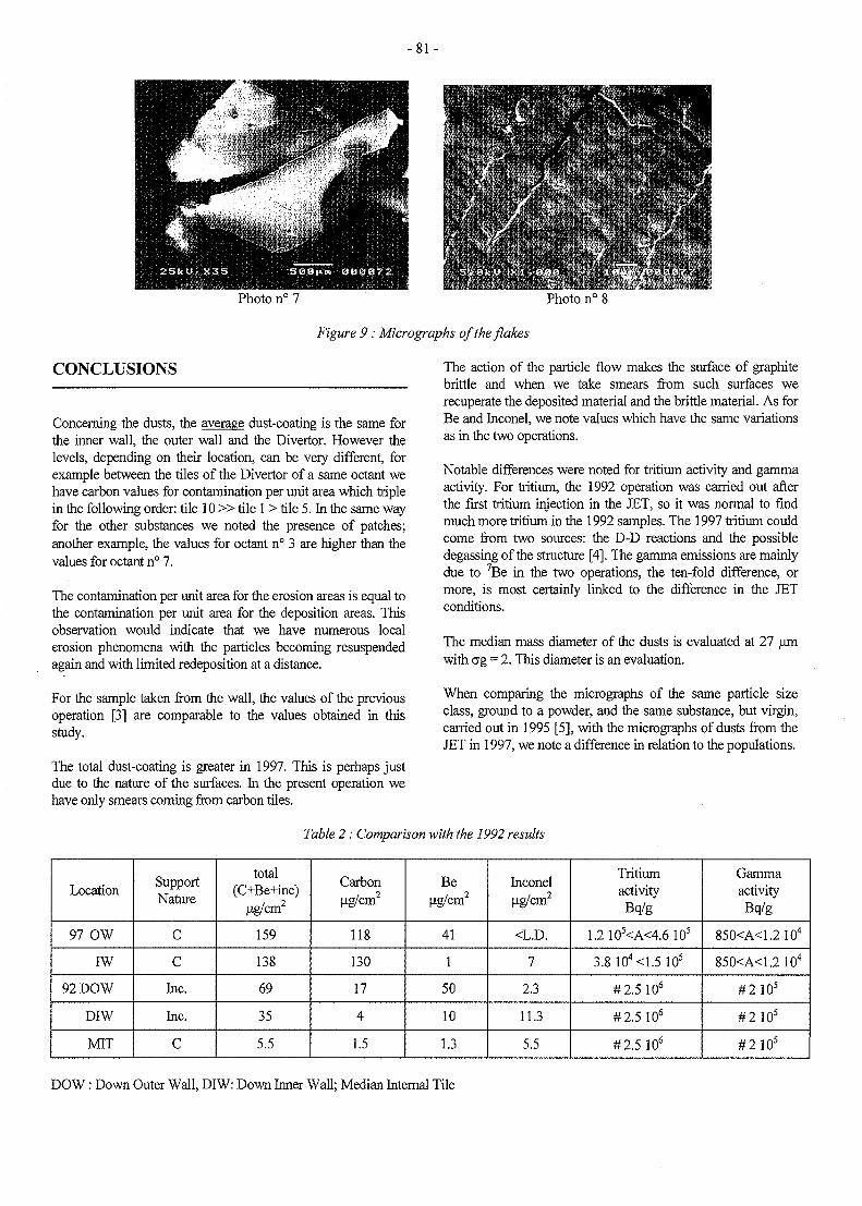
- 8 1 -
Photo n° 7 Photo n° 8
Figure 9: Micrographs of the flakes
CONCLUSIONS
Concerning the dusts, the average dust-coating is the same forthe inner wall, the outer wall and the Divertor. However thelevels, depending on their location, can be very different, forexample between the tiles of the Divertor of a same octant wehave carbon values for contamination per unit area which triplein the following order: tile 10 » t i l e 1 > tile 5. In the same wayfor the other substances we noted the presence of patches;another example, the values for octant n° 3 are higher than thevalues for octant n° 7.
The contamination per unit area for the erosion areas is equal tothe contamination per unit area for the deposition areas. Thisobservation would indicate that we have numerous localerosion phenomena with the particles becoming resuspendedagain and with limited redeposition at a distance.
For the sample taken from the wall, the values of the previousoperation [3] are comparable to the values obtained in thisstudy.
The total dust-coating is greater in 1997. This is perhaps justdue to the nature of the surfaces. In the present operation wehave only smears coming from carbon tiles.
The action of the particle flow makes the surface of graphitebrittle and when we take smears from such surfaces werecuperate the deposited material and the brittle material. As forBe and Inconel, we note values which have the same variationsas in the two operations.
Notable differences were noted for tritium activity and gammaactivity. For tritium, the 1992 operation was carried out afterthe first tritium injection in the JET, so it was normal to findmuch more tritium in the 1992 samples. The 1997 tritium couldcome from two sources: the D-D reactions and the possibledegassing of the structure [4]. The gamma emissions are mainlydue to 7Be in the two operations, the ten-fold difference, ormore, is most certainly linked to the difference in the JETconditions.
The median mass diameter of the dusts is evaluated at 27 umwith erg = 2. This diameter is an evaluation.
When comparing the micrographs of the same particle sizeclass, ground to a powder, and the same substance, but virgin,carried out in 1995 [5], with the micrographs of dusts from theJET in 1997, we note a difference in relation to the populations.
Table 2: Comparison with the 1992 results
Location
97 OW
IW
92 DOW
DIW
MIT
SupportNature
C
C
Inc.
Inc.
C
total(C+Be+inc)
ug/cm2
159
138
69
35
5.5
Carbonug/cm2
118
130
17
4
1.5
Beug/cm2
41
1
50
10
1.3
Inconelug/cm2
<L.D.
7
2.3
11.3
5.5
TritiumactivityBq/g
1.2 105<A<4.6 105
3.8 104<1.5 10s
#2.5 106
#2.5 106
#2.5 106
GammaactivityBq/g
850<A<1.2 104
850<A<1.2104
#2 105
#2 10s
#2105
DOW : Down Outer Wall, DIW: Down Inner Wall; Median Internal Tile
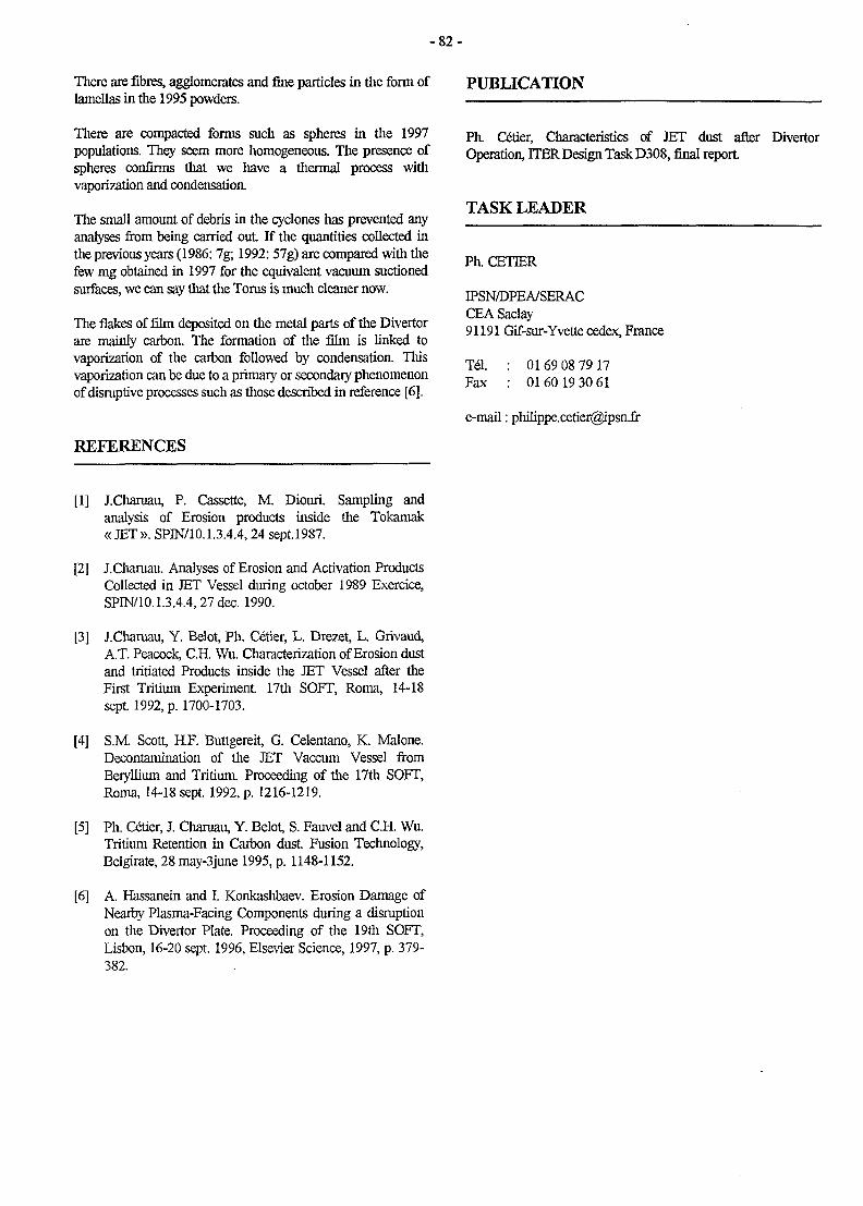
- 8 2 -
There are fibres, agglomerates and fine particles in the form oflamellas in the 1995 powders.
There are compacted forms such as spheres in the 1997populations. They seem more homogeneous. The presence ofspheres confirms that we have a thermal process withvaporization and condensatioa
The small amount of debris in the cyclones has prevented anyanalyses from being carried out If the quantities collected inthe previous years (1986:7g; 1992:57g) are compared with thefew mg obtained in 1997 for the equivalent vacuum suctionedsurfaces, we can say that the Torus is much cleaner now.
The flakes of film deposited on the metal parts of the Divertorare mainly carbon. The formation of the film is linked tovaporization of the carbon followed by condensation. Thisvaporization can be due to a primary or secondary phenomenonof disruptive processes such as those described in reference [6],
REFERENCES
PUBLICATION
Ph. Ce"tier, Characteristics of JET dust after DivertorOperation, HER Design Task D308, final report.
TASK LEADER
Ph. CETIER
IPSN/DPEA/SERACCEA Saclay91191 Gif-sur-Yvette cedex, France
Tel.Fax
0169 08 79 170160 19 30 61
e-mail: [email protected]
[1] J.Charuau, P. Cassette, M. Diouri. Sampling andanalysis of Erosion products inside the Tokamak« JET». SPIN/10.1.3.4.4,24 sept.1987.
[2] J.Cliaruau. Analyses of Erosion and Activation ProductsCollected in JET Vessel during October 1989 Exercice,SPIN/10.1.3.4.4,27 dec. 1990.
[3] J.Charuau, Y. Belot, Ph. Cetier, L. Drezet, L. Grivaud,A.T. Peacock, C.H. Wu. Characterization of Erosion dustand tritiated Products inside the JET Vessel after theFirst Tritium Experiment 17th SOFT, Roma, 14-18sept 1992, p. 1700-1703.
[4] S.M Scott, H.F. Buttgereit, G. Celentano, K. Malone.Decontamination of the JET Vaccum Vessel fromBeryllium and Tritium. Proceeding of the 17th SOFT,Roma, 14-18 sept. 1992, p. 1216-1219.
[5] Ph. Cetier, J. Chamau, Y. Belot, S. Fauvel and C.H. Wu.Tritium Retention in Carbon dust Fusion Technology,Belgirate, 28 may-3june 1995, p. 1148-1152.
[6] A. Hassanein and I. Konkashbaev. Erosion Damage ofNearby Plasma-Facing Components during a disruptionon the Divertor Plate. Proceeding of the 19th SOFT,Lisbon, 16-20 sept. 1996, Elsevier Science, 1997, p. 379-382.
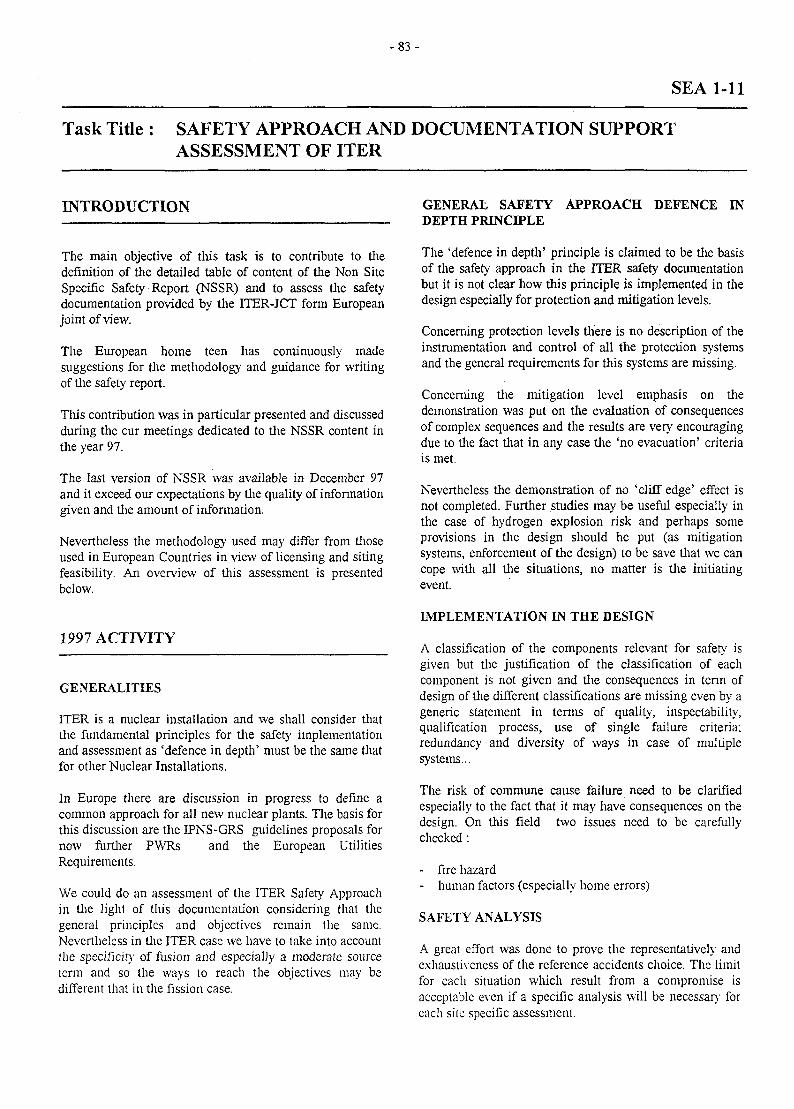
- 8 3 -
SEA 1-11
Task Title : SAFETY APPROACH AND DOCUMENTATION SUPPORTASSESSMENT OF ITER
INTRODUCTION
The main objective of this task is to contribute to thedefinition of the detailed table of content of the Non SiteSpecific Safety Report (NSSR) and to assess the safetydocumentation provided by the ITER-JCT form Europeanjoint of view.
The European home teen has continuously madesuggestions for the methodology and guidance for writingof the safety report.
This contribution was in particular presented and discussedduring the cur meetings dedicated to the NSSR content inthe year 97.
The last version of NSSR was available in December 97and it exceed our expectations by the quality of informationgiven and the amount of information.
Nevertheless the methodology used may differ from thoseused in European Countries in view of licensing and sitingfeasibility. An overview of this assessment is presentedbelow.
1997 ACTIVITY
GENERALITIES
ITER is a nuclear installation and we shall consider thatthe fundamental principles for the safety implementationand assessment as 'defence in depth' must be the same thatfor other Nuclear Installations.
In Europe there are discussion in progress to define acommon approach for all new nuclear plants. The basis forthis discussion are the IPNS-GRS guidelines proposals fornow further PWRs and the European UtilitiesRequirements.
We could do an assessment of the ITER Safety Approachin the light of this documentation considering that thegeneral principles and objectives remain the same.Nevertheless in the ITER case we have to take into accountthe specificity of fusion and especially a moderate sourceterm and so the ways to reach the objectives may bedifferent that in the fission case.
GENERAL SAFETY APPROACH DEFENCE INDEPTH PRINCIPLE
The 'defence in depth' principle is claimed to be the basisof the safety approach in the ITER safety documentationbut it is not clear how this principle is implemented in thedesign especially for protection and mitigation levels.
Concerning protection levels there is no description of theinstrumentation and control of all the protection systemsand the general requirements for this systems are missing.
Concerning the mitigation level emphasis on thedemonstration was put on the evaluation of consequencesof complex sequences and the results are very encouragingdue to the fact that in any case the 'no evacuation' criteriais met.
Nevertheless the demonstration of no 'cliff edge' effect isnot completed. Further studies may be useful especially inthe case of hydrogen explosion risk and perhaps someprovisions in the design should he put (as mitigationsystems, enforcement of the design) to be save that we cancope with all the situations, no matter is the initiatingevent.
IMPLEMENTATION IN THE DESIGN
A classification of the components relevant for safety isgiven but the justification of the classification of eachcomponent is not given and the consequences in term ofdesign of the different classifications are missing even by ageneric statement in terms of quality, inspectability,qualification process, use of single failure criteria;redundancy and diversity of ways in case of multiplesystems...
The risk of commune cause failure need to be clarifiedespecially to the fact that it may have consequences on thedesign. On this field two issues need to be carefullychecked:
- fire hazard- human factors (especially home errors)
SAFETY ANALYSIS
A great effort was done to prove the representatively andexhaustiveness of the reference accidents choice. The limitfor each situation which result from a compromise isacceptable even if a specific analysis will be necessary foreach site specific assessment.
- 8 4 -
Nevertheless tlie classification of each sequence is difficultto assess essentially due to the fact that description of manysystems are missing (as Fast Plasma Shutdown System)and that the reliability is unknown as consequence of thelack of generic requirements of safety classification.
The approach of external events analysis seems to beacceptable with the reservation that we have to ensure thatin, especially in the seismic case, any 'cliff edge' effect isavoided.
In this matter the sequence earthquake + VDE must becarefully checked.
REFERENCES
Minutes of the ITER Safety meeting 21-25/04/97NT DER/STML/FUSION 97.043G. MARBACH
Preliminary analysis of the ITER Safety ApproachNT DER/SIS/LSS/97.32G.L. FIORINI
TASK LEADER
CONCLUSION
NSSR is a very useful report providing better knowledge ofITER safety and in general fusion safety .
Nevertheless additional work will be necessary in the oncoming years to set it at the level required for licensing andsiting feasibility.
Gabriel MARBACH
DRN/DER/STMLCadarache
Tel.Fax
04 42 25 34 1404 42 25 65 08
e-mail : marbach @ babaorum.cad.CEA.fr
- 8 5 -
SEA 1-12
Task title : SAFETY ASSESSMENT OF CONFINEMENT
Task subtitle : Safety approach and HTS reliability
INTRODUCTION
The technical complexity of the development of ITER(International Tokamak Experimental Reactor) led thedesigners to focus primarily on the feasibility of the fusionreaction and secondly on the safety, reliability, andavailability aspects of the reactor.
The objective of the study is double:
- In a first part, to make a critical review of the safetyapproach defined for the design of ITER, and,
- In a second part to make a preliminary analysis of thereliability and the availability of ITER's heat removalsystem so as to highlight the need to take operationalsafety studies into account as early as in the designstage. This part presents the following two analyses:
* Analysis of Primary Heat Transfer Systemreliability for the Vacuum Vessel (PHTS-VV),
* Analysis of PHTS availability.
REVIEW OF THE ITER SAFETY APPROACH
- Many detailed comments concerning the safetyimplementation can be presented but all of them can besummarized under the following statement: « althoughthe proposed method may seem intellectuallyacceptable, they must be not too complex to beimplemented if not, the objective can not be reached ».
This can be illustrated by the implementation of theaggravating LOOP (Loss of offsite power).
For ITER, which will not supply a grid, there shouldbe no dependence relationship between a PIE and aLOOP, except, perhaps, in the event of externalaggression, such as earthquake or tornado, etc. Takinginto account all the superpositions with short, long,and especially "total station blackout" LOOPs (in ClassV) is cumbersome, even unrealistic! The combinationof a PIE and station blackout is highly improbable(<cat. V frequency) except if the electric powersources are really unreliable or if the site is reallyunfavorable (considerable seismic activity).
On the other hand, the superposition of a PIE withunavailability due to preventive maintenance (and a
SFC) is not mentioned, although a combination such asthis may be more probable than a combination with a"total station blackout".
The analysis of sequences modeling shows thatunconventional rules are followed. In fact, thesequences presented seem to mix the notion of EventTrees (ET) and that of a logigram (or logic diagram).
There seems to be a confusion between the eventsconsidered in the ETs, random events (good operationor failure of a system), and "probabilisable" eventswith questions (without answers through lack ofsufficient knowledge) as to the occurrence or not of afailure brought about by the failure considered justbefore in the ET.
For example, following a PIE combined with thefailure of the system « SYST1 », will the structure« ST1 > resist or not?
Except very rarely, this type of non-random eventshould not be present in the ET of a PSA. One shouldbe able, using a deterministic evaluation, to saywhether, depending on its design conditions, the ST1structure will resist or not.
This being so, in the preliminary design stage, whenmany questions of this type may remain unanswered,one could envisage leaving this type of question in theETs, provided they are distinguished from events ofrandom (or probabilistic) nature by putting a questionmark, for example, at the beginning or end of theirdesignation.
However, as the project evolves, this type of questionshould find a deterministic answer and the ETs shouldbe modified in consequence.
The most recent reports highlights the importance ofidentifying PIEs as exhaustively as possible. This firststage is a stage common to both the deterministic andthe probabilistic approaches.
A combination of various "top down" and "bottom up"methods is applied (FMEA, HAZOP, MLD) so as tobe as exhaustive as possible.
The approach followed for fission reactors is similar.
To our knowledge, there currently exists no methodthat is simple or rapid to implement to identify possibleinitiators and prove the exhaustivity of the list.
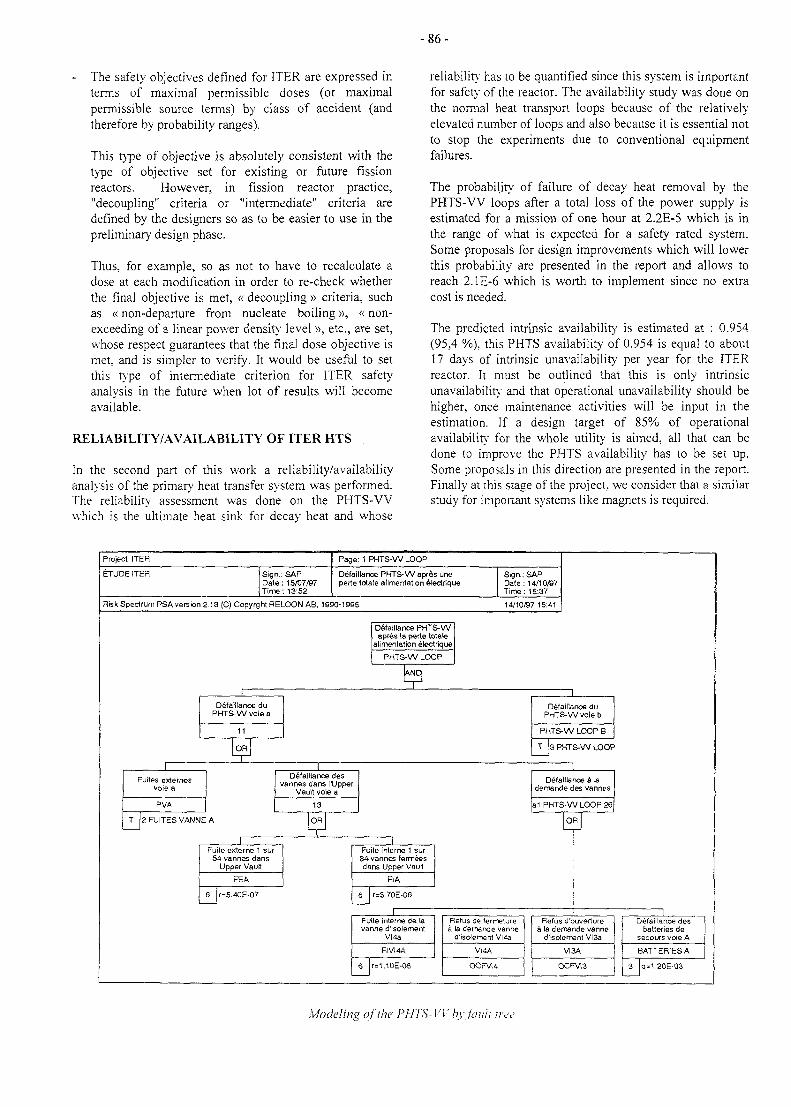
- 8 6 -
- The safety objectives defined for ITER are expressed interms of maximal permissible doses (or maximalpermissible source terms) by class of accident (andtherefore by probability ranges).
This type of objective is absolutely consistent with thetype of objective set for existing or future fissionreactors. However, in fission reactor practice,"decoupling" criteria or "intermediate" criteria aredefined by the designers so as to be easier to use in thepreliminary design phase.
Thus, for example, so as not to have to recalculate adose at each modification in order to re-check whetherthe final objective is met, « decoupling » criteria, suchas «non-departure from nucleate boiling», «non-exceeding of a linear power density level », etc., are set,whose respect guarantees that the final dose objective ismet, and is simpler to verify. It would be useful to setthis type of intermediate criterion for ITER safetyanalysis in the future when lot of results will becomeavailable.
RELIABILITY/AVAILABILITY OF ITER HTS
In the second part of this work a reliability/availabilityanalysis of the primary heat transfer system was performed.The reliability assessment was done on the PHTS-VVwhich is the ultimate heat sink for decay heat and whose
reliability has to be quantified since this system is importantfor safety of the reactor. The availability study was done onthe normal heat transport loops because of the relativelyelevated number of loops and also because it is essential notto stop the experiments due to conventional equipmentfailures.
The probability of failure of decay heat removal by thePHTS-VV loops after a total loss of the power supply isestimated for a mission of one hour at 2.2E-5 which is inthe range of what is expected for a safety rated system.Some proposals for design improvements which will lowerthis probability are presented in the report and allows toreach 2.1E-6 which is worth to implement since no extracost is needed.
The predicted intrinsic availability is estimated at : 0.954(95,4 %). this PHTS availability of 0.954 is equal to about17 days of intrinsic unavailability' per year for the ITERreactor. It must be outlined that this is only intrinsicunavailability and that operational unavailability should behigher, once maintenance activities will be input in theestimation. If a design target of 85% of operationalavailability for the whole utility is aimed, all that can bedone to improve the PHTS availability has to be set up.Some proposals in this direction are presented in the report.Finally at this stage of the project, we consider that a similarstudy for important systems like magnets is required.
Project ITER
ETUDE ITER Sign.: SAPDate : 15/07/97Time: 13:52
Page: 1 PHTS-W LOOP
Defalllance PHTS-W apres uneperte totals alimentation electrique
Sign.: SAPDate: 14/10/97T i r e : 15:37
Risk Spectrum PSA version 2.13 (C) Copyrght RELOON AB, 1990-19S5 14/10/87 15:41
Defaillance PHTS-Wapr&s la perte totale
alimentation electrique
PHTS-W LOOP
Defaillance duPHTS-W voie a
Fuites externesvoie a
PVA
Defaillance desvannes dans ITJpper
Vault voie a
13
T 2 FUITES VANNE A jjTFuite externe 1 sur
54 vannes dansUpper Vault
FEA
6 r=5.4OE-07
Fuite interne 1 sur34 vannes fermeesdans Upper Vault
FIA
6 r=3.70E-06
Defaillance duPHTS-W voie b
PHTS-W LOOP B
T [3 PHTS-W LOOP
Defaillance a lademande des vannes
a1 PHTS-W LOOP 26
IFuite interne de lavanne d'isolement
VI 4a
FIVI4A
6 lr=1.10E-06
Refus de fetmeturea la demande vanne
d'isoJemerrt VI4a
ViiA
OCFVI4
Refus d'ouverturea la demande vanne
d'isolement VI3a
VI3A
OCFV13
IDefaillance des
batteries desecours voie A
BATTERIES A
3 |q=1.20E-03
Modeling of the PHTS-VV by fault tret
- 8 7 -
CONCLUSIONS LIST OF REPORTS
As far as safety approach is concerned, the mainconclusion that can be drawn from this assessment is thatthe probabilistic analysis should stay at a complementarilylevel and that safety demonstration must rely strongly ondeterministic approaches.
The PHTS-VV reliability studies and PHTS availabilitystudies permit the following conclusions to be drawn:
With respect to safety :
The choice of passive operation of the PHTS-VV toremove decay heat after the occurrence of initiating eventssuch as total loss of the electric power supply, LOFA,etc., is highly favorable to reliability and safety.The sensitive point of this design is the exchanger by-passthat has to be isolated so that the thermosiphon operatingmode can become established.
The PHTS is only efficient if the trip occurs within the 15seconds following the occurrence of the initiating event.The risk linked to the removal of decay heat in the eventof the trip occurring after this time is not clearly taken intoaccount.
With respect to availability :
Are the criteria that led to the definition of the number ofPHTS loops the most suitable? The current PHTS designwith its 20 all necessary loops does not facilitate theavailability of the fusion reactor. The PHTS alone couldlead to more than 17 days of predicted intrinsicunavailability per year.
Finally, this study highlights the importance of takingsafety and availability aspects into account in the designstage so as to orient the designers in their work as early onas possible. At present, we consider that a similar studyof the magnet cooling systems is required.
[1] ITER safety implementation and reliability/availability of Heat Transfer Systems.NT : DER/STML/LCFI 97/061 C. Girard, A. Ellia-Hervy, G. Saint Paul.
TASK LEADER
Christian GIRARD
DRN/DER/STML/LCFICadarache
Tel.Fax
04 42 25 49 5604 45 25 66 38
e-mail : [email protected]
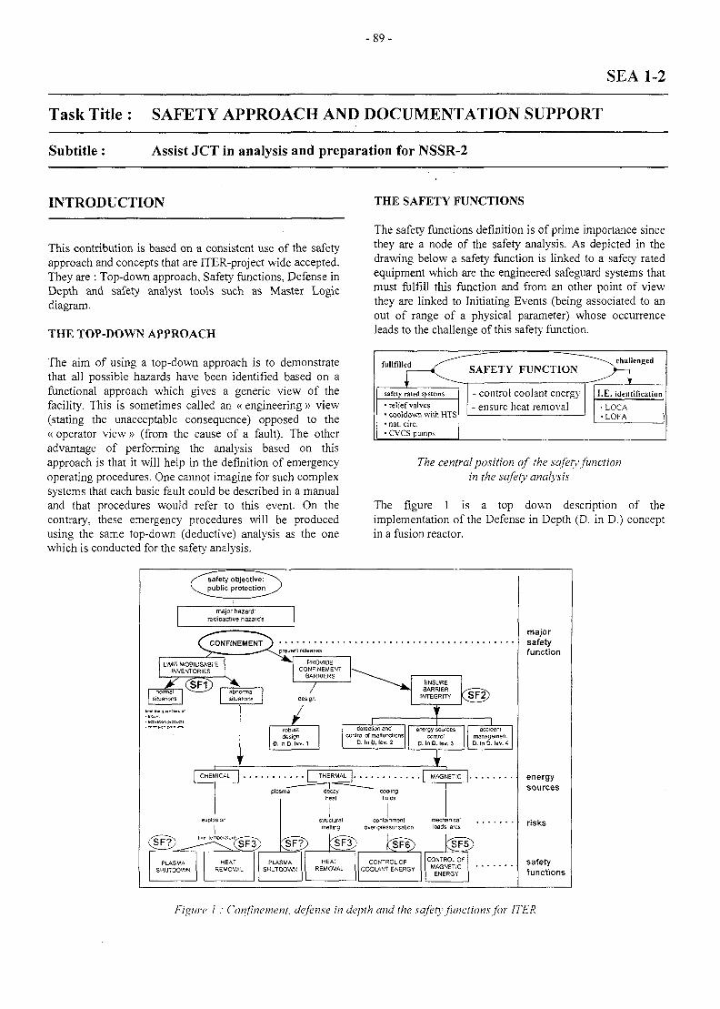
- 8 9 -
SEA 1-2
Task Title : SAFETY APPROACH AND DOCUMENTATION SUPPORT
Subtitle : Assist JCT in analysis and preparation for NSSR-2
INTRODUCTION THE SAFETY FUNCTIONS
This contribution is based on a consistent use of the safetyapproach and concepts that are ITER-project wide accepted.They are : Top-down approach, Safety functions, Defense inDepth and safety analyst tools such as Master Logicdiagram.
THE TOP-DOWN APPROACH
The safety functions definition is of prime importance sincethey are a node of the safety analysis. As depicted in thedrawing below a safety function is linked to a safety ratedequipment which are the engineered safeguard systems thatmust fulfill this function and from an other point of viewthey are linked to Initiating Events (being associated to anout of range of a physical parameter) whose occurrenceleads to the challenge of this safety function.
The aim of using a top-down approach is to demonstratethat all possible hazards have been identified based on afunctional approach which gives a generic view of thefacility. This is sometimes called an « engineering » view(stating the unacceptable consequence) opposed to the« operator view » (from the cause of a fault). The otheradvantage of performing the analysis based on thisapproach is that it will help in the definition of emergencyoperating procedures. One cannot imagine for such complexsystems that each basic fault could be described in a manualand that procedures would refer to this event. On thecontrary, these emergency procedures will be producedusing the same top-down (deductive) analysis as the onewhich is conducted for the safetv analysis.
• relief valves• cooldown with HTS• nat. circ.• CVCS pumps
- control coolant energy• ensure heat removal
I.E. identification
• LOCA•LOFA
The central position of the safety functionin the safety analysis
The figure 1 is a top down description of theimplementation of the Defense in Depth (D. in D.) conceptin a fusion reactor.
PLASMASHUTDOWN
HEATREMOVAL
structural containment mechanicalmelting over-pressunsalion loads arcs
PLASMASHUTDOWN
HEATREMOVAL
CONTROL OFCOOLANT ENERGY
CONTROL OFMAGNETIC
ENERGY
majorsafetyfunction
energysources
risks
safetyfunctions
Figure 1 : Confinement, defense in depth and the safety functions for ITER
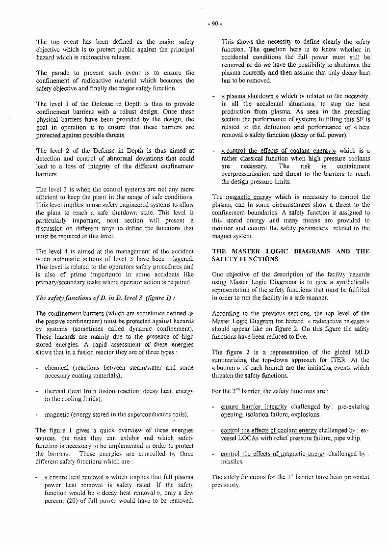
- 9 0 -
The top event has been defined as the major safetyobjective which is to protect public against the principalhazard which is radioactive release.
The parade to prevent such event is to ensure theconfinement of radioactive material which becomes thesafety objective and finally the major safer}' function.
The level 1 of the Defense in Depth is thus to provideconfinement barriers with a robust design. Once thesephysical barriers have been provided by the design, thegoal in operation is to ensure that these barriers areprotected against possible threats.
The level 2 of the Defense in Depth is thus aimed atdetection and control of abnormal deviations that couldlead to a loss of integrity of the different confinementbarriers.
The level 3 is when the control systems are not any moreefficient to keep the plant in the range of safe conditions.This level implies to use safety engineered systems to allowthe plant to reach a safe shutdown state. This level isparticularly important, next section will present adiscussion on different ways to define the functions thatmust be required at this level.
The level 4 is aimed at the management of the accidentwhen automatic actions of level 3 have been triggered.This level is related to the operators safety procedures andis also of prime importance in some accidents likeprimary/secondary leaks where operator action is required.
The safety functions ofD. in D. level 3 (figure 1) :
The confinement barriers (which are sometimes defined asdie passive confinement) must be protected against hazardsby systems (sometimes called dynamic confinement).These hazards are mainly due to the presence of highstored energies. A rapid assessment of these energiesshows that in a fusion reactor they are of three types :
chemical (reactions between steam/water and somenecessary coating materials),
- thermal (heat from fusion reaction, decay heat, energyin the cooling fluids),
- magnetic (energy stored in the superconductors coils).
The figure 1 gives a quick overview of these energiessources, the risks they can exlu'bit and which safetyfunction is necessary to be implemented in order to protectthe barriers. These energies are controlled by threedifferent safer}' functions which are :
- « ensure heat removal » which implies that full plasmapower heat removal is safety rated. If the safetyfunction would be « decay heat removal », only a fewpercent (20) of full power would have to be removed.
This shows the necessity to define clearly the safetyfunction. The question here is to know whether inaccidental conditions the full power must still beremoved or do we have the possibility to shutdown theplasma correctly and then assume that only decay heathas to be removed.
- « plasma shutdown » which is related to the necessity,in all the accidental situations, to stop the heatproduction from plasma. As seen in the precedingsection the performance of systems fulfilling this SF isrelated to the definition and performance of « heatremoval » safety function (decay or full power).
- « control the effects of coolant energy» which is arather classical function when high pressure coolantsare necessary. The risk is containmentoverpressurisation and threat to the barriers to reachthe design pressure limits.
The magnetic energy wliich is necessary to control theplasma, can in some circumstances show a threat to theconfinement boundaries. A safety function is assigned tothis stored energy and many means are provided tomonitor and control the safety parameters related to themagnet system.
THE MASTER LOGIC DIAGRAMS AND THESAFETY FUNCTIONS
One objective of the description of the facility hazardsusing Master Logic Diagrams is to give a syntheticallyrepresentation of the safety functions that must be fulfilledin order to run the facility in a safe manner.
According to the previous sections, the top level of theMaster Logic Diagram for hazard « radioactive releases »should appear like on figure 2. On this figure the safetyfunctions have been reduced to five.
The figure 2 is a representation of the global MLDsummarizing the top-down approach for ITER. At the« bottom » of each branch are the initiating events whichthreaten the safety functions.
For the 2nd barrier, the safety functions are :
- ensure barrier integrity challenged by : pre-existingopening, isolation failure, explosions.
- control the effects of coolant energy challenged by : ex-vessel LOCAs with relief pressure failure, pipe whip.
- control the effects of magnetic energy challenged by :missiles.
The safety functions for the 1st barrier have been presentedpreviously.
- 9 1 -
EXCESSIVERADIOACTIVE
RELEASE
J_1st CONFINEMENT
BARRIERFAIULJRE
ftt t i IT:-
ENSUREBWRIER
INTEGRITY
CONTROL OFFUSION REACTION
DECAY HEATREMOVAL
CONTROLTHE EFFECTS OF
COOLANT ENERGY
- severe disruptions-LOCAs-LOVAs
CONTROLTHE EFFECTS OF
MAGNETIC ENERGY
• power excursion• plasma disruption
- LOFAs-LOCAs- Loss of heat sink
-in W LOCAs -arcs- quenches-loss: of supracondudivity
2nd CONFINEMENTBARRIERFAILURE
ENSUREBARRIER
INTEGRITY
CONTROLTHE EFFECTS OF
COOLANT ENERGY
CONTROLTHE EFFECTS OF
MAGNETIC ENERGY
-pre-existing opening-isolation failure
(HVAC, AC'S)- exploaon (H;)Mri:>ufv:;i*nt gas control)
-ex WJ-OCAs-overpressurisaticn(relief failure)
-pipe whip
-Maanets
Figure 2 : Global Master Logic Diagram for ITER
The scenarios leading to the loss of both confinement arefinally those which needs the more attention. Indeed, theyare not so numerous and from a quick look at figure 2, wecan identify some of the most relevant sequences whichare :
sequences where an initiating event challenging the1st barrier is combined with a poor isolation on the2nd confinement.
sequences where an initiating event challenging the1st barrier leads to a presence of hydrogen within the2nd barrier.
sequences where an initiating event challenging the1st barrier is combined with a loss of control ofcoolant energy within the 2nd barrier (an ex-vesselLOCA dependency or independently occurring withan in-vessel LOCA).
situations where an initiating event challenging theIs1 barrier is combined with a magnet failure (missilegeneration for example).
CONCLUSIONS
A good definition of the safety functions is quite importantfor consistency when using a top-down approach which is.by definition, based on a functional approach of the safetyobjectives. A tentative of the definition of the necessarynumber of safety functions has been presented in this work.
This is also consistent with what is usually done in othernuclear facility. The fusion safety functions differs of theclassical ones by the addition of a function specific to thetokamak (« control of the magnetic energy ») but is quitecomparable to what is found on nuclear installation for theother functions. However, « control of water inventor.- »which is one of the most important safety function in awater cooled fission reactor is not present in a fusion plantanalysis since this does not induce the consequences thatare related to a fission core uncovery.Once those functions defined, the implementation of thedefense in depth approach is easy to justify and then thetop-down method is of interest to identify the possibleparades set up to ensure a graduated and safe control of theplant.

-92-
LIST OF REPORTS TASK LEADER
[1] Sequence Analysis Workshop - ITER task SEA1-2. Christian GIRARDCRR : DER/STML/LCFI 97/235, C. Girard
DRN/DER/STML/LCFI[2] Participation to the ITER NSSR-2 volume X - Master Cadarache
Logic DiagramNT: DER/STML/LCFI 97/054, C. Girard Tel. : 04 42 25 49 56
Fax : 04 45 25 66 38
e-mail: [email protected]
- 9 3 -
SEA 3-1
Task Title : INTEGRATED SAFETY ANALYSIS CODE SYSTEM ISAS
INTRODUCTION
The purpose of this task has been to help users to get betterrvmtrnl anH intfvmrAtcttinTi rwr&r rvntnlinO" 1*UXIS t)Y
variouscontrol and interpretation over couplingintroducing post-processoringoptimizations of the runs.
abilities and
Another natural continuation of this task was to includethe Japanese simulation code Safaly into the ISAS systemwith some Athena partial results.
1997 ACTIVITIES
Development of graphical abilities of ISAS
Graplu'cal abilities have been introduced by using theXmgr product and associated Gibiane procedures inorder to visualize any value provided by each code atany time.
Various optimizations in the systemAccording to the requirements of ISAS users, severalimprovements of the ISAS system have been made :
1. An implementation of specific modules to reach thestatus of memory and CPU time during a coupledrun, in order to optimize the time calculations of theslave codes.
2, An updating of the ISAS kernel using the lastversion of PVM libraries, for example by improvingthe ISAS control when the calculation breaks into aslave code.
5. Supervisor time steps now controlled by comparisonwith the Athena and the Intra internal time step inorder to get a better adjustment for the transientconditions.
- Integration of Safaly within Isas
- Writing two reports
The first report gives specific informations about theintegration of each code wich has been integrated into thesystem : detailed mechanisms used for this integration andfor the data exchanges.
The second report includes the translation, the updatingand the installation on the sites of the on linedocumentation of ISAS system, so as to have the possibilityto consult the last updating on any host type.
PUBLICATIONS
Th. De Gramont, I. Toumi ISAS : on line documentationbased on HTML 3.2 language.CEA report DMT 95/574 December 1997.
Th. De Gramont, I. Toumi ISAS : Description ofATHENA, INTRA, NAUA and SAFALY coupling for safetyanalysis. CEA report DMT 95/575 December 1997.
TASK LEADER
I. TOUMI
3. Possibility to inquire the status of a slave code inorder to avoid sending command when thecorresponding slave code is stopped, to have thepossibility to pursue the run. An application can begiven by a coupling run between Athena and Intra,where Athena can be stopped when physicalconditions become unworkable (pipes empty),without having to stop Intra which calculates byitself values normally delivered by Athena.
4. An optimization of storage of thermal structures forNaua in order to avoid the generation of hugearclu've files.
CEA Saclay - DMT/SYSCO91191 - GIF-SUR-YVETTE CEDEX
Tel.Fax
0169 08 91 120169 08 96 96
e-mail: imad.toumi(5),cea.fr
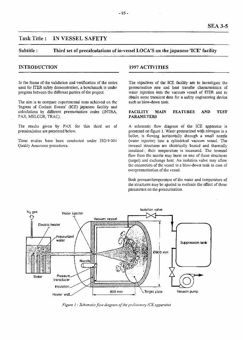
- 9 5 -
SEA 3-5
Task Title : IN VESSEL SAFETY
Subtitle: Third set of precalculations of in-vessel LOCA'S on the Japanese 'ICE' facility
INTRODUCTION 1997 ACTIVITIES
In the frame of the validation and verification of the codesused for ITER safety demonstration, a benchmark is underprogress between the different parties of the project.
The aim is to compare experimental tests achieved on the'Ingress of Coolant Events' (ICE) Japanese facility andcalculations by different pressurisation codes (INTRA,PAX, MELCOR, TRAC).
The results given by PAX for this third set ofprecalculation are presented below.
These studies have been conducted under ISO 9 001Quality Assurance procedures.
The objectives of the ICE facility are to investigate thepressurisation rate and heat transfer characteristics ofwater injection into the vacuum vessel of ITER and toobtain some transient data for a safety engineering devicesuch as blow-down tank.
FACILITY MAINPARAMETERS
FEATURES AND TEST
A schematic flow diagram of the ICE apparatus ispresented on figure 1. Water pressurized with nitrogen in aboiler, is flowing horizontally through a small nozzle(water injector) into a cylindrical vacuum vessel. Theinvessel structures are electrically heated and thermallyinsulated; their temperature is measured. The invesselflow from the nozzle may burst on one of these structures(target) and exchange heat. An isolation valve may allowthe connection of the vessel to a blow-down tank in case ofoverpressurisation of the vessel.
Both pressure/temperature of the water and temperature ofthe structures may be ajusted to evaluate the effect of theseparameters on the pressurisation.
Isolation valve
V/////////////////^^^^^
plate vacuum pomp
Figure 1 : Schematic /low diagram of the preliminary ICE apparatus
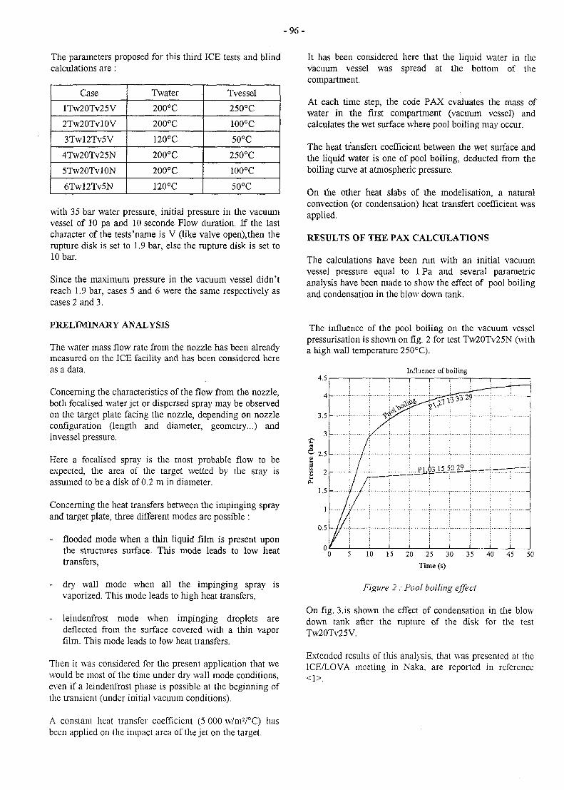
- 9 6 -
The parameters proposed for this third ICE tests and blindcalculations are :
Case
1TW20TV25V
2Tw20Tvl0V
3Twl2Tv5V
4Tw20Tv25N
5Tw20Tvl0N
6Twl2Tv5N
Twater
200°C
200°C
120°C
200°C
200°C
120°C
Tvessel
250°C
100°C
50°C
250°C
100°C
50°C
with 35 bar water pressure, initial pressure in the vacuumvessel of 10 pa and 10 seconde Flow duration. If the lastcharacter of the tests'name is V (like valve open),then therupture disk is set to 1.9 bar, else the rupture disk is set to10 bar.
Since the maximum pressure in the vacuum vessel didn'treach 1.9 bar, cases 5 and 6 were the same respectively ascases 2 and 3.
It has been considered here that the liquid water in thevacuum vessel was spread at the bottom of thecompartment.
At each time step, the code PAX evaluates the mass ofwater in the first compartment (vacuum vessel) andcalculates the wet surface where pool boiling may occur.
The heat tfansfert coefficient between the wet surface andthe liquid water is one of pool boiling, deducted from theboiling curve at atmospheric pressure.
On the other heat slabs of the modelisation, a naturalconvection (or condensation) heat transfert coefficient wasapplied.
RESULTS OF THE PAX CALCULATIONS
The calculations have been run with an initial vacuumvessel pressure equal to 1 Pa and several parametricanalysis have been made to show the effect of pool boilingand condensation in the blow down tank.
PRELIMINARY ANALYSIS
The water mass flow rate from the nozzle has been alreadymeasured on the ICE facility and has been considered hereas a data.
Concerning the characteristics of the flow from the nozzle,both focalised water jet or dispersed spray may be observedon tine target plate facing the nozzle, depending on nozzleconfiguration (length and diameter, geometry...) andinvessel pressure.
Here a focalised spray is the most probable flow to beexpected, the area of the target wetted by the sray isassumed to be a disk of 0.2 m in diameter.
Concerning the heat transfers between the impinging sprayand target plate, three different modes are possible :
- flooded mode when a thin liquid film is present uponthe structures surface. This mode leads to low heattransfers,
dry wall mode when all the impinging sprayvaporized. This mode leads to high heat transfers,
is
- leindenfrost mode when impinging droplets aredeflected from the surface covered with a thin vaporfilm. This mode leads to low heat transfers.
Then it was considered for the present application that wewould be most of the time under dry wall mode conditions,even if a leindenfrost phase is possible at the beginning ofthe transient (under initial vacuum conditions).
A constant heat transfer coefficient (5 000 w/m2/°C) hasbeen applied on the impact area of the jet on the target.
The influence of the pool boiling on the vacuum vesselpressurisation is shown on fig. 2 for test Tw20Tv25N (witha high wall temperature 250°C).
4.5
4
3.5
Influence of boiling
{a
2 -
/
/ f~
1 i
/ / !
/ ! !
....PL* 232-
... 1, . 1. .
i i
1.5 -
1 -
0.5 -
0 5 10 15 20 25 30 35 40 45 50
Time (s)
Figure 2 : Poo! boiling effect
On fig. 3.is shown the effect of condensation in the blowdown tank after the rupture of the disk for the testTw20Tv25V.
Extended results of this analysis, that was presented at theICE/LOVA meeting in Naka, are reported in reference
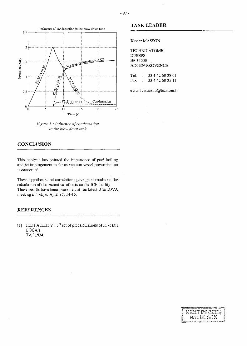
- 9 7 -
2.5Influence of condensation in the blow down tank
TASK LEADER
a 1.5
0.5
/. 53t?7_13 52 41 '"-• Condensation
XavierMASSON
TECHNICATOMEDI/SEPSBP 34000 .AIX-EN-PROVENCE
Tel. : 33 4 42 60 28 61Fax : 33 4 42 60 25 11
e mail: [email protected]
10 15
Time (s)
20 25
Figure 3 : Influence of condensationin the blow down tank
CONCLUSION
This analysis has pointed the importance of pool boilingand jet impingement as far as vacuum vessel pressurisationis concerned.
These hypothesis and correlations gave good results on thecalculation of the second set of tests on the ICE facility.These results have been presented at the latest ICE/LOVAmeeting in Tokyo, April 97, 14-16.
REFERENCES
[ 1 ] ICE FACILITY : 3rd set of precalculations of in vesselLOCA'sTA 11934
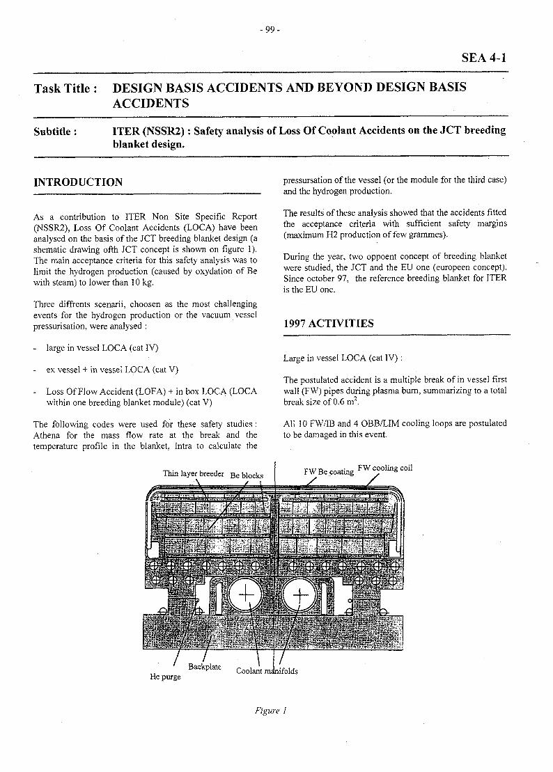
- 9 9 -
SEA 4-1
Task Title : DESIGN BASIS ACCIDENTS AND BEYOND DESIGN BASISACCIDENTS
Subtitle : ITER (NSSR2): Safety analysis of Loss Of Coolant Accidents on the JCT breedingblanket design.
INTRODUCTION
As a contribution to ITER Non Site Specific Report(NSSR2), Loss Of Coolant Accidents (LOCA) have beenanalysed on the basis of the JCT breeding blanket design (ashematic drawing ofth JCT concept is shown on figure 1).The main acceptance criteria for this safety analysis was tolimit the hydrogen production (caused by oxydation of Bewith steam) to lower than 10 kg.
Three diffrents scenarii, choosen as the most challengingevents for the hydrogen production or the vacuum vesselpressurisation, were analysed :
- large in vessel LOCA (cat IV)
- ex vessel + in vessel LOCA (cat V)
- Loss Of Flow Accident (LOFA) + in box LOCA (LOCAwithin one breeding blanket module) (cat V)
The following codes were used for these safety studies :Athena for the mass flow rate at the break and thetemperature profile in the blanket, Intra to calculate the
Thin layer breeder Be blocksA
pressursation of the vessel (or the module for the third case)and the hydrogen production.
The results of these analysis showed that the accidents fittedthe acceptance criteria with sufficient safety margins(maximum H2 production of few grammes).
During the year, two oppoent concept of breeding blanketwere studied, the JCT and the EU one (europeen concept).Since October 97, the reference breeding blanket for ITERis the EU one.
1997 ACTIVITIES
Large in vessel LOCA (cat IV):
The postulated accident is a multiple break of in vessel firstwall (FW) pipes during plasma burn, summarizing to a totalbreak size of 0.6 m2.
All 10 FW/IB and 4 OBB/LIM cooling loops are postulatedto be damaged in this event.
FW Be coating FW cooling coil
_ <- jut- ^ i -i V
He purgeBackplate
Figure I
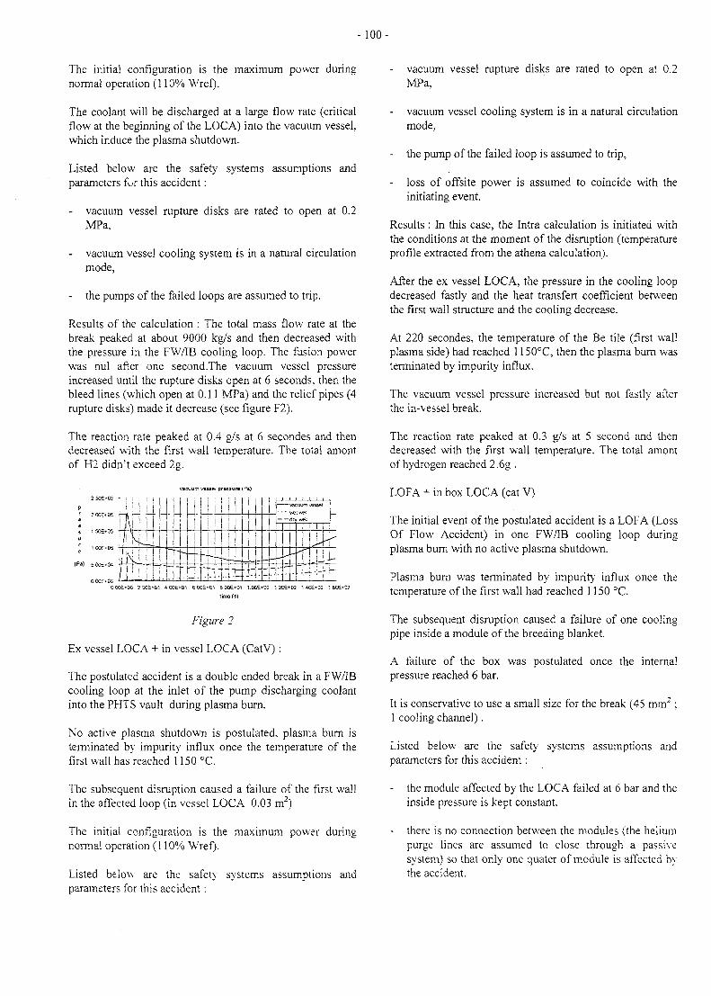
-100-
The initial configuration is the maximum power duringnormal operation (110% Wref).
The coolant will be discharged at a large flow rate (criticalflow at the beginning of the LOCA) into the vacuum vessel,which induce the plasma shutdown.
Listed below are the safety systems assumptions andparameters fur this accident:
- vacuum vessel rupture disks are rated to open at 0.2MPa,
vacuum vessel cooling system is in a natural circulationmode,
- the pumps of the failed loops are assumed to trip.
Results of the calculation: The total mass flow rate at thebreak peaked at about 9000 kg/s and then decreased withthe pressure in the FW/IB cooling loop. The fusion powerwas nul after one second.The vacuum vessel pressureincreased until the rupture disks open at 6 seconds, then thebleed lines (which open at 0.11 MPa) and the relief pipes (4rupture disks) made it decrease (see figure F2).
The reaction rate peaked at 0.4 g/s at 6 secondes and thendecreased with the first wall temperature. The total amontof H2 didn't exceed 2g.
vacuum vessel pressure (Pa)
s 1 SOE+05
^ 1OOE-05
(Pa) £ 0O£+W
O.OOE'CC
'rk1
-
-1
i-
JI
"!T.it1i4tt;d:jr
- • • wet vvefl L_dry well \
r-
T-f j L
OO0£+0C 2OOE*O1 600E+01 aooe*(n 1.00E*02 12OE+O2 1.40E-02 : 6O£*02trme(s)
Figure 2
Ex vessel LOCA + in vessel LOCA (CatV):
The postulated accident is a double ended break in a FW/IBcooling loop at the inlet of the pump discharging coolantinto the PHTS vault during plasma burn.
No active plasma shutdown is postulated, plasma burn isterminated by impurity influx once the temperature of thefirst wall has reached 1150 °C.
The subsequent disruption caused a failure of the first wallin the affected loop (in vessel LOCA 0.03 m2)
The initial configuration is the maximum power duringnormal operation (110% Wref).
Listed below are the safety systems assumptions andparameters for this accident:
- vacuum vessel rupture disks are rated to open at 0.2MPa,
vacuum vessel cooling system is in a natural circulationmode,
- the pump of the failed loop is assumed to trip,
- loss of offsite power is assumed to coincide with theinitiating event.
Results : In this case, the Intra calculation is initiated withthe conditions at the moment of the disruption (temperatureprofile extracted from the athena calculation).
After the ex vessel LOCA, the pressure in the cooling loopdecreased fastly and the heat transfert coefficient betweenthe first wall structure and the cooling decrease.
At 220 secondes, the temperature of the Be tile (first wallplasma side) had reached 1150°C, then the plasma burn wasterminated by impurity influx.
The vacuum vessel pressure increased but not fastly afterthe in-vessel break.
The reaction rate peaked at 0.3 g/s at 5 second and thendecreased with the first wall temperature. The total amontof hydrogen reached 2.6g .
LOFA + in box LOCA (cat V)
The initial event of the postulated accident is a LOFA (LossOf Flow Accident) in one FW/IB cooling loop duringplasma burn with no active plasma shutdown.
Plasma burn was terminated by impurity influx once thetemperature of the first wall had reached 1150 °C.
The subsequent disruption caused a failure of one coolingpipe inside a module of the breeding blanket.
A failure of the box was postulated once the internalpressure reached 6 bar.
It is conservative to use a small size for the break (45 mm2;1 cooling channel).
Listed below are the safety systems assumptions andparameters for this accident:
- the module affected by the LOCA failed at 6 bar and theinside pressure is kept constant,
there is no connection between the modules (the heliumpurge lines are assumed to close through a passivesystem) so that only one quater of module is affected bythe accident.
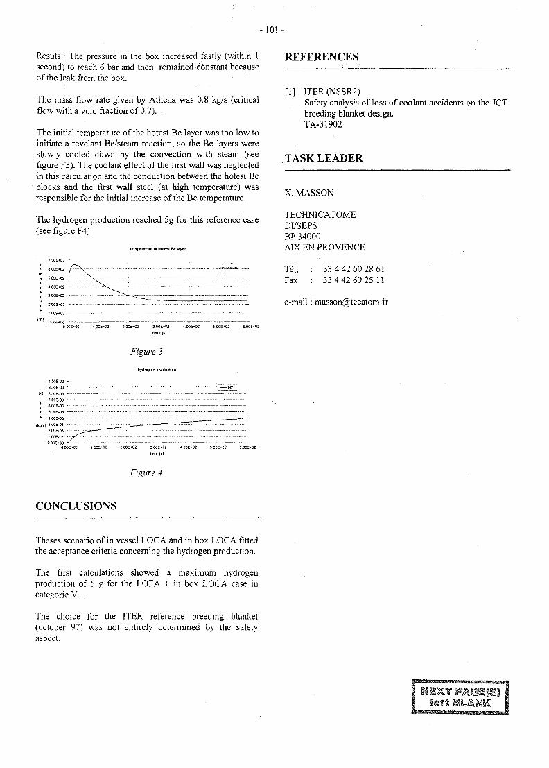
-101 -
Resuts : The pressure in the box increased fastly (within 1second) to reach 6 bar and then remained constant becauseof the leak from the box.
The mass flow rate given by Athena was 0.8 kg/s (criticalflow with a void fraction of 0.7).
The initial temperature of the hotest Be layer was too low toinitiate a revelant Be/steam reaction, so the Be layers wereslowly cooled down by the convection with steam (seefigure F3). The coolant effect of the first wall was neglectedin this calculation and the conduction between the hotest Beblocks and the first wall steel (at high temperature) wasresponsible for the initial increase of the Be temperature.
The hydrogen production reached 5g for this reference case(see figure F4).
temperature of ftotest Be layer
"0Q£-«O2 -
e 6.0CE*02
p S.OOE-02
r 4.005*02
, 3.00£*O2
" 2 . 0 0 E - 0 2 - - - - • : - • • -
e !O0E*C2 - - - - • —
0 OOE-00 1 .OOE-02 2.00E+02 3 OOE-02 4.00£*02 5 00E*02 6.00S*02
time (s)
REFERENCES
[1] ITER(NSSR2)Safety analysis of loss of coolant accidents on the JCTbreeding blanket design.TA-31902
TASK LEADER
X. MASSON
TECHNICATOMEDI/SEPSBP 34000AIX EN PROVENCE
Tel. : 33 4 42 60 28 61Fax : 33 4 42 60 25 11
e-mail : [email protected]
Figure 3
hydrogen production
1.O0E-O2 -
9O0E-O3 • - - - -
H2 8.OOE-O3 - - - — —
7.O0E-O3 — - • " — ' - —P
t 6.00E-03
o 5 00E-O3 —• - - ••--d 4.00E-03 - - -
( k f t , s , 3.O0E-O3 -
2.00E-03 - --
1 OOE-03
0 O0E+0C 1 OOS*C2 2.00E-«02 3 00E*C2 4 O0E*O2 5 O0£*02 6.00E*02
time (si
Figure 4
CONCLUSIONS
Theses scenario of in vessel LOCA and in box LOCA fittedthe acceptance criteria concerning the hydrogen production.
The first calculations showed a maximum hydrogenproduction of 5 g for the LOFA + in box LOCA case incategorie V.
The choice for the ITER reference breeding blanket(october 97) was not entirely determined by the safetyaspect.
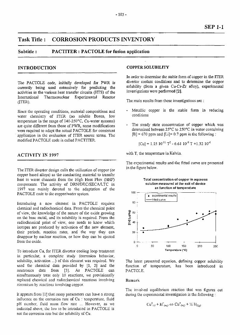
- 1 0 3 -
SEP 1-1
Task Title : CORROSION PRODUCTS INVENTORY
Subtitle: PACTITER : PACTOLE for fusion application
INTRODUCTION
The PACTOLE code, initially developed for PWR iscurrently being used extensively for predicting theactivities in the various heat transfer circuits (HTS) of theInternational Thermonuclear Experimental Reactor(ITER).
Since the operating conditions, material compositions andwater chemistry of ITER (no soluble Boron, lowtemperature in the range of 140-250°C, Cu-water systems)are quite different from those of PWR, some modificationswere required to adapt the actual PACTOLE for consistentapplication in the evaluation of ITER source terms. Themodified PACTOLE code is called PACTITER.
ACTIVITY IN 1997
The ITER divertor design calls the utilization of copper (orcopper based alloys) as the conducting material to transferheat to water channels from the High Heat Flux (HHF)components. The activity of DRN/DEC/SECA/LTC in1997 was mainly devoted to the adaptation of thePACTOLE code to the copper/water system.
Introducing a new element in PACTOLE requireschemical and radiochemical data. From the chemical pointof view, the knowledge of the nature of the oxide growingon the base metal, and its solubility is required. From theradiochemical point of view, one needs to know whichisotopes are produced by activation of the new element,their periods, reaction rates, and the way they candisappear by nuclear reaction, or how they can be ejectedfrom the oxide.
To introduce Cu, for ITER divertor cooling loop treatmentin particular, a complete study (corrosion behavior,solubility, activation ...) of this element was required. Weused the chemical data provided by [1, 2] and theneutronics data from [3]. As PACTOLE cansimultaneously treat only 10 reactions, we provisionallyreplaced chemical and radiochemical reactions involvingzirconium by reactions involving copper.
It appears from [1] that many parameters can have a stronginfluence on the corrosion rale of Cu : temperature, fluidpH number, fluid mass flow rate ... However, as weindicated above, the law to be introduced in PACTOLE isnot the corrosion rate but the solubility of Cu.
COPPER SOLUBILITY
In order to determine the stable form of copper in the ITERdivertor coolant conditions and to determine the coppersolubility (from a given Cu-Cr-Zr alloy), experimentalinvestigations were performed [2].
The main results from those investigations are :
- Metallic copper is the stable form in reducingconditions
- The steady state concentration of copper which wasdetermined between 25°C to 250°C in water containing[B] = 670 ppm and [Li]= 0.7 ppm is the following :
[Cu]= 1.15 10"nT2-6.61 10"9T+1.32 lO"6
with T, the temperature in Kelvin.
The experimental results and the fitted curve are presentedin the figure below.
Total concentration of copper in aqueoussolution measured at the exit of device
as function of temperature100
80 -
60 -
40 -r
20 4-
* experimental results—fitted curve
100 150Temperature (°C)
200 250
The latest presented equation, defining copper solubilityfunction of temperature, has been introduced inPACTOLE.
Remark
The involved equilibrium reaction that was figures outduring the experimental investigation is the following :
Cu°(s)
Cu+(a H2,2(g)
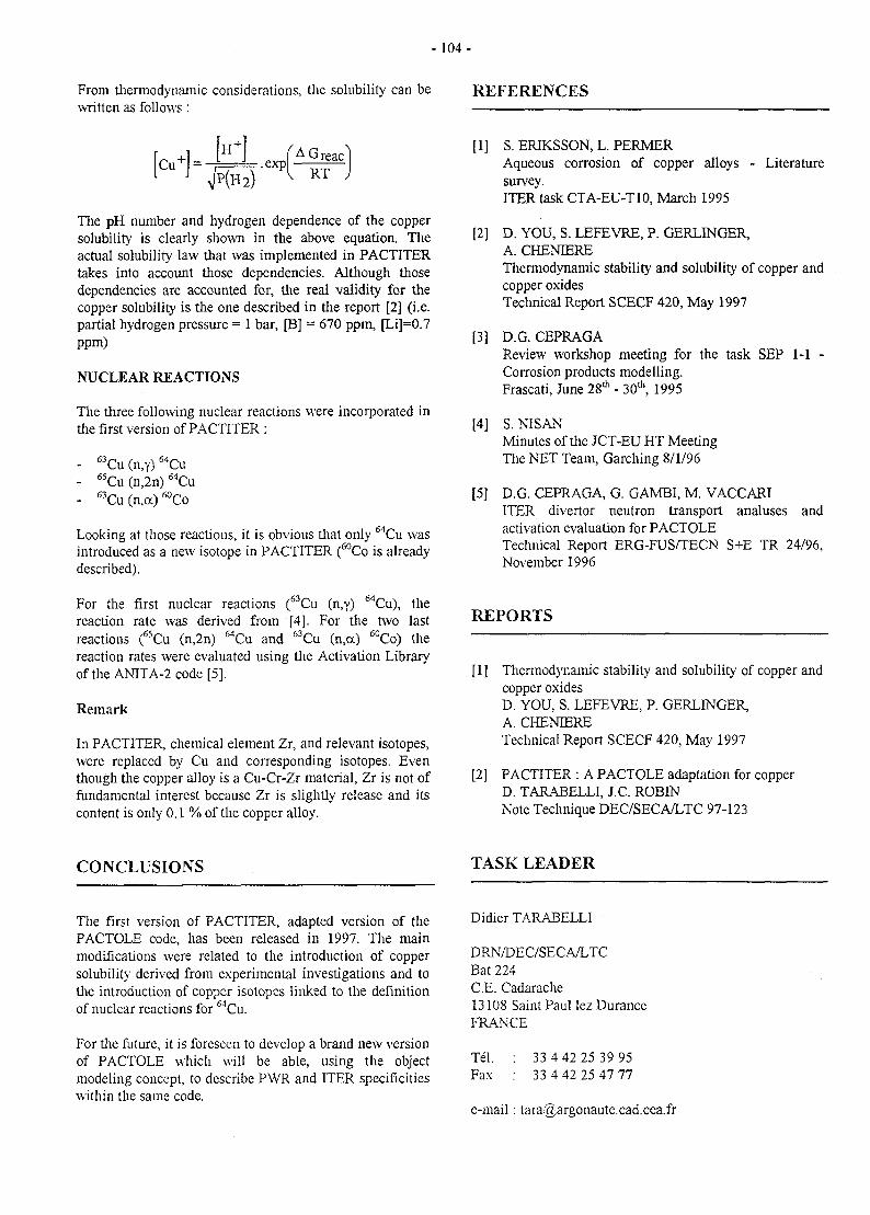
-104 -
From thermodynamic considerations, the solubility can bewritten as follows :
REFERENCES
The pH number and hydrogen dependence of the coppersolubility is clearly shown in the above equation. Theactual solubility law that was implemented in PACTITERtakes into account those dependencies. Although thosedependencies are accounted for, the real validity for thecopper solubility is the one described in the report [2] (i.e.partial hydrogen pressure = 1 bar, [B] = 670 ppm, [Li]=0.7ppm)
NUCLEAR REACTIONS
The three following nuclear reactions were incorporated inthe first version of PACTITER :
- 63Cu (n,y) 64Cu- 65Cu (n,2n) 64Cu- 63Cu (n,oc) ^Co
Looking at those reactions, it is obvious that only 64Cu wasintroduced as a new isotope in PACTITER (60Co is alreadydescribed).
For thereaction
first nuclear reactions ("Cu (n,y) MCu), therate was derived from
, 6 5 ,[41-63 e
For the two60/-
lastreactions ("Cu (n,2n) MCu and wCu (n,a) 60Co) thereaction rates were evaluated using the Activation Libraryof the ANITA-2 code [5].
Remark
In PACTITER, chemical element Zr, and relevant isotopes,were replaced by Cu and corresponding isotopes. Eventhough the copper alloy is a Cu-Cr-Zr material, Zr is not offundamental interest because Zr is slightly release and itscontent is only 0 . 1 % of the copper alloy.
[1] S. ERIKSSON, L. PERMERAqueous corrosion of copper alloys - Literaturesurvey.ITER task CTA-EU-T10, March 1995
[2] D. YOU, S. LEFEVRE, P. GERLINGER,A. CHENIEREThermodynamic stability and solubility of copper andcopper oxidesTechnical Report SCECF 420, May 1997
[3] D.G. CEPRAGAReview workshop meeting for the task SEP 1-1 -Corrosion products modelling.Frascati, June 28th - 30th, 1995
[4] S. NTSANMinutes of the JCT-EU HT MeetingThe NET Team, Garching 8/1/96
[5] D.G. CEPRAGA, G. GAMBI, M. VACCARIITER divertor neutron transport analuses andactivation evaluation for PACTOLETechnical Report ERG-FUS/TECN S+E TR 24/96,November 1996
REPORTS
[1] Thermodynamic stability and solubility of copper andcopper oxidesD. YOU, S. LEFEVRE, P. GERLINGER,A. CHENIERETechnical Report SCECF 420, May 1997
[2] PACTITER : A PACTOLE adaptation for copperD. TARABELLI, J.C. ROBINNote Technique DEC/SECA/LTC 97-123
CONCLUSIONS TASK LEADER
The first version of PACTITER, adapted version of thePACTOLE code, has been released in 1997. The mainmodifications were related to the introduction of coppersolubility' derived from experimental investigations and tothe introduction of copper isotopes linked to the definitionof nuclear reactions for 6ACa.
For the future, it is foreseen to develop a brand new versionof PACTOLE which will be able, using the objectmodeling concept, to describe PWR and ITER specificitieswithin the same code.
Didier TARABELLI
DRN/DEC/SECA/LTCBat 224C.E. Cadarache13108 Saint Paul Iez DuranceFRANCE
Tel. : 33 4 42 25 39 95Fax : 33 4 42 25 47 77
e-mail : [email protected]
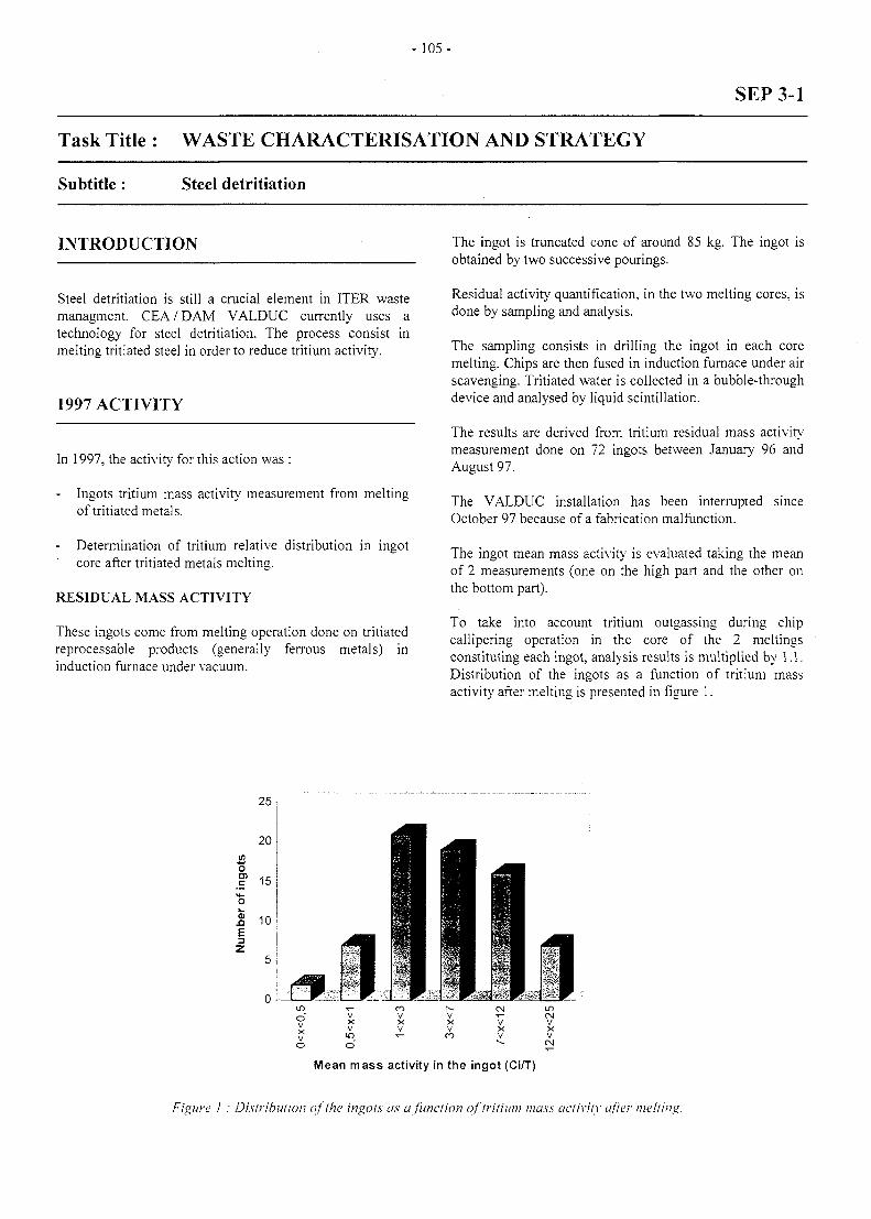
- 1 0 5 -
SEP 3-1
Task Title : WASTE CHARACTERISATION AND STRATEGY
Subtitle : Steel detritiation
INTRODUCTION
Steel detritiation is still a crucial element in ITER wastemanagment. CEA/DAM VALDUC currently uses atechnology for steel detritiation. The process consist inmelting tritiated steel in order to reduce tritium activity.
1997 ACTIVITY
In 1997, the activity for this action was :
Ingots tritium mass activity measurement from meltingof tritiated metals.
Determination of tritium relative distribution in ingotcore after tritiated metals melting.
RESIDUAL MASS ACTIVITY
These ingots come from melting operation done on tritiatedreprocessable products (generally ferrous metals) ininduction furnace under vacuum.
The ingot is truncated cone of around 85 kg. The ingot isobtained by two successive pourings.
Residual activity quantification, in the two melting cores, isdone by sampling and analysis.
The sampling consists in drilling the ingot in each coremelting. Chips are then fused in induction furnace under airscavenging. Tritiated water is collected in a bubble-throughdevice and analysed by liquid scintillation.
The results are derived from tritium residual mass activitymeasurement done on 72 ingots between January 96 andAugust 97.
The VALDUC installation has been interrupted sinceOctober 97 because of a fabrication malfunction.
The ingot mean mass activity is evaluated taking the meanof 2 measurements (one on the high part and the other onthe bottom part).
To take into account tritium outgassing during chipcallipering operation in the core of the 2 meltingsconstituting each ingot, analysis results is multiplied by 1.1.Distribution of the ingots as a function of tritium massactivity after melting is presented in figure 1.
Ico
t
25,
20
15-j
10
VXV
COVXV
^—
N-VXVCO
T—
VXV
t oCMVXV
Mean mass activity in the ingot (Ci/T)
Figure 1 : Disiribution of the ingots as a function of tritium mass activity after melting
-106 -
The mean mass activity of the 72 ingots is 5.4 Ci/T.
N.B. : Correlation between mass activity before andafter melting as well as decontamination factordetermination can not be done because tritiatedsteels have not been characterised before melting.
TRITIUM RESIDUAL ACTIVITYGRAPHY IN INGOT CORE
AUTORADIO-
Autoradiography allows determination of tritium relativedistribution in the ingot core.
Autoradiography method aim is not to quantify tritiumresidual activity but to permit qualitative visualisation oftritium distribution and to realise isoactivity area mapping.
The device is made of a flexible plate directly in contactwith the material. The plate is excited by tritium p-radiations. It is then disposed on a rotating roller and de-energised by laser with vertical movement (helicoidscanning). Fluorescence acoustic radiation resulting fromde-energisation is read and displayed on screen. Then, thesignal (high sensibility) is converted into image. Themaximum resolution is 42(im pixels.
This plate (not contaminated at the end of measurement,wipe test in support) is re-usable after UV regeneration.
The main problem is that the use of tliis device is onlydedicated for the moment to very weakly radioactive body(biologic tissue). In our case, ingots have an importantactivity level. This involves very short exposition time ofthe plate or printing limitation with a protection film(thickness < 20 \xm), Milar for example. Tests arenecessary to set the experimental conditions.
Concerning tritium residual activity autoradiography iningot core, study continues with alternative saw order andinstallation, non active ingot cutting, real ingot cutting,solid scintillation method establishment andmeasurements.
REPORTS
[1] J.P. DACLIN, S. ROSANVALLON, "Determinationof tritium relative distribution in ingot core aftertritiated metals melting. Program proposition.11, NoteTechnique STML/LEPE 98/006.
[2] J.P. DACLIN, S. ROSANVALLON, "Ingots tritiummass activity measurement from melting of tritiatedmetals", Note Technique STML/LEPE 98/007.
TASK LEADER
Sandrine ROSANVALLON
DRN/DER/STML/LEPEC.E.N. Cadarache
Tel.Fax
04 42 25 64 1904 42 25 72 87
e-mail: [email protected]
CONCLUSIONS
Concerning residual mass activity measurements,conclusions of these tests are the same as in the previousreports with :
- An improvement in the operating mode, since 1993,allows a better outgassing of the molten metal bath anda mean mass activity of the ingots around 5.4 Ci/T(instead of 6.6 Ci/T in 1995).
- No influence of initial mass activity.
In 1998, new measurements of tritium outgassing rate willbe done on 6 ingots produced between 1984 and 1994,selected for their daily tritium outgassing raterepresentativity (low, middle and high values).
- 107-
SEP 3-3
Task Title : DECOMMISSIONING STRATEGY OF ITER
INTRODUCTION 1997 ACTIVITY
In many countries according to the legal rules an initialdecommissioning plan has to be drawn up by the licenseesof new nuclear facilities.
This is a reason to think about the definition ofdecommissioning scenario for ITER, but this regulatoryapproach is depending on many parameters which arecountry dependant and is not suitable for ITER at thisstage of the studies.
Nevertheless decommissioning studies are important forITER project from technical point of view for two otherreasons:
- ITER will be the first nuclear installation and even if itis not totally representative of the future fusion plan, itis of prior interest to show that ITER could be build,operated and dismantled without any undesirableimpact on the population, the worker and theenvironment.
ITER studies have to show that after operation it willnot be a burden for many generations and that it will bepossible, if it is desirable, to return the site to a "greenfield status".
- From engineering point of view the experience ofdecommissioning of the first nuclear plants has shownthat the dismantling work will be easier in term oftechnical point of view, and dose for the workers (andfinally from economical point of view) if this kind ofoperation are taken into account into the design.
Implications may be related to some conditions whichcan be easily incorporated in the design in order tofacilitate the dismantling operations, the transfer andthe packaging of the dismantled components.
From this point of view, due mainly to the fact thatseveral internal component may be changed duringoperation, the design of ITER has made a lot ofimprovement for the IDR design.
Other implications are related to the remote handlingequipment and manutention tools in order to makeeasier the dismantling of the active components.
The purpose of this work is to do a first evaluation ofsome decommissioning scenarios in order to point outsome of the implications.
PRESENTATION OF THE SCENARIOS OFTOKAMAK BUILDING DECOMMISSIONING
Reference scenario (1)
This reference scenario is presented in the ITER NSSR 1document.
After shutdown the first phase includes the dismantling ofthe inner components (by remote handling tools in place)and the beginning of dismantling of low level components(as auxiliaries for example). The installation is thenmothballed for a decrease time of about 50 years in order toreach hands-on level dose for a large part of thecomponents.
Nevertheless even after 50 years the radioactivity of theinner part of the Vacuum Vessel would be too high andremote handling tools are necessary to dimantle the innercomponents.
As soon as this operation has been performed, it will bepossible to dismantle all the other components and thebioshield by hands-on).
Early decommissioning - Scenario 2
The idea of this scenario is to use as much as possible thein place remote handling tools to dismantle the innercomponents.
An advantage is that the personnel in place has a goodexperience of the facility (they first have extract theblankets and other in vessel components).
The time required for the remote handling operation isestimated to be more important by a factor two, that for thescenario 1.
Delayed decommissioning - Scenario 3
The third scenario will consist in considering a timesufficient to decrease the activity of the inner wall of theVacuum Vessel so that, all the operation could be doneby hands-on work. This required about a decreasing timeof 100 years.
The dismantling of all the components will be more easyand it will be possible to begin the operations bydismantling the components from outside to inside usingconventional tools.
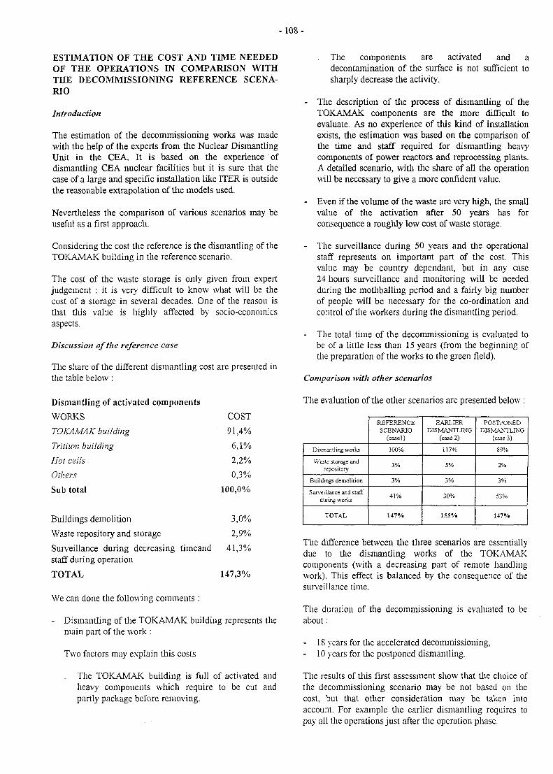
- 1 0 8 -
ESTIMATION OF THE COST AND TIME NEEDEDOF THE OPERATIONS IN COMPARISON WITHTHE DECOMMISSIONING REFERENCE SCENA-RIO
Introduction
The estimation of the decommissioning works was madewith the help of the experts from the Nuclear DismantlingUnit in the CEA. It is based on the experience ofdismantling CEA nuclear facilities but it is sure that thecase of a large and specific installation like ITER is outsidethe reasonable extrapolation of the models used.
Nevertheless the comparison of various scenarios may beuseful as a first approach.
Considering the cost the reference is the dismantling of theTOKAMAK building in the reference scenario.
The cost of the waste storage is only given from expertjudgement : it is very difficult to know what will be thecost of a storage in several decades. One of the reason isthat tliis value is highly affected by socio-econoinicsaspects.
Discussion of the reference case
The share of the different dismantling cost are presented inthe table below :
Dismantling of activated components
WORKS
TOKAMAK building
Tritium building
Hot cells
Others
Sub total
COST
91,4%
6,1%
2,2%
0,3%
100,0%
Buildings demolition 3,0%
Waste repository and storage 2,9%
Surveillance during decreasing timeand 41,3%staff during operation
TOTAL 147,3%
We can done the following comments :
Dismantling of the TOKAMAK building represents themain part of the work :
Two factors may explain this costs
. The TOKAMAK building is full of activated andheavy components which require to be cut andpartly package before removing.
. The components are activated and adecontamination of the surface is not sufficient tosharply decrease the activity.
- The description of the process of dismantling of theTOKAMAK components are the more difficult toevaluate. As no experience of this kind of installationexists, the estimation was based on the comparison ofthe time and staff required for dismantling heavycomponents of power reactors and reprocessing plants.A detailed scenario, with the share of all the operationwill be necessary to give a more confident value.
- Even if the volume of the waste are very high, the smallvalue of the activation after 50 years has forconsequence a roughly low cost of waste storage.
- The surveillance during 50 years and the operationalstaff represents on important part of the cost. Thisvalue may be country dependant, but in any case24 hours surveillance and monitoring will be neededduring the mothballing period and a fairly big numberof people will be necessary for the co-ordination andcontrol of the workers during the dismantling period.
The total time of the decommissioning is evaluated tobe of a little less than 15 years (from the beginning ofthe preparation of the works to the green field).
Comparison with other scenarios
The evaluation of the other scenarios are presented below :
Dismantling works
Waste storage andrepository
Buildings demolition
Surveillance and staffduring works
TOTAL
REFERENCESCENARIO
(easel)
100%
3%
3%
41%
147%
EARLIERDISMANTLING
(case 2)
117%
5%
3%
30%
155%
POSTPONEDDISMANTLING
(case 3)
89%
2%
3%
53%
147%
The difference between the three scenarios are essentiallydue to the dismantling works of the TOKAMAKcomponents (with a decreasing part of remote handlingwork). This effect is balanced by the consequence of thesurveillance time.
The duration of the decommissioning is evaluated to beabout :
- 18 years for the accelerated decommissioning,- 10 years for the postponed dismantling.
The results of this first assessment show that the choice ofthe decommissioning scenario may be not based on thecost, but that other consideration may be taken intoaccount. For example the earlier dismantling requires topay all the operations just after the operation phase.
- 1 0 9 -
REFERENCES
[ 1 ] ITER Decommissioning strategyNT DER/STML/97.90G. MARBACH
TASK LEADER
Gabriel MARBACH
DRN/DER/STMLCadarache
Tel. : 04 42 25 34 14Fax : 04 42 25 65 08
e-mail: marbach @ babaorum.cad.CEA.fr
- I l l -
LONG TERMPROGRAMME
UnderlyingTechnology
InertialConfinement
BasicMachine
left BLA1K-tf?p^
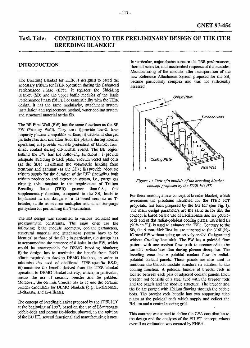
-113-
CNET 97-454
Task Title: CONTRIBUTION TO THE PRELIMINARY DESIGN OF THE ITERBREEDING BLANKET
INTRODUCTION
The Breeding Blanket for ITER is designed to breed thenecessary tritium for ITER operation during the EnhancedPerformance Phase (EPP). It replaces the ShieldingBlanket (SB) and the upper baffle modules of the BasicPerformance Phase (BPP). For compatibility with the ITERdesign, it has the same modularity, attachment system,installation and replacement method, water cooling system,and structural material as the SB.
The BB First Wall (FW) lias the same functions as the SBFW (Primary Wall). They are: i) provide low-Z, low-impurity plasma compatible surface; ii) withstand chargedparticle flux and radiation from the plasma during normaloperation; iii) provide suitable protection of blanket fromdirect contact during off-normal events. The BB regionbehind the FW has the following functions: i) provideadequate shielding to back plate, vacuum vessel and coils(as the SB); ii) exhaust the volumetric heating fromneutrons and gammas (as the SB); iii) provide adequatetritium supply for the duration of the EPP (including bothtritium production and extraction system, i.e., purge gascircuit); this translate in the requirement of TritiumBreeding Ratio (TBR) greater than 0.8; thissupplementary function, compared to the SB, leads toimplement in the design of a Li-based ceramic as T-breeder, of Be as neutron-multiplier and of an He-purgegas system for performing the T-extraction.
The BB design was submitted to various technical andprogrammatic constraints. The main ones are thefollowing: i) the module geometry, coolant parameters,structural material and attachment system have to beidentical to those of the SB ; in particular, the design hasto accommodate the presence of 8 holes in the FW, whichwould be unacceptable for DEMO breeding blankets;ii) the design has to maximise the benefit from R&Defforts required to develop DEMO blankets, in order tominimise the need of additional ITER-specific R&D;iii) maximise the benefit derived from the ITER blanketoperation to DEMO blanket activity, which, in particular,means the use of ceramic breeder and Be pebbles.Moreover, the ceramic breeder has to be one the ceramicbreeder candidates for DEMO blankets (e.g., Li-zirconate,Li-titanate, and Li-silicate).
The concept of breeding blanket proposed by the ITER JCTat the beginning of 1997, based on the use of Li-zirconatepebble-beds and porous Be-blocks, showed, in the opinionof the EU HT, several functional and manufacturing issues.
In particular, major doubts concern the TBR performances,thermal behavior, and mechanical response of the modules.Manufacturing of the module, after incorporation of thenew Reference Attachment System proposed for the SB,became particularly complex and was not sufficientlyassessed.
Shield Plate
Breeder Rods
Figure 1: View of a module of the breeding blanketconcept proposed by the ITER EU HT.
For these reasons, a new concept of breeder blanket, whichovercomes the problems identified for the ITER JCTproposals, has been proposed by the EU HT (see Fig. 1).The main design parameters are the same as for SB; theconcept is based on the use of Li-zirconate and Be pebble-beds and of flat radial-poloidal cooling plates. Enriched Li(90% in 6Li) is used to enhance the TBR. Contrary to theSB, the 5 mm-thick Be-tiles are attached to the 316L(N)-IG steel FW without using an actively cooled Cu layer andwithout Cu-alloy heat sink. The FW has a poloidal flowpattern with one coolant flow path to accommodate thetoroidal surface heat flux during plasma disruption. Thebreeding zone has a poloidal coolant flow in radial-poloidal coolant panels. These panels are also used toreinforce the blanket module structure in addition to thecooling function. A poloidal bundle of breeder rods islocated between each pair of adjacent coolant panels. Eachbreeder rod consists of a steel tube with the breeder rodsand the panels and the module structure. The breeder andthe Be are purged with Helium flowing through the pebblebeds. The breeder rods bundle has two supporting tubeplates at the poloidal ends which supply and collect theHelium and a central spacing grid.
This contract was aimed to define the CEA contribution tothe design and the analyses of the EU HT concept, whoseoverall co-ordination was ensured by ENEA.
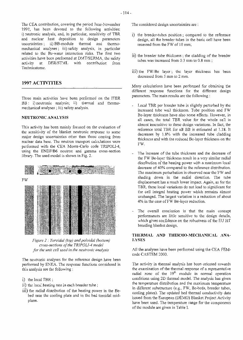
-114-
The CEA contribution, covering the period June-November1997, has been devoted to the following activities:i) neutronic analysis, and, in particular, sensitivity of TBRand nuclear heat deposition to design parametersuncertainties; ii) BB-module thermal and thermo-mechanical analyses; iii) safety analysis, in particularrelated to the Be-water interaction risks. The first twoactivities have been performed at DMT/SERMA, the safetyactivity at DER/STML with contribution fromTechnicatome.
1997 ACTIVITIES
Three main activities have been performed on the ITERBB: i) neutronic analysis; ii) thermal and thermo-mechanical analyses ; iii) safety analysis.
NEUTRONIC ANALYSIS
This activity has been mainly focused on the evaluation ofthe sensitivity of the blanket neutronic response to somemajor design uncertainties other then those coming fromnuclear data base. The neutron transport calculations wereperformed with the CEA Monte-Carlo code TRIPOLI-4,using the ENDF/B6 neutron and gamma cross-sectionlibrary. The used model is shown in Fig. 2.
FW
4
7'
U 1iif?!
I1'Ii
IIm
ifI?
IB:
-,t;
-
II
Figure 2 : Toroidal (top) andpoloidal (bottom)cross-sections of the TRIPOLI-4 model
for the unit cell used in the neutronic analysis
The neutronic analyses for the reference design have beenperformed by ENEA. The response functions considered inthis analysis are the following :
i) the local TBR;ii) the local heating rate in each breeder tube ;iii) the radial distribution of the heating power in the Be-
bed near the cooling plate and in the bed toroidal mid-plane.
The considered design uncertainties are :
i) the breeder-tubes position ; compared to the referencedesign, all the breeder tubes in the basic cell have beenrecessed from the FW of 10 mm;
ii) the breeder tube thickness ; the cladding of the breedertubes was increased from 0.3 mm to 0.8 mm ;
iii) the FW-Be layer; the layer thickness has beendecreased from 5 mm to 2 mm.
Many calculations have been performed for obtaining thedifferent response functions for the different designparameters. The main results are the following :
- Local TBR per breeder tube is slightly perturbed by theincreased tube wall thickness. Tube position and FWBe-layer thickness have also some effects. However, inall cases, the total TBR value for the whole cell isalmost insensitive to these design variations. In fact, thereference total TBR for all BB is estimated at 1.18. Itdecreases by 1.8% with the increased tube claddingthickness and with the reduced Be-layer thickness on theFW.
- The increase of the tube thickness and the decrease ofthe FW Be-layer thickness result in a very similar radialdistribution of the heating power with a maximum localdecrease of 40% compared to the reference distribution.The maximum perturbation is observed near the FW andshading down in the radial direction. The tubedisplacement has a much lower impact. Again, as for theTBR, these local variations do not lead to significant forthe cell integral heating power which remains almostunchanged. The largest variation is a reduction of about4% in the case of FW Be-layer reduction.
The overall conclusion is that the main conceptperformances are little sensitive to the design details,which gives confidence on the robustness of the EU HTbreeding blanket design.
THERMAL AND THERMO-MECHANICAL ANA-LYSES
All the analyses have been performed using the CEA FEM-code CASTEM 2000.
The activity in thermal analysis has been oriented towardsthe examination of the thermal response of a representativeradial zone of the 19th module in normal operationconditions using 2D thermal model. The analysis has giventhe temperature distribution and the maximum temperaturein different substructure (e.g., FW, Be-beds, breeder tubes,cooling plates). The updated bed thermal conductivity dataissued from the European (DEMO) Blanket Project Activityhave been used. The temperature range for the componentsof the module are given in Table I.
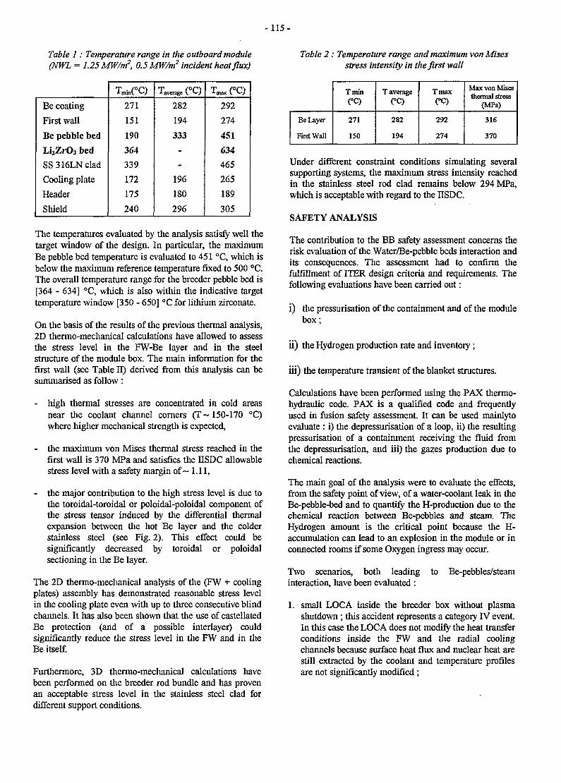
-115-
Table 1: Temperature range in the outboard module(NWL = 1.25 MW/m2, 0.5 MW/m2 incident heat flux)
Table 2: Temperature range and maximum vonMisesstress intensity in the first wall
Be coating
First wall
Be pebble bed
Li2ZrO3 bed
SS316LNclad
Cooling plate
Header
Shield
T^CC)271
151
190
364
339
172
175
240
1 average v *-v
282
194
333
-
-
196
180
296
292
274
451
634
465
265
189
305
The temperatures evaluated by the analysis satisfy well thetarget window of the design. In particular, the maximumBe pebble bed temperature is evaluated to 451 °C, which isbelow the maximum reference temperature fixed to 500 °C.The overall temperature range for the breeder pebble bed is[364 - 634] °C, which is also within the indicative targettemperature window [350 - 650] °C for lithium zirconate.
On the basis of the results of the previous thermal analysis,2D thermo-mechanical calculations have allowed to assessthe stress level in the FW-Be layer and in the steelstructure of the module box. The main information for thefirst wall (see Table II) derived from this analysis can besummarised as follow:
- high thermal stresses are concentrated in cold areasnear the coolant channel corners (T ~ 150-170 °C)where higher mechanical strength is expected,
- the maximum von Mises thermal stress reached in thefirst wall is 370 MPa and satisfies the IISDC allowablestress level with a safety margin of ~ 1.11,
- the major contribution to the high stress level is due tothe toroidal-toroidal or poloidal-poloidal component ofthe stress tensor induced by the differential thermalexpansion between the hot Be layer and the colderstainless steel (see Fig. 2). This effect could besignificantly decreased by toroidal or poloidalsectioning in the Be layer.
The 2D thermo-mechanical analysis of the (FW + coolingplates) assembly has demonstrated reasonable stress levelin the cooling plate even with up to three consecutive blindchannels. It has also been shown that the use of castellatedBe protection (and of a possible interlayer) couldsignificantly reduce the stress level in the FW and in theBe itself.
Furthermore, 3D thermo-mechanical calculations havebeen performed on the breeder rod bundle and has provenan acceptable stress level in the stainless steel clad fordifferent support conditions.
Be Layer
First Wall
Tmin(°C)
271
150
T average(°C)
282
194
Ttnax(°C)
292
274
Max von Misesthermal stress
(MPa)
316
370
Under different constraint conditions simulating severalsupporting systems, the maximum stress intensity reachedin the stainless steel rod clad remains below 294 MPa,which is acceptable with regard to the IISDC.
SAFETY ANALYSIS
The contribution to the BB safety assessment concerns therisk evaluation of the Water/Be-pebble beds interaction andits consequences. The assessment had to confirm thefulfillment of ITER design criteria and requirements. Thefollowing evaluations have been carried out:
i) the pressurisation of the containment and of the modulebox;
ii) the Hydrogen production rate and inventory;
iii) the temperature transient of the blanket structures.
Calculations have been performed using the PAX thermo-hydraulic code. PAX is a qualified code and frequentlyused in fusion safety assessment It can be used mainlytoevaluate : i) the depressurisation of a loop, ii) the resultingpressurisation of a containment receiving the fluid fromthe depressurisation, and iii) the gazes production due tochemical reactions.
The main goal of the analysis were to evaluate the effects,from the safety point of view, of a water-coolant leak in theBe-pebble-bed and to quantify the H-production due to thechemical reaction between Be-pebbles and steam. TheHydrogen amount is the critical point because the H-accumulation can lead to an explosion in the module or inconnected rooms if some Oxygen ingress may occur.
Two scenarios, both leading to Be-pebbles/steaminteraction, have been evaluated :
1. small LOCA inside the breeder box without plasmashutdown; this accident represents a category IV event.In this case the LOCA does not modify the heat transferconditions inside the FW and the radial coolingchannels because surface heat flux and nuclear heat arestill extracted by the coolant and temperature profilesare not significantly modified;
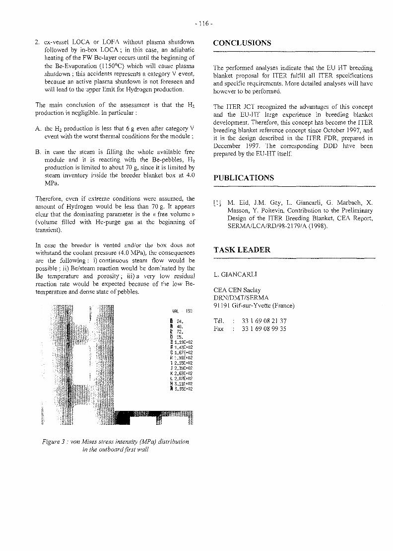
-116-
2. ex-vessel LOCA or LOFA without plasma shutdownfollowed by in-box LOCA ; in this case, an adiabaticheating of the FW Be-layer occurs until the beginning ofthe Be-Evaporation (1150°C) which will cause plasmashutdown ; this accidents represents a category V event,because an active plasma shutdown is not foreseen andwill lead to the upper limit for Hydrogen production.
The main conclusion of the assessment is that the H2production is negligible. In particular :
A. the H2 production is less that 6 g even after category Vevent with the worst thermal conditions for the module ;
B. in case the steam is filling the whole available freemodule and it is reacting with the Be-pebbles, H2
production is limited to about 70 g, since it is limited bysteam inventory inside the breeder blanket box at 4.0MPa.
Therefore, even if extreme conditions were assumed, theamount of Hydrogen would be less than 70 g. It appearsclear that the dominating parameter is the « free volume »(volume filled with He-purge gas at the beginning oftransient).
In case the breeder is vented and/or the box does notwithstand the coolant pressure (4.0 MPa), the consequencesare the following : i) continuous steam flow would bepossible ; ii) Be/steam reaction would be dominated by theBe temperature and porosity; iii) a very low residualreaction rate would be expected because of the low Be-temperature and dense state of pebbles.
VflL - ISO
I 24.I 48.B 72.I 95.i 1.19E+02B 1.43E+021 1.B7E+02H 1.91E+021 2.15E+02J 2.39E+02K 2.63E+02I 2.87E+02W 3.11E+02I 3.35E+02
CONCLUSIONS
The performed analyses indicate that the EU HT breedingblanket proposal for ITER fulfill all ITER specificationsand specific requirements. More detailed analyses will havehowever to be performed.
The ITER JCT recognized the advantages of this conceptand the EU-HT large experience in breeding blanketdevelopment. Therefore, this concept has become the ITERbreeding blanket reference concept since October 1997, andit is the design described in the ITER FDR, prepared inDecember 1997. The corresponding DDD have beenprepared by the EU-HT itself.
PUBLICATIONS
[1] M. Eid, J.M. Gay, L. Giancarli, G. Marbach, X.Masson, Y. Poitevin, Contribution to the PreliminaryDesign of the ITER Breeding Blanket, CEA Report,SERMA/LCA/RD/98-2179/A (1998).
TASK LEADER
L. GIANCARLI
CEA CEN SaclayDRN/DMT/SERMA91191 Gif-sur-Yvette (France)
Tel. : 33 169 08 2137Fax : 33 1 69 08 99 35
Figure 3 : von Mises stress intensity (MPa) distributionin the outboard first wall
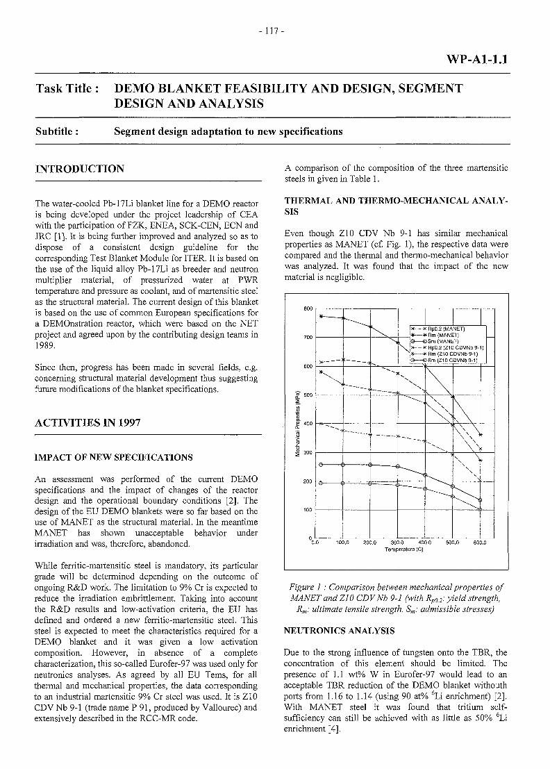
-117-
WP-A1-1.1
Task Title : DEMO BLANKET FEASIBILITY AND DESIGN, SEGMENTDESIGN AND ANALYSIS
Subtitle : Segment design adaptation to new specifications
INTRODUCTION
The water-cooled Pb-17Li blanket line for a DEMO reactoris being developed under the project leadership of CEAwith the participation of FZK, ENEA, SCK-CEN, ECN andJRC [1]. It is being further improved and analyzed so as todispose of a consistent design guideline for thecorresponding Test Blanket Module for ITER. It is based onthe use of the liquid alloy Pb-17Li as breeder and neutronmultiplier material, of pressurized water at PWRtemperature and pressure as coolant, and of martensitic steelas the structural material. The current design of this blanketis based on the use of common European specifications fora DEMOnstration reactor, which were based on the NETproject and agreed upon by the contributing design teams in1989.
Since then, progress has been made in several fields, e.g.concerning structural material development thus suggestingfuture modifications of the blanket specifications.
ACTIVITIES IN 1997
IMPACT OF NEW SPECIFICATIONS
An assessment was performed of the current DEMOspecifications and the impact of changes of the reactordesign and the operational boundary conditions [2], Thedesign of the EU DEMO blankets were so far based on theuse of MANET as the structural material. In the meantimeMANET has shown unacceptable behavior underirradiation and was, therefore, abandoned.
While ferritic-martensitic steel is mandatory, its particulargrade will be determined depending on the outcome ofongoing R&D work. The limitation to 9% Cr is expected toreduce the irradiation embrittlement. Taking into accountthe R&D results and low-activation criteria, the EU hasdefined and ordered a new ferritic-martensitic steel. Thissteel is expected to meet the characteristics required for aDEMO blanket and it was given a low activationcomposition. However, in absence of a completecharacterization, this so-called Eurofer-97 was used only forneutronics analyses. As agreed by all EU Tems, for allthermal and mechanical properties, the data correspondingto an industrial martensitic 9% Cr steel was used. It is Z10CDV Nb 9-1 (trade name P 91, produced by Vallourec) andextensively described in the RCC-MR code.
A comparison of the composition of the three martensiticsteels in given in Table 1.
THERMAL AND THERMO-MECHANICAL ANALY-SIS
Even though Z10 CDV Nb 9-1 has similar mechanicalproperties as MANET (cf. Fig. 1), the respective data werecompared and the thermal and thermo-mechanical behaviorwas analyzed. It was found that the impact of the newmaterial is negligible.
500 i—•
400
4 300
I j x — * Rp0.2 (MANET)I* *Rm (MANET)
• ^ O OSm (MANET)j x- - x Rp0.2 (210 CDVNb 9-1)"|* * Rm (Z10 CDVNb 9-1):G OSm (210 CDVNb 9-1J
0.0 100.0 200.0 300.0 400.0 500.0 600.0Temperature (C)
Figure 1 : Comparison between mechanical properties ofMANET and Z10 CDVNb 9-1 (with Rp0J: yield strength,
Rm: ultimate tensile strength, Sm: admissible stresses)
NEUTRONICS ANALYSIS
Due to the strong influence of tungsten onto the TBR, theconcentration of this element should be limited. Thepresence of 1.1 wt% W in Eurofer-97 would lead to anacceptable TBR reduction of the DEMO blanket withouthports from 1.16 to 1.14 (using 90 at% 6Li enrichment) [2].With MANET steel it was found that tritium self-sufficiency can still be achieved with as little as 50% 6Lienrichment [4].
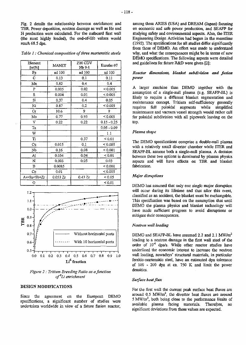
- 1 1 8 -
Fig. 2 details the relationship between enrichment andTBR. Power deposition, neutron damage as well as He andH production were calculated. For the outboard first wall(the most highly loaded), the end-of-life values wouldreach 68.5 dpa.
Table 1: Chemical composition of three martensitic steels
Elementfwt°/o]
FeC
MnPSSiNiCrMoVTaWTiCuNbAlNBCo
As+Sn+Sb+Zr0
MANET
ad 1000.130.820.0050.0040.370.8710.60.770.22
0.0150.160.0540.003
0.00850.01
0.053 Zr
Z10 CDVNb9-1ad 100
0.10.4
0.020.010.40.29
0.950.22
0.370.10.080.040.05
0.43 Zr
Eurofer-97
ad 1000.110.4
< 0.005< 0.005
0.05< 0.005
9< 0.005
0.15-0.250.05 - 0.09
1.1<0.01
< 0.005< 0.001<0.010.03
< 0.001< 0.005<0.05<0.01
0.5 J
Without horizontal ports
With 10 horizontal ports
0.0 0.1 0.2 0.3 0.4 0.5 0.6 0.7 0.8 0.9 1.0
Li fraction
Figure 2 : Tritium Breeding Ratio as a functionof6Li enrichment
DESIGN MODIFICATIONS
Since the agreement on the European DEMOspecifications, a significant number of studies wereundertaken worldwide in view of a future fusion reactor,
among them ARIES (USA) and DREAM (Japan) focusingon economic and safe power production, and SEAFP forstudying safety and environmental aspects. Also, the ITEREngineering Design Activities had begun in the meantime(1992). The specifications for all studies differ significantlyfrom those of DEMO. An effort was made to understandwhy, and what the consequences might be in terms of newDEMO specifications. The following aspects were detailedand guidelines for future R&D were given [2]:
Reactor dimensions, blanket subdivision and fusionpower
A larger machine than DEMO together with theassumption of a single-null plasma (e.g. SEAFP-BL) islikely to require a different blanket segmentation andmaintenance concept. Tritium self-sufficiency generallyrequires full poloidal segments while simplifiedmaintenance and vacuum vessel strength would rather callfor poloidal subdivision with all pipework leaving on thetop.
Plasma shape
The DEMO specifications comprise a double-null plasmawith a relatively small divertor chamber while ITER andSEAFP-BL assume both a single-null plasma. A decisionbetween these two options is dominated by plasma physicsaspects and will have effects on TBR and blanketfabrication.
Major disruptions
DEMO has assumed that only one single major disruptionwill occur during its lifetime and that after this event,classified as an accident, the blanket must be exchangable.This specification was based on the assumption that untilDEMO the plasma physics and blanket technology willhave made sufficient progress to avoid disruptions ormitigate their consequences.
Neutron wall loading
DEMO and SEAFP-BL have assumed 2.2 and 2.1 MW/m2
leading to a neutron damage in the first wall steel of theorder of 10"6 dpa/s. While other reactor studies haveunderlined the economic interest to increase the neutronwall loading, nowadays' structural materials, in particularferritic-martensitic steel, have an estimated dpa toleranceof 100 - 200 dpa at ca. 750 K and limit the powerdensities.
Surface heat flux
For the first wall the current peak surface heat fluxes arearound 0.5 MW/m2, the divertor heat fluxes are around5 MW/m2, both being close to the performance limits ofavailable plasma facing materials. Therefore, nosignificant deviations from these values are expected.
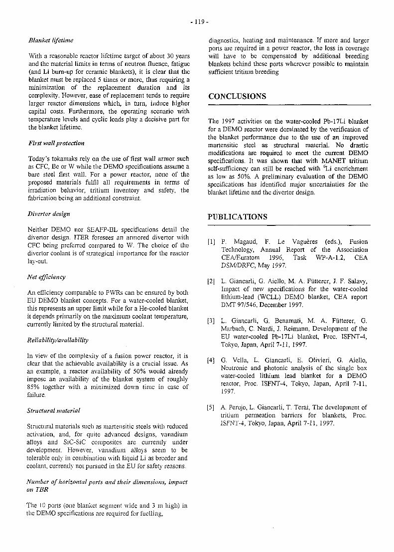
-119 -
Blanket lifetime
With a reasonable reactor lifetime target of about 30 yearsand the material limits in terms of neutron fluence, fatigue(and Li burn-up for ceramic blankets), it is clear that theblanket must be replaced 5 times or more, thus requiring aminimization of the replacement duration and itscomplexity. However, ease of replacement tends to requirelarger reactor dimensions which, in turn, induce highercapital costs. Furthermore, the operating scenario withtemperature levels and cyclic loads play a decisive part forthe blanket lifetime.
First wall protection
Today's tokamaks rely on the use of first wall armor suchas CFC, Be or W while the DEMO specifications assume abare steel first wall. For a power reactor, none of theproposed materials fulfil all requirements in terms ofirradiation behavior, tritium inventory and safety, thefabrication being an additional constraint.
Divertor design
Neither DEMO nor SEAFP-BL specifications detail thedivertor design. ITER foresees an armored divertor withCFC being preferred compared to W. The choice of thedivertor coolant is of strategical importance for the reactorlay-out.
Net efficiency
An efficiency comparable to PWRs can be ensured by bothEU DEMO blanket concepts. For a water-cooled blanket,this represents an upper limit while for a He-cooled blanketit depends primarily on the maximum coolant temperature,currently limited by the structural material.
Reliab ility/availab ility
In view of the complexity of a fusion power reactor, it isclear that the achievable availability is a crucial issue. Asan example, a reactor availability of 50% would alreadyimpose an availability of the blanket system of roughly85% together with a minimized down time in case offailure.
Structural material
Structural materials such as martensitic steels with reducedactivation, and, for quite advanced designs, vanadiumalloys and SiC-SiC composites are currently underdevelopment. However, vanadium alloys seem to betolerable only in combination with liquid Li as breeder andcoolant, currently not pursued in the EU for safety reasons.
Number of horizontal ports and their dimensions, impacton TBR
diagnostics, heating and maintenance. If more and largerports are required in a power reactor, the loss in coveragewill have to be compensated by additional breedingblankets behind these ports wherever possible to maintainsufficient tritium breeding
CONCLUSIONS
The 1997 activities on the water-cooled Pb-17Li blanketfor a DEMO reactor were dominated by the verification ofthe blanket performance due to the use of an improvedmartensitic steel as structural material. No drasticmodifications are required to meet the current DEMOspecifications. It was shown that with MANET tritiumself-sufficiency can still be reached with ^ i encrichmentas low as 50%. A preliminary evaluation of the DEMOspecifications has identified major uncertainties for theblanket lifetime and the divertor design.
PUBLICATIONS
[1] P. Magaud, F. Le Vagueres (eds.), FusionTechnology, Annual Report of the AssociationCEA/Euratom 1996, Task WP-A-1.2, CEADSM/DRFC, May 1997.
[2] L. Giancarli, G. Aiello, M. A. Futterer, J. F. Salavy,Impact of new specifications for the water-cooledlithium-lead (WCLL) DEMO blanket, CEA reportDMT 97/546, December 1997.
[3] L. Giancarli, G. Benamati, M. A. Futterer, G.Marbach, C. Nardi, J. Reimann, Development of theEU water-cooled Pb-17Li blanket, Proc. ISFNT-4,Tokyo, Japan, April 7-11, 1997.
[4] G. Vella, L. Giancarli, E. Olivieri, G. Aiello,Neutronic and photonic analysis of the single boxwater-cooled lithium lead blanket for a DEMOreactor, Proc. ISFNT-4, Tokyo, Japan, April 7-11,1997.
[5] A. Perujo, L. Giancarli, T. Terai, The development oftritium permeation barriers for blankets, Proc.ISFNT-4, Tokyo, Japan, April 7-11, 1997.
The 10 ports (one blanket segment wide and 3 m high) inthe DEMO specifications are required for fuelling,

- 120 -
TASK LEADER
Michael A. Fiitterer
CEA SaclayDRN/DMT/SERMA/LCAF-91191 Gif-sur-Yvette Cedex, France
Tel. : 33 1 69 08 36 36Fax : 33 1 69 08 99 35
e-mail : [email protected]
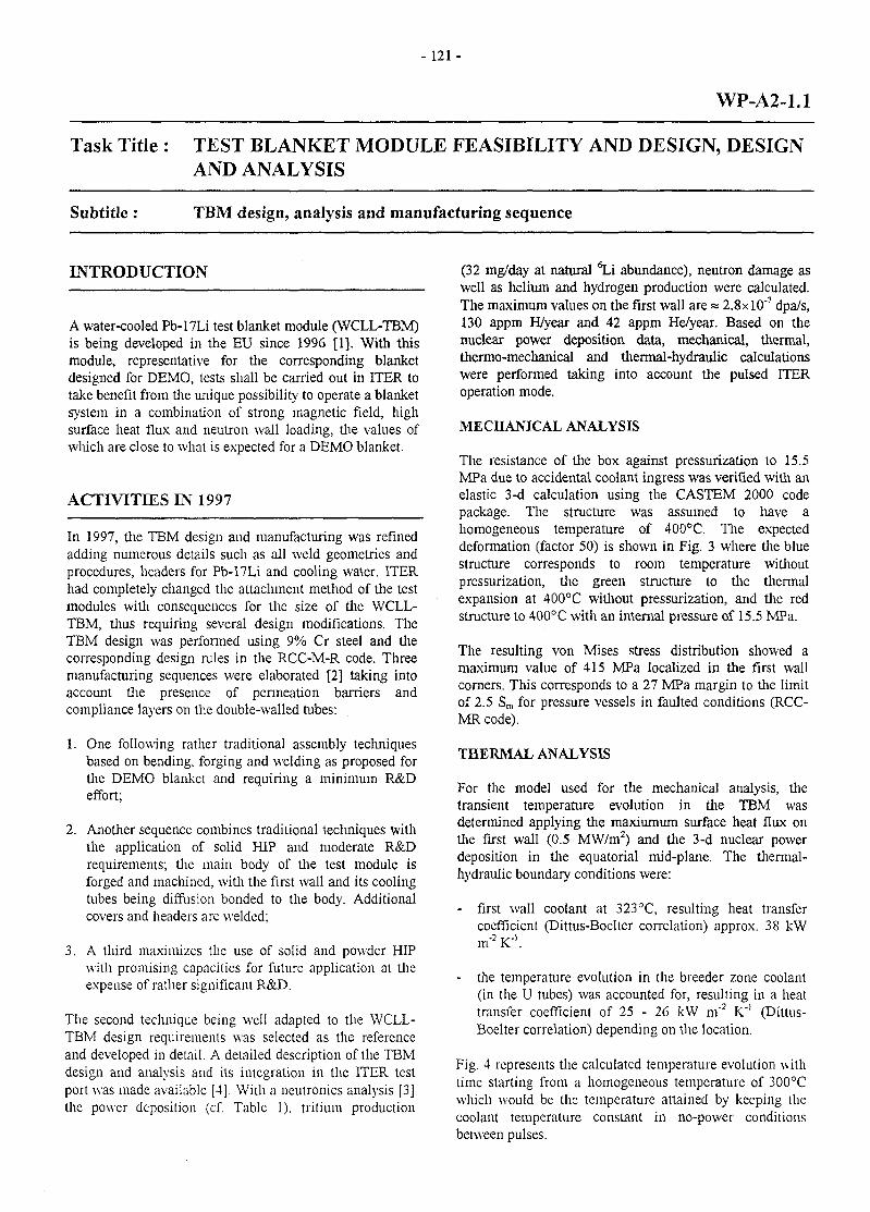
- 1 2 1 -
WP-A2-1.1
Task Title : TEST BLANKET MODULE FEASIBILITY AND DESIGN, DESIGNAND ANALYSIS
Subtitle : TBM design, analysis and manufacturing sequence
INTRODUCTION
A water-cooled Pb-17Li test blanket module (WCLL-TBM)is being developed in the EU since 1996 [1]. With thismodule, representative for the corresponding blanketdesigned for DEMO, tests shall be carried out in ITER totake benefit from the unique possibility to operate a blanketsystem in a combination of strong magnetic field, highsurface heat flux and neutron wall loading, the values ofwhich are close to what is expected for a DEMO blanket.
ACTIVITIES IN 1997
In 1997, the TBM design and manufacturing was refinedadding numerous details such as all weld geometries andprocedures, headers for Pb-17Li and cooling water. ITERhad completely changed the attachment method of the testmodules with consequences for the size of the WCLL-TBM, thus requiring several design modifications. TheTBM design was performed using 9% Cr steel and thecorresponding design rules in the RCC-M-R code. Threemanufacturing sequences were elaborated [2] taking intoaccount the presence of permeation barriers andcompliance layers on the double-walled tubes:
1. One following rather traditional assembly techniquesbased on bending, forging and welding as proposed forthe DEMO blanket and requiring a minimum R&Deffort;
2. Another sequence combines traditional techniques withthe application of solid HIP and moderate R&Drequirements; the main body of the test module isforged and machined, with the first wall and its coolingtubes being diffusion bonded to the body. Additionalcovers and headers are welded;
3. A third maximizes the use of solid and powder HIPwith promising capacities for future application at theexpense of rather significant R&D.
The second technique being well adapted to the WCLL-TBM design requirements was selected as the referenceand developed in detail. A detailed description of the TBMdesign and analysis and its integration in the ITER testport was made available [4]. With a neutronics analysis [3]the power deposition (cf. Table 1), tritium production
(32 mg/day at natural ^ i abundance), neutron damage aswell as helium and hydrogen production were calculated.The maximum values on the first wall are » 2.8xlO'7 dpa/s,130 appm H/year and 42 appm He/year. Based on thenuclear power deposition data, mechanical, thermal,thermo-mechanical and thermal-hydraulic calculationswere performed taking into account the pulsed ITERoperation mode.
MECHANICAL ANALYSIS
The resistance of the box against pressurization to 15.5MPa due to accidental coolant ingress was verified with anelastic 3-d calculation using the CASTEM 2000 codepackage. The structure was assumed to have ahomogeneous temperature of 400°C. The expecteddeformation (factor 50) is shown in Fig. 3 where the bluestructure corresponds to room temperature withoutpressurization, the green structure to the thermalexpansion at 400°C without pressurization, and the redstructure to 400°C with an internal pressure of 15.5 MPa.
The resulting von Mises stress distribution showed amaximum value of 415 MPa localized in the first wallcorners. This corresponds to a 27 MPa margin to the limitof 2.5 Sm for pressure vessels in faulted conditions (RCC-MR code).
THERMAL ANALYSIS
For the model used for the mechanical analysis, thetransient temperature evolution in the TBM wasdetermined applying the maxiumum surface heat flux onthe first wall (0.5 MW/m2) and the 3-d nuclear powerdeposition in the equatorial mid-plane. The thermal-hydraulic boundary conditions were:
- first wall coolant at 323°C, resulting heat transfercoefficient (Dittus-Boelter correlation) approx. 38 kW
2 '
- the temperature evolution in the breeder zone coolant(in the U tubes) was accounted for, resulting in a heattransfer coefficient of 25 - 26 kW m'2 K"1 (Dittus-Boelter correlation) depending on the location.
Fig. 4 represents the calculated temperature evolution withtime starting from a homogeneous temperature of 300°Cwhich would be the temperature attained by keeping thecoolant temperature constant in no-power conditionsbetween pulses.
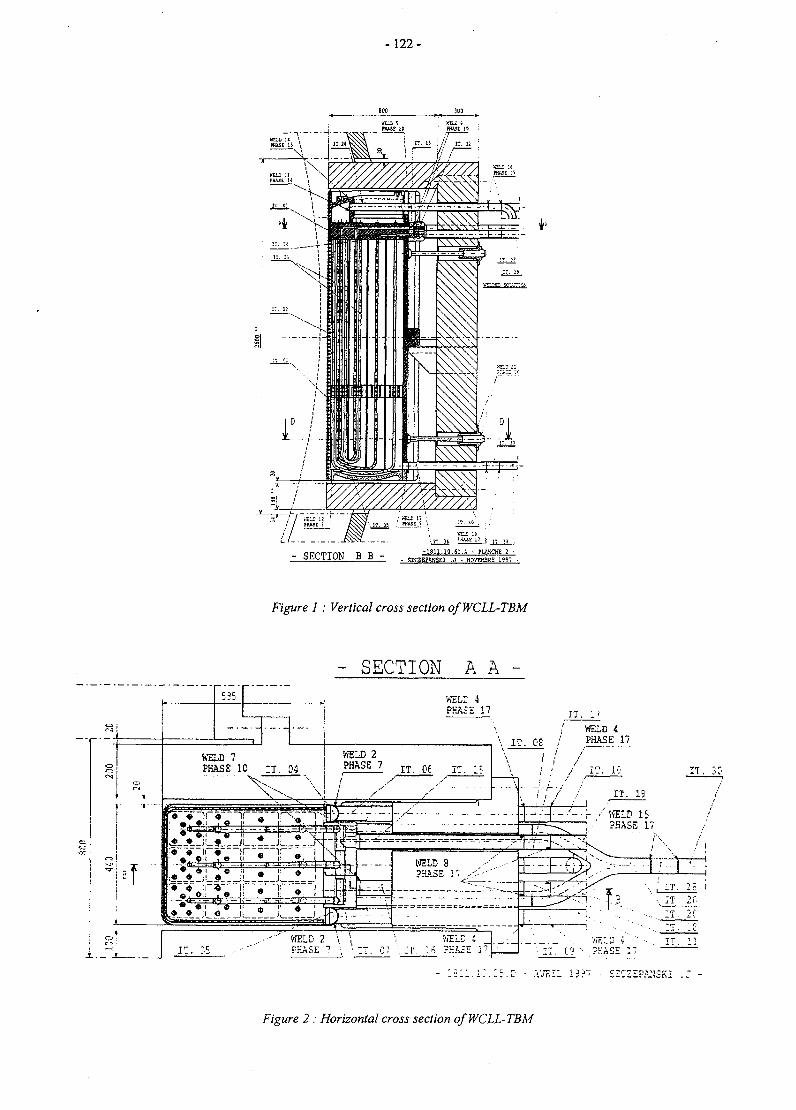
-122-
'.17. it ! * " ; : I < i; ii 1-Mil.10.SI.A - PLUCKE 2 -- SECTION B B - - SZCSEPAHSKI . J - HOVEM3Eg 1 9 ? "
Figure 1: Vertical cross section of WCLL-TBM
! s
1 •*• i -.
- SECTION A A -
^
WEL: iPHASE 17
WEI.D 7PHASE 10 ; T . 04
VffilD 2PHASE 7 I T _ o e r - :
H . 1 '
/ WELD 4
PHASE 17 ^-.-:-'-''
WELD 4 ViRLD i ' " • - . T x " |I T . C? ••• P H A S E 1 7 ' —
Figure 2 : Horizontal cross section of WCLL-TBM
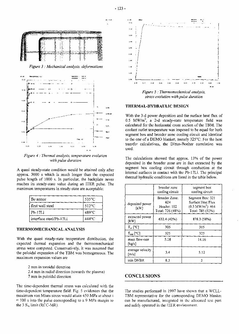
- 1 2 3 -
Figure 3 : Mechanical analysis, deformations
Figure 4 : Thermal analysis, temperature evolutionwith pulse duration
A quasi steady-state condition would be attained only afterapprox. 3000 s which is much longer than the expectedpulse length of 1000 s. In particular, the backplate neverreaches its steady-state value during an ITER pulse. Themaximum temperatures in steady-state are acceptable:
Be armor
first wall steel
Pb-17Li
interface steel/Pb-17Li
535°C
512°C
489°C
444°C
THERMOMECHANICAL ANALYSIS
With the quasi steady-state temperature distribution, theexpected thermal expansion and the thermomechanicalstress were computed. Conservatively, it was assumed thatthe poloidal expansion of the TBM was homogeneous. Themaximum expansion values are
2 mm in toroidal direction2.4 mm in radial direction (towards the plasma)7 mm in poloidal direction
The time-dependent thermal stress was calculated with thetime-dependent temperature field. Fig. 5 evidences that themaximum von Mises stress would attain 450 MPa at about t= 100 s into the pulse corresponding to a 9 MPa margin tothe 3 Sm limit (RCC-MR).
.... L
Figure 5 : Thermomechanical analysis,stress evolution with pulse duration
THERMAL-HYDRAULIC DESIGN
With the 3-d power deposition and the surface heat flux of0.5 MW/m2, a 2-d steady-state temperature field wascalculated for the horizontal cross section of the TBM. Thecoolant outlet temperature was imposed to be equal for bothsegment box and breeder zone cooling circuit and identicalto the one of a DEMO blanket, namely 325°C. For the heattransfer calculations, the Dittus-Boelter correlation wasused.
The calculations showed that approx. 13% of the powerdeposited in the breeder zone are in fact extracted by thesegment box cooling circuit through conduction at theinternal surfaces in contact with the Pb-17Li. The principalthermal hydraulic conditions are listed in the table below.
deposited power[kW]
extracted power[kW]
Tin [°C]
Tou,[°C]
mass flow-rate[kg/s]
average velocity[m/s]
min DNBR
breeder zonecooling circuit
Breeder Zone:624
Header: 102Total: 726 (48%)
632.4 (42%)
305
325
5.28
3.4
8.3
segment boxcooling circuit
Segment Box: 321Surface Heat Flux(0.5 MW/m2): 464Total: 785 (52%)
878.3 (58%)
315
325
14.16
5.12
3
CONCLUSIONS
The studies performed in 1997 have shown that a WCLL-TBM representative for the corresponding DEMO blanketcan be manufactured, integrated in the allocated test portand safely operated in the ITER environment.
- 124 -
PUBLICATIONS TASK LEADER
[1] P. Magaud, F. Le Vaguères (eds.), FusionTechnology, Annual Report of the AssociationCEAVEuratom 1996, Task WP-A-1.2, CEADSM/DRFC, May 1997.
[2] M. A. Futterer, B. Bielak, J.-P. Deffain, C. Dellis, L.Giancarli, A. Li Puma, C. Nardi, J.-F. Salavy, K.Schleisiek, J. Szczepanski, Design development andmanufacturing sequence of the European water-cooled Pb-17Li test blanket module, Proc. ISFNT-4,April 7 - 1 1 , 1997, Tokyo, Japan.
[3] G. Vella et al., Water-cooled Pb-17Li test blanketmodule for ITER: Impact of the structural materialgrade on the Neutronic responses, Proc. ICFRM-8,27-31 October 1997, Sendai, Japan.
[4] M. A. Fûtterer et al., Design Description Documentfor the European water-cooled Pb-17Li Test BlanketModule (final version), CEA report DMT 97/549,December 1997.
Michael A. Futterer
CEA SaclayDRN/DMT/SERMA7LCAF-91191 Gif-sur-Yvette Cedex, France
Tél. : 33 1 69 08 36 36Fax : 33 1 69 08 99 35
e-mail : [email protected]
- 1 2 5 -
WP-A2-2.1
Task Title : TEST BLANKET MODULE FEASIBILITY AND DESIGN,TBM SUBSYSTEMS
Subtitle : TBM Ancillary equipment design
INTRODUCTION
The water-cooled Pb-17Li test blanket module (WCLL-TBM) in ITER [1] requires the lay-out, dimensioning andintegration of ancillary equipment into the allocated space.This ancillary equipment comprises two primary coolingcircuits and one Pb-17Li circuit for tlie extraction of thegenerated tritium. For the later demonstration of electricpower generation, a steam cycle was also designed.
ACTIVITIES IN 1997
COOLING SYSTEM
The principal components of the cooling circuits weredefined and their approximate size determined assumingthe availability of one wedge shaped segment in the pit ofPort #20. The 3 ancillary circuits were attributed equalspace. The lack of space must be considered critical.Components for electricity production will have to belocated outside the pit area.
The two independent cooling circuits remove the powerfrom the TBM with cooling water at PWR conditions.During normal operation, this heat shall be dissipated intoa low temperature, low pressure secondary cooling circuitprovided by ITER. Pressurized water cooling is standardtechnology and no additional requirements are necessaryexcept downsizing and the adaptation of the coolantchemistry to the fusion environment and tlie employedmaterials. The basic components are a storage/drain tank,a pressurizer, a heat exchanger to a secondary coolantsystem for heat dissipation (provided by ITER), a pumpand connecting pipework. Fluctuations of the coolant inlettemperature (pulsed operation) can be damped by acontrolled heat exchanger bypass or an additional heater.In order to allow natural convection cooling, the heatexchanger should in principle be located on a higher levelthan the coolant outlet of the TBM which is, however, inconflict with the proposed deployment area in the pit (samelevel as TBM). Additional valves allow the isolation of thecooling system and heating/cooling of the system at start-up and shut-down. Filters will be installed to removepaniculate impurities. The heater power in the pressurizerand in an auxiliary heater shall suffice to maintain thenominal coolant temperature without power deposition inthe test module and to keep the breeder material above itsmelting point by conduction.
All equipment complies with the requirements based onthe ITER safety classification of the ancillary circuits.
The coolant will be demineralized water, its precisechemistry is still to be determined and has the objective tominimize corrosion and transport of corrosion products(even though this is of only minor importance due to theshort absolute operating time). If compatible with the ITERHeat Transfer System, the following coolant treatmentwould be favorable to combat corrosion. The acidity shouldbe adjusted to pH 7 at approx. 300°C using LiOH or KOH(both alkalines could be used). The simultaneous use of abuffer acid is not clear yet. During operation, the coolingsystem will accumulate corrosion products, H2O2 fromradiolysis and tritium from permeation. To keep theconcentrations of these products on an admissible level, H2
is expected to be added to the coolant (approx. 30 cnrVkg)and a slip stream of the cooling water will be sent to theITER water detritiation and make-up system where thewater chemistry will be adjusted as well (possibly in asmall unit dedicated to the WCLL-TBM). The slip streamfraction depends on the measured tritium permeation intothe coolant which is a test objective and on the tolerabletritium concentration in the cooling water. To facilitate thecommon use of the ITER water treatment plant, theapplied coolant chemistry should not be much differentfrom the one applied in the ITER Heat Transfer System,otherwise additional equipment would be required for theTBM cooling circuits.
In view of compatibility of materials and their qualificationunder irradiation, the TBM and the pipework will be madeof the same martensitic steel. Transition welds to austeniticsteel in the circuits will be done only in low-irradiationzones.
For the envisaged electricity production, different circuitconfigurations were studied depending on whether or notthe power should be maximized and whether anintermediate cooling circuit is necessary for safety reasons.All secondary equipment will be housed in the TokamakServices Building.
Pb-17Li SYSTEM
The Pb-17Li system includes three subsystems:
- a mainPb-17Li loop,- a Pb-17Li drain system,- a Pb-17Li detritiation system to recover the produced
tritium.
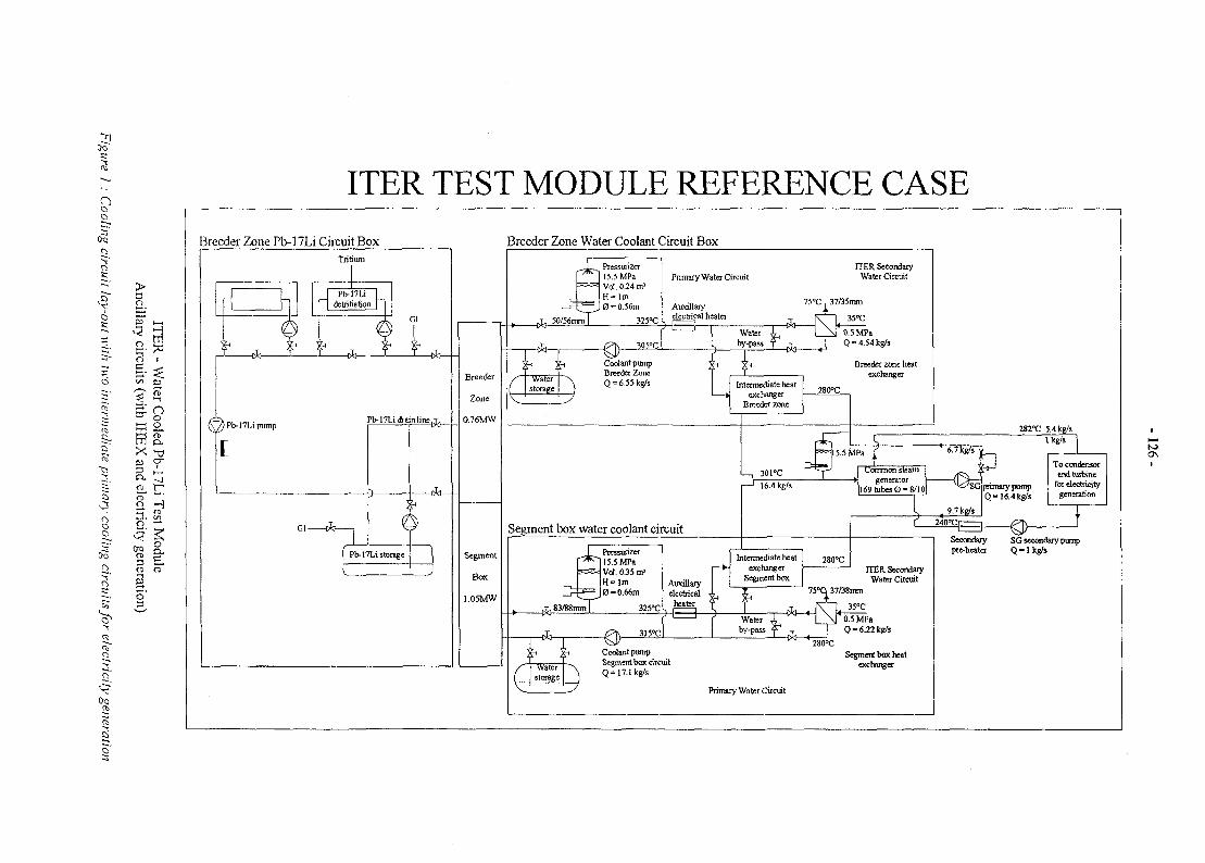
09 '
ITER TEST MODULE REFERENCE CASE
nc
x;
i t—' t—i
o
C O" o
8X
^
CO
O
s'
JL jr.
a. S
s l3
09TO3TO
Breeder Zone Pb-17Li Circuit Box Breeder Zone Water Coolant Circuit BoxTritium
Pb-17Lidetritiation
-t i t--
)Pb-17LiputnpPb-17Li drain line
GI
Pb-17Li storage
Segment box water coolant circuit
Intermediate heatexchanger
Segment box
Coolant pumpSegment box circuitQ=17.Ikg/s
ITER SecondaryWater Circuit
75°C,37/38mm
W 280°C
35°C0.5 MPaQ-6.22kg/s
Segment box heatexchanger
Primary Water Circuit
SG secondary pumpQ - l k g / s
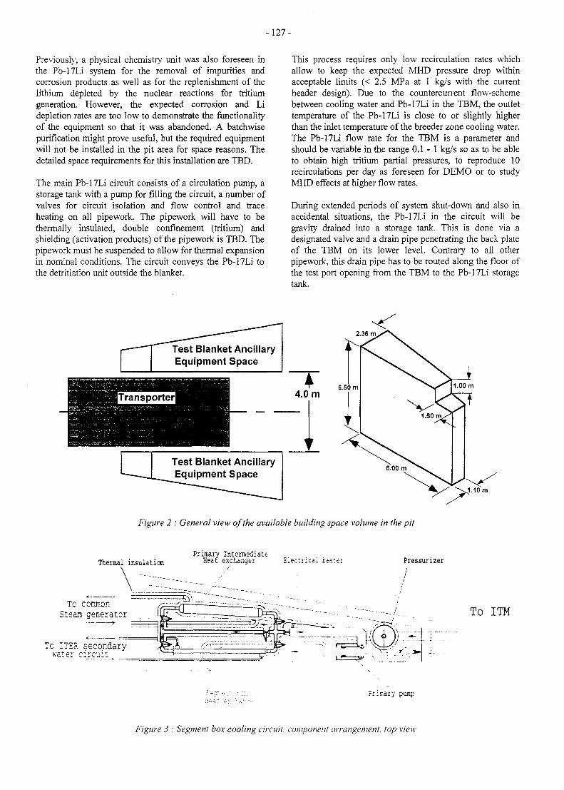
-127-
Previously, a physical chemistry unit was also foreseen inthe Pb-17Li system for the removal of impurities andcorrosion products as well as for the replenishment of thelithium depleted by the nuclear reactions for tritiumgeneration. However, the expected corrosion and Lidepletion rates are too low to demonstrate the functionalityof the equipment so that it was abandoned. A batchwisepurification might prove useful, but the required equipmentwill not be installed in the pit area for space reasons. Thedetailed space requirements for this installation are TBD.
The main Pb-17Li circuit consists of a circulation pump, astorage tank with a pump for filling the circuit, a number ofvalves for circuit isolation and flow control and traceheating on all pipework. The pipework will have to bethermally insulated, double confinement (tritium) andshielding (activation products) of the pipework is TBD. Thepipework must be suspended to allow for thermal expansionin nominal conditions. The circuit conveys the Pb-17Li tothe detritiation unit outside the blanket.
This process requires only low recirculation rates whichallow to keep the expected MHD pressure drop withinacceptable limits (< 2.5 MPa at 1 kg/s with the currentheader design). Due to the countercurrent flow-schemebetween cooling water and Pb-17Li in the TBM, the outlettemperature of the Pb-17Li is close to or slightly higherthan the inlet temperature of the breeder zone cooling water.The Pb-17Li flow rate for the TBM is a parameter andshould be variable in the range 0 .1-1 kg/s so as to be ableto obtain high tritium partial pressures, to reproduce 10recirculations per day as foreseen for DEMO or to studyMHD effects at higher flow rates.
During extended periods of system shut-down and also inaccidental situations, the Pb-17Li in the circuit will begravity drained into a storage tank. This is done via adesignated valve and a drain pipe penetrating the back plateof the TBM on its lower level. Contrary to all otherpipework, this drain pipe has to be routed along the floor ofthe test port opening from the TBM to the Pb-17Li storagetank.
Test Blanket AncillaryEquipment Space
Test Blanket AncillaryEquipment Space
6.50 m
_L
Figure 2 : General view of the available building space volume in the pit
Thermal insulationPrimary Intermediate
Heat exchanger Eleccncai hea:e: Pressurizer
Tc commonSteam generator To ITM
Primary pump
Figure 3 : Segment box cooling circuit, component arrangement, top view
- 1 2 8 -
The gravity draining requires that the storage tank besituated on a lower level than the TBM. Nevertheless, Heinjection through the Pb-17Li feed/return lines androughing of the storage tank is foreseen to acceleratedraining and to avoid the build-up of an underpressure inthe TBM that could prevent full draining, so that thestorage tank can be accommodated together with the othercircuit components in the pit area. Additional Heinjection/roughing is foreseen for the main pipework andthe storage tank.
Pb-17Li DETRITIATION SYSTEM
This system is charged with the removal and recovery ofthe tritium produced in the TBM. For a DEMO blanket atritium extractor of the liquid/gas contactor type isforeseen.
The so far best performing system is a packed columnextractor in which helium, probably with hydrogenaddition for better performance, is brought into contactwith a large Pb-17Li surface for desorption of the tritiumdissolved in the Pb-17Li. Due to the low tritium productionin the TBM and the long intervals between pulses, asimplified and less performing system with batchwiseoperation (e.g. gettering) could be an alternative if theliquid/gas contactor should prove too space consuming.The detailed system design is subject to ongoing R&D.
This subsystem consists of valves for isolation and flowcontrol, a pump and a tritium extractor with vacuumpumping and purge gas supply. The subsystem and itscomponents must be sufficiently shielded and confined.The entire Pb-17Li pipework is equipped with traceheating and thermal insulation. The detritiation system canbe bypassed, but in nominal conditions the entire flow ratewill go through the detritiation system. Only the Pb-17Lidetritiation system will be accommodated in the pit area,the tritium extraction from the purge-gas will take place inthe ITER tritium plant.
CONFINEMENT OF Pb-17Li SYSTEM
The Pb-17Li system including its subsystems will containtritium and activated material from transmutation of thebreeder material and its impurities as well as activatedcorrosion products. Whether double confinement of thetubes must be used is TBD. A detailed evaluation of theexpected activity levels is yet to be performed. The Pb-17Lisystem is confined by a modular container structure toallow manned access in its vicinity after a short (TBD)decay period. The admissible radiation levels are TBD.The container modules shall enable the complete removalof the Pb-17Li system after disconnection of plumbing andcablework. The container modules shall be designed to fitthe dimensional and load specifications of the transportercask.
CONCLUSIONS
The lay-out of the cooling circuits for the WCLL-TBM wasperformed and the possibility of electricity generation wastaken into account. The lack of space in the pit area iscritical, in paticular because the actual space requirementsfor the Pb-17Li circuit are not precisely known yet.Therefore, equal space requirements for all three circuitswere assumed. Equipment for electricity production willhave to be located in the Tokamak Services Building.
PUBLICATIONS
[1] P. Magaud, F. Le Vagueres (eds.), FusionTechnology, Annual Report of the AssociationCEA/Euratom 1996, Task WP-A-1.2, CEADSM/DRFC, May 1997.
[2] J.-P. Deffain, M. A. Futterer, Activation and tritiumproduction in the alkaline doped cooling water of thewater-cooled Pb-17Li test module for ITER -Definition of coolant chemistry, CEA report DMT97/181.
[3] Y. Seven, ITER test module subsystem, CEA NTDER. STML/LCFI-97-213.
[4] Y. Severi, ITER test module subsystem, Definition andsizing of the main ancillary components, CEA NTDER/STML/LCFI-97-360.
TASK LEADER
Michael A. FUTTERER
CEA SaclayDRN/DMT/SERMA/LCAF-91191 Gif-sur-Yvette Cedex, France
Tel. : 33 1 69 08 36 36Fax : 33 1 69 08 99 35
e-mail: michael.futterer(Scea.fr
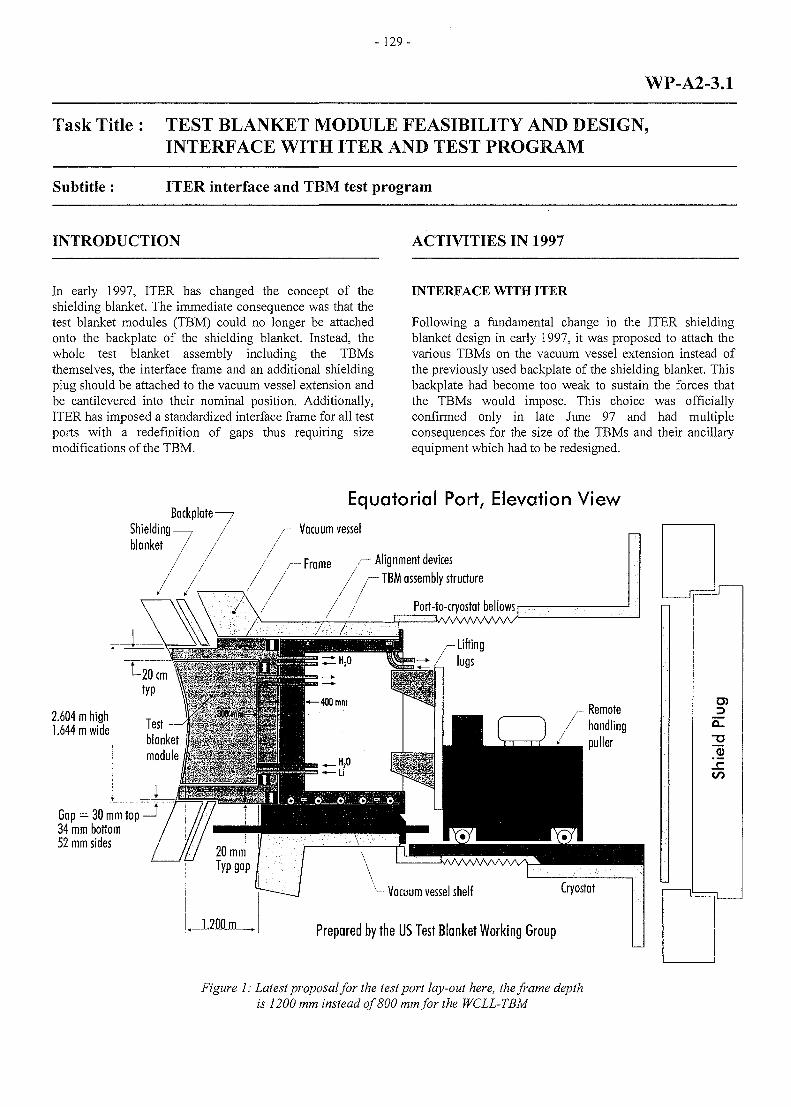
- 129 -
WP-A2-3.1
Task Title : TEST BLANKET MODULE FEASIBILITY AND DESIGN,INTERFACE WITH ITER AND TEST PROGRAM
Subtitle : ITER interface and TBM test program
INTRODUCTION ACTIVITIES IN 1997
In early 1997, ITER has changed the concept of theshielding blanket. The immediate consequence was that thetest blanket modules (TBM) could no longer be attachedonto the backplate of the shielding blanket. Instead, thewhole test blanket assembly including the TBMsthemselves, the interface frame and an additional shieldingplug should be attached to the vacuum vessel extension andbe cantilevered into their nominal position. Additionally,ITER has imposed a standardized interface frame for all testports with a redefinition of gaps thus requiring sizemodifications of the TBM.
INTERFACE WITH ITER
Following a fundamental change in the ITER shieldingblanket design in early 1997, it was proposed to attach thevarious TBMs on the vacuum vessel extension instead ofthe previously used backplate of the shielding blanket. Thisbackplate had become too weak to sustain the forces thatthe TBMs would impose. This choice was officiallyconfirmed only in late June 97 and had multipleconsequences for the size of the TBMs and their ancillaryequipment which had to be redesigned.
ShieldingBackplate-
Equatorial Port, Elevation View/— Vacuum vessel
/--Frame / - A l i g n m e n t devicesTBM assembly structure
2.604 m high1.644 mwide
Gap = 30 mm top —J34 mm bottom52 mm sides
- Vacuum vessel shelf C|Tostat
Prepared by the US Test Blanket Working Group
Figure 1: Latest proposal for the test port lay-out here, the frame depthis 1200 mm instead of 800 mm for the WCLL-TBM
Q_
GO
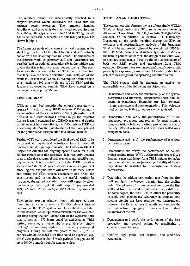
- 130 -
The interface frames are mechanically attached to asupport structure which cantilevers the TBM into thevacuum vessel extension. The remotely handledinstallation and removal is thus facilitated and requires lesstime, though the gaps between frame and shielding blankethad to be increased. A schematic of this test port lay-out isshown in Fig. 1.
The frames are made of the same structural material as theshielding blanket (AISI 316 LN-IG) and are activelycooled with the shielding blanket water. The thickness ofthe external walls is generally 200 mm (exceptions arepossible) and an optional separation rib in the middle maydivide the frame into two equal compartments. One suchframe can thus be shared by two TBMs on the conditionthat they have the same orientation. The backplate of theframe is 300 mm thick. Some TBMs require a frame depthof as much as 1200 mm while the WCLL-TBM and theJapanese water-cooled ceramic TBM have agreed on acommon frame depth of 800 mm.
TEST PROGRAM
ITER as a test bed provides the unique opportunity tooperate for the first time a DEMO relevant TBM system ina combination of strong magnetic field, high surface heatflux and 14.1 MeV neutrons. Even though the expectedfluence is small compared to a DEMO reactor and despitecertain unavoidable size effects, the TBM tests in ITER area necessary step for the qualification of the concepts andfor the performance extrapolation to a DEMO blanket.
Testing of TBMs is considered the final step of R&D to beperformed in in-pile and out-of-pile tests to meet allfunctions and design requirements. The European BlanketProject has oriented the ongoing specific R&D for a testblanket system onto this objective. It is regularly updatedso as to take due account of achievements and possible newrequirements. It is expected that, as the ITER operationscenario and the TBM system design evolve, a significantmodeling and analysis effort will have to be made beforeand during the TBM tests to accompany and orient theexperiments, and to maximize the useful results. Inparticular, the pulsed operation mode will certainly allowfunctionality tests, yet it will require sophisticatedanalytical tools for the interpretation of the experimentaldata.
TBM testing requires relatively long, uninterrupted burntimes, in particular to reach a DEMO relevant tritiumbuild-up in the TBM system and to establish a reliabletritium balance. As an optimistic estimate for the availabletest time during the BPP, about half of the expected burntime of approx. 1670 hours could be dedicated to TBMtesting. Some more time might be available by "piggy-backing" on run time dedicated to other experimentalprograms. During the last four years of the BPP, 2 - 4periods with an extended burn time could be expected, e.g.two 6-week periods or four 3-week periods. Long pulses ofup to 10000 s length might be available also.
TEST PLAN AND OBJECTIVES
The current test plan foresees the use of one single WCLL-TBM at least during the BPP, so as to accumulate amaximum of operating time. Only in case of degradation,accident or malfunction, a removal is mandatory.Depending on the results acquired during the BPP, anexchange and post-irradiation analysis of the irradiatedTBM will be performed, followed by a modified TBM forthe EPP. Modifications could include type and location ofthe tritium permeation barrier, the design of the First Wallor ancillary components. They would be a consequence ofboth new R&D results and experience from TBMoperation. Because these exchanges and modifications willprobably be expensive, a maximum of flexibility should beachieved by changes of the operating conditions alone.
The TBM system shall be designed to enable theaccomplishment of the following test objectives:
1. Demonstrate and verify the functionality of the system,subsystems and individual components under nominaloperating conditions. Examples are heat removal,tritium extraction and instrumentation. This objectivemust be reached before all others can be achieved.
2. Demonstrate and verify the performance of tritiumproduction, extraction, and recovery by establishing acomplete tritium balance. Tritium production is one ofHie key tasks of a blanket and was never tested on acomparable scale.
3. Demonstrate and verify the performance of a tritiumpermeation barrier.
4. Demonstrate and verify the performance of double-walled cooling tubes (DWT). Although the use of DWTdoes not seem mandatory for a TBM, neither for safetynor for reliability reasons (reduced probability of leaks),they should be installed for demonstration of theirperformance.
5. Determine the tritium permeation rate from the firstwall and from the breeder material into the coolingwater. The physics of tritium permeation from the firstwall and from the breeder material are very different.To some degree, the WCLL-TBM offers the possibilityto study both phenomena separately as long as bothcooling circuits are kept separate and independent.However, the Be armor could significantly reduce thepermeation from impinging tritium ions thus limitingthe interest of the test.
6. Demonstrate and verify the performance of the heatproduction and removal system by establishing acomplete power balance.
7. Confirm high grade heat removal and electricitygeneration.
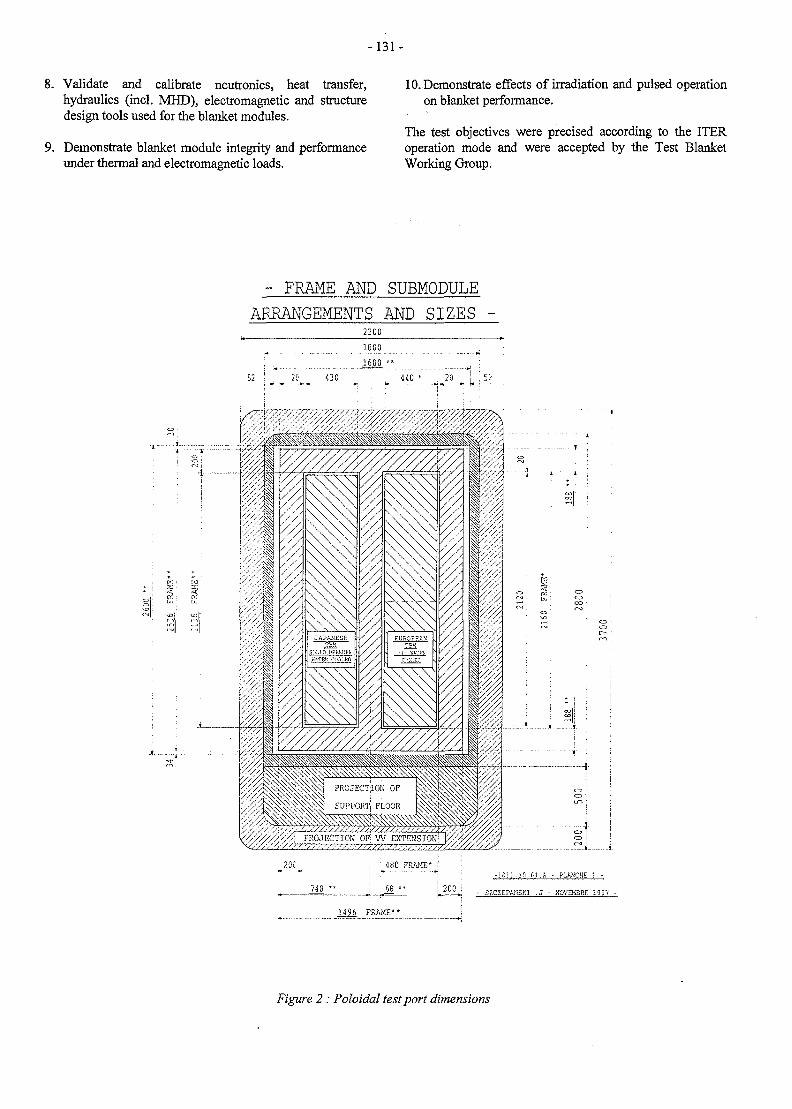
- 1 3 1 -
8. Validate and calibrate neutronics, heat transfer,hydraulics (incl. MHD), electromagnetic and structuredesign tools used for the blanket modules.
9. Demonstrate blanket module integrity and performanceunder thermal and electromagnetic loads.
10. Demonstrate effects of irradiation and pulsed operationon blanket performance.
The test objectives were precised according to the ITERoperation mode and were accepted by the Test BlanketWorking Group.
- FRAME AND SUBMODULEARRANGEMENTS AND SIZES -
2200
Z\ PROJECTIOM OFJ V\> EXTEH
743
•180 FRAME* 'h» - • - W
68 " ! 200
II
T_ t.
-if.li-IO-fl.A - PLAKCHE 1 -
SZCZEPANSK1 -J - H0VEK3RE 199?
1496 FRAME**
Figure 2 : Poloidal test port dimensions
- 1 3 2 -
CONCLUSIONS TASK LEADER
A significant progress was made concerning theintegration of the WCLL-TBM in the ITER machine, inparticular concerning the mechanical interfaces. Apreliminary test program with clear test objectives wasdefined. In the next step it has to be verified how these testobjectives can be achieved in detail. A particular effort willhave to be invested in the definition of the instrumentationand the development of simulation tools to interpret theexperimental data.
PUBLICATIONS
Michael A. Fiitterer
CEA SaclayDRN/DMT/SERMA/LCAF-91191 Gif-sur-Yvette Cedex, France
Tel : 33 169 08 36 36Fax : 33 1 69 08 99 35
e-mail: [email protected]
[1] E. Proust, M. Abdou, Y. Gohar, S. Paidassi, R.Parker, Y. Strebkov, H. Takatsu, DEMO blankettesting in ITER and the international collaborationvia the ITER Test Blanket Working Group, Proc.ISFNT-4, April 7-11, 1997, Tokyo, Japan.
[2] M. Fiitterer, L. Giancarli, J. Szczepanski, Interfacesbetween the WCLL-TBM and ITER including testingprogram: Contributions to the TBWG and exchangeswith the ITER JCT, CEA report DMT 97/556.
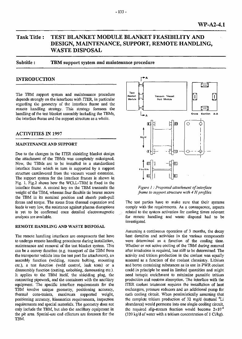
- 133 -
WP-A2-4.1
Task Title : TEST BLANKET MODULE BLANKET FEASIBILITY ANDDESIGN, MAINTENANCE, SUPPORT, REMOTE HANDLING,WASTE DISPOSAL
Subtitle: TBM support system and maintenance procedure
INTRODUCTION
The TBM support system and maintenance proceduredepends strongly on the interfaces with ITER, in particularregarding the geometry of the interface frame and theremote handling strategy. This strategy foresees thehandling of the test blanket assembly including the TBMs,the interface frame and the support structure as a whole.
ACTIVITIES IN 1997
MAINTENANCE AND SUPPORT
Due to the clianges in the ITER shielding blanket designthe attachment of the TBMs was completely redesigned.Now, the TBMs are to be installed in a standardizedinterface frame which in turn is supported by a supportstructure cantilevered from the vacuum vessel extension.The support system for the interface frames is shown inFig. 1. Fig.2 shows how the WCLL-TBM is fixed in theinterface frame. A central key on the TBM transmits theweight of the TBM, whereas four flexible tie beams securethe TBM in its nominal position and absorb push-pullforces and torque. The stress from thermal expansion andloads is very low, the resistance against plasma disruptionsis yet to be confirmed once detailed electromagneticanalyses are available.
REMOTE HANDLING AND WASTE DISPOSAL
The remote handling interfaces are components that haveto undergo remote handling procedures during installation,maintenance and removal of the test blanket system. Tluscan be a convey function (e.g. transport of the TBM fromthe transporter vehicle into the test port for attachment), anassembly function (welding, remote bolting, mountingetc.), a test function (weld control, leak tests) or adisassembly function (cutting, unbolting, demounting etc.).It applies to the TBM itself, the shielding plug, theconnecting pipework, and the containers with the ancillaryequipment. The specific interface requirements for theTBM involve unique geometry, positioning accuracy,thermal cons-traints, maximum supported weight,positioning accuracy, kinematics requirements, inspectionrequirements and special materials. The geometry does notonly include the TBM, but also the ancillary equipment inthe pit area. Special-use end effectors are foreseen for theTBM.
BlankatModuli -
rA
-4
- -1
VaeuuPort
•n Vftecrvbduls
si
Cro • • Section A-A
"5 <p
Rigid
Figure 1: Proposed attachment of interfaceframe to support structure with 4 Hprofiles
The test parties have to make sure that their systemscomply with the requirements. As a consequence, aspectsrelated to the system activation for cooling times relevantfor remote handling and waste disposal had to beinvestigated.
Assuming a continuous operation of 3 months, the decayheat densities and activities in the various componentswere determined as a function of the cooling time.Whether or not active cooling of the TBM during removalafter irradiation is required, has still to be determined. Theactivity and tritium production in the coolant was equallyassessed as a function of the coolant chemistry. Lithiumand boron containing substances as in use in PWR coolantcould in principle be used in limited quantities and mightneed isotopic enrichment to minimize parasitic tritiumproduction and neutron absorption. The interface with theITER coolant treatment requires the installation of heatexchangers, pressure reducers and an additional pump foreach cooling circuit. When pessimistically assuming thatthe complete tritium production of 32 mg/d (natural \Aabundance) would permeate into one single cooling circuit,the required slip-stream fraction would become 2X10"4
(320 kg/d of water with a tritium concentration of 1 Ci/kg).
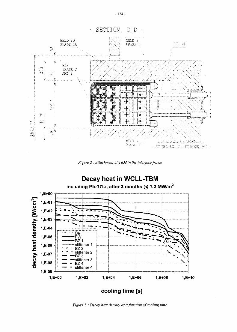
-134-
IT, il
pis
yfkf j i
Figure 2: Attachment ofTBMin the interface frame
Decay heat in WCLL-TBMincluding Pb-17Li, after 3 months @ 1.2 MW/m2
BeFWBZ1stiffener 1BZ2stiffener 2BZ3stiffener 3B2 4stiffener 4
1.E+00 1.E+02 1.E+04 1.E+06 1,E+08 1.E+10
cooling time [s]
Figure 3 : Decay heat density as a function of cooling time
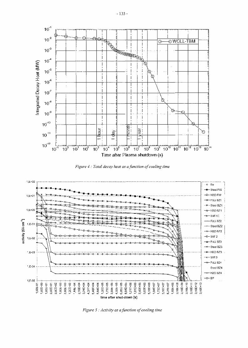
- 135-
10"
10"'
10"
10"
10,-e
,-7
,-9
D 10'
"82 10"'CDa>
^ 1 0
10"
10'
10"
R
1
1
i11
8!~!
\
lay
1—
a,
nont
n
r -
' 1
1
I
1
1
i
ear
\
u—
\
V
•eWCLL-TBM
V\
::
:;!:
10"1 10° 101 102 103 104 105 10e 107 10s 10 s 1010 1011 1012 1013 1014
Time after Plasma shutdown (s)
Figure 4 : Total decay heat as a function of cooling time
1.E+02Be
Steel FW
H20FW
- * -PbLiBZ1
Steel BZ1
H2O BZ1
Stiff 1D
PbLi BZ2
Steel BZ2
H2O BZ2
- • -S t i f f 2
PbLi BZ3
Steel BZ3
1.E-05 -i i : 1i - O t-
o o o * -
^ L U U J U J L l J U L J U J L U l l J I J J U J U J L U L i J U J U J L l J U J l J U I I J U J I l J2 o O O O O O O I ^ - t D - * C N C O N f O C O C n c M i n - ^ r ' ^ - ^ 0 4 f O C O I * C O C D i - c O C D C D C D ( D C D C D° O O O O O O t D C N J ^ T - C N J C O - ^ - C D C O r - i n c O O C D C \ I C O « ^ U 3 T - O r - T - C O l O - < - ' t - ^ ^ - v - r -
t - r - CD (O CD CO T - CO CO CO CO
time after shut-down [s]
Figure 5 : Activity as a function of cooling time
-136-
The cooling system contains tritium and activatedcorrosion products as well as N-16 (hard y emitter, half life7.13 s) and N-17 (fast neutron emitter, half life 4.17 s)from oxygen activation and must be confined accordingly.To minimize activation of the cooling circuit structure, abuffer volume might need to be considered to allow decay.The y shielding requirements depend on the corrosion rateof the involved materials. The consequences of a largecoolant break in the ex-vessel system need be accountedfor. A detailed evaluation of the expected activity levels isyet to be performed. The cooling system has to be suitablyconfined to allow manned access in its vicinity after a shortdecay period. A modular container system confining eachcooling system and compatible with the ITER remotehandling approach seems to be the best solution. Thesystem will have to be accommodated in ventilatedcontainers with radioactivity control and sufficientshielding. If required, this confinement might significantlyincrease the space requirements of the cooling system. Thecontainer modules shall enable the complete removal of theentire cooling system after disconnection of primary andsecondary cooling pipes, cablework and ventilation ducts.
CONCLUSIONS
In 1997, the TBM support system was completelyredesigned to conform to the new boundary conditionsimposed by ITER. The activity and decay heat of the TBMincluding structure, breeder and coolant were calculatedand a confinement was proposed.
PUBLICATIONS
[1] M. Futterer et al., Design Description Document forthe European water-cooled Pb-17Li test blanketmodule (Sept 97), CEA report DMT97/441.
[2] J.-P. Deffain, M. A. Futterer, One-dimensionalneutronic, activation and decay-heat analysis of theWCLL Test Blanket Module, CEA report DMT97/567, December 1997.
TASK LEADER
Michael A. Futterer
CEA SaclayDRN/DMT/SERMA/LCAF-91191 Gif-sur-Yvette Cedex, France
Tel. : 33 1 69 08 36 36Fax : 33 1 69 08 99 35
e-mail: [email protected]
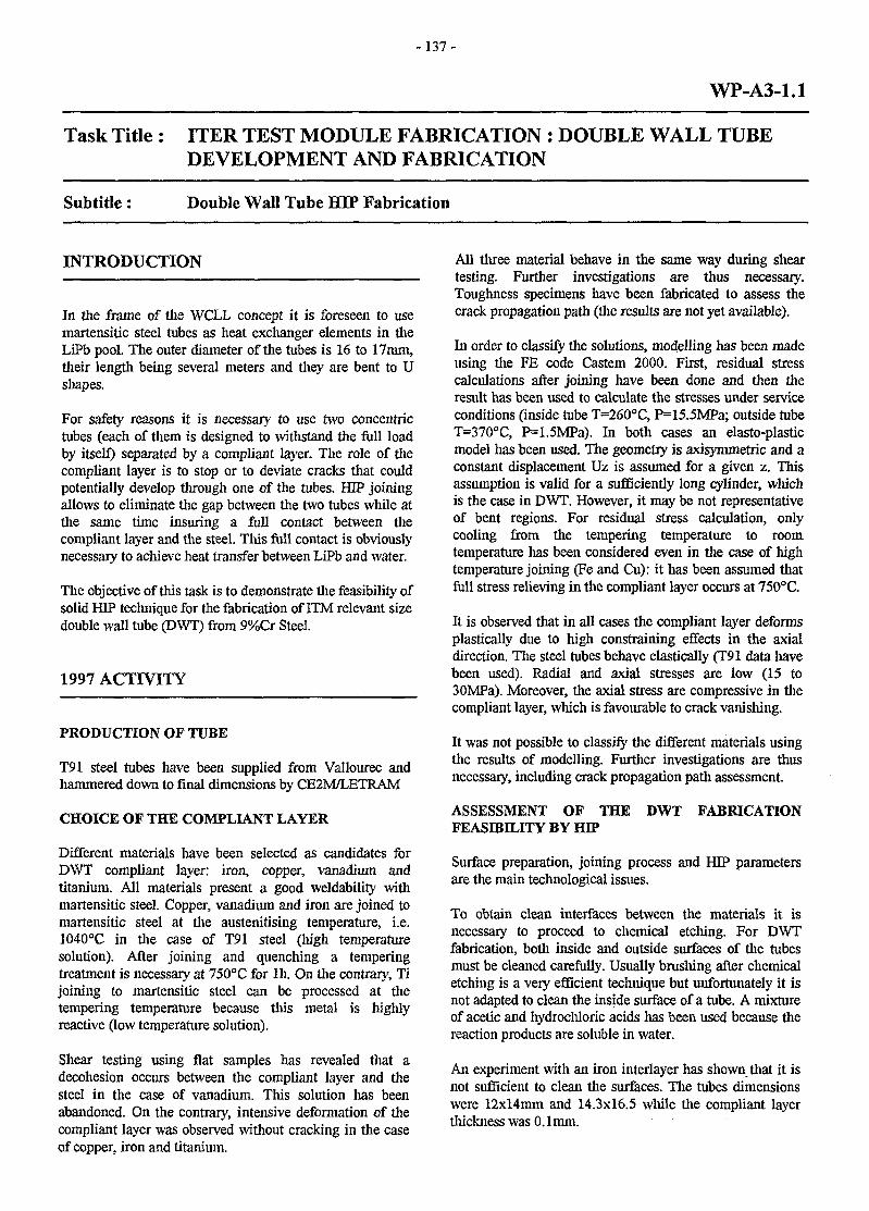
- 137 -
WP-A3-1.1
Task Title : ITER TEST MODULE FABRICATION : DOUBLE WALL TUBEDEVELOPMENT AND FABRICATION
Subtitle: Double Wall Tube HIP Fabrication
INTRODUCTION
In the frame of the WCLL concept it is foreseen to usemartensitic steel tubes as heat exchanger elements in theLiPb pool. The outer diameter of the tubes is 16 to 17mm,their length being several meters and they are bent to Ushapes.
For safety reasons it is necessary to use two concentrictubes (each of them is designed to withstand the full loadby itself) separated by a compliant layer. The role of thecompliant layer is to stop or to deviate cracks that couldpotentially develop through one of the tubes. HIP joiningallows to eliminate the gap between the two tubes while atthe same time insuring a full contact between thecompliant layer and the steel. This full contact is obviouslynecessary to achieve heat transfer between LiPb and water.
The objective of this task is to demonstrate the feasibility ofsolid HEP technique for the fabrication of ITM relevant sizedouble wall tube (DWT) from 9%Cr Steel.
1997 ACTIVITY
PRODUCTION OF TUBE
T91 steel tubes have been supplied from Vallourec andhammered down to final dimensions by CE2M/LETRAM
CHOICE OF THE COMPLIANT LAYER
Different materials have been selected as candidates forDWT compliant layer: iron, copper, vanadium andtitanium. All materials present a good weldability withmartensitic steel. Copper, vanadium and iron are joined tomartensitic steel at the austenitising temperature, i.e.1040°C in the case of T91 steel (high temperaturesolution). After joining and quenching a temperingtreatment is necessary at 750°C for lh. On the contrary, Tijoining to martensitic steel can be processed at thetempering temperature because this metal is highlyreactive (low temperature solution).
Shear testing using flat samples has revealed that adecohesion occurs between the compliant layer and thesteel in the case of vanadium. This solution has beenabandoned. On the contrary, intensive deformation of thecompliant layer was observed without cracking in the caseof copper, iron and titanium.
All three material behave in the same way during sheartesting. Further investigations are thus necessary.Toughness specimens have been fabricated to assess thecrack propagation path (the results are not yet available).
In order to classify the solutions, modelling has been madeusing the FE code Castem 2000. First, residual stresscalculations after joining have been done and then theresult has been used to calculate the stresses under serviceconditions (inside tube T=260°C, P=15.5MPa; outside tubeT=370°C, P=1.5MPa). In both cases an elasto-plasticmodel has been used. The geometry is axisymmetric and aconstant displacement Uz is assumed for a given z. Thisassumption is valid for a sufficiently long cylinder, whichis the case in DWT. However, it may be not representativeof bent regions. For residual stress calculation, onlycooling from the tempering temperature to roomtemperature has been considered even in the case of hightemperature joining (Fe and Cu): it has been assumed thatfull stress relieving in the compliant layer occurs at 750°C.
It is observed that in all cases the compliant layer deformsplastically due to high constraining effects in the axialdirection. The steel tubes behave elastically (T91 data havebeen used). Radial and axial stresses are low (15 to30MPa). Moreover, the axial stress are compressive in thecompliant layer, which is favourable to crack vanishing.
It was not possible to classify the different materials usingthe results of modelling. Further investigations are thusnecessary, including crack propagation path assessment.
ASSESSMENT OF THE DWT FABRICATIONFEASIBILITY BY HIP
Surface preparation, joining process and HEP parametersare the main technological issues.
To obtain clean interfaces between the materials it isnecessary to proceed to chemical etching. For DWTfabrication, both inside and outside surfaces of the tubesmust be cleaned carefully. Usually brushing after chemicaletching is a very efficient technique but unfortunately it isnot adapted to clean the inside surface of a tube. A mixtureof acetic and hydrochloric acids has been used because thereaction products are soluble in water.
An experiment with an iron interlayer has shown that it isnot sufficient to clean the surfaces. The tubes dimensionswere 12xl4mm and 14.3x16.5 while the compliant layerthickness was 0. lmm.
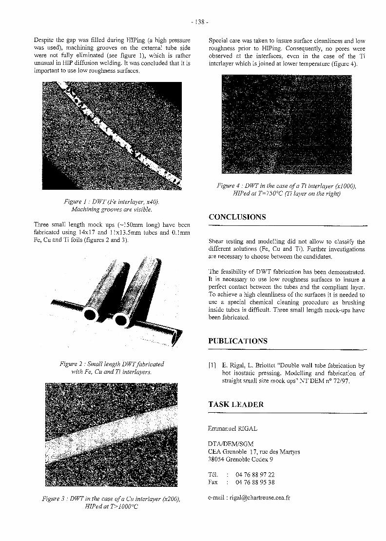
- 138 -
Despite the gap was filled during HIPing (a high pressurewas used), machining grooves on the external tube sidewere not fully eliminated (see figure 1), which is ratherunusual in HIP diffusion welding. It was concluded that it isimportant to use low roughness surfaces.
Figure 1: DWT (Fe interlayer, x40).Machining grooves are visible.
Three small length mock ups (~150mm long) have beenfabricated using 14x17 and llxl3.5mm tubes and 0.1mmFe, Cu and Ti foils (figures 2 and 3).
Special care was taken to insure surface cleanliness and lowroughness prior to HIPing. Consequently, no pores wereobserved at the interfaces, even in the case of the Tiinterlayer which is joined at lower temperature (figure 4).
Figure 4 : DWT in the case of a Ti interlayer (xlOOO),HIPed at T=750°C (Ti layer on the right)
CONCLUSIONS
Shear testing and modelling did not allow to classify thedifferent solutions (Fe, Cu and Ti). Further investigationsare necessary to choose between the candidates.
The feasibility of DWT fabrication has been demonstrated.It is necessary to use low roughness surfaces to insure aperfect contact between the tubes and the compliant layer.To achieve a high cleanliness of the surfaces it is needed touse a special chemical cleaning procedure as brushinginside tubes is difficult. Three small length mock-ups havebeen fabricated.
PUBLICATIONS
Figure 2 : Small length DWT fabricatedwith Fe, Cu and Ti interlayers.
Figure 3 : DWT in the case of a Cu interlayer (x200),HIPed at T>1000°C
[1] E. Rigal, L. Briottet "Double wall tube fabrication byhot isostatic pressing. Modelling and fabrication ofstraight small size mock ups" NT DEM n° 72/97.
TASK LEADER
Emmanuel RIGAL
DTA/DEM/SGMCEA Grenoble 17, rue des Martyrs38054 Grenoble Cedex 9
Tel.Fax
04 76 88 97 2204 76 88 95 38
e-mail: [email protected]
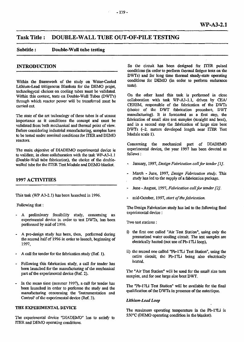
- 1 3 9 -
WP-A3-2.1
Task Title : DOUBLE-WALL TUBE OUT-OF-PILE TESTING
Subtitle: Double-Wall tube testing
INTRODUCTION
Within the framework of the study on Water-CooledLithium-Lead tritigenous Blankets for the DEMO projet,technologycal choices on cooling tubes must be validated.Within this context, tests on Double-Wall Tubes (DWTs)through which reactor power will be transferred must becarried out.
The state of the art technology of these tubes is of utmostimportance as it conditions the concept and must bevalidated from both mechanical and thermal point of view.Before considering industrial manufacturing, samples haveto be tested under nominal conditions for ITER and DEMOreactors.
The main objective of DIADEMO experimental device isto validate, in close collaboration with the task WP-A3-1.1(Double-Wall tube fabrication), the choice of the double-walled tube for the ITER Test Module and DEMO blanket.
1997 ACTrVTriES
This task (WP A3-2.1) has been launched in 1996.
Following that:
- A preliminary feasibility study, concerning anexperimental device in order to test DWTs, has beenperformed by mid of 1996.
- A pre-design study has been, then, performed duringthe second half of 1996 in order to launch, beginning of1997,
- A call for tender for the fabrication study (Ref. 1).
- Following this fabrication study, a call for tender hasbeen launched for the manufacturing of the mechanicalpart of the experimental device (Ref. 2).
- In the mean time (summer 1997), a call for tender hasbeen launched in order to performe the study and themanufacturing concerning the 'Instrumentation andControl' of the experimental device (Ref. 3).
THE EXPERIMENTAL DEVICE
The experimental device "DIADEMO" has to satisfy toITER and DEMO operating conditions.
So the circuit has been designed for ITER pulsedconditions (in order to perform thermal fatigue tests on theDWTs) and for long time thermal steady-state operatingconditions for DEMO (in order to perform endurancetests).
On the other hand this task is performed in closecollaboration with task WP-A3-1.1, driven by CEA/CEREM, responsible of the fabrication of the DWTs(choice of the DWT fabrication procedure, DWTmanufacturing). It is forecasted as a first step, thefabrication of small size test samples (straight and bent),and in a second step the fabrication of large size bentDWTs (~2. meters developed length near ITER TestModule scale 1).
Concerning the mechanical part of DIADEMOexperimental device, the year 1997 has been devoted asfollows :
- January, 1997, Design Fabrication call for tender flj.
- March - June, 1997, Design Fabrication study. Thisstudy has led to the supply of a fabrication package.
- June - August, 1997, Fabrication call for tender [2].
- mid-October, 1997, start of the fabrication.
The Design Fabrication study has led to the following finalexperimental device:
Two test stations:
i) the first one called "Air Test Station", using only thepressurized water cooling circuit The test samples areelectrically heated (not use of Pb-17Li loop),
ii) the second one called "Pb-17Li Test Station", using theentire circuit; the Pb-17Li being also electricallyheated.
The "Air Test Station" will be used for the small size testssamples, and for one large size bent DWT.
The "Pb-17Li Test Station" will be available for the finalqualification of the DWTs in presence of the eutectique.
Lithium-Lead Loop
The maximum operating temperature in the Pb-I7Li is550°C (DEMO operating condition in the blanket).
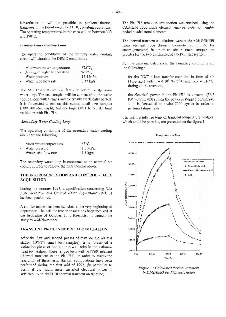
- 140 -
Nevertheless it will be possible to perform thermaltransients in the liquid metal for ITER operating conditions.The operating temperatures in this case will be between 300and 390°C.
Primary Water Cooling Loop
The operating conditions of the primary water coolingcircuit will simulate the DEMO conditions :
Maximum water temperature : 325°C,- Minimum water temperature : 265°C,- Water pressure : 15.5 MPa,- Water tube flow rate : 0.37 kg/s.
The "Air Test Station" is in fact a derivation on the mainwater loop. The test samples will be connected to the watercooling loop with flanges and externally electrically heated.It is forecasted to test on this station small size samples(100/ 500 mm lenght) and one large DWT before the finalvalidation with Pb-17Li.
Secondary Water Cooling Loop
The operating conditions of the secondary water coolingcircuit are the following :
Mean water temperatureWater pressureWater tube flow rate
: 55°C,: 1.5 MPa,: 1.5 kg/s.
The secondary water loop is connected to an external aircooler, in order to remove the final thermal power.
THE INSTRUMENTATION AND CONTROL - DATAACQUISITION
During the summer 1997, a specification concerning "theInstrumentation and Control -Data Acquisition" (Ref. 3)has been performed.
A call for tender has been launched at the very beginning ofSeptember. The call for tender answer has been received atthe beginning of October. It is forecasted to launch thestudy by mid-November.
TRANSIENT Pb-17Li NUMERICAL SIMULATION
After the first and second phases of tests on the air teststation (DWT's small test samples), it is forecasted avalidation phase of one Double-Wall tube in the Lithium-Lead test station. These fatigue tests will be ITER relevant(thermal transient in the Pb-17Li). In order to assess thefeasibility of these tests, thermal computations have beenperformed during the first mid of 1997, (in particular toverify if the liquid metal installed electrical power issufficient to obtain ITER thermal transient on the tube).
The Pb-17Li mock-up test section was meshed using theCASTEM 2000 finite element analysis code with eight-noded quadrilateral elements.
The thermal transient calculations were made with GENEPIfinite element code (French thermohydraulic code forsteam-generator) in order to obtain mean temperatureprofiles for the two dimensionnal Pb-17Li test section.
For the transient calculation, the boundary conditions arethe following :
- for the DWT a heat transfer condition in form of : h(Twaii-Tbuik) with h = 4.104 W/m2oC and Tbulk = 310°C,during all the transient,
- the electrical power in the Pb-17Li is constant (56.5KW) during 420 s, then the power is stopped during 240s. It is forecasted to make 5000 cycles in order toperform fatigue tests.
The main results, in term of transient temperature profiles,which could be possible, are presented on the figure 1.
Temperature vs Time
500,00 T
480,00 -,
K— Internal tube wall
e— External tube wall
A— Electrical heater outer wall
B-LiPb
300,00
200,00 400,00 600,00
Time (s)
Figure 1: Calculated thermal transientin DIADEMO Pb-17Li test station
-141-
TIME SCHEDULE TASK LEADER
The manufacture is planned on the years 1997 and 1998.
Yves SEVERIThe instrumentation and control of the loop (includingacceptance tests) could be completed mid 98. The first DRN/DER/STML/LCFIacceptance tests of the "Air Test Station" could be made Centre de Cadarachebetween july and September 98. The first tests on small sizestraight samples could be started in October 1998. Tel. : 04 42 25 64 01
Fax : 04 42 25 66 38
REFERENCES e-mail: [email protected]
[1] NT. DER/ STML/ LCFI - 97-001. (21/ 01/ 1997)."Specifications pour 1'etude de fabrication d'undispositif d'essais de tubes a double paroi".
[2] NT. DER/ STML/ LCFI - 97-017. (05/ 06/ 1997)."Specifications pour la fabrication d'un dispositifd'essais de tubes a double paroi"
[3] NT. DER/ STML/ LCFI - 97-024. (31/ 08/ 1997)."Appel d'offres - Specifications pour 1'etude et larealisation du controle-commande du dispositifd'essais DIADEMO".
[4] IEA International Workshop on "Liquid MetalBlanket Experimental Activities"September 16-18, 1997. CEA Headquarters, PARIS."Water-Cooled Pb-17Li Blanket - DiademoExperimental Programme for Testing Double-WalledTubes"
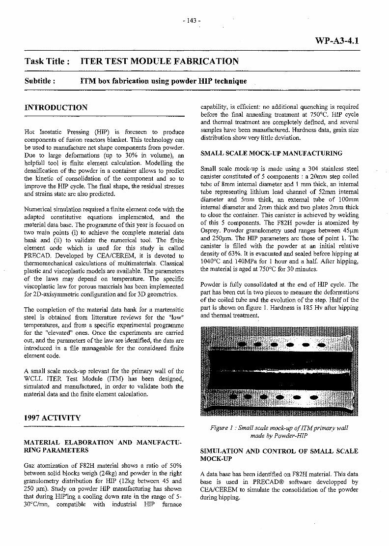
-143 -
WP-A3-4.1
Task Title : ITER TEST MODULE FABRICATION
Subtitle : ITM box fabrication using powder HIP technique
INTRODUCTION
Hot Isostatic Pressing (HIP) is foreseen to producecomponents of fusion reactors blanket. This technology canbe used to manufacture net shape components from powder.Due to large deformations (up to 30% in volume), anhelpfull tool is finite element calculation. Modelling thedensification of the powder in a container allows to predictthe kinetic of consolidation of the component and so toimprove the HIP cycle. The final shape, the residual stressesand strains state are also predicted.
Numerical simulation required a finite element code with theadapted constitutive equations implemented, and thematerial data base. The programme of this year is focused ontwo main points (i) to achieve the complete material databank and (ii) to validate the numerical tool. The finiteelement code which is used for this study is calledPRECAD. Developed by CEA/CEREM, it is devoted tothermomechanical calculations of multimaterials. Classicalplastic and viscoplastic models are available. The parametersof the laws may depend on temperature. The specificviscoplastic law for porous materials has been implementedfor 2D-axisymmetric configuration and for 3D geometries.
The completion of the material data bank for a martensiticsteel is obtained from litterature reviews for the "low"temperatures, and from a specific experimental programmefor the "elevated" ones. Once the experiments are carriedout, and the parameters of the law are identified, the data areintroduced in a file manageable for the considered finiteelement code.
A small scale mock-up relevant for the primary wall of theWCLL ITER Test Module (ITM) has been designed,simulated and manufactured, in order to validate both thematerial data and the finite element calculation.
1997 ACTIVITY
MATERIAL ELABORATION AND MANUFACTU-RING PARAMETERS
Gaz atomization of F82H material shows a ratio of 50%between solid blocks weigh (24kg) and powder in the rightgranulometry distribution for HIP (12kg between 45 and250 um). Study on powder HIP manufacturing has shownthat during HIP'ing a cooling down rate in the range of 5-30°C/mn, compatible with industrial HIP furnace
capability, is efficient: no additional quenching is requiredbefore the final annealing treatment at 750°C. HIP cycleand thermal treatment are completely defined, and severalsamples have been manufactured. Hardness data, grain sizedistribution show very little deviation.
SMALL SCALE MOCK-UP MANUFACTURING
Small scale mock-up is made using a 304 stainless steelcanister constituted of 5 components : a 20mm step coiledtube of 8mm internal diameter and 1 mm thick, an internaltube representing lithium lead channel of 52mm internaldiameter and 5mm thick, an external tube of 100mminternal diameter and 2mm thick and two plates 2mm thickto close the container. This canister is achieved by weldingof this 5 components. The F82H powder is atomized byOsprey. Powder granulometry used ranges between 45umand 250um. The HIP parameters are those of point 1. Thecanister is filled with the powder at an initial relativedensity of 63%. It is evacuated and sealed before hipping at1040°C and 140MPa for 1 hour and a half. After hipping,the material is aged at 750°C for 30 minutes.
Powder is fully consolidated at the end of HIP cycle. Thepart has been cut in two pieces to measure the deformationsof the coiled tube and the evolution of the step. Half of thepart is shown on figure 1. Hardness is 185 Hv after hippingand thermal treatment.
Figure 1: Small scale mock-up of ITM primary wallmade by Powder-HIP
SIMULATION AND CONTROL OF SMALL SCALEMOCK-UP
A data base has been identified on F82H material. This database is used in PRECAD® software developped byCEA/CEREM to simulate the consolidation of the powderduring hipping.
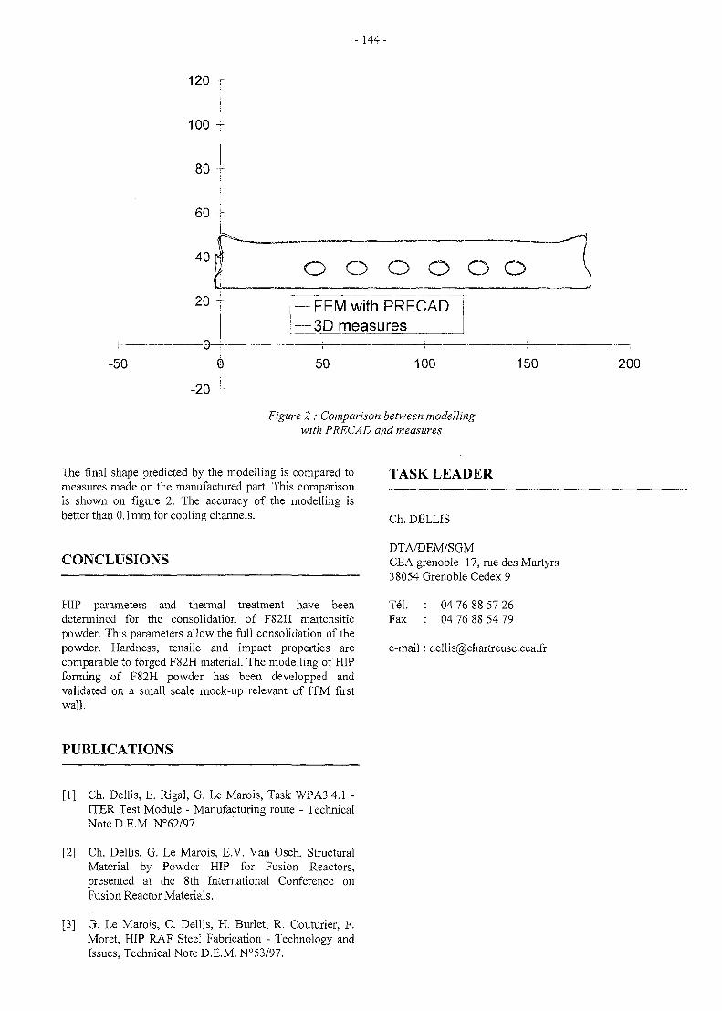
-144 -
120 T
100 r
80
60 j40 r o o o o o o
-50
20
0—
-20
FEM with PRECAD•3D measures
50 100 150 200
Figure 2 : Comparison between modellingwith PRECAD and measures
The final shape predicted by the modelling is compared tomeasures made on the manufactured part. This comparisonis shown on figure 2. The accuracy of the modelling isbetter than 0.1mm for cooling channels.
CONCLUSIONS
HIP parameters and thermal treatment have beendetermined for the consolidation of F82H martensiticpowder. This parameters allow the full consolidation of thepowder. Hardness, tensile and impact properties arecomparable to forged F82H material. The modelling of HIPforming of F82H powder has been developped andvalidated on a small scale mock-up relevant of ITM firstwall.
TASK LEADER
Ch. DELLIS
DTA/DEM/SGMCEA grenoble 17, rue des Martyrs38054 Grenoble Cedex 9
Tel.Fax
04 76 88 57 2604 76 88 54 79
e-mail: dellis(5)chartreuse.cea.fr
PUBLICATIONS
[1] Ch. Dellis, E. Rigal, G. Le Marois, Task WPA3.4.1 -ITER Test Module - Manufacturing route - TechnicalNote D.E.M. N°62/97.
[2] Ch. Dellis, G. Le Marois, E.V. Van Osch, StructuralMaterial by Powder HIP for Fusion Reactors,presented at the 8th International Conference onFusion Reactor Materials.
[3] G. Le Marois, C. Dellis, H. Burlet, R. Couturier, F.Moret, HIP RAF Steel Fabrication - Technology andIssues, Technical Note D.E.M. N°53/97.
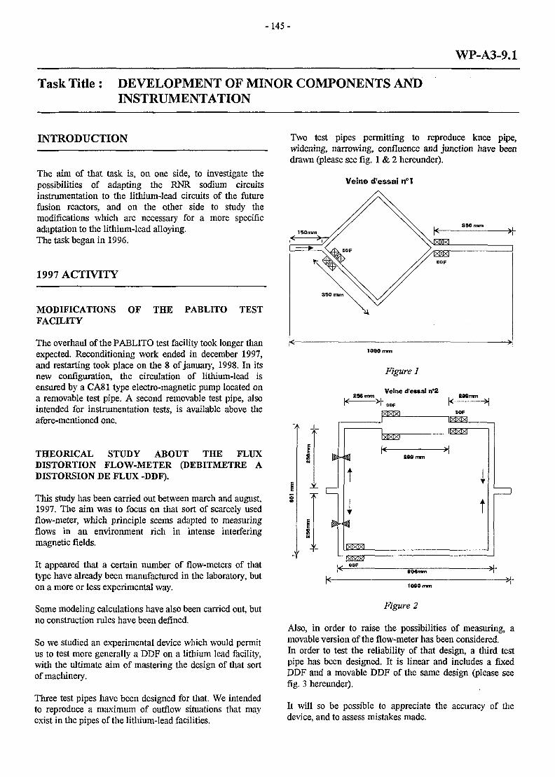
-145 -
WP-A3-9.1
Task Title: DEVELOPMENT OF MINOR COMPONENTS ANDINSTRUMENTATION
INTRODUCTION
The aim of that task is, on one side, to investigate thepossibilities of adapting the RNR sodium circuitsinstrumentation to the lithium-lead circuits of the futurefusion reactors, and on the other side to study themodifications which are necessary for a more specificadaptation to the lithium-lead alloying.The task began in 1996.
1997 ACTIVITY
MODIFICATIONS OF THE PABLITO TESTFACILITY
The overhaul of the PABLITO test facility took longer thanexpected. Reconditioning work ended in december 1997,and restarting took place on the 8 of January, 1998. In itsnew configuration, the circulation of lithium-lead isensured by a CA81 type electro-magnetic pump located ona removable test pipe. A second removable test pipe, alsointended for instrumentation tests, is available above theafore-mentioned one.
THEORICAL STUDY ABOUT THE FLUXDISTORTION FLOW-METER (DEBITMETRE ADISTORTION DE FLUX -DDF).
This study has been carried out between march and august,1997. The aim was to focus on that sort of scarcely usedflow-meter, which principle seems adapted to measuringflows in an environment rich in intense interferingmagnetic fields.
It appeared that a certain number of flow-meters of thattype have already been manufactured in the laboratory, buton a more or less experimental way.
Some modeling calculations have also been carried out, butno construction rules have been defined.
So we studied an experimental device which would permitus to test more generally a DDF on a lithium lead facility,with the ultimate aim of mastering the design of that sortof machinery.
Three test pipes have been designed for that. We intendedto reproduce a maximum of outflow situations that mayexist in the pipes of the lithium-lead facilities.
Two test pipes permitting to reproduce knee pipe,widening, narrowing, confluence and junction have beendrawn (please see fig. 1 & 2 hereunder).
Veine d'essai n°I
loao
tWmm
Figure 1
Veine d'essai n°2&S9mm
j _
ti
If
1* 209 mm
llXIXIXl
1
It
1X1X7X1ODF
604mm
•M-
Figure 2
Also, in order to raise the possibilities of measuring, amovable version of the flow-meter has been considered.In order to test the reliability of that design, a third testpipe has been designed. It is linear and includes a fixedDDF and a movable DDF of the same design (please seefig. 3 hereunder).
It will so be possible to appreciate the accuracy of thedevice, and to assess mistakes made.
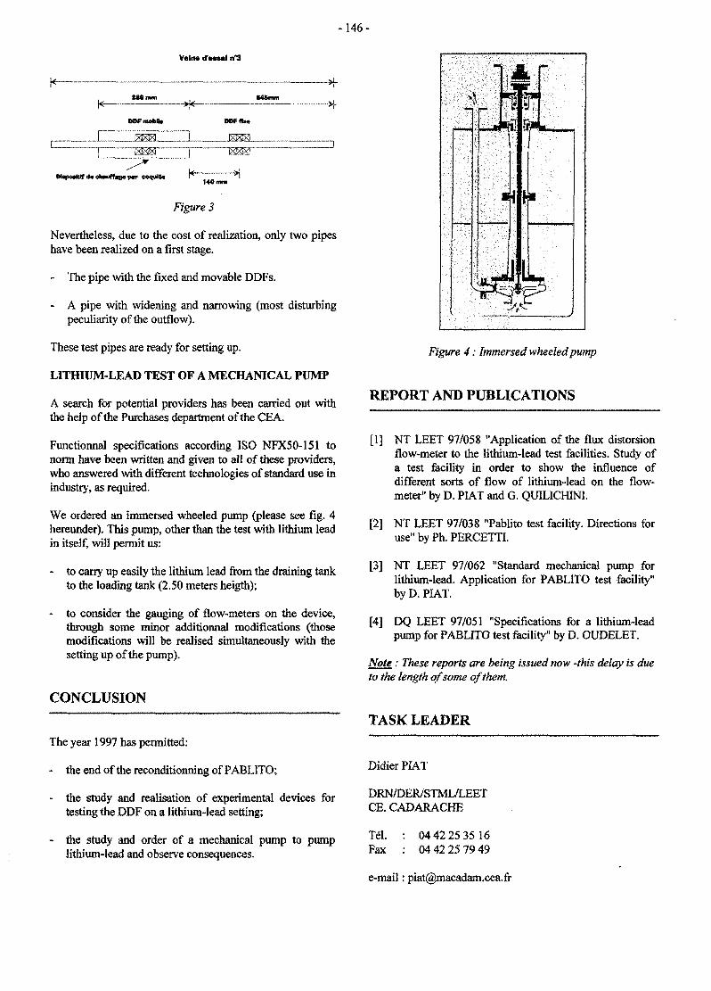
-146-
Velno d'essai n°3
DOFmotoK. DOFfb*
Figure 3
Nevertheless, due to the cost of realization, only two pipeshave been realized on a first stage.
- The pipe with the fixed and movable DDFs.
- A pipe with widening and narrowing (most disturbingpeculiarity of the outflow).
These test pipes are ready for setting up.
LITHIUM-LEAD TEST OF A MECHANICAL PUMP
A search for potential providers has been carried out withthe help of the Purchases department of the CEA.
Functionnal specifications according ISO NFX50-151 tonorm have been written and given to all of these providers,who answered with different technologies of standard use inindustry, as required.
We ordered an immersed wheeled pump {please see fig. 4hereunder). This pump, other than the test with lithium leadin itself, will permit us:
- to carry up easily the lithium lead from the draining tankto the loading tank (2.50 meters heigth);
- to consider the gauging of flow-meters on the device,through some minor additionnal modifications (thosemodifications will be realised simultaneously with thesetting up of the pump).
CONCLUSION
The year 1997 has permitted:
- the end of the reconditionning of PABLITO;
- the study and realisation of experimental devices fortesting the DDF on a lithium-lead setting;
- the study and order of a mechanical pump to pumplithium-lead and observe consequences.
Figure 4: Immersed wheeled pump
REPORT AND PUBLICATIONS
[1] NT LEET 97/058 "Application of the flux distorsionflow-meter to the lithium-lead test facilities. Study ofa test facility in order to show the influence ofdifferent sorts of flow of lithium-lead on the flow-meter" by D. PIAT and G. QUILICH1NI.
[2] NT LEET 97/038 "Pablito test facility. Directions forusenbyPh.PERCETTL
[3] NT LEET 97/062 "Standard mechanical pump forlithium-lead. Application for PABLITO test facility"by D. PIAT.
[4] DQ LEET 97/051 "Specifications for a lithium-leadpump for PABLITO test facility" by D. OUDELET.
Note : These reports are being issued now -this delay is dueto the length of some of them.
TASK LEADER
DidierPlAT
DRN/DER/STML/LEETCE. CADARACHE
Tel.Fax
04 42 25 35 1604 42 25 79 49
e-mail: [email protected]
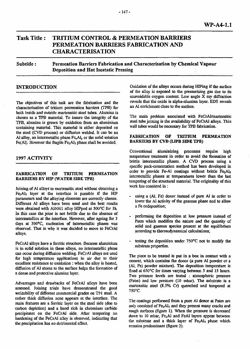
-147 -
WP-A4-1.1
Task Title : TRITIUM CONTROL & PERMEATION BARRIERSPERMEATION BARRIERS FABRICATION ANDCHARACTERISATION
Subtitle: Permeation Barriers Fabrication and Characterisation by Chemical VapourDeposition and Hot Isostatic Pressing
INTRODUCTION
The objectives of this task are the fabrication and thecharacterisation of tritium permeation barriers (TPB) forboth inside and outside martensitic steel tubes. Alumina ischosen as a TPB material. To insure the integrity of theTPB, alumina is grown by oxidation from an aluminiumcontaining material. This material is either deposited onthe steel (CYD process) or diffusion welded. It can be anAl alloy, an intermetallic phase Fe*Aly or the solid solutionFe(Al). However the fragile FejAls phase shall be avoided.
1997 ACTIVITY
FABRICATION OF TRITIUM PERMEATIONBARRIERS BY HIP (WATER SIDE TPB)
Joining of Al alloys to martensitic steel without obtaining aFe2Als layer at the interface is possible if the HIPparameters and the alloying elements are correctly chosen.Different Al alloys have been used and the best resultswere obtained with A16061 alloy HIPped at 500°C for In.In this case the joint is not brittle due to the absence ofintermetallics at the interface. However, after ageing for 3days at 300°C, nucleation of intermetallic phases wasobserved. That is why it was decided to move to FeCrAlalloys.
FeCrAl alloys have a ferritic structure. Because aluminiumis in solid solution in these alloys, no intermetallic phasecan occur during diffusion welding. FeCrAl alloys are usedfor high temperature applications in air due to theirexcellent resistance to oxidation : when the alloy is heated,diffusion of Al atoms to the surface helps the formation ofa dense and protective alumina layer.
Advantages and drawbacks of FeCrAl alloys have beenassessed. Joining trials have demonstrated the goodweldability of different commercial grades on T91 steel. Arather thick diffusion zone appears at the interface. Themain features are a ferritic layer on the steel side (due tocarbon depletion) and a band rich in chromium carbideprecipitates on the FeCrAl side. After tempering nohardening of the FeCrAl alloy is observed, indicating thatthe precipitation has no detrimental effect.
Oxidation of the alloys occurs during HJPing if the surfaceof the alloy is exposed to the pressurising gas due to itsunavoidable oxygen content Low angle X ray diffractionreveals that the oxide is alpha-alumina layer. EDS revealsan Al enrichment close to the surface.
The main problem associated with FeCrAl/martensiticsteel tube joining is the availability of FeCrAl alloys. Thinwall i
FABRICATION OF TRITIUM PERMEATIONBARRIERS BY CVD (LBPB SIDE TPB)
Conventional aluminizing processes require hightemperature treatment in order to avoid the formation ofbrittle intermetallic phases. A CVD process using aspecific pack-cementation method has been developed inorder to provide Fe-Al coatings without brittle FejAlsintermetallic phases at temperatures lower than the lasttempering of the structural material. The originality of thiswork has consisted in :
- using a (Al, Fe) donor instead of pure Al in order tolower the A! activity of the gaseous phase and to allowa Fe codeposition;
- performing the deposition at low pressure instead ofPatm which modifies the nature and the quantity ofsolid and gaseous species present at the equilibriumaccording to thermodynamical calculations;
- testing the deposition under 750°C not to modify thesubstrate properties.
The piece to be treated is put in a box in contact with acement, which contains the donor (a pure Al powder or a(Al, Fe) powder mixture). The deposition temperature isfixed at 650°C for times varying between 5 and 15 hours.Two pressure levels are tested : atmospheric pressure(Patm) and low pressure (10 mbar). The substrate is amartensitic steel (8.3% Cr) quenched and tempered at750°C.
The coatings performed from a pure Al donor at Patm areonly consisted of F^Als and they present many cracks andrough surfaces (figure 1). When the pressure is decreaseddown to 10 mbar, Fe3AI and FeAl layers appear betweenthe substrate and a thick layer of FejAls phase whichremains predominant (figure 2).
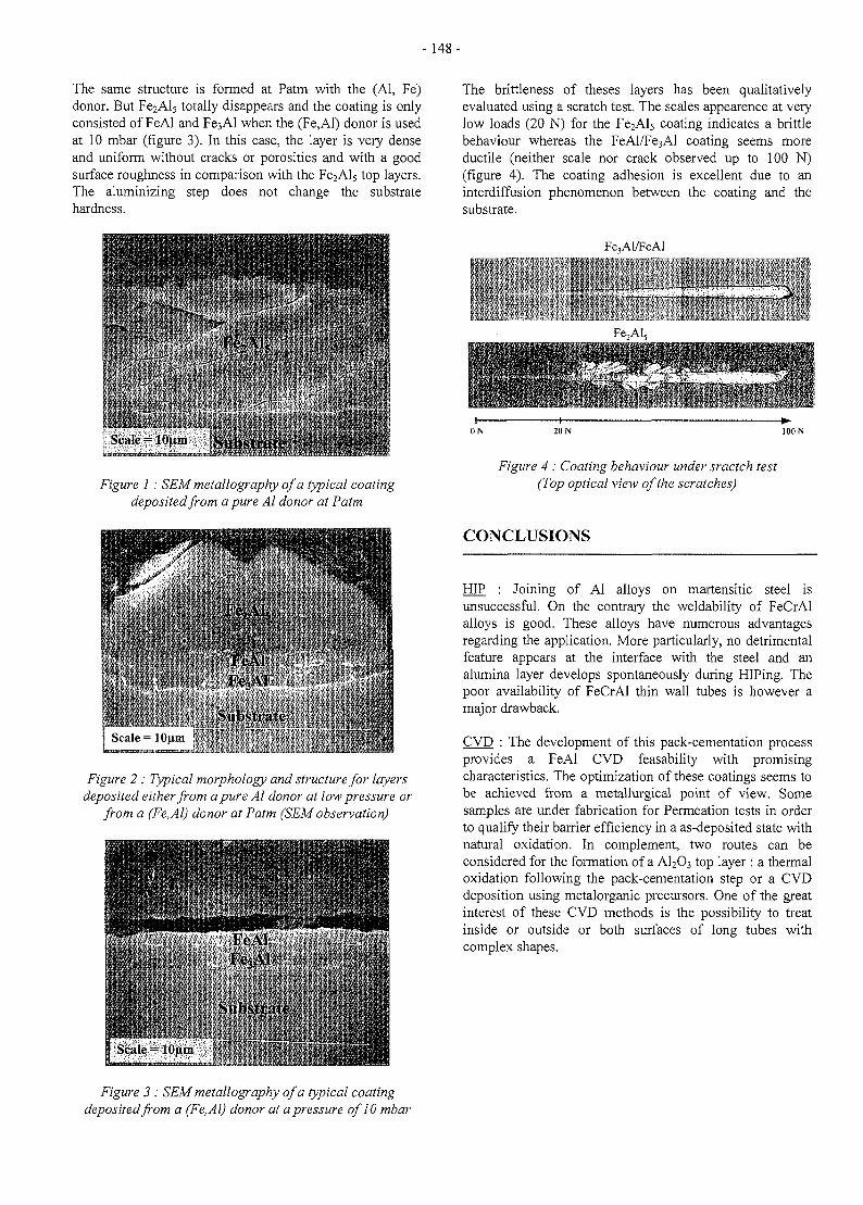
- 148-
The same structure is formed at Patm with the (Al, Fe)donor. But Fe2Al5 totally disappears and the coating is onlyconsisted of FeAl and Fe3Al when the (Fe,Al) donor is usedat 10 mbar (figure 3). In this case, the layer is very denseand uniform without cracks or porosities and with a goodsurface roughness in comparison with the Fe2Al5 top layers.The aluminizing step does not change the substratehardness.
Fe, \l«
scale=ionm [Substrate 'tf-iriSfcrFKH!
Figure 1 : SEM metallography of a typical coatingdeposited from a pure Al donor at Patm
Suit-- Idiiin
Figure 2 : Typical morphology and structure for layersdeposited either from a pure Al donor at low pressure or
from a (Fe.Al) donor at Patm (SEM observation)
.Ml| Scale- lOfiiu
Figure 3 : SEM metallography of a typical coatingdeposited from a (Fe,Al) donor at a pressure of 10 mbar
The brittleness of theses layers has been qualitativelyevaluated using a scratch test. The scales appearence at verylow loads (20 N) for the FeaAls coating indicates a brittlebehaviour whereas the FeAl/Fe3Al coating seems moreductile (neither scale nor crack observed up to 100 N)(figure 4). The coating adhesion is excellent due to aninterdiffusion phenomenon between the coating and thesubstrate.
Fe,Al/FeAl
; • - . .
100 N
Figure 4 : Coating behaviour under sractch test(Top optical view of the scratches)
CONCLUSIONS
HIP : Joining of Al alloys on martensitic steel isunsuccessful. On the contrary the weldability of FeCrAlalloys is good. These alloys have numerous advantagesregarding the application. More particularly, no detrimentalfeature appears at the interface with the steel and analumina layer develops spontaneously during HIPing. Thepoor availability of FeCrAl thin wall tubes is however amajor drawback.
CVD : The development of this pack-cementation processprovides a FeAl CVD feasability with promisingcharacteristics. The optimization of these coatings seems tobe achieved from a metallurgical point of view. Somesamples are under fabrication for Permeation tests in orderto qualify their barrier efficiency in a as-deposited state withnatural oxidation. In complement, two routes can beconsidered for the formation of a AI2O3 top layer : a thermaloxidation following the pack-cementation step or a CVDdeposition using metalorganic precursors. One of the greatinterest of these CVD methods is the possibility to treatinside or outside or both surfaces of long tubes withcomplex shapes.

-149-
PUBLICATIONS TASK LEADER
[1] C. Chabrol, E. Rigal, F. Schuster "Permeation barrier Emmanuel RIGALfabrication by hot isostatic pressing and chemicalvapor deposition" Note Technique DEM n° 73/97. DTA/DEM/SGM
CEA Grenoble 17, rue des Martyrs[2] F. Schuster, C. Chabrol, C. Locatelli, V. Benevent, E. 38054 Grenoble Cedex 9
Rouviere, S. Anderbouhr "Elaboration of Fe-Alcoatings by a new pack-cementation process for Tel. : 04 76 88 97 22tritium permeation barriers" Proceedings of the lrst Fax : 04 76 88 95 38International Workshop on Liquid Metal BlanketExperimental Activities, Sept. 16-18, 1997, e-mail: [email protected]
-»pff % i
j [ , E3
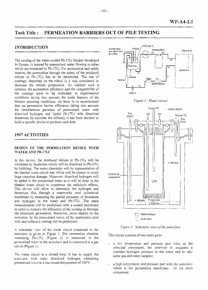
-151 -
WP-A4-2.1
Task Title : PERMEATION BARRIERS OUT OF PILE TESTING
INTRODUCTION -5/25 bars H,
The cooling of the water-cooled Pb-17Li blanket developedin Europe, is insured by pressurised water flowing in tubeswhich are immersed in Pb-17Li. For economical and safetyreasons, the permeation through the tubes, of the producedtritium in Pb-17Li, has to be minimised. The use ofcoatings, deposited on the tubes, is a way considered todecrease the tritium permeation. To validate such asolution, the permeation efficiency and the compatibility ofthe coatings have to be evaluated in experimentalconditions taking into account the main features of theblanket operating conditions. As there is no experimentaldata on permeation barrier efficiency taking into accountthe simultaneous presence of pressurised water withdissolved hydrogen and liquid Pb-17Li with dissolveddeuterium (to simulate the tritium), it has been decided tobuild a specific device to produce such data.
1997 ACTIVITIES
DESIGN OF THE PERMEATION DEVICE WITHWATER AND PB-17LI
In this device, the produced tritium in Pb-17Li will besimulated by deuterium which will be dissolved in Pb-17Liby bubbling. The water chemistry will be representative ofthe blanket water circuit one which will be chosen to avoidlarge corrosion damage. Moreover, dissolved hydrogen willbe added in the pressurised water as it will be done in theblanket water circuit to counteract the radiolysis effects.This device will allow to determine the hydrogen anddeuterium flux through a martensitic steel cylindricalmembrane by measuring the partial pressures of deuteriumand hydrogen in the water and Pb-17Li. The samemeasurements will be performed with a coated membranein order to evaluate the efficiency of the coating to decreasethe deuterium permeation. Moreover, some studies on thecorrosion, by the pressurised water, of the martensitic steelwith and without a coating will be performed.
A schematic view of the water circuit connected to theautoclave is given in Figure 1. The permeation chambercontaining Pb-17Li (Figure 2) is immersed in thepressurised water in the autoclave and is connected to a gascircuit (Figure 3).
The water circuit is a closed loop. It has to supply theautoclave with some dissolved hydrogen containingpressurised water at a maximum temperature of 350°C.
Arrivee d'eau Analysepour ajustemenl—••du niveau
Mesure H,
Resines
Detente
Figure 1 : Water circuit
SondeD2 -Laine d'acier
Mesure H2
Eau35O°C
Cellule de .permeation
| '• Martensitique
Acier inox
Figure 2 : Schematic view of the autoclave
This circuit consists of two main parts:
a low temperature and pressure part with, as theprincipal component, the reservoir to maintain aconstant hydrogen pressure in the water and to takesome gas and water samples;
- a high temperature and pressure part with the autoclavewhere is the permeation membrane, as the maincomponent.
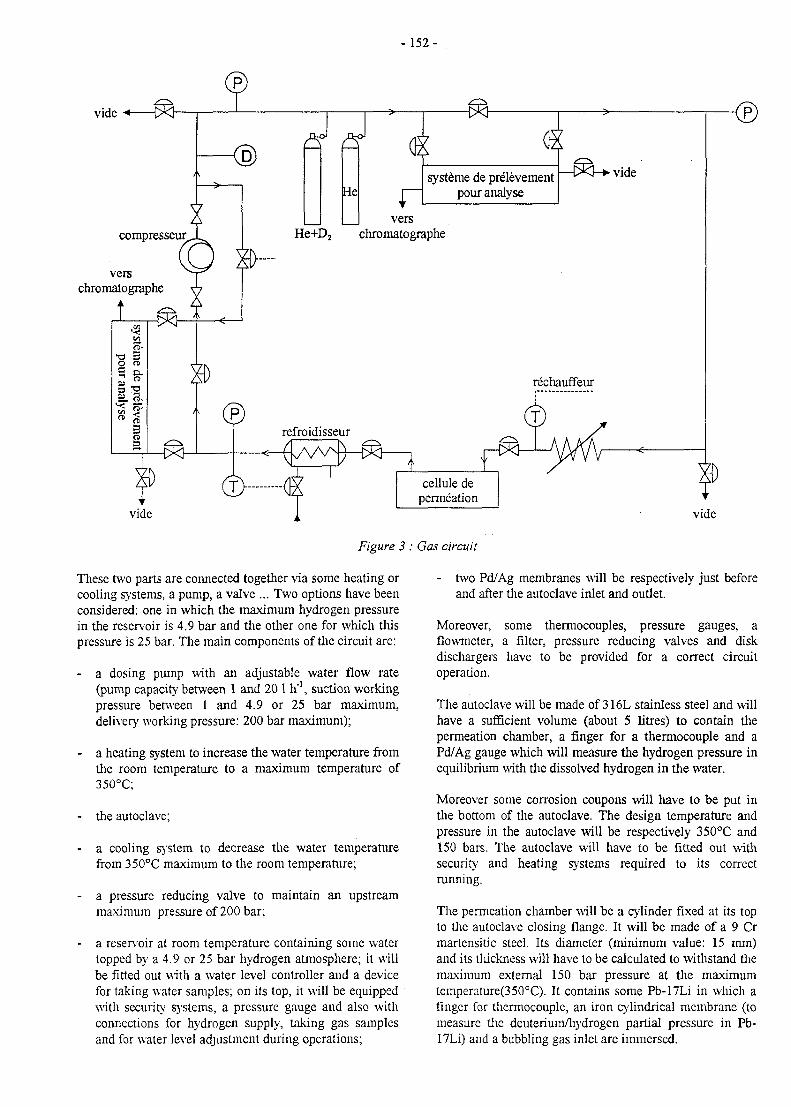
- 152-
vide < $3nJ nJ
He
versHe+D2 chromatographe
verschromatographe
systeme de pre"levementpour analyse
vide
cellule depermeation
vide vide
Figure 3 : Gas circuit
These two parts are connected together via some heating orcooling systems, a pump, a valve ... Two options have beenconsidered: one in which the maximum hydrogen pressurein the reservoir is 4.9 bar and the other one for which thispressure is 25 bar. The main components of the circuit are:
- a dosing pump with an adjustable water flow rate(pump capacity between 1 and 20 1 h'1, suction workingpressure between 1 and 4.9 or 25 bar maximum,delivery working pressure: 200 bar maximum);
- a heating system to increase the water temperature fromthe room temperature to a maximum temperature of350°C;
- the autoclave;
- a cooling system to decrease the water temperaturefrom 350°C maximum to the room temperature;
- a pressure reducing valve to maintain an upstreammaximum pressure of 200 bar;
- a reservoir at room temperature containing some watertopped by a 4.9 or 25 bar hydrogen atmosphere; it willbe fitted out with a water level controller and a devicefor taking water samples; on its top, it will be equippedwith security systems, a pressure gauge and also withconnections for hydrogen supply, taking gas samplesand for water level adjustment during operations;
- two Pd/Ag membranes will be respectively just beforeand after the autoclave inlet and outlet.
Moreover, some thermocouples, pressure gauges, aflowmeter, a filter, pressure reducing valves and diskdischargers have to be provided for a correct circuitoperation.
The autoclave will be made of 316L stainless steel and willhave a sufficient volume (about 5 litres) to contain thepermeation chamber, a finger for a thermocouple and aPd/Ag gauge which will measure the hydrogen pressure inequilibrium with the dissolved hydrogen in the water.
Moreover some corrosion coupons will have to be put inthe bottom of the autoclave. The design temperature andpressure in the autoclave will be respectively 350°C and150 bars. The autoclave will have to be fitted out withsecurity and heating systems required to its correctrunning.
The permeation chamber will be a cylinder fixed at its topto the autoclave closing flange. It will be made of a 9 Crmartensitic steel. Its diameter (minimum value: 15 mm)and its tliickness will have to be calculated to witlistand themaximum external 150 bar pressure at the maximumtemperature(350°C). It contains some Pb-17Li in which afinger for thermocouple, an iron cylindrical membrane (tomeasure the deuterium/hydrogen partial pressure in Pb-17Li) and a bubbling gas inlet are immersed.
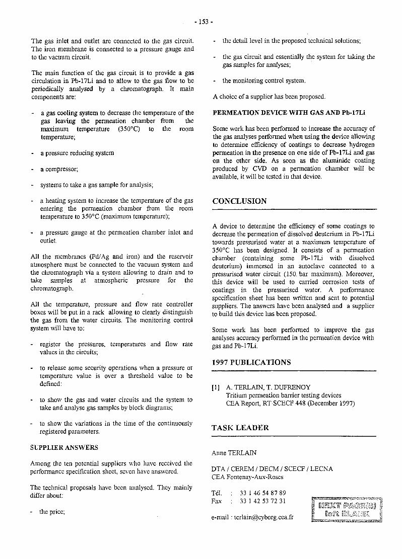
- 1 5 3 -
The gas inlet and outlet are connected to die gas circuit.The iron membrane is connected to a pressure gauge andto the vacuum circuit.
The main function of the gas circuit is to provide a gascirculation in Pb-17Li and to allow to the gas flow to beperiodically analysed by a chromatograph. It maincomponents are:
- a gas cooling system to decrease the temperature of thegas leaving the permeation chamber from themaximum temperature (350°C) to the roomtemperature;
- a pressure reducing system
- a compressor;
- systems to take a gas sample for analysis;
- a heating system to increase the temperature of the gasentering the permeation chamber from the roomtemperature to 350°C (maximum temperature);
- a pressure gauge at the permeation chamber inlet andoutlet.
All the membranes (Pd/Ag and iron) and the reservoiratmosphere must be connected to the vacuum system andthe chromatograph via a system allowing to drain and totake samples at atmospheric pressure for thechromatograph.
All the temperature, pressure and flow rate controllerboxes will be put in a rack allowing to clearly distinguishthe gas from the water circuits. The monitoring controlsystem will have to:
- register the pressures, temperatures and flow ratevalues in the circuits;
- to release some security operations when a pressure ortemperature value is over a threshold value to bedefined:
- to show the gas and water circuits and the system totake and analyse gas samples by block diagrams;
- to show the variations in the time of the continuouslyregistered parameters.
SUPPLIER ANSWERS
Among the ten potential suppliers who have received theperformance specification sheet, seven have answered.
The technical proposals have been analysed. They mainlydiffer about:
- the price;
- the detail level in the proposed technical solutions;
- the gas circuit and essentially the system for taking thegas samples for analyses;
- the monitoring control system.
A choice of a supplier has been proposed.
PERMEATION DEVICE WITH GAS AND Pb-17Li
Some work has been performed to increase the accuracy ofthe gas analyses performed when using the device allowingto determine efficiency of coatings to decrease hydrogenpermeation in the presence on one side of Pb-17Li and gason the other side. As soon as the aluminide coatingproduced by CVD on a permeation chamber will beavailable, it will be tested in that device.
CONCLUSION
A device to determine the efficiency of some coatings todecrease the permeation of dissolved deuterium in Pb-17Litowards pressurised water at a maximum temperature of350°C has been designed. It consists of a permeationchamber (containing some Pb-17Li with dissolveddeuterium) immersed in an autoclave connected to apressurised water circuit (150. bar maximum). Moreover,this device will be used to carried corrosion tests ofcoatings in the pressurised water. A performancespecification sheet has been written and sent to potentialsuppliers. The answers have been analysed and a supplierto build this device lias been proposed.
Some work has been performed to improve the gasanalyses accuracy performed in the permeation device withgas and Pb-17Li.
1997 PUBLICATIONS
[ 1 ] A. TERLAIN, T. DUFRENOYTritium permeation barrier testing devicesCEA Report, RT SCECF 448 (December 1997)
TASK LEADER
Anne TERLAIN
DTA / CEREM / DECM / SCECF / LECNACEA Fontenay-Aux-Roses
Tel. : 33 I 46 54 87 89Fax : 33 142 53 72 31
e-mail : [email protected]
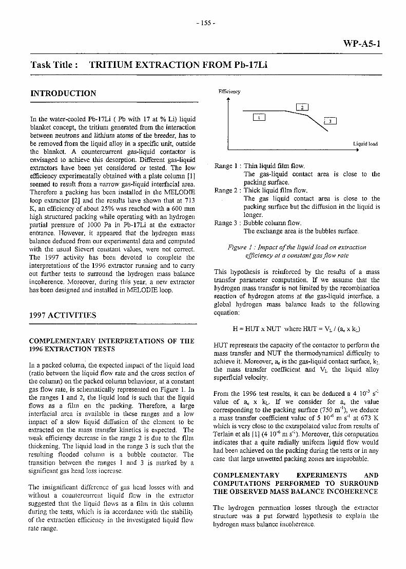
-155-
WP-A5-1
Task Title : TRITIUM EXTRACTION FROM Pb-17Li
INTRODUCTION Efficiency
In the water-cooled Pb-17Li ( Pb with 17 at % Li) liquidblanket concept, the tritium generated from the interactionbetween neutrons and lithium atoms of the breeder, has tobe removed from the liquid alloy in a specific unit, outsidethe blanket. A countercurrent gas-liquid contactor isenvisaged to achieve this desorption. Different gas-liquidextractors have been yet considered or tested. The lowefficiency experimentally obtained with a plate column [1]seemed to result from a narrow gas-liquid interfacial area.Therefore a packing has been installed in the MELODIEloop extractor [2] and the results have shown that at 713K, an efficiency of about 25% was reached with a 600 mmhigh structured packing while operating with an hydrogenpartial pressure of 1000 Pa in Pb-17Li at the extractorentrance. However, it appeared that the hydrogen massbalance deduced from our experimental data and computedwith the usual Sievert constant values, were not correct.The 1997 activity has been devoted to complete theinterpretations of the 1996 extractor running and to carryout further tests to surround the hydrogen mass balanceincoherence. Moreover, during this year, a new extractorhas been designed and installed in MELODIE loop.
1997 ACTIVITIES
COMPLEMENTARY INTERPRETATIONS OF THE1996 EXTRACTION TESTS
In a packed column, the expected impact of the liquid load(ratio between the liquid flow rate and the cross section ofthe column) on the packed column behaviour, at a constantgas flow rate, is schematically represented on Figure 1. Inthe ranges 1 and 2, the liquid load is such that the liquidflows as a film on the packing. Therefore, a largeinterfacial area is available in these ranges and a lowimpact of a slow liquid diffusion of the element to beextracted on die mass transfer kinetics is expected. Theweak efficiency decrease in the range 2 is due to the filmthickening. The liquid load in the range 3 is such that theresulting flooded column is a bubble contactor. Thetransition between the ranges 1 and 3 is marked by asignificant gas head loss increase.
The insignificant difference of gas head losses with andwithout a countercurrent liquid flow in the extractorsuggested that the liquid flows as a film in this columnduring the tests, which is in accordance with the stabilityof the extraction efficiency in the investigated liquid flowrate range.
Liquid load— •
Range 1 : Thin liquid film flow.The gas-liquid contact area is close to thepacking surface.
Range 2 : Thick liquid film flow.The gas liquid contact area is close to thepacking surface but the diffusion in the liquid islonger.
Range 3 : Bubble column flow.The exchange area is the bubbles surface.
Figure 1 : Impact of the liquid load on extractionefficiency at a constant gas flow rate
This hypothesis is reinforced by the results of a masstransfer parameter computation. If we assume that thehydrogen mass transfer is not limited by the recombinationreaction of hydrogen atoms at the gas-liquid interface, aglobal hydrogen mass balance leads to the followingequation:
H = HUT x NUT where HUT = VL / (a. x kL)
HUT represents the capacity of the contactor to perform themass transfer and NUT the thermodynamical difficulty toachieve it. Moreover, a,, is the gas-liquid contact surface, kL
the mass transfer coefficient and VL the liquid alloysuperficial velocity.
From the 1996 test results, it can be deduced a 4 10"3 s"1
value of a,; x kL. If we consider for a the valuecorresponding to the packing surface (750 m'1), we deducea mass transfer coefficient value of 5 10"6 m s"1 at 673 Kwhich is very close to the extrapolated value from results ofTerlain et als [1] (4 10"6 m s"1). Moreover, this computationindicates that a quite radially uniform liquid flow wouldhad been achieved on the packing during the tests or in anycase that large unwetted packing zones are improbable.
COMPLEMENTARY EXPERIMENTS ANDCOMPUTATIONS PERFORMED TO SURROUNDTHE OBSERVED MASS BALANCE INCOHERENCE
The hydrogen permeation losses through the extractorstructure was a put forward hypothesis to explain thehydrogen mass balance incoherence.
-156-
A permeation loss calculation in the extractor, assumingthat the aluminide coating on 316L is totally inefficientand that the hydrogen concentration in the gas of thecolumn is constant and equal to that in equilibrium withthe liquid at the column entrance, shows that the hydrogenpermeation losses cannot exceed 5% of the hydrogen massbalance difference at 673K and 13% at 713K. Therefore,these losses cannot explained on their own the hydrogenmass balance difference.
These calculations are consistent with the results of thefollowing experiment conducted at 713 K in two steps withflowing Pb-17Li:
- the first step consists of reaching a uniform 2000 PaPb-17Li hydrogen partial pressure in all the loop byinjecting a 2% hydrogen content argon flow in thesaturator and extractor;
- in the second step, the 2% argon flow is onlymaintained in the saturator.
At the end of the first step, the hydrogen pressure in themembranes at the bottom and the top of the extractor arethe same and equal to 1980 Pa. At the end of the secondstep, the difference between the hydrogen pressures inthese two membranes is 40 Pa. This difference leads to alost hydrogen flux of about 3 10"5 mol H h'1, which is 20times lower than the hydrogen flux missing lo loop themass balance during the tests.
Finally, a new extraction test has shown that the hydrogenflux transferred, in the saturator, from the gas to the liquidis very close to the hydrogen flux transferred from theliquid to the gas in the extractor. Then, hydrogen lossescould be definitely dismissed from the extractor massbalance incoherence hypothesis.
Another hypothesis put forward to explain the hydrogenmass balance incoherence was a wrong hydrogen solubilityin Pb-17Li value. Therefore an experiment was performedin order to assess the sensitivity of hydrogen solubility inPb-17Li to the temperature. This experiment consists inrising the liquid alloy temperature of 40 K during its flowbetween the bottom of the saturator, where it was saturatedat 673K by means of the bubbling of a 2% hydrogencontent gas, and the extractor entrance. As the solubilityincreases with the temperature, the hydrogen pressure inthe membrane at the extractor entrance should be lowerthan that at the bottom of the saturator. The sensitivity ofthe hydrogen solubility in Pb-17Li deduced from thisexperiment is more in agreement with the Reiter data [3]than with our previous extraction test results. Therefore,according to this experiment, the variations of hydrogensolubility with the temperature seem weak. This is indesagreement with the hypothesis of a wrong value ofsolubility as the single cause of the mass balanceincoherence in our extraction tests.
DESIGN AND CONSTRUCTION OF A NEWEXTRACTOR
The main features of the new extractor and the expectedresulting advances are the following:
- the contactor will be a 64 mm diameter column madeof 316L stainless steel, covered internally andexternally with an aluminide coating. A liquiddistributor, a gas sparger and the packing willconstitute the internal components;
- the packing will consist of four 207 mm high cylindersof AISI 410S Mellapak® structured packing.Therefore, the total height of the packing will beincreased of 33% in comparison with the previousextractor. A comparison of the efficiencies achieved inthe two extractors will be possible;
- the gas will be spargered by means of a sintered disc. Itshould be convenient to test the packing column as abubble contactor;
- the liquid distributor at the top of the extractor has beendesigned to spread uniformly radially the liquid alloyand then to take advantage of the first packing lengths;
- a cold trap has been added at the gas extractor exit tostop the particles transported by the gas flow;
- a valve has been added at the extractor exit in order torun the extractor as a bubble column.
The construction of this new extractor is now ended.
CONCLUSION
From 1996 extraction tests and 1997 complementaryinterpretations, it can kept in mind that, with a liquid loadof 0.01 m s'\ a liquid film seems to be achieved which isthe required hydrodynamic configuration to take advantageof the packing surface. The uniformity of the film radialspreading cannot be asserted but wide unwetted packingareas seem highly improbable if we trust in previousdetermination of the mass transfer kinetic constant.
Further experiments and computations have beenperformed to try to surround the hydrogen mass balanceincoherence observed during the 1996 extraction tests.Even if hydrogen losses through the structure seem to beweak in comparison with the flux missing to loop thebalance, no other clear explanation was found. Indeed, aninsignificant variation of the hydrogen solubility in Pb-17Li with the temperature has been experimentallyassessed, which is not in agreement with the put forwardhypothesis of an inaccurate solubility value. The 1998extractor has been designed and the construction is nowended.
- 157 -
REFERENCES TASK LEADER
[1] A. TERLAIN, T. SAMPLE, M. FUTTERER Anne TERLAINProceedings of the 18th Symposium On FusionTechnology, Karlsruhe 1994, Eds. K. Herschbach, W. DTA / CEREM / DECM / SCECF / LECNAMaurer, J.E. Vetter (Elsevier Science B.V., 1995), CEA Fontenay-Aux-Roses1265-1268
Tel. : 33 1 46 54 87 89[2] N. ALPY, T. DUFRENOY, A. TERLAIN Fax : 33 1 42 53 72 31
Hydrogen extraction tests in Melodie loop: 1996results with a packed column e-mail: [email protected]
[3] F. REITER, I CAMPOSELN, G.GERVASINI,R. ROTAInteraction of hydrogen isotopes with the liquideutectic alloy 17Li83PbProceedings of the 14th Symposium On FusionTechnology, Avignon 1986 (Pergamon Press 1986),vol.2, 1185-1190
1997 PUBLICATIONS
N. ALPY, T. DUFRENOY, A.TERLAINHydrogen Extraction from Pb-17Li: tests with a packedcolumnProceedings of the 4th International Symposium on FusionNuclear Technology, April 6-11, 1997, Tokyo Japan, toappear in Fusion Engineering and Design
N. ALPY, T. DUFRENOY, A. TERLAINHydrogen Extraction from Pb-17Li: tests with a packedcolumnProceedings of the First International Workshop on LiquidMetal Blanket Experimental Activities, September 16-18,1997, Paris
N. ALPY, A.TERLAJN, M. PERROT, T. DUFRENOYHydrogen Extraction from Pb-17Li: 1997 results on thepacked column running and 1998 viewsCEA Report, RT-SCECF 446 (December 1997)
- 159-
WP-A6-1.1
Task Title : SAFETY ANALYSIS FOR DEMO REACTOR
INTRODUCTION
The DEMO reactor is a fusion reactor of TOKAMAK typewith magnetic confineinent.lt is a electricity-producingprototype reactor whose objective is to demonstrate thetechnological feasibility and eventually the economicviability of the system.
In addition, it has to have an excellent safety level andminimize the impact on the environment.
In the European context, studies have so far been limited toblanket design studies.
- One with water as the coolant and the eutectic, lithium-lead, as the breeder material (WCLL design);
- The other with helium as the coolant and a lithiumceramic as the breeder material (HCPB design).
In both cases, the structural material of the internals is alow-activation martensitic steel (current reference :EUROFER 97).
The objective of this task is to present what could be thesafety approach of the DEMO reactor, examine its impactof the blanket design itself, and possibly suggestsupplementary studies.
The focus of this study is more particularly the reactordesign that uses the lithium-lead eutectic (WCLL). Thegeneral approach, however, could easily be transferred toanother design.
Tlu's work obviously benefits from all the data acquired inprevious work, in particular:
- The safety analysis performed for the ITER reactor,
- The studies performed previously in the EuropeanCommunity, notably the SEAFP.
1997 ACTIVITY
THE SAFETY APPROACH
General
On account of its inventory in tritium and the activation ofits materials under the effect of the neutrons generated bythe reaction, the DEMO reactor will be a nuclear facility.
The objective of the safety approach is to ensure efficientprotection of workers and the public from the possiblyharmful effects of both reactor operation and potentialaccidents. This also means ensuring that the impact on theenvironment is acceptable for present and futuregenerations.
Safety Principles
In order to ensure control of radioactive substances underall normal, incident, and accident conditions, safety isbased on the application of a few fundamental principles:
The first consists in implementing defence-in-depth tominimize risks and ensure that, by installing efficientsystems, all the safety objectives are taken into account.
Another basic concept that has a considerable effect on thedesign is the ALARA principle (As Low As ReasonablyAchievable). It stipulates that meeting the requirements ofstatutory- limits or limits defined a priori for the project isnot enough, but that all reasonable efforts must be made tominimize the doses resulting from the exposure to, orcontamination from, radioactive material (it can beimplemented using a cost-benefit analysis).
Inventory of Risks and Safety Functions
For the application of the principles set forth above, thesafety approach can be broken down into the followingstages:
- Identification of the risks,
- Definition of the safety functions to be ensured,resulting from the consideration of these risks.
Once the safety functions are incorporated into the design,the safety analysis will subsequently aim to demonstratethat the safety objectives are fully met using theseprinciples while respecting the regulations in force, at allstages (prevention, protection, mitigation) and under allconditions (normal and accident), obviously withoutforgetting the impact on the environment.
The inventory of risks has already been presentednumerous times for a fusion facility.The main risks are :
- Radioactive risks
- The risks associated with the energy of the coolant(water under pressure) and to the decay heat.
-160-
- The chemical risks related to Li-Pb - water interactionand those related to the interaction of the componentfacing tlie plasma with water which differs according tothe material used.
To these risks linked to the blankets should be addedthose linked to the other components, particularly themagnets and tlie cryogenic fluid.
The main safety functions result from this inventory ofrisks:
. The function of radioactive confinement, a basicfunction for any nuclear facility, which must bemodulated according to conditions and to the risk ofradionuclide mobilization.
In this domain, the level of prevention consists notonly in limiting the inventory, but also in ensuringthat under both normal and accident conditions, thismobilization factor is minimized.
. The function of coolant energy control.
This function is applicable at all levels: design, caregiven to fabrication, in-service inspection, leakdetection, mitigation of the con sequences (ex:depressurization volume).
The function of power and decay heat control.
The control of power under operating conditionsand the detection of anomalies, plasma shutdown inthe event of failure in a power removal system, andthe decay heat removal systems all form part of thisissue.
The function of chemical energy control.
In addition to the care given to fabrication, thismeans being able to detect any leak as early aspossible and providing for accident managementthat enables returning as soon as possible (that is tosay by minimizing the amounts liable to react) to asafe and stable state. In the case of the most severeaccidents, the provision of systems that permitremoving the hydrogen produced or averting therisk of its contact with air (by inertizing adjacentrooms, for example) may be used.
Finally, with respect to the magnets, their controlmust be ensured by a function that permits avoidingthe deterioration of the confinement barriers by anarc (design of the magnets and their environment,efficient quench and discharge detection).
DESIGN, FABRICATION, AND OPERATINGRECOMMENDATIONS
Before addressing the actual safety analysis, it is of interestto examine how the various levels of defense-in-depth
resulting from tlie consideration of the safety functions canbe integrated into the design and the various designchoices.
Main issues are:
- Sizing and design laws.- Design margins.- Prevention of abnormal conditions.- Minimization of the consequences of an anomaly.- Minimization of wastes and management optimization.- Simplicity of control under normal conditions
(operation and maintenance).- Minimization of doses to the personnel.- Easy and reliable anomaly detection.- Control of abnormal conditions.- Reduction of the risk of development of abnormal
conditions.- Minimization of the mobilizable source term and its
consequences in the event of accident.- Definition and implementation of mitigation systems.
SAFETY ANALYSIS
The purpose of the safety analysis is to demonstrate thatthe principles and methods defined by tlie regulations inforce or, more restrictively, those selected by the designerand the operator, are well integrated in the design. Amajor part of this analysis obviously concerns accidentanalysis, but other aspects, such as impact on tlieenvironment, operational safety, waste management, anddismantling must also be studied.
This study is based from the beginning on a previsionalanalysis using the designs and architecture of the systems.This approach is essentially interactive with correctivefeedback on the design, either because tlie requirements asdefined have not been met, or in accordance with theALARA principle, with a view to minimizing effects.
Accident Analysis
Accident analysis comprises several stages:
- Identification of tlie sequences that could be performedusing different approaches (Top Down, event trees,fractional failure analysis),
- Qualitative evaluation of consequences, identifiedsequences, and the probability of their occurrence, thuspermitting classification and selection of referencesequences,
- Deterministic analysis of reference sequences.
When the design has progressed further, this approach canbe completed by a more thorough probabilistic analysis inorder to validate, justify, or even correct, the choices made.
- 161 -
Wastes and Dismantling TASK LEADER
Dose and long-term effect calculations were the subject offairly in-depth studies in the SEAFP framework and are Gabriel MARBACHbeing continued in the framework of SEAL and SEAFP 2.They should be updated according to the evolution of the DRN/DER/STMLdesign with, in addition, a study of the management Cadaracheassociated with the replacement of the internals, their routethrough the reactor and the waste strategy of the various Tel • 04 42 25 34 14components. p a x • 04 42 25 65 08
Other Issues t-mz\\ : marbach @ babaorum.cad.CEA.fr
With respect to either the impact on the environment undernormal operating conditions, or the evaluation of doses forworkers, all the aspects of operational safety will have to beaddressed by systematically applying the ALARAprinciple.
REFERENCES
[ 1 ] Safety approach of the DEMO reactorNTDER/STML/97.100G. MARBACH
- 163 -
WP-A6-2.1WP-B6-1.3
Task Title : SAFETY ANALYSIS OF ITER TEST MODULESDEFINITION OF SAFETY APPROACH
CONTEXT 1997 ACTIVITY
ITER is an experimental fusion D-T reactor. One of theEuropean Union objective for the Basic Performance Phaseis to include and irradiate two small scale experimentaltest-blanket modules.
These test-blanket modules (ITMs) will help qualifytritium breeding blanket for future Fusion Power Reactor(FPR). Main objectives are to :
- verify and demonstrate the functionality of theintegrated system, subsystems and individualcomponents in the fusion environment,
- verify and demonstrate the performance of tritiumproduction, extraction, and recover}' by establishing acomplete tritium balance of the system which as tocorrectly simulate the envisaged FPR system (e.g.presence of permeation barriers, correct He-ELOchemistry),
- verify and demonstrate the performance of high-gradeheat production and removal by establishing a completepower balance of the system which as to correctlysimulate the envisaged FPR system (e.g. correctnumber of independent circuits, presence of DWTs),
- calibrate and validate the performed analyses, includingto maintain the full integrity of ITMs under thermaland electromagnetic loads.
The two EU selected concepts are :
- helium cooled Li-based ceramic breeder (HCBP),
- water cooled liquid eutectic Pb-17Li breeder (WCLL).
HCBP and WCLL ITMs have to fit in the ITER test portlocated in the outboard equatorial plane.
To make these concepts acceptable for ITER ICT, it isnecessary to supply a specific safety report additionaly tothe detailed reactor design, blankets and support systemsdescription.
This report has to be a specific one to avoid several updatesof the Reactor Safety Report.
ITER TEST MODULE GENERAL SAFETYAPPROACH
According to ITER safety methodology, the overallapproach for the ITMs safety analysis will basically followa deterministic framework.
It could be complemented by a probabilistic framework ifnecessary.
Introduction
To take into account the uncertainties concerning theperformances of experimental modules, the safetydemonstration has to follow the ITER Safety Principleswhich include Design Guideline of Releases (DGR). Themain principles are :
- safety analysis has to take in account ITMs failures andinduced potential hazards, from the defense in depthpoint of view (prevention, detection, protection andmitigation of consequences),
- ITMs are designed in such a way that, during anyoperation or accidental sequence, it does not lead tounacceptable consequences in relation to the safety ofITER facility, workers and public surrounding thefacility,
- the analysis of ITMs roles, as far as ITER main safetyfunctions are concerned, has to demonstrate that:
. either safety functions planned for the reactor itselfare not degraded by the potential risks due to theimplementation of ITMs,
or safety functions planned for ITMs design arecovering these risks.
- lastly, ITMs safety analysis has to highlight means(systems or functions) to :
prevent initiating events occurrence,
prevent the occurrence of accidental sequences andlimit their progression.
-164-
Implementation of the « defense in depth » concept
Implementation of the defense in depth concept involvesthe facility design that has to foreseen radioactive materialconfinement inside successive containment barriers.Defense in depth concept also involves to set the followingfunctions:
- guanuitee design quality assurance,
- protect barriers from potential hazards or incidents thatcould cause their failure,
- preserve the rest of the facility in case of barriersfailure,
- minimize radioactive releases consequences in relationto the safety and health of workers and public, in caseprevious precautions are not fully effective.
Considering experimental blankets, we have todemonstrate that the barriers built by the modulesthemselves, besides reactor own barriers, are preserved inrelation to potential hazards and minimize :
- toxical and radioactive releases to the other ITERfacilities and/or environment,
- dispersion of high-level risk energy sources present intothe facilities.
ITMs and associated heat-transfer loops will participate inreactor first confinement barrier. Consequently, design ofthese facilities has to follow principles of passivity andgeographical separation in relation to reactor secondconfinement barrier.
Analysis of reference events
In relation to availability objectives which results from it,events sequence analysis tech to size necessary protectionsystems to respect each of events sequence categoryacceptance safety criteria.
Therefore, analysis objective is to prove that acceptancecriteria are not exceeded during any events sequence. Thatis to say :
- acceptable radiological consequences to workers, thepublic and environment.
- safety criteria relating to each of the confinementbarriers.
The identification of the events sequences that have to bestudied has to be consistent with the recommended NSSR-1 guidelines safety analysis. So :
- a functional failure modes and effects analysis(FFMEA) has to be performed for initiating events
identification. Basic accident initiating events(component failures modes in the FFMEA) are groupedinto sets (or families) events that result in similarfacility responses. These sets of events are referred to asPostulated Initiating Events : PIEs,
- each PIE is classified into a frequency category inrelation to its consequence gravity,
- the choice of events sequences to be studied is based ona potential consequence qualitative analysis (e.g. on adeterministic framework),
- events sequences that have being considered (e.g.sequences which analysis will continue) are assessed bythe events tree method. Each events tree sequence isclassified into one of the frequency category accordingto ITER accepted principle,
- quantitative consequences analysis is finally performedfor some accidents which are Reference Events, e.g.events or sequences that are formulated to provide anadequate envelope for each PIE category.
So ITMs safety evaluation process can lead during theITER safety analysis to new basic initiating eventsidentification, in comparison with initiating events beingconsidered before.
A list of event sequences for each european ITM conceptwas proposed with the related initial conditions andacceptance criteria.
Impact on iter safety functions
Safety demonstration has to highlight ITMs role in relationto the comprehensive ITER facility safety (in accordancewith NSSR-1 main principles).
ITMs design has to be consistent with concept adopted forITER design. Particularly, ITMs implementation shouldnot lead to change reactor safety objectives (e.g. thenumber of planned safety functions which are given intoNSSR-1 volume I).
So we have to analyze how ITMs have to participate invarious reactor safety functions and to demonstrate thatsafety principles planned for ITMs design are consistentwith reactor safety functions. Among others, main roles areto:
- prohibit overrunning of acceptance criteria risks (e.g.criteria which have been decided for variousconfinement barriers),
- avoid that a confinement barrier failure could lead toother barriers damage,
- respect radiological protection criteria, since ITMsparticipate in the radiological protection system.
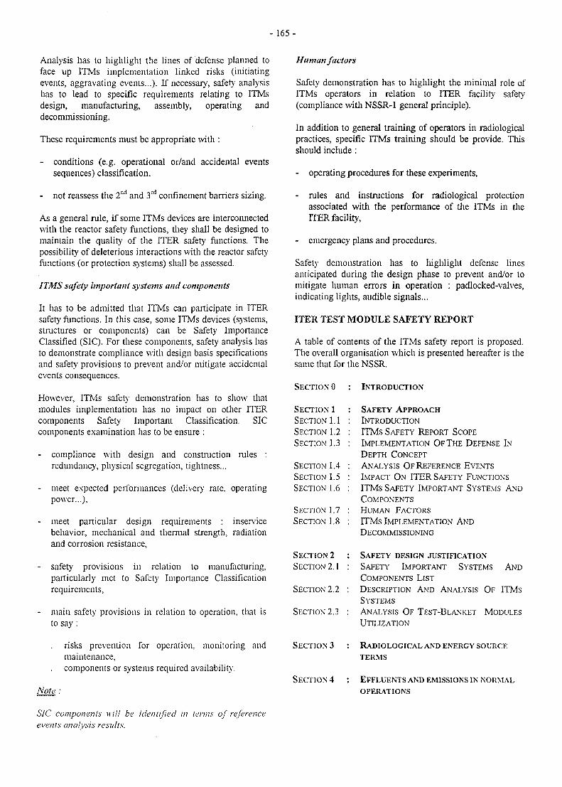
- 1 6 5 -
Analysis has to highlight the lines of defense planned toface up ITMs implementation linked risks (initiatingevents, aggravating events...). If necessary', safety analysishas to lead to specific requirements relating to ITMsdesign, manufacturing, assembly, operating anddecommissioning.
These requirements must be appropriate with :
- conditions (e.g. operational or/and accidental eventssequences) classification,
- not reassess the 2nd and 3rd confinement barriers sizing.
As a general rule, if some ITMs devices are interconnectedwith the reactor safety functions, they shall be designed tomaintain the quality of the ITER safety functions. Thepossibility of deleterious interactions with the reactor safetyfunctions (or protection systems) shall be assessed.
ITMS safety important systems and components
It has to be admitted that ITMs can participate in ITERsafety functions. In this case, some ITMs devices (systems,structures or components) can be Safety ImportanceClassified (SIC). For these components, safety analysis hasto demonstrate compliance with design basis specificationsand safety provisions to prevent and/or mitigate accidentalevents consequences.
However, ITMs safety demonstration has to show thatmodules implementation has no impact on other ITERcomponents Safety Important Classification. SICcomponents examination has to be ensure :
- compliance with design and construction rules :redundancy, physical segregation, tightness...
- meet expected performances (delivery rate, operatingpower...),
- meet particular design requirements : inservicebehavior, mechanical and thermal strength, radiationand corrosion resistance,
- safety provisions in relation to manufacturing,particularly met to Safety Importance Classificationrequirements,
- main safety provisions in relation to operation, that isto say :
risks prevention for operation, monitoring andmaintenance,components or systems required availability.
Note:
SIC components will be identified in terms of referenceevents analysis results.
Human factors
Safety demonstration has to lu'ghlight the minimal role ofITMs operators in relation to ITER facility safety(compliance with NSSR-1 general principle).
In addition to general training of operators in radiologicalpractices, specific ITMs training should be provide. Thisshould include:
- operating procedures for these experiments,
- rules and instructions for radiological protectionassociated with the performance of the FTMs in theITER facility,
- emergency plans and procedures.
Safety demonstration has to lu'ghlight defense linesanticipated during the design phase to prevent and/or tomitigate human errors in operation : padlocked-valves,indicating lights, audible signals...
ITER TEST MODULE SAFETY REPORT
A table of contents of the ITMs safety report is proposed.The overall organisation which is presented hereafter is thesame that for the NSSR.
SECTION 0 : INTRODUCTION
SECTION 1 : SAFETY APPROACH
SECTION 1.1 : INTRODUCTION
SECTION 1.2 : ITMs SAFETY REPORT SCOPE
SECTION 1.3 : IMPLEMENTATION OF THE DEFENSE IN
DEPTH CONCEPT
SECTION 1.4 : ANALYSIS O F REFERENCE EVENTS
SECTION 1.5 : IMPACT ON ITER SAFETY FUNCTIONS
SECTION 1.6 : ITMs SAFETY IMPORTANT SYSTEMS AND
COMPONENTS
SECTION 1.7 : HUMAN FACTORS
SECTION 1.8 : ITMs IMPLEMENTATION AND
DECOMMISSIONING
SECTION 2 : SAFETY DESIGN JUSTIFICATION
SECTION 2.1 : SAFETY IMPORTANT SYSTEMS AND
COMPONENTS LIST
SECTION 2.2 : DESCRIPTION AND ANALYSIS OF ITMS
SYSTEMS
SECTION 2.3 : ANALYSIS O F TEST-BLANKET MODULES
UTILIZATION
SECTION 3 : RADIOLOGICAL AND ENERGY SOURCE
TERMS
SECTION 4 : EFFLUENTS AND EMISSIONS IN NORMAL
OPERATIONS
-166-
SECTION5 : WASTE MANAGEMENT AND
DECOMMISSIONING
SECTION 5.1 : ITMs WASTE CHARACTERIZATION AND
MANAGEMENT
SECTION 5.2 : DECOMMISSIONING
SECTION 6 : OCCUPATIONAL SAFETY
SECTION 6.1 : ALARA PRINCIPLES
SECTION 6.2 : ITMs UTILIZATION
SECTION 6.3 : ITMs OPERATION
SECTION 7 : ANALYSIS OF REFERENCE EVENTS
SECTION 7.1 : IDENTIFICATION OF EVENTS AND PEES
SECTION 7.2 : SAFETY ANALYSIS
SECTION 8 : ULTIMATE SAFETY MARGINS
SECTION 9 : EXTERNAL HAZARDS ASSESSMENTS
SECTION 9.1 : INTRODUCTION
SECTION 9.2 : SEISMIC SAFETY ASSESSMENT
TASK LEADER
Gabriel MARBACH
DRN/DER/STMLCadarache
Tel.Fax
04 42 25 34 1404 42 25 65 08
e-mail: marbach (2) babaorum.cad.CEA.fr
REFERENCES
[1] ITER test blanket modulesGeneral Safety approachVINCENT Report TA-6322
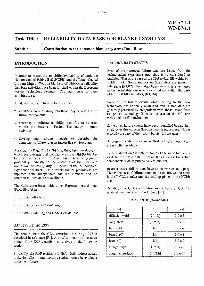
-167-
WP-A7-1.1WP-B7-1.1
Task Title : RELIABILITY DATA BASE FOR BLANKET SYSTEMS
Subtitle: Contribution to the common blanket systems Data Base
INTRODUCTION
In order to assess the reliability/availability of both theHelium-Cooled Pebble Bed (HCPB) and the Water-CooledLithium Liquid (WCLL) blankets of DEMO, a reliabilitydata base activities have been lunched within the EuropeanFusion Teclmology Program. The main tasks of theseactivities are to
1. identify needs in basic reliability data
2. identify among existing data those may be relevant forfusion components
3. construct a uniform reliability data file to be usedwithin the European Fusion Teclmology programactivities.
4. develop and validate models to describe thecomponents failure rates in fusion-like environment.
A Reliability Data File [RDF] has, thus, been developed inwhich basic events that contribute in the DEMO blanketfailures have been identified and listed. A working groupproceeds periodically to the updating of the RDF andimproving the data quality in function of the tecluiologicalexperience feedback. Basic events failure parameters aresupposed time independent for the moment and nocommon failures data are available.
The CEA contributes with other European associations[FzK, ENEA] in :
1. the data collection,
2. the data critical examination,
3. the data modelling and models validations
ACTIVITY IN 1997
The details about the CEA contribution during 1997 isdescribed in reference [PI]. A brief summary on the mainpoints of the CEA contribution is given in the followingsection.
Physically, the RDF resides at ENEA - Italy. Direct accessto the data file through working stations would be availablein the near future.
FAILURE DATA STATUS
Most of the approved failure data are issued from thetechnological experience and thus it is considered asqualified. This is the case of the TIG welds, EB welds, buttwelds ... etc. Some sources of these data are given inreferences [R1.R2J. These data bases were extensively usedin the reliability assessments carried on within the past-phase of DEMO activities, [R3, R4].
Some of the failure events which belong to the newtechnology are critically examined and related data aregenerally produced by comparison with those issued fromthe proven-technology. This is the case of the diffusionwelds and the HIP technology.
Some other failure events have been identified but no datacould be evaluated even through experts judgement. This istypically the case of the tritium barrier failure rates.
At present, needs in data are well-identified although dataare not often available.
Table 1 shows an example of some of the most frequentlyused failure basic data. Similar tables exists for activecomponents such as pumps, valves, motors,...
In other cases, failure data have to be worked out, [R5].This is the case of failures such as the double-walled tubesin the WCLL blanket and the cooling-plates in the HCPBone.
Details on the CEA contribution in the Failure Data Fileestablishment are given in reference [PI].
Table 1: Basic failure rates
EB weld
diffusion weld
long, weld
butt weld
bent(180)
bent(90)
straight pipe
container surface
[1/m.h]
[1/m.h]
[1/m.h]
[1/h]
[1/h]
[1/h]
[1/m.h]
[l/m2.h]
1.0 e-9
1.0 e-8
1.0 e-9
1.0 e-9
1.0 e-8
5.0 e-9
1.0e-10
1.0e-10
- 1 6 8 -
REFERENCES PUBLICATIONS
[Rl] L.C. Cadwallader, S.J. Piet « 1989 Failure ratescreening data for fusion reliability and riskanalysis.» EGG-FSP-8709, September 1989, IdahoNational Laboratory, US-DOE contract* DE-AC07-761D01570,
[R2] R, Bunde, S. Fabritsiev, V. Rybin «Reliability ofwelds and brazed joints in blankets and its influenceon reliability » Fusion Eng. & Des. 16 11991] 59-72.
[R3] M Eid, 'A Comparative Study on theAvailabilitj'/Reliability of the EU-Blanket ConceptualDesign Lines.' DMT 95/271, SERMA/LCA 1756.
[R4] B. Bielak, M. Eid, «Reliability/AvailabilityAssessment of the Water-Cooled lithium Lead-ITERTest Module» DMT 97/262, SERMA/LCA 2062,1997.
[R5] M. Eid «Evaluation of the cooling plates loss ofintegrity occurrence frequency and related issues»technical note in preparation.
[PI] M. Eid, «CEA Contribution to thereliability/availability assessment of DEMO &reliability data base activities» DMT 97/562,SERMA/LCA 2159, 1997.
TASK LEADER
Mohamed EID
DRN/DMT-SERMASaclay-F91191 Gif sur Yvette Cedex
Tel. : 33 0169 08 3175Fax : 33 0169 08 99 35
e-mail: [email protected]
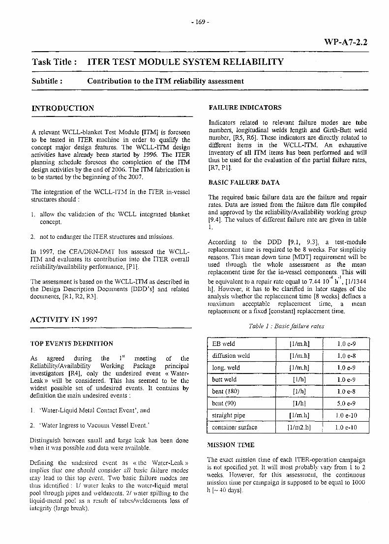
- 169-
WP-A7-2.2
Task Title : ITER TEST MODULE SYSTEM RELIABILITY
Subtitle: Contribution to the ITM reliability assessment
INTRODUCTION
A relevant WCLL-blanket Test Module [ITM] is foreseento be tested in ITER machine in order to qualify theconcept major design features. The WCLL-ITM designactivities have already been started by 1996. The ITERplanning schedule foresees the completion of the ITMdesign activities by the end of 2006. The ITM fabrication isto be started by the beginning of the 2007.
The integration of the WCLL-ITM in the ITER in-vesselstructures should :
1. allow the validation of the WCLL integrated blanketconcept.
2. not to endanger the ITER structures and missions.
In 1997, the CEA/DRN-DMT has assessed the WCLL-ITM and evaluates its contribution into the ITER overallreliability/availability performance, [PI].
The assessment is based on the WCLL-ITM as described inthe Design Description Documents [DDD's] and relateddocuments, [R1,R2, R3].
ACTIVITY IN 1997
TOP EVENTS DEFINITION
As agreed during the 1st meeting of theReliability/Availability Working Package principalinvestigators [R4], only the undesired event «Water-Leak » will be considered. This has seemed to be thewidest possible set of undesired events. It contains bydefinition the main undesired events :
1. 'Water-Liquid Metal Contact Event', and
2. 'Water Ingress to Vacuum Vessel Event.'
Distinguish between small and large leak has been donewhen it was possible and data were available.
Defining the undesired event as «the Water-Leak»implies that one should consider all basic failure modesmay lead to this top event. Two basic failure modes arethus identified : 1/ water leaks to the water-liquid metalpool through pipes and weldments, 2/ water spilling to theliquid-metal pool as a result of tubes/weldements loss ofintegrity (large break).
FAILURE INDICATORS
Indicators related to relevant failure modes are tubenumbers, longitudinal welds length and Girth-Butt weldnumber, [R5, R6]. These indicators are directly related todifferent items in the WCLL-ITM. An exhaustiveinventory of all ITM items has been performed and willthus be used for the evaluation of the partial failure rates,[R7, PI].
BASIC FAILURE DATA
The required basic failure data are the failure and repairrates. Data are issued from the failure data file compiledand approved by the reliability/Availability working group[9.4]. The values of different failure rate are given in table1.
According to the DDD [9.1, 9.3], a test-modulereplacement time is required to be 8 weeks. For simplicityreasons. Tlu's mean down time [MDT] requirement will beused tlirough the whole assessment as the meanreplacement time for the in-vessel components. This will
be equivalent to a repair rate equal to 7.44 10 h , [1/1344h]. However, it has to be clarified in later stages of theanalysis whether the replacement time [8 weeks] defines amaximum acceptable replacement time, a meanreplacement or a fixed [constant] replacement time.
Table 1: Basic failure rates
EB weld
diffusion weld
long, weld
butt weld
bent (180)
bent (90)
straight pipe
container surface
[1/m.h]
[1/m.h]
[1/m.h]
[1/h]
[1/h]
[1/h]
[1/m.h]
[l/m2.h]
1.0 e-9
1.0 e-8
1.0 e-9
1.0 e-9
1.0 e-8
5.0 e-9
1.0e-10
1.0e-10
MISSION TIME
The exact mission time of each ITER-operation campaignis not specified yet. It will most probably vary from 1 to 2weeks. However, for this assessment, the continuousmission time per campaign is supposed to be equal to 1000h [-40 days].
-170-
ITM OVERALL FAILURE RATE
The WCLL-ITM overall failure rate, excluding the firstwall structure contribution, is evaluated to be of the order
of 1.12 e-6 h and 5.91 e-8 h in the case of simple- anddouble-walled cooling tubes, respectively.
It has been found that the most important contributions arethose of the FW-Cooling tubes in the simple-walled tubeoption [8.23 e-7 /h] and the water-cooling U-rubes if thedouble-walled tube option is considered [4.80 e-8]. Thecontribution of the Water-Inlet/Outlet Chamber CoverPlate and the Bottom Closure Plate are of two order ofmagnitude lower [1.1 e-9, 2.0 e-9 and 2.2 e-9,respectively].
The WCLL-ITM [FW-cooling tube included] contributionto ITER blanket overall failure rate would mount to some1.12 e-6 /h which corresponds to a Mean Time BetweenFailure [MTBF] equal to 102 years of continuousoperation. If the double walled cooling tubes option isconsidered, the WCLL-ITM contribution to ITER blanketoverall failure rate would mount to 5.91 e-8 /h whichcorresponds to a Mean Time Between Failure [MTBF]equal to 1932 years.
Accordingly, the Annual Occurrence Frequency [AOF] offailures resulted from the WCLL-ITM [FW-cooling tubeincluded] is estimated to be equal to 9.8 e-3 and 5.18 e-4for simple- and double- walled tube options, respectively.
Thus, WCLL-ITM failure event would be classified ofcategory III [1.0 e-2 > AOF >. 1.0 e-4/ year, unlikelyevent], according to the ITER classification grid [ITER-GDDD].
It is most probable that taking into account thecontribution of the ITM-FW structure failure would notalter significantly the above estimated figures as someprevious studies have already demonstrated for DEMOblanket [R5, R6]. This is mainly due to the fact that themain contribution in the FW comes essentially from itscooling tubes and related welds rather than its structure.The FW-cooling tubes have already been included in theassessment as mentioned above.
CONTRIBUTION TO ITER UNAVAILABILITY
The contribution of the WCLL-ITM in ITER blanketoverall asymptotic unavailability would thus be equal to1.50 e-3 and to 7.94 e-5, in simple- and double-walledoptions, respectively.
CONCLUSIONS
A 8 weeks Mean Down Time [MDT]replacement/reparation [TBD] is assumed.
for item
This relatively very low contribution in the overall ITER-blanket unavailability is mainly resulted from the assumedlow MDT.
The RHS and related maintenance procedures are themajor issues to dimension the replacement and the MDT.
Only the undesired event «Water-Leak» will beconsidered. The required basic failure data are the failureand repair rates.
Data are issued from the failure data file compiled andapproved by the reliability/Availability working group.
The Annual Occurrence Frequency [AOF] of failuresresulted from the WCLL-ITM is estimated to be equal to9.80 e-3 and 5.18 e-4 in the simple- and double-walledoptions, respectively.
The contribution of the WCLL-ITM in ITER blanketoverall asymptotic unavailability would be dependant onthe Mean Down Time [MDT] for itemreplacement/reparation [TBD].
The RHS and related maintenance procedures are themajor issues to dimension the replacement and mean downtimes [MDT].
REFERENCES
[Rl] 'Design description Document for the EuropeanWater-Cooled Pb-17Li test Blanket, Chapter l.'DMT96/476, SERMA/LCA 1959.
[R2] 'Water-Cooled Pb-17Li DEMO Blanket Line, StatusReport on the Related EU Activities' DMT 95/505,SERMA/LCA 1801.
[R3] 'Design description Document for the EuropeanWater-Cooled Pb-17Li test Blanket, Chapter 2.'DMT96/349, SERMA/LCA 1911.
[R4] 'Minutes of the 1st Meeting of Principal Investigatorson the Working Packages Reliability/Availability,30th June 1997, ENEA-Frascati, Italy'.
[R5] M. EID, ' A Critical Analysis of theAvailability/Reliability Evaluations performed withinthe Framework of the European Blanket Comparison& Selection Exercise.' DMT 95/363
[R6] M. Eid, 'A Comparative Study on theAvailability/Reliability of the EU-Blanket ConceptualDesign Lines.' DMT 95/271, SERMA/LCA 1756.
[R7] B. Bielak 'DEMO-LiPb Concept Test Blanket ModuleFor ITER, Design Progress and FeasibilityAnalysis.'DT/DI-DC-0132, Framatome, 05/1997.
- 171 -
PUBLICATIONS
[PI] B. Bielak, M. Eid, «Reliability/AvailabilityAssessment of the Water-Cooled lithium Lead-ITERTest Module» DMT 97/262, SERMA/LCA 2062,1996.
TASK LEADER
Mohamed EID
DRN/DMT-SERMASaclay-F91191 Gif sur Yvette Cedex
Tel. : 33 0169 08 3175Fax : 33 0169 08 99 35
e-mail : [email protected]
Xmimmmm
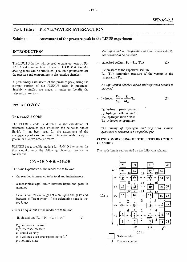
- 1 7 3 -
WP-A9-2.2
Task Title : Pbl7Li/WATER INTERACTION
Subtitle: Assessment of the pressure peak in the LIFUS experiment
INTRODUCTION
The LIFUS 5 facility will be used to carry out tests on Pb-17Li / water interaction. Breaks in ITER Test Modulescooling tubes will be simulated. The main parameters arethe pressure and temperature in the reaction chamber.
A preliminary assessment of the pressure peak, using thecurrent version of the PLEXUS code, is presented.Sensitivity studies are made, in order to identify therelevant parameters.
1997 ACTIVITY
THE PLEXUS CODE
The PLEXUS code is devoted to the calculation ofstructures dynamics (the structures can be solids and/orfluids). It has been used for the assessment of theconsequences of a sodium-water interaction within a steamgenerator of a fast breeder reactor.
PLEXUS has a specific module for Na-H2O interaction. Inthis module, only the following chemical reaction isconsidered:
2 Na + 2 H2O -» H2 + 2 NaOH
The basic hypotheses of the model are as follows:
- the reaction is assumed to be total and instantaneous
- a mechanical equilibrium between liquid and gases isassumed
- there is no heat exchange between liquid and gases andbetween different gases (if the calculation time is nottoo long)
The basic equations of the model are as follows:
liquid sodium: cL2(pL-pL
0) (1)
Psat: saturation pressurePL°: reference pressurecL: sound velocitypL°: volumic mass corresponding lo PL
U
pL: volumic mass
The liquid sodium temperature and the sound velocityare assumed to be constant
vaporized sodium: Py - Ps (2)
Pv: pressure of the vaporized sodiumPsat (Tna): saturation pressure of the vapour at thetemperature TNa
An equilibrium between liquid and vaporized sodium isassumed
- hydrogen:p H M H
(3)
PH: hydrogen partial pressurepH: hydrogen volumic massMH: hydrogen molar massTH: hydrogen temperature
The mixing of hydrogen and vaporized sodiumhydroxide is assumed to be a perfect gas
PLEXUS MODELLING OF THE LIFUS REACTIONCHAMBER
The modelling is represented on the following scheme:
0.72 m
i
1
I1
0.6 •
1
0.48 \
0.36-|
1
0.24
1
0.12 '
1
u .-
1
1
29
25
21-
16...
30
26
2
13•17-
.13.
• 9 -
.5.
1
—
10
7
4
1
•1
.1
1<
<
2'
8
17
14
31
2
2
*11
J.
2
0.07
fNode number
8
5
2
).21 m
.If
1-
1
1
?
9
i.
[•
3
0.14
18...
15—
12
9
6
3
28
'24-
•20-
46
.12.
.8.
4
32
33
34
35
36
37
38
0.21
1 Element number
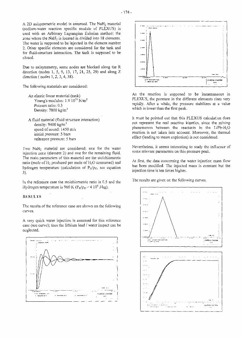
-174-
A 2D axisymmetric model is assumed. The NaH2 material(sodium-water reaction specific module of PLEXUS) isused with an Arbitrary Lagrangian Eulerian method; thezone where the NaH2 is located is divided into 18 elements.The water is supposed to be injected in the element number2. Other specific elements are considered for the tank andfor fluid-structure interaction. The tank is supposed to beclosed.
Due to axisymmetry, some nodes are blocked along the Rdirection (nodes 1, 5, 9, 13, 17, 21, 25, 29) and along Zdirection (nodes 1, 2, 3, 4, 38).
The following materials are considered:
An elastic linear material (tank)Young's modulus: 1.9 10" N/m2
Poisson ratio: 0.3Density: 7800 kg/m3
A fluid material (fluid structure interaction)density: 9400 kg/m3
speed of sound: 1450 m/sinitial pressure: 5 barsreference pressure: 5 bars
Two NaH2 material are considered: one for the waterinjection zone (element 2) and one for the remaining fluid.The main parameters of this material are the stoichiometricratio (mole of H2 produced per mole of H2O consumed) andhydrogen temperature (calculation of PH/PH- see equation3).
In the reference case the stoichiometric ratio is 0.5 and theHydrogen temperature is 960 K (PH/pH= 4 106 J/kg).
RESULTS
The results of the reference case are shown on the followingcurves.
A very quick water injection is assumed for this referencecase (see curve); thus the lithium lead / water impact can beneglected.
As the reaction is supposed to be instantaneous inPLEXUS, the pressure in the different elements rises veryrapidly. After a while, the pressure stabilizes at a valuewhich is lower than the first peak.
It must be pointed out that this PLEXUS calculation doesnot represent the real reaction kinetics, since the mixingphenemenon between the reactants in the LiPb-H2Oreaction is not taken into account. Moreover, the thermaleffect (leading to steam explosion) is not considered.
Nevertheless, it seems interesting to study the influence ofsome relevant parameters on this pressure peak.
At first, the data concerning the water injection mass flowhas been modified. The injected mass is constant but theinjection time is ten times higher.
The results are given on the following curves.
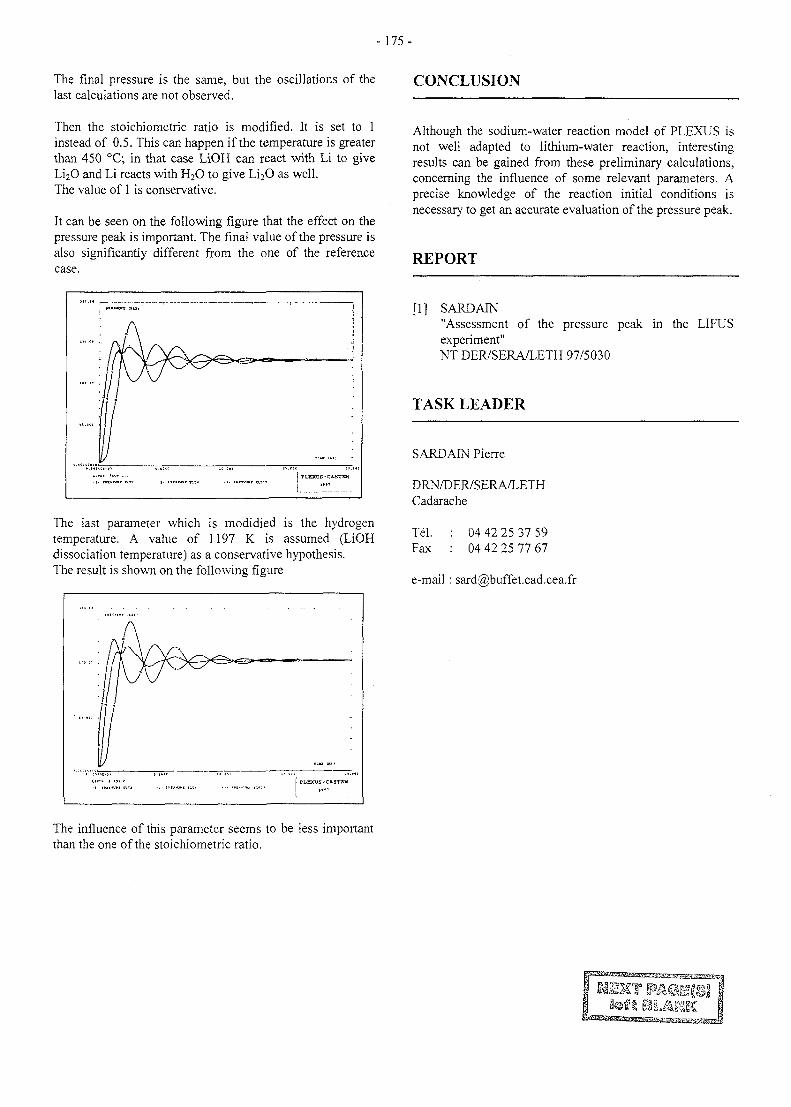
-175-
The final pressure is the same, but the oscillations of thelast calculations are not observed.
Then the stoichiometric ratio is modified. It is set to 1instead of 0.5. This can happen if the temperature is greaterthan 450 °C; in that case LiOH can react with Li to giveLi2<3 and Li reacts with H2O to give Li2O as well.The value of 1 is conservative.
It can be seen on the following figure that the effect on thepressure peak is important. The final value of the pressure isalso significantly different from the one of the referencecase.
The last parameter which is modidied is the hydrogentemperature. A value of 1197 K is assumed (LiOHdissociation temperature) as a conservative hypothesis.The result is shown on the following figure
CONCLUSION
Although the sodium-water reaction model of PLEXUS isnot well adapted to lithium-water reaction, interestingresults can be gained from these preliminary calculations,concerning the influence of some relevant parameters. Aprecise knowledge of the reaction initial conditions isnecessary to get an accurate evaluation of the pressure peak.
REPORT
[1] SARDAIN"Assessment of the pressure peak in the LIFUSexperiment"NT DER/SERA/LETH 97/5030
TASK LEADER
SARDAIN Pierre
DRN/DER7SERA/LETHCadarache
Tel.Fax
04 42 25 37 5904 42 25 77 67
e-mail : sard(5)buffet.cad.cea.fr
The influence of this parameter seems to be less importantthan the one of the stoichiometric ratio.
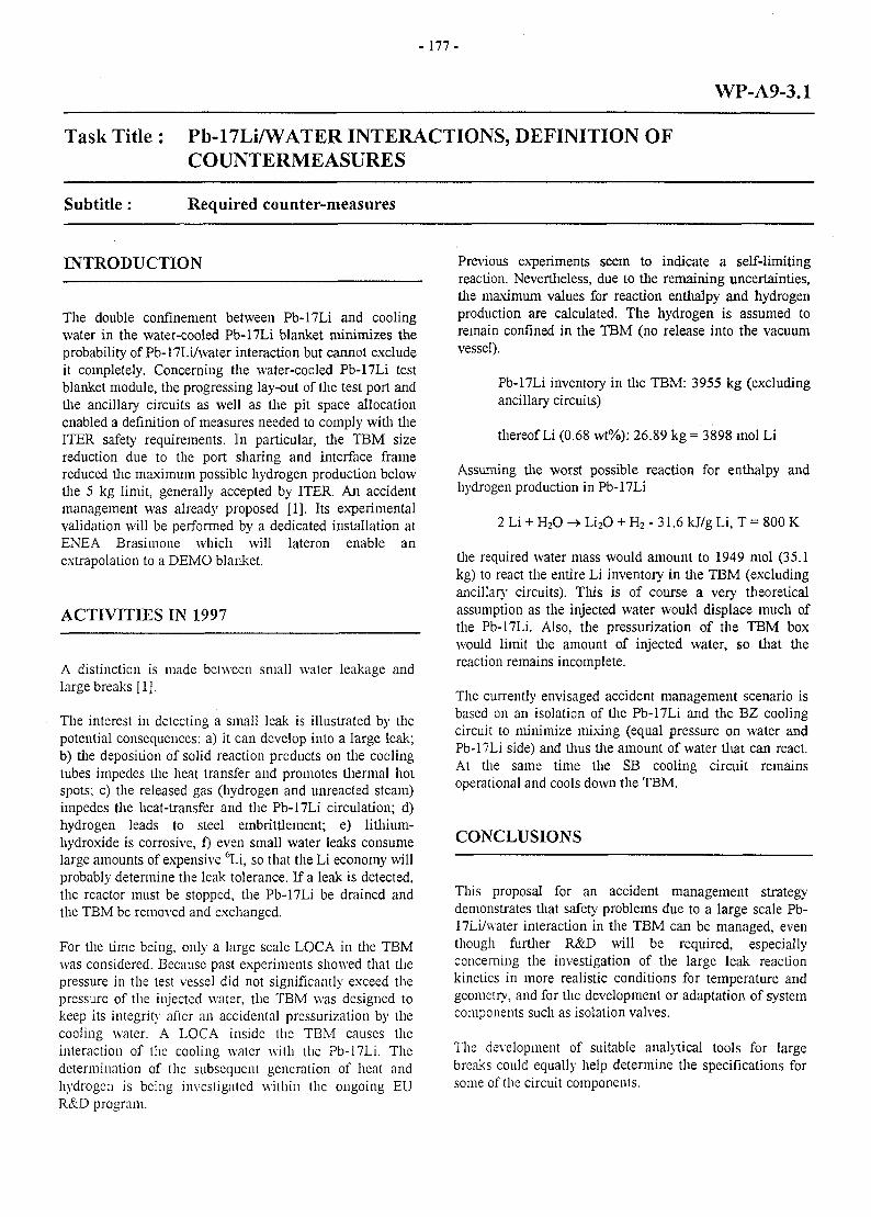
- 1 7 7 -
WP-A9-3.1
Task Title : Pb-17Li/WATER INTERACTIONS, DEFINITION OFCOUNTERMEASURES
Subtitle: Required counter-measures
INTRODUCTION
The double confinement between Pb-17Li and coolingwater in the water-cooled Pb-17Li blanket minimizes theprobability of Pb-17Li/water interaction but cannot excludeit completely. Concerning the water-cooled Pb-17Li testblanket module, the progressing lay-out of the test port andthe ancillary circuits as well as the pit space allocationenabled a definition of measures needed to comply with theITER safety requirements. In particular, the TBM sizereduction due to the port sharing and interface framereduced the maximum possible hydrogen production belowthe 5 kg limit, generally accepted by ITER. An accidentmanagement was already proposed [1], Its experimentalvalidation will be performed by a dedicated installation atENEA Brasimone which will lateron enable anextrapolation to a DEMO blanket.
ACTIVITIES IN 1997
A distinction is made between small water leakage andlarge breaks [1].
The interest in detecting a small leak is illustrated by thepotential consequences: a) it can develop into a large leak;b) the deposition of solid reaction products on the coolingtubes impedes the heat transfer and promotes thermal hotspots; c) the released gas (hydrogen and unreacted steam)impedes the heat-transfer and the Pb-17Li circulation; d)hydrogen leads to steel embrittlement; e) lithium-hydroxide is corrosive, f) even small water leaks consumelarge amounts of expensive 6Li, so that the Li economy willprobably determine the leak tolerance. If a leak is detected,the reactor must be stopped, the Pb-17Li be drained andthe TBM be removed and exchanged.
For the time being, only a large scale LOCA in the TBMwas considered. Because past experiments showed that thepressure in the test vessel did not significantly exceed thepressure of the injected water, the TBM was designed tokeep its integrity after an accidental pressurization by (hecooling water. A LOCA inside the TBM causes theinteraction of the cooling water with the Pb-17Li. Thedetermination of the subsequent generation of heat andhydrogen is being investigated within the ongoing EUR&D program.
Previous experiments seem to indicate a self-limitingreaction. Nevertheless, due to tlie remaining uncertainties,the maximum values for reaction enthalpy and hydrogenproduction are calculated. The hydrogen is assumed toremain confined in the TBM (no release into the vacuumvessel).
Pb-17Li inventory in the TBM: 3955 kg (excludingancillary circuits)
thereof Li (0.68 wt%): 26.89 kg = 3898 mol Li
Assuming the worst possible reaction for enthalpy andhydrogen production in Pb-17Li
2 Li + H2O -> Li2O + H2 - 31.6 kJ/g Li, T = 800 K
the required water mass would amount to 1949 mol (35.1kg) to react tlie entire Li inventory in tlie TBM (excludingancillary circuits). This is of course a very theoreticalassumption as tlie injected water would displace much ofthe Pb-17Li. Also, tlie pressurization of the TBM boxwould limit the amount of injected water, so that thereaction remains incomplete.
The currently envisaged accident management scenario isbased on an isolation of the Pb-17Li and the BZ coolingcircuit to minimize mixing (equal pressure on water andPb-17Li side) and thus the amount of water that can react.At the same time the SB cooling circuit remainsoperational and cools down the TBM.
CONCLUSIONS
This proposal for an accident management strategydemonstrates that safety problems due to a large scale Pb-17LiAvater interaction in the TBM can be managed, eventhough further R&D will be required, especiallyconcerning the investigation of the large leak reactionkinetics in more realistic conditions for temperature andgeometry, and for the development or adaptation of systemcomponents such as isolation valves.
The development of suitable analytical tools for largebreaks could equally help detennine the specifications forsome of the circuit components.

- 178 -
PUBLICATIONS TASK LEADER
(1] P. Magaud, F. Le Vagueres (eds.), Fusion Michael A. FUTTERERTechnology, Annual Report of the AssociationCEA/Euratom 1996, Task WP-A-7.2, CEA CEA SaclayDSM/DRFC, May 1997. DRN/DMT/SERMA/LCA
F-91191 Gif-sur-Yvette Cedex, France[2] M. Fiitterer, J. F. Salavy, L. Giancarli, WCLL Test
Blanket Module for ITER: Thermal, mechanical, Tel. : 33 1 69 08 36 36thermo-mechanical and LOCA analysis, CEA report Fax : 33 1 69 08 99 35DMT97/494.
e-mail: [email protected]
- 179 -
WP-A10-2.2
Task Title : EXPERIMENTAL DEMONSTRATION OF MHD PHENOMENA
Subtitle: Experiments on turbulence
INTRODUCTION
The objective is to give a contibution to the understandingof the Pb-17Li flow behaviour in the WCLL blanket and inparticular to assess the presence of two-dimensionnalturbulences in MHD flow shear layers and to characterizethem under representative magnetic field. Relevantparameters and scaling laws have to be obtained in order toevaluate the impact of MHD effects on Pb-17Li velocityand temperature distribution and consequently on the T-permation towards the water coolant in WCLL blanket.
1997 ACTIVITIES
Within the framework of the study on MHD turbulence inwater cooled lithium-lead blankets in fusion reactors, thetheoritical and numerical approaches have been speciallydeveloped in 1997. However, in order to give these resultstheir full meaning, they must be presented in permanentcomparison to the results obtained in the EPM-MADYLAM Laboratory on the MATUR experiment.
PROGRESS MADE ON BASIC IDEAS
Similarity law
In 1996, the similarity conditions between the MATURexperimental conditions (circular mercury' cell at thelaboratory scale under moderate magnetic field) and thoseof the tritigenous blankets of WCLL (water cooled lithiumlead) concept were discussed. The idea was that the smallscale could compensate for the weakness of the magneticfield and lead to making this similarity completelyplausible. This year, the study conducted in the EPM-MADYLAM Laboratory allowed these ideas to be clarified.
As long as the number of magnetic Reynolds is muchsmaller than the unit and that the number of Hartmann isclearly greater than the unit, three essential mechanismsoccur:
- a tendency towards two-dimensionality,inertial interactions between the different vortexes ,
- friction in the Hartmann layers.
The theory behind each one of these is well enoughaccepted so that the characteristic time of each mechanismbe defined :
- T2D> *"ne necessary to establish two-dimensionality,- x^, turning over time of vortexes,- xH, friction time in the Hartmann layer.
The tfy/TjQ ratio is, in the case of the blankets as in thecase of MATUR, very high compared to the unit and hasvalues of the same order of magnitude in both cases.Moreover, this ratio is practically fixed and no longerintervenes as a parameter of the problem.
The only actual parameter without dimension is thereforethe 1^, /XJJ ratio equivalent to the ratio of the number ofHartmann Ha over the number of Reynolds Re.
In the blankets, the number of Hartmann is very high(roughly 10 000) whereas it is moderate in MATUR (about40). But this difference is well compensated for by thedifferences in the values of Re, of about 100 to 1000 inMATUR, roughly 100 times more in the blankets.
The effective parameter of control in MATUR is theelectric current which conditions the velocity and Ttu. Inthe blankets, it is also the velocity, still only slightly knownbecause of the uncertainties on the influence of naturalconvection under intense magnetic field. But, in bothcases, the magnetic field, is practically set, and it alwaysintervenes through the H/B ratio, which means thatreducing H in MATUR comes down to increasing B.
Thus, it is possible to establish similarity conditionsbetween the WCLL blankets of fusion reactors and anexperiment at the laboratory scale by adapting the values ofthe magnetic field and the distance of Hartmann.
Theorem of the kinetic moment
In MATUR, the main flow is turning. A centrifugalperturbation is therefore necessarily present. It is in theshape of a radial flow directed towards the exterior andwhich closes in the Hartmann layers. The effect of theradial core flow is to transport the kinetic moment towardsthe outside, i.e. towards the boundary layer which developsalong the vertical wall. The latter, having reached thislayer, is dissipated by friction. This mechanism cantherefore be expected to induce a significant loss of thekinetic moment.
It appears that the integration of the centrifugal transportterm allows the theory to be in agreement with theexperimental results in a certain range of current, thereforeof energy. Beyond this, another effect seems to occur : itappears that the Hartmann layer becomes unstable.
- 1 8 0 -
Initially obsen'ed experimentally, this instability has beenobserved numerically in the same energy range.
Detachment of the boundary layer on the vertical wall
A study has been started on the risk of detachment of theboundary layer existing along the vertical wall. If thisdetachment is present, its consequences are serious :ejection of negative vorticity which will be later mixed tothe positive vorticity of the shear layer (effect equivalent toan additional dissipation), heat transfer greatly increasedby the ejection of cold fluid and its replacement by hotfluid.
From a theoretical point of view, the model based on theprinciple of a maximum entropy production needs to becompleted by a law at the wall. In the present model, thecondition temporarily selected is an assumption on frictionequal to zero, which seems better adapted than the velocityequal to zero. The best condition will only come from atreatment of this boundary layer, if not a coupling betweenthe equations in the theory of maximum entropy and anequation-model of the boundary layer.
From the physical point of view, the mechanism is thefollowing. Near the wall which is assumed to be plane, theflow is the superposition of a uniform parallel flow and aflow due to large vortexes. The fluid is acceleratedupstream from the vortex, but it is slowed downstream.This is where the boundary layer might detach if it doesnot have a sufficient quantity of movement to counter theadverse pressure gradient.
An analytical solution of the present model alreadyindicates that this idea of detachment of the boundary layercaused by the passage of large vortexes, also suggested bythe numerical results, seems very appropriate.
This solution should therefore be further studied, as itapplies to any achievement of this type of flow carryinglarge quasi-two-dimensional structures, whether it be anexperiment like MATUR or fusion reactor blankets.
NUMERICAL SOLUTION
An attempt has been made to directly numerically simulatethe equations of the two-dimensional velocity field and ofthe enthalpy using the FLUENT solver available at theEPM-MADYLAM Laboratory. The idea was to test, bycomparison with MATUR, this possibility of numericalsimulation which is relatively simple and cost-effective,made possible by the two-dimensionality of the turbulence.
The velocity profiles determined by calculation are in goodagreement with the experiment for a large operation rangeof MATUR. Beyond a certain energy, (he model over-estimates the velocity significantly (roughly 25 %). Thismeans that an effect which has become significant in theexperiment is not taken into account in the model whichcan be an instability of the Hanmann layer in the presence
of perturbations forced by a neighboring turbulence, oreven a three-dimensional perturbation of the flow.
In any event, the validation of the model can be consideredas satisfactory on the prediction level of the velocity fieldand the model could be applied to the prediction of somequasi-two-dimensional flows present in the blankets.Concerning the heat transfer and the prediction ontemperature distributions, it appears that the model under-estimates the effective diffusivity in the boundary layer,even when this boundary layer seems to be well simulatedfrom the velocity point of view. This question will beexamined again to identify the origin of the problem(numerical or linked to modeling).
INFLUENCE OF THREE-DIMENSIONAL MODES
The approximation according to which the turbulencebecomes two-dimensional, except in the Hartmann layers,and the theoretical modeling of these layers date back to1982 [Sommeria et Moreau,l]. All the experimentsconducted since then, in Grenoble and in Riga (Latvia)confirm these ideas but state that velocities are lower thanthose predicted by the model, in other words a greaterdissipation. A first explanation of this dissipation, specificto the circular geometry of MATUR, resides in thecentrifugal transport of the kinetic moment towards theboundary layers where it is dissipated. But in the straightline experiments of Kolesnikov and Kljukin in Riga [2],one can also see a greater dissipation than that predicted bythe model. A second explanation must therefore be foundand the role of three-dimensional modes which, even whenweak, could significantly contribute to the total dissipationthrough the electric currents they induce should be studied(a perfect 2D flow does not induce any and is thus notaffected by any dissipation).
Two actions have been undertaken with the aim to analyzethe importance of these three-dimensional modes.
The first is an analytical study which introduces the first3D mode compatible with the electrically insulating wallcondition, of which the amplitude is itself a pseudo 2Dfield. The result shows that the 3D mode is indeed moregreatly dissipated than the 2D one. This result will befurther analyzed, as if it is confirmed, it would mean thatthe 3D modes are significantly more important thansuggested by Sommeria and Moreau [1].
The second approach, aimed at confirming or negating thisfirst result, is based on a numerical study which takes intoaccount, not only the first 3D mode, but a whole series ofvertical undulations of successively smaller size, using amixed numerical method : spectral in the vertical directionso as to simulate this series, and with finite differences onthe horizontal plane. A specific program is beingdeveloped in the EPM-MADYLAM Laboratory and thefirst qualitative results clearly show an evolution towards asmaller and smaller number of large vortex structures.
- 1 8 1 -
BRIEF OVERVIEW ON PROGRSS MADE BYAPPLYING THE MAXIMUM ENTROPY THEORY
The application of the maximum entropy theory,specifically adapted to flows dominated by a 2D dynamicand initiated in the EPM-MADYLAM Laboratory [3] [4],was furthered by Sommeria and Dumont [5] and resultedin the writing of a code allowing the reconstitution of theaverage velocity field.
The results obtained are in good qualitative agreementwith the measurements but the velocity is over-estimatedby a factor close to two. It therefore seems necessary tointroduce the additional dissipating mechanismsmentioned above and which are not yet included in themodel : centrifugal transport and dissipation of the kineticmoment, detachment of the boundary layer, instability ofthe Hartmann layer. This work will be started in the weeksto come.
RECENT EXPERIMENTAL RESULTS
Even though the MATUR experiment is not included inthe framework of the contract on studies on MHDturbulence in the WCLL blankets, die experimental resultsare for the EPM-MADYLAM Laboraton' team the basis oftheir ideas and the validation reference of their theory.
Tliroughout this year, the experimental studies were aimedat exploring the operating regimes in which the Hartmannlayer became unstable. The most recent discovery is due tothe fact that at high energies, the energy1 spectrum ofvelocity fluctuations is no longer continuous (as in the caseof lower energies), but shows a ray spectrum.
This result leads to a new idea on MHD turbulence whenthe latter carries a lot of energy : it is no longer marked bythe interactions between vortexes of different sizes whichallow die energy to reach larger scales. It seems to be madeup of a finite number of structures which are well defined(vortexes) circulating at a very well defined velocity.
CONCLUSION AND PERSPECTIVES
Different results are now well established. Among them,we can mention the similarity conditions, from which wecan conclude that an experiment at the laboraton- scalewith a liquid metal such as mercury, a moderate magneticfield and a moderate Hartmann distance allows the flow inthe blankets in which the size of the magnetic field iscompensated by the size of the Hartmann distance to besimulated.
We must also mention a result typical of MATUR, thecircular cell in which is flow is turning : the importance ofthe centrifugal transport of the kinetic moment of whichthe integration allowed the agreement of predictions andmeasurements.
More generally, this means that one must be prepared totake into account the inertial effects as end effects in theblankets.
It is to be noted that these inertial effects do not follow thesame inertial laws as the main flow and are much moreslowed down. It will be of importance to verify this underintense magnetic field.
The results of a general nature and which can be directlyapplied to WCLL blankets in fusion reactors are thefollowing:
- The direct numerical simulation of a velocity fieldusing classic solver such as FLUENT adapted to theequation-model of Sommeria-Moreau [1] is perfectlyreliable.
We can now consider adapting these calculations to theWCLL blankets of fusion reactors where the newdifficulty will reside in the geometry complexity. Animprovement must still be made concerning heattransfer.
- When the turbulence carries more and more energy, itevolves from a classic state marked by a large variety ofscales towards a relatively well organized state, markedby a series of large identical vortexes.
- Between these large structures, it seems realistic thatthe Hartmann layer, along the walls perpendicular tothe magnetic field, becomes unstable when the energyof the neighboring turbulence becomes great enough.
- The weakness of the velocities measured despite thecorrection due to the centrifugal transport of the kineticmoment, suggests that three-dimensional modes persistand are greater than initially assumed.
A first theoretical study, which should be numericallycompleted, confirms this fact. The influence of thesethree-dimensional modes on the mixing of any scalarsuch as temperature or concentration in tritium couldbe important.
The perspectives for the year to come are dominated, onthe experimental level, by the achievement of a newMATUR cell aimed at being used under intense magneticfield, and on the theoretical level, by the adaptation of thetheory of maximum entropy to the quasi-2D MHDturbulence aimed at improving the equation model ofSommeria-Moreau [1] through the integration of theinstability of the Hartmann layer and the 3D effects, which,after validation by comparison with the experiment, shouldresult in an application to the fusion reactor water cooledlithium lead blankets.
- 182-
REFERENCES TASK LEADER
[1] "Why, when and how MHD turbulence becomes two-dimensional"J. Sommeria, R.Moreau, J. Fluid Mech.(1982), vol.118 pp 507-518.
[2] "Liquid Metal Magnetohydrodynamics" eds.Lielpeteris et Moreau,Kluwer Acad. Pub. , 1989, pp 449-454.
REPORTS AND PUBLICATIONS
[1] "Two dimensional numerical simulation of a MHDturbulent shear flow".Y. Delannoy - R. Moreau . 3rd Pamir Coiif., Aussois,France, Sept.22-26, 1997.
[2] "Quasi-2D MHD shear layers"T. Alboussiere, V. Ujpenski, R. Moreau.11th Turbulent Shear Flows, Grenoble, France, Sept.8-10, 1997.
[3] "An experimental investigation on quasi-2Dturbulence in MHD shear flows"T. Alboussiere, V. Ujpenski, B. Pascal, R.Moreau.3rd Pamir Conf., Aussois, France, Sept.22-26, 1997.
[4] "Recent theorical and experimental results on MHDturbulence"T. Alboussiere, V. Ujpenski, R. Moreau - Int.Workshop on Liquid Metal Blanket ExperimentalActivities, CEA, Paris, France, Sept. 16-18, 1997.
[5] NT DER/STML/LCFI 97/049 : " Turbulence in MHDflow shear layers : 1997 progress report."G. Laffont (DER/STML/LCFI), R. Moreau(MADYLAM - Grenoble).
Guy LAFFONT
DRN/DER/STML/LCFICadarache
Tel. : 04 42 25 73 14Fax : 04 42 25 77 88
e-mail : [email protected]
in collaboration with
R. MOREAU (MADYLAM-Grenoble)
- 1 8 3 -
WP-B1-1.2
Task Title : DEMO-BLANKET : SEGMENT DESIGN & ANALYSIS
Subtitle: Design optimisation for alternative ceramics Li
INTRODUCTION
During the years 1996-1997, CEA has optimised theHCPB blanket reference design for the use of thealternative ceramics. Theses alternative breeder ceramicsare the meta-zirconate and the meta-titanate of the Li. Twovariants of the optimised HCPB-blanket are proposed bythe CEA, [Rlj.
Both variants have a cooling plate thickness of 8 mm and aBe-bed thickness of 50 mm. The breeder bed thickness is16 and 18 mm assuming a maximum allowabletemperature of 1200 °C in the breeder bed. Both variantshave reached the same local TBR as the reference designusing the silicate.
The use of breeder beds as thick as 18mm should reliefmuch of the fabrication constraints. However, the use ofbreeder beds of 16mm thickness would decrease themaximum temperature value in the breeding bed duringnormal operation. The final selection between the twovariants will be done in the light of the exact thermalresponse function of the beds and of the maximumallowable operating temperatures in normal operation.
ACTIVITY IN 1997
POWER DENSITY RADIAL DISTRIBUTION
The power density radial distributions have been calculatedfor bed thickness of 16, 18 and 20 mm considering anenrichment in Li6 equal to 25%. These densities are issuedfrom the neutronic evaluations performed within the taskUT-SM&C-Blk, [Rl],
USED MODEL FOR THERMAL EVALUATIONS
A 2-D model with fine meshes is used in the thermalcalculations with a uniform temperature boundaryconditions imposed on the FW and the cooling plate. Itmust be stressed that, by imposing a temperature on theFW and the cooling plates, the model takes into accountthe helium temperature, convection coefficient between thehelium and the steel, conduction through the steel and thetransfer between the steel and the pebble bed.
The thermal model used for these calculations is based onthe following working hypotheses :
1. two operating uniform temperatures are imposed on thecooling plates outer surfaces which are equal to 450and 580 °C.
2. two operating uniform temperatures are imposed of theFW inner surface which are equal to 450 and 580 °C.
Considering that the He-coolant maximum temperature is450 °C, the maximum temperature of 580 °C is supposedto take into account the helium operating temperature, theconvection coefficient between helium and steel, theconduction through steel and the heat transfer coefficientbetween pebbles and steel. With two imposed temperatureson the FW and on the cooling plates as well, we will have4 representative configurations to be examined. These 4configurations are
1. FW = 450 °C and CP = 450 °C,2. FW = 580 °C and CP = 450 °C,3. FW = 450 °C and CP = 580 °C,4. FW = 580 °C and CP = 580 °C.
THERMAL CONDUCTIVITY ESTIMATION
The question of the pebble-bed conductivity is still an openissue. The existing models need to be validated throughadequate experiments. In this assessment, the thermalconductivity correlations proposed by P. Gierszewski,ref.[R2] are used. These correlations are developed for themeta-zirconate pebble-bed of a pebble radius of 1.2 mm,packing factor of 65% and pebble porosity of 18%, at 0.1MPa helium.
Various values of pebble bed conductivity have beenassumed in the thermal calculations. Starting from thereference value of thermal conductivity for zirconatepebble bed as function of temperature, various coefficientshave been introduced in order to take into account theporosity and the packing factor. The following relations arethus to be used for the zirconate pebble bed:
Kb=d 0 = 0.66 + 1.17e-7 TKbed 1 = Kw 0 * 1.12850Kbed2 = K b e d0* 1.19486Kbed 3 = K ^ 0 * 1.22144
.2.2 [W/m/K] with T [in °C](porosity = 15%)(porosity = 10%)(porosity = 8%)
OBTAINED RESULTS & CONCLUSIONS
The main thermal characteristics of the HCPB blanket,using meta-zirconate/meta-titanate as breeder materials,can be summarised in the following points :
1. an optimised version of the HCPB blanket is proposedwhere the ceramic breeder bed thickness is between 16and 18 mm with 25% enriclunent in Li6 and the Be-bed thickness is of 50 mm.
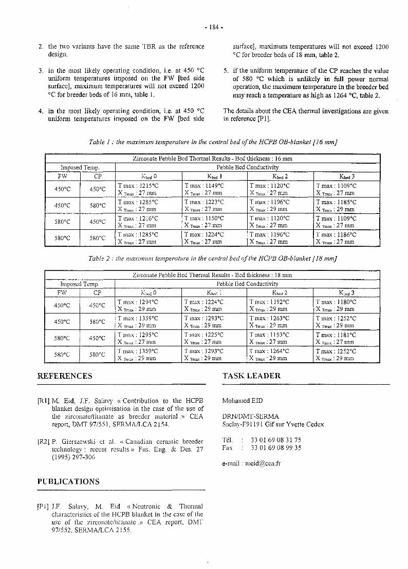
-184-
2. the two variants have the same TBR as the referencedesign.
3. in the most likely operating condition, i.e. at 450 °Cuniform temperatures imposed on the FW [bed sidesurface], maximum temperatures will not exceed 1200°C for breeder beds of 16 mm, table 1.
4. in the most likely operating condition, i.e. at 450 °Cuniform temperatures imposed on the FW [bed side
surface], maximum temperatures will not exceed 1200°C for breeder beds of 18 mm, table 2.
5. if the uniform temperature of the CP reaches the valueof 580 °C which is unlikely in full power normaloperation, the maximum temperature in the breeder bedmay reach a temperature as high as 1264 °C, table 2.
The details about the CEA thermal investigations are givenin reference [PI].
Table 1: the maximum temperature in the central bed of the HCPB OB-blanket [16 mm]
Zirconate Pebble Bed Thermal Results - Bed thickness : 16 mm
Imposed Temp.
FW
450°C
450°C
580°C
580°C
CP
450°C
580°C
450°C
580°C
Pebble Bed Conductivity
KbedO
Tmax: 1215°CX Tmax : 2 7 111111
Tmax: 1285°CX Tmax: 27 mm
Tmax: 1216°CX Tn,ax: 27 mm
Tmax: 1285°CX Tmax : 27 mm
Kbedl
Tmax: 1149°CX Tmax : 27 mm
Tmax: 1223°CX Tmax : 27 mm
Tmax: 1150°CX Tmax : 27 mm
Tmax: 1224°CX Tmax : 27 mm
Kbed 2
Tmax:1120°CX Tmax : 27 mm
Tmax: 1196°CX Tmax : 29 mm
T max : 1120°CX Tmax : 27 mm
Tmax: 1196°CX Tmax : 27 mm
Kbed3
Tmax: 1109°CX Tmax: 27 mm
Tmax: 1185°CX Tmax : 29 mm
Tmax: 1109°CX Tmax: 27 mm
Tmax: 1186°CX Tmax : 27 mm
Table 2 : the maximum temperature in the central bed of the HCPB OB-blanket [18 mm]
Zirconate Pebble Bed Thermal Results - Bed thickness : 18 mm
Imposed Temp.
FW
450°C
450°C
580°C
580°C
CP
450°C
580°C
450°C
580°C
Pebble Bed Conductivity
KbedO
T max: 1294°CX Tmax : 2 9 m m
Tmax: 1359°CX Tn,ax : 29 mm
T max : 1295°CX Tmax: 27 mm
Tmax: 1359°CX Tmax : 29 mm
Kbed 1
Tmax: 1224°CX Tmax: 29 mm
Tmax: 1293°CX Tmax : 29 mm
T max: 1225°CX Tmax : 27 nun
Tmax: 1293°CX w : 29 mm
Kbed 2
Tmax: 1192°CX Tmax : 29 mm
Tmax: 1263°CX Tmax: 29 mm
Tmax: 1193°CX Tmax: 27 mm
T max: 1264°CX Tmax : 29 mm
Kbed 3
Tmax: 1180°CX Tmax : 29 mm
Tmax: 1252°CX Tmax: 29 mm
Tmax: 1181°CX Tmax : 27 mm
T max: 1252°CX Tmax : 29 mm
REFERENCES TASK LEADER
[Rl] M. Eid, J.F. Salavy « Contribution to the HCPBblanket design optimisation in the case of the use ofthe zirconate/titanate as breeder material .» CEAreport, DMT 97/551, SERMA/LCA 2154.
[R2] P. Gierszewski et al. « Canadian ceramic breedertechnology : recent results» Fus. Eng. & Des. 27(1995)297-306
Mohamed EID
DRN/DMT-SERMASaclay-F91191 Gif sur Yvette Cedex
Tel. : 33 0169 08 3175Fax : 33 0169 08 99 35
e-mail : meid(fi)cea.fr
PUBLICATIONS
[PI] J.F. Salavy, M. Eid «Neutronic & Thermalcharacteristics of the HCPB blanket in the case of theuse of the zirconate/litanate .» CEA report, DMT97/552, SERMA/LCA 2155.
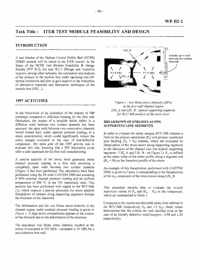
- 185 -
WP-B2-1
Task Title : ITER TEST MODULE FEASIBILITY AND DESIGN
INTRODUCTION
A test blanket of the Helium Cooled Pebble Bed (HCPB)DEMO module will be tested in the ITER reactor. In theframe of the HCPB Test Blanket Feasibility & DesignStudies (WP B.2), the task B.2.1 (Design and Analysis)requires, among other subtasks, the calculation and analysisof the stresses in the module box under operating and off-normal conditions and also to give support to the evaluationof alternative materials and fabrication techniques of themodule box (HIP,...).
LIG B
Initially open weldbetween two coolantchannels
1997 ACTIVITIES
In the framework of an evaluation of the interest of HIPtechnique compared to diffusion bonding for the first wallfabrication, the impact of a possible initial defect in adiffusion weld between two coolant channels has beenassessed. An open weld between two consecutive channelswould indeed lead, under channel pressure loading, to astress concentration which could significantly reduce thesafety margin evaluated in the case of non-defectivecomponent. The main goal of the 1997 activity was toevaluate this risk, knowing that a HIP fabrication couldoffer a safer approach for the first wall manufacturing.
A precise analysis of the stress level generated underchannel pressure loading in a first wall assuming acompletely open weld between two coolant channels(Figure 1) has been performed. The calculation have beenperformed using the FE code CASTEM 2000 and assuming8 MPa nominal channel pressure loading and an uniformtemperature of 500 °C in the T91 martensitic steel. Thisanalysis has been performed with regard to the RCC-MR[1], which imposes a precise procedure for stress analysis(breakdown of stresses along supporting segments throughthe thickness of the channels).
The deformation and the von Mises stress intensity in thechannel region under nominal pressure loading is given inFigure 1. A high stress concentration appears at the cornersof the channels due to the deformation of the structure.
The maximum von Mises stress intensity reached at thecorner is evaluated to 222 MPa - compared to 53 MPa for anon-defective first wall.
Figure 1: von Mises stress intensity (MPa)in the first wall channel region
LIG_A and LIGB: typical supporting segmentsfor RCC-MR analysis of the stress level
BREAKDOWN OF STRESSES ALONGSUPPORTING LINE SEGMENTS
In order to evaluate the safety margin, RCC-MR imposes alimit on the primary membrane (Pm) and primary membraneplus bending (Pm + Pb) stresses, which are evaluated bylinearization of the stress tensor along supporting segmentsin the thickness of the channel (see two typical supportingsegments - LIG_A and LIG_B - on Figure 1). Pm is definedas the mean value of the stress profile along a segment and(Pm + Pb) as the linearized profile of the stress.
An example of this linearization, performed with CASTEM2000, is given in Figure 2 corresponding to the linearizationof the cs-yv component of the stress tensor along LIGB.
This procedure permits then to evaluate the overallmaximum values of Pm and (Pm + Pb) in the component,which are summarised in Table 1.
Compared to the maximum allowable stress limit defined inthe RCC-MR (respectively Sm and 1.5 S,n), these valuesdemonstrate that the criteria are well satisfied even in thecase of an initially defective weld (margins : 2.98 and 1.56respectively).
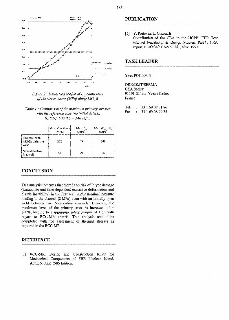
-186-
PUBLICATION
O.OO 9J» 1.7S 5.26 6.16
Figure 2 : Linearized profile qfcryy componentof the stress tensor (MPa) along LIGB
Table 1: Comparison of the maximum primary stresseswith the reference case (no initial defect).
Sm(T91,500°C) =
[1] Y. Poitevin, L. GiancarliContribution of the CEA to the HCPB HER TestBlanket Feasibility & Design Studies, Part 1, CEAreport, SERMA/LCA/97-2141,Nov. 1997.
TASK LEADER
Yves POITEVIN
DRN/DMT/SERMACEA Saclay91191 Gif-sur-Yvette CedexFrance
Tel. : 33 169 08 3186Fax : 33 1 69 08 99 35
First wall withinitially defectiveweld
None-defectivefirst wall
Max. Von Mises(MPa)
222
53
Max.Pm
(MPa)
49
29
Max. (Pm + Pb)(MPa)
140
35
CONCLUSION
This analysis indicates that there is no risk of P type damage(immediate and time-dependent excessive deformation andplastic instability) in the first wall under nominal pressureloading in the channel (8 MPa) even with an initially openweld between two consecutive channels. However, themaximum level of the primary stress is increased of +300%, leading to a minimum safety margin of 1.56 withregard to RCC-MR criteria. This analysis should becompleted with the assessment of thermal stresses asrequired in the RCC-MR
REFERENCE
[1] RCC-MR. Design and Construction Rules forMechanical Components of FBR Nuclear Island.AFCEN, June 1985 Edition.
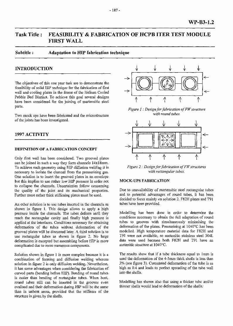
-187-
WP-B3-1.2
Task Title : FEASIBILITY & FABRICATION OF HCPB ITER TEST MODULEFIRST WALL
Subtitle: Adaptation to HIP fabrication technique
INTRODUCTION v v v v
The objectives of this one year task are to demonstrate thefeasibility of solid HIP technique for the fabrication of firstwall and cooling plates in the frame of the Helium CooledPebble Bed Blanket. To achieve this goal several designshave been considered for the joining of martensitic steelparts.
Two mock ups have been fabricated and the microstructureof the joints has been investigated.
1997 ACTIVITY
DEFINITION OF A FABRICATION CONCEPT
Only first wall has been considered. Two grooved platescan be joined in such a way they form channels 14xl8mm.To achieve such geometry using HIP diffusion welding it isnecessary to isolate the channel from the pressurising gas.One solution is to insert the grooved plates in an envelopebut this implies to use rather low HIP pressure in order notto collapse the channels. Uncertainties follow concerningthe quality of the joint and its mechanical properties.Further more rather thick stiffening plates must be used.
An other solution is to use tubes inserted in the channels asshown in figure 1. This design allows to apply a highpressure inside the channels. The tubes deform until theyreach the rectangular cavity and finally high pressure isapplied at the interfaces. Conditions necessary for obtainingdeformation of the tubes without deformation of thegrooved plates will be discussed later. A third solution is touse rectangular tubes as shown in figure 2. No largedeformation is excepted but assembling before HIP is morecomplicated due to more numerous components.
Solution shown in figure 1 is more complex because it is acombination of forming and diffusion welding whereassolution in figure 2 is only diffusion welding. Nevertheless,it has some advantages when considering the fabrication ofcurved parts (bending before HIP). Bending of round tubesis easier than bending of rectangular tubes. When bent,round tubes still can be inserted in the grooves evenovalised and their deformation during HIP will be the samethan in unbent areas, provided that the stiffness of thestructure is given by the shells.
Figure 1: Design for fabrication ofFWstructurewith round tubes.
i v V 1
t t t t tFigure 2: Design for fabrication of FW structures
with rectangular tubes.
MOCK-UPS FABRICATION
Due to unavailability of martensitic steel rectangular tubesand to potential advantages of round tubes, it has beendecided to focus mainly on solution 2. F82H plates and T91tubes have been provided.
Modelling has been done in order to determine theconditions necessary to obtain the full adaptation of roundtubes to grooves with simultaneously minimising thedeformation of the plates. Pressurising at 1040°C has beenmodelled. High temperature material data for F82H andT91 were not available, so austenitic stainless steel 304Ldata were used because both F82H and T91 have anaustenitic structure at 1040°C.
The results show that if a tube thickness equal to lmm isused the deformation of the 4-5mm thick shells is less than3% (see figure 3). Cumulated deformation of the tube is ashigh as 0.4 and leads to perfect spreading of the tube wallinto the shells.
Modelling has shown also that using a thicker tube and/orthinner shells would lead to deformation of the shells.-
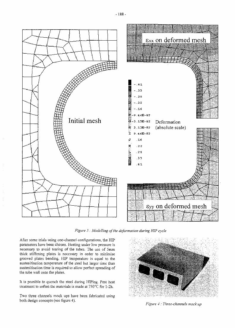
-188-
on deformed mesh
02 Deformation02 (absolute scale)
Syy on deformed mesh
Figure 3 : Modelling of the deformation during HIP cycle
After some trials using one-channel configurations, the HIPparameters have been chosen. Heating under low pressure isnecessary to avoid tearing of the tubes. The use of 5mmthick stiffening plates is necessary in order to minimisegrooved plates bending. HIP temperature is equal to theaustenitisation temperature of the steel but larger time thanaustenitisation time is required to allow perfect spreading ofthe tube wall onto the plates.
It is possible to quench the steel during HIPing. Post heattreatment to soften the materials is made at 750°C for l-2h.
Two three channels mock ups have been fabricated usingboth design concepts (see figure 4).
Figure 4 : Three-channels mock up
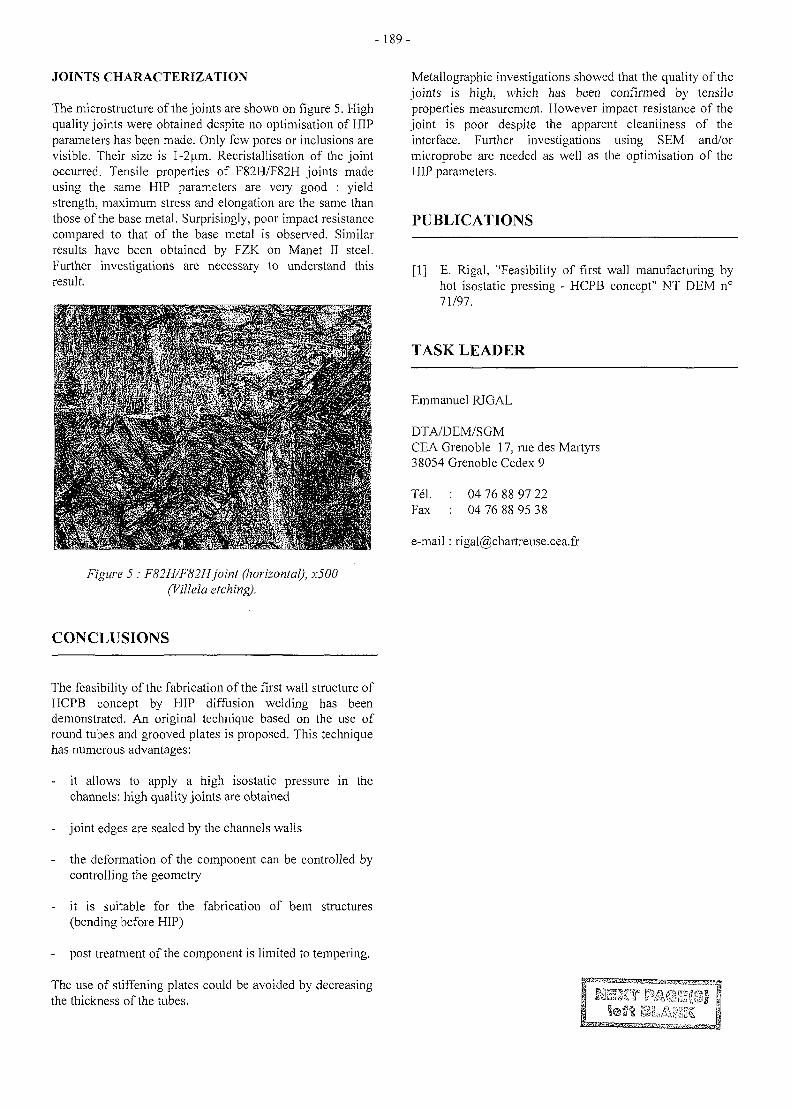
- 189 -
JOINTS CHARACTERIZATION
The microstructure of the joints are shown on figure 5. Highquality joints were obtained despite no optimisation of HIPparameters has been made. Only few pores or inclusions arevisible. Their size is 1-2 urn. Recristallisation of the jointoccurred. Tensile properties of F82H/F82H joints madeusing the same HIP parameters are very good : yieldstrength, maximum stress and elongation are the same thanthose of the base metal. Surprisingly, poor impact resistancecompared to that of the base metal is observed. Similarresults have been obtained by FZK on Manet II steel.Further investigations are necessary to understand thisresult.
Metallographic investigations showed that the quality of thejoints is high, which has been confirmed by tensileproperties measurement. However impact resistance of thejoint is poor despite the apparent cleanliness of theinterface. Further investigations using SEM and/ormicroprobe are needed as well as the optimisation of theHIP parameters.
PUBLICATIONS
[1] E. Rigal, "Feasibility of first wall manufacturing byhot isostatic pressing - HCPB concept" NT DEM n°71/97.
TASK LEADER
Emmanuel RIGAL
DTA/DEM/SGMCEA Grenoble 17, rue des Martyrs38054 Grenoble Cedex 9
Tel.Fax
04 76 88 97 2204 76 88 95 38
e-mail : [email protected]
e 5 : F82H/F82Hjoint (horizontal), x500(Villela etching).
CONCLUSIONS
The feasibility of the fabrication of the first wall structure ofHCPB concept by HIP diffusion welding has beendemonstrated. An original technique based on the use ofround tubes and grooved plates is proposed. This techniquehas numerous advantages:
it allows to apply a high isostatic pressure in thechannels: high quality joints are obtained
- joint edges are sealed by the channels walls
the deformation of the component can be controlled bycontrolling the geometry
- it is suitable for the fabrication of bent structures(bending before HIP)
post treatment of the component is limited to tempering.
The use of stiffening plates could be avoided by decreasingthe thickness of the tubes.
-191 -
WP-B7-2.3
Task Title : ITER TEST MODULE SYSTEM RELIABILITY
Subtitle: Contribution to the ITM reliability Assessment
INTRODUCTION
A part of the Reliability/Availability Assessment taskwithin the European Fusion Technology Program [EFTP]is to assess the reliability/availability of the ITER-TestModules.
In the following, we report briefly on the CEA contributionto the Helium Cooled pebble Bed [HCPB] ITM reliabilityassessment. The details of the CEA contribution arereported in [PI],
The CEA activity in 1997 consists in assessing the impactof the use of the zirconate/titanate on the global HCPB andthe ITM reliability.
ACTIVITY IN 1997
The use of the zirconate/titanate may allow the breeder bedthickness to be as large as 16-18 mm, if a maximumoperating temperature of the order of 1200 °C in thebreeder bed is acceptable, [Rl]. Subsequently, it woulddecrease the total number of cooling plates by 12% if weconsider the option with a breeder bed with 16 mmcompared to the reference blanket.
The impact of such reduction on the HCPB blanket and therelated ITM reliability has been assessed by the CEA. Forthe purpose of this assessment, basic failure data issuedfrom the European Failure Data File, [R2], are used.
Some previous assessments, {R3], for the HCPB blanketreliability have demonstrated that cooling platescontribution in the overall blanket reliability is the mostimportant one.
As it is expected, the direct impact of the use of thezirconate/titanate may be the reduction of the coolingplates number in the blanket.
In the table (1), the contribution of the cooling plates in theblanket overall failure rate and unreliability is calculatedand compared between different options of the HCPBblanket.In terms of unreliability, this would result in a reduction ofabout 14% in the blanket overall unreliability.
No significant difference exist between the option of 16mm and that with 18 mm in terms of unreliability and/ormean failure rate.
The absolute value of the unreliability in each case shouldbe very carefully interpreted.
In this exercise the diffusion weld has been assimilated to aTIG one with a basic failure rate of l.e-9 /h/m. If thediffusion weld is considered as a new technology item, itsbasic failure rate would rather be about l.e-8 /h/m. Theresultant ITM failure rate significantly change.
It should be emphasised that these figures have to be usedin a comparative way between different options. Theevaluation of absolute values of reliability for the blanketand for the ITM would necessarily demand the validationof the failure data specially for new technology items.
Table 1: Impact of the use of the zirconate/titanate on DEMO-HCPB blanket overall failure rate
Cell
Nb of cells/segment
effective height of the blanket
Nb of cooling plates
mean failure rate of the cooling plates
contribution in the blanket unreliability [20000 h]
[mm]
[mm]
[/h]
ref. design
(silicate)
72
150
1080
24000
2.9e-7
5.7e-3
alternative
16 mm
82
132
1082
21120
2.5e-7
5e-3
(zirconate/titanate)
18 mm
84
128
1075
2048
2.4e-7
4.9e-3
- 192-
CONCLUSION PUBLICATIONS
The impact of the use of the zirconate/titanate as breedermaterials rather than tlie silicate as proposed in thereference HCPB blanket design has been assessed. Theresult of the assessment has concluded that «the use of thezirconate/titanate would improve the overall unreliabilityof the blanket by some 12-14% with respect to thereference design using the silicate ».
The impact of the use of the zirconate/titanate on the ITMis by so far less significant. This is due to the fact that themain contribution in the HCPB blanket comes from tliecooling plates and that few number of the cooling plates [~10] will be presented in tlie ITM. In all cases the ITMreliability is not sensitive to the type of the breedermaterial.
However, some open questions still to be answeredconcerning the validation of the new technologyprocedures, namely, tlie diffusion welds and the HIP.Diffusion weld is proposed for the fabrication of thecooling plates and the HIP is proposed for the fabricationoftheFW.
As no validated data are available about these two items,the reliability/availability assessment results should behandled with much care. Absolute figures about tlie globalrates of tlie HCPB would significantly vary weather thenew technology items are supposed qualified or not.Accordingly, resultant figures should be used in acomparative manner.
[PI] M. Eid, «CEA Contribution to the reliability/availability assessment of DEMO & reliability database activities» DMT 97/562, SERMA/LCA 2159,1997.
TASK LEADER
Mohamed EID
DRN/DMT-SERMASaclay-F91191 Gif sur Yvette Cedex
Tel. : 33 0169 08 3175Fax : 33 01 69 08 99 35
e-mail: [email protected]
REFERENCES
[Rl] M. Eid, J.F. Salavy « Contribution to the HCPBblanket design optimisation in the case of the use ofthe zirconate/titanate as breeder material.» CEAreport, DMT 97/551, SERMA/LCA 2154.
[R2] « Minutes of the 1st Meeting of principal investigatorson the working packages reliability/availability » 30th
June 1997, ENEA-Frascati, Italy.
[R3] M. Eid « A comparative study on thereliability/availability of the EU blanket conceptualdesign lines » DMT 95/271, SERMA/LCA 1756.
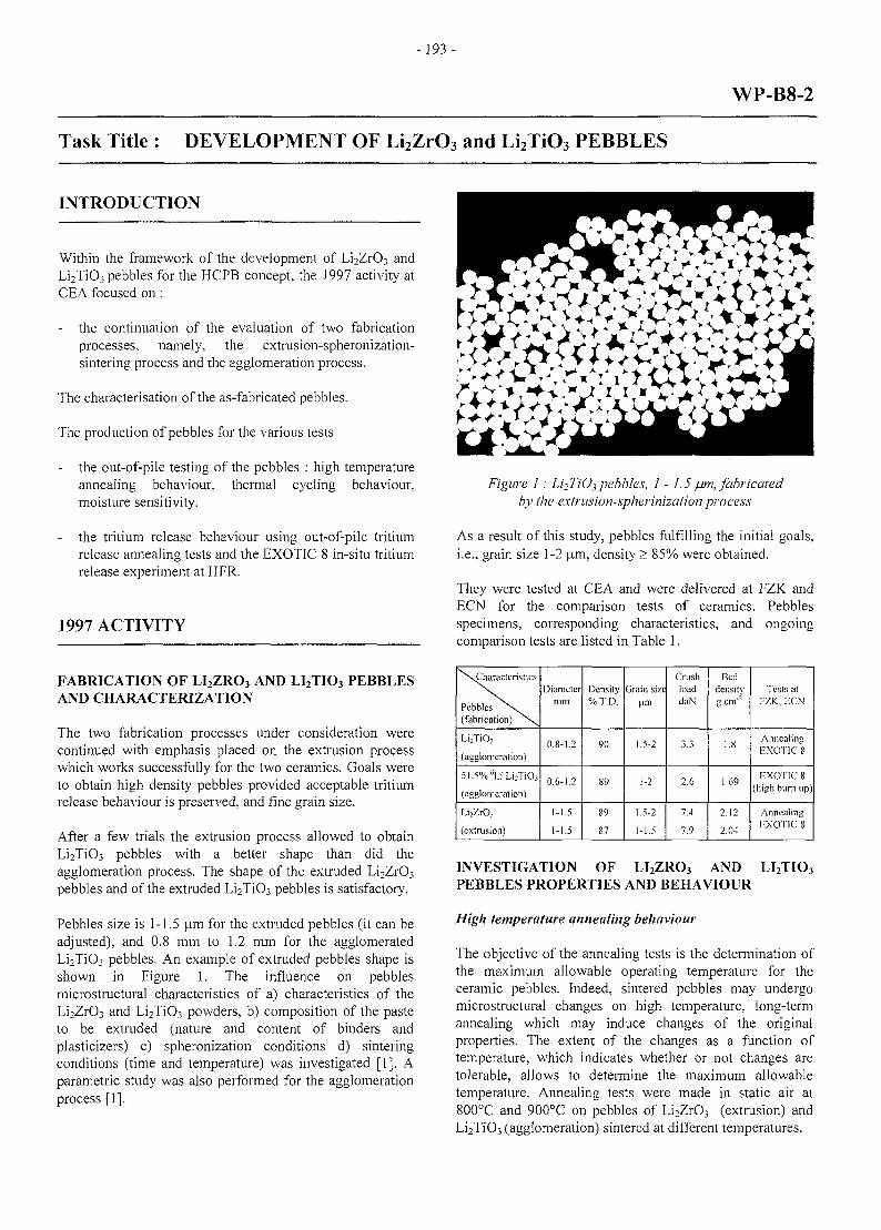
- 193 -
Task Title : DEVELOPMENT OF Li2ZrO3 and Li2TiO3 PEBBLES
WP-B8-2
INTRODUCTION
Within the framework of the development of Li2Zr03 andLi2Ti03 pebbles for the HCPB concept, the 1997 activity atCEA focused on :
- the continuation of the evaluation of two fabricationprocesses, namely, the extrusion-spheronization-sintering process and the agglomeration process.
The characterisation of the as-fabricated pebbles.
The production of pebbles for the various tests
- the out-of-pile testing of the pebbles : high temperatureannealing behaviour, thermal cycling behaviour,moisture sensitivity.
the tritium release behaviour using out-of-pile tritiumrelease annealing tests and the EXOTIC 8 in-situ tritiumrelease experiment at HFR.
1997 ACTIVITY
FABRICATION OF LI2ZRO3 AND LI2TIO3 PEBBLESAND CHARACTERIZATION
The two fabrication processes under consideration werecontinued with emphasis placed on the extrusion processwhich works successfully for the two ceramics. Goals wereto obtain high density pebbles provided acceptable tritiumrelease behaviour is preserved, and fine grain size.
After a few trials the extrusion process allowed to obtainLi2Ti03 pebbles with a better shape than did theagglomeration process. The shape of the extruded Li2Zr03
pebbles and of the extruded Li2TiO3 pebbles is satisfactory.
Pebbles size is 1-1.5 um for the extruded pebbles (it can beadjusted), and 0.8 mm to 1.2 mm for the agglomeratedLi2Ti03 pebbles. An example of extruded pebbles shape isshown in Figure 1. The influence on pebblesmicrostructural characteristics of a) characteristics of theLi2Zr03 and Li2Ti03 powders, b) composition of the pasteto be extruded (nature and content of binders andplasticizers) c) spheronization conditions d) sinteringconditions (time and temperature) was investigated [1]. Aparametric study was also performed for the agglomerationprocess [1].
Figure 1 : Li2TiO3 pebbles, 1 -1.5 /urn, fabricatedby the extrusion-spherinization process
As a result of this study, pebbles fulfilling the initial goals,i.e., grain size 1-2 um, density > 85% were obtained.
They were tested at CEA and were delivered at FZK andECN for the comparison tests of ceramics. Pebblesspecimens, corresponding characteristics, and ongoingcomparison tests are listed in Table 1.
^^Characteristics
Pebbles ^ v(fabrication) ^ \
Li2Ti03
(agglomeration)
51.5%6Li Li2Ti03
(agglomeration)
Li2ZrO,
(extrusion)
Diametermm
0.8-1.2
0.6-1.2
1-1.5
1-1.5
Density% T.D.
90
89
89
87
Grain sizeurn
1.5-2
1-2
1.5-2
1-1.5
CrushloaddaN
3.3
2.6
7.4
7.9
Beddensityg cm'5
1.8
1.69
2.12
2.04
Tests atFZK, ECN
AnnealingEXOTIC 8
EXOTIC 8(high burn up)
AnnealingEXOTIC S
INVESTIGATION OF LI2ZRO3 AND LI2TIO3
PEBBLES PROPERTIES AND BEHAVIOUR
High temperature annealing behaviour
The objective of the annealing tests is the detennination ofthe maximum allowable operating temperature for theceramic pebbles. Indeed, sintered pebbles may undergomicrostructural changes on high temperature, long-termannealing which may induce changes of the originalproperties. The extent of the changes as a function oftemperature, which indicates whether or not changes aretolerable, allows to determine the maximum allowabletemperature. Annealing tests were made in static air at800°C and 900°C on pebbles of Li2Zr03 (extrusion) andLi2Ti03 (agglomeration) sintered at different temperatures.
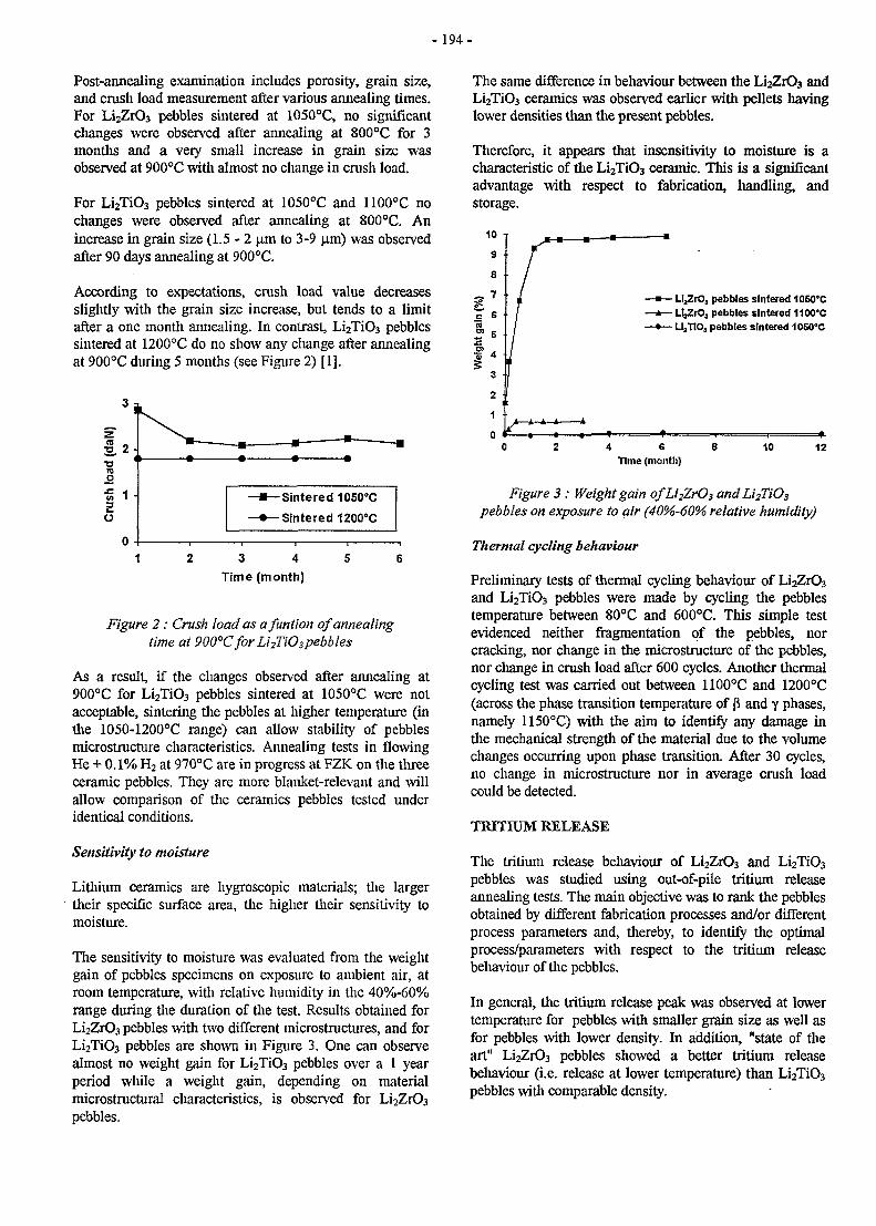
- 194 -
Post-annealing examination includes porosity, grain size,and crush load measurement after various annealing times.For Li2ZrO3 pebbles sintered at 1050°C, no significantchanges were observed after annealing at 800°C for 3months and a very small increase in grain size wasobserved at 900°C with almost no change in crush load.
For Li2Ti03 pebbles sintered at 1050°C and 1100°C nochanges were observed after annealing at 800°C. Anincrease in grain size (1 .5-2 ^m to 3-9 jxm) was observedafter 90 days annealing at 900°C.
According to expectations, crush load value decreasesslightly with the grain size increase, but tends to a limitafter a one month annealing. In contrast, Li2Ti03 pebblessintered at 1200°C do no show any change after annealingat 900°C during 5 months (see Figure 2) [1].
2 .
load
Cru
sh
3 j
2 -<
1 -
0 -
— • — • — —m —-**— i
Sintered 1050oC
Sintered 1200°C
1 2 3 4 5 6Time (month)
Figure 2 : Crush load as afuntion of annealingtime at 900°Cfor Li2Ti03pebbles
As a result, if the changes observed after annealing at900°C for Li2Ti03 pebbles sintered at 1050°C were notacceptable, sintering the pebbles at higher temperature (inthe 1050-1200°C range) can allow stability of pebblesmicrostructure characteristics. Annealing tests in flowingHe + 0.1% H2 at 970°C are in progress at FZK on the threeceramic pebbles. They are more blanket-relevant and willallow comparison of the ceramics pebbles tested underidentical conditions.
Sensitivity to moisture
Lithium ceramics are hygroscopic materials; the largertheir specific surface area, the higher their sensitivity tomoisture.
The sensitivity to moisture was evaluated from the weightgain of pebbles specimens on exposure to ambient air, atroom temperature, with relative humidity in the 40%-60%range during the duration of the test. Results obtained forLi2Zr03 pebbles with two different microstructures, and forLi2Ti03 pebbles are shown in Figure 3. One can observealmost no weight gain for Li2Ti03 pebbles over a 1 yearperiod while a weight gain, depending on materialmicrostructural characteristics, is observed for Li2Zr03
pebbles.
The same difference in behaviour between the Li2Zr03 andLi2Ti03 ceramics was observed earlier with pellets havinglower densities than the present pebbles.
Therefore, it appears that insensitivity to moisture is acharacteristic of the Li2Ti03 ceramic. This is a significantadvantage with respect to fabrication, handling, andstorage.
UjZrOj pebbles sintered 1050°CLljZrOj pebbles sintered 1100°CL^TiO, pebbles sintered 1050'C
4 6Time (month)
10 12
Figure 3 : Weight gain ofLi2ZrO3 andLi2TiO3
pebbles on exposure to air (40%-60% relative humidity)
Thermal cycling behaviour
Preliminary tests of thermal cycling behaviour of Li2ZrO3
and Li2Ti03 pebbles were made by cycling the pebblestemperature between 80°C and 600°C. This simple testevidenced neither fragmentation of the pebbles, norcracking, nor change in the microstructure of the pebbles,nor change in crush load after 600 cycles. Another thermalcycling test was carried out between 1100°C and 1200°C(across the phase transition temperature of p and y phases,namely 1150°C) with the aim to identify any damage inthe mechanical strength of the material due to the volumechanges occurring upon phase transition. After 30 cycles,no change in microstructure nor in average crush loadcould be detected.
TRITIUM RELEASE
The tritium release behaviour of Li2Zr03 and Li2Ti03
pebbles was studied using out-of-pile tritium releaseannealing tests. The main objective was to rank the pebblesobtained by different fabrication processes and/or differentprocess parameters and, thereby, to identify the optimalprocess/parameters with respect to the tritium releasebehaviour of the pebbles.
In general, the tritium release peak was observed at lowertemperature for pebbles with smaller grain size as well asfor pebbles with lower density. In addition, "state of theart" Li2Zr03 pebbles showed a better tritium releasebehaviour (i.e. release at lower temperature) than Li2Ti03
pebbles with comparable density.
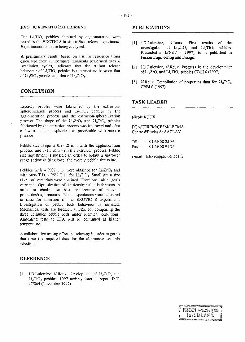
-195-
EXOTIC 8 IN-SITU EXPERIMENT
The Li2Ti03 pebbles obtained by agglomeration weretested in the EXOTIC 8 in-situ tritium release experiment.Experimental data are being analyzed.
A preliminary result, based on tritium residence timescalculated from temperature transients performed over 6irradiation cycles, indicates that the tritium releasebehaviour of Li2Ti03 pebbles is intermediate between thatof Li4Si04 pebbles and that of Li2Zr03.
CONCLUSION
PUBLICATIONS
[1J J.D.LuIewicz, N.Roux. First results of theinvestigation of Li2Zr03 and Li2Ti03 pebbles.Presented at IFNST 4 (1997), to be published inFusion Engineering and Design.
[2] J.D.LuIewicz, N.Roux. Progress in the developmentof Li2Zr03 and Li2Ti03 pebbles CBBI 6 (1997)
[3] N.Roux. Compilation of properties data for Li2Ti03
CBBI 6 (1997)
Li2Zr03 pebbles were fabricated by the extrusion-spheronization process and Li2Ti03 pebbles by theagglomeration process and the extrusion-spheronizationprocess. The shape of the Li2Zr03 and Li2Ti03 pebblesfabricated by the extrusion process was improved and aftera few trials is as spherical as practicable with such aprocess.
Pebble size range is 0.8-1.2 mm with the agglomerationprocess, and 1-1.5 mm with the extrusion process. Pebblesize adjustment is possible in order to obtain a narrowerrange and/or shifting lower the average pebble size value.
Pebbles with ~ 90% T.D. were obtained for Li2Zr03 andwith 90% T.D. - 95% T.D. for Li2Ti03 Small grain size(1-2 um) materials were obtained. Therefore, initial goalswere met. Optimization of the density value is foreseen inorder to obtain the best compromise of relevantproperties/requirements. Pebbles specimens were deliveredin time for insertion in the EXOTIC 8 experiment.Investigation of pebble beds behaviour is initiated.Mechanical tests are foreseen at FZK for comparing thethree ceramics pebble beds under identical conditions.Annealing tests at CEA will be continued at highertemperature.
A collaborative testing effort is underway in order to get indue time the required data for the alternative ceramicselection.
TASK LEADER
Nicole ROUX
DTA/CEREM/CE2M/LECMACentre d'Etudes de SACLAY
Tel.Fax
0169 08 25 8601 69 08 91 75
e-mail : [email protected]
REFERENCE
[1] J.D.LuIewicz, N.Roux, Development of Li2Zr03 andLi2Ti03 pebbles. 1997 activity internal report D.T.97/064 (Novembre 1997)
-197 -
SM 1-2.4
Task Title: IRRADIATION EXPERIMENTS - PIE OF SAMPLESIRRADIATED IN HFR - PHASE 1A
INTRODUCTION
The irradiation experiment Phase 1A performed in HFRreactor consists on a screening irradiation test of reducedactivation martensitic steels, including 7 Europeancandidates and F82H mod. materials. Irradiationtemperatures ranges from 250°C to 450°C and the dose is2.4 dpa.
This subtask deals the with post-irradiation tests ofmaterials supplied by CEA, that is LA12LC andLA12TaLC experimental steels. Materials have beenirradiated as tensile and Charpy V specimens. Post-irradiation tests will be performed at ECN hot-cells(Petten).
1997 ACTIVITIES
The irradiation experiment started on early 96 and finishedon May 97. The dismantling of the capsule started onSeptember 97 and the irradiated specimens weretransferred to ECN hot-cells on December 97. Post-irradiation tests are planned in the period February-June98. In the meantime, the following PIE program wasdefined.
MATERIALS AND SPECIMENS
LA12LC and LA12TaLC are experimental reducedactivation steels, where the chemical composition isbasically Fe-9Cr-0.7W-0.3V-l.0Mn-0.09C (weight %)with different tantalum content, which is 0.01% in the caseof LA12LC and 0.10% for LA12TaLC.
These materials have been included in HFR Phase-IAexperiment as tensile and Charpy specimens. The firstones are cylindrical samples of 3 mm in diameter and 18mm of gauge length. Impact specimens are « subsize »Charpy V samples, named KLST specimens, where thedimensions are 27 mm long, 4 mm wide and 3 mm thick.All specimens have been obtained parallel to the rollingdirection of plates.
For each material, 7 Charpy V and 2 tensile specimenshave been included in the capsule for each irradiationtemperature. Their identifications and irradiationconditions are given in table 1.
POST-IRRADIATION TESTS
To qualify the irradiation behaviour of mentionedmaterials, the following series of mechanical tests will beperformed. Also, the preparation of samples formicrostructural studies by Transmission ElectronMicroscopy (TEM) and Small Angle Neutron Scattering(SANS) techniques are planned.
a) Impact properties: Full transition curves in the range -150°C to +200cC will be obtained for each irradiationtemperature and each material. Charpy tests will beperformed according to the ISO KLST EuropeanStandard presently under development.
b) Tensile properties: For each irradiation temperatureand each material, two tensile tests will be conducted,one at 20°C and the other at the irradiationtemperature, using a strain rate of about 1.8 lO^/s.Tests will be done according to the ASTM E-8Standard. For each broken specimen, measurements ofarea reduction to rupture will be performed by imageanalysis techniques.
Table 1 : Irradiation conditions and identification of mechanical test specimens
Irradiation
Temper. (°C)
250
300
350
400
450
Dose
(dpa)
2.4
2.4
2.4
2.4
2.4
LA12LC
Identification
Charpy V
XG01-XG07
XG08-XG14
XG15-XG21
XG22-XG28
XG29-XG35
Identification
Tensile
G1-G2
G3-G4
G5-G6
G7-G8
G9-G0
LA12TaLC
Identification
Charpy V
XH01-XH07
XH08-XH14
XH15-XH21
XH22-XH28
XH29-XH35
Identification
Tensile
H1-H2
H3-H4
H5-H6
H7-H8
H9-H0
- 1 9 8 -
TEM and SANS specimens, that is respectively discs of 3mm of diameter-O.lmm thick and plates of 4mm wide, 10mm long and 1 mm thick, will be obtained from Charpyspecimens. They will be selected according to the results ofmechanical tests. In particular, specimens will be obtainedfor the irradiation temperature where the induced-irradiation effect is more pronounced (probably specimensirradiated at 250-300°C).
CONCLUSIONS
The common experimental irradiation destined tocharacterise the irradiation behaviour of seven Europeancandidates and F82H steels have been finished on May 97.This irradiation experiment have been performed in HFRreactor at five temperatures ranging from 250°C to 450°Cwith a dose of 2.4 dpa. The post-irradiation test programcorresponding to two experimental materials studied atCEA and included in this experiment have been defined.PIE will be performed in the ECN hot-cells during theperiod February-June 98.
TASK LEADER
A. ALAMO
DTA/DECM/SRMACEA - SACLAY91191 Gif-sur-Yvette
Tel : 33 1 69 08 67 26Fax : 33 1 69 08 71 30
e-mail: [email protected]
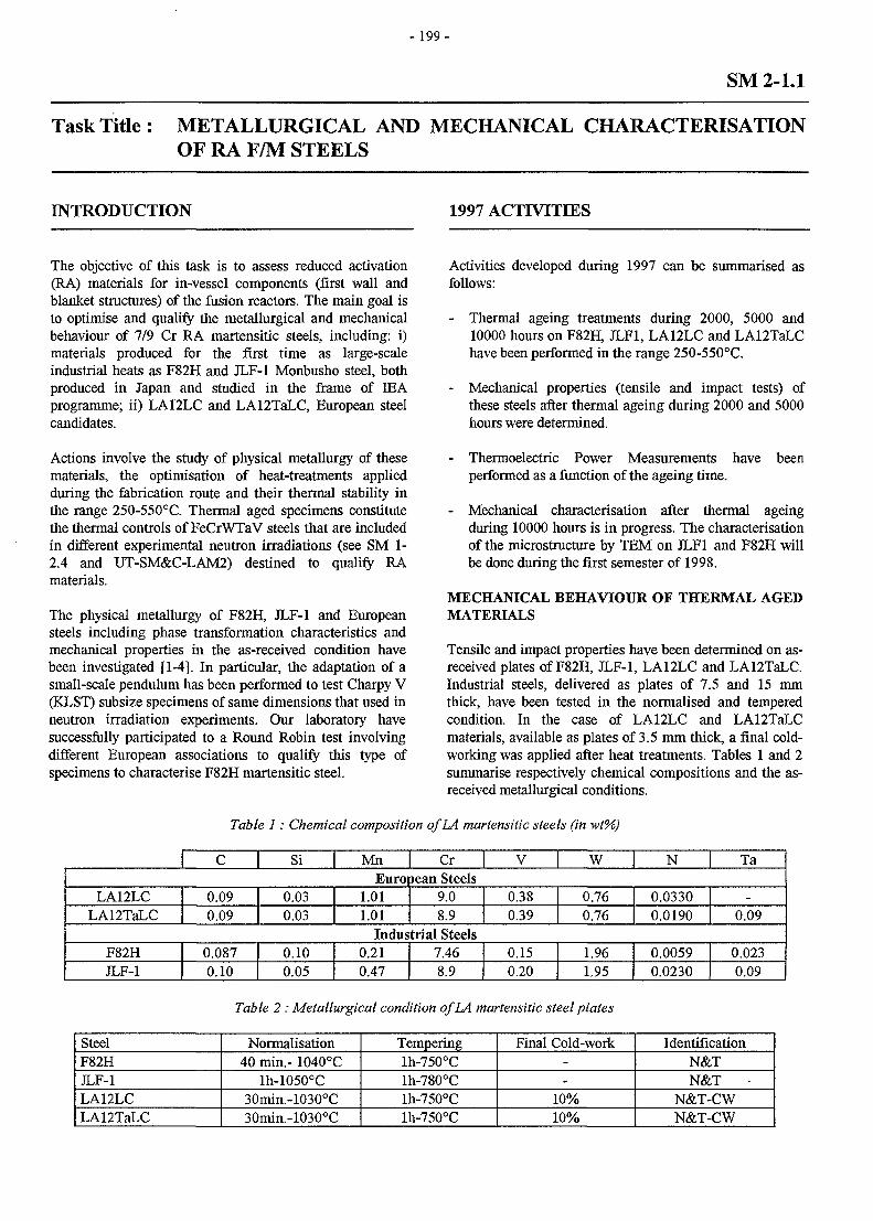
-199 -
SM 2-1.1
Task Title: METALLURGICAL AND MECHANICAL CHARACTERISATIONOF RA F/M STEELS
INTRODUCTION 1997 ACTIVITIES
The objective of this task is to assess reduced activation(RA) materials for in-vessel components (first wall andblanket structures) of the fusion reactors. The main goal isto optimise and qualify the metallurgical and mechanicalbehaviour of 7/9 Cr RA martensitic steels, including: i)materials produced for the first time as large-scaleindustrial heats as F82H and JLF-1 Monbusho steel, bothproduced in Japan and studied in the frame of JJEAprogramme; ii) LA12LC and LA12TaLC, European steelcandidates.
Actions involve the study of physical metallurgy of thesematerials, the optimisation of heat-treatments appliedduring the fabrication route and their thermal stability inthe range 250-550°C. Thermal aged specimens constitutethe thermal controls of FeCrWTaV steels that are includedin different experimental neutron irradiations (see SM 1-2.4 and UT-SM&C-LAM2) destined to qualify RAmaterials.
The physical metallurgy of F82H, JLF-1 and Europeansteels including phase transformation characteristics andmechanical properties in the as-received condition havebeen investigated [1-4]. In particular, the adaptation of asmall-scale pendulum has been performed to test Charpy V(KLST) subsize specimens of same dimensions that used inneutron irradiation experiments. Our laboratory havesuccessfully participated to a Round Robin test involvingdifferent European associations to qualify this type ofspecimens to characterise F82H martensitic steel.
Activities developed during 1997 can be summarised asfollows:
- Thermal ageing treatments during 2000, 5000 and10000 hours on F82H, JLF1, LA12LC and LA12TaLChave been performed in the range 250-550°C.
- Mechanical properties (tensile and impact tests) ofthese steels after thermal ageing during 2000 and 5000hours were determined.
Thermoelectric Power Measurements haveperformed as a function of the ageing time.
been
- Mechanical characterisation after thermal ageingduring 10000 hours is in progress. The characterisationof the microstructure by TEM on JLF1 and F82H willbe done during the first semester of 1998.
MECHANICAL BEHAVIOUR OF THERMAL AGEDMATERIALS
Tensile and impact properties have been determined on as-received plates of F82H, JLF-1, LA12LC and LA12TaLC.Industrial steels, delivered as plates of 7.5 and 15 mmthick, have been tested in the normalised and temperedcondition. In the case of LA12LC and LA12TaLCmaterials, available as plates of 3.5 mm thick, a final cold-working was applied after heat treatments. Tables 1 and 2summarise respectively chemical compositions and the as-received metallurgical conditions.
Table 1: Chemical composition of LA martensitic steels (in wt%)
C Si Mn Cr V W N TaEuropean Steels
LA12LCLA12TaLC
0.090.09
0.030.03
1.011.01
9.08.9
0.380.39
0.760.76
0.03300.0190
-0.09
Industrial SteelsF82HJLF-1
0.0870.10
0.100.05
0.210.47
7.468.9
0.150.20
1.961.95
0.00590.0230
0.0230.09
Table 2 : Metallurgical condition of LA martensitic steel plates
SteelF82HJLF-1LA12LCLA12TaLC
Normalisation40 min.- 1040°C
lh-1050°C30min.-1030°C30min.-1030°C
Temperinglh-750°Clh-780°Clh-750°Clh-750°C
Final Cold-work--
10%10%
IdentificationN&TN&T •
N&T-CWN&T-CW
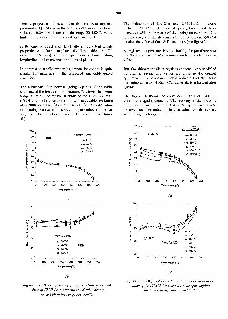
-200 -
Tensile properties of these materials have been reportedpreviously [1]. Alloys in the N&T condition exhibit lowervalues of 0.2% proof stress in the range 20-450°C, but athigher temperatures the trend is slightly inversed.
In the case of F82H and JLF-1 alloys, equivalent tensileproperties were found on plates of different thickness (7.5mm and 15 mm) and for specimens obtained alonglongitudinal and transverse directions of plates.
The behaviour of LA12Ta and LA12TaLC is quitedifferent. At 20°C. after thermal ageing, their proof stressdecreases with the increase of the ageing temperature. Dueto the recover}' of the structure, after 5000 hours at 550°C itreaches the value of the N&T specimens (see figure 2a).
At high test temperature (beyond 500°C), the proof stress ofthe N&T and N&T-CW specimens tends to reach the samevalue.
In contrast to tensile properties, impact behaviour is quitesimilar for materials in the tempered and cold-workedcondition.
The behaviour after thermal ageing depends of the initialstate and of the treatment temperature. Whatever the ageingtemperature is. the tensile strength of the N&T materials(F82H and J1F1) does not show any noticeable evolutionafter 2000 hours (see figure la). No significant modificationof ductility values is observed. In particular, a manifeststability of the reduction in area is also observed (see figurelb).
But, the ultimate tensile strength is not sensitively modifiedby thermal ageing and values are close to the controlspecimen. This behaviour should indicate that the strainhardening capacity of N&T-CW materials is enhanced afterageing.
The figure 2b shows the reduction in area of LA12LCcontrol and aged specimens. The recovery of the structureafter thermal ageing of the N&T-CW specimens is alsoobserved on their reduction in area values which increasewith the ageing temperature.
1000
900 :
•« 800 :CL '
~ 700 :
S 500,
^ 400-
300;
200
100
90
(0| 80 '
coB 70-
•ooa.
60 -
50
F82H
Aoeinq for 2000 h
•H..350vC
,£. .400°C
JC 550°C
• Control
100 200 300 400 500 600
Temperature (°C)
la
ci-
700
ftqeing for 2000 h
- O
-£ 400 °C
-X- 550 °C
- # Control
F82H
100 200 300 400 500
Temperature (°C)
lb
630 700
Figure 1 : 0.2% proof stress (a) and reduction in area (b)values o/F82H RA martensitic steel after ageing
for 2000h in the range 350-550°C
LA12LC
Aoeinq for 5000 h
-«-
-D-
-fi-—
-x-
Control
250°C
350 °C
400'C
450°C
550 "C
100 200 300 400 500
Temperature (°C)
2a
600
100
200 300 400 500
Temperature (°C)
2b
600 700
Figure 2 : 0.2% proof stress (a) and reduction in area (b)values ofLA12LC RA martensitic steel after ageing
for 5000h in the range 250-550°C
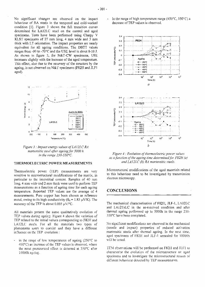
- 2 0 1 -
No significant changes are observed on the impactbehaviour of RA steels in the tempered and cold-workedcondition [1]. Figure 3 shows the full transition curvesdetermined for LA12LC steel on the control and agedspecimens. Tests have been performed using Charpy VKLST specimens of 27 mm long, 4 mm wide and 3 mmthick with LT orientation. The impact properties are nearlyequivalent for all ageing conditions. The DBTT valuesranges from -90 to -70°C and the USE level is about 8-10 J.As shown in figure 3, for N&T-CW specimens, USEincreases slightly with the increase of the aged temperature.This effect, also due to the recovery of the structure by theageing, is not observed on N&T specimens (F82H and JLF1aged).
in the range of high temperature range (450°C, 550°C) adecrease of TEP values is observed.
102 103
Time (h)
0.4 —
0.3 j j - LA12LC
-200 -100 0 100 200 300 400 500
Temperature (°C)
Figure 3 : Impact energy values ofLA12LC RAmartensitic steel after ageing for 5000 h
in the range 250-550°C.
THERMOELECTRIC POWER MEASUREMENTS
Thermoelectric power (TEP) measurements are verysensitive to microstructural modifications of the matrix, inparticular to the interstitial content. Samples of 40 mmlong, 4 mm wide and 2 mm thick were used to perform TEPmeasurements as a function of ageing time for each ageingtemperature. Reported TEP values are the average of 4measurements. Pure copper has been chosen as referencemetal, owing to its high conductivity (So = 1.83 uV/K). Theaccuracy of the TEP is about 0.005 uV/°C.
All materials present the same qualitatively evolution ofTEP values during ageing. Figure 4 shows the variation ofTEP related to the initial values corresponding to F82H andLA12LC steels. For all the materials two types ofphenomena seem to coexist and they have a differentinfluence on the TEP evolution :
in the range of low temperatures of ageing (250°C to400°C) an increase of the TEP values is observed, wherethe most pronounced effect is detected at 350°C afterlOOOOh ageing.
10 10 10Time (h)
Figure 4 : Evolution of thermoelectric power valuesas a function of the ageing time determined for F82H (a)
and LAI 2 LC (b) RA martensitic steels.
Microstructural modifications of the aged materials relatedto this behaviour need to be investigated by transmissionelectron microscopy.
CONCLUSIONS
The mechanical characterisation of F82H, JLF-1, LA12LCand LA12TaLC in the as-received condition and afterthermal ageing performed up to 5000h in the range 250-550°C have been completed.
No significant modifications are observed in the mechanical(tensile and impact) properties of reduced activationmartensitic steels after thermal ageing. In the next time,aged specimens of F82H and JLF-1 annealed for lOOOOhwill be tested.
TEM observations will be performed on F82H and JLF1 tocharacterise the evolution of the microstructure on agedspecimens and to investigate the microstructura] reason ofdifferent behaviour detected by TEP measurements.
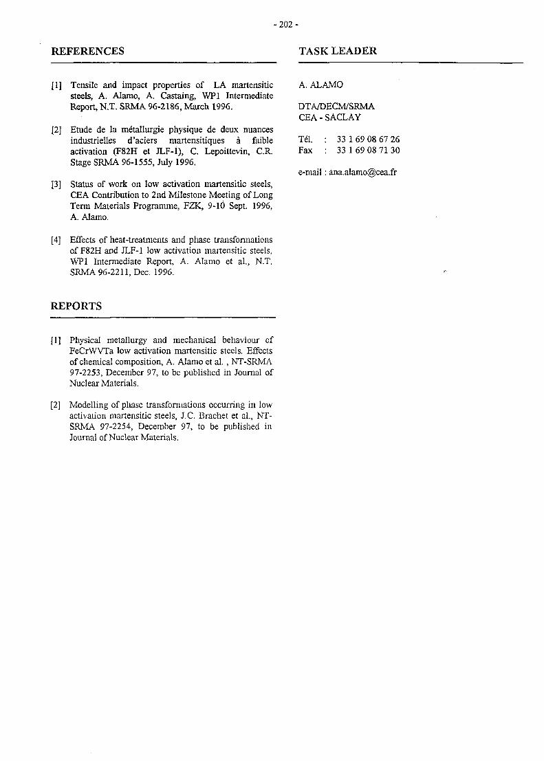
- 2 0 2 -
REFERENCES TASK LEADER
[1] Tensile and impact properties of LA martensiticsteels, A. Alamo, A. Castaing, WP1 IntermediateReport, N.T. SRMA 96-2186, March 1996.
[2] Etude de la me"tallurgie physique de deux nuancesindustrielles d'aciers martensitiques a faibleactivation (F82H et JLF-1), C. Lepoittevin, C.R.Stage SRMA 96-1555, July 1996.
[3] Status of work on low activation martensitic steels,CEA Contribution to 2nd Milestone Meeting of LongTerm Materials Programme, FZK, 9-10 Sept. 1996,A. Alamo.
[4] Effects of heat-treatments and phase transformationsof F82H and JLF-1 low activation martensitic steels,WP1 Intermediate Report, A. Alamo et al., N.T.SRMA 96-2211, Dec. 1996.
A. ALAMO
DTA/DECM/SRMACEA - SACLAY
Tel. : 33 1 69 08 67 26Fax : 33 1 69 08 71 30
e-mail: [email protected]
REPORTS
[1] Physical metallurgy and mechanical behaviour ofFeCrWVTa low activation martensitic steels. Effectsof chemical composition, A. Alamo et al. , NT-SRMA97-2253, December 97, to be published in Journal ofNuclear Materials.
[2] Modelling of phase transformations occurring in lowactivation martensitic steels, J.C. Brachet et al., NT-SRMA 97-2254, December 97, to be published inJournal of Nuclear Materials.
- 2 0 3 -
SM 2-2.3
Task Title : CREEP PROPERTIES OF BASE METAL - F82H STEEL
INTRODUCTION REPORTS
The objective of this task is to characterise creep propertiesof F82H low activation martensitic steel. This candidatematerial for in-vessel components was developed at JAERI(Japan) and produced as two large-scale heats (5 tons each)by NKK Corporation. Characterisation consists onscreening creep tests performed on F82H base metal,which will be used as reference to compare the creepbehaviour of F82H weldments.
1997 ACTIVITES
Creep tests have been performed at 550 and 600°C. Severalstress levels have been used for each test temperature,which range from 180 to 220 MPa at 550°C and 120-160MPa for tests performed at 600°C.
Specimens of 4 mm diameter and 20 mm gauge lengthhave been machined from a 15mm thick plate of F82H(heat 9741, plate reference RB 802-3-12). They wereobtained in the perpendicular direction compared to therolling direction. The same type of specimens are used forweldments.
Tests started on January 1997. The preliminary results ofthe base metal are presented in ref. (1) and also in thereport corresponding to the task SM2-3.1 in comparisonwith the creep characterisation of F82H weldments (seefigures 4 and 5 of SM2-3.1 report). Times to rupture of thebase metal, obtained for both temperature tests in thetransverse direction, are in good agreement with thosedetermined at FZK in the longitudinal direction.Consequently, no anisotropy seems to be detected in F82Hplates.
[1] B. Girard, L. Allais, « Progress report of creep testson F82H: base metal, TIG and EB weld joints », C.KSRMA 97-1588, Dec. 1997.
TASK LEADER
A. ALAMO
DTA/DECM/SRMACEA-SACLAY91191 Gif-sur-Yvette
Tel. : 33 1 69 08 67 26Fax : 33 1 69 08 71 30
e-mail : [email protected]
CONCLUSIONS
Creep tests are being performed at 550°C and 600°C onF82H base metal plates for different stress levels.Specimens were obtained perpendicularly to the rollingdirection of plates to be compared with weldmentssamples. Some tests are still running and they will becompleted in order to have a more reliable description ofcreep behaviour of F82H, base metal and weldments.
WLMmi
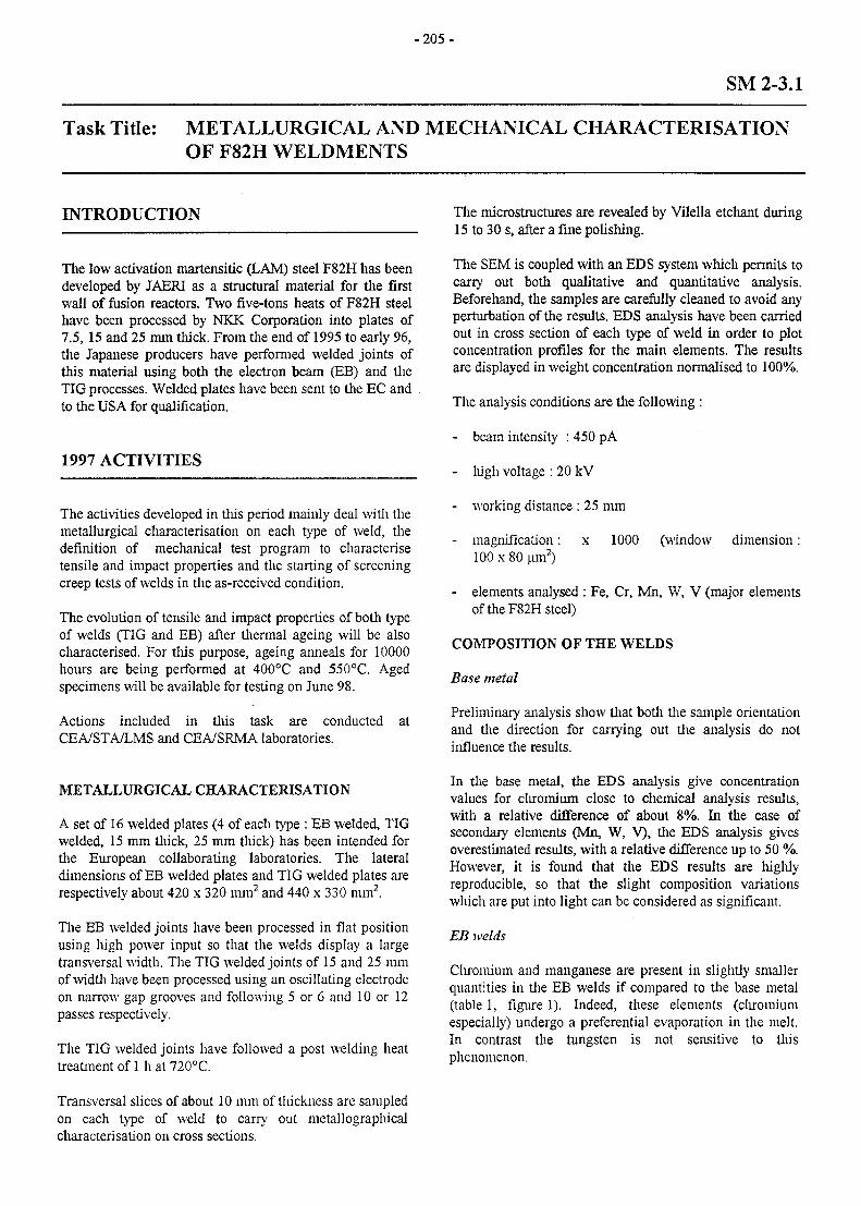
- 2 0 5 -
SM 2-3.1
Task Title: METALLURGICAL AND MECHANICAL CHARACTERISATIONOF F82H WELDMENTS
INTRODUCTION
The low activation martensitic (LAM) steel F82H has beendeveloped by JAERI as a structural material for the firstwall of fusion reactors. Two five-tons heats of F82H steelhave been processed by NKK Corporation into plates of7.5, 15 and 25 mm thick. From the end of 1995 to early 96,the Japanese producers have performed welded joints ofthis material using both the electron beam (EB) and theTIG processes. Welded plates have been sent to the EC andto the USA for qualification.
1997 ACTIVITIES
The activities developed in this period mainly deal with themetallurgical characterisation on each type of weld, thedefinition of mechanical test program to characterisetensile and impact properties and the starting of screeningcreep tests of welds in the as-received condition.
The evolution of tensile and impact properties of both typeof welds (TIG and EB) after thermal ageing will be alsocharacterised. For this purpose, ageing anneals for 10000hours are being performed at 400°C and 550°C. Agedspecimens will be available for testing on June 98.
Actions included in this task are conducted atCEA/STA/LMS and CEA/SRMA laboratories.
The microstructures are revealed by Vilella etchant during15 to 30 s, after a fine polishing.
The SEM is coupled with an EDS system which permits tocarry out both qualitative and quantitative analysis.Beforehand, the samples are carefully cleaned to avoid anyperturbation of the results. EDS analysis have been carriedout in cross section of each type of weld in order to plotconcentration profiles for the main elements. The resultsare displayed in weight concentration normalised to 100%.
The analysis conditions are the following :
- beam intensity : 450 pA
- high voltage : 20 kV
- working distance : 25 mm
- magnification: x 1000 (window dimension:100 x 80 um2)
- elements analysed : Fe, Cr, Mn, W, V (major elementsof the F82H steel)
COMPOSITION OF THE WELDS
Base metal
Preliminary analysis show that both the sample orientationand the direction for carrying out the analysis do notinfluence the results.
METALLURGICAL CHARACTERISATION
A set of 16 welded plates (4 of each type : EB welded, TIGwelded, 15 mm thick, 25 mm thick) has been intended forthe European collaborating laboratories. The lateraldimensions of EB welded plates and TIG welded plates arerespectively about 420 x 320 mm2 and 440 x 330 mm2.
The EB welded joints have been processed in flat positionusing high power input so that the welds display a largetransversal width. The TIG welded joints of 15 and 25 mmof width have been processed using an oscillating electrodeon narrow gap grooves and following 5 or 6 and 10 or 12passes respectively.
The TIG welded joints have followed a post welding heattreatment of 1 h at 720°C.
In the base metal, the EDS analysis give concentrationvalues for chromium close to chemical analysis results,with a relative difference of about 8%. In the case ofsecondary elements (Mn, W, V), the EDS analysis givesoverestimated results, with a relative difference up to 50 %.However, it is found that the EDS results are highlyreproducible, so that the slight composition variationswhich are put into light can be considered as significant.
EB welds
Chromium and manganese are present in slightly smallerquantities in the EB welds if compared to the base metal(table 1, figure 1). Indeed, these elements (chromiumespecially) undergo a preferential evaporation in the melt.In contrast the tungsten is not sensitive to thisphenomenon.
Transversal slices of about 10 mm of thickness are sampledon each type of weld to carry out metallographicalcharacterisation on cross sections.
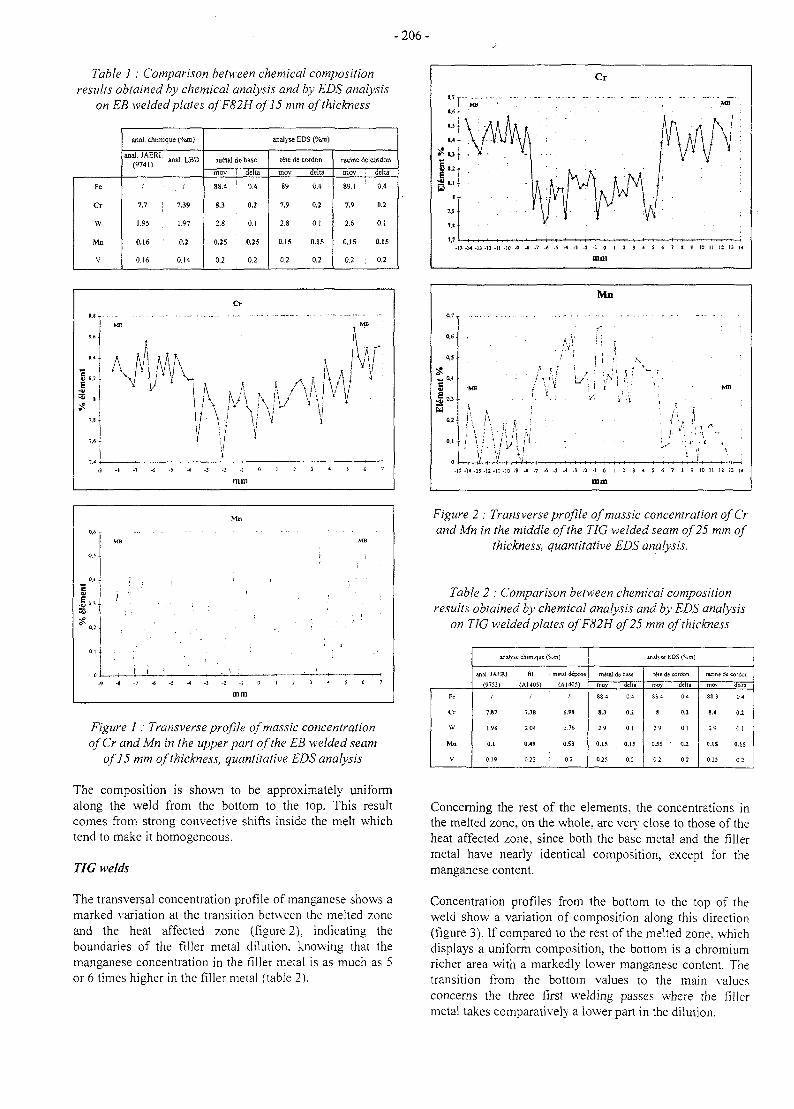
-206-
Table 1 : Comparison between chemical compositionresults obtained by chemical analysis and by EDS analysis
on EB welded plates of F82H of 15 mm of thickness
Fe
Cr
W
Mn
V
anal, chimique ("/cm)
acal.JAERL(9741) :
; :
7.7
1.95 |
0.16
0.16
anal.LBD
;
7.39
1.97
0.2
0.14
ra fetal de base
moy
88.4
S.3
2.8
0.25
0.2
delta
0.4
0.2
0.1
0.25
0.2
analyse EDS (°/<m)
tete de cordon
mov
89
7.9
2.8
0.15
0.2
delta
0.4
0.2
0.1
0.15
0.2
rarine de cordon
moy
89.1
7,9
2.6
0.15
0.2
delta
0.4
0.2
0.1
0.15
0.2
CM
0.1
c
MB
j
i
Mr,
' 1
J
, 1 :
mm
MB
i ;
. < , :
Figure 1: Transverse profile ofmassic concentrationofCr and Mn in the upper part of the EB welded seam
of 15 mm of thickness, quantitative EDS analysis
The composition is shown to be approximately uniformalong the weld from the bottom to the top. This resultcomes from strong convective shifts inside the melt whichtend to make it homogeneous.
TIG welds
The transversal concentration profile of manganese shows amarked variation at the transition between the melted zoneand the heat affected zone (figure 2). indicating theboundaries of the filler metal dilution, knowing that themanganese concentration in the filler metal is as much as 5or 6 times higher in the filler metal (table 2).
Mn
0,6
0,5
*. 0,4
e
!\
j '* •
B
I,y
: \
wy
|
' •'! Hv w.•1
. i'i;./ ; i \
ii l
' • i i ;
T)
M
^ i
';(
"I
i. '
; /' i '•
MB
-13 -14 -13 -12 -11 -15 -9
Figure 2 : Transverse profile ofmassic concentration ofCrand Mn in the middle of the TIG welded seam of 25 mm of
thickness, quantitative EDS analysis.
Table 2 : Comparison between chemical compositionresults obtained by chemical analysis and by EDS analysis
on TIG welded plates ofF82H of 25 mm of thickness
Fe
Cr
W
Mn
V
analyse chimique (
anal. JAERJ
(9753)
7.81
1.98
0.1
0.19
111
(A140S)
/
7JS
2 04
0.49
022
meial depose
/
6.98
1.76
033
02
metal de base
mov
88 4
SJ
29
0.15
0 25
delta
0-1
02
01
o.ts
02
» * - EDS (%m)
teie de cordon
mov
8E 4
8
29
0J5
02
della
04
0.2
01
<u02
tacin
mo\
88 3
8.4
29
CIS
0.25
de co idor.
delta
04
0.2
0 !
0.15
o;
Concerning the rest of the elements, the concentrations inthe melted zone, on the whole, are very close to those of theheat affected zone, since both the base metal and the fillermetal have nearly identical composition, except for themanganese content.
Concentration profiles from the bottom to the top of theweld show a variation of composition along this direction(figure 3). If compared to the rest of the melted zone, whichdisplays a uniform composition, the bottom is a chromiumricher area with a markedly lower manganese content. Thetransition from the bottom values to the main valuesconcerns the three first welding passes where the fillermetal takes comparatively a lower part in the dilution.
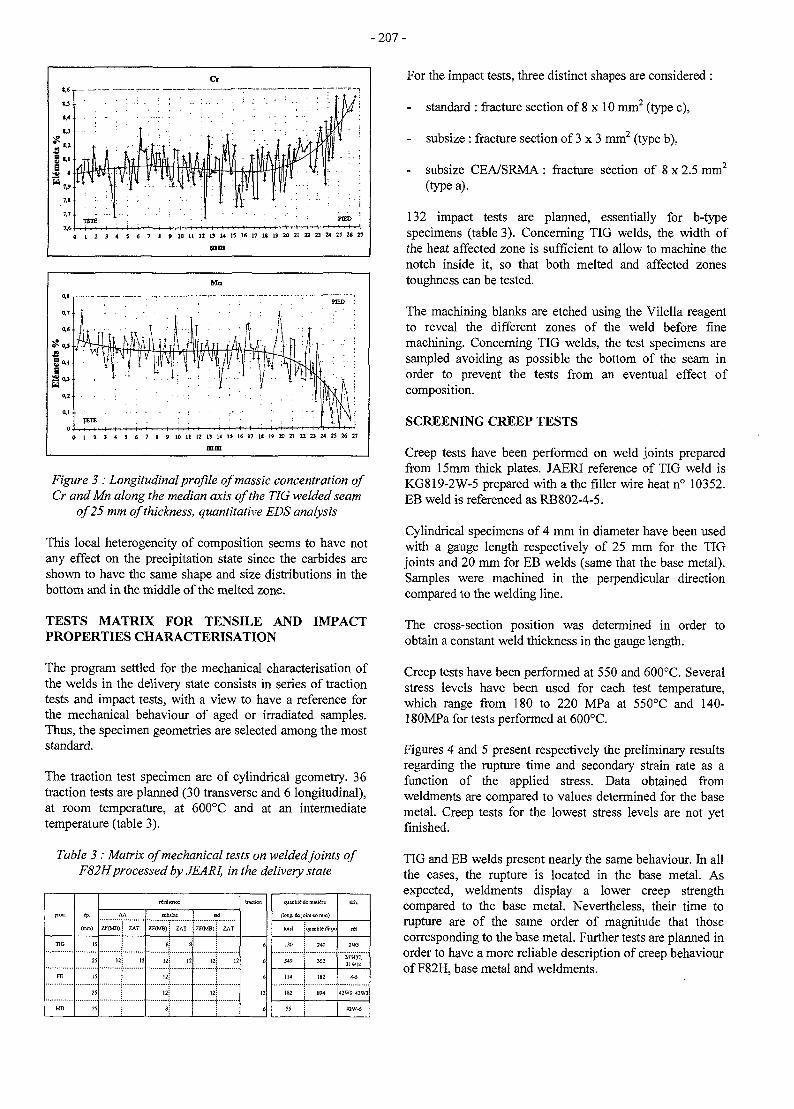
- 207 -
A IS 16 17 t l 1? 20 21 22 23 24 25 35 27
Figure 3 : Longitudinal profile ofmassic concentration ofCr andMn along the median axis of the TIG welded seam
of 25 mm of thickness, quantitative EDS analysis
This local heterogeneity of composition seems to have notany effect on the precipitation state since the carbides areshown to have the same shape and size distributions in thebottom and in the middle of the melted zone.
TESTS MATRIX FOR TENSILE AND IMPACTPROPERTIES CHARACTERISATION
The program settled for the mechanical characterisation ofthe welds in the delivery state consists in series of tractiontests and impact tests, with a view to have a reference forthe mechanical behaviour of aged or irradiated samples.Thus, the specimen geometries are selected among the moststandard.
The traction test specimen are of cylindrical geometry. 36traction tests are planned (30 transverse and 6 longitudinal),at room temperature, at 600°C and at an intermediatetemperature (table 3).
Table 3 : Matrix of mechanical tests on welded joints ofF82Hprocessed by JEARI, in the delivery state
TIG
FE
MB
(mm)
IS
25
15
25
25
rfaitiaKc
AA
ZF<MB)
12
ZAT
subsizc
XF(MB)
i
12
12
ZAT
8
8:
ad
ZFfMB)
12
ZAT
tr&aion
6
6
12
6
«juantil<S dc malitre
(long, dejoinl en mm)
lOUl
130
114
182
55
quantity tJispo
240
362
182
894
feh.
tti
2W5
31W37.31W14
4-5
42W9.42W3
42W-6
For the impact tests, three distinct shapes are considered :
- standard : fracture section of 8 x 10 mm2 (type c),
subsize : fracture section of 3 x 3 mm2 (type b),
- subsize CEA/SRMA : fracture section of 8 x 2.5 mm2
(type a).
132 impact tests are planned, essentially for b-typespecimens (table 3). Concerning TIG welds, the width ofthe heat affected zone is sufficient to allow to machine thenotch inside it, so that both melted and affected zonestoughness can be tested.
The machining blanks are etched using the Vilella reagentto reveal the different zones of the weld before finemachining. Concerning TIG welds, the test specimens aresampled avoiding as possible the bottom of the seam inorder to prevent the tests from an eventual effect ofcomposition.
SCREENING CREEP TESTS
Creep tests have been performed on weld joints preparedfrom 15mm thick plates. JAERI reference of TIG weld isKG819-2W-5 prepared with a the filler wire heat n° 10352.EB weld is referenced as RB802-4-5.
Cylindrical specimens of 4 mm in diameter have been usedwith a gauge length respectively of 25 mm for the TIGjoints and 20 mm for EB welds (same that the base metal).Samples were machined in the perpendicular directioncompared to the welding line.
The cross-section position was determined in order toobtain a constant weld thickness in the gauge length.
Creep tests have been performed at 550 and 600°C. Severalstress levels have been used for each test temperature,which range from 180 to 220 MPa at 550°C and 140-180MPa for tests performed at 600°C.
Figures 4 and 5 present respectively the preliminary resultsregarding the rupture time and secondary strain rate as afunction of the applied stress. Data obtained fromweldments are compared to values determined for the basemetal. Creep tests for the lowest stress levels are not yetfinished.
TIG and EB welds present nearly the same behaviour. In allthe cases, the rupture is located in the base metal. Asexpected, weldments display a lower creep strengthcompared to the base metal. Nevertheless, their time torupture are of the same order of magnitude that thosecorresponding to the base metal. Further tests are planned inorder to have a more reliable description of creep behaviourof F82H, base metal and weldments.
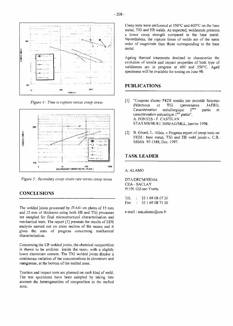
-208-
Figure 4 : Time to rupture versus creep stress
200 :
10 100SECONDARY CREEP RATE (10-6/h )
Figure 5 : Secondary creep strain rate versus creep stress
CONCLUSIONS
The welded joints processed by JEARI on plates of 15 mmand 25 mm of thickness using both EB and TIG processesare sampled for final microstructural characterisation andmechanical tests. The report [1] presents the results of EDSanalysis carried out on cross section of the seams and itgives the state of progress concerning mechanicalcharacterisation.
Creep tests were performed at 550°C and 600°C on the basemetal, TIG and EB welds. As expected, weldments presentsa lower creep strength compared to the base metal.Nevertheless, the rupture times of welds are of the sameorder of magnitude than those corresponding to the basemetal.
Ageing thermal treatments destined to characterise theevolution of tensile and impact properties of both type ofweldments are in progress at 400 and 550°C. Agedspecimens will be available for testing on June 98.
PUBLICATIONS
[1] "Coupons d'acier F82H soudes par procede faisceaud'electrons et TIG (provenance JAERI).Caracterisation metallurgique 2eme partie etcaracterisation mecanique lere partie".A. FONTES - F. CASTILANSTA/LMS/98-RT 3650/AG/MLL, Janvier 1998.
[2] B. Girard, L. Allais, « Progress report of creep tests onF82H : base metal, TIG and EB weld joints », C.R.SRMA 97-1588, Dec. 1997.
TASK LEADER
A. ALAMO
DTA/DECM/SRMACEA-SACLAY91191 Gif-sur-Yvette
Tel. : 33 1 69 08 67 26Fax : 33 1 69 08 71 30
e-mail: ana.alamo(S)cea.fr
Concerning the EB welded joints, the chemical compositionis shown to be uniform inside the seam, with a slightlylower chromium content. The TIG welded joints display acontinuous variation of the concentrations in chromium andmanganese, at the bottom of the melted zone.
Traction and impact tests are planned on each kind of weld.The test specimens have been sampled by taking intoaccount the heterogeneities of composition in the meltedzone.
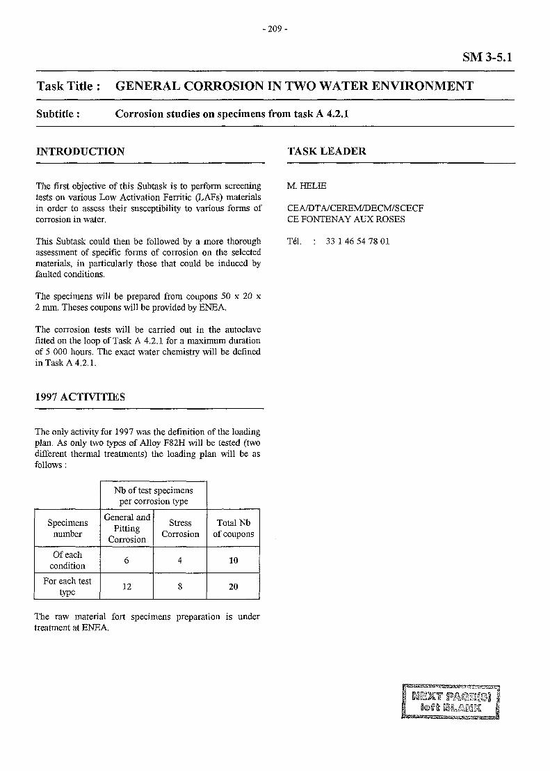
-209 -
SM 3-5.1
Task Title : GENERAL CORROSION IN TWO WATER ENVIRONMENT
Subtitle: Corrosion studies on specimens from task A 4.2.1
INTRODUCTION TASK LEADER
The first objective of this Subtask is to perform screeningtests on various Low Activation Ferritic (LAFs) materialsin order to assess their susceptibility to various forms ofcorrosion in water.
This Subtask could then be followed by a more thoroughassessment of specific forms of corrosion on the selectedmaterials, in particularly those that could be induced byfaulted conditions.
The specimens will be prepared from coupons 50 x 20 x2 mm. Theses coupons will be provided by ENEA.
The corrosion tests will be carried out in the autoclavefitted on the loop of Task A 4.2.1 for a maximum durationof 5 000 hours. The exact water chemistry will be definedin Task A 4.2.1.
M. HELIE
CEA/DTA/CEREM7DECM/SCECFCE FONTENAY AUX ROSES
Tel. 33 1 46 54 78 01
1997 ACTIVITIES
The only activity for 1997 was the definition of the loadingplan. As only two types of Alloy F82H will be tested (twodifferent thermal treatments) the loading plan will be asfollows :
Specimensnumber
Of eachcondition
For each testtype
Nb of test specimensper corrosion type
General andPitting
Corrosion
6
12
StressCorrosion
4
8
Total Nbofcoupons
10
20
The raw material fort specimens preparation is undertreatment at ENEA.
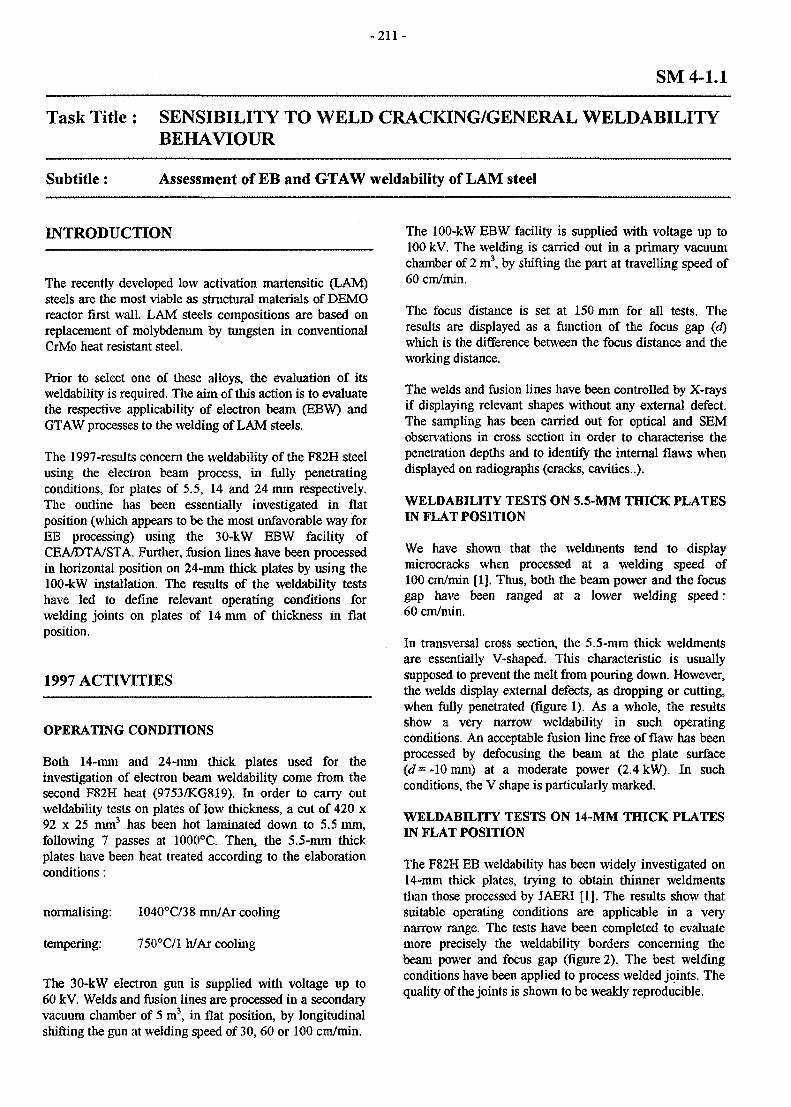
- 2 1 1 -
SM 4-1.1
Task Title : SENSIBILITY TO WELD CRACKING/GENERAL WELDABILITYBEHAVIOUR
Subtitle: Assessment of EB and GTAW weldability of LAM steel
INTRODUCTION
The recently developed low activation martensitic (LAM)steels are the most viable as structural materials of DEMOreactor first wall. LAM steels compositions are based onreplacement of molybdenum by tungsten in conventionalCrMo heat resistant steel.
Prior to select one of these alloys, the evaluation of itsweldability is required. The aim of this action is to evaluatethe respective applicability of electron beam (EBW) andGTAW processes to the welding of LAM steels.
The 1997-results concern the weldability of the F82H steelusing the electron beam process, in fully penetratingconditions, for plates of 5.5, 14 and 24 mm respectively.The outline has been essentially investigated in flatposition (which appears to be the most unfavorable way forEB processing) using the 30-kW EBW facility ofCEA/DTA/STA. Further, fusion lines have been processedin horizontal position on 24-mm thick plates by using the100-kW installation. The results of the weldability testshave led to define relevant operating conditions forwelding joints on plates of 14 mm of thickness in flatposition.
1997 ACTIVITIES
OPERATING CONDITIONS
Both 14-mm and 24-mm thick plates used for theinvestigation of electron beam weldability come from thesecond F82H heat (9753/KG819). In order to carry outweldabiliry tests on plates of low thickness, a cut of 420 x92 x 25 mm3 has been hot laminated down to 5.5 mm,following 7 passes at 1000X. Then, the 5.5-mm thickplates have been heat treated according to the elaborationconditions:
normalising: 1040°C/38 mn/Ar cooling
tempering: 750°C/l h/Ar cooling
The 30-kW electron gun is supplied with voltage up to60 kV. Welds and fusion lines are processed in a secondaryvacuum chamber of 5 m3, in flat position, by longitudinalshifting the gun at welding speed of 30,60 or 100 cm/min.
The 100-kW EBW facility is supplied with voltage up to100 kV. The welding is carried out in a primary vacuumchamber of 2 m3, by shifting the part at travelling speed of60 cm/min.
The focus distance is set at 150 mm for all tests. Theresults are displayed as a function of the focus gap (d)which is the difference between the focus distance and theworking distance.
The welds and fusion lines have been controlled by X-raysif displaying relevant shapes without any external defect.The sampling has been carried out for optical and SEMobservations in cross section in order to characterise thepenetration depths and to ideatify the internal flaws whendisplayed on radiographs (cracks, cavities..).
WELDABILITY TESTS ON 5.5-MM THICK PLATESBSf FLAT POSITION
We have shown that the weldments tend to displaymicrocracks when processed at a welding speed of100 cm/min [lj. Thus, both the beam power and the focusgap have been ranged at a lower welding speed:60 cm/min.
In transversal cross section, the 5.5-mm thick weldmentsare essentially V-shaped. This characteristic is usuallysupposed to prevent the melt from pouring down. However,the welds display external defects, as dropping or cutting,when fully penetrated (figure 1). As a whole, the resultsshow a very narrow weldability in such operatingconditions. An acceptable fusion line free of flaw has beenprocessed by defocusing the beam at the plate surface(d - -10 mm) at a moderate power (2.4 kW). In suchconditions, the V shape is particularly marked.
WELDABILITY TESTS ON 14-MM THICK PLATESIN FLAT POSITION
The F82H EB weldability has been widely investigated on14-mm thick plates, trying to obtain thinner weldmentsthan those processed by JAERI [1]. The results show thatsuitable operating conditions are applicable in a verynarrow range. The tests have been completed to evaluatemore precisely the weldability borders concerning thebeam power and focus gap (figure 2). The best weldingconditions have been applied to process welded joints. Thequality of the joints is shown to be weakly reproducible.
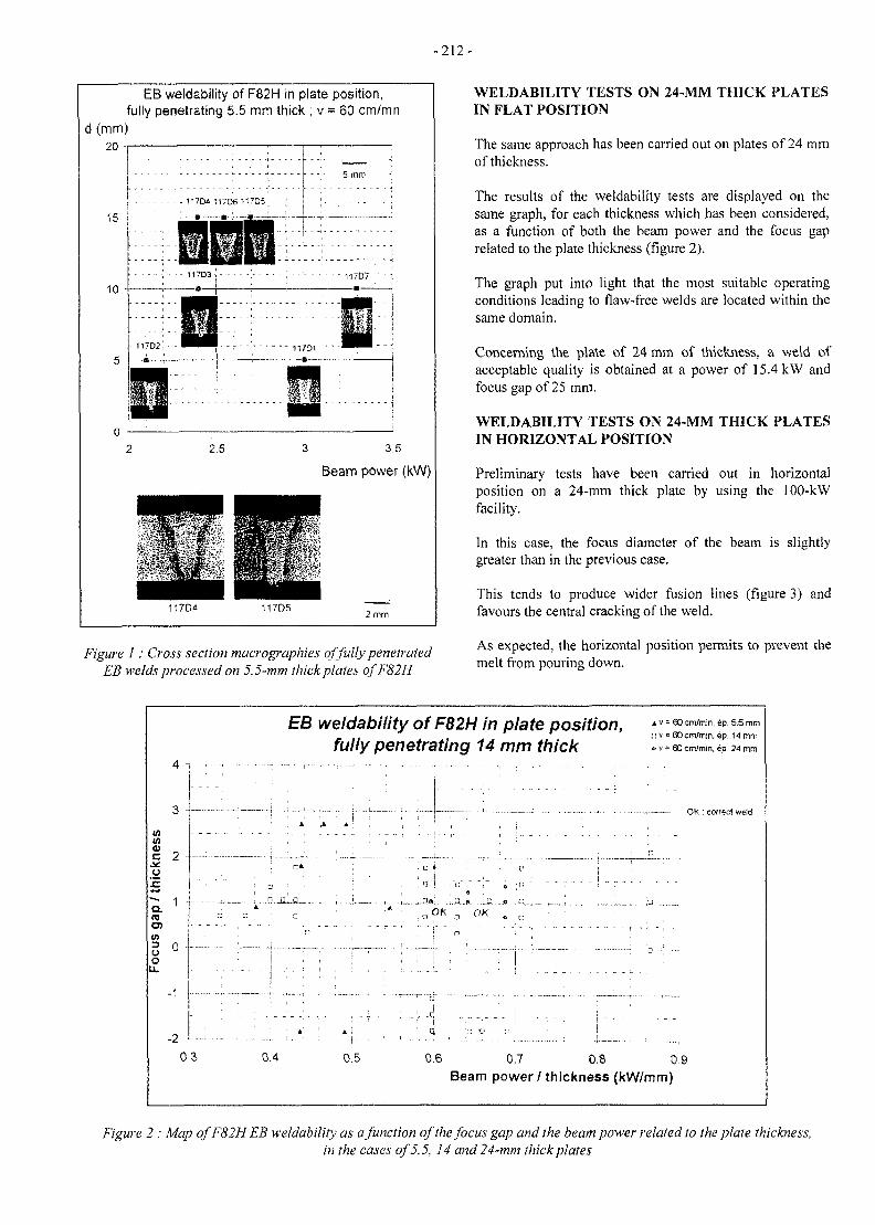
- 2 1 2 -
EB weldability of F82H in plate position,fully penetrating 5.5 mm thick ; v = 60 cm/mn
3 3.5
Beam power (kW)
117D52 mm
Figure 1 : Cross section macrographies of fully penetratedEB welds processed on 5.5-mm thick plates ofF82H
WELDABILITY TESTS ON 24-MM THICK PLATESIN FLAT POSITION
The same approach has been carried out on plates of 24 mmof thickness.
The results of the weldability tests are displayed on thesame graph, for each thickness which has been considered,as a function of both the beam power and the focus gaprelated to the plate thickness (figure 2).
The graph put into light that the most suitable operatingconditions leading to flaw-free welds are located within thesame domain.
Concerning the plate of 24 mm of thickness, a weld ofacceptable quality is obtained at a power of 15.4 kW andfocus gap of 25 mm.
WELDABILITY TESTS ON 24-MM THICK PLATESIN HORIZONTAL POSITION
Preliminary tests have been carried out in horizontalposition on a 24-tnm thick plate by using the 100-kWfacility.
In this case, the focus diameter of the beam is slightlygreater than in the previous case.
This tends to produce wider fusion lines (figure 3) andfavours the central cracking of the weld.
As expected, the horizontal position permits to prevent themelt from pouring down.
4 -,
o
0
S 2
-1
-20.3
EB weldability ofF82H in plate position, ^ = 000*/™,,iP 5.5mm, , r, v = 60 cm/mm, ep 14 mm
fully penetrating 14 mm thick . v=eoenvmm. <*. 24 mm
A A
0.4 0.5
! * . . . . i. B.J. .J3 ,.* B
, OK „ OK ^ ,.
• r" v
OK : correct weld
0.6 0.7 0.8 0.9Beam power/thickness (kW/mm)
Figure 2 : Map ofF82H EB weldability as a function of the focus gap and the beam power related to the plate thickness,in the cases of 5.5, 14 and 24-mm thick plates
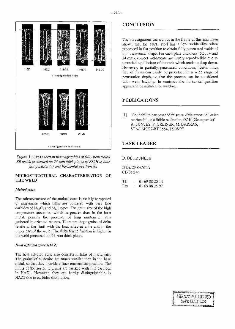
- 213 -
11SD1 116D2 116D3 116D4
:i : configuration a plat
116D5
28M2 28M3 28 M4
b : configuration en cornichc
CONCLUSION
Figure 3 : Cross section macrographies of fully penetratedEB welds processed on 24-mm thick plates ofF82Hin both
flat position (a) and horizontal position (b)
MICROSTRUCTURAL CHARACTERISATION OFTHE WELD
Melted zone
The microstructure of the melted zone is mainly composedof martensite which laths are bordered with very finecarbides of M23C6 and MgC types. The grain size of the hightemperature austenite, which is greater than in the basemetal, permits the presence of long martensite lathsgathered in oriented masses. There are large grains of deltaferrite at the limit with the heat affected zone and in theupper part of the weld. The delta ferrite fraction is higher inthe weld processed on 24-mm thick plates.
Heat affected zone (HAZ)
The heat affected zone also consists in laths of martensite.The grains of austenite are much smaller than in the basemetal, so that they provide a finer martensitic structure. Thelimits of the austenite grains are marked with fine carbidesin HAZ1. However, they are hardly distinguishable inHAZ2 due to carbides dissolution.
The investigations carried out in the frame of this task haveshown that the F82H steel has a low weldability whenprocessed in flat position to obtain fully penetrated welds ofthin transversal shape. For each plate thickness (5.5, 14 and24 mm), correct weldments are hardly reproducible due tounsettled equilibrium of the melt which tends to drop down.However, in partially penetrated conditions, fusion linesfree of flaws can easily be processed in a wide range ofpenetration depth, so that the process can be consideredwith weld backing. In contrast, the horizontal positionappears to be suitable for welding.
PUBLICATIONS
[1] "Soudabilite par procede faisceau d'electrons de l'aciermartensitique a faible activation F82H (2eme partie)"A. FONTES, P. GREINER, M. BARRAS,STA/LMS/97-RT 3554, 15/08/97
TASK LEADER
D. DE PRUNELE
DTA/DPSA/STACE-Saclay
Tel.Fax
01 69 08 20 1401 69 08 75 97
f SLJIMf
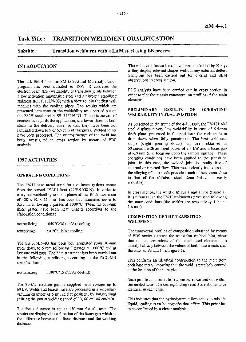
- 2 1 5 -
SM 4-4.1
Task Title : TRANSITION WELDMENT QUALIFICATION
Subtitle: Transition weldment with a LAM steel using EB process
INTRODUCTION
The task SM 4-4 of the SM (Structural Material) Fusionprogram has been initiated in 1997. It concerns theelectron beam (EB) weldability of transition joints betweena low activation martensitic steel and a nitrogen stabilisedstainless steel (316LN-IG) with a view to join the first wallmodules with the cooling pipes. The results which arepresented here concern the weldability tests carried out onthe F82H steel and a SS 316LN-IG. The thicknesses ofconcern as regards the application, are lower those of bothsteels in the delivery state, so that they have been hotlaminated down to 5 or 5.5 mm of thickness. Welded jointshave been processed. The microstructure of the weld hasbeen investigated in cross section by means of EDSanalysis.
1997 ACTIVITIES
OPERATING CONDITIONS
The F82H base metal used for the investigations comesfrom the second JEARI heat (9753/KG819). In order tocarry out weldability tests on plates of low thickness, a cutof 420 x 92 x 25 mm3 has been hot laminated down to5.5 mm, following 7 passes at 1000°C. Then, the 5.5-mmthick plates have been heat treated according to theelaboration conditions:
normalizing:
tempering:
1040°C/38 mn/Ar cooling
750°C/l h/Ar cooling
The SS 316LN-IG has been hot laminated from 30-mmthick down to 5 mm following 7 passes at 1000°C and atlast one cold pass. The heat treatment has been carried outin the following conditions, according to the RCC-MRspecifications :
normalizing: 1100°C/15 mn/Ar cooling
The 30-kW electron gun is supplied with voltage up to60 kV. Welds and fusion lines are processed in a secondaryvacuum chamber of 5 m3, in flat position, by longitudinalshifting the gun at welding speed of 30, 60 or 100 cm/min.
The focus distance is set at 150 mm for all tests. Theresults are displayed as a function of the focus gap which isthe difference between the focus distance and the workingdistance.
The welds and fusion lines have been controlled by X-raysif they display relevant shapes without any external defect.Sampling has been carried out for optical and SEMobservations in cross section.
EDS analysis have been carried out in cross section inorder to plot the massic concentration profiles of the mainelements.
PRELIMINARY RESULTS OFWELDABELITY IN FLAT POSITION
OPERATING
As presented in the frame of the 4-1.1 task, the F82H LAMsteel displays a very low weldability in case of 5.5-mmthick plates processed in flat position: the melt tends todrop down when fully penetrated. The best weldmentshape (slight pouring down) has been obtained at60 cm/min with an input power of 2.4 kW and a focus gapof -10 mm (/'. e. focusing upon the sample surface). Theseoperating conditions have been applied to the transitionjoint. In this case, the welded joint is totally free ofexternal or internal flaw. This result clearly indicates thatthe alloying of both steels provide a melt of behaviour closeto that of the stainless steel alone (which is easilyweldable).
In cross section, the weld displays a nail shape (figure 1).It is thinner than the F82H weldments processed followingthe same conditions (the widths are respectively 1.0 and1.6 mm).
COMPOSITION OF THE TRANSITIONWELDMENT
The transversal profiles of composition obtained by meansof EDS analysis across the transition welded joint, showthat the concentrations of the considered elements areexactly halfway between the values of both base metals (seethe cases of Fe and Cr in figure 2).
This confirms an identical contribution to the melt fromeach base metal, knowing that the weld is precisely centredat the location of the joint plan.
Each profile contains at least 3 measures carried out withinthe melted zone. The corresponding results are shown to beidentical in each case.
This indicates that the hydrodynamic flow tends to mix theliquid, leading to an homogenization effect. This point hasto be confirmed by a closer analysis.
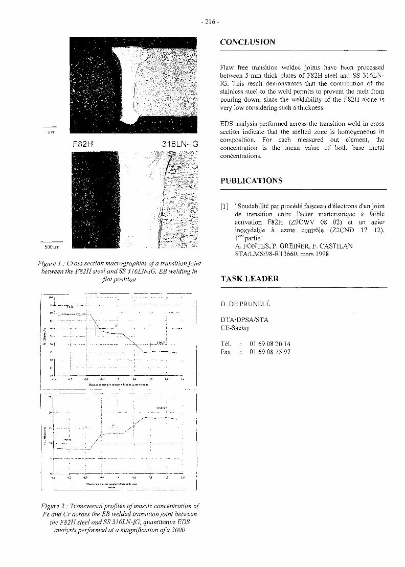
- 2 1 6 -
CONCLUSION
F82H 316LN-IG
53CIUT
Figure 1 : Cross section macrographies of a transition jointbetween the F82Hsteel andSS 316LN-JG, EB welding in
flat position
Flaw free transition welded joints have been processedbetween 5-mm thick plates of F82H steel and SS 316LN-1G. This result demonstrates that the contribution of thestainless steel to the weld permits to prevent the melt frompouring down, since the weldability of the F82H alone isvery low considering such a thickness.
EDS analysis performed across the transition weld in crosssection indicate that the melted zone is homogeneous incomposition. For each measured out element, theconcentration is the mean value of both base metalconcentrations.
PUBLICATIONS
[1] "Soudabilite par procede faisceau d'electrons d'un jointde transition entre l'acier martensitique a faihleactivation F82H (Z9CWV 08 02) et un acierinoxydable a azote controle (Z2CND 17 12),rcpartie"A. FONTES, P. GREFNER. F. CAST1LANSTA/LMS/98-RT3660, mars 1998
TASK LEADER
I
-1.6 -1.2 -ft l -0 1 0 0,4 0,1
DhUacim nai pir npfnrx I I'lM dtli laot
D. DE PRUNELE
DTA/DPSA/STACE-Saclay
Tel.Fax
01 69 08 20 1401 69 08 75 97
Figure 2 : Transversal profiles ofmassic concentration ofFe and Cr across the EB welded transition joint between
the F82H steel and SS 316LN-IG, quantitative EDSanalysis performed at a magnification ofx 2000
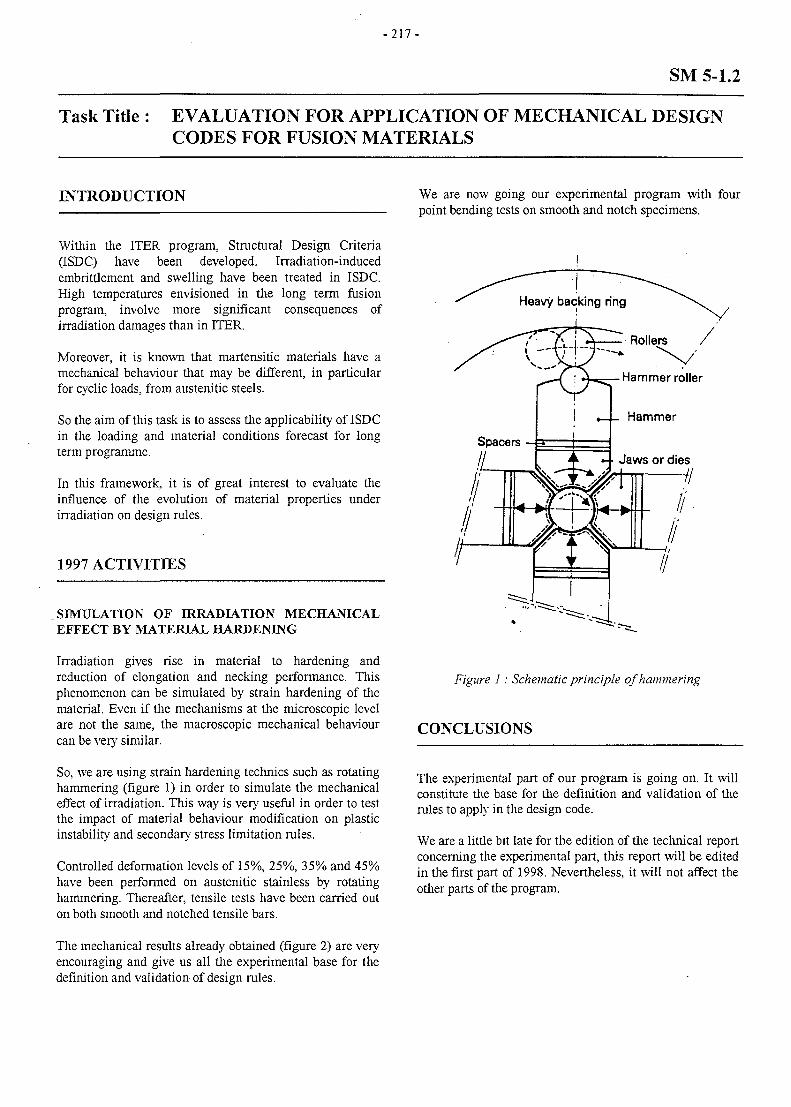
- 2 1 7 -
SM 5-1.2
Task Title : EVALUATION FOR APPLICATION OF MECHANICAL DESIGNCODES FOR FUSION MATERIALS
INTRODUCTION We are now going our experimental program with fourpoint bending tests on smooth and notch specimens.
Within the ITER program, Structural Design Criteria(ISDC) have been developed. Irradiation-inducedembrittlement and swelling have been treated in ISDC.High temperatures envisioned in the long term fusionprogram, involve more significant consequences ofirradiation damages than in ITER.
Moreover, it is known that martensitic materials have amechanical behaviour that may be different, in particularfor cyclic loads, from austenitic steels.
So the aim of this task is to assess the applicability of ISDCin the loading and material conditions forecast for longterm programme.
In this framework, it is of great interest to evaluate theinfluence of the evolution of material properties underirradiation on design rules.
1997 ACTIVITIES
SIMULATION OF IRRADIATION MECHANICALEFFECT BY MATERIAL HARDENING
Irradiation gives rise in material to hardening andreduction of elongation and necking performance. Thisphenomenon can be simulated by strain hardening of thematerial. Even if the mechanisms at the microscopic levelare not the same, the macroscopic mechanical behaviourcan be very similar.
So, we are using strain hardening technics such as rotatinghammering (figure 1) in order to simulate the mechanicaleffect of irradiation. This way is very useful in order to testthe impact of material behaviour modification on plasticinstability and secondary stress limitation rules.
Controlled deformation levels of 15%, 25%, 35% and 45%have been performed on austenitic stainless by rotatinghammering. Thereafter, tensile tests have been carried outon both smooth and notched tensile bars.
Figure 1 : Schematic principle of hammering
CONCLUSIONS
The experimental part of our program is going on. It willconstitute the base for the definition and validation of therules to apply in the design code.
We are a little bit late for the edition of the technical reportconcerning the experimental part, this report will be editedin the first part of 1998. Nevertheless, it will not affect theother parts of the program.
The mechanical results already obtained (figure 2) are veryencouraging and give us all the experimental base for thedefinition and validation of design rules.
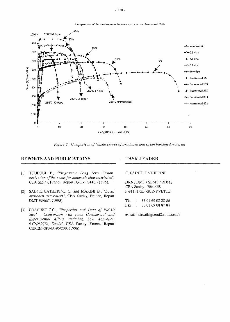
- 2 1 8 -
1000 T 250°C 6,8dpa
Comparaison of the tensile curves between irradiated and hammered 316L
, 45%
10 20 30 40
elongation ((L- Lo)/Lo)(%)
50 60 70
Figure 2 : Comparison of tensile curves of irradiated and strain hardened material
REPORTS AND PUBLICATIONS TASK LEADER
[1] TOUBOUL F., "Programme Long Term Fusion:evaluation of the needs for materials characteristics",CEA Saclay, France, Report DMT-95/440, (1995).
[2] SAINTE CATHERINE C. and MARINI B., "Localapproach assessment", CEA Saclay, France, ReportDMT-95/667, (1995).
[3] BRACKET J-C, "Properties and Data of EM 10Steel - Comparison with some Commercial andExperimental Alloys, including Low Activation9Cr(N,V,Ta) Steels", CEA Saclay, France, ReportCEREM-SRMA-96/200, (1996).
C. SATNTE CATHERINE
DRN / DMT / SEMT / RDMSCEA Saclay - Bat. 458F-91191 GIF-SUR-YVETTE
Tel. : 33 0169 08 88 56Fax : 33 01 69 08 87 84
e-mail: [email protected]
- 2 1 9 -
SM 5-3.1
Task Title : PROCUREMENT SPECIFICATION AND SPECIFICATIONVERIFICATION OF A NEW HEAT
INTRODUCTION
The objective of this task is to provide a fabricationspecification of new heat of reduced activation martensiticsteel (RA F/M) according to the requirements of EuropeanBlanket Project (EBP) of the EU Fusion TechnologyProgram. The procurement of this material respond to theexpressed need for a common structural material fordifferent technological tests and processes developed forthe blanket program.
Nevertheless, this specification must be considered as apreliminary one. It is destined to produce a large-scale heatto satisfy material requirements and to gain industrialexperience in RA martensitic steel fabrication. In a secondstep, an other industrial heat should be ordered based ontechnical experience from the first heat and essentially,based on data that will be obtained in the presentStructural Material qualification program (95-98) ofdifferent European developmental steels.
Actions concerning this task are developed in common byFZK and CEA.
1997 ACTIVITIES
The main activity consisted on the participation to theelaboration of the manufacturing specification of a reducedactivation ferritic/martensitic steel of 9CrWTaV type. Theprocurement specification document [1] concerning thesupplying of an industrial-scale heat, have been preparedunder the co-ordination of Dr. W. Dietz.
PROCUREMENT SPECIFICATION
This product specification contains the technical rules forthe manufacturing of a weldable chromium-tungsten-tantalum-vanadium ferritic / martensitic steel, used forcomponents within the European Blanket Project (EBP) ofthe EU Fusion Technology Program. It is a preliminaryspecification for the alloy developed for use in blanketstructures of a fusion reactor. Under operation the materialwill be exposed to temperatures up to 550°C, cyclic loadingand neutron irradiation. It will be used for componentswith high reliability requirements.
Material: Martensitic steel with 9 CrWTaVMaterial Name: EUROFER97Delivery state: Normalised and tempered
The specification covers the following product forms anddimensions:
Product form
plate
tubing
bars
forging
Dimensions in mm
2 to 100
diameter < 20
< 100
<100
The present document includes the following items :
- Documentation requirements for the manufacturer(quality assurance system, manufacturing program,plans for sequence of testing, inspection and controls).
- Requirements for manufacturing (melting process,individual processing steps, marking, storage).
- Required properties (chemical composition, finalthermomechanical treatments, mechanical properties,microstructure controls, surface conditions).
- Testing procedures and sampling (standards andsamples to be used for different controls).
- Final documentation (inspection certificate andinformation for each manufacturing lot).
- Deviations from the specification (procedures to befollowed).
In particular, the chemical composition of the first large-scale heat, as determined by ladle and product analysis,shall comply with the requirements given in table I.
The elements As, Sn, Sb, Zr and 0 are given forinformation purposes only.
The required chemical composition must be valid also nearsurface after the final heat treatment.
ALAP: as low as possible by application of state of the arttechnology for high clean steel manufacturing.
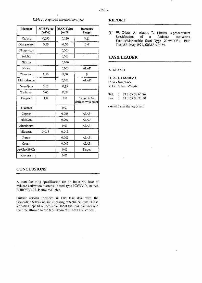
- 2 2 0 -
Table I: Required chemical analysis REPORT
Element
Carbon
Manganese
Phosphorus
Sulphur
Silicon
Nickel
Chromium
Molybdenum
Vanadium
Tantalum
Tungsten
Titanium
Copper
Niobium
Aluminium
Nitrogen
Boron
Cobalt
As+Sn+Sb+Zr
Oxygen
JVQN Value(wt%)
0,090
0,20
8,50
0,15
0,05
1,0
0,015
MAX Value(wt%)
0,120
0,60
0,005
0,005
0,050
0,005
9,50
0,005
0,25
0,09
2,0
0,01
0,005
0,001
0,01
0,045
0,001
0,005
0,05
0,01
RemarksTarget
0,11
0,4
-
ALAP
9
ALAP
Target to bedefined with order
ALAP
ALAP
ALAP
ALAP
ALAP
Target
CONCLUSIONS
[1] W. Dietz, A. Alamo, R. Lindau, «procurementSpecification of a Reduced ActivationFerritic/Martensitic Steel Type 9CrWTaV», EBPTask 5.3, May 1997, SRMA 97/385.
TASK LEADER
A. ALAMO
DTA/DECM/SRMACEA-SACLAY91191 Gif-sur-Yvette
Tel. : 33 1 69 08 67 26Fax : 33 169 08 7130
e-mail: [email protected]
A manufacturing specification for an industrial heat ofreduced activation martensitic steel type 9CrWVTa, namedEUROFER 97, is now available.
Further actions included in this task deal with thefabrication follow-up and checking of technical data. Theseactivities depend on decisions about the manufacturer andthe time allowed to the fabrication of EUROFER 97 heat.
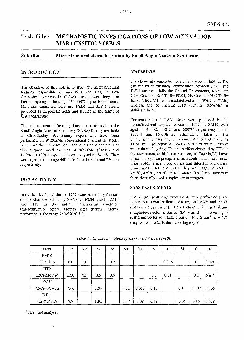
- 2 2 1 -
SM 6-4.2
Task Title : MECHANISTIC INVESTIGATIONS OF LOW ACTIVATIONMARTENSITIC STEELS
Subtitle: Microstructural characterisation by Small Angle Neutron Scattering
INTRODUCTION
The objective of this task is to study the microstructuralfeatures responsible of hardening occurring in LowActivation Martensitic (LAM) steels after long-termthermal ageing in the range 250-550°C up to 10000 hours.Materials examined here are F82H and JLF-1 steels,produced as large-scale heats and studied in the frame ofIEA programme.
The microstructural investigations are performed on theSmall Angle Neutron Scattering (SANS) facility availableat CEA-Saclay. Preliminary experiments have beenperformed on 9/12CrMo conventional martensitic steels,which are the reference for LAM steels development. Forthis purpose, aged samples of 9Cr-lMo (EM10) and12CrMo (HT9) alloys have been analysed by SANS. Theywere aged in the range 400-550°C for 15000h and 22000hrespectively.
1997 ACTIVITY
Activities developed during 1997 were essentially focusedon the characterisation by SANS of F82H, JLF1, EM10and HT9 in the initial metallurgical condition(microstructure before ageing) after thermal ageingperformed in the range 250-550°C [1].
MATERIALS
The chemical composition of steels is given in table 1. Thedifferences of chemical composition between F82H andJLF-1 are essentially the Cr and Ta contents, which are7.5% Cr and 0.02% Ta for F82H, 9% Cr and 0.08% Ta forJLF-1. The EM10 is an unstabilized alloy (9% Cr, l%Mo)whereas the commercial HT9 (12%Cr, 0.5%Mo) isstabilised by V.
Conventional and LAM steels were produced in thenormalised and tempered condition. HT9 and EM10, wereaged at 400°C, 450°C and 500°C respectively up to22000h and 15000h as indicated in table 2. Theprecipitated phases and their concentrations observed byTEM are also reported. M23C6 particles do not evolveunder thermal ageing. The main effect observed by TEM isthe occurrence, at high temperature, of Fe2(Mo, W) Lavesphase. This phase precipitates as a continuous thin film onprior austenite grain boundaries and interlath boundaries.Concerning F82H and JLF1, they were aged at 250°C,350°C, 450°C, 550°C up to 13400h. The TEM studies ofthese thermally aged samples are in progress.
SANS EXPERIMENTS
The neutron scattering experiments were performed at theLaboratoire Leon Brillouin, Saclay, on PAXY and PAXEsmall-angle devices [6]. The wavelength X was 6 A andsample-to-detector distance (D) was 2 m, covering ascattering vector (q) range from 0,3 to 1.6 nm'1 (q = 4TTsinq / X , where 2q is the scattering angle).
Table 1: Chemical analysis of experimental steels (wt %)
Steel
EM10
9Cr-lMo
HT9
12Cr-MoVW
F82H
7.5Cr-2WVTa
JLF-1
9Cr-2WVTa
Cr
8.8
12.0
7.46
8.7
Mo
1.0
0.5
W
0.5
1.96
1.91
Ni
0.2
0.6
Mn
0.21
0.47
Ta
0.023
0.08
V
0.3
0.15
0.18
P
0.015
0.01
Si
0.10
0.05
c
0.1
0.1
0.087
0.10
N
0.024
NA*
0.006
0.028
: NA= not analysed
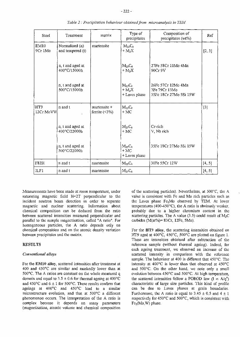
- 2 2 2 -
Table 2 : Precipitation behaviour obtained from microanalysis in TEM
Steel
EM109Cr IMo
HT912Cr MoVW
F82H
JLF1
Treatment
Normalised (n)and tempered (t)
n, t and aged at400°C/15000h
n, t and aged at500°C/15000h
nand t
n, t and aged at400°C/22000h
n, t and aged at500°C/22000h
n and t
nand t
matrix
martensite
martensite +ferrite (<3%)
martensite
martensite
Type ofprecipitates
M23C6
+ M2X
M23C6
+ M2X
M23C6
+ M2X+ Laves phase
M23C6
+ MC
M23C6
+ MC
M23C6
+ MC+ Laves phase
M23C6
M23C6
Composition ofprecipitates (wt%)
27Fe58Cr l lMo4Mn90Cr 9V
26Fe 57Cr 12Mo 4Mn3Fe 79Cr 13Mo35Fe l8Cr27Mo5Si l5W
Cr-richV, Nb rich
35Fe l8Cr27Mo5Si l5W
3OFe 55Cr 12W
Ref
[2,3]
[3]
[4,5]
[4,5]
Measurements have been made at room temperature, undersaturating magnetic field H=2T perpendicular to theincident neutron beam direction in order to separatemagnetic and nuclear scattering. Information aboutchemical composition can be deduced from the ratiobetween scattered intensities measured perpendicular andparallel to the sample magnetisation, called "A ratio". Forhomogeneous particles, the A ratio depends only onchemical composition and on the atomic density variationbetween precipitates and the matrix.
RESULTS
Conventional alloys
For the EM10 alloy, scattered intensities after treatment at400 and 450°C are similar and markedly lower than at500°C. The A ratios are constant on the whole measured qdomain and equal to 3.5 ± 0.6 for thermal ageing at 400°Cand 450cC and 6 ± 1 for 500°C. These results confirm thatageings at 400°C and 450°C lead to a similarmicrostructure evolution, and that at 500°C a differentphenomenon occurs. The interpretation of the A ratio iscomplex because it depends on many parameters(magnetisation, atomic volume and chemical composition
of the scattering particles). Nevertheless, at 500°C, the Avalue is consistent with Fe and Mo rich particles such asthe Laves phase Fe2Mo observed by TEM. At lowertemperatures (400-450°C), the A ratio is obviously weaker,probably due to a higher chromium content in thescattering particles. The A value (3.5) could result of M2Ccarbides (M(at%)= 83Cr, 12Fe, 5Mo).
For the HT9 alloy, the scattering intensities obtained onHT9 aged at 400°C, 450°C, 500°C are plotted on figure 1.These are intensities obtained after subtraction of thereference sample (without thermal ageing). Indeed, foreach ageing treatment, we observed an increase of thescattered intensity in comparison with the referencesample. The behaviour at 400 is different that 450°C. Theintensity at 400°C is lower than that observed at 450°Cand 500°C. On the other hand, we note only a smallevolution between 450°C and 500°C. At high temperature,the scattered intensities follow a POROD law (I « A/q4)characteristic of large size particles. This kind of profilecan be due to Laves phases at grain boundaries.Furthermore, the A ratio is equal to 3.45 + 0.5 and 4 ± 1respectively for 450°C and 500°C, which is consistent withFe2(Mo,W) phase.
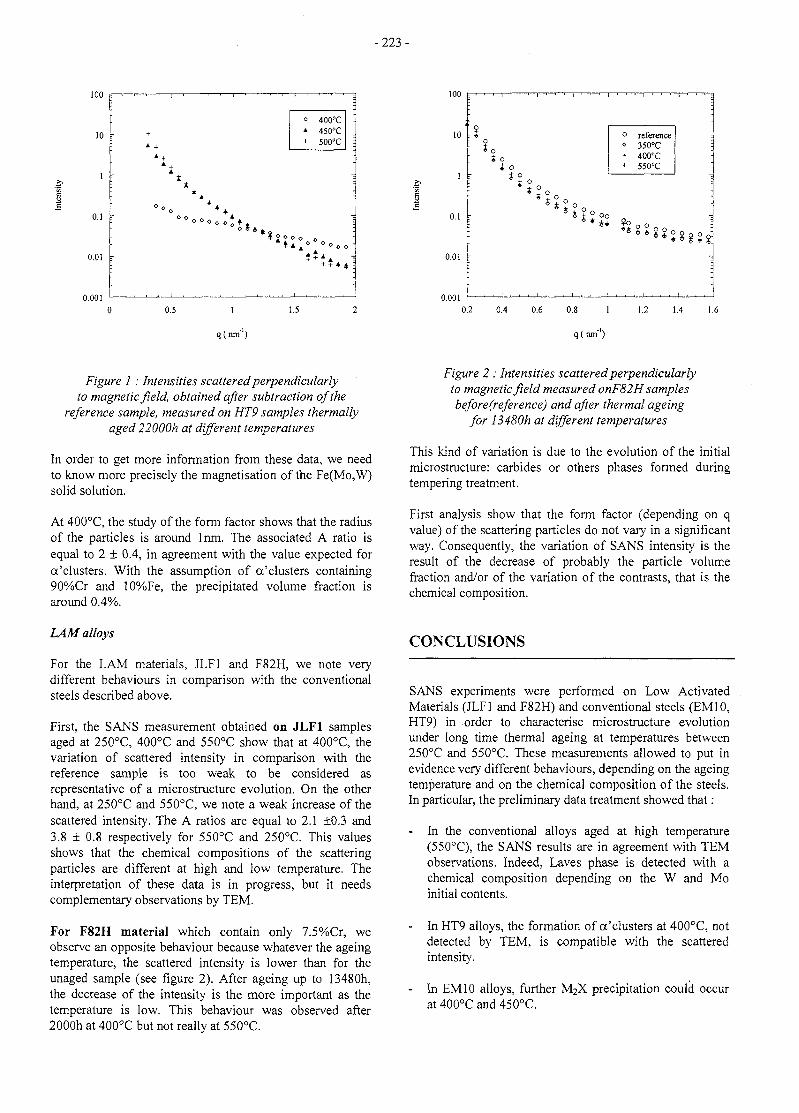
-223 -
100
10 -
1 -
0.1 r
0.01 r
0.001
; , • , - - " , , I , r 1 1 | 1 1 1 1
- +
: A +
: t
« 400°C* 450°C+ 500°C
;
• =
-
1
IOO r —i—i—i—i—[—
0.5 1
q (nm'')
1.5
« ot o
1 k t°
0.1 r
0.01 r
0.001
o0
+
reference350°C400°C55O°C
0.2 0.4 0.6 0.8 1 1.2 1.4 1.6
q (nm'')
Figure 1 : Intensities scattered perpendicularlyto magnetic field, obtained after subtraction of the
reference sample, measured on HT9 samples thermallyaged 22000h at different temperatures
In order to get more information from these data, we needto know more precisely the magnetisation of the Fe(Mo, W)solid solution.
At 400°C, the study of the form factor shows that the radiusof the particles is around lnm. The associated A ratio isequal to 2 ± 0.4, in agreement with the value expected forcc'clusters. With the assumption of a'clusters containing90%Cr and 10%Fe, the precipitated volume fraction isaround 0.4%.
Figure 2 : Intensities scattered perpendicularlyto magnetic field measured onF82H samplesbefore(reference) and after thermal ageing
for I3480h at different temperatures
This kind of variation is due to the evolution of the initialmicrostructure: carbides or others phases formed duringtempering treatment.
First analysis show that the form factor (depending on qvalue) of the scattering particles do not vary in a significantway. Consequently, the variation of SANS intensity is theresult of the decrease of probably the particle volumefraction and/or of the variation of the contrasts, that is thechemical composition.
LAM alloys
For the LAM materials, JLF1 and F82H, we note verydifferent behaviours in comparison with the conventionalsteels described above.
First, the SANS measurement obtained on JLF1 samplesaged at 250°C, 400°C and 550°C show that at 400°C, thevariation of scattered intensity in comparison with thereference sample is too weak to be considered asrepresentative of a microstructure evolution. On the otherhand, at 250°C and 550°C, we note a weak increase of thescattered intensity. The A ratios are equal to 2.1 ±0.3 and3.8 ± 0.8 respectively for 550°C and 250°C. This valuesshows that the chemical compositions of the scatteringparticles are different at high and low temperature. Theinterpretation of these data is in progress, but it needscomplementary observations by TEM.
For F82H material which contain only 7.5%Cr, weobserve an opposite behaviour because whatever the ageingtemperature, the scattered intensity is lower than for theunaged sample (see figure 2). After ageing up to 13480h,the decrease of the intensity is the more important as thetemperature is low. This behaviour was observed after2000h at 400°C but not really at 550°C.
CONCLUSIONS
SANS experiments were performed on Low ActivatedMaterials (JLF1 and F82H) and conventional steels (EM10,HT9) in order to characterise microstructure evolutionunder long time thermal ageing at temperatures between250°C and 550°C. These measurements allowed to put inevidence very different behaviours, depending on the ageingtemperature and on the chemical composition of the steels.In particular, the preliminary data treatment showed that:
- In the conventional alloys aged at high temperature(550°C), the SANS results are in agreement with TEMobservations. Indeed, Laves phase is detected with achemical composition depending on the W and Moinitial contents.
- In HT9 alloys, the formation of a'clusters at 400°C, notdetected by TEM, is compatible with the scatteredintensity.
- In EM 10 alloys, further M2X precipitation could occurat 400°C and 450°C.
- 2 2 4 -
- For the JLF1 alloy, the microstructure evolutions arevery weak and completely different of those observed inthe EM10 alloy.
- Finally, in F82H, whatever the ageing temperature, nonew phase is detected by SANS but on the other hand,the scattering particles initially present evolve withageing time.
The last points put in obviousness an important effect ofW, certainly in synergy with Cr content, on the kind ofphases formed under thermal ageing. In order to precisethese phenomena, TEM observations are essential toconfirm the SANS results. Then, studies of model LAMalloys (La4Ta, Lal2Ta and Lal3Ta) thermally agedbetween 250 and 550°C should allow to clarify the role ofeach element.
REFERENCES
[1] M.H. MATHON, G. GEOFFROY, C.H. DENOVION, Y. DE CARLAN, A. ALAMO,Microstructural characterisation of EM10,HT9,F82H, JLF1 by small angle neutron scattering- Notetechnique LLB/97/170-LSI/98/01
[2] A. ALAMO, J.C. BRACHET, A. CASTAJNG, C.FOUCHER,Effects of the initial metallurgical condition on themicrostructure and mechanical properties of 9Cr-lMoand 9Cr-lMoVNb thermal aged steels Proc. of Int.Conf. On Microstructures and Mechanical Propertiesof Ageing Materials II - Las Vegas, Feb. 12-16, 1995,Ed. P.K. Liaw et al., TMS, 1996, p 121.
[3] J.C BRACHET, A. CASTAING, C. FOUCHEREffects of chemical composition on the behaviourafter thermal ageing of 9-12 Cr / 0.5-1 Mo (WVNb)Ferritic-Martensitic steels - Pro. of Int. Symp. onMaterial Ageing, Milan, Italy, Oct. 10-13, 1995.
[4] A. ALAMO, C. LEPOITTEVTN, F. NEE, C.BOUSSIDAN, Effects of heat treatments and phasetransformations of F82H and JLF-1 low activationmartensitic steels, CEA Report, NT SRMA 96-2211,dec. 1996
[5] C. BOUSSIDANDetermination des fractions de phases a 1'equilibrethennodynamique de differents aciers inoxydablesd'interet nucleaire.CEA Report, C.R. SRMA 95-1519, aout 1995
[6] Equipements experimentaux, Laboratoire LeonBrillouin, CEA Saclay, p. 67, 1995
REPORT
[1] M.H. MATHON, G. GEOFFROY, C.H. DENOVION, Y. DE CARLAN, A. ALAMO,«Microstructural characterisation of EM10,HT9,F82H, JLF1 by small angle neutron scattering », Notetechnique LLB/97/170-LSI/98/01, December 97.
TASK LEADER
A. ALAMO
DTA/DECM/SRMACEA - SACLAY91191 Gif-sur-Yvette
Tel. : 33 1 69 08 67 26Fax : 33 1 69 08 71 30
e-mail : [email protected]
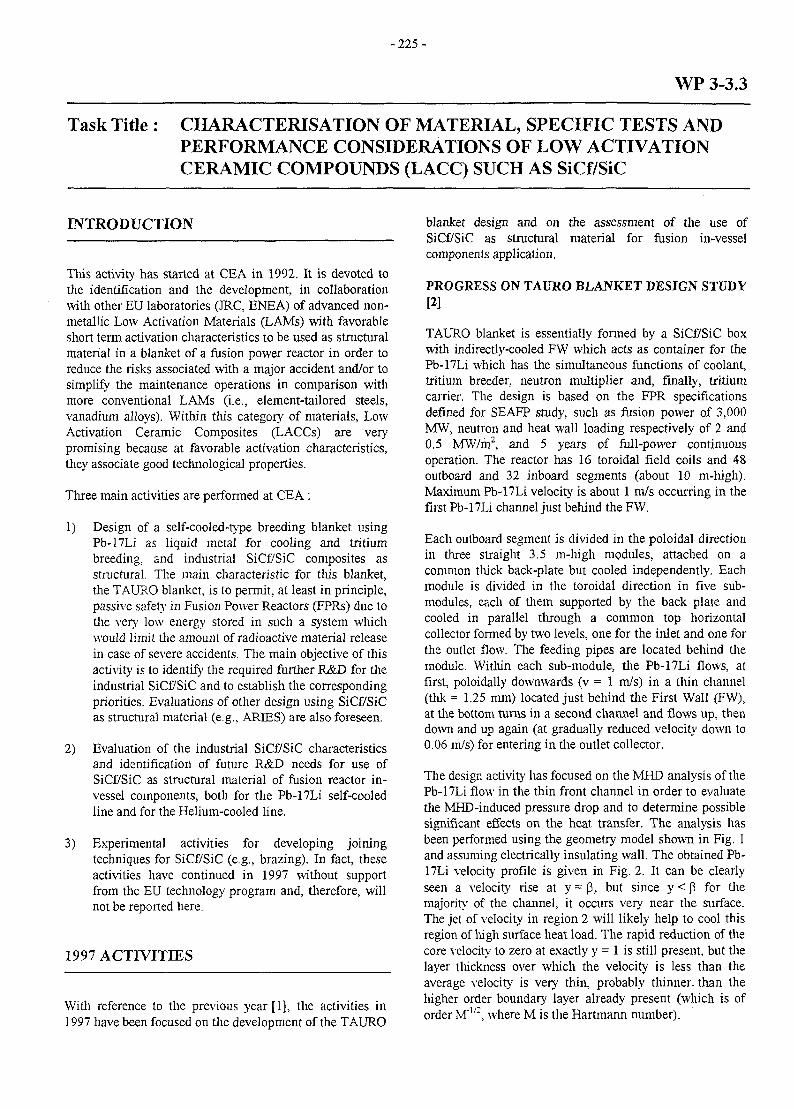
- 2 2 5 -
WP 3-3.3
Task Title : CHARACTERISATION OF MATERIAL, SPECIFIC TESTS ANDPERFORMANCE CONSIDERATIONS OF LOW ACTIVATIONCERAMIC COMPOUNDS (LACC) SUCH AS SiCf/SiC
INTRODUCTION
This activity has started at CEA in 1992. It is devoted tothe identification and the development, in collaborationwith other EU laboratories (JRC, ENEA) of advanced non-metallic Low Activation Materials (LAMs) with favorableshort term activation characteristics to be used as structuralmaterial in a blanket of a fusion power reactor in order toreduce the risks associated with a major accident and/or tosimplify the maintenance operations in comparison withmore conventional LAMs (i.e., element-tailored steels,vanadium alloys). Within this category of materials, LowActivation Ceramic Composites (LACCs) are verypromising because at favorable activation characteristics,they associate good technological properties.
Three main activities are performed at CEA :
1) Design of a self-cooled-type breeding blanket usingPb-17Li as liquid metal for cooling and tritiumbreeding, and industrial SiCf/SiC composites asstructural. The main characteristic for this blanket,the TAURO blanket, is to permit, at least in principle,passive safety in Fusion Power Reactors (FPRs) due tothe very low energy stored in such a system whichwould limit the amount of radioactive material releasein case of severe accidents. The main objective of thisactivity is to identify the required further R&D for theindustrial SiCf/SiC and to establish the correspondingpriorities. Evaluations of other design using SiCf/SiCas structural material (e.g., ARIES) are also foreseen.
2) Evaluation of the industrial SiCf/SiC characteristicsand identification of future R&D needs for use ofSiCf/SiC as structural material of fusion reactor in-vessel components, both for the Pb-17Li self-cooledline and for the Helium-cooled line.
3) Experimental activities for developing joiningtechniques for SiCf/SiC (e.g., brazing). In fact, theseactivities have continued in 1997 without supportfrom the EU techno! ogy program and, therefore, willnot be reported here.
1997 ACTIVITIES
With reference to the previous year [1], the activities in1997 have been focused on the development of the TAURO
blanket design and on the assessment of the use ofSiCf/SiC as structural material for fusion in-vesselcomponents application.
PROGRESS ON TAURO BLANKET DESIGN STUDY[2]
TAURO blanket is essentially formed by a SiCf/SiC boxwith indirectly-cooled FW which acts as container for thePb-17Li which has the simultaneous functions of coolant,tritium breeder, neutron multiplier and, finally, tritiumcarrier. The design is based on the FPR specificationsdefined for SEAFP study, such as fusion power of 3,000MW, neutron and heat wall loading respectively of 2 and0.5 MW/m2, and 5 years of full-power continuousoperation. The reactor has 16 toroidal field coils and 48outboard and 32 inboard segments (about 10 m-high).Maximum Pb-17Li velocity is about 1 m/s occurring in thefirst Pb-17Li channel just behind the FW.
Each outboard segment is divided in the poloidal directionin three straight 3.5 m-high modules, attached on acommon thick back-plate but cooled independently. Eachmodule is divided in the toroidal direction in five sub-modules, each of them supported by the back plate andcooled in parallel through a common top horizontalcollector formed by two levels, one for the inlet and one forthe outlet flow. The feeding pipes are located behind themodule. Within each sub-module, the Pb-17Li flows, atfirst, poloidally downwards (v = 1 m/s) in a thin channel(thk = 1,25 mm) located just behind the First Wall (FW),at the bottom turns in a second channel and flows up, thendown and up again (at gradually reduced velocity down to0.06 m/s) for entering in the outlet collector.
The design activity has focused on the MHD analysis of thePb-17Li flow in the thin front channel in order to evaluatethe MHD-induced pressure drop and to determine possiblesignificant effects on the heat transfer. The analysis hasbeen performed using the geometry model shown in Fig. 1and assuming electrically insulating wall. The obtained Pb-17Li velocity profile is given in Fig. 2. It can be clearlyseen a velocity rise at y = p, but since y < p for themajority of the channel, it occurs very near the surface.The jet of velocity in region 2 will likely help to cool thisregion of high surface heat load. The rapid reduction of thecore velocity to zero at exactly y = 1 is still present, but thelayer thickness over which the velocity is less than theaverage velocity is very thin, probably thinner, than thehigher order boundary layer already present (which is oforder M'"2, where M is the Hartmann number).
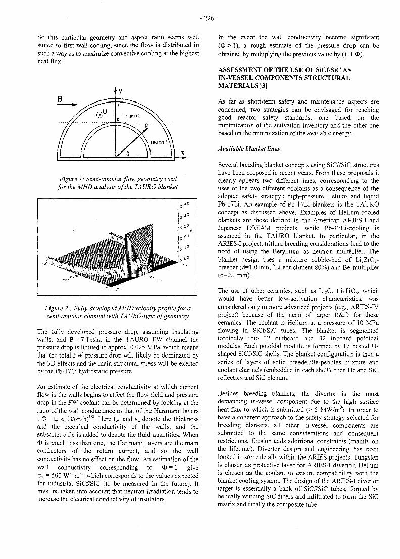
-226-
So this particular geometry and aspect ratio seems wellsuited to first wall cooling, since the flow is distributed insuch a way as to maximize convective cooling at the highestheat flux.
B
Figure 1: Semi-annular flow geometry usedfor the MHD analysis of the TAURO blanket
Figure 2 : Fully-developed MHD velocity profile for asemi-annular channel with TA URO-type of geometry
The fully developed pressure drop, assuming insulatingwalls, and B = 7 Tesla, in the TAURO FW channel thepressure drop is limited to approx. 0.025 MPa, which meansthat the total FW pressure drop will likely be dominated bythe 3D effects and the main structural stress will be exertedby the Pb-17Li hydrostatic pressure.
An estimate of the electrical conductivity at which currentflow in the walls begins to affect the flow field and pressuredrop in the FW coolant can be determined by looking at theratio of the wall conductance to that of the Hartmann layers: <X> = tw Sw B/(crf h)"2. Here tw and sw denote the thicknessand the electrical conductivity of the walls, and thesubscript « f» is added to denote the fluid quantities. WhenO is much less than one, the Hartmann layers are the mainconductors of the return current, and so the wallconductivity has no effect on the flow. An estimation of thewall conductivity corresponding to O = 1 give0W = 500 W"' m"1, which corresponds to the values expectedfor industrial SiCf/SiC (to be measured in the future). Itmust be taken into account that neutron irradiation tends toincrease the electrical conductivity of insulators.
In the event the wall conductivity become significant(O > 1), a rough estimate of the pressure drop can beobtained by multiplying the previous value by (1 + <£).
ASSESSMENT OF THE USE OF SiCf/SiC ASIN-VESSEL COMPONENTS STRUCTURALMATERIALS [3]
As far as short-term safety and maintenance aspects areconcerned, two strategies can be envisaged for reachinggood reactor safety standards, one based on theminimization of the activation inventory and the other onebased on the minimization of the available energy.
Available blanket lines
Several breeding blanket concepts using SiCf/SiC structureshave been proposed in recent years. From these proposals itclearly appears two different lines, corresponding to theuses of the two different coolants as a consequence of theadopted safety strategy : high-pressure Helium and liquidPb-17Li. An example of Pb-17Li blankets is the TAUROconcept as discussed above. Examples of Helium-cooledblankets are those defined in the American ARIES-I andJapanese DREAM projects, while Pb-17Li-cooling isassumed in the TAURO blanket. In particular, in theARIES-I project, tritium breeding considerations lead to theneed of using the Beryllium as neutron multiplier. Theblanket design uses a mixture pebble-bed of Li2Zr03-breeder (d=1.0 mm, 6Li enrichment 80%) and Be-multiplier(d=0.1 mm).
The use of other ceramics, such as Li2O, Li2Ti03, whichwould have better low-activation characteristics, wasconsidered only in more advanced projects (e.g., ARIES-IVproject) because of the need of larger R&D for theseceramics. The coolant is Helium at a pressure of 10 MPaflowing in SiCf/SiC tubes. The blanket is segmentedtoroidally into 32 outboard and 32 inboard poloidalmodules. Each poloidal module is formed by 17 nested U-shaped SiCf/SiC shells. The blanket configuration is then aseries of layers of solid breeder/Be-pebbles mixture andcoolant channels (embedded in each shell), then Be and SiCreflectors and SiC plenum.
Besides breeding blankets, the divertor is the mostdemanding in-vessel component due to the high surfaceheat-flux to which is submitted (> 5 MW/m2). In order tohave a coherent approach to the safety strategy selected forbreeding blankets, all other in-vessel components aresubmitted to the same considerations and consequentrestrictions. Erosion adds additional constraints (mainly onthe lifetime). Divertor design and engineering has beenlooked in some details within the ARIES projects. Tungstenis chosen as protective layer for ARIES-I divertor. Heliumis chosen as the coolant to ensure compatibility with theblanket cooling system. The design of the ARIES-I divertortarget is essentially a bank of SiCf/SiC tubes, formed byhelically winding SiC fibers and infiltrated to form the SiCmatrix and finally the composite tube.
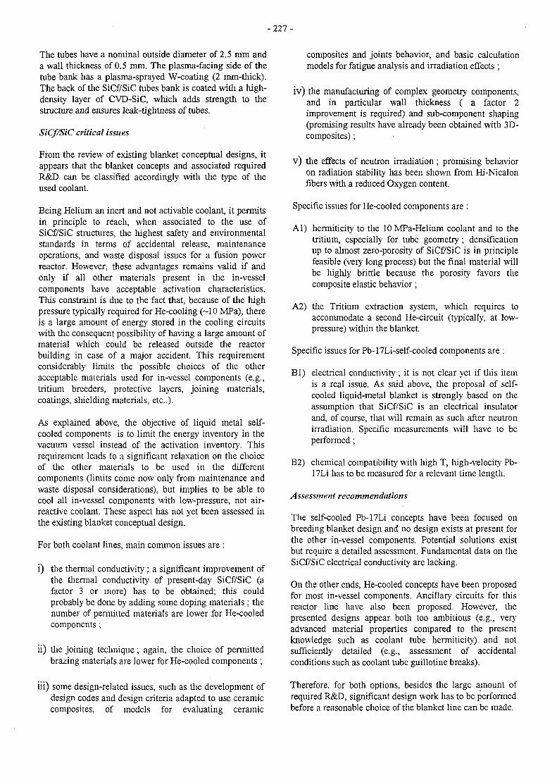
- 2 2 7 -
The tubes have a nominal outside diameter of 2.5 mm anda wall thickness of 0.5 mm. The plasma-facing side of thetube bank has a plasma-sprayed W-coating (2 mm-thick).The back of the SiCf/SiC tubes bank is coated with a high-density layer of CVD-SiC, which adds strength to thestructure and ensures leak-tightness of tubes.
SiCf/SiC critical issues
From the review of existing blanket conceptual designs, itappears that the blanket concepts and associated requiredR&D can be classified accordingly with the type of theused coolant.
Being Helium an inert and not activable coolant, it permitsin principle to reach, when associated to the use ofSiCf/SiC structures, the highest safety and environmentalstandards in terms of accidental release, maintenanceoperations, and waste disposal issues for a fusion powerreactor. However, these advantages remains valid if andonly if all other materials present in the in-vesselcomponents have acceptable activation characteristics.This constraint is due to the fact that, because of the highpressure typically required for He-cooling (~10 MPa), thereis a large amount of energy stored in the cooling circuitswith the consequent possibility of having a large amount ofmaterial which could be released outside the reactorbuilding in case of a major accident. This requirementconsiderably limits the possible choices of the otheracceptable materials used for in-vessel components (e.g.,tritium breeders, protective layers, joining materials,coatings, shielding materials, etc.).
As explained above, the objective of liquid metal self-cooled components is to limit the energy inventory in thevacuum vessel instead of the activation inventory. Thisrequirement leads to a significant relaxation on the choiceof the other materials to be used in the differentcomponents (limits come now only from maintenance andwaste disposal considerations), but implies to be able tocool all in-vessel components with low-pressure, not air-reactive coolant. These aspect has not yet been assessed inthe existing blanket conceptual design.
For both coolant lines, main common issues are :
i) the thermal conductivity ; a significant improvement ofthe thermal conductivity of present-day SiCf/SiC (afactor 3 or more) has to be obtained; this couldprobably be done by adding some doping materials ; thenumber of permitted materials are lower for He-cooledcomponents ;
ii) the joining technique ; again, the choice of permittedbrazing materials are lower for He-cooled components ;
iii) some design-related issues, such as the development ofdesign codes and design criteria adapted to use ceramiccomposites, of models for evaluating ceramic
composites and joints behavior, and basic calculationmodels for fatigue analysis and irradiation effects ;
iv) the manufacturing of complex geometry components,and in particular wall thickness ( a factor 2improvement is required) and sub-component shaping(promising results have already been obtained with 3D-composites);
v) the effects of neutron irradiation ; promising behavioron radiation stability has been shown from Hi-Nicalonfibers with a reduced Oxygen content.
Specific issues for He-cooled components are :
Al) hermiticity to the 10 MPa-Helium coolant and to thetritium, especially for tube geometry; densificationup to almost zero-porosity of SiCf/SiC is in principlefeasible (very long process) but the final material willbe highly brittle because the porosity favors thecomposite elastic behavior;
A2) the Tritium extraction system, which requires toaccommodate a second He-circuit (typically, at low-pressure) within the blanket.
Specific issues for Pb-17Li-self-cooled components are :
Bl) electrical conductivity ; it is not clear yet if this itemis a real issue. As said above, the proposal of self-cooled liquid-metal blanket is strongly based on theassumption that SiCf/SiC is an electrical insulatorand, of course, that will remain as such after neutronirradiation. Specific measurements will have to beperformed;
B2) chemical compatibility with high T, high-velocity Pb-17Li has to be measured for a relevant time length.
Assessment recommendations
The self-cooled Pb-17Li concepts have been focused onbreeding blanket design and no design exists at present forthe other in-vessel components. Potential solutions existbut require a detailed assessment. Fundamental data on theSiCf/SiC electrical conductivity are lacking.
On the other ends, He-cooled concepts have been proposedfor most in-vessel components. Ancillary circuits for thisreactor line have also been proposed. However, thepresented designs appear both too ambitious (e.g., veryadvanced material properties compared to the presentknowledge such as coolant tube hermiticity) and notsufficiently detailed (e.g., assessment of accidentalconditions such as coolant tube guillotine breaks).
Therefore, for both options, besides the large amount ofrequired R&D, significant design work has to be performedbefore a reasonable choice of the blanket line can be made.
- 2 2 8 -
Fabrication of dedicated mock-ups of relevant size appearsas one of the essential steps for performing a soundevaluation a the various concepts. Moreover, results fromlong term irradiation experiments could have a significantimpact on the acceptability of SiCf/SiC structures fornuclear components.
CONCLUSIONS
Further studies of the TAURO breeding blanket concepthave shown that electrical conductivity of SiCf/SiCcomposites is an important characteristic for self-cooledPb-17Li blanket. The performed MHD analyses haveindicated that the expected value, to be confirmed byexperimental measurements of the industrial 3D-SiCf/SiCcomposites, would lead to an acceptable pressure dropwithout the need of insulating coating.
The TAURO concept is proposed as an alternative to He-cooled blankets which are much more sensitive to thesignificant porosity of the present-day SiCf/SiCcomposites. Moreover, self-cooled Pb-17Li blankets,although if they are able to reach only passive safety level,presents a much larger flexibility in the choice ofadditional materials required for brazing, and, possibly, forimproving basic SiCf/SiC characteristics (i.e., doping).
All other major issues are common issues for all lines ofblankets. For instance, significant R&D will be requiredfor improving the composite thermal conductivity at hightemperature and for fabricating composite with thickerthickness. One of the most important general point forfuture R&D is the development of suitable joiningtechniques.
The behavior under irradiation, again a common issue forall concepts, appears to be the largest uncertaintiesintrinsic to this type of structure and to require the longerleading time for material development and qualification.
PUBLICATIONS
TASK LEADER
L. GIANCARLI
CEA CEN SaclayDRN/DMT/SERMA91191 Gif-sur-Yvette (France)
Tel. : 33 1 69 08 21 37Fax : 33 1 69 08 99 35
[1] Fusion Technology, 1996 Annual Report of theAssociation CEA/Euratom, Task WP 3-3.3. Compiledby P. Magaud (May 1997).
[2] L. Giancarli, J.P. Bonal, A. Caso, G. Le Marois, N.B.Morley, J.F. Salavy, Design Requirements forSiCf/SiC Composite Structural Material in FusionPower Reactor Blankets, Proceeding of ISFNT-4,April 6-11, 1997, Tokyo, Japan.
[3] L. Giancarli, Preliminary Assessment of the Use ofSiCf/SiC as Structural Material for Breeding Blanketin Fusion Power Reactors, CEA Report DMT 97/400,SERMA/LCA/2104, October 1997.
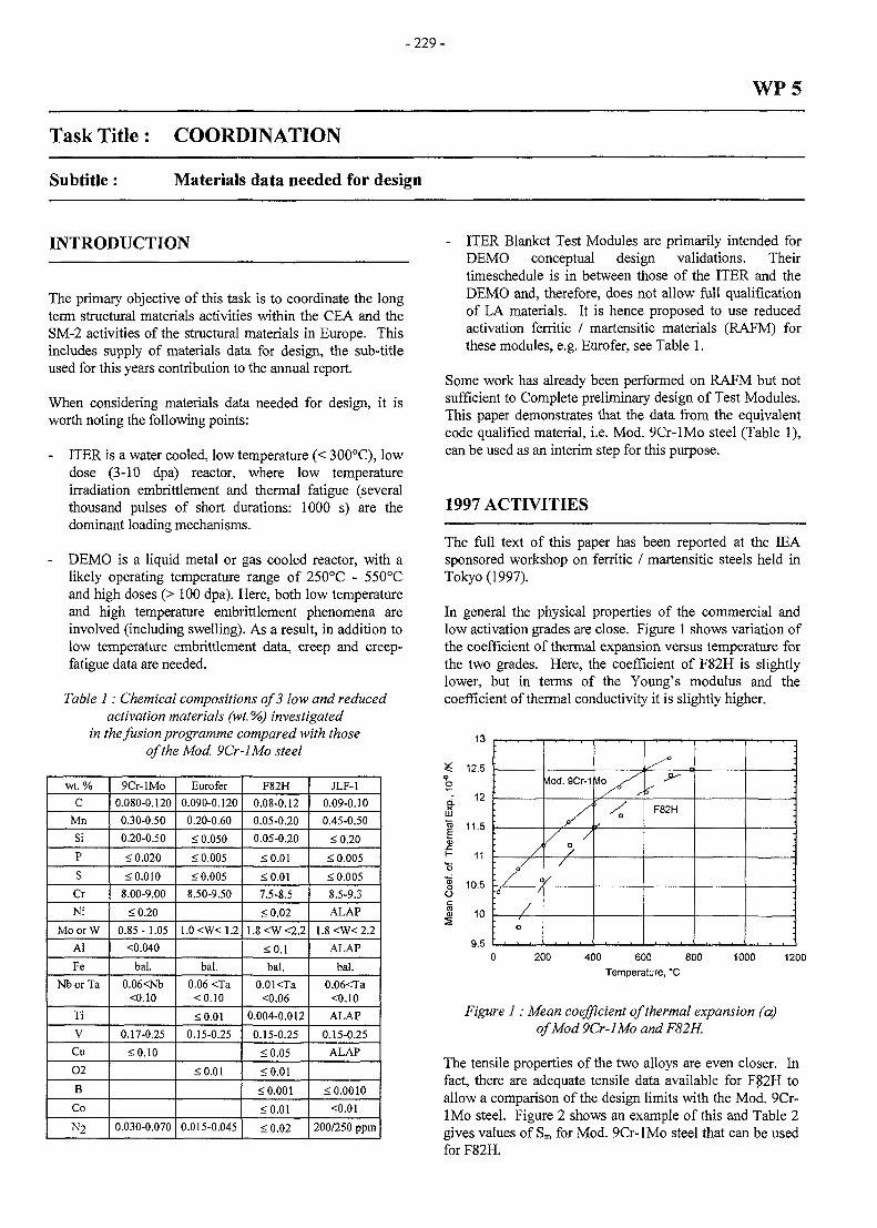
-229-
Task Title: COORDINATION
WP5
Subtitle: Materials data needed for design
INTRODUCTION
The primary objective of this task is to coordinate the longterm structural materials activities within the CEA and theSM-2 activities of the structural materials in Europe. Thisincludes supply of materials data for design, the sub-titleused for this years contribution to the annual report.
When considering materials data needed for design, it isworth noting the following points:
- ITER is a water cooled, low temperature (< 300°C), lowdose (3-10 dpa) reactor, where low temperatureirradiation embrittlement and thermal fatigue (severalthousand pulses of short durations: 1000 s) are thedominant loading mechanisms.
- DEMO is a liquid metal or gas cooled reactor, with alikely operating temperature range of 250°C - 550°Cand high doses (> 100 dpa). Here, both low temperatureand high temperature embrittlement phenomena areinvolved (including swelling). As a result, in addition tolow temperature embrittlement data, creep and creep-fatigue data are needed.
Table 1: Chemical compositions of 3 low and reducedactivation materials (wt. %) investigated
in the fusion programme compared with thoseof the Mod. 9Cr-lMo steel
wt. %
C
Mn
Si
P
S
Cr
Ni
MoorW
AI
Fe
NborTa
Ti
V
Cu
02
B
Co
N2
9Cr-lMo
0.080-0.120
0.30-0.50
0.20-0.50
< 0.020
< 0.010
8.00-9.00
<0.20
0.85- 1.05
<0.040
bal.
0.06<Nb<0.10
0.17-0.25
£0.10
0.030-0.070
Eurofer
0.090-0.120
0.20-0.60
< 0.050
< 0.005
< 0.005
8.50-9.50
1.0<W<1.2
bal.
0.06 <Ta<0.10
<0.01
0.15-0.25
£0.01
0.015-0.045
F82H
0.08-0.12
0.05-0.20
0.05-0.20
<0.01
£0.01
7.5-8.5
<0.02
1.8<W<2.2
<0.1
bal.
O.OKTa<0.06
0.004-0.012
0.15-0.25
<0.05
<0.01
< 0.001
<0.01
<0.02
JLF-1
0.09-0.10
0.45-0.50
<0.20
< 0.005
< 0.005
8.5-9.3
ALAP
1.8<W<2.2
ALAP
bal.
0.06<Ta<0.10
ALAP
0.15-0.25
ALAP
< 0.0010
<0.01
200/250 ppm
- ITER Blanket Test Modules are primarily intended forDEMO conceptual design validations. Theirtimeschedule is in between those of the ITER and theDEMO and, therefore, does not allow full qualificationof LA materials. It is hence proposed to use reducedactivation ferritic / martensitic materials (RAFM) forthese modules, e.g. Eurofer, see Table 1.
Some work has already been performed on RAFM but notsufficient to Complete preliminary design of Test Modules.This paper demonstrates that the data from the equivalentcode qualified material, i.e. Mod. 9Cr-lMo steel (Table 1),can be used as an interim step for this purpose.
1997 ACTIVITIES
The full text of this paper has been reported at the IEAsponsored workshop on ferritic / martensitic steels held inTokyo (1997).
In general the physical properties of the commercial andlow activation grades are close. Figure 1 shows variation ofthe coefficient of thermal expansion versus temperature forthe two grades. Here, the coefficient of F82H is slightlylower, but in terms of the Young's modulus and thecoefficient of thermal conductivity it is slightly higher.
13
^ 12.5o
; 1 2
LU
1 11.5
I- 11
g 10.5O
| 10
9.5
/
/ \i 1
/
o
vlod. 9Cr-1
Atoy/
4
^ n- * -
fF82H •
•
200 400 600 800
Temperature, °C
1000 1200
Figure 1: Mean coefficient of thermal expansion (a)of Mod 9Cr-lMo and F82H.
The tensile properties of the two alloys are even closer. Infact, there are adequate tensile data available for F82H toallow a comparison of the design limits with the Mod. 9Cr-lMo steel. Figure 2 shows an example of this and Table 2gives values of Sm for Mod. 9Cr-lMo steel that can be usedforF82H.
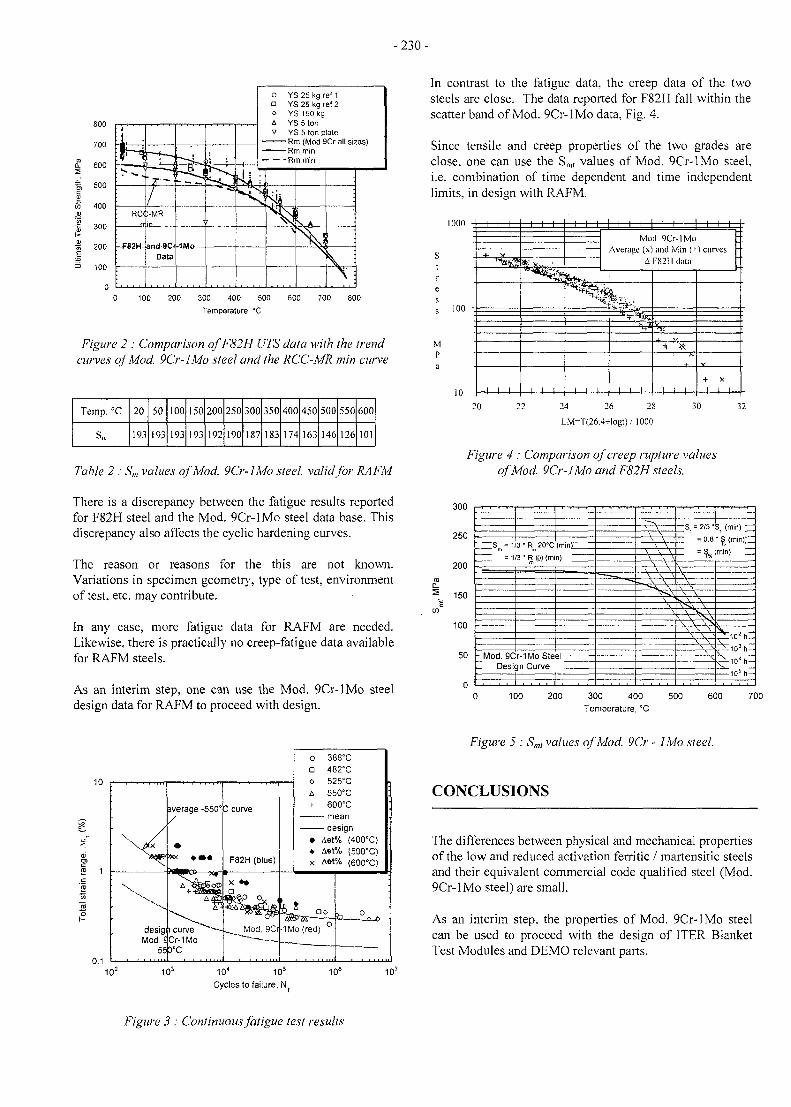
-230-
800
700
i 600
%. 600 -SI55• =
400
<S 200
100
RCC
-F82H-
:-MR
and-BCrData
o YS 25 kg ref 1• YS 25 kg ref 2o YS150kga YS 5 tonv YS 5 ton plate
Rm (Mod 9Cr all siz es)Rm min
-Rm min
— — ^
N
I
V i
100 200 300 400 500
Temperature, °C
600 700 800
Figure 2 : Comparison ofF82H UTS data with the trendcurves of Mod. 9Cr-lMo steel and the RCC-MR min curve
Temp. °C 20
19:
50
19;
100
193
150 200
193192
250
190
300
187
350
183
400 450
174
500
146
550 600
126101
Table 2 : Sm values of Mod. 9Cr-lMo steel, valid for RAFM
There is a discrepancy between the fatigue results reportedfor F82H steel and the Mod. 9Cr-lMo steel data base. Thisdiscrepancy also affects the cyclic hardening curves.
The reason or reasons for the this are not known.Variations in specimen geometry, type of test, environmentof test, etc. may contribute.
In any case, more fatigue data for RAFM are needed.Likewise, there is practically no creep-fatigue data availablefor RAFM steels.
As an interim step, one can use the Mod. 9Cr-lMo steeldesign data for RAFM to proceed with design.
In contrast to the fatigue data, the creep data of the twosteels are close. The data reported for F82H fall within thescatter band of Mod. 9Cr-lMo data, Fig. 4.
Since tensile and creep properties of the two grades areclose, one can use the Smt values of Mod. 9Cr-lMo steel,i.e. combination of time dependent and time independentlimits, in design with RAFM.
1000
Mp
100
10
—I—I—I—
•4- V
1 1 1
1 1 1
1 1 1
1 1 1 ' I I I 1 1 1 -
Mod. 9Cr-lMoAverage (x) and Min (+
A F82H data
1 1 1
—^^r^^
| j |
'i(
-i- A
[ ; |
hH r—
) curves
V
+ X
20 22 24 26 28
LM=T(26.4+logt) / 1000
30 32
Figure 4 : Comparison of creep rupture valuesof Mod. 9Cr-JMo and F82H steels.
300
250
200
150
100
50
S - 1 3 " Rn 20°C
= i / 3 * R < 0 ) ( m
-Mod. 9CDesi
m
Immi
r-IMoStejn Curve
"——.
\ \\ \\ \
\ \ \\ \ \\ \\ \ \
\
, , . . j . . . ,
- r - r - - . •
= s
s\\ S
\ \Is. \ \
\ \ \
K \ \x \\ \ N\ \ *\ "\\ s.
\\
S (min) —'
* S (min)min)
\ 2 • •
. s 10J h •
100 200 300 400 500 600 700Temperature, °C
Aet% (400°C)Aet% (500°C)Aet% (600°C)
10 10 10" 105
Cycles to failure, N10" 10'
Figure 5 : Smt values of Mod. 9Cr - IMo steel.
CONCLUSIONS
The differences between physical and mechanical propertiesof the low and reduced activation ferritic / martensitic steelsand their equivalent commercial code qualified steel (Mod.9Cr-lMo steel) are small.
As an interim step, the properties of Mod. 9Cr-lMo steelcan be used to proceed with the design of ITER BlanketTest Modules and DEMO relevant parts.
Figure 3 : Continuous fatigue test results
-231 -
REPORTS AND PUBLICATIONS
[1] F. Tavassoli , Materials data needed for design, IEAWorkshop on Reduced Activation Ferritic/MartensiticSteels, JAERI Headquarters, Tokyo, JapanNovember 3-4, 1997
TASK LEADER
Farhad TAVASSOLI
DTA/CEREM/DECMSaclay
Tel. : 33 169 08 60 21Fax : 33 169 08 7131
e-mail: [email protected]
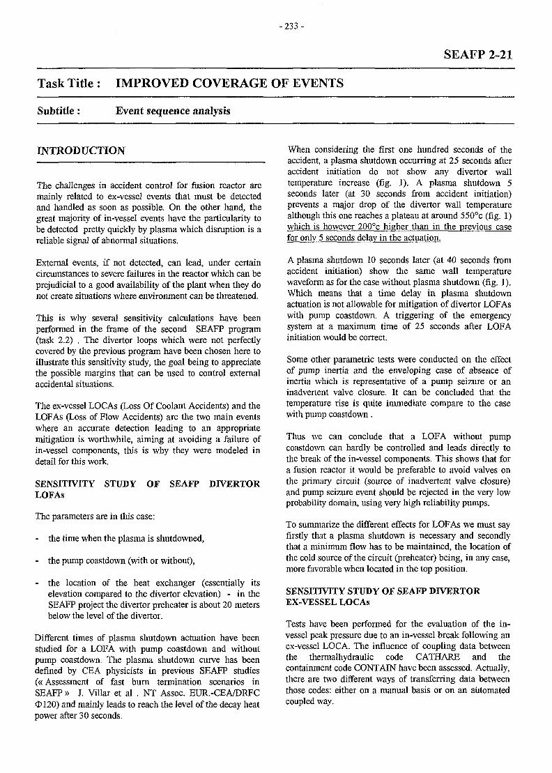
- 2 3 3 -
SEAFP 2-21
Task Title : IMPROVED COVERAGE OF EVENTS
Subtitle : Event sequence analysis
INTRODUCTION
The challenges in accident control for fusion reactor aremainly related to ex-vessel events that must be detectedand handled as soon as possible. On the other hand, thegreat majority of in-vessel events have the particularity tobe detected pretty quickly by plasma which disruption is areliable signal of abnormal situations.
External events, if not detected, can lead, under certaincircumstances to severe failures in the reactor which can beprejudicial to a good availability of the plant when they donot create situations where environment can be threatened.
This is why several sensitivity calculations have beenperformed in the frame of the second SEAFP program(task 2.2) . The divertor loops which were not perfectlycovered by the previous program have been chosen here toillustrate this sensitivity study, the goal being to appreciatethe possible margins that can be used to control externalaccidental situations.
The ex-vessel LOCAs (Loss Of Coolant Accidents) and theLOFAs (Loss of Flow Accidents) are the two main eventswhere an accurate detection leading to an appropriatemitigation is worthwhile, aiming at avoiding a failure ofin-vessel components, this is why they were modeled indetail for this work.
SENSITIVITY STUDY OF SEAFP DIVERTORLOFAs
The parameters are in this case:
- the time when the plasma is shutdowned,
- the pump coastdown (with or without),
- the location of the heat exchanger (essentially itselevation compared to the divertor elevation) - in theSEAFP project the divertor preheater is about 20 metersbelow the level of the divertor.
Different times of plasma shutdown actuation have beenstudied for a LOFA with pump coastdown and withoutpump coastdown. The plasma shutdown curve has beendefined by CEA physicists in previous SEAFP studies(«Assessment of fast burn termination scenarios inSEAFP » J. Villar et al . NT Assoc. EUR.-CEA/DRFCO120) and mainly leads to reach the level of the decay heatpower after 30 seconds.
When considering the first one hundred seconds of theaccident, a plasma shutdown occurring at 25 seconds afteraccident initiation do not show any divertor walltemperature increase (fig. 1). A plasma shutdown 5seconds later (at 30 seconds from accident initiation)prevents a major drop of the divertor wall temperaturealthough this one reaches a plateau at around 550°c (fig. 1)which is however 200°c higher than in the previous casefor only 5 seconds delay in the actuation.
A plasma shutdown 10 seconds later (at 40 seconds fromaccident initiation) show the same wall temperaturewaveform as for the case without plasma shutdown (fig. 1).Which means that a time delay in plasma shutdownactuation is not allowable for mitigation of divertor LOFAswith pump coastdown. A triggering of the emergencysystem at a maximum time of 25 seconds after LOFAinitiation would be correct.
Some other parametric tests were conducted on the effectof pump inertia and the enveloping case of absence ofinertia which is representative of a pump seizure or aninadvertent valve closure. It can be concluded that thetemperature rise is quite immediate compare to the casewith pump coastdown.
Thus we can conclude that a LOFA without pumpcoastdown can hardly be controlled and leads directly tothe break of the in-vessel components. This shows that fora fusion reactor it would be preferable to avoid valves onthe primary circuit (source of inadvertent valve closure)and pump seizure event should be rejected in the very lowprobability domain, using very high reliability pumps.
To summarize the different effects for LOFAs we must sayfirstly that a plasma shutdown is necessary and secondlythat a minimum flow has to be maintained, the location ofthe cold source of the circuit (preheater) being, in any case,more favorable when located in the top position.
SENSITIVITY STUDY OF SEAFP DIVERTOREX-VESSEL LOCAs
Tests have been performed for the evaluation of the in-vessel peak pressure due to an in-vessel break following anex-vessel LOCA. The influence of coupling data betweenthe thermalhydraulic code CATHARE and thecontainment code CONTAIN have been assessed. Actually,there are two different ways of transferring data betweenthose codes: either on a manual basis or on an automatedcoupled way.

-234-
The first one let the thermalhydraulic code perform itscalculation till the end of the transient and then, the userenters «manually» the information necessary to thecontainment code (principally the mass break flow and thebreak enthalpy). Thus there is no « return » effect of thedownstream pressure on the behavior of thethermalhydraulic transient.
The coupled way was achieved using the macro-languagePVM (Parallel Virtual Machine) which allows to run twodifferent codes in parallel and also exchange data betweenthe codes. In this manner the boundary conditions for thethermalhydraulic code (CATHARE) and the containmentcode (CONTAIN) are exchanged at each time step.
The major result is plotted on figure 2 which shows a stronginfluence on the level of the maximum pressure in thevacuum vessel since there is a discrepancy of about 40%.The reason is certainly due to the effect of accounting forthe downstream pressure in the coupled case, which reducesthe break flow in the non-choked phase and consequentlythe peak pressure.
Anyhow the calculations which have been performed tillnow, neglecting this coupling effect, are in factconservative; the question being to know if a 40%conservatism can be accepted.
1400.
1200.
1000.
eco.
eco.
400.
aoa.
J/
A . . ..
D
/
SEQonds
A P S S _ 2 5 E
B FSS_30e
D TO_PSS
20. 40. eo. 80. 100,
PSS time of actuationDIVERTOR WALL TEMPERATURE
CA1HARE v l . 4
SEAFP
CS-9702QCI7cs-ff>02aaeCS-SP02009CS7O2D
Figure 1 : effects of different times of plasma shutdown on the divertor wall temperature
4°
3.6
3.2
2.8
2.4
2.
1.6
1.2
0.9
0.4
nI
4. 8. 12. 16. 20. 24. 2S. 32. 3$. 40.
/
/
a
1
//v/
_-—-
;emps
A
I
temps
J;
i
•
:
;
I
SEC)-
4. 8. 12. 16. 20. 24. 28. 3^. 36. 4
3.6
3.2
2.S
2.4
2.
1.6
1.2
0.8
0.4
8:
PiessuiE in VACCUn VESSELSEAPF PROTECT
STriL/LCFI
A simple
3 c-Duple
EX+INVESSELBREAK
db»-.F^Tr£GCEL.?z>t
ccwnun
y i o l m JL.U
Figure 2 : effects of code coupling on the in-vesse! peak pressure
- 2 3 5 -
CONCLUSION LIST OF REPORTS
The detection of ex-vessel abnormal situations has beenshown to be of great importance. The delays and the timeof actuation of emergency systems are of prime importancein the control of the accident.
A normal control of a LOFA calls for a quite earlydetection in order to actuate the safety systems as plasmashutdown and emergency circulation (pumps or gravity).However we must add that a loop configuration wherenatural circulation is favored exhibits less constraint on thetime of plasma shutdown actuation, although it does notavoid it.
In case of failure of the plasma shutdown the accidentevolves irremediably towards an in-vessel LOCA and incase of total loss of flow (failure of the circulation system),the in-vessel LOCA must take place more or less rapidly-according to the ability of the structures to store energy butis also unavoidable at a medium term. When consideringthat these transients can be classified in category IIincidents, that is a yearly probability of occurrence, one hasto take care of the control not only from a safer}' view butalso on an operational one.
For ex-vessel LOCA events, the influence of code couplingon vacuum vessel peak pressure is quite significant whenan in-vessel LOCA is induced.
We have noticed that the effect is acting in the gooddirection since when using the coupled version, in-vesselpeak pressure was less important than in the manualcoupling. This effect has to be assessed more in detail andcomparisons with other coupled codes should beperformed.
[1] Seafp2 - Macrotask 2 : coordination meeting - CRRDER/STML/LCFI 97/367
[2] Seafp2 macrotask 2 - complementary informationDER/STML/LCFI 97/435
[3] SEAFP-2 : Accidents on divertor loops - parametricstudyDER/STML/LCFI 97/013
TASK LEADER
Christian GIRARD
DRN/DER/STML/LCFICadarache
Tel.Fax
04 42 25 49 5604 45 25 66 38
e-mail : [email protected]
- 2 3 7 -
SEAFP 2-22
Task Title : IMPROVED COVERAGE OF EVENTS
Subtitle : SEAFP 2 : Response of model 1 concept (Helium cooled) to loss of coolantaccidents inside the vacuum vessel (in-vessel LOCA)
INTRODUCTION
The work presented here takes place within the Safety andEnvironmental Assessment of Fusion Power part 2(SEAFP2).
The aim is to synthesize the results of the studies that weremade in the frame of SEAFP (Model 1 reactor) concerningloss of coolant accidents inside the vacuum vessel and toevaluate if additional assessments are necessary.
The two reference cases for in-vessel LOCA in term ofpressure build-up are the following :
- rupture of one of the sub or main He cooling manifoldfor LOCA of the He cooling system within the Blanketwich may induce the rupture of the First-Wall,
- guillotine rupture of the Divertor collector for LOCA ofthe He cooling system within the plasma vessel.
Safety analysis, made within the topic « Pressure VesselSafety" Analysis» of the «Safety and EnvironmentalAssessment of Fusion Power» study, had been realised inorder to determine the feasible design options of Model 1reactor to cope with the consequences of in-vessel LOCA.
That's the reason why the design characteristics of SEAFPModel 1 reactor described in the project Final Reportcouldn't be used in the safety analysis because some maindesign options are issued from these analysis.
1997 ACTIVITIES
SYNTHESIS OF SAFETY STUDIES MADE IN THEFRAMEWORK OF SEAFP1 PROJECT :
In-box LOCA :
Safety analysis of interfacial LOCA (ingress of the He intopurge gas loop which extracts the T from the breederceramics in model 1) led to suggesting that the purge gasloop be connected to the expansion volume.
The use of this concept (connection of the purge gas systemto the expansion volume) will, in addition, necessitatedefining procedure to reinstate normal conditions in the
expansion volume after interfacial LOCA as quickly aspossible in order to minimise radioactive releases to theenvironment.
In-vessel LOCA :
The design characteristics used for the safety analysis of inplasma vessel LOCA doesn't correspond to the SEAFPmodel 1 final design ; the main differences are concerningthe design of the expansion volume and of the separateDivertor He cooling loop.
We have to distinguish two cases for Model 1 reactor(helium cooled) :
- cas A : the pressure of the divertor cooling loop is 90bar (270 m3),
- cas B : the Divertor is cooled by a specific cooling loopat a pressure up to 200 bar, the volume of the Divertorspecific cooling loop being unknown.
SYNTHESIS OF SAFETY STUDIES MADE IN THEFRAMEWORK OF SEAFP2 PROJECT (IN-VESSELLOCA) :
The main conclusions of the safety calculations made inthe frame of SEAFP part 2, concerning the large size break(300 mm diameter) for in-vessel LOCA, are the following :
- case A (divertor cooling loop at 90 bar, 270 m3) : thedesign pressure of the vacuum vessel (5 bar) and theexpansion volume (1,4 bar) are not reached,
- case B (separate divertor cooling loop at 200 bar forexample) : the maximum cooling loop volumeadmissible to avoid the design pressure of theexpansion volume to be reached is about 150 m3.
CONCLUSIONS
ADDITIONAL ASSESSMENTS :
In-box LOCA :
Additional safety calculations will have to be done in orderto define the design pressure of the Blanket segments andthe purge gas system (the exact values will have to bedetermined by sizing calculations for the relief lines purgegas circuit to the expansion volume).

-238 -
In-vessel LOCA : TASK LEADER
In case of separate divertor cooling loop with a pressurehigher than 90 bar, such design will have to be subject to x MASSONsome additional safety study.
TECHNICATOMEDI/SEPS
REFERENCES BP 34000AIX EN PROVENCE
[1] SEAFP2 : Response of model 1 concept (helium Tel. : 33 4 42 60 28 61cooled) to loss of coolant accidents inside the vacuum Fax : 33 4 42 60 25 11vessel (in-vessel LOCA)
e-mail: [email protected]
-239 -
SEAFP3-11
Task Title : IMPROVED CONTAINMENT CONCEPTS
INTRODUCTION
This study falls within the scope of the SEAFP 2programme. The objective of the task performed this yearis to initiate reflexion on the safety options of anelectricity-producing fusion reactor of the future.
This type of plant, if only on account of its tritiuminventory, will be a nuclear facility and therefore submittedto the constraints associated with a nuclear plant.
One of the first requirements is to show that by design, orby the safety systems that are implemented, radiologicalreleases will not affect neighbouring populations, and thatthis holds true whatever the events or succession of eventsof internal origin that may occur. Under no circumstances,therefore, should there be any technical reason to envisagethe evacuation of the population.
These requirements are no different from those set by thedesigners for future fission plants. It seems, however, thattheir implementation can prove significantly advantageousfor fusion technology.
It is no doubt unnecessary to enumerate here the intrinsicadvantages of fusion, as these have already been presenteda great many times. One can nevertheless recall:
- The moderate "mobilizable" radioactive inventory,
- The absence of any critical power excursion and thefact that any external perturbation leads to theshutdown of the reaction,
- Its low decay heat, due for the most part to theactivation of materials, and which depends, therefore,on the choice of the materials.
It can be added that the quantity of fuel available inside theplasma is very small.
Nevertheless, serious reflexion is needed in order to takethese objectives into account early in the first designstudies.
One can only privilege, therefore, the implementation ofthe Defense-in-Depth principle, taking into account notonly severe accidents, but also various accident andincident sequences whose occurrence is more frequent.
This paper does not address the long-term consequences onthe environment related to wastes, which are the subject ofanother part of the programme.
We shall limit ourselves to initiating a discussion on thesafety functions that should be set up in a TOKAMAK,including the links with the studies performed in theframework of the SEAFP 2 programme and describingsome of the orientations for their incorporation in thedesign and implementation of the safety systems wherenecessary.
1997 ACTIVITY
INVENTORY OF THE RISKS AND ASSOCIATEDSAFETY FUNCTIONS
These issues have already been the subject of analyses inthe framework of the first SEAFP programme, as well as inthe framework of the ITER programme: a genericsummary is in progress in SEAFP 2 Macrotask 1.
The main risks are:
- Radioactive risks.
In addition to the tritium, these are linked to theactivation of the materials surrounding the plasma. Anevaluation has been made in the case of the threeblanket concepts (see Task 5.1):
. Model 1: Vanadium is used as the structuralmaterial, helium as the coolant, and lithium-containing ceramic as the breeder material;
. Model 2: Martensitic steel is used as the structuralmaterial, pressurized water as the coolant, andlithium-lead eutectic as the breeder material(concept identical to the DEMO WCLL blanket)
. Model 3: Martensitic steel is used as the structuralmaterial, helium as the coolant, lithium-containingceramic as the breeder material (concept identical tothe DEMO HPCB blanket).
- Risks associated with the energy of the coolant (seeTask 1.2) and with the decay heat.
- Chemical risks associated with the beryllium-water andlithium-lead-water interactions (see Task 1.3).
- Risks linked to the magnets, particularly the electric archazard that could lead to structural and barrier damage(see Task 1.5).
The plasma itself should also be considered, as itsdisruption could lead to damage of the first wall.
- 2 4 0 -
The main safety functions ensue from this inventory ofrisks:
- The function of radioactive confinement basic to anynuclear facility,
- The function of coolant energy control,
- The function of power and residual power control,
- The function of magnetic energy control,
- The function of chemical energy control,
- The function of power and decay heat control.
Each main safety function can be broken down into a moreelementary function by reasoning from the risk one wishesto avert. This approach is the subject of Task 2.1 using anMLD (Master Logic Diagram) methodology. It is clear thatwithout a clear design, it is impossible, using thisapproach, to draw up an inventory of all elementaryinitiator events.
This approach nevertheless enables discussing as early asthe design stage how these elementary safety functions canbe incorporated into the design.
In the framework of the Defense-in-Depth principle, eachsafety function merits examination at the well knownlevels of prevention, protection and mitigation.
With respect to energy control, safety functions can beimplemented at various levels:
- By choosing operating parameters or designparameters, it is possible to limit the energy that couldbe mobilized in the event of an incident (the samenotion of mobilizable quantity is used for radioactivematerials), and it is this notion of mobilizable energythat should be retained for the design of the barriers;
- The safety function can be set up using a specificsystem that ensures a function of protection withrespect to the development of an accident.
Most energy sources have been submitted to in-depthanalyses for ITER or SEAFP. However, there is one thatmerits a specific study, and that is the energy of themagnets. This is the object of Tasks 1.5 and 2.2 FZK. Inparticular, this involves studying whether designprovisions permit minimizing the consequences of an arc.
SAFETY OPTIONS AND CONFINEMENTSTRATEGY
Safety Options and Accident Sequences
The definition of safety options and suggestions as regardstheir implementation requires knowledge of thedevelopment of main accident sequences and the efficiency
of the protection and mitigation systems. In this respectone can benefit from the in-depth studies performed forITER, SEAFP and SEAL.
In the framework of SEAFP 2, work has been focused oncompleting these studies by an analysis of sequences thathave not been thoroughly studied until present (ex: breakat steam generator level), by parametric studies (ex: breakof the divertor circuit), or by an analysis of the efficiency ofspecific mitigation systems (ex: cold surface effectallowing condensation of the water and reduction of theload on the barriers).
All these issues are being submitted to analysis andsummary within the scope of Macrotask 2 (see Bolognameeting, STML Report (LCFI 97/319). It should be addedthat it is planned to take the human factor into account,both in the framework of accident management and as aninitiator risk per se.
It is certain that particular mention should be made ofsequences that permit by-passing successive barriers, butone should not forget to discuss certain accidents of morefrequent occurrence in the context of the Defense-in-Depthprinciple.
In the framework of specific parametric studies, twoconfinement options are being studied (report to be issuedfrom C. GIRARD)
One of ITER type with the cryostat and the exchangerhall as the second barrier, and with an outside buildingequipped with controlled ventilation;
- The other having its confinement function ensured bythe outside building (containment to withstandoverpressures to be defined).
Confinement Strategy
Even if the mobilizable inventory is much lower than inother nuclear facilities, its direct impact on thesurrounding population seems to exceed the "non-evacuation" dose.
With respect to the tritium, previous studies have shownthat the release of 1 Kg of tritium at ground level under themost unfavourable weather conditions would exceed thislevel by a factor of 10.
With respect to activation products, this level depends onthe choice of material and a UKAEA study (Task 1.4)should permit situating this problem.
However, the confinement function should not beconsidered solely in the context of ultimate situations andthe ITER studies should be used as a basis to evaluate theefficiency required for other accident causes.
- 2 4 1 -
Discussion of some Safety Functions Associated with theConfinement Strategy
During the Aix-en-Provence workshop, it appeared thatthree safety functions merited discussion, particularly inview of their possible impact on design or operatingparameters.
These safety functions are plasma shutdown, decay heatremoval, and hydrogen hazard control.
Macrotask 2 studies should determine if other functions areto be added to this list.
Plasma shutdown
- Either by choosing normal and transient operatingparameters so as to limit the production of hydrogen,which could require emergency cooling systems forcertain situations (ex: LOFA, external LOCA);
- Or by implementing hydrogen absorption or mitigationsystems together with the inertization of certain rooms.
This issue will also be discussed for the other models andstudied according to the type of confinement concept in thefinal report.
REFERENCES
In the case of severe situations (ex: external LOCA), therise in temperature of the walls may permit automaticshutdown of the plasma.
The case of accidents of less frequent occurrence, however,should also be discussed, such as, for example, spuriouspump shutdown, that should not have any significantconsequences on the environment;
Decay heat removal
Decay heat depends greatly on the materials selected: intheabsence of a cooling system, it nevertheless always leads toa significant increase in the temperature of the internalstructures without, however, jeopardizing these internalstructures by melting of the components.
This problem was solved in different ways for ITER andSEAFP.
For SEAFP, attention was mainly focused on themanagement of the most severe accidents (ex: totalblackout) and emphasis was placed on limiting internaltemperatures by favouring the conduction of variousbarriers (also with the idea of a specific system at the levelof the second barrier).
For ITER, this function is assumed by the vacuum chambercircuit in natural convection, with air-coolant exchangers.
After having ensured that the risk of induced by-passing islimited, this configuration has the advantage of managingall situations and granting a low safety classification to thenormal decay heat removal systems (ex: no need foremergency pumping).
The advantages and drawbacks of these two options will bediscussed.
Hydrogen hazard control
The study performed by the CEA Technicatome showedthat there were only two ways of greatly reducing theoccurrence frequency of the hydrogen hazard associatedwith beryllium-water interaction in the case of Model 2:
[1] Safety analysis of radiactive or chemical materialsrelease outside the reactor building due to onhydrogen explosionTA-26 310M. MEUNIER, J.M GAY
[2] First reflexions on the Safety Options of a fusionreactorNT DER/STML/97.98ind aG. MARBACH
TASK LEADER
Gabriel MARBACH
DRN/DER/STMLCadarache
Tel.Fax
04 42 25 34 1404 42 25 65 08
e-mail : marbach (S) babaorum.cad.CEA.fr
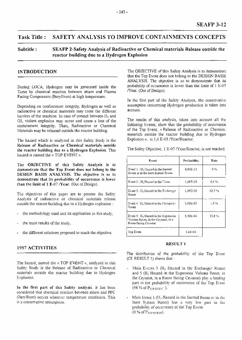
- 2 4 3 -
SEAFP 3-12
Task Title : SAFETY ANALYSIS TO IMPROVE CONTAINMENTS CONCEPTS
Subtitle : SEAFP 2-Safety Analysis of Radioactive or Chemical materials Release outside thereactor building due to a Hydrogen Explosion
INTRODUCTION
During LOCA, Hydrogen may be generated inside theTorus by chemical reaction between steam and PlasmaFacing Components (Beryllium) at high temperature.
Depending on confinement integrity, Hydrogen as well asradioactive or chemical materials may cross the differentbarriers of the machine. In case of contact between H2 and02, violent explosion may occur and cause a loss of thecontainment integrity. Then, Radioactive or ChemicalMaterials may be released outside the reactor building.
The hazard which is analyzed in this Safety Study is theRelease of Radioactive or Chemical materials outsidethe reactor building due to a Hydrogen Explosion. Thishazard is named the « TOP EVENT ».
The OBJECTIVE of this Safety Analysis is todemonstrate that the Top Event does not belong to theDESIGN BASIS ANALYSIS. The objective is so todemonstrate that its probability of occurrence is lowerthan the limit of 1 E-07 /Year. (Out of Design).
The objectives of this paper are to present the SafetyAnalysis of radioactive or chemical materials releaseoutside the reactor building due to a Hydrogen explosion :
- the methodology used and its application in this study,
- the main results of the study,
- the different solutions proposed to reach the objective.
1997 ACTIVITIES
The hazard, named the « TOP EVENT », analyzed in thisSafety Study is the Release of Radioactive or Chemicalmaterials outside the reactor building due to HydrogenExplosion.
In the first part of this Safety analysis, it has beenconsidered that chemical reaction between steam and PFC(Beryllium) occurs whatever temperature conditions. Thisis a conservative assumption.
The OBJECTIVE of this Safety Analysis is to demonstratethat the Top Event does not belong to the DESIGN BASISANALYSIS. The objective is so to demonstrate that itsprobability of occurrence is lower than the limit of 1 E-07/Year. (Out of Design).
In the first part of the Safety Analysis, the conservativeassumption concerning Hydrogen production is taken intoaccount.
The results of this analysis, taken into account all theInitiating Events, show that the probability of occurrenceof the Top Event, « Release of Radioactive or Chemicalmaterials outside the reactor building due to HydrogenExplosion », is 1,6 E-03 /Year/Reactor.
The Safety Objective, 1 E-07 /Year/Reactor, is not reached.
Event
Event 1 : H2 Hazard in the InertedRoom or in the Inert System Room
Event 2 : Hi Hazard in the Torus
Event 3 : Hi Hazard in the ExchangerRoom
Event 4 : Hi Hazard in the CryogenicRoom
Event 5 : H2 Hazard in the ExpansionVolume Room, in the Cryostat, in aRoom facing Cryostat
Top Event
Probability
8.80E-11
l.OOE-05
l.OOE-03
3,00E-05
5,30E-04
1.6E-03
Rate
0%
0,6 %
(53,7 %
1,9%
33.8 %
RESULT 1
The distribution of the probability of the Top Event(Cf. RESULT 1) shows that:
- Main Events 3 (H2 Hazard in the Exchanger Room)and 5 (H: Hazard in the Expansion Volume Room, inthe Cryostat, in a Room facing Cryostat) play a leadingpart in the probability of occurrence of the Top Event(98%OfPTOPEVENT),
- Main Event 1 (H2 Hazard in the Inerted Room or in theInert System Room) has a very low part in theprobability of occurrence of the Top Event
(0 % of PTOp EVENT)-
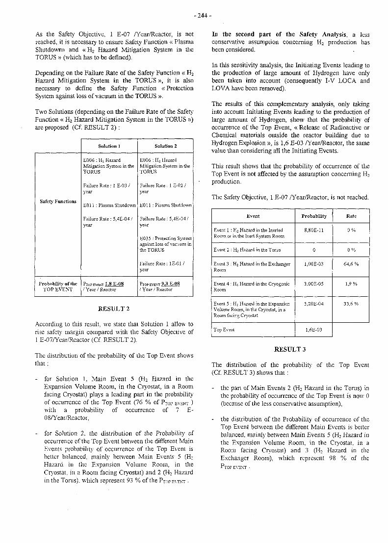
- 2 4 4 -
As the Safety Objective, 1 E-07 /Year/Reactor, is notreached, it is necessary to ensure Safety Function « PlasmaShutdown)) and «H2 Hazard Mitigation System in theTORUS » (which has to be defined).
Depending on the Failure Rate of the Safety Function « H2
Hazard Mitigation System in the TORUS », it is alsonecessary to define the Safety Function «ProtectionSystem against loss of vacuum in the TORUS ».
Two Solutions (depending on the Failure Rate of the SafetyFunction « H2 Hazard Mitigation System in the TORUS »)are proposed (Cf. RESULT 2) :
Safety Functions
Probability of theTOP EVENT
Solution 1
E006 : Hi HazardMitigation System in theTORUS
Failure Rate : 1 E-03 /year
E011 : Plasma Shutdown
Failure Rate : 5,4E-04 /year
PTOPFVKNT 1.8 E-08
/ Year / Reactor
Solution 2
E006 : Hi HazardMitigation System in theTORUS
Failure Rate : 1 E-02 /year
E011 : Plasma Shutdown
Failure Rate : 5.4E-04 /year
E035 : Protection Systemagainst loss of vacuum inthe TORUS
Failure Rate: 1E-01/year
PTOP EVENT 9,3 E-08
/ Year / Reactor
RESULT 2
According to this result, we state that Solution 1 allow torise safety margin compared with the Safety Objective of1 E-07/Year/Reactor (Cf. RESULT 2).
The distribution of the probability of the Top Event showsthat:
- for Solution 1, Main Event 5 (H2 Hazard in theExpansion Volume Room, in the Cryostat, in a Roomfacing Cryostat) plays a leading part in the probabilityof occurrence of the Top Event (76 % of PTOP EVENT )with a probability1 of occurrence of 7 E-08/Year/Reactor,
- for Solution 2, the distribution of the Probability ofoccurrence of the Top Event between the different MainEvents probability of occurrence of the Top Event isbetter balanced, mainly between Main Events 5 (H2
Hazard in the Expansion Volume Room, in theCryostat. in a Room facing Cryostat) and 2 (H2 Hazardin the Torus), which represent 93 % of the PTOP EVENT •
In the second part of the Safety Analysis, a lessconservative assumption concerning H2 production hasbeen considered.
In this sensitivity analysis, the Initiating Events leading tothe production of large amount of Hydrogen have onlybeen taken into account (consequently I-V LOCA andLOVA have been removed).
The results of this complementary analysis, only takinginto account Initiating Events leading to the production oflarge amount of Hydrogen, show that the probability ofoccurrence of the Top Event, « Release of Radioactive orChemical materials outside the reactor building due toHydrogen Explosion », is 1,6 E-03 /Year/Reactor, the samevalue than considering all the Initiating Events.
This result shows that the probability of occurrence of theTop Event is not affected by the assumption concerning H2
production.
The Safety Objective, 1 E-07 /Year/Reactor, is not reached.
Event
Event 1 : H2 Hazard in the InertedRoom or in the Inert System Room
Event 2 : H2 Hazard in the Torus
Event 3 : H2 Hazard in the ExchangerRoom
Event 4 : H : Hazard in the CryogenicRoom
Event 5 : H; Hazard in the ExpansionVolume Room, in the Cryostat, in aRoom facing Cryostat
Top Event
Probability
8,80E-ll
0
1.00E-03
3,00E-05
5.20E-04
1.6E-03
Rate
0%
0%
64,6 %
1,9%
33,6 %
RESULT 3
The distribution of the probability of the Top Event(Cf. RESULT 3) shows that:
- the part of Main Events 2 (H2 Hazard in the Torus) inthe probability of occurrence of the Top Event is now 0(because of the less conservative assumption),
- the distribution of the Probability' of occurrence of theTop Event between the different Main Events is betterbalanced, mainly between Main Events 5 (H2 Hazard inthe Expansion Volume Room, in the Cryostat, in aRoom facing Cryoslat) and 3 (H2 Hazard in theExchanger Room), which represent 98 % of theP T O P EVENT •
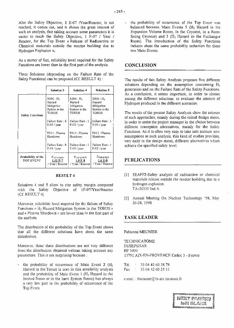
- 2 4 5 -
Also the Safety Objective, 1 E-07 /Year/Reactor, is notreached, it comes out, and it shows the great interest ofsuch an analysis, that taking account some parameters it iseasier to reach the Safety Objective, 1 E-07 / Year /Reactor, for the Top Event « Release of Radioactive orChemical materials outside the reactor building due toHydrogen Explosion ».
As a matter of fact, reliability level required for the SafetyFunctions are lower than in the first part of the analysis.
Three Solutions (depending on the Failure Rate of theSafety Functions) can be proposed (Cf. RESULT 4) :
Safety Functions
Probability of theTOP EVENT
Solution 3
E006 : H2
HazardMitigationSystem in theTORUS
Failure Rate : 8E-03 / year
E011 : PlasmaShutdown
Failure Rate : 8E-03 / year
PTOP EVENT
1,02 E-7/ Year / Reactor
Solution 4
E006 : H2
HazardMitigationSystem in theTORUS
Failure Rate : 1E-02 / year
E011 : PlasmaShutdown
Failure Rate : 1E-03 / year
PTOP EVENT
1,9 E-8/ Year / Reactor
Solution 5
E006 : H2
HazardMitigationSystem in theTORUS
Failure Rate : 1E-03 / year
E011 : PlasmaShutdown
Failure Rate: 1E-02 / year
PTOPEVENT
1.6 E-8/ Year / Reactor
RESULT 4
Solutions 4 and 5 allow to rise safely margin comparedwith the Safety Objective of 1E-07/Year/Reactor(Cf. RESULT 4).
Moreover, reliability level required for the failure of SafetyFunctions « H2 Hazard Mitigation System in the TORUS »and « Plasma Shutdown » are lower than in the first part ofthe analysis.
The distribution of the probability of the Top Event showsthat all the different solutions have about the samedistribution.
Moreover, those three distributions are not very differentfrom the distribution obtained without taking account anyparameters. This is not surprising because :
- the probability of occurrence of Main Event 2 (H2
Hazard in the Torus) is zero in this sensibility analysisand the probability of Main Event 1 (H2 Hazard in theInerted Room or in the Inert System Room) has alwaysa very low part in the probability of occurrence of theTop Event.
the probability of occurrence of the Top Event wasbalanced between Main Events 5 (H2 Hazard in theExpansion Volume Room, in the Cryostat, in a Roomfacing Cryostat) and 3 (H2 Hazard in the ExchangerRoom). The introduction of the Safety Functionsinduces about the same probability reduction for thesetwo Main Events.
CONCLUSION
The results of this Safety Analysis proposes five differentsolutions depending on the assumption concerning H2
generation and on the Failure Rate of the Safety Functions.As a conclusion, it seems important, in order to chooseamong the different solutions, to evaluate the amount ofHydrogen produced in the different scenarios.
The results of the present Safety Analysis show the interestof such approaches, mainly during the initial design states,in order to assist the project manager in the choice betweendifferent conception alternatives, mainly for the SafetyFunctions. As it is often very easy to take into account newassumptions in such analysis, this kind of studies provides,very early in the design states, different alternatives whichachieve the specified safety level.
PUBLICATIONS
[1] SEAFP2-Safety analysis of radioactive or chemicalmaterials release outside the reactor building due to ahydrogen explosionTA-26310IndA
[2] Annual Meeting On Nuclear Technology '98, May26-28, 1998
TASK LEADER
Fabienne MEUNTER
TECHNICATOMEDI/SEPS/SARBP 340013791 AIX-EN-PROVENCE Cedex 3 - France
Tel. : 33 04 42 60 28 78Fax : 33 04 42 60 25 11
e-mail : fmeunier^ta-aix.tecatom.fr
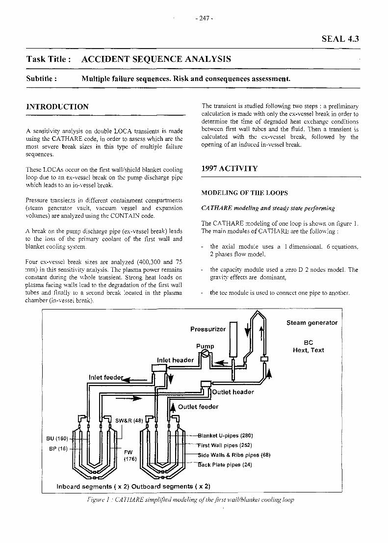
- 247 -
SEAL 4.3
Task Title : ACCIDENT SEQUENCE ANALYSIS
Subtitle : Multiple failure sequences. Risk and consequences assessment.
INTRODUCTION
A sensitivity analysis on double LOCA transients is madeusing the CATHARE code, in order to assess which are themost severe break sizes in this type of multiple failuresequences.
These LOCAs occur on the first wall/shield blanket coolingloop due to an ex-vessel break on the pump discharge pipewhich leads to an in-vessel break.
Pressure transients in different containment compartments(steam generator vault, vacuum vessel and expansionvolumes) are analyzed using the CONTAIN code.
A break on the pump discharge pipe (ex-vessel break) leadsto the loss of the primary coolant of the first wall andblanket cooling system.
Four ex-vessel break sizes are analyzed (400,300 and 75mm) in this sensitivity analysis. The plasma power remainsconstant during the whole transient. Strong heat loads onplasma facing walls lead to the degradation of the first walltubes and finally to a second break located in the plasmachamber (in-vessel break).
The transient is studied following two steps : a preliminarycalculation is made with only the ex-vessel break in order todetermine the time of degraded heat exchange conditionsbetween first wall tubes and the fluid. Then a transient iscalculated with the ex-vessel break, followed by theopening of an induced in-vessel break.
1997 ACTIVITY
MODELING OF THE LOOPS
CA THARE modeling and steady state performing
The CATHARE modeling of one loop is shown on figure 1.The main modules of CATHARE are the following :
the axial module uses a 1 dimensional. 6 equations,2 phases flow model,
- the capacity module used a zero D 2 nodes model. Thegravity effects are dominant.
- the tee module is used to connect one pipe to another.
Inlet header
Inlet feeder.
BU(160)-
BP(16)-
<=D SW&R (48)
t\iJFW(176)
Steam generator
BCHext, Text
A Outlet feeder
-Blanket U-pipes (280)
"First Wall pipes (252)
"Side Walls & Ribs pipes (68)
"Back Plate pipes (24)
Inboard segments ( x 2) Outboard segments ( x 2)
Figure I: CATHARE simplified modeling of the first wall/blanket cooling loop
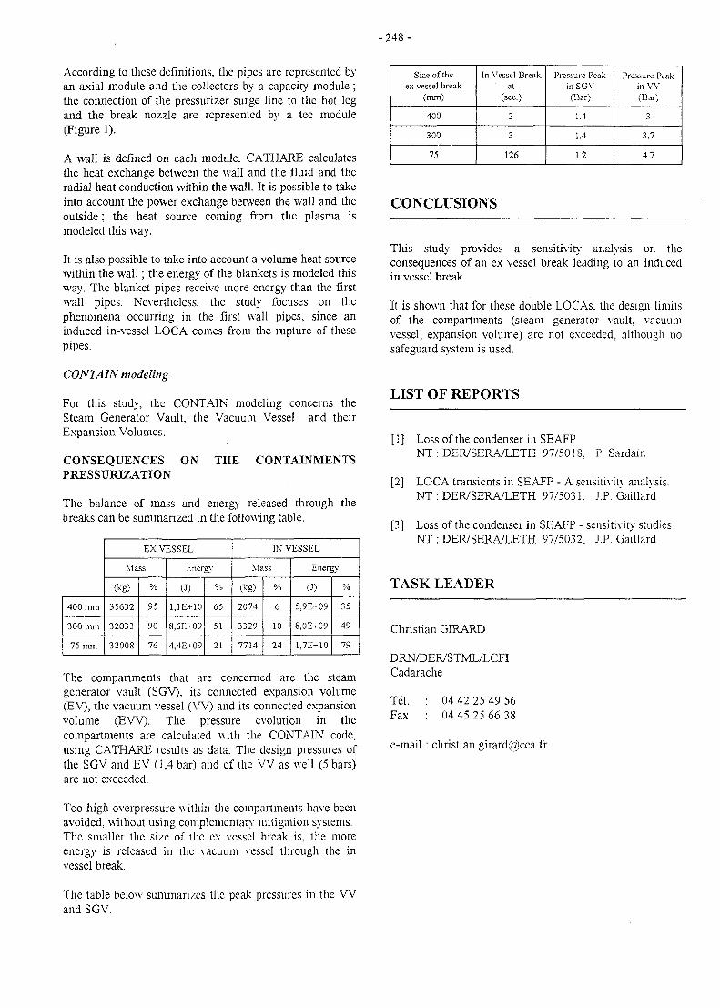
- 2 4 8 -
According to these definitions, the pipes are represented byan axial module and the collectors by a capacity module;the connection of the pressurizer surge line to the hot legand the break nozzle are represented by a tee module(Figure 1).
A wall is defined on each module. CATHARE calculatesthe heat exchange between the wall and the fluid and theradial heat conduction within the wall. It is possible to takeinto account the power exchange between the wall and theoutside; the heat source coming from the plasma ismodeled this way.
It is also possible to take into account a volume heat sourcewithin the wall; the energy of the blankets is modeled thisway. The blanket pipes receive more energy than the firstwall pipes. Nevertheless, the study focuses on thephenomena occurring in the first wall pipes, since aninduced in-vessel LOCA comes from the rupture of thesepipes.
CONTAIN modeling
For this study, the CONTAIN modeling concerns theSteam Generator Vault, the Vacuum Vessel and theirExpansion Volumes.
CONSEQUENCES ON THE CONTAINMENTSPRESSURTZATION
The balance of mass and energy released through thebreaks can be summarized in the following table.
400 mm
300 mm
75 mm
EX VESSEL
Mass
(kg)
35632
32033
32008
%
95
90
76
Energy
(J)
1.1E+10
8.6E+09
4,4E-09
%
65
51
21
IN VESSEL
Mass
(kg)
2074
3329
7714
%
6
10
24
Energy
(•>)
5.9E+09
8,0E+O9
1.7E+10
%
35
49
79
The compartments that are concerned are the steamgenerator vault (SGV), its connected expansion volume(EV), the vacuum vessel ( W ) and its connected expansionvolume (JEW). The pressure evolution in thecompartments are calculated with the CONTAIN code,using CATHARE results as data. The design pressures ofthe SGV and EV (1,4 bar) and of the VV as well (5 bars)are not exceeded.
Size of theex vessel break
(mm)
400
300
75
In Vessel Breakal
(sec.)
3
3
126
Pressure Peakin SGV(Bar)
1.4
1.4
1.2
Pressure Peakin VV(Bar)
3
3.7
4.7
CONCLUSIONS
This study provides a sensitivity analysis on theconsequences of an ex vessel break leading to an inducedin vessel break.
It is shown that for these double LOCAs. the design limitsof the compartments (steam generator vault, vacuumvessel, expansion volume) are not exceeded, although nosafeguard system is used.
LIST OF REPORTS
[1] Loss of the condenser in SE AFPNT : DER/SERA/LETH 97/5018. P. Sardain
[2] LOCA transients in SEAFP - A sensitivity analysis.NT : DER/SERA/LETH 97/5031. J.P. Gaillar'd
[3] Loss of the condenser in SEAFP - sensitivity studiesNT : DER/SERA/LETH 97/5032. J.P. Ga'illard
TASK LEADER
Christian GIRARD
DRN/DER/STML/LCFICadarache
Tel.Fax
04 42 25 49 5604 45 25 66 38
e-mail : [email protected]
Too high overpressure within the compartments have beenavoided, without using complementary mitigation systems.The smaller the size of the ex vessel break is, the moreenergy is released in the vacuum vessel through the invessel break.
The table below summarizes the peak pressures in the Wand SGV.
-249 -
SERF 0-3
Task Title : LONG TERM SCENARIOS
Subtitle : Prospects in energy supply and price in a world without fusion
INTRODUCTION
1. The task aims at contributing to a reflection on themethodology leading to the construction of globalscenarios on the availability, depletion, prices,emergence of substitutes, etc., of energy resources.
2. In parallel, we study the principles of the economicvaluation of industrial/scientific projects whoseoutcome is inherently uncertain.
2. The role of uncertainty has been recognised as major.Specifically, a substantial fraction of the value of agiven project can be associated to its flexibility, widely-defined. In consequence, the practice of averaging overpossible deterministic scenarios misses its goal: goodprojects providing a hedging against variability in theirfunctioning conditions, they should not be designed forminimising expected costs only. In the context of fusionresearch, the determinants of how the programmeshould be established are impregnated by the highdegree of uncertainty over event trees on which noconsensus can be reached.
1997 ACTIVITY
ACHIEVEMENT IN 1997
We have come to the following conclusions.
1. Though evaluating the physical availability' andtechnical feasibility of alternative energy sources overthe next century is obviously a necessary step for anylong term scenario, the comparative advantages canonly be observed in the equilibrium (defined below)trajectories of relative prices.
This comparison can be performed only through aneconomic (rather than purely technological) modellingwhere market forces are taken seriously.
It appeared that in most existing scenarios, supply anddemand trajectories are mere extrapolations withoutunderlying structure.
Economic analysis teaches us that they should be basedon a correct understanding of their relationship withexpectations and market powers, as well as bytechnologies.
The interest of the structural economic analysis is to seeprices and exchanged quantities as endogenousvariables.
The clarification we gain is that we can directly andconsistently examine the logical consequences in thechanges in these expectations, technologies, and marketpowers on the endogenous variables without invokingobscure guess. In the age of substitutability, a vision ofthe major spontaneous input shifts will prove moreilluminating than wishful recommendations.
PROGRAMME
1. A general equilibrium approach is potentially bettersuited for our purpose than partial and ad hocapproximations calculating, say, the dates of fulldepletion of various fuels. General equilibrium meansthat agents interact in the economy on severaldimensions, rather that through a single market wherethey would confront their supply and demand curves.This simple reasonable choice considerably enrichesour analysis by connecting sectors that are generallystudied separately. Given the complexity of the subject.our general philosophy is to organise dispersedintuitions.
The numerical difficulty of course considerablyincreases with the number of markets involved. Inorder to keep a manageable code, the model is notsophisticated in terms of technological information.With these principles in mind, we will describe a verysimplified world without fusion. We will construct ageneral equilibrium computable model of small size.Our self-imposed constraint of limited complexity firstderives from our will to keep control of our hypothesesand underlying mechanisms, and second is anindication that we refuse to make use of arguments thatwould remain a black-box to our (educated)interlocutors. Practically, we hope that our projectionscould be confronted to projections of the cost of fusionenergy year after year (to be supplied by othercontributors), providing a simple evaluation tool of theoptimal date of introduction of that technology in thecompetitive sector.
2. We will provide a new numerical approach to theimplementation of economically founded comparisonsof alternative research programmes. Our method isrelated to the recent development in mathematicalfinance.

-250-
TASK LEADER
Bertrand VBLLENEUVE
CEA/DSE/SEE/LEMME
DDEI Universite de Toulouse 1Place Anatole France31042 Toulouse cedex
Tel. : 33 5 61 12 85 95Fax : 33 5 61 12 86 37
e-mail : [email protected]
-251 -
UNDERLYINGTECHNOLOGY
BasicMachine Long Term
InertialConfinement
III2CF PA@1|Sleft SLM9C
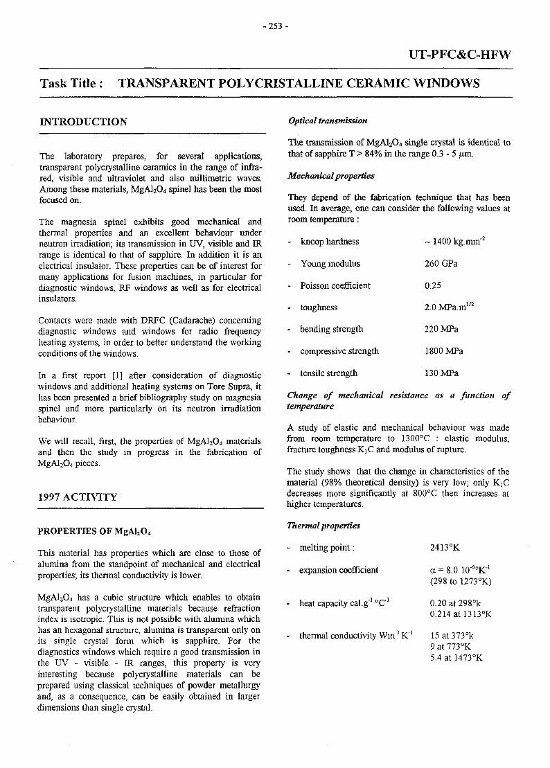
- 2 5 3 -
UT-PFC&C-HFW
Task Title : TRANSPARENT POLYCRISTALLINE CERAMIC WINDOWS
INTRODUCTION
The laboratory prepares, for several applications,transparent polycrystalline ceramics in the range of infra-red, visible and ultraviolet and also millimetric waves.Among these materials, MgAl2O4 spinel has been the mostfocused on.
The magnesia spinel exhibits good mechanical andthermal properties and an excellent behaviour underneutron irradiation; its transmission in UV, visible and IRrange is identical to that of sapphire. In addition it is anelectrical insulator. These properties can be of interest formany applications for fusion machines, in particular fordiagnostic windows, RF windows as well as for electricalinsulators.
Contacts were made with DRFC (Cadarache) concerningdiagnostic windows and windows for radio frequencyheating systems, in order to better understand the workingconditions of the windows.
In a first report [1] after consideration of diagnosticwindows and additional heating systems on Tore Supra, ithas been presented a brief bibliography study on magnesiaspinel and more particularly on its neutron irradiationbehaviour.
We will recall, first, the properties of MgAl2O4 materialsand then the study in progress in the fabrication ofMgAl2C>4 pieces.
1997 ACTIVITY
PROPERTIES OF MgAl2O4
This material has properties which are close to those ofalumina from the standpoint of mechanical and electricalproperties; its thermal conductivity is lower.
MgAl2O4 has a cubic structure which enables to obtaintransparent polycrystalline materials because refractionindex is isotropic. This is not possible with alumina whichhas an hexagonal structure, alumina is transparent only onits single crystal form which is sapphire. For thediagnostics windows which require a good transmission inthe UV - visible - IR ranges, this property is veryinteresting because polycrystalline materials can beprepared using classical techniques of powder metallurgyand, as a consequence, can be easily obtained in largerdimensions than single crystal.
Optical transmission
The transmission of MgAl2O4 single crystal is identical tothat of sapphire T > 84% in the range 0.3-5 \im.
Mechanical properties
They depend of the fabrication technique that has beenused. In average, one can consider the following values atroom temperature:
- knoop hardness
- Young modulus
- Poisson coefficient
- toughness
- bending strength
- compressive strength
- tensile strength
~ 1400 kg.mm"2
260 GPa
0.25
2.0 MPa.m1/2
220 MPa
1800 MPa
130 MPa
Change of mechanical resistance as a function oftemperature
A study of elastic and mechanical behaviour was madefrom room temperature to 1300°C : elastic modulus,fracture toughness KiC and modulus of rupture.
The study shows that the change in characteristics of thematerial (98% theoretical density) is very low; only KiCdecreases more significantly at 800°C then increases athigher temperatures.
Th ermal properties
- melting point:
- expansion coefficient
- heat capacity cal.g"1 °C"'
- thermal conductivity Wm"1 K"!
2413°K
a = 8.0 10"6oK-'(298 to 1273°K)
0.20 at 298°k0.214 at 1313°K
15 at 373°k9 at 773°K5.4 at 1473°K
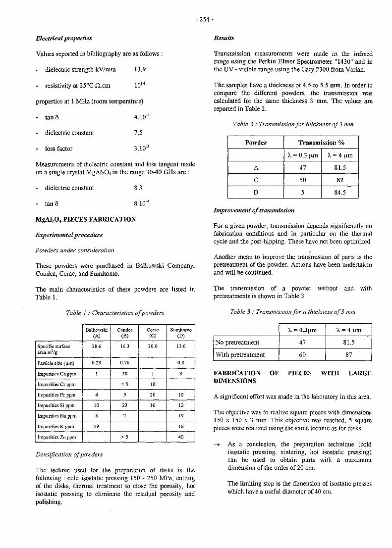
-254-
Electrical properties
Values reported in bibliography are as follows :
- dielectric strength kV/mm 11.9
- resistivity at 2 5 ° C a c m 1014
properties at 1 MHz (room temperature)
- tan 8 4.10"4
- dielectric constant 7.5
- loss factor 3.10"3
Measurements of dielectric constant and loss tangent madeon a single crystal MgAl2O4 in the range 30-40 GHz are :
- dielectric constant 8.3
- tan 8 8.10"4
MgAl2O4 PIECES FABRICATION
Experimental procedure
Powders under consideration
These powders were purchased in Ba'ikowski Company,Condea, Cerac, and Sumitomo.
The main characteristics of these powders are listed inTable 1.
Table 1: Characteristics of powders
Specific surfacearea m2/g
Particle size (nm)
Impurities Ca ppm
Impurities Cr ppm
Impurities Fe ppm
Impurities Si ppm
Impurities Na ppm
Impurities K ppm
Impurities Zn ppm
Baflcowski(A)
28.6
0.29
1
4
10
8
29
Condea(B)
16.3
0.76
38
< 5
9
23
7
<5
Cerac(C)
30.0
1
10
20
10
Sumitomo(D)
13.6
0.8
3
10
12
19
16
40
Densifwation of powders
The technic used for the preparation of disks is thefollowing : cold isostatic pressing 150 - 250 MPa, cuttingof the disks, thermal treatment to close the porosity, hotisostatic pressing to eliminate the residual porosity andpolishing.
Results
Transmission measurements were made in the infraedrange using the Perkin Elmer Spectrometer "1430" and inthe UV - visible range using the Cary 2300 from Varian.
The samples have a thickness of 4.5 to 5.5 mm. In order tocompare the different powders, the transmission wascalculated for the same thickness 3 mm. The values arereported in Table 2.
Table 2 : Transmission for thickness of 3 mm
Powder
A
C
D
Transmission %
X = 0.3 \im
47
50
5
X = 4 (am
81.5
82
84.5
Improvement of transmission
For a given powder, transmission depends significantly onfabrication conditions and in particular on the thermalcycle and the post-hipping. These have not been optimized.
Another mean to improve the transmission of parts is thepretreatment of the powder. Actions have been undertakenand will be continued.
The transmission of a powder without and withpretreatments is shown in Table 3.
Table 3 : Transmission for a thickness of 3 mm
No pretreatment
With pretreatment
X = 0.3 nm
47
60
X = 4 |im
81.5
87
FABRICATION OF PIECES WITH LARGEDIMENSIONS
A significant effort was made in the laboratory in this area.
The objective was to realize square pieces with dimensions150 x 150 x 3 mm. This objective was reached, 5 squarepieces were realized using the same technic as for disks.
-> As a conclusion, the preparation technique (coldisostatic pressing, sintering, hot isostatic pressing)can be used to obtain parts with a maximumdimension of the order of 20 cm.
The limiting step is the dimension of isostatic presseswhich have a useful diameter of 40 cm.
- 2 5 5 -
CONCLUSION TASK LEADER
Obtaining parts with large dimensions - 15 cm - was FreMe"ric VALINdemonstrated.
DTA/CEREM/CE2M/LECMAFuture work will focus on the improvement of the Centre d'Etudes de SACLAYtransmission level; two routes are being considered :pretratment of powder and paramaters of sintering and Te"l. : 01 69 08 25 14post-hipping. Fax : 0169089175
e-mail: [email protected]
REFERENCES
[1] F. Valin CEA/DTA/CEREM/CE2M/LECMADT 97/048 - 4/07/1997. Potentiates de MgAl2O4
dans les machines de fusion.
^
f I &L&MK
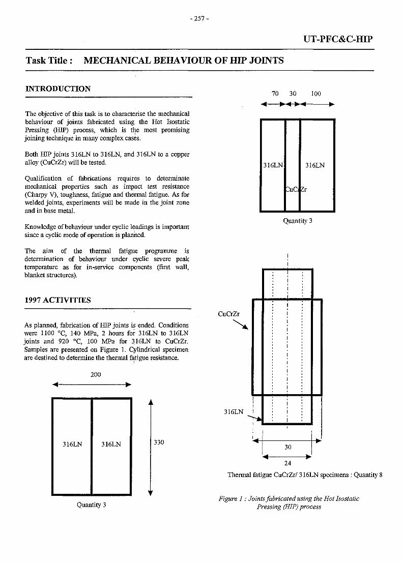
-257 -
UT-PFC&C-HIP
Task Title : MECHANICAL BEHAVIOUR OF HIP JOINTS
INTRODUCTION70 30
The objective of this task is to characterise the mechanicalbehaviour of joints fabricated using the Hot IsostaticPressing (HIP) process, which is the most promisingjoining technique in many complex cases.
Both HIP joints 316LN to 316LN, and 316LN to a copperalloy (CuCrZr) will be tested.
Qualification of fabrications requires to determinatemechanical properties such as impact test resistance(Charpy V), toughness, fatigue and thermal fatigue. As forwelded joints, experiments will be made in the joint zoneand in base metal.
Knowledge of behaviour under cyclic loadings is importantsince a cyclic mode of operation is planned.
The aim of the thermal fatigue programme isdetermination of behaviour under cyclic severe peaktemperature as for in-service components (first wall,blanket structures).
1997 ACTIVITIES
As planned, fabrication of HIP joints is ended. Conditionswere 1100 °C, 140 MPa, 2 hours for 316LN to 316LNjoints and 920 °C, 100 MPa for 316LN to CuCrZr.Samples are presented on Figure 1. Cylindrical specimenare destined to determine the thermal fatigue resistance.
200
100
316LN 316LN 330
316LN
^uC
316LN
Zx
CuCrZr
316LN
Quantity 3
30< •
Quantity 3
24
Thermal fatigue CuCrZr/ 316LN specimens : Quantity 8
Figure 1: Joints fabricated using the Hot IsostaticPressing (HIP) process
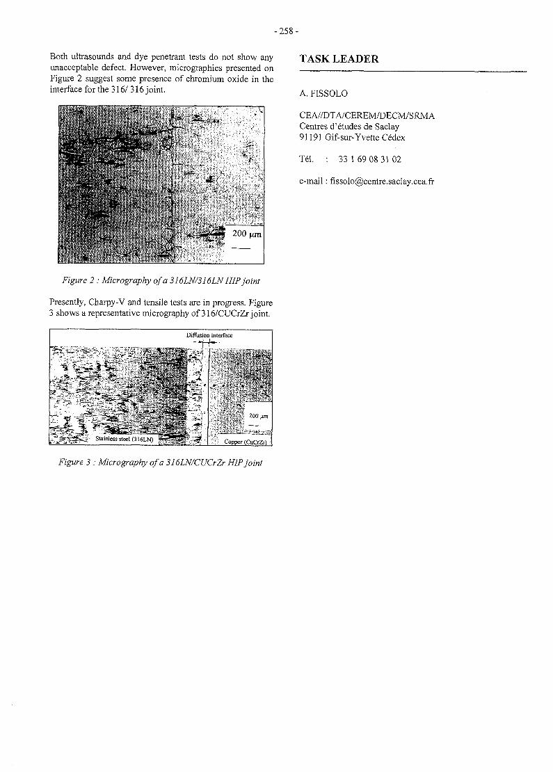
-258-
Both ultrasounds and dye penetrant tests do not show anyunacceptable defect. However, micrographies presented onFigure 2 suggest some presence of chromium oxide in theinterface for the 316/ 316 joint.
TASK LEADER
• » * •V "
-- N '•
ssa.- * 4
- ,'*
.->
\
- " -vV-^ 200 nm
Figure 2 : Micrography of a 316LN/316LN HIP joint
Presently, Charpy-V and tensile tests are in progress. Figure3 shows a representative micrography of 316/CUCrZr joint.
"£*
Diffusion interface
, - • % . - •
Slainles steel(316LN) } Copper (CuCrZr) j
A. FISSOLO
CEA//DTA/CEREM/DECM/SRMACentres d'etudes de Saclay91191 Gif-sur-Yvette Cedex
Tel. : 33 169 08 3102
e-mail: [email protected]
Figure 3 : Micrography of a 316LN/CUCrZr HIP joint
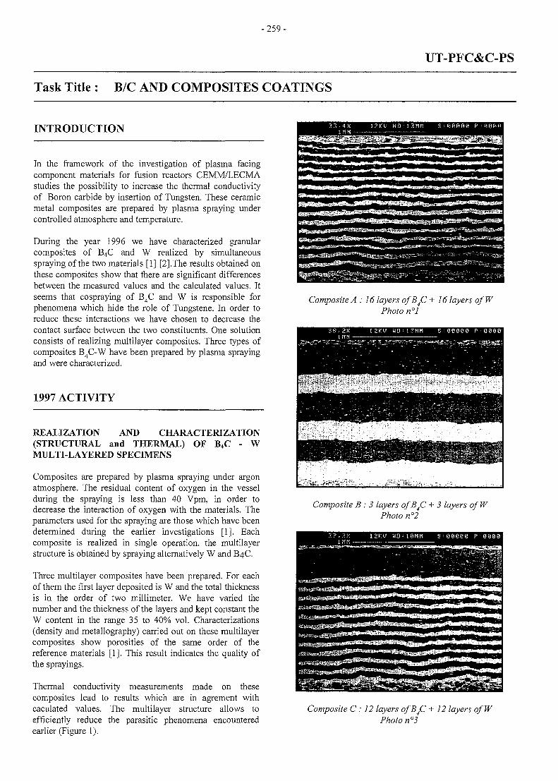
-259-
UT-PFC&C-PS
Task Title : B/C AND COMPOSITES COATINGS
INTRODUCTION 1 2 K U H O • i z n n s = eeeae P •
In the framework of the investigation of plasma facingcomponent materials for fusion reactors CEMM/LECMAstudies the possibility to increase the thermal conductivityof Boron carbide by insertion of Tungsten. These ceramicmetal composites are prepared by plasma spraying undercontrolled atmosphere and temperature.
During the year 1996 we have characterized granularcomposites of B4C and W realized by simultaneousspraying of the two materials [1] [2] .The results obtained onthese composites show that there are significant differencesbetween the measured values and the calculated values. Itseems that cospraying of B4C and W is responsible forphenomena which hide the role of Tungstene. In order toreduce these interactions we have chosen to decrease thecontact surface between the two constituents. One solutionconsists of realizing multilayer composites. Three types ofcomposites B4C-W have been prepared by plasma sprayingand were characterized.
1997 ACTIVITY
REALIZATION AND CHARACTERIZATION(STRUCTURAL and THERMAL) OF B4C - WMULTI-LAYERED SPECIMENS
Composites are prepared by plasma spraying under argonatmosphere. The residual content of oxygen in the vesselduring the spraying is less than 40 Vpm, in order todecrease the interaction of oxygen with the materials. Theparameters used for the spraying are those which have beendetermined during the earlier investigations [1]. Eachcomposite is realized in single operation, the multilayerstructure is obtained by spraying alternatively W and B4C.
Three multilayer composites have been prepared. For eachof them the first layer deposited is W and the total thicknessis in the order of two millimeter. We have varied thenumber and the thickness of the layers and kept constant theW content in the range 35 to 40% vol. Characterizations(density and metallography) carried out on these multilayercomposites show porosities of the same order of thereference materials [1]. This result indicates the quality ofthe sprayings.
Thermal conductivity measurements made on thesecomposites lead to results which are in agrement withcaculated values. The multilayer structure allows toefficiently reduce the parasitic phenomena encounteredearlier (Figure 1).
• P *
Composite A : 16 layers ofBJZ + 16 layers ofWPhoto n°l
Composite B : 3 layers ofB^C + 3 layers of WPhoto n°2
Composite C: 12 layers o/B4C + 12 layers ofWPhoto n°3
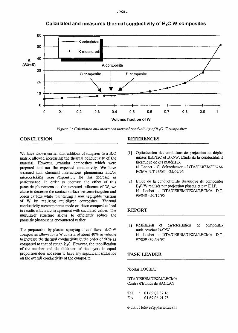
- 2 6 0 -
Calculated and measured thermal conductivity of B4C-W composites
K(W/rnK)
60
50
40
30
20
10
• K calculateul
' K measuredl
C composite
\
\
•H 1 h -
I1A composite
•—«
B composite
\ >/ _ _ _ _ ^ - ^
-H 1 1 1
• M
/
/
H 1 1
0.1 0.2 0.3 0.4 0.5 0.6
Volumic fraction of W
0.7 0.8 0.9
Figure 1: Calculated and measured thermal conductivity of B4C-W composites
CONCLUSION REFERENCES
We have shown earlier that addition of tungsten to a B4Cmatrix allowed increasing the thermal conductivity of thematerial. However, granular composites which wereprepared had not the expected conductivity. We haveassumed that chemical interactions phenomena and/ormicrocracking were responsible for this decrease inperformance. In order to decrease the effect of thisparasitic phenomena on the expected influence of W, wechose to decrease the contact surface between tungsten andboron carbide while maintening a non negligible fractionof W by realizing multilayer composites. Thermalconductivity measurements made on these composites leadto results which are in agrement with caculated values. Themultilayer structure allows to efficiently reduce theparasitic phenomena encountered earlier.
The preparation by plasma spraying of multilayer B4C-Wcomposites allows for a W content of about 40% in volumeto increase the thermal conductivity in the order of 50% ascompared to that of rough B4C. However, the modificationof the number and the thickness of the layers in equalproportion does not seem to have any significant influenceon the overall conductivity of the composite.
[1] Optimisation des conditions de projection de depotsmixtes B4C/TiC et B4C/W. Etude de la conductibilitethermique de ces materiauxN. Lochet - G. Schnedecker - DTA/CEREM/CE2M/ECMA R.T.96/034 -24/09/96
[2] Etude de la conductibilite thermique de compositesB4C/W realises par projection plasma et par H.I.P.N. Lochet - DTA/CEREM/CE2M/LECMA D.T.96/040 - 20/12/96
REPORT
[1] Realisation et caracterisation de compositesmulticouches B4C/WN. Lochet - DTA/CEREM/CE2M/LECMA D.T.97/059 -30 /09/97
TASK LEADER
Nicolas LOCHET
DTA/CEREM/CE2M/LECMACentre d'Etudes de SACLAY
Tel.Fax
0169 08 32 160169 08 9175
e-mail: [email protected]
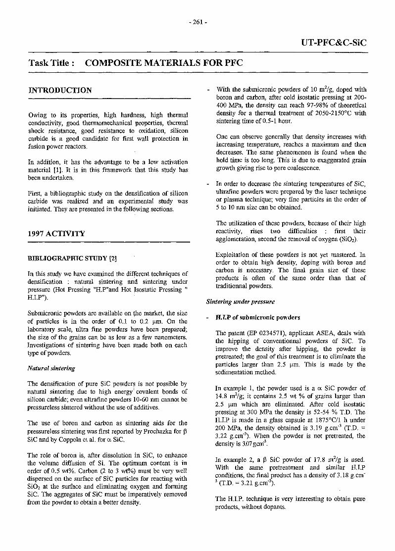
- 2 6 1 -
UT-PFC&C-SiC
Task Title : COMPOSITE MATERIALS FOR PFC
INTRODUCTION
Owing to its properties, high hardness, high thermalconductivity, good thermomechanical properties, thermalshock resistance, good resistance to oxidation, siliconcarbide is a good candidate for first wall protection infusion power reactors.
In addition, it has the advantage to be a low activationmaterial [1]. It is in this framework that this study hasbeen undertaken.
First, a bibliographic study on the densification of siliconcarbide was realized and an experimental study wasinitiated. They are presented in the following sections.
1997 ACTIVITY
BIBLIOGRAPHIC STUDY [2]
In this study we have examined the different techniques ofdensification : natural sintering and sintering underpressure (Hot Pressing "H.P"and Hot Isostatic Pressing "H.I.P").
Submicronic powders are available on ^he market, the sizeof particles is in the order of 0.1 to 0.2 urn. On thelaboratory scale, ultra fine powders have been prepared;the size of the grains can be as low as a few nanometers.Investigations of sintering have been made both on eachtype of powders.
Natural sintering
The densification of pure SiC powders is not possible bynatural sintering due to high energy' covalent bonds ofsilicon carbide; even ultrafine powders 10-60 nm cannot bepressureless sintered without the use of additives.
The use of boron and carbon as sintering aids for thepressureless sintering was first reported by Prochazka for J3SiC and by Coppola et al. for a SiC.
The role of boron is, after dissolution in SiC, to enhancethe volume diffusion of Si. The optimum content is inorder of 0.5 wt%. Carbon (2 to 3 wt%) must be very welldispersed on the surface of SiC particles for reacting withSiO2 at the surface and eliminating oxygen and formingSiC. The aggregates of SiC must be imperatively removedfrom the powder to obtain a better density.
- With the submicronic powders of 10 m2/g, doped withboron and carbon, after cold isostatic pressing at 200-400 MPa, the density can reach 97-98% of theoreticaldensity for a thermal treatment of 2050-2150°C withsintering time of 0.5-1 hour.
One can observe generally that density increases withincreasing temperature, reaches a maximum and thendecreases. The same phenomenon is found when thehold time is too long. This is due to exaggerated graingrowth giving rise to pore coalescence.
- In order to decrease the sintering temperatures of SiC,ultrafine powders were prepared by the laser techniqueor plasma technique; very fine particles in the order of5 to 10 nm size can be obtained.
The utilization of these powders, because of their highreactivity, rises two difficulties : first theiragglomeration, second the removal of oxygen (SiO2).
Exploitation of these powders is not yet mastered. Inorder to obtain high density, doping with boron andcarbon is necessary. The final grain size of theseproducts is often of the same order than that oftraditionnal powders.
Sintering underpressure
- H.I.P of submicronic powders
The patent (EP 0234571), applicant ASEA, deals withthe hipping of conventionnal powders of SiC. Toimprove the density after hipping, the powder ispretreated; the goal of this treatment is to eliminate theparticles larger than 2.5 um. This is made by thesedimentation method.
In example 1, the powder used is a a SiC powder of14.8 m2/g; it contains 2.5 wt % of grains larger than2.5 um which are eliminated. After cold isostaticpressing at 300 MPa the density is 52-54 % T.D. TheH.I.P is made in a glass capsule at 1875°C/1 h under200 MPa, the density obtained is 3.19 g.cm'3 (T.D. =3.22 g.cm"3). When the powder is not pretreated, thedensity is 3.07 gem"3.
In example 2, a P SiC powder of 17.8 m2/g is used.With the same pretreatment and similar H.I.Pconditions, the final product has a density of 3.18 g.cm"3 (T.D. = 3.21 g.cm"3).
The H.I.P. technique is very interesting to obtain pureproducts, without dopants.
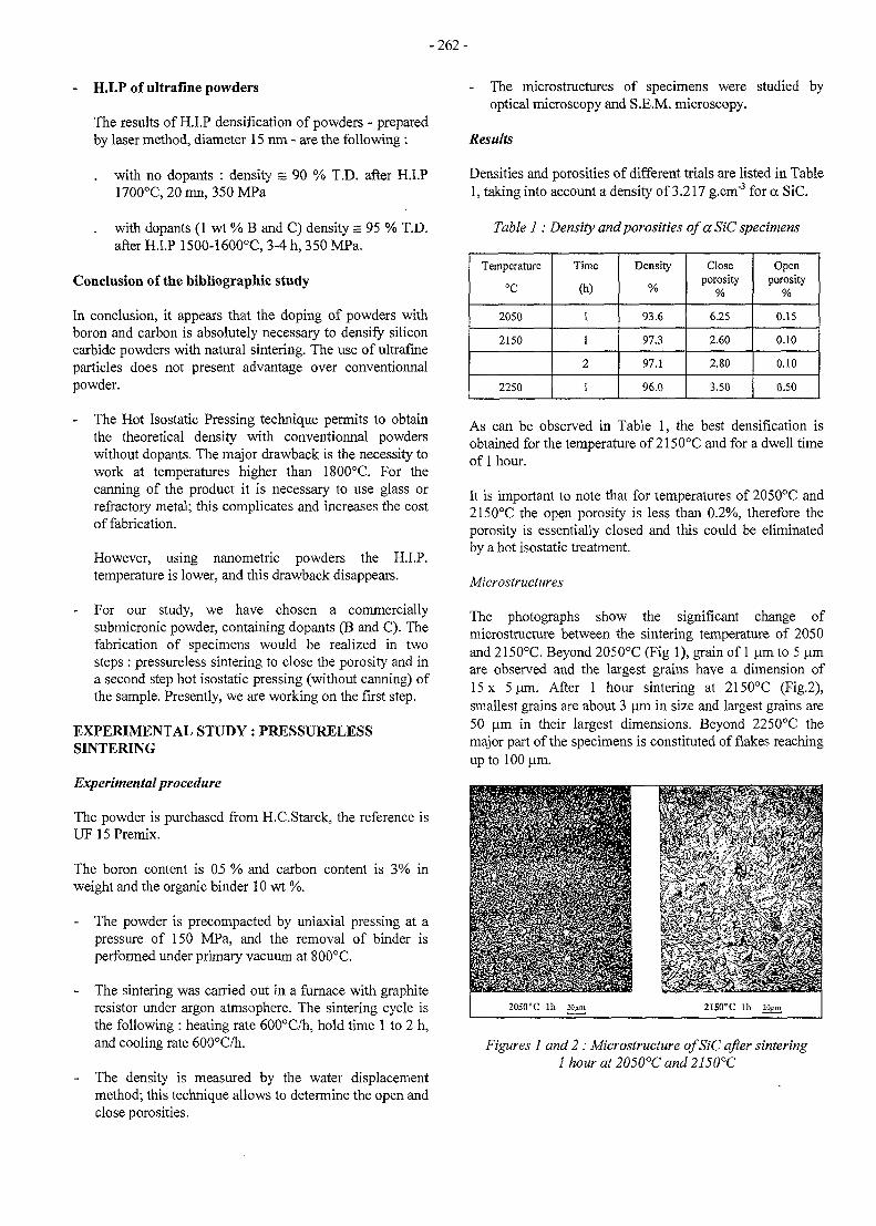
-262-
- H.I.P of ultrafine powders
The results of H.I.P densification of powders - preparedby laser method, diameter 15 run - are the following :
. with no dopants : density s 90 % T.D. after H.I.P1700°C,20mn,350MPa
. with dopants (1 wt % B and C) density s 95 % T.D.after H.I.P 1500-1600°C, 3-4 h, 350 MPa.
Conclusion of the bibliographic study
In conclusion, it appears that the doping of powders withboron and carbon is absolutely necessary to densify siliconcarbide powders with natural sintering. The use of ultrafmeparticles does not present advantage over conventionnalpowder.
- The Hot Isostatic Pressing technique permits to obtainthe theoretical density with conventionnal powderswithout dopants. The major drawback is the necessity towork at temperatures higher than 1800°C. For thecanning of the product it is necessary to use glass orrefractory metal; this complicates and increases the costof fabrication.
However, using nanometric powders the H.I.P.temperature is lower, and this drawback disappears.
- For our study, we have chosen a commerciallysubmicronic powder, containing dopants (B and C). Thefabrication of specimens would be realized in twosteps : pressureless sintering to close the porosity and ina second step hot isostatic pressing (without canning) ofthe sample. Presently, we are working on the first step.
EXPERIMENTAL STUDY: PRESSURELESSSINTERING
Experimental procedure
The powder is purchased from H.C.Starck, the reference isUF15Premix.
The boron content is 05 % and carbon content is 3% inweight and the organic binder 10 wt %.
- The powder is precompacted by uniaxial pressing at apressure of 150 MPa, and the removal of binder isperformed under primary vacuum at 800°C.
- The sintering was carried out in a furnace with graphiteresistor under argon atmsophere. The sintering cycle isthe following : heating rate 600°C/h, hold time 1 to 2 h,and cooling rate 600°C/h.
The density is measured by the water displacementmethod; this technique allows to determine the open andclose porosities.
- The microstructures of specimens were studied byoptical microscopy and S.E.M. microscopy.
Results
Densities and porosities of different trials are listed in Table1, taking into account a density of 3.217 g.cm"3 for a SiC.
Table 1: Density and porosities of a SiC specimens
Temperature
°C
2050
2150
2250
Time
(h)
1
1
2
1
Density
%
93.6
97.3
97.1
96.0
Closeporosity
%
6.25
2.60
2.80
3.50
Openporosity
%
0.15
0.10
0.10
0.50
As can be observed in Table 1, the best densification isobtained for the temperature of 2150°C and for a dwell timeof 1 hour.
It is important to note that for temperatures of 2050°C and2150°C the open porosity is less than 0.2%, therefore theporosity is essentially closed and this could be eliminatedby a hot isostatic treatment.
Microstructures
The photographs show the significant change ofmicrostructure between the sintering temperature of 2050and 2150°C. Beyond 2050°C (Fig 1), grain of 1 um to 5 umare observed and the largest grains have a dimension of15 x 5um. After 1 hour sintering at 2150°C (Fig.2),smallest grains are about 3 um in size and largest grains are50 um in their largest dimensions. Beyond 2250°C themajor part of the specimens is constituted of flakes reachingup to 100 um.
Figures 1 and 2 : Microstructure of SiC after sintering1 hour at 2050°C and 2150°C
- 2 6 3 -
These microstructural observations indicate that in order tomaintain a homogeneous structure the sinteringtemperature should be less than 2150°C.
CONCLUSION
The first results of denssification by natural sintering of acommercial powder appear promising because a density of97.3 % was obtained without optimization of sinteringcycle.
The next step in this study will be to research the bestnatural sintering cycle to obtain the highest density and tocharacterize the mechanical resistance of the product.
Another research objective will be the densification of SiCusing natural sintering followed by hot isostatic pressing.In this work the lowest temperature will be aimed at fornatural sintering leading to an open porosity less than 0.2%. The as obtained specimens will be subjected to apressure of 200 MPa at a temperature of about 2000°C.Mechanical characterization of the product will allow theselection of preparation process in between the naturalsintering and the technique in two steps.
TASK LEADER
Frederic VALIN
DTA/CEREM/CE2M/LECMACentre dEtudes de SACLAY
TelFax
01 69 08 25 1401 69 08 91 75
e-mail: [email protected]
REFERENCES
[1] L.Giancarli, J.D.Lulewicz CEA/DRN/DMT/SERMA95/115. Preliminary selection of Low-ActivationCeramics Composites to be used as StructuralMaterials in Fusion Power Reactors.
[2] F.Valin. CEA/DTA/CEREM/CE2M/LECMA R.T.97/060 23/10/97. Densification du carbure desilicium. RaportM.2.
- 2 6 5 -
UT-SM&C-A4
Task Title : ASSESMENT OF LASER WELDABILITY OF INTERNALCOMPONENTS MATERIALS
Subtitle: Laser weldability of martensitic and low activation steels
INTRODUCTION
The objective of this task is to complete and finalize theknowledge of the base metal weldability and the feasibilityof laser welding processes of martensitic and lowactivation steels (JLF1 and F82H nuancies). Thecharacteristics, advantages and limits of the lasersprocesses have been established, with the CEA laser tools.In using the CLFA facilities, an opening of the laserprocess feasibility will be explored in order to increase theprocess srength, to assume larger assembly tolerances, andconclude on the laser welding of these types of steels.
1997 ACTIVITY
1997 activities has been devoted to the study of martensiticand low activation steels, such comparison of the behaviorof JLF1 and F82H steels in CO2 flat welding, and YAGposition welding on F82H butt joints.
RESULTS
Following the CO* weldabilty work on JLF1 and F82Hsteels, performed in 1996, butt joints have been realized todetermine the mechanical characteristics of the weldedjoints with this process. Due to the small quantity of thesematerials, the same welding parameters, coming from theabove study, have been applied for the test samples. Thesame dimensions (6 mm thickness) have been used for thewelding samples.
The maximum number of tensile and resilience testssamples have been machined on the welded samples, onwhich a postweld heat treatment has been applied (750°/lhour). The quantity of bubbles in the molten pool is higherin JLF1 rather than F82H. The welding behavior is lesssensitive for these two steels than Manet one.
For JLF1 and F82H steels, a good recover of themechanical properties of the welded joints is observed,compared to the base metal.It has been observed :
- joints hardness below 300 Hv ( 210 Hv in the basemetal)
- a good mechanical strength at room temperature :640 Mpa
- a low decreasing of the mechanical strength at 400° C
- the same elongation rate than nominal one at roomtemperature and 400° C
- a fragile/ductile temperature transition as good as in thebase metal
Position welding has been tested for pulsed YAG laserwelding on the F82H steel. Two welding positions havebeen carried out : wall and vertical rising. For bothpositions, the same welding samples, than descrived above,have been used. Due to the small quantity of thesematerials, the welding parameters have been shortlyoptimized. In fact, very quickly, good welds have been get.This shows that the process seems to be tolerant with thewelding position. Welds on butt joints have been realized,for characterisation.
For both welding positions, smooth welds in fullpenetration have been get (at top and bottom). The weldwidth is larger in the case of vertical rising welding. Thequantity of bubbles in the molten pooi is high for bothwelding positions, but their dimensions are rather small :around 0.2 mm, and rarely 0.6 mm. The weld structure iscomparable to those observed in flat position. The heataffected zone is similar whatever the welding position(6 mm width). The hardness behavior is independant of thewelding position : 350 to 420 Hv in the welded zone, for190 to 220 Hv in the base metal.
CONCLUSIONS
The JLF1 and F82H steels welding behavior is lesssensitive for these two steels than Manet one. The CO2
welding, followed by a proper postweld heat treatment,provides good using properties for these two steels for theproduction of internal components. However, an improvingof the joint compacity must be carried out for this goal.
The possibility of welding in wall and vertical risingpositions has been demonstrated on F82H butt joints.Acceptable welds have been get. The mastering of themolten pool seems to be manageble. The decreasing of theporosity rate must be implemented. The increasing of thewelded zone size is not so high. The dimension of the heataffected zone and the behavior of the hardness profile isindependant of the welding position.
- 2 6 6 -
With a suitable postweld heat treatment, laser YAGprocess can provide good using properties for this steel.More development welding trials must be conducted toassess these first set-up.
REPORTS AND PUBLICATIONS
[1] "Caract&isation m6canique des soudures par laserCO2 en e'paisseur 6 mm des aciers JLF1 et F82H.Etude comparative du comportement des jointssoudds",Ph. AUBERT, A. RICHARD, J. SCHILDKNECHT,DPSA/CLFA/97-NT002/PhA/NA, Novembre 1997
[2] "Comportement du soudage en position de l'acierferrito-martensitique a faible activation F82H ene'paisseur 6 mm. Etude comparative du comportementdes joints soudes en corniche et verticale montantepar laser YAG",Ph. AUBERT, DPSA/CLFA/97-NT007/PhA/NA,Janvier 1998
TASK LEADER
Diane DE PRUNELE
DTA/DPSA/STACEN/SACLAY
TelFax
01 69 08 20 1401 69 08 75 97
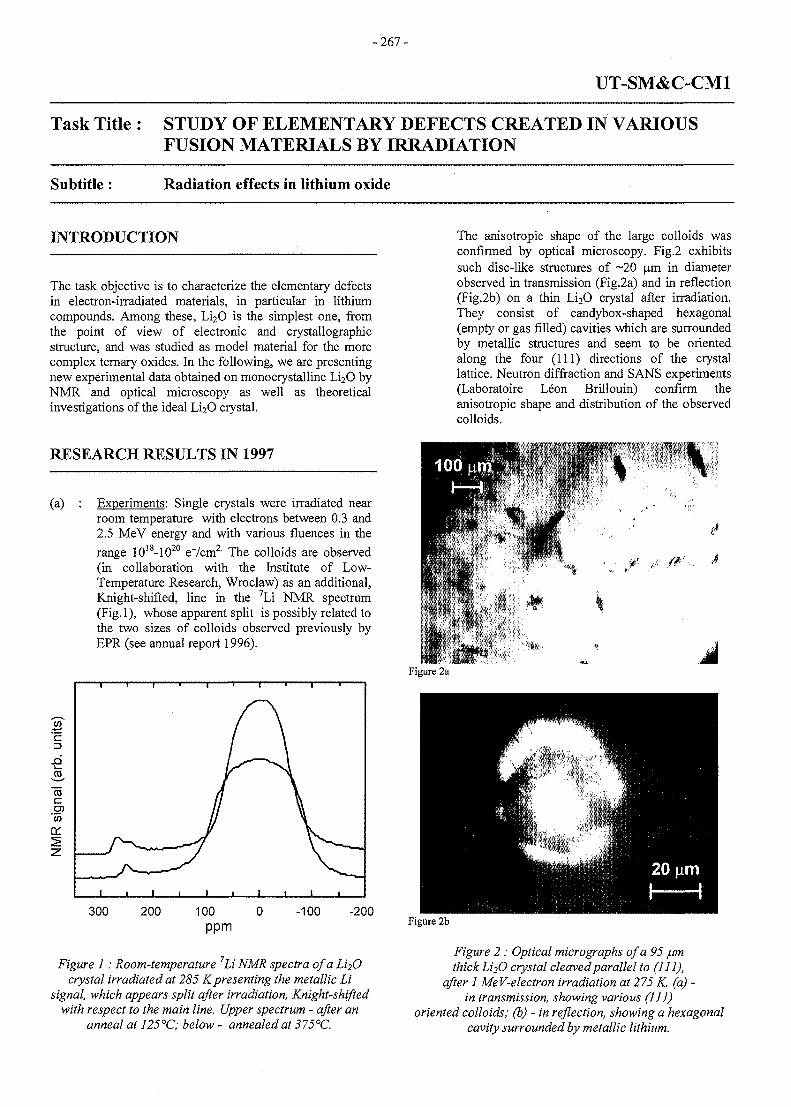
-267-
UT-SM&C-CM1
Task Title : STUDY OF ELEMENTARY DEFECTS CREATED IN VARIOUSFUSION MATERIALS BY IRRADIATION
Subtitle : Radiation effects in lithium oxide
INTRODUCTION
The task objective is to characterize the elementary defectsin electron-irradiated materials, in particular in lithiumcompounds. Among these, Li2O is the simplest one, fromthe point of view of electronic and crystallographicstructure, and was studied as model material for the morecomplex ternary oxides. In the following, we are presentingnew experimental data obtained on monocrystalline Li2O byNMR and optical microscopy as well as theoreticalinvestigations of the ideal Li2O crystal.
RESEARCH RESULTS IN 1997
(a) : Experiments: Single crystals were irradiated nearroom temperature with electrons between 0.3 and2.5 MeV energy and with various fiuences in the
range 1018-1020 e7cm2 The colloids are observed(in collaboration with the Institute of Low-Temperature Research, Wroclaw) as an additional,Knight-shifted, line in the 7Li NMR spectrum(Fig.l), whose apparent split is possibly related tothe two sizes of colloids observed previously byEPR (see annual report 1996).
300 -100 -200
Figure 1: Room-temperature 7Li NMR spectra of a Li2Ocrystal irradiated at 285 Kpresenting the metallic Li
signal, which appears split after irradiation, Knight-shiftedwith respect to the main line. Upper spectrum - after an
anneal at 125°C; below - annealed at 375°C.
The anisotropic shape of the large colloids wasconfirmed by optical microscopy. Fig.2 exhibitssuch disc-like structures of ~20 p.m in diameterobserved in transmission (Fig.2a) and in reflection(Fig.2b) on a thin Li2O crystal after irradiation.They consist of candybox-shaped hexagonal(empty or gas filled) cavities which are surroundedby metallic structures and seem to be orientedalong the four (111) directions of the crystallattice. Neutron diffraction and SANS experiments(Laboratoire Leon Brillouin) confirm theanisotropic shape and distribution of the observedcolloids.
dFigure 2a
Figure 2b
Figure 2 : Optical micrographs of a 95 fxmthick Li 2O crystal cleaved parallel to (111),
after 1 MeV-electron irradiation at 275 K. (a) -in transmission, showing various (111)
oriented colloids; (b) - in reflection, showing a hexagonalcavity surrounded by metallic lithium.
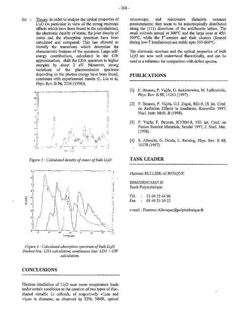
-268-
(b) : Theory: In order to analyse the optical properties ofLi2O (in particular in view of the strong excitoniceffects which have been found in the calculations),the electronic density of states, the joint density ofstates and the absorption spectrum have beencalculated and compared. This has allowed toidentify the transitions which determine thecharacteristic features of the spectrum. Large self-energy contributions, calculated in the GWapproximation, shift the LDA spectrum to higherenergies by about 2 eV. Moreover, strongvariations of the photoemission spectrumdepending on the photon energy have been found,consistent with experimental results (L. Liu et al,Phys. Rev. B 54, 2236 (1996)).
W AA •• ' « • • :
microscopy, and microwave dielectric constantmeasurements; they seem to be anisotropically distributedalong the (111) directions of the antifluorite lattice. Thesmall colloids anneal at 300°C and the large ones at 450-500°C, while the F+-centers and their clusters (formedduring low-T irradiations) are stable upto 550-600°C.
The electronic structure and the optical properties of bulkLi2O are now well understood theoretically, and can beused as a reference for comparison with defect spectra.
PUBLICATIONS
[1] F. Beuneu, P. Vajda, G. Jaskierowicz, M. Lafleurielle,Phys. Rev. B 55,11263(1997).
[2] F. Beuneu, P. Vajda, O.J. Zogal, REI-9, IX Int. Conf.on Radiation Effects in Insulators, Knoxville 1997;Nucl. Instr. Meth. B (1998).
[3] P. Vajda, F. Beuneu, ICFRM-8, VIII Int. Conf. onFusion Reactor Materials, Sendai 1997; J. Nucl. Mat.(1998).
[4] S. Albrecht, G. Onida, L. Reining, Phys. Rev. B 55,10278(1997).
Figure 3 : Calculated density of states of bulk L12O TASK LEADER
Florence RULLIER-ALBENQUE
DSM/DRECAM/LSIEcole Polytechnique
Tel.Fax
01 69 33 44 960169 33 30 22
e-mail: [email protected]
Figure 4 : Calculated absorption spectrum of bulk L12O.Dashed line: LDA calculation, continuous line: LDA + GW
calculation.
CONCLUSIONS
Electron irradiation of Li2O near room temperature leadsunder certain conditions to the creation of two types of disc-shaped metallic Li colloids, of respectively «lum and>lum in diameter, as observed by EPR, NMR, optical
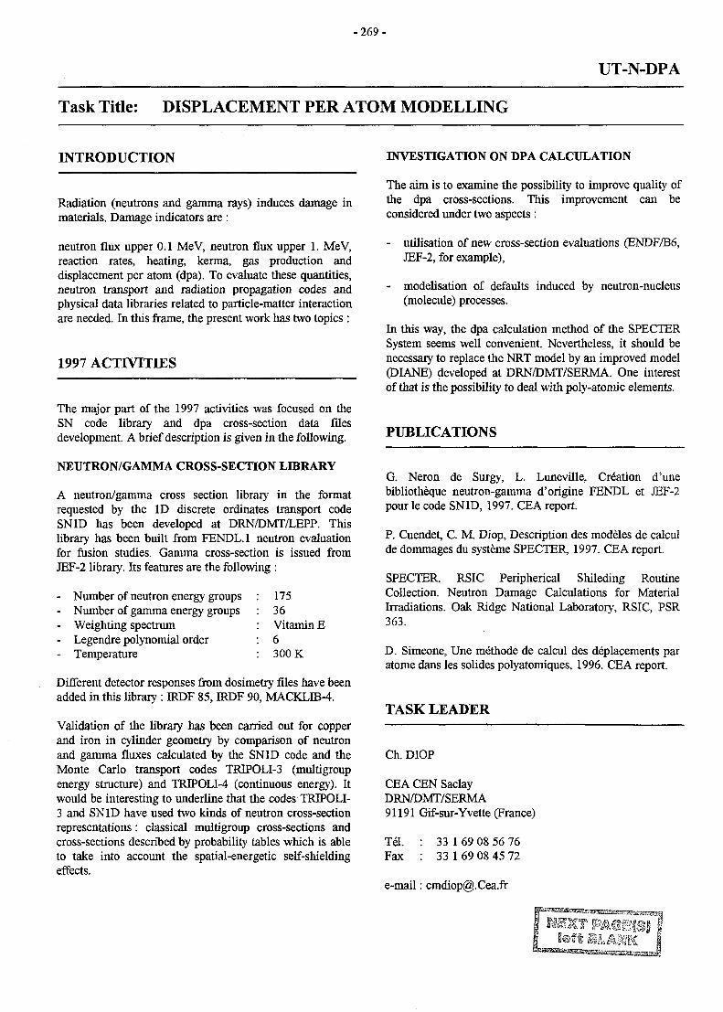
-269 -
UT-N-DPA
Task Title: DISPLACEMENT PER ATOM MODELLING
INTRODUCTION
Radiation (neutrons and gamma rays) induces damage inmaterials. Damage indicators are :
neutron flux upper 0.1 MeV, neutron flux upper 1. MeV,reaction rates, heating, kerma, gas production anddisplacement per atom (dpa). To evaluate these quantities,neutron transport and radiation propagation codes andphysical data libraries related to particle-matter interactionare needed. In this frame, the present work has two topics :
1997 ACTIVITIES
The major part of the 1997 activities was focused on theSN code library and dpa cross-section data filesdevelopment. A brief description is given in the following.
NEUTRON/GAMMA CROSS-SECTION LIBRARY
A neutron/gamma cross section library in the formatrequested by the ID discrete ordinates transport codeSN1D has been developed at DRN/DMT/LEPP. Thislibrary has been built from FENDL.l neutron evaluationfor fusion studies. Gamma cross-section is issued fromJEF-2 library. Its features are the following :
- Number of neutron energy groups : 175- Number of gamma energy groups : 36- Weighting spectrum : Vitamin E- Legendre polynomial order : 6- Temperature : 300 K
Different detector responses from dosimetry files have beenadded in this library : IRDF 85, IRDF 90, MACKLIB-4.
Validation of the library has been carried out for copperand iron in cylinder geometry by comparison of neutronand gamma fluxes calculated by the SN1D code and theMonte Carlo transport codes TRIPOLI-3 (multigroupenergy structure) and TRIPOLI-4 (continuous energy). Itwould be interesting to underline that the codes TRJPOLI-3 and SN1D have used two kinds of neutron cross-sectionrepresentations: classical multigroup cross-sections andcross-sections described by probability tables which is ableto take into account the spatial-energetic self-shieldingeffects.
INVESTIGATION ON DPA CALCULATION
The aim is to examine the possibility to improve quality ofthe dpa cross-sections. This improvement can beconsidered under two aspects :
- utilisation of new cross-section evaluations (ENDF/B6,JEF-2, for example),
- modelisation of defaults induced by neutron-nucleus(molecule) processes.
In this way, the dpa calculation method of the SPECTERSystem seems well convenient. Nevertheless, it should benecessary to replace the NRT model by an improved model(DIANE) developed at DRN/DMT/SERMA. One interestof that is the possibility to deal with poly-atomic elements.
PUBLICATIONS
G. Neron de Surgy, L. Luneville, Creation d'unebibliotheque neutron-gamma d'origine FENDL et JEF-2pour le code SN1D, 1997. CEA report.
P. Cuendet, C. M. Diop, Description des modeles de calculde dommages du systeme SPECTER, 1997. CEA report.
SPECTER. RSIC Peripherical Shileding RoutineCollection. Neutron Damage Calculations for MaterialIrradiations. Oak Ridge National Laboratory, RSIC, PSR363.
D. Simeone, Une methode de calcul des deplacements paratome dans les solides polyatomiques, 1996. CEA report.
TASK LEADER
Ch. DIOP
CEA CEN SaclayDRN/DMT/SERMA91191 Gif-sur-Yvette (France)
Tel. : 33 1 69 08 56 76Fax : 33 1 69 08 45 72
e-mail: cmdiop@. Cea.fr
- 2 7 1 -
UT-N-NDA
Task Title : NUCLEAR DATA ASSESSMENT
INTRODUCTION
The UT-Nuclear Data Assessment task focuses on thedevelopment of basic Nuclear data files, tools and modelsin association with neutronic design of the blanket andneutronic calculation schemes, relevant to fusiontechnology.
ACTIVITIES IN 1997
During 1997, activities were oriented towards thefollowing directions :
1. the activation library and its extension to new elements,
2. pre-processors to prepare the geometry input filesdescribing the DEMO-HCPB blanket in 3-D full sizenecessary for the neutron transport calculations.
3. post-processors to evaluate the heating powerdistribution starting from the output file of the neutrontransport code.
4. temperature-dependant neutron cross-section files.
5. additional response functions in TRIPOLI4.
6. Participation in the pre-feasibility analyses for theEuropean Neutronic Experiment for ITER-Pebble Bedblanket.
ACTIVATION LIBRARY
In 1996, the activation library contained the activationcharacteristics of nuclides such as : Al, C, Cr, Cu Fe, Mg,Mn, Si, Ti, V and Zr, ref [PI]. In 1997, other nuclides areadded to the Material Activation Library [MAL], such as ;Hg, Ge, Ca, Ni and Mo. The results of these evaluationsare used in the development of the fabrication proceduresand the selection of the FW structure materials.
The neutron-induced activation is evaluated using a fusion-like neutron spectrum under normal operation condition.The activation evaluations are carried out with FISPACTcode [Rl], using an EFF-2 activation cross section file.
The different quantities in the material activation libraryitself are evaluated at lMW/m2 FW neutron loading. A fullirradiation time of 20000 h was supposed. Cooling timesbetween 0 and 1000 years were considered. Correctionswill thus be needed in order to count for the normaloperation conditions of each machine [DEMO, ITER].
The calculated quantities are the total specific activity(Bq/kg), the tritium specific contribution in the totalactivity (Bq/kg), the decay heat rate (kW/kg), the DoseEquivalent Rate (Sv/kg), the Ingestion Dose (Sv) and theInhalation Dose (Sv). The details are reported in reference[P2].
The calculation of the neutron spectrum in the FW wasperformed using the Monte-Carlo simulation codeTRIPOLI4, ref {R2], using an ENDF/B6 cross-sectionlibrary. A total of 1 200 000 neutrons were sampledresulting in a statistical error less than 1% in the worstcase.
PRE-PROCESSOR FORGEOMETRY MODEL
DEMO BLANKET
In order to evaluate the global TBR of the DEMO-HCPBblanket a 3D full size model had to be used to describe theblanket geometry. A full size 3D geometry model of theDEMO-HCPB blanket may contain about 6000 volumesand about 4660 boundary conditions. The construction ofsuch a geometry model necessitates the development of aspecific module to automatically perform the task. Themodule is used to assess the impact of slight variations inthe geometry and in the composition of the referencedesign, on the main neutronic functions such as the globalTBR. The module constructs the geometry input filenecessary for the neutron transport simulation by theMonte-Carlo code, Tripoli-4, [R2]. The module wasbaptised HCPB-G.
The module performs its functions in two will distinctsteps:
1. the surfaces construction as required by TRIPOLI4code, and
2. the volume construction as required by TRIPOLI4 code.
Exhaustive tests are ongoing to qualify the module. Fewmodifications are still to be carried out in the HCPB-Gmodule in order to improve the quality of its messages andto allow the user to extract the maximum of theinformation about the geometry.
Extension of the HCPB-G may also be envisaged to addnew facilities such as the automatic construction of theplasma neutron source meshes and the use of the exactDEMO-like neutron source distribution.
The HCPB-G programme is fully written in Fortan90 andhas been developed and runs on SUN-Working stationsunder UNIX/Windows environment. The exact details ofthe program input/output files will be given in a UserGuide to be issued during the 1st part of the year 1998. Thedetails about the HCPB-G module and its differentfacilities are given in reference [P2].
- 2 7 2 -
POST-PROCESSOR FOR NEUTRONIC RESPONSEFUNCTIONS
The TRIPOLI4 input file corresponding to such highnumber of volumes is relatively of large size [~ 1.4 mo ofuseful information] and the output file is even larger [~ 4mo]. Treating such output files to extract informationabout the local and the global TBR and/or the heatingradial distributions is only possible via an adequate post-processing modules. Thus, a module has been developed inorder to allow the automatic extraction of the informationrelevant to the heating densities and heating radialdistributions.
The module, written in Fortran77, allows to calculate thesefunctions directly from the TRIPOLI-4 output file. Thedetails are given in reference [P2].
TEMPERATURE-DEPENDENT CROSS-SECTIONS
The dependence of the global TBR on the blankettemperature need to be assessed. The work on producingadequate cross section libraries at high temperatures : at250, and 400 °C for the beryllium and at 250, 400, 600 and900 °C for the Si, Zr, Ti, O and Li has started by the end ofthe year 1997. This work will continue for 1998. The hightemperature cross section library is issued from ENDF-B6.Priorities were given to the multiplicator and the breederceramic materials
This high temperature cross-sections library should allowus to assess the uncertainties in the neutron transportevaluation due to the temperature effect. Special care willcertainly be given to response functions such as the TBRand heating rates.
The processing of the nuclear data at high temperatureshas been carried on by the DRN-DMTSERMA/LEPP teamworking on the development & the maintenance ofTRIPOLI-4 package and its libraries.
ADDITIONAL RESPONSE FUNCTIONS INTRD7OLI-4
New response functions [detectors] have been integrated inthe TRIPOLI4 package to satisfy the fusion needs of theblanket neutronic design activities. Subsequently, reactionsat high energy such as [n,n], [n,2n] and [n,3n] can be nowevaluated separately in TRIPOLI4. This would contributeefficiently in the neutron transport evaluations in the Be-beds.
Another new facility in TRIPOLI-4 package is the functionSUM. It permits to integrate a given reaction rate over agiven number of meshes defined by the user. This newresponse function developed especially to allow theevaluation of the global TBR in a given blanket. It becomesvery useful when the blanket contains too much meshes (~6000 meshes in the 1/20* of the HCPB blanket).
A similar response function, which has been identified andneed to be developed and implemented in TRBPOLI-4package, is the dpa response function as a sum over manydifferent nuclides in the same neighbourhood (mesh).
This work is being carried out by the DRN-DMTSERMA/LEPP team working on the development ofthe TRIPOLI-4 package.
ITER-PBB BLANKET NEUTRONIC EXPERIMENT
The 'Future Experimental Activities and Nuclear DataNeeds' is one of the issues that have been worked outduring the 1997 within the EU-Fusion TechnologyProgram. A first proposal of these Post-EDA ExperimentalActivities was elaborated by the EU HT in April-June1997. The proposal showed a particular interest in ITER-Breeding Blanket Neutronic Experiments for blanketdesign validation.
The proposal foresees two types of experiments : tests inFNG (point source) and tests in JET (volume source). TheFNG/JET experiments schedule is planned from 1998 to2003.
Although, there is no real concerns about the evaluationsquality of the existing Monte-Carlo codes such as MCNPor TRTPOLI4, many concerns exist as far as the dataquality is concerned. The quality of the data on the Be and,with lesser extend, of the breeder materials needs to beimproved and fully qualified. This is generally the opinionof the neutron transport experts in the different EUlaboratories. Experimental activities should help inreducing data uncertainties and in confirm the TBR andthe heating power evaluations. The feasibility of suchexperiments has been examined by the different EU-associations.
The CEA has, consequently, participated in thispreliminary feasibility analysis and offered somerecommendations [P3]. These recommendation may besummarised as following:
1. A detailed program of R&D seems necessary to beundertaken in order to help the design to achieve areasonable state of maturity. Many other key issues willcertainly need an important R&D effort ( e.g. thePebble Bed thermal and thermo-mechanical responsefunctions, Be-Water interaction,...).
2. Neither the design specifications are fixed nor therelative contribution of uncertainties, other than theneutronic data ones, are yet evaluated. Thus, anextensive campaign of sensitivity analysis & studies isstill necessary to help in fixing the designspecifications, in identifying [in an exhaustive way]different sources of uncertainties, and in evaluating theimpact of these uncertainties on the main neutronicresponse functions with emphasis on distinguishingbetween integral and local response functions.
- 2 7 3 -
3. Once intervening parameters (design, responsefunctions and uncertainty sources) are fixed,experiments layout are elaborated and suitableexperimental installations are identified, decisions onlunching experimental activities would be envisaged.
CEA sees no identified needs that could justifyexperimental activities, in the period 1998-2000. Effortsmay rather be oriented towards an efficient R&D programin parallel with the identification of the needs inexperimental activities and their specifications.
Identification and specification of the experimentationneeds would be possible through a reasonable phase offeasibility studies and sensitivity analyses.The detailed report on the CEA recommendations is givenin reference [P3],
TASK LEADER
Mohamed EID
DRN/D1VIT-SERMASaclay-F91191 Gif sur Yvette Cedex
Tel. : 33 0169 08 3175Fax : 33 01 69 08 99 35
e-mail: [email protected]
REFERENCES
[R1]R.A. Forrest, J.Ch. Sublet «FISPACT-3 UserManual» AEA-InTec-1293, AEA/FUS/227, AEATechnology, April 1993.
[R2] I P . Both et al, « Notice d'utilisation de TRIPOLI4 »DMT 96/650, SERMA/LEPP 2009, 20/12/1996.
PUBLICATIONS
[PI] M. Eid, « An Activation library to help in the choiceof the material composition of the first wall of DEMOblanket» DMT 96/604, SERMA/LCA 1987,6/11/1996.
[P2] M. Eid, « Nuclear data assessment in support of theEuropean Fusion Program : reporting on the 1997activities in the DRN/DMT/SERMA. » DMT 97/550,SERMA/LCA 2153, November 1997.
[P3] M. Eid, «CEA-recommandations for the ITER-Breeder Blanket neutronic experiment. »DMT97/523, SRMA/LCA 2133, September 1997.
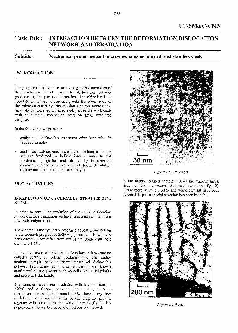
-275 -
UT-SM&C-CM3
Task Title : INTERACTION BETWEEN THE DEFORMATION DISLOCATIONNETWORK AND IRRADIATION
Subtitle : Mechanical properties and micro-mechanisms in irradiated stainless steels
INTRODUCTION
The purpose of this work is to investigate the interaction ofthe irradiation defects with the dislocation networkproduced by the plastic deformation. The objective is tocorrelate the measured hardening with the observation ofthe microstructures by transmission electron microscopy.Since the samples are ion irradiated, part of the work dealswith developping mechanical tests on small irradiatedsamples.
In the following, we present:
- analysis of dislocation structures after irradiation infatigued samples
apply the submicronic indentation technique to thesamples irradiated by helium ions in order to testmechanical properties and observe by transmissionelectron microscopy the interaction between the glidingdislocations and the irradiation damages.
1997 ACTIVITIES
IRRADIATION OF CYCLICALLY STRAINED 316LSTEEL
In order to reveal the evolution of the initial dislocationnetwork during irradiation we have irradiated samples fromlow cycle fatigue tests.
These samples are cyclically deformed at 350°C and belongto the research program of SRMA [1] from which two havebeen chosen. They differ from strains amplitude equal to :0.5% and 1.6%.
In the low strain sample, the dislocations microstructureconsists mainly in planar configurations. The highlystrained sample show a more structured dislocationnetwork. From many region observed various well-knownconfigurations are present such as cells, veins, labyrinthsand persistent slip bands.
The samples have been irradiated with krypton ions at350°C and a fluence corresponding to 1 dpa. Afterirradiation, the sample strained 0,5% shows very fewevolution : only scarce events of climbing are presenttogether with some black and white contrasts (fig. 1). Nopopulation of irradiation secondary defects is observed.
50 nm
Figure 1: Black dots
In the highly strained sample (1,6%) the various initialstructures do not present the least evolution (fig. 2).Furthermore, very few black and white contrast have beendetected despite a special attention has been brought.
Figure 2: Walls
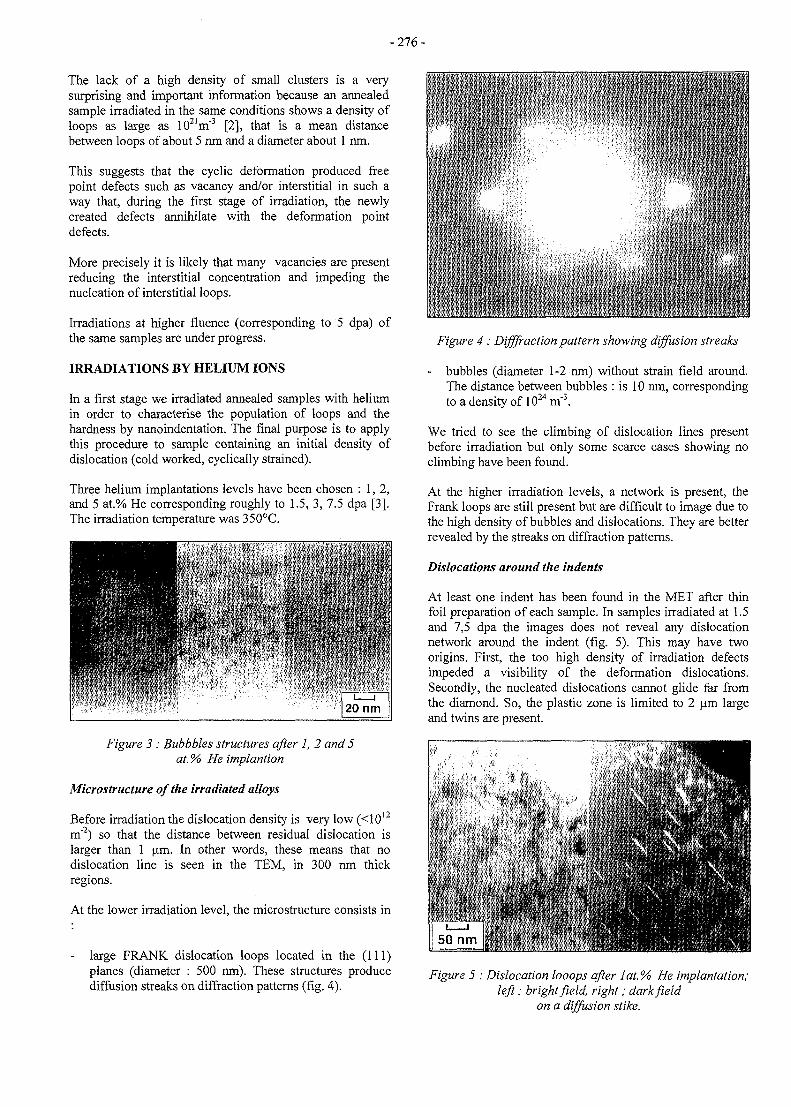
-276-
The lack of a high density of small clusters is a verysurprising and important information because an annealedsample irradiated in the same conditions shows a density ofloops as large as 102im"3 [2], that is a mean distancebetween loops of about 5 nm and a diameter about 1 run.
This suggests that the cyclic deformation produced freepoint defects such as vacancy and/or interstitial in such away that, during the first stage of irradiation, the newlycreated defects annihilate with the deformation pointdefects.
More precisely it is likely that many vacancies are presentreducing the interstitial concentration and impeding thenucleation of interstitial loops.
Irradiations at higher fluence (corresponding to 5 dpa) ofthe same samples are under progress.
IRRADIATIONS BY HELIUM IONS
In a first stage we irradiated annealed samples with heliumin order to characterise the population of loops and thehardness by nanoindentation. The final purpose is to applythis procedure to sample containing an initial density ofdislocation (cold worked, cyclically strained).
Three helium implantations levels have been chosen : 1, 2,and 5 at.% He corresponding roughly to 1.5, 3, 7.5 dpa [3].The irradiation temperature was 350°C.
Figure 3 : Bubbbles structures after 1, 2 and 5at. % He implantion
Microstructure of the irradiated alloys
Before irradiation the dislocation density is very low (<1012
m"2) so that the distance between residual dislocation islarger than 1 urn. In other words, these means that nodislocation line is seen in the TEM, in 300 nm thickregions.
At the lower irradiation level, the microstructure consists in
large FRANK dislocation loops located in the (111)planes (diameter : 500 nm). These structures producediffusion streaks on diffraction patterns (fig. 4).
Figure 4 : Difffraction pattern showing diffusion streaks
- bubbles (diameter 1-2 nm) without strain field around.The distance between bubbles : is 10 nm, correspondingto a density of 1024 m~3.
We tried to see the climbing of dislocation lines presentbefore irradiation but only some scarce cases showing noclimbing have been found.
At the higher irradiation levels, a network is present, theFrank loops are still present but are difficult to image due tothe high density of bubbles and dislocations. They are betterrevealed by the streaks on diffraction patterns.
Dislocations around the indents
At least one indent has been found in the MET after thinfoil preparation of each sample. In samples irradiated at 1.5and 7,5 dpa the images does not reveal any dislocationnetwork around the indent (fig. 5). This may have twoorigins. First, the too high density of irradiation defectsimpeded a visibility of the deformation dislocations.Secondly, the nucleated dislocations cannot glide far fromthe diamond. So, the plastic zone is limited to 2 u.m largeand twins are present.
Figure 5 : Dislocation hoops after lat.% He implantation;left: bright field, right; dark field
on a diffusion stike.
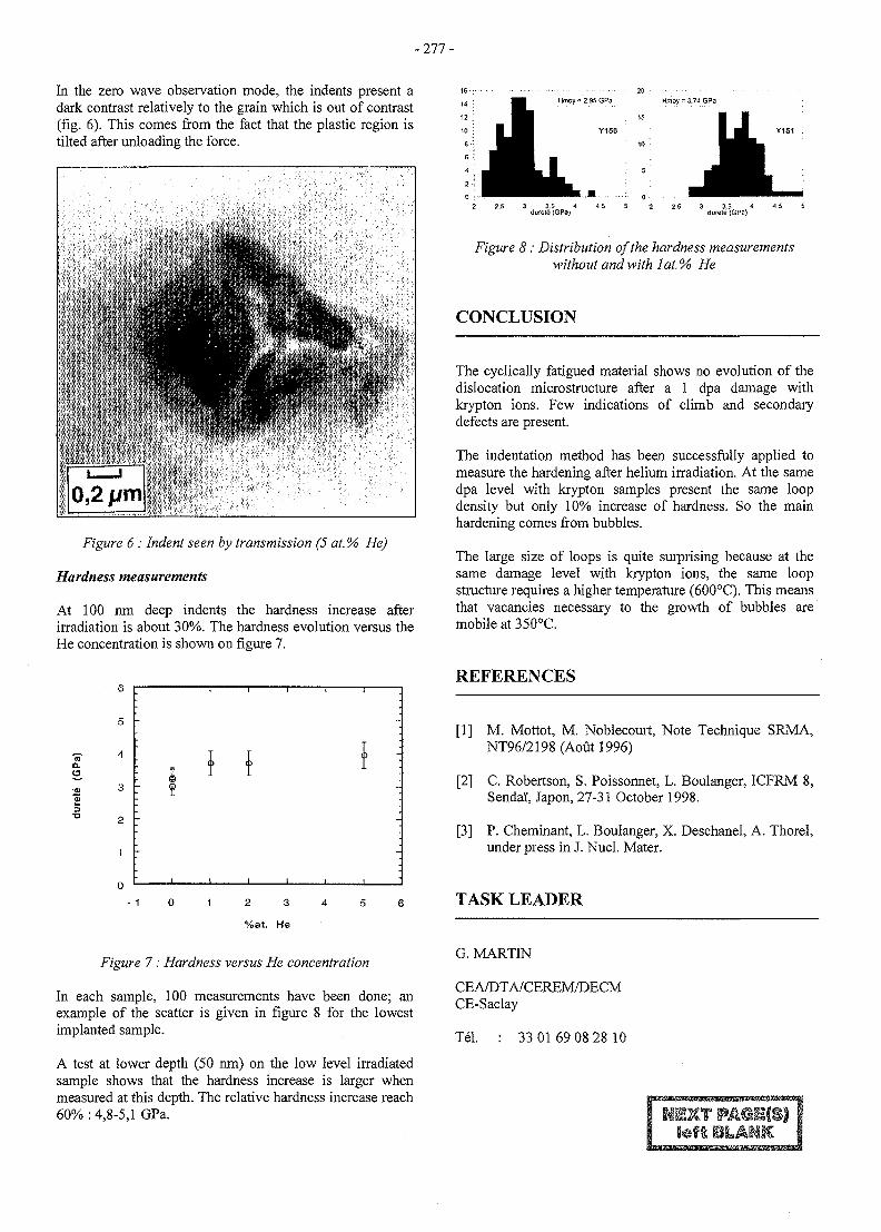
- 277 -
In the zero wave observation mode, the indents present adark contrast relatively to the grain which is out of contrast(fig. 6). This comes from the fact that the plastic region istilted after unloading the force.
Figure 6: Indent seen by transmission (5 at.% He)
Hardness measurements
At 100 nm deep indents the hardness increase afterirradiation is about 30%. The hardness evolution versus theHe concentration is shown on figure 7.
a.
Figure 7: Hardness versus He concentration
In each sample, 100 measurements have been done; anexample of the scatter is given in figure 8 for the lowestimplanted sample.
A test at lower depth (50 nm) on the low level irradiatedsample shows that the hardness increase is larger whenmeasured at this depth. The relative hardness increase reach60%: 4,8-5,1 GPa.
20Hmoy = 2.95 GPa • Hmoy = 3.74 GPi
;• 1 5
Y150
10
2 2.5 3 3.5 1 1.5 5 2 2.5 3 3.5 1 4 5 5durel6 (GPa) durele {GPa)
Figure 8 : Distribution of the hardness measurementswithout and with lat. % He
CONCLUSION
The cyclically fatigued material shows no evolution of thedislocation microstructure after a 1 dpa damage withkrypton ions. Few indications of climb and secondarydefects are present.
The indentation method has been successfully applied tomeasure the hardening after helium irradiation. At the samedpa level with krypton samples present the same loopdensity but only 10% increase of hardness. So the mainhardening comes from bubbles.
The large size of loops is quite surprising because at thesame damage level with krypton ions, the same loopstructure requires a higher temperature (600°C). This meansthat vacancies necessary to the growth of bubbles aremobile at 350°C.
REFERENCES
[1] M. Mottot, M. Noblecourt, Note Technique SRMA,NT96/2198(Aoutl996)
[2] C. Robertson, S. Poissonnet, L. Boulanger, ICFRM 8,Sendai", Japon, 27-31 October 1998.
[3] P. Cheminant, L. Boulanger, X. Deschanel, A. Thorel,under press in J. Nucl. Mater.
TASK LEADER
G. MARTIN
CEA/DTA/CEREM/DECMCE-Saclay
Tel. 33 0169 08 28 10
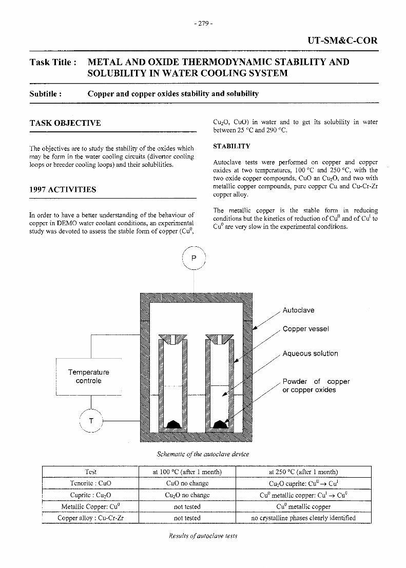
-279-
UT-SM&C-COR
Task Title : METAL AND OXIDE THERMODYNAMIC STABILITY ANDSOLUBILITY IN WATER COOLING SYSTEM
Subtitle : Copper and copper oxides stability and solubility
TASK OBJECTIVE
The objectives are to study the stability of the oxides whichmay be form in the water cooling circuits (divertor coolingloops or breeder cooling loops) and their solubilities.
1997 ACTIVITIES
In order to have a better understanding of the behaviour ofcopper in DEMO water coolant conditions, an experimentalstudy was devoted to assess the stable form of copper (Cu°,
Cu2O, CuO) in water and to get its solubility in waterbetween 25 °C and 290 °C.
STABILITY
Autoclave tests were performed on copper and copperoxides at two temperatures, 100 °C and 250 °C, with thetwo oxide copper compounds, CuO an CU2O, and two withmetallic copper compounds, pure copper Cu and Cu-Cr-Zrcopper alloy.
The metallic copper is the stable form in reducingconditions but the kinetics of reduction of Cu" and of Cu1 toCu° are very slow in the experimental conditions.
Temperaturecontrole
Schematic of the autoclave device
Autoclave
Copper vessel
Aqueous solution
Powder of copperor copper oxides
Test
Tenorite : CuO
Cuprite : Cu2O
Metallic Copper: Cu°
Copper alloy : Cu-Cr-Zr
at 100 °C (after 1 month)
CuO no change
Cu2O no change
not tested
not tested
at 250 °C (after 1 month)
Cu2O cuprite: Cu11 -> Cu1
Cu° metallic copper: Cu1 -> Cu°
Cu° metallic copper
no crystalline phases clearly identified
Results of autoclave tests
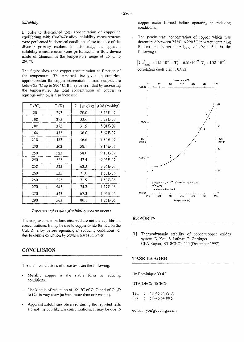
-280 -
Solubility
In order to determined total concentration of copper inequilibrium with Cu-Cr-Zr alloy, solubility measurementswere performed in chemical conditions close to those of thedivertor primary coolant. In this study, the apparentsolubility measurements were performed in a flow devicemade of titanium in the temperature range of 25 °C to290 °C.
The figure shows the copper concentration as function ofthe temperature. The reported line gives an empiricalapproximation for copper concentration from temperaturebelow 25 °C up to 290 °C. It may be seen that by increasingthe temperature, the total concentration of copper inaqueous solution is also increased.
T(°C)
20
100
100
160
210
230
250
250
250
260
260
270
270
290
T(K)
293
373
373
433
483
503
523
523
523
533
533
543
543
563
[Cu] (ug/kg)
20.0
33.6
31.9
36.0
46.6
58.1
58.0
57.4
63.3
71.0
71.9
74.2
67.3
80.1
[Cu] (mol/kg)
3.15E-07
5.28E-07
5.01E-07
5.67E-07
7.34E-07
9.14E-07
9.13E-07
9.03E-07
9.96E-07
1.12E-06
1.13E-06
1.17E-06
1.06E-06
1.26E-06
Experimental results of solubility measurements
The copper concentrations observed are not the equilibriumconcentrations. It may be due to copper oxide formed on theCuCrZr alloy before operating in reducing conditions, ordue to copper oxidation by oxygen traces in water.
CONCLUSION
The main conclusions of these tests are the following:
- Metallic copper is the stable form in reducingconditions.
- The kinetic of reduction at 100 °C of CuO and of Cu2Oto Cu° is very slow (at least more than one month).
Apparent solubilities observed during the reported testsare not the equilibrium concentrations. It may be due to
copper oxide formed before operating in reducingconditions.
The steady state concentration of copper which wasdetermined between 25 °C to 290 °C in water containinglithium and boron at pH25°c of about 6.4, is thefollowing:
[CuLai = U5-l°"''• Tk ' 6 ' 6 1 'Lai 1-32.
correlation coefficient: 0,953.
Temperature (°CJ
100 150 200
[Cu)|mo«isi = 1,1510" TK ! • 6,61 10"* T K * 1,3210'
R2 = 0,953
* data used for the fit
- ^ - ^ — , — ^ - , — . . . i .———.—r-i—~—~-t~^—^
323 373 423 473
Temperature (K)
REPORTS
[1] Thermodynamic stability of copper/copper oxidessystem. D. You, S. Lefevre, P. GerlingerCEA Report, RT-SCECF 440 (December 1997)
TASK LEADER
Dr Dominique YOU
DTA/DECM/SCECF
Tel.Fax
(1)46 54 83 71(1)46 54 88 51
e-mail : [email protected]
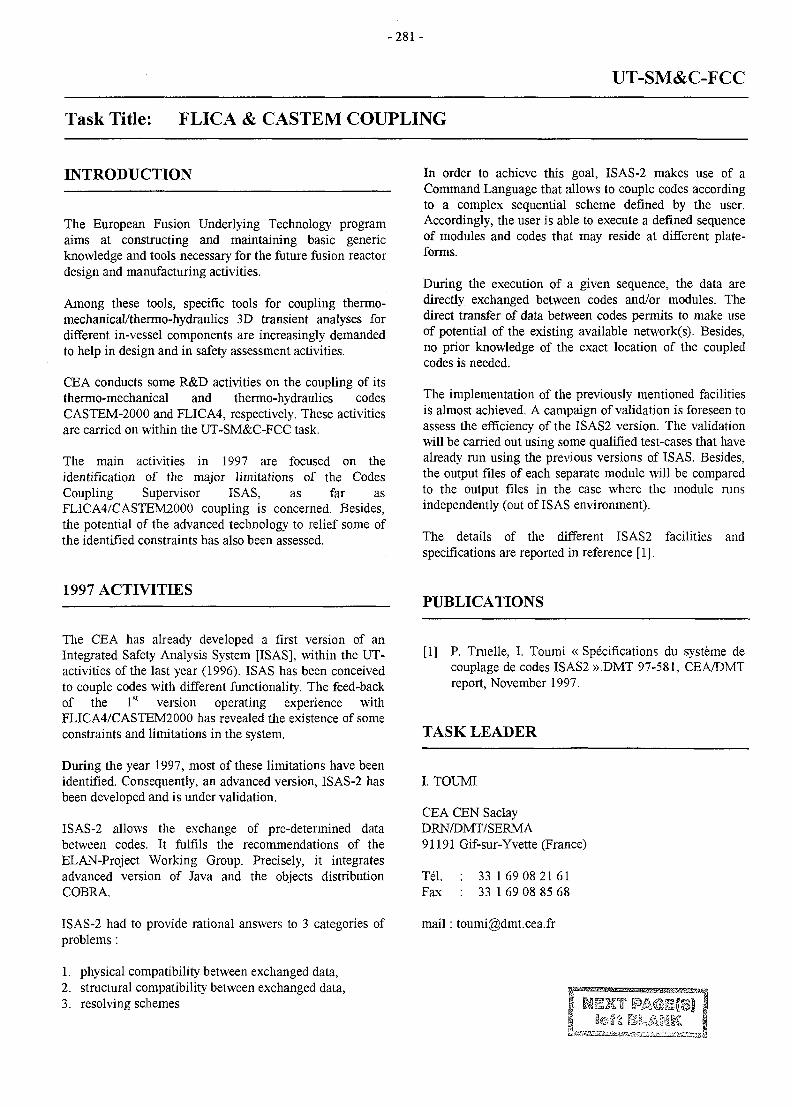
-281 -
UT-SM&C-FCC
Task Title: FLICA & CASTEM COUPLING
INTRODUCTION
The European Fusion Underlying Technology programaims at constructing and maintaining basic genericknowledge and tools necessary for the future fusion reactordesign and manufacturing activities.
Among these tools, specific tools for coupling thermo-mechanical/thermo-hydraulics 3D transient analyses fordifferent in-vessel components are increasingly demandedto help in design and in safety assessment activities.
CEA conducts some R&D activities on the coupling of itsthermo-mechanical and thermo-hydraulics codesCASTEM-2000 and FLICA4, respectively. These activitiesare carried on within the UT-SM&C-FCC task.
The main activities in 1997 are focused on theidentification of the major limitations of the CodesCoupling Supervisor ISAS, as far asFLICA4/CASTEM2000 coupling is concerned. Besides,the potential of the advanced technology to relief some ofthe identified constraints has also been assessed.
In order to achieve this goal, ISAS-2 makes use of aCommand Language that allows to couple codes accordingto a complex sequential scheme defined by the user.Accordingly, the user is able to execute a defined sequenceof modules and codes that may reside at different plate-forms.
During the execution of a given sequence, the data aredirectly exchanged between codes and/or modules. Thedirect transfer of data between codes permits to make useof potential of the existing available network(s). Besides,no prior knowledge of the exact location of the coupledcodes is needed.
The implementation of the previously mentioned facilitiesis almost achieved. A campaign of validation is foreseen toassess the efficiency of the ISAS2 version. The validationwill be carried out using some qualified test-cases that havealready run using the previous versions of ISAS. Besides,the output files of each separate module will be comparedto the output files in the case where the module runsindependently (out of ISAS environment).
The details of the different ISAS2 facilitiesspecifications are reported in reference [1].
and
1997 ACTIVITIES
The CEA has already developed a first version of anIntegrated Safety Analysis System [ISAS], within the UT-activities of the last year (1996). ISAS has been conceivedto couple codes with different functionality. The feed-backof the 1st version operating experience withFLICA4/CASTEM2000 has revealed the existence of someconstraints and limitations in the system.
During the year 1997, most of these limitations have beenidentified. Consequently, an advanced version, ISAS-2 hasbeen developed and is under validation.
ISAS-2 allows the exchange of pre-determined databetween codes. It fulfils the recommendations of theELAN-Project Working Group. Precisely, it integratesadvanced version of Java and the objects distributionCOBRA.
ISAS-2 had to provide rational answers to 3 categories ofproblems :
1. physical compatibility between exchanged data,2. structural compatibility between exchanged data,3. resolving schemes
PUBLICATIONS
[1] P. Truelle, I. Toumi « Specifications du systeme decouplage de codes ISAS2 ».DMT 97-581, CEA/DMTreport, November 1997.
TASK LEADER
I. TOUMI
CEA CEN SaclayDRN/DMT/SERMA91191 Gif-sur-Yvette (France)
Tel. : 33 169 08 2161Fax : 33 1 69 08 85 68
mail: toumi(S)dmt.cea.fr
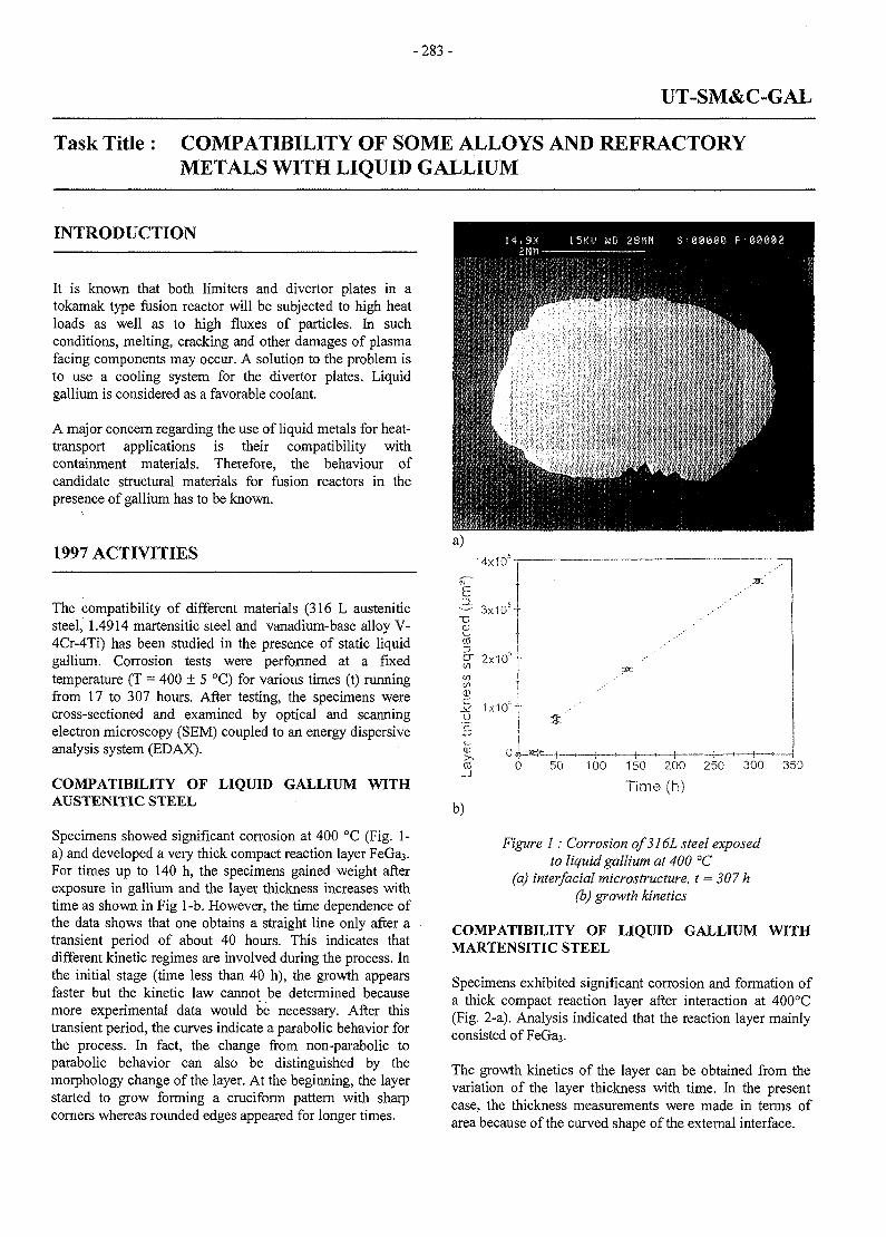
- 283 -
UT-SM&C-GAL
Task Title: COMPATIBILITY OF SOME ALLOYS AND REFRACTORYMETALS WITH LIQUID GALLIUM
INTRODUCTION
It is known that both limiters and divertor plates in atokamak type fusion reactor will be subjected to high heatloads as well as to high fluxes of particles. In suchconditions, melting, cracking and other damages of plasmafacing components may occur. A solution to the problem isto use a cooling system for the divertor plates. Liquidgallium is considered as a favorable coolant.
A major concern regarding the use of liquid metals for heat-transport applications is their compatibility withcontainment materials. Therefore, the behaviour ofcandidate structural materials for fusion reactors in thepresence of gallium has to be known.
1997 ACTIVITIES
The compatibility of different materials (316 L austeniticsteel, 1.4914 martensitic steel and vanadium-base alloy V-4Cr-4Ti) has been studied in the presence of static liquidgallium. Corrosion tests were performed at a fixedtemperature (T = 400 + 5 °C) for various times (t) runningfrom 17 to 307 hours. After testing, the specimens werecross-sectioned and examined by optical and scanningelectron microscopy (SEM) coupled to an energy dispersiveanalysis system (EDAX).
COMPATIBILITY OF LIQUID GALLIUM WITHAUSTENITIC STEEL
Specimens showed significant corrosion at 400 °C (Fig. 1-a) and developed a very thick compact reaction layer FeGa3.For times up to 140 h, the specimens gained weight afterexposure in gallium and the layer thickness increases withtime as shown in Fig 1-b. However, the time dependence ofthe data shows that one obtains a straight line only after atransient period of about 40 hours. This indicates thatdifferent kinetic regimes are involved during the process. Inthe initial stage (time less than 40 h), the growth appearsfaster but the kinetic law cannot be determined becausemore experimental data would be necessary. After thistransient period, the curves indicate a parabolic behavior forthe process. In fact, the change from non-parabolic toparabolic behavior can also be distinguished by themorphology change of the layer. At the beginning, the layerstarted to grow forming a cruciform pattern with sharpcorners whereas rounded edges appeared for longer times.
•4x10
3x10 --
wega" 2x10s-^ \01 ICD
S 1x10s-o
CO 50 100 150 200 250 300 350
Time (h)
b)
Figure 1: Corrosion of316L steel exposedto liquid gallium at 400 °C
(a) interfacial microstructure, t — 307 h(b) growth kinetics
COMPATIBILITY OF LIQUID GALLIUM WITHMARTENSITIC STEEL
Specimens exhibited significant corrosion and formation ofa thick compact reaction layer after interaction at 400°C(Fig. 2-a). Analysis indicated that the reaction layer mainlyconsisted of FeGa3.
The growth kinetics of the layer can be obtained from thevariation of the layer thickness with time. In the presentcase, the thickness measurements were made in terms ofarea because of the curved shape of the external interface.
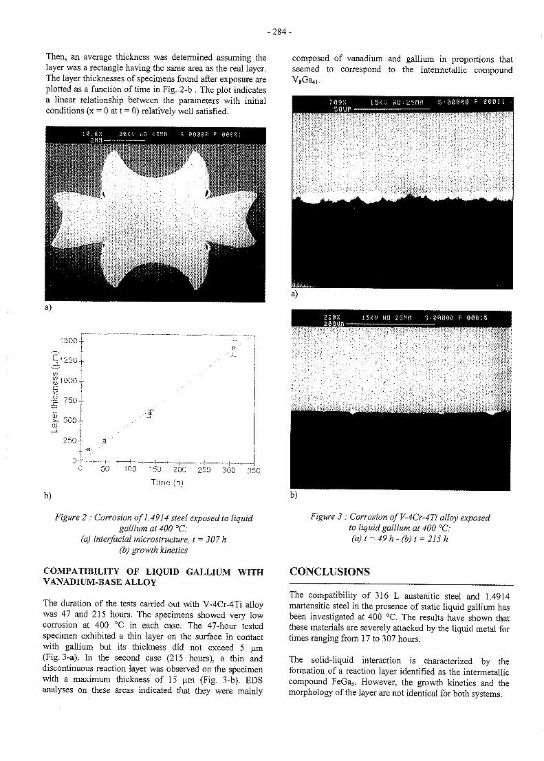
-284 -
Then, an average thickness was determined assuming thelayer was a rectangle having the same area as the real layer.The layer thicknesses of specimens found after exposure areplotted as a function of time in Fig. 2-b . The plot indicatesa linear relationship between the parameters with initialconditions (x = 0 at t = 0) relatively well satisfied.
composed of vanadium and gallium in proportions thatseemed to correspond to the intermetallic compound
100 150 200 250 300 350
Time (h)
b)
Figure 2 : Corrosion of 1.4914 steel exposed to liquidgallium at 400 °C:
(a) interfacial microstructure, t = 307 h(b) growth kinetics
COMPATIBILITY OF LIQUID GALLIUM WITHVANADIUM-BASE ALLOY
The duration of the tests carried out with V-4Cr-4Ti alloywas 47 and 215 hours. The specimens showed very lowcorrosion at 400 °C in each case. The 47-hour testedspecimen exhibited a thin layer on the surface in contactwith gallium but its thickness did not exceed 5 urn(Fig. 3-a). In the second case (215 hours), a thin anddiscontinuous reaction layer was observed on the specimenwith a maximum thickness of 15 urn (Fig. 3-b). EDSanalyses on these areas indicated that they were mainly
NO : 25Plfl S - 88S60 ?
Figure 3 : Corrosion ofV-4Cr-4Ti alloy exposedto liquid gallium at 400 °C:(a)t = 49h-(b)t =
CONCLUSIONS
The compatibility of 316 L austenitic steel and 1.4914martensitic steel in the presence of static liquid gallium hasbeen investigated at 400 °C. The results have shown thatthese materials are severely attacked by the liquid metal fortimes ranging from 17 to 307 hours.
The solid-liquid interaction is characterized by theformation of a reaction layer identified as the intermetalliccompound FeGa3. However, the growth kinetics and themorphology of the layer are not identical for both systems.
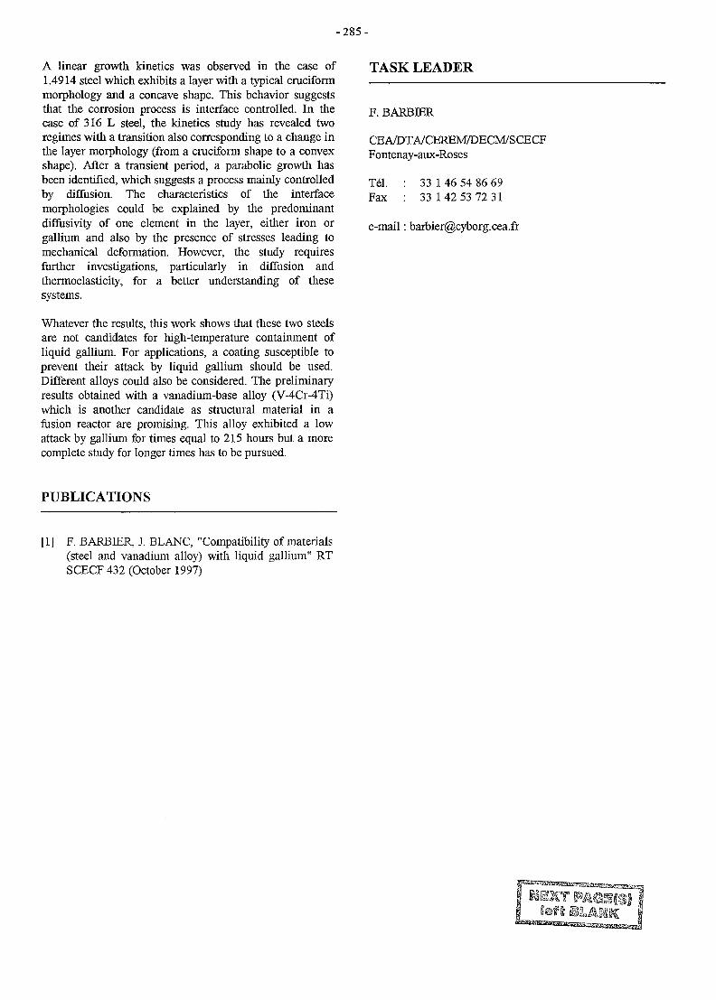
- 2 8 5 -
A linear growth kinetics was observed in the case of1.4914 steel which exhibits a layer with a typical cruciformmorphology and a concave shape. This behavior suggeststhat the corrosion process is interface controlled. In thecase of 316 L steel, the kinetics study has revealed tworegimes with a transition also corresponding to a change inthe layer morphology (from a cruciform shape to a convexshape). After a transient period, a parabolic growth hasbeen identified, which suggests a process mainly controlledby diffusion. The characteristics of the interfacemorphologies could be explained by the predominantdiffusivity of one element in the layer, either iron orgallium and also by the presence of stresses leading tomechanical deformation. However, the study requiresfurther investigations, particularly in diffusion andthermoelasticity, for a better understanding of thesesystems.
Whatever the results, this work shows that these two steelsare not candidates for high-temperature containment ofliquid gallium. For applications, a coating susceptible toprevent their attack by liquid gallium should be used.Different alloys could also be considered. The preliminaryresults obtained with a vanadium-base alloy (V-4Cr-4Ti)which is another candidate as structural material in afusion reactor are promising. This alloy exhibited a lowattack by gallium for times equal to 215 hours but a morecomplete study for longer times has to be pursued.
TASK LEADER
F. BARBER
CEA/DTA/CEREM7DECM/SCECFFontenay-aux-Roses
Tel. : 33 1 46 54 86 69Fax : 33 142 53 72 31
e-mail: [email protected]
PUBLICATIONS
[1] F. BARBIER, J. BLANC, "Compatibility of materials(steel and vanadium alloy) with liquid gallium" RTSCECF 432 (October 1997)
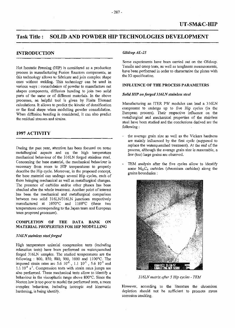
- 2 8 7 -
UT-SM&C-HIP
Task Title : SOLID AND POWDER HIP TECHNOLOGIES DEVELOPMENT
INTRODUCTION
Hot Isostatic Pressing (HIP) is considered as a productionprocess in manufacturing Fusion Reactors components, asthis technology allows to fabricate and join complex shapeones without welding. This technology can be used invarious ways : consolidation of powder to manufacture netshapes components, diffusion bonding to join two solidparts of the same or of different materials. Jn the aboveprocesses, an helpful tool is given by Finite Elementcalculations. It allows to predict the kinetic of densificationor the final shape when modelling powder consolidation.When diffusion bonding is considered, it can also predictthe residual stresses and strains.
1997 ACTIVITY
During the past year, attention has been focused on somemetallurgical aspects and on the high temperaturemechanical behaviour of the 316LN forged stainless steel.Concerning the base material, the mechanical behaviour isnecessary from room to HIP temperatures to properlydescribe the Hip cycle. Moreover, in the proposed concept,the base material can undergo several Hip cycles, each ofthem bringing mechanical as well as metallurgical changes.The presence of carbides and/or other phases has beenchecked after the whole treatment. Another point of interesthas been the mechanical and metallurgical comparisonbetween two solid 316LN/316LN junctions respectivelymanufactured at 1050°C and 1100°C (these twotemperatures corresponding to the Japan team and Europeanteam proposed processes).
COMPLETION OF THE DATA BANK ONMATERIAL PROPERTIES FOR HIP MODELLING
316LN stainless steel forged
High temperature uniaxial compression tests (includingrelaxation tests) have been performed on waterquenchedforged 316LN samples. The studied temperatures are thefollowing : 800, 850, 880, 900, 1000 and 1100°C. Theimposed strain rates are 5.6 10"6., 1.1 10'5 ,5 .6 10'5 and1.1 10"4 s"1. Compression tests with strain rates jumps arealso performed. These mechanical tests allow to identify abehaviour in the viscoplastic range above 800°C. Since theNorton law is too poor to model the performed tests, a morecomplex behaviour, including isotropic and kinematichardening, is being identify.
Glidcop AL-25
Some experiments have been carried out on the Glidcop.Tensile and creep tests, as well as toughness measurements,have been performed in order to characterise the plates withthe IG specification.
INFLUENCE OF THE PROCESS PARAMETERS
Solid HIP on forged 316LN stainless steel
Manufacturing an ITER PW modules can lead a 316LNcomponent to undergo up to five Hip cycles (in theEuropean process). Their respective influence on themetallurgical and mechanical properties of the stainlesssteel have been studied and the conclusions derived are thefollowing:
- the average grain size as well as the Vickers hardnessare mainly influenced by the first cycle (supposed toreplace the waterquenched treatment). At the end of theprocess, although the average grain size is reasonable, afew (too) large grains are observed.
- TEM analysis after the five cycles allow to identifysome M23C6 carbides (chromium carbides) along thegrains boundaries :
316LN matrix after 5 Hip cycles - TEM
However, according to the literature the chromiumdepletion should not be sufficient to promote stresscorrosion cracking.
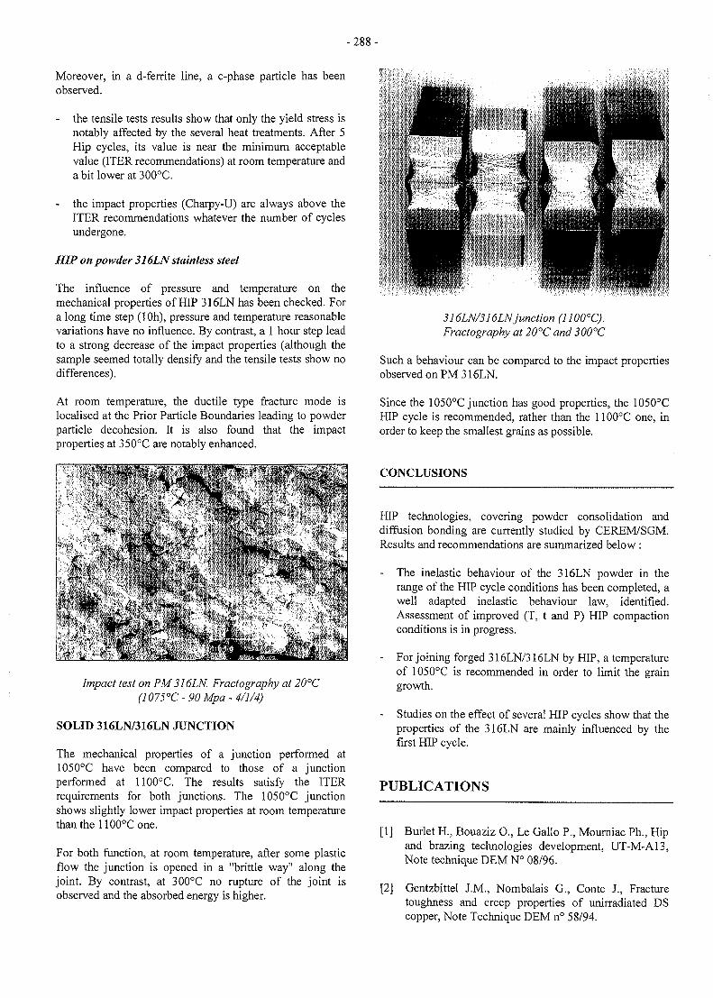
-288-
Moreover, in a d-ferrite line, a c-phase particle has beenobserved.
- the tensile tests results show that only the yield stress isnotably affected by the several heat treatments. After 5Hip cycles, its value is near the minimum acceptablevalue (ITER recommendations) at room temperature anda bit lower at 300°C.
- the impact properties (Charpy-U) are always above theITER recommendations whatever the number of cyclesundergone.
HIP on powder 316LN stainless steel
The influence of pressure and temperature on themechanical properties of HIP 316LN has been checked. Fora long time step (IOh), pressure and temperature reasonablevariations have no influence. By contrast, a 1 hour step leadto a strong decrease of the impact properties (although thesample seemed totally density and the tensile tests show nodifferences).
At room temperature, the ductile type fracture mode islocalised at the Prior Particle Boundaries leading to powderparticle decohesion. It is also found that the impactproperties at 350°C are notably enhanced.
Impact test on PM316LN. Fractography at 20°C(1075°C-90 Mpa-4/1/4)
SOLID 316LN/316LN JUNCTION
The mechanical properties of a junction performed at1050°C have been compared to those of a junctionperformed at 1100°C. The results satisfy the ITERrequirements for both junctions. The 1050°C junctionshows slightly lower impact properties at room temperaturethan the 1100°C one.
For both function, at room temperature, after some plasticflow the junction is opened in a "brittle way" along thejoint. By contrast, at 300°C no rupture of the joint isobserved and the absorbed energy is higher.
316LN/316LNjunction (1100°C).Fractography at 20°C and 300°C
Such a behaviour can be compared to the impact propertiesobserved on PM 316LN.
Since the 1050°C junction has good properties, the 1050°CHIP cycle is recommended, rather than the 1100°C one, inorder to keep the smallest grains as possible.
CONCLUSIONS
HIP technologies, covering powder consolidation anddiffusion bonding are currently studied by CEREM/SGM.Results and recommendations are summarized below :
- The inelastic behaviour of the 316LN powder in therange of the HIP cycle conditions has been completed, awell adapted inelastic behaviour law, identified.Assessment of improved (T, t and P) HIP compactionconditions is in progress.
- For joining forged 316LN/316LN by HIP, a temperatureof 1050°C is recommended in order to limit the graingrowth.
- Studies on the effect of several HIP cycles show that theproperties of the 316LN are mainly influenced by thefirst HIP cycle.
PUBLICATIONS
[1] Burlet H., Bouaziz O., Le Gallo P., Mourniac Ph., Hipand brazing technologies development, UT-M-A13,Note technique DEM N° 08/96.
[2] Gentzbittel J.M., Nombalais G., Conte 1, Fracturetoughness and creep properties of unirradiated DScopper, Note Technique DEM n° 58/94.

-289 -
[3] Briottet L., Bouaziz O., Burlet H., Hip and brazing TASK LEADERtechnologies development, UT-M-A13, Notetechnique DEM N° 62/96.
L. BRIOTTET[4] Briottet L., Burlet H., Couturier R., Riccetti B., Chu
I., Solid and powder Hip technologies development, DTA/DEM/SGMUT-SM&C-HIP, Milestones Rl , Note technique DEM CEA grenoble 17, rue des Martyrsn ° 9 7 / 6 7 - 38054 Grenoble Cedex 9
[5] LeMarois G., Burlet H., Solomon R., Marini B., j£\ - Q4 76 88 33 15Gentzbittel J.M., Briottet L., Structural materials p ^ • Q4 76 88 94 63joints for ITER in-vessel components, ISFNT-4, April6-11 1997, Tokyo, Japan. e . m a i l • [email protected]
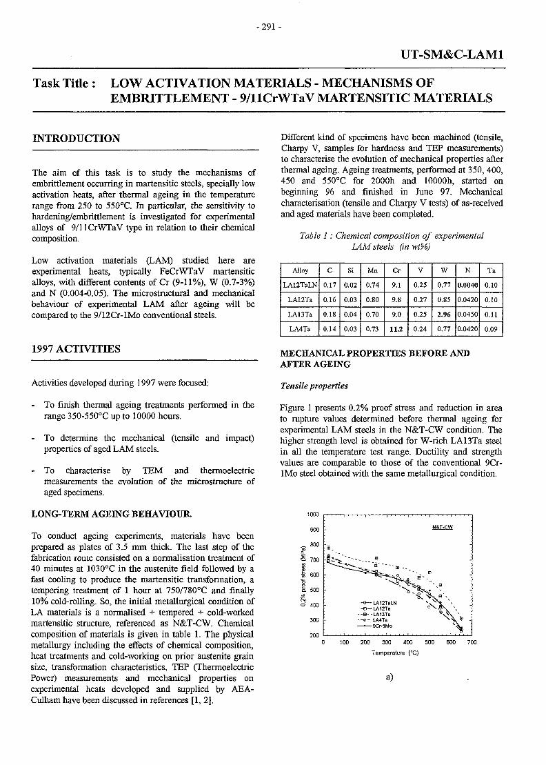
- 2 9 1 -
UT-SM&C-LAM1
Task Title: LOW ACTIVATION MATERIALS - MECHANISMS OFEMBRITTLEMENT - 9/llCrWTaV MARTENSITIC MATERIALS
INTRODUCTION
The aim of this task is to study the mechanisms ofembrittlement occurring in martensitic steels, specially lowactivation heats, after thermal ageing in the temperaturerange from 250 to 550°C. In particular, the sensitivity tohardening/embrittlement is investigated for experimentalalloys of 9/llCrWTaV type in relation to their chemicalcomposition.
Low activation materials (LAM) studied here areexperimental heats, typically FeCrWTaV martensiticalloys, with different contents of Cr (9-11%), W (0.7-3%)and N (0.004-0.05). The microstructural and mechanicalbehaviour of experimental LAM after ageing will becompared to the 9/12Cr-lMo conventional steels.
1997 ACTIVITIES
Activities developed during 1997 were focused:
- To finish thermal ageing treatments performed in therange 350-550°C up to 10000 hours.
- To determine the mechanical (tensile and impact)properties of aged LAM steels.
- To characterise by TEM and thermoelectricmeasurements the evolution of the microstructure ofaged specimens.
LONG-TERM AGEING BEHAVIOUR.
To conduct ageing experiments, materials have beenprepared as plates of 3.5 mm thick. The last step of thefabrication route consisted on a normalisation treatment of40 minutes at 1030°C in the austenite field followed by afast cooling to produce the martensitic transformation, atempering treatment of 1 hour at 750/780°C and finally10% cold-rolling. So, the initial metallurgical condition ofLA materials is a normalised + tempered + cold-workedmartensitic structure, referenced as N&T-CW. Chemicalcomposition of materials is given in table 1. The physicalmetallurgy including the effects of chemical composition,heat treatments and cold-working on prior austenite grainsize, transformation characteristics, TEP (ThermoelectricPower) measurements and mechanical properties onexperimental heats developed and supplied by AEA-Culham have been discussed in references [1, 2].
Different kind of specimens have been machined (tensile,Charpy V, samples for hardness and TEP measurements)to characterise the evolution of mechanical properties afterthermal ageing. Ageing treatments, performed at 350, 400,450 and 550°C for 2000h and lOOOOh, started onbeginning 96 and finished in June 97. Mechanicalcharacterisation (tensile and Charpy V tests) of as-receivedand aged materials have been completed.
Table 1: Chemical composition of experimentalLAM steels (inwt%)
Alloy
LA12TaLN
LA12Ta
LA13Ta
LA4Ta
C
0.17
0.16
0.18
0.14
Si
0.02
0.03
0.04
0.03
Mn
0.74
0.80
0.70
0.73
Cr
9.1
9.8
9.0
11.2
V
0.25
0.27
0.25
0.24
W
0.77
0.85
2.96
0.77
N
0.0040
0.0420
0.0450
0.0420
Ta
0.10
0.10
0.11
0.09
MECHANICAL PROPERTIES BEFORE ANDAFTER AGEING
Tensile properties
Figure 1 presents 0.2% proof stress and reduction in areato rupture values determined before thermal ageing forexperimental LAM steels in the N&T-CW condition. Thehigher strength level is obtained for W-rich LA13Ta steelin all the temperature test range. Ductility and strengthvalues are comparable to those of the conventional 9Cr-lMo steel obtained with the same metallurgical condition.
1000
900
„ 800ro
Q_
1 600
I 500
o 400
300
200
-o— LA12TaLN- a - LA12Ta
--ss--LA13Ta• - » - LA4Ta—•—9Cr-1Mo
100 200 300 400 500
Temperature (°C)
600 700
a)
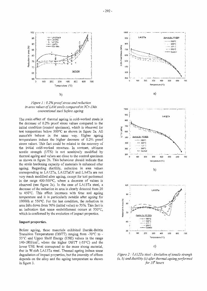
-292-
- s — LA12TaLN-EJ - LA12Ta
--E--lAI3Ta- - » - LA4Ta—•—9CMMo
0 100 200 300 400 500 600 700
Temperature (°C)
b)
Figure 1 : 0.2% proof stress and reductionin area values of LAM steels compared to 9Cr-lMo
conventional steel before ageing.
The main effect of thermal ageing in cold-worked steels isthe decrease of 0.2% proof stress values compared to theinitial condition (control specimen), which is observed fortest temperature below 500°C as shown in figure 2a. Allmaterials behave in the same way. Higher ageingtemperatures induce the higher decrease of 0.2% proofstress values. This fact could be related to the recovery ofthe initial cold-worked structure. In contrast, ultimatetensile strength (UTS) is not sensitively modified bythermal ageing and values are close to the control specimenas shown in figure 2b. This behaviour should indicate thatthe strain hardening capacity of materials is enhanced afterageing. Regarding ductility, reduction in area valuescorresponding to LA12Ta, LA12TaLN and LA4Ta are notvery much modified after ageing, except for test performedin the range 400-500°C, where a decrease of values isobserved (see figure 2c). In the case of LA13Ta steel, adecrease of the reduction in area is clearly detected from 20to 450°C This effect increases with time and ageingtemperature and it is particularly notable after ageing forlOOOOh at 550°C. For the last condition, the reduction inarea falls down from 70% (initial value) to 55%. This fact isan indication that some embrittlement occurs at 550°C,which is confirmed by the evolution of impact properties.
Impact properties.
Before ageing, these materials exhibited Ductile-BrittleTransition Temperatures (DBTT) ranging from -70°C to -55°C and Upper Shelf Energy (USE) values in the range140-180J/cm2, where the higher DBTT (-55°C) and thelower USE level correspond to the more strong material,that is W-rich LA13Ta steel. Thermal ageing induce somedegradation of impact properties, but the intensity of effectsdepends on the alloy and the ageing temperature as shownin figure 3.
200 300 400 500
Temperature (°C)
a)
3 500 [-• Ageing for IQOOOh
300 j - - " 550X; — • — Corarol
0 100 200 300 400 500 600 700
Temperature (°C)
b)
Ageing for 10 OOOh
• - - : - - -350*C
60 - ' 4 0 0 ° c
450'Cr 550°C[ — • — Control
0 100 200 300 400 500 600 700
Temperature (°C)
C)
Figure 2 : LA12Ta steel - Evolution of tensile strengh(a, b) and ductility (c) after thermal ageing performed
for 104 hours
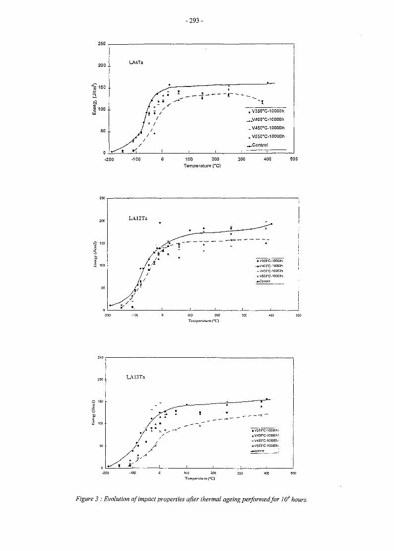
- 2 9 3 -
250
-200 -100 100 200Temperature (°C)
V350°C-10000h
..V400''C-10000ri
V450°C-10000h
V550°C-10000h .
.Control
300 400 500
LA12Ta
/#
7/
/•
K
I ( I
A
a V3S0"C-10C00h
-V4SO'C-10000h
XV55O-C-10OO0H
•^Central
1C0 200
Temperature (°C)
200
^ 150
2 100 •
50
0
LA13Ta
/f• w K /
u * *— — x
" < «V3SO-C.!00O0h:
;-V45O-C-1OO00hi
• K-V550"C-1OOOOn:
I I , .
•200 -100 100 200
Temperature (°C)
Figure 3 : Evolution of impact properties after thermal ageing performed for 104 hours.
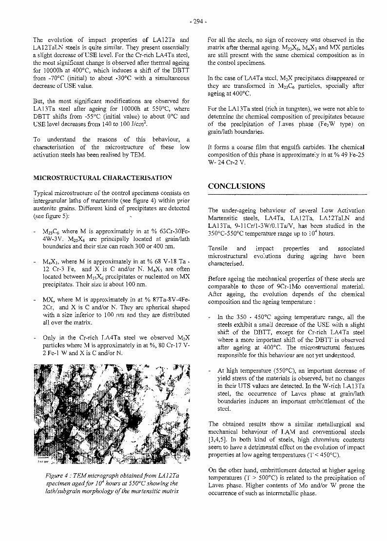
-294-
The evolution of impact properties of LA12Ta andLA12TaLN steels is quite similar. They present essentiallya slight decrease of USE level. For the Cr-rich LA4Ta steel,the most significant change is observed after thermal ageingfor lOOOOh at 400°C, which induces a shift of the DBTTfrom -70°C (initial) to about -30°C with a simultaneousdecrease of USE value.
But, the most significant modifications are observed forLA13Ta steel after ageing for lOOOOh at 550°C, whereDBTT shifts from -55°C (initial value) to about 0°C andUSE level decreases from 140 to 100 J/cm2.
To understand the reasons of this behaviour, acharacterisation of the microstructure of these lowactivation steels has been realised by TEM.
For all the steels, no sign of recovery was observed in thematrix after thermal ageing. M23X6, M4X3 and MX particlesare still present with the same chemical composition as inthe control specimens.
In the case of LA4Ta steel, M2X precipitates disappeared orthey are transformed in M23Q particles, specially afterageing at 400°C.
For the LA13Ta steel (rich in tungsten), we were not able todetermine the chemical composition of precipitates becauseof the precipitation of Laves phase (Fe2W type) ongrain/lath boundaries.
It forms a coarse film that engulfs carbides. The chemicalcomposition of this phase is approximately in at % 49 Fe-25W- 24 Cr-2 V.
MICROSTRUCTURAL CHARACTERISATION
Typical microstructure of the control specimens consists onintergranular laths of martensite (see figure 4) within prioraustenite grains. Different kind of precipitates are detected(see figure 5):
M23C6 where M is approximately in at % 63Cr-30Fe-4W-3V. M23X6 are principally located at grain/lathboundaries and their size can reach 300 or 400 nm.
M4X3, where M is approximately in at % 68 V-18 Ta -12 Cr-3 Fe, and X is C and/or N. M4X3 are oftenlocated between JV^X^ precipitates or nucleated on MXprecipitates. Their size is about 100 nm.
- MX, where M is approximately in at % 87Ta-8V-4Fe-2Cr, and X is C and/or N. They are spherical shapedwith a size inferior to 100 nm and they are distributedall over the matrix.
- Only in the Cr-rich LA4Ta steel we observed M2Xparticles where M is approximately in at %, 80 Cr-17 V-2 Fe-1 W and X is C and/or N.
CONCLUSIONS
Figure 4: TEM micrograph obtained from LA12Taspecimen aged for 104 hours at 550°C showing thelath/subgrain morphology of the martensitic matrix
The under-ageing behaviour of several Low ActivationMartensitic steels, LA4Ta, LA12Ta, LA12TaLN andLA13Ta, 9-llCr/l-3W/0.1Ta/V, has been studied in the350°C-550°C temperature range up to 104 hours.
Tensile and impact properties and associatedmicrostructural evolutions during ageing have beencharacterised.
Before ageing the mechanical properties of these steels arecomparable to those of 9Cr-lMo conventional material.After ageing, the evolution depends of the chemicalcomposition and the ageing temperature :
- In the 350 - 450°C ageing temperature range, all thesteels exhibit a small decrease of the USE with a slightshift of the DBTT, except for Cr-rich LA4Ta steelwhere a more important shift of the DBTT is observedafter ageing at 400°C. The microstructural featuresresponsible for this behaviour are not yet understood.
- At high temperature (550°C), an important decrease ofyield stress of the materials is observed, but no changesin their UTS values are detected. In the W-rich LA13Tasteel, the occurrence of Laves phase at grain/lathboundaries induces an important embrittlement of thesteel.
The obtained results show a similar metallurgical andmechanical behaviour of LAM and conventional steels[3,4,5]. In both kind of steels, high chromium contentsseem to have a detrimental effect on the evolution of impactproperties at low ageing temperatures (T < 450°C).
On the other hand, embrittlement detected at higher ageingtemperatures (T > 500°C) is related to the precipitation ofLaves phase. Higher contents of Mo and/or W prone theoccurrence of such as intermetallic phase.
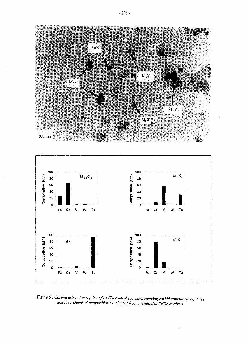
100 run
M X
-295-
• , r
M.X-.
\
MX
",' >-
M. <\.
100
s.
Ion
sit
&E0u
SO :
60 ,
4 0 •;
20 ••
0 •'••IFe Cr V W Ta
« 80
100
MX
co~<noa
oo
60 -
40 •!
20 -,
Fe Cr V W Ta
100 •:
re 8 0 •;
I 6°^| 4 0 JE 20 -oO 0
M,
.I IFe Cr V W Ta
100
UO
I
siti
S.Eoo
80
60 j
40 i
20 -
0 -
M,X
Fe Cr V W Ta
Figure 5: Carbon extraction replica ofLA4Ta control specimen showing carbide/nitride precipitatesand their chemical compositions evaluated from quantitative XEDS analysis.
- 2 9 6 -
REFERENCES REPORT
[1] K.W. Tupholme,D. Dulieu and GJ. Butterworth -AEA Fusion Report - AEA FUS 109 - Grain-refinedlow actvation martensitic steels.
[2] A.Alamo, J.C. Brachet, A. Castaing, C. Foucher, F.Barcelo - N.T. SRMA 96-2173 - Low ActivationMartensitic Materials, Physical metallurgy of Fe-9/12CrWTaV alloys.
[3] J.C. Brachet, CEA report, CEA R-5581, France, 1991
[4] A. Alamo, J.C. Brachet, A. Castaing, C. Foucher,Effects of the initial metallurgical condition on themicrostructure and mechanical properties of 9Cr-lMoand 9 Cr-lMoVNb thermal aged steels,Microstructures and Mechanical Properties of AgeingMaterials II, edited by P.K. Liaw et al., TMS, 1996 p121-134
[5] J.C. Brachet, A. Castaing, C. Foucher, Effects of thechemical composition on the behaviour of 9-12Cr/0.5-lMo/(W,Nb,V) thermal aged steels,Proceeding of Int. Symp. on « Materials Ageing »Milan, Italy, 10-13 Oct. 1995
[1] Y. de CARLAN et al., Final report UT-SM&C-LAM1, « Long term ageing behaviour ofexperimental 9/llCrWTaV low activation martensiticsteels », NT SRMA mars 98.
TASK LEADER
A.ALAMO
DTA/DECM/SRMACEA - SACLAY91191 Gif-sur-Yvette
Tél. : 33 1 69 08 67 26Fax : 33 1 69 08 71 30
e-mail : ana.alamo(Slcea.fr
-297 -
UT-SM&C-LAM2
Task Title: IRRADIATED BEHAVIOUR OF REDUCED ACTIVATION (RA)MARTENSITIC STEELS AFTER NEUTRON IRRADIATION AT325°C
INTRODUCTION
The objective of this task is to study the metallurgical andmechanical behaviour of Reduced Activation (RA) as wellas conventional martensitic steels during neutronirradiation at 325°C.
RA steels are planned to be used as structural componentsof fusion reactors, where in-service temperatures couldrange from 250 to 550°C. The behaviour under neutronirradiation of conventional martensitic steels 9/12Cr havebeen largely studied in the range 400-550°C. Availabledata show that irradiation-induced hardening increaseswith decreasing irradiation temperature [1-5]. Noequivalent data exist for RA steels and specially forirradiation temperatures lower than 400°C.
So, the main goal of this task is to study the irradiationbehaviour of FeCrW RA steels and compare them withFeCrMo conventional alloys irradiated in Osiris reactor at325°C, temperature relevant of fusion reactor applications.Irradiated specimens of each material will be available for5 levels of radiation damage ranging from 1 to 9 dpa, dosesthat appear as enough to investigate the first step ofirradiation-induced embrittlement [6] and to detect aneventual threshold-dose for hardening of such as materials.
Post-irradiation examinations (PIE) involve tensile tests,measurements of area reduction to rupture, fractographicexaminations and microstructural studies by transmissionelectron microscopy (TEM) of irradiated specimens. PIEalso include dose decay rate and spectrometricmeasurements of activated elements after irradiation.
1997 ACTIVITIES
During this period, the main activities were focused to thedetermination of tensile properties of available specimensirradiated with three dose levels ranging from 1 to 3.4 dpa.Tensile tests have been performed at the irradiationtemperature, that is 325°C. Reduction in areameasurements have been also performed by image analysistechniques on broken specimens.
IRRADIATION CONDITIONS
Irradiation in Osiris reactor started on January 96 and theending of this experiment is planned on December 98.
Because of two partial unloadings, made on March andDecember 96, irradiated samples are available withdifferent dose levels, that is, 1, 2, 3.4, 6-7 and 8-9 dpa.
Materials are irradiated at 325°C (+5°C, -10°C) inpressurised water at 155 bars as tensile specimens andplate samples intended for different post-irradiationexaminations.
Irradiation is carried out in a mixed neutron spectrum. Themaximal neutron flux is about 2.10!4 n/cm2s (E > lMev)and the fast to thermal flux ratio is about 1.1.
MATERIALS
Two types of relevant martensitic materials for fusionapplications are irradiated in the present experiment, thatis, 7/llCrW RA steels and 9/12CrMo conventionalmartensitic steels, which have been used as reference forRA alloy development. Chemical compositions aresummarised on table 1.
The following nuances of RA martensitic steels are beingirradiated:
- F82H is a 7.5CrWTaV RA-steel developed by JAERI(Japan) and produced for the first time as a large-scaleheat (5 tons) [7].
- LA12LC, LA4Ta and LA13Ta are RA experimentalalloys of 9/llCrWTaV type with different contents ofCr, W, Ta.
Conventional martensitic steels are commercial alloyswhich present different contents of Cr (9 to 12%), Mo andstabilising elements (V, Nb). These materials wereproduced as plates in the normalised and temperedcondition (N&T) like F82H RA-steel.
RA experimental alloys have been supplied by AEA-Culham as cast ingots [8]. They were subsequentlytransformed in our laboratory as plates, where the last stepsof the fabrication route consisted on the normalisation andtempering followed by 10% cold-working (N&T-CW).Only 9Cr-lMo conventional steel was produced in bothmetallurgical conditions.
The choice of N&T-CW condition for RA experimentalsteels is based on the previous results obtained on 9Cr-lMoconventional steels, which exhibited for this metallurgicalcondition a more stable behaviour and a betterstrength/ductility ratio, specially after thermal ageing [9].
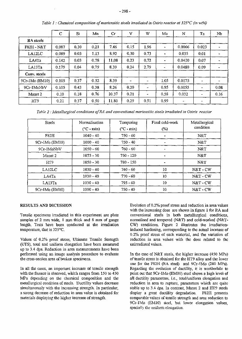
- 2 9 8 -
Table 1: Chemical composition of martensitic steels irradiated in Osiris reactor at 325°C (in wt%)
RA steels
F82H-N&T
LA12LC
LA4Ta
LA13Ta
Conv. steels
9Cr-lMo (EM10)
9Cr-lMoNbV
Manet 2
HT9
C
0.087
0.089
0.142
0.179
0.105
0.105
0.10
0.21
Si
0.10
0.03
0.03
0.04
0.37
0.43
0.18
0.37
Mn
0.21
1.13
0.78
0.79
0.52
0.38
0.76
0.50
Cr
7.46
8.92
11.08
8.39
8.39
8.26
10.37
11.80
V
0.15
0.30
0.23
0.24
-
0.20
0.21
0.29
W
1.96
0.73
0.72
2.79
-
-
-
0.51
Mo
-
-
-
-
1.05
0.95
0.58
0.99
N
0.0066
0.035
0.0410
0.0480
0.0175
0.0055
0.032
-
Ta
0.023
0.01
0.07
0.09
-
-
-
-
Nb
-
-
-
-
-
0.08
0.16
Table 2 : Metallurgical conditions ofRA and conventional martensitic steels irradiated in Osiris reactor
Steels
F82H
9Cr-lMo (EM10)
9Cr-lMoNbV
Manet 2
HT9
LA12LC
LA4Ta
LA13Ta
9Cr-lMo (EM10)
Normalisation
(°C - min)
1040 - 40
1000 - 40
1050 - 60
1075 - 30
1050 - 30
1030 - 40
1030 - 40
1030 - 40
1000 - 40
Tempering
(°C - min)
750 - 60
750 - 40
760 - 60
750 - 120
780 - 150
740 - 60
770 - 60
795 - 60
750 - 40
Final cold-work
(%)
-
-
-
-
-
10
10
10
10
Metallurgicalcondition
N&T
N&T
N&T
N&T
N&T
N&T-CW
N&T-CW
N&T-CW
N&T-CW
RESULTS AND DICUSSION
Tensile specimens irradiated in this experiment are platesamples of 2 mm wide, 1 mm thick and 8 mm of gaugelength. Tests have been conducted at the irradiationtemperature, that is 325°C.
Values of 0.2% proof stress, Ultimate Tensile Strength(UTS), total and uniform elongation have been measuredup to 3.4 dpa. Reduction in area measurements have beenperformed using an image analysis procedure to evaluatethe cross-section area of broken specimens.
In all the cases, an important increase of tensile strengthwith the fluence is observed, which ranges from 150 to 450MPa depending on the chemical composition and themetallurgical condition of steels. Ductility values decreasesimultaneously with the increasing strength. In particular,a strong decrease of reduction in area value is obtained formaterials displaying the higher increase of strength.
Evolution of 0.2% proof stress and reduction in area valueswith the increasing dose are shown in figure 1 for RA andconventional steels in both metallurgical conditions,normalised and tempered (N&T) and cold-worked (N&T-CW) conditions. Figure 2 illustrates the irradiation-induced hardening, corresponding to the actual increase of0.2% proof stress of each material, and the variation ofreduction in area values with the dose related to theunirradiated values.
In the case of N&T steels, the higher increase (450 MPa)of tensile stress is obtained for the HT9 alloy and the lowerone for the F82H (RA steel) and 9Cr-lMo (280 MPa).Regarding the evolution of ductility, it is worthwhile topoint out that 9Cr-lMo (EM10) steel shows a high level ofall ductility parameters, i.e., total/uniform elongation andreduction in area to rupture, parameters which are quitestable up to 3.4 dpa. In contrast, Manet 2 and HT9 steelsdisplay a great ductility degradation. F82H presentscomparable values of tensile strength and area reduction to9Cr-lMo (EM10) steel, but lower elongation values,specially the uniform elongation.
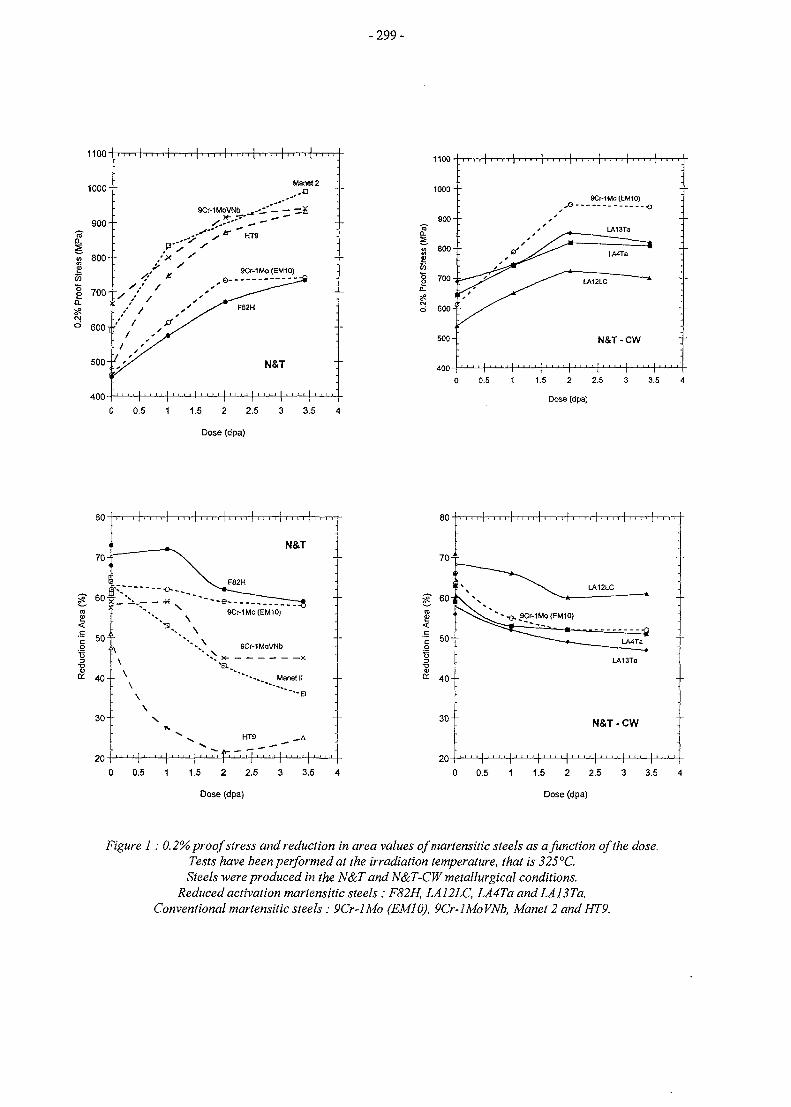
-299 -
1100
1000 - -
900--
400
N&T
0 0.5 1 1.5 2 2.5 3 3.5 4
Dose (dpa)
1100
1000- -
900
55
8 0 0 - -
7 0 0 - ^
d 600 - -
5 0 0 - -
400
9Cr-1Mo(EM10)o
N&T-CW
0 0.5 1 1.5 2 2.5 3 3.5 4
Dose (dpa)
80"
3 0 - -
20
80--r
N&T
HT9
0 0.5 1 1.5 2 2.5 3 3.5 4
Dose (dpa)
• • • • I . . . . • • . • • • • • • • • • • • . • • • • , . . • •
0 0.5 1 1.5 2 2.5 3 3.5 4
20
Figure 1: 0.2% proof stress and reduction in area values of martensitic steels as a function of the dose.Tests have been performed at the irradiation temperature, that is 325°C.Steels were produced in the N&T and N&T-CW metallurgical conditions.
Reduced activation martensitic steels: F82H, LA12LC, LA4Ta and LA13Ta.Conventional martensitic steels : 9Cr-lMo (EM10), 9Cr-lMoVNb, Manet 2 andHT9.
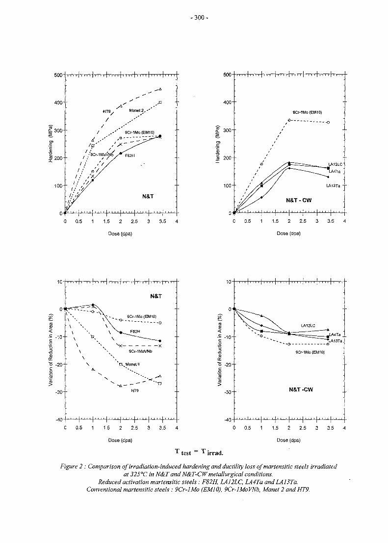
- 300 -
500-
400--
11 i i i i i i i i i i i i i i i i i i i i i i
0 0.5 1 1.5 2 2.5 3 3.5 4
500-
400--
I 300f
SCMMo (EM1O)
0 0.5 1 1.5 2 2.5 3 3.5 4
10
(0
•E -10--
8."5 -20--co• •§
I-30--
-40
i i i i i i i i i i i i i i i i i i i i i i i i i i i i i i i
N&T
HT9
10
-40
0 0.5 1 1.5 2 2.5 3 3.5 4 0 0.5 1 1.5 2 2.5 3 3.5 4
Dose (dpa) Dose (dpa)
T test = ^ irrad.
Figure 2 : Comparison of irradiation-induced hardening and ductility loss ofmartensitic steels irradiatedat 325°C in N&T and N&T-CW metallurgical conditions.
Reduced activation martensitic steels: F82H, LA12LC, LA4Ta and LA13Ta.Conventionalmartensiticsteels : 9Cr-lMo (EM10), 9Cr-lMoVNb, Manet 2 andHT9.
- 3 0 1 -
Strength values corresponding to N&T-CW steels,increase with the fluence up to 2 dpa and saturate beyondthis dose as shown in figures 1 and 2. The morepronounced hardening is observed for the 9Cr-lMo (cold-worked) steel. Ductility values also display saturation at2 dpa.
Figure 2 compare the variation of absolute values ofreduction in area measured for different materials in bothmetallurgical conditions (N&T and N&T-CW). The highervalues are obtained for 9Cr-lMo and F82H N&T steels andLA12LC RA-alloy (N&T-CW).
Available results enable to remark some importantfeatures. For both metallurgical conditions, FeCrWTaVRA-steels seem to be less sensitive to irradiation hardeningand ductility degradation compared to conventionalFeCrMo martensitic steels, except for 9Cr-lMo (EM10)alloy in the N&T condition. In fact, the last one presentsthe better strength/ductility ratio for materials examinedhere. In the case of low activation martensitic steels,LA12LC, LA4TA and LA13Ta alloys obtained in N&T-CW condition, a lower hardening and a lower decrease ofductility is observed in regard to F82H N&T steel.
Correlation of the irradiation hardening with the chemicalcomposition is not easy to establish. Regarding N&Tsteels, they could be classified by increasing sensitivity tohardening as follows: F82H, (7.5Cr), EM10/T91 (9Cr),Manet 2 (10.4Cr), HT9 (12Cr) as shown in figure 3. So,hardening should be qualitatively correlated to the Crcontent of alloys.
In the case of N&T-CW steels, 9Cr-lMo hardens muchfaster than LA12LC (9Cr-0.8W) and the same increase ofstrength is detected for the last one, LA4Ta (llCr-0.8W)and LA13Ta (9Cr-3W). Consequently, irradiationbehaviour is strongly related not only to the chemicalcomposition but also to the metallurgical condition.
CONCLUSIONS
Several Cr-W low activation and Cr-Mo conventionalmartensitic steels have been irradiated in the Osiris reactorat 325°C for three dose levels : 1, 2 and 3.4 dpa. Tensiletests performed at the irradiation temperature enable to setthe following conclusions :
- All materials exhibited an increase of tensile strengthaccompanied by a decrease of ductility. The degree ofhardening and ductility loss depend on the chemicalcomposition and the metallurgical condition of steels.
- For the fluence levels examined here, 7.5-9%Crcontaining steels present a lower sensitivity to theirradiation-induced hardening and ductilitydegradation. In particular, lower hardening is observedfor cold-worked N&T-CW specimens of reducedactivation martensitic steels.
- 9Cr-lMo (EM10) in N&T condition exhibited thehigher values of all ductility parameters (total anduniform elongation, reduction in area) after irradiation.In contrast, a strong hardening accompanied by asevere ductility degradation is obtained in the case ofManet 2 and HT9 conventional steels.
REFERENCES
[1] R.L. Klueh, J.M. Vitek, J. Nucl. Mater. 182 (1991)230.
[2] S£ran J. L., Levy V., Dubuisson P., Gilbon D.,Maillard A., Fissolo A., Touron H., Cauvin R.,Chalony A., Le Boulbin E., Proc.of the 15th Intern.Conf. on Effects of Radiation on Materials^(Nashville, June 1990). ASTM STP 1125 (1992), p.1209.
[3] Dubuisson P., Gilbon D., Seran J.L.,"Microstructuralevolution of ferritic-martensitic steels irradiated inthe Fast breeder reactor Phe"nix", J. of Nucl. Mater.205 (1993) 178.
[4] M. Rieth, B. Dafferner, H.D. Rohrig, C. Wassilew,Fusion Engineering and Design, vol. 29 (1995) 365.
[5] D. S. Gelles, J. Nucl. Mater. 239 (1996) 99.
[6] R.L. Klueh, D.J. Alexander, J. Nucl. Mater. 191(1992) 896.
[7] R.L. Klueh, Proc. of the EEA Working Group Meetingon Ferritic/Martensitic Steels, Sun Valley, USA,June 1994, Report ORNL/M-3777, (1994).
[8] K.W. Tupholme, D. Dulieu, G.J. Butterworth,Euratom/UKAEA Fusion Association, AEA FusionReport 109, May 1991.
[9] A. Alamo, J.C. Brachet, A. Castaing, C. Foucher,Proc. of the 2nd Int. Conf. on Microstructures andMechanical Properties of Aging Materials, Ed. P.K.Liaw, TMS (1996) 121.
REPORT
[1] Alamo, J.C. Brachet, X. Averty, "Tensile propertiesof 7.5/12%Cr Martensitic Steels Irradiated at 325°Cup to 3.4 dpa in Osiris Reactor", Progress Report UT-SM&C-LAM2 December 1997, NT SRMA 98-2259.

- 3 0 2 -
TASK LEADER
A. ALAMO
DTA/DECM/SRMACEA - SACLAY91191 Gif-sur-Yvette
Tel. : 33 1 69 08 67 26Fax : 33 1 69 08 71 30
e-mail: [email protected]
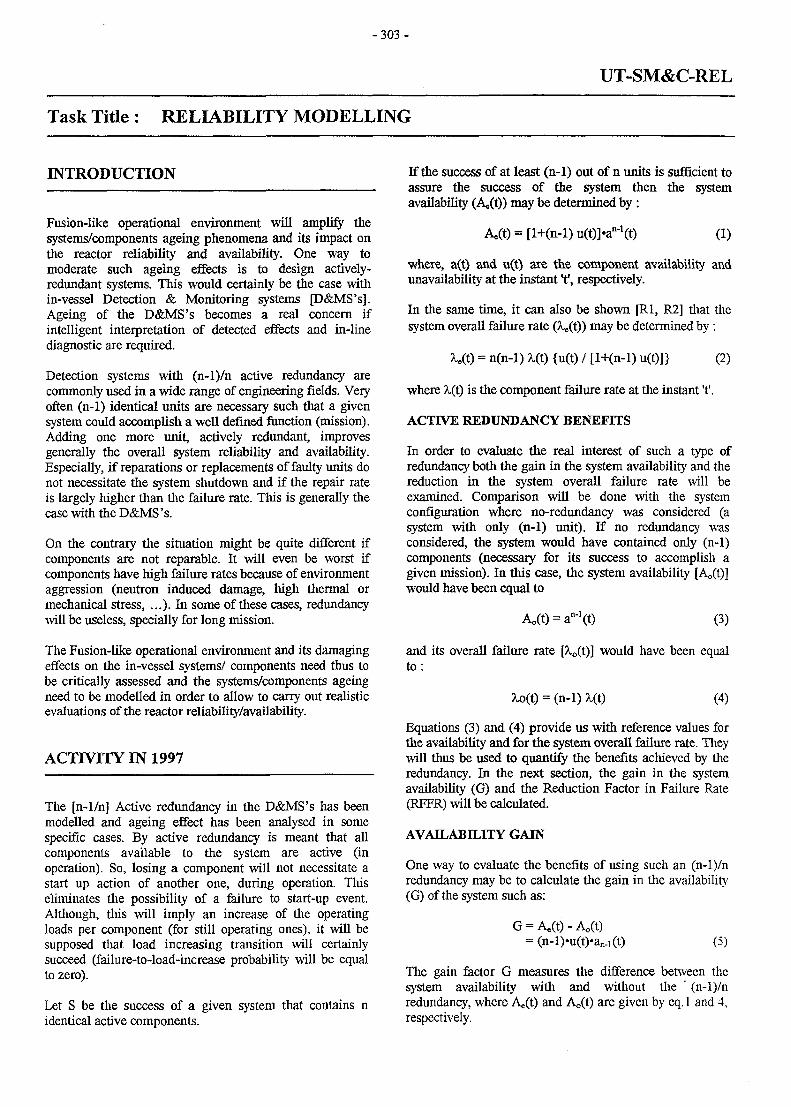
- 3 0 3 -
UT-SM&C-REL
Task Title : RELIABILITY MODELLING
INTRODUCTION
Fusion-like operational environment will amplify thesystems/components ageing phenomena and its impact onthe reactor reliability and availability. One way tomoderate such ageing effects is to design actively-redundant systems. This would certainly be the case within-vessel Detection & Monitoring systems [D&MS's].Ageing of the D&MS's becomes a real concern ifintelligent interpretation of detected effects and in-linediagnostic are required.
Detection systems with (n-l)/n active redundancy arecommonly used in a wide range of engineering fields. Veryoften (n-1) identical units are necessary such that a givensystem could accomplish a well defined function (mission).Adding one more unit, actively redundant, improvesgenerally the overall system reliability and availability.Especially, if reparations or replacements of faulty units donot necessitate the system shutdown and if the repair rateis largely higher than the failure rate. This is generally thecase with the D&MS's.
On the contrary the situation might be quite different ifcomponents are not reparable. It will even be worst ifcomponents have high failure rates because of environmentaggression (neutron induced damage, high thermal ormechanical stress, . . .). In some of these cases, redundancywill be useless, specially for long mission.
The Fusion-like operational environment and its damagingeffects on the in-vessel systems/ components need thus tobe critically assessed and the systems/components ageingneed to be modelled in order to allow to carry out realisticevaluations of the reactor reliability/availability.
ACTIVITY IN 1997
The [n-l/n] Active redundancy in the D&MS's has beenmodelled and ageing effect has been analysed in somespecific cases. By active redundancy is meant that allcomponents available to the system are active (inoperation). So, losing a component will not necessitate astart up action of another one, during operation. Thiseliminates the possibility of a failure to start-up event.Although, this will imply an increase of the operatingloads per component (for still operating ones), it will besupposed that load increasing transition will certainlysucceed (failure-to-load-increase probability will be equalto zero).
Let S be the success of a given system that contains nidentical active components.
If the success of at least (n-1) out of n units is sufficient toassure the success of the system then the systemavailability (Ae(t)) may be determined by:
(1)
where, a(t) and u(t) are the component availability andunavailability at the instant t1, respectively.
In the same time, it can also be shown [Rl, R2] that thesystem overall failure rate (Xe(t)) may be determined by :
= n(n-l) X(t) {u(t) / [l+(n-l) u(t)]} (2)
where X(t) is the component failure rate at the instant't'.
ACTIVE REDUNDANCY BENEFITS
In order to evaluate the real interest of such a type ofredundancy both the gain in the system availability and thereduction in the system overall failure rate will beexamined. Comparison will be done with the systemconfiguration where no-redundancy was considered (asystem with only (n-1) unit). If no redundancy wasconsidered, the system would have contained only (n-1)components (necessary for its success to accomplish agiven mission). In this case, the system availabilitywould have been equal to
= an-'(t) (3)
and its overall failure rate [Xo(t)] would have been equalto :
= (n-1) (4)
Equations (3) and (4) provide us with reference values forthe availability and for the system overall failure rate. Theywill thus be used to quantify the benefits achieved by theredundancy. In the next section, the gain in the systemavailability (G) and the Reduction Factor in Failure Rate(RFFR) will be calculated.
AVAILABILITY GAIN
One way to evaluate the benefits of using such an (n-l)/nredundancy may be to calculate the gain in the availability(G) of the system such as:
= As(t)-Ao(t)(5)
The gain factor G measures the difference between thesystem availability with and without the " (n-l)/nredundancy, where Ae(t) and Ao(t) are given by eq. 1 and 4,respectively.
- 3 0 4 -
First of all, it is worth observing that the gain factor isalways positive ( > 0), Eq (5). Thus, It is not possible tolose in terms of availability in making use of this type ofredundancy.
The second remark is that the gain varies with componentunavailability and attains some maximum values. Thesemaximum values are higher for redundancies with highvalues of n (total number of systems' components). In thecase of 2/3 redundancy, gains in availability can go up toattain its maximum value of 0.30 for a componentunavailability around 0.30.
The 3rd remark is that at the extreme values of thecomponent unavailability (u = 0 or u = 1) such redundancyis not really interesting in terms of global systemavailability. This would be the case for systems whosecomponents have a very small failure rate and a very shortreparation time. Or on the contrary, the systemcomponents are not reparable and have a very high failurerate. In both cases the redundancy may not be justified.
In all cases, one should proceed to exact calculations ofavailability gain taking into account the total number ofcomponents and the time profile of their unavailability tobe able to judge the real interest of making use of suchredundancy.
RELIABILITY GAIN
The same could also be done to determine the reduction interms of the system unreliability. The comparison will bemade on the basis of the ratio of the system global failurerates with and without redundancy. This will be called theReduction Factor in Failure Rate (RFFR). A reductionfactor (H) will the be determined as following:
0.
H =(6)
As it could be expected from equation (6), for values ofcomponent unavailability less than 0.1, the reduction infailure rate due to redundancy is almost linearlyproportional to the component unavailability.
It can also be observed that reduction in failure rate ishigher for systems with smaller number of components.
AGING & FAILURE RATE
Failure rate time behaviour is a direct indicator of systemsand components aging. A system, a sub-system or acomponent is said to suffer from ageing if;
0.dt
where, 1 is its failure rate.
However, a system, a sub-system or a component is said tobe regenerated if;
dt
On the other hand if the failure rate (X) is timeindependent (constant);
dt= 0.
The system, the sub-system or the component may becalled simple.
If the failure rate is defined as «the conditional probabilityper unit time to have the first failure at t » and if failure isdefined as the non-capability to fulfil the mission that hasbeen assigned to the system, to the sub-system or to thecomponent.
Then, ageing is a measure of the time-degradation in thecapacity of accomplishing a predefined mission (function).The failure rate of a system could then be defined as theconditional probability per unit time not to fulfil anassigned mission (function) at instant t'. Besides, if manymissions are assigned to the same system, the system mayhave many partial failure rates, one per mission (function).
AGEING OF 2/3 REDUNDANT SYSTEMS
One of the widely used (n-l)/n active redundancy systemsis the 2/3 one, specially in monitoring & detection, signaltransmission or power transmission systems. In such acase, the system overall availability (A) is given by:
A(t) = [l+2u(t)]-a2(t) (7)
where u(t) and a(t) are the component unavailability andavailability, respectively.
The system overall failure rate is determined by eq(8) asfollows:
(8)= 6X(t){u(t)/[l+2u(t)]}
where X(t) is the component failure rate.
It will be interesting to examine three different practicalcases with 2/3 active redundancy:
1. the basic component has a constant failure rate andnon-reparable (|x=0),
2. the basic component has a constant failure rate andreparable (p.=10'2) and
3. the basic component has a constant failure rate, isreparable 0J.=10"2) and has a non zero failure-to-startprobability C^lCr1).
The details of this assessment is given in reference [PI].Only the summary of the main conclusions will be givenfor each configuartion in the following sections.
- 3 0 5 -
casel
In this case, the basic component is non-reparable (n=0)and with zero failure to start probability (y=O).This gives abasic component unavailability varying from 0 (at t=0) to 1( t » 1 A). Consequently, the system over all failure rate,Eq.(8), will vary from 0 (at t=0) to 2X (at t » 11%).
The most interesting conclusion here i s ; « Although, thebasic component itself does not show any ageing thesystem shows an ageing effect», [PI]. This is what may becalled a fatigue ageing. It reflects the effect of the non-reparability of the basic component that leads consequentlyto a steadily time-increasing unavailability.
Consequently, the overall system failure rate increasessteadily with the time and it becomes even higher than thefailure rate of one basic component (10"Vh) around 2 103
hours.
After a long enough time ( » 1/2/1) the system globalfailure rate tends to its asymptotic value (twice thecomponent failure rate) 2 10"* /h.
An immediate conclusion is that systems, with non-reparable components, show an ageing effect althoughbasic components do not.
case 2
In the 2nd case, the basic component is supposed to bereparable (n=10"2) and to have a constant failure rate. Thefact that the component is reparable has led to a situationwhere component unavailability attains its asymptoticvalue in a shorter time (than in case 1).
Consequently, the system global failure rate will attains itasymptotic value in a shorter time ( 200 hours) besides itwill not exceed the failure rate of the basic component.The overall system unreliability has been improved with norisk of becoming worse than that of one component, evenfor long time missions.
Although the system keeps on showing an ageing effect inspite of that the component itself does not. Again, thiscould be classified as fatigue ageing.
It may seems reasonable to deduce that general ageing isthe combination of two fundamentally different effects, aphysical one (degradation due to wear) and a functionalone. The later reflects a degradation in the functionalperformances that may be due to the non-reparability(among other possible reasons).
case 3
The 3rd case is almost identical to the 2nd one with thedifference that basic components had a non-zero failure tostart probability (y). Thus, the component unavailabilitywill be determined by equation (9).
It can be shown that the component unavailability willhave a time-decreasing profile. It is to say that thecomponent availability improves with the time. Thisreflects the fact that this specific basic components hassome evident problems to start up.
No-surprise then that the system global failure rate willhave a time-decreasing profile (regeneration effect).Although there was no ageing to determine in this exampleit demonstrates clearly that system ageing does not reflectexclusively component physical deterioration but it couldreflect rather the performances deterioration (oramelioration) of the components.
FATIGUE AGEING & FRRF
It has been demonstrated that fatigue ageing translates insome way the time-increasing behaviour of basiccomponents' unavailability.
It has been also mentioned above, that using the 2/3redundancy permits achievement of some reduction in theglobal system failure rate with respect to the case of 1/2 (atleast two out of two components are needed for themission).
If the system contains non-reparable components, case n°l,the FRRF will then decrease with time. Thus, for longmissions with non-reparable system, redundancy losses itsinterest with time, as far as system reliability is concerned.
On the contrary, for systems with difficult-to-startcomponents, case n°3, redundancy becomes more andmore interesting with time, in terms of reliability.
The interest of FRRF is that it provides a direct measure ofrelative ageing of the system with respect to its basiccomponents. This can easily be estimated duringobservations by calculating the ratio between the observedsystem number of failures and the observed components'number of failures within the same time intervals.
In the case of time independent basic components, thesystem is considered showing an ageing effect if the FRRFestimator increases with the time. In fact this easilycalculated estimator may be very useful in helping to orientdecision making in preventive maintenance.
CONCLUSION
ITER and DEMO would most probably employ Detection& Monitoring systems with [n-l/n] active redundancy type.The sever nominal operating conditions of in fusionenvironment would amplify ageing phenomenon and theirconsequences. Thus, ageing behaviour of such systemsshould be assessed.
- 3 0 6 -
While there is no general scheme of analysis to beproposed for the moment, the examination of some specificcases may help in deriving some pertinent conclusions ofgeneral interest. One of the specific cases is the (n-l)/ndetection systems active redundancy.
Although the detailed analysis has been performed for the2/3 systems, conclusions are yet valid for the class ofsystems with (n-l)/n active redundancy.
System ageing reflects components' ageing andperformance degradation. In the note, basic componentsare supposed simple. Consequently, observed systemageing was only due to the performance degradation of thebasic components. This may be called fatigue ageing.
It seems that generally, system ageing and components'ageing may be of different tendencies although exposed tothe same operational environment agression..
As system ageing influences the gain in availability or theFRRF of systems with active redundancy, so it may happenthat some redundancies become less interesting either forlong time missions or for short time missions. In order tojudge the pertinence of a given redundancy, system ageinganalysis should then be performed.
PUBLICATIONS
[PI] M. Eid, «Modelling of Detection Systems Ageingand its Impact on the Reactor OverallReliability/Availability.» DMT 97/261,SERMA/LCA2061
TASK LEADER
Mohamed EID
DRN/DMT-SERMASaclay-F91191 Gif sur Yvette Cedex
Tel. : 33 0169 08 3175Fax : 33 0169 08 99 35
e-mail: [email protected]
REFERENCES
[Rl] M. Eid et al.,' Reliability Calculation Methods,Recent Development in the CEA-France.' IAEA-specialists' meeting on "Analysis & Experience inControl and Instrumentation as a Decision Tool", 16-19 October 1990, Arnhem, the Netherlands.
[R2] M. Eid et al.,1 Ageing of systems, TheoreticalInvestigations on systems and Components timeBehaviour.' Proceeding of ESRA-Workshop onReliability of Mechanical Components, June 1994, LaBaule-France.
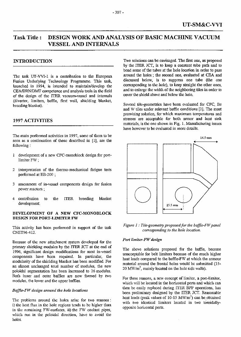
- 3 0 7 -
UT-SM&C-WI
Task Title : DESIGN WORK AND ANALYSIS OF BASIC MACHINE VACUUMVESSEL AND INTERNALS
INTRODUCTION
The task UT-WI-1 is a contribution to the EuropeanFusion Underlying Technology Programme. This task,launched in 1994, is intended to maintain/develop theCEA/DRN/DMT competence and analysis tools in the fieldof the design of the ITER vacuum-vessel and internals(divertor, limiters, baffle, first wall, shielding blanket,breeding blanket).
1997 ACTIVITIES
The main performed activities in 1997, some of them to beseen as a continuation of those described in [1], are thefollowing:
1 development of a new CFC-monoblock design for port-limiter FW;
2 interpretation of the thermo-mechanical fatigue testsperformed at EB-200 ;
3 assessment of in-vessel components design for fusionpower reactors;
4 contribution to the ITER breeding blanketdevelopment.
DEVELOPMENT OF A NEW CFC-MONOBLOCKDESIGN FOR PORT-LIMITER FW
This activity has been performed in support of the taskCNET96-412.
Because of the new attachment system developed for theprimary shielding modules by the ITER JCT at the end of1996, significant design modifications for most in-vesselcomponents have been required. In particular, themodularity of the shielding blanket has been modified. Foran almost unchanged total number of modules, the newpoloidal segmentation has been increased to 26 modules.Both inner and outer baffles are now formed by twomodules, the lower and the upper baffles.
Baffle-FW design around the hole locations
The problems around the holes arise for two reasons:i) die heat flux in the hole regions tends to be higher thanin the remaining FW-surfaces, ii) the FW coolant pipes,which run in the poloidal direction, have to avoid theholes.
Two solutions can be envisaged. The first one, as proposedby the ITER JCT, is to keep a constant tube path and tobend some of the tubes at the hole location in order to passaround the holes ; the second one, evaluated at CEA anddiscussed below, is to suppress one tube (the onecorresponding to the hole), to keep straight the other ones,and to enlarge the width of the neighboring tiles in order tocover the shield above and below the hole.
Several tile-geometries have been evaluated for CFC, Beand W tiles under relevant baffle conditions [2]. The mostpromising solution, for which maximum temperatures andstresses are acceptable for both armor and heat sinkmaterials, is the one shown in Fig. 1. Manufacturing issueshave however to be evaluated in more details.
14.5 mm
Figure 1: Tile-geometry proposed for the baffle-FW panelcorresponding to the hole location.
Port lintiter-FWdesign
The above solutions proposed for the baffle, becomeunacceptable for belt limiters because of the much higherheat loads compared to the baffle-FW at which the armourmaterial around the frontal holes would be submitted (15-20 MW/m2, mainly located on the hole side walls).
For these reasons, a new concept of limiter, a port-Iimiter,which will be located in the horizontal ports and which canthen be easily replaced during ITER BPP operations, hasbeen preliminary designed by the ITER JCT. Reasonableheat loads (peak values of 10-15 MW/m2) can be obtainedwith two identical limiters located in two toroidally-opposite horizontal ports.
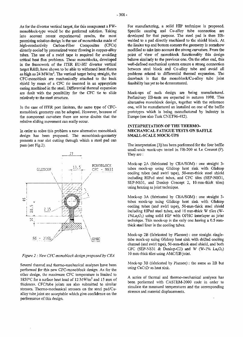
-308 -
As for the divertor vertical target, for this component a FW-monoblock-type would be the preferred solution. Takinginto account recent experimental results, the mostpromising solution design is the use of monoblocks made ofhigh-conductivity Carbon-Fiber Composites (CFCs)directly cooled by pressurized water flowing in copper-alloytubes. The use of a swirl tape is required for avoidingcritical heat flux problems. These monoblocks, developedin the framework of the ITER EU-HT divertor verticaltarget R&D, have shown to be able to withstand heat fluxesas high as 24 MW/m2. The vertical target being straight, theCFC-monoblock are mechanically attached to the backshield by mean of a CFC tie inserted in an appropriatecasing machined in the steel. Differential thermal expansionare dealt with the possibility for the CFC tie to sliderelatively to the steel structure.
In the case of ITER port limiters, the same type of CFC-monoblock geometry can be adopted. However, because ofthe component curvature there are some doubts that therelative sliding movement can really occur.
In order to solve this problem a new alternative monoblockdesign has been proposed. The monoblock-geometrypresents a rear slot cutting through which a steel pad canpass (see Fig.2).
27
GLIDCO?13,5:
MONOBLOCKCFC - NS31
SS - 3 1 6 L /
Figure 2 : New CFC-monoblock design proposed by CEA
Several thermal and thermo-mechanical analyses have beenperformed for this new CFC-monoblock design. As for theother design, the maximum CFC temperature is limited to1850°C for a surface heat load of 12 MW/m2 and 15 mm ofthickness. CFC/tube joints are also submitted to similarstresses. Thermo-mechanical stresses on the steel pad/Cu-alloy tube joint are acceptable which give confidence on theperformance of this design.
For manufacturing, a solid HIP technique is proposed.Specific canning and Cu-alloy tube connection aredeveloped for that purpose. The steel pad is then EB-welded to a pad directly machined to the shield block. Atthe limiter top and bottom corners the geometry is somehowmodified to take into account the strong curvature. From thepoint of view of monoblock functionality this designbehave similarly to the previous one. On the other end, thiswell-defined mechanical system ensure a strong connectionbetween steel block and Cu-alloy tube and avoid allproblems related to differential thermal expansion. Thedrawback is that the monoblock/Cu-alloy tube jointfeasibility has yet to be demonstrated.
Mock-ups of such design are being manufactured.Preliminary EB-tests are expected in autumn 1998. Thisalternative monoblock design, together with the referenceone, will be manufactured an installed on one of the baffleprototypes which is being manufactured by industry inEurope (see also Task CNET96-412).
INTERPRETATION OF THE THERMO-MECHANICAL FATIGUE TESTS ON BAFFLESMALL-SCALE MOCK-UPS
The interpretation [3] has been performed for the four bafflesmall-scale mock-ups tested in EB-200 at Le Creusot (F).They are :
Mock-up 2A (fabricated by CEA/SGM): one straight 3-tubes mock-up using Glidcop heat sink with Glidcopcooling tubes (and swirl tape), 50-mm-thick steel shieldincluding HIPed steel tubes, and CFC tiles (SEP-NB31,SEP-NS31, and Dunlop Concept 2, lOmm-thick tiles)using brazing as joint technique.
Mock-up 3A (fabricated by CEA/SGM): one straight 3-tubes mock-up using Glidcop heat sink with Glidcopcooling tubes (and swirl tape), 50-mm-thick steel shieldincluding HIPed steel tubes, and 10 mm-thick W tiles (W-l%La2O3) using solid HIP with OFHC interlayer as jointtechnique. This mock-up is the only one having a 0.5 mm-thick steel liner in the cooling tubes.
Mock-up 2B (fabricated by Plansee): one straight single-tube mock-up using Glidcop heat sink with drilled coolingchannel (and swirl tape), 50-mm-thick steel shield, and bothCFC (SEP-NS31 & Dunlop-C2) and W (W-1% La2O3)10 mm-thick tiles using AMC/EB joint.
Mock-up 3B (fabricated by Plansee): the same as 2B butusing CuCrZr as heat sink.
A series of thermal and thermo-mechanical analyses hasbeen performed with CASTEM-2000 code in order tosimulate the measured temperatures and the correspondingstresses and material displacements.
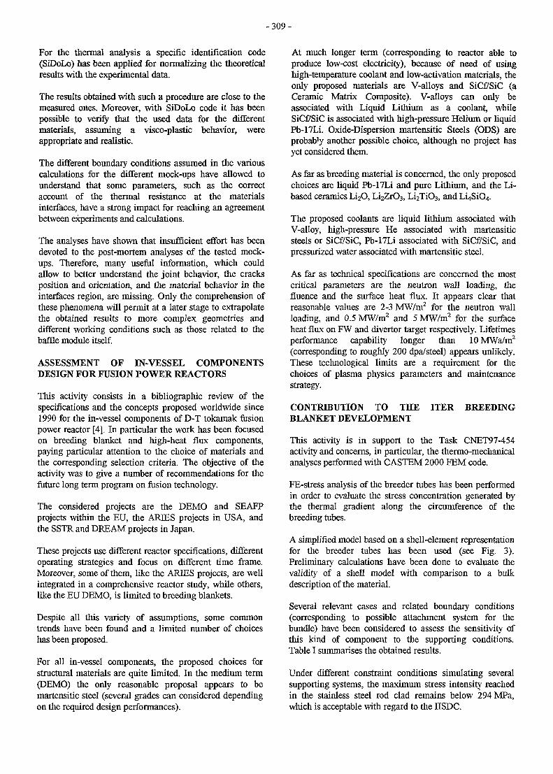
- 3 0 9 -
For the thermal analysis a specific identification code(SiDoLo) has been applied for normalizing the theoreticalresults with the experimental data.
The results obtained with such a procedure are close to themeasured ones. Moreover, with SiDoLo code it has beenpossible to verify that the used data for the differentmaterials, assuming a visco-plastic behavior, wereappropriate and realistic.
The different boundary conditions assumed in the variouscalculations for the different mock-ups have allowed tounderstand that some parameters, such as the correctaccount of the thermal resistance at the materialsinterfaces, have a strong impact for reaching an agreementbetween experiments and calculations.
The analyses have shown that insufficient effort has beendevoted to the post-mortem analyses of the tested mock-ups. Therefore, many useful information, which couldallow to better understand the joint behavior, the cracksposition and orientation, and the material behavior in theinterfaces region, are missing. Only the comprehension ofthese phenomena will permit at a later stage to extrapolatethe obtained results to more complex geometries anddifferent working conditions such as those related to thebaffle module itself.
ASSESSMENT OF IN-VESSEL COMPONENTSDESIGN FOR FUSION POWER REACTORS
This activity consists in a bibliographic review of thespecifications and the concepts proposed worldwide since1990 for the in-vessel components of D-T tokamak fusionpower reactor [4]. In particular the work has been focusedon breeding blanket and high-heat flux components,paying particular attention to the choice of materials andthe corresponding selection criteria. The objective of theactivity was to give a number of recommendations for thefuture long term program on fusion technology.
The considered projects are the DEMO and SEAEPprojects within the EU, the ARIES projects in USA, andthe SSTR and DREAM projects in Japan.
These projects use different reactor specifications, differentoperating strategies and focus on different time frame.Moreover, some of them, like the ARIES projects, are wellintegrated in a comprehensive reactor study, while others,like the EU DEMO, is limited to breeding blankets.
Despite all this variety of assumptions, some commontrends have been found and a limited number of choiceshas been proposed.
For all in-vessel components, the proposed choices forstructural materials are quite limited. In the medium term(DEMO) the only reasonable proposal appears to bemartensitic steel (several grades can considered dependingon the required design performances).
At much longer term (corresponding to reactor able toproduce low-cost electricity), because of need of usinghigh-temperature coolant and low-activation materials, theonly proposed materials are V-alloys and SiCf/SiC (aCeramic Matrix Composite). V-alloys can only beassociated with Liquid Lithium as a coolant, whileSiCf/SiC is associated with high-pressure Helium or liquidPb-I7Li. Oxide-Dispersion martensitic Steels (ODS) areprobably another possible choice, although no project hasyet considered them.
As far as breeding material is concerned, the only proposedchoices are liquid Pb-17Li and pure Lithium, and the Li-based ceramics Li2O, Li2ZrO3, Li2Ti03, and LL)SiO4.
The proposed coolants are liquid lithium associated withV-alloy, high-pressure He associated with martensiticsteels or SiCf/SiC, Pb-17Li associated with SiCf/SiC, andpressurized water associated with martensitic steel.
As far as technical specifications are concerned the mostcritical parameters are the neutron wall loading, thefluence and the surface heat flux. It appears clear thatreasonable values are 2-3 MW/m2 for the neutron wallloading, and 0.5 MW/m2 and 5 MW/m2 for the surfaceheat flux on FW and divertor target respectively. Lifetimesperformance capability longer than 10 MWa/m2
(corresponding to roughly 200 dpa/steel) appears unlikely.These technological limits are a requirement for thechoices of plasma physics parameters and maintenancestrategy.
CONTRIBUTION TO THE ITER BREEDINGBLANKET DEVELOPMENT
This activity is in support to the Task CNET97-454activity and concerns, in particular, the thermo-mechanicalanalyses performed with CASTEM 2000 FEM code.
FE-stress analysis of the breeder tubes has been performedin order to evaluate the stress concentration generated bythe thermal gradient along the circumference of thebreeding tubes.
A simplified model based on a shell-element representationfor the breeder tubes has been used (see Fig. 3).Preliminary calculations have been done to evaluate thevalidity of a shell model with comparison to a bulkdescription of the material.
Several relevant cases and related boundary conditions(corresponding to possible attachment system for thebundle) have been considered to assess the sensitivity ofthis kind of component to the supporting conditions.Table I summarises the obtained results.
Under different constraint conditions simulating severalsupporting systems, the maximum stress intensity reachedin the stainless steel rod clad remains below 294 MPa,which is acceptable with regard to the IISDC.
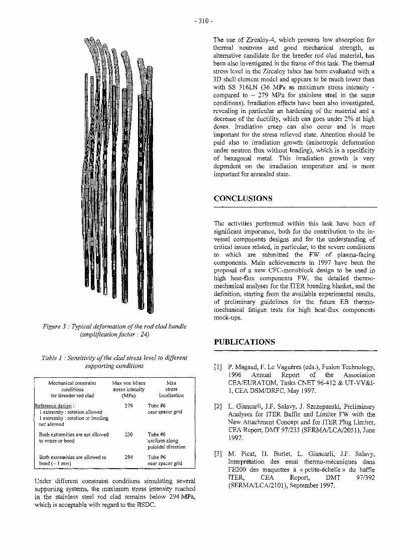
- 3 1 0 -
Figure 3 : Typical deformation of the rod clad bundle(amplification factor: 24)
Table 1: Sensitivity of the clad stress level to differentsupporting conditions
Mechanical constraintconditions
for Breeder rod clad
Reference design :1 extremity : rotation allowed1 extremity : rotation or bendingnot allowed
Both extremities are not allowedto rotate or bend
Both extremities are allowed tobend (~ 1 mm)
Max von Misesstress intensity
(MPa)
279
230
294
Maxstress
localisation
Tube #6near spacer grid
Tube #6uniform alongpoloidal direction
Tube #6near spacer grid
Under different constraint conditions simulating severalsupporting systems, the maximum stress intensity reachedin the stainless steel rod clad remains below 294 MPa,which is acceptable with regard to the IISDC.
The use of Zircaloy-4, which presents low absorption forthermal neutrons and good mechanical strength, asalternative candidate for the breeder rod clad material, hasbeen also investigated in the frame of this task. The thermalstress level in the Zircaloy tubes has been evaluated with a3D shell element model and appears to be much lower thanwith SS 316LN (36 MPa as maximum stress intensity -compared to ~ 279 MPa for stainless steel in the sameconditions). Irradiation effects have been also investigated,revealing in particular an hardening of the material and adecrease of the ductility, which can goes under 2% at highdoses. Irradiation creep can also occur and is moreimportant for the stress relieved state. Attention should bepaid also to irradiation growth (anisotropic deformationunder neutron flux without loading), which is a specificityof hexagonal metal. This irradiation growth is verydependent on the irradiation temperature and is moreimportant for annealed state.
CONCLUSIONS
The activities performed within this task have been ofsignificant importance, both for the contribution to the in-vessel components designs and for the understanding ofcritical issues related, in particular, to the severe conditionsto which are submitted the FW of plasma-facingcomponents. Main achievements in 1997 have been theproposal of a new CFC-monoblock design to be used inhigh heat-flux components FW, the detailed thermo-mechanical analyses for the ITER breeding blanket, and thedefinition, starting from the available experimental results,of preliminary guidelines for the future EB thermo-mechanical fatigue tests for high heat-flux componentsmock-ups.
PUBLICATIONS
[1] P. Magaud, F. Le Vagueres (eds.), Fusion Technology,1996 Annual Report of the AssociationCEA/EURATOM, Tasks CNET 96-412 & UT-VV&I-1, CEA DSM/DRFC, May 1997.
[2] L. Giancarli, J.F. Salavy, J. Szczepanski, PreliminaryAnalyses for ITER Baffle and Limiter FW with theNew Attachment Concept and for ITER Plug Limiter,CEA Report, DMT 97/233 (SERMA/LCA/2051), June1997.
[3] M. Picat, H. Burlet, L. Giancarli, J.F. Salavy,Interpretation des essai thermo-mecaniques dansFE200 des maquettes a « petite-echelle» du baffleITER, CEA Report, DMT 97/392(SERMA/LCA/2101), September 1997.
- 3 1 1 -
[4] L. Giancarli, G. Le Marois, Internes de la chambre a T A S K L E A D E Rplasma d'un reacteur de puissance - Revuebibliographique des propositions r&entes, CEAReport, DMT 97/338 (SERMA/LCA/2088), L GIANCARLISeptember 1997.
CEA CEN Saclay[5] Y. Poitevin, L. Giancarli, Contribution of the CEA to DRN/DMT/SERMA
the EU HT ITER Breeding Blanket Development and 91191 Gif-sur-Yvette (France)Design, CEA Report, DMT 97/316(SERMA/LCA/2084), August 1997. T e l . 3 3 l 6 9 0 8 2 1 37
Fax : 33 1 69 08 99 35[6] G. Vieider, L. Giancarli, et al., Overview of the EU
small-scale mock-ups Tests for ITER High Heat FluxComponents, Proceeding of ISFNT-4, April 6-11,1997, Tokyo, Japan.
[7] A. Cardella, L. Giancarli, et al., Design of the ITEREDA Plasma Facing Components, Proceeding ofISFNT-4, April 6-11, 1997, Tokyo, Japan.
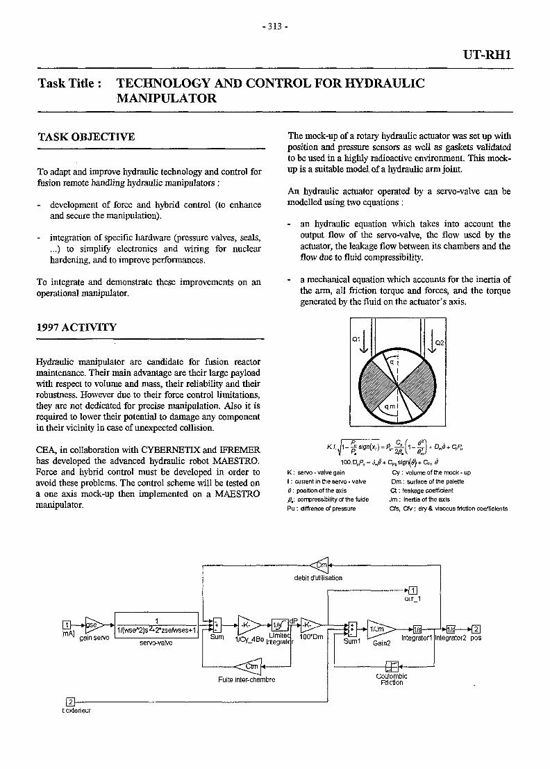
- 3 1 3 -
UT-RH1
Task Title : TECHNOLOGY AND CONTROL FOR HYDRAULICMANIPULATOR
TASK OBJECTIVE
To adapt and improve hydraulic technology and control forfusion remote handling hydraulic manipulators :
- development of force and hybrid control (to enhanceand secure the manipulation).
- integration of specific hardware (pressure valves, seals,...) to simplify electronics and wiring for nuclearhardening, and to improve performances.
To integrate and demonstrate these improvements on anoperational manipulator.
1997 ACTIVITY
Hydraulic manipulator are candidate for fusion reactormaintenance. Their main advantage are their large payloadwith respect to volume and mass, their reliability and theirrobustness. However due to their force control limitations,they are not dedicated for precise manipulation. Also it isrequired to lower their potential to damage any componentin their vicinity in case of unexpected collision.
CEA, in collaboration with CYBERNETIX and IFREMERhas developed the advanced hydraulic robot MAESTRO.Force and hybrid control must be developed in order toavoid these problems. The control scheme will be tested ona one axis mock-up then implemented on a MAESTROmanipulator.
The mock-up of a rotary hydraulic actuator was set up withposition and pressure sensors as well as gaskets validatedto be used in a highly radioactive environment. This mock-up is a suitable model of a hydraulic arm joint.
An hydraulic actuator operated by a servo-valve can bemodelled using two equations :
- an hydraulic equation which takes into account theoutput flow of the servo-valve, the flow used by theactuator, the leakage flow between its chambers and theflow due to fluid compressibility.
- a mechanical equation which accounts for the inertia ofthe arm, all friction torque and forces, and the torquegenerated by the fluid on the actuator's axis.
1-1100. DmP,, = Jj + CFS sig
K: servo - valve gainI : current in the servo - valve8: position of the axisfi,: compressibility of the fuidePu : diffrence of pressure
Cy : volume of the mock - upDm: surface of the paletteCt: leakage coefficientJm: Inertia of the axisCfs, Cfv: dry & viscous friction coefficients
texterieur
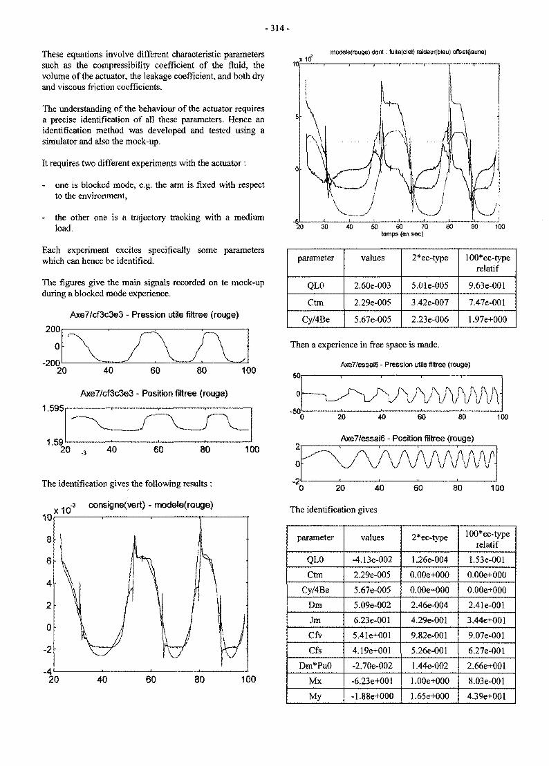
- 3 1 4 -
These equations involve different characteristic parameterssuch as the compressibility coefficient of the fluid, thevolume of the actuator, the leakage coefficient, and both dryand viscous friction coefficients.
The understanding of the behaviour of the actuator requiresa precise identification of all these parameters. Hence anidentification method was developed and tested using asimulator and also the mock-up.
It requires two different experiments with the actuator:
- one is blocked mode, e.g. the arm is fixed with respectto the environment,
- the other one is a trajectory tracking with a mediumload.
Each experiment excites specifically some parameterswhich can hence be identified.
The figures give the main signals recorded on te mock-upduring a blocked mode experience.
mode)e(rouge) dont: fuite(ciei) raideur{bteu) offeetflaune)
Axe7/cf3c3e3 - Pression utile filtree (rouge)
200
-20020 40 60 80 100
Axe7/cf3c3e3 - Position filtree (rouge)
1.595
1.59
The identification gives the following results :
x10-3 consigne(vert) - modete(rGuge)
20 40 60 80
20 30 40 50 60 70temps {en sec)
90 100
parameter
QL0
Ctm
Cy/4Be
values
2.60e-003
2.29e-005
5.67e-005
2*ec-type
5.01e-005
3.42e-007
2.23e-006
100*ec-typerelatif
9.63e-001
7.47e-001
1.97e+O00
Then a experience in free space is made.
Axe7/essai6 - Pnession utile filtree (rouge)
Axe7/essai6 - Position filtree (rouge)
20 40 60 80 100
The identification gives
parameter
QL0
Ctm
Cy/4Be
Dm
Jm
Cfv
Cfs
Dm*Pu0
Mx
My
values
-4.13e-002
2.29e-005
5.67e-005
5.09e-002
6.23e-001
5.41e+001
4.19e+001
-2.70e-002
-6.23e+001
-1.88e+000
2*ec-type
1.26e-004
0.00e+000
0.00e+000
2.46e-004
4.29e-001
9.82e-001
5.26e-O01
1.44e-002
1.00e+000
1.65e+O00
100*ec-typerelatif
1.53e-001
O.GOe+000
0.00e+000
2.41e-001
3.44e+001
9.07e-001
6.27e-001
2.66e+001
8.03e-001
4.39e+001
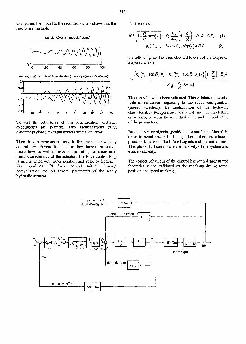
-315-
Comparing the model to the recorded signals shows that theresults are trustable.
consigne(vert) - modele(rouge)
For the system:
-0.220 40
modele(rouge) dont : fuite(ciel) raideur(bleu) mecanique(violet) oflset<|aune)
10 20 30 40 50 60 70 80 90 100
To test the robustness of this identification, differentexperiments are perform. Two identifications (withdifferent payload) gives parameters within 2% error.
Then these parameters are used in for position or velocitycontrol laws. Several force control laws have been tested :linear laws as well as laws compensating for some non-linear characteristic of the actuator. The force control loopis implemented with outer position and velocity feedback.The non-linear PI force control without linkagecompensation requires several parameters of the rotaryhydraulic actuator.
100.DmPu =M.<9+
tPu (1)
(2)
the following law has been choosed to control the torque ona hydraulic axis :
/ = •
K h-
The control law has been validated. This validation includestests of robustness regarding to the robot configuration(inertia variation), the modification of the hydrauliccharacteristics (temperature, viscosity) and the modellingerror (error between the identified value and the real valueof the parameters).
Besides, sensor signals (position, pressure) are filtered inorder to avoid spectral aliasing. These filters introduce aphase shift between the filtered signals and the initial ones.This phase shift can disturb the passivity of the system andeven its stability.
The correct behaviour of the control has been demonstratedtheoretically and validated on the mock-up during force,position and speed tracking.
compensation du
iQc |-^-•p-^kp+K.i/p -<>•*•
debit d'utilisation
debit d'utilisation
gser-K) *•+
servo-valv
Dm
Pu
debit de fuiteCtm
retouren effort1 OO.ADm
lOO.Dm M.p+R 59
mecanique
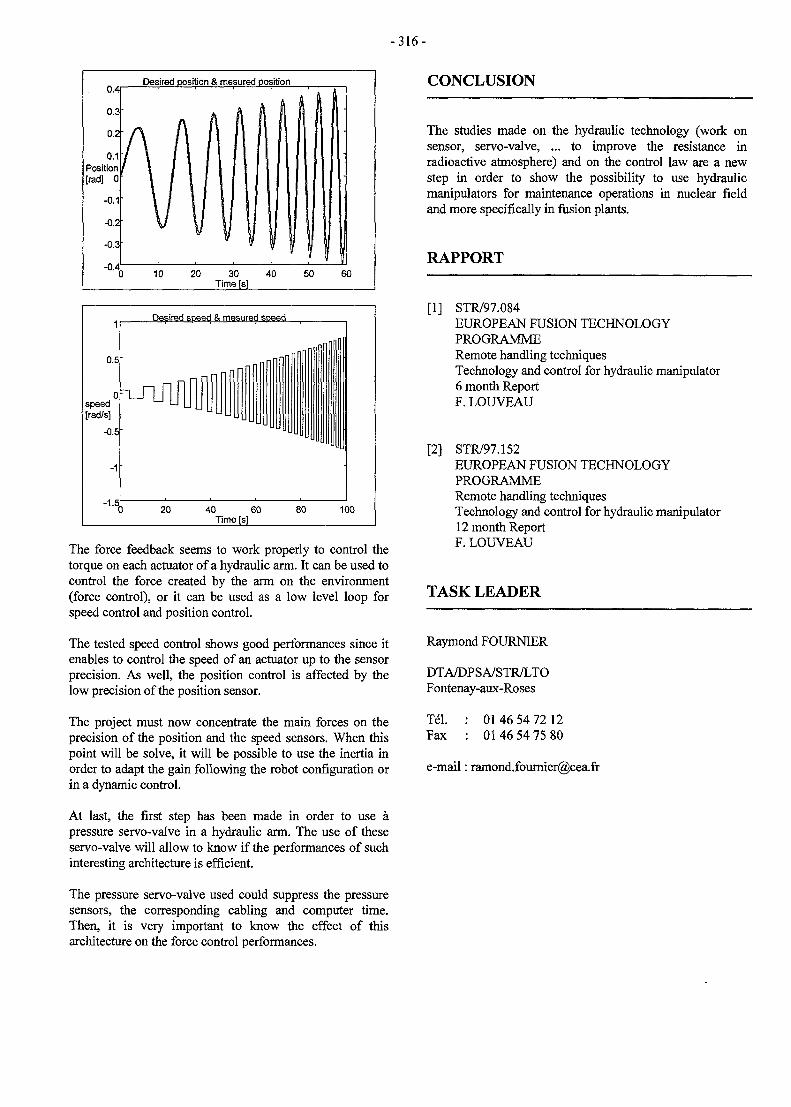
- 3 1 6 -
0.4
0.3
0.2
0.1Position[rad] 0
-0.1
-0.2
-0.3
-0.4
Desired position & mesured position
h j
A A l l
Will\ / i l lV y i
| I Siil
I il if I1J 10 20 30 40 50 60
Time [s]
CONCLUSION
1
0.5
0speedIrad/s]
-0.5
-1
-'•H
Desired speed & mesured speed
_ n n n (1
-
) 20 40 60Time[s
n o l l l
80 100
The force feedback seems to work properly to control thetorque on each actuator of a hydraulic arm. It can be used tocontrol the force created by the arm on the environment(force control), or it can be used as a low level loop forspeed control and position control.
The tested speed control shows good performances since itenables to control the speed of an actuator up to the sensorprecision. As well, the position control is affected by thelow precision of the position sensor.
The project must now concentrate the main forces on theprecision of the position and the speed sensors. When thispoint will be solve, it will be possible to use the inertia inorder to adapt the gain following the robot configuration orin a dynamic control.
At last, the first step has been made in order to use apressure servo-valve in a hydraulic arm. The use of theseservo-valve will allow to know if the performances of suchinteresting architecture is efficient.
The pressure servo-valve used could suppress the pressuresensors, the corresponding cabling and computer time.Then, it is very important to know the effect of thisarchitecture on the force control performances.
The studies made on the hydraulic technology (work onsensor, servo-valve, ... to improve the resistance inradioactive atmosphere) and on the control law are a newstep in order to show the possibility to use hydraulicmanipulators for maintenance operations in nuclear fieldand more specifically in fusion plants.
RAPPORT
[1] STR/97.084EUROPEAN FUSION TECHNOLOGYPROGRAMMERemote handling techniquesTechnology and control for hydraulic manipulator6 month ReportF. LOUVEAU
[2] STR/97.152EUROPEAN FUSION TECHNOLOGYPROGRAMMERemote handling techniquesTechnology and control for hydraulic manipulator12 month ReportF. LOUVEAU
TASK LEADER
Raymond FOURNIER
DTA/DPSA/STR/LTOFontenay-aux-Roses
Tel.Fax
01 46 54 72 1201 46 54 75 80
e-mail: [email protected]
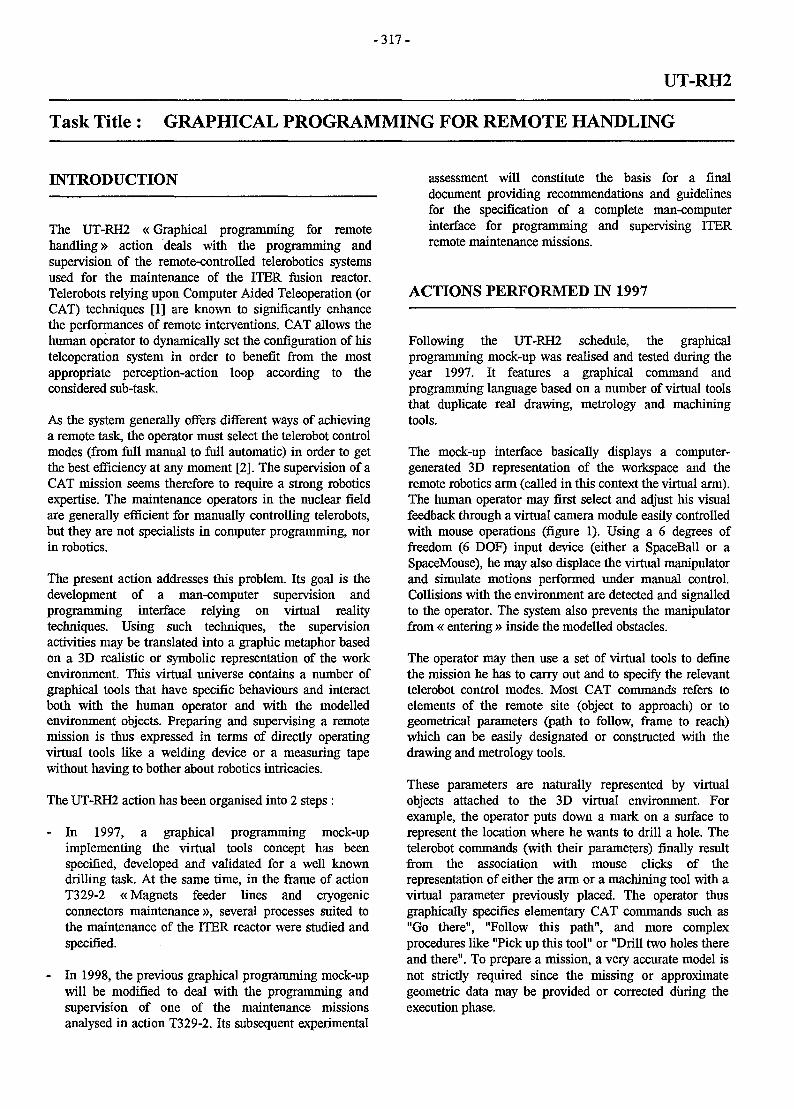
- 3 1 7 -
UT-RH2
Task Title : GRAPHICAL PROGRAMMING FOR REMOTE HANDLING
INTRODUCTION
The UT-RH2 «Graphical programming for remotehandling» action deals with the programming andsupervision of the remote-controlled telerobotics systemsused for the maintenance of the ITER fusion reactor.Telerobots relying upon Computer Aided Teleoperation (orCAT) techniques [1] are known to significantly enhancethe performances of remote interventions. CAT allows thehuman operator to dynamically set the configuration of histeleoperation system in order to benefit from the mostappropriate perception-action loop according to theconsidered sub-task.
As the system generally offers different ways of achievinga remote task, the operator must select the telerobot controlmodes (from full manual to full automatic) in order to getthe best efficiency at any moment [2]. The supervision of aCAT mission seems therefore to require a strong roboticsexpertise. The maintenance operators in the nuclear fieldare generally efficient for manually controlling telerobots,but they are not specialists in computer programming, norin robotics.
The present action addresses this problem. Its goal is thedevelopment of a man-computer supervision andprogramming interface relying on virtual realitytechniques. Using such techniques, the supervisionactivities may be translated into a graphic metaphor basedon a 3D realistic or symbolic representation of the workenvironment. This virtual universe contains a number ofgraphical tools that have specific behaviours and interactboth with the human operator and with the modelledenvironment objects. Preparing and supervising a remotemission is thus expressed in terms of directly operatingvirtual tools like a welding device or a measuring tapewithout having to bother about robotics intricacies.
The UT-RH2 action has been organised into 2 steps :
- In 1997, a graphical programming mock-upimplementing the virtual tools concept has beenspecified, developed and validated for a well knowndrilling task. At the same time, in the frame of actionT329-2 «Magnets feeder lines and cryogenicconnectors maintenance », several processes suited tothe maintenance of the ITER reactor were studied andspecified.
- In 1998, the previous graphical programming mock-upwill be modified to deal with the programming andsupervision of one of the maintenance missionsanalysed in action T329-2. Its subsequent experimental
assessment will constitute the basis for a finaldocument providing recommendations and guidelinesfor the specification of a complete man-computerinterface for programming and supervising ITERremote maintenance missions.
ACTIONS PERFORMED IN 1997
Following the UT-RH2 schedule, the graphicalprogramming mock-up was realised and tested during theyear 1997. It features a graphical command andprogramming language based on a number of virtual toolsthat duplicate real drawing, metrology and machiningtools.
The mock-up interface basically displays a computer-generated 3D representation of the workspace and theremote robotics arm (called in this context the virtual arm).The human operator may first select and adjust his visualfeedback through a virtual camera module easily controlledwith mouse operations (figure 1). Using a 6 degrees offreedom (6 DOF) input device (either a SpaceBall or aSpaceMouse), he may also displace the virtual manipulatorand simulate motions performed under manual control.Collisions with the environment are detected and signalledto the operator. The system also prevents the manipulatorfrom « entering »inside the modelled obstacles.
The operator may then use a set of virtual tools to definethe mission he has to carry out and to specify the relevanttelerobot control modes. Most CAT commands refers toelements of the remote site (object to approach) or togeometrical parameters (path to follow, frame to reach)which can be easily designated or constructed with thedrawing and metrology tools.
These parameters are naturally represented by virtualobjects attached to the 3D virtual environment. Forexample, the operator puts down a mark on a surface torepresent the location where he wants to drill a hole. Thetelerobot commands (with their parameters) finally resultfrom the association with mouse clicks of therepresentation of either the arm or a machining tool with avirtual parameter previously placed. The operator thusgraphically specifies elementary CAT commands such as"Go there", "Follow this path", and more complexprocedures like "Pick up this tool" or "Drill two holes thereand there". To prepare a mission, a very accurate model isnot strictly required since the missing or approximategeometric data may be provided or corrected during theexecution phase.
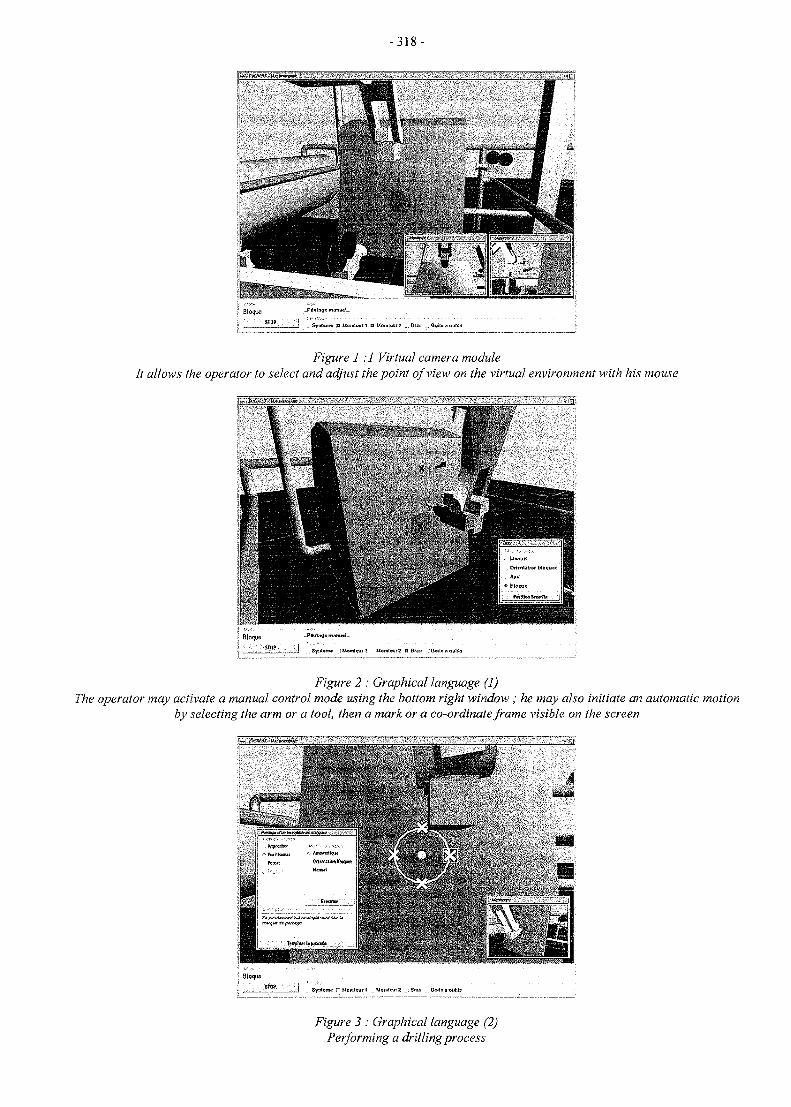
- 3 1 8 -
_J _ Synttttw; U Momlcuri B HomlaitZ _. B(»3 O«<lo 3 oulils
Figure 1:1 Virtual camera moduleIt allows the operator to select and adjust the point of view on the virtual environment with his mouse
Figure 2 : Graphical language (1)The operator may activate a manual control mode using the bottom right window ; he may also initiate an automatic motion
by selecting the arm or a tool, then a mark or a co-ordinate frame visible on the screen
T Jcmc ~ Moralouri ManitmirZ . Brau . JioAa a outila
Figure 3 : Graphical language (2)Performing a drilling process
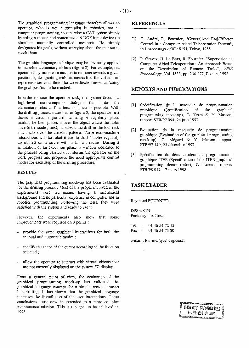
-319-
The graphical programming language therefore allows anoperator, who is not a specialist in robotics, nor incomputer programming, to supervise a CAT system simplyby using a mouse and sometimes a 6 DOF input device (tosimulate manually controlled motions). He simplydesignates his goals, without worrying about the manner toreach them.
The graphic language technique may be obviously appliedto the robot elementary actions (figure 2). For example, theoperator may initiate an automatic motions towards a givenposition by designating with his mouse first the virtual armrepresentation and then the co-ordinate frame matchingthe goal position to be reached.
In order to ease the operator task, the system favours ahigh-level man-computer dialogue that hides theelementary robotics functions as much as possible. Withthe drilling process described in figure 3, the operator firstdraws a circular pattern featuring 4 regularly pacedmarks ; he then places it over the object where the holeshave to be made ; next, he selects the drill in the tool rackand clicks over the circular pattern. These man-machineinteractions tell the robot it has to drill 4 holes regularlydistributed on a circle with a known radius. During asimulation or an execution phase, a window dedicated tothe process being carried out informs the operator on thework progress and proposes the most appropriate controlmodes for each step of the drilling procedure.
RESULTS
The graphical programming mock-up has been evaluatedfor the drilling process. Most of the people involved in theexperiments were technicians having a mechanicalbackground and no particular expertise in computer, nor inrobotics programming. Following the tests, they weresatisfied with the system and ready to use it.
However, the experiments also show that someimprovements were required on 3 points :
- provide the same graphical interactions for both themanual and automatic modes ;
- modify the shape of the cursor according to the functionselected;
- allow the operator to interact with virtual objects thatare not currently displayed on the system 3D display.
From a general point of view, the evaluation of thegraphical programming mock-up has validated thegraphical language concept for a simple remote processlike drilling. It has shown that the graphical languageincreases the friendliness of the user interactions. Theseconclusions must now be extended to a more complexmaintenance mission. This is the goal to be achieved in1998.
REFERENCES
[1] G. Andre, R. Founder, "Generalized End-EffectorControl in a Computer Aided Teleoperation System",in Proceedings oflCAR '85, Tokyo, 1985.
[2] P. Gravez, H. Le Bars, R. Fournier, "Supervision inComputer Aided Teleoperation : An Approach Basedon the Description of Remote Tasks", SPJEProceedings, Vol. 1833, pp. 266-277, Boston, 1992.
REPORTS AND PUBLICATIONS
[1] Specification de la maquette de programmationgraphique (Specification of the graphicalprogramming mock-up), C. Terre & Y. Masson,rapport STR/97.094, 24 juin 1997.
[2] Evaluation de la maquette de programmationgraphique (Evaluation of the graphical programmingmock-up), C. Megard & Y. Masson, rapportSTR/97.140, 23 decembre 1997.
[3] Specification du demonstrates de programmationgraphique ITER (Specification of the ITER graphicalprogramming demonstrator), C. Leroux, rapportSTR/98.017, 17 mars 1998.
TASK LEADER
Raymond FOURNIER
DPSA/STRFontenay-aux-Roses
Tel.Fax
01 46 54 72 1201 46 54 75 80
e-mail: [email protected]
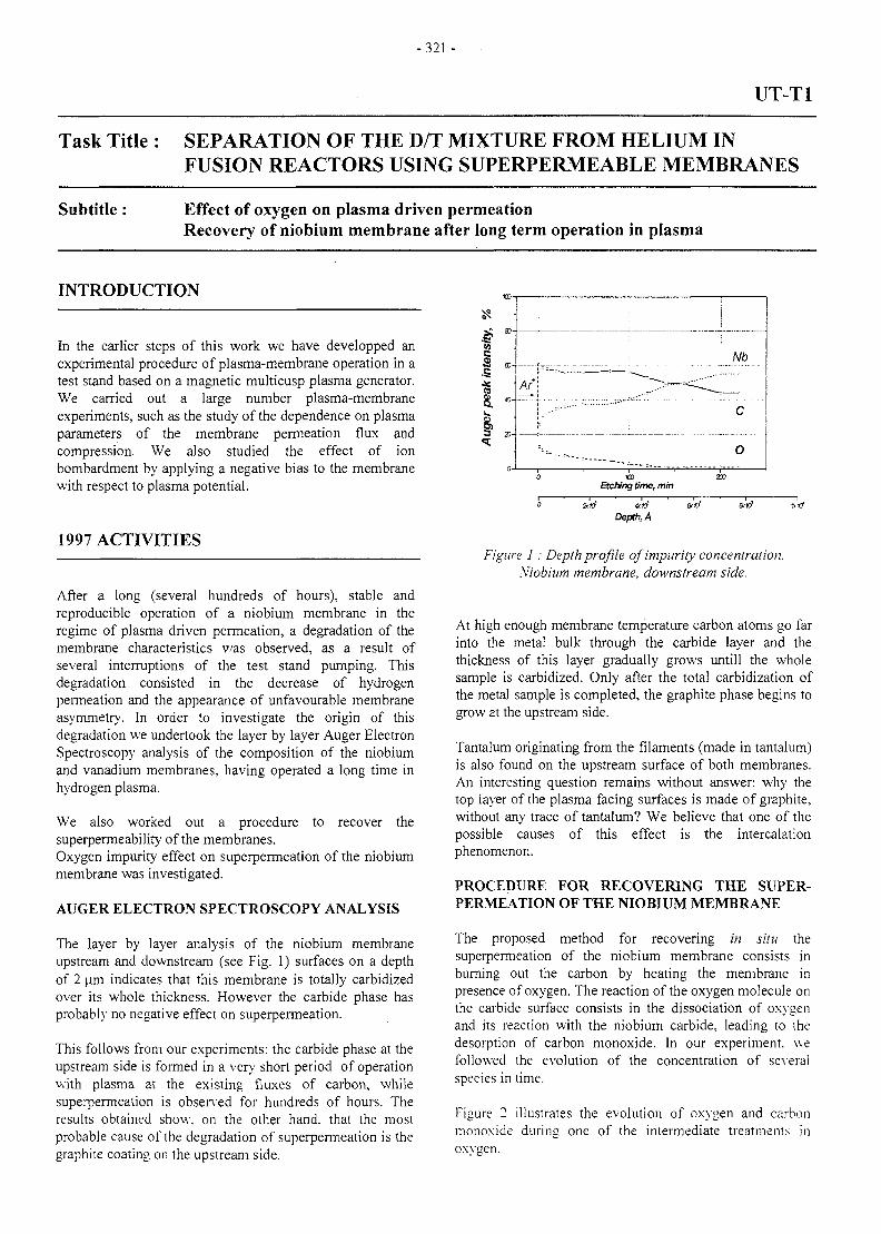
-321 -
UT-T1
Task Title : SEPARATION OF THE D/T MIXTURE FROM HELIUM INFUSION REACTORS USING SUPERPERMEABLE MEMBRANES
Subtitle : Effect of oxygen on plasma driven permeationRecovery of niobium membrane after long term operation in plasma
INTRODUCTION
In the earlier steps of this work we have developped anexperimental procedure of plasma-membrane operation in atest stand based on a magnetic multicusp plasma generator.We carried out a large number plasma-membraneexperiments, such as the study of the dependence on plasmaparameters of the membrane permeation flux andcompression. We also studied the effect of ionbombardment by applying a negative bias to the membranewith respect to plasma potential.
1997 ACTIVITIES
After a long (several hundreds of hours), stable andreproducible operation of a niobium membrane in theregime of plasma driven permeation, a degradation of themembrane characteristics v/as observed, as a result ofseveral interruptions of the test stand pumping. Thisdegradation consisted in the decrease of hydrogenpermeation and the appearance of unfavourable membraneasymmetry. In order to investigate the origin of thisdegradation we undertook the layer by layer Auger ElectronSpectroscopy analysis of the composition of the niobiumand vanadium membranes, having operated a long time inhydrogen plasma.
We also worked out a procedure to recover thesuperpermeability of the membranes.Oxygen impurity effect on superpermeation of the niobiummembrane was investigated.
AUGER ELECTRON SPECTROSCOPY ANALYSIS
The layer by layer analysis of the niobium membraneupstream and downstream (see Fig. 1) surfaces on a depthof 2 jam indicates that this membrane is totally carbidizedover its whole thickness. However the carbide phase hasprobably no negative effect on superpermeation.
This follows from our experiments: the carbide phase at theupstream side is formed in a very short period of operationwith plasma at the existing fluxes of carbon, whilesuperpermeation is observed for hundreds of hours. Theresults obtained show, on the other hand, that the mostprobable cause of the degradation of superpermeation is thegraphite coating on the upstream side.
mEtching time, mm
Depth, A
Figure 1 : Depth profile of impurity concentration.Niobium membrane, downstream side.
At high enough membrane temperature carbon atoms go farinto the metal bulk through the carbide layer and thethickness of this layer gradually grows untill the wholesample is carbidized. Only after the total carbidization ofthe metal sample is completed, the graphite phase begins togrow at the upstream side.
Tantalum originating from the filaments (made in tantalum)is also found on the upstream surface of both membranes.An interesting question remains without answer: why thetop layer of the plasma facing surfaces is made of graphite,without any trace of tantalum? We believe that one of thepossible causes of this effect is the intercalationphenomenon.
PROCEDURE FOR RECOVERING THE SUPER-PERMEATION OF THE NIOBIUM MEMBRANE
The proposed method for recovering in situ thesuperpermeation of the niobium membrane consists inburning out the carbon by heating the membrane inpresence of oxygen. The reaction of the oxygen molecule onthe carbide surface consists in the dissociation of oxygenand its reaction with the niobium carbide, leading to thedesorption of carbon monoxide. In our experiment, wefollowed the evolution of the concentration of severalspecies in time.
Figure 2 illustrates the evolution of oxygen and carbonmonoxide during one of the intermediate treatments inoxygen.
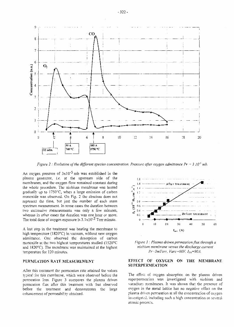
-322-
i L i
2
02adm.
k
I
50A
740 °C
6i L
8
185A
1750°C
10 12 14 16 18 20
Figure 2 : Evolution of the different species concentration. Pressure after oxygen admittance Pr = 3 10~} mb.
An oxygen pressure of 3xlO"^mb was established in theplasma generator, i.e. at the upstream side of themembranes, and the oxygen flow remained constant duringthe whole procedure. The niobium membrane was heatedgradually up to 1750°C, when a large emission of carbonmonoxide was observed. On Fig. 2 the abscissa does notrepresent the time, but just the number of each massspectrum measurement. In some cases the duration betweentwo successive measurements was only a few minutes,whereas in other cases the duration was one hour or more.The total dose of oxygen exposure is 3.1x10"^ Torr minute.
A last step in the treatment was heating the membrane tohigh temperature (1820°C) in vacuum, without new oxygenadmittance. One observed the desorption of carbonmonoxide at the two highest temperatures studied (1520°Cand 1820°C). The membrane was maintained at the highesttemperature for 120 minutes.
PERMEATION RATE MEASUREMENT
After this treatment the permeation rate attained the valuestypical for this membrane, which were observed before thepermeation loss. Figure 3 compares the plasma drivenpermeation flux after this treatment with that observedbefore the treatment and demonstrates the largeenhancement of permeability obtained.
Figure 3 : Plasma driven permeation flux through aniobium membrane versus the discharge current
Pr=3mTorr, Varc=60V, /M
EFFECT OF OXYGEN ON THE MEMBRANESUPERPERMEATION
The effect of oxygen absorption on the plasma drivensuperpermeation was investigated with niobium andvanadium membranes. It was shown that the presence ofoxygen in the metal lattice has no negative effect on theplasma driven permeation at all the concentration of oxygeninvestigated, including such a high concentration as severalatomic percents.
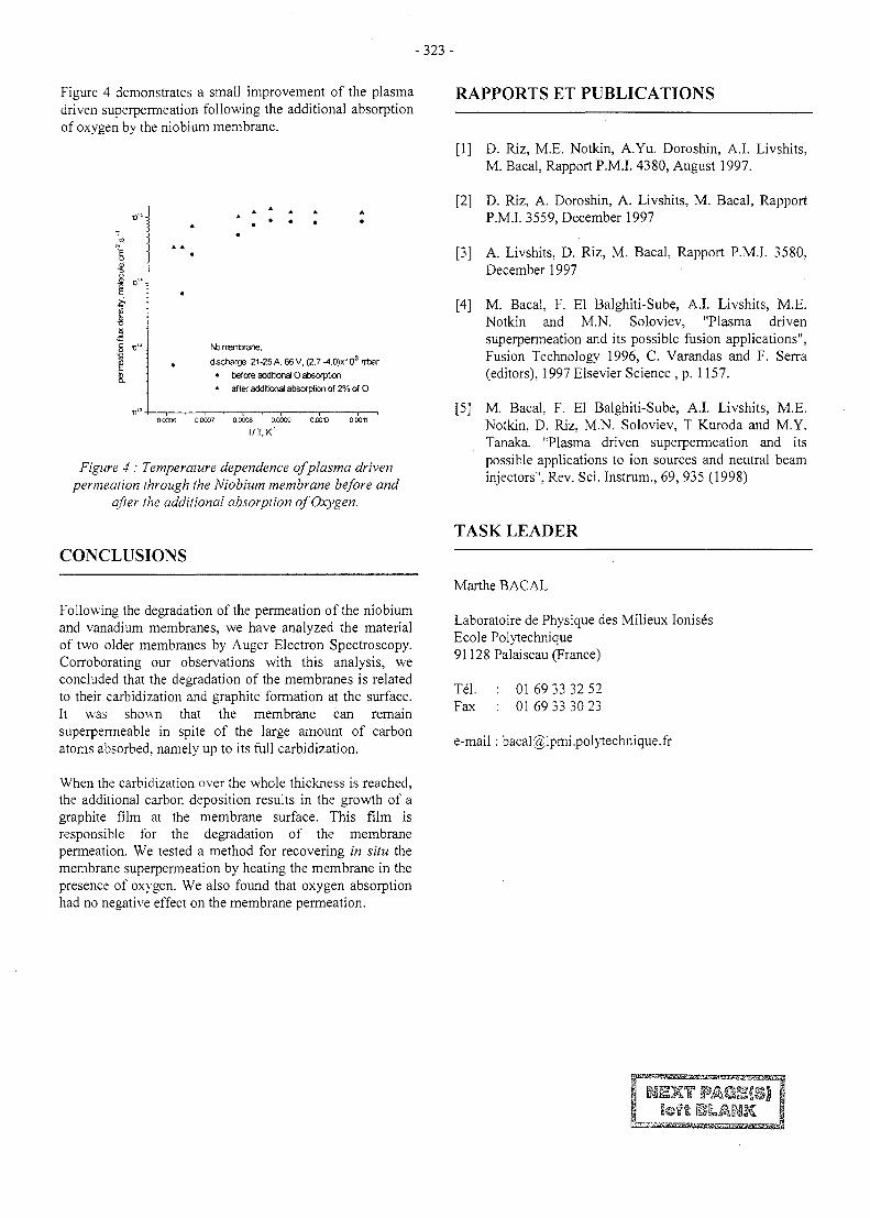
- 323 -
Figure 4 demonstrates a small improvement of the plasmadriven superpermeation following the additional absorptionof oxygen by the niobium membrane.
ht> rrentxane,
discharge: 21-25 A, 66 V, (2.7 -4.0)x103 ntar
• before additional O absorption
* after additional absorption of 2% of O
00006 0.00O7 0.0O08 0.0009 O.OOt) 00011
I/T.K'
Figure 4 : Temperature dependence of plasma drivenpermeation through the Niobium membrane before and
after the additional absorption of Oxygen.
CONCLUSIONS
Following the degradation of the permeation of the niobiumand vanadium membranes, we have analyzed the materialof two older membranes by Auger Electron Spectroscopy.Corroborating our observations with this analysis, weconcluded that the degradation of the membranes is relatedto their carbidization and graphite formation at the surface.It was shown that the membrane can remainsuperpermeable in spite of the large amount of carbonatoms absorbed, namely up to its full carbidization.
When the carbidization over the whole thickness is reached,the additional carbon deposition results in the growth of agraphite film at the membrane surface. This film isresponsible for the degradation of the membranepermeation. We tested a method for recovering in situ themembrane superpermeation by heating the membrane in thepresence of oxygen. We also found that oxygen absorptionhad no negative effect on the membrane permeation.
RAPPORTS ET PUBLICATIONS
[1] D. Riz, M.E. Notkin, A.Yu. Doroshin, A.I. Livshits,M. Bacal, Rapport P.M.I. 4380, August 1997.
[2] D. Riz, A. Doroshin, A. Livshits, M. Bacal, RapportP.M.I. 3559, December 1997
[3] A. Livshits, D. Riz, M. Bacal, Rapport P.M.I. 3580,December 1997
[4] M. Bacal, F. El Balghiti-Sube, A.I. Livshits, M.E.Notkin and M.N. Soloviev, "Plasma drivensuperpermeation and its possible fusion applications",Fusion Technology 1996, C. Varandas and F. Serra(editors), 1997 Elsevier Science , p. 1157.
[5] M. BacaL F. El Balghiti-Sube, A.I. Livshits, M.E.Notkin, D. Riz, M.N. Soloviev, T Kuroda and M.Y.Tanaka. "Plasma driven superpermeation and itspossible applications to ion sources and neutral beaminjectors", Rev. Sci. Instrum., 69, 935 (1998)
TASK LEADER
Marthe BACAL
Laboratoire de Physique des Milieux IonisesEcole Polytechnique91128 Palaiseau (France)
Tel.Fax
01 69 33 32 5201 69 33 30 23
e-mail: [email protected]
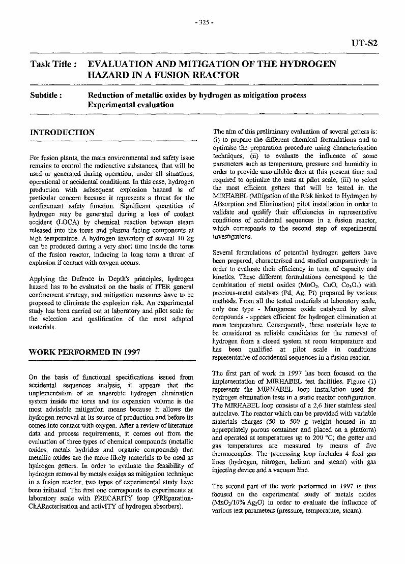
- 3 2 5 -
UT-S2
Task Title : EVALUATION AND MITIGATION OF THE HYDROGENHAZARD IN A FUSION REACTOR
Subtitle: Reduction of metallic oxides by hydrogen as mitigation processExperimental evaluation
INTRODUCTION
For fusion plants, the main environmental and safety issueremains to control the radioactive substances, that will beused or generated during operation, under all situations,operational or accidental conditions. In this case, hydrogenproduction with subsequent explosion hazard is ofparticular concern because it represents a threat for theconfinement safety function. Significant quantities ofhydrogen may be generated during a loss of coolantaccident (LOCA) by chemical reaction between steamreleased into the torus and plasma facing components athigh temperature. A hydrogen inventory of several 10 kgcan be produced during a very short time inside the torusof the fusion reactor, inducing in long term a threat ofexplosion if contact with oxygen occurs.
Applying the Defence in Depth's principles, hydrogenhazard has to be evaluated on the basis of ITER generalconfinement strategy, and mitigation measures have to beproposed to eliminate the explosion risk. An experimentalstudy has been carried out at laboratory and pilot scale forthe selection and qualification of the most adaptedmaterials.
WORK PERFORMED IN 1997
On the basis of functional specifications issued fromaccidental sequences analysis, it appears that theimplementation of an anaerobic hydrogen eliminationsystem inside the torus and its expansion volume is themost advisable mitigation means because it allows thehydrogen removal at its source of production and before itscomes into contact with oxygen. After a review of literaturedata and process requirements, it comes out from theevaluation of three types of chemical compounds (metallicoxides, metals hydrides and organic compounds) thatmetallic oxides are the more likely materials to be used ashydrogen getters. In order to evaluate the feasibility ofhydrogen removal by metals oxides as mitigation techniquein a fusion reactor, two types of experimental study havebeen initiated. The first one corresponds to experiments atlaboratory scale with PRECAPJTY loop (PREparation-ChARacterisation and activITY of hydrogen absorbers).
The aim of this preliminary evaluation of several getters is:(i) to prepare the different chemical formulations and tooptimise the preparation procedure using characterisationtechniques, (ii) to evaluate the influence of someparameters such as temperature, pressure and humidity inorder to provide unavailable data at this present time andrequired to optimize the tests at pilot scale, (iii) to selectthe most efficient getters that will be tested in theMRHABEL (Mitigation of the Risk linked to Hydrogen byABsorption and Elimination) pilot installation in order tovalidate and qualify their efficiencies in representativeconditions of accidental sequences in a fusion reactor,which corresponds to the second step of experimentalinvestigations.
Several formulations of potential hydrogen getters havebeen prepared, characterised and studied comparatively inorder to evaluate their efficiency in term of capacity andkinetics. These different formulations correspond to thecombination of metal oxides (MnO2, CuO, C03O4) withprecious-metal catalysts (Pd, Ag, Pt) prepared by variousmethods. From all the tested materials at laboratory scale,only one type - Manganese oxide catalyzed by silvercompounds - appears efficient for hydrogen elimination atroom temperature. Consequently, these materials have tobe considered as reliable candidates for the removal ofhydrogen from a closed system at room temperature andhas been qualified at pilot scale in conditionsrepresentative of accidental sequences in a fusion reactor.
The first part of work in 1997 has been focused on theimplementation of MIRHABEL test facilities. Figure (1)represents the MIRHABEL loop installation used forhydrogen elimination tests in a static reactor configuration.The MIRHABEL loop consists of a 2,6 liter stainless steelautoclave. The reactor which can be provided with variablematerials charges (50 to 500 g weight housed in anappropriately porous container and placed on a platform)and operated at temperatures up to 200 °C; the getter andgas temperatures are measured by means of fivethermocouples. The processing loop includes 4 feed gaslines (hydrogen, nitrogen, helium and steam) with gasinjecting device and a vacuum line.
The second part of the work performed in 1997 is thusfocused on the experimental study of metals oxides(MnO2/10% Ag2O) in order to evaluate the influence ofvarious test parameters (pressure, temperature, steam).
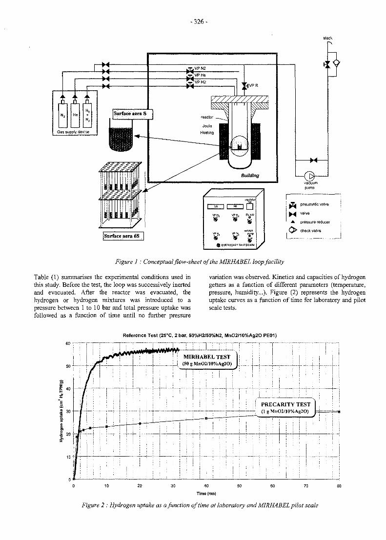
-326-
stack
ff ff. .P
N, HeH,+N2
Gas supply device
-X--M--M-- M -
Surface aera S
Surface aera 6S
'VPH2JVPR
Building
1 TR j
VPH,
¥
V P K
1 PR
VPN,
VPN,
W
EVAIR
¥vacuum
pump
® EMERGENCY SHUTDOWN
:y
- M -
MM
o
pump
pneumatic valve
valve
pressure reducer
check valve
Figure 1 : Conceptual flow-sheet of the MIRHABEL loop facility
Table (1) summarises the experimental conditions used inthis study. Before the test, the loop was successively inertedand evacuated. After the reactor was evacuated, thehydrogen or hydrogen mixtures was introduced to apressure between 1 to 10 bar and total pressure uptake wasfollowed as a function of time until no further pressure
variation was observed. Kinetics and capacities of hydrogengetters as a function of different parameters (temperature,pressure, humidity...). Figure (2) represents the hydrogenuptake curves as a function of time for laboratory and pilotscale tests.
Reference Test (ZSX, 2 bar, 50%H2/50%N2, MnO2/10%Ag2O PE01)
MIRHABEL TEST--i.-i-i (50gMnO2/10%Ag2O)
PRECARITY TEST(lgMnO2/10%Ag2O)
Figure 2 : Hydrogen uptake as a function of time at laboratory and MIRHABEL pilot scale
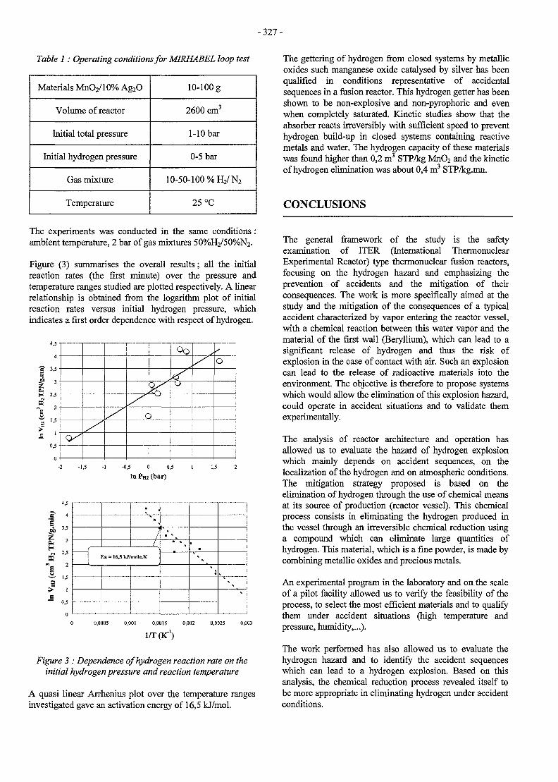
- 3 2 7 -
Table 1: Operating conditions for MIRHABEL loop test
Materials MnO2/10% Ag2O
Volume of reactor
Initial total pressure
Initial hydrogen pressure
Gas mixture
Temperature
10-100 g
2600 cm3
1-10 bar
0-5 bar
10-50-100 %H2 /N2
25 °C
The experiments was conducted in the same conditions:ambient temperature, 2 bar of gas mixtures 50%H2/50%N2.
Figure (3) summarises the overall results; all the initialreaction rates (the first minute) over the pressure andtemperature ranges studied are plotted respectively. A linearrelationship is obtained from the logarithm plot of initialreaction rates versus initial hydrogen pressure, whichindicates a first order dependence with respect of hydrogen.
3,5
H 2,5
1,5
0,5-
c
%
O
-0,5 0 0,5
In P m (bar)
£
I
4.5
4
3,5
3
2,5
2
1,5
1
0,5
/
/
Ea = 16,5 kJ/mola,K
• *
• V mm
s
0,001 0,0015
1/T (K"1)
0,0025 0,003
Figure 3 : Dependence of hydrogen reaction rate on theinitial hydrogen pressure and reaction temperature
A quasi linear Arrhenius plot over the temperature rangesinvestigated gave an activation energy of 16,5 kJ/mol.
The gettering of hydrogen from closed systems by metallicoxides such manganese oxide catalysed by silver has beenqualified in conditions representative of accidentalsequences in a fusion reactor. This hydrogen getter has beenshown to be non-explosive and non-pyrophoric and evenwhen completely saturated. Kinetic studies show that theabsorber reacts irreversibly with sufficient speed to preventhydrogen build-up in closed systems containing reactivemetals and water. The hydrogen capacity of these materialswas found higher than 0,2 m3 STP/kg MnO2 and the kineticof hydrogen elimination was about 0,4 m3 STP/kg.mn.
CONCLUSIONS
The general framework of the study is the safetyexamination of ITER (International ThermonuclearExperimental Reactor) type thermonuclear fusion reactors,focusing on the hydrogen hazard and emphasizing theprevention of accidents and the mitigation of theirconsequences. The work is more specifically aimed at thestudy and the mitigation of the consequences of a typicalaccident characterized by vapor entering the reactor vessel,with a chemical reaction between this water vapor and thematerial of the first wall (Beryllium), which can lead to asignificant release of hydrogen and thus the risk ofexplosion in the case of contact with air. Such an explosioncan lead to the release of radioactive materials into theenvironment. The objective is therefore to propose systemswhich would allow the elimination of this explosion hazard,could operate in accident situations and to validate themexperimentally.
The analysis of reactor architecture and operation hasallowed us to evaluate the hazard of hydrogen explosionwhich mainly depends on accident sequences, on thelocalization of the hydrogen and on atmospheric conditions.The mitigation strategy proposed is based on theelimination of hydrogen through the use of chemical meansat its source of production (reactor vessel). This chemicalprocess consists in eliminating the hydrogen produced inthe vessel through an irreversible chemical reduction usinga compound which can eliminate large quantities ofhydrogen. This material, which is a fine powder, is made bycombining metallic oxides and precious metals.
An experimental program in the laboratory and on the scaleof a pilot facility allowed us to verify the feasibility of theprocess, to select the most efficient materials and to qualifythem under accident situations (high temperature andpressure, humidity,...).
The work performed has also allowed us to evaluate thehydrogen hazard and to identify the accident sequenceswhich can lead to a hydrogen explosion. Based on thisanalysis, the chemical reduction process revealed itself tobe more appropriate in eliminating hydrogen under accidentconditions.
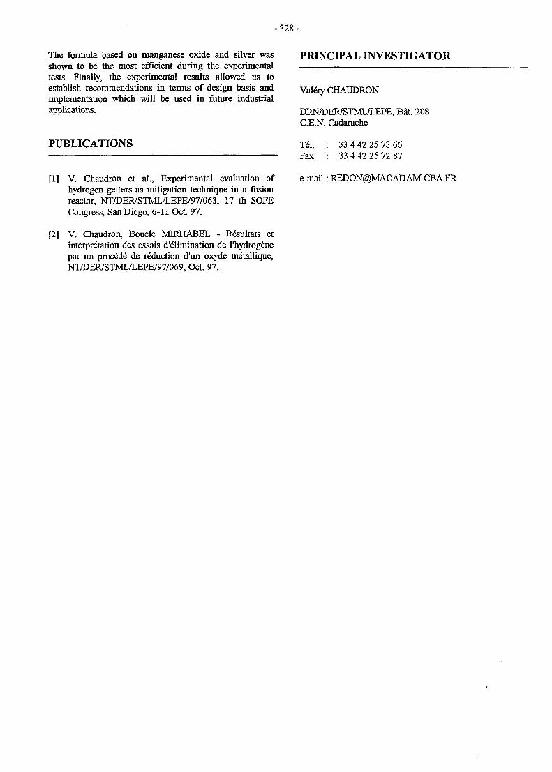
-328 -
The formula based on manganese oxide and silver wasshown to be the most efficient during the experimentaltests. Finally, the experimental results allowed us toestablish recommendations in terms of design basis andimplementation which will be used in future industrialapplications.
PUBLICATIONS
[1] V. Chaudron et al., Experimental evaluation ofhydrogen getters as mitigation technique in a fusionreactor, NT/DER/STML/LEPE/97/063, 17 th SOFECongress, San Diego, 6-11 Oct. 97.
[2] V. Chaudron, Boucle MERHABEL - Resultats etinterpretation des essais d'elimination de l'hydrogenepar un precede de reduction d'un oxyde metallique,NT/DER/STML/LEPE/97/069, Oct. 97.
PRINCIPAL INVESTIGATOR
Vale"ry CHAUDRON
DRN/DER/STML/LEPE, Bat. 208C.E.N. Cadarache
Tel. : 33 4 42 25 73 66Fax : 33 4 42 25 72 87
e-mail: [email protected]
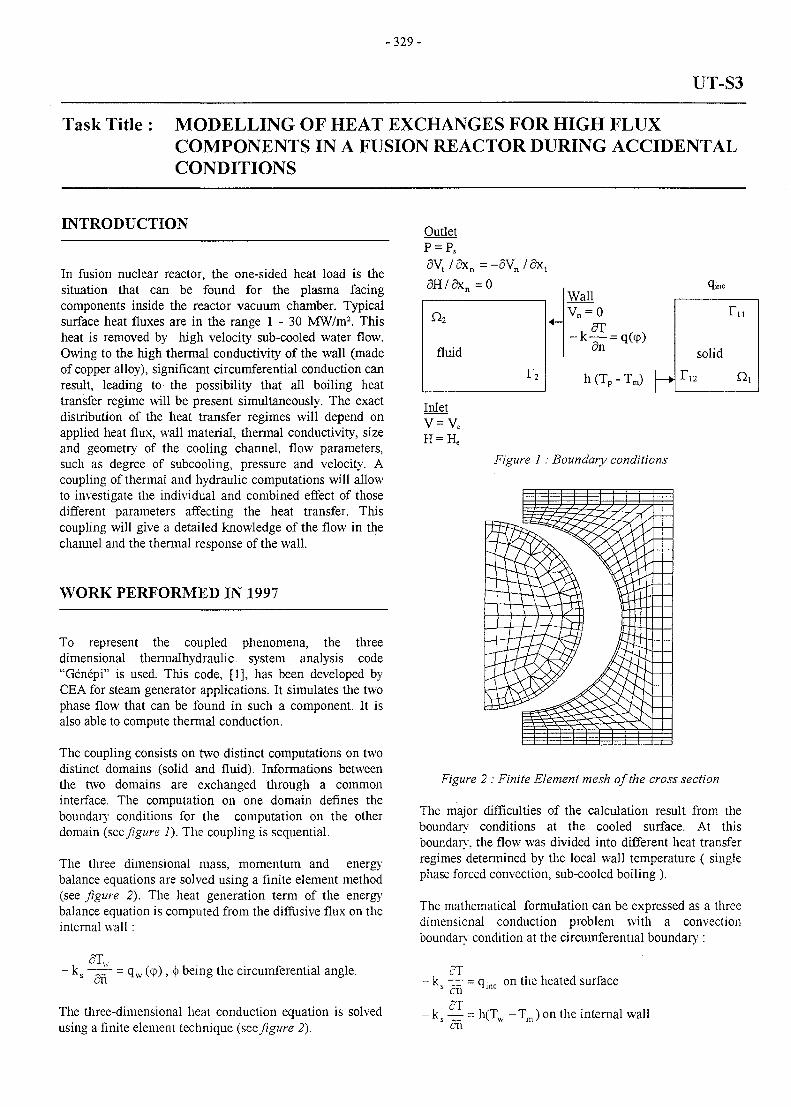
-329-
UT-S3
Task Title : MODELLING OF HEAT EXCHANGES FOR HIGH FLUXCOMPONENTS IN A FUSION REACTOR DURING ACCIDENTALCONDITIONS
INTRODUCTION
In fusion nuclear reactor, the one-sided heat load is thesituation that can be found for the plasma facingcomponents inside the reactor vacuum chamber. Typicalsurface heat fluxes are in the range 1 - 3 0 MW/m2. Thisheat is removed by high velocity sub-cooled water flow.Owing to the high thermal conductivity of the wall (madeof copper alloy), significant circumferential conduction canresult, leading to the possibility that all boiling heattransfer regime will be present simultaneously. The exactdistribution of the heat transfer regimes will depend onapplied heat flux, wall material, thermal conductivity, sizeand geometry of the cooling channel, flow parameters,such as degree of subcooling, pressure and velocity. Acoupling of thermal and hydraulic computations will allowto investigate the individual and combined effect of thosedifferent parameters affecting the heat transfer. Thiscoupling will give a detailed knowledge of the flow in thechannel and the thermal response of the wall.
WORK PERFORMED IN 1997
To represent the coupled phenomena, the threedimensional thermalhydraulic system analysis code"Genepi" is used. This code, [1], has been developed byCEA for steam generator applications. It simulates the twophase flow that can be found in such a component. It isalso able to compute thermal conduction.
The coupling consists on two distinct computations on twodistinct domains (solid and fluid). Informations betweenthe two domains are exchanged through a commoninterface. The computation on one domain defines theboundary conditions for the computation on the otherdomain (see figure 1). The coupling is sequential.
The three dimensional mass, momentum and energybalance equations are solved using a finite element method(see figure 2). The heat generation term of the energybalance equation is computed from the diffusive flux on theinternal wall :
OutletP = PS
5 V t / a x n = - 5 V n / 5 x t
WallVn =
-—dn = q(cp)
-T m )
qinc
solid
r,2
r,,
Figure 1 : Boundary conditions
Figure 2 : Finite Element mesh of the cross section
The major difficulties of the calculation result from theboundary conditions at the cooled surface. At thisboundary, the flow was divided into different heat transferregimes determined by the local wall temperature ( singlephase forced convection, sub-cooled boiling ).
The mathematical formulation can be expressed as a threedimensional conduction problem with a convectionboundary condition at the circumferential boundarv :
- k .an
• qw (cp), <j> being the circumferential angle.
The three-dimensional heat conduction equation is solvedusing a finite element technique (see figure 2).
cT- ks — = qmc on the heated surface
- k — = h(T - T ) on the internal walloi
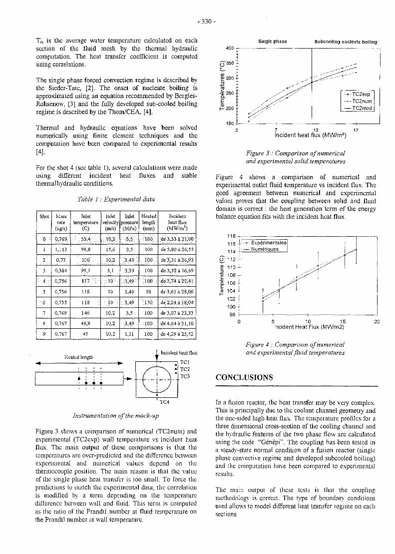
- 3 3 0 -
Tm is the average water temperature calculated on eachsection of the fluid mesh by the thermal hydrauliccomputation. The heat transfer coefficient is computedusing correlations.
The single phase forced convection regime is described bythe Sieder-Tate, [2]. The onset of nucleate boiling isapproximated using an equation recommended by Bergles-Rohsenow, [3] and the fully developed sub-cooled boilingregime is described by the Thom/CEA, [4].
Thermal and hydraulic equations have been solvednumerically using finite element techniques and thecomputation have been compared to experimental results[4].
For the shot 4 (see table 1), several calculations were madeusing different incident heat fluxes and stablethermalhydraulic conditions.
Table 1: Experimental data
Shot
0 •
1
2 :
3
4 -
5
6
7
8
9
Massrate
(kg/s)
0,769!
1,113
0,77
0,384
0J56
0,756
0,755
0,769
0,767
0,767
Inlettemperature
(C)
•• ^ 5 3 , 4 ; : : ; ; ' :
98,8
100 .; ;:
99,1
118
iis: '
146
49,8
45
Inletvelocity
(m/s)
15,6
: io,2\
5,1: : toM :
10
1 0
10,2
10,2
10,2
Inletpressure(MPa)
3,5
:3;43; i
3,39
:::3;49J:
3,49
3,5
3;49
1,11
Heatedlength(mm)
••HlPP.'.;:
100
:: ipO :
100
50
;ii5o i
100
. l o o :
100
Incidentheat flux(MW/m2)
de 3 3 3 a 21,00
de 5,80 a 26,55
;de3,31a;26,93:
de 3,52 a 16,69
:de3J4:a: 22,41
de3,61 a 28,06
de;2,24:a 18,04
de 3,07 a 23,33
de 4,64 a 31,10
de 4,29 a 25,52
Heated lengthIncident heat flux
TC4
Instrumentation of the mock-up
Figure 3 shows a comparison of numerical (TC2num) andexperimental (TC2exp) wall temperature vs incident heatflux. The main output of these comparisons is that thetemperatures are over-predicted and the difference betweenexperimental and numerical values depend on thethermocouple position. The main reason is that the valueof the single phase heat transfer is too small. To force thepredictions to match the experimental data, the correlationis modified by a term depending on the temperaturedifference between wall and fluid. This term is computedas the ratio of the Prandtl number at fluid temperature onthe Prandtl number at wall temperature.
400
5-350;
in :OJ300 -
=>
2 :-<D 250 •Q.
E :CD
h - 2 0 0 •
150 -
Single phase
1 1
Subcooling nucleate boiling
—1
•-••TC2exp-«-TC2num—TC2mod
1
7 12 17Incident heat flux (MW/m2)
Figure 3 : Comparison of numericaland experimental solid temperatures
Figure 4 shows a comparison of numerical andexperimental outlet fluid temperature vs incident flux. Thegood agreement between numerical and experimentalvalues proves that the coupling between solid and fluiddomain is correct : the heat generation term of the energybalance equation fits with the incident heat flux.
118
116
114
O" 112
.. •••• Expe'rimentales! j -— Numeriques
5 10 15Incident Heat Flux (MW/m2)
Figure 4 : Comparison of numericaland experimental fluid temperatures
CONCLUSIONS
In a fusion reactor, the heat transfer may be very complex.This is principally due to the coolant channel geometry andthe one-sided lu'gh heat flux. The temperature profiles for athree dimensional cross-section of the cooling channel andthe hydraulic features of the two phase flow are calculatedusing the code "Genepi". The coupling has been tested ina steady-state normal condition of a fusion reactor (singlephase convective regime and developed subcooled boiling)and the computation have been compared to experimentalresults.
The main output of these tests is that the couplingmethodology is correct. The type of boundary conditionsused allows to model different heat transfer regime on eachsections.
- 3 3 1 -
The comparisons between experimental and numericalvalue show that the value of the single phase heat transfercoefficient is too small. To force the predictions to matchthe experimental data, the correlation is modified. Thecomputations with the new correlation are better.
The next step consists to adjust this correlation by asensitivity study on the different flow parameters.
REFERENCES
[1] M. Grandotto and P. Obry, Computation of twophases flow in heat exchanges by a finite elementmethod, European Journal of Finite Element, volume5, n°l, 1996
[2] E.N. Sieder and G.E. Tate, Heat transfer and pressuredrop of liquids in tubes, Ind Eng Chem, 28, 1936
[3] A.E. Bergles and W.M. Rohsenow, Thedetermination of forced convection surface boilingheat transfer, J. Heat Transfer, 1964
[4] J. Schlosser and al., Thermal-hydraulic design ofhigh heat flux elements for controlled fusion.
PUBLICATIONS
[1] G. Langlais, Validation du couplage thermiquethermohydraulique de Genepi, (Task UTS3/M3),NT/DER/STML/LCFI/ 97/043
[2] G. Langlais, Premiers resultats du couplagethermique thermohydraulique de Genepi sur les essaisdes maquettes DRFC, (Task UTS3/M4),NT/DER/STML/LCFI/ 97/026
[3] G. Langlais et al.', Moderation de lathermohydraulique et de la thermique dans lescomposants a hauts flux d'un reacteur a fusion ensituation accidentelle, JITH 97, Marseille, 7 -10juillet 1997
PRINCIPAL INVESTIGATOR
Gilles Langlais
DRN/DER/STML/LCFICadarache
Tel.Fax
04 42 25 27 6304 42 25 66 38
e-mail: [email protected]
-333 -
UT-SM&C-BLK
Task Title : HELIUM COOLED PEBBLE BED BLANKET
INTRODUCTION
The major activities of the CEA related to the HCPBDEMO blanket are to assess the interest of the use of otherceramic breeder materials namely the meta-zirconate andthe meta-titanate besides the reference breeder ceramic[ortho-silicate], see Task WP-B1-1.2. If the potential ofthese two candidates is confirmed their use may allow to:
1. increase the maximum allowable operating temperatureofDEMO-HCPB
2. relief some of the blanket fabrication constraints due tothe relatively small thickness of the breeder bed in thereference design (with ortho-silicate)
3. minimise associated technological risks on the EUBlanket Program, if technological answers were notavailable by the due time on the silicate thermo-mechanical behaviour under cyclic loading, irradiationageing, and other related subjects.
ACTIVITIES IN 1997
The introduction of these alternative ceramic candidateswould necessitate an optimisation of the reference concept.Optimisation activities have started on 1996, [Rl, R2]. In1997, the HCPB optimisation was continued using a local3-D neutron transport scheme.
As a result of these investigations, an optional concept forthe HCPB has been proposed with two variants: with 18mm and with 16 mm breeder bed thickness. The range ofthickness 16-18 mm has been fixed in function of theoptimum TBR.
The use of breeder beds as thick as 18mm should reliefmuch of the fabrication constraints. However, it may resultin an unacceptable operating temperatures. For instance,the maximum allowable operating temperatures are limitedby the Li vaporisation phenomena in the ceramics. Manyinvestigations on Li-vaporisation will be performed in1998.
The major part of the 1997 effort was devoted to theneutronic design optimisation of the DEMO-HCPB blanketfor the use of the meta-zirconate/meta-titinate as breedermaterials.
The optimisation condition was to conserve the same TBRas in the reference concept. The TBR of the reference EU-DEMO HCPB blanket using the ortho-silicate is about 1.13[BoL] without considering the ports (16 ports) and about1.07 if the ports are considered.
The optimisation of the HCPB's TBR for the use of themeta-zirconate and the meta-titanate is based on a series ofcalculations performed by the Monte Carlo simulationcode, TROPOLI4. The nuclear data file used during thiscalculations is the ENDF/B6 file.
In all calculations, some 1200000 neutrons have beensampled with a statistical evaluated error less that 1.2% inthe worst case.
GEOMETRICAL MODELLING
A local 3-D geometrical model has been developed toperform the neutron transport calculations necessary forthe optimisation. In this model only a few number of cellsnear the equatorial plan of the blanket have beenconsidered. A cell is described by a succession of beds inthe following order: a cooling plate, a breeder bed, acooling plate, a multiplier bed
The same geometrical modelling scheme was used for theevaluation of the TBR in reference design. Thus, thecomparison between TBR in different options ismeaningful.
The development of a local 3-D model for the neutronicdesign could in fact be justified by the following :
1. the optimisation of the TBR is based on a comparativeassessment between different options. The comparisonis valid whether it is based on a 3D full size-blanketmodel or on a 3D local model.
2. a 3D local model produces correctly the maximumheating density radial profile.
MATERIAL SPECIFICATIONS
The specifications of different materials used in thisassessment are given in reference [PI]. All two ceramicswere considered with 65% packing factor and 15%porosity.
Additives in the Be-pebble and in ceramic pebbles have notbeen taken into account. The existing uncertainty about theexact behaviour of such additives justified dropping themin the present stage of analysis. Besides, the envisagedorder of magnitude of the additives concentration is toosmall to have a significant impact on the neutron transportevaluations.
Through the whole assessment, MANET was considered asthe reference blanket structure material.
Basic material specifications are mainly issued fromreference [R3].
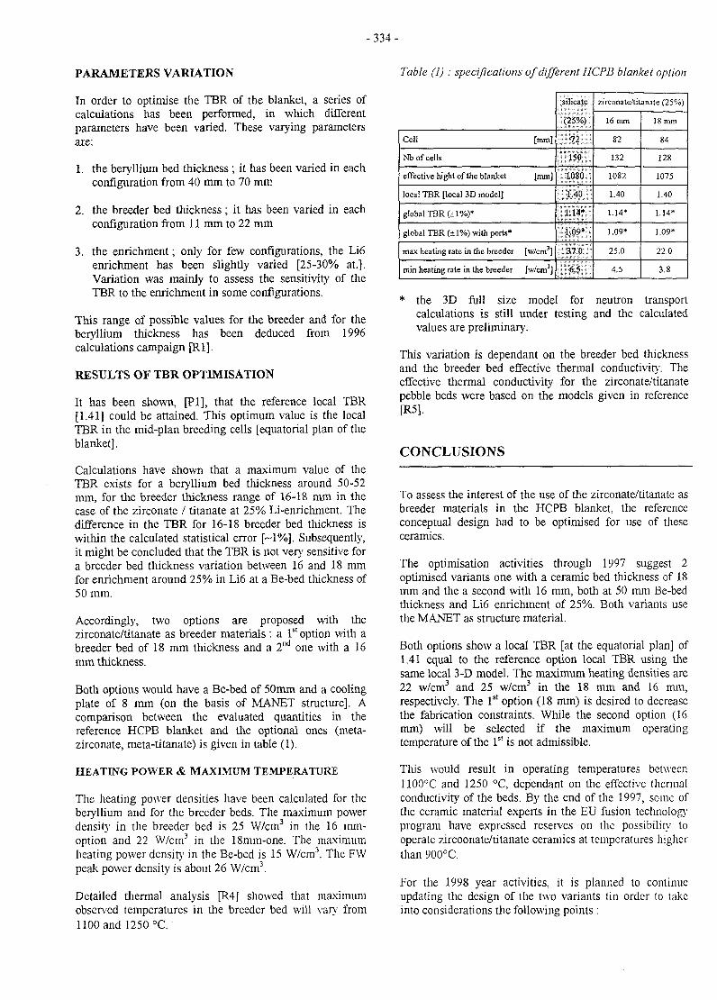
- 3 3 4 -
PARAMETERS VARIATION
In order to optimise the TBR of the blanket, a series ofcalculations has been performed, in which differentparameters have been varied. These varying parametersare:
1. the beryllium bed thickness ; it has been varied in eachconfiguration from 40 mm to 70 nun
2. the breeder bed thickness; it has been varied in eachconfiguration from 11 mm to 22 mm
3. the enrichment; only for few configurations, the Li6enrichment has been slightly varied [25-30% at.].Variation was mainly to assess the sensitivity of theTBR to the enrichment in some configurations.
This range of possible values for the breeder and for theberyllium thickness has been deduced from 1996calculations campaign [Rl].
RESULTS OF TBR OPTIMISATION
It has been shown, [PI], that the reference local TBR[1.41] could be attained. This optimum value is the localTBR in the mid-plan breeding cells [equatorial plan of theblanket].
Calculations have shown that a maximum value of theTBR exists for a beryllium bed thickness around 50-52mm, for the breeder thickness range of 16-18 mm in thecase of the zirconate / titanate at 25% Li-enrichment. Thedifference in the TBR for 16-18 breeder bed thickness iswithin the calculated statistical error [~1%]. Subsequently,it might be concluded that the TBR is not very sensitive fora breeder bed thickness variation between 16 and 18 mmfor enrichment around 25% in Li6 at a Be-bed thickness of50 mm.
Accordingly, two options are proposed with thezirconate/titanate as breeder materials : a 1st option with abreeder bed of 18 mm thickness and a 2nd one with a 16mm thickness.
Both options would have a Be-bed of 50mm and a coolingplate of 8 mm (on the basis of MANET structure]. Acomparison between the evaluated quantities in thereference HCPB blanket and the optional ones (meta-zirconate, meta-titanate) is given in table (1).
HEATING POWER & MAXIMUM TEMPERATURE
The heating power densities have been calculated for theberyllium and for the breeder beds. The maximum powerdensity in the breeder bed is 25 W/cm3 in the 16 ram-option and 22 W/cm3 in the 18mm-one. The maximumheating power density in the Be-bed is 15 W/cm3. The FWpeak power density is about 26 W/cm3.
Detailed thermal analysis [R4] showed that maximumobserved temperatures in the breeder bed will vary from1100 and 1250°C.
Table (1) : specifications of different HCPB blanket option
Cell [mm]
Nb of cells
effective hight of the blanket [nun]
local TBR [local 3D model]
global TBR (±1%)*
global TBR (±1%) with ports*
max heating rate in the breeder [w/cm3]
min heating rate in the breeder [w/cm3]
•silicate
liilp
ill!!,;'
illlir
zirconate/titanate (25%)
16 mm
82
132
1082
1.40
1.14*
1.09*
25.0
4.5
18 nun
84
128
1075
1.40
1.14*
1.09*
22.0
3.8
* the 3D full size model for neutron transportcalculations is still under testing and the calculatedvalues are preliminary.
This variation is dependant on the breeder bed thicknessand the breeder bed effective thermal conductivity. Theeffective thermal conductivity for the zirconate/titanatepebble beds were based on the models given in reference[R5].
CONCLUSIONS
To assess the interest of the use of the zirconate/titanate asbreeder materials in the HCPB blanket, the referenceconceptual design had to be optimised for use of theseceramics.
The optimisation activities through 1997 suggest 2optimised variants one with a ceramic bed thickness of 18mm and the a second with 16 mm, both at 50 mm Be-bedthickness and Li6 enrichment of 25%. Both variants usethe MANET as structure material.
Both options show a local TBR [at the equatorial plan] of1.41 equal to the reference option local TBR using thesame local 3-D model. The maximum heating densities are22 w/cm3 and 25 w/cm3 in the 18 mm and 16 mm,respectively. The l3t option (18 mm) is desired to decreasethe fabrication constraints. While the second option (16mm) will be selected if the maximum operatingtemperature of the 1st is not admissible.
This would result in operating temperatures between1100°C and 1250 °C, dependant on the effective thermalconductivity of the beds. By the end of the 1997, some ofthe ceramic material experts in the EU fusion technologyprogram have expressed reserves on the possibility tooperate zircoonate/titanate ceramics at temperatures higherthan 900°C.
For the 1998 year activities, it is planned to continueupdating the design of the two variants tin order to lakeinto considerations the following points :
-335 -
1. Very recently, EU material experts have stated that therecommended figure for meta/zirconate/meta-titanatebed packing factor is 56 % rather than 65% as it hasbeen considered during the assessment. The targetvalue of 65% is only reached in the silicate pebble bed.This is due to the fact that the pebbles of the silicate areproduced with more regular spherical shape than thezirconate/titanate ones.
2. Besides, EUROFER has been very recently chosen as areference blanket structure materials in replacement ofthe MANET. This should necessitate the examinationof the impact of the use of the EUROFER on theneutronic behaviour of the HCPB blanket. Precisely, theimpact of the use of the EUROFER on the TBR shouldbe assessed.
REFERENCES
[Rl] M. Eid « Impact of the use of the zirconate/titanate onthe neutron induced activation and the residualheating in the structure of the HCPB blanket.» CEAreport, DMT 96/602, SERMA/LCA 1985.
[R2] M. Eid « Investigations on the HCPB test object withzirconate/titanate as breeding materials.» CEAreport, DMT 96/603, SERMA/LCA 1986.
[R3] M. Kuchle (compiled by), « Material Data Base forNET Test Blanket Design Studies» European TestBlanket Development Program, Test BlanketAdvisory Group, FzK, February 1990.
[R4] J.F. Salavy, M. Eid «Neutronic & Thermalcharacteristics of the HCPB blanket in the case of theuse of the zirconate/titanate.» CEA report, DMT97/552, SERMA/LCA 2155.
[R5] P. Gierszewski, et al. « Canadian ceramic breedertechnology : recent results. » Fus. Eng. & Des., 27(1995) 297-306.
PUBLICATIONS
[PI] M. Eid, J.F. Salavy « Contribution to the HCPBblanket design optimisation in the case of the use ofthe zirconate/titanate as breeder material.» CEAreport, DMT 97/551, SERMA/LCA 2154.
TASK LEADER
Mohamed EID
DRN/DMT-SERMASaclay-F91191 Gif sur Yvette Cedex
Tel. : 33 0169 08 3175Fax : 33 01 69 08 99 35
e-mail: eid(5)soleil. serma.cea.fr
- 3 3 7 -
UT-SM&C-LiPb
Task Title : PURIFICATION OF LIQUID METALS
INTRODUCTION
During operation of the water-cooled liquid metal blanket,the steel box which acts as the liquid metal container canbe corroded by the Pb-17Li alloy flowing at low velocity.The corrosion products dissolved in the alloy are thentransported with the flow. In some regions, characterizedfor example by low temperatures, these corrosion productscan crystallize and form aggregates which can be depositedon the walls. The processes of corrosion, formation ofaggregates and deposition depend on several factors suchas hydrodynamics, solubility, kinetics of exchange at thesolid/liquid interface, roughness of the wall... Anothersignificant factor is the high external magnetic field usedto confine the plasma.
The deposition in uncontrolled zones can lead to pluggingand the accumulation of activated products is a problem forthe maintenance. Therefore, it is necessary to remove themetallic impurities present in the liquid alloy andpurification methods have to be developped. One way is topromote the preferential deposition of the products incontrolled areas either by cold trapping or by magnetictrapping. It results that the deposition process has to beunderstood from a basic point of view.
1997 ACTIVITIES
In 1997, a literature survey has been carried out on thesubject. It deals more specifically with the effect of amagnetic field on the hydrodynamics and, as aconsequence, on the formation of deposits in a flowingliquid metal. The current state of the understanding of thepossible effects of a magnetic field on hydrodynamics,crystallization and deposition has been examined.
GENERAL FEATURES
The magnetic field has clearly an influence on the velocitydistribution of the duct flow. It is responsible of a thinlayer formation with strong velocity gradient at the walls.The turbulence generation being strongly attenuated by themagnetic field, the mixing properties of the flow and thusthe aggregate formation are expected to be reduced.
The influence of magnetic field on the crystallization ofparticles in a liquid metal has not intensively been studiedup to now. Nevertheless, in the water-treatment area, it hasbeen observed that the magnetic field reduces theformation of calcium deposits in the ducts.
In particular, the nucleation of CaCO3 particles would beslower in presence of magnetic field. In another area, thestability of the non-magnetic colloidal particles (forexample, SiO2 in electrolytes) has been studied under amagnetic field and an increase of the coalescence has beenreported. In another study, the influence of magnetic fieldon the precipitation of various inorganic salts has beenexamined. It is reported that the rate of nucleation andcrystal growth are increased in magnetic field. It seemsthat these results can be explained by the spin effect ratherthan by the Lorentz force. In the case of studies on metallicfilms resulting of electrodeposition processes undermagnetic field, an effect of the field on the crystalorientation of the deposited film (modification of thetexture coefficient) has been observed. However, on thewhole, the literature data are not always in full agreement.
The influence of a magnetic field on the formation of solidparticles and on their shape during the solidification of ametallic alloy has been studied. It is observed that apulsating force field, obtained by interaction of alternativecurrents with a constant magnetic field, produces particleswith a spherical shape and increases their number. As aconsequence, the alloy has a more homogeneouscomposition. This can be attributed to the presence ofdepressive zones which appear at some instants of thecycle. These depressions generate some cavitation zoneswhich implose in the high pressure instants of the forcecycle, and produce a disintegration and scattering ofgrains.
These examples show that the action of a magnetic field onthe formation of aggregates and deposits can affect variousareas. The possible effects of the field are far from to beidentified and, in the case of liquid metals, the literature isstill very poor. Nevertheless, two types of problems can beconsidered according to the nature and configuration ofparticles formed in the liquid phase.
FORMATION OF PARTICLES UNDER AMAGNETIC FIELD
In this case, the solute atoms in motion in the liquid phasecan collide and by addition of single atom can form doubleatoms... It results that nuclei or microaggregates are able togrow if the activation free energy is higher than a criticalvalue which depends on supersaturation, solid/liquidinterfacial energy and magnetic field intensity. The growthof aggregates depends on several factors such as the abilityfor the atoms to integrate the crystal and the collisionfrequency of the solute atoms with the crystal in formation.This collision frequency depends largely on thehydrodynamics. For example, the collision frequency isincreased by the velocity gradient in laminar flows. In thecase of turbulent flows, it is the stirring which controls thenumber of collisions.
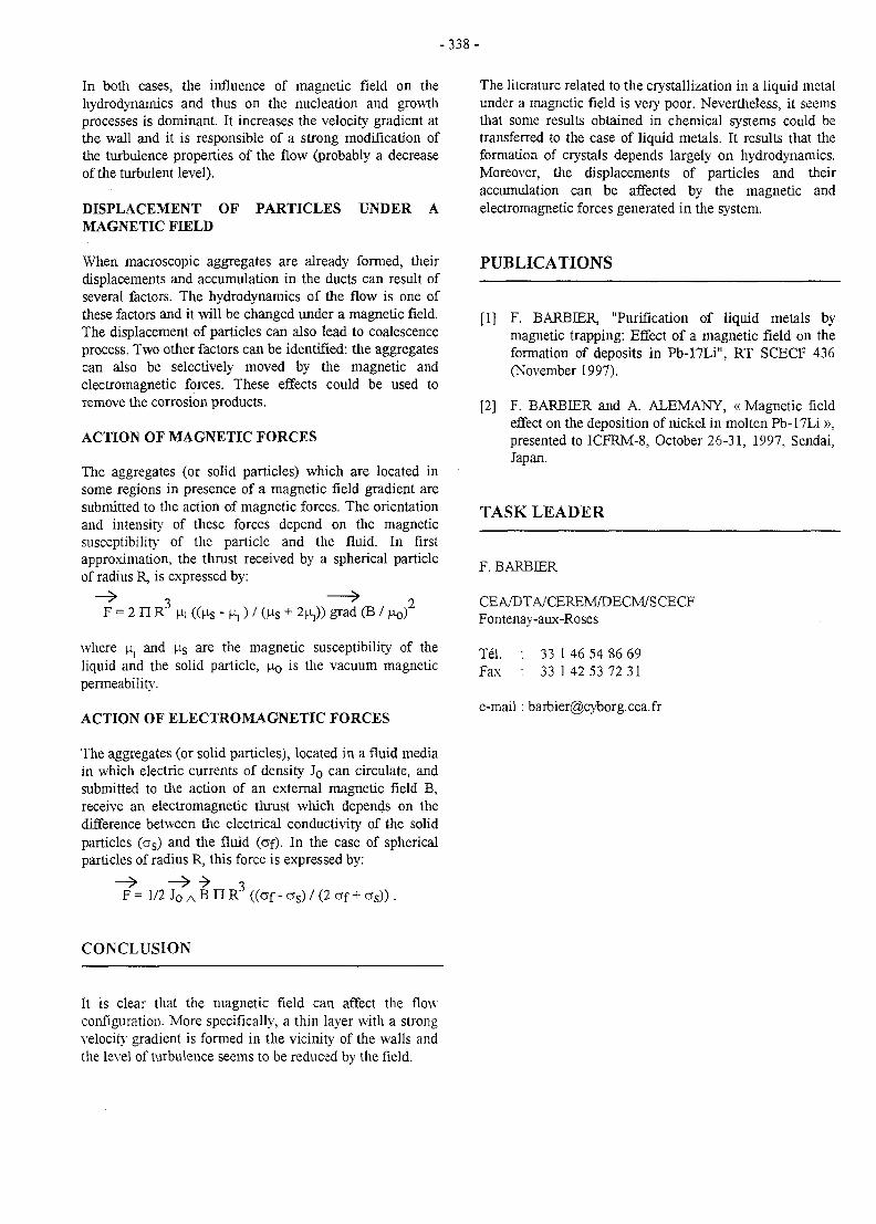
-338 -
In both cases, the influence of magnetic field on thehydrodynamics and thus on the nucleation and growthprocesses is dominant. It increases the velocity gradient atthe wall and it is responsible of a strong modification ofthe turbulence properties of the flow (probably a decreaseof the turbulent level).
DISPLACEMENT OF PARTICLES UNDER AMAGNETIC FD3LD
When macroscopic aggregates are already formed, theirdisplacements and accumulation in the ducts can result ofseveral factors. The hydrodynamics of the flow is one ofthese factors and it will be changed under a magnetic field.The displacement of particles can also lead to coalescenceprocess. Two other factors can be identified: the aggregatescan also be selectively moved by the magnetic andelectromagnetic forces. These effects could be used toremove the corrosion products.
ACTION OF MAGNETIC FORCES
The aggregates (or solid particles) which are located insome regions in presence of a magnetic field gradient aresubmitted to the action of magnetic forces. The orientationand intensity of these forces depend on the magneticsusceptibility of the particle and the fluid. In firstapproximation, the thrust received by a spherical particleof radius R, is expressed by:
F = 2 n R3 ) / (us + 2n,)) grad (B / j
where ns and ias are the magnetic susceptibility of theliquid and the solid particle, JOQ is the vacuum magneticpermeability.
ACTION OF ELECTROMAGNETIC FORCES
The aggregates (or solid particles), located in a fluid mediain which electric currents of density Jo can circulate, andsubmitted to the action of an external magnetic field B,receive an electromagnetic thrust which depends on thedifference between the electrical conductivity of the solidparticles (as) and the fluid (of). In the case of sphericalparticles of radius R, this force is expressed by:
The literature related to the crystallization in a liquid metalunder a magnetic field is very poor. Nevertheless, it seemsthat some results obtained in chemical systems could betransferred to the case of liquid metals. It results that theformation of crystals depends largely on hydrodynamics.Moreover, the displacements of particles and theiraccumulation can be affected by the magnetic andelectromagnetic forces generated in the system.
PUBLICATIONS
[1] F. BARBIER, "Purification of liquid metals bymagnetic trapping: Effect of a magnetic field on theformation of deposits in Pb-17Li", RT SCECF 436(November 1997).
[2] F. BARBER and A. ALEMANY, « Magnetic fieldeffect on the deposition of nickel in molten Pb-17Li »,presented to ICFRM-8, October 26-31, 1997, Sendai,Japan.
TASK LEADER
F. BARBIER
CEA/DTA/CEREM/DECM7SCECFFontenay-aux-Roses
Tel. : 33 1 46 54 86 69Fax : 33 142 53 72 31
e-mail : [email protected]
F = 1/2 Jo A B3
RJ ((of - a s) / (2 af + a s ) ) .
CONCLUSION
It is clear that the magnetic field can affect the flow-configuration. More specifically, a thin layer with a strongvelocity gradient is formed in the vicinity of the walls andthe level of turbulence seems to be reduced by the field.
- 3 3 9 -
UT-SM&C-LME
Task Title : LIQUID METAL EMBRITTLEMENT
INTRODUCTION
In the frame of the future fusion reactors, liquid metalsmight be used as coolants in parts submitted to high heatpeaks (for example, divertor), or as tritium breedingmaterials (for example, lithium-lead alloy). This impliesthat the properties of the structural materials must not beaffected by the presence of the liquid metal. Thus, for asafe operation of the reactor, one must be aware of theproblems which can arise during the solid-liquid contact.
It has long been known that ductile solid metals exposed tospecific liquid metal environments may exhibit asignificant reduction in elongation to failure and fracturestrength when they are tested in tension. Under certainexperimental conditions, the liquid metal embrittlement(LME) can be quite dramatic and one of the peculiarities ofthis phenomenon is the crack propagation rate which isreported to be very high (up to 50-500 cm.s"1). The factthat a liquid metal can drastically affect the material'sresistance to fracture has serious technologicalsignificance.
Embrittlement in liquid metal environments has been thesubject of many reviews describing the phenomenologicalfeatures of the LME, the prerequisites for its occurrence,the effects of variables including grain size, strain rate,temperature, metallurgical state... However, despitedecades of research, a qualitative explanation of LME hasnot yet emerged and its prediction is still missing. It istherefore appropriate that LME should be reviewed in thelight of more recent work to provide a current assessmentof this phenomenon.
1997 ACTIVITIES
In 1997, a literature survey has been carried out. Thevarious mechanisms and models which have beenadvanced so far to describe the LME have been examined.
A first category of mechanisms is based on dissolution anddiffusion. For example, the Robertson model assumes thatthe crack propagates by dissolution of the solid in theliquid at the crack tip under an applied stress, with volumediffusion of the dissolved solute through the liquidcontrolling the propagation. The model uses macroscopic,thermodynamic. kinetic and elastic concepts. Then, itassumes the crack is filled with liquid metal; the presenceof the liquid is essential because the rate of propagation iscontrolled by diffusion through the liquid.
The Glikman model assumes that the nucleation andsubcritical growth of cracks which take place along grainboundaries is associated with selective dissolution in themelt of solid metal atoms at the crack tip. This is followedby rapid diffusion of solid metal atoms from the crack tipand their precipitation on stress-free walls of the crack.
A second category of mechanisms is based on the effect ofadsorption of liquid metal species. In this regard, a purethermodynamic approach based on the reduction of thesurface energy by the adsorbing species has been proposed.In addition, atomistic approaches associated with thereduction of surface energy have also been suggested.
The Rebinder effect is one of the effects exerted by a liquidor a gaseous medium on the mechanical properties ofsolids. It appears as a plastic flow increase and a strengthreduction. The origin of these phenomena is the surfacefree energy reduction caused by adsorption which is alocalized physicochemical interaction between a solid andthe medium at the interphase boundary. In a general form,the mechanism proposed to explain the Rebinder effect, isthe weakening of interatomic bonds in the surface layer ofthe solid in contact with the medium. However, a changein the potential of interatomic interaction is not a sufficientcondition for its occurrence. Interaction between atoms ofthe medium and crack walls at the crack tip sets up forcesacting on these walls and promotes crack propagation.
According to the Lynch model, it is generally accepted thatLME is due to adsorption of liquid metal atoms at cracktips, with the transport of atoms to tips of growing cracksoccurring by capillarity flow. The consequence of thisadsorption is the weakening of interatomic bonds at thecrack tip, thereby facilitating the nucleation of dislocations.In another attempt to reach a broader understanding, it wassuggested to treat LME as a type of brittle fracture. Thetheory of the brittle fracture considers the reduction ofatomic bond strength and involves both plastic yield andsurface energy and hence, incorporates both metallurgicaland environmental factors. In the SJWK model, it wasconsidered that a relationship exist between surface energyand interatomic bonds energy.
The major point of this review on the LME mechanisms isthat no one is completely satisfactory since it is unable topredict the probability of LME occurring. Although severalclassifications of cmbrittlcment couples have beenproposed, no mechanism is able to predict whether a solid-liquid couple forms an embrittlement couple or not.Moreover, the suggested mechanisms do not lead topredictions that compare well with experiment. Forexample, the stress-assisted dissolution model of Robertsonpredicts that the severity of embrittlement will increase
- 3 4 0 -
with the temperature and the solubility of the solid in theliquid, which is in disagreement with the practicalobservation. Thus, the stress-assisted dissolution may havean effect in some systems but it cannot be considered as amechanism for LME. The approach of Rebinder which isentirely based on the thermodynamics has also limitationssince it does not permit quantitative assessment of theembrittlement nor does it provide insight into the detailedatomic mechanism. Observation of plastic deformation onLME fracture surfaces has led Lynch to propose that theliquid metal facilitated dislocation nucleation andmovement but the dislocation activity was notsystematically detected at crack tips in experimentalobservations. The SJWK model based on the adsorption-induced reduction in strength is attractive in some respectsbut it does not take into account plastic deformationobserved on fracture surface of some embrittled metals.Finally, none of the mechanisms described here canaccount for all the various LME phenomena, but neithercan be completely discounted.
PUBLICATIONS
[1] B. JOSEPH, M. PICAT and F. BARBER, "Aliterature survey on the mechanisms of liquid metalembrittlement", RT SCECF 444 (December 1997)
TASK LEADER
F. BARBffiR
CEA/DTA/CEREM/DECM/SCECFFontenay-aux-Roses
Tel. : 33 1 46 54 86 69Fax : 33 142 53 72 31
e-mail: [email protected]
CONCLUSION
A lierature survey on the mechanisms of liquid metalembrittlement has been carried out. Despite largeinvestigations, not at all of the suggested mechanisms areable to predict the occurrence of LME. A better acquisitionand interpretation of quantitative data in well characterizedmaterials is thus necessary. In particular, there-is a lack insurface analysis, probably because the methods permittinga chemical characterization of surfaces were notsufficiently well developed in the last decades. Suchinvestigation should help in the understanding of the LMEphenomenon.
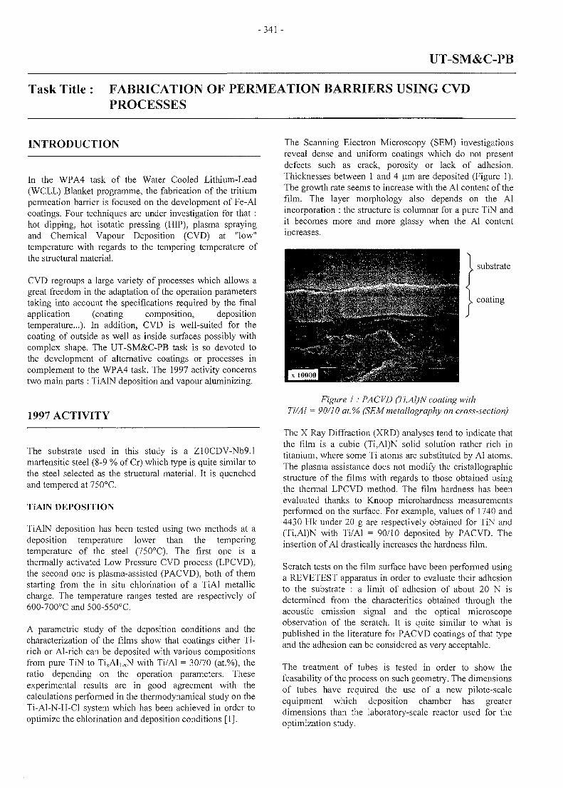
-341 -
UT-SM&C-PB
Task Title : FABRICATION OF PERMEATION BARRIERS USING CVDPROCESSES
INTRODUCTION
In the WPA4 task of the Water Cooled Lithium-Lead(WCLL) Blanket programme, the fabrication of the tritiumpermeation barrier is focused on the development of Fe-Alcoatings. Four techniques are under investigation for that :hot dipping, hot isotatic pressing (HIP), plasma sprayingand Chemical Vapour Deposition (CVD) at "low"temperature with regards to the tempering temperature ofthe structural material.
CVD regroups a large variety of processes which allows agreat freedom in the adaptation of the operation parameterstaking into account the specifications required by the finalapplication (coating composition, depositiontemperature...). In addition, CVD is well-suited for thecoating of outside as well as inside surfaces possibly withcomplex shape. The UT-SM&C-PB task is so devoted tothe development of alternative coatings or processes incomplement to the WPA4 task. The 1997 activity concernstwo main parts : TiAIN deposition and vapour aluminizing.
1997 ACTIVITY
The substrate used in this study is a Z10CDV-Nb9.1martensitic steel (8-9 % of Cr) which type is quite similar tothe steel selected as the structural material. It is quenchedand tempered at 750°C.
TiAIN DEPOSITION
TiAIN deposition has been tested using two methods at adeposition temperature lower than the temperingtemperature of the steel (750°C). The first one is athermally activated Low Pressure CVD process (LPCVD),the second one is plasma-assisted (PACVD), both of themstarting from the in situ chlorination of a TiAl metalliccharge. The temperature ranges tested are respectively of600-700°C and 500-550°C.
A parametric study of the deposition conditions and thecharacterization of the films show that coatings either Ti-rich or Al-rich can be deposited with various compositionsfrom pure TiN to TixAl,.xN with Ti/Al = 30/70 (at.%), theratio depending on the operation parameters. Theseexperimental results are in good agreement with thecalculations performed in the thermodynamical study on theTi-Al-N-H-Cl system which has been achieved in order tooptimize the chlorination and deposition conditions [1].
The Scanning Electron Microscopy (SEM) investigationsreveal dense and uniform coatings which do not presentdefects such as crack, porosity or lack of adhesion.Thicknesses between 1 and 4 urn are deposited (Figure 1).The growth rate seems to increase with the Al content of thefilm. The layer morphology also depends on the Alincorporation : the structure is columnar for a pure TiN andit becomes more and more glassy when the Al contentincreases.
substrate
coating
Figure i . FACr D \Fi,Al)N coating withTi/Al = 90/10 at.% (SEMmetallography on cross-section)
The X Ray Diffraction (XRD) analyses tend to indicate thatthe film is a cubic (Ti,Al)N solid solution rather rich intitanium, where some Ti atoms are substituted by Al atoms.The plasma assistance does not modify the cristallographicstructure of the films with regards to those obtained usingthe thermal LPCVD method. The film hardness has beenevaluated thanks to Knoop microhardness measurementsperformed on the surface. For example, values of 1740 and4430 Hk under 20 g are respectively obtained for TiN and(Ti,Al)N with Ti/Al = 90/10 deposited by PACVD. Theinsertion of Al drastically increases the hardness film.
Scratch tests on the film surface have been performed usinga REVETEST apparatus in order to evaluate their adhesionto the substrate : a limit of adhesion of about 20 N isdetermined from the characteritics obtained through theacoustic emission signal and the optical microscopeobservation of the scratch. It is quite similar to what ispublished in the literature for PACVD coatings of that typeand the adhesion can be considered as very acceptable.
The treatment of tubes is tested in order to show thefeasability of the process on such geometry. The dimensionsof tubes have required the use of a new pilote-scaleequipment which deposition chamber has greaterdimensions than the laboratory-scale reactor used for theoptimization study.
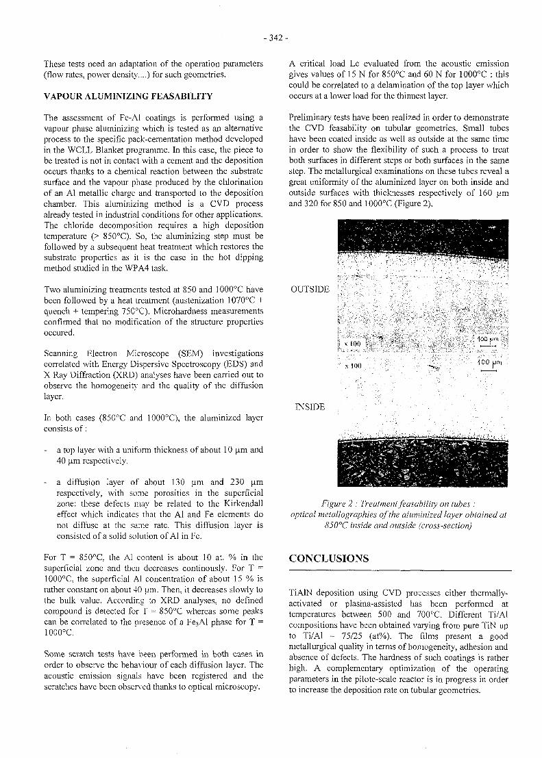
- 3 4 2 -
These tests need an adaptation of the operation parameters(flow rates, power density....) for such geometries.
VAPOUR ALUMINIZING FEASABILITY
The assessment of Fe-Al coatings is performed using avapour phase aluminizing which is tested as an alternativeprocess to the specific pack-cementation method developedin the WCLL Blanket programme. In this case, the piece tobe treated is not in contact with a cement and the depositionoccurs thanks to a chemical reaction between the substratesurface and the vapour phase produced by the chlorinationof an Al metallic charge and transported to the depositionchamber. This aluminizing method is a CVD processalready tested in industrial conditions for other applications.The chloride decomposition requires a high depositiontemperature (> 850°C). So, the aluminizing step must befollowed by a subsequent heat treatment which restores thesubstrate properties as it is the case in the hot dippingmethod studied in the WPA4 task.
Two aluminizing treatments tested at 850 and 1000°C havebeen followed by a heat treatment (austenization 1070°C +quench + tempering 750°C). Microhardness measurementsconfirmed that no modification of the structure propertiesoccured.
Scanning Electron Microscope (SEM) investigationscorrelated with Energy Dispersive Spectroscopy (EDS) andX Ray Diffraction (XRD) analyses have been carried out toobserve the homogeneity and the quality of the diffusionlayer.
In both cases (850°C and 10.00°C), the aluminized layerconsists of:
a top layer with a uniform thickness of about 10 jam and40 um respectively.
- a diffusion layer of about 130 um and 230 umrespectively, with some porosities in the superficialzone: these defects may be related to the Kirkendalleffect which indicates that the Al and Fe elements donot diffuse at the same rate. This diffusion layer isconsisted of a solid solution of Al in Fe.
For T = 850°C, the Al content is about 10 at. % in thesuperficial zone and then decreases continously. For T =1000°C, the superficial Al concentration of about 15 % israther constant on about 40 um. Then, it decreases slowly tothe bulk value. According to XRD analyses, no definedcompound is detected for T = 850°C whereas some peakscan be correlated to the presence of a Fe3Al phase for T =1000°C.
Some scratch tests have been performed in both cases inorder to observe the behaviour of each diffusion layer. Theacoustic emission signals have been registered and thescratches have been observed thanks to optical microscopy.
A critical load Lc evaluated from the acoustic emissiongives values of 15 N for 85O°C and 60 N for 1000°C : thiscould be correlated to a delamination of the top layer whichoccurs at a lower load for the thinnest layer.
Preliminary tests have been realized in order to demonstratethe CVD feasability on tubular geometries. Small tubeshave been coated inside as well as outside at the same timein order to show the flexibility of such a process to treatboth surfaces in different steps or both surfaces in the samestep. The metallurgical examinations on these tubes reveal agreat uniformity of the aluminized layer on both inside andoutside surfaces with thicknesses respectively of 160 umand 320 for 850 and 1000°C (Figure 2).
OUTSIDE
y x 100 !H3
•• x K M ) . : , /100 urr\
INSIDE
Figure 2 : Treatment feasability on tubes :optical metallographies of the aluminized layer obtained at
85Q°C inside and outside (cross-section)
CONCLUSIONS
TiAIN deposition using CVD processes either thermally-activated or plasma-assisted has been performed attemperatures between 500 and 700°C. Different Ti/AIcompositions have been obtained varying from pure TiN upto Ti/AI = 75/25 (at%). The films present a goodmetallurgical quality in terms of homogeneity, adhesion andabsence of defects. The hardness of such coatings is ratherhigh. A complementary optimization of the operatingparameters in the pilote-scale reactor is in progress in orderto increase the deposition rate on tubular geometries.
- 3 4 3 -
The vapour phase aluminizing has been tested to performFe-Al layers : treatments of 5 hours at 850 and 1000°Cgive thick diffusion layers (up to 300 um) without brittleintermetallic compounds (FeaAls) but they imply a furtherheat treatment in order to restore the substrate properties.The feasability of this CVD process on small tubes hasbeen demonstrated successfully for the treatment of theoutside surface as well as the inside surface with a gooduniformity.
PUBLICATIONS
[1] S. Anderbouhr, C. Chabrol, F. Schuster "CVDdeposition of TiAIN for permeation barriers" NoteTechnique DEM n° 50/97.
[2] S. Anderbouhr, C. Chabrol, F. Schuster "CVDdeposition for permeation barriers" Note TechniqueDEM n° 98/13.
TASK LEADER
Claude CHABROL
DTA/DEM/SGMCEA grenoble17, rue des Martyrs38054 GRENOBLE Cedex 9
Tel.Fax
04 76 88 99 7704 76 88 99 85
e-mail: [email protected]
- 3 4 5 -
UT-SM&C-PBM
Task Title : PEBBLE BED THERMO-MECHANICAL MODELLING
INTRODUCTION
One of the two blanket concepts in consideration in theEU-Fusion Technology program is the Helium CooledPebble Bed [HCPB] blanket. The main feature of thisconcept is the use of the pebble bed unites, both for thebreeder and the multiplier materials. Many of the data andmodels necessary to better model and evaluate the pebblebed different response functions are not yet available orneed further validations [mechanical, thermal and thermo-mechanical]. Under the pressure of the design needs ofDEMO-blanket and DEMO-Iter Test Module [ITER-ITM],many activities have started aiming at identifying theneeds in data and models, and at developing adequateR&D programs for their qualification.
Although there are many data concerning the single pebblebehaviour [thermal, mechanical, tritium release,macrostructure, . . . ] , few data are available as far as pebble-bed overall behaviour is concerned. It appears, too, thatextrapolation from single-pebble to pebble bed behaviour isnot straight forward. Only through experimental activities,modelling and validation of the pebble-bed behaviourwould be possible.
CEA has initiated some experimental activities on thepebble bed mechanical behaviour modelling, since 1995.These activities has produced some interesting and originalresults [PI].
These activities allowed the development and thequalification of a model [Hujeux model] and itsimplementation in CASTEM200 structure mechanics codeof the CEA/DRN-DMT.
Additional investigations on related issues such as themechanical response under cyclic loading, and the thermo-mechanical response functions of the pebble-bed still needto be initiated.
ACTIVITY IN 1997
The details of the activities in 1997 are given in [P2, P3].
PEBBLE BED MECHANICAL BEHAVIOUR
Indeed very few literature is available on the subject andfusion-like relevant experimental experience is almost non-existent.
An experimental program has been carried out last twoyears (1995-1997) in the CEA /DRN-DMT to identify themain issues and to qualify some models describing themechanical behaviour of pebble beds relevant toDEMO/ITER blankets, [Rl, R2].
A specific apparatus has been designed for thisexperimental campaign. The apparatus contains a cellplaced on a press-surface that moves upward with aconstant velocity. The exact measurement of the axial forceacting on the cell is transmitted to a monitor with the helpof a fixed piston. The inter-pebble space is full of waterthat would allow the measurements of the volume strainunder a given stress. The sample is surrounded by anelastic membrane in order to eliminate the effect of the bedwalls. Measurments reflect only the pebble bed bulkmechanical response. The pebble-wall interaction is notexamined in this phase of activities (1995-1997).
Tested pebble materials varied between glass, steel, sandand ceramic (meta-titanate of lithium). Pebbles have a verysmall diameter compared to the test-sample size [<j> = 1.0-1.2 mm],
Two main conclusions came out of this experimentalcampaign, [P. 2]:
1. no matter the pebble material type is, the pebble bedmechanical response is governed by soil mechanicsprincipals. Precisely, the pebble-bed bulk mechanicalresponse function can be described through a Hujeuxelasto-plastic model.
2. under uniform slowly-increasing stresses the bulk of thepebble-bed behaves in a continuos manner up to somelimit before changing suddenly its state [jump effect].This phenomena of cyclic re-arrangement of thepebbles in the bed seems dependent only on the pebblesshape. It becomes significant when pebbles are uniformwith perfect spherical surface.
Although, the impact of the pebble-wall interaction onthese two conclusions could not be examined, it seemsmost probable that considering the wall presence, at leastin the DEMO-yTTER-beds relevant geometry, would notsignificantly modify this typical behaviour. However, it is apoint that still need to be verified.
Following the statement done by the European Workinggroup on Ceramic & beryllium pebbles, [R3], «there areindications that the strength of a single pebble at roomtemperature is not really representative for the behaviour ofa pebble bed at blanket temperatures », it would be justifiedto suppose that the bulk of the pebble-bed would show aneffective crush strength higher than that measured for onesingle pebble. In all cases, this point needs to be veryclosely examined through next experimental campaigns.Effective crush strength would certainly be differentbetween the bulk of the pebble-bed and the pebbles near bythe bed-walls.
Next experimental program should, thus, be able toconsider the real geometry of the DEMO-ITER beds and tointegrate the pebble-bed walls interaction.
-346-
THERMAL BEHAVIOUR
CEA has proceeded to a critical examination of theexisting knowledge on the subject Details are given inreference [P3].
The thermal behaviour of the pebble bed has relativelyreceived more intention, in the past, than the mechanicalone. Some literature and come experimental data are, thus,available. As far as, experimental data relevant to DEMO-/rrER-type of beds, the most significant data are thosereported by M. Dalle Donne for the silicate, [R4, R6], andby P. Gierszewski, [R5], for the titanate and the zirconate.The corresponding correlations on the global thermalconductivity are detailed in [R4, R5, P3].
Although, these models provide reasonable estimations foroverall conductivity of DEMO-/ITER-type beds.Experimental conditions seems approximate. Testingrelevant to the exact geometry of the DEMO/ITER beds areneeded to validate these models and to minimise theexisting uncertainties.
THERMO-MECHANICAL BEHAVIOUR
As far as we can tell, no data are available at the presenton the thermo-mechanical response of pebble-beds, inEurope. Some activities are projected for the next years intheHe-FUS3 [ENEA-Brasimone], [R7].
The ENEA experimental activities are covered by the WP-B3.2.2 sub-task. It is objective is to test the thermo-mechanical response function of a mock-up representingthe ITER Test Module [ITM] and the DEMO HCPBblanket. A brief description of the experimental mock-up isgiven in [P3].
CONCLUSIONS
In terms of experimental needs, it is clear that nextexperiments should
1. permit considering the real geometry of the pebble-bedof the DEMO/TTER blankets.
2. allow more precise modelling schemes separating thecontribution of the pebble-pebble (bulk) and the pebble-bed walls in the overall bed mechanical behaviour.
3. allow examining the coupled thermal-mechanicalbehaviour of the DEMO and/or ITER blankets.
4. allow studying steady state and transient thermo-mechanical behaviour.
These preceding required data have partially beenrecognised by the European Working Group on Ceramic &beryllium Pebbles, [R3]. However, for 1997-1998 the WGhad to establish some priorities for required data. Thegroup recognised the priority of some tests [mechanical,thermal and thermo-mechanical].
REFERENCES
[Rl] A. Duchesne, X. Raepsaet « Compte-rendu de lacampagne d'essais triaxiaux sur materiauxgranulaires a grains arrondis » Rapport DMT 96/353,SERMA LCA/ 1929.
[R2] A. Duchesne, X. Raepsaet «Un modele elasto-plastique de CASTEM 2000, Utilisable pour lamodelisation du comportement mecanique d'un lit departicules» Rapport DMT 96/353, SERMA LCA/1929.
[R3] M. Dalle Donne et al., « Working Group on Ceramic& Beryllium Pebbles: Ceramic Breeder MaterialSelection Criteria; priorities and required R&D in1997-1998» 23 September, 1997, FzK-Karlsruh.[meeting minutes]
[R4] M. Dalle Donne et al., «Measurements of theeffective thermal conductivity of a bed of Li4SiO4pebbles of 0.35-0.60 mm diameter and mixed bed ofsilicate and aluminium pebbles» ICFRM-5,Clearwater 1991
[R5] P. Gierszewski et al, «Canadian ceramic breedertechnology : recent results» Fus. Eng. & Des. 27(1995) 297-306
[R6] M. Dalle Donne et al., «Heat transfer andtechnological investigations on mixed beds ofberyllium and Li4SiO4 pebbles» Journal of Nuc.Mat. 212-215 (1994) 872-876.
[R7] G. Dell'Orco, «The ENEA proposal for thepreliminary design of the HCPB mock-up for He-Fus3 » Draft, July 1997
PUBLICATIONS
[PI] Fusion Technology, 1996 Annual Report of theAssociation CEA/Euratom, Task UT-PBM, compiledby Ph. Magaud (5/1997).
[P2] A. Duchesne et X. Raepsaet, « Un modele elasto-plastique de CASTEM-2000 utilisable pour lamodelisation du comportement mecanique d'un lit departicules » DMT 97/237, SERMA/LCA 2054.
[P3] M. Eid, « Status of Thermal and Thermo-mechanicalBehaviour of Pebble Beds» DMT 97/558,SERMA/LCA 2158

- 3 4 7 -
TASK LEADER
Mohamed EID
DRN/DMT-SERMASaclayF91191 Gif sur Yvette Cedex
Tel. : 33 0169 08 3175Fax : 33 01 69 08 99 35
e-mail: [email protected]
-349-
INERTIALCONFINEMENT
Long Term
BasicMachine
UnderlyingTechnology
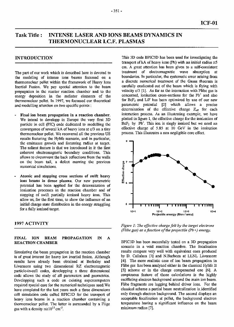
- 3 5 1 -
ICF-01
Task Title: INTENSE LASER AND IONS BEAMS DYNAMICS INTHERMONUCLEAR I.C.F. PLASMAS
INTRODUCTION
The part of our work which is described here is devoted tothe modeling of intense ions beams focussed on athermonuclear pellet within the framework of Heavy IonsInertial Fusion. We pay special attention to the beampropagation in the reactor reaction chamber and to theenergy deposition in the radiator elements of thethermonuclear pellet. In 1997, we focussed our theoreticaland modelling attention on two specific points :
- Final ion beam propagation in a reaction chamber.We intend to developp in Europe the very first 3Dparticle in cell (PIC) code dedicated to modelling theconvergence of several kA of heavy ions at c/3 on a tinythermonuclear pellet. We recovered all the previous USresults featuring the Hylife scenario, and in particular,the emittance growth and focussing radius at target.The salient feature is that we introduced in it the firstcoherent electromagnetic boundary conditions. Thisallows to circumvent the back reflections from the wallson the beam tail, a defect marring the previousnumerical simulations.
- Atomic and stopping cross sections of swift heavyions beams in dense plasma. Our new parametricpotential has been applied for the determination ofionization processes in the reaction chamber and ofstopping of swift partially ionized heavy ions. Thisallow us, for the first time, to show the influence of aninitial charge state distribution in the energy stragglingfor a fully ionized target.
1997 ACTIVITY
FINAL ION BEAM PROPAGATION IN AREACTION CHAMBER
Simulating the beam propagation in the reaction chamberis of great interest for heavy ion inertial fusion. Althoughresults have already been obtained at Berkeley andLivermore using two dimensional RZ electromagneticparticle-in-cell codes, developping a three dimensionalcode allows the study of all parameters and geometries.Developping such a code on existing supercomputersrequired special care for the numerical techniques used. Wehave completed for the last years such a three dimensionscell simulation code called BPIC3D for the transport ofheavy ions beams in a reaction chamber containing athermonuclear pellet. The latter is surrounded by a Fligegas with a density nslO13 cm"3.
This 3D code BPIC3D has been used for investigating thetransport of kA of heavy ions (Pb) with an initial radius =5cm. A great attention has been given to a self-consistenttreatment of electromagnetic wave absorption atboundaries. In particular, the systematic error arising froma discrete numerical treatment of the Gauss theorem iscarefully eradicated out of the beam which is flying withvelocity c/3 [1]. As far as the interaction with Flibe gas isconcerned, ionisation cross-sections for the Pb+ and alsofor BeF2 and LiF has been optimized by use of our newparametric potential [2] which allows a precisedetermination of the effective charge Zeg- for eachinteraction process. As an illustrating example, we haveplotted in figure 1, the effective charge for the ionization ofBeF2 by Pb+. This ion is singly ionized but we need aneffective charge of 5.85 at 10 GeV in the ionizationprocess. This illustrates a non negligible core effect.
1E+2 1E+3Projectile energy (Mev / amu)
Figure 1: The effective charge felt by the target electrons(Flibe gas) as a function of the projectile (Pb+) energy.
BPIC3D has been succesfully tested on a 3D propagationscenario in a void reaction chambre. The focalisationresults compare very well with equivalent ones producedby D. Callahan [3] and N.Barboza at LLNL Livermore[4]. The more realistic case of ion beam propagation inFlibe gas has been analyzed either in the classical Hylife II[5] scheme or in the charge compensated one [6]. Aconpicuous feature of those calculations is the highlyoscillating electron background around the main ion beam.Flibe fragments are lagging behind driver ions. For theclassical scheme a partial beam neutralization is .identifiedonly through electron background. The second displays anacceptable focalization at pellet, the background electrontemperature having a significant influence on the beamminimum radius [7].
-352-
The space charge compensated beam converges to a muchsmaller radius = 2.5mm than the non-compensated HylifeII one = 5.7mm.
Obviously, charge compensation appears to be of greathelp in securing adequate beam focussing on the target.The beam dynamics imply that negative ions are swiftlyneutralized and, hence, positively ionized on entering thereaction chamber. However, the discrepancy with respectto standard and non-charge compensated propagationremains substantial. In this latter case, a huge amount ofelectrostatic energy ( s 150 keV per ion beam) has to bedissipated in order to allow for beam neutralization. Part ofthis energy is indeed transferred to free electrons, whichlessens their neutralizing capabilities. So, the bonus ofusing negative ion beams up to the chamber entrance arisesfrom the fact that the exact number of cold electrons (inthe ion beam frame) is indeed adequately provided forsecuring a complete neutralization of ion beam current.
ENERGY DEPOSITION IN THE THERMONU-CLEAR PELLET
Swift heavy ions beams that are used as drivers in ICFscenarios are highly but not fully ionized during theslowing down process inside the target. The influence ofthe projectile bound electrons at low velocities has beenwell established since the work of J. Lindhard and hiscollaborators. However for swift heavy ions the situation isquite unclear : on one side Born I calculations exhibit alarge core effect whereas, on the other side, the so calledStandard Stopping Model (SSM) results using point likeprojectiles show that the correction terms can be large sothat the Born I result should not be valid [8,9]. Thesepoints was reconsidered recently by us in the framework ofan Extended SSM (ESSM) [9]. The basic point of ESSMis to generalized the SSM formalism, the close collisionscorrection terms being calculated for a non coulombicpotential.
The purpose here is to apply ESSM to the stopping ofheavy ions in the radiator element of an indirect driventarget. The radiators generally have a thin foil of heavymaterial (gold) in front of a low atomic number material(berryllium). During the irradiation by the intense heavyion beams, the temperature of the radiators quicklyincrease up to 100-200 eV. The beryllium target becomesfully ionized while the gold ions still have many boundelectrons.
Therefore, at the exit surface of the gold foil, the beam ionshave nearly the same broad charge distribution as at thebeginning time of irradiation. Our main goal is to showthat this broad charge distribution increases substantiallythe straggling in the energy loss in the beryllium, henceleading to a broader Bragg peak at the end of the beamrange. This broadening can has a substantial influence inthe overall efficiency of the X-radiation emission.
The main problem here is to determine the stopping powerof a partially ionized ion taking into account the core of theprojectile in a non perturbative way.
This was done in ESSM by including the SSM in a newand more general formulation that can be applied to thenon coulombic perturbation potential given by our newparametric potential to describe the core of the projectile.The contribution of the projectile excitation/ionization andof the charge transfer process to the stopping can beestimated comparing the cross sections for the twocollisional systems : a) the heavy ion interacting with atarget electron or b) a target atom interacting with aprojectile electron.
For the asymmetric system of highly ionized heavy ion in alow atomic number target, obviously the cross sections ina) are much larger than in b) so that the so called inelasticcontribution to the stopping power is negligible [8].Therefore the contribution of the projectile electronic cloudcan be taken into account using the frozen coreapproximation, that is, simply through an elastic formfactor. This elastic form factor is given by our parametricpotential [2] which provides atomic data with the samedegree of accuracy as Hartree-Fock-Slater calculations.
The full results for a gold foil followed by a fully ionizedberyllium target will be given in the next report. Here, as afirst step, we show a test of our calculations by comparingour results with the new experimental data obtained in acollaboration with the group of M.Chabot and D. Gardes ofthe Nuclear Institut of Orsay [9-11] concerning 1.5 MeV/uClq+ in deuterium gas and plasma.
We can see in the figure 2 twice a factor of two betweenthe plasma and the cold gas results : one between theabsolute values of stopping and one between the slopes.The factor of two in the enhancement of the stoppingpower in plasma compared to the cold matter one is a wellknown fact. The new result that we have obtained is thatthe straggling coming from the charge distribution exhibitsthe same enhancement.
Therefore the straggling in energy loss due to the chargedistribution, as the stopping power, is much larger in theplasma than in the cold matter. This comes from the factthat charge changing cross sections are much lower in theplasma (the bound-bound processes have been eliminated)than in the cold gas target. Therefore an ion with a givenionization state has, on the average, more time in plasmathan in gas, for losing energy before changing to anothercharge state.
Thus yielding more differences in plasma between thevarious ionization states. The last figure, show the goodagreement that we obtained between our new ESSMcalculations and the experimental results.
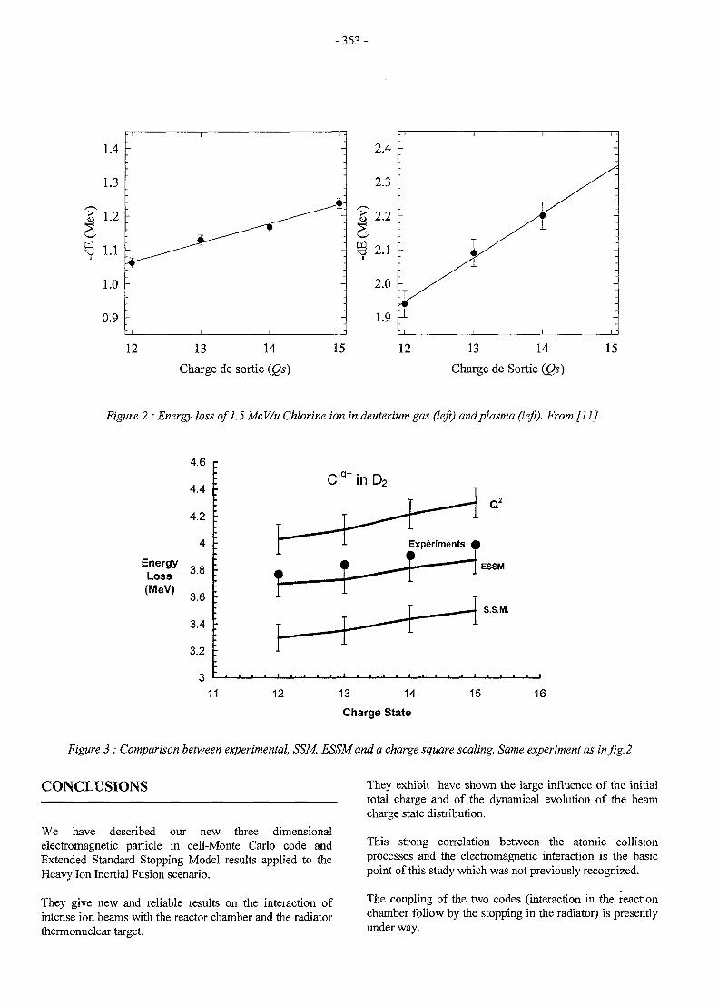
- 3 5 3 -
12 13 14
Charge de sortie (Qs)
15
2.4
2.3
2.2
2.1
2.0
1.9
-
- 1
1 1 -
-
y
-
12 13 14
Charge de Sortie (Qs)
15
Figure 2 : Energy loss of 1.5 MeV/u Chlorine ion in deuterium gas (left) and plasma (left). From [11]
EnergyLoss(MeV)
4.6
4.4
4.2
4
3.8
3.6
3.4
3.2
311 12
Clq in D2
ESSM
S.S.M.
13 14
Charge State
15 16
Figure 3 : Comparison between experimental, SSM, ESSMand a charge square scaling. Same experiment as in fig. 2
CONCLUSIONS
We have described our new three dimensionalelectromagnetic particle in cell-Monte Carlo code andExtended Standard Stopping Model results applied to theHeavy Ion Inertial Fusion scenario.
They give new and reliable results on the interaction ofintense ion beams with the reactor chamber and the radiatorthermonuclear target.
They exhibit have shown the large influence of the initialtotal charge and of the dynamical evolution of the beamcharge state distribution.
This strong correlation between the atomic collisionprocesses and the electromagnetic interaction is the basicpoint of this study which was not previously recognized.
The coupling of the two codes (interaction in the reactionchamber follow by the stopping in the radiator) is presentlyunder way.
-354-
REFERENCES REPORT & PUBLICATIONS
[I] J.L.Vay and C. Deutsch, Fus. Eng. Des.32-33,467(1996)
[2] S. Mabong, G. Maynard, and K. Katsonis, Laser andParticle Beams 14, 575 (1996).
[3] D.Callahan, Fus. Eng. Des. 32-33, 441 (1996)
[4] N.Barboza, Fus. Eng. Des. 31-33, 453 (1993)
[5] R.Moir, Fusion Technol. 29, 306 (1991)
[6] D.G.Koshkarev, Nuovo Cimento A106, 1567 (1993)
[7] J.L.Vay and C.Deutsch, Phys. Plasmas, 5,n° 4 (1998)
[8] G. Maynard, K. Katsonis, and S. Mabong, Nucl.Instr. and Meth. B 107, 51 (1996).
[9] D. Gardes , M. Chabot, G.Maynard, G. MaynardNucl. Instr. Meth. A (1998)
[10] G. Maynard, G. Zwicknagel, M. Chabot, and D.Gardes, C. Deutsch Nucl. Instr. Meth. A (1998) andPhys. Rev. E (1998), submitted.
[II] M. Chabot, D. Gardes, G.Maynard and C. DeutschNucl. Instr. Meth. A (1998)
[12] J.L. Vay and C. Deutsch, Nucl. Instr. Meth. A (1998)
[13] J.L. Vay and C. Deutsch, Plasma Physics andControlled Fusion (1998)
See references [1], [7], et [9-13]
TASK LEADER
Claude DEUTSCH
Laboratoire de Physique des Gaz et des PlasmasBat. 210University Paris XIF-91405 Orsay cedex
Tel.Fax
01 69 15 76 0501 69 15 78 44
e-mail: [email protected]
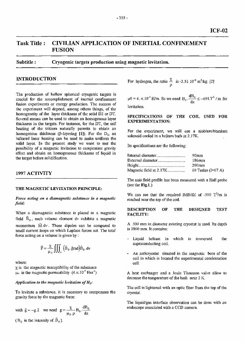
- 3 5 5 -
ICF-02
Task Title : CIVILIAN APPLICATION OF INERTIAL CONFINEMENTFUSION
Subtitle: Cryogenic targets production using magnetic levitation.
INTRODUCTION
The production of hollow spherical cryogenic targets iscrucial for the accomplishment of inertial confinementfusion experiments or energy production. The success ofthe experiment will depend, among others things, of thehomogeneity of the layer thickness of the solid D2 or DT.Several means can be used to obtain an homogenous layerthickness in the targets. For instance, for the DT, the selfheating of the tritium naturally permits to obtain anhomogenous thickness (p-layering [1]). For the D2, aninfrared laser heating can be used to make uniform thesolid layer. In the present study we want to test thepossibility of a magnetic levitation to compensate gravityeffect and obtain an homogeneous thickness of liquid inthe target before solidification.
1997 ACTIVITY
THE MAGNETIC LEVITATION PRINCIPLE:
Force acting on a diamagnetic substance in a magneticfield:
When a diamagnetic substance is placed in a magnetic
field B o , each volume element dv exhibits a magnetic
momentum M.dv. Those dipoles can be compared tosmall current loops on which Laplace forces act. The totalforce acting on a volume is given by :
where:% is the magnetic susceptibility of the substanceHo is the magnetic permeability (4.7T.10"7 Hm"1)
Application to the magnetic levitation o
To levitate a substance, it is necessary to compensate thegravity force by the magnetic force:
dB0withg = -g.z weneed g- B o .
Ho-P dz(B o is the intensity of B o ).
For hydrogen, the ratio — is -2.51 10"8 m3/kg [2]P
•7 d B n ->
u.0 = 4. Ti.10'7 H/m. So we need B n . — - S -491.T2 /m for0 dz
levitation.
SPECIFICATIONS OF THE COIL USED FOREXPERIMENTATION:
For the experiment, we will use a niobium/titaniumsolenoid cooled in a helium bath at 2.17K.
Its specifications are the following:
Internal diameter 90mmExternal diameter 186mmHeight.. 200mmMagnetic field at 2.17K 10 Teslas (1=67 A)
The axis field profile has been measured with a Hall probe(see the Fig.l.)
We can see that the required BdB/dZ of -500 T2/m isreached near the top of the coil.
DESCRffTION OF THE DESIGNED TESTFACILITY:
A 300 mm in diameter existing cryostat is used. Its depthis 1800 mm. It contains:
- Liquid helium in which is immersed thesupraconducting coil.
- An anticryostat situated in the magnetic bore of thecoil in which is located the experimental condensationcell.
A heat exchanger and a Joule Thomson valve allow todecrease the temperature of the bath near 2 K.
The cell is lightened with an optic fiber from the top of thecryostat.
The liquid/gas interface observation can be done with anendoscope associated with a CCD camera.
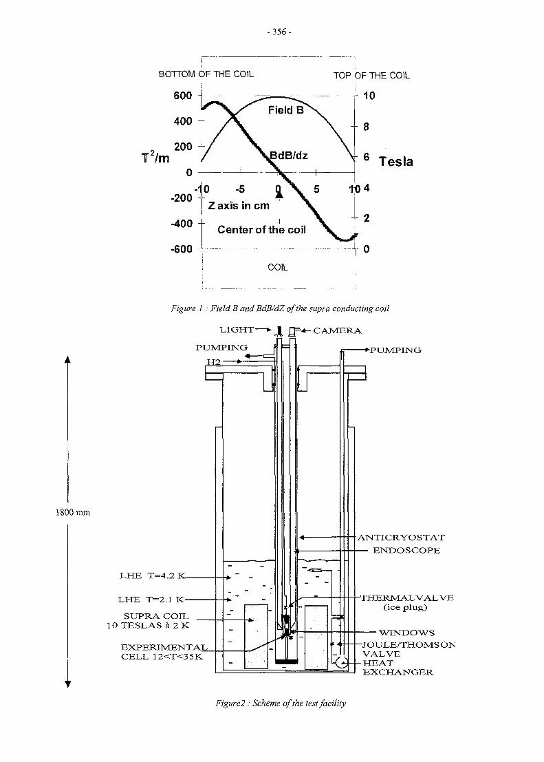
-356-
BOTTOM (
600 -
400 -
, 200T2/m
0
-200"
-400
-600
DF THE COIL
/ N
0 -5Z axis in
Center
tVcm X1 \of the coil
COIL
TOP
1
OF THE COIL
10
8
6 Tesla
04
2
0
1800 mm
Figure 1 : Field B and BdB/dZ of the supra conducting coil
LIGHT—* | rj=4- CAMERA
PUMPING
H2 *-—JH
LHE T=4.2 JC
LHE T=2.1 K-
SUPRA COIL10 TESLAS 4 2 K
EXPERIMENTAL.CELL 12<T<3 5K
•PUMPING
ANTICRYOSTAT
— ENDOSCOPE
-THERMAL VALVE(ice plug)
WINDOWS
-JOULE/THOMSONVALVE
-HEATEXCHANGER
Figure2 : Scheme of the test facility
- 3 5 7 -
CONCLUSION TASK LEADER
An experiment allowing the magnetic levitation of the Denis CHATAINhydrogen has been designed.
DSM/DRFMC/SBTThe supraconducting coil has been characterized. The CEA/Grenoblerequired product of the field by the field gradient tolevitate the hydrogen is -500 TVm. This will be obtained Tel 04 76 88 50 28with a 10 Teslas field. Fax : 04 76 88 5186
Levitation experiments will be performed during the first e-mail: [email protected] of 1998.
REFERENCES
[1] Fusion technology Vol 21 Mar 92 p. 330.
[2] 'Hydrogen properties for fusion energy' p.339. ClarkSouers. LLNL
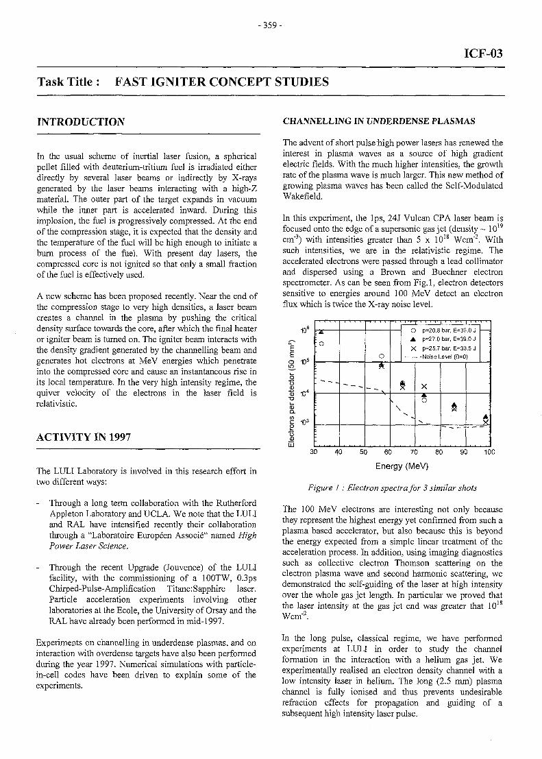
- 3 5 9 -
ICF-03
Task Title : FAST IGNITER CONCEPT STUDIES
INTRODUCTION
In the usual scheme of inertial laser fusion, a sphericalpellet filled with deuterium-tritium fuel is irradiated eitherdirectly by several laser beams or indirectly by X-raysgenerated by the laser beams interacting with a high-Zmaterial. The outer part of the target expands in vacuumwhile the inner part is accelerated inward. During thisimplosion, the fuel is progressively compressed. At the endof the compression stage, it is expected that the density andthe temperature of the fuel will be high enough to initiate aburn process of the fuel. With present day lasers, thecompressed core is not ignited so that only a small fractionof the fuel is effectively used.
A new scheme has been proposed recently. Near the end ofthe compression stage to very high densities, a laser beamcreates a channel in the plasma by pushing the criticaldensity surface towards the core, after which the final heateror igniter beam is turned on. The igniter beam interacts withthe density gradient generated by the channelling beam andgenerates hot electrons at MeV energies which penetrateinto the compressed core and cause an instantaneous rise inits local temperature. In the very high intensity regime, thequiver velocity of the electrons in the laser field isrelativistic.
ACTIVITY IN 1997
The LULI Laboratory is involved in this research effort intwo different ways:
- Through a long term collaboration with the RutherfordAppleton Laboratory and UCLA. We note that the LULIand RAL have intensified recently their collaborationthrough a "Laboratoire Europeen Associe" named HighPower Laser Science.
Through the recent Upgrade (Jouvence) of the LULIfacility, with the commissioning of a 100TW, 0.3psChirped-Pulse-Amplification TitanerSapphire laser.Particle acceleration experiments involving otherlaboratories at the Ecole, the University of Orsay and theRAL have already been performed in mid-1997.
Experiments on channelling in underdense plasmas, and oninteraction with overdense targets have also been performedduring the year 1997. Numerical simulations with particle-in-cell codes have been driven to explain some of theexperiments.
CHANNELLING IN UNDERDENSE PLASMAS
The advent of short pulse high power lasers has renewed theinterest in plasma waves as a source of high gradientelectric fields. With the much higher intensities, the growthrate of the plasma wave is much larger. This new method ofgrowing plasma waves has been called the Self-ModulatedWakefield.
In this experiment, the lps, 24 J Vulcan CPA laser beam isfocused onto the edge of a supersonic gas jet (density ~ 1019
cm"3) with intensities greater than 5 x 10¹⁸ Wcm"2. Withsuch intensities, we are in the relativistic regime. Theaccelerated electrons were passed through a lead collimatorand dispersed using a Brown and Buechner electronspectrometer. As can be seen from Fig. 1, electron detectorssensitive to energies around 100 MeV detect an electronflux which is twice the X-ray noise level.
10°
E
I
__0
10*
103
LU
• o
— _____
o
> • . • • ' • i • > • > > • •
O p-20.8 bar, E-36.0 JA p=27.0 bar, E=39.0 JX P=25.7 bar, E=33.5 J
Noise Level (B=0)
a\
X
o
:
30 40 50 60 70 80
Energy (MeV)
90 100
Figure 1: Electron spectra for 3 similar shots
The 100 MeV electrons are interesting not only becausethey represent the highest energy yet confirmed from such aplasma based accelerator, but also because this is beyondthe energy expected from a simple linear treatment of theacceleration process. In addition, using imaging diagnosticssuch as collective electron Thomson scattering on theelectron plasma wave and second harmonic scattering, wedemonstrated the self-guiding of the laser at high intensityover the whole gas jet length. In particular we proved thatthe laser intensity at the gas jet end was greater that I018
Wcm"2.
In the long pulse, classical regime, we have performedexperiments at LULI in order to study the channelformation in the interaction with a helium gas jet. Weexperimentally realised an electron density channel with alow intensity laser in helium. The long (2.5 mm) plasmachannel is fully ionised and thus prevents undesirablerefraction effects for propagation and guiding of asubsequent high intensity laser pulse.
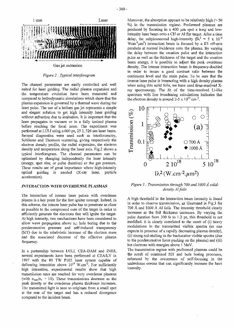
-360-
1 mm Laser
Gas jet extension
Figure 2 : Typical interferogram
The channel parameters are easily controlled and wellsuited for laser guiding. The radial plasma expansion andthe temperature evolution have been measured andcompared to hydrodynamic simulations which show that theplasma expansion is governed by a thermal wave during thelaser pulse. The use of a helium gas jet represents a simpleand elegant solution to get high intensity laser guidingwithout refraction due to ionisation. It is important that thelaser propagates in vacuum or in a fully ionised plasmabefore reaching the focal zone. The experiment wasperformed at LULI using a 600 ps, 25 J, 526 nm laser beam.Several diagnostics were used such as interferometry,Schlieren and Thomson scattering, giving respectively theelectron density profile, the radial expansion, the electrondensity and temperature along the laser axis. Fig.2 shows atypical interferogram. The channel parameters can beoptimised by changing independently the laser intensity(energy, spot size, or pulse duration) or the gas pressure.These results are of great importance where high-intensityoptical guiding is needed (X-ray laser, particleacceleration).
INTERACTION WITH OVERDENSE PLASMAS
The interaction of intense laser pulses with overdenseplasma is a key point for the fast igniter concept. Indeed, inthis scheme, the intense laser pulse has to penetrate as closeas possible to the compressed core of the target in order toefficiently generate the electrons that will ignite the target.At high intensity, two mechanisms have been considered toallow wave propagation above r^: hole boring due to theponderomotive pressure and self-induced transparency(SIT) due to the relativistic increase of the electron massand the associated decrease of the effective plasmafrequency.
In a partnership between LULI, CEA-DAM and MRS,several experiments have been performed at CEA/LV in1997 with the 80 TW PI02 laser system capable ofdelivering intensities above 1019 W.cm"2. For sufficientlyhigh intensities, experimental results show that hightransmission rates are reached for very overdense plasmas(with nmax/nc = 10). These transmissions decrease as thepeak density or the overdense plasma thickness increases.The transmitted light is seen to originate from a small spotat the rear of the target and has a reduced divergencecompared to the incident beam.
Moreover, the absorption appears to be relatively high (= 50%) in the transmission regime. Preformed plasmas areproduced by focusing in a 400 urn spot a long and low-intensity laser beam onto a CH or Al flat target. After a timedelay, the subpicosecond high-intensity (IX2 = 5 x 10¹⁸
Wcm"2um2) interaction beam is focused by a f/3 off-axisparabola at normal incidence onto the plasma. By varyingthe delay between the creation pulse and the interactionpulse as well as the thickness of the target and the creationbeam energy, it is possible to adjust the peak overdensedensity. The intense interaction beam is frequency-doubledin order to insure a good contrast ratio between thecontinuum level and the main pulse. To be sure that theintense laser pulse is interacting with a high density plasmawhen using thin solid foils, we have used time-resolved X-ray spectroscopy. The fit of the time-resolved Li-likespectrum with line broadening calculations indicates thatthe electron density is around 2-5 x 1023 cm-3.
;O O
O700A - =• 1000 A
180 210 iU 5 10
a 2 (W.cm-2./* m2)
Figure 3 : Transmission through 700 and 1000 A solid-density Al foils
A high threshold in the interaction beam intensity is foundin order to observe transmission, as illustrated in Fig.3 for700 A and 1000 A Al foils. The intensity threshold clearlyincreases as the foil thickness increases. By varying thepulse duration from 300 fs to 1.2 ps, this threshold is notmodified. It is clearly correlated to the onset of (i) heavymodulations in the transmitted visible spectra (as oneexpects in presence of a rapidly decreasing plasma density),(ii) strong red-shifting in the backscatter visible spectra (dueto the ponderomotive force pushing on the plasma) and (iii)hot electrons with energies above 1 MeV.The transmission regime with preformed plasmas could bethe result of combined SIT and hole boring processes,enhanced by the occurrence of self-focusing in theunderdense corona that can significantly increase the laserintensity.
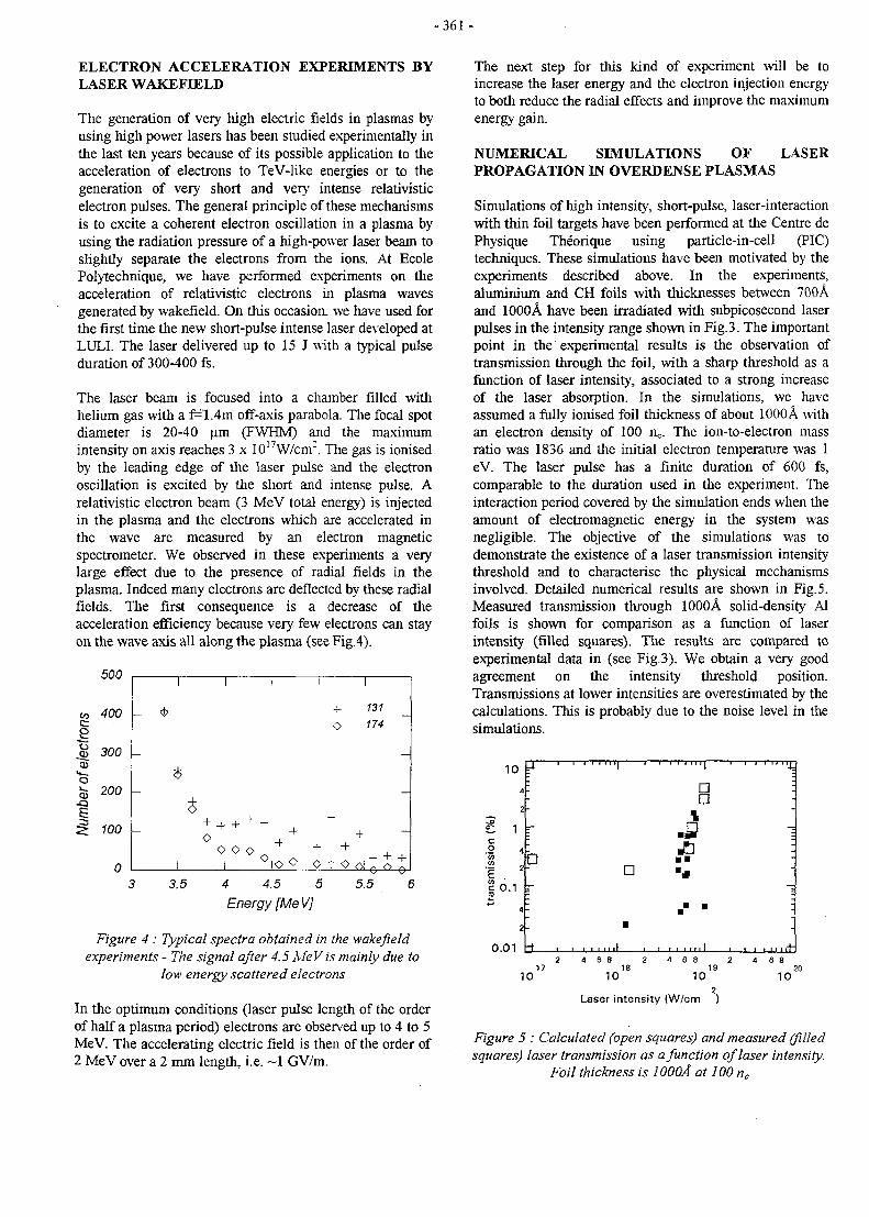
- 3 6 1 -
ELECTRON ACCELERATION EXPERIMENTS BYLASER WAKEFIELD
The generation of very high electric fields in plasmas byusing high power lasers has been studied experimentally inthe last ten years because of its possible application to theacceleration of electrons to TeV-like energies or to thegeneration of very short and very intense relativisticelectron pulses. The general principle of these mechanismsis to excite a coherent electron oscillation in a plasma byusing the radiation pressure of a high-power laser beam toslightly separate the electrons from the ions. At EcolePolytechnique, we have performed experiments on theacceleration of relativistic electrons in plasma wavesgenerated by wakefield. On this occasion, we have used forthe first time the new short-pulse intense laser developed atLULL The laser delivered up to 15 J with a typical pulseduration of 300-400 fs.
The laser beam is focused into a chamber filled withhelium gas with a f=1.4m off-axis parabola. The focal spotdiameter is 20-40 urn (FWHM) and the maximumintensity on axis reaches 3 x 10¹⁷W/cnr. The gas is ionisedby the leading edge of the laser pulse and the electronoscillation is excited by the short and intense pulse. Arelativistic electron beam (3 MeV total energy) is injectedin the plasma and the electrons which are accelerated inthe wave are measured by an electron magneticspectrometer. We observed in these experiments a verylarge effect due to the presence of radial fields in theplasma. Indeed many electrons are deflected by these radialfields. The first consequence is a decrease of theacceleration efficiency because very few electrons can stayon the wave axis all along the plasma (see Fig.4).
500
4 4.5 5
Energy [Me V]5.5
Figure 4 : Typical spectra obtained in the wakefieldexperiments - The signal after 4.5 MeV is mainly due to
low energy scattered electrons
In the optimum conditions (laser pulse length of the orderof half a plasma period) electrons are observed up to 4 to 5MeV. The accelerating electric field is then of the order of2 MeV over a 2 mm length, i.e. ~1 GV/m.
The next step for this kind of experiment will be toincrease the laser energy and the electron injection energyto both reduce the radial effects and improve the maximumenergy gain.
NUMERICAL SIMULATIONS OF LASERPROPAGATION IN OVERDENSE PLASMAS
Simulations of high intensity, short-pulse, laser-interactionwith thin foil targets have been performed at the Centre dePhysique Theorique using particle-in-cell (PIC)techniques. These simulations have been motivated by theexperiments described above. In the experiments,aluminium and CH foils with thicknesses between 700Aand 1000A have been irradiated with subpicosecond laserpulses in the intensity range shown in Fig.3. The importantpoint in the experimental results is the observation oftransmission through the foil, with a sharp threshold as afunction of laser intensity, associated to a strong increaseof the laser absorption. In the simulations, we haveassumed a fully ionised foil thickness of about 1000A withan electron density of 100 nc. The ion-to-electron massratio was 1836 and the initial electron temperature was 1eV. The laser pulse has a finite duration of 600 fs,comparable to the duration used in the experiment. Theinteraction period covered by the simulation ends when theamount of electromagnetic energy in the system wasnegligible. The objective of the simulations was todemonstrate the existence of a laser transmission intensitythreshold and to characterise the physical mechanismsinvolved. Detailed numerical results are shown in Fig. 5.Measured transmission through 1000A solid-density Alfoils is shown for comparison as a function of laserintensity (filled squares). The results are compared toexperimental data in (see Fig.3). We obtain a very goodagreement on the intensity threshold position.Transmissions at lower intensities are overestimated by thecalculations. This is probably due to the noise level in thesimulations.
10 •
O.O1
:
r-
p
- f • 1
1 ' " " i
•
•
1
'1 ' ••••••%
• :•
-fl 1JE] -• •
• • i•
10
4 6 8 218
10
4 6 8 2 4 6 819 20
10 10
Laser intensity (W/cm )
Figure 5 : Calculated (open squares) and measured (filledsquares) laser transmission as a function of laser intensity.
Foil thickness is 1000A at 100 nc
-362 -
CONCLUSIONS
Using the 24TW Vulcan laser focused on the edge of ahelium gas jet, we have been able to detect lOOMeVelectrons accelerated by the Raman self-modulatedwakefield. This corresponds to electric fields of aboutlOOGV/m. Channeling by the relativistically-intense laserpulse has been demonstrated. Using the LULI laser in thelong pulse regime, we have demonstrated channeling overdistances of several millimeters. The channel parameterscan be optimised by changing independently the laserintensity or the gas pressure. These results are veryencouraging for experimental situations (particleacceleration, fast igniter) where high-intensity opticalguiding is needed. Transmission of laser pulses in therelativistic regime has been observed at a level of a fewpercent for target thicknesses around lOOnm. Spectra ofthe back-scattered light show a strong red-shift which isthe signature of the effect of the laser ponderomotive forcepushing on the plasma. At the same time, transmitted lightspectra show strong modulations. These observations showthat neither SIT nor hole-boring can, on their own, explainthe observations. In the optimum conditions (laser pulselength of the order of half a plasma period) electronsinjected at 3 MeV have been accelerated to 4 to 5 MeV.The accelerating electric field is then of the order of1 GV/m. Numerical simulations performed with the PICcode available at the Center of Theoretical Physics of theEcole Polytechnique are in very good agreement withexperiments for the description of the processes of laser-induced transparency. This makes this approach invaluablefor the understanding of the physical mechanisms involvedin the interaction of a high-intensity, short-pulse, laserwith solid or gaseous targets. This paves the way to adetailed understanding of plasma physics processes in therelativistic regime.
PUBLICATIONS
[1] V. Malka, E. De Wispelaere, F. Amiranoff, A.Modena, R. Haroutunian, R. Bonadio, C. Coulaud, D.Puissant, C. Stenz, S. Hiiller, and M. CasanovaChannel Formation In Long Laser Pulse Interactionwith a Helium Gas JetPhys. Rev. Lett. 79, 16 (1997).
[2] V. Malka, A. Modena, Z. Najmudin, A. E. Dangor,C. E. Clayton, K. A. Marsh, C. Joshi, C. Danson, D.Neely, and F. N. Walsh.Second Harmonic Generation and its Interaction withRelativistic Plasma Waves Driven by Forward RamanInstability in Underdense PlasmaPhysics of Plasma 4, 1127, (1997).
[3] D. Gordon, K. C. Tzeng, C. E. Clayton, A. E.Dangor, V. Malka, K. A. Marsh, A. Modena, W. B.Mori, P. Muggli, Z. Najmudin, and C. JoshiObservation of Electron Energies Beyond the LinearDephasing Limit from a Laser-Excited RelativisticPlasma Wave(submitted to Phys. Rev. Lett.)
[4] C. E. Clayton, D. Gordon, K. A. Marsh, C. Joshi, V.Malka, Z. Najmudin, A. Modena, A. E. Dangor, D.Neely, and C. DansonObservation of self-channeling of relativistically-intense laser light in a very underdense plasma(submitted to Phys. Rev. Lett.)
[5] J. Fuchs, J.C. Adam, F. Amiranoff, S.D. Baton, P.Gallant, L. Gremillet, A. Heron, J.C. Kieffer, G.Laval, G. Malka, J.L. Miquel, P. Mora, H. Pepin, andC. RousseauxTransmission through highly overdense plasma slabswith a subpicosecond relativistic laser pulsePhys. Rev. Lett (a paraitre 1998).
[6] J. Fuchs, G. Malka, J.C. Adam, F. Amiranoff, S.D.Baton, N. Blanchot, A. Heron, G. Laval, J.L. Miquel,P. Mora, H. Pepin, and C. RousseauxDynamics of subpicosecond relativistic laser pulseself-channeling in an underdense preformed plasmaPhys. Rev. Lett (a paraitre 1998).
[7] JR. Marques, F. Dorchies, F. Amiranoff, P.Audebert, J.C. Gauthier, J.P. Geindre, A. Antonetti,T.M. Antonsen Jr., P. Chessa, and P. MoraLaser wakefield : experimental study of non-linearradial electron oscillationsPhysics of Plasmas (a paraitre 1998).
[8] J.C. Adam, A. Heron, S. Guerin, G. Laval, P. Mora,et B. QuesnelAnomalous absorption of very high-intensity laserpulses propagating through moderately dense plasmaPhys. Rev. Lett, (accepte, 1997).
TASK LEADER
Arnold MIGUS
Laboratoire LULIEcole Polytechnique91128 Palaiseau
Tel.Fax
0169 33 38 5001 69 33 30 09
e-mail: [email protected]
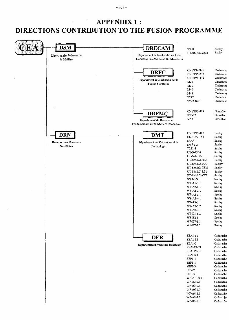
- 3 6 3 -
APPENDIX 1 :DIRECTIONS CONTRIBUTION TO THE FUSION PROGRAMME
Direction des Sciences dela Matiere
DRECAMDepartement de Recherche sur I'Etat
Condense, les Atomes et les Molecules
DRFCDepartement de Recherche sur la
Fusion Controlee
DRFMClDepartement de Recherche
Fondamentale sur la Matiere Condensee
Direction des ReacteursNucleates
DMTDepartement de Mecanique et de
Technologie
PERDepartement dTLtude des Reacteurs
T330UT-SM&C-CM1
CNET94-345CNET95-375CNET96-432M29M30M40M48T222T222.4ter
CNET96-409ICF-02M53
CNET96-412CNET97-454SEA3-1SM5-1.2T221-1UT-N-DPAUT-N-NDAUT-SM&C-BLKUT-SM&C-FCCUT-SM&C-PBMUT-SM&C-RELUT-SM&C-WIWP3-3.3WP-A1-1.1WP-A2-1.1WP-A2-2.1WP-A2-3.1WP-A2-4.1WP-A7-1.1WP-A7-2.2WP-A9-3.1WP-BM.2WP-B2-1WP-B7-1.1WP-B7-2.3
SEA1-11SEA1-12SEA1-2SEAFP2-21SEAFP3-11SEAL4.3SEP1-1SEP3-1SEP3-3UT-S2UT-S3WP-A10-2.2WP-A3-2.1WP-A3-9.1WP-A6-1.1WP-A6-2.1WP-A9-2.2WP-B6-1.3
SaclaySaclay
GrenobleGrenobleGrenoble
SaclaySaclaySaclaySaclaySaclaySaclaySaclaySaclaySaclaySaclaySaclaySaclaySaclaySaclaySaclaySaclaySaclaySaclaySaclaySaclaySaclaySaciaySaclaySaclaySaclay
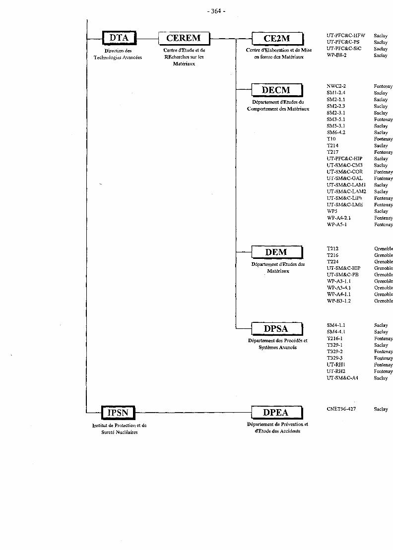
- 3 6 4 -
CEREMDirection des
Technologies Avancées
Centre d'Etude et deREcherches sur les
Matériaux
CE2MCentre d'Elaboration et de Mise
en forme des Matériaux
DECM IDépartement d'Etudes du
Comportement des Matériaux
DEMDépartement d'Etudes des
Matériaux
DPSA IDépartement des Procédés et
Systèmes Avancés
UT-PFC&C-HFW SaclayUT-PFC&C-PS SaclayUT-PFC&C-SiC SaclayWP-B8-2 Saclay
NWC2-2SM1-2.4SM2-1.1SM2-2.3SM2-3.1SM3-5.1SM5-3.1SM6-4.2T10T214T217UT-PFC&C-HIPUT-SM&C-CM3UT-SM&C-CORUT-SM&C-GALUT-SM&C-LAM1UT-SM&C-LAM2UT-SM&C-LiPbUT-SM&C-LMEWP5WP-A4-2.1WP-A5-1
T212T216T224UT-SM&C-HIPUT-SM&C-PBWP-A3-1.1WP-A3-4.1WP-A4-1.1WP-B3-1.2
SM4-1.1SM4-4.1T216-1T329-1T329-2T329-3UT-RH1UT-RH2UT-SM&C-A4
FontenaySaclaySaclaySaclaySaclayFontenaySaclaySaciayFontenaySaclayFontenaySaclaySaclayFontenayFontenaySaclaySaclayFontenayFontenaySaclayFontenayFontenay
GrenobleGrenobleGrenobleGrenobleGrenobleGrenobleGrenobleGrenobleGrenoble
SaclaySaclayFontenaySaclayFontenayFontenayFontenayFontenaySaclav
DPEAInstitut de Protection et de
Sûreté Nucléaires
Département de Prévention etd'Etude des Accidents
CNET96-427 Saclay
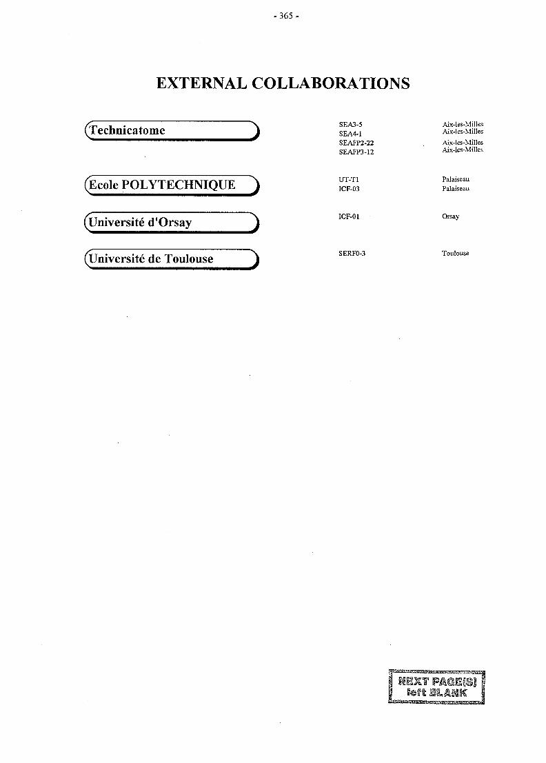
- 3 6 5 -
EXTERNAL COLLABORATIONS
(Technicatome
(Ecole POLYTECHNIQUE )
SEA3-5SEA4-1SEAFP2-22SEAFP3-12
UT-T1ICF-03
Aix-les-MillesAix-les-Milles
Aix-les-MillesAix-les-Milles
PalaiseauPalaiseau
(llniversite d'Orsay
(Universite de Toulouse
ICF-01
SERFO-3
Orsay
Toulouse
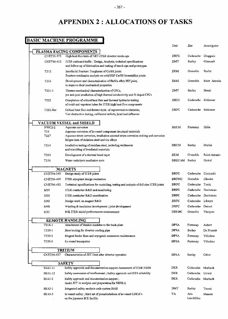
- 3 6 7 -
APPENDIX 2 : ALLOCATIONS OF TASKS
I BASIC MACHINE PROGRAMME |
- | PLASMA FACING COMPONENTS
- T VACUUM VESSEL and SHIELD |
-c
- L
-L
CNET95-375 High heat flux tests of NET-ITER divertor mock-ups
CNET96-412 ITER outboard baffle : Design, Analysis, technical specifications
and follow-up of fabrication and testing of mock-ups and prototypes
T212 Interfacial Fracture Toughness of Cu/SS jointsFracture mechanics analysis on solid HIP Cu/SS bi-metallics joints
T216 Development and characterization of Be/Cu alloy HIP joint,to improve their mechanical properties
T221 -1 Thermo-mechanical characterization of CFCs,pre and post irradiation of high thermal conductivity and Si doped CFCs
T222 Completion of critical heat flux and thermal hydraulic testingof swirl and vapotron tubes for ITER high heat flux components
T222.4ter Critical heat flux and thermo-hydr. of representative elements;Non destructive testing, calibrated defects, heat load influence
NWC2-2 Aqueous corrosionT10 Aqueous corrosion of in-vessel component structural materialsT217 Aqueous stress corrosion, irradiation assisted stress corrosion crcking and corrosion
fatigue tests of stainless steel and Cu alloys
T214 Irradiation testing of stainless steel, including weldments
and rewelding of irradiated materials
T224 Development of a thermal bond layer
T330 Water radiolysis irradiation tests
MAGNETSCNET94-345 Design study of ITER joints
CNET96-409 ITER cryoplant design evaluation
CNET96-432 Technical specifications for modelling, testing and analysis of full size ITER joints
M29 ITER conductor R&D and monitoring
M30 ITER conductor R&D coordination
M40 Design work on magnet R&D
M48 Winding & insulation development; joint development
M53 80K ITER shield performances measurement
REMOTE HANDLINGT216-1 Attachment of blanket modules to the back-plate
T329-1 Bore tooling for divertor cooling pipe
T329-2 Magnet feeder lines and cryogenic connectors maintenance
T329-3 Ex-vessel transporter
TRITIUMCNET96-427 Characteristics of JET Dust after divertor operation
SAFETYSEAl-l 1 Safety approach and documentation support Assessment of ITER NSSR
SEA1-12 Safety assessment of confinement; Safety approach and HTS reliability
SEA1-2 Safety approach and documentation support;
Assist JCT in analysis and preparation for NSSR-2
SEA3-1 Integrated safety analysis code system IS AS
SEA3-5 In vessel safety; third set of precalculations of in-vessel LOCA'son the Japanese ICE facility
Unit Site Investigator
DRFC Cadarache Chappuis
DMT Saclay Giancarli
DEM Grenoble Burlet
DEM Grenoble Saint Antonin
DMT Saclay Bonal
DRJFC Cadarache Schlosser
DRFC Cadarache Schlosser
DECM Fontenay Helie
DECM Saclay Marini
DEM
DRECAM
DRFC
DRFMC
DRFC
DRFC
DRFC
DRFC
DRFC
DRFMC
DPSA
DPSA
DPSA
DPSA
Grenoble
Saclay
Cadarache
Grenoble
Cadarache
Cadarache
Cadarache
Cadarache
Cadarache
Grenoble
Fontenay
Saclay
Fontenay
Fontenay
Saint-Antomn
Hickel
Ciazynski
Claudet
Turck
Duchateau
Duchateau
Libeyre
Decool
Viargues
Aubert
De Prunele
Villedieu
ViUedieu
DPEA Saclay Cetier
DER
DER
DER
DMT
TA
Cadarache
Cadarache
Cadarache
Saclay
Aix-Les-Milles
Marbach
Girard
Marbach
Toumi
Masson
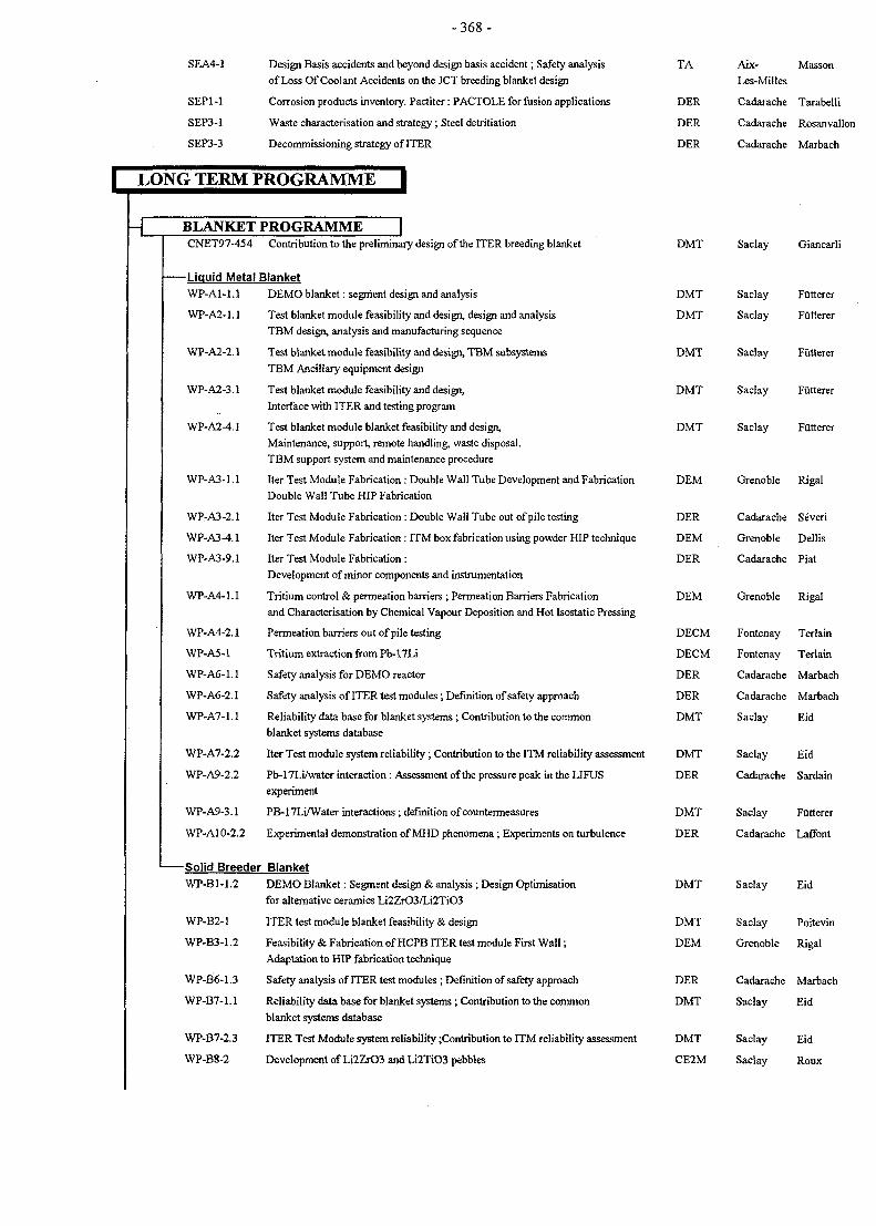
- 3 6 8 -
SEA4-1 Design Basis accidents and beyond design basis accident; Safety analysis
of Loss Of Coolant Accidents on the JCT breeding blanket design
SEP1 -1 Corrosion products inventory. Pactiter: PACTOLE for fusion applications
SEP3-1 Waste characterisation and strategy; Steel detritiation
SEP3-3 Decommissioning strategy of ITER
LONG TERM PROGRAMME
TA
DER
DER
DER
Aix-Les-Milles
Cadarache
Cadarache
Cadarache
Masson
Tarabelli
Rosanvallon
Marbach
-L BLANKET PROGRAMMECNET97-454 Contribution to the preliminary design of the ITER breeding blanket
-Liquid Metal BlanketWP-A1-1.1 DEMO blanket: segment design and analysis
WP-A2-1.1 Test blanket module feasibility and design, design and analysisTBM design, analysis and manufacturing sequence
WP-A2-2.1 Test blanket module feasibility and design, TBM subsystemsTBM Ancillary equipment design
WP-A2-3.1 Test blanket module feasibility and design,Interface with ITER and testing program
WP-A2-4.1 Test blanket module blanket feasibility and design,Maintenance, support, remote handling, waste disposal.TBM support system and maintenance procedure
WP-A3-1.1 Iter Test Module Fabrication : Double Wall Tube Development and FabricationDouble Wall Tube HIP Fabrication
WP-A3-2.1 Iter Test Module Fabrication : Double Wall Tube out of pile testing
WP-A3-4.1 Iter Test Module Fabrication : ITM box fabrication using powder HIP technique
WP-A3-9.1 Iter Test Module Fabrication :Development of minor components and instrumentation
WP-A4-1.1 Tritium control & permeation barriers ; Permeation Barriers Fabrication
and Characterisation by Chemical Vapour Deposition and Hot Isostatic Pressing
WP-A4-2.1 Permeation barriers out of pile testing
WP-A5-1 Tritium extraction from Pb-17Li
WP-A6-1.1 Safety analysis for DEMO reactor
WP-A6-2.1 Safety analysis of ITER test modules; Definition of safety approach
WP-A7-1.1 Reliability data base for blanket systems; Contribution to the commonblanket systems database
WP-A7-2.2 Iter Test module system reliability; Contribution to the ITM reliability assessment
WP-A9-2.2 Pb-17Li/water interaction : Assessment of the pressure peak in the LIFUSexperiment
WP-A9-3.1 PB-17Li/Water interactions ; definition of countermeasures
WP-A10-2.2 Experimental demonstration of MHD phenomena; Experiments on turbulence
-Solid Breeder BlanketWP-B1-1.2 DEMO Blanket: Segment design & analysis ; Design Optimisation
for alternative ceramics Li2ZrO3/Li2TiO3
WP-B2-1 ITER test module blanket feasibility & design
WP-B3-1.2 Feasibility & Fabrication of HCPB ITER test module First Wall;
Adaptation to HIP fabrication technique
WP-B6-1.3 Safety analysis of ITER test modules ; Definition of safety approach
WP-B7-1.1 Reliability data base for blanket systems; Contribution to the commonblanket systems database
WP-B7-2.3 ITER Test Module system reliability Contribution to ITM reliability assessment
WP-B8-2 Development of Li2ZrO3 and Li2TiO3 pebbles
DMT Saclay Giancarli
DMT Saclay Futterer
DMT Saclay Futterer
DMT Saclay Futterer
DMT
DMT
DEM
DER
DEM
DER
DEM
DECM
DECM
DER
DER
DMT
DMT
DER
DMT
DER
DMT
DMT
DEM
DER
DMT
DMT
CE2M
Saclay
Saclay
Grenoble
Cadarache
Grenoble
Cadarache
Grenoble
Fontenay
Fontenay
Cadarache
Cadarache
Saclay
Saclay
Cadarache
Saclay
Cadarache
Saclay
Saclay
Grenoble
Cadarache
Saclay
Saclay
Saclay
Futterer
Futterer
Rigal
Severi
Dellis
Piat
Rigal
Terlain
Terlain
Marbach
Marbach
Eid
Eid
Sardain
Futterer
Laffont
Eid
Poitevin
Rigal
Marbach
Eid
Eid
Roux
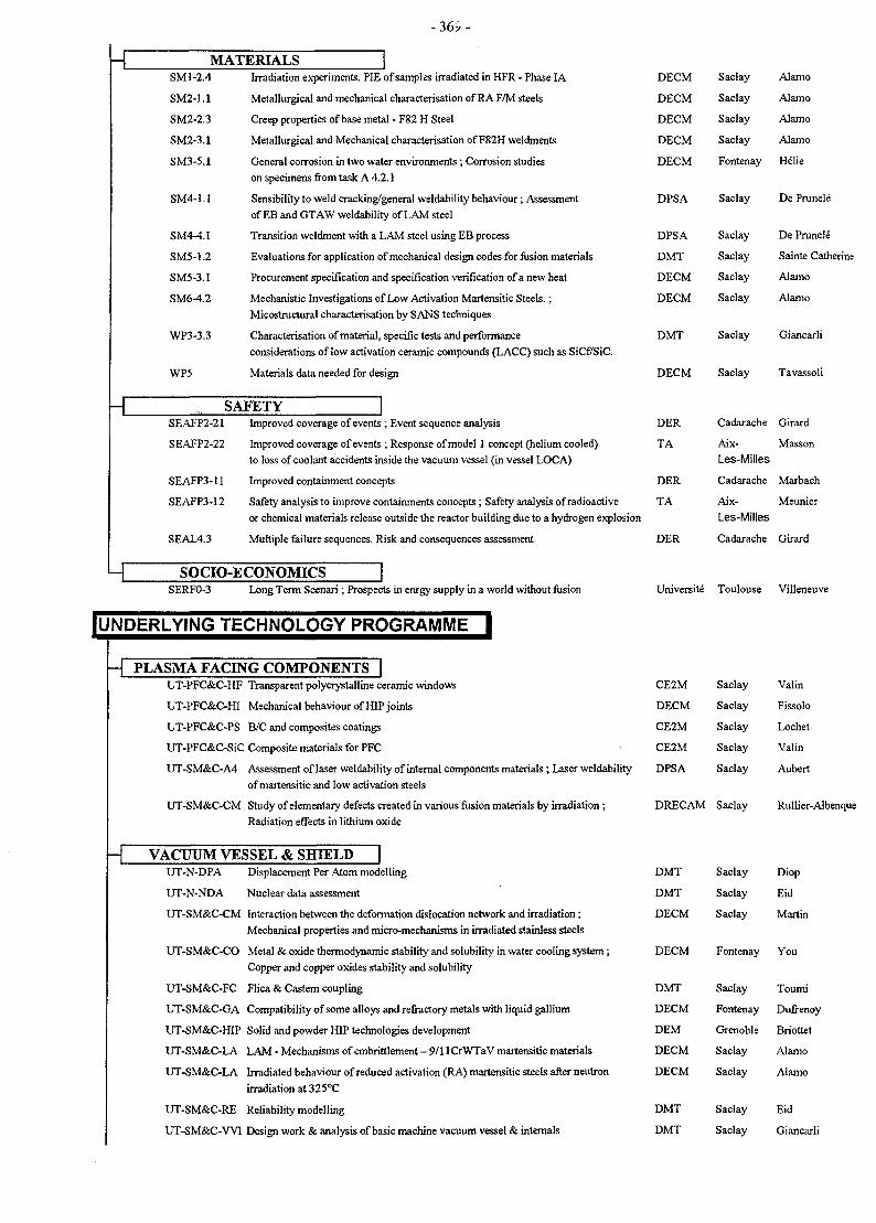
- 3 6 ? -
-c MATERIALSSM 1-2.4 Irradiation experiments. PIE of samples irradiated in HFR - Phase IA
SM2-1.1 Metallurgical and mechanical characterisation of RA F/M steels
SM2-2.3 Creep properties of base metal - F82 H Steel
SM2-3.1 Metallurgical and Mechanical characterisation of F82H weldments
SM3-5.1 General corrosion in two water environments; Corrosion studieson specimens from task A 4.2.1
SM4-1.1 Sensibility to weld cracking/general weldability behaviour; Assessment
of EB and GTAW weldability of LAM steel
SM4-4.1 Transition weldment with a LAM steel using EB process
SM5-1.2 Evaluations for application of mechanical design codes for fusion materials
SM5-3.1 Procurement specification and specification verification of a new heat
SM6-4.2 Mechanistic Investigations of Low Activation Martensitic Steels.;Micostructura! characterisation by SANS techniques
WP3-3.3 Characterisation of material, specific tests and performanceconsiderations of low activation ceramic compounds (LACC) such as SiCfTSiC.
WP5 Materials data needed for design
-L SAFETYSEAFP2-21 Improved coverage of events ; Event sequence analysis
SEAFP2-22 Improved coverage of events ; Response of model 1 concept (helium cooled)to loss of coolant accidents inside the vacuum vessel (in vessel LOCA)
SEAFP3-11 Improved containment concepts
SEAFP3-12 Safety analysis to improve containments concepts; Safety analysis of radioactive
or chemical materials release outside the reactor building due to a hydrogen explosion
SEAL4.3 Multiple failure sequences. Risk and consequences assessment
SOCIO-ECONOMICSSERFO-3 Long Term Scenari ; Prospects in enrgy supply in a world without fusion
IUNDERLYING TECHNOLOGY PROGRAMME I
H PLASMA FACING COMPONENTS |UT-PFC&C-HF Transparent polycrystalline ceramic windows
UT-PFC&C-HI Mechanical behaviour of HIP joints
UT-PFC&C-PS B/C and composites coatings
UT-PFC&C-SiC Composite materials for PFC
UT-SM&C-A4 Assessment of laser weldability of internal components materials; Laser weldability
of martensitie and low activation steels
UT-SM&C-CM Study of elementary defects created in various fusion materials by irradiation;Radiation effects in lithium oxide
-T VACUUM VESSEL & SHIELDUT-N-DPA Displacement Per Atom modelling
UT-N-NDA Nuclear data assessment
UT-SM&C-CM Interaction between the deformation dislocation network and irradiation;Mechanical properties and micro-mechanisms in irradiated stainless steels
UT-SM&C-CO Metal & oxide thermodynamic stability and solubility in water cooling system;Copper and copper oxides stability and solubility
UT-SM&C-FC Flica & Castem coupling
UT-SM&C-GA Compatibility of some alloys and refractory metals with liquid gallium
UT-SM&C-HIP Solid and powder HIP technologies development
UT-SM&C-LA LAM - Mechanisms of embrittlement - 9/1 lCrWTaV martensitic materials
UT-SM&C-LA Irradiated behaviour of reduced activation (RA) martensitic steels after neutron
irradiation at 325°C
UT-SM&C-RE Reliability modelling
UT-SM&C-WI Design work & analysis of basic machine vacuum vessel & internals
DECM
DECM
DECM
DECM
DECM
DPSA
DPSA
DMT
DECM
DECM
DMT
DECM
DER
TA
DER
TA
DER
Saclay
Saclay
Saclay
Saclay
Fontenay
Saclay
Saclay
Saclay
Saclay
Saclay
Saclay
Saclay
Cadarache
Aix-Les-Milles
Cadarache
Aix-Les-Milles
Cadarache
Alamo
Alamo
Alamo
Alamo
Helie
De Prunele
De Prunele
Sainte Catherine
Alamo
Alamo
Giancarli
Tavassoli
Girard
Masson
Marbach
Meunier
Girard
Universite Toulouse Villeneuve
CE2M
DECM
CE2M
CE2M
DPSA
DRECAM
Saclay
Saclay
Saclay
Saclay
Saclay
Saclay
Valin
Fissolo
Lochet
Valin
Aubert
Rullier-Albenque
DMT
DMT
DECM
DECM
DMT
DECM
DEM
DECM
DECM
DMT
DMT
Saclay
Saclay
Saclay
Fontenay
Saclay
Fontenay
Grenoble
Saclay
Saclay
Saclay
Saclay
Diop
Eid
Martin
You
Toumi
Dufrenoy
Briottet
Alamo
Alamo
Eid
Giancarli
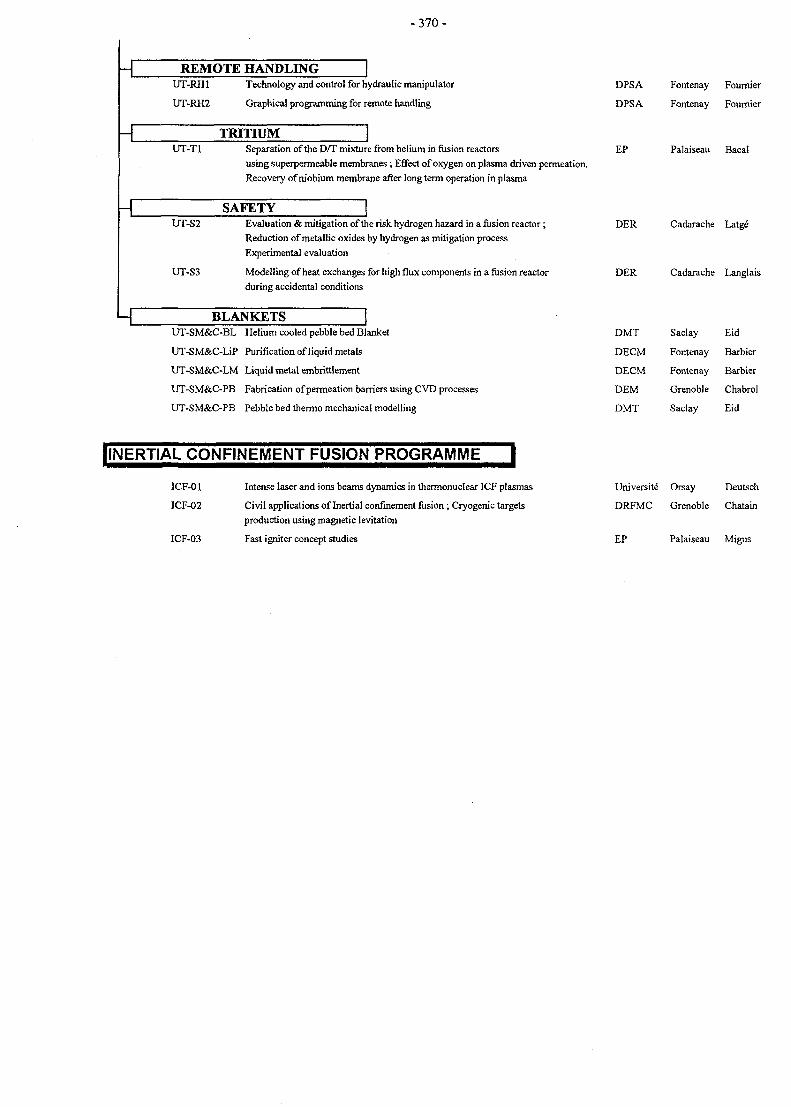
- 3 7 0 -
REMOTE HANDLINGUT-RH1 Technology and control for hydraulic manipulator
UT-RH2 Graphical programming for remote handling
TRITIUM JUT-TI Separation of the D/T mixture from helium in fusion reactors
using superpermeable membranes; Effect of oxygen on plasma driven permeation.Recovery of niobium membrane after long term operation in plasma
SAFETYUT-S2 Evaluation & mitigation of the risk hydrogen hazard in a fusion reactor;
Reduction of metallic oxides by hydrogen as mitigation processExperimental evaluation
UT-S3 Modelling of heat exchanges for high flux components in a fusion reactorduring accidental conditions
BLANKETSUT-SM&C-BL Helium cooled pebble bed Blanket
UT-SM&C-LiP Purification of liquid metals
UT-SM&C-LM Liquid metal embrittlement
UT-SM&C-PB Fabrication of permeation barriers using CVD processes
UT-SM&C-PB Pebble bed thermo mechanical modelling
DPSA
DPSA
EP
Fontenay
Fontenay
Palaiseau
Fourruer
Fournier
Bacal
DER
DER
DMT
DECM
DECM
DEM
DMT
Cadarache
Cadarache
Saclay
Fontenay
Fontenay
Grenoble
Saclay
Latge
Langlais
Eid
Barbier
Barbier
Chabrol
Eid
HNERTIAL CONFINEMENT FUSION PROGRAMME I
ICF-01 Intense laser and ions beams dynamics in thermonuclear ICF plasmas
ICF-02 Civil applications of Inertial confinement fusion; Cryogenic targetsproduction using magnetic levitation
ICF-03 Fast igniter concept studies
Universite Orsay Deutsch
DRFMC Grenoble Chatain
EP Palaiseau Migus
-371 -
APPENDIX 3 : REPORTS and PUBLICATIONS (1997)
BASIC MACHINE
PLASMA FACING COMPONENTS
P. Magaud, F. Le Vagueres (eds.), Fusion Technology, 1996 Annual Report of theAssociation CEA/EURATOM, Task CNET 96-412, CEA DSM/DRFC, May 1997.
ITER Baffle Module Small-scale Mock-ups : First Wall Thermo-mechanical Testing Results Y. Severi, P. Chappuis, L. Giancarli, G.Proceeding of ISFNT-4, April 6-11,1997, Tokyo, Japan. Le Marois, Y. Poitevin, M. Rodig, J.F.
Salavy, G. Vieider
P. Magaud, F. Le Vagueres (eds.), Fusion Technology, 1996 Annual Report of theAssociation CEA/EURATOM, Task UT-WI-1, CEA DSM/DRFC, May 1997.
Iter DPI task T212. Development and testing of Cu alloys/316LN SS joints by solid HIPNT DEM 97/11
Burlet H., Gentzbittel J.M., Bernier F.,Mourniac P., Labonne C.
Iter DPI task T212b. Fracture testing of Cu alloys/316LN SS joint interfaceNT DEM 97/42
Burlet H., Gentzbittel J.M., Bucci P., Chu
Iter DPI task T212b. Fracture testing of Cu alloys/316LN SS joint interfaceNT DEM 97/77
Burlet H., Bucci P., Chu I.
Development and characterisation of Be/Cu alloy HIP joint, ITER Task T216aNT DEM n°80/97, 29 Dec. 1997.
F. Saint-Antonin, G. Bourgeois, P. Bucci,H. Buiiet
Development of Be/Glidcop® joint obtained by Hot Isostatic Pressing diffusion bonding forhigh in-service temperature3rd international Beryllium Workshop, 22-24 October 1997, Mito (Japan).
F. Saint-Antonin, P. Bucci, D. Barberi, H.Burlet, A. Laille, G. Le Marois
Development and characterisation of Be/Glidcop® joint obtained by Hot Isostatic Pressingfor high temperature working conditions8th Int. Conf. on Fusion Reactor Materials, Oct. 26-31,1997, Sendai (Japon) in press.
F. Saint-Antonin, D. Barberi, G. LeMarois, A. Laille
Thermal properties changes induced by thermal shock tests on NS31 silicon doped carbon J.P. BONAL, J.B. PLANCHERfiber compositeRapport DMT 97/077
Thermal annealing of irradiatod carbon fiber composites used for fusion applicationsRapport DMT 97/150
J.P. BONAL
T222.4 bis, Intermediate Report 1, Comparison between one-side peaked and uniformincident heat flux on the divertor target; reference heat transfer correlationP/CO/96-013, Jan. 97.
F.Escourbiac, J.Schlosser
T222.4 bis, Intermediate Report 2, Design of a Glidcop mock-up for macroblock simulation F.Escourbiac, J.SchlosserP/CO/96-012, Jan. 97.
T222.4 bis, Intermediate Report 3, Lay-out of the mock-upsNT/CO/97/06, June 97.
J.Schlosser
- 3 7 2 -
T222.4 bis, Intermediate Report 4, Review about CHF tests on CEA ST22, ST23, ST24,ST082, ST083 and ST084 mock-upsNT/CO/97/11,Oct.97.
F.Escourbiac, J.Schlosser
T222.4 bis, Intermediate Report 5, Critical Heat Flux Data Base of Association Euratom-CEA for High Heat Flux componentsNT/CO/97/14, Nov. 97.
J.Schlosser, J. Boscary, F.Escourbiac
T222.4ter, Test procedure for thermal-hydraulic divertor mock-ups target ST22bis andST22terto be referenced, Sept. 97.
J.Schlosser
T222.15, Intermediate report 1, Definition and location of calibrated defects for monoblocktype mock-upsto be referenced, Oct. 97.
J.Schlosser
VACUUM VESSEL and SHIELD
ITER Task CTA-EU-T10 - Progress report on 316L SS In-pile Corrosion TestingRT SCECF 442 (December 1997)
M. HELIE
International Colloquium, Processing on Stainless Steels, Mons, Belgium, April 1997 R. Couturier, J.M. Genzbittel, H. Burlet,F. Moret
Mechanical Properties of HIP Bonded Joints of 316LN SteelProgress Report ITER Task T214 NT DEM/CEA N°97/25
Mechanical Properties of HIP Bonded Joints of 316LN SteelProgress Report ITER TaskT214: Sub-tasks CEA-9, CEA-10, CEA-11, NT DEM/CEAN°97/66
J.M. Gentzbittel, G. Nombalais; B. Ricetti,H. Burlet.
J.M. Gentzbittel, G. Nombalais; B. Ricetti,H. Burlet.
Development of a thermal bond layer: Study of compliant layer for in-situ rebrazing. Statuson the Improvement of the thixotropic alloyITER TaskT224, Note Technique n°55/97,1 October, 1997.
J. Valer, P. Meneses, F. Saint-Antonin,M. Suery, G. Le Marois
Development of a thermal bond layer: Study of compliant layer for in-situ rebrazing. Dataproperties review on Al-Ge alloysITER Task T224, Note Technique n°79/97, 23 Dec. 1997.
J. Valer, P. Meneses, F. Saint-Antonin,M. Suery, G. Le Marois
Developpement d'une brasure base Al-Ge a comportement thixotropeJournees Franco-Espagnoles, Grenoble (France), 27-29 nov. 1997.
Primary water loops technology (1997)Final Report on the task T 50
Ions beam irradiation of water saturated with hydrogen, experiments and simulations (1997)First intermediate report on the task T330
J. Valer, P. Meneses, F. Saint-Antonin,M. Suery
B. Hickel and E. Bjergbakke
B. Hickel and E. Bjergbakke
MAGNETS
TFMC : Analysis of the First Ansaldo Compaction TestNote NT/EM/97/50 - November 11,1997
FE Analysis of the Voltage Distribution in the SS-FSJSNote NT/EM/97/51 - November 18, 1997
Summary of the Instrumentation for the SS-FSJSNote NT/EM/97/38 - August 8,1997
NET Contract 96/432 : Modelling, Testing and Analysis of Full-Size ITER Joints :Preliminary Report on Analysis MethodNote NT/EM/97/21 - April 25,1997.
P. DECOOL, J.M. VERGER, H. CLOE2
P. DECOOL
D. CIAZYNSKI
D. CIAZYNSKI
- 3 7 3 -
NET Contract 96/432 : Modelling, Testing and Analysis of Full-Size ITER Joints : Report on D. CIAZYNSKI3-D Model and Analysis of Two Load CasesNote NT/EM/97/53 - December 2,1997.
EU-SS-FSJS : Analysis of the First Ansaldo Compaction TestNote NT/EM/97/22 - June 10,1997.
Field and temperature dependencies of critical current on industrial Nb3Sn strandsCyogenics 37 (1997) 865-875.
P. DECOOL, J.M. VERGER
A. Martinez, J.L Duchateau
First results of strain effects on critical current of incoloy jacketed Nb3Sn CICC'sPresented at MT-15, Oct 20-24, Beijing, China.
W. Specking, J.L Duchateau, P. Decool
Critical current vs strain tests on EU strands and subsize cable in conduits with stainless W. Specking, J.L Duchateau, P. Decoolsteel and incoloy jacketsITER Task GB5-M29 Final report October 1997.
Experimental checking of an a.c. losses model for superconducting twisted cable-in-conduit T Schild, S. Negroni, D. Ciazynski, J.LPresented at ICMC, July 1997, Portland, Oregon, US. Duchateau
Prediction of eddy currents in the ITER TF Model Coil experiment using the code CORFOU P. Hertout et al.ISTET97, Palerme, Italy, June 1997
Numerical evaluation of the quench behaviour of the ITER Toroidal Field Model CoilICMC97, Portland OR, USA, July 1997
R. Heller et al.
Construction of a Toroidal Field Model Coil for ITERMT15, Beijing, China, October 1997
Final report M48 part 1: Tests of two Nb3Sn ITER strands under various field anglesNote NT/EM/97.40, September 22, 1997
E. Salpietro et al.
T. SCHILD, H. CLOEZ
Task M48: Test of one modified MWIN-2 subsize joint sample for the TFMCNote NT/EM/97.08, February 17, 1997
P. DECOOL
REMOTE HANDLING
ITER : Controle par ultrasons des tuyauteries de 160 mm. Evaluation de la methode enlaboratoireSTA/LMUS RT3669.
M. WOJTOWICZ
Projet ITER : controle par ultrasons des tuyauteries 160 mm. Description et specifications M. WOJTOWICZde fonctionnement de I'acquisitionSTA/LMUS RT3602.
Magnet feeder lines and cryogenic connectors Maintenance- T329-2-Task Report-Detailed JP FRICONNEAUtechnical specificationsCEA/DPSA/STR- ref. str/lam/96.116 rel. 0, Nov 96.
Magnet feeder lines and cryogenic connectors Maintenance- T329-2-lntermediate TaskReportCEA/DPSA/STR- ref. str/lam/97.089 rel. 0, July 97.
J. JOUAN, JP FRICONNEAU
Magnet feeder lines and cryogenic connectors Maintenance- T329-2-Cryogenic linemaintenance with one manipulatorCEA/DPSA/STR- ref. str/lam/97.138 rel. 0, Dec. 97.
J. JOUAN, JP FRICONNEAU
- 3 7 4 -
Analysis of the present access limit for Remote Handling requirements - Ex. VesselTransporter - T329-3 - Intermediate Task reportCEA/DPSA/STR- ref. str/lam/96.117, March 1997,
J-P FRICONNEAU
Detailed Description of Top Access Transporter - Ex. Vessel Transporter - T329-3 -Intermediate task reportCEA/DPSA/STR- ref. str/Iam/97.126, Feb 1998,
J-P FRICONNEAU
SAFETY
Minutes of the ITER Safety meeting 21-25/04/97NT DER/STML/FUSION 97.043
G. MARBACH
Preliminary analysis of the ITER Safety ApproachNT DER/SIS/LSS/97.32
G.L. FIORINI
ITER safety implementation and reliability/availability of Heat Transfer SystemsNT DER/STML/LCFI 97/061
C. Girard, A. Ellia-Hervy, G. Saint Paul
Sequence Analysis Workshop - ITER task SEA1-2CRR DER/STML/LCFI 97/235
C. Girard
Participation to the ITER NSSR-2 volume X - Master Logic DiagramNT DER/STML/LCFI 97/054
C. Girard
ISAS : on line documentation based on HTML 3.2 languageCEA report DMT 95/574 December 1997
ISAS : Description of ATHENA, INTRA, NAUA and SAFALY coupling for safety analysisCEA report DMT 97/575 December 1997
Th. De Gramont, I. Toumi
Th. De Gramont, I. Toumi
ICE FACILITY: 3rd set of precalculations of in vessel LOCA'sTA11934
ITER (NSSR2) Safety analysis of loss of coolant accidents on the JCT breeding blanketdesignTA-31902
Thermodynamic stability and solubility of copper and copper oxidesRapport Technique SCECF 420 (Mai 1997)
PACTITER : A PACTOLE adaptation for copperNote Technique DEC/SECA/LTC 97-123
Ingots tritium mass activity measurement from melting of tritiated metalsNote Technique STML/LEPE 98/007.
ITER Decommissioning strategyNT DER/STML/97.90
D. YOU, S. LEFEVRE, P. GERLINGER,A. CHENIERE
D. TARABELLI, J.C. ROBIN
J.P. DACLIN, S. ROSANVALLON
G.MARBACH
LONG TERM PROGRAMME
BLANKET PROGRAMME
Contribution to the Preliminary Design of the ITER Breeding BlanketCEA Report, SERMA/LCA/RD/98-2179/A (1998).
M. Eid, J.M. Gay, L. Giancarli, G.Marbach, X. Masson, Y. Poitevin
liquid Metal Blanket
Turbulence in MHD flow shear layers ;1997 progress reportNT DER/STMULCFI 97/049
G. Laffont (DER/STML/LCFI), R.Moreau (MADYLAM - Grenoble)
- 3 7 5 -
Two dimensional numerical simulation of a MHD turbulent shear flow3rd Pamir Conf., Aussois, France, Sept.22-26,1997
Quasi-2D MHD shear layers11th Turbulent Shear Flows, Grenoble, France, Sept. 8-10,1997
Y. Delannoy, R. Moreau
T. Alboussiere, V. Ujpenski, R. Moreau
An experimental investigation on quasi-2D turbulence in MHD shear flows3rd Pamir Conf., Aussois, France, Sept.22-26,1997
T. Alboussiere, V. Ujpenski, B. Pascal,R. Moreau
Recent theorical and experimental results on MHD turbulenceInt. Workshop on Liquid Metal Blanket, Experimental Activities, CEA, Paris, France, Sept.16-18,1997
T. Alboussiere, V. Ujpenski, R. Moreau
P. Magaud, F. Le Vagueres (eds.), Fusion Technology, Annual Report of the AssociationCEA/Euratom 1996, Task WP-A-1.2, CEA DSM/DRFC, May 1997.
Impact of new specifications for the water-cooled lithium-lead (WCLL) DEMO blanketCEA report DMT 97/546, December 1997.
L. Giancarli, G. Aiello, M. A. Fiitterer, J.F. Salavy
Development of the EU water-cooled Pb-17Li blanketProc. ISFNT-4, Tokyo, Japan, April 7-11, 1997.
L. Giancarli, G. Benamati, M. A. Futterer,G. Marbach, C. Nardi, J. Reimann
Neutronic and photonic analysis of the single box water-cooled lithium lead blanket for aDEMO reactorProc. ISFNT-4, Tokyo, Japan, April 7-11,1997.
G. Vella, L. Giancarli, E. Olivieri, G. Aiello
The development of tritium permeation barriers for blanketsProc. ISFNT-4, Tokyo, Japan, April 7-11,1997.
P. Magaud, F. Le Vagueres (eds.), Fusion Technology, Annual Report of the AssociationCEA/Euratom 1996, Task WP-A-1.2, CEA DSM/DRFC, May 1997.
A. Perujo, L. Giancarli, T. Terai
Design development and manufacturing sequence of the European water-cooled Pb-17Li M. A. Futterer, B. Bielak, J.-P. Deffain, C.test blanket module Dellis, L. Giancarli, A. Li Puma, C. Nardi,Proc. ISFNT-4, April 7-11,1997, Tokyo, Japan. J.-F. Salavy, K. Schleisiek, J.
Szczepanski
Water-cooled Pb-17Li test blanket module for ITER: Impact of the structural material grade G. Vella et al.on the Neutronic responsesProc. ICFRM-8, 27-31 October 1997, Sendai, Japan.
Design Description Document for the European water-cooled Pb-17Li Test Blanket Module M. A. Futterer et al.(final version)CEA report DMT 97/549, December 1997.
P. Magaud, F. Le Vagueres (eds.), Fusion Technology, Annual Report of the AssociationCEA/Euratom 1996, Task WP-A-1.2, CEA DSM/DRFC, May 1997.
Activation and tritium production in the alkaline doped cooling water of the water-cooled Pb- J.-P. Deffain, M. A. Futterer17Li test module for ITER - Definition of coolant chemistryCEA report DMT 97/181
ITER test module subsystemCEA NT DER/STML/LCFI 97-213
Y. SEVERI
ITER test module subsystem Y. SEVERIDefinition and sizing of the main ancillary components, CEA NT DER/STML/LCFI 97-360
- 3 7 6 -
DEMO blanket testing in ITER and the international collaboration via the ITER Test Blanket Proust, Abdou, Gohar, Pai'dassi, Parker,Working Group Stebkov, TakatsuProc. ISFNT 4, April 7-11,1997, Tokyo, Japan
Interfaces between the WCLL-TBM and ITER including test program : Contributions to the Futterer, Giancarli, SzczepanskiTBWG and exchanges with the ITER JCTCEA report DMT 97/556
Design Description Document for the European water-cooled Pb-17Li test blanket moduleCEA report DMT97/441 (Sept. 97)
M. Futterer et al.
One-dimensional neutronic, activation and decay-heat analysis of the WCLL Test BlanketModuleCEA report DMT 97/567, December 1997.
J.-P. Deffain, M. A. Futterer
Double wall tube fabrication by hot isostatic pressing. Modelling and fabrication of straightsmall size mock upsNT DEM n° 72/97.
E. Rigal, L. Briottet
Specifications pour I'etude de fabrication d'un dispositif d'essais de tubes a double paroiNT. DER/ STML/ LCFI - 97-001. (21/01/1997)
Specifications pour la fabrication d'un dispositif d'essais de tubes a double paroiNT. DER/ STML/ LCFI - 97-017. (05/ 06/1997)
Appel d'offres - Specifications pour I'etude et la realisation du controle-commande dudispositif d'essais DIADEMONT. DER/ STML/ LCFI - 97-024. (31/ 08/1997)
Water-Cooled Pb-17Li Blanket - Diademo Experimental Programme for Testing Double-Walled TubesIEA International Workshop on "Liquid Metal Blanket Experimental Activities", September 1618,1997. CEA Headquarters, PARIS
Task WPA3.4.1 - ITER Test Module - Manufacturing routeTechnical Note D.E.M. N°62/97.
Structural Material by Powder HIP for Fusion Reactorspresented at the 8th International Conference on Fusion Reactor Materials.
Ch. Dellis, E. Rigal, G. Le Marois
Ch. Dellis, G. Le Marois, E.V. Van Osch
HIP RAF Steel Fabrication - Technology and IssuesTechnical Note D.E.M. N°53/97
G. Le Marois, C. Dellis, H. Burlet, R.Couturier, F. Moret
Application of the flux distorsion flow-meter to the lithium-lead test facilities. Study of a testfacility in order to show the influence of different sorts of flow of lithium-lead on the flow-meterNT LEET 97/058
D. PIATandG. QUILICHINI
Pablito test facility. Directions for useNT LEET 97/038
Ph. PERCETTI
Standard mechanical pump for lithium-lead. Application for PABLITO test facilityNT LEET 97/062
D. PIAT
Specifications for a lithium-lead pump for PABLITO test facilityDQ LEET 97/051
D. OUDELET
Permeation barrier fabrication by hot isostatic pressing and chemical vapor depositionNote Technique DEM n° 73/97.
C. Chabrol, E. Rigal, F. Schuster
- 3 7 7 -
Elaboration of Fe-AI coatings by a new pack-cementation process for tritium permeationbarriersProceedings of the 1rst International Workshop on Liquid Metal Blanket ExperimentalActivities, Sept. 16-18,1997,
F. Schuster, C. Chabrol, C. Locatelli, V.Benevent, E. Rouviere, S. Anderbouhr
Tritium permeation barrier testing devicesCEA Report, RT SCECF 448 (December 1997)
Hydrogen Extraction from Pb-17Li: tests with a packed columnProceedings of the 4th International Symposium on Fusion Nuclear Technology, April 6-11,1997, Tokyo Japan, to appear in Fusion Engineering and Design
A. TERLAIN, T. DUFRENOY
N. ALPY, T. DUFRENOY, A.TERLAIN
Hydrogen Extraction from Pb-17Li: tests with a packed columnProceedings of the First International Workshop on Liquid Metal Blanket ExperimentalActivities, September 16-18,1997, Paris
N. ALPY, T. DUFRENOY, A. TERLAIN
Hydrogen Extraction from Pb-17Li: 1997 results on the packed column running and 1998viewsCEA Report, RT-SCECF 446 (December 1997)
N. ALPY, A.TERLAIN, M. PERROT, T.DUFRENOY
Safety approach of the DEMO reactorNTDER/STML/97.100
G. MARBACH
ITER test blanket modules, General Safety approachReport TA-6322
VINCENT
CEA Contribution to the reliability/availability assessment of DEMO & reliability data baseactivitiesDMT 97/562, SERMA/LCA 2159,1997.
M. Eid
Reliability/Availability Assessment of the Water-Cooled lithium Lead-ITER Test ModuleDMT 97/262, SERMA/LCA 2062, 1996.
B. Bielak, M. Eid,
Assessment of the pressure peak in the LIFUS experimentNT DER/SERA/LETH 97/5030
SARDAIN
P. Magaud, F. Le Vagueres (eds.), Fusion Technology, Annual Report of the AssociationCEA/Euratom 1996, Task WP-A-7.2, CEA DSM/DRFC, May 1997.
WCLL Test Blanket Module for ITER: Thermal, mechanical, thermo-mechanical and LOCA M. Futterer, J. F. Salavy, L. GiancarlianalysisCEA report DMT97/494.
* Solid Breeder Blanket
Neutronic & Thermal characteristics of the HCPB blanket in the case of the use of thezirconate/titanateCEA report, DMT 97/552, SERMA/LCA 2155.
J.F. Salavy, M. Eid
Contribution of the CEA to the HCPB ITER Test Blanket Feasibility & Design Studies, Part Y. Poitevin, L. Giancarli1CEA report, SERMA/LCA/97-2141, Nov. 1997.
Feasibility of first wall manufacturing by hot isostatic pressing - HCPB conceptNT DEM n° 71/97.
E. Rigal
CEA Contribution to the reliability/availability assessment of DEMO & reliability data baseactivitiesDMT 97/562, SERMA/LCA 2159, 1997.
M. Eid
- 3 7 8 -
First results of the investigation of Li2ZrO3 and Li2TiO3 pebblesPresented at IFNST 4 (1997), to be published in Fusion Engineering and Design.
J.D.Lulewicz, N.Roux
Progress in the development of Li2ZrO3 and Li2TiO3 pebblesCBBI6(1997)
Compilation of properties data for Li2TiO3CBBI6{1997)
J.D.Lulewicz, N.Roux
N.Roux
MATERIALS
Progress report of creep tests on F82H : base metal, TIG and EB weld jointsC.R. SRMA 97-1588, Dec. 1997.
B. Girard, L. Allais
Coupons d'acier F82H soudes par procede faisceau d'electrons et TIG (provenance A. FONTES - F. CASTILANJAERI). Caracterisation metallurgique 2eme partie et caracterisation mecanique 1ere partieSTA/LMS/98-RT 3650/AG/MLL, Janvier 1998
Progress report of creep tests on F82H : base metal, TIG and EB weld jointsC.R. SRMA 97-1588, Dec. 1997
B. Girard, L. Allais
Soudabilite par procede faisceau d'electrons de I'acier martensitique a faible activation F82H(2eme partie)STA/LMS/97-RT 3554, 15/08/97
A. FONTES, P. GREINER, M. BARRAS,
Soudabilite par procede faisceau d'electrons d'un joint de transition entre I'aciermartensitique a faible activation F82H (Z9CWV 08 02) et un acier inoxydable a azotecontrole (Z2CND 1712), 1ere partieSTA/LMS/98-RT3660, mars 1998
A. FONTES, P. GREINER, F.CASTILAN
Procurement Specification of a Reduced Activation Ferritic/Martensitic Steel Type9CrWTaVEBP Task 5.3, May 1997, SRMA 97/385
W. Dietz, A. Alamo, R. Lindau
Microstructural characterisation of EM10.HT9, F82H, JLF1 by small angle neutronscatteringNote technique LLB/97/170-LS1/98/01, December 97.
M.H. MATHON, G. GEOFFROY, C.H.DE NOVION, Y. DE CARLAN, A.ALAMO
Fusion Technology, 1996 Annual Report of the Association CEA/Euratom, Task WP 3-3.3.Compiled by P. Magaud (May 1997).
Design Requirements for SiCf/SiC Composite Structural Material in Fusion Power ReactorBlanketsProceeding of ISFNT-4, April 6-11,1997, Tokyo, Japan.
L. Giancarli, J.P. Bonal, A. Caso, G. LeMarois, N.B. Morley, J.F. Salavy
Preliminary Assessment of the Use of SiCf/SiC as Structural Material for Breeding Blanketin Fusion Power ReactorsCEA Report DMT 97/400, SERMA/LCA/2104, October 1997.
L. Giancarli
Materials data needed for designIEA Workshop on Reduced Activation Ferritic/Martensitic Steels, JAERI Headquarters,Tokyo, Japan, November 3-4,1997
F. Tavassoli
SAFETY
Seafp2 - Macrotask 2 : coordination meetingCRR DER/STML/LCFI 97/367
Seafp2 macrotask 2 - complementary informationref. DER/STML/LCFI 97/435
-379-
SEAFP-2: Accidents on divertor loops - parametric studyNT: DER/STML/LCFI 97/013
SEAFP2 : RESPONSE OF MODEL 1 CONCEPT (HELIUM COOLED) TO LOSS OFCOOLANT ACCIDENTS INSIDE THE VACUUM VESSEL(IN-VESSEL LOCA)
Safety analysis of radiacth/e or chemical materials release outside the reactor building due to M. MEUNIER, J.M GAYon hydrogen explosionTA-26 310
First reflexions on the Safety Options of a fusion reactorNT DER/STML/97.98ind a
G.MARBACH
SEAFP2-Safety analysis of radioactive or chemical materials release outside the reactorbuilding due to a hydrogen explosionTA-26310 Ind. A
Publication on Annual Meeting On Nuclear Technology '98, May 26-28,1998
Loss of the condenser in SEAFPNT : DER/SERA/LETH 97/5018
P. Sardain
LOCA transients in SEAFP - A sensitivity analysisNT: DER/SERA/LETH 97/5031
J.P. Gaillard
Loss of the condenser in SEAFP - sensitivity studiesNT: DER/SERA/LETH 97/5032
J.P. Gaillard
UNDERLYING TECHNOLOGY PROGRAMME
PLASMA FACING COMPONENTS
Potentiates de MgAI2O4 dans les machines de fusionCEA/DTA/CEREM/CE2M/LECMA DT 97/048 - 4/07/1997
F. Valin
Realisation et caracterisation de composites multicouches B4C/WDTA/CEREM/CE2M/LECMA D.T.97/059 -30 /09/97
N. Lochet
Densification du carbure de silicium. Raport M.2CEA/DTA/CEREM/CE2M/LECMA R.T. 97/060 23/10/97
F.Valin
Caracterisation mecanique des soudures par laser CO2 en epaisseur 6 mm des aciers JLF1 Ph. AUBERT, A. RICHARD, J.et F82H. Etude comparative du comportement des joints soudes SCHILDKNECHTDPSA/CLFA/97-NT002/PhA/NA, Novembre 1997
Comportement du soudage en position de 1'acier ferrito-martensitique a faible activationF82H en epaisseur 6 mm. Etude comparative du comportement des joints soudes encomiche et verticale montante par laser YAGDPSA/CLFA/97-NT007/PhA/NA, Janvier 1998
Ph. AUBERT
Phys. Rev. B 55,11263 (1997). F. Beuneu, P. Vajda, G. Jaskierowicz, M.Lafleurielle
REI-9, IX Int. Conf. on Radiation Effects in Insulators, Knoxville 1997; Nucl. Instr. Meth. B F. Beuneu, P. Vajda, O.J. Zogal(1998).
ICFRM-8, VIII Int. Conf. on Fusion Reac-tor Materials, Sendai 1997; J. Nucl. Mat. (1998). P. Vajda, F. Beuneu
Phys. Rev. B 55,10278 (1997). S. Albrecht, G. Onida, L. Reining
- 3 8 0 -
VACUUM VESSEL and SHIELD
Une méthode de calcul des déplacements par atome dans les solides polyatomiques1996. CEA report.
D. Simeone
Création d'une bibliothèque neutron-gamma d'origine FENDL et JEF-2 pour le code SN1D G. Néron de Surgy, L. Luneville1997. CEA report.
Description des modèles de calcul de dommages du système SPECTER1997. CEA report.
An Activation library to help in the choice of the material composition of the first wall ofDEMO blanketDMT 96/604, SERMA/LCA 1987, 6/11/1996.
P. Cuendet, C. M. Diop
M. Eid
Nuclear data assessment in support of the European Fusion Program, reporting on the 1997 M. Eidactivities in the DRN/DMT/SERMADMT 97/550, SERMA/LCA 2153, November 1997.
CEA-recommandations for the ITER-Breeder Blanket neutronic experimentDMT 97/523, SRMA/LCA 2133, September 1997.
M. Eid
ICFRM 8, Sendaï, Japon, 27-31 October 1997.
Thermodynamic stability of copper/copper oxides systemCEA Report, RT-SCECF 440 (December 1997)
Spécifications du système de couplage de codes ISAS2DMT 97-581, CEA/DMT report, November 1997.
Compatibility of materials (steel and vanadium alloy) with liquid galliumRT SCECF 432 (October 1997)
Solid and powder Hip technologies development, UT-SM&C-HIP, Milestones R1Note technique DEM n° 97/67.
C. Robertson, S. Poissonnet, L.Boulanger
D. You, S. Lefevre, P. Gerlinger
P. Truelle, I. Toumi
F. BARBIER, J. BLANC
Briottet L., Burlet H., Couturier R.,Riccetti B., Chu I.
Structural materials joints for ITER in-vessel componentsISFNT-4, April 6-11 1997, Tokyo, Japan.
Le Marois G., Buriet H., Solomon R.,Marini B., Gentzbittel J.M., Briottet L.
Final report UT-SM&C-LAM1, Long term ageing behaviour of experimental 9/11 CrWTaVlow activation martensitic steelsNT SRMA mars 98
Y. de CARLAN et al.
Tensile properties of 7.5/12%Cr Martensitic Steels Irradiated at 325°C up-to 3.4 dpa inOsiris ReactorProgress Report UT-SM&C-LAM2 December 1997, NT SRMA 98-2259
Alamo, J.C. Brachet, X. Averty
Modelling of Detection Systems Ageing and its Impact on the Reactor OverallReliability/AvailabilityDMT 97/261, SERMA/LCA 2061
M. Eid
P. Magaud, F. Le Vaguères (eds.), Fusion Technology, 1996 Annual Report of theAssociation CEA/EURATOM, Tasks CNET96-412& UT-W&I-1, CEA DSM/DRFC, May1997.
Preliminary Analyses for ITER Baffle and Limiter FW with the New Attachment Concept and L. Giancarli, J.F. Salavy, J. Szczepanskifor ITER Plug LimiterCEA Report, DMT 97/233 (SERMA/LCA/2051), June 1997.

- 3 8 1 -
Interpretation des essai thermo-mecaniques dans FE200 des maquettes a « petite-echelle » M. Picat, H. Burlet, L. Giancarli, J.F.du baffle HER SalavyCEA Report, DMT 97/392 (SERMA/LCA/2101), September 1997.
Internes de la chambre a plasma d'un reacteur de puissance - Revue bibliographique despropositions recentesCEA Report, DMT 97/338 (SERMA/LCA/2088), September 1997.
L. Giancarli, G. Le Marois
Contribution of the CEA to the EU HT ITER Breeding Blanket Development and DesignCEA Report, DMT 97/316 (SERMA/LCA/2084), August 1997.
Y. Poitevin, L Giancarli
Overview of the EU small-scale mock-ups Tests for ITER High Heat Flux ComponentsProceeding of lSFNT-4, April 6-11, 1997, Tokyo, Japan.
G. Vieider, L. Giancarli, et al.
Design of the ITER EDA Plasma Facing ComponentsProceeding of ISFNT-4, April 6-11,1997, Tokyo, Japan.
A. Cardella, L. Giancarli, et al.
REMOTE HANDLING
REMOTE HANDLING TECHNIQUES, TECHNOLOGY AND CONTROL FORHYDRAULIC MANIPULATOR, 6 month ReportSTR/97.084
F. LOUVEAU
REMOTE HANDLING TECHNIQUES, TECHNOLOGY AND CONTROL FORHYDRAULIC MANIPULATOR12 month Report, STR/97.152
F. LOUVEAU
Specification de la maquette de programmation graphique (Specification of the graphicalprogramming mock-up)rapport STR/97.094, 24 juin 1997.
C. Terre & Y. Masson
Evaluation de la maquette de programmation graphique (Evaluation of the graphicalprogramming mock-up)rapport STR/97.140, 23 decembre 1997.
C. Megard & Y. Masson
TRITIUM
Plasma driven superpermeation and its possible applications to ion sources and neutralbeam injectorsRev. Sci. Instrum., 69, 935 (1998)
M. Bacal, F. El Balghiti-Sube, A.I.Livshits, M.E. Notkin, D. Riz, M.N.Soloviev, T Kuroda and M.Y. Tanaka
Rapport P.M.I. 4380, August 1997. D. Riz, M.E. Notkin, A.Yu. Doroshin, A.I.Livshits, M. Bacal
Rapport P.M.I. 3559, December 1997 D. Riz, A. Doroshin, A. Livshits, M. Bacal
Rapport P.M.I. 3580, December 1997 A. Livshits, D. Riz, M. Bacal
Plasma driven superpermeation and its possible fusion applicationsFusion Technology 1996, C. Varandas and F. Serra (editors), 1997 Elsevier Science , p.1157.
M. Bacal, F. El Balghiti-Sube, A.I.Livshits, M.E. Notkin and M.N. Soloviev
SAFETY
Experimental evaluation of hydrogen getters as mitigation technique in a fusion reactorNT/DER/STMULEPE/97/063,17 th SOFE Congress, San Diego, 6-11 Oct. 97.
V. Chaudron et al.
-382 -
Boucle MIRHABEL - Resultats et interpretation des essais d'elimination de I'hydrogene parun precede de reduction d'un oxyde metalliqueNT/DER/STML/LEPE/97/069, Oct. 97.
V. Chaudron
Validation du couplage thermique thermohydraulique de Genepi, (Task UTS3/M3)NT/DER/STML/LCFI/ 97/043
G. Langlais
Premiers resuttats du couplage thermique thermohydraulique de Genepi sur les essais des G. Langlaismaquettes DRFC, (Task UTS3/M4)NT/DER/STML/LCFI/ 97/026
Modelisation de la thermohydraulique et de la thermique dans les composants a hauts fluxd'un reacteur a fusion en situation accidentelleJITH 97, Marseille, 7-10 juillet 1997
G. Langlais et al.
BLANKETS
Contribution to the HCPB blanket design optimisation in the case of the use of thezirconate/titanate as breeder materialCEA report, DMT 97/551, SERMA/LCA 2154.
M. Eid, J.F. Salavy
Purification of liquid metals by magnetic trapping: Effect of a magnetic field on the formation F. BARBIERof deposits in Pb-17LiRT SCECF 436 (November 1997).
Magnetic field effect on the deposition of nickel in molten Pb-17Lipresented to ICFRM-8, October 26-31,1997, Sendai, Japan.
A literature survey on the mechanisms of liquid metal embrittlementRT SCECF 444 (December 1997)
CVD deposition for permeation barriersNote Technique DEM n" 98/13.
CVD deposition of TiAIN for permeation barriersNote Technique DEM n° 50/97.
Fusion Technology1996 Annual Report of the Association CEA/Euratom, Task UT-PBM, compiled by Ph.Magaud (5/1997)
F. BARBIER and A. ALEMANY
B. JOSEPH, M. PICAT and F. BARBIER
S. Anderbouhr, C. Chabrol, F. Schuster
S. Anderbouhr, C. Chabrol, F. Schuster
Un modele elasto-plastique de CASTEM-2000 utilisable pour la modelisation ducomportement mScanique d'un lit de particulesDMT 97/237, SERMA/LCA 2054.
A. Duchesne et X. Raepsaet
Status of Thermal and Thermo-mechanical Behaviour of Pebble BedsDMT 97/558, SERMA/LCA 2158
M. Eid
INERT!AL CONFINEMENT FUSION PROGRAMME
Channel Formation In Long Laser Pulse Interaction with a Helium Gas JetPhys. Rev. Lett. 79,16 (1997)
V. Malka, E. De Wispelaere, F.Amiranoff, A. Modena, R. Haroutunian,R. Bonadio, C. Coulaud, D. Puissant, C.Stenz, S. Hiiller, and M. Casanova
Second Harmonic Generation and its Interaction with Relativistic Plasma Waves Driven byForward Raman Instability in Underdense PlasmaPhysics of Plasma 4,1127, (1997)
Anomalous absorption of very high-intensity laser pulses propagating through moderatelydense plasmaPhys. Rev. Lett, (accepte, 1997)
V. Malka, A. Modena, Z. Najmudin, A. E.Dangor, C. E. Clayton, K. A. Marsh, C.Joshi, C. Danson, D. Neely, and F. N.Walsh
J.-C.Adam, A.Heron, S.Guerin, G.Laval,P.Mora, et B.Quesnel
-383 -
APPENDIX 4 : CEA TASKS IN ALPHABETICAL ORDER
CNET 94-345
CNET 95-375
CNET 96-409
CNET 96-412
CNET 96-427
CNET 96-432
CNET 97-454
ICF-01
ICF-02
ICF-03
M29
M30
M40
M48
M53
NWC2-2T10T217
SEA 1-11
SEA 1-12
SEA 1-2
SEA 3-1
SEA 3-5
Design study on ITER joints 43
High heat flux tests of NET-ITER divertor mock-ups 5
ITER cryoplant design evaluation 45
ITER outboard baffle : design, analysis, technical specifications & follow-up
of fabrication & testing of mock-ups and prototypes 7
Characteristics of jet dust after divertor operation 77
Technical specifications for modelling, testing and analysis
of full size ITER joints 47
Contribution to the preliminary design of the ITER breeding blanket 113
Intense laser and ions beams dynamics in thermonuclear I.C.F. plasmas 351
Civilian application of inertial confinement fusion 355
Fast igniter concept studies 359
Conductor fabrication - ITER Conductor R&D and monitoring 51
Conductor fabrication - ITER Conductor R&D coordination 55
Design work on magnet R&D 57
Winding and insulation development 61
80K ITER shield performances measurement 63
Aqueous corrosion
Aqueous corrosion of in-vessel component structural materialsAqueous stress corrosion, irradiation assisted stress corrosion cracking andcorrosion fatigue tests of stainless steel and Cu alloys 33
Safety approach and documentation support assessment of ITER 83
Safety assessment of confinement 85
Safety approach and documentation support 89
Integrated safety analysis code system ISAS 93
In vessel safety 95
- 3 8 4 -
SEA4-1 Design basis accidents and beyond design basis accidents 99
SEAFP 2-21 Improved coverage of events - Event sequence analysis 233
SEAFP 2-22 Improved coverage of events -SEAFP 2 : Response of model 1 concept (helium cooled)
to loss of coolant accidents inside the vacuum vessel (in-vessel LOCA) 237
SEAFP 3-11 Improved containment concepts 239
SEAFP 3-12 Safety analysis to improve containments concepts 243
SEAL 4.3 Accident sequence analysis 247
SEP 1-1 Corrosion products inventory 103
SEP 3-1 Waste characterisation and strategy 105
SEP 3-3 Decommissioning strategy of ITER 107
SERF 0-3 Long term scenarios 249
SM 1-2.4 Irradiation experiments - Pie of samples irradiated in HFR - Phase 1A 197
SM 2-1.1 Metallurgical and mechanical characterisation of RAF/M steels 199
SM 2-2.3 Creep properties of base metal - F82H steel 203
SM 2-3.1 Metallurgical and mechanical characterisation of F82H weldments 205
SM 3-5.1 General corrosion in two water environment 209
SM 4-1.1 Sensibility to weld cracking/general weldability behaviour 211
SM 4-4.1 Transition weldment qualification 215
SM 5-1.2 Evaluation for application of mechanical design codes for fusion materials 217
SM 5-3.1 Procurement specification and specification verification of a new heat 219
SM 6-4.2 Mechanistic investigations of low activation martensitic steels 221
T212 Interfacial fracture toughness of Cu/SS joints 11
T214 Irradiation testing of stainless steel including weldments
and rewelding of irradiated materials 35
T216 Development and characterization of Be/Cu alloy HIP joint 15
T216-1 Attachment of blanket modules to the back-plate 65
T221-1 Thermo-mechanical characterization of CFCs 19
- 3 8 5 -
T222 Manufacture and testing of permanent components optimisation of cooling systemCompletion of critical heat flux and thermal hydraulic testing of swirl andvapotron tubes for ITER high heat flux components 23
T222.4ter Manufacture and testing of permanent components optimisation of cooling systemCritical heat flux and thermo-hydr. of representative elements;Non destructive testing, calibrated defects, heat load influence 29
T224 Development of a thermal bond layer 37
T329-1 Bore tooling for divertor cooling pipe 67
T329-2 Magnet feeder lines and cryogenic connectors maintenance 69
T329-3 Ex-vessel transporter 73
T330 Water radiolysis irradiation tests 41
UT-N-DPA Displacement per atom modelling 269
UT-N-NDA Nuclear data assessment 271
UT-PFC&C-HFW Transparent polycristalline ceramic windows 253
UT-PFC&C-fflP Mechanical behaviour of HIP joints 257
UT-PFC&C-PS B/C and composites coatings 259
UT-PFC&C-SiC Composite materials for PFC 261
UT-RH1 Technology and control for hydraulic manipulator 313
UT-RH2 Graphical programming for remote handling 317
UT-S2 Evaluation and mitigation of the hydrogen hazard in a fusion reactor 325
UT-S3 Modelling of heat exchanges for high flux components in a fusion reactor during
accidental conditions 329
UT-SM&C-A4 Assesment of laser weldability of internal components materials 265
UT-SM&C-BLK Helium cooled pebble bed blanket 333
UT-SM&C-CM1 Study of elementary defects created in various fusion materials by irradiation 267
UT-SM&C-CM3 Interation between the deformation dislocation network and irradiation 275
UT-SM&C-COR Metal and oxide thermodynamic stability and solubility in water cooling system . 279
UT-SM&C-FCC FLICA & CASTEM coupling 281
UT-SM&C-GAL Compatibility of some alloys and refractory metals with liquid gallium 283UT-SM&C-HIP Solid and powder HIP technologies development 287
UT-SM&C-LAM1
UT-SM&C-LAM2
UT-SM&C-LiPb
UT-SM&C-LME
UT-SM&C-PB
UT-SM&C-PBM
UT-SM&C-REL
UT-SM&C-WI
UT-T1
WP-A1-1.1
WP-A2-1.1
WP-A2-2.1
WP-A2-3.1
WP-A2-4.1
WP-A3-1.1
WP-A3-2.1
WP-A3-4.1
WP-A3-9.1
WP-A4-1.1
WP-A4-2.1
WP-A5-1
WP-A6-1.1
WP-A6-2.1
WP-A7-1.1
WP-A7-2.2
-386-
Low activation materials - Mechanisms of embrittlement -9/1 lCrWTaVmartensitic materials 291
Irradiated behaviour of reduced activation (RA)
martensitic steels after neutron irradiation at 325°C 297
Purification of liquid metals 337
Liquid metal embrittlement 339
Fabrication of permeation barriers using CVD processes 341
Pebble bed thermo-mechanical modelling 345
Reliability modelling 303
Design work and analysis of basic machine vacuum vessel and internals 307
Separation of the D/T mixture from helium in fusion reactors using
superpermeable membranes 321
DEMO blanket feasibility and design, segment design and analysis 117
Test blanket module feasibility and design, design and analysis 121
Test blanket module feasibility and design, TBM subsystems 125
Test blanket module feasibility and design, interfacewith ITER and test program 129Test blanket module blanket feasibility and design, maintenance, support,
remote handling, waste disposal 133
ITER test module fabrication : double wall tube development and fabrication 137
Double-wall tube out-of-pile testing 139
ITER test module fabrication 143
Development of minor components and instrumentation 145
Tritium control & permeation barriers permeation barriers fabrication
and characterisation 147
Permeation barriers out of pile testing 151
Tritium extraction from Pb-17Li 155
Safety analysis for DEMO reactor 159
Safety analysis of ITER test modules - Definition of safety approach 163
Reliability data base for blanket systems 167
ITER test module system reliability 169
-387 -
WP-A9-2.2 Pbl7Li/Water interaction 173
WP-A9-3.1 Pb-17Li/Water interactions, definition of countermeasures 177
WP-A10-2.2 Experimental demonstration of MHD phenomena 179
WP-B1-1.2 DEMO-blanket: segment design & analysis 183
WP-B2-1 ITER test module feasibility and design 185
WP-B3-1.2 Feasibility & fabrication ofHCPB ITER test module first wall 187
WP-B6-1.3 Safety analysis of ITER test modules - Definition of safety approach 163
WP-B7-1.1 Reliability data base for blanket systems 167
WP-B7-2.3 ITER test module system reliability 191
WP-B8-2 Development of Li2Zr03 and Li2Ti03 pebbles 193
WP 3-3.3 Characterisation of material, specific tests and performance considerationsof low activation ceramic compounds (LACC) such as SiC/SiC 225
WP 5 Coordination 229
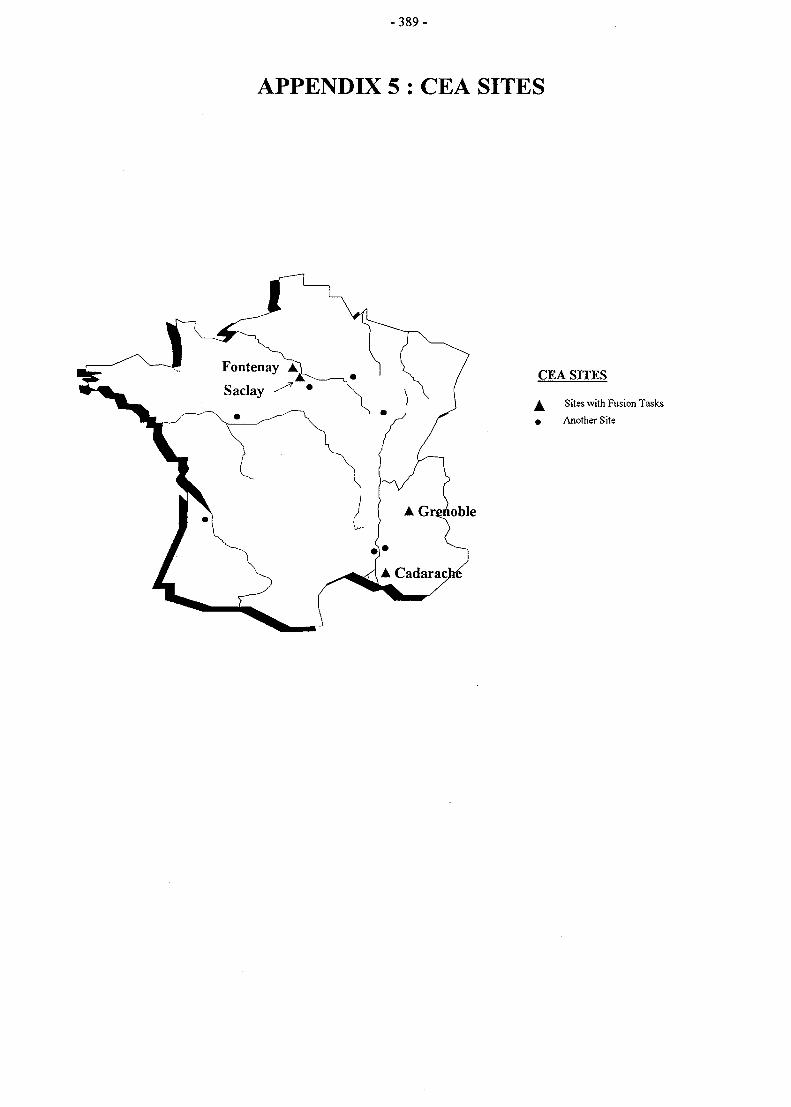
- 3 8 9 -
APPENDIX 5 : CEA SITES
CEA SITES
J^ Sites with Fusion Tasks
• Another Site
Related Documents