361 Application Guide RED indicates NEW information Cooper Bussmann Electrical Safety Services Section Contents Cooper Bussmann Electrical Safety Services . . . . . 362 Application Guide Fuse technology ............................ 363-369 Motor circuit branch circuit protection ............... 370 Conductor & termination considerations ......... 371-373 Glossary ................................... 374-376 Out-of-stock substitution/upgrades ................. 376 Cooper Bussmann electrical trademarks ............ 376 Industrial & commercial fuse applications ........ 377-378 Catalog number index . . . . . . . . . . . . . . . . . . . . .379-383 Sales support & manufacturing facilities . . . . . . . . . 384

Fuse Application Guide Bussmann
Nov 08, 2014
Fuse Application Guide Bussmann
Welcome message from author
This document is posted to help you gain knowledge. Please leave a comment to let me know what you think about it! Share it to your friends and learn new things together.
Transcript

361
ApplicationGuide
RED indicates NEW information
Cooper BussmannElectrical SafetyServices
Section ContentsCooper Bussmann Electrical Safety Services . . . . . 362Application Guide Fuse technology . . . . . . . . . . . . . . . . . . . . . . . . . . . . 363-369
Motor circuit branch circuit protection . . . . . . . . . . . . . . . 370
Conductor & termination considerations . . . . . . . . . 371-373
Glossary . . . . . . . . . . . . . . . . . . . . . . . . . . . . . . . . . . . 374-376
Out-of-stock substitution/upgrades . . . . . . . . . . . . . . . . . 376
Cooper Bussmann electrical trademarks . . . . . . . . . . . . 376
Industrial & commercial fuse applications . . . . . . . . 377-378
Catalog number index . . . . . . . . . . . . . . . . . . . . .379-383Sales support & manufacturing facilities . . . . . . . . . 384

For product data sheets, visit www.cooperbussmann.com/products/datasheet.asp362
Application Guide
ImproveElectrical
Safetyand
ReduceLiability
Improving Safety, Reducing Liability
A Safe Working Environment
Complete electrical safety involves a total approach to theselection, installation and continued maintenance of all electrical system components.
Keeping on top of all facets of any power distribution systemcan become a complex task involving ever-evolving codeschanges, changes made by electrical utilities and governmentregulations that affect what goes on inside any commercial,industrial or institutional facility.
While this Application Guide is intended to provide a generalunderstanding, its depth of coverage is limited. For moredetailed information, we recommend reviewing the CooperBussmann SPD (Selecting Protective Devices — Reorder# 3002).
Electrical Safety Services
To help you be sure your power distribution system is up tocode, and providing maximum safety and reduced liability,Cooper Bussmann offers Electrical Safety Services.
Our professional staff of degreed Electrical Engineers is available to assist in assessing your current electrical system;analyzing it for areas of weakness and making recommendations for improvements that will help assure itssafety and integrity.
Cooper Bussmann Electrical Safety Services
Employee Training
At Cooper Bussmann we recognize any electrical system isn'ta "get it and forget it" affair. It's vital that your employees areproperly trained to perform the tasks they're called upon foroperating and maintaining your electrical power distributionsystem.
We have developed comprehensive training programs that canbe modified to meet your specific needs so that your maintenance staff is qualified to perform their duties.
Contact Cooper Bussmann
To learn more about our comprehensive approach to enhancing electrical safety in facilities like yours, contact yourlocal Cooper Bussmann representative, or call 636-207-3294.
For product data sheets, visit www.cooperbussmann.com/products/datasheet.asp 363
Application Guide
ApplicationGuide
Fuse technology
Circuit Protection
Electrical distribution systems are often quite complicated.They cannot be absolutely fail-safe. Circuits are subject todestructive overcurrents. Harsh environments, general deterioration, accidental damage, damage from natural causes,excessive expansion, and/or overloading of the electrical distribution system are factors which contribute to the occurrence of such overcurrents. Reliable protective devicesprevent or minimize costly damage to transformers, conductors, motors, and the other many components andloads that make up the complete distribution system. Reliablecircuit protection is essential to avoid the severe monetarylosses which can result from power blackouts and prolongeddowntime of facilities. It is the need for reliable protection, safety, and freedom from fire hazards that has made the fuse awidely used protective device.
Overcurrents
An overcurrent is either an overload current or a short-circuitcurrent. The overload current is an excessive current relative tonormal operating current, but one which is confined to the normal conductive paths provided by the conductors and othercomponents and loads of the distribution system. As the nameimplies, a short-circuit current is one which flows outside thenormal conducting paths.
Overloads
Overloads are most often between one and six times the normal current level. Usually, they are caused by harmlesstemporary surge currents that occur when motors are started-up or transformers are energized. Such overload currents, or transients, are normal occurrences. Since they areof brief duration, any temperature rise is trivial and has noharmful effect on the circuit components. (It is important thatprotective devices do not react to them.)
Continuous overloads can result from defective motors (suchas worn motor bearings), overloaded equipment, or too manyloads on one circuit. Such sustained overloads are destructiveand must be cut off by protective devices before they damagethe distribution system or system loads. However, since theyare of relatively low magnitude compared to short-circuit currents, removal of the overload current within minutes willgenerally prevent equipment damage. A sustained overloadcurrent results in overheating of conductors and other components and will cause deterioration of insulation, whichmay eventually result in severe damage and short-circuits if notinterrupted.
Short-Circuits
Whereas overload currents occur at rather modest levels, theshort-circuit or fault current can be many hundred times largerthan the normal operating current. A high level fault may be50,000A (or larger). If not cut off within a matter of a few thousandths of a second, damage and destruction canbecome rampant—there can be severe insulation damage,melting of conductors, vaporization of metal, ionization ofgases, arcing, and fires.
Simultaneously, high level short-circuit currents can develophuge magnetic-field stresses. The magnetic forces betweenbus bars and other conductors can be many hundreds ofpounds per linear foot; even heavy bracing may not be adequate to keep them from being warped or distorted beyond repair.
Fuses
The fuse is a reliable overcurrent protective device. A “fusible”link or links encapsulated in a tube and connected to contactterminals comprise the fundamental elements of the basicfuse. Electrical resistance of the link is so low that it simply actsas a conductor. However, when destructive currents occur, thelink very quickly melts and opens the circuit to protect conductors and other circuit components and loads. Fuse characteristics are stable. Fuses do not require periodic maintenance or testing. Fuses have three unique performancecharacteristics:
1. Modern fuses have an extremely “high interrupting rating”—can with-stand very high fault currents without rupturing.
2. Properly applied, fuses prevent “blackouts.” Only the fuse nearest a faultopens without upstream fuses (feeders or mains) being affected—fusesthus provide “selective coordination.” (These terms are precisely definedin subsequent pages.)
3. Fuses provide optimum component protection by keeping fault currentsto a low value…They are said to be “current limiting.”
Voltage Rating
The voltage rating of a fuse must be at least equal to or greaterthan the circuit voltage. It can be higher but never lower. Forinstance, a 600V fuse can be used in a 208V circuit.
The voltage rating of a fuse is a function of its capability toopen a circuit under an overcurrent condition. Specifically, thevoltage rating determines the ability of the fuse to suppress theinternal arcing that occurs after a fuse link melts and an arc isproduced. If a fuse is used with a voltage rating lower than thecircuit voltage, arc suppression will be impaired and, undersome fault current conditions, the fuse may not clear the overcurrent safely. Special consideration is necessary for semiconductor fuse and medium voltage fuse applications,where a fuse of a certain voltage rating is used on a lower voltage circuit.
Ampere Rating
Every fuse has a specific amp rating. In selecting the amp rating of a fuse, consideration must be given to the type of loadand code requirements. The amp rating of a fuse normallyshould not exceed the current carrying capacity of the circuit.For instance, if a conductor is rated to carry 20A, a 20A fuse isthe largest that should be used. However, there are some specific circumstances in which the amp rating is permitted tobe greater than the current carrying capacity of the circuit.
For product data sheets, visit www.cooperbussmann.com/products/datasheet.asp364
Application Guide
Fuse technology
A typical example is the motor circuit; dual-element fuses generally are permitted to be sized up to 175% and non-time-delay fuses up to 300% of the motor full-load amps. As a rule,the amp rating of a fuse and switch combination should beselected at 125% of the continuous load current (this usuallycorresponds to the circuit capacity, which is also selected at125% of the load current). There are exceptions, such as whenthe fuse-switch combination is approved for continuous operation at 100% of its rating.
Interrupting Rating
A protective device must be able to withstand the destructiveenergy of short-circuit currents. If a fault current exceeds thecapability of the protective device, the device may actually rupture, causing additional damage. Thus, it is important whenapplying a fuse or circuit breaker to use one which can sustainthe largest potential short-circuit currents. The rating whichdefines the capacity of a protective device to maintain itsintegrity when reacting to fault currents is termed its “interrupting rating”. The interrupting rating of most branch-circuit, molded case, circuit breakers typically used in residential service entrance panels is 10,000A. (Please notethat a molded case circuit breaker’s interrupting capacity willtypically be lower than its interrupting rating.) Larger, moreexpensive circuit breakers may have interrupting ratings of14,000A or higher. In contrast, most modern, current-limitingfuses have an interrupting rating of 200,000 or 300,000A andare commonly used to protect the lower rated circuit breakers.The National Electrical Code, Section 110-9, requires equipment intended to break current at fault levels to have aninterrupting rating sufficient for the current that must be interrupted.
Selective Coordination – Prevention of Blackouts
The coordination of protective devices prevents system poweroutages or blackouts caused by overcurrent conditions. Whenonly the protective device nearest a faulted circuit opens andlarger upstream fuses remain closed, the protective devicesare “selectively” coordinated (they discriminate). The word“selective” is used to denote total coordination…isolation of afaulted circuit by the opening of only the localized protectivedevice.
This diagram shows the minimum ratios of amp ratings of Low-PeakYellow fuses that are required to provide “selective coordination” (dis-crimination) of upstream and downstream fuses.
Unlike electromechanical inertial devices (circuit breakers), it isa simple matter to selectively coordinate fuses of moderndesign. By maintaining a minimum ratio of fuse-amp ratingsbetween an upstream and downstream fuse, selective coordination is assured.
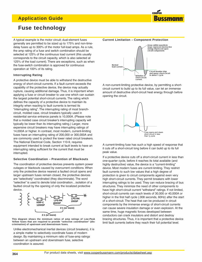
Current Limitation – Component Protection
A non-current-limiting protective device, by permitting a short-circuit current to build up to its full value, can let an immenseamount of destructive short-circuit heat energy through beforeopening the circuit.
A current-limiting fuse has such a high speed of response thatit cuts off a short-circuit long before it can build up to its fullpeak value.
If a protective device cuts off a short-circuit current in less thanone-quarter cycle, before it reaches its total available (andhighly destructive) value, the device is a “current-limiting”device. Most modern fuses are current-limiting. They restrictfault currents to such low values that a high degree of protection is given to circuit components against even veryhigh short-circuit currents. They permit breakers with lowerinterrupting ratings to be used. They can reduce bracing of busstructures. They minimize the need of other components tohave high short-circuit current “withstand” ratings. If not limited,short-circuit currents can reach levels of 30,000 or 40,000A orhigher in the first half cycle (.008 seconds, 60Hz) after the startof a short-circuit. The heat that can be produced in circuit components by the immense energy of short-circuit currentscan cause severe insulation damage or even explosion. At thesame time, huge magnetic forces developed between conductors can crack insulators and distort and destroy bracing structures. Thus, it is important that a protective devicelimit fault currents before they reach their full potential level.
KRP-C1200SP
2:1 (or more)
LPS-RK600SP
LPS-RK200SP
2:1 (or more)
Initiation ofshort-circuit current
Normalload current
Areas within waveformloops represent destructiveenergy impressed uponcircuit components
Circuit breaker tripsand opens short-circuitin about 1 cycle
Fuse opens and clearsshort-circuit in lessthan ⁄Ω™ cycle
For product data sheets, visit www.cooperbussmann.com/products/datasheet.asp 365
Application Guide
ApplicationGuide
Fuse technology
Operating Principles of Cooper Bussmann Fuses
The principles of operation of the modern, current-limitingfuses are covered in the following paragraphs.
Non-Time-Delay Fuses
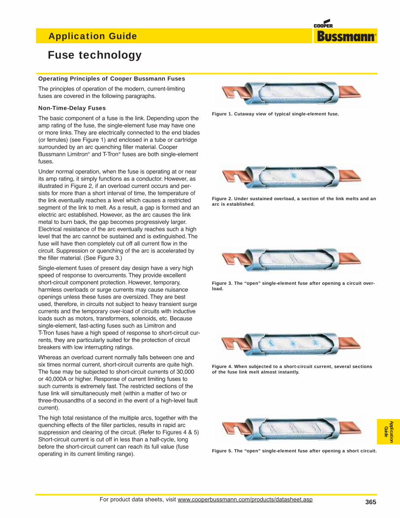
The basic component of a fuse is the link. Depending upon theamp rating of the fuse, the single-element fuse may have oneor more links. They are electrically connected to the end blades(or ferrules) (see Figure 1) and enclosed in a tube or cartridgesurrounded by an arc quenching filler material. CooperBussmann Limitron® and T-Tron® fuses are both single-elementfuses.
Under normal operation, when the fuse is operating at or nearits amp rating, it simply functions as a conductor. However, asillustrated in Figure 2, if an overload current occurs and per-sists for more than a short interval of time, the temperature ofthe link eventually reaches a level which causes a restrictedsegment of the link to melt. As a result, a gap is formed and anelectric arc established. However, as the arc causes the linkmetal to burn back, the gap becomes progressively larger.Electrical resistance of the arc eventually reaches such a highlevel that the arc cannot be sustained and is extinguished. Thefuse will have then completely cut off all current flow in the circuit. Suppression or quenching of the arc is accelerated bythe filler material. (See Figure 3.)
Single-element fuses of present day design have a very highspeed of response to overcurrents. They provide excellentshort-circuit component protection. However, temporary, harmless overloads or surge currents may cause nuisanceopenings unless these fuses are oversized. They are bestused, therefore, in circuits not subject to heavy transient surgecurrents and the temporary over-load of circuits with inductiveloads such as motors, transformers, solenoids, etc. Becausesingle-element, fast-acting fuses such as Limitron and T-Tron fuses have a high speed of response to short-circuit cur-rents, they are particularly suited for the protection of circuitbreakers with low interrupting ratings.
Whereas an overload current normally falls between one andsix times normal current, short-circuit currents are quite high.The fuse may be subjected to short-circuit currents of 30,000or 40,000A or higher. Response of current limiting fuses tosuch currents is extremely fast. The restricted sections of thefuse link will simultaneously melt (within a matter of two orthree-thousandths of a second in the event of a high-level faultcurrent).
The high total resistance of the multiple arcs, together with thequenching effects of the filler particles, results in rapid arc suppression and clearing of the circuit. (Refer to Figures 4 & 5)Short-circuit current is cut off in less than a half-cycle, longbefore the short-circuit current can reach its full value (fuseoperating in its current limiting range).
Figure 2. Under sustained overload, a section of the link melts and anarc is established.
Figure 3. The “open” single-element fuse after opening a circuit over-load.
Figure 4. When subjected to a short-circuit current, several sectionsof the fuse link melt almost instantly.
Figure 5. The “open” single-element fuse after opening a short circuit.
Figure 1. Cutaway view of typical single-element fuse.

For product data sheets, visit www.cooperbussmann.com/products/datasheet.asp366
Application Guide
Fuse technology
Cooper Bussmann Dual-Element Fuses
There are many advantages to using these fuses. Unlike single-element fuses, the Cooper Bussmann dual-element, time-delay fuses can be sized closer to provide both highperformance short-circuit protection and reliable overload protection in circuits subject to temporary overloads and surge currents. For ac motor loads, a single-element fusemay need to be sized at 300% of an a.c. motor current in order to hold the starting current. However, dual-element, time delay fuses can be sized much closer to motorloads. For instance, it is generally possible to size Fusetron Dual-Element Fuses, FRS-R and FRN-R and Low-Peak® Dual-Element Fuses, LPS-RK_SP and LPN-RK_SP, at125% and 130% of motor full load current, respectively. Generally, the Low-Peak Dual-Element Fuses, LPJ_SP, and CUBEFuse™, TCF, can be sized at 150% of motor fullload amps. This closer fuse sizing may provide many advantages such as: (1) smaller fuse and block, holder or disconnect amp rating and physical size, (2) lower cost dueto lower amp rated devices and possibly smaller required panel space, (3) better short-circuit protection – less short-circuit current let-through energy, and (4) potentialreduction in the arc-flash hazard.
Figure 6. This is the LPS-RK100SP, a 100A, 600V Low-Peak, Class RK1, Dual-Element Fuse that has excellent time-delay, excellent current-limitation and a 300,000A interrupting rating. Artisticliberty is taken to illustrate the internal portion of this fuse. The real fuse has a non-transparent tube and special small granular, arc-quenching material completely filling the internal space.
Figure 7. The true dual-element fuse has distinct and separate overload element and short-circuit element.
Short-circuit element
Overload element
Spring
Filler quenches the arcs
Small volume of metal to vaporize
Filler material
Insulated end-caps to help preventaccidental contact with live parts.
Figure 8. Overload operation: Under sustained overload conditions, the trigger spring frac-tures the calibrated fusing alloy and releases the “connector”. The insets represent a model of theoverload element before and after. The calibrated fusing alloy connecting the short-circuit ele-ment to the overload element fractures at a specific temperature due to a persistent overload cur-rent. The coiled spring pushes the connector from the short-circuit element and the circuit isinterrupted.
Figure 9. Short-circuit operation: Modern fuses are designed with minimum metal in therestricted portions which greatly enhance their ability to have excellent current-limiting charac-teristics – minimizing the short circuit let-through current. A short-circuit current causes therestricted portions of the short-circuit element to vaporize and arcing commences. The arcs burnback the element at the points of the arcing. Longer arcs result, which assist in reducing the current. Also, the special arc quenching filler material contributes to extinguishing the arcingcurrent. Modern fuses have many restricted portions, which results in many small arclets – allworking together to force the current to zero.
Figure 10. Short-circuit operation: The special small granular, arc-quenching material playsan important part in the interruption process. The filler assists in quenching the arcs; the fillermaterial absorbs the thermal energy of the arcs, fuses together and creates an insulating barrier.This process helps in forcing the current to zero. Modern current-limiting fuses, under short-cir-cuit conditions, can force the current to zero and complete the interruption within a few thou-sandths of a second.
When the short-circuit current is in the current-limiting range of a fuse, it is not possible for the full available short-circuit current to flow through the fuse – it’s a matter ofphysics. The small restricted portions of the short-circuit element quickly vaporize and the filler material assists in forcing the current to zero. The fuse is able to “limit” theshort-circuit current.
Overcurrent protection must be reliable and sure. Whether it is the first day of the electrical system or thirty or more years later, it is important that overcurrent protectivedevices perform under overload or short-circuit conditions as intended. Modern current-limiting fuses operate by very simple, reliable principles.
Before
After

For product data sheets, visit www.cooperbussmann.com/products/datasheet.asp 367
Application Guide
ApplicationGuide
Fuse technology
Fuse Time-Current Curves
When a low level overcurrent occurs, a long interval of time willbe required for a fuse to open (melt) and clear the fault. On theother hand, if the overcurrent is large, the fuse will open veryquickly. The opening time is a function of the magnitude of thelevel of overcurrent. Overcurrent levels and the correspondingintervals of opening times are logarithmically plotted in graphform as shown to the right. Levels of overcurrent are scaled onthe horizontal axis; time intervals on the vertical axis. The curveis thus called a “time-current” curve.
This particular plot reflects the characteristics of a 200A, 250V,Low-Peak dual-element fuse. Note that at the 1,000A overloadlevel, the time interval which is required for the fuse to open is10 seconds.Yet, at approximately the 2,200A overcurrent level,the opening (melt) time of a fuse is only 0.01 seconds. It isapparent that the time intervals become shorter as the overcurrent levels become larger. This relationship is termed aninverse time-to-current characteristic. Time-current curves arepublished or are available on most commonly used fusesshowing “minimum melt,” “average melt” and/or “total clear”characteristics. Although upstream and downstream fuses areeasily coordinated by adhering to simple amp ratios, thesetime-current curves permit close or critical analysis of coordination.
Better Motor Protection in Elevated Ambients
The derating of dual-element fuses based on increased ambient temperatures closely parallels the derating curve ofmotors in elevated ambient. This unique feature allows for optimum protection of motors, even in high temperatures.
Affect of ambient temperature on operating characteristics ofFusetron and Low-Peak Dual-Element Fuses.
400300
200
1008060
4030
20
1086
43
2
1.8
.6
.4
.3
.2
.1.08.06
.04
.03
.02
.01
100
200
300
400
600
800
1,00
0
2,00
0
3,00
04,
000
6,00
08,
000
10,0
00
TIM
E IN
SE
CO
ND
S
CURRENT IN AMPERES
LOW-PEAK YELLOWLPN-RK200 SP (RK1)
150
140
130
120
110
100
90
80
70
60
50
40
30
AMBIENT
PE
RC
EN
T O
F R
AT
ING
OR
OP
EN
ING
TIM
E
Affect on CarryingCapacity Rating
Affect onOpening Time
–76°F(–60°C)
–40°F(–40°C)
–4°F(–20°C)
–32°F(0°C)
68°F(20°C)
104°F(40°C)
140°F(60°C)
176°F(80°C)
212°F(100°C)

For product data sheets, visit www.cooperbussmann.com/products/datasheet.asp368
Application Guide
In the above illustration, a grooved ring in one ferrule providesthe rejection feature of the Class R fuse in contrast to the lowerinterrupting rating, non-rejection type.
Branch-Circuit Listed Fuses
Branch-circuit listed fuses are designed to prevent the installation of fuses that cannot provide a comparable level ofprotection to equipment.
The characteristics of Branch-circuit fuses are:1. They must have a minimum interrupting rating of 10,000A2. They must have a minimum voltage rating of 125V.3. They must be size rejecting such that a fuse of a lower
voltage rating cannot be installed in the circuit.4. They must be size rejecting such that a fuse with a current
rating higher than the fuse holder rating cannot be installed.
Better Protection Against Motor Single Phasing
When secondary single-phasing occurs, the current in theremaining phases increases to approximately 200% rated fullload current. (Theoretically 173%, but change in efficiency andpower factor make it about 200%.) When primary single-phasing occurs, unbalanced voltages occur on the motor circuitcausing currents to rise to 115%, and 230% of normal runningcurrents in delta-wye systems.
Dual-element fuses sized for motor running overload protectionwill help to protect motors against the possible damages of single-phasing.
Classes of Fuses
Safety is the industry mandate. However, proper selection,overall functional performance and reliability of a product arefactors which are not within the basic scope of listing agencyactivities. In order to develop its safety test procedures, listingagencies develop basic performance and physical specifications or standards for a product. In the case of fuses,these standards have culminated in the establishment of distinct classes of low-voltage (600V or less) fuses; classesRK1, RK5, G, L, T, J, H and CC being the more important.
The fact that a particular type of fuse has, for instance, a classification of RK1, does not signify that it has the identicalfunction or performance characteristics as other RK1 fuses. Infact, the Limitron® non-time-delay fuse and the Low-Peak dual-element, time-delay fuse are both classified as RK1.Substantial differences in these two RK1 fuses usually requiresconsiderable difference in sizing. Dimensional specifications ofeach class of fuse does serve as a uniform standard.
Class R Fuses
Class R (“R” for rejection) fuses are high performance,1⁄10 to600A units, 250V and 600V, having a high degree of currentlimitation and a short-circuit interrupting rating of up to300,000A (RMS Sym.). Cooper Bussmann Class R fusesinclude Class RK1 Low-Peak and Limitron® fuses, and RK5Fusetron fuses. They have replaced the K1 Low-Peak and Limitron fuses and K5 Fusetron fuses. Thesefuses are identical, with the exception of a modification in themounting configuration called a “rejection feature.” This featurepermits Class R fuses to be mounted in rejection type fuse-clips. “R” type fuseclips prevent older type Class H, ONE-TIMEand RENEWABLE fuses from being installed. The use of ClassR fuse holders is thus an important safeguard. The applicationof Class R fuses in such equipment as disconnect switches permits the equipment to have a high interrupting rating. NEC®
Articles 110-9 and 230-65 require that protective devices haveadequate capacity to interrupt short-circuit currents. Article240-60(b) requires fuse holders for current-limiting fuses toreject non-current-limiting type fuses.
Fuse technology

For product data sheets, visit www.cooperbussmann.com/products/datasheet.asp 369
Application Guide
ApplicationGuide
Fuse technology
Reliability and Maintenance ofOvercurrent Protective DevicesModern fuses have several significant advantages overmechanical overcurrent protective devices - one of thoseadvantages is reliability. Whether the first day of the electricalsystem or years later, it is important that overcurrent protectivedevices perform under overload and fault conditions as intended.
Modern current-limiting fuses operate by very simple, reliableprinciples. Fuses do not have to be maintained. By their inherent design, fuses do not have elements or mechanismsto calibrate, adjust or lubricate. If and when fuses are calledupon to open on an overcurrent, installing the same type andampere rated fuses provides the circuit with new factory-calibrated protection. The original design integrity can be maintained throughout the life of the electrical system. Onelast point on fuse systems; the terminations, clips anddisconnects should be maintained as necessary.
In contrast, circuit breakers are mechanical devices, eventhose with electronic sensing, and circuit breakers require periodic maintenance, testing, and if necessary reconditioningor replacement. This is required per the circuit breaker manufacturers' instructions, NFPA 70B RecommendedPractice for Electrical Equipment Maintenance, and NEMAAB4. If circuit breakers are not properly maintained, the interrupting rating, circuit component protection, coordination,and electrical safety may be compromised.See www.cooperbussmann.com for more information onReliability and Maintenance.
Supplementary Overcurrent ProtectiveDevices for use in Motor ControlCircuits
Branch Circuit vs. Supplemental Overcurrent
Protective Devices
Branch circuit overcurrent protective devices (OCPD) can beused everywhere OCPD are used, from protection of motorsand motor circuits and group motor circuits, to protection ofdistribution and utilization equipment. Supplemental OCPDcan only be used where proper protection is already beingprovided by a branch circuit device, by exception [i.e.,430.72(A)], or if protection is not required. SupplementalOCPD can often be used to protect motor control circuits butthey cannot be used to protect motors or motor circuits. A verycommon misapplication is the use of a supplementary overcurrent protective device such as a UL 1077 mechanicalovercurrent device for motor branch circuit short-circuit andground fault protection. Supplementary OCPDs are incompletein testing compared to devices that are evaluated for branchcircuit protection. THIS IS A SERIOUS MISAPPLICATIONAND SAFETY CONCERN!! Caution should be taken to assurethat the proper overcurrent protective device is being used forthe application at hand. Below is a description of popular supplementary overcurrent protective devices.
Most supplemental overcurrent protective devices have verylow interrupting ratings. Just as any other overcurrent protec-tive device, supplemental OCPDs must have an interruptingrating equal to or greater than the available short-circuit current.
Supplemental Fuses As listed or recognized to the
UL/CSA/ANCE Trinational 248-14 Standard
These are fuses that can have many voltages and interruptingratings within the same case size. Examples of supplementalfuses are 13⁄32'' X 1 1⁄2'', 5 x 20mm, and 1⁄4'' x 1 1⁄4'' fuses.Interrupting ratings range from 35 to 100,000 amperes.

For product data sheets, visit www.cooperbussmann.com/products/datasheet.asp370
Application Guide
Motor circuit branch circuit protection
Motor Circuits – Choice of Overcurrent Protection
Motor circuits have unique characteristics and several func-tions, such as short-circuit protection, overload protection andautomatic/ remote start/stop, that may be required. Sometimesthe comment is made that users prefer circuit breakersbecause they can be reset. Let’s examine the choice of eithercircuit breakers or current- limiting fuses for motor branch cir-cuit protection.
In the case to be examined, fuses and circuit breakers(includes magnetic only circuit breakers which are calledMCPs or motor circuit protectors) are sized with the intent toprovide only short-circuit and ground fault protection for themotor branch circuit protection per 430.52. Other means, suchas overload relays, provide the motor overload protection.Typical thermal magnetic circuit breakers can only be sized formotor branch circuit protection (typically 200% - 250% ofmotor current) because if they are sized closer, the motorstarting current trips the circuit breaker’s instantaneous mechanism. Magnetic only circuit breakers (MCPs) are intentionally not provided with overload capability; they onlyoperate on short-circuit currents. There are some fuses suchas the FRS-R and LPS-RK fuses that can be sized closeenough for motor running overload protection or backup motorrunning protection. But for the discussion in this section,assume current-limiting fuses are sized only for motor short-circuit and ground fault protection.
It is important to note that in this protection level being discussed, a circuit breaker or fuses should only open if thereis a fault on the motor circuit. A separate overload protectivedevice, such as an overload relays, provides motor overloadprotection per 430.32. Here are some important considerations:
1. OSHA regulation 1910.334(b)(2) Use of Equipment states:
Reclosing circuits after protective device operation. After a circuit isdeenergized by a circuit protective device, the circuit may not be manually reenergized until it has been determined that the equipmentand circuit can be safely energized. The repetitive manual reclosing ofcircuit breakers or reenergizing circuits through replaced fuses is prohibited. NOTE: When it can be determined from the design of the circuit and the over-current devices involved that the automatic operationof a device was caused by an overload rather than a fault condition, noexamination of the circuit or connected equipment is needed before thecircuit is reenergized.
So the speed of reclosing a circuit breaker after a fault is not an advantage. The law requires that if the condition is a fault (that is theonly reason the circuit breaker or fuses should open on a motor circuit),then the fault must be corrected prior to replacing fuses or resetting thecircuit breaker.
2. The typical level of short-circuit protection for the motor starter providedby circuit breakers and MCPs is referred to as Type 1. This is becausemost circuit breakers are not current-limiting. So, for a loadside fault,the starter may sustain significant damage such as severe welding ofcontacts and rupturing of the heater elements. Or the heater/overloadrelay system may lose calibration. This is an acceptable level of performance per UL508, which is the product standard for motorstarters. Current-limiting fuses can be selected that can provide Type 2“no damage” short-circuit protection for motor starters.
Consequently, with circuit breaker protection, after a fault condition,
significant downtime and cost may be incurred in repairing or replacingthe starter. With properly selected fuses for Type 2 protection, after thefault is repaired, only new fuses need to be inserted in the circuit; thestarter does not have to be repaired or replaced.
3. Circuit breakers must be periodically tested to verify they mechanicaloperate and electrically tested to verify they still are properly calibratedwithin specification. The circuit breaker manufacturers recommend this.Typically circuit breakers should be mechanically operated at least everyyear and electrically tested every 1 to 5 years, depending on the serviceconditions. Modern current-limiting fuses do not have to be maintainedor electrically tested to verify they still will operate as intended. The terminations of both circuit breakers and fusible devices need to be peri-odically checked and maintained to prevent thermal damage. Plus fuseclips should be periodically inspected and if necessary maintained.
4. After a circuit breaker interrupts a fault, it may not be suitable for furtherservice. UL489, the product standard for molded case circuit breakers,only requires a circuit breaker to interrupt two short-circuit currents atits interrupting rating. Circuit breakers that are rated 100 amps or lessdo not have to operate after only one short-circuit operation under “busbar” short-circuit conditions. If the fault current is high, circuit breakermanufacturers recommend that a circuit breaker should receive a thorough inspection with replacement, if necessary. How does one knowa circuit breaker’s service history or what level of fault current that a circuit breaker interrupts? With modern current-limiting fuses, if the fuseinterrupts a fault, new factory calibrated fuses are installed in the circuit.The original level of superior short-circuit protection can be there for thelife of the motor circuit.
5. After a fault, the electrician has to walk back to the storeroom to get newfuses; that is if spare fuses are not stored adjacent to the equipment.This does require some additional down time. However, if fuses openedunder fault conditions, there is a fault condition that must be remedied.The electrician probably will be going back to the storeroom anyway forparts to repair the fault. If properly selected current-limiting fuses areused in the original circuit, the starter will not sustain any significantdamage or loss of overload calibration.
With circuit breaker protection on motor circuits, after a faultcondition, it may be necessary to repair or replace the starter,so a trip to the storeroom may be necessary. And if the starteris not significantly damaged, it may still need to be tested toinsure the let-through energy by the circuit breaker has notcaused the loss of starter overload calibration. Also, the circuitbreaker needs to be evaluated for suitability before placing itback into service. Who is qualified for that evaluation? Howmuch time will that take?
In summary, resettability is not an important feature for motorbranch circuit (short-circuit) protection and resettability of thebranch circuit protective device is not a benefit for motor circuits. As a matter of fact, resettability of the motor branchcircuit overcurrent protective device may encourage an unsafepractice. The function of motor branch circuit protection is faultprotection: short-circuit and ground fault protection. Faults donot occur on a regular basis. But when a fault does occur, it isimportant to have the very best protection. The best motorbranch circuit protection can be judged by (1) reliability - itsability to retain its calibration and speed of operation over itslifetime, (2) current-limiting protection -its ability to provideType 2 “no damage” protection to the motor starter, and (3)safety - its ability to meet a facility’s safety needs. Modern current-limiting fuses are superior to circuit breakers for motorbranch circuit protection.

For product data sheets, visit www.cooperbussmann.com/products/datasheet.asp 371
Application Guide
ApplicationGuide
Conductor & termination considerations
Conductor & Termination Considerations
A fuse, as well as a circuit breaker, is part of a system wherethere are electrical, mechanical and thermal considerations. Allthree of these are interrelated. If there is too much electricalcurrent for the circuit, the components can overheat. If a conductor termination is not properly torqued, the terminationcan be a “hot spot” and contribute excess heat. This additionalheat is detrimental to the integrity of the termination means,conductor insulation and even the overcurrent protectivedevice. If the conductor size is too small for the circuit load orfor how the fuse/termination or circuit breaker/termination hasbeen rated, the undersized conductor will be a source of detrimental excess heat, which bleeds into the devices throughthe terminals. This excess heat can cause integrity issues.
How important is the proper conductor size and proper termination methods? Very! Many so called “nuisance” open-ings of overcurrent protective devices or device failures can betraced to these root causes. Improper electrical connectionscan result in fire or other damage to property and can causeinjury and death. If there are loose terminal connections, then:
• The conductor overheats and the conductor insulation may break down.This can lead to a fault; typically line to ground. Or, if conductors of different potential are touching, the insulation of both may deteriorateand a phase-to-neutral or phase-to-phase fault occurs.
• Arcing can occur between the conductor and lug. Since a poor connection is not an overload or a short-circuit, the overcurrent protective device does not operate.
• The excessive thermal condition of the conductor termination increasesthe temperature beyond the thermal rating of the fuse clip material. Theresult is that the fuse clip can lose its spring tension, which can resultin a hot spot at the interface surface of the fuse and clip.
• These excessive thermal conditions described above may cause thedevice (block, switch, fuse, circuit breaker, etc.) insulating system todeteriorate, which may result in a mechanical and/or electrical breakdown. For instance, the excessive thermal condition of a conductor termination of a circuit breaker can degrade the insulatingcase material. Or a fuse block material may carbonize due to the excessive thermal conditions over a long time.
Normally, a fuse is mounted in a fuse clip or bolted to a metalsurface. It is important that the two surfaces (such as fuse toclip) are clean and mechanically tight so that there is minimalelectrical resistance of this interface. If not, this interface is ahigh resistance spot, which can lead to a hot spot. With a fuseto clip application, the temperature rise from a poor clip cancause even further deterioration of the clip tension. This resultsin the hot spot condition getting worse.
The fuse clip on the right has excellent tension that provides agood mechanical and electrical interface (low resistance)between the fuse and clip. The clip on the left experiencedexcessive thermal conditions due to an improper conductortermination or undersized conductor. As a result, the clip lostits tension. Consequently, the mechanical and electrical interface between the fuse and clip was not adequate whichfurther accelerated the unfavorable thermal condition.
Some causes of loose terminal connections
Below are some possible causes for loose terminal connections for various termination methods and possiblecauses of excessive heating of the overcurrent protectivedevice / termination / conductor system:
1. The conductor gauge and type of conductor, copper or aluminum, mustbe within the connector’s specifications. The terminals for a fuse block,terminal block, switch, circuit breaker, etc. are rated to accept specificconductor type(s) and size(s). If the conductor is too large or too smallfor the connector, a poor connection results, and issues may arise.Additionally, it must be verified that the terminal is suitable for aluminumconductor, copper conductor, or both. Usually the termination means israted for acceptable conductor type(s) and range of conductor sizes; thisis evidenced by the ratings being marked on the device (block, switch,circuit breaker, etc.) or specified on the data sheet.
For product data sheets, visit www.cooperbussmann.com/products/datasheet.asp372
Application Guide
2. The connector is not torqued to the manufacturer’s recommendation.Conductors loosen as they expand and contract with changes in temperature due to equipment running and not running. If the connec-tions are not torqued appropriately, loose connections may result. For amechanical screw, nut, bolt or box lug type connection, follow the manufacturer’s recommended torque. Typically the specified torque for aconnector is marked on the device. For a specific connector, the specified torque may be different for different wire sizes.
3. The conductor is not crimped appropriately. A poor crimp could bebetween the conductor and a ring terminal. It could be between the conductor and the quick connect terminal. Or, it could be between theconductor and an in-line device. If using a compression connection, usethe manufacturer’s recommended crimp tool with the proper locationand number of crimps.
4. The quick connect terminal is not seated properly. If the male-femaleconnections are not fully seated, a hot spot may be created.
5. The quick connect terminal is being used beyond its amp rating. Quickconnects typically have limited continuous current ratings that must notbe exceeded. Typical maximum ratings possible for a quick connect are16 or 20A (some are less); this is based on a proper conductor size, too.If the quick connect is used beyond its amp rating, excessive temperature will result which can degrade the quick connect’s tensionproperties and further overheating issues result.
6. The conductor is not properly soldered to a solder terminal. Again, ifthere is not a good connection between the two, a hot spot will be created.
7. The terminal is only rated to accept one conductor, but multiple conductors are being used. Again, the product specifications must bechecked to see if the terminal is rated for dual conductors. If the productis not marked suitable for dual conductors, then only one conductor canbe used for this termination. Inserting too many conductors will cause apoor connection, which can result in heat or other problems.
Other important aspects in the electrical and thermal relationship for circuit components in a circuit are the conductor size, conductor rated ampacity, the conductor insulation temperature rating and the permissible connectordevice conductor temperature limits. Conductors have specified maximum ampacities that are based on many variables including the size of the conductor and its insulationtemperature rating. The NEC® establishes the allowableampacity of conductors for various variables and applications.In addition, there are some overriding requirements in theNEC® and product standards that dictate the ampacity of conductors when connected to terminals. For instance, theampacity for a conductor with 90°C insulation is generallygreater than the ampacity of a conductor of the same size butwith 60°C insulation. However, the greater ampacity of a conductor with 90°C insulation is not always permitted to beused due to limitations of the terminal temperature ratingand/or the requirements of the NEC®. (Reference 110.14 inthe NEC® for specific requirements.) However, there are somesimple rules to follow for circuits of 100A and less. These simple rules generally should be followed because these arethe norms for the device component product standards andperformance evaluation to these standards for fuses, blocks,disconnects, holders, circuit breakers, etc.
Simple rules for 100 amps and less:
1. Use 60°C rated conductors [110.14(C)(1)(a)(1)]. This assumes all terminations are rated for 60°C rated conductors.
2. Higher temperature rated conductors can be used, but the ampacity ofthese conductors must be as if they are 60°C rated conductors. In otherwords, even if a 90°C conductor is used, it has to be rated for ampacityas if it were a 60°C conductor [110.14(C)(1)(a)(2)]. For instance,assume an ampacity of 60A is needed in a circuit that has terminationsthat are rated for 60°C conductors. If a 90°C conductor is to be used,what is the minimum conductor size required?
Wire Size 60°C Ampacity 90°C Ampacity6 AWG 55 754 AWG 70 95
The answer is 4 AWG, 90°C conductor. A 6 AWG, 90°C conductor has anampacity of 75 amps per (NEC® Table 310.16); but this ampacity can notbe used for a 60°C termination. For this circuit, if a 90°C, 6 AWG con-ductor is evaluated, the ampacity of this conductor must be according to the 60°C conductor ampacity, which is 55A. Ampacities arefrom NEC® Table 310.16.
3. Conductors with higher temperature ratings can be used at their ratedampacities if the terminations of the circuit devices are rated for thehigher temperature rated conductor [110.14(C)(1)(a)(3)]. However, theindustry norm is that most devices rated 100A or less, such as blocks,disconnects and circuit breakers, have 60°C or 75°C rated terminations.
4. For motors with design letters B, C, D, or E, conductors with insulationrating of 75°C of higher are permitted as long as the ampacity of theconductors is not greater than the 75°C rating [110.14(C)(1)(a)(4)].
5. If a conductor is run between two devices that have terminals rated attwo different temperatures, the rules above must be observed that correlate to the terminal with the lowest temperature rating.
For circuits greater than 100A, use conductors with at least a75°C insulation rating at their 75°C ampacity rating.
So why would anyone ever want to use a conductor with a90°C or a 105°C rating if they can’t be applied at their ampacity ratings for those temperatures? The answer lies inthe fact that those higher ampacity ratings can be utilizedwhen derating due to ambient conditions or due to exceedingmore than 3 current carrying conductors in a raceway.
Example (ampacity and derating table next page)
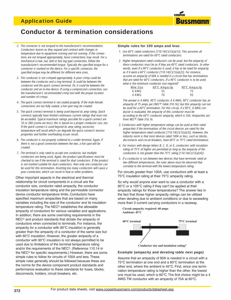
Assume that an ampacity of 60A is needed in a circuit with a75°C termination at one end and a 60°C termination at theother end, where the ambient is 45°C. First, since one termi-nation temperature rating is higher than the other, the lowestone must be used, which is 60°C. The first choice might be a 4AWG TW conductor with an ampacity of 70A at 60°C.
Conductor & termination considerations
Circuit ampacity required: 60 ampsAmbient: 45°C
75°C terminal60°C terminal
Conductor size and insulation rating?

For product data sheets, visit www.cooperbussmann.com/products/datasheet.asp 373
Application Guide
ApplicationGuide
However, in the NEC® the Correction Factors table at the bottom of conductor ampacity Table 310.16 reveals that the70A ampacity must be derated, due to the 45°C ambient, by afactor of .71. This yields a new ampacity of 49.7, which is lessthan the required 60. This is where a conductor with a highertemperature rating becomes useful. A 4 AWG THHN conductor has a 90°C ampacity of 95A. Again, looking at thetable at the bottom of Table 310.16, a factor of .87 must beused, due to the 45°C ambient. This yields a new ampacity of82.65, which is adequate for the required 60A ampacity.
Could a 6 AWG THHN conductor be used in this application?Its 90°C ampacity is 75A. Using the factor of .87 for the 45°Cambient gives a new ampacity of 65.25, which seems adequatefor a required ampacity of 60A. However, a 6 AWG conductor ofany insulation rating could never be used in this applicationbecause the 60°C terminal requires that the smallest amount ofcopper is a 4 AWG for a 60A ampacity (simple rule 2 in previous paragraphs). The amount of copper associated with a 4 AWGconductor is required to bleed the right amount of heat away fromthe terminal. The use of less copper won’t bleed enough heataway, and therefore overheating problems could result.
Allowable AmpacitiesThe table below shows the allowable ampacities of insulated copper
conductors rated 0 through 2000 volts, 60°C through 90°C, not more thanthree current-carrying conductors in a raceway, cable, or earth (directly buried),based on ambient of 30°C (86°F) (data taken from NEC® Table 310.16). Thenote for 14, 12, and 10 AWG conductors is a very important note that limits theprotection of these conductors.
*See NEC® 240.4(D) which essentially limits (with several exceptions)the overcurrent protection of copper conductors to the following ratingsafter any correction factors have been applied for ambient temperatureor number of conductors: 14 AWG - 15 amps, 12 AWG - 20 amps, 10AWG - 30 amps. Depending on the circumstances of a specific application, the ampacity determined due to the correction factors maybe less than the values in Table 310.16. In those cases, the lower valueis the ampacity that must be observed. For instance, a 75°C, 10AWG in50°C ambient would have a derating factor of 0.75, which results in anampacity of 26.25 (35A x 0.75). So in this case, the ampacity would be26.25. Since 26.25 is not a standard size fuse per NEC® 240.6, NEC®
240.4(B) would allow the next standard fuse, which is a 30A fuse. The30A fuse is in compliance with 240.4(D). In a 35°C ambient, the correcting factor for this same conductor is 0.94, so the new ampacityis 32.9A (35A x 0.94). However, a 35A fuse can not be utilized becauseNEC® 240.4(D) limits the protection to 30A.
Ambient DeratingConductor allowable ampacities must be derated when in temperature
ambient greater than 30°C. The correction factors for the conductor allowableampacities in NEC® Table 310.16.are below.
Conductor Ampacity Correction Factors For Ambient Temperatures
Conduit Fill Derating
Also, conductor ampacity must be derated when there aremore than three current-carrying conductors in a raceway orcable per NEC® 310.15(B)(2). There are several exceptions;the derating factors are:
# Of Current- % Values in NEC® Ampacity TablesCarrying 310.16 to 310.19 As Adjusted for
Conductors Ambient Temperature if Necessary4 – 6 807 – 9 70
10 – 20 5021 – 30 4531 – 40 40
41 & greater 35
Termination Ratings
As discussed above, terminations have a temperature ratingthat must be observed and this has implications on permissible conductor temperature rating and ampacity.Shown below are three common termination ratings and therules. Remember, from the example above, the conductorampacity may also have to be derated due to ambient, conduitfill or other reasons.
60°C Can use 60°C, 75°C, 90°C or higher temperature rated conductor,but the ampacity of the conductor must be based as if conductor israted 60°C.
75°C Can use 75°C, 90°C or higher temperature rated conductor, but theampacity of the conductor must be based as if conductor is rated75°C. A 60°C conductor not permitted to be used.
60°C/75°C Dual temperature rated termination. Can use either 60°C conductors at 60°C ampacity or 75°C conductors at 75°C ampacity. If 90°C or higher temperature rated conductor is used,the ampacity of the conductor must be based as if conductor israted 75°C.
Conductor & termination considerations
Conductor Ampacity For Temperature RatedSize AWG Copper Conductors (NEC® Table 310.16)
60°C 75°C 90°C
14* 20* 20* 25*
12* 25* 25* 30*
10* 30* 35* 40*
8 40 50 55
6 55 65 75
4 70 85 95
3 85 100 110
2 95 115 130
1 110 130 150
Ambient For ambient other than 30°C, multiply conductor allowable AmbientTemp. °C ampacities by factors below (NEC® Table 310.16) Temp. °F
60°C 75°C 90°C
21-25 1.08 1.05 1.04 70-77
26-30 1.00 1.00 1.00 78-86
31-35 0.91 0.94 0.96 87-95
36-40 0.82 0.88 0.91 96-104
41-45 0.71 0.82 0.87 105-113
46-50 0.58 0.75 0.82 114-122
51-55 0.41 0.67 0.76 123-131
56-60 – 0.58 0.71 132-140
61-70 – 0.33 0.58 141-158
71-80 – – 0.41 159-176
For product data sheets, visit www.cooperbussmann.com/products/datasheet.asp374
Application Guide
374
Glossary
Ampere (Amp)
The measurement of intensity of rate offlow of electrons in an electric circuit. Anampere (amp) is the amount of currentthat will flow through a resistance of oneohm under a pressure of one volt.
Amp Rating
The current-carrying capacity of a fuse.When a fuse is subjected to a currentabove its amp rating, it will open the circuit after a predetermined period oftime.
Amp Squared Seconds, l2t
The measure of heat energy developedwithin a circuit during the fuse’s clear-ing. It can be expressed as “melting l2t”,“arcing l2t” or the sum of them as“Clearing l2t”. “l” stands for effective let-through current (RMS), which issquared, and “t” stands for time of opening, in seconds.
Arcing I2t
Value of the I2t during the arcing timeunder specified conditions.
Arcing Time
The amount of time from the instant thefuse link has melted until the overcur-rent is interrupted, or cleared.
Breaking Capacity
(See Interrupting Rating)
Cartridge Fuse
A fuse consisting of a current responsive element inside a fuse tubewith terminals on both ends.
Class CC Fuses
600V, 200,000A interrupting rating,branch circuit fuses with overall dimensions of 13⁄32” x 11⁄2”. Their designincorporates a rejection feature thatallows them to be inserted into rejectionfuse holders and fuse blocks that rejectall lower voltage, lower interrupting rating 13⁄32” x 11⁄2” fuses. They are available from 1⁄10A through 30A.
Class G Fuses
480V, 100,000A interrupting ratingbranch circuit fuses that are size reject-ing to eliminate overfusing. The fusediameter is 13⁄32” while the length variesfrom 15⁄16” to 21⁄4”. These are available inratings from 1A through 60A.
Class H Fuses
250V and 600V, 10,000A interruptingrating branch circuit fuses that may berenewable or non-renewable. These areavailable in ampere ratings of 1 ampthrough 600A.
Class J Fuses
These fuses are rated to interrupt a minimum of 200,000A ac. They arelabeled as “Current-Limiting”, are ratedfor 600Vac, and are not interchangeablewith other classes.
Class K Fuses
These are fuses listed as K-1, K-5, or K-9 fuses. Each subclass has designated I2t and lp maximums. Theseare dimensionally the same as Class Hfuses, and they can have interruptingratings of 50,000, 100,000, or 200,000A. These fuses are current-limiting.However, they are not marked “current-limiting” on their label since theydo not have a rejection feature.
Class L Fuses
These fuses are rated for 601 through6000A, and are rated to interrupt a minimum of 200,000A ac. They arelabeled “Current-Limiting” and are ratedfor 600Vac. They are intended to bebolted into their mountings and are notnormally used in clips. Some Class Lfuses have designed in time-delay features for all purpose use.
Class R Fuses
These are high performance fuses rated1⁄10-600A in 250V and 600V ratings. Allare marked “Current Limiting” on theirlabel and all have a minimum of200,000A interrupting rating. They haveidentical outline dimensions with theClass H fuses but have a rejection feature which prevents the user frommounting a fuse of lesser capabilities(lower interrupting capacity) when usedwith special Class R Clips. Class Rfuses will fit into either rejection or non-rejection clips.
Class T Fuses
An industry class of fuses in 300V and600V ratings from 1 amp through1200A. They are physically very smalland can be applied where space is at apremium. They are fast acting fuses withan interrupting rating of 200,000A RMS.
Classes of Fuses
The industry has developed basic physical specifications and electricalperformance requirements for fuses withvoltage ratings of 600V or less. Theseare known as standards. If a type offuse meets the requirements of a standard, it can fall into that class.Typical classes are K, RK1, RK5, G, L,H, T, CC, and J.
Clearing Time
The total time between the beginning ofthe overcurrent and the final opening ofthe circuit at rated voltage by an overcurrent protective device. Clearingtime is the total of the melting time andthe arcing time.
Current Limitation
A fuse operation relating to short circuitsonly. When a fuse operates in its current-limiting range, it will clear a shortcircuit in less than 1⁄2 cycle. Also, it willlimit the instantaneous peak let-throughcurrent to a value substantially less thanthat obtainable in the same circuit if thatfuse were replaced with a solid conductor of equal impedance.

For product data sheets, visit www.cooperbussmann.com/products/datasheet.asp 375
Application Guide
ApplicationGuide
375
Dual Element Fuse
Fuse with a special design that utilizestwo individual elements in series insidethe fuse tube. One element, the springactuated trigger assembly, operates onoverloads up to 5-6 times the fuse current rating. The other element, theshort circuit section, operates on shortcircuits up to their interrupting rating.
Electrical Load
That part of the electrical system whichactually uses the energy or does thework required.
Fast Acting Fuse
A fuse which opens on overload andshort circuits very quickly. This type offuse is not designed to withstand temporary overload currents associatedwith some electrical loads.
Fuse
An overcurrent protective device with afusible link that operates and opens thecircuit on an overcurrent condition.
High Speed Fuses
Fuses with no intentional time-delay inthe overload range and designed toopen as quickly as possible in the short-circuit range. These fuses areoften used to protect solid-state devices.
Inductive Load
An electrical load which pulls a largeamount of current—an inrush current—when first energized. After a few cyclesor seconds the current “settles down” tothe full-load running current.
Interrupting Capacity
(See Interrupting Rating)
Interrupting Rating — IR
(Breaking Capacity)
The rating which defines a fuse’s abilityto safely interrupt and clear short circuits. This rating is much greater thanthe ampere rating of a fuse. The NEC®
defines Interrupting Rating as “The highest current at rated voltage that anovercurrent protective device is intendedto interrupt under standard test conditions.”
Melting I2t
Value of the I2t during the melting timeof the fuse link under specified conditions.
Melting Time
The amount of time required to melt thefuse link during a specified overcurrent.(See Arcing Time and Clearing Time.)
“NEC®” Dimensions
These are dimensions once referencedin the National Electrical Code. They arecommon to Class H and K fuses andprovide interchangeability between manufacturers for fuses and fusibleequipment of given ampere and voltage ratings.
Ohm
The unit of measure for electric resistance. An ohm is the amount ofresistance that will allow one ampere toflow under a pressure of one volt.
Ohm’s Law
The relationship between voltage, current, and resistance, expressed bythe equation E = IR, where E is the voltage in volts, I is the current in amps,and R is the resistance in ohms.
One Time Fuses
Generic term used to describe a ClassH non-renewable cartridge fuse, with asingle element.
Overcurrent
A condition which exists on an electricalcircuit when the normal load current isexceeded. Overcurrents take on twoseparate characteristics—overloads andshort circuits.
Overload
Can be classified as an overcurrentwhich exceeds the normal full load current of a circuit. Also characteristic ofthis type of overcurrent is that it doesnot leave the normal current carryingpath of the circuit—that is, it flows fromthe source, through the conductors,through the load, back through the conductors, to the source again.
Peak Let-Through Current, lp
The instantaneous value of peak currentlet-through by a current-limiting fuse,when it operates in its current-limitingrange.
Renewable Fuse (600V & below)
A fuse in which the element, typically azinc link, may be replaced after the fusehas opened, and then reused.Renewable fuses are made to Class Hstandards.
Resistive Load
An electrical load which is characteristicof not having any significant inrush current. When a resistive load is energized, the current rises instantly toits steady-state value, without first risingto a higher value.
RMS Current
The RMS (root-mean-square) value ofany periodic current is equal to thevalue of the direct current which, flowingthrough a resistance, produces thesame heating effect in the resistance asthe periodic current does.
Semiconductor Fuses
Fuses used to protect solid-statedevices. See “High Speed Fuses.”
Short Circuit
Can be classified as an overcurrentwhich exceeds the normal full load current of a circuit by a factor manytimes (tens, hundreds or thousandsgreater). Also characteristic of this typeof overcurrent is that it leaves the normal current carrying path of the circuit—it takes a “short cut” around theload and back to the source.
Short-Circuit Current Rating
The maximum short-circuit current anelectrical component can sustain without the occurrence of excessivedamage when protected with an overcurrent protective device.
Short-Circuit Withstand Rating
Same definition as short-circuit rating.
Glossary

For product data sheets, visit www.cooperbussmann.com/products/datasheet.asp376
Application Guide
Agencies & standards
Single Phasing
That condition which occurs when onephase of a three phase system opens,either in a low voltage (secondary) orhigh voltage (primary) distribution system. Primary or secondary singlephasing can be caused by any numberof events. This condition results inunbalanced currents in polyphasemotors and unless protective measuresare taken, causes overheating and failure.
Threshold Current
The symmetrical RMS available currentat the threshold of the current-limitingrange, where the fuse becomes current-limiting when tested to theindustry standard. This value can beread off of a peak let-through chartwhere the fuse curve intersects the A-Bline. A threshold ratio is the relationshipof the threshold current to the fuse’scontinuous current rating.
Time-Delay Fuse
A fuse with a built-in delay that allowstemporary and harmless inrush currentsto pass without opening, but is sodesigned to open on sustained overloads and short circuits.
Total Clearing I2t
Total measure of heat energy developedwithin a circuit during the fuse’s clearingof a fault current. Total Clearing I2t is thesum of the melting I2t and arcing I2t.
Voltage Rating
The maximum open circuit voltage inwhich a fuse can be used, yet safelyinterrupt an overcurrent. Exceeding thevoltage rating of a fuse impairs its abilityto clear an overload or short circuit safely.
Withstand Rating
The maximum current that an unprotected electrical component cansustain for a specified period of timewithout the occurrence of extensivedamage.
CooperBussmann # Upgrade # Description Data Sheet #AGC-(AMP) ABC-(AMP) FAST-ACTING, 1⁄4” X 11⁄4” FUSE 2001
AGC-V-(AMP) ABC-V-(AMP) FAST-ACTING, 1⁄4” X 11⁄4” FUSE WITH LEADS 2001
AGU-(AMP) LP-CC-(AMP) FAST-ACTING, 13⁄32” X 11⁄2” FUSE 2008
BAF-(AMP) LP-CC-(AMP) FAST-ACTING, 13⁄32” X 11⁄2” FUSE 2011
BAN-(AMP) LP-CC-(AMP) FAST-ACTING, 13⁄32” X 11⁄2” FUSE 2046
FNM-(AMP) LP-CC-(AMP) TIME-DELAY, 13⁄32” X 11⁄2” FUSE 2028
FNQ-R-(AMP) LP-CC-(AMP) TIME-DELAY, 500V, 13⁄32” X 11⁄2” FUSE 1012
FNR-R-(AMP) LPN-RK-(AMP)SP TIME-DELAY, 250V, CLASS RK5 FUSES 1019/1020
FRS-R-(AMP) LPS-RK-(AMP)SP TIME-DELAY, 600V, CLASS RK5 FUSES 1017/1018
JKS-(AMP) LPJ-(AMP)SP FAST-ACTING, 600V, CLASS J FUSE 1026/1027
KLU-(AMP) KRP-C-(AMP)SP TIME-DELAY, CLASS L FUSE 1013
KTK-(AMP) KTK-R-(AMP) FAST-ACTING, 600V, 13⁄32” X 11⁄2” FUSE 1011
KTK-R-(AMP) LP-CC-(AMP) FAST-ACTING, 600V, CLASS CC FUSE 1015
KTN-R-(AMP) LPN-RK-(AMP)SP FAST-ACTING, 250V, CLASS RK1 FUSE 1043
KTS-R-(AMP) LPS-RK-(AMP)SP FAST-ACTING, 600V, CLASS RK1 FUSE 1044
KTU-(AMP) KPR-C-(AMP)SP FAST-ACTING, 600V, CLASS L FUSE 1010
MDL-(AMP) MDA-(AMP) TIME-DELAY, 1⁄4” X 11⁄4” FUSE 2004
MDL-V-(AMP) MDA-V-(AMP) TIME-DELAY, 1⁄4” X 11⁄4” FUSE WITH LEADS 2004
MTH-(AMP) ABC-(AMP) FAST-ACTING, 1⁄4” X 11⁄4” FUSE
NON-(AMP) LPN-RK-(AMP)SP GENERAL PURPOSE, 250V, CLASS H FUSES 1030
NOS-(AMP) LPS-RK-(AMP)SP GENERAL PURPOSE, 600V, CLASS H FUSES 1030
REN-(AMP) LPN-RK-(AMP)SP 250V RENEWABLE FUSELINK 1028
RES-(AMP) LPS-RK-(AMP)SP 600V RENEWABLE FUSELINK 1028
SL-(AMP) S-(AMP) TIME-DELAY, 125V, PLUG FUSE 1033
TL-(AMP) T-(AMP) TIME-DELAY, 125V, PLUG FUSE 1035
Out-of-StockSubstitution/Upgrades
Cooper Bussmann Electrical Trademarks
The following word trademarks are registered to
Cooper Industries, Inc. for the use of the
Cooper Bussmann division, electrical business unit:
Buss®
Bussmann®
Edison®
Fusetron®
Limitron®
Low-Peak®
Magnum®
Optima®
Telpower®
Tron®
Typower®
The following trademarks are not yet registered:
Coordination Module™
CUBEFuse™
Dura-Lag™
easyID™
Power Module™
Safety J™
Safety Module™
Surge3™
For product data sheets, visit www.cooperbussmann.com/products/datasheet.asp 377
Application Guide
ApplicationGuide
Industrial fuse applications
12
34
5
6
7 8 910 11
1213
15
14
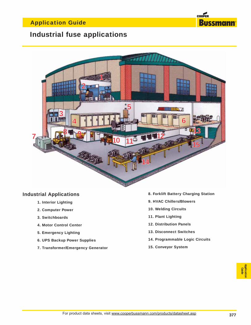
Industrial Applications
1. Interior Lighting
2. Computer Power
3. Switchboards
4. Motor Control Center
5. Emergency Lighting
6. UPS Backup Power Supplies
7. Transformer/Emergency Generator
8. Forklift Battery Charging Station
9. HVAC Chillers/Blowers
10. Welding Circuits
11. Plant Lighting
12. Distribution Panels
13. Disconnect Switches
14. Programmable Logic Circuits
15. Conveyor System

For product data sheets, visit www.cooperbussmann.com/products/datasheet.asp378
Application Guide
Commercial fuse applications
13
45
6 7
8 9 10 11
12
2
Commercial Applications
1. Interior Lighting
2. HVAC Blowers
3. Computer Power
4. Branch Circuits
5. Emergency Lighting
6. Load Centers
7. Disconnect/Distribution Panels
8. HVAC/Chillers
9. Switchboards/Motor Control Centers
10. UPS Backup Power Supplies
11. Elevator Control Centers
12. Transformer/Emergency Generator
For product data sheets, visit www.cooperbussmann.com/products/datasheet.asp 379
Application Guide
ApplicationGuide
379
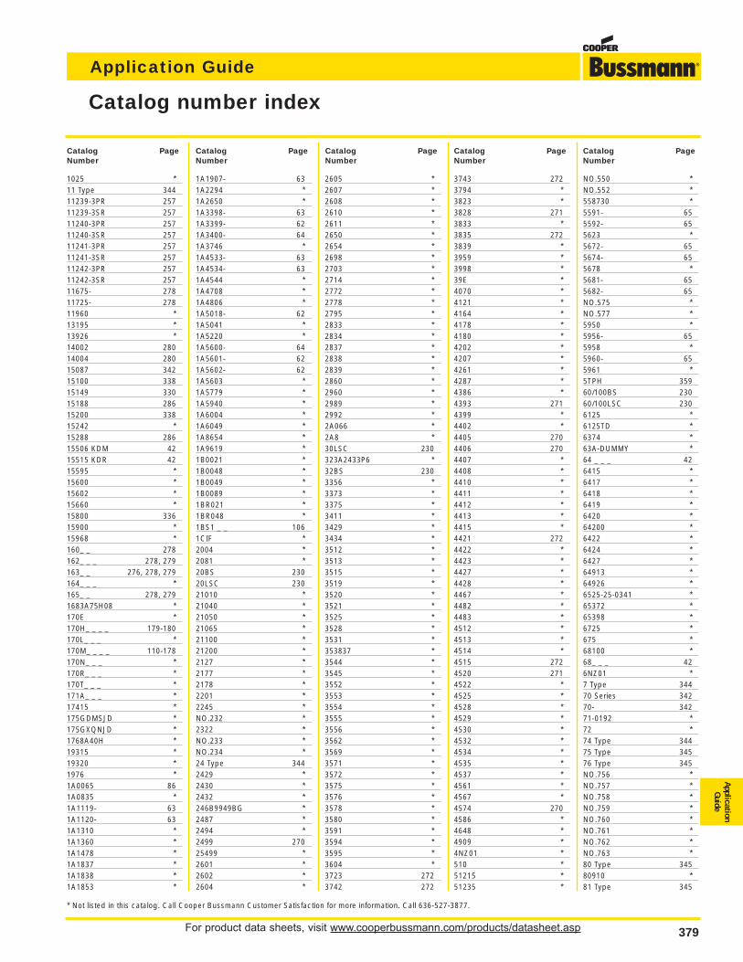
Catalog number index
1025 *11 Type 34411239-3PR 25711239-3SR 25711240-3PR 25711240-3SR 25711241-3PR 25711241-3SR 25711242-3PR 25711242-3SR 25711675- 27811725- 27811960 *13195 *13926 *14002 28014004 28015087 34215100 33815149 33015188 28615200 33815242 *15288 28615506 KDM 4215515 KDR 4215595 *15600 *15602 *15660 *15800 33615900 *15968 *160_ _ 278162_ _ _ 278, 279163_ _ 276, 278, 279164_ _ _ *165_ _ 278, 2791683A75H08 *170E *170H_ _ _ _ 179-180170L_ _ _ *170M_ _ _ _ 110-178170N_ _ _ *170R_ _ _ *170T_ _ _ *171A_ _ _ *17415 *175GDMSJD *175GXQNJD *1768A40H *19315 *19320 *1976 *1A0065 861A0835 *1A1119- 631A1120- 631A1310 *1A1360 *1A1478 *1A1837 *1A1838 *1A1853 *
1A1907- 631A2294 *1A2650 *1A3398- 631A3399- 621A3400- 641A3746 *1A4533- 631A4534- 631A4544 *1A4708 *1A4806 *1A5018- 621A5041 *1A5220 *1A5600- 641A5601- 621A5602- 621A5603 *1A5779 *1A5940 *1A6004 *1A6049 *1A8654 *1A9619 *1B0021 *1B0048 *1B0049 *1B0089 *1BR021 *1BR048 *1BS1 _ _ 1061CIF *2004 *2081 *20BS 23020LSC 23021010 *21040 *21050 *21065 *21100 *21200 *2127 *2177 *2178 *2201 *2245 *NO.232 *2322 *NO.233 *NO.234 *24 Type 3442429 *2430 *2432 *246B9949BG *2487 *2494 *2499 27025499 *2601 *2602 *2604 *
2605 *2607 *2608 *2610 *2611 *2650 *2654 *2698 *2703 *2714 *2772 *2778 *2795 *2833 *2834 *2837 *2838 *2839 *2860 *2960 *2989 *2992 *2A066 *2A8 *30LSC 230323A2433P6 *32BS 2303356 *3373 *3375 *3411 *3429 *3434 *3512 *3513 *3515 *3519 *3520 *3521 *3525 *3528 *3531 *353837 *3544 *3545 *3552 *3553 *3554 *3555 *3556 *3562 *3569 *3571 *3572 *3575 *3576 *3578 *3580 *3591 *3594 *3595 *3604 *3723 2723742 272
3743 2723794 *3823 *3828 2713833 *3835 2723839 *3959 *3998 *39E *4070 *4121 *4164 *4178 *4180 *4202 *4207 *4261 *4287 *4386 *4393 2714399 *4402 *4405 2704406 2704407 *4408 *4410 *4411 *4412 *4413 *4415 *4421 2724422 *4423 *4427 *4428 *4467 *4482 *4483 *4512 *4513 *4514 *4515 2724520 2714522 *4525 *4528 *4529 *4530 *4532 *4534 *4535 *4537 *4561 *4567 *4574 2704586 *4648 *4909 *4NZ01 *510 *51215 *51235 *
NO.550 *NO.552 *558730 *5591- 655592- 655623 *5672- 655674- 655678 *5681- 655682- 65NO.575 *NO.577 *5950 *5956- 655958 *5960- 655961 *5TPH 35960/100BS 23060/100LSC 2306125 *6125TD *6374 *63A-DUMMY *64 _ _ _ 426415 *6417 *6418 *6419 *6420 *64200 *6422 *6424 *6427 *64913 *64926 *6525-25-0341 *65372 *65398 *6725 *675 *68100 *68_ _ _ 426NZ01 *7 Type 34470 Series 34270- 34271-0192 *72 *74 Type 34475 Type 34576 Type 345NO.756 *NO.757 *NO.758 *NO.759 *NO.760 *NO.761 *NO.762 *NO.763 *80 Type 34580910 *81 Type 345
Catalog PageNumber
Catalog PageNumber
Catalog PageNumber
Catalog PageNumber
Catalog PageNumber
* Not listed in this catalog. Call Cooper Bussmann Customer Satisfaction for more information. Call 636-527-3877.

For product data sheets, visit www.cooperbussmann.com/products/datasheet.asp380
Application Guide
380
Catalog number index
82048 *8414677 *84345 *8456A85H *847966108 *8583A36H *8588A81H *88914568 *9078A67G04 869435 *9483 *9732 *9789 *9834 *9835 *9838 *9841 *9843 *A3354705 *A3354710 86A3354720 *A3354730 86A3354745 *A404302 *AAO 221ABC 58ABC-V 58ABCNA 82ABFNA 82ABGNA 82ABS *ABU *ABWNA 82AC 222ACB *ACF *ACH *ACK *ACL *ACO *AD 222ADL *ADLSJ 81ADOSJ 81AF *AFS *AFX *AGA 57AGA-V 57AGC 58AGC-V 58AGS *AGU *AGW 57AGX 57AGX-V 57AGY *AL-D 240ALS *ALW *AMG *AMI *AMWNA 82ANL 48
ANN 48ASZ350B3 *AT *ATC 49ATF *ATM 49B22- 329B40 *B48 *B83 *B84 *B93 *BAF 43BAN 43BAO 221BBS 46BBU 69BBU-EFID *BC 222BC603 _ _ _ 256BCA603 _ _ _ 255BCC *BCCM *BCCM603 *BCF *BD 222BDAUX _ 324BDDHK *BDF *BDFH *BDFL *BDH _ _ 310, 313, 315, 321,
323, 326BDH79 309BDNF _ _ _ _ 323BDS _ _ _ 310, 312, 323BDST _ _ 310BDTA _ 311, 313BDTL _ _ _ 311, 313, 323BDTS _ _ 324BDZD *BDZW *BDZX _ _ 324BFW *BG30 _ _ _ _ 256BGH *BH- _ _ _ _ 257BH-_ XXX 106BM603 _ _ 256BMA603 _ _ _ 255BNQ21-WH 289BP/AGX *BP/GLH *BP/MAS *BP/XMAS *BP655 *BQE *BQQ41-WH 289BRT *BRW *C08G 227C08M 228C08NL 240C10G 227
C10M 228C10NL 240C14G 227C14G_S 229C14M 228C14M_S 229C14NL 240C19 *C22G 227C22G_S 229C22M 228C22M_S 229C22NL 240C2617 *C2791 *C2909 *C30BS 230C30F 230C30FBS 230C4044 *C4534 *C4559 *C515 54C517 54C518 54C519 54C520 54C5237 *C5268- 106C5898 *C60BS 230C60F 230C60FBS 230C6344 *C7018 *C7019 *C7020 *C7021- 349C7024- 350CAV 82CAVH 82CB123 *CB174 *CB174B *CB174M *CB181F *CB181P *CB184F *CB184P *CB185 *CB185P *CB1911 *CB1921 *CB203107S2105 *CB211 *CB212 *CB221 *CB222 *CB223 *CB3 *CB5 *CBB *CBC *CBD *
CBF *CBP *CBS *CBT *CBU *CCB *CCC *CCE *CCG *CCSK-45 355CD 222CD1 *CD100 *CD27 *CD33 *CDAUX _ _ _ 311CDB *CDBY _ _ _ _ _ 320CDC *CDE *CDH4 310CDHX _ _ _310, 313, 315, 321,
323, 326CDHZX_ 322CDH_S 308, 315, 320, 322CDMB *CDMC1 320CDN 215CDN63P *CDNF _ _ _ 320, 321, 322CDS 215CDS _ _ T 321CDS _ _ _P 309, 321CDS _ _ _S 308, 320CDS6 *CDS8 *CDS9 *CDSWM 320CDTL *CDTS *CEO 221CFC60J 311CFCVR100 311CFD- 307-310CFZ _ 311CFTS100 311CFZ *CGL 216CH _ _ J _ 236CH _ _ J _I 236CH08 _ _ _ _ 239CH10 *CH10CL *CH10CM *CH14 _ _ _ _ 239CH14-HP 240CH14MS- _ D 240CH22 _ _ _ _ 239CH810-HP 240CHCC _ _ 239CHM _ _ _ _ 239CIF06 217CIF21 217CIH 219
CIK 219CIL 219CJ 218CM _ _ _ CF 230CM_ _CF *CP14002 *CPB16 _ 278CPDB- 278CPS-C *CS/XMAS-6F *CT 185CUG *D125 223D16 223D27 223D33 223DCM 44DD 222DEO 221DFC *DIA *DLN-R 30DLS-R 30DRA-1 358DRA-2 358DRLC-A *E-6188 *EBI055- 71ECF *ECL055- 71ECL155- 72ECNR *ECSR *ED 222EDA *EET 185EF 222EFC- 314, 316, 317EFF *EFH *EFJ- 314, 316, 317EFL *EFS 222EK *ELN *EN6 *ENA *ENF- 325, 326, 327, 328ENN *EP _ M230 _ _ GCC 305ERK-28 356ERS2 *ERS30 *ESD 221ET 185ETF *EVF *F01A *F02A *F02B *F03A *F03B *F06A *F07A *
Index
Catalog PageNumber
Catalog PageNumber
Catalog PageNumber
Catalog PageNumber
Catalog PageNumber
* Not listed in this catalog. Call Cooper Bussmann Customer Satisfaction for more information. Call 636-527-3877.

For product data sheets, visit www.cooperbussmann.com/products/datasheet.asp 381
Application Guide
ApplicationGuide
381
F09A *F09B *F10A *F15A *F15B *F16A *F16B *F19B *F29A *F38- 346F380 *F60C *F61C *F62C *F63C *F64C *F65C *F7036- 348FA02 *FA2A *FA4H *FBI 61FBM 61FBP *FC *FCB *FCC *FCU *FD _ _ _ _ _ 312FDM *FE 185FE2475- 347FEE 185FEH *FF 222FG 222FH2 *FHL *FHN *FL- *FL11H_ _ 85FL11K_ _ 85FL11N_ _ *FL11T_ _ 85FL12K _ _ 85FL1A5 *FL3H *FL3K _ _ _ 85FL3T _ _ _ 85FLB *FLD *FLF *FLM *FLN *FLS *FM 185FM01A *FM08A *FM09A *FM09B *FMM 185FMX *FNA 47FNJ *
FNM 45FNQ 45FNQ-R 31FNW *FP-2 359FP-3 359FP-4 359FP-6 359FP-A3 359FR-1000 *FRN-R 22FRS-R 24FSD *FT-2 359FT-3 359FTI *FTM *FWA 91, 93, 192FWC 200FWH 97, 196-199FWJ 104, 208FWK 206FWL 210FWP 101, 202-205FWS 210FWX 95, 194G30060 *GBA 47GBB 58GBB-V 58GBC *GDA 55GDA-V 55GDB 55GDB-V 55GDC 55GDC-V 55GF 222GFA *GG 222GH 222GKB *GKJ *GLD 47GLH *GLN *GLP 230GLQ 51GLR 52GLX *GMA 56GMA-V 56GMC 56GMC-V 56GMD 56GMD-V 56GMF 52GMQ 51GMT 343GMT-A 343GMW *GOB *GRF 52GSK-260 355
H25 _ _ _ - _ 242H60 _ _ _ - _ 245HAC-R *HAS-R *HBC *HBH-I 61HBH-M 61HBM *HBO *HBP- *HBS- *HBV-I 61HBV-M 61HBW-I 61HBW-M 61HC- *HC1 *HC2 *HC3 *HC7 *HC8 *HCM *HEB 261HEC 261HEF *HEG 261HEH 261HEJ 261HET 261HEX 261HEY 261HFA 260HFB 259HFB-10 259HGA *HGB *HGC *HHB 259HHC 50HHD 50HHF 50HHG 50HHH *HHI *HHJ *HHK *HHL 50HHM 50HHN *HHR *HHT 260HHX 50HIF *HJL 267HJM *HK- 267HKA *HKL *HKP 264HKP-BBHH 264HKP-HH 264HKP-L 264HKP-LW-HH 264HKP-OO 264
HKP-W 264HKQ *HKR 267HKT 267HKU 267HKX 267HLA *HLD 267HLQ 51HLR 52HLS 343HLT 343HM 260HME *HMF *HMG *HMH *HMI *HMJ *HMK *HMR *HN-1 *HN-3 *HN-5 *HOB *HOF *HPC-D 269HPD 268HPF 268HPG 268HPL *HPM 269HPS 268HPS2 269HR 260HRC 220HRE *HRF *HRG *HRH *HRI *HRJ *HRK 259HSK *HTB- 265-266HTC-10M *HTC-140M 62HTC-15M 62HTC-200M 62HTC-210M 62HTC-30M 263HTC-35M 263HTC-40M 263HTC-45M 60HTC-50M 60HTC-55M 263HTC-60M 60HTC-65M 60HTC-70M 263HVA 83HVB 83HVJ 83HVL 83HVR 83
HVT 83HVU 83HVW 83HVX 83HWA *IXL70F *J-13 360J-16 316J-21 360J-23 360J-26 360J-41 360J-42 360J-62 360J-63 360J-64 360J-_ _ 360J101/J *J201/J *J301/J *J60 _ _ _ - _ _ 248J70100 *JB1 *JB3 *JCA *JCD- 74JCE- 74JCG- 77JCH- 77JCI- 74JCK- 77JCK-A- 77JCK-B- 77JCL- 77JCL-A- 77JCL-B- 77JCM *JCN *JCP *JCQ- 74JCR- 77JCR-B- 77JCT- 74JCU- 75JCW- 74JCX- 75JCY- 75JCZ- 75JDN *JDZ- 75JF1 *JJN- 32JJS- 33JKS 25JN *JP60030 - _ _ _ _ 250JPA-3 *JSK-36 355JT(N)60030 237JT(N)60060 237JT60030 237JT60060 237JTN60030 237JTN60060 237
Catalog number index
Catalog PageNumber
Catalog PageNumber
Catalog PageNumber
Catalog PageNumber
Catalog PageNumber
* Not listed in this catalog. Call Cooper Bussmann Customer Satisfaction for more information. Call 636-527-3877.

For product data sheets, visit www.cooperbussmann.com/products/datasheet.asp382
Application Guide
382
JU *KAA *KAB *KAC 99KAD *KAF *KAJ *KAL *KAW *KAX *KAZ 48KBC 100KBD *KBJ *KBO *KBR *KBT *KBY *KCA 42KCB 42KCC 42KCD 42KCE 42KCF 42KCH 42KCJ 42KCM 42KCM-B 42KCR 42KCS 42KCV 42KCY 42KCZ 42KDA 42KDB 42KDC 42KDD 42KDE 42KDF 42KDH 42KDJ 42KDM 42KDP 42KDR 42KDT 42KDU 42KDY 42KEF *KEM *KER *KEW 42KEX 42KFH-A 42KFM 42KFT 42KFZ 42KGC *KGJ *KGJ-A *KGJ-E *KGL *KGO-E *KGS *KGS-A *
KGT *KGX *KGY *KIG 42KJA *KJB *KLC *KLM 43KLP *KLU 29KMH-C *KOS15 *KPF 42KQO 42KQT 42KQV 42KQW-M *KRP-CL 21KRP-C_SP 20KS-19392-L36 *KT3-RE *KT3-WH 288KT4-WH 288KTE *KTJ *KTK 43KTK-R 28KTN-R 26KTN-S *KTQ 46KTS-R 27KTS-S *KTU 29KU- 299KWN-R *KWS-R *LA *LA8D324 *LAA *LAC *LAG *LAN *LAR *LCT 182LCU *LD1 *LD2 *LEF *LET 182LKB *LKC *LKN *LKS *LMMT 182LMT 182LP-CC 19LPF1- *LPJ-SPI 15LPJ_SP 15LPN-RK_SP 16LPN-RK_SPI 16LPRK-28 356LPS-RK_SP 16LPS-RK_SPI 16
LPT *LS1D3 *MA-5 *MAI *MAS *MAX 49MB- *MBO *MCRW *MDA 59MDA-V 59MDF *MDL 59MDL-V 59MDM *MDQ 59MDQ-V 59MDX *MEQ *MFN *MIC 47MIJ *MIN 47MIS 48MKA *MKB *MKG *MMB *MMT 185MP2 *MP2A *MPR *MS100 *MSK-45 355MSL *MSW710 *MT 185MT12 *MTC6 *MTH *MTMU *MV055- 73MV155- 73N512-BK 284NBB *NBC *NBE *NC3-WH 285ND-1260 *NDN 282NDN1-WH 283NDN111- 283NDN3- 282NDN63- 282NDNA100 311NDNAS *NDND1 *NDNF1-WH 273NDNFD1 *NDNLFD1 273NDNV4- 282NFA *NFT2-WH 284NFT3- 284
NFTA *NH _ _ G-690 226NH _ _ _ M 226NHG _ _ _ B 224NI *NITD 221NNB 360NNB-R 360NNC 360No. 1 358No. 100 *No. 140 357No. 15 *No. 2 358No. 200 *No. 201 *No. 204 *No. 205 *No. 213 360No. 216 360No. 220 357No. 226 360No. 242 360No. 2621 360No. 263 360No. 2641 360No. 2642 360No. 2661 360No. 2662 360No. 2664 360No. 270 357No. 2880 *No. 36 356No. 4 358No. 5 358No. 6 358No. 7 358No. 8 358NON 35NOS 35NPL *NRA37 *NSD 221NSE3-WH 285NSS3-WH 285NTN-R- 360NTQ23-WH 289NTS-R- 360NUE *NXA *NXC *NZ01 223NZ02 223NZ_ _ 223OEFMA 84OEGMA 84OHFMA 84OHGMA 84OIA *OJ *OLGMA 84OPM-1038 232, 233OPM-NG-SC3 234OPM-NG-SM3 234
OPMNGSA 234OPMNGSAAUX 234OPMRH 320OSD 221OSP *PCB *PCC *PCD *PCF *PCG *PCH *PCI- *PCT 343PF1 *PLK3- 288PLU1-WH 287PLU11 *PLU111 *PLU3- 287PMP 306PON 215PS 306PS1RPLSW *PSU1-WH 287QC202/J *QC203/J *R25 _ _ _ - _ 243R60 _ _ _ - _ 246REG *REN *RES *RFI *RFL *RK1SK-39 355RK5SK-39 355RLA *RLC *RYA *RYC *S- 37S-8001 270S-8002 270S-8101 270S-8102 270S-8201 270S-8202 270S-8203 270S-8301 270S3Holder *S500 *S501 *S504 *S505 *S506 *SA- 37SAMI- 241SB *SC 34SCV15 *SCV20 *SCY 258SDA *SDLSJ 81SDMSJ 81
Catalog number index
Index
Catalog PageNumber
Catalog PageNumber
Catalog PageNumber
Catalog PageNumber
Catalog PageNumber
* Not listed in this catalog. Call Cooper Bussmann Customer Satisfaction for more information. Call 636-527-3877.

For product data sheets, visit www.cooperbussmann.com/products/datasheet.asp 383
Application Guide
ApplicationGuide
383
Catalog number index
SDQ *SDQSJ 81SEW-5B *SF25H *SFB1030 *SFC-FUSE-CAB 359SFD27 *SFE *SFLSJ 81SFMSJ 81SFQSJ 81SFR *SFR1 *SKA 258SKLSJ 81SL- 36SM363 _ _ 304SNF-7K *SNF-7M *SNL-7K *SOA72 *SOU 258SOW 258SOX 258SOY 258SOY-B 258SPJ *SPP *SRA-R *SRD *SRT-A *SRU 258SRU-BC *SRW 258SRX 258SRY 258SSD 221SSN *SSU 258SSW 258SSX 258SSY 258SSY-RL 258STD 221STI *STM *STY 258SYC *SZQ *T- 37T1320-2R *T30 _ _ _ - _ _ _ 251T60 _ _ _ - _ _ _ 253TB100- 290TB200- 292TB200HB- 292TB300- 294TB345- 294TB400- 298TBM-14M 42TC *TCF 13TCFH 13TCP *
TDC *TDC10 *TDC11 *TDC180 *TDC600 *TDP *TFC *TFF *TFL *TGC *TGH *THL *TIQ *TJD *TL- 36TP/MDA-B-30 *TP158HC 337TP15900 *TP15900-4 335TP15914 334TP2 *TP3 *TP4 *TPA 335TPA-B 335TPB *TPC 332TPCDS 332TPH *TPHCS- 339TPJ *TPL 340TPM 333TPMDS 333TPN 341TPS 336TPSFH- _ _ _ 359TPW *TPWDS *TR6/MCRW *TRF *TS- 300-302TVS- 352TVSS- 353UCB *UHA *UHC *UHJ *UHS *UHT *UHW *ULR *VFNHA 80VKNHA 80W- 36WDFHO 80WDLSJ 80 & 81WDOH6 80WDOSJ 81WER 344WFFHO 80WFLSJ 80 & 81WFMSJ 80WFNHO 80
WFOH6 80WFOSJ 81WGA *WHA *WHN *WIE *WJON6 80WKB *WKFHO 80WKH *WKJ *WKK *WKL *WKLSJ 81WKMSJ 80 & 81WKNHO 80WKS *WKU *WKV *WLF *WMB *WMM *WMQ *WPQ *WQL *WQN *WQP *WSE *WSH *WSL *WSM *WSP *WSQ *WST *WSU *WTJ *WTK *WTT *WTZ *WUC *WUD *WUE *WUG *WUH *WUI *WUQ *WUR *WUU *WUV *WUW *WUY *WVA *WVQ *WVR *WWD *WWE *WWF *WWG *WWI *WWK *WWL *WWU *WWV *WWX *
WYG *WYM *WZC *WZJ *WZK *WZL *WZX *XL25X *XL50F *XL70F *
Catalog PageNumber
Catalog PageNumber
Catalog PageNumber
Catalog PageNumber
Catalog PageNumber
* Not listed in this catalog. Call Cooper Bussmann Customer Satisfaction for more information. Call 636-527-3877.

For product data sheets, visit www.cooperbussmann.com/products/datasheet.asp384
Application Guide
World HeadquartersCooper Bussmann
P. O. Box 14460
St. Louis, Missouri 63178-4460 USA
Telephone: 636/394-2877
Fax: 800/544-2570
Email: [email protected]
Asian HeadquartersCooper Bussmann
Cooper Electric (Shanghai) Co. Ltd.
28th Floor Yu An Building
738 Dongfang Road
Pudong, Shanghai 200122 China
Telephone: 8621-5831-6805
Fax: 8621-6876-5532
European HeadquartersCooper (UK) Ltd.
Bussmann Division
Burton-on-the-Wolds
Leicestershire LE12 5th England
Telephone: 44-1509-882737
Fax: 44-1509-882786
Bussmann Asia-Pacific1 Jalan Kilang Timor
#06-01 Pacific Tech Centre
Singapore 159303
Republic of Singapore
Telephone: 65-6278-6151
Fax: 65-6278-3151
Email: [email protected]
Bussmann Australia205 – 209 Woodpark Road
P O Box 2577
Smithfield NSW 2164
Australia
Telephone: 61-2-8787-2700
Fax: 61-2-9609-2746
Bussmann BrasilBussmann do Brasil Ltda.
Rodovia Santos Dumont, km 23
13.300-000, Caixa Postal 095
Itu – Sao Paulo Brasil
Telephone: 55-11-4024-8400
Fax: 55-11-4024-8424
Bussmann Denmark5 Literbuen
DK-2740 Skovlunde
Copenhagen Denmark
Telephone: 45-4485-0900
Fax: 45-4485-0901
Bussmann India#3 EVR Street, Sedarapet
Pondicherry – 605 111
India
Telephone: 91-413-2678203
or 91-413-2678204
Fax: 91-413-267-7010
Bussmann MexicoCooper Wiring Devices
Poniente 148 No. 933
Industrial Vallejo
02300 Mexico, D.F. Mexico
Telephone: 52-55-57-47-4519, Ext 3219
Fax: 52-55-57-52-5336
Cooper Bussmann Transportation175 Hansen Court
Wood Dale, IL 60191
Telephone: 630/422-2400
Fax: 630/422-2500
Cooper Electronic Technologies3601 Quantum Blvd.
Boynton Beach, FL 33426
Telephone: 561/752-5000
Fax: 561/742-0134
Enbray ContactorsEnbray Cooper (U.K.) Limited
Salterbeck Industrial Est.
Workington, Cumbria CA14 5DT England
Telephone: 44-1946-839000
Fax: 44-1946-833000
Email: [email protected]
Sales Support & Manufacturing Facilities
Related Documents