THARSYS NAPA CENTER – 3, Rue Ariane – Parc Technologique du Canal — Ramonville 31520 — FRANCE SARL au capital de 1 000 000 FF — TVA FR 65 378 445 647 Tél. +33 (0)5 61 75 15 87 — Fax +33 (0)5 61 75 15 89 Email :[email protected] FUSE Application Experiment 182 Improvement of the electronics and display for a dashboard for automotive applications

Welcome message from author
This document is posted to help you gain knowledge. Please leave a comment to let me know what you think about it! Share it to your friends and learn new things together.
Transcript

THARSYS
NAPA CENTER – 3, Rue Ariane – Parc Technologique du Canal — Ramonville 31520 — FRANCESARL au capital de 1 000 000 FF — TVA FR 65 378 445 647
Tél. +33 (0)5 61 75 15 87 — Fax +33 (0)5 61 75 15 89 Email :[email protected]
FUSEApplication Experiment 182
Improvement of the electronics and display for adashboard for automotive applications

THARSYS
FUSE Application Experiment 182 2
ABSTRACT
THARSYS has 6 employees and produces electronic equipments for Space and Automotiveapplications. One of their products is an electronic dashboard for racing cars. This dashboardis very accurate (50 rpm resolution) with a special design for drivers on circuits, which makesit an ideal instrument for teaching and training. The thousand rpm indication uses a 7 segmentdisplay, while the hundreds and fifties are handled as a luminous needle.
The objective of the Application Experiment (AE) was to improve the performance, addfunctions and flexibility to the THARSYS dashboard and reduce its cost.
The existing display part of the dashboard requires a large number of parts (140) and is costlyto manufacture. It comprises 12 seven-segment-LEDs, 20 LEDs, one specially made plasticbar to hold the LEDs in place, 2 Display controller components, 29 MOS transistors, 24operational amplifiers, and 52 resistors.
In this AE the display was replaced by one custom graphic LCD screen and the number offunctions was increased by implementing microcontroller external logic in FPGA. Theupgraded product becomes adaptable to a large number of vehicles. It is also improvedergonomically.
The use of an integrated solution provides advantages through cost and assembly timereduction. With the extra functionality, the manufacturing cost is reduced by 10%. Thecommercial margin is nearly doubled and hence the potential market is significantly larger.
The duration of the AE was 16 months as opposed to the 11 months planned and cost 107 KECU. It cost a further 38K ECU to productionise the unit. The payback period will bearound 2 years, and assuming a 4 year product life cycle the ROI will be around 200%.
During the AE, THARSYS acquired the knowledge of two technologies:
The experience in FPGA design and use of VHDL will enable the transfer of this technologyto other products for car products and embedded computers.
The know how in custom LCD screen definition, integration and utilisation will be used forother display systems for cars and to other industrial fields than space computers andautomotive applications.

THARSYS
FUSE Application Experiment 182 3
1. COMPANY NAME AND ADDRESS
THARSYS
3, Rue Ariane
31520 Ramonville saint-Agne
FRANCE
Tél. +33 5 61 75 15 87
Fax +33 5 61 75 15 89
2. COMPANY SIZE
The number of employees is 6, with 3 involved in electronic development and 2 in softwaredevelopment.
3. COMPANY BUSINESS DESCRIPTION
THARSYS are specialists in computers and embedded software development, initially forspace applications. In 1992 they diversified in to the automotive electronic sector.
Their activities involve the design and manufacturing of computers, electronic equipment anddisplay systems, the production of small and medium series (from a few units to severalthousand) and the development of test equipment.
In 1992, THARSYS succeeded to diversify their activities towards automotive electronic andelectrical systems. Their products now include digital dashboards for race cars, looms,electrical control units, safety LED rain lights approved by FIA and automatic gear box ratiotest equipment.
The expertise of the company can be summarised by its capability to integrate mechanics,electronics and software in to the following types of products:
Automobile looms and electronics,
Spacecraft data handling systems,
Real time computer software development (ADA, C, C++ and assembly languages),
Ground systems and scientific software development under UNIX, DOS, WINDOWS,
Man /Machine Interfaces,
Industrialisation of electronic products.
THARSYS design their own products, perform part procurement, assembly and test. PCBrouting and most of the manufacturing is subcontracted. They produce typically 400 partsper year for each type of product.
4. COMPANY MARKETS AND CURRENT COMPETITIVE POSITION AT THE START OF THE AE
The company Fields of Activities are:
• Automotive (40%)
• Space (50%)
THARSYS
FUSE Application Experiment 182 4
• Industry (10%)
Current products are single board computers used by large aerospace firms in the USA and inEurope, and national and international space agencies for the evaluation of ASICs, thedevelopment of embedded software and the implementation of spacecraft simulators.
VME Single Board Computers using the GEC Plessey radiation hardened microprocessorMA31750 and its Memory Management Unit MA31751 are available.
VME Single Board Computers using the Matra Harris Semiconductor / TEMIC radiationhardened 32 bit Reduced Instruction Set (RISC) SPARC microprocessor, floating point unitand memory extension controller are under development.
The automotive market now represents around 40% of THARSYS turnover. Concerningdashboards, THARSYS equip a number of race cars (single seaters):
• Formule Renault (FR 95, FR96 series)
• Campus cars
• FORD Formula cars
The number of active racing cars can be estimated around 10000. 80% are equipped withconventional electromechanical instrumentation. 20% only are equipped with digitalinstrumentation. THARSYS market share is around 30% of them, which represents 10% ofthe potential market.
The market remains largely to be equipped with potential extensions represented by karts,motorcycles and sport cars.
The geographical distribution is:
• France: 50% (mainly automotive activities)
• European Union and Switzerland: 35% (mainly space activities)
• USA and India: 15% (space activities)
The space market clients are large European and USA aerospace firms and national orinternational space organisations, such as the Indian Space Research Organisation( ISRO),CNES, ESA, UK defence Research Agency.
The automotive market is represented by large companies promoting race car activities, ordeveloping sport cars and a number of SMEs manufacturing racing cars.
Automotive activities are stable in Europe, but presently offer development opportunities inSouth America (Brazil and Argentina), Indonesia and China.
The recent economic crisis in South East Asia might delay the sales of Campus cars equippedwith THARSYS dashboards.
THARSYS Single Board Computers for space activities have no commercially availablecompetitive products. Before the AE, the company was outclassed by all competitors forwhat concerns the capability of designing microelectronics circuits. The AE allowsTHARSYS to be in a position to compete for the design of specialised circuits. For manyapplications, FPGA prototypes have indeed to be developed to validate designs beforeimplementation in ASICs.

THARSYS
FUSE Application Experiment 182 5
Sales of the electronic dashboard were 25% of total company sales in 1995, and dropped to10% in 1996.
The drop on the national market was due to a lack of performances of the existing product.Competitors offered a product initially developed for Formula 1 race cars with morefunctions, such as:
• LCD display
• Flexibility
• Data logging functions
• Standard CAN interfaces allowing data acquisition from the engine control units.
It was essential for THARSYS to upgrade their product to the level of the competitorsproduct. The competitors offering rather expensive products, so the AE should allowTHARSYS to re-gain its original market share thanks to a better price/quality ratio. Though80% of the potential market is not yet equipped with digital instrumentation, ancient cars arerarely upgraded. So the competition is restricted to new cars
5. PRODUCT TO BE IMPROVED AND ITS INDUSTRIAL SECTOR
The existing dashboard was very accurate (50 rpm resolution) with an adapted design forracing car drivers on circuits, which makes it an ideal instrument for teaching and training.
The thousand rpm indication used a 7 segment display, while the hundreds and fifties werehandled as a luminous needle.
Presently, the display part of the Dashboard requires a large number of parts (140):
12 seven-segment-LEDs, 20 LEDs, one specially made plastic bar to hold the LEDs in place, 2Display controller components, 29 MOS transistors, 24 operational amplifiers, and 52resistors were necessary to implement all the functions.
The overall dimensions of the unit were 200 x 100 x 30mm, and the mass was 0.6kg.
Reliability (mtbf) was not an issue since the products are only used for a few hours.However, the product was resistant to environmental conditions (waterproof, high vibrationlevels, and shock. It was also highly protected against hazardous conditions to coversituations where users would ignore the standard test procedures.
Of the total product cost, 50% is due to the electronic components, 20% for the mechanicalcomponents and 30% for assembly and test.

THARSYS
FUSE Application Experiment 182 6
6. DESCRIPTION OF THE PRODUCT IMPROVEMENTS
The product improvements can be summarised as follows:
Power
Real TimeClock
CPU
LED Drivers
AnalogInputs
Logic Inputs
Outputs
LEDs
IGNITION
START
RAIN
Powersupply
T° waterT° oilPr bar oilPr bar fuel
AlarmsIgnistartrainmaxi
Shift gear
CURRENT DASHBOARD
The improved product block diagram is:
Power
Real TimeClock
UART+
Interface RS232
FPGA
CPU+
Memory
LCD Driver
CANInterface
AnalogInputs
Logic Inputs
Timer Inputs
Outputs
LCD
IGNITION
START
RAINMemory Dump
(parallel)
PC
Powersupply
T° waterT° oilPbar oilPbar fuelVbatFuel gaugeGear potSpare ana1,2,3,4
AlarmsLoadIgni, start, rain,maxi, record,set/resetTopperLightsSpare log 1,2,3
TachySpeedSpare timer 1
CAN BUS Shift gear ruptor
IMPROVED DASHBOARD

THARSYS
FUSE Application Experiment 182 7
Functions Current Improved
Functional modes Race Race, Road, Training, Practice, shift gearreprogrammation, gear-box tuning,engine ruptor tuning.
rpm indication 0 to 9950 0 to 19950
Data logging 1 sample (maxvalue)
up to 2 Mbytes data recording
Data acquisition limited to race cars extended for race and road cars
Display LED's various LCD screens
Sequential gear-box interface none yes, with potentiometer/gear tuning
PC interface none RS232
Fast parallel data dump
CAN bus interface none Yes
Engine ruptor none yes, with ruptor action tuning
The mass and volume of the new product are the same as for the existing product. It was alsodesigned to meet the same environmental requirements and hazardous, non standard testconditions
The total cost of the new product, with all the additional features described was 20% less thanthe existing product. This saving was largely attributed to a reduction in the assembly and testtime.
The functions included into the FPGA are all new. In the previous product LEDs were used,whilst in the new product these have been replaced with a custom graphic LCD. A number ofadditional functions have also been added which are achieved by the use of the FPGA.
The display was replaced by one custom graphic LCD screen. The number of functions wasincreased and the amount of components was reduced by implementing microcontrollerexternal logic (data multiplexing and fast data dump) in FPGA.
The advantage of the LCD screen is that several displays are foreseen and can be selectedaccording to the user's needs.
The new dashboard can be used in road, race and training conditions.
ü A system of menus is provided.
ü Updates of essential features, such as the value triggering the gear shift alarms can bereprogrammed externally, while the initial version implements a rudimentary system basedon PCB electrical track scratching.
ü Specific training functions, such as engine ruptor control for a proper use of gear boxes canbe provided.
ü Data logging and data dump functions are proposed as options.
Such functions are useful to train pilots. During tests, essential data, such as the angle of thesteering wheel, engine RPM, longitudinal and lateral accelerations, clutched gear can be

THARSYS
FUSE Application Experiment 182 8
recorded by the dashboard. At the end of the training session, data is dumped to a portablePC and displayed. A correlation between the performances and these data is performed by theteam leader/teacher to analyse the pilots behaviour, correct defects, and improve results.
For example, a common trend for pilots is indeed to change down gears before braking. This isnot efficient and represents a loss of time. An appropriate driving style is to accelerate, reachand maintain a maximum speed, then to apply the brakes before changing down. In case ofdamages, for example on an engine, a subsequent data analysis allows also to arbitrate betweenthe engine manufacturer and the pilot and to charge repair fees to the responsible.
Such functions increase the potential market of the existing product, at the express conditionof a moderate price.
An important feature is the speed of the data dump between the dashboard and the PC toavoid costly and exasperating loss of time on circuits.
The use of an FPGA integrating direct memory access and fast parallel input/output linksallows THARSYS to achieve this goal with a minimum number of components.
Furthermore, due to the physical separation between data logging and display functions, theproduct improved in the framework of the AE is modular and can be delivered in threeversions:
- a data logger (black box), mainly for road cars (pre-series testing),
- a dashboard for road, race cars and motorcycles,
- a dashboard with logging functions, mainly for race cars.
NEW DASHBOARD DISPLAY

THARSYS
FUSE Application Experiment 182 9

THARSYS
FUSE Application Experiment 182 10
7. CHOICES AND RATIONALE FOR THE SELECTED TECHNOLOGIES AND METHODOLOGIES
The FPGA technology was selected due to its great flexibility and reprogrammability. ASICtechnology was also envisaged at the beginning, but this technology is relatively expensive,and the low dashboards sold per year (a few hundreds maximum), with reasonable costconstraints, would not justify the use of ASIC technology.
Moreover, with the ASIC technology, including new functionalities due to a new LCD displaywould mean expensive design modifications and a return to the foundry.
The use of an additional micro controller was not considered an economical or technicallyviable solution. Adding another micro-controller would have implied a significant designcomplication due to duplication of memory, additional software development, problems ofmore than one clock on the same PCB and communication between both micro-controllers.
A slave FPGA was considered to be the best technical solution since it offered betterperformance and a simpler design.
Following the recommendation of the TTN, THARSYS chose to design their FPGA usingVery High Description Language (VHDL), instead of schematic capture.
Using VHDL allows easier component evolution. It appears more practical to modify VHDLfiles to include new functions rather than modifying schematics.
Another positive aspect is that VHDL language can be easily read by engineers which mayhave basic computer science language, without being experts in electronics.
Investing in VHDL was also important for the First User, because VHDL is widely used inthe Aerospace domain. Many components are specifically designed for space applications,and VHDL models at component or even board levels must be provided by the designers.
Choice of FPGA technology
The selection criteria between ALTERA, XILINX, FPGA and Lattice 6000 series was mainlythe availability of appropriate training and the cost of development tools. The selection ofXILINX was favourably influenced by the large experience of this company since 1987.
Several FPGA component families are available on the market. Among them, XILINXappeared to have the largest diffusion. One great advantage was that XILINX offers a broadrange of components with identical pin-out configuration. This means that a circuit can beupgraded with no other change than removing the FPGA.
Internal functionalities can be increased without the need for PCB redesign, which is a costlyoperation (In the case of THARSYS, routing and PCB manufacturing are subcontracted).
Choice of development tools
A review of available development tools was made with the help and TTN support of theTTN.
The selected development tool was Foundation, by AXESS technology (XACT) for Windows95 on PC.

THARSYS
FUSE Application Experiment 182 11
This tool was selected due to its relatively low price and the possibility to install them onto aPC based platform.
The complexity of the function was then evaluated, which demonstrated that a 4K gateversion would meet the requirements. The selected FPGA device was eventually the XC4003E, which offers 4K gates.
With this approach, it was possible to start with a small and cheap version, with the freedomto extend the licence to 25 K gate components in the future if required.
Display technology
Since no standard screen model met the requirements, it was necessary to develop a customscreen. User requirements were investigated, especially in terms of viewing angle for thedriver, thermal environment and ambient light variations.
A transreflective LCD type with antireflection polariser was selected, with a 12 hours visionangle.
The operating conditions are typical of automotive applications: -30°C to +80°C.
The definition of the various data to display led to a total number of 195 segments to drive.
The other components in the improved dashboard are:
An 8 bit NEC 78P014 microcontroller with 32 Kword of EPROM was selected, mainly due tothe availability in the company of software development tool for this device and previousdevelopment experience. The improved dashboard implying the introduction of twotechnologies, it was felt more secure to keep a well known component for the processor.
A MAX1232, with LTC 1232 as a second source was selected to implement the reset andwatchdog functions.
In order to allow the physical separation between the microcontroller board and the displayscreen, a serial interface between the micro and the LCD screen driver was selected.
A commercially available LCD display driver was selected. The selection criteria being itscapability to drive the required number of segments. A 60 output NEC µPD16430A devicewas found adequate to drive the screen in quadruplexed mode.
Flash EPROM was selected, with byte addressing mode. The design allows both the use of128 Kbytes chips (1 Mbyte total memory size) and 256 Kbytes chips for a total size of 2Mbytes.
For 1 Mbyte of memory, 8 Thomson 28F101 chips are used.
An existing Phillips CAN 82C200 driver was selected for the CAN interface.
8. EXPERTISE AND EXPERIENCE IN MICROELECTRONICS OF THE COMPANY AND THE STAFF
ALLOCATED TO THE PROJECT
In terms of electronics, most development work includes analogue data conditioningelectronics, microprocessors, microcontrollers and programmable logic (PALs).
Before the AE, the company had experience in conventional electronics, and digital boarddesign but little competence and no design tools for microelectronics. They were not able inparticular to perform any simulation prior to implementation.

THARSYS
FUSE Application Experiment 182 12
This represented a weakness for future development, at a time when requirements in logicintegration and complexity are increasing.
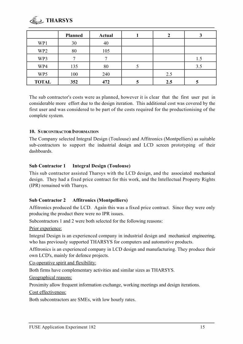
9. WORK PLAN
The Gantt chart below shows the planned and actual work plan. The top line (in grey) wasthe planned work, and the bottom line (in blue) the actual work.
The key phases of the AE are described as follows:
1 Work Package 1 Management
Tharsys were the overall project manager for the AE. They first prepared the project plan,with assistance from their TTN and input from the sub contractors. They then organisedregular meetings with their sub contractors to ensure that the project was proceeding to plan.The main slip in the programme was caused by limited internal resources, which meant thatthey had to make a management decision to slip the project. The internal resource level wasalso monitored during the project.
2 Work Package 2 System specification
The first work was to identify in details all necessary functions for the improved dashboard,which allowed to define the LCD display. Potential customers were contacted to define themost appropriate product. Several brain storming sessions involving the whole company werededicated to this work. The specification work was carried out in two phases. The reason for
ID me M-2 M-1 M1 M2 M3 M4 M5 M6 M7 M8 M9 M10 M11 M12 M13 M14 M15 M16

THARSYS
FUSE Application Experiment 182 13
this was that during the first detailed design and prototype testing some problems wereencountered, and hence a complete design iteration, which included an update to thespecification was required.
3 Work Package 3 Training
Personnel from Tharsys attended 2 training courses: VHDL synthesis - 3 days, and XILINXFPGA design - 4 days. In addition they were given some on-the-job training during the designof the FPGA.
4 Work Package 4 Design
The design was broken down in to system level, and then sub system level. The sub systemswere:
4.1 LCD display design
All LCD screen segments were designed, a subcontractor performed the mechanical andindustrial design, which required several iterations. The LCD screen was routed. This processtook around four months due to the size and shape of the display segments.
4.2 Display screen driver board PCB
A PCB carrying the display was designed, routed and manufactured. This element ismechanically mandatory to provide a clean rigid interface for the zebra connectors between theLCD screen contact tracks and the driver's electronics. This board carries 20 CMS chips,which is a significant improvement compared to the 140 components necessary in the oldproduct.
4.3 Microprocessor board development
The design of the processor board was performed, with gradual implementation and electricaltesting of all functions.
4.4 Software development
The embedded software was developed, implementing first all basic interface andcommunication functions.
Software was developed on PC, using IAR systems microprocessor development tool forNEC 78K/0 series.
4.5 FPGA development
The FPGA functions were implemented with a top down methodology, starting withschematics. Each function (FIFO, multiplexer, control, standard parallel port, nibblemanagement) was synthesised and functionally simulated. For each function, it was necessaryto perform 5 or 6 iterations. In spite of a brand new 133MHz Pentium dedicated to thisactivity, the time required for design synthesis was found to be extremely long. Facilities forthe test vectors definition was found also rather poor. However, the schematics tools werejudged to be quite efficient.

THARSYS
FUSE Application Experiment 182 14
5 Work Package 5 Evaluation
Each part was evaluated independently, and then tested as a complete system.
5.1 LCD display design
Three successive LCD prototypes were produced. The original one showed fading segmentsand had one wrong segment. The error on the segment was due to design communicationproblems between France and China, were the design is actually made. The support is stillfaxed paper, which does not allow to catch small details. This was corrected by a redesign ofthe LCD screen. The fading effects are due to the fact that the display takes most of the screensurface. Very little room is left for the electrical tracks on the external part of the screen. sovery thin tracks were implemented leading to a poor conductivity. Direct pin connectors weretested, in case the zebra connector resistivity would be too high, with no improvement. Adifferent liquid crystal was used with a higher driving voltage, with better results.
5.2 Microprocessor
Monitor functions, basic software communications functions and memory managementfunctions were tested on the microprocessor board, mostly with the help of a portable PC.
A simple hardware tester was developed to simulate varying analogue data sources to test theacquisition functions.
5.3 Integrated system
The LCD display was connected and all segment controls checked, the automatic test softwareactivated groups of segments corresponding to the dashboard menus.
The FPGA was installed and functionally tested on the microprocessor board, the downloadprobe from XILINX was used, rather than burning EPROMs.
Some difficulties were found in the development of the test software on the PC side, Windows95 creating obstacles to the access of hardware.
At last, functional tests were carried out, using the hardware test tool to validate the completeunit. These tests included data acquisition, display, data logging and dump functions.
Timescales and resources
The total development took 16 months, instead of 11, as originally planned. Three months(Months 5 to 7 inclusive) of the 5 months delay was due to Tharsys receiving an importantorder during the AE. The small size of the company meant that personnel had to be movedshort term from the AE on to the other work. The other 2 months delay was due more timethan planned to produce and test the prototypes.
EffortFirst User man days
Actual
Sub Contractors Costs (K ECU)
THARSYS
FUSE Application Experiment 182 15
Planned Actual 1 2 3
WP1 30 40
WP2 80 105
WP3 7 7 1.5
WP4 135 80 5 3.5
WP5 100 240 2.5
TOTAL 352 472 5 2.5 5
The sub contractor's costs were as planned, however it is clear that the first user put inconsiderable more effort due to the design iteration. This additional cost was covered by thefirst user and was considered to be part of the costs required for the productionising of thecomplete system.
10. S UBCONTRACTOR INFORMATION
The Company selected Integral Design (Toulouse) and Affitronics (Montpelliers) as suitablesub-contractors to support the industrial design and LCD screen prototyping of theirdashboards.
Sub Contractor 1 Integral Design (Toulouse)
This sub contractor assisted Tharsys with the LCD design, and the associated mechanicaldesign. They had a fixed price contract for this work, and the Intellectual Property Rights(IPR) remained with Tharsys.
Sub Contractor 2 Affitronics (Montpelliers)
Affitronics produced the LCD. Again this was a fixed price contract. Since they were onlyproducing the product there were no IPR issues.
Subcontractors 1 and 2 were both selected for the following reasons:
Prior experience:
Integral Design is an experienced company in industrial design and mechanical engineering,who has previously supported THARSYS for computers and automotive products.
Affitronics is an experienced company in LCD design and manufacturing. They produce theirown LCD's, mainly for defence projects.
Co-operative spirit and flexibility:
Both firms have complementary activities and similar sizes as THARSYS.
Geographical reasons:
Proximity allow frequent information exchange, working meetings and design iterations.
Cost effectiveness:
Both subcontractors are SMEs, with low hourly rates.

THARSYS
FUSE Application Experiment 182 16
Sub Contractor 3 AIME
In addition, AIME (Atelier Interuniversitaire de Micro-Electronique) in Toulouse was selectedas a subcontractor for training and FPGA design support.
AIME is the local node for JESSICA, the French part of the European JESSI SMI SUPPORTprogramme.
As a member of JESSICA GRAND SUD OUEST, since February 1994, THARSYS engineersand technicians had the opportunity to attend a number of training sessions, (in particularPSPICE analogue simulation modelling tools and Electromagnetic Compatibility issues).
The quality of the training sessions, their low cost and immediate proximity make that AIMEwas an ideal partner for XILINX FPGA training and technical design support.
AIME provided two training sessions
• VHDL synthesis - 3 days
• XILINX FPGA design - 4 days
In addition 5 days of FPGA design support were supplied to Tharsys during the AE byAIME, as part of the Jessica programme. Since this was a Government initiative, standardcontracts were issued, and all IPR remained with Tharsys.
11. BARRIERS PERCEIVED BY THE COMPANY IN THE FIRST USE OF THE PROPOSED TECHNOLOGIES
Knowledge barriers
The company was aware of the necessity to improve the dashboard, both from display andfunctionality point of view, and this was clearly demonstrated by the sales drop in 1997,resulting from the loss of a market equivalent to the cumulated sales of 1995 and 1997.
The need for LCD display and microelectronics to implement more complex functions wascrucial.
Several questions were pending:
- How to develop a custom LCD for automotive application?
- How to find it at a less unreasonable price than indicated by preliminary contacts?
- In which type of microelectronics to invest between apparently similar devices (Lattice,Xilinx, Altera).
- What is VHDL, and which benefits to expect from this methodology?
- Which design methodology should be used (schematics, logic equations)?
- Which development tool is the most appropriate - each one being more user friendly,reliable and efficient than the other, according to each software house marketing - andwhich costly options to purchase?
The development tool issue was rather worrying. In addition to the financial aspects, evencustomers contacted by the company seemed rather biased on this subject (exactly as peoplemay show excess for programming languages). One objective of the company being to provide

THARSYS
FUSE Application Experiment 182 17
compatible tools with important potential customers, this point was a matter of concern atmanagement level.
Psychological barriers
The move to microelectronics was then felt as risky.
The move to LCD displays was also felt risky because of the nature of the display (glass andliquid crystals), which appeared difficult to propose for race cars, in spite of successfulimplementations by the competitors.
As a consequence it was rather considered to invest in different physical presentations of theproduct, such as including into a steering wheel, as can be seen in some Formula 1 cars, ratherthan redefining its electronics and display.
Financial barriers
Due to the recent diversification of the company activities towards automotive electronics, theinvestment for the automotive dashboard was far from being written off, hence somedifficulties to face the necessary additional investment:
• LCD design,
• LCD prototypes,
• FPGA design tools,
• Powerful workstation to perform simulations with decent execution times,
• Important manpower effort.
AIME provided an essential technical support, which is detailed in section 12.
12. S TEPS TAKEN TO OVERCOME BARRIERS TO ARRIVE AT AN IMPROVED PRODUCT
In general terms, the TTN support was essential to overcome many barriers.
Passed contacts and successful training sessions with AIME (Atelier Interuniversitaire enMicroélectronique) had established confidence .
Knowledge barriers
The TTN organised information meetings about the FUSE programme, which showed thatmany other SMEs experienced similar situations.
Two training sessions on VHDL design and XILINX FPGA design gave some theoretical andpractical background to the technical team.
For the LCD display, a small specialised firm was found, with lower prices than the marketleader. They provided technology transfer about the various types of LCD technologies,demonstrated LCD screen manufacturing process in their facilities, took part to the designfeasibility and provided many practical details concerning screen interface control issues, forexample zebra connectors and interface electronics.

THARSYS
FUSE Application Experiment 182 18
Psychological barriers
The TTN appeared as a neutral expert for the selection of microelectronics devices anddevelopment tools. Their practical experience, combined with the feedback they have frommany microelectronics developers allowed to size the complexity of the component to bedeveloped and to define which would be the most adequate product to purchase. Thiscontributed to take sound decision for the selection of development tools. The TTN also gavea continuous very useful support. First at the reception of the development tool to handle theXILINX XACT tool, which is complex, with many layers and logical interactions. The TTNhelped to kick off properly the development by showing the importance of top-downmethodology and its practical implementation. They then monitored the implementationphase, reviewed the design and gave precious detailed indications, out of reach for a newcomer,such as the most appropriate VHDL statements to optimise component resources.
Support for project management and reporting was also given, which was seen as crucial to thesuccess of the project by Tharsys.
13. KNOWLEDGE AND EXPERIENCE ACQUIRED
Significant progress has been achieved by THARSYS thanks to the knowledge and experienceacquired during this AE.
For future projects, THARSYS has improved its work methodology and invested in additionalVHDL tools.
In the immediate term, mid 1997, THARSYS is developing a complex VME Single BoardComputer using the Matra Harris semiconductor radiation hardened 32 bit SPARC RISCprocessor.
Following the AE, it was decided to switch to VHDL for the design based on Lattice isp LSI3256 ( 160 pins, 11000 gates, 256 macro-cell High-Density PLD)
THARSYS has since purchased the isp VHDL Viewlogic System.
Further work in 1998 is to model neuronal networks for space communications applications.This will be performed using VHDL, in order to assess the implementation feasibility of suchsystems. This work will be carried out in the framework of the ACTS programme (Newtestexperiment).
Control and display systems using LCD screens are also proposed to potential customers, forautomotive and industrial applications.
14. LESSONS LEARNED
THARSYS
FUSE Application Experiment 182 19
During the development of the AE, which took a little more than one year, the company hasmainly accumulated technical experience, which makes it more competitive both in the fieldsof space and automotive applications.
The development of a XILINX FPGA, with the most recent tools allowed Tharsys to covermost of the microelectronics development problems and gave an essential experience to thecompany. Nevertheless, the complexity of the development tools and the diversity ofpossible implementations made possible by microelectronics, means that progress is stillnecessary in order for THARSYS to reach the highest level in this technology.
The initial impulse has been given thanks to the Fuse AE and the company has already madeplans to develop new microelectronic products over the next two years, which will build onthis experience.
But the most important lesson is the understanding that the company must continuously stickto the best technology level, and shall dedicate efforts with this goal, even if a fulldevelopment is not always possible.
15. RESULTING PRODUCT, ITS INDUSTRIALISATION AND INTERNAL REPLICATION
The industrialisation of the improved dashboard took a further 5 months and cost anadditional 37K ECU. The final product is now on the market, and orders are being received.
From the AE, THARSYS have acquired knowledge in the design of XILINX FPGA familyusing VHDL language. THARSYS is now able to design and evaluate hardware systems andplans to include XILINX FPGA in some of their new projects, without the help of anysubcontractor. The next projects in 1997/1998 using VHDL language are ongoing in theframework of one EC Research and Development programme, ACTS/Newtest and thedevelopment of a Single Board Computer for the French and European Space Agencies.
The LCD display will also be used for a specific display control unit in a new car usinginnovative propulsion modes.
16. ECONOMIC IMPACT AND IMPROVEMENT IN COMPETITIVE POSITION
The improved dashboard reaches a performance level, which makes it technically equal orsuperior or equal to the three known competitive products.
It can be used on all types of sport and road cars and motorcycles.
The most complete version of the improved dashboard is 20% less expensive to produce thanthe previous model, and can be sold for a further 50%.

THARSYS
FUSE Application Experiment 182 20
The realised and expected sales for the old and new products are (in units):
In terms of margins, the figures are as follows:
0 F
50,000 F
100,000 F
150,000 F
200,000 F
250,000 F
300,000 F
350,000 F
400,000 F
450,000 F
500,000 F
1 2 3 4 5 6
margin old product margin new product
The total product development cost was 145 K ECU for which the payback period will bearound 2 years. Assuming a 4 year produce life cycle, and a steadying of the sales figures afteryear 3 the ROI will be around 200%.
050
100
150200250
300350400
1995 1996 1997 1998 1999 2000 2001Sales old product
Sales new product

THARSYS
FUSE Application Experiment 182 21
17. TARGET AUDIENCE FOR DISSEMINATION
This AE describes how a First User (FU), with 6 employees introduced FPGA technology into a dashboard used by the automotive market. The dashboard is really a training aid, andhence a fairly niche market. The AE has however demonstrated the benefits that can beachieved by moving to a digital hardware solution using a FPGA from a micro controller basedproduct.
The FU was able to reduce the complexity of the product and thus reduce the cost, and alsogreatly improve the functionality.
The FU followed Best Practice procedures in that they were trained in and then used VHDLto design the FPGA. They have subsequently used VHDL to design new products withoutthe need for a sub contractor.
Other companies that may benefit from this AE are those with no knowledge of designingusing digital micro-electronics, and have no experience in VHDL. The companies are likely tobe small and are likely to be familiar with micro-controllers.
Whilst this AE is concerned with the development of a dashboard used in the automotivesector for training, replication should not be restricted to this industrial sector. In generalterms the AE combines analogue and digital data acquisition, real time embedded software, realtime data display, and data logging and dumping.
Such functions are met in all sorts of systems including:
- dashboards for transport systems (cars, busses, aircraft, ships)
- dashboards for specialised equipment (agriculture, public works)
- control and monitoring panels units (for example control units for energy distributionnetworks)
The target audience for dissemination becomes very large and includes a number of industrialsectors including:
3430 VL (Vehicle for land transportation)
3511 VS (Vehicles for sea transportation)
2924 + 2950 EQ (Machinery, electrical and optical equipment)
2932 AF (Agriculture and forestry)
3330 Industrial Process Control
Related Documents