October 14, 2008 Dr. Andrew Rawicz School of Engineering Science Simon Fraser University Burnaby, British Columbia V5A 1S6 Re: ENSC 440 Functional Specifications: Cyclic Technologies Anti‐lock Braking System (ABS) Dear Dr. Rawicz: Attached with this letter is the Functional Specifications for Cyclic Technologies ABS System. We are developing an ABS system for bicycles that would enable riders to maintain more control and stop faster during hard braking events. The ABS system will improve rider safety by enabling cyclists to maintain better control of their bicycles and avoid accidents. This functional specification outlines the requirements and goals of our product for both the proof‐of‐concept and production phases of development. The specification and test plans for individual modules are presented. Each specification is prioritized, within each module, during design and development of the product. Cyclic Technologies consists of five dedicated, resourceful, and enthusiastic engineering students: Zack Blair, Amir Tavakoli, Rahm Lavon, Datis Danesh, and Milad Gougani. Our team brings together people with different skill sets and experience which will help Cyclic Technologies to achieve its goals. Should you require additional information or would like to meet us in person, please feel free to contact us at cyclic‐[email protected]. Sincerely, Cyclic Technologies Enclosure: Functional Specifications for Cyclic Technologies Anti‐lock Braking System

Welcome message from author
This document is posted to help you gain knowledge. Please leave a comment to let me know what you think about it! Share it to your friends and learn new things together.
Transcript

October 14, 2008 Dr. Andrew Rawicz School of Engineering Science Simon Fraser University Burnaby, British Columbia V5A 1S6
Re: ENSC 440 Functional Specifications: Cyclic Technologies Anti‐lock Braking System (ABS)
Dear Dr. Rawicz:
Attached with this letter is the Functional Specifications for Cyclic Technologies ABS System. We are developing an ABS system for bicycles that would enable riders to maintain more control and stop faster during hard braking events. The ABS system will improve rider safety by enabling cyclists to maintain better control of their bicycles and avoid accidents.
This functional specification outlines the requirements and goals of our product for both the proof‐of‐concept and production phases of development. The specification and test plans for individual modules are presented. Each specification is prioritized, within each module, during design and development of the product.
Cyclic Technologies consists of five dedicated, resourceful, and enthusiastic engineering students: Zack Blair, Amir Tavakoli, Rahm Lavon, Datis Danesh, and Milad Gougani. Our team brings together people with different skill sets and experience which will help Cyclic Technologies to achieve its goals.
Should you require additional information or would like to meet us in person, please feel free to contact us at cyclic‐[email protected].
Sincerely,
Cyclic Technologies
Enclosure: Functional Specifications for Cyclic Technologies Anti‐lock Braking System

Submitted to: Dr. Andrew Rawicz – ENSC 440
Mike Sjoerdsma – ENSC 305
School of Engineering Science
Simon Fraser University
10/14/08
Functional Specification
Project team:
Milad Gougani
Rahm Lavon
Datis Danesh
Amir Tavakoli
Zack Blair
Contact person: Amir Tavakoli
cyclic‐[email protected]
Bicycle Anti‐lock Braking System

Bicycle ABS Functional Specification
Copyright ©2008, Cyclic Technologies ii
Executive Summary
Bicycling can be a very dangerous activity, largely because bicyclists have little to no protection relative to other vehicles on the road. In 2001, Transport Canada recorded 60 bicyclist fatalities and thousands of bicyclist injuries [1]. Governments have mandated safety equipment like helmets to protect cyclists in the event of an accident, but as any experienced bicyclist will tell you, keeping safe on a bike is largely about avoiding accidents in the first place. To meet this need for better bicycling safety, Cyclic Technologies is developing an antilock braking system (ABS) for bicycles that will help cyclists to avoid accidents by enabling them to stop faster and with more control.
Development of the Cyclic Technologies ABS system will be achieved in two stages: proof‐of‐concept phase and prototyping phase. Currently the engineering team is entering the POC phase in the ABS development cycle, spanning from October to December of 2008. By the end of this phase, a fully functional mock‐up model of the Cyclic Technologies ABS system is expected to be released. The engineering team will then closely analyze the system and its major modules to determine the feasibility of the product to be introduced to the market. The major modules of the ABS system that will be studied closely are:
ECU (Electronic Control Unit)
Speed sensors
HCU (Hydraulic Control Unit)
Once it’s been approved, the ABS system will enter next phase of its development cycle which is prototyping phase. In this phase, Cyclic Technologies ABS mock‐up model will undergo a significant make over to satisfy all the functional requirements and industry standards. Once the system has been prototyped, it will go through a thorough test plan where all subsystems functionality will be tested to the smallest detail. Only then the Cyclic Technologies ABS system will be introduced to the market.

Bicycle ABS Functional Specification
Copyright ©2008, Cyclic Technologies iii
Table of Contents
Executive Summary ..........................................................................................................................ii
List of Figures ................................................................................................................................... v
Glossary ............................................................................................................................................ v
1. Introduction ............................................................................................................................. 1
1.1 Purpose statement ........................................................................................................... 1 1.2 Intended Audience ........................................................................................................... 1 1.3 Classification ..................................................................................................................... 1
2. System Requirements .............................................................................................................. 2
2.1 System Overview .............................................................................................................. 2 2.2 General Requirements ..................................................................................................... 3 2.3 Physical Requirements ..................................................................................................... 3 2.4 Electrical Requirements (ECU) ......................................................................................... 3 2.5 Mechanical Requirements (HCU) ..................................................................................... 4 2.6 Environmental Requirements .......................................................................................... 4 2.7 Standards .......................................................................................................................... 4 2.8 Reliability and Durability .................................................................................................. 5 2.9 Safety Requirements ........................................................................................................ 5 2.10 Performance Requirements ............................................................................................. 5 2.11 Usability Requirements .................................................................................................... 5 2.12 Advance Functions ........................................................................................................... 6
3. Electronic Control Unit (ECU) .................................................................................................. 6
3.1 Performance Requirements ............................................................................................. 6
4. Speed Sensors .......................................................................................................................... 6
4.1 Performance Requirements ............................................................................................. 6 4.2 Physical Requirements ..................................................................................................... 7
5. Actuators ................................................................................................................................. 7
5.1 Valves ............................................................................................................................... 7 5.2 Pumps ............................................................................................................................... 7
6. User Interface Unit .................................................................................................................. 8
6.1 General Requirement ....................................................................................................... 8

Bicycle ABS Functional Specification
Copyright ©2008, Cyclic Technologies iv
6.2 Usability Requirements .................................................................................................... 8 6.3 Physical Requirements ..................................................................................................... 8
7. User Documentation ............................................................................................................... 9
8. System Test Plan ...................................................................................................................... 9
8.1 Scope ................................................................................................................................ 9 8.2 Goals ................................................................................................................................. 9 8.3 Approach ........................................................................................................................ 10 8.4 Unit Test ......................................................................................................................... 10 8.5 Acceptance Test ............................................................................................................. 19
9. Conclusion ............................................................................................................................. 19
10. References ............................................................................................................................. 20
11. Technical Appendices ............................................................................................................ 21
11.1 User Interface Unit Mockup ........................................................................................... 21

Bicycle ABS Functional Specification
Copyright ©2008, Cyclic Technologies v
List of Figures
Figure 1: System overview .............................................................................................................. 2
Figure 2: System Block Diagram ...................................................................................................... 3
Glossary
ECU Electronic Control Unit
HCU Hydraulic Control Unit
NEMA National Electrical Manufacturers Association
FCC Federal Communications Commission
UI User interface
GPS Global Positioning System

Bicycle ABS Functional Specification
Copyright ©2008, Cyclic Technologies 1
1. Introduction The Cyclic Technologies ABS system is a one‐of‐a‐kind electromechanical braking system used on bicycles, making them safer, reliable, and more practical than ever before. The systems novelty lies on the fact that it can detect and prevent wheel lock‐up during hard braking event thereby enabling riders to maintain better control of their bicycles and avoid accidents.
1.1 Purpose statement This document summarizes the functional requirements of Cyclic Technologies' ABS system and its interdependent subsystems. The functional requirements are prioritized and will be considered in great detail in the design phase of the product. Because of time constraints, the low priority requirements will not be considered in the Proof‐Of‐Concept phase. By the end of this phase the Cyclic Technology team is determined to have a fully functional mock‐up model satisfying the high priority functional requirements discussed hereby.
1.2 Intended Audience The functional specification document is intended to be a design guideline for the engineering team as it summarized all the functional requirements of the system. This document will further guide engineers in the design to implementation phase. Then during the test phase, the functional requirements of the system will be compared to the functionality of the actual product to ensure safety and reliability of the end product and help the engineering team to trace the abnormalities of the system. Last but not least marketing will use this document to arrange sales strategies. Any description provided in this document will be protected as Cyclic Technologies' intellectual property.
1.3 Classification Each requirement is denoted by a Requirement Number (RN), and the RN format proceeds as follows:
[RX‐Y]
Below is a description of the RN:
R Denotes the word "Requirement". X Denotes the requirement number. Y Denotes the priority and can take on one of two values: “H” for high priority and “L” for low priority.

Bicycle ABS Functional Specification
Copyright ©2008, Cyclic Technologies 2
2. System Requirements
2.1 System Overview
Cyclic Technologies ABS will be composed of an Electronic Control Unit (ECU), two wheel speed sensors (one for each wheel), and a Hydraulic Control Unit (HCU) as shown in Figure 1. The wheel speed sensors also double as induction generators, recharging the batteries inside the ECU which operates the system. Also included are two LCD displays that show a speedometer and an odometer, along with an optional pressure sensor for the rear suspension.
Figure 1: System overview
2.1.1 System functionality
When a cyclist has to brake hard – to avoid an obstacle or another vehicle – they often risk skidding and flipping over, especially on wet or slippery surfaces. Cyclic Technologies’ ABS system prevents wheel lock‐up during hard braking and provides the user with the ability to easily customize the braking system’s performance using a menu‐driven user interface on an LCD display.
2.1.2 Subsystems functionality
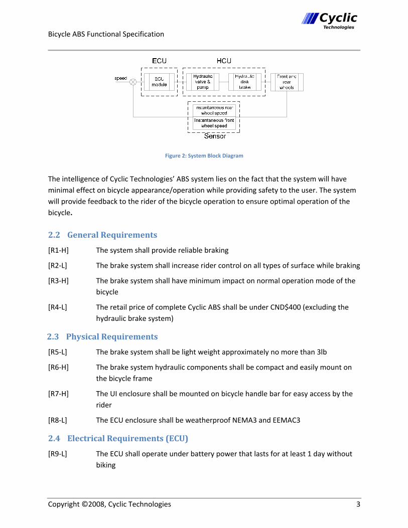
The ECU constantly collects data from front and rear speed sensors. When it senses that there is an acute differential deceleration (i.e. wheel lock), it will actuate the valve to reduce the pressure applied to the caliper. This effectively reduces braking force on the disk brake the wheel then turns faster. A fraction of a second later, the pressure is reapplied [2]. The system is expected to continuously execute the process up to 10 times per second [3]. The Cyclic Technologies’ ABS system can be modeled at high‐level as shown in Figure 2.
Bicycle ABS Functional Specification
Copyright ©2008, Cyclic Technologies 3
Figure 2: System Block Diagram
The intelligence of Cyclic Technologies’ ABS system lies on the fact that the system will have minimal effect on bicycle appearance/operation while providing safety to the user. The system will provide feedback to the rider of the bicycle operation to ensure optimal operation of the bicycle.
2.2 General Requirements [R1‐H] The system shall provide reliable braking
[R2‐L] The brake system shall increase rider control on all types of surface while braking
[R3‐H] The brake system shall have minimum impact on normal operation mode of the bicycle
[R4‐L] The retail price of complete Cyclic ABS shall be under CND$400 (excluding the hydraulic brake system)
2.3 Physical Requirements [R5‐L] The brake system shall be light weight approximately no more than 3lb
[R6‐H] The brake system hydraulic components shall be compact and easily mount on the bicycle frame
[R7‐H] The UI enclosure shall be mounted on bicycle handle bar for easy access by the rider
[R8‐L] The ECU enclosure shall be weatherproof NEMA3 and EEMAC3
2.4 Electrical Requirements (ECU)
[R9‐L] The ECU shall operate under battery power that lasts for at least 1 day without biking

Bicycle ABS Functional Specification
Copyright ©2008, Cyclic Technologies 4
[R10‐L] The battery shall be recharged by biking so that the batteries do not normally need to be replaced
[R11‐H] The ECU shall enter into a low‐power mode and turn‐off the LCD screen after 10 minutes of inactivity (no buttons pressed, zero wheel speed, and brakes not applied) and then restore itself automatically when a button is pressed, wheel speed becomes non‐zero, or the brakes are applied
2.5 Mechanical Requirements (HCU)
[R12‐L] The ABS shall operate normally while experiencing external shock of up to 10g
[R13‐H] The ABS shall not require the operator to apply work to the system to facilitate the braking operation
[R14‐H] The ABS shall function through the standard braking interface, i.e., the standard brake lever mounted on the handlebar
[R15‐L] The ABS shall not require the application of a force greater than 25 kg on the interface
[R16‐L] The ABS shall require the input of work from the bicycle's motion while the operator is braking, but not sufficient work to interfere with the antilock feature
[R17‐H] The ABS shall require the input of work from the bicycle's motion while the operator is not braking, but it must be almost imperceptible to the operator
[R18‐H] The HCU shall be able to engage and disengage the braking action of the bicycle within 20 milliseconds
2.6 Environmental Requirements [R19‐L] The ABS shall operate normally with in elevation range of sea level to 2000m above sea level
[R20‐L] The ABS shall operate normally with in industrial temperature range from ‐40OC to +85OC
[R21‐H] The noise level of hydraulic vale and pump shall be minimized during anti‐brake modulation period of operation‐ no more than 30dB
[R22‐L] The system shall operate normally in all weather condition the bicycle can be used
2.7 Standards
[R23‐L] The Cyclic ABS shall comply with ANSI standards

Bicycle ABS Functional Specification
Copyright ©2008, Cyclic Technologies 5
[R24‐ L] The ECU components shall comply with FCC standards [4]
[R25‐ L] The Cyclic ABS shall comply with Institute of Electrical and Electronics Engineers (IEEE) standard [5]
2.8 Reliability and Durability [R26‐H] The ABS shall withstand harsh braking conditions for all types of riders with different skill levels
[R27‐H] The ABS shall need minimum maintenance period of 6 months
[R28‐H] The ABS shall have no effect on Hydraulic brake system reliability and durability
[R29‐L] The ABS shall have minimum of 6 hours of continues braking operation without need of replenishing power source
[R30‐H] The end user shall be able to perform simple system maintenance such as replenishing power source and hydraulic fluid on the ABS system
[R31‐H] The mean time between failures of the ABS shall not exceed 8800 hours
2.9 Safety Requirements
[R32‐H] The ABS shall be fail safe, malfunction in ABS module shall not cause brake failure
[R33‐H] The hydraulic fluid shall not combust due to heat dissipation during braking
[R34‐L] The electronic and mechanical components shall be enclosed
[R35‐H] The electronic components shall not cause interference with other devices
[R36‐H] The ABS shall detect mechanical and electrical malfunction. In case of error the system shall notify the rider and the ABS shall be bypassed
2.10 Performance Requirements
[R37‐H] The ECU shall start sampling and provide the rider with average instantaneous speed after 5 sec of motion
[R38‐H] The ABS module shall engage within 20 ms from the time the rider applies the brake
2.11 Usability Requirements
[R39‐H] The system shall have user friendly interface
[R40‐L] The system shall be light enough for minimum impact on bicycle performance

Bicycle ABS Functional Specification
Copyright ©2008, Cyclic Technologies 6
[R41‐L] The system shall be upgradable by train technician
[R42‐L] The system shall have an interface port with a PC for diagnostic purposes
2.12 Advance Functions
[R43‐L] The system shall be equipped with GPS system
[R44‐L] The system shall be equipped with rear view camera
[R45‐L] The system shall be equipped with heart rate monitor
3. Electronic Control Unit (ECU) The function of the Electronic Control Unit (ECU) is to continuously monitor wheel speed and break lever position, process that information, and actuate the brakes to avoid wheel lockup and skidding in real‐time. Additionally, the ECU provides a user interface (UI) shown on a 2x16 backlit character LCD display that lets the user monitor their speed and distance travelled, and to configure various options of the ABS system.
3.1 Performance Requirements [R46‐H] The ECU shall be able to respond changes in wheel speed in fractions of a second
[R47‐H] The ECU shall be designed so that even unreasonable demands placed on the UI (for example due to someone rapidly pressing all of the buttons at once) do not prevent it from responding to ABS‐related processes in a timely fashion
4. Speed Sensors The function of the sensor unit is to provide data (i.e. wheel speed) to ECU. The cyclic technologies use industry standard Hall Effect sensors. The quantity of two units shall be mounted on bicycles front and back fork. Alternating polarity magnets shall be mounted on each wheel rim with 60O intervals.
4.1 Performance Requirements [R48‐H] The sensor shall have quiescent temperature‐stable output voltage
[R49‐H] The sensor shall operate within 4.5 to 5.5 V
[R50‐H] The sensor shall immune to mechanical stress
[R51‐H] The sensor shall have Solid‐state reliability

Bicycle ABS Functional Specification
Copyright ©2008, Cyclic Technologies 7
4.2 Physical Requirements [R52‐H] The sensor shall be Compact and light
[R53‐L] The sensor shall be Weatherproof
[R54‐L] The sensor shall come complete with flange and strap for mounting on bicycle fort and back fork
5. Actuators In a typical bicycle, the operator may apply a force of up to 25 kg to the brake lever. This in turn drives a piston with an area of about 6 square mm into the brake line. This develops a pressure of roughly 70,000 KG/ meter squared, or 700 bar. Since we are modifying such a high pressure system, all components must be able to withstand these high pressures.
5.1 Valves Valves are the heart of the HCU. They enable the ECU to control the oil flow in the hydraulics kit thereby controlling brakes. A 3 way normally open valve will be used for this purpose. The basic functionality is to regulate the oil flow between input and output. The third port can be used to as a diverter to give an alternate path for the fluid.
5.1.1 Performance Requirements
[R55‐H] The hydraulic valve shall withstand pressures as great as 700 Bar
[R56‐H] The hydraulic valve shall operate on a low voltage (at or near 12VDC) and with low current (at or near 1Amp)
[R57‐H] The hydraulic valve shall withstand Petroleum distillates and so their seals must be approved for DOT fluid or mineral oil
[R58‐L] The hydraulic valve shall open or close within 15 milliseconds
[R59‐H] The hydraulic valve shall have a sufficiently large orifice to not impede the flow of fluid while in the open position
5.2 Pumps
Hydraulic pumps may be used to compensate for the system's natural losses. This prevents the system from drawing work from the operator, and instead recovers energy from the bicycle's motion. Also pumps may be used as a means of braking in themselves, as they draw energy from the bicycle's motion [6].

Bicycle ABS Functional Specification
Copyright ©2008, Cyclic Technologies 8
5.2.1 Performance Requirements
[R60‐H] The hydraulic pump shall withstand pressures as great as 700 Bar
[R61‐H] The hydraulic pump shall be driven by mechanical connection to the bicycle's wheel
[R62‐H] The hydraulic pump shall withstand Petroleum distillates and so their seals must be approved for DOT fluid or mineral oil
[R63‐H] The hydraulic pump shall not require periodic maintenance
[R64‐H] The hydraulic pump shall not apply a significant resistance to the driving shaft while there is no hydraulic load on the pump
6. User Interface Unit Cyclic Technologies’ ABS system allows the user to select different system modes, specified to road conditions, using permanent menu. The user can interact with the system using a set of buttons and a LCD screen to provide inputs and output interface respectively. Details of the User Interface Unit operation can be found in the appendix.
6.1 General Requirement [R65‐H] The user interface unit shall have a button to shut down the entire system
[R66‐H] The primary means of user control shall be through a set of push buttons to locate and choose between a set of options displayed on the output screen
[R67‐L] The output screen shall indicate the battery status, speed, acceleration, and also the current system setting if any
[R68‐L] The user interface unit shall include the power saving mode option
6.2 Usability Requirements
[R69‐H] The choice of menu items and priorities shall be clear and concise
[R70‐H] The choice of button shape and location shall be coordinated and natural respectively
[R71‐L] The user interface unit shall provide continuous feedback even on system failure
6.3 Physical Requirements
[R72‐L] The control panel shall be easily accessible so the cyclist can make adjustment while riding

Bicycle ABS Functional Specification
Copyright ©2008, Cyclic Technologies 9
[R73‐L] The buttons shall be placed such a way that it is difficult to press unintentionally, especially the shut down button
7. User Documentation [R74‐H] Quick user manual shall be clear and brief for all users to set up the device and start using immediately
[R75‐H] Detailed user documentation shall be comprehensive to provide trouble shooting assistance
[R76‐L] The user manual shall be provided in English, French, German, Spanish, Chinese, Arabic, and Farsi to account for potential different customers around the world
[R77‐H] A detailed installation and service guide has to be provided for the vendors and retail companies
[R78‐L] The user manual shall be accessible online through the Cyclic Technologies website
8. System Test Plan
8.1 Scope Comprehensive testing involves testing functionality, reliability, and safety aspects of Cyclic Systems' ABS system. Cyclic Systems' ABS system will undergo three levels of testing: Unit, System/Integration and Acceptance. The details for each level are addressed in the following sections.
8.2 Goals Through comprehensive testing, we wish to verify that Cyclic Systems' ABS system is capable of preventing prolonged wheel lockup while stopping the bicycle quickly on a variety of surfaces:
1. dry pavement 2. wet pavement 3. loose gravel 4. grass 5. black ice
We also wish to verify that the system operates in a fail‐safe manner, meaning that even if the ABS system fails or malfunctions, the braking system should continue to work at least as well as

Bicycle ABS Functional Specification
Copyright ©2008, Cyclic Technologies 10
a non‐ABS equipped braking system. Some specific failure modes and malfunctions we would test include:
sudden and permanent loss of power (e.g because of a battery jiggling loose) momentary loss of power (e.g. because if a loose connection) sudden failure of wheel speed sensors (e.g. because of a rock bouncing up and severing an electrical connection or otherwise rendering the sensors inoperable)
8.3 Approach
Unit testing will be performed throughout the development process by the engineers working on each subsystem. Because unit testing will be performed by people with detailed knowledge of the subsystem under test, they will be able to use white‐box testing methodologies to track down bugs quickly and find solutions for them. Thus, unit testing is an integral part of our development cycle and is very important for assuring a quality system. Subsystems that will be individually tested include:
LCD display and user interface Electronic Control Unit (ECU) Wheel speed sensors Brake actuator
Integration testing will be performed after all unit tests have passed and the subsystems have been integrated into a complete system. All members will contribute to integration testing so that their insight into each subsystem can be leveraged for troubleshooting any problems that may arise.
Acceptance testing will be performed last; after all other tests have passed. All Cyclic Systems' team members, as well as some of their friends and family, will participate in acceptance testing. Acceptance testing will primarily involve using a Cyclic Systems' ABS equipped bicycle for short trips and some demanding rides and noting any deficiencies or possible improvements on the system. Thus, acceptance testing will be primarily black‐box testing, where the systems performance is tested without detailed knowledge of its inner workings, and outsider feedback is solicited to further identify any issues with the product.
8.4 Unit Test
8.4.1 LCD display and User Interface
8.4.1.1 Home Screen Content
Steps:

Bicycle ABS Functional Specification
Copyright ©2008, Cyclic Technologies 11
1. Turn on the ECU and attached LCD
Expected Result:
• The "Home" screen is shown, which shows the current speed and distance travelled at the top.
• On the bottom row, there is a soft key for "Menu" and an indicator that ABS is enabled, as shown below.
8.4.1.2 Menu Screen Content
Steps:
1. Turn on the ECU and attached LCD 2. When at the "Home" screen, press the left soft‐key (corresponding to "Menu")
Expected Result:
• The "Menu" screen is shown with the first item ("1. Disable ABS" if ABS is enabled or "1. Enable ABS" if ABS is disabled) shown and three soft key labels shown on the bottom row: Back, Select, and Next.

Bicycle ABS Functional Specification
Copyright ©2008, Cyclic Technologies 12
8.4.1.3 Return to Home Screen Timeout
Steps:
1. Navigate to the various screens in the UI 2. Don't press any keys for 1 minute
Expected Result:
• After 1 minute of not pressing any keys, the UI returns to the "Home" screen automatically. If the user was in the middle of editing a field, their changes are not saved.
8.4.1.4 Low Battery Indicator
Steps:
1. Run the ECU with attached LCD with the battery very low (at least 1 hour before it cannot power the device reliably)
2. Replace or recharge the battery
Expected Result:
• The "Home" screen shows a low battery indication "!LOW BAT!".
• After replacing or recharging the battery, the "Home" screen does not show "!LOW BAT!".
8.4.1.5 ABS Status Indicators
Steps:
1. Turn on the ECU and attached LCD 2. Note the ABS status indicated on the bottom right corner of the "Home" screen: "ABS"
indicates it's enabled, and "!ABS OFF!" indicates it's disabled 3. Press the soft key labeled "Menu"

Bicycle ABS Functional Specification
Copyright ©2008, Cyclic Technologies 13
Expected Result:
• Verify that if the "Home" screen shows "ABS", the first item in the "Menu" screen is "1. Disable ABS", and if the "Home" screen shows "!ABS OFF!", the first "Menu" screen item is "1. Enable ABS".
8.4.1.6 Disabling ABS
Steps:
1. Navigate to the "Home" screen 2. Verify that the "Home" screen indicates ABS is enabled by showing "ABS" on the bottom
right corner 3. Press the "Menu" soft key to navigate to the "Menu" screen 4. Verify that the first item is "1. Disable ABS" 5. With the first item in view, press the "Select" soft key
Expected Result:
• After pressing the "Select" soft key with the first item in the "Menu" screen selected, the device returns to the "Home" screen.
• After pressing the "Select soft key, the "Home" screen shows "!ABS OFF!".
8.4.1.7 Enabling ABS
Steps:
1. Navigate to the "Home" screen 2. Verify that the "Home" screen indicates ABS is disabled by showing "!ABS OFF!" on the
bottom right corner. 3. Press the "Menu" soft key to navigate to the "Menu" screen. 4. Verify that the first item is "1. Enable ABS" 5. With the first item in view, press the "Select" soft key
Expected Result:
• After pressing the "Select" soft key with the first item in the "Menu" screen selected, the device returns to the "Home" screen.
• After pressing the "Select" soft key, the "Home" screen shows "ABS".

Bicycle ABS Functional Specification
Copyright ©2008, Cyclic Technologies 14
8.4.1.8 Menu Screen Scrolling
Steps:
1. Navigate to the "Menu" screen 2. Press the "Next" soft key until you reach the bottom of the list 3. Press the right‐most soft key once more. 4. Press the "Back" soft key until you reach the top of the list 5. Press the "Back" soft key once more
Expected Result:
• Except for the last item in the list, pressing the "Next" soft key moves down in the list. • Except for the first item in the list, pressing the "Back" soft key moves up in the list. • When the last item in the list is shown, the "Next" soft key label is not shown, and
pressing the "Next" soft key has no effect. • When the first item in the list is shown, the "Back" soft key navigates back to the
"Home" screen.
8.4.1.9 Configuration Parameter Editing
Steps:
1. Navigate to the "Menu" screen 2. Select "Config ABS..." 3. Select "1. Delay" 4. Adjust the delay up and down using the "Up" and "Down" soft keys 5. Press "Back" once you are done editing the field 6. Repeat steps 3‐5 for "2. Amax" and "3. Vmin"
Expected Result:
• The cursor is positioned on the selected parameter number. • The "Up" and "Down" soft keys increase and decrease the selected parameter,
respectively. • After you press "Back", the cursor no longer appears beneath the selected parameter
number, your changes are preserved, and the "Up" and "Down" soft keys are replaced with "Select" and "Next" soft keys, respectively.

Bicycle ABS Functional Specification
Copyright ©2008, Cyclic Technologies 15
8.4.2 Electronic Control Unit (ECU)
8.4.2.1 Hardware Damage Immunity to Source Voltage Reversal
Steps:
1. Insert battery backwards in the battery holder
Expected Result:
• The system does not turn on • The system is not damaged, and does turn on if the battery is reinserted with the
correct orientation
8.4.2.2 LowPower Mode and Wakeup
Steps:
1. Leave the ECU on for 10 minutes without applying any input to it (wheel speed is zero, no buttons are pressed, brakes are not applied)
2. Press a button, move the bicycle wheel, or apply the brakes
Expected Result:
• The system places itself into a low‐power mode, turning off the LCD screen • When a button is pressed, the bicycle starts moving, or the brakes are applied, the
system turns on again and the LCD screen shows the "Home" screen.
8.4.2.3 Hardware UnderVoltage Operation
Steps:
1. Use the ABS system as the battery gets so low that it is unable to reliably power the system
2. While the battery is low, provide the ECU with signals indicating a locked up wheel with the brakes applied, simulating the situation where a user is moving and skidding because of a hard brake
Expected Result:
• The ECU should operate correctly, and then when the battery gets too low, it should turn off. It should not operate in an unreliable state.
Bicycle ABS Functional Specification
Copyright ©2008, Cyclic Technologies 16
8.4.2.4 Electromagnetic Interference (EMI) Tolerance
Steps:
1. Place the ECU beside a source of high EMI (e.g. a large running electric motor)
Expected Result:
• The system continues to work correctly and is unaffected by the EMI.
8.4.2.5 Software Recovery from Intermittent Power
Steps:
1. Cycle the device power on and off quickly to simulate the effect of a loose power connection or battery
Expected Result:
• The system does not enter a dangerous state and once power is reapplied, the ECU recovers to correct operation. If the system does enter an undefined state as a result of the brief power loss, it should automatically reboot itself and recover to a good state within 0.5 seconds.
8.4.3 Wheel speed sensors Wheel speed sensors will be tested with the bicycle in a stationary position and allowing the wheels to rotate. Cables may be tethered temporarily from a wire harness near the sensors to a test bench. From there, signal analysis may be performed to detect whether the speed sensors are working.
8.4.4 Brake actuators
The brake actuators will be tested by manually applying the control signal to the actuator whilst applying the brakes. If the brake actuator is functioning properly, the brakes will be released and the lever will not drop until the actuator is released.
The pump will be tested by rotating the wheel during this procedure and the lever should rise above the 1/2 way point.

Bicycle ABS Functional Specification
Copyright ©2008, Cyclic Technologies 17
8.4.5 Integration Test
8.4.5.1 Antilock Braking On Various Surfaces
Steps:
1. Perform steps 2‐7 for various surfaces: dry pavement, wet pavement, loose gravel, grass 2. Ride the bicycle at 20 km/h (or well above the Vmin configured) 3. Suddenly apply the rear brakes fully 4. Ride the bicycle at 20 km/h (or well above the Vmin configured) 5. Suddenly apply the front brakes fully 6. Ride the bicycle at 20 km/h (or well above the Vmin configured) 7. Suddenly apply both the front and rear brakes fully
Expected Result:
• In each situation, the ABS system modulates the applied brake(s) to avoid prolonged skidding at a rate of 7 Hz or greater.
8.4.5.2 Appropriate Brake Modulated
Steps:
1. Ride the bicycle at 20 km/h (or well above the Vmin configured) 2. Apply the front brakes lightly and the rear brakes fully to skid the rear wheel only 3. Apply the front brakes fully and the rear brakes lightly to skid the front wheel only
Expected Result:
• When the rear brake is fully applied, it is modulated while the front brake is NOT modulated.
• When the front brake is fully applied, it is modulated while the rear brake is NOT modulated.
8.4.5.3 System Deactivation When Speed is Less Than Vmin
Steps:
1. Ride the bicycle at 5 km/h (or below the Vmin configured) 2. Suddenly apply the rear brakes fully 3. Ride the bicycle at 5 km/h (or below the Vmin configured) 4. Suddenly apply the front brakes fully 5. Ride the bicycle at 5 km/h (or below the Vmin configured) 6. Suddenly apply both the front and rear brakes fully

Bicycle ABS Functional Specification
Copyright ©2008, Cyclic Technologies 18
Expected Result: • In each situation, the ABS system should not modulate the brakes because the speed is
below Vmin.
8.4.5.4 System Can Be Disabled and Enabled
Steps:
1. In the UI, select "Menu‐>Disable ABS" to disable the ABS system 2. Ride the bicycle at 20 km/h (or well above the Vmin configured) 3. Fully apply each brake separately, and then both brakes together 4. In the UI, select "Menu‐>Enable ABS" to re‐enable the ABS system 5. Ride the bicycle at 20 km/h (or well above the Vmin configured) 6. Fully apply each brake separately, and then both brakes together
Expected Result:
• After disabling the ABS system, the brakes are not modulated during a hard stop and the bicycle is allowed to skid.
• After enabling the ABS system, the brakes are modulated during a hard stop and the bicycle is not allowed to skid.
8.4.5.5 System UnderVoltage Operation
Steps:
1. Use the ABS system as the battery gets so low that it is unable to reliably power the system
2. While the battery is low, and the ABS system is enabled, ride at 20 km/h (or well above the Vmin configured)
3. Apply both brakes fully
Expected Result:
• The ABS system should operate correctly, modulating the brakes to prevent a prolonged skid.
8.4.5.6 UI Load Does Not Interfere with ABS
Steps:
1. Ride the bicycle at 20 km/h (or well above the Vmin configured) 2. Slam on the brakes while rapidly pressing random soft key buttons on the LCD screen
Expected Result:

Bicycle ABS Functional Specification
Copyright ©2008, Cyclic Technologies 19
• The ABS system should operate correctly, without abnormal delay, modulating the brakes to prevent a prolonged skid.
• The UI should not hang or act unexpectedly.
8.5 Acceptance Test
8.5.1 General Acceptance Tests
Steps:
1. Ride the bicycle, according to typical usage patterns (e.g. bicycling around town, through parks, etc)
Expected Result:
• The ABS system should meet or exceed the users' expectations.
9. Conclusion The functional requirements for The Cyclic Technologies’ ABS system defined in this document clearly details the capabilities and provisions of our system. The development of the mock‐up model will take pace in two different phases. The design and detailed test and analysis of distinct functions will be completed by October 31. In second and final phase of development the different functions will be synchronized to work and operate together as a single unit by mid December.

Bicycle ABS Functional Specification
Copyright ©2008, Cyclic Technologies 20
10. References [1] Canada. Transport Canada, “Road Safety in Canada – 2001”, Transport Canada. [Online]. Available: http://www.tc.gc.ca/roadsafety/tp/tp13951/2001/page7.htm [Accessed: Sept. 21, 2008] [2] “Anti‐lock Braking System” in Wikipedia, History, Sept. 18, 2008. [Online]. Available: http://en.wikipedia.org/wiki/Anti‐lock_braking_system [Accessed: Sept. 21, 2008]. [3] Dynamic Research Inc. “Motorcycle ABS testing”. Dynamic Research Inc. June 2006. [Online]. Available: http://www.dyners.com [Accessed: Sept. 30, 2008]. [4] “Federal Communication Commission”. FCC [Online]. Available: http://www.fcc.gov [Accessed: Sept. 15, 2008]. [5] “Institute of Electrical and Electronics Engineers” IEEE. [Online]. Available: http://www.ieee.org [Accessed: Sept. 16, 2008]. [6] Bosch, “Radial piston pump fixed displacement data sheet”. Bosch [Online]. Available: http://www.boschrexroth.com/Rexroth‐IHD/Home.cfm?Page=RDSearch&Filter=11260 [Accessed: October 10, 2008].

Bicycle ABS Functional Specification
Copyright ©2008, Cyclic Technologies 21
11. Technical Appendices
11.1 User Interface Unit Mockup
11.1.1 Home Screen
Normal screen with ABS enabled
Normal screen with ABS disabled
Normal screen with low bat (and therefore ABS disabled)
11.1.2 Menu
Menu screen with ABS enabled
Menu screen with ABS disabled
Menu screen with ABS disabled

Bicycle ABS Functional Specification
Copyright ©2008, Cyclic Technologies 22
11.1.3 Configuring ABS
Editing the ABS delay
Maximum deceleration allowed for a wheel. Deceleration greater than Amax will indicate to the ECU that the wheel has locked‐up and is skidding.
Minimum bicycle speed before the ABS system is activated. If you apply the brakes and are cycling slower than Vmin, the ABS system will not modulate the brakes to prevent skidding.
Related Documents