Fundamentals of Microwave & Satellite Technologies TEL 117 Telekomunikasi Dasar

Fundamentals of Microwave & Satellite Technologies TEL 117 Telekomunikasi Dasar.
Dec 21, 2015
Welcome message from author
This document is posted to help you gain knowledge. Please leave a comment to let me know what you think about it! Share it to your friends and learn new things together.
Transcript

Fundamentals of Microwave & Satellite
Technologies
TEL 117Telekomunikasi Dasar
Historical Perspective
Founded during WWII Used for long-haul
telecommunications Displaced by fiber optic networks Still viable for right-of-way bypass and
geographic obstruction avoidance

Microwave Spectrum
Range is approximately 1 GHz to 40 GHz Total of all usable frequencies
under 1 GHz gives a reference on the capacity of in the microwave range
Microwave Impairments
Equipment, antenna, and waveguide failures
Fading and distortion from multipath reflections
Absorption from rain, fog, and other atmospheric conditions
Interference from other frequencies
Microwave Engineering Considerations
Free space & atmospheric attenuation
Reflections Diffractions Rain attenuation
Skin affect Line of Sight
(LOS) Fading Range Interference
Free Space & Atmospheric Attenuation
Free space & atmospheric attenuation is
defined by the loss the signal undergoes
traveling through the atmosphere.
Changes in air density and absorption by
atmospheric particles.
Reflections
Reflections can occur as the
microwave signal traverses a body
of water or fog bank; cause
multipath conditions
Diffraction
Diffraction is the result of
variations in the terrain the signal
crosses
Rain Attenuation
Raindrop absorption or scattering
of the microwave signal can cause
signal loss in transmissions.
Skin Affect Skin Affect is the concept that high
frequency energy travels only on the outside skin of a conductor and does not penetrate into it any great distance. Skin Affect determines the properties of microwave signals.
Line of SightFresnel Zone Clearance
Fresnel Zone Clearance is the minimum clearance over obstacles that the signal needs to be sent over. Reflection or path bending will occur if the clearance is not sufficient.

LOS & FZC-cont’dFresnel Zone
D1
D2
72.2
D1 X D2
F x D
secret formula
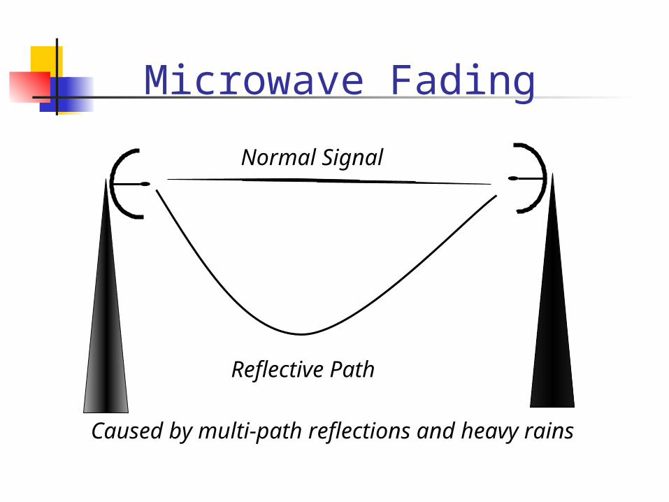
Microwave Fading
Normal Signal
Reflective Path
Caused by multi-path reflections and heavy rains

Range
The distance a signal travels and
its increase in frequency are
inversely proportional Repeaters extend range
Back-to-back antennas Reflectors
Range-cont’d
High frequencies are
repeated/received at or below one
mile
Lower frequencies can travel up to
100 miles but 25-30 miles is the
typical placement for repeaters
Interference Adjacent Channel Interference
digital not greatly affected Overreach
caused by signal feeding past a repeater to the receiving antenna at the next station in the route. Eliminated by zigzag path alignment or alternate frequency use between adjacent stations
Components of a Microwave System
Digital Modem
Radio Frequency (RF) Unit
Antenna
Digital Modem
The digital modem modulates the
information signal (intermediate
frequency or IF).

RF Unit
IF is fed to the RF unit which is
mounted as close physically to the
antenna as possible (direct
connect is optimal).
Antenna
The antenna is a passive device
that radiates the modulated signal.
It is fed by direct connect of the RF
unit, coaxial cable, or waveguides
at higher frequencies.
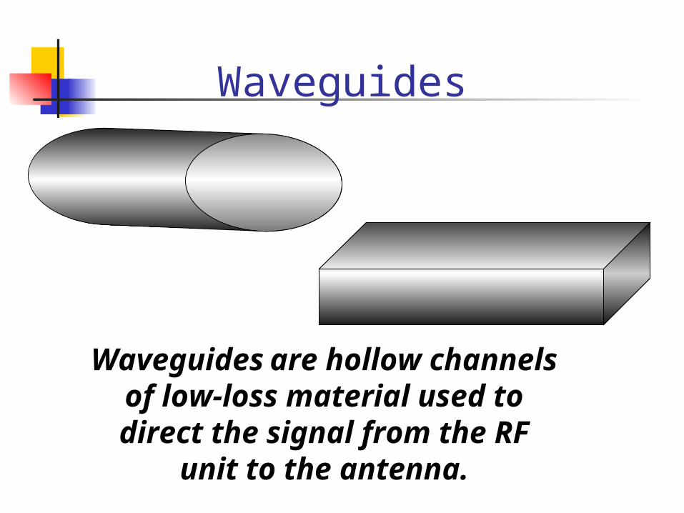
Waveguides
Waveguides are hollow channels of low-loss material used to direct the
signal from the RF unit to the antenna.

Modulation Methods
Primarily modulated today with
digital FM or AM signals
Digital signal remains quiet until
failure threshold bit error rate renders
it unusable

Bit Error Rate (BER) The BER is a performance measure
of microwave signaling throughput 10 or one error per million
transmitted bits of information Data fail over is at 10; voice traffic
can withstand this error rate
-6
-3
Diversity Space Diversity Frequency Diversity Hot Standby PRI

Space Diversity
Normal Signal
Faded Signal
Transmitter Receiver

Space Diversity-cont’d Space Diversity protects against
multi-path fading by automatic switch over to another antenna place below the primary antenna. This is done at the BER failure point or signal strength attenuation point to the secondary antenna that is receiving the transmitted signal at a stronger power rating.
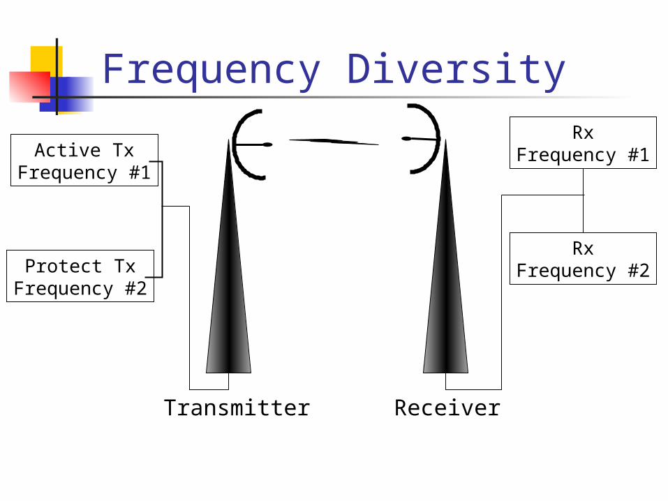
Frequency Diversity
Receiver
Active TxFrequency #1
Protect TxFrequency #2
RxFrequency #1
RxFrequency #2
Transmitter
Frequency Diversity-cont’d Frequency Diversity uses separate
frequencies (dual transmit and receive systems); it monitors primary for fail over and switches to standby. Interference usually affects only one range of frequencies. Not allowed in non-carrier applications because of spectrum scarcity.

Hot Standby*
Receiver
System TxPrimary #1
System TxStandby #2
failure switch
Active Rx#1
Standby Rx#2
Transmitter
*Hot standby is designed for equipment failure only
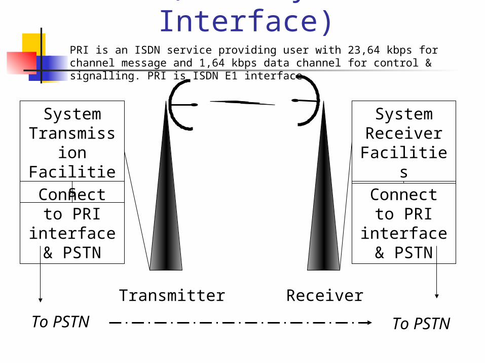
PRI (Primary Rate Interface)
ReceiverTransmitter
Connect to PRI interface
& PSTN
Connect to PRI interface
& PSTN
To PSTN To PSTN
System Transmission
Facilities
System Receiver Facilities
PRI is an ISDN service providing user with 23,64 kbps for channel message and 1,64 kbps data channel for control & signalling. PRI is ISDN E1 interface.
Availability Formula
Percent Availability equals:
1 – (outage hours/8760 hours per year)
Private microwaves have 99.99% availability
Microwave Path Analysis Transmitter output power Antenna gain
proportional to the physical characteristics of the antenna (diameter)
Free space gain Antenna alignment factor Unfaded received signal level
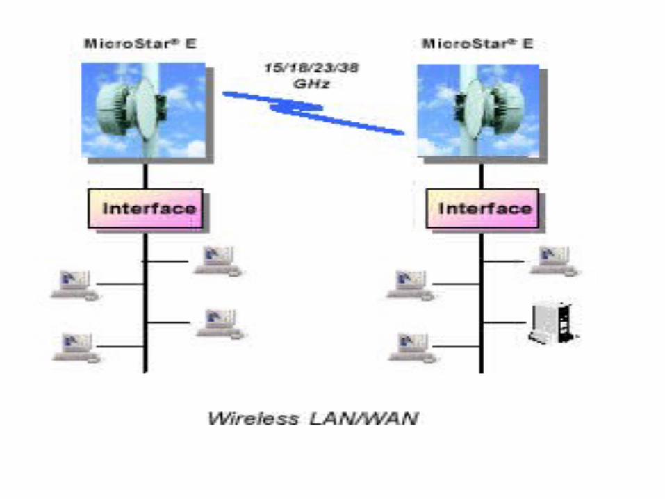
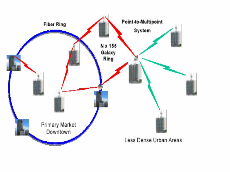
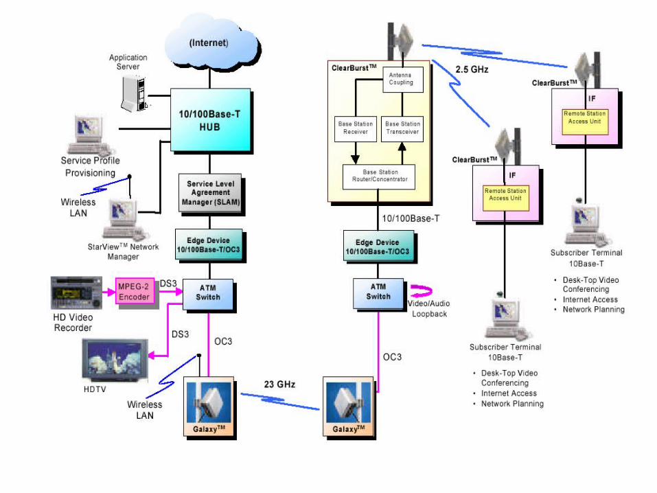
Microwave Radio Applications

Satellite Communications

Satellite-Related Terms Earth Stations – antenna systems on or near earth Uplink – transmission from an earth station to a
satellite Downlink – transmission from a satellite to an
earth station Transponder – electronics in the satellite that
convert uplink signals to downlink signals
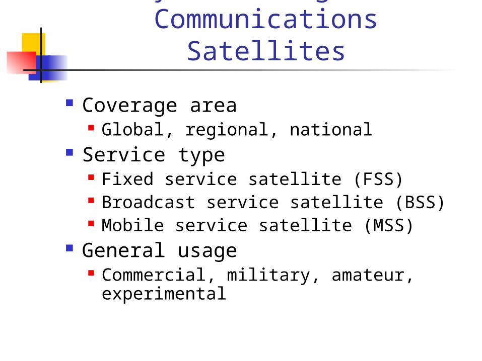
Ways to CategorizeCommunications Satellites
Coverage area Global, regional, national
Service type Fixed service satellite (FSS) Broadcast service satellite (BSS) Mobile service satellite (MSS)
General usage Commercial, military, amateur, experimental
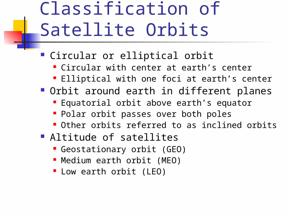
Classification of Satellite Orbits Circular or elliptical orbit
Circular with center at earth’s center Elliptical with one foci at earth’s center
Orbit around earth in different planes Equatorial orbit above earth’s equator Polar orbit passes over both poles Other orbits referred to as inclined orbits
Altitude of satellites Geostationary orbit (GEO) Medium earth orbit (MEO) Low earth orbit (LEO)

Geometry Terms Elevation angle - the angle from the
horizontal to the point on the center of the main beam of the antenna when the antenna is pointed directly at the satellite
Minimum elevation angle Coverage angle - the measure of the portion
of the earth's surface visible to the satellite

Minimum Elevation Angle Reasons affecting minimum elevation angle
of earth station’s antenna (>0o) Buildings, trees, and other terrestrial objects
block the line of sight Atmospheric attenuation is greater at low
elevation angles Electrical noise generated by the earth's heat
near its surface adversely affects reception
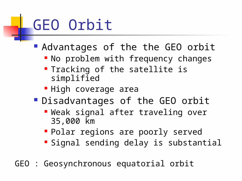
GEO Orbit Advantages of the the GEO orbit
No problem with frequency changes Tracking of the satellite is simplified High coverage area
Disadvantages of the GEO orbit Weak signal after traveling over 35,000 km Polar regions are poorly served Signal sending delay is substantial
GEO : Geosynchronous equatorial orbit

LEO Satellite Characteristics Circular/slightly elliptical orbit under 2000 km Orbit period ranges from 1.5 to 2 hours Diameter of coverage is about 8000 km Round-trip signal propagation delay less than 20
ms Maximum satellite visible time up to 20 min System must cope with large Doppler shifts Atmospheric drag results in orbital deterioration
LEO : Low earth orbit

LEO Categories Little LEOs
Frequencies below 1 GHz 5MHz of bandwidth Data rates up to 10 kbps Aimed at paging, tracking, and low-rate messaging
Big LEOs Frequencies above 1 GHz Support data rates up to a few megabits per sec Offer same services as little LEOs in addition to voice
and positioning services

MEO Satellite Characteristics Circular orbit at an altitude in the range of 5000 to
12,000 km Orbit period of 6 hours Diameter of coverage is 10,000 to 15,000 km Round trip signal propagation delay less than 50
ms Maximum satellite visible time is a few hours
MEO : Medium Earth Orbit

Satellite Systems
SOURCE: WASHINGTON UNIV.
GEO
M EO
LEO
GEO (22,300 mi., equatorial) high bandwidth, power, latency
MEO high bandwidth, power, latency
LEO (400 mi.) low power, latency
more satellites
small footprint
V-SAT (Very Small Aperture
Terminal)
private WAN
SATELLITE MAP

Geostationary Orbit
SOURCE: BILL LUTHER, FCC

GPS Satellite Constellation
• Global Positioning System• Operated by USAF• 28 satellites• 6 orbital planes at a height of 20,200 km• Positioned so a minimum of 5 satellites are visible at all times• Receiver measures distance to satellite
SOURCE: NAVSTAR
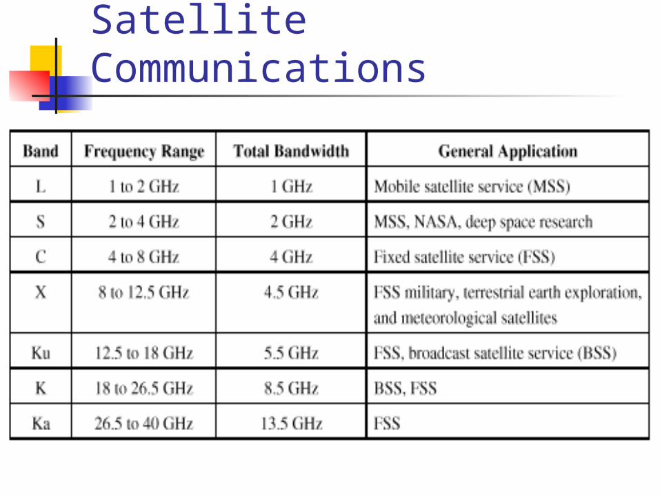
Frequency Bands Available for Satellite Communications
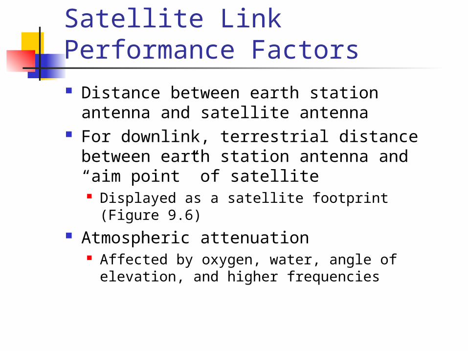
Satellite Link Performance Factors
Distance between earth station antenna and satellite antenna
For downlink, terrestrial distance between earth station antenna and “aim point” of satellite Displayed as a satellite footprint (Figure 9.6)
Atmospheric attenuation Affected by oxygen, water, angle of elevation, and
higher frequencies
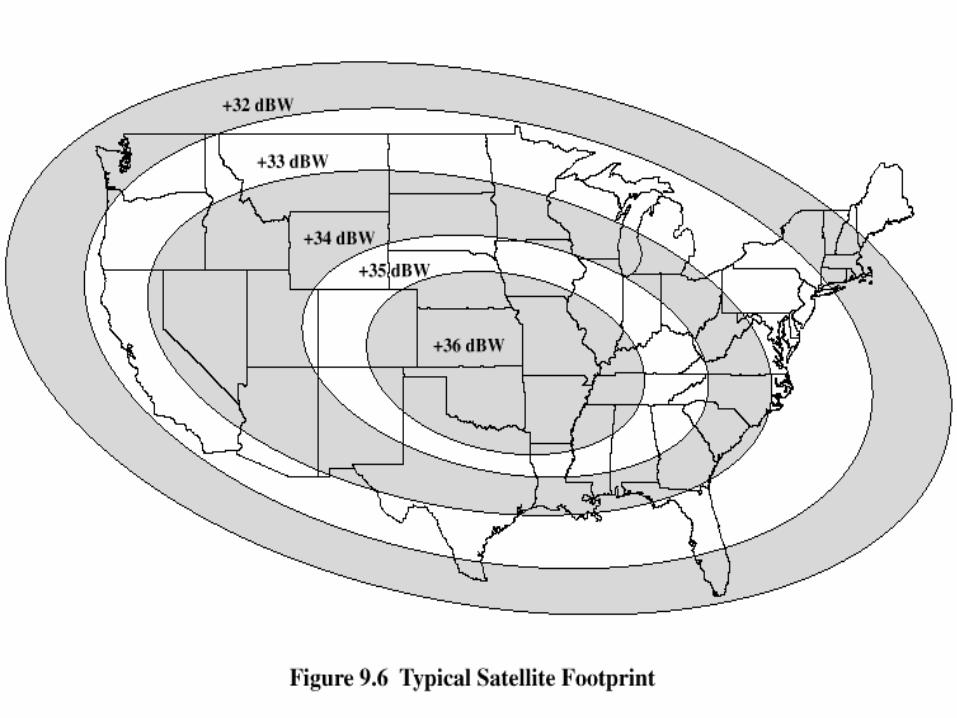
Satellite Footprint

Satellite Network Configurations
Capacity Allocation Strategies Frequency division multiple access
(FDMA) Time division multiple access (TDMA) Code division multiple access (CDMA)

Frequency-Division Multiplexing Alternative uses of channels in point-to-point
configuration 1200 voice-frequency (VF) voice channels One 50-Mbps data stream 16 channels of 1.544 Mbps each 400 channels of 64 kbps each 600 channels of 40 kbps each One analog video signal Six to nine digital video signals
Frequency-Division Multiple Access Factors which limit the number of
subchannels provided within a satellite channel via FDMA Thermal noise Intermodulation noise Crosstalk
Forms of FDMA Fixed-assignment multiple access (FAMA)
The assignment of capacity is distributed in a fixed manner among multiple stations
Demand may fluctuate Results in the significant underuse of capacity
Demand-assignment multiple access (DAMA) Capacity assignment is changed as needed to respond
optimally to demand changes among the multiple stations
FAMA-FDMA FAMA – logical links between stations are
preassigned FAMA – multiple stations access the
satellite by using different frequency bands Uses considerable bandwidth
DAMA-FDMA Single channel per carrier (SCPC) – bandwidth
divided into individual VF channels Attractive for remote areas with few user stations near
each site Suffers from inefficiency of fixed assignment
DAMA – set of subchannels in a channel is treated as a pool of available links For full-duplex between two earth stations, a pair of
subchannels is dynamically assigned on demand Demand assignment performed in a distributed fashion
by earth station using CSC
Reasons for Increasing Use of TDM Techniques
Cost of digital components continues to drop
Advantages of digital components Use of error correction
Increased efficiency of TDM Lack of intermodulation noise

FAMA-TDMA Operation Transmission in the form of repetitive sequence of
frames Each frame is divided into a number of time slots Each slot is dedicated to a particular transmitter
Earth stations take turns using uplink channel Sends data in assigned time slot
Satellite repeats incoming transmissions Broadcast to all stations
Stations must know which slot to use for transmission and which to use for reception

FAMA-TDMA Uplink
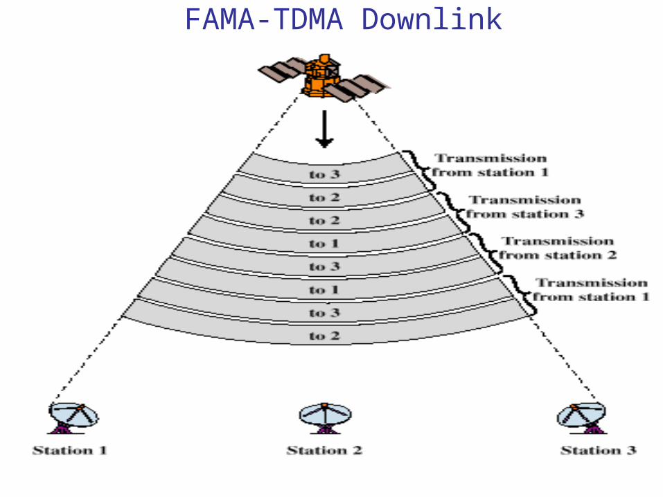
FAMA-TDMA Downlink
Related Documents