Manufacturing Technology Dr. Ramadan EL-Gamsy Lecturer Desgin & production Engineering Dept. Mobile +201005066892 e-mail [email protected] [email protected]g

Welcome message from author
This document is posted to help you gain knowledge. Please leave a comment to let me know what you think about it! Share it to your friends and learn new things together.
Transcript

Manufacturing Technology
Dr. Ramadan EL-Gamsy
Lecturer
Desgin & production Engineering Dept.
Mobile +201005066892
e-mail [email protected]
What is manufacturing?
• To make or process a raw material into a finished
product, especially by means of a large-scale
industrial operation
Processes are.
• Primary process.
• Secondary process.

Primary vs. Secondary
Manufacturing
Primary processes convert raw materials into standard stock
bauxite ore aluminum
petroleum polyester resin
Tree Wood
Secondary processes convert standard stock into usable parts
aluminum rod fuel valve
polyester resin medical tubing
lumber furniture
3

Products often made of many parts
• Steel sheets and bars
• Iron & aluminum ingots
• Plastic resin pellets
• Uncured rubber
• Copper wire
• Nylon thread
• Glass sheets
4
CAR

Secondary Manufacturing Processes
• Casting and Molding
• Forming
• Machining / Material Removal
• Assembling / Joining
• Finishing
5

Secondary Processes
• Forming processes use a shaping device and pressure to cause a material to take on a new shape and size
• Machining processes remove material to produce a desired shape and surface finish
6

Manufacturing Work Flow
• Custom
• Batch
• Continuous
7

Custom manufacturing
• Limited number of products built to customer specifications.
• Requires highly skilled labor.
8

Batch manufacturing
• Parts made in lots of 10 – 1,000
• General-purpose machinery (table saw, vertical mill) is used, often run by hand
• Setup times per part decreases as batches get larger
9

“Continuous” manufacturing
• Same product made repeatedly by dedicated machinery (custom built machine – NOT CUSTOM built product)
• Automation becomes more cost-effective
• Some processes still require batch staging
• Tooling and setup are large initial expenses
10

PRODUCTION TECHNOLOGY
Manufacturing Processes
Contents
1. Metal forming.
2. Metal Machining.
Definition of Forming
Forming is a fabrication process for solid
substances by controlled plastic deformation
in order to obtain alterations of:
- the form,
- the material properties,
- the surface properties.
-.
1. Overview of Metal Forming
FUNDAMENTALS OF METAL FORMING
1. Overview of Metal Forming
2. Material Behavior in Metal Forming
3. Temperature in Metal Forming
4. Strain Rate Sensitivity
5. Friction and Lubrication in Metal Forming

Terms for Classifying Forming Processes
• Classification by Type of Raw Material
• Classification by State of Stress
• Classification by Forming Temperature
• Classification by Methods of Induction of
Forces into the Work-Piece
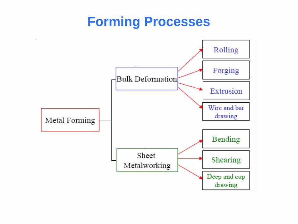
Forming Processes

1-Bulk Deformation Processes
• Characterized by significant deformations and
massive shape changes
• "Bulk" refers to workparts with relatively low
surface area-to-volume ratios
• Starting work shapes include cylindrical billets
and rectangular bars
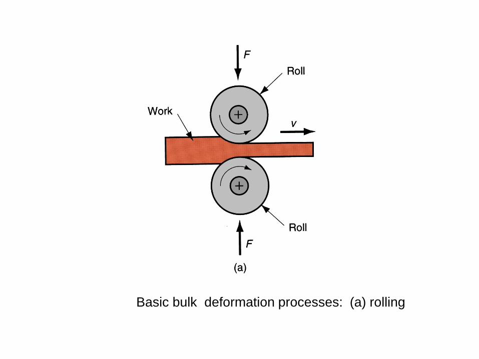
Figure 18.2 – Basic bulk deformation processes: (a) rolling (a)
rolling
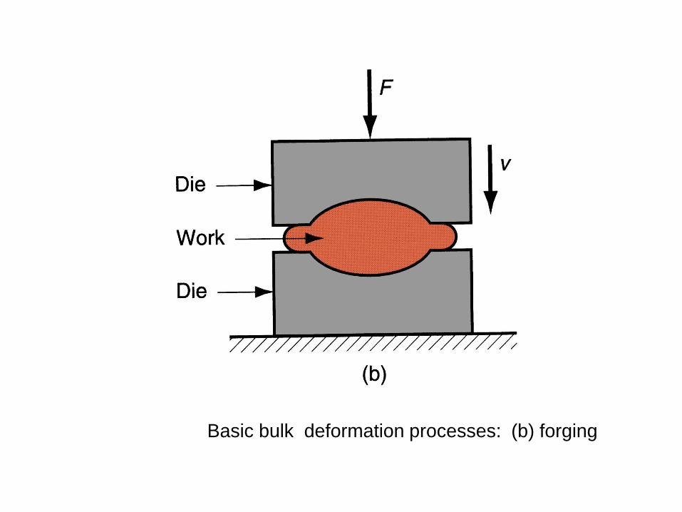
Figure 18.2 – Basic bulk deformation processes: (b) forging Figure 18.2 – Basic bulk deformation processes: (b) forging
(a) rolling

Figure 18.2 – Basic bulk deformation processes: (c) extrusion Figure 18.2 – Basic bulk deformation processes: (c) extrusion
(a) rolling

Figure 18.2 – Basic bulk deformation processes: (d) drawing Figure 18.2 – Basic bulk deformation processes: (d) drawing
(a) rolling
Sheet Metalworking
• Forming and related operations performed on
metal sheets and strips
• High surface area-to-volume ratio of starting
metal, which distinguishes these from bulk
deformation
• Often called press working because presses
perform these operations
Parts are called stampings
Usual tooling: punch and die
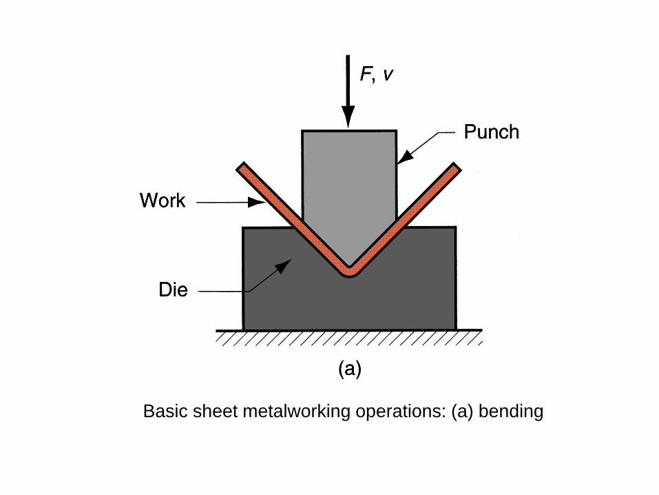
Basic sheet metalworking operations: (a) bending

Basic sheet metalworking operations: (b) drawing

- Basic sheet metalworking operations: (c) shearing
Metal Forming
Large group of manufacturing processes in
which plastic deformation is used to change
the shape of metal workpieces
• The tool, usually called a die, applies
stresses that exceed yield strength of metal
• The metal takes a shape determined by the
geometry of the die
Stresses in Metal Forming
• Stresses to plastically deform the metal are usually
compressive
Examples: rolling, forging, extrusion
• However, some forming processes
Stretch the metal (tensile stresses)
Others bend the metal (tensile and compressive)
Still others apply shear stresses
Material Properties in Metal Forming
• Desirable material properties:
Low yield strength and high ductility
• These properties are affected by temperature :
Ductility increases and yield strength
decreases when work temperature is raised
• Other factors:
Strain rate and friction

Material Behavior in Metal Forming
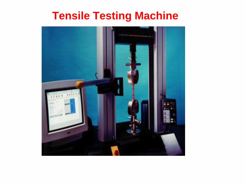
Tensile Testing Machine
Mechanical properties of materials
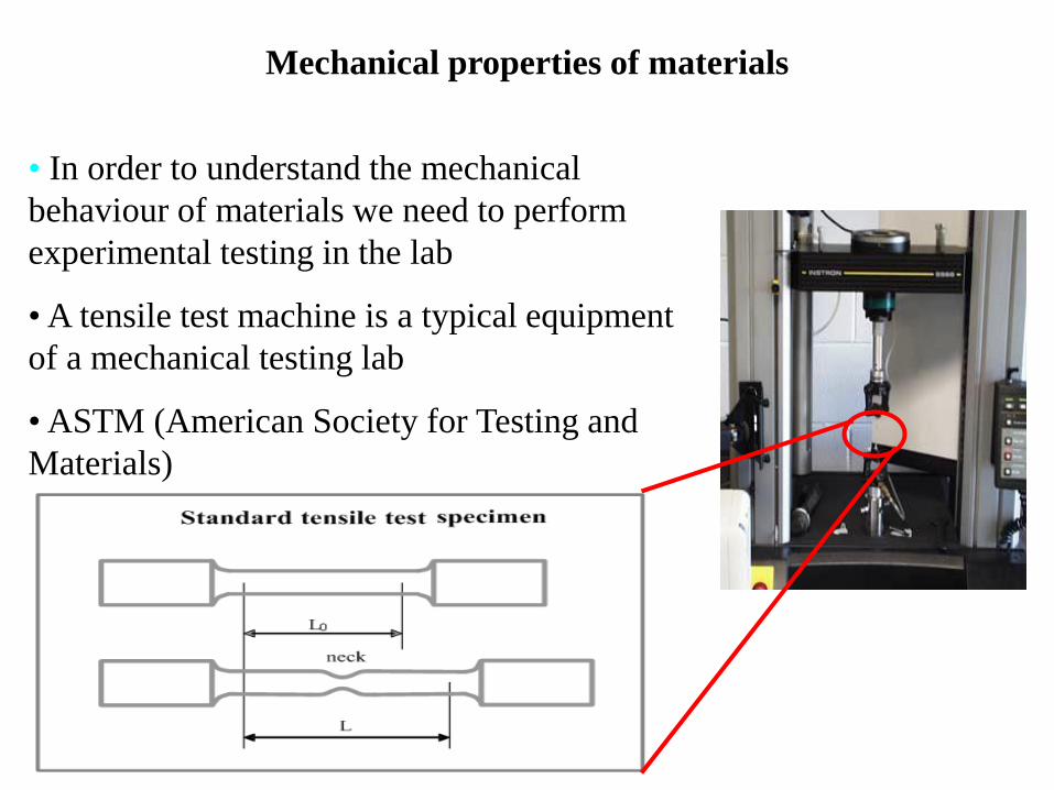
• In order to understand the mechanical
behaviour of materials we need to perform
experimental testing in the lab
• A tensile test machine is a typical equipment
of a mechanical testing lab
• ASTM (American Society for Testing and
Materials)
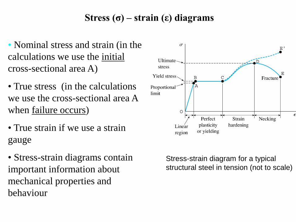
Stress-strain diagram for a typical
structural steel in tension (not to scale)
Stress (σ) – strain (ε) diagrams
• Nominal stress and strain (in the
calculations we use the initial
cross-sectional area A)
• True stress (in the calculations
we use the cross-sectional area A
when failure occurs)
• True strain if we use a strain
gauge
• Stress-strain diagrams contain
important information about
mechanical properties and
behaviour
Stress (σ) – strain (ε) diagrams
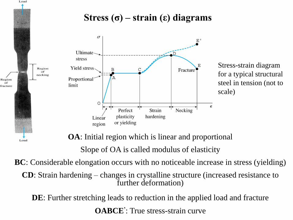
OA: Initial region which is linear and proportional
Slope of OA is called modulus of elasticity
BC: Considerable elongation occurs with no noticeable increase in stress (yielding)
CD: Strain hardening – changes in crystalline structure (increased resistance to further deformation)
DE: Further stretching leads to reduction in the applied load and fracture
OABCE’: True stress-strain curve
Stress-strain diagram
for a typical structural
steel in tension (not to
scale)
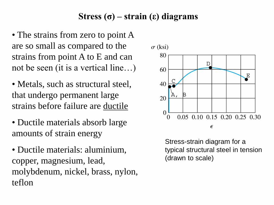
Stress-strain diagram for a
typical structural steel in tension
(drawn to scale)
Stress (σ) – strain (ε) diagrams
• The strains from zero to point A
are so small as compared to the
strains from point A to E and can
not be seen (it is a vertical line…)
• Metals, such as structural steel,
that undergo permanent large
strains before failure are ductile
• Ductile materials absorb large
amounts of strain energy
• Ductile materials: aluminium,
copper, magnesium, lead,
molybdenum, nickel, brass, nylon,
teflon
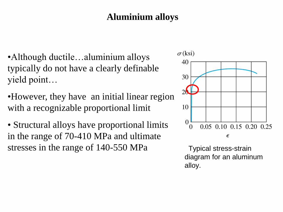
Typical stress-strain
diagram for an aluminum
alloy.
Aluminium alloys
•Although ductile…aluminium alloys
typically do not have a clearly definable
yield point…
•However, they have an initial linear region
with a recognizable proportional limit
• Structural alloys have proportional limits
in the range of 70-410 MPa and ultimate
stresses in the range of 140-550 MPa

Copyright 2005 by Nelson, a division of Thomson Canada Limited
FIG 1-14 Arbitrary yield stress determined by the offset method
Offset method
• When the yield point is not
obvious, like in the previous
case, and undergoes large
strains, an arbitrary yield stress
can be determined by the offset
method
• The intersection of the offset
line and the stress-strain curve
(point A) defines the yield
stress

Typical stress-strain diagram
for a brittle material showing
the proportional limit (point A)
and fracture stress (point B)
Brittle materials
• Brittle materials fail at relatively
low strains and little elongation
after the proportional limit
• Brittle materials: concrete,
marble, glass, ceramics and
metallic alloys
• The reduction in the cross-
sectional area until fracture (point
B) is insignificant and the fracture
stress (point B) is the same as the
ultimate stress
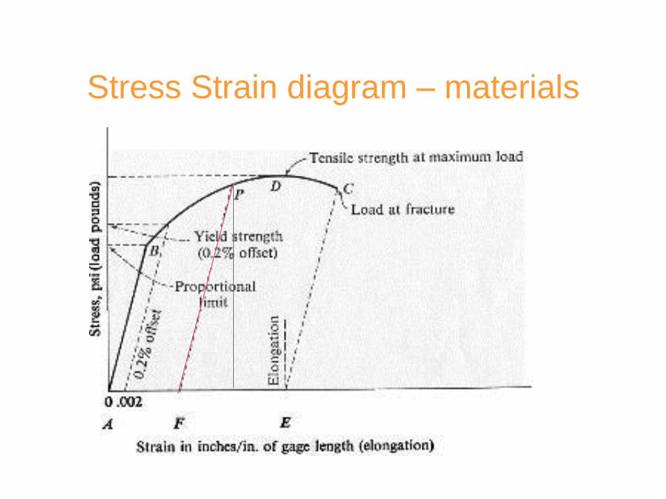
Stress Strain diagram – materials
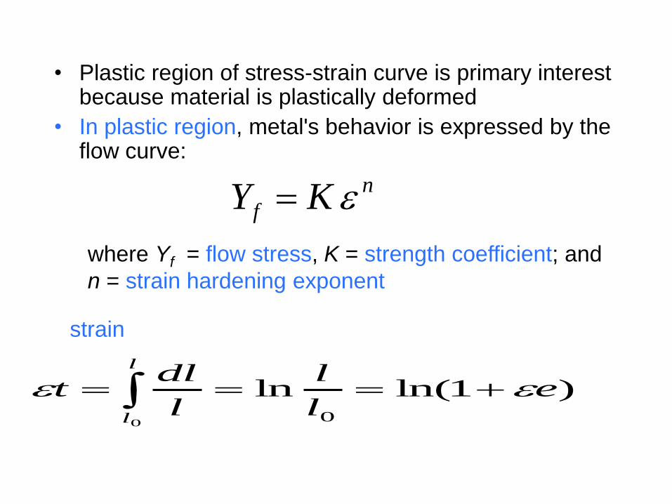
• Plastic region of stress-strain curve is primary interest because material is plastically deformed
• In plastic region, metal's behavior is expressed by the flow curve:
strain
)1ln(ln0
0
el
l
l
dlt
l
l
n
f KY
where Yf = flow stress, K = strength coefficient; and
n = strain hardening exponent
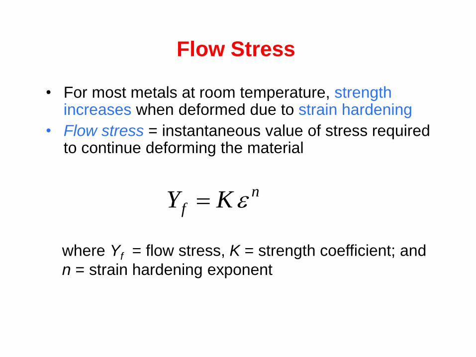
Flow Stress
• For most metals at room temperature, strength increases when deformed due to strain hardening
• Flow stress = instantaneous value of stress required to continue deforming the material
where Yf = flow stress, K = strength coefficient; and
n = strain hardening exponent
nf KY
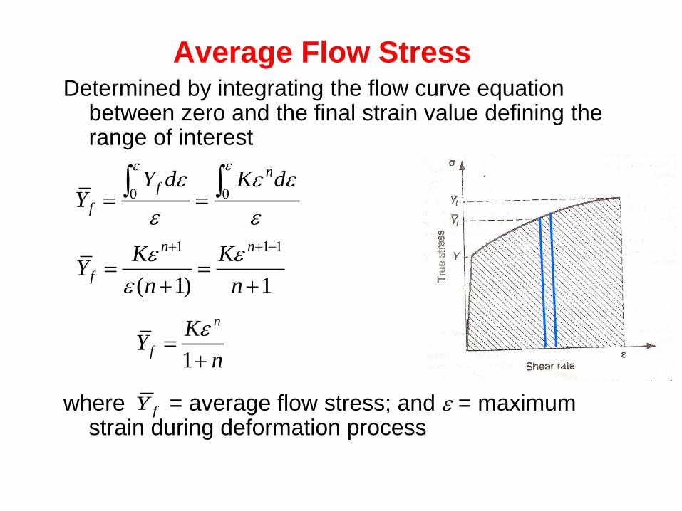
Average Flow Stress Determined by integrating the flow curve equation
between zero and the final strain value defining the range of interest
where = average flow stress; and = maximum strain during deformation process
n
KY
n
f
1
fY
00
dKdYY
nf
f
1)1(
111
n
K
n
KY
nn
f

Hot Forming
Kalpakjian

Hot Working:
Paul Berenson, www.paulb.com T.Green, WIT
www.smeedwerkunica.nl
Open Die Forging
Temperature in Metal Forming
• For any metal, K and n in the flow curve
depend on temperature
• Both strength and strain hardening are
reduced at higher temperatures
• In addition, ductility is increased at higher
temperatures

Temperature in Metal Forming
• Any deformation operation can be accomplished
with lower forces and power at elevated
temperature
• At elevated temperature
• Three temperature ranges in metal forming:
Cold working
Warm working
Hot working
KYY ff
0n
Cold Working
• Performed at room temperature(below RC
temperature.)
• Many cold forming processes are important
mass production operations
• Minimum or no machining usually required
Warm Working
• Performed at temperatures above room
temperature but below recrystallization
temperature
• Warm working: T/Tm from 0.3 to 0.5, where
Tm = melting point (tm+273) for metal
Hot Working
• Deformation at temperatures above recrystallization
temperature
• In practice, hot working usually performed
somewhat above 0.5Tm
• Metal continues to soften as temperature increases
above 0.5Tm, enhancing advantage of hot working
above this level
Advantages of Cold Forming vs.
Hot Working
• Better accuracy, closer tolerances
• Better surface finish
• Strain hardening increases strength and
hardness
• No heating of work required
• Grain flow during deformation can cause
desirable directional properties in product
Disadvantages of Cold Forming
• Higher forces and power required
• Surfaces of starting workpiece must be free of
scale and dirt
• In some operations, metal must be annealed
to allow further deformation
• In other cases, metal is simply not ductile
enough to be cold worked

Advantages of Warm Working
• Lower forces and power than in cold working
• More intricate work geometries possible
• Need for annealing may be reduced or
eliminated
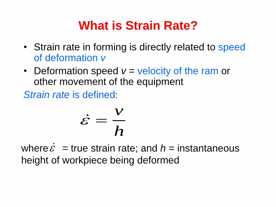
What is Strain Rate?
• Strain rate in forming is directly related to speed of deformation v
• Deformation speed v = velocity of the ram or other movement of the equipment
Strain rate is defined:
where = true strain rate; and h = instantaneous
height of workpiece being deformed
h
v

Strain Rate Sensitivity Equation
where
C = strength constant (similar but not equal to
strength coefficient in flow curve equation),
and
m = strain-rate sensitivity exponent
mf CY

handout 7a 53
• Strain rate (related to elevated temperatures)
- Rate at which metal is strained in a forming process
- In the hot forming or warm forming, the strain rate can affect
the flow stress
hv /
Speed of
deformation (could
be equal to velocity
of ram)
Instantaneous
height of
work-piece
being
deformed h
m
f CY Flow stress
Strain Rate
h

54
m
f CY
where
C strength constant
m strain-rate sensitivity exponent
C and m are determined by the following figure
which is generated from the experiment
nKfY
Strength
coefficient but not
the same as K
Effect of Strain Rate on Flow Stress
• Flow stress is a function of temperature
• At hot working temperatures, flow stress also
depends on strain rate
• As strain rate increases, resistance to
deformation increases
• This effect is known as strain-rate sensitivity
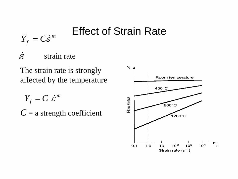
Effect of Strain Rate m
f CY
strain rate
The strain rate is strongly
affected by the temperature.
m
f CY
C = a strength coefficient
Friction in Metal Forming
• In most metal forming processes, friction is
undesirable:
Forces and power are increased
Wears tooling faster
Metal flow is retarded
• Friction and tool wear are more severe in hot
working
Lubrication in Metal Forming
• Metal working lubricants are applied to
tool-work interface in many forming
operations to reduce harmful effects of friction
• Benefits:
Reduced sticking, forces, power, tool wear
Better surface finish
Removes heat from the tooling

Considerations in Choosing a
Lubricant
• Type of forming process (rolling, forging,
sheet metal drawing, etc.)
• Hot working or cold working
• Work material
• Chemical reactivity with tool and work metals
• Ease of application
• Cost

0
ln
0l
l
l
dll
l
mn
f CKY
h
v
Metal Forming Laws
n
KY
n
f
1

Example (1)
A metal has a flow curve with parameters: K = 850 MPa and
strain hardening exponent n = 0.30. A tensile specimen of
the metal with gage length = 100 mm is stretched to a
length = 157 mm. Determine the flow stress at the new
length and the average flow stress that the metal has been
subjected to during the deformation.
Solution
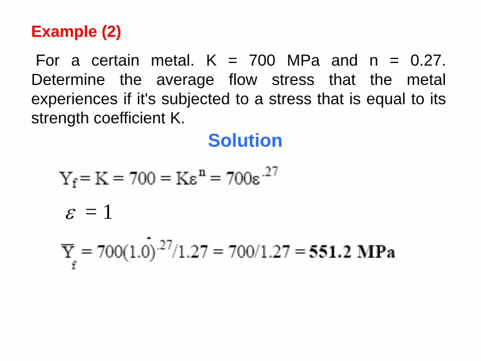
Example (2)
For a certain metal. K = 700 MPa and n = 0.27.
Determine the average flow stress that the metal
experiences if it's subjected to a stress that is equal to its
strength coefficient K.
= 1
Solution

Example (3) The gage length of a tensile test specimen
= 150 mm. It is subjected to a tensile test in which the
grips holding the end of the test specimen are moved
with a relative velocity = 0.1 m/s. Construct a plot of the
strain rate as a function of length as the specimen is
pulled to a length = 200 mm.
Solution
The following values are calculated for the plot:
At L = 150 mm, = 0.1/0.15 = 0.667 s-1
At L = 160 mm, = 0.1/0.16 = 0.625 s-1
At L = 170 mm, = 0.1/0.17 = 0.588 s-1
At L = 180 mm, = 0.1/0.18 = 0.555 s-1
At L = 190 mm, = 0.1/0.19 = 0.526 s-1
At L = 200 mm, = 0.1/0.20 = 0.500 s-1
0.4
0.45
0.5
0.55
0.6
0.65
0.7
150 160 170 180 190 200
Str
ain
rate
Length
Related Documents