Fundamentals Of Non-Directional Overcurrent & Earth Fault Protection

Welcome message from author
This document is posted to help you gain knowledge. Please leave a comment to let me know what you think about it! Share it to your friends and learn new things together.
Transcript

Fundamentals OfNon-Directional
Overcurrent & Earth Fault Protection
Overcurrent Protection: Purpose of Protection
Detect abnormal conditions Isolate faulty part of the systemSpeed
Fast operation to minimise damage and dangerDiscrimination
Isolate only the faulty sectionDependability / reliability Security / stability Cost of protection / against cost of potential hazards

Overcurrent Protection Co-ordination
F3F2F1
Co-ordinate protection so that relay nearest to fault operates firstMinimise system disruption due to the fault

Fuses

Overcurrent Protection Fuses
SimpleCan provide very fast fault clearance
<10ms for large currentLimit fault energy
Pre Arc Time
Arcing Time
Prospective Fault Current
TotalOperatingTime
t

Overcurrent Protection Fuses - disadvantages
Problematic co-ordination
IFA approx 2 x IFB
Limited sensitivity to earth faultsSingle phasingFixed characteristicNeed replacing following fault clearance
Fuse A Fuse B

Tripping Methods

Overcurrent Protection Direct Acting AC Trip
AC series tripcommon for electromechanical O/C relays
51
IF
Trip Coil

Overcurrent Protection Direct Acting AC Trip
Capacitor discharge tripused with static relays where no secure DC supply is available
IF'
SensitiveTripCoil
IF
51
+
-

Overcurrent Protection DC Shunt Trip
IF'IF
DCBATTERY
SHUNTTRIP COIL
51
Requires secure DC auxiliaryNo trip if DC fails

Overcurrent Protection

Overcurrent Protection Principles
Operating SpeedInstantaneousTime delayed
DiscriminationCurrent settingTime settingCurrent and time
CostGenerally cheapest form of protection relay

Overcurrent Protection Instantaneous Relays
Current settings chosen so that relay closest to fault operatesProblem
Relies on there being a difference in fault level between the two relay locationsCannot discriminate if IF1 = IF2
IF1IF1IF250
B
50
A
IF1IF2

Overcurrent Protection Definite (Independent) Time Relays
TOP
TIME
IS Applied Current(Relay Current Setting)

Overcurrent Protection Definite (Independent) Time Relays
Operating time is independent of currentRelay closest to fault has shortest operating timeProblem
Longest operating time is at the source where fault level is highest
510.9 sec 0.5 sec
51

Overcurrent Protection IDMT
TIME
Applied Current(Relay Current Setting)
IS
Inverse Definite Minimum Time characteristic

Overcurrent Protection Disc Type O/C Relays
Current setting via plug bridgeTime multiplier setting via disc movementSingle characteristicConsider 2 ph & EF or 3 ph plus additional EF relay

Overcurrent Protection Static Relay
Electronic, multi characteristicFine settings, wide rangeIntegral instantaneous elements

Overcurrent Protection Numerical Relay
Multiple characteristics and stagesCurrent settings in primary or secondary valuesAdditional protection elements
Current
Time
I>1
I>2
I>3
I>4

Co-ordination

Overcurrent Protection Co-ordination Principle
Relay closest to fault must operate firstOther relays must have adequate additional operating time to prevent them operating Current setting chosen to allow FLCConsider worst case conditions, operating modes and current flows
T
IS1IS2 MaximumFaultLevel
I
R2R1IF1

Overcurrent Protection Co-ordination Example
C AB
0.01
0.1
1
10O
pera
ting
time
(s)
Current (A) FLB FLC FLD
ED
C
B
DE

Overcurrent Protection IEC Characteristics
SI t = 0.14(I0.02 -1)
VI t = 13.5 (I2 -1)
EI t = 80(I2 -1)
LTI t = 120(I - 1)
Current (Multiples of Is)
0.1
1
10
100
1000
1 10010O
pera
ting
Tim
e (s
)
VI
EI
SI
LTI

Overcurrent Protection Operating Time Setting -Terms Used
Relay operating times can be calculated using relay characteristic chartsPublished characteristcs are drawn against a multiple of current setting or Plug Setting MultiplierTherefore characteristics can be used for any application regardless of actual relay current settinge.g at 10x setting (or PSM of 10) SI curve op time is 3s Current (Multiples of Is)
0.1
1
10
100
1000
1 10010
Ope
ratin
g Ti
me
(s)

Overcurrent Protection Current Setting
Set just above full load currentallow 10% tolerance
Allow relay to reset if fault is cleared by downstream device
consider pickup/drop off ratio (reset ratio)relay must fully reset with full load current flowing
PU/DO for static/numerical = 95%PU/DO for EM relay = 90%
e.g for numerical relay, Is = 1.1 x IFL/0.95

Overcurrent Protection Current Setting
Current gradingensure that if upstream relay has started downstream relay has also started
Set upstream device current setting greater than downstream relay
e.g. IsR1 = 1.1 x IsR2
R1 R2 IF1

Overcurrent Protection Grading Margin
Operating time difference between two devices to ensure that downstream device will clear fault before upstream device tripsMust include
breaker opening timeallowance for errorsrelay overshoot timesafety margin
GRADING MARGIN

Overcurrent Protection Grading Margin -between relays
Traditionalbreaker op time - 0.1relay overshoot - 0.05allow. For errors - 0.15safety margin - 0.1Total 0.4s
Calculate using formula
R2R1

Overcurrent Protection Grading Margin -between relays
Formulat’ = (2Er + Ect) t/100 + tcb + to + ts
Er = relay timing errorEct = CT measurement errort = op time of downstream relaytcb = CB interupting timeto = relay overshoot timets = safety margin
Op time of Downstream Relay t = 0.5s0.375s margin for EM relay, oil CB0.24s margin for static relay, vacuum CB

Overcurrent Protection Grading Margin -relay with fuse
Grading Margin = 0.4Tf + 0.15s over whole characteristicAssume fuse minimum operating time = 0.01sUse EI or VI curve to grade with fuseCurrent setting of relay should be 3-4 x rating of fuse to ensure co-ordination

Overcurrent Protection Grading Margin -relay with upstream fuse
1.175Tr + 0.1 + 0.1 = 0.6Tf
orTf = 2Tr + 0.33s
Allowance for CT and relay error
CB Safety margin Allowance for fuse error (fast)
Tf
Tr
IFMAX

Overcurrent Protection Time Multiplier Setting
Used to adjust the operating time of an inverse characteristicNot a time setting but a multiplierCalculate TMS to give desired operating time in accordance with the grading margin
Current (Multiples of Is)
0.1
1
10
100
1 10010
Ope
ratin
g Ti
me
(s)

Overcurrent Protection Time Multiplier Setting - Calculation
Calculate relay operating time required, Treq
consider grading marginfault level
Calculate op time of inverse characteristic with TMS = 1, T1
TMS = Treq /T1

Overcurrent Protection Co-ordination - Procedure
Calculate required operating currentCalculate required grading marginCalculate required operating timeSelect characteristicCalculate required TMSDraw characteristic, check grading over whole curve
Grading curves should be drawn to a common voltage base to aid comparison

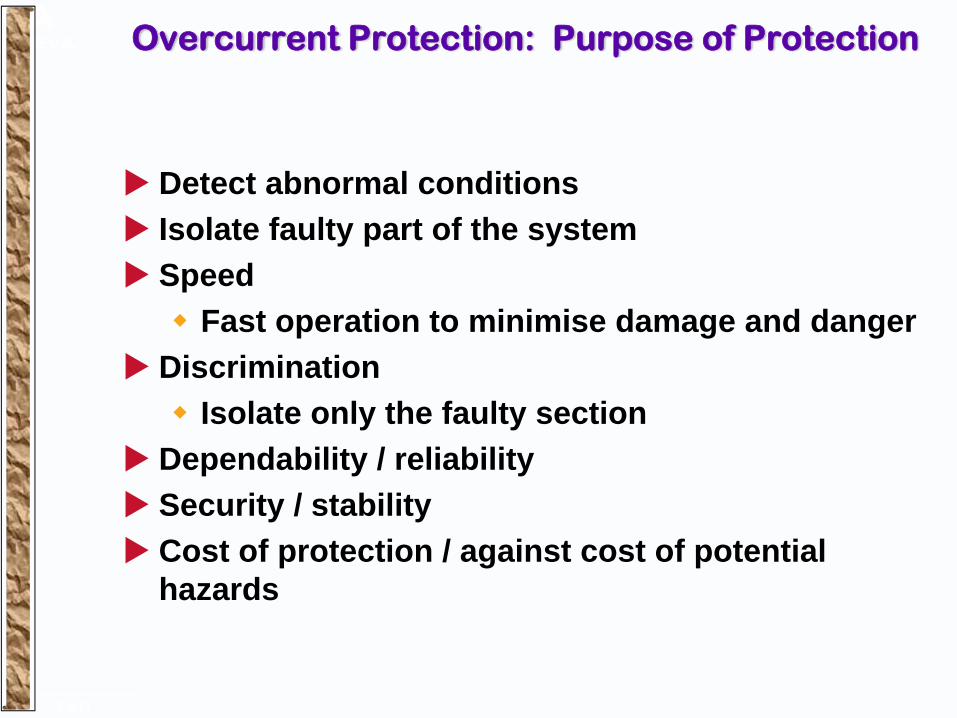
Overcurrent Protection Co-ordination Example
Grade relay B with relay ACo-ordinate at max fault level seen by both relays = 1400AAssume grading margin of 0.4s
Is = 5 Amp; TMS = 0.05, SI
IFMAX= 1400 Amp
B A
200/5 100/5
Is = 5 Amp
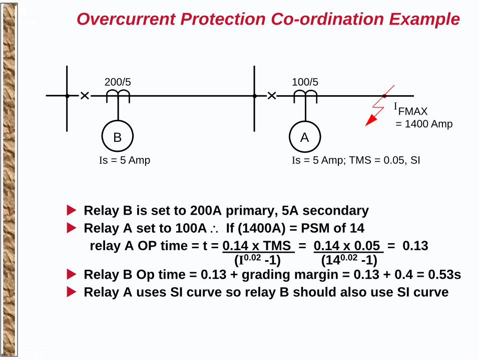
Overcurrent Protection Co-ordination Example
Relay B is set to 200A primary, 5A secondaryRelay A set to 100A ∴ If (1400A) = PSM of 14relay A OP time = t = 0.14 x TMS = 0.14 x 0.05 = 0.13
(I0.02 -1) (140.02 -1)Relay B Op time = 0.13 + grading margin = 0.13 + 0.4 = 0.53sRelay A uses SI curve so relay B should also use SI curve
Is = 5 Amp; TMS = 0.05, SI
IFMAX= 1400 Amp
B A
200/5 100/5
Is = 5 Amp

Overcurrent Protection Co-ordination Example
Relay B Op time = 0.13 + grading margin = 0.13 + 0.4 = 0.53sRelay A uses SI curve so relay B should also use SI curveRelay B set to 200A ∴ If (1400A) = PSM of 7relay B OP time TMS = 1 = 0.14 x TMS = 0.14 = 3.52s
(I0.02 -1) (70.02 -1)Required TMS = Required Op time = 0.53 = 0.15
Op time TMS=1 3.52Set relay B to 200A, TMS = 0.15, SI
Is = 5 Amp; TMS = 0.05, SI
IFMAX= 1400 AmpB A
200/5 100/5
Is = 5 Amp

Overcurrent Protection LV Protection Co-ordination
Relay 1Relay 2Relay 3Relay 4Fuse
1
2
3
4
F
350MVA4 4
3 3
2
F
11kV
MCGG CB
ACB CTZ61 (Open)CTZ61
ACBMCCB
27MVA
20MVALoad
Fuse
2 x 1.5MVA11kV/433V
5.1%
K
1

Overcurrent Protection LV Protection Co-ordination
1000S
100S
10S
1.0S
0.1S
0.01S0. 1kA 10kA 1000kA
TX damage
Veryinverse

Overcurrent Protection LV Protection Co-ordination
Relay 1Relay 2Relay 3Relay 4Fuse
1
2
3
4
F
350MVA4 4
3 3
2
1
F
11kV
KCGG 142 CB
ACB (Open)KCEG 142
ACBMCCB
27MVA
20MVALoad
Fuse
2 x 1.5MVA11kV/433V
5.1%
K

Overcurrent Protection LV Protection Co-ordination
1000S
100S
10S
1.0S
0.1S
0.01S0. 1kA 10kA 1000kA
TX damage
Long timeinverse

Overcurrent Protection Blocked OC Schemes
R3
R2
R1
Block t >
I > StartIF2
IF1M (Transient backfeed ?)
Gradedprotection
Blockedprotection

Delta/Star Transformers

Overcurrent Protection Transformer Protection - 2-1-1 Fault Current
A phase-phase fault on one side of transformer produces 2-1-1 distribution on other sideUse an overcurrent element in each phase (cover the 2x phase)2∅ & EF relays can be used provided fault current > 4x setting
Iline
0.866 If3∅
Turns Ratio = √3 :1
Idelta

Overcurrent Protection Transformer Protection - 2-1-1 Fault Current
Istar = E∅-∅/2Xt = √3 E∅-n/2Xt
Istar = 0.866 E∅-n/Xt
Istar = 0.866 If3∅
Idelta = Istar/√3 = If3∅ /2
Iline = If3∅
Iline
0.866 If3∅
Turns Ratio = √3 :1
Idelta

Overcurrent Protection Transformer Protection - 2-1-1 Fault Current
Grade HV relay with respect to 2-1-1 for ∅-∅ faultNot only at max fault level
51
HV
Ø/Ø51
LV
If3∅86.6%If3∅

Use of High Sets

Overcurrent Protection Instantaneous Protection
Fast clearance of faultsensure good operation factor, If >> Is (5 x ?)
Current setting must be co-ordinated to prevent overtrippingUsed to provide fast tripping on HV side of transformersUsed on feeders with Auto Reclose, prevents transient faults becoming permanent
AR ensures healthy feeders are re-energisedConsider operation due to DC offset - transient overreach

Overcurrent Protection Instantaneous OC on Transformer Feeders
Set HV inst 130% IfLV
Stable for inrushNo operation for LV faultFast operation for HV faultReduces op times required of upstream relaysCURRENT
HV2 LVHV1
HV2
LVTIM
E HV1
IF(LV) IF(HV)1.3IF(LV)

Earthfault Protection

Overcurrent Protection Earth Fault Protection
Earth fault current may be limitedSensitivity and speed requirements may not be met by overcurrent relays
Use dedicated EF protection relaysConnect to measure residual (zero sequence) current
Can be set to values less than full load current Co-ordinate as for OC elements
May not be possible to provide co-ordination with fuses

Overcurrent Protection Earth Fault Relay Connection - 3 Wire System
Combined with OC relays Economise using 2x OC relays
E/F OC OC OC E/F OC OC

Overcurrent Protection Earth Fault Relay Connection - 4 Wire System
EF relay setting must be greater than normal neutral current
Independent of neutral current but must use 3 OC relays for phase to neutral faults
E/F OC OC OC E/F OC OC OC

Overcurrent Protection Earth Fault Relays Current Setting
Solid earth30% Ifull loadadequate
Resistance earthsetting w.r.t earth fault levelspecial considerations for impedance earthing - directional?

Overcurrent Protection Sensitive Earth Fault Relays
Settings down to0.2% possibleIsolated/highimpedance earth networksFor low settings cannot use residual connection, use dedicated CTAdvisable to use core balance CTCT ratio related to earth fault current not line currentRelays tuned to system frequency to reject 3rd harmonic
BC
E/F
A

Overcurrent Protection Core Balance CT Connections
Need to take care with core balance CT and armoured cablesSheath acts as earth return pathMust account for earth current path in connections - insulate cable gland
NO OPERATION OPERATION
CABLEBOX
CABLE GLAND
CABLE GLAND/SHEATHEARTH CONNECTION
E/F
Related Documents