January 22 nd , 2019 11:00 PDT / 13:00 CDT (1PDH issued by Cummins) Functions and Features of Generator Set Control Based Paralleling PowerHour webinar series for consulting engineers Experts you trust. Excellence you count on.

Welcome message from author
This document is posted to help you gain knowledge. Please leave a comment to let me know what you think about it! Share it to your friends and learn new things together.
Transcript

January 22nd, 2019 11:00 PDT / 13:00 CDT(1PDH issued by Cummins)
Functions and Features of Generator Set Control Based ParallelingPowerHour webinar series for consulting engineersExperts you trust. Excellence you count on.

2
Welcome!PowerHour is designed to help our engineer partners to…• Keep up to date on products, technology, and codes and standards development
• Interact with Cummins experts and gain access to ongoing technical support
• Participate at your convenience, live or on-demand
• Earn Professional Development Hours (PDH)
Technical tips: Audio is available through teleconference, or your computer (don’t
forget to unmute) You are in “listen only” mode throughout the event Use the WebEx Q&A Panel to submit questions, comments, and
feedback throughout the event. We will provide sufficient Q&A time after presentation If you lose audio, get disconnected, or experience a poor connection,
please disconnect and reconnect Report technical issues using the WebEx Q&A Panel, or email

3
Meet your panelists
Hassan R ObeidGlobal Technical Advisor – Systems and ControlsCummins Inc.
Cummins presenter: Cummins facilitator:
Tom Bakritzes, Global Sales Training ManagerCummins Inc.
High Resolution Headshot
Your local Cummins contacts: Western Canada: Ian Lindquist ([email protected]), Western Canada Region Eastern Canada: Gianluca Ianiro ([email protected]), Eastern Canada Region AZ, ID, NM, NV: Carl Knapp ([email protected]), Rocky Mountain Region CO, MT, ND, UT, WY: Chris Scott ([email protected]), Rocky Mountain Region Northern IL, IA: John Kilinskis ([email protected]), Central Region UP of MI, MN, East ND, WI: Michael Munson ([email protected]), Central Region NE, SD, West MO, KS: Earnest Glaser ([email protected]), Central Region
South IL, East MO: Jeff Yates ([email protected]), Central Region TX, OK, AR, LA, MS, AL, Western TN: Scott Thomas ([email protected]), Gulf Region FL, GA, NC, SC, Eastern TN: Robert Kelly ([email protected]), South Region NY, NJ, CT, PA, MD: Charles Attisani ([email protected]), East Region CA, HI: Brian E Pumphrey ([email protected]), Pacific Region WA, OR, AK: Tom Tomlinson ([email protected]), Pacific Region For other states and territories, email [email protected] or visit
http://power.cummins.com/sales-service-locator

4
Disclaimer
The views and opinions expressed in this course shall not be considered the official position of any regulatory organization and shall not be considered to be, nor be relied upon as, a Formal Interpretation. Participants are encouraged to refer to the entire text of all referenced documents. In addition, when it doubt, reach out to the Authority Having Jurisdiction.

5
Course ObjectivesFunctions and Features of Generator Set Control Based ParallelingThis course provides a comprehensive overview of a typical paralleling emergency power system and dives into the fundamental key features needed to parallel generator sets. Throughout this course, the instructor will review critical control functionality for paralleling systems and will compare distributed logic architecture with traditional switchgear paralleling. System reliability will be explored while the instructor reviews the ability of paralleling and control strategies employed to eliminate potential single points of failure.
After completing this course, participants will be able to: Identify the advantages of paralleling as they relate to overall system reliability, performance and flexibility. Recognize basic generator set paralleling control components, functions and features. Describe common strategies employed by paralleling systems using distributed logic architecture. Discuss the benefits of distributed logic architecture as it relates to paralleling, system reliability and its ability to
eliminate a single point of failure.
6
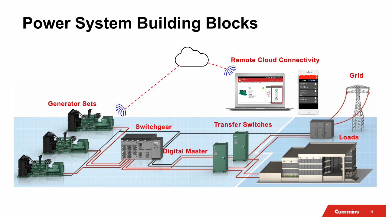
Generator Sets
Switchgear Transfer Switches
Grid
Loads
Digital Master
Remote Cloud Connectivity
Power System Building Blocks

7
Generator Set
Skid Engine Alternator Cooling Control

8
What is Paralleling? Synchronous operation of two or more generator sets connected together on a bus in order to
provide power to loads
NEC2017-700.10 (B) (5)
𝑓𝑓 𝐻𝐻𝐻𝐻 =𝑛𝑛𝑛𝑛
120𝑛𝑛: 𝑟𝑟𝑟𝑟𝑟𝑟,𝑛𝑛:𝑛𝑛𝑃𝑃𝑃𝑃𝑃𝑃𝑃𝑃
Emergency
Legally Required
Optional
Transfer Switches Generator Sets
Point of Power Connection:Switchgear, Collector Bus,…
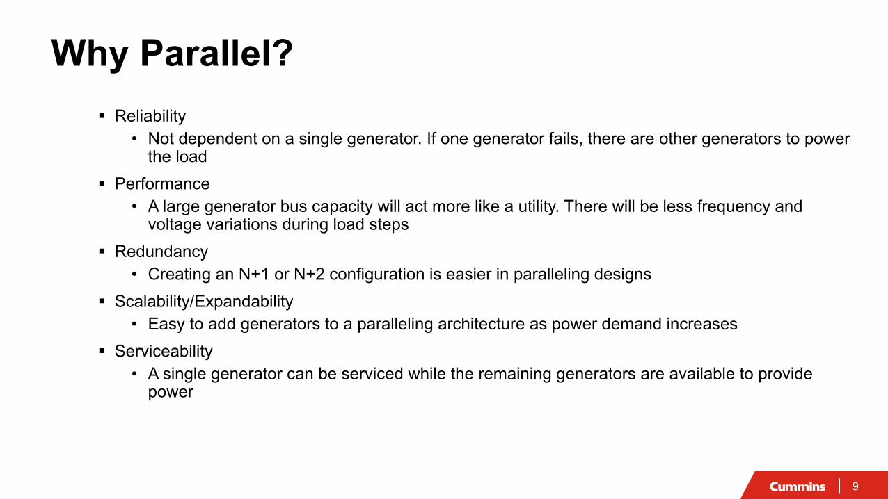
9
Why Parallel? Reliability
• Not dependent on a single generator. If one generator fails, there are other generators to power the load
Performance• A large generator bus capacity will act more like a utility. There will be less frequency and
voltage variations during load steps Redundancy
• Creating an N+1 or N+2 configuration is easier in paralleling designs Scalability/Expandability
• Easy to add generators to a paralleling architecture as power demand increases Serviceability
• A single generator can be serviced while the remaining generators are available to provide power

10
What To Specify For a Paralleled Power System Seamless operation if a generator set fails
• During a start • While paralleled
No single point of failure • Control architecture redundancy• Not dependent on a paralleling master control
Capacity to load consumption optimization• Prolong generator sets life expectancy • Save fuel
Ability of generator sets to self-protect• Overload, reverse power,…• Intelligent control with built-in protection
Energy reducing maintenance switching• If there is a need to work on an energized generator set
Comprehensive remote monitoring• Manage assets, monitor alarms, mitigate issues, etc. in real-time

11
Paralleling Control

12
Elements of Paralleling Controls Speed control – Governor (ECM) Voltage control – Automatic Voltage Regulator (AVR) Generator set arbitration
• De-energized bus: which generator set closes its breaker first Synchronization (frequency, phase and voltage)
• Energized bus Load sharing
• (kW: governor and kVAR: voltage regulator) Protection: engine and generator
• Reverse Power, Under/Over Voltage & Frequency, Sync Check,… Metering, faults, alarms
• kW, kVA, V, PF, Hz, Battery Voltage, Engine Temp,…
ECM AVR
900 180 270 360
Øv
Deg

13
A generator set output power can be connected to a another generator source only when the following conditions are met:
• Waveform (2/3rd pitch or 5/6th pitch)• Phase sequence• Speed difference (frequency)• Phase angle difference• Voltage amplitude difference
Paralleling Generator Sets
900 180 270 360
Øv
Deg
Generator 1 output Generator 2 output
t10 t2 t3 t4
v
t
∆V
f1
t10 t2 t3 t4
v
t
f2
A
B CACB
120°120°
A
C BABC
120°120°
v
t
14
f2
f1
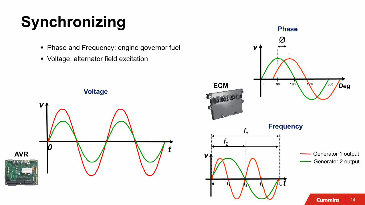
Synchronizing Phase and Frequency: engine governor fuel Voltage: alternator field excitation
900 270
Ø
v
v
Deg180 360
t10 t2 t3 t4 t
v
t0
Voltage
Phase
Frequency
Generator 1 output Generator 2 output
ECM
AVR

15
What are the advantages of paralleling generator sets? a) Scalability/Expandabilityb) Reliabilityc) Redundancyd) All of the Above
Concept Check
16
GOV
MASTERCONTROL
PARALLELINGUNIT #1
PARALLELINGUNIT #2
VM WM AM
W
25
SELSW
SELSW
HZ
EH
32
ILS
VM WM AM
LS
W
81U
SELSW
SELSW
SS
SL SL
VM WM AM
W
25
SELSW
SELSW
HZ
EH
32
ILS
SSSW
SSSW
PLC
PLC PLC
UTILITY MAIN
VM WM AM
W
25
SELSW
SELSW
HZ
32
VARPF
I/E
TO LOADS
TOUTILITY
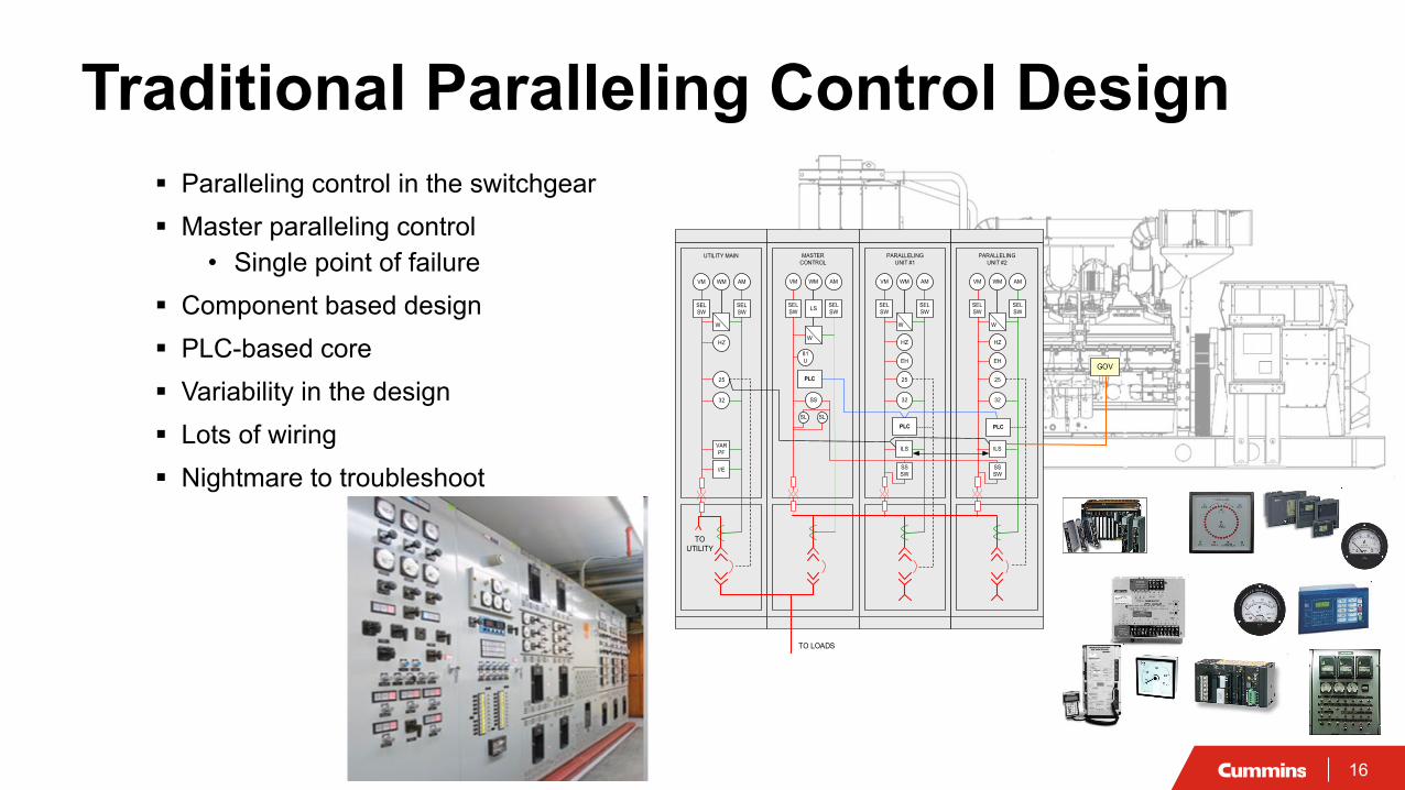
Traditional Paralleling Control Design Paralleling control in the switchgear Master paralleling control
• Single point of failure Component based design PLC-based core Variability in the design Lots of wiring Nightmare to troubleshoot

17
Integrated Generator Set Control
Human Machine Interface
Integrated Autonomous Paralleling Design

18
First Start Arbitration Synchronizing (Ø, V, Hz) Voltage Regulation Load Sharing (kW, kVAR) Generator Set Metering Generator Set Protection
Generator Set Controller
Governing Engine Protection Engine metering
Engine Control Module
Data Link
Human Machine Interface
Data Link
User Interface Configurations/Settings Alarms Start/Stop Manual Paralleling
Paralleling Control – Closer Look

19
Integrated Autonomous Paralleling Design
No paralleling master No single point of failure
Consistent design
Reduce wiring
Reduce footprint
Easy to learn and operate
Low or medium voltage
Point of Power Connection
Control wires

20
Paralleling Control (Energized Bus) Match Frequency, Phase and Voltage
CBCBClose Signal
Offset
-+Load Side Line Side
Offset
Closed feedback loop: Hz, Ø & V
Generator Set ControlSense line & load waves:Frequency HzPhase ØVoltage V
Energized Bus 480 VAC, 60 Hz, 3Ø
VoltageField
FuelHz, Ø
V
Synchronized
Line Side Wave
Load Side WaveFeedback 'A'
CB Green: Breaker Open
CB Red: Breaker Closed
21
CBCBCB CBCB CBCBCB
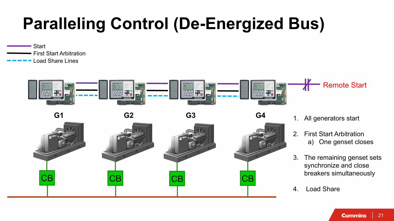
Load Share LinesFirst Start Arbitration
Remote Start
Paralleling Control (De-Energized Bus)
1. All generators start
2. First Start Arbitrationa) One genset closes
3. The remaining genset sets synchronize and close breakers simultaneously
4. Load Share
G1 G2 G3 G4
Start

22
Remote Start
Sync CheckConditions Met
Engine Cranks & Builds Up To Rated Speed & Voltage
GenBus Status
Ready to Load
De-energizedFirst Start Arbitration
Energized Synchronize
Close Generator Breaker& Load Share
First StartPermission Won
CBCBCB CB
G1 G2
Paralleling Sequence of Operation
Gen Bus

23
Load Sharing The proportional division of the kW and kVAR total load
between multiple generator sets in a paralleled system• Load sharing is essential to avoid overloading and
stability problems on the generator sets Load share can be Isochronous or Droop
• Isochronous: frequency & voltage are fixed regardless of the load. Requires communication wiring
• Droop: frequency & voltage vary as the load varies. Communication wiring between generators not needed
e.g. 2.8MW Load
2 MW
1.4 MW
1 MW
0.7 MW
1 MW
0.7 MW
kW = Engine
kVA
R =
A
ltern
ator
kW Demanded by Load
kVAR Demanded by Load
All generator set are70% Loaded

24
Seamless Paralleling Operation Paralleling is a function of the generator set control
Distributed logic architecture (control redundancy):• The paralleling logic (synchronizing, load sharing, governing, protection,...) is repeated on each
generator set • If a generator set fails
- Open paralleling breaker- Shutdown generator set- The paralleling system continues running
No paralleling master control• Single point of failure eliminated
CB CB CB CBCB

25
Capacity to Load Consumption Optimization Prolong generator sets life expectancy
Save fuel
CB
1 MW
CB
1 MW
CB
1 MW
CB
1 MW
CB
1 MW
Load:
1 MW
CB
1 MW
CB
1 MW
CB
1 MW
CB
Capacity: 5MW
0.5 MW1.5 MW3.0 MW3.5 MW4.75 MW

27
Generator Protection Elements 15 – Synchronizer 25 – Synch Check 27 – Undervoltage 32 – Directional Power 40 – Loss of Excitation/Reverse kVAR 46 – Phase Balance Current 47 – Phase Sequence Voltage 50 – Instantaneous overcurrent 51 – Time Overcurrent 59 – Overvoltage 81U/O – Under/Over Frequency Reverse kWReverse kVAR
CB CB
The numbers represent ANSI device numbers

28
Some generator set manufacturers have built into their controls:
• Overcurrent protection• Maintenance mode
- Bypasses all time delays
Energy Reducing Maintenance Switching Energy Reduction Maintenance Setting (ERMS)
ERMS Switch “OFF” and “ON” Mode
Local ERMS Switch

29
Comprehensive Remote Monitoring Single point visibility to assets
and site performance anytime anywhere
Immediate notification of any critical or non-critical issues through automated emails and push notifications
Access to historical performance data to any asset through reports and trending

30
Concept Check
Which of the following is true when isochronous load sharing is utilized:
a) Output voltage is constant but not frequency b) Frequency and phase angle are constant c) Output voltage and frequency stay constant as the load variesd) Output voltage and frequency vary as the load varies
31
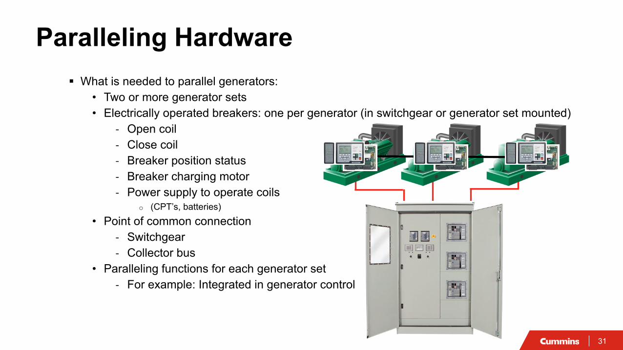
Paralleling Hardware What is needed to parallel generators:
• Two or more generator sets• Electrically operated breakers: one per generator (in switchgear or generator set mounted)
- Open coil- Close coil- Breaker position status- Breaker charging motor- Power supply to operate coils
o (CPT’s, batteries)• Point of common connection
- Switchgear- Collector bus
• Paralleling functions for each generator set- For example: Integrated in generator control
32
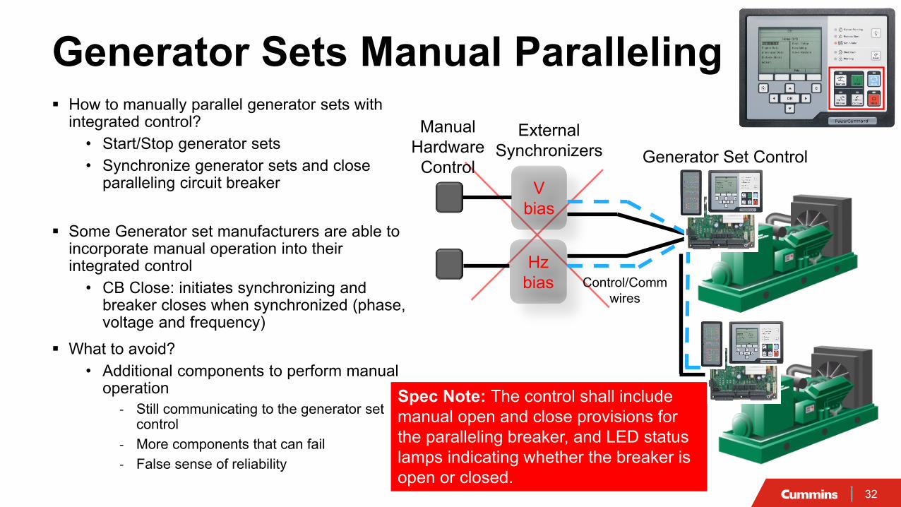
Spec Note: The control shall include manual open and close provisions for the paralleling breaker, and LED status lamps indicating whether the breaker is open or closed.
How to manually parallel generator sets with integrated control?
• Start/Stop generator sets• Synchronize generator sets and close
paralleling circuit breaker
Some Generator set manufacturers are able to incorporate manual operation into their integrated control
• CB Close: initiates synchronizing and breaker closes when synchronized (phase, voltage and frequency)
What to avoid?• Additional components to perform manual
operation- Still communicating to the generator set
control- More components that can fail- False sense of reliability
Generator Sets Manual ParallelingExternal
Synchronizers Manual
HardwareControl
V bias
Hz bias Control/Comm
wires
Generator Set Control

33
Obtain approval from the utility Hard-closed transition (100msec) Soft-Closed transition (>100msec, load ramp) Extended closed transition
Minimum import set point
Power export back to the utility? Reverse power protection
Extended closed-transition control algorithm expectations: Keep the lights on! Follow the utility Output power regulation Fast response as load changes
Cummins Plant in Minnesota, USAExtended Paralleling Example

34
Extended parallel with UMA: Close GMA and GMB Open UMB Start all generator sets and ramp load
Utility import set points: Start at 600 kW @ Approx. 7:24:37 import set point changed
to 400kW Frequency of four generator sets and utility during
operation locked at 60Hz
Hz regulation <0.1Hz variation
Utility A ramp down
All Gensets ramp up
Extended Paralleling Example
52UMB
52GMA
52GMB
52UMA
~1400kw ~800kw
52G1
52G2
52G3
52G4
5MW13.8kV13.8kV 13.8kV
N.O. N.O.
Instant of two utilities closed
together52
GMA52
GMB
52G1
52G2
52G3
52G4
52UMB
Load on Utility A
Load on Utility B
Ending operation
35
Course SummaryFunctions and Features of Generator Set Control Based Paralleling
• Identify the advantages of paralleling as they relate to overall system reliability, performance and flexibility.
• Recognize basic generator set paralleling control components, functions and features.
• Describe common strategies employed by paralleling systems using distributed logic architecture.
• Discuss the benefits of distributed logic architecture as it relates to paralleling, system reliability and its ability to eliminate a single point of failure.
Specify:
• Write specifications based on functions and performance
• Integrated paralleling and protection control
• Seamless paralleling operation if a generator set fails
• Paralleling control architecture redundancy
• Capacity to load consumption optimization to reduce fuel and wear/tear on generator sets
• Request a paralleling demonstration/witness testing for future projects
Avoid specifying:
• Specific hardware and components
• External hardware to perform generator set manual paralleling
36
Q&A
Type your questions, comments, feedback in the WebEx Q&A box. We will get to as many questions as we canWe will publish consolidated FAQ along with presentation and webinar recording on powersuite.cummins.com
Your local Cummins contacts:AZ, ID, NM, NV: Carl Knapp ([email protected]), Rocky Mountain RegionCO, MT, ND, UT, WY: Joe Pekarek ([email protected]), Rocky Mountain RegionNorthern IL, IA: John Kilinskis ([email protected]), Central RegionUP of MI, MN, East ND, WI: Michael Munson ([email protected]), Central RegionNB, SD, West MO, KS: Earnest Glaser ([email protected]), Central RegionSouth IL, East MO: Jeff Yates ([email protected]), Central RegionTX: Scott Thomas ([email protected]), Gulf RegionFL, GA, SC, NC and Eastern TN: Robert Kelly ([email protected]), South RegionNY, NJ, CT, PA, MD: Charles Attisani ([email protected] ): East RegionCA, HI: Brian E Pumphrey ([email protected])WA, OR, AK: Tom Tomlinson ([email protected])For other states and territories, email [email protected] or visit http://power.cummins.com/sales-service-locator

37
Closing
Watch out for a follow-up email includingA Link to webinar recording and presentationA PDH Certificate
Visit powersuite.cummins.com for PowerHour webinar recording, presentation and FAQ archiveOther Cummins Continuing Education programsSizing and spec development tool
Please contact Mohammed Gulam if you have any questions related to the PowerHour webinar ([email protected])

38
Q+A

3939
Related Documents


![Vector Signal Generator MG3710A Product Introduction · Vector Signal Generator MG3710A Features AWGN generator [Opt-049/079] AM/FM/ M/PM Functions [Standard] Additional analog modulation](https://static.cupdf.com/doc/110x72/5eb581a18015c7750f3b383c/vector-signal-generator-mg3710a-product-introduction-vector-signal-generator-mg3710a.jpg)

