1 Functional Specification Purpose The intended reader of this functional specification is the writer of a user’s guide. The user’s guide’s purpose would be to teach persons interested in installing a kitchen sink, a kitchen faucet, an air gap or hard food disposer how to do so. Scope The user’s guide should contain procedures for the installation of angle stops onto hot and cold water pipes, the installation of a standard size top mount kitchen sink, the installation of a standard size kitchen faucet, the faucet’s waterlines, an air gap, a hard food disposer and a separate sink drain if the kitchen sink should have a second bowl. The user’s guide should not contain procedures for cutting a hole in a kitchen coun- tertop to match a kitchen sink’s specifications, the installation of an udermount kitchen sink or the installation of angle stops onto copper water pipes that have been cut too far back in the wall due to excessive compression ring crimpling. Prerequisites / Requirements The target audience is any persons interested in doing their own repair work or installing new products. Apprentice plumbers, handy persons and hardware store employees, including kitchen designers, might benefit from reading the guide to bet- ter understand how the procedures within the guide apply to their work. Tools a reader should have at hand to accomplish the procedures found in the guide: • Emery cloth • Channel locks • Pliers • Vice grips • One set of open end wrenches • One set of right angle open end wrenches • An adjustable spanner • Sets of Phillips and flat head screwdrivers • A flashlight • A copper pipe cutting tool • A wire brush • Teflon tape • A tube of liquid silicone • Drain tool • A rubber hose to connect the air gap to the hard food disposer • A power cord to attach to the bottom of the hard food disposer Processes The processes that follow are based on the writer’s opinions, material descriptions and a number of general plumbing procedures.

Welcome message from author
This document is posted to help you gain knowledge. Please leave a comment to let me know what you think about it! Share it to your friends and learn new things together.
Transcript
1
Functional Specification
Purpose The intended reader of this functional specification is the writer of a user’s guide. The user’s guide’s purpose would be to teach persons interested in installing a kitchen sink, a kitchen faucet, an air gap or hard food disposer how to do so.
Scope The user’s guide should contain procedures for the installation of angle stops onto hot and cold water pipes, the installation of a standard size top mount kitchen sink, the installation of a standard size kitchen faucet, the faucet’s waterlines, an air gap, a hard food disposer and a separate sink drain if the kitchen sink should have a second bowl.
The user’s guide should not contain procedures for cutting a hole in a kitchen coun-tertop to match a kitchen sink’s specifications, the installation of an udermount kitchen sink or the installation of angle stops onto copper water pipes that have been cut too far back in the wall due to excessive compression ring crimpling.
Prerequisites / Requirements
The target audience is any persons interested in doing their own repair work or installing new products. Apprentice plumbers, handy persons and hardware store employees, including kitchen designers, might benefit from reading the guide to bet-ter understand how the procedures within the guide apply to their work.
Tools a reader should have at hand to accomplish the procedures found in the guide:
• Emery cloth• Channel locks• Pliers• Vice grips• One set of open end wrenches• One set of right angle open end wrenches• An adjustable spanner• Sets of Phillips and flat head screwdrivers• A flashlight• A copper pipe cutting tool• A wire brush • Teflon tape • A tube of liquid silicone• Drain tool• A rubber hose to connect the air gap to the hard food disposer• A power cord to attach to the bottom of the hard food disposer
Processes The processes that follow are based on the writer’s opinions, material descriptions and a number of general plumbing procedures.

2
Kitchen Countertop OverviewKitchen countertops are ordinarily special order items. They are cut to a customer’s specification as a part of a kitchen remodel. Contractors often install the countertops when they install a customer’s kitchen cabinets.
Kitchen coutertops can be ordered in granite, soapstone, stainless steel, cement, wood, laminate surface, or ceramic tile. Laminate surfaced countertops may be found as in-stock items at many hardware stores and are available in a number of lengths. They usually have a 3” backsplash molded onto the back of them and their depth is stan-dard as they are manufactured to sit on top of a standard 24” deep kitchen cabinet. In-stock countertops should be excluded from the user’s guide because they need to be cut to the kitchen sink’s specifications.
Kitchen Sink Installation A standard size top mount kitchen sink is available in cast iron, stainless steel and var-ious acrylic compounds. A kitchen sink is packaged with its cutout specifications included in its box if it comes in one. The standard size of a kitchen sinks is measured by the exterior dimensions of its surface. A standard size kitchen sink’s surface mea-sures thirty three inches wide and twenty two inches deep (front to back).
Most standard size top mount kitchen sinks have at least three holes an equidistant apart on their surface. The holes are located at the backside of the sink’s surface to accommodate a standard size dual or single valve kitchen faucet.The midpoints of the outer two holes of three hole sinks measure 8” apart, midpoint to midpoint, and match the width of a standard size dual valve kitchen faucet’s installation fittings.
If a kitchen faucet’s installation requires only a single hole the faucet will be packaged with a plate that fits under the faucet to cover the other two holes. An optional fourth whole in the sink may accommodate an air gap. If a sink has a fifth hole an instant hot water dispenser can be installed in it.
Cast iron sinks
White standard size top mount cast iron sinks may be found at most hardware stores. Other colors and styles may be special ordered as well. Cast iron sinks weigh approx-imately one hundred twenty pounds depending on their manufacture and design. Cast iron sinks are very sturdy and widely popular. One problem consumers have with them is their porcelain coatings chipping. Porcelain touch up kits are available at most hardware stores.
A cast iron sink will drop into a whole in a countertop that has been cut to the manu-factory’s specifications. Gravity keeps the sink in place due to its extreme weight. It is recommended that the sink be pulled back out of the countertop, turned over and liq-uid silicone put around the bottom of its lip. Once the sink is reinstalled the silicone creates a waterproof seal. Excess silicone squeezing out from under the edges of the sink’s lip can be evenly wiped away to give the edges of the sink a finished look.
The most common kitchen sink has one or two bowls and four holes, three for the fau-cet and one for the air gap. There are many cast iron sink designs. They can be ordered in many colors, bowl sizes, number of bowls, and faucet hole positions.
3
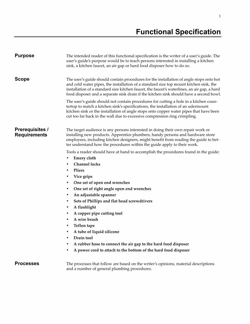
Below are pictures of two cast iron kitchen sinks. Figure 1 is a picture of a top mount sink that is likely to be found in stock at your local hardware store.
Figure 1: A standard size white cast iron kitchen sink
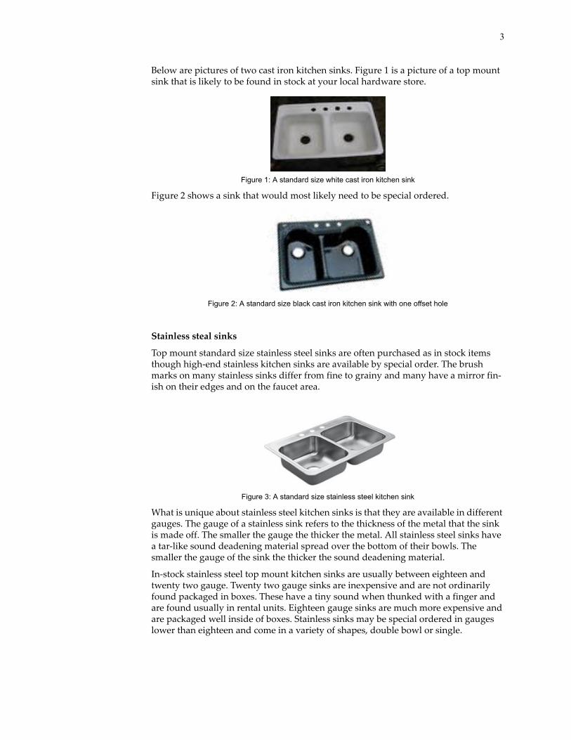
Figure 2 shows a sink that would most likely need to be special ordered.
Figure 2: A standard size black cast iron kitchen sink with one offset hole
Stainless steal sinks
Top mount standard size stainless steel sinks are often purchased as in stock items though high-end stainless kitchen sinks are available by special order. The brush marks on many stainless sinks differ from fine to grainy and many have a mirror fin-ish on their edges and on the faucet area.
Figure 3: A standard size stainless steel kitchen sink
What is unique about stainless steel kitchen sinks is that they are available in different gauges. The gauge of a stainless sink refers to the thickness of the metal that the sink is made off. The smaller the gauge the thicker the metal. All stainless steel sinks have a tar-like sound deadening material spread over the bottom of their bowls. The smaller the gauge of the sink the thicker the sound deadening material.
In-stock stainless steel top mount kitchen sinks are usually between eighteen and twenty two gauge. Twenty two gauge sinks are inexpensive and are not ordinarily found packaged in boxes. These have a tiny sound when thunked with a finger and are found usually in rental units. Eighteen gauge sinks are much more expensive and are packaged well inside of boxes. Stainless sinks may be special ordered in gauges lower than eighteen and come in a variety of shapes, double bowl or single.
4
A top mount stainless steel kitchen sink needs to be installed with sink clamps because it does not have the weight of a cast iron sink to hold the sink firmly in place. It is installed in a precut countertop by liquid silicone being applied all along the edge of the bottom of flanges of the sink.
Once the sink is laid in place sink clamps are screwed onto long threaded nuts. The heads of the threaded nuts slide into rails welded onto the underside of the flanges on both sides of the sink. The ends of the nuts opposite of their heads have slots in them for a screwdriver to fit in. As the nuts are screwed down the clamps tighten down to clamp the flanges of the sink onto the counter top using the clips on the underside to hold them down. Once the silicone dries the sink clamps may be removed.
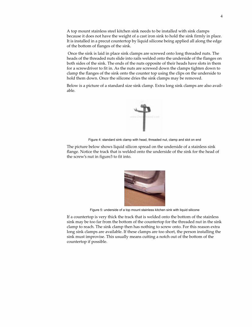
Below is a picture of a standard size sink clamp. Extra long sink clamps are also avail-able.
Figure 4: standard sink clamp with head, threaded nut, clamp and slot on end
The picture below shows liquid silicon spread on the underside of a stainless sink flange. Notice the track that is welded onto the underside of the sink for the head of the screw’s nut in figure3 to fit into.
Figure 5: underside of a top mount stainless kitchen sink with liquid silicone
If a countertop is very thick the track that is welded onto the bottom of the stainless sink may be too far from the bottom of the countertop for the threaded nut in the sink clamp to reach. The sink clamp then has nothing to screw onto. For this reason extra long sink clamps are available. If these clamps are too short, the person installing the sink must improvise. This usually means cutting a notch out of the bottom of the countertop if possible.

5
The picture below shows a sink clamp with its head in the track and its clamp screwed down onto the bottom of a countertop.
Figure 6: standard sink clamp installed in track and on countertop
After the silicone has dried and the excess has been cleaned from around the edges of the top side of the sink a screwdriver will fit in the slot on the end of the threaded screws to uninstal the sink clamps.
Acrylic sinks
There many chemical compounds in different manufacture’s acrylic sinks and the manufactures give the various acrylic sinks different names. Top mount standard size acrylic kitchen sinks are inexpensive purchases regardless of what their labels state.
Some acrylic top mount sinks come with only a circular indentation on the bottom of the facet plate where the faucet holes usually are. This allows a customer to only drill out the number of holes which the faucet will need. This leaves the surface of the sink smooth and negates the need for an optional faucet plate which single handled fau-cets ordinarily come with. The user’s guide will cover only top mount standard size
acrylic kitchen sinks that come with at least one hole stamped out by the manufacture.
Figure 7: Acrylic top mount kitchen sink
First, fit the acrylic sink into the hole cut for it in the countertop to see if it properly fits. Pull the sink back out and apply liquid silicone around the bottom edge of its flange. Reinstall the sink into the countertop pushing down on the flange all the way around. It is best to put some weighted objects around the top of the sink’s flange to weight the sink down until the silicone dries. Once the silicone is dry lift the weighted objects off and clean any dried silicone from the countertop. You may wish to apply silicone around the edges where the sink meets the countertop to seal it.
Kitchen Sink Drain InstallationKitchen sink drains are a standard size and are available at any hardware store. The quality of kitchen sink drains vary in accordance with their price. The majority of kitchen sink drains are chrome though they are available in white and gold.
6
First, take the drain out of its box if it comes in one. Next take the drain apart. On the bottom of the flange apply a fair amount of liquid silicone or plumber’s putty if it is preferred. Place the inner part of the drain down through the sink’s drain hole with the silicone sitting between the flange and the rim of the drain inside of the sink’s bowl. The rest of the drain and its threads should be protruding through the bottom of the sink.
Figure 8: Kitchen sink drain
Next, take the large nut that came with the drain and screw it down onto the bottom of the drain until it is firm. Channel locks are probably the best tool for this. Wipe the excess silicon from around the drain both below and above the sink. Insert the drain’s strainer and wait for the silicone to dry.
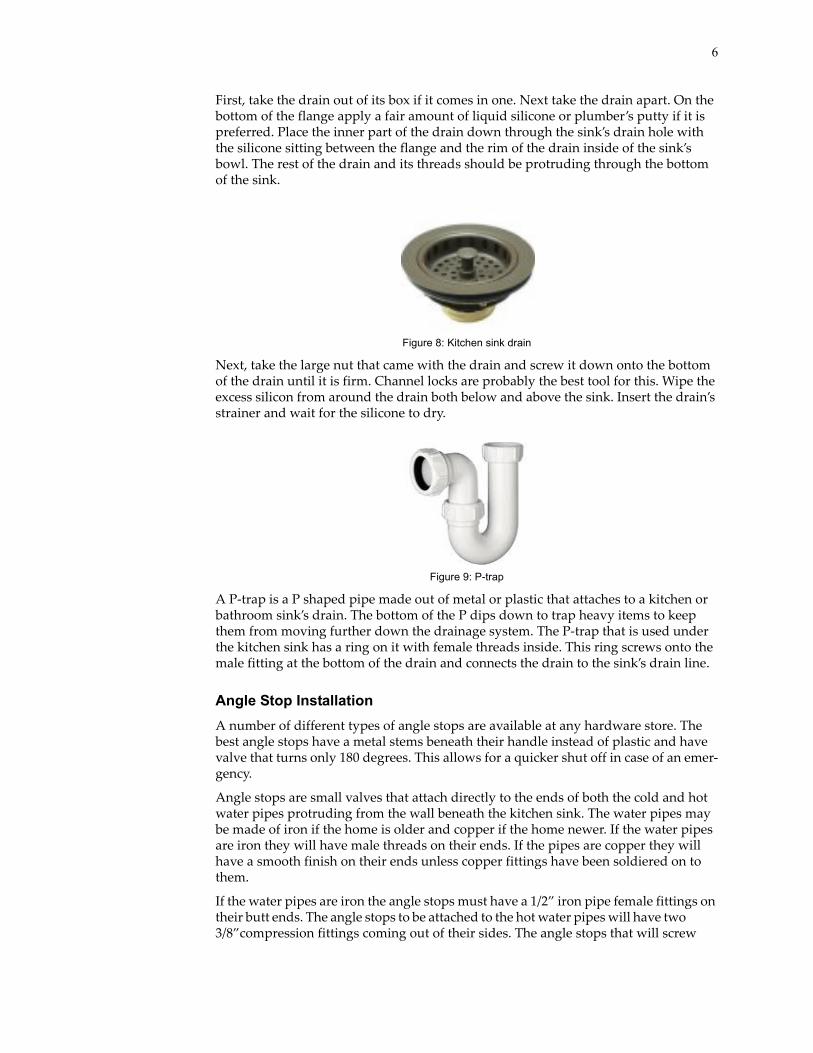
Figure 9: P-trap
A P-trap is a P shaped pipe made out of metal or plastic that attaches to a kitchen or bathroom sink’s drain. The bottom of the P dips down to trap heavy items to keep them from moving further down the drainage system. The P-trap that is used under the kitchen sink has a ring on it with female threads inside. This ring screws onto the male fitting at the bottom of the drain and connects the drain to the sink’s drain line.
Angle Stop InstallationA number of different types of angle stops are available at any hardware store. The best angle stops have a metal stems beneath their handle instead of plastic and have valve that turns only 180 degrees. This allows for a quicker shut off in case of an emer-gency.
Angle stops are small valves that attach directly to the ends of both the cold and hot water pipes protruding from the wall beneath the kitchen sink. The water pipes may be made of iron if the home is older and copper if the home newer. If the water pipes are iron they will have male threads on their ends. If the pipes are copper they will have a smooth finish on their ends unless copper fittings have been soldiered on to them.
If the water pipes are iron the angle stops must have a 1/2” iron pipe female fittings on their butt ends. The angle stops to be attached to the hot water pipes will have two 3/8”compression fittings coming out of their sides. The angle stops that will screw

7
onto the cold water pipes will have a 3/8” compression fittings and 1/4” compression fittings coming out of their sides. The handles for turning the valves off and on will be on the tops of these kinds of angle stops. Compression fittings on angle stops are male with female nuts and compression rings on them. Compression fittings have very small threads that resist water leakage better that larger thread sizes. Compression fit-tings which have compression rings in them are made to fit onto copper pipes or tubes.
Figure 10: Angle stop for use with copper pipe
Before starting this process make sure to turn the main water supply valve off.
To install the angle stops onto the ends of the iron pipes the male threads should be brushed off with a wire brush to get rid off any residue. Next, wrap teflon tape around the iron threads on the ends of both pipes in a clockwise direction, facing the wall, so that the tape will not unravel when the angle stops are screwed on.
Screw the angle stop with the two 3/8” fittings onto the hot water pipe. The angle stop will have flat sides that a channel lock will fit over. Unscrew the nuts off the 3/8” com-pression fittings on the angle stop if needed. Screw the 3/8” female end of the dish-washer waterline to one 3/8” male fitting on the angle stop. Screw the 3/8” female the end of the hot waterline from the kitchen faucet onto the other 3/8” male compression fitting on the angle stop. When the female ends screw onto the male fittings of the angle stops the compression threads create a waterproof seal. No Teflon tape is needed.
Figure 11: Angle stop for use with iron pipe
Screw the angle stop with the 1/4” fitting onto the cold water pipe. Again, use a chan-nel lock to screw this on. Now, screw the 1/4” female end of the refrigerator’s ice maker waterline onto the male 1/4” fitting on this angle stop. Next, screw the female 3/8” end of the cold water line from the kitchen faucet to the 3/8” male compression fitting on the angle stop.
Turn both valve handles on the angle stops to the off position. Put pans or some other receptacles under the angle stops before turning the main water valve back on. If any leaks are found in the angle stops after the main valve is turned on shut the main water line off again and redo the installation process of the angle stops adding more teflon tape onto the threads of the iron pipes before reinstalling the angle stops. If the

8
leak is not at this end of the angle stop the angle stop is defective and needs to be replaced.
The angle stops to be installed onto the ends of the copper water pipes will have 1/2” compression fittings on their butt ends. The angle stop to be attached to the hot water pipe will have two 3/8”compression fittings coming out of its side. The angle stop that will screw onto the cold water pipe will have a 3/8” compression fating and a 1/4” compression fitting coming out of its side. The handles for turning the valves off and on will be on the top of these kinds of angle stops.
Before starting this process turn the main water supply valve off.
Both copper water pipes coming out of the wall should be scoured with emery cloth. Unscrew the large compression nuts and their rings off of the butt ends of the angle stops and slip them over the copper pipes face out. Slip the compression rings down the copper pipes and in inside of the nuts.
Fit the angle stop with the two 3/8” fittings over the end of the hot water pipe. Make sure that the 1/2” compression ring that was inside of the nut is now between the end of the angle stop and the copper pipe. Screw the 1/2” compression nut back onto the angle stop compressing the ring onto the water pipe. The angle stop will have flat sides that a channel lock will fit over to hold it in place while the nut is screwed on with a wrench. The compression ring between the end of the angle stop and the cop-per pipe will compress onto the pipe as the nut is tightened down to create a water-proof seal.
Next, attach the female 3/8” end of the dishwasher waterline to the 3/8” male com-pression fitting on the angle stop. An open end wrench or adjustable spanner may be used to do this. Now, screw the 3/8” end of the hot waterline from the kitchen faucet onto the 3/8” male compression fitting on the angle stop. The female ends simply screw onto the male fittings of the angle stop. The compression threads of both ends create waterproof seals. No teflon tape is needed.
Fit the angle stop with the 1/4” fitting over the end of the cold water pipe. Make sure that the 1/2” compression ring that was inside of the nut is now between the end of the angle stop and the copper pipe. Screw the 1/2” compression nut back onto the angle stop compressing the ring onto the copper pipe. The angle stop will have flat sides that a channel lock will fit over to hold it in place while the nut is screwed on with a wrench. The compression ring inside the angle stop will be compressed onto the copper pipe creating a waterproof seal. No teflon tape is needed.
Screw the 1/4” female end of the refrigerator’s ice maker waterline onto the male 1/4” fitting on the side of the angle stop. Screw the female 3/8” end of the cold water line from the kitchen faucet to the 3/8” male compression fitting on the side of the angle stop.
Turn both valve handles on the angle stops to the off position. Put pans or some other receptacles under the angle stops before turning the main water valve back on. If any leaks are found in the angle stops after the main valve is turned on shut the main water line off again and redo the installation process adding more teflon tape onto the iron threads on the pipes. Screw the angle stops back on. If the leak is not at these junctions the angle stops are defective and must be replaced.
Kitchen Faucet Installation The standard size kitchen faucet is made to install in the standard size top mount kitchen sink. Its instillation fittings have a spread of 8” midpoint to midpoint if the faucet is a dual valve faucet. Standard size kitchen faucets come in a wide variety of

9
styles. The two main styles of kitchen faucets found in plumbing and hardware stores today are single valve faucets and dual valve faucets. Single valve kitchen faucets have only one handle and require only one hole for installation in a top mount kitchen sink. Single valve faucets come packaged with a plate that sits under them when they are installed onto a sink. The plate covers the holes on both side of the hole the faucets install in. One valve kitchen faucets have a singles handles that control both the hot and cold water. Separate hot and cold water lines are still required for single handle faucets however. Single valve faucets are more popular and are more expensive than dual valve faucets.
Figure 12: Two handle kitchen faucet
Dual valve faucets have separate handles for hot and cold water. They are simple, inexpensive and found in many rental units. One brand of dual valve faucets is even made out of plastic.
Before starting this process make sure that both angle stops or the main water supply valve has been turned off.
To install both single and dual valve faucets the gasket which sits between the faucet and the top mount kitchen sink must be laid down with liquid silicone between it and the kitchen sink. The faucet is then set down over the gasket and the faucets installa-tion nuts) are threaded onto the faucet’s installation fittings) under the sink. These are tightened down with an open end wrench, a channel lock or an adjustable spanner. The angle stops are turned back on the faucet’s valves are turned on to see how the faucet works.
Figure 13: Single handle kitchen faucet
If the faucet comes with its own water lines attached to its underside the fittings on the waterline’s ends are usually 3/8” female compression thread. The water lines are simply screwed onto the 3/8” male compression thread fittings protruding from the appropriate angle stops below.
If the faucet does not come with its own water lines the person installing the faucet can then choose which lengths and types of water lines the installer wishes to use. The best faucet water lines available are coated in a stainless steel flexible mesh coating and they come in a number of lengths.
Faucets that comes without water lines are installed the same way that ones with waterlines are except that the chosen water lines need to be installed onto the

10
threaded fittings underneath the faucet itself and then onto the appropriate angle stops. Usually a right angle open end wrench and a flashlight are the best tools to for this job if the kitchen sink has already been installed. This is because the installer will be underneath the sink reaching up into confined areas that are dark. A specialty tool is also made for this purpose. Once the faucet’s water lines are connected and the angles stops are turned back on the faucet can be tested at this.
Hard Food Disposer InstallationThere are five or six levels of hard food disposers to choose from. A disposers is priced according to its torque and its quietness rating. When a hard food disposer is taken out of its box its mounting bracket is usually packaged in Styrofoam and will be partially connected to the disposer. A hard food disposers, like a dishwasher, is not packaged with a power cord. Distances to electrical outlets vary for both 120 watt appliances.
A hard food disposer is easiest to install if the sink is out of the countertop and turned upside down. The process described, however, assumes that the sink is still in the countertop. The disposer’s installation bracket must be removed from the disposer and disassembled before installation. To disassemble the bracket the snap ring must first be pried off the installation bracket’s end with a flat head screw driver.
Figure 14: Snap ring in disposer’s installation collar
The installation bracket is combination of a fiber washer, two wide flat metal rings and a short a metal tube with a flange on one end and a groove on the other. The groove is where the snap ring sits. The flat metal rings sit on opposite ends of the short metal tube with a flange on one end and the snap ring groove on the other. One of the flat metal rings has three threaded rods loosely attached to three protrusions which are an equidistant apart. The other metal ring’s three protrusions have threaded metal eyelets in their centers. These protrusion are a equidistant apart. Both ring’s protrusions line up with one another as the rings sit at opposite ends of the short metal tube. The three metal rods on one ring screw into the threaded eyelets in the other to hold the mounting bracket together.
Figure 15: Hard food dispose collar parts
To install the disposer, liquid silicone should first be spread over the rim of the drain hole in the bowl of the kitchen sink. The short metal tube with a flange on one end and a groove on the other, which is part of the disposer’s installation kit, should be set

11
down in the hole and on to the silicone. The flange should be pushed down firmly into the silicone and the rim of the whole in the sink to become the rim of the dis-poser’s drain.
Underneath the sink, the fiber washer which came with the disposer’s installation kit should be slipped up over the bottom of the short metal tube that was just seated in the sink’s drain. The washer should sit beneath the bottom of the sink where the tube’s flange now sits above. A dab of liquid silicone should keep the washer from falling off.
Figure 16: Fiber washer slipped over metal tube
Slide the wide flat metal ring with the three threaded metal rods loosely attached to it over the metal tube and up on to the washer making sure the threaded rods point down. Hold the second wide flat metal ring with its three threaded eyelets up to the threaded rods and screw each rod into the corresponding eyelet in the second flat metal ring. hold the entire assembly up against the bottom of the sink and snap the snap ring back into the grove at the end of the round metal tube. Once the snap ring is installed it holds the entire assembly in place.
Before attaching the hard food disposer to its installation bracket the dishwasher drain line attachment hole needs to be prepped. Turn the disposer on its side so that both the drain line hole and the disposer drain line hole are facing upward. Use a screwdriver and a hammer to knock out the plastic drain guard that sits inside the plastic tube protruding from the upper section of the disposer’s side. This is only done if their is a dishwasher is installed. Make sure to turn the disposer over so that the plastic guard will fall out. If the guard is left in the grind chamber it will catch between the disposers blades once the disposer is turned on.
Figure 17: Knocking out the drain guard
Undo the screws holding the small plate over the electrical connection for the dis-poser’s power cord. It is on the bottom of the disposer. Connect the two ends of the power cord, which was purchased separately, onto the electrical connections (two screws). Replace the small plate.
The rim of the hard food disposer has fittings which screw into the bottom ring of its installation bracket. This is how the disposer attaches to the sink. Make sure that the disposer is screwed on securely.

12
Once the hard food disposer has been attached to the sink it must be attached to both the sink drain line and the dishwasher drain line coming from the air gap. Attach the dishwasher drain line onto the larger of the two plastic ends jutting out from the air gap’s bottom using a rubber hose which must be purchased separately at a hardware store. The rubber hose should connect to both the disposer and the air gap with ordi-nary hose clamps which may be purchased separately if they do not come with the rubber hose.
The kitchen sink drain line now needs to be attached to the larger of the two drain holes on the side of the disposer and to the drain connected to the second bowl of the kitchen sink if it is a double bowl. A dedicated drain line assembly kit is available at many hardware stores for this purpose. A standard kitchen drain line measures one and one half inches in diameter. The fittings screw together with one piece having a small flange at one end and the other piece a threaded end with a nut on it. The nut is taken off its threaded end and is slipped onto the second piece of drain and over its flanged end. The nut is then screwed back onto its threaded end trapping the flanged end of the second drain piece inside of it.
Figure 18: Drain line between disposer and sink drain
There is a black sharp angled one and one half inch tail piece that comes packaged with the an older disposer. It fits onto the disposer’s drain line fitting. It has a unique flange on its end that is beveled outward. On older disposers this fits into a hollow male threaded fitting that is bevelled inward. The disposer has a nut that screws down over the flange to clamp the black tailpiece onto the disposer.
On newer disposers, the outward bevelled fitting on the tailpiece, which is no longer packaged with the disposer, is held onto the inwardly beveled fitting on the disposer by a flat metal fitting and a gasket. These are held onto the disposer with two screws. The tail piece, acting as a drain line, then attaches onto a P-trap if the disposer has been installed in a single bowl sink.
If the disposer is installed in a double bowl sink a T shaped one and one half inch drain line is attached to the disposer and a small tailpiece coming out of the second sink’s drain. These then attach to the drain line that is coming out of the wall under the kitchen sink.
To complete the hard food disposer’s installation plug the disposer’s power cord in the nearest electrical outlet that has a power switch governing it.
Air Gap InstallationAn air gap is usually made of plastic and has two angled fitting at its bottom. The air gap attaches through a hole in a kitchen sink that is next to or near the kitchen faucet. An air gap usually has a chrome or white cap which sits over its top. The two angled fittings that jut out from the air gap’s bottom attach to the dishwasher and to the hard food disposer. The air gap is in line with the dishwasher’s drainage system and only needs to be installed if a dishwasher is also installed. The air gap’s purpose is to act as a breathing device. It allows the dirty water draining from the dishwasher to more

13
easily drain into the hard food disposer. It also keeps water that should not drain from the dishwasher from doing so.
The top section of an air gap is threaded. This section has both a threaded fitting which screws down over the air gap on to the top of the kitchen sink and a threaded nut which screws up over the threaded section of the air gap on to the bottom of the kitchen sink. Once the air gap is trapped between the top and bottom fittings the air gap is installed in the sink.
Figure 19: Air gap
The drain line from the dishwasher attaches to the smaller of the angled fittings which jut out from the bottom end of the air gap by means of a hose clamp. The rubber hose from to the hard food disposer fits on the larger of the two fittings that jut out from the bottom of the air gap and attaches with a hose clamp. This drain line is described in the installation process for the hard food disposer and may be purchased at any hardware store.
Once the air gap is in place and the drain lines have been attached the cap which came with the air gap may be placed over its top.
Troubleshooting The following are some answers to the most common problems that one might encounter when working with the plumbing in the kitchen sink area:
• Angle stop leaks. If an angle stop leaks, it must be replaced unless the leak is at the point where the angle stop attaches to the water pipe. If the leak is at the installation point turn off the main water valve for the house. Remove the angle stop from the water pipe and take the old teflon tape off the threads of the iron pipe and replace it with more teflon tape wrapping it around the threads in clock-wise direction. If the water pipe is copper replace the compression ring that is compressed onto the copper pipe if the indentation below it is ineligible. Many times the pipe will need to be cut behind the old copper compression ring because it is either to tight to get off or the copper pipe is crimped too badly. Insert a new compression ring onto the pipe only after the nut it sits in is slid over the pipe first. Reinstall the angle stop.
• If water flows out of the air gap. When an air gap has water flowing out of it this means one of two things. Either the water draining out of the dishwasher can not drain any further than the air gap because the line from the air gap to the hard food disposer is clogged. The second possibility is that the person who installed the hard food disposer did not knock out the tab in the wall of the disposer where the line from the air gap attaches. The tab may be knocked out with a screw driver and a hammer without having to uninstal the disposer. Stick a hand down the dis-poser making sure it is off and feel to see the tab has been knocked out. If it has then the hose running from the air gap to the hard food disposer needs to be taken off and either cleaned out or replaced.

14
• If the hard food disposer jams. Most hardware stores have a unique tool to fix this problem.Insert the specialty tool inside he disposer and turn. Many disposers have a reset button on them somewhere. Push this button once the jam has been cleared.
• If water leaks from the kitchen faucet. Water leaking from a kitchen faucet usu-ally means that the valve(s) in the faucet must be replaced. Turn the knobs on the angle stops to off. If they leak turn the main water valve off. Unscrew the screw(s) on the top(s) of the handle(s) of the faucet. Pull out the valve(s). Replace the valve(s) by following these procedure in reverse.
If the faucet’s brand name is Delta or an off brand made by Delta it will have a ball with a stem which sits on top of two springs and rubber seats. In this case only the rubber seats need replacing.
It is rare in this day and age but if the faucet has brass valves only the rubber gas-ket(s) on the valves will need replacing.
Glossary • Adjustable spanner. An adjustable spanner looks and acts like a square jawed wrench. Its difference is that it has a smaller roller on its side that adjusts how far the jaw of the wrench opens and closes. The adjustable spanner is better known by its brand name, the Crescent Wrench.
• Air gap. An air gap is usually made of plastic and has two angled fittings at its bottom. These connect the drain line from the dishwasher to the hard food dis-poser. An air gap attaches through the kitchen sink and has a cap which sits over its top.
• Angle stop. Angle stops are small valves. They attach to the hot and cold water pipes below the kitchen sink. The kitchen faucet’s water lines run down and attach onto each of them. Angle stops can be shut off quickly in the case of an emergency.
• Brass pipe thread. Brass pipe thread is the largest thread size found in brass fit-tings. It is smaller in size than iron pipe thread. Brass pipe thread is found in one size of one end of a faucet waterline. This end of the faucet waterline connects only to a kitchen faucet. It is not the only size brass fitting which connects to a fau-cet however.
• Compression fitting. A compression fitting is a male or female fitting which has compression threads on or in it. A male compression fitting may or may not have a nut on it with a compression ring inside. The nut and ring on the male compres-sion fitting attach only to copper pipes and copper tubing.
• Compression ring. A compression ring is a ring made of brass. The ring sits inside of a brass nut on some angle stops and other plumbing applications. When an angle stop, for instance, is meant to attach to a copper pipe the nut is in screws down over the compression ring. This compresses the ring onto the pipe. The compression ring sits between the pipe and the end of the angle stop to crate a waterproof seal.
• Compression thread. Compression thread is the smallest size thread found on a brass fitting. The small space between compression threads resists water leakage better than the space between larger threads. Compression threads are found inside one end of a faucet waterline.
• Female thread. Female thread is the thread on the inside of an inverted fitting.
• Male thread. Male thread is the thread on the outside of a protruding fitting.
• Pipe thread. Pipe thread is the largest thread size found on or in iron pipe.

15
• P-trap. A P-trap is a P shaped pipe that is usually attached to a kitchen or bath-room sink drain. The bottom of the loop in the P dips down to trap heavier items that fall to its bottom such as dirt and hair. The P-trap keeps water that is draining further down the line free of debris. A P-trap might catch a wedding ring it has drops down the kitchen sink’s drain.
• Right angle open end wrench. An open end wrench is a static wrench that has an opening at the end that fits onto a nut. It is open so that it can slide on the nut rather that having to fit over the nut’s top. A right angle open end wrench has a ninety degree bend at the end that slides over the nut. This allows the right angle open end wrench to fit into places that other wrenches can not.
• Sink clip. Sink clips are used only on stainless steel sinks as temporary clamps. Sink clips are a folded over pieces of metal an inch and a half wide with a threaded metal rod screwed through them. The threaded metal rods have heads on one of their ends and slots in their other ends. The heads on the metal rods slip inside of tracks welded onto the bottoms of stainless kitchen sinks. The rods hold the sink clamps onto the sinks as the folded metals sides screwed on to the metal rods clamp onto the bottoms of countertops holding the sinks in place. After liq-uid silicone that has been spread under the lips of the stainless sinks dries the sink clips are taken off and either stored or thrown away.
• Stainless steel sink gauge. The gauge of a stainless steel sink is measured the same as the gauge of any metal. The smaller the gauge the thicker the metal. Stainless steel kitchen sinks with smaller or heavier gauges are much more sturdy, make less noise and are more expensive. Kitchen sinks available as in stock items at stores are usually between 22 and 18 gauge. Stainless steel sinks with gauges lower than 18 ordinarily have to be special ordered.
• Standard size kitchen faucet. A standard size kitchen faucet is a faucet that has been manufactured to fit over the three mounting holes in a standard size kitchen sink. A standard size kitchen sink has three mounting holes that are 8” from the midpoints of the outer two holes. A standard size kitchen faucet may have either separate handles for the hot and cold water or a single handle for both. The dou-ble handled standard size kitchen faucet has mounting screws that measure 8” apart. The single handled standard size kitchen faucet needs only one mounting hole though it comes with a matching mounting plate that will sit under it to cover the other two holes if necessary. A single handled standard size kitchen fau-cet does not need to be mounted on a standard size kitchen sink and may be mounted onto the countertop itself.
• Standard size kitchen sink. A standard size kitchen sink might be made out of any material that sinks are made of. The definition for the user’s guide defines a standard size kitchen sink to be a self rimming top mount kitchen sink that has three or more in line holes for the faucet and an air gap. A further definition of a standard size kitchen sink requires that two in a series of three of holes in the sink measure 8” apart midpoint to midpoint.
• Teflon tape. Teflon tape is an extremely thin tape made of Teflon. Its packaging consists of the Teflon tape wrapped around a spindle inside a circular plastic con-tainer. The tape is ordinarily white in color and measures about a half-inch in diameter. Wrapping Teflon tape over the threaded end of a pipe before screwing the female fitting on to it helps prevent water leakage.