Functionalities of Smart Inverter System for Grid-Connected Applications 0.1. Adekola and A.K. Raji Abstract-The effects on the atmosphere of the global use of conventional fossil el have given rise to the use of renewable energy sources as distributed generation (DG) generators. The renewable energy source is considered as a clean source of power generation which is also known as an alteative energy to conventional fossil els. Among the renewable energy sources, high interest is on the solar energy which generates electricity using PV (photo voltaic) modules. This has led to the increasing number of the grid-connected inverter affecting the power quality of the system and also causing instability in the grid. The smt inverter has gained more attention for mitigating the negative impacts of grid interfaced variable and inteittent energy sources such as solar energy. This paper presents the nctionalities of the vious configurations of the grid- connected inverter and how efficient each of the configurations is d their benefits. Simulation results were caied out in MA TLAB/SIMULINK to demonstrate the capability of grid- connected distributed generation to provide ancilly services. Ind Terms- Distributed generation (DG), Inverter, Photovoltaic (PV), Renewable energy source (S), Voltage source inverter (VSI) 1. INTRODUCTION In recent times, there has been continuous increase in energy consumption which has also led to the increase of renewable energy production. There are different sources of energy currently in use but unfortunately, most of the energy sources come from conventional fossil els[l]. The use of conventional fossil fuels for the production of electricity in South Africa contributes more than 90% of total consumption making South Aica the biggest polluter on the continent. The I environmental impact of fossil els such as oil, coal and gas is very enormous and hazardous. Apart om contaminating the air, polluting and harming the environment, it has been identified as the main culprit in increasing greenhouse gases in the atmosphere which is causing global climate change. The greenhouse gases such as carbon dioxide, nitrous oxide and methane are released when fossil fuels are used for energy generation. This work was supported by the Cape Peninsula University of Technology university research fund. O. I. Adekola, Cape Peninsula University of Technology, P 0 Box 7535, Cape Town 7535, South Africa (e-mail: [email protected]). A. K. Atanda is a Senior Lecturer/Researcher at the Centre for Distributed power and Electronics Systems, Electrical Electronic and Computer Engineering Department. Cape Peninsula University of Technology. Cape Town 7535. South Africa. (e-mail: raj [email protected]) Therefore, it has become essential to look at other means of diversiing the power generating modes through the use of renewable resources. The real power output om these energy sources is unstable. The unpredictable and inconsistent renewable energy oſten relies on the weather for its source of power which has made the integration of intelligent grid systems very important in order for this not to be so. To achieve a reliable and consistent generation through RES, new control strategies must be developed for the efficient operation of the grid system to improve the reliability of the system. Due to the intermittent nature of renewable energy, there is the need to integrate in the grid system appropriate filter, the monitoring and control of varying energy flows and to plan for standby capacity to absorb the intermittent generation. Solar photovoltaic CPY) systems are used for many applications due to their low maintenance requirements and no pollution emitted. This paper highlights the nctionalities of the smart inverter. Fig. 1 below shows that South Aica uses a very high percentage of coal to generate electricity than any other source of energy. The decrease in the cost of renewable energy technology in the past years till the next five years is also shown in the graph in Fig. 2. 35.0 30.0 25.0 20.0 15.0 10.0 5.0 0.0 coal - - nuclear hydroelectric conventional pumped-stomge hydO Fig. 1. Energy mix in South Aica [2] gas Authorized licensed use limited to: Cape Peninsula University of Technology. Downloaded on July 28,2020 at 16:04:45 UTC from IEEE Xplore. Restrictions apply.

Welcome message from author
This document is posted to help you gain knowledge. Please leave a comment to let me know what you think about it! Share it to your friends and learn new things together.
Transcript
Functionalities of Smart Inverter System for Grid-Connected Applications
0.1. Adekola and A.K. Raji
Abstract-The effects on the atmosphere of the global use of conventional fossil fuel have given rise to the use of renewable energy sources as distributed generation (DG) generators. The
renewable energy source is considered as a clean source of power generation which is also known as an alternative energy to conventional fossil fuels. Among the renewable energy sources, high interest is on the solar energy which generates electricity using PV (photo voltaic) modules. This has led to the increasing number of the grid-connected inverter affecting the power quality of the system and also causing instability in the grid. The smart inverter has gained more attention for mitigating the negative impacts of grid interfaced variable and intermittent energy sources such as solar energy. This paper presents the functionalities of the various configurations of the gridconnected inverter and how efficient each of the configurations is and their benefits. Simulation results were carried out in MA TLAB/SIMULINK to demonstrate the capability of gridconnected distributed generation to provide ancillary services.
Index Terms- Distributed generation (DG), Inverter, Photovoltaic (PV), Renewable energy source (RES), Voltage
source inverter (VSI)
1. INTRODUCTION
In recent times, there has been continuous increase in
energy consumption which has also led to the increase of
renewable energy production. There are different sources
of energy currently in use but unfortunately, most of the
energy sources come from conventional fossil fuels[l].
The use of conventional fossil fuels for the production of
electricity in South Africa contributes more than 90% of
total consumption making South Africa the biggest
polluter on the continent. The I environmental impact of
fossil fuels such as oil, coal and gas is very enormous and
hazardous. Apart from contaminating the air, polluting
and harming the environment, it has been identified as the
main culprit in increasing greenhouse gases in the
atmosphere which is causing global climate change. The
greenhouse gases such as carbon dioxide, nitrous oxide
and methane are released when fossil fuels are used for
energy generation.
This work was supported by the Cape Peninsula University of Technology university research fund.
O. I. Adekola, Cape Peninsula University of Technology, P 0 Box 7535, Cape Town 7535, South Africa (e-mail: [email protected]).
A. K. Atanda is a Senior Lecturer/Researcher at the Centre for Distributed power and Electronics Systems, Electrical Electronic and Computer Engineering Department. Cape Peninsula University of Technology. Cape Town 7535. South Africa. (e-mail: raj [email protected])
Therefore, it has become essential to look at other means
of diversifying the power generating modes through the
use of renewable resources. The real power output from
these energy sources is unstable. The unpredictable and
inconsistent renewable energy often relies on the weather
for its source of power which has made the integration of
intelligent grid systems very important in order for this
not to be so. To achieve a reliable and consistent
generation through RES, new control strategies must be
developed for the efficient operation of the grid system to
improve the reliability of the system. Due to the
intermittent nature of renewable energy, there is the need
to integrate in the grid system appropriate filter, the
monitoring and control of varying energy flows and to
plan for stand by capacity to absorb the intermittent
generation. Solar photovoltaic CPY) systems are used for
many applications due to their low maintenance
requirements and no pollution emitted.
This paper highlights the functionalities of the smart
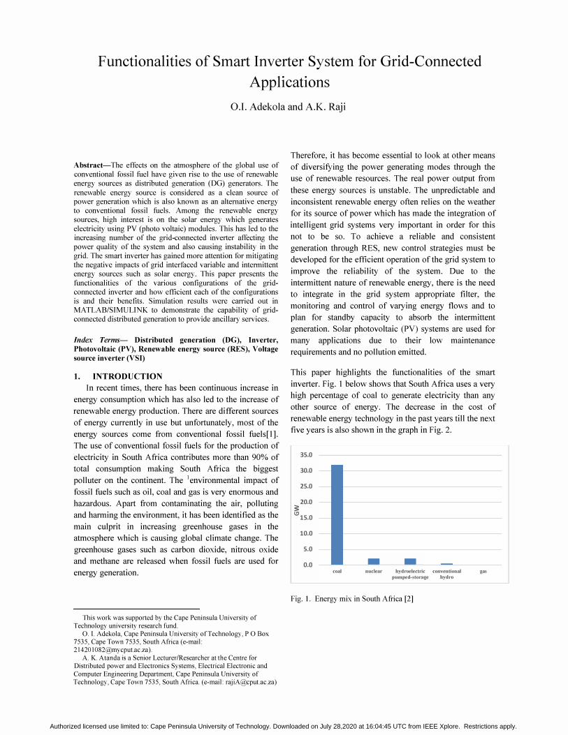
inverter. Fig. 1 below shows that South Africa uses a very
high percentage of coal to generate electricity than any
other source of energy. The decrease in the cost of
renewable energy technology in the past years till the next
five years is also shown in the graph in Fig. 2.
35.0
30.0
25.0
20.0 :3:
\!I 15.0
10.0
5.0
0.0 coal
- -nuclear hydroelectric conventional
pumped-stomge hydr'O
Fig. 1. Energy mix in South Africa [2]
gas
Authorized licensed use limited to: Cape Peninsula University of Technology. Downloaded on July 28,2020 at 16:04:45 UTC from IEEE Xplore. Restrictions apply.
100
80
60
40
20
1980 1990
PV
2000 2010 2020 Fig. 2. Cost reduction curve for renewable energy technology [3]
For an inverter to be considered smart, it must have a
digital architecture, bidirectional communications
capability and robust software infrastructure. The system
begins with reliable, rugged and efficient silicon-centric
hardware, which can be controlled by a scalable software
platform incorporating a sophisticated performance
monitoring capability. Power electronics technology
provides the platform upon which such intelligent and
smart interface may be developed. Development has
occurred vastly in the area of power electronics in recent
times. The fundamental features of Power Electronics are
semiconductor device technology, system engineering and
mounting technology including cooling, control and
protection. The smart inverter is a very essential part of
the distributed generation (DG) interface as it increases
the reliability and efficiency of the utility grid. Distributed
generation generators have developed interest in the use
of renewable energy as their source recently. There are
different types of renewable energy sources which are
used by distributed generators but the power outputs from
these sources are unstable. Smart technologies and Power
Electronics are key factors in the operation of distributed
generation and therefore, power electronics interface
system as smart inverter will be the most efficient way to
achieve the stability. The smart technology is gradually
penetrating the market and Fig. 3 shows the world market
share for inverters in recent years.
90
80
= 70
� g 60
� 50 c QI E 40 Co :c
VI 30 3: :E 20
10
o
2010 2011 2012 2013 2014 2015
_Smart inverter ....... Standard inverter
Fig. 3. World market share of standard inverter and smart
inverter graph [4]
2. TOPOLOGIES OF GRID-CONNECTED
INVERTERS
The multi functional inverters are power electronics
interface system used to convert DC to AC power. The
inverter interface to the grid ensures that it operates at the
MPPT (maximum power point tracking). In order to
utilize the maximum power produced by the PV modules,
the power conversion equipment has to be equipped with
a maximum power point tracker (MPPT). This MPPT is a
device which tracks the voltage where the maximum
power is utilized at all times[5]. The inverter topologies
have been categorized based on their applications and
characteristics of the grid-tied inverter conversion stage:
• Central inverters
• String inverters
• Multi-string inverters
• Module inverters (micro inverters)
2.1 Central Inverters
In this kind of inverter, the PV arrays are connected in
parallel to one central inverter. It is mostly used in three
phase power plants between lOkw to lOOOkw. This type
of inverter has a very high efficiency due to low losses in
the power conversion stage but the disadvantage of this
system is that the cost is higher because of the long cables
required to connect the PV array to the inverter and the
centralized MPPT. Also there is an increased cost for
installation and maintenance of the system. The
conventional solar PV installations feed DC voltage to a
central inverter for distribution locally and across the
utility grid[4], [6].
Authorized licensed use limited to: Cape Peninsula University of Technology. Downloaded on July 28,2020 at 16:04:45 UTC from IEEE Xplore. Restrictions apply.
2.2 String Inverters
This architecture was presented to improve on the
disadvantages of the central inverters. In this topology,
the PV strings are connected to separate inverters. String
converters provide DC-DC conversion to enhance the
power delivered to the central inverter by each string. The
efficiency of the PV array and reliability of the entire
system is improved in this configuration compared to the
central inverter that depends on a single inverter. The
configuration reduces the impact of a poor performing
single panel to its string rather than the entire system.
String inverters eliminate the need for a central inverter
by converting from DC to AC at the output of each string.
This system allows the MPPT at each string [4], [6].
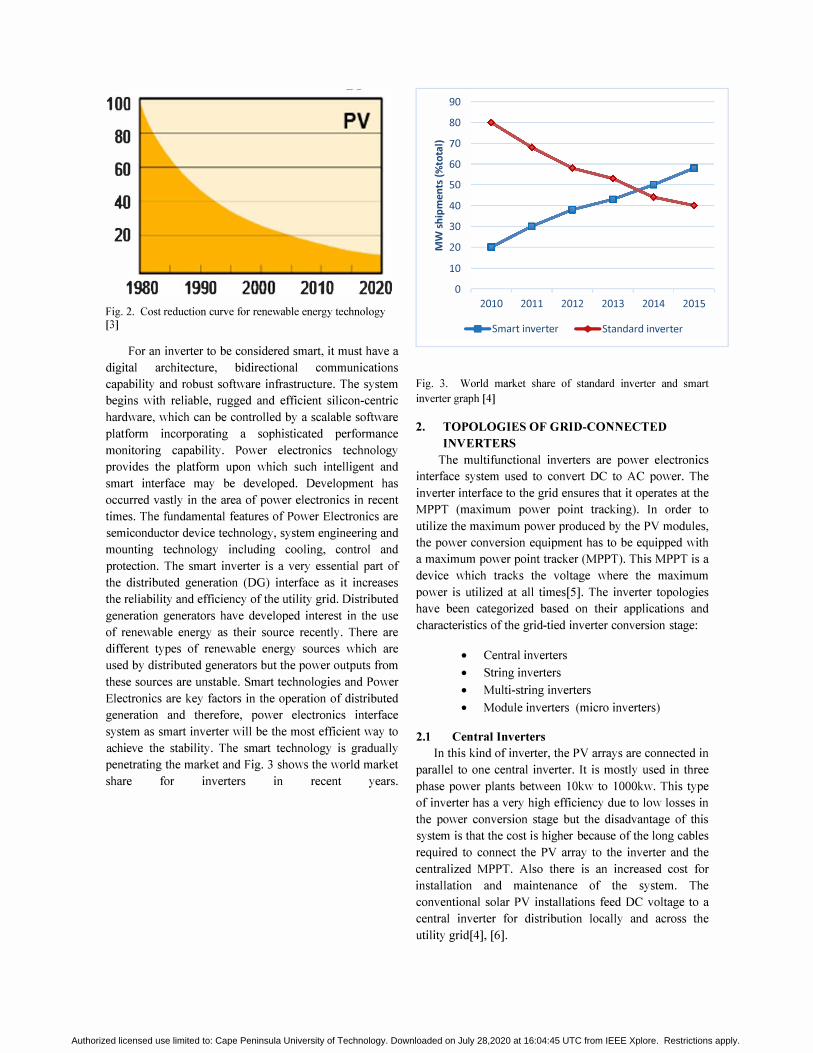
2.3 Multi-String Inverters
This architecture combines configuration of both the
string and module inverters. As it is shown in Fig.4c, it is
a development of the string inverter. The power range of
this configuration is 5KW and the strings use an
individual DC to DC converter before connection to a
common inverter. MPPT is implemented for each string
in this configuration as well thereby improving the
efficiency of the system[ 4].
2.4 Module Inverters
This is the present and future technology. In this
architecture, the inverter consists of single solar panels so
therefore, MPPT is implemented for every each panel. It
provides DC to AC conversion from each individual panel
rather than an entire string [4], [6].
Fig. 4 below shows the different types of PV grid tied
inverter configurations.
PVSlri'l' PVStrings PVStrin�
la)
Fig. 4. PV grid connected systems configurations[4]
3. HARMONIC FILTERING
Hannonic filtering is required to improve the output
waveform of the inverter in order to reduce its respective
harmonic content, consequently the size of the filter used
and the level of electromagnetic interference (EMI)
generated by switching operation of the inverter[7]. A lot
of work is being done to improve the power distribution
system requirement that is, the voltage quality and
reliability. Random voltage disturbances might occur due
to fluctuating output power of solar or wind generation.
There has been major interest in the use of LCL filter in
grid connected inverters which yields better attenuation of
switching harmonics thereby allowing the use of a lower
switching frequency that meets the harmonic limits, and
reduces the electromagnetic interference also defined by
standards IEEE-1547 and IEEE-519 [8][9].
One of the major things to be considered in the designing
of the inverter is that the power quality must comply with
interconnection standards. The commonly used inverter is
the voltage source inverter (VSI) but the output is a
modulated voltage which needs to be filtered to produce
the output voltage required by the utility grid. The mostly
used filter is the inductor-capacitor-inductor (LCL) due to
its better harmonic attenuation, reduced power
consumption and reduced electromagnetic interference.
However, more work is still being done on the evaluation
of LCL filter for designing purposes [10].
4. VSI CONTROLS
Voltage source inverter (VSI) is used to convert
energy from a DC source to an AC output, both in a
standalone mode or when connected to the utility
grid[ll]. One of the major control strategies used to
operate an inverter is the VSI controls. VSI control was
explained as a condition whereby the inverter is
controlled to supply the load with specified values of
voltage and frequency. Depending on the load, the VSI
real and reactive power output is defined
automatically[12], [13]. The three phase voltage source
inverter (VSI) is commonly used as the interface between
RES-based DG generators and the grid system in
designing applications. The switching signals for VSI
which are mostly the current signals when designing a
smart inverter, may have information on the active power
supplied from the RES and the reactive power needed to
compensate for the power quality disturbances at the PCC
(point of power coupling)[14]. It is uncommon to find a
synchronous generator that can be controlled fully in a
micro grid which is responsible for the frequency and a. Central Inverter b. String Inverter
d. Module Inverter
c. Multi-string Inverter voltage controls in conventional power systems.
Microsource technologies that are mostly installed in a
microgrid (MG) are not suitable to be connected directly
to the electrical network due to the kind of energy that is
Authorized licensed use limited to: Cape Peninsula University of Technology. Downloaded on July 28,2020 at 16:04:45 UTC from IEEE Xplore. Restrictions apply.

produced. However, a power electronic interface such as
an inverter will be suitable. The block diagram of this
inverter interface setup is shown in Fig. 5. It is required
that the VSI are able to sustain over currents for a larger
time interval than the time required for fault clearance.
Hence, when there is a case of short-circuits of induction
machines the VSI will provide reactive power within the
specified current limits and this behavior will be sustained
until the induction machines recover[12].
POWER Ol/rPl/r FILTER GRID PV PANEL � PROCESSING � .. UNIT
ODNTROLLER '_dt"",,1roI IlSP&PC SlMULlNK
Fig. 5. Block diagram of grid connected inverter
5. SIMULA TION RESULTS
The schematic of the three phase voltage source
inverter is shown in Fig. 6. However, to test the
practicability of this system, the model in Fig. 7 was built
and simulated using the SimPowerSystems tool box in
Matlab/Simulink. The simulation results are shown in
Fig.8 and Fig. 9 respectively.
0-1
� ( ' +
0-1 ( '
Fig. 6. Three phase Voltage source inverter topology
�"t, " "'",1 poM!IlJUI
O �r r"L . . � I ",
" �
Ds
�vdcll= 11, : ; � Unw"" I Bodg, lCI.
-!-
�. � ",·Phas, � Sen es RLLoad
Fig. 7. Simulink model of a three phase inverter with LCL filter and load
0.01 0 .• 0_05
-
o
Fig. 8. a) Inverter output voltage Vab b) load voltage Vabc before the filter was connected c) Van
--
Fig. 9. a) Inverter output voltage Vabc b) load voltage Vabc after
the fi1 ter was connected c) Van
Authorized licensed use limited to: Cape Peninsula University of Technology. Downloaded on July 28,2020 at 16:04:45 UTC from IEEE Xplore. Restrictions apply.

6. RESUL T DISCUSSION
PWM switching strategy was used for the simulations
carried out. This compares reference signal with the
triangular carrier signal which generates the switching
signals for the switches in the inverter. The reference
signal frequency or the fundamental frequency is 50 Hz
which is the operating frequency for one of the legs of the
inverter while the carrier signal frequency which was 5
KHz is the operating frequency for the other leg of the
inverter. The switching frequency is an important factor
as regards to the inverter efficiency since major source of
losses is due to switching losses. Also, the higher the
switching frequency, the lesser the cost and size of the
filter though there is a limit not to be exceeded as regards
to standard requirements [9]. The shape of the output
voltage of the inverter is usually determined by the
modulation index 'M'. The value chosen for M in Fig. 8
and Fig. 9 was 0.5 while the dc link voltage of the inverter
was kept at 800 V. The inverter output voltage and the
load voltage waveforms indicates harmonics present
before the filter was connected as seen in Fig. 8. Also, it
can be seen in Fig. 9 that the voltage output waveform
after the LCL filter has been connected is much smoother
with very minimal ripples. This shows that the LCL low
pass filter is capable of reducing low order harmonics.
7. CONCLUSION
This paper reviewed the background study on means
of energy production and consumption rate. Since it has
become evident that the use of conventional fuel is
hazardous to human health and would also no longer be
sufficient in the nearest future, the use of alternative
energy as solar is being emphasized. However, to achieve
stability with the solar and other RES, the design of the
output filter is very important. The output filter was
designed in such a way that the harmonics present in the
inverter can be filtered out and also to comply with the
total harmonic distortion requirements by producing a
sinusoidal voltage and current which is acceptable. The
methodology proposed in this paper can be applied in DG
applications.
REFERENCES [I] K. Ross and B. Jordan, "Renewable Energy for a Cleaner Future,"
earthdaynetwork, 2012. [2] A. Pegels. (2010). Renewable energy in South Africa: Potentials,
barriers and options for support. Energy Policy 38(9). pp. 4945-4954.
[3] D. Banks and 1. Schaffler, 'The potential contribution of renewable energy in South Africa," Draft Updat. Rep., February, 2006.
[4] E. A. Man, "Control of Grid Connected PV Systems with Grid Support Functions," MSc thesis, Department of Energy Technology, Aalborg University, Denmark, 2012.
[5] H. B. Massawe, "Grid Connected Photovoltaic Systems with SmartGrid functionality," MSc thesis, Department of Electrical Power Engineering, Norwegian University of Science and Technology, Trondheim, 2013.
[6] M. Bouzguenda, A. Gastli, A. H. AI Badi and T. Salmi. (2011). Solar photovoltaic inverter requirements for smart grid applications. Presented at Innovative Smart Grid Technologies - Middle East (ISGT Middle East), 2011 IEEE PES Conference.
[7] J. Selvaraj and N. a. Rahim. (Jan., 2009). Multilevel Inverter For Grid-Connected PV System Employing Digital PI Controller. IEEE Trans. Ind. Electron., 56(1) pp. 149-158.
[8] Y. A. 1. Mohamed (Sept. , 20 11). Mitigation of Dynamic , Unbalanced , and Harmonic Voltage Disturbances Using GridConnected Inverters With LCL Filter. IEEE Trans. Ind. Electron., 58(9), pp. 3914-3924.
[9] IEEE Standard for Interconnecting Distributed Resources with Electric Power Systems, IEEE Std 1547.2, 2009.
[IO]A. Reznik, "Analysis and design of a smart-inverter for renewable energy interconnection to the grid" MSc thesis, Dept. Elect. Eng., Colorado school of mines, Illinois, United States, 2012.
[II]A. Reznik, M. G. Simoes, A. AI-Durra, and S. M. Muyeen. (March/April 2014). LCL filter design and performance analysis for small wind turbine systems. IEEE Trans. on Ind. Applications, 50(2), pp. 1225-1232.
[12]1. A. P. Lopes, C. L. Moreira, and A. G. Madureira. (May, 2006). Defining Control Strategies for MicroGrids Islanded Operation. IEEE Trans. PowerSyst. 21(2), pp. 916-924.
[13] S. Barsali, M. Ceraolo, P. Pelacchi and D. Poli. (2002). Control techniques of dispersed generators to improve the continuity of electricity supply. Presented at Power Engineering Society Winter Meeting.
[14]A. Teke and M. B. Latran. (Mar., 2014). Review of Multifunctional Inverter Topologies and Control Schemes Used in Distributed Generation Systems. J. Power Electron., 14(2), pp. 324-340.
Olawale Ibrahim Adekola was born in
France in 1990. He received the B.Eng in
Electrical and Electronics Engineering
from the University of I10rin (Nigeria) in
• 2012. He is currently busy with his
Masters of Technology in Electrical Engineering and his thesis
is on the design and development of a smart inverter system at
Cape Peninsula University of Technology (CPUT) in South
Africa. He is an active student of Centre for Distributed Power
and Electronics Systems at CPUT.
Raji K Atanda. received the B.Eng
(Electrical) from University of Ilorin in
1992; M-Tech (Electrical) and M.Sc.
(Electronics) from Cape Peninsula
University of Technology (CPUT) and
Ecole Superieure d'Ingenieurs en
Electronique et Electrotechnique France
in 2009 respectively and DTech (Electrical) from CPUT in
2013. He is currently a Senior Lecturer and researcher at the
Department of Electrical, Electronic and Computer Engineering
in CPUT and also the programme coordinator of the BTech
Electrical programme. He is a Certified Renewable Energy
Professional (CREP) by the Association of Energy Engineers.
He is a member of Power Electronics Society of IEEE, Power
System Society of IEEE and National Energy Association of
South Africa and an active member of the Centre for Distributed
Power and Electronics Systems. His research interest is in the
application of power electronics technology and control system
development for alternative electricity generation,
transmission, distribution and utilization.
Presenting author: This paper will be presented by O.I. Adekola
Authorized licensed use limited to: Cape Peninsula University of Technology. Downloaded on July 28,2020 at 16:04:45 UTC from IEEE Xplore. Restrictions apply.
Related Documents