Page | 1 Copyright © Accellera Systems Initiative Inc. All rights reserved. May 10, 2021 Functional Safety Working Group White Paper May 10, 2021

Welcome message from author
This document is posted to help you gain knowledge. Please leave a comment to let me know what you think about it! Share it to your friends and learn new things together.
Transcript
P a g e | 1
Copyright © Accellera Systems Initiative Inc. All rights reserved. May 10, 2021
Functional Safety Working Group White Paper
May 10, 2021
P a g e | 2
Copyright © Accellera Systems Initiative Inc. All rights reserved. May 10, 2021
Table of Contents Table of Contents ............................................................................................................................ 2
Abstract ........................................................................................................................................... 3
I. Introduction ........................................................................................................................ 4
II. Industry Challenges ............................................................................................................. 7
III. Mission .............................................................................................................................. 13
IV. Accellera FSWG and the FS Standardization Landscape ................................................... 15
V. The Accellera FS Standard................................................................................................. 16
VI. Additional Goals and Topics for Future Exploration ......................................................... 20
Concluding Remarks...................................................................................................................... 23
References .................................................................................................................................... 24
List of Figures ................................................................................................................................ 25
Acronyms ...................................................................................................................................... 26
Accellera FSWG Supporting Entities ............................................................................................. 27
Acknowledgements ....................................................................................................................... 27
P a g e | 3
Copyright © Accellera Systems Initiative Inc. All rights reserved. May 10, 2021
Abstract With the increasing demand of compute power, the electrical and electronic systems deployed in safety-critical applications become more and more complex. This complexity also extends to Functional Safety (FS) requirements, and it affects all parts of the system including hardware and software components.
Addressing FS requires specific safety activities and operations, documented in what the ISO26262 standard [1] refers to as “work products.” The generation of these work products relies on sharing common data and faces specific challenges during development and integration to manage:
The exchange and integration of FS data between different work products and activities among different teams and different layers of the supply chain
The traceability of FS data to provide evidence of correctness, completeness, and consistency
The use of automation tools and flows for gathering and processing data The retargeting of the safety case and analysis from one standard to another by
efficiently evolving them and avoiding duplication of effort
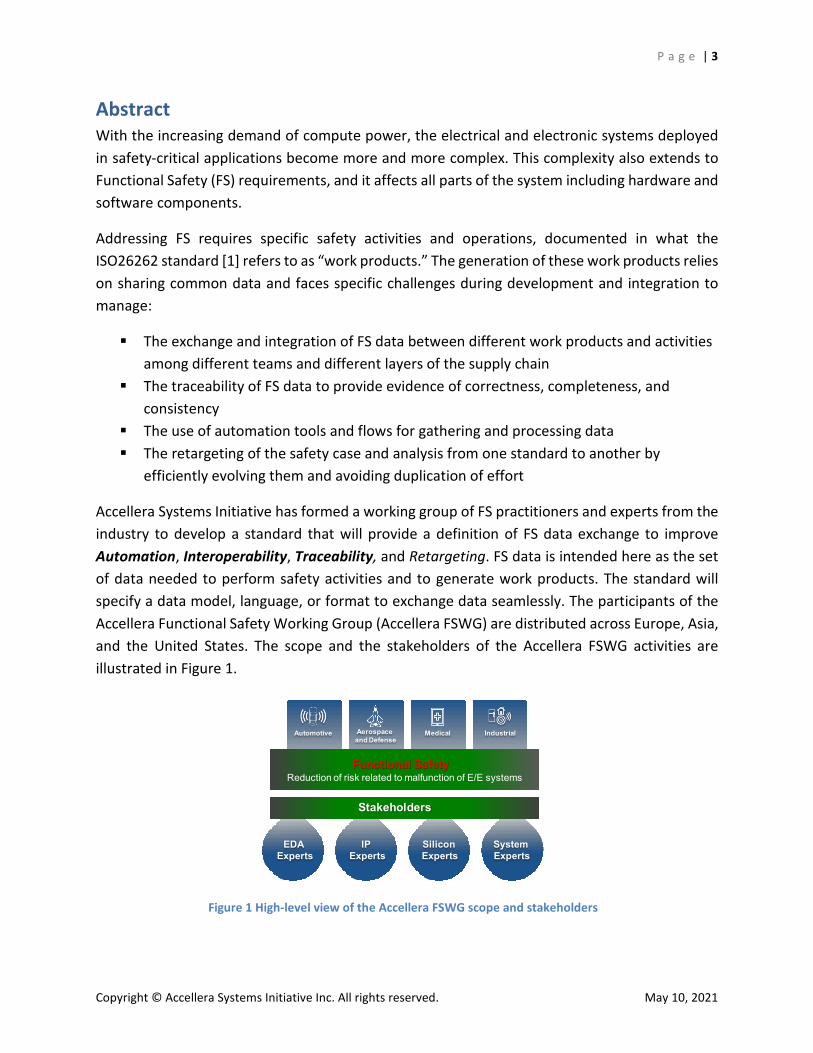
Accellera Systems Initiative has formed a working group of FS practitioners and experts from the industry to develop a standard that will provide a definition of FS data exchange to improve Automation, Interoperability, Traceability, and Retargeting. FS data is intended here as the set of data needed to perform safety activities and to generate work products. The standard will specify a data model, language, or format to exchange data seamlessly. The participants of the Accellera Functional Safety Working Group (Accellera FSWG) are distributed across Europe, Asia, and the United States. The scope and the stakeholders of the Accellera FSWG activities are illustrated in Figure 1.
Figure 1 High-level view of the Accellera FSWG scope and stakeholders
IndustrialAutomotive Aerospace and Defense
Medical
Functional SafetyReduction of risk related to malfunction of E/E systems
System Experts
Stakeholders
Silicon Experts
IP Experts
EDA Experts
Stakeholders
P a g e | 4
Copyright © Accellera Systems Initiative Inc. All rights reserved. May 10, 2021
During its first year of activity, the Accellera FSWG (and previously the Accellera FS Proposed WG) captured many of the challenges in the industry about managing and exchanging FS data. The objective of this white paper is to illustrate these challenges and to present the goals and mission of the Accellera FSWG towards a new FS standard addressing them. As the standard is still in development, this white paper does not focus on the details of the FS data nor provide specific indications on the new model/language that captures it.
The white paper is organized as follows:
Section I (Introduction) provides basic background on key concepts of the safety development lifecycle and work products that are involved in the standardization discussions.
Section II (Industry Challenges) reports the challenges of the development process of safety-critical applications identified by the FSWG.
Section III (Mission) summarizes the mission of the FSWG. Section IV (Accellera FSWG and the FS Standardization Landscape) details the
connection of the work of the FSWG to the landscape of some of the existing safety standards for handling electrical and electronics parts.
Section V (The Accellera FS Standard) contains introductory information on the Accellera FS standard: general concepts and approach, its objectives, and its connection to a use case example.
Section VI (Additional Goals and Topics for Future Exploration) explores a few directions connected to the development of the FSWG data format/language standard.
Concluding remarks are included to summarize the mission, challenges, and approach of the FSWG.
I. Introduction This section provides background about the development environment of safety-critical electronics circuits and systems and presents the definitions introduced by the Accellera FSWG that will be used throughout the paper. It also summarizes some key concepts of the safety development lifecycle and work products that are involved in the standardization discussions.
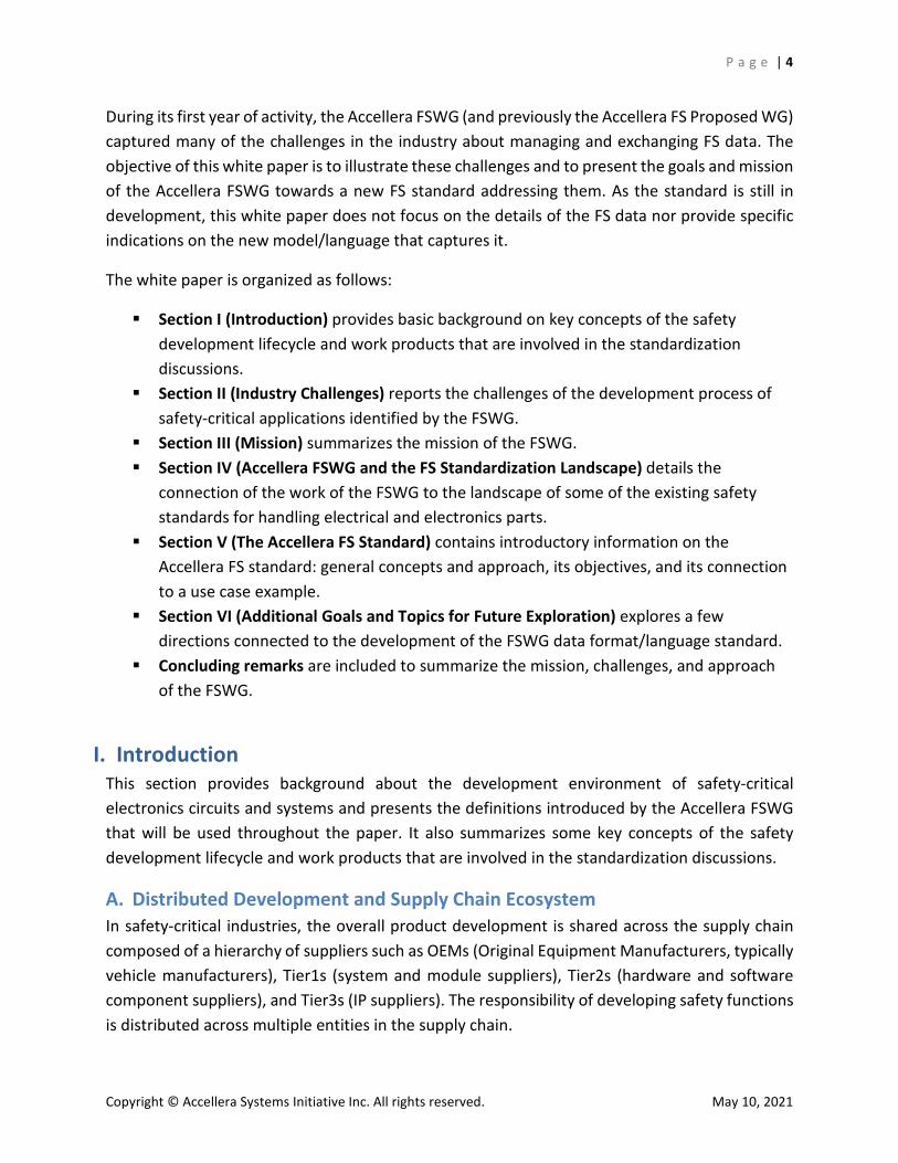
A. Distributed Development and Supply Chain Ecosystem In safety-critical industries, the overall product development is shared across the supply chain composed of a hierarchy of suppliers such as OEMs (Original Equipment Manufacturers, typically vehicle manufacturers), Tier1s (system and module suppliers), Tier2s (hardware and software component suppliers), and Tier3s (IP suppliers). The responsibility of developing safety functions is distributed across multiple entities in the supply chain.
P a g e | 5
Copyright © Accellera Systems Initiative Inc. All rights reserved. May 10, 2021
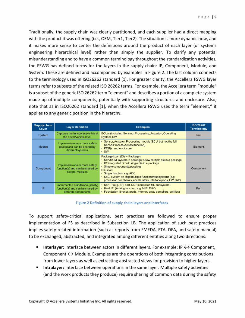
Traditionally, the supply chain was clearly partitioned, and each supplier had a direct mapping with the product it was offering (i.e., OEM, Tier1, Tier2). The situation is more dynamic now, and it makes more sense to center the definitions around the product of each layer (or systems engineering hierarchical level) rather than simply the supplier. To clarify any potential misunderstanding and to have a common terminology throughout the standardization activities, the FSWG has defined terms for the layers in the supply chain: IP, Component, Module, and System. These are defined and accompanied by examples in Figure 2. The last column connects to the terminology used in ISO26262 standard [1]. For greater clarity, the Accellera FSWG layer terms refer to subsets of the related ISO 26262 terms. For example, the Accellera term “module” is a subset of the generic ISO 26262 term “element” and describes a portion of a complete system made up of multiple components, potentially with supporting structures and enclosure. Also, note that as in ISO26262 standard [1], when the Accellera FSWG uses the term “element,” it applies to any generic position in the hierarchy.
To support safety-critical applications, best practices are followed to ensure proper implementation of FS as described in Subsection I.B. The application of such best practices implies safety-related information (such as reports from FMEDA, FTA, DFA, and safety manual) to be exchanged, abstracted, and integrated among different entities along two directions:
Interlayer: Interface between actors in different layers. For example: IP ↔ Component, Component ↔ Module. Examples are the operations of both integrating contributions from lower layers as well as extracting abstracted views for provision to higher layers.
Intralayer: Interface between operations in the same layer. Multiple safety activities (and the work products they produce) require sharing of common data during the safety
Figure 2 Definition of supply chain layers and interfaces
Supply chain Layer Layer Definition Examples ISO 26262
Terminology
System Captures the function(s) visible at the driver/vehicle level
ECU(s) including Sensing, Processing, Actuation, Operating System, SW Item
ModuleImplements one or more safety goal(s) and can be shared by
different systems
• Sensor, Actuator, Processing module (ECU, but not the full Sense-Process-Actuate function)
• PCB(s) and enclosure,• SW
Element
ComponentImplements one or more safety
function(s) and can be shared by several modules
Packaged part (Die + Package):• SIP /MCM: system in package: a few multiple die in a package• IC: integrated circuit: single die in a package• Simple components: passivesDie-level:• Single function: e.g. ADC• SoC: system on chip: multiple functions/subsystems (e.g.
processor, peripherals, accelerators, interface ports, FW, SW)
Component
IPImplements a standalone (safety) function(s) and can be shared by
different components
• Soft IP (e.g. SPI port, DDR controller, ML subsystem)• Hard IP (Analog function, e.g. MIPI PHY)• Foundation libraries (pads, memory array compilers, cell libs)
Part
P a g e | 6
Copyright © Accellera Systems Initiative Inc. All rights reserved. May 10, 2021
lifecycle development. Examples are the connections between safety analysis and verification.
More details about the safety workflow are covered next.
B. Functional Safety Workflow, Work Products, and Operations FS standards, such as ISO26262 [1] and IEC 61508 [2], define requirements for safety activities conducted in the development lifecycle phases of safety-related products. To achieve FS of an entire product, such as an automotive vehicle, aircraft, or industrial robot, each top-level safety-critical system is developed to mitigate unreasonable risk due to malfunctions. All of the entities participating in the system’s development—the makers of IP, components, modules, and systems—must work together to achieve “safety goals” identified for the system. This distributed work is performed according to well-established standard safety lifecycle processes.
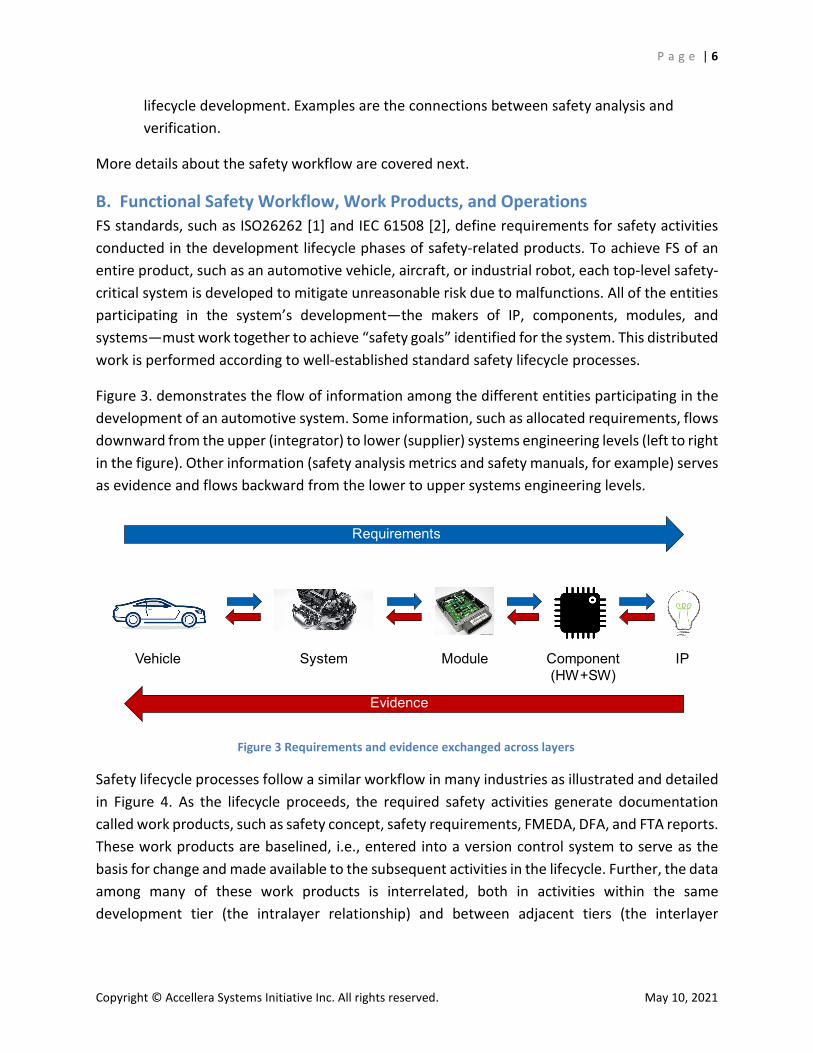
Figure 3. demonstrates the flow of information among the different entities participating in the development of an automotive system. Some information, such as allocated requirements, flows downward from the upper (integrator) to lower (supplier) systems engineering levels (left to right in the figure). Other information (safety analysis metrics and safety manuals, for example) serves as evidence and flows backward from the lower to upper systems engineering levels.
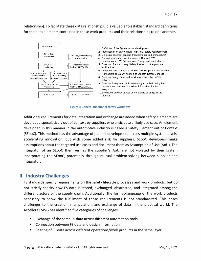
Safety lifecycle processes follow a similar workflow in many industries as illustrated and detailed in Figure 4. As the lifecycle proceeds, the required safety activities generate documentation called work products, such as safety concept, safety requirements, FMEDA, DFA, and FTA reports. These work products are baselined, i.e., entered into a version control system to serve as the basis for change and made available to the subsequent activities in the lifecycle. Further, the data among many of these work products is interrelated, both in activities within the same development tier (the intralayer relationship) and between adjacent tiers (the interlayer
Figure 3 Requirements and evidence exchanged across layers
IPComponent(HW+SW)
ModuleSystemVehicle
Requirements
Evidence
P a g e | 7
Copyright © Accellera Systems Initiative Inc. All rights reserved. May 10, 2021
relationship). To facilitate these data relationships, it is valuable to establish standard definitions for the data elements contained in these work products and their relationships to one another.
Additional requirements for data integration and exchange are added when safety elements are developed speculatively out of context by suppliers who anticipate a likely use case. An element developed in this manner in the automotive industry is called a Safety Element out of Context (SEooC). This method has the advantage of parallel development across multiple system levels, accelerating innovation, but with some added risk for suppliers. SEooC developers make assumptions about the targeted use cases and document them as Assumption of Use (AoU). The integrator of an SEooC then verifies the supplier’s AoU are not violated by their system incorporating the SEooC, potentially through mutual problem-solving between supplier and integrator.
II. Industry Challenges FS standards specify requirements on the safety lifecycle processes and work products, but do not strictly specify how FS data is stored, exchanged, abstracted, and integrated among the different actors of the supply chain. Additionally, the format/language of the work products necessary to show the fulfillment of those requirements is not standardized. This poses challenges to the creation, manipulation, and exchange of data in the practical world. The Accellera FSWG has identified five categories of challenges:
Exchange of the same FS data across different automation tools Connection between FS data and design information Sharing of FS data across different operations/work products in the same layer
Figure 4 General functional safety workflow
P a g e | 8
Copyright © Accellera Systems Initiative Inc. All rights reserved. May 10, 2021
Exchange of FS data between suppliers and integrators Traceability of information across the distributed development environment
A. Exchange of the Same FS Data Across Different Automation Tools In the last few years, there has been fervent activity in the development of automation tools to support FS best practices. In fact, the state-of-the-art automated tools are well positioned to address some of the challenges faced by the FS supply chain, because they can provide databases/languages to store and exchange FS data. Databases, associated schema, and languages foster scalability and maintain synchronization and traceability among the work products.
However, these automation tools have been developed in parallel and currently lack a standard format/language to exchange and integrate data. This hinders the interoperability in the exchange of FS data that is instead well established for other requirements (e.g., performance, power, area) [6][7]. Referring to the workflow in Figure 4., an example of this case is a preliminary FMEDA created by a supplier in one tool that cannot be used directly by an integrator using another tool. Another example is when a preliminary FMEDA is leveraged into a final FMEDA.
B. Connection Between FS Data and Design Information Some of the information required for FS analysis comes from the design metrics of the circuit/system under analysis. In the case of digital ICs, the final FMEDA (Figure 4.) uses the Failure Rate and the probability of Failure Modes to occur, which are related to the total area or transistor count of the design and to the parts of the design on which the failure modes can manifest. Other parameters are taken into account (technology, high power, low power, etc.). For PCB-level designs, the failure rate may be extracted from libraries of discrete components or handbooks. Automated tools are a recent entry into the FS community, and the operation of extracting design information from the design (e.g., gate counts, area, etc.) has traditionally been a manual process or performed with custom solutions. These design details are extracted and refined multiple times during the lifecycle. Accordingly, there is a huge potential for efficiency improvement in this area. Creating an automated FS-aware flow between the FS data domain and the design/verification domain can simplify these operations tremendously.
C. Sharing of FS Data Across Different Operations/Work Products in the Same Layer
As of today, the industry is lacking a standard way of representing, exchanging, abstracting, and integrating FS data, thus leading to an effort-intense and error-prone development environment. Several FS-related operations are performed and work products are generated within the same layer of the supply chain. These operations and work products are interdependent and rely on exchange, abstraction, and integration of FS data. Often the information is generated and
P a g e | 9
Copyright © Accellera Systems Initiative Inc. All rights reserved. May 10, 2021
processed by different functional teams within the same organization. Listed here are a few examples:
After an FMEDA is performed, the safety verification plan is executed to evaluate the effectiveness of safety mechanisms, and the verification results must be back-annotated into the FMEDA by the safety engineer. These verification activities might consist of fault simulation, emulation, or analysis and might be executed with a variety of tools.
Safety mechanism attributes need to be shared between the safety manual and safety analyses, such as (qualitative) FMEA, FTA, FMEDA, DFA, etc.
The FMEA needs to be updated with the latest design metrics when a design goes through modifications, refinements, or FS implementation.
Basic failure events in an FTA are to be correlated with the failure modes in the FMEDA.
These examples demonstrate the need to maintain the coherency of FS data among all of these operations, which is crucial to the integrity of the safety case. Additionally, another part of the challenge might be the reuse of FS data for the retargeting of the safety case to satisfy the requirements of another safety standard.
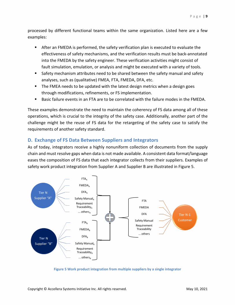
D. Exchange of FS Data Between Suppliers and Integrators As of today, integrators receive a highly nonuniform collection of documents from the supply chain and must resolve gaps when data is not made available. A consistent data format/language eases the composition of FS data that each integrator collects from their suppliers. Examples of safety work product integration from Supplier A and Supplier B are illustrated in Figure 5.
Figure 5 Work product integration from multiple suppliers by a single integrator
Tier NSupplier “A”
FTAA
FMEDAA
DFAA
Safety ManualARequirement TraceabilityA
... othersA
Tier NSupplier “B”
FTAB
FMEDAB
DFAB
Safety ManualBRequirement TraceabilityB
... othersB
Tier N-1 Customer
FTA
FMEDA
DFA
Safety ManualRequirement Traceability
... others
P a g e | 10
Copyright © Accellera Systems Initiative Inc. All rights reserved. May 10, 2021
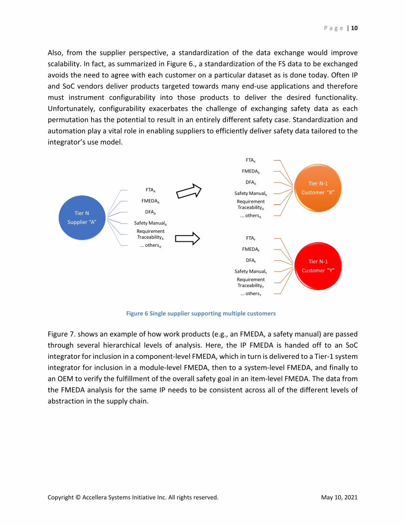
Also, from the supplier perspective, a standardization of the data exchange would improve scalability. In fact, as summarized in Figure 6., a standardization of the FS data to be exchanged avoids the need to agree with each customer on a particular dataset as is done today. Often IP and SoC vendors deliver products targeted towards many end-use applications and therefore must instrument configurability into those products to deliver the desired functionality. Unfortunately, configurability exacerbates the challenge of exchanging safety data as each permutation has the potential to result in an entirely different safety case. Standardization and automation play a vital role in enabling suppliers to efficiently deliver safety data tailored to the integrator’s use model.
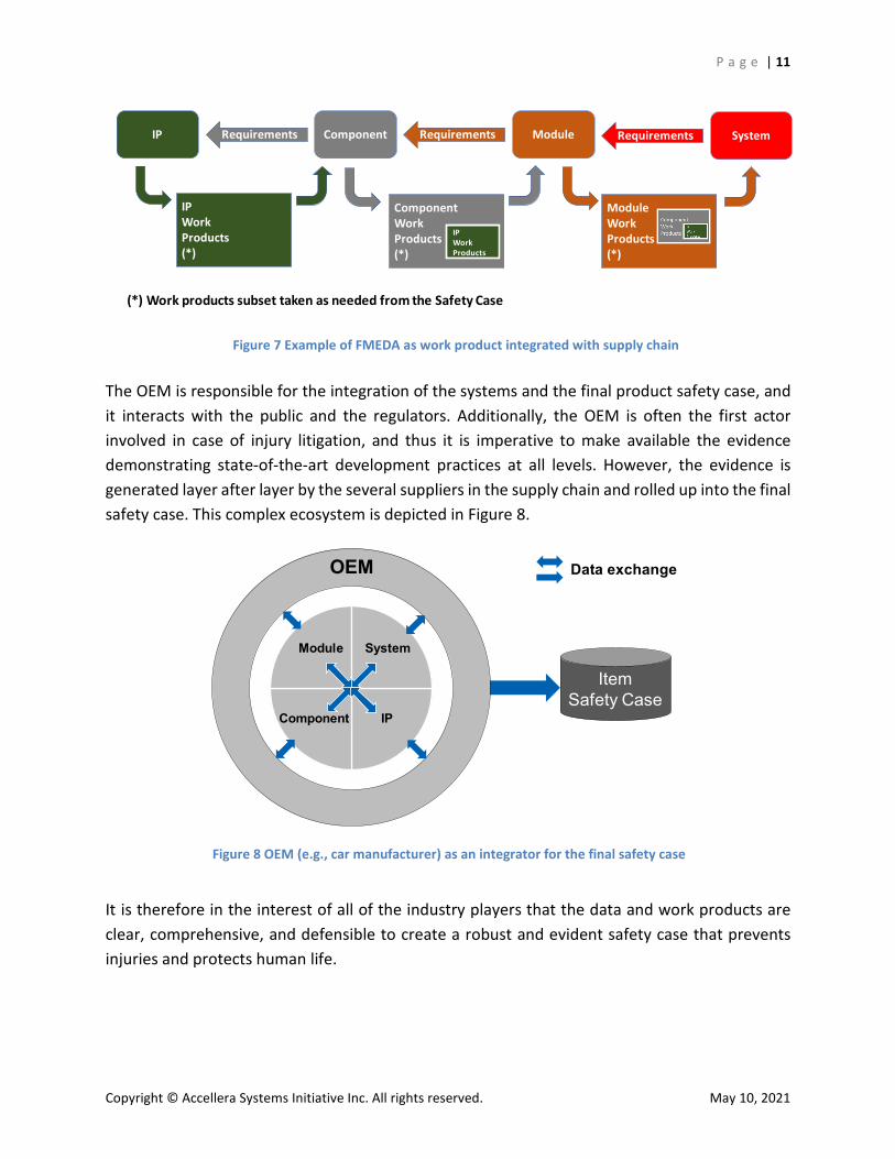
Figure 7. shows an example of how work products (e.g., an FMEDA, a safety manual) are passed through several hierarchical levels of analysis. Here, the IP FMEDA is handed off to an SoC integrator for inclusion in a component-level FMEDA, which in turn is delivered to a Tier-1 system integrator for inclusion in a module-level FMEDA, then to a system-level FMEDA, and finally to an OEM to verify the fulfillment of the overall safety goal in an item-level FMEDA. The data from the FMEDA analysis for the same IP needs to be consistent across all of the different levels of abstraction in the supply chain.
Figure 6 Single supplier supporting multiple customers
Tier NSupplier “A”
FTAA
FMEDAA
DFAA
Safety ManualARequirement TraceabilityA
... othersA
Tier N-1 Customer “X”
FTAX
FMEDAX
DFAX
Safety ManualXRequirement TraceabilityX
... othersX
Tier N-1 Customer “Y”
FTAY
FMEDAY
DFAY
Safety ManualYRequirement TraceabilityY
... othersY
P a g e | 11
Copyright © Accellera Systems Initiative Inc. All rights reserved. May 10, 2021
The OEM is responsible for the integration of the systems and the final product safety case, and it interacts with the public and the regulators. Additionally, the OEM is often the first actor involved in case of injury litigation, and thus it is imperative to make available the evidence demonstrating state-of-the-art development practices at all levels. However, the evidence is generated layer after layer by the several suppliers in the supply chain and rolled up into the final safety case. This complex ecosystem is depicted in Figure 8.
It is therefore in the interest of all of the industry players that the data and work products are clear, comprehensive, and defensible to create a robust and evident safety case that prevents injuries and protects human life.
Figure 7 Example of FMEDA as work product integrated with supply chain
IP
IPWorkProducts (*)
Component
ComponentWorkProducts(*)
IPWorkProducts
ModuleWorkProducts(*)
ModuleRequirementsRequirements SystemRequirements
(*) Work products subset taken as needed from the Safety Case
Figure 8 OEM (e.g., car manufacturer) as an integrator for the final safety case
Component
Module System
IP
OEM
ItemSafety Case
Data exchange
P a g e | 12
Copyright © Accellera Systems Initiative Inc. All rights reserved. May 10, 2021
E. Traceability of Information Across the Distributed Development Environment An important aspect of managing FS development is the requirement for traceability of information, i.e., the ability to identify its origin and a way to follow the chain of refinements and modifications that a design element goes through. This applies to both intralayer and interlayer management and can be especially challenging when different actors in the supply chain are involved. Traceability is key to ensure freedom from systematic faults that could introduce an unacceptable risk to humans or the environment.
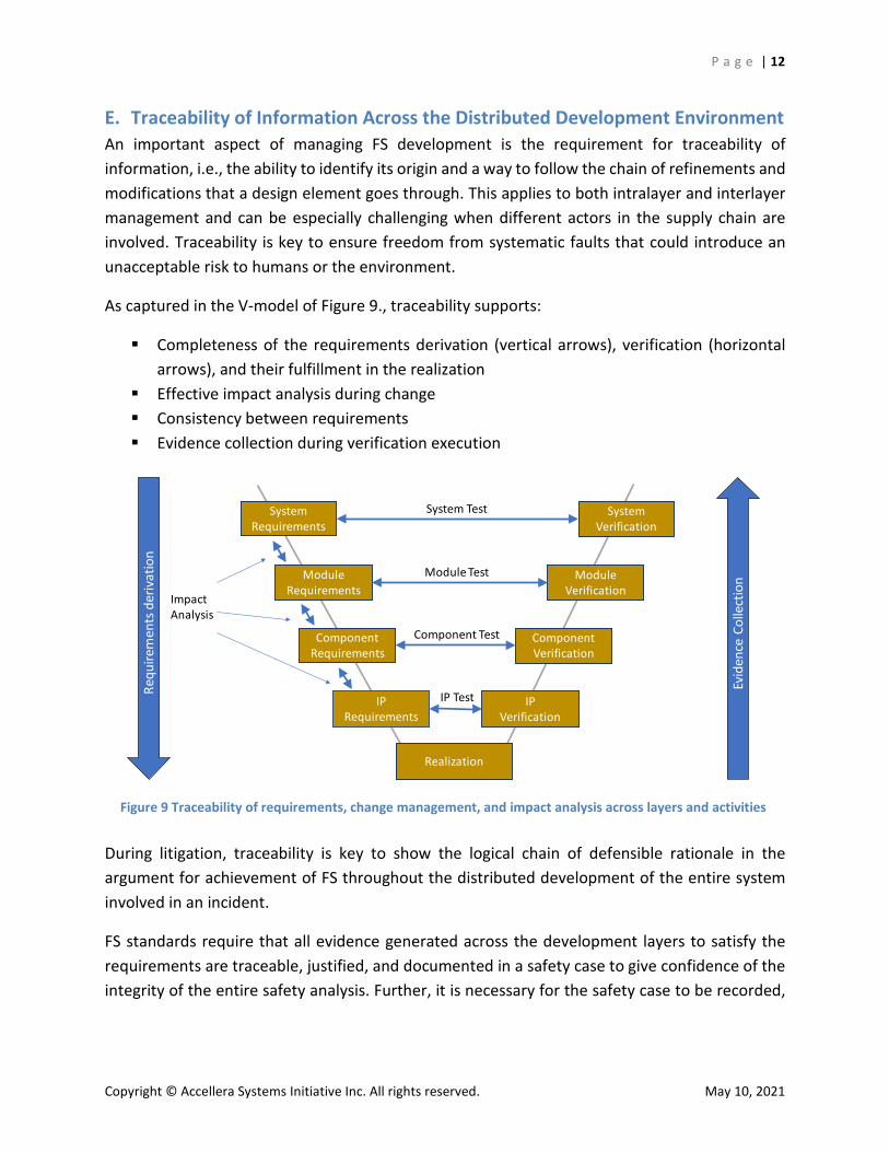
As captured in the V-model of Figure 9., traceability supports:
Completeness of the requirements derivation (vertical arrows), verification (horizontal arrows), and their fulfillment in the realization
Effective impact analysis during change Consistency between requirements Evidence collection during verification execution
During litigation, traceability is key to show the logical chain of defensible rationale in the argument for achievement of FS throughout the distributed development of the entire system involved in an incident.
FS standards require that all evidence generated across the development layers to satisfy the requirements are traceable, justified, and documented in a safety case to give confidence of the integrity of the entire safety analysis. Further, it is necessary for the safety case to be recorded,
Figure 9 Traceability of requirements, change management, and impact analysis across layers and activities
System Requirements
Module Requirements
Component Requirements
IP Requirements
System Verification
Module Verification
Component Verification
IP Verification
Evid
ence
Col
lect
ion
Requ
irem
ents
der
ivat
ion
Impact Analysis
System Test
Module Test
Component Test
IP Test
Realization
P a g e | 13
Copyright © Accellera Systems Initiative Inc. All rights reserved. May 10, 2021
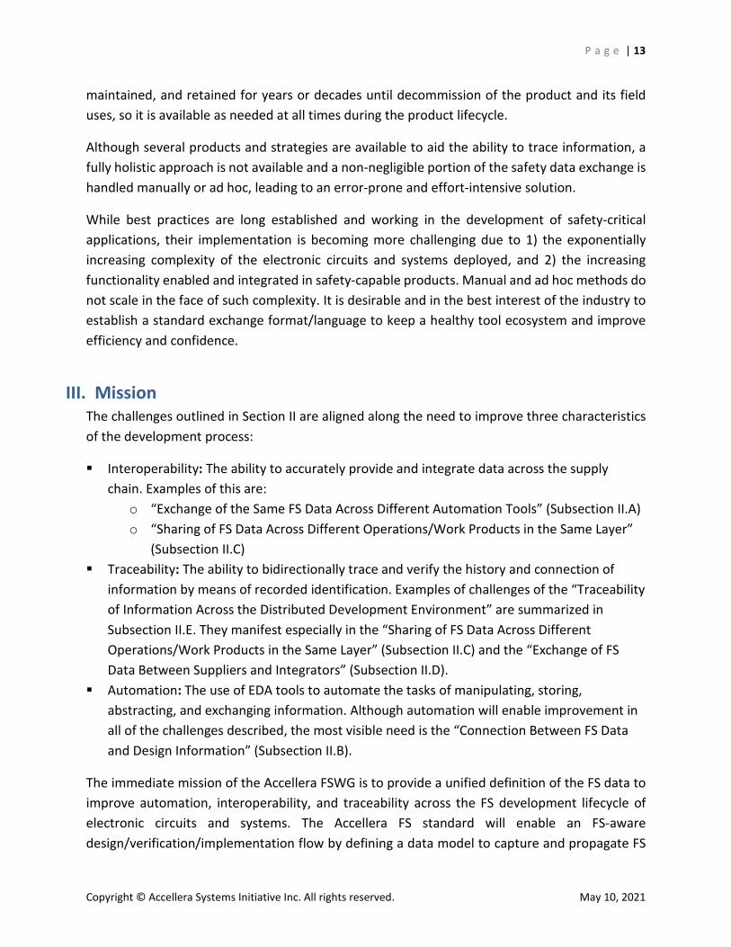
maintained, and retained for years or decades until decommission of the product and its field uses, so it is available as needed at all times during the product lifecycle.
Although several products and strategies are available to aid the ability to trace information, a fully holistic approach is not available and a non-negligible portion of the safety data exchange is handled manually or ad hoc, leading to an error-prone and effort-intensive solution.
While best practices are long established and working in the development of safety-critical applications, their implementation is becoming more challenging due to 1) the exponentially increasing complexity of the electronic circuits and systems deployed, and 2) the increasing functionality enabled and integrated in safety-capable products. Manual and ad hoc methods do not scale in the face of such complexity. It is desirable and in the best interest of the industry to establish a standard exchange format/language to keep a healthy tool ecosystem and improve efficiency and confidence.
III. Mission The challenges outlined in Section II are aligned along the need to improve three characteristics of the development process:
Interoperability: The ability to accurately provide and integrate data across the supply chain. Examples of this are:
o “Exchange of the Same FS Data Across Different Automation Tools” (Subsection II.A) o “Sharing of FS Data Across Different Operations/Work Products in the Same Layer”
(Subsection II.C) Traceability: The ability to bidirectionally trace and verify the history and connection of
information by means of recorded identification. Examples of challenges of the “Traceability of Information Across the Distributed Development Environment” are summarized in Subsection II.E. They manifest especially in the “Sharing of FS Data Across Different Operations/Work Products in the Same Layer” (Subsection II.C) and the “Exchange of FS Data Between Suppliers and Integrators” (Subsection II.D).
Automation: The use of EDA tools to automate the tasks of manipulating, storing, abstracting, and exchanging information. Although automation will enable improvement in all of the challenges described, the most visible need is the “Connection Between FS Data and Design Information” (Subsection II.B).
The immediate mission of the Accellera FSWG is to provide a unified definition of the FS data to improve automation, interoperability, and traceability across the FS development lifecycle of electronic circuits and systems. The Accellera FS standard will enable an FS-aware design/verification/implementation flow by defining a data model to capture and propagate FS
P a g e | 14
Copyright © Accellera Systems Initiative Inc. All rights reserved. May 10, 2021
data across the different safety operations and the distributed development environment, from the system to the IP.
The initial goals of the FSWG are to:
Unify and standardize a methodology to exchange FS data for FS operations (e.g., analysis, verification and validation, optimization, implementation) to produce work products (e.g., FMEA, FMEDA, AoU, FTA, DFA, safety requirements)
Define a format/language to exchange the FS data across the distributed development environment of the FS lifecycle
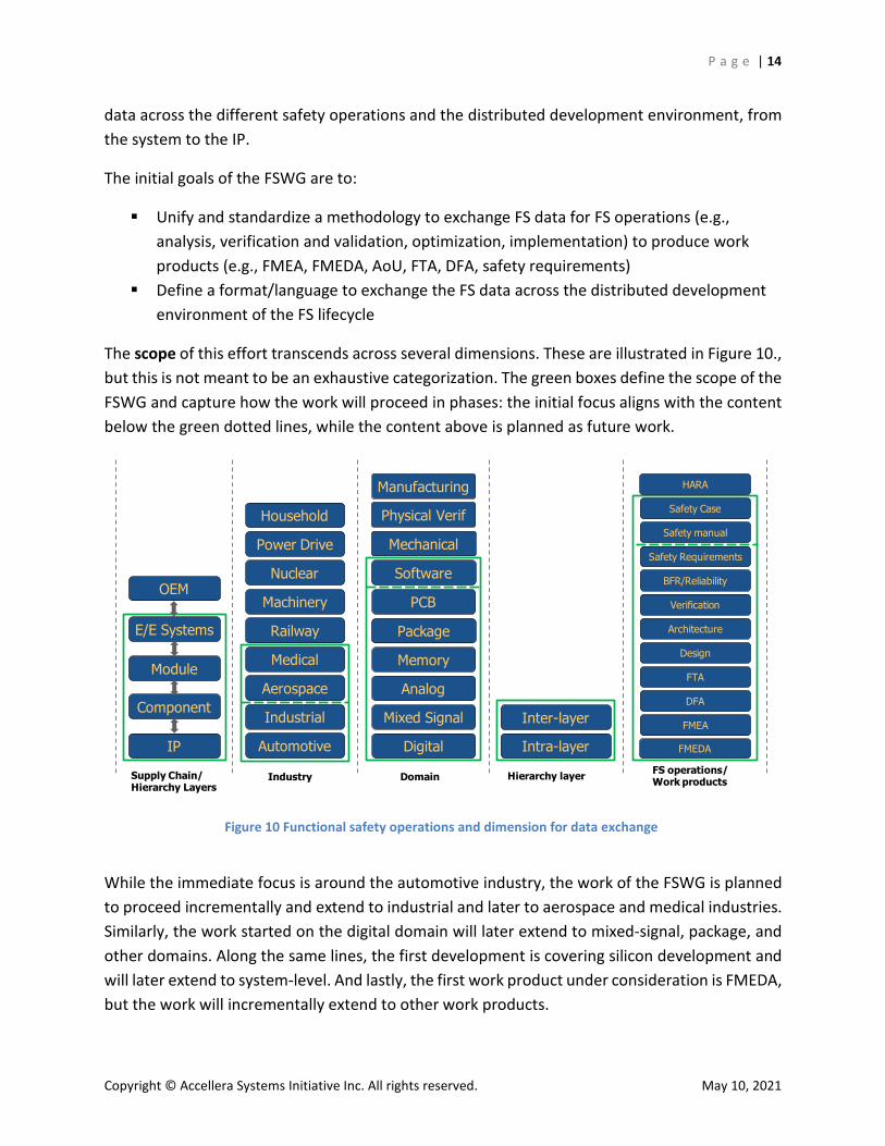
The scope of this effort transcends across several dimensions. These are illustrated in Figure 10., but this is not meant to be an exhaustive categorization. The green boxes define the scope of the FSWG and capture how the work will proceed in phases: the initial focus aligns with the content below the green dotted lines, while the content above is planned as future work.
While the immediate focus is around the automotive industry, the work of the FSWG is planned to proceed incrementally and extend to industrial and later to aerospace and medical industries. Similarly, the work started on the digital domain will later extend to mixed-signal, package, and other domains. Along the same lines, the first development is covering silicon development and will later extend to system-level. And lastly, the first work product under consideration is FMEDA, but the work will incrementally extend to other work products.
Figure 10 Functional safety operations and dimension for data exchange
Supply Chain/Hierarchy Layers
Automotive
Nuclear
Industrial
Machinery
Railway
Medical
Aerospace
Industry
Analog
Mixed Signal
Memory
Digital
Domain
Software
PCB
Mechanical
Physical Verif
Inter-layer
Intra-layer
Hierarchy layer
DFA
FMEA
FTA
FMEDA
FS operations/Work products
Verification
Safety Requirements
Safety manual
Safety Case
HARA
Power Drive
Household
Package Architecture
Design
BFR/Reliability
IP
Component
Module
OEM
Manufacturing
E/E Systems
P a g e | 15
Copyright © Accellera Systems Initiative Inc. All rights reserved. May 10, 2021
Also, while the immediate execution focuses on the development of the data model and goals described above, the FSWG is also planning to explore connected topics that concern state-of-the-art methodologies and automation. These are further described in Section VI.
The development of the FS standard is structured along the following rationale:
Formalize and harmonize the process of FS operations. Focus first on the content of the FS data (which will be captured in a conceptual data
model) and its objectives. Define the format/language to represent the FS data content. Create an example use case that supports both the definition of requirements and the
validation of the data model being developed.
While this section outlines only the execution plan, more details on the FS standard are provided in Section V. It is also important to note that Section V includes only the key objectives, while a different document will be published by the FSWG to detail the FS data model content and language.
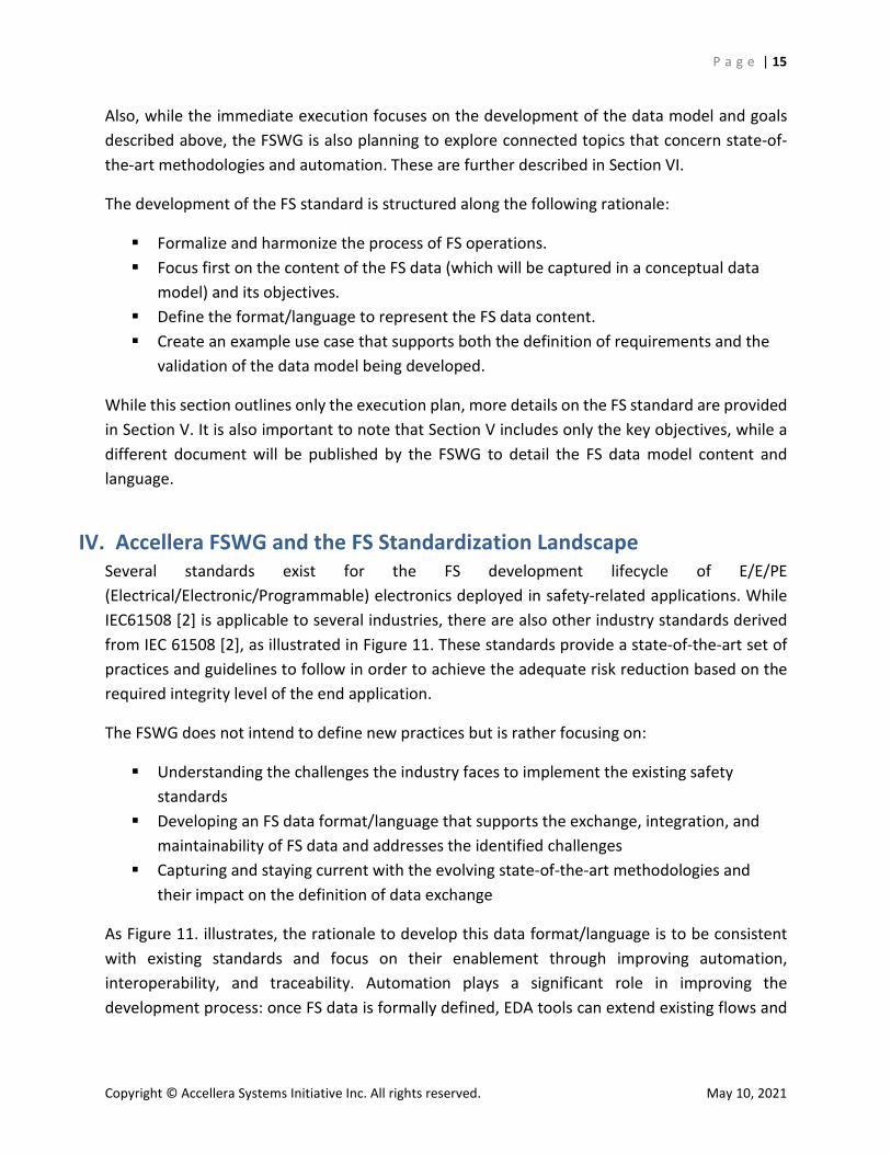
IV. Accellera FSWG and the FS Standardization Landscape Several standards exist for the FS development lifecycle of E/E/PE (Electrical/Electronic/Programmable) electronics deployed in safety-related applications. While IEC61508 [2] is applicable to several industries, there are also other industry standards derived from IEC 61508 [2], as illustrated in Figure 11. These standards provide a state-of-the-art set of practices and guidelines to follow in order to achieve the adequate risk reduction based on the required integrity level of the end application.
The FSWG does not intend to define new practices but is rather focusing on:
Understanding the challenges the industry faces to implement the existing safety standards
Developing an FS data format/language that supports the exchange, integration, and maintainability of FS data and addresses the identified challenges
Capturing and staying current with the evolving state-of-the-art methodologies and their impact on the definition of data exchange
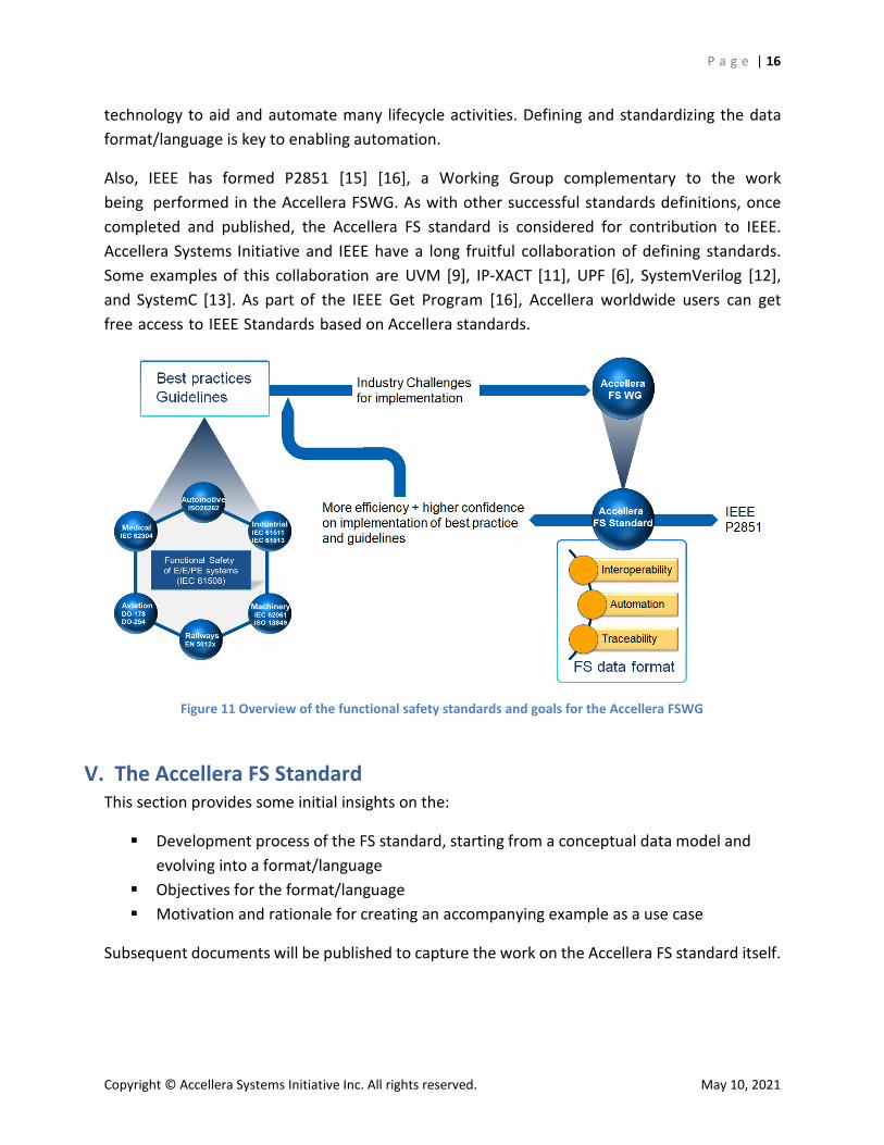
As Figure 11. illustrates, the rationale to develop this data format/language is to be consistent with existing standards and focus on their enablement through improving automation, interoperability, and traceability. Automation plays a significant role in improving the development process: once FS data is formally defined, EDA tools can extend existing flows and
P a g e | 16
Copyright © Accellera Systems Initiative Inc. All rights reserved. May 10, 2021
technology to aid and automate many lifecycle activities. Defining and standardizing the data format/language is key to enabling automation.
Also, IEEE has formed P2851 [15] [16], a Working Group complementary to the work being performed in the Accellera FSWG. As with other successful standards definitions, once completed and published, the Accellera FS standard is considered for contribution to IEEE. Accellera Systems Initiative and IEEE have a long fruitful collaboration of defining standards. Some examples of this collaboration are UVM [9], IP-XACT [11], UPF [6], SystemVerilog [12], and SystemC [13]. As part of the IEEE Get Program [16], Accellera worldwide users can get free access to IEEE Standards based on Accellera standards.
V. The Accellera FS StandardThis section provides some initial insights on the:
Development process of the FS standard, starting from a conceptual data model andevolving into a format/language
Objectives for the format/language Motivation and rationale for creating an accompanying example as a use case
Subsequent documents will be published to capture the work on the Accellera FS standard itself.
Figure 11 Overview of the functional safety standards and goals for the Accellera FSWG
P a g e | 17
Copyright © Accellera Systems Initiative Inc. All rights reserved. May 10, 2021
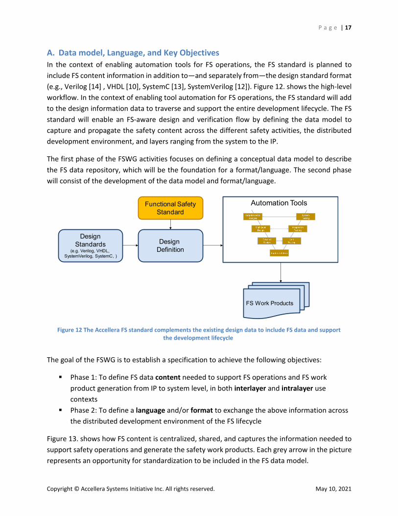
A. Data model, Language, and Key Objectives In the context of enabling automation tools for FS operations, the FS standard is planned to include FS content information in addition to—and separately from—the design standard format (e.g., Verilog [14] , VHDL [10], SystemC [13], SystemVerilog [12]). Figure 12. shows the high-level workflow. In the context of enabling tool automation for FS operations, the FS standard will add to the design information data to traverse and support the entire development lifecycle. The FS standard will enable an FS-aware design and verification flow by defining the data model to capture and propagate the safety content across the different safety activities, the distributed development environment, and layers ranging from the system to the IP.
The first phase of the FSWG activities focuses on defining a conceptual data model to describe the FS data repository, which will be the foundation for a format/language. The second phase will consist of the development of the data model and format/language.
The goal of the FSWG is to establish a specification to achieve the following objectives:
Phase 1: To define FS data content needed to support FS operations and FS work product generation from IP to system level, in both interlayer and intralayer use contexts
Phase 2: To define a language and/or format to exchange the above information across the distributed development environment of the FS lifecycle
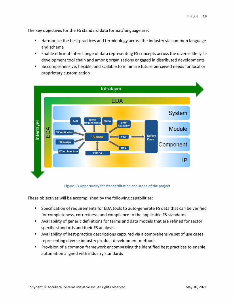
Figure 13. shows how FS content is centralized, shared, and captures the information needed to support safety operations and generate the safety work products. Each grey arrow in the picture represents an opportunity for standardization to be included in the FS data model.
Figure 12 The Accellera FS standard complements the existing design data to include FS data and support the development lifecycle
Functional SafetyStandard
DesignStandards
(e.g. Verilog, VHDL, SystemVerilog, SystemC, )
Design Definition
Automation Tools
FS Work Products
P a g e | 18
Copyright © Accellera Systems Initiative Inc. All rights reserved. May 10, 2021
The key objectives for the FS standard data format/language are:
Harmonize the best practices and terminology across the industry via common language and schema
Enable efficient interchange of data representing FS concepts across the diverse lifecycle development tool chain and among organizations engaged in distributed developments
Be comprehensive, flexible, and scalable to minimize future perceived needs for local or proprietary customization
These objectives will be accomplished by the following capabilities:
Specification of requirements for EDA tools to auto-generate FS data that can be verified for completeness, correctness, and compliance to the applicable FS standards
Availability of generic definitions for terms and data models that are refined for sector specific standards and their FS analysis
Availability of best-practice descriptions captured via a comprehensive set of use cases representing diverse industry product development methods
Provision of a common framework encompassing the identified best practices to enable automation aligned with industry standards
Figure 13 Opportunity for standardization and scope of the project
P a g e | 19
Copyright © Accellera Systems Initiative Inc. All rights reserved. May 10, 2021
Availability of formal descriptions of fundamental operations to enable data modeling within the FS lifecycle—analysis, validation, verification, automation—termed FS content
The key characteristics of the data exchange standard will be as follows:
Human readable and machine parseable (e.g., XML, TCL or script base, DSL) Independent of the design standard format Flexible to allow for future capabilities/enhancements Tool independent Provision of different views at different abstraction levels of FS data
B. Use Case Example: Adaptive Cruise Control The FSWG will deliver a practical example with the following goals in mind:
Demonstrate industry challenges Concretely illustrate parts of a development lifecycle Illustrate and validate detailed use cases:
o Verify how integrators may combine the different data and work products coming from their suppliers
o Verify work product format and content consistency o Connect FMEDA, FTA, DFA, safety manual, requirement traceability, AoU, etc.
Ease understanding and adoption of the FS data format/language
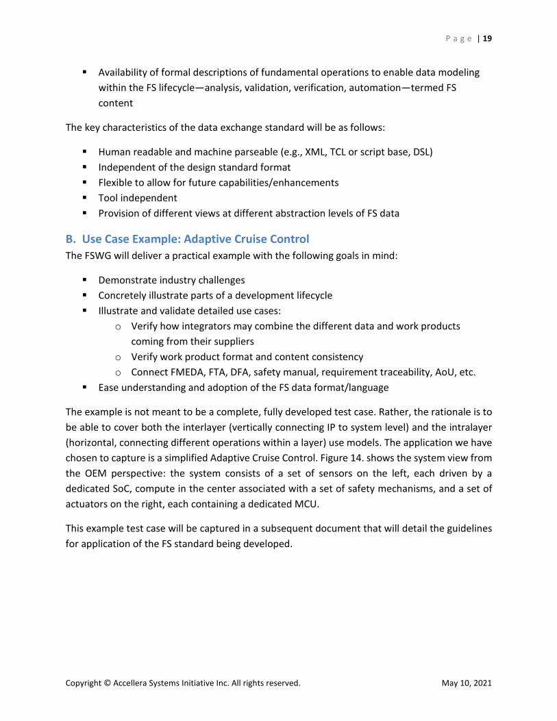
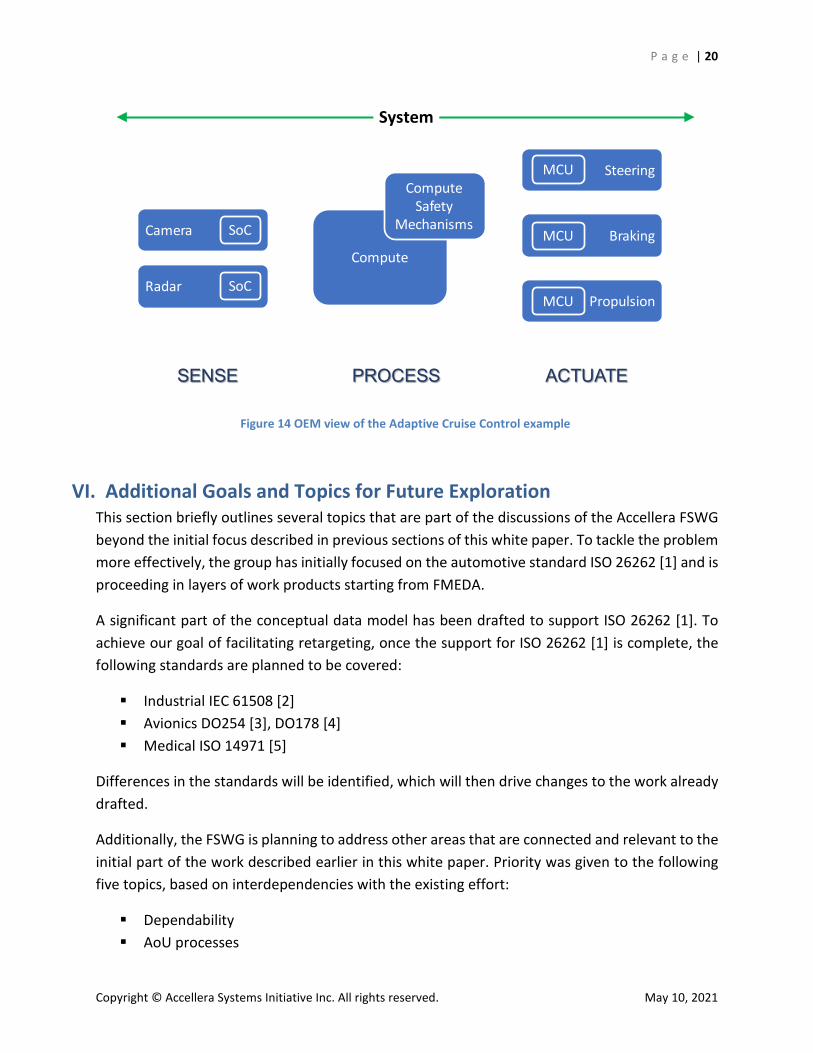
The example is not meant to be a complete, fully developed test case. Rather, the rationale is to be able to cover both the interlayer (vertically connecting IP to system level) and the intralayer (horizontal, connecting different operations within a layer) use models. The application we have chosen to capture is a simplified Adaptive Cruise Control. Figure 14. shows the system view from the OEM perspective: the system consists of a set of sensors on the left, each driven by a dedicated SoC, compute in the center associated with a set of safety mechanisms, and a set of actuators on the right, each containing a dedicated MCU.
This example test case will be captured in a subsequent document that will detail the guidelines for application of the FS standard being developed.
P a g e | 20
Copyright © Accellera Systems Initiative Inc. All rights reserved. May 10, 2021
VI. Additional Goals and Topics for Future Exploration This section briefly outlines several topics that are part of the discussions of the Accellera FSWG beyond the initial focus described in previous sections of this white paper. To tackle the problem more effectively, the group has initially focused on the automotive standard ISO 26262 [1] and is proceeding in layers of work products starting from FMEDA.
A significant part of the conceptual data model has been drafted to support ISO 26262 [1]. To achieve our goal of facilitating retargeting, once the support for ISO 26262 [1] is complete, the following standards are planned to be covered:
Industrial IEC 61508 [2] Avionics DO254 [3], DO178 [4] Medical ISO 14971 [5]
Differences in the standards will be identified, which will then drive changes to the work already drafted.
Additionally, the FSWG is planning to address other areas that are connected and relevant to the initial part of the work described earlier in this white paper. Priority was given to the following five topics, based on interdependencies with the existing effort:
Dependability AoU processes
Figure 14 OEM view of the Adaptive Cruise Control example
Steering
Braking
Propulsion
Camera
Radar
System
SoC
SoC
MCU
MCU
MCU
SENSE PROCESS ACTUATE
Compute
Compute Safety
Mechanisms
P a g e | 21
Copyright © Accellera Systems Initiative Inc. All rights reserved. May 10, 2021
Requirements of FS verification techniques Safety manual process Safety case process
The remainder of this section will describe the scope of each of the these topics and highlight the interdependencies with the current work that is covered by the group.
Dependability Dependability [20][21] refers to the quality of service that a system provides, and it covers the reliability, availability, safety, maintainability, and security aspects of the system. Reliability [17][18], safety, and availability [19] are within the scope of the working group. Maintainability and security are out of scope and may or may not be covered in the future.
Reliability, availability, and safety share several aspects, and the focus of the FSWG is to define the interrelation between them and identify whether and how the data model will be able to support them.
Assumption of Use Processes (AoU) AoU are an integral part of the overall FS requirements and can be used at different levels in the development lifecycle of the design and in different contexts. For example, in the development of SEooC products, AoU can be used when customer product requirements are not available. AoU are used in FMEDA or DFA when the actual requirements are not available at the time of development. It is the responsibility of the consumer or integrator to verify that they are adhering to the AoU.
There are a few challenges that exist today in handling these assumptions through the product development. Most of the AoU are developed using natural language without any format or a common structure that has been agreed on. This could be a potential for errors and also a burden in communication between the different development layers. Also, as of today there is no agreed upon standard methods for tying the AoU into the product or engineering requirements. The topics in which the FSWG is interested are:
To define an acceptable AoU format to enable proper communication across different layers
To investigate processes to evaluate the correctness of the AoU by the consumer of the AoU at the different layers
Requirements of FS Verification Techniques There are several techniques for verifying the diagnostic effectiveness of safety mechanisms. The most common techniques are fault simulation [22] [23], analytical methods [24] [25] [26], formal
P a g e | 22
Copyright © Accellera Systems Initiative Inc. All rights reserved. May 10, 2021
methods [23][27][28][29], and statistical analysis [30]. These techniques can be used standalone or together to evaluate the design capability of detecting errors or failures.
The topics in which the FSWG is interested are:
Identifying all of the techniques for safety validation Defining the data model requirements for each of the safety validation techniques for
the different layers Identifying rules and procedures to compare or merge the outputs from the different
techniques Defining the intraoperability/interoperability between these methods/tools and other
tools (e.g., FMEDA, FTA) at the same layer and other layers
Safety Manual Process All safety standards require a safety manual be delivered to integrators that contains safety information such as safety analysis, AoU, safety architecture, and more. However, at this time the industry is not standardized on the content or format of the safety manual. Some other safety standards, such as IEC 61508 [2], do not cover IP or SoC safety manual content. Thus, there is variation across different companies on what a safety manual should contain, and, in many cases, a single company may have several versions of the same safety manual to satisfy different customers’ requirements. Finally, most of the safety manual development follows a manual process and does not support automation or extraction of the information from the data model.
The topics in which the FSWG is interested are:
Identifying the essential information needed by the integrator to complete their design and safety analysis
Defining methods to enable extraction/automation from the data model Defining how a safety manual development could be automated, e.g., using a
combination of executable specifications and descriptive language
Safety Case Process Although there are several tools and languages that have been proposed for deriving the safety case [28], there is no agreement on the format or language structure. In addition, current tools or languages might not be adequate to the safety argument and are not flexible enough to enable changes in the safety argumentation without major rework of the safety case.
The topics in which the Accellera FSWG is interested are:
Standard language(s) and template structure for the safety case Exploring solutions for the integration of the safety case from different suppliers
P a g e | 23
Copyright © Accellera Systems Initiative Inc. All rights reserved. May 10, 2021
Proposing a solution for work product documentation Proposing techniques to automate the development of the safety case Providing solution examples for the different layers
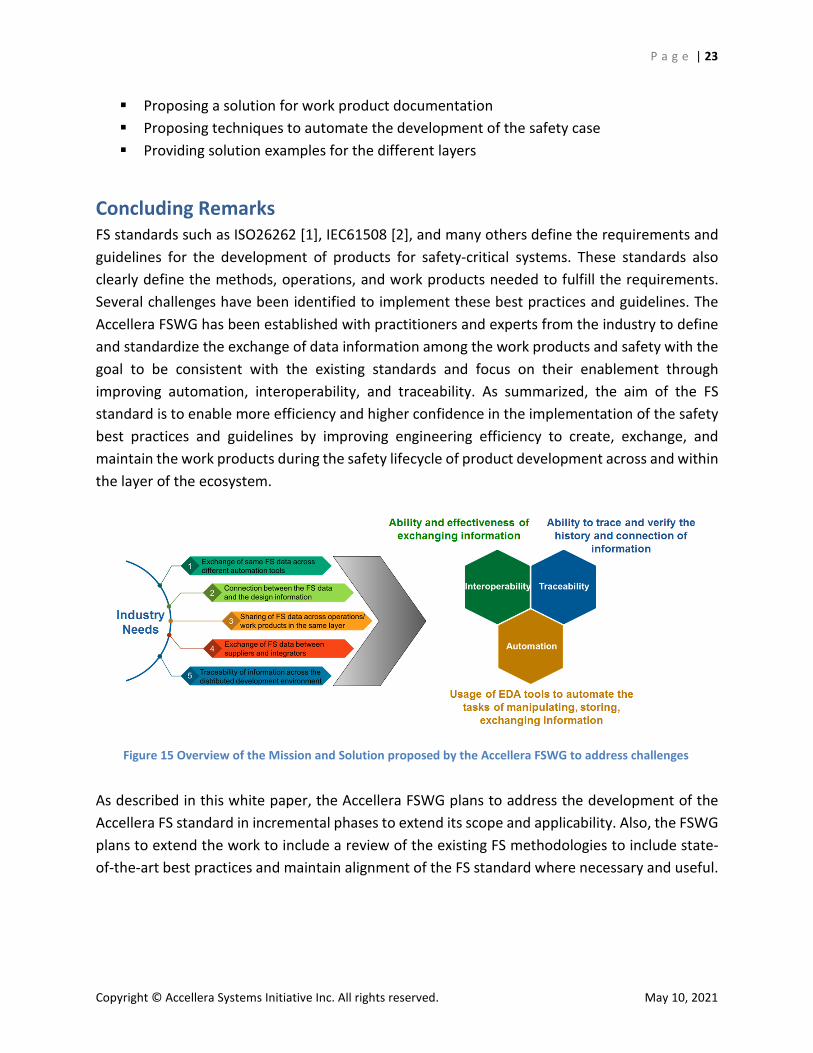
Concluding Remarks FS standards such as ISO26262 [1], IEC61508 [2], and many others define the requirements and guidelines for the development of products for safety-critical systems. These standards also clearly define the methods, operations, and work products needed to fulfill the requirements. Several challenges have been identified to implement these best practices and guidelines. The Accellera FSWG has been established with practitioners and experts from the industry to define and standardize the exchange of data information among the work products and safety with the goal to be consistent with the existing standards and focus on their enablement through improving automation, interoperability, and traceability. As summarized, the aim of the FS standard is to enable more efficiency and higher confidence in the implementation of the safety best practices and guidelines by improving engineering efficiency to create, exchange, and maintain the work products during the safety lifecycle of product development across and within the layer of the ecosystem.
As described in this white paper, the Accellera FSWG plans to address the development of the Accellera FS standard in incremental phases to extend its scope and applicability. Also, the FSWG plans to extend the work to include a review of the existing FS methodologies to include state-of-the-art best practices and maintain alignment of the FS standard where necessary and useful.
Figure 15 Overview of the Mission and Solution proposed by the Accellera FSWG to address challenges
P a g e | 24
Copyright © Accellera Systems Initiative Inc. All rights reserved. May 10, 2021
References [1] ISO 26262:2018 Road vehicles - Functional safety of electrical/electronic/programmable
electronic safety-related Systems [2] IEC 61508:2010 Functional safety of electrical/electronic/programmable electronic
safety-related systems [3] RTCA DO 254 Design Assurance Guidance for Airborne Electronic Hardware [4] DO 178C Software considerations in airborne systems and equipment certification [5] ISO 14971 Medical devices — Application of risk management to medical devices [6] IEEE P1801 - Draft Standard for Design and Verification of Low Power, Energy Aware
Electronic Systems (UPF) [7] IEEE 1497-2001 - IEEE Standard for Standard Delay Format (SDF) for the Electronic
Design Process [8] Accellera Standards Success: https://accellera.org/about [9] IEEE 1800.2-2017 - IEEE Standard for Universal Verification Methodology Language
Reference Manual [10] IEEE 1076 - IEEE Standard for VHDL Language Reference Manual [11] IEEE 1685-2014 - IEEE Standard for IP-XACT, Standard Structure for Packaging,
Integrating, and Reusing IP within Tool Flows [12] P1800 - Standard for SystemVerilog—Unified Hardware Design, Specification, and
Verification Language [13] IEEE 1666-2011 - IEEE Standard for Standard SystemC Language Reference Manual [14] 1364-2005 - IEEE Standard for Verilog Hardware Description Language [15] IEEE P2851 https://sagroups.ieee.org/2851/ [16] IEEE P2851 https://standards.ieee.org/project/2851.html [17] IEEE Get Program https://www.accellera.org/downloads/ieee [18] Siewiorek, Daniel P.; Swartz, Robert S.; 1998. “Reliable computer systems: design and
evaluation” [19] E.J. McClusky & S. Mitra (2004). “Fault Tolerance” in Computer Science Handbook 2ed.
ed. A.B. Tucker. CRC Press [20] Spencer, Richard H.; Floyd, Raymond E. (2011). “Perspectives on Engineering”
Bloomington, Indiana: AuthorHouse [21] J.C. Laprie, “Dependability—Its Attributes, Impairments and Means,” Predictably
Dependable Computing Systems, B. Randell et al., eds., pp. 3-24, 1995 [22] A. Avizienis, J.C. Laprie, B. Randell, and C. Landwehr, “Basic Concepts and Taxonomy of
Dependable and Secure Computing,” IEEE Transactions on Dependable and Secure Computing, Vol. 1, No. 1, January-March 2004
[23] A. Nardi and A. Armato, “Functional safety methodologies for automotive applications,” in 2017 IEEE/ACM International Conference on Computer-Aided Design (ICCAD). IEEE, Nov 2017
[24] Xueying Yang et al., “Fault Simulation and Formal Analysis in Functional Safety CPU FMEDA Campaign,” 2021 J. Phys.: Conf. Ser. 1769 012061
P a g e | 25
Copyright © Accellera Systems Initiative Inc. All rights reserved. May 10, 2021
[25] Bouricius, W.G., W.C. Carter and P.R. Schneider. Reliability Modeling techniques for self repairing computer system, “Proceedings of the 24th ACM Annual Conference, 1969, pp. 295-309
[26] S. Sunter, M. Wolinski, A. Coyette, R. Vanhooren, W. Dobbelaere, N, Xama, J. Gomez, G. Gielen, “Quick Analyses for Improving Reliability and Functional Safety of Mixed-Signal ICs,” Proc. of Int’l Test Conf. (ITC), Nov. 2020
[27] S. Chonnad, R. Iacob and V. Litovtchenko, “A Quantitative Approach to SoC Functional Safety Analysis” in IEEE System-on-Chip Conference (SOCC) Sept 4-9 2018, pp 2-6
[28] S. Marchese and J. Grosse, “Formal fault propagation analysis that scales to modern automotive SoCs,” in 2017 Design and Verification Conference and Exhibition DVCON Europe, 2017
[29] D.Smith, “It’s Not My Fault! How to Run a Better Fault Campaign Using Formal“ in DVCON USA 2018 proceedings
[30] A. Traskov, T. Ehrenberg, and S. Loitz, “Fault proof: Using formal techniques for safety verification and fault analysis,” in 2016 Design and Verification Conference and Exhibition DVCON Europe. DVCON, 2016, pp. 27–32
[31] Trivedi K.S, Probability and Statistics with Reliability, Queuing, and Computer Science Applications, Prentice-Hall, Englewood Cliffs, N.J., 1982
[32] Structured Assurance Case Metamodel (SACM) https://www.omg.org/spec/SACM/2.1/PDF
List of Figures Figure 1 High-level view of the Accellera FSWG scope and stakeholders ...................................... 3 Figure 2 Definition of supply chain layers and interfaces ............................................................... 5 Figure 3 Requirements and evidence exchanged across layers ..................................................... 6 Figure 4 General functional safety workflow ................................................................................. 7 Figure 5 Work product integration from multiple suppliers by a single integrator ....................... 9 Figure 6 Single supplier supporting multiple customers .............................................................. 10 Figure 7 Example of FMEDA as work product integrated with supply chain ............................... 11 Figure 8 OEM (e.g., car manufacturer) as an integrator for the final safety case ........................ 11 Figure 9 Traceability of requirements, change management, and impact analysis across layers and activities ................................................................................................................................. 12 Figure 10 Functional safety operations and dimension for data exchange ................................. 14 Figure 11 Overview of the functional safety standards and goals for the Accellera FSWG ......... 16 Figure 12 The Accellera FS standard complements the existing design data to include FS data and support the development lifecycle ............................................................................................... 17 Figure 13 Opportunity for standardization and scope of the project .......................................... 18 Figure 14 OEM view of the Adaptive Cruise Control example ..................................................... 20 Figure 15 Overview of the Mission and Solution proposed by the Accellera FSWG to address challenges ..................................................................................................................................... 23
P a g e | 26
Copyright © Accellera Systems Initiative Inc. All rights reserved. May 10, 2021
Acronyms Acronym Brief description ADC Analog-to-Digital Converter AoU Assumption of Use ASIL Automotive Safety Integrity Level BFR Base Failure Rate CPU Central Processing Unit DAL Design Assurance Level DDR Double Data Rate DFA Dependent Failure Analysis DSL Domain-specific Programming Language ECU Electronic Control Unit EDA Electronic Design Automation FIT Failure In Time FMEA Failure Model and Effect Analysis FMEDA Failure Mode and Effects and Diagnostic Analysis FS Functional Safety FSWG Functional Safety Working Group FTA Fault Tree Analysis HARA Hazard Analysis and Risk Assessment HW Hardware IC Integrated Circuit IEEE Institute of Electrical and Electronics Engineers IP Intellectual Property LFM Latent Fault Metric MCM Multichip Module MCU Microcontroller unit MIPI PHY Mobile Industry Processor Interface Physical Layer ML Machine Learning OEM Original Equipment Manufacturer PCB Printed Circuit Board SDF Standard Delay Format SEooC Safety Element out of Context SIL Safety Integrity Level SIP/MCM System-In-Package SM Safety Mechanism SoC System On a Chip SPFM Single-Point Fault Metric SPI Serial Peripheral Interface SR Safety Requirement SW Software TCL Tool Command Language
P a g e | 27
Copyright © Accellera Systems Initiative Inc. All rights reserved. May 10, 2021
UPF Unified Power Format WG Working Group WP Work Product XML Extensible Markup Language
Accellera FSWG Supporting Members We are thankful to our supporting member companies (in alphabetical order): Aedvices Consulting, Agnisys, AMD, ams AG, Analog Devices, ARM, Arteris, Breker Verification Systems, Cadence Design Systems, Ethernovia (2020 membership), Fraunhofer Institute For Integrated Circuits, Infineon Technologies AG, Intel Corporation, Marvell International, Microchip Technologies, NVIDIA Corporation, NXP Semiconductors, OneSpin Solutions, Perforce, Qualcomm, Robert Bosch GmbH, Siemens EDA, STMicroelectronics, Synopsys, Technical University Dortmund, Texas Instruments, Vayavya Labs, XEPIC Corporation, Xilinx.
Accellera FS Proposed WG Supporting Entities We appreciate the support and contributions from the following companies (in alphabetical order) that helped us during the Proposed WG phase: ANSYS Germany GmbH, Exida, Intento Design, IROC Technologies, Optima Design Automation, Renesas Electronics Europe, Resiltech S.R.L, SafeSecureAI LLC, The MathWorks GmbH, TÜV SÜD RAIL GmbH.
Acknowledgements Special recognition (in alphabetical order by last name) for their contributions to the Accellera FS WG and Proposed WG with discussions, brainstorming, examples, and writing/reviewing of this white paper: Dan Alexandrescu, Jyotika Athavale, Oscar Ballan, Pramod Bhardwaj, Alexis Boutillier, Samir Camdzic, Jason Campbell, Giuseppe Capodanno, Agostino Cefalo, Bala Chavali, Divya Chawla, Wen Chen, Shivakumar Chonnad, Kaushik De, Franck Galtie, Joerg Grosse, Regis Gubian, Mark Hampton, John Hayden, Anamaria Hutuleac, Ghani Kanawati, Francesco Lertora, Thiyagu Loganathan, Stefano Lorenzini, Cristian Macario, Nir Maor, Riccardo Mariani, Jamil Mazzawi, James McGinley, Shrenik Mehta, Alessandra Nardi, Meirav Nitzan, Alexandre Palus, Vatsa Prahallada, Iskander Ramy, Om Ranjan, Kevin Rich, Rolf Schlagenhaft, Francesco Sforza, Kurt Shuler, Gaurav Tomar, Ivano Shivananda Troja, Varin Vahia, Ashish Vanjari, Federico Venini, Harish Venkataraman, Riccardo Vincelli, Jens Warmuth, Jacob Wiltgen, Rafael Zalman, Marc Zeller.
Special thank you (in alphabetical order by last name) for their guidance to navigate the world of standardization to Martin Barnasconi, Dennis Brophy, Lu Dai, Tom Fitzpatrick, Lynn Garibaldi, Jonathan Goldberg, and Stan Krolikoski.
Related Documents


