HAL Id: hal-02616829 https://hal-normandie-univ.archives-ouvertes.fr/hal-02616829 Submitted on 20 Nov 2020 HAL is a multi-disciplinary open access archive for the deposit and dissemination of sci- entific research documents, whether they are pub- lished or not. The documents may come from teaching and research institutions in France or abroad, or from public or private research centers. L’archive ouverte pluridisciplinaire HAL, est destinée au dépôt et à la diffusion de documents scientifiques de niveau recherche, publiés ou non, émanant des établissements d’enseignement et de recherche français ou étrangers, des laboratoires publics ou privés. Fully coupled electromagnetic-thermal-mechanical comparative simulation of direct vs hybrid microwave sintering of 3Y-ZrO 2 Charles Manière, Tony Zahrah, Eugene A. Olevsky To cite this version: Charles Manière, Tony Zahrah, Eugene A. Olevsky. Fully coupled electromagnetic-thermal-mechanical comparative simulation of direct vs hybrid microwave sintering of 3Y-ZrO 2. Journal of the American Ceramic Society, Wiley, 2017, 100 (6), pp.2439-2450. 10.1111/jace.14762. hal-02616829

Welcome message from author
This document is posted to help you gain knowledge. Please leave a comment to let me know what you think about it! Share it to your friends and learn new things together.
Transcript

HAL Id: hal-02616829https://hal-normandie-univ.archives-ouvertes.fr/hal-02616829
Submitted on 20 Nov 2020
HAL is a multi-disciplinary open accessarchive for the deposit and dissemination of sci-entific research documents, whether they are pub-lished or not. The documents may come fromteaching and research institutions in France orabroad, or from public or private research centers.
L’archive ouverte pluridisciplinaire HAL, estdestinée au dépôt et à la diffusion de documentsscientifiques de niveau recherche, publiés ou non,émanant des établissements d’enseignement et derecherche français ou étrangers, des laboratoirespublics ou privés.
Fully coupled electromagnetic-thermal-mechanicalcomparative simulation of direct vs hybrid microwave
sintering of 3Y-ZrO 2Charles Manière, Tony Zahrah, Eugene A. Olevsky
To cite this version:Charles Manière, Tony Zahrah, Eugene A. Olevsky. Fully coupled electromagnetic-thermal-mechanicalcomparative simulation of direct vs hybrid microwave sintering of 3Y-ZrO 2. Journal of the AmericanCeramic Society, Wiley, 2017, 100 (6), pp.2439-2450. �10.1111/jace.14762�. �hal-02616829�
1
Fully Coupled Electromagnetic-Thermal-Mechanical Comparative
Simulation of Direct vs. Hybrid Microwave Sintering of 3Y-ZrO2
Charles Manièrea, Tony Zahrah
b, Eugene A. Olevsky
a, c*
(a) Powder Technology Laboratory, San Diego State University, San Diego, USA
(b) Matsys Inc., Sterling, USA
(c) NanoEngineering, University of California, San Diego, La Jolla, USA
Keywords
Microwave Sintering, Finite Element Method, Densification, Direct Heating, Hybrid Heating,
Zirconia
Abstract
Direct and hybrid microwave sintering of 3Y-ZrO2 are comparatively studied at frequency of
2.45 GHz. Using the continuum theory of sintering, a fully coupled electromagnetic-thermal-
mechanical (EMTM) finite element simulation is carried out to predict powder samples
deformation during their microwave processing. Direct and hybrid heating configurations are
computationally tested using advanced heat transfer simulation tools including the surface to
surface thermal radiation boundary conditions and a numeric proportional–integral–derivative
(PID) regulation. The developed modeling framework shows a good agreement of the calculation
results with the known experimental data on the microwave sintering of 3Y-ZrO2 in terms of the
densification kinetics. It is shown that the direct heating configuration renders highly hot spot
effects resulting in non-homogenous densification causing processed specimen’s final shape
distortions. Compared to the direct heating, the hybrid heating configuration provides a reduction
of the thermal inhomogeneity along with a densification homogenization. As a result of the
hybrid heating, the total densification of the specimen is attained without specimen distortions. It
is also shown that the reduction of the sample size has a stabilization effect on the temperature
and relative density spatial distributions.
_________________________________
* Corresponding author: EO (ACerS Fellow): Powder Technology Laboratory, San Diego State
University, 5500 Campanile Drive, San Diego, CA 92182-1323,
Ph.: (619)-594-6329; Fax: (619)-594-3599, E-mail address: [email protected]
2
I. Introduction
The microwave sintering process showed appealing results for the densification1-8
, synthesis9,
assembling10
, annealing11
of various materials and for the achievement of enhanced materials
properties12-14
. A wide range of ceramic15-17
, metallic18-23
, polymeric24-25
, composite26-27
material
systems have been successfully fabricated by this technology. Compared to the conventional
sintering (utilizing a convective indirect heating28-30
pattern), a volume and direct microwave
heating1,3
of the sample is applicable with potentially high heating rates31
of about 100K/min.
This processing specifics results in energy savings and in the reduction of the grain growth
allowing to produce materials with dense and fine microstructures32-36
possessing high
mechanical properties. Because of these benefits, the microwave sintering process encounters a
growing number of applications in both research and industrial fields.
Many authors reported an acceleration of the sintering kinetics in microwave compared to
conventionally sintered samples37-41
for the same thermal cycle. The origin of this so-called “non-
thermal effect” or “microwave effect” is still debated but a possible explanation can be the action
of ponderomotive forces at the pore/grain boundary junctions42-46
and/or diffusion mechanism
enhancements induced by the microwave alternative fields47-48
. In addition to the earlier
mentioned benefits, this phenomenon also contributes to the reduction of the sintering time and
promotes fine microstructures.
Despite all its benefits, microwave sintering remains a rather difficult process to control. The
temperature and displacement measurements are not easy to perform because thermocouples or
pushrods inserted in the furnace working space may interact with microwaves49-50
. As a rule, non-
contact measurements using pyrometer and/or camera are employed in microwave sintering with
the calibration of the measurement devices as described by Croquesel et al.37
. Another difficulty
of this technology is the inherent heating instabilities51-54
. The wave propagation in the
microwave cavity intrinsically generates areas of high and low electric and magnetic fields

3
intensity. Therefore, depending of the sample location, the heating can be very different and then
non-reproducible55
. In a previous work56
, we showed that the temperature-dependent evolution of
the dielectric properties of ceramic materials can promote the formation of highly hot spots in the
center of the sintered samples, thereby causing problems of inhomogeneous densification. This
hot spot phenomenon appears often under conditions of the direct microwave heating. To
stimulate the temperature homogenization and to assist the processing of low dielectric loss
materials, a hybrid heating using susceptors can be used. A susceptor is a material highly sensible
to the microwaves. Silicon carbide is often used for susceptor components since this material
exhibits high values of dielectric loss at low temperatures57-60
. Numerous researches21,61-64
reported a more stable heating using susceptors in hybrid or indirect heating configurations. In
order to aid the adjustments of the tooling to a specific microwave sintering application, a
respective simulation tool is needed.
The finite element (FE) simulation is a powerful tool for the prediction of:
- the areas of high electric/magnetic fields intensity in the microwave cavity;
- the thermal gradients generation;
- the sample densification gradient and deformation for simple or complex shapes;
- the process regulation parameters;
- the effect of susceptors on the hybrid heating of the sample.
The FE simulation allows optimization studies for the heating/densification stabilization.
Microwave sintering simulations encompass three main physics highly coupled to each other:
electromagnetism, heat transfer and sintering. In the past, researchers studied the
electromagnetic-thermal (EMT) aspects of the microwave sintering process using the finite
element61-62,64,65-67
, or finite-difference time-domain68-69
(FDTD) methods. In 2010, Bouvard et

4
al.64
included the sintering aspect of the process through an empirical densification equation and
coupled the densification to the other physics assuming a fixed specimen’s geometry during the
sintering cycle. Birnboim et al.70
and Riedel et al.71
used similar approaches to conduct coupled
simulations of microwave sintering. More recently, Abedinzadeh et al.72
modeled a pressure
assisted microwave cavity. They studied first the cold compaction by the Gurson–Tvergaard–
Needleman model73-76
and then the microwave heating was modeled using COMSOL
MultiphysicsTM77
, and finally they investigated the hot densification based on the previously
obtained cold pressing and heating modeling data.
Overall, fully or partially coupled EMTM models exist in the literature, but they are rare and
sparse. In most cases, these studies employ simplified model conditions like idealized sample
geometry; material parameters, which are not always temperature/porosity dependent; and
idealized conduction and radiation heat exchange conditions.
In the present study, a fully coupled EMTM simulation of pressureless microwave sintering is
investigated using COMSOL MultiphysicsTM
software. The purpose of this modeling approach is
to include the coupled effects of the electromagnetic fields, heating, densification and complex
deformation of a powder sample in the comparative analysis of the direct and hybrid heating
taking into account the influence of the sample dimensions. In this study, the susceptor technique
is explored as this approach is simple and highly adaptable to a wide range of microwave furnace.
Below, a TE102 resonant rectangular waveguide cavity is investigated at the excitation frequency
of 2.45GHz. In the developed model the dielectric, thermal and mechanical parameters are
coupled to each other and evolve with the temperature and porosity. The surface to surface
thermal radiation between all the parts and PID regulation are also taken into account.
II. Theory and calculations
II.1. EMTM model description
5
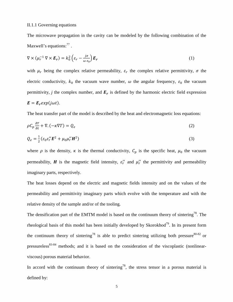
II.1.1 Governing equations
The microwave propagation in the cavity can be modeled by the following combination of the
Maxwell’s equations:77
.
∇ × (𝜇𝑟−1 ∇ × 𝑬𝒓) = 𝑘0
2 (𝜀𝑟 −𝑗𝜎
𝜔 𝜀0) 𝑬𝒓 (1)
with 𝜇𝑟 being the complex relative permeability, 𝜀𝑟 the complex relative permittivity, 𝜎 the
electric conductivity, 𝑘0 the vacuum wave number, 𝜔 the angular frequency, 𝜀0 the vacuum
permittivity, j the complex number, and 𝑬𝒓 is defined by the harmonic electric field expression
𝑬 = 𝑬𝒓𝑒𝑥𝑝(𝑗𝜔𝑡).
The heat transfer part of the model is described by the heat and electromagnetic loss equations:
𝜌𝐶𝑝𝜕𝑇
𝜕𝑡+ ∇. (−𝜅∇𝑇) = 𝑄𝑒 (2)
𝑄𝑒 =1
2(𝜀0𝜀𝑟
′′𝑬2 + 𝜇0𝜇𝑟′′𝑯2) (3)
where 𝜌 is the density, 𝜅 is the thermal conductivity, 𝐶𝑝 is the specific heat, 𝜇0 the vacuum
permeability, 𝑯 is the magnetic field intensity, 𝜀𝑟′′ and 𝜇𝑟
′′ the permittivity and permeability
imaginary parts, respectively.
The heat losses depend on the electric and magnetic fields intensity and on the values of the
permeability and permittivity imaginary parts which evolve with the temperature and with the
relative density of the sample and/or of the tooling.
The densification part of the EMTM model is based on the continuum theory of sintering78
. The
rheological basis of this model has been initially developed by Skorokhod79
. In its present form
the continuum theory of sintering78
is able to predict sintering utilizing both pressure80-82
or
pressureless83-84
methods; and it is based on the consideration of the viscoplastic (nonlinear-
viscous) porous material behavior.
In accord with the continuum theory of sintering78
, the stress tensor in a porous material is
defined by:

6
𝜎 =𝜎𝑒𝑞
�̇�𝑒𝑞(𝜑𝜀̇ + (𝜓 −
1
3𝜑) 𝑡𝑟(𝜀̇)𝕚) + 𝑃𝑙𝕚 (4)
where 𝜎𝑒𝑞 and 𝜀�̇�𝑞 are the equivalent stress and strain rate, 𝜀̇ is the strain rate tensor, 𝕚 is the
identity tensor, Pl is the sintering stress, 𝜑 and 𝜓 are the shear and bulk moduli defined as
functions of the porosity 𝜃:
𝜑 = (1 − 𝜃)2 (5)
𝜓 =2
3
(1−𝜃)3
𝜃 (6)
The sintering stress expression depends on the average particle radius 𝑟0, on the porosity, and on
the surface energy 𝛼:
𝑃𝑙 =3𝛼
𝑟0(1 − 𝜃)2 (7)
The equivalent strain rate is defined as:
𝜀�̇�𝑞 =1
√1−𝜃√𝜑�̇�2 + 𝜓�̇�2 (8)
with the strain rate tensor invariants:
�̇� = 𝜀�̇� + 𝜀�̇�+𝜀�̇� (9)
�̇� = √2(𝜀�̇�𝑦2 + 𝜀�̇�𝑧
2 +𝜀�̇�𝑧2 ) +
2
3(𝜀�̇�
2+𝜀�̇�2+𝜀�̇�
2) −2
3(𝜀�̇�𝜀�̇� + 𝜀�̇�𝜀�̇� + 𝜀�̇�𝜀�̇�) (10)
The equivalent stress and strain rate are related by a power law creep equation:
𝜀�̇�𝑞 = 𝐴(𝑇)𝜎𝑒𝑞𝑛 (11)
where A is a parameter defining the decrease of the material resistance to deformation with the
temperature. The stress exponent n defines the nonlinearity of the material behavior. Usually the
free sintering experiments show linear viscous behavior (n=1), with the exception of the nano-
powders that possess high values of sintering stress and nonlinear85
behavior (n>1). For the linear
viscous material behavior, A(T) represents the reciprocal of the material viscosity 1
2𝜂(𝑇).
7
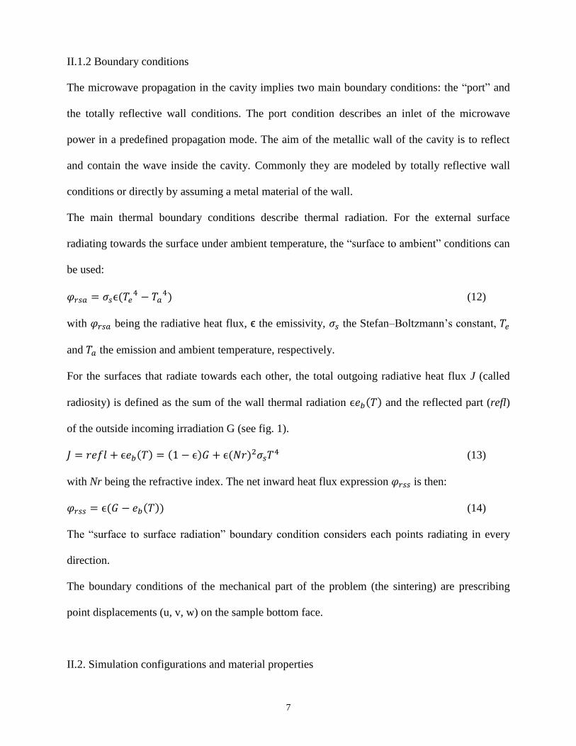
II.1.2 Boundary conditions
The microwave propagation in the cavity implies two main boundary conditions: the “port” and
the totally reflective wall conditions. The port condition describes an inlet of the microwave
power in a predefined propagation mode. The aim of the metallic wall of the cavity is to reflect
and contain the wave inside the cavity. Commonly they are modeled by totally reflective wall
conditions or directly by assuming a metal material of the wall.
The main thermal boundary conditions describe thermal radiation. For the external surface
radiating towards the surface under ambient temperature, the “surface to ambient” conditions can
be used:
𝜑𝑟𝑠𝑎 = 𝜎𝑠ϵ(𝑇𝑒4 − 𝑇𝑎
4) (12)
with 𝜑𝑟𝑠𝑎 being the radiative heat flux, ϵ the emissivity, 𝜎𝑠 the Stefan–Boltzmann’s constant, 𝑇𝑒
and 𝑇𝑎 the emission and ambient temperature, respectively.
For the surfaces that radiate towards each other, the total outgoing radiative heat flux J (called
radiosity) is defined as the sum of the wall thermal radiation ϵ𝑒𝑏(𝑇) and the reflected part (refl)
of the outside incoming irradiation G (see fig. 1).
𝐽 = 𝑟𝑒𝑓𝑙 + ϵ𝑒𝑏(𝑇) = (1 − ϵ)𝐺 + ϵ(𝑁𝑟)2𝜎𝑠𝑇4 (13)
with Nr being the refractive index. The net inward heat flux expression 𝜑𝑟𝑠𝑠 is then:
𝜑𝑟𝑠𝑠 = ϵ(𝐺 − 𝑒𝑏(𝑇)) (14)
The “surface to surface radiation” boundary condition considers each points radiating in every
direction.
The boundary conditions of the mechanical part of the problem (the sintering) are prescribing
point displacements (u, v, w) on the sample bottom face.
II.2. Simulation configurations and material properties

8
In this work three direct and hybrid heating configurations are explored. A rectangular waveguide
cavity is investigated in TE102 mode (fig. 2a). The tooling includes a high temperature insulating
box86
(maximum operating temperature 2073 K) made of alumina 80%-silica 20% and a silicon
carbide susceptor ring for the hybrid heating (see fig. 2b). The sample is a cylindrical green
compact of 3Y- ZrO2 with an initial relative density of 55%. The first configuration is the direct
heating of a 12 mm diameter sample, the second configuration is similar but uses a smaller
(7 mm diameter) sample and the last is a hybrid heating configuration with the 12 mm diameter
sample (with SiC susceptor). For each samples the height is the same of the diameter. Contrarily
to flat samples, these high height samples geometry have enough volume space to allow the
creation of high hot spot and allow to see the distortion they generate. The aim of these three
configurations is to study the impact of the microwave heating on the densification, temperature
gradients, scale factor for the direct heating configuration and the potential stabilization of the
hybrid heating configuration.
The material properties for 3Y-ZrO2 are represented in Table.1. These properties depend on both
the temperature (T) and relative density (D). The sintering process conditions based on the
experimental data of Wroe and Rowley41
(see fig. 3) render a good agreement of the experimental
and the developed model data in terms of the densification kinetics. The alumina-silicate and
silicon carbide temperature dependent properties are reported in Table. 2. The temperature cycle
is similar to the reference cycle41
(10 K/min from 300 to 1673 K and 20 min of dwell at 1673 K)
and is imposed at the point at the center of the upper sample face. A numeric PID regulation is
employed to utilize this thermal cycle regulating the input power 𝑃𝑖𝑛:
𝑃𝑖𝑛 = 𝐾𝑝𝑒(𝑡) + 𝐾𝐼 ∫ 𝑒(𝑡)𝑑𝜏𝑡
0+ 𝐾𝐷
𝑑𝑒(𝑡)
𝑑𝑡 (15)
where 𝑒(𝑡) is the temperature error (Tcycle - Tregulation), 𝐾𝑝, 𝐾𝐼, 𝐾𝐷, are the proportional,
integral, and derivative coefficients, respectively.

9
For the direct heating, we determined the PID coefficients: 𝐾𝑝 = 20, 𝐾𝐼 = 4, 𝐾𝐷 = 1. For the
hybrid heating the behavior of the heating changes and the following PID coefficients are
adapted: 𝐾𝑝 = 10, 𝐾𝐼 = 0.05, 𝐾𝐷 = 150. Because the hybrid heating configuration provides a
long thermal response between the imposed electromagnetic power input and the sample heating,
the derivative coefficient is high (𝐾𝐷 = 150) which slows down the regulation and helps
avoiding the PID regulation runaway.
III. Modeling Results
III.1. Electromagnetic wave propagation in the cavity.
Depending on the waveguide shape and dimensions, different propagation modes can be
applied90-92
. The dimensions of the considered rectangular waveguide (fig. 2a) have been
calculated using Eq. (16) to obtain a TE102 resonant mode93
for the excitation frequency of
2.45 GHz:
𝜔𝑛𝑚𝑝 = 𝑐√(𝑛𝜋
𝑎)
2
+ (𝑚𝜋
𝑏)
2
+ (𝑝𝜋
𝑙)
2
(16)
where a, b are the rectangular cross-section dimensions, l is the waveguide length, c is the light
velocity, n, m, p are the mode coefficients (1; 0; 2 for TE102), and 𝜔𝑛𝑚𝑝 is the resonant
frequency. Typically, the TE102 mode in empty cavity possesses two principal maximum areas of
the electric field as shown in fig.4a. In order to allow the maximum heating efficiency, the 3Y-
ZrO2 sample is placed in one of these areas37
. Because the real part of 3Y-ZrO2 permittivity is
equal roughly to 10, the electric field is higher outside the sample in the direct (figs. 4b,c) and
hybrid (fig. 4d) configurations. The disturbances of the electric field caused by the dielectric
properties of 3Y-ZrO2 generate a displacement of the maximum electric field point location in the
cavity. The sample location is then adjusted to be in the highest electric field area among the
different configurations. The hybrid heating configuration (fig. 4d) renders the maximum field

10
disturbance due to the presence of both the sample and the susceptor. Because the sample is a
good dissipative material only at high temperatures, the input power in high at low temperatures
and about 2000W and fall to about 200W at high temperatures.
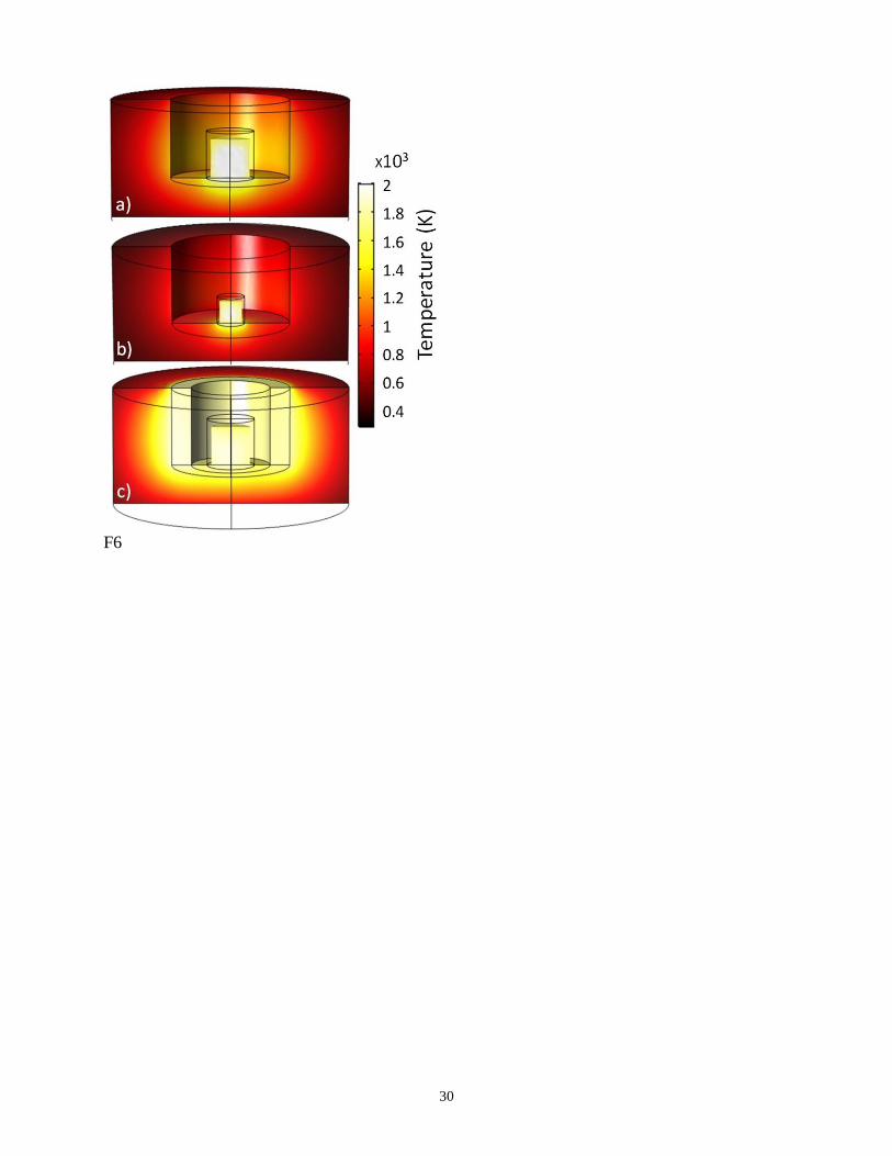
III.2. Heating and thermal exchanges
The temperature profiles of the tooling and sample at end of the heating cycle are reported in fig.
5 for the three configurations. The black lines represent the initial geometry. For these
configurations, the insulation box succeeds to decrease the temperature of the insulated bottom
face being in contact with the other support tools (Tmax = 800K). The sample lateral surface
radiation is responsible for the insulation box inner lateral faces’ temperature rise (up to 1400 K
for the large dimension sample (fig. 5a) and 900 K for the small sample dimension (fig 5b)). The
first direct heating case shown in fig. 5a points out to the presence of the two main
sample/insulation heat fluxes: one is the thermal conduction at the sample bottom face of about
1E5 W/m2 and the other is the surface to surface radiation at the other sample faces of about
2.6E5 W/m2. The radiative flux is higher because the sample radiates heat to a wide colder
insulation box surface. On the contrary, the conduction flux is limited by the insulation box low
density and its high low thermal conductivity. The surface integral of the incoming/emitted
radiative flux and the surface integral of the total net inward radiative flux and conductive flux on
the sample bottom face are reported in fig.6 for the three configurations.
As a first step, the comparison of the incoming/emitted flux on the radiative surfaces shows that
the incoming radiation flux from the heated insulating box is not negligible for the direct heating
configurations (figs. 6a and 6b) and represents roughly 30% of the incoming flux. The total net
inward radiative flux on the sample surfaces for the direct configurations is therefore negative
(heat loss) and about 150 W for the larger sample and 75 W for the smaller sample. For the
hybrid configuration, the SiC susceptor produces high amount of heat that radiates the sample
11
(fig. 6c). For the hybrid configuration, the incoming radiation flux is of the same order of
magnitude as the one of the sample producing this radiation flux. Consequently, the emitted and
incoming radiation compensate each other and the total surface inward radiation flux is low and
is about 30 W. In our case the hybrid heating configuration acts as a “thermal insulation” of the
sample surfaces.
On the other hand, the surface integral of the conductive heat flux at the sample/insulation box
interface is very low with the value of about 15 W for the direct configurations (figs. 6a and 6b)
and 5 W for the hybrid configuration (fig. 6c). As discussed earlier, the main reason of these low
values is the very low thermal conductivity of the insulating box, but the main explanation of the
difference between the total inward surface radiation values (conduction of 15W vs. radiation of
150W) is the difference in the interface area, which is 5 time lower than the total surface area for
thermal radiation. Consequently, the thermal insulation condition for this contact interface with
the support tool is a good approximation, similarly to the previously obtained results56
.
III.3. Densification/heating comparison
The relative density and temperature fields for the 12 mm diameter sample direct configuration
are reported in fig. 7. The temperature and relative density kinetic curves at the sample upper
surface and center indicate the formation of a hot spot at the center of the sample with maximum
temperature differences (ΔTsurf-center) of about 500 K while the surface maximum temperature
(ΔTmax-surf) is between 20 and 100 K. This ΔTsurf-center difference represents two regimes: at the
first stage ΔTsurf-center increases exponentially, at the second stage, when the densification occurs,
the temperature difference ΔTsurf-center stops increasing and maintains the value of about 500 K up
till the end of the cycle. As it was shown in a previous work56
, the hot spot formation is due to the
𝜀𝑟′′ increase with the temperature and the reduction of the size of the sample in turn reduces the
hot spot phenomenon. Additionally, because 𝜀𝑟 increases with the temperature and relative
12
density, the penetration depth 𝑑𝑝 given by eq. (17) evolves from meters to millimeters for high
temperatures and relative density (see fig. 8).
𝑑𝑝 =𝑐
2𝜋𝑓√2𝜀𝑟′ (√1+(
𝜀𝑟′′
𝜀𝑟′ )
2
−1)
(17)
where 𝑓 is the frequency, 𝑐 is the light speed and 𝜀𝑟′ is the real part of the relative permittivity.
Then at roughly 1300K the penetration depth is of the same order of magnitude as the sample
dimensions. Above this temperature, the electromagnetic heating starts to become more
superficial and the thermal gradient stops increasing.
Moreover, considering the presence of the hot spot and taking into account that the penetration
depth value is around 5 mm when the densification happens (see figs. 7 and 8), one can see that
the area of electromagnetic heat loss follows the densification front from the center to the edge of
the sample. Afterwards, when densification happens, the temperature gradients are stabilized.
Concerning the sample shape evolution (fig. 7), the hot spot generates a non-cylindrical shape
due to a heterogeneous densification field. The densification starts from the center and propagates
to the sample’s edge. The sample first assumes a highly non-cylindrical shape and goes back to
the cylindrical configuration at the end of the sintering. The final shape (fig. 7) is close to a
cylinder except the corners remain not fully densified due to lower temperatures at these
locations.
The 7 mm sample direct heating experiment (fig. 9) shows similar results except the temperature
difference ΔTsurf-center is reduced to 300 K. Even despite this value is still generally high, the value
of ΔTsurf-center is now sufficiently low to allow a complete densification of all the sample areas.
This reduction of the temperature gradient can be explained by the size of the sample being of the
same order of magnitude as the size of the hot spot area in the previous configuration (fig. 7).
Therefore, the smaller the sample is, the better the temperature and densification homogeneity is.

13
For the large sample configuration, a technical solution enabling the reduction of the thermal
gradients is needed. The hybrid heating configuration is studied for this purpose.
As shown in fig. 6, the hybrid configuration balances the sample thermal radiation by an
incoming radiation of the same order of magnitude. It is claimed in the literature that the hot spot
formation at the center of the sample can be balanced by the susceptor heating1-3, 62, 64-65
. Indeed,
our present simulation (fig. 10) shows a substantial degree of the homogenization of the
temperatures in the radial direction (of about 100 K.) In the vertical direction, the temperature
difference is reduced to about 200 K, but the radiation at the upper face, which is less subjected
to the susceptor radiative compensation, is less intensive. Nevertheless, the total densification of
the larger sample becomes possible with rendering a cylindrical final shape.
IV. Conclusions
A fully coupled electromagnetic-thermal-mechanical simulation of the microwave sintering of
3Y-ZrO2 has been carried out. The developed modeling framework shows a good agreement of
the calculation results with the known experimental data on microwave sintering of 3Y-ZrO2 in
terms of the densification kinetics. Direct and hybrid microwave heating configurations have
been tested for different sample dimensions. The direct heating configuration shows the
formation of a hot spot at the center of the sample. The hot spot phenomenon increases drastically
in the beginning of the process and then stabilizes when the densification occurs resulting at the
end of the heating cycle in a temperature difference of 500 K across the sample’s volume. The
microwave field penetration and then the heating become more superficial when the densification
happens; this fact explains the temperature gradients’ stabilization. The sample shape is highly
deformed during the densification due to the hot spot formation but tends to go back to the
cylindrical shape at the end of the densification. Decrease of the sample size appears to reduce
the thermal gradients and, at the same time, it resolves the problem of densification

14
heterogeneities. This result shows that the low dimension samples’ sintering is more stable. The
hybrid heating configuration succeeds in reducing the temperature gradients in the sample
allowing a more uniform overall densification of the large sample. Concerning the heat exchange
aspects, the direct configuration surprisingly shows that the far-range radiation from the
insulating tool is non-negligible in the surface-to-surface radiation heat exchanges. The use of
SiC susceptors allows to balance the sample incoming amount of heat by offsetting it through
thermal radiation.
Acknowledgements
The authors gratefully acknowledge the support from the Office of Naval Research, Contract #
N00014-14-C-0233, and Dr. William Mullins, Program Officer.
References
1 K.I. Rybakov, E.A. Olevsky, and E.V. Krikun, Microwave Sintering: Fundamentals and
Modeling, Journal of the American Ceramic Society, 96 [4] 1003–1020 (2013).
2 S. Charmond, C.P. Carry, and D. Bouvard, Densification and microstructure evolution of Y-
Tetragonal Zirconia Polycrystal powder during direct and hybrid microwave sintering in a
single-mode cavity, Journal of the European Ceramic Society, 30 [6] 1211–1221 (2010).
3 M. Oghbaei and O. Mirzaee, Microwave versus conventional sintering: A review of
fundamentals, advantages and applications, Journal of Alloys and Compounds, 494 [1-2] 175–
189 (2010).
4 D. Agrawal, Microwave Sintering of Ceramics, Composites and Metallic Materials, and
Melting of Glasses, Transactions of the Indian Ceramic Society, 65 [3] 129–144 (2006).
5 S. Chandrasekaran, S. Ramanathan, and T. Basak, Microwave material processing-a review,
AIChE Journal, 58 [2] 330–363 (2011).

15
6 A. J. Bertaud and J. C. Badot, High Temperature Microwave Heating in Refractory Materials,
Journal of Microwave Power and Electromagnetic Energy. 11 315-320(1976).
7 S.P. Kochhar and A.P. Singh, Developments in Microwave Processing of Materials, Asian
Journal of Chemistry. 23 3307-3312 (2011).
8 S. Singh, D. Gupta, V. Jain, and A.K. Sharma, Microwave Processing of Materials and
Applications in Manufacturing Industries: A Review, Materials and Manufacturing Processes,
30 [1] 1–29 (2014).
9 K.J. Rao, B. Vaidhyanathan, M. Ganguli, and P.A. Ramakrishnan, Synthesis of Inorganic
Solids Using Microwaves, Chemistry of Materials, 11 [4] 882–895 (1999).
10 D. Clark,. Microwave solutions for ceramic engineers. Westerville, Ohio: American Ceramic
Society. (2005)
11 T.L. Alford, D.C. Thompson, J.W. Mayer, and N.D. Theodore, Dopant activation in ion
implanted silicon by microwave annealing, J. Appl. Phys., 106 [11] 114902 (2009).
12 C.R. Gautam, S. Kumar, S. Biradar, S. Jose, and V.K. Mishra, Synthesis and enhanced
mechanical properties of MgO substituted hydroxyapatite: a bone substitute material, RSC
Adv., 6 [72] 67565–67574 (2016).
13 Q.B. Nguyen, I. Quader, M.L. Sharon Nai, S. Seetharaman, E.W. Wai Leong, A. Almajid, and
M. Gupta, Enhancing hardness, CTE and compressive response of powder metallurgy
magnesium reinforced with metastable Al90Y10powder particles, Powder Metallurgy, 59 [3]
209–215 (2016).
14 S.J. Nicholls, I.M. Reaney, and O.P. Leisten, Enhancing Properties in Microwave Ceramics
Using a Designer Sintering Aid, Journal of the American Ceramic Society, 98 [12] 3891–3896
(2015).
15 K.H. Brosnan, G.L. Messing, and D.K. Agrawal, Microwave Sintering of Alumina at 2.45
GHz, Journal of the American Ceramic Society, 86 [8] 1307–1312 (2003).

16
10 D. Lynn Johnson, Microwave and plasma sintering of ceramics, Ceramics International, 17 [5]
295–300 (1991).
16 D.K. Agrawal, Microwave processing of ceramics, Current Opinion in Solid State and
Materials Science, 3 [5] 480–485 (1998).
17 J. Binner and B. Vaidhyanathan, Microwave Sintering of Ceramics: What Does it Offer?,
KEM, 264 725–730 (2004).
18 R. Roy, D. Agrawal, J. Cheng and S. Gedevanishvili, Full sintering of powdered-metal bodies
in a microwave field, Nature, 399 668–670 (1999).
19 M. Gupta and W. Wai Leong Eugene, Microwaves and Metals. Wiley-Blackwell, 2007.
20 D. Agrawal, Microwave sintering of metal powders, Advances in Powder Metallurgy, 361–
379 (2013).
21 S.D. Luo, C.L. Guan, Y.F. Yang, G.B. Schaffer, and M. Qian, Microwave Heating, Isothermal
Sintering, and Mechanical Properties of Powder Metallurgy Titanium and Titanium Alloys,
Metall and Mat Trans A, 44 [4] 1842–1851 (2012).
22 V.D. Buchelnikov, D.V. Louzguine-Luzgin, G. Xie, S. Li, N. Yoshikawa, M. Sato, A.P.
Anzulevich, I.V. Bychkov, et al., Heating of metallic powders by microwaves: Experiment and
theory, J. Appl. Phys., 104 [11] 113505 (2008).
23 K.I. Rybakov, V.E. Semenov, S.V. Egorov, A.G. Eremeev, I.V. Plotnikov, and Y.V. Bykov,
Microwave heating of conductive powder materials, J. Appl. Phys., 99 [2] 023506 (2006).
24 S. Das, A.K. Mukhopadhyay, S. Datta, and D. Basu, Prospects of microwave processing: An
overview, Bulletin of Materials Science, 32 [1] 1–13 (2009).
25 L. Chen, C.Y. Tang, H.S. Ku, C.P. Tsui, and X. Chen, Microwave sintering and
characterization of polypropylene/multi-walled carbon nanotube/hydroxyapatite composites,
Composites Part B: Engineering, 56 504–511 (2014).

17
26 A.D. Akinwekomi, W.-C. Law, C.-Y. Tang, L. Chen, and C.-P. Tsui, Rapid microwave
sintering of carbon nanotube-filled AZ61 magnesium alloy composites, Composites Part B:
Engineering, 93 302–309 (2016).
27 Y. Makino, T. Ohmae, Y. Setsuhara, S. Miyake, and S. Sano, Sintering of Al2O3-ZrO2
Composites Using Millimeter-Wave Radiation, KEM, 161-163 41–44 (1999).
28 E. Hachem, G. Jannoun, J. Veysset, M. Henri, R. Pierrot, I. Poitrault, E. Massoni, and T.
Coupez, Modeling of heat transfer and turbulent flows inside industrial furnaces, Simulation
Modelling Practice and Theory, 30 35–53 (2013).
29 E. Hachem, T. Kloczko, H. Digonnet, and T. Coupez, Stabilized finite element solution to
handle complex heat and fluid flows in industrial furnaces using the immersed volume
method, International Journal for Numerical Methods in Fluids, 68 [1] 99–121 (2010).
30 A.O. Nieckele, M.F. Naccache, and M.S.P. Gomes, Numerical Modeling of an Industrial
Aluminum Melting Furnace, Journal of Energy Resources Technology, 126 [1] 72 (2004).
31 G. Xu, I.K. Lloyd, Y. Carmel, T. Olorunyolemi, and O.C. Wilson, Microwave sintering of
ZnO at ultra high heating rates, Journal of Materials Research, 16 [10] 2850–2858 (2001).
32 Y. Bykov, A. Eremeev, S. Egorov, V. Ivanov, Y. Kotov, V. Khrustov, and A. Sorokin,
Sintering of nanostructural titanium oxide using millimeter-wave radiation, Nanostructured
Materials, 12 [1-4] 115–118 (1999).
33 J. Binner, K. Annapoorani, A. Paul, I. Santacruz, and B. Vaidhyanathan, Dense
nanostructured zirconia by two stage conventional/hybrid microwave sintering, Journal of the
European Ceramic Society, 28 [5] 973–977 (2008).
34 I.-W. Chen and X.-H. Wang, Sintering dense nanocrystalline ceramics without final-stage
grain growth, Nature, 404 [6774] 168–171 (2000).
35 Yu. V. Bykov, K. I. Rybakov and V. E. Semenov, High-temperature microwave processing of
materials, IOP Journal of Physics D: Applied Physics, 34 R55–R75 (2001).

18
36 S. Saremi-Yarahmadi, B. Vaidhyanathan, and K.G.U. Wijayantha, Microwave-assisted low
temperature fabrication of nanostructured α-Fe2O3 electrodes for solar-driven hydrogen
generation, International Journal of Hydrogen Energy, 35 [19] 10155–10165 (2010).
37 J. Croquesel, D. Bouvard, J.-M. Chaix, C.P. Carry, and S. Saunier, Development of an
instrumented and automated single mode cavity for ceramic microwave sintering: Application
to an alpha pure alumina powder, Materials & Design, 88 98–105 (2015).
38 J. Wang, J. Binner, B. Vaidhyanathan, N. Joomun, J. Kilner, G. Dimitrakis, and T.E. Cross,
Evidence for the Microwave Effect During Hybrid Sintering, Journal of the American Ceramic
Society, 89 [6] 1977–1984 (2006).
39 F. Zuo, S. Saunier, C. Meunier, and D. Goeuriot, Non-thermal effect on densification kinetics
during microwave sintering of α-alumina, Scripta Materialia, 69 [4] 331–333 (2013).
40 F. Zuo, A. Badev, S. Saunier, D. Goeuriot, R. Heuguet, and S. Marinel, Microwave versus
conventional sintering: Estimate of the apparent activation energy for densification of α-
alumina and zinc oxide, Journal of the European Ceramic Society, 34 [12] 3103–3110 (2014).
41 R. Wroe and A.T. Rowley, Evidence for a non-thermal microwave effect in the sintering of
partially stabilized zirconia, Journal of Materials Science, 31 [8] 2019–2026 (1996).
42 J.H. Booske, R.F. Cooper, S.A. Freeman, K.I. Rybakov, and V.E. Semenov, Microwave
ponderomotive forces in solid-state ionic plasmas, Physics of Plasmas, 5 [5] 1664 (1998).
43 K.I. Rybakov, V.E. Semenov, S.A. Freeman, J.H. Booske, and R.F. Cooper, Dynamics of
microwave-induced currents in ionic crystals, Phys. Rev. B, 55 [6] 3559–3567 (1997).
44 K.I. Rybakov and V.E. Semenov, Mass transport in ionic crystals induced by the
ponderomotive action of a high-frequency electric field, Phys. Rev. B, 52 [5] 3030–3033
(1995).
45 K.I. Rybakov, E.A. Olevsky, and V.E. Semenov, The microwave ponderomotive effect on
ceramic sintering, Scripta Materialia, 66 [12] 1049–1052 (2012).

19
46 E.A. Olevsky, A.L. Maximenko, and E.G. Grigoryev, Ponderomotive effects during contact
formation in microwave sintering, Modelling and Simulation in Materials Science and
Engineering, 21 [5] 055022 (2013).
47 A.G. Whittaker, Diffusion in Microwave-Heated Ceramics, Chemistry of Materials, 17 [13]
3426–3432 (2005).
48 M. A. Janney, H. D. Kimrey, W. R. Allen, J. O. Kiggans, Enhanced diffusion in sapphire
during microwave heating, Journal of Materials Science, 32 1347–1355(1997).
49 J.A. Aguilar-Garib, F. García, and Z. Valdez, Estimating resistive and dielectric effects during
microwave heating of Fe0.22Ni0.67Mn2.11O4, Journal of the Ceramic Society of Japan, 117
[1367] 801–807 (2009).
50 R.R. Thridandapani, D.C. Folz, and D.E. Clark, Development of a microwave dilatometer for
generating master sintering curves, Measurement Science and Technology, 22 [10] 105706
(2011).
51 A. Alcolado, T. Kolokolnikov, and D. Iron, Instability thresholds in the microwave heating
model with exponential non-linearity, Eur. J. Appl. Math, 22 [03] 187–216 (2011).
52 J.M. Hill and T.R. Marchant, Modelling microwave heating, Applied Mathematical
Modelling, 20 [1] 3–15 (1996).
53 D. Iron and M.J. Ward, The stability and dynamics of hot-spot solutions to two one-
dimensional microwave heating models, Analysis and Applications, 02 [01] 21–70 (2004).
54 G. Kriegsmann, Hot spot formation in microwave heated ceramic fibres, IMA Journal of
Applied Mathematics, 59 [2] 123–148 (1997).
55 A. Diaz-Ortiz, A. de la Hoz, J. Alcazar, J. Ramon Carrillo, M. Antonia Herrero, A. Fontana,
and J. de Mata Munoz, Reproducibility and Scalability of Solvent-Free Microwave-Assisted
Reactions:From Domestic Ovens to Controllable Parallel Applications, Combinatorial
Chemistry & High Throughput Screening, 10 [3] 163–169 (2007).

20
56 C. Manière, T. Zahrah, and E.A. Olevsky, Inherent heating instability of direct microwave
sintering process: Sample analysis for porous 3Y-ZrO2, Scripta Materialia, 128 49–52 (2017).
57 T. A. Baeraky, Microwave Measurements of the Dielectric Properties of Silicon Carbide at
High Temperature. Egypt. J. Sol. 25 [2] 263-273 (2002).
58 G. Zheng, X. Yin, J. Wang, M. Guo, and X. Wang, Complex Permittivity and Microwave
Absorbing Property of Si3N4–SiC Composite Ceramic, Journal of Materials Science &
Technology, 28 [8] 745–750 (2012).
59 D. Ding, W. Zhou, X. Zhou, F. Luo, and D. Zhu, Influence of pyrolysis temperature on
structure and dielectric properties of polycarbosilane derived silicon carbide ceramic,
Transactions of Nonferrous Metals Society of China, 22 [11] 2726–2729 (2012).
60 H.-J. Yang, J. Yuan, Y. Li, Z.-L. Hou, H.-B. Jin, X.-Y. Fang, and M.-S. Cao, Silicon carbide
powders: Temperature-dependent dielectric properties and enhanced microwave absorption at
gigahertz range, Solid State Communications, 163 1–6 (2013).
61 A. Thuault, E. Savary, J. Bazin, and S. Marinel, Microwave sintering of large size pieces with
complex shape, Journal of Materials Processing Technology, 214 [2] 470–476 (2014).
62 R. Heuguet, S. Marinel, A. Thuault, and A. Badev, Effects of the Susceptor Dielectric
Properties on the Microwave Sintering of Alumina, Journal of the American Ceramic Society,
96 [12] 3728–3736 (2013).
63 G.A. Danko, R. Silberglitt, P. Colombo, E. Pippel, and J. Woltersdorf, Comparison of
Microwave Hybrid and Conventional Heating of Preceramic Polymers to Form Silicon
Carbide and Silicon Oxycarbide Ceramics, Journal of the American Ceramic Society, 83 [7]
1617–1625 (2004).
64 D. Bouvard, S. Charmond and C.P. Carry, Finite element modeling of microwave sintering,
Advances in Sintering Science and Technology, Ceram. Trans. 209 173-180 (2010).

21
65 L. Acevedo, S. Usón, and J. Uche, Numerical study of cullet glass subjected to microwave
heating and SiC susceptor effects. Part I: Combined electric and thermal model, Energy
Conversion and Management, 97 439–457 (2015).
66 K. Pitchai, S.L. Birla, J. Subbiah, D. Jones, and H. Thippareddi, Coupled electromagnetic and
heat transfer model for microwave heating in domestic ovens, Journal of Food Engineering,
112 [1-2] 100–111 (2012).
67 T. Santos, M.A. Valente, J. Monteiro, J. Sousa, and L.C. Costa, Electromagnetic and thermal
history during microwave heating, Applied Thermal Engineering, 31 [16] 3255–3261 (2011).
68 M.F. Iskander, R.L. Smith, A.O.M. Andrade, H. Kimrey, and L.M. Wal, FDTD simulation of
microwave sintering of ceramics in multimode cavities, IEEE Transactions on Microwave
Theory and Techniques, 42 [5] 793–800 (1994).
69 M.J. White, M.F. Iskander, and Z. Huang, Development of a multigrid FDTD code for three-
dimensional applications, IEEE Transactions on Antennas and Propagation, 45 [10] 1512–
1517 (1997).
70 A. Birnboim and Y. Carmel, Simulation of Microwave Sintering of Ceramic Bodies with
Complex Geometry, Journal of the American Ceramic Society, 82 [11] 3024–3030 (2004).
71 H. Riedel and J. Svoboda, Simulation of Microwave Sintering with Advanced Sintering
Models, Advances in Microwave and Radio Frequency Processing, 210–216 (2006).
72 R. Abedinzadeh, S.M. Safavi, and F. Karimzadeh, Finite Element modeling of Microwave-
Assisted Hot Press process in a multimode furnace, Applied Mathematical Modelling, 39 [23-
24] 7452–7468 (2015).
73 F. Fritzen, S. Forest, T. Böhlke, D. Kondo, and T. Kanit, Computational homogenization of
elasto-plastic porous metals, International Journal of Plasticity, 29 102–119 (2012).
74 V. Tvergaard, On localization in ductile materials containing spherical voids, International
Journal of Fracture. 18 237–252 (1982).

22
75 D.M. Elzey, H.N.G. Wadley, Modelling the densification of metal matrix composite
monotape, Acta Metall. Mater. 41 2297–2316 (1993).
76 E. Olsson and P.-L. Larsson, A numerical analysis of cold powder compaction based on
micromechanical experiments, Powder Technology, 243 71–78 (2013).
77 K. Pitchai, S. Birla, J.D. Raj, J. Subbiah, and D.D. Jones, Modeling of Susceptor Assisted
Microwave Heating in Domestic Ovens, Boston Comsol conference proceeding (2011).
78 E.A. Olevsky, Theory of sintering: from discrete to continuum, Materials Science and
Engineering: R: Reports, 23 [2] 41–100 (1998).
79 V.V. Skorokhod, M.B. Shtern, and I.F. Martynova, Theory of nonlinearly viscous and plastic
behavior of porous materials, Soviet Powder Metallurgy and Metal Ceramics, 26 [8] 621–626
(1987).
80 E.A. Olevsky, C. Garcia-Cardona, W.L. Bradbury, C.D. Haines, D.G. Martin, and D. Kapoor,
Fundamental Aspects of Spark Plasma Sintering: II. Finite Element Analysis of Scalability,
Journal of the American Ceramic Society, 95 [8] 2414–2422 (2012).
81 D. Giuntini, E. Olevsky, C. Garcia-Cardona, A. Maximenko, M. Yurlova, C. Haines, D.
Martin, and D. Kapoor, Localized Overheating Phenomena and Optimization of Spark-Plasma
Sintering Tooling Design, Materials, 6 [7] 2612–2632 (2013).
82 X. Wei, C. Back, O. Izhvanov, O. Khasanov, C. Haines, and E. Olevsky, Spark Plasma
Sintering of Commercial Zirconium Carbide Powders: Densification Behavior and Mechanical
Properties, Materials, 8 [9] 6043–6061 (2015).
83 E.A. Olevsky and R.M. German, Effect of gravity on dimensional change during sintering—I.
Shrinkage anisotropy, Acta Materialia, 48 [5] 1153–1166 (2000).
84 E.. Olevsky, R.. German, and A. Upadhyaya, Effect of gravity on dimensional change during
sintering—II. Shape distortion, Acta Materialia, 48 [5] 1167–1180 (2000).
85 F. Li and J. Pan, Modelling “Nano-Effects” in Sintering, Sintering, 17–34 (2012).
23
86 http://www.zircarceramics.com/pages/rigidmaterials/specs/sali2.htm (2016).
87 http://www.matweb.com/ (2016).
88 H. TanakaS. SawaiK. MorimotoK. Hisano, Measurement of Spectral Emissivity and Thermal
Conductivity of Zirconia by Thermal Radiation Calorimetry, Journal of Thermal Analysis and
Calorimetry, 64 [3] 867–872 (2001).
89 http://www.optotherm.com/emiss-table.htm (2016)
90 K.S. Packard, The Origin of Waveguides: A Case of Multiple Rediscovery, IEEE
Transactions on Microwave Theory and Techniques, 32 [9] 961–969 (1984).
91 A. Shadab, Comparative Analysis of Rectangular and Circular Waveguide Using Matlab
Simulation, International Journal of Distributed and Parallel systems, 3 [4] 39–52 (2012).
92 E. Snitzer, Cylindrical Dielectric Waveguide Modes, J. Opt. Soc. Am, 51, 491-498 (1961)
93 Hee Yong Hwang and Sang-Won Yun, Novel TE/sub 10δ/ rectangular-waveguide-type
resonators and their bandpass filter applications, IEEE Transactions on Microwave Theory and
Techniques, 50 [7] 1821–1831 (2002).

24
Figure captions
Fig. 1: Scheme of the surface to surface radiation exchanges at one surface point.
Fig. 2: a) Dimensions of the TE102 rectangular waveguide cavity with the internal
tooling and sample, b) Cutting slice of direct/hybrid tooling configurations
(direct heating is the same configuration without the susceptor).
Fig. 3: Densification model used based on Wroe and Rowley [41], experiment/model
comparison.
Fig. 4: Electric (multislice), magnetic (red arrows) cavity fields for: a) empty cavity, b)
direct heating, c) direct heating small sample, d) hybrid sample heating
configuration.
Fig. 5: Temperature field for the sample and tooling at the end of the heating cycle for:
a) direct heating, b) direct heating small sample, c) hybrid sample heating
configuration (the black lines represent the initial geometry).
Fig. 6: Surface integral of the incoming radiation (toolingsample), produced thermal
radiation (sampletooling) and net inward surface thermal flux for: a) direct
heating, b) direct heating small sample, c) hybrid sample heating configuration.
Fig. 7: Relative density (RD) and temperature fields for the direct heating
configuration.
Fig. 8: Penetration depth temperature and relative density dependence; the red line
indicates the sample dimensions (12 mm).
Fig. 9: Relative density (RD) and temperature fields for the direct small sample heating
configuration.
Fig. 10: Relative density (RD) and temperature fields for the hybrid heating
configuration.

25
Table captions
Table 1: Electromagnetic-thermal-mechanical properties of 3Y-ZrO2 (T is temperature
in K and D is the relative density).
Table 2: Electromagnetic-thermal properties of the alumina-silica insulating box and
silicon carbide susceptor (T is temperature in K).

26
Table 1: Electromagnetic-thermal-mechanical properties of 3Y-ZrO2 (T is temperature in K
and D is the relative density).
Temperature
range (K)
Expression
Cp [87]
(J .kg-1
.K-1
)
273-1473
(43+2.35 T-0.34E-3 T2+4.25E-6 T
3-2.09E-9
T4+4.06E-13 T
5) × (1-1.5 × (1-D))
1473-2200 638 × (1-1.5 × (1-D))
κ [87]
(W.m-1
.K-1
)
273-2200
(1.96-2.32E-4 T+6.33E-7 T2-1.91E-10 T
3) × (1-1.5 ×
(1-D))
ρ [87]
(kg .m-3
)
273-2200
(6132 -9.23E-2 T-7.26E-5 T2+4.58E-8 T
3-1.31E-11
T4) × D
Emissivity ϵ 273-2200 0.7 [88]
𝜀𝑟′ [56] 273-2200 -5.38-4.34E-3 T+2.22E1 D+1.37E-2 T D
𝜀𝑟′′ [56]
273-673 1.48E-1-5.76E-4 T-4.55E-01 D+1.77E-03 T D
673-873 3.82-6.03E-3 T-1.172E1 D+1.85E-2 T D
873-1073 1.56E1-1.95E-2 T-4.74E1 D+5.94E-2 T D
1073-2200
3.25E1-3.86E-2 T-7.64E1 D+8.46E-2 T D+3.82E-6
T2+1.07 D
2
𝐴 =1
2𝜂
(s-1
.Pa-1
)
273-2200
(0.21/T) exp(-200000/(RT))
Identity from data ref [41]

27
Table 2: Electromagnetic-thermal properties of the alumina-silica insulating box and
silicon carbide susceptor (T is temperature in K).
Material
Temperature
range (K)
Expression
Al2O3-
SiO2
Cp [86]
(J .kg-1
.K-1
)
273-2200 1047
κ [86]
(W.m-1
.K-1
)
273-2200 6.15E-2+1.74E-4 T
ρ [86]
(kg .m-3
)
273-2200 510
SiC
Cp [87]
(J .kg-1
.K-1
)
273-673
673-1573
1573-2200
-8.35+3.08T-0.00293 T2+1.0268E-6 T
3
772+0.431 T-2.10E-5 T2
1400
κ [87]
(W.m-1
.K-1
)
273-2200 192-0.326 T+2.74E-4 T2-7.71E-8 T
3
ρ [87]
(kg .m-3
)
273-2200
2977+0.0510 T-2.29E-4 T2+2.98E-7 T
3-
1.92E-10 T4+4.77E-14 T
5
Al2O3-
SiO2
SiC
Emissivity
ϵ [89]
273-2200
0.83
0.9
SiC
𝜀𝑟′ [57] 273-2200 1.88E-06 T
2-1.67E-03 T+6.4
𝜀𝑟′ [57] 273-2200
2.36E-12 T4-7.15E-09 T
3+7.72E-06 T
2-3.43E-
03 T+9.92E-01
Al2O3-
SiO2 𝜀𝑟 273-2200 1 microwave transparent [61]

28
F1
F2
F3

29
F4
F5
30
F6

31
F7

32
F8
F9

33
F10

34
Related Documents