1 CONCEPTUAL DESIGN AND ECONOMIC ANALYSIS FOR INTEGRATING SOLAR PV AND SOLAR THERMAL SYSTEMS IN ELECTROPLATING INDUSTRY A SUMMER INTERNSHIP PROJECT REPORT Submitted by ARAVINDH.M.A as a part of MASTER OF TECHNOLOGY in GREEN ENERGY TECHNOLOGY CENTRE FOR GREEN ENERGY TECHNOLOGY PONDICHERRY UNIVERSITY PUDUCHERRY – 605014 JUNE - 2013

Welcome message from author
This document is posted to help you gain knowledge. Please leave a comment to let me know what you think about it! Share it to your friends and learn new things together.
Transcript
1
CONCEPTUAL DESIGN AND ECONOMIC ANALYSIS
FOR INTEGRATING SOLAR PV AND SOLAR
THERMAL SYSTEMS IN ELECTROPLATING
INDUSTRY
A SUMMER INTERNSHIP
PROJECT REPORT
Submitted by
ARAVINDH.M.A
as a part of
MASTER OF TECHNOLOGY
in
GREEN ENERGY TECHNOLOGY
CENTRE FOR GREEN ENERGY TECHNOLOGY
PONDICHERRY UNIVERSITY
PUDUCHERRY – 605014
JUNE - 2013
2
ACKNOWLEDGEMENT
First, foremost I thank God Almighty for his grace in enabling me to
complete this project work in successful way.
I thank my Centre Head Dr. P.ELUMALAI., Centre for Green Energy
Technology, Pondicherry University for permitting me to do this project and
for his guidance.
I also thank all faculty and non teaching staffs of Centre for Green Energy
Technology, Pondicherry University for their support.
I also thank Mr. Bhoovarahan Thirumalai, CEO, Aspiration Energy and his
colleuge for letting me to do the project in his organisation.
I also like to spell our sincere thanks to my parents and friends for their
support and encouragement.
M.A.ARAVINDH
3
ABSTRACT
Development in solar energy utilization has been booming day after day and
hence utilizing it for different applications is much welcomed now a days.
Industries are direct market for such applications. Solar power can be
utilized for producing electricity and heating applications using solar PV and
solar thermal technologies respectively. In this project, electroplating is
studied for finding the possibility of integrating solar power into the current
process. Conceptual design is made for integrating solar power systems to
the industry and its approximate economic analysis is done.
4
TABLE OF CONTENTS
CHAPTER NO. TITLE PAGE NO.
ABSTRACT iii
LIST OF TABLES v
LIST OF FIGURES v
1 INTRODUCTION 1
1.1 SOLAR POWER 1
1.1.1 SOLAR PV SYSTEMS 1
1.1.2 SOLAR THERMAL SYSTEMS 4
1.2 ELECTROPLATING INDUSTRY 7
1.3 INDUSTRIAL PROCESS HEATING 9
1.4 INTEGRATING SOLAR POWER 10
INTO INDUSTRIAL PROCESSES
1.5 ECONOMIC CONSIDERATION 12
2 LITERATURE REVIEW 13
3 METHODS AND METHODOLOGY 14
3.1 COMPANY PROFILE 14
3.2 SYSTEM CONCEPTUAL DESIGN 14
3.2.1 SOLAR THERMAL SYSTEM 15
3.2.2 SOLAR PV SYSTEM 15
4 RESULTSAND DISCUSSIONS 16
4.1 ECONOMIC ANALYSIS 16
5 CONCLUSION 17
REFERENCES 18

5
List of Figures
Figure 1 Functioning of the photovoltaic cell 2
Figure 2 Parabolic trough 4
Figure 3 Central Receiver or Solar Tower 5
Figure 4 Parabolic Dish 6
Figure 5 ETHP 7
Figure 6 Electroplating Process 8
Figure 7 Electroplating industry process 8
Figure 8 Solar thermal energy feeding into the existing 11
hot water system
Figure 9 Conceptual design 14
List of Tables
Table1 Basic parameters of electroplating baths 9
6
1. INTRODUCTION
1.1 SOLAR POWER
The sun is the central star of the solar system in which the Earth is. It has a
form of a large glowing ball of gas, the chemical composition of mostly
hydrogen and helium, but also other elements that are in it to a lesser extent,
like oxygen, carbon, iron, neon, nitrogen, silicon, magnesium and sulphur.
Energy from the Sun comes to the Earth in the form of solar radiation.
Nuclear reactions take place in the interior of the Sun, during which
hydrogen is transformed into helium by a fusion process, accompanied by
the release of large amounts of energy, where the temperature reaches 15
million °C. Part of this energy comes to Earth in form of heat and light, and
allows all processes, from photosynthesis, production of electricity in
photovoltaic systems, heating in solar thermal systems.
Under optimal conditions, the earth's surface can obtain 1.000 W/m2, while
the actual value depends on the location, i.e. latitude; climatological location
parameters such as frequency of cloud cover and haze, air pressure, etc.
Harvesting solar power can be done in two ways
Solar to electricity - Solar PV
Solar to heat - Solar Thermal
1.1.1 SOLAR PV SYSTEMS
Converting solar energy into electrical energy by PV installations is the most
recognized way to use solar energy. Solar photovoltaic modules, which are a
result of combination of photovoltaic cells to increase their power, are highly
reliable, durable and low noise devices to produce electricity. The fuel for
the photovoltaic cell is free. Sun is the only resource that is required for the
operation of PV systems, and its energy is almost inexhaustible. Typically
photovoltaic cell efficiency is about 15-20%, which means it can convert 1/6
of solar energy into electricity. Photovoltaic systems produce no noise, there
are no moving parts and they do not emit pollutants into the environment.
7
Taking into account the energy consumed in the production of photovoltaic
cells, they produce several tens of times less carbon dioxide per unit in
relation to the energy produced from fossil fuel technologies. Photovoltaic
cell has a lifetime of more than thirty years and is one of the most reliable
semiconductor products. Most solar cells are produced from silicon, which is
non‐toxic and is found in abundance in the earth's crust.
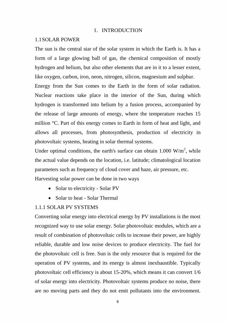
FUNCTIONING OF THE PHOTOVOLTAIC CELL
PV junction (diode) is a boundary between two differently doped
semiconductor layers; one is a P‐type layer (excess holes), and the second
one is an N‐type (excess electrons). At the boundary between the P and the
N area, there is a spontaneous electric field, which affects the generated
electrons and holes and determines the direction of the current.
Figure 1 Functioning of the photovoltaic cell
To obtain the energy by the photoelectric effect, there shall be a directed
motion of photoelectrons, i.e. electricity. All charged particles,
photoelectrons also, move in a directed motion under the influence of
electric field. The electric field in the material itself is located in
semiconductors, precisely in the impoverished area of PV junction (diode). It
was pointed out for the semiconductors that, along with the free electrons in
them, there are cavities as charge carriers, which are a sort of a by product in
8
the emergence of free electrons. Cavities occurs whenever the valence
electron turns into a free electron, and this process is called the generation,
while the reverse process, when the free electron fills the empty spaces ‐ a
cavity, is called recombination. If the electron‐cavity pairs occur away from
the impoverished areas it is possible to recombine before they are separated
by the electric field.
Photoelectrons and cavities in semiconductors are accumulated at opposite
ends, thereby creating an electromotive force. If a consuming device is
connected to such a system, the current will flow and we will get electricity.
In this way, solar cells produce a voltage around 0.5‐0.7 V, with a current
density of about several tens of mA/cm2 depending on the solar radiation
power as well as on the radiation spectrum.
TYPES OF SOLAR PHOTOVOLTAIC CELLS
Electricity is produced in solar cells which, as noted, consist of more layers
of Semi conductive material. When the sun's rays shine down upon the solar
cells, the electromotive force between these layers is being created, which
causes the flow of electricity. The most common material for the production
of solar cells is silicon. Silicon is obtained from sand and is one of the most
common elements in the earth's crust, so there is no limit to the availability
of raw materials. Solar cell manufacturing technologies are:
• Monocrystalline. •Thin-film technology.
•Polycrystalline. •Polymer based solar cell.
PHOTOVOLTAIC SYSTEM TYPES
Photovoltaic systems can be generally divided into two basic groups:
1. Photovoltaic systems not connected to the network, stand‐alone
systems (off‐grid)
2. Photovoltaic systems connected to public electricity network
(on‐grid)
9
1.1.2 SOLAR THERMAL SYSTEMS
Solar thermal power is a relatively new technology which has already shown
enormous promise. With few environmental impacts and a massive resource,
it offers a comparable opportunity to the sunniest countries of the world as
offshore wind farms are currently offering to European nations with the
windiest shorelines. Solar thermal power uses direct sunlight, so it must be
sited in regions with high direct solar radiation.
Solar thermal power plants, often also called Concentrating Solar Power
(CSP) plants, produce electricity in much the same way as conventional
power stations. The difference is that they obtain their energy input by
concentrating solar radiation and converting it to high-temperature steam or
gas to drive a turbine or motor engine. Four main elements are required: a
concentrator, a receiver, some form of transport media or storage, and power
conversion. Many different types of systems are possible, including
combinations with other renewable and non-renewable technologies, but the
most promising solar thermal technologies are:
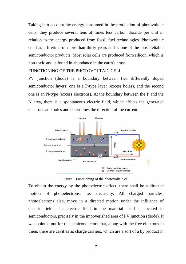
PARABOLIC TROUGH
Figure 2: Parabolic trough
Parabolic trough-shaped mirror reflectors are used to concentrate sunlight on
to thermally efficient receiver tubes placed in the trough’s focal line. A
thermal transfer fluid, such as synthetic thermal oil, is circulated in these
10
tubes. Heated to approximately 400°C by the concentrated sun’s rays, this
oil is then pumped through a series of heat exchangers to produce
superheated steam. The steam is converted to electrical energy in a
conventional steam turbine generator, which can either be part of a
conventional steam cycle or integrated into a combined steam and gas
turbine cycle.
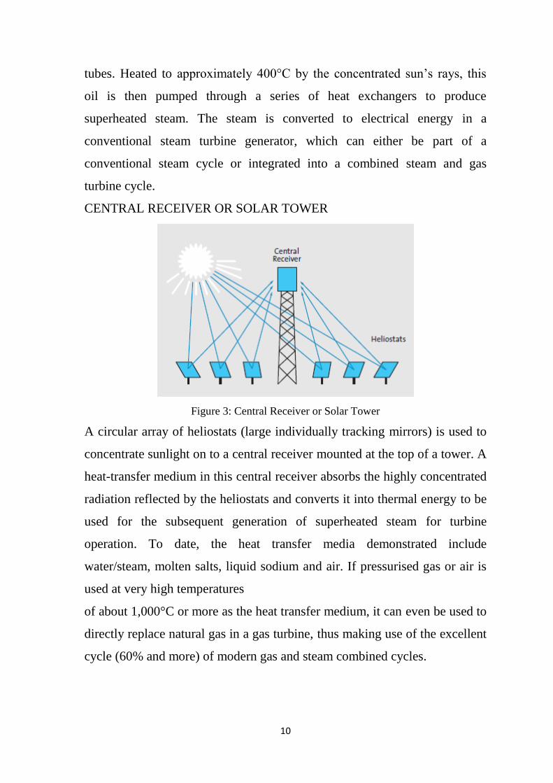
CENTRAL RECEIVER OR SOLAR TOWER
Figure 3: Central Receiver or Solar Tower
A circular array of heliostats (large individually tracking mirrors) is used to
concentrate sunlight on to a central receiver mounted at the top of a tower. A
heat-transfer medium in this central receiver absorbs the highly concentrated
radiation reflected by the heliostats and converts it into thermal energy to be
used for the subsequent generation of superheated steam for turbine
operation. To date, the heat transfer media demonstrated include
water/steam, molten salts, liquid sodium and air. If pressurised gas or air is
used at very high temperatures
of about 1,000°C or more as the heat transfer medium, it can even be used to
directly replace natural gas in a gas turbine, thus making use of the excellent
cycle (60% and more) of modern gas and steam combined cycles.
11
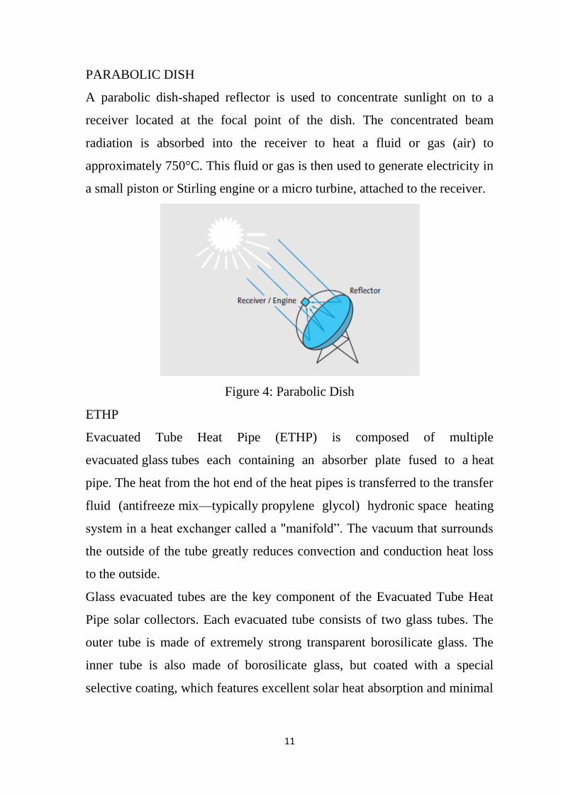
PARABOLIC DISH
A parabolic dish-shaped reflector is used to concentrate sunlight on to a
receiver located at the focal point of the dish. The concentrated beam
radiation is absorbed into the receiver to heat a fluid or gas (air) to
approximately 750°C. This fluid or gas is then used to generate electricity in
a small piston or Stirling engine or a micro turbine, attached to the receiver.
Figure 4: Parabolic Dish
ETHP
Evacuated Tube Heat Pipe (ETHP) is composed of multiple
evacuated glass tubes each containing an absorber plate fused to a heat
pipe. The heat from the hot end of the heat pipes is transferred to the transfer
fluid (antifreeze mix—typically propylene glycol) hydronic space heating
system in a heat exchanger called a "manifold”. The vacuum that surrounds
the outside of the tube greatly reduces convection and conduction heat loss
to the outside.
Glass evacuated tubes are the key component of the Evacuated Tube Heat
Pipe solar collectors. Each evacuated tube consists of two glass tubes. The
outer tube is made of extremely strong transparent borosilicate glass. The
inner tube is also made of borosilicate glass, but coated with a special
selective coating, which features excellent solar heat absorption and minimal

12
heat reflection properties. Evacuated tube heat pipe collectors use a copper
pipe attached to an absorber plate, inside a vacuum sealed solar tube.
The heat pipe is hollow and the space inside is also evacuated inside the heat
pipe is a small quantity of liquid, such as alcohol or purified water plus
special additives. The vacuum enables the liquid to boil at lower temperature
than it would be at normal atmospheric pressure. When sunlight falls on the
surface of the absorber, the liquid in the heat tube quickly turns to hot vapor
and rises to the pipe. Water glycol flows back down the tube. This process
continues, as long as the sun shines. Since there is a “Dry” connection
between the absorber and header installation, it is much than the direct flow
collectors. Individual tubes can also be exchanged without emptying the
entire system of its fluid and should one tube break, there is little impact on
the complete system.
Figure 5: ETHP
1.2 ELECTROPLATING INDUSTRY
Electroplating is an electro deposition process for producing a dense,
uniform, and adherent coating, usually of metal or alloys, upon a surface by
the act of electric current. The coating produced is usually for decorative
and=or protective purposes, or enhancing specific properties of the surface.
The surface can be conductors, such as metal, or non-conductors, such as
plastics. Electroplating products are widely used for many industries, such as

13
automobile, ship, air space, machinery, electronics, jewellery, defence, and
toy industries. The core part of the electroplating process is the electrolytic
cell (electroplating unit). In the electrolytic cell (electroplating unit) a
current is passed through a bath containing electrolyte, the anode, and the
cathode. In industrial production, pre-treatment and post-treatment steps are
usually needed as well.
Figure 6: Electroplating Process.
Figure 7: Electroplating industry process

14
Table1: Basic parameters of electroplating baths.
1.3 INDUSTRIAL PROCESS HEATING
Process heating is essential in the manufacture of most consumer and
industrial products, including those made out of metal, plastic, rubber,
concrete, glass, and ceramics. Process heating systems can be broken into
three basic categories:
(a) Fuel-based process heating with fuel-based systems, heat is
generated by the combustion of solid, liquid, or gaseous fuel, and transferred
either directly or indirectly to the material. The combustion gases can be
either in contact with the material (direct heating), or be confined and thus
be separated from the material (indirect heating, e.g., radiant burner tube,
retort, muffle). Examples of fuel-based process heating equipment include
furnaces, ovens, kilns, etc.
(b) Electric-Based Process Heating Electric-based process heating
systems (sometimes called electro technologies) use electric currents or
electromagnetic fields to heat materials. Direct heating methods generate
heat within the work piece, by either (1) passing an electrical current through

15
the material, (2) inducing an electrical current (eddy current) into the
material, or (3) exciting atoms and/or molecules within the material with
electromagnetic radiation (e.g., microwave). Indirect heating methods use
one of these three methods to heat an element, which transfers the heat to the
work piece by either conduction, convection, radiation, or a combination of
these.
(c) Steam-Based Process Heating Steam has several favourable
properties for process heating applications. Since most of the heat content of
steam is stored as latent heat, large quantities of heat can be transferred
efficiently at a constant temperature, which is a useful attribute in many
process heating applications. Steam-based process heating has low toxicity,
ease of transportability, and high heat capacity.
Hybrid systems use a combination of process heating systems by using
different energy sources or different heating methods of the same energy
source. Electric infrared, in combination with either an electric convection
oven or a gas convection oven is a hybrid system.
1.4 INTEGRATING SOLAR POWER INTO INDUSTRIAL PROCESSES
Integration of solar power to industry can be done in for their major
requirements such as heat and electricity. Both the requirements can be met
using solar PV and solar thermal technologies.
For integrating solar PV system, their electricity requirement and the
available spacing are the factors to be considered. Power requirement is
calculated for the entire load to be connected to the system for the operation
of the industry. Also for the same power requirement there should be
sufficient area for erection of PV systems. The cost consideration is done by
the requirement of the industry whether they need a standalone system or a
grid connected or with or without battery backup.
The integration of solar heat into industrial production processes is a
challenge to both: the process engineer and the solar expert. Usually the

16
thermal solar system will be only a part of the total process energy system
and will supply only a fraction of the total energy demand.
Existing heating system – based on steam or hot water from a boiler – don’t
have to take care of temperature level too much. In general they are designed
at much higher temperatures compared to what the processes need in order
to keep temperature differences – and by that heat exchanger surfaces –
small. Very often we can find steam temperatures at 150 to 180°C while the
processes run below 100°C or even much lower. Applying solar heat, much
more attention has to be paid to the temperature levels.
Another challenge in applying solar thermal energy to industrial production
processes is the time dependency of the solar energy supply and the heat
demand of the processes. Only very few production lines run at constant
loads all over the day. Most processes in smaller companies run for one or
two shifts per day and are batch processes by themselves. Direct process
heating or feeding into existing heating system. The easiest way of
integrating solar thermal heat into industrial energy systems, is to supply it
to the existing heating system. In that case, the solar collector has to be
operated at the same temperature level as the existing heating system, which
will be above 100°C in general. The heat transfer medium should be water
and not steam if possible. Such a set up is easy to install and to control, but
the thermal efficiency will be low.
Figure 8: Solar thermal energy feeding into the existing hot water system
17
1.5 ECONOMIC CONSIDERATION
In industry the demands on the economic performance of investments
usually is very high. Payback times of 3 years and less are required for
production equipment, but 10 years are accepted for infrastructure as
buildings and energy systems. Such numbers are difficult to obtain with
solar systems if energy savings are considered as the only benefits but there
exist examples that it is possible even at present energy and equipment
prices. There are also new and promising considerations offering solar-
contracting solutions to industry. In these contracting models, the solar
energy supplier takes the investment costs of the solar equipment and the
enterprise pays for the energy delivered.
Looking closer to the energy systems of industrial installations, one can find
other options for energy conservation or energy efficiency in many cases.
Heat exchange can provide low temperature heat from outgoing process
streams. Cogeneration with gas turbines, steam turbines and/or diesel motors
provides low temperature heat at reasonable prices as well. More than this,
new technological developments can shift the energy demand from heat to
power and will change the future demands. But there is a market for solar
thermal energy in the process industry as soon as strategic considerations are
being made in addition to simple payback calculations. Investments in
sustainable solutions like solar energy will improve the supplier’s position in
the market through image gained, through increased workers engagement
and a long term stability of energy prices.
18
2. LITERATURE REVIEW
[1] Solar thermal systems can be utilized for industrial applications like
process heating, drying etc. Various technologies like ETC, ETHP, Parabolic
Concentrators etc are used for this.
[2, 3] Process heating is mostly essential for industries like rubber, paper,
etc. Most of the heating source will be fuel based, electric based or steam
based. Approaches to improve a certain heating operation might be
applicable to multiple processes, but may be unknown within and/or outside
a given industry segment.
[4, 5] Electroplating process requires heating and DC supply based on the
type of plating. Heating is not much required, but the DC supply is the major
requirement and the source of electroplating process.
[6] Cost analysis for renewable energy systems has been well explained by
the IRENA in the cost analysis series explaining the different considerations
to be made while cost analysis. Considerations to be taken are system cost,
installation cost, labour cost and maintenance cost

19
3. METHODS AND METHODOLOGY
The project is done by taking a company as an example for understanding
the process and requirement and hence focussing on possibility of
integration of solar power to electroplating industry
3.1 COMPANY PROFILE
Company Name : GRG Designs.
Products : Electroplating (Nickel and Alkaline).
Area Available : 800 Sq. Ft.
Requirements
1. Temperature : 60o to 80
o C.
2. Rectifying Load
Voltage : 5 to 7 V
Current : 100 to 500 A
3.2 SYSTEM CONCEPTUAL DESIGN
Figure 6: Conceptual design

20
Conceptual Design for integrating solar thermal and solar PV into the
Electroplating Industrial will completely replace power requirement for
heating and rectifying load.
3.2.1 SOLAR THERMAL SYSTEM
In the solar thermal system, a copper coil is used as a heat transfer system in
which the Heat Transfer Fluid (HTF) will be flowing. The flow is
maintained using a pump for regulating the required temperature and proper
heat transfer. The pump is operated with a microcontroller, which gets a feed
from a thermocouple from the chemical bath. The microcontroller is
calibrated for the required temperature, say 70oC. Depending on the
temperature variation of the bath, the pump will be worked to maintain the
bath temperature as 70oC. Hence the functioning of the pump is automated to
maintain the required temperature.
3.2.2 SOLAR PV SYSTEM
Solar PV system in here is a very simple system with no backup system and
inverter. Based on the requirement, solar PV panels are erected and through
controller the power is directly used because the requirement is DC power.
21
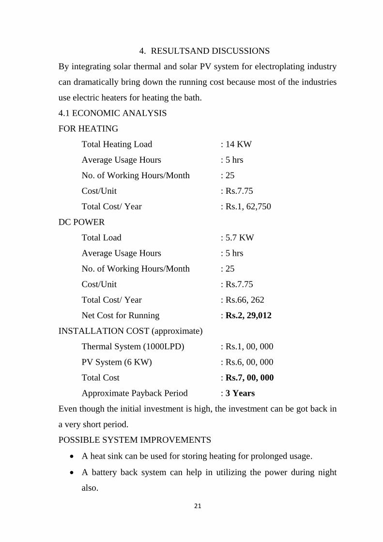
4. RESULTSAND DISCUSSIONS
By integrating solar thermal and solar PV system for electroplating industry
can dramatically bring down the running cost because most of the industries
use electric heaters for heating the bath.
4.1 ECONOMIC ANALYSIS
FOR HEATING
Total Heating Load : 14 KW
Average Usage Hours : 5 hrs
No. of Working Hours/Month : 25
Cost/Unit : Rs.7.75
Total Cost/ Year : Rs.1, 62,750
DC POWER
Total Load : 5.7 KW
Average Usage Hours : 5 hrs
No. of Working Hours/Month : 25
Cost/Unit : Rs.7.75
Total Cost/ Year : Rs.66, 262
Net Cost for Running : Rs.2, 29,012
INSTALLATION COST (approximate)
Thermal System (1000LPD) : Rs.1, 00, 000
PV System (6 KW) : Rs.6, 00, 000
Total Cost : Rs.7, 00, 000
Approximate Payback Period : 3 Years
Even though the initial investment is high, the investment can be got back in
a very short period.
POSSIBLE SYSTEM IMPROVEMENTS
A heat sink can be used for storing heating for prolonged usage.
A battery back system can help in utilizing the power during night
also.

22
5. CONCLUSION
The major requirements for the industry, heat and DC power, can be directly
given using solar thermal and solar PV systems respectively. Integrating
solar power to electroplating industry will dramatically bring down the
power expenses because of the proper utilization of the technology.
23
REFERENCES
[1] Page 93-103, solar thermal applications, Centre for Study of Science,
Technology and Policy (CSTEP).
[2] Improving Process Heating System Performance: A Sourcebook for
Industry, Second Edition, National Renewable Energy Laboratory Golden,
Colorado.
[3]Solar heat for industrial processes – Potential, technologies and
applications, Klaus Vajen, Christoph Lauterbach, Bastian Schmitt,Kassel
University, Institute of Thermal Engineering, Kassel (Germany).
[4] Electroplating, Pollution Prevention and Abatement Handbook, WORLD
BANK GROUP.
[5] Electroplating, Helen H. Lou, Department of Chemical Engineering,
Lamar University, Beaumont, Texas, U.S.A.
[6] Renewable energy technologies: cost analysis series, Volume 1: Power
Sector, Issue 4/5, IRENA working paper.
Related Documents