Full compliance with the IEC61131-3 International Standard

Welcome message from author
This document is posted to help you gain knowledge. Please leave a comment to let me know what you think about it! Share it to your friends and learn new things together.
Transcript

Full compliance with the IEC61131-3 International Standard

User program memoryMax. 2,048 KB
3 commutation ports
● USB port (Ver2.0 FullSpeed 12 Mbps)
● Serial port (RS-232C / RS-422 / RS-485)
● Ethernet port (10BASE-T/100BASE-TX)
User program is stored in non-volatile FLASH memory.(Data is stored in volatile RAM memory
retained by battery.)
7 Segment LED Display
Error code is displayed here.
The Ethernet and the Serial port have
LEDs of communication status.
EHV+ CPU module
EHV+ Series is small size but powerful PLC covering wide range of applications since it is possible to
expand up to 5 expansion bases, which offers max. 4,224 I/O points in 66 I/O modules.
No. of I/O is Max. 4,224 (using 64 pts. modules)
A max. of 5expansion base
Power module
CPU module
Input and output controller
Power module
Basic base
I/O module
Expansion cable
Expansion base
The battery can be replaced easily with
CPU module mounted.
Battery
Battery connector
Modbus-TCP master / slave function EtherCAT® master function.
EtherCAT® master function is in corporated
into the LAN port of the CPU module.
A combined use of an EtherCAT® slave (I/O
terminals, Variable Frequency Drivers and
so on) is possible.
EHV+ Series CPU modules
■Standardized programming style with 5 programming languages (LD, FBD, IL, ST, SFC).
■No need to study manufacturer’ s specific programming way.
■Easy to start using Hitachi PLC for those who having;
No experience of PLC
Experience of other manufacturer’ s programming
Experience of high level languages
■Same Variable names are shared by PLC, HMI, SCADA, and other I/O devices.
■Offline simulation function on programming software.
The EHV+ Series is a fully IEC61131-3 compliant PLC Series which offers effective programming features and reduced debugging and commissioning time.
CPU module “EHV+”The powerful hardware performances of existing EHV Series are succeeded to EHV+, such as
multi-programming port (USB, Ethernet, Serial), compatibility of I/O modules for EH-150 Series,
high reliability, superior in quality and much more.
Programming software “HX-CODESYS”HX-CODESYS is a professional development tool based on CODESYS V3.5 by 3S.
Compared to standard CODESYS, following components are additionally included in the installation file
(setup.exe)
- Device description files (.xml) for EHV+ Series
- Special libraries for EHV+ Series. (get_error_info, Counter_interface, etc.)
Well over 200 renowned device manufacturers from different industrial sectors program their automation
devices with CODESYS. Today, CODESYS is the widest-spread IEC61131-3 development tool in Europe
and has established itself as the standard in controller and PLC programming. Advantages of CODESYS
are introduced as follows.
EHV-CPU1025 (512 KB)
EHV-CPU1102 (2,048 KB)
EHV+ CPU Series:Scalable memory size (2 Models)
Hitachi version of CODESYSby 3S-Smart Software Solutions GmbH
1 2

■EtherCAT® Master Specifications
Items
Communication protocol
Supported services
Synchronization
Physical layer
Modulation
Baud rate
Duplex mode
Topology
Transmission media
Transmission distance
Maximum number of slaves
Maximum process data size
Maximum data sizes per slave
Maximum message size
Minimum communications cycle
Sync jitter between slaves
Process data communications
SDO communications
Configuration
RAS functions
Slave information
Mailbox support
Specifications
EtherCAT® protocol
CoE (process data communications and SDO communications)
None (DC is not supported)
100BASE-TX
Baseband
100 M bits/s (100BASE-TX)
Full / Auto
Daisy chain, branch wiring
Category 5 shielded twisted-pair cable or higher
Distance between nodes: 100 m or less (IEEE802.3)
255
Input 5,736 bytes, Output 5,736 bytes
Input 1,434 bytes, Output 1,434 bytes
2,048 bytes
10 ms
1 μs
PDO mapping using CoE
Fail-soft operation for slave communications errors
Stop operation for slave communications errors
CoE
- Emergency message server (receptions from slaves)
- SDO requests and responses
Setting node address using HX-CODESYS network scan
Display of network configuration information
Slave configuration check when starting network
Reading of error information
Trouble shooting information
- Automatic reboot of the slaves
- Scanning slaves supported
CoE (CAN open / CAN application layer over EtherCAT®)
SoE (Servodrive over EtherCAT®)
FoE (File over EtherCAT®)
VoE (Vendor over EtherCAT®)
Note:
• Please note that using various Ethernet based communication (EtherCAT®, Modbus-TCP, NVL, Gateway) at the same time will limit the communication performance.
• If connected slave devices are drives (e.g. servo drives), it is strongly recommended to use profile mode in their operation mode.
Since EtherCAT® cycle of the CPU is not fast enough, cyclic synchronous mode may not work in full performance.
Specif ications
■CPU Module
Items
User program memory
Source file memory
Data memory (non retain)
Data memory (retain)
Data memory (persistent)
Data memory (Fieldbus)
No. of expansion base
No. of I/O (using 64 pts module)
No. of logical port for Gateway*
Programming languages
I/O updating cycle
Communication
Switch, indications
Calendar clock
Battery
Maintenance function
Protocol
USB
Ethernet
Serial
Indications
RUN switch
E.CLR button
4,864 KB
384 KB
64 KB
64 KB
16 KB (2 KB×8 = 1 KW×8)
5
4,224
6
IEC61131-3 compliant 5 languages
LD : Ladder Diagram
FBD: Function Block Diagram (incl. CFC: Continuous Function Chart)
SFC: Sequential Function Chart
IL : Instruction List
ST : Structured Text
Refresh processing
CODESYS V3 protocol
USB 2.0 Full speed (Gateway*)
10BASE-T / 100BASE-TX (Gateway*, Modbus-TCP client / server, EtherCAT® master, Global network variables)
RS-232C / 422 / 485 (Modbus-RTU master, General purpose)
RUN LED, ERR LED, 7-segment LED (2 digits)
STOP / RUN (Remote RUN / STOP enabled when the switch position is in RUN.)
Reset error information
Support (Built-in RTC)
LIBAT-H (for RTC and RETAIN data)
Diagnosis (micro processor error, watch dog timer error, memory error, battery error, etc.)
EHV-CPU1025
512 KB
EHV-CPU1102
2,048 KB
*Gateway: Communication with HX-CODESYS
3 4

● Reduces software development costs
Local variables and global variables It is possible to define local variables, which are only effective for each program, and global variables,
which are common to all programs. Properly using local variables and global variables makes it possible
to create application programs with high rates of reusability.
Structured programmingIt is possible to create a hierarchy of programs and function blocks. This enhances the readability of
application programs, and improves the stability, and as a result enhances efficiency in application
development.
Creating a librarySince function blocks of commonly used process can be registered in the library, frequently used
process can be easily reused in other application programs. Process contents of these function blocks
can be also set as hidden, therefore can be distributed to end users without disclosing technical
information to outside.
● The powerful debugging function reduces launch costs
● Online monitor
● Offline simulation
● Break points
● Force
● Single step execution
● Single cycle scan
● Flow control
● Changes while running
● Trace
● Visualization
System design Programming Debugging Commissioning
Compressing
Main_PRG---SUB_A( );---------------IF a>10 THEN SUB_B( );END_IF---
SUB_A---SUB_C( );------
SUB_B
SUB_DLD aAND bOR cST d
SUB_ESUB_F
SUB_C---SUB_D( );------SUB_E( );---
SUB_F---I:=I+1;------
ces launch costs
Programming software “HX-CODESYS”
● Five programming language editors
The user can freely select among the 5 programming languages of the IEC61131-3 standard according
to the intended purpose and the programmer’s skills and experience.
● Easy and efficient programming
Structured Programming Task configuration and structured-based editors on
POU (Program Organization Unit) enable flexible
programming.
Programming with variable namesProgramming with variable name enables you to be
free from I/O addressing of PLC.
Minimal requirements for small projects with up to 100 POUs, 10 visualizations, 8 field bus devices.
LDLadder Diagram
FBDFunction Block
Diagram
SFCSequential Function Chart
ILInstruction List
STStructured Text
■Specifications of HX-CODESYS
Items Descriptions
System requirements
Communication cables
RAM
Operating system
CPU
Hard disk
Screen resolution
USB
Ethernet
1 GB
Windows® 7 / 8 / 10 (32 / 64 bit)
x 86 1 GHz
1 GB
1,024x768
Standard USB cable (Type-B connector)
UTP or STP cable (cat 5E)
5 6

Analog input and output modules
Counter modules
Analog input and output moduleslog input and outpu
Digital input and output modules
Analog Input moduleEH-AX44 : 12-bit analog input, Current 4 to 20 mA, Voltage 0 to 10 V, 4 ch each
EH-AX8V : 12-bit analog input, Voltage 0 to 10 V, 8 ch
EH-AX8H : 12-bit analog input, Voltage -10 to 10 V, 8 ch
EH-AX8I : 12-bit analog input, Current 4 to 20 mA, 8 ch
EH-AX8IO : 12-bit analog input, Current 0 to 22 mA, 8 ch
EH-AXH8M: 14-bit analog input, Current 0 to 22 mA / 4 to 22 mA, Voltage -10 to 10 V / 0 to 10 V, 8 ch
EH-AXG5M: 16-bit analog input, Current 0 to 22 mA / 4 to 22 mA, Voltage -10 to 10 V / 0 to 10 V, 5 ch Isolated
Analog Output moduleEH-AY22 : 12-bit analog output, Current 4 to 20 mA, Voltage 0 to 10 V, 2 ch each
EH-AY4V : 12-bit analog output, Voltage 0 to 10 V, 4 ch
EH-AY4H : 12-bit analog output, Voltage -10 to 10 V, 4 ch
EH-AY4I : 12-bit analog output, Current 4 to 20 mA
EH-AY2H : 12-bit analog output, Voltage -10 to 10 V, 2 ch
EH-AYH8M: 14-bit analog output, Current 0 to 22 mA / 4 to 22 mA, Voltage 0 to 10 V, 8 ch
EH-AYG4M: 16-bit analog output, Current 0 to 22 mA / 4 to 22 mA, Voltage -10 to 10 V / 0 to 10 V, 4 ch Isolated
Temperature Detective Input moduleEH-PT4 : Signed 15-bit, Pt 100 / Pt 1,000, 4 ch
EH-TC8 : Signed 15-bit, Thermo-couple (K, E, J, T, B, R, S, N) 8 ch
EH-RTD8 : Signed 15-bit, Pt 100 / Pt 1,000, 6 ch (3 wire) / 8 ch (2 wire)
High speed counter moduleEH-CU : Maximum 100 kHz, 2 ch
EH-CUE: Maximum 100 kHz, 1 ch
DC Input and DC Output modulesEH-XD32H: 32 pts. DC 24 V input
(EM / H-200 compatible connector type)EH-YT32H: 32 pts. DC 24 V output
(EM / H-200 compatible connector type)
Overview of the I/O module lineupBig variety of modules to meet various applications demands
DC and AC digital input and output modules
8 / 16 pts. Input module (terminal block)EH-XD8 : 8 pts. 24 V DC
(Input lag 5 ms max.)
EH-XD16 : 16 pts. 24 V DC
(Input lag 5 ms max.)
EH-XDL16 : 16 pts. 24 V DC
(Input lag 16 ms max.)
EH-XDS16 : 16 pts. 24 V DC
(Input lag 1 ms max.)
EH-XA16 : 16 pts. 100 to 120 V AC
(Input lag 15 ms max.)
EH-XAH16: 16 pts. 200 to 240 V AC
(Input lag 15 ms max.)
8 / 16 pts. Output module(terminal block)EH-YT8 : 8 pts. Transistor (sink)
EH-YTP8 : 8 pts. Transistor (source)
EH-YT16 : 16 pts. Transistor (sink)
EH-YTP16 : 16 pts. Transistor (source)
EH-YTP16S: 16 pts. Transistor
(source with short circuit
protection)
EH-YS16 : 16 pts. Triac
EH-YR12 : 12 pts. Relay
EH-YR16 : 16 pts. Relay
EH-YR8B : 8 pts. Isolated relay
EH-YR16D : 16 pts. Relay (2 common)
32 pts. Input module(Spring type terminal block)EH-XD32E : 32 pts. 24 V DC
(Input lag 5 ms max.)
EH-XDL32E: 32 pts. 24 V DC
(Input lag 16 ms max.)
32 pts. Output module(Spring type terminal block)EH-YT32E : 32 pts. Transistor (sink)
EH-YTP32E: 32 pts. Transistor (source)
32 pts. Input module(connector)EH-XD32 : 32 pts. 24 V DC
(Input lag 5 ms max.)
EH-XDL32: 32 pts. 24 V DC
(Input lag 15 ms max.)
EH-XDS32: 32 pts. 24 V DC
(Input lag 1 ms max.)
32 pts. Output module(connector) EH-YT32 : 32 pts. Transistor (sink)
EH-YTP32: 32 pts. Transistor (source)
64 pts. Input module(connector)EH-XD64: 64 pts. 24 V DC
(Input lag 1 ms max.)
64 pts. Output module(connector) EH-YT64 : 64 pts. Transistor (sink)
EH-YTP64: 64 pts. Transistor (source)
7 8

EtherCAT® slave controller
■EtherCAT® Slave Controller Specifications
SpecificationsEH-IOCA
EtherCAT® dedicated protocolBaseband100 Mbps
100BASE-TX (IEEE802.3) RJ45 (IN, OUT)
Daisy chainCategory 5 or higher STP cable
Within 100 m in distance between nodes (slaves)200 μs or higher*1
1 to 99: Setting by the node address switch1 to 65,535: Setting by EtherCAT® master
Fixed PDO mappingSupport
Free Run mode (asynchronous)Support (set by master)
EH-BS3A / 5A / 6A / 8A / 11A / 8RMaximum 22 units per slave device
1,408 points for digital input and output, 176 ch for analog input and output1 stage
500 μs fixedWDT check
LED350 mA
*1: The communication cycle depends on EtherCAT® master specifications.
1,408 points for maximum input and output(analog input and output 176 ch)Users can create any configurations because of the coupler type. It can be also applied to the large-scale control system.
Passing down the I/O module assets of the EH-150 / EHV / EHV+ SeriesPower supplies, bases, and I/O modules (some are excluded) of the EH-150 / EHV / EHV+ Series can be used.
High-speed response and high reliabilityAt the fastest pace, the communication cycle is 200 μs. When communication abnormalities occur, the output data can be retained.
Model
Communication protocolModulation methodTransmission speedPhysical layerConnectorTopologyCommunication cableCommunication distanceCommunication cycle
Node address range
Process dataMail boxSynchronous modeOutput hold functionUsable baseNumber of mounted modulesInput and output pointsNumber of extendable stagesRefresh timeSelf-diagnosticsError displayConsumption current
Items
Communicationspecifications
Functional specifications
[Configuration Example]
EH-IOCA
Input and output controller EH-IOCH2
Slave Slave Redundant power supply
Slave
EH-IOCA EH-IOCA
CAT 5 or higher LAN cable (Maximum 100 m between stations)
EtherCAT® master
Communication and Network modules
Serial communication Module: EH-SIOInterface: RS-232C×1, RS-232C / 422 / 485×1Communication mode : Half-duplexCommunication speed : 300-57,600 bpsCommunication protocol: Non-protocol Modbus-RTU master
PROFIBUS® DP V0 Master / Slave ControllerNumber of slave-connected units: Max. 125(of which maximum 22 units are EH-IOCP2)Communication speed Max. 12 MbpsCommunication distance Max. 1,200 m (Lower than 93.75 kbps)Input / Output data 512 words / 512 words
DeviceNetTM Master / Slave ControllerNumber of slave-connected units: Max. 63(of which maximum 22 units are EH-IOCD2)Communication speed Max. 500 KbpsCommunication distance Max. 500 m (Lower than 125 kbps)Input / Output data 256 words / 256 words
9 10

Items Model Specifications RemarksI/O type
Basic
base
(*1)
Expansion
base
(*2)
Salve
(*3)
RTD input module
Thermocouple input
module
High function
and communication
module
Others
Expansion cables
32/64 points
module cables
Counter module
cables
Battery
Signed 15 bits, 4 ch. Resistance Temperature Detector input, PT100 / PT1,000
Signed 15 bits, 6 ch. (3-wire) / 8 ch. (2-wire) Resistance Temperature Detector input, PT100 / PT1,000
Signed 15 bits, 8 ch. Thermocouple input (K, E, J, T, B, R, S, N)
2 ch. high-speed counter input, 100 kHz, 4 points open collector output
1 ch. high-speed counter input, 100 kHz, 2 points open collector output
Serial interface module
DeviceNetTM master module, 256 / 256 words I/O
PROFIBUS®-DP master module, 512 / 512 words I/O
DeviceNetTM slave controller, 1,408 points (176 words) I/O
PROFIBUS®-DP slave controller, 1,408 points (176 words) I/O
EtherCAT® slave controller, 1,408 points (176 words) I/O
Module for empty slot
Half-size terminal block cover (Lot 10 configuration)
Expansion cable (0.5 m)
Expansion cable (1 m)
Expansion cable (2 m)
32 / 64-point module cable, open and connector end (1 m)
32 / 64-point module cable, open and connector end (3 m)
32 / 64-point module cable, open and connector end (5 m)
32 / 64-point module cable, open and connector end (10 m)
EM / H-200 compatible 32 point module cable, open and connector end (2 m)
EM / H-200 compatible 32 point module cable, open and connector end (5 m)
EM / H-200 compatible 32 point module cable, open and connector end (10 m)
Counter module cable, open and connector end (1 m)
Counter module cable, open and connector end (2 m)
Counter module cable, open and connector end (3 m)
Counter module cable, open and connector end (4 m)
Counter module cable, open and connector end (5 m)
Lithium battery for retentive data and RTC
EH-PT4
EH-RTD8
EH-TC8
EH-CU
EH-CUE
EH-SIO
EH-RMD2
EH-RMP2
EH-IOCD2
EH-IOCP2
EH-IOCA
EH-DUM
EH-TMCV
EH-CB05A
EH-CB10A
EH-CB20A
EH-CBM01
EH-CBM03
EH-CBM05
EH-CBM10
CBM-02
CBM-05
CBM-10
EH-CUC01
EH-CUC02
EH-CUC03
EH-CUC04
EH-CUC05
LIBAT-H
☆☆☆☆☆☆☆☆☆---☆☆
AI 4
AI 8 / AI 4
AI 8
EH-CU / E
EH-CU / E
EH-SIO
EH-LNK
EH-LNK
---
Empty
-----------------
☆☆☆☆☆☆☆-----☆☆
☆☆☆☆☆☆☆--☆☆☆☆☆
*4
Items Specifications Remarks
Integrated development environment in conformance with IEC61131-3 *8
Note: Please check the usable units, restrictions, and other matters in the product manual before selecting components.
*1: ☆ means mountable on the basic base.
*2: ☆ means mountable on the expansion base.
*3: ☆ means mountable on the EtherCAT® and PROFIBUS®-DP slave, DeviceNetTM slave base.
*4: CPU, power module and I/O controller (IOCH2, IOCD2, IOCP2, IOCA) can be mounted on reserved positions only.
*8: A cable for connecting the PC to the CPU (A-mini B type USB cable or LAN cable) must be obtained by the customer.
Model
HX-CDSIntegrated development environment HX-CODESYS
Components list
Items Model Specifications RemarksI/O type
Basic
base
(*1)
Expansion
base
(*2)
Salve
(*3)
CPU module
Power module
I/O controller
Base unit
Input module
Output module
Analog input module
Analog output module
Program capacity 512 KB, Max. 4,224 I/O points(*5), Ethernet port / Serial port / USB port
Program capacity 2014 KB, Max. 4,224 I/O points(*5), Ethernet port / Serial port / USB port
Input 100 to 240 V AC, Output 5 V DC 3.8 A, 24 V DC 0.4 A
Input 24 VDC, Output 5 V DC 3.8 A
Input 100 to 240 V AC, Output 5 V DC 5.6 A
I/O control module (1 unit / expansion base)
3 I/O modules installed
5 I/O modules installed
6 I/O modules installed
8 I/O modules installed
11 I/O modules installed
8 pts., 24 V DC input (response time 5 ms)
16 pts., 24 V DC input (response time 5 ms)
16 pts., 24 V DC input (response time 16 ms)
16 pts., 24 V DC input (response time 1 ms)
32 pts., 24 V DC input (response time 5 ms)
32 pts., 24 V DC input (response time 16 ms)
32 pts., 24 V DC input (response time 1 ms)
32 pts., 24 V DC input (response time 1 ms), Spring type terminal
32 pts., 24 V DC input (response time 16 ms), Spring type terminal
32 pts., 24 V DC input (response time 4 ms), compatible connector with PIM / H-DM (EM / H-200)
64 pts., 24 V DC input (response time 1 ms)
16 pts., 100 to 120 V AC input (response time 15 ms)
16 pts., 200 to 240 V AC input (response time 15 ms)
8 pts., Independent relay output, 100 / 240 V AC, 24 V DC
12 pts., Relay output, 100 / 240 V AC, 24 V DC
16 pts., Relay output, 100 / 240 V AC, 24 V DC
16 pts., Relay output, 100 / 240 V AC, 24 V DC, 2-common type
8 pts., Transistor output, 12 / 24 V DC (sink type)
8 pts., Transistor output, 12 / 24 V DC (source type)
16 pts., Transistor output, 12 / 24 V DC (sink type)
16 pts., Transistor output, 12 / 24 V DC (source type)
16 pts., Transistor output, 12 / 24 V DC (source type)
32 pts., Transistor output, 12 / 24 V DC (sink type)
32 pts., Transistor output, 12 / 24 V DC (source type)
32 pts., Transistor output, 12 / 24 V DC (sink type), Spring type terminal
32 pts., Transistor output, 12 / 24 V DC (source type), Spring type terminal
32 pts., Transistor output, 5 / 12 / 24 V DC (sink type), compatible connector with POM / H-DM (EM / H-200)
64 pts., Transistor output, 12 / 24 V DC (sink type)
64 pts., Transistor output, 12 / 24 V DC (source type)
16 pts., Triac output, 100 / 240 V AC
12 bits, analog input 8 ch. (4 ch. of 4 to 20 mA, 4 ch. of 0 to 10 V)
12 bits, analog input 8 ch., Voltage (0 to 10 V)
12 bits, analog input 8 ch., Voltage (-10 to +10 V)
12 bits, analog input 8 ch., Current (4 to 20 mA)
12 bits, analog input 8 ch, Current (0 to 22 mA)
14 bits, analog input 8 ch. (0 to 22 mA, 4 to 22 mA, -10 to +10 V, 0 to 10 V)
16 bits, isolated analog input 5 ch. (0 to 22 mA, 4 to 22 mA, -10 to +10 V, 0 to 10 V)
12 bits, analog output 4 ch. (2 ch. of 4 to 20 mA, 2 ch. of 0 to 10 V)
12 bits, analog output 2 ch., Voltage (-10 to +10 V)
12 bits, analog output 4 ch., Voltage (0 to 10 V)
12 bits, analog output 4 ch., Voltage (-10 to +10 V)
12 bits, analog output 4 ch., Current (4 to 20 mA)
14 bits, analog output 8 ch. (0 to 22 mA, 4 to 22 mA, 0 to 10 V)
16 bits, isolated analog output 4 ch. (0 to 22 mA, 4 to 22 mA, -10 to +10 V, 0 to 10 V)
EHV-CPU1025
EHV-CPU1102
HX-PSA
HX-PSD
EH-PSR
EH-IOCH2
EH-BS3A
EH-BS5A
EH-BS6A
EH-BS8A
EH-BS11A
EH-XD8
EH-XD16
EH-XDL16
EH-XDS16
EH-XD32
EH-XDL32
EH-XDS32
EH-XD32E
EH-XDL32E
EH-XD32H
EH-XD64
EH-XA16
EH-XAH16
EH-YR8B
EH-YR12
EH-YR16
EH-YR16D
EH-YT8
EH-YTP8
EH-YT16
EH-YTP16
EH-YTP16S
EH-YT32
EH-YTP32
EH-YT32E
EH-YTP32E
EH-YT32H
EH-YT64
EH-YTP64
EH-YS16
EH-AX44
EH-AX8V
EH-AX8H
EH-AX8I
EH-AX8IO
EH-AXH8M
EH-AXG5M
EH-AY22
EH-AY2H
EH-AY4V
EH-AY4H
EH-AY4I
EH-AYH8M
EH-AYG4M
☆☆☆☆☆-☆☆☆☆☆☆☆☆☆☆☆☆☆☆☆☆☆☆☆☆☆☆☆☆☆☆☆☆☆☆☆☆☆☆☆☆☆☆☆☆☆☆☆☆☆☆☆☆☆
-----------
DI 16
DI 16
DI 16
DI 16
DI 32
DI 32
DI 32
DI 32
DI 32
DI 32
DI 64
DI 16
DI 16
DO 16
DO 16
DO 16
DO 16
DO 16
DO 16
DO 16
DO 16
DO 16
DO 32
DO 32
DO 32
DO 32
DO 32
DO 64
DO 64
DO 16
AI 8
AI 8
AI 8
AI 8
AI 8
AI 8
AI 8
AO 8
AO 8
AO 8
AO 8
AO 8
AO 8
AO 8
--☆☆☆☆☆☆☆☆☆☆☆☆☆☆☆☆☆☆☆☆☆☆☆☆☆☆☆☆☆☆☆☆☆☆☆☆☆☆☆☆☆☆☆☆☆☆☆☆☆☆☆☆☆
--☆☆☆-☆☆☆☆☆☆☆☆☆☆☆☆☆☆☆☆☆☆☆☆☆☆☆☆☆☆☆☆☆☆☆☆☆☆☆☆☆☆☆☆☆☆☆☆☆☆☆☆☆
*4
*4
*4
*6
*7
*7
Note: Please check the usable units, restrictions, and other matters in the product manual before selecting components.
*1: ☆ means mountable on the basic base.
*2: ☆ means mountable on the expansion base.
*3: ☆ means mountable on the EtherCAT® and PROFIBUS®-DP slave, DeviceNetTM slave base.
*4: CPU, power module and I/O controller (IOCH2, IOCD2, IOCP2, IOCA) can be mounted on reserved positions only.
*5: In case of 64 points I/O module is used
*6: Commonly used for basic, expansion or slave base.
*7: With short circuit protection
11 12
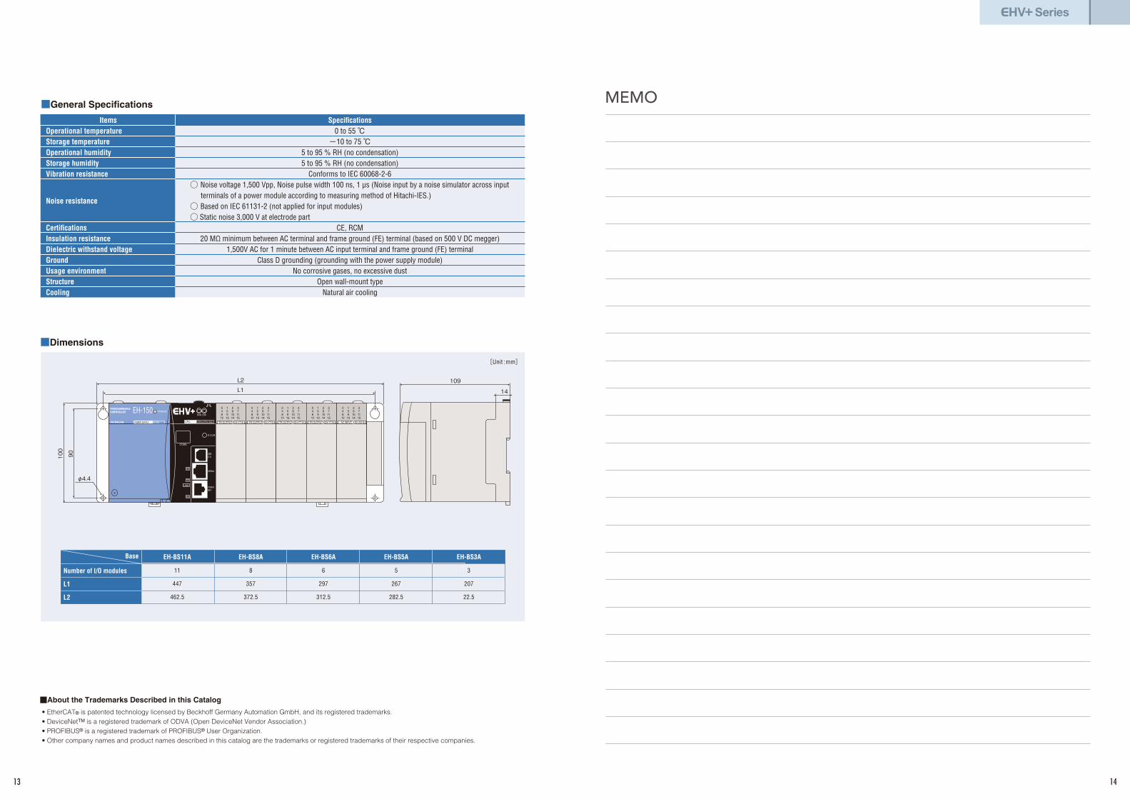
MEMO■General Specifications
Items
Operational temperature
Storage temperature
Operational humidity
Storage humidity
Vibration resistance
Noise resistance
Certifications
Insulation resistance
Dielectric withstand voltage
Ground
Usage environment
Structure
Cooling
Specifications
0 to 55 ℃-10 to 75 ℃
5 to 95 % RH (no condensation)
5 to 95 % RH (no condensation)
Conforms to IEC 60068-2-6
◯ Noise voltage 1,500 Vpp, Noise pulse width 100 ns, 1 μs (Noise input by a noise simulator across input terminals of a power module according to measuring method of Hitachi-IES.)
◯ Based on IEC 61131-2 (not applied for input modules)
◯ Static noise 3,000 V at electrode part
CE, RCM
20 MΩ minimum between AC terminal and frame ground (FE) terminal (based on 500 V DC megger)
1,500V AC for 1 minute between AC input terminal and frame ground (FE) terminal
Class D grounding (grounding with the power supply module)
No corrosive gases, no excessive dust
Open wall-mount type
Natural air cooling
■Dimensions
Number of I/O modules
L1
L2
EH-BS11A
11
447
462.5
EH-BS8A
8
357
372.5
EH-BS6A
6
297
312.5
EH-BS5A
5
267
282.5
EH-BS3A
3
207
22.5
[Unit : mm]
Base
109
14
PROGRAMMABLECONTROLLER
POWER SUPPLY EH-PSA
POWER
TR OUTPUT EH-YT16
0 1 2 3 4 5 6 7 8 9 10 11 12 13 14 15
TR OUTPUT EH-YT16
0 1 2 3 4 5 6 7 8 9 10 11 12 13 14 15
TR OUTPUT EH-YT16
0 1 2 3 4 5 6 7 8 9 10 11 12 13 14 15
TR OUTPUT EH-YT16
0 1 2 3 4 5 6 7 8 9 10 11 12 13 14 15
AC INPUT EH-XA16
0 1 2 3 4 5 6 7 8 9 10 11 12 13 14 15
100
90
φ4.4
L2
L1
CPU EHV-CPU1102
RUN ERR
E.CLR
CODE
SD
RD
LINK
RX
USB2.0
SERIAL
ETHERNET
■About the Trademarks Described in this Catalog
• EtherCAT® is patented technology licensed by Beckhoff Germany Automation GmbH, and its registered trademarks.
• DeviceNetTM is a registered trademark of ODVA (Open DeviceNet Vendor Association.)
• PROFIBUS® is a registered trademark of PROFIBUS® User Organization.
• Other company names and product names described in this catalog are the trademarks or registered trademarks of their respective companies.
13 14

ISO 14001JQA-EM5428
ISO 9001JQA-1000
The EH-150 series PLCs are produced at the factory registered under the ISO 14001 standard for environmental management system and the ISO 9001 standard for quality management system.
Information in this brochure is subject to change without notice.
For further information, please contact your nearest sales representative.
Printed in Japan (H) SI-E125Q 1217
GermanyHitachi Europe GmbH, Industrial Components & Equipment Group
Am Seestern 18 (Euro Center)
D-40547 Düsseldorf, GERMANY
TEL: 〈+49〉(211) 5283-0
FAX: 〈+49〉(211) 5283-649
http://www.hitachi-eu.com/
http://www.hitachi-ds.com/
U.S.A Hitachi America, Ltd. Industrial Components & Equipment Division
50 Prospect Avenue,
Tarrytown, NY 10591-4698
TEL: +1 (914) 332-5800
FAX: +1 (914) 332-5555
http://www.hitachi-america.us/ice/
China Hitachi Industrial Equipment Systems (CHINA) Co., Ltd.(Shanghai Office)
Industrial Equipment Systems Division
12th Floor, Rui Jin Building No. 205,
Maoming Road (S) Shanghai, 200020
TEL: +86 (21) 5489-2378
FAX: +86 (21) 3356-5070
(Beijing Office)
14th Floor Beijing Fortune Building,
5 Dong San Huan Bei Lu,
Chao Yang District, Beijing 100004
TEL: +86 (10) 6590-8180
FAX: +86 (10) 6590-8189
Hitachi Industrial Equipment Systems (Hong Kong) Co., Ltd.(Hong Kong Office)
6th Floor, North Tower, World Finance Centre,
Harbour City, Canton Road, Tsim Sha Tsui,
Kowloon Hong Kong.
TEL: +852-2735-9218
FAX: +852-2735-6793
Taiwan Hitachi Asia Pacific Co., Ltd.3rd Floor, Hung Kuo Building No.167
Tun-Hwa North Road, Taipei (105), Taiwan
TEL: 〈+886〉(2) 2514-3666
FAX: 〈+886〉(2) 2514-7664
SingaporeHitachi Asia Ltd.Industrial Components & Equipment Division
No.30 Pionner Crescent
#10-15, West Park Bizcentral
Singapore 628560
TEL: 〈+65〉(6305)-7400
FAX: 〈+65〉(6305)-7401
http://www.hitachi.com.sg/
ThailandHitachi Asia (Thailand) Co., Ltd. 18th Floor, Ramaland Building,
952 Rama IV Road, Bangrak
Bangkok 10500
TEL: 〈+66〉(2) 632-9292
FAX: 〈+66〉(2) 632-9299
http://www.hitachi.co.th/
AustraliaHitachi Australia Pty Ltd.Suite 801, Level 8, 123 Epping Road,
North Ryde, NSW, 2113, Australia
TEL: 〈+61〉(2) 9888-4100
FAX: 〈+61〉(2) 9888-4188
http://www.hitachi.com.au/
Network
Related Documents