Fuel Evaporation Control System Examensarbete i samverkan med Halmstad 2007-05-29 Daniel Axfeldt Johan Bruno 15 poäng, C-nivå Högskolan i Halmstad Sektionen för Ekonomi & Teknik Utvecklingsingenjörsprogrammet Examinator: Leif Nordin Handledare: Fawzi Halila

Welcome message from author
This document is posted to help you gain knowledge. Please leave a comment to let me know what you think about it! Share it to your friends and learn new things together.
Transcript

Fuel Evaporation Control System
d
HögskolSektioneUtveckliExaminaHandled
Examensarbete i samverkan me
Halmstad 2007-05-29 Daniel Axfeldt Johan Bruno
15 poäng, C-nivå
an i Halmstad n för Ekonomi & Teknik ngsingenjörsprogrammet tor: Leif Nordin are: Fawzi Halila

Sammanfattning Husqvarna AB uppmärksammade att det kommer införas nya miljöregler i Kalifornien gällande diffusionsutsläpp. De åkgräsklippare som går under namnet Rider och tillverkas av Husqvarna idag uppfyller ej dessa krav. Dagens bränsletank är tillverkad i plastmaterialet HDPE och avdunstande bränsleångor klättrar lätt igenom tankväggen ut i atmosfären vilket ej är tillåtet enligt de nya reglerna. Vi blev tillfrågade om vi kunde lösa problematiken och ta fram ett system som kontrollerar de avdunstade bränsleångorna och se till att detta system uppfyller de krav som ställs i Kalifornien. Som blivande ingenjörer tyckte vi att detta var ett passande examensarbete med många olika områden involverade som materialkunskap, tillverkningsprocesser, produktutveckling samt inblick i ett större företags arbete. Vi har med detta examensarbete tagit fram ett system som minskar det miljövådliga diffusionsutsläppet med cirka 90 %. Vi har arbetat med projektet så att det är klart för implementering samt gjort en modell som visar hur ett färdigt system kan se ut. Erfarenhet visar att de regler som uppkommer i Kalifornien sedan sprids till övriga USA. Även Europa förväntas skärpa sina diffusionsregler. Detta gör att vår lösning kan få en betydande spridning och få stora positiva effekter på miljön.

Abstract It came Husqvarna AB to attention that new regulations according environmental issues where applied in California on their riding mowers called Riders. These new regulations concerns fuel evaporation from fuel tanks. The fuel tank used today is made of the plastic material HDPE. This material can not hold the evaporating fuel fumes and the fumes goes through the tank shell witch is not allowed according the new regulations. We were asked to solve this problem and develop a system that controls the evaporation and can be approved by Californian rules. As future engineers we thought this could be an appropriate thesis work that concerns several of the working areas an engineer suppose to be able to handle. With this thesis work we have developed a fuel evaporation control system that reduces the fuel fumes that affect the environment with approximately 90 %. We have worked with this project so it now can, if selected, be used for implementation. We also have made a model that shows how a system approved by the new regulations can look like. There is potential for this project to be applied on riding mowers throughout the rest of the world. When following other environmental regulations applied on motor vehicles they often have their origin in California.

Förord Denna rapport är ett resultat av vårt examensarbete på Utvecklingsingenjörsprogrammet vid Högskolan i Halmstad. Projekt Fuel Evaporation Control System genomfördes hösten 2006 till våren 2007 i samarbete med Husqvarna AB. Arbetet har varit en mycket lärorik och intressant erfarenhet. Vi hoppas att konceptet vi tagit fram kommer till användning för Husqvarna. Vi vill rikta ett stort tack till alla på Husqvarna som hjälpt oss i vårt arbete. Vår uppdragsgivare Roger Andersson som presenterade uppgiften för oss. Erik Skoog och Sture Lexén för ert engagemang och den hjälpsamhet ni visat under projektets gång samt Jonas Andersson som bland annat hjälpt till med inköp av komponenter. Vi vill även tacka vår handledare på skolan, Fawzi Halila, som har stöttat och trott på oss i vårt arbete. Halmstad 2007-05-30 ______________________ _____________________ Daniel Axfeldt Johan Bruno
Innehållsförteckning 1 Introduktion........................................................................................................................ 2
1.1 Bakgrund .................................................................................................................... 2 1.2 Syfte och mål.............................................................................................................. 2
2 Projektplan ......................................................................................................................... 3 2.1 Projektgruppen ........................................................................................................... 3 2.2 Budget ........................................................................................................................ 3 2.3 Tidsplan...................................................................................................................... 3
3 Metoder .............................................................................................................................. 4 4 Projektbeskrivning ............................................................................................................. 4
4.1 Problemformulering ................................................................................................... 4 4.2 Diffusion..................................................................................................................... 6 4.3 Avgränsningar ............................................................................................................ 6 4.4 Krav/önskemål ........................................................................................................... 6
5 Förarbete............................................................................................................................. 6 5.1 Miljöregler.................................................................................................................. 7 5.2 Certifiering och test .................................................................................................... 7
6 Lösningsförslag .................................................................................................................. 8 6.1 Material ...................................................................................................................... 8
6.1.1 Stål...................................................................................................................... 8 6.1.2 Kompositer ......................................................................................................... 9 6.1.3 HDPA................................................................................................................. 9 6.1.4 HDPE ................................................................................................................. 9
6.2 Spärrtekniker .............................................................................................................. 9 6.2.1 Fluorinering........................................................................................................ 9 6.2.2 Nanolera ............................................................................................................. 9 6.2.3 Flerskiktskonstruktion...................................................................................... 10 6.2.4 Utvärdering....................................................................................................... 10
6.3 Lämpliga tillverkare ................................................................................................. 11 6.3.1 Flerskiktstank ................................................................................................... 11 6.3.2 Tanklock och kolkanister ................................................................................. 12
7 Resultat............................................................................................................................. 12 7.1 Vald lösning ............................................................................................................. 13 7.2 SWOT....................................................................................................................... 15
8 Slutsatser och reflektion ................................................................................................... 16 9 Referenser......................................................................................................................... 17 10 Bilagor.......................................................................................................................... 18
1

1 Introduktion
1.1 Bakgrund Klimatfrågorna är ett globalt och alltjämt aktuellt diskussionsämne. Att en ändring måste ske är det ingen som ifrågasätter idag. Utsläppen av växthusgaser och slöseriet med jordens naturtillgångar måste minska för att bromsa rådande klimatutveckling. Föreliggande examensarbete genomfördes i regi av Halmstad Högskola som en del av Utvecklingsingenjörsprogrammet, årskurs tre. Uppdragsgivare för projektet var Husqvarna AB. Företaget är beläget i Huskvarna och är en av världens största tillverkare av utomhusprodukter för skog, park, gräs och trädgård såsom motor- och röjsågar, trimmers och gräsklippare. Husqvarna har en ungefärlig årsomsättning på 30 miljarder kronor (2006) och cirka 2200 anställda på fabriken i Huskvarna. Föremålet för projektet var en modell av åkgäsklippare som benämns Rider. Åkgräsklipparen finns i flera olika utföranden gällande motorstorlek, klippbredd och drivning (2wd/Awd). Gemensamt för alla Riders är att de är midjestyrda och har frontmonterat klipparaggregat. Husqvarna vill behålla, och i framtiden expandera, sin marknadsandel på den Nordamerikanska marknaden vilket innebär att miljöanpassningen av Ridern måste förbättras. Ridern och motsvarande produkter diffunderar miljövådliga bränsleångor vilket gör att denna inte lever upp till de stränga miljöregler som förekommer i USA.
1.2 Syfte och mål Syftet med projektet är att uppfylla Husqvarnas behov av en Rider miljöanpassad för den Nordamerikanska marknaden. Målet med projektet är att : …klarlägga vilka lagar och förordningar som påverkar bränsletankens egenskaper. …förse Husqvarna med beslutsunderlag över lämpliga material och tillverkningsmetoder att producera bränsletanken i. …bygga en funktionsmodell över hur lösningen kan se ut.
2

2 Projektplan Innan projektets start sattes en preliminär projektplan upp vilken under projektets gång har modifierats. Nedan följer en kort sammanfattning av denna. För fullständig information se bilaga A.
2.1 Projektgruppen Deltagande och medhjälpare i projektet har varit: Från Högskolan i Halmstad: Johan Bruno Teknolog Daniel Axfeldt Teknolog Fawzi Halila Handledare Från Husqvarna AB: Roger Andersson FoU-chef Erik Skoog Konstruktör Sture Lexén Test & lab Jonas Andersson Inköpare
2.2 Budget Ingen budget är uppsatt. All finansiering som behövs inom ramarna för projektet och andra kostnader såsom reseersättning står Husqvarna AB för. Blir det fråga om större kostnader som t.ex. vid byggande av prototyp kommer handledaren på Husqvarna att tillfrågas om godkännande innan eventuella beställningar och annat görs.
2.3 Tidsplan Projektet delas in i följande faser vilka delvis kommer att löpa parallellt:
• Förstudier • Koncept • Produktframtagning • Idégenerering • Rapport • Utomstående kontakter
Bilaga A innehåller tidsplanen där uppskattad tidsåtgång för de olika faserna visas och delmomenten som projektet innefattar. En mer detaljerad veckoplanering har gjorts efterhand.
3
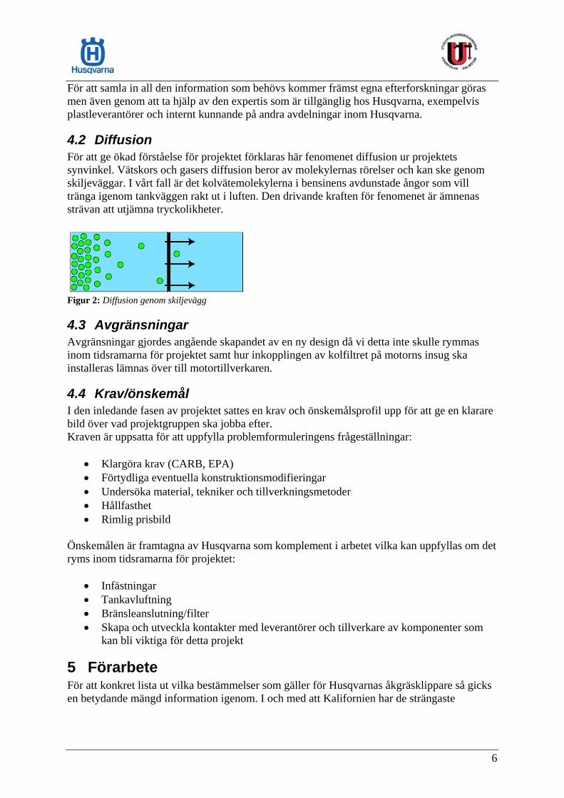
3 Metoder Projektet har tillämpat arbetsmetoden ”Dynamisk produktutveckling” (Stig Ottosson, 1999). Detta har inneburit att många mindre beslut tagits och justeringar ofta gjorts vilket medfört att lösningar och kravställningar vuxit fram under projektets gång. För att samla in de data som ligger till grund för projektets genomförande har vi:
• Knutit kontakter med KTH, Chalmers och Kristianstads Högskola då dessa är framstående när det gäller kunskap och forskning av polymera material. Detta för att få grundkunskap inom polymerer.
• Besökt och pratat med plasttillverkarna Blowtech AB1, Gnosjöplast AB2 och Hordagruppen AB3 i syfte att lära mer om vilka tillverkningsmetoder som går att tillämpa i en tillverkningsprocess av bränsletanken och tekniken bakom dessa samt hur olika polymera material agerar under olika tillverkningsprocesser.
• Utfört litteraturstudier4 och efterforskningar på Internet för att få information om diffusionsspärrtekniker och material.
• Talat med andra avdelningar inom Husqvarna5 för att ta del av deras erfarenhet av liknande diffusionsproblem.
• Satt oss in i CARB:s regel och testsystem gällande åkgräsklippare av typen Rider. Lösningar har tagits fram genom brainstorming och diskussioner inom projektgruppen, i samråd med uppdragsgivaren samt med extern expertis. Alla förslag har analyserats och diskuterats tillsammans för att få förståelse innan idéerna arbetats vidare med eller förkastats. Skisser (PAD, Pencil Aided Design) på lösningsförslag har gjorts på papper för att enkelt visualisera förslagen. För att kunna jämföra olika koncept mot varandra användes en utvärderingsmatris. I denna värderas de olika koncepten, som kommit fram under projektets gång, genom att varje påverkande faktor viktas och därefter bedömdes de olika lösningarna. Se avsnitt 6.2.4. Byggandet av en funktionsmodell (MAD, Model Aided Design) på en Rider visar tydligt hur installationen av den valda konceptlösningen skulle kunna se ut. Se bilaga B.
4 Projektbeskrivning
4.1 Problemformulering Vid vår första kontakt med Husqvarna hade det blivit känt att nya diffusionsregler för Small Off-Road Equipment (SORE) ska börja tillämpas 2008 i Kalifornien USA men några mer ingående detaljer var för dem okända. Kaliforniens miljömyndighet, California Air Resourse Board (CARB), har de strängaste kraven och övriga USA och senare Europa väntas följa CARB:s riktlinjer. 1 www.blowtech.se 2 www.gnosjoplast.se 3 www.hordagruppen.com 4 Hans-Erik Strömvall, Producera i plast (2002) – Lars-Erik Edshammar, Plasthandboken (2002) 5Motorsågar, Daniel Mannerström
4

En liten del av tidigare nämnda Rider-modeller som produceras exporteras för försäljning i USA. Sedan produktionsstarten 1986 har olika tillverkningstekniker av bränsletanken använts men genomgående har varit och beräknas bestå, att tanken är en fullt synlig detalj samt en del av produktens identitet och design. I samråd med handledare och ansvariga på Husqvarna AB sammanställdes tre huvudsakliga problemområden beträffande detta projekt som kan beskådas i figur 1. Huvudproblem Delproblem Informationsbehov
California Air Resuorses Board – CARB, U.S Environmental Protection Agency – EPA,
Vilka lagar och förordningar påverkar tankens egenskaper?
Hur skall bränsle-
tanken utformas så att den uppfyller framtida diffusionskrav och bibehåller sin funktionalitet?
Materialegenskaper Hållfasthet Kostnader Aktörer
Vilka material och tillverkningsmetoder kan appliceras?
Anslutningar Tanklock Infästning av tank Motor
Vilka ändringar på maskinen är nödvändiga för funktionaliteten?
Figur 1: Problemorienteringsmodell Det första problemområdet behandlar lagkrav och förordningar och hur dessa påverkar bränsletankens egenskaper. För att angripa detta problem krävdes information angående vilka miljöskyddsorgan som finns och hur reglerna för diffusion är utformade. Delproblem två tar upp materialegenskaper och hur bränsletanken kan tillverkas på ett så enkelt och billigt sätt som möjligt med bibehållna produktegenskaper. Detta för att dagens tank inte tillfredställer diffusionskravet. Den främsta styrande faktorn ansågs ligga på materialval och hur olika material fungerar tekniskt. En annan viktig faktor kring denna punkt bedömdes vara tankens krav på hållfasthet då tanken är placerad på en utsatt plats på Ridern där risk för mekanisk åverkan finns. Tredje området tar upp om det krävs modifieringar på någon detalj i Riderns utformning för att på ett önskvärt sätt kunna tillfredställa de krav som framkom i det första delproblemet. Tänkbara detaljer som gör sig gällande är bland annat slanganslutningar, tanklock samt motor.
5
För att samla in all den information som behövs kommer främst egna efterforskningar göras men även genom att ta hjälp av den expertis som är tillgänglig hos Husqvarna, exempelvis plastleverantörer och internt kunnande på andra avdelningar inom Husqvarna.
4.2 Diffusion För att ge ökad förståelse för projektet förklaras här fenomenet diffusion ur projektets synvinkel. Vätskors och gasers diffusion beror av molekylernas rörelser och kan ske genom skiljeväggar. I vårt fall är det kolvätemolekylerna i bensinens avdunstade ångor som vill tränga igenom tankväggen rakt ut i luften. Den drivande kraften för fenomenet är ämnenas strävan att utjämna tryckolikheter.
Figur 2: Diffusion genom skiljevägg
4.3 Avgränsningar Avgränsningar gjordes angående skapandet av en ny design då vi detta inte skulle rymmas inom tidsramarna för projektet samt hur inkopplingen av kolfiltret på motorns insug ska installeras lämnas över till motortillverkaren.
4.4 Krav/önskemål I den inledande fasen av projektet sattes en krav och önskemålsprofil upp för att ge en klarare bild över vad projektgruppen ska jobba efter. Kraven är uppsatta för att uppfylla problemformuleringens frågeställningar:
• Klargöra krav (CARB, EPA) • Förtydliga eventuella konstruktionsmodifieringar • Undersöka material, tekniker och tillverkningsmetoder • Hållfasthet • Rimlig prisbild
Önskemålen är framtagna av Husqvarna som komplement i arbetet vilka kan uppfyllas om det ryms inom tidsramarna för projektet:
• Infästningar • Tankavluftning • Bränsleanslutning/filter • Skapa och utveckla kontakter med leverantörer och tillverkare av komponenter som
kan bli viktiga för detta projekt
5 Förarbete För att konkret lista ut vilka bestämmelser som gäller för Husqvarnas åkgräsklippare så gicks en betydande mängd information igenom. I och med att Kalifornien har de strängaste
6
miljökraven i Nordamerika har utgångspunkten i arbetet varit CARB:s reglemente för att
ng, leverera samt sälja eller Hyra ut Ridern för bruk Kalifornien måste ett bränsleemissionssystem som är certifierat och märkt av CARB
lla Riders har en motorcylindervolym som är större än 225 kubikcentimeter. Gränsvärdena för llation är enligt CARB:s ”Final Reg a
• Bränsletank – 1,5 gram bränsleångor/m /dygn
ormation.
Det och kolkanistrar. De
ångor • Locket måste antingen med ljud eller visuellt påvisa för användare att locket är riktigt
n kolkanister är ett kolfilter som renar avdunstande bensinångor från kolväten. Angående kol ktvärdet är framtaget av CARB och mängden kol doseras efter bränsletankens nominella tankvolym:
Kal r er en certifiering av produkten där man genom testprocesser tärk r satta gränsvärden. Det finns två sätt att certifiera produkten:
edan förklaras respektive certifieringsprocess väldigt kortfattat. För fullständig information
da som
B att användas tillsammans i en applikation. För Husqvarnas del skulle det innebära att en certifieringsansökan av Ridern inte behöver
säkerställa projektets vidd.
5.1 Miljöregler För att Husqvarna ska få erbjuda försäljnii appliceras. Reglerna omfattar endast maskiner som har bensindrivna motorer med maximal effekt på 19kW vilket innefattar Ridern. A
bränslediffusion på maskiner med denna motorinstaul tion Order”:
• Bränsleslang – 15 gram bränsleångor/m2/dygn
2
Se bilaga E (CD-skiva) för fullständig tabell och inf
finns även regelverk som inkluderar kringutrustningen såsom tanklock regler som gäller enligt CARB för tanklock är:
• Det får inte finnas någon ventil som orenat släpper ut bränsle
stängt. • Det ska inte vara möjligt att avlägsna locket ifrån maskinen.
E
kanistern finns det ett riktvärde för hur mycket aktivt kol denna bör innehålla. Ri
• Arbetskapacitet på kolkanister – 2 gram aktivt kol/liter nominell tankvolym
5.2 Certifiering och test ifo niens miljölagar kräv
e att denna ligger inoms• Design-based • Performance-based
Nhänvisas till CARB:s dokument för certifiering (CP-902) bilaga F (CD-skiva) och testprocess (TP-902) bilaga G (CD-skiva). Design-based certifiering av Ridern innebär stor fördel om Husqvarna väljer att använförcertifierade komponenter i kontrollsystemet för bränsleemissioner. Komponenterna,består av bränsletank, bränsleslang, kolfilter och tanklock, har var och en gått igenom en testprocess och är godkända av CAR
7

innehålla några emissonstestresultat utan endast de, av CARB satta, kontrollnummer på deolika detaljerna i kontrollsystemet. Alternativt scenario är att Husqvarna själva utvecklar egna kompon
enter vilka var och en missionstestas enligt CARB:s testprocess och certifieras enskilt. Komponenterna kan sedan
lar eller av egna
onstruerade detaljer. Sedan testas Ridern i ett slutet rum där emissionerna mäts och jämförs
ska Forskningsinstitut emissionsmätningar.
ar vi försökt samla tillräcklig kunskap om för att sedan presentera de olika förslagen för Husqvarna med förhoppningen att välja det eller de koncept som är bäst lämpade för
ör att göra ett lämpligt materialval att tillverka tanken i så undersöktes ett antal alternativa ma a
e upp till 80°C utan försämrade egenskaper el
dighet egenskaperna över längre tid
rypresistens • Nötningsbeständighet
aterial som var mest intressanta efter att studerat deras egenskaper var:
tank
, färgläggning och lackering räknats in. Dessutom är placeringen av tanken på Ridern utsatt och en ståltank, som har låg slagseghet, skulle kunna bli deformerad vid slag
eappliceras på Ridern vilken då kan certifieras som beskrivet ovan. Performance-based certifiering medför att Husqvarna själva kan bygga ett kontrollsystem påRidern av befintliga men inte nödvändigtvis CARB-godkända dekmed gränsdata. Resultatet får inte överstiga CARB-standarden.
I Sverige utför SP Sveriges Tekni
6 Lösningsförslag Nedan listas de material och diffusionsspärrande tekniker vilka vi har funnit intressanta. Dessa h
Rider.
6.1 Material F
teri l med fokus på följande egenskaper:
• Pris • UV-beständig • Materialet får ej bli sprött och tåla kyla ner till -40°C • Materialet måste tåla värm• God beständighet mot bensin, alkohol och lösningsmed• Diffusionsbestän• God hållfasthet och hålla • Tåla vibrationer • Tillräcklig k
• Slagseghet
Några av de m
6.1.1 Stål Stål är ett av de material som är kompatibelt med CARB:s regelverk vilket innebär att entillverkad av detta material garanterar spärreffekt och slipper därmed genomgå en emissionstestprocess. Negativa faktorer är att stål korroderar och skulle bli för dyrt när tillverkning
och stötar.
8

6.1.2 Kompositer Här används härdplast tillsammans med glas- eller kolfiber som armering. Enligt Jan Wahlberg, professor i polymerteknik på Kristianstad Universitet, har materialet mycket goda mekaniska och sldock mycket hög
itstarka egenskaper som dessutom hindrar diffusion. Materialkostnaden är och för att denna lösning ska vara ekonomiskt försvarbar bör tanken
skar.
y Amid är ett plastmaterial som efter behandlat med UV-stabilisator skulle
ematiken. HDPE är tre till fyra gånger billigare
iker
ing enna lösning för sina CARB-godkända tankar till handhållna
ma n ch motorsågar. Här efterbehandlas den befintliga HDPE-tanken genom ten reagerar med och bildar ett ytskikt som hin r
ördelarna med tekniken:
De g
• Extra transporter mellan tillverkare av tank och fluorinerare g enligt TP-901. Se bilaga H (CD-skiva)
6.2 Den landas i HDPE-plasten. Lermaterialet lägger sig som små flak i plasten och förlänger därmed vägen för diffusionens framfart.
materialmixen ger är:
integreras med fler delar, exempelvis med infästningsplattan och manöverpanelen på motsatt sida av tanken. Fördelen blir att antalet delar reduceras och kostnaden för montering min
6.1.3 HDPA High Density Poluppfylla de flesta av våra krav. Dock behövs det någon form av behandling för att även uppfylla diffusionkravet.
6.1.4 HDPE High Density Poly Eten är ett plastmaterial som de flesta av alla bränsletankar är gjorda av idag. Materialet uppfyller flertalet av kraven men det fordras någon typ av efterbehandling eller annan lösning för att lösa diffusionsprobljämfört med HDPA. Efter samråd med sakkunniga inom plast- och tillverkningsteknik bestämdes att HDPE skulle vara det bästa materialet att bygga vidare på.
6.2 Spärrtekniker För att lösa diffusionsproblematiken med en bränsletank gjord av HDPE undersöktes teknsom har funktionen att hindra genomträngning av kolväten genom tankväggen.
6.2.1 FluorinerHusqvarna använder idag d
ski er som t.ex trimmers o att denna utsätts för fluorgas vilken plas
dra diffusion. F
• Känd för Husqvarna • Relativt billig • Efterbehandling av befintlig tank
ne ativa faktorerna med tekniken:
• Kräver testnin• Långtidshållbarheten av diffusionsskyddet är inte beprövad • Känslig mot mekanisk åverkan
.2 Nanolera na materialteknik går ut på att ett lermaterial b
Positiva följder som• Förstärker mekaniska egenskaper hos HDPE
9
• Kan appliceras i alla tillverkningsmetoder
gt TP-901. Se bilaga H (CD-skiva)
u olika lager. Tekniken kan
umformning
tår en,
genskaper att förhindra genomträngning av kolväten har dålig ndra plaster och behöver därför limmas fast
metillverkningsprocessen av tanken mals ned och smältes om för att åter v består av HPDE.
ositiva faktorer:
rregenskaper • ekanisk åverkan
åsas och vakuumformas
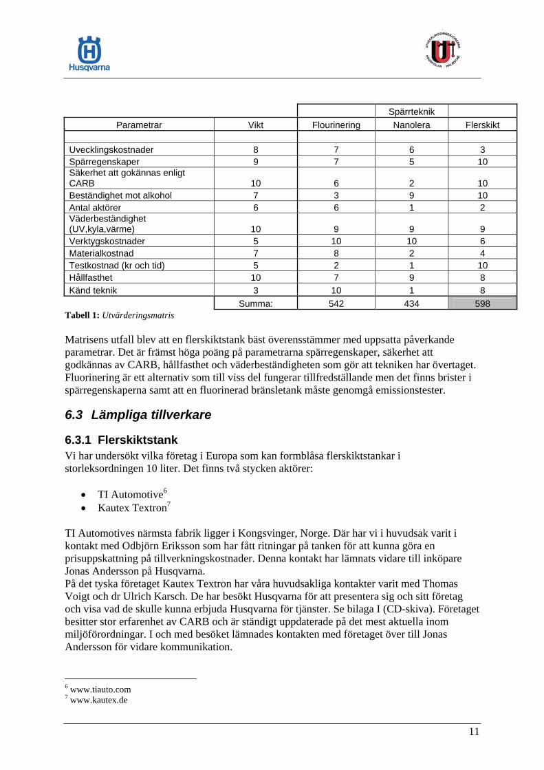
6.2.4 Utvärdering För att kunna reda ut och välja vilket koncept som anses lämpligast att tillämpa i bränsletankstillverkningen användes en utvärderingsmatris. Matrisen tar upp de viktigaste påverkande faktorerna vilka i sin tur är viktade. Varje koncept är sedan utifrån faktorerna bedömda på en skala från ett till tio huruvida de anses leva upp till dessa. Se tabell 1.
Negativa faktorer:
• Kräver testning enli• Hög materialkostnad
När vi gjorde djupare efterforskningar framkom det att denna metod med nanolera är under utveckling och kan därmed inte med säkerhet garantera att tekniken skulle kunna klara av diffusionskraven till fullo.
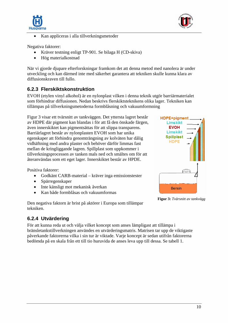
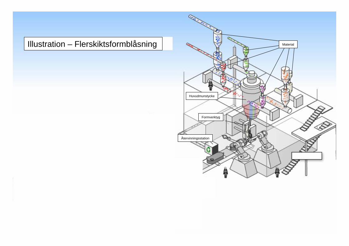
6.2.3 Flerskiktskonstruktion EVOH (etylen vinyl alkohol) är en nylonplast vilken i denna tekniksom förhindrar diffusionen. Nedan beskrivs flerskiktsteknikenstillämpas på tillverkningsmetoderna formblåsning och vaku Figur 3 visar ett tvärsnitt av tankväggen. Det yttersta lagret besav HDPE där pigment kan blandas i för att få den önskade färgäven innerskiktet kan pigmentsättas för att slippa transparens. Barriärlagret består av nylonplasten EVOH som har unika
tgör barriärmaterialet
evidhäftning med a
llan de kringliggande lagren. Spillplast som uppkommer i
an ändas som ett eget lager. Innerskiktet
P• Godkänt CARB-material – kräver inga emissionstester • Spä Inte känsligt mot m• Kan både formbl
Den negativa faktorn är brist på aktörer i Europa som tillämpar tekniken.
Figur 3: Tvärsnitt av tankvägg
10
Spärrteknik
Parametrar Vikt Flourinering Nanolera Flerskikt Uvecklingskostnader 8 7 6 3 Spärregenskaper 9 7 5 10 Säkerhet att gokännas enligt CARB 10 6 2 10 Beständighet mot alkohol 7 3 9 10 Antal aktörer 6 6 1 2 Väderbeständighet (UV,kyla,värme) 10 9 9 9 Verktygskostnader 5 10 10 6 Materialkostnad 7 8 2 4 Testkostnad (kr och tid) 5 2 1 10 Hållfasthet 10 7 9 8 Känd teknik 3 10 1 8 Summa: 542 434 598
Tabell 1: Utvärderingsmatris Matrisens utfall blev att en flerskiktstank bäst överensstämmer med uppsatta påverkande parametrar. Det är främst höga poäng på parametrarna spärregenskaper, säkerhet att godkännas av CARB, hållfasthet och väderbeständigheten som gör att tekniken har övertaget. Fluorinering är ett alternativ som till viss del fungerar tillfredställande men det finns brister i spärregenskaperna samt att en fluorinerad bränsletank måste genomgå emissionstester.
6.3 Lämpliga tillverkare
6.3.1 Flerskiktstank Vi har undersökt vilka företag i Europa som kan formblåsa flerskiktstankar i storleksordningen 10 liter. Det finns två stycken aktörer:
• TI Automotive6 • Kautex Textron7
TI Automotives närmsta fabrik ligger i Kongsvinger, Norge. Där har vi i huvudsak varit i kontakt med Odbjörn Eriksson som har fått ritningar på tanken för att kunna göra en prisuppskattning på tillverkningskostnader. Denna kontakt har lämnats vidare till inköpare Jonas Andersson på Husqvarna. På det tyska företaget Kautex Textron har våra huvudsakliga kontakter varit med Thomas Voigt och dr Ulrich Karsch. De har besökt Husqvarna för att presentera sig och sitt företag och visa vad de skulle kunna erbjuda Husqvarna för tjänster. Se bilaga I (CD-skiva). Företaget besitter stor erfarenhet av CARB och är ständigt uppdaterade på det mest aktuella inom miljöförordningar. I och med besöket lämnades kontakten med företaget över till Jonas Andersson för vidare kommunikation.
6 www.tiauto.com 7 www.kautex.de
11

Tillverkningsmetoden som båda aktörerna tillämpar är, som tidigare nämnts, formblåsning i flerskikt. Formblåsningsmaskinen är utrustad med ett specialutformat munstycke som kan hantera upp till sex olika material samtidigt. De olika materialen sprutas samtidigt ut genom munstycket och bildar en flerskiktig ”strumpa” som blåses upp och formas efter ett verktygs konturer. Se illustration, bilaga C.
6.3.2 Tanklock och kolkanister Som vi tidigare påvisat så måste ett tanklock som klarar CARBs regler och ett kolfilter dimensionerat efter vår 10 liters tank appliceras. Då det för närvarande endast är Kalifornien som har stränga förordningar angående dessa komponenter är urvalet av tillverkare och leverantörer mycket begränsat. I USA hittades dock två stora företag som kunde bistå med önskade produkter:
Kelch8 tillverkar tanklock vilka uppfyller alla krav enligt CARB. När locket är riktigt stängt så hörs ett klickande ljud och det går inte att dra åt det hårdare. För att inte kunna avlägsna locket ifrån maskinen förbinds detta med tanken via en speciell anordning med ett snöre. Stant Manufacturing Inc9 tillverkar kolkanistrar som är CARB-certifierade och kan skräddarsys efter kundens önskemål. Till vår funktionsprototyp beställdes en kanister som var dimensionerad efter Riderns tankvolym på 10 liter.
7 Resultat Vår uppgift var att lösa bränslediffusionsproblemet på Husqvarnas åkgräsklippare av modell Rider. Lösningen ska tillfredställa behovet av miljöanpassade produkter då företaget vill behålla och, i framtiden, expandera sin marknad i Nordamerika. Med vårt Fuel Evaporation Control System har vi löst detta problem genom att tillverka bränsletanken i en flerskiktskonstruktion samt att applicera CARB-godkända kringkomponenter såsom tanklock, bränsleslang och kolfilter. Har vi uppfyllt kraven?
• Vårt arbete har tydliggjort vilka miljökrav som ställs på Husqvarnas produkt och inom vilka tidsramar de gäller.
• Genom byggandet av en funktionsprototyp har arbetet påvisat vilka konstruktionsmodifieringar som är nödvändiga för installationen av vårt Fuel Evaporation Control System.
• Utredningen av material och diffusionsspärrtekniker gav underlag till val av tillverkningsmetod och tankuppbyggnad. Materialvalet, HDPE, uppfyller även ställda krav på materialegenskaper.
Att ta fram en flerskikts bränsletank hos en ny aktör kräver stora verktygsinvesteringar vilket gör att merkostnaden per tillverkad tank på kort sikt vid låga tillverkningsvolymer ser oförsvarbar ut. Långsiktigt däremot med större tillverkningsvolymer, när övriga USA och Europa tar efter CARB:s miljöarbete, kan en bättre prisbild målas upp med en merkostnad som får anses rimlig med tanke på den nya teknik som används.
8 www.kelch.com 9 www.stant.com
12

Ur önskemålssynpunkt uppfyllde vi Husqvarnas önskan att leta och skapa kontakter med leverantörer och tillverkare. Den viktigaste kontakten som knutits bedöms vara med det tyska formblåsningsföretaget Kautex Textron.
7.1 Vald lösning Projektets utfall rekommenderar Husqvarna att låta tanken formblåsas i en flerskiktskonstruktion av Kautex Textron. Troligtvis kan det befintliga formblåsningsverktyget som används till dagens tank även användas till flerskiktsformblåsning efter enklare modifiering. Företaget vill dock göra en besiktning av det befintliga verktyget för att vara helt säkra. Flerskiktstankens spärrskikt gör att inga avdunstade kolväten kan tränga igenom tankväggen och rakt ut i atmosfären. Som en enkel lösning att förhindra överfyllnad hett större tanklock valts då det större påfyllningshålet ger bättre överblick ner i tanken vilket gör det lättare att se när tanken börjar bli full vid tankning. Tanklocket har enligt reglerna inga ventiler som ohindrat släpper ut bränsleångor och uppfyller kraven angående ljudligt uppmärksammande vid korrekt stängning samt är konstant fäst vid tanken via ett snöre. Se Figur 4.
ar
Figur 4: Tanklock i snöre
Eftersom både tanklocket och tanken är helt täta för diffusion så kan de avdunstade bränsleångorna kontrollerat föras genom en kolkanister (figur5) som tar upp de miljövådliga kolvätena innan de släpps ut i luften.
Figur 5: Bränsletank med tillkopplad kolkanister Figur 6: Kolkanister monterad på Ridern
13

Det bör påpekas att kolkanistern mättas och förlorar cirka hälften av sin reningsförmåga efter ungefär 14 dagar om ingen rening görs under denna period. Rening av kanistern löses genom att man reverserar processen i kolfiltret genom att koppla detta till motorns insug. När motorn är igång går luftflödet åt andra hållet genom det aktiva kolet i kanistern varvid det uppfångade bränslet frigörs och följer med insugsluften in i motorn och förbränns. Se figur 7.
Figur 7: Kolfiltret renas
14

7.2 SWOT
SWOT över valt koncept
(Strengths, Weaknesses, Opportunities, Threats) Denna analys går ut på att identifiera de styrkor och svagheter som konceptet för med sig samt vilka av yttre omvärldens möjligheter och hot som kan påverka konceptet.
STYRKOR
Öppnar Kaliforniens marknad Övriga världen brukar följa CARB senare Marknadsföra sig som miljövänlig Kräver inga kostsamma emissionstester Luktfri vid förvaring
SVAGHETER
Fler delar som ska integreras Extra kostnad Nytt – ingen erfarenhet
MÖJLIGHETER
Ökad försäljning till miljömedvetna Stärka Husqvarnas image
HOT Regler ändras
Motortillverkare erbjuder inte alla motorer med modifierat insug.
Med det nya CARB-godkända system som presenterats så öppnas en stor marknad för Husqvarna i Kalifornien. Troligtvis så kommer de skärpta lagarna spridas till resten av USA och senare även Europa. Husqvarna kommer då vara bra förberedda och redan byggt upp det kontaktnät som behövs av tillverkare och leverantörer av CARB-godkända komponenter. Om Husqvarna vill kan detta Fuel Evaporation Control System appliceras redan nu på maskiner i Europa och kanske vinna marknadsandelar hos miljömedvetna kunder. Även kunder som vill slippa bensinlukten i sitt garage kan vara villiga att betala lite extra för detta.
15

Problem som kan uppkomma är att regler ändras och att dessa inte kommer Husqvarna till vetskap. Det kan även bli svårt att få motortillverkarna att modifiera insuget som ska kopplas till reningen av kolfiltret. Detta medför att det blir färre motoralternativ att välja på samt att priset höjs på motorerna. Det finns idag bara ett fåtal aktörer som tillverkar och levererar CARB-godkända komponenter detta medför dålig konkurrens och det kan vara svårt att pressa priser för Husqvarna.
8 Slutsatser och reflektion Vi har med detta projekt visat Husqvarna hur de kan tillverka en maskin som är miljöanpassad och godkänd enligt CARB på ett bra sätt. Vi har även etablerat kontakter med företag som kan hjälpa Husqvarna att få fram erforderliga komponenter. Det koncept vi presenterat i denna rapport är klart för implementering. När vi gjorde undersökningar av vilken lösning vi skulle använda visade det sig att det underlättar för CARB-godkännande om beprövade tekniker och material används. CARB styr mer eller mindre in tillverkare att använda exempelvis flerskiktstankar eller plåttankar då företaget slipper dyra och tidskrävande tester om dessa används. Projektet har varit givande då vi har fått lära oss hur olika tillverkningsprocesser går till inom plastindustrin samt hos Husqvarna. Vi har även vunnit kunskaper i olika polymera material och lärt oss hur man tyder krångliga regelverk som t.ex. hos CARB. Det har varit nyttigt att få sitta med på möte med representanter för andra företag och se hur detta går till. En viktig reflektion vi gjort är hur styrt allt är av ekonomi då detta inte känts av på samma sätt i projekt vi tidigare gjort under utbildningen.
16
9 Referenser Litterära källor Edshammar Lars-Erik, Plasthandboken (2002), Industrilitteratur AB Strömvall Hans-Erik, Producera i plast (2002), Industrilitteratur AB Elektroniska källor California Air Resourses Board http://www.arb.ca.gov/ U.S. Environmental Protection Agency http://www.epa.gov/ Stant Manufacturing, Inc http://www.stant.com/ Kelch Co. http://www.kelch.com/ Arkema Inc. http://www.arkema-inc.com/ Plastics Dome http://plastics.turkavkaz.ru/ SP Sveriges Tekniska Forskningsinstitut http://www.sp.se/ Polykemi AB http://www.polykemi.se/ Muntliga källor Dr. Ulrich A. Karsch, Director Research, Kautex Textron Gmbh & Co. Thomas Voigt, Dipl. Ing. , Kautex Textron Gmbh & Co. Daniel Mannerström, Product Laboratory, Husqvarna AB Jan Wahlberg, forskare fiberpolymerer, Högskolan Kristianstad Thomas Skåre, Universitetslektor i produktionsteknik, Högskolan Kristianstad Claes Jansson, VD, Blowtech AB
17
Thomas Hjertberg, Professor i polymera material, Chalmers Tekniska Högskola Franz Maurer, Professor i polymera material, Lunds Tekniska Högskola Mikael Hedenqvist, Professor i polymera material, Kungliga Tekniska Högskolan Axel Kaufman, VD, Molybon Industriplast AB Odbjörn Eriksson, Sales management, TI Automotive Henrik Eriksson, Utvecklingschef, Polykemi AB
10 Bilagor Bilaga A Projektplan Bilaga B Funktionsmodell Bilaga C Illustration – formblåsning Bilaga D Ritning: Bränsletank – endast basmått utsatta p g a flerformsmodellering, hänvisning bilaga J CD-skiva: Bilaga E CARB: ”Final Regulation Order” Bilaga F CARB: ”CP-902” Bilaga G CARB: ”TP-902” Bilaga H CARB: ”TP-901” Bilaga I Kautex Textron – presentation Bilaga J Digital ritning: Bränsletank
18
BILAGA A Högskolan i Halmstad Utvecklingsingenjörer
Projektplan
Bränsletank
Examensarbete 2006/2007
I samarbete med
Husqvarna AB
Daniel Axfeldt
Johan Bruno

Innehållsförteckning BAKGRUND ......................................................................................................................................................... 3 SYFTE MED PROJEKTET ................................................................................................................................ 3 PROJEKTETS MÅLSÄTTNING ....................................................................................................................... 3 AVGRÄNSNINGAR............................................................................................................................................. 3 INTRESSENTSTRUKTUR ................................................................................................................................. 3
HUSQVARNA ....................................................................................................................................................... 4 PROJEKTGRUPPEN ............................................................................................................................................... 4 HANDLEDAREN ................................................................................................................................................... 4
TIDPLAN............................................................................................................................................................... 4 BUDGET, FINANSIERING ................................................................................................................................ 4
BILAGA A – INFLYTANDEMODELLEN........................................................................................................ 5 BILAGA B – GANTTSCHEMA.......................................................................................................................... 6
2

Detta projekts huvudsakliga syfte är att säkerställa miljökraven på Husqvarna AB:s bränsletankar för åkgräsklippare.
Bakgrund Husqvarna AB har ett modellprogram med åkgräsklippare som riktar sig mot konsumentmarknaden. En del av modellprogrammet saluförs under märket Jonsered och den andra delen under märket Husqvarna. Jonsereds maskiner går under modellbeteckningen Frontrider och Husqvarna under beteckningen Rider. En liten del av ovan nämnda modeller som produceras exporteras för försäljning i USA. Miljökraven för ”Off-Road Equipment” där Frontrider och Rider (fortsättningsvis i dokumentet benämns båda som riders) ingår kommer att skärpas successivt med start 2006. Kaliforniens miljömyndighet CARB har de hårdaste kraven och övriga USA och senare Europa väntas följa CARB:s riktlinjer. De bränsletankar som Riders är utrustade med klarar inte de nya kraven. Främst är det nya diffusionskrav som gör att de nuvarande tankarna kommer att underkännas.
Syfte med projektet Projektet ska hjälpa Husqvarna att ta fram nya bränsletankar som är godkända att säljas i Kalifornien och ett godkännande av CARB kan höja märkets miljöimage. Första steget blir att lista alla de lagar och krav som olika myndigheter har när det gäller bränsletankar och dess förslutning på åkgräsklippare. När alla lagar och krav identifierats, blir materialval, design och tillverkningsmetod nästa steg. Här kommer även aspekter som produktionskostnad och montering in. För att samla in all den information som behövs kommer främst egna efterforskningar göras men även genom att ta hjälp av den expertis som är tillgänglig hos Husqvarna som t.ex. plastleverantörer och internt kunnande på andra avdelningar inom Husqvarna. En förhoppning är att det kommer att finnas rum för innovativa lösningar när det gäller att förhindra övertankning, mäta kvarvarande bränslemängd, kvalitetskänsla, design, förslutning osv.
Projektets målsättning Vi jobbar för att i slutet av april -07 kunna presentera en färdig prototyp som är godkänd enligt de krav som ställs på bränsletankar av berörda organ som t.ex. CARB. Det är viktigt att tanken ska passa designmässigt samtidigt som den ska vara ekonomiskt försvarbar för tillverkning och övrig hantering.
Avgränsningar Vi fokuserar främst på tanken och förslutningen av denna. Till en början görs avgränsningar när det gäller val av anslutning (bränsleslang) och design. För att bli certifierad måste även anslutningen vara godkänd enlig vissa krav.
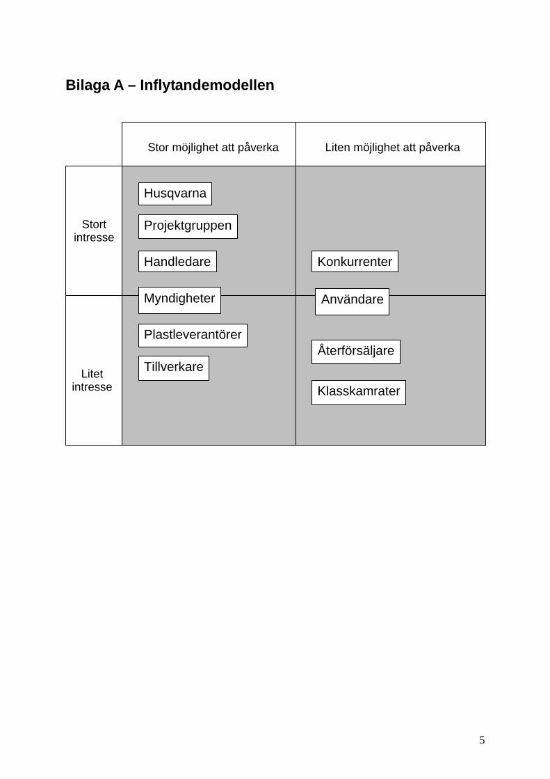
Intressentstruktur Att identifiera intressenterna av projektet är en viktig del av arbetet. En intressent kan vara personer, grupper, företag eller myndigheter som på något sätt kan påverka eller ha synpunkter på projektets fortgång. Betydande intressenter är viktiga att ha regelbunden kommunikation med för att snabbt kunna göra korrigeringar och förbättringar i projektet om så erfordras. Nedan presenteras de viktigaste grupperna enligt inflytandemodellen (bilaga A)
3

Husqvarna Uppdragsgivaren har stort intresse av att projektet ska lyckas då de finansierar och är beroende av att en funktionell produkt tas fram. Deras påverkan är mycket stor då krav och viktiga beslut fattas tillsammans med projektgruppen.
Projektgruppen Har mycket stort intresse av projektet eftersom det bidrar till personlig utveckling och erfarenhet av ingenjörsarbete. Påverkan är även denna mycket stor då gruppen medverkar hela vägen från idé till färdig produkt.
Handledaren Har stort intresse av projektets framfart då han är mån om att arbetet flyter bra för teknologerna vilket leder till hög motivation och gott omdöme för skolan. Med erfarenhet och kunnande inom projektarbete påverkar handledaren projektet och teknologerna i hög grad genom hela processens gång.
Tidplan Projektet delas in i följande faser vilka delvis kommer att löpa parallellt:
• Förstudier • Koncept • Produktframtagning • Idégenerering • Rapport • Utomstående kontakter
Bilaga B visar uppskattad tidsåtgång för de olika faserna och delmomenten som projektet innefattar
Budget, Finansiering Ingen budget är uppsatt. All finansiering som behövs inom ramarna för projektet och andra kostnader såsom reseersättning står Husqvarna AB för. Blir det fråga om större kostnader som t.ex. vid byggande av prototyp kommer handledaren på Husqvarna att tillfrågas om godkännande innan eventuella beställningar och annat görs.
4
Bilaga A – Inflytandemodellen
Stor möjlighet att påverka Liten möjlighet att påverka
Husqvarna
Stort intresse
Projektgruppen
Handledare Konkurrenter
Myndigheter Användare
PlastleverantörerÅterförsäljare
Tillverkare Litet intresse Klasskamrater
5
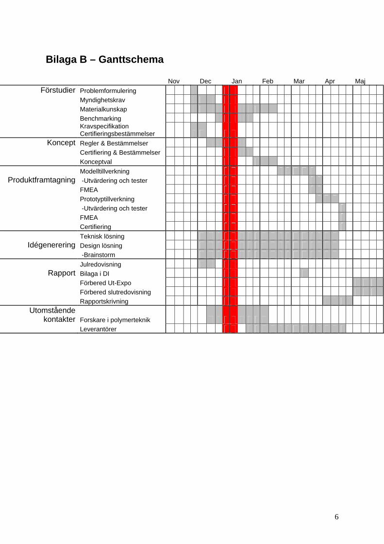
Bilaga B – Ganttschema
Nov Dec Jan Feb Mar Apr Maj Förstudier Problemformulering
Myndighetskrav Materialkunskap Benchmarking
Kravspecifikation Certifieringsbestämmelser
Koncept Regler & Bestämmelser Certifiering & Bestämmelser
Konceptval Modelltillverkning
Produktframtagning -Utvärdering och tester FMEA Prototyptillverkning -Utvärdering och tester FMEA
Certifiering Teknisk lösning
Idégenerering Design lösning -Brainstorm Julredovisning
Rapport Bilaga i DI Förbered Ut-Expo Förbered slutredovisning
Rapportskrivning Utomstående
kontakter Forskare i polymerteknik Leverantörer
6

BILAGA B Funktionsmodell
Översiktsbild: Bränsletank och kolkanister Förtydligande: Bränsletank och kolkanister - koppling
Tanklock förankrat i ett snöre Kolkanister
Återvinningsstation
Formverktyg
Huvudmunstycke
MaterialIllustration – Flerskiktsformblåsning

BIL
AG
A C
Återvinningsstation
Formverktyg
Huvudmunstycke
MaterialIllustration – Flerskiktsformblåsning
Pigmenterat yttre lager HDPE
Innre lager HDPE
Återvunnet material
Barriärlager EVOH
Limskikt
1
Final Regulation Order
Adopt Article 1, Chapter 15, Division 3, Title 13, California Code of Regulations,to read as follows:
Chapter 15. Additional Off-Road Vehicles and Engines Pollution ControlRequirements
Article 1. Evaporative Emission Requirements for Off-Road Equipment
§2750. Purpose.
The purpose of these regulations is to:
(a) Set performance standards for gasoline-fueled, spark-ignited small off-roadengines rated at equal to or less than 19 Kilowatts, and equipment utilizingsuch engines;
(b) In order to give manufacturers maximum flexibility, compliance programs are available beginning the 2006 model year. The two options are identified in section 2754(a) and in section 2754(b), and assume running loss emissions are controlled during engine operation, which result in greater evaporative emissions reductions. Manufacturers must select one option for each evaporative family they certify.
NOTE: Authority cited: Sections 39600, 39601, and 43013 Health and SafetyCode. Reference: Section Health and Safety Code 43013.
§2751. Applicability.
(a) For the model year engines or equipment subject to this Article, no personshall:
(1) manufacture for sale or lease for use or operation in California, or
(2) sell or lease or offer for sale or lease for use or operation inCalifornia, or
(3) deliver or import into California for introduction into commerce inCalifornia,
without an evaporative emission control system that has been certifiedand labeled pursuant to this Article.

2
(b) This Article does not apply to:
(1) engines or equipment that use compression-ignition engines, or enginesor equipment powered with compressed natural gas (CNG), propane,liquefied petroleum gas (LPG), or liquefied natural gas (LNG).
(2) engines or equipment that use small off-road engines manufactured inCalifornia for sale and use outside of California.
(3) snowthrowers or ice augers.
NOTE: Authority cited: Sections 39600, 39601, and 43013 Health and SafetyCode. Reference: Section Health and Safety Code 43013.
§2752. Definitions.
(a) The definitions in section 2401 (a), and section 2403 (b), Chapter 9,Title 13 of the California Code of Regulations, apply to this Article with thefollowing additions:
(1) “Coextruded Multilayer Fuel Tank” means a multi-layered high-density polyethylene fuel tank with a continuous nylon or ethylenevinyl alcohol layer(s) present within the walls of the tank.
(2) “CP-901” means “Certification and Approval Procedures for SmallOff-Road Engine Fuel Tanks”, adopted July 26, 2004.
(3) “CP-902” means “Certification and Approval Procedures forEvaporative Emission Control Systems”, adopted July 26, 2004.
(4) “Diurnal Emissions” means evaporative emissions resulting fromthe daily cycling of ambient temperatures and include restinglosses, and permeation emissions, as measured according to testprocedures incorporated in this Article.
(5) “Equivalent Fuel Tank” means a metal or coextruded multilayer fueltank used on a small off-road engine. Fuel tanks approved persection 2767 are also deemed equivalent fuel tanks. The volume ofan equivalent tank must be less than or equal to a nominal tank.An equivalent tank must be functionally equivalent to a nominaltank.
(6) “Equivalent Fuel Line” means a fuel line that permeates less than orequal to 15 grams per square meter per day when tested per SAEJ1737 at 40ºC or higher, and ambient pressure using Phase IICalifornia Reformulated Certification (CERT) fuel, CE10, CM10,CM15, or Indolene.

3
(7) “Evaporative Emissions” means emissions that result from theevaporation of reactive organic gases into the atmosphere.
(8) “Evaporative Emission Control System” means the fuel system andassociated components that are designed to control evaporativeemissions.
(9) “Evaporative Family” means a class of off-road engines orequipment that are grouped together based on similar fuel systemcharacteristics as they relate to evaporative emissions. Forequipment less than or equal to 80 cc, the engine family andevaporative family are considered equivalent. For integratedequipment greater than 80 cc the engine family and the evaporativefamily may be considered equivalent at the manufacturer’sdiscretion.
(10) “Evaporative Model Emission Limit (EMEL)” means the diurnalemissions level declared by the manufacturer for a model within anevaporative family. The declared level must be based on diurnalemissions test results for a worst case model of engine orequipment within the evaporative family, obtained by following TestProcedure 902.
(11) “Evaporative Family Emission Limit Differential (EFELD)” meansthe emission level differential between the effective standard levelfor a specific model and the EMEL declared for the model and isapplicable to the entire evaporative family represented by themodel.
(12) “Executive Order of Certification” means an order signed by theExecutive Officer that documents certification of evaporativeemission control systems on engines or equipment to theperformance standards of this Article.
(13) "Holder" means the person to whom the Executive Order ofCertification is issued.
(14) “Hot Soak Emissions” means evaporative emissions that occur forthe one-hour period following the termination of engine operation.
(15) “Hydrocarbon” means a molecule composed primarily of carbonand hydrogen atoms.
(16) “Manufacturer” means either an engine manufacturer or equipmentmanufacturer.
4
(17) “Nominal Capacity” means the volume of fuel indicated by themanufacturer that represents the maximum recommended fill level.
(18) “Nominal Fuel Tank” means the fuel tank that is used by an engineor equipment manufacturer to certify the evaporative emissionscontrol system on a small off-road engine.
(19) “Nominal Fuel Line” means the fuel line that is used by an engine orequipment manufacturer to certify the evaporative emissionscontrol system on a small off-road engine.
(20) “Permeation Emissions” means evaporative emissions that resultfrom reactive organic gas molecules penetrating through the wallsof fuel system components and evaporating on outside surfaces, asmeasured by test procedures incorporated in this Article.Permeation emissions are a component of diurnal emissions, asmeasured by test procedures incorporated in this Article.
(21) “Permeation Rate” means the total mass of reactive organic gasmolecules passing through the internal surface area of a fuel tankin a 24-hour period, as measured by test procedures incorporatedin this Article.
(22) “Person” means any individual, association, partnership, limitedliability company, or corporation.
(23) “Reactive Organic Gases (ROG)” means any compound of carbon,excluding carbon monoxide, carbon dioxide, carbonic acid,metallic carbides or carbonates, and ammonium carbonate, andexcluding the following:
CAS *
(1) methane; [ 74-82-8 ]methylene chloride (dichloromethane); [ 75-09-2 ]1,1,1-trichloroethane (methyl chloroform); [ 71-55-6 ]trichlorofluoromethane (CFC-11); [ 75-69-4 ]dichlorodifluoromethane (CFC-12); [ 75-71-8 ]1,1,2-trichloro-1,2,2-trifluoroethane (CFC-113); [ 76-13-1 ]1,2-dichloro-1,1,2,2-tetrafluoroethane (CFC-114); [ 76-14-2 ]chloropentafluoroethane (CFC-115); [ 76-15-3 ]chlorodifluoromethane (HCFC-22); [ 75-45-6 ]
1,1,1-trifluoro-2,2-dichloroethane (HCFC-123); [ 306-83-2 ] 2-chloro-1,1,1,2-tetrafluoroethane (HCFC-124); [ 2837-89-0 ] 1,1-dichloro-1-fluoroethane (HCFC-141b); [ 1717-00-6] 1-chloro-1,1-difluoroethane (HCFC-142b); [ 75-68-3 ]
trifluoromethane (HFC-23); [ 75-46-7 ] pentafluoroethane (HFC-125); [ 354-33-6 ] 1,1,2,2-tetrafluoroethane (HFC-134); [ 359-35-3 ] 1,1,1,2-tetrafluoroethane (HFC-134a); [ 811-97-2 ]

5
1,1,1-trifluoroethane (HFC-143a); [ 420-46-2 ] 1,1-difluoroethane (HFC-152a); [ 75-37-6 ]
cyclic, branched, or linear completely methylated siloxanes; [ various ] the following classes of perfluorocarbons: [ various ]
(A) cyclic, branched, or linear, completely fluorinated alkanes; (B) cyclic, branched, or linear, completely fluorinated ethers with no unsaturations; (C) cyclic, branched, or linear, completely fluorinated tertiary amines with no
unsaturations; and (D) sulfur-containing perfluorocarbons with no unsaturations and with the sulfur bonds
only to carbon and fluorine; and
(2) the following low-reactive organic compounds which have been exempted by the U.S. EPA:acetone; [ 67-64-1 ]ethane; [ 74-84-0 ]methyl acetate; [ 79-20-9 ]perchloroethylene; and [ 127-18-4 ]
parachlorobenzotrifluoride (1-chloro-4-trifluoromethyl benzene). [ 98-56-6 ]
--------------------------------------------- * NOTE: Chemical Abstract Service (CAS) identification numbers have been included in brackets [ ]for convenience.
(24) “Running Loss Emissions” means evaporative emissions from asmall off-road engine that occur while it is being operated.
(25) “SHED” (Sealed Housing Evaporative Determination) means theenclosure and associated equipment used to determineevaporative emissions. A SHED must meet the designspecifications in 40 Code of Federal Regulations Part 86.107-96.
(26) “Small Production Volume Tank Exemption applies to all modelswith identical tanks produced by an engine or equipmentmanufacturer with total California sales of 400 or fewer units peryear.
(27) “Structurally Integrated Nylon Fuel Tank” means a fuel tank havingthe following characteristics:
(A) The fuel tank is made of a polyamide material which:
1. does not contain more than 50 percent by weight of areinforcing glass fiber and/or mineral filler; and
2. does not contain more than 10 percent by weight ofimpact modified polyamides which use rubberized agentssuch as EPDM rubber
(B) The fuel tank must be:
1. used in a chainsaw; or

6
2. of a pre-existing design that is substantially similar to acurrent production fuel tank used by the samemanufacturer that is integrated into a major structuralmember where, as a single component, the fuel tankmaterial is a primary structural/stress member for othermajor components such as the engine, transmission orcutting attachment.
(28) “TP-901” means “Test Procedure for Determining PermeationEmissions from Small Off-Road Engine Equipment Fuel Tanks,”adopted July 26, 2004.
(29) “TP-902” means “Test Procedure for Determining DiurnalEvaporative Emissions from Small Off-Road Engines,” adoptedJuly 26, 2004.
(30) “Total Hydrocarbons” means the total mass of open chain andcyclic hydrocarbon molecules, as measured under the testprocedures incorporated in this Article.
(31) “Walk-Behind Mower” means a grass-cutting product which has:
(A) A Class I vertical shaft engine that includes a blade brakemechanism that provides for compliance with ANSI B71.1requirements;
(B) A horizontally fixed blade and/or string directly attached to thecrankshaft of a vertical shaft engine.
NOTE: Authority cited: Sections 39600, 39601, and 43013 Health and SafetyCode. Reference: Section Health and Safety Code 43013.
§2753. Certification Requirements and Procedures.
(a) Certification
Small off-road engines or equipment that use small off-road enginessubject to this Article must contain evaporative emission control systems.For engines less than or equal to 80 cc, the evaporative emission controlsystem consists of the fuel tank only. The evaporative emission controlsystems must be certified annually to the performance-based or systemdesign standards set out in sections 2754 through 2757 by the AirResources Board. An Executive Order of Certification for such engines orequipment must be obtained prior to the sale or lease, or the offering forsale or lease, for use or operation in California or the delivery orimportation for introduction into commerce in California. Engine

7
manufacturers or equipment manufacturers may apply for an ExecutiveOrder of Certification. Applicants must follow the certification proceduresoutlined in CP-901, adopted July 26, 2004 or CP-902, July 26, 2004, asapplicable, which are incorporated by reference herein.
(b) Certification of Complete Systems
Certification of a complete evaporative emission control system isrequired. An applicant for certification of an evaporative emission controlsystem that complies with the diurnal standards specified in section 2754(a), or section 2757 must submit diurnal evaporative emission datafor an engine or equipment that exhibits the highest evaporative emissioncharacteristics for an evaporative family as part of the certificationapplication.
(1) An applicant for certification of an evaporative emission controlsystem that complies with the fuel hose permeation standardspecified in section 2754(a) must submit fuel hose permeation datafor model year 2006 equipment as part of the certification application.Alternatively, manufacturers may submit the Executive Order numberapproving the component pursuant to section 2767.1 of this Article.
(2) An applicant for certification of an evaporative emission controlsystem that complies with the design standards specified in section2754(b) must submit fuel tank permeation data, fuel hose permeationdata, and carbon canister butane working capacity data or equivalentfor an engine or equipment that exhibits the highest evaporativeemission characteristics for an evaporative family as part of thecertification application. Alternatively, manufacturers may submit theExecutive Order number approving the component pursuant tosection 2767.1 of this Article.
(3) An applicant for certification of an evaporative emission controlsystem that complies with the fuel tank permeation standardsspecified in section 2755 must submit fuel tank permeation data thatexhibits the highest evaporative emission characteristics for anevaporative family as part of the certification application. For enginesless than or equal to 80 cc, the manufacturer need only test the tankwith the most surface area for all evaporative families with the samematerial/process. These certification test results can then be used inthe certification of other tanks/engine families constructed of thesame materials/processes.
(4) TP-901, adopted July 26, 2004, is used to determine fuel tankpermeation. TP-902, adopted July 26, 2004, is used to determine theevaporative emissions from engines or equipment with completeevaporative emission control systems.

8
(c) Modifications to the Evaporative Emission Control System
(1) Manufacturers are allowed to replace the nominal fuel tank and/ornominal fuel line of a certified evaporative emission control systemthat complies with the performance-based standards specified insection 2754 with an equivalent fuel tank and/or equivalent fuel line.All other evaporative emission control components in a system thatcomplies with the performance-based standards in section 2754 mustfunction similarly and have equivalent or better performance to thosecomponents used to certify the control system.
(2) Modification of any certified evaporative emission control systems inany manner other than replacement of the nominal tanks and/or fuellines with equivalent fuel tanks and/or fuel lines invalidates thecertification of the control system. When any evaporative emissioncontrol system’s certification is invalidated due to an unapprovedmodification, a new certification is required per CP-902, adoptedJuly 26, 2004.
(3) Manufacturers are required to notify the Executive Officer in writing ofany modification of any certified evaporative emission control system.The notification must include a statement citing the basis for theequivalent fuel tank and/or fuel line determination.
(d) Reduced Certification Requirements
Manufacturers meeting the requirements of section 2766 of this Articlemust be certified annually by the Air Resources Board by submitting aLetter of Conformance. The Letter of Conformance must include, at aminimum, a statement citing the basis for complying with section 2766.An Executive Order of Certification for such engines or equipment must beobtained prior to the sale or lease, or the offering for sale or lease, or thedelivery or importation for introduction into commerce in California of suchengines or equipment in California.
NOTE: Authority cited: Sections 39600, 39601, and 43013 Health and SafetyCode. Reference: Section Health and Safety Code 43013.
§2754 Evaporative Emission Performance and Design Standards
The table below specifies the evaporative emission performance and designstandards for small off-road engines, and equipment that use small off-roadengines, with displacements greater than 80 cc.

9
Table 1Evaporative Emission Standards
PerformanceRequirements
Section2754(a)1
Design Requirements Section 2754(b)
EffectiveDate
Model Year
DiurnalStandard
Grams HC/day
Fuel HosePermeation
GramsROG/m2/day
Fuel TankPermeation2
GramsROG/m2/day
Carbon Canister3 orEquivalent
Butane WorkingCapacity
Grams HCDisplacement Category: Walk-Behind Mowers
>80 cc - <225 cc2006 None 15 None None
2007 and2008
1.3 N/A N/A N/A
2009 1.0 N/A N/A N/A
Displacement Category: Non Walk-Behind Mowers> 80 cc - < 225 cc
2006 None 15 None None2007
through2011
1.20 +0.056*tank vol.
(liters)15 2.5 Specified in TP-902
20120.95 +
0.056*tank vol.(liters)
15 1.5 Specified in TP-902
Displacement Category: >225 cc2006 and
2007None 15 None None
20081.20 +
0.056*tank vol.(liters)
15 2.5 Specified in TP-902
20104 None 15 None Specified in TP-902
20131.20 +
0.056*tank vol.(liters)
15 1.5 Specified in TP-902
1 For model year 2006 only, all engines and equipment with displacements > 80 cc - <225 ccmust comply with the fuel hose permeation design requirement in section 2754(a)(1)(C). Enginesand equipment with displacements greater than or equal to 225 cc must comply with the fuel hosepermeation design requirement in section 2754(a)(1)(C) for model years 2006 and 2007 only.2 Permeation emissions as determined by TP-901. Permeation emissions must be measured totwo significant figures.3 Canister design requirements and the procedure for determining butane working capacity arespecified in TP-902. The Executive Officer may designate technology equivalent to carboncanisters on a case by case basis as part of the certification process per section 2767.

10
(a) On or after the model year set out in Table 1 of section 2754, evaporativeemissions from any small off-road engine or equipment that use small off-road engines certifying under this section 2754(a) must not exceed theperformance requirements specified in Table 1 of section 2754.
(1) Manufacturers certifying engines or equipment under this section2754(a) shall do the following:
(A) Submit a determination in the certification application thatrunning loss emissions are controlled from being emitted intothe atmosphere. The Executive Officer must approve thedetermination for an Executive Order of Certification to beissued. Approval by the Executive Officer is not required ifactively purged carbon canisters meeting the requirements ofthis article are used.
(B) Test all evaporative families in accordance with TP-902.
(C) Provide test data in the certification application showing that fuellines meet the permeation requirement of 15 grams/m2/dayusing test procedure SAE J1737 (Issued August 1997). Thepermeation testing must be conducted at 40ºC, or higher, andambient pressure using Phase II California ReformulatedCertification (CERT) fuel, CE10, CM15, or Indolene.Alternatively, manufacturers can submit the Executive Ordernumber approving the component pursuant to section 2767.1 ofthis Article.
(b) On or after the model year set out in Table 1 of section 2754, evaporativeemissions from any small off-road engine or equipment that use small off-road engines certifying under this section 2754(b) must not exceed thedesign requirements specified in Table 1 of section 2754.
(1) Manufacturers certifying engines or equipment under 2754(b) shallalso do the following:
(A) Submit a determination in the certification application that therunning loss emissions are controlled from being emitted intothe atmosphere. The Executive Officer must approve thedetermination before an Executive Order of Certification can beissued. Approval by the Executive Officer is not required ifactively purged carbon canisters meeting the requirements ofthis article are used.
(B) Provide test data in the certification application showing that thefuel tank and carbon canister meet the applicable design

11
requirements. Provide test data in the certification applicationshowing that fuel lines meet the permeation requirement of 15grams/m2/day using test procedure SAE J1737 (Issued August1997). The permeation testing must be conducted at 40ºC, orhigher, and ambient pressure using Phase II CaliforniaReformulated Certification (CERT) fuel, CE10, CM15, orIndolene. Alternatively, manufacturers can submit the ExecutiveOrder number approving the component pursuant to section2767.1 of this Article.
NOTE: Authority cited: Sections 39600, 39601, and 43013 Health and SafetyCode. Reference: Section Health and Safety Code 43013.
§2754.1 Certification Averaging and Banking
(a) Applicability - The averaging requirements specified in this section 2754apply only to engines or equipment with complete evaporative emissioncontrol systems certified to the diurnal emission performance standardsspecified in section 2754(a) of this Article. Participation in the certificationaveraging and banking program is voluntary. The provisions of thissection are applicable only for determining compliance with this section.
(b) General provisions.
(1) The certification averaging and banking provisions for diurnalemissions from eligible engines and equipment are described in thissection.
(2) A manufacturer of an evaporative family subject to this Article mayuse the averaging and banking provisions of this section 2754 for thepurpose of creating diurnal emissions credits.
(3) A manufacturer shall not include in its calculation of credit generationand may exclude from its calculation of credit usage, any newengines or equipment not subject to this Article.
(4) A manufacturer may include its entire inventory of an evaporativefamily subject to this Article in calculating the diurnal emissions creditfor a given model year.
A manufacturer shall certify evaporative families to an EvaporativeFamily Emission Limit Differential (EFELD). The EFELD is declaredby an engine or equipment manufacturer and can be positive ornegative subject to the limitation in subsections (b)(6) and (b)(7) ofthis section, provided the sum of the manufacturer's projectedbalance of credits from all credit transactions for each engine class ina given model year is greater than or equal to zero, as determinedunder subsection (e). The EFELD is determined based on the
12
diurnal test results, in accordance with TP-902, of the worst casemodel of engine or equipment within an evaporative family. Theworst case model of engine or equipment is defined as the engine orequipment expected to produce the highest negative or the smallestpositive EFELD within the family on a per unit basis. The EFELD iscalculated by setting the EMEL for the model of engine or equipmenttested at a level above the diurnal test results and then subtractingthe EMEL from the applicable standard level for the model.
(A) A manufacturer of an evaporative family with a negative EFELDshall obtain positive emission credits sufficient to address theassociated credit shortfall within the time period set out in (8)below.
(B) An evaporative family with a positive EFELD may generatepositive emission credits for averaging, or banking, or acombination thereof.
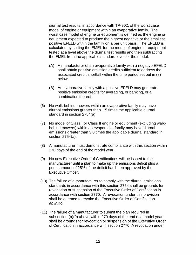
(6) No walk-behind mowers within an evaporative family may havediurnal emissions greater than 1.5 times the applicable diurnalstandard in section 2754(a).
(7) No model of Class I or Class II engine or equipment (excluding walk-behind mowers) within an evaporative family may have diurnalemissions greater than 3.0 times the applicable diurnal standard insection 2754(a).
(8) A manufacturer must demonstrate compliance with this section within270 days of the end of the model year.
(9) No new Executive Order of Certifications will be issued to themanufacturer until a plan to make up the emissions deficit plus apenal amount of 25% of the deficit has been approved by theExecutive Officer.
(10) The failure of a manufacturer to comply with the diurnal emissionsstandards in accordance with this section 2754 shall be grounds forrevocation or suspension of the Executive Order of Certification inaccordance with section 2770. A revocation under this provisionshall be deemed to revoke the Executive Order of Certificationab initio.
(11) The failure of a manufacturer to submit the plan required insubsection (b)(9) above within 270 days of the end of a model yearshall be grounds for revocation or suspension of the Executive Orderof Certification in accordance with section 2770. A revocation under

13
this provision shall be deemed to revoke the Executive Order ofCertification ab initio.
(c) Averaging.
(1) Negative credits from evaporative families with negative EFELDsmust be offset by positive credits from evaporative families havingpositive EFELDs, as allowed under the provisions of this section.Averaging of credits in this manner is used to determine complianceunder subsection (e)(2).
(2) Subject to the provisions in subsection (b)(9), credits used inaveraging for a given model year may be obtained from creditsgenerated in the same model year by another evaporative family, orcredits banked in previous model years, The restrictions of thissubsection notwithstanding, credits from a given model year may beused to address credit needs of previous model year engines.
(d) Banking.
(1) Beginning with the 2007 model year, a manufacturer of an evaporativefamily with a positive EFELD for model year 2007 and subsequentengines and equipment may bank credits in that model year for use inaveraging. Positive credits may be banked only according to therequirements of subsection (e)(1) of this section.
(2) A manufacturer may bank emission credits only after the end of themodel year and after ARB has reviewed the manufacturer's end-of-year reports. During the model year and before submittal of the end-of-year report, credits originally designated in the certification processfor banking will be considered reserved and may be redesignated foraveraging in the end-of-year report and final report.
(3) A manufacturer may use credits claimed from a previous model yearthat have not been approved by the ARB, in an averaging calculationpending the review of the ARB. In the event such review does notsubstantiate the amount of credits claimed, an Executive Order will notbe issued until a plan to make up the emissions deficit has beenapproved by the Executive Officer.
(e) Credit Calculation and Manufacturer Compliance with Emission Standards
(1) For evaporative family, diurnal emission credits (positive or negative)are to be calculated according to the following equation and roundedto the nearest tenth of a gram. Consistent units with two significantdigits are to be used throughout the equation.

14
EFELD = Applicable standard level – EMEL
Credits = EFELD x Sales
Where:
EMEL = the declared evaporative model emission limit for the modeltested within the evaporative family in grams
EFELD = the calculated evaporative family emission limit differentialin grams
Sales = the total Sales for all models within a given evaporativefamily
Sales or Eligible Sales means the actual or calculated sales of anevaporative family in California for the purposes of averaging andbanking. Upon Executive Officer approval, an engine or equipmentmanufacturer may calculate its eligible sales through market analysis.Because of the multiple steps in the product distribution chain andconfidential nature of sales information for many retailers and originalequipment manufacturers an educated and consistent estimate withthe best available documentation will be acceptable as the finalreport of sales in California. Actual sales are sales calculated at theend of a model year on that model year’s production, rather thanestimates of production. Actual sales volume is used in determiningactual credits for end-of-year compliance determination.
(2) Manufacturer compliance with this section is determined on acorporate average basis at the end of each model year. Amanufacturer is in compliance when the sum of positive and negativeemission credits it holds is greater than or equal to zero.
(f) Certification Using Credits.
(1) For certification relying on averaging or banking of credits, amanufacturer shall:
(A) Submit a statement that the engines for which certification isrequested will not, to the best of the manufacturer's knowledge,cause the manufacturer to be in noncompliance undersubsection (e)(2) when all credits are calculated for all themanufacturer's engine families.
(B) Declare an EFELD for the evaporative family. The EFELD mustbe calculated to two significant digits.
15
(C) Indicate the projected number of emission creditsgenerated/needed for this family; the projected applicableeligible sales volume and the values required to calculatecredits as given in section 2754(e).
(D) Submit calculations in accordance with section 2754(e) ofprojected emission credits (positive or negative) based onproduction projections for each family.
(E) (i) If the evaporative family is projected to generate negativeemission credits, state specifically the source(manufacturer/evaporative family or reserved) and quantityof the credits necessary to offset the credit deficit accordingto projected production.
(ii) If the evaporative family is projected to generate positiveemission credits, state specifically the recipient(manufacturer/evaporative family or reserved) and quantityof the credits used to offset a deficit banked according towhere the projected credits will be applied.
(2) The manufacturer may supply the information required above insection 2754(f)(1)(C), (D), and (E) by use of a spreadsheet detailingthe manufacturer's annual production plans and the creditsgenerated or consumed by each evaporative family.
(3) The manufacturer bears the burden of establishing to the satisfactionof the Executive Officer that the conditions upon which the ExecutiveOrder was issued were satisfied.
(4) Projected credits based on information supplied in the certificationapplication may be used to obtain an Executive Order. However, anysuch credits may be revoked based on review of end-of-year reports,follow-up audits, and any other verification steps consideredappropriate by the Executive Officer.
(g) Maintenance of records.
(1) The manufacturer shall establish, maintain, and retain the followingadequately organized and indexed records for each evaporativefamily:
(A) ARB evaporative family identification code,(B) Declared EFELD,(C) Projected sales volume for the model year, and

16
(D) Records appropriate to establish the quantities of engines orequipment that constitute eligible sales for each evaporativefamily.
(2) The manufacturer shall retain all records required to be maintainedunder this section for a period of eight years from the due date for theend-of-model year report. Records may be retained as hard copy,CD-ROM, diskettes, and so forth, depending on the manufacturer'srecord retention procedure; provided, that in every case allinformation contained in the hard copy is retained.
(3) Nothing in this section limits the Executive Officer's discretion inrequiring the manufacturer to retain additional records or submitinformation not specifically required by this section.
(4) A manufacturer shall submit all information requested by theExecutive Officer within 30 days of the date of such request.
(5) The Executive Officer may revoke or suspend the Executive Orderfor an evaporative family for which the manufacturer fails to retain therecords required in this section or to provide such information to theExecutive Officer upon request. No new Executive Orders will beissued to the manufacturer until the requested records are madeavailable and/or a plan that describes the records to be retained asrequired by this section is approved by the Executive Officer.
(h) End-of-year and final reports.
(1) End-of-year and final reports must indicate the evaporative family,the actual sales volume, the values required to calculate credits asgiven in subsection (e), and the number of creditsgenerated/required. Manufacturers shall also submit how and wherecredit surpluses were dispersed (or are to be banked) and/or howand through what means credit deficits were met. The report mustinclude a calculation of credit balances to show that the creditsummation for each class of engines or equipment is equal to orgreater than zero.
(2) The calculation of eligible sales as defined in subsection (e)(1) of thissection for end-of-year and final reports must be based on thelocation of the point of first retail sale (for example, retail customer ordealer) also called the final product purchase location. Upon advancewritten request, the Executive Officer will consider other methods totrack engines for credit calculation purposes, such as shipments todistributors of products intended for sale in California.
17
(3) (A) End-of-year reports must be submitted within 90 days of the endof the model year to:
Chief, Mobile Source Operations Division, Air Resources Board,9528 Telstar, El Monte, CA 91731.
(B) Unless otherwise approved by the Executive Officer, finalreports must be submitted within 270 days of the end of themodel year to: Chief, Mobile Source Operations Division, AirResources Board, 9528 Telstar, El Monte, CA 91731.
(4) Failure by a manufacturer to submit any end-of-year or final reports inthe specified time for any engines or equipment subject to regulationunder this section is a violation of this section for each engine orequipment in the evaporative family covered by the report.
(5) A manufacturer generating credits for banking only who fails tosubmit end-of-year reports in the applicable specified time period (90days after the end of the model year) may not use the credits untilsuch reports are received and reviewed by ARB. Use of projectedcredits pending ARB review is not permitted in these circumstances.
(6) Errors discovered by ARB or the manufacturer in the end-of-yearreport, including errors in credit calculation, may be corrected in thefinal report.
(7) If ARB or the manufacturer determines that a reporting error occurredon an end-of-year or final report previously submitted to ARB underthis section, the manufacturer's credits and credit calculations mustbe recalculated. Erroneous positive credits will be void except asprovided in subsection (h) of this section. Erroneous negative creditbalances may be adjusted by ARB.
(8) If within 270 days of the end of the model year, ARB reviewdetermines a reporting error in the manufacturer's favor (that is,resulting in an increased credit balance) or if the manufacturerdiscovers such an error within 270 days of the end of the model year,ARB must restore the credits for use by the manufacturer.
NOTE: Authority cited: Sections 39600, 39601, and 43013 Health and SafetyCode. Reference: Section Health and Safety Code 43013.
§2754.2 Validation Study
(a) To confirm that the performance-based evaporative certification option insection 2754(a) and the design-based evaporative certification option insection 2754(b) are achieving ARB’s overall emission reduction goals,
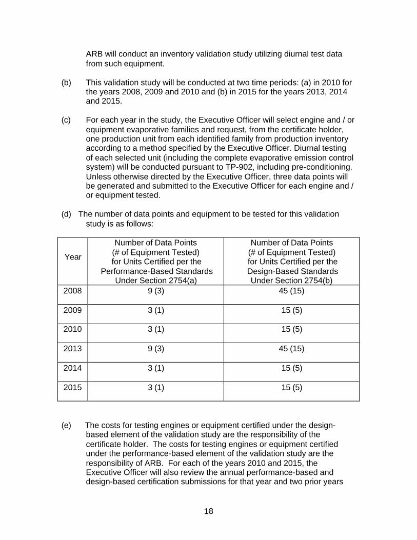
18
ARB will conduct an inventory validation study utilizing diurnal test datafrom such equipment.
(b) This validation study will be conducted at two time periods: (a) in 2010 for the years 2008, 2009 and 2010 and (b) in 2015 for the years 2013, 2014and 2015.
(c) For each year in the study, the Executive Officer will select engine and / orequipment evaporative families and request, from the certificate holder,one production unit from each identified family from production inventoryaccording to a method specified by the Executive Officer. Diurnal testingof each selected unit (including the complete evaporative emission controlsystem) will be conducted pursuant to TP-902, including pre-conditioning.Unless otherwise directed by the Executive Officer, three data points willbe generated and submitted to the Executive Officer for each engine and /or equipment tested.
(d) The number of data points and equipment to be tested for this validationstudy is as follows:
Year
Number of Data Points(# of Equipment Tested)
for Units Certified per the Performance-Based Standards
Under Section 2754(a)
Number of Data Points(# of Equipment Tested)
for Units Certified per the Design-Based Standards
Under Section 2754(b)2008 9 (3) 45 (15)
2009 3 (1) 15 (5)
2010 3 (1) 15 (5)
2013 9 (3) 45 (15)
2014 3 (1) 15 (5)
2015 3 (1) 15 (5)
(e) The costs for testing engines or equipment certified under the design-based element of the validation study are the responsibility of thecertificate holder. The costs for testing engines or equipment certifiedunder the performance-based element of the validation study are theresponsibility of ARB. For each of the years 2010 and 2015, theExecutive Officer will also review the annual performance-based anddesign-based certification submissions for that year and two prior years

19
(i.e., 2010, 2009, 2008 for the 2010 validation and 2015, 2014, 2013 forthe 2015 validation) to supplement this validation study.
(f) The Executive Officer will evaluate the data collected and, based onreasonable criteria, make a determination whether the performance-basedoption in section 2754(a) and the design-based option in section 2754(b)are achieving ARB's overall emission reduction goals. In making thisdetermination, the Executive Officer will consider, among other things,whether a particular product tested is in full compliance with the underlyingstandards and whether the product configurations are non-representative(i.e., large tanks).
NOTE: Authority cited: Sections 39600, 39601, and 43013 Health and SafetyCode. Reference: Section Health and Safety Code 43013.
§2755. Permeation Emissions Performance Standard
On or after the model year set out herein, fuel tanks used on equipment subjectto this section must not exceed the following permeation rates:
Permeation Rate Standard(grams per meter2 per day)
Effective DateModel Year Applicability Requirement1
Tank Permeation
2007
Equipment That UseGasoline Powered Small Off-
Road Engines WithDisplacements
< 80 cc
Fuel Tank PermeationEmissions Shall Not Exceed2.0 Grams Per Square MeterPer Day As Determined ByTP-901.
1 Permeation rate must be measured to two significant digits.
(a) Data documenting the permeation rate of fuel tanks must be included in acertification application, except for models of equipment which use“equivalent fuel tanks.” Such data are not required for engines orequipment meeting the requirements of section 2766.
(b) The test procedure for determining compliance with the standards forpermeation rates from small off-road engine fuel tanks are set forth in“Test Procedure for Determining Permeation Emissions from Small Off-Road Engine Equipment Fuel Tanks, TP-901, ” adopted July 26, 2004,which is incorporated by reference herein.
NOTE: Authority cited: Sections 39600, 39601, and 43013 Health and SafetyCode. Reference: Section Health and Safety Code 43013.

20
§2756. Fuel Cap Performance Standard.
For the model year set out herein, no person shall sell, supply, offer for sale ormanufacture for sale fuel caps for fuel tanks for small off-road engines orequipment that use small off-road engines with displacements >80 cc subject tothis Article that do not meet the following performance standards unlessexempted in an Executive Order issued pursuant to section 2767 of the Article:
Fuel Cap Performance Standards
(a) Fuel cap must be permanently tethered to the tank, equipment, or engine;and
(b) Fuel cap must be designed to provide physical and/or audible feedback tothe user that a fuel tank vapor seal is established.
The following table defines equipment subject to the fuel cap performancestandards of this section:
Equipment Subject to the Fuel Cap Performance Standards
Effective DateModel Year Applicability
2007Fuel Caps For ALL SORE Equipment With Small Off-
Road Engines>80 cc to < 225 cc
2008Fuel Caps For ALL SORE Equipment With Small Off-
Road Engines> 225 cc
NOTE: Authority cited: Sections 39600, 39601, and 43013 Health and SafetyCode. Reference: Section Health and Safety Code 43013.
§2757. Optional Performance Standards.
The Air Resources Board recognizes that evaporative emissions can be furtherreduced by incorporating advanced fuel system designs that reduce or eliminatecarburetor and permeation emissions. These optional performance standards areemission targets that are more stringent than the performance standards set outin section 2754, and 2755. These optional performance standards will be part ofa statewide clean air-labeling program. Upon implementation, a manufacturercertifying to an optional performance standard would be allowed to affix a “BlueSky Label” on their equipment.

21
Optional Permeation Rate Standard
Effective DateModel Year Applicability Requirement1
Tank Permeation
2007
Equipment That UseGasoline Powered Small Off-
Road Engines WithDisplacements
< 80 cc
Fuel Tank PermeationEmissions Shall NotExceed 1.0 Grams PerSquare Meter Per DayAs Determined By TP-901.
1 Permeation rate must be measured to two significant digits.
Optional Evaporative Emission Standards(Grams per 24-hour diurnal test)
Effective DateModel Year Applicability Requirement1
Total Hydrocarbons
2007
All Equipment That UseSmall Off-Road Engines With
Displacements> 80 cc To < 225 cc
Diurnal EmissionsShall Not Exceed 0.5Grams TotalHydrocarbons Per DayAs Determined By TP-902.
2008 and Later
All Equipment That UseSmall Off-Road Engines With
Displacements> 225 cc
Diurnal EmissionsShall Not Exceed 1.0Grams TotalHydrocarbons Per DayAs Determined ByTP-902.
1 Diurnal emissions must be measured to two significant digits.
NOTE: Authority cited: Sections 39600, 39601, and 43013 Health and SafetyCode. Reference: Section Health and Safety Code 43013.
§2758. Test Procedures.
(a) Testing to determine compliance with section 2754 of this Article shall beperformed using TP-902, adopted July 26, 2004, which is incorporated byreference herein.

22
(b) Testing to determine compliance with section 2755 of this Article shall beperformed using TP-901, adopted July 26, 2004, which is incorporated byreference herein.
(c) Testing to determine compliance with section 2757 of this Article shall beperformed using TP-901, adopted July 26, 2004 to determine permeationemissions, and TP-902, adopted July 26, 2004, to determine diurnalemissions.
Test procedures referred to in this Article may be obtained from the California AirResources Board at P.O. Box 2815, Sacramento, California 95812 or over theInternet at http:\\www.arb.ca.gov.
NOTE: Authority cited: Sections 39600, 39601, and 43013 Health and SafetyCode. Reference: Section Health and Safety Code 43013.
§2759. Equipment and Component Labeling.
(a) Purpose. The Air Resources Board recognizes that certain emissions-critical and/or emissions-related parts must be properly labeled in order toidentify equipment that meets applicable evaporative emission standards.These specifications require equipment and/or engine manufacturers toaffix a certification label (or labels) on each production equipment (orengine, as applicable).
(b) Applicability. These specifications apply to:
(1) Engines or equipment that have been certified to the applicableevaporative emission standards in this Article.
(2) Equipment manufacturers who use an engine certified under thisArticle if their equipment obscures the emissions control label of suchcertified engine.
(c) Certification Label Content and Location.
(1) A plastic or metal label must be welded, riveted or otherwisepermanently attached by the equipment or engine manufacturer to anarea on the engine or equipment in such a way that it will be readilyvisible.
(2) In selecting an acceptable location, the possibility of accidentaldamage must be considered (e.g. possibility of tools or sharpinstruments coming in contact with the label). Each certification labelmust be affixed in such a manner that it cannot be removed withoutdestroying or defacing the label, and must not be affixed to any
23
engine (or equipment, as applicable) component that is easilydetached from the engine or equipment as applicable.
(3) The engine or equipment label information must be written in theEnglish language and use block letters and numerals (i.e., sans serif,upper-case characters) that must be of a color that contrasts with thebackground of the label.
(4) The engine or equipment label must contain the followinginformation:
(A) The label heading must read: “IMPORTANT EMISSIONSINFORMATION.” When combined with an exhaust label,“EMISSIONS” relates to both exhaust and evaporativeemissions.
(B) The full corporate name or trademark of the engine orequipment manufacturer.
1. A manufacturer may request approval to delete its nameand trademark, and substitute the name and trademark ofanother manufacturer, original equipment manufacturer, orthird-party distributor.
2. Such an approval does not relieve the manufacturer ofcomplying with the requirements imposed by this Article.
(C) Identification of the evaporative emission control system.Abbreviations per SAE J1930 dated May 14, 2002, ormanufacturers evaporative code as defined in the ownersmanual are allowed if they are submitted as part of thecertification application.
(D) The date of engine manufacture (month and year) forevaporative emission control systems certified by the enginemanufacturer or the date of equipment manufacture (month andyear) for evaporative emission control systems certified by theequipment manufacturer.
(E) An unconditional statement of compliance with the appropriatemodel year(s) (for 2006 and later) California regulations; forexample, “THIS ENGINE MEETS 2006 CALIFORNIA EVPEMISSION REGULATIONS FOR SMALL OFF-ROADENGINES”.
(F) Evaporative emissions family. Attachment 1 of the CertificationProcedures, CP-902, adopted July 26, 2004, contains the

24
classification criteria for determining an evaporative family forengines greater than 80 cc. For equipment less than or equal to80 cc, the engine exhaust family is the evaporative family.
(d) Conformance with Other Requirements. A label may state that theequipment conforms to any applicable Federal, Canadian, or Europeanevaporative emission standards for new equipment; or any otherinformation that the manufacturer deems necessary for, or useful to, theproper operation and satisfactory maintenance of the engine.
(e) Label Visibility. As used in these specifications, readily visible to theaverage person means that a label is readable from a distance of 46centimeters (18 inches) without any obstructions from equipment orengine parts (including all original equipment manufacturer or enginemanufacturer (as applicable) available optional equipment) except forflexible parts (e.g., vacuum hoses, ignition wires) that can be moved out ofthe way without disconnection. Alternatively, information required bythese specifications to be printed on the equipment and/or engine (asapplicable) must be no smaller than 2 millimeters in height provided thatno equipment or engine parts (including all manufacturer availableoptional equipment), except for flexible parts, obstruct the label(s).
(f) Label Durability. The labels and any adhesives used must be designed towithstand, for the equipment's useful life, typical equipment environmentalconditions in the area where the labels required by this section areattached. Typical equipment environmental conditions include, but are notlimited to, exposure to engine fuels, lubricants and coolants (e.g.,gasoline, motor oil, water, and ethylene glycol). The engine or equipmentmanufacturer must submit, with its certification application, a statementattesting that its labels comply with these requirements.
(g) Sample Label Submission. Samples of all actual production labels usedwithin an evaporative family must be submitted to the Executive Officerwithin thirty days after the start of production. Sample labels are notrequired for carry over certification unless labels are revised. Enginemanufacturers must provide samples of their own applicable productionlabels, and samples of applicable production labels of the equipmentmanufacturer that are accessible to the engine manufacturers due to anydirect market arrangement between such manufacturers.
(h) The Executive Officer may approve alternate label locations or may, uponrequest, waive or modify the label content requirements provided that theintent of these specifications is met. Such approval may be conditionedupon providing such information in the owner’s manual as the ExecutiveOfficer deems appropriate.
(i) Labeling Enforcement

25
Use of labels that are different from those approved will be grounds forrevocation or suspension of the Executive Order of Certification.
NOTE: Authority cited: Sections 39600, 39601, and 43013 Health and SafetyCode. Reference: Section Health and Safety Code 43013.
§2760. Defects Warranty Requirements for Small Off-Road Engines.
(a) Applicability. This section applies to small off-road engines or equipmentthat use small off-road engines subject to the performance standards inthis Article. The warranty period begins on the date the engine orequipment is delivered to an ultimate purchaser.
(b) General Evaporative Emissions Warranty Coverage. The engine orequipment must be warranted to the ultimate purchaser and anysubsequent owner that the evaporative emission control system wheninstalled was:
(1) Designed, built, and equipped so as to conform with all applicableregulations; and
(2) Free from defects in materials and workmanship that causes thefailure of a warranted part for a period of two years.
(c) The warranty on evaporative emissions-related parts will be interpreted asfollows:
(1) Any warranted part that is not scheduled for replacement as requiredmaintenance in the written instructions required by subsection (e)must be warranted for the warranty period defined in subsection(b)(2). If any such part fails during the period of warranty coverage, itmust be repaired or replaced by the manufacturer issuing thewarranty according to subsection (4) below. Any such part repairedor replaced under the warranty must be warranted for a time not lessthan the remaining warranty period.
(2) Any warranted part that is scheduled only for regular inspection in thewritten instructions required by subsection (e) must be warranted forthe warranty period defined in subsection (b)(2). A statement in suchwritten instructions to the effect of “repair or replace as necessary”will not reduce the period of warranty coverage. Any such partrepaired or replaced under warranty must be warranted for a time notless than the remaining warranty period.
(3) Any warranted part that is scheduled for replacement as requiredmaintenance in the written instructions required by subsection (e)

26
must be warranted for the period of time prior to the first scheduledreplacement point for that part. If the part fails prior to the firstscheduled replacement, the part must be repaired or replaced by themanufacturer according to subsection (4) below. Any such partrepaired or replaced under warranty must be warranted for a time notless than the remainder of the period prior to the first scheduledreplacement point for the part.
(4) Repair or replacement of any warranted part under the warrantyprovisions of this article must be performed at no charge to the ownerat a warranty station.
(5) Notwithstanding the provisions of subsection (4) above, warrantyservices or repairs must be provided at distribution centers that arefranchised to service the subject engines or equipment.
(6) The owner must not be charged for diagnostic labor that leads to thedetermination that a warranted part is in fact defective, provided thatsuch diagnostic work is performed at a warranty station.
(7) Throughout the evaporative emission control system's warrantyperiod set out in subsection (b)(2), the manufacturer issuing thewarranty must maintain a supply of warranted parts sufficient to meetthe expected demand for such parts.
(8) Manufacturer approved replacement parts must be used in theperformance of any warranty maintenance or repairs and must beprovided without charge to the owner. Such use will not reduce thewarranty obligations of the manufacturer issuing the warranty.
(9) The use of any add-on or modified parts will be grounds fordisallowing a warranty claim made in accordance with this article.The manufacturer issuing the warranty will not be liable under thisArticle to warrant failures of warranted parts caused by the use of anadd-on or modified part.
(10) The manufacturer issuing the warranty shall provide any documentsthat describe that manufacturer's warranty procedures or policieswithin five working days of request by the Executive Officer.
(d) A copy of the following evaporative emission warranty parts list must beincluded with each new engine or equipment subject to this Article, usingthose portions of the list applicable to the engine or equipment.
(1) Fuel Tank*(2) Fuel Cap(3) Fuel Line

27
(4) Fuel Line Fittings(5) Clamps**(6) Pressure Relief Valves**(7) Control Valves**(8) Control Solenoids**(9) Electronic Controls**(10) Vacuum Control Diaphragms**(11) Control Cables**(12) Control Linkages**(13) Purge Valves(14) Vapor Hoses(15) Liquid/Vapor Separator(16) Carbon Canister(17) Canister Mounting Brackets(18) Carburetor Purge Port Connector
*Note: The parts list for equipment less than or equal to 80 cc onlyincludes the fuel tank.
**Note: As they relate to the evaporative emission control system.
(e) Written instructions for the maintenance and use of the evaporativeemissions control system by the owner shall be furnished with each newengine or equipment subject to this Article. The instructions must beconsistent with this article and applicable regulations contained herein.
(f) The documents required by subsection (d) must be submitted with theapplication for evaporative emission control system certification forapproval by the Executive Officer. Approval by the Executive Officer ofthe documents required by subsection (d) is a condition of certification.The Executive Officer will approve or disapprove the documents requiredby subsection (d) within 90 days of the date such documents are received.
(g) The application for evaporative emission control system certification mustalso include a statement regarding the maintenance of the evaporativeemission control system. The statement must include, but not be limitedto, information on evaporative emission control system maintenance, anda maintenance schedule.
NOTE: Authority cited: Sections 39600, 39601, and 43013 Health and SafetyCode. Reference: Section Health and Safety Code 43013.
§2761. Emission-Related Defect Reporting Requirements.
(a) Applicability. This section applies to 2007 model year and later small off-road engines and equipment that use small off-road engines. Therequirement to report evaporative emission-related defects affecting a

28
given class or category of engines or equipment will remain applicable forfive years from the end of the calendar year in which such engines orequipment were manufactured.
(b) A manufacturer must file a defect information report whenever, on thebasis of data obtained subsequent to the effective date of theseregulations:
(1) The manufacturer determines, in accordance with proceduresestablished by the manufacturer to identify either safety-related orperformance defects, that a specific evaporative emission-relateddefect exists; and
(2) A specific evaporative emission-related defect exists in 25 or moretanks, engines or equipment of a given evaporative familymanufactured in the same Executive Order or model year.
(c) No report must be filed under this section for any evaporative emission-related defect corrected prior to the sale of the affected engines orequipment to ultimate purchasers.
(d) The manufacturer must submit defect information reports to Chief, MobileSource Operations Division, Air Resources Board, 9528 Telstar, El Monte,CA 91731, not more than 15 working days after an emission-related defectis found to affect 25 or more engines or equipment certified under thesame Executive Order or model year. Information required by subsection(d) of this section that is either not available within 15 working days or issignificantly revised must be submitted to the Executive Officer as itbecomes available.
(e) Each defect report must contain the following information:
(1) The manufacturer’s corporate name.
(2) A description of the defect.
(3) A description of each class or category of engines or equipmentpotentially affected by the defect including make, model, model year,calendar year produced, and any other information required toidentify the engines affected.
(4) For each class or category of engines or equipment described inresponse to subsection (d) of this section, the following must also beprovided:
29
(A) The number of engines or equipment known or estimated tohave the defect and an explanation of the means by which thisnumber was determined.
(B) The address of the plant(s) at which the potentially defectiveengines or equipment were produced.
(5) An evaluation o f the evaporative emissions impact of the defect anda description of any operational problems that a defective engine orequipment might exhibit.
(6) Available evaporative emission data that relate to the defect.
(7) An indication of any anticipated manufacturer follow-up.
NOTE: Authority cited: Sections 39600, 39601, and 43013 Health and SafetyCode. Reference: Section Health and Safety Code 43013.
§2762. Voluntary Emission Recall Program.
(a) When any manufacturer initiates a voluntary emissions recall programinvolving 25 or more tanks, engines, or equipment, the manufacturer mustsubmit a report describing the manufacturer’s voluntary emissions recallplan as prescribed by this section within 15 working days of the dateowner notification began. The report must contain the following:
(1) A description of each class or category of engines or equipmentrecalled including the number of tanks, engines or equipment to berecalled, the model year, the make, the model, and such otherinformation as may be required to identify the engines recalled;
(2) A description of the specific modifications, alterations, repairs,corrections, adjustments, or other changes to be made to correct thetanks, engines, or equipment affected by the emission-related defect;
(3) A description of the method by which the manufacturer will notifyengine or equipment owners and, if applicable, the method by whichthe manufacturer will determine the names and addresses of engineor equipment owners;
(4) A description of the proper maintenance or use, if any, upon whichthe manufacturer conditions eligibility for repair under the recall plan,an explanation of the manufacturer’s reasons for imposing any suchconditions, and a description of the proof to be required of an engineor equipment owner to demonstrate compliance with any suchconditions;

30
(5) A description of the procedure to be followed by engine or equipmentowners to obtain correction of the nonconformity. This may includedesignation of the date on or after which the owner can have thenonconformity remedied, the time reasonably necessary to performthe labor to remedy the defect, and the designation of facilities atwhich the defect can be remedied;
(6) A description of the class of persons other than dealers andauthorized warranty agents of the manufacturer who will remedy thedefect;
(7) When applicable, three copies of any letters of notification to be sentengine owners;
(8) A description of the system by which the manufacturer will assurethat an adequate supply of parts is available to perform the repairunder the plan, and that the supply remains both adequate andresponsive to owner demand;
(9) Three copies of all necessary instructions to be sent to those personswho are to perform the repair under the recall plan;
(10) A description of the impact of the proposed changes on fuelconsumption, performance, and safety of each class or category ofengines or equipment to be recalled;
(11) A sample of any label to be applied to engines or equipment thatparticipated in the voluntary recall campaign.
(b) The manufacturer must submit at least one report on the progress of therecall campaign. Such report must be submitted no later than 18 monthsfrom the date notification was begun and include the following information:
(1) The methods used to notify both engine or equipment owners,dealers and other individuals involved in the recall campaign;
(2) The number of engines or equipment to be affected by the emission-related defect and an explanation of the means by which this numberwas determined;
(3) The number of engines or equipment actually receiving repair underthe plan; and
(4) The number of engines or equipment determined to be ineligible forremedial action due to a failure to properly maintain or use suchengines.

31
(c) Send the defect report, voluntary recall plan, and the voluntary recallprogress report to: Chief, Mobile Source Operations Division, AirResources Board, 9528 Telstar Avenue, El Monte, CA, 91731.
(d) Retain the information gathered by the manufacturer to compile thereports for not less than five years from the date of the end of the modelyear. The manufacturer must make this information available to dulyauthorized officials of the ARB upon request.
(e) The filing of any report under the provisions of this section does not affecta manufacturer’s responsibility to file reports or applications, obtainapproval, or give notice under any provision of law.
(f) The act of filing an Emission Defect Information Report is inconclusive asto the existence of a defect subject to the warranty provided by section2764 of this Article.
(g) A manufacturer may include on each page of its Emission DefectInformation Report a disclaimer stating that the filing of a DefectInformation Report pursuant to these regulations is not conclusive as tothe applicability of the warranty provided by section 2764 of this Article.
NOTE: Authority cited: Sections 39600, 39601, and 43013 Health and SafetyCode. Reference: Section Health and Safety Code 43013.
§2763. Ordered Recalls.
(a) (1) If the Executive Officer determines that a substantial number of anyclass or category of engines or equipment, or components used onsuch engines or equipment certified pursuant to section 2754(b),although properly maintained and used, do not meet the performanceor design standards prescribed under this Article, when in actual usethroughout their useful life, the Executive Officer shall immediatelynotify the responsible manufacturer of such nonconformity and requirethe manufacturer to submit a plan for remedying the nonconformity.
The manufacturer’s plan shall provide that the nonconformity of anysuch engines or equipment that are properly used and maintained willbe remedied at the expense of the manufacturer.
If the manufacturer disagrees with such determination ofnonconformity, the manufacturer may appeal such determinationpursuant to section 2771.
(2) Any notification required to be given by the manufacturer undersubsection (a)(1) of this section with respect to any class or category ofengines or equipment shall be given to dealers, ultimate purchasers,
32
and subsequent purchasers (if known) in such manner and containingsuch information as required in section 2761 of this Article.
(3) (A) Prior to an ARB ordered recall, the manufacturer may perform avoluntary emissions recall pursuant to section 2762 of this Article.Such manufacturer is subject to the reporting and record keepingrequirements of section 2762 subsections (c) and (d) of thisArticle.
(B) Once ARB determines that a substantial number of engines orequipment fail to conform to the requirements of this Article, themanufacturer will not have the option of a voluntary recall.
(b) The manufacturer bears all cost obligation a dealer incurs as a result of arequirement imposed by subsection (a) of this section. The transfer of anysuch cost obligation from a manufacturer to a dealer through franchise orother agreement is prohibited.
(c) Any inspection of an engine or equipment for purposes of subsection(a)(1) of this section, after its sale to the ultimate purchaser, is to be madeonly if the owner of such engine or equipment voluntarily permits suchinspection to be made, except as may be provided by any state or localinspection program.
NOTE: Authority cited: Sections 39600, 39601, and 43013 Health and SafetyCode. Reference: Section Health and Safety Code 43013.
§2764. Evaporative Emission Control Warranty Statement.
(a) Any application for an evaporative emission control system certificationmust include a copy of the following statement:
CALIFORNIA EVAPORATIVE EMISSION CONTROL WARRANTYSTATEMENT
YOUR WARRANTY RIGHTS AND OBLIGATIONSThe California Air Resources Board (and manufacturer’s name, optional)is pleased to explain the evaporative emission control system’s warrantyon your (year(s)) (equipment type). In California, new equipment that usesmall off-engines must be designed, built, and equipped to meet theState’s stringent anti-smog standards. (Manufacturer’s name) mustwarrant the evaporative emission control system on your (equipment type)for the period listed below provided there has been no abuse, neglect orimproper maintenance of your equipment.
Your evaporative emission control system may include parts such as:carburetors, fuel tanks, fuel lines, fuel caps, valves, canisters, filters, vaporhoses, clamps, connectors, and other associated components. For
33
engines less than or equal to 80 cc, only the fuel tank is subject tothe evaporative emission control warranty requirements of thissection.
A combined exhaust and evaporative warranty statement is acceptable.For combined warranty statements, “evaporative emission” can bereplaced with “emissions” where “emissions” is understood to mean bothexhaust and evaporative emissions.
MANUFACTURER’S WARRANTY COVERAGE:This evaporative emission control system is warranted for two years. Ifany evaporative emission-related part on your equipment is defective, thepart will be repaired or replaced by (manufacturer’s name).
OWNER’S WARRANTY RESPONSIBILITIES:§ As the (equipment type) owner, you are responsible for performance of
the required maintenance listed in your owner’s manual.(Manufacturer’s name) recommends that you retain all receiptscovering maintenance on your (equipment type), but (manufacturer’sname) cannot deny warranty solely for the lack of receipts.
§ As the (equipment type) owner, you should however be aware that the(manufacturer’s name) may deny you warranty coverage if your(equipment type) or a part has failed due to abuse, neglect, orimproper maintenance or unapproved modifications.
§ You are responsible for presenting your (equipment type) to a(manufacturer’s name) distribution center or service center as soon asthe problem exists. The warranty repairs should be completed in areasonable amount of time, not to exceed 30 days. If you have aquestion regarding your warranty coverage, you should contact (Insertchosen manufacturer’s contact) at 1-XXX-XXX-XXXX.
NOTE: Authority cited: Sections 39600, 39601, and 43013 Health and SafetyCode. Reference: Section Health and Safety Code 43013.
§2765. New Equipment Compliance Testing.
(a) Compliance Test Procedures.
(1) The Executive Officer may order an engine or equipmentmanufacturer to make available for compliance testing and/orinspection five fuel lines, carbon canisters, tanks, engines, orequipment units. Unless otherwise directed by the Executive Officer,the fuel lines, carbon canisters, tanks, engines, or equipment unitsshall be delivered to the Haagen-Smit Laboratory, 9528 TelstarAvenue, El Monte, California. Fuel lines, carbon canisters, tanks,engines or equipment units must be selected at random from sourcesspecified by the Executive Officer according to a method approved by
34
the Executive Officer, that, insofar as practical, must exclude enginesor equipment that would result in an unreasonable disruption of themanufacturer's distribution system. Such an order may include arequirement to demonstrate that the measured rate or volume ofpurge from a representative sample of production canisters andengines certified under section 2754 (b) meets any designspecification required by the Executive Officer in the applicableExecutive Order of Certification or included by the manufacturer inthe application for such an Order.
(2) The method for selection and testing of the fuel lines, carboncanisters, tanks, engines or equipment and the evaluation of testdata must be made in accordance with the procedures set forthherein.
(3) Air Resources Board personnel shall have access to the fuel line,carbon canister, tank, engine, or equipment assembly plants, ordistribution facilities for the purposes of tank, engine, or equipmentselection and testing. Scheduling of access shall be arranged withthe representative designated in the application for certification.
(4) All testing must be conducted in accordance with the applicablemodel year evaporative emission test procedures. Any evaporativeemission control system parameters must be set to values orpositions that are within the range available to the ultimate purchaseras determined by ARB. No break-in or modifications, adjustments, orspecial preparation or maintenance will be allowed on engines orequipment units chosen for compliance testing without the writtenconsent of the Executive Officer.
(5) Correction of damage or maladjustment that may reasonably befound to have resulted from shipment of the engine or equipment ispermitted only after an initial test of the engine or equipment, exceptwhere 100 percent of the manufacturer's production is given thatinspection or maintenance by the manufacturer's own personnel.The manufacturer may request that the engine or equipment berepaired from shipping damage, and be retested. If the ExecutiveOfficer concurs, the engine or equipment may be retested, and theoriginal test results may be replaced by the after-repair test results.
(6) Engines or equipment must be randomly chosen from the selectedevaporative family or subgroup.
(7) Five fuel lines, carbon canisters, tanks, engines or equipment of thesame model within an evaporative family or subgroup will be selectedfor testing per the applicable test procedure. An evaporative familyor subgroup will be deemed to have passed the compliance testing if

35
all five test results are below the applicable standard. If one or moreof the test results are above the applicable standard, an evaporativefamily or subgroup will be deemed to have failed the compliancetesting if the upper 95% confidence limit of the five samples is greaterthan 150%, 130%, or 110% of the applicable performance standardsspecified in sections 2754 through 2757 of this Article per thefollowing table:
Test Category “Pass” If “U” is lessthan or equal to
“Fail” If “U” is greaterthan
Ist Year of Production ofEvaporative Families 1.5*Applicable Standard 1.5*Applicable Standard
2nd Year of Production ofEvaporative Families 1.3*Applicable Standard 1.3*Applicable Standard
3rd and Subsequent Yearsof Production of
Evaporative Families1.1*Applicable Standard 1.1*Applicable Standard
Where:
ns
xU *776.2+=
n
samplex
n
ii∑
== 1
1
)(1
2
−
−=
∑=
n
xxs
n
ii
5=n
(8) If any group of fuel lines, carbon canisters, tanks, engines, orequipment units selected for inspection fails an evaporative emissiontest as determined by subsection (a)(7), or fails to conform to thelabeling requirements of section 2759, the Executive Officer shallnotify the manufacturer in accordance with subsection (b).
(b) Notification of Failure
If compliance testing identifies engines or equipment units that do notmeet the standards set out in (a)(7) above, or that do not conform with thepermeation control design or permeation specifications of section 2754,the Executive Officer will notify the Holder of the Executive Order of

36
Certification covering the engines or equipment. The Executive Officershall also notify such Holder that the Executive Order of Certification maybe suspended or revoked. The Holder of the Executive Order ofCertification shall have 30fourteen calendar days in which to notify theExecutive Officer of their intent to provide additional information and/orindependent test results for five tanks, engines, or equipment thatdocument compliance of the evaporative family. The Executive Officer willconsider all relevant information provided by the manufacturer, and otherinterested parties, including, but not limited to corrective actions applied tothe noncompliant evaporative family and emission credits to remedy thefailure.
(c) Suspension and Revocation of Executive Orders.
(1) The Executive Officer shall not revoke or suspend the ExecutiveOrder of Certification, without considering any information providedby the holder of such certification pursuant to (b) above.
(2) If the results of the compliance testing indicate that the failed tanks,engines, or equipment units of a particular evaporative family orsubgroup are produced at one plant, the Executive Officer may electto suspend the Executive Order of Certification with respect to thatevaporative family for engines or equipment manufactured at thatplant.
(3) Notwithstanding the foregoing, the Executive Officer may suspendan Executive Order of Certification , in whole or in part, effective uponwritten notice to the Holder if the Executive Officer finds that:
(A) The Holder of the Executive Order of Certification has refused tocomply with any of the requirements of this section; or
(B) The Holder has submitted false or incomplete information in anyreport or information provided to the Executive Officer under thissection;
(C) The Holder has rendered inaccurate any test data submittedunder this section;
(D) That ARB personnel have been denied the opportunity toconduct activities authorized under this section after a warrantor court order is presented to the Holder;
(E) That ARB personnel were unable to conduct activitiesauthorized in this Article because the facility is located in aforeign jurisdiction where local law prohibits those activities.

37
(4) The Executive Officer may revoke an Executive Order of Certificationfor an evaporative family after the Executive Order of Certificationhas been suspended pursuant to subsection (1) or (2) of this sectionif the proposed remedy for the nonconformity, as reported by theHolder to the Executive Officer, is one requiring a design change orchanges to the evaporative emission control system as described inthe application for certification of the affected evaporative family orsubgroup.
(5) Once an Executive Order of Certification has been suspended for afailed tank, engine, or equipment, as provided for in subsection (1) ofthis section, the Holder must take the following actions before theExecutive Order of Certification can be reinstated:
(A) Remedy the nonconformity;
(B) Demonstrate that the tank, engine, or equipment conforms tothe evaporative emission standards by retesting the tank,engine, or equipment in accordance with these regulations; and
(C) Submit a written report to the Executive Officer, after successfulcompletion of testing on the failed tank, engine, or equipmentthat contains a description of the remedy and test results foreach tank, engine, or equipment in addition to other informationthat may be required by this part.
(6) Once an Executive Order of Certification for a failed evaporativefamily or subgroup has been suspended pursuant to subsection (1),(2) or (3) of this section, the Holder must take the following actionsbefore the Executive Officer will consider reinstating the ExecutiveOrder of Certification:
(A) Submit a written report to the Executive Officer that identifiesthe reason for the noncompliance of the tanks, engines, orequipment, describes the proposed remedy, including adescription of any proposed quality control and/or qualityassurance measures to be taken by the Holder to preventfuture occurrences of the problem, and states the date on whichthe remedies will be implemented; and
(B) Demonstrate that the evaporative family or subgroup for whichthe Executive Order of Certification has been suspended doesin fact comply with the regulations of this part by testing nofewer than five tanks, engines, or equipment. The results mustmeet the “Pass” criteria in subsection (a)(7). Such testing mustcomply with the provisions of this section.

38
(7) Once the Executive Order of Certification has been revoked for anevaporative family or subgroup, if the Holder desires to continueintroduction into commerce of a modified version of that evaporativefamily or subgroup, the Holder must :
After implementing the change or changes intended to remedy thenonconformity, demonstrate that the modified evaporative familydoes in fact conform to the applicable standards of this Article bytesting five engines or equipment from the modified evaporativefamily unless such testing is waived by the Executive Officer.
(8) To permit a Holder to avoid storing non-test engines or equipmentwhile conducting subsequent testing of the noncomplying evaporativefamily, a Holder may request that the Executive Officer conditionallyreinstate the Executive Order of Certification for that evaporativefamily.
NOTE: Authority cited: Sections 39600, 39601, and 43013 Health and SafetyCode. Reference: Section Health and Safety Code 43013.
§2766. Exemptions.
(a) Low Permeation Tanks - Metal tanks, coextruded multilayer tanks, andstructurally integrated nylon fuel tanks on SORE equipment with enginedisplacements < 80 cc are specifically exempt from section 2755 of thisArticle. Tank permeation data is not required to be submitted in thecertification application.
(b) Small Production Volume Tank Exemption. These engines or equipmentqualifying under section 2752(a)(26) are exempt from the diurnalstandards in section 2754 and the fuel tank permeation standard in 2754of this Article if the equipment contains the following:
(1) An evaporative emission control system certified by an enginemanufacturer that uses an actively purged carbon canister, anequivalent fuel line, and a sealed tethered fuel cap; or
(2) An evaporative emission control system that passively vents fuel tankvapors to a carbon canister with a minimum butane working capacityas specified in TP-902, an equivalent fuel line, and a sealed tetheredfuel cap.
Tank permeation data is not required to be submitted in the certificationapplication for Small Production Volume Tanks.
(c) Equipment Fueled by a Vehicle Fuel Tank – Generators that are fueledfrom the fuel tank of an on-road motor vehicle or marine vessel are

39
exempt from the diurnal performance requirements in section 2754 andthe fuel tank permeation and carbon canister design requirements insection 2754(b). However, these generators must use fuel hose thatmeets the design requirements specified in section 2754(b).
NOTE: Authority cited: Sections 39600, 39601, and 43013 Health and SafetyCode. Reference: Section Health and Safety Code 43013.
§2767. Innovative Products.
(a) The Executive Officer may make a determination that tank vent emissioncontrol achieved by an innovative technology may be approved persection 2767.1 if an evaluation of the innovative technology reveals thatthe technology can meet the evaporative emission requirements in section2754.
(b) The Executive Officer may make a determination to exempt engines andequipment from section 2756(b) of this Article if an evaluation of theinnovative technology reveals that the technology can meet the diurnalevaporative emission standards in section 2754.
(c) The Executive Officer may make a determination that fuel tanks that haveundergone special treatment or that have been manufactured from aunique material are “equivalent fuel tanks” if it can be demonstrated thatthey meet the permeation standard in section 2755 of this Article whenusing TP-901, July 26, 2004. Tanks deemed equivalent augment“equivalent fuel tanks” already defined in section 2752 of this Article.
(d) A manufacturer must apply in writing to the Executive Officer for aninnovative product equivalency claimed under subsection (a, b, or c). Theapplication must include the supporting documentation that quantifies theemissions from at least 5 samples of the innovative product, including thetest methods used to generate the data. The test methods shall includecriteria for reproducibility, accuracy, and sampling and laboratoryprocedures. In addition, the applicant must provide any information toenable the Executive Officer to establish conditions for making adetermination of “equivalency”. All information, including proprietary datasubmitted by a manufacturer pursuant to this section, shall be handled inaccordance with the procedures specified in title 17, California Code ofRegulations, sections 91000-91022.
(e) Within 30 days of receipt of the application, the Executive Officer shalldetermine whether an application is complete.
(f) Within 90 days after an application has been deemed complete, theExecutive Officer will determine whether, under what conditions, and towhat extent, a determination of “equivalency” will be permitted. The

40
applicant and the Executive Officer may mutually agree to a longer timeperiod for reaching a decision. An applicant may submit additionalsupporting documentation before a decision has been reached. TheExecutive Officer will notify the applicant of the decision in writing andspecify such terms and conditions that are necessary to ensure thatemissions from use of the product will meet the emissions reductionsspecified in subsection (a, b, or c).
(g) In granting an “equivalency” determination for a fuel tank, the ExecutiveOfficer shall specify the test method(s) for determining conformance to theconditions established.
(h) For any fuel tank for which an innovative product “equivalency” has beengranted pursuant to this section, the manufacturer shall notify theExecutive Officer in writing at least 30 days before the manufacturerchanges a product’s design, connections, or other factors that may effectthe ROG emissions during recommended usage. The manufacturer mustalso notify the Executive Officer within 30 days after the manufacturerlearns of any information that would alter the emissions estimatessubmitted to the Executive Officer in support of the “equivalency”application.
(i) If the permeation standards are amended for a product category, allinnovative “equivalency” determinations granted for products in theproduct category, except as provided in subsection (j), have no force andeffect as of the effective date of the amended permeation standards.
(j) If the Executive Officer believes that a fuel tank for which an “equivalency”determination has been granted no longer meets the criteria for aninnovative product specified in subsections (a, b, or c), the ExecutiveOfficer may hold a public hearing in accordance with the proceduresspecified in title 17, California Code of Regulations, article 1, subchapter1.25, to determine if the “equivalency” determination should be modified orrevoked.
NOTE: Authority cited: Sections 39600, 39601, and 43013 Health and SafetyCode. Reference: Section Health and Safety Code 43013.
§2767.1 Approved Evaporative Emission Control System Components
(a) The Executive Officer may make a determination to approve components(fuel tanks, fuel hoses, and carbon canisters) for use on evaporativeemission control systems that have been shown to meet the DesignRequirements in Table 1 of section 2754 of this Article.
(b) A component manufacturer must apply in writing to the Executive Officerfor a component claimed under subsection (a). The application shall

41
include the supporting documentation that quantifies the emissions orperformance from at least five samples of the component, including thetest methods used to generate the data. If the test methods are not asprescribed in this article the test methods shall include criteria forreproducibility, accuracy, and sampling and laboratory procedures. Allinformation, including proprietary data submitted by a manufacturerpursuant to this section, shall be handled in accordance with theprocedures specified in title 17, California Code of Regulations, sections91000-91022.
(c) Within 30 days of receipt of the application, the Executive Officer shalldetermine whether an application is complete.
(d) Within 90 days after an application has been deemed complete, theExecutive Officer will approve/disapprove the component. If approved, anExecutive Order will be issued for the component. The applicant and theExecutive Officer may mutually agree to a longer time for reaching adecision. An applicant may submit additional supporting documentationbefore a decision has been reached. The Executive Officer will notify theapplicant of the decision in writing and specify such terms and conditionsthat are necessary to ensure that the component will meet theperformance standards in subsection (a).
(e) If the Evaporative Emission Performance and Design Standards(reference section 2754) are amended for a product category, all“approvals” granted for components in the product category, except asprovided in subsection (f), have no force and effect as of the effective dateof the amended standards unless the applicable component requirementsare not amended.
(f) If the Executive Officer determines that a component for which an“approval” has been granted no longer meets the performance standardsspecified in subsection (a), the Executive Officer may deny, suspend orrevoke the Executive Order following provisions of Section 2770 of thisArticle.
NOTE: Authority cited: Sections 39600, 39601, and 43013 Health and SafetyCode. Reference: Section Health and Safety Code 43013.
§2768. Variances.
(a) Any manufacturer of small off-road engines or equipment that use smalloff-road engines or fuel tanks subject to this Article that cannot meet therequirements set forth in sections 2754 through 2757 of this Article, due toextraordinary reasons beyond the manufacturer’s reasonable control, mayapply in writing for a variance. The variance application must set forth:

42
(1) The provisions of the regulations for which a variance is sought;
(2) the specific grounds upon which the variance is sought;
(3) the proposed date(s) by which compliance will be achieved; and
(4) a compliance plan detailing the method(s) that will achievecompliance.
(b) Within 75 calendar days of receipt of a variance application containing theinformation required in subsection (a), the Executive Officer or hisnominee shall hold a public hearing to determine whether, under whatconditions, and to what extent, a variance is necessary and should beallowed. Notice of the time and place of the hearing must be sent to theapplicant by certified mail not less than 30 days before to the hearing.Notice of the hearing must also be submitted for publication in theCalifornia Regulatory Notice Register and sent to every person whorequests such a notice, not less than 30 days before the hearing. Thenotice must state that the parties may, but not need to be, represented bycounsel at the hearing. At least 30 days before the hearing, the varianceapplication must be made available to the public for inspection. Interestedmembers of the public must be allowed a reasonable opportunity to testifyat the hearing and their testimony must be considered.
(c) No variance may be granted unless all of the following findings are made:
(1) that, due to reasons beyond the reasonable control of the applicant,compliance would result in extraordinary economic hardship;
(2) that the public interest in mitigating the extraordinary hardship to theapplicant by issuing the variance outweighs the public interest inavoiding any increased emissions of air contaminants that wouldresult from issuing the variance;
(3) that the compliance plan proposed by the applicant can reasonablybe implemented, and will achieve compliance as expeditiously aspossible; and
(4) that the applicant has mitigated the noncompliance to the maximumextent feasible.
(d) Any variance order shall specify a final date by which compliance will beachieved. Any variance order shall contain a condition that specifiesincrements of progress necessary to assure timely compliance, and suchother conditions that the Executive Officer, in consideration of thetestimony received at the hearing, finds necessary to carry out thepurposes of Division 26 of the Health and Safety Code.

43
(e) A variance shall cease to be effective upon failure of the party to whomthe variance was granted to comply with any term or condition of thevariance.
(f) Upon the application of any person, the Executive Officer may review, andfor good cause, modify or revoke a variance from requirements of sections2753 through 2756 or section 2759 after holding a public hearing inaccordance with the provisions of subsection (b).
(g) A variance shall not be granted for more than one full model year after theyear such variance is granted.
NOTE: Authority cited: Sections 39600, 39601, and 43013 Health and SafetyCode. Reference: Section Health and Safety Code 43013.
§2769. Inspection.
The Executive Officer, or an authorized representative of the Executive Officer,may periodically inspect any facility of a manufacturers of equipment,manufacturers of engines, or manufacturers of evaporative emission controlcomponents, technology, or systems subject to this Article as deemed necessaryto ensure compliance with these regulations. Failure of a manufacturer,distributor, or retailer or other person subject to this Article to allow access forinspection purposes shall be grounds for suspension or revocation of anExecutive Order of Certification.
NOTE: Authority cited: Sections 39600, 39601, and 43013 Health and SafetyCode. Reference: Section Health and Safety Code 43013.
§2770. Denial, Suspension or Revocation of Certification.
(a) The Executive Officer for just cause may deny, suspend or revoke anExecutive Order of Certification in any of the following circumstances:
(1) An applicant or Holder has materially misrepresented themeaning, findings, effect or any other material aspect of thecertification application, including submitting false or incompleteinformation in its application for certification regardless of theapplicant’s personal knowledge of the falsity or incompleteness ofthe information;
(2) An applicant or Holder that uses a label other than the approvedlabel on any engine or equipment, or the label used otherwisefails to comply with the requirements of this Article.

44
(3) An applicant or Holder may be denied certification or be subject toa suspension or revocation action pursuant to this section basedupon the actions of an agent, employee, licensee, or otherauthorized representative.
(4) Pursuant to section 2754.1(b)(10) and (11) and 2769 above.
(b) The Executive Officer shall notify the applicant or Holder by certifiedmail of any action taken by the Executive Officer to deny, suspend orrevoke any certification granted under this Article. The notice shall setforth the reasons for and evidence supporting the action(s) taken. Asuspension or revocation is effective upon receipt of the notification.
(c) A Holder may request that the suspension or revocation be stayedpending a hearing under section 2771. In determining whether to grantthe stay, the Executive Officer shall consider the harm the Holder willlikely suffer if the stay is not granted. The Executive Officer shall denythe stay if the adverse effects of the stay on the public health, safety,and welfare outweigh the harm to the Holder if the stay is not granted.
(d) Once an Executive Order of Certification has been suspendedpursuant to (a) above, the Holder must satisfy and correct all notedreasons for the suspension and submit a written report to theExecutive Officer advising him or her of all such steps taken by theHolder before the Executive Officer will consider reinstating theExecutive Order of Certification.
(e) Nothing in this section shall prohibit the Executive Officer from takingany other action provided for by law for violations of the Health andSafety Code.
NOTE: Authority cited: Sections 39600, 39601, and 43013 Health and SafetyCode. Reference: Section Health and Safety Code 43013.
§2771. Appeals.
Any person whose application for Executive Order of Certification has beendenied, or whose certification has been suspended or revoked may request ahearing to review the action as provided herein. Any such request shall be madewithin fifteen working days of the date the action for which review is soughtbecame final.
(a) Hearing Procedure.
Except as provided for in subsection (b) below, any appeal pursuant tothis section shall be conducted in accordance with the AdministrativeHearing Procedures for Petitions for Review of Executive Officer

45
Decisions, title 17, California Code of Regulations, Division 3. Chapter 1Article 2, commencing with section 60055.1.
(b) Review by written submission.
(1) In lieu of the hearing procedure set forth in (a) above, a manufacturermay request that a review of the Executive Officer's decision beconducted by a hearing officer solely by written submission.
(2) A manufacturer may request a review of the Executive Officer'sdecision to deny, suspend or revoke a certification no later than 20days from the date of issuance of the notice of the denial,suspension, or revocation. Such request shall include, at a minimum,the following:
(A) name of the manufacturer, the name, address and telephonenumber of the person representing the manufacturer and astatement signed by a senior officer of the manufacturerwarranting that the representative has full authority to bind themanufacturer as to all matters regarding the appeal;
(B) copy of the Executive Order granting certification and the writtennotification of denial;
(C) a statement of facts and explanation of the issues to be raisedsetting forth the basis for challenging the denial, suspension, orrevocation (conclusory allegations will not suffice) together withall documents relevant to those issues; and
(D) the signature of the representative named in (A) above.
(3) Upon receipt of a request for review, the request shall be referred tothe administrative hearing office of the state board for assignment ofa hearing officer.
(4) Within 15 days of appointment of a hearing officer ARB staff shallsubmit a written response to the manufacturer’s submission anddocuments in support of the Executive Officer's action no later than10 days after receipt of the manufacturer’s submission;
(5) within 7 days of receipt of the ARB response, the manufacturer maysubmit one rebuttal statement which shall be limited to the issuesraised in the ARB rebuttal;
(6) if the manufacturer submits a rebuttal, ARB staff may, within 7 daysof receipt of the manufacturer’s rebuttal, submit one rebuttal

46
statement which shall be limited to the issues raised in themanufacturer’s rebuttal; and
(7) the hearing officer shall receive all statements and documents andrender a written decision. The hearing officer's decision shall bemailed to the manufacturer no later than 60 working days after thefinal deadline for submission of papers.
NOTE: Authority cited: Sections 39600, 39601, and 43013 Health and SafetyCode. Reference: Section Health and Safety Code 43013.
§2772. Penalties.
In addition to suspension or revocation of an Executive Order of Certification asprovided in this Article, the Executive Officer may seek civil or criminal penaltiesas provided for by law and/or such equitable relief deemed appropriate by theExecutive Officer for any violation of these regulations. Such penalties shallapply on a per engine or equipment unit basis. Each day in which there is aviolation shall be a separate violation.
NOTE: Authority cited: Sections 39600, 39601, and 43013 Health and SafetyCode. Reference: Section Health and Safety Code 43013.
§2773. Severability.
Each part of this article is severable, and in the event that any part of this articleis held to be invalid, the remainder of this article remains in full force and effect.
NOTE: Authority cited: Sections 39600, 39601, and 43013 Health and SafetyCode. Reference: Section Health and Safety Code 43013.

Small Off-Road Engine Evaporative Emission Control SystemCertification Procedure
CP - 902
Certification And Approval Procedure forEvaporative Emission Control Systems
Adopted: July 26, 2004

i
CP-902TABLE OF CONTENTS
Section Page1. GENERAL INFORMATION AND APPLICABILITY.............................................. 11.1 Requirement to Comply with Applicable Codes and Regulations............. 12. PERFORMANCE STANDARDS AND SPECIFICATIONS.................................... 12.1 Performance Standards.................................................................................. 12.2 Performance Specifications........................................................................... 22.3 Design Requirements..................................................................................... 23. OPTIONAL PERFORMANCE STANDARDS....................................................... 24. CERTIFICATION OVERVIEW............................................................................. 25. CERTIFICATION OF ENGINES.......................................................................... 55.1 Certification Process ...................................................................................... 55.2 Certification Responsibilities........................................................................ 55.3 Certification Testing ....................................................................................... 65.4 Data Carryover and Carryacross ................................................................... 66. CERTIFICATION OF EVAPORATIVE EMISSION CONTROL SYSTEMS........... 66.1 Certification Options....................................................................................... 66.2 Evaporative Emission Control System Modifications................................. 67. GENERAL INSTRUCTIONS – EVAPORATIVE EMISSION ................................. 77.1 Where to Submit Applications for Equipment Certification ....................... 77.2 Letter of Intent................................................................................................. 77.3 Cover Letter..................................................................................................... 87.4 Equipment Labeling ........................................................................................ 87.5 Engineering Description of Evaporative Emission System....................... 87.6 Certification Summary Sheet ......................................................................... 87.7 Certification Database Form.......................................................................... 87.8 Emission Warranty........................................................................................... 87.9 Test Procedures.............................................................................................. 87.10 Modified Test Procedures ............................................................................. 97.11 Adjustable Parameters and Anti-Tampering Devices................................. 97.12 Certification Test Fuel.................................................................................... 97.13 Amendments to the Application ................................................................... 97.14 Running Changes and Field Fixes................................................................ 107.15 Confidentiality.................................................................................................. 107.16 Summary of Certification Process................................................................. 108. APPLICATION FORMAT INSTRUCTIONS ......................................................... 119. DOCUMENTATION OF CERTIFICATION........................................................... 1110. CONDITIONS OF CERTIFICATION.................................................................... 1110.1 Duration of System Certification ................................................................... 11
ii
10.2 Performance Monitoring ................................................................................ 1111. APPROVAL OF APPLICATION FOR CERTIFICATION....................................... 11
References ...................................................................................................... 12
Attachments Page1 SORE Evaporative Family Classification Criteria ........................................ 132 Certification Summary Sheet ......................................................................... 143 Certification Database Form (Supplementary Information) ...................... 16
FIGURE1 Certification Process Diagram....................................................................... 4
1
California Environmental Protection AgencyAir Resources Board
Small Off-Road Engine Evaporative Emission Control SystemCertification Procedures
CP-902
Certification and Approval Procedures forEvaporative Emission Control Systems
A set of definitions common to all Certification and Test Procedures are in Title 13, California Code ofRegulations (CCR), Section 2752 et seq.
For the purpose of this procedure, the term "ARB" refers to the California Air Resources Board, and theterm "Executive Officer" refers to the ARB Executive Officer, or his or her authorized representative ordesignate.
1. GENERAL INFORMATION AND APPLICABILITY
This document describes the procedures for evaluating and certifying evaporative emission controlsystems on small off-road engines > 80 cc or equipment that use small off-road engines > 80 cc. Bydefinition, evaporative emission control systems are fuel system components that are designed toreduce evaporative and permeation emissions. Fuel system components may include fuel tanks, fuellines and any or all associated fittings, mechanisms to control fuel tank venting, tethered fuel caps,and any other equipment, components, or technology necessary for the control of evaporative andpermeation emissions.
These Certification Procedures, CP-902, are proposed pursuant to Section 43824 of the CaliforniaHealth and Safety Code (CH&SC) and describe the process required to certify evaporative emissioncontrol systems on small off-road engines (SORE) or equipment that use small off-road engines toevaporative emission performance standards. Small off-road engines are defined in Title 13,California Code of Regulations (CCR), Section 2401 et seq.
1.1 Requirement to Comply with Applicable Codes and Regulations
Certification of any evaporative emission control system by the Executive Officer does not exemptthe same from compliance with other applicable codes and regulations such as state and federalsafety codes and regulations.
2. PERFORMANCE STANDARDS, SPECIFICATIONS, AND DESIGN STANDARDS
2.1 Performance Standards
A performance standard defines the minimum performance requirements for certification of anevaporative emission control system, including any or all associated components. Compliance
2
with all applicable performance standards must be demonstrated in order to obtain certificationas described in these procedures. Title 13, CCR, Section 2754 identifies the performancestandards and the affected model years.
2.2 Performance Specifications
A performance specification is an engineering requirement that relates to the proper operationof a specific system or component used in a small off-road engine evaporative emission controlsystem. Performance specifications shall be identified in the application for certification.Compliance with the minimum level of performance specifications identified herein must bedemonstrated in the application for certification and specified in the certification Executive Orders.The performance specification to which a system or component is certified shall be the minimumallowable level of performance the evaporative emission control system is required to meet.
2.3 Design Requirements
A design requirement is an engineering specification that sets the minimum performancerequirement for a component. Setting design requirements for specific evaporative emissioncontrol system components is intended to control evaporative emissions from complete enginesor equipment.
3. OPTIONAL PERFORMANCE STANDARDS
Optional performance standards are emission targets that are more stringent than the normalperformance standards. Manufacturers that certify to these optional standards are allowed to affixa unique label to their engines or equipment that identifies them as low polluting. Title 13, CCR,Section 2757 identifies the optional performance standards.
4. CERTIFICATION OVERVIEW
For certification purposes, small off-road engines (SORE) are grouped into three categories. The firstcategory includes all walk-behind mowers with displacements greater than 80 cc to less than 225 cc.The second includes all other SI engines with displacements greater than 80 cc to less than 225 cc. The third and final category includes SI engines with displacements greater than or equal to 225 cc. Executive Orders certifying the evaporative emission control system on engines or equipment arevalid for only one model-year of production. New Executive Orders in each subsequent model yearmust be obtained from ARB for any small off-road engine or equipment subject to any of theperformance standards or design requirements prescribed herein.
Evaporative emission control systems may be grouped into evaporative families for certification andother implementation purposes (e.g., testing, recall). An evaporative family includes engine orequipment models that share similar fuel systems, engine designs, and emission control features suchthat the equipment can be expected to exhibit similar evaporative emission characteristics. Attachment1 of these procedures defines the classification criteria and codes for determining evaporativefamilies. Any engine certified as a complete (both exhaust and evaporative emissions) unit can becertified using one common exhaust and evaporative family name. At the manufacturers option, thetwo letters identifying the evaporative control system can be part of the family name or be placedelsewhere on the emission label.

3
Manufacturers that certify evaporative emission control systems under these procedures are requiredto submit test data that documents compliance with the applicable diurnal evaporative emissionstandard. Manufacturers certifying to diurnal evaporative emission standards must test a minimumof one engine model or equipment for every evaporative family for which certification is requested.The engine or equipment selected for testing must be of a configuration that is expected to yield thehighest evaporative emissions within an evaporative family. The test procedures used to determinecompliance with applicable diurnal evaporative emission standards are described in TP-902, “TestProcedure for Determining Diurnal Evaporative Emissions from Small Off-Road Engines”.
Manufacturers certifying to the design standards in 13 CCR Section 2754(b) must provide testdata for each component on the test engine or equipment selected for each evaporative family.Alternatively, manufacturers can submit the Executive Order number approving the componentper 13 CCR section 2767.1 in lieu of component test data. Evaporative system components on thetest engine or equipment must be tested per the applicable test procedure. The model year testengine or equipment selected for testing must be of a configuration that is expected to yield thehighest evaporative emissions within an evaporative family.
Figure I provides a graphic overview of the certification process.

4
Figure I
Submits Cover Letterand Certification
Applicationper CP-902
ARB AcceptsCertificationApplication
ARB Reviews TestData
ARB ReviewsApplication
ARB RejectsCertificationApplication &
NotifiesManufacturer
MeetsPerformance or
DesignStandards?
ARB DeniesCertification and
Notifies Manufacturer
ARB PreparesCertification
Summary, IssuesExecutive Order and
NotifiesManufacturer
Deficient Complete
No
Evaporative Emission Control System Certification Process
Yes
ManufacturerSubmits Letter of
Intentper CP-902
PerformanceStandards
Design Standards orOptional Performance
Standard
Reference

5
5. CERTIFICATION OF ENGINES AND EQUIPMENT
5.1 Certification Process
5.1.1 Certifying Emission-Compliant Engines and/or Equipment to 13 CCR Section 2754: Foreach evaporative family, the manufacturer must select and test a certification engine orequipment. The certification engine or equipment must contain a complete and functionalevaporative emission control system. The system shall include all emission controlsystems and components that are specified in the certification application. The officialcertification engine or equipment is one that has been selected and stabilized as to showcompliance with the appropriate diurnal evaporative emission performance standard. Inaddition, the evaporative family test engine or equipment shall be selected such that theevaporative emission control system is expected to exhibit worst-case emissions, (e.g.,highest diurnal evaporative emissions) of all engines or equipment within the evaporativefamily.
Manufacturers certifying to the design standards in 13 CCR Section 2754(b) must providetest data for the fuel line permeation, fuel tank permeation, and canister on the testengine or equipment selected for each evaporative family. Evaporative systemcomponents on the test engine or equipment must be tested per the applicable testprocedure. Alternatively, manufacturers can submit the Executive Order numberapproving the component per 13 CCR section 2767.1 in lieu of component test data.
The ARB may direct the manufacturer to conduct a retest if the original test resultsindicate marginal (within 5% of the standard) compliance. The retest must be performedon the same engine and/or equipment that generated the original test results. The retestmay be performed omitting the preconditioning and durability portions of the testprocedure if the test engine or equipment has continuously contained fuel subsequent tothe original test. Any anti-tampering devices that will be installed on production enginesfor protection against unauthorized adjustments of emission-related adjustableparameters must be approved by ARB. The manufacturer’s format for the certificationlabel and the location where the label is affixed to the production engine must beapproved by the ARB. The manufacturer’s emission warranty statement provided witheach production engine must also be approved by ARB.
5.1.2 Application for Certification: For each evaporative family, the manufacturer must submitto ARB an application for certification containing all the required information and/or testdata in the ARB-specified format. The ARB is required to approve or disapprove anapplication within 90 days after receipt of the complete application. The normalprocessing time is about 4-6 weeks. To expedite the certification approval, requests forARB approval of anti-tampering devices, labels, the emission warranty statement, and anymodification to the test procedure should be submitted in advance of the application.
5.2 Certification Responsibilities
Under these procedures, manufacturers are required to obtain ARB certification forevaporative emission control systems on small off-road engines or equipment that use smalloff-road engines. Manufacturers applying for certification are held liable for complying with allof ARB’s certification and emission warranty requirements.
5.3 Certification Testing
Prior to the time of production, an evaporative family test engine or equipment is durability tested

6
and preconditioned as specified in TP-902 to stabilize the evaporative and permeation emissions.An emission test is then conducted using TP-902 and the results submitted to ARB as part of thecertification application. If, after review of the application for certification including all test datasubmitted by the manufacturer, and any other pertinent data or information the Executive Officerdetermines is necessary, the Executive Officer determines that the application has satisfied theconditions set forth in these procedures, the Executive Officer may approve the application andissue an Executive Order.
5.4 Data Carryover and Carryacross
Subject to approval by the Executive Officer, certification test data of an evaporative family testengine or equipment may be carried over, in lieu of new tests, to subsequent evaporative familiesin following model years, provided there have been no changes to the evaporative emissioncontrol system or to any evaporative emission control system component(s). Also, subject to ARBapproval, the certification test data of an evaporative family certification engine or equipment maybe carried across, in lieu of new tests, to a different evaporative family in the same model yearif the manufacturer adequately demonstrates to the satisfaction of the ARB that the emission datais representative of the new evaporative family.
6. CERTIFICATION OF EVAPORATIVE EMISSION CONTROL SYSTEMS
6.1 Certification Options
There are two options for certifying evaporative emission control systems. They are:
• Option one allows an engine manufacturer to certify a complete evaporative emissioncontrol system installed on a small off-road engine.
• Option two allows an equipment manufacturer to certify a complete evaporative emissioncontrol system installed on equipment that uses a small off-road engine.
Option one is intended for engine manufacturers that sell engines with complete evaporativeemission control systems.
Option two is intended for equipment manufacturers that purchase engines withoutevaporative emission control systems. In this case, equipment manufacturers independentlyinstall and certify complete evaporative emission control systems on equipment they intend tosell.
6.2 Evaporative Emission Control System Modifications
The evaporative emission control system components used to certify the system are definedas nominal components. Modification to the evaporative emission control system’s fuel tankand/or fuel line is allowed without affecting the original certification of the engine or equipmentonly in cases where the fuel tank and/or fuel line are equivalent to the nominal fuel tank and/orfuel line, or as approved by the Executive Officer.
7. GENERAL INSTRUCTIONS – EVAPORATIVE EMISSION CERTIFICATION
These instructions provide guidance regarding the preparation, submission and revision of small off-road engine evaporative emission certification applications for 2007 and subsequent model year smalloff-road engines. Only information essential for certification is required in this format. Otherinformation required by the test procedures (e.g., test equipment build records, test and maintenancerecords, etc.) must be maintained by the manufacturer and made available to the ARB within 30 days
7
upon request. An application submitted in accordance with these instructions would enable anexpedited review and approval by the ARB. Manufacturers must submit all revisions to the applicationto the ARB for approval. This Section covers the following subject matter:
§ Where To Submit Applications for Certification§ Letter of Intent (LOI)§ Cover Letter§ Engine Labeling§ Engineering Description of Evaporative Emission System§ Certification Summary Sheet§ Certification Database Form (Paper and/or electronic copies)§ Emission Warranty§ Test Procedures§ Modified Test Procedures§ Nominal Fuel Tank and/or Fuel Line (if applicable)§ Adjustable Parameters and Anti-Tampering Devices§ Certification Test Fuels§ Amendments to the Application§ Running Changes and Field Fixes§ Confidentiality§ Summary of Certification Process
7.1 Where To Submit Applications For Certification
All certification-related applications and correspondence should be forwarded to:
Mobile Source Operations DivisionAir Resources Board9480 Telstar Avenue, Suite 4El Monte, California 91731-2988Attn: Division Chief
7.2 Letter of Intent (LOI)
ARB staff uses the information provided in the LOI to plan ahead for the certification year and toresolve issues in advance so that manufacturers’ anticipated certification schedules can be met.A LOI should be submitted to the ARB at least 30 days prior to the first application for certificationfor the model-year. The LOI should list planned evaporative families and the projected dateswhen the applications will be submitted. The manufacturer’s phase-in compliance plan for theModel Year should also be included in the LOI. Any certification or testing issues that could delaythe certification process of any evaporative family may be included in the LOI. Any updates to themanufacturer’s certification plan should be submitted in a timely manner.

8
7.3 Cover Letter
A cover letter, signed by the manufacturer’s authorized representative, must accompany eachevaporative family application. The cover letter should recap highlights about the evaporativefamily, such as its new or carry-over test data status, the use of a new emission controltechnology, the use of a modified test procedure, or the anticipated start date of production. Thecover letter can combine cover letter information and submission with exhaust certification. Thefollowing statements of compliance must be provided in the letter:
• Conformance with the general standards regarding an increase in emissions and unsafeconditions as required by Section 5 of the “California Exhaust Emission Standards andTest Procedures for 1995 and Later Small Off-Road Engines”, adopted March 20, 1992,and amended March 26, 1998.
• Conformance with the specifications for the emission control label per 13 CCR, Section2759.
7.4 Equipment Labeling
The evaporative emission certification label is an important ARB requirement for identifyingcertified and legal equipment from those uncertified. The labels are used to assistenforcement activities. The evaporative emission certification label may be integrated with theexhaust emission label and must include an unconditional statement of conformance withapplicable standards. Labeling requirements are specified in 13 CCR, Section 2759.
Manufacturers are required to submit samples of the evaporative emission certification labels (ordrawings) for each evaporative family to ARB for review and approval of the format, content andplacement location. The ARB retains the right to request actual labels on a case by case basis. The proposed location(s) must be shown by either a drawing or photograph. Detailed writtenexplanations of the label locations are also acceptable. Label samples and proposed labellocations may be submitted to ARB for approval in advance of the actual certification applicationto prevent any certification delay.
7.5 Engineering Description of Evaporative Emission System
An engineering description of the technology used to control evaporative emission. Thedescription should include the method used to control running loss emissions.
7.6 Certification Summary Sheet (A sample is provided as Attachment 2)
7.7 Certification Database Form (A sample is provided as Attachment 3)
7.8 Emission Warranty
A copy of the manufacturer’s emission warranty statement for the small off-road engineevaporative emission control system and/or components must be submitted for ARB review andapproval. The warranty requirements are specified in 13 CCR, Section 2760.
7.9 Test Procedures
The test procedures used to determine compliance with the Performance Standards, or Design
9
Standards, including equipment provisions and emission test procedures, are specified in TP-901,Test Procedure for Determining Permeation Emissions from Small Off-Road Engine, adopted July26, 2004, TP-902, Test Procedure for Determining Diurnal Evaporative Emissions from Small Off-Road Engines, adopted July 26, 2004, and in 13 CCR section 2752(a)(6).
7.10 Modified Test Procedures
Any modifications to the prescribed test equipment and/or test procedures due to unique enginedesigns, laboratory equipment arrangements, facility limitations, etc. must be approved inadvance by the Executive Officer and described in the certification application. The use ofunapproved test equipment or procedures may result in rejection of generated test data by theExecutive Officer.
7.11 Adjustable Parameters and Anti-Tampering Devices
A manufacturer shall utilize good engineering practice to prevent unauthorized or in-useadjustments of any adjustable parameter of an evaporative emission control system. These mayinclude the use of anti-tampering devices. Samples of a manufacturer’s proposed anti-tamperingmeasure to prevent unauthorized or in-use adjustments or other such devices, should besubmitted in advance of the application to ARB for approval. In-use adjustments of adjustableparameters of an evaporative emission control system are allowed if the adjustments do notinvalidate a system’s compliance. All adjustable parameters and the corresponding ARB approvalnumber must be reported in the application. If the parameter or method of tamper-resistance issubsequently modified, a new ARB approval will be required.
7.12 Certification Test Fuels
The fuel for emission testing must meet the specifications in the test procedures to reduceemission variations. Testing with unauthorized fuel will result in rejection of the test results. Theallowable test fuels are the same as the allowable test fuels for on-road cars and light-dutyvehicles (Reference 3). The test fuel specifications are listed here for manufacturer’sconvenience.
Gasoline. Two test fuels are allowed:
(i) Indolene Clear. This certification gasoline is specified in the Code of FederalRegulations, Title 40, Part 86, Section 113-94(a)(1). [40 CFR 86.113-94(a)(1)].
(ii) California Phase 2 Gasoline (Cleaner Burning Gasoline). The specifications of thiscertification gasoline are provided in “California Exhaust Emission Standards and TestProcedures For 2001 and Subsequent Model Passenger Cars, Light-Duty Trucks, andMedium-Duty Vehicles”, (Reference #3, Part II, Section 100.3.1). This gasoline may beused as an option to Indolene Clear.
7.13 Amendments to the Application
Any revisions to an application due to typographical errors, corrections, running changes or fieldfixes, new test data, or additional information must be submitted to ARB. If the changes affect theCertification Summary, the entire application or only those pages affected shall be resubmittedto ARB. For the other parts of the application, only the revised information on the affectedapplication pages must be submitted, together with the following for identification purposes as

10
applicable:
§ Manufacturer Name§ Model Year§ Evaporative Family§ Engine Family§ Process Code (e.g., correction, running change)§ Engine Displacement§ Comments Field (describing the update or change)§ The fields that have been changed or corrected.
7.14 Running Changes and Field-Fixes
Any factory change to an evaporative family during the model-year production that couldpotentially affect the evaporative emissions must be approved by ARB via a manufacturer’ssubmitted running change request. In addition, any post assembly line change that couldpotentially affect the evaporative emissions (e.g., at factory warehouses, distribution centers,dealers) must be approved by ARB via a manufacturer’s submitted field fix request; a field fixrequest typically occurs after the model-year production has ended. Running changes and fieldfixes not approved by ARB will render an affected evaporative family uncertified and subject themanufacturer to ARB enforcement actions. If the change affects an emission-related part orresults in a new evaporative family test engine or equipment, new test data and engineeringevaluations will be required to demonstrate that the evaporative family will remain in complianceand a new certification application must be submitted. If the change does not result in a newevaporative family test engine or equipment, only the affected pages and information fields of thecertification application need to be submitted.
7.15 Confidentiality
Any other information that is designated by the manufacturer as confidential may not receiveautomatic treatment for confidentiality unless the manufacturer can justify that the information istruly privileged, confidential business information. California guidelines (Sections 91000-91002,Title 17, California Code of Regulations, and Health and Safety Code Section 39660(e)) will befollowed in the handling of confidential information.
7.16 Summary of Certification Process
The applicant shall prepare a summary of the certification process for each certified evaporativefamily. It shall contain documentation of the successful completion of all applicable portions of therequirements contained in this Certification Procedure including but not limited to the following:
§ All problems encountered throughout the certification process,§ The types of testing performed, and§ The frequency and/or duration of any testing, as appropriate.
Any other pertinent information about the evaluation process shall be contained in the summary.
8. APPLICATION FORMAT INSTRUCTIONS
For information regarding the format of the certification application please see Attachment 2.
9. DOCUMENTATION OF CERTIFICATION
11
Documentation of certification shall be in the form of an Executive Order.
The certification Executive Order shall include, at a minimum, the following items.
§ A list of approved engines or equipment model(s) under the evaporative family.§ A list of components certified for use with the evaporative family including component
specifications.§ Applicable Performance Standards, Performance Specifications, Design Standards, and Test
Procedures.§ Applicable Operating Parameters and Limitations.§ Warranty period(s).§ Factory testing requirements, if applicable.
10. CONDITIONS OF CERTIFICATION
Evaporative family certifications shall specify the duration and conditions by which the certification isissued and include a list of all engine or equipment models covered by the certification.
10.1 Duration of System Certification
Evaporative families shall be certified for a period of one model-year.
10.2 Performance Monitoring
During the certification period, any deficiencies identified through complaint investigations,certification or compliance tests, etc., shall be noted in the performance section of the certificationfile and brought to the attention of the engine or equipment manufacturer. If the deficiencies resultin emissions in excess of the applicable standard, the manufacturer may be subject to remedialactions that are accepted and approved by ARB.
11. APPROVAL OF APPLICATION FOR CERTIFICATION
The Executive Officer shall certify only those evaporative families that can be expected to comply withthe performance standards.
After a review of the complete application for certification and any other information that the ExecutiveOfficer requires, the Executive Officer will approve the application for certification if all the foregoingconditions are satisfied.

12
REFERENCES
1. Title 13, California Code of Regulations, (13 CCR) Section 2400.
2. 13 CCR, Sections 2401 and 2752.
3. California Exhaust Emission Standards and Test Procedures For 2001 and Subsequent ModelPassenger Cars, Light-Duty Trucks, and Medium-Duty Vehicles, California EnvironmentalProtection Agency, Air Resources Board, El Monte CA, 2000.
4. California Exhaust Emission Standards and Test Procedures for 1995 and Later Small Off-RoadEngines, California Environmental Protection Agency, Air Resources Board, El Monte CA, 1998.
5. Test Procedure for Determining Permeation Emissions from Small Off-Road Engine EquipmentFuel Tanks, TP-901, California Environmental Protection Agency, Air Resources Board,Sacramento, CA, 2003.
6. Test Procedure for Determining Diurnal Evaporative Emissions from Small Off-Road Engines, TP-902, California Environmental Protection Agency, Air Resources Board, Sacramento, CA, 2003.
7. SAE J1737, Test Procedure to Determine Hydrocarbon Losses from Fuel Tubes, Hoses, Fittings,and Fuel Line Assemblies by Recirculation, Issued August 1997
8. Title 40, Code of Federal Regulations, Part 86
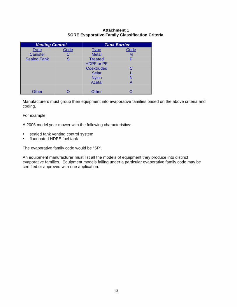
13
Attachment 1SORE Evaporative Family Classification Criteria
Venting Control Tank BarrierType Code Type Code
Canister C Metal MSealed Tank S Treated
HDPE or PEP
Coextruded CSelar LNylon NAcetal A
Other O Other O
Manufacturers must group their equipment into evaporative families based on the above criteria andcoding.
For example:
A 2006 model year mower with the following characteristics:
§ sealed tank venting control system§ fluorinated HDPE fuel tank
The evaporative family code would be “SP”.
An equipment manufacturer must list all the models of equipment they produce into distinctevaporative families. Equipment models falling under a particular evaporative family code may becertified or approved with one application.

14
Attachment 2SMALL OFF-ROAD EQUIPMENT CERTIFICATION
Certification Summary Sheet
Model Year: Application Type:Manufacturer: Executive Order:Evaporative Family Name:Engine families within the evaporative family above:
Certification for Diurnal Emissions:a) New Testing? _____ if carry over/carry across, from evaporative family:______________b) Test Engine or Equipment Model: ____________ Test Equipment ID: ___________c) Test Fuel: _____________ d) Running Loss Vented Emissions Controlled (yes/no): e) Test Procedure: _____________f) Declared Evaporative Family Emissions Limit Differential (EFELD) in grams HC/day: Special Test Equipment
For Systems Certified to Performance Standards
Official 24-Hour Diurnal Test Results, g/dayTest No.
AndType
(CertificationCTG or
ConfirmatoryRTG)
Certification Test Result (g/day) Standard (g/day)
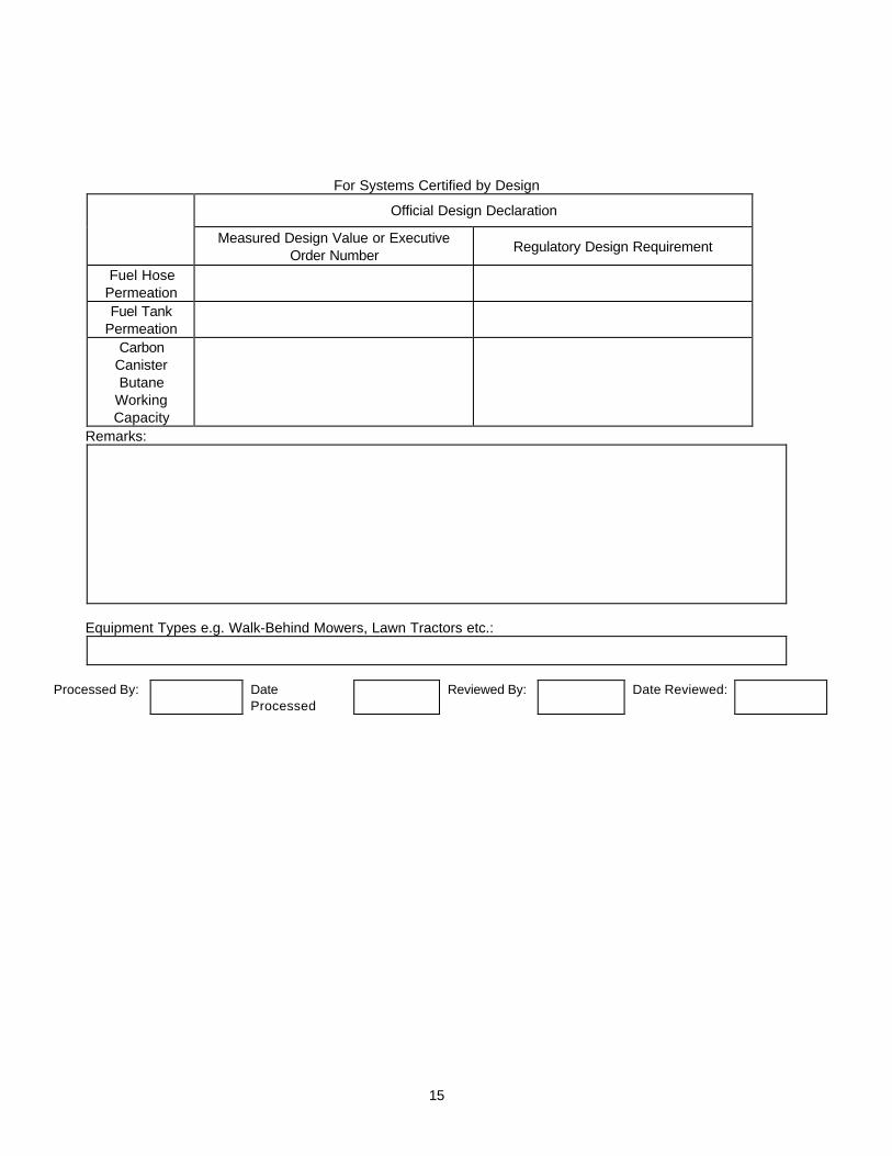
15
For Systems Certified by Design
Official Design Declaration
Measured Design Value or ExecutiveOrder Number
Regulatory Design Requirement
Fuel HosePermeationFuel Tank
PermeationCarbon
CanisterButane
WorkingCapacity
Remarks:
Equipment Types e.g. Walk-Behind Mowers, Lawn Tractors etc.:
Processed By: DateProcessed
Reviewed By: Date Reviewed:

16
Attachment 3Certification Database Form(Supplementary Information)
S1. MODEL SUMMARY (Use an asterisk (*) to identify “worst-case” equipment model used for certification testing.)
S3.Sales Codes
(Check all appropriate)
S2.
Engine orEquipment
Model Calif.Only
49-State
50-State
S4.
EngineClass(I or II)
S5.
FuelSystem(FI orCarb)
S6.
FuelTankVol.
(liters)
S7.
Fuel TankInternal
Surf. Area(m2)
S8.
FuelLineType
S9.
FuelLine
Length(mm)
S10.
FuelLine
InsideDia.(mm)

17
S11. LABELING: Evaporative emission label format approved? No____ Yes ___ If yes, reference approval:___________ Sample label attached? No____ Yes (put label in #S13)____
S12. WARRANTY: Evaporative emission warranty approved? No___ (Provide full warranty statement in #S15) Yes ___ (Reference approval: _______________ )
Have any changes been made since the last approval? No____ Yes ____ If yes, provide an explanation of thechanges: _______________________________________________________________________________________________________________________________________________________________________________________________________________________________________________________________________________________________________________________________________________________________________________________________________________________________
S13. EVAPORATIVE EMISSION LABEL INFORMATION
S14. ADJUSTABLE PARAMETERS AND ANTI-TAMPERING MEASURES
Parameter Adjustable Range(or N/A)
Tamper Resistance Method (or N/A)
Approval Reference

18
S15. EVAPORATIVE EMISSION WARRANTY STATEMENT

19
S16. ADDITIONAL INFORMATION AND COMMENTS

Small Off-Road Engine and Equipment Evaporative Emissions TestProcedure
TP - 902
Test Procedure for Determining Diurnal EvaporativeEmissions from Small Off-Road Engines and Equipment
Adopted: July 26, 2004
i
TP-902TABLE OF CONTENTS
Section Page1. APPLICABILITY .......................................................................................................... 11.1 Requirement to Comply with all Other Applicable Codes and Regulations...... 11.2 Safety......................................................................................................................... 12. PERFORMANCE STANDARDS................................................................................... 13. PRE-CERTIFICATION REQUIREMENTS.................................................................... 23.1 Durability ................................................................................................................... 23.2 Canister Working Capacity...................................................................................... 33.3 Engine Purge ............................................................................................................ 34. GENERAL SUMMARY OF TEST PROCEDURE ......................................................... 35. INSTRUMENTATION................................................................................................... 45.1 Diurnal Evaporative Emission Measurement Enclosure .................................... 45.2 Calibrations............................................................................................................... 66. TEST PROCEDURE .................................................................................................... 96.1 Fuel Tank / Fuel System Preconditioning.............................................................. 106.2 Refueling and Hot Soak Test .................................................................................. 116.3 Forced Cooling......................................................................................................... 116.4 24-Hour Diurnal Test ................................................................................................ 116.5 Calculation of Mass of Diurnal Evaporative Emissions....................................... 117. TEST FUEL ................................................................................................................. 118. ALTERNATIVE TEST PROCEDURES.......................................................................... 129. REFERENCES ............................................................................................................ 12
LIST OF TABLES AND FIGURESTABLE TITLE Page6-1 Diurnal Temperature Profile ................................................................. 11
FIGURE Page1 24-Hour Diurnal Test Sequence ........................................................... 10
ATTACHMENT1 Procedure for Determining Carbon Canister Performance
1
California Environmental Protection AgencyAir Resources Board
Small Off-Road Engine and Equipment Evaporative Emissions TestProcedure
TP-902
Test Procedure for Determining Diurnal EvaporativeEmissions from Small Off-Road Engines and Equipment
A set of definitions common to all Certification and Test Procedures are in Title 13, California Codeof Regulations (CCR), Section 2752 et seq.
For the purpose of this procedure, the term "CARB" refers to the California Air Resources Board,and the term "Executive Officer" refers to the CARB Executive Officer or his or her authorizedrepresentative or designate.
1. APPLICABILITY
This Test Procedure, TP-902, is used by the Air Resources Board to determine the diurnal andresting loss evaporative emissions from small off-road engines and equipment less than orequal to 19 kilowatts. Small off-road engines are defined in Title 13, California Code ofRegulations (CCR), section 2401 et seq. This Test Procedure is proposed pursuant to Section43824 of the California Health and Safety Code (CH&SC) and is applicable in all cases wheresmall off-road engines are sold, supplied, offered for sale, or manufactured for use in the Stateof California.
1.1 Requirement to Comply with All Other Applicable Codes and Regulations
Certification or approval of any engine or evaporative emission control system by theExecutive Officer does not exempt the engine or evaporative emission control system fromcompliance with other applicable codes and regulations such as state and federal safetycodes and regulations.
1.2 Safety
This test procedure involves the use of flammable materials and operations and shouldonly be used by or under the supervision of those familiar and experienced in the use ofsuch materials and operations. Appropriate safety precautions should be observed at alltimes while performing this test procedure.
2. PERFORMANCE STANDARDS
The minimum performance standards for certification of evaporative emission control systemson small off-road engines or equipment that use small off-road engines is defined in CCR Title13, Chapter 15, Article 1, Section 2754.
2
3. PRE-CERTIFICATION REQUIREMENTS
3.1 Durability
A demonstration of durability of the applicant’s evaporative emission control system is requiredprior to performing an evaporative emissions test.
Prior to the commencement of a durability demonstration, the applicant is required tosubmit and obtain approval of an evaporative emission durability test procedure. Onceapproved, a manufacturer is not required to obtain a new approval for an evaporativeemission durability demonstration unless changes result in new testing requirements.
Tanks that have a secondary operation for drilling holes for insertion of fuel line andgrommet system may have these eliminated for purposes of durability demonstration.
Components shall be deemed acceptable if they remain functional after the durabilitydemonstration prescribed below. Fuel tanks utilized for certification must havepressure/vacuum (if applicable) and slosh testing prior to certification testing.
The Executive Officer shall review the method based on the following requirements:
(a) The durability test must actuate control valves, cables, and linkages, whereapplicable, for a minimum of 5000 cycles.
(b) The Pressure/Vacuum test is performed prior to any preconditioning of the fueltank. Determine the fuel tank system’s design pressure and vacuum limits undernormal operating conditions considering the influence of any associatedpressure/vacuum relief components. Pressurize the empty tank, sealed with theOEM fuel cap, or a modified OEM fuel cap as required, to within 10% of thesystem’s normal high pressure operating limit and then evacuate to within 10% ofthe system’s normal vacuum operating limit. If the fuel tank has no features thatwould cause positive or negative pressures during normal operation, thenpressure/vacuum cycling is not required. The tank pressure/vacuum cycling shallbe performed in a 49º C+/- 3º C ambient with compressed air of no less than 21º C. Repeat the pressure/vacuum process until the tank has been subjected to not lessthan 1000 cycles in 8 hours +/- 1 hour.
(c) The durability test must include a slosh test of the engines fuel tank. The slosh testcan be performed during the preconditioning period. A slosh test must beperformed on a fuel tank filled to 50 percent capacity with CERT fuel. The fuel tankmust be sealed with the OEM fuel cap. A laboratory orbital shaker table or similardevice is then used to subject the tank to a peak horizontal centripetal accelerationof at least 2.4 meter/second2 at a frequency of 2 cycles per second +/- 0.25 for onemillion cycles. As an alternative, slosh testing may be performed using the methodspecified in 40 CFR Part 1051 §1051.515 (c).
(d) For systems that utilize a carbon canister, the durability test procedure(s) shallinclude thermal cycling and vibration exposure of the canister.
(1) For thermal cycling, the test must subject the canister to 100 cycles of thefollowing temperature profile:
(A) Heat and hold at 60ºC ± 2ºC for 30 minutes. (Up to 10 minutes is allowed forthe temperature to rise and stabilize.)

3
(B) Cool and hold at 0ºC ± 2ºC for 30 minutes. (Up to 20 minutes is allowed for thetemperature to reach 0ºC during the cooling period.)
(2) For vibration exposure, at a minimum, the canister must be placed in a suitable testfixture while maintaining its specified orientation (as designed). Subject the fixtureto a peak horizontal vibration force of 4.5G x 60Hz x 107 times.
3.2 Canister Working Capacity
(a) For evaporative emission control systems that only use a carbon canister and donot pressurize the fuel tank, the carbon canister must have a working capacity of atleast 1.4 grams of vapor storage capacity per liter of nominal fuel tank volume fortanks greater than or equal to 3.78 liters, and 1.0 grams of vapor storage capacityper liter of nominal fuel tank volume for tanks less than 3.78 liters. For evaporativeemission control systems that use a carbon canister and pressurized fuel tank, theworking capacity must be specified by the applicant. For all systems utilizingactively purged carbon canisters, running loss emissions must be controlled frombeing emitted into the atmosphere.
(b) Working capacity is determined following the procedure in Attachment 1 of this testprocedure. In lieu of the loading and purge rates specified in Attachment 1, thecanister manufacturer’s maximum loading and purge rates may be used.
3.3 Engine Purge
If a canister is used, the engine must actively purge the canister when the engine isrunning. This requirement may not apply to Small Production Volume Tanks specified in 13CCR 2766.
4. GENERAL SUMMARY OF TEST PROCEDURE
A Sealed Housing for Evaporative Determination (SHED) is used to measure diurnal emissions.This method subjects test engines to a preprogrammed temperature profile while maintaining aconstant pressure and continuously sampling for hydrocarbons with a Flame Ionization Detector(FID). The volume of a SHED enclosure can be accurately determined. The mass of totalhydrocarbons that emanates from a test engine over the test period is calculated using the idealgas equation.
This test procedure measures diurnal emissions from engines or equipment with completeevaporative emission control systems as defined in 13 CCR 2752 (a)(8) by subjecting them to ahot soak and diurnal test sequence. The engine with complete evaporative emission controlsystem can be tested without the equipment chassis. The basic process is as follows:
§ Fill the engine fuel tank with fuel and operate at maximum governed speed for 5-minutes§ Precondition the evaporative emission control and fuel delivery system§ Drain and fill fuel tank to 50% capacity with California certification fuel§ Purge carbon canister (if so equipped) with 400 bed volumes of nitrogen or dry air at the
canister manufacturer’s recommended rate§ Operate engine at the maximum governed speed for fifteen minutes§ Subject engine/equipment to a one-hour constant 95°F hot soak§ Soak engine/equipment for two hours at 65°F
4
§ Subject engine/equipment to a 24-hour variable (65°F - 105°F - 65°F) temperature diurnalprofile
The mass of total hydrocarbons measured by the SHED over the 24-hour diurnal profile iscompared with the performance standards in CCR Title 13, Chapter 15, Article 1, Section 2754.Engines or equipment that meet the appropriate performance standard shall be consideredcompliant.
5. INSTRUMENTATION
The instrumentation necessary to perform evaporative emission testing for small off-road enginesis the same instrumentation used for passenger cars and light duty vehicles, and is described in40 CFR 86.107-96. The ARB will consider data generated with mini-SHEDs as valid if approvedas an alternative test procedure.
5.1 Diurnal Evaporative Emission Measurement Enclosure
References to methanol in this test procedure can be disregarded.
The diurnal evaporative emissions measurement enclosure shall be equipped with aninternal blower or blowers coupled with an air temperature management system (typicallyair to water heat exchangers and associated programmable temperature controls) toprovide for air mixing and temperature control. The blower(s) shall provide a nominal totalflow rate of 0.8 ± 0.2 ft3/min per ft3 of the nominal enclosure volume, Vn. The inlets andoutlets of the air circulation blower(s) shall be configured to provide a well-dispersed aircirculation pattern that produces effective internal mixing and avoids significant temperatureor hydrocarbon and alcohol stratification. The discharge and intake air diffusers in theenclosure shall be configured and adjusted to eliminate localized high air velocities whichcould produce non-representative heat transfer rates between the engine fuel tank(s) andthe air in the enclosure. The air circulation blower(s), plus any additional blowers ifrequired, shall maintain a homogeneous mixture of air within the enclosure.
The enclosure temperature shall be taken with thermocouples located 3 feet above thefloor at the approximate mid-length of each side wall of the enclosure and within 3 to 12inches of each side wall. The temperature conditioning system shall be capable ofcontrolling the internal enclosure air temperature to follow the prescribed temperatureversus time cycle as specified in 40 CFR §86.133-90 as modified by paragraph III.D.10(diurnal breathing loss test) of the “California Evaporative Emission Standards and TestProcedures for 2001 and Subsequent Model Motor Vehicles” within an instantaneoustolerance of ± 3.0oF and an average tolerance of ± 2.0oF as measured by side wallthermocouples. The control system shall be tuned to provide a smooth temperaturepattern, which has a minimum of overshoot, hunting, and instability about the desired long-term temperature profile.
The enclosure shall be of sufficient size to contain the test equipment with personnelaccess space. It shall use materials on its interior surfaces, which do not adsorb or desorbhydrocarbons, or alcohols (if the enclosure is used for alcohol-fueled vehicles). Theenclosure shall be insulated to enable the test temperature profile to be achieved with aheating/cooling system, which has minimum surface temperatures in the enclosure no lessthan 25.0oF below the minimum diurnal temperature specification. The enclosure shall beequipped with a pressure transducer with an accuracy and precision of ± 0.1 inches H2O. The enclosure shall be constructed with a minimum number of seams and joints, whichprovide potential leakage paths. Particular attention shall be given to sealing andgasketing of such seams and joints to prevent leakage.

5
The enclosure shall be equipped with features, which provide for the effective enclosurevolume to expand and contract in response to both the temperature changes of the airmass in the enclosure, and any fluctuations in the ambient barometric pressure during theduration of the test. Either a variable volume enclosure or a fixed volume enclosure may beused for diurnal emission testing.
A variable volume enclosure shall have the capability of latching or otherwise constrainingthe enclosed volume to a known, fixed value, Vn. The Vn shall be determined by measuringall pertinent dimensions of the enclosure in its latched configuration, including internalfixtures, based on a temperature of 84oF, to an accuracy of ± 1/8 inch (0.5 cm) andcalculating the net Vn to the nearest 1 ft3. In addition, Vn shall be measured based on atemperature of 65oF and 105oF. The latching system shall provide a fixed volume with anaccuracy and repeatability of 0.005xVn. Two potential means of providing the volumeaccommodation capabilities are; a moveable ceiling which is joined to the enclosure wallswith a flexure, or a flexible bag or bags of Tedlar or other suitable materials, which areinstalled in the enclosure and provided with flowpaths which communicate with the ambientair outside the enclosure. By moving air into and out of the bag(s), the contained volumecan be adjusted dynamically. The total enclosure volume accommodation shall besufficient to balance the volume changes produced by the difference between the extremeenclosure temperatures and the ambient laboratory temperature with the addition of asuperimposed barometric pressure change of 0.8 in. Hg. A minimum total volumeaccommodation range of ± 0.07xVn shall be used. The action of the enclosure volumeaccommodation system shall limit the differential between the enclosure internal pressureand the external ambient barometric pressure to a maximum value of ± 2.0 inches H2O.
The fixed volume enclosure shall be constructed with rigid panels that maintain a fixedenclosure volume, which shall be referred to as Vn. Vn shall be determined by measuring allpertinent dimensions of the enclosure including internal fixtures to an accuracy of ± 1/8 inch(0.5 cm) and calculating the net Vn to the nearest 1 ft3. The enclosure shall be equippedwith an outlet flow stream that withdraws air at a low, constant rate and provides makeup airas needed, or by reversing the flow of air into and out of the enclosure in response to risingor falling temperatures. If inlet air is added continuously throughout the test, it must befiltered with activated carbon to provide a relatively constant hydrocarbon and alcohol level. Any method of volume accommodation shall maintain the differential between theenclosure internal pressure and the barometric pressure to a maximum value of ±2.0inches of water. The equipment shall be capable of measuring the mass of hydrocarbon,and alcohol (if the enclosure is used for alcohol-fueled equipment) in the inlet and outletflow streams with a resolution of 0.01 gram. A bag sampling system may be used to collecta proportional sample of the air withdrawn from and admitted to the enclosure. Alternatively, the inlet and outlet flow streams may be continuously analyzed using an on-line Flame Ionization Detector (FID) analyzer and integrated with the flow measurements toprovide a continuous record of the mass hydrocarbon and alcohol removal.
An online computer system or strip chart recorder shall be used to record the followingparameters during the diurnal evaporative emissions test sequence:
− Enclosure internal air temperature− Diurnal ambient air temperature specified profile as defined in 40 CFR §86.133-
90 as modified in paragraph III.D.10 of the “California Evaporative EmissionStandards and Test Procedures for 2001 and Subsequent Model MotorVehicles” (diurnal breathing loss test).
− Enclosure internal pressure− Enclosure temperature control system surface temperature(s)− FID output voltage recording the following parameters for each sample analysis:

6
− zero gas and span gas adjustments− zero gas reading− enclosure sample reading− zero gas and span gas readings
The data recording system shall have a time resolution of 30 seconds and shall provide apermanent record in magnetic, electronic or paper media of the above parameters for theduration of the test.
Other equipment configurations may be used if approved in advance by the ExecutiveOfficer. The Executive Officer shall approve alternative equipment configurations if themanufacturer demonstrates that the equipment will yield test results equivalent to thoseresulting from use of the specified equipment.
5.2 Calibrations
Evaporative emission enclosure calibrations are specified in 40 CFR §86.117-90. Methanolmeasurements may be omitted when methanol-fueled engines will not be tested in theevaporative enclosure. Amend 40 CFR §86.117-90 to include an additional subsection 1.1,to read:
The diurnal evaporative emission measurement enclosure calibration consists of thefollowing parts: initial and periodic determination of enclosure background emissions, initialdetermination of enclosure volume, and periodic hydrocarbon (HC) and methanol retentioncheck and calibration. Calibration for HC and methanol may be conducted in the same testrun or in sequential test runs.
5.2.1 The initial and periodic determination of enclosure background emissions shall beconducted according to the procedures specified in §86.117-90(a)(1) through(a)(6). The enclosure shall be maintained at a nominal temperature of 105.0oFthroughout the four-hour period. Variable volume enclosures may be operatedeither in the latched volume configuration, or with the variable volume featureactive. Fixed volume enclosures shall be operated with inlet and outlet flow streamsclosed. The allowable enclosure background emissions of HC and/or methanol ascalculated according to 40 CFR §86.117-90(a)(7) shall not be greater than 0.05grams in 4 hours. The enclosure may be sealed and the mixing fan operated for aperiod of up to 12 hours before the initial HC concentration reading (CHCi) and theinitial methanol concentration reading (CCH3OHi) is taken and the four-hourbackground measurement period begins.
5.2.2 The initial determination of enclosure internal volume shall be performed accordingto the procedures specified in paragraph I.A.1.3 of the “California EvaporativeEmission Standards and Test Procedures for 2001 and Subsequent Model MotorVehicles.” If the enclosure will be used for hot soak determination, the determinationof enclosure internal volume shall also be performed based on 105oF.
5.2.3 The HC and methanol measurement and retention checks shall evaluate theaccuracy of enclosure HC and methanol mass measurements and the ability of theenclosure to retain trapped HC and methanol. The check shall be conducted overa 24-hour period with all of the normally functioning subsystems of the enclosureactive. A known mass of propane and/or methanol shall be injected into theenclosure and an initial enclosure mass measurement(s) shall be made. Theenclosure shall be subjected to the temperature cycling specified in paragraphIII.D.10.1.7 of the “California Evaporative Emission Standards and Test Procedures

7
for 2001 and Subsequent Model Motor Vehicles” (revising 40 CFR §86.133-90(l))for a 24-hour period. The temperature cycle shall begin at 105EF (hour 11) andcontinue according to the schedule until a full 24-hour cycle is completed. A finalenclosure mass measurement(s) shall be made. The following procedure shall beperformed prior to the introduction of the enclosure into service and following anymodifications or repairs to the enclosure that may impact the integrity of thisenclosure; otherwise, the following procedure shall be performed on a monthlybasis. (If six consecutive monthly retention checks are successfully completedwithout corrective action, the following procedure may be determined quarterlythereafter as long as no corrective action is required.)
(A) Zero and span the HC analyzer.
(B) Purge the enclosure with atmospheric air until a stable enclosure HC level isattained.
(C) Turn on the enclosure air mixing and temperature control system and adjustit for an initial temperature of 105.0oF and a programmed temperatureprofile covering one diurnal cycle over a 24 hour period according to theprofile specified in paragraph III.D.10.1.7. Of the “California EvaporativeEmission Standards and Test Procedures for 2001 and Subsequent ModelMotor Vehicles” (revising 40 CFR §86.133-90). Close the enclosure door. On variable volume enclosures, latch the enclosure to the enclosure volumemeasured at 105oF. On fixed volume enclosures, close the outlet and inletflow streams.
(D) When the enclosure temperature stabilizes at 105.0oF ± 3.0oF seal theenclosure; measure the enclosure background HC concentration (CHCe1)and/or background methanol concentration (CCH3OH1) and the temperature(T1), and pressure (P1) in the enclosure.
(E) Inject into the enclosure a known quantity of propane between 2 to 6 gramsand a known quantity of methanol in gaseous form between 2 to 6 grams. For evaporative emission enclosures that will be used for testing equipmentsubject to the standards shown in Table 2-1, use a known amount ofpropane or gaseous methanol between 0.5 to 1.0 grams. The injectionmethod shall use a critical flow orifice to meter the propane and/or methanolat a measured temperature and pressure for a measured time period. Techniques that provide an accuracy and precision of ± 0.5 percent of theinjected mass are also acceptable. Allow the enclosure internal HC and/ormethanol concentration to mix and stabilize for up to 300 seconds. Measurethe enclosure HC concentration (CHCe2) and/or the enclosure methanolconcentration (CCH3OH2). For fixed volume enclosures, measure thetemperature (T2) and pressure in the enclosure (P2). On variable volumeenclosures, unlatch the enclosure. On fixed volume enclosures, open theoutlet and inlet flow streams. Start the temperature cycling function of theenclosure air mixing and temperature control system. These steps shall becompleted within 900 seconds of sealing the enclosure.
(F) For fixed volume enclosures, calculate the initial recovered HC mass (MHCe1)according to the following formula:
MHCe1 = (3.05 x V x 10-4 x [P2 (CHCe2 - rCCH3OH2 )/T2 - P1 (CHCe1 - rCCH3OH1)/T1])
Where:

8
V is the enclosure volume at 105oF (ft3)P1 is the enclosure initial pressure (inches Hg absolute)P2 is the enclosure final pressure (inches Hg absolute)CHCen is the enclosure HC concentration at event n (ppm C)
CCH3OHn is the enclosure methanol concentration calculatedaccording to 40 CFR §86.117-90 (d)(2)(iii) at event n (ppm C)r is the FID response factor to methanolT1 is the enclosure initial temperature (oR)T2 is the enclosure final temperature (oR)
For variable volume enclosures, calculate the initial recovered HC mass andinitial recovered methanol mass according to the equations used aboveexcept that P2 and T2 shall equal P1 and T1.
Calculate the initial recovered methanol mass (MCH3OH1) according to 40CFR §86.117-96(d)(1), as amended March 24, 1993.
If the recovered HC mass agrees with the injected mass within 2.0 percentand/or the recovered methanol mass agrees with the injected mass within6.0 percent, continue the test for the 24 hour temperature cycling period. Ifthe recovered mass differs from the injected mass by greater than theacceptable percentage(s) for HC and/or methanol, repeat the enclosureconcentration measurement in step (E) and recalculate the initial recoveredHC mass (MHCe1) and/or methanol mass (MCH3OH1). If the recovered massbased on the latest concentration measurement agrees within theacceptable percentage(s) of the injected mass, continue the test for the 24-hour temperature cycling period and substitute this second enclosureconcentration measurement for CHCe2 and/or CCH3OH2 in all subsequentcalculations. In order to be a valid calibration, the final measurement ofCHCe2 and CCH3OH2 shall be completed within the 900-second time limitoutlined above. If the discrepancy persists, the test shall be terminated andthe cause of the difference determined, followed by the correction of theproblems(s) and the restart of the test.
(G) At the completion of the 24-hour temperature cycling period, measure thefinal enclosure HC concentration (CHCe3) and/or the final enclosure methanolconcentration (CCH3OH3). For fixed-volume enclosures, measure the finalpressure (P3) and final temperature (T3) in the enclosure.
For fixed volume enclosures, calculate the final recovered HC mass (MHCe2)as follows:
MHCe2 = [3.05 x V x 10-4 x(P3 (CHCe3 - rCCH3OH3)/T3 - P1 (CHCe1 - rCCH3OH1)/T1)] + MHC,out - MHC, in
Where:
V is the enclosure volume at 105oF (ft3)P1 is the enclosure initial pressure (inches Hg absolute)P3 is the enclosure final pressure (inches Hg absolute)CHCe3 is the enclosure HC concentration at the end of the 24-hour
temperature cycling period (ppm C)CCH3OH3 is the enclosure methanol concentration at the end of the 24-hour
temperature cycling period, calculated according to 40 CFR §86.117-90
9
(d)(2)(iii) (ppm C)r is the FID response factor to methanolT1 is the enclosure initial temperature (oR)T3 is the enclosure final temperature (oR)MHC,out is mass of HC exiting the enclosure, (grams)MHC,in is mass of HC entering the enclosure, (grams)
For variable volume enclosures, calculate the final recovered HC mass andfinal recovered methanol mass according to the equations used aboveexcept that P3 and T3 shall equal P1 and T1, and MHC, out and MHC, in shallequal zero.
Calculate the final recovered methanol mass (MCH3OH2) according to 40 CFR§86.117-96(d)(1), as amended March 24, 1993.
(H) If the calculated final recovered HC mass for the enclosures is not within 3percent of the initial enclosure mass, or if the calculated final recoveredmethanol mass for the enclosures is not within 6 percent of the initialenclosure mass, then action shall be required to correct the error to theacceptable level.
6. TEST PROCEDURE
The test sequence is shown graphically in Figure 1. Methanol measurements may be omittedwhen methanol-fueled equipment will not be tested in the evaporative enclosure. Thetemperatures monitored during testing shall be representative of those experienced by theequipment. The equipment shall be approximately level during all phases of the test sequenceto prevent abnormal fuel distribution. The temperature tolerance of a soak period may bewaived for up to 10 minutes to allow purging of the enclosure or transporting the equipment intothe enclosure.
Testing a representative piece of equipment for each evaporative family and comparing theresults to the appropriate performance standard determines compliance with requirements ofCCR Title 13, Chapter 15, Article 1, Section 2754.
The 24-hour diurnal test sequence is shown in Figure 1.

10
6.1 Fuel Tank / Fuel System Preconditioning
The purpose of the preconditioning period is to introduce gasoline into the fuel system andprecondition all fuel system components. Precondition the tank and other fuel deliverysystem components by filling the tank to its nominal capacity with fresh test fuel as specifiedin Section 7 of these procedures. After filling the tank start the engine and allow it to run atrated speed (unloaded or blade load) for approximately five minutes. Soak the tank andother components at 30º C + 10º C for not less than 140 days. Data documenting that thetank has reached equilibrium must be provided for tanks soaked less than 140 days. Theperiod of slosh testing may be considered part of the preconditioning period provided eachtank and all fuel system components tested remain filled with fuel and are never empty formore than one hour over the entire preconditioning period.
As an alternative, accelerated preconditioning of the tank and components can beaccomplished by soaking both at an elevated temperature. Precondition the tank and otherfuel delivery system components by filling the tank to its nominal capacity with fresh test fuelas specified in Section 7 of these procedures. After filling the tank start the engine andallow it to run at maximum governed speed (unloaded or blade load) for approximately fiveminutes. Begin soaking the tank and other components at 40º C + 2º C. For engines withfuel tanks that have a nominal wall thickness of not greater than 0.15”, soak the tank andall fuel system components for not less than 30 days. For engines with fuel tanks that havea nominal wall thickness of greater than 0.15” but less than or equal to 0.2”, soak the tank
Start
Perform Durability DemonstrationFill Engine Fuel Tank with fuel
and Operate for 5 MinutesPrecondition the Engines Evaporative
Emission / Fuel Delivery System
Drain and fill tank to 50% capacitywith test fuel
Purge Carbon Canister (if equipped)Operate for 15 Minutes
Perform a one-hour hot soak at aconstant 95°F
Perform a 24-hour diurnal testusing a (65°F-105°F-65°F)
variable temperature profile
End
Cool Enclosure to 65F thenSoak System at 65°F for 2 hours
Figure 1.
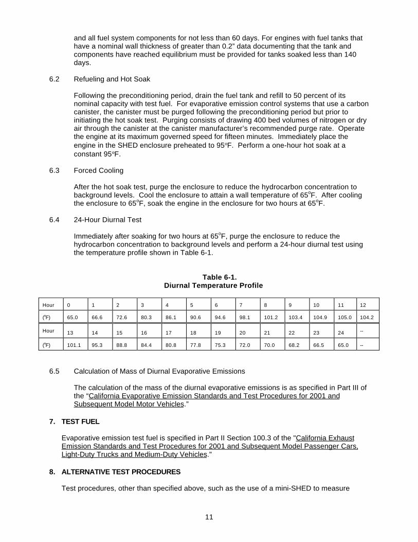
11
and all fuel system components for not less than 60 days. For engines with fuel tanks thathave a nominal wall thickness of greater than 0.2” data documenting that the tank andcomponents have reached equilibrium must be provided for tanks soaked less than 140days.
6.2 Refueling and Hot Soak
Following the preconditioning period, drain the fuel tank and refill to 50 percent of itsnominal capacity with test fuel. For evaporative emission control systems that use a carboncanister, the canister must be purged following the preconditioning period but prior toinitiating the hot soak test. Purging consists of drawing 400 bed volumes of nitrogen or dryair through the canister at the canister manufacturer’s recommended purge rate. Operatethe engine at its maximum governed speed for fifteen minutes. Immediately place theengine in the SHED enclosure preheated to 95°F. Perform a one-hour hot soak at aconstant 95°F.
6.3 Forced Cooling
After the hot soak test, purge the enclosure to reduce the hydrocarbon concentration tobackground levels. Cool the enclosure to attain a wall temperature of 65oF. After coolingthe enclosure to 65oF, soak the engine in the enclosure for two hours at 65oF.
6.4 24-Hour Diurnal Test
Immediately after soaking for two hours at 65oF, purge the enclosure to reduce thehydrocarbon concentration to background levels and perform a 24-hour diurnal test usingthe temperature profile shown in Table 6-1.
Table 6-1. Diurnal Temperature Profile
Hour 0 1 2 3 4 5 6 7 8 9 10 11 12
(oF) 65.0 66.6 72.6 80.3 86.1 90.6 94.6 98.1 101.2 103.4 104.9 105.0 104.2
Hour 13 14 15 16 17 18 19 20 21 22 23 24 --
(oF) 101.1 95.3 88.8 84.4 80.8 77.8 75.3 72.0 70.0 68.2 66.5 65.0 --
6.5 Calculation of Mass of Diurnal Evaporative Emissions
The calculation of the mass of the diurnal evaporative emissions is as specified in Part III ofthe “California Evaporative Emission Standards and Test Procedures for 2001 andSubsequent Model Motor Vehicles.”
7. TEST FUEL
Evaporative emission test fuel is specified in Part II Section 100.3 of the "California ExhaustEmission Standards and Test Procedures for 2001 and Subsequent Model Passenger Cars,Light-Duty Trucks and Medium-Duty Vehicles."
8. ALTERNATIVE TEST PROCEDURES
Test procedures, other than specified above, such as the use of a mini-SHED to measure
12
diurnal evaporative emissions, shall only be used if prior written approval is obtained from theARB Executive Officer. In order to secure the ARB Executive Officer's approval of an alternativetest procedure, the applicant is responsible for demonstrating to the ARB Executive Officer'ssatisfaction that the alternative test procedure is equivalent to this test procedure.
(1) Documentation of any such approvals, demonstrations, and approvals shall bemaintained by the ARB Executive Officer and shall be made available upon request.
(2) Once approved for use, an alternative test procedure may be used and referenced byany manufacturer subject to the limitations and constraints in the Executive Orderapproving the alternative test procedure.
9. REFERENCES
1. California Evaporative Emission Standards and Test Procedures for 2001 and SubsequentModel Passenger Cars, Light-Duty Trucks, and Medium-Duty Vehicles, CaliforniaEnvironmental Protection Agency, Air Resources Board, El Monte, CA, 2000.
2. California Exhaust Emission Standards and Test Procedures for 2001 and SubsequentModel Passenger Cars, Light-Duty Trucks and Medium-Duty Vehicles, CaliforniaEnvironmental Protection Agency, Air Resources Board, El Monte, CA, 2002.
3. 40 CFR Part 86

1
Attachment 1 to TP-902
Procedure forDetermining Carbon Canister Performance:
Working Capacity

2
Attachment 1TABLE OF CONTENTS
1. APPLICABILITY................................................................................................................... 4
1.1 Requirement to Comply with All Other Applicable Codes and Regulations 4
1.2 Safety.................................................................................................................................. 4
2. PRINCIPLE AND SUMMARY OF TEST PROCEDURE ......................................................... 4
3. BIASES AND INTERFERENCES.......................................................................................... 4
4. SENSITIVITY AND RANGE .................................................................................................. 4
5. EQUIPMENT CALIBRATIONS .............................................................................................. 5
6. CARBON CANISTER WORKING CAPACITY DETERMINATION........................................... 5
6.1. Number of Test Cycles........................................................................................................ 5
6.2. Canister Purge.................................................................................................................... 5
6.3. Pause.................................................................................................................................. 6
6.4. Measurement ...................................................................................................................... 6
6.5. Canister Load ..................................................................................................................... 6
7. CALCULATING RESULTS................................................................................................... 6
8. QUALITY ASSURANCE / QUALITY CONTROL (QA/QC) ..................................................... 6
9. RECORDING DATA............................................................................................................. 6
10. FIGURES............................................................................................................................. 6
3
LIST OF FIGURES
Figure 1 ........................................................................................................................................... 7
4
Small Off-Road Engine Evaporative Emissions Test Procedure
Attachment 1
Procedure forDetermining Carbon Canister Performance:
Durability Demonstration and Working Capacity
A set of definitions common to all Certification and Test Procedures are in Title 13, California Codeof Regulations (CCR), Section 2752 et seq.For the purpose of this procedure, the term "CARB" refers to the California Air Resources Board,and the term "Executive Officer" refers to the CARB Executive Officer, or his or her authorizedrepresentative or designate.
1 APPLICABILITY
This Test Procedure is used by the Air Resources Board to determine the performance ofcarbon canisters used to control evaporative emission from equipment that use gasolinepowered small off-road engines. Small off-road engines are defined in Title 13, California Codeof Regulations (CCR), section 2401 et seq. This Test Procedure is proposed pursuant toSection 43824 of the California Health and Safety Code (CH&SC) and applies to engine orequipment manufacturers seeking an Executive Order for a evaporative control system utilizinga carbon canister.
1.1 Requirement to Comply with All Other Applicable Codes and Regulations
Approval of an evaporative emission control component, technology, or system by theExecutive Officer does not exempt the same from compliance with other applicable codesand regulations such as state and federal safety codes and regulations.
1.2 Safety
This test procedure involves the use of flammable liquids and operations and should onlybe used by or under the supervision of those familiar and experienced in the use of suchmaterials and operations. Appropriate safety precautions should be observed at all timeswhile performing this test procedure.
2 PRINCIPLE AND SUMMARY OF TEST PROCEDURE
These test procedures are designed to provide consistent methods to evaluate the durability andworking capacity of carbon canisters utilized on small engine powered equipment.
Working capacity is a defining parameter expressing the mass of hydrocarbons that can be storedin the canister under controlled conditions. The canister’s working capacity is established byrepeated canister loading and purging. This procedure involves a cycle that includes a 400 bedvolume purge, a 5 minute pause, and then loading the canister with butane mixed 50/50 by volumewith air or nitrogen to a measured breakthrough.
3 BIASES AND INTERFERENCES
To accurately quantify the working capacity the complete test system must be leak tight. Loosefittings and connectors may result in leaks that can significantly affect working capacity
5
determinations.
Care should be taken to minimize or limit the humidity of the air or nitrogen used to purge thecanister. Humid purge air can bias canister desorption weight measurements. Dryerite (CaCl2),or other suitable dehumidification methods, must be used to control the humidity of the purgeair.
4 SENSITIVITY AND RANGE
The minimum sensitivity of the balance must be selected using good engineering judgment.
5 EQUIPMENT CALIBRATIONS
Mass flow meters must undergo an annual multiple point calibration with a primary standardand have a R2 coefficient of 0.99 or greater.
The top loading balance must be calibrated with ASTM Class I weights prior to use per themanufacturer specifications. Prior to use the balance must be challenged with weights aboveand below the range of mass measurements.
6 CARBON CANISTER WORKING CAPACITY DETERMINATION
6.1 Number of Test Cycles
Working capacity is determined through cyclic loading and purging of a carbon canister. Tenor more cycles may be required to stabilize new carbon. A minimum of three cycles isadequate if the carbon has a previous history of stabilization with butane or gasoline vapors.The “working capacity” value is the average of the butane mass supplied to the canister for lasttwo repeatable cycles.
6. 2 Canister Purge
The sequence starts by first purging the canister with 400 bed volumes of dry air ornitrogen in 30 minutes at laboratory conditions. Bed volume is the design volume of thecarbon contained in the canister. Purge for all the canister models is defined as a 400 bedvolume purge in approximately 30 minutes. The purge rate will therefore vary with canistersize. Purge may be accomplished by drawing a vacuum at the tank or purge port, or bypushing air or N2 into the atmospheric vent.

6
6.3 Pause
Pause testing for approximately 5 minutes between both purge and load and also load andpurge sequences.
6.4 Measurement
Weigh the test canister before and after each canister load sequence.
6.5 Canister Load
Load the test canister with butane mixed 50/50 by volume with air or nitrogen until thespecified breakthrough criteria has been met. The canister load is accomplished by flowingthe butane mixture into the canister via the tank fitting. The butane load rates andbreakthrough criteria are determined by canister’s bed volume. In order to accommodatethe expected wide range of canister bed volumes expected in the small engine poweredequipment, four ranges of canister loading and breakthrough criteria are defined: small (<99cc), medium (100 to 249cc) large (249 to 550cc) and extra large (> 550cc). The loadand breakthrough criteria are defined as follows:
Carbon Canister Bed Volume Small< 99cc
Medium100 to249cc
Large 249cc to
550
Extra Large>550
Butane Load Rate [grams C4H10
/ hour]5.0 10.0 15.0 15.0
Break-through limit [grams](*) 2.0 2.0 2.0 2.0(*). If the canister shows weight loss prior to the 2.0 grams breakthrough then an alternate lower
breakthough limit can be used.
7 CALCULATING RESULTS
The working capacity is the average test canister weight gain in grams determined from the lasttwo load cycles. The resultant working capacity is expressed in grams of C4H10
8 QUALITY ASSURANCE / QUALITY CONTROL (QA/QC)
This section is reserved for future specification.
9 RECORDING DATA
Record data on a form similar to the one shown in Figure 1 (see page 7).
10 FIGURES
Figure 1. Canister Data Sheet

7
Figure 1 Canister Data Sheet
Canister Manufacturer:
Canister I.D:
Tested By:
Canister Volume [cc]:
Canister Purge DataTime
Start/EndDuration
[seconds]Flow RateQ [LPM]
Initial WeightWi [grams]
Final WeightWf [grams]
Weight LossWl [grams]
Canister Load DataTime
Start/EndDuration
[seconds]Butane Rate
Qb [g/hr]Initial WeightWi [grams]
Final WeightWf [grams]
Break-Through
Wb [grams]
WeightGain
Wg [grams]
Working Capacity [grams C4H10]
Small Off-Road Engine and Equipment Evaporative Emissions TestProcedure
TP - 901
Test Procedure for Determining Permeation Emissionsfrom Small Off-Road Engines and Equipment Fuel Tanks
Adopted: July 26, 2004
TP-901TABLE OF CONTENTS
Section Page1 APPLICABILITY ..................................................................................................... 11.1 Requirement to Comply with All Other Applicable Codes and
Regulations.......................................................................................................... 1
1.2 Safety.................................................................................................................... 12 PERFORMANCE STANDARDS.............................................................................. 13 PRINCIPAL AND SUMMARY OF TEST PROCEDURE .......................................... 24 BIASES AND INTERFERENCES............................................................................ 25 SENSITIVITY AND RANGE .................................................................................... 26 EQUIPMENT .......................................................................................................... 27 CALIBRATION PROCEDURE................................................................................. 38 DURABILITY DEMONSTRATION........................................................................... 39 PRECONDITIONING PROCEDURE ...................................................................... 410 SEALING PROCEDURE......................................................................................... 411 TEST PROCEDURE WITH TRIP BLANK CORRECTION........................................ 412 QUALITY ASSURANCE/ QUALITY CONTROL....................................................... 513 RECORDING DATA................................................................................................ 514 CALCULATING PERMEATION RATE USING TRIP BLANK CORRECTION........... 515 ALTERNATIVE TEST PROCEDURES..................................................................... 6
16 REFERENCES ....................................................................................................... 617 FIGURES ............................................................................................................... 6
LIST OF FIGURESFIGURE Page1 FIELD DATA SHEET (Trip Blank Correction) .................................................... 7
1
California Environmental Protection AgencyAir Resources Board
Small Off-Road Engine and Equipment Evaporative Emissions TestProcedure
TP-901
Test Procedure for Determining Permeation Emissionsfrom Small Off-Road Engines and Equipment Fuel Tanks
A set of definitions common to all Certification and Test Procedures are in Title 13, California Codeof Regulations (CCR), Section 2752 et seq.
For the purpose of this procedure, the term "CARB" refers to the California Air Resources Board,and the term "Executive Officer" refers to the CARB Executive Officer, or his or her authorizedrepresentative or designate.
1. APPLICABILITY
This Test Procedure, TP-901, is used by the Air Resources Board to determine the permeationrate from fuel tanks of equipment that use spark ignited small off-road engines and equipment.Small off-road engines (SORE) are defined in Title 13, California Code of Regulations (CCR),section 2401 et seq. This Test Procedure is proposed pursuant to Section 43824 of theCalifornia Health and Safety Code (CH&SC) and is applicable in all cases where equipment withfuel tanks subject to the maximum allowable permeation performance standard are sold,supplied, offered for sale, or manufactured for use in the State of California.
1.1 Requirement to Comply with All Other Applicable Codes and Regulations
Certification or approval of an equipment fuel tank by the Executive Officer does not exemptthe fuel tank from compliance with other applicable codes and regulations such as stateand federal safety codes and regulations.
1.2 Safety
This test procedure involves the use of flammable materials and operations and shouldonly be used by or under the supervision of those familiar and experienced in the use ofsuch materials and operations. Appropriate safety precautions should be observed at alltimes while performing this test procedure.
2. PERFORMANCE STANDARDS
The minimum performance standards for certification of evaporative emission control systemson small off-road engines or equipment that use small off-road engines are defined in CCRTitle 13, Chapter 15, Article 1, Section 2755 and Section 2754.
3. PRINCIPLE AND SUMMARY OF TEST PROCEDURE
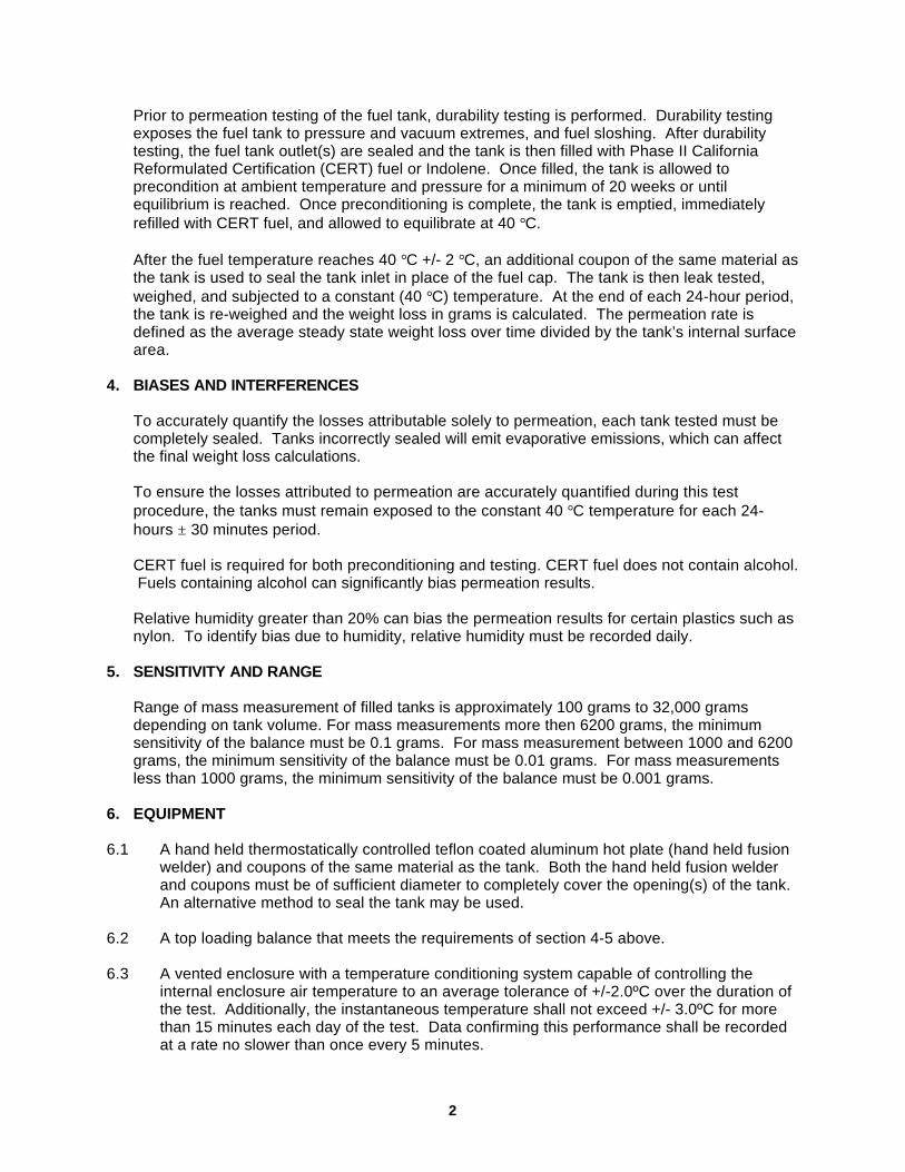
2
Prior to permeation testing of the fuel tank, durability testing is performed. Durability testingexposes the fuel tank to pressure and vacuum extremes, and fuel sloshing. After durabilitytesting, the fuel tank outlet(s) are sealed and the tank is then filled with Phase II CaliforniaReformulated Certification (CERT) fuel or Indolene. Once filled, the tank is allowed toprecondition at ambient temperature and pressure for a minimum of 20 weeks or untilequilibrium is reached. Once preconditioning is complete, the tank is emptied, immediatelyrefilled with CERT fuel, and allowed to equilibrate at 40 °C.
After the fuel temperature reaches 40 °C +/- 2 °C, an additional coupon of the same material asthe tank is used to seal the tank inlet in place of the fuel cap. The tank is then leak tested,weighed, and subjected to a constant (40 °C) temperature. At the end of each 24-hour period,the tank is re-weighed and the weight loss in grams is calculated. The permeation rate isdefined as the average steady state weight loss over time divided by the tank’s internal surfacearea.
4. BIASES AND INTERFERENCES
To accurately quantify the losses attributable solely to permeation, each tank tested must becompletely sealed. Tanks incorrectly sealed will emit evaporative emissions, which can affectthe final weight loss calculations.
To ensure the losses attributed to permeation are accurately quantified during this testprocedure, the tanks must remain exposed to the constant 40 °C temperature for each 24-hours ± 30 minutes period.
CERT fuel is required for both preconditioning and testing. CERT fuel does not contain alcohol. Fuels containing alcohol can significantly bias permeation results.
Relative humidity greater than 20% can bias the permeation results for certain plastics such asnylon. To identify bias due to humidity, relative humidity must be recorded daily.
5. SENSITIVITY AND RANGE
Range of mass measurement of filled tanks is approximately 100 grams to 32,000 gramsdepending on tank volume. For mass measurements more then 6200 grams, the minimumsensitivity of the balance must be 0.1 grams. For mass measurement between 1000 and 6200grams, the minimum sensitivity of the balance must be 0.01 grams. For mass measurementsless than 1000 grams, the minimum sensitivity of the balance must be 0.001 grams.
6. EQUIPMENT
6.1 A hand held thermostatically controlled teflon coated aluminum hot plate (hand held fusionwelder) and coupons of the same material as the tank. Both the hand held fusion welderand coupons must be of sufficient diameter to completely cover the opening(s) of the tank. An alternative method to seal the tank may be used.
6.2 A top loading balance that meets the requirements of section 4-5 above.
6.3 A vented enclosure with a temperature conditioning system capable of controlling theinternal enclosure air temperature to an average tolerance of +/-2.0ºC over the duration ofthe test. Additionally, the instantaneous temperature shall not exceed +/- 3.0ºC for morethan 15 minutes each day of the test. Data confirming this performance shall be recordedat a rate no slower than once every 5 minutes.
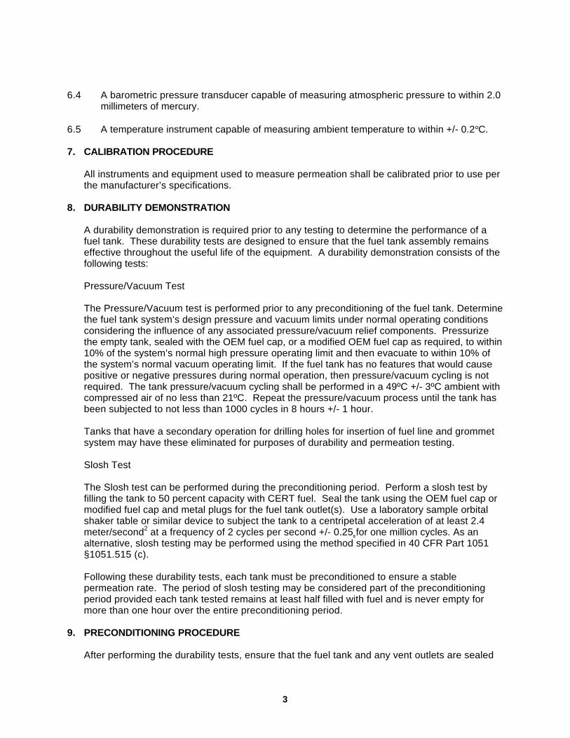
3
6.4 A barometric pressure transducer capable of measuring atmospheric pressure to within 2.0millimeters of mercury.
6.5 A temperature instrument capable of measuring ambient temperature to within +/- 0.2°C.
7. CALIBRATION PROCEDURE
All instruments and equipment used to measure permeation shall be calibrated prior to use perthe manufacturer’s specifications.
8. DURABILITY DEMONSTRATION
A durability demonstration is required prior to any testing to determine the performance of afuel tank. These durability tests are designed to ensure that the fuel tank assembly remainseffective throughout the useful life of the equipment. A durability demonstration consists of thefollowing tests:
Pressure/Vacuum Test
The Pressure/Vacuum test is performed prior to any preconditioning of the fuel tank. Determinethe fuel tank system’s design pressure and vacuum limits under normal operating conditionsconsidering the influence of any associated pressure/vacuum relief components. Pressurizethe empty tank, sealed with the OEM fuel cap, or a modified OEM fuel cap as required, to within10% of the system’s normal high pressure operating limit and then evacuate to within 10% ofthe system’s normal vacuum operating limit. If the fuel tank has no features that would causepositive or negative pressures during normal operation, then pressure/vacuum cycling is notrequired. The tank pressure/vacuum cycling shall be performed in a 49ºC +/- 3ºC ambient withcompressed air of no less than 21ºC. Repeat the pressure/vacuum process until the tank hasbeen subjected to not less than 1000 cycles in 8 hours +/- 1 hour.
Tanks that have a secondary operation for drilling holes for insertion of fuel line and grommetsystem may have these eliminated for purposes of durability and permeation testing.
Slosh Test
The Slosh test can be performed during the preconditioning period. Perform a slosh test byfilling the tank to 50 percent capacity with CERT fuel. Seal the tank using the OEM fuel cap ormodified fuel cap and metal plugs for the fuel tank outlet(s). Use a laboratory sample orbitalshaker table or similar device to subject the tank to a centripetal acceleration of at least 2.4meter/second2 at a frequency of 2 cycles per second +/- 0.25 for one million cycles. As analternative, slosh testing may be performed using the method specified in 40 CFR Part 1051§1051.515 (c).
Following these durability tests, each tank must be preconditioned to ensure a stablepermeation rate. The period of slosh testing may be considered part of the preconditioningperiod provided each tank tested remains at least half filled with fuel and is never empty formore than one hour over the entire preconditioning period.
9. PRECONDITIONING PROCEDURE
After performing the durability tests, ensure that the fuel tank and any vent outlets are sealed
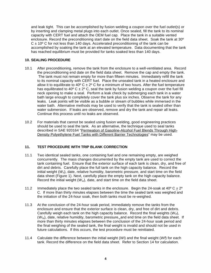
4
and leak tight. This can be accomplished by fusion welding a coupon over the fuel outlet(s) orby inserting and clamping metal plugs into each outlet. Once sealed, fill the tank to its nominalcapacity with CERT fuel and attach the OEM fuel cap. Place the tank in a suitable ventedenclosure. Record the preconditioning start date on the field data sheet. Soak the tank at 30ºC ± 10º C for not less than 140 days. Accelerated preconditioning of the tank can beaccomplished by soaking the tank at an elevated temperature. Data documenting that the tankhas reached equilibrium must be provided for tanks soaked less than 140 days.
10. SEALING PROCEDURE
10.1 After preconditioning, remove the tank from the enclosure to a well-ventilated area. Recordthe preconditioning end date on the field data sheet. Remove the cap and empty the tank. The tank must not remain empty for more than fifteen minutes. Immediately refill the tankto its nominal capacity with CERT fuel. Place the unsealed tank in a heated enclosure andallow it to equilibrate to 40º C ± 2º C for a minimum of two hours. After the fuel temperaturehas equilibrated to 40º C ± 2º C, seal the tank by fusion welding a coupon over the fuel fillneck opening to make a seal. Perform a leak check by submerging each tank in a waterbath large enough to completely cover the tank plus six inches. Observe the tank for anyleaks. Leak points will be visible as a bubble or stream of bubbles while immersed in thewater bath. Alternative methods may be used to verify that the tank is sealed other thanwater submersion. If leaks are observed, remove and dry the tank and repair all leaks.Continue this process until no leaks are observed.
10.2 For materials that cannot be sealed using fusion welding, good engineering practicesshould be used to seal the tank. As an alternative, the technique used to seal tanksdescribed in SAE 920164 “Permeation of Gasoline-Alcohol Fuel Blends Through High-Density Polyethylene Fuel Tanks with Different Barrier Technologies” may be used.
11. TEST PROCEDURE WITH TRIP BLANK CORRECTION
11.1 Two identical sealed tanks, one containing fuel and one remaining empty, are weighedconcurrently. The mass changes documented by the empty tank are used to correct thetank containing fuel. Ensure that the exterior surface of each tank is clean, dry, and free ofdirt and debris. Carefully place the full tank on the high capacity balance. Record theinitial weight (W if), date, relative humidity, barometric pressure, and start time on the fielddata sheet (Figure 1). Next, carefully place the empty tank on the high capacity balance. Record the initial weight (W ie), date, and start time on the field data sheet.
11.2 Immediately place the two sealed tanks in the enclosure. Begin the 24-soak at 40º C + 2ºC. If more than thirty minutes elapses between the time the sealed tank was weighed andthe initiation of the 24-hour soak, then both tanks must be re-weighed.
11.3 At the conclusion of the 24-hour soak period, immediately remove the tanks from theenclosure and ensure that the exterior surface is clean, dry, and free of dirt and debris. Carefully weigh each tank on the high capacity balance. Record the final weights (W ff),(W fe), date, relative humidity, barometric pressure, and end time on the field data sheet. Ifmore than thirty minutes elapses between the conclusion of the 24-hour soak period andthe final weighing of the sealed tank, the final weight is invalid and should not be used infuture calculations. If this occurs, the test procedure must be reinitiated.
11.4 Calculate the difference between the initial weight (Wi) and the final weight (Wf) for eachtank. Record the difference on the field data sheet. Refer to Section 14 for calculation.

5
11.5 Repeat this process until the correlation coefficient (R2), from a plot of the cumulative dailyweight loss versus time for ten consecutive 24-hour cycles, is 95% or greater.
12. QUALITY ASSURANCE / QUALITY CONTROL (QA/QC)
This section is reserved for future specification.
13. RECORDING DATA
Record data on field data sheet shown in figure 1.
14. CALCULATING PERMEATION RATE USING TRIP BLANK CORRECTION
The daily weight loss in grams is calculated for each 24-hour cycle as follows:
Wl = W if – Df
Where:Wl = The weight loss in gramsW if = The initial weight of the full tank in gramsW ff = The final weight of the full tank in gramsDf = W ff + De
De = W ie – W fe
W ie = The initial weight of the empty tank in gramsW fe = The final weight of the empty tank in grams
Plot the cumulative daily weight loss (in grams) against the sampling time (days). Perform alinear regression on ten consecutive data points.
If the correlation coefficient is at least 95%, the permeation rate in grams per square meter perday is calculated by dividing the slope of the regression line (grams/day) by the tanks internalsurface area (obtained from the tank manufacturer).
Prate = Slope/ Atank
Where:Prate = The permeation rate in grams/meter2/daySlope = The slope of the regression line in grams/dayAtank
1 = The tank’s internal surface area in meter2
1 Report the tank’s internal surface area in square-meters to at least three significantfigures. The tank internal surfaces are those surfaces that are subjected to fuel liquidor vapor under normal operating conditions and have an opposing surface through thewall section that is in communication with the atmosphere. Internal webs andstrengthening structures not in communication with the atmosphere are not consideredinternal surfaces for the purposes of this testing.
15. ALTERNATIVE TEST PROCEDURES
Test procedures, other than specified above, shall only be used if prior written approval isobtained from the ARB Executive Officer. In order to secure the ARB Executive Officer'sapproval of an alternative test procedure, the applicant is responsible for demonstrating to theARB Executive Officer's satisfaction that the alternative test procedure is equivalent to this testprocedure.
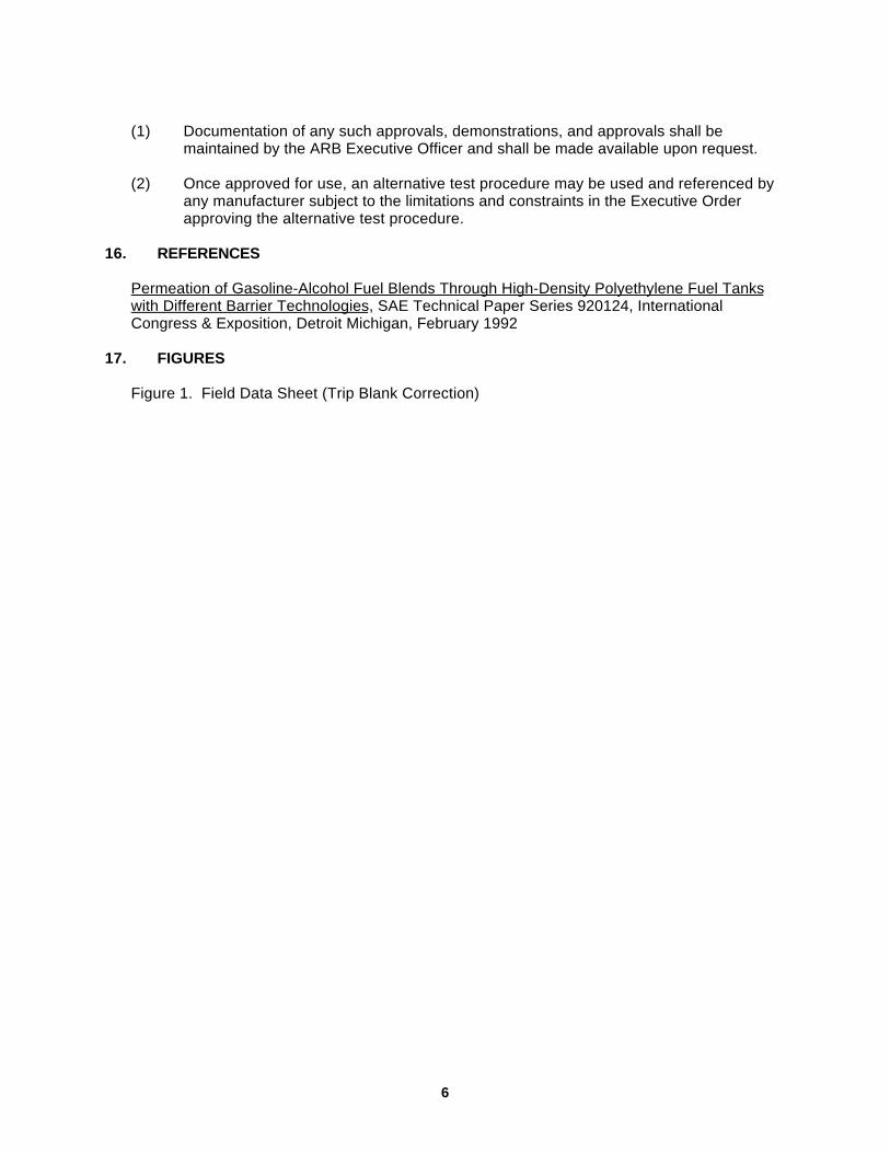
6
(1) Documentation of any such approvals, demonstrations, and approvals shall bemaintained by the ARB Executive Officer and shall be made available upon request.
(2) Once approved for use, an alternative test procedure may be used and referenced byany manufacturer subject to the limitations and constraints in the Executive Orderapproving the alternative test procedure.
16. REFERENCES
Permeation of Gasoline-Alcohol Fuel Blends Through High-Density Polyethylene Fuel Tankswith Different Barrier Technologies, SAE Technical Paper Series 920124, InternationalCongress & Exposition, Detroit Michigan, February 1992
17. FIGURES
Figure 1. Field Data Sheet (Trip Blank Correction)

7
Figure 1 Field Data Sheet
(Trip Blank Correction)
Tank Manufacturer:
Tank I.D:
Tested By:
Water Bath Test (pass/fail):
Tank Internal Surface Area (meter2):
Full Tank DataDate/Time
StartDate/Time
EndInitial WeightW if (grams)
Final WeightW ff (grams)
DifferenceDf (grams)
Weight LossWl (grams)
Wl = (W if – Df), Df = (W ff + De), De = (W ie – W fe)
Empty Tank DataDate/Time
StartDate/Time
EndInitial WeightW ie (grams)
Final WeightW fe (grams)
DifferenceDe (grams)
%RH Baro.Pres.

Com
pany
Priv
ate
& C
onfid
entia
l
Small Off Road Engine (SORE)
HC Emission Requirements
Presentation at Husqvarna, Sweden
March 7th, 2007
byDr.-Ing. Ulrich A. Karsch

Com
pany
Priv
ate
& C
onfid
entia
lAgenda
è Actual CARB OHRV Regulation Development
è CARB SORE Evap Regulations
è Kautex Barrier Technology Development

Com
pany
Priv
ate
& C
onfid
entia
l

Com
pany
Priv
ate
& C
onfid
entia
lObjective
è Reduce evaporative emissions by controlling:èDiurnal emissionsèRunning loss emissionsèAdditional permeation emissionsèCarburetor and fitting emissions
è Find and test cost effective emissions control technology
è Evaluate exhaust emissions control technology that works in conjunction with evaporative emission control technology
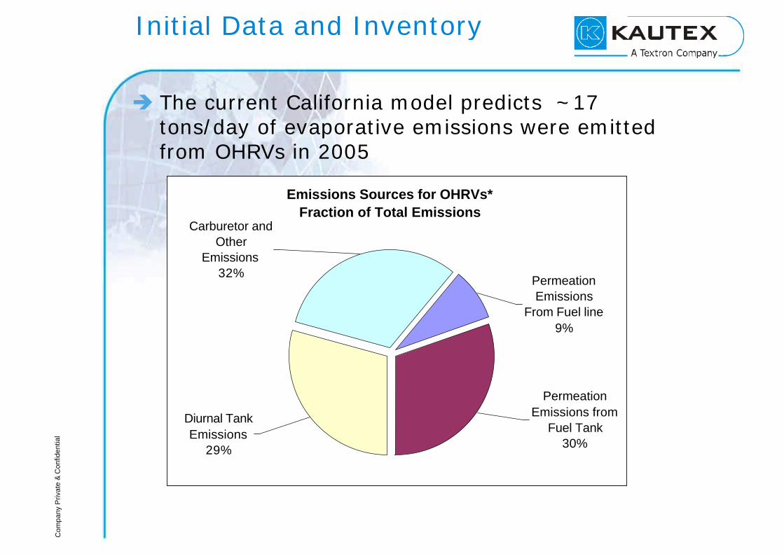
Com
pany
Priv
ate
& C
onfid
entia
l
Initial Data and Inventory
è The current California model predicts ~17 tons/day of evaporative emissions were emitted from OHRVs in 2005
Emissions Sources for OHRVs* Fraction of Total Emissions
Permeation Emissions
From Fuel line9%
Carburetor and Other
Emissions32%
Permeation Emissions from
Fuel Tank 30%
Diurnal Tank Emissions
29%

Com
pany
Priv
ate
& C
onfid
entia
l
EPA regulations are standard at 1.5g/mˆ2/day
0.0
1.5
3.0
4.5
6.0
7.5
9.0
10.5
Large Industrial Spark-IgnitionEngines (engines > 25hp)
Recreational vehicles On-road Motorcycles
gram
s/m
^2/d
ay
Final Standard Uncontrolled emissions
Permeation emissions from U.S. auto fuel tanks range from 40mg to 100mg per day

Com
pany
Priv
ate
& C
onfid
entia
l
Initial Emissions Data
è Initial evaporative emissions test data from Automotive Testing Laboratories
0.7513.383.003.00Average for ATVs
0.915.404.962.6088 Kawasaki KLF220 (Bayou) 4cyc
2.950.085.362.163.2001 Suzuki LT-F250 (Quadrunner) 4cyc
1.2815.792.643.2001 Yamaha YFZ350N-W (Banshee)
2cyc
16.982.243.0083 Honda FL250 (Odyssey) 2cyc
ATVs
1.0810.514.992.45Average for Dirt Bikes
1.2718.579.703.2001Yamaha WR250F 4cyc
6.814.492.0084 Suzuki RM125 2cyc
2.518.291.802.2000 Kawasaki KX250 2cyc
0.888.363.962.4082 Honda XR200R 4cyc
Refueling Losses(grams/gal)
Running Loss(grams/mile)
Diurnal Losses(grams/day)
Hot Soak Losses(grams per 3 hour soak)
Fuel TankVolume(gal)
Dirt bikes
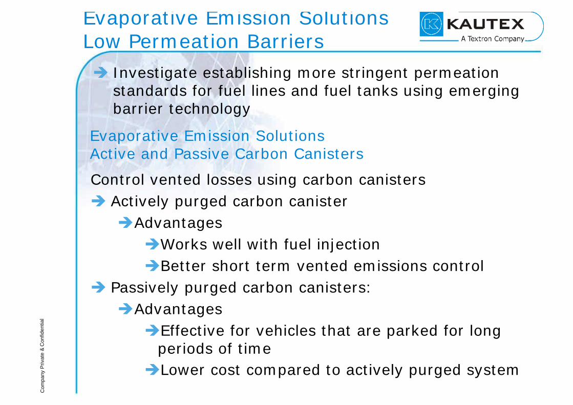
Com
pany
Priv
ate
& C
onfid
entia
l
Evaporative Emission SolutionsLow Permeation Barriers
è Investigate establishing more stringent permeation standards for fuel lines and fuel tanks using emerging barrier technology
Evaporative Emission Solutions Active and Passive Carbon Canisters
Control vented losses using carbon canistersè Actively purged carbon canisterèAdvantagesèWorks well with fuel injectionèBetter short term vented emissions control
è Passively purged carbon canisters:èAdvantagesèEffective for vehicles that are parked for long
periods of timeèLower cost compared to actively purged system
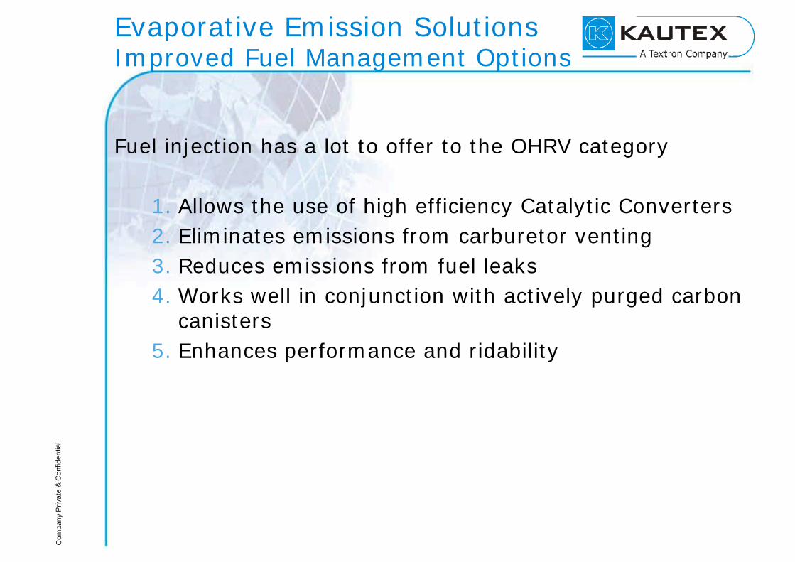
Com
pany
Priv
ate
& C
onfid
entia
l
Evaporative Emission Solutions Improved Fuel Management Options
Fuel injection has a lot to offer to the OHRV category
1. Allows the use of high efficiency Catalytic Converters2. Eliminates emissions from carburetor venting3. Reduces emissions from fuel leaks4. Works well in conjunction with actively purged carbon
canisters5. Enhances performance and ridability

Com
pany
Priv
ate
& C
onfid
entia
lTest Plan
è The following vehicles will be used to evaluate emissions control technology
è2005 Polaris Sportsman 500 ATV
è2006 Honda 450X dirt bike
è ARB will conduct baseline and controlled emissions testing
è The results will support proposed standards
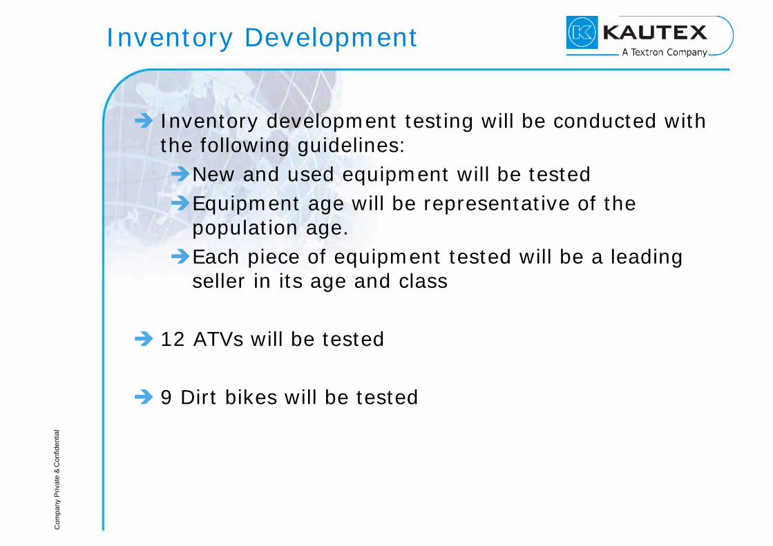
Com
pany
Priv
ate
& C
onfid
entia
l
Inventory Development
è Inventory development testing will be conducted with the following guidelines:èNew and used equipment will be testedèEquipment age will be representative of the
population age.èEach piece of equipment tested will be a leading
seller in its age and class
è 12 ATVs will be tested
è 9 Dirt bikes will be tested

Com
pany
Priv
ate
& C
onfid
entia
lControl Technology Testing
3111Refill, All Perm control, Summertime 65-105Phase II
cert
333Low Perm line/tank + Active CC+ FI + Catalyst, summertime 65-105
333Low Perm line/tank, Active CC, FI, summertime 65-105
333Low Perm Fuel line/tank + passive CC, summertime 65-105
333Low Perm Fuel line/tank, soaked 140 days, summertime 65-105
CE 10
3111Uncontrolled, Summertime 65-105 temp ProfilePhase II
cert
333Uncontrolled, Summertime 65-105 temp. ProfileCE 10
ExhaustDiurnal Hot soak
Running loss
Configuration (all fuel levels at 1/2 full)
Fuel Used
Test Type

Com
pany
Priv
ate
& C
onfid
entia
lRegulatory Time Line (Tentative)
è Emission Inventory DevelopmentSpring 2007 – Summer 2008
è Control Technology EvaluationSpring 2007 – Spring 2008
è Development of Staff ProposalSummer 2008
è Board Hearing Early 2009

Com
pany
Priv
ate
& C
onfid
entia
l
CARB regulations for SORE phase in between 2007 - 2013
StandardEffective DateSmall Off-Road Engines (SORE)
2g/mˆ2/day2007Handheld
2.5g/mˆ2/day1.5g/mˆ2/day
20082013
Large Non-Handheld
2.5g/mˆ2/day1.5g/mˆ2/day
2007-20112012
Small Non-Handheld (excluding walk-behind mowers)
1.3g/mˆ2/day1g/mˆ2/day
20072009
Small Non-Handheld (walk-behind mowers)
* Detailed spreadsheet with items included in each category is available.
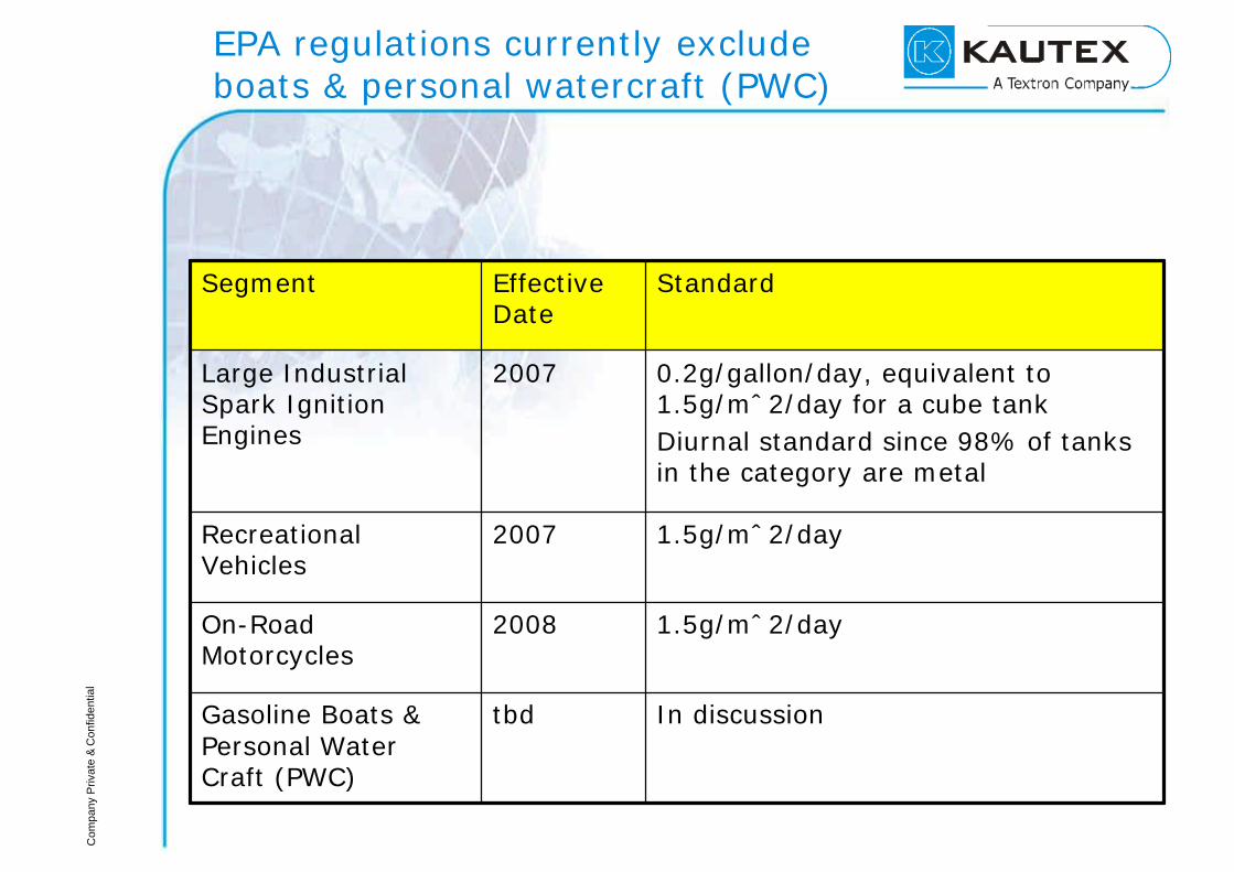
Com
pany
Priv
ate
& C
onfid
entia
l
EPA regulations currently exclude boats & personal watercraft (PWC)
StandardEffective Date
Segment
0.2g/gallon/day, equivalent to 1.5g/mˆ2/day for a cube tankDiurnal standard since 98% of tanks in the category are metal
2007Large Industrial Spark Ignition Engines
In discussiontbdGasoline Boats & Personal Water Craft (PWC)
1.5g/mˆ2/day2008On-Road Motorcycles
1.5g/mˆ2/day2007Recreational Vehicles

Com
pany
Priv
ate
& C
onfid
entia
l
CARB’s SORE regulations are not as stringent as automobile regulations
0.0
1.5
3.0
4.5
6.0
7.5
9.0
10.5
Handheld Small Non-Handheld(walk behind mowers)
Small Non-Handheld,excluding walk-behind
mowers
Large Non-Handheld
gram
s/m
^2/d
ay
Phase-In Standard Final Standard Uncontrolled emissions
Permeation emissions from U.S. auto fuel tanks range from 40mg to 100mg per day

Com
pany
Priv
ate
& C
onfid
entia
l

Com
pany
Priv
ate
& C
onfid
entia
l

Com
pany
Priv
ate
& C
onfid
entia
l

Com
pany
Priv
ate
& C
onfid
entia
l

Com
pany
Priv
ate
& C
onfid
entia
l

Com
pany
Priv
ate
& C
onfid
entia
l

Com
pany
Priv
ate
& C
onfid
entia
l
è Kautex Barrier Technology

Com
pany
Priv
ate
& C
onfid
entia
l
0,60,5
0,120,3 0,02
0,1
Tank Shell Filler Lines FDM Valves CC
„old“ Standard ~ 1,6before 1994
Values in [g/24h]
0,03
0,020,01
0,01
0,010,01
LEVII ~ 0,12004
HC-Emission Reduction StepsDraft Example
Enhanced Evap ~ 0,21since 1996
0,05
0,02
0,06
0,03
0,030,02
Emission drivenMarkets

Com
pany
Priv
ate
& C
onfid
entia
lThe Way to Coextrusion
è Introduction of the diurnal Temperature Profiles- Higher temperature load 30°C è 36°C, 40.5°C- Longer effective time 2h è 12, 24, 36 hours
è Reduction of total HC-Emission Levels per Vehicle- EU III/IV: 2g/test, but longer time, higher
temperature- EPA Tier2: 2g/test è 0.95g/test- CARB LEV II: 2g/test è 0.5 g/test (PZEV: 0.35 g/test)
è Increase of Liability /Warranty Time Frame- 10 years è 15 years- 100.000 miles è 150.000 miles
è Introduction of Alcohol, Flex Fuel (up to 100% Alcohol)
è Conclusion: More effective Barrier for PFT needed
Emission drivenMarkets

Com
pany
Priv
ate
& C
onfid
entia
lThe Way to Coextrusion
èWhich Barriers are used beside Coex?
è Fluorination- In-line- Off-line
è Sulfonation (not longer in use)
è These Technologies are chemically bound onto theouter surface and affected by mechanical Loads
è Selar® Technology- Polyamide based lamellar Structure
è All above Technologies are more or less affected byAlcohol containing Fuels
è Coextrusion is not affected by Alcohol containing Fuels
Barrier Technology
Benchmarking
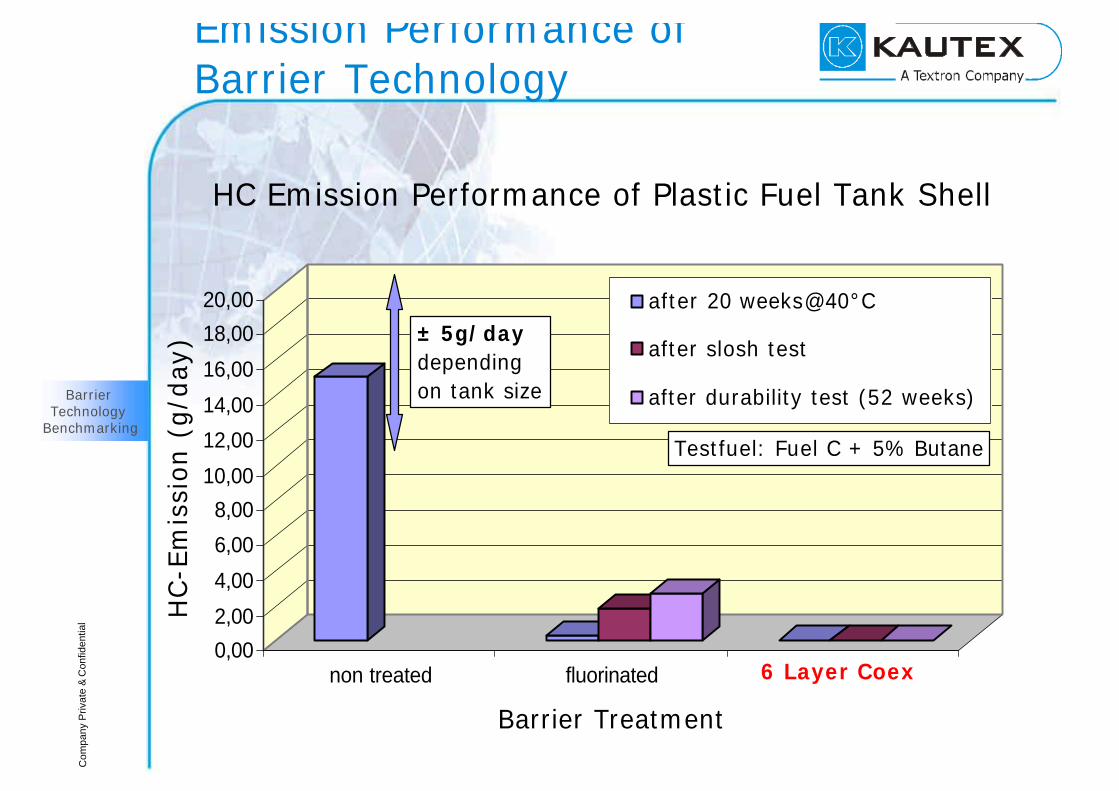
Com
pany
Priv
ate
& C
onfid
entia
l
0,00
2,00
4,00
6,00
8,00
10,00
12,00
14,00
16,00
18,00
20,00
HC
-Em
issi
on (
g/d
ay)
non treated fluorinated 6 layer coex
Barrier Treatment
HC Emission Performance of Plastic Fuel Tank Shell
after 20 weeks@40°C
after slosh test
after durability test (52 weeks)
Testfuel: Fuel C + 5% Butane
± 5g/daydepending on tank size
Emission Performance of Barrier Technology
Barrier Technology
Benchmarking
6 Layer Coex

Com
pany
Priv
ate
& C
onfid
entia
l
0,0 g/d
0,1 g/d
0,2 g/d
0,3 g/d
0,4 g/d
0,5 g/d
0,6 g/d
0,7 g/d
0,8 g/d
0,9 g/d
1,0 g/d
0 10 20 30 40 50 60 70 80 90 100
Ethanol-concentration [%]
Em
issi
on lo
ss [
g/d]
Fluorination CoextrusionSoak temperature: 40 ± 2 °CSHED: CARB diurnal cycleTest fuel: EPA + X % EtOH
Emission Performance withAlcohol containing Fuel
Tank Shell
Barrier Technology
Benchmarking
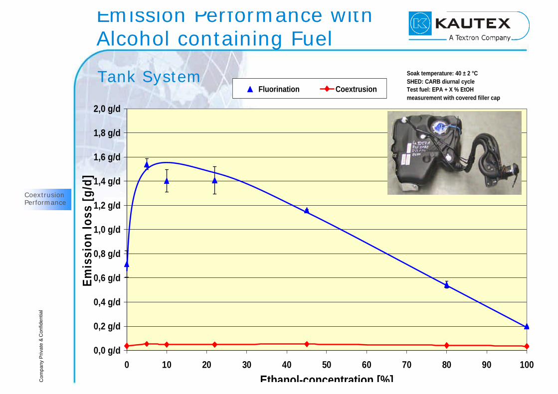
Com
pany
Priv
ate
& C
onfid
entia
l
Emission Performance withAlcohol containing Fuel
0,0 g/d
0,2 g/d
0,4 g/d
0,6 g/d
0,8 g/d
1,0 g/d
1,2 g/d
1,4 g/d
1,6 g/d
1,8 g/d
2,0 g/d
0 10 20 30 40 50 60 70 80 90 100
Ethanol-concentration [%]
Em
issi
on lo
ss [
g/d]
Fluorination Coextrusion
Soak temperature: 40 ± 2 °CSHED: CARB diurnal cycleTest fuel: EPA + X % EtOHmeasurement with covered filler cap
Tank System
CoextrusionPerformance

Com
pany
Priv
ate
& C
onfid
entia
lMilestones of Kautex for Coex
è Setting up first Coex Machine in 1992
è Proprietory Development with ETA for New Coex-Head
è Gravimetric Extruder Feed Control with BOLDER Automation
è Development of effective Regrind processing Screws
è First Volume Production 1994 (DC Grand Cherokee)
è Ultra Sonic destruction-free wall Thickness Control withPROSENSYS
è Emission Calculation Tool
è Long Term Testing Inventories
è Setting Benchmarks in the Fuel Tank Industry
CoextrusionPerformance
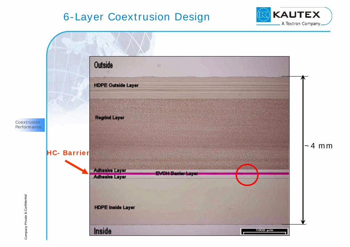
Com
pany
Priv
ate
& C
onfid
entia
l
6-Layer Coextrusion Design
~4 mmHC- Barrier
CoextrusionPerformance
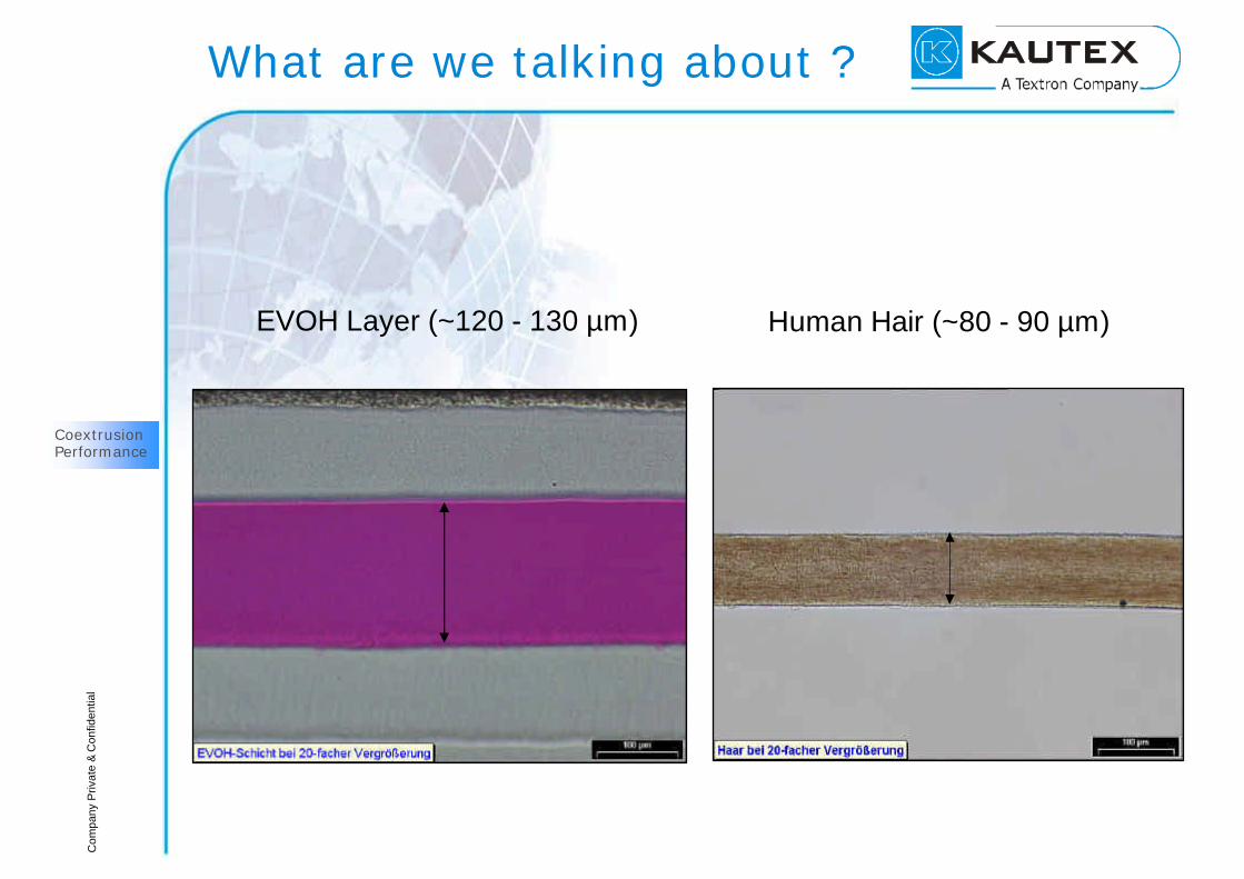
Com
pany
Priv
ate
& C
onfid
entia
lWhat are we talking about ?
EVOH Layer (~120 - 130 µm) Human Hair (~80 - 90 µm)
CoextrusionPerformance
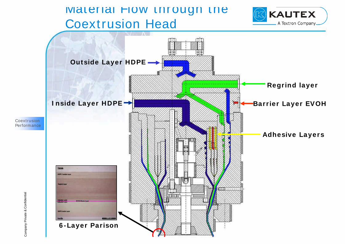
Com
pany
Priv
ate
& C
onfid
entia
l
Material Flow through theCoextrusion Head
CoextrusionPerformance
Inside Layer HDPE
Outside Layer HDPE
Adhesive Layers
Barrier Layer EVOH
Regrind layer
6-Layer Parison
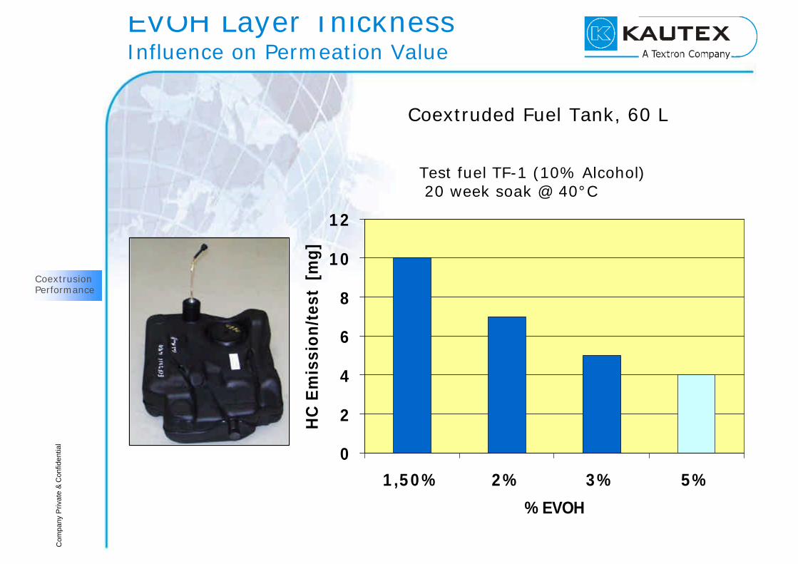
Com
pany
Priv
ate
& C
onfid
entia
l
Test fuel TF-1 (10% Alcohol)20 week soak @ 40°C
EVOH Layer Thickness Influence on Permeation Value
0
2
4
6
8
10
12
1,50% 2% 3% 5%
% EVOH
HC
Em
issi
on/t
est
[m
g]
CoextrusionPerformance
Coextruded Fuel Tank, 60 L

Com
pany
Priv
ate
& C
onfid
entia
lUS Layer Thickness Control I
CoextrusionPerformance
US=Ultra Sonic Destructrion-free Measurement

Com
pany
Priv
ate
& C
onfid
entia
l
Emission Calculation
Permeation coefficient of the COEX wall (def.):
( ) ( )∑=
=
n
1ii
i
wall
wall
TPl
TPl
Emissions of the wall:
( )wall
wallWwall
lTP
Apm ⋅⋅∆=•
( ) ( )TPl
TPl
Apm
HDPE
HDPE
EVOH
EVOH
Wwall
+
⋅∆=
•Emissions of the tank shell, without
wall thickness variation :
CoextrusionPerformance

Com
pany
Priv
ate
& C
onfid
entia
l
KAUTEX pinch-off Designand Definitions
x
y l(x=0)
x0
xmin=x0/2 xmax
0
l(x), EVOH
CoextrusionPerformance
Emission Calculation

Com
pany
Priv
ate
& C
onfid
entia
l
Complete Equation for a Tank Shellincluding Wall Thickness Distribution
x
y l(x=0)
x0
xmin=x0/2 xmax
0
l(x), EVOH
( ) ( ) ( )
( ) ( )
+
⋅α+
⋅⋅+⋅⋅∆= ∑
==
•n
1iHDPE
i,HDPE
EVOH
i,EVOH
Wi
min
maxEVOH
0x
0HDPEkshelltan
TPl
TPl
Axx
lnaA
TPlA
TPpTm
Permeation
through HDPE
around x=0
Permeation through the
wall, respecting the wall
thickness distribution
Permeation through
variable EVOH
layer (pinch off)
x
y
Jy
c1, l1
c2 < c1, l2
CoextrusionPerformance
Emission Calculation
Com
pany
Priv
ate
& C
onfid
entia
lWhy Calculation ?
è Development Tool
è Prediction of Emission Value of a Plastic Fuel Tank
- According to Design
- According to required Emission Class of the Vehicle
- First reliable Emission Estimation before finishing long term
Emission Test
- Proof of Production Performance
è Design Verification
CoextrusionPerformance
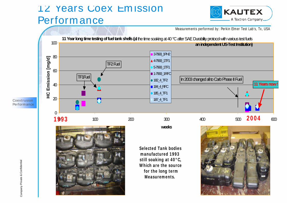
Com
pany
Priv
ate
& C
onfid
entia
l
12 Years Coex Emission Performance
0
20
40
60
80
100
0 100 200 300 400 500 600
weeks
HC
Em
issi
on
[m
g/d
] 3-7993_1PH2
4-7993_1TF1
5-7993_1TF1
1-7993_1RFC
182_4_TF2
184_4_RFC
185_4_TF1
187_4_TF1
TF2 Fuel
TF1Fuel In 2003 changed all to Carb Phase II Fuel
11 Year long time testing of fuel tank shells (all the time soaking at 40 °C after SAE Durability protocol with various test fuels an independent US-Test Institution)
11 Years now !
Measurements performed by: Perkin Elmer Test Lab‘s, Tx, USA
Selected Tank bodiesmanufactured 1993 still soaking at 40°C,Which are the source
for the long termMeasurements.
1993 2004
CoextrusionPerformance

Com
pany
Priv
ate
& C
onfid
entia
lIn-Use and Long Term Conclusion
è Fluorination demonstrates strong long term effects
è Performance of Fluorination is very non homogenous
- No Correlation to driven Mileage
- Strong Influence of Fuels and Process Treatment Parameters
è Even enhanced Fluorination was not sufficient for US Demands
è Coextruded Fuel Tanks show allways lower Values
è In-Use Tests and enhanced Durability proof good Barrier
Benefits of Coextrusion

Com
pany
Priv
ate
& C
onfid
entia
lBenefits of Coextrusion
è Coextrusion Technology introduced globally
è Basic Material is HDPE
è Barrier Material EVOH offers best Barrier Performance
è EVOH Layer Thickness adjustable and measurable
è Processing is State of the Art
è Welding and downline Processes remain as today
è Coex Blow Molding Technology is robust and long term proven
è All Fuels including up to 100% Alcohol are not an Issue
Benefits of Coextrusion

Com
pany
Priv
ate
& C
onfid
entia
lSummary
è Increasing Emission Legislation Requirements demandimproved Activities for Plastic Fuel Tanks in OHRV/SORE
è Standard Barriers like Fluorination are mechanically unstable,EVOH is a mechanical Barrier embedded safely in theFuel Tank Wall
è Alcohol as Part of the Future Market is a Challenge forcurrent Barrier Technology
è Coex Plastic Fuel Tank Systems are in global Production
è Coex Plastic Fuel Tank Systems Emissions fulfill VehicleApproval acc. to specific Market Emission Requirements
è 6-Layer Coex Design is best Choice
Summary

Com
pany
Priv
ate
& C
onfid
entia
l
Thank Youfor
Your Attention
Related Documents