4.1 PCB Piezotronics, Inc. Toll-Free in USA 888-684-0004 716-684-0001 www.pcb.com Torque Sensors Torque sensors manufactured by PCB ® fall into two categories of measurement: reaction torque and rotational torque. Both styles utilize strain gages, which are configured into a Wheatstone bridge circuit, as their primary sensing element. Accuracies are typically within 0.1% and optional speed sensors permit additional measurement of rotational speed (RPM) and horsepower calculations. Reaction torque sensors are rigid structures with no moving parts and are typically mounted in a fixed position. Their output signal varies proportionally to an applied torsional force. Applications for reaction torque sensors include torsional testing machines, brake testing, bearing friction studies, dynamometer testing, and viscosity and lubrication studies. Rotary torque sensors employ a freely rotating shaft within a fixed housing. When installed, the rotating shaft becomes a coupling between a driving mechanism and an absorber or load. As the shaft is torsionally stressed, a proportional change in the output signal is observed. Changes in rotational speed and load affect the torque that is measured. Applications for rotary torque sensors include electric motor testing, automotive engine testing, dynamometer testing, drive train measurements, and gearbox testing. Configurations ............................................................................................................4.2 Typical Measurement Systems ..............................................................................4.4 Typical Applications ..................................................................................................4.6 Selection Guide ..........................................................................................................4.6 Product Information ..................................................................................................4.9 Reaction Torque Sensors ........................................................................................4.10 Flange Mount ......................................................................................................4.10 Small Capacity Flange Mount ............................................................................4.12 Rotary Transformer Torque Sensors........................................................................4.14 Shaft End..............................................................................................................4.14 Flange-Shaft ........................................................................................................4.18 TORKDISC ® ..............................................................................................................4.20 General Accessories ................................................................................................5.1 Signal Conditioners....................................................................................................5.2 Speed Sensor Cables ................................................................................................5.4 Reaction Torque Sensor Cable Assemblies..............................................................5.5 Rotary Torque Sensor Cable Assemblies ................................................................5.7 Torque Sensor Accessories ......................................................................................5.9 Calibration Services ................................................................................................5.11 Technical Information ..............................................................................................6.1 Introduction to Torque Sensors ................................................................................6.2 Torque Sensor Application Questionnaire ................................................................6.4 Glossary of Terms ......................................................................................................6.5 Application Notes and Technical Articles ................................................................6.6 Table of Contents 2301 ..................4.10, 4.11 2302 ..................4.10, 4.11 2303 ..................4.10, 4.11 2304 ..................4.10, 4.11 2305 ..................4.10, 4.11 2308 ..................4.12, 4.13 2309 ..................4.12, 4.13 2508 ..................4.12, 4.13 4102 ..................4.16, 4.17 4103 ..................4.16, 4.17 4104 ..................4.16, 4.17 4105 ..................4.16, 4.17 4106 ..................4.16, 4.17 4107 ..................4.16, 4.17 4115A ................4.18, 4.19 4115K ................4.18, 4.19 4203 ..................4.14, 4.15 4204 ..................4.14, 4.15 4205 ..................4.14, 4.15 4206 ..................4.14, 4.15 4207 ..................4.14, 4.15 5302C ................4.20, 4.21 4.22, 4.23 5308C ................4.20, 4.21 4.22, 4.23 5309C ................4.20, 4.21 4.22, 4.23 5310C ................4.20, 4.21 4.22, 4.23 Model Number Index

Welcome message from author
This document is posted to help you gain knowledge. Please leave a comment to let me know what you think about it! Share it to your friends and learn new things together.
Transcript
4.1PCB Piezotronics, Inc. Toll-Free in USA 888-684-0004 716-684-0001 www.pcb.com
----------
Torque SensorsTorque sensors manufactured by PCB® fall into two categories of measurement: reactiontorque and rotational torque. Both styles utilize strain gages, which are configured intoa Wheatstone bridge circuit, as their primary sensing element. Accuracies are typicallywithin 0.1% and optional speed sensors permit additional measurement of rotationalspeed (RPM) and horsepower calculations.
Reaction torque sensors are rigid structures with no moving parts and are typicallymounted in a fixed position. Their output signal varies proportionally to an appliedtorsional force. Applications for reaction torque sensors include torsional testingmachines, brake testing, bearing friction studies, dynamometer testing, and viscosityand lubrication studies.
Rotary torque sensors employ a freely rotating shaft within a fixed housing. Wheninstalled, the rotating shaft becomes a coupling between a driving mechanism and anabsorber or load. As the shaft is torsionally stressed, a proportional change in the outputsignal is observed. Changes in rotational speed and load affect the torque that ismeasured. Applications for rotary torque sensors include electric motor testing,automotive engine testing, dynamometer testing, drive train measurements, andgearbox testing.
Configurations ............................................................................................................4.2Typical Measurement Systems ..............................................................................4.4Typical Applications ..................................................................................................4.6Selection Guide ..........................................................................................................4.6Product Information ..................................................................................................4.9
Reaction Torque Sensors ........................................................................................4.10Flange Mount ......................................................................................................4.10Small Capacity Flange Mount ............................................................................4.12
Rotary Transformer Torque Sensors........................................................................4.14Shaft End..............................................................................................................4.14Flange-Shaft ........................................................................................................4.18
TORKDISC® ..............................................................................................................4.20General Accessories ................................................................................................5.1
Signal Conditioners....................................................................................................5.2Speed Sensor Cables ................................................................................................5.4Reaction Torque Sensor Cable Assemblies..............................................................5.5Rotary Torque Sensor Cable Assemblies ................................................................5.7Torque Sensor Accessories ......................................................................................5.9
Calibration Services ................................................................................................5.11Technical Information ..............................................................................................6.1
Introduction to Torque Sensors ................................................................................6.2Torque Sensor Application Questionnaire................................................................6.4Glossary of Terms ......................................................................................................6.5Application Notes and Technical Articles ................................................................6.6
Table of Contents
2301 ..................4.10, 4.112302 ..................4.10, 4.112303 ..................4.10, 4.112304 ..................4.10, 4.112305 ..................4.10, 4.112308 ..................4.12, 4.132309 ..................4.12, 4.132508 ..................4.12, 4.134102 ..................4.16, 4.174103 ..................4.16, 4.174104 ..................4.16, 4.174105 ..................4.16, 4.174106 ..................4.16, 4.174107 ..................4.16, 4.17
4115A ................4.18, 4.194115K ................4.18, 4.194203 ..................4.14, 4.154204 ..................4.14, 4.154205 ..................4.14, 4.154206 ..................4.14, 4.154207 ..................4.14, 4.155302C ................4.20, 4.21
4.22, 4.235308C ................4.20, 4.21
4.22, 4.235309C ................4.20, 4.21
4.22, 4.235310C ................4.20, 4.21
4.22, 4.23
Model Number Index

4.2 PCB Piezotronics, Inc. Toll-Free in USA 888-684-0004 716-684-0001 www.pcb.com
----------------------
Reaction torque sensors are suitable for a wide array of torque measurementapplications. They are typically used in torsional test machines, motor dynamometers, orin any application where rotation is limited to 360° or less. Due to the fact that thesesensors do not utilize bearings, slip-rings, or other rotating elements, their installationand use can be very cost effective.
The rigid sensor mechanically resists rotation and will experience a torsional stress inresponse to an applied torsional force. This stress causes a proportional resistancechange to occur in the strain gages, resulting in a voltage shift in the sensor's outputsignal. You might consider a reaction torque sensor to be similar to a pickle jar with atight lid. As you try to twist the lid of the jar, the reaction torque experienced by the jarincreases until the lid becomes loosened.
Reaction torque sensors are particularly useful in applications where the introduction ofinertia due to a rotating mass between the driver motor and driven load is undesirable.
An example of this can be found in small motor testing, where introduction of a rotatingmass between the motor and load device will result in an error during acceleration. Forthese applications, the reaction torque sensor can be used between the driver motor, ordriven load, and ground. An added benefit is that such an installation is not limited inRPM by the torque sensor.
Shown below are some of the standard reaction torque sensor configurations offered bythe PCB®. Capacities range from 5 to 500k in-lb (0.56 to 56.5k N-m).
Rotating Shaft Torque SensorsRotating shaft torque sensors are designed to mount in-line between a driving source,and an absorber, or load. They are used in engine dynamometers, electric motor testing,hydraulic pump testing, fan testing, and a multitude of other applications.
PCB® offers a choice of rotary transformer torque sensors. For most applications, a rotarytransformer-type sensor will be recommended. The rotary transformer is a non-contacting type of sensor, providing very low maintenance, quiet operation (with anexcellent signal-to-noise ratio), higher speed ratings, and better accuracy. This type ofsensor should be used with an AC carrier excitation source, ideally operating at 3.28 k Hz.
The torque sensor’s shaft is coupled between the rotating driving mechanism under testand a load. A variety of mounting styles are offered including keyed shaft, and flange-shaft. As the driving mechanism (such as an electric motor or automotive engine) turnsthe shaft, a torsional stress occurs, which causes a proportional resistance change in thestrain gages, resulting in a voltage shift in the sensor’s output signal. As the speed andthe load on the rotating coupling changes, so too will the torque.
Rotary transformer torque sensors offer high accuracies and RPM ratings. They aredesigned with an advanced trans-former, shaft and housing to provide enhanceddurability in rugged industrial applications.
Rotating shaft torque sensors are available in a wide range of configurations, withcapacities from 50 in-oz to 100k in-lb (0.35 to 11.3k N-m).
Reaction Torque Sensors
Strain Gage Torque Sensor Configurations
Flange Ends
Keyed Shaft Ends
AND
Flange-Shaft
----------------------
4.3PCB Piezotronics, Inc. Toll-Free in USA 888-684-0004 716-684-0001 www.pcb.com
TORKDISC®
The TORKDISC® is a short-coupled, torsionally stiff structure that is ideal for a widerange of applications requiring high-accuracy, in-line rotary torque measurements. Thesensor consists of a spring element which is torsionally loaded as torque is appliedbetween an inner and outer mounting surface. Male and female pilots are provided toensure good concentricity as the TORKDISC® is bolted into a driveline. Torque istransmitted by friction created between the mounting surfaces of the TORKDISC® andcustomer-provided mounting fixtures. Sixteen-bit digital telemetry signal transmissionprovides noise-free operation. The TORKDISC® is available in a wide range of capacitiesfrom 1k to 225k in-lb (113 to 25.4k N-m).
Strain Gage Torque Sensor Configurations
4.4 PCB Piezotronics, Inc. Toll-Free in USA 888-684-0004 716-684-0001 www.pcb.com
Typical Torque Sensor Measurement Systems
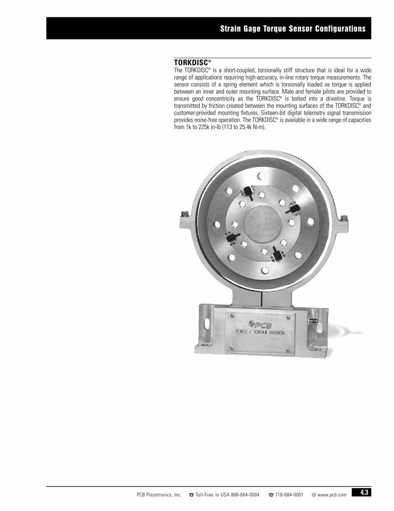
Typical measurement system forSeries 2300 and 2500 reaction torque sensorAll PCB® reaction torque sensors utilize strain gages that are configured in a Wheatstonebridge as their primary sensing element. The resistance value of the strain gageschanges when torsional load is applied to the sensing structure and consequently, anyvoltage through the bridge circuit will be varied. The Wheatstone bridge requires aregulated DC voltage excitation that is commonly provided by a strain gage signalconditioner. The resultant output signal from the torque sensor is typically expressed inunits of millivolt per volt of excitation. This millivolt signal then varies proportionately tothe applied torque. The strain gage signal conditioner provides zero and spanadjustments to scale its 0 to 5 VDC analog output to be proportional to any desired inputrange. Additional features of the signal conditioner may include a digital display andalarm set point limits.
Reaction torque sensors are provided with an electrical connector, and cable assembliesare necessary to interface this connection to the strain gage signal conditioner. Two typesof cable are commonly available, and their use is dependent upon signal transmissiondistance. Cable assemblies may be selected with a terminating connector, which makesit easier to connect to a PCB® strain gage signal conditioner, or with a pigtail terminationthat allows connection to screw terminal connections on other styles of strain gagesignal conditioners.
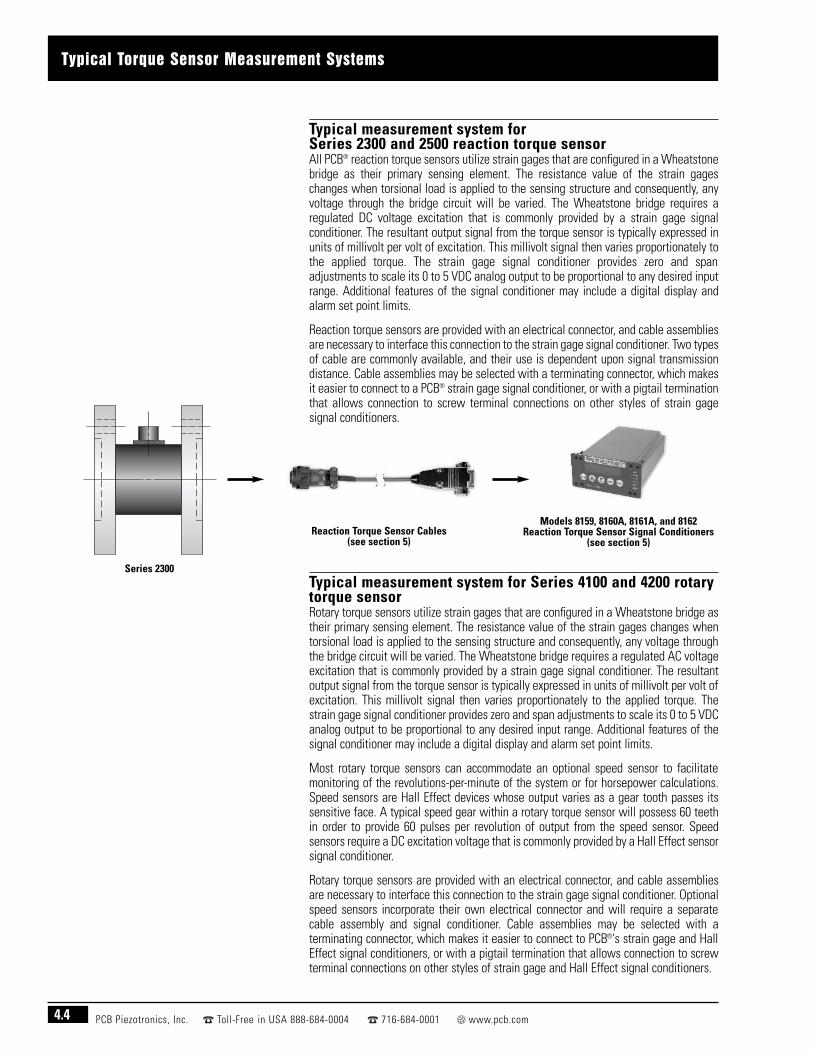
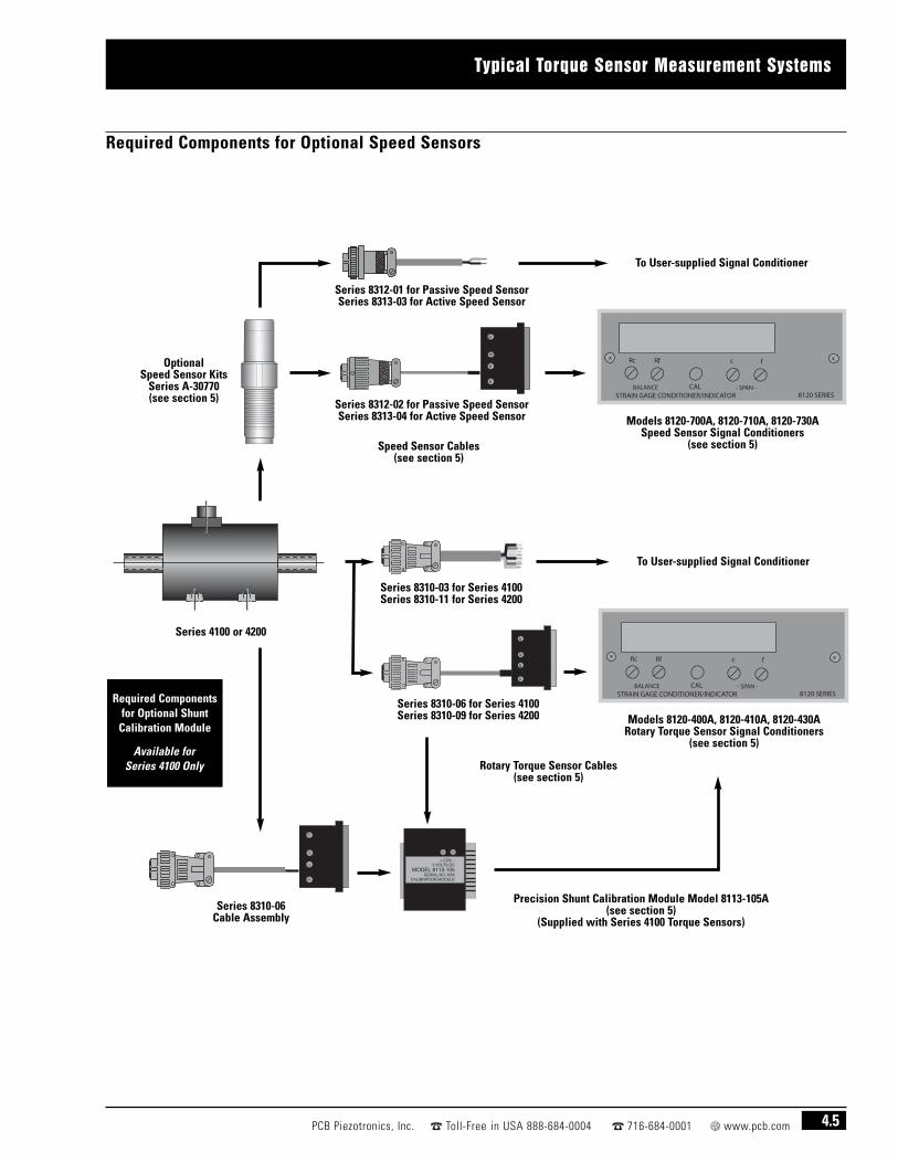
Typical measurement system for Series 4100 and 4200 rotarytorque sensorRotary torque sensors utilize strain gages that are configured in a Wheatstone bridge astheir primary sensing element. The resistance value of the strain gages changes whentorsional load is applied to the sensing structure and consequently, any voltage throughthe bridge circuit will be varied. The Wheatstone bridge requires a regulated AC voltageexcitation that is commonly provided by a strain gage signal conditioner. The resultantoutput signal from the torque sensor is typically expressed in units of millivolt per volt ofexcitation. This millivolt signal then varies proportionately to the applied torque. Thestrain gage signal conditioner provides zero and span adjustments to scale its 0 to 5 VDCanalog output to be proportional to any desired input range. Additional features of thesignal conditioner may include a digital display and alarm set point limits.
Most rotary torque sensors can accommodate an optional speed sensor to facilitatemonitoring of the revolutions-per-minute of the system or for horsepower calculations.Speed sensors are Hall Effect devices whose output varies as a gear tooth passes itssensitive face. A typical speed gear within a rotary torque sensor will possess 60 teethin order to provide 60 pulses per revolution of output from the speed sensor. Speedsensors require a DC excitation voltage that is commonly provided by a Hall Effect sensorsignal conditioner.
Rotary torque sensors are provided with an electrical connector, and cable assembliesare necessary to interface this connection to the strain gage signal conditioner. Optionalspeed sensors incorporate their own electrical connector and will require a separatecable assembly and signal conditioner. Cable assemblies may be selected with aterminating connector, which makes it easier to connect to PCB®'s strain gage and HallEffect signal conditioners, or with a pigtail termination that allows connection to screwterminal connections on other styles of strain gage and Hall Effect signal conditioners.
Reaction Torque Sensor Cables (see section 5)
Models 8159, 8160A, 8161A, and 8162Reaction Torque Sensor Signal Conditioners
(see section 5)
Series 2300
4.5PCB Piezotronics, Inc. Toll-Free in USA 888-684-0004 716-684-0001 www.pcb.com
Typical Torque Sensor Measurement Systems
Rotary Torque Sensor Cables(see section 5)
Models 8120-400A, 8120-410A, 8120-430A Rotary Torque Sensor Signal Conditioners
(see section 5)
Series 8310-03 for Series 4100 Series 8310-11 for Series 4200
Series 8310-06 for Series 4100Series 8310-09 for Series 4200
To User-supplied Signal Conditioner
Precision Shunt Calibration Module Model 8113-105A (see section 5)
(Supplied with Series 4100 Torque Sensors)
Speed Sensor Cables (see section 5)
Models 8120-700A, 8120-710A, 8120-730A Speed Sensor Signal Conditioners
(see section 5)
Series 8312-01 for Passive Speed Sensor Series 8313-03 for Active Speed Sensor
Series 8312-02 for Passive Speed Sensor Series 8313-04 for Active Speed Sensor
Optional Speed Sensor Kits
Series A-30770(see section 5)
To User-supplied Signal Conditioner
Required Componentsfor Optional Shunt
Calibration Module
Available for Series 4100 Only
Series 4100 or 4200
Series 8310-06Cable Assembly
Required Components for Optional Speed Sensors
4.6 PCB Piezotronics, Inc. Toll-Free in USA 888-684-0004 716-684-0001 www.pcb.com
Torque Sensor Selection Guide
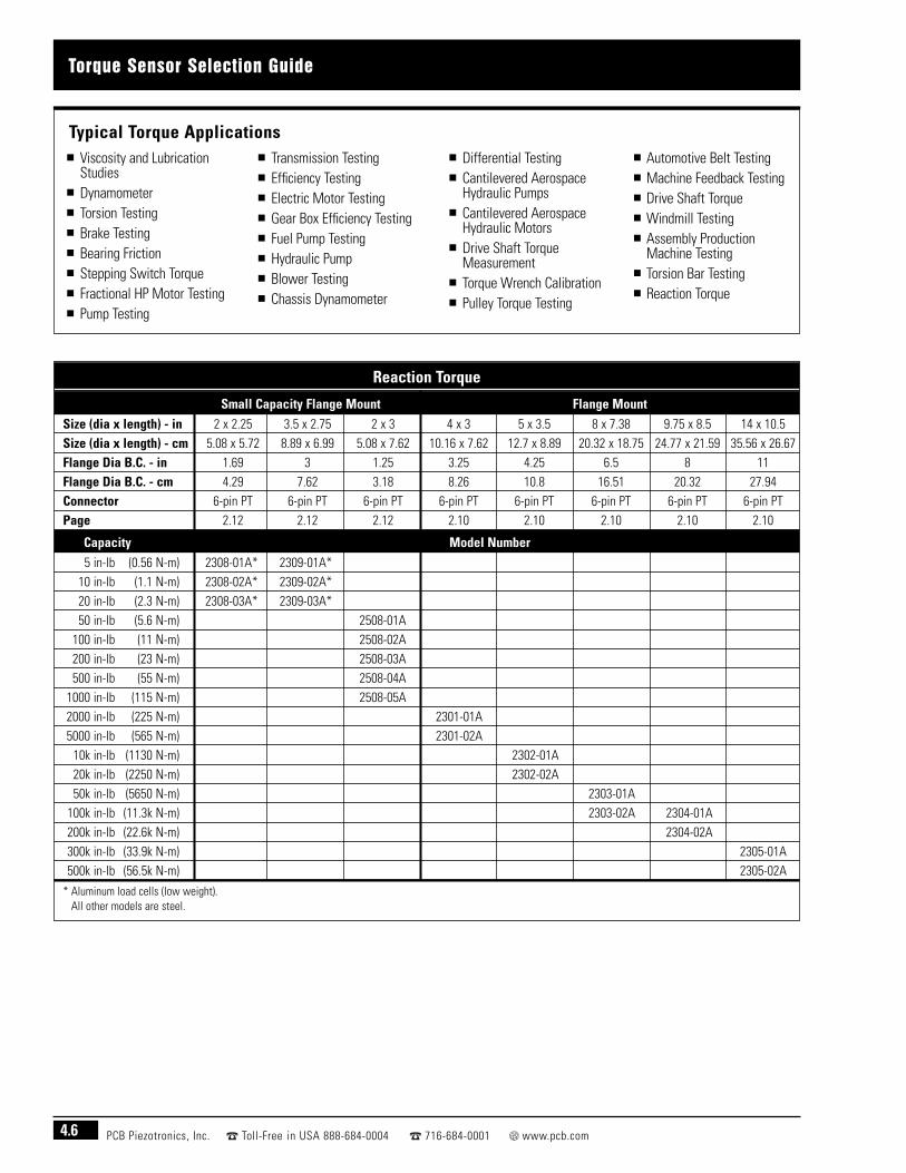
Reaction Torque
Small Capacity Flange Mount Flange Mount
Size (dia x length) - in 2 x 2.25 3.5 x 2.75 2 x 3 4 x 3 5 x 3.5 8 x 7.38 9.75 x 8.5 14 x 10.5 Size (dia x length) - cm 5.08 x 5.72 8.89 x 6.99 5.08 x 7.62 10.16 x 7.62 12.7 x 8.89 20.32 x 18.75 24.77 x 21.59 35.56 x 26.67Flange Dia B.C. - in 1.69 3 1.25 3.25 4.25 6.5 8 11Flange Dia B.C. - cm 4.29 7.62 3.18 8.26 10.8 16.51 20.32 27.94Connector 6-pin PT 6-pin PT 6-pin PT 6-pin PT 6-pin PT 6-pin PT 6-pin PT 6-pin PTPage 2.12 2.12 2.12 2.10 2.10 2.10 2.10 2.10
Capacity Model Number
5 in-lb (0.56 N-m) 2308-01A* 2309-01A*10 in-lb (1.1 N-m) 2308-02A* 2309-02A*20 in-lb (2.3 N-m) 2308-03A* 2309-03A*50 in-lb (5.6 N-m) 2508-01A
100 in-lb (11 N-m) 2508-02A200 in-lb (23 N-m) 2508-03A500 in-lb (55 N-m) 2508-04A
1000 in-lb (115 N-m) 2508-05A2000 in-lb (225 N-m) 2301-01A5000 in-lb (565 N-m) 2301-02A
10k in-lb (1130 N-m) 2302-01A20k in-lb (2250 N-m) 2302-02A50k in-lb (5650 N-m) 2303-01A
100k in-lb (11.3k N-m) 2303-02A 2304-01A200k in-lb (22.6k N-m) 2304-02A300k in-lb (33.9k N-m) 2305-01A500k in-lb (56.5k N-m) 2305-02A
* Aluminum load cells (low weight).All other models are steel.
Typical Torque Applications ■ Viscosity and Lubrication
Studies■ Dynamometer■ Torsion Testing■ Brake Testing■ Bearing Friction■ Stepping Switch Torque■ Fractional HP Motor Testing■ Pump Testing
■ Transmission Testing■ Efficiency Testing■ Electric Motor Testing■ Gear Box Efficiency Testing■ Fuel Pump Testing■ Hydraulic Pump■ Blower Testing■ Chassis Dynamometer
■ Differential Testing■ Cantilevered Aerospace
Hydraulic Pumps■ Cantilevered Aerospace
Hydraulic Motors■ Drive Shaft Torque
Measurement■ Torque Wrench Calibration■ Pulley Torque Testing
■ Automotive Belt Testing■ Machine Feedback Testing■ Drive Shaft Torque■ Windmill Testing■ Assembly Production
Machine Testing■ Torsion Bar Testing■ Reaction Torque
Torque Sensor Selection Guide
4.7PCB Piezotronics, Inc. Toll-Free in USA 888-684-0004 716-684-0001 www.pcb.com
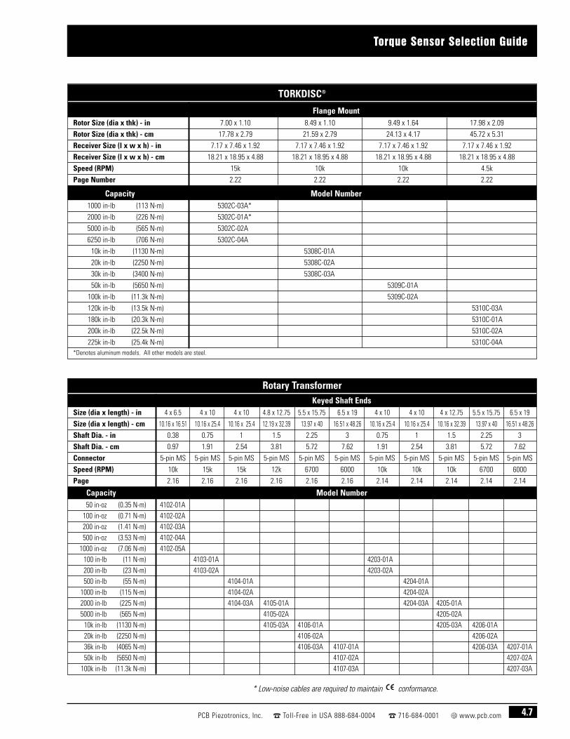
* Low-noise cables are required to maintain conformance.
Rotary TransformerKeyed Shaft Ends
Size (dia x length) - in 4 x 6.5 4 x 10 4 x 10 4.8 x 12.75 5.5 x 15.75 6.5 x 19 4 x 10 4 x 10 4 x 12.75 5.5 x 15.75 6.5 x 19
Size (dia x length) - cm 10.16 x 16.51 10.16 x 25.4 10.16 x 25.4 12.19 x 32.39 13.97 x 40 16.51 x 48.26 10.16 x 25.4 10.16 x 25.4 10.16 x 32.39 13.97 x 40 16.51 x 48.26
Shaft Dia. - in 0.38 0.75 1 1.5 2.25 3 0.75 1 1.5 2.25 3
Shaft Dia. - cm 0.97 1.91 2.54 3.81 5.72 7.62 1.91 2.54 3.81 5.72 7.62
Connector 5-pin MS 5-pin MS 5-pin MS 5-pin MS 5-pin MS 5-pin MS 5-pin MS 5-pin MS 5-pin MS 5-pin MS 5-pin MS
Speed (RPM) 10k 15k 15k 12k 6700 6000 10k 10k 10k 6700 6000
Page 2.16 2.16 2.16 2.16 2.16 2.16 2.14 2.14 2.14 2.14 2.14
Capacity Model Number50 in-oz (0.35 N-m) 4102-01A
100 in-oz (0.71 N-m) 4102-02A200 in-oz (1.41 N-m) 4102-03A500 in-oz (3.53 N-m) 4102-04A
1000 in-oz (7.06 N-m) 4102-05A100 in-lb (11 N-m) 4103-01A 4203-01A200 in-lb (23 N-m) 4103-02A 4203-02A500 in-lb (55 N-m) 4104-01A 4204-01A
1000 in-lb (115 N-m) 4104-02A 4204-02A2000 in-lb (225 N-m) 4104-03A 4105-01A 4204-03A 4205-01A5000 in-lb (565 N-m) 4105-02A 4205-02A
10k in-lb (1130 N-m) 4105-03A 4106-01A 4205-03A 4206-01A20k in-lb (2250 N-m) 4106-02A 4206-02A36k in-lb (4065 N-m) 4106-03A 4107-01A 4206-03A 4207-01A50k in-lb (5650 N-m) 4107-02A 4207-02A
100k in-lb (11.3k N-m) 4107-03A 4207-03A
TORKDISC®
Flange MountRotor Size (dia x thk) - in 7.00 x 1.10 8.49 x 1.10 9.49 x 1.64 17.98 x 2.09
Rotor Size (dia x thk) - cm 17.78 x 2.79 21.59 x 2.79 24.13 x 4.17 45.72 x 5.31
Receiver Size (l x w x h) - in 7.17 x 7.46 x 1.92 7.17 x 7.46 x 1.92 7.17 x 7.46 x 1.92 7.17 x 7.46 x 1.92
Receiver Size (l x w x h) - cm 18.21 x 18.95 x 4.88 18.21 x 18.95 x 4.88 18.21 x 18.95 x 4.88 18.21 x 18.95 x 4.88
Speed (RPM) 15k 10k 10k 4.5k
Page Number 2.22 2.22 2.22 2.22
Capacity Model Number1000 in-lb (113 N-m) 5302C-03A*
2000 in-lb (226 N-m) 5302C-01A*
5000 in-lb (565 N-m) 5302C-02A*
6250 in-lb (706 N-m) 5302C-04A*
10k in-lb (1130 N-m) 5308C-01A
20k in-lb (2250 N-m) 5308C-02A
30k in-lb (3400 N-m) 5308C-03A
50k in-lb (5650 N-m) 5309C-01A
100k in-lb (11.3k N-m) 5309C-02A
120k in-lb (13.5k N-m) 5310C-03A
180k in-lb (20.3k N-m) 5310C-01A
200k in-lb (22.5k N-m) 5310C-02A
225k in-lb (25.4k N-m) 5310C-04A*Denotes aluminum models. All other models are steel.
4.8 PCB Piezotronics, Inc. Toll-Free in USA 888-684-0004 716-684-0001 www.pcb.com
----------------------Torque Sensor Selection Guide
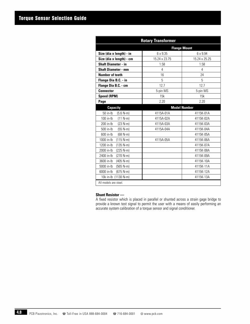
Rotary Transformer
Flange Mount
Size (dia x length) - in 6 x 9.35 6 x 9.94 Size (dia x length) - cm 15.24 x 23.75 15.24 x 25.25 Shaft Diameter - in 1.58 1.58Shaft Diameter - mm 4 4Number of teeth 16 24Flange Dia B.C. - in 5 5Flange Dia B.C. - cm 12.7 12.7Connector 5-pin MS 5-pin MSSpeed (RPM) 15k 15kPage 2.20 2.20
Capacity Model Number
50 in-lb (5.6 N-m) 4115A-01A 4115K-01A100 in-lb (11 N-m) 4115A-02A 4115K-02A200 in-lb (23 N-m) 4115A-03A 4115K-03A500 in-lb (55 N-m) 4115A-04A 4115K-04A600 in-lb (68 N-m) 4115K-05A
1000 in-lb (115 N-m) 4115A-05A 4115K-06A1200 in-lb (135 N-m) 4115K-07A2000 in-lb (225 N-m) 4115K-08A2400 in-lb (270 N-m) 4115K-09A3600 in-lb (405 N-m) 4115K-10A5000 in-lb (565 N-m) 4115K-11A6000 in-lb (675 N-m) 4115K-12A
10k in-lb (1130 N-m) 4115K-13A
All models are steel.
Shunt Resistor —A fixed resistor which is placed in parallel or shunted across a strain gage bridge toprovide a known test signal to permit the user with a means of easily performing anaccurate system calibration of a torque sensor and signal conditioner.
Strain Gage TorqueSensors
4.9PCB Piezotronics, Inc. Toll-Free in USA 888-684-0004 716-684-0001 www.pcb.com
■ Reaction torque measurements
■ Low-maintenance rotary transformer type
■ Noise-free digital telemetry type
■ NIST traceable
Highlights
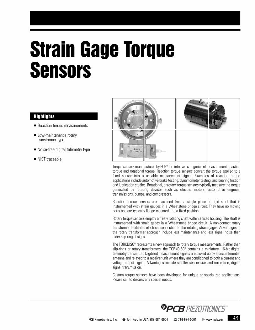
Torque sensors manufactured by PCB® fall into two categories of measurement; reactiontorque and rotational torque. Reaction torque sensors convert the torque applied to afixed sensor into a useable measurement signal. Examples of reaction torqueapplications include automotive brake testing, dynamometer testing, and bearing frictionand lubrication studies. Rotational, or rotary, torque sensors typically measure the torquegenerated by rotating devices such as electric motors, automotive engines,transmissions, pumps, and compressors.
Reaction torque sensors are machined from a single piece of rigid steel that isinstrumented with strain gauges in a Wheatstone bridge circuit. They have no movingparts and are typically flange mounted into a fixed position.
Rotary torque sensors employ a freely rotating shaft within a fixed housing. The shaft isinstrumented with strain gages in a Wheatstone bridge circuit. A non-contact rotarytransformer facilitates electrical connection to the rotating strain gages. Advantages ofthe rotary transformer approach include less maintenance and less signal noise thanolder slip-ring designs.
The TORKDISC® represents a new approach to rotary torque measurements. Rather thanslip-rings or rotary transformers, the TORKDISC® contains a miniature, 16-bit digitaltelemetry transmitter. Digitized measurement signals are picked up by a circumferentialantenna and relayed to a receiver unit where they are conditioned to both a current andvoltage output signal. Advantages include smaller sensor size and noise-free, digitalsignal transmission.
Custom torque sensors have been developed for unique or specialized applications.Please call to discuss any special needs.
-------------------
PCB Piezotronics, Inc. Toll-Free in USA 888-684-0004 716-684-0001 www.pcb.com
Reaction Torque Sensors 2000 – 500k in-lb
4.10 PCB Piezotronics, Inc. Toll-Free in USA 888-684-0004 716-684-0001 www.pcb.com
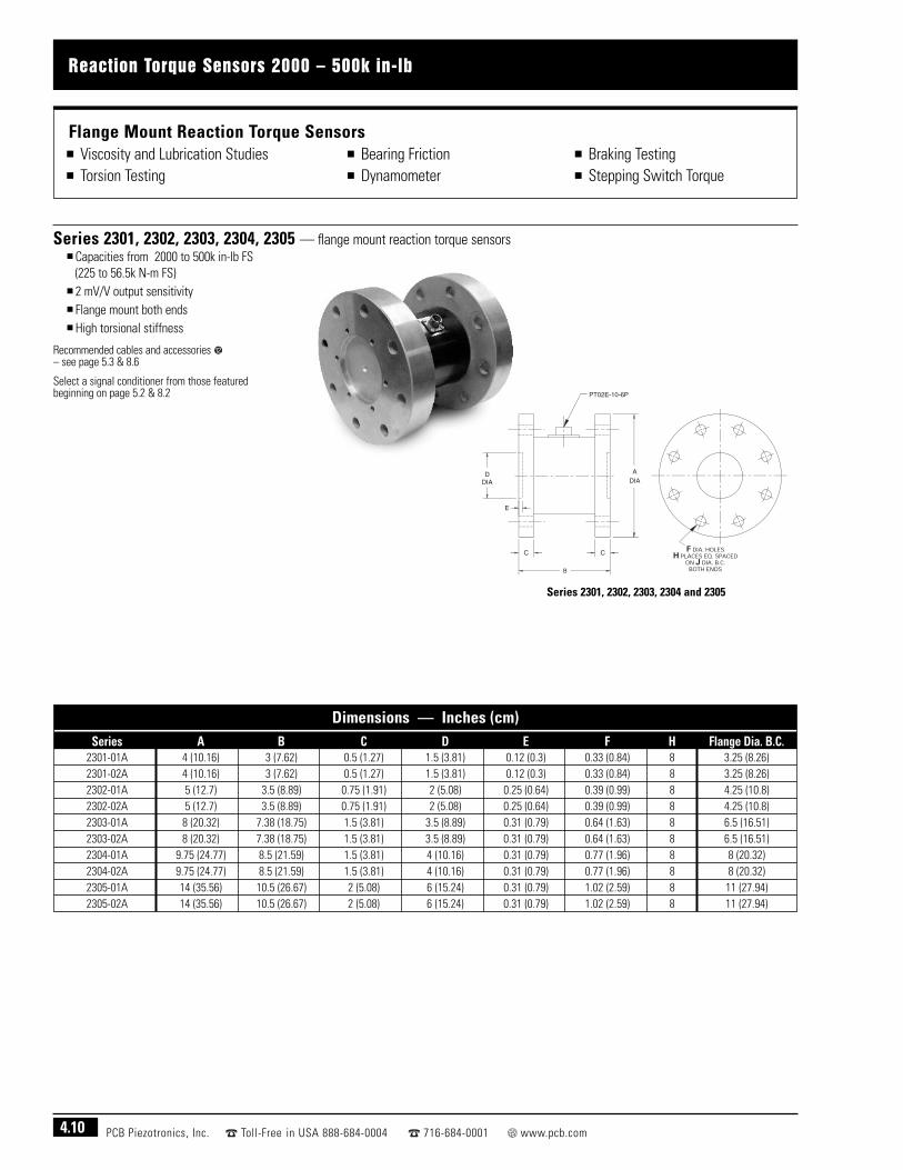
Dimensions — Inches (cm)Series A B C D E F H Flange Dia. B.C.
2301-01A 4 (10.16) 3 (7.62) 0.5 (1.27) 1.5 (3.81) 0.12 (0.3) 0.33 (0.84) 8 3.25 (8.26)2301-02A 4 (10.16) 3 (7.62) 0.5 (1.27) 1.5 (3.81) 0.12 (0.3) 0.33 (0.84) 8 3.25 (8.26)2302-01A 5 (12.7) 3.5 (8.89) 0.75 (1.91) 2 (5.08) 0.25 (0.64) 0.39 (0.99) 8 4.25 (10.8)2302-02A 5 (12.7) 3.5 (8.89) 0.75 (1.91) 2 (5.08) 0.25 (0.64) 0.39 (0.99) 8 4.25 (10.8)2303-01A 8 (20.32) 7.38 (18.75) 1.5 (3.81) 3.5 (8.89) 0.31 (0.79) 0.64 (1.63) 8 6.5 (16.51)2303-02A 8 (20.32) 7.38 (18.75) 1.5 (3.81) 3.5 (8.89) 0.31 (0.79) 0.64 (1.63) 8 6.5 (16.51)2304-01A 9.75 (24.77) 8.5 (21.59) 1.5 (3.81) 4 (10.16) 0.31 (0.79) 0.77 (1.96) 8 8 (20.32)2304-02A 9.75 (24.77) 8.5 (21.59) 1.5 (3.81) 4 (10.16) 0.31 (0.79) 0.77 (1.96) 8 8 (20.32)2305-01A 14 (35.56) 10.5 (26.67) 2 (5.08) 6 (15.24) 0.31 (0.79) 1.02 (2.59) 8 11 (27.94)2305-02A 14 (35.56) 10.5 (26.67) 2 (5.08) 6 (15.24) 0.31 (0.79) 1.02 (2.59) 8 11 (27.94)
Series 2301, 2302, 2303, 2304, 2305 — flange mount reaction torque sensors■ Capacities from 2000 to 500k in-lb FS
(225 to 56.5k N-m FS)■ 2 mV/V output sensitivity■ Flange mount both ends■ High torsional stiffness
Recommended cables and accessories– see page 5.3 & 8.6
Select a signal conditioner from those featured beginning on page 5.2 & 8.2
Series 2301, 2302, 2303, 2304 and 2305
Flange Mount Reaction Torque Sensors ■ Viscosity and Lubrication Studies■ Torsion Testing
■ Bearing Friction■ Dynamometer
■ Braking Testing■ Stepping Switch Torque
Sub Head w/Rule Here---------------------------------------------------------------------------------------------------------------------------------------------------------------------------------------------------------------------------------------------------------------------------------------------------------------------------------------------------------------------------------------------------------------------------------------------------------------------------------------------------------------------------------------------------------------------------------------------------------------------------------------------------------------------------------------------------------------------------------------------------------------------------------------
Sub Head w/Rule Here---------------------------------------------------------------------------------------------------------------------------------------------------------------------------------------------------------------------------------------------------------------------------------------------------------------------------------------------------------------------------------------------------------------------------------------------------------------------------------------------------------------------------------------------------------------------------------------------------------------------------------------------------------------------------------------------------------------------------------------------------------------------------------------
4.11PCB Piezotronics, Inc. Toll-Free in USA 888-684-0004 716-684-0001 www.pcb.com
Reaction Torque Sensors 2000 – 500k in-lb
Specifications Extraneous Load LimitsModel Capacity Safe Torsional Stiffness Ringing Weight Material Overhung Shear Thrust
Number in-lb (N-m) Overload in-lb/rad Frequency lb (kg) Moment WxS W Pin-lb (N-m) (N-m/rad) Hz in-lb (N-m) lb (N) lb (N)
Flange Mount Reaction Torque Sensors2301-01A 2000 (225) 3000 (340) 380k (42.9k) 1000 5 (2.27) steel 1000 (115) 1000 (4450) 2000 (8900)2301-02A 5000 (565) 7500 (850) 1.29M (145k) 1800 5 (2.27) steel 2500 (280) 2500 (11.1k) 5000 (22.2k)2302-01A 10k (1130) 15k (1700) 2.98M (337k) 1400 10 (4.54) steel 5000 (565) 5000 (22.2k) 10k (44.5k)2302-02A 20k (2250) 30k (3400) 7.5M (847k) 2200 10 (4.54) steel 10k (1130) 10k (44.5k) 20k (89k)2303-01A 50k (5650) 75k (8500) 10.2M (1.15M) 750 58 (26.3) steel 25k (2825) 10k (44.5k) 50k (220k)2303-02A 100k (11.3k) 150k (16.9k) 25.7M (2.9M) 1250 58 (26.3) steel 50k (5650) 20k (89k) 100k (450k)2304-01A 100k (11.3k) 150k (16.9k) 21.4M (2.4M) 690 106 (48.1) steel 50k (5650) 15k (66.7k) 100k (450k)2304-02A 200k (22.6k) 300k (33.9k) 53.9M (6.1M) 1100 106 (48.1) steel 100k (11.3k) 30k (130k) 200k (900k)2305-01A 300k (33.9k) 450k (50.8k) 75.8M (8.6M) 560 220 (99.8) steel 150k (16.9k) 30k (130k) 300k (1.3M)2305-02A 500k (56.5k) 750k (84.7k) 150M (16.9M) 780 220 (99.8) steel 250k (28.2k) 50k (220k) 500k (2.2M)
Common Specifications
Output (nominal) ........................................................................2 mV/VoltNon-linearity (max)........................................................................0.1% FSHysteresis (max) ............................................................................0.1% FSNon-repeatability (max) ..............................................................0.02% FSBridge Resistance (nom) ..............................................................350 ohmExcitation (recommended) ............................................................10 Volts
Excitation (max) ......................................................20 Volts DC or AC rmsTemp. Range (compensated) ..........+70 °F to +170 °F (+21 °C to +77 °C)Temp. Range (usable) ......................-65 °F to +200 °F (-54 °C to +93 °C)Temp. Effect on Zero (max) ....................0.002% FS/°F (0.0036% FS/°C)Temp. Effect on Output (max) ......................................0.002% reading/°F
(0.0036% reading/°C)
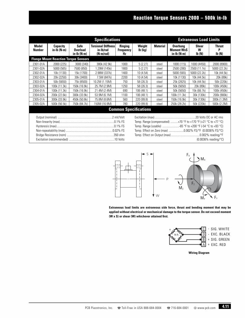
Extraneous load limits are extraneous side force, thrust and bending moment that may beapplied without electrical or mechanical damage to the torque sensor. Do not exceed moment(W x S) or shear (W) whichever attained first.
Wiring Diagram
Reaction Torque Sensors 5 – 1000 in-lb
4.12 PCB Piezotronics, Inc. Toll-Free in USA 888-684-0004 716-684-0001 www.pcb.com
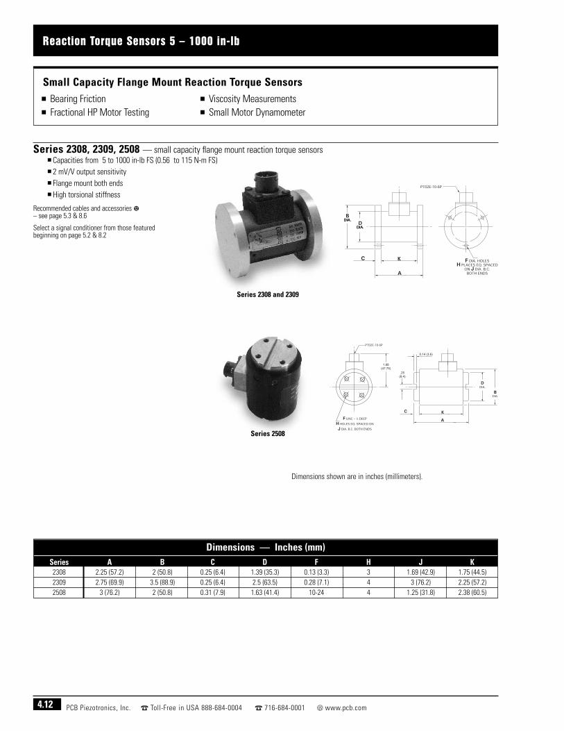
Series 2308, 2309, 2508 — small capacity flange mount reaction torque sensors■ Capacities from 5 to 1000 in-lb FS (0.56 to 115 N-m FS)■ 2 mV/V output sensitivity■ Flange mount both ends■ High torsional stiffness
Recommended cables and accessories– see page 5.3 & 8.6
Select a signal conditioner from those featured beginning on page 5.2 & 8.2
Small Capacity Flange Mount Reaction Torque Sensors ■ Bearing Friction■ Fractional HP Motor Testing
■ Viscosity Measurements■ Small Motor Dynamometer
Dimensions — Inches (mm)Series A B C D F H J K2308 2.25 (57.2) 2 (50.8) 0.25 (6.4) 1.39 (35.3) 0.13 (3.3) 3 1.69 (42.9) 1.75 (44.5)2309 2.75 (69.9) 3.5 (88.9) 0.25 (6.4) 2.5 (63.5) 0.28 (7.1) 4 3 (76.2) 2.25 (57.2)2508 3 (76.2) 2 (50.8) 0.31 (7.9) 1.63 (41.4) 10-24 4 1.25 (31.8) 2.38 (60.5)
Dimensions shown are in inches (millimeters).
Series 2308 and 2309
Series 2508
Reaction Torque Sensors 5 – 1000 in-lb
4.13PCB Piezotronics, Inc. Toll-Free in USA 888-684-0004 716-684-0001 www.pcb.com
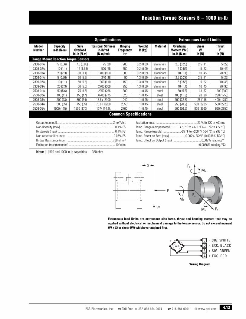
Extraneous load limits are extraneous side force, thrust and bending moment that may beapplied without electrical or mechanical damage to the torque sensor. Do not exceed moment(W x S) or shear (W) whichever attained first.
Wiring Diagram
Specifications Extraneous Load LimitsModel Capacity Safe Torsional Stiffness Ringing Weight Material Overhung Shear Thrust
Number in-lb (N-m) Overload in-lb/rad Frequency lb (kg) Moment WxS W Pin-lb (N-m) (N-m/rad) Hz in-lb (N-m) lb (N) lb (N)
Flange Mount Reaction Torque Sensors2308-01A 5 (0.56) 7.5 (0.85) 175 (20) 200 0.2 (0.09) aluminum 2.5 (0.28) 2.5 (11) 5 (22)2308-02A 10 (1.1) 15 (1.69) 500 (55) 350 0.2 (0.09) aluminum 5 (0.56) 5 (22) 10 (45)2308-03A 20 (2.3) 30 (3.4) 1400 (160) 580 0.2 (0.09) aluminum 10 (1.1) 10 (45) 20 (90)2309-01A 5 (0.56) 50 (5.6) 340 (38) 90 1.3 (0.59) aluminum 2.5 (0.28) 2.5 (11) 5 (22)2309-02A 10 (1.1) 50 (5.6) 960 (110) 150 1.3 (0.59) aluminum 5 (0.56) 5 (22) 10 (45)2309-03A 20 (2.3) 50 (5.6) 2700 (300) 250 1.3 (0.59) aluminum 10 (1.1) 10 (45) 20 (90)2508-01A 50 (5.6) 75 (8.5) 2350 (266) 380 1 (0.45) steel 50 (5.6) 13 (57) 200 (900)2508-02A 100 (11) 150 (17) 6700 (775) 620 1 (0.45) steel 100 (11.3) 20 (90) 280 (1250)2508-03A 200 (23) 300 (34) 18.8k (2100) 1040 1 (0.45) steel 200 (22.6) 26 (116) 400 (1780)2508-04A 500 (55) 750 (85) 73.6k (8200) 2050 1 (0.45) steel 250 (28.2) 500 (2225) 500 (2225)2508-05A 1000 (115) 1500 (170) 127k (14.3k) 2700 1 (0.45) steel 500 (56.5) 800 (3560) 660 (2950)
Common Specifications
Output (nominal) ..........................................................................2 mV/VoltNon-linearity (max) ........................................................................0.1% FSHysteresis (max) ............................................................................0.1% FSNon-repeatability (max) ..............................................................0.05% FSBridge Resistance (nom) ............................................................700 ohm[1]
Excitation (recommended)..............................................................10 Volts
Excitation (max) ......................................................20 Volts DC or AC rmsTemp. Range (compensated)............+70 °F to +170 °F (+21 °C to +77 °C)Temp. Range (usable) ........................-65 °F to +200 °F (-54 °C to +93 °C)Temp. Effect on Zero (max) ....................0.002% FS/°F (0.0036% FS/°C)Temp. Effect on Output (max) ......................................0.002% reading/°F
(0.0036% reading/°C)
Note: [1] 500 and 1000 in-lb capacities — 350 ohm
Rotary Transformer Torque Sensors 100 – 100k in-lb
4.14 PCB Piezotronics, Inc. Toll-Free in USA 888-684-0004 716-684-0001 www.pcb.com
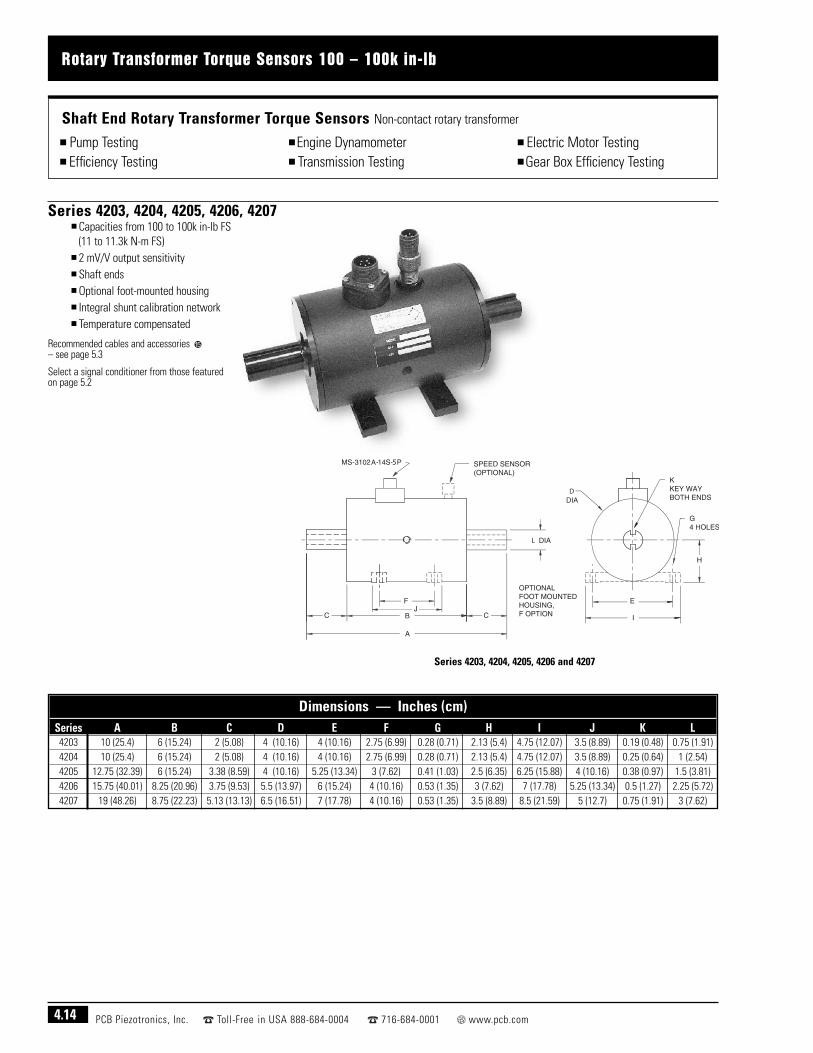
Series 4203, 4204, 4205, 4206 and 4207
Series 4203, 4204, 4205, 4206, 4207■ Capacities from 100 to 100k in-lb FS
(11 to 11.3k N-m FS) ■ 2 mV/V output sensitivity■ Shaft ends■ Optional foot-mounted housing■ Integral shunt calibration network■ Temperature compensated
Recommended cables and accessories – see page 5.3
Select a signal conditioner from those featured on page 5.2
Dimensions — Inches (cm)Series A B C D E F G H I J K L4203 10 (25.4) 6 (15.24) 2 (5.08) 4 (10.16) 4 (10.16) 2.75 (6.99) 0.28 (0.71) 2.13 (5.4) 4.75 (12.07) 3.5 (8.89) 0.19 (0.48) 0.75 (1.91)4204 10 (25.4) 6 (15.24) 2 (5.08) 4 (10.16) 4 (10.16) 2.75 (6.99) 0.28 (0.71) 2.13 (5.4) 4.75 (12.07) 3.5 (8.89) 0.25 (0.64) 1 (2.54)4205 12.75 (32.39) 6 (15.24) 3.38 (8.59) 4 (10.16) 5.25 (13.34) 3 (7.62) 0.41 (1.03) 2.5 (6.35) 6.25 (15.88) 4 (10.16) 0.38 (0.97) 1.5 (3.81)4206 15.75 (40.01) 8.25 (20.96) 3.75 (9.53) 5.5 (13.97) 6 (15.24) 4 (10.16) 0.53 (1.35) 3 (7.62) 7 (17.78) 5.25 (13.34) 0.5 (1.27) 2.25 (5.72)4207 19 (48.26) 8.75 (22.23) 5.13 (13.13) 6.5 (16.51) 7 (17.78) 4 (10.16) 0.53 (1.35) 3.5 (8.89) 8.5 (21.59) 5 (12.7) 0.75 (1.91) 3 (7.62)
Shaft End Rotary Transformer Torque Sensors Non-contact rotary transformer
■ Pump Testing■ Efficiency Testing
■ Engine Dynamometer■ Transmission Testing
■ Electric Motor Testing■ Gear Box Efficiency Testing
Rotary Transformer Torque Sensors 100 – 100k in-lb
4.15PCB Piezotronics, Inc. Toll-Free in USA 888-684-0004 716-684-0001 www.pcb.com
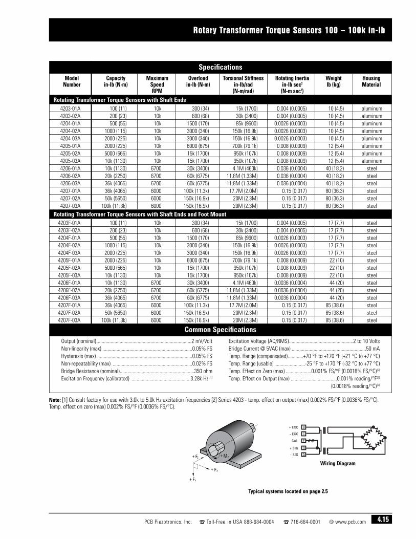
SpecificationsModel Capacity Maximum Overload Torsional Stiffness Rotating Inertia Weight Housing
Number in-lb (N-m) Speed in-lb (N-m) in-lb/rad in-lb sec2 lb (kg) MaterialRPM (N-m/rad) (N-m sec2)
Rotating Transformer Torque Sensors with Shaft Ends4203-01A 100 (11) 10k 300 (34) 15k (1700) 0.004 (0.0005) 10 (4.5) aluminum4203-02A 200 (23) 10k 600 (68) 30k (3400) 0.004 (0.0005) 10 (4.5) aluminum4204-01A 500 (55) 10k 1500 (170) 85k (9600) 0.0026 (0.0003) 10 (4.5) aluminum4204-02A 1000 (115) 10k 3000 (340) 150k (16.9k) 0.0026 (0.0003) 10 (4.5) aluminum4204-03A 2000 (225) 10k 3000 (340) 150k (16.9k) 0.0026 (0.0003) 10 (4.5) aluminum4205-01A 2000 (225) 10k 6000 (675) 700k (79.1k) 0.008 (0.0009) 12 (5.4) aluminum4205-02A 5000 (565) 10k 15k (1700) 950k (107k) 0.008 (0.0009) 12 (5.4) aluminum4205-03A 10k (1130) 10k 15k (1700) 950k (107k) 0.008 (0.0009) 12 (5.4) aluminum4206-01A 10k (1130) 6700 30k (3400) 4.1M (460k) 0.036 (0.0004) 40 (18.2) steel4206-02A 20k (2250) 6700 60k (6775) 11.8M (1.33M) 0.036 (0.0004) 40 (18.2) steel4206-03A 36k (4065) 6700 60k (6775) 11.8M (1.33M) 0.036 (0.0004) 40 (18.2) steel4207-01A 36k (4065) 6000 100k (11.3k) 17.7M (2.0M) 0.15 (0.017) 80 (36.3) steel4207-02A 50k (5650) 6000 150k (16.9k) 20M (2.3M) 0.15 (0.017) 80 (36.3) steel4207-03A 100k (11.3k) 6000 150k (16.9k) 20M (2.3M) 0.15 (0.017) 80 (36.3) steel
Rotating Transformer Torque Sensors with Shaft Ends and Foot Mount4203F-01A 100 (11) 10k 300 (34) 15k (1700) 0.004 (0.0005) 17 (7.7) steel4203F-02A 200 (23) 10k 600 (68) 30k (3400) 0.004 (0.0005) 17 (7.7) steel4204F-01A 500 (55) 10k 1500 (170) 85k (9600) 0.0026 (0.0003) 17 (7.7) steel4204F-02A 1000 (115) 10k 3000 (340) 150k (16.9k) 0.0026 (0.0003) 17 (7.7) steel4204F-03A 2000 (225) 10k 3000 (340) 150k (16.9k) 0.0026 (0.0003) 17 (7.7) steel4205F-01A 2000 (225) 10k 6000 (675) 700k (79.1k) 0.008 (0.0009) 22 (10) steel4205F-02A 5000 (565) 10k 15k (1700) 950k (107k) 0.008 (0.0009) 22 (10) steel4205F-03A 10k (1130) 10k 15k (1700) 950k (107k) 0.008 (0.0009) 22 (10) steel4206F-01A 10k (1130) 6700 30k (3400) 4.1M (460k) 0.0036 (0.0004) 44 (20) steel4206F-02A 20k (2250) 6700 60k (6775) 11.8M (1.33M) 0.0036 (0.0004) 44 (20) steel4206F-03A 36k (4065) 6700 60k (6775) 11.8M (1.33M) 0.0036 (0.0004) 44 (20) steel4207F-01A 36k (4065) 6000 100k (11.3k) 17.7M (2.0M) 0.15 (0.017) 85 (38.6) steel4207F-02A 50k (5650) 6000 150k (16.9k) 20M (2.3M) 0.15 (0.017) 85 (38.6) steel4207F-03A 100k (11.3k) 6000 150k (16.9k) 20M (2.3M) 0.15 (0.017) 85 (38.6) steel
Common SpecificationsOutput (nominal) ..........................................................................2 mV/VoltNon-linearity (max) ......................................................................0.05% FSHysteresis (max) ..........................................................................0.05% FSNon-repeatability (max) ..............................................................0.02% FSBridge Resistance (nominal)..........................................................350 ohmExcitation Frequency (calibrated) ..............................................3.28k Hz [1]
Excitation Voltage (AC/RMS)..................................................2 to 10 VoltsBridge Current @ 5VAC (max) ..........................................................50 mATemp. Range (compensated)............+70 °F to +170 °F (+21 °C to +77 °C)Temp. Range (usable) ........................-25 °F to +170 °F (-32 °C to +77 °C)Temp. Effect on Zero (max) ....................0.001% FS/°F (0.0018% FS/°C) [2]
Temp. Effect on Output (max) ....................................0.001% reading/°F [2]
(0.0018% reading/°C) [2]
Typical systems located on page 2.5
Wiring Diagram
Note: [1] Consult factory for use with 3.0k to 5.0k Hz excitation frequencies [2] Series 4203 - temp. effect on output (max) 0.002% FS/°F (0.0036% FS/°C).Temp. effect on zero (max) 0.002% FS/°F (0.0036% FS/°C).

Rotary Transformer Torque Sensors 50 in-oz – 100k in-lb
4.16 PCB Piezotronics, Inc. Toll-Free in USA 888-684-0004 716-684-0001 www.pcb.com
Series 4102, 4103, 4104, 4105, 4106, 4107■ Capacities from 50 in-oz to 100k in-lb FS
(5.6 to 11.3k N-m FS) ■ 2 mV/V or 2.5 mV/V output sensitivity■ Shaft ends■ High signal to noise ratio■ High accuracy■ High torsional stiffness
Recommended cables and accessories – see page 5.3
Select a signal conditioner from those featured on page 5.2
Dimensions — Inches (cm)Series A B C D E F G H I J K S4103 10 (25.4) 6 (15.24) 2 (5.08) 4 (10.16) 4 (10.16) 2.75 (6.99) 0.28 (0.71) 2.13 (5.41) 4.75 (12.07) 3.5 (8.89) 0.19 (0.48) 0.75 (1.91)4104 10 (25.4) 6 (15.24) 2 (5.08) 4 (10.16) 4 (10.16) 2.75 (6.99) 0.28 (0.71) 2.13 (5.41) 4.75 (12.07) 3.5 (8.89) 0.25 (0.64) 1 (2.54)4105 12.75 (32.39) 7.25 (18.42) 2.75 (6.99) 4.75 (12.07) 5.25 (13.34) 3 (7.62) 0.41 (1.03) 2.5 (6.35) 6.25 (15.88) 4 (10.16) 0.38 (0.97) 1.5 (3.81)4106 15.75 (40.01) 8.25 (20.96) 3.75 (9.53) 5.5 (13.97) 6 (15.24) 4 (10.16) 0.53 (1.35) 3 (7.62) 7 (17.78) 5.25 (13.34) 0.5 (1.27) 2.25 (5.72)4107 19 (48.26) 8.75 (22.23) 5 (12.7) 6.5 (16.51) 7 (17.78) 4 (10.16) 0.53 (1.35) 3.5 (8.89) 8.5 (21.59) 5 (12.7) 0.75 (1.91) 3 (7.62)
Dimensions — Inches (cm)Series A B C D E F G H I J K x L S4102 6.5 (16.51) 4.5 (11.43) 1 (2.54) 4 (10.16) 3.5 (8.89) 2 (5.08) 13/64 2.1 (5.33) 4 (10.16) 2.5 (6.35) 0.34 x 0.75 (0.86 x 1.91) 0.38 (0.97)
Series 4102
Series 4103, 4104, 4105, 4106 and 4107
Shaft End Rotary Transformer Torque Sensors ■ Fuel Pump Testing■ Transmission
Development
■ Hydraulic Motor■ Dynamometer■ Hydraulic Pump
■ Chassis Dynamometer■ Blower Testing■ Aerospace
Reaction Torque Sensors 50 in-oz – 100k in-lb
4.17PCB Piezotronics, Inc. Toll-Free in USA 888-684-0004 716-684-0001 www.pcb.com
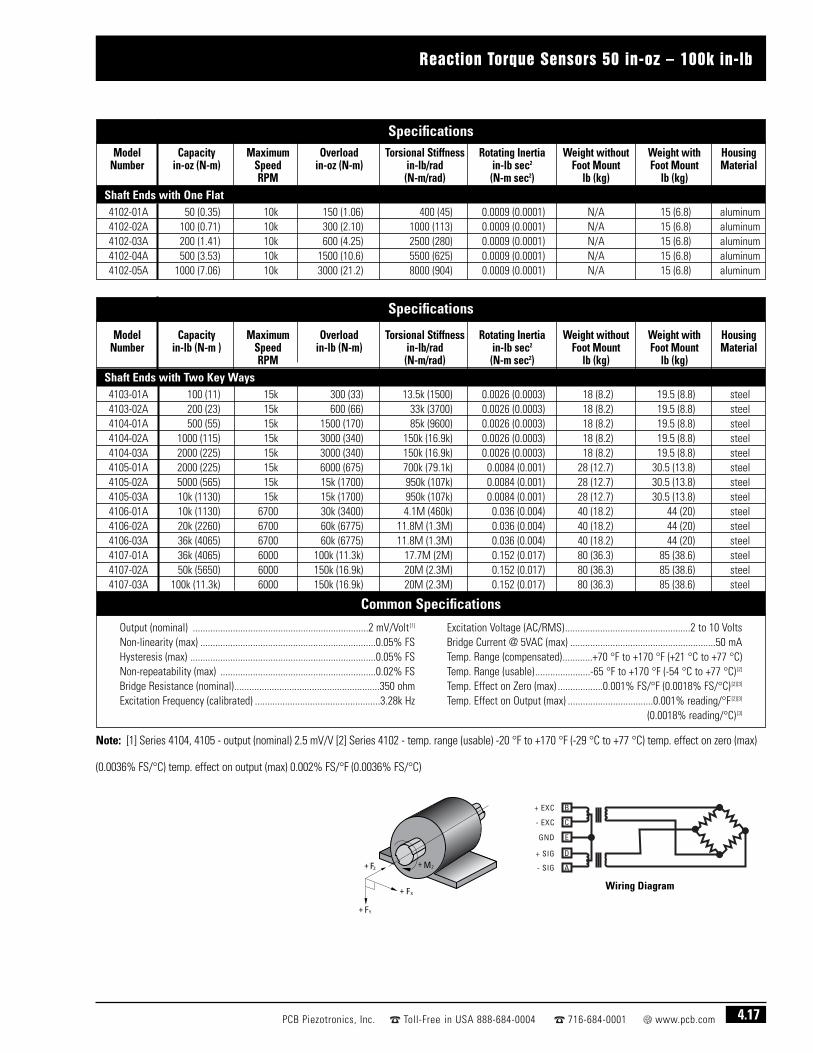
SpecificationsModel Capacity Maximum Overload Torsional Stiffness Rotating Inertia Weight without Weight with Housing
Number in-oz (N-m) Speed in-oz (N-m) in-lb/rad in-lb sec2 Foot Mount Foot Mount MaterialRPM (N-m/rad) (N-m sec2) lb (kg) lb (kg)
Shaft Ends with One Flat4102-01A 50 (0.35) 10k 150 (1.06) 400 (45) 0.0009 (0.0001) N/A 15 (6.8) aluminum4102-02A 100 (0.71) 10k 300 (2.10) 1000 (113) 0.0009 (0.0001) N/A 15 (6.8) aluminum4102-03A 200 (1.41) 10k 600 (4.25) 2500 (280) 0.0009 (0.0001) N/A 15 (6.8) aluminum4102-04A 500 (3.53) 10k 1500 (10.6) 5500 (625) 0.0009 (0.0001) N/A 15 (6.8) aluminum4102-05A 1000 (7.06) 10k 3000 (21.2) 8000 (904) 0.0009 (0.0001) N/A 15 (6.8) aluminum
Specifications
Model Capacity Maximum Overload Torsional Stiffness Rotating Inertia Weight without Weight with HousingNumber in-lb (N-m ) Speed in-lb (N-m) in-lb/rad in-lb sec2 Foot Mount Foot Mount Material
RPM (N-m/rad) (N-m sec2) lb (kg) lb (kg)Shaft Ends with Two Key Ways4103-01A 100 (11) 15k 300 (33) 13.5k (1500) 0.0026 (0.0003) 18 (8.2) 19.5 (8.8) steel4103-02A 200 (23) 15k 600 (66) 33k (3700) 0.0026 (0.0003) 18 (8.2) 19.5 (8.8) steel4104-01A 500 (55) 15k 1500 (170) 85k (9600) 0.0026 (0.0003) 18 (8.2) 19.5 (8.8) steel4104-02A 1000 (115) 15k 3000 (340) 150k (16.9k) 0.0026 (0.0003) 18 (8.2) 19.5 (8.8) steel4104-03A 2000 (225) 15k 3000 (340) 150k (16.9k) 0.0026 (0.0003) 18 (8.2) 19.5 (8.8) steel4105-01A 2000 (225) 15k 6000 (675) 700k (79.1k) 0.0084 (0.001) 28 (12.7) 30.5 (13.8) steel4105-02A 5000 (565) 15k 15k (1700) 950k (107k) 0.0084 (0.001) 28 (12.7) 30.5 (13.8) steel4105-03A 10k (1130) 15k 15k (1700) 950k (107k) 0.0084 (0.001) 28 (12.7) 30.5 (13.8) steel4106-01A 10k (1130) 6700 30k (3400) 4.1M (460k) 0.036 (0.004) 40 (18.2) 44 (20) steel4106-02A 20k (2260) 6700 60k (6775) 11.8M (1.3M) 0.036 (0.004) 40 (18.2) 44 (20) steel4106-03A 36k (4065) 6700 60k (6775) 11.8M (1.3M) 0.036 (0.004) 40 (18.2) 44 (20) steel4107-01A 36k (4065) 6000 100k (11.3k) 17.7M (2M) 0.152 (0.017) 80 (36.3) 85 (38.6) steel4107-02A 50k (5650) 6000 150k (16.9k) 20M (2.3M) 0.152 (0.017) 80 (36.3) 85 (38.6) steel4107-03A 100k (11.3k) 6000 150k (16.9k) 20M (2.3M) 0.152 (0.017) 80 (36.3) 85 (38.6) steel
Common Specifications
Output (nominal) ......................................................................2 mV/Volt [1]
Non-linearity (max) ......................................................................0.05% FSHysteresis (max) ..........................................................................0.05% FSNon-repeatability (max) ..............................................................0.02% FSBridge Resistance (nominal)..........................................................350 ohmExcitation Frequency (calibrated) ..................................................3.28k Hz
Excitation Voltage (AC/RMS)..................................................2 to 10 VoltsBridge Current @ 5VAC (max) ..........................................................50 mATemp. Range (compensated)............+70 °F to +170 °F (+21 °C to +77 °C)Temp. Range (usable)......................-65 °F to +170 °F (-54 °C to +77 °C) [2]
Temp. Effect on Zero (max) ..................0.001% FS/°F (0.0018% FS/°C) [2] [3]
Temp. Effect on Output (max) ..................................0.001% reading/°F [2] [3]
(0.0018% reading/°C) [3]
Wiring Diagram
Note: [1] Series 4104, 4105 - output (nominal) 2.5 mV/V [2] Series 4102 - temp. range (usable) -20 °F to +170 °F (-29 °C to +77 °C) temp. effect on zero (max)0.002% FS/°F (0.0036% FS/°C) temp. effect on output (max) 0.002% FS/°F (0.0036% FS/°C)[3] Series 4103 - temp. effect on zero (max) 0.002% FS/°F(0.0036% FS/°C) temp. effect on output (max) 0.002% FS/°F (0.0036% FS/°C)

4.18 PCB Piezotronics, Inc. Toll-Free in USA 888-684-0004 716-684-0001 www.pcb.com
Rotary Transformer Torque Sensors 50 – 10k in-lb
Series 4115A, 4115KDimensions shown are in inches (centimeters).
Dimensions — Inches (cm) Internal and External Spline DataSeries A B C D E Pressure Angle Pitch Dia — in (cm) Pitch Number of Teeth4115A 9.35 (23.75) 1.10 (2.79) 0.25 (0.64) 1.58 (4) 0.6 (1.52) 30° 0.8 (2.03) 20/30 164115K 9.94 (25.25) 1.69 (4.29) 0.38 (0.97) 1.58 (4) 1 (2.54) 30° 1.2 (3.05) 20/30 24
Series 4115A, 4115K ■ Capacities from 50 to 10k in-lb FS (5.6 to 1130 N-m FS) ■ 2.5 mV/V output sensitivity■ Splined shaft drive■ High signal-to-noise ratio■ High torsional stiffness
Recommended cables and accessories – see page 5.3
Select a signal conditioner from those featured on page 5.2
AND Flange-shaft Rotary Transformer Torque Sensors Specifically designed for testing of
■ Cantilevered Aerospace Hydraulic Pumps■ Cantilevered Aerospace Hydraulic Motors

4.19PCB Piezotronics, Inc. Toll-Free in USA 888-684-0004 716-684-0001 www.pcb.com
Rotary Transformer Torque Sensors 50 – 10k in-lb
SpecificationsModel Capacity Maximum Overload Torsional Stiffness Rotating Inertia Weight Material
Number in-lb (N-m) Speed in-lb (N-m) in-lb/rad in-lb sec2 lb (kg)RPM (N-m/rad) (N-m sec2)
Flange-Shaft Rotating Transformer Torque Sensors4115A-01A 50 (5.6) 15k 150 (17) 4500 (500) 0.0047 (0.0005) 46 (20.9) steel4115A-02A 100 (11) 15k 300 (34) 13.5k (1500) 0.0048 (0.0005) 46 (20.9) steel4115A-03A 200 (23) 15k 600 (68) 33k (3700) 0.0049 (0.0005) 46 (20.9) steel4115A-04A 500 (55) 15k 1500 (170) 94k (10.6k) 0.005 (0.0006) 46 (20.9) steel4115A-05A 1000 (115) 15k 1500 (170) 94k (10.6k) 0.005 (0.0006) 46 (20.9) steel4115K-01A 50 (5.6) 15k 150 (17) 4500 (500) 0.0048 (0.0005) 47 (21.3) steel4115K-02A 100 (11) 15k 300 (34) 13.5k (1500) 0.0049 (0.0005) 47 (21.3) steel4115K-03A 200 (23) 15k 600 (68) 33k (3700) 0.005 (0.0006) 47 (21.3) steel4115K-04A 500 (55) 15k 1500 (170) 94k (10.6k) 0.0051 (0.0006) 47 (21.3) steel4115K-05A 600 (68) 15k 1800 (200) 120k (13.6k) 0.0051 (0.0006) 47 (21.3) steel4115K-06A 1000 (115) 15k 3000 (340) 204k (23k) 0.0052 (0.0006) 47 (21.3) steel4115K-07A 1200 (135) 15k 3600 (405) 204k (23k) 0.0052 (0.0006) 47 (21.3) steel4115K-08A 2000 (225) 15k 6000 (675) 204k (23k) 0.0052 (0.0006) 47 (21.3) steel4115K-09A 2400 (270) 15k 7200 (815) 380k (42.9k) 0.0055 (0.0006) 47 (21.3) steel4115K-10A 3600 (405) 15k 10.8k (1220) 420k (47.5k) 0.0058 (0.0007) 47 (21.3) steel4115K-11A 5000 (565) 15k 15k (1700) 500k (56.5k) 0.0062 (0.0007) 47 (21.3) steel4115K-12A 6000 (675) 15k 15k (1700) 500k (56.5k) 0.0062 (0.0007) 47 (21.3) steel4115K-13A 10k (1130) 15k 15k (1700) 500k (56.5k) 0.0062 (0.0007) 47 (21.3) steel
Common Specifications
Output (nominal) ......................................................................2.5 mV/VoltNon-linearity (max) ......................................................................0.05% FSHysteresis (max) ..........................................................................0.05% FSNon-repeatability (max) ..............................................................0.03% FSBridge Resistance (nominal)..........................................................350 ohmExcitation Frequency (calibrated) ..................................................3.28k HzExcitation Voltage (AC/RMS)..................................................2 to 10 VoltsBridge Current @ 5VAC (max) ..........................................................50 mATemp. Range (compensated)............+70 °F to +170 °F (+21 °C to +77 °C)Temp. Range (usable) ......................-65 °F to +225 °F (-54 °C to +107 °C)
Temp. Effect on Zero (from +70 °F to +225 °F) ............................................................................................................0.002% FS/°F (0.0036% FS/°C)Temp. Effect on Span (from +70 °F to +225 °F) ............................................................................................0.002% reading/°F (0.0036% reading/°C)Temp. Effect on Zero (from -65 °F to +70 °F)....................................................................................................................0.02% FS/°F (0.036% FS/°C)Temp. Effect on Span (from -65 °F to +70 °F) ..................................................................................................................0.02% FS/°F (0.036% FS/°C)Maximum Bending Moment..................................1200 in-lb (135 N-m) [1]
Typical systems located on page 2.5
Wiring Diagram
Note: [1] Bending moment induced by overhung pump weight
4.20 PCB Piezotronics, Inc. Toll-Free in USA 888-684-0004 716-684-0001 www.pcb.com
TORKDISC® Rotary Torque Sensor System 1000 – 225k in-lb
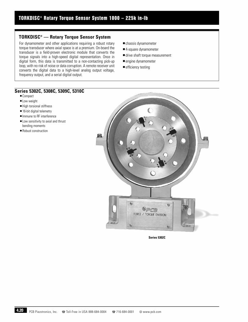
Series 5302C, 5308C, 5309C, 5310C■ Compact■ Low weight■ High torsional stiffness■ 16-bit digital telemetry■ Immune to RF interference■ Low sensitivity to axial and thrust
bending moments■ Robust construction
Series 5302C
TORKDISC® — Rotary Torque Sensor SystemFor dynamometer and other applications requiring a robust rotarytorque transducer where axial space is at a premium. On-board thetransducer is a field-proven electronic module that converts thetorque signals into a high-speed digital representation. Once indigital form, this data is transmitted to a non-contacting pick-uploop, with no risk of noise or data corruption. A remote receiver unitconverts the digital data to a high-level analog output voltage,frequency output, and a serial digital output.
■ chassis dynamometer■ 4-square dynamometer■ drive shaft torque measurement■ engine dynamometer■ efficiency testing
TORKDISC® Rotary Torque Sensor System 1000 – 225k in-lb
4.21PCB Piezotronics, Inc. Toll-Free in USA 888-684-0004 716-684-0001 www.pcb.com
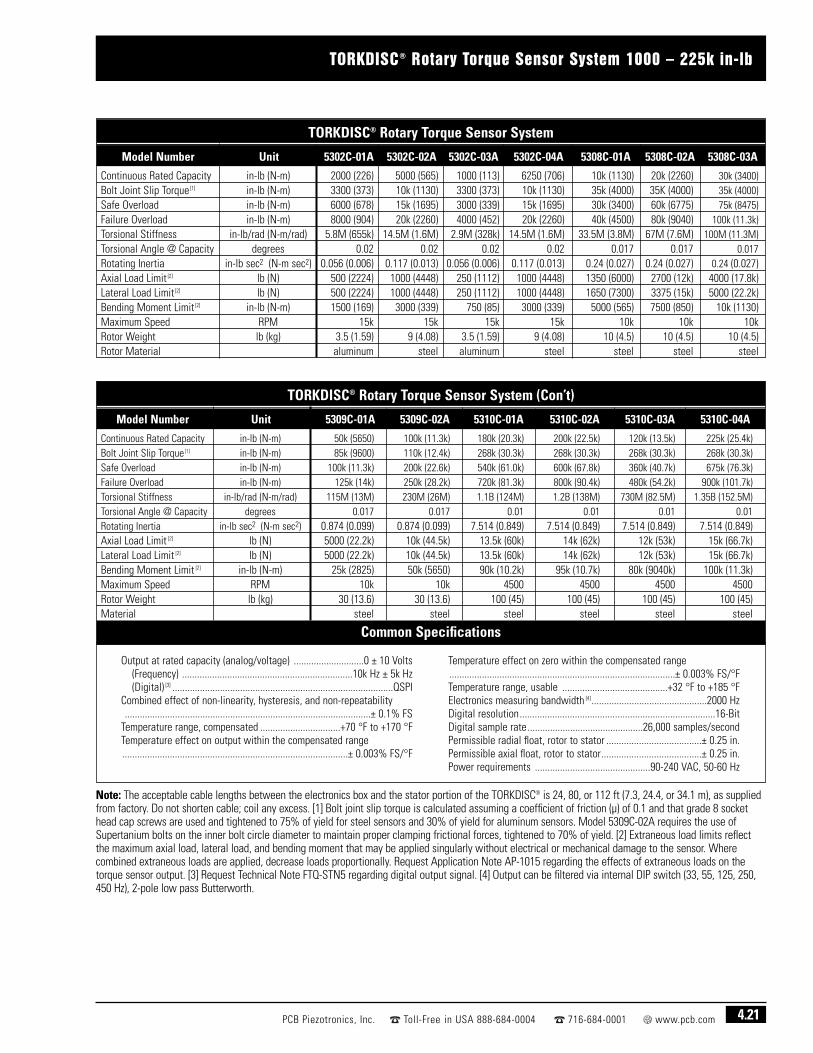
TORKDISC® Rotary Torque Sensor System
Model Number Unit 5302C-01A 5302C-02A 5302C-03A 5302C-04A 5308C-01A 5308C-02A 5308C-03A
Continuous Rated Capacity in-lb (N-m) 2000 (226) 5000 (565) 1000 (113) 6250 (706) 10k (1130) 20k (2260) 30k (3400)Bolt Joint Slip Torque [1] in-lb (N-m) 3300 (373) 10k (1130) 3300 (373) 10k (1130) 35k (4000) 35K (4000) 35k (4000)Safe Overload in-lb (N-m) 6000 (678) 15k (1695) 3000 (339) 15k (1695) 30k (3400) 60k (6775) 75k (8475)Failure Overload in-lb (N-m) 8000 (904) 20k (2260) 4000 (452) 20k (2260) 40k (4500) 80k (9040) 100k (11.3k)Torsional Stiffness in-lb/rad (N-m/rad) 5.8M (655k) 14.5M (1.6M) 2.9M (328k) 14.5M (1.6M) 33.5M (3.8M) 67M (7.6M) 100M (11.3M)Torsional Angle @ Capacity degrees 0.02 0.02 0.02 0.02 0.017 0.017 0.017Rotating Inertia in-lb sec2 (N-m sec2) 0.056 (0.006) 0.117 (0.013) 0.056 (0.006) 0.117 (0.013) 0.24 (0.027) 0.24 (0.027) 0.24 (0.027)Axial Load Limit [2] lb (N) 500 (2224) 1000 (4448) 250 (1112) 1000 (4448) 1350 (6000) 2700 (12k) 4000 (17.8k)Lateral Load Limit [2] lb (N) 500 (2224) 1000 (4448) 250 (1112) 1000 (4448) 1650 (7300) 3375 (15k) 5000 (22.2k)Bending Moment Limit [2] in-lb (N-m) 1500 (169) 3000 (339) 750 (85) 3000 (339) 5000 (565) 7500 (850) 10k (1130)Maximum Speed RPM 15k 15k 15k 15k 10k 10k 10kRotor Weight lb (kg) 3.5 (1.59) 9 (4.08) 3.5 (1.59) 9 (4.08) 10 (4.5) 10 (4.5) 10 (4.5)Rotor Material aluminum steel aluminum steel steel steel steel
TORKDISC® Rotary Torque Sensor System (Con’t)
Model Number Unit 5309C-01A 5309C-02A 5310C-01A 5310C-02A 5310C-03A 5310C-04A
Continuous Rated Capacity in-lb (N-m) 50k (5650) 100k (11.3k) 180k (20.3k) 200k (22.5k) 120k (13.5k) 225k (25.4k)Bolt Joint Slip Torque [1] in-lb (N-m) 85k (9600) 110k (12.4k) 268k (30.3k) 268k (30.3k) 268k (30.3k) 268k (30.3k)Safe Overload in-lb (N-m) 100k (11.3k) 200k (22.6k) 540k (61.0k) 600k (67.8k) 360k (40.7k) 675k (76.3k)Failure Overload in-lb (N-m) 125k (14k) 250k (28.2k) 720k (81.3k) 800k (90.4k) 480k (54.2k) 900k (101.7k)Torsional Stiffness in-lb/rad (N-m/rad) 115M (13M) 230M (26M) 1.1B (124M) 1.2B (138M) 730M (82.5M) 1.35B (152.5M)Torsional Angle @ Capacity degrees 0.017 0.017 0.01 0.01 0.01 0.01Rotating Inertia in-lb sec2 (N-m sec2) 0.874 (0.099) 0.874 (0.099) 7.514 (0.849) 7.514 (0.849) 7.514 (0.849) 7.514 (0.849)Axial Load Limit [2] lb (N) 5000 (22.2k) 10k (44.5k) 13.5k (60k) 14k (62k) 12k (53k) 15k (66.7k)Lateral Load Limit [2] lb (N) 5000 (22.2k) 10k (44.5k) 13.5k (60k) 14k (62k) 12k (53k) 15k (66.7k)Bending Moment Limit [2] in-lb (N-m) 25k (2825) 50k (5650) 90k (10.2k) 95k (10.7k) 80k (9040k) 100k (11.3k)Maximum Speed RPM 10k 10k 4500 4500 4500 4500Rotor Weight lb (kg) 30 (13.6) 30 (13.6) 100 (45) 100 (45) 100 (45) 100 (45)Material steel steel steel steel steel steel
Common Specifications
Output at rated capacity (analog/voltage) ............................0 ± 10 Volts(Frequency) ....................................................................10k Hz ± 5k Hz(Digital) [3] ........................................................................................QSPI
Combined effect of non-linearity, hysteresis, and non-repeatability..................................................................................................± 0.1% FS
Temperature range, compensated ................................+70 °F to +170 °FTemperature effect on output within the compensated range..........................................................................................± 0.003% FS/°F
Temperature effect on zero within the compensated range..........................................................................................± 0.003% FS/°FTemperature range, usable ..........................................+32 °F to +185 °FElectronics measuring bandwidth [4] ..............................................2000 HzDigital resolution..............................................................................16-BitDigital sample rate..............................................26,000 samples/secondPermissible radial float, rotor to stator ......................................± 0.25 in.Permissible axial float, rotor to stator........................................± 0.25 in.Power requirements ..............................................90-240 VAC, 50-60 Hz
Note: The acceptable cable lengths between the electronics box and the stator portion of the TORKDISC® is 24, 80, or 112 ft (7.3, 24.4, or 34.1 m), as suppliedfrom factory. Do not shorten cable; coil any excess. [1] Bolt joint slip torque is calculated assuming a coefficient of friction (µ) of 0.1 and that grade 8 sockethead cap screws are used and tightened to 75% of yield for steel sensors and 30% of yield for aluminum sensors. Model 5309C-02A requires the use ofSupertanium bolts on the inner bolt circle diameter to maintain proper clamping frictional forces, tightened to 70% of yield. [2] Extraneous load limits reflectthe maximum axial load, lateral load, and bending moment that may be applied singularly without electrical or mechanical damage to the sensor. Where combined extraneous loads are applied, decrease loads proportionally. Request Application Note AP-1015 regarding the effects of extraneous loads on thetorque sensor output. [3] Request Technical Note FTQ-STN5 regarding digital output signal. [4] Output can be filtered via internal DIP switch (33, 55, 125, 250,450 Hz), 2-pole low pass Butterworth.

4.22 PCB Piezotronics, Inc. Toll-Free in USA 888-684-0004 716-684-0001 www.pcb.com
TORKDISC® Rotary Torque Sensor System 1000 – 225k in-lb
(E) Driven (inner)Bolt Circle (typical)
(F) Load (outer)Bolt Circle (typical)
B
A
Direction for Positive Output
Drawing View ShowsMounting Surface forDriven Bolt Circle
Telemetry Collar
Request Detailed Drawing for Installation
~
~
C D
TORKDISC® Sensor Dimensions
A B C D E FSeries O.D. - Outside Overall Thickness Male Pilot Female Pilot Driven (inner) Bolt Circle Load (outer) Bolt Circle
Diameter (including Diameter Diametertelemetry collar)
5302C 7.00 in (177.8 mm) 1.10 in (27.9 mm) 1.999 in (50.8 mm) 4.375 in (111.1 mm) (8) 3/8-24 threaded holes, equally (8) 0.406 in (10.31 mm) dia through holesspaced on a 3.00 in (76.20 mm) B.C. equally spaced on a 5.00 in (127.0 mm) B.C.
5308C 8.49 in (215.5 mm) 1.10 in (27.9 mm) 2.748 in (69.9 mm) 5.513 in (140.0 mm) (8) 5/8-11 threaded holes, spaced (8) 0.531 in (13.49 mm) dia through holeson a 3.75 in (95.25 mm) B.C. equally spaced on a 6.5 in (165.0 mm) B.C.
5309C 10.49 in (241.0 mm) 1.64 in (41.7 mm) 3.998 in (101.5 mm) 7.500 in (190.5 mm) (12) 5/8-11 threaded holes, spaced (16) 0.531 in (13.49 mm) dia through holeson a 6.0 in (152.4 mm) B.C. equally spaced on a 8.5 in (215.9 mm) B.C.
5310C 17.98 in (456.7 mm) 2.09 in (53.0 mm) 5.499 in (139.7 mm) 11.001 in (279.4 mm) (12) 7/8-14 threaded holes, spaced (16) 0.780 in (19.8 mm) dia through holeson a 9.0 in (288.6 mm) B.C. equally spaced on a 13.0 in (330.2 mm) B.C.

4.23PCB Piezotronics, Inc. Toll-Free in USA 888-684-0004 716-684-0001 www.pcb.com
TORKDISC® Rotary Torque Sensor System 1000 – 225k in-lb
The TORKDISC® and receiver make up a complete system. No additional signalconditioning is required. The receiver box provides voltage, frequency, and digital outputvia a 25-pin (F) D-sub connector.
4.24 PCB Piezotronics, Inc. Toll-Free in USA 888-684-0004 716-684-0001 www.pcb.com
Phot
o Co
urte
sy o
f Mus
tang
Dyn
amom
eter
.Ph
oto
Cour
tesy
of M
usta
ng D
ynam
omet
er.
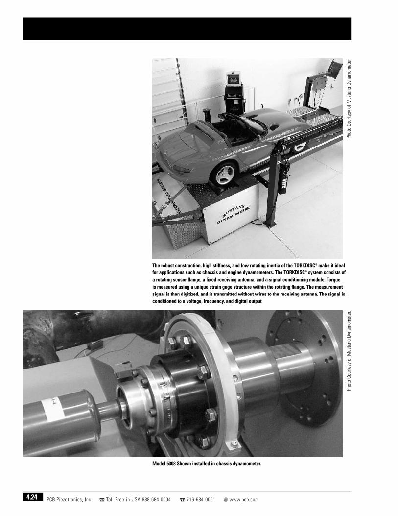
The robust construction, high stiffness, and low rotating inertia of the TORKDISC® make it idealfor applications such as chassis and engine dynamometers. The TORKDISC® system consists of a rotating sensor flange, a fixed receiving antenna, and a signal conditioning module. Torque is measured using a unique strain gage structure within the rotating flange. The measurementsignal is then digitized, and is transmitted without wires to the receiving antenna. The signal isconditioned to a voltage, frequency, and digital output.
Model 5308 Shown installed in chassis dynamometer.
5.1PCB Piezotronics, Inc. Toll-Free in USA 888-684-0004 716-684-0001 www.pcb.com
Torque Sensor Accessories and Services
■ Strain gage signal conditioners
■ Cable assemblies
■ Speed sensors
■ Shunt calibration modules and thermocouples
■ Calibration services
Highlights
-------------------

5.2 PCB Piezotronics, Inc. Toll-Free in USA 888-684-0004 716-684-0001 www.pcb.com
Signal Conditioners For use with Torque or Speed Sensors
Models: 8120-100A, 8120-400A, and 8120-700A
Models: 8120-110A, 8120-130A, 8120-410A, 8120-430A, 8120-710A, and 8120-730A
The Series 8120 family of signal conditioners are designed for usewith either strain gage reaction torque sensors, strain gage rotarytorque sensors, or Hall Effect speed (RPM) sensors. Within eachcategory, the series offers a choice of either a basic signal
conditioner, signal conditioner with digital display, or signalconditioner with digital display and Hi-Lo set points. Each unitdelivers a 0 to ± 5 Volts analog output signal.
Sensor/Excitation *Strain Gage Strain Gage Hall EffectDC Excitation AC Excitation (Speed)
(Reaction) (Rotary)Basic Signal Conditioner 8120-100A 8120-400A 8120-700A
Signal Conditioner 8120-110A 8120-410A 8120-710Awith 4 1/2 digit LED display3 Hz refresh rate
Signal Conditioner 8120-130A 8120-430A 8120-730Awith LED display and Hi-Lo set points (TTL compatible)
Input transducers 90-2000 ohm 90-1000 ohm 0.1-200V
Excitation 5 or 10 VDC 2 VAC (RMS) @ 3.28 kHz 9 VDC
Accuracy ± 0.05% FS ± 0.05% FS ± 0.05% FS
Balance range10 turn coarse and fine pots, 10 turn coarse and fine pots,
—± 1.5 mV/V imbalance ± 1.5 mV/V imbalance
Span range10 turn coarse and fine pots, 10 turn coarse and fine pots, Selectable ranges of 0, 100, 200, 500, 1 to 8 mV/V 0.5 to 5 mV/V 1000, 2000, 5000, 10k, 20k, 50k
Active filterSelectable 2, 200, 2000 Hz Selectable 2, 400 Hz 2 Hz on input ranges of 0-500 Hz,
10 Hz on all other
Output ripple and noise0.02% FS (RMS) with 2 Hz filter 0.02% FS (RMS) with 2 Hz filter 0.1% FS (RMS) from 20%-100%0.15% all other filter ranges 0.15% all other filter ranges of input range
Input power110/120 VAC @ 50-400 Hz, 110/120 VAC @ 50-400 Hz, 110/120 VAC @ 50-400 Hz, 9 watts max 9 watts max 9 watts max
Operating temp. range 0 to +130 ºF (0 to +54 ºC) 0 to +130 ºF (0 to +54 ºC) 0 to +130 ºF (0 to +54 ºC)
Weight (approx.) 2 lb (0.9 Kg) 2 lb (0.9 Kg) 2 lb (0.9 Kg)
* For additional signal conditioners for use with reaction torque sensors, see section 8
Available Signal Conditioner Options Can be Combined with One of the
(Consult Factory) Options ListedB 12 Volt DC Power P, C, G, RP Peak Capture F, BC 4 to 20 mA Current Output F, BF 230 VAC Power P, C, G, R, SG ± 10 Volt Output (0.1% FS Non-linearity) F, BR* Dual Limits - Mechanical Relays F, BS* Dual Limits - Solid State Relays F* Model 8120-X30A Only
Supplied Accessories
Star Bridge Sensor Simulator* (if precision shunt calibration module is not supplied)Mating Connector (if cable is not purchased)Power Cord
* Hall Effect signal conditioners are not supplied with a star bridge, as they contain built-in crystal oscillators
5.3PCB Piezotronics, Inc. Toll-Free in USA 888-684-0004 716-684-0001 www.pcb.com
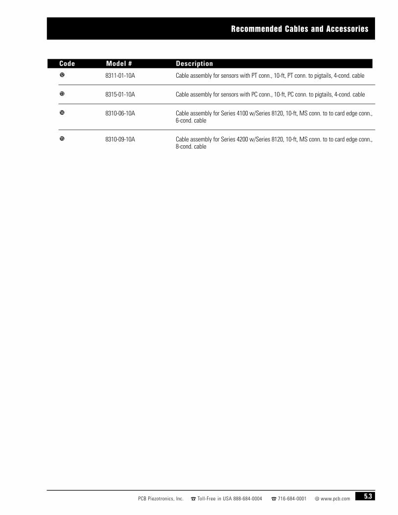
8311-01-10A Cable assembly for sensors with PT conn., 10-ft, PT conn. to pigtails, 4-cond. cable
8315-01-10A Cable assembly for sensors with PC conn., 10-ft, PC conn. to pigtails, 4-cond. cable
8310-06-10A Cable assembly for Series 4100 w/Series 8120, 10-ft, MS conn. to to card edge conn., 6-cond. cable
8310-09-10A Cable assembly for Series 4200 w/Series 8120, 10-ft, MS conn. to to card edge conn., 8-cond. cable
Code Model # Description
Recommended Cables and Accessories
5.4 PCB Piezotronics, Inc. Toll-Free in USA 888-684-0004 716-684-0001 www.pcb.com
3-Socket Plug Pigtails
2-Socket Plug Pigtails
2-Socket Plug Card Edge
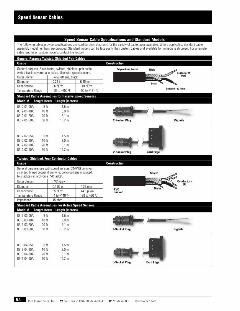
Speed Sensor Cables
Speed Sensor Cable Specifications and Standard ModelsThe following tables provide specifications and configuration diagrams for the variety of cable types available. Where applicable, standard cableassembly model numbers are provided. Standard models can be less costly than custom cables and available for immediate shipment. For alternatecable lengths or custom models, contact the factory.
General Purpose Twisted, Shielded Pair CablesUsage Construction
General purpose, 2-conductor, twisted, shielded, pair cable with a black polyurethane jacket. Use with speed sensors.Outer Jacket Polyurethane, blackDiameter 0.25 in 6.35 mmCapacitance 36 pF/ft 118 pF/mTemperature Range -58 to +250 ºF -50 to +121 ºC
Standard Cable Assemblies for Passive Speed SensorsModel # Length (feet) Length (meters)
8312-01-05A 5 ft 1.5 m8312-01-10A 10 ft 3.0 m8312-01-20A 20 ft 6.1 m8312-01-50A 50 ft 15.2 m
8312-02-05A 5 ft 1.5 m8312-02-10A 10 ft 3.0 m 8312-02-20A 20 ft 6.1 m8312-02-50A 50 ft 15.2 m
Twisted, Shielded, Four-Conductor CablesUsage ConstructionGeneral purpose, use with speed sensors. 24AWG common stranded tinned copper drain wire, polypropylene insulated, twisted pair in a chrome PVC jacket.Outer Jacket PVC, grey
Diameter 0.168 in 4.27 mmCapacitance 35 pF/ft 44.3 pF/mTemperature Range -4 to +140 ºF -20 to +60 ºCImpedance 45 ohm
Standard Cable Assemblies For Active Speed SensorsModel # Length (feet) Length (meters)
8313-03-05A 5 ft 1.5 m8313-03-10A 10 ft 3.0 m8313-03-20A 20 ft 6.1 m8313-03-50A 50 ft 15.2 m
8313-04-05A 5 ft 1.5 m8313-04-10A 10 ft 3.0 m8313-04-20A 20 ft 6.1 m 8313-04-50A 50 ft 15.2 m
Conductor #1(red)
Conductor #2 (blue)
Drain
ShieldPolyurethane Jacket
PVCJacket
Conductors(4)
Shield
Drain
3-Socket Plug Card Edge
PT 9-pin (M) D-sub
PT Pigtails
5.5PCB Piezotronics, Inc. Toll-Free in USA 888-684-0004 716-684-0001 www.pcb.com
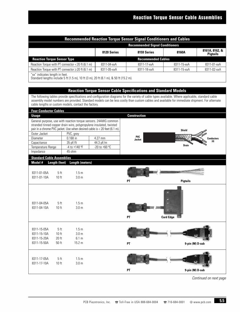
Reaction Torque Sensor Cable Assemblies
Reaction Torque Sensor Cable Specifications and Standard ModelsThe following tables provide specifications and configuration diagrams for the variety of cable types available. Where applicable, standard cableassembly model numbers are provided. Standard models can be less costly than custom cables and available for immediate shipment. For alternatecable lengths or custom models, contact the factory.G
Four-Conductor CablesUsage Construction
General purpose, use with reaction torque sensors. 24AWG commonstranded tinned copper drain wire, polypropylene insulated, twistedpair in a chrome PVC jacket. Use when desired cable is < 20 feet (6.1 m).Outer Jacket PVC, greyDiameter 0.168 in 4.27 mmCapacitance 35 pF/ft 44.3 pF/mTemperature Range -4 to +140 ºF -20 to +60 ºCImpedance 45 ohm
Standard Cable AssembliesModel # Length (feet) Length (meters)
8311-01-05A 5 ft 1.5 m8311-01-10A 10 ft 3.0 m
8311-04-05A 5 ft 1.5 m8311-04-10A 10 ft 3.0 m
8311-15-05A 5 ft 1.5 m8311-15-10A 10 ft 3.0 m8311-15-20A 20 ft 6.1 m8311-15-50A 50 ft 15.2 m
8311-17-05A 5 ft 1.5 m8311-17-10A 10 ft 3.0 m
Recommended Reaction Torque Sensor Signal Conditioners and CablesRecommended Signal Conditioners
8120 Series 8159 Series 8160A 8161A, 8162, & Pigtails
Reaction Torque Sensor Type Recommended CablesReaction Torque with PT connector <20 ft (6.1 m) 8311-04-xxA 8311-17-xxA 8311-15-xxA 8311-01-xxAReaction Torque with PT connector ≥20 ft (6.1 m) 8311-05-xxA 8311-18-xxA 8311-15-xxA 8311-02-xxA”xx” indicates length in feet.Standard lengths include 5 ft (1.5 m), 10 ft (3 m), 20 ft (6.1 m), & 50 ft (15.2 m).
Conductors(4)
Shield
Drain
PT Card Edge
Continued on next page
PVCJacket
PT 9-pin (M) D-sub
5.6 PCB Piezotronics, Inc. Toll-Free in USA 888-684-0004 716-684-0001 www.pcb.com
9-pin (M) D-sub PT
PT Card Edge
PT Pigtails
15-pin (M) D-sub Pigtails
9-socket (F) D-sub Pigtails
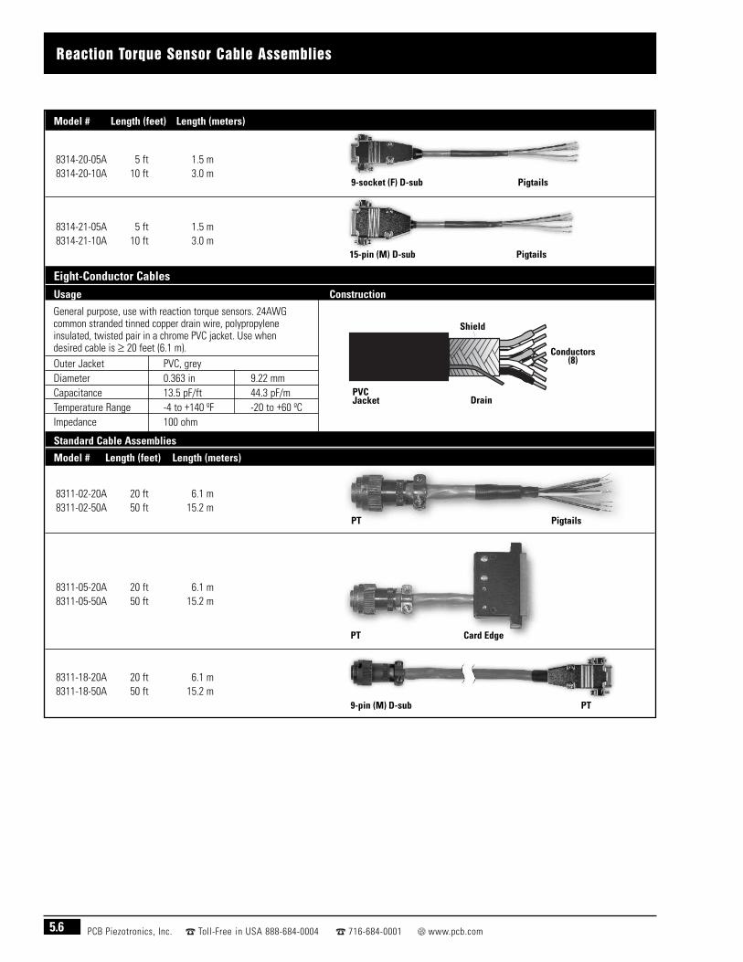
Reaction Torque Sensor Cable Assemblies
Model # Length (feet) Length (meters)
8314-20-05A 5 ft 1.5 m8314-20-10A 10 ft 3.0 m
8314-21-05A 5 ft 1.5 m8314-21-10A 10 ft 3.0 m
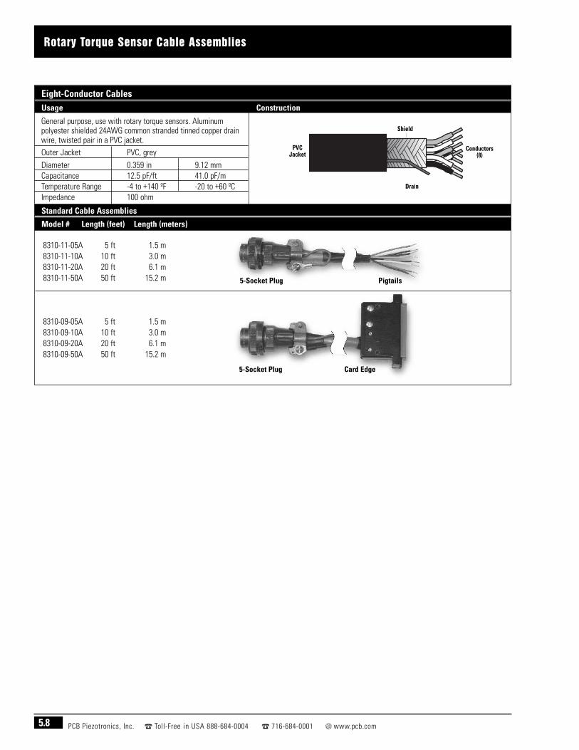
Eight-Conductor CablesUsage Construction
General purpose, use with reaction torque sensors. 24AWG common stranded tinned copper drain wire, polypropylene insulated, twisted pair in a chrome PVC jacket. Use when desired cable is ≥ 20 feet (6.1 m).Outer Jacket PVC, greyDiameter 0.363 in 9.22 mmCapacitance 13.5 pF/ft 44.3 pF/mTemperature Range -4 to +140 ºF -20 to +60 ºCImpedance 100 ohm
Standard Cable Assemblies
Model # Length (feet) Length (meters)
8311-02-20A 20 ft 6.1 m8311-02-50A 50 ft 15.2 m
8311-05-20A 20 ft 6.1 m8311-05-50A 50 ft 15.2 m
8311-18-20A 20 ft 6.1 m8311-18-50A 50 ft 15.2 m
PVCJacket
Conductors(8)
Shield
Drain

5-Socket Plug Card Edge
5-Socket Plug Pigtails
Rotary Torque Sensor Cable Assemblies
Rotary Torque Sensor Cable Specifications and Standard ModelsThe following tables provide specifications and configuration diagrams for the variety of cable types available. Where applicable, standard cableassembly model numbers are provided. Standard models can be less costly than custom cables and available for immediate shipment. For alternatecable lengths or custom models, contact the factory.General PurposeTwisted, Shielded Pair
Six-Conductor CablesUsage Construction
General purpose, use with rotary torque sensors. Aluminumpolyester shielded 24AWG common stranded tinned copper drain wire, twisted pair in a PVC jacket.Outer Jacket PVC, greyDiameter 0.359 in 9.12 mmCapacitance 12.5 pF/ft 41.0 pF/mTemperature Range -4 to +140 ºF -20 to +60 ºCImpedance 100 ohm
Standard Cable Assemblies
Model # Length (feet) Length (meters)
8310-03-20A 20 ft 6.1 m8310-03-50A 50 ft 15.2 m
8310-06-05A 5 ft 1.5 m8310-06-10A 10 ft 3.0 m8310-06-20A 20 ft 6.1 m8310-06-50A 50 ft 15.2 m
Recommended Rotary Torque Sensor Signal Conditioners and CablesSignal Conditioners
8120 Series Pigtails (other)Rotary Torque Sensor Type Recommended CablesSeries 4100 Rotary Transformer Torque 8310-06-xxA 8310-03-xxASeries 4200 Rotary Transformer Torque 8310-09-xxA 8310-11-xxA”xx” indicates length in feet.Standard lengths include 5 ft (1.5 m), 10 ft (3 m), 20 ft (6.1 m), & 50 ft (15.2 m).
PVCJacket
Conductors(6)
Shield
Drain
5.7PCB Piezotronics, Inc. Toll-Free in USA 888-684-0004 716-684-0001 www.pcb.com
5.8 PCB Piezotronics, Inc. Toll-Free in USA 888-684-0004 716-684-0001 www.pcb.com
5-Socket Plug Pigtails
5-Socket Plug Card Edge
PVCJacket
Conductors(8)
Shield
Drain
Eight-Conductor CablesUsage Construction
General purpose, use with rotary torque sensors. Aluminumpolyester shielded 24AWG common stranded tinned copper drainwire, twisted pair in a PVC jacket.Outer Jacket PVC, grey
Diameter 0.359 in 9.12 mmCapacitance 12.5 pF/ft 41.0 pF/mTemperature Range -4 to +140 ºF -20 to +60 ºCImpedance 100 ohm
Standard Cable Assemblies
Model # Length (feet) Length (meters)
8310-11-05A 5 ft 1.5 m8310-11-10A 10 ft 3.0 m8310-11-20A 20 ft 6.1 m8310-11-50A 50 ft 15.2 m
8310-09-05A 5 ft 1.5 m8310-09-10A 10 ft 3.0 m8310-09-20A 20 ft 6.1 m8310-09-50A 50 ft 15.2 m
Rotary Torque Sensor Cable Assemblies

5.9PCB Piezotronics, Inc. Toll-Free in USA 888-684-0004 716-684-0001 www.pcb.com
Model A-30775-1A — active speed sensor kit■ Requires supply voltage■ 0 to 20,000 RPM max■ 3-pin connector
Model A-30774A — passive speed sensor kit■ Self-generating■ 200 RPM to rated speed of torque sensor■ 2-pin connector
---------------------- Torque Sensor Accessories
Speed Sensors
Speed Sensors KitsModel Number Unit A-30775-1A A-30774ASpecifications
Type Active PassiveSupply Voltage VDC 5 to 15 Self-generatingSupply Current - typical mA 15 —Frequency Range Hz 0 to 20k 200 to 20kOutput Voltage - logic 0 VDC 0.6 max —
- logic 1 VDC 2.4 min —Output Voltage V P-P — 10 to 170
Supplied AccessoriesMating Connector 180-021A 180-017A
(MS3106A-10SL-3S) (MS3106A-10SL-4S)Cable Clamp 180-018A 180-018A
(MS3057-4A) (MS3057-4A)
Pin OutA 5 to 15 VDC Signal OutputB Signal Signal CommonC Common —
Kit Components
Assembled Kit
Active Speed Sensor * Length with mating connector
Passive Speed Sensor * Length with mating connector
Speed sensors may be used with rotary torque sensors to provide ameasurement of rotational speed. Horsepower can then becalculated using the speed and torque measurements by thefollowing relationship:
HP = Torque (in-lbs) x RPM63025
These devices install into ports provided on Series 4100 and Series4200 torque sensors. The output of a speed sensor switches in thepresence of ferromagnetic material such as steel gear teeth.
Output amplitude and wave-form are affected by gear speed andtooth shape.
Speed sensor gears are usually made with 60 teeth. A speed sensorused with a 60 tooth gear will have an output of 100 Hz for a shaftspeed of 100 RPM.
Proper orientation of the sensor tip, relative to gear movement, isrequired. See drawing below for orientation information.
Speed Sensor
MatingConnector
Cable Clamp
5.10 PCB Piezotronics, Inc. Toll-Free in USA 888-684-0004 716-684-0001 www.pcb.com
----------------------Torque Sensor Accessories
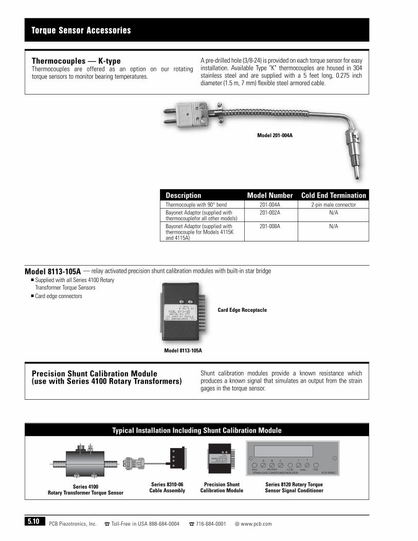
Description Model Number Cold End TerminationThermocouple with 90° bend 201-004A 2-pin male connectorBayonet Adaptor (supplied with 201-002A N/Athermocouplefor all other models)Bayonet Adaptor (supplied with 201-008A N/Athermocouple for Models 4115K and 4115A)
Model 201-004A
Model 8113-105A — relay activated precision shunt calibration modules with built-in star bridge■ Supplied with all Series 4100 Rotary
Transformer Torque Sensors■ Card edge connectors
Typical Installation Including Shunt Calibration Module
Series 4100Rotary Transformer Torque Sensor
Series 8310-06Cable Assembly
Series 8120 Rotary TorqueSensor Signal Conditioner
Precision ShuntCalibration Module
Thermocouples — K-typeThermocouples are offered as an option on our rotating torque sensors to monitor bearing temperatures.
A pre-drilled hole (3/8-24) is provided on each torque sensor for easyinstallation. Available Type "K" thermocouples are housed in 304stainless steel and are supplied with a 5 feet long, 0.275 inchdiameter (1.5 m, 7 mm) flexible steel armored cable.
Precision Shunt Calibration Module (use with Series 4100 Rotary Transformers)
Shunt calibration modules provide a known resistance whichproduces a known signal that simulates an output from the straingages in the torque sensor.
Model 8113-105A
Card Edge Receptacle
5.11PCB Piezotronics, Inc. Toll-Free in USA 888-684-0004 716-684-0001 www.pcb.com
---------------------- Torque Sensor Calibration Services
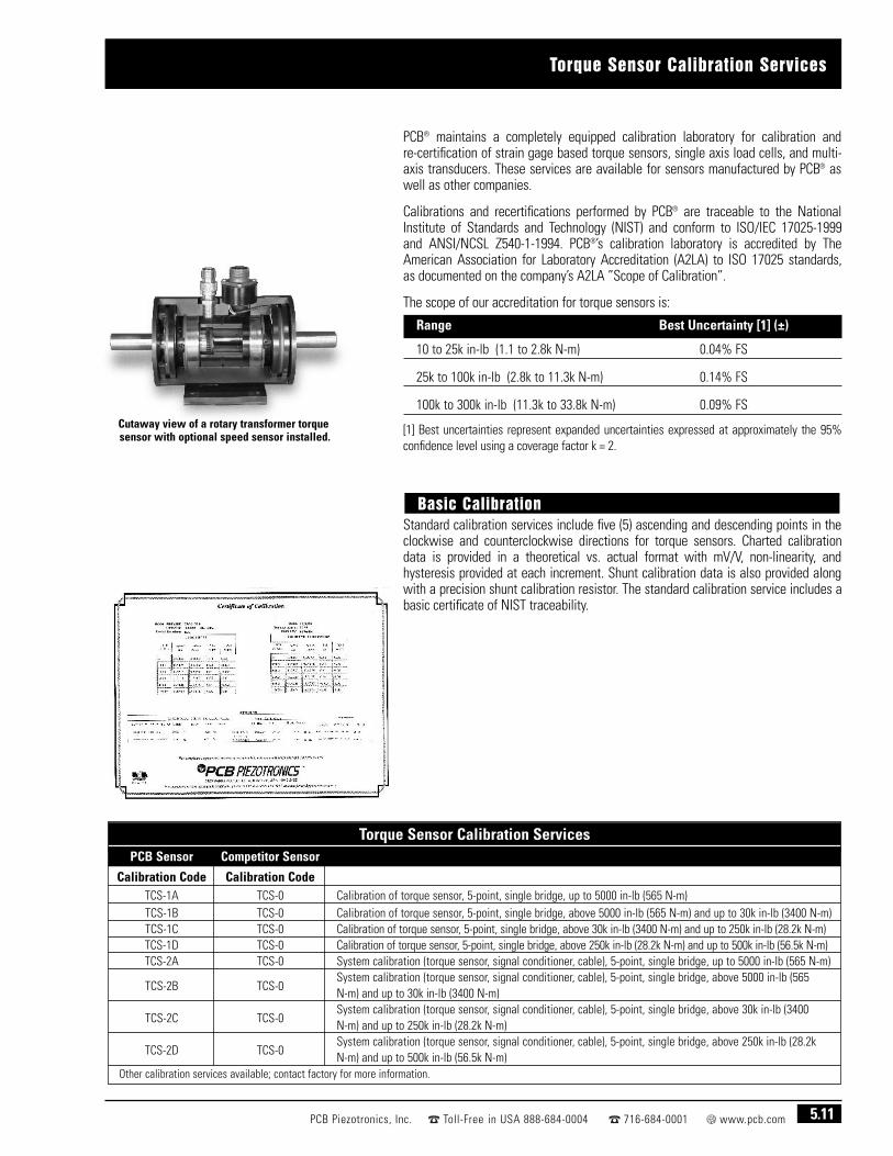
PCB® maintains a completely equipped calibration laboratory for calibration and re-certification of strain gage based torque sensors, single axis load cells, and multi-axis transducers. These services are available for sensors manufactured by PCB® aswell as other companies.
Calibrations and recertifications performed by PCB® are traceable to the NationalInstitute of Standards and Technology (NIST) and conform to ISO/IEC 17025-1999 and ANSI/NCSL Z540-1-1994. PCB®’s calibration laboratory is accredited by The American Association for Laboratory Accreditation (A2LA) to ISO 17025 standards, as documented on the company’s A2LA ”Scope of Calibration”.
The scope of our accreditation for torque sensors is:
Range Best Uncertainty [1] (±)
10 to 25k in-lb (1.1 to 2.8k N-m) 0.04% FS
25k to 100k in-lb (2.8k to 11.3k N-m) 0.14% FS
100k to 300k in-lb (11.3k to 33.8k N-m) 0.09% FS
[1] Best uncertainties represent expanded uncertainties expressed at approximately the 95%confidence level using a coverage factor k = 2.
Standard calibration services include five (5) ascending and descending points in theclockwise and counterclockwise directions for torque sensors. Charted calibration data is provided in a theoretical vs. actual format with mV/V, non-linearity, andhysteresis provided at each increment. Shunt calibration data is also provided alongwith a precision shunt calibration resistor. The standard calibration service includes abasic certificate of NIST traceability.
Basic Calibration
Cutaway view of a rotary transformer torquesensor with optional speed sensor installed.
Torque Sensor Calibration ServicesPCB Sensor Competitor Sensor
Calibration Code Calibration CodeTCS-1A TCS-0 Calibration of torque sensor, 5-point, single bridge, up to 5000 in-lb (565 N-m)TCS-1B TCS-0 Calibration of torque sensor, 5-point, single bridge, above 5000 in-lb (565 N-m) and up to 30k in-lb (3400 N-m)TCS-1C TCS-0 Calibration of torque sensor, 5-point, single bridge, above 30k in-lb (3400 N-m) and up to 250k in-lb (28.2k N-m)TCS-1D TCS-0 Calibration of torque sensor, 5-point, single bridge, above 250k in-lb (28.2k N-m) and up to 500k in-lb (56.5k N-m)TCS-2A TCS-0 System calibration (torque sensor, signal conditioner, cable), 5-point, single bridge, up to 5000 in-lb (565 N-m)
TCS-2B TCS-0System calibration (torque sensor, signal conditioner, cable), 5-point, single bridge, above 5000 in-lb (565 N-m) and up to 30k in-lb (3400 N-m)
TCS-2C TCS-0System calibration (torque sensor, signal conditioner, cable), 5-point, single bridge, above 30k in-lb (3400 N-m) and up to 250k in-lb (28.2k N-m)
TCS-2D TCS-0System calibration (torque sensor, signal conditioner, cable), 5-point, single bridge, above 250k in-lb (28.2k N-m) and up to 500k in-lb (56.5k N-m)
Other calibration services available; contact factory for more information.
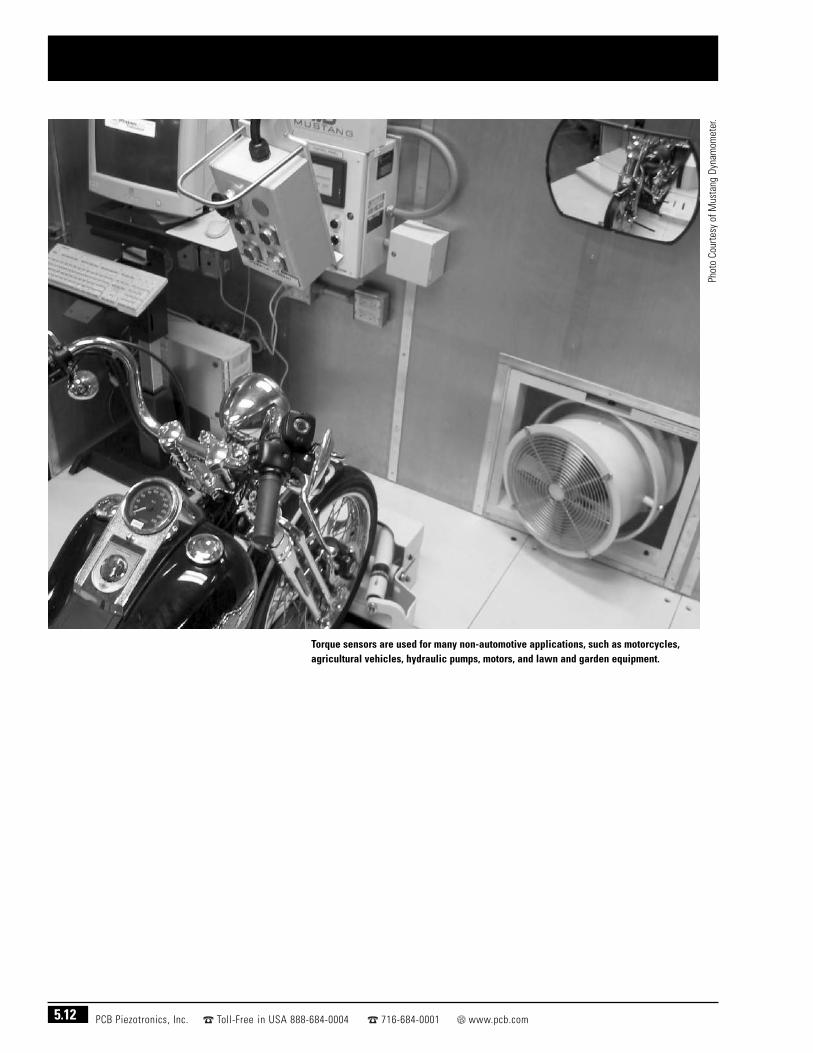
5.12 PCB Piezotronics, Inc. Toll-Free in USA 888-684-0004 716-684-0001 www.pcb.com
Torque sensors are used for many non-automotive applications, such as motorcycles, agricultural vehicles, hydraulic pumps, motors, and lawn and garden equipment.
Phot
o Co
urte
sy o
f Mus
tang
Dyn
amom
eter
.
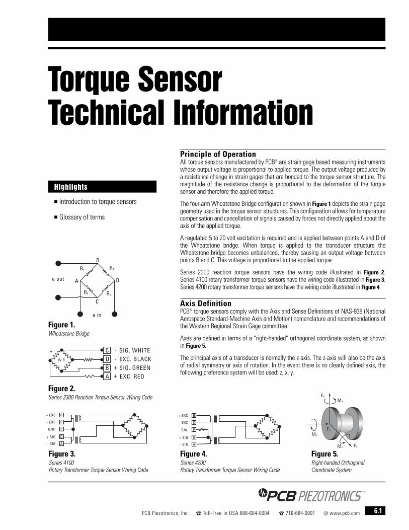
6.1PCB Piezotronics, Inc. Toll-Free in USA 888-684-0004 716-684-0001 www.pcb.com
Torque SensorTechnical Information
■ Introduction to torque sensors
■ Glossary of terms
Highlights
Figure 1. Wheatstone Bridge
Figure 2. Series 2300 Reaction Torque Sensor Wiring Code
Figure 3. Series 4100 Rotary Transformer Torque Sensor Wiring Code
Figure 4. Series 4200 Rotary Transformer Torque Sensor Wiring Code
Figure 5. Right-handed OrthogonalCoordinate System
Principle of OperationAll torque sensors manufactured by PCB® are strain gage based measuring instrumentswhose output voltage is proportional to applied torque. The output voltage produced bya resistance change in strain gages that are bonded to the torque sensor structure. Themagnitude of the resistance change is proportional to the deformation of the torquesensor and therefore the applied torque.
The four-arm Wheatstone Bridge configuration shown in Figure 1 depicts the strain gagegeometry used in the torque sensor structures. This configuration allows for temperaturecompensation and cancellation of signals caused by forces not directly applied about theaxis of the applied torque.
A regulated 5 to 20 volt excitation is required and is applied between points A and D ofthe Wheatstone bridge. When torque is applied to the transducer structure theWheatstone bridge becomes unbalanced, thereby causing an output voltage betweenpoints B and C. This voltage is proportional to the applied torque.
Series 2300 reaction torque sensors have the wiring code illustrated in Figure 2. Series 4100 rotary transformer torque sensors have the wiring code illustrated in Figure 3.Series 4200 rotary transformer torque sensors have the wiring code illustrated in Figure 4.
Axis DefinitionPCB® torque sensors comply with the Axis and Sense Definitions of NAS-938 (NationalAerospace Standard-Machine Axis and Motion) nomenclature and recommendations ofthe Western Regional Strain Gage committee.
Axes are defined in terms of a “right-handed” orthogonal coordinate system, as shown in Figure 5.
The principal axis of a transducer is normally the z-axis. The z-axis will also be the axisof radial symmetry or axis of rotation. In the event there is no clearly defined axis, thefollowing preference system will be used: z, x, y.
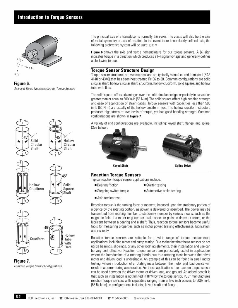
6.2 PCB Piezotronics, Inc. Toll-Free in USA 888-684-0004 716-684-0001 www.pcb.com
Introduction to Torque Sensors
Figure 6. Axis and Sense Nomenclature for Torque Sensors
Figure 7. Common Torque Sensor Configurations
Keyed Shaft Spline Drive
The principal axis of a transducer is normally the z-axis. The z-axis will also be the axisof radial symmetry or axis of rotation. In the event there is no clearly defined axis, thefollowing preference system will be used: z, x, y.
Figure 6 shows the axis and sense nomenclature for our torque sensors. A (+) signindicates torque in a direction which produces a (+) signal voltage and generally definesa clockwise torque.
Torque Sensor Structure DesignTorque sensor structures are symmetrical and are typically manufactured from steel (SAE4140 or 4340) that has been heat-treated Rc 36 to 38. Common configurations are solidcircular shaft, hollow circular shaft, cruciform, hollow cruciform, solid square, and hollowtube with flats.
The solid square offers advantages over the solid circular design, especially in capacitiesgreater than or equal to 500 in-lb (55 N-m). The solid square offers high bending strengthand ease of application of strain gages. Torque sensors with capacities less than 500 in-lb (55 N-m) are usually of the hollow cruciform type. The hollow cruciform structureproduces high stress at low levels of torque, yet has good bending strength. Commonconfigurations are shown in Figure 7.
A variety of end configurations are available, including: keyed shaft, flange, and spline.(See below).
Reaction Torque SensorsTypical reaction torque sensor applications include:
■ Bearing friction ■ Starter testing■ Stepping switch torque ■ Automotive brake testing
■ Axle torsion test
Reaction torque is the turning force or moment, imposed upon the stationary portion ofa device by the rotating portion, as power is delivered or absorbed. The power may betransmitted from rotating member to stationary member by various means, such as themagnetic field of a motor or generator, brake shoes or pads on drums or rotors, or thelubricant between a bearing and a shaft. Thus, reaction torque sensors become usefultools for measuring properties such as motor power, braking effectiveness, lubrication,and viscosity.
Reaction torque sensors are suitable for a wide range of torque measurementapplications, including motor and pump testing. Due to the fact that these sensors do notutilize bearings, slip-rings, or any other rotating elements, their installation and use canbe very cost effective. Reaction torque sensors are particularly useful in applicationswhere the introduction of a rotating inertia due to a rotating mass between the drivermotor and driven load is undesirable. An example of this can be found in small motortesting, where introduction of a rotating mass between the motor and load device willresult in an error during acceleration. For these applications, the reaction torque sensorcan be used between the driver motor, or driven load, and ground. An added benefit isthat such an installation is not limited in RPM by the torque sensor. PCB® manufacturesreaction torque sensors with capacities ranging from a few inch ounces to 500k in-lb(56.5k N-m), in configurations including keyed shaft and flange.
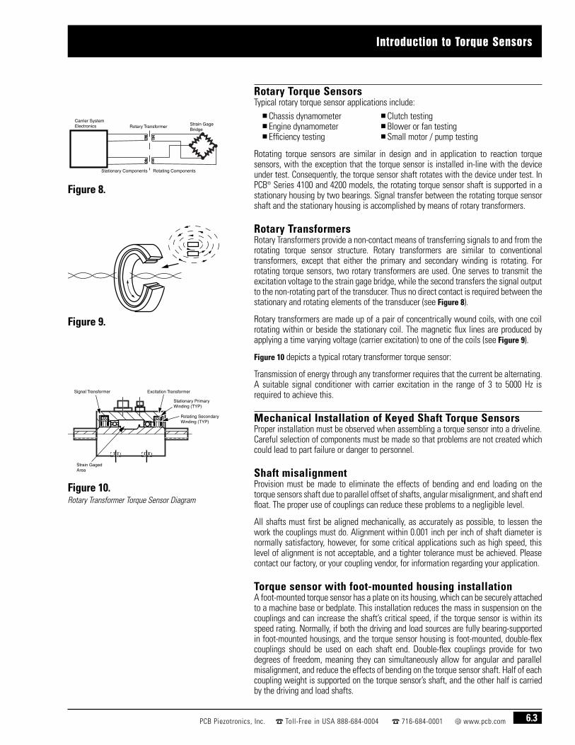
6.3PCB Piezotronics, Inc. Toll-Free in USA 888-684-0004 716-684-0001 www.pcb.com
Introduction to Torque Sensors
Rotary Torque SensorsTypical rotary torque sensor applications include:
■ Chassis dynamometer ■ Clutch testing■ Engine dynamometer ■ Blower or fan testing■ Efficiency testing ■ Small motor / pump testing
Rotating torque sensors are similar in design and in application to reaction torquesensors, with the exception that the torque sensor is installed in-line with the deviceunder test. Consequently, the torque sensor shaft rotates with the device under test. InPCB® Series 4100 and 4200 models, the rotating torque sensor shaft is supported in astationary housing by two bearings. Signal transfer between the rotating torque sensorshaft and the stationary housing is accomplished by means of rotary transformers.
Rotary TransformersRotary Transformers provide a non-contact means of transferring signals to and from therotating torque sensor structure. Rotary transformers are similar to conventionaltransformers, except that either the primary and secondary winding is rotating. Forrotating torque sensors, two rotary transformers are used. One serves to transmit theexcitation voltage to the strain gage bridge, while the second transfers the signal outputto the non-rotating part of the transducer. Thus no direct contact is required between thestationary and rotating elements of the transducer (see Figure 8).
Rotary transformers are made up of a pair of concentrically wound coils, with one coilrotating within or beside the stationary coil. The magnetic flux lines are produced byapplying a time varying voltage (carrier excitation) to one of the coils (see Figure 9).
Figure 10 depicts a typical rotary transformer torque sensor:
Transmission of energy through any transformer requires that the current be alternating.A suitable signal conditioner with carrier excitation in the range of 3 to 5000 Hz isrequired to achieve this.
Mechanical Installation of Keyed Shaft Torque SensorsProper installation must be observed when assembling a torque sensor into a driveline.Careful selection of components must be made so that problems are not created whichcould lead to part failure or danger to personnel.
Shaft misalignmentProvision must be made to eliminate the effects of bending and end loading on thetorque sensors shaft due to parallel offset of shafts, angular misalignment, and shaft endfloat. The proper use of couplings can reduce these problems to a negligible level.
All shafts must first be aligned mechanically, as accurately as possible, to lessen thework the couplings must do. Alignment within 0.001 inch per inch of shaft diameter isnormally satisfactory, however, for some critical applications such as high speed, thislevel of alignment is not acceptable, and a tighter tolerance must be achieved. Pleasecontact our factory, or your coupling vendor, for information regarding your application.
Torque sensor with foot-mounted housing installationA foot-mounted torque sensor has a plate on its housing, which can be securely attachedto a machine base or bedplate. This installation reduces the mass in suspension on thecouplings and can increase the shaft’s critical speed, if the torque sensor is within itsspeed rating. Normally, if both the driving and load sources are fully bearing-supportedin foot-mounted housings, and the torque sensor housing is foot-mounted, double-flexcouplings should be used on each shaft end. Double-flex couplings provide for twodegrees of freedom, meaning they can simultaneously allow for angular and parallelmisalignment, and reduce the effects of bending on the torque sensor shaft. Half of eachcoupling weight is supported on the torque sensor’s shaft, and the other half is carriedby the driving and load shafts.
Figure 8.
Figure 9.
Figure 10. Rotary Transformer Torque Sensor Diagram

6.4 PCB Piezotronics, Inc. Toll-Free in USA 888-684-0004 716-684-0001 www.pcb.com
Introduction to Torque Sensors
Torque sensor with floating shaft installationA floating shaft torque sensor does not have a foot-mount plate on the housing, nor isthe housing affixed to a bedplate in any other fashion. It depends on being carried by thedriver and load shafts for its support. The housing, which is meant to remain stationaryand not rotate with the shaft, must be restrained from rotating with a conductive flexiblestrap. Tapped threaded holes are provided on the side of the housing for this purpose.The other end of the strap is bolted to a bedplate or other stationary-grounded member,which will electrically ground the torque sensor housing to the electrical system ground.
Therefore, with the floating shaft, there is just one degree of freedom between eachshaft end of the torque sensor and the adjacent mating shaft, which is bearing-supported (driver and load shafts) on the bedplate. Consequently, a single flex couplingis required at each end of the torque sensor.
Error AnalysisPCB® typically supplies accuracy information on its products in the form individual errors.They are non-linearity, hysteresis, non-repeatability, effect of temperature on zerounbalance, and effect of temperature on output.
The customer can combine these individual errors to establish the maximum possibleerror for the measurement, or just examine the applicable individual error. If thetemperature remains stable during the test, the temperature related errors can beignored. If the sensor is used for increasing load measurement only, ignore the hysteresiserror. If the load measurement is near the full capacity, the linearity error can be ignored.If the capability exists to correct the data through linearization-fit or a look-up-table, theerror in the measurement can be minimized. A sophisticated user can get rid of all theerrors except for the non-repeatability error in the measurement.
Often overlooked by the customer is error due to the presence of non-measured forcesand bending moments. Even though the single axis of measurement sensors aredesigned and built to withstand these non-measured forces and bending moments(extraneous loads), the errors due to them are present. The user can design the set-up toeliminate or minimize these extraneous loads. However, if these extraneous loads arepresent, the errors due to them should be considered.
Determine the capacityrequired
A. What is the maximum expectedtorque, including transients?
B. What is the minimum expectedtorque?
C. What is the typical expectedtorque? D. What are the dynamics of the system,
(i.e. frequency response)?E. What are the maximum extraneous
loads to which the torque sensor willbe subjected?
How will the torque sensor beintegrated into the system?
A. What are the physical constraints, (e.g. length, diameter)?
B. Will the torque sensor be foot-mounted or floated?
C. Couplings, torsionally stiff, or torsionally soft?
What type of environment will the torque sensor beoperating in?
A. Maximum temperature?B. Minimum temperature?C. Humidity?D. Contaminants,
(e.g. water, oil, dirt, dust)?What speed will the torquesensor be required to rotate?
A. What length of time will the torquesensor be rotating, and at whatspeed?
Application Questionnaire
Accuracy — Stated as a limit tolerance, which defines theaverage deviation between the actual outputversus theoretical output.
In practical transducer applications, thepotential errors of non-linearity, hysteresis,non-repeatability and temperature effects donot normally occur simultaneously, nor arethey necessarily additive.
Therefore, accuracy is calculated based uponRMS value of potential errors, assuming atemperature variation of ± 10 °F (± 5.5 °C),full rated load applied, and proper set-up and calibration. Potential errors of the readout,cross-talk, or creep effects are not included.
Ambient Conditions — The conditions (humidity, pressure, tempera-ture, etc.) of the medium surrounding thetransducer.
Ambient Temperature — The temperature of the medium surroundingof transducers.
Calibration — The comparison of transducer output againststandard test loads.
Calibration Curve — a record (graph) of the comparison of transducer output against standard test loads.
Combined Error (Non-linearity & Hysteresis) — the maximum deviation from a straight linedrawn between the original no-load andrated load outputs expressed as a percentageof the rated output and measured on bothincreasing and decreasing loads.
Compensation — The utilization of supplementary devices,materials, or processes to minimize knownsources of error.
Creep — The change of transducer output occurringwith time, while under load, and with allenvironmental conditions and other variablesremaining constant.Note: Usually measured with rated load appliedand expressed as a percent of rated output over aspecific period of time.
Creep Recovery — The change in no-load output occurring withtime, after removal of a load, which has beenapplied for a specific period of time.
Cross-talk — With one component loaded to capacity, andthe other unloaded, the output of theunloaded component will not exceed the percentage specified of its full-scale capacity.
Deflection — The change in length along the primary axisof the load cell between no-load and ratedload conditions.
Drift — A random change in output under constantload conditions.
Error — The algebraic difference between the indicated and true value of the load beingmeasured.
Excitation, Electrical — The voltage or current applied to the inputterminals of the transducer.
Fatigue Capacity — Capacity as percentage of the nominal loadlimit capacity, and based on 100 X 106 cycles(minimum) from zero to full fatigue capacityand 50 X 106 cycles (minimum) from fullfatigue capacity tension to full fatigue capacity compression load.
Hysteresis — The maximum difference between the transducer output readings for the sameapplied load, one reading obtained byincreasing the load from zero and the otherby decreasing the load from rated load.Note: Usually measured at half rated output andexpressed in percent of rated output. Measurementsshould be taken as rapidly as possible to minimizecreep.
Insulation Resistance — The DC resistance measured between thetransducer circuit and the transducer structure.Note: Normally measured at fifty volts DC andunder standard test conditions.
Natural Frequency — The frequency of free oscillations under no-load conditions.
Nominal Load Limit Capacity — It is the designed normal maximum capacityof a transducer. Output sensitivity of thetransducer is based on this capacity unlessspecified.
Non-linearity — The maximum deviation of the calibrationcurve from a straight line drawn between theno load and rated load output, expressed as a percentage of the rated output and measured on increasing load only.
Output — This signal (voltage, current, etc.) producedby the transducer.Note: Where the output is directly proportional toexcitation, the signal must be expressed in terms ofvolts per volt, volts per ampere, etc. of excitation.
Output, Rated — The algebraic difference between the outputsat no-load and at rated load.
Overload Rating — The maximum load in percent of rated capacity, which can be applied without producing a permanent shift in performancecharacteristics beyond those specified.
Primary Axis — The axis along which the transducer isdesigned to be loaded; normally its geometriccenterline.
Rated Capacity (Rated Load) — The maximum axial load that the transduceris designed to measure within its specifications.
Repeatability — The maximum difference between transduceroutput readings for repeated loading underidentical loading and environmental conditions.
Resolution — The smallest change in mechanical input,which produces a detectable change in theoutput signal.
Glossary of Terms
6.5PCB Piezotronics, Inc. Toll-Free in USA 888-684-0004 716-684-0001 www.pcb.com
6.6 PCB Piezotronics, Inc. Toll-Free in USA 888-684-0004 716-684-0001 www.pcb.com
Sensitivity — The ratio of the change in output to thechange in mechanical input.
Shunt Calibration — Electrical simulation of transducer output byinsertion of known shunt resistors betweenappropriate points within the circuitry.
Shunt-to-load Correlation — The difference in output readings obtainedthrough electrically simulated and actualapplied loads.
Standard Test Conditions — The environmental conditions under whichmeasurements should be made, when measurements under any other conditionsmay result in disagreement between variousobservers at difference times and places.These conditions are a follows:
Temperature 72 °F ± 3.6 °F (23 °C ± 2 °C)
Relative Humidity: 90% or less
Barometric Pressure: 28 to 32 inch Hg
Static Extraneous Load Limits — Static Extraneous Load Limits are calculatedsuch that only one extraneous load (Fx or Fy or Mx or My or Mz) can be applied simultaneously with 50% of the nominalload limit applied.
Temperature Effect on Output — The change in output due to a change intransducer temperature.Note: Usually expressed as a percentage of load reading per degree Fahrenheit change in temperature.
Temperature Effect on Zero Balance — The change in zero balance due to a changein transducer temperature.Note: Usually expressed as the change in zerobalance in percent of rated output per degreesFahrenheit (change in temperature).
Temperature Range,Compensated — The range of temperature over which the transducer is compensated to maintain ratedoutput and zero balance within specified limits.
Temperature Range, Usable —The extremes of temperature within whichthe transducer will operate without permanent adverse change to any of its performance characteristics.
Terminal Resistance — The resistance of the transducer circuitmeasured at specific adjacent bridge terminals at standard temperature, with no-load applied, and with the excitation and output terminals open-circuited.
Terminal Resistance,Excitation — The resistance of the transducer circuitmeasured at the excitation terminals, atstandard temperature, with no-load applied,and with the output terminals open-circuited.
Terminal Resistance, Signal — The resistance of the transducer circuitmeasured at the output signal terminals, at standard temperature, with no-load applied, and with the excitation terminals open-circuited.
Traceability — The step-by-step transducer process bywhich the transducer calibration can berelated to primary standards.
Zero Balance — The output signal of the transducer withrated excitation and with no-load applied,usually expressed in percent of rated output.
Zero Return — The difference in zero balance measuredimmediately before rated load application ofspecified duration and measured afterremoval of the load, and when the output hasstabilized.
Zero Shift, Permanent — A permanent change in the no-load output.
Zero Stability — The degree to which the transducer maintains its zero balance with all environmental conditions and other variablesremaining constant.
Application Notes andTechnical ArticlesTo order copies of the following applicationnotes, call PCB® toll-free at 888-684-0004.
Application NotesAP-1001 Extraneous Loads
AP-1002 Equivalent Force of a Falling Object
AP-1003 Mechanical Installation of PCB® Torque Transducers
AP-1004 Installation of PCB® Driveline Torque Transducers
AP-1007 Dynamometer Installation of PCB Model 1401 Load Cell
AP-1008 Spline Lubrication PCB® Model 4115A& K, Preliminary Release
AP-1009 Explosive Environment
AP-1011 Effects of Thrust and BendingMoment on The Torque Output ofTorque Disk. Model 5304-101-01
AP-1012 Grease Lubrication
AP-1013 Effects of Thrust, Lateral, Loads andBending Moment on the TorqueOutput. Models 5307-01 & 5307-02
AP-1015 Effects of Extraneous Loads on TORKDISC® Series 5308 and 5309
AP-1016 Shunt Calibration of a Strain Gage Sensor
Technical Articles TA-1001 What is a Transducer?
TA-1002 Cross-talk in a Multi-Component Sensor
TA-1003 Accuracy
Glossary of Terms
Related Documents