Use of Bridgetek devices in life support and/or safety applications is entirely at the user’s risk, and the user agrees to defend, indemnify and hold Bridgetek harmless from any and all damages, claims, suits or expense resulting from such use. Bridgetek Pte Ltd (BRTChip) 178 Paya Lebar Road, #07-03, Singapore 409030 Tel: +65 6547 4827 Fax: +65 6841 6071 Web Site: http://www.brtchip.com Copyright © Bridgetek Pte Ltd Application Note AN_365 FT9XX API Programmers Manual Version 1.7 Issue Date: 2018-11-14 This document describes the API for the FT9XX Peripheral Driver Library.

Welcome message from author
This document is posted to help you gain knowledge. Please leave a comment to let me know what you think about it! Share it to your friends and learn new things together.
Transcript

Use of Bridgetek devices in life support and/or safety applications is entirely at the user’s risk, and the user agrees to defend, indemnify and hold Bridgetek harmless from any and all damages,
claims, suits or expense resulting from such use.
Bridgetek Pte Ltd (BRTChip) 178 Paya Lebar Road, #07-03, Singapore 409030
Tel: +65 6547 4827 Fax: +65 6841 6071 Web Site: http://www.brtchip.com
Copyright © Bridgetek Pte Ltd
Application Note
AN_365
FT9XX API Programmers Manual
Version 1.7
Issue Date: 2018-11-14
This document describes the API for the FT9XX Peripheral Driver Library.

Application Note
AN_365 FT9XX API Programmers Manual Version 1.7
Document Reference No.: BRT_000118 Clearance No.: BRT#075
1 Product Page
Document Feedback Copyright © Bridgetek Pte Ltd
Table of Contents
1 Introduction .............................................................. 7
1.1 Overview ............................................................................. 7
2 Precompiled Libraries ................................................ 8
2.1 Chip Management ................................................................ 8
API Cross Reference ............................................................................ 8
Enumeration Type ............................................................................... 9
Function Documentation .................................................................... 11
2.2 Delay Functions ................................................................. 12
API Cross Reference .......................................................................... 12
Macro Definition Documentation ......................................................... 13
2.3 Interrupt Management ...................................................... 14
API Cross Reference .......................................................................... 14
Macro Definition Documentation ......................................................... 14
Typedef Documentation ..................................................................... 14
Enumeration Type Documentation....................................................... 14
Function Documentation .................................................................... 16
2.4 General Purpose I/O and Pad Control ............................... 18
API Cross Reference .......................................................................... 18
Function to Pad Mappings .................................................................. 18
Enumeration Type Documentation....................................................... 22
Function Documentation .................................................................... 33
2.5 Assembler Definitions ....................................................... 38
API Cross Reference .......................................................................... 38
Macro Documentation ........................................................................ 38
Function Documentation .................................................................... 42
2.6 Watchdog Timer ................................................................ 43
API Cross Reference .......................................................................... 43
Enumeration Type Documentation....................................................... 43
Function Documentation .................................................................... 44
2.7 Timers ............................................................................... 45
Application Note
AN_365 FT9XX API Programmers Manual Version 1.7
Document Reference No.: BRT_000118 Clearance No.: BRT#075
2 Product Page
Document Feedback Copyright © Bridgetek Pte Ltd
API Cross Reference .......................................................................... 45
Enumeration Type Documentation....................................................... 45
Function Documentation .................................................................... 46
2.8 Analogue to Digital Converter ........................................... 49
API Cross Reference .......................................................................... 49
Enumeration Type Documentation....................................................... 49
Function Documentation .................................................................... 50
2.9 Digital to Analogue Converter ........................................... 53
API Cross Reference .......................................................................... 53
Enumeration Type Documentation....................................................... 53
Function Documentation .................................................................... 53
2.10 Ethernet driver ............................................................... 57
API Cross Reference .......................................................................... 57
Enumeration Type Documentation....................................................... 57
Function Documentation .................................................................... 57
2.11 UART ............................................................................... 61
API Cross Reference .......................................................................... 61
Macro Definition Documentation ......................................................... 61
Enumeration Type Documentation....................................................... 62
Function Documentation .................................................................... 64
2.12 I2C Master ....................................................................... 73
API Cross Reference .......................................................................... 73
Enumeration Type Documentation....................................................... 73
Function Documentation .................................................................... 74
2.13 I2C Slave ......................................................................... 77
API Cross Reference .......................................................................... 77
Function Documentation .................................................................... 77
2.14 I2S Audio ........................................................................ 80
API Cross Reference .......................................................................... 80
Enumeration Type Documentation....................................................... 80
Function Documentation .................................................................... 83
2.15 SPI Bus ........................................................................... 87

Application Note
AN_365 FT9XX API Programmers Manual Version 1.7
Document Reference No.: BRT_000118 Clearance No.: BRT#075
3 Product Page
Document Feedback Copyright © Bridgetek Pte Ltd
API Cross Reference .......................................................................... 87
Enumeration Type Documentation....................................................... 87
Function Documentation .................................................................... 89
2.16 CANBus ........................................................................... 95
API Cross Reference .......................................................................... 95
Enumeration Type Documentation....................................................... 95
Function Documentation .................................................................... 98
Variable Documentation ................................................................... 104
2.17 Camera interface .......................................................... 105
API Cross Reference ........................................................................ 105
Enumeration Type Documentation..................................................... 105
Function Documentation .................................................................. 105
2.18 Pulse Width Modulation ................................................ 108
API Cross Reference ........................................................................ 108
Enumeration Type Documentation..................................................... 108
Function Documentation .................................................................. 108
2.19 PWM Audio ................................................................... 112
API Cross Reference ........................................................................ 112
Enumeration Type Documentation..................................................... 112
Function Documentation .................................................................. 114
2.20 Real Time Clock ............................................................ 117
FT90X and FT93X register definitionsAPI Cross Reference .................... 117
Enumeration Type Documentation..................................................... 117
Function Documentation .................................................................. 118
2.21 USB Device Stack API ................................................... 122
API Cross Reference ........................................................................ 122
Macro Definition Documentation ....................................................... 123
Typedef Documentation ................................................................... 123
Enumeration Type Documentation..................................................... 124
Structure Documentation ................................................................. 127
Function Documentation .................................................................. 129
2.22 USB Device Stack Extensions API ................................. 137

Application Note
AN_365 FT9XX API Programmers Manual Version 1.7
Document Reference No.: BRT_000118 Clearance No.: BRT#075
4 Product Page
Document Feedback Copyright © Bridgetek Pte Ltd
API Cross Reference ........................................................................ 137
Structure Documentation ................................................................. 137
Function Documentation .................................................................. 138
2.23 DFU Device for USB Device Stack API ........................... 141
API Cross Reference ........................................................................ 141
Macro Definition Documentation ....................................................... 141
Function Documentation .................................................................. 142
2.24 High Bandwidth Isochronous IN support in USB Device
Stack API ................................................................................ 145
API Cross Reference ........................................................................ 145
Macro Definition Documentation ....................................................... 145
Enumeration Type Documentation..................................................... 145
Function Documentation .................................................................. 146
2.25 USB Host Stack API ...................................................... 147
API Cross Reference ........................................................................ 147
Macro Definition Documentation ....................................................... 147
Typedef Documentation ................................................................... 148
Structure Documentation ................................................................. 149
Enumeration Type Documentation..................................................... 151
Function Documentation .................................................................. 153
2.26 USB Host Stack Extensions API ..................................... 168
API Cross Reference ........................................................................ 168
Function Documentation .................................................................. 168
2.27 HID Devices on USB Host Stack API .............................. 170
API Cross Reference ........................................................................ 170
Structure Documentation ................................................................. 171
Function Documentation .................................................................. 171
2.28 BOMS Devices on USB Host Stack API ........................... 174
API Cross Reference ........................................................................ 174
Macro Definition Documentation ....................................................... 174
Structure Documentation ................................................................. 175
Function Documentation .................................................................. 176
2.29 CDC ACM Devices on USB Host Stack API ...................... 180

Application Note
AN_365 FT9XX API Programmers Manual Version 1.7
Document Reference No.: BRT_000118 Clearance No.: BRT#075
5 Product Page
Document Feedback Copyright © Bridgetek Pte Ltd
Macro Definition Documentation ....................................................... 181
Structure Documentation ................................................................. 182
Function Documentation .................................................................. 184
2.30 Android Open Accessory (AOA) Devices on USB Host Stack
API 191
API Cross Reference ........................................................................ 191
Macro Definition Documentation ....................................................... 191
Structure Documentation ................................................................. 192
Function Documentation .................................................................. 193
2.31 FT devices on USB host stack API (ft900_usbh_ft.h) .... 197
API Cross Reference ........................................................................ 197
Structure Documentation ................................................................. 197
Functions ....................................................................................... 198
2.32 Startup DFU Feature ..................................................... 202
API Cross Reference ........................................................................ 202
Macro Definition Documentation ....................................................... 203
Function Documentation .................................................................. 203
2.33 SD Host ......................................................................... 203
Enumeration Type Documentation..................................................... 203
Function Documentation .................................................................. 205
2.34 Datalogger Feature ....................................................... 206
Datalogger Partition ........................................................................ 206
API Cross Reference ........................................................................ 207
Variable Documentation ................................................................... 207
Function Documentation .................................................................. 207
2.35 D2XX Feature ................................................................ 208
API Cross Reference ........................................................................ 209
Variable Documentation ................................................................... 209
Macro Definition Documentation ....................................................... 209
Structure Documentation ................................................................. 210
Enumeration Type Documentation..................................................... 211
Typedef Documentation ................................................................... 212
Function Documentation .................................................................. 212
Application Note
AN_365 FT9XX API Programmers Manual Version 1.7
Document Reference No.: BRT_000118 Clearance No.: BRT#075
6 Product Page
Document Feedback Copyright © Bridgetek Pte Ltd
3 Header Files ........................................................... 216
3.1 Hardware Register Definition Files .................................. 216
Using Register Header Files .............................................................. 216
3.2 API Header Files .............................................................. 218
3.3 Additional Header Files ................................................... 219
4 Contact Information .............................................. 220
Appendix A – References ........................................... 221
Document References ............................................................. 221
Acronyms and Abbreviations ................................................... 221
Appendix B – List of Tables & Figures ........................ 223
List of Tables ........................................................................... 223
List of Figures ......................................................................... 223
Appendix C – Revision History ................................... 224
Application Note
AN_365 FT9XX API Programmers Manual Version 1.7
Document Reference No.: BRT_000118 Clearance No.: BRT#075
7 Product Page
Document Feedback Copyright © Bridgetek Pte Ltd
1 Introduction
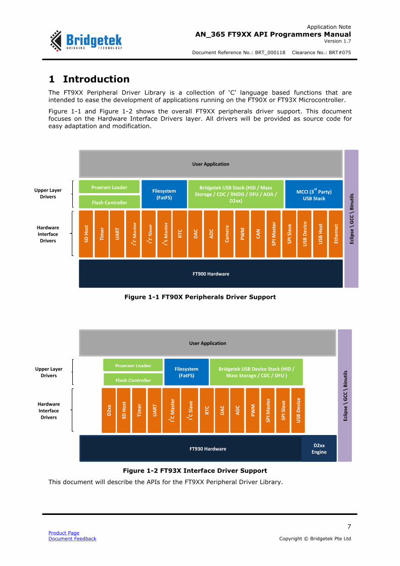
The FT9XX Peripheral Driver Library is a collection of ‘C’ language based functions that are intended to ease the development of applications running on the FT90X or FT93X Microcontroller.
Figure 1-1 and Figure 1-2 shows the overall FT9XX peripherals driver support. This document focuses on the Hardware Interface Drivers layer. All drivers will be provided as source code for easy adaptation and modification.
Figure 1-1 FT90X Peripherals Driver Support
1.1 Overview
This document will describe the APIs for the FT9XX Peripheral Driver Library.
Filesystem (FatFS)
Bridgetek USB Stack (HID / Mass Storage / CDC / RNDIS / DFU / AOA /
D2xx)
MCCI (3rd
Party) USB Stack
Program Loader
Flash Controller
SD H
ost
Tim
er
UA
RT
I2 C M
aste
r
I2 C S
lave
I2 S M
aste
r
RTC
DA
C
AD
C
Cam
era
PW
M
CA
N
SPI M
aste
r
SPI S
lave
USB
De
vice
USB
Ho
st
Eth
ern
et
FT900 Hardware
Eclip
se \
GC
C \
Bin
uti
ls Upper Layer
Drivers
User Application
Hardware Interface Drivers
Filesystem (FatFS)
Bridgetek USB Device Stack (HID / Mass Storage / CDC / DFU )
Program Loader
Flash Controller
SD H
ost
Tim
er
UA
RT
I2 C M
aste
r
I2 C S
lave
RTC
DA
C
AD
C
PW
M
SPI M
aste
r
SPI S
lave
USB
De
vice
FT930 Hardware
Eclip
se \
GC
C \
Bin
uti
ls Upper Layer
Drivers
User Application
Hardware Interface Drivers
D2
xx
D2xx Engine
Figure 1-2 FT93X Interface Driver Support

Application Note
AN_365 FT9XX API Programmers Manual Version 1.7
Document Reference No.: BRT_000118 Clearance No.: BRT#075
8 Product Page
Document Feedback Copyright © Bridgetek Pte Ltd
2 Precompiled Libraries
The precompiled libraries provided with the FT9XX Toolchain are shown in Error! Reference source not found.
Table 1- Precompiled Libraries released with FT9XX Toolchain
Library Name Description
libft900.a Peripheral driver library for FT90X Series of MCUs
libft900_d2xx_dev.a D2XX library for FT90X Series of MCUs
libft900_d2xx_dev_rtos.a D2XX library for FT90X Series of MCUs with support for FreeRTOS [Only required for FT90x]
libft930.a Peripheral driver library for FT93X Series of MCUs
libft930_d2xx_dev.a D2XX library for FT93X Series of MCUs [Note that FT93X does not require a special library for FreeRTOS. This library can be used for both RTOS and non-RTOS use cases]
libftd2xx_host.a D2XX Host library for FT90X Series of MCUs
All libraries are built in two modes – Debug and Release. Debug uses –Og optimization while Release uses –Os. The libraries are located in the toolchain installation folder at the relative path Toolchain\hardware\lib\Debug and Toolchain\hardware\lib\Release. The precompiled driver libraries can be used as is. The source code to the library is provided and it may be modified. To change the source code, make a local copy of the source code pertaining to
the module into the Eclipse project. The linker command line ensures that the local copy of the API object is used during linking. For example, if you want to force the Ethernet to use 10 Mbit/sec mode only, then copy the source code file, ethernet.c to the project and make the required changes to ETHERNET_AUTO_NEG_ALLOW and ETHERNET_MODE macro defintions in ethernet.c, in the
project’s workspace.
Compiling against the library will take the local version in preference to the library’s version. Source code can be found here (once IDE has been installed) at the relative path: Toolchain\hardware\src
The sources for the D2xx libraries are not released with the toolchain. Please contact [email protected] if access to the source code is required.
2.1 Chip Management
The file ft900_sys.h contains the definitions for the chip management functions in the libft900.a library and libft930.a
API Cross Reference
It utilises the following library APIs:
ft900_delay.h – Delay
Additional definitions are taken from:
ft900_registers.h – FT90x and FT93x register definitions
Application Note
AN_365 FT9XX API Programmers Manual Version 1.7
Document Reference No.: BRT_000118 Clearance No.: BRT#075
9 Product Page
Document Feedback Copyright © Bridgetek Pte Ltd
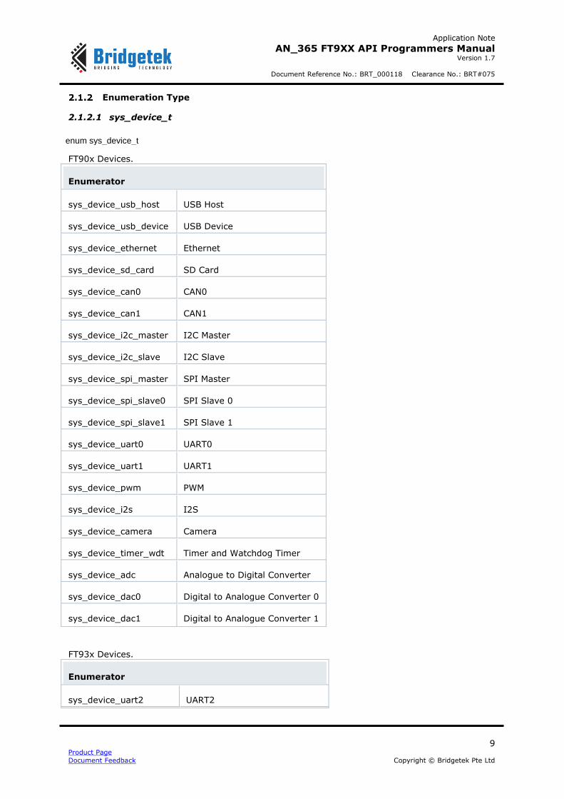
Enumeration Type
2.1.2.1 sys_device_t
enum sys_device_t
FT90x Devices.
Enumerator
sys_device_usb_host USB Host
sys_device_usb_device USB Device
sys_device_ethernet Ethernet
sys_device_sd_card SD Card
sys_device_can0 CAN0
sys_device_can1 CAN1
sys_device_i2c_master I2C Master
sys_device_i2c_slave I2C Slave
sys_device_spi_master SPI Master
sys_device_spi_slave0 SPI Slave 0
sys_device_spi_slave1 SPI Slave 1
sys_device_uart0 UART0
sys_device_uart1 UART1
sys_device_pwm PWM
sys_device_i2s I2S
sys_device_camera Camera
sys_device_timer_wdt Timer and Watchdog Timer
sys_device_adc Analogue to Digital Converter
sys_device_dac0 Digital to Analogue Converter 0
sys_device_dac1 Digital to Analogue Converter 1
FT93x Devices.
Enumerator
sys_device_uart2 UART2

Application Note
AN_365 FT9XX API Programmers Manual Version 1.7
Document Reference No.: BRT_000118 Clearance No.: BRT#075
10 Product Page
Document Feedback Copyright © Bridgetek Pte Ltd
sys_device_uart3 UART3
sys_device_pwm PWM
sys_device_uart1 UART1
sys_device_uart0 UART0
sys_device_spi_slave0 SPI Slave
sys_device_spi_master SPI Master
sys_device_i2c_slave I2C Slave
sys_device_spi_master SPI Master
sys_device_i2c_master I2C Master
sys_device_usb_device USB Device
sys_device_timer_wdt Timer and Watchdog Timer
sys_device_adc ADC
sys_device_dac0 DAC0
sys_device_dac1 DAC1
2.1.2.2 sys_cpu_divider_t
enum sys_cpu_divider_t
CPU Clock divider.
Enumerator
sys_cpu_divider_1 No clock divider (Default)
sys_cpu_divider_2 Divide Input Clock by 2
sys_cpu_divider_4 Divide Input Clock by 4
sys_cpu_divider_8 Divide Input Clock by 8
sys_cpu_divider_64 Divide Input Clock by 64
sys_cpu_divider_128 Divide Input Clock by 128
sys_cpu_divider_512 Divide Input Clock by 512
2.1.2.3 sys_pwm_trigger_t
enum sys_pwm_trigger_t
PWM External Trigger pin (only for FT90x).

Application Note
AN_365 FT9XX API Programmers Manual Version 1.7
Document Reference No.: BRT_000118 Clearance No.: BRT#075
11 Product Page
Document Feedback Copyright © Bridgetek Pte Ltd
Enumerator
sys_pwm_trigger_none None
sys_pwm_trigger_gpio18 GPIO18
sys_pwm_trigger_gpio26 GPIO26
sys_pwm_trigger_gpio35 GPIO35
sys_pwm_trigger_gpio40 GPIO40
sys_pwm_trigger_gpio46 GPIO46
sys_pwm_trigger_gpio52 GPIO52
sys_pwm_trigger_gpio58 GPIO58
Function Documentation
2.1.3.1 sys_enable
int sys_enable ( sys_device_t dev )
Enable a device on the FT9xx.
Parameters
dev The device to enable
Returns
On success a 0, otherwise -1
2.1.3.2 sys_disable
int sys_disable ( sys_device_t dev )
Disable a device on the FT9xx.
Parameters
dev The device to Disable
Returns
On success a 0, otherwise -1
2.1.3.3 sys_reset_all
void sys_reset_all ( void
)
Reset all peripherals. sys_cpu_clock_div
int sys_cpu_clock_div ( sys_cpu_divider_t div )
Enable a divider on the CPU.
Parameters
div The divider to use

Application Note
AN_365 FT9XX API Programmers Manual Version 1.7
Document Reference No.: BRT_000118 Clearance No.: BRT#075
12 Product Page
Document Feedback Copyright © Bridgetek Pte Ltd
Returns
On success a 0, otherwise -1
2.1.3.4 sys_get_cpu_clock
uint32_t sys_get_cpu_clock ( void
)
Get the current clock of the CPU.
Returns
The clock rate of the CPU in Hertz
2.1.3.5 sys_i2c_swop
int sys_i2c_swop ( uint8_t swop )
Swap the I2C Master and slave pins. The user must first configure the default master pins and assign the swapped I2C master to those pins. [This function is only available for FT90X] For example:
gpio_function(44, pad_i2c1_scl);
gpio_pull(44, pad_pull_none);
gpio_function(45, pad_i2c1_sda);
gpio_pull(45, pad_pull_none);
Parameters
swop Enable or disable the swop feature
Returns
On success a 0, otherwise -1
2.1.3.6 sys_pwm_ext_trigger
int sys_pwm_ext_trigger ( sys_pwm_trigger_t exttrigger )
Configure the External PWM trigger. [This function is only available for FT90X]
Parameters
exttrigger The selection of external trigger
Returns
On success a 0, otherwise -1
2.1.3.7 sys_check_ft900_revB
Function macro that checks whether the revision of FT90X series is Revision B.
Returns
True if device is Revision B and False is returned if FT900 Revision C or FT93x.
2.2 Delay Functions
The file ft900_delay.h contains the definitions for the delay functions in the libft900.a and libft930.a libraries.
API Cross Reference
Additional definitions are taken from:

Application Note
AN_365 FT9XX API Programmers Manual Version 1.7
Document Reference No.: BRT_000118 Clearance No.: BRT#075
13 Product Page
Document Feedback Copyright © Bridgetek Pte Ltd
ft900_registers.h – FT90X and FT93X register definitions
Macro Definition Documentation
2.2.2.1 sleep
#define sleep ( x ) delayms(x*1000)
POSIX standard second sleep call.
Note: This function consists of a tight loop counting CPU cycles to perform the delay. It is not recommended to use this function call at interrupt level or in FreeRTOS applications.
Parameters
x The number of milliseconds to sleep
2.2.2.2 usleep
#define usleep ( x ) delayus(x)
POSIX standard microsecond sleep call.
Note: This function consists of a tight loop counting CPU cycles to perform the delay. It is not recommended to use this function call at interrupt level or in FreeRTOS applications.
Parameters
x The number of microseconds to sleep

Application Note
AN_365 FT9XX API Programmers Manual Version 1.7
Document Reference No.: BRT_000118 Clearance No.: BRT#075
14 Product Page
Document Feedback Copyright © Bridgetek Pte Ltd
2.3 Interrupt Management
The file ft900_interrupt.h contains the definitions for the interrupt management functions in the libft900.a and libft930.a libraries.
API Cross Reference
Additional definitions are taken from:
ft900_registers.h – FT90X and FT93X register definitions
Macro Definition Documentation
2.3.2.1 N_INTERRUPTS
#define N_INTERRUPTS (34)
The number of interrupts supported by the CPU, includes watch dog interrupt vector which is not under the purview of interrupt controller.
Typedef Documentation
2.3.3.1 isrptr_t
typedef void(* isrptr_t) (void)
Interrupt handler function prototype.
Enumeration Type Documentation
2.3.4.1 interrupt_t
enum interrupt_t
FT90X Interrupt vectors:
Enumerator
interrupt_0 Reserved
interrupt_usb_host USB Host Interrupt
interrupt_usb_device USB Device Interrupt
interrupt_ethernet Ethernet Interrupt
interrupt_sd_card SD Card Interrupt
interrupt_can0 CAN0 Interrupt
interrupt_can1 CAN1 Interrupt
interrupt_camera Camera Interrupt
interrupt_spim SPI Master Interrupt
interrupt_spis0 SPI Slave 0 Interrupt

Application Note
AN_365 FT9XX API Programmers Manual Version 1.7
Document Reference No.: BRT_000118 Clearance No.: BRT#075
15 Product Page
Document Feedback Copyright © Bridgetek Pte Ltd
interrupt_spis1 SPI Slave 1 Interrupt
interrupt_i2cm I2C Master Interrupt
interrupt_i2cs I2C Slave Interrupt
interrupt_uart0 UART0 Interrupt
interrupt_uart1 UART1 Interrupt
interrupt_i2s I2S Interrupt
interrupt_pwm PWM Interrupt
interrupt_timers Timers Interrupt
interrupt_gpio GPIO Interrupt
interrupt_rtc RTC Interrupt
interrupt_adc ADC Interrupt
interrupt_dac DAC Interrupt
interrupt_slowclock Slow clock timer interrupt
interrupt_wdg First level watchdog timeout interrupt
FT93x Interrupt vectors:
Enumerator
interrupt_0 Reserved
interrupt_1 Reserved
interrupt_usb_device USB Device Interrupt
interrupt_3 Reserved
interrupt_sd_card SD Card Interrupt
Interrupt_mailbox_source Mailbox Source Interrupt
interrupt_mailbox_dest Mailbox Destination Interrupt
interrupt_uart3 UART3 Interrupt
interrupt_spim SPI Master Interrupt
interrupt_spis0 SPI Slave 0 Interrupt
interrupt_10 Reserved
interrupt_i2cm I2C Master Interrupt
interrupt_i2cs I2C Slave Interrupt

Application Note
AN_365 FT9XX API Programmers Manual Version 1.7
Document Reference No.: BRT_000118 Clearance No.: BRT#075
16 Product Page
Document Feedback Copyright © Bridgetek Pte Ltd
interrupt_uart0 UART0 Interrupt
interrupt_uart1 UART1 Interrupt
interrupt_uart2 UART2 Interrupt
interrupt_pwm PWM Interrupt
interrupt_timers Timers Interrupt
interrupt_gpio GPIO Interrupt
interrupt_rtc RTC Interrupt
interrupt_adc ADC Interrupt
interrupt_dac DAC Interrupt
interrupt_slowclock Slow Clock Timer
interrupt_7channel_fifo 7 Channel FIFO interrupt
interrupt_wdg First level watchdog timeout interrupt
Function Documentation
2.3.5.1 interrupt_attach
int8_t interrupt_attach ( interrupt_t interrupt,
uint8_t priority,
isrptr_t func
)
Attach an interrupt.
Parameters
interrupt The interrupt vector to attach to
priority The priority to give the interrupt.
func The function to call when interrupted
Returns
0 on a success or -1 for a failure
Note: Interrupt_attach for a peripheral interrupt should be called prior to enabling that peripheral’s interrupt. Doing otherwise could lead to a system hang
2.3.5.2 interrupt_detach
int8_t interrupt_detach ( interrupt_t interrupt )
Detach an interrupt.
Parameters
Application Note
AN_365 FT9XX API Programmers Manual Version 1.7
Document Reference No.: BRT_000118 Clearance No.: BRT#075
17 Product Page
Document Feedback Copyright © Bridgetek Pte Ltd
interrupt The interrupt vector to detach
Returns
0 on a success or -1 for a failure
2.3.5.3 interrupt_disable_globally
int8_t interrupt_disable_globally ( void
)
Disable all interrupts.
Returns
0 on a success or -1 for a failure
2.3.5.4 interrupt_disable_nesting
int8_t interrupt_disable_nesting ( void
)
Disable nesting interrupts.
Returns
0 on a success or -1 for a failure
2.3.5.5 interrupt_enable_globally
int8_t interrupt_enable_globally ( void
)
Enable interrupts to fire.
Returns
0 on a success or -1 for a failure
2.3.5.6 interrupt_enable_nesting
int8_t interrupt_enable_nesting ( uint8_t max )
Enable nesting interrupts.
Parameters
max The maximum number of levels to nest (max 16)
Returns
0 on a success or -1 for a failure

Application Note
AN_365 FT9XX API Programmers Manual Version 1.7
Document Reference No.: BRT_000118 Clearance No.: BRT#075
18 Product Page
Document Feedback Copyright © Bridgetek Pte Ltd
2.4 General Purpose I/O and Pad Control
The file ft900_gpio.h contains the definitions for the GPIO and Pad Control functions in the libft900.a and libft930.a libraries.
API Cross Reference
Additional definitions are taken from:
ft900_registers.h – FT90X and FT93X register definitions
Function to Pad Mappings
Pins on FT90X and FT93X have multiple functions mapped onto them. The required function is
selected by configuring the pin to its corresponding pad function. pad_func_X (X=0 to 3) select the mapping. The available functions on a pin are shown in the following table.
Table 2- FT90X Pin Mapping
Pin pad_func_0 pad_func_1 pad_func_2 pad_func_3
VBUS_DISCH/GPIO0 GPIO0
OC_N/GPIO1 GPIO1 OC_N
PSW_N/GPIO2 GPIO2
VBUS_DTC/GPIO3 GPIO3 VBUS_DTC
ENET_LED0/GPIO4 GPIO4 ENET_LED0
ENET_LED1/GPIO5 GPIO5 ENET_LED1
ADC1/CAM_XCLK/GPIO6 GPIO6 CAM_XCLK
ADC1
ADC2/CAM_PCLK/GPIO7 GPIO7 CAM_PCLK
ADC2
ADC3/CAM_VD/GPIO8 GPIO8 CAM_VD
ADC3
ADC4/CAM_HD/GPIO9 GPIO9 CAM_HD
ADC4
ADC5/CAM_D7/GPIO10 GPIO10 CAM_D7
ADC5
ADC6/CAM_D6/GPIO11 GPIO11 CAM_D6
ADC6
ADC7/CAM_D5/GPIO12 GPIO12 CAM_D5
ADC7
DAC1/CAM_D4/GPIO13 GPIO13 CAM_D4
DAC1
DAC0/CAM_D3/GPIO14 GPIO14 CAM_D3
DAC0
CAN0_TXD/CAM_D2/GPIO15 GPIO15 CAM_D2 CAN0_TXD
CAN0_RXD/CAM_D1/GPIO16 GPIO16 CAM_D1 CAN0_RXD
CAN1_TXD/CAM_D0/GPIO17 GPIO17 CAM_D0 CAN1_TXD
CAN1_RXD/GPIO18 GPIO18
CAN1_RXD
SD_CLK/GPIO19 GPIO19 SD_CLK
SD_CMD/GPIO20 GPIO20 SD_CMD
SD_DATA3/GPIO21 GPIO21 SD_DATA3

Application Note
AN_365 FT9XX API Programmers Manual Version 1.7
Document Reference No.: BRT_000118 Clearance No.: BRT#075
19 Product Page
Document Feedback Copyright © Bridgetek Pte Ltd
Pin pad_func_0 pad_func_1 pad_func_2 pad_func_3
SD_DATA2/GPIO22 GPIO22 SD_DATA2
SD_DATA1/GPIO23 GPIO23 SD_DATA1
SD_DATA0/GPIO24 GPIO24 SD_DATA0
SD_CD/GPIO25 GPIO25 SD_CD
SD_WP/GPIO26 GPIO26 SD_WP
SPIM_CLK/GPIO27 GPIO27 SPIM_CLK
SPIM_SS0/GPIO28 GPIO28 SPIM_SS0
SPIM_MOSI/GPIO29 GPIO29 SPIM_MOSI
SPIM_MISO/GPIO30 GPIO30 SPIM_MISO
SPIM_IO2/GPIO31 GPIO31 SPIM_IO2
SPIM_IO3/GPIO32 GPIO32 SPIM_IO3
SPIM_SS1/GPIO33 GPIO33 SPIM_SS1
SPIM_SS2/GPIO34 GPIO34 SPIM_SS2
SPIM_SS3/GPIO35 GPIO35 SPIM_SS3
SPIS0_CLK/GPIO36 GPIO36 SPIS0_CLK
SPIS0_SS/GPIO37 GPIO37 SPIS0_SS
SPIS0_MOSI/GPIO38 GPIO38 SPIS0_MOSI
SPIS0_MISO/GPIO39 GPIO39 SPIS0_MISO
SPIS1_CLK/GPIO40 GPIO40 SPIS1_CLK
SPIS1_SS/GPIO41 GPIO41 SPIS1_SS
SPIS1_MOSI/GPIO42 GPIO42 SPIS1_MOSI
SPIS1_MISO/GPIO43 GPIO43 SPIS1_MISO
I2C0_SCL/GPIO44 GPIO44 I2C0_SCL
I2C0_SDA/GPIO45 GPIO45 I2C0_SDA
I2C1_SCL/GPIO46 GPIO46 I2C1_SCL
I2C1_SDA/GPIO47 GPIO47 I2C1_SDA
UART0_TXD/GPIO48 GPIO48
UART0_TXD
UART0_RXD/GPIO49 GPIO49
UART0_RXD
UART0_RTS/GPIO50 GPIO50
UART0_RTS
UART0_CTS/GPIO51 GPIO51
UART0_CTS
UART0_DTR/UART1_TXD/PWM4/GPIO52 GPIO52 PWM4 UART1_TXD UART0_DTR
UART0_DSR/UART1_RXD/PWM5/GPIO53 GPIO53 PWM5 UART1_RXD UART0_DSR
UART0_DCD/UART1_RTS/PWM6/GPIO54 GPIO54 PWM6 UART1_RTS UART0_DCD

Application Note
AN_365 FT9XX API Programmers Manual Version 1.7
Document Reference No.: BRT_000118 Clearance No.: BRT#075
20 Product Page
Document Feedback Copyright © Bridgetek Pte Ltd
Pin pad_func_0 pad_func_1 pad_func_2 pad_func_3
UART0_RI/UART1_CTS/PWM7/GPIO55 GPIO55 PWM7 UART1_CTS UART0_RI
PWM0/GPIO56 GPIO56 PWM0
PWM1/GPIO57 GPIO57 PWM1
PWM2/GPIO58 GPIO58 PWM2
PWM3/GPIO59 GPIO59 PWM3
I2S_SDAO/GPIO60 GPIO60 I2S_SDAO
I2S_SDAI/GPIO61 GPIO61 I2S_SDAI
I2S_BCLK/GPIO62 GPIO62 I2S_BCLK I2SS_BCLK
I2S_LRCLK/GPIO63 GPIO63 I2S_LRCLK I2SS_LRCLK
I2S_MCLK/GPIO64 GPIO64 I2S_MCLK
I2S_CLK22/GPIO65 GPIO65 I2S_CLK22
I2S_CLK24/GPIO66 GPIO66 I2S_CLK24
Table 3- FT93X Pin Mapping
Pin pad_func
_0 pad_func_1 pad_func_2 pad_func_3
SD_CLK/SPIS_CLK/GPIO0 GPIO0 SPIS_CLK SD_CLK
SD_CMD/SPIS_MISO/GPIO1 GPIO1 SPIS_MISO SD_CMD
SD_CD/SPIS_MOSI/GPIO2 GPIO2 SPIS_MOSI SD_CD
SD_DATA0/SPIS_SS/GPIO3 GPIO3 SPIS_SS SD_DATA0
PWM0/SD_DATA1/PWM7/GPIO4 GPIO4 PWM7 SD_DATA1 PWM0
PWM6/SD_DATA2/PWM1/GPIO5 GPIO5 PWM1 SD_DATA2 PWM6
SD_DATA3/PWM5/GPIO6 GPIO6 PWM5 SD_DATA3
SD_WP/PWM4/GPIO7 GPIO7 PWM4 SD_WP
PWM3/GPIO8 GPIO8 PWM3
PWM2/GPIO9 GPIO9 PWM2
PWM1/GPIO10 GPIO10 PWM1
PWM0/GPIO11 GPIO11 PWM0
I2CS_SCL/I2CM_SCL/GPIO12 GPIO12 I2CM_SCL I2CS_SCL
I2CS_SDA/I2CM_SDA/GPIO13 GPIO13 I2CM_SDA I2CS_SDA
UART2_RXD/GPIO14 GPIO14 UART2_RXD
UART2_TXD/GPIO15 GPIO15 UART2_TXD
UART2_RTS/GPIO16 GPIO16 UART2_RTS

Application Note
AN_365 FT9XX API Programmers Manual Version 1.7
Document Reference No.: BRT_000118 Clearance No.: BRT#075
21 Product Page
Document Feedback Copyright © Bridgetek Pte Ltd
Pin pad_func
_0 pad_func_1 pad_func_2 pad_func_3
UART2_CTS/GPIO17 GPIO17 UART2_CTS
UART3_RXD/UART2_DTR/GPIO18 GPIO18 UART2_DTR UART3_RXD
UART3_TXD/UART2_DSR/GPIO19 GPIO19 UART2_DSR UART3_TXD
UART3_RTS/UART2_DCD/GPIO20 GPIO20 UART2_DCD UART3_RTS
UART3_CTS/UART2_RI/GPIO21 GPIO21 UART2_RI UART3_CTS
PWM3/UART0_RXD/GPIO22 GPIO22 UART0_RXD PWM3
PWM2/UART0_TXD/GPIO23 GPIO23 UART0_TXD PWM2
PWM1/UART0_RTS/GPIO24 GPIO24 UART0_RTS PWM1
PWM0/UART0_CTS/GPIO25 GPIO25 UART0_CTS PWM0
UART1_RXD/UART0_DTR/GPIO26 GPIO26 UART0_DTR UART1_RXD
UART1_TXD/UART0_DSR/GPIO27 GPIO27 UART0_DSR UART1_TXD
UART1_RTS/UART0_DCD/GPIO28 GPIO28 UART0_DCD UART1_RTS
SPIM_SS0/UART1_CTS/UART0_RI/GPIO2
9 GPIO29 UART0_RI UART1_CTS SPIM_SS0
SPIM_SS0/GPIO30 GPIO30 SPIM_SS0
SPIM_SS1/GPIO31 GPIO31 SPIM_SS1
SPIM_SS2/GPIO32 GPIO32 SPIM_SS2
SPIM_SS3/GPIO33 GPIO33 SPIM_SS3
SPIS_CLK/SPIM_CLK/GPIO34 GPIO34 SPIM_CLK SPIS_CLK
SPIS_MISO/SPIM_MISO/GPIO35 GPIO35 SPIM_MISO SPIS_MISO
SPIS_MOSI/SPIM_MOSI/GPIO36 GPIO36 SPIM_MOSI SPIS_MOSI
SPIS_SS/SPIM_IO2/GPIO37 GPIO37 SPIM_IO2 SPIS_SS
RTC_REF/SPIM_IO3/GPIO38 GPIO38 SPIM_IO3 RTC_REF
SPIS0_MISO/GPIO39 GPIO39 SPIS0_MISO
VBUS_DTC/GPIO39 GPIO40 VBUS_DTC

Application Note
AN_365 FT9XX API Programmers Manual Version 1.7
Document Reference No.: BRT_000118 Clearance No.: BRT#075
22 Product Page
Document Feedback Copyright © Bridgetek Pte Ltd
Enumeration Type Documentation
2.4.3.1 gpio_int_edge_t
enum gpio_int_edge_t
GPIO Interrupt control.
Enumerator
gpio_int_edge_falling Interrupt on a falling edge
gpio_int_edge_raising Interrupt on a raising edge
2.4.3.2 pad_dir_t
enum pad_dir_t
Pad direction control.
Enumerator
pad_dir_input Input
pad_dir_output Output
pad_dir_open_drain Open Drain
2.4.3.3 pad_drive_t
enum pad_drive_t
Pad current drive control.
Enumerator
pad_drive_4mA 4mA maximum current
pad_drive_8mA 8mA maximum current
pad_drive_12mA 12mA maximum current
pad_drive_16mA 16mA maximum current
2.4.3.4 pad_func_t
enum pad_func_t
Pad function control for FT90X
Enumerator
pad_func_0 Pad function 0
pad_func_1 Pad function 1
pad_func_2 Pad function 2

Application Note
AN_365 FT9XX API Programmers Manual Version 1.7
Document Reference No.: BRT_000118 Clearance No.: BRT#075
23 Product Page
Document Feedback Copyright © Bridgetek Pte Ltd
pad_func_3 Pad function 3
pad_gpio0 VBUS_DISCH/GPIO0 Pad function 0
pad_gpio1 OC_N/GPIO1 Pad function 0
pad_gpio2 PSW_N/GPIO2 Pad function 0
pad_gpio3 VBUS_DTC/GPIO3 Pad function 0
pad_gpio4 ENET_LED0/GPIO4 Pad function 0
pad_gpio5 ENET_LED1/GPIO5 Pad function 0
pad_gpio6 ADC1/CAM_XCLK/GPIO6 Pad function 0
pad_gpio7 ADC2/CAM_PCLK/GPIO7 Pad function 0
pad_gpio8 ADC3/CAM_VD/GPIO8 Pad function 0
pad_gpio9 ADC4/CAM_HD/GPIO9 Pad function 0
pad_gpio10 ADC5/CAM_D7/GPIO10 Pad function 0
pad_gpio11 ADC6/CAM_D6/GPIO11 Pad function 0
pad_gpio12 ADC7/CAM_D5/GPIO12 Pad function 0
pad_gpio13 DAC1/CAM_D4/GPIO13 Pad function 0
pad_gpio14 DAC0/CAM_D3/GPIO14 Pad function 0
pad_gpio15 CAN0_TXD/CAM_D2/GPIO15 Pad function 0
pad_gpio16 CAN0_RXD/CAM_D1/GPIO16 Pad function 0
pad_gpio17 CAN1_TXD/CAM_D0/GPIO17 Pad function 0
pad_gpio18 CAN1_RXD/GPIO18 Pad function 0
pad_gpio19 SD_CLK/GPIO19 Pad function 0
pad_gpio20 SD_CMD/GPIO20 Pad function 0
pad_gpio21 SD_DATA3/GPIO21 Pad function 0
pad_gpio22 SD_DATA2/GPIO22 Pad function 0
pad_gpio23 SD_DATA1/GPIO23 Pad function 0
pad_gpio24 SD_DATA0/GPIO24 Pad function 0
pad_gpio25 SD_CD/GPIO25 Pad function 0
pad_gpio26 SD_WP/GPIO26 Pad function 0
pad_gpio27 SPIM_CLK/GPIO27 Pad function 0

Application Note
AN_365 FT9XX API Programmers Manual Version 1.7
Document Reference No.: BRT_000118 Clearance No.: BRT#075
24 Product Page
Document Feedback Copyright © Bridgetek Pte Ltd
pad_gpio28 SPIM_SS0/GPIO28 Pad function 0
pad_gpio29 SPIM_MOSI/GPIO29 Pad function 0
pad_gpio30 SPIM_MISO/GPIO30 Pad function 0
pad_gpio31 SPIM_IO2/GPIO31 Pad function 0
pad_gpio32 SPIM_IO3/GPIO32 Pad function 0
pad_gpio33 SPIM_SS1/GPIO33 Pad function 0
pad_gpio34 SPIM_SS2/GPIO34 Pad function 0
pad_gpio35 SPIM_SS3/GPIO35 Pad function 0
pad_gpio36 SPIS0_CLK/GPIO36 Pad function 0
pad_gpio37 SPIS0_SS/GPIO37 Pad function 0
pad_gpio38 SPIS0_MOSI/GPIO38 Pad function 0
pad_gpio39 SPIS0_MISO/GPIO39 Pad function 0
pad_gpio40 SPIS1_CLK/GPIO40 Pad function 0
pad_gpio41 SPIS1_SS/GPIO41 Pad function 0
pad_gpio42 SPIS1_MOSI/GPIO42 Pad function 0
pad_gpio43 SPIS1_MISO/GPIO43 Pad function 0
pad_gpio44 I2C0_SCL/GPIO44 Pad function 0
pad_gpio45 I2C0_SDA/GPIO45 Pad function 0
pad_gpio46 I2C1_SCL/GPIO46 Pad function 0
pad_gpio47 I2C1_SDA/GPIO47 Pad function 0
pad_gpio48 UART0_TXD/GPIO48 Pad function 0
pad_gpio49 UART0_RXD/GPIO49 Pad function 0
pad_gpio50 UART0_RTS/GPIO50 Pad function 0
pad_gpio51 UART0_CTS/GPIO51 Pad function 0
pad_gpio52 UART0_DTR/UART1_TXD/PWM4/GPIO52 Pad function 0
pad_gpio53 UART0_DSR/UART1_RXD/PWM5/GPIO53 Pad function 0
pad_gpio54 UART0_DCD/UART1_RTS/PWM6/GPIO54 Pad function 0
pad_gpio55 UART0_RI/UART1_CTS/PWM7/GPIO55 Pad function 0
pad_gpio56 PWM0/GPIO56 Pad function 0

Application Note
AN_365 FT9XX API Programmers Manual Version 1.7
Document Reference No.: BRT_000118 Clearance No.: BRT#075
25 Product Page
Document Feedback Copyright © Bridgetek Pte Ltd
pad_gpio57 PWM1/GPIO57 Pad function 0
pad_gpio58 PWM2/GPIO58 Pad function 0
pad_gpio59 PWM3/GPIO59 Pad function 0
pad_gpio60 I2S_SDAO/GPIO60 Pad function 0
pad_gpio61 I2S_SDAI/GPIO61 Pad function 0
pad_gpio62 I2S_BCLK/GPIO62 Pad function 0
pad_gpio63 I2S_LRCLK/GPIO63 Pad function 0
pad_gpio64 I2S_MCLK/GPIO64 Pad function 0
pad_gpio65 I2S_CLK22/GPIO65 Pad function 0
pad_gpio66 I2S_CLK24/GPIO66 Pad function 0
pad_oc_n OC_N/GPIO1 Pad function 1
pad_vbus_dtc VBUS_DTC/GPIO3 Pad function 1
pad_enet_led0 ENET_LED0/GPIO4 Pad function 1
pad_enet_led1 ENET_LED1/GPIO5 Pad function 1
pad_cam_xclk ADC1/CAM_XCLK/GPIO6 Pad function 1
pad_cam_pclk ADC2/CAM_PCLK/GPIO7 Pad function 1
pad_cam_vd ADC3/CAM_VD/GPIO8 Pad function 1
pad_cam_hd ADC4/CAM_HD/GPIO9 Pad function 1
pad_cam_d7 ADC5/CAM_D7/GPIO10 Pad function 1
pad_cam_d6 ADC6/CAM_D6/GPIO11 Pad function 1
pad_cam_d5 ADC7/CAM_D5/GPIO12 Pad function 1
pad_cam_d4 DAC1/CAM_D4/GPIO13 Pad function 1
pad_cam_d3 DAC0/CAM_D3/GPIO14 Pad function 1
pad_cam_d2 CAN0_TXD/CAM_D2/GPIO15 Pad function 1
pad_cam_d1 CAN0_RXD/CAM_D1/GPIO16 Pad function 1
pad_cam_d0 CAN1_TXD/CAM_D0/GPIO17 Pad function 1
pad_sd_clk SD_CLK/GPIO19 Pad function 1
pad_sd_cmd SD_CMD/GPIO20 Pad function 1
pad_sd_data3 SD_DATA3/GPIO21 Pad function 1

Application Note
AN_365 FT9XX API Programmers Manual Version 1.7
Document Reference No.: BRT_000118 Clearance No.: BRT#075
26 Product Page
Document Feedback Copyright © Bridgetek Pte Ltd
pad_sd_data2 SD_DATA2/GPIO22 Pad function 1
pad_sd_data1 SD_DATA1/GPIO23 Pad function 1
pad_sd_data0 SD_DATA0/GPIO24 Pad function 1
pad_sd_cd SD_CD/GPIO25 Pad function 1
pad_sd_wp SD_WP/GPIO26 Pad function 1
pad_spim_sck SPIM_CLK/GPIO27 Pad function 1
pad_spim_ss0 SPIM_SS0/GPIO28 Pad function 1
pad_spim_mosi SPIM_MOSI/GPIO29 Pad function 1
pad_spim_miso SPIM_MISO/GPIO30 Pad function 1
pad_spim_io2 SPIM_IO2/GPIO31 Pad function 1
pad_spim_io3 SPIM_IO3/GPIO32 Pad function 1
pad_spim_ss1 SPIM_SS1/GPIO33 Pad function 1
pad_spim_ss2 SPIM_SS2/GPIO34 Pad function 1
pad_spim_ss3 SPIM_SS3/GPIO35 Pad function 1
pad_spis0_clk SPIS0_CLK/GPIO36 Pad function 1
pad_spis0_ss SPIS0_SS/GPIO37 Pad function 1
pad_spis0_mosi SPIS0_MOSI/GPIO38 Pad function 1
pad_spis0_miso SPIS0_MISO/GPIO39 Pad function 1
pad_spis1_clk SPIS1_CLK/GPIO40 Pad function 1
pad_spis1_ss SPIS1_SS/GPIO41 Pad function 1
pad_spis1_mosi SPIS1_MOSI/GPIO42 Pad function 1
pad_spis1_miso SPIS1_MISO/GPIO43 Pad function 1
pad_i2c0_scl I2C0_SCL/GPIO44 Pad function 1
pad_i2c0_sda I2C0_SDA/GPIO45 Pad function 1
pad_i2c1_scl I2C1_SCL/GPIO46 Pad function 1
pad_i2c1_sda I2C1_SDA/GPIO47 Pad function 1
pad_pwm4 UART0_DTR/UART1_TXD/PWM4/GPIO52 Pad function 1
pad_pwm5 UART0_DSR/UART1_RXD/PWM5/GPIO53 Pad function 1
pad_pwm6 UART0_DCD/UART1_RTS/PWM6/GPIO54 Pad function 1

Application Note
AN_365 FT9XX API Programmers Manual Version 1.7
Document Reference No.: BRT_000118 Clearance No.: BRT#075
27 Product Page
Document Feedback Copyright © Bridgetek Pte Ltd
pad_pwm7 UART0_RI/UART1_CTS/PWM7/GPIO55 Pad function 1
pad_pwm0 PWM0/GPIO56 Pad function 1
pad_pwm1 PWM1/GPIO57 Pad function 1
pad_pwm2 PWM2/GPIO58 Pad function 1
pad_pwm3 PWM3/GPIO59 Pad function 1
pad_i2s_sdao I2S_SDAO/GPIO60 Pad function 1
pad_i2s_sdai I2S_SDAI/GPIO61 Pad function 1
pad_i2s_bclk I2S_BCLK/GPIO62 Pad function 1
pad_i2s_lrclk I2S_LRCLK/GPIO63 Pad function 1
pad_i2s_mclk I2S_MCLK/GPIO64 Pad function 1
pad_i2s_clk22 I2S_CLK22/GPIO65 Pad function 1
pad_i2s_clk24 I2S_CLK24/GPIO66 Pad function 1
pad_can0_txd CAN0_TXD/CAM_D2/GPIO15 Pad function 2
pad_can0_rxd CAN0_RXD/CAM_D1/GPIO16 Pad function 2
pad_can1_txd CAN1_TXD/CAM_D0/GPIO17 Pad function 2
pad_can1_rxd CAN1_RXD/GPIO18 Pad function 2
pad_uart1_txd UART0_DTR/UART1_TXD/PWM4/GPIO52 Pad function 2
pad_uart1_rxd UART0_DSR/UART1_RXD/PWM5/GPIO53 Pad function 2
pad_uart1_rts UART0_DCD/UART1_RTS/PWM6/GPIO54 Pad function 2
pad_uart1_cts UART0_RI/UART1_CTS/PWM7/GPIO55 Pad function 2
pad_i2ss_bclk I2S_BCLK/GPIO62 Pad function 2
pad_i2ss_lrclk I2S_LRCLK/GPIO63 Pad function 2
pad_adc1 ADC1/CAM_XCLK/GPIO6 Pad function 3
pad_adc2 ADC2/CAM_PCLK/GPIO7 Pad function 3
pad_adc3 ADC3/CAM_VD/GPIO8 Pad function 3
pad_adc4 ADC4/CAM_HD/GPIO9 Pad function 3
pad_adc5 ADC5/CAM_D7/GPIO10 Pad function 3
pad_adc6 ADC6/CAM_D6/GPIO11 Pad function 3
pad_adc7 ADC7/CAM_D5/GPIO12 Pad function 3

Application Note
AN_365 FT9XX API Programmers Manual Version 1.7
Document Reference No.: BRT_000118 Clearance No.: BRT#075
28 Product Page
Document Feedback Copyright © Bridgetek Pte Ltd
pad_dac1 DAC1/CAM_D4/GPIO13 Pad function 3
pad_dac0 DAC0/CAM_D3/GPIO14 Pad function 3
pad_uart0_txd UART0_TXD/GPIO48 Pad function 3
pad_uart0_rxd UART0_RXD/GPIO49 Pad function 3
pad_uart0_rts UART0_RTS/GPIO50 Pad function 3
pad_uart0_cts UART0_CTS/GPIO51 Pad function 3
pad_uart0_dtr UART0_DTR/UART1_TXD/PWM4/GPIO52 Pad function 3
pad_uart0_dsr UART0_DSR/UART1_RXD/PWM5/GPIO53 Pad function 3
pad_uart0_dcd UART0_DCD/UART1_RTS/PWM6/GPIO54 Pad function 3
pad_uart0_ri UART0_RI/UART1_CTS/PWM7/GPIO55 Pad function 3
Pad function control for FT93x
Enumerator
pad_func_0 Pad function 0
pad_func_1 Pad function 1
pad_func_2 Pad function 2
pad_func_3 Pad function 3
pad_gpio0 SD_CLK/SPIS_CLK/GPIO0 Pad function 0
pad_gpio1 SD_CMD/SPIS_MISO/GPIO1 Pad function 0
pad_gpio2 SD_CD/SPIS_MOSI/GPIO2 Pad function 0
pad_gpio3 SD_DATA0/SPIS_SS/GPIO3 Pad function 0
pad_gpio4 PWM0/SD_DATA1/PWM7/GPIO4 Pad function 0
pad_gpio5 PWM6/SD_DATA2/PWM1/GPIO5 Pad function 0
pad_gpio6 SD_DATA3/PWM5/GPIO6 Pad function 0
pad_gpio7 SD_WP/PWM4/GPIO7 Pad function 0
pad_gpio8 PWM3/GPIO8 Pad function 0
pad_gpio9 PWM2/GPIO9 Pad function 0
pad_gpio10 PWM1/GPIO10 Pad function 0
pad_gpio11 PWM0/GPIO11 Pad function 0

Application Note
AN_365 FT9XX API Programmers Manual Version 1.7
Document Reference No.: BRT_000118 Clearance No.: BRT#075
29 Product Page
Document Feedback Copyright © Bridgetek Pte Ltd
pad_gpio12 I2CS_SCL/I2CM_SCL/GPIO12 Pad function 0
pad_gpio13 I2CS_SDA/I2CM_SDA/GPIO13 Pad function 0
pad_gpio14 UART2_RXD/GPIO14 Pad function 0
pad_gpio15 UART2_TXD/GPIO15 Pad function 0
pad_gpio16 UART2_RTS/GPIO16 Pad function 0
pad_gpio17 UART2_CTS/GPIO17 Pad function 0
pad_gpio18 UART3_RXD/UART2_DTR/GPIO18 Pad function 0
pad_gpio19 UART3_TXD/UART2_DSR/GPIO19 Pad function 0
pad_gpio20 UART3_RTS/UART2_DCD/GPIO20 Pad function 0
pad_gpio21 UART3_CTS/UART2_RI/GPIO21 Pad function 0
pad_gpio22 PWM3/UART0_RXD/GPIO22 Pad function 0
pad_gpio23 PWM2/UART0_TXD/GPIO23 Pad function 0
pad_gpio24 PWM1/UART0_RTS/GPIO24 Pad function 0
pad_gpio25 PWM0/UART0_CTS/GPIO25 Pad function 0
pad_gpio26 UART1_RXD/UART0_DTR/GPIO26 Pad function 0
pad_gpio27 UART1_TXD/UART0_DSR/GPIO27 Pad function 0
pad_gpio28 UART1_RTS/UART0_DCD/GPIO28 Pad function 0
pad_gpio29 SPIM_SS0/UART1_CTS/UART0_RI/GPIO29 Pad function 0
pad_gpio30 SPIM_SS0/GPIO30 Pad function 0
pad_gpio31 SPIM_SS1/GPIO31 Pad function 0
pad_gpio32 SPIM_SS2/GPIO32 Pad function 0
pad_gpio33 SPIM_SS3/GPIO33 Pad function 0
pad_gpio34 SPIS_CLK/SPIM_CLK/GPIO34 Pad function 0
pad_gpio35 SPIS_MISO/SPIM_MISO/GPIO35 Pad function 0
pad_gpio36 SPIS_MOSI/SPIM_MOSI/GPIO36 Pad function 0
pad_gpio37 SPIS_SS/SPIM_IO2/GPIO37 Pad function 0
pad_gpio38 RTC_REF/SPIM_IO3/GPIO38 Pad function 0
pad_gpio39 VBUS_DTC/GPIO39 Pad function 0
pad0_spis0_clk SD_CLK/SPIS_CLK/GPIO0 Pad function 1

Application Note
AN_365 FT9XX API Programmers Manual Version 1.7
Document Reference No.: BRT_000118 Clearance No.: BRT#075
30 Product Page
Document Feedback Copyright © Bridgetek Pte Ltd
pad1_spis0_miso SD_CMD/SPIS_MISO/GPIO1 Pad function 1
pad2_spis0_mosi SD_CD/SPIS_MOSI/GPIO2 Pad function 1
pad3_spis0_ss SD_DATA0/SPIS_SS/GPIO3 Pad function 1
pad_pwm7 PWM0/SD_DATA1/PWM7/GPIO4 Pad function 1
pad_pwm6 PWM6/SD_DATA2/PWM1/GPIO5 Pad function 1
pad_pwm5 SD_DATA3/PWM5/GPIO6 Pad function 1
pad_pwm4 SD_WP/PWM4/GPIO7 Pad function 1
pad8_pwm3 PWM3/GPIO8 Pad function 1
pad9_pwm2 PWM2/GPIO9 Pad function 1
pad11_pwm0 PWM0/GPIO11 Pad function 1
pad10_pwm1 PWM1/GPIO10 Pad function 1
pad_i2cm_scl I2CS_SCL/I2CM_SCL/GPIO12 Pad function 1
pad_i2cm_sda I2CS_SDA/I2CM_SDA/GPIO13 Pad function 1
pad_uart2_rxd UART2_RXD/GPIO14 Pad function 1
pad_uart2_txd UART2_TXD/GPIO15 Pad function 1
pad_uart2_rts UART2_RTS/GPIO16 Pad function 1
pad_uart2_cts UART2_CTS/GPIO17 Pad function 1
pad_uart2_dtr UART3_RXD/UART2_DTR/GPIO18 Pad function 1
pad_uart2_dsr UART3_TXD/UART2_DSR/GPIO19 Pad function 1
pad_uart2_dcd UART3_RTS/UART2_DCD/GPIO20 Pad function 1
pad_uart0_rxd UART3_CTS/UART2_RI/GPIO21 Pad function 1
pad_uart0_txd PWM3/UART0_RXD/GPIO22 Pad function 1
pad_uart0_rts PWM2/UART0_TXD/GPIO23 Pad function 1
pad_uart0_cts PWM1/UART0_RTS/GPIO24 Pad function 1
pad_uart0_dtr PWM0/UART0_CTS/GPIO25 Pad function 1
pad_uart0_dsr UART1_RXD/UART0_DTR/GPIO26 Pad function 1
pad_uart0_dcd UART1_TXD/UART0_DSR/GPIO27 Pad function 1
pad_uart0_ri UART1_RTS/UART0_DCD/GPIO28 Pad function 1
pad30_spim_ss0 SPIM_SS0/UART1_CTS/UART0_RI/GPIO29 Pad function 1

Application Note
AN_365 FT9XX API Programmers Manual Version 1.7
Document Reference No.: BRT_000118 Clearance No.: BRT#075
31 Product Page
Document Feedback Copyright © Bridgetek Pte Ltd
pad_spim_ss1 SPIM_SS1/GPIO31 Pad function 1
pad_spim_ss2 SPIM_SS2/GPIO32 Pad function 1
pad_spim_ss3 SPIM_SS3/GPIO33 Pad function 1
pad_spim_sck SPIM_CLK/SPIS_CLK/GPIO34 Pad function 1
pad_spim_miso SPIS_MISO/SPIM_MISO/GPIO35 Pad function 1
pad_spim_mosi SPIS_MOSI/SPIM_MOSI/GPIO36 Pad function 1
pad_spim_io2 SPIS_SS/SPIM_IO2/GPIO37 Pad function 1
pad_spim_io3 RTC_REF/SPIM_IO3/GPIO38 Pad function 1
pad_vbus_dtc VBUS_DTC/GPIO39 Pad function 1
pad_sd_clk SD_CLK/SPIS_CLK/GPIO0 Pad function 2
pad_sd_cmd SD_CMD/SPIS_MISO/GPIO1 Pad function 2
pad_sd_cd SD_CD/SPIS_MOSI/GPIO2 Pad function 2
pad_sd_data0 SD_DATA0/SPIS_SS/GPIO3 Pad function 2
pad_sd_data1 PWM0/SD_DATA1/PWM7/GPIO4 Pad function 2
pad_sd_data2 PWM6/SD_DATA2/PWM1/GPIO5 Pad function 2
pad_sd_data3 SD_DATA3/PWM5/GPIO6 Pad function 2
pad_sd_wp SD_WP/PWM4/GPIO7 Pad function 2
pad_i2cs_scl I2CS_SCL/I2CM_SCL/GPIO12 Pad function 2
pad_i2cs_sda I2CS_SDA/I2CM_SDA/GPIO13 Pad function 2
pad_uart3_rxd UART3_RXD/UART2_DTR/GPIO18 Pad function 2
pad_uart3_txd UART3_TXD/UART2_DSR/GPIO19 Pad function 2
pad_uart3_rts UART3_RTS/UART2_DCD/GPIO20 Pad function 2
pad_uart3_cts UART3_CTS/UART2_RI/GPIO21 Pad function 2
pad22_pwm3 PWM3/UART0_RXD/GPIO22 Pad function 1
pad23_pwm2 PWM2/UART0_TXD/GPIO23 Pad function 1
pad24_pwm1 PWM1/UART0_RTS/GPIO24 Pad function 2
pad25_pwm0 PWM0/UART0_CTS/GPIO25 Pad function 2
pad_uart1_txd UART1_RXD/UART0_DTR/GPIO26 Pad function 2
pad_uart1_rxd UART1_TXD/UART0_DSR/GPIO27 Pad function 2
Application Note
AN_365 FT9XX API Programmers Manual Version 1.7
Document Reference No.: BRT_000118 Clearance No.: BRT#075
32 Product Page
Document Feedback Copyright © Bridgetek Pte Ltd
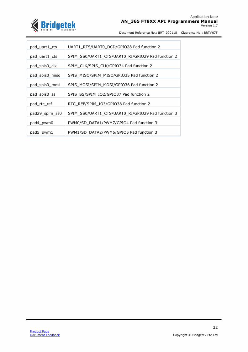
pad_uart1_rts UART1_RTS/UART0_DCD/GPIO28 Pad function 2
pad_uart1_cts SPIM_SS0/UART1_CTS/UART0_RI/GPIO29 Pad function 2
pad_spis0_clk SPIM_CLK/SPIS_CLK/GPIO34 Pad function 2
pad_spis0_miso SPIS_MISO/SPIM_MISO/GPIO35 Pad function 2
pad_spis0_mosi SPIS_MOSI/SPIM_MOSI/GPIO36 Pad function 2
pad_spis0_ss SPIS_SS/SPIM_IO2/GPIO37 Pad function 2
pad_rtc_ref RTC_REF/SPIM_IO3/GPIO38 Pad function 2
pad29_spim_ss0 SPIM_SS0/UART1_CTS/UART0_RI/GPIO29 Pad function 3
pad4_pwm0 PWM0/SD_DATA1/PWM7/GPIO4 Pad function 3
pad5_pwm1 PWM1/SD_DATA2/PWM6/GPIO5 Pad function 3

Application Note
AN_365 FT9XX API Programmers Manual Version 1.7
Document Reference No.: BRT_000118 Clearance No.: BRT#075
33 Product Page
Document Feedback Copyright © Bridgetek Pte Ltd
2.4.3.5 pad_pull_t
enum pad_pull_t
Pad pull up and pull downs control.
Enumerator
pad_pull_none No pull up or pull down
pad_pull_pullup Weak pull up enabled
pad_pull_pulldown Weak pull down enabled
pad_pull_keeper Weak pull up/down reflects output
2.4.3.6 pad_schmitt_t
enum pad_schmitt_t
Pad Schmitt trigger control.
Enumerator
pad_schmitt_off Pad input is filtered through a schmitt trigger
pad_schmitt_on Pad input is unfiltered
2.4.3.7 pad_slew_t
enum pad_slew_t
Pad slew rate control.
Enumerator
pad_slew_fast Fast Slew Rate
pad_slew_slow Slow Slew Rate
Function Documentation
2.4.4.1 gpio_dir
int8_t gpio_dir ( uint8_t num,
pad_dir_t dir
)
Configure the direction of a pin.
Parameters
num The GPIO number
dir The direction
Application Note
AN_365 FT9XX API Programmers Manual Version 1.7
Document Reference No.: BRT_000118 Clearance No.: BRT#075
34 Product Page
Document Feedback Copyright © Bridgetek Pte Ltd
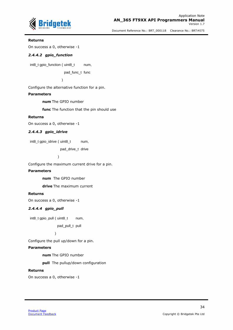
Returns
On success a 0, otherwise -1
2.4.4.2 gpio_function
int8_t gpio_function ( uint8_t num,
pad_func_t func
)
Configure the alternative function for a pin.
Parameters
num The GPIO number
func The function that the pin should use
Returns
On success a 0, otherwise -1
2.4.4.3 gpio_idrive
int8_t gpio_idrive ( uint8_t num,
pad_drive_t drive
)
Configure the maximum current drive for a pin.
Parameters
num The GPIO number
drive The maximum current
Returns
On success a 0, otherwise -1
2.4.4.4 gpio_pull
int8_t gpio_pull ( uint8_t num,
pad_pull_t pull
)
Configure the pull up/down for a pin.
Parameters
num The GPIO number
pull The pullup/down configuration
Returns
On success a 0, otherwise -1

Application Note
AN_365 FT9XX API Programmers Manual Version 1.7
Document Reference No.: BRT_000118 Clearance No.: BRT#075
35 Product Page
Document Feedback Copyright © Bridgetek Pte Ltd
2.4.4.5 gpio_schmitt
int8_t gpio_schmitt ( uint8_t num,
pad_schmitt_t schmitt
)
Configure the schmitt trigger for a pin.
Parameters
num The GPIO number
schmitt The Schmitt trigger configuration
Returns
On success a 0, otherwise -1
2.4.4.6 gpio_slew
int8_t gpio_slew ( uint8_t num,
pad_slew_t slew
)
Configure the slew rate for a pin.
Parameters
num The GPIO number
slew The slew rate of the pin
Returns
On success a 0, otherwise -1
2.4.4.7 gpio_read
int8_t gpio_read ( uint8_t num )
Read a value from a GPIO pin.
Parameters
num The GPIO number
Returns
The value of the pin (1 = high, 0 = low), otherwise -1

Application Note
AN_365 FT9XX API Programmers Manual Version 1.7
Document Reference No.: BRT_000118 Clearance No.: BRT#075
36 Product Page
Document Feedback Copyright © Bridgetek Pte Ltd
2.4.4.8 gpio_write
int8_t gpio_write ( uint8_t num,
uint8_t val
)
Write a value to a GPIO pin.
Parameters
num The GPIO number
val The value to write
Returns
On success a 0, otherwise -1
2.4.4.9 gpio_toggle
int8_t gpio_toggle ( uint8_t num )
Toggle the value of a GPIO pin.
Parameters
num The GPIO number
Returns
On success a 0, otherwise -1
2.4.4.10 gpio_interrupt_enable
int8_t gpio_interrupt_enable ( uint8_t num,
gpio_int_edge_t edge
)
Enable an interrupt on a GPIO pin.
Parameters
num The GPIO number
edge The edge at which to trigger on
Returns
On success a 0, otherwise -1
2.4.4.11 gpio_interrupt_disable
int8_t gpio_interrupt_disable ( uint8_t num )
Disable an interrupt on a GPIO pin.
Parameters
num The GPIO number
Returns
On success a 0, otherwise -1

Application Note
AN_365 FT9XX API Programmers Manual Version 1.7
Document Reference No.: BRT_000118 Clearance No.: BRT#075
37 Product Page
Document Feedback Copyright © Bridgetek Pte Ltd
2.4.4.12 gpio_is_interrupted
int8_t gpio_is_interrupted ( uint8_t num )
Check if an interrupt has happened on a GPIO pin.
Parameters
num The GPIO number
Returns
On no interrupt 0, on an interrupt 1, otherwise -1

Application Note
AN_365 FT9XX API Programmers Manual Version 1.7
Document Reference No.: BRT_000118 Clearance No.: BRT#075
38 Product Page
Document Feedback Copyright © Bridgetek Pte Ltd
2.5 Assembler Definitions
The file ft900_asm.h contains the definitions for assembler instructions used in the libft900.a and libft930.a libraries.
API Cross Reference
No additional definitions are required.
Macro Documentation
2.5.2.1 asm_noop
#define asm_noop()
A No Operation Instruction.
2.5.2.2 asm_memcpy8
#define asm_memcpy8(src, dst, size)
8-bitwise memory copy.
Parameters
src A pointer to the source data.
dst A pointer to the destination data.
size The size of the data to copy.
2.5.2.3 asm_memcpy16
#define asm_memcpy16(src, dst, size)
16-bitwise memory copy.
Parameters
src A pointer to the source data.
dst A pointer to the destination data.
size The size of the data to copy.
2.5.2.4 asm_memcpy32
#define asm_memcpy32(src, dst, size)
32-bitwise memory copy.
Parameters
src A pointer to the source data.
dst A pointer to the destination data.
size The size of the data to copy.

Application Note
AN_365 FT9XX API Programmers Manual Version 1.7
Document Reference No.: BRT_000118 Clearance No.: BRT#075
39 Product Page
Document Feedback Copyright © Bridgetek Pte Ltd
2.5.2.5 asm_memset8
#define asm_memset8(val, dst, size)
8-bitwise memory set.
Parameters
val The value to set the memory to.
dst A pointer to the destination data.
size The size of the data to copy.
2.5.2.6 asm_memset16
#define asm_memset16(val, dst, size)
16-bitwise memory set.
Parameters
val The value to set the memory to.
dst A pointer to the destination data.
size The size of the data to copy.
2.5.2.7 asm_memset32
#define asm_memset32(val, dst, size)
32-bitwise memory set.
Parameters
val The value to set the memory to.
dst A pointer to the destination data.
size The size of the data to copy.
2.5.2.8 asm_strcpy
#define asm_strcpy(src, dst)
String copy.
Parameters
src A pointer to the source string.
dst A pointer to the destination string.
2.5.2.9 asm_streamin8
#define asm_streamin8 (src, dst, size)
8-bitwise memory stream from FIFO to memory.
Parameters
src A pointer to the source registers.
dst A pointer to the destination data.
Application Note
AN_365 FT9XX API Programmers Manual Version 1.7
Document Reference No.: BRT_000118 Clearance No.: BRT#075
40 Product Page
Document Feedback Copyright © Bridgetek Pte Ltd
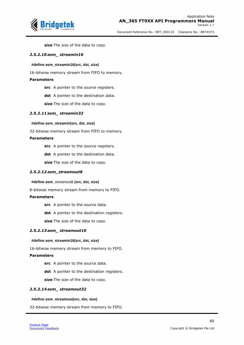
size The size of the data to copy.
2.5.2.10 asm_ streamin16
#define asm_streamin16(src, dst, size)
16-bitwise memory stream from FIFO to memory.
Parameters
src A pointer to the source registers.
dst A pointer to the destination data.
size The size of the data to copy.
2.5.2.11 asm_ streamin32
#define asm_streamin(src, dst, size)
32-bitwise memory stream from FIFO to memory.
Parameters
src A pointer to the source registers.
dst A pointer to the destination data.
size The size of the data to copy.
2.5.2.12 asm_streamout8
#define asm_streamout8 (src, dst, size)
8-bitwise memory stream from memory to FIFO.
Parameters
src A pointer to the source data.
dst A pointer to the destination registers.
size The size of the data to copy.
2.5.2.13 asm_ streamout16
#define asm_streamin16(src, dst, size)
16-bitwise memory stream from memory to FIFO.
Parameters
src A pointer to the source data.
dst A pointer to the destination registers.
size The size of the data to copy.
2.5.2.14 asm_ streamout32
#define asm_streamout(src, dst, size)
32-bitwise memory stream from memory to FIFO.

Application Note
AN_365 FT9XX API Programmers Manual Version 1.7
Document Reference No.: BRT_000118 Clearance No.: BRT#075
41 Product Page
Document Feedback Copyright © Bridgetek Pte Ltd
Parameters
src A pointer to the source data.
dst A pointer to the destination registers.
size The size of the data to copy.
2.5.2.15 asm_setbit
#define asm_setbit(val, bit)
Set a bit in a 32 bit value.
Parameters
val The value to use.
bit The bit position to set.
2.5.2.16 asm_clrbit
#define asm_clrbit(val, bit)
Set a bit in a 32 bit value.
Parameters
val The value to use.
bit The bit position to clear.
2.5.2.17 asm_flip32
#define asm_flip32(src, dst, val)
Flip bit regions.
Parameters
src A pointer to the source data.
dst A pointer to the destination data.
val The region of bits to flip.
- If bit 0 is set, then every alternate bit is exchanged.
- If bit 1 is set, then every alternate 2-bit group is exchanged.
- If bit 2 is set, then every alternate 4-bit group is exchanged.
- If bit 3 is set, then every alternate 8-bit group is exchanged.
- If bit 4 is set, then the two 16-bit groups are exchanged.
2.5.2.18 asm_reverse_endianness
#define asm_reverse_endianness (val)
Reverse the endianness of a value.
Parameters
val The value to use.
Application Note
AN_365 FT9XX API Programmers Manual Version 1.7
Document Reference No.: BRT_000118 Clearance No.: BRT#075
42 Product Page
Document Feedback Copyright © Bridgetek Pte Ltd
2.5.2.19 asm_reverse_bits
#define asm_reverse_bits (val)
Reverse the bits of a value.
Parameters
val The value to use.
2.5.2.20 asm_rotate32
#define asm_rotate32 (val, num)
Rotate bits left or right.
Parameters
val The value to use.
num The number and direction to rotate in (negative numbers rotate left).
Function Documentation
2.5.3.1 asm_strcmp
static inline int32_t asm_strcmp(const char *src1, const char *src2)
String compare.
Parameters
src1 A pointer to the first source string.
src2 A pointer to the second source string.
Returns
The difference between the two strings.
2.5.3.2 asm_strlen
static inline int32_t asm_strlen(const char *src)
String length.
Parameters
src A pointer to the source string.
Returns
The length of the string.

Application Note
AN_365 FT9XX API Programmers Manual Version 1.7
Document Reference No.: BRT_000118 Clearance No.: BRT#075
43 Product Page
Document Feedback Copyright © Bridgetek Pte Ltd
2.6 Watchdog Timer
The file ft900_wdt.h contains the definitions for the watchdog timer functions in the libft900.a and libft930.a libraries.
API Cross Reference
Additional definitions are taken from:
ft900_registers.h – FT90x and FT93x register definitions
Enumeration Type Documentation
2.6.2.1 wdt_counter_t
enum wdt_counter_t
Watchdog Timeouts.
Enumerator
wdt_counter_1_clocks 10 nsec @ 100 MHz
wdt_counter_2_clocks 20 nsec @ 100 MHz
wdt_counter_4_clocks 40 nsec @ 100 MHz
wdt_counter_8_clocks 80 nsec @ 100 MHz
wdt_counter_16_clocks 160 nsec @ 100 MHz
wdt_counter_32_clocks 320 nsec @ 100 MHz
wdt_counter_64_clocks 640 nsec @ 100 MHz
wdt_counter_128_clocks 1.28 usec @ 100 MHz
wdt_counter_256_clocks 2.56 usec @ 100 MHz
wdt_counter_512_clocks 5.12 usec @ 100 MHz
wdt_counter_1K_clocks 10.24 usec @ 100 MHz
wdt_counter_2K_clocks 20.48 usec @ 100 MHz
wdt_counter_4K_clocks 40.96 usec @ 100 MHz
wdt_counter_8K_clocks 81.92 usec @ 100 MHz
wdt_counter_16K_clocks 163.84 usec @ 100 MHz
wdt_counter_32K_clocks 327.68 usec @ 100 MHz
wdt_counter_64K_clocks 655.35 usec @ 100 MHz
wdt_counter_128K_clocks ~1.31 msec @ 100 MHz
wdt_counter_256K_clocks ~2.62 msec @ 100 MHz

Application Note
AN_365 FT9XX API Programmers Manual Version 1.7
Document Reference No.: BRT_000118 Clearance No.: BRT#075
44 Product Page
Document Feedback Copyright © Bridgetek Pte Ltd
wdt_counter_512K_clocks ~5.24 msec @ 100 MHz
wdt_counter_1M_clocks ~10.49 msec @ 100 MHz
wdt_counter_2M_clocks ~20.97 msec @ 100 MHz
wdt_counter_4M_clocks ~41.94 msec @ 100 MHz
wdt_counter_8M_clocks ~83.89 msec @ 100 MHz
wdt_counter_16M_clocks ~167.77 msec @ 100 MHz
wdt_counter_32M_clocks ~335.54 msec @ 100 MHz
wdt_counter_64M_clocks ~671.09 msec @ 100 MHz
wdt_counter_128M_clocks ~1.34 sec @ 100 MHz
wdt_counter_256M_clocks ~2.68 sec @ 100 MHz
wdt_counter_512M_clocks ~5.37 sec @ 100 MHz
wdt_counter_1G_clocks ~10.74 sec @ 100 MHz
wdt_counter_2G_clocks ~21.47 sec @ 100 MHz
Function Documentation
2.6.3.1 wdt_init
int8_t wdt_init ( wdt_counter_t timeout )
Initialise and start the Watchdog timer.
Parameters
timeout The timeout value of the Watchdog
Returns
0 on success, -1 otherwise
2.6.3.2 wdt_kick
int8_t wdt_kick ( void
)
Reset a running Watchdog Timer.
Returns
0 on success, -1 otherwise

Application Note
AN_365 FT9XX API Programmers Manual Version 1.7
Document Reference No.: BRT_000118 Clearance No.: BRT#075
45 Product Page
Document Feedback Copyright © Bridgetek Pte Ltd
2.7 Timers
The file ft900_timers.h contains the definitions for the timer management functions in the libft900.a and libft930.a libraries.
API Cross Reference
Additional definitions are taken from:
ft900_registers.h – FT90x and FT93x register definitions
Enumeration Type Documentation
2.7.2.1 timer_select_t
enum timer_select_t
Timer Select.
Enumerator
timer_select_a Timer A
timer_select_b Timer B
timer_select_c Timer C
timer_select_d Timer D
2.7.2.2 timer_direction_t
enum timer_direction_t
Timer count direction.
Enumerator
timer_direction_up Count up
timer_direction_down Count down
2.7.2.3 timer_mode_t
enum timer_mode_t
Timer count mode.
Enumerator
timer_mode_continuous Count continuous
timer_mode_oneshot Count one shot
2.7.2.4 timer_prescaler_select_t
enum timer_prescaler_select_t
Timer prescaler select.

Application Note
AN_365 FT9XX API Programmers Manual Version 1.7
Document Reference No.: BRT_000118 Clearance No.: BRT#075
46 Product Page
Document Feedback Copyright © Bridgetek Pte Ltd
Enumerator
timer_prescaler_select_off Timer prescaler off
timer_prescaler_select_on Timer prescaler on
Function Documentation
2.7.3.1 timer_init
int8_t timer_init ( timer_select_t timer,
uint16_t initial,
timer_direction_t dir,
timer_prescaler_select_t prescaler,
timer_mode_t mode
)
Initialise a timer.
Parameters
timer The timer to set up
initial The initial value for the timer
dir The direction that the timer should count in
prescaler Whether or not this timer should use the prescaler
mode If the timer should be continuously counting or a one shot
Returns
On success a 0, otherwise -1
2.7.3.2 timer_start
int8_t timer_start ( timer_select_t timer )
Start a timer.
Parameters
timer The timer to start
Returns
On success a 0, otherwise -1

Application Note
AN_365 FT9XX API Programmers Manual Version 1.7
Document Reference No.: BRT_000118 Clearance No.: BRT#075
47 Product Page
Document Feedback Copyright © Bridgetek Pte Ltd
2.7.3.3 timer_stop
int8_t timer_stop ( timer_select_t timer )
Stop a timer.
Parameters
timer The timer to stop
Returns
2.7.3.4 On success a 0, otherwise -1timer_read
int8_t timer_read ( timer_select_t timer,
uint16_t * value
)
Read the value of a timer.
Parameters
timer The timer to read from
value A pointer to store the value
Returns
On success a 0, otherwise -1
2.7.3.5 timer_prescaler
int8_t timer_prescaler ( uint16_t prescaler ) [FT90X Revison B]
int8_t timer_prescaler ( timer_select_t timer, uint16_t prescaler ) [FT93x and FT90x Revision C]
Set up the prescaler.
Parameters
prescaler The clock prescaler to apply to the timer
timer The timer to use [Only for FT93X]
Returns
On success a 0, otherwise -1
Warning
This can only be used before starting timers
Note:
FT93X and FT90X series Revision C devices have separate prescalers for each timer, while on FT90X revision B, there is one common prescaler for all timers.
2.7.3.6 timer_disable_interrupt
int8 t timer disable interrupt (timer_select_t)
Disable the interrupt for a timer.

Application Note
AN_365 FT9XX API Programmers Manual Version 1.7
Document Reference No.: BRT_000118 Clearance No.: BRT#075
48 Product Page
Document Feedback Copyright © Bridgetek Pte Ltd
Parameters
timer The timer to disable the interrupt for
Returns
On success a 0, otherwise -1
2.7.3.7 timer_enable_interrupt
int8_t timer_enable_interrupt ( timer_select_t timer )
Enable the interrupt for a timer.
Parameters
timer The timer to enable the interrupt for
Returns
On success a 0, otherwise -1
2.7.3.8 timer_is_interrupted
int8_t timer_is_interrupted ( timer_select_t timer )
Check if a timer has been interrupted.
Parameters
timer The timer to check
Warning
This function clears the current interrupt status bit
Returns
1 for if a timer is interrupted, 0 if the timer is not interrupted, -1 otherwise

Application Note
AN_365 FT9XX API Programmers Manual Version 1.7
Document Reference No.: BRT_000118 Clearance No.: BRT#075
49 Product Page
Document Feedback Copyright © Bridgetek Pte Ltd
2.8 Analogue to Digital Converter
The file ft900_adc.h contains the definitions for the analogue to digital conversion functions in the libft900.a and libft930.a libraries.
API Cross Reference
It utilises the following library APIs:
ft900_asm.h – FT90X and FT93X assembler definitions
Additional definitions are taken from:
ft900_registers.h – FT90X andFT93X register definitions
Enumeration Type Documentation
2.8.2.1 adc_resolution_t
enum adc_resolution_t
ADC resolution configuration – ADC resolution can be configured to 10-bit or 8-bit ONLY in FT90X Revision C.
Enumerator
adc_10bit 10-bit ADC resolution
adc_8bit 8-bit ADC resolution
2.8.2.2 adc_clock_t
enum adc_clock_t
ADC Clock frequency for sampling - Applicable ONLY in FT90X Revision C.
Enumerator
adc_12_5_MHz ADC clock is 12.5 MHz
adc_6_25_MHz ADC clock is 6.25 MHz
2.8.2.3 adc_mode_t
enum adc_mode_t
ADC Run Mode.
Enumerator
adc_mode_single One analogue reading will be taken and then the ADC stopped
adc_mode_continuous The ADC will continuously acquire analogue readings

Application Note
AN_365 FT9XX API Programmers Manual Version 1.7
Document Reference No.: BRT_000118 Clearance No.: BRT#075
50 Product Page
Document Feedback Copyright © Bridgetek Pte Ltd
Function Documentation
2.8.3.1 adc_start
int8_t adc_start ( uint8_t channel )
Start the ADC capturing.
Parameters
channel The channel to select
Returns
0 on success, -1 otherwise
2.8.3.2 adc_stop
int8_t adc_stop ( void
)
Stop the ADC from capturing.
Returns
0 on success, -1 otherwise
2.8.3.3 adc_mode
int8 t adc mode (adc_mode_t mode)
Choose the mode that the ADC will run in.
Parameters
mode The mode (single or continuous)
Returns
0 on success, -1 otherwise
2.8.3.4 adc_select_resolution
int8_t adc_select_resolution(adc_resolution_t resolution)
Choose the ADC to be 10-bit or 8-bit resolution. The ADC resolution is configurable ONLY in FT90x Revision C.
Parameters
resolution The resolution (10 or 8 bit)
Returns
0 on success, -1 otherwise (in case of FT930 or FT90x Revision B)
2.8.3.5 adc_select_frequency
int8_t adc_select_frequency(adc_clock_t frequency)
Choose the ADC clock for sampling to be 12.5MHz or half of this rate at 6.25MHz. The ADC clock is configurable ONLY in FT90x Revision C.
Parameters

Application Note
AN_365 FT9XX API Programmers Manual Version 1.7
Document Reference No.: BRT_000118 Clearance No.: BRT#075
51 Product Page
Document Feedback Copyright © Bridgetek Pte Ltd
frequency The clock frequency (12.5MHz or 6.25MHz)
Returns
0 on success, -1 otherwise (in case of FT930 or FT90x Revision B)
2.8.3.6 adc_read
int8_t adc_read ( uint16_t * val )
Get the next sample from the ADC.
Parameters
val A pointer to store the sample
Returns
The number of samples read, -1 otherwise
2.8.3.7 adc_readn
Int adc_readn ( uint16_t * val,
size_t len
)
Get a collection of samples from the ADC and store it in the array passed as parameter.
Parameters
val An array pointer to store the samples
len The number of 10-bit word samples to read from the FIFO
Warning
This function will only work when the ADC is in continuous mode
Returns
The number of word samples read, -1 otherwise
2.8.3.8 adc_available
uint8_t adc_available ( void
)
Get the number of ADC samples available.
Returns
The number of ADC samples
Note: In case of FT90x series Revision B, this function should be called in interrupt context for a reliable count of the ADC samples available. For FT90X Revision C or FT93X, this API can be used in interrupt or polling method of servicing the ADC application.
2.8.3.9 adc_disable_interrupt
int8_t adc_disable_interrupt ( void
)
Disable the Interrupt on the ADC.

Application Note
AN_365 FT9XX API Programmers Manual Version 1.7
Document Reference No.: BRT_000118 Clearance No.: BRT#075
52 Product Page
Document Feedback Copyright © Bridgetek Pte Ltd
Returns
0 on success, -1 otherwise
2.8.3.10 adc_enable_interrupt
int8_t adc_enable_interrupt ( void
)
Enable the Interrupt on the ADC.
Returns
0 on success, -1 otherwise
2.8.3.11 adc_is_interrupted
int8_t adc_is_interrupted ( void
)
Check that the ADC has been interrupted.
Warning
This function will clear the current interrupt bit when called
Returns
1 interrupted, 0 not interrupted

Application Note
AN_365 FT9XX API Programmers Manual Version 1.7
Document Reference No.: BRT_000118 Clearance No.: BRT#075
53 Product Page
Document Feedback Copyright © Bridgetek Pte Ltd
2.9 Digital to Analogue Converter
The file ft900_dac.h contains the definitions for the digital to analogue conversion functions in the libft900.a and libft930.a libraries.
API Cross Reference
It utilises the following library APIs:
ft900_asm.h – FT90X and FT93X assembler definitions
Additional definitions are taken from:
ft900_registers.h – FT90X and FT93X register definitions
Enumeration Type Documentation
2.9.2.1 dac_mode_t
enum dac_mode_t
DAC run mode.
Enumerator
dac_mode_single Run the DAC in Single Shot mode
dac_mode_continuous Run the DAC in Continuous mode
Function Documentation
2.9.3.1 dac_start
int8_t dac_start ( uint8_t num )
Start the DAC.
Parameters
num The DAC to use
Returns
0 on success, -1 otherwise
2.9.3.2 dac_stop
int8_t dac_stop ( uint8_t num )
Stop the DAC.
Parameters
num The DAC to use
Returns
0 on success, -1 otherwise

Application Note
AN_365 FT9XX API Programmers Manual Version 1.7
Document Reference No.: BRT_000118 Clearance No.: BRT#075
54 Product Page
Document Feedback Copyright © Bridgetek Pte Ltd
2.9.3.3 dac_mode
int8_t dac_mode ( uint8_t num,
dac_mode_t mode
)
Select the mode of the DAC.
Parameters
num The DAC to use
mode The mode the DAC should be in (single or continuous)
Returns
0 on success, -1 otherwise
2.9.3.4 dac_divider
int8_t dac_divider ( uint8_t div )
Select the divider for the DAC conversion rate.
fDAC=fperipheraldiv+1
Parameters
div The divider
Warning
The maximum conversion rate is 1 MHz
Returns
0 on success, -1 otherwise
2.9.3.5 dac_write
int8_t dac_write ( uint8_t num,
uint16_t data
)
Write a value to the DAC.
This function will automatically update the DAC when it is in single mode.
Parameters
num The DAC to use
data The sample to write
Returns
The number of bytes written, -1 otherwise
Application Note
AN_365 FT9XX API Programmers Manual Version 1.7
Document Reference No.: BRT_000118 Clearance No.: BRT#075
55 Product Page
Document Feedback Copyright © Bridgetek Pte Ltd
2.9.3.6 dac_writen
int dac_writen ( uint8_t num,
uint16_t * data,
size_t len
)
Write a series of values to the DAC.
Parameters
num The DAC to use
data The array of samples to write
len The number of samples to write
Warning
This function will only work when continuous mode is selected
Returns
The number of samples written, -1 otherwise
2.9.3.7 dac_available
uint8_t dac_available ( uint8_t num )
See how many samples are still being converted.
Parameters
num The DAC to use
Returns
The number of samples still to be converted, or 0 otherwise
2.9.3.8 dac_disable_interrupt
int8_t dac_disable_interrupt ( uint8_t num )
Disable the interrupt on a DAC.
Parameters
num The DAC to use
Returns
0 on success, -1 otherwise

Application Note
AN_365 FT9XX API Programmers Manual Version 1.7
Document Reference No.: BRT_000118 Clearance No.: BRT#075
56 Product Page
Document Feedback Copyright © Bridgetek Pte Ltd
2.9.3.9 dac_enable_interrupt
int8_t dac_enable_interrupt ( uint8_t num )
Enable the interrupt on a DAC.
Enable the DAC module to generate an interrupt. The DAC module will generate an interrupt after 64 samples have been generated on the DAC.
Parameters
num The DAC to use
Returns
0 on success, -1 otherwise
2.9.3.10 dac_is_interrupted
int8_t dac_is_interrupted ( uint8_t num )
Check if the DAC has fired an interrupt.
Parameters
num The DAC to use
Warning
This function clears the current interrupt status bit
Returns
1 when interrupted, 0 when not interrupted, -1 otherwise

Application Note
AN_365 FT9XX API Programmers Manual Version 1.7
Document Reference No.: BRT_000118 Clearance No.: BRT#075
57 Product Page
Document Feedback Copyright © Bridgetek Pte Ltd
2.10 Ethernet driver
The file ft900_eth.h contains the definitions for the Ethernet management and control functions in the libft900.a library.
API Cross Reference
It utilises the following library APIs:
ft900_sys.h – Chip Management
ft900_gpio.h – General Purpose I/O and Pad Control
Additional definitions are taken from:
ft900_registers.h – FT90X register definitions
Enumeration Type Documentation
2.10.2.1 ethernet_led_mode_t
enum ethernet_led_mode_t
Ethernet LED pin mode.
Enumerator
ethernet_led_mode_link Link active
ethernet_led_mode_tx Transmit
ethernet_led_mode_rx Receive
ethernet_led_mode_col Collision
ethernet_led_mode_fdx Full duplex
ethernet_led_mode_spd Speed 10/100
Function Documentation
2.10.3.1 ethernet_init
void ethernet_init ( const uint8_t * mac )
Initialise the ethernet hardware.
Parameters
mac pointer to a six byte array containing MAC
2.10.3.2 ethernet_tx_enable
void ethernet_tx_enable ( int flag )
Enable or disable the Ethernet transmitter.
Parameters
flag 0 - disable transmitter, 1 - enable transmitter

Application Note
AN_365 FT9XX API Programmers Manual Version 1.7
Document Reference No.: BRT_000118 Clearance No.: BRT#075
58 Product Page
Document Feedback Copyright © Bridgetek Pte Ltd
2.10.3.3 ethernet_rx_enable
void ethernet_rx_enable ( int flag )
Enable or disable the Ethernet receiver.
Parameters
flag 0 - disable receiver, 1 - enable receiver
2.10.3.4 ethernet_led_mode
void ethernet_led_mode ( uint8_t led,
ethernet_led_mode_t mode
)
Set the mode of the led.
Parameters
led The number of the led (0 or 1)
mode The mode which the led will be in
2.10.3.5 ethernet_set_mac
void ethernet_set_mac ( const uint8_t * mac )
Set the Ethernet MAC.
Parameters
mac A pointer to a six byte array containing MAC
2.10.3.6 ethernet_set_promiscuous
void ethernet_set_promiscuous ( int flag )
Set the Ethernet peripheral in promiscuous mode.
Parameters
flag 0 - reset promiscuous mode, 1 - set promiscuous mode
2.10.3.7 ethernet_read
int ethernet_read ( size_t * blen,
uint8_t * buf
)
Poll the ethernet peripheral for the reception of a single packet.
Parameters
buf Pointer to buffer to store the received packet.
blen Size of reception buffer
Returns
1 packet received, 0 no packet received

Application Note
AN_365 FT9XX API Programmers Manual Version 1.7
Document Reference No.: BRT_000118 Clearance No.: BRT#075
59 Product Page
Document Feedback Copyright © Bridgetek Pte Ltd
2.10.3.8 ethernet_mii_read
uint16_t ethernet_mii_read ( uint8_t reg )
Read the content of an MII register.
Parameters
reg register to read
Returns
The content of requested register
2.10.3.9 ethernet_write
int ethernet_write ( uint8_t * buf,
size_t blen
)
Outputs a packet on the ethernet interface.
The buffer must be in the following format: To send (n) bytes
Table 4- Ethernet buffer format
Offset Use
buf[0] lsb of payload length (n & 0xff)
buf[1] msb of payload length (n >> 16)
buf[2] destination MAC[0]
buf[3] destination MAC[1]
buf[4] destination MAC[2]
buf[5] destination MAC[3]
buf[6] destination MAC[4]
buf[7] destination MAC[5]
buf[8] source MAC[0]
buf[9] source MAC[1]
buf[10] source MAC[2]
buf[11] source MAC[3]
buf[12] source MAC[4]
buf[13] source MAC[5]
buf[14] packet type
buf[15] packet type

Application Note
AN_365 FT9XX API Programmers Manual Version 1.7
Document Reference No.: BRT_000118 Clearance No.: BRT#075
60 Product Page
Document Feedback Copyright © Bridgetek Pte Ltd
Offset Use
buf[16] payload
buf[.] ...
buf[n+16] end of payload (n bytes).
Parameters
buf Pointer to packet to send
blen Length of packet to send (in bytes)
2.10.3.10 ethernet_mii_write
int ethernet_mii_write ( uint8_t reg,
uint16_t v
)
Write a value to an MII register.
Parameters
reg Register to write to
v Value to write to requested register
Returns
0 on success, -1 on error
2.10.3.11 ethernet_is_link_up
int ethernet_is_link_up ( void
)
Return the Ethernet link status.
Returns
1 - link up, 0 - link is not up.
2.10.3.12 ethernet_enable_interrupt
void ethernet_enable_interrupt ( uint8_t mask )
Enable the Ethernet peripheral to fire interrupts.
Parameters
mask

Application Note
AN_365 FT9XX API Programmers Manual Version 1.7
Document Reference No.: BRT_000118 Clearance No.: BRT#075
61 Product Page
Document Feedback Copyright © Bridgetek Pte Ltd
2.11 UART
The file ft900_simple_uart.h contains the definitions for the UART management and control functions in the libft900.a library.
API Cross Reference
It utilises the following library APIs:
ft900_asm.h – FT90X and FT93X assembler definitions
Additional definitions are taken from:
ft900_registers.h – FT90X and FT93X register definitions
Macro Definition Documentation
#define UART_DIVIDER_1000000_BAUD (25)
Predefined divider for 1000000 baud.
#define UART_DIVIDER_110_BAUD (56818)
Predefined divider for 110 baud.
#define UART_DIVIDER_115200_BAUD (217)
Predefined divider for 115200 baud.
#define UART_DIVIDER_1200_BAUD (20833)
Predefined divider for 1200 baud.
#define UART_DIVIDER_150_BAUD (55555)
Predefined divider for 150 baud.
#define UART_DIVIDER_19200_BAUD (1302)
Predefined divider for 19200 baud.
#define UART_DIVIDER_230400_BAUD (109)
Predefined divider for 230400 baud.
#define UART_DIVIDER_2400_BAUD (10417)
Predefined divider for 2400 baud.
#define UART_DIVIDER_300_BAUD (27778)
Predefined divider for 300 baud.
#define UART_DIVIDER_31250_BAUD (800)
Predefined divider for 31250 baud.
#define UART_DIVIDER_38400_BAUD (651)
Predefined divider for 38400 baud.
#define UART_DIVIDER_460800_BAUD (54)
Predefined divider for 460800 baud.
#define UART_DIVIDER_4800_BAUD (5208)
Predefined divider for 4800 baud.

Application Note
AN_365 FT9XX API Programmers Manual Version 1.7
Document Reference No.: BRT_000118 Clearance No.: BRT#075
62 Product Page
Document Feedback Copyright © Bridgetek Pte Ltd
#define UART_DIVIDER_57600_BAUD (434)
Predefined divider for 57600 baud.
#define UART_DIVIDER_921600_BAUD (27)
Predefined divider for 921600 baud.
#define UART_DIVIDER_9600_BAUD (2604)
Predefined divider for 9600 baud.
Enumeration Type Documentation
2.11.3.1 uart_data_bits_t
enum uart_data_bits_t
UART Data bits.
Enumerator
uart_data_bits_5 5 data bits
uart_data_bits_6 6 data bits
uart_data_bits_7 7 data bits
uart_data_bits_8 8 data bits
2.11.3.2 uart_interrupt_t
enum uart_interrupt_t
UART Interrupts.
Enumerator
uart_interrupt_none No Interrupt
uart_interrupt_tx Transmit Interrupt
uart_interrupt_rx Receive Interrupt
uart_interrupt_dcd_ri_dsr_cts DCD/RI/DSR/CTS Change Interrupt
uart_interrupt_xon_xoff In-band flow control Interrupt (in 16950 mode only)
uart_interrupt_rts_cts Out-of-band flow control Interrupt (in 16950 mode only)
2.11.3.3 uart_parity_t
enum uart_parity_t
UART Parity bits.
Enumerator

Application Note
AN_365 FT9XX API Programmers Manual Version 1.7
Document Reference No.: BRT_000118 Clearance No.: BRT#075
63 Product Page
Document Feedback Copyright © Bridgetek Pte Ltd
uart_parity_none No parity
uart_parity_odd Odd parity
uart_parity_even Even parity
2.11.3.4 uart_stop_bits_t
enum uart_stop_bits_t
UART Stop bits.
Enumerator
uart_stop_bits_1 1 stop bit
uart_stop_bits_1_5 1.5 stop bit
uart_stop_bits_2 2 stop bit
2.11.3.5 uart_flow_t
enum uart_flow_t
UART Flow control.
Enumerator
uart_flow_none No flow control
uart_flow_rts_cts RTS/CTS flow control
uart_flow_dtr_dsr DTR/DSR flow control
uart_flow_xon_xoff XON/XOFF flow control
2.11.3.6 uart_mode_t
enum uart_mode_t
UART Mode control.
Enumerator
uart_mode_16450 16450 mode No FIFO enabled
uart_mode_16550 16550 mode 16 byte FIFO enabled
uart_mode_16650 16650 mode 128 byte FIFO enabled, autoRTS/CTS, XON/XOFF
uart_mode_16750 16750 mode 128 byte FIFO enabled, autoRTS/CTS
uart_mode_16950 16950 mode 128 byte FIFO enabled, autoRTS/CTS, autoDTR/DSR, XON/XOFF, RS485

Application Note
AN_365 FT9XX API Programmers Manual Version 1.7
Document Reference No.: BRT_000118 Clearance No.: BRT#075
64 Product Page
Document Feedback Copyright © Bridgetek Pte Ltd
2.11.3.7 uart_interrupt_t
enum uart_interrupt_t
UART interrupts.
Enumerator
uart_interrupt_none No Interrupt
uart_interrupt_tx Transmit Interrupt
uart_interrupt_rx Receive Interrupt
uart_interrupt_9th_bit 9th bit set interrupt in 9-bit mode and also Receiver error
interrupt
uart_interrupt_rx_time_out Receive TimeOut Interrupt
uart_interrupt_dcd_ri_dsr_cts DCD/RI/DSR/CTS Change Interrupt
uart_interrupt_xon_xoff In-band flow control Interrupt (in 16950 mode only) along with Special character Interrupt for 9-bit data mode and Special
character Interrupt
uart_interrupt_rts_cts Out-of-band flow control Interrupt (in 16950 mode only)
Function Documentation
2.11.4.1 uart_open
int8_t uart_open ( ft900_uart_regs_t * dev,
uint8_t prescaler,
uint32_t divisor,
uart_data_bits_t databits,
uart_parity_t parity,
uart_stop_bits_t stop
)
Open a UART for communication.
Parameters
dev The device to use
prescaler The value of the prescaler
divisor The value of the divisor
databits The number of data bits
parity The parity scheme

Application Note
AN_365 FT9XX API Programmers Manual Version 1.7
Document Reference No.: BRT_000118 Clearance No.: BRT#075
65 Product Page
Document Feedback Copyright © Bridgetek Pte Ltd
stop The number of stop bits
Warning
1.5 stop bits is only available in 5 bit mode
Returns
0 on success, -1 otherwise (invalid device)
2.11.4.2 uart_close
int8_t uart_close ( ft900_uart_regs_t * dev )
Close a UART from communication.
Parameters
dev The device to use
Returns
0 on success, -1 otherwise (invalid device)
2.11.4.3 uart_calculate_baud
int32_t uart_calculate_baud ( uint32_t target_baud,
uint8_t samples,
uint32_t f_perif,
uint16_t * divisor,
uint8_t * prescaler
)
Calculate the prescaler and divisor from a baudrate.
Parameters
target_baud The baud rate to use
samples The number of samples the UART will take for a bit, the default for this is 4
f_perif Peripheral frequency, the default for this is 100,000,000
divisor A pointer to store the divisor
prescaler A pointer to store the prescaler, if this is NULL the prescaler will be set to 1
For Nsamples = 4 the following baud rates can be obtained from these Divisors and Prescalers:
Table 5- UART Baudrate table
Desired baud Prescaler Divisor Actual baud Error
110 4 56818 110.00035 ~0.000%
150 3 55555 150.00150 +0.001%
300 3 27778 299.99760 ~0.000%

Application Note
AN_365 FT9XX API Programmers Manual Version 1.7
Document Reference No.: BRT_000118 Clearance No.: BRT#075
66 Product Page
Document Feedback Copyright © Bridgetek Pte Ltd
1200 1 20833 1200.01920 +0.002%
2400 1 10417 2399.92320 -0.003%
4800 1 5208 4800.30720 +0.006%
9600 1 2604 9600.61440 +0.006%
19200 1 1302 19201.2288 +0.006%
31250 1 800 31250.00000 0.000%
38400 1 651 38402.45800 +0.006%
57600 1 434 57603.68700 +0.006%
115200 1 217 115207.37000 +0.006%
230400 1 109 229357.80000 -0.452%
460800 1 54 462962.96000 -0.469%
921600 1 27 925925.93000 -0.469%
1000000 1 25 1000000.00000 0.000%
Returns
The absolute error from the target baud rate
2.11.4.4 uart_puts
size_t uart_puts ( ft900_uart_regs_t * dev,
char * str
)
Write a string to the serial port.
Parameters
dev The device to use
str The null-terminated string to write
Returns
The number of bytes written or -1 otherwise
2.11.4.5 uart_read
size_t uart_read ( ft900_uart_regs_t * dev,
uint8_t * buffer
)
Read a data word from a UART.
Parameters
dev The device to use

Application Note
AN_365 FT9XX API Programmers Manual Version 1.7
Document Reference No.: BRT_000118 Clearance No.: BRT#075
67 Product Page
Document Feedback Copyright © Bridgetek Pte Ltd
buffer A pointer to the data word to store into
Returns
The number of bytes read or -1 otherwise (invalid device)
2.11.4.6 uart_readn
size_t uart_readn ( ft900_uart_regs_t * dev,
uint8_t * buffer,
size_t len
)
Read a series of data words from a UART.
Parameters
dev The device to use
buffer A pointer to the array of data words to store into
len The number of data words to read
Returns
The number of bytes read or -1 otherwise (invalid device)
2.11.4.7 uart_write
size_t uart_write ( ft900_uart_regs_t * dev,
uint8_t buffer
)
Write a data word to a UART.
Parameters
dev The device to use
buffer The data to send
Returns
The number of bytes written or -1 otherwise (invalid device)
2.11.4.8 uart_writen
size_t uart_writen ( ft900_uart_regs_t * dev,
uint8_t * buffer,
size_t len
)
Write a series of data words to a UART.
Parameters
dev The device to use

Application Note
AN_365 FT9XX API Programmers Manual Version 1.7
Document Reference No.: BRT_000118 Clearance No.: BRT#075
68 Product Page
Document Feedback Copyright © Bridgetek Pte Ltd
buffer A pointer to the array to send
len The size of buffer
Returns
The number of bytes written or -1 otherwise (invalid device)
2.11.4.9 uart_is_interrupted
int8_t uart_is_interrupted ( ft900_uart_regs_t * dev,
uart_interrupt_t interrupt
)
Check if an interrupt has been triggered.
Parameters
dev The device to use
interrupt The interrupt to check
Warning
This function clears the current interrupt status bit
Returns
1 when interrupted, 0 when not interrupted, -1 otherwise (invalid device)
2.11.4.10 uart_enable_interrupt
int8_t uart_enable_interrupt ( ft900_uart_regs_t * dev,
uart_interrupt_t interrupt
)
Enable an interrupt on the UART.
Parameters
dev The device to use
interrupt The interrupt to enable
Returns
0 on success, -1 otherwise (invalid device)
2.11.4.11 uart_enable_interrupts_globally
int8_t uart_enable_interrupts_globally ( ft900_uart_regs_t * dev )
Enable a UART to interrupt.
Parameters
dev The device to use
Returns
0 on success, -1 otherwise (invalid device)

Application Note
AN_365 FT9XX API Programmers Manual Version 1.7
Document Reference No.: BRT_000118 Clearance No.: BRT#075
69 Product Page
Document Feedback Copyright © Bridgetek Pte Ltd
2.11.4.12 uart_disable_interrupt
int8_t uart_disable_interrupt ( ft900_uart_regs_t * dev,
uart_interrupt_t interrupt
)
Disable an interrupt on the UART.
Parameters
dev The device to use
interrupt The interrupt to disable
Returns
0 on success, -1 otherwise (invalid device)
2.11.4.13 uart_disable_interrupts_globally
int8_t uart_disable_interrupts_globally ( ft900_uart_regs_t * dev )
Disable a UART from interrupting.
Parameters
dev The device to use
Returns
0 on success, -1 otherwise (invalid device)
2.11.4.14 uart_get_interrupt
uint8_t uart_get_interrupt(ft900_uart_regs_t *dev)
Return the currently indicated interrupt.
Parameters
dev The device to use
Returns
enum of possible interrupt levels.
Cast to values defined in enum uart_interrupt_t or 0xff if invalid device.
2.11.4.15 uart_rts
int8_t uart_rts(ft900_uart_regs_t *dev, int active)
Enable or disable RTS signal.
Parameters
dev The device to use
active Non-zero to enable RTS (line high) zero to disable (line low)
Returns
0 on success or -1 otherwise(invalid device).
2.11.4.16 uart_dtr
int8_t uart_dtr(ft900_uart_regs_t *dev, int active)
Enable or disable DTR signal.

Application Note
AN_365 FT9XX API Programmers Manual Version 1.7
Document Reference No.: BRT_000118 Clearance No.: BRT#075
70 Product Page
Document Feedback Copyright © Bridgetek Pte Ltd
Parameters
dev The device to use
active Non-zero to enable DTR (line high) zero to disable (line low)
Returns
0 on success or -1 otherwise(invalid device).
2.11.4.17 uart_cts
int8_t uart_cts(ft900_uart_regs_t *dev)
Test status of CTS signal.
Parameters
dev The device to use
Returns
1 when CTS enabled, 0 when not enabled, -1 otherwise (invalid device)
2.11.4.18 uart_dsr
int8_t uart_dsr(ft900_uart_regs_t *dev)
Test status of DSR signal.
Parameters
dev The device to use
Returns
1 when DSR enabled, 0 when not enabled, -1 otherwise (invalid device)
2.11.4.19 uart_ri
int8_t uart_ri(ft900_uart_regs_t *dev)
Test status of RI signal.
Parameters
dev The device to use
Returns
1 when RI enabled, 0 when not enabled, -1 otherwise (invalid device)
2.11.4.20 uart_dcd
int8_t uart_dcd(ft900_uart_regs_t *dev)
Test status of DCD signal.
Parameters
dev The device to use
Returns
1 when DCD enabled, 0 when not enabled, -1 otherwise (invalid device)
2.11.4.21 uart_mode
int8_t uart_mode(ft900_uart_regs_t *dev, uart_mode_t mode)
Set the mode of the UART. After the mode is selected all flow control and UART settings are reset. The uart_open function must be called again to re-initialise the UART.

Application Note
AN_365 FT9XX API Programmers Manual Version 1.7
Document Reference No.: BRT_000118 Clearance No.: BRT#075
71 Product Page
Document Feedback Copyright © Bridgetek Pte Ltd
Parameters
dev The device to use
mode The mode to select
Returns
0 if successful, -1 otherwise (invalid device)
2.11.4.22 uart_set_trigger_level
int8_t uart_set_trigger_level(ft900_uart_regs_t *dev, uart_mode_t mode, uart_fifo_trigger_level_t rxIntLevel, uart_fifo_trigger_level_t txIntLevel, uint8_t FCH, uint8_t FCL)
Set TriggerLevel for various UART modes(550/650/750/950).
Parameters
dev The device to use
mode The UART mode
rxIntLevel Receiver interrupt level
txIntLevel Transmitter interrupt level
FCH Flow Control High
FCL Flow Control Low
Returns
0 if successful, -1 otherwise (invalid device or invalid parameter)
2.11.4.23 uart_set_flow_control
int8_t uart_set_flow_control(ft900_uart_regs_t *dev, uart_flow_t mode, uint8_t xOn, uint8_t xOff)
Set flow control.
Parameters
dev The device to use
mode The flow control mode to enable
xOn xOn character(only used in XON-XOFF flow control, ignored in other cases)
xOff xOff character(only used in XON-XOFF flow control, ignored in other cases)
Returns
0 if successful, -1 otherwise (invalid device)
2.11.4.24 uart_get_rx_fifo_level
uint8_t uart_get_rx_fifo_level(ft900_uart_regs_t *dev)
Get receiver FIFO level.
Parameters
dev The device to use
Returns

Application Note
AN_365 FT9XX API Programmers Manual Version 1.7
Document Reference No.: BRT_000118 Clearance No.: BRT#075
72 Product Page
Document Feedback Copyright © Bridgetek Pte Ltd
Number of bytes in receiver FIFO
2.11.4.25 uart_get_tx_fifo_level
uint8_t uart_get_tx_fifo_level(ft900_uart_regs_t *dev)
Get transmitter FIFO level.
Parameters
dev The device to use
Returns
Number of bytes in transmitter FIFO
2.11.4.26 uart_flush_rx_fifo
uint8_t uart_flush_rx_fifo(ft900_uart_regs_t *dev)
Clears all bytes in the receiver FIFO and resets its counter logic to 0. Note: The shift register is not cleared.
Parameters
dev The device to use
Returns
0 if successful, -1 otherwise (invalid device)
2.11.4.27 uart_flush_tx_fifo
uint8_t uart_flush_tx_fifo(ft900_uart_regs_t *dev)
Clears all bytes in the transmitter FIFO and resets its counter logic to 0. Note: The shift register is not cleared.
Parameters
dev The device to use
Returns
0 if successful, -1 otherwise (invalid device)
2.11.4.28 uart_configure_9bit_address
int8_t uart_configure_9bit_address(ft900_uart_regs_t *dev, uint16_t address_1, uint16_t
address_2, uint16_t address_3, uint16_t address_4)
Configure and enable 9-bit mode for sending and receiving 9-bit address and data. Upto four addresses can be configured for 9-bit mode address detection. Before configuring 9-bit address, UART has to be enabled for uart_mode_16950. Note: If only 1 address has to be configured for address matching, then all four address parameters should be configured with the same address.
Parameters
dev The device to use
address_1 One among four addresses for address detection
address_2 One among four addresses for address detection
address_3 One among four addresses for address detection
address_4 One among four addresses for address detection
Returns
0 if successful, -1 otherwise (invalid device)

Application Note
AN_365 FT9XX API Programmers Manual Version 1.7
Document Reference No.: BRT_000118 Clearance No.: BRT#075
73 Product Page
Document Feedback Copyright © Bridgetek Pte Ltd
2.11.4.29 uart_send_9bit_address
int8_t uart_send_9bit_address( ft900_uart_regs_t * dev, uint16_t address )
Send 9-bit address from UART. Before sending 9-bit address, UART has to be enabled for 9-bit mode.
Parameters
dev The device to use
address The 9 bit address to send out
Returns
0 if successful, -1 otherwise (invalid device)
2.11.4.30 uart_soft_reset
void uart_soft_reset(ft900_uart_regs_t *dev)
Issues UART Soft reset, which resets all UART registers to default value except clock select register(CKS) and clock alteration(CKA) registers.
Parameters
dev The device to use
Returns
None
2.12 I2C Master
The file ft900_i2cm.h contains the definitions for the I2C master bus functions in the libft900.a and libft930.a libraries
API Cross Reference
It utilises the following library APIs:
ft900_asm.h – FT90X and FT93X assembler definitions
Additional definitions are taken from:
ft900_registers.h – FT90X and FT93X register definitions
Enumeration Type Documentation
2.12.2.1 I2CM_speed_mode
enum I2CM_speed_mode
Available speed modes.
Enumerator
I2CM_NORMAL_SPEED Speed range: 98Kbps to 100 kbps
I2CM_FAST_SPEED Speed range: 130Kbps to 400 kbps

Application Note
AN_365 FT9XX API Programmers Manual Version 1.7
Document Reference No.: BRT_000118 Clearance No.: BRT#075
74 Product Page
Document Feedback Copyright © Bridgetek Pte Ltd
I2CM_FAST_PLUS_SPEED Speed range: 130Kbps to 1000 kbps
I2CM_HIGH_SPEED Speed range: 529Kbps to 3400 kbps
2.12.2.2 I2CM_clk_speeds
enum I2CM_clk_speeds
Some common I2C clock speeds.
Enumerator
I2CM_100_Kbps For 100 kbps
I2CM_400_Kbps For 400 kbps
I2CM_1000_Kbps For 1000 kbps
I2CM_3400_Kbps For 3400 kbps
Function Documentation
2.12.3.1 i2cm_init
void i2cm_init ( I2CM_speed_mode mode,
uint32_t i2c_clk_speed
)
Call once, to initialise the master and reset it to a known state.
It is not valid to call any other I2C Master functions before this one.
Parameters
[in] mode I2C Master Clock mode
[in] i2c_clk_speed The clock rate of the I2C bus. Enums of I2C_clk_speeds can be used.
2.12.3.2 i2cm_read
int8_t i2cm_read ( const uint8_t addr,
const uint8_t cmd,
uint8_t * data,
const uint16_t number_to_read
)
Read a specified number of bytes from an I2C device.
Automatically adopts burst mode if the slave supports it, and more than one byte is to be read.
Parameters
[in] addr I2C address to write to.
[in] cmd I2C command byte

Application Note
AN_365 FT9XX API Programmers Manual Version 1.7
Document Reference No.: BRT_000118 Clearance No.: BRT#075
75 Product Page
Document Feedback Copyright © Bridgetek Pte Ltd
[in] data Buffer containing bytes to write.
[in] number_to_read Number of bytes to read.
Returns
0 on success, -1 on an error
2.12.3.3 i2cm_write
int8_t i2cm_write ( const uint8_t addr,
const uint8_t cmd,
const uint8_t * data,
const uint16_t number_to_write
)
Write a specified number of bytes to an I2C device.
Automatically adopts burst mode if the slave supports it, and more than one byte is to be written.
Parameters
[in] addr I2C address to write to.
[in] cmd I2C command byte
[in] data Buffer containing bytes to write.
[in] number_to_write Number of bytes to read.
Returns
2.12.3.4 0 on success, -1 on an errori2cm_get_status
uint8_t i2cm_get_status ( void
)
Determine I2C Master status.
Table 6- I2CM Status Mask
Bit Mask Name Set when...
0 (LSB) MASK_I2CM_STATUS_I2C_BUSY The Bus is currently busy transmitting/reveiving
1 MASK_I2CM_STATUS_I2C_ERR An error occurred (ADDR_ACK, DATA_ACK, ARB_LOST)
2 MASK_I2CM_STATUS_ADDR_ACK Slave address was not acknowledged
3 MASK_I2CM_STATUS_DATA_ACK Data was not acknowledged
4 MASK_I2CM_STATUS_ARB_LOST Arbitration lost
5 MASK_I2CM_STATUS_I2C_IDLE The I2C Controller is idle
6 MASK_I2CM_STATUS_BUS_BUSY The I2C Bus is busy
7 (MSB)
- -

Application Note
AN_365 FT9XX API Programmers Manual Version 1.7
Document Reference No.: BRT_000118 Clearance No.: BRT#075
76 Product Page
Document Feedback Copyright © Bridgetek Pte Ltd
Returns
0 on success, -1 on an error
2.12.3.5 i2cm_interrupt_disable
int8_t i2cm_interrupt_disable ( uint8_t mask )
Disable an interrupt.
See also
i2cm_interrupt_enable
Parameters
mask The bit pattern of interrupts to disable
Returns
0 on success, -1 on an error
2.12.3.6 i2cm_interrupt_enable
int8_t i2cm_interrupt_enable ( uint8_t mask )
Enable an interrupt.
Parameters
mask The bit pattern of interrupts to enable
Table 7- I2CM FIFO interrupt Mask
Bit Mask Name Interrupts on...
0 (LSB) MASK_I2CM_FIFO_INT_ENABLE_TX_EMPTY When the Transmit FIFO is empty
1 MASK_I2CM_FIFO_INT_ENABLE_TX_HALF When the Transmit FIFO is half empty
2 MASK_I2CM_FIFO_INT_ENABLE_TX_FULL When the Transmit FIFO is full
3 MASK_I2CM_FIFO_INT_ENABLE_RX_EMPTY When the Receive FIFO is empty
4 MASK_I2CM_FIFO_INT_ENABLE_RX_HALF When the Receive FIFO is half full
5 MASK_I2CM_FIFO_INT_ENABLE_RX_FULL When the Receive FIFO is full
6 MASK_I2CM_FIFO_INT_ENABLE_I2C_INT When an operation is complete on the I2C
Master
7 (MSB)
MASK_I2CM_FIFO_INT_ENABLE_DONE
Returns
0 on success, -1 on an error
2.12.3.7 i2cm_is_interrupted
int8_t i2cm_is_interrupted ( uint8_t mask )
Check that an interrupt has been fired.

Application Note
AN_365 FT9XX API Programmers Manual Version 1.7
Document Reference No.: BRT_000118 Clearance No.: BRT#075
77 Product Page
Document Feedback Copyright © Bridgetek Pte Ltd
See also
i2cm_interrupt_enabled
Parameters
mask The bit pattern of interrupts to check
Returns
1 if the interrupt has been fired, 0 if the interrupt has not been fired, -1 otherwise
2.13 I2C Slave
The file ft900_i2cs.h contains the definitions for the I2C slave bus functions in the libft900.a library.
API Cross Reference
It utilises the following library APIs:
ft900_asm.h – FT90X and FT93X assembler definitions
Additional definitions are taken from:
ft900_registers.h – FT90X and FT93X register definitions
Function Documentation
2.13.2.1 i2cs_init
void i2cs_init ( uint8_t addr )
Call once, to initialise the slave and reset it to a known state.
Parameters
[in] addr Slave (read or write) address
int8_t i2cs_is_interrupted ( uint8_t mask )
Check the status of an interrupt.
Parameters
mask The bit pattern of interrupts to check
Returns
1 if the interrupt has been fired, 0 if the interrupt has not been fired, -1 otherwise
2.13.2.2 i2cs_read
int8_t i2cs_read ( uint8_t * data,
size_t size
)
Read a specified number of bytes from the I2C Slave.
This transaction is orchestrated by the I2C Master. The number of bytes written may be less than the number requested if the master terminates the transaction early.
Parameters

Application Note
AN_365 FT9XX API Programmers Manual Version 1.7
Document Reference No.: BRT_000118 Clearance No.: BRT#075
78 Product Page
Document Feedback Copyright © Bridgetek Pte Ltd
[out] data Caller-allocated buffer to receive any bytes read.
[in] size The number of bytes to read.
Returns
0 on success, -1 on an error
2.13.2.3 i2cs_write
int8_t i2cs_write ( const uint8_t * data,
size_t size
)
Write a specified number of bytes to an open device.
This transaction is orchestrated by the I2C Master. The number of bytes written may be less than the number requested if the master terminates the transaction early.
Parameters
[in] data Buffer containing bytes to write.
[in] size The number of bytes to write.
Returns
0 on success, -1 on an error

Application Note
AN_365 FT9XX API Programmers Manual Version 1.7
Document Reference No.: BRT_000118 Clearance No.: BRT#075
79 Product Page
Document Feedback Copyright © Bridgetek Pte Ltd
2.13.2.4 i2cs_get_status
uint8_t i2cs_get_status ( void
)
Determine I2C Slave status.
Table 8- I2CS Status Mask
Bit Mask Name Set when...
0 (LSB) MASK_I2CS_STATUS_RX_REQ The slave controller head received data
1 MASK_I2CS_STATUS_TX_REQ The slave controller is transmitter and requires data
2 MASK_I2CS_STATUS_SEND_FIN The master has ended the receive operation
3 MASK_I2CS_STATUS_REC_FIN The master has ended the transmit operation
4 MASK_I2CS_STATUS_BUS_ACTV The bus is currently busy with an operation
5 - -
6 MASK_I2CS_STATUS_DEV_ACTV The slave controller is enabled
7 (MSB) - -
Returns
Returns the status byte of the I2C Slave Status register
2.13.2.5 i2cs_disable_interrupt
int8_t i2cs_disable_interrupt ( uint8_t mask )
Disable an interrupt.
Parameters
mask The bit pattern of interrupts to disable
Returns
0 on success, -1 on an error
2.13.2.6 i2cs_enable_interrupt
int8_t i2cs_enable_interrupt ( uint8_t mask )
Enable an interrupt.
Parameters
mask The bit pattern of interrupts to enable
Returns
0 on success, -1 on an error

Application Note
AN_365 FT9XX API Programmers Manual Version 1.7
Document Reference No.: BRT_000118 Clearance No.: BRT#075
80 Product Page
Document Feedback Copyright © Bridgetek Pte Ltd
2.14 I2S Audio
The file ft900_i2s.h contains the definitions for the I2S bus functions in the libft900.a library.
API Cross Reference
It utilises the following library APIs:
ft900_asm.h – FT90X assembler definitions
Additional definitions are taken from:
ft900_registers.h – FT90X register definitions
Enumeration Type Documentation
2.14.2.1 i2s_mode_t
enum i2s_mode_t
I2S mode definitions.
Enumerator
i2s_mode_slave I2S Slave
i2s_mode_master I2S Master
2.14.2.2 i2s_format_t
enum i2s_format_t
I2S format definitions.
Enumerator
i2s_format_i2s I2S format
i2s_format_leftjust Left justified format
i2s_format_rightjust Right justified format
2.14.2.3 i2s_length_t
enum i2s_length_t
I2S data length definitions.
Enumerator
i2s_length_16 16 bit data length
i2s_length_20 20 bit data length
i2s_length_24 24 bit data length
i2s_length_32 32 bit data length

Application Note
AN_365 FT9XX API Programmers Manual Version 1.7
Document Reference No.: BRT_000118 Clearance No.: BRT#075
81 Product Page
Document Feedback Copyright © Bridgetek Pte Ltd
2.14.2.4 i2s_padding_t
enum i2s_padding_t
I2S padding definitions.
Enumerator
i2s_padding_0 No padding
i2s_padding_4 4 bits of padding
i2s_padding_8 8 bits of padding
i2s_padding_12 12 bits of padding
i2s_padding_16 16 bits of padding
2.14.2.5 i2s_bclk_div
enum i2s_bclk_div
I2S BCLK speed definitions.
Enumerator
i2s_bclk_div_1 Divide BCLK by 1
i2s_bclk_div_2 Divide BCLK by 2
i2s_bclk_div_3 Divide BCLK by 3
i2s_bclk_div_4 Divide BCLK by 4
i2s_bclk_div_6 Divide BCLK by 6
i2s_bclk_div_8 Divide BCLK by 8
i2s_bclk_div_12 Divide BCLK by 12
i2s_bclk_div_16 Divide BCLK by 16
i2s_bclk_div_24 Divide BCLK by 24
i2s_bclk_div_32 Divide BCLK by 32
i2s_bclk_div_48 Divide BCLK by 48
i2s_bclk_div_64 Divide BCLK by 64
2.14.2.6 i2s_mclk_div_t
enum i2s_mclk_div_t
I2S MCLK speed definitions.

Application Note
AN_365 FT9XX API Programmers Manual Version 1.7
Document Reference No.: BRT_000118 Clearance No.: BRT#075
82 Product Page
Document Feedback Copyright © Bridgetek Pte Ltd
Enumerator
i2s_mclk_div_1 Divide MCLK by 1
i2s_mclk_div_2 Divide MCLK by 2
i2s_mclk_div_3 Divide MCLK by 3
i2s_mclk_div_4 Divide MCLK by 4
i2s_mclk_div_6 Divide MCLK by 6
i2s_mclk_div_8 Divide MCLK by 8
i2s_mclk_div_12 Divide MCLK by 12
i2s_mclk_div_16 Divide MCLK by 16
i2s_mclk_div_24 Divide MCLK by 24
i2s_mclk_div_32 Divide MCLK by 32
i2s_mclk_div_48 Divide MCLK by 48
i2s_mclk_div_64 Divide MCLK by 64
2.14.2.7 i2s_bclk_per_channel_t
enum i2s_bclk_per_channel_t
I2S BCLK cycles per channel, used in master mode only.
Enumerator
i2s_bclk_per_channel_16 16 BCLK per channel
i2s_bclk_per_channel_32 32 BCLK per channel
2.14.2.8 i2s_master_input_clk_t
enum i2s_master_input_clk_t
I2S master input clk frequency definitions.
Enumerator
i2s_master_input_clk_22mhz 22.5792 MHz Master clock
i2s_master_input_clk_24mhz 24.576 MHz Master clock
2.14.2.9 i2s_rx_t
enum i2s_rx_t
I2S RX definitions.

Application Note
AN_365 FT9XX API Programmers Manual Version 1.7
Document Reference No.: BRT_000118 Clearance No.: BRT#075
83 Product Page
Document Feedback Copyright © Bridgetek Pte Ltd
Enumerator
i2s_rx_disabled Receive Disabled
i2s_rx_enabled Receive Enabled
2.14.2.10 i2s_tx_t
enum i2s_tx_t
I2S TX definitions.
Enumerator
i2s_tx_disabled Transmit Disabled
i2s_tx_enabled Transmit Enabled
Function Documentation
2.14.3.1 i2s_init
void i2s_init ( i2s_mode_t mode,
i2s_length_t length,
i2s_format_t format,
i2s_padding_t padding,
i2s_master_input_clk_t mclk_in,
i2s_bclk_div bclk_div,
i2s_mclk_div_t mclk_div,
i2s_bclk_per_channel_t bclk_per_channel
)
Call once, to initialise the peripheral and reset it to a known state.
Parameters
[in] mode The I2S Mode
[in] length The transfer length
[in] format The format of the transfer
[in] padding The number of padding bits that have been added to the transfer
[in] mclk_in The MCLK to use
[in] bclk_div The BCLK divider
[in] mclk_div The MCLK divider
[in] bclk_per_channel The number of BCLK per channel

Application Note
AN_365 FT9XX API Programmers Manual Version 1.7
Document Reference No.: BRT_000118 Clearance No.: BRT#075
84 Product Page
Document Feedback Copyright © Bridgetek Pte Ltd
2.14.3.2 i2s_start_rx
void i2s_start_rx ( void
)
Start reception of the I2S Module.
2.14.3.3 i2s_start_tx
void i2s_start_tx ( void
)
Start transmission of the I2S Module.
2.14.3.4 i2s_stop_rx
void i2s_stop_rx ( void
)
Stop reception of the I2S Module.
2.14.3.5 i2s_stop_tx
void i2s_stop_tx ( void
)
Stop transmission of the I2S Module.
2.14.3.6 i2s_read
size_t i2s_read ( uint8_t * data,
const size_t num_bytes
)
Reads x number of bytes from the I2S FIFO.
Parameters
[out] data Caller-allocated buffer to receive any bytes read.
[in] num_bytes Number of bytes to read from the FIFO.
2.14.3.7 i2s_write
size_t i2s_write ( const uint8_t * data,
const size_t num_bytes
)
Writes x number of bytes to the I2S FIFO.
Warning
Due to the hardware implementation of I2S, there is a performance hit when using this function
with 24 bit input.
Parameters
[in] data Buffer containing bytes to write.
[in] num_bytes Number of bytes to write to the FIFO.

Application Note
AN_365 FT9XX API Programmers Manual Version 1.7
Document Reference No.: BRT_000118 Clearance No.: BRT#075
85 Product Page
Document Feedback Copyright © Bridgetek Pte Ltd
2.14.3.8 i2s_get_status
uint16_t i2s_get_status ( void
)
Determine I2S status.
Get the status of the interrupts on the I2S module.
Returns
Returns the status of the I2S peripheral.
The copy of the Interrupt Status Register
2.14.3.9 i2s_get_rx_count
uint16_t i2s_get_rx_count ( void
)
Get the receive count of the I2S Module.
Returns
The number of receptions that have been made
2.14.3.10 i2s_get_tx_count
uint16_t i2s_get_tx_count ( void
)
Get the transmit count of the I2S Module.
Returns
The number of transmissions that have been made
2.14.3.11 i2s_disable_int
void i2s_disable_int ( uint16_t mask )
Disable interrupts on the I2S module.
Parameters
mask The mask of bits to disable
See also
i2s_enable_int
2.14.3.12 i2s_enable_int
void i2s_enable_int ( uint16_t mask )
Enable interrupts on the I2S module.
Table 9- I2S Interrupt Enable Mask
Bit Mask Name Interrupts when...
0 (LSB) MASK_I2S_IE_FIFO_TX_UNDER Transmit FIFO has underflowed
1 MASK_I2S_IE_FIFO_TX_EMPTY Transmit FIFO is empty
2 MASK_I2S_IE_FIFO_TX_HALF_FULL Transmit FIFO is half empty
3 MASK_I2S_IE_FIFO_TX_FULL Transmit FIFO is full

Application Note
AN_365 FT9XX API Programmers Manual Version 1.7
Document Reference No.: BRT_000118 Clearance No.: BRT#075
86 Product Page
Document Feedback Copyright © Bridgetek Pte Ltd
4 MASK_I2S_IE_FIFO_TX_OVER Transmit FIFO has overflowed
5 - -
6 - -
7 - -
8 MASK_I2S_IE_FIFO_RX_UNDER Receive FIFO has underflowed
9 MASK_I2S_IE_FIFO_RX_EMPTY Receive FIFO is empty
10 MASK_I2S_IE_FIFO_RX_HALF_FULL Receive FIFO is half empty
11 MASK_I2S_IE_FIFO_RX_FULL Receive FIFO is full
12 MASK_I2S_IE_FIFO_RX_OVER Receive FIFO has overflowed
13 - -
14 - -
15 (MSB) - -
Parameters
mask The mask of bits to enable
2.14.3.13 i2s_clear_int_flag
void i2s_clear_int_flag ( uint16_t mask )
Clear interrupt flags on the I2S module.
Parameters
mask The mask of bits to clear
2.14.3.14 i2s_is_interrupted
int8_t i2s_is_interrupted ( uint16_t mask )
Check if an interrupt has been fired.
Warning
This function will clear the current interrupts you are checking for
Parameters
mask The mask of interrupts to check for
Returns
1 when an interrupt has fired, 0 otherwise.
See also
i2s_enable_int

Application Note
AN_365 FT9XX API Programmers Manual Version 1.7
Document Reference No.: BRT_000118 Clearance No.: BRT#075
87 Product Page
Document Feedback Copyright © Bridgetek Pte Ltd
2.15 SPI Bus
The file ft900_spi.h contains the definitions for the SPI Master and Slave bus functions in the libft900.a library.
API Cross Reference
Additional definitions are taken from:
ft900_registers.h – FT90X and FT93X register definitions
Enumeration Type Documentation
2.15.2.1 enum spi_clock_mode_t
The SPI mode.
Enumerator
spi_mode_0 CPOL = 0, CPHA = 0
spi_mode_1 CPOL = 0, CPHA = 1
spi_mode_2 CPOL = 1, CPHA = 0
spi_mode_3 CPOL = 1, CPHA = 1
2.15.2.2 enum spi_option_t
SPI Options.
Enumerator
spi_option_fifo Enable or disable the FIFO
spi_option_fifo_size Set the size of the FIFO
spi_option_fifo_receive_trigger Set the FIFO trigger level
spi_option_force_ss_assertions Force SS to go low in assert
spi_option_bus_width Set the SPI bus width
spi_option_multi_receive Set the SPI device to clock in data without loading it into the RX FIFO
spi_option_fifo_transmit_trigger Set the FIFO transmit trigger level
spi_option_baud_factor Applicable in FT93X and FT90X Revision C. SCK frequency is determined by BAUD FACTOR ( divided by 2 to divided by 256)
spi_option_fast_spi Applicable ONLY in FT90X Revision C. The master clock is set to CLK (system clock)/2
spi_option_change_spi_rate SCK frequency is determined by CHG_SPI and SPR[0:2] bits ( CLK gets divided 2 to divided by 511)

Application Note
AN_365 FT9XX API Programmers Manual Version 1.7
Document Reference No.: BRT_000118 Clearance No.: BRT#075
88 Product Page
Document Feedback Copyright © Bridgetek Pte Ltd
spi_option_ignore_incoming Not supported as of now.
2.15.2.3 enum spi_dir_t
SPI Direction.
Enumerator
spi_dir_slave The SPI Device is in Slave mode
spi_dir_master The SPI Device is in Master mode
2.15.2.4 enum spi_fifo_size_t
SPI FIFO size.
Enumerator
spi_fifo_size_16 Use a 16 level FIFO
spi_fifo_size_64 Use a 64 Byte FIFO
2.15.2.5 enum spi_width_t
SPI Data Bus Width.
Enumerator
spi_width_1bit The SPI Device is working in 1 bit wide mode (i.e. 4 wire SPI)
spi_width_2bit The SPI Device is working in 2 bit wide mode
spi_width_4bit The SPI Device is working in 4 bit wide mode
2.15.2.6 enum spi_ss_assertions_t
SS Assertion control.
Enumerator
spi_ss_assertions_force SS will reflect the status of SPISS
spi_ss_assertions_auto SS will go low during transmissions if selected
2.15.2.7 enum spi_interrupt_t
SPI Interrupts
NOTE: Call spi_is_interrupted() to clear interrupt flags.
Enumerator
spi_interrupt_transmit_empty Either the FIFO or the data register are empty.

Application Note
AN_365 FT9XX API Programmers Manual Version 1.7
Document Reference No.: BRT_000118 Clearance No.: BRT#075
89 Product Page
Document Feedback Copyright © Bridgetek Pte Ltd
spi_interrupt_data_ready A transmission or reception was completed or the FIFO was filled to a trigger level.
spi_interrupt_transmit_1bit_complete Transmission was complete when using the SPI1BIT
method.
spi_interrupt_fault The SPI device was asserted when in Master mode.
Function Documentation
2.15.3.1 spi_init
int8_t spi_init ( ft900_spi_regs_t * dev,
spi_dir_t dir,
spi_clock_mode_t clock_mode,
uint16_t div
)
Initialise the SPI device.
Parameters
dev the device to use
dir The direction for the device to work in (Master/Slave)
clock_mode The SPI Clock mode to use
div The clock divider to use (4,8,16,32,64,128,256,512)
Returns
0 on a success or -1 for a failure
Warning
This will reset the peripheral and all options
2.15.3.2 spi_open
int8_t spi_open ( ft900_spi_regs_t * dev,
uint8_t num
)
Select a device to start communicating with.
Parameters
dev the device to use
num The device to select
Returns
0 on a success or -1 for a failure
Application Note
AN_365 FT9XX API Programmers Manual Version 1.7
Document Reference No.: BRT_000118 Clearance No.: BRT#075
90 Product Page
Document Feedback Copyright © Bridgetek Pte Ltd
2.15.3.3 spi_close
int8_t spi_close ( ft900_spi_regs_t * dev,
uint8_t num
)
Stop communicating with a certain device.
Parameters
dev the device to use
num The device to select
Returns
0 on a success or -1 for a failure
2.15.3.4 spi_read
int32_t spi_read ( ft900_spi_regs_t * dev,
uint8_t b
)
Reads a byte from the SPI device.
Reads a byte by writing a dummy byte into the SPI bus.
Parameters
dev the device to use
b A variable to store the byte
Returns
The number of bytes read or -1 for a failure
2.15.3.5 spi_readn
int32_t spi_readn ( ft900_spi_regs_t * dev,
uint8_t * b,
size_t len
)
Reads several bytes from the SPI device.
Reads len number of bytes by writing len number of bytes into SPI bus.
Parameters
dev the device to use
b A pointer to the array to read into
len The number of bytes to read
Returns
The number of bytes read or -1 for a failure

Application Note
AN_365 FT9XX API Programmers Manual Version 1.7
Document Reference No.: BRT_000118 Clearance No.: BRT#075
91 Product Page
Document Feedback Copyright © Bridgetek Pte Ltd
2.15.3.6 spi_write
int32_t spi_write ( ft900_spi_regs_t * dev,
uint8_t b
)
Writes a byte to the SPI device.
Parameters
dev the device to use
b The byte to send
Returns
The number of bytes written or -1 for a failure
2.15.3.7 spi_writen
int32_t spi_writen ( ft900_spi_regs_t * dev,
const uint8_t * b,
size_t len
)
Writes several bytes to the SPI device .
Parameters
dev the device to use
b A pointer to the array to sendspi_open
len The number of bytes to write
Returns
The number of bytes written or -1 for a failure
2.15.3.8 spi_xchange
int32_t spi_xchange ( ft900_spi_regs_t * dev,
uint8_t b,
uint8_t c
)
Exchange a byte to the SPI device. Supports single channel mode only.
Parameters
dev the device to use
b A variable to send the byte
c A variable to store the byte
Returns
The number of bytes exchanged or -1 for failure.

Application Note
AN_365 FT9XX API Programmers Manual Version 1.7
Document Reference No.: BRT_000118 Clearance No.: BRT#075
92 Product Page
Document Feedback Copyright © Bridgetek Pte Ltd
2.15.3.9 spi_xchangen
int32_t spi_xchangen ( ft900_spi_regs_t * dev,
uint8_t * binp,
uint8_t * bout,
size_t len
)
Exchange several bytes to the SPI device. Supports single channel mode only.
Parameters
dev the device to use
binp A pointer to the array to send
bout A pointer to the array to receive
len The number of bytes to exchange
Returns
2.15.3.10 The number of bytes exchanged or -1 for a failurespi_status
uint8_t spi_status ( ft900_spi_regs_t * dev )
Return the status register.
Table 10- SPI Status flags
Bit Name When set to 1 When set to 0
0 AUTOSS Auto SS Assertions Enabled SSO always shows contents of SSCR
1 RXFULL Receiver FIFO is full Receiver FIFO not is full
2 EMPTY TX FIFO or TX register empty TX FIFO or TX register not empty
3 IDLE SPI Device Idle Transmission in progress
4 FAULT Mode Fault (SS Low in Master mode) –
5 1BITTX End of TX from SPDR BIS Register –
6 WCOL Data Register Write Collision occurred –
7 IRQ An interrupt occurred –
Parameters
dev The device to use
Returns
A copy of the SPISTAT register
2.15.3.11 spi_option
int8_t spi_option ( ft900_spi_regs_t * dev,
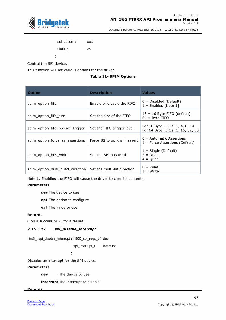
Application Note
AN_365 FT9XX API Programmers Manual Version 1.7
Document Reference No.: BRT_000118 Clearance No.: BRT#075
93 Product Page
Document Feedback Copyright © Bridgetek Pte Ltd
spi_option_t opt,
uint8_t val
)
Control the SPI device.
This function will set various options for the driver.
Table 11- SPIM Options
Option Description Values
spim_option_fifo Enable or disable the FIFO 0 = Disabled (Default)
1 = Enabled [Note 1]
spim_option_fifo_size Set the size of the FIFO 16 = 16 Byte FIFO (default) 64 = Byte FIFO
spim_option_fifo_receive_trigger Set the FIFO trigger level For 16 Byte FIFOs: 1, 4, 8, 14 For 64 Byte FIFOs: 1, 16, 32, 56
spim_option_force_ss_assertions Force SS to go low in assert 0 = Automatic Assertions 1 = Force Assertions (Default)
spim_option_bus_width Set the SPI bus width 1 = Single (Default) 2 = Dual 4 = Quad
spim_option_dual_quad_direction Set the multi-bit direction 0 = Read 1 = Write
Note 1: Enabling the FIFO will cause the driver to clear its contents.
Parameters
dev The device to use
opt The option to configure
val The value to use
Returns
0 on a success or -1 for a failure
2.15.3.12 spi_disable_interrupt
int8_t spi_disable_interrupt ( ft900_spi_regs_t * dev,
spi_interrupt_t interrupt
)
Disables an interrupt for the SPI device.
Parameters
dev The device to use
interrupt The interrupt to disable
Returns
Application Note
AN_365 FT9XX API Programmers Manual Version 1.7
Document Reference No.: BRT_000118 Clearance No.: BRT#075
94 Product Page
Document Feedback Copyright © Bridgetek Pte Ltd
0 on a success or -1 for a failure
See also
spim_disable_interrupts_globally
2.15.3.13 spi_disable_interrupts_globally
int8_t spi_disable_interrupts_globally ( ft900_spi_regs_t * dev )
Disables the SPI device from generating an interrupt.
Parameters
dev the device to use
Returns
0 on a success or -1 for a failure
2.15.3.14 spi_enable_interrupt
int8_t spi_enable_interrupt ( ft900_spi_regs_t * dev,
spi_interrupt_t interrupt
)
Enables an interrupt for the SPI device.
Parameters
dev the device to use
interrupt The interrupt to enable
Returns
0 on a success or -1 for a failure
See also
spim_enable_interrupts_globally
2.15.3.15 spi_enable_interrupts_globally
int8_t spi_enable_interrupts_globally ( ft900_spi_regs_t * dev )
Enables the SPI device to generate an interrupt.
Parameters
dev the device to use
Returns
0 on a success or -1 for a failure
2.15.3.16 spi_is_interrupted
int8_t spi_is_interrupted ( ft900_spi_regs_t * dev,
spi_interrupt_t interrupt
)
Disables an interrupt for the QSPI device.
Parameters

Application Note
AN_365 FT9XX API Programmers Manual Version 1.7
Document Reference No.: BRT_000118 Clearance No.: BRT#075
95 Product Page
Document Feedback Copyright © Bridgetek Pte Ltd
dev The device to use
interrupt The interrupt to check
Returns
1 when interrupted, 0 when not interrupted, -1 otherwise
See also
spi_disable_interrupts_globally
2.15.3.17 spi_uninit
int8_t spi_uninit ( ft900_spi_regs_t * dev )
Disable the SPI device.
Parameters
dev the device to use
Returns
0 on a success or -1 for a failure
2.16 CANBus
The file ft900_can.h contains the definitions for the CANBus functions in the libft900.a library.
API Cross Reference
Additional definitions are taken from:
ft900_registers.h – FT90X register definitions
Enumeration Type Documentation
2.16.2.1 can_mode_t
enum can_mode_t
The mode of the CAN device.
Enumerator
can_mode_normal The CAN Device is operating normally
can_mode_listen The CAN Device is in listen-only mode and will not allow data transmission or send ACKs on the bus
2.16.2.2 can_type_t
enum can_type_t
CAN message type.

Application Note
AN_365 FT9XX API Programmers Manual Version 1.7
Document Reference No.: BRT_000118 Clearance No.: BRT#075
96 Product Page
Document Feedback Copyright © Bridgetek Pte Ltd
Enumerator
can_type_standard CAN2.0A Standard Frame
can_type_extended CAN2.0B Extended Frame
2.16.2.3 can_filter_mode_t
enum can_filter_mode_t
The mode of the filter.
Enumerator
can_filter_mode_single Single Filter mode
can_filter_mode_dual Dual Filter mode
2.16.2.4 can_arbitration_lost_t
enum can_arbitration_lost_t
The location of where arbitration was lost.
Enumerator
can_arbitration_lost_id28_11 Arbitration was lost on the 12th bit of the ID (29th bit extended)
can_arbitration_lost_id27_10 Arbitration was lost on the 11th bit of the ID (28th bit extended)
can_arbitration_lost_id26_9 Arbitration was lost on the 10th bit of the ID (27th bit extended)
can_arbitration_lost_id25_8 Arbitration was lost on the 9th bit of the ID (26th bit extended)
can_arbitration_lost_id24_7 Arbitration was lost on the 8th bit of the ID (25th bit extended)
can_arbitration_lost_id23_6 Arbitration was lost on the 7th bit of the ID (24th bit extended)
can_arbitration_lost_id22_5 Arbitration was lost on the 6th bit of the ID (23th bit extended)
can_arbitration_lost_id21_4 Arbitration was lost on the 5th bit of the ID (22th bit extended)
can_arbitration_lost_id20_3 Arbitration was lost on the 4th bit of the ID (21th bit extended)
can_arbitration_lost_id19_2 Arbitration was lost on the 3rd bit of the ID (20th bit extended)
can_arbitration_lost_id18_1 Arbitration was lost on the 2nd bit of the ID (19th bit extended)
can_arbitration_lost_id17_0 Arbitration was lost on the 1st bit of the ID (18th bit extended)
can_arbitration_lost_srtr_rtr Arbitration was lost on the SRTR/RTR bit
can_arbitration_lost_id16 Arbitration was lost on the 17th bit of the extended ID
can_arbitration_lost_id15 Arbitration was lost on the 16th bit of the extended ID

Application Note
AN_365 FT9XX API Programmers Manual Version 1.7
Document Reference No.: BRT_000118 Clearance No.: BRT#075
97 Product Page
Document Feedback Copyright © Bridgetek Pte Ltd
can_arbitration_lost_id14 Arbitration was lost on the 15th bit of the extended ID
can_arbitration_lost_id13 Arbitration was lost on the 14th bit of the extended ID
can_arbitration_lost_id12 Arbitration was lost on the 13th bit of the extended ID
can_arbitration_lost_id11 Arbitration was lost on the 12th bit of the extended ID
can_arbitration_lost_id10 Arbitration was lost on the 11th bit of the extended ID
can_arbitration_lost_id9 Arbitration was lost on the 10th bit of the extended ID
can_arbitration_lost_id8 Arbitration was lost on the 9th bit of the extended ID
can_arbitration_lost_id7 Arbitration was lost on the 8th bit of the extended ID
can_arbitration_lost_id6 Arbitration was lost on the 7th bit of the extended ID
can_arbitration_lost_id5 Arbitration was lost on the 6th bit of the extended ID
can_arbitration_lost_id4 Arbitration was lost on the 5th bit of the extended ID
can_arbitration_lost_id3 Arbitration was lost on the 4th bit of the extended ID
can_arbitration_lost_id2 Arbitration was lost on the 3rd bit of the extended ID
can_arbitration_lost_id1 Arbitration was lost on the 2nd bit of the extended ID
can_arbitration_lost_id0 Arbitration was lost on the 1st bit of the extended ID
can_arbitration_lost_rtr Arbitration was lost on the RTR bit
can_arbitration_lost_invalid No valid arbitration could be found
2.16.2.5 can_interrupt_t
enum can_interrupt_t
CAN Peripheral Interrupts.
Enumerator
can_interrupt_data_overrun
can_interrupt_bus_error
can_interrupt_transmit
can_interrupt_receive
can_interrupt_error_passive
can_interrupt_error_warning
can_interrupt_arbitration_lost
can_interrupt_data_overload This enum for FT90X

Application Note
AN_365 FT9XX API Programmers Manual Version 1.7
Document Reference No.: BRT_000118 Clearance No.: BRT#075
98 Product Page
Document Feedback Copyright © Bridgetek Pte Ltd
Revision C onwards only
2.16.2.6 can_rtr_t
enum can_rtr_t
Remote transfer request flag.
Enumerator
can_rtr_none No RTR
can_rtr_remote_request RTR Set
Function Documentation
2.16.3.1 can_init
int8_t can_init ( ft900_can_regs_t * dev,
can_mode_t mode,
const can_time_config_t * timeconfig
)
Initialise the CAN device.
Parameters
dev A pointer to the device to use
mode The mode that this CAn device should be in (normal or listen)
timeconfig The configuration struct that defines the timing of the device
Returns
0 on a success, -1 otherwise
2.16.3.2 can_open
int8_t can_open ( ft900_can_regs_t * dev )
Open the CAN device for reading and writing.
Parameters
dev A pointer to the device to use
Returns
0 on a success, -1 otherwise
2.16.3.3 can_close
int8_t can_close ( ft900_can_regs_t * dev )
Close the CAN device for reading and writing.
Parameters

Application Note
AN_365 FT9XX API Programmers Manual Version 1.7
Document Reference No.: BRT_000118 Clearance No.: BRT#075
99 Product Page
Document Feedback Copyright © Bridgetek Pte Ltd
dev A pointer to the device to use
Returns
0 on a success, -1 otherwise
2.16.3.4 can_filter
int8_t can_filter ( ft900_can_regs_t * dev,
can_filter_mode_t filtmode,
uint8_t filternum,
const can_filter_t * filter
)
Set up a filter for the CAN device.
Set up the CAN device to filter for specific criteria.
The filter can work in two modes: single or dual. Depending on which mode the filter is in certain types of information can be used, as shown in the table below.
Table 12- CAN mode and message filters
Mode Message Type ID RTR Data[0] Data[1]
Single Standard Yes Yes Yes Yes
Single Extended Yes Yes No No
Dual Standard Yes Yes Filter 0 Only No
Dual Extended Only bits 13 to 28 No No No
Any field which is not used in a certain configuration will be ignored.
Parameters
dev A pointer to the device to use
filtmode The mode that the filters should be in (single or dual)
filternum The number of filter to use. When in single mode, only 0 will work.
filter A pointer to the configuration to use
Returns
0 on a success, -1 otherwise
Warning
This command only works when the CAN device is closed
See also
can_filter_t
2.16.3.5 can_read
int8_t can_read ( ft900_can_regs_t * dev,
can_msg_t * msg

Application Note
AN_365 FT9XX API Programmers Manual Version 1.7
Document Reference No.: BRT_000118 Clearance No.: BRT#075
100 Product Page
Document Feedback Copyright © Bridgetek Pte Ltd
)
Receive a message from the CAN Bus.
This function will take the first available message from the Receive FIFO.
Parameters
dev A pointer to the device to use
msg The struct to pack the message into
Returns
0 on a success, -1 otherwise
Warning
This command only works when the CAN device is open
This function will automatically clear the Receive interrupt flag and increment the Receive message counter.
2.16.3.6 can_write
int8_t can_write ( ft900_can_regs_t * dev,
const can_msg_t * msg
)
Send a message on the CAN Bus.
This function will accept a can_msg_t and pack it into a format to be fed into the CAN Transmit
FIFO.
Parameters
dev A pointer to the device to use
msg The message to send
Returns
0 on a success, -1 otherwise
Warning
This command only works when the CAN device is open
2.16.3.7 can_abort
int8_t can_abort ( ft900_can_regs_t * dev )
Abort the transmission of messages on the CAN Bus.
This function will cause the CAN device to abort transmission on the CAN Bus. After the
transmission of the current message on the Bus, no further transmissions will occur (including retransmissions for erroneous messages).
Parameters
dev A pointer to the device to use
Returns
0 on a success, -1 otherwise
Application Note
AN_365 FT9XX API Programmers Manual Version 1.7
Document Reference No.: BRT_000118 Clearance No.: BRT#075
101 Product Page
Document Feedback Copyright © Bridgetek Pte Ltd
2.16.3.8 can_status
uint8_t can_status ( ft900_can_regs_t * dev )
Query the status register.
The return value is a bit-mask with the following format:
Table 13- CAN Status Bit Mask
Bit Name Description Set when...
7 (MSB)
RX_BUF_STS Receive Buffer Status At least one message in the receive FIFO
6 OVRN_STS Data Overrun Status The receive FIFO has encountered an overrun
5 TX_BUF_STS Transmit Buffer Status
The CPU is able to write to the transmit FIFO
4 -
3 RX_STS Receive Status CAN is currently receiving a message
2 TX_STS Transmit Status CAN is currently transmitting a message
1 ERR_STS Error Status One CAN error counter has reached warning
(96)
0 (LSB) BUS_OFF_STS Bus Off Status The CAN device is in a bus off state
Parameters
dev A pointer to the device to use
Returns
A bit-mask of the current status or 0 for an unknown device.
2.16.3.9 can_available
uint8_t can_available ( ft900_can_regs_t * dev )
Return how many messages are available in the receive FIFO.
Parameters
dev A pointer to the device to use
Returns
The number of messages available in the receive FIFO
2.16.3.10 can_rx_error_count
uint8_t can_rx_error_count ( ft900_can_regs_t * dev )
Get the current number of receive errors reported by the CAN device.
Parameters
dev A pointer to the device to use
Returns

Application Note
AN_365 FT9XX API Programmers Manual Version 1.7
Document Reference No.: BRT_000118 Clearance No.: BRT#075
102 Product Page
Document Feedback Copyright © Bridgetek Pte Ltd
The current number of receive errors (0 - 255) or 0 for an unknown device.
2.16.3.11 can_tx_error_count
uint8_t can_tx_error_count ( ft900_can_regs_t * dev )
Get the current number of transmit errors reported by the CAN device.
When the transmit error counter exceeds limit of 255, the Bus Status bit in the Status register is
set to logic 1 (bus off), the CAN controller set reset mode, and if enabled an error warning interrupt is generated. The transmit error counter is then set to 127 and receive error counter is cleared.
Parameters
dev A pointer to the device to use
Returns
The current number of receive errors (0 - 255) or 0 for an unknown device.
2.16.3.12 can_ecode
uint8_t can_ecode ( ft900_can_regs_t * dev )
Get the current value of the ECC (Error Code Capture) register.
This function will return the value of the ECC (Error Code Capture) register. This register holds the
error code for the LAST bus error that occurred on the CAN network.
The return value is a bit-mask with the following format:
Table 14- CAN Error Code Mask
Bit Name Description Set when...
7 (MSB) RX_WRN Receive Warning The number of receive errors is >= 96
6 TX_WRN Transmit Warning The number of transmit errors is >= 96
5 ERR_DIR Direction The error occurred on reception.
4 ACK_ERR Acknowledgement Error An ACK Error occurred
3 FRM_ERR Form Error A Form Error occurred
2 CRC_ERR CRC Error A CRC Error occurred
1 STF_ERR Stuff Error A Bit Stuffing Error occurred
0 (LSB) BIT_ERR Bit Error A Bit Error occurred
Parameters
dev A pointer to the device to use
Returns
The value of the ECC (Error Code Capture) register or 0 for an unknown device.
2.16.3.13 can_arbitration_lost_location
can_arbitration_lost_t can_arbitration_lost_location ( ft900_can_regs_t * dev )

Application Note
AN_365 FT9XX API Programmers Manual Version 1.7
Document Reference No.: BRT_000118 Clearance No.: BRT#075
103 Product Page
Document Feedback Copyright © Bridgetek Pte Ltd
Get the location where arbitration was lost.
Parameters
dev A pointer to the device to use
Returns
The location where arbitration was lost
2.16.3.14 can_enable_interrupt
int8_t can_enable_interrupt ( ft900_can_regs_t * dev,
can_interrupt_t interrupt
)
Enable an Interrupt.
Enable the CAN device to generate an interrupt. The value of mask is a bit-mask with the following format:
Table 15- CAN Interrupt Enable Mask
Bit Name Description Trigger
7 (MSB)
Unused
6 ARB_LOST Arbitration Lost
Interrupt Arbitration is lost
5 ERR_WARN Error Warning Interrupt Changes in ES or BS of the Status register
4 ERR_PSV Error Passive Interrupt Bus enters or exits a passive state
3 RX Receive Interrupt A message is received on CAN
2 TX Transmit Interrupt A message is successfully received on CAN
1 BUS_ERR Bus Error Interrupt A bus error occurred when transmitting\receiving
0 (LSB) DATA_OVRN Data Overrun Interrupt A receive FIFO overrun occurred
Parameters
dev A pointer to the device to use
interrupt The interrupt to enable
Returns
0 on a success, -1 otherwise
Warning
This command only works when the CAN device is closed
2.16.3.15 can_disable_interrupt
int8_t can_disable_interrupt ( ft900_can_regs_t * dev,

Application Note
AN_365 FT9XX API Programmers Manual Version 1.7
Document Reference No.: BRT_000118 Clearance No.: BRT#075
104 Product Page
Document Feedback Copyright © Bridgetek Pte Ltd
can_interrupt_t interrupt
)
Disable an Interrupt.
Disable the CAN device from generating an interrupt.
Parameters
dev A pointer to the device to use
interrupt The interrupt to disable
Returns
0 on a success, -1 otherwise
Warning
This command only works when the CAN device is closed
2.16.3.16 can_is_interrupted
int8_t can_is_interrupted ( ft900_can_regs_t * dev,
can_interrupt_t interrupt
)
Query the Interrupt register.
Query the Interrupt register in order to determine what caused the interrupt.
Parameters
dev A pointer to the device to use
interrupt The interrupt to check
Warning
This function clears the interrupt bit so that it does not fire constantly
Returns
0 when the interrupt hasn't been fired, 1 when the interrupt has fired and -1 otherwise
Variable Documentation
const can_time_config_t g_can125kbaud
Configuration for 125 kBaud at fcpu = 100 MHz
const can_time_config_t g_can1Mbaud
Configuration for 1 MBaud at fcpu = 100 MHz
const can_time_config_t g_can250kbaud
Configuration for 250 kBaud at fcpu = 100 MHz
const can_time_config_t g_can500kbaud
Configuration for 500 kBaud at fcpu = 100 MHz

Application Note
AN_365 FT9XX API Programmers Manual Version 1.7
Document Reference No.: BRT_000118 Clearance No.: BRT#075
105 Product Page
Document Feedback Copyright © Bridgetek Pte Ltd
2.17 Camera interface
The file ft900_cam.h contains the definitions for the camera bus functions in the libft900.a library.
API Cross Reference
It utilises the following library APIs:
ft900_asm.h – FT90X assembler definitions
Additional definitions are taken from:
ft900_registers.h – FT90X register definitions
Enumeration Type Documentation
2.17.2.1 cam_clock_pol_t
enum cam_clock_pol_t
Camera clock polarity.
Enumerator
cam_clock_pol_falling Sample data on a falling PCLK edge
cam_clock_pol_raising Sample data on a raising PCLK edge
2.17.2.2 cam_trigger_mode_t
enum cam_trigger_mode_t
Camera vertical/horizontal trigger mode Control at what logic levels the camera will accept data.
Enumerator
cam_trigger_mode_0 VD = L, HD = L
cam_trigger_mode_1 VD = L, HD = H
cam_trigger_mode_2 VD = H, HD = L
cam_trigger_mode_3 VD = H, HD = H
Function Documentation
2.17.3.1 cam_init
int8_t cam_init ( cam_trigger_mode_t triggers,
cam_clock_pol_t clkpol
)
Initialise the Camera interface.
Parameters
triggers The VD/HD levels to trigger on

Application Note
AN_365 FT9XX API Programmers Manual Version 1.7
Document Reference No.: BRT_000118 Clearance No.: BRT#075
106 Product Page
Document Feedback Copyright © Bridgetek Pte Ltd
clkpol The clock polarity of the input
Returns
0 on success, -1 otherwise
2.17.3.2 cam_available
uint16_t cam_available ( void
)
Check how many bytes are available on the FIFO.
Returns
The number of bytes available
2.17.3.3 cam_start
int8_t cam_start ( uint16_t bytes )
Start capturing data.
Parameters
bytes The number of bytes to capture
Returns
0 on success, -1 otherwise
2.17.3.4 cam_stop
int8_t cam_stop ( void
)
Stop capturing data.
Returns
0 on success, -1 otherwise
2.17.3.5 cam_set_threshold
int8_t cam_set_threshold ( uint16_t n )
Set the threshold for when the camera interrupt fires.
Parameters
n The number of bytes to fill the FIFO with before the interrupt fires (this must be a multiple of 4)
Returns
0 on success, -1 otherwise
2.17.3.6 cam_readn
uint16_t cam_readn ( uint8_t * b,
size_t len
)
Read a number of bytes from the FIFO.
Parameters
Application Note
AN_365 FT9XX API Programmers Manual Version 1.7
Document Reference No.: BRT_000118 Clearance No.: BRT#075
107 Product Page
Document Feedback Copyright © Bridgetek Pte Ltd
b A pointer to read the data into
len The number of bytes to read from the FIFO (this must be a multiple of 4)
Returns
The number of bytes read, 0 otherwise
2.17.3.7 cam_flush
void cam_flush ( void
)
Empty out the camera buffer.
2.17.3.8 cam_total_read
uint16_t cam_total_read ( void
)
Check how many bytes have been read by the Camera Interface.
Returns
2.17.3.9 The number of bytes readcam_enable_interrupt
int8_t cam_enable_interrupt ( void
)
Enable the threshold interrupt.
Returns
0 on success, -1 otherwise
2.17.3.10 cam_disable_interrupt
int8_t cam_disable_interrupt ( void
)
Disable the threshold interrupt.
Returns
0 on success, -1 otherwise
2.17.3.11 cam_is_interrupted
int8_t cam_is_interrupted ( void
)
Check that an interrupt has occurred.
Returns
0 when the interrupt hasn't been fired, 1 when the interrupt has fired and -1 otherwise

Application Note
AN_365 FT9XX API Programmers Manual Version 1.7
Document Reference No.: BRT_000118 Clearance No.: BRT#075
108 Product Page
Document Feedback Copyright © Bridgetek Pte Ltd
2.18 Pulse Width Modulation
The file ft900_pwm.h contains the definitions for the Pulse Width Modulation functions in the libft900.a library.
API Cross Reference
Additional definitions are taken from:
ft900_registers.h – FT90X and FT93X register definitions
Enumeration Type Documentation
2.18.2.1 pwm_restore_t
enum pwm_restore_t
PWM restore state.
Enumerator
pwm_restore_disable Do not restore the setup state on wrap around
pwm_restore_enable Do not restore the setup state on wrap around
2.18.2.2 pwm_state_t
enum pwm_state_t
Enumerator
pwm_state_low Setup as low
pwm_state_high Setup as high
2.18.2.3 pwm_trigger_t
enum pwm_trigger_t
PWM Triggering.
Enumerator
pwm_trigger_disabled Do not trigger
pwm_trigger_positive_edge Trigger on a positive edge
pwm_trigger_negative_edge Trigger on a negative edge
pwm_trigger_any_edge Trigger on any edge
Function Documentation
2.18.3.1 pwm_init
int8_t pwm_init ( uint8_t prescaler,

Application Note
AN_365 FT9XX API Programmers Manual Version 1.7
Document Reference No.: BRT_000118 Clearance No.: BRT#075
109 Product Page
Document Feedback Copyright © Bridgetek Pte Ltd
uint16_t maxcount,
uint8_t shots
)
Initialise the PWM subsystem.
Parameters
prescaler The prescaler for the PWM subsystem
maxcount The maximum count of the 16 bit master counter
shots The number of loops the PWM subsystem will make, 0 is infinity
Returns
On success a 0, otherwise -1
2.18.3.2 pwm_enable
int8_t pwm_enable ( void
)
Enable the PWM subsystem.
Returns
On success a 0, otherwise -1
2.18.3.3 pwm_disable
int8_t pwm_disable ( void
)
Disable the PWM subsystem.
Returns
On success a 0, otherwise -1
2.18.3.4 pwm_add_toggle
int8_t pwm_add_toggle ( uint8_t channel,
uint8_t toggle
)
Add a toggle to a specific PWM channel.
Parameters
channel The channel to add the toggle to
toggle The channel to toggle on
Returns
On success a 0, otherwise -1
2.18.3.5 pwm_remove_toggle
int8_t pwm_remove_toggle ( uint8_t channel,
uint8_t toggle
)

Application Note
AN_365 FT9XX API Programmers Manual Version 1.7
Document Reference No.: BRT_000118 Clearance No.: BRT#075
110 Product Page
Document Feedback Copyright © Bridgetek Pte Ltd
Remove a toggle to a specific PWM channel.
Parameters
channel The channel to remove the toggle from
toggle The channel to remove the toggle of
Returns
On success a 0, otherwise -1
2.18.3.6 pwm_compare
int8_t pwm_compare ( uint8_t channel,
uint16_t value
)
Set a compare value for a PWM counter.
Parameters
channel The channel to use
value The value to toggle on
Returns
On success a 0, otherwise -1
2.18.3.7 pwm_levels
int8_t pwm_levels ( uint8_t channel,
pwm_state_t initstate,
pwm_restore_t restorestate
)
Set up the logic levels for a PWM counter.
Parameters
channel The channel to use
initstate The initial state of the counter (high or low)
restorestate The rollover restore setting
Returns
On success a 0, otherwise -1
2.18.3.8 pwm_trigger
int8_t pwm_trigger ( pwm_trigger_t trigger )
Set the external trigger settings.
Parameters

Application Note
AN_365 FT9XX API Programmers Manual Version 1.7
Document Reference No.: BRT_000118 Clearance No.: BRT#075
111 Product Page
Document Feedback Copyright © Bridgetek Pte Ltd
trigger The trigger setting
Returns
On success a 0, otherwise -1

Application Note
AN_365 FT9XX API Programmers Manual Version 1.7
Document Reference No.: BRT_000118 Clearance No.: BRT#075
112 Product Page
Document Feedback Copyright © Bridgetek Pte Ltd
2.19 PWM Audio
The file ft900_pwm_pcm.h contains the definitions for the PWM audio functions in the libft900.a library.
API Cross Reference
It utilises the following library APIs:
ft900_pwm.h – Pulse Width Modulation
ft900_asm.h – FT90X and FT93X assembler definitions
Additional definitions are taken from:
ft900_registers.h – FT90X and FT93X register definitions
Enumeration Type Documentation
2.19.2.1 pwm_pcm_channels_t
enum pwm_pcm_channels_t
PWM Channel selection.
Enumerator
pwm_pcm_channels_mono Mono
pwm_pcm_channels_stereo Stereo
2.19.2.2 pwm_pcm_data_size_t
enum pwm_pcm_data_size_t
PWM data size selection.
Enumerator
pwm_pcm_data_size_8 8 bit
pwm_pcm_data_size_16 16 bit
2.19.2.3 pwm_pcm_endianness_t
enum pwm_pcm_endianness_t
PWM endianness selection.
Enumerator
pwm_pcm_endianness_big Big endian data
pwm_pcm_endianness_little Little endian data
2.19.2.4 pwm_pcm_filter_t
enum pwm_pcm_filter_t

Application Note
AN_365 FT9XX API Programmers Manual Version 1.7
Document Reference No.: BRT_000118 Clearance No.: BRT#075
113 Product Page
Document Feedback Copyright © Bridgetek Pte Ltd
PWM PCM Filter.
Enumerator
pwm_pcm_filter_off Off
pwm_pcm_filter_on On
2.19.2.5 pwm_pcm_interrupt_t
enum pwm_pcm_interrupt_t
PWM PCM Interrupt selection.
Enumerator
pwm_pcm_interrupt_empty FIFO Empty
pwm_pcm_interrupt_full FIFO Full
pwm_pcm_interrupt_half_full FIFO Half Full
pwm_pcm_interrupt_overflow FIFO Overflow
pwm_pcm_interrupt_underflow FIFO Underflow
2.19.2.6 pwm_pcm_volume_t
enum pwm_pcm_volume_t
PWM PCM Volume.
Enumerator
pwm_pcm_volume_mute
pwm_pcm_volume_6 6.25% volume
pwm_pcm_volume_12 12.5% volume
pwm_pcm_volume_19 19% volume
pwm_pcm_volume_25 25% volume
pwm_pcm_volume_31 31% volume
pwm_pcm_volume_37 37% volume
pwm_pcm_volume_44 44% volume
pwm_pcm_volume_50 50% volume
pwm_pcm_volume_56 56% volume
pwm_pcm_volume_63 63% volume
pwm_pcm_volume_69 69% volume

Application Note
AN_365 FT9XX API Programmers Manual Version 1.7
Document Reference No.: BRT_000118 Clearance No.: BRT#075
114 Product Page
Document Feedback Copyright © Bridgetek Pte Ltd
pwm_pcm_volume_75 75% volume
pwm_pcm_volume_81 81% volume
pwm_pcm_volume_88 88% volume
pwm_pcm_volume_94 94% volume
pwm_pcm_volume_100 100% volume
Function Documentation
2.19.3.1 pwm_pcm_open
int8_t pwm_pcm_open ( pwm_pcm_channels_t channels,
uint16_t samplerate,
pwm_pcm_data_size_t datasize,
pwm_pcm_endianness_t endianness,
pwm_pcm_filter_t filter
)
Initialise the PWM PCM output.
Parameters
channels The number of channels to output.
samplerate The sample rate of the audio data.
datasize The word size of the samples (8 or 16 bit).
endianness The endianness of the 16 bit word. In 8 bit mode this will be ignored.
filter If a PCM filter will be used to filter out the PWM carrier.
Returns
On success a 0, otherwise -1
2.19.3.2 pwm_pcm_close
int8_t pwm_pcm_close ( void
)
Close the PWM PCM Output.
Returns
On success a 0, otherwise -1
2.19.3.3 pwm_pcm_volume
int8_t pwm_pcm_volume ( pwm_pcm_volume_t vol )
Set the volume of the PWM PCM device.
Parameters
vol The volume to set to.
Application Note
AN_365 FT9XX API Programmers Manual Version 1.7
Document Reference No.: BRT_000118 Clearance No.: BRT#075
115 Product Page
Document Feedback Copyright © Bridgetek Pte Ltd
Returns
On success a 0, otherwise -1
2.19.3.4 pwm_pcm_write
int8_t pwm_pcm_write ( uint16_t data )
Write a word of data to the PWM PCM device.
Parameters
data The data to write. If 8 bit mode is selected, the top 8 bits will be ignored
Returns
The number of bytes written to the FIFO, otherwise -1
2.19.3.5 pwm_pcm_writen
int8_t pwm_pcm_writen ( uint16_t * data,
size_t len
)
Write a number of words of data to the PWM PCM device.
Parameters
data The data to write. If 8 bit mode is selected, the top 8 bits will be ignored
len The size of data to write.
Returns
2.19.3.6 The number of bytes written to the FIFO, otherwise -1pwm_pcm_disable_interrupt
int8_t pwm_pcm_disable_interrupt ( pwm_pcm_interrupt_t interrupt )
Disable an interrupt.
Parameters
interrupt The interrupt to disable
Returns
On success a 0, otherwise -1
2.19.3.7 pwm_pcm_enable_interrupt
int8_t pwm_pcm_enable_interrupt ( pwm_pcm_interrupt_t interrupt )
Enable an interrupt.
Parameters
interrupt The interrupt to enable
Returns
On success a 0, otherwise -1

Application Note
AN_365 FT9XX API Programmers Manual Version 1.7
Document Reference No.: BRT_000118 Clearance No.: BRT#075
116 Product Page
Document Feedback Copyright © Bridgetek Pte Ltd
2.19.3.8 pwm_pcm_is_interrupted
int8_t pwm_pcm_is_interrupted ( pwm_pcm_interrupt_t interrupt )
Query if an interrupt has fired.
Parameters
interrupt The interrupt to query
Warning
This function will clear the interrupt being queried and the global PWM interrupt flag
Returns
1 for if PWM is interrupted, 0 if PWM is not interrupted, -1 otherwise

Application Note
AN_365 FT9XX API Programmers Manual Version 1.7
Document Reference No.: BRT_000118 Clearance No.: BRT#075
117 Product Page
Document Feedback Copyright © Bridgetek Pte Ltd
2.20 Real Time Clock
The file ft900_rtc.h contains the definitions for the real time clock functions in the libft900.a and libft930.a library. The RTC API is meant for the on-chip RTC on FT90X Revision C and FT93X which are the same. However the RTC API is also made backward compatible with FT90X Revision B, where the RTC hardware block is different from that of FT93X/FT90X rev C. The definitions below indicate wherever there is a difference for FT90X revision B.
FT90X and FT93X register definitionsAPI Cross Reference
Additional definitions are taken from:
ft900_registers.h – FT90X and FT93X register definitions
time.h – C library time.h, used to access struct tm
Enumeration Type Documentation
2.20.2.1 rtc_interrupt_t
enum rtc_interrupt_t
RTC Interrupts
Enumerator
rtc_interrupt_alarm1 Alarm 1 Interrupt
rtc_interrupt_alarm2 Alarm 2 Interrupt
rtc_interrupt_ext_osc_stopped External Oscillator Stopped Interrupt
rtc_interrupt_int_osc_stopped Internal Oscillator Stopped Interrupt
rtc_interrupt_int_auto_calibration Auto Calibration Interrupt
rtc_interrupt_max Placeholder for maximum value
rtc_legacy_interrupt_alarm This ENUM is ONLY applicable to FT90x Revision B on-chip RTC and is the only enum to be used.
2.20.2.2 rtc_alarm_type_t
enum rtc_alarm_type_t
RTC Alarm Types
Enumerator
rtc_alarm_1Hz Alarm every second
rtc_alarm_match_sec Alarm when seconds match
rtc_alarm_match_min_sec Alarm when seconds and minutes match
rtc_alarm_match_hr_min_sec Alarm when seconds, minutes and hours match
rtc_alarm_match_date_hr_min_sec Alarm when seconds, minutes, hours and date matches

Application Note
AN_365 FT9XX API Programmers Manual Version 1.7
Document Reference No.: BRT_000118 Clearance No.: BRT#075
118 Product Page
Document Feedback Copyright © Bridgetek Pte Ltd
rtc_alarm_match_day_hr_min_sec Alarm when seconds, minutes, hours and day matches
rtc_legacy_alarm This ENUM is ONLY applicable to FT90X Revision B on-chip RTC and and is the only enum to be used.
2.20.2.3 rtc_option_t
enum rtc_option_t
RTC Option
Enumerator
rtc_option_auto_refresh Auto Refresh Option
rtc_option_wrap Enable or disable RTC Wrap around (Applicable ONLY in FT900 Revision B)
rtc_option_mask_interrupt Option to set whether the Real Time Clock module should mask the
match interrupt line (Applicable ONLY in FT90X Revision B)
Function Documentation
2.20.3.1 rtc_init
int8_t rtc_init ( void
)
Initialise the Real Time Clock.
Returns
0 on success, -1 otherwise
2.20.3.2 rtc_start
int8_t rtc_start ( void
)
Start the Real Time Clock.
Returns
0 on success, -1 otherwise
2.20.3.3 rtc_stop
int8_t rtc_stop ( void
)
Stop the Real Time Clock.
Returns
0 on success, -1 otherwise
2.20.3.4 rtc_read
int8_t rtc_read ( struct tm* const time )
Read the current value of the Real Time Clock.

Application Note
AN_365 FT9XX API Programmers Manual Version 1.7
Document Reference No.: BRT_000118 Clearance No.: BRT#075
119 Product Page
Document Feedback Copyright © Bridgetek Pte Ltd
Parameters
time A pointer of type struct tm* (defined in <time.h>) to which the RTC time is to be read in case of FT93X and FT90X rev C. Only the field tm.sec is written to with current RTC time read, in case of FT90X rev B.
Returns
0 on success, -1 otherwise
2.20.3.5 rtc_write
int8_t rtc_write ( const struct tm* time )
Write the given date/time to the Real Time Clock
Parameters
time A pointer of type struct tm* (defined in <time.h>) contains the time to be written into the RTC for FT93X and FT90X rev C. Only the field tm.sec should contain the RTC time to be written in case of FT90X rev B.
Returns
0 on success, -1 otherwise
2.20.3.6 rtc_option
int8_t rtc_option ( rtc_option_t opt, uitn8_t val )
Control options of the RTC
Parameters
opt The type of option to update
val The value of the selected option
Returns
0 on success, -1 otherwise
2.20.3.7 rtc_set_alarm
int8_t rtc_set_alarm ( uint8_t number,
struct tm* time,
rtc_alarm_type alarm_type
)
Set an Alarm on the RTC
Parameters
number The number of the Alarm to set (1 or 2)
time The date/time of the Alarm
alarm_type The type of alarm match required
Returns

Application Note
AN_365 FT9XX API Programmers Manual Version 1.7
Document Reference No.: BRT_000118 Clearance No.: BRT#075
120 Product Page
Document Feedback Copyright © Bridgetek Pte Ltd
0 on success, -1 otherwise
2.20.3.8 rtc_is_interrupted
int8_t rtc_is_interrupted ( rtc_interrupt_t Interrup)
Check if an interrupt has been triggered.
Parameters
interrupt The interrupt to check
Warning
This function clears the current interrupt status bit
Returns
1 when interrupted, 0 when not interrupted, -1 otherwise
2.20.3.9 rtc_enable_interrupt
int8_t rtc_enable_interrupt ( rtc _interrupt_t Interrupt)
Enable an interrupt on the RTC.
Parameters
interrupt The interrupt to enable
Returns
0 on success, -1 otherwise
2.20.3.10 rtc_enable_interrupts_globally
int8_t rtc_enable_interrupts_globally ( void
)
Enable RTC interrupts
Returns
0 on success, -1 otherwise
2.20.3.11 rtc_disable_interrupt
int8_t rtc_disable_interrupt ( rtc_interrupt_t Interrup)
Disable an interrupt on the RTC.
Parameters
interrupt The interrupt to disable
Returns
0 on success, -1 otherwise
2.20.3.12 rtc_disable_interrupts_globally
int8_t rtc_disable_interrupts_globally ( void
)
Disable the RTC from interrupting.
Returns

Application Note
AN_365 FT9XX API Programmers Manual Version 1.7
Document Reference No.: BRT_000118 Clearance No.: BRT#075
121 Product Page
Document Feedback Copyright © Bridgetek Pte Ltd
0 on success, -1 otherwise

Application Note
AN_365 FT9XX API Programmers Manual Version 1.7
Document Reference No.: BRT_000118 Clearance No.: BRT#075
122 Product Page
Document Feedback Copyright © Bridgetek Pte Ltd
2.21 USB Device Stack API
The file ft900_usbd.h contains the definitions for the USB device functions in the libft900.a and libft930.a library.
This contains USB Device API function definitions, constants and structures which are exposed in the API.
Note that as this is a USB device all transaction nomenclature is from the point of view from the host. If the device sends data to the host then it is called an IN transaction, if it receives data from the host then it is an OUT transaction.
Synchronous transfer and Asynchronous transfer:
The ft900_usbd.h provides synchronous transfer function i.e., the caller waits until the return of the callee, which is the end of the transfer to the USB endpoint.
Using APIs in ft900_usbd.h,
• Application prepares and processes the payload buffer
• Application calls USBD_transfer() to transfer the buffer
– USBD_Transfer is a synchronous call that waits for EP ready and sends the data in
batches of 512 and return.
• Application processes the buffer again only after USBD_transfer returns.
There are extended APIs defined in ft900_usbdx.h that provides asynchronous transfer of USB data.
• USBD manages buffer, buffer is divided into chunks called USB Request Blocks (URBs) and
are marked with ownership as ‘USBD owned’ or ‘Application owned’.
• USBD will transfer its owned URB to the USBD ISR, and releases the empty URB(s) back to application (change ownership)
• Application can
– get owned URB(s) in main loop or another ISR
– process URB(s)
– queue back URB(s) to USBD (change ownership)
More information about USDB Device Stack Extension API is found in the next section.
API Cross Reference
Utilises the following library APIs:
ft900_gpio.h – General Purpose I/O and Pad Control
ft900_sys.h – Chip Management
ft900_delay.h – Delay
ft900_interrupt.h – Interrupt Management
Additional definitions are taken from:
ft900_usb.h – General USB definitions
ft900_registers.h – FT90X and FT93X register definitions

Application Note
AN_365 FT9XX API Programmers Manual Version 1.7
Document Reference No.: BRT_000118 Clearance No.: BRT#075
123 Product Page
Document Feedback Copyright © Bridgetek Pte Ltd
Macro Definition Documentation
2.21.2.1 USB Device Error Codes
#define USBD_ERR_DISCONNECTED -10
Device not configured by host.
Device physically disconnected from host.
#define USBD_ERR_INCOMPLETE -5
Incomplete/interrupted transfer.
#define USBD_ERR_RESOURCES -4
Not enough endpoint resources.
#define USBD_ERR_NOT_SUPPORTED -3
Operation not supported.
#define USBD_ERR_NOT_CONFIGURED -2
Endpoint not configured.
#define USBD_ERR_INVALID_PARAMETER -1
Invalid parameter supplied to API function.
Typedef Documentation
2.21.3.1 USBD_reset_callback
typedef void(* USBD_reset_callback) (uint8_t status)
Callback declaration for a host reset.
Parameters
[in] status Unused.
2.21.3.2 USBD_suspend_callback
typedef void(* USBD_suspend_callback) (uint8_t status)
Callback declaration for a suspend/resume.
Parameters
[in] status Unused.
2.21.3.3 USBD_request_callback
typedef int8_t(* USBD_request_callback) (USB_device_request *req)
Callback declaration for Vendor, Class and optionally Standard USB requests.
Parameters
[in] req USB request.

Application Note
AN_365 FT9XX API Programmers Manual Version 1.7
Document Reference No.: BRT_000118 Clearance No.: BRT#075
124 Product Page
Document Feedback Copyright © Bridgetek Pte Ltd
Returns
USBD_OK if the request was handled successfully; any other return value (such as FT9XX_FAILED) causes the USB driver to stall the control endpoints.
2.21.3.4 USBD_descriptor_callback
typedef int8_t(* USBD_descriptor_callback) (USB_device_request *req, uint8_t **buffer, uint16_t *len)
Callback declaration for standard get descriptor requests to obtain descriptor data.
Parameters
[in] req USB request.
[in] buffer Data buffer containing descriptor.
Returns
USBD_OK if the request was handled successfully; any other return value (such as FT9XX_FAILED) causes the USB driver to stall the control endpoints.
2.21.3.5 USBD_ep_callback
typedef void(* USBD_ep_callback) (USBD_ENDPOINT_NUMBER ep_number)
Callback declaration for transaction completion on endpoint. The endpoint number is passed to the callback to allow the same function to handle multiple endpoints.
Enumeration Type Documentation
2.21.4.1 USBD_STATE
enum USBD_STATE
USB States. USB Spec section 9.1.
Enumerator
USBD_STATE_NONE Device is not attached.
USBD_STATE_ATTACHED Device is attached to USB.
USBD_STATE_POWERED Device is attached and powered.
USBD_STATE_DEFAULT Device is attached, has power and has been reset.
USBD_STATE_ADDRESS Unique device address has not been set.
USBD_STATE_CONFIGURED Unique device address is now assigned. Device can be used by
host.
USBD_STATE_SUSPENDED Device has been suspended.
2.21.4.2 USBD_DEVICE_SPEED
enum USBD_DEVICE_SPEED
USB Endpoint Speed setting.
Enumerator

Application Note
AN_365 FT9XX API Programmers Manual Version 1.7
Document Reference No.: BRT_000118 Clearance No.: BRT#075
125 Product Page
Document Feedback Copyright © Bridgetek Pte Ltd
USBD_SPEED_FULL Full speed.
USBD_SPEED_HIGH High speed.
2.21.4.3 USBD_ENDPOINT_NUMBER
enum USBD_ENDPOINT_NUMBER
USB Endpoint Numbers.
Enumerator
USBD_EP_0 Endpoint 0 (Control Endpoint)
USBD_EP_1 Endpoint 1.
USBD_EP_2 Endpoint 2.
USBD_EP_3 Endpoint 3.
USBD_EP_4 Endpoint 4.
USBD_EP_5 Endpoint 5.
USBD_EP_6 Endpoint 6.
USBD_EP_7 Endpoint 7.
USBD_EP_8 Endpoint 8.[FT93X only]
USBD_EP_9 Endpoint 9. [FT93X only]
USBD_EP_10 Endpoint 10. [FT93X only]
USBD_EP_11 Endpoint 11. [FT93X only]
USBD_EP_12 Endpoint 12. [FT93X only]
USBD_EP_13 Endpoint 13. [FT93X only]
USBD_EP_14 Endpoint 14. [FT93X only]
USBD_EP_15 Endpoint 15. [FT93X only]
2.21.4.4 USBD_ENDPOINT_DIR
enum USBD_ENDPOINT_DIR
USB Endpoint Direction.
Enumerator
USBD_DIR_OUT Direction host to device.
USBD_DIR_IN Direction device to host.

Application Note
AN_365 FT9XX API Programmers Manual Version 1.7
Document Reference No.: BRT_000118 Clearance No.: BRT#075
126 Product Page
Document Feedback Copyright © Bridgetek Pte Ltd
2.21.4.5 USBD_ENDPOINT_SIZE
enum USBD_ENDPOINT_SIZE
USB Endpoint Sizes.
Enumerator
USBD_EP_SIZE_8 8 Bytes
USBD_EP_SIZE_16 16 Bytes
USBD_EP_SIZE_32 32 Bytes
USBD_EP_SIZE_64 64 Bytes
USBD_EP_SIZE_128 128 Bytes. Only available on High Speed endpoints.
USBD_EP_SIZE_256 256 Bytes. Only available on High Speed endpoints.
USBD_EP_SIZE_512 512 Bytes. Only available on High Speed endpoints.
USBD_EP_SIZE_1023 1023 Bytes. Only available on Full Speed ISO endpoints.
USBD_EP_SIZE_1024 1024 Bytes. Only available on High Speed ISO and Interrupt endpoints.
2.21.4.6 USBD_ENDPOINT_TYPE
enum USBD_ENDPOINT_TYPE
USB Endpoint Types.
Enumerator
USBD_EP_TYPE_DISABLED Disabled.
USBD_EP_BULK Bulk Endpoint.
USBD_EP_INT Interrupt Endpoint.
USBD_EP_ISOC Isochronous Endpoint.
USBD_EP_CTRL Control Endpoint.
2.21.4.7 USBD_ENDPOINT_DB
enum USBD_ENDPOINT_DB
USB Endpoint Double Buffering Enable.
Enumerator
USBD_DB_OFF Disabled.
USBD_DB_ON Enabled.

Application Note
AN_365 FT9XX API Programmers Manual Version 1.7
Document Reference No.: BRT_000118 Clearance No.: BRT#075
127 Product Page
Document Feedback Copyright © Bridgetek Pte Ltd
2.21.4.8 USBD_TESTMODE_SELECT
enum USBD_TESTMODE_SELECT
Enums used to select the test modes. For more information refer to Section 7.1.20 of USB2.0 Specification.
Enumerator
USBD_TEST_J Test mode Test_J
USBD_TEST_K Test mode Test_K
USBD_TEST_SE0_NAK Test mode Test_SE0_NAK
USBD_TEST_PACKET Test mode Test_PACKET
Structure Documentation
2.21.5.1 USBD_ctx
Struct containing callback functions for the USB upper layer driver and callback functions for USB suspend/resume and USB reset. Sets USBD configuration information.
Data Fields
USBD_descriptor_callback get_descriptor_cb
USBD_set_configuration_callback set_configuration_cb
USBD_request_callback standard_req_cb
USBD_set_interface_callback set_interface_cb
USBD_get_interface_callback get_interface_cb
USBD_request_callback class_req_cb
USBD_request_callback vendor_req_cb
USBD_request_callback ep_feature_req_cb
USBD_request_callback feature_req_cb
USBD_suspend_callback suspend_cb
USBD_suspend_callback resume_cb
USBD_suspend_callback lpm_cb
USBD_reset_callback reset_cb
USBD_suspend_callback sof_cb
USBD_ENDPOINT_SIZE ep0_size
USBD_ep_callback ep0_cb
USBD_DEVICE_SPEED speed
uint8_t lowPwrSuspend
Field Documentation

Application Note
AN_365 FT9XX API Programmers Manual Version 1.7
Document Reference No.: BRT_000118 Clearance No.: BRT#075
128 Product Page
Document Feedback Copyright © Bridgetek Pte Ltd
class_req_cb
[Optional] class request callback function.
ep0_cb
Callback function for a data transfer to or from the control endpoint.
ep0_size
Endpoint size for control endpoints. Section 3.3.1 FT900 USB Program Manual. Sets
DC_EP0_CONTROL register in Table 3.6. 0: 8 bytes. 1: 16 bytes. 2: 32 bytes. 3: 64 bytes.
get_descriptor_cb
[Optional] Descriptor callback function.
Handler function to obtain descriptors (device, configuration, string, HID, Hub etc.) for use with the built-in USB standard request handler. This must be present if the standard request handler callback is not used.
set_configuration_cb
[Optional] Handler function to check set configuration is valid for application. For use with the built-in USB standard request handler. If this is not present then the default handling of the
request will occur.
set_interface_cb
[Optional] Handler function to set the alternate settings for an interface. For use with the built-in USB standard request handler. If this is not present then the request will be stalled.
get_interface_cb
[Optional] Handler function to return the alternate settings for an interface. For use with the built-in USB standard request handler. If this is not present then the request will be stalled.
ep_feature_req_cb
[Optional] Endpoint Feature request callback function.
feature_req_cb
[Optional] Device Feature (Remote Wakeup) request callback function.
lowPwrSuspend
Device power control. Engage power saving mode if bus-powered and suspend state entered. 0: Disable. 1: Enabled.
lpm_cb
[Optional] USB bus LPM (Link Power Management) callback function.
reset_cb
[Optional] USB bus reset callback function.
resume_cb
[Optional] USB bus suspend callback function.

Application Note
AN_365 FT9XX API Programmers Manual Version 1.7
Document Reference No.: BRT_000118 Clearance No.: BRT#075
129 Product Page
Document Feedback Copyright © Bridgetek Pte Ltd
sof_cb
[Optional] USB SOF callback function.
speed
Device configuration section. High speed/full speed select. Section 3.2.2 FT900 USB Program Manual. 0: Full speed only. 1: High speed if available.
standard_req_cb
[Optional] Standard request callback function.
Handler for USB standard requests. This is used for overriding the built-in standard request handler to customise the responses to standard requests. If it is not set then the built-in handler will be used and the descriptor_cb function used to obtain descriptors.
suspend_cb
[Optional] USB bus suspend callback function.
vendor_req_cb
[Optional] vendor request callback function.
Function Documentation
2.21.6.1 USBD_initialise
void USBD_initialise ( USBD_ctx * ctx )
Initialise USB hardware.
Performs a software reset and intialises the USB hardware.
The USBD_ctx contains function pointers to the protocol layer handling USB requests. Appropriate USB requests will be routed to the correct handler, whether that is Standard, Class or Vendor requests. A device may not need a handler for Vendor or Class requests depending on the device configuration.
Optional function pointers are also available for USB suspend and resume call-backs and bus
resets issued by the host.
This function MUST be called prior to any further call to the USB functions.
Parameters
[in] ctx USB context.
2.21.6.2 USBD_finalise
void USBD_finalise ( void
)
Finalise USB hardware.
Releases any resources associated with the USB driver and disables the hardware.
2.21.6.3 USBD_attach
void USBD_attach ( void
)
Attach USB hardware.
Attaches the USB device to the USB host after a USBD_detach call.

Application Note
AN_365 FT9XX API Programmers Manual Version 1.7
Document Reference No.: BRT_000118 Clearance No.: BRT#075
130 Product Page
Document Feedback Copyright © Bridgetek Pte Ltd
2.21.6.4 USBD_detach
void USBD_detach ( void
)
Detach USB hardware.
Detaches the USB device from the USB host. This will look like a device disconnect to the host and it will act like the device is removed.
2.21.6.5 USBD_is_connected
int8_t USBD_is_connected (
)
Check if the device is connected to a host (or external power source).
Checks the VBUS detect line for a host connected.
2.21.6.6 USBD_set_state
void USBD_set_state ( USBD_STATE state )
Set USB state.
Sets the current state of the current USB device. Please refer to section 9.1 of the USB 2.0 spec for more information.
Parameters
[in] state The new state of the current USB device.
2.21.6.7 USBD_create_endpoint
int8_t USBD_create_endpoint ( USBD_ENDPOINT_NUMBER ep_number,
USBD_ENDPOINT_TYPE ep_type,
USBD_ENDPOINT_DIR ep_dir,
USBD_ENDPOINT_SIZE ep_size,
USBD_ENDPOINT_DB ep_db,
USBD_ep_callback ep_cb
)
Create a USB endpoint.
Creates an endpoint with the requested properties. There is a total of 4 kB of RAM for FT90x Rev B, 6KB for FT90x Rev C and 8KB for FT930. This total
RAM is for all the IN and OUT endpoints. Therefore the total max packet for all IN endpoints and OUT endpoints must be less than this figure. If double buffering is employed for an endpoint then it will use twice the amount of RAM. .
Parameters
[in] ep_number USB endpoint number. (N/A for control endpoints).
[in] ep_type USB endpoint type: BULK, ISO or INT. (N/A for control endpoints).
[in] ep_dir Endpoint direction, In or Out.
[in] ep_size USB endpoint max packet size in bytes.
[in] ep_db USB endpoint double buffering enable. (N/A for control endpoints).

Application Note
AN_365 FT9XX API Programmers Manual Version 1.7
Document Reference No.: BRT_000118 Clearance No.: BRT#075
131 Product Page
Document Feedback Copyright © Bridgetek Pte Ltd
[in] ep_cb Callback functions for this endpoint. This function will be called from the
USBD_process function when an event concerned with the endpoint has occurred. This can be used for receiving notification of a transaction to or from the endpoint heralding the availability of data (OUT endpoints) or the completion of a transmission of data (IN endpoints). However, the USBD_ep_buffer_full() function can be polled to determine the same status if callbacks are inappropriate.
Returns
USBD_OK if successful. USBD_ERR_NOT_SUPPORTED if an endpoint higher than the maximum number of endpoints is
requested. USBD_ERR_INVALID_PARAMETER if an illegal endpoint size is requested. USBD_ERR_RESOURCES if there is not enough endpoint RAM for the endpoint size requested.
2.21.6.8 USBD_free_endpoint
int8_t USBD_free_endpoint ( USBD_ENDPOINT_NUMBER ep_number )
Free USB endpoint.
Disable and free the specified endpoint.
Parameters
[in] ep USB endpoint handle.
Returns
USBD_OK if successful USBD_ERR_NOT_CONFIGURED if endpoint is not configured. USBD_ERR_INVALID_PARAMETER if endpoint number not allowed.
2.21.6.9 USBD_get_bus_speed
USBD_DEVICE_SPEED USBD_get_bus_speed (
void )
To be called to get the current USB bus speed at which USBD operates
Returns
Full or High Speed.
2.21.6.10 USBD_connect
int8_t USBD_connect ( void
)
Connect to a USB host.
Checks the VBUS detect line for a host connected and proceed to allow the device to negotiate a
connection to the host.
Returns
USBD_OK on success. USBD_ERR_INVALID_PARAMETER if req is invalid.
2.21.6.11 USBD_timer
void USBD_timer ( void
)
USB timer.

Application Note
AN_365 FT9XX API Programmers Manual Version 1.7
Document Reference No.: BRT_000118 Clearance No.: BRT#075
132 Product Page
Document Feedback Copyright © Bridgetek Pte Ltd
To be called every millisecond from an interrupt handler to provide timeout support for USB device transactions. This will check all pending transfers, decrement timeout values and expire any timed out transactions.
2.21.6.12 USBD_process
int8_t USBD_process ( void
)
USB process.
To be continuously called by the user application or USB device thread. Checks for control endpoint transfer activity and invoke relevant callback. Manages suspend and resume states and power management.
Note: This function is deprecated.
Returns
Non-zero if USB transaction has been processed.
2.21.6.13 USBD_transfer
int32_t USBD_transfer ( USBD_ENDPOINT_NUMBER ep_number,
uint8_t * buffer,
size_t _t length
)
Transfer data to/from a non-control USB endpoint.
USB IN or OUT request is implied from the settings of the endpoint passed as a parameter.
Parameters
[in] ep_number USB endpoint number.
[in] buffer Appropriately sized buffer for the transfer.
[in] length For IN transfers, the number of bytes to be sent. For OUT transfers, the maximum number of bytes to read.
Returns
The number of bytes actually transferred. USBD_ERR_NOT_CONFIGURED if endpoint is not configured.
USBD_ERR_INVALID_PARAMETER if endpoint number not allowed.
2.21.6.14 USBD_transfer_ex
int32_t USBD_transfer_ex ( USBD_ENDPOINT_NUMBER ep_number,
uint8_t * buffer,
size_t _t length,
int8_t part,
size_t offset
)
Transfer data to/from a non-control USB endpoint with options.
USB IN or OUT request is implied from the settings of the endpoint passed as a parameter. The end-of-packet will not be sent when the data from the buffer parameter is sent.

Application Note
AN_365 FT9XX API Programmers Manual Version 1.7
Document Reference No.: BRT_000118 Clearance No.: BRT#075
133 Product Page
Document Feedback Copyright © Bridgetek Pte Ltd
This will allow a follow-on USBD_transfer_ex call to either send more data (with the part parameter non-zero and a correct offset set) or an end-of-packet with part not set.
This allows a USB data packet to a non-control endpoint to be formed from multiple calls with data from potentially different places.
Parameters
[in] ep_number USB endpoint number.
[in] buffer Appropriately sized buffer for the transfer.
[in] length For IN transfers, the number of bytes to be sent. For OUT transfers, the maximum number of bytes to read.
[in] part Signifies that this is a partial transfer.
[in] offset Offset (within the current packet) from where to continue for subsequent
calls when using partial packets.
Returns
The number of bytes actually transferred. USBD_ERR_NOT_CONFIGURED if endpoint is not configured.
USBD_ERR_INVALID_PARAMETER if endpoint number not allowed.
2.21.6.15 USBD_transfer_ep0
int32_t USBD_transfer_ep0 ( USBD_ENDPOINT_DIR dir,
uint8_t * buffer,
size_t dataLength,
size_t requestLength
)
Transfer data to/from a USB control endpoint.
Endpoint number is assumed to be zero.
Parameters
[in] dir Control endpoint data direction.
[in] buffer Appropriately sized buffer for the transfer.
[in] dataLength For IN transfers, the number of bytes to be sent. For OUT transfers,
the maximum number of bytes to read.
[in] requestLength The number of bytes requested by the host in the wLength field of the SETUP packet.
Returns
The number of bytes actually transferred. USBD_ERR_NOT_CONFIGURED if endpoint is not configured.
2.21.6.16 USBD_clear_endpoint
int8_t USBD_clear_endpoint ( USBD_ENDPOINT_NUMBER ep_number )
Clears endpoint stall.
Clears a stall from the specified endpoint. The default standard request handler will call this function for a CLEAR_FEATURE endpoint request.
Application Note
AN_365 FT9XX API Programmers Manual Version 1.7
Document Reference No.: BRT_000118 Clearance No.: BRT#075
134 Product Page
Document Feedback Copyright © Bridgetek Pte Ltd
Parameters
[in] ep_number USB endpoint number.
Returns
USBD_OK if successful USBD_ERR_NOT_CONFIGURED if endpoint is not configured. USBD_ERR_INVALID_PARAMETER if endpoint number not allowed.
2.21.6.17 USBD_ep_max_size
uint16_t USBD ep_max_size ( USBD_ENDPOINT_NUMBER ep_number )
Find Max Packet Size of USB endpoint.
Parameters
[in] ep_number USB endpoint number.
Returns
Return the maximum number of bytes which can be sent or received single USB packets for an endpoint.
USBD_ERR_NOT_CONFIGURED if the endpoint is not configured.
USBD_ERR_INVALID_PARAMETER if the endpoint number is not allowed.
2.21.6.18 USBD_ep_buffer_full
int8_t USBD_ep_buffer_full ( USBD_ENDPOINT_NUMBER ep_number )
Get USB endpoint buffer status.
Returns the current buffer status of an endpoint using the SELECT_ENDPOINT call.
Parameters
[in] ep_number USB endpoint number.
Returns
Current state of the endpoint buffer. TRUE if full, FALSE if empty.
2.21.6.19 USBD_get_ep_stalled
int8_t USBD_get_ep_stalled ( USBD_ENDPOINT_NUMBER ep_number )
Get USB endpoint stall status.
Returns the current stall status of an endpoint using the SELECT_ENDPOINT call.
Parameters
[in] ep_number USB endpoint number.
Returns
Current stall state of the endpoint. >0 if stalled, zero if not stalled.
USBD_ERR_NOT_CONFIGURED if the endpoint is not configured. USBD_ERR_INVALID_PARAMETER if the endpoint number is not allowed.
2.21.6.20 USBD_stall_endpoint
int8_t USBD_stall_endpoint ( USBD_ENDPOINT_NUMBER ep_number )

Application Note
AN_365 FT9XX API Programmers Manual Version 1.7
Document Reference No.: BRT_000118 Clearance No.: BRT#075
135 Product Page
Document Feedback Copyright © Bridgetek Pte Ltd
Stall endpoint.
Stalls the specified endpoint. The default standard request handler will call this function for a SET_FEATURE endpoint request.
Parameters
[in] ep_number USB endpoint number.
Returns
USBD_OK if successful USBD_ERR_NOT_CONFIGURED if the endpoint is not configured.
USBD_ERR_INVALID_PARAMETER if the endpoint number is not allowed.
2.21.6.21 USBD_get_state
USBD_STATE USBD_get_state ( void
)
Get USB state.
Returns the current state of the current USB device. Please refer to section 9.1 of the USB 2.0 spec for more information.
Returns
Current state of the current USB device.
2.21.6.22 USBD_req_get_configuration
int8_t USBD_req_get_configuration ( void
)
Handles GET_CONFIGURATION request.
Handles the DATA phase of a GET_CONFIGURATION request from the host. The application has to respond with SETUP ACK or STALL. The default standard request handler will call this function; if
the handler is overridden then the application must call this when this request is received.
Returns
USBD_OK on success. USBD_ERR_INVALID_PARAMETER if req is invalid.
2.21.6.23 USBD_req_set_address
int8_t USBD_req_set_address ( USB_device_request * req )
Handles SET_ADDRESS request.
Places the device in the ADDRESS state. The application has to respond with SETUP ACK or STALL.
The default standard request handler will call this function; if the handler is overridden then the application must call this when this request is received.
Parameters
[in] req USB request.
Returns
USBD_OK on success. USBD_ERR_INVALID_PARAMETER if req is invalid.
2.21.6.24 USBD_req_set_configuration
int8_t USBD_req_set_configuration ( USB_device_request * req )
Handles SET_CONFIGURATION request.
Application Note
AN_365 FT9XX API Programmers Manual Version 1.7
Document Reference No.: BRT_000118 Clearance No.: BRT#075
136 Product Page
Document Feedback Copyright © Bridgetek Pte Ltd
Places the device in the CONFIGURED state or puts it back into the ADDRESS state. The application has to respond with SETUP ACK or STALL. The default standard request handler will call this function; if the handler is overridden then the application must call this when this request is received.
Parameters
[in] req USB request.
Returns
USBD_OK on success.
USBD_ERR_INVALID_PARAMETER if req is invalid.
2.21.6.25 USBD_get_remote_wakeup
uint8_t USBD_get_remote_wakeup ( void
)
Get USB remote wakeup feature status.
Returns the current feature status of remote wakeup.
Returns
Current remote wakeup feature status. TRUE if enabled, FALSE if not enabled.
2.21.6.26 USBD_set_remote_wakeup
void USBD_set_remote_wakeup ( void
)
Set USB remote wakeup feature status.
2.21.6.27 USBD_clear_remote_wakeup
void USBD_clear_remote_wakeup ( void
)
Clear USB remote wakeup feature status.
2.21.6.28 USBD_wakeup
void USBD_wakeup ( void
)
Drive resume signalling upstream when remote wakeup is enabled.
2.21.6.29 USBD_resume
void USBD_resume ( void
)
When USB related events like host resume and host reset are detected, PM irq will be received if it is enabled. The firmware needs to remove the SUSPEND from the PHY by calling this function.
2.21.6.30 USBD_ep_data_rx_count(USBD_ENDPOINT_NUMBER ep_number)
void USBD_ep_data_rx_count ( USBD_ENDPOINT_NUMBER ep_number
)
Provides the size of the OUT packet that is yet to be read.
Parameters
[in] ep_number USB endpoint number.
Returns

Application Note
AN_365 FT9XX API Programmers Manual Version 1.7
Document Reference No.: BRT_000118 Clearance No.: BRT#075
137 Product Page
Document Feedback Copyright © Bridgetek Pte Ltd
The number of bytes actually received.
USBD_ERR_NOT_CONFIGURED if endpoint is not configured.
2.21.6.31 USBD_set_testmode
void USBD_set_testmode ( USBD_TESTMODE_SELECT test_selector )
To be called to enter into Test Mode.
Parameters
[in] test_selector the type of test to be performed in the Test Mode
2.21.6.32 USBD_suspend_device
void USBD_suspend_device ( void
)
When device is initialized and no bus activity for certain time, this API can be called to put the USB device to suspend. This API takes the USBD state to USBD_STATE_SUSPENDED.
2.22 USB Device Stack Extensions API
The file ft900_usbdx.h contains the definitions for the USB device extension functions in the libft900.a library.
The application has to provide a linear space buffer to the USBD. An array of URB blocks are then initialized by USBD, dividing the linear space into small chunks (512 bytes for HS, 64 bytes for FS). A Pipe is initialized by USBD that points to its own URBs. Each endpoint is
represented by a pipe structure. Application can create multiple pipes.
1. The pipe and the URB structures and URB buffers are to be provided by the application. USBD will initialize the structures and manage them.
2. Application need to take care of the buffer alignment which should at least 4-byte aligned. 3. Application need to implement function USBD_pipe_isr() to enable Asynchronous data
transfer in USBD. Refer to USBD examples for sample implementation of USBD_pipe_isr().
API Cross Reference
It utilises the following library APIs:
ft900_memctl.h – FT9xx memory controller driver
Structure Documentation
2.22.2.1 urb
Singly linked list structure for maintaining URBs out of a linear buffer passed by the application.
Data Fields
uint8_t *start Start of URB
uint8_t
*ptr
reset to start of linear buffer after data transfer.
OUT: start of buffer to be processed
IN: end of data to be transferred
uint8_t
*end
For OUT endpoint: end of data to be transferred
For IN endpoint: Maximum packet length
bool owned_by_usbd Ownership bit

Application Note
AN_365 FT9XX API Programmers Manual Version 1.7
Document Reference No.: BRT_000118 Clearance No.: BRT#075
138 Product Page
Document Feedback Copyright © Bridgetek Pte Ltd
uint8_t id URB number/id
struct urb *next Pointer to next URB
2.22.2.2 pipe
Structure to maintain the pipe related data. A pipe structure is for each endpoint.
Data Fields
struct urb *usbd_urb
The address of the start of the URB that is available for USBD to process.
struct urb *app_urb
The address of the start of the URB that is available for application to process.
uint8_t *buf_start Start of the linear buffer
uint8_t *buf_end End of the liner buffer
usbd_callback
on_usbd_ready
Application’s callback function registered with USBD will be called at the event when USBD engine is ready.
usbd_callback
on_usbd_underrun
Application’s callback function registered with USBD will be called at the event when USBD engine is underrunning.
uint8_t id
USBD_ENDPOINT_NUMBER for which a pipe has to be created
uint8_t ep
USBD_ENDPOINT_NUMBER with MSB bit set incase of IN endpoint
bool usbd_paused Set if USBD engine is paused when no application data
bool
app_paused
Application pause itself when no more buffer can be processed, and waiting for USBD to give more datas. USBD engine will call the on_usbd_ready() callback once app is paused, to resume the application's process.
Function Documentation
2.22.3.1 Helper functions
Below list of functions are defined in ft900_usbdx.h to be ‘static inline’ that could become of use for the application to poll the status of the URB.
Function Name Description
uint8_t urb_get_id(const struct urb *urb) URB id, for debugging purpose
uint16_t urb_get_app_to_process(const struct urb *urb)
Length to be processed by application
IN: length of free space to fill in,
OUT: length of host data
uint16_t urb_get_app_consumed(const struct urb *urb)
Length of data already been processed by application
bool urb_in_fully_filled(const struct urb *urb)
To detect aligned IN data transfer
bool urb_in_empty(const struct urb *urb) To detect empty IN URB

Application Note
AN_365 FT9XX API Programmers Manual Version 1.7
Document Reference No.: BRT_000118 Clearance No.: BRT#075
139 Product Page
Document Feedback Copyright © Bridgetek Pte Ltd
bool urb_owned_by_app(const struct urb *urb)
To detect if application are free to use the URB
2.22.3.2 usbd_pipe_init
Initialise the URB pipe for data transfer.
bool usbd_pipe_init(struct pipe *pp, uint8_t id, uint8_t ep, struct urb *urbs, uint8_t *bufs, uint8_t urb_count);
Application provides a linear space buffer to USBD. An array of URBs is initialised by USBD, dividing the linear space into small chunks (512 bytes for HS, 64 bytes for FS). A pipe is initialised by USBD, pointing to its own URBs. Each Endpoint is represented by a pipe structure. Application can create multiple pipes using this API.
Parameters
[in] pp Pipe structure that gets initialised by USBD upon creation of pipe
[in] id USBD_ENDPOINT_NUMBER for which a pipe has to be created.
[in] ep USBD_ENDPOINT_NUMBER with MSB bit set incase of IN endpoints.
[in] urbs URB structure that gets initialised by USBD upon creation of pipe.
[in] bufs Linear buffer to be passed by the application which gets divided into URBs.
[in] urb_count number of URBs.
Returns 'True' if pipe is created. 'False' if the input parameters are invalid.
2.22.3.3 usbd_force_acquire_urb_for_app
API to always return a URB.
struct urb *usbd_force_acquire_urb_for_app(struct pipe *pp);
Application can choose to acquire URB even if it is still held by USBD.
Parameters
[in] pp The pipe whose data to be transferred to/from USBD
Returns A URB.
2.22.3.4 usbd_submit_urb
API to submit a URB to USBD.
void usbd_submit_urb(struct pipe *pp, struct urb *urb);
Application fills the urb and submits to USBD through this API call. When a URB is submitted without filling, this will make USBD to send a ZLP.
Parameters
[in] pp The pipe whose data to be transferred to/from USBD
[in] urb URB filled by application

Application Note
AN_365 FT9XX API Programmers Manual Version 1.7
Document Reference No.: BRT_000118 Clearance No.: BRT#075
140 Product Page
Document Feedback Copyright © Bridgetek Pte Ltd
2.22.3.5 usbd_get_app_urbs
API to be used to get more than one URBs for application.
uint8_t *usbd_get_app_urbs(const struct pipe *pp, uint16_t len)
Application shall use this API to get more than one URB from the USBD.
Note: This function should be called to obtain the length before copying and submitting the URBs through usbd_sumit_urbs().
Parameters
[in] pp The pipe whose data to be transferred to/from USBD
[in] len The length of the data that the application wants to transfer.
Returns The length of the URBs that is available for application usage.
2.22.3.6 usbd_submit_urbs
The API to submit more than one URBs from the application.
struct urb *usbd_submit_urbs(struct pipe *pp, uint16_t len)
Application fills the URBs and submits to USBD through this API call
Note: This function should be protected by critical section since it is called from application's context.
Parameters
[in] pp The pipe whose data to be transferred to/from USBD
[in] len The length must be equal or smaller than the length gotten from usbd_get_app_urbs().
Returns The next available URB.
2.22.3.7 usbd_pipe_process
void usbd_pipe_process(struct pipe *pp)
The given pipe is processed to transfer the data to/from USBD hardware endpoint
Note: This function has to be called from USBD_pipe_isr() implemented by the application.
Parameters
[in] pp The pipe whose data to be transferred to/from USBD
2.22.3.8 usbd_pipe_purge
void usbd_pipe_purge(struct pipe *pp)
Purge the data in the the URBs for a given pipe.
Parameters

Application Note
AN_365 FT9XX API Programmers Manual Version 1.7
Document Reference No.: BRT_000118 Clearance No.: BRT#075
141 Product Page
Document Feedback Copyright © Bridgetek Pte Ltd
[in] pp The pipe for which the data to be purged
2.23 DFU Device for USB Device Stack API
The file ft900_usbd_dfu.h contains the definitions for the USB DFU device functions in the libft900.a and libft930.a libraries.
API functions for USB Device DFU interfaces. These functions provide functionality required to communicate with a DFU application through the USB Device interface.
Please consult the Device Firmware Upgrade 1.1 Specification from the USB-IF for details of the DFU state machine employed in this driver.
API Cross Reference
It utilises the following library APIs:
ft900_gpio.h – General Purpose I/O and Pad Control
ft900_sys.h – Chip Management
ft900_delay.h – Delay
ft900_interrupt.h – Interrupt Management
Additional definitions are taken from:
ft900_usbh_internal.h – Internal-only USB host definitions
ft900_usb.h – General USB definitions
ft900_registers.h – FT90x and FT93x register definitions
Macro Definition Documentation
2.23.2.1 USBD_DFU_ATTRIBUTES
#define USBD_DFU_ATTRIBUTES
Value:
(USB_DFU_BMATTRIBUTES_CANDNLOAD |
USB_DFU_BMATTRIBUTES_WILLDETACH |
USB_DFU_BMATTRIBUTES_CANUPLOAD)
Sets the default feature support for the DFU library. This will allow firmware uploads (read of device firmware), downloads (program device firmware) and device detaches (no USB reset needs to be generated by the host).
2.23.2.2 USBD_DFU_MAX_BLOCK_SIZE
#define USBD_DFU_MAX_BLOCK_SIZE
Value:
256
Sets the maximum size of a download or upload block for the library. The physical addresses calculated for programs are based on this value.

Application Note
AN_365 FT9XX API Programmers Manual Version 1.7
Document Reference No.: BRT_000118 Clearance No.: BRT#075
142 Product Page
Document Feedback Copyright © Bridgetek Pte Ltd
2.23.2.3 USBD_DFU_TIMEOUT
#define USBD_DFU_TIMEOUT
Value:
0x2000
The timeout (in milliseconds) used to revert to the appIDLE state after a DFU_DETACH request if a USB reset is not received. This is not applicable when the USB_DFU_BMATTRIBUTES_WILLDETACH bit is set in the attributes.
Function Documentation
2.23.3.1 USBD_DFU_timer
uint8_t USBD_DFU_timer ( void
)
Decrements the detach_counter and adjusts state accordingly.
If the state is appDETACH move to dfuIDLE state if we have been in the appDETACH state longer than the attach timeout specified by the DFU_DETACH request.
NOTE: This is run from INTERRUPT LEVEL as a handler for an ISR.
The bmAttributes value set in the USBD_DFU_ATTRIBUTES determines the actions that are taken
upon a timer event (i.e. may call a detach).
Parameters
attributes - The bmAttributes value set in the DFU functional descriptor. This determines the actions that are taken upon a reset.
Returns
Zero if timer running, non-zero if timer expired.
2.23.3.2 USBD_DFU_reset
uint8_t USBD_DFU_reset ( void
)
Implementation of USB reset state handler for DFU.
Reset or advance the DFU state machine when a USB reset is encountered. This will change the
state to dfuIDLE if it was in appDETACH state before. It will change to dfuERROR if a download was in progress. Otherwise it will return to appIDLE.
Return a byte to the host indicating if the next state change of the DFU state machine byte requires code to be reloaded and run. I.e. a new program needs to be run. The bmAttributes value set in the USBD_DFU_ATTRIBUTES determines the actions that are taken upon a reset.
Returns
status - non-zero if new program is to be run.
2.23.3.3 USBD_DFU_is_runtime
uint8_t USBD_DFU_is_runtime ( void
)
Determine current mode of DFU.
Returns
Returns non-zero if the DFU state machine is in runtime mode.

Application Note
AN_365 FT9XX API Programmers Manual Version 1.7
Document Reference No.: BRT_000118 Clearance No.: BRT#075
143 Product Page
Document Feedback Copyright © Bridgetek Pte Ltd
2.23.3.4 USBD_DFU_set_dfumode
void USBD_DFU_set_dfumode ( void
)
Force a transition into DFU mode. There is no detaching. This is used when the run-time mode is not used.
2.23.3.5 USBD_DFU_class_req_detach
void USBD_DFU_class_req_detach ( uint16_t timeout )
USB class request handler for DFU_DETACH.
Move the state machine to appDETACH state from appIDLE and initialise a timeout within which
time the host should set a USB reset on the bus. An ACK packet is sent on the USB control IN endpoint to the host to acknowledge successful completion of this request. The bmAttributes value
set in the USBD_DFU_ATTRIBUTES determines the actions that are taken upon a detach.
Parameters
[in] timeout - Number of milliseconds timeout before reverting to appIDLE if no USB reset is forthcoming from the host.
2.23.3.6 USBD_DFU_class_req_getstate
void USBD_DFU_class_req_getstate ( uint16_t requestLen )
USB class request handler for DFU_GETSTATE.
Return a single byte to the host containing the current DFU state machine byte. The data is written
via the control IN endpoint to the host.
Parameters
requestLen - Number of bytes requested by the host.
2.23.3.7 USBD_DFU_class_req_getstatus
void USBD_DFU_class_req_getstatus ( uint16_t requestLen )
USB class request handler for DFU_GETSTATUS.
Return a structure to the host containing the current DFU state machine and status bytes. These are used by the application on the host to work out whether any errors have occurred and what the status of the device is. The structure is written via the control IN endpoint to the host. The bmAttributes value set in the USBD_DFU_ATTRIBUTES determines the actions that are taken upon a GET_STATUS.
Parameters
requestLen - Number of bytes requested by the host.
2.23.3.8 USBD_DFU_class_req_download
void USBD_DFU_class_req_download ( uint32_t block,
uint16_t dataLength
)
USB class request handler for DFU_DNLOAD.
Receive blocks of firmware from the host on the control OUT endpoint and program these into the MTP. If the state machine is in dfuIDLE then move to dfuDNLOAD_IDLE state.

Application Note
AN_365 FT9XX API Programmers Manual Version 1.7
Document Reference No.: BRT_000118 Clearance No.: BRT#075
144 Product Page
Document Feedback Copyright © Bridgetek Pte Ltd
If zero length data is received indicating the end of the firmware then move the state machine to dfuMANIFEST_WAIT_RESET. If an address or data length error are detected then move to the dfuERROR state. An ACK packet is sent on the USB control IN endpoint to the host to acknowledge successful completion of this request. If the bmAttributes value set in the USBD_DFU_ATTRIBUTES does not support download then this function will have no body.
Parameters
[in] address - starting address of data to program. It is up to the calling program to make sure this is calculated correctly.
[in] dataLength - Number of bytes to program. This can be between the control endpoint max packet size and DFU_MAX_BLOCK_SIZE.
2.23.3.9 USBD_DFU_class_req_upload
void USBD_DFU_class_req_upload ( uint32_t block,
uint16_t dataLength
)
USB class request handler for DFU_UPLOAD.
Receive blocks of firmware from the Flash to the control IN endpoint. If the state machine is in dfuIDLE then move to dfuUPLOAD_IDLE. If an address or data length error are detected then move to the dfuERROR state. An ACK packet is sent on the USB control IN endpoint to the host to acknowledge successful completion of this request. If the bmAttributes value set in the USBD_DFU_ATTRIBUTES does not support upload then this function will have no body.
Parameters
[in] address - starting address of data to read. It is up to the calling program to make
sure this is calculated correctly.
[in] dataLength - Number of bytes to read. This can be between the control endpoint max packet size and DFU_MAX_BLOCK_SIZE.
2.23.3.10 USBD_DFU_class_req_clrstatus
void USBD_DFU_class_req_clrstatus ( void
)
USB class request handler for DFU_CLRSTATUS.
Clears an error state for the DFU state machine.
2.23.3.11 USBD_DFU_class_req_abort
void USBD_DFU_class_req_abort ( void
)
USB class request handler for DFU_ABORT.
Aborts transaction and resets the DFU state machine.
2.23.3.12 USBD_DFU_is_wait_reset
uint8_t USBD_DFU_is_wait_reset ( void
)
Determine if DFU waiting to reset.
Returns

Application Note
AN_365 FT9XX API Programmers Manual Version 1.7
Document Reference No.: BRT_000118 Clearance No.: BRT#075
145 Product Page
Document Feedback Copyright © Bridgetek Pte Ltd
Returns non-zero if the DFU state machine is in dfuMANIFEST-WAIT-RESET and is therefore waiting for a host reset or detach/attach sequence. If the bmAttributes value set in the USBD_DFU_ATTRIBUTES does support manifestation then this function should not be required.
2.24 High Bandwidth Isochronous IN support in USB Device
Stack API
The file ft900_usbd_hbw.h contains the definitions for the USB Device High Bandwidth
Isochronous IN transfer (more than 1024 bytes and less than 3073 bytes per microframe) support APIs
on FT90x Revision C onwards, in the libft900.a library.
API functions for creating a high-bandwidth isochronous IN pipe and performing high-bandwidth isochronous transfers. There is no high-bandwidth isochronous pipe support in FT93x devices.
API Cross Reference
It utilises the following library APIs:
ft900_usb.h – General USB definitions
ft900_registers.h – FT90x register definitions
Macro Definition Documentation
2.24.2.1 USBD_HBW_ISOCHRONOUS_AUTOHEADER
#define USBD_HBW_ISOCHRONOUS_AUTOHEADER
When defined, it means the UVC payload header is generated and inserted by the hardware automatically whereas the firmware only has to feed the payload data to the Isochronous IN endpoint buffer, checking the space availability in the buffer. The hardware automatically inserts the UVC header - USB_UVC_Payload_Header_PTS. The PTS (presentation time stamp) engine SCR
(Source clock reference) engine in the hardware can be enabled to send the Presentation time and
Source clock reference in this payload header. By default the PTS engine and SCR engine are not enabled in the configuration. When end of video frame is reached, firmware has to notify the sequence end to the hardware which then automatically generates the frame end payload for UVC.
When USBD_HBW_ISOCHRONOUS_AUTOHEADER is disabled, the streaming firmware application
has to supply the UVC header (USB_UVC_Payload_Header or USB_UVC_Payload_Header_PTS).
Enumeration Type Documentation
2.24.3.1 USBD_HBW_HBWMODE
enum USBD_HBW_HBWMODE
Enums used to configure whether the endpoint handles one or two or three 1024-byte packets per microframe
Enumerator
USBD_HBW_TRANSACTION_1 Expect 1 ISO IN. (DATA0)
USBD_HBW_TRANSACTION_2 Expect 2 ISO IN. (DATA1/0)
USBD_HBW_TRANSACTION_3 Expect 2 ISO IN. (DATA2/1/0)

Application Note
AN_365 FT9XX API Programmers Manual Version 1.7
Document Reference No.: BRT_000118 Clearance No.: BRT#075
146 Product Page
Document Feedback Copyright © Bridgetek Pte Ltd
Function Documentation
2.24.4.1 USBD_HBW_init_endpoint
void USBD_HBW_init_endpoint(USBD_ENDPOINT_NUMBER ep_number,
uint16_t fifo_size,
USBD_HBW_HBWMODE mode);
Initializes HBW pipe and hooks up to a logical endpoint. This function need to be called after creation of IN endpoint using USBD_create_endpoint(). There is a total of 6 kB of RAM for all the endpoints EP1-7 (excluding the RAM allocated to endpoint 0). Out of 6kB, upto a maximum of 4kB of fifo size can be configured for HBW isochronous IN pipe.
Parameters
ep_number USB IN endpoint number. (N/A for control and OUT endpoints)
fifo_size Define the FIFO size for HBW ISO IN pipe allocated in SRAM
mode Number of ISO IN transactions in a USB microframe (enum USBD_HBW_HBWMODE).
Returns
None
2.24.4.2 USBD_HBW_iso_transfer
int32_t USBD_HBW_iso_transfer(USBD_ENDPOINT_NUMBER ep_number,
uint8_t *buffer,
size_t length,
uint8_t part,
size_t offset);
The data to be sent on the IN endpoint is copied to the FIFO in SRAM whenever atleast there 1 packet of data space is available. The offset is useful in case UVC header information is passed
from the application (within the current packet) and the data following the header to be copied at an offset of header bytes.
Parameters
ep_number USB IN endpoint number
buffer Appropriately sized buffer for the transfer
length the number of bytes to be sent
part UNUSED
offset Offset (within the current packet) from where to continue for subsequent calls
when using partial packets.
Returns
The number of bytes actually transferred
2.24.4.3 USBD_HBW_is_fifo_full
Int8_t USBD_HBW_is_fifo_full ( void
)
Reads from HW register and indicates HBW FIFO status
Returns
Application Note
AN_365 FT9XX API Programmers Manual Version 1.7
Document Reference No.: BRT_000118 Clearance No.: BRT#075
147 Product Page
Document Feedback Copyright © Bridgetek Pte Ltd
Returns 1 if status of HBW FIFO is full. Returns 0 if not full.
2.24.4.4 USBD_HBW_is_space_avail
Int8_t USBD_HBW_is_space_avail ( void
)
Reads from HW register and indicates if atleast 1 burst space (1024) available
Returns
Returns 1 if at least 1 burst space for data available. Returns 0 if not enough space.
2.24.4.5 USBD_HBW_send_end_of_frame
void USBD_HBW_send_end_of_frame ( void
)
Sets SEQEND to terminate a video frame so that the hardware automatically generates the frame end payload for UVC, in case of USBD_HBW_ISOCHRONOUS_AUTOHEADER configuration.
2.25 USB Host Stack API
The file ft900_usbh.h contains the definitions for the USB host functions in the libft900.a library.
This contains USB Host API function definitions, constants and structures which are exposed in the API.
API Cross Reference
It utilises the following library APIs:
ft900_gpio.h – General Purpose I/O and Pad Control
ft900_sys.h – Chip Management
ft900_delay.h – Delay
ft900_interrupt.h – Interrupt Management
Additional definitions are taken from:
ft900_usb.h – General USB definitions
ft900_registers.h – FT90x register definitions
Macro Definition Documentation
2.25.2.1 Library status values.
#define USBH_OK 0x00
Success for USB Host function.
#define USBH_ENUM_NO_CHANGE 1
No change in enumeration. This status does not constitute an error condition.
#define USBH_ENUM_PARTIAL 2
Partial enumeration only. The enumeration process did not have enough resources to completely enumerate all devices on the USB. This may constitute an error.
#define USBH_ERR_RESOURCES -1

Application Note
AN_365 FT9XX API Programmers Manual Version 1.7
Document Reference No.: BRT_000118 Clearance No.: BRT#075
148 Product Page
Document Feedback Copyright © Bridgetek Pte Ltd
Lack of resources to perform USB Host function.
#define USBH_ERR_USBERR -2
Host controller completed and reported an error.
#define USBH_ERR_HOST_HALTED -3
Host controller halted.
#define USBH_ERR_NOT_FOUND -4
Endpoint, Device or Interface not found.
#define USBH_ERR_REMOVED -5
Endpoint, Device or Interface removed.
#define USBH_ERR_STALLED -6
Endpoint stalled.
#define USBH_ERR_TIMEOUT -8
Endpoint transaction timeout.
#define USBH_ERR_PARAMETER -15
Request parameter error.
#define USBH_ERR_HALTED -16
Transaction completed with halted state.
#define USBH_ERR_DATA_BUF -17
Endpoint data underun or overrun.
#define USBH_ERR_BABBLE -18
Endpoint data babble detected.
#define USBH_ERR_MISSED_MICROFRAME -20
Endpoint data missed microframe.
2.25.2.2 Predefined Handles
#define USBH_ROOT_HUB_HANDLE 0
Handle used to access Root hub.
#define USBH_ROOT_HUB_PORT 0
Port used to access Root hub.
#define USBH_HUB_ALL_PORTS 0
Port used to access all devices on a hub.
Typedef Documentation
2.25.3.1 USBH_callback
typedef int8_t(* USBH_callback) (uint32_t id, int8_t status, uint16_t len, uint8_t *buffer)

Application Note
AN_365 FT9XX API Programmers Manual Version 1.7
Document Reference No.: BRT_000118 Clearance No.: BRT#075
149 Product Page
Document Feedback Copyright © Bridgetek Pte Ltd
USB callback used when completing a transaction or receiving a notification from the USBH library. It is not permissible to make a call to USBH_transfer_async() and specify a callback function. This will produce unspecified results.
Parameters
[in] id Identifier for completed transaction
[in] status Status of operation that caused callback
[in] len Size of data buffer
[in] buffer Pointer to data buffer
Returns
USBH_OK if the request was handled successfully. USBH_ERR_* depending on function.
2.25.3.2 Device, Endpoint and Interface Handles
Handles are used to pass devices, interfaces and endpoints to the application. (Pointers to the USBH_device, USBH_interface and USBH_endpoint structures are not allowed as these are only used internally.) The handles allow embedding an enumeration value to detect stale handles which have been retained by the application. Enumeration is a dynamic operation and devices may appear and disappear without warning. This makes sure that new devices cannot be mistakenly used by an old handle.
typedef uint32_t USBH_device_handle
Structure that is used to pass a handle to a device to the application. It is made up of a pointer to the device structure and a fairly unique value to detect enumeration changes and hence stale handles.
typedef uint32_t USBH_endpoint_handle
Structure that is used to pass a handle to an endpoint to the application. It is made up of a pointer to the endpoint structure and a fairly unique value to detect enumeration changes and hence stale handles.
typedef uint32_t USBH_ interface _handle
Structure that is used to pass a handle to an interface to the application. It is made up of a pointer to the interface structure and a fairly unique value to detect enumeration changes and hence stale handles.
2.25.3.3 Endpoint Information
typedef uint8_t USBH_ENDPOINT_NUMBER
USB Endpoint Numbers.
typedef uint16_t USBH_ENDPOINT_SIZE
USB Endpoint Sizes.
Structure Documentation
2.25.4.1 USBH_ctx
Struct containing configuration data for the USB EHCI controller, USBH memory space allocation, callback functions for USB events.
Data Fields
USBH_callback enumeration_change

Application Note
AN_365 FT9XX API Programmers Manual Version 1.7
Document Reference No.: BRT_000118 Clearance No.: BRT#075
150 Product Page
Document Feedback Copyright © Bridgetek Pte Ltd
Field Documentation
enumeration_change
NOT CURRENTLY IMPLEMENTED. Enumeration state callback function. Optional. TBD: return a code and maybe a structure to indicate what has changed and how.
2.25.4.2 USBH_device_info
Structure containing current information about a device.
Data Fields
uint8_t port_number
uint8_t Addr
uint8_t Speed
uint8_t Configuration
uint8_t num_configurations
Field Documentation
port_number
Port number on parent hub.
addr
Configured address on USB bus.
speed
Current USB bus speed for device. Definitions in USBH_ENDPOINT_SPEED. 0 - Low speed. 1 - Full speed. 2 - High speed.
configuration
Active configuration for this device currently set with SET_CONFIGURATION.
num_configurations
Total number of configurations for this device.
2.25.4.3 USBH_interface_info
Structure containing current information about an interface.
Data Fields
USBH_device_handle dev
uint8_t interface_number
uint8_t alt
Field Documentation
dev
Handle to the parent device of this interface.
interface_number
Interface number from Interface Descriptor.
alt

Application Note
AN_365 FT9XX API Programmers Manual Version 1.7
Document Reference No.: BRT_000118 Clearance No.: BRT#075
151 Product Page
Document Feedback Copyright © Bridgetek Pte Ltd
Alternate setting for this interface currently set with SET_INTERFACE.
2.25.4.4 USBH_endpoint_info
Structure containing current information about an endpoint.
Data Fields
USBH_interface_handle iface
USBH_ENDPOINT_NUMBER index
USBH_ENDPOINT_DIR direction
USBH_ENDPOINT_SIZE max_packet_size
USBH_ENDPOINT_TYPE type
Field Documentation
iface
Handle to the parent interface of this endpoint.
index
Encodes USB endpoint number (0-127).
direction
IN or OUT endpoint
max_packet_size
Endpoint max packet size
type
BULK, ISO, INT or CTRL endpoint
Enumeration Type Documentation
2.25.5.1 USBH_STATE
enum USBH_STATE
USB Root Hub Connection States.
Enumerator
USBH_STATE_NOTCONNECTED No device is attached to USB root hub.
USBH_STATE_CONNECTED Device is attached to USB root hub.
USBH_STATE_ENUMERATED Device is attached successfully and enumerated. All downstream devices have also been successfully enumerated.
USBH_STATE_ENUMERATED_PARTIAL Device is attached and has been partially enumerated. There may be more devices, interfaces or endpoints connected than configured. Some devices may be missing interfaces and/or endpoints. It is conceivable
that some downstream devices may not be configured at

Application Note
AN_365 FT9XX API Programmers Manual Version 1.7
Document Reference No.: BRT_000118 Clearance No.: BRT#075
152 Product Page
Document Feedback Copyright © Bridgetek Pte Ltd
all.
2.25.5.2 USBH_CONTROLLER_STATE
enum USBH_CONTROLLER_STATE
USB Host Controller State describing if the host is operational or suspending or resuming. Used to control transitions between these states.
Enumerator
USBH_CONTROLLER_STATE_RESET Controller reset and uninitialized.
USBH_CONTROLLER_STATE_OPERATIONAL Controller initialised and operational.
USBH_CONTROLLER_STATE_SUSPENDING Controller performing a suspend. Transitioning from
operational to suspend.
USBH_CONTROLLER_STATE_SUSPEND Controller in suspend state. No SOFs generated.
USBH_CONTROLLER_STATE_RESUME Controller performing a resume. Transitioning from suspend to operational.
2.25.5.3 USBH_ENDPOINT_DIR
enum USBH_ENDPOINT_DIR
USB Endpoint Direction.
Enumerator
USBH_DIR_OUT Direction host to device.
USBH_DIR_IN Direction device to host.
USBH_DIR_SETUP Force a SETUP PID to a control endpoint.
2.25.5.4 USBH_ENDPOINT_SPEED
enum USBH_ENDPOINT_SPEED
USB Endpoint Speed.
Enumerator
USBH_SPEED_LOW Low speed.
USBH_SPEED_FULL Full speed.
USBH_SPEED_HIGH High speed.
Application Note
AN_365 FT9XX API Programmers Manual Version 1.7
Document Reference No.: BRT_000118 Clearance No.: BRT#075
153 Product Page
Document Feedback Copyright © Bridgetek Pte Ltd
2.25.5.5 USBH_ENDPOINT_TYPE
enum USBH_ENDPOINT_TYPE
USB Endpoint Types.
Enumerator
USBH_EP_TYPE_DISABLED Disabled.
USBH_EP_BULK Bulk Endpoint.
USBH_EP_INT Interrupt Endpoint.
USBH_EP_ISOC Isochronous Endpoint.
USBH_EP_CTRL Control Endpoint.
Function Documentation
2.25.6.1 USBH_initialise
void USBH_initialise ( USBH_ctx * ctx )
Initialise USB hardware.
Performs a software reset and initialises the USB hardware.
The USBH_ctx contains function pointers to the application for handling USB events. Currently only and enumeration change event is implemented. This function MUST be called prior to any further call to the USB functions.
Parameters
[in] ctx USB context.
2.25.6.2 USBH_finalise
void USBH_finalise ( void
)
Finalise USB hardware.
Releases any resources associated with the USB driver and disables the hardware.
2.25.6.3 USBH_enumerate
int8_t USBH_enumerate ( USBH_device_handle hub,
uint8_t port
)
Force a re-enumeration of a hub.
Select a hub to force re-enumeration. To enumerate the root hub the handle is set to USBH_ROOT_HUB_HANDLE or zero. To enumerate all ports on a hub set the port value to
USBH_HUB_ALL_PORTS or zero.
NOTE: The USBH_process call will monitor the Root hub and downstream hubs to manage the connection/removal of devices and enumeration of devices.
Parameters

Application Note
AN_365 FT9XX API Programmers Manual Version 1.7
Document Reference No.: BRT_000118 Clearance No.: BRT#075
154 Product Page
Document Feedback Copyright © Bridgetek Pte Ltd
[in] hub Handle to hub device.
[in] port Port on hub.
Returns
USBH_OK if successful. USBH_ERR_NOT_FOUND if hub handle is invalid. USBH_ERR_RESOURCES if there are insufficient resources. USBH_ERR_* depending on USB bus errors.
2.25.6.4 USBH_process
int8_t USBH_process ( void
)
To be continuously called by the user application. Checks for asynchronous transfer completions
and root hub events.
When a root hub connection is detected then the enumeration routine is called automatically. There is no requirement to call USBH_enumerate if USBH_process is called periodically.
Parameters
[in] Nothing
Returns
Non-zero if USB transaction has been processed.
2.25.6.5 USBH_timer
void USBH_timer ( void
)
To be called every millisecond from an interrupt handler to provide timeout support for USB host transactions. This will check all pending transfers, decrement timeout values and expire any timed
out transactions.
2.25.6.6 USBH_transfer
int32_t USBH_transfer ( USBH_endpoint_handle endpoint,
uint8_t * buffer,
size_t length,
uint16_t timeout
)
Transfer data to/from a USB endpoint.
USB IN or OUT request is implied from the ep parameter. This is a blocking call to complete a
transaction.
Parameters
[in] endpoint Endpoint to address.
[in] buffer Appropriately sized buffer for the transfer.
[in] length For IN transfers, the number of bytes to be sent. For OUT transfers, the maximum number of bytes to read.
[in] timeout Number of milliseconds to wait for response.
Returns

Application Note
AN_365 FT9XX API Programmers Manual Version 1.7
Document Reference No.: BRT_000118 Clearance No.: BRT#075
155 Product Page
Document Feedback Copyright © Bridgetek Pte Ltd
Number of bytes transferred if successful. (i.e. >= 0) USBH_ERR_NOT_FOUND if endpoint handle is invalid. USBH_ERR_RESOURCES if there are insufficient resources. USBH_ERR_* depending on USB bus errors.
2.25.6.7 USBH_transfer_async
int32_t USBH_transfer_async ( USBH_endpoint_handle endpoint,
uint8_t * buffer,
size_t length,
uint16_t timeout,
uint32_t id,
USBH_callback cb
)
Asynchronously transfer data to/from a USB endpoint.
USB IN or OUT request is implied from the ep parameter. This is a blocking call to complete a transaction.
Parameters
[in] endpoint Endpoint to address.
[in] buffer Appropriately sized buffer for the transfer.
[in] length For IN transfers, the number of bytes to be sent. For OUT transfers, the maximum number of bytes to read.
[in] timeout Number of milliseconds to wait for response. Zero for infinite timeout.
[in] id Identifier for asynchronous transaction. Passed to the callback function.
[in] cb Callback function to notify application of completion of asynchronous
transfer. Parameters for callback function are defined in the USBH_callback typedef. The status of the transaction and any pending data (from an IN) will be returned to the callback function. The function must return with minimum processing. When it returns the USB_xfer structure is discarded and invalidated. It is not permissible to make further calls to this function from with the callback function.This will produce unspecified results. SETUP and blocking calls are allowed but may have a performance penalty on
application code.
Returns
Number of bytes transferred if successful. (i.e. >= 0) USBH_ERR_NOT_FOUND if endpoint handle is invalid. USBH_ERR_RESOURCES if there are insufficient resources.
USBH_ERR_* depending on USB bus errors.
2.25.6.8 USBH_get_connect_state
int8_t USBH_get_connect_state ( USBH_device_handle hub,
uint8_t port,
USBH_STATE * state
)
Application Note
AN_365 FT9XX API Programmers Manual Version 1.7
Document Reference No.: BRT_000118 Clearance No.: BRT#075
156 Product Page
Document Feedback Copyright © Bridgetek Pte Ltd
Determine if a hub port has a downstream connection.
Select a hub and a port to query. For the root hub the handle will be NULL and the port zero.
Parameters
[in] hub Handle to hub device.
[in] port Port number on hub.
[out] state USBH_STATE enumeration for current state of hub port connection.
Returns
USBH_OK if successful.
USBH_ERR_NOT_FOUND if hub handle is invalid. USBH_ERR_* an error occurred sending the request to a USB hub.
2.25.6.9 USBH_get_controller_state
int8_t USBH_get_controller_state ( USBH_CONTROLLER_STATE * state )
Get host controller state.
Get the state of the host controller. This may be used by an application to check if the controller is in suspend or operational state. There are intermediate states which can be found during
transitions from operational to suspend and back. Recommended to use explicit state tests, i.e. "if state is suspended" rather than "if state is not operational".
Parameters
[out] state State enum for host.
Returns
USBH_OK if successful.
2.25.6.10 USBH_get_frame_number
uint16_t USBH_get_frame_number ( void
)
Get frame number.
Get the current frame number. These increments when the host is operational and will cease to increment when suspended. This number is sent in the SOF.
Returns
Frame number (14 bit value).
2.25.6.11 USBH_get_device_count
int8_t USBH_get_device_count ( USBH_device_handle device,
uint8_t * count
)
Get device count.
Get the count of child device enumerated for a device. For devices on the root hub the handle is set to USBH_ROOT_HUB_HANDLE.
Parameters
[in] device Count child devices on this device
[out] count Number of child devices

Application Note
AN_365 FT9XX API Programmers Manual Version 1.7
Document Reference No.: BRT_000118 Clearance No.: BRT#075
157 Product Page
Document Feedback Copyright © Bridgetek Pte Ltd
Returns
USBH_OK if successful. USBH_ERR_NOT_FOUND if device handle is invalid.
2.25.6.12 USBH_get_device_list
int8_t USBH_get_device_list ( USBH_device_handle device,
USBH_device_handle * child
)
Get device list.
Get the first child device of a device. The function will return a handle to a device if there are one or more child devices. For devices on the root hub the handle is set to USBH_ROOT_HUB_HANDLE.
If there are no interfaces then a NULL is returned.
Parameters
[in] device Handle to a device.
[out] child Handle to first child device.
Returns
USBH_OK if successful. USBH_ERR_NOT_FOUND if device handle is invalid.
2.25.6.13 USBH_get_next_device
int8_t USBH_get_next_device ( USBH_device_handle device,
USBH_device_handle * next
)
Get next device in list.
Get the next device in the list. The function will return a handle to the device if there are more devices. If there are no more devices then a NULL is returned.
Parameters
[in] device Handle to a device.
[in] device Handle to a device.
Returns
USBH_OK if successful.
USBH_ERR_NOT_FOUND if device handle is invalid.
2.25.6.14 USBH_device_get_info
int8_t USBH_device_get_info ( USBH_device_handle device,
USBH_device_info * info
)
Get device information.
Get information of a device.

Application Note
AN_365 FT9XX API Programmers Manual Version 1.7
Document Reference No.: BRT_000118 Clearance No.: BRT#075
158 Product Page
Document Feedback Copyright © Bridgetek Pte Ltd
Parameters
[in] device Handle to a device.
[out] info Structure to receive device information.
Returns
USBH_OK if successful. USBH_ERR_NOT_FOUND if device handle is invalid.
2.25.6.15 USBH_device_get_descriptor
int8_t USBH_device_get_descriptor ( USBH_device_handle device,
uint8_t type,
uint8_t index,
uint16_t len,
uint8_t * buf
)
Get a descriptor from a device.
Sends a GET_DESCRIPTOR request to a device.
Parameters
[in] device Handle to a device.
[in] type Configuration descriptor type.
[in] index Index of descriptor.
[in] len Configuration descriptor len (or number of bytes to read).
[in] buf Location to copy descriptor into.
Returns
USBH_OK if successful. USBH_ERR_NOT_FOUND if device handle is invalid. USBH_ERR_RESOURCES if there are insufficient resources. USBH_ERR_* depending on USB bus errors.
2.25.6.16 USBH_device_get_configuration
int8_t USBH_device_get_configuration ( USBH_device_handle device,
uint8_t * conf
)
Gets the current configuration value of a device.
Sends a GET_CONFIGURATION request to a device.
Parameters
[in] device Handle to a device.

Application Note
AN_365 FT9XX API Programmers Manual Version 1.7
Document Reference No.: BRT_000118 Clearance No.: BRT#075
159 Product Page
Document Feedback Copyright © Bridgetek Pte Ltd
[out] conf Current configuration value.
Returns
USBH_OK if successful.
USBH_ERR_NOT_FOUND if device handle is invalid. USBH_ERR_RESOURCES if there are insufficient resources. USBH_ERR_* depending on USB bus errors.
2.25.6.17 USBH_device_get_vid_pid
int8_t USBH_device_get_vid_pid ( USBH_device_handle device,
uint16_t * vid,
uint16_t * pid
)
Get device VID and PID.
Get the VID and PID of a device.
Parameters
[in] device Handle to a device.
[out] vid Vendor ID value from Device Descriptor.
[out] pid Product ID value from Device Descriptor.
Returns
USBH_OK if successful. USBH_ERR_NOT_FOUND if device handle is invalid.
2.25.6.18 USBH_device_setup_transfer
int32_t USBH_device_setup_transfer ( USBH_device_handle device,
USB_device_request * req,
uint8_t * buffer,
int16_t timeout
)
Transfer data to/from a USB control endpoint.
USB IN or OUT request is implied from the req parameter. The length of the transfer is implied from the dwLength member of the USB_device_request structure. For IN transfers, length is the number of bytes to be sent. For OUT transfers, length is the maximum number of bytes to read.
Parameters
[in] device Device to address.
[in] req USB Device Request to send in SETUP token.
[in] buffer Appropriately sized buffer for the transfer.
[in] timeout Number of milliseconds to wait for response.
Returns

Application Note
AN_365 FT9XX API Programmers Manual Version 1.7
Document Reference No.: BRT_000118 Clearance No.: BRT#075
160 Product Page
Document Feedback Copyright © Bridgetek Pte Ltd
Number of bytes transferred if successful. (i.e. >= 0) USBH_ERR_NOT_FOUND if device handle is invalid. USBH_ERR_RESOURCES if there are insufficient resources. USBH_ERR_* depending on USB bus errors.
2.25.6.19 USBH_device_remote_wakeup
int8_t USBH_device_remote_wakeup ( USBH_device_handle device,
const uint8_t request
)
Sets or clears a remote wakeup feature request to a device.
Sends a SET_FEATURE request to a device.
This function is currently NOT IMPLEMENTED.
Parameters
[in] device Handle to a device.
[in] request Set or Clear Port feature. Described in Table 9-4 in Section 9.4 of USB Specification.
Returns
USBH_OK if successful. USBH_ERR_NOT_FOUND if device handle is invalid. USBH_ERR_RESOURCES if there are insufficient resources. USBH_ERR_* depending on USB bus errors.
2.25.6.20 USBH_device_set_configuration
int8_t USBH_device_set_configuration ( USBH_device_handle device,
const uint8_t conf
)
Sets the current configuration value of a device.
Sends a SET_CONFIGURATION request to a device.
NOTE: Should strictly only be done during enumeration.
Parameters
[in] device Handle to a device.
[in] conf New configuration value.
Returns
USBH_OK if successful.
USBH_ERR_NOT_FOUND if the device handle is invalid. USBH_ERR_RESOURCES if there are insufficient resources. USBH_ERR_* depending on USB bus errors.
2.25.6.21 USBH_get_interface_count
int8_t USBH_get_interface_count ( USBH_device_handle device,
uint8_t * count
)

Application Note
AN_365 FT9XX API Programmers Manual Version 1.7
Document Reference No.: BRT_000118 Clearance No.: BRT#075
161 Product Page
Document Feedback Copyright © Bridgetek Pte Ltd
Get interface count.
Get the count of interfaces enumerated for a device.
Parameters
[in] device Count interface on this device
[out] count Number of interfaces on device
Returns
USBH_OK if successful. USBH_ERR_NOT_FOUND if the device handle is invalid.
2.25.6.22 USBH_get_interface_list
int8_t USBH_get_interface_list ( USBH_device_handle device,
USBH_interface_handle * interface
)
Get interface list.
Get the first interface of a device. The function will return a handle to the interface if there is one
or more interfaces. If there are no interfaces then a NULL is returned.
Parameters
[in] device Handle to a device.
[out] interface Handle to the first interface.
Returns
USBH_OK if successful.
USBH_ERR_NOT_FOUND if device handle is invalid.
2.25.6.23 USBH_get_next_interface
int8_t USBH_get_next_interface ( USBH_interface_handle interface,
USBH_interface_handle * next
)
Get next interface in list.
Get the next interface in the list. The function will return a handle to the interface if there are more interfaces. If there are no more interfaces then a NULL is returned.
Parameters
[in] interface Handle to an interface.
[out] next Handle to the next interface.
Returns
USBH_OK if successful.
USBH_ERR_NOT_FOUND if interface handle is invalid.
2.25.6.24 USBH_interface_get_info
int8_t USBH_interface_get_info ( USBH_interface_handle interface,
USBH_interface_info * info
Application Note
AN_365 FT9XX API Programmers Manual Version 1.7
Document Reference No.: BRT_000118 Clearance No.: BRT#075
162 Product Page
Document Feedback Copyright © Bridgetek Pte Ltd
)
Get interface information.
Get information of an interface.
Parameters
[in] interface Handle to an interface.
[out] info Structure to receive interface information.
Returns
USBH_OK if successful. USBH_ERR_NOT_FOUND if interface handle is invalid.
2.25.6.25 USBH_interface_get_class_info
int8_t USBH_interface_get_class_info ( USBH_interface_handle interface,
uint8_t * devClass,
uint8_t * devSubclass,
uint8_t * devProtocol
)
Get interface class, subclass and protocol.
Get the class information of an interface.
Parameters
[in] interface Handle to an interface.
[out] devClass USB class value for the interface.
[out] devSubclass USB subclass value for the interface.
[out] devProtocol USB protocol value for the interface.
Returns
USBH_OK if successful. USBH_ERR_NOT_FOUND if interface handle is invalid.
2.25.6.26 USBH_get_control_endpoint
int8_t USBH_get_control_endpoint ( USBH_device_handle device,
USBH_endpoint_handle * endpoint
)
Get control endpoint.
Get the control endpoint of a device. The function will return a handle to the control endpoint.
Parameters
[in] device Handle to a device.
[out] endpoint Handle to a control endpoint.
Returns

Application Note
AN_365 FT9XX API Programmers Manual Version 1.7
Document Reference No.: BRT_000118 Clearance No.: BRT#075
163 Product Page
Document Feedback Copyright © Bridgetek Pte Ltd
USBH_OK if successful. USBH_ERR_NOT_FOUND if device handle is invalid.
2.25.6.27 USBH_get_endpoint_count
int8_t USBH_get_endpoint_count ( USBH_interface_handle interface,
uint8_t * count
)
Get endpoint count.
Get the count of endpoints enumerated for an interface.
Parameters
[in] interface Count endpoints on this interface
[out] count Number of endpoints on interface
Returns
USBH_OK if successful. USBH_ERR_NOT_FOUND if interface handle is invalid.
2.25.6.28 USBH_get_endpoint_list
int8_t USBH_get_endpoint_list ( USBH_interface_handle interface,
USBH_endpoint_handle * endpoint
)
Get endpoint list.
Get the first endpoint of an interface. The function will return a handle to the endpoint if there are
one or more endpoints. If there are no endpoints then a NULL is returned.
Parameters
[in] interface Handle to an interface.
[out] next Handle to first endpoint.
Returns
USBH_OK if successful. USBH_ERR_NOT_FOUND if interface handle is invalid.
2.25.6.29 USBH_get_next_endpoint
int8_t USBH_get_next_endpoint ( USBH_endpoint_handle endpoint,
USBH_endpoint_handle * next
)
Get next endpoint in list.
Get the next endpoint in the list. The function will return a handle to the endpoint if there are more endpoints. If there are no more endpoints then a NULL is returned.
Parameters
[in] endpoint Handle to an endpoint.
[out] next Handle to next endpoint.

Application Note
AN_365 FT9XX API Programmers Manual Version 1.7
Document Reference No.: BRT_000118 Clearance No.: BRT#075
164 Product Page
Document Feedback Copyright © Bridgetek Pte Ltd
Returns
USBH_OK if successful. USBH_ERR_NOT_FOUND if endpoint handle is invalid.
2.25.6.30 USBH_endpoint_get_info
int8_t USBH_endpoint_get_info ( USBH_endpoint_handle endpoint,
USBH_endpoint_info * info
)
Get endpoint information.
Get information of an endpoint.
Parameters
[in] endpoint Handle to an endpoint.
[out] info Structure to receive endpoint information.
Returns
USBH_OK if successful. USBH_ERR_NOT_FOUND if endpoint handle is invalid.
2.25.6.31 USBH_endpoint_halt
int8_t USBH_endpoint_halt ( USBH_endpoint_handle endpoint,
const uint8_t request
)
Sets or clears an endpoint halt feature request to an endpoint.
Sends a SET_FEATURE request to an endpoint.
Parameters
[in] endpoint Handle to an endpoint.
[in] request Set or Clear Port feature. Described in Table 9-4 in Section 9.4 of USB Specification.
Returns
USBH_OK if successful. USBH_ERR_NOT_FOUND if endpoint handle is invalid. USBH_ERR_RESOURCES if there are insufficient resources.
USBH_ERR_* depending on USB bus errors.
2.25.6.32 USBH_interface_clear_host_halt
int8_t USBH_interface_clear_host_halt ( USBH_endpoint_handle endpoint )
Clear a halted flag on an endpoint in the host controller.
Instruct the USB host controller to remove the halt flag from an endpoint.
Parameters
[in] endpoint Handle to an endpoint.

Application Note
AN_365 FT9XX API Programmers Manual Version 1.7
Document Reference No.: BRT_000118 Clearance No.: BRT#075
165 Product Page
Document Feedback Copyright © Bridgetek Pte Ltd
Returns
USBH_OK if successful. USBH_ERR_NOT_FOUND if endpoint handle is invalid.
2.25.6.33 USBH_get_hub_status
int8_t USBH_get_hub_status ( USBH_device_handle hub,
USB_hub_status * status
)
Return status specified hub.
For the hub pointed to by the handle, return the status of the hub. For the root hub the handle will be NULL.
Parameters
[in] hub Handle to hub device.
[out] status Hub status. As described in Table 11-19 and Table 11-20 of Section 11.24.2.6 in the USB Specification. Status in low word and change in high word.
Returns
USBH_OK on success. USBH_ERR_NOT_FOUND if hub handle is invalid. USBH_ERR_* an error occurred querying a USB hub.
2.25.6.34 USBH_get_hub_port_count
int8_t USBH_get_hub_port_count ( USBH_device_handle hub,
uint8_t * count
)
Return number of ports on specified hub.
For the hub pointed to by the handle, return the number of ports that are available. For the root hub the handle will be NULL.
Parameters
[in] hub Handle to hub device.
[out] count Number of ports on hub.
Returns
USBH_OK on success.
USBH_ERR_NOT_FOUND if hub handle is invalid.
2.25.6.35 USBH_get_hub_port_status
int8_t USBH_get_hub_port_status ( USBH_device_handle hub,
const uint8_t port,
USB_hub_port_status * status
)
Return the status of the specified port on the hub.

Application Note
AN_365 FT9XX API Programmers Manual Version 1.7
Document Reference No.: BRT_000118 Clearance No.: BRT#075
166 Product Page
Document Feedback Copyright © Bridgetek Pte Ltd
For the hub pointed to by the handle, return the status of the numbered port. For the root hub the handle will be NULL.
Parameters
[in] hub Handle to hub device.
[in] port Port number on hub.
[out] status Port status. As described in Table 11-21 of Section 11.24.2.7 in the USB
Specification.
Returns
USBH_OK on success. USBH_ERR_NOT_FOUND if hub handle is invalid. USBH_ERR_* an error occurred querying a USB hub.
2.25.6.36 USBH_hub_set/clear_feature
int8_t USBH_hub_clear_feature ( USBH_device_handle hub,
const uint16_t feature
)
int8_t USBH_hub_set_feature ( USBH_device_handle hub,
const uint16_t feature
)
Set/Clear Features on hub.
For the hub pointed to by the handle, send a set or clear feature. For the root hub the handle will
be NULL. Set or Clear feature operation described in Section 11.24.2.12 & 11.24.2.1 of the USB Specification.
Parameters
[in] hub Handle to hub device.
[in] feature Port feature. As described in Table 11-17 of Section 11.24.2 in the USB Specification.
Returns
USBH_OK on success.
USBH_ERR_NOT_FOUND if hub handle is invalid. USBH_ERR_* an error occurred sending the request to a USB hub.
2.25.6.37 USBH_hub_set/clear_port_feature
int8_t USBH_hub_set_port_feature ( USBH_device_handle hub,
const uint8_t port,
const uint16_t feature
)
int8_t USBH_hub_clear_port_feature ( USBH_device_handle hub,
const uint8_t port,

Application Note
AN_365 FT9XX API Programmers Manual Version 1.7
Document Reference No.: BRT_000118 Clearance No.: BRT#075
167 Product Page
Document Feedback Copyright © Bridgetek Pte Ltd
const uint16_t feature
)
Set/Clear Port Features on hub.
For the hub pointed to by the handle, send a set or clear port feature. For the root hub the handle will be NULL. Set or Clear Port feature operation described in Section 11.24.2.13 & 11.24.2.2 of the USB Specification.
Parameters
[in] hub Handle to hub device.
[in] port Port number on hub.
[in] feature Port feature. As described in Table 11-17 of Section 11.24.2 in the USB
Specification.
Returns
USBH_OK on success. USBH_ERR_NOT_FOUND if hub handle is invalid. USBH_ERR_* an error occurred sending the request to a USB hub.

Application Note
AN_365 FT9XX API Programmers Manual Version 1.7
Document Reference No.: BRT_000118 Clearance No.: BRT#075
168 Product Page
Document Feedback Copyright © Bridgetek Pte Ltd
2.26 USB Host Stack Extensions API
The file ft900_usbhx.h contains the definitions for the USB host extension functions in the libft900.a library.
API functions for extensions to the USB Host stack. These functions provide additional functionality useful to implement a USB Host application.
API Cross Reference
It utilises the following library APIs:
ft900_usbh.h – USB host
Additional definitions are taken from:
ft900_usb.h – General USB definitions
Function Documentation
2.26.2.1 USBHX_enumerate_wait
USBH_STATE USBHX_enumerate_wait ( void
)
Waits for a connection to the root hub and enumerates the device.
Will block until a device is connected to the root hub and then proceed to enumerate it and any downstream devices. Once this is complete then it will check the enumeration result and return. Will never return USBH_STATE_NOTCONNECTED.
Returns
USBH_STATE_CONNECTED - a device is connected but there was a general failure to enumerate.
USBH_STATE_ENUMERATED - Device connected and enumerated properly. USBH_STATE_ENUMERATED_PARTIAL - Device connected and enumeration started. Enumeration
did not complete so some devices, interfaces or endpoints may be missing.
2.26.2.2 USBHX_find_by_class
int8_t USBHX_find_by_class ( USBH_device_handle * phDev,
USBH_interface_handle * phInterface,
uint8_t usbClass,
uint8_t usbSubclass,
uint8_t usbProtocol
)
Get interface class, subclass and protocol.
Get the class information of an interface.
Parameters
[in] interface Handle to an interface.
[out] class USB class value for interface.
[out] subclass USB subclass value for interface.
[out] protocol USB protocol value for interface.
Returns
Application Note
AN_365 FT9XX API Programmers Manual Version 1.7
Document Reference No.: BRT_000118 Clearance No.: BRT#075
169 Product Page
Document Feedback Copyright © Bridgetek Pte Ltd
USBH_OK if successful. USBH_ERR_NOT_FOUND if interface handle is invalid.
2.26.2.3 USBHX_find_by_vid_pid
int8_t USBHX_find_by_vid_pid ( USBH_device_handle * phDev,
uint16_t usbVid,
uint16_t usbPid
)
Find the first device with a specific VID and PID.
Get the VID and PID of a device.
Parameters
[in] device Handle to a device.
[out] vid Vendor ID value from Device Descriptor.
[out] pid Product ID value from Device Descriptor.
Returns
USBH_OK if successful. USBH_ERR_NOT_FOUND if device handle is invalid.
2.26.2.4 USBHX_get_config_descriptor
int8_t USBHX_get_config_descriptor ( USBH_device_handle device,
uint8_t type,
uint8_t index,
uint16_t offset,
uint16_t len,
uint8_t * buf
)
Get a partial descriptor from a device.
Sends a GET_DESCRIPTOR request to a device and returns a section of the data.
Parameters
[in] device Handle to a device.
[in] type Configuration descriptor type.
[in] index Index of descriptor.
[in] offset Start position in descriptor to read.
[in] len Number of bytes to read from position "offset".
[in] buf Location to copy descriptor into (must be minimum size of "len").
Returns

Application Note
AN_365 FT9XX API Programmers Manual Version 1.7
Document Reference No.: BRT_000118 Clearance No.: BRT#075
170 Product Page
Document Feedback Copyright © Bridgetek Pte Ltd
USBH_OK if successful. USBH_ERR_NOT_FOUND if device handle is invalid. USBH_ERR_RESOURCES if there are insufficient resources. USBH_ERR_* depending on USB bus errors.
2.26.2.5 USBHX_root_connected
int8_t USBHX_root_connected ( void
)
Tests if a device is connected to the root hub.
Returns
zero - No device connected.
non-zero - A device is connected but may not be enumerated.
2.26.2.6 USBHX_root_enumerated
int8_t USBHX_root_enumerated ( void
)
Tests if a device is connected to the root hub and enumerated.
Returns
zero - No device enumerated.
non-zero - A device is connected and enumerated. The device can be used with the USBH driver.
2.26.2.7 USBHX_root_enumeration_failed
int8_t USBHX_root_enumeration_failed ( void
)
Tests if the enumeration worked correctly.
Returns
zero - Device(s) enumerated correctly. non-zero - No device connected, a device is connected but not enumerated or the device may have not been enumerated completely.
2.27 HID Devices on USB Host Stack API
The file ft900_usbh_hid.h contains the definitions for the USB host HID functions in the
libft900.a library.
API functions for USB Host HID devices. These functions provide functionality required to communicate with a HID device through the USB Host interface.
Please refer to the documentation produced by the USB-IF covering HID devices including the Device Class Definition for HID 1.11.
API Cross Reference
It utilises the following library APIs:
ft900_delay.h – Delay
ft900_usbh.h – USB host
Additional definitions are taken from:
ft900_usb.h – General USB definitions
ft900_usb_hid.h –USB HID definitions
Application Note
AN_365 FT9XX API Programmers Manual Version 1.7
Document Reference No.: BRT_000118 Clearance No.: BRT#075
171 Product Page
Document Feedback Copyright © Bridgetek Pte Ltd
Structure Documentation
2.27.2.1 USBH_HID_context
HID device context.
Holds a context structure required by each instance of the driver.
Data Fields
USBH_device_handle hHIDDevice
USBH_interface_handle hHIDInterface
uint8_t hidInterfaceNumber
USBH_endpoint_handle hHIDEpIn
USBH_endpoint_handle hHIDEpOut
uint8_t reportInSize
uint8_t reportOutSize
Field Documentation
hHIDDevice
USB host device handle for HID device.
hHIDInterface
USB host interface handle for HID device.
hidInterfaceNumber
Interface number for HID device.
hHIDEpIn
Handle for IN endpoint used by HID device.
hHIDEpOut
Handle for OUT endpoint used by HID device.
reportInSize
Report size in bytes for IN reports.
reportOutSize
Report size in bytes for OUT reports.
Function Documentation
2.27.3.1 USBH_HID_init
int8_t USBH_HID_init ( USBH_device_handle hHIDDev,
USBH_interface_handle hHIDInterface,
USBH_HID_context * ctx
)
Initialise HID device.

Application Note
AN_365 FT9XX API Programmers Manual Version 1.7
Document Reference No.: BRT_000118 Clearance No.: BRT#075
172 Product Page
Document Feedback Copyright © Bridgetek Pte Ltd
Initialises the instance of the HID device and stores information in the USBH_HID_context structure passed from the application. This allows individual instances of the HID device to be accessed independently.
Parameters
[in] hHIDDev Handle of HID device on USB bus.
[in] hHIDInterface Handle of interface on hHIDDev to use for driver. There may be
more than one HID interface on a device.
[out] ctx Pointer to HID context.
Returns
Zero if successful, non-zero if not.
2.27.3.2 USBH_HID_get_report_size_in
int8_t USBH_HID_get_report_size_in ( USBH_HID_context * ctx )
Gets the IN report size for the HID device.
Allows the application to discover the size of reports sent by the HID device.
Parameters
[in] ctx Pointer to HID context.
Returns
Zero if fail, non-zero for report size.
2.27.3.3 USBH_HID_get_report_size_out
int8_t USBH_HID_get_report_size_out ( USBH_HID_context * ctx )
Gets the OUT report size for the HID device.
Allows the application to discover the size of reports to send to the HID device.
Parameters
[in] ctx Pointer to HID context.
Returns
Zero if fail, non-zero for report size.
2.27.3.4 USBH_HID_set_idle
int8_t USBH_HID_set_idle ( USBH_HID_context * ctx,
uint16_t idle
)
Send a SET IDLE request to the HID device.
Forms and sends a SET IDLE request to the control endpoint of the HID device. The interface number of the HID interface is included to tell the device which of possible multiple interfaces to idle.
Parameters
[in] ctx Pointer to HID context.
[in] idle Timeout for idle, zero is infinite.

Application Note
AN_365 FT9XX API Programmers Manual Version 1.7
Document Reference No.: BRT_000118 Clearance No.: BRT#075
173 Product Page
Document Feedback Copyright © Bridgetek Pte Ltd
Returns
Zero if successful, non-zero if not.
2.27.3.5 USBH_HID_get_report
int8_t USBH_HID_get_report ( USBH_HID_context * ctx,
uint8_t * buffer
)
Gets an IN report from the HID device.
Returns a report from the device's IN endpoint into the buffer pointed to in the parameters. The buffer must be large enough for the number of bytes returned in USBH_HID_get_report_size_in()
Parameters
[in] ctx Pointer to HID context.
[out] buffer Buffer to receive data.
Returns
Zero if successful, non-zero if not.
2.27.3.6 USBH_HID_set_report
int8_t USBH_HID_set_report ( USBH_HID_context * ctx,
uint8_t * buffer
)
Sends an OUT report to the HID device.
Transmits a report to the device's OUT endpoint from the buffer pointed to in the parameters. The buffer must contain at least the number of bytes returned in USBH_HID_get_report_size_out()
Parameters
[in] ctx Pointer to HID context.
[out] buffer Buffer providing data.
Returns
Zero if successful, non-zero if not.

Application Note
AN_365 FT9XX API Programmers Manual Version 1.7
Document Reference No.: BRT_000118 Clearance No.: BRT#075
174 Product Page
Document Feedback Copyright © Bridgetek Pte Ltd
2.28 BOMS Devices on USB Host Stack API
The file ft900_usbh_boms.h contains the definitions for the USB host BOMS functions in the libft900.a library.
API functions for USB Host BOMS devices. These functions provide functionality required to communicate with a BOMS device through the USB Host interface.
Please refer to the documentation produced by the USB-IF covering BOMS devices including the Mass Storage Bulk Only 1.0 specification.
API Cross Reference
It utilises the following library APIs:
ft900_delay.h – Delay
ft900_usbh.h – USB host
ft900_usbhx.h – USB host extensions
Additional definitions are taken from:
ft900_usb.h – General USB definitions
ft900_usb_boms.h –USB BOMS definitions
Macro Definition Documentation
2.28.2.1 Block Size
#define USBH_BOMS_BLOCK_SIZE 512
Defines the size of a sector on the BOMS device used by this library. This can be 512 bytes or 2 kB according to the Bulk Only Mass Storage specification. Only 512 byte sectors have been tested.
2.28.2.2 Library Return Codes
#define USBH_BOMS_OK 0
Success for BOMS function.
#define USBH_BOMS_ERR_PARAMETER -1
Parameter error in call to BOMS function.
#define USBH_BOMS_ERR_CLASS_NOT_SUPPORTED -2
Device class not supported.
#define USBH_BOMS_ERR_SCSI -3
USB error received during SCSI commands.
#define USBH_BOMS_ERR_STATUS -5
Error received during status phase.
#define USBH_BOMS_ERR_CLASS -6
BOMS class error during function.
#define USBH_BOMS_ERR_LUN -7
Requested LUN is not available.
#define USBH_BOMS_ERR_CAPACITY_TIMEOUT -8

Application Note
AN_365 FT9XX API Programmers Manual Version 1.7
Document Reference No.: BRT_000118 Clearance No.: BRT#075
175 Product Page
Document Feedback Copyright © Bridgetek Pte Ltd
SCSI Get Capacity request timed out.
Structure Documentation
2.28.3.1 USBH_BOMS_context
BOMS device context.
Holds a context structure required by each instance of the driver.
Data Fields
USBH_device_handle hBomsDevice
USBH_interface_handle hBomsInterface
uint8_t bomsInterfaceNumber
USBH_endpoint_handle hBomsEpIn
USBH_endpoint_handle hBomsEpOut
uint8_t maxLun
uint8_t lun
uint32_t lba_count
uint16_t lba_size
uint16_t vid
uint16_t pid
uint8_t vendorId [8]
uint8_t productId [16]
uint8_t rev [4]
uint32_t tag
Field Documentation
hBomsDevice
USB host device handle for BOMS device.
hBomsInterface
USB host interface handle for BOMS device.
bomsInterfaceNumber
Interface number for BOMS device.
hBomsEpIn
Handle for IN endpoint used by BOMS device.
hBomsEpOut
Handle for OUT endpoint used by BOMS device.
maxLun
Maximum LUN supported on this BOMS device.
lun

Application Note
AN_365 FT9XX API Programmers Manual Version 1.7
Document Reference No.: BRT_000118 Clearance No.: BRT#075
176 Product Page
Document Feedback Copyright © Bridgetek Pte Ltd
Current LUN in use.
lba_count
Logical block count (number of sectors on device).
lba_size
Size of logical blocks (sector size).
vid
VID of BOMS device.
pid
PID of BOMS device.
vendorId
String containing Vendor Name of BOMS device (may not be NULL terminated).
productId
String containing Product Name of BOMS device (may not be NULL terminated).
rev
Device specific revision information.
tag
Library Internal Use Tag.
Function Documentation
2.28.4.1 USBH_BOMS_init
int8_t USBH_BOMS_init ( USBH_interface_handle hBomsInterface,
uint8_t lun,
USBH_BOMS_context * ctx
)
Initialise the BOMS driver.
Setup a context for the BOMS driver to use the interfaces and settings provided in the call.
Parameters
hBomsInterface - handle to the BOMS interface.
lun - Logical Unit Number on device to use.
ctx - Structure instantiated in the application to hold the context information for this instance of the driver.
Returns
USBH_BOMS_OK if successful
2.28.4.2 USBH_BOMS_get_max_lun
int8_t USBH_BOMS_get_max_lun ( USBH_BOMS_context * ctx,

Application Note
AN_365 FT9XX API Programmers Manual Version 1.7
Document Reference No.: BRT_000118 Clearance No.: BRT#075
177 Product Page
Document Feedback Copyright © Bridgetek Pte Ltd
uint8_t * maxLun
)
Gets the number of LUNs on the BOMS device.
Queries the device to find the number of Logical Units on the device.
Parameters
ctx - Driver context.
maxLun - The number of the highest numbered LUN on the device.
Returns
USBH_BOMS_OK if successful
2.28.4.3 USBH_BOMS_reset
int8_t USBH_BOMS_reset ( USBH_BOMS_context * ctx )
Reset the BOMS device.
Performs a BOMS device reset operation.
Parameters
ctx - Driver context.
Returns
USBH_BOMS_OK if successful
2.28.4.4 USBH_BOMS_read
int8_t USBH_BOMS_read ( USBH_BOMS_context * ctx,
uint32_t lba,
uint32_t len,
uint8_t * buffer
)
Read sectors from the BOMS device.
Read one or more sectors from the device. This blocks until the required amount of data is read.
Parameters
ctx - Driver context.
lba - Logical Block Address (sector number) to commence read.
len - Number of bytes to read. This must be a multiple of the sector size.
buffer - Memory to receive data from on-disk sectors.
Returns
USBH_BOMS_OK if successful USBH_BOMS_ERR_PARAMETER length is not a multiple of the sector size. USBH_BOMS_ERR_SCSI if a SCSI (protocol error) occurred. USBH_BOMS_ERR_STATUS the device returned a status error.

Application Note
AN_365 FT9XX API Programmers Manual Version 1.7
Document Reference No.: BRT_000118 Clearance No.: BRT#075
178 Product Page
Document Feedback Copyright © Bridgetek Pte Ltd
2.28.4.5 USBH_BOMS_write
int8_t USBH_BOMS_write ( USBH_BOMS_context * ctx,
uint32_t lba,
uint32_t len,
uint8_t * buffer
)
Write sectors to the BOMS device.
Write one or more sectors to the device. This blocks until the required amount of data is written.
Parameters
ctx - Driver context.
lba - Logical Block Address (sector number) to commence write.
len - Number of bytes to write. This must be a multiple of the sector size.
buffer - Memory to source data from.
Returns
USBH_BOMS_OK if successful
USBH_BOMS_ERR_PARAMETER length is not a multiple of the sector size. USBH_BOMS_ERR_SCSI if a SCSI (protocol error) occurred. USBH_BOMS_ERR_STATUS the device returned a status error.
2.28.4.6 USBH_BOMS_mult_read_start
int8_t USBH_BOMS_mult_read_start ( USBH_BOMS_context * ctx,
uint32_t lba,
uint32_t len
)
Commence multiple sector reads from the BOMS device.
Start a read of multiple sectors from the device. The function does not block allowing data to be processed as it is read. This allows large amounts of data to be streamed from the device without using large amounts of memory to hold the data for processing.
The USBH_BOMS_mult_read_data() function is used to perform the read – which must take exactly the number of bytes requested – before the USBH_BOMS_mult_end() function completes the read. There must be no other BOMS operations while a multiple sector read operation is in process.
Parameters
ctx - Driver context.
Lba - Logical Block Address (sector number) to commence read.
Len - Number of bytes to read. This must be a multiple of the sector size.
Returns
USBH_BOMS_OK if successful
USBH_BOMS_ERR_PARAMETER length is not a multiple of the sector size.

Application Note
AN_365 FT9XX API Programmers Manual Version 1.7
Document Reference No.: BRT_000118 Clearance No.: BRT#075
179 Product Page
Document Feedback Copyright © Bridgetek Pte Ltd
2.28.4.7 USBH_BOMS_mult_write_start
int8_t USBH_BOMS_mult_write_start ( USBH_BOMS_context * ctx,
uint32_t lba,
uint32_t len
)
Commence multiple sector writes to the BOMS device.
Start a write of multiple sectors to the device. The function does not block allowing data to be generated as it is written. This allows large amounts of data to be streamed to the device without using large amounts of memory to hold the data after generating it.
The USBH_BOMS_mult_write_data() function is used to perform the write – which must
receive exactly the number of bytes requested – before the USBH_BOMS_mult_end() function completes the write. There must be no other BOMS operations while a multiple sector write
operation is in process.
Parameters
ctx - Driver context.
Lba - Logical Block Address (sector number) to commence write.
Len - Number of bytes to write. This must be a multiple of the sector size.
Returns
USBH_BOMS_OK if successful USBH_BOMS_ERR_PARAMETER length is not a multiple of the sector size.
2.28.4.8 USBH_BOMS_mult_read_data
int8_t USBH_BOMS_mult_read_data ( USBH_BOMS_context * ctx,
uint32_t len,
uint8_t * buffer
)
Read sectors from the BOMS device during a multiple sector read.
Reads one or more sectors from a device after a multiple sector read has been started with
the USBH_BOMS_mult_read_start() function.
Parameters
ctx - Driver context.
Len - Number of bytes to read. This must be a multiple of the sector size.
Buffer - Memory to receive data.
Returns
USBH_BOMS_OK if successful USBH_BOMS_ERR_PARAMETER length is not a multiple of the sector size. USBH_BOMS_ERR_SCSI if a SCSI (protocol error) occurred. USBH_BOMS_ERR_STATUS the device returned a status error.
2.28.4.9 USBH_BOMS_mult_write_data
int8_t USBH_BOMS_mult_write_data ( USBH_BOMS_context * ctx,

Application Note
AN_365 FT9XX API Programmers Manual Version 1.7
Document Reference No.: BRT_000118 Clearance No.: BRT#075
180 Product Page
Document Feedback Copyright © Bridgetek Pte Ltd
uint32_t len,
uint8_t * buffer
)
Write sectors to the BOMS device during a multiple sector write.
Writes one or more sectors to a device after a multiple sector write has been started with the USBH_BOMS_mult_write_start() function.
Parameters
ctx - Driver context.
Len - Number of bytes to write. This must be a multiple of the sector size.
Buffer - Memory to source data from.
Returns
USBH_BOMS_OK if successful USBH_BOMS_ERR_PARAMETER length is not a multiple of the sector size. USBH_BOMS_ERR_SCSI if a SCSI (protocol error) occurred. USBH_BOMS_ERR_STATUS the device returned a status error.
2.28.4.10 USBH_BOMS_mult_end
int8_t USBH_BOMS_mult_end ( USBH_BOMS_context * ctx )
Complete a multiple sector write or read.
Finishes a multiple sector write or read and checks the status.
Parameters
ctx - Driver context.
Returns
USBH_BOMS_OK if successful USBH_BOMS_ERR_SCSI if a SCSI (protocol error) occurred. USBH_BOMS_ERR_STATUS the device returned a status error.
2.28.4.11 USBH_BOMS_status
int8_t USBH_BOMS_status ( USBH_BOMS_context * ctx )
Get the device SCSI status.
Performs a SCSI Sense operation to retrieve the status of the BOMS device.
Parameters
ctx - Driver context.
Returns
USBH_BOMS_OK if successful USBH_BOMS_ERR_SCSI if a SCSI (protocol error) occurred. USBH_BOMS_ERR_STATUS the device returned a status error.
2.29 CDC ACM Devices on USB Host Stack API
The file ft900_usbh_cdcacm.h contains the definitions for the USB host CDC ACM functions in the libft900.a library. API functions for USB Host stack. These functions provide additional

Application Note
AN_365 FT9XX API Programmers Manual Version 1.7
Document Reference No.: BRT_000118 Clearance No.: BRT#075
181 Product Page
Document Feedback Copyright © Bridgetek Pte Ltd
functionality useful to implement a USB Host application. Please refer to the documentation produced by the USB-IF covering CDC devices including the Class Definitions for Communications Devices 1.2.API Cross Reference.
It utilises the following library APIs:
ft900_usbh.h – USB host
ft900_usbhx.h – USB host extensions
Additional definitions are taken from:
ft900_usb.h – General USB definitions
ft900_usb_cdc.h –USB CDC definitions
Macro Definition Documentation
2.29.1.1 Feature Configuration
#define CDCACM_FLAG_NO_NOTIFICATION 1
Do not expect or poll the notification endpoint in the Communication Class Interface.
#define CDCACM_IN_BUFFER 512
Size of internal receive circular buffer for CDC DATA interface.
#define CDCACM_IN_MAX_PACKET 512
Maximum packet size of data which may be received. On High Speed devices this can be 512
bytes, on Full Speed this will be 64 bytes. The larger size will support both Full and High Speed devices.
#define CDCACM_NOTIFICATION_BUFFER 12
Size of internal buffer used to hold notifications from the CDC CONTROL interface.
2.29.1.2 Library Return Codes
#define USBH_CDCACM_OK 0
Success for CDC function.
#define USBH_CDCACM_ERR_PARAMETER -1
Parameter error in call to CDC function.
#define USBH_CDCACM_ERR_CLASS_NOT_SUPPORTED -2
Device class not supported.
#define USBH_CDCACM_ERR_CLASS -3
Class request not supported.
#define USBH_CDCACM_ERR_DATA_ENDPOINT -5
Data Endpoints not found or polling failed.
#define USBH_CDCACM_ERR_FUNCTIONAL_DESCRIPTOR -6
Function descriptor not found.
#define USBH_CDCACM_ERR_USB -7
Unexpected USB error occurred.

Application Note
AN_365 FT9XX API Programmers Manual Version 1.7
Document Reference No.: BRT_000118 Clearance No.: BRT#075
182 Product Page
Document Feedback Copyright © Bridgetek Pte Ltd
Structure Documentation
2.29.2.1 USBH_CDCACM_context
CDC ACM device context.
Holds a context structure required by each instance of the driver.
Data Fields
USBH_device_handle hControlDevice
USBH_interface_handle hControlInterface
USBH_interface_handle hDataInterface
USBH_endpoint_handle hControlEpIn
USBH_endpoint_handle hDataEpIn
USBH_endpoint_handle hDataEpOut
uint8_t controlInterfaceNumber
uint8_t dataInterfaceNumber
uint8_t callCapabilities
uint8_t acmCapabilities
USB_CDC_UartStateBitmap uartState
USB_CDC_UartStateBitmap networkState
int8_t responseAvailable
int8_t notificationStatus
uint32_t notificationBuffer [ CDCACM_NOTIFICATION_BUFFER/ sizeof(uint32_t)]
int8_t recvStatus
uint32_t recvPacket [ CDCACM_IN_MAX_PACKET/ sizeof(uint32_t)]
uint8_t recvBuffer [CDCACM_IN_BUFFER]
volatile uint16_t recvBufferWrite
volatile uint16_t recvBufferRead
volatile uint16_t recvBufferAvail
Field Documentation
hControlDevice
USB host device handle to the CDC device. There may be multiple CDC interfaces on the same devices.
hControlInterface
USB host interface handle for CDC CONTROL interface.
hDataInterface
Application Note
AN_365 FT9XX API Programmers Manual Version 1.7
Document Reference No.: BRT_000118 Clearance No.: BRT#075
183 Product Page
Document Feedback Copyright © Bridgetek Pte Ltd
USB host interface handle for CDC DATA interface.
hControlEpIn
USB host endpoint handle for CDC CONTROL endpoint.
hDataEpIn
USB host endpoint handle for CDC DATA interface IN endpoint.
hDataEpOut
USB host endpoint handle for CDC DATA interface OUT endpoint.
controlInterfaceNumber
Interface number for CDC CONTROL interface. These are used in SETUP requests to identify the
correct interface.
dataInterfaceNumber
Interface number for CDC DATA interface. These are used in SETUP requests to identify the correct interface.
callCapabilities
Call Management capabilities. Bitmap from Call Management Functional descriptor indicating the method for managing calls on the device.
acmCapabilities
Abstract Control Management capabilities. Bitmap from Abstract Control Management Functional descriptor indicating support for Comm, Line Coding, Break and Network features.
uartState
Notification bitmap for the UART state received from device.
networkState
Notification bitmap for the network state received from device.
responseAvailable
Response available notification flag indicating that an encapsulated response can be read from the interface.
notificationStatus
Last status of CDC CONTROL notification poll from USB Host driver.
notificationBuffer
Buffer to receive notification structure from USB Host driver. This must be of type uint32_t to
follow alignment requirements of data buffers in USB Host driver.
recvStatus
Last status of CDC DATA IN endpoint poll from USB Host driver.
recvPacket
Buffer to receive data from the USB Host driver. This is exactly one MaxPacket size buffer. It must be of type uint32_t to follow alignment requirements of data buffers in USB Host driver.
Note: can be of type uint8_t if it is qualified with: __attribute__ ((aligned (4))).

Application Note
AN_365 FT9XX API Programmers Manual Version 1.7
Document Reference No.: BRT_000118 Clearance No.: BRT#075
184 Product Page
Document Feedback Copyright © Bridgetek Pte Ltd
recvBuffer
Circular buffer used to group packet data from the USB Host. This does not have any alignment issues.
recvBufferWrite
Write pointer for circular buffer (internal use).
recvBufferRead
Read pointer for circular buffer (internal use).
recvBufferAvail
Available space counters for circular buffer (internal use).
Function Documentation
2.29.3.1 USBH_CDCACM_init
int8_t USBH_CDCACM_init ( USBH_interface_handle hControlInterface,
uint8_t flags,
USBH_CDCACM_context * ctx
)
Initialise the CDC ACM driver.
Setup a context for the CDC driver to use the interfaces and settings provided in the call.
Parameters
hControlInterface - handle to the CDC CONTROL interface.
Flags - CDCACM_FLAG_NO_NOTIFICATION to not poll notification endpoint.
Ctx - Structure instantiated in the application to hold the context information for this instance of the driver.
Returns
USBH_CDCACM_OK if successful
2.29.3.2 USBH_CDCACM_read
int32_t USBH_CDCACM_read ( USBH_CDCACM_context * ctx,
uint8_t * buffer,
size_t len
)
Read data from the CDC ACM device.
Read a block of data from the CDC device DATA interface. The data is buffered internally in the driver as it is produced by the CDC device and polled by the USB host. The buffer is designed to discard incoming data if the internal buffer fills. Care must therefore be taken to ensure an adequate consumption rate of data from the CDC device.

Application Note
AN_365 FT9XX API Programmers Manual Version 1.7
Document Reference No.: BRT_000118 Clearance No.: BRT#075
185 Product Page
Document Feedback Copyright © Bridgetek Pte Ltd
Parameters
ctx - Context information for this instance of the driver.
Buffer - receiving buffer.
Len - Maximum length of data to read.
Returns
Number of bytes transferred to the receiving buffer. This may be less than the amount requested if insufficient data has been received from the CDC device. A negative value will represent an error on the USB host.
2.29.3.3 USBH_CDCACM_write
int32_t USBH_CDCACM_write ( USBH_CDCACM_context * ctx,
uint8_t * buffer,
size_t len
)
Write data to the CDC ACM device.
Write a block of data to the CDC device DATA interface. Data is written immediately to the device without buffering.
Parameters
ctx - Context information for this instance of the driver.
Buffer - Transmission buffer.
Len - Maximum length of data to write.
Returns
Number of bytes transferred from the transmission buffer to the device. A negative value will represent an error on the USB host.
2.29.3.4 USBH_CDCACM_get_poll_status
void USBH_CDCACM_get_poll_status ( USBH_CDCACM_context * ctx,
int8_t * notification_status,
int8_t * data_status
)
Returns the last USB Host statuses for endpoint polling.
Each time an endpoint is polled the status is stored. Both the notification endpoint and the data IN endpoint values are stored and can be queried by this function.
Parameters
ctx - Context information for this instance of the driver.
Notification_status - Pointer to receive status of notification endpoint polling.
Data_status - Pointer to receive status of data endpoint polling.
Returns

Application Note
AN_365 FT9XX API Programmers Manual Version 1.7
Document Reference No.: BRT_000118 Clearance No.: BRT#075
186 Product Page
Document Feedback Copyright © Bridgetek Pte Ltd
N/A.
2.29.3.5 USBH_CDCACM_set_comm_feature
int8_t USBH_CDCACM_set_comm_feature ( USBH_CDCACM_context * ctx,
uint16_t selector,
uint16_t feature
)
Set Comm Features on the device.
The selector parameter is used to select between the abstract state and country setting data.
Parameters
ctx - Context information for this instance of the driver.
Selector - Abstract State or Country Setting: CDC_ACM_FEATURE_SELECTOR_ABSTRACT_STATE,
CDC_ACM_FEATURE_SELECTOR_COUNTRY_SETTING.
Feature - Bitmap to set the abstract state bitmap or country setting code.
Returns
USBH_CDCACM_OK – if the interface supports the COMM Feature requests. USBH_CDCACM_ERR_CLASS – if it does not support it.
2.29.3.6 USBH_CDCACM_clear_comm_feature
int8_t USBH_CDCACM_clear_comm_feature ( USBH_CDCACM_context * ctx,
uint16_t selector
)
Clear the Comm Features on the device.
The selector parameter is used to select between the abstract state and country setting data.
Parameters
ctx - Context information for this instance of the driver.
Selector - Abstract State or Country Setting: CDC_ACM_FEATURE_SELECTOR_ABSTRACT_STATE, CDC_ACM_FEATURE_SELECTOR_COUNTRY_SETTING.
Returns
USBH_CDCACM_OK – if the interface supports the COMM Feature requests. USBH_CDCACM_ERR_CLASS – if it does not support it.
2.29.3.7 USBH_CDCACM_get_acm_capabilities
int8_t USBH_CDCACM_get_acm_capabilities ( USBH_CDCACM_context * ctx )
Returns the ACM Capabilities bitmap.
Returns the bmCapabilities value obtained from the Abstract Control Management Functional Descriptor for the CDC ACM interface.
Parameters

Application Note
AN_365 FT9XX API Programmers Manual Version 1.7
Document Reference No.: BRT_000118 Clearance No.: BRT#075
187 Product Page
Document Feedback Copyright © Bridgetek Pte Ltd
ctx - Context information for this instance of the driver.
Returns
Values are defined as CDC_ACM_CAPABILITIES_*
2.29.3.8 USBH_CDCACM_get_call_capabilities
int8_t USBH_CDCACM_get_call_capabilities ( USBH_CDCACM_context * ctx )
Returns the Call Capabilities bitmap.
Returns the bmCapabilities value obtained from the Call Management Functional Descriptor for the CDC ACM interface.
Parameters
ctx - Context information for this instance of the driver.
Returns
Values are defined as CDC_CM_CAPABILITIES_*
2.29.3.9 USBH_CDCACM_get_comm_feature
int8_t USBH_CDCACM_get_comm_feature ( USBH_CDCACM_context * ctx,
uint16_t selector,
uint16_t * feature
)
Get a bitmap containing the currently set Comm Features.
The selector parameter is used to select between the abstract state and country setting data.
Parameters
ctx - Context information for this instance of the driver.
Selector - Abstract State or Country Setting: CDC_ACM_FEATURE_SELECTOR_ABSTRACT_STATE, CDC_ACM_FEATURE_SELECTOR_COUNTRY_SETTING.
Feature - Bitmap to receive abstract state bitmap or country setting code.
Returns
USBH_CDCACM_OK – if the interface supports the COMM Feature requests.
USBH_CDCACM_ERR_CLASS – if it does not support it.
2.29.3.10 USBH_CDCACM_get_encapsulated_response
int8_t USBH_CDCACM_get_encapsulated_response ( USBH_CDCACM_context * ctx,
char * rsp,
uint16_t len
)
Read an encapsulated command response from the CDC ACM device.
Read a block of data from the CDC device control interface. Data is read immediately to the device without buffering.

Application Note
AN_365 FT9XX API Programmers Manual Version 1.7
Document Reference No.: BRT_000118 Clearance No.: BRT#075
188 Product Page
Document Feedback Copyright © Bridgetek Pte Ltd
Parameters
ctx - Context information for this instance of the driver.
Rsp - receive buffer for receiving response.
Len - Maximum length of data to receive.
Returns
Number of bytes transferred from the device to the receive buffer.
2.29.3.11 USBH_CDCACM_get_line_coding
int8_t USBH_CDCACM_get_line_coding ( USBH_CDCACM_context * ctx,
USB_CDC_line_coding * coding
)
Get Current Line Coding settings from the device.
The USB_CDC_line_coding structure describes the data output format on the ‘UART’ side of the CDC device. This will query the settings and return them in the structure.
Parameters
ctx - Context information for this instance of the driver.
Coding - Pointer to structure containing the currently set parameters for formatting data.
Returns
USBH_CDCACM_OK – if the interface supports the Line Coding Feature requests. USBH_CDCACM_ERR_CLASS – if it does not support it.
2.29.3.12 USBH_CDCACM_set_line_coding
int8_t USBH_CDCACM_set_line_coding ( USBH_CDCACM_context * ctx,
USB_CDC_line_coding * coding
)
Set Line Coding on the device.
The USB_CDC_line_coding structure is used to set the data output format on the CDC device. This is on the ‘UART’ side of the device.
Parameters
ctx - Context information for this instance of the driver.
Coding - Pointer to structure containing the requested parameters for formatting data.
Returns
USBH_CDCACM_OK – if the interface supports the Line Coding Feature requests. USBH_CDCACM_ERR_CLASS – if it does not support it.
2.29.3.13 USBH_CDCACM_get_network_connection
uint8_t USBH_CDCACM_get_network_connection ( USBH_CDCACM_context * ctx,
USB_CDC_NetworkConnectionBitmap * state
)
Application Note
AN_365 FT9XX API Programmers Manual Version 1.7
Document Reference No.: BRT_000118 Clearance No.: BRT#075
189 Product Page
Document Feedback Copyright © Bridgetek Pte Ltd
Returns the Network state bitmap.
When a notification arrives updating the Network state this is kept in the driver and can be queried by this command.
Parameters
ctx - Context information for this instance of the driver.
State - Pointer to structure to receive last received state.
Returns
USBH_CDCACM_OK – if the interface supports the Network_Connection notification.
USBH_CDCACM_ERR_CLASS – if it does not support it.
2.29.3.14 USBH_CDCACM_get_uart_state
uint8_t USBH_CDCACM_get_uart_state ( USBH_CDCACM_context * ctx,
USB_CDC_UartStateBitmap * state
)
Returns the UART state bitmap.
When a notification arrives updating the UART state this is kept in the driver and can be queried by this command.
Parameters
ctx - Context information for this instance of the driver.
State - Pointer to structure to receive last received state.
Returns
USBH_CDCACM_OK – if the interface supports the Serial_State notification. USBH_CDCACM_ERR_CLASS – if it does not support it.
2.29.3.15 USBH_CDCACM_set_control_line_state
int8_t USBH_CDCACM_set_control_line_state ( USBH_CDCACM_context * ctx,
USB_CDC_control_line_state * state
)
Set Control Line State on the device.
The USB_CDC_control_line_state structure is used to set the state of the control lines on the CDC device. This is on the ‘UART’ side of the device.
Parameters
ctx - Context information for this instance of the driver.
State - Pointer to structure containing the requested state for the control lines.
Returns
USBH_CDCACM_OK – if the interface supports the Line Coding Feature requests. USBH_CDCACM_ERR_CLASS – if it does not support it.

Application Note
AN_365 FT9XX API Programmers Manual Version 1.7
Document Reference No.: BRT_000118 Clearance No.: BRT#075
190 Product Page
Document Feedback Copyright © Bridgetek Pte Ltd
2.29.3.16 USBH_CDCACM_get_response_available
int8_t USBH_CDCACM_get_response_available ( USBH_CDCACM_context * ctx )
Indicates the response to an encapsulated command is waiting.
When a notification arrives indicating that a response to a encapsulated command is waiting to be read this is kept in the driver and can be queried by this command.
Parameters
ctx - Context information for this instance of the driver.
Returns
Non-zero if a encapsulated response is available.
2.29.3.17 USBH_CDCACM_send_encapsulated_command
int8_t USBH_CDCACM_send_encapsulated_command ( USBH_CDCACM_context * ctx,
char * cmd,
uint16_t len
)
Send an encapsulated command to the CDC ACM device.
Write a block of data to the CDC device control interface. Data is written immediately to the device
without buffering.
Parameters
ctx - Context information for this instance of the driver.
Cmd - Transmission buffer containing command.
Len - Maximum length of data to write.
Returns
Number of bytes transferred from the transmission buffer to the device.
2.29.3.18 USBH_CDCACM_send_break
int8_t USBH_CDCACM_send_break ( USBH_CDCACM_context * ctx,
uint16_t duration
)
Instructs the device to set a break state on the UART line.
Parameters
ctx - Context information for this instance of the driver.
Duration - Length of time in milliseconds to set the break state.
Returns
USBH_CDCACM_OK – if the interface supports the Send_Break request. USBH_CDCACM_ERR_CLASS – if it does not support it.

Application Note
AN_365 FT9XX API Programmers Manual Version 1.7
Document Reference No.: BRT_000118 Clearance No.: BRT#075
191 Product Page
Document Feedback Copyright © Bridgetek Pte Ltd
2.30 Android Open Accessory (AOA) Devices on USB Host
Stack API
The file ft900_usbh_aoa.h contains the definitions for the USB host AOA functions in the libft900.a library.
Please refer to the Android AOA Documentation at:
https://source.android.com/devices/accessories/aoa2.html for more details on AOA features and protocol.
API Cross Reference
It utilizes the following libraries:
ft900_usbh.h – USB host
ft900_usbhx.h – USB host extensions
Additional definitions are taken from:
ft900_usb.h – General USB definitions
ft900_usb_aoa.h – AOA definitions
Macro Definition Documentation
2.30.2.1 Library Return Codes
#define USBH_AOA_OK 0
Success for AOA function.
#define USBH_AOA_DETECTED 1
AOA device detected in accessory mode. Device is ready to use.
#define USBH_AOA_STARTED 2
AOA device detected in accessory mode. Device has been restarted and need re-enumerated.
#define USBH_AOA_ERR_PARAMETER -1
Parameter error in call to AOA function.
#define USBH_AOA_ERR_CLASS_NOT_SUPPORTED -2
Device class not supported.
#define USBH_AOA_ERR_CLASS -3
Class request not supported.
#define USBH_AOA_ERR_PROTOCOL -4
AOA Protocol not supported.
#define USBH_AOA_ERR_CONFIG -5
AOA Protocol configuration error.
#define USBH_AOA_ERR_ENDPOINT -6
Data Endpoints not found or polling failed.
#define USBH_AOA_ERR_USB -7

Application Note
AN_365 FT9XX API Programmers Manual Version 1.7
Document Reference No.: BRT_000118 Clearance No.: BRT#075
192 Product Page
Document Feedback Copyright © Bridgetek Pte Ltd
Unexpected USB error occurred.
Structure Documentation
2.30.3.1 USBH_AOA_context
AOA device context.
Holds a context structure required by each instance of the driver.
Data Fields
USBH_device_handle hDevAccessory
uint16_t vid
uint16_t pid
USBH_interface_handle hAccessoryInterface
USBH_endpoint_handle hAccessoryEpIn
USBH_endpoint_handle hAccessoryEpOut
USBH_interface_handle hAdbInterface
USBH_endpoint_handle hAdbEpIn
USBH_endpoint_handle hAdbEpOut
USBH_interface_handle hAudioInterface
USBH_endpoint_handle hAudioEp
uint16_t maxIsoSize
uint16_t protocol
uint16_t HIDDescriptorSize
Field Documentation
hDevAccessory
Handle to the AOA device.
Vid, pid
VID and PID of device when in accessory mode
hAccessoryInterface
Interface handle for AOA general interface.
hAccessoryEpIn
Endpoint handles for the AOA general interface.
hAdbInterface
Interface handle for AOA adb interface
hAdbEpIn, hAdbEpOut
Endpoint handles for the AOA adb interface.
hAudioInterface
Interface handle for AOA audio interface.

Application Note
AN_365 FT9XX API Programmers Manual Version 1.7
Document Reference No.: BRT_000118 Clearance No.: BRT#075
193 Product Page
Document Feedback Copyright © Bridgetek Pte Ltd
hAudioEp
Audio device endpoint handle.
maxIsoSize
Maximum packet size of audio isochronous endpoint.
Protocol
Android Open Accessory Protocol version.
HIDDescriptorSize
Size of HID descriptor.
Function Documentation
2.30.4.1 USBH_AOA_init
int8_t USBH_AOA_init ( USBH_interface_handle hAOAInterface,
USBH_AOA_context *ctx,
USBH_AOA_descriptors * descriptors,
int16_t audio
)
Initialise the AOA driver.
The sequence for connecting to AOA devices is:
1) Check AOA protocol is valid. This means that the special vendor SETUP command works and the return value is non-zero and matches a protocol version supported by the driver.
2) Send string descriptors to the AOA device using the vendor SETUP commands. Then send a start accessory device vendor SETUP command.
3) The device re-enumerates by doing a device reset.
4) The host re-enumerates the device as an Android accessory.
The device will need to be attached using USBH_AOA_attach() once it has been re-enumerated.
Parameters
hAOAInterface - handle to the AOA interface to use.
Descriptors - Pointer to a structure containing string descriptors to send to the AOA device.
Ctx - Structure instantiated in the application to hold the context information for this instance of the driver.
Audio - if the protocol supports audio then send the enable audio command to the accessory to enable the audio interface
Returns
USBH_AOA_STARTED if an Android accessory device in its normal mode was detected. It will have
been started as an accessory and will therefore perform a device reset and be re-enumerated. USBH_AOA_DETECTED if an Android accessory device in accessory mode was detected. This

Application Note
AN_365 FT9XX API Programmers Manual Version 1.7
Document Reference No.: BRT_000118 Clearance No.: BRT#075
194 Product Page
Document Feedback Copyright © Bridgetek Pte Ltd
device can now be attached and used. USBH_AOA_ERR_CLASS_NOT_SUPPORTED if a device which is not an Android accessory was detected.
2.30.4.2 USBH_AOA_attach
int8_t USBH_AOA_attach ( USBH_AOA_context *ctx)
Attaches to the AOA device.
Connects to the AOA device which is in accessory mode. It will decode the AOA protocol, VID and the PID to determine support for accessories, adb bridge and audio. Endpoints and size information is stored for use by the driver later.
Parameters
ctx - context of AOA device to use.
Returns
USBH_AOA_OK if successful
USBH_AOA_ERR_CONFIG if a device reporting to possess a particular interface does not, in fact, present that interface. USBH_AOA_ERR_CLASS_NOT_SUPPORTED if a device which is not an Android accessory was detected.
2.30.4.3 USBH_AOA_detach
int8_t USBH_AOA_detach ( USBH_AOA_context *ctx)
Detaches from the AOA device.
Parameters
ctx - context of AOA device to use.
Returns
USBH_AOA_OK if successful
2.30.4.4 USBH_AOA_get_protocol
int8_t USBH_AOA_detach ( USBH_AOA_context *ctx)
Detaches from the AOA device.
Parameters
ctx - Context of AOA device to use.
Protocol - pointer to BCD protocol revision
Returns
This will return a positive value if the device supports the accessory class. Zero if it does not. Negative if there was an error.
2.30.4.5 USBH_AOA_has_accessory
int8_t USBH_AOA_has_accessory ( USBH_AOA_context *ctx)
AOA device supports accessories.
Parameters
ctx - Context of AOA device to use.
Returns
Application Note
AN_365 FT9XX API Programmers Manual Version 1.7
Document Reference No.: BRT_000118 Clearance No.: BRT#075
195 Product Page
Document Feedback Copyright © Bridgetek Pte Ltd
This will return a positive value if the device supports the accessory class. Zero if it does not. Negative if there was an error.
2.30.4.6 USBH_AOA_has_audio
int8_t USBH_AOA_has_audio ( USBH_AOA_context *ctx)
AOA device supports audio.
Parameters
ctx - Context of AOA device to use.
Returns
This will return a positive value if the device supports the audio class. Zero if it does not. Negative if there was an error.
2.30.4.7 USBH_AOA_has_adb
int8_t USBH_AOA_has_adb ( USBH_AOA_context *ctx)
AOA device supports adb.
Parameters
ctx - Context of AOA device to use.
Returns
This will return a positive value if the device supports the adb class. Zero if it does not. Negative if there was an error.
2.30.4.8 USBH_AOA_get_audio_endpoint
int8_t USBH_AOA_get_audio_endpoint ( USBH_AOA_context *ctx,
USBH_endpoint_handle * hAudio,
uint16_t * maxSize
)
Gets a handle to the audio endpoint. If the AOA device supports it then the audio isochronous
endpoint can be obtained with this call.
Parameters
ctx - Context of AOA device to use.
hAudio - Pointer to handle to receive audio endpoint.
maxSize - Max size of the audio endpoint
Returns
USBH_AOA_OK if successful.
2.30.4.9 USBH_AOA_register_hid
int8_t USBH_AOA_register_hid ( USBH_AOA_context *ctx,
uint16_t hidID,
uint16_t descriptorSize

Application Note
AN_365 FT9XX API Programmers Manual Version 1.7
Document Reference No.: BRT_000118 Clearance No.: BRT#075
196 Product Page
Document Feedback Copyright © Bridgetek Pte Ltd
)
Register a new HID device.
Parameters
ctx - Context of AOA device to use.
hidID - ID of new HID device
descriptorSize - Number of bytes in HIDs report descriptor. This is sent separately as it can be changed.
Returns
USBH_AOA_OK if successful.
2.30.4.10 USBH_AOA_unregister_hid
int8_t USBH_AOA_register_hid ( USBH_AOA_context *ctx,
uint16_t hidID
)
Unregister a HID device.
Parameters
ctx - Context of AOA device to use.
hidID - ID of previously registered HID device
Returns
USBH_AOA_OK if successful.
2.30.4.11 USBH_AOA_set_hid_report_descriptor
int8_t USBH_AOA_set_hid_report_descriptor ( USBH_AOA_context *ctx,
uint16_t hidID,
uint16_t descriptorOffset,
uint16_t descriptorLength,
uint8_t * descriptor
)
Set the HID descriptor for a HID device.
Parameters
ctx - Context of AOA device to use.
hidID - ID of previously registered HID device
descriptorOffset - used when the HID descriptor is sent in multiple packets. This is the offset to the position in the descriptor where this fragment goes.
descriptorLength - Length of this section of HID descriptor. If the HID descriptor is sent
in one packet then this will be the same as the length set in descriptorSize parameter of USBH_AOA_register_hid. If the descriptor

Application Note
AN_365 FT9XX API Programmers Manual Version 1.7
Document Reference No.: BRT_000118 Clearance No.: BRT#075
197 Product Page
Document Feedback Copyright © Bridgetek Pte Ltd
is made up of multiple packets then the length will be smaller.
Descriptor - HID descriptor.
2.30.4.12 USBH_AOA_send_hid_data
int8_t USBH_AOA_send_hid_data ( USBH_AOA_context *ctx,
uint16_t hidID,
uint16_t reportSize,
uint8_t * data,
)
Send a report descriptor to the AOA device.
Parameters
ctx - Context of AOA device to use.
hidID - ID of previously registered HID device
reportSize - Number of bytes in HIDs report.
Data - Report data.
2.31 FT devices on USB host stack API (ft900_usbh_ft.h)
The file ft900_usbh_ft.h contain the API functions for enumerating FT devices on USB Host stack. These functions provide additional functionality useful to implement a USB Host application.
API Cross Reference
It utilizes the following libraries:
ft900_usbh.h – USB host
Structure Documentation
2.31.2.1 USBH_FT232_context
Holds a context structure required by each instance of the FT232 driver.
USBH_device_handle hDevice Handle to the FT232 device. There may be multiple FT232
interfaces on the same devices.
USBH_interface_handle hDataInterface Interface handles for FT232 DATA interface
USBH_endpoint_handle hDataEpIn IN Endpoint handle for the FT232 DATA interfaces.
USBH_endpoint_handle hDataEpOut OUT Endpoint handle for the FT232 DATA interfaces.
uint16_t bcdDev bcdDevice from the Device Descriptor. Used to work out the type of FT232 device we are connected to.
uint8_t dataInterfaceNumber Interface number for data interface. These are used in SETUP requests to identify the correct interface.
int8_t recvStatus Last status of FT232 DATA IN endpoint poll from USB Host driver

Application Note
AN_365 FT9XX API Programmers Manual Version 1.7
Document Reference No.: BRT_000118 Clearance No.: BRT#075
198 Product Page
Document Feedback Copyright © Bridgetek Pte Ltd
uint32_t recvPacket Buffer to receive data from USB Host driver. This is exactly one MaxPacket size buffer. It must be of type uint32_t to follow alignment requirements of data buffers in USB Host driver. Note: can be of type uint8_t if it is qualified with: attribute ((aligned (4)))
uint8_t recvBuffer Circular buffer used to group packet data from USB Host. This does not have any alignment issues.
uint16_t recvBufferWrite Read pointers for circular buffer.
uint16_t recvBufferRead Write pointers for circular buffer.
uint16_t recvBufferAvail Avail pointers for circular buffer.
uint16_t lastModemStatus Modem status and line status from the device. The least
significant byte of the modemstat parameter holds the modem status. The line status is in the most significant byte.
Functions
2.31.3.1 USBH_FT232_init
int8_t USBH_FT232_init (USBH_interface_handle hInterface, uint8_t flags, USBH_FT232_context *ctx)
Initialises the FT232 driver. Setup a context for the FT232 driver to use the interface and settings provided in the call.
Parameters:
USBH_interface_handle hInterface - handle to the FT232 interface to use.
uint8_t flags - None.
USBH_FT232_context * ctx - structure instantiated in the application to hold the context information for this instance of the driver.
Returns:
USBH_FT232_OK if successful
2.31.3.2 USBH_FT232_read
int32_t USBH_FT232_read (USBH_FT232_context *ctx, uint8_t *buffer, size_t len)
Reads a block of data from the FT232 device DATA interface. The data is buffered internally in the driver as it is produced by the FT232 device and polled by the USB host. The buffer is designed to
discard incoming data if the internal buffer fills. Care must therefore be taken to ensure an adequate consumption rate of data from the FT232 device.
Parameters:
USBH_FT232_context * ctx - context information for this instance of the driver.
uint8_t * buffer - receiving buffer.
size_t len - maximum length of data to read.
Returns:
Number of bytes transferred to the receiving buffer. This may be less than the amount requested if insufficient data has been received from the CDC device.

Application Note
AN_365 FT9XX API Programmers Manual Version 1.7
Document Reference No.: BRT_000118 Clearance No.: BRT#075
199 Product Page
Document Feedback Copyright © Bridgetek Pte Ltd
2.31.3.3 USBH_FT232_write
int32_t USBH_FT232_write (USBH_FT232_context *ctx, uint8_t *buffer, size_t len)
Writes a block of data to the CDC device DATA interface. Data is written immediately to the device without buffering.
Parameters:
USBH_FT232_context * ctx - context information for this instance of the driver.
uint8_t * buffer - transmission buffer.
size_t len - maximum length of data to write.
Returns:
Number of bytes transferred from the transmission buffer to the device.
2.31.3.4 USBH_FT232_set_baud_rate
int8_t USBH_FT232_set_baud_rate (USBH_FT232_context *ctx, uint32_t baud)
Sets FT232 Baud Rate. The baud rate is passed as a uint32_t and the routine works out the divisor
and sub-integer prescalar required. Refer to: http://www.ftdichip.com/Support/Documents/AppNotes/AN232B-05_BaudRates.pdf It doesn't check if the baud rate can be calculated within the +/- 3% required to ensure a stable link.
Parameters:
USBH_FT232_context * ctx - context information for this instance of the driver.
uint32_t baud - requested baud rate.
Returns:
USBH_FT232_OK - if the interface supports the COMM Feature requests. USBH_FT232_ERR_CLASS - if it does not support it.
2.31.3.5 USBH_FT232_set_flow_control
int8_t USBH_FT232_set_flow_control (USBH_FT232_context *ctx, uint16_t mode)
Sets FT232 Flow Control. Flow control can be set as CTS/RTS, DTR/DSR or None.
Parameters:
USBH_FT232_context * ctx - context information for this instance of the driver.
uint16_t mode - flow control mode required. Can be zero for none or USB_FT232_SETFLOWCTRL_RTS_CTS or USB_FT232_SETFLOWCTRL_DTR_DSR.
Returns:
USBH_FT232_OK - if the interface supports the COMM Feature requests. USBH_FT232_ERR_CLASS - if it does not support it.
2.31.3.6 USBH_FT232_set_modem_control
int8_t USBH_FT232_set_modem_control (USBH_FT232_context *ctx, uint16_t mode, uint8_t assert)

Application Note
AN_365 FT9XX API Programmers Manual Version 1.7
Document Reference No.: BRT_000118 Clearance No.: BRT#075
200 Product Page
Document Feedback Copyright © Bridgetek Pte Ltd
Sets FT232 Modem Control. Enable RTS, DTR signals for use with flow control and set their current state.
Parameters:
USBH_FT232_context * ctx - context information for this instance of the driver.
uint16_t mode - flow control mode USB_FT232_SETFLOWCTRL_RTS_CTS or USB_FT232_SETFLOWCTRL_DTR_DSR
uint8_t assert - To set or clear RTS or DTR control signals according to the flow control selected. Value 1 to Set RTS or DTR and Value 0 to clear RTS or DTR.
Returns:
USBH_FT232_OK - if the interface supports the COMM Feature requests. USBH_FT232_ERR_CLASS - if it does not support it.
2.31.3.7 USBH_FT232_set_data
int8_t USBH_FT232_set_data (USBH_FT232_context *ctx, uint16_t bits, uint16_t parity, uint16_t stop)
Sets FT232 Data Format. Data format sets the number of data bits, stop bits and parity mode used. Parameters:
USBH_FT232_context * ctx - context information for this instance of the driver.
uint16_t bits - Can be either USB_FT232_SETDATA_7_BIT or USB_FT232_SETDATA_8_BIT
uint16_t parity - Can be one of USB_FT232_SETDATA_NOPAR,
USB_FT232_SETDATA_ODDPAR, USB_FT232_SETDATA_EVENPAR, USB_FT232_SETDATA_MARKPAR,
USB_FT232_SETDATA_SPACEPAR.
uint16_t stop - Number of stop bits. Can be one of USB_FT232_SETDATA_1_STOP or USB_FT232_SETDATA_2_STOP.
Returns:
USBH_FT232_OK - if the interface supports the COMM Feature requests. USBH_FT232_ERR_CLASS
- if it does not support it.
2.31.3.8 USBH_FT232_set_latency
int8_t USBH_FT232_set_latency (USBH_FT232_context *ctx, uint16_t latency)
Sets FT232 Latency Timer. Latency timer can be set from 2 upwards. Parameters:
USBH_FT232_context * ctx - context information for this instance of the driver.
uint16_t latency - Number of frames between reporting by FT232 device.
Returns:

Application Note
AN_365 FT9XX API Programmers Manual Version 1.7
Document Reference No.: BRT_000118 Clearance No.: BRT#075
201 Product Page
Document Feedback Copyright © Bridgetek Pte Ltd
USBH_FT232_OK - if the interface supports the COMM Feature requests. USBH_FT232_ERR_CLASS - if it does not support it.
2.31.3.9 USBH_FT232_get_poll_status
void USBH_FT232_get_poll_status (USBH_FT232_context *ctx, int8_t *data_status)
Returns the last USB Host statuses for endpoint polling. Each time an endpoint is polled the status is stored. The data IN endpoint values are stored and can be queried by this function.
Parameters:
USBH_FT232_context * ctx - context information for this instance of the driver.
int8_t * data_status - pointer to receive status of data endpoint polling.
Returns:
None
2.31.3.10 USBH_FT232_get_latency
int8_t USBH_FT232_get_latency (USBH_FT232_context *ctx, uint16_t *latency)
Gets FT232 Latency Timer. Latency timer can be got from 2ms upwards..
Parameters:
USBH_FT232_context * ctx - context information for this instance of the driver.
uint16_t * latency - Number of frames between reporting by FT232 device.
Returns:
USBH_FT232_OK - if the interface supports the COMM Feature requests. USBH_FT232_ERR_CLASS - if it does not support it.
2.31.3.11 USBH_FT232_get_modemstat
int8_t USBH_FT232_get_modemstat (USBH_FT232_context *ctx, uint16_t *modemstat)
Gets the modem status and line status from the device. The least significant byte of the modemstat parameter holds the modem status. The line status in most significant byte. The modem status is bit-mapped as follows: Clear To Send (CTS) = 0x10, Data Set Ready (DSR) = 0x20, Ring Indicator (RI) = 0x40, Data Carrier Detect (DCD) = 0x80. The line status is bit-mapped as follows: Overrun Error (OE) = 0x02, Parity Error (PE) = 0x04, Framing Error (FE) = 0x08, Break Interrupt (BI) = 0x10.
Parameters:
USBH_FT232_context * ctx - context information for this instance of the driver.
uint16_t * modemstat - Pointer to a variable which receives the modem status and line status from the device.
Returns:
USBH_FT232_OK - if the interface supports the COMM Feature requests.
USBH_FT232_ERR_CLASS - if it does not support it.

Application Note
AN_365 FT9XX API Programmers Manual Version 1.7
Document Reference No.: BRT_000118 Clearance No.: BRT#075
202 Product Page
Document Feedback Copyright © Bridgetek Pte Ltd
2.31.3.12 USBH_FT232_eeprom_read
int8_t USBH_FT232_eeprom_read (USBH_FT232_context *ctx, uint16_t e2address, uint16_t *e2data)
Read a value from an EEPROM location. EEPROMs for FTDI devices are organized by WORD, so each value returned is 16-bits wide. Parameters:
USBH_FT232_context * ctx - context information for this instance of the driver.
uint16_t e2address - EEPROM location to read from.
uint16_t * e2data - Pointer to the WORD value read from the EEPROM.
Returns:
USBH_FT232_OK - if the interface supports the COMM Feature requests.
USBH_FT232_ERR_CLASS - if it does not support it.
2.32 Startup DFU Feature
The file ft900_startup_dfu.h contains the definitions for the USB start up DFU device functions in the libft900.a and libft930.a libraries.
The Startup DFU library allows an application to enable the USB device on the FT9xx temporarily
to present a DFU interface to the USB host. Software on the USB host can then update the application stored in Flash on the FT9xx regardless of the functionality or features of the existing application.
The feature can be added to any application by adding a call to the function STARTUP_DFU. This call can be made under any conditions – maybe a button press at power-up detected by a GPIO or
just unconditionally when the application is started.
The USB interface remains active for a short period of time (~200ms) and once activated by
enumeration from the USB host will continue to stay active for around 1000ms after activity has ceased.
This file contains Startup DFU feature function definitions, constants and structures which are exposed in the API.
Note that as this is a USB device all transaction nomenclature is from the point of view from the host. If the device sends data to the host then it is called an IN transaction, if it receives data from the host then it is an OUT transaction.
API Cross Reference
It utilises the following library APIs:
ft900_timers.h – Timers
ft900_sys.h – Chip Management
ft900_interrupt.h – Interrupt Management
ft900_usbd.h – USB device
Additional definitions are taken from:
ft900_usb.h – General USB definitions
ft900_usb_dfu.h –USB DFU definitions

Application Note
AN_365 FT9XX API Programmers Manual Version 1.7
Document Reference No.: BRT_000118 Clearance No.: BRT#075
203 Product Page
Document Feedback Copyright © Bridgetek Pte Ltd
Macro Definition Documentation
2.32.2.1 STARTUP_DFU
#define STARTUP_DFU(…)
Macros to overload startup_dfu function. Allows the STARTUP_DFU call to be made with either no parameters or with one parameter. This permits an optional timeout to be passed to the
startup_dfu() function.
Function Documentation
2.32.3.1 STARTUP_DFU
void startup_dfu ( int timeout
)
Temporarily start the USB device with a DFU interface.
When called, the USB device will be enabled for around 200ms allowing a USB host to enumerate the device. Once enumerated, the function will wait for around 1000ms for a DFU connection from
the USB host. This will allow a program on the host PC to download new firmware to the device. The function returns after one of the timeouts has completed. If the firmware on the device is updated or the device is reset via a USB reset then the device will be reset.
Parameters
int timeout Number of milliseconds to wait until a connection from a host controller is established and a DFU_DETACH request sent to the device. A value of zero will result in the default to infinite.
2.33 SD Host
The file ft900_sdhost.h contains the definitions for the SD card device functions in the libft900.a and libft930.a libraries.
Enumeration Type Documentation
2.33.1.1 sdhost_cmd_t
enum sdhost_cmd_t
Enumerator
SDHOST_BUS_CMD
SDHOST_APP_SPECIFIC_CMD
2.33.1.2 sdhost_response_t
enum sdhost_response_t
Enumerator
SDHOST_RESPONSE_NONE
SDHOST_RESPONSE_R1

Application Note
AN_365 FT9XX API Programmers Manual Version 1.7
Document Reference No.: BRT_000118 Clearance No.: BRT#075
204 Product Page
Document Feedback Copyright © Bridgetek Pte Ltd
SDHOST_RESPONSE_R1b
SDHOST_RESPONSE_R2
SDHOST_RESPONSE_R3
SDHOST_RESPONSE_R4
SDHOST_RESPONSE_R5
SDHOST_RESPONSE_R5b
SDHOST_RESPONSE_R6
SDHOST_RESPONSE_R7
2.33.1.3 SDHOST_STATUS
enum SDHOST_STATUS
Enumerator
SDHOST_OK
SDHOST_ERROR
SDHOST_CARD_INSERTED
SDHOST_CARD_REMOVED
SDHOST_INVALID_RESPONSE_TYPE
SDHOST_CMD_TIMEOUT
SDHOST_UNUSABLE_CARD
SDHOST_CMD2_FAILED
SDHOST_CMD3_FAILED
SDHOST_CMD8_FAILED
SDHOST_CMD9_FAILED
SDHOST_CMD55_FAILED
SDHOST_ACMD41_FAILED
SDHOST_CANNOT_ENTER_TRANSFER_STATE
SDHOST_CANNOT_SET_CARD_BUS_WIDTH
SDHOST_RESPONSE_ERROR
SDHOST_WRITE_ERROR
SDHOST_READ_ERROR

Application Note
AN_365 FT9XX API Programmers Manual Version 1.7
Document Reference No.: BRT_000118 Clearance No.: BRT#075
205 Product Page
Document Feedback Copyright © Bridgetek Pte Ltd
Function Documentation
2.33.2.1 sdhost_abort
SDHOST_STATUS sdhost_abort ( void
)
Abort current sdhost operation.
Returns
SDHOST_OK if successful
2.33.2.2 sdhost_card_detect
SDHOST_STATUS sdhost_card_detect ( void
)
Check to see if a card is inserted.
Returns
SDHOST_CARD_INSERTED if a card is inserted.
SDHOST_CARD_REMOVED if no card is inserted.
2.33.2.3 sdhost_card_init
SDHOST_STATUS sdhost_card_init ( void
)
Identifies and initializes the inserted card. SDHOST can work at baseclock (50Mhz) when the SD card supports it.
Returns
either SDHOST_ERROR or SDHOST_OK
2.33.2.4 sdhost_init
void sdhost_init ( void
)
Function initializes SD Host device.
2.33.2.5 sdhost_sys_init
void sdhost_sys_init ( void
)
Function used for initializing system registers.
2.33.2.6 sdhost_transfer_data
SDHOST_STATUS sdhost_transfer_data ( uint8_t direction,
void * buf,
uint32_t numBytes,
uint32_t addr
)
Transfer data to/from SD card.
Parameters
direction SDHOST_READ or SDHOST_WRITE

Application Note
AN_365 FT9XX API Programmers Manual Version 1.7
Document Reference No.: BRT_000118 Clearance No.: BRT#075
206 Product Page
Document Feedback Copyright © Bridgetek Pte Ltd
buf address of memory data to be read or written
numBytes size of data to be read or written
addr address of SD card to write to or read from
Returns
SDHOST_STATUS enum indicating on outcome of operation.
2.34 Datalogger Feature
FT9XX provides several peripherals which may be interfaced to output or storage devices. Developers may use any of these peripherals to output debug or diagnostic information during
development. Peripherals attached to storage (SPI flash, SD Card memory, USB Mass Storage, etc.) may be used to store such information, too. However, there are customer applications in which no external storage is available and it becomes impossible to capture and store debug or diagnostic information collected in the field. The datalogger feature uses the on-chip flash in the
FT9XX for such storage.
FT90X has 256KB of flash. The flash is organized as a multiple of blocks. Blocks are made up of sectors and sectors in turn are made up of pages. The smallest programmable unit is a page and the smallest erasable unit is a sector. The following table describes the flash geometry in FT90X.
Table 16 – FT90X Flash Geometry
Memory Organization Multiples Units Size
Complete Flash 4 Blocks 256 KB
Block 16 Sectors 64 KB
Sector 16 Page 4 KB
Page 256 Bytes 256 B
Datalogger Partition
The datalogger partition occupies one sector of the flash and is 4KB in size. As mentioned in FT90X Flash Geometry tableError! Reference source not found., there are 16 pages in one sector. The first and last pages are reserved and the remaining 14 pages are available to the user application for usage. User application refers to the 14 pages via page index 0 to 13.
Once a page has been programmed, it may not be programmed again. In order to overwrite a previously programmed page, the partition has to be erased.
Figure 2-1 Datalogger Partition
256 bytes
Reserved Page
14 user
programmable pages
Datalogger Partition (4KB)
Reserved Page

Application Note
AN_365 FT9XX API Programmers Manual Version 1.7
Document Reference No.: BRT_000118 Clearance No.: BRT#075
207 Product Page
Document Feedback Copyright © Bridgetek Pte Ltd
API Cross Reference
It utilizes the following libraries:
ft900_memctl.h– FT9xx memory controller driver
The file ft900_dlog.h contains the definitions for the datalogger feature functions in the libft900.a and libft930.a libraries.
Variable Documentation
2.34.3.1 __dlog_partition
extern __flash__ uint32_t __dlog_partition[];
The global variable__dlog_partition has to be referenced in the user application through an extern.
The __dlog_partition variable is defined in the C runtime for a datalogger application. This value is passed to the dlog_init() API function. The __flash__ attribute informs the compiler that this is a pointer to flash memory.
Function Documentation
2.34.4.1 dlog_init
int dlog_init ( __flash__ uint32_t *flashbuf,
int *pgsz,
int pages,
)
dlog_init must be the first function to be called to initialize the datalogger API. Set flashbuf to
__dlog_partition. On successful return, pgsz and pages shall be initialized. Pgsz indicates the
size of the page in flash and pages indicates the number of pages available in the partition. In the present API, pgsz is fixed to 256 bytes and pages is fixed to 14.
dlog_init does not keep track of which pages were programmed and which pages remain erased. Such page management is left to the user application.
Parameters
flashbuf Pointer to flash datalog partition
pgsz Size of page on flash
pages Number of pages in partition, pg=1…pages
Returns
On success a 0, otherwise -1 if partion is invalid.
2.34.4.2 dlog_erase
int dlog_erase ( void
)
This function is used to erase the flash partition. It then programs the first and last pages with the datalogger signature.
Returns
0 when datalog partition was erase, otherwise -1 if datalog library has not been initialized.

Application Note
AN_365 FT9XX API Programmers Manual Version 1.7
Document Reference No.: BRT_000118 Clearance No.: BRT#075
208 Product Page
Document Feedback Copyright © Bridgetek Pte Ltd
2.34.4.3 dlog_read
int dlog_read ( int pg,
uint32_t *data,
)
dlog_read is used to read pages from the datalogger partition. Pg is an input argument and denotes the user page number to read. Valid values for pg are 0 to 13. data is an output 32-bit
pointer into which page content is transferred to.
Parameters
pg page number, valid range 0..13
data 32-bit pointer to buffer of page size length
Returns
On success a 0, otherwise -1 if page or data is invalid.
2.34.4.4 dlog_prog
int dlog_prog ( int pg,
uint32_t *data,
)
dlog_prog is used to program pages with user data. Pg is an input argument and denotes the user page number to program. Valid values for pg are 0 to 13. No check is made if a page was previously programmed. data is an input 32-bit pointer containing the information to be programmed.
Parameters
pg page number, valid range 0..13
data 32-bit pointer to buffer of page size length
Returns
On success a 0, otherwise -1 if page or data is invalid.
2.35 D2XX Feature
The D2XX interface is a proprietary interface specifically for FTDI devices. A D2XX channel
connects two processes; the D2XX application on the USB Host and the user application executing on the FT9xx. Data is exchanged transparently between the peer applications at each end of the
channel. It shall relieve the user firmware from dealing with any USB related communication.
D2XX library API calls for the purpose are:
D2XX_Init() – To provide user configuration and initialize the D2XX Solution library.
D2XX_Exit() – To exit D2XX mode and USB device is released to the system.
D2XX_Read() – A read returns data from the D2XX channel. If the channel is empty, zero bytes are returned
D2XX_Write() – A write loads data into the D2XX channel. If the channel is full, the data is not accepted into the channel

Application Note
AN_365 FT9XX API Programmers Manual Version 1.7
Document Reference No.: BRT_000118 Clearance No.: BRT#075
209 Product Page
Document Feedback Copyright © Bridgetek Pte Ltd
D2XX_IOCTL() – Can be used to for remote wakeup or interface related controls
Figure 2-2 D2XX Solution Context Diagram
API Cross Reference
It utilises the following library APIs:
ft900_sys.h – Chip Management
ft900_interrupt.h – Interrupt Management
ft900_usbd.h – USB device API
Additional definitions are taken from
ft900_usb.h – General USB definitions
ft900_usb_dfu.h – USB DFU class definitions
Variable Documentation
2.35.2.1 __d2xx_partition
extern TD2XX_DeviceConfiguration __pD2XXDefaultConfiguration[];
The global variable indicating start of d2xx configuration structure in flash. __pD2XXDefaultConfiguration
has to be referenced in the user application through an extern. The __pD2XXDefaultConfiguration variable is defined in the C runtime for a d2xx firmware
application. The default d2xx configuration is available through ft900_d2xx_default_config.inc or ft930_d2xx_default_config.inc as part of the d2xx project template in the FT9xx toolchain. The user application passes this value to the D2XX_Init() API function. The configuration can be modified using the FT9xx Toolchain’s programmer utility and saved back to the application development project. The configuration structure ends with a 16 bit XOR checksum.
Macro Definition Documentation
#define D2XX_MAX_INTERFACES (3) [FT90x]
#define D2XX_MAX_INTERFACES (7) [FT93x]
The maximum number of D2XX interfaces the D2XX solution for FT9xx can support.
#define D2XX_MAX_DESCRIPTOR_STRING_SIZE (128) The maximum total length of all the four strings used in the string descriptors. Refer TD2XX_DeviceConfiguration for the details on the strings used.

Application Note
AN_365 FT9XX API Programmers Manual Version 1.7
Document Reference No.: BRT_000118 Clearance No.: BRT#075
210 Product Page
Document Feedback Copyright © Bridgetek Pte Ltd
#define D2XX_DEVICEGUID_STRING_SIZE (40)
Double Null terminated ASCII string for Unique device interface GUID in registry format (including Braces and hyphen) for. E.g.: {2C69C451-55E9-46f0-8E4E-1F30D1E148EE}.
#define D2XX_API_ERR_BASE (-1)
A non-zero, negative, number base to start the error coding for the Enum ED2XX_ErrorCode.
Structure Documentation
2.35.4.1 TproductDescriptors
Struct to provide the product specific information about D2XX USB device.
Fields:
uint16_t VendorID Vendor ID (assigned by the USB-IF)
uint16_t ProductID Product ID (assigned by the manufacturer)
2.35.4.2 TconfigDescriptors
Struct to provide the configuration descriptor information about D2XX USB device.
Fields:
uint8_t BCDEnable Battery Charge Detection to be enabled or not. 0=disable, 1=enable
uint8_t DFUCapable DFU support. 0=disable, 1=enable
uint8_t SelfPowered Bus or Self Powered Device. 0=disable, 1=enable
uint8_t MaxPower Maximum power consumption of the USB device from the bus
in this specific configuration when the device is fully operational. Expressed in 2 mA units (i.e., 50 = 100 mA).
Uint8_t NumOfD2XXInterfaces Number of D2XX interfaces supported by this USB configuration. Range: 1 to D2XX_MAX_INTERFACES
uint8_t RMWKUPEnable Remote Wakeup capable or not. 0=disable, 1=enable
uint16_t MaxTransferSize The maximum packet size for which transfer happens on each of the D2XX interfaces. Value: 0 or enum values defined in ED2XX_TransferSize. Fill the value to 0 if a d2xx interface is not used (i.e. Indexes >= NumOfD2XXInterfaces)
2.35.4.3 TD2XX_DeviceConfiguration
Fields:
TproductDescriptors ProductDesc Struct to provide the product specific information about D2XX USB device.
TconfigDescriptors ConfigDesc Struct to provide the configuration descriptor information about D2XX USB device.
Uint8_t Strings String configuration section. String 1 – ASCII string detailing
the manufacturer. String 2 – ASCII string detailing the Product. String 3 – ASCII string for the Serial Number. String 4 – ASCII string for the DFU Runtime Interface Name. Note: All the strings should be preceded with the data length of the string. For e.g.

Application Note
AN_365 FT9XX API Programmers Manual Version 1.7
Document Reference No.: BRT_000118 Clearance No.: BRT#075
211 Product Page
Document Feedback Copyright © Bridgetek Pte Ltd
0x04,’F’,’T’,’D’,’I’, 0x0A,’F’,’T’,’9’,’0’,’0’,’ ‘,’D’,’2’,’X’,’X’, 0x0E,’F’,’T’,’9’,’0’,’0’,’S’,’e’,’r’,’’'’'’'’'’'’'’'’'’'’'’',
uint8_t DfuDeviceInterfaceGUID Double Null terminated ascii string for Unique device interface GUID in registry format (including Braces and hyphen).
for. e.g.: {2C69C451-55E9-46f0-8E4E-1F30D1E148EE} uint16_t Checksum XOR Checksum of the TD2XX_DeviceConfiguration
structure
Enumeration Type Documentation
2.35.5.1 ED2XX_ErrorCode
The return values returned by the API functions.
D2XX_ERR_NONE = 0 returns Success
D2XX_ERR_IO = D2XX_API_ERR_BASE in case of IO operation error
D2XX_ERR_MULTI = D2XX_API_ERR_BASE-1 in case of multiple call of the init or exit API
D2XX_ERR_DEVICE = D2XX_API_ERR_BASE-2 in case of Device error
D2XX_ERR_INSUFFICIENT_RESOURCES = D2XX_API_ERR_BASE-3 in case of insufficient memory or resources
D2XX_ERR_INVALID_PARAMETER = D2XX_API_ERR_BASE-4 Invalid Parameter supplied to API function
D2XX_ERR_NOT_SUPPORTED = D2XX_API_ERR_BASE-5 Operation not supported
2.35.5.2 ED2XX_EventCode
The events for which the D2XX API provides callback.
D2XX_EVT_SUSPEND SUSPEND EVENT from USB Host
D2XX_EVT_RESUME RESUME EVENT from USB Host
D2XX_EVT_BUS_RESET BUS RESET EVENT from USB Host
D2XX_EVT_READY D2XX enters Ready state where READ/WRITE requests are processed
D2XX_EVT_UNREADY D2XX exits Ready state (USB disconnected)
D2XX_EVT_DFU_DETACH DFU DETACH Class command from DFU application
D2XX_EVT_TESTMODE D2XX enters Test Mode. Exit is via power cycle
D2XX_EVT_INTF_RESET D2XX interface reset command to clear the channel
D2XX_EVT_MAX_CODE
2.35.5.3 ED2XX_IoctlID
The ioctl id is the unique identifier used by the D2XX IOCTL API to process the ioctl request.
D2XX_IOCTL_SYS_REMOTE_WAKEUP REMOTE WAKEUP to the USB Host
D2XX_IOCTL_INTERFACE_WAKEUP D2XX interface wakeup to be sent for a D2XX interface
D2XX_IOCTL_MAX_ID End of IOCTL ID List
Application Note
AN_365 FT9XX API Programmers Manual Version 1.7
Document Reference No.: BRT_000118 Clearance No.: BRT#075
212 Product Page
Document Feedback Copyright © Bridgetek Pte Ltd
2.35.5.4 ED2XX_TransferSize
The maximum packet size for which transfer happens on the D2XX interface.
D2XX_XFER_SIZE_32 = 32 32 Bytes
D2XX_XFER_SIZE_64 = 64 64 Bytes
D2XX_XFER_SIZE_128 = 128 128 Bytes
D2XX_XFER_SIZE_256 = 256 256 Bytes
D2XX_XFER_SIZE_512 = 512 512 Bytes
D2XX_XFER_SIZE_1024 = 1024 1024 Bytes
Typedef Documentation
2.35.6.1 FD2XX_Callback
typedef void (*FD2XX_Callback)(ED2XX_EventCode eventID, void *ref, void* param1, void* param2);
Callback declaration for user callback functions invoked from D2XX solution.
Parameters
[in] eventID The events for which the D2XX provides callback
[in] ref User application context which is stored and given back during invocation of
callback functions on events.
[in] param1 In case of D2XX_EVT_SUSPEND, this PARAM gives whether the
RemoteWakeup is enabled or not.
1 – Enabled
0 – Disabled
Based on which the user application can issue a Remote Wakeup to the host
device in Suspend mode.
[in] param2 Currently unused.
Returns
void
Function Documentation
2.35.7.1 D2XX_Init
ED2XX_ErrorCode D2XX_Init(TD2XX_DeviceConfiguration *d2xxDeviceConfig, FD2XX_Callback
callbackFn, void *ref)
Initialises the D2XX solution library. This function MUST be called prior to any further call to the
USB functions.

Application Note
AN_365 FT9XX API Programmers Manual Version 1.7
Document Reference No.: BRT_000118 Clearance No.: BRT#075
213 Product Page
Document Feedback Copyright © Bridgetek Pte Ltd
Important Integration Notes:
1. The D2XX library uses Timer D for scheduling its internal process with a clock prescalar set to 1000. Only the remaining hardware timers – Timer A, Timer B and Timer C are available to the user for the application and these timers have to be initialized for the same prescalar value of 1000.
2. As Timer D is used in the D2XX library, the Timer and the Watchdog hardware block is already enabled in the library through the function call - sys_enable(sys_device_timer_wdt). The API call of sys_enable(sys_device_timer_wdt) cannot be called by the user after D2XX_Init(), as this would affect the D2XX functionality.
Parameters
[in] d2xxDeviceConfig User application custom specific information about the D2XX USB
device and its interfaces. This data is used in the construction of
device, config and string descriptors.
[in] callbackFn The user application registers its callback function through this
param.
[in] ref The user application registers its callback context through this
param.
Returns
D2XX_ERR_NONE if successful.
D2XX_ERR_INVALID_PARAMETER if invalid values or ranges provided through the
d2xxDeviceConfig param.
2.35.7.2 D2XX_Exit
void D2XX_Exit(void)
The application calls this function to exit D2XX mode. This function cleans up the D2XX solution and USB Driver.
Returns
void
2.35.7.3 D2XX_Read
int32_t D2XX_Read(int32_t interfaceNum, uint8_t *readBuffer, const int32_t length)
Performs Read on a D2XX interface.
Parameters
[in] interfaceNum D2XX Interface Number Range: 1..n, n -> Number of D2XX Interfaces
configured by the application
[in] readBuffer A pointer to the buffer which the stream data is read into.
[in] length The number of bytes of data to read from D2XX interface buffer.
Returns
Returns the actual number of bytes read from the D2XX interface.

Application Note
AN_365 FT9XX API Programmers Manual Version 1.7
Document Reference No.: BRT_000118 Clearance No.: BRT#075
214 Product Page
Document Feedback Copyright © Bridgetek Pte Ltd
Zero bytes are returned if the internal D2XX buffer is empty.
D2XX_ERR_INVALID_PARAMETER if invalid values or ranges provided through the
interfaceNum or readBuffer params.
D2XX_ERR_IO if unsuccessful.
D2XX_ERR_DEVICE if D2XX is not in the state of processing the request
2.35.7.4 D2XX_Write
int32_t D2XX_Write(int32_t interfaceNum, uint8_t *writeBuffer, const int32_t length)
Performs Write on a D2XX interface.
Parameters
[in] interfaceNum D2XX Interface Number Range: 1..n, n -> Number of D2XX
Interfaces configured by the application
[in,out] writeBuffer A pointer to the buffer to which the stream data is written to.
[in] length The number of bytes of data to write from user buffer to the D2XX
interface.
Returns
Returns the actual number of bytes written to the D2XX interface.
Zero bytes are returned if the internal D2XX buffer is full.
D2XX_ERR_INVALID_PARAMETER if invalid values or ranges provided through the
interfaceNum or writeBuffer params.
D2XX_ERR_IO if unsuccessful.
D2XX_ERR_DEVICE if D2XX is not in the state of processing the request
2.35.7.5 D2XX_IOCTL
ED2XX_ErrorCode D2XX_IOCTL(int32_t interfaceNum, int ioctlID, void *param1, void *param2)
The ioctl API is a catch-all that can handle transactions where read and write are not suitable. Typically, this means control data for a D2XX interface or system control of USB device.
Parameters
[in] interfaceNum D2XX Interface Number Value: 0–- System Purpose (e.g. Remote
Wakeup) 1..n, n -> Number of D2XX Interfaces configured by the
application
[in] ioctlID D2XX IOCTL ID Refer to ED2XX_IoctlID documentation
[in] param1 Additional Parameter that application passes for
D2XX_IOCTL_INTERFACE_WAKEUP. It is for set or clear 1 -> Set
Wakeup 0 -> Clear Wakeup

Application Note
AN_365 FT9XX API Programmers Manual Version 1.7
Document Reference No.: BRT_000118 Clearance No.: BRT#075
215 Product Page
Document Feedback Copyright © Bridgetek Pte Ltd
[in] param2 Currently unused.
Returns
D2XX_ERR_NONE if successful.
D2XX_ERR_INVALID_PARAMETER if invalid values or ranges provided through the
interfaceNum or ioctlID params.
D2XX_ERR_DEVICE if D2XX is not in the state of processing the request
D2XX_ERR_NOT_SUPPORTED if any unsupported IOCTL request is made.

Application Note
AN_365 FT9XX API Programmers Manual Version 1.7
Document Reference No.: BRT_000118 Clearance No.: BRT#075
216 Product Page
Document Feedback Copyright © Bridgetek Pte Ltd
3 Header Files
3.1 Hardware Register Definition Files
The following is a list of all hardware register definition files. These are located in the inc/registers
directory.
ft900_adc_dac_registers.h ADC/DAC registers
ft900_cam_registers.h Camera/Parallel interface registers
ft900_can_registers.h CANBus registers
ft900_ehci_registers.h EHCI Registers
ft900_eth_registers.h Ethernet registers
ft900_flash_registers.h
ft900_gpio_registers.h General Purpose IO and Pad control registers
ft900_i2c_registers.h I2C registers
ft900_i2s_registers.h I2S registers
ft900_interrupt_registers.h Interrupt management registers
ft900_pwm_registers.h Pulse Width Modulation registers
ft900_registers.h FT90x and FT93x register definitions
ft900_rtc_registers.h Real Time Clock Registers
ft900_sdhost_registers.h SD Host Registers
ft900_spi_registers.h SPI Registers
ft900_sys_registers.h Chip management registers
ft900_timer_wdt_registers.h Timer and Watchdog Registers
ft900_uart_registers.h UART Registers
ft900_usbd_registers.h USBD Registers
ft900_usbd_hbw_register.h High Bandwidth ISO configuration registers
ft930_slave_cpu_registers.h Registers to control the D2XX hardware engine
Using Register Header Files
The register header files can be used to directly access the device registers.
Here are the steps involved:
1. Find the module define in ft900_registers.h
2. Find the register to access in the associated register header file.
3. Decide if any of the constants will be used to help set or clear specific bit fields

Application Note
AN_365 FT9XX API Programmers Manual Version 1.7
Document Reference No.: BRT_000118 Clearance No.: BRT#075
217 Product Page
Document Feedback Copyright © Bridgetek Pte Ltd
3.1.1.1 Example 1 –Read a Register
To read the Chip ID Register in the General System Registers:
uint32_t HIPID_value;
HIPID_value = SYS->HIPID;
3.1.1.2 Example 2 –Write to a Register
To set the entire CAN 0 Interrupt enables:
CAN0->CAN_INT_ENABLE |= 0x7F;
3.1.1.3 Example 3 –Set and Clear Bits
To bring the CAN 0 module out of reset (set RST to 0):
CAN0->CAN_MODE &= ~MASK_CAN_MODE_RST;
To put the CAN 0 back into reset (set RST to 1):
CAN0->CAN_MODE |= MASK_CAN_MODE_RST;

Application Note
AN_365 FT9XX API Programmers Manual Version 1.7
Document Reference No.: BRT_000118 Clearance No.: BRT#075
218 Product Page
Document Feedback Copyright © Bridgetek Pte Ltd
3.2 API Header Files
This is a list of all the API header files. These are located in the inc directory.
ft900.h FT9xx API (all include files)
ft900_adc.h Analogue to Digital Converter
ft900_asm.h FT9xx Assembler Macros
ft900_cam.h Camera interface
ft900_can.h CANBus
ft900_dac.h Digital to Analogue Converter
ft900_delay.h Delay functions
ft900_eth.h Ethernet driver
ft900_gpio.h General Purpose I/O and Pad control
ft900_i2cm.h I2C Master
ft900_i2cs.h I2C Slave
ft900_i2s.h I2S Audio
ft900_interrupt.h Interrupt management
ft900_pwm.h Pulse Width Modulation
ft900_pwm_pcm.h PWM Audio
ft900_rtc.h Real Time Clock
ft900_sdhost.h SD Host
ft900_spi.h SPI
ft900_startup_dfu.h Startup DFU Feature
ft900_sys.h Chip management
ft900_timers.h Timers
ft900_uart_simple.h UART
ft900_usbd.h USB Device API
ft900_usbd_dfu.h DFU device for USB device stack API
ft900_usbd_hbw.h USB Device High Bandwidth Isochronous IN support API on FT90x
Rev C.
ft900_usbd_rndis.h RNDIS Device for USB device stack API
ft900_usbh.h USB host stack API
ft900_usbh_boms.h BOMS devices on USB host stack API
ft900_usbh_cdcacm.h CDC ACM devices on USB host stack API
ft900_usbh_hid.h HID devices on USB host stack API
Application Note
AN_365 FT9XX API Programmers Manual Version 1.7
Document Reference No.: BRT_000118 Clearance No.: BRT#075
219 Product Page
Document Feedback Copyright © Bridgetek Pte Ltd
3.3 Additional Header Files
This list contains all additional header files that are not directly part of the API but provide additional definitions for the API and applications. They are located in the inc directory.
ft900_usb.h USB definitions
ft900_usb_boms.h USB BOMS class definitions
ft900_usb_cdc.h USB CDC class USB definitions
ft900_usb_dfu.h USB DFU class definitions
ft900_usb_hid.h USB HID class definitions
ft900_usb_aoa.h USB AOA class definitions
ft900_usb_rndis.h USB RNDIS class definitions
ft900_usb_uvc.h USB UVC class definitions
ft900_usbh_aoa.h AOA devices on USB host stack API
ft900_usbhx.h USB host API extensions
ft900_wdt.h Watchdog Timer
ftd2xx_api.h D2XX Solution API for FT9xx

Application Note
AN_365 FT9XX API Programmers Manual Version 1.7
Document Reference No.: BRT_000118 Clearance No.: BRT#075
220 Product Page
Document Feedback Copyright © Bridgetek Pte Ltd
4 Contact Information
Head Quarters – Singapore Branch Office – Taipei, Taiwan
Bridgetek Pte Ltd 178 Paya Lebar Road, #07-03 Singapore 409030 Tel: +65 6547 4827 Fax: +65 6841 6071
Bridgetek Pte Ltd, Taiwan Branch 2 Floor, No. 516, Sec. 1, Nei Hu Road, Nei Hu District Taipei 114 Taiwan, R.O.C. Tel: +886 (2) 8797 5691 Fax: +886 (2) 8751 9737
E-mail (Sales) [email protected] E-mail (Sales) [email protected] E-mail (Support) [email protected] E-mail (Support) [email protected]
Branch Office - Glasgow, United Kingdom Branch Office – Vietnam
Bridgetek Pte. Ltd. Unit 1, 2 Seaward Place, Centurion Business Park Glasgow G41 1HH United Kingdom Tel: +44 (0) 141 429 2777 Fax: +44 (0) 141 429 2758
Bridgetek VietNam Company Limited Lutaco Tower Building, 5th Floor, 173A Nguyen Van Troi, Ward 11, Phu Nhuan District, Ho Chi Minh City, Vietnam Tel : 08 38453222 Fax : 08 38455222
E-mail (Sales) [email protected] E-mail (Sales) [email protected] E-mail (Support) [email protected] E-mail (Support) [email protected]
Web Site
http://brtchip.com/
Distributor and Sales Representatives
Please visit the Sales Network page of the Bridgetek Web site for the contact details of our distributor(s) and sales representative(s) in your country.
System and equipment manufacturers and designers are responsible to ensure that their systems, and any Bridgetek Pte Ltd
(BRTChip) devices incorporated in their systems, meet all applicable safety, regulatory and system-level performance
requirements. All application-related information in this document (including application descriptions, suggested Bridgetek
devices and other materials) is provided for reference only. While Bridgetek has taken care to assure it is accurate, this
information is subject to customer confirmation, and Bridgetek disclaims all liability for system designs and for any applications
assistance provided by Bridgetek. Use of Bridgetek devices in life support and/or safety applications is entirely at the user ’s
risk, and the user agrees to defend, indemnify and hold harmless Bridgetek from any and all damages, claims, suits or expense
resulting from such use. This document is subject to change without notice. No freedom to use patents or other intellectual
property rights is implied by the publication of this document. Neither the whole nor any part of the information contained in, or the product described in this document, may be adapted or reproduced in any material or electronic form without the prior
written consent of the copyright holder. Bridgetek Pte Ltd, 178 Paya Lebar Road, #07-03, Singapore 409030. Singapore
Registered Company Number: 201542387H.

Application Note
AN_365 FT9XX API Programmers Manual Version 1.7
Document Reference No.: BRT_000118 Clearance No.: BRT#075
221 Product Page
Document Feedback Copyright © Bridgetek Pte Ltd
Appendix A – References
Document References
FT900/FT901/FT902/FT903 Datasheet
FT905/FT906/FT907/FT908 Datasheet
FT930/FT931/FT932/FT933 Datasheet
AN_325 FT900 Toolchain Installation Guide GNU Make Manual–- 9.5 Overriding Variables (http://www.gnu.org/software/make/manual/html_node/Overriding.html#Overriding)
USB-IF Device Firmware Upgrade 1.1 Specification
https://www.usb.org/documents (https://www.usb.org/document-library/device-firmware-
upgrade-11-new-version-31-aug-2004)
USB-IF Class definitions for Communication Devices 1.2
https://www.usb.org/document-library/class-definitions-communication-devices-12
https://www.usb.org/sites/default/files/CDC1.2_WMC1.1_012011.zip
USB-IF Device Class Definitions for HID 1.11
https://www.usb.org/document-library/device-class-definition-hid-111
https://www.usb.org/sites/default/files/documents/hid1_11.pdf
USB-IF Mass Storage Bulk Only
https://www.usb.org/sites/default/files/usbmassbulk_10.pdf
Android Open Accessory Specification
https://source.android.com/devices/accessories/aoa2.html
Acronyms and Abbreviations
Terms Description
ADC Analogue to Digital Converter
AOA Android Open Accessory
ARP Address Resolution Protocol
BOMS Bulk Only Mass Storage
CAN Controller Area Network
CDC Communication Device Class
DAC Digital to Analogue Converter
DFU Device Firmware Upgrade
EEPROM Electronically Erasable PROgrammable Memory
GPIO General Purpose I/O

Application Note
AN_365 FT9XX API Programmers Manual Version 1.7
Document Reference No.: BRT_000118 Clearance No.: BRT#075
222 Product Page
Document Feedback Copyright © Bridgetek Pte Ltd
HID Human Interface Device
I2C Inter-IC
I2S Inter-IC Sound
ICMP Internet Control Messaging Protocol
MDI-X Medium Dependent Interface Crossover
PC Personal Computer
PWM Pulse Width Modulation
RNDIS Remote Network Driver Interface Specification
RTC Real Time Clock
SD Secure Digital
SPI Serial Peripheral Interface
UART Universal Asynchronous Receiver Transmitter
WDT Watchdog Timer

Application Note
AN_365 FT9XX API Programmers Manual Version 1.7
Document Reference No.: BRT_000118 Clearance No.: BRT#075
223 Product Page
Document Feedback Copyright © Bridgetek Pte Ltd
Appendix B – List of Tables & Figures
List of Tables
Table 1- Precompiled Libraries released with FT9XX Toolchain .................................................. 8
Table 2- FT90X Pin Mapping ............................................................................................... 18
Table 3- FT93X Pin Mapping ............................................................................................... 20
Table 4- Ethernet buffer format .......................................................................................... 59
Table 5- UART Baudrate table ............................................................................................. 65
Table 6- I2CM Status Mask ................................................................................................. 75
Table 7- I2CM FIFO interrupt Mask ...................................................................................... 76
Table 8- I2CS Status Mask ................................................................................................. 79
Table 9- I2S Interrupt Enable Mask ..................................................................................... 85
Table 10- SPI Status flags .................................................................................................. 92
Table 11- SPIM Options ..................................................................................................... 93
Table 12- CAN mode and message filters ............................................................................. 99
Table 13- CAN Status Bit Mask .......................................................................................... 101
Table 14- CAN Error Code Mask ......................................................................................... 102
Table 15- CAN Interrupt Enable Mask ................................................................................. 103
Table 16 – FT90X Flash Geometry ...................................................................................... 206
List of Figures
Figure 1-1 FT90X Peripherals Driver Support .......................................................................... 7
Figure 1-2 FT93X Interface Driver Support ............................................................................. 7
Figure 2-1 Datalogger Partition .......................................................................................... 206
Figure 2-2 D2XX Solution Context Diagram ......................................................................... 209
Application Note
AN_365 FT9XX API Programmers Manual Version 1.7
Document Reference No.: BRT_000118 Clearance No.: BRT#075
224 Product Page
Document Feedback Copyright © Bridgetek Pte Ltd
Appendix C – Revision History
Document Title: AN_365 FT9XX API Programmers Manual
Document Reference No.: BRT_000118
Clearance No.: BRT#075
Product Page: http://brtchip.com/product/
Document Feedback: Send Feedback
Revision Changes Date
1.0 Initial Release 2015-06-29
1.1 Updated to reflect changes in USB Host API 2015-09-14
1.2 Added USBH AOA API, Datalogger and D2XX API 2016-02-25
1.3 Updated USBD, STARTUP_DFU sections and Added
‘FT devices on USB host stack’ API 2016-09-20
1.4
Updated release
Migration of the product from FTDI to Bridgetek name – logo changed, copyright changed, contact
information changed
2017-03-09
1.5 Updated D2XX_Init() call with the integration notes
about the usage of Timer D inside the library. 2017-07-05
1.6
Updated document for - FT900C porting. Following topics are updated – SD Host, CAN, RTC, SPI, I2S, I2C, UART, USBD_HW; RTC on the compatibility for
FT900 rev B.
2018-01-19
1.7 Updated the document for ADC, UART and USBD 2018-11-14
Related Documents